
ITU-T Rec. H.241 Amendment 1 (06/2012) Extended video ...
60
International Telecommunication Union ITU-T H.241 TELECOMMUNICATION STANDARDIZATION SECTOR OF ITU Amendment 1 (06/2012) SERIES H: AUDIOVISUAL AND MULTIMEDIA SYSTEMS Infrastructure of audiovisual services – Communication procedures Extended video procedures and control signals for ITU-T H.300-series terminals Amendment 1: Support for Constrained High, Scalable Constrained Baseline and Scalable Constrained High ITU-T H.264 profiles Recommendation ITU-T H.241 (2012) – Amendment 1
-
Upload
khangminh22 -
Category
Documents
-
view
2 -
download
0
Transcript of ITU-T Rec. H.241 Amendment 1 (06/2012) Extended video ...
I n t e r n a t i o n a l T e l e c o m m u n i c a t i o n U n i o n
ITU-T H.241TELECOMMUNICATION STANDARDIZATION SECTOR OF ITU
Amendment 1(06/2012)
SERIES H: AUDIOVISUAL AND MULTIMEDIA SYSTEMS
Infrastructure of audiovisual services – Communication procedures
Extended video procedures and control signals for
ITU-T H.300-series terminals
Amendment 1: Support for Constrained High, Scalable Constrained Baseline and Scalable Constrained High ITU-T H.264 profiles
Recommendation ITU-T H.241 (2012) – Amendment 1
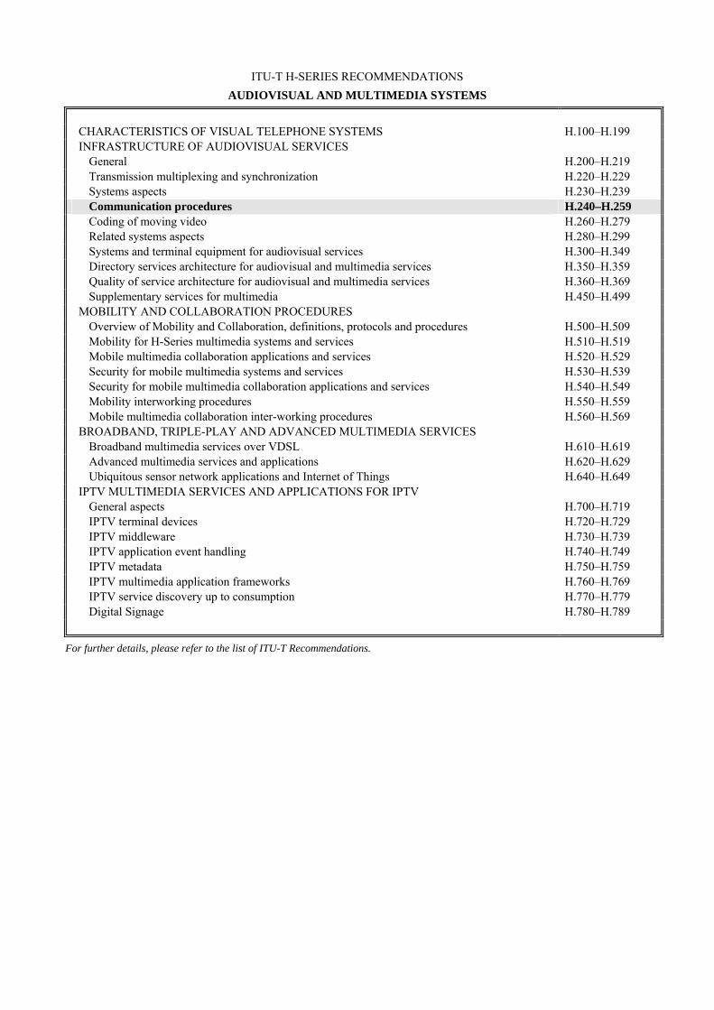
ITU-T H-SERIES RECOMMENDATIONS
AUDIOVISUAL AND MULTIMEDIA SYSTEMS
CHARACTERISTICS OF VISUAL TELEPHONE SYSTEMS H.100–H.199 INFRASTRUCTURE OF AUDIOVISUAL SERVICES
General H.200–H.219 Transmission multiplexing and synchronization H.220–H.229 Systems aspects H.230–H.239 Communication procedures H.240–H.259Coding of moving video H.260–H.279 Related systems aspects H.280–H.299 Systems and terminal equipment for audiovisual services H.300–H.349 Directory services architecture for audiovisual and multimedia services H.350–H.359 Quality of service architecture for audiovisual and multimedia services H.360–H.369 Supplementary services for multimedia H.450–H.499
MOBILITY AND COLLABORATION PROCEDURES Overview of Mobility and Collaboration, definitions, protocols and procedures H.500–H.509 Mobility for H-Series multimedia systems and services H.510–H.519 Mobile multimedia collaboration applications and services H.520–H.529 Security for mobile multimedia systems and services H.530–H.539 Security for mobile multimedia collaboration applications and services H.540–H.549 Mobility interworking procedures H.550–H.559 Mobile multimedia collaboration inter-working procedures H.560–H.569
BROADBAND, TRIPLE-PLAY AND ADVANCED MULTIMEDIA SERVICES Broadband multimedia services over VDSL H.610–H.619 Advanced multimedia services and applications H.620–H.629 Ubiquitous sensor network applications and Internet of Things H.640–H.649
IPTV MULTIMEDIA SERVICES AND APPLICATIONS FOR IPTV General aspects H.700–H.719 IPTV terminal devices H.720–H.729 IPTV middleware H.730–H.739 IPTV application event handling H.740–H.749 IPTV metadata H.750–H.759 IPTV multimedia application frameworks H.760–H.769 IPTV service discovery up to consumption H.770–H.779 Digital Signage H.780–H.789
For further details, please refer to the list of ITU-T Recommendations.
Rec. ITU-T H.241 (2012)/Amd.1 (06/2012) i
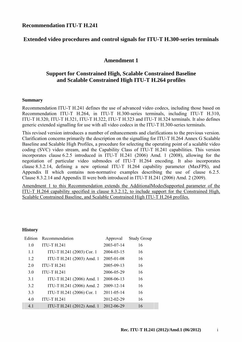
Recommendation ITU-T H.241
Extended video procedures and control signals for ITU-T H.300-series terminals
Amendment 1
Support for Constrained High, Scalable Constrained Baseline and Scalable Constrained High ITU-T H.264 profiles
Summary
Recommendation ITU-T H.241 defines the use of advanced video codecs, including those based on Recommendation ITU-T H.264, in ITU-T H.300-series terminals, including ITU-T H.310, ITU-T H.320, ITU-T H.321, ITU-T H.322, ITU-T H.323 and ITU-T H.324 terminals. It also defines generic extended signalling for use with all video codecs in the ITU-T H.300-series terminals.
This revised version introduces a number of enhancements and clarifications to the previous version. Clarification concerns primarily the description on the signalling for ITU-T H.264 Annex G Scalable Baseline and Scalable High Profiles, a procedure for selecting the operating point of a scalable video coding (SVC) video stream, and the Capability Class of ITU-T H.241 capabilities. This version incorporates clause 6.2.5 introduced in ITU-T H.241 (2006) Amd. 1 (2008), allowing for the negotiation of particular video submodes of ITU-T H.264 encoding. It also incorporates clause 8.3.2.14, defining a new optional ITU-T H.264 capability parameter (MaxFPS), and Appendix II which contains non-normative examples describing the use of clause 6.2.5. Clause 8.3.2.14 and Appendix II were both introduced in ITU-T H.241 (2006) Amd. 2 (2009).
Amendment 1 to this Recommendation extends the AdditionalModesSupported parameter of the ITU-T H.264 capability specified in clause 8.3.2.12, to include support for the Constrained High, Scalable Constrained Baseline, and Scalable Constrained High ITU-T H.264 profiles.
History
Edition Recommendation Approval Study Group
1.0 ITU-T H.241 2003-07-14 16
1.1 ITU-T H.241 (2003) Cor. 1 2004-03-15 16
1.2 ITU-T H.241 (2003) Amd. 1 2005-01-08 16
2.0 ITU-T H.241 2005-09-13 16
3.0 ITU-T H.241 2006-05-29 16
3.1 ITU-T H.241 (2006) Amd. 1 2008-06-13 16
3.2 ITU-T H.241 (2006) Amd. 2 2009-12-14 16
3.3 ITU-T H.241 (2006) Cor. 1 2011-05-14 16
4.0 ITU-T H.241 2012-02-29 16
4.1 ITU-T H.241 (2012) Amd. 1 2012-06-29 16
ii Rec. ITU-T H.241 (2012)/Amd.1 (06/2012)
FOREWORD
The International Telecommunication Union (ITU) is the United Nations specialized agency in the field of telecommunications, information and communication technologies (ICTs). The ITU Telecommunication Standardization Sector (ITU-T) is a permanent organ of ITU. ITU-T is responsible for studying technical, operating and tariff questions and issuing Recommendations on them with a view to standardizing telecommunications on a worldwide basis.
The World Telecommunication Standardization Assembly (WTSA), which meets every four years, establishes the topics for study by the ITU-T study groups which, in turn, produce Recommendations on these topics.
The approval of ITU-T Recommendations is covered by the procedure laid down in WTSA Resolution 1.
In some areas of information technology which fall within ITU-T's purview, the necessary standards are prepared on a collaborative basis with ISO and IEC.
NOTE
In this Recommendation, the expression "Administration" is used for conciseness to indicate both a telecommunication administration and a recognized operating agency.
Compliance with this Recommendation is voluntary. However, the Recommendation may contain certain mandatory provisions (to ensure, e.g., interoperability or applicability) and compliance with the Recommendation is achieved when all of these mandatory provisions are met. The words "shall" or some other obligatory language such as "must" and the negative equivalents are used to express requirements. The use of such words does not suggest that compliance with the Recommendation is required of any party.
INTELLECTUAL PROPERTY RIGHTS
ITU draws attention to the possibility that the practice or implementation of this Recommendation may involve the use of a claimed Intellectual Property Right. ITU takes no position concerning the evidence, validity or applicability of claimed Intellectual Property Rights, whether asserted by ITU members or others outside of the Recommendation development process.
As of the date of approval of this Recommendation, ITU had received notice of intellectual property, protected by patents, which may be required to implement this Recommendation. However, implementers are cautioned that this may not represent the latest information and are therefore strongly urged to consult the TSB patent database at http://www.itu.int/ITU-T/ipr/.
ITU 2013
All rights reserved. No part of this publication may be reproduced, by any means whatsoever, without the prior written permission of ITU.
Rec. ITU-T H.241 (2012)/Amd.1 (06/2012) iii
Table of Contents
Page
1 Scope ............................................................................................................................ 1
2 References..................................................................................................................... 1
3 Definitions .................................................................................................................... 2
3.1 Terms defined elsewhere ................................................................................ 2
3.2 Terms defined in this Recommendation ......................................................... 2
4 Abbreviations and acronyms ........................................................................................ 3
5 Conventions .................................................................................................................. 3
5.1 System terminology ........................................................................................ 3
5.2 Message names ............................................................................................... 3
5.3 Requirement terminology ............................................................................... 4
6 Commands and indications ........................................................................................... 4
6.1 Control and îndication (C&I) applicable to all video codecs ......................... 4
6.2 C&I for use with ITU-T H.264 ....................................................................... 4
7 Transport of coded video in ITU-T H.300-series systems ........................................... 19
7.1 Transport of Recommendation ITU-T H.264 video streams .......................... 19
8 Capability exchange signalling ..................................................................................... 22
8.1 General ........................................................................................................... 22
8.2 Signalling of ITU-T H.245 generic parameters in BAS-based systems ......... 22
8.3 ITU-T H.264 capabilities ................................................................................ 22
Annex A – ITU-T H.264 transport for ITU-T H.323............................................................... 38
Annex B – Reduced-complexity decoding operation (RCDO) for ITU-T H.264 Baseline Profile bitstreams .......................................................................................................... 39
B.1 Scope .............................................................................................................. 39
B.2 Definitions ...................................................................................................... 39
B.3 General ........................................................................................................... 39
B.4 RCDO bitstreams ............................................................................................ 39
B.5 OpenLogicalChannel signalling ..................................................................... 40
B.6 Procedures ...................................................................................................... 40
Appendix I – ASN.1 OIDs defined in this Recommendation .................................................. 46
Appendix II – Examples of the set submode procedure .......................................................... 47
II.1 Optimization of the picture aspect ratio ......................................................... 47
II.2 Limiting the picture frame rate ....................................................................... 47
II.3 Eliminating the adverse effects of picture rescaling ....................................... 48
II.4 Improving bandwidth utilization by limiting maximum picture size ............. 49
Bibliography............................................................................................................................. 51

Rec. ITU-T H.241 (2012)/Amd.1 (06/2012) 1
Recommendation ITU-T H.241
Extended video procedures and control signals for ITU-T H.300-series terminals
Amendment 1
Support for Constrained High, Scalable Constrained Baseline and Scalable Constrained High ITU-T H.264 profiles
1 Scope
This Recommendation defines the procedures for use of advanced video codecs, including those based on [ITU-T H.264], in ITU-T H.300-series terminals, including ITU-T H.310, ITU-T H.320, ITU-T H.321, ITU-T H.322, ITU-T H.323 and ITU-T H.324 terminals. Such procedures include control, indication, capability exchange, and transport mechanisms.
Additionally, this Recommendation defines generic extended video control, indication, and capability signalling, applicable for use with all video codecs used in ITU-T H.300-series multimedia terminals.
Annex A specifies ITU-T H.264 transport for ITU-T H.323 systems, including Annex G of [ITU-T H.264] (Scalable Video Coding).
Annex B specifies a reduced-complexity decoding process to be applied to ITU-T H.264 Baseline profile bitstreams when such use has been negotiated using [ITU-T H.241].
2 References
The following ITU-T Recommendations and other references contain provisions which, through reference in this text, constitute provisions of this Recommendation. At the time of publication, the editions indicated were valid. All Recommendations and other references are subject to revision; users of this Recommendation are therefore encouraged to investigate the possibility of applying the most recent edition of the Recommendations and other references listed below. A list of the currently valid ITU-T Recommendations is regularly published. The reference to a document within this Recommendation does not give it, as a stand-alone document, the status of a Recommendation.
[ITU-T H.221] Recommendation ITU-T H.221 (2009), Frame structure for a 64 to 1 920 kbit/s channel in audiovisual teleservices.
[ITU-T H.230] Recommendation ITU-T H.230 (2009), Frame-synchronous control and indication signals for audiovisual systems.
[ITU-T H.239] Recommendation ITU-T H.239 (2005), Role management and additional media channels for H.300-series terminals.
[ITU-T H.242] Recommendation ITU-T H.242 (2009), System for establishing communication between audiovisual terminals using digital channels up to 2 Mbit/s.
[ITU-T H.243] Recommendation ITU-T H.243 (2005), Procedures for establishing communication between three or more audiovisual terminals using digital channels up to 1 920 kbit/s.
[ITU-T H.245] Recommendation ITU-T H.245 (2011), Control protocol for multimedia communication.
2 Rec. ITU-T H.241 (2012)/Amd.1 (06/2012)
[ITU-T H.261] Recommendation ITU-T H.261 (1993), Video codec for audiovisual services at p × 64 kbit/s.
[ITU-T H.262] Recommendation ITU-T H.262 (2000), Information technology – Generic coding of moving pictures and associated audio information: Video.
[ITU-T H.263] Recommendation ITU-T H.263 (2005), Video coding for low bit rate communication.
[ITU-T H.264] Recommendation ITU-T H.264 (20121), Advanced video coding for generic audiovisual services.
[ITU-T H.310] Recommendation ITU-T H.310 (1998), Broadband audiovisual communication systems and terminals.
[ITU-T H.320] Recommendation ITU-T H.320 (2004), Narrow-band visual telephone systems and terminal equipment.
[ITU-T H.323] Recommendation ITU-T H.323 (2009), Packet-based multimedia communications systems.
[ITU-T H.324] Recommendation ITU-T H.324 (2009), Terminal for low bit-rate multimedia communication.
[IETF RFC 3550] IETF RFC 3550 (2003), RTP: A Transport Protocol for Real-Time Applications.
[IETF RFC 6184] IETF RFC 6184 (2011), RTP Payload Format for H.264 Video.
[IETF RFC 6190] IETF RFC 6190 (2011), RTP Payload Format for Scalable Video Coding.
3 Definitions
3.1 Terms defined elsewhere
None.
3.2 Terms defined in this Recommendation
This Recommendation defines the following terms:
3.2.1 picture aspect ratio: The ratio between the intended horizontal width and the intended vertical height of a displayed picture. Picture aspect ratio is expressed as h:v, where h is horizontal width and v is vertical height (in arbitrary units of spatial distance). For the purposes of this definition, a picture is the complete displayed image (including both fields in the case of interlaced-scan video). For example, the picture aspect ratio for a common intermediate format (CIF) picture according to [ITU-T H.263] is 4:3.
3.2.2 sample aspect ratio: The ratio between the intended horizontal distance between the columns and the intended vertical distance between the rows of the luma sample array in a frame. Sample aspect ratio is expressed as h:v, where h is horizontal width and v is vertical height (in arbitrary units of spatial distance). For the purposes of this definition, a sample is an individual luma picture element (pixel) making up the complete displayed image (including both fields in the case of interlaced-scan video). For example, the sample aspect ratio for a CIF picture according to [ITU-T H.263] is 12:11.
3.2.3 terminal: A terminal is any end point and may be a user's terminal or some other communication system such as a multipoint control unit (MCU) or an information server.
Rec. ITU-T H.241 (2012)/Amd.1 (06/2012) 3
4 Abbreviations and acronyms
This Recommendation uses the following abbreviations and acronyms:
4CIF 4x Common Intermediate Format
4SIF 4x Standard Interchange Format
AL-SDU Adaptation Layer Service Data Unit
ASN.1 Abstract Syntax Notation One
BAS Bit-rate Allocation Signal
C&I Control and Indication
CIF Common Intermediate Format
IDR Instantaneous Decoding Refresh
MBE Multiple Byte Extension
MCU Multipoint Control Unit
OID Object Identifier
PAR Picture Aspect Ratio
QCIF Quarter Common Intermediate Format
QVGA Quarter VGA
RCDO Reduced Complexity Decoding Operation
RTP Real-time Transport Protocol
SAR Sample Aspect Ratio
SEI Supplemental Enhancement Information
SIF Standard Interchange Format
SVC Scalable Video Coding
VUI Video Usability Information
5 Conventions
5.1 System terminology
In order to simplify references, this Recommendation refers to two classes of signalling systems for ITU-T H.300-series terminals:
– "BAS-based systems" refers to those systems that use signalling in the ITU-T H.221 bit-rate allocation system (BAS) channel; these include ITU-T H.320, ITU-T H.321 and ITU-T H.322 systems.
– "ITU-T H.245-based systems" refers to those systems that use signalling according to [ITU-T H.245]; these include ITU-T H.310, ITU-T H.323 and ITU-T H.324 systems.
5.2 Message names
In this Recommendation, signalling messages which are common to both ITU-T H.245 and BAS signalling systems are referred to by their names, as given in Annex A of [ITU-T H.245], except in cases where their use in the unique BAS signalling environment is described. Message names are presented in bold font to distinguish them from the other text of this Recommendation.
4 Rec. ITU-T H.241 (2012)/Amd.1 (06/2012)
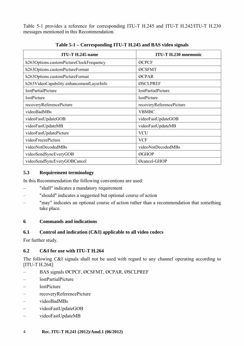
Table 5-1 provides a reference for corresponding ITU-T H.245 and ITU-T H.242/ITU-T H.230 messages mentioned in this Recommendation.
Table 5-1 – Corresponding ITU-T H.245 and BAS video signals
ITU-T H.245 name ITU-T H.230 mnemonic
h263Options.customPictureClockFrequency ØCPCF
h263Options.customPictureFormat ØCSFMT
h263Options.customPictureFormat ØCPAR
h263VideoCapability.enhancementLayerInfo ØSCLPREF
lostPartialPicture lostPartialPicture
lostPicture lostPicture
recoveryReferencePicture recoveryReferencePicture
videoBadMBs VBMBC
videoFastUpdateGOB videoFastUpdateGOB
videoFastUpdateMB videoFastUpdateMB
videoFastUpdatePicture VCU
videoFreezePicture VCF
videoNotDecodedMBs videoNotDecodedMBs
videoSendSyncEveryGOB ØGHOP
videoSendSyncEveryGOBCancel Øcancel-GHOP
5.3 Requirement terminology
In this Recommendation the following conventions are used:
– "shall" indicates a mandatory requirement
– "should" indicates a suggested but optional course of action
– "may" indicates an optional course of action rather than a recommendation that something take place.
6 Commands and indications
6.1 Control and îndication (C&I) applicable to all video codecs
For further study.
6.2 C&I for use with ITU-T H.264
The following C&I signals shall not be used with regard to any channel operating according to [ITU-T H.264]:
– BAS signals ØCPCF, ØCSFMT, ØCPAR, ØSCLPREF
– lostPartialPicture
– lostPicture
– recoveryReferencePicture
– videoBadMBs
– videoFastUpdateGOB
– videoFastUpdateMB
Rec. ITU-T H.241 (2012)/Amd.1 (06/2012) 5
– videoNotDecodedMBs
– videoSendSyncEveryGOB
– videoSendSyncEveryGOBCancel.
NOTE 1 – The above signals are either specific to [ITU-T H.263] or have parameters which do not correspond to ITU-T H.264 structures or value ranges. Replacement signals which could be used either with [ITU-T H.264] or in a generic form for any video codec are for further study.
All other C&I not mentioned in this clause shall be used as specified elsewhere.
NOTE 2 – For example, the use of videoIndicateReadyToActivate and corresponding BAS signal VIR is not affected by this Recommendation.
6.2.1 videoFreezePicture command in ITU-T H.264
When a video decoder according to [ITU-T H.264] receives a videoFreezePicture command, it shall freeze its displayed picture until one of the following events occurs:
a) a recovery point signalled in a recovery point service end interface (SEI) message (see clause D.2.7 of [ITU-T H.264]) is reached
b) reception of an instantaneous decoding refresh (IDR) picture
c) A timeout period of at least six seconds has elapsed since the videoFreezePicture command was received.
6.2.2 videoFastUpdatePicture command in ITU-T H.264
When a video encoder according to [ITU-T H.264] receives a videoFastUpdatePicture command, the encoder shall enter the fast update mode by using one of the procedures specified in clause 6.2.2.1 or 6.2.2.2 below. The procedure in 6.2.2.1 is the preferred response in a lossless transmission environment. Both procedures satisfy the requirement to enter the fast update mode for ITU-T H.264 video encoding.
NOTE 1 – The procedures re-initialize an ITU-T H.264 decoder completely so that valid video frames will be decoded. Such re-initialization is effective regardless of whether or not the decoder was previously decoding any video stream from any end point.
The procedure should be accomplished as quickly as possible, but the re-initialization video stream shall be completely transmitted within three seconds of receiving the videoFastUpdatePicture command.
NOTE 2 – The 3-second requirement is needed to avoid timeout of the six-second timer associated with the videoFreezePicture command, taking into account network and system latencies and possible cascaded MCUs. The videoFreezePicture command is used by multipoint control units (MCUs) as part of the video switching procedure (see clause 6.1.1 of [ITU-T H.243]).
6.2.2.1 IDR procedure to respond to videoFastUpdatePicture
This clause gives one possible way to respond to videoFastUpdatePicture.
The encoder shall, in the order presented here:
1) immediately prepare to send an IDR picture (see clause 3 of [ITU-T H.264])
2) send a ITU-T H.264 sequence parameter set corresponding to the IDR picture to be sent. The encoder may optionally also send other parameter sets
3) send a ITU-T H.264 picture parameter set corresponding to the IDR picture to be sent. The encoder may optionally also send other parameter sets
4) send the IDR picture
6 Rec. ITU-T H.241 (2012)/Amd.1 (06/2012)
5) from this point forward in time, send or re-send any other sequence or picture parameter sets, not sent in this procedure, prior to their reference by any ITU-T H.264 slice, regardless of whether such parameter sets were previously sent prior to receiving the videoFastUpdatePicture command. Such parameter sets may be sent all at once (within the limits of [ITU-T H.264]), one at a time as needed, or in any combination of these methods. Parameter sets may be re-sent at any time for redundancy.
6.2.2.2 Gradual recovery procedure to respond to videoFastUpdatePicture
This clause gives one possible way to respond to videoFastUpdatePicture.
The encoder shall, in the order presented here:
1) send a recovery point (supplemental enhancement information (SEI) message (see clause D.2.7 of [ITU-T H.264]).
2) repeat any sequence and picture parameter sets that were sent before the recovery point SEI message, prior to their reference in a ITU-T H.264 slice.
The encoder shall ensure that the decoder has access to all reference pictures, in output order, for inter prediction of pictures at or after the recovery point. For example, the encoder may mark all reference pictures as "unused for reference" by issuing a memory_management_control_operation equal to 5 (see clause 8.2.5 of [ITU-T H.264]).
The value of the recovery_frame_cnt syntax element in the recovery point SEI message shall be such that the time between reception of the videoFastUpdatePicture command and completing the transmission of the access unit, including the recovery point as specified in clause D.2.7 of [ITU-T H.264], is less than or equal to three seconds.
Re-sending of parameter sets may be done all at once (within the limits of [ITU-T H.264]), one at a time as needed, or in any combination of these methods. Parameter sets may be re-sent at any time for redundancy.
6.2.3 Recovery point SEI message
ITU-T H.264 video decoders in ITU-T H.300-series terminals shall support reception of the recovery point SEI message (see clause D.2.7 of [ITU-T H.264]), and identify the signalled recovery point.
Upon reception of a recovery point SEI message, the decoder shall continue to decode until the recovery point regardless of apparent errors in the stream, such as reference to absent pictures, and should not send a videoFastUpdatePicture command in response to such apparent error.
If a videoFreezePicture is in force, the decoder shall not display the decoded pictures, and shall continue to display the previously frozen picture. If the broken_link_flag in the recovery point SEI message is set, the decoder may choose not to display decoded pictures until the recovery point is reached.
If the decoder detects bitstream corruption between the SEI message and the recovery point in decoding order, a videoFastUpdatePicture command should be sent.
6.2.4 ITU-T H.264-on BAS command
For BAS-based systems, the ITU-T H.264-on BAS command defined in [ITU-T H.221] shall be used to signal that video according to [ITU-T H.264] is being transmitted. This command shall be used analogously to the BAS command ITU-T H.261-on. Video shall occupy the same capacity as stipulated in [ITU-T H.221] for the case of ITU-T H.261 video. The use of ITU-T H.264 Annex G scalable video coding (SVC) in BAS-based systems is for further study.
Rec. ITU-T H.241 (2012)/Amd.1 (06/2012) 7
6.2.5 Set submode procedure
This clause defines a procedure that may be used by ITU-T H.320 and ITU-T H.245 systems to negotiate the use of a particular ITU-T H.264 video encoding submode. Such a submode may limit the ITU-T H.264 encoding to a specified group of sample aspect ratios (SARs), picture aspect ratios (PARs), and picture heights while it is in force. It may also reduce the MaxMBPS value in Table A.1 of [ITU-T H.264] (or its optional replacement CustomMaxMBPS in Table 8-5) to a lower value. Additionally, it may reduce the MaxStaticMBPS value in Table 8-9 to a lower value.
Some examples illustrating the use of this procedure are given in Appendix II.
6.2.5.1 SetSubmode capability
ITU-T H.320 and ITU-T H.245 systems may optionally support the set submode procedure.
In [ITU-T H.320], this capability shall be signalled as a BAS message <h264SetSubmode> (see clause 3.1 of [ITU-T H.230]). <h264SetSubmode> is a BAS SBE message.
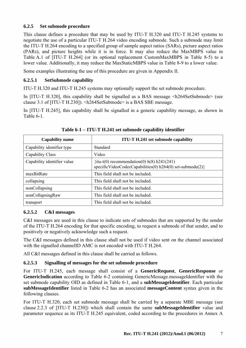
In [ITU-T H.245], this capability shall be signalled in a generic capability message, as shown in Table 6-1.
Table 6-1 − ITU-T H.241 set submode capability identifier
Capability name ITU-T H.241 set submode capability
Capability identifier type Standard
Capability Class Video
Capability identifier value {itu-t(0) recommendation(0) h(8) h241(241) specificVideoCodecCapabilities(0) h264(0) set-submode(2)}
maxBitRate This field shall not be included.
collapsing This field shall not be included.
nonCollapsing This field shall not be included.
nonCollapsingRaw This field shall not be included.
transport This field shall not be included.
6.2.5.2 C&I messages
C&I messages are used in this clause to indicate sets of submodes that are supported by the sender of the ITU-T H.264 encoding for that specific encoding, to request a submode of that sender, and to positively or negatively acknowledge such a request.
The C&I messages defined in this clause shall not be used if video sent on the channel associated with the signalled channelID AMC is not encoded with ITU-T H.264.
All C&I messages defined in this clause shall be carried as follows.
6.2.5.3 Signalling of messages for the set submode procedure
For ITU-T H.245, each message shall consist of a GenericRequest, GenericResponse or GenericIndication according to Table 6-2 containing GenericMessage.messageIdentifier with the set submode capability OID as defined in Table 6-1, and a subMessageIdentifier. Each particular subMessageIdentifier listed in Table 6-2 has an associated messageContent syntax given in the following clauses.
For ITU-T H.320, each set submode message shall be carried by a separate MBE message (see clause 2.2.3 of [ITU-T H.230]) which shall contain the same subMessageIdentifier value and parameter sequence as its ITU-T H.245 equivalent, coded according to the procedures in Annex A
8 Rec. ITU-T H.241 (2012)/Amd.1 (06/2012)
of [ITU-T H.239]. This MBE message uses the BAS code <H.264Submode-message> (see Table 2 of [ITU-T H.230]). The MBE contents are in the format:
{ Start-MBE / N / <H.264Submode-message> / subMessageIdentifier / zero or more message content bytes }
ITU-T H.320-ITU-T H.245 gateways that signal the SetSubmode capability shall translate these messages between the ITU-T H.320 and ITU-T H.245 signalling systems as specified in Annex A of [ITU-T H.239].
Except for ITU-T H.320/ITU-T H.245 gateways, devices that receive MessageContent containing an unrecognized parameterIdentifier shall ignore such parameterIdentifiers and any associated parameterValues.
6.2.5.4 SetSubmode messages
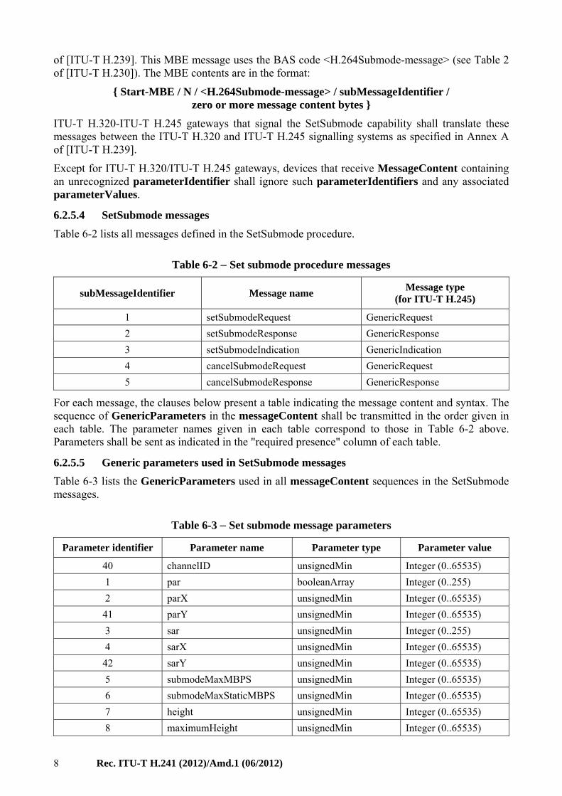
Table 6-2 lists all messages defined in the SetSubmode procedure.
Table 6-2 − Set submode procedure messages
subMessageIdentifier Message name Message type
(for ITU-T H.245)
1 setSubmodeRequest GenericRequest
2 setSubmodeResponse GenericResponse
3 setSubmodeIndication GenericIndication
4 cancelSubmodeRequest GenericRequest
5 cancelSubmodeResponse GenericResponse
For each message, the clauses below present a table indicating the message content and syntax. The sequence of GenericParameters in the messageContent shall be transmitted in the order given in each table. The parameter names given in each table correspond to those in Table 6-2 above. Parameters shall be sent as indicated in the "required presence" column of each table.
6.2.5.5 Generic parameters used in SetSubmode messages
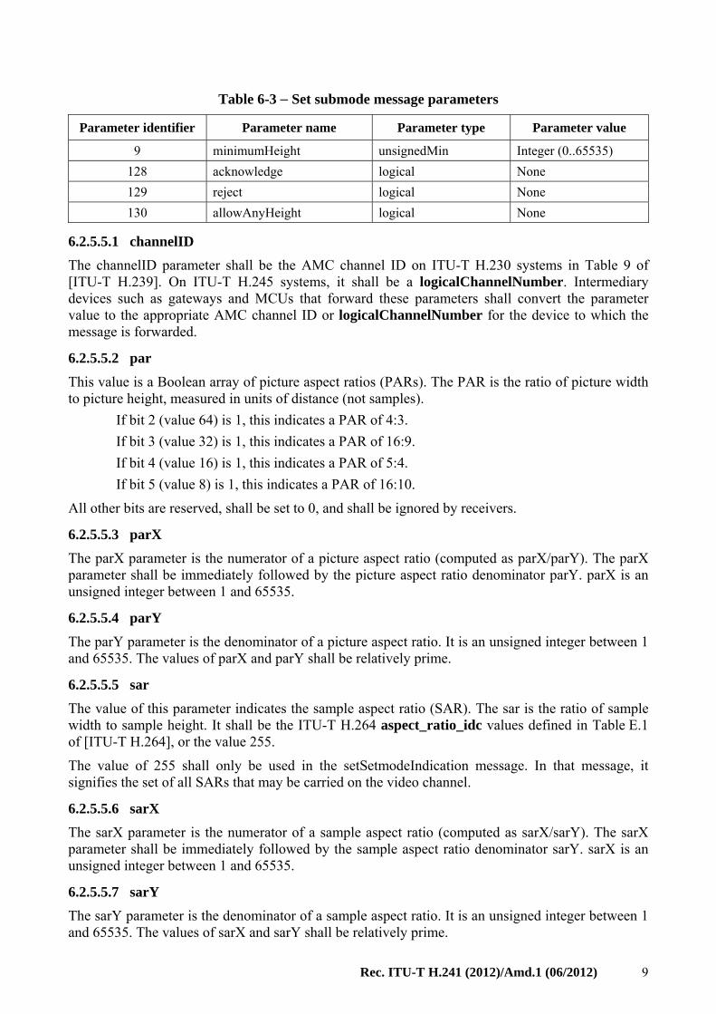
Table 6-3 lists the GenericParameters used in all messageContent sequences in the SetSubmode messages.
Table 6-3 − Set submode message parameters
Parameter identifier Parameter name Parameter type Parameter value
40 channelID unsignedMin Integer (0..65535)
1 par booleanArray Integer (0..255)
2 parX unsignedMin Integer (0..65535)
41 parY unsignedMin Integer (0..65535)
3 sar unsignedMin Integer (0..255)
4 sarX unsignedMin Integer (0..65535)
42 sarY unsignedMin Integer (0..65535)
5 submodeMaxMBPS unsignedMin Integer (0..65535)
6 submodeMaxStaticMBPS unsignedMin Integer (0..65535)
7 height unsignedMin Integer (0..65535)
8 maximumHeight unsignedMin Integer (0..65535)
Rec. ITU-T H.241 (2012)/Amd.1 (06/2012) 9
Table 6-3 − Set submode message parameters
Parameter identifier Parameter name Parameter type Parameter value
9 minimumHeight unsignedMin Integer (0..65535)
128 acknowledge logical None
129 reject logical None
130 allowAnyHeight logical None
6.2.5.5.1 channelID
The channelID parameter shall be the AMC channel ID on ITU-T H.230 systems in Table 9 of [ITU-T H.239]. On ITU-T H.245 systems, it shall be a logicalChannelNumber. Intermediary devices such as gateways and MCUs that forward these parameters shall convert the parameter value to the appropriate AMC channel ID or logicalChannelNumber for the device to which the message is forwarded.
6.2.5.5.2 par
This value is a Boolean array of picture aspect ratios (PARs). The PAR is the ratio of picture width to picture height, measured in units of distance (not samples).
If bit 2 (value 64) is 1, this indicates a PAR of 4:3.
If bit 3 (value 32) is 1, this indicates a PAR of 16:9.
If bit 4 (value 16) is 1, this indicates a PAR of 5:4.
If bit 5 (value 8) is 1, this indicates a PAR of 16:10.
All other bits are reserved, shall be set to 0, and shall be ignored by receivers.
6.2.5.5.3 parX
The parX parameter is the numerator of a picture aspect ratio (computed as parX/parY). The parX parameter shall be immediately followed by the picture aspect ratio denominator parY. parX is an unsigned integer between 1 and 65535.
6.2.5.5.4 parY
The parY parameter is the denominator of a picture aspect ratio. It is an unsigned integer between 1 and 65535. The values of parX and parY shall be relatively prime.
6.2.5.5.5 sar
The value of this parameter indicates the sample aspect ratio (SAR). The sar is the ratio of sample width to sample height. It shall be the ITU-T H.264 aspect_ratio_idc values defined in Table E.1 of [ITU-T H.264], or the value 255.
The value of 255 shall only be used in the setSetmodeIndication message. In that message, it signifies the set of all SARs that may be carried on the video channel.
6.2.5.5.6 sarX
The sarX parameter is the numerator of a sample aspect ratio (computed as sarX/sarY). The sarX parameter shall be immediately followed by the sample aspect ratio denominator sarY. sarX is an unsigned integer between 1 and 65535.
6.2.5.5.7 sarY
The sarY parameter is the denominator of a sample aspect ratio. It is an unsigned integer between 1 and 65535. The values of sarX and sarY shall be relatively prime.
10 Rec. ITU-T H.241 (2012)/Amd.1 (06/2012)
6.2.5.5.8 submodeMaxMBPS
The submodeMaxMBPS parameter is the maximum macroblock processing rate, in units of 500 macroblocks per second.
6.2.5.5.9 submodeMaxStaticMBPS
The submodeMaxStaticMBPS parameter is the static macroblock processing rate, under the assumption that all macroblocks are static macroblocks, in units of 500 macroblocks per second.
6.2.5.5.10 height
This is the height of the picture in samples.
6.2.5.5.11 maximumHeight
This is the largest height of the picture in samples (used in a setSubmodeRequest message).
6.2.5.5.12 minimumHeight
This is the smallest supported picture height in samples (used in a setSubmodeResponse message).
6.2.5.5.13 acknowledge
This parameter, if present, indicates a positive acknowledgment of a request.
6.2.5.5.14 reject
This parameter, if present, indicates a rejection of a request.
6.2.5.5.15 allowAnyHeight
This parameter, if present, indicates that any requested picture height will be positively acknowledged for the specified combination of SARs and PARs.
6.2.5.6 setSubmodeIndication
This message indicates the combinations of SARs and PARs that are available for the ITU-T H.264 video encoding on a specified video channel. These combinations shall be sent as a series of one or more groups, each group comprising a SAR and one or more PARs. The full set of combinations that are available is the union of the combinations of all the groups in the message.
The SAR shall be signalled as either a single sar parameter or as a single sarX, sarY parameter pair. A sar parameter value of 255 in a group shall indicate that all SARs that can be carried on the channel are combined with the PARs for that group.
The PARs shall be signalled as either a single par parameter or as a list of one or more parX, parY parameter pairs. The par parameter may indicate more than one PAR. The omission of par or parX, parY from a group shall indicate that all the SARs in that group are combined with all possible PARs.
The presence of the allowAnyHeight parameter from a group shall indicate that all picture heights that can be carried on the channel are available for each SAR and PAR combination that is included in that group.
The absence of the allowAnyHeight parameter from a group shall indicate that one or more unspecified picture heights are available for each SAR and PAR combination that is included in that group. Those heights may differ for each combination.
When a video channel is opened to a device which signals support for the set submode procedure, the device transmitting the video channel shall send the setSubmodeIndication. The setSubmodeIndication message shall also be sent whenever the available combinations of SARs and PARs change.
Rec. ITU-T H.241 (2012)/Amd.1 (06/2012) 11
On ITU-T H.320 connections, setSubmodeIndication shall be sent periodically.
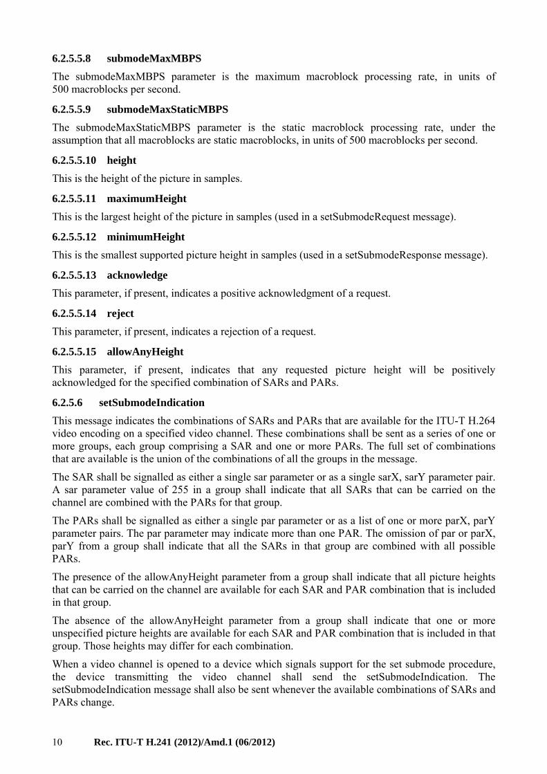
Table 6-4 − setSubmodeIndication syntax
GenericParameter order Parameter name Required presence
1 channelID Mandatory
2 sar Either one sar or one sarX, sarY shall be present in each group.
This group of parameters may be present multiple times.
sarX
sarY
3 par Either one par or multiple parX, parY pairs may be present. parX
parY
4 allowAnyHeight allowAnyHeight may be present in each group.
6.2.5.6.1 setSubmodeIndication examples (informative)
This clause does not form an integral part of this Recommendation.
For example:
A setSubmodeIndication contains one group, with sar=255 and allowAnyHeight.
This message indicates that the sender is capable of sending a picture of any size within its capability set with any sample aspect ratio and picture aspect ratio.
For example:
A setSubmodeIndication contains two groups. The first group has sar=1 and allowAnyHeight. The second group has sar=255, par=96.
The first group indicates that the sender is capable of sending pictures with square samples at any PAR and any desired picture height. This is equivalent to saying that the sender is capable of sending pictures with square pixels of any size.
The second group indicates that the sender is capable of sending pictures with any SAR as long as the overall picture aspect ratio is either 4:3 or 16:9. Since allowAnyHeight is not specified, only some picture sizes (perhaps only one size) are available for this group.
A picture with a SAR of 1:1 and an aspect ratio of 4:3 is a member of both groups. Because one of the groups signals allowAnyHeight, such pictures are available at any size.
For example:
A setSubmodeIndication contains 4 groups. The first group has sar=1, par=120 and allowAnyHeight. The second group has sar=2 and par=64. The third group has sar=3 and par=64. The fourth group has sar=7 and par=64.
The first group indicates the ability to send pictures with square samples at picture aspect ratios of 4:3, 16:9, 5:4 or 16:10. These pictures can be sent at any size.
The second group indicates the ability to send pictures with the sample aspect ratio used for PAL with a picture aspect ratio of 4:3. Not all sizes are available, perhaps only QCIF and CIF.
The third group indicates the ability to send pictures with the sample aspect ratio used for NTSC, with a picture aspect ratio of 4:3. Not all sizes are available, perhaps only QSIF and SIF.
12 Rec. ITU-T H.241 (2012)/Amd.1 (06/2012)
The last group indicates the ability to send pictures with the sample aspect ratio used for interlaced NTSC, with a picture aspect ratio of 4:3. Not all sizes are available, perhaps only 352×480.
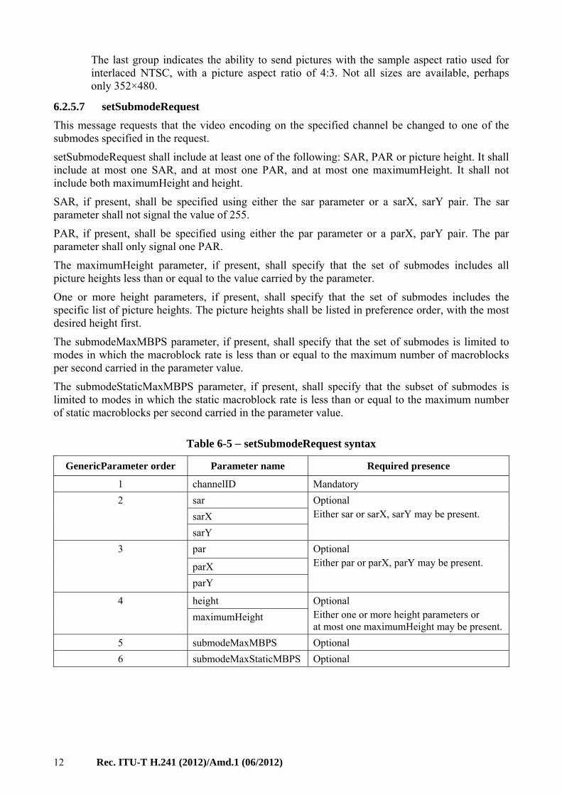
6.2.5.7 setSubmodeRequest
This message requests that the video encoding on the specified channel be changed to one of the submodes specified in the request.
setSubmodeRequest shall include at least one of the following: SAR, PAR or picture height. It shall include at most one SAR, and at most one PAR, and at most one maximumHeight. It shall not include both maximumHeight and height.
SAR, if present, shall be specified using either the sar parameter or a sarX, sarY pair. The sar parameter shall not signal the value of 255.
PAR, if present, shall be specified using either the par parameter or a parX, parY pair. The par parameter shall only signal one PAR.
The maximumHeight parameter, if present, shall specify that the set of submodes includes all picture heights less than or equal to the value carried by the parameter.
One or more height parameters, if present, shall specify that the set of submodes includes the specific list of picture heights. The picture heights shall be listed in preference order, with the most desired height first.
The submodeMaxMBPS parameter, if present, shall specify that the set of submodes is limited to modes in which the macroblock rate is less than or equal to the maximum number of macroblocks per second carried in the parameter value.
The submodeStaticMaxMBPS parameter, if present, shall specify that the subset of submodes is limited to modes in which the static macroblock rate is less than or equal to the maximum number of static macroblocks per second carried in the parameter value.
Table 6-5 − setSubmodeRequest syntax
GenericParameter order Parameter name Required presence
1 channelID Mandatory
2 sar Optional Either sar or sarX, sarY may be present. sarX
sarY
3 par Optional Either par or parX, parY may be present. parX
parY
4 height Optional Either one or more height parameters or at most one maximumHeight may be present.
maximumHeight
5 submodeMaxMBPS Optional
6 submodeMaxStaticMBPS Optional
Rec. ITU-T H.241 (2012)/Amd.1 (06/2012) 13
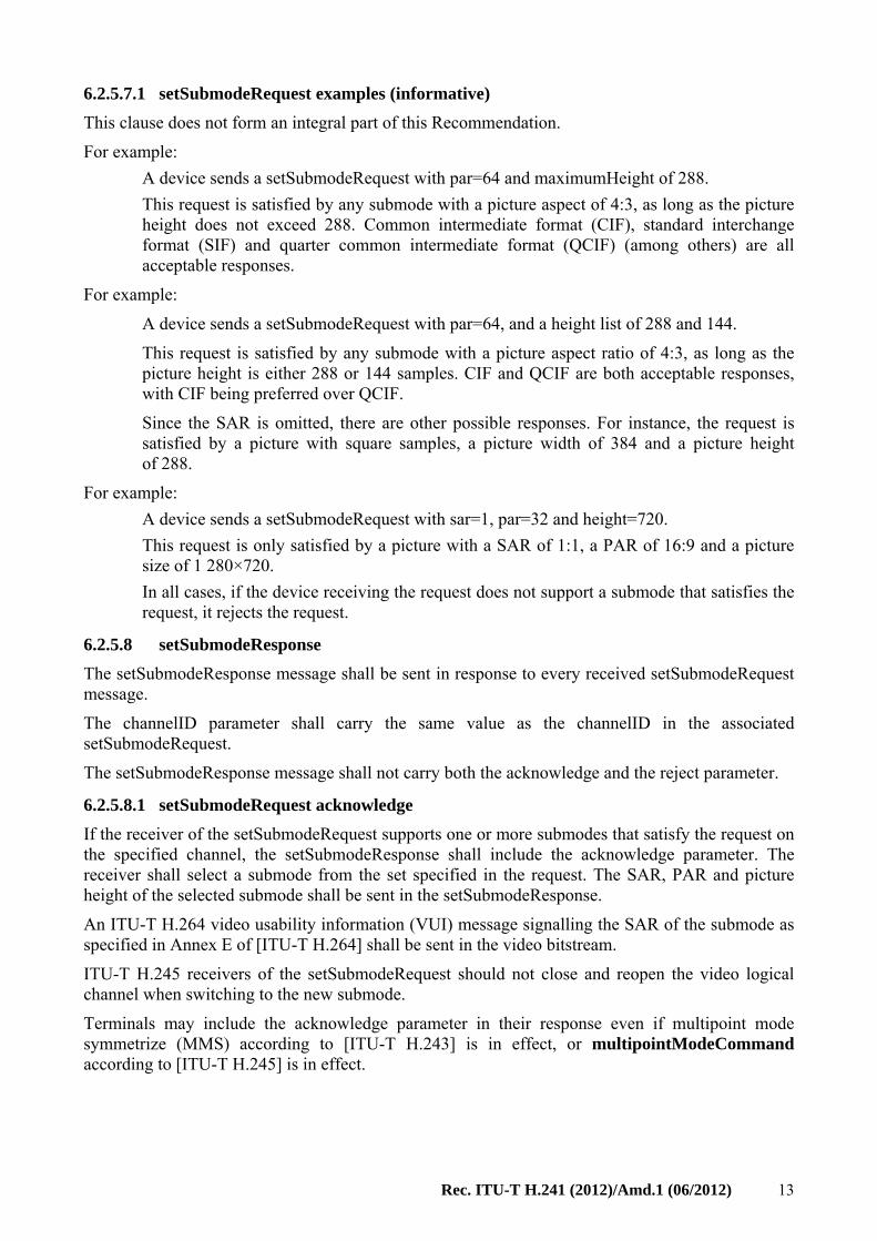
6.2.5.7.1 setSubmodeRequest examples (informative)
This clause does not form an integral part of this Recommendation.
For example:
A device sends a setSubmodeRequest with par=64 and maximumHeight of 288.
This request is satisfied by any submode with a picture aspect of 4:3, as long as the picture height does not exceed 288. Common intermediate format (CIF), standard interchange format (SIF) and quarter common intermediate format (QCIF) (among others) are all acceptable responses.
For example:
A device sends a setSubmodeRequest with par=64, and a height list of 288 and 144.
This request is satisfied by any submode with a picture aspect ratio of 4:3, as long as the picture height is either 288 or 144 samples. CIF and QCIF are both acceptable responses, with CIF being preferred over QCIF.
Since the SAR is omitted, there are other possible responses. For instance, the request is satisfied by a picture with square samples, a picture width of 384 and a picture height of 288.
For example:
A device sends a setSubmodeRequest with sar=1, par=32 and height=720.
This request is only satisfied by a picture with a SAR of 1:1, a PAR of 16:9 and a picture size of 1 280×720.
In all cases, if the device receiving the request does not support a submode that satisfies the request, it rejects the request.
6.2.5.8 setSubmodeResponse
The setSubmodeResponse message shall be sent in response to every received setSubmodeRequest message.
The channelID parameter shall carry the same value as the channelID in the associated setSubmodeRequest.
The setSubmodeResponse message shall not carry both the acknowledge and the reject parameter.
6.2.5.8.1 setSubmodeRequest acknowledge
If the receiver of the setSubmodeRequest supports one or more submodes that satisfy the request on the specified channel, the setSubmodeResponse shall include the acknowledge parameter. The receiver shall select a submode from the set specified in the request. The SAR, PAR and picture height of the selected submode shall be sent in the setSubmodeResponse.
An ITU-T H.264 video usability information (VUI) message signalling the SAR of the submode as specified in Annex E of [ITU-T H.264] shall be sent in the video bitstream.
ITU-T H.245 receivers of the setSubmodeRequest should not close and reopen the video logical channel when switching to the new submode.
Terminals may include the acknowledge parameter in their response even if multipoint mode symmetrize (MMS) according to [ITU-T H.243] is in effect, or multipointModeCommand according to [ITU-T H.245] is in effect.
14 Rec. ITU-T H.241 (2012)/Amd.1 (06/2012)
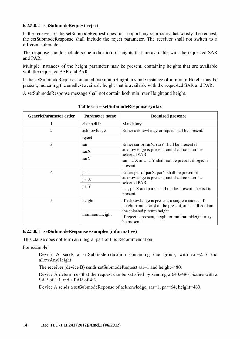
6.2.5.8.2 setSubmodeRequest reject
If the receiver of the setSubmodeRequest does not support any submodes that satisfy the request, the setSubmodeResponse shall include the reject parameter. The receiver shall not switch to a different submode.
The response should include some indication of heights that are available with the requested SAR and PAR.
Multiple instances of the height parameter may be present, containing heights that are available with the requested SAR and PAR
If the setSubmodeRequest contained maximumHeight, a single instance of minimumHeight may be present, indicating the smallest available height that is available with the requested SAR and PAR.
A setSubmodeResponse message shall not contain both minimumHeight and height.
Table 6-6 − setSubmodeResponse syntax
GenericParameter order Parameter name Required presence
1 channelID Mandatory
2 acknowledge Either acknowledge or reject shall be present.
reject
3 sar Either sar or sarX, sarY shall be present if acknowledge is present, and shall contain the selected SAR. sar, sarX and sarY shall not be present if reject is present.
sarX
sarY
4 par Either par or parX, parY shall be present if acknowledge is present, and shall contain the selected PAR. par, parX and parY shall not be present if reject is present.
parX
parY
5 height If acknowledge is present, a single instance of height parameter shall be present, and shall contain the selected picture height. If reject is present, height or minimumHeight may be present.
minimumHeight
6.2.5.8.3 setSubmodeResponse examples (informative)
This clause does not form an integral part of this Recommendation.
For example:
Device A sends a setSubmodeIndication containing one group, with sar=255 and allowAnyHeight.
The receiver (device B) sends setSubmodeRequest sar=1 and height=480.
Device A determines that the request can be satisfied by sending a 640x480 picture with a SAR of 1:1 and a PAR of 4:3.
Device A sends a setSubmodeReponse of acknowledge, sar=1, par=64, height=480.
Rec. ITU-T H.241 (2012)/Amd.1 (06/2012) 15
For example:
Device A sends a setSubmodeIndication containing two groups. The first group has sar=1 and allowAnyHeight. The second group has sar=255, par=96.
The receiver (device B) sends setSubmodeRequest sar=1 and par=64
Device A determines that the request can be satisfied by sending either a 640×480 or a 1 024×768 picture with a SAR of 1:1 and a PAR of 4:3. Device A chooses to send the 1 024×768 picture.
Device A sends a setSubmodeReponse of acknowledge, sar=1, par=96, height=768.
For example:
Device A sends a setSubmodeIndication containing two groups, one with sar=1 and par=64, the other with sar=2, par=64.
The receiver (device B) sends setSubmodeRequest with sar=2 and par=64 and height=576.
Device A determines that the request cannot be satisfied because the picture size is too large. It supports heights of 288 and 144 for this SAR and PAR combination.
Device A sends a setSubmodeReponse of reject, sar=1, height=288, height=144.
Device B sends a second setSubmodeRequest with sar=2, par=64, height=288.
Device A sends a setSubmodeResponse of acknowledge, sar=2, par=64, height=288.
For example:
Device A sends a setSubmodeIndication containing two groups, one with sar=1, par=64, the other with sar=2, par=64.
The receiver (device B) sends setSubmodeRequest with sar=2, par=64 and maximumHeight=576.
Device A determines that it supports heights of 288 and 144 for this SAR and PAR combination.
Device A sends a setSubmodeResponse of acknowledge, sar=2, par=64, height=288.
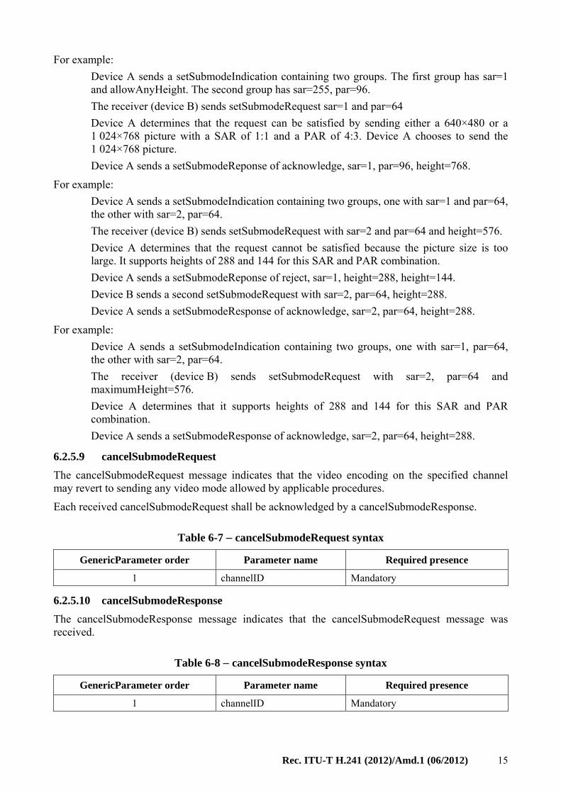
6.2.5.9 cancelSubmodeRequest
The cancelSubmodeRequest message indicates that the video encoding on the specified channel may revert to sending any video mode allowed by applicable procedures.
Each received cancelSubmodeRequest shall be acknowledged by a cancelSubmodeResponse.
Table 6-7 − cancelSubmodeRequest syntax
GenericParameter order Parameter name Required presence
1 channelID Mandatory
6.2.5.10 cancelSubmodeResponse
The cancelSubmodeResponse message indicates that the cancelSubmodeRequest message was received.
Table 6-8 − cancelSubmodeResponse syntax
GenericParameter order Parameter name Required presence
1 channelID Mandatory
16 Rec. ITU-T H.241 (2012)/Amd.1 (06/2012)
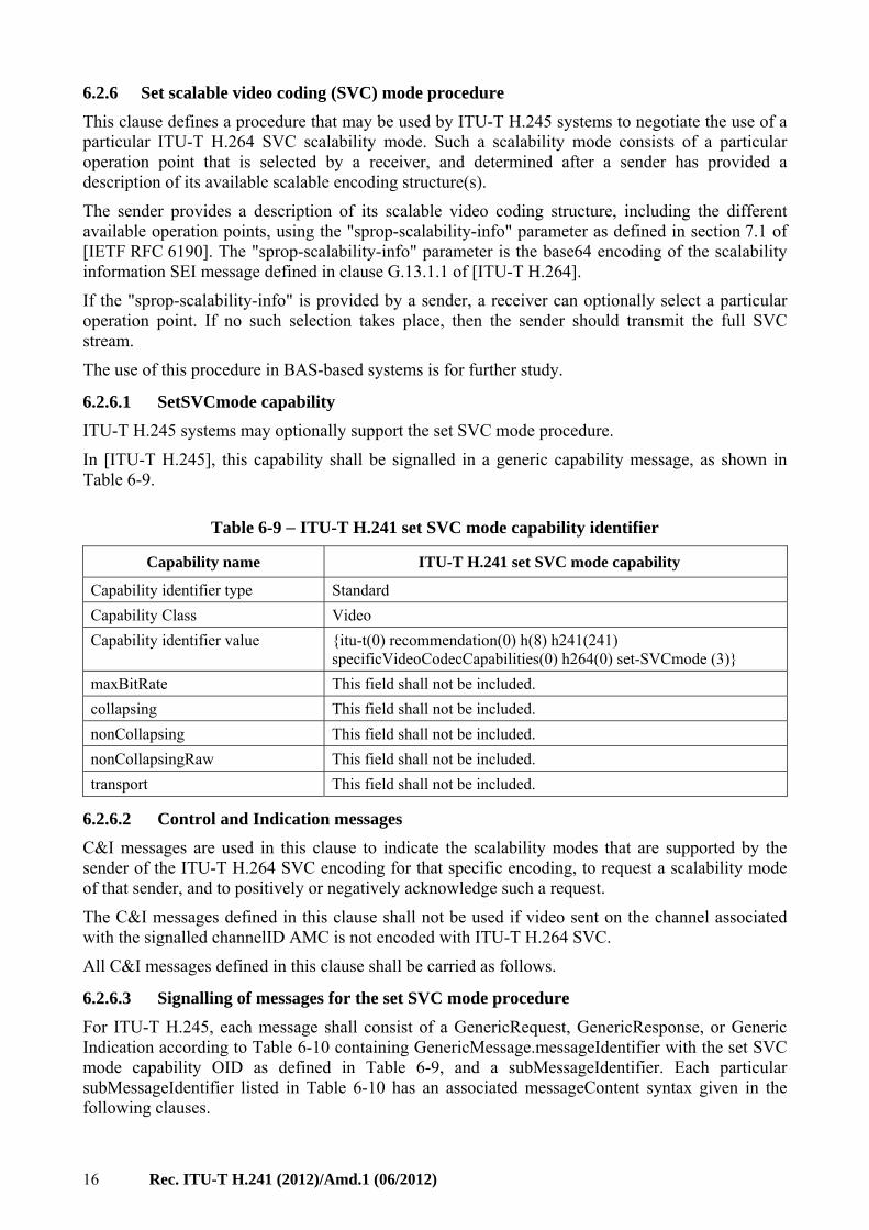
6.2.6 Set scalable video coding (SVC) mode procedure
This clause defines a procedure that may be used by ITU-T H.245 systems to negotiate the use of a particular ITU-T H.264 SVC scalability mode. Such a scalability mode consists of a particular operation point that is selected by a receiver, and determined after a sender has provided a description of its available scalable encoding structure(s).
The sender provides a description of its scalable video coding structure, including the different available operation points, using the "sprop-scalability-info" parameter as defined in section 7.1 of [IETF RFC 6190]. The "sprop-scalability-info" parameter is the base64 encoding of the scalability information SEI message defined in clause G.13.1.1 of [ITU-T H.264].
If the "sprop-scalability-info" is provided by a sender, a receiver can optionally select a particular operation point. If no such selection takes place, then the sender should transmit the full SVC stream.
The use of this procedure in BAS-based systems is for further study.
6.2.6.1 SetSVCmode capability
ITU-T H.245 systems may optionally support the set SVC mode procedure.
In [ITU-T H.245], this capability shall be signalled in a generic capability message, as shown in Table 6-9.
Table 6-9 − ITU-T H.241 set SVC mode capability identifier
Capability name ITU-T H.241 set SVC mode capability
Capability identifier type Standard
Capability Class Video
Capability identifier value {itu-t(0) recommendation(0) h(8) h241(241) specificVideoCodecCapabilities(0) h264(0) set-SVCmode (3)}
maxBitRate This field shall not be included.
collapsing This field shall not be included.
nonCollapsing This field shall not be included.
nonCollapsingRaw This field shall not be included.
transport This field shall not be included.
6.2.6.2 Control and Indication messages
C&I messages are used in this clause to indicate the scalability modes that are supported by the sender of the ITU-T H.264 SVC encoding for that specific encoding, to request a scalability mode of that sender, and to positively or negatively acknowledge such a request.
The C&I messages defined in this clause shall not be used if video sent on the channel associated with the signalled channelID AMC is not encoded with ITU-T H.264 SVC.
All C&I messages defined in this clause shall be carried as follows.
6.2.6.3 Signalling of messages for the set SVC mode procedure
For ITU-T H.245, each message shall consist of a GenericRequest, GenericResponse, or Generic Indication according to Table 6-10 containing GenericMessage.messageIdentifier with the set SVC mode capability OID as defined in Table 6-9, and a subMessageIdentifier. Each particular subMessageIdentifier listed in Table 6-10 has an associated messageContent syntax given in the following clauses.
Rec. ITU-T H.241 (2012)/Amd.1 (06/2012) 17
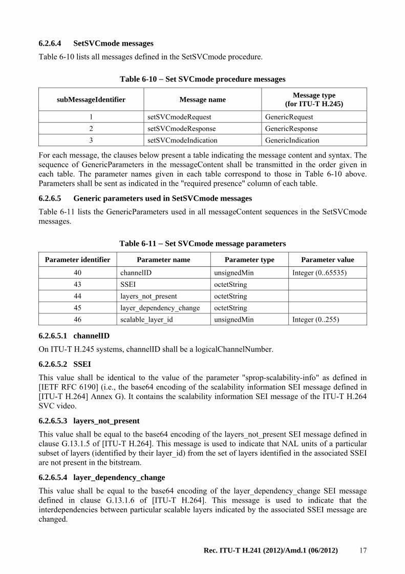
6.2.6.4 SetSVCmode messages
Table 6-10 lists all messages defined in the SetSVCmode procedure.
Table 6-10 − Set SVCmode procedure messages
subMessageIdentifier Message name Message type
(for ITU-T H.245)
1 setSVCmodeRequest GenericRequest
2 setSVCmodeResponse GenericResponse
3 setSVCmodeIndication GenericIndication
For each message, the clauses below present a table indicating the message content and syntax. The sequence of GenericParameters in the messageContent shall be transmitted in the order given in each table. The parameter names given in each table correspond to those in Table 6-10 above. Parameters shall be sent as indicated in the "required presence" column of each table.
6.2.6.5 Generic parameters used in SetSVCmode messages
Table 6-11 lists the GenericParameters used in all messageContent sequences in the SetSVCmode messages.
Table 6-11 − Set SVCmode message parameters
Parameter identifier Parameter name Parameter type Parameter value
40 channelID unsignedMin Integer (0..65535)
43 SSEI octetString
44 layers_not_present octetString
45 layer_dependency_change octetString
46 scalable_layer_id unsignedMin Integer (0..255)
6.2.6.5.1 channelID
On ITU-T H.245 systems, channelID shall be a logicalChannelNumber.
6.2.6.5.2 SSEI
This value shall be identical to the value of the parameter "sprop-scalability-info" as defined in [IETF RFC 6190] (i.e., the base64 encoding of the scalability information SEI message defined in [ITU-T H.264] Annex G). It contains the scalability information SEI message of the ITU-T H.264 SVC video.
6.2.6.5.3 layers_not_present
This value shall be equal to the base64 encoding of the layers_not_present SEI message defined in clause G.13.1.5 of [ITU-T H.264]. This message is used to indicate that NAL units of a particular subset of layers (identified by their layer_id) from the set of layers identified in the associated SSEI are not present in the bitstream.
6.2.6.5.4 layer_dependency_change
This value shall be equal to the base64 encoding of the layer_dependency_change SEI message defined in clause G.13.1.6 of [ITU-T H.264]. This message is used to indicate that the interdependencies between particular scalable layers indicated by the associated SSEI message are changed.
18 Rec. ITU-T H.241 (2012)/Amd.1 (06/2012)
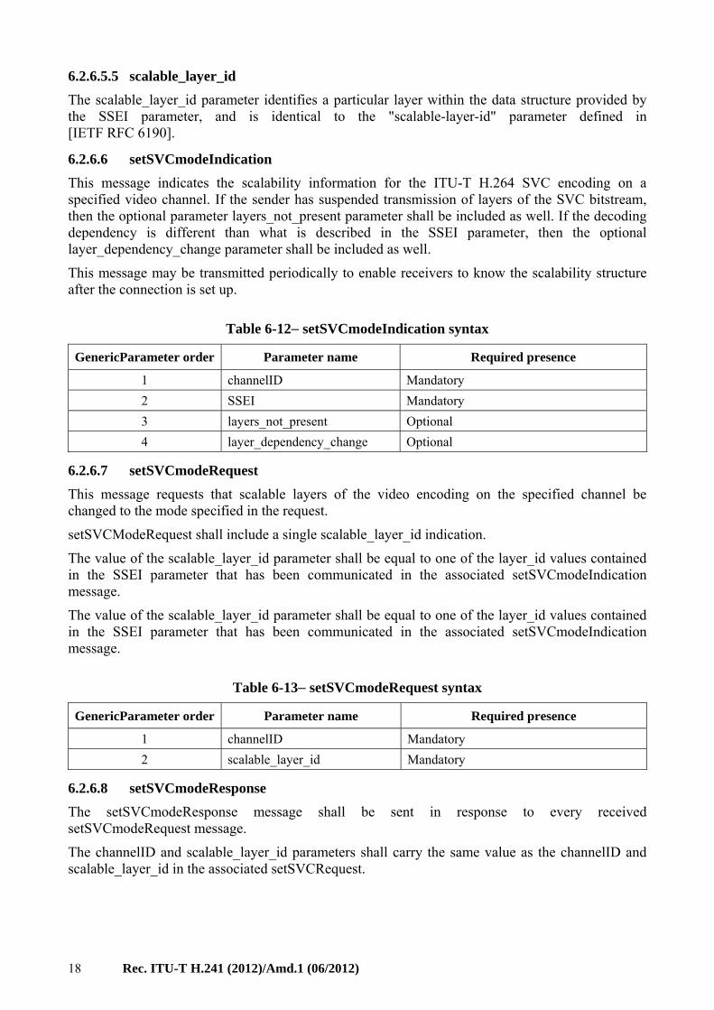
6.2.6.5.5 scalable_layer_id
The scalable_layer_id parameter identifies a particular layer within the data structure provided by the SSEI parameter, and is identical to the "scalable-layer-id" parameter defined in [IETF RFC 6190].
6.2.6.6 setSVCmodeIndication
This message indicates the scalability information for the ITU-T H.264 SVC encoding on a specified video channel. If the sender has suspended transmission of layers of the SVC bitstream, then the optional parameter layers_not_present parameter shall be included as well. If the decoding dependency is different than what is described in the SSEI parameter, then the optional layer_dependency_change parameter shall be included as well.
This message may be transmitted periodically to enable receivers to know the scalability structure after the connection is set up.
Table 6-12− setSVCmodeIndication syntax
GenericParameter order Parameter name Required presence
1 channelID Mandatory
2 SSEI Mandatory
3 layers_not_present Optional
4 layer_dependency_change Optional
6.2.6.7 setSVCmodeRequest
This message requests that scalable layers of the video encoding on the specified channel be changed to the mode specified in the request.
setSVCModeRequest shall include a single scalable_layer_id indication.
The value of the scalable_layer_id parameter shall be equal to one of the layer_id values contained in the SSEI parameter that has been communicated in the associated setSVCmodeIndication message.
The value of the scalable_layer_id parameter shall be equal to one of the layer_id values contained in the SSEI parameter that has been communicated in the associated setSVCmodeIndication message.
Table 6-13− setSVCmodeRequest syntax
GenericParameter order Parameter name Required presence
1 channelID Mandatory
2 scalable_layer_id Mandatory
6.2.6.8 setSVCmodeResponse
The setSVCmodeResponse message shall be sent in response to every received setSVCmodeRequest message.
The channelID and scalable_layer_id parameters shall carry the same value as the channelID and scalable_layer_id in the associated setSVCRequest.
Rec. ITU-T H.241 (2012)/Amd.1 (06/2012) 19
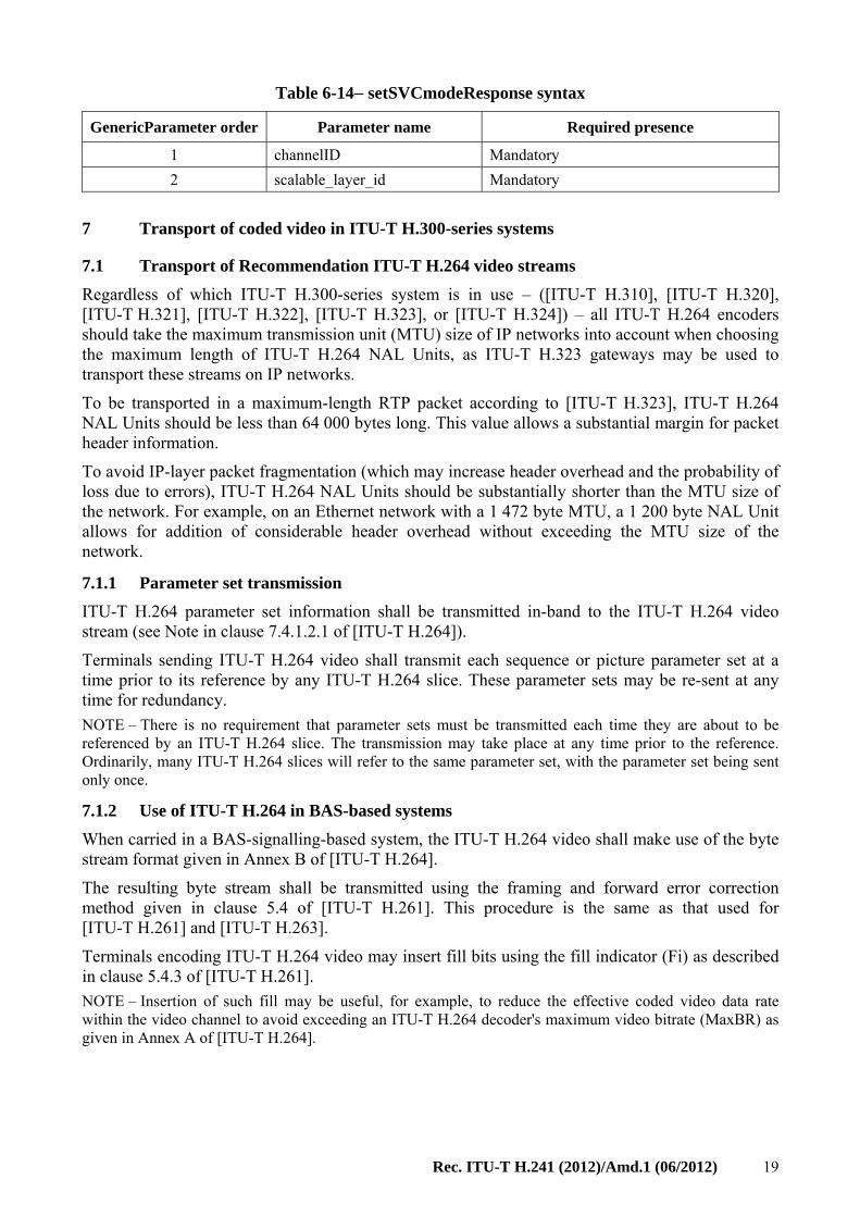
Table 6-14− setSVCmodeResponse syntax
GenericParameter order Parameter name Required presence
1 channelID Mandatory
2 scalable_layer_id Mandatory
7 Transport of coded video in ITU-T H.300-series systems
7.1 Transport of Recommendation ITU-T H.264 video streams
Regardless of which ITU-T H.300-series system is in use – ([ITU-T H.310], [ITU-T H.320], [ITU-T H.321], [ITU-T H.322], [ITU-T H.323], or [ITU-T H.324]) – all ITU-T H.264 encoders should take the maximum transmission unit (MTU) size of IP networks into account when choosing the maximum length of ITU-T H.264 NAL Units, as ITU-T H.323 gateways may be used to transport these streams on IP networks.
To be transported in a maximum-length RTP packet according to [ITU-T H.323], ITU-T H.264 NAL Units should be less than 64 000 bytes long. This value allows a substantial margin for packet header information.
To avoid IP-layer packet fragmentation (which may increase header overhead and the probability of loss due to errors), ITU-T H.264 NAL Units should be substantially shorter than the MTU size of the network. For example, on an Ethernet network with a 1 472 byte MTU, a 1 200 byte NAL Unit allows for addition of considerable header overhead without exceeding the MTU size of the network.
7.1.1 Parameter set transmission
ITU-T H.264 parameter set information shall be transmitted in-band to the ITU-T H.264 video stream (see Note in clause 7.4.1.2.1 of [ITU-T H.264]).
Terminals sending ITU-T H.264 video shall transmit each sequence or picture parameter set at a time prior to its reference by any ITU-T H.264 slice. These parameter sets may be re-sent at any time for redundancy.
NOTE – There is no requirement that parameter sets must be transmitted each time they are about to be referenced by an ITU-T H.264 slice. The transmission may take place at any time prior to the reference. Ordinarily, many ITU-T H.264 slices will refer to the same parameter set, with the parameter set being sent only once.
7.1.2 Use of ITU-T H.264 in BAS-based systems
When carried in a BAS-signalling-based system, the ITU-T H.264 video shall make use of the byte stream format given in Annex B of [ITU-T H.264].
The resulting byte stream shall be transmitted using the framing and forward error correction method given in clause 5.4 of [ITU-T H.261]. This procedure is the same as that used for [ITU-T H.261] and [ITU-T H.263].
Terminals encoding ITU-T H.264 video may insert fill bits using the fill indicator (Fi) as described in clause 5.4.3 of [ITU-T H.261].
NOTE – Insertion of such fill may be useful, for example, to reduce the effective coded video data rate within the video channel to avoid exceeding an ITU-T H.264 decoder's maximum video bitrate (MaxBR) as given in Annex A of [ITU-T H.264].
20 Rec. ITU-T H.241 (2012)/Amd.1 (06/2012)
7.1.3 Transport of ITU-T H.264 streams in ITU-T H.310 systems
In ITU-T H.310 systems, the ITU-T H.264 video shall make use of the byte stream format given in Annex B of [ITU-T H.264]. ITU-T H.264 shall be used without BCH error correction and without error correction framing.
7.1.4 Transport of ITU-T H.264 streams in ITU-T H.323 systems
In ITU-T H.323 systems, ITU-T H.264 shall be used without BCH error correction and without error correction framing. ITU-T H.323 systems shall not make use of the byte stream format given in Annex B of [ITU-T H.264].
All ITU-T H.323 systems that support ITU-T H.264 shall support carriage of the ITU-T H.264 video stream according to Annex A, and shall signal this in their capability set by including MediaPacketizationCapability.rtpPayload.Type.payloadDescriptor.oid, with the OID having the value {itu-t(0) recommendation(0) h(8) h241(241) specificVideoCodecCapabilities(0) h264(0) iPpacketization(0) h241AnnexA(0)} and a capability class of Video.
ITU-T H.323 systems that support ITU-T H.264 should also support the non-interleaved mode of [IETF RFC 6184] and may support the interleaved mode of [IETF RFC 6184], in addition to Annex A.
ITU-T H.323 systems that support ITU-T H.264 Annex G profiles shall support the non-interleaved mode of [IETF RFC 6184]. Furthermore, ITU-T H.323 systems that support ITU-T H.264 Annex G profiles shall support carriage of the ITU-T H.264 SVC stream with the single-session transmission mode of [IETF RFC 6190]. The use of the multi-session transmission mode of [IETF RFC 6190] in ITU-T H.323 systems is for further study.
The capability of using the non-interleaved mode of [IETF RFC 6184] shall be signalled by including a MediaPacketizationCapability.rtpPayloadType.payloadDescriptor.oid, with the OID having the value {itu-t(0) recommendation(0) h(8) h241(241) specificVideoCodecCapabilities(0) h264(0) iPpacketization(0) rfc6184NonInterleaved(1)} and a capability class of Video. The capability of using the interleaved mode of [IETF RFC 6184] shall be signalled by including a MediaPacketizationCapability.rtpPayloadType.payloadDescriptor.oid, with the OID having the value {itu-t(0) recommendation(0) h(8) h241(241) specificVideoCodecCapabilities(0) h264(0) iPpacketization(0) rfc6184Interleaved(2)} and a capability class of Video.
NOTE 1 – Since the single NAL unit mode of [IETF RFC 6184] and Annex A are technically identical, the codepoints above permit the use of all packetization modes of [IETF RFC 6184].
A sender which signals one of these packetization modes in its Open Logical Channel message shall transmit video according to the corresponding mode of [IETF RFC 6184] or Annex A.
In the interleaved mode of [IETF RFC 6184], senders and receivers need to have a common understanding of the required buffer sizes for the interleaving buffer. Unless signalled explicitly, these buffer sizes shall take the following values:
– sprop-interleaving-depth 80
– sprop-deint-buf-req 65 536
The explicit signalling of these parameters is for further study.
NOTE 2 – See section 8.1 of [IETF RFC 6184] for a description of both parameters. The values given are sufficient to support macroblock-line interleaved packetization of video signals with 1 080 lines at 8 Mbit/s. See clause III.2.3.1 of [ITU-T H.263] for a discussion of macroblock-line interleaved packetization.
7.1.5 Transport of ITU-T H.264 streams in ITU-T H.324 systems
In ITU-T H.324 systems, ITU-T H.264 shall be used without BCH error correction and without error correction framing, and shall make use of the byte stream format given in Annex B of [ITU-T H.264].
Rec. ITU-T H.241 (2012)/Amd.1 (06/2012) 21
ITU-T H.264 encoders shall align the Annex B of ITU-T H.264 start code prefix for the first NAL unit of each access unit with the start of an AL-SDU.
7.1.6 Sample aspect ratios (informative)
Transmission of the sample aspect ratio in the VUI parameters specified in Annex E of [ITU-T H.264] was not required in earlier versions of this Recommendation, and many older systems do not indicate the sample aspect ratio in the ITU-T H.264 video bitstream.
In the absence of an ITU-T H.264 VUI parameter aspect_ratio_idc value in the received ITU-T H.264 bitstream, and in the case of an aspect_ratio_idc value equal to 0, the sample aspect ratio may be assumed to have a value according to Table 7-1 below:
Table 7-1 – Assumed sample aspect ratios
Frame size (luma width × luma height)
Sample aspect ratio
128 × 96 (SQCIF) 12:11
176 × 144 (QCIF) 12:11
352 × 288 (CIF) 12:11
704 × 576 (4CIF) 12:11
720 × 576 (625 ITU-R BT.601) 12:11
352 × 576 (625 HHR) 24:11
528 × 576 (625 3/4 HR) 16:11
480 × 576 (625 2/3 HR) 18:11
352 × 240 (525 SIF) 10:11
704 × 480 (525 4SIF) 10:11
720 × 480 (525 ITU-R BT.601) 10:11
352 × 480 (525 HHR) 20:11
528 × 480 (525 3/4 HR) 40:33
480 × 480 (525 2/3 HR) 15:11
320 × 240 (QVGA) 1:1
640 × 480 (VGA) 1:1
800 × 600 (SVGA) 1:1
1 024 × 768 (XGA) 1:1
1 280 × 1 024 (SXGA) 1:1
1 600 × 1 200 (UXGA) 1:1
1 280 × 720 (720 HD) 1:1
1 920 × 1 080 (1080 HD) 1:1
1 920 × 1 088 (1080 HD) 1:1
other the value which will produce a picture
aspect ratio of 4:3
NOTE – All systems which send ITU-T H.264 video should indicate the sample aspect ratio in the VUI parameters specified in Annex E of [ITU-T H.264].
22 Rec. ITU-T H.241 (2012)/Amd.1 (06/2012)
8 Capability exchange signalling
8.1 General
Terminals which display received video shall be capable of displaying any picture format and frame rate for which they signal the capability. The format used to display such received video streams is not required to match the exact format transmitted.
NOTE – For example, a video conferencing system which decodes [ITU-T H.264] at a given Profile and Level must display any picture format and frame rate allowed by that Profile and Level.
If during an ongoing connection a terminal which is transmitting video receives a changed capability set, the terminal shall adapt its video coding method to conform with all the limitations signalled in the received capability set.
8.2 Signalling of ITU-T H.245 generic parameters in BAS-based systems
This Recommendation signals a subset of ITU-T H.245 GenericParameter structures in BAS channel MBE messages. These messages shall be carried in BAS-based systems using the procedures of Annex A of [ITU-T H.239]. These procedures avoid emulation of the MBE BAS code.
8.3 ITU-T H.264 capabilities
8.3.1 General
ITU-T H.300-series terminals may optionally support video according to [ITU-T H.264].
The ITU-T H.264 capability set is structured as a list of one or more ITU-T H.264 capabilities, each of which includes:
• Profile (mandatory)
• Level (mandatory)
• Zero or more optional parameters.
These capabilities indicate the ability to decode using one or more ITU-T H.264 Profiles. The exact syntax and semantics are given in the clauses below. In the case of ITU-T H.245-based systems, each capability is contained in a GenericCapability structure. For BAS-based systems, all capabilities are carried in a single MBE message.
The bitrate made available for a video stream by an ITU-T H.300-series system may be less than the maximum video bitrate which decoders are required to support by Annex A of [ITU-T H.264]. Terminals are not required to decode video streams which they do not receive.
8.3.1.1 Optional parameters
For each [ITU-T H.264] capability, optional parameters may be signalled. These parameters permit a terminal to signal that, in addition to meeting the support requirements for the signalled Profile and Level, the terminal has additional capabilities or constraints.
For ITU-T H.264 SVC, the optional parameters are also used to indicate that one of the scalable profiles is used. This is performed via the AdditionalModesSupported parameter as explained below.
Terminals shall not signal a set of optional parameters indicating the practical capability to fully support a given Level, without also signalling support for that Level.
Rec. ITU-T H.241 (2012)/Amd.1 (06/2012) 23
The optional parameters are:
1) CustomMaxMBPS – If present, indicates that the decoder has a higher processing rate capability.
2) CustomMaxFS – If present, indicates that the decoder can decode larger picture (frame) sizes.
3) CustomMaxDPB – If present, indicates that the decoder has additional decoded picture buffer memory.
4) CustomMaxBRandCPB – If present, indicates that the decoder can decode a higher video bitrate and has a correspondingly larger coded picture buffer.
5) MaxStaticMBPS – If present, indicates the maximum number of macroblocks per second that the decoder could process in the hypothetical case that all macroblocks are static macroblocks (see clause 8.3.2.8).
6) max-rcmd-nal-unit-size – If present, indicates in bytes the maximum recommended NAL unit size. Encoders may exceed this size, but inefficiencies or an increased chance of loss due to errors might result (see clause 8.3.2.9).
7) max-nal-unit-size – If present, indicates in bytes the maximum NAL unit size that the receiver can process. The encoder shall not exceed this size (see clause 8.3.2.10).
8) SampleAspectRatiosSupported – If present, indicates the range of supported sample aspect ratios (see clause 8.3.2.11).
9) AdditionalModesSupported – If present, indicates one or more additional ITU-T H.264 modes supported (see clause 8.3.2.12).
10) AdditionalDisplayCapabilities – If present, indicates one or more additional display capabilities (see clause 8.3.2.13).
11) MaxFPS – If present, indicates the maximum picture rate that can be efficiently received or the maximum picture rate that can be sent (see clause 8.3.2.14).
If these parameters are present, the signalled values replace the MaxMBPS, MaxFS, MaxDPB, MaxBR, and MaxCPB values, respectively, in Table A.1 of [ITU-T H.264] for the given Profile and Level, and indicate that, in addition to fully conforming with the Profile and Level requirements, these additional capabilities are available at the decoder.
These optional parameters permit, for example, support of 1 024 × 768 × 3 Hz while using Level 2 (CIF/30 Hz), a common mode for videoconferencing systems.
NOTE – The use of these optional parameters to signal decoder capabilities does not alter the requirement of [ITU-T H.264] that the level_idc syntax element, set by the encoder in the video bitstream, indicate an Annex A of [ITU-T H.264] Level with which the bitstream fully conforms. The use of these optional parameters permits the encoder to send bitstreams with a Level higher than the Level capability of the decoder, if the bitstream exceeds the decoder's Level capability only within the limits of these optional parameters. To maximize interoperability, encoders should set level_idc to indicate the lowest Level of Annex A of [ITU-T H.264] that the bitstream fully conforms to.
All ITU-T H.300-series systems which support ITU-T H.264 shall support Baseline Profile, Level 1, in addition to any other Profiles, Levels or optional parameters.
8.3.2 ITU-T H.264 generic capabilities for ITU-T H.245
This clause defines the generic capabilities for ITU-T H.264 in the ITU-T H.245 signalling system.
If a terminal has the capability to decode according to more than one ITU-T H.264 Profile with different Levels capabilities (for example, Baseline Profile at Level 3 and Extended Profile at Level 2) or with different optional parameters for each Profile, this may be signalled by a separate Generic Capability for each supported Profile.
24 Rec. ITU-T H.241 (2012)/Amd.1 (06/2012)
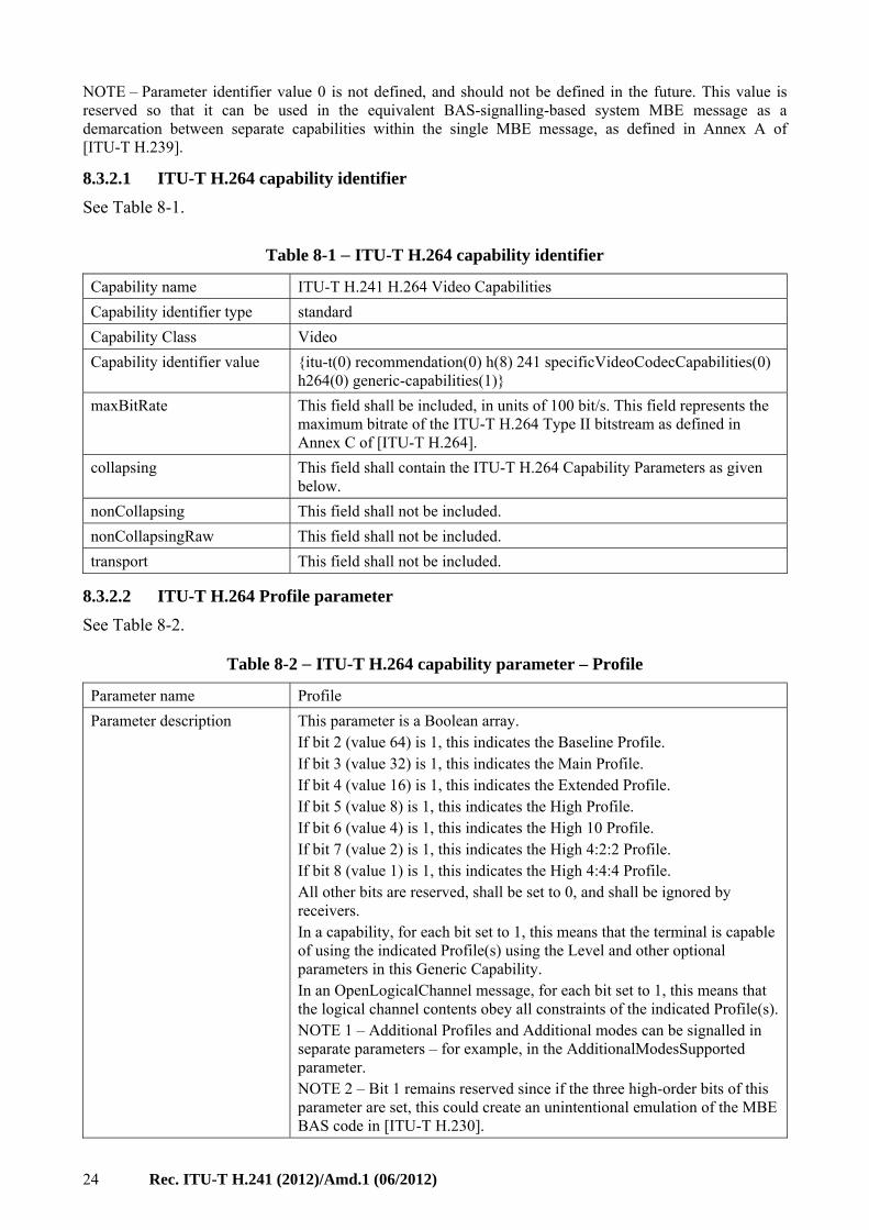
NOTE – Parameter identifier value 0 is not defined, and should not be defined in the future. This value is reserved so that it can be used in the equivalent BAS-signalling-based system MBE message as a demarcation between separate capabilities within the single MBE message, as defined in Annex A of [ITU-T H.239].
8.3.2.1 ITU-T H.264 capability identifier
See Table 8-1.
Table 8-1 − ITU-T H.264 capability identifier
Capability name ITU-T H.241 H.264 Video Capabilities
Capability identifier type standard
Capability Class Video
Capability identifier value {itu-t(0) recommendation(0) h(8) 241 specificVideoCodecCapabilities(0) h264(0) generic-capabilities(1)}
maxBitRate This field shall be included, in units of 100 bit/s. This field represents the maximum bitrate of the ITU-T H.264 Type II bitstream as defined in Annex C of [ITU-T H.264].
collapsing This field shall contain the ITU-T H.264 Capability Parameters as given below.
nonCollapsing This field shall not be included.
nonCollapsingRaw This field shall not be included.
transport This field shall not be included.
8.3.2.2 ITU-T H.264 Profile parameter
See Table 8-2.
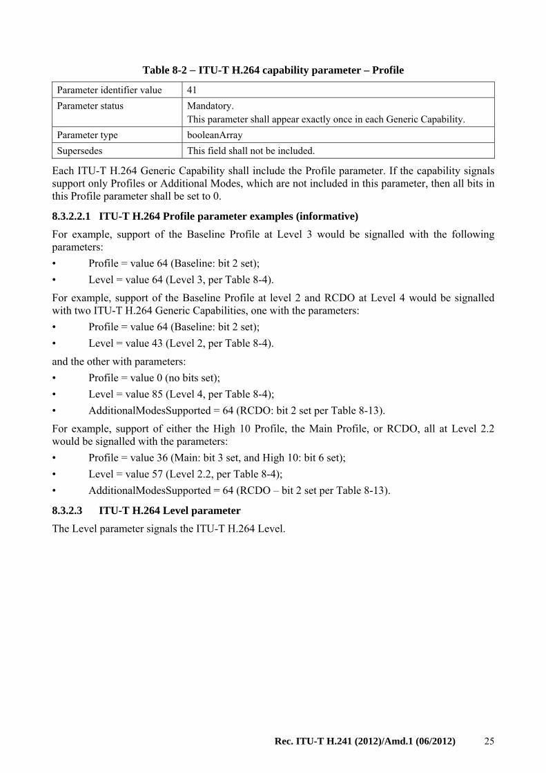
Table 8-2 − ITU-T H.264 capability parameter – Profile
Parameter name Profile
Parameter description This parameter is a Boolean array. If bit 2 (value 64) is 1, this indicates the Baseline Profile. If bit 3 (value 32) is 1, this indicates the Main Profile. If bit 4 (value 16) is 1, this indicates the Extended Profile. If bit 5 (value 8) is 1, this indicates the High Profile. If bit 6 (value 4) is 1, this indicates the High 10 Profile. If bit 7 (value 2) is 1, this indicates the High 4:2:2 Profile. If bit 8 (value 1) is 1, this indicates the High 4:4:4 Profile. All other bits are reserved, shall be set to 0, and shall be ignored by receivers. In a capability, for each bit set to 1, this means that the terminal is capable of using the indicated Profile(s) using the Level and other optional parameters in this Generic Capability. In an OpenLogicalChannel message, for each bit set to 1, this means that the logical channel contents obey all constraints of the indicated Profile(s). NOTE 1 – Additional Profiles and Additional modes can be signalled in separate parameters – for example, in the AdditionalModesSupported parameter. NOTE 2 – Bit 1 remains reserved since if the three high-order bits of this parameter are set, this could create an unintentional emulation of the MBE BAS code in [ITU-T H.230].
Rec. ITU-T H.241 (2012)/Amd.1 (06/2012) 25
Table 8-2 − ITU-T H.264 capability parameter – Profile
Parameter identifier value 41
Parameter status Mandatory. This parameter shall appear exactly once in each Generic Capability.
Parameter type booleanArray
Supersedes This field shall not be included.
Each ITU-T H.264 Generic Capability shall include the Profile parameter. If the capability signals support only Profiles or Additional Modes, which are not included in this parameter, then all bits in this Profile parameter shall be set to 0.
8.3.2.2.1 ITU-T H.264 Profile parameter examples (informative)
For example, support of the Baseline Profile at Level 3 would be signalled with the following parameters:
• Profile = value 64 (Baseline: bit 2 set);
• Level = value 64 (Level 3, per Table 8-4).
For example, support of the Baseline Profile at level 2 and RCDO at Level 4 would be signalled with two ITU-T H.264 Generic Capabilities, one with the parameters:
• Profile = value 64 (Baseline: bit 2 set);
• Level = value 43 (Level 2, per Table 8-4).
and the other with parameters:
• Profile = value 0 (no bits set);
• Level = value 85 (Level 4, per Table 8-4);
• AdditionalModesSupported = 64 (RCDO: bit 2 set per Table 8-13).
For example, support of either the High 10 Profile, the Main Profile, or RCDO, all at Level 2.2 would be signalled with the parameters:
• Profile = value 36 (Main: bit 3 set, and High 10: bit 6 set);
• Level = value 57 (Level 2.2, per Table 8-4);
• AdditionalModesSupported = 64 (RCDO – bit 2 set per Table 8-13).
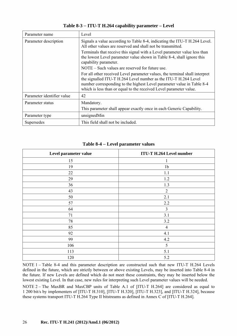
8.3.2.3 ITU-T H.264 Level parameter
The Level parameter signals the ITU-T H.264 Level.
26 Rec. ITU-T H.241 (2012)/Amd.1 (06/2012)
Table 8-3 − ITU-T H.264 capability parameter – Level
Parameter name Level
Parameter description Signals a value according to Table 8-4, indicating the ITU-T H.264 Level. All other values are reserved and shall not be transmitted. Terminals that receive this signal with a Level parameter value less than the lowest Level parameter value shown in Table 8-4, shall ignore this capability parameter. NOTE – Such values are reserved for future use. For all other received Level parameter values, the terminal shall interpret the signalled ITU-T H.264 Level number as the ITU-T H.264 Level number corresponding to the highest Level parameter value in Table 8-4 which is less than or equal to the received Level parameter value.
Parameter identifier value 42
Parameter status Mandatory. This parameter shall appear exactly once in each Generic Capability.
Parameter type unsignedMin
Supersedes This field shall not be included.
Table 8-4 − Level parameter values
Level parameter value ITU-T H.264 Level number
15 1 19 1b 22 1.1 29 1.2 36 1.3 43 2 50 2.1 57 2.2 64 3 71 3.1 78 3.2 85 4 92 4.1 99 4.2
106 5 113 5.1 120 5.2
NOTE 1 – Table 8-4 and this parameter description are constructed such that new ITU-T H.264 Levels defined in the future, which are strictly between or above existing Levels, may be inserted into Table 8-4 in the future. If new Levels are defined which do not meet these constraints, they may be inserted below the lowest existing Level. In that case, new rules for interpreting such Level parameter values will be needed.
NOTE 2 – The MaxBR and MaxCBP units of Table A.1 of [ITU-T H.264] are considered as equal to 1 200 bit/s by implementers of [ITU-T H.310], [ITU-T H.320], [ITU-T H.323], and [ITU-T H.324], because these systems transport ITU-T H.264 Type II bitstreams as defined in Annex C of [ITU-T H.264].
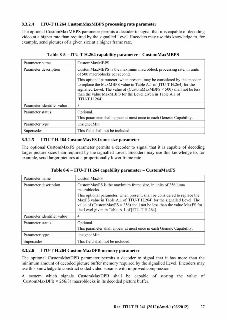
Rec. ITU-T H.241 (2012)/Amd.1 (06/2012) 27
8.3.2.4 ITU-T H.264 CustomMaxMBPS processing rate parameter
The optional CustomMaxMBPS parameter permits a decoder to signal that it is capable of decoding video at a higher rate than required by the signalled Level. Encoders may use this knowledge to, for example, send pictures of a given size at a higher frame rate.
Table 8-5 − ITU-T H.264 capability parameter – CustomMaxMBPS
Parameter name CustomMaxMBPS
Parameter description CustomMaxMBPS is the maximum macroblock processing rate, in units of 500 macroblocks per second. This optional parameter, when present, may be considered by the encoder to replace the MaxMBPS value in Table A.1 of [ITU-T H.264] for the signalled Level. The value of (CustomMaxMBPS × 500) shall not be less than the value MaxMBPS for the Level given in Table A.1 of [ITU-T H.264].
Parameter identifier value 3
Parameter status Optional. This parameter shall appear at most once in each Generic Capability.
Parameter type unsignedMin
Supersedes This field shall not be included.
8.3.2.5 ITU-T H.264 CustomMaxFS frame size parameter
The optional CustomMaxFS parameter permits a decoder to signal that it is capable of decoding larger picture sizes than required by the signalled Level. Encoders may use this knowledge to, for example, send larger pictures at a proportionally lower frame rate.
Table 8-6 − ITU-T H.264 capability parameter – CustomMaxFS
Parameter name CustomMaxFS
Parameter description CustomMaxFS is the maximum frame size, in units of 256 luma macroblocks. This optional parameter, when present, shall be considered to replace the MaxFS value in Table A.1 of [ITU-T H.264] for the signalled Level. The value of (CustomMaxFS × 256) shall not be less than the value MaxFS for the Level given in Table A.1 of [ITU-T H.264].
Parameter identifier value 4
Parameter status Optional. This parameter shall appear at most once in each Generic Capability.
Parameter type unsignedMin
Supersedes This field shall not be included.
8.3.2.6 ITU-T H.264 CustomMaxDPB memory parameter
The optional CustomMaxDPB parameter permits a decoder to signal that it has more than the minimum amount of decoded picture buffer memory required by the signalled Level. Encoders may use this knowledge to construct coded video streams with improved compression.
A system which signals CustomMaxDPB shall be capable of storing the value of (CustomMaxDPB × 256/3) macroblocks in its decoded picture buffer.
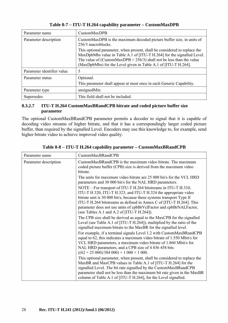
28 Rec. ITU-T H.241 (2012)/Amd.1 (06/2012)
Table 8-7 − ITU-T H.264 capability parameter – CustomMaxDPB
Parameter name CustomMaxDPB
Parameter description CustomMaxDPB is the maximum decoded picture buffer size, in units of 256/3 macroblocks. This optional parameter, when present, shall be considered to replace the MaxDpbMbs value in Table A.1 of [ITU-T H.264] for the signalled Level. The value of (CustomMaxDPB × 256/3) shall not be less than the value (MaxDpbMbs) for the Level given in Table A.1 of [ITU-T H.264].
Parameter identifier value 5
Parameter status Optional. This parameter shall appear at most once in each Generic Capability.
Parameter type unsignedMin
Supersedes This field shall not be included.
8.3.2.7 ITU-T H.264 CustomMaxBRandCPB bitrate and coded picture buffer size parameter
The optional CustomMaxBRandCPB parameter permits a decoder to signal that it is capable of decoding video streams of higher bitrate, and that it has a correspondingly larger coded picture buffer, than required by the signalled Level. Encoders may use this knowledge to, for example, send higher bitrate video to achieve improved video quality.
Table 8-8 − ITU-T H.264 capability parameter – CustomMaxBRandCPB
Parameter name CustomMaxBRandCPB
Parameter description CustomMaxBRandCPB is the maximum video bitrate. The maximum coded picture buffer (CPB) size is derived from the maximum video bitrate. The units for maximum video bitrate are 25 000 bit/s for the VCL HRD parameters and 30 000 bit/s for the NAL HRD parameters. NOTE – For transport of ITU-T H.264 bitstreams in ITU-T H.310, ITU-T H.320, ITU-T H.323, and ITU-T H.324 the appropriate video bitrate unit is 30 000 bit/s, because these systems transport Type II ITU-T H.264 bitstreams as defined in Annex C of [ITU-T H.264]. This parameter does not use units of cpbBrVclFactor and cpbBrNALFactor, (see Tables A.1 and A.2 of [ITU-T H.264]). The CPB size shall be derived as equal to the MaxCPB for the signalled Level (see Table A.1 of [ITU-T H.264]), multiplied by the ratio of the signalled maximum bitrate to the MaxBR for the signalled level. For example, if a terminal signals Level 1.2 with CustomMaxBRandCPB equal to 62, this indicates a maximum video bitrate of 1.550 Mbit/s for VCL HRD parameters, a maximum video bitrate of 1.860 Mbit/s for NAL HRD parameters, and a CPB size of 4 036 458 bits ((62 × 25 000)/384 000) × 1 000 × 1 000. This optional parameter, when present, shall be considered to replace the MaxBR and MaxCPB values in Table A.1 of [ITU-T H.264] for the signalled Level. The bit rate signalled by the CustomMaxBRandCPB parameter shall not be less than the maximum bit rate given in the MaxBR column of Table A.1 of [ITU-T H.264], for the Level signalled.
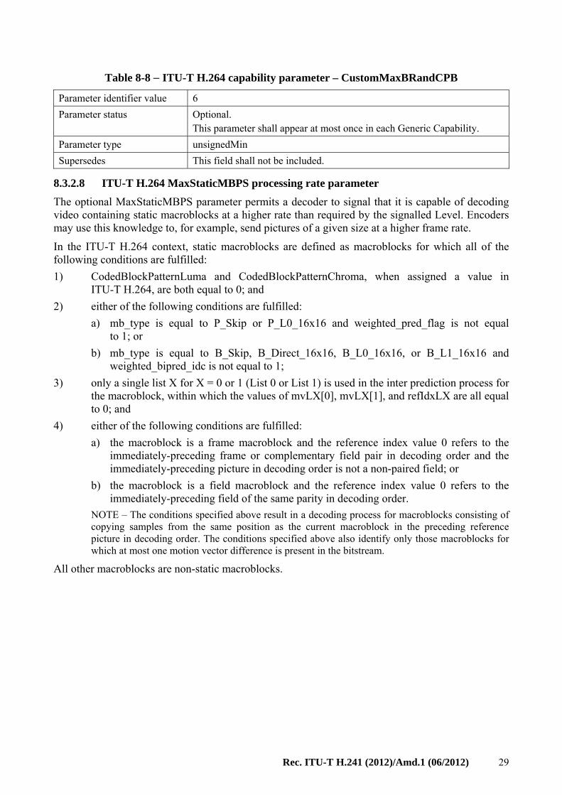
Rec. ITU-T H.241 (2012)/Amd.1 (06/2012) 29
Table 8-8 − ITU-T H.264 capability parameter – CustomMaxBRandCPB
Parameter identifier value 6
Parameter status Optional. This parameter shall appear at most once in each Generic Capability.
Parameter type unsignedMin
Supersedes This field shall not be included.
8.3.2.8 ITU-T H.264 MaxStaticMBPS processing rate parameter
The optional MaxStaticMBPS parameter permits a decoder to signal that it is capable of decoding video containing static macroblocks at a higher rate than required by the signalled Level. Encoders may use this knowledge to, for example, send pictures of a given size at a higher frame rate.
In the ITU-T H.264 context, static macroblocks are defined as macroblocks for which all of the following conditions are fulfilled:
1) CodedBlockPatternLuma and CodedBlockPatternChroma, when assigned a value in ITU-T H.264, are both equal to 0; and
2) either of the following conditions are fulfilled:
a) mb_type is equal to P_Skip or P_L0_16x16 and weighted_pred_flag is not equal to 1; or
b) mb_type is equal to B_Skip, B_Direct_16x16, B_L0_16x16, or B_L1_16x16 and weighted_bipred_idc is not equal to 1;
3) only a single list X for X = 0 or 1 (List 0 or List 1) is used in the inter prediction process for the macroblock, within which the values of mvLX[0], mvLX[1], and refIdxLX are all equal to 0; and
4) either of the following conditions are fulfilled:
a) the macroblock is a frame macroblock and the reference index value 0 refers to the immediately-preceding frame or complementary field pair in decoding order and the immediately-preceding picture in decoding order is not a non-paired field; or
b) the macroblock is a field macroblock and the reference index value 0 refers to the immediately-preceding field of the same parity in decoding order.
NOTE – The conditions specified above result in a decoding process for macroblocks consisting of copying samples from the same position as the current macroblock in the preceding reference picture in decoding order. The conditions specified above also identify only those macroblocks for which at most one motion vector difference is present in the bitstream.
All other macroblocks are non-static macroblocks.
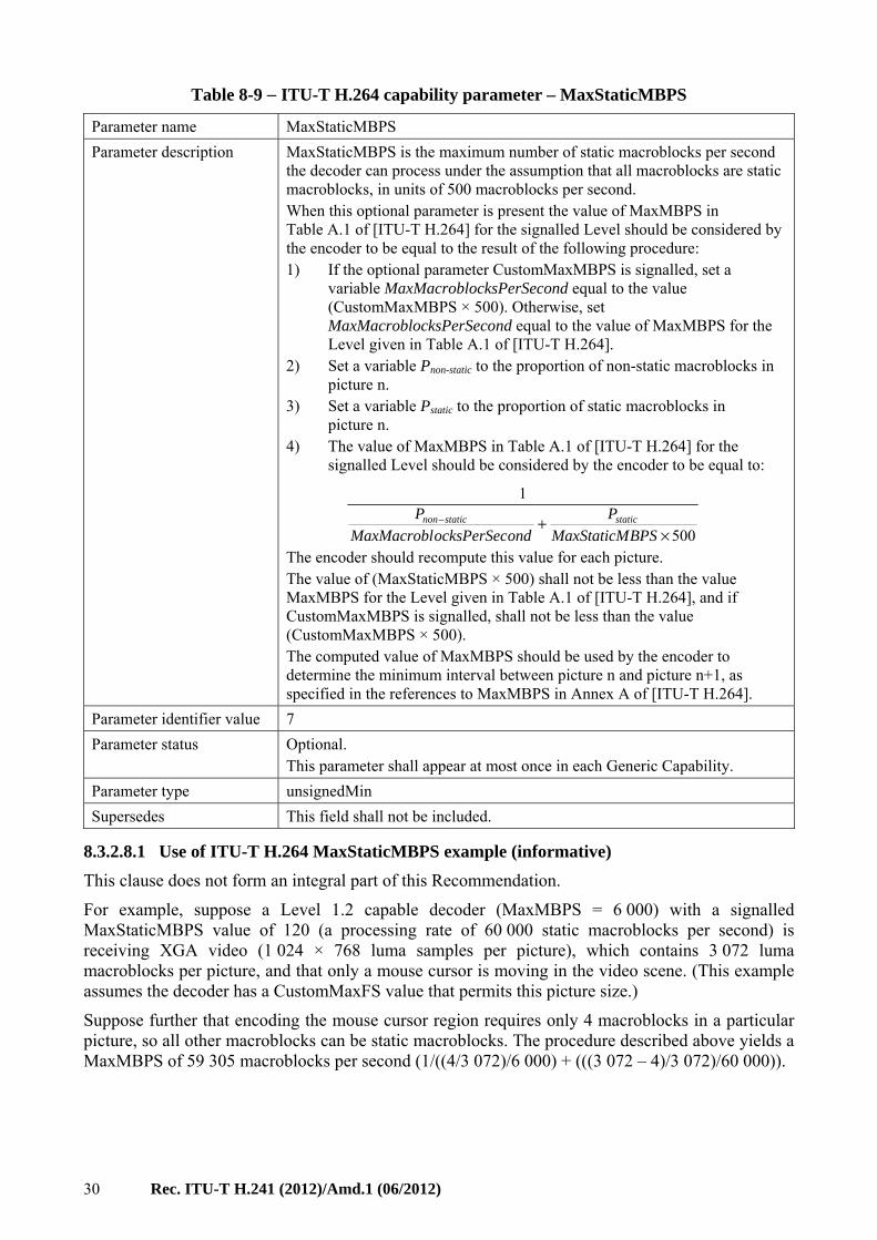
30 Rec. ITU-T H.241 (2012)/Amd.1 (06/2012)
Table 8-9 − ITU-T H.264 capability parameter – MaxStaticMBPS
Parameter name MaxStaticMBPS
Parameter description MaxStaticMBPS is the maximum number of static macroblocks per second the decoder can process under the assumption that all macroblocks are static macroblocks, in units of 500 macroblocks per second. When this optional parameter is present the value of MaxMBPS in Table A.1 of [ITU-T H.264] for the signalled Level should be considered by the encoder to be equal to the result of the following procedure: 1) If the optional parameter CustomMaxMBPS is signalled, set a
variable MaxMacroblocksPerSecond equal to the value (CustomMaxMBPS × 500). Otherwise, set MaxMacroblocksPerSecond equal to the value of MaxMBPS for the Level given in Table A.1 of [ITU-T H.264].
2) Set a variable Pnon-static to the proportion of non-static macroblocks in picture n.
3) Set a variable Pstatic to the proportion of static macroblocks in picture n.
4) The value of MaxMBPS in Table A.1 of [ITU-T H.264] for the signalled Level should be considered by the encoder to be equal to:
500
1
×+−
BPSMaxStaticM
P
ondocksPerSecMaxMacrobl
P staticstaticnon
The encoder should recompute this value for each picture. The value of (MaxStaticMBPS × 500) shall not be less than the value MaxMBPS for the Level given in Table A.1 of [ITU-T H.264], and if CustomMaxMBPS is signalled, shall not be less than the value (CustomMaxMBPS × 500). The computed value of MaxMBPS should be used by the encoder to determine the minimum interval between picture n and picture n+1, as specified in the references to MaxMBPS in Annex A of [ITU-T H.264].
Parameter identifier value 7
Parameter status Optional. This parameter shall appear at most once in each Generic Capability.
Parameter type unsignedMin
Supersedes This field shall not be included.
8.3.2.8.1 Use of ITU-T H.264 MaxStaticMBPS example (informative)
This clause does not form an integral part of this Recommendation.
For example, suppose a Level 1.2 capable decoder (MaxMBPS = 6 000) with a signalled MaxStaticMBPS value of 120 (a processing rate of 60 000 static macroblocks per second) is receiving XGA video (1 024 × 768 luma samples per picture), which contains 3 072 luma macroblocks per picture, and that only a mouse cursor is moving in the video scene. (This example assumes the decoder has a CustomMaxFS value that permits this picture size.)
Suppose further that encoding the mouse cursor region requires only 4 macroblocks in a particular picture, so all other macroblocks can be static macroblocks. The procedure described above yields a MaxMBPS of 59 305 macroblocks per second (1/((4/3 072)/6 000) + (((3 072 – 4)/3 072)/60 000)).
Rec. ITU-T H.241 (2012)/Amd.1 (06/2012) 31
This would permit the encoder to generate the next picture after an interval of 51.8 ms (3 072/59 305), corresponding to an instantaneous frame rate of 19.3 Hz (59 305/3 072), compared to an interval of 512 ms (3 072/6 000), corresponding to an instantaneous frame rate of only 2.0 Hz without the use of MaxStaticMBPS.
8.3.2.8.2 Determination of ITU-T H.264 MaxStaticMBPS value (informative)
This clause does not form an integral part of this Recommendation. It provides informative guidance regarding considerations for the determination of the MaxStaticMBPS value for a given decoder implementation.
Practical decoder implementations make use of a wide variety of hardware and software architectures, and there may be no single method of determining a decoder's value of MaxStaticMBPS that is appropriate in all cases; determination of this value is left to the implementer.
One possible method is described here solely as an example:
1) Given an implementation which can decode sequences containing only non-static macroblocks at a rate of Rdecode macroblocks per second.
2) An encoded test video sequence with a known number of macroblocks (N), proportion of static macroblocks (Pstatic), and of non-static macroblocks (Pnon-static = 1 – Pstatic) can be decoded, and the time required to decode either each picture or the entire sequence measured by experiment (Tdecode in seconds).
3) The rate at which static macroblocks can be decoded (StaticMBPS) can be calculated by:
StaticMBPS = Pstatic/(Tdecode/N – Pnon-static/Rdecode)
This procedure can be repeated with different test sequences containing different proportions of static and non-static macroblocks and different picture sizes.
4) The values of StaticMBPS obtained can be plotted against varying values of Pstatic and picture size tested, and interpolation applied between the test points. (Note that in many decoder implementation architectures, the plot of StaticMBPS versus picture size will form a curve.)
5) The lowest value of StaticMBPS obtained on the plots could then be used as the value of MaxStaticMBPS.
In some decoder implementation architectures, the decoding rate is affected by a deblocking filter computation where static and non-static macroblocks are adjacent to each other. To take account of this factor, worst-case test patterns of static and non-static macroblocks can be used.
8.3.2.9 ITU-T H.264 max-rcmd-nal-unit-size
The value of this parameter indicates the largest NAL unit size in bytes that the receiver can handle efficiently. The parameter value is a recommendation, not a strict upper boundary. The sender may create larger NAL units but implementers should consider that inefficiencies or an increased chance of loss due to errors might result.
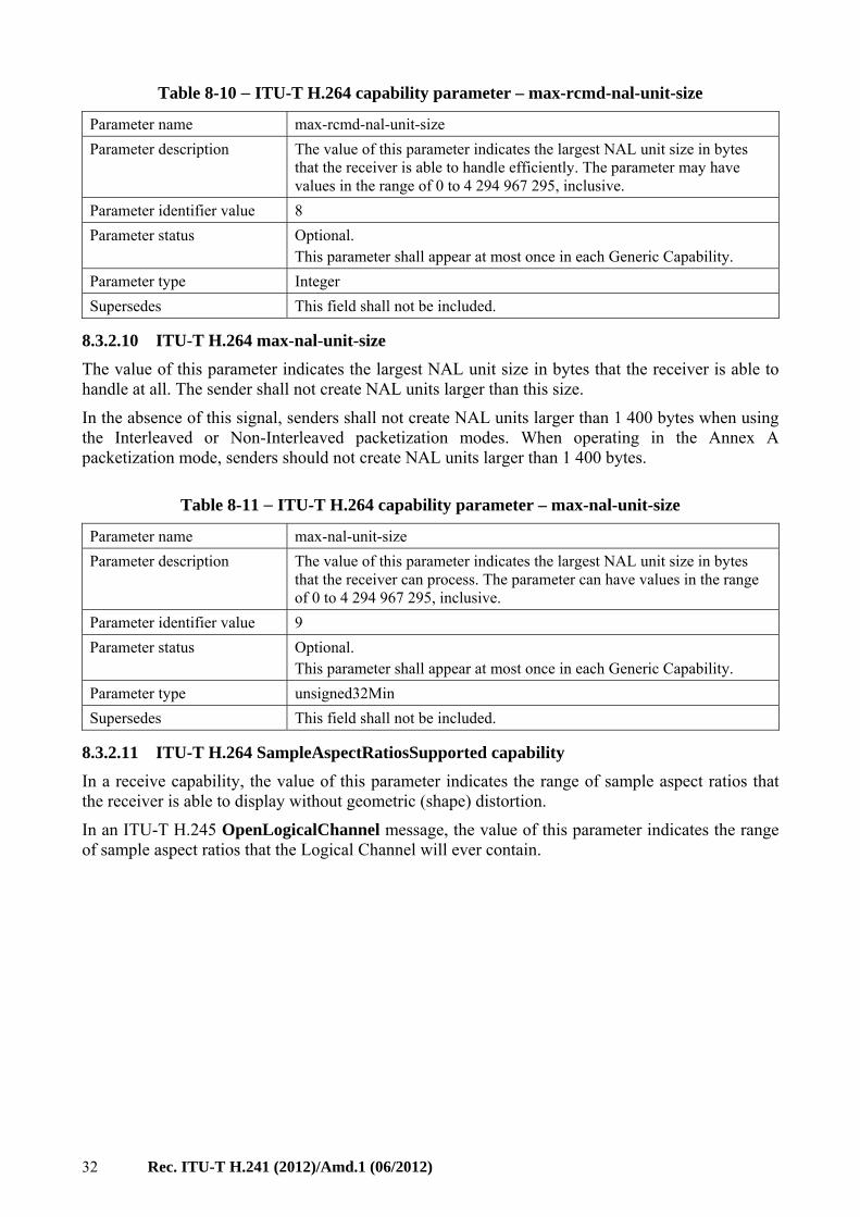
32 Rec. ITU-T H.241 (2012)/Amd.1 (06/2012)
Table 8-10 − ITU-T H.264 capability parameter – max-rcmd-nal-unit-size
Parameter name max-rcmd-nal-unit-size
Parameter description The value of this parameter indicates the largest NAL unit size in bytes that the receiver is able to handle efficiently. The parameter may have values in the range of 0 to 4 294 967 295, inclusive.
Parameter identifier value 8
Parameter status Optional. This parameter shall appear at most once in each Generic Capability.
Parameter type Integer
Supersedes This field shall not be included.
8.3.2.10 ITU-T H.264 max-nal-unit-size
The value of this parameter indicates the largest NAL unit size in bytes that the receiver is able to handle at all. The sender shall not create NAL units larger than this size.
In the absence of this signal, senders shall not create NAL units larger than 1 400 bytes when using the Interleaved or Non-Interleaved packetization modes. When operating in the Annex A packetization mode, senders should not create NAL units larger than 1 400 bytes.
Table 8-11 − ITU-T H.264 capability parameter – max-nal-unit-size
Parameter name max-nal-unit-size
Parameter description The value of this parameter indicates the largest NAL unit size in bytes that the receiver can process. The parameter can have values in the range of 0 to 4 294 967 295, inclusive.
Parameter identifier value 9
Parameter status Optional. This parameter shall appear at most once in each Generic Capability.
Parameter type unsigned32Min
Supersedes This field shall not be included.
8.3.2.11 ITU-T H.264 SampleAspectRatiosSupported capability
In a receive capability, the value of this parameter indicates the range of sample aspect ratios that the receiver is able to display without geometric (shape) distortion.
In an ITU-T H.245 OpenLogicalChannel message, the value of this parameter indicates the range of sample aspect ratios that the Logical Channel will ever contain.
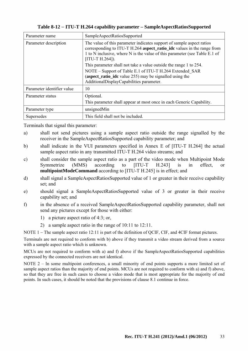
Rec. ITU-T H.241 (2012)/Amd.1 (06/2012) 33
Table 8-12 − ITU-T H.264 capability parameter – SampleAspectRatiosSupported
Parameter name SampleAspectRatiosSupported
Parameter description The value of this parameter indicates support of sample aspect ratios corresponding to ITU-T H.264 aspect_ratio_idc values in the range from 1 to N inclusive, where N is the value of this parameter (see Table E.1 of [ITU-T H.264]). This parameter shall not take a value outside the range 1 to 254. NOTE – Support of Table E.1 of ITU-T H.264 Extended_SAR (aspect_ratio_idc value 255) may be signalled using the AdditionalDisplayCapabilities parameter.
Parameter identifier value 10
Parameter status Optional. This parameter shall appear at most once in each Generic Capability.
Parameter type unsignedMin
Supersedes This field shall not be included.
Terminals that signal this parameter:
a) shall not send pictures using a sample aspect ratio outside the range signalled by the receiver in the SampleAspectRatiosSupported capability parameter; and
b) shall indicate in the VUI parameters specified in Annex E of [ITU-T H.264] the actual sample aspect ratio in any transmitted ITU-T H.264 video streams; and
c) shall consider the sample aspect ratio as a part of the video mode when Multipoint Mode Symmetrize (MMS) according to [ITU-T H.243] is in effect, or multipointModeCommand according to [ITU-T H.245] is in effect; and
d) shall signal a SampleAspectRatiosSupported value of 1 or greater in their receive capability set; and
e) should signal a SampleAspectRatiosSupported value of 3 or greater in their receive capability set; and
f) in the absence of a received SampleAspectRatiosSupported capability parameter, shall not send any pictures except for those with either:
1) a picture aspect ratio of 4:3; or,
2) a sample aspect ratio in the range of 10:11 to 12:11.
NOTE 1 – The sample aspect ratio 12:11 is part of the definition of QCIF, CIF, and 4CIF format pictures.
Terminals are not required to conform with b) above if they transmit a video stream derived from a source with a sample aspect ratio which is unknown.
MCUs are not required to conform with a) and f) above if the SampleAspectRatiosSupported capabilities expressed by the connected receivers are not identical.
NOTE 2 – In some multipoint conferences, a small minority of end points supports a more limited set of sample aspect ratios than the majority of end points. MCUs are not required to conform with a) and f) above, so that they are free in such cases to choose a video mode that is most appropriate for the majority of end points. In such cases, it should be noted that the provisions of clause 8.1 continue in force.
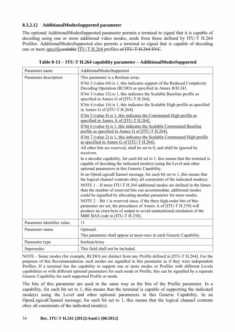
34 Rec. ITU-T H.241 (2012)/Amd.1 (06/2012)
8.3.2.12 AdditionalModesSupported parameter
The optional AdditionalModesSupported parameter permits a terminal to signal that it is capable of decoding using one or more additional video modes, aside from those defined by ITU-T H.264 Profiles. AdditionalModesSupported also permits a terminal to signal that is capable of decoding one or more specificscalable ITU-T H.264 profiles of ITU-T H.264 SVC.
Table 8-13 − ITU-T H.264 capability parameter – AdditionalModesSupported
Parameter name AdditionalModesSupported
Parameter description This parameter is a Boolean array. If bit 2 (value 64) is 1, this indicates support of the Reduced Complexity Decoding Operation (RCDO) as specified in Annex B/H.241. If bit 3 (value 32) is 1, this indicates the Scalable Baseline profile as specified in Annex G of [ITU-T H.264]. If bit 4 (value 16) is 1, this indicates the Scalable High profile as specified in Annex G of [ITU-T H.264]. If bit 5 (value 8) is 1, this indicates the Constrained High profile as specified in Annex A of [ITU-T H.264]. If bit 6 (value 4) is 1, this indicates the Scalable Constrained Baseline profile as specified in Annex G of [ITU-T H.264]. If bit 7 (value 2) is 1, this indicates the Scalable Constrained High profile as specified in Annex G of [ITU-T H.264]. All other bits are reserved, shall be set to 0, and shall be ignored by receivers. In a decoder capability, for each bit set to 1, this means that the terminal is capable of decoding the indicated mode(s) using the Level and other optional parameters in this Generic Capability. In an OpenLogicalChannel message, for each bit set to 1, this means that the logical channel contents obey all constraints of the indicated mode(s). NOTE 1 – If more ITU-T H.264 additional modes are defined in the future than the number of reserved bits can accommodate, additional modes could be signalled by allocating another parameter for more modes. NOTE 2 – Bit 1 is reserved since, if the three high-order bits of this parameter are set, the procedures of Annex A of [ITU-T H.239] will produce an extra byte of output to avoid unintentional emulation of the MBE BAS code in [ITU-T H.230].
Parameter identifier value 11
Parameter status Optional. This parameter shall appear at most once in each Generic Capability.
Parameter type booleanArray
Supersedes This field shall not be included.
NOTE – Some modes (for example, RCDO) are distinct from any Profile defined in [ITU-T H.264]. For the purposes of this Recommendation, such modes are signalled in this parameter as if they were independent Profiles. If a terminal has the capability to support one or more modes or Profiles with different Levels capabilities or with different optional parameters for each mode or Profile, this can be signalled by a separate Generic Capability for each supported Profile or mode.
The bits of this parameter are used in the same way as the bits of the Profile parameter. In a capability, for each bit set to 1, this means that the terminal is capable of supporting the indicated mode(s) using the Level and other optional parameters in this Generic Capability. In an OpenLogicalChannel message, for each bit set to 1, this means that the logical channel contents obey all constraints of the indicated mode(s).
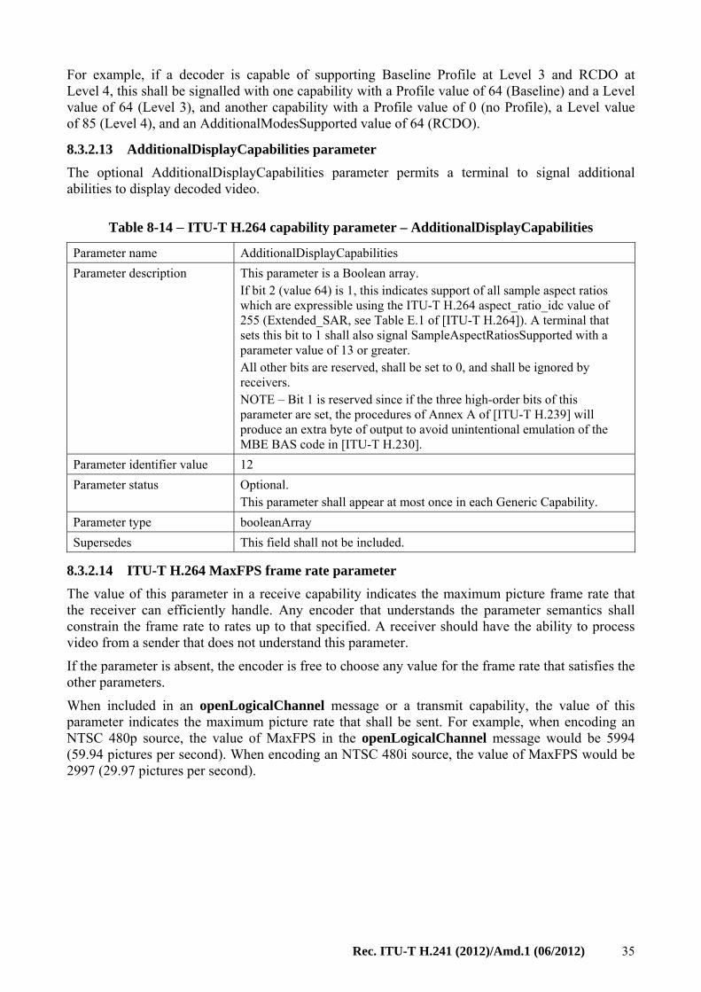
Rec. ITU-T H.241 (2012)/Amd.1 (06/2012) 35
For example, if a decoder is capable of supporting Baseline Profile at Level 3 and RCDO at Level 4, this shall be signalled with one capability with a Profile value of 64 (Baseline) and a Level value of 64 (Level 3), and another capability with a Profile value of 0 (no Profile), a Level value of 85 (Level 4), and an AdditionalModesSupported value of 64 (RCDO).
8.3.2.13 AdditionalDisplayCapabilities parameter
The optional AdditionalDisplayCapabilities parameter permits a terminal to signal additional abilities to display decoded video.
Table 8-14 − ITU-T H.264 capability parameter – AdditionalDisplayCapabilities
Parameter name AdditionalDisplayCapabilities
Parameter description This parameter is a Boolean array. If bit 2 (value 64) is 1, this indicates support of all sample aspect ratios which are expressible using the ITU-T H.264 aspect_ratio_idc value of 255 (Extended_SAR, see Table E.1 of [ITU-T H.264]). A terminal that sets this bit to 1 shall also signal SampleAspectRatiosSupported with a parameter value of 13 or greater. All other bits are reserved, shall be set to 0, and shall be ignored by receivers. NOTE – Bit 1 is reserved since if the three high-order bits of this parameter are set, the procedures of Annex A of [ITU-T H.239] will produce an extra byte of output to avoid unintentional emulation of the MBE BAS code in [ITU-T H.230].
Parameter identifier value 12
Parameter status Optional. This parameter shall appear at most once in each Generic Capability.
Parameter type booleanArray
Supersedes This field shall not be included.
8.3.2.14 ITU-T H.264 MaxFPS frame rate parameter
The value of this parameter in a receive capability indicates the maximum picture frame rate that the receiver can efficiently handle. Any encoder that understands the parameter semantics shall constrain the frame rate to rates up to that specified. A receiver should have the ability to process video from a sender that does not understand this parameter.
If the parameter is absent, the encoder is free to choose any value for the frame rate that satisfies the other parameters.
When included in an openLogicalChannel message or a transmit capability, the value of this parameter indicates the maximum picture rate that shall be sent. For example, when encoding an NTSC 480p source, the value of MaxFPS in the openLogicalChannel message would be 5994 (59.94 pictures per second). When encoding an NTSC 480i source, the value of MaxFPS would be 2997 (29.97 pictures per second).
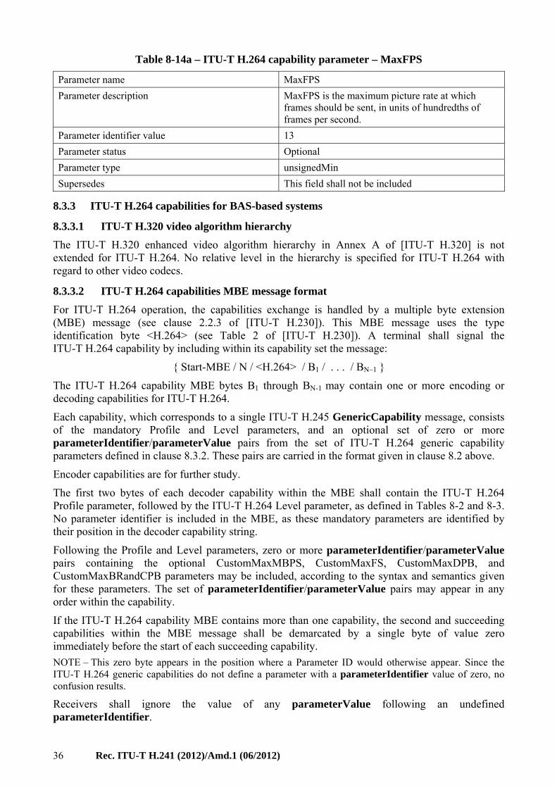
36 Rec. ITU-T H.241 (2012)/Amd.1 (06/2012)
Table 8-14a – ITU-T H.264 capability parameter – MaxFPS
Parameter name MaxFPS
Parameter description MaxFPS is the maximum picture rate at which frames should be sent, in units of hundredths of frames per second.
Parameter identifier value 13
Parameter status Optional
Parameter type unsignedMin
Supersedes This field shall not be included
8.3.3 ITU-T H.264 capabilities for BAS-based systems
8.3.3.1 ITU-T H.320 video algorithm hierarchy
The ITU-T H.320 enhanced video algorithm hierarchy in Annex A of [ITU-T H.320] is not extended for ITU-T H.264. No relative level in the hierarchy is specified for ITU-T H.264 with regard to other video codecs.
8.3.3.2 ITU-T H.264 capabilities MBE message format
For ITU-T H.264 operation, the capabilities exchange is handled by a multiple byte extension (MBE) message (see clause 2.2.3 of [ITU-T H.230]). This MBE message uses the type identification byte <H.264> (see Table 2 of [ITU-T H.230]). A terminal shall signal the ITU-T H.264 capability by including within its capability set the message:
{ Start-MBE / N / <H.264> / B1 / . . . / BN–1 }
The ITU-T H.264 capability MBE bytes B1 through BN-1 may contain one or more encoding or decoding capabilities for ITU-T H.264.
Each capability, which corresponds to a single ITU-T H.245 GenericCapability message, consists of the mandatory Profile and Level parameters, and an optional set of zero or more parameterIdentifier/parameterValue pairs from the set of ITU-T H.264 generic capability parameters defined in clause 8.3.2. These pairs are carried in the format given in clause 8.2 above.
Encoder capabilities are for further study.
The first two bytes of each decoder capability within the MBE shall contain the ITU-T H.264 Profile parameter, followed by the ITU-T H.264 Level parameter, as defined in Tables 8-2 and 8-3. No parameter identifier is included in the MBE, as these mandatory parameters are identified by their position in the decoder capability string.
Following the Profile and Level parameters, zero or more parameterIdentifier/parameterValue pairs containing the optional CustomMaxMBPS, CustomMaxFS, CustomMaxDPB, and CustomMaxBRandCPB parameters may be included, according to the syntax and semantics given for these parameters. The set of parameterIdentifier/parameterValue pairs may appear in any order within the capability.
If the ITU-T H.264 capability MBE contains more than one capability, the second and succeeding capabilities within the MBE message shall be demarcated by a single byte of value zero immediately before the start of each succeeding capability.
NOTE – This zero byte appears in the position where a Parameter ID would otherwise appear. Since the ITU-T H.264 generic capabilities do not define a parameter with a parameterIdentifier value of zero, no confusion results.
Receivers shall ignore the value of any parameterValue following an undefined parameterIdentifier.
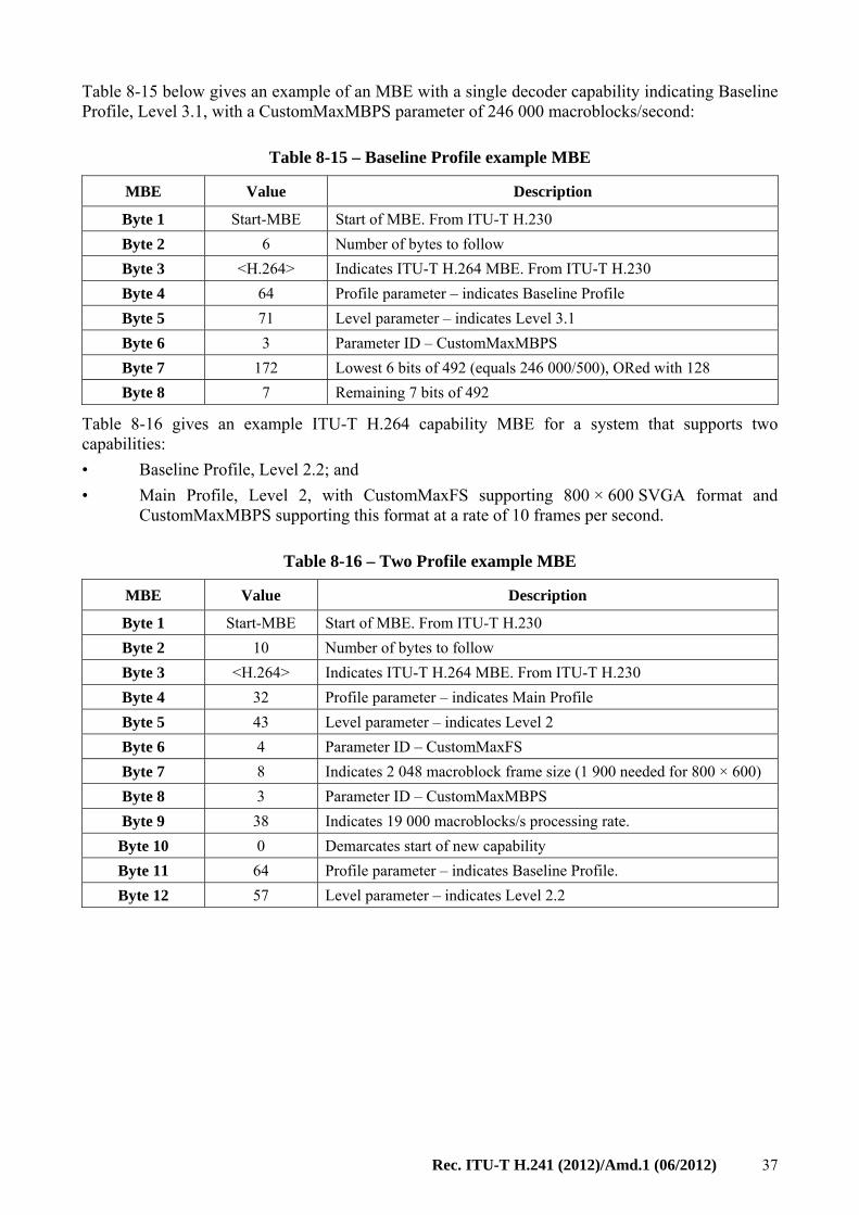
Rec. ITU-T H.241 (2012)/Amd.1 (06/2012) 37
Table 8-15 below gives an example of an MBE with a single decoder capability indicating Baseline Profile, Level 3.1, with a CustomMaxMBPS parameter of 246 000 macroblocks/second:
Table 8-15 – Baseline Profile example MBE
MBE Value Description
Byte 1 Start-MBE Start of MBE. From ITU-T H.230
Byte 2 6 Number of bytes to follow
Byte 3 <H.264> Indicates ITU-T H.264 MBE. From ITU-T H.230
Byte 4 64 Profile parameter – indicates Baseline Profile
Byte 5 71 Level parameter – indicates Level 3.1
Byte 6 3 Parameter ID – CustomMaxMBPS
Byte 7 172 Lowest 6 bits of 492 (equals 246 000/500), ORed with 128
Byte 8 7 Remaining 7 bits of 492
Table 8-16 gives an example ITU-T H.264 capability MBE for a system that supports two capabilities:
• Baseline Profile, Level 2.2; and
• Main Profile, Level 2, with CustomMaxFS supporting 800 × 600 SVGA format and CustomMaxMBPS supporting this format at a rate of 10 frames per second.
Table 8-16 – Two Profile example MBE
MBE Value Description
Byte 1 Start-MBE Start of MBE. From ITU-T H.230
Byte 2 10 Number of bytes to follow
Byte 3 <H.264> Indicates ITU-T H.264 MBE. From ITU-T H.230
Byte 4 32 Profile parameter – indicates Main Profile
Byte 5 43 Level parameter – indicates Level 2
Byte 6 4 Parameter ID – CustomMaxFS
Byte 7 8 Indicates 2 048 macroblock frame size (1 900 needed for 800 × 600)
Byte 8 3 Parameter ID – CustomMaxMBPS
Byte 9 38 Indicates 19 000 macroblocks/s processing rate.
Byte 10 0 Demarcates start of new capability
Byte 11 64 Profile parameter – indicates Baseline Profile.
Byte 12 57 Level parameter – indicates Level 2.2
38 Rec. ITU-T H.241 (2012)/Amd.1 (06/2012)
Annex A
ITU-T H.264 transport for ITU-T H.323
(This annex forms an integral part of this Recommendation.)
ITU-T H.323 terminals which support the transport of video according to [ITU-T H.264] shall support the single NAL unit mode of [IETF RFC 6184]. ITU-T H.323 terminals which support the transport of video according to ITU-T H.264 Annex G profiles shall support the non-interleaved mode of [IETF RFC 6184] and the single-session transmission mode of [IETF RFC 6190]. ITU-T H.323 terminals may additionally support other modes.
NOTE – The single NAL unit mode of [IETF RFC 6184] is technically identical to the text contained in previous editions of this annex.
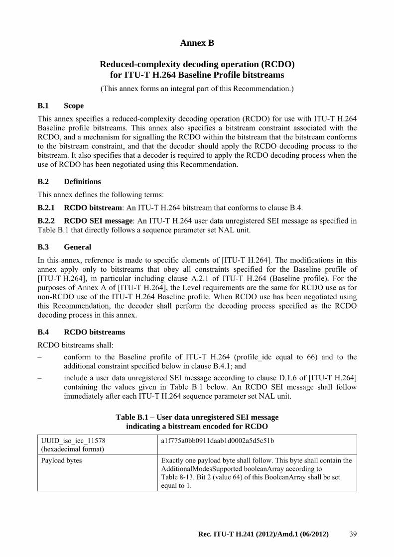
Rec. ITU-T H.241 (2012)/Amd.1 (06/2012) 39
Annex B
Reduced-complexity decoding operation (RCDO) for ITU-T H.264 Baseline Profile bitstreams
(This annex forms an integral part of this Recommendation.)
B.1 Scope
This annex specifies a reduced-complexity decoding operation (RCDO) for use with ITU-T H.264 Baseline profile bitstreams. This annex also specifies a bitstream constraint associated with the RCDO, and a mechanism for signalling the RCDO within the bitstream that the bitstream conforms to the bitstream constraint, and that the decoder should apply the RCDO decoding process to the bitstream. It also specifies that a decoder is required to apply the RCDO decoding process when the use of RCDO has been negotiated using this Recommendation.
B.2 Definitions
This annex defines the following terms:
B.2.1 RCDO bitstream: An ITU-T H.264 bitstream that conforms to clause B.4.
B.2.2 RCDO SEI message: An ITU-T H.264 user data unregistered SEI message as specified in Table B.1 that directly follows a sequence parameter set NAL unit.
B.3 General
In this annex, reference is made to specific elements of [ITU-T H.264]. The modifications in this annex apply only to bitstreams that obey all constraints specified for the Baseline profile of [ITU-T H.264], in particular including clause A.2.1 of ITU-T H.264 (Baseline profile). For the purposes of Annex A of [ITU-T H.264], the Level requirements are the same for RCDO use as for non-RCDO use of the ITU-T H.264 Baseline profile. When RCDO use has been negotiated using this Recommendation, the decoder shall perform the decoding process specified as the RCDO decoding process in this annex.
B.4 RCDO bitstreams
RCDO bitstreams shall:
– conform to the Baseline profile of ITU-T H.264 (profile_idc equal to 66) and to the additional constraint specified below in clause B.4.1; and
– include a user data unregistered SEI message according to clause D.1.6 of [ITU-T H.264] containing the values given in Table B.1 below. An RCDO SEI message shall follow immediately after each ITU-T H.264 sequence parameter set NAL unit.
Table B.1 – User data unregistered SEI message indicating a bitstream encoded for RCDO
UUID_iso_iec_11578 (hexadecimal format)
a1f775a0bb0911daab1d0002a5d5c51b
Payload bytes Exactly one payload byte shall follow. This byte shall contain the AdditionalModesSupported booleanArray according to Table 8-13. Bit 2 (value 64) of this BooleanArray shall be set equal to 1.
40 Rec. ITU-T H.241 (2012)/Amd.1 (06/2012)
B.4.1 Constraint on luma inter prediction block sizes to 8 × 8 samples or larger
The value of sub_mb_type as specified in [ITU-T H.264], when applicable, shall always be equal to 0.
B.5 OpenLogicalChannel signalling
In an ITU-T H.245 OpenLogicalChannel message, bit 2 of the AdditionalModesSupported parameter in Table 8-13 shall be equal to 1 and the Profile parameter shall be equal to 0.
For the purpose of robustness to transmission errors, a decoder that is capable of using the RCDO decoding process should cross-check the presence or absence of the RCDO SEI message with the content of the OpenLogicalChannel message. When bit 2 of the AdditionalModesSupported parameter is equal to 1 and the RCDO SEI message is not detected by the decoder, a decoder should send a videoFastUpdatePicture message to the encoder to force retransmission of the RCDO SEI message.
B.6 Procedures
When the use of RCDO has been negotiated using this Recommendation and the bitstream is a conforming RCDO bitstream (as specified in clause B.4 above), the RCDO decoding process, as specified in this clause, shall be applied by the decoder. To avoid accumulation of "drift" error in the decoded video sequence, the encoder should model the RCDO decoding process accurately during the encoding process.
B.6.1 Reduced-complexity interpolation for inter prediction in the RCDO decoding process
The operations specified in clause 8.4.2.2 of [ITU-T H.264], "Fractional sample interpolation, process" shall be performed with the changes specified in this clause during operation of the RCDO decoding process. The modifications are as follows:
1) Referencing clause 8.4.2.2 of [ITU-T H.264], the following modifications apply:
– frame_num is an additional input to the process.
– (xFracc,yFracc) is in quarter sample units instead of one-eighth sample units.
– Rather than using Equations 8-227 through 8-230 of [ITU-T H.264], the following modified equations apply:
xIntC = ( xAL / SubWidthC ) + ((mvCLX[ 0 ] + (frame_num & 1)) >> 3 ) + xC (8-227)
yIntC = ( yAL / SubHeightC ) + ((mvCLX[ 1 ] + (frame_num & 1)) >> 3 ) + yC (8-228)
xFracC = ((mvCLX[ 0 ] + (frame_num & 1)) >> 1) & 3 (8-229)
yFracC = ((mvCLX[ 1 ] + (frame_num & 1)) >> 1) & 3 (8-230)
2) Referencing 8.4.2.2.1 of [ITU-T H.264], the following modifications apply:
– The luma prediction values at half sample positions b and s are derived by applying a 6-tap filter with tap values ( 1, –5, 20, 20, –5, 1 ).
– The luma prediction values at half sample positions h and m are derived by applying a 4-tap filter with tap values ( –1, 5, 5, –1 ).
– Equations 8-241, 8-242, 8-245 and 8-246 to define b1, h1 and j1 in [ITU-T H.264] are not needed.
– Rather than using Equations 8-243, 8-244, 8-247, 8-248, 8-249, 8-254, 8-255, 8-256 and 8-257 of [ITU-T H.264], the following modified equations apply:
b = Clip1Y( (E – 5 * F + 20 * G + 20 * H – 5 * I + J + 6 ) >> 5 ) (8-243)
h = Clip1Y( (– C + 5 * G + 5 * M – R + 1 ) >> 3 ) (8-244)
j = ( H + M ) >> 1 (8-247)
Rec. ITU-T H.241 (2012)/Amd.1 (06/2012) 41
s = Clip1Y( (K – 5 * L + 20 * M + 20 * N – 5 * P + Q + 6 ) >> 5 ) (8-248)
m = Clip1Y( (– D + 5 * H + 5 * N – S + 1 ) >> 3 ) (8-249)
f = ( G + m + 1 ) >> 1 (8-254)
i = ( M + b + 1 ) >> 1 (8-255)
k = ( H + s + 1 ) >> 1 (8-256)
q = ( N + h + 1 ) >> 1 (8-257)
3) Referencing 8.4.2.2.2 of [ITU-T H.264], the following modifications apply:
– Figure B.1 depicts the position of integer and fractional chroma sample positions.
A a b c B
d e f g
h i j k m
n p q r
C s D
Figure B.1 – Integer sample positions (shaded blocks with upper-case letters) and fractional sample positions (un-shaded blocks with lower-case letters)
for quarter sample chroma interpolation
– For further specification of integer and fractional chroma sample positions, Table 8-12 of [ITU-T H.264] also applies for assignment of chroma prediction sample predPartLXC[ xC, yC ] by replacing subscript L by subscript C, and by replacing G with A.
– To specify predPartLXC[ xC, yC ], rather than using Equation 8-270 of [ITU-T H.264], the following expressions apply:
b = ( A + B ) >> 1
h = ( A + C ) >> 1
j = ( B + C ) >> 1
m = ( B + D ) >> 1
s = ( C + D ) >> 1
a = ( A + b + 1 ) >> 1
c = ( B + b + 1 ) >> 1
d = ( A + h + 1 ) >> 1
e = ( b + h + 1 ) >> 1
f = ( A + m + 1 ) >> 1
g = ( b + m + 1 ) >> 1
i = ( C + b + 1 ) >> 1
k = ( B + s + 1 ) >> 1
n = ( C + h + 1 ) >> 1
p = ( h + s + 1 ) >> 1
42 Rec. ITU-T H.241 (2012)/Amd.1 (06/2012)
q = ( D + h + 1 ) >> 1
r = ( m + s + 1 ) >> 1
B.6.2 Reduced-complexity deblocking filter in the RCDO decoding process
During operation of the RCDO decoding process, rather than applying the deblocking filter as specified in clause 8.7 of [ITU-T H.264], "Deblocking filter process", the deblocking filter shall be applied as specified in this clause. The definitions of indexA and indexB are as specified in Equations 8-454 and 8-455 of [ITU-T H.264].
B.6.2.1 Deblocking filter process
A conditional filtering is applied to all 4 × 4 block edges of a picture, except edges at the boundary of the picture and any edges for which the deblocking filter process is disabled by disable_deblocking_filter_idc, as specified below. This filtering process is performed on a macroblock basis after completion of the picture construction process prior to the deblocking filter process (as specified in clause 8.5.14 of [ITU-T H.264]) for the entire decoded picture, with all macroblocks in a picture processed in order of increasing macroblock address.
The deblocking filter process is invoked for the luma and chroma components separately. For each macroblock and each component, vertical edges are filtered first, starting with the edge on the left-hand side of the macroblock proceeding through the edges toward the right-hand side of the macroblock in their geometrical order. Then horizontal edges are filtered, starting with the edge on the top of the macroblock proceeding through the edges toward the bottom of the macroblock in their geometrical order.
Macroblocks of type I_PCM are treated as Intra macroblocks with qPz = 0.
NOTE – This is in accordance with the treatment of such macroblocks in the deblocking filtering process specified in [ITU-T H.264].
Table B.2 – Value of tC and β as a function of index
index 0-15 16 17 18 19 20 21 22 23 24 25 26 27 28 29 30 31 32 33
tC 0 1 1 1 1 1 2 2 2 2 2 2 2 2 2 2 3 3 3
β 0 6 7 8 9 10 11 12 13 14 15 16 17 18 20 22 24 26 28
To obtain tC, use index = indexA. To obtain β, use index = indexB.
Table B.3 (concluded) – Value of tC and β as a function of index
index 34 35 36 37 38 39 40 41 42 43 44 45 46 47 48 49 50 51
tC 3 4 4 4 5 5 6 6 7 8 9 9 11 12 13 13 16 18
β 30 32 34 36 38 40 42 44 46 48 50 52 54 56 58 60 62 64
To obtain tC, use index = indexA. To obtain β, use index = indexB.
B.6.2.2 Filtering process for luma samples
Filtering of luma samples takes place within units of 8 × 8 luma samples. Figure B.2 illustrates how the 8 × 8 blocks are organized when filtering both across vertical and horizontal edges.
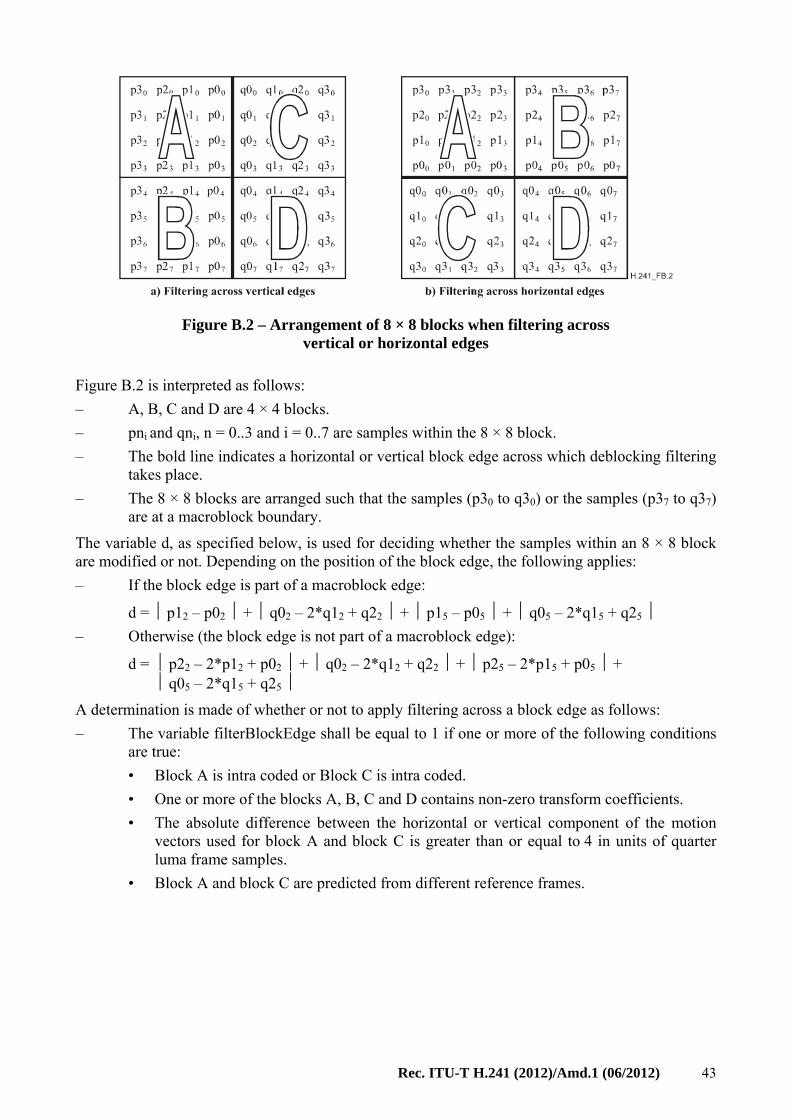
Rec. ITU-T H.241 (2012)/Amd.1 (06/2012) 43
Figure B.2 – Arrangement of 8 × 8 blocks when filtering across vertical or horizontal edges
Figure B.2 is interpreted as follows:
– A, B, C and D are 4 × 4 blocks.
– pni and qni, n = 0..3 and i = 0..7 are samples within the 8 × 8 block.
– The bold line indicates a horizontal or vertical block edge across which deblocking filtering takes place.
– The 8 × 8 blocks are arranged such that the samples (p30 to q30) or the samples (p37 to q37) are at a macroblock boundary.
The variable d, as specified below, is used for deciding whether the samples within an 8 × 8 block are modified or not. Depending on the position of the block edge, the following applies:
– If the block edge is part of a macroblock edge:
d = ⏐ p12 – p02 ⏐ + ⏐ q02 – 2*q12 + q22 ⏐ + ⏐ p15 – p05 ⏐ + ⏐ q05 – 2*q15 + q25 ⏐
– Otherwise (the block edge is not part of a macroblock edge):
d = ⏐ p22 – 2*p12 + p02 ⏐ + ⏐ q02 – 2*q12 + q22 ⏐ + ⏐ p25 – 2*p15 + p05 ⏐ + ⏐ q05 – 2*q15 + q25 ⏐
A determination is made of whether or not to apply filtering across a block edge as follows:
– The variable filterBlockEdge shall be equal to 1 if one or more of the following conditions are true:
• Block A is intra coded or Block C is intra coded.
• One or more of the blocks A, B, C and D contains non-zero transform coefficients.
• The absolute difference between the horizontal or vertical component of the motion vectors used for block A and block C is greater than or equal to 4 in units of quarter luma frame samples.
• Block A and block C are predicted from different reference frames.
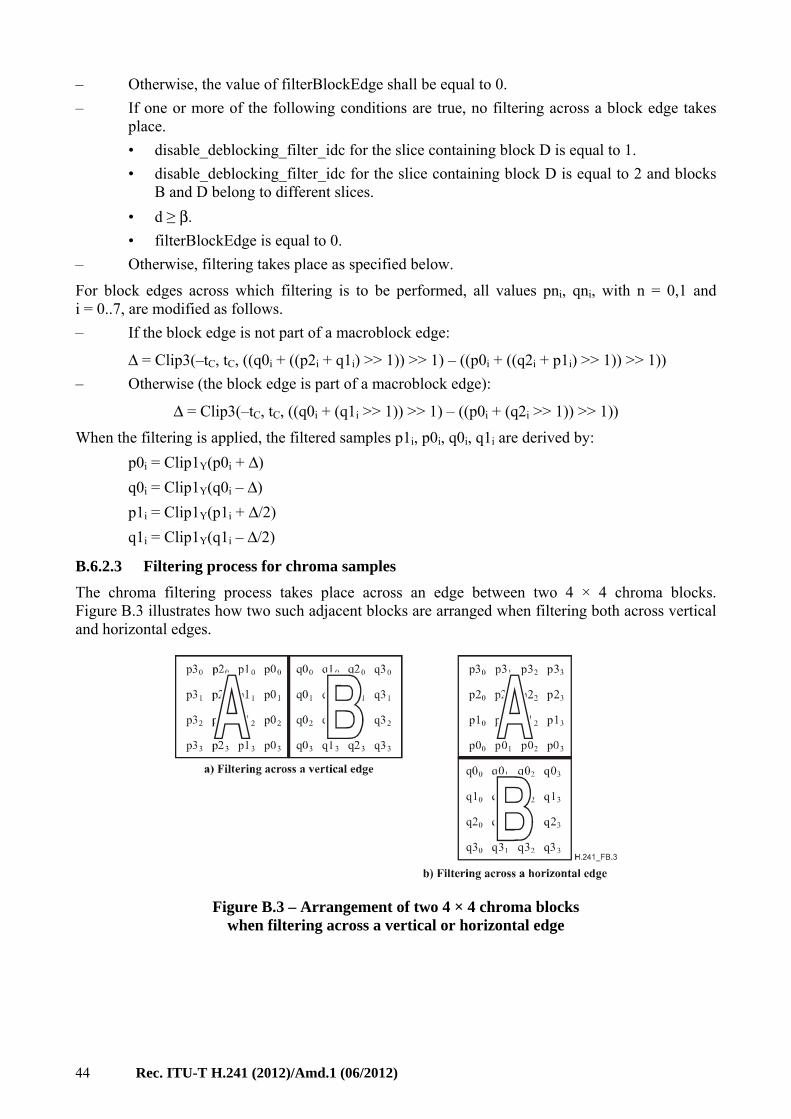
44 Rec. ITU-T H.241 (2012)/Amd.1 (06/2012)
– Otherwise, the value of filterBlockEdge shall be equal to 0.
– If one or more of the following conditions are true, no filtering across a block edge takes place.
• disable_deblocking_filter_idc for the slice containing block D is equal to 1.
• disable_deblocking_filter_idc for the slice containing block D is equal to 2 and blocks B and D belong to different slices.
• d ≥ β.
• filterBlockEdge is equal to 0.
– Otherwise, filtering takes place as specified below.
For block edges across which filtering is to be performed, all values pni, qni, with n = 0,1 and i = 0..7, are modified as follows.
– If the block edge is not part of a macroblock edge:
Δ = Clip3(–tC, tC, ((q0i + ((p2i + q1i) >> 1)) >> 1) – ((p0i + ((q2i + p1i) >> 1)) >> 1))
– Otherwise (the block edge is part of a macroblock edge):
Δ = Clip3(–tC, tC, ((q0i + (q1i >> 1)) >> 1) – ((p0i + (q2i >> 1)) >> 1))
When the filtering is applied, the filtered samples p1i, p0i, q0i, q1i are derived by:
p0i = Clip1Y(p0i + Δ)
q0i = Clip1Y(q0i – Δ)
p1i = Clip1Y(p1i + Δ/2)
q1i = Clip1Y(q1i – Δ/2)
B.6.2.3 Filtering process for chroma samples
The chroma filtering process takes place across an edge between two 4 × 4 chroma blocks. Figure B.3 illustrates how two such adjacent blocks are arranged when filtering both across vertical and horizontal edges.
Figure B.3 – Arrangement of two 4 × 4 chroma blocks when filtering across a vertical or horizontal edge
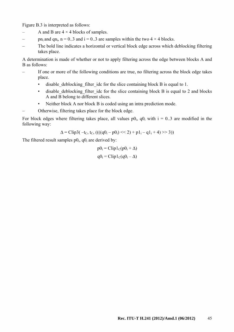
Rec. ITU-T H.241 (2012)/Amd.1 (06/2012) 45
Figure B.3 is interpreted as follows:
– A and B are 4 × 4 blocks of samples.
– pni and qni, n = 0..3 and i = 0..3 are samples within the two 4 × 4 blocks.
– The bold line indicates a horizontal or vertical block edge across which deblocking filtering takes place.
A determination is made of whether or not to apply filtering across the edge between blocks A and B as follows:
– If one or more of the following conditions are true, no filtering across the block edge takes place.
• disable_deblocking_filter_idc for the slice containing block B is equal to 1.
• disable_deblocking_filter_idc for the slice containing block B is equal to 2 and blocks A and B belong to different slices.
• Neither block A nor block B is coded using an intra prediction mode.
– Otherwise, filtering takes place for the block edge.
For block edges where filtering takes place, all values p0i, q0i with i = 0..3 are modified in the following way:
Δ = Clip3( –tC, tC, ((((q0i – p0i) << 2) + p1i – q1i + 4) >> 3))
The filtered result samples p0i, q0i are derived by:
p0i = Clip1C(p0i + Δ)
q0i = Clip1C(q0i – Δ)
46 Rec. ITU-T H.241 (2012)/Amd.1 (06/2012)
Appendix I
ASN.1 OIDs defined in this Recommendation
(This appendix does not form an integral part of this Recommendation.)
OID Clause
reference
{itu-t(0) recommendation(0) h(8) h241(241) specificVideoCodecCapabilities(0) h264(0) set-submode(2)}
6.2.5.1
{itu-t(0) recommendation(0) h(8) h241(241) specificVideoCodecCapabilities(0) h264(0) set-SVCmode (3)}
6.2.6.1
{itu-t(0) recommendation(0) h(8) h241(241) specificVideoCodecCapabilities(0) h264(0) iPpacketization(0) h241AnnexA(0)}
7.1.4
{itu-t(0) recommendation(0) h(8) h241(241) specificVideoCodecCapabilities(0) h264(0) iPpacketization(0) rfc6184NonInterleaved(1)}
7.1.4
{itu-t(0) recommendation(0) h(8) h241(241) specificVideoCodecCapabilities(0) h264(0) iPpacketization(0) rfc6184Interleaved(2)}
7.1.4
{itu-t(0) recommendation(0) h(8) h241(241) specificVideoCodecCapabilities(0) h264(0) generic-capabilities(1)}
8.3.2.1
Rec. ITU-T H.241 (2012)/Amd.1 (06/2012) 47
Appendix II
Examples of the set submode procedure
(This appendix does not form an integral part of this Recommendation.)
This appendix provides informative guidance and examples illustrating the use of the set submode procedure defined in clause 6.2.5.
The ITU-T H.264 capabilities defined by clause 8.3 usually allow more than one set of encoding parameters to be used by the video source.
For instance, the capabilities specify the ability to receive a maximum picture size of CustomMaxFS macroblocks. The video source may choose to send any picture height and width combination that does not exceed that total. Although the receiver is required by this Recommendation to be capable of rendering these picture sizes, it is frequently desirable to negotiate further constraints on the picture size. For example, an MCU that can control the picture height and width sent from each terminal can create a more functional picture composition.
There are four common cases where constraining the encoding with the set submode procedure is useful:
– to optimize the picture aspect ratio for a specific display or a sub-picture in a composition
– to limit the picture frame rate to match the frame rate of a specific picture composition
– to eliminate the adverse effects of rescaling on the picture quality
– to improve bandwidth utilization by negotiating a picture size that does not exceed the limits of a display or the size of a sub-picture in a composition.
The use of the set submode procedure is illustrated for each of these cases by the following clauses.
II.1 Optimization of the picture aspect ratio
In this example, the video channel is constrained to carry a picture which has a specific picture aspect ratio. The sample aspect ratio and the picture size are not constrained.
The video source indicates which SAR and PAR combinations can be carried on this video channel in a setSubmodeIndication message.
The video receiver requests a specific PAR which is included in that indication by sending a setSubmodeRequest.
The video source selects an image height and SAR that it can send using the requested PAR.
The video source positively acknowledges the request, including the SAR, PAR and the image height by sending a setSubmodeResponse. It then switches to the new submode, sending the SAR in the ITU-T H.264 VUI message per Table E.1 of [ITU-T H.264].
setSubmodeIndication: channelID, list of (SAR, list of (PAR), [allowAnyHeight]
setSubmodeRequest: channelID, PAR
setSubmodeResponse: channelID, acknowledge, SAR, PAR, height
II.2 Limiting the picture frame rate
The setSubmode procedure does not allow the picture frame rate to be directly constrained. However, it does allow macroblocks per second (submodeMaxMBPS) to be limited. Therefore, in order to limit frame rate, the video stream must be constrained to carry a picture of a specific size and also limited to a maximum macroblocks-per-second rate. This results in a constrained picture frame rate.
48 Rec. ITU-T H.241 (2012)/Amd.1 (06/2012)
First, the video source indicates which SAR and PAR combinations can be carried on this video channel by sending a setSubmodeIndication.
The video receiver then requests a specific height, and a submodeMaxMBPS value that achieves the desired frame rate for the requested picture size by sending a setSubmodeRequest. It may also request any specific SAR and PAR combination that is included in the indication message.
The video source positively acknowledges the request by sending a setSubmodeResponse that includes the SAR, PAR and the image height. It then switches to the new submode, sending the SAR in the ITU-T H.264 VUI message per Table E.1 of [ITU-T H.264].
setSubmodeIndication: channelID, list of (SAR, list of (PAR), [allowAnyHeight]
setSubmodeRequest: channelID, SAR, PAR, height, submodeMaxMBPS
setSubmodeResponse: channelID, acknowledge, SAR, PAR, height
II.3 Eliminating the adverse effects of picture rescaling
In order to eliminate the adverse effects of scaling, the video channel is constrained to carry a picture of specific PAR, SAR and picture size. Three different examples are presented. The first example describes the case where the video source is capable of re-scaling its image to any requested size. The second and third examples describe cases where the video source does not have this capability.
II.3.1 Video source is capable of arbitrary scaling
The video source first indicates which SAR and PAR combinations can be carried on this video channel by sending a setSubmodeIndication.
The video receiver sends a setSubmodeRequest to request a specific SAR and PAR combination which is included in the indication. Since the selected SAR and PAR include the allowAnyHeight designation, the video receiver also requests a specific height.
The video source positively acknowledges the request by sending a setSubmodeResponse that includes the SAR, PAR and the image height. It then switches to the new submode, sending the SAR in the ITU-T H.264 VUI message per Table E.1 of [ITU-T H.264].
setSubmodeIndication: channelID, list of (SAR, list of (PAR), [allowAnyHeight])
setSubmodeRequest: channelID, SAR, PAR, height (SAR and PAR have allowAnyHeight set)
setSubmodeResponse: channelID, acknowledge, SAR, PAR, height
II.3.2 Video source is not capable of arbitrary scaling
The video source first indicates which SAR and PAR combinations can be carried on this video channel by sending a setSubmodeIndication.
The video receiver requests a specific PAR and SAR combination which is included in the indication by sending a setSubmodeRequest. Since the selected PAR and SAR does not include the allowAnyHeight designation, the video receiver offers a list of acceptable heights, in preference order.
The video source selects the first height on the list that it is capable of sending.
Rec. ITU-T H.241 (2012)/Amd.1 (06/2012) 49
The video source then positively acknowledges the request, including the PAR, SAR and the image height in its setSubmodeResponse. It then switches to the new submode, sending the SAR in the ITU-T H.264 VUI message per Table E.1 of [ITU-T H.264].
setSubmodeIndication: channelID, list of (SAR, list of (PAR))
setSubmodeRequest: channelID, SAR, PAR, list of (height)
setSubmodeResponse: channelID, acknowledge, SAR, PAR, height
However, if the video source does not find a height in the request that it is capable of sending, it responds with a rejection in its setSubmodeResponse, which includes the list of heights it can send with the requested SAR and PAR combination.
The video receiver then selects one of those specific heights and sends a new setSubmodeRequest.
The video source then positively acknowledges the request, including the PAR, SAR and the image height in its setSubmodeResponse. It then switches to the new submode, sending the SAR in the ITU-T H.264 VUI message per Table E.1 of [ITU-T H.264].
setSubmodeIndication: channelID, list of (SAR, list of (PAR))
setSubmodeRequest: channelID, SAR, PAR, list of (height)
setSubmodeResponse: channelID, reject, list of (height) (requested heights were not supported)
setSubmodeRequest: channelID, SAR, PAR, height
setSubmodeResponse: channelID, acknowledge, PAR, SAR, height
II.4 Improving bandwidth utilization by limiting maximum picture size
Reducing the picture size frequently improves the picture quality by reducing compression artefacts. It can also reduce the bandwidth required to send the picture. In this case, it is often useful to further constrain the video channel through the use of flow control.
The video source sends a setSubmodeIndication which indicates which PAR and SAR combinations can be carried on this video channel.
The video receiver then sends a setSubmodeRequest message choosing a specific PAR and SAR combination which is included in the indication, and also the maximum image height.
The video source selects an image height that it is capable of sending that is less than or equal to the maximum.
The video source then positively acknowledges the request, including the PAR, SAR and the image height in its setSubmodeResponse message. The image height is less than the requested maximum height. It then switches to the new submode, sending the SAR in the ITU-T H.264 VUI message per Table E.1 of [ITU-T H.264].
setSubmodeIndication: channelID, list of (SAR, list of (PAR))
setSubmodeRequest: channelID, [SAR], [PAR], maximumHeight
setSubmodeResponse: channelID, acknowledge, SAR, PAR, height
If the smallest height that the video source can send exceeds the maximum height requested, the video source rejects the request, including the smallest height it can send in the reject message.
The video receiver then sends a new setSubmodeRequest with a new maximum height that can be accommodated by the video source.
The video source then positively acknowledges the second request, including the PAR, SAR and the image height in its setSubmodeResponse. It then switches to the new submode, sending the SAR in the ITU-T H.264 VUI message per Table E.1 of [ITU-T H.264].
50 Rec. ITU-T H.241 (2012)/Amd.1 (06/2012)
Finally, the video receiver constrains the channel bandwidth using the ITU-T H.245 flowControlCommand
setSubmodeIndication: channelID, list of (SAR, list of (PAR))
setSubmodeRequest channelID, [SAR], [PAR], maximumHeight
setSubmodeResponse: channelID, reject, minimumHeight (requested height was too large)
setSubmodeRequest: channelID, [SAR], [PAR], maximumHeight
setSubmodeResponse: channelID, acknowledge, SAR, PAR, height
flowControlCommand: channelID, maximumBitRate

Rec. ITU-T H.241 (2012)/Amd.1 (06/2012) 51
Bibliography
[b-IETF RFC 4648] IETF RFC 4648 (2006), The Base16, Base32, and Base64 Data Encodings.


Printed in Switzerland Geneva, 2013
SERIES OF ITU-T RECOMMENDATIONS
Series A Organization of the work of ITU-T
Series D General tariff principles
Series E Overall network operation, telephone service, service operation and human factors
Series F Non-telephone telecommunication services
Series G Transmission systems and media, digital systems and networks
Series H Audiovisual and multimedia systems
Series I Integrated services digital network
Series J Cable networks and transmission of television, sound programme and other multimedia signals
Series K Protection against interference
Series L Construction, installation and protection of cables and other elements of outside plant
Series M Telecommunication management, including TMN and network maintenance
Series N Maintenance: international sound programme and television transmission circuits
Series O Specifications of measuring equipment
Series P Terminals and subjective and objective assessment methods
Series Q Switching and signalling
Series R Telegraph transmission
Series S Telegraph services terminal equipment
Series T Terminals for telematic services
Series U Telegraph switching
Series V Data communication over the telephone network
Series X Data networks, open system communications and security
Series Y Global information infrastructure, Internet protocol aspects and next-generation networks
Series Z Languages and general software aspects for telecommunication systems