Categorical Amendment Criteria Background & Instructions
23
Categorical Amendment Criteria Background & Instructions [email protected] 301-427-9769 Aviation and Space Weather Services Branch National Weather Service Headquarters Silver Spring, Maryland Updated March 2020 1 of 23
-
Upload
khangminh22 -
Category
Documents
-
view
5 -
download
0
Transcript of Categorical Amendment Criteria Background & Instructions

Categorical Amendment Criteria Background & Instructions
[email protected] 301-427-9769 Aviation and Space Weather Services Branch National Weather Service Headquarters Silver Spring, Maryland
Updated March 2020 1 of 23

Table of Contents
Table of Contents 2
Background 3 Why do we do CAC? 3 FAA Cycles 4
The CAC Update Process 5
Categories 6
Determining Airspace Class 7
Determining CAC for Your TAF Sites 12 Threshold A - Airport Landing Minimums 12
Part 1 12 Part 2 - No ILS Available for the Airport 16
Threshold B - Airport Alternate Minimums 17 Threshold C, D, and E - Instrument Flight Rule Conditions, Marginal Visual Flight Rule Conditions, and Alternate Fuel for Airport Under IFR Conditions 19 Threshold F - Other Conditions Defined by Local Air Traffic Managers or Airport Requirements 20
Definitions 21
Additional Resources 22 AvnFPS Instructions - Adding or Updating TAF Sites in AvnFPS 22 AWIPS System Manager’s Manual: AWIPS II Operational Build 18.2.1 22 VFR Map 22 FAA AVCamsPlus 22 FAA Aeronautical Data Delivery Service (ADDS) 23 FlightAware 23
References 23
Updated March 2020 2 of 23
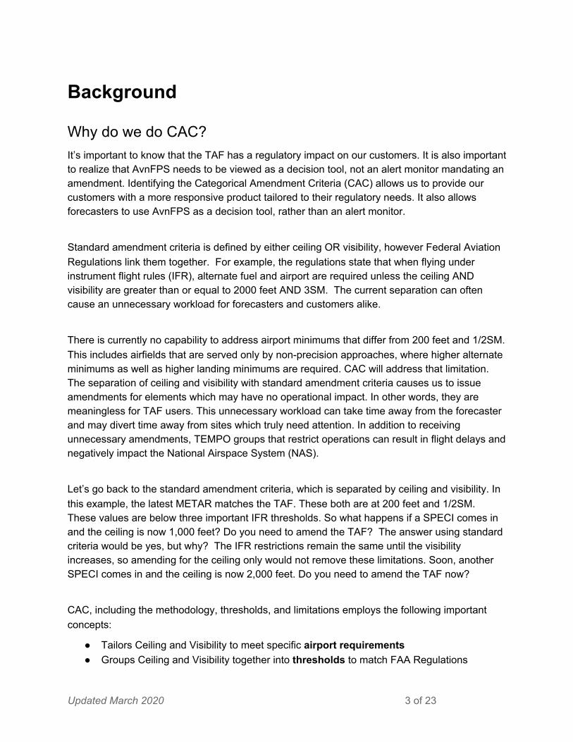
Background
Why do we do CAC? It’s important to know that the TAF has a regulatory impact on our customers. It is also important to realize that AvnFPS needs to be viewed as a decision tool, not an alert monitor mandating an amendment. Identifying the Categorical Amendment Criteria (CAC) allows us to provide our customers with a more responsive product tailored to their regulatory needs. It also allows forecasters to use AvnFPS as a decision tool, rather than an alert monitor.
Standard amendment criteria is defined by either ceiling OR visibility, however Federal Aviation Regulations link them together. For example, the regulations state that when flying under instrument flight rules (IFR), alternate fuel and airport are required unless the ceiling AND visibility are greater than or equal to 2000 feet AND 3SM. The current separation can often cause an unnecessary workload for forecasters and customers alike.
There is currently no capability to address airport minimums that differ from 200 feet and 1/2SM. This includes airfields that are served only by non-precision approaches, where higher alternate minimums as well as higher landing minimums are required. CAC will address that limitation. The separation of ceiling and visibility with standard amendment criteria causes us to issue amendments for elements which may have no operational impact. In other words, they are meaningless for TAF users. This unnecessary workload can take time away from the forecaster and may divert time away from sites which truly need attention. In addition to receiving unnecessary amendments, TEMPO groups that restrict operations can result in flight delays and negatively impact the National Airspace System (NAS).
Let’s go back to the standard amendment criteria, which is separated by ceiling and visibility. In this example, the latest METAR matches the TAF. These both are at 200 feet and 1/2SM. These values are below three important IFR thresholds. So what happens if a SPECI comes in and the ceiling is now 1,000 feet? Do you need to amend the TAF? The answer using standard criteria would be yes, but why? The IFR restrictions remain the same until the visibility increases, so amending for the ceiling only would not remove these limitations. Soon, another SPECI comes in and the ceiling is now 2,000 feet. Do you need to amend the TAF now?
CAC, including the methodology, thresholds, and limitations employs the following important concepts:
● Tailors Ceiling and Visibility to meet specific airport requirements ● Groups Ceiling and Visibility together into thresholds to match FAA Regulations
Updated March 2020 3 of 23

● TEMPO groups checked immediately against METARS to notify forecasters of resulting customer impacts
In essence, what we are doing is moving away from ceiling or visibility and instead using combined ceiling and visibility thresholds for each TAF site.
This is why we need to define airfield minimums, alternate minimums, and local needs for each TAF site. This document will help explain that process. In short, airfield minimums are determined from the airfield’s approach chart. Alternate minimums are based upon whether or not the airfield has a precision approach or is served only by a non-precision approach. Local needs generally deal with traffic flow. You can consult your CWSU to determine traffic flow needs.
FAA Cycles The FAA follows a 56- and 28-day cycle for updating their Digital - Terminal Procedures Publications (d-TPP). A simplistic explanation of these two cycles is explained below. The 56-day cycle starts where the current procedures, d-TPPs, are in effect until the start of the next cycle 56-day cycle. At the halfway point in the cycle, 28-days, a Terminal Change Notice (TCN) will be published. The TCN includes all changes to procedures in the d-TPP that were in effect at the beginning of that 56 day cycle. Generally speaking, the TCN is roughly an order of magnitude smaller than the TPP that it applies to. At the beginning of the next 56-day cycle, the changes that occured in the first half, along with anything applicable in the second half as a result of a TCN will now be included in the new cycle. And the process repeats itself. How we see this on our end with some example dates (the dates are not static): On January 3, 2019, a new cycle starts. Roughly a week prior, the FAA will email the POC at NWS HQ with their spreadsheet indicating the new changes that will go into effect on January 3, 2019. The NWS HQ POC will scrub the spreadsheet to see if the changes affect any of the TAF site minimums and make the necessary changes on the CAC Threshold Spreadsheet and then push it out to the AFPs to make local changes to the AvnFPS software. The halfway point will be January 31, 2019, that 28-day point, and roughly one week prior, the FAA will again email the NWS HQ POC with a spreadsheet indicating the TCN changes to be published. The NWS HQ POC will scrub this spreadsheet looking for any changes to TAF site minimums and make the necessary changes on the CAC Threshold Spreadsheet and push out to the AFPs. Since this TCN/28-day update is generally so much smaller than the TPP changes on the 56-day cycle, there may not be any changes that affect TAF sites. If that is the case, no
Updated March 2020 4 of 23

update is necessary to the CAC Threshold Spreadsheet or AvnFPS and an email indicating there were no changes to NWS TAF locations will be sent out from the NWS HQ POC. The next cycle will then begin on February 28, 2019 where everything that was updated with both the January 3 and January 31 cycles is now considered current. And with this new cycle, the above begins again with the FAA emailing their spreadsheet over to the NWS HQ POC for review. Again, this is a fairly simplistic explanation for a rather complicated process based on the printing times for the actual book volumes of the Terminal Procedure Publications (TPP). The TPPs are still printed out (26 volumes) however, they now also have the digital versions. For more information on the d-TPP, please visit: https://www.faa.gov/air_traffic/flight_info/aeronav/digital_products/dtpp/
The CAC Update Process In sync with the FAA cycle above, AFS24 staff at NWS HQ updates the CAC Threshold Spreadsheet and sends it out to the Aviation Focal Points (AFP) to review. When the updated spreadsheet is received, the AFP or other designated personnel at each WFO needs to accomplish the following:
1. Review the CAC Threshold Spreadsheet, after you receive it every 28 days. 2. If any site is highlighted in yellow, make the appropriate changes within AvnFPS to
ensure it matches the values in the spreadsheet. If a site is not highlighted in yellow, there are no changes required during that cycle.
3. If there are any questions regarding the updated information, please contact the AFS24 staff member who sent you the spreadsheet. Make sure to include your RAM, as applicable.
The remainder of this document lays out the instructions on how staff in the Aviation and Space Weather Services Program (AFS24) branch determines the CAC values for any TAF site in the spreadsheet you receive. This is background info that is intended to assist AFS24 staff in following the process, and to show the field how the values they receive in the spreadsheet are derived. This process is done every 28 days by the program lead in the AFS24 branch at NWS HQ and pushed out to the Aviation Focal Points (AFP) each cycle. So, generally speaking, you will not need to do this regularly. However, these instructions will help you figure out the values for your TAF sites in case there appears to be a discrepancy between the values HQ provides or you need to set up a new TAF site.
Updated March 2020 5 of 23

Categories Prior to September 2019, there were two definitions of “category”. This was confusing, especially to new users in the NWS. After sufficient coordination, it was determined that the use of “category” and its spreadsheet abbreviation, “CAT” could be changed to eliminate the dual use of the word. Now the spreadsheet simply refers to “thresholds” or “THRESH”. The use of “category” is part of the CAC acronym, so the historical context is important. However, the use of “category” now simply refers to airport approach categories. This singular definition represents a grouping of aircraft based on a predetermined speed used when an aircraft is on approach to the airport. These groupings are shown below and highlighted on the following approach plate.
● Category A: Speed less than 91 knots ● Category B: Speed 91 knots or more but less than 121 knots ● Category C: Speed 121 knots or more but less than 141 knots ● Category D: Speed 141 knots or more but less than 166 knots ● Category E: Speed 166 knots or more
If needed, aircraft speeds can be found by viewing Table A1-1 of the FAA Advisory Circular found at the link below:
https://www.faa.gov/documentLibrary/media/Advisory_Circular/150-5300-13A-chg1-interactive-201804.pdf
The FAA Aircraft characteristics database can be found starting on page 221 and are sorted by aircraft manufacturer/model.
Updated March 2020 6 of 23

Determining Airspace Class In some cases, you may need to determine why an airport has a certain airspace classification. This is probably rare, but is good information to know. Follow these instructions to find an airport’s airspace classification.
Updated March 2020 7 of 23

1.) Go to the FAA’s Chart Supplements website to do a quick search: https://www.faa.gov/air_traffic/flight_info/aeronav/digital_products/dafd/search/ 2.) Enter the airport ID into the Airport Identifier box and click “Go” (highlighted in the red box).
3.) Click on the available link under the Airport/NavAid Listing in the Dark Blue table (highlighted in the red box). This link will open a PDF document. Daytona Beach (DAB) is being used as the example.
Updated March 2020 8 of 23

4.) Verify that you have the correct airport in the document that opens in your browser window (highlighted in the red box).
Updated March 2020 9 of 23

5.) Scroll through the PDF document until you find the information on the airspace classification. It will look similar to this (highlighted in the red box):
Updated March 2020 10 of 23

Updated March 2020 11 of 23

Determining CAC for Your TAF Sites Determining the CAC Thresholds for TAF sites is always a bit daunting at first. But once it’s done a few times, it becomes easier to do and starts making some sense. Generally, the NWS HQ POC will do this as a result of changes on the FAA spreadsheet during the 56- and 28-day cycles. However, it is always good to understand how the process is done so that errors can be avoided on the CAC Threshold spreadsheet and in AvnFPS. It is ultimately the responsibility of the local office to ensure the information in the CAC Threshold spreadsheet is correct.
Threshold A - Airport Landing Minimums In this section, Threshold A refers to the airport landing minimums and corresponds to the Thresh A column in the CAC Threshold spreadsheet.
This section is also divided into 2 parts: Part 1 is finding minimums when ILS procedures are available. Part 2 is finding minimums when there are no ILS procedures available.
Part 1 1.) Go to the FAA’s Terminal Procedures website to do a quick search: https://www.faa.gov/air_traffic/flight_info/aeronav/digital_products/dtpp/search/ 2.) Enter the airport ID into the Airport Identifier box and click “Go” (highlighted in the red box). We will use Daytona Beach (DAB) as an example.
Updated March 2020 12 of 23

3.) If this is the first time you are setting up the minimums for a location, you will need to review all ILS procedures to see which one has the lowest minimums. In the Procedure Column of the table, look for all procedures that have “ILS” indicated and click on the links and view each one individually. NOTE: If no ILS is available, follow the instructions in Part 2.
Updated March 2020 13 of 23

In the DAB example below, you’ll see there are two ILS procedures: ILS or LOC RWY 7L and ILS or LOC RWY 25R (click image to enlarge). The Threshold A minimums will be listed in the lower left portion of the airport diagram. In the “S-ILS” line, use the values in parentheses, highlighted in yellow in both images below. In the DAB example, minimums for RWY 7L are 200 - 3/4 (200 feet and 3/4SM) and minimums for RWY 25R are 200 - 1/2 (200 feet and 1/2SM).
Updated March 2020 14 of 23

Between these two ILS procedures, 200 - 1/2 is the lowest, so your CAC would be based on ILS or LOC RWY 25R with minimums of 200 - 1/2. Once you have found the ILS with the lowest minimums, review all other approaches (except CAT I, II, or III ILS) to ensure no lower minimums exist. Here’s another example from Chicago Midway (MDW). To enlarge, click on the image to reveal the link. You can see the minimums highlighted in yellow in the two images. ILS or LOC/DME RWY 13C has a minimum of 300 - 1 and ILS or LOC/DME RWY 31C has a minimum of 300 - 3/4. So your minimum for MDW would be 300 - 3/4.
Updated March 2020 15 of 23

Part 2 - No ILS Available for the Airport For airports that are not served with ILS, review all available approaches to determine which has the lowest published minimums to be used as THRESH A. The following list shows the typical progression of approaches that will have the lowest published minimums in descending order. All need to be reviewed as this is not always the case.
● LOC/DME (Localizer with Distance Measuring Equipment) ● LOC ● VOR/DME (Very High Frequency Omnidirectional Range ● VOR ● NDB (Non-Directional Beacon)
NOTE: approaches that require special authorization, aircrew, and equipment are not to be used, except in rare cases. See example under Category F.
Updated March 2020 16 of 23

Threshold B - Airport Alternate Minimums
This section will help you determine the alternate minimums for your TAF sites. For airports in Class B airspace, the alternate minimums have been pre-determined in an agreement between the FAA and major airlines. The alternate minimums for these airports are 400 - 1 and are indicated on the CAC Threshold spreadsheet in bolded blue font.
Updated March 2020 17 of 23

In some cases, there are no Alternate Minimums in the published procedures. When this occurs, simply use the following for THRESH B values:
● Precision approach (ILS only) = 600 - 2 ● Non-precision approach (all others) = 800 - 2
To complete the minimums for Threshold B, you must go back to the Terminal Procedures Search page (see Steps 1 and 2 in Part I above) and click on the Alternate Minimums link. See the example on the next page.
Updated March 2020 18 of 23

Additional notes for THRESH B minimums:
1. If the airport has regularly scheduled Part 121 commercial service, at a minimum, Category C approach speeds apply (as opposed to the Category A/B approach speeds that show up in many Alternate Minimums sections for airfields).
2. In addition, many, but not all, commercial aircraft are Category C approach speeds. Many aircraft commonly used by the airlines are Category C and/or Category D. Therefore, it is recommended that unless the airfield is a smaller airport only served by regional aircraft (i.e. CRJs, turboprops - not 737s), it be considered a "Category D" field for approach speed purposes.
3. Military airfields can generally be considered Category C (unless there is commercial service that would render it a Category D, per #2 above). However, most military bases aren't going to be using NWS TAFs anyways.
4. Most fields we are writing a TAF for should be considered a candidate for Category C, as many faster General Aviation (GA) aircraft (think Learjets) are Category C, and if the airfield is significant enough to warrant a TAF, it probably has Category C GA aircraft flying in (except perhaps some remote fields in Alaska). Practically speaking, if the runway length is greater than 5000 ft, one should assume that Category C aircraft may be landing there.
Threshold C, D, and E - Instrument Flight Rule Conditions, Marginal Visual Flight Rule Conditions, and Alternate Fuel for Airport Under IFR Conditions
This section is the easiest of all sections to perform. Threshold C, D, and E are set values across all sites so no additional research is needed. Simply follow the information in the bullets below:
● Threshold C - Instrument Flight Rule Conditions (IFR): 1000 feet and 3SM ● Threshold D - Marginal Visual Flight Rule Conditions (MVFR): 3000 feet and 5SM ● Threshold E - Alternate fuel for Airport Under IFR Conditions (Alt): 2000 feet and 3SM
Updated March 2020 19 of 23

Threshold F - Other Conditions Defined by Local Air Traffic Managers or Airport Requirements
This is a specific, local category that is coordinated with the WFO, CWSU and local airport management for applicable values. Most locations will not have values for this category. Here are a couple of examples of situations with THRESH F values and the reasoning behind them:
● Addition of a new runway at an airport resulted in the addition of 1500 - 5 as a THRESH F minimum. 1500 - 5 is basically a visual minimum for the tower. The airport opened up a new runway and the tower would lose visual of an aircraft departing on 32L and a missed approach/go around on 27R. So we lose the 32L departure at 1500 - 5. Previously, 1500 - 5 would typically have an effect on arrival rate because of shared approach/departure runways and breakout points for the tower to see.
● At a western US airport, the RNAV (RNP) RWY 30 approach has the lowest of all published minimums. However, special authorization is required to use this approach. Because of this, the THRESH A minimums had to be derived from another approach that did not have this restriction. Input from the airport manager indicated that RNAV (RNP) RWY 30 is one of the airports busier runways, especially under calm winds. So, a THRESH F of 400 - 1 was developed, with coordination of the local airport.
Updated March 2020 20 of 23

Definitions Area Navigation (RNAV) - RNAV is a method of navigation that permits aircraft operation on any desired flight path within the coverage of ground- or space-based navigation aids or within the limits of the capability of self-contained aids, or a combination of these (CFI Notebook, n.d.) CAC Threshold Spreadsheet - The NWS spreadsheet used to track changes in ceiling and visibility minimums in FAA approach plates for NWS TAF sites. This spreadsheet also tracks individual TAF locations. Can be found at: CAC Threshold Spreadsheet Categorical Amendment Criteria (CAC) - A customer-based approach to amending TAFs based on minimum threshold criteria for ceilings and visibility. Category - A grouping of aircraft based on a predetermined speed used when an aircraft is on approach to the airport. Distance Measuring Equipment - a system requiring both aircraft-installed and ground-based equipment, with the latter normally co-located with a VHF omnidirectional radio range (VOR) or, sometimes, an instrument landing system (ILS). It provides the pilot with the slant-range distance to the DME transmitter (AOPA, 2017). Instrument Landing System (ILS) - A landing navigation used by the FAA to provide aircraft with precision vertical and horizontal navigation guidance information during approach and landing (FAA, 2016-a). Localizer (LOC) - generates and radiates signals to provide final approach azimuth navigation information to landing aircraft (FAA-a, 2016). LOC/DME (Localizer with Distance Measuring Equipment) - is a radio navigation station that combines the LOC and DME. Non-Directional Beacon (NDB) - is a ground-based, low frequency radio transmitter used as an instrument approach for airports and offshore platforms Non-precision Approach - an approach which provides the pilot horizontal guidance only. Precision Approach - an approach which provides the pilot with vertical and horizontal flight path information for an approach to landing. Required Navigation Performance - Required Navigation Performance (RNP) is similar to Area Navigation (RNAV); but, RNP requires on-board navigation performance monitoring and
Updated March 2020 21 of 23

alerting capability to ensure that the aircraft stays within a specific containment area (FAA-b, 2016). Very High Frequency Omni-Directional Range (VOR) - is a ground-based electronic system that provides azimuth information for high and low altitude routes and airport approaches (FAA, 2017). VOR/DME (Very High Frequency Omni-Directional Range) - is a radio navigation station that combines the VOR and DME.
Additional Resources
AvnFPS Instructions - Adding or Updating TAF Sites in AvnFPS Specific instructions on how to configure AvnFPS: https://docs.google.com/document/d/1YP6CQd4Hf3NIUoKvjrflhaGdLkKOaDXy-Jf0l70eMsU/edit?ts=5e59a8a1
AWIPS System Manager’s Manual: AWIPS II Operational Build 18.2.1 Instructions on how to configure the AvnFPS GUI for category monitoring can be found in Appendix DD in the AWIPS System Manager’s Manual at the following link in VLab: https://vlab.ncep.noaa.gov/object_storage/awips/Documentation/18.2.1/SMM/WithOutRedLines.pdf NOTE: To access VLab, you will need to use our NOAA credentials (firstname.lastname) and LDAP password.
VFR Map A free online resource using stitched VFR and IFR aeronautical charts - http://vfrmap.com/
FAA AVCamsPlus Supplemental product page with clickable sites to gather near-real time data - https://avcamsplus.faa.gov/map/
Updated March 2020 22 of 23

FAA Aeronautical Data Delivery Service (ADDS) http://ais-faa.opendata.arcgis.com/
FlightAware Free flight tracking data - https://flightaware.com/
References Aircraft Owners and Pilots Organization (AOPA), (2017, December 1). How It Works: Distance Measuring Equipment. Retrieved from goo.gl/nRHahn. CFI Notebook, (n.d.). Area Navigation. Retrieved from goo.gl/u7KfGc Federal Aviation Administration (FAA)-a, (2016, December 20). Ground-Based Navigation - Instrument Landing System. Retrieved from https://go.usa.gov/xPQGG. Federal Aviation Administration (FAA)-b, (2016, December 23). Retrieved from https://go.usa.gov/xPU8x Federal Aviation Administration (FAA), (2017, March 25). Ground-Based Navigation - Very High Frequency Omni-Directional Range. Retrieved from https://go.usa.gov/xPQ7p Southern Avionics Company (SAC), (2011, April 28). What is an NDB or Non-Directional Beacon? Retrieved from goo.gl/XtWUAT.
Updated March 2020 23 of 23