
ITU-T Rec. M.1400 Amendment 1 (01/2018) Designations for ...
154
International Telecommunication Union ITU-T M.1400 TELECOMMUNICATION STANDARDIZATION SECTOR OF ITU Amendment 1 (01/2018) SERIES M: TELECOMMUNICATION MANAGEMENT, INCLUDING TMN AND NETWORK MAINTENANCE Designations and information exchange Designations for interconnections among operators' networks Amendment 1: Addition of new function codes for optical networks beyond 100 Gb/s Recommendation ITU-T M.1400 (2015) – Amendment 1
-
Upload
khangminh22 -
Category
Documents
-
view
3 -
download
0
Transcript of ITU-T Rec. M.1400 Amendment 1 (01/2018) Designations for ...
I n t e r n a t i o n a l T e l e c o m m u n i c a t i o n U n i o n
ITU-T M.1400 TELECOMMUNICATION STANDARDIZATION SECTOR OF ITU
Amendment 1 (01/2018)
SERIES M: TELECOMMUNICATION MANAGEMENT, INCLUDING TMN AND NETWORK MAINTENANCE
Designations and information exchange
Designations for interconnections among operators' networks
Amendment 1: Addition of new function codes for optical networks beyond 100 Gb/s
Recommendation ITU-T M.1400 (2015) – Amendment 1

ITU-T M-SERIES RECOMMENDATIONS
TELECOMMUNICATION MANAGEMENT, INCLUDING TMN AND NETWORK MAINTENANCE
Introduction and general principles of maintenance and maintenance organization M.10–M.299
International transmission systems M.300–M.559
International telephone circuits M.560–M.759
Common channel signalling systems M.760–M.799
International telegraph systems and phototelegraph transmission M.800–M.899
International leased group and supergroup links M.900–M.999
International leased circuits M.1000–M.1099
Mobile telecommunication systems and services M.1100–M.1199
International public telephone network M.1200–M.1299
International data transmission systems M.1300–M.1399
Designations and information exchange M.1400–M.1999
International transport network M.2000–M.2999
Telecommunications management network M.3000–M.3599
Integrated services digital networks M.3600–M.3999
Common channel signalling systems M.4000–M.4999
For further details, please refer to the list of ITU-T Recommendations.

Rec. ITU-T M.1400 (2015)/Amd.1 (01/2018) i
Recommendation ITU-T M.1400
Designations for interconnections among operators' networks
Amendment 1
Addition of new function codes for optical networks beyond 100 Gb/s
Summary
Recommendation ITU-T M.1400 covers the designations of interconnections among operators'
networks of circuits, groups, group and line links, digital blocks, digital paths, data transmission
systems, digital blocks created between digital circuit multiplication equipment (DCME), virtual
containers and multiplex sections.
The designation information is in two layers:
– Layer 1: The unique information; the designation;
– Layer 2: Additional information; the related information.
Guidance for the user is provided in a series of examples.
Recommendation ITU-T G.709 (2016) has introduced support for optical transport networks with
rates beyond 100 Gb/s.
This Amendment 1 to ITU-T M.1400 introduces new function codes for the corresponding optical
channel data units (ODUs) and optical channel transport units (OTUs). It also corrects a few editorial
inconsistencies.
History
Edition Recommendation Approval Study Group Unique ID*
1.0 ITU-T M.14 1960-12-16 11.1002/1000/7407
2.0 ITU-T M.14 1964-06-26 11.1002/1000/7406
3.0 ITU-T M.14 1968-10-25 11.1002/1000/7405
4.0 ITU-T M.14 1972-12-15 11.1002/1000/7404
5.0 ITU-T M.140 1976-10-08 11.1002/1000/7403
6.0 ITU-T M.140 1980-11-21 11.1002/1000/7402
7.0 ITU-T M.140 1984-10-19 11.1002/1000/5748
8.0 ITU-T M.140 1988-11-25 11.1002/1000/1488
9.0 ITU-T M.1400 1992-10-05 11.1002/1000/1489
10.0 ITU-T M.1400 1997-04-19 4 11.1002/1000/4033
10.1 ITU-T M.1400 (1997) Amd. 1 1998-06-26 4 11.1002/1000/4421
11.0 ITU-T M.1400 2000-02-04 4 11.1002/1000/4861
12.0 ITU-T M.1400 2001-10-14 4 11.1002/1000/5554
12.1 ITU-T M.1400 (2001) Amd. 1 2002-05-29 4 11.1002/1000/6037
13.0 ITU-T M.1400 2004-01-10 4 11.1002/1000/7092
14.0 ITU-T M.1400 2006-07-14 4 11.1002/1000/8853
15.0 ITU-T M.1400 2013-03-16 2 11.1002/1000/11903
16.0 ITU-T M.1400 2015-04-29 2 11.1002/1000/12467
16.1 ITU-T M.1400 (2015) Amd. 1 2018-01-13 2 11.1002/1000/13478
____________________
* To access the Recommendation, type the URL http://handle.itu.int/ in the address field of your web
browser, followed by the Recommendation's unique ID. For example, http://handle.itu.int/11.1002/1000/11
830-en.

ii Rec. ITU-T M.1400 (2015)/Amd.1 (01/2018)
FOREWORD
The International Telecommunication Union (ITU) is the United Nations specialized agency in the field of
telecommunications, information and communication technologies (ICTs). The ITU Telecommunication
Standardization Sector (ITU-T) is a permanent organ of ITU. ITU-T is responsible for studying technical,
operating and tariff questions and issuing Recommendations on them with a view to standardizing
telecommunications on a worldwide basis.
The World Telecommunication Standardization Assembly (WTSA), which meets every four years,
establishes the topics for study by the ITU-T study groups which, in turn, produce Recommendations on
these topics.
The approval of ITU-T Recommendations is covered by the procedure laid down in WTSA Resolution 1.
In some areas of information technology which fall within ITU-T's purview, the necessary standards are
prepared on a collaborative basis with ISO and IEC.
NOTE
In this Recommendation, the expression "Administration" is used for conciseness to indicate both a
telecommunication administration and a recognized operating agency.
Compliance with this Recommendation is voluntary. However, the Recommendation may contain certain
mandatory provisions (to ensure, e.g., interoperability or applicability) and compliance with the
Recommendation is achieved when all of these mandatory provisions are met. The words "shall" or some
other obligatory language such as "must" and the negative equivalents are used to express requirements. The
use of such words does not suggest that compliance with the Recommendation is required of any party.
INTELLECTUAL PROPERTY RIGHTS
ITU draws attention to the possibility that the practice or implementation of this Recommendation may
involve the use of a claimed Intellectual Property Right. ITU takes no position concerning the evidence,
validity or applicability of claimed Intellectual Property Rights, whether asserted by ITU members or others
outside of the Recommendation development process.
As of the date of approval of this Recommendation, ITU had not received notice of intellectual property,
protected by patents, which may be required to implement this Recommendation. However, implementers
are cautioned that this may not represent the latest information and are therefore strongly urged to consult the
TSB patent database at http://www.itu.int/ITU-T/ipr/.
ITU 2018
All rights reserved. No part of this publication may be reproduced, by any means whatsoever, without the
prior written permission of ITU.

Rec. ITU-T M.1400 (2015)/Amd.1 (01/2018) iii
Table of Contents
Page
1 Scope ............................................................................................................................. 1
2 References ..................................................................................................................... 2
3 Definitions .................................................................................................................... 5
4 Abbreviations and acronyms ........................................................................................ 7
5 Conventions .................................................................................................................. 8
6 Framework .................................................................................................................... 9
6.1 Layer 1 ............................................................................................................ 9
6.2 Layer 2 ............................................................................................................ 11
6.3 Implementation ............................................................................................... 11
6.4 Operator information ...................................................................................... 11
7 Designations of public switched circuit interconnections ............................................ 12
7.1 General ........................................................................................................... 12
7.2 Telephone-type circuits .................................................................................. 13
7.3 Circuit used for switched telex and telegraph services .................................. 14
7.4 Interconnecting circuits in the public switched data network ........................ 14
7.5 Related information ........................................................................................ 14
8 Related information for public switched circuit interconnections ................................ 15
8.1 Urgency for restoration [item 1] ..................................................................... 15
8.2 Terminal countries [item 2] ............................................................................ 15
8.3 Names of network operators/service providers [item 3] ................................ 15
8.4 Control station (sub-control station(s)) [item 4] ............................................. 16
8.5 Fault report points [item 5] ............................................................................. 16
8.6 Routing [item 6] ............................................................................................. 17
8.7 Association [item 7] ....................................................................................... 17
8.8 Equipment information [item 8] ..................................................................... 17
8.9 Use [item 9] .................................................................................................... 18
8.10 Transmission medium information [item 10] ................................................. 18
8.11 Composition of the transmission [item 11] .................................................... 19
8.12 Bandwidth or bit rate [item 12] ...................................................................... 19
8.13 Signalling type [item 13] ................................................................................ 19
9 Designations of fixed (non-switched) circuit interconnections between operators ...... 20
9.1 General ........................................................................................................... 20
9.2 Leased circuit interconnections ...................................................................... 21
9.3 Fixed (non-switched) public circuits .............................................................. 26
9.4 Related information ........................................................................................ 29
10 Related information for fixed circuit interconnections ................................................. 29

iv Rec. ITU-T M.1400 (2015)/Amd.1 (01/2018)
Page
10.1 Urgency for restoration [item 1] ..................................................................... 29
10.2 Terminal countries [item 2] ............................................................................ 30
10.3 Names of network operators/service providers [item 3] ................................ 30
10.4 Control station (sub-control station(s)) [item 4] ............................................. 30
10.5 Fault report points [item 5] ............................................................................. 31
10.6 Routing [item 6] ............................................................................................. 31
10.7 Association [item 7] ....................................................................................... 32
10.8 Equipment information [item 8] ..................................................................... 33
10.9 Use [item 9] .................................................................................................... 33
10.10 Transmission medium information [item 10] ................................................. 33
10.11 Composition of the transmission [item 11] .................................................... 34
10.12 Bandwidth or bit rate [item 12] ...................................................................... 34
10.13 Signalling type [item 13] ................................................................................ 35
10.14 Applicable ITU-T Recommendations [item 14] ............................................. 35
11 Designations of group, supergroup, etc. (bidirectional and unidirectional)
interconnections ............................................................................................................ 35
11.1 General ........................................................................................................... 35
11.2 Bidirectional groups, etc. ................................................................................ 37
11.3 Unidirectional groups and supergroups .......................................................... 38
11.4 Related information ........................................................................................ 39
12 Designations of group link, supergroup link and line link interconnections ................ 39
12.1 Group and supergroup links ........................................................................... 39
12.2 Line links ........................................................................................................ 40
12.3 Related information ........................................................................................ 41
13 Related information for group, group link and line link interconnections ................... 41
13.1 Urgency for restoration [item 1] ..................................................................... 42
13.2 Terminal countries [item 2] ............................................................................ 42
13.3 Names of network operators/service providers [item 3] ................................ 42
13.4 Control station sub-control station(s) [item 4] ............................................... 43
13.5 Fault report points [item 5] ............................................................................. 43
13.6 Routing [item 6] ............................................................................................. 44
13.7 Association [item 7] ....................................................................................... 45
13.8 Equipment information [item 8] ..................................................................... 45
13.9 Use [item 9] .................................................................................................... 46
13.10 Transmission medium information [item 10] ................................................. 46
13.11 End-to-end information or operational agreement [item 11] ......................... 46
13.12 Bandwidth [item 12] ....................................................................................... 47
13.13 Occupancy (for groups/supergroups, etc., and for line links) [item 13] ......... 47
14 Designations of digital block (bidirectional and unidirectional) interconnections ....... 48

Rec. ITU-T M.1400 (2015)/Amd.1 (01/2018) v
Page
14.1 General ........................................................................................................... 48
14.2 Bidirectional digital blocks ............................................................................. 50
14.3 Restoration digital blocks ............................................................................... 50
14.4 Multiple destination unidirectional digital blocks .......................................... 50
14.5 Single destination unidirectional digital blocks ............................................. 51
14.6 Related information ........................................................................................ 51
15 Designation of digital path interconnections ................................................................ 51
15.1 Conventional digital paths not connected to their terminal equipment .......... 52
15.2 Restoration digital paths ................................................................................. 52
15.3 Digital line sections and digital radio sections ............................................... 52
15.4 Related information ........................................................................................ 52
16 Designations of routes in the mixed analogue/digital transmission network ............... 53
16.1 Transmission routes with one analogue-to-digital conversion ....................... 53
16.2 Transmission routes with two analogue-to-digital conversions ..................... 54
16.3 Transmission routes with more than two analogue-to-digital conversions .... 56
16.4 Related information ........................................................................................ 56
17 Designation of data transmission systems .................................................................... 56
17.1 General ........................................................................................................... 56
17.2 Data transmission links ................................................................................... 59
17.3 Related information ........................................................................................ 60
18 Designations of digital block interconnections created by the interconnection of
digital circuit multiplication equipments (DCMEs) ..................................................... 60
18.1 General ........................................................................................................... 60
18.2 Multi-clique configuration of DCMEs ........................................................... 61
18.3 Low-rate encoding equipment ........................................................................ 62
18.4 Related information ........................................................................................ 62
19 Synchronous digital hierarchy (SDH) .......................................................................... 63
19.1 Designation of multiplex sections of the synchronous digital hierarchy
(SDH) ............................................................................................................. 63
19.2 Designations of virtual container interconnections ........................................ 65
19.3 Concatenated virtual containers ..................................................................... 66
19.4 Leased circuits based on SDH ........................................................................ 67
20 Related information for digital block, path, data transmission system, block
interconnections created by the interconnection of DCMEs, SDH multiplex
sections and virtual containers ...................................................................................... 68
20.1 Urgency for restoration [item 1] ..................................................................... 68
20.2 Terminal countries [item 2] ............................................................................ 69
20.3 Names of network operators/service providers [item 3] ................................ 69
20.4 Control station [sub-control station(s)] [item 4] ............................................. 70
20.5 Fault report points [item 5] ............................................................................. 70

vi Rec. ITU-T M.1400 (2015)/Amd.1 (01/2018)
Page
20.6 Routing [item 6] ............................................................................................. 71
20.7 Association [item 7] ....................................................................................... 72
20.8 Equipment information [item 8] ..................................................................... 73
20.9 Use [item 9] .................................................................................................... 74
20.10 Transmission medium information [item 10] ................................................. 75
20.11 End-to-end information or composition of transmission or operational
agreement [item 11] ........................................................................................ 75
20.12 Bit rate (for blocks, paths and SDH multiplex sections) [item 12] ................ 76
20.13 Occupancy (except for paths) [item 13] ......................................................... 76
20.14 Actual number of channels and access point identifier [item 14] .................. 79
20.15 Clocking information (for blocks only) [item 15] .......................................... 80
20.16 Direction of transmission (for unidirectional blocks) [item 16] ..................... 80
21 Designation of connections for the asynchronous transfer mode (ATM) .................... 81
21.1 General ........................................................................................................... 81
21.2 Transport links ................................................................................................ 81
21.3 Virtual path ..................................................................................................... 82
21.4 Virtual channels (VCAs) ................................................................................ 83
21.5 ATM Layer 2 .................................................................................................. 83
22 Related information for the asynchronous transfer mode (ATM) ................................ 84
22.1 Urgency for restoration [item 1] ..................................................................... 84
22.2 Terminal countries [item 2] ............................................................................ 84
22.3 Names of network operators/service providers [item 3] ................................ 84
22.4 Control and sub-control station(s) [item 4] .................................................... 84
22.5 Fault report points [item 5] ............................................................................. 84
22.6 Routing [item 6] ............................................................................................. 84
22.7 Association [item 7] ....................................................................................... 84
22.8 Equipment information [item 8] ..................................................................... 84
22.9 Use [item 9] .................................................................................................... 85
22.10 Transmission medium information [item 10] ................................................. 85
22.11 Operational agreement [item 11] .................................................................... 85
22.12 Unassigned item [item 12] .............................................................................. 85
22.13 Occupancy [item 13] ...................................................................................... 85
22.14 Direction of transmission (for unidirectional transit network services
only) [item 14] ................................................................................................ 85
22.15 ATM transfer capability [item 15] ................................................................. 85
22.16 Source traffic descriptor [item 16] ................................................................. 86
22.17 Cell delay variation tolerance [item 17] ......................................................... 86
22.18 Quality of service [item 18] ............................................................................ 86
23 Transit network services ............................................................................................... 87
23.1 General ........................................................................................................... 87

Rec. ITU-T M.1400 (2015)/Amd.1 (01/2018) vii
Page
23.2 Transit digital transmission service ................................................................ 88
23.3 Transit dark fibre service ................................................................................ 89
23.4 Related information ........................................................................................ 89
24 Related information on transit network service ............................................................ 90
24.1 Urgency for restoration [item 1] ..................................................................... 90
24.2 Terminal countries [item 2] ............................................................................ 90
24.3 Names of network operators/service providers [item 3] ................................ 90
24.4 Control station [sub-control station(s)] [item 4] ............................................. 90
24.5 Fault report points [item 5] ............................................................................. 90
24.6 Routing [item 6] ............................................................................................. 90
24.7 Association [item 7] ....................................................................................... 90
24.8 Equipment information [item 8] ..................................................................... 90
24.9 Use [item 9] .................................................................................................... 90
24.10 Transmission medium information [item 10] ................................................. 90
24.11 SLA [item 11] ................................................................................................. 91
24.12 Bit rate [item 12] ............................................................................................ 91
24.13 Commercial identifier [item 13] ..................................................................... 91
24.14 Unassigned item [item 14] .............................................................................. 91
24.15 Clocking information [item 15] ...................................................................... 91
24.16 Direction of transmission (for unidirectional transit network services
only) [item 16] ................................................................................................ 91
25 Designations for wavelength division multiplexing (simple and dense) ...................... 91
25.1 General ........................................................................................................... 91
25.2 The equipment ................................................................................................ 92
25.3 Configurations for the newly created transmission systems .......................... 93
25.4 General format for the optical transmission systems ..................................... 96
25.5 Related information ........................................................................................ 99
26 Related information on DWDM ................................................................................... 99
27 Designation of connections for the digital subscriber line (DSL) ................................ 101
27.1 General ........................................................................................................... 101
27.2 Related information for the ADSL connections ............................................. 104
27.3 Related information for the SDSL connection ............................................... 105
27.4 Examples ........................................................................................................ 107
28 Exceptional designations .............................................................................................. 107
28.1 Exceptional designations with intelligence in the serial number ................... 107
29 Designation of optical transport networks .................................................................... 108
29.1 General ........................................................................................................... 108
29.2 Data transmission links ................................................................................... 109
29.3 Related information ........................................................................................ 110

viii Rec. ITU-T M.1400 (2015)/Amd.1 (01/2018)
Page
Annex A – Full examples for designation information............................................................ 111
A.1 Full example for the designation information of a public switched
telephone circuit ............................................................................................. 111
A.2 Full example for the designation information of a leased analogue circuit ... 111
A.3 Full examples for the designation information of a group and a group link
interconnection ............................................................................................... 112
A.4 Full examples for the designation information of a digital block, digital
path, data transmission system, blocks created between DCMEs, virtual
containers and SDH multiplex section interconnections ................................ 114
Annex B – KLM addressing and its relationship to time slot numbering for virtual
containers ...................................................................................................................... 123
B.1 KLM addressing relationship to time slot numbering .................................... 123
B.2 KLM addressing of VC-4 occupancy ............................................................. 124
B.3 Comparative notation of KLM addressing vs. time slot numbering .............. 124
Annex C – Reference clause numbers for the various types of routes .................................... 127
Annex D – Numbering of channels in data transmission systems ........................................... 130
Annex E – Notification form for List of ITU Carrier Codes ................................................... 132
Annex F – List of all ITU function codes .................................................................................... 133
Bibliography............................................................................................................................. 140

Rec. ITU-T M.1400 (2015)/Amd.1 (01/2018) ix
Introduction
Designation of interconnecting routes is of great importance for identification and information.
Technical developments, especially those due to digital technology, have brought a much greater
variety of techniques and allow for a more efficient use of equipment.
Information on the equipment and techniques used is of great interest to staff working in the field of
maintenance and operation. Present operational conditions can be more complicated than those
previously, e.g., as a consequence of greater competition in the field of telecommunication. Another
consideration is automated file handling, which is often a necessity for network operators/service
providers, and the standardization of designation is an important factor to facilitate this.
The 2004 version of ITU-T M.1400 replaced every occurrence of "town" with "geographical area"
on the basis of "geographical area" being more applicable for the termination of trails than "town".
In addition, the 2004 revision aligned ITU-T M.1400 more closely with the ATIS Standard for
location identification, which is not restricted to a town.
The 2013 revised version of this Recommendation includes additional designations for Ethernet
connections and optical transport networks (OTNs), and new Annex F – List of all ITU function
codes.
The 2015 revised version of this Recommendation includes additional designations for Ethernet
connections, optical channel transport units (OTUk) and optical channel data units (ODUk).


Rec. ITU-T M.1400 (2015)/Amd.1 (01/2018) 1
Recommendation ITU-T M.1400
Designations for interconnections among operators' networks
Amendment 1
Addition of new function codes for optical networks beyond 100 Gb/s
Editorial note: This is a complete-text publication. Modifications introduced by this amendment are shown in
revision marks relative to Recommendation ITU-T M.1400 (2015).
1 Scope
This Recommendation defines designations and additional information intended primarily for
human-to-human communication between various operators, i.e., network operators or service
providers.
This Recommendation focuses on human needs for stable and recognizable data formats
independent of the media through which they are communicated. Therefore, in order to support the
human-to-human communication, the formats defined in this Recommendation will have to be
provided at the corresponding human-to-computer interfaces as well. Hence, this Recommendation
defines the presentation formats of data at human-to-computer interfaces, but does not define the
data communication formats for interfaces between computer systems such as at the
telecommunications management network (TMN) X interface, or non-TMN computer interfaces.
However, it must be possible to automatically map the human-to-computer formats to the
computer-to-computer formats and vice versa. The details of this mapping are for further study.
This Recommendation extends the previous designation of international routes to also cover routes
between national operators. However, use of this Recommendation inside national jurisdictions
would be subject to national regulation and/or bilateral agreement between operators. Although
compliance with all ITU-T Recommendations is voluntary, special mention is made for
Recommendation ITU-T M.1400 due to the sensitivity of designations for interconnection from a
regulatory and legal standpoint. This extension greatly increases the number of routes and nodes to
be identified, and in this way extends the name spaces to be provided.
This Recommendation defines both designations and additional information to be exchanged
between two operators. However, this Recommendation focuses on information on network
resources, operators and their addresses, and does not define order or transaction identification or
additional information on the status or processing of these orders or transactions.
The definition of information is independent of which function it supports. However, the selection
of information defined in this Recommendation basically supports provisioning and network
maintenance. In addition, this Recommendation may cover some information required for other
TMNs or non-TMN functions, such as ordering and billing.
This Recommendation aims at supporting communication between network operators, but may also
support communication among network operators and service providers, brokers, retailers,
customers and installation providers.
This Recommendation aims at defining designations and additional information for technicians and
file-support personnel at their terminals supporting the network, and serves as design information
for developers of operational support systems.
This Recommendation is presented in informal usual language, tables and figures. To support
automatic interaction between computer systems of various operators, more formalization is

2 Rec. ITU-T M.1400 (2015)/Amd.1 (01/2018)
needed. Also, the formalization may lead to redefinition of the scope of this Recommendation.
These issues are for further study.
2 References
The following ITU-T Recommendations and other references contain provisions which, through
reference in this text, constitute provisions of this Recommendation. At the time of publication, the
editions indicated were valid. All Recommendations and other references are subject to revision;
users of this Recommendation are therefore encouraged to investigate the possibility of applying the
most recent edition of the Recommendations and other references listed below. A list of the
currently valid ITU-T Recommendations is regularly published. The reference to a document within
this Recommendation does not give it, as a stand-alone document, the status of a Recommendation.
[ITU-T E.164] Recommendation ITU-T E.164 (2010), The international public
telecommunication numbering plan.
[ITU-T E.171] Recommendation ITU-T E.171/Q.13 (1988), International telephone routing
plan.
[ITU-T F.162] Recommendation ITU-T F.162 (1996), Service and operational requirements
of store-and-forward facsimile service.
[ITU-T F.163] Recommendation ITU-T F.163 (1996), Operational requirements of the
interconnection of facsimile store-and-forward units.
[ITU-T G.113] Recommendation ITU-T G.113 (2007), Transmission impairments due to
speech processing.
[ITU-T G.692] Recommendation ITU-T G.692 (1998), Optical interfaces for multichannel
systems with optical amplifiers.
[ITU-T G.702] Recommendation ITU-T G.702 (1988), Digital hierarchy bit rates.
[ITU-T G.707] Recommendation ITU-T G.707/Y.1322 (2007), Network node interface for the
synchronous digital hierarchy (SDH).
[ITU-T G.709] Recommendation ITU-T G.709/Y.1331 (20122016), Interfaces for the optical
transport network.
[ITU-T G.734] Recommendation ITU-T G.734 (1988), Characteristics of synchronous digital
multiplex equipment operating at 1544 kbit/s.
[ITU-T G.736] Recommendation ITU-T G.736 (1993), Characteristics of a synchronous
digital multiplex equipment operating at 2048 kbit/s.
[ITU-T G.742] Recommendation ITU-T G.742, (1988), Second order digital multiplex
equipment operating at 8448 kbit/s and using positive justification.
[ITU-T G.743] Recommendation ITU-T G.743 (1988), Second order digital multiplex
equipment operating at 6312 kbit/s and using positive justification.
[ITU-T G.745] Recommendation ITU-T G.745 (1988), Second order digital multiplex
equipment operating at 8448 kbit/s and using positive/zero/negative
justification.
[ITU-T G.751] Recommendation ITU-T G.751 (1988), Digital multiplex equipments operating
at the third order bit rate of 34 368 kbit/s and the fourth order bit rate of 139
264 kbit/s and using positive justification.
[ITU-T G.752] Recommendation ITU-T G.752 (1988), Characteristics of digital multiplex
equipments based on a second order bit rate of 6312 kbit/s and using positive
justification.
Rec. ITU-T M.1400 (2015)/Amd.1 (01/2018) 3
[ITU-T G.753] Recommendation ITU-T G.753 (1988), Third order digital multiplex
equipment operating at 34 368 kbit/s and using positive/zero/negative
justification.
[ITU-T G.754] Recommendation ITU-T G.754 (1988), Fourth order digital multiplex
equipment operating at 139 264 kbit/s and using positive/zero/negative
justification.
[ITU-T G.803] Recommendation ITU-T G.803 (2000), Architecture of transport networks
based on the synchronous digital hierarchy (SDH).
[ITU-T G.811] Recommendation ITU-T G.811 (1997), Timing characteristics of primary
reference clocks.
[ITU-T G.831] Recommendation ITU-T G.831 (2000), Management capabilities of transport
networks based on the synchronous digital hierarchy (SDH).
[ITU-T G.872] Recommendation ITU-T G.872 (2012), Architecture of optical transport
networks.
[ITU-T G.991.1] Recommendation ITU-T G.991.1 (1998), High bit rate digital subscriber line
(HDSL) transceivers.
[ITU-T G.992.1] Recommendation ITU-T G.992.1 (1999), Asymmetric digital subscriber line
(ADSL) transceivers.
[ITU-T G.992.2] Recommendation ITU-T G.992.2 (1999), Splitterless asymmetric digital
subscriber line (ADSL) transceivers.
[ITU-T G.994.1] Recommendation ITU-T G.994.1 (2012), Handshake procedures for digital
subscriber line transceivers.
[ITU-T G.996.1] Recommendation ITU-T G.996.1 (2001), Test procedures for digital
subscriber line (DSL) transceivers.
[ITU-T G.997.1] Recommendation ITU-T G.997.1 (2012), Physical layer management for
digital subscriber line transceivers.
[ITU-T I.121] Recommendation ITU-T I.121 (1991), Broadband aspects of ISDN.
[ITU-T I.150] Recommendation ITU-T I.150 (1999), B-ISDN asynchronous transfer mode
functional characteristics.
[ITU-T I.211] Recommendation ITU-T I.211 (1993), B-ISDN service aspects.
[ITU-T I.230] Recommendation ITU-T I.230 (1988), Definition of bearer service categories.
[ITU-T I.231.1] Recommendation ITU-T I.231.1 (1988), Circuit-mode 64 kbit/s unrestricted,
8 kHz structured bearer service.
[ITU-T I.231.2] Recommendation ITU-T I.231.2 (1988), Circuit-mode 64 kbit/s, 8 kHz
structured bearer service usable for speech transfer.
[ITU-T I.231.3] Recommendation ITU-T I.231.3 (1988), Circuit-mode 64 kbit/s, 8 kHz
structured bearer service usable for 3.1 kHz audio information transfer.
[ITU-T I.231.4] Recommendation ITU-T I.231.4 (1988), Circuit-mode, alternate
speech/64 kbit/s unrestricted, 8 kHz structured bearer service.
[ITU-T I.231.5] Recommendation ITU-T I.231.5 (1988), Circuit-mode 2*64 kbit/s unrestricted,
8 kHz structured bearer service.
[ITU-T I.231.6] Recommendation ITU-T I.231.6 (1996), Circuit-mode 384 kbit/s unrestricted,
8 kHz structured bearer service.

4 Rec. ITU-T M.1400 (2015)/Amd.1 (01/2018)
[ITU-T I.231.7] Recommendation ITU-T I.231.7 (1996), Circuit-mode 1536 kbit/s unrestricted,
8 kHz structured bearer service.
[ITU-T I.231.8] Recommendation ITU-T I.231.8 (1996), Circuit-mode 1920 kbit/s unrestricted,
8 kHz structured bearer service.
[ITU-T I.231.9] Recommendation ITU-T I.231.9 (1993), Circuit-mode 64 kbit/s 8 kHz
structured multi-use bearer service.
[ITU-T I.231.10] Recommendation ITU-T I.231.10 (1992), Circuit-mode multiple rate
unrestricted 8 kHz structured multi-use bearer service.
[ITU-T I.232.1] Recommendation ITU-T I.232.1 (1988), Virtual call and permanent virtual
circuit bearer service category.
[ITU-T I.232.2] Recommendation ITU-T I.232.2 (1988), Connectionless bearer service
category.
[ITU-T I.232.3] Recommendation ITU-T I.232.3 (1993), User signalling bearer service
category.
[ITU-T I.310] Recommendation ITU-T I.310 (1993), ISDN – Network functional principles.
[ITU-T I.311] Recommendation ITU-T I.311 (1996), B-ISDN general network aspects.
[ITU-T I.326] Recommendation ITU-T I.326 (2003), Functional architecture of transport
networks based on ATM.
[ITU-T I.365.1] Recommendation ITU-T I.365.1 (1993), Frame relaying service specific
convergence sublayer (FR-SSCS).
[ITU-T I.365.2] Recommendation ITU-T I.365.2 (1995), Service-specific coordination function
to provide the connection-oriented network service.
[ITU-T I.365.3] Recommendation ITU-T I.365.3 (1995), Service-specific coordination function
to provide the connection-oriented transport service.
[ITU-T I.365.4] Recommendation ITU-T I.365.4 (1996), Service-specific convergence sublayer
for HDLC applications.
[ITU-T I.432.1] Recommendation ITU-T I.432.1 (1999), General characteristics.
[ITU-T I.432.2] Recommendation ITU-T I.432.2 (1999), 155 520 kbit/s and 622 080 kbit/s
operation.
[ITU-T I.432.3] Recommendation ITU-T I.432.3 (1999), 1544 kbit/s and 2048 kbit/s operation.
[ITU-T I.432.4] Recommendation ITU-T I.432.4 (1999), 61 840 kbit/s operation.
[ITU-T I.432.5] Recommendation ITU-T I.432.5 (1997), 25 600 kbit/s operation.
[ITU-T M.20] Recommendation ITU-T M.20 (1992), Maintenance philosophy for
telecommunication networks.
[ITU-T M.60] Recommendation ITU-T M.60 (1993), Maintenance terminology and
definitions.
[ITU-T M.80] Recommendation ITU-T M.80 (1988), Control stations.
[ITU-T M.90] Recommendation ITU-T M.90 (1988), Sub-control stations.
[ITU-T M.1013] Recommendation ITU-T M.1013 (1988), Sub-control station for leased and
special circuits.
[ITU-T M.1020] Recommendation ITU-T M.1020 (1993), Characteristics of special quality
international leased circuits with special bandwidth conditioning.

Rec. ITU-T M.1400 (2015)/Amd.1 (01/2018) 5
[ITU-T M.1045] Recommendation ITU-T M.1045 (1996), Preliminary exchange of information
for the provision of international leased circuits and international data
transmission systems.
[ITU-T M.1055] Recommendation ITU-T M.1055 (1988), Lining up an international
multiterminal leased circuit.
[ITU-T M.1340] Recommendation ITU-T M.1340 (2000), Performance objectives, allocations
and limits for international PDH leased circuits and supporting data
transmission links and systems.
[ITU-T M.1380] Recommendation ITU-T M.1380 (2000), Bringing-into-service of international
leased circuits that are supported by international data transmission systems.
[ITU-T M.1385] Recommendation ITU-T M.1385 (2000), Maintenance of international leased
circuits that are supported by international data transmission systems.
[ITU-T M.1510] Recommendation ITU-T M.1510 (1992), Exchange of contact point
information for the maintenance of international services and the international
network.
[ITU-T M.2130] Recommendation ITU-T M.2130 (2000), Operational procedures for the
maintenance of the transport network.
[ITU-T M.3208.1] Recommendations ITU-T M.3208.1 (1997), TMN management services for
dedicated and reconfigurable circuits network: Leased circuit services.
[ITU-T M.3320] Recommendations ITU-T M.3320 (1997), Management requirements
framework for the TMN X-Interface.
[ITU-T Q.8] Recommendation ITU-T Q.8 (1988), Signalling systems to be used for
international manual and automatic working on analogue leased circuits.
[ITU-T Q.9] Recommendation ITU-T Q.9 (1988), Vocabulary of switching and signalling
terms.
[ITU-T R.70] Recommendation ITU-T R.70 (1988), Designation of international telegraph
circuits.
[ITU-T V.29] Recommendation ITU-T V.29 (1988), 9600 bits per second modem
standardized for use on point-to-point 4-wire leased telephone-type circuits.
[ISO 3166-1] ISO 3166-1 (2013), Codes for the representation of names of countries and
their subdivisions – Part 1: Country codes.
[ITU-T Carrier] ITU-T List of ITU Carrier Codes
NOTE –The list of ITU Carrier Codes is available at: http://itu.int/ITU-T/inr/icc/.
3 Definitions
This Recommendation defines the following terms:
3.1 association: Information about a route that identifies which other route(s) are related and
what the type of relation is between them (e.g., diverse routing).
3.2 clocking information: Information used to specify if an [ITU-T G.811] compliant clocking
system or a master-slave clocking system is applied to the digital block. If a master-slave clocking
system is applied, this information identifies the master and the slave.
3.3 composition of transmission: Information about a circuit with respect to its applied
routing, i.e., on analogue, digital or mixed transmission.

6 Rec. ITU-T M.1400 (2015)/Amd.1 (01/2018)
3.4 created digital block: A digital block created by the interconnection of two digital circuit
multiplication equipments (DCMEs). The bit rate for this kind of digital block is 1544 kbit/s or
2048 kbit/s. Its frame structure does not coincide with the multi-frame structure as defined in
[ITU-T G.704] as the bit rate of each channel is one of the following: 64, 40, 32, 24, 16 kbit/s. The
number of channels carried by a created digital block ranges from 30 to 240, in multiples of 30.
3.5 designation: Information in a structured format that provides identification of a route. The
designation consists of traffic relation, function code and serial number.
3.6 digital block: A block which is part of the digital multiplex hierarchy and which is
formatted according to [ITU-T G.734], [ITU-T G.736], [ITU-T G.742], [ITU-T G.743],
[ITU-T G.745], [ITU-T G.751], [ITU-T G.752], [ITU-T G.753] and [ITU-T G.754].
3.7 equipment information: Information about the equipment used in the route when this
equipment requires special maintenance attention.
3.8 function code: A portion of a designation that identifies the type of route by a
distinguishing characteristic, e.g., directionality, bit rate.
3.9 geographical area name: The official name of a geographical area as identified in the
country to which it belongs.
3.10 ITU Carrier Code (ICC): A unique identifier of a network operator/service provider,
listed and maintained in the "List of ITU Carrier Codes (according to ITU-T M.1400)". Its
assignment may be delegated to a lower-level administration, e.g., province or state.
3.11 network operator: An operator that manages a telecommunications network. A network
operator may be a service provider and vice versa. A network operator may or may not provide
particular telecommunications services. See clause 1.4.2.3 of [ITU-T M.3208.1], and clause 1.4.4 of
[ITU-T M.3320].
3.12 operator: An organization responsible for identification and management of
telecommunication resources. An operator must be legally recognized by the telecommunication
administration of the country, or delegation thereof. An operator may or may not correspond to a
trading partner.
3.13 related information: A set of information about a route that it is necessary to know about
at both terminations of that route.
NOTE 1 – Related information is also referred to as Layer 2.
NOTE 2 –The set is categorized by numbered items with specified formats. The items cover technical
characteristics, e.g., routing and occupancy, as well as operational ones, e.g., control stations.
3.14 route: All types of telecommunication connections: circuits, groups, blocks, etc.
3.15 serial number: A portion of a designation that enumerates routes having the same traffic
relation and function code.
3.16 service provider: A general reference to an operator that provides telecommunication
services to customers and other users, either on a tariff or contract basis. A service provider may or
may not operate a network. A service provider may or may not be a customer of another service
provider. See clause 1.4.6 of [ITU-T M.3320].
3.17 suffix: Information about the network node and network operator/service provider
operating the node and that are associated with a route termination.
3.18 terminal country: Information that identifies one of the countries in which a route is
terminating.
3.19 transmission medium information: Information about a route meant to give a warning
about routing restrictions with respect to the transmission medium.

Rec. ITU-T M.1400 (2015)/Amd.1 (01/2018) 7
3.20 transport relation: An ordered pair of route terminations.
3.21 use: Information on the usage of the route when this usage is required by the operator.
4 Abbreviations and acronyms
This Recommendation uses the following abbreviations and acronyms:
ADPCM Adaptive Differential Pulse Code Modulation
ADSL Asymmetric Digital Subscriber Line
AP Access Point
ATM Asynchronous Transfer Mode
BC Bearer Circuit
CDVT Cell Delay Variation Tolerance
CIC Circuit Identification Code
CO Compandor
CPE Customer Premises Equipment
CS Control Station
CTE Channel Translating Equipment
DC Derived Circuit
DCME Digital Circuit Multiplication Equipment
DSL Digital Subscriber Line
DSLAM Digital Subscriber Line Access Multiplexer
DWDM Dense Wavelength Division Multiplexing
EC Echo Canceller
EP Even Position
ES Echo Suppressor
GE Gigabit Ethernet
GTE Group Translating Equipment
IBT Intrinsic Burst Tolerance
ICC ITU Carrier Code
IDR Intermediate Data Rate
LAN Local Area Network
LRE Low Rate Encoding
MU Multiple destination Unidirectional
NO/SP Network Operator/Service Provider
NTE Network Terminating Equipment
OADM Optical Add-Drop Multiplexer
OAS Optical Amplifier Section
OC Optical Channel

8 Rec. ITU-T M.1400 (2015)/Amd.1 (01/2018)
ODU Optical channel Data Unit
OCh Optical Channel
OMS Optical Multiplex Section
OP Odd Position
OTN Optical Transport Network
OTU Optical channel Transport Unit
PDH Plesiochronous Digital Hierarchy
PHY Physical layer
PLR Part of a Longer Route
PTE Path Terminating Equipment
QoS Quality of Service
ORS Optical Regenerator Section
SCR Sustainable Cell Rate
SCS Sub-Control Station
SDH Synchronous Digital Hierarchy
SDSL Symmetric Digital Subscriber Line
SGTE Super Group Translating Equipment
SI Speech Interpolation
SLA Service Level Agreement
SONET Synchronous Optical Network
SPC Signalling Point Code
STD Source Traffic Descriptor
STM Synchronous Transport Module
TDM Time Division Multiplex
TMN Telecommunications Management Network
VBR Variable Bit Rate
VC Virtual Container
VC-n Virtual Container-n
VCA Virtual Channel
WAN Wide Area Network
WDM Wavelength Division Multiplexing
5 Conventions
Data fields in the designation and related information shall consist of sequences of characters, each
character being either alphabetic (A-Z) or numeric (0-9). Additional requirements for symbols are
explicitly stated in format requirements for specific fields. It is recommended that alphabetic
characters be represented with upper case letters, unless stated otherwise.

Rec. ITU-T M.1400 (2015)/Amd.1 (01/2018) 9
6 Framework
To cover the need for standardized designations which are easy to handle but which give precise
information, the designation information is built up from two layers:
– Layer 1 provides the unique identification: the designation.
– Layer 2 provides the necessary additional information which must be known at both
terminations of the routes: the related information.
6.1 Layer 1
The general format of Layer 1 for the designation of all types of interconnecting routes is shown in
Table 1.
Table 1 – Layer 1 designation format
Format of
designation
Geo
gra
ph
ica
l
Are
a A
/
Ter
min
ati
on
det
ail
/
Op
era
tor
ID
/
Co
un
try
co
de
–
Geo
gra
ph
ica
l
Are
a B
/
Ter
min
ati
on
det
ail
/
Op
era
tor
ID
/
Co
un
try
co
de
Fu
nct
ion
co
de
Ser
ial
nu
mb
er
Character
types
Let
ters
or
spac
e
Sla
sh
Let
ters
or
dig
its
Sla
sh
Let
ters
or
dig
its
Sla
sh
Let
ters
Hy
ph
en
Let
ters
or
spac
e
Sla
sh
Let
ters
or
dig
its
Sla
sh
Let
ters
or
dig
its
Sla
sh
Let
ters
Sp
ace
Let
ters
or
dig
its
Dig
its
Number of
characters 12 1 6 1 6 1 3 1 12 1 6 1 6 1 3 1 6 4
No space
The elements of the Layer 1 format are as follows:
a) Transport relation
An ordered pair of route termination identifiers:
Geographical Area A and Geographical Area B refer to the names of the two geographical
areas in which the origin and destination terminations of the interconnecting routes are
located. The geographical area names (required: one to twelve characters or space) (see
Note) in all types of designations should always take the official name of a geographical
area as used in the country to which it belongs. Upper and lower case letters are permitted.
Symbols that may be included in Geographical Area A and Geographical Area B are
hyphen (–), underscore (_), and space ( ).
Termination detail is assigned by an operator to uniquely identify its route terminations
within a geographical area. Termination detail is required and consists of one to six
characters. Symbols that may be included in termination detail are hyphen (–), underscore
(_), and space ( ).
Operator ID is the ICC that identifies the operator originating a route termination
identification (one to six characters, each character being either alphabetic (i.e., A-Z) or
numeric (i.e., 0-9) characters). For stability, it is required that this code not be changed for
the life of the route termination identifier, regardless of any change in the operator
responsible for maintaining the route termination identifier. Thus, Related Information
Item 3 of Rec. ITU-T M.1400 Layer 2 must be referred to in determining the current
responsible operator.

10 Rec. ITU-T M.1400 (2015)/Amd.1 (01/2018)
Country code identifies the country in which the geographical area is located. Format:
[ISO 3166-1] alpha-3 code.
b) Function code (required: one to six alphabetic or numeric characters):
Indicates the type of route.
c) Serial number (required: one to four numbers):
Identifies the instance of the route (e.g., circuit, group, digital block, etc.) within the same
transport relation and the same function code. The serial numbering starts anew if there is a
difference in:
transport relation;
function code.
NOTE – If the name of the geographical area exceeds 12 characters, the responsible operator will supply an
appropriate abbreviation, which should be unique.
This Recommendation includes specifications for two route configurations: a route for end-to-end
service between end-points A and B in Figure 1, and a route that includes a transit network service
provided by Network Operator/Service Provider 2 (NO/SP 2). It is important to note that NO/SP 1
and NO/SP 3 in the transit network configuration may be the same, e.g., where NO/SP 1 is
operating as a competitor in the country of NO/SP 2. In such a case, when NO/SP 2 provides transit
service to NO/SP 1, NO/SP 2 does not need to know the origin and destination or other
characteristics of the end-to-end service route for NO/SP 1. Transit route connections are specified
using their origins and destinations, as opposed to using the origin and destination of the entire
route. NO/SP 1 does not share the designation of the entire route with NO/SP 2. However, NO/SP 1
and NO/SP 2 do share the transit designations.
M.1400(13)_F01
Transit network connection Transit network connection
End-to-end service
NO/SP 1 NO/SP 2 NO/SP 3
A B
Figure 1 – Transit network
The use of transit networks reflects the new operating conditions due to liberalization of
telecommunications and the consequent increased competition. To accommodate this approach,
clause 23 covers transit networks. In addition, a note is provided in each clause where transit
networks apply.
If identical place names occur in different countries, and if confusion is likely to arise, the network
operators/service providers concerned should agree to identify the country in the designation by
adding after the place name a three-letter (alpha-3) country code as defined in [ISO 3166-1]. This
country code must be included within the 12 characters of the geographical area name, if necessary
by providing an abbreviation of the geographical area name.
The serial number should be written without leading zeros.

Rec. ITU-T M.1400 (2015)/Amd.1 (01/2018) 11
6.2 Layer 2
The general format for Layer 2 (related information) is as follows:
1 . . . , . . . ;
2 . . . , . . . ;
3 . . . , . . . ; etc.
The numbers identifying the fields in Layer 2 indicate the various items. Each item provides
information on the route, e.g., operational: operating companies and control station, etc., or
technical: analogue/digital, use of special equipment, etc. The items provide flexibility in
designation information because they can be extended in the future if there is a need.
6.3 Implementation
Where designations do not comply with this Recommendation, e.g., due to outdated rules, it is
recommended that operators change such designations.
To facilitate the change, operators with control station responsibility should prepare proposals
containing designations conforming to Layer 1 and propose the items of related information to be
included in Layer 2.
Agreement should then follow on the designation as well as an exchange of the agreed Layer 2
information.
Operators will need to ensure that the Layer 2 related information is kept up to date and that other
operators concerned are informed of any changes.
6.4 Operator information
Due to liberalization of telecommunications and increased competition in the telecommunications
industry, there is a mandatory requirement that telecommunications operators that interoperate be
identified. A centralized list of ITU Carrier Codes (ICCs) has been created, with
TSB (ITU-T Secretariat) as the repository [ITU-T Carrier]. Instead of individual operators sending
their ICCs to the TSB for registration, the national regulatory authorities are requested to provide
the validated codes, and related information concerning international and domestic network
operators, directly to the TSB by using the ICC notification form in Annex E.
NOTE 1 – This form is also available online at http://www.itu.int/en/ITU-T/inr/forms/Pages/carrier.aspx.
This list may be used to identify the operators while completing Layer 2 records, and related
information, as explained in clauses 8.3, 13.3 and 20.3.
Information and notification forms concerning ICC assignment should be directed to:
Director of TSB
International Telecommunication Union
Place des Nations
1211 Geneva 20
Switzerland
Fax: +41 22 730 58 53
The ICC list identifies operators that are recognized by each Member State's Administration.
NOTE 2 – Such a list is provided at http://www.itu.int/ITU-T/inr/icc/index.html.
The ICCs may be used both for electronic commerce between operators and for designation of
resources in their networks. Hence, ICCs can be assigned both to network operators and to service
providers.

12 Rec. ITU-T M.1400 (2015)/Amd.1 (01/2018)
It should be noted that ICCs can be assigned both to ITU-T and non-ITU-T Members, and that the
referenced local ICC website may contain ICCs of operators of both kinds.
The central ITU ICC website includes a page for ICC information, having one entry for each
country. Each entry may have a reference to a local ICC website containing the appropriate
information about ICCs in that country. Some Administrations may ask the TSB to maintain their
list of ICCs at the central ITU ICC website, while others may choose to establish their own website
directly, or through another organization, e.g., NECA1. All local ICC websites should be accessible
free of charge.
7 Designations of public switched circuit interconnections
7.1 General
The format of the designation of public switched circuits is shown in Table 2.
Table 2 – Public switched circuit designation format
Format of
designation
Geo
gra
ph
ica
l
Are
a A
/
Ex
cha
ng
e d
eta
il
/
Op
era
tor
ID
/
Co
un
try
co
de
–
Geo
gra
ph
ica
l
Are
a B
/
Ex
cha
ng
e d
eta
il
/
Op
era
tor
ID
/
Co
un
try
co
de
Fu
nct
ion
co
de
Ser
ial
nu
mb
er
Character
types
Let
ters
or
spac
e
Sla
sh
Let
ters
or
dig
its
Sla
sh
Let
ters
or
dig
its
Sla
sh
Let
ters
Hy
ph
en
Let
ters
or
spac
e
Sla
sh
Let
ters
or
dig
its
Sla
sh
Let
ters
or
dig
its
Sla
sh
Let
ters
Sp
ace
Let
ters
or
dig
its
Dig
its
Number of
characters 12 1 6 1 6 1 3 1 12 1 6 1
6
1 3 1 1 or
2 4
No space
The elements of the Layer 1 format are as follows:
a) Transport relation
Switched circuit termination A and switched circuit termination B refer to the names of the
two exchanges in which the circuit terminates. The name of each exchange consists of the
following elements: geographical area name, exchange detail, operator ID and country
code. The order of the two exchanges is dependent on the operation of the circuit which
will be indicated by the function code.
Geographical area: the geographical area where the exchange is situated (required: one to
twelve characters or space).
Exchange detail shows the information that makes the exchange unique in the operator
domain in that particular geographical area (see Note). Format: one to six letters and/or
digits.
Operator ID is the identification of the operator that created the exchange identification.
Format: ICC (consisting of one to six letters and/or digits).
Country code identifies the country in which the geographical area is located. Format:
[ISO 3166-1] alpha-3 code.
b) Function code (format: one to two letters and/or digits):
____________________
1 National Exchange Carrier Association, Inc. (NECA) in North America.

Rec. ITU-T M.1400 (2015)/Amd.1 (01/2018) 13
Indicates the type of circuit.
c) Serial number (required: one to four digits):
Identifies the instance of the circuit. The serial numbering starts anew if there is a
difference in transport relation and/or function code.
NOTE – In the example given in Figure 2, there may be only one exchange detail or three exchange details
to be decided by the operator.
M.1400(13)_F02
Analogue
SPC
Electro-
mechanic
equipment
Digital SPC
Internationalexchange
Figure 2 – Exchange configuration
7.2 Telephone-type circuits
7.2.1 General
Possible function codes are:
M manual telephone circuits;
Z automatic and semi-automatic telephone circuits in one-way operation;
B both-way telephone circuits.
For the serial number, a special condition applies: by bilateral agreement, operators may wish to
apply a serial number to telephone-type circuits on a geographical-area-to-geographical-area basis
rather than on an exchange-to-exchange basis.
7.2.2 Telephone circuits used in manual operation
The circuit terminations are arranged in alphabetical order.
The function code is: M.
Example:
The first telephone circuit for manual operation between London Keybridge of BT and the
exchange Paris Bagnolet of France is designated:
London/KB/BTPLC/GBR–Paris/BA/FRTE/FRA M1.
7.2.3 One-way telephone circuits used for semi-automatic or automatic operation
The circuit terminations are arranged in the order according to the direction of operation of the
circuit.
The function code is: Z.
Serial numbering: Circuits operated in the direction corresponding to the alphabetical order of the
terminations should have odd numbers: (2n − 1). Circuits operated in the direction corresponding to
an inverse alphabetical order of the terminations should have even numbers: (2n).

14 Rec. ITU-T M.1400 (2015)/Amd.1 (01/2018)
Examples:
The eleventh circuit operated in the London Mollison exchange of BT to the Montreal 1TE
exchange operated by Teleglobe Canada ULC with traffic in the direction from London to Montreal
(alphabetical order of geographical areas) is designated:
London/SM/BTPLC/GBR–Montreal/1TE/TGB/CAN Z21.
The ninth circuit operated in the Montreal 1TE to London Mollison direction (inverse alphabetical
order of geographical areas) is designated:
Montreal/1TE/TGB/CAN–London/SM/BTPLC/GBR Z18.
7.2.4 Both-way telephone circuits used for semi-automatic or automatic operation
The circuit terminations are arranged in alphabetical order.
The function code is: B.
Example:
The first both-way circuit between the London Kelvin exchange of BT and the New York 24
exchange of MCI is designated:
London/J/BTPLC/GBR–New York/24/MCI/USA B1.
7.3 Circuit used for switched telex and telegraph services
See [ITU-T R.70].
7.4 Interconnecting circuits in the public switched data network
The terminations of the circuit are arranged in alphabetical order.
The function code is: XD.
Example:
The first interconnection public switched data circuit between the Oslo A exchange of Telenor and
the Stockholm HYX exchange of TeliaSonera AB is designated:
Oslo/A/TELNOR/NOR–Stockholm/HYX/TELIA/SWE XD1.
7.5 Related information
The additional information on public switched circuits is covered by the following items:
1) urgency for restoration;
2) terminal countries;
3) names of network operators/service providers;
4) control and sub-control station(s);
5) fault report points;
6) routing;
7) association;
8) equipment information;
9) use;
10) transmission medium information;

Rec. ITU-T M.1400 (2015)/Amd.1 (01/2018) 15
11) composition of transmission;
12) bandwidth or bit rate;
13) signalling type.
The various items will be dealt with in clause 8.
8 Related information for public switched circuit interconnections
The following subclauses explain the items of related information concerned with public switched
circuit interconnections. A full example for the designation information of a public switched
telephone circuit interconnection is given in clause A.1.
8.1 Urgency for restoration [item 1]
This item supplies information on the urgency of restoration of the circuit, based upon bilateral
agreement between the terminal network operators/service providers.
Format:
1. xxx . . . xx; (maximum ten characters)
Illustration:
a) if the priority is top: 1;
if the priority is second: 2;
if the priority is third: 3; or
b) if repair is required within, e.g., 24 hours: 24 h; or
c) if no urgency has to be indicated: –;
8.2 Terminal countries [item 2]
This item presents the countries in which the circuit is terminating.
Format:
2. XXX, YYY; (three characters for each)
Specification:
XXX: code for country of Geographical Area A
YYY: code for country of Geographical Area B
NOTE – The alpha-3 codes are according to [ISO 3166-1].
Example:
For the circuit London/KB/BTPLC/GBR–Paris/BA/FRTE/FRA M1:
2. UKM, FRA;
8.3 Names of network operators/service providers [item 3]
This item records the names of the network operators/service providers which operate the circuit.
The applicable codes can be selected from the List of ITU Carrier Codes as described in clause 6.4.
Format:
3. YYYYYY, ZZZZZZ; (maximum six characters for each)
Specification:
YYYYYY: code for company operating in Geographical Area A

16 Rec. ITU-T M.1400 (2015)/Amd.1 (01/2018)
ZZZZZZ: code for company operating in Geographical Area B
Example:
For the circuit London/KB/BTPLC/GBR–Paris/BA/FRTE/FRA M1 operated by BT and FRTE:
3. BT, FRTE;
8.4 Control station (sub-control station(s)) [item 4]
This item lists the appointed control station and sub-control stations (according to [ITU-T M.80]
and [ITU-T M.90]). Further details about the stations can be found in the list of contact points
[ITU-T M.1510].
Format:
4. CS: designation of control station,
SCS1: designation of sub-control station,
SCS2: designation of sub-control station,
M M
SCSn: designation of sub-control station;
Specification:
CS: designation of the control station,
SCS1: designation of the terminal sub-control station,
SCS2 to SCSn: if applicable, other sub-control stations have to be placed in the
geographical order according to the traffic relation.
Example:
For the circuit New York/10/ATT/USA–Stockholm/HYX/TELIA/SWE XD1 where New York is
the control station and sub-control stations are in London and Stockholm:
4. CS: New York/10/ATT/USA,
SCS1: Stockholm/HYX/TELIA/SWE,
SCS2: London/KB/BTPLC/GBR;
8.5 Fault report points [item 5]
This item presents the names of both fault report points on the circuit. Further information about the
fault report points can be found in the list of contact points [ITU-T M.1510]).
Format:
5. Designation of fault report point, designation of fault report point;
Specification:
The first report point is that of the country of Geographical Area A.
The second fault report point is that of the country of Geographical Area B.
Example:
For the circuit London/M/BTPLC/GBR–Reims/IP/FRTE/FRA1 Z999 with fault report points in
London M and Reims XRE:
5. London/M/BTPLC/GBR, Reims/XRE/FRTE/FRA;

Rec. ITU-T M.1400 (2015)/Amd.1 (01/2018) 17
8.6 Routing [item 6]
This item shows the interconnecting primary group(s) or primary block(s) and channel number(s)
which carry the circuit. If there is more than one, the groups or digital blocks appear in the
geographical order from Geographical Area A to Geographical Area B.
Format:
6. Designation of an interconnecting primary group or primary block/channel number,
designation of a primary group/channel number, ..., designation of a primary group/channel
number;
NOTE – Primary groups or digital blocks can be unidirectional as well. Two consecutive unidirectional
groups or digital blocks are separated by a + sign instead of a comma.
Example:
For a circuit London/KB/BTPLC/GBR–Santiago/CTCMDO/CHL1 Z27:
6. London/KB/BTPLC/GBR–Paris/IP/FRTE/FRA 1204/4, Paris/IP/FRTE/FRA–(MU)
1202/2+Santiago/CTCMDO/CHL–(MU) 1203/3;
8.7 Association [item 7]
This item informs whether there are associated circuits and, if so, of which nature.
Format:
7. Association code: designation of associated circuit;
Specification:
If the circuit has a reserve circuit, the association code is: S followed by the function code and the
serial number of the principal circuit.
If the circuit is a reserve circuit, the association code is: function code followed by S and the serial
number of the reserve circuit.
Example 1:
7. ZS13: Roma/AS1/TI/ITA–Zurich/SEL/CHEPTT/CHE T1;
which indicates that the actual circuit Z13 is a reserve circuit for the circuit
Roma/AS1/TI/ITA-Zurich/SEL/CHEPTT/CHE T1.
If the circuit belongs to a group of circuits for which the time slot sequential order (end-to-end)
must be guaranteed, the association code is: TSG. The designations of the associated circuits are
abbreviated by taking the function code of the circuits followed by the lowest sequential number, a
hyphen and the highest sequential number.
Example 2:
If the circuit Sherman Oaks/4ES/ATT/USA–Singapore/EST/ST/SGP B607 belongs to a group of
30 circuits for which the time slot sequential order must be guaranteed, the association is:
7. TSG: B601-630;
8.8 Equipment information [item 8]
This item records any equipment in the circuit which requires special maintenance attention.
Format:
8. XX, XX, XX, XX, XX;

18 Rec. ITU-T M.1400 (2015)/Amd.1 (01/2018)
Specification:
If the circuit has been routed via analogue circuit multiplication equipment: AM
If the circuit has been routed via digital circuit multiplication equipment:
– using reduced bit rate encoding: RB
– using speech interpolation: SI
If the circuit has a compandor: CO
If the circuit has an echo suppressor: ES
If the circuit has an echo canceller: EC
If the circuit has an echo suppressor in terminal country of Geographical Area A and an echo
canceller in terminal country of Geographical Area B: ES, EC (any combination of EC and ES is
possible).
If the circuit is a bearer circuit: BC
If the circuit is a derived circuit: DC
NOTE 1 – If there is a need to record an additional special equipment, additional codes can be used by
bilateral agreement between the network operators/service providers. The codes must be unique and shall
have two characters.
NOTE 2 – A bearer circuit refers to the circuit type that continues to be provided in the case of a breakdown
of the circuit multiplication equipment. For a derived circuit, this is not the case.
8.9 Use [item 9]
This item supplies information on the usage of the circuit. It concerns the role of the circuit in the
traffic (e.g., belonging to a final route) and the usage of the circuit made by the user.
Format:
9. XX, YYYY; (maximum seven characters)
Specification:
XX refers to the type of traffic carried by the circuit:
– if it belongs to an overflow group of circuits: OF
– if it belongs to a transit group of circuits: TR
– if the information is not known: –
YYYY refers to the use of the circuit:
– in the case where a public telephone circuit is used for phototelegraphy or facsimile: F
– in the case where such a circuit is occasionally used for narrow-band sound programme
transmission: RK.
8.10 Transmission medium information [item 10]
This item identifies whether a satellite is involved in the routing of the circuit.
Format:
10. ST; or –;
Specification:
If the circuit has been routed via satellite: ST
If the circuit is not being routed via satellite: –

Rec. ITU-T M.1400 (2015)/Amd.1 (01/2018) 19
Example:
For the circuit Amsterdam/2H/TCOMNL/NLD–New York/24/ATT/USA Z33 routed partly via
satellite:
10. ST;
8.11 Composition of the transmission [item 11]
This item shows the type of transmission on the circuit.
Format:
11. A; or N; or C;
Specification:
If the transmission is analogue: A
If the transmission is digital: N
If the transmission is mixed analogue/digital: C
8.12 Bandwidth or bit rate [item 12]
This item shows the bandwidth (in the case of an analogue or mixed circuit) or the bit rate (in the
case of a digital circuit).
Format:
12. xxxx.x Hz; or kHz; or MHz; bit/s; or kbit/s; or Mbit/s;
Rule for the notation of the figures:
Leading zeros may be omitted, and if the decimal is a zero, this decimal and the decimal point may
also be omitted.
If the figure is up to 999, use Hz, bit/s.
If the figure is between 1000 and 9 999 999, use kHz, kbit/s.
If the figure is 10 000 000 or more, use MHz, Mbit/s.
Specification:
If the circuit is analogue or mixed analogue/digital: the bandwidth in Hz, kHz, MHz.
If the circuit is digital: the bit rate in bit/s, kbit/s, Mbit/s.
8.13 Signalling type [item 13]
This item presents the signalling information that applies to the circuit.
Format:
13. xx . . . xx; (maximum 20 characters)
Specification:
If the signalling is of the type xxxx Hz/xx Hz: xxxx/xx
If the ITU-T Signalling System R2 is applied: R2
If the ITU-T Signalling System R2-digital is applied: R2D
If the ITU-T Signalling System No. 4 is applied: C4
If the ITU-T Signalling System No. 5 is applied: C5

20 Rec. ITU-T M.1400 (2015)/Amd.1 (01/2018)
If the ITU-T Signalling System No. 6 is applied: C6, xxx/yy where xxx/yy refers to band and circuit
number respectively.
If the ITU-T Signalling System No. 7 is applied: C7, xxxx, Y–YYY–Y, Z–ZZZ–Z where xxxx
refers to the Circuit Identification Code (CIC).
Y–YYY–Y refers to the Signalling Point Code (SPC) or National Signalling Point Code (NSPC) for
Geographical Area A/exchange.
Z–ZZZ–Z refers to the SPC or NSPC for Geographical Area B/exchange.
Example:
For a circuit with C6-signalling type and being the seventh circuit in band number 32:
13. C6, 032/06; (circuit counting starts at 0)
9 Designations of fixed (non-switched) circuit interconnections between operators
9.1 General
The designations of leased circuits and public fixed circuits are treated in clauses 9.2 and 9.3
respectively. The format of the designation of fixed circuits is shown in Table 3.
Table 3 – Leased circuit designation format
Format of
designation
Geo
gra
ph
ica
l
Are
a A
/
Tra
nsm
issi
on
sta
tio
n d
eta
il
/
Op
era
tor
ID
/
Co
un
try
co
de
–
Geo
gra
ph
ica
l
Are
a B
/
Tra
nsm
issi
on
sta
tio
n d
eta
il
/
Op
era
tor
ID
/
Co
un
try
co
de
Fu
nct
ion
co
de
Ser
ial
nu
mb
er
Character
types
Let
ters
or
spac
e
Sla
sh
Let
ters
or
dig
its
Sla
sh
Let
ters
or
dig
its
Sla
sh
Let
ters
Hy
ph
en
Let
ters
or
spac
e
Sla
sh
Let
ters
or
dig
its
Sla
sh
Let
ters
or
dig
its
Sla
sh
Let
ters
Sp
ace
Let
ters
or
dig
its
Dig
its
Number of
characters 12 1 6 1 6 1 3 1 12 1 6 1
6
1 3 1 1 to
4 4
No space
The elements of the Layer 1 format are as follows:
a) Transport relation
Non-switched circuit termination A and non-switched circuit termination B refer to the
names of the two transmission stations in which the circuit is terminating. The name of
each transmission station consists of the following elements: geographical area name,
transmission station detail, operator ID and country code. The order of the two transmission
stations is dependent on the operation of the circuit which will be indicated by the function
code.
Geographical area: the geographical area where the transmission station is situated
(required: one to twelve characters or space).
Transmission station detail shows the information that makes the transmission station
unique in the operator domain in that particular geographical area. Format: one to six letters
and/or digits.
Operator ID is the identification of the operator that created the transmission station
identification. Format: ICC (consisting of one to six letters and/or digits).
Rec. ITU-T M.1400 (2015)/Amd.1 (01/2018) 21
Country code identifies the country in which the geographical area is located. Format:
[ISO 3166-1] alpha-3 code.
b) Function code (format: one to four letters and/or digits):
Indicates the type of circuit.
c) Serial number (required: one to four digits):
Identifies the instance of the circuit. The serial numbering starts anew if there is a
difference in transport relation and/or function code.
The designations of the different categories of leased circuits are given below. In special cases in
which ITU-T Recommendations do not apply, agreement should be reached between the terminal
network operators/service providers.
9.2 Leased circuit interconnections
9.2.1 General
Leased circuits are fixed circuits for private services or particular purposes. They are distinguished
by the letter P. When a leased circuit route includes a transit network, clause 23 applies.
The designation format for leased circuits is as stated in clause 9.1. Possible function codes are:
P for analogue leased circuits used wholly for telephony;
TP for analogue leased circuits used for voice-frequency telegraphy;
TDP for analogue leased circuits used for TDM-telegraphy;
DP for analogue leased circuits used wholly for data transmission;
FP for analogue leased circuits used wholly for phototelegraphy or facsimile;
RP for analogue leased unidirectional sound-programme circuits;
RRP for analogue leased reversible sound-programme circuits;
VP for analogue leased unidirectional television-programme circuits;
VVP for analogue leased reversible television-programme circuits;
XP for analogue leased circuits used for multiple type transmissions;
NP for digital leased circuits.
NOTE 1 – In the case of leased circuits connecting three or more locations, the letter M should follow these
function codes.
NOTE 2 – Whether these circuits make use of analogue or digital transmission is not relevant for the above
codes; the service is coded.
NOTE 3 – For digital leased circuits, the actual use is not relevant; all are coded as NP.
9.2.2 Analogue leased circuits used for telephony
The terminal points of the circuits are arranged in alphabetical order.
The function code is: P.
Example:
The first analogue leased circuit used for telephony between Paris (France) and Wellington (New
Zealand) is designated:
Paris/AB/FRTE/FRA–Wellington/E2/CLEAR/NZL P1.

22 Rec. ITU-T M.1400 (2015)/Amd.1 (01/2018)
9.2.3 Analogue leased circuits used for telegraphy
9.2.3.1 Voice-frequency telegraphy
The terminal points of the circuits are arranged in alphabetical order.
The function code is: TP.
Example:
The first analogue leased circuit used for voice-frequency telegraphy between Bern 1RS and
New York 1RC is designated:
Bern/1RS/CHEPTT/CHE–New York/1RC/ATT/USA TP1.
9.2.3.2 TDM-telegraphy
The terminal points of the circuits are arranged in alphabetical order.
The function code is: TDP.
Example:
The third analogue leased circuit used for TDM-telegraphy between London (Great Britain) and
Montreal (Canada) is designated:
London/XZ/BTPLC/GBR–Montreal/AB/TGB/CAN TDP3.
9.2.4 Leased telegraph circuits
See [ITU-T R.70].
9.2.5 Analogue leased circuits used for data transmission
The terminal points of the circuits are arranged in alphabetical order.
The function code is: DP.
Example:
The third analogue leased circuit used for data transmission between London and Paris is
designated:
London/AS3/BTPLC/GBR–Paris/HVE/FRTE/FRA DP3.
9.2.6 Analogue leased circuits used for phototelegraphy or facsimile
The terminal points of the circuits are arranged in alphabetical order.
If these circuits are different from P-circuits, the function code is: FP.
Example:
The second analogue leased circuit used for phototelegraphy between London and Paris is
designated:
London/AS3/BTPLC/GBR –Paris/HVE/FRTE/FRA FP2.
If normal P-circuits are used, then these circuits are designated accordingly.
9.2.7 Analogue leased circuits used for sound-programme transmission
9.2.7.1 Analogue leased unidirectional sound-programme circuit
The terminal points of the circuits are arranged in the order corresponding to the direction of
transmission (instead of alphabetically, if this is different).
The function code for these circuits is: RP.

Rec. ITU-T M.1400 (2015)/Amd.1 (01/2018) 23
Serial numbering: Circuits which transmit in the direction corresponding to the alphabetical order
of the terminals should have odd serial numbers (2n − 1), circuits in the other direction even
numbers (2n).
Examples:
The first leased sound-programme circuit transmitting in the direction Montreal to Wellington will
be designated:
Montreal/XX/TGB/CAN–Wellington/E2A/CLEAR/NZL RP1.
The first leased sound-programme circuit transmitting in the direction Wellington to Montreal will
be designated:
Wellington/E2A/CLEAR/NZL–Montreal/XX/TGB/CAN RP2.
9.2.7.2 Analogue leased reversible sound-programme circuits
The terminal points of the circuits are arranged in alphabetical order.
The function code is: RRP.
Example:
The first leased circuit with reversible sound-programme transmission between Montreal and
Wellington is designated:
Montreal/XX/TGB/CAN–Wellington/E2A/CLEAR/NZL RRP1.
9.2.8 Analogue leased circuits used for television transmission
9.2.8.1 Analogue leased unidirectional television-programme circuits
The terminal points of the circuit are arranged in the order corresponding to the direction of
transmission (instead of alphabetically, if this is different).
The function code is: VP.
Serial numbering: Circuits which transmit in the direction corresponding to the alphabetical order
of the terminals should have odd serial numbers (2n − 1), circuits in the other direction even
numbers (2n).
Example:
The first leased television programme circuit transmitting in the direction Wellington
(New Zealand) to Montreal (Canada) will be designated:
Wellington/E2A/CLEAR/NZL–Montreal/XX/TGB/CAN VP2.
9.2.8.2 Analogue leased reversible television-programme circuits
The terminal points of the circuits are arranged in alphabetical order.
The function code is: VVP.
Example:
The first circuit with reversible television transmission between Montreal (Canada) and Wellington
(New Zealand) is designated:
Montreal/XX/TGB/CAN–Wellington/E2A/CLEAR/NZL VVP1.
9.2.9 Leased circuits used for digital video transmission
These circuits are designated as digital leased circuits (irrespective of the use); see clauses 9.2.15
and 9.2.16.

24 Rec. ITU-T M.1400 (2015)/Amd.1 (01/2018)
9.2.10 Analogue leased circuits connecting circuit multiplication terminal equipment at
renters' premises
These circuits are designated as normal leased circuits. The information indicating that these
circuits connect circuit multiplication terminal equipment can be recorded under item 9 (Use) of
related information (see clause 10.9).
Circuits routed via circuit multiplication equipment are also designated as normal circuits. The
multiplication equipment appears under item 8 (Equipment information) of related information
(see clause 10.8).
9.2.11 Analogue leased circuits used for transmission other than those designated above, or
used for combinations of transmissions
In this category are circuits used for different transmissions at different times, or circuits in which
the bandwidth is divided into two or more bands, thus providing two or more derived circuits which
may be used for different transmissions.
The terminal points of the circuits are arranged in alphabetical order.
The function code is: XP.
Example:
Bruxelles/X2E/BGACOM/BEL–Paris/XYZ/FRTE/FRA XP8.
9.2.12 Analogue leased circuits connecting three or more locations
Various types and configurations of multi-terminal circuits fall into this category. Each section of
the circuit should have a unique designation. A section is any part of the circuit which connects a
branching point to either a customer terminal or another branching point.
Interconnecting sections should use the designation described below.
The terminal geographical area points of each section are arranged in alphabetical order.
The function code is formed by adding the letter M to the function codes recommended in clauses
9.2.2 to 9.2.11. This leads, in principle, to the function codes PM, TPM, TDPM, DPM, FPM, RPM,
RRPM, VPM, VVPM and XPM.
The association between sections should be recorded in the related information of each section
under item 7 (Association) (see clause 10.7).
Wholly national sections with national designations may be included if bilaterally agreed.
Example:
Let there be an interconnecting multiterminal leased circuit connecting Bruxelles (Belgium) and
Paris (France) (seventh PM circuit between Bruxelles and Paris) with branches from Bruxelles to
Edinburgh (first PM-circuit on this relation) and from Bruxelles to Muenchen (fourth PM-circuit)
and with an extension from Paris to Marseille.
The interconnecting sections are designated:
Bruxelles/X2E/BGACOM/BEL–Edinburgh/EZC/BTPLC/GBR PM1
Muenchen/XFG/DTAG/DEU–Bruxelles/X2E/BGACOM/BEL PM4
Bruxelles/X2E/BGACOM/BEL–Paris/X34/FRTE/FRA PM7.
9.2.13 Leased analogue groups, supergroups, etc.
These groups, supergroups, etc., will receive a circuit type designation. The additional information
on the constitution of these leased groups, supergroups, etc., is to be recorded in related information

Rec. ITU-T M.1400 (2015)/Amd.1 (01/2018) 25
under item 12 (Bandwidth or bit rate) (see clause 10.12) and under item 6 (Routing)
(see clause 10.6).
The function codes are according to the relevant codes for circuits.
Example:
A supergroup between renters' premises in London and Paris for data transmission, which is the
15th lease circuit for data transmission on this relation, is designated:
London/SDE/BTPLC/GBR–Paris/XXC/FRTE/FRA DP15.
9.2.14 Leased analogue group, supergroup links
These group and supergroup links will receive a circuit type designation. The additional information
on the constitution of these leased group, supergroup links, etc., is to be recorded in related
information under item 12 (Bandwidth or bit rate) (see clause 10.12) and under item 6 (Routing)
(see clause 10.6).
Example:
A group link provided between renters' premises in London and Montreal devoted to data
transmission, which is the tenth leased circuit for data transmission on this relation, is designated:
London/SDE/BTPLC/GBR–Montreal/XNC/TGB/CAN DP10.
9.2.15 Digital leased circuits connecting two locations
Designations given below also apply for leased digital blocks and paths.
NOTE 1 – For digital leased circuits, the use of the circuit will no longer be taken into account for the
designation: the use may change without notification to the network operator/service provider or may be
unknown.
The additional information concerning the bit rate is to be found in related information under
item 12 (Bandwidth or bit rate) (see clause 10.12).
The terminations of the circuit are placed in alphabetical order.
The function code is: NP.
Example:
The fifth digital leased circuit between Birmingham and Toulouse is designated:
Birmingham/X2E/BTPLC/GBR–Toulouse/TYU/FRTE/FRA NP5.
NOTE 2 – It may happen that a digital leased circuit has been routed via one or more exchanges; in this case,
they are designated as normal digital leased circuits. However, in such cases, an exchange suffix may replace
the transmission station suffix. The information concerning the permanent switched mode is recorded in
related information under item 8 (Equipment information) (see clause 10.8).
Example:
The twelfth digital leased circuit between users' premises in Athens and Reims, which is connected
to transmission station TS2 in Athens and permanently switched in the exchange IP2 in Reims, is
designated:
Athinai/TS2/CDE/OTE/GRC–Reims/IP2/CCV/FRTE/FRA NP12.
9.2.16 Digital leased circuits connecting three or more locations
Various types and configurations of multiterminal circuits fall into this category. Each section of the
circuit should have a unique designation. A section is any part of the circuit which connects a
branching point to either a customer terminal or another branching point. (See also
[ITU-T M.1055].)

26 Rec. ITU-T M.1400 (2015)/Amd.1 (01/2018)
Sections should use the designation described below.
The terminal points of each section are arranged in alphabetical order.
The function code is formed by adding the letter M to the function code recommended in
clause 9.2.15, i.e., the function code is: NPM.
The association between sections should be recorded in the related information of each section
under item 7 (Association) (see clause 10.7).
Wholly national sections with national designations may be included if bilaterally agreed.
Example:
In a digital multiterminal leased circuit connecting Oslo, London, Paris, Rome and Amsterdam, the
section between Oslo and London (being the first NPM circuit on this relation) is designated:
London/23R/BTPLC/GBR–OsloVPE/TELNOR/NOR NPM1.
9.3 Fixed (non-switched) public circuits
9.3.1 General
The designation format is according to clause 9.1. When a fixed public circuit route includes a
transit network, clause 18 applies. Possible function codes are:
R for a unidirectional sound-programme circuit;
RR for a reversible sound-programme circuit;
RK for telephone type circuits for narrow-band sound-programme transmission;
V for a unidirectional television circuit;
VV for a reversible television circuit;
F for a phototelegraphy or facsimile circuit;
T for circuits providing voice-frequency telegraph links;
TD for circuits providing TDM-telegraph systems;
D for data transmission circuits;
DL for circuits providing transfer links for common channel signalling systems.
NOTE – Information on whether a sound-programme circuit together with a second sound-programme
circuit form a stereophonic pair will be recorded in the related information under the item 7 (Association)
(see clause 10.7).
9.3.2 Circuits used for sound-programme transmission
9.3.2.1 Circuits used for unidirectional sound-programme transmission
The terminations of the circuit are arranged in the order corresponding to the direction of
transmission (instead of alphabetically, if this is different).
The function code is: R.
Serial numbering: Circuits which transmit in the direction corresponding to the alphabetical order
of the terminals should have odd serial numbers (2n − 1). Circuits which transmit in the direction
corresponding to the inverse alphabetical order of the terminals should have even serial numbers
(2n).
Example:
The first circuit transmitting in the direction Wellington to Montreal is designated:
Rec. ITU-T M.1400 (2015)/Amd.1 (01/2018) 27
Wellington/FT3/CLEAR/NZL–Montreal/NT4/TGB/CAN R2.
9.3.2.2 Circuits used for reversible sound-programme transmission
The terminations of the circuit are arranged in alphabetical order.
The function code is: RR.
Example:
The first circuit with reversible sound-programme transmission between Montreal and Wellington
is designated:
Montreal/NT4/TGB/CAN–Wellington/FT3/CLEAR/NZL RR1.
9.3.2.3 Telephone-type circuits used for narrow-band sound-programme transmission
In the traffic relation, the terminals of the circuit are arranged in the order corresponding to the
direction of operation (instead of alphabetically, if this is different).
The function code is: RK.
Serial numbering: Circuits which transmit in the direction corresponding to the alphabetical order
of the terminals should have odd serial numbers (2n − 1). Circuits which transmit in the direction
corresponding to the inverse alphabetical order of the terminals should have even serial numbers
(2n).
Example:
The first telephone-type circuit set up for the narrow-band sound-programme transmission in the
direction from Milano to Madrid is designated:
Milano/TY5/TI/ITA–Madrid/M2Z/TFCAES/ESP RK2.
9.3.3 Circuits used for television transmission
9.3.3.1 Circuits used for unidirectional television transmission
In the traffic relation, the terminations of the circuit are arranged in the order corresponding to the
direction of transmission (instead of alphabetically, if this is different).
The function code is: V.
Serial numbering: Circuits which transmit in the direction corresponding to the alphabetical order
of the terminals should have odd serial numbers (2n − 1). Circuits which transmit in the direction
corresponding to the inverse alphabetical order of the terminals should have even serial numbers
(2n).
Example:
The first unidirectional television circuit transmitting in the direction Paris to Helsinki is
designated:
Paris/FRU/FRTE/FRA–Helsinki/2R5/SONERA/FIN V2.
9.3.3.2 Circuits used for reversible television transmission
The terminations of the circuit are arranged in alphabetical order.
The function code is: VV.
Example:
The first reversible television transmission circuit between Tokyo TS1 and New Delhi is
designated:
28 Rec. ITU-T M.1400 (2015)/Amd.1 (01/2018)
New Delhi/RT/VSNL/IND–Tokyo/TS1/UUE/NTT/JPN VV1.
9.3.4 Circuits for digital audio and video transmission
These circuits are designated according to the data transmission system, see clause 17.
9.3.5 Telephone-type circuits used for phototelegraphy or facsimile
Circuits used for phototelegraphy or facsimile which are different from normal telephone circuits
will have the function code: F.
The terminal points of the circuit are arranged in alphabetical order.
If normal telephone circuits are used, they are designated accordingly. Information about the usage
may be recorded in the related information under item 9 (Use) (see clause 10.9).
Example:
The first circuit for phototelegraphy between Koebenhavn and Tokyo:
Koebenhavn/XCR/TD/DNK–Tokyo/4T5/NTT/JPN F1.
9.3.6 Telephone-type circuits used to provide voice-frequency telegraph links
The terminal points of the circuit are arranged in alphabetical order.
The function code is: T.
Example:
The first circuit to provide a voice-frequency telegraph link between Koebenhavn 1 and Montreal
1TE is designated:
Koebenhavn/1/TD/DNK–Montreal/1TE/TGB/CAN T1.
A reserve T-circuit is designated according to its present function. Information concerning the
nature of the reserve T-circuit is found in the related information under item 7 (Association) (see
clause 10.7).
9.3.7 Telephone-type circuits used to provide time division multiplex (TDM) telegraph
systems
The terminal points of the circuit are arranged in alphabetical order.
The function code is: TD.
Example:
The first circuit to provide a TDM-telegraph system between London Keybridge and Montreal 1TE:
London/KB/BTPLC/GBR–Montreal/1TE/TGB/CAN TD1.
(Suffixes are optional.)
A reserve TD-circuit is designated according to its present function. Information concerning the
nature of the reserve TD-circuit is found in the related information under item 7 (Association)
(see clause 10.7).
9.3.8 Telephone-type circuits used for data transmission
The terminal points of the circuit are arranged in alphabetical order.
The function code is: D.
Example:
The first circuit used for data transmission between Frankfurt 1 and Toronto 1TE is designated:
Rec. ITU-T M.1400 (2015)/Amd.1 (01/2018) 29
Frankfurt/1/DTAG/DEU–Toronto/1TE/SCNM/CAN D1.
9.3.9 Telephone-type circuits used as transfer links for common channel Signalling Systems
No. 6 and No. 7
The terminal points of the circuit are arranged in alphabetical order.
The function code is: DL.
Example:
The first data link used for common channel signalling between Sacramento 4ESS and Tokyo
Shinjuku is designated:
Sacramento/4ES/ATT/USA–Tokyo/SJK/NTT/JPN DL1.
9.4 Related information
The additional information on fixed circuits is covered by the following items:
1) urgency for restoration;
2) terminal countries;
3) names of network operators/service providers;
4) control and sub-control station(s);
5) fault report points;
6) routing;
7) association;
8) equipment information;
9) use;
10) transmission medium information;
11) composition of transmission;
12) bandwidth or bit rate;
13) signalling type;
14) applicable ITU-T Recommendations.
The various items will be dealt with in clause 10.
10 Related information for fixed circuit interconnections
The following subclauses explain the items of related information concerned with fixed circuit
interconnections. A full example for the designation information of an interconnecting leased
analogue circuit is given in clause A.2.
10.1 Urgency for restoration [item 1]
This item supplies information on the urgency of restoration of the circuit based upon bilateral
agreement between the terminal network operators/service providers.
Format:
1. xxx . . . xx; (maximum ten characters)
Illustration:
a) if the priority is top: 1;
if the priority is second: 2;
if the priority is third: 3; or

30 Rec. ITU-T M.1400 (2015)/Amd.1 (01/2018)
b) if repair is required within, e.g., 24 hours: 24 h; or
c) if no urgency has to be indicated: –;
NOTE – In the case of a digital leased circuit, the priority or urgency may be decided upon by taking into
account the bit rate of the circuit.
10.2 Terminal countries [item 2]
This item presents the countries in which the circuit is terminating.
Format:
2. XXX, YYY; (three characters for each)
Specification:
XXX: code for country of Geographical Area A
YYY: code for country of Geographical Area B
NOTE – The alpha-3 codes are according to [ISO 3166-1].
Example:
For the circuit Paris/RE3/FRTE/FRA–Wellington/YBC/CLEAR/NZL P1:
2. FRA, NZL;
10.3 Names of network operators/service providers [item 3]
This item records the names of the network operators/service providers which operate the circuit or,
in the case of sound-programme and television circuits, the name of the broadcasting company. The
applicable carrier codes can be selected from the ITU-T List of ITU Carrier Codes [ITU-T Carrier].
Format:
3. YYYYYY, ZZZZZZ; (maximum six characters for each)
Specification:
YYYYYY: code for company operating in Geographical Area A
ZZZZZZ: code for company operating in Geographical Area B
Example:
For the circuit Bern/1RS/CHEPTT/CHE–NewYork/1RC/MCI/USA TP1 operated by Radio Suisse
and RCA:
3. RS, MCI;
10.4 Control station (sub-control station(s)) [item 4]
This item lists the appointed control station and sub-control stations (according to [ITU-T M.80]
and [ITU-T M.90] or [ITU-T M.1012] and [ITU-T M.1013] for leased circuits). Further details
about the stations can be found in the list of contact points ([ITU-T M.1510]).
Format:
4. CS: designation of control station,
SCS1: designation of sub-control station,
SCS2: designation of sub-control station,
M M
SCSn: designation of sub-control station.
Rec. ITU-T M.1400 (2015)/Amd.1 (01/2018) 31
Specification:
CS: designation of the control station,
SCS1: designation of the terminal sub-control station,
SCS2 to SCSn: if applicable, other sub-control stations have to be placed in the
geographical order according to the traffic relation.
Example:
For the circuit London/KB/BTPLC/GBR–Paris/ARC/FRTE/FRA RP1 where Paris Archives is the
control station and London Keybridge is the sub-control station:
4. CS: Paris/ARC/FRTE/FRA,
SCS1: London/KB/BTPLC/GBR.
10.5 Fault report points [item 5]
This item presents the names of both fault report points on the circuit. Further information about the
fault report points can be found in the list of contact points [ITU-T M.1510]).
Format:
5. Designation of fault report point, designation of fault report point.
Specification:
The first fault report point is that of the country of Geographical Area A.
The second fault report point is that of the country of Geographical Area B.
Example:
The fault report points for the circuit Athinai/NXQ/OTE/GRC–Roma DP3/TI/ITA:
5. Athinai/TSB/OTE/GRC, Roma/TS1/TI/ITA.
10.6 Routing [item 6]
This item shows the interconnecting primary group(s) or primary block(s) and the channel
number(s) which carry the circuit (see Notes 1 and 2). If there is more than one, the groups or
blocks appear in the geographical order from Geographical Area A to Geographical Area B.
Format:
6. Designation of an interconnecting primary group (Note 1) or primary block/channel
number, designation of a primary group or block/channel number, ..., designation of a
primary group or block/channel number;
Example 1:
For the circuit from London Mollison to Paris Archives DP7:
6. London/MOL/BTPLC/GBR–Paris/ARC/FRTE/FRA 1204/4;
Example 2:
For the wideband circuit Frankfurt–London DP5:
6. Amsterdam/PR1/TCOMNL/NLD–Frankfurt/ABC/DTAG/DEU 6005/2,
Amsterdam/PR1/TCOMNL/NLD–London/XYZ/BTPLC/GBR 6002/3;
NOTE 1 – In the case where a leased circuit consists of a group or block, the primary groups or blocks are to
be replaced by the next higher groups or blocks. In this case, the channel numbers are to be replaced by the
group numbers.

32 Rec. ITU-T M.1400 (2015)/Amd.1 (01/2018)
NOTE 2 – Primary groups or blocks can be unidirectional as well. Two consecutive unidirectional groups or
blocks are separated by a + sign instead of a comma.
10.7 Association [item 7]
This item informs whether there are associated circuits and, if so, of what nature.
Format:
7. Association code: Designation(s) of associated circuit(s);
Specification:
If the circuit has a reserve circuit, the association code is: S. This is followed by the function code
and the serial number of the principal circuit.
NOTE 1 – In this case, the designation of the associated circuit may be replaced by the designation of a free
time slot or a free channel.
If the circuit is a reserve circuit, the association code is: function code followed by S and this is the
serial number of the reserve circuit.
If a circuit must have diverse routing with respect to another circuit, the association code is: DVR.
This is followed by the designation of the other circuit.
If the circuit is one of a stereophonic pair, the other circuit will appear in this item. The association
code is: H followed by a two-digit serial number indicating the number of the stereophonic pair.
This is followed by the function code and the serial number of the actual circuit.
If the circuit belongs to a multiterminal leased circuit, the association code is: PM, DPM, etc.,
(see clauses 9.2.12 and 9.2.16) and this is followed by the serial number of the circuit.
Example 1:
7. ST1: Roma/AS1/TI/ITA–Zurich/SEL/CHEPTT/CHE Z13;
which indicates that the reserve circuit for the principal circuit T1 is
Roma/AS1/TI/ITA-Zurich/SEL/CHEPTT/CHE Z13.
In the case of a free channel in the group Roma/AS1/TI/ITA–Zurich/SEL/CHEPTT/CHE 1205:
7. ST1: Roma/AS1/TI/ITA–Zurich/SEL/CHEPTT/CHE 1205/6;
Example 2:
The two leased circuits Kolding/PTY/DTAG/DEU–Lausanne/CHEPTT/CHE DP and
Geneve/RT1/CHEPTT/CHE–Koebenhavn/IVT/TD/DNK DP18 must have diverse routing.
For the first circuit Kolding/PTY/DTAG/DEU–Lausanne/CHEPTT/CHE DP7:
7. DVR: Geneve/RT1/CHEPTT/CHE–Koebenhavn/IVT/TD/DNK DP18;
Example 3:
If the circuit London/KB/BTPLC/GBR–Paris/ARC/FRTE/FRA R1 is bearing one channel of the
second stereophonic pair from London to Paris, and
London/KB/BTPLC/GBR-Paris/ARC/FRTE/FRA R5 is bearing the other channel of this pair:
7. H02R1: London/KB/BTPLC/GBR–Paris/ARC/FRTE/FRA R5;
which indicates that circuit R1, being one of the stereophonic pair number 2, has as the
other circuit of this pair: London/KB/BTPLC/GBR–Paris/ARC/FRTE/FRA R5.
Rec. ITU-T M.1400 (2015)/Amd.1 (01/2018) 33
Example 4:
If the circuit Bruxelles/Z5A/BGACOM/BEL–Edinburgh PM1/BTPLC/GBR is a part of an
interconnecting multiterminal telephone circuit connecting Bruxelles and Paris (being the seventh
PM-circuit on that relation) with branches from Bruxelles to Edinburgh and to Aachen (being the
second PM-circuit on that relation) and with an extension from Paris to Marseille, then for the
circuit Bruxelles/Z5A/BGACOM/BEL–Edinburgh PM1/BTPLC/GBR:
7. PM1: Aachen/EB/DTAG/DEU–Bruxelles/Z5A/BGACOM/BEL PM2,
Bruxelles/Z5A/BGACOM/BEL–Paris/UV/FRTE/FRA PM7;
NOTE 2 – The interconnecting branches may appear in any order. Intraconnecting branches may be added
after bilateral agreement.
10.8 Equipment information [item 8]
This item records any equipment in the circuit which requires special maintenance attention.
Format:
8. XX, XX, XX, XX, XX;
Specification:
If the circuit has been routed via digital circuit multiplication equipment: AM
If the circuit has been routed via digital circuit multiplication equipment
– using reduced bit rate encoding: RB
– using speech interpolation: SI
If the circuit has a compandor: CO
If the circuit consists of a semi-permanent switched connection: SP
NOTE – If there is a need to record additional special equipment, additional codes can be used by bilateral
agreement between the network operators/service providers. The codes must be unique and shall have two
characters.
10.9 Use [item 9]
This item identifies for what purpose the circuit is used (if this is known by the network
operator/service provider and of use for maintenance).
Format:
9. XXX .. XX; (maximum seven characters)
Specification:
XX .. XX allows the record of the usage of the circuit. A comma may be included anywhere to
separate two or more codes, in the case that the circuit has two or more simultaneous usages.
If the circuit has been provided with circuit multiplication equipment at renters' premises with
connection channels: CC.
If the circuit is used for the COMFAX service: CFX.
10.10 Transmission medium information [item 10]
This item identifies whether a particular transmission medium is required in the routing of the
circuit.
Format:
10. ST: XX ... XX; or 10. NS: XX ... XX; or 10. –; (XX ... XX maximum ten characters)
34 Rec. ITU-T M.1400 (2015)/Amd.1 (01/2018)
Specification:
If the circuit has to be routed via satellite: ST followed by the designation of the satellite.
If the circuit must not be routed via satellite: NS followed by the designation of the terrestrial
transmission medium.
If there is no transmission medium requirement: –.
Example:
For the circuit London/XYZ/BTPLC/GBR–Paris/ARC/FRTE/FRA DP3 that has to be routed via
satellite Telecom 1:
10. ST: Tel 1.
10.11 Composition of the transmission [item 11]
This item shows the type of transmission on the circuit.
Format:
11. A; N; or C;
Specification:
If the transmission is analogue: A
If the transmission is digital: N
If the transmission is mixed analogue/digital: C
10.12 Bandwidth or bit rate [item 12]
This item shows the bandwidth (in the case of an analogue circuit or mixed circuit) or the bit rate
(in the case of a digital circuit).
Format:
12. xxxx.x Hz; or kHz; or MHz; bit/s; or kbit/s; or Mbit/s;
Rules for the notation of the figures:
Leading zeroes may be omitted, and if the decimal is a zero, this decimal and the decimal point may
also be omitted.
If the figure is up to 999, use Hz, bit/s.
If the figure is between 1000 and 9 999 999, use kHz, kbit/s.
If the figure is 10 000 000 or more, use MHz, Mbit/s.
Specification:
If the circuit is analogue or mixed analogue/digital: the bandwidth Hz, kHz, MHz.
If the circuit is digital: the bit rate in bit/s, kbit/s, Mbit/s.
Example:
For the circuit Bordeaux/ZZ/FRTE/FRA–Darmstadt/RA/DTAG/DEU NP7 with a bit rate of
64 kbit/s:
12. 64 kbit/s.

Rec. ITU-T M.1400 (2015)/Amd.1 (01/2018) 35
10.13 Signalling type [item 13]
This item presents the signalling type that applies to the circuit (reference is made to
[ITU-T M.1045] and [ITU-T Q.8]).
Format:
13. xxxxxxx; (maximum seven characters)
Specification:
If the signalling is of the type xxxx Hz/xx Hz: xxxx/xx. Otherwise, the characters can be used on
the basis of bilateral agreement between the two terminal network operators/service providers.
Example:
For a circuit with in-band signalling 1000 Hz/20 Hz:
13. 1000/20.
10.14 Applicable ITU-T Recommendations [item 14]
This item records the ITU-T Recommendation(s) applied as regards the parameters of the circuit.
Format:
14. Rec. ITU-T X.xxxx, Rec. ITU-T Y.yyyy; or 14. Rec. ITU-T X.xxxx; or 14. –;
Specification:
The number of Recommendations to be recorded (2, 1, or 0) is dependent on the need.
Example 1:
If the circuit is an analogue leased line:
14. Rec. [ITU-T M.1020];
Example 2:
If the circuit is used for the COMFAX (CFX) service:
14. [ITU-T F.162], [ITU-T F.163];
11 Designations of group, supergroup, etc. (bidirectional and unidirectional)
interconnections
11.1 General
The format of the designation of groups, etc., is shown in Table 4. When a group, supergroup, etc.,
route includes a transit network, clause 23 applies.

36 Rec. ITU-T M.1400 (2015)/Amd.1 (01/2018)
Table 4 – Group designation format
Format of
designation
Geo
gra
ph
ica
l
Are
a A
/
Ter
min
ati
on
det
ail
/
Op
era
tor
ID
/
Co
un
try
co
de
–
Geo
gra
ph
ica
l
Are
a B
/
Ter
min
ati
on
det
ail
/
Op
era
tor
ID
/
Co
un
try
co
de
Fu
nct
ion
co
de
Ser
ial
nu
mb
er
Character
types
Let
ters
or
spac
e
Sla
sh
Let
ters
or
dig
its
Sla
sh
Let
ters
or
dig
its
Sla
sh
Let
ters
Hy
ph
en
Let
ters
or
spac
e
Sla
sh
Let
ters
or
dig
its
Sla
sh
Let
ters
or
dig
its
Sla
sh
Let
ters
Sp
ace
Let
ters
or
dig
its
Dig
its
Number of
characters 12 1 6 1 6 1 3 1 12 1 6 1 6 1 3 1
1 to
6
2 to
3
No space
The elements of the Layer 1 format are as follows:
a) Transport relation
Group termination A and group termination B refer to the names of the two transmission
stations in which the group, etc., is terminating. The name of each transmission station
consists of the following elements: geographical area name, transmission station detail,
operator ID and country code. The order of the two transmission stations is arranged
according to alphabetical order of the respective geographical area names. For multiple
destination unidirectional groups, the name of Geographical Area B is replaced by (MU)
(see clause 11.3.1).
Geographical area: the geographical area where the transmission station is situated
(required: one to twelve characters or space).
Transmission station detail shows the information that makes the transmission station
unique in the operator domain in that particular geographical area. Format: one to six letters
and/or digits.
Operator ID is the identification of the operator that created the transmission station
identification. Format: ICC (consisting of one to six letters and/or digits).
Country code identifies the country in which the geographical area is located. Format:
ISO 3166-1 alpha-3 code.
b) Function code (format: one to six letters and/or digits)
This code consists of the nominal number of channels in the group (see Note). In the case
of a unidirectional single destination group, the number is preceded by (U) (see
clause 11.3.2).
NOTE – Where group, supergroup, etc., links are directly interfaced by analogue to digital
conversion equipment, the number of channels is followed by the letter C (see clause 16).
c) Serial number (required: two to three digits)
Identifies the instance of the group, etc. The serial numbering starts anew if there is a
difference in transport relation and/or function code. The numbering of a group,
supergroup, etc., is applied between the point where the group, etc., is assembled to the
point where it is broken down, independently of the position it occupies in the band of line
frequencies.
If the number is less than 10, it is preceded by a zero.
Rec. ITU-T M.1400 (2015)/Amd.1 (01/2018) 37
11.2 Bidirectional groups, etc.
11.2.1 Group
The function code is a number that indicates the nominal number of channels in the group, as
follows:
8 for 8-channel groups,
12 for 12-channel groups,
16 for 16-channel groups.
Example:
The third 12-channel group between Moskva and New York is designated:
Moskva/3RA/ROSTEL/RUS–New York/WXX/ATT/USA 1203.
11.2.2 Supergroup
The function code is a number that indicates the nominal number of channels in the supergroup, as
follows:
60 for 60-channel supergroups.
80 for 80-channel supergroups.
Example:
The first 60-channel supergroup between London and Amsterdam is designated:
Amsterdam/PRR/TCOMNL/NLD–London/XXC/BTPLC/GBR 6001.
11.2.3 Mastergroup
The function code is: 300.
Example:
The first mastergroup between Bruxelles and London is designated:
Bruxelles/XYZ/BGACOM/BEL–London/FGH/BTPLC/GBR 30001.
11.2.4 Supermastergroup
The function code is: 900.
Example:
The tenth supergroup between Amsterdam and Paris is designated:
Amsterdam/EVR/TCOMNL/NLD–Paris/ARC/FRTE/FRA 90010.
11.2.5 Use of the groups, etc.
This information will be contained in related information under item 9 (Use) (see clause 13.9). If
groups are used for private purposes, see clause 9.2.13.
11.2.6 Restoration groups and supergroups
Groups and supergroups set up on restoration groups and supergroups, or on spare groups and
supergroups for restoration purposes, will receive a serial number from the 800 series, in
descending order and starting from 899.
38 Rec. ITU-T M.1400 (2015)/Amd.1 (01/2018)
Restoration groups: 8899, 8898, 8897, etc.
12899, 12898, 12897, etc., or
16899, 16898, 16897, etc., as appropriate.
Restoration supergroups: 60899, 60898, 60897, etc.
Example 1:
The second 12-channel restoration group between London and Sydney is designated:
London/CVB/BTPLC/GBR–Sydney/VRY/TELSTR/AUS 12898.
Example 2:
The first restoration supergroup between Amsterdam and Bruxelles is designated:
Amsterdam/EVT/TCOMNL/NLD–Bruxelles/1WZ/BGACOM/BEL 60899.
11.3 Unidirectional groups and supergroups
11.3.1 Multiple destination unidirectional groups and supergroups
The unidirectional route will be designated by the name of the sending terminal station (in the
general format: Geographical Area A) followed by a hyphen, and the letters MU (multiple
destination unidirectional) in parentheses replace Geographical Area B. This will be followed by the
function code and serial number of the group or supergroup.
Example 1:
The first multiple destination unidirectional supergroup from London (to, for example, Bogota,
Lusaka and Montreal) is designated:
London/ERT/BTPLC/GBR–(MU) 6001.
The next such supergroup from the same point of origin to any destination would take the next
number in the series, e.g., the second supergroup from London is designated:
London/ERT/BTPLC/GBR–(MU) 6002.
This supergroup might go, for example, to Tokyo, Hawaii and Melbourne.
Example 2:
The first supergroup from Montreal (to, for example, London, Lusaka and Paris) is designated:
Montreal/5TC/TGB/CAN–(MU) 6001.
NOTE – Groups and supergroups routed via a multiple-access system may be provided for exclusive use
between two terminal stations only, in which case the normal designations given above in this
Recommendation will apply.
11.3.2 Single destination unidirectional groups and supergroups
The unidirectional route will be designated by the name of the sending terminal station (in the
general format: Geographical Area A) followed by a hyphen and the name of the receiving terminal
station (Geographical Area B). The function code consists of the letter U (unidirectional) in
parentheses and the nominal number of channels of the group or supergroup.
Example:
A unidirectional group transmitting in the direction from Paris to London, which, in the reverse
direction of transmission, is assigned to a multiple destination unidirectional (MU) group from
London to Paris and Rio de Janeiro, would be designated as:

Rec. ITU-T M.1400 (2015)/Amd.1 (01/2018) 39
Paris/ARC/FRTE/FRA–London/VRT/BTPLC/GBR (U) 1201.
The next group between these locations, Paris and London, if bidirectional, would be designated in
the normal manner as:
London/VRT/BTPLC/GBR–Paris 1202.
NOTE – Groups and supergroups routed via a multiple-access system may be provided on a bidirectional
basis for exclusive use between two terminal stations only, and in this case the normal designations given
above in this Recommendation will apply.
11.4 Related information
The additional information on groups, etc., is covered by the following items:
1) urgency for restoration;
2) terminal countries;
3) names of network operators/service providers;
4) control and sub-control station(s);
5) fault report points;
6) routing;
7) association;
8) equipment information;
9) use;
10) transmission medium information;
11) operational agreement;
12) bandwidth;
13) occupancy.
The various items will be dealt with in clause 13.
12 Designations of group link, supergroup link and line link interconnections
12.1 Group and supergroup links
Group links and supergroup links are designated according to the general format for groups
(see clause 11.1). In practice, it may be that terminal equipment is not connected to a group link or
supergroup link. Nevertheless, for designation purposes, the link will be numbered as though
terminal equipment were connected.
12.1.1 Conventional links not connected to their terminal equipment
Such links are included in the normal numbering sequence of groups and supergroups and are not
given a separate numbering sequence.
When a group link or supergroup link is used only part time with terminal translating equipment
(to provide a conventional group or supergroup), it will be designated in the normal way. The part
time condition of the group link has to be indicated in related information under item 9 (Use)
(see clause 13.9).
Example:
The group link between Amsterdam and London set up following 5 groups already in service, is
designated:
Amsterdam/VRT/TCOMNL/NLD–London/B1C/BTPLC/GBR 1206.

40 Rec. ITU-T M.1400 (2015)/Amd.1 (01/2018)
12.1.2 Restoration links
Group links and supergroup links nominated for restoration purposes will receive a serial number
from the 800-series in ascending order and starting from 801.
Restoration group links: 12801, 12802, 12803, etc.
Restoration supergroup links: 60801, 60802, 60803, etc.
Example:
The second restoration group link between Hong Kong and Sydney is designated:
Hong Kong/33R/CWHKTI/HKG–Sydney/12R/TELSTR/AUS 12802.
NOTE – The first two digits (e.g., 12) in the designation of a restoration group link do not necessarily
indicate the number of channels in the group which is set up via the link. For example, a restoration group
link London/1VT/BTPLC/GBR–Montreal/RST/TGB/CAN 12801 might be used to restore the group
London/1VT/BTPLC/GBR–Montreal/RST/TGB/CAN 1605.
12.2 Line links
The format of the designation of line links is shown in Table 5.
Table 5 – Line link designation format
Format of
designation
Geo
gra
ph
ica
l
Are
a A
/
Ter
min
ati
on
det
ail
/
Op
era
tor
ID
/
Co
un
try
co
de
–
Geo
gra
ph
ica
l
Are
a B
/
Ter
min
ati
on
det
ail
/
Op
era
tor
ID
/
Co
un
try
co
de
Fu
nct
ion
co
de
Ser
ial
nu
mb
er
Character
types
Let
ters
or
spac
e
Sla
sh
Let
ters
or
dig
its
Sla
sh
Let
ters
or
dig
its
Sla
sh
Let
ters
Hy
ph
en
Let
ters
or
spac
e
Sla
sh
Let
ters
or
dig
its
Sla
sh
Let
ters
or
dig
its
Sla
sh
Let
ters
Sp
ace
Let
ters
or
dig
its
Dig
its
Number of
characters 12 1 6 1 6 1 3 1 12 1 6 1 6 1 3 1
3 to
5 2
No space
The elements of the Layer 1 format are as follows:
a) Transport relation
Group termination A and group termination B refer to the names of the two transmission
stations in which the group, etc., is terminating. The name of each transmission station
consists of the following elements: geographical area name, transmission station detail,
operator ID and country code. The order of the two transmission stations is arranged
according to alphabetical order of the respective geographical area names.
Geographical area: the geographical area where the transmission station is situated
(required: one to twelve characters or space).
Transmission station detail shows the information that makes the transmission station
unique in the operator domain in that particular geographical area. Format: one to six letters
and/or digits.
Operator ID is the identification of the operator that created the transmission station
identification. Format: ICC (consisting of one to six letters and/or digits).
Country code identifies the country in which the geographical area is located. Format:
[ISO 3166-1] alpha-3 code.

Rec. ITU-T M.1400 (2015)/Amd.1 (01/2018) 41
b) Function code (format: three to five letters and/or digits)
This code consists of a number indicating the nominal telephone channel transmission
capacity followed by the letter A.
c) Serial number (required: two digits)
Identifies the instance of the group link, etc. The serial numbering starts anew if there is a
difference in transport relation and/or function code.
Example 1:
The first 1840 telephone channel capacity line link between Beaver Harbour and Widemouth is
designated:
Beaver Harbo/23R/TGB/CAN–Widemouth/45T/BTPLC/GBR 1840A01.
Example 2:
The first 432 telephone channels capacity line link between London and Pleumeur-Bodou is
designated:
London/3ER/BTPLC/GBR–Pleumeur-Bod/DFC/FRTE/FRA 432A01.
NOTE – Line links are sometimes characterized by having channel capacities not in accordance with normal
group, supergroup, etc., alignments. Examples of these non-standard capacities may often be found in
submarine cable or satellite line links. These links will be numbered in accordance with the nominal channel
capacity of the link.
12.3 Related information
The additional information on group links, supergroup links and line links is covered by the
following items:
1) urgency for restoration;
2) terminal countries;
3) names of network operators/service providers;
4) control and sub-control station(s);
5) fault report points;
6) routing;
7) association;
8) equipment information;
9) use;
10) transmission medium information;
11) operational agreement;
12) bandwidth;
13) occupancy (this item is not in use for group links and line links).
The various items will be dealt with in clause 13.
13 Related information for group, group link and line link interconnections
The following subclauses explain the items of related information concerned with group, group
link, line link, etc., interconnections. Full examples for the designation information of an
interconnecting group and an interconnecting group link are given in clause A.3.

42 Rec. ITU-T M.1400 (2015)/Amd.1 (01/2018)
13.1 Urgency for restoration [item 1]
This item supplies information on the urgency of restoration of the group/group link based upon
bilateral agreement between the terminal network operators/service providers.
Format:
1. xxx ... xx; (maximum ten characters)
Illustration:
a) if the priority is top: 1;
if the priority is second: 2;
if the priority is third: 3; or
b) if repair is required within, e.g., 24 hours: 24 h; or
c) if no urgency has to be indicated: –;
Example:
If the group Bonn/RFT/DTAG/DEU–Paris/ARC/FRTE/FRA 1201 needs top priority restoration:
1. 1;
13.2 Terminal countries [item 2]
This item presents the countries in which the group/group link is terminating.
Format:
2. XXX, YYY; or XXX; (three characters for each)
Specification:
XXX: code for country of Geographical Area A
YYY: code for country of Geographical Area B
In the case of a multiple destination unidirectional group (MU), only XXX applies.
Example 1:
For the group Beograd/RED/YUGTEL/YUG–Roma/EDD/TI/ITA 1201:
2. YUG, ITA;
Example 2:
For the multiple destination group Toronto/34R/TGB/CAN–(MU) 1202:
2. CAN;
NOTE – The alpha-3 codes are according to [ISO 3166-1].
13.3 Names of network operators/service providers [item 3]
This item records the names of the carriers, etc., which operate the group/group link. The applicable
carrier codes can be selected from the List of ITU Carrier Codes as described in clause 6.4.
Format:
3. XXXXXX, YYYYYY; or XXXXXX; (maximum six characters for each)
Specification:
XXXXXX: name of company in Geographical Area A
YYYYYY: name of company in Geographical Area B

Rec. ITU-T M.1400 (2015)/Amd.1 (01/2018) 43
In the case of a unidirectional multiple destination, only XXXXXX applies.
Example 1:
For the supergroup Amsterdam/E1R/TCOMNL/NLD–London/ERT/BTPLC/GBR 6002:
3. TCOMNL, BTPLC;
Example 2:
For the multiple destination group Hong Kong/WXX/CWHKTI/HKG–(MU) 1201:
3. CWHKTI.
13.4 Control station sub-control station(s) [item 4]
This item lists the appointed control station and sub-control stations (according to [ITU-T M.80]
and [ITU-T M.90]). Further details about the stations can be found in the list of contact point
[ITU-T M.1510]).
Format:
4. CS: designation of control station,
SCS1: designation of sub-control station,
SCS2: designation of sub-control station,
M M
SCSn: designation of sub-control station.
or in the case of a multiple destination unidirectional group:
4. CS: designation of control station,
Specification:
CS: designation of the control station,
SCS1: designation of the terminal sub-control station,
SCS2 to SCSn: if applicable, other sub-control stations have to be placed in the
geographical order according to the traffic relation.
In the case of a multiple destination unidirectional group, only CS applies.
Example 1:
For a group Helsinki/TM1/SONERA/FIN–Paris/ARC/FRTE/FRA 1201 where the control station is
Helsinki TM1 and the sub-control station is Paris Archives:
4. CS: Helsinki/TM1/SONERA/FIN,
SCS1: Paris/ARC/FRTE/FRA;
Example 2:
For the multiple destination unidirectional group Wien/ARS/RSLCOM/AUT–(MU) 1201:
4. CS: Wien/ARS/RSLCOM/AUT;
13.5 Fault report points [item 5]
This item presents the names of both fault report points on the group/group link (according to
[ITU-T M.2130]). Further details about the fault report points can be found in the list of contact
points [ITU-T M.1510].

44 Rec. ITU-T M.1400 (2015)/Amd.1 (01/2018)
Format:
5. Designation of fault report point, designation of fault report point;
or
5. Designation of fault report point;
Specification:
The first fault report point is that of the country of Geographical Area A. The second fault report
point is that of the country of Geographical Area B. In the case of a multiple destination
unidirectional group, there is only one fault report point under item 5.
Example 1:
For the group Moskva/MNA/ROSTEL/RUS–Paris/ARC/FRTE/FRA 1201:
5. Moskva/MNA/ROSTEL/RUS, Paris/ARC/FRTE/FRA;
Example 2:
For the multiple destination unidirectional group Caracas/TS1/CANTV/VEN–(MU) 1201:
5. Caracas/TS1/CANTV/VEN;
13.6 Routing [item 6]
This item records the next higher group within the multiplex hierarchy on which the group/group
link has been routed and the position number, or in the case of the highest multiplex level, the
transmission media on which the group/group link has been routed.
Format:
6. Designation of an interconnecting group/position number or designation of transmission
medium, designation of an interconnecting group/position number or designation of
transmission medium, ..., designation of an interconnecting group/position number or
designation of transmission medium;
NOTE – Two consecutive unidirectional groups are separated by a + sign instead of a comma.
Specification:
The designation of an interconnecting group refers to the next higher level in the multiplex
hierarchy. If there is more than one, the groups are noted in geographical order from Geographical
Area A to Geographical Area B.
The designation of the transmission medium refers to the transmission medium leaving the country
of Geographical Area A and to the transmission medium entering the country of Geographical
Area B, respectively.
As no ITU-T designations of transmission media are provided for the time being, the terminal
countries should provide designations or agree on designations.
If there is only one transmission medium, the designation of this medium applies.
Example 1:
A group Alger/5RT/PTT/DZA–London/34R/BTPLC/GBR 1201 has been routed between operators
as follows:
6. Alger/5RT/PTT/DZA–Paris/ARC/FRTE/FRA 6002/2,
London/34R/BTPLC/GBR-Paris/ARC/FRTE/FRA 6040/5;

Rec. ITU-T M.1400 (2015)/Amd.1 (01/2018) 45
Example 2:
A supermaster group Barcelona/WSX/TFCAES/ESP–Perpignan/EST/FRTE/FRA 90001 has been
routed as follows:
6. Gerona/EB2/TFCAES/ESP–Perpignan/EST/FRTE/FRA 1800A08;
Example 3:
A group Caracas/24E/CANTV/VEN–Paris/ARC/FRTE/FRA 1201 has been routed as follows:
6. Caracas/24E/CANTV/VEN–Paris/ARC/FRTE/FRA 6001/2+Caracas–(MU) 6002/3;
13.7 Association [item 7]
This item informs whether there are associated group/group links and if so, of which nature.
Format:
7. Association code: designation(s) of the associated group(s) or group link(s);
Specification:
If the group has a reserve group, the association code is: S followed by the function code and the
serial number of the group.
If the group is a reserve group, the association code is: function code followed by S and the serial
number of the reserve group.
The same applies for group links.
Example:
If the normal group is Bruxelles/EDC/BGACOM/BEL–Luxembourg/EXX/LUXPT/LUX 1215 and
if the group Bruxelles/EDC/BGACOM/BEL–Luxembourg/EXX/LUXPT/LUX 12899 serves as a
restoration group for the group Bruxelles/EDC/BGACOM/BEL–LuxembourgEXX/LUXPT/LUX
1215:
7. S1215: Bruxelles/EDC/BGACOM/BEL–Luxembourg/EXX/LUXPT/LUX 12899;
For the group Bruxelles–Luxembourg 12899 there has to be recorded under item 7:
7. 12S899: Bruxelles/EDC/BGACOM/BEL–Luxembourg/EXX/LUXPT/LUX 1215;
13.8 Equipment information [item 8]
This item records information on equipment in the group/group link which requires special
maintenance attention.
Format:
8. XX, XX, XX, XX;
Specification:
If the group is carrying companded circuits: CO
If a group has been routed via TDMA: TD
If there is no special equipment: –
NOTE – If there is a need to record any additional equipment information, the free codeplaces are available
for that purpose. The codes to be used must consist of two characters, be unique and can be chosen by
bilateral agreement between network operators/service providers.

46 Rec. ITU-T M.1400 (2015)/Amd.1 (01/2018)
Example:
If a group Genève/DCV/CHEPTT/CHE–Mexico/N1M/TELMEX/MEX 1210 is carrying
companded circuits:
8. CO;
13.9 Use [item 9]
This item identifies for what purpose the group/group link is used (if this is known by the network
operator/service provider and of use for maintenance).
Format:
9. XXXXXX; (maximum six characters)
Specification:
XXXXXX refers to (among others) the designatory letters Z, B, D, X, DP, RP, VP, etc., as
explained in clauses 7 and 9. If no other information is available, the sign – is used.
Example:
If the group London/45R/BTPLC/GBR–Melbourne/23E/TELSTR/AUS 1212 is dedicated to
DP-circuits:
9. DP.
13.10 Transmission medium information [item 10]
This item identifies whether a satellite is involved in the routing.
Format:
10. ST; or –;
Specification:
If the group/group link has been routed via satellite: ST
If the group/group link has not been routed via satellite: –
Example:
If the group Caracas/ECV/CANTV/VEN–Madrid/234/TFCAES/ESP 1203 has been routed via
satellite:
10. ST.
13.11 End-to-end information or operational agreement [item 11]
13.11.1 End-to-end information (for mixed analogue/digital routes only)
This item provides information on the destinations of the traffic carried by the group.
Format:
11. X ... X, Y ... Y; (maximum 12 characters each) or –;
Specification:
X ... X and Y ... Y are the names of a geographical area and refer to the destinations of the traffic in
the group. The destinations are placed according to the order of geographical areas in the traffic
relation.

Rec. ITU-T M.1400 (2015)/Amd.1 (01/2018) 47
If the group has a multiple destination, one geographical area name is replaced by the code: M.
If the group is within an analogue environment, X ... X, Y ... Y is replaced by the sign –.
Example:
If the group Athinai/ECC/OTE/GRC–Paris/ARC/FRTE/FRA 60C11 carries traffic from Bruxelles
to Sofia:
11. Sofia, Bruxelles;
13.11.2 Operational agreement (for groups, group links and line links only)
This item signifies that the operators of a network connection have an agreement in place that may
require special maintenance or operational procedures.
Format:
11. XXXXXXXXXX; (maximum ten characters)
Specification:
XXXXXXXXXX refers to the interconnecting network for which the operational agreement
applies.
Example:
If the group, group link or line link was established for an interconnecting network, e.g., GEN,
requiring special maintenance procedures:
11. GEN;
13.12 Bandwidth [item 12]
This item shows the bandwidth of the group/group link.
Format:
12. xxxx kHz or MHz or GHz
Rules for the notation of the bandwidth figures:
No leading zeros required.
If the figure is between 10 000 and 9 999 999, use kHz.
If the figure is between 10 000 000 and 9 999 999 999, use MHz.
If the figure is 10 000 000 000 or more, use GHz.
Example:
A group Bangkok/R45/TOT/THA–New Delhi/EDV/VSNL/IND 1201:
12. 48 kHz;
13.13 Occupancy (for groups/supergroups, etc., and for line links) [item 13]
This item lists the occupancy of the group expressed by the next lower group and/or circuits which
have been routed in the group.
Format in the case of a group (lowest level):
13. Position number: designation of the circuit, or the sign –,
M M
Position number: designation of the circuit, or the sign –;

48 Rec. ITU-T M.1400 (2015)/Amd.1 (01/2018)
Format in the case of a supergroup or higher level group:
13. Position number: designation of a group, of a leased circuit, or the sign –,
M M
Position number: designation of a group of a leased circuit, or the sign –;
Specification:
If the position number is occupied by a next lower group: designation of this group.
If the position number is occupied by a leased circuit (with a bandwidth corresponding to the
bandwidth of the next lower multiplex level, e.g., see clause 9.2.13): designation of this leased
circuit.
If the position number is not in use: –
Example:
For a supergroup Athinai/WED/OTE/GRC–Paris/ARC/FRTE/FRA 6002:
13. 01: Beyrouth/3ED/BTPLC/GBR–Paris/ARC/FRTE/FRA 1209,
02: London/2WS/BTPLC/GBR–Sofia/3ED/FRTE/FRA 1202,
03: Athinai/3CC/OTE/GRC–Paris/ARC/FRTE/FRA 1205,
04: Athinai/3CC/OTE/GRC–Rotterdam/WSX/TCOMNL/NLD 1202,
05: Athinai/3CC/OTE/GRC–Paris/ARC/FRTE/FRA DP4;
14 Designations of digital block (bidirectional and unidirectional) interconnections
14.1 General
This clause refers to blocks which are part of the digital multiplex hierarchy and which are
formatted according to [ITU-T G.734], [ITU-T G.736], [ITU-T G.742], [ITU-T G.743],
[ITU-T G.745], [ITU-T G.751], [ITU-T G.752], [ITU-T G.753] and [ITU-T G.754]. When a digital
block route includes a transit network, clause 23 applies. The bit rates for these blocks, defined in
[ITU-T G.702], are: 1544 kbit/s, 2048 kbit/s, 6312 kbit/s, 8448 kbit/s, 32 064 kbit/s, 34 368 kbit/s,
44 736 kbit/s, 97 728 kbit/s and 139 264 kbit/s. All other blocks are designated according to
clause 17.
An interconnecting digital block exists between two terminal points when it is possible to operate
and monitor the digital block at both terminal points, without any other intermediate point where the
original transmission structure ceases or is in some way modified.
When in the interconnection route between two terminal transmission points an intermediate point
is present where the digital transmission structure is demodulated, the route is split in two separate
parts. Therefore, all present possible digital blocks exist only between the original route end points
and that intermediate point and then have to be designated separately (according to the above rule).
Basically, two different multiplex configurations apply:
Symmetrical: Both terminal points have the same multiplexing configuration. The digital blocks
existing (i.e., those effectively operated and monitored) are designated as described
in clause 14.2.1 (according to the above rule).
Asymmetrical: One of the two terminal points has a different multiplexing configuration from the
one used by the other point. The digital blocks existing (i.e., those effectively
operated and monitored) are designated as described in clause 14.2.2.
The format of the designation of digital blocks is shown in Table 6.

Rec. ITU-T M.1400 (2015)/Amd.1 (01/2018) 49
Table 6 – Digital block designation format
Format of
designation
Geo
gra
ph
ica
l
Are
a A
/
Ter
min
ati
on
det
ail
/
Op
era
tor
ID
/
Co
un
try
co
de
–
Geo
gra
ph
ica
l
Are
a B
/
Ter
min
ati
on
det
ail
/
Op
era
tor
ID
/
Co
un
try
co
de
Fu
nct
ion
co
de
Ser
ial
nu
mb
er
Character
types
Let
ters
or
spac
e
Sla
sh
Let
ters
or
dig
its
Sla
sh
Let
ters
or
dig
its
Sla
sh
Let
ters
Hy
ph
en
Let
ters
or
spac
e
Sla
sh
Let
ters
or
dig
its
Sla
sh
Let
ters
or
dig
its
Sla
sh
Let
ters
Sp
ace
Let
ters
or
dig
its
Dig
its
Number of
characters 12 1 6 1 6 1 3 1 12 1 6 1 6 1 3 1
3 to
6 4
No space
The elements of the Layer 1 format are as follows:
a) Transport relation
Digital block termination A and digital block termination B refer to the names of the two
transmission stations in which the digital block is terminating. The name of each
transmission station consists of the following elements: geographical area name,
transmission station detail, operator ID and country code. The order of the two transmission
stations is arranged according to alphabetical order of the respective geographical area
names.
Geographical area: the geographical area where the transmission station is situated
(required: one to twelve characters or space). In the case of a multiple destination
unidirectional digital block, Geographical Area B is replaced by (MU) (see clause 14.4).
Transmission station detail shows the information that makes the transmission station
unique in the operator domain in that particular geographical area. Format: one to six letters
and/or digits.
Operator ID is the identification of the operator that created the transmission station
identification. Format: ICC (consisting of one to six letters and/or digits).
Country code identifies the country in which the geographical area is located. Format:
[ISO 3166-1] alpha-3 code.
b) Function code (format: three to six letters and/or digits)
This code consists of a number indicating the nominal number of channels in the digital
block followed by the letter N. The function codes, for digital blocks formatted according
to [ITU-T G.734], [ITU-T G.736], [ITU-T G.742], [ITU-T G.743], [ITU-T G.745],
[ITU-T G.751], [ITU-T G.752], [ITU-T G.753] and [ITU-T G.754], are: 24N, 30N, 96N,
120N, 480N, 672N, 1440N and 1920N.
For blocks in a mixed analogue/digital environment, see clause 16.1.2. (In this case, six
characters or less are required.)
c) Serial number (required: one to four digits)
Identifies the instance of the digital block. The serial numbering starts anew if there is a
difference in transport relation and/or function code.

50 Rec. ITU-T M.1400 (2015)/Amd.1 (01/2018)
14.2 Bidirectional digital blocks
14.2.1 Symmetrical configuration
As stated in clause 14.1, symmetric configuration means the same multiplexing configuration is
present in both terminal transmission stations. The configuration in use defines the digital blocks to
be designated.
Example 1:
In London and Paris, the same multiplexer configuration is being applied with a 34-Mbit/s
supplying 4 8-Mbit/s digital block. Then, an 8-Mbit/s block exists. The fourth secondary order
block between London and Paris is designated:
London/1L7/BTPLC/GBR–Paris/ARC/FRTE/FRA 120N4.
Example 2:
The tenth primary order block between New York and Tokyo is designated:
New York/ERT/ATT/USA–Tokyo/MNM/NTT/JPN 24N10.
14.2.2 Asymmetrical configuration
As stated in clause 14.1, asymmetrical configuration means that different multiplexing
configurations are present in the two terminal transmission stations. As the transmission station at
one end has another multiplexer configuration than the one at the other end, only the digital blocks
are deemed to exist that can be manipulated at both stations.
Example 1:
Lisbon and Rome are interconnected by a 34-Mbit/s line system. In Lisbon, a traditional multiplexer
configuration is used (i.e., 34 Mbit/s <> 8 Mbit/s <> 2 Mbit/s). In Rome, an equipment with
34 Mbit/s <> 2 Mbit/s multiplexer configuration is used, without the 8-Mbit/s modulation levels. In
this case, the 8-Mbit/s blocks do not exist. Only the 34-Mbit/s and the 2-Mbit/s blocks exist
between Lisbon and Rome. If only the first 2-Mbit/s block exists within the first 34 Mbit/s, the
designation is:
Lisboa/DFT/PT/PRT–Roma/VBB/TI/ITA 30N3.
(See also the example in clause A.4.1.2.)
14.3 Restoration digital blocks
Digital blocks set up on restoration digital paths or spare digital paths for restoration purposes will
receive a serial number from the 800-series, in descending order and starting from 899.
Example:
The first fourth order restoration block between Koebenhavn and Stockholm is designated:
Koebenhavn/SST/TD/DNK–Stockholm/1BR/TELIA/SWE 1920N899.
14.4 Multiple destination unidirectional digital blocks
For these blocks, the traffic relation is composed of the name of the sending terminal station
followed by a hyphen and the letters MU (multiple destination unidirectional) in parentheses.
Examples:
The first multiple destination unidirectional primary digital block from Bercenay (to, for example,
London and Bruxelles) is designated:
Bercenay/EVE/FRTE/FRA–(MU) 30N1.
Rec. ITU-T M.1400 (2015)/Amd.1 (01/2018) 51
The next multiple destination unidirectional primary digital block from Bercenay (to, for example,
Frankfurt and Roma) is designated:
Bercenay/EVE/FRTE/FRA–(MU) 30N2.
NOTE – Digital blocks routed via a multi-access system may be provided for exclusive use between two
terminal stations only, in which case the normal designations given above in this Recommendation will
apply.
14.5 Single destination unidirectional digital blocks
These blocks are designated as normal digital blocks and numbered in the same sequence. The
unidirectional property as well as the direction of transmission has to be registered in Related
information under item 16 (Direction of transmission) (see clause 20.16).
Example:
A unidirectional primary digital block transmitting in the direction Roma to London, which is the
21st primary digital block on that relation, is designated:
London/CCD/BTPLC/GBR–Roma/DV1/TI/ITA 30N21.
14.6 Related information
The additional information on digital blocks is covered by the following items:
1) urgency for restoration;
2) terminal countries;
3) names of network operators/service providers;
4) control and sub-control station(s);
5) fault report points;
6) routing;
7) association;
8) equipment information;
9) use;
10) transmission medium information;
11) operational agreement;
12) bit rate;
13) occupancy;
14) actual number of channels (for primary blocks only);
15) clocking information;
16) direction of transmission (for unidirectional blocks only).
The various items will be dealt with in clause 20.
15 Designation of digital path interconnections
In practice, it may be that terminal equipment is not connected to a digital path. Nevertheless, for
designation purposes, the digital path will be designated as though digital blocks had been set up
(see clause 14.1).

52 Rec. ITU-T M.1400 (2015)/Amd.1 (01/2018)
15.1 Conventional digital paths not connected to their terminal equipment
Such digital paths are included in the normal serial numbering sequence of digital blocks and are
not given a separate numbering sequence. When a digital path route includes a transit network,
clause 23 applies.
15.2 Restoration digital paths
Digital paths nominated for restoration purposes are designated by serial numbers taken from the
800-series in ascending order and starting from 801.
Restoration paths for first-order digital blocks: 30N801, 30N802, etc.
Restoration paths for second-order digital blocks: 120N801, 120N802, etc.
Example 1:
The fourth second-order restoration digital path between London and Paris is designated:
London/1N/BTPLC/GBR–Paris/ARC/FRTE/FRA 120N804.
Example 2:
The first third-order restoration digital path between Amsterdam and Paris is designated:
Amsterdam/23T/TCOMNL/NLD–Paris/ARC/FRTE/FRA 480N801.
15.3 Digital line sections and digital radio sections
Designations of digital line sections and digital radio sections are under consideration.
15.4 Related information
The additional information on digital paths is covered by the following items:
1) urgency for restoration;
2) terminal countries;
3) names of network operators/service providers;
4) control and sub-control station(s);
5) fault report points;
6) routing;
7) association;
8) equipment information;
9) use;
10) transmission medium information;
11) operational agreement;
12) bit rate.
The various items will be dealt with in clause 20.

Rec. ITU-T M.1400 (2015)/Amd.1 (01/2018) 53
16 Designations of routes2 in the mixed analogue/digital transmission network
Conforming to the philosophy for lining-up and maintaining a mixed analogue/digital transmission
network [ITU-T M.20], the analogue and digital parts of the network are designated separately. To
indicate that the end-to-end transmission relies on a mixture of analogue and digital transmission
systems, the letter C is included in both the analogue and digital designations. The function code
may, therefore, consist of a maximum of six characters.
Transmultiplexer equipment is included in the designation of the analogue part of the route.
16.1 Transmission routes with one analogue-to-digital conversion
16.1.1 Groups and supergroups, etc., forming part of a mixed analogue/digital transmission
route
Groups, supergroups, etc., which are converted into digital paths at some point, are designated in
the same way as conventional groups or supergroups (see clause 11.1) but have a letter C included
in the function code and placed after the nominal number of channels.
Examples:
Group: London/VEA/BTPLC/GBR–Riyadh/TYU/MOPTT/SAU 12C02
Amsterdam/REV/TCOMNL/NLD–Koebenhavn/OOP/TD/DNK 12C899
(restoration group)
Supergroup: Paris/ARC/FRTE/FRA–Sydney/8UR/TELSTR/AUS 60C01
Mastergroup: Bruxelles/23E/BGACOM/BEL–London/ERT/BTPLC/GBR 300C03
Supermastergroup: Amsterdam/EDC/TCOMNL/NLD–Paris/ARC/FRTE/FRA 900C04
16.1.2 Digital blocks and paths forming part of a mixed analogue/digital transmission route
Digital blocks and paths which are converted into analogue groups, supergroups, etc., at some point,
are designated in the same way as conventional digital blocks and paths, but have an additional
letter C placed after the letter N.
Example:
Madrid/EEC/TFCAES/ESP–Roma/UE9/TI/ITA 480NC1.
Figure 3 shows a typical analogue/digital arrangement and how it will be designated.
____________________
2 This term is used provisionally in this context to designate various combinations of analogue and digital
sections with appropriate intermediate equipment and usually also including terminal equipment, as
illustrated in Figures 3 and 4.

54 Rec. ITU-T M.1400 (2015)/Amd.1 (01/2018)
M.1400(13)_F03
London-Frankfurt Z388 (Circuit designation)
London-Paris 12C122 Frankfurt-Paris 30NC6
London Paris Frankfurt
Analogue
IE
(Note 3)
Mastergroup
link
Digital
IE
8448 kbit/s path
London-Paris 30002 (Note 1) Frankfurt-Paris 120N2 (Note 2)
London-Paris 60C47
London-Paris 12C123
Frankfurt-Paris 30NC7
CT
EC
TE
GT
E
SG
TE
SG
TE 60 ch
T/MUX
60 ch
T/MUX
Channel translating equipment
Group translating equipment
Supergroup translating equipment
Digital multiplexing
equipment
Transmultiplexer
(60-channel type)
Analogue switching
Digital switching
NOTE 1 – The conventional analogue designation is used.
NOTE 2 – The conventional digital designation is used.
NOTE 3 – Mastergroup link equipment is assumed and not shown here.
1
5 5
12
1
121
54
11
4
1
1
CT
ES
GT
EG
TE
Figure 3 – Example of a transmission route involving one analogue-to-digital conversion,
showing how the various parts will be designated
16.1.3 End-to-end designations
This subject is covered by item 11 in related information for digital blocks (see clause 20.11).
16.2 Transmission routes with two analogue-to-digital conversions
16.2.1 End-to-end designations
Where both ends of a route involving two analogue-to-digital conversions are analogue, an
end-to-end designation using the analogue notation described in clause 16.1.1 should be agreed
between the terminal network operators/service providers.
Where both ends are digital, an end-to-end designation using the digital notation described in
clause 16.1.2 should be agreed between the terminal network operators/service providers.

Rec. ITU-T M.1400 (2015)/Amd.1 (01/2018) 55
By the above means, both terminal stations have available a common designation for the end-to-end
transmission route, and are informed of its mixed analogue/digital nature.
16.2.2 Intermediate section designation
The intermediate part of the route is given a separate designation using the appropriate notation.
The choice of this designation is the responsibility of the network operators/service providers
providing the intermediate part of the route, and it is their responsibility to associate, in their
records, this intermediate designation with the overall designation.
Figure 4 shows two examples of routes involving two analogue-to-digital conversions and how they
will be designated.
M.1400(13)_F04
A-D Z427 (Circuit designation)
A-D 30NC34 + A-D 30NC35
B-C 60C47
Location A Location D
Location B Location C
Supergroup
link
(Note 1)60 ch
T/MUX
60 ch
T/MUX
2048 kbit/s
(Note 1)
2048 kbit/s
(Note 1)
Digital
IE
A-D Z125 (Circuit designation)
A-D 12C94
A-D 60C46
B-C 30NC146 + B-C 30NC7Location A Location D
Location B Location C
Analogue
IE
Analogue
IE
Supergroup
link
(Note 1)
Supergroup
link
(Note 1)60 ch
T/MUX
60 ch
T/MUX
2048 kbit/s
(Note 1)
a) Digital-analogue-digital route
b) Analogue-digital-analogue route
IE International exchange
Digital
IE
NOTE 1 – Higher-order groups and digital blocks would be designated in the conventional manner.
NOTE 2 – Symbols are defined in Figure 3.
1
5
1
12
1
5
1
12
CT
E
CT
E
GT
E
GT
E
Figure 4 – Examples of transmission routes involving two analogue-to-digital conversions,
showing how the various parts will be designated

56 Rec. ITU-T M.1400 (2015)/Amd.1 (01/2018)
16.3 Transmission routes with more than two analogue-to-digital conversions
The transmission planning rules given in clause 3 of [ITU-T G.113] effectively restrict the number
of unintegrated digital processes (e.g., analogue-to-digital conversions) permitted in the
interconnection part of a telephone connection. Similarly, the routing plan given in [ITU-T E.171]
restricts the number of interconnecting circuits in a connection to four.
In view of these rules, it is desirable to limit the number of analogue-to-digital conversions in each
direction between interconnecting centres to a maximum of two. Therefore, the detailed designation
requirements of routes with more than two analogue-to-digital conversions are not considered.
16.4 Related information
The additional information on groups and blocks in the mixed analogue/digital network is covered
by the same items as analogue groups and digital blocks respectively. However, item 11
"End-to-end information" is used in addition (see clauses 13.11 and 20.11).
17 Designation of data transmission systems
17.1 General
This clause deals with data transmission systems provided between the premises of network
operators/service providers. (Those between renters' premises are designated according to
clause 9.2.15 concerning digital leased circuits connecting two locations.) Individual 56 or 64 kbit/s
time slot interconnections (e.g., rented as single bearers in submarine cables) are considered as data
transmission links and get a designation accordingly. For an example, see clause 17.2. When a data
transmission system route includes a transit network, clause 23 applies.
The designation scheme of these data transmission systems can only be used if they are
non-hierarchical or not formatted according to [ITU-T G.734], [ITU-T G.736], [ITU-T G.742],
[ITU-T G.743], [ITU-T G.745], [ITU-T G.751], [ITU-T G.752], [ITU-T G.753] and
[ITU-T G.754]. This means that digital blocks from a digital multiplex hierarchy, with a format
defined in [ITU-T G.702], cannot have a designation taken from this clause. They should be
designated according to clause 14. The bit rates for these blocks, defined in [ITU-T G.702] are:
1544 kbit/s, 2048 kbit/s, 6312 kbit/s, 8448 kbit/s, 32 064 kbit/s, 34 368 kbit/s, 44 736 kbit/s,
97 728 kbit/s and 139 264 kbit/s.
This clause also applies to single channel, optical transport network systems and their bit rates as
defined in [ITU-T G.709], Interface for the optical transport network.
These rates are: 2 666 057.143 kbit/s (2.666 Gb/s); 10 709 225.316 kbit/s (10.7 Gb/s);
43 018 413.559 kbit/s (43.0 Gb/s).
Additionally, this clause applies for Ethernet connections at bit rates 1, 2.5 (but see Note 2), 10, 40 and
100 Gb/s.
NOTE 1 – This clause deals with digital transmission only. Analogue data transmission systems and links are
covered by the clauses treating circuits, groups and group links.
NOTE 2 – 2.5 Gb/s is predominantly used in SONET/SDH networks. It is included in this clause (which
applies only to Ethernet transmission) for possible future applications. Therefore, service providers should
refer to clause 19 for function codes of 2.5 Gb/s in SDH.
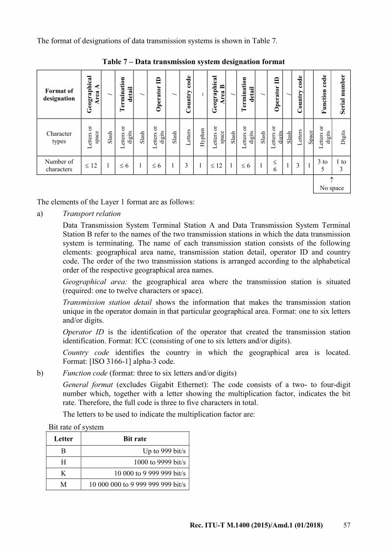
Rec. ITU-T M.1400 (2015)/Amd.1 (01/2018) 57
The format of designations of data transmission systems is shown in Table 7.
Table 7 – Data transmission system designation format
Format of
designation
Geo
gra
ph
ica
l
Are
a A
/
Ter
min
ati
on
det
ail
/
Op
era
tor
ID
/
Co
un
try
co
de
–
Geo
gra
ph
ica
l
Are
a B
/
Ter
min
ati
on
det
ail
/
Op
era
tor
ID
/
Co
un
try
co
de
Fu
nct
ion
co
de
Ser
ial
nu
mb
er
Character
types
Let
ters
or
spac
e
Sla
sh
Let
ters
or
dig
its
Sla
sh
Let
ters
or
dig
its
Sla
sh
Let
ters
Hy
ph
en
Let
ters
or
spac
e
Sla
sh
Let
ters
or
dig
its
Sla
sh
Let
ters
or
dig
its
Sla
sh
Let
ters
Sp
ace
Let
ters
or
dig
its
Dig
its
Number of
characters 12 1 6 1 6 1 3 1 12 1 6 1
6
1 3 1 3 to
5
1 to
3
No space
The elements of the Layer 1 format are as follows:
a) Transport relation
Data Transmission System Terminal Station A and Data Transmission System Terminal
Station B refer to the names of the two transmission stations in which the data transmission
system is terminating. The name of each transmission station consists of the following
elements: geographical area name, transmission station detail, operator ID and country
code. The order of the two transmission stations is arranged according to the alphabetical
order of the respective geographical area names.
Geographical area: the geographical area where the transmission station is situated
(required: one to twelve characters or space).
Transmission station detail shows the information that makes the transmission station
unique in the operator domain in that particular geographical area. Format: one to six letters
and/or digits.
Operator ID is the identification of the operator that created the transmission station
identification. Format: ICC (consisting of one to six letters and/or digits).
Country code identifies the country in which the geographical area is located.
Format: [ISO 3166-1] alpha-3 code.
b) Function code (format: three to six letters and/or digits)
General format (excludes Gigabit Ethernet): The code consists of a two- to four-digit
number which, together with a letter showing the multiplication factor, indicates the bit
rate. Therefore, the full code is three to five characters in total.
The letters to be used to indicate the multiplication factor are:
Bit rate of system
Letter Bit rate
B Up to 999 bit/s
H 1000 to 9999 bit/s
K 10 000 to 9 999 999 bit/s
M 10 000 000 to 9 999 999 999 bit/s

58 Rec. ITU-T M.1400 (2015)/Amd.1 (01/2018)
Specific format for Gigabit Ethernet: This code consists of three to five alphanumeric characters
which convey information about the rate of the signal for the digital transport system.
Bit rate of system
Bit rate Function code Description
1 Gb/s GE1 1 Gigabit Ethernet (see Note 2)
2.5 Gb/s GE2X 2.5 Gigabit Ethernet (see Note 3)
10 Gb/s
(see Note 4)
10GE 10 Gigabit Ethernet (generic)
GE10L 10 Gigabit Ethernet LAN
GE10W 10 Gigabit Ethernet WAN
40 Gb/s
(see Note 4)
40GE 40 Gigabit Ethernet (generic)
GE40L 40 Gigabit Ethernet LAN
GE40W 40 Gigabit Ethernet WAN
100 Gb/s
(see Note 4)
100GE 100 Gigabit Ethernet (generic)
GE100L 100 Gigabit Ethernet LAN (see Note 5)
GE100W 100 Gigabit Ethernet WAN (see Note 5)
NOTE 1 – The leading or ending "GE" indicate Gigabit Ethernet. Numbers
indicate bit rates in Gigabits per second. The suffix "L" indicates LAN at the
physical layer. The suffix "W" indicates WAN at the physical layer.
NOTE 2 – The "GE1" function code varies from the usual practice (in Rec. ITU-T
M.1400) of using a letter as a separator at the end of the function code. Therefore,
network operators/service providers, in particular, should take care to
communicate clearly when referring to circuits using this code. Further, no future
function codes ending with a digit will be created.
NOTE 3 – The "GE2X" function code varies from the general format (see above)
of using a letter showing the multiplication factor. In this case, the suffix "X"
indicates a fraction of a Gigabit.
NOTE 4 – When network operators/service providers agree to share separate
Layer 2 information, including differentiation between LAN PHY and WAN
PHY, the "10GE" (respectively, "40GE", "100GE") function code may be used. If
Layer 2 information is not shared, or does not include differentiation between
LAN PHY and WAN PHY, the specific function codes "GE10L" and "GE10W"
(respectively, "GE40L" and "GE40W", "GE100L" and "GE100W") are used to
differentiate between LAN PHY and WAN PHY at Layer 1.
NOTE 5 – Although function codes "GE100L" and "GE100W" do not conform
with the limitation to 5 characters in Table 7, they are kept for historical purposes.
The 100 GE technology supports both LAN PHY and WAN PHY, and
differentiation is not necessary. Therefore, 100 GE links should use function code
"100GE" unless use of "GE100L" or "GE100W" is specifically required.
c) Serial number (required: one to three digits)
Identifies the instance of the transmission system. The serial numbering starts anew if there
is a difference in transport relation and/or function code.
NOTE 3 – The use of the data transmission system (e.g., multiplex of digital leased circuits, broadcasting,
video) will be recorded in Related information under Item 9 (Use) (see clause 20.9).

Rec. ITU-T M.1400 (2015)/Amd.1 (01/2018) 59
Example 1:
The first 9600 bit/s data transmission system between Lisbon RM1 and New York (for example, in
use for a multiplex of 2400 bit/s and 7200 bit/s circuits):
Lisboa/RM1/VCE/PT/PRT–New York/56H/ATT/USA 96H1.
Example 2:
The eleventh 2048 kbit/s data transmission system between London and Paris (used, for example,
for a public video conference):
London/MNM/BTPLC/GBR–Paris/ARC/FRTE/FRA 2048K11.
Example 3:
The first 512 kbit/s data transmission system (in use as an intermediate data rate (IDR) satellite
carrier, rented from INTELSAT) between Dubai and Montreal satellite earth stations (used, for
example, for the public telephone service):
Dubai/ERD/MOPTT/SAU–Montreal/TGB/CAN 512K1.
Example 4:
The third 100 Gigabit Ethernet LAN data transmission system between Milan and Rome, Italy:
Milan/TI/ITA – Rome/TI/ITA GE100L3.
Figure 5 – Gigabit Ethernet LAN
17.2 Data transmission links
Data transmission links are designated as data transmission systems.
Example:
In TAT-9, several single bearers between New York and London are in operation, being rented
from the cable operating company by KPN Telecom in the Netherlands. The first single 64 kbit/s
bearer gets the designation:
London/XYZ/BTPLC/GBR–New York/ABC/ATT/USA 64K1.
NOTE 1 – The suffix has to be agreed between the cable operating company and KPN Telecom, or simply
by KPN.
NOTE 2 – If the bearer is in use for the leased circuit Amsterdam/ERT/TCOMNL/NLD–New
York/ABC/ATT/USA NP25, the occupancy is as follows:
London/XYZ/BTPLC/GBR–New York/ABC/ATT/USA 64K1
1. Amsterdam/TCOMNL/NLD–New York/ABC/ATT/USA NP25
Should the bearer be idle, the occupancy is: 1.

60 Rec. ITU-T M.1400 (2015)/Amd.1 (01/2018)
Reference is made to Annex B, which shows a more detailed example and the remaining part of
routing from London to Amsterdam.
17.3 Related information
The additional information on data transmission systems is covered by the following items:
1) urgency for restoration;
2) terminal countries;
3) names of network operators/service providers;
4) control and sub-control station(s);
5) fault report points;
6) routing;
7) association;
8) equipment information;
9) use;
10) transmission medium information;
11) composition of transmission;
12) (unassigned item, use: "–;");
13) occupancy.
The various items will be dealt with in clause 20.
18 Designations of digital block interconnections created by the interconnection of digital
circuit multiplication equipments (DCMEs)
18.1 General
The format of the designation of digital blocks created by the interconnection of digital circuit
multiplication equipments (DCMEs) is shown in Table 8.
Table 8 – DCME designation format
Format of
designation
Geo
gra
ph
ica
l
Are
a A
/
Ter
min
ati
on
det
ail
/
Op
era
tor
ID
/
Co
un
try
co
de
–
Geo
gra
ph
ica
l
Are
a B
/
Ter
min
ati
on
det
ail
/
Op
era
tor
ID
/
Co
un
try
co
de
Fu
nct
ion
co
de
Ser
ial
nu
mb
er
Character
types
Let
ters
or
spac
e
Sla
sh
Let
ters
or
dig
its
Sla
sh
Let
ters
or
dig
its
Sla
sh
Let
ters
Hy
ph
en
Let
ters
or
spac
e
Sla
sh
Let
ters
or
dig
its
Sla
sh
Let
ters
or
dig
its
Sla
sh
Let
ters
Sp
ace
Let
ters
or
dig
its
Dig
its
Number of
characters 12 1 6 1 6 1 3 1 12 1 6 1 6 1 3 1
2 to
4 4
No space
The elements of the Layer 1 format are as follows:

Rec. ITU-T M.1400 (2015)/Amd.1 (01/2018) 61
a) Transport relation
Digital block Terminal Point A and digital block Terminal Point B refer to the names of the
two transmission stations in which the digital block is terminating. The name of each
transmission station consists of the following elements: geographical area name,
transmission station detail, operator ID and country code. The order of the two transmission
stations is arranged according to alphabetical order of the respective geographical area
names.
Geographical area: the geographical area where the transmission station is situated
(required: one to twelve characters or space).
Transmission station detail shows the information that makes the transmission station
unique in the operator domain in that particular geographical area. Format: one to six letters
and/or digits.
Operator ID is the identification of the operator that created the transmission station
identification. Format: ICC (consisting of one to six letters and/or digits).
Country code identifies the country in which the geographical area is located. Format:
[ISO 3166-1] alpha-3 code.
b) Function code (format: two to four letters and/or digits)
This code consists of a number indicating the nominal maximum number of channels in the
block followed by the letter Y.
c) Serial number (required: one to four digits)
Identifies the instance of the digital block. The serial numbering starts anew if there is a
difference in transport relation and/or function code.
Example 1:
The second block created by the interconnection of DCMEs with a nominal maximum number of
240 channels between Frankfurt and Melbourne will be designated:
Frankfurt/1WE/DTAG/DEU–Melbourne/34R/TELSTR/AUS 240Y2.
Example 2:
A block is created by the interconnection of DCMEs, and routed via a 512 kbit/s data transmission
system. This data transmission system is an intermediate data rate (IDR) digital satellite carrier
rented from INTELSAT (with 8 64 kbit/s bearer channels). Only one port will be used at both
DCMEs. The first of such blocks to be established between Lisbon and Hong Kong will be
designated:
Hong Kong/4RT/CWHKTI/HKG–Lisboa/RFV/PT/PRT 30Y1.
18.2 Multi-clique configuration of DCMEs
If the created block is partly directed to destination B and partly to C (Figure 6) the designation of
the blocks is:
Geographical Area A/Transmission station detail/ICC/CC–Geographical Area B/Transmission
station detail/ICC/CC n1n1n1 Y xxxx
Geographical Area A/Transmission station detail/ICC/CC–Geographical Area B/Transmission
station detail/ICC/CC n2n2n2 Y xxxx
– n1n1n1, n2n2n2 are the numbers of channels dedicated to that relation (multiples of 30);
– n1n1n1 + n2n2n2 the capacity of the DCME.

62 Rec. ITU-T M.1400 (2015)/Amd.1 (01/2018)
Example:
London/EDC/BTPLC/GBR–New York/EV1/ATT/USA 120Y1
London/EDC/BTPLC/GBR–Pittsburgh/VBE/ATT/USA 120Y1
Figure 6 – DCME configuration A
The same designation applies to the configuration in Figure 7 (A1 – B1, A1 – B2, A2 – B1 and
A2 – B2).
Figure 7 – DCME configuration B
18.3 Low-rate encoding equipment
Low-rate encoding equipment is considered as a special case of DCMEs.
If two of these equipment components are linked, by using a 2-Mbit/s path, the designation 60Y
(if multiplication factor 2) should be applied.
For low-rate encodings (LREs) linked by paths with other bit rates, the function code to be used is
also dependent on the nominal maximum number of channels allowed by the configuration.
Example:
A block is created by the interconnection of LREs, and routed via a 512-kbit/s data transmission
system. This data transmission system is an IDR digital satellite carrier rented from INTELSAT
(with 8 64 kbit/s bearer channels). The multiplication factor is 2. The first of such blocks to be
established between Rome and Beijing will be designated:
Beijing/11W/CT/CHN–Roma/ECB/TI/ITA 16Y1.
18.4 Related information
The additional information digital blocks created by the interconnection of DCMEs are covered by
the following items:

Rec. ITU-T M.1400 (2015)/Amd.1 (01/2018) 63
1) urgency for restoration;
2) terminal countries;
3) names of network operators/service providers;
4) control and sub-control station(s);
5) fault report points;
6) routing;
7) association;
8) equipment information;
9) use;
10) transmission medium information;
11) operational agreement;
12) bit rate;
13) occupancy.
The various items will be dealt with in clause 20.
19 Synchronous digital hierarchy (SDH)
19.1 Designation of multiplex sections of the synchronous digital hierarchy (SDH)
19.1.1 General
This clause deals with multiplex sections of the synchronous digital hierarchy (SDH) synchronous
transport modules (STMs) as defined in [ITU-T G.707]. When a multiplex section route includes a
transit network, clause 23 applies.
The format of designation of multiplex sections is shown in Table 9:
Table 9 – Multiplex section designation format
Format of
designation
Geo
gra
ph
ica
l
Are
a A
/
Ter
min
ati
on
det
ail
/
Op
era
tor
ID
/
Co
un
try
co
de
–
Geo
gra
ph
ica
l
Are
a B
/
Ter
min
ati
on
det
ail
/
Op
era
tor
ID
/
Co
un
try
co
de
Fu
nct
ion
co
de
Ser
ial
nu
mb
er
Character
types
Let
ters
or
spac
e
Sla
sh
Let
ters
or
dig
its
Sla
sh
Let
ters
or
dig
its
Sla
sh
Let
ters
Hy
ph
en
Let
ters
or
spac
e
Sla
sh
Let
ters
or
dig
its
Sla
sh
Let
ters
or
dig
its
Sla
sh
Let
ters
Sp
ace
Let
ters
or
dig
its
Dig
its
Number of
characters 12 1 6 1 6 1 3 1
12
1 6 1 6 1 3 1 2 to
4
1 to
3
No space
The elements of the Layer 1 format are as follows:

64 Rec. ITU-T M.1400 (2015)/Amd.1 (01/2018)
a) Transport relation
Multiplex section Terminal Point A and multiplex section Terminal Point B refer to the
names of the two transmission stations in which the multiplex section is terminating. The
name of each transmission station consists of the following elements: geographical area
name, transmission station detail, operator ID and country code. The order of the two
transmission stations is arranged according to alphabetical order of the respective
geographical area names.
Geographical area: the geographical area where the transmission station is situated
(required: one to twelve characters or space).
Transmission station detail shows the information that makes the transmission station
unique in the operator domain in that particular geographical area. Format: one to six letters
and/or digits.
Operator ID is the identification of the operator that created the transmission station
identification. Format: ICC (consisting of one to six letters and/or digits).
Country code identifies the country in which the geographical area is located. Format:
[ISO 3166-1] alpha-3 code.
b) Function code (format: two to four letters and/or digits)
This code consists of a number (one to three digits) indicating the nominal number of
VC-4s which can be carried by the multiplex section, followed by the letter S.
NOTE – Network operators/service providers should refer to clause 17.1 for function codes of
2.5 Gb/s in Ethernet applications because 2.5 Gb/s is predominantly used in SONET/SDH
networks. This clause 19 applies only to SDH transmission.
c) Serial number (required: one to three digits)
Identifies the instance of the multiplex section. The serial numbering starts anew if there is
a difference in transport relation and/or function code.
Example:
The eleventh multiplex section STM-16 (bit rate = 16 155 Mbit/s) between London and Paris is
designated:
London/22D/BTPLC/GBR–Paris/ARC/FRTE/FRA 16S11.
19.1.2 Related information
The additional information on multiplex sections is covered by the following items:
1) urgency for restoration;
2) terminal countries;
3) names of network operators/service providers;
4) control and sub-control station(s);
5) fault report points;
6) routing;
7) association;
8) equipment information;
9) use;
10) transmission medium information;
11) operational agreement;
12) bit rate;

Rec. ITU-T M.1400 (2015)/Amd.1 (01/2018) 65
13) occupancy;
14) access point identifiers.
The various items will be dealt with in clause 20.
19.2 Designations of virtual container interconnections
19.2.1 General
This clause refers to virtual containers (VCs) of the synchronous digital hierarchy as defined in
[ITU-T G.707]. When a virtual container route includes a transit network, clause 23 applies. The
format of the designation of virtual containers is shown in Table 10.
Table 10– Virtual container designation format
Format of
designation
Geo
gra
ph
ica
l
Are
a A
/
Ter
min
ati
on
det
ail
/
Op
era
tor
ID
/
Co
un
try
co
de
–
Geo
gra
ph
ica
l
Are
a B
/
Ter
min
ati
on
det
ail
/
Op
era
tor
ID
/
Co
un
try
co
de
Fu
nct
ion
co
de
Ser
ial
nu
mb
er
Character
types
Let
ters
or
spac
e
Sla
sh
Let
ters
or
dig
its
Sla
sh
Let
ters
or
dig
its
Sla
sh
Let
ters
Hy
ph
en
Let
ters
or
spac
e
Sla
sh
Let
ters
or
dig
its
Sla
sh
Let
ters
or
dig
its
Sla
sh
Let
ters
Sp
ace
Let
ters
or
dig
its
Dig
its
Number of
characters 12 1 6 1 6 1 3 1 12 1 6 1 6 1 3 1
4 to
5 4
No space
The elements of the Layer 1 format are as follows:
a) Transport relation
Data transmission system Terminal Point A and data transmission system Terminal Point B
refer to the names of the two transmission stations in which the data transmission system is
terminating. The name of each transmission station consists of the following elements:
geographical area name, transmission station detail, operator ID and country code. The
order of the two transmission stations is arranged according to alphabetical order of the
respective geographical area names.
Geographical area: the geographical area where the transmission station is situated
(required: one to twelve characters or space).
Transmission station detail shows the information that makes the transmission station
unique in the operator domain in that particular geographical area. Format: one to six letters
and/or digits.
Operator ID is the identification of the operator that created the transmission station
identification. Format: ICC (consisting of one to six letters and/or digits).
Country code identifies the country in which the geographical area is located. Format:
[ISO 3166-1] alpha-3 code.
b) Function code (format: four to five letters and/or digits)
This code is the following:
VC11S for a VC-11 virtual container
VC12S for a VC-12 virtual container
VC2S for a VC-2 virtual container

66 Rec. ITU-T M.1400 (2015)/Amd.1 (01/2018)
VC3S for a VC-3 virtual container
VC4S for a VC-4 virtual container
Function codes for concatenated virtual containers are covered by clause 19.3.
c) Serial number (required: one to four digits)
Identifies the instance of the virtual container. The serial numbering starts anew if there is a
difference in transport relation and/or function code.
Example:
The tenth VC-4 virtual container between Barcelona and Toulouse is designated:
Barcelona/ECT/TFCAES/ESP–Toulouse/CVB/FRTE/FRA VC4S10.
19.2.2 Related information
The additional information on virtual containers is covered by the following items:
1) urgency for restoration;
2) terminal countries;
3) names of network operators/service providers;
4) control and sub-control station(s);
5) fault report points;
6) routing;
7) association;
8) equipment information;
9) use;
10) transmission medium information;
11) operational agreement;
12) (unassigned item, use: ";");
13) occupancy;
14) access point identifiers.
The various items will be dealt with in clause 20.
19.3 Concatenated virtual containers
Concatenated virtual containers (VCs) are a group of virtual containers which are being
concatenated. Such a concatenation configuration provides higher payload capability because the
overhead in all but one virtual container is removed. The configuration therefore is a transport entity
and receives a discrete designation.
Concatenation can have two forms: contiguous and virtual. Contiguous refers to the configuration
where the individual containers are in time slot order, whilst virtual concatenation refers to the
configuration where the individual containers are spread over various time slots. The network
management system keeps track of the actual configuration.
The configurations are called in the operational field according to an expression using the letters
VC followed by a hyphen followed by the VC level followed by a hyphen followed by the number
of concatenated virtual containers followed by the letter v or c depending on the type of
concatenation, so contiguous or virtual; example: VC-4-4c.
This operational expression is used to explain the use of function codes for concatenated virtual
containers.

Rec. ITU-T M.1400 (2015)/Amd.1 (01/2018) 67
The function codes for concatenated virtual containers follows the scheme shown below:
For contiguous concatenation and virtual concatenation respectively the function codes are:
mVpC and mVpV with,
m V p C/V
m indicating the number of concatenated VCs up to 256 (maximum three
digits)
V defining that it is a Virtual container (one letter )
p indicating the VC level (2, 4, 11, 12) (maximum two digits)
C defining that it is a Contiguous concatenated VC (one letter)
or V defining that it is a Virtual concatenated VC (one letter) }
Use of function codes for various payload types:
Payload type Function code
3 virtual concatenated VC-12's VC-12-3v 3V12V
5 contiguous concatenated VC-2's VC-2-5c 5V2C
4 contiguous concatenated VC-4's VC-4-4c 4V4C
4 virtual concatenated VC-4's VC-4-4v 4V4V
16 contiguous concatenated VC-4's VC-4-16c 16V4C
256 contiguous concatenated VC-4's VC-4-256c 256V4C
Example:
The third group of 16 contiguous concatenated VC-4's of payload type VC-4-16c, between Denver
and Grenoble is designated:
Denver/ABC/ATT/USA–Grenoble/EC1/FRTE/FRA 16V4C3.
NOTE – Network operators/service providers should refer to clause 17.1 for function codes of 2.5 Gb/s in
Ethernet applications because 2.5 Gb/s is predominantly used in SONET/SDH networks. This clause 19
applies only to SDH transmission.
19.4 Leased circuits based on SDH
19.4.1 General
By placing SDH terminal equipment at users' premises, a leased circuit service can be offered to
such users. This clause deals with these leased circuit types. When a leased circuit based on an SDH
route includes a transit network, clause 23 applies.
Various configurations apply:
– terminal equipment at both sides is owned by a network operator/service provider (type A);
or
– by the end user (type B); or
– on one side by the operator and on the other side by the user (type C).
In case A, a fully managed leased circuit service is offered. The connection is a normal trail;
namely, a virtual container. The use of the virtual container is expressed by a leased circuit service.
In the case of type B and C at the side, where the terminal equipment is owned by the user, one has
to identify a point where the connection is deemed to terminate and is handed over to the user; the
role of such a point is expressed by the network terminating equipment (NTE). Because the

68 Rec. ITU-T M.1400 (2015)/Amd.1 (01/2018)
connection is not terminating in the regular way, i.e., in the path terminating equipment (PTE), this
is not a trail according to the definition of [ITU-T G.803]. Instead, this is a so-called tandem
connection. In these cases no end-to-end managed connection is offered by the network
operator/service provider to the user. The connection can only be partially managed.
19.4.2 Designations
The designation format is according to clause 9. However, new function codes apply. To that end, a
distinction is made between the fully managed and the partially managed types:
– For partially managed SDH leased circuits, the function code is: HP;
– For fully managed SDH leased circuits, the function code is: MHP.
19.4.3 Application
In case A, a virtual container is running from one user location to the other; it will receive a
designation according to clause 19: so, for a VC12: Geographical Area A/termination
detail/ICC/CC–Geographical Area B/termination detail/ICC/CC VC12S1
The leased circuit designation then will read: Geographical Area A/termination
detail/ICC/CC-Geographical Area B/termination detail/ICC/CC MHP1
In the cases B and C, a tandem connection is running; a new function code applies: TCxxS where
xx can take the values 12, 3 and 4.
The tandem connection will receive a designation as follows:
Geographical Area A/termination detail/ICC/CC–Geographical Area B/termination detail/ICC/CC
TC12S1 and the leased circuit a designation:
Geographical Area A/termination detail/ICC/CC–Geographical Area B/termination
detail/ICC/CC HP1.
It should be noted that function codes for leased circuits based on other network configurations,
e.g., mixed PDH/SDH, require further study.
19.4.4 Related information
This is left for further study. This will be organized within clause 20.
20 Related information for digital block, path, data transmission system, block
interconnections created by the interconnection of DCMEs, SDH multiplex sections
and virtual containers
The following subclauses explain the items of related information concerned with interconnecting
digital blocks, paths, data transmission systems, blocks created by the interconnection of DCMEs,
virtual containers and SDH multiplex sections. Full examples of the designation information of an
interconnecting digital block, an interconnecting digital path, an interconnecting data transmission
system, an interconnecting block created by the interconnection of DCMEs, an interconnecting
virtual container and an interconnecting SDH multiplex section are given in clause A.4.
20.1 Urgency for restoration [item 1]
This item supplies information on the urgency of restoration of the block, path, etc., based upon
bilateral agreement between the terminal network operators/service providers.
Format:
1. xx ... xx; (maximum ten characters)

Rec. ITU-T M.1400 (2015)/Amd.1 (01/2018) 69
Illustration:
a) If the priority is top: 1;
If the priority is second: 2;
If the priority is third: 3; or
b) If repair is required within, e.g., 24 hours: 24 h; or
c) If no urgency has to be indicated: –;
Example:
If a block needs top priority in the case of restoration:
1. 1;
20.2 Terminal countries [item 2]
This item presents the countries in which the block, path, etc., is terminating.
Format:
2. XXX, YYY; (three characters for each) or two. XXX;
Specification:
XXX: code for country of Geographical Area A
YYY: code for country of Geographical Area B
In the case of multiple destination unidirectional block, only XXX applies.
NOTE – The alpha-3 codes are according to [ISO 3166-1].
Example:
For a digital block Bruxelles/ERY/BGACOM/BEL–Frankfurt/EVT/DTAG/DEU 120N1:
2. BEL, DEU;
20.3 Names of network operators/service providers [item 3]
This item records the names of the carriers, etc., which operate the block, path, etc. The applicable
carrier codes can be selected from the List of ITU Carrier Codes as described in clause 6.4.
Format:
3. XXXXXX, YYYYYY; (maximum six characters for each) or three. XXXXXX;
Specification:
XXXXXX: name of company in Geographical Area A
YYYYYY: name of company in Geographical Area B
In the case of a multiple destination unidirectional block, only XXXXXX applies.
Example:
For a digital block Frankfurt/EVT/DTAG/DEU–London/CCB/BTPLC/GBR 30N1 operated by
Deutsche Telekom and BT (British Telecom):
3. DTAG, BTPLC;

70 Rec. ITU-T M.1400 (2015)/Amd.1 (01/2018)
20.4 Control station [sub-control station(s)] [item 4]
This item lists the appointed control station and sub-control stations (according to [ITU-T M.80]
and [ITU-T M.90]). Further details about the stations can be found in the list of contact points in
[ITU-T M.1510].
Format:
4. CS: designation of control station,
SCS1: designation of sub-control station,
SCS2: designation of sub-control station,
M M
SCSn: designation of sub-control station,
or, in the case of a multiple destination unidirectional block:
4. CS: designation of control station.
Specification:
CS: designation of the control station,
SCS1: designation of the terminal sub-control station,
SCS2 to SCSn: if applicable, other sub-control stations are to be placed in the geographical
order according to the traffic relation.
In the case of a multiple destination unidirectional block, only CS applies.
Example 1:
For the digital block Stockholm/ECC/TELIA/SWE–Venezia/XX1/TI/ITA 30N1 with control station
Stockholm and sub-control stations Venezia and Paris:
4. CS: Stockholm/HAM/TELIA/SWE;
SCS1: Venezia/CEN/TI/ITA;
SCS2: Paris/ARC/FRTE/FRA;
Example 2:
For the digital block Rio de Janei/E1X/EBTLBR/BRA–(MU) 30N1:
4. CS: Rio de Janei/1/EBTLBR/BRA:
20.5 Fault report points [item 5]
This item presents the names of both fault report points on the block, path, etc., (according to
[ITU-T M.2130]). Further details about the fault report points can be found in the list of contact
points in [ITU-T M.1510].
Format:
5. Designation of fault report point, Designation of fault report point
or
5. Designation of fault report point;
Specification:
The first fault report point is that of the country of Geographical Area A.
The second fault report point is that of the country of Geographical Area B.

Rec. ITU-T M.1400 (2015)/Amd.1 (01/2018) 71
In the case of a multiple destination unidirectional block, the second station and the comma are
omitted.
Example 1:
For the digital block Lisboa/EC1/PT/PRT–Zurich/CCB/CHEPTT/CHE 30N1:
5. Lisboa/PCS/PT/PRT, Zurich/SEL/CHEPTT/CHE;
Example 2:
For the digital block Jakarta/2WS/INDSAT/IDN–(MU) 30N1:
5. Jakarta/1/INDSAT/IDN;
20.6 Routing [item 6]
This item records the next higher block within the multiplex hierarchy on which the block, path,
virtual container, multiplex sections, etc., have been routed and the position number, or in the case
of the highest multiplex level, the transmission media on which the block has been routed.
Format:
6. Designation of an interconnecting block/position number or designation of transmission
medium, Designation of an interconnecting block/position number or designation of
transmission medium, ..., Designation of an interconnecting block/position number or
designation of transmission medium.
NOTE 1 – For the case of a lower order virtual container (VC), the position number should be given using
KLM addressing. KLM addressing is described in clause 7.3 of [ITU-T G.707]. Also, refer to Annex B for a
description of how KLM addressing relates to time slot numbering.
NOTE 2 – Two consecutive unidirectional blocks are separated by a + sign instead of a comma.
NOTE 3 – For contiguous concatenation of lower order virtual containers the KLM-addressing applies as for
normal virtual containers; for the concatenation of VC-4s and for virtual concatenation of all VC levels the
time slot numbering must be applied.
Specification:
The designation of an interconnecting block refers to the next higher level in the digital multiplex
hierarchy. If there is more than one, the blocks are noted in geographical order from Geographical
Area A to Geographical Area B.
The designation of the transmission medium refers to the transmission medium leaving the country
of Geographical Area A and to the transmission medium entering the country of Geographical Area
B respectively.
As no ITU-T designations of transmission media, nor digital line or radio sections, are
recommended for the time being, the terminal countries should provide designations or agree on
designations.
If there is only one transmission medium, the designation of this medium applies.
Example 1:
For the primary digital block Frankfurt/DCF/DTAG/DEU–Zurich/37T/CHEPTT/CHE 30N7:
6. Frankfurt/DCF/DTAG/DEU–Zurich/37T/CHEPTT/CHE 120N1/3;
Example 2:
For the block Bruxelles/2WS/BGACOM/BEL–London/CBN/BTPLC/GBR 1920N1, with
transmission medium corresponding to submarine cable:
6. Bruxelles/2WS/BGACOM/BEL–London/CBN/BTPLC/GBR 5;

72 Rec. ITU-T M.1400 (2015)/Amd.1 (01/2018)
20.7 Association [item 7]
This item identifies whether there are associated blocks, paths, data transmission systems, digital
blocks created between DCMEs, virtual containers and SDH multiplex sections, and if so, of what
type.
Format:
7. Association code: designation(s) of the associated block(s), path(s), etc.;
Further study is needed on the development of association codes for (shared) protection of SDH
multiplex sections.
20.7.1 Information on reserve blocks, paths, data transmission systems created digital blocks
between DCMEs, virtual containers and multiplex sections
Specification:
If the block has a reserve block, the association code is: S followed by the function code and the
serial number of the principal block.
If the block is a reserve block, the association code is: function code followed by S and the serial
number of the reserve block.
The same applies for digital paths, data transmission systems, etc.
Example:
If the path Hongkong/11W/CWHKTI/HKG–Singapore/SSD/ST/SGP 30N801 is the restoration path
for the normal block Hongkong/11W/CWHKTI/HKG–Singapore/SSD/ST/SGP 30N3, the Related
information for the normal block under Association must show:
7. S30N3: Hongkong/11W/CHKTI/HKG–Singapore/SSD/ST/SGP 30N801;
20.7.2 Information on diverse routing
Specification:
If a block is required to be routed on a different route than other blocks, the association code is
DVR followed by the designation of the other blocks.
The same applies for digital paths, data transmission systems, etc.
Example:
If a block Amsterdam/CBN/TCOMNL/NLD–Paris/ARC/FRTE/FRA 30N7 is required to be routed
on a different route than the blocks Amsterdam/CBN/TCOMNL/NLD–Bruxelles/VVC/BGACOM/
BEL 30N12 and Bruxelles/VVC/BGACOM/BEL–Paris/ARC/FRTE/FRA 30N2, the related
information for the block Amsterdam/CBN/TCOMNL/NLD–Paris/ARC/FRTE/FRA 30N7 under
Association must show:
7. DVR: Amsterdam/CBN/TCOMNL/NLD–Bruxelles/VVC/BGACOM/BEL 30N12,
Bruxelles/VVC/BGACOM/BEL–Paris/ARC/FRTE/FRA 30N2;
NOTE – The codes listed in clauses 20.7.1 and 20.7.2 may both appear under Association.
20.7.3 Information on consecutive routing
Specification:
If the time slots in a block carry traffic that is consecutively routed on single bearers, the block and
the single bearers get an Association code, namely:
PLR = part of a longer route.

Rec. ITU-T M.1400 (2015)/Amd.1 (01/2018) 73
Example:
If five single bearers (see the example in 12.2) are connected in London to five time slots in the
interconnecting 2 Mbit/s digital block Amsterdam/PTT/TCOMNL/NLD–
London/XYZ/BTPLC/GBR 30N1 the Association is as follows:
Amsterdam/PTT/TCOMNL/NLD–London/XYZ/BTPLC/GBR 30N1
7. PLR: London/XYZ/BTPLC/GBR–New York/ABC/ATT/USA 64K1
London/XYZ/BTPLC/GBR–New York/ABC/ATT/USA 64K2
London/XYZ/BTPLC/GBR–New York/ABC/ATT/USA 64K3
London/XYZ/BTPLC/GBR–New York/ABC/ATT/USA 64K4
London/XYZ/BTPLC/GBR–New York/ABC/ATT/USA 64K5
Similar for each of the single bearers, e.g., for London/XYZ/BTPLC/GBR–New
York/ABC/ATT/USA 64K1:
7. PLR: London/XYZ/BTPLC/GBR–New York/ABC/ATT/USA 30N1
20.7.4 Information on maintaining the sequential order of digital paths (concatenation)
Specification:
If a couple of digital paths together support a service, it may be required to maintain the sequential
order of the paths when multiplexed into a higher order block or container. In that case the
designations of the paths get an Association code on concatenation, namely TSG = time slot
sequential order must be guaranteed on an end-to-end basis; the format then is: 7. TSG followed by
the function code and the sequential numbers of all concatenated digital paths including those of the
path under consideration.
Example:
Three interconnecting 2-Mbit/s digital paths together support a video service, namely
Lisboa/X1Y/PT/PRT–Milano/TI1/TI/ITA 30N21, Lisboa/X1Y/PT/PRT–Milano/TI1/TI/ITA 30N22,
Lisboa/X1Y/PT/PRT–Milano/TI1/TI/ITA 30N23;
They must stay concatenated when they are being multiplexed into a virtual container and therefore
each of their designations gets the Association code TSG followed by function code and the
sequential numbers of all three concatenated 2 Mbit/s digital paths: Lisboa/X1Y/PT/PRT–Milano/
TI1/TI/ITA 30N22 has under Related information item 7:
7. TSG: 30N21-23
20.8 Equipment information [item 8]
20.8.1 This item records information on equipment in the block, path, etc., which requires special
maintenance attention.
Format:
8. XX, XX, XX, XX;
Specification:
If the block has been routed via TDMA: TD.
If the block has been created by the interconnection of two transcoders (low-rate encoding
equipment) using the A-law: AI or -law: MI.
NOTE – If there is a need to record any additional equipment information, the next free codeplaces are
available for that purpose. The codes to be used must consist of two characters, be unique and can be chosen
by bilateral agreement between network operators/service providers.
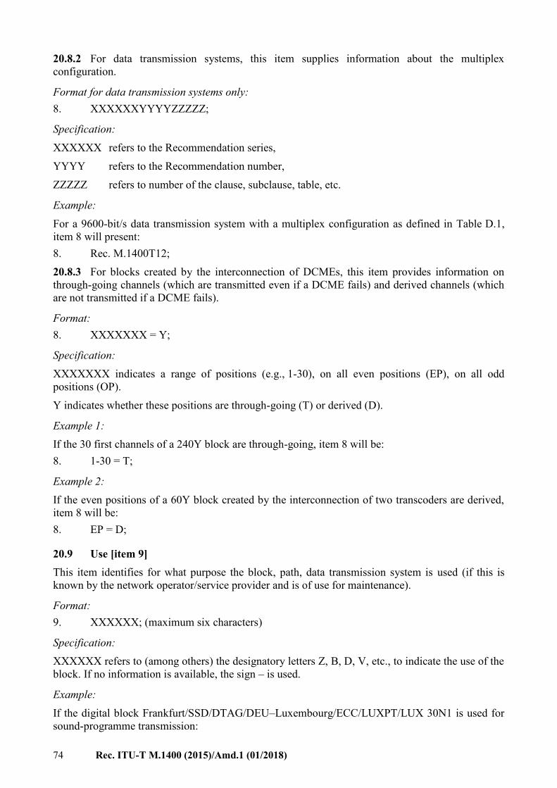
74 Rec. ITU-T M.1400 (2015)/Amd.1 (01/2018)
20.8.2 For data transmission systems, this item supplies information about the multiplex
configuration.
Format for data transmission systems only:
8. XXXXXXYYYYZZZZZ;
Specification:
XXXXXX refers to the Recommendation series,
YYYY refers to the Recommendation number,
ZZZZZ refers to number of the clause, subclause, table, etc.
Example:
For a 9600-bit/s data transmission system with a multiplex configuration as defined in Table D.1,
item 8 will present:
8. Rec. M.1400T12;
20.8.3 For blocks created by the interconnection of DCMEs, this item provides information on
through-going channels (which are transmitted even if a DCME fails) and derived channels (which
are not transmitted if a DCME fails).
Format:
8. XXXXXXX = Y;
Specification:
XXXXXXX indicates a range of positions (e.g., 1-30), on all even positions (EP), on all odd
positions (OP).
Y indicates whether these positions are through-going (T) or derived (D).
Example 1:
If the 30 first channels of a 240Y block are through-going, item 8 will be:
8. 1-30 = T;
Example 2:
If the even positions of a 60Y block created by the interconnection of two transcoders are derived,
item 8 will be:
8. EP = D;
20.9 Use [item 9]
This item identifies for what purpose the block, path, data transmission system is used (if this is
known by the network operator/service provider and is of use for maintenance).
Format:
9. XXXXXX; (maximum six characters)
Specification:
XXXXXX refers to (among others) the designatory letters Z, B, D, V, etc., to indicate the use of the
block. If no information is available, the sign – is used.
Example:
If the digital block Frankfurt/SSD/DTAG/DEU–Luxembourg/ECC/LUXPT/LUX 30N1 is used for
sound-programme transmission:

Rec. ITU-T M.1400 (2015)/Amd.1 (01/2018) 75
9. R;
20.10 Transmission medium information [item 10]
This item identifies whether a satellite is involved in the routing.
Format:
10. ST; or –;
Specification:
If the block has been routed via satellite: ST
If the block has not been routed via satellite: –.
Example:
For the block Paris/ARC/FRTE/FRA–(MU) 30N1:
10. ST;
20.11 End-to-end information or composition of transmission or operational agreement
[item 11]
20.11.1 End-to-end information (for blocks and paths on mixed analogue/digital routes only)
This item provides information on the destinations of the traffic carried by the block or path.
Format:
11. X ... X, Y ... Y; (maximum 12 characters each) or –;
Specification:
X ... X and Y ... Y are the names of a geographical area and refer to the destinations of the traffic on
the block/path. The destinations are placed according to the order of geographical areas in the traffic
relation.
If the block has multiple destinations, the Geographical area name is replaced by the code: M.
If the block is within a digital environment X ... X, Y ... Y is replaced by the sign –.
Example 1:
For primary digital block Frankfurt/MMN/DTAG/DEU–Paris/ARC/FRTE/FRA 30NC6 carrying
from Frankfurt–London:
11. Frankfurt, London;
Example 2:
For primary block Amsterdam/EC2/TCOMNL/NLD–Bruxelles/EXX/BGACOM/BEL 30NC146
carrying traffic from London to Luxembourg:
11. London, Luxembourg;
20.11.2 Composition of transmission (for data transmission systems)
This item shows the type of transmission on the data transmission system.
Format:
11. A; N; or C;
Specification:
If the transmission is analogue: A
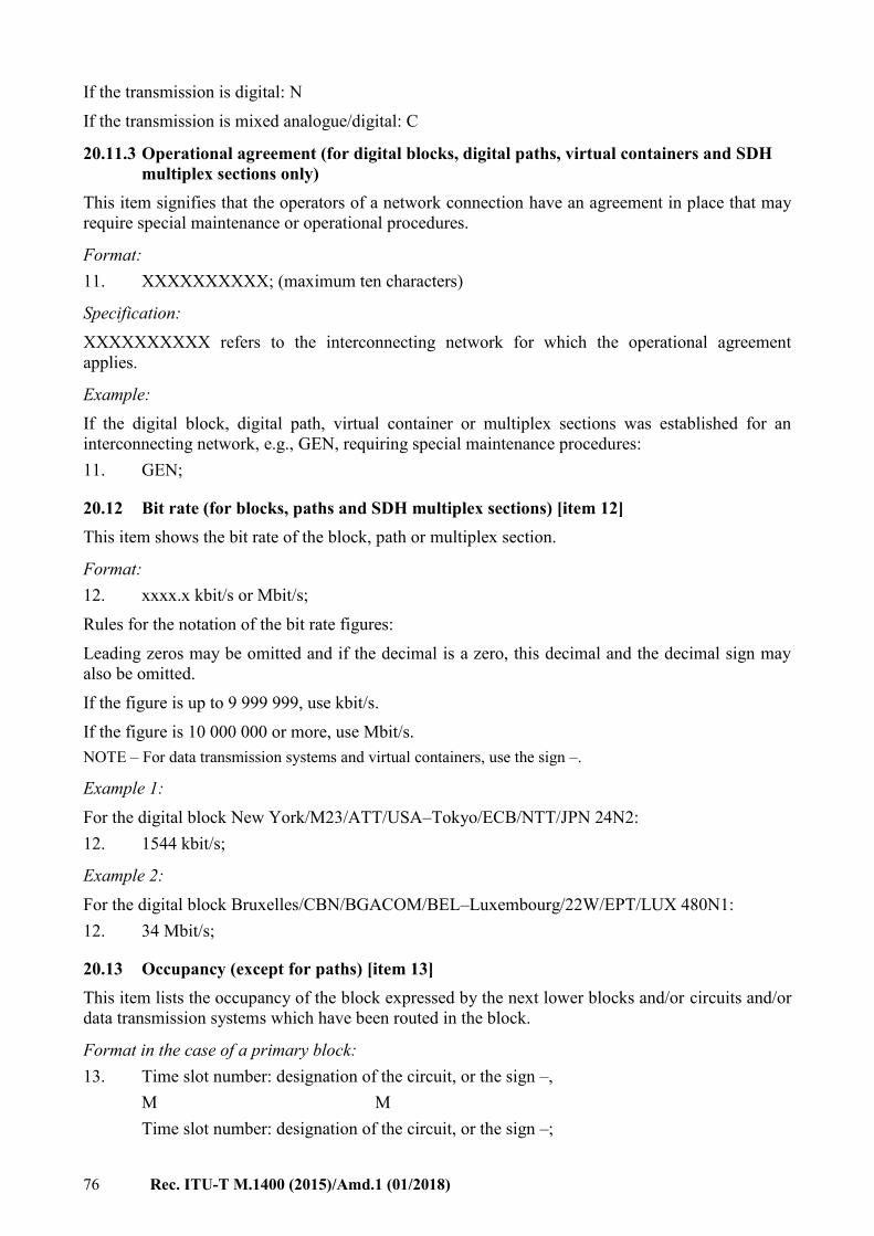
76 Rec. ITU-T M.1400 (2015)/Amd.1 (01/2018)
If the transmission is digital: N
If the transmission is mixed analogue/digital: C
20.11.3 Operational agreement (for digital blocks, digital paths, virtual containers and SDH
multiplex sections only)
This item signifies that the operators of a network connection have an agreement in place that may
require special maintenance or operational procedures.
Format:
11. XXXXXXXXXX; (maximum ten characters)
Specification:
XXXXXXXXXX refers to the interconnecting network for which the operational agreement
applies.
Example:
If the digital block, digital path, virtual container or multiplex sections was established for an
interconnecting network, e.g., GEN, requiring special maintenance procedures:
11. GEN;
20.12 Bit rate (for blocks, paths and SDH multiplex sections) [item 12]
This item shows the bit rate of the block, path or multiplex section.
Format:
12. xxxx.x kbit/s or Mbit/s;
Rules for the notation of the bit rate figures:
Leading zeros may be omitted and if the decimal is a zero, this decimal and the decimal sign may
also be omitted.
If the figure is up to 9 999 999, use kbit/s.
If the figure is 10 000 000 or more, use Mbit/s.
NOTE – For data transmission systems and virtual containers, use the sign –.
Example 1:
For the digital block New York/M23/ATT/USA–Tokyo/ECB/NTT/JPN 24N2:
12. 1544 kbit/s;
Example 2:
For the digital block Bruxelles/CBN/BGACOM/BEL–Luxembourg/22W/EPT/LUX 480N1:
12. 34 Mbit/s;
20.13 Occupancy (except for paths) [item 13]
This item lists the occupancy of the block expressed by the next lower blocks and/or circuits and/or
data transmission systems which have been routed in the block.
Format in the case of a primary block:
13. Time slot number: designation of the circuit, or the sign –,
M M
Time slot number: designation of the circuit, or the sign –;

Rec. ITU-T M.1400 (2015)/Amd.1 (01/2018) 77
Format in the case of a secondary or higher level block:
13. Position number: designation of a block, of a leased circuit, of a data transmission system
or the sign –,
M M
Position number: designation of a block, of a leased circuit, of a data transmission system
or the sign –;
Format in the case of a data transmission system:
1. Position number: designation of the circuit,
M M
n. Position number: designation of the circuit;
NOTE – Alternatively, instead of the position number, the channel numbering according to Annex D may be
applied.
Specification:
If the position number is occupied by a next lower digital block: designation of this block.
If the position number is occupied by a digital leased circuit (with a bit rate corresponding to the bit
rate of the next lower multiplex level): designation of this leased circuit.
If the position number is occupied by a data transmission system (with a bit rate corresponding to
the bit rate of the next lower multiplex level): designation of this data transmission system.
If the position number is not in use: the sign –.
Format in the case of virtual containers
For higher order VCs:
13. KLM number: designation of the lower order VC,
M M
KLM number: designation of the lower order VC;
For lower order VCs:
13. Designation of the digital block or digital path carried in this VC;
Format in the case of SDH multiplex sections
13. Position number: designation of the carried VC,
M M
Position number: designation of the carried VC;
Example 1:
For the digital block Genève/XXV/CHEPTT/CHE–Paris/ARC/FRTE/FRA 120N2:
13. 01: Genève/XXV/CHEPTT/CHE–Lisboa/XZX/PT/PRT 30N1,
02: –,
03: Genève/XXV/CHEPTT/CHE–Paris/ARC/FRTE/FRA 2048K1,
04: Bruxelles/23Z/BGACOM/BEL–Wien/XCX/RLSCOM/AUT 30N1;
Example 2:
For the digital block New York/24/ATT/USA–Paris/PT2/FRTE/FRA 24N5:
13. 01: New York/24/ATT/USA–Paris/PT2/FRTE/FRA Z1,
02: New York/24/ATT/USA–Paris/PT2/FRTE/FRA Z3,

78 Rec. ITU-T M.1400 (2015)/Amd.1 (01/2018)
03: New York/24/ATT/USA–Paris/PT2/FRTE/FRA Z5,
04: Paris/PT2/FRTE/FRA–New York/24/ATT/USA Z2,
05: Paris/PT2/FRTE/FRA–New York/24/ATT/USA Z4,
06: Paris/PT2/FRTE/FRA–New York/24/ATT/USA Z6,
07: –,
08: –,
09: –,
10: Orlando/TS1/ATT/USA–Toulouse/FER/FRTE/FRA 64K1,
11: –,
12: –,
13: –,
14: –,
15: New York/TS1/ATT/USA–Paris/ARC/FRTE/FRA R1,
16: New York/TS1/ATT/USA–Paris/ARC/FRTE/FRA R3,
17: –,
18: –,
19: –,
20: Paris/BEA/FRTE/FRA–Washington/TS1/ATT/USA NP1,
21: –,
22: –,
23: –,
24: –;
Example 3:
For the VC-4 Paris/ARC/FRTE/FRA–Roma/23T/TI/ITA VC4S12:
13. 1,0,0: Napoli/EC/TI/ITA–Paris/ARC/FRTE/FRA VC3S15,
2,1,0: Lille/WS/FRTE/FRA–Roma/23T/TI/ITA VC2S8,
2,2,0: Lille/WS/FRTE/FRA–Roma/23T/TI/ITA VC2S121,
2,3,0: –,
2,4,1: London/113/BTPLC/GBR–Roma/23T/TI/ITA VC12S30,
2,4,2: Paris/ARC/FRTE/FRA–Roma/23T/TI/ITA VC12S4,
2,4,3: London/113/BTPLC/GBR–Roma/23T/TI/ITA VC12S31,
2,5,0: London/113/BTPLC–Roma/23T/TI/ITA VC2S67,
2,6,0: –,
2,7,0: Paris/ARC/FRTE/FRA–Roma/23T/TI/ITA VC2S82,
3,0,0: Napoli/EC/TI/ITA–Paris/ARC/FRTE/FRA VC3S16;
Example 4:
For the multiplex section London/113/BTPLC/GBR–Paris/ARC/FRTE/FRA 4S1:
13. 1: Glasgow/24R/BTPLC/GBR–Paris/ARC/FRTE/FRA VC4S12,
2: London/113/BTPLC/GBR–Paris/ARC/FRTE/FRA VC4S21,
3: ,

Rec. ITU-T M.1400 (2015)/Amd.1 (01/2018) 79
4: London/113/BTPLC/GBR–Toulouse/WSX/FRTE/FRA VC4S;
20.14 Actual number of channels and access point identifier [item 14]
In the case of primary blocks, clause 20.14.1 applies; in the case of virtual containers and SDH
multiplex sections, clause 20.14.2 applies.
20.14.1 Actual number of channels (primary blocks only)
This item contains the actual number of channels on a primary digital block.
Format:
14. xxx;
Specification:
xxx indicates the actual number of channels.
For higher blocks xxx is replaced by the sign –.
Example 1:
For the digital block New York/WSX/ATT/USA–Paris/ARC/FRTE/FRA 30N5 dedicated to leased
circuits:
14. 31;
Example 2:
For the digital block London/23T/BTPLC/GBR–New York/3ED/ATT/USA 30N3 used for
switched public telephone circuits with ADPCM, the information may be:
14. 60;
Example 3:
For the digital block Honolulu/CCC/ATT/USA–Osaka/EDC/NTT/JPN 24N2 used for switched
public telephone circuits:
14. 24;
20.14.2 Access point identifiers (virtual containers and SDH multiplex sections)
This item contains the access point identifiers associated with the trail terminations at the ends of
the trail. For Geographical Area A in the designation of a virtual container or a multiplex section,
the APId A applies. For Geographical Area B in the designation of a virtual container or a multiplex
section, the APId B applies.
Format:
14. APId A: xxx ... xx, (maximum 15 characters)
APId B: xxx ... xx; (maximum 15 characters)
The access point identifier consists of a maximum of 15 characters and begins with either:
a) the three alphabetic character (alpha-3) country code as defined in [ISO 3166-1]; or
b) the country code as defined in [ITU-T E.164].
For further details, see [ITU-T G.831].
Comments:
1) the identifiers must be unique per layer, so identifiers may be the same if and only if they
belong to different VC-layers;

80 Rec. ITU-T M.1400 (2015)/Amd.1 (01/2018)
2) operators within a country may apply format a) or b), but must agree together with other
users of that format on how to keep the remaining part of the code unique.
Application:
1) A VC-4 Access Point in the USA: USA12345ABC6789 where 12345ABC6789 is to be
designated by the responsible operator in the USA.
2) A VC-3 Access Point in the USA: USA12345ABC6789
Comment: This code may be the same as the one for the VC-4 Access Point, in accordance
with Comment 1 above.
3) A VC-4 Access Point in the UK: 449876543210123 where 9876543210123 is to be
designated by the operator in the UK.
4) A VC-12 Access Point in the Netherlands: NLDTCOMNL99ASD2; here the code
TCOMNL99ASD2 was assigned by the operator KPN Telecom in the Netherlands.
Example:
For a VC-4 between Dallas in the USA and Manchester in the UK, item 14 is specified as:
14. APId A: USA12345ABC6789,
APId B: 449876543210123;
20.15 Clocking information (for blocks only) [item 15]
This item specifies whether network operators/service providers apply a clocking system according
to [ITU-T G.811] or use a master/slave system.
Format:
15. XX ... XX; (maximum 30 characters)
Specification:
If clocking according to [ITU-T G.811] is applied: then use the information therein;
If a master/slave clocking is applied:
M = XX ... XX, S = XX ... XX;
(Geographical area name for the master) (Geographical area name for the slave)
Example 1:
Clocking according to [ITU-T G.811]:
15. Use the information therein;
Example 2:
Clocking according to master/slave system:
15. M = London, S = Frankfurt;
20.16 Direction of transmission (for unidirectional blocks) [item 16]
This item gives information on the direction of transmission of a unidirectional digital block.
Format:
16. I; or A;
Specification:
If the block is unidirectional and if it has a single destination:

Rec. ITU-T M.1400 (2015)/Amd.1 (01/2018) 81
– if the direction of transmission is in alphabetical order A;
– if the direction of transmission is in inverse alphabetical order I.
Example:
For the unidirectional digital block London/23E/BTPLC/GBR–Roma/CCB/TI/ITA 30N1
transmitting in the direction Roma to London:
16. I;
21 Designation of connections for the asynchronous transfer mode (ATM)
21.1 General
This clause deals with semi-permanent or permanent connections for the ATM as defined in
[ITU-T I.121], [ITU-T I.150], [ITU-T I.211], [ITU-T I.230], [ITU-T I.231.x], [ITU-T I.232.x],
[ITU-T I.310], [ITU-T I.311], [ITU-T I.326], [ITU-T I.365.1], [ITU-T I.365.2], [ITU-T I.365.3],
[ITU-T I.365.4], [ITU-T I.365.5], [ITU-T I.365.6] and [ITU-T I.432.x]. When an ATM connection
includes a transit network, clause 23 applies.
An ATM transport network can be supported by PDH and SDH through a number of transmission
systems. ATM transport network nodes are connected by transport links (physical layer) and a
virtual path (Function code VP). A VP's transmission capacity can be assigned to one or more
virtual channels (Function code VCA).
The designation format of ATM transport links, VP and VCA, is shown in Table 11:
Table 11 – ATM transport link, VP and VCA designation format
Designation
format
Geo
gra
ph
ica
l
Are
a A
/
Ter
min
ati
on
det
ail
/
Op
era
tor
ID
/
Co
un
try
co
de
–
Geo
gra
ph
ica
l
Are
a B
/
Ter
min
ati
on
det
ail
/
Op
era
tor
ID
/
Co
un
try
co
de
Fu
nct
ion
co
de
Ser
ial
nu
mb
er
Character
types
Let
ters
or
spac
e
Sla
sh
Let
ters
or
dig
its
Sla
sh
Let
ters
or
dig
its
Sla
sh
Let
ters
Hy
ph
en
Let
ters
or
spac
e
Sla
sh
Let
ters
or
dig
its
Sla
sh
Let
ters
or
dig
its
Sla
sh
Let
ters
Sp
ace
Let
ters
or
dig
its
Dig
its
Number of
characters 12 1 6 1 6 1 3 1 12 1 6 1 6 1 3 1
2 to
6
1 to
4
No space
21.2 Transport links
Transport links are based upon either PDH digital paths or SDH virtual containers. So the links are
not identical to the paths or containers, but do use them. The paths therefore act as a server and
ATM transport link as the client. From a network model point of view, the PDH digital path and the
SDH virtual container belong to the server layer and the ATM transport link to the client layer. This
relation will be reflected in the routing of ATM transport links: they are being routed either on a
PDH digital path or a virtual container.
The elements of the Layer 1 format are as follows:
a) Transport relation

82 Rec. ITU-T M.1400 (2015)/Amd.1 (01/2018)
ATM transport link terminal station A and ATM transport link terminal station B refer to
the names of the two transmission stations in which the ATM transport link is terminating.
The name of each transmission station consists of the following elements: geographical
area name, transmission station detail, operator ID and country code. The order of the two
transmission stations is arranged according to alphabetical order of the respective
geographical area names.
Geographical area: the geographical area where the transmission station is situated
(required: one to twelve characters or space).
Transmission station detail shows the information that makes the transmission station
unique in the operator domain in that particular geographical area. Format: one to six letters
and/or digits.
Operator ID is the identification of the operator that created the transmission station
identification. Format: ICC (consisting of one to six letters and/or digits).
Country code identifies the country in which the geographical area is located. Format:
[ISO 3166-1] alpha-3 code.
b) Function code (format: two to six letters and/or digits)
This code is the following:
A34M for 34 Mbit/s ATM transport link
A45M for 45 Mbit/s ATM transport link
A155M for 155 Mbit/s ATM transport link
A622M for 622 Mbit/s ATM transport link
A2500M for 2.5 Gbit/s ATM transport link
A10G for 10 Gbit/s ATM transport link
A40G for 40 Gbit/s ATM transport link
c) Serial number (required: one to four digits)
Identifies the instance of the transport link. The serial numbering starts anew if there is a
difference in transport relation and/or function code.
Example:
The first transport link at the speed of 34 Mbit/s between Lugano and Milan will be designated:
Lugano/SUI/CHEPTT/CHE–Milano/M*I/TI/ITA A34M1
21.3 Virtual path
The elements of the Layer 1 format are as follows:
a) Transport relation
ATM virtual path terminal station A and ATM virtual path terminal station B refer to the
names of the two transmission stations in which the ATM virtual path is terminating. The
name of each transmission station consists of the following elements: geographical area
name, transmission station detail, operator ID and country code. The order of the two
transmission stations is arranged according to alphabetical order of the respective
geographical area names.
Geographical area: the geographical area where the transmission station is situated
(required: one to twelve characters or space).
Transmission station detail shows the information that makes the transmission station
unique in the operator domain in that particular geographical area. Format: one to six letters
and/or digits.

Rec. ITU-T M.1400 (2015)/Amd.1 (01/2018) 83
Operator ID is the identification of the operator that created the transmission station
identification. Format: ICC (consisting of one to six letters and/or digits).
Country code identifies the country in which the geographical area is located. Format:
[ISO 3166-1] alpha-3 code.
b) Function code (format: three letters)
This code is VPA.
c) Serial number (required: one to four digits)
Identifies the instance of the virtual path. The serial numbering starts anew if there is a
difference in transport relation and/or function code.
Example:
The first ATM virtual path from Leeds to Koeln will be designated:
Leeds/FGY/FRTE/FRA–Koeln/DG/DTAG/DEU VPA1
21.4 Virtual channels (VCAs)
The elements of the Layer 1 format are as follows:
a) Transport relation
ATM virtual channel (VCA) terminal station A and ATM VCA terminal station B refer to
the names of the two transmission stations in which the ATM VCA is terminating. The
name of each transmission station consists of the following elements: geographical area
name, transmission station detail, operator ID and country code. The order of the two
transmission stations is arranged according to alphabetical order of the respective
geographical area names.
NOTE – The information about the virtual channel being bidirectional or unidirectional and, in this
case, the information about its origin and destination points is crucial for maintenance, and will be
addressed in the related information, which is open for further study.
Geographical area: the geographical area where the transmission station is situated
(required: one to twelve characters or space).
Transmission station detail shows the information that makes the transmission station
unique in the operator domain in that particular geographical area. Format: one to six letters
and/or digits.
Operator ID is the identification of the operator that created the transmission station
identification. Format: ICC (consisting of one to six letters and/or digits).
Country code identifies the country in which the geographical area is located. Format:
[ISO 3166-1] alpha-3 code.
b) Function code (format: three letters)
This code is VCA.
c) Serial number (required: one to four digits)
Identifies the instance of the VCA. The serial numbering starts anew if there is a difference
in transport relation and/or function code.
21.5 ATM Layer 2
The related information on ATM is covered by the following items:
1) urgency for restoration;
2) terminal countries;
3) names of network operators/service providers;
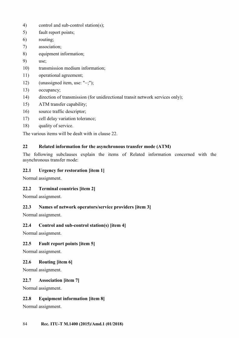
84 Rec. ITU-T M.1400 (2015)/Amd.1 (01/2018)
4) control and sub-control station(s);
5) fault report points;
6) routing;
7) association;
8) equipment information;
9) use;
10) transmission medium information;
11) operational agreement;
12) (unassigned item, use: ";");
13) occupancy;
14) direction of transmission (for unidirectional transit network services only);
15) ATM transfer capability;
16) source traffic descriptor;
17) cell delay variation tolerance;
18) quality of service.
The various items will be dealt with in clause 22.
22 Related information for the asynchronous transfer mode (ATM)
The following subclauses explain the items of Related information concerned with the
asynchronous transfer mode:
22.1 Urgency for restoration [item 1]
Normal assignment.
22.2 Terminal countries [item 2]
Normal assignment.
22.3 Names of network operators/service providers [item 3]
Normal assignment.
22.4 Control and sub-control station(s) [item 4]
Normal assignment.
22.5 Fault report points [item 5]
Normal assignment.
22.6 Routing [item 6]
Normal assignment.
22.7 Association [item 7]
Normal assignment.
22.8 Equipment information [item 8]
Normal assignment.

Rec. ITU-T M.1400 (2015)/Amd.1 (01/2018) 85
22.9 Use [item 9]
Normal assignment.
22.10 Transmission medium information [item 10]
Normal assignment.
22.11 Operational agreement [item 11]
Normal assignment.
22.12 Unassigned item [item 12]
Not applicable.
22.13 Occupancy [item 13]
Normal assignment.
22.14 Direction of transmission (for unidirectional transit network services only) [item 14]
Normal assignment.
22.15 ATM transfer capability [item 15]
An ATM transfer capability is intended to support an ATM layer service model and associated
quality of service (QoS) through a set of ATM layer traffic parameters and procedures. An ATM
transfer capability may include the specification of primitives to comply with, and of traffic control
information to be exchanged through standardized interfaces.
There may be more than one quality of service (QoS) class for a given ATM transfer capability
(ATC) [ITU-T I.356]. Given that a user can commit to submitting cells in conformance to traffic
descriptors in addition to the peak cell rate (PCR), the reason a user would choose a service based
on an ATM transfer capability other than the deterministic bit rate transfer capability is the potential
of incurring a lower cost from the network provider.
It is mandatory that the ATM transfer capability used on a given ATM connection, among those
that are made available by the network, be implicitly or explicitly declared at connection
establishment.
Once an ATM connection is established, the agreed-upon ATC is the same at all standardized
interfaces along the connection. However, it is a network operator's choice on how to support a
given ATM transfer capability, provided it is complying with specifications at standardized
interfaces.
A given ATM communication uses the same ATM transfer capability for both directions. Use of
different transfer capabilities for the two connections of a communication raises issues relating, for
example, to OAM and resource management cells, or to routing and is thus not currently specified
in this Recommendation. This also applies to multicast connections.
Format:
15. XXX; (three characters)
Specifications:
DBR Deterministic Bit Rate capability
SBR Statistical Bit Rate capability
ABR Available Bit Rate capability
86 Rec. ITU-T M.1400 (2015)/Amd.1 (01/2018)
ABT ATM Block Transfer capability
Example:
For an ATM-transport link Bruxelles/ZXC/BGACOM/BEL–Frankfurt/54T/DTAG/DEU A34M1 in
which the ATM transfer capability is the deterministic bit rate capability:
15. DBR;
22.16 Source traffic descriptor [item 16]
This descriptor includes parameters that describe the traffic originated from the source. These
parameters depend on the ATC. The source traffic descriptor (STD) and cell delay variation
tolerance (CDVT) specified for each connection describe the traffic descriptor at the interface.
Peak cell rate in the source traffic descriptor specifies an upper bound on the traffic that can be
submitted on an ATM connection.
Sustainable cell rate (SCR) together with a parameter characterizing the maximum burst size at the
peak cell rate, i.e., intrinsic burst tolerance (IBT), are intended to describe variable bit rate (VBR)
sources and allow for statistical multiplexing of traffic flows from such sources. SCR and IBT limit
the medium frequency on which a connection can transmit cells.
Format:
16. XXXXXX, YYYYYY, ZZZZZZ; (maximum six characters each)
Specifications:
XXXXXX Peak cell rate [cells/s]
YYYYYY Sustainable cell rate [cells/s]
ZZZZZZ Intrinsic Burst Tolerance [cells]
Example:
For an ATM-transport link Bruxelles/XCV/BGACOM/BEL–Frankfurt/RTY/DTAG/DEU A34M1
in which the Peak cell rate = 32000 cell/s, Sustainable cell rate = not specified, intrinsic burst
tolerance = not specified.
16. 32000, , ;
22.17 Cell delay variation tolerance [item 17]
This parameter specifies the maximum acceptable delay from the network, of the real arrival time of
a cell at a UNI/INI interface compared to the theoretical arrival time of a cell at the UNI/INI
interface at the same interface.
Format:
17. XXXXXX; (six characters)
Specifications:
XXXXXX Cell delay variation tolerance [s]
Example:
17. (For further study.)
22.18 Quality of service [item 18]
These parameters characterize the quality of the connection.
Cell error ratio is the ratio of total errored cells to the total of successfully transmitted cells.

Rec. ITU-T M.1400 (2015)/Amd.1 (01/2018) 87
Cell loss ratio is the ratio of total lost cells to total transmitted cells in a population of interest.
Cell transfer delay is the maximum delay for transferring a cell from the entry of the network to the
exit of the network.
Cell delay variation is the maximum variation of the cell transfer delay accepted between two points
of the network.
Format:
18. XXXXXX,YYYYYY,ZZZZZZ,KKKKKK; (maximum six characters each)
Specifications:
XXXXXX Cell loss ratio
YYYYYY Cell error ratio
ZZZZZZ Cell transfer delay [s]
KKKKKK Cell delay variation [s]
Example:
For an ATM-transport link Bruxelles/XCV/BGACOM/BEL–Frankfurt/45G/DTAG/DEU A34M1 in
which are defined Cell Loss Ratio 3 10–7, Cell Error Ratio 3 10–6, Cell Transfer
Delay 400 10–3 ms, Cell Delay Variation 3 10–3
18. 3 10–7, 3 10–6, 4 10–1, 3 10–3;
23 Transit network services
23.1 General
Up till now network operators/service providers (NOs/SPs) providing transit network service were
aware of the terminations used by the other NOs/SPs. Presently, particularly in a multi-operator
competitive environment (either domestic or international), this is no longer necessarily a desirable
situation. Today's view is that the NO/SP that provides the transit network service does not need to
know the actual terminations of the carried characteristic information. So, the NO(s)/SP(s) that
provide(s) this kind of service does (do) not need to know the actual routing and destination inside
the renter's domain. Figure 8 illustrates a transit network.
Figure 8 – Transit network

88 Rec. ITU-T M.1400 (2015)/Amd.1 (01/2018)
The format for the designation of transit network services is shown in Table 12.
Table 12 – Format for designation of transit network services
Format of
designation G
eog
rap
hic
al
Are
a A
/
Ter
min
ati
on
det
ail
/
Op
era
tor
ID
/
Co
un
try
co
de
–
Geo
gra
ph
ica
l
Are
a B
/
Ter
min
ati
on
det
ail
/
Op
era
tor
ID
/
Co
un
try
co
de
Fu
nct
ion
co
de
Ser
ial
nu
mb
er
Character
types
Let
ters
or
spac
e
Sla
sh
Let
ters
or
dig
its
Sla
sh
Let
ters
or
dig
its
Sla
sh
Let
ters
Hy
ph
en
Let
ters
or
spac
e
Sla
sh
Let
ters
or
dig
its
Sla
sh
Let
ters
or
dig
its
Sla
sh
Let
ters
Sp
ace
Let
ters
or
dig
its
Dig
its
Number of
characters 12 1 6 1 6 1 3 1 12 1 6 1 6 1 3 1
2 or
3 4
No space
The elements of the Layer 1 format are as follows:
a) Transport relation
Transit network service terminal station A and transit network service terminal station B
refer to the names of the two transmission stations in which the transit network service is
terminating. The name of each transmission station consists of the following elements:
geographical area name, transmission station detail, operator ID and country code. The
order of the two transmission stations is arranged according to alphabetical order of the
respective geographical area names.
Geographical area: the geographical area where the transmission station is situated
(required: one to twelve characters or space).
Transmission station detail shows the information that makes the transmission station
unique in the operator domain in that particular geographical area. Format: one to six letters
and/or digits.
Operator ID is the identification of the operator that created the transmission station
identification. Format: ICC (consisting of one to six letters and/or digits).
Country code identifies the country in which the geographical area is located. Format:
[ISO 3166-1] alpha-3 code.
b) Function code (format: two to three letters)
The function code for transit network services may vary depending on the type. See
clauses 23.2 and 23.3.
c) Serial number (required: one to four digits)
Identifies the instance of the transit network service. The serial numbering starts anew if
there is a difference in transport relation and/or function code. For each traffic relation, the
numbering of transit network services will begin from 1 and will increase by 1 for each new
one. If a transit network service is deleted (i.e., it ceases to exist), its serial number can be
reused without renumbering the other ones.
23.2 Transit digital transmission service
This clause deals with the transit network service consisting of a digital transmission route. This
may be PDH or SDH transmission. The service is referred to as a circuit. In this case, the function
code is DC. DC stands for digital circuit.

Rec. ITU-T M.1400 (2015)/Amd.1 (01/2018) 89
Example 1:
The first 2 Mbit/s PDH transit network service supplied by Telecom Italia connecting the WIND's
building in Rome with France Telecom building in Reims (named Roma/taw and Reims/xmr
respectively) will have the following designation:
Roma/TAW/TI/ITA–Reims/XMR/FRTE/FRA DC1
Example 2:
The first 155 Mbit/s SDH transit network service connecting the WIND's Main Site in Rome and
the Telecom Italia International Exchange in Rome (named Roma/taw and Roma/tat respectively)
will have the following designation:
Roma/TAW/WIND–Roma/TAT/TI DC1
23.3 Transit dark fibre service
Optical fibres owned by one operator may be rented by another. This clause covers dark fibres: a
bare optical fibre, i.e., without optical signals. This is referred to as "dark" because no light is turned
on by the owner. Instead, providing the light is the responsibility of the renter. The dark fibre
service may be built upon one single fibre or upon consecutive dark fibres in series.
NOTE – If the fibres are offered in combination with a digital, optical or electrical interface, the previous
clause applies.
In this case, the function code is DFS. DFS stands for dark fibre service.
Example 1:
The first dark fibre service between Paris/FT1 and Strasbourg/FT1 owned by France Telecom (and
possibly rented by KPN Telecom) is designated (by France Telecom):
Paris/FT1/FRTE–Strasbourg/FT1/FRTE DFS1
Example 2:
The third dark fibre service between Muenster and Osnabrueck in Germany owned by Deutsche
Telekom (and possibly rented by Belgacom) is designated (by Deutsche Telekom):
Muenster/DT1/DTAG–Osnabrueck/DT1/DTAG DFS3
23.4 Related information
The related information on transit network service is covered by the following items:
1) urgency for restoration;
2) terminal countries;
3) names of network operators/service providers;
4) control and sub-control station(s);
5) fault report points;
6) –; (unassigned item because no routing information applicable)
7) association;
8) equipment information;
9) –; (no information on use applicable)
10) transmission medium information;
11) SLA;

90 Rec. ITU-T M.1400 (2015)/Amd.1 (01/2018)
12) bit rate;
13) commercial identifier;
14) –; (unassigned item)
15) clocking information;
16) direction of transmission (for unidirectional transit network services only).
The various items will be dealt with in clause 24.
24 Related information on transit network service
The following subclauses explain the items of Related information concerned with international or
domestic transit network service.
24.1 Urgency for restoration [item 1]
Normal assignment.
24.2 Terminal countries [item 2]
Normal assignment.
24.3 Names of network operators/service providers [item 3]
Normal assignment.
24.4 Control station [sub-control station(s)] [item 4]
Normal assignment.
24.5 Fault report points [item 5]
Normal assignment.
24.6 Routing [item 6]
Not applicable.
24.7 Association [item 7]
Normal assignment.
24.8 Equipment information [item 8]
Normal assignment.
24.9 Use [item 9]
Not applicable.
24.10 Transmission medium information [item 10]
Normal assignment.
Rec. ITU-T M.1400 (2015)/Amd.1 (01/2018) 91
24.11 SLA [item 11]
Format:
SLA;
Specification:
It is an indicator that an SLA agreement exists between the renter operator and the leased
operator(s). This reference has to be agreed bilaterally or multilaterally among the operators
involved. SLA definitions and further details may be found in other ITU-T Recs,
e.g., [ITU-T M.1340], [ITU-T M.1380] and [ITU-T M.1385].
24.12 Bit rate [item 12]
Normal assignment.
24.13 Commercial identifier [item 13]
Format:
xxx ... xx; (maximum 20 characters)
Specification:
It is a service identifier used to uniquely identify the contract between the renter operator and the
leaser operator(s). This identifier has to be agreed bilaterally or multilaterally among the operators
involved.
24.14 Unassigned item [item 14]
Not applicable.
24.15 Clocking information [item 15]
Normal assignment.
24.16 Direction of transmission (for unidirectional transit network services only) [item 16]
Normal assignment.
25 Designations for wavelength division multiplexing (simple and dense)
25.1 General
Wavelength division multiplexing (WDM) is an optical transport functionality that allows for the
use of more than one wavelength on a fibre. The term WDM is applied if there are just two
wavelengths to be combined and split by a passive element: the wave division (de)multiplexer.
Dense wavelength division multiplexing (DWDM) is a species of WDM where combining and
splitting of more than two channels with different wavelength. The actual numbers of channels may
vary according to the equipment manufacturer and to the state of the technical art at given point in
time; 4, 8, 16, 32 and even 64 channels are now typical figures.
Comment 1: Though optical, the DWDM can use converters that convert an optical signal into an
electrical one, process that signal and convert it back to optical.
Comment 2: The interface is not yet a standard interface and varies per manufacturer. When
[ITU-T G.692] comes into operation, this situation may change.

92 Rec. ITU-T M.1400 (2015)/Amd.1 (01/2018)
Comment 3: The definitions for bidirectional systems (two directions in a single fibre) need further
study.
25.2 The equipment
The equipment coding convention in this text is as follows:
• WDM2: Simple wave division multiplexing using two wavelengths.
• DWDMnW.
DWDM stands for dense wavelength division multiplexing and nW for the number of wavelengths
which can be carried by the DWDM.
This dense wavelength division multiplexer is made of three different parts:
• The wavelength multiplexer which multiplexes the wavelengths. The abbreviation for this
unit is: WMXn, (n is the number of wavelengths of the system).
• The wavelength adapter which converts the wavelength. The abbreviation for this unit is:
WLAnn (nn is the number of the wavelength counted from 1 to n according to a numbering
scheme for the allowed wavelengths).
• The optical (line) amplifier, which amplifies the multiplex signal. The abbreviation for this
unit is: OAnW (n is the number of wavelengths and W stands for wavelength).
Figure 9 shows an example of the scheme for a DWDM16W.
Figure 9 – Example of the equipment on one side with 16 wavelengths
The optical regenerator: In the future it is possible to apply equipment that regenerates the optical
DWDM signal. The equipment is called an optical regenerator. The abbreviation for this equipment
is: OREGnW. OREG stands for optical regenerator and nW for the number of wavelengths which
are regenerated.
The optical add-drop multiplexer (OADM): It is possible now to add-drop in an optical DWDM
system. The functionality of this equipment is an optical add – drop multiplexer. The abbreviation
for this equipment is: OADMnW. OADM stands for optical add-drop multiplexer and nW for the
number of wavelengths which can be carried by an OADM. Figure 10 shows an example of the
scheme for an optical add–drop multiplexing.

Rec. ITU-T M.1400 (2015)/Amd.1 (01/2018) 93
Figure 10 – Example of an optical add-drop multiplexer 16 wavelengths
with 2 wavelengths extracted and inserted
A special case of OADM is the fixed optical add-drop multiplexer (FOADM); it is realized by two
multiplexers in a back-to-back configuration. The dropped channels (wavelengths) are defined by
optical cabling. This network element is referred to as FOADMn where n represents the number of
wavelengths that is added/dropped at the location.
Figure 11 shows an example of the detail scheme for an optical add-drop multiplexer.
Figure 11 – Detail of the optical add-drop multiplexer 16 wavelengths
with 2 wavelengths extracted and inserted
25.3 Configurations for the newly created transmission systems
This clause deals with multiplex sections on the DWDM as defined in [ITU-T G.692] and
[ITU-T G.872].
According to the terminology used throughout this Recommendation, the newly created higher-
order multiplex section will be addressed as an optical multiplex section. It includes the multiplex
equipment. The lower-order multiplex section will be called an optical channel. No multiplex
equipment is involved on this level. If optical amplifiers are required, then optical amplifier sections
are being created (not shown in the figures below) and if an optical regenerator is applied due to
long distances or poor fibre performance before and after this regenerator, an optical regenerator
section will be identified.
There are three different configurations to use DWDM equipment and each deserves a distinct
registration.

94 Rec. ITU-T M.1400 (2015)/Amd.1 (01/2018)
Configuration 1:
The use of wavelength adapters in both sides of the DWDM equipment.
Figure 12 shows an example.
Figure 12 – Example of the scheme for DWDM with wavelength
adapters on both sides

Rec. ITU-T M.1400 (2015)/Amd.1 (01/2018) 95
Configuration 2:
The use of wavelength adapters is only at the receive side of the DWDM equipment. The sending
side does not have wavelength adapters and the PDH/SDH equipment has the possibility to
recognize the DWDM wavelength.
Figure 13 shows an example.
Figure 13 – Example of the scheme for DWDM
with wavelength adapters on one side

96 Rec. ITU-T M.1400 (2015)/Amd.1 (01/2018)
Configuration 3:
DWDM equipment without wavelength adapters. The sending and receive sides do not have these
adapters and the PDH/SDH equipment has the possibility to transmit and recognize the DWDM
wavelength. In this case the optical line systems do not exist.
Figure 14 shows an example.
Figure 14 – Example of the scheme for DWDM without wavelength adapters
25.4 General format for the optical transmission systems
The optical transmission systems are designated according to the general format. We recognize four
system types to describe the coupling of the DWDM equipment:
• the optical regenerator section;
• the optical amplifier section;
• the optical multiplex section (multiplex section at higher order);
• the optical channel (multiplex section at lower order between two wavelength adapters).
These four system types have their own function codes; see clause 25.4.1.
The format of designation of optical transmission systems in (D)WDM is shown in Table 13:
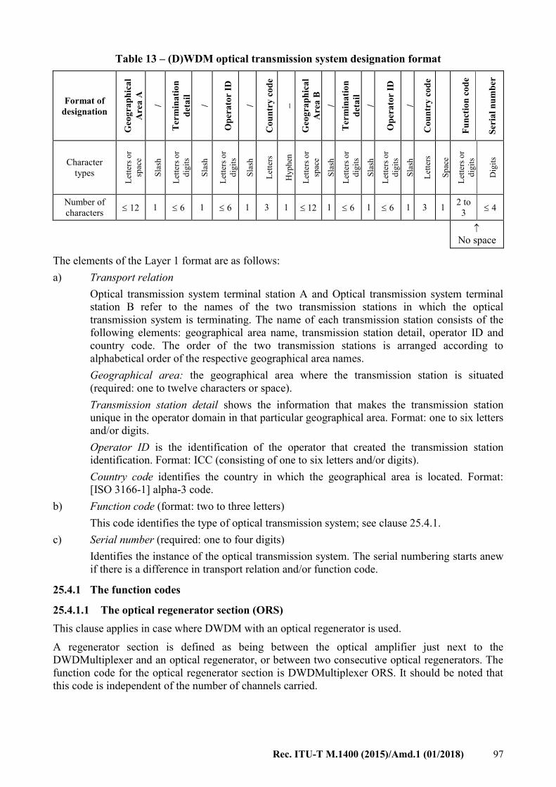
Rec. ITU-T M.1400 (2015)/Amd.1 (01/2018) 97
Table 13 – (D)WDM optical transmission system designation format
Format of
designation
Geo
gra
ph
ica
l
Are
a A
/
Ter
min
ati
on
det
ail
/
Op
era
tor
ID
/
Co
un
try
co
de
–
Geo
gra
ph
ica
l
Are
a B
/
Ter
min
ati
on
det
ail
/
Op
era
tor
ID
/
Co
un
try
co
de
Fu
nct
ion
co
de
Ser
ial
nu
mb
er
Character
types
Let
ters
or
spac
e
Sla
sh
Let
ters
or
dig
its
Sla
sh
Let
ters
or
dig
its
Sla
sh
Let
ters
Hy
ph
en
Let
ters
or
spac
e
Sla
sh
Let
ters
or
dig
its
Sla
sh
Let
ters
or
dig
its
Sla
sh
Let
ters
Sp
ace
Let
ters
or
dig
its
Dig
its
Number of
characters 12 1 6 1 6 1 3 1 12 1 6 1 6 1 3 1
2 to
3 4
No space
The elements of the Layer 1 format are as follows:
a) Transport relation
Optical transmission system terminal station A and Optical transmission system terminal
station B refer to the names of the two transmission stations in which the optical
transmission system is terminating. The name of each transmission station consists of the
following elements: geographical area name, transmission station detail, operator ID and
country code. The order of the two transmission stations is arranged according to
alphabetical order of the respective geographical area names.
Geographical area: the geographical area where the transmission station is situated
(required: one to twelve characters or space).
Transmission station detail shows the information that makes the transmission station
unique in the operator domain in that particular geographical area. Format: one to six letters
and/or digits.
Operator ID is the identification of the operator that created the transmission station
identification. Format: ICC (consisting of one to six letters and/or digits).
Country code identifies the country in which the geographical area is located. Format:
[ISO 3166-1] alpha-3 code.
b) Function code (format: two to three letters)
This code identifies the type of optical transmission system; see clause 25.4.1.
c) Serial number (required: one to four digits)
Identifies the instance of the optical transmission system. The serial numbering starts anew
if there is a difference in transport relation and/or function code.
25.4.1 The function codes
25.4.1.1 The optical regenerator section (ORS)
This clause applies in case where DWDM with an optical regenerator is used.
A regenerator section is defined as being between the optical amplifier just next to the
DWDMultiplexer and an optical regenerator, or between two consecutive optical regenerators. The
function code for the optical regenerator section is DWDMultiplexer ORS. It should be noted that
this code is independent of the number of channels carried.

98 Rec. ITU-T M.1400 (2015)/Amd.1 (01/2018)
Example 1:
A third optical regenerator section (between an amplifier in Bruxelles/KQ1 and a regenerator in
Paris/KQ1) is designated as:
Bruxelles/KQ1/BGACOM/BEL–Paris/KQ1/FRTE/FRA ORS3.
25.4.1.2 The optical amplifier section
An amplifier section is defined as being between a first multiplexer and a first amplifier, between
two consecutive amplifiers and between a last amplifier in the route and a final multiplexer. The
function code is OAS.
Example 2:
The second optical regenerator section between an amplifier in London/KQ1 and Lille/KQ1 is
designated as:
London/KQ1/BTPLC/GBR–Lille/KQ1/FRTE/FRA OAS2.
25.4.1.3 The optical multiplex section
Such a block is defined as being from one DWDMultiplexer to another. The equipment components
are a part of the block. The function code for the optical block is OMS. It should be noted that this
code is independent of the number of channels carried.
Example 3:
The eleventh optical block (e.g., carrying 16 channels with 2.5 Gbit/s) between London/BT1 and
Paris/FT1 is designated as:
London/BT1/BTPLC/GBR–Paris/FT1/FRTE/FRA OMS11.
25.4.1.4 The optical channel (OC)
This clause applies when DWDM is used with wavelength adapters.
Such a system is defined as being between two corresponding wavelength adapters. The function
code for the optical line system is: OC. If the adapters are built into other equipment, the "OC" may
not be registered as a separate resource. In this case, the use of OC is optional.
Example 4:
The fourth optical line system between Amsterdam/KP1 and Roma/TI1 is designated as:
Amsterdam/KP1/TCOMNL/NLD–Roma/TI1/TI/ITA OC4.
Figure 15 presents an example of the scheme with the function codes.

Rec. ITU-T M.1400 (2015)/Amd.1 (01/2018) 99
Figure 15 – Example of the DWDM scheme with the function codes
25.5 Related information
The related information on DWDM is covered by the following items:
1) urgency for restoration;
2) terminal countries;
3) names of network operators/service providers;
4) control and sub-control station(s);
5) fault report points;
6) routing;
7) association;
8) equipment information;
9) use;
10) transmission medium information;
11) operational agreement;
12) bit rate;
13) occupancy;
14) access point identifiers.
The various items will be dealt with in clause 26.
26 Related information on DWDM
The related information on optical transmission in DWDM is indicated in Table 14:
Further study is needed on the development of association codes for protection of WDM systems.

100 Rec. ITU-T M.1400 (2015)/Amd.1 (01/2018)
Table 14 – Information related to DWDM optical transmission systems
Item For optical multiplex
section (OMS)
For optical regenerator
section (ORS)
For optical amplifier
section (OAS)
For optical channel (OC)
1) Urgency for restoration Normal assignment Normal assignment Normal assignment Normal assignment
2) Terminal countries Normal assignment Normal assignment Normal assignment Normal assignment
3) Names of network
operators/service providers
Normal assignment Normal assignment Normal assignment Normal assignment
4) Control and sub-control
station(s)
Normal assignment Normal assignment Normal assignment Normal assignment
5) Fault report points Normal assignment Normal assignment Normal assignment Normal assignment
6) Routing OAS or ORS or the fibre Pair of fibre Pair of fibres OMS
7) Association Not applicable Not applicable Not applicable Set of OC on direction West
and East respectively
8) Equipment information – Maximum number
channels/wavelengths
– ITU-T G.692 if
applicable or
manufacturer type
– Maximum number of
channels/wavelengths
– ITU-T G.692 if applicable
or manufacturer type
– Maximum number of
channels/wavelengths
– ITU-T G.692 if applicable
or manufacturer type
ITU-T G.692 if applicable or
manufacturer type
9) Use Not applicable Not applicable Not applicable Not applicable
10) Transmission medium
information
SMF = single mode fibre
DSF = dispersion shift fibre
NZ DSF+ = non-zero DSF+
NZ DSF– = non-zero DSF–
Other
SMF = single mode fibre
DSF = dispersion shift fibre
NZ DSF+ = non-zero DSF+
NZ DSF– = non-zero DSF–
Other
SMF = single mode fibre
DSF = dispersion shift fibre
NZ DSF+ = non-zero DSF+
NZ DSF– = non-zero DSF–
other
No
11) Operational agreement Normal assignment Normal assignment Normal assignment Normal assignment
12) Bit rate Normal assignment No No No
13) Occupancy Position in the block:
designation of client
Designation of OMS carried Designation of OMS carried Designation of SDH or PDH
system
14) Access point identifiers Not applicable Not applicable Not applicable Not applicable

Rec. ITU-T M.1400 (2015)/Amd.1 (01/2018) 101
27 Designation of connections for the digital subscriber line (DSL)
27.1 General
This clause deals with connections for the digital subscriber line (DSL) as defined in the family of
ITU-T Recommendations: [ITU-T G.991.1], [ITU-T G.992.1], [ITU-T G.992.2], [ITU-T G.994.1],
[ITU-T G.996.1] and [ITU-T G.997.1].
Within the access network, some DSL connections can be created between two equipments: a
customer premises equipment (CPE) on the customer side and a digital subscriber line access
multiplexer (DSLAM) on the operator side. According to the type of cards contained in the
DSLAM, the DSL connection will be symmetrical (SDSL connection) or asymmetrical (ADSL
connection).
In the following, an xDSL connection will represent either an ADSL connection or an SDSL
connection.
The format of designation of xDSL connections is shown in Table 15:
Table 15 – xDSL connection designation format
Format of
designation
Geo
gra
ph
ica
l
Are
a A
/
Ter
min
ati
on
det
ail
/
Op
era
tor
ID
/
Co
un
try
co
de
–
Geo
gra
ph
ica
l
Are
a B
/
Ter
min
ati
on
det
ail
/
Op
era
tor
ID
/
Co
un
try
co
de
Fu
nct
ion
co
de
Ser
ial
nu
mb
er
Character
Types
Let
ters
or
spac
e
Sla
sh
Let
ters
or
dig
its
Sla
sh
Let
ters
or
dig
its
Sla
sh
Let
ters
Hy
ph
en
Let
ters
or
spac
e
Sla
sh
Let
ters
or
dig
its
Sla
sh
Let
ters
or
dig
its
Sla
sh
Let
ters
Sp
ace
Let
ters
or
dig
its
Dig
its
Number of
characters 12 1 6 1 6 1 3 1 12 1 6 1 6 1 3 1
2 to
6
1 to
4
No space
27.1.1 ADSL connection
ADSL connections are based upon bare copper connections. An ADSL connection uses one and
only one bare copper connection. One bare copper connection can only be used once in the routing
of an ADSL connection. From a network point of view, the bare copper connection belongs to the
server layer and the ADSL connection to the client layer.
The elements of the Layer 1 format are as follows:
a) Transport relation
ADSL connection termination A and ADSL connection termination B refer to the names of
the two extremities in which the ADSL connection is terminating. The name of each
termination consists of the following elements: geographical area name, node detail,
operator ID and country code. The order of the two terminations is arranged according to
alphabetical order of the respective geographical area names.

102 Rec. ITU-T M.1400 (2015)/Amd.1 (01/2018)
Geographical area: the geographical area where the terminal equipments are situated
(required: one to twelve characters or space).
Termination detail shows the information that makes the extremity of an ADSL connection
unique in the operator domain in that particular geographical area. Format: one to six letters
and/or digits.
Operator ID is the identification of the operator that created the extremity identification.
Format: ICC (consisting of one to six letters and/or digits).
Country code identifies the country in which the geographical area is located. Format:
[ISO 3166-1] alpha-3 code.
b) Function code (format: two to six letters and/or digits)
This function code is 8448A (8448 kbit/s being the maximum bit rate of an ADSL
connection and the character "A" being set for ADSL).
c) Serial number (required: one to four digits)
Identifies the instance of the ADSL connection. The serial numbering starts anew if there is
a difference in transport relation and/or function code.
Example:
The second 64 kbit/s ADSL connection between two nodes in Toulouse, using France Telecom
copper lines and a DSLAM belonging to Deutsche Telekom will be designed as:
Toulouse/Matab/FRTE/FRA–Toulouse/Balma/DTAG/DEU 8448A2
27.1.2 ADSL Layer 2
The related information on ADSL is covered by the following items:
1) urgency for restoration;
2) terminal countries;
3) names of network operators/service providers;
4) control and sub-control station(s);
5) fault report points;
6) routing;
7) association;
8) equipment information;
9) use;
10) transmission medium information;
11) operational agreement;
12) bandwidth;
13) occupancy;
14) actual number of channel/access point identifiers;
15) clocking information;
16) direction of transmission;
The various items will be dealt with in clause 27.2.
27.1.3 Symmetric digital subscriber line (SDSL) connection
Symmetric digital subscriber line (SDSL) connections are based upon bare copper connections. An
SDSL connection uses one bare copper connection or several bare copper connections in parallel.

Rec. ITU-T M.1400 (2015)/Amd.1 (01/2018) 103
One bare copper connection can only be used once in the routing of an SDSL connection. From a
network point of view, the bare copper connection belongs to the server layer and the SDSL
connection to the client layer.
The elements of the Layer 1 format are as follows:
a) Transport relation
SDSL connection termination A and SDSL connection termination B refer to the names of
the two extremities in which the SDSL connection is terminating. The name of each
termination consists of the following elements: Geographical area name, node detail,
operator ID and country code. The order of the two terminations is arranged according to
alphabetical order of the respective Geographical area names.
Geographical area: the geographical area where the terminal equipments are situated
(required: one to twelve characters or space).
Termination detail shows the information that makes the extremity of an SDSL connection
unique in the operator domain in that particular geographical area. Format: one to six letters
and/or digits.
Operator ID is the identification of the operator that created the extremity identification.
Format: ICC (consisting of one to six letters and/or digits).
Country code identifies the country in which the geographical area is located. Format:
[ISO 3166-1] alpha-3 code.
b) Function code (format: two to six letters and/or digits)
This function code is built from:
– A bit rate information that represents the maximum bit rate of the SDSL connection;
– A character "S" set for SDSL.
Format:
xxxxxS where x is a numerical value from 0 to 9
Examples:
8448S
4224S
c) Serial number (required: one to four digits)
Identifies the instance of SDSL connection. The serial numbering starts anew if there is a
difference in transport relation and/or function code.
Example:
The first 4 Mbit/s SDSL connection sold by France Telecom between two nodes in Paris will be
designed as:
Paris/Monp1 – Paris/Bertra 4224S1
27.1.4 SDSL Layer 2
The related information on SDSL is covered by the following items:
1) urgency for restoration;
2) terminal countries;
3) names of network operators/service providers;
4) control and sub-control station(s);
5) fault report points;

104 Rec. ITU-T M.1400 (2015)/Amd.1 (01/2018)
6) routing;
7) association;
8) equipment information;
9) use;
10) transmission medium information;
11) operational agreement;
12) bandwidth;
13) occupancy;
14) actual number of channel/access point identifiers;
15) clocking information;
16) direction of transmission.
The various items will be dealt with in clause 27.3.
27.2 Related information for the ADSL connections
The following subclauses explain the items of Related information concerned with ADSL
connections:
27.2.1 Urgency for restoration [item 1]
Normal assignment.
27.2.2 Terminal countries [item 2]
Normal assignment.
27.2.3 Names of network operators/service providers [item 3]
Normal assignment.
27.2.4 Control and sub-control station(s) [item 4]
Not applicable.
27.2.5 Fault report points [item 5]
Normal assignment.
27.2.6 Routing [item 6]
Normal assignment.
27.2.7 Association [item 7]
Not applicable.
27.2.8 Equipment information [item 8]
Normal assignment.
27.2.9 Use [item 9]
Not applicable.
27.2.10 Transmission medium information [item 10]
Normal assignment.

Rec. ITU-T M.1400 (2015)/Amd.1 (01/2018) 105
27.2.11 Operational agreement [item 11]
Normal assignment.
27.2.12 Bandwidth [item 12]
This item shows the real bit rate of the ADSL connection.
Format:
12. xxxx kbit/s or Mbit/s;
Rules for the notation of the bandwidth figures:
No leading zeros required.
If the figure is between 0 and 9999, use kbit/s, else use Mbit/s.
Example:
A 64 kbit/s ADSL connection:
Toulouse/Matab/FRTE–Toulouse/Balma/DTAG 8448A2
12. 64 kbit/s;
27.2.13 Occupancy [item 13]
Normal assignment.
27.2.14 Actual number of channel/access point identifiers [item 14]
Not applicable.
27.2.15 Clocking information [item 15]
Normal assignment.
27.2.16 Direction of transmission [item 16]
Normal assignment.
27.3 Related information for the SDSL connection
The following subclauses explain the items of related information concerned with SDSL
connections:
27.3.1 Urgency for restoration [item 1]
Normal assignment.
27.3.2 Terminal countries [item 2]
Normal assignment.
27.3.3 Names of network operators/service providers [item 3]
Normal assignment.
27.3.4 Control and sub-control station(s) [item 4]
Not applicable.
27.3.5 Fault report points [item 5]
Normal assignment.

106 Rec. ITU-T M.1400 (2015)/Amd.1 (01/2018)
27.3.6 Routing [item 6]
Normal assignment.
27.3.7 Association [item 7]
Not applicable.
27.3.8 Equipment information [item 8]
Normal assignment.
27.3.9 Use [item 9]
Not applicable.
27.3.10 Transmission medium information [item 10]
This item shows the number of pairs of copper lines used for the given SDSL connection.
Format:
10. xP where x is a numerical value from 0 to 9
Example:
10. 2P
27.3.11 Operational agreement [item 11]
Normal assignment.
27.3.12 Bandwidth [item 12]
This item shows the real bit rate of the SDSL connection.
Format:
12. xxxx kbit/s or Mbit/s;
Rules for the notation of the bandwidth figures:
No leading zeros required.
If the figure is between 0 and 9999, use kbit/s, else use Mbit/s.
Example:
A 64 kbit/s SDSL connection:
Toulouse/Matab/FRTE/FRA–Toulouse/Balma/DTAG/DEU 8448A2
12. 64 kbit/s;
27.3.13 Occupancy [item 13]
Normal assignment.
27.3.14 Actual number of channel/access point identifiers [item 14]
Not applicable.
27.3.15 Clocking information [item 15]
Normal assignment.
27.3.16 Direction of transmission [item 16]
Normal assignment.

Rec. ITU-T M.1400 (2015)/Amd.1 (01/2018) 107
27.4 Examples
The first 4 Mbit/s SDSL connection (using two pairs of copper lines) sold by France Telecom
between two nodes in Paris will be designed as:
Paris/Monp1–Paris/Bertra 4224S1
10. 2P
12. 4224 kbit/s
The second 64 kbit/s ADSL connection between two nodes in Toulouse, using France Telecom
copper lines and a DSLAM belonging to Deutsche Telekom will be designed as:
Toulouse/Matab/FRTE/FRA–Toulouse/Balma/DTAG/DEU 8448A2
12. 64 kbit/s
28 Exceptional designations
This clause deals with designations that are temporarily tolerated until the Related information in
this Recommendation is generally applied. These designations namely do not comply with the spirit
of the Recommendation because they violate the regular use of traffic relation, function code or
serial numbering. In the latter case, such an exceptional designation may contain information in the
serial number.
28.1 Exceptional designations with intelligence in the serial number
Rationale
Operational staff want to see as quickly as possible what spare routes are available in case a
telecommunication system breaks down. This need may lead to the wish to recognize from the
Layer 1 designation what dedicated restoration routes are available, and which dedicated restoration
route is the back-up for the interrupted main route. This information can be supplied by the serial
number as follows:
The main route and the dedicated back-up route share the traffic relation and the function code; the
serial number for the main route is as usual but the serial number of the dedicated back-up route is
precisely 8000 higher; so if the serial number of the main route is xx, the serial number of the
back-up route is 80xx.
Therefore, in the case of dedicated restoration routes, the designations are:
For the main route of the usual type: A-B Function code xx
For the dedicated protection route a special type: A-B Function code 80xx
Example:
In the case of a Virtual Container-4 on a submarine cable between the United Kingdom and Spain,
the main route may be designated as:
Brighton-Valladolid VC4S1 with a dedicated restoration route:
Brighton-Valladolid VC4S8001
Corresponding correct registration
The correct designations according to the spirit of this Recommendation are (see clauses 19 and
20):
For the main route: A-B Function code serial number and
For the restoration route: A-B Function code another serial number

108 Rec. ITU-T M.1400 (2015)/Amd.1 (01/2018)
in combination with the item Association from the Related information as follows:
For the main route, e.g., a VC-4: A-B VC4S1:
Item 7 Association: 7. S1: A-B VC4S2
And for the restoration route A-B VC4S2:
Item 7 Association: 7. 2S: A-B VC4S1
29 Designation of optical transport networks
29.1 General
This clause applies to optical channel transport units, optical channel data units, and their bit rates
as defined in [ITU-T G.709] and [b-ITU-T G.Suppl. 43].
The format of designations of optical channel transport units and data units is shown in Table 16.
Table 16 –Optical transport network designation format
Format of
designation
Geo
gra
ph
ica
l
Are
a A
/
Ter
min
ati
on
det
ail
/
Op
era
tor
ID
/
Co
un
try
co
de
–
Geo
gra
ph
ica
l
Are
a B
/
Ter
min
ati
on
det
ail
/
Op
era
tor
ID
/
Co
un
try
co
de
Fu
nct
ion
co
de
Ser
ial
nu
mb
er
Character
types
Let
ters
or
spac
e
Sla
sh
Let
ters
or
dig
its
Sla
sh
Let
ters
or
dig
its
Sla
sh
Let
ters
Hy
ph
en
Let
ters
or
spac
e
Sla
sh
Let
ters
or
dig
its
Sla
sh
Let
ters
or
dig
its
Sla
sh
Let
ters
Sp
ace
Let
ters
or
dig
its
Dig
its
Number of
characters 12 1 6 1 6 1 3 1 12 1 6 1 6 1 3 1
3 to
5
1 to
34
No space
The elements of the Layer 1 format are as follows:
a) Transport relation
Data Transmission System Terminal Station A and Data Transmission System Terminal
Station B refer to the names of the two transmission stations or optical channel data units in
which the data transmission system is terminating. The name of each transmission station
or optical channel data unit consists of the following elements: geographical area name,
transmission station detail, operator ID and country code. The order of the two transmission
stations or optical channel data units is arranged according to the alphabetical order of the
respective geographical area names.
Geographical area: the geographical area where the transmission station is situated
(required: one to twelve characters or space).
Transmission station detail shows the information that makes the transmission station
unique in the operator domain in that particular geographical area. Format: one to six letters
and/or digits.
Operator ID is the identification of the operator that created the transmission station
identification. Format: ICC (consisting of one to six letters and/or digits).
Country code identifies the country in which the geographical area is located.
Format: [ISO 3166-1] alpha-3 code.
b) Function code (format: three to five letters and/or digits)

Rec. ITU-T M.1400 (2015)/Amd.1 (01/2018) 109
The following function codes are defined for optical channel transport units (OTUs):
Function code Bit rate
OTU1S 2.666 Gb/s [ITU-T G.709]
OTU2S 10.709 Gb/s (OTU2) [ITU-T G.709]
or 11.09 Gb/s (OTU2e) [b-ITU-T G.Suppl. 43]
OTU3S 43.018 Gb/s (OTU3) [ITU-T G.709]
or 44.57 Gb/s (OTU3e1) [b-ITU-T G.Suppl. 43]
or 44.58 Gb/s (OTU3e2) [b-ITU-T G.Suppl. 43]
OTU4S 111.809 Gb/s [ITU-T G.709]
NOTE 1 – The letter "S" separates the number representing the bit rate in the function code from the serial
number that follows it (as shown in Example 1 below).
The following function codes are defined for optical channel data units (ODUs):
Function code Bit rate
ODUF ODUflex [ITU-T G.709]
ODU0S 1.25 Gb/s [ITU-T G.709]
ODU1S 2.5 Gb/s [ITU-T G.709]
ODU2S 10.037 Gb/s (ODU2) [ITU-T G.709]
or 10.399 Gb/s (ODU2e) [ITU-T G.709]
ODU3S 40.319 Gb/s (ODU3) [ITU-T G.709]
or 44.57 Gb/s (ODU3e1) [b-ITU-T G.Suppl. 43]
ODU4S 104.79 Gb/s (ODU4) [ITU-T G.709]
NOTE 2 – Except for function code "ODUF", the letter "S" separates the number representing the bit rate in
the function code from the serial number that follows it (as shown in Example 2 below).
c) Serial number (required: one to three digits)
Identifies the instance of the transmission system. The serial numbering starts anew if there
is a difference in transport relation and/or function code.
NOTE 3 – The use of the data transmission system (e.g., multiplex of digital leased circuits, broadcasting,
video) will be recorded in Related information under Item 9 (Use) (see clause 20.9).
The following function codes are defined for optical transport networks with bit rates over 100 Gb/s:
Function code Bit rate
CnODU n × 105.258 Gb/s [ITU-T G.709]
CnOTU n × 105.258 Gb/s [ITU-T G.709]
NOTE 4 – n is an integer between 2 and 9. Case n = 1 is covered by function codes OTU4S and ODU4S
defined above.
29.2 Data transmission links
Data transmission links are designated as data transmission systems.
Example 1:
The first 10.7 Gigabit optical transmission transport network (OTN) data transmission system
between Dubai and Montreal (see Figure 16):
Dubai/ERD/MOPTT/SAU–Montreal/TGB/CAN OTU2S1.

110 Rec. ITU-T M.1400 (2015)/Amd.1 (01/2018)
Figure 16 – Example of an OTN data transmission systemSingle optical channel (OCh) with
reduced functionality
Example 2:
The first 10 Gigabit optical data unit (ODU) between Dubai and Montreal:
Dubai/ERD/MOPTT/SAU–Montreal/TGB/CAN ODU2S1.
Example 3:
A 300 Gigabit optical data unit (ODU) between Dubai and Montreal:
Dubai/ERD/MOPTT/SAU–Montreal/TGB/CAN C3ODU1726
29.3 Related information
The additional information on data transmission systems is covered by the following items:
1) urgency for restoration;
2) terminal countries;
3) names of network operators/service providers;
4) control and sub-control station(s);
5) fault report points;
6) routing;
7) association;
8) equipment information;
9) use;
10) transmission medium information;
11) composition of transmission;
12) (unassigned item, use: "–;");
13) occupancy.
The various items are dealt with in clause 20.

Rec. ITU-T M.1400 (2015)/Amd.1 (01/2018) 111
Annex A
Full examples for designation information
(This annex forms an integral part of this Recommendation.)
A.1 Full example for the designation information of a public switched telephone circuit
The circuit is the 604th both-way telephone circuit between Sherman Oaks 4ES and Tokyo
Shinjuku, operated by AT&T and KDDI. The signalling type is ITU-T No. 6 with band/circuit
number assigned as 000/03. The control station and sub-control station of the circuit are Sherman
Oaks-transmission station 1 and Tokyo-transmission station 1 respectively. Both stations are also
the fault report points of the circuit. The circuit has been routed on the fourth channel of the first
group between Sherman Oaks and Ibaraki which is routed via satellite and has been connected to
digital blocks in domestic networks.
Designation:
Sherman Oaks/4ES/ATT/USA–Tokyo/SJK/KDDI/JPN B604
Related information:
1. 2;
2. USA, JPN;
3. ATT, KDDI;
4. CS: Sherman Oaks/TS1/ATT/USA,
SCS1: Tokyo/TS1/KDDI/JPN;
5. Sherman Oaks/TS1/ATT/USA, Tokyo/TS1/KDDI/JPN;
6. Ibaraki/2SD/KDDI/JPN–Sherman Oaks/EC/ATT/USA 12C01/4;
7. –;
8. –;
9. –;
10. ST;
11. C;
12. 3.4 kHz;
13. C6, 000/03.
A.2 Full example for the designation information of a leased analogue circuit
The circuit is the first analogue leased circuit used for data transmission between London and
Frankfurt, operated by British Telecom International and the Deutsche Telekom. The signalling
type is 500 Hz/20 Hz. The control station and sub-control station of the circuit are London Mollison
and Frankfurt 0 respectively. Both stations are also the fault report points of the circuit. The circuit
is routed on the third channel of the first group between Frankfurt and London. As regards the
parameters of the circuit, [ITU-T M.1020] is applied. The maintenance contract between network
operators/service providers and customer is repair within 24 hours.
Designation:
Frankfurt/ERT/DTAG/DEU–London/EVC/BTPLC/GBR DP1

112 Rec. ITU-T M.1400 (2015)/Amd.1 (01/2018)
Related information:
1. 24 h;
2. DEU, GBR;
3. DTAG, BTPLC;
4. CS: London/SM/BTPLC/GBR,
SCS1: Frankfurt/0/DTAG/DEU;
5. Frankfurt/0/DTAG/DEU, London/SM/BTPLC/GBR;
6. Frankfurt/ERT/DTAG/DEU–London/EVC/BTPLC/GBR 1201/3;
7. –;
8. –;
9. D;
10. –;
11. A;
12. 3.4 kHz;
13. 500/20;
14. Rec. ITU-T M.1020.
A.3 Full examples for the designation information of a group and a group link
interconnection
A.3.1 Full example for the designation information of a group interconnection
NOTE – The numbers between parentheses refer to the numbers of the items in the Related information.
The interconnecting group is the fifth group between Amsterdam and Paris. The urgency for
restoration (1) is third priority, the terminal countries (2) are the Netherlands and France, the
network operators/service providers involved (3) are the Netherlands KPN Telecom and France
Telecom, the control station and sub-control station (4) are Paris Archives and Amsterdam 1
respectively, the fault report points (5) are Amsterdam 2 and Paris Archives, the routing (6) of the
group is in the supergroup Amsterdam–Bruxelles 6011 on position 1 and in the supergroup
Bruxelles–Paris 6002 on position 3, there is an associated group (7) carrying traffic but indicated for
restoration, namely Amsterdam–Paris 1209, there is special equipment involved (8) because the
group is carrying companded circuits, the use (9) is: Z-circuits and a DP circuit, no satellite (10) is
involved, no end-to-end information (11) is to be recorded, the bandwidth (12) is 48 kHz and the
occupancy (13) is to be seen from the example.
Designation:
Amsterdam/EDC/TCOMNL/NLD–Paris/ARC/FRTE/FRA 1205
Related information:
1. 3;
2. NLD, FRA;
3. TCOMNL, FRTE;
4. CS: Paris/ARC/FRTE/FRA,
SCS1: Amsterdam/1/TCOMNL/NLD;
5. Amsterdam/2/TCOMNL/NLD, Paris/ARC/FRTE/FRA;

Rec. ITU-T M.1400 (2015)/Amd.1 (01/2018) 113
6. Amsterdam/EDC/TCOMNL/NLD–Bruxelles/ZZC/BGACOM/BEL 6011/1,
Bruxelles/ZZC/BGACOM/BEL–Paris/ARC/FRTE/FRA 6002/3;
7. S1205: Amsterdam/EDC/TCOMNL/NLD–Paris/ARC/FRTE/FRA 1209;
8. CO;
9. Z, DP;
10. –;
11. –;
12. 48 kHz;
13. 01: Amsterdam/EDC/TCOMNL/NLD–Paris/ARC/FRTE/FRA Z111,
02: Amsterdam/EDC/TCOMNL/NLD–Paris/ARC/FRTE/FRA Z113,
03: Amsterdam/EDC/TCOMNL/NLD–Paris/ARC/FRTE/FRA Z115,
04: Amsterdam/EDC/TCOMNL/NLD–Paris/ARC/FRTE/FRA Z117,
05: Amsterdam/EDC/TCOMNL/NLD–Paris/ARC/FRTE/FRA Z119,
06: Amsterdam/EDC/TCOMNL/NLD–Paris/ARC/FRTE/FRA Z121,
07: Paris/ARC/FRTE/FRA–Amsterdam/EDC/TCOMNL/NLD Z120,
08: Paris/ARC/FRTE/FRA–Amsterdam/EDC/TCOMNL/NLD Z122,
09: Paris/ARC/FRTE/FRA–Amsterdam/EDC/TCOMNL/NLD Z124,
10: Paris/ARC/FRTE/FRA–Amsterdam/EDC/TCOMNL/NLD Z126,
11: Paris/ARC/FRTE/FRA–Amsterdam/EDC/TCOMNL/NLD Z128,
12: Amsterdam/EDC/TCOMNL/NLD–Paris/ARC/FRTE/FRA DP5.
A.3.2 Full example for the designation information of a group link interconnection
NOTE – The numbers between parentheses refer to the numbers of the items in the Related information.
The link is the first restoration group link between Paris and Genève. The urgency for restoration
(1) is third priority, the terminal countries (2) are Switzerland and France, the network
operators/service providers (3) are Swisscom and France Telecom, the control and sub-control
stations (4) are Genève Monthoux and Paris Archives respectively, the fault report points (5) are the
same stations, the routing (6) is in the second supergroup between Genève and Annemasse on
position 1, there is no information to be recorded about association (7), special equipment (8), use
(9), there is no satellite involved (10), no end-to-end information (11) is required, the bandwidth
(12) is 48 kHz.
Designation:
Genève/MON/CHEPTT/CHE–Paris/ARC/FRTE/FRA 12801
Related information:
1. 3;
2. CHE, FRA;
3. CHEPTT, FRTE;
4. CS: Genève/MON/CHEPTT/CHE,
SCS1: Paris/ARC/FRTE/FRA;

114 Rec. ITU-T M.1400 (2015)/Amd.1 (01/2018)
5. Genève/MON/CHEPTT/CHE, Paris/ARC/FRTE/FRA;
6. Annemasse/WSX/FRTE/FRA–Genève/11W/CHEPTT/CHE 6002/1;
7. –;
8. –;
9. –;
10. –;
11. –;
12. 48 kHz;
A.4 Full examples for the designation information of a digital block, digital path, data
transmission system, blocks created between DCMEs, virtual containers and SDH
multiplex section interconnections
A.4.1 Full example for the designation information of a digital block (bidirectional)
interconnection
NOTE – The numbers between parentheses refer to the numbers of the items in the Related information.
A.4.1.1 Full example for the designation information of a digital block (bidirectional
symmetrical configuration) interconnection
The interconnecting digital block is the 12th primary digital block between Roma and Paris. The
urgency for restoration (1) is 2, the terminal countries (2) are France and Italy, the network
operators/service providers involved (3) are France Telecom and Telecom Italia, control station (4)
is Roma 1 and sub-control station is Paris Archives, the fault report points (5) are the same stations,
the block has been routed (6) in the secondary digital block Paris–Roma 120N2 on position
number 3, it has an associated block (7) indicated for restoration: Paris–Roma 30N5, no special
equipment (8) is involved, the use of the block (9) is DP- and NP-circuits, no satellite is involved
(10), no end-to-end information (11) is required, the bit rate (12) is 2048 Mbit/s, the occupancy (13)
is seen in the example, the actual number of channels (14) is 31, the clocking system (15) is a
master/slave system with the master in Paris and the slave in Roma.
Designation:
Paris/ARC/FRTE/FRA–Roma/TI/ITA 30N12
Related information:
1. 2;
2. FRA, ITA;
3. FRTE, TI;
4. CS: Roma/1/TI/ITA,
SCS1: Paris/ARC/FRTE/FRA;
5. Paris/ARC/FRTE/FRA, Roma/1/TI/ITA;
6. Paris/ARC/FRTE/FRA–Roma1/TI/ITA 120N2/3;
7. S30N12: Paris/ARC/FRTE/FRA–Roma/1/TI/ITA 30N5;
8. –;
9. DP, NP;
10. –;

Rec. ITU-T M.1400 (2015)/Amd.1 (01/2018) 115
11. –;
12. 2048 kbit/s;
13. 01: London/22/BTPLCL/GBR–Roma/1/TI/ITA DP12,
02: Paris/ARC/FRTE/FRA–Roma/1/TI/ITA DP2,
03: Napoli/34/TI/ITA–Rouen/CDD/FRTE/FRA NP1,
04: Paris/ARC/FRTE/FRA–Roma/1/TI/ITA NP3,
05: Paris/ARC/FRTE/FRA–Roma/1/TI/ITA NP4,
06: Paris/ARC/FRTE/FRA–Roma/1/TI/ITA NP5,
07: –,
08: –,
09: –,
10: Lille/XVC/FRTE/FRA–Roma/1/TI/ITA DP1,
11: Paris/ARC/FRTE/FRA–Roma/1/TI/ITA DP5,
12: –,
13: –,
14: –,
15: –,
16: Bruxelles/DCC/BGACOM/BEL–Roma/1/TI/ITA DPM4,
17: Paris/ARC/FRTE/FRA–Roma/1/TI/ITA DPM1,
18: –,
19: –,
20: –,
21: –,
22: –,
23: –,
24: –,
25: –,
26: –,
27: –,
28: –,
29: –,
30: –,
31: –;
14. 31;
15. M = Paris, S = Roma.

116 Rec. ITU-T M.1400 (2015)/Amd.1 (01/2018)
A.4.1.2 Full example for the designation information of a digital block – Bidirectional
asymmetrical configuration interconnection
In the asymmetrical configuration, one transmission station has less modulation levels than the
other one. In Figure A.1, the transmission station on the left (Palermo) uses a 2-Mbit/s<>140-Mbit/s
multiplexer without intermediate modulation levels. The transmission station on the right
(Marseille) uses an equipment with three possible modulation schemes: 2 Mbit/s<>140 Mbit/s,
2 Mbit/s<>34 Mbit/s<>140 Mbit/s and the traditional 2 Mbit/s<>8 Mbit/s<>34 Mbit/s<>140 Mbit/s.
M.1400(13)_FA.1
140/2
64x
140/34+140/2
34/8 8/2
4x
16x
32x
4x
34/2
2 Mbit/s blocks
140 Mbit/s block
34 Mbit/s block
8 Mbit/s block
Palermo Marseille
Figure A.1 – Digital block bidirectional asymmetrical configuration
In this case, only the 2-Mbit/s and 140-Mbit/s blocks exist between Palermo and Marseille. The
8-Mbit/s and 34-Mbit/s blocks exist only between the multiplexing equipment components in the
transmission station at the right (Marseille). The 8-Mbit/s and 34-Mbit/s blocks do not exist
between operators. Therefore no interconnecting designation is needed.
Example 1:
The interconnecting digital block is the second 140 Mbit/s digital block between Palermo and
Marseille. The urgency for restoration (1) is not indicated, the terminal countries (2) are France and
Italy, the network operators/service providers involved (3) are France Telecom and Telecom Italia,
control station (4) is Marseille/KND and sub-control station is Palermo/L*I, the fault report
points (5) are the same stations, the block has been routed (6) in the optical fibre systems
Marseille-Ajaccio F01, Ajaccio-Golfo Aranci F02, Golfo Aranci–Palermo/L*I F02, it has no
associated block (7) indicated for restoration, no special equipment (8) is involved, the use of the
block (9) is not specified, no satellite is involved (10), no end-to-end information (11) is required,
the bit rate (12) is 139 264 kbit/s, the occupancy (13) is seen in the example, the actual number of
channels (14) is 64, the clocking system (15) is a master/slave system with the master in Marseille
and the slave in Palermo.
Designation:
Marseille/KND/FRTE/FRA–Palermo/L*I/TI/ITA 1920N2

Rec. ITU-T M.1400 (2015)/Amd.1 (01/2018) 117
Related information:
1. –;
2. FRA, ITA;
3. FRTE, TI;
4. CS: Marseille/KND/FRTE/FRA
SCS1: Palermo/L*I/TI/ITA;
5. Marseille/KND/FRTE/FRA, Palermo/L*I/TI/ITA;
6. Marseille/KND/FRTE/FRA–Ajaccio/34F/TI/ITA F01,
Ajaccio/34F/TI/ITA–Golfo Aranci/VBN/TI/ITA F02,
Golfo Aranci/VBN/TI/ITA–Palermo/L*I/TI/ITA F02;
7. –;
8. –;
9. –;
10. –;
11. –;
12. 139 264 kbit/s;
13. 01: Athinai/CCB/OTE/GRC–Bracknell/NMN/BTPLC/GBR 30N1,
02: Athinai/CCB/OTE/GRC–Bracknell/NMN/BTPLC/GBR 30N2,
03: Dublin/RRT/EIRCOM/IRL–Tel Aviv/BARAK/ISR 30N1,
04: Athinai/CCB/OTE/GRC–Linda Velha/WX/ROMTL/ROM 30N1,
05: Marseille/KND/FRTE/FRA–Palermo/L*I/TI/ITA 30N1,
.
.
35 –,
36: –,
37: New York/MLT/ATT/USA–Whitehill/MCL/BTPLC/GBR 30N1,
38: New York/MLT/ATT/USA–Bruxelles/ZZD/BGACOM/BEL 30N1
.
.
.
62: Athinai/CCB/OTE/GRC–White Plains/ZXC/ATT/USA 30N5,
63: Istanbul/3DF/TT/TUR–Vauxhall/2/BTPLC/GBR 30N4,
64: –;
14. 64;
15. M = Marseille, S = Palermo.
Example 2:
Routing of a 2 Mbit/s digital block between Marseille and Palermo routed on the fifth time slot of
the Marseille/KND/FRTE/FRA–Palermo/L*I/TI/ITA1920N2
Designation:
Marseille/KND/FRTE/FRA–Palermo/L*I/TI/ITA 30N1

118 Rec. ITU-T M.1400 (2015)/Amd.1 (01/2018)
Related information:
6. Marseille/KND/FRTE/FRA–Palermo/L*I/TI/ITA 1920N2/5
NOTE – The related information does not describe the actual routing of the 2-Mbit/s digital block, but only
its interconnecting portion. The country in which the multiplexer equipment components exist (in this
example, France) will document the local routing, which is not the object of this Recommendation.
A.4.2 Full example for the designation information of a digital path interconnection
NOTE – The numbers between parentheses refer to the numbers of the items in the Related information.
The interconnecting digital path is the first restoration digital second order path between Paris and
Bruxelles. The urgency for restoration (1) is 3, the terminal countries (2) are Belgium and France,
the network operators/service providers involved (3) are Belgacom and France Telecom, control
station (4) is Bruxelles BLA and sub-control station is Paris Archives, the fault report points (5) are
the same stations, the path has been routed (6) in the first third order block Bruxelles–Paris on
position number 1, there are no associated blocks (7), no special equipment (8), use (9) has not been
indicated, no satellite is involved (10), no end-to-end information (11) is required, the bit rate (12)
is 8448 Mbit/s.
Designation:
Bruxelles/BLA/BGACOM/BEL–Paris/ARC/FRTE/FRA 120N801
Related information:
1. 3;
2. BEL, FRA;
3. BGACOM, FRTE;
4. CS: Bruxelles/BLA/BGACOM/BEL,
SCS1: Paris/ARC/FRTE/FRA;
5. Bruxelles/BLA/BGACOM/BEL–Paris/ARC/FRTE/FRA;
6. Bruxelles/BLA/BGACOM/BEL–Paris/ARC/FRTE/FRA 480N1/1;
7. –;
8. –;
9. –;
10. –;
11. –;
12. 8448 kbit/s.
A.4.3 Full example for the designation information of a data transmission system
interconnection
NOTE – The numbers between parentheses refer to the numbers of the items in the Related information.
The data transmission system interconnection is the first 64-kbit/s data transmission system between
London and Paris. The urgency for restoration (1) is 1, the terminal countries (2) are United
Kingdom and France, the network operators/service providers involved (3) are British Telecom
International and France Telecom, the control and sub-control stations (4) are London Mollison and
Paris Archives respectively, the fault report points (5) are the same stations, the system has been
routed (6) in the 12th primary block between Paris and London on timeslot number 3, there is no
information to be recorded about association (7), equipment information (8) and use (9), there is no
satellite involved (10), composition of transmission (11) is digital, item (12) does not apply, the
occupancy (13) is seen in the example.
Rec. ITU-T M.1400 (2015)/Amd.1 (01/2018) 119
Designation:
London/SM/BTPLC/GBR–Paris/ARC/FRTE/FRA 64K1
Related information:
1. 1;
2. GBR, FRA;
3. BTPLC, FRTE;
4. CS: London/SM/BTPLC/GBR,
SCS1: Paris/ARC/FRTE/FRA;
5. London/SM/BTPLC/GBR–Paris/ARC/FRTE/FRA;
6. London/113/BTPLC/GBR–Paris/EDC/FRTE/FRA 30N12/3;
7. –;
8. –;
9. –;
10. –;
11. N;
12. –;
13. A4: London/113/BTPLC/GBR–Paris/EDC/FRTE/FRA NP12,
B4: London/113/BTPLC/GBR–Toulouse/RRC/FRTE/FRA NP3,
C4: –;
D4: Dublin/45/BTE/IRL–Paris/EDC/FRTE/FRA NP6,
E4: London/113/BTPLC/GBR–Paris/EDC/FRTE/FRA NP11,
F4: London/113/BTPLC/GBR–Paris/EDC/FRTE/FRA NP14.
A.4.4 Full example for the designation information of a block created by the interconnection
of DCMEs
NOTE – The numbers between parentheses refer to the numbers of the items in the Related information.
This block is the second block created by the interconnection of DCMEs with a maximal nominal
number of 240 channels between Boston and Reims. The urgency for restoration (1) is 2, the
terminal countries (2) are the United States and France, the network operators/service providers
involved (3) are AT&T and France Telecom, control station is Boston (4) and sub-control station is
Reims/CRE, the fault report points (5) are the same stations, the block has been routed (6) on the
22nd primary digital path between Reims and New York, it has no associated block (7), the first
30 channels are through-going (8), use (9) has not been indicated, a satellite is involved in
transmission (10), items 11 and 12 do not apply and the occupancy (13) is seen in the example (only
90 channels are occupied with circuits).
Designation:
Boston/FRC/ATT/USA–Reims/CRE/FRTE/FRA 240Y2
Related information:
1. 2;
2. USA, FRA;
3. ATT, FRTE;
4. CS: Boston/FRC/ATT/USA,

120 Rec. ITU-T M.1400 (2015)/Amd.1 (01/2018)
SCS1: Reims/CRE/FRTE/FRA;
5. Boston/FRC/ATT/USA, Reims/CRE/FRTE/FRA;
6. New York/45/ATT/USA–Reims/CRE/FRTE/FRA 30N22;
7. –;
8. 1-30 = T;
9. –;
10. ST;
11. –;
12. –;
13. 001: New York/24/ATT/USA–Paris/PT3/FRTE/FRA B1,
002: New York/24/ATT/USA–Paris/PT3/FRTE/FRA B2,
.....
090: New York/24/ATT/USA–Paris/PT3/FRTE/FRA B90.
A.4.5 Full example for the designation of a virtual container interconnection
NOTE – The numbers between parentheses refer to the numbers of the items in the Related information.
The virtual container (VC) interconnection is the 12th VC-4 between Roma and Paris. The urgency
for restoration (1) is 2, the terminal countries (2) are France and Italy, the network operators/service
providers involved (3) are France Telecom and Telecom Italia, control station (4) is Roma 1 and
sub-control station is Paris Archives, the fault report points (5) are the same stations, the block has
been routed (6) in the multiplex section Paris–Roma 4S2 on position number 3, it has no associated
block (7), no special equipment (8) is involved, the use of the block (9) is unknown, no satellite is
involved (10), no end-to-end information (11) is required, the bit rate (12) is 155 Mbit/s, the
occupancy (13) is seen in the example and the access points (14) are shown there as well.
Designation:
Paris/35R/FRTE/FRA–Roma/VVB/TI/ITA VC4S12
Related information:
1. 2;
2. FRA, ITA;
3. FRTE, TI;
4. CS: Roma/1/TI/ITA,
SCS1: Paris/ARC/FRTE/FRA;
5. Paris/ARC/FRTE/FRA, Roma/1/TI/ITA;
6. Paris/35R/FRTE/FRA–Roma/VVB/TI/ITA 4S2/3;
7. –;
8. –;
9. –;
10. –;
11. –;
12. –;

Rec. ITU-T M.1400 (2015)/Amd.1 (01/2018) 121
13. 1,0,0: Napoli/55E/TI/ITA–Paris/35R/FRTE/FRA VC3S15,
2,1,0: Lille/CVB/FRTE/FRA–Roma/1/TI/ITA VC2S8,
2,2,0: Lille/CVB/FRTE/FRA–Roma/1/TI/ITA VC2S121,
2,3,0: –,
2,4,1: London/XXC/BTPLC/GBR–Roma/1/TI/ITA VC12S30,
2,4,2: Paris/35R/FRTE/FRA–Roma/VVB/TI/ITA VC12S4,
2,4,3: London/XXC/BTPLC/GBR–Roma/VVB/TI/ITA VC12S31,
2,5,0: London/XXC/BTPLC/GBR–Roma/VVB/TI/ITA VC2S67,
2,6,0: –,
2,7,0: Paris/35R/FRTE/FRA–Roma/VVB/TI/ITA VC2S82,
3,0,0: Napoli/55E/TI/ITA–Paris/35R/FRTE/FRA VC3S16;
14. APId A: FRAFRTE12345678,
APId B: ITATI987654321.
A.4.6 Full example for the designation information of a multiplex section interconnection
NOTE – The numbers between parentheses refer to the numbers of the items in the Related information.
The multiplex section interconnection is the first STM-4 between London and Paris. The urgency
for restoration (1) is 1, the terminal countries (2) are United Kingdom and France, the network
operators/service providers involved (3) are British Telecom International and France Telecom, the
control and sub-control stations (4) are London Mollison and Paris Archives respectively, the fault
report points (5) are the same stations, the system has been routed (6) on the France–UK
4 submarine cable, there is no information to be recorded about association (7), equipment
information (8) and use (9), there is no satellite involved (10), item (11) does not apply, the bit rate
(12) is 620 Mbit/s, the occupancy (13) is seen in the example.
Designation:
London/SM/BTPLC/GBR–Paris/ARC/FRTE/FRA 4S1
Related information:
1. 1;
2. GBR, FRA;
3. BTPLC, FRTE;
4. CS: London/SM/BTPLC/GBR,
SCS1: Paris/ARC/FRTE/FRA
5. London/SM/BTPLC/GBR, Paris/ARC/FRTE/FRA;
6. France–UK 4;
7. –;
8. –;
9. –;
10. –;
11. –;
12. 620 Mbit/s;

122 Rec. ITU-T M.1400 (2015)/Amd.1 (01/2018)
13. 1: Glasgow/DDC/BTPLC/GBR–Paris/ARC/FRTE/FRA VC4S12,
2: London/SM/BTPLC/GBR–Paris/ARC/FRTE/FRA VC4S21,
3: –,
4: London/SM/BTPLC/GBR–Toulouse/EDR/FRTE/FRA VC4S2;
14. APId A: 441234567890123,
APId B: FRAFRTE87654321.

Rec. ITU-T M.1400 (2015)/Amd.1 (01/2018) 123
Annex B
KLM addressing and its relationship to time slot
numbering for virtual containers
(This annex forms an integral part of this Recommendation.)
B.1 KLM addressing relationship to time slot numbering
It is possible to relate VC-4 occupancy listing with time slot numbering or tributary numbering to
an occupancy listing with KLM addressing by using the following process.
– List the designations of all tributaries (irrespective of type) in order. This will consist of a
possible combination of VC-12s, VC-2s and/or VC-3s.
– Assign a K number:
Every VC-n is contained in one of three TU3s (or TUG3s). Each VC-n tributary should be
assigned a K number, from 1 to 3, corresponding to the position in which its TU3 (or
TUG3) is contained within the VC-4, e.g., the VC-3 in the second TU3 has a K number of
2; any VC-12 in the third TU3 has a K number of 3, etc.
– Assign an L number:
For each VC-3, the L number is 0.
Each VC-2 or VC-12 is contained within one of seven TU2s (or TUG2s) within a TUG3.
Each VC-2 or VC-12 should be assigned an L number from 1 to 7, corresponding to the
position in which its TU2 (or TUG2) is contained within its TU3, e.g., a VC-2 in the fifth
TU2 within its TUG3 has an L number of 5; any VC-12 within the sixth TUG2 in a TUG3
has an L number of 6, etc.
– Assign an M number:
For each VC-3 and VC-2, the M number is 0.
Each VC-12 is contained within one of three TU12s within a TUG2. Each VC-12 should be
assigned an M number from 1 to 3, corresponding to the position in which its TU12 is
contained within its TUG2, e.g., the VC-12 corresponding to the third TU12 within a TUG2
has an M number of 3.

124 Rec. ITU-T M.1400 (2015)/Amd.1 (01/2018)
B.2 KLM addressing of VC-4 occupancy
Figure B.1 illustrates VC-3, VC-2 and VC-12 occupancy of a VC-4.
M.1400(06)_FB.1
2
34567
1123
KLM = 1,1,3
KLM = 2,1,0 0
0
00
1
2
3
TUG3
TUG3
TUG3KLM = 3,0,0
3
(1,.,3)
7
(1,.,.,...,7)
3
(1,..,3)
(K) (L) (M)
VC-3 VC-2 VC-12
VC-4 organization
Figure B.1 – VC-4 organization
B.3 Comparative notation of KLM addressing vs. time slot numbering
The following example shows the two alternative ways of presenting occupancy. List 1 shows an
occupancy listing using KLM numbering. List 2 shows the corresponding occupancy using time slot
numbering. Note that each KLM address is specified only once in list 1. Also note that in List 2 a
VC-3 (n,0,0) is repeated at every third time slot; a VC-2, (n,n,0) is repeated at every 21st time slot:
a VC-12 (n,n,n) is not repeated within the 63 time slots.

Rec. ITU-T M.1400 (2015)/Amd.1 (01/2018) 125
List 1 List 2
Using KLM addressing Using time slot numbering
1,0,0: Napoli/1/TI/ITA–Paris/2/FT/FRA VC3S15,
2,1,0: Lille/3/FRTE/FRA–Roma/4/TI/ITA VC2S8,
2,2,0: Lille/3/FRTE/FRA–Roma/4/TI/ITA VC2S66,
2,3,0: –,
2,4,1: London/5/BTPLC/GBR–Roma/4/TI/ITA
VC12S30,
01: Napoli/1/TI/ITA–Paris/2/FRTE/FRA VC3S15,
02: Lille/3/FRTE/FRA–Roma/4/TI/ITA VC2S8,
03: Napoli/1/TI/ITA–Paris/2/FRTE/FRA VC3S16,
04: Napoli/1/TI/ITA–Paris/2/FRTE/FRA VC3S15,
05: Lille/3/FRTE/FRA–Roma/4/TI/ITA VC2S66,
2,4,2: Paris/2/FRTE/FRA–Roma/4/TI/ITA
VC12S44,
2,4,3: London/5/BTPLC/GBR–Roma/4/TI/ITA
VC12S31,
2,5,0: Lille/3/FRTE/FRA–Roma/4/TI/ITA VC2S67,
2,6,0: –,
2,7,0: Paris/2/FRTE/FRA–Roma/4/TI/ITA VC2S82,
3,0,0: Napoli/1/TI/ITA–Paris/2/FRTE/FRA
VC3S16;
06: Napoli/1/TI/ITA–Paris/2/FRTE/FRA VC3S16,
07: Napoli/1/TI/ITA–Paris/2/FRTE/FRA VC3S15,
08: –,
09: Napoli/1/TI/ITA–Paris/2/FRTE/FRA VC3S16,
10: Napoli/1/TI/ITA–Paris/2/FRTE/FRA VC3S15,
11: London/5/BTPLC/GBR–Roma/4/TI/ITA
VC12S30,
12: Napoli/1/TI/ITA–Paris/2/FRTE/FRA VC3S16,
13: Napoli/1/TI/ITA–Paris/2/FRTE/FRA VC3S15,
14: Lille/3/FRTE/FRA–Roma/4/TI/ITA VC2S67,
15: Napoli/1/TI/ITA–Paris/2/FRTE/FRA VC3S16,
16: Napoli/1/TI/ITA–Paris/2/FRTE/FRA VC3S15,
17: –,
18: Napoli/1/TI/ITA–Paris/2/FRTE/FRA VC3S16,
19: Napoli/1/TI/ITA–Paris/2/FRTE/FRA VC3S15,
20: Paris/2/FRTE/FRA–Roma/4/TI/ITA VC2S82,
21: Napoli/1/TI/ITA–Paris2/FRTE/FRA VC3S16,
22: Napoli/1/TI/ITA–Paris2/FRTE/FRA VC3S15,
23: Lille/3/FRTE/FRA–Roma/4/TI/ITA VC2S8,
24: Napoli/1/TI/ITA–Paris/2/FRTE/FRA VC3S16,
25: Napoli/1/TI/ITA–Paris/2/FRTE/FRA VC3S15,
26: Lille/3/FRTE/FRA–Roma/4/TI/ITA VC2S66,
27: Napoli/1/TI/ITA–Paris/2/FRTE/FRA VC3S16,
28: Napoli/1/TI/ITA–Paris/2/FRTE/FRA VC3S15,
29: –,
30: Napoli/1/TI/ITA–Paris/2/FRTE/FRA VC3S16,
31: Napoli/1/TI/ITA–Paris/2/FRTE/FRA VC3S15,
32: Paris/2/FRTE/FRA–Roma/4/TI/ITA VC12S44,
33: Napoli/1/TI/ITA–Paris/2/FRTE/FRA VC3S16,
34: Napoli/1/TI/ITA–Paris/2/FRTE/FRA VC3S15,
35: Lille3/FRTE/FRA–Roma/4/TI/ITA VC2S67,
36: Napoli/1/TI/ITA–Paris/2/FRTE/FRA VC3S16,
37: Napoli/1/TI/ITA–Paris/2/FRTE/FRA VC3S15,
38: –,
39: Napoli/1/TI/ITA–Paris/2/FRTE/FRA VC3S16,
40: Napoli/1/TI/ITA–Paris/2/FRTE/FRA VC3S15,
41: Paris/2/FRTE/FRA–Roma/4/TI/ITA VC2S82,
42: Napoli/1/TI/ITA–Paris/2/FRTE/FRA VC3S16,
43: Napoli/1/TI/ITA–Paris/2/FRTE/FRA VC3S15,
44: Lille/3/FRTE/FRA–Roma/4/TI/ITA VC2S8,
45: Napoli/1/TI/ITA–Paris/2/FRTE/FRA VC3S16,

126 Rec. ITU-T M.1400 (2015)/Amd.1 (01/2018)
List 1 List 2
Using KLM addressing Using time slot numbering
46: Napoli/1/TI/ITA–Paris/2/FRTE/FRA VC3S15,
47: Lille/3/FRTE/FRA–Roma/4/TI/ITA VC2S66,
48: Napoli/1/TI/ITA–Paris/2/FRTE/FRA VC3S16,
49: Napoli/1/TI/ITA–Paris/2/FRTE/FRA VC3S15,
50: –,
51: Napoli/1/TI/ITA–Paris/2/FRTE/FRA VC3S16,
52: Napoli/1/TI/ITA–Paris/2/FRTE/FRA VC3S15,
53: London/5/BTPLC/GBR–Roma/4/TI/ITA
VC12S31,
54: Napoli/1/TI/ITA–Paris/2/FRTE/FRA VC3S16,
55: Napoli/1/TI/ITA–Paris/2/FRTE/FRA VC3S15,
56: Lille/3/FRTE/FRA–Roma/4/TI/ITA VC2S67,
57: Napoli/1/TI/ITA–Paris/2/FRTE/FRA VC3S16,
58: Napoli/1/TI/ITA–Paris/2/FRTE/FRA VC3S15,
59: –,
60: Napoli/1/TI/ITA–Paris/2/FRTE/FRA VC3S16,
61: Napoli/1/TI/ITA–Paris/2/FRTE/FRA VC3S15,
62: Paris/2/FRTE/FRA–Roma/4/TI/ITA VC2S82,
63: Napoli/1/TI/ITA–Paris/2/FRTE/FRA VC3S16;

Rec. ITU-T M.1400 (2015)/Amd.1 (01/2018) 127
Annex C
Reference clause numbers for the various types of routes
(This annex forms an integral part of this Recommendation.)
Clause Type of interconnecting route
7.2.2 Telephone circuits used in manual operation
7.2.3 One-way telephone circuits used for semi-automatic or automatic operation
7.2.4 Both-way telephone circuits used for semi-automatic or automatic operation
7.3 Circuits used for switched telex and telegraph service
7.4 Interconnecting circuits in the public switched data network
9.2.2 Analogue leased circuits used for telephony
9.2.3.1 Analogue circuits used for voice-frequency telegraphy
9.2.3.2 Analogue leased circuits used for TDM-telegraphy
9.2.4 Leased telegraph circuits
9.2.5 Analogue leased circuits used for data transmission
9.2.6 Analogue leased circuits used for phototelegraphy or facsimile
9.2.7.1 Analogue leased unidirectional sound-programme transmission circuits
9.2.7.2 Analogue leased reversible sound-programme transmission circuits
9.2.8.1 Analogue leased unidirectional television-programme circuits
9.2.8.2 Analogue leased reversible television-programme circuits
9.2.9 Leased circuits used for digital video transmission
9.2.10 Analogue leased circuits connecting circuit multiplication terminal equipment at
renters' premises
9.2.11 Analogue leased circuits used for combinations of transmissions, etc.
9.2.12 Analogue leased circuits connecting three or more locations
9.2.13 Leased analogue groups, supergroups, etc.
9.2.14 Leased analogue group, supergroup links
9.2.15 Digital leased circuits connecting two locations
9.2.16 Digital leased circuits connecting three or more locations
9.3.2.1 Public circuits used for unidirectional sound-programme transmission
9.3.2.2 Public circuits used for reversible sound-programme transmission
9.3.2.3 Public circuits used for narrow-band sound-programme transmission
9.3.3.1 Public circuits used for unidirectional television transmission
9.3.3.2 Public circuits used for reversible television transmission
9.3.4 Public circuits for digital audio and video transmission
9.3.5 Public telephone-type circuits used for phototelegraphy or facsimile
9.3.6 Telephone-type circuits used to provide voice-frequency telegraph links
9.3.7 Telephone-type circuits used to provide time division multiplex telegraph systems
9.3.8 Telephone-type circuits used for data transmission

128 Rec. ITU-T M.1400 (2015)/Amd.1 (01/2018)
9.3.9 Telephone-type circuits used as transfer links for common channel Signalling
Systems Nos 6 and 7
11.2.1 Groups (bidirectional)
11.2.2 Supergroups (bidirectional)
11.2.3 Mastergroups (bidirectional)
11.2.4 Supermastergroup (bidirectional)
11.2.6 Restoration groups and supergroups (bidirectional)
11.3.1 Multiple destination unidirectional groups and supergroups
11.3.2 Single destination unidirectional groups and supergroups
12.1.1 Conventional group and supergroup links
12.1.2 Restoration links
12.2 Line links
14.2 Bidirectional digital blocks
14.3 Restoration digital blocks
14.4 Multiple destination unidirectional digital blocks
14.5 Single destination unidirectional digital blocks
15.1 Conventional digital paths not connected to their terminal equipment
15.2 Restoration digital paths
16.1.1 Groups and supergroups, etc., on a mixed analogue/digital transmission route
16.1.2 Digital blocks and paths on a mixed analogue/digital transmission route
16.2 Designation of routes with two analogue-to-digital conversions
17 Designation of data transmission systems
17.2 Data transmission links
18 Blocks created by interconnection of DCMEs
18.2 Multi-clique configuration of DCMEs
18.3 Low rate encoding equipment
19.1 SDH multiplex sections
19.2 Virtual containers
19.3 "Virtual STMs" consisting of concatenated virtual containers (VCs)
19.4 Leased circuits based on SDH
21.2 ATM transport links
21.3 ATM virtual paths
21.4 ATM virtual channels (VCAs)
23.2 Transit digital transmission service
23.3 Transit dark fibre service
25.4.1.1 Wavelength division multiplexing optical regenerator section
25.4.1.2 WDM optical amplifier section
25.4.1.3 WDM optical multiplex section

Rec. ITU-T M.1400 (2015)/Amd.1 (01/2018) 129
25.4.1.4 WDM optical channel
27.1.1 ADSL connection
27.1.3 SDSL connection
28.1 Exceptional designations with intelligence in the serial number

130 Rec. ITU-T M.1400 (2015)/Amd.1 (01/2018)
Annex D
Numbering of channels in data transmission systems
(This annex forms an integral part of this Recommendation.)
Using suitable modems and multiplexers, it is possible to provide for a combination of data
channels multiplexed together to form an aggregate bit rate for data transmission purposes.
The principle shown in Figure D.1 and Table D.1 may be applied to higher bit rates as modems,
etc., are developed and deployed.
The numbering of data channels is obtained by indicating the multiplex channel followed by the
sub-channel data rate assigned number in accordance with the scheme contained in Table D.1.
As an example, Figure D.1 shows a data transmission system, London/EVY/BTPLC/GBR–
Montreal/CCN/TGB/CAN 96H001, employing equipment providing for 2 channels at 2400 bit/s
and one channel at 4800 bit/s, forming an aggregate bit rate of 9600 bit/s.
London/EVY/BTPLC/GBR–Montreal/CCN/TGB/CAN 96H001/A2
London/EVY/BTPLC/GBR–Montreal/CCN/TGB/CAN 96H001/B1
London/EVY/BTPLC/GBR–Montreal/CCN/TGB/CAN 96H001/C1
M.1400(13)_FD.1
London-Montreal 96H001/A2,B1,C1
London-Montreal 96H001
London-Montreal D1
A2
B1
C1
A2
B1
C1ITU-TV.29
(4800 bit/s)(4800 bit/s)
(2400 bit/s) (2400 bit/s)
(2400 bit/s)(2400 bit/s)
Mu
ltip
lexer
Modem
Mu
ltip
lexer
Modem
ITU-TV.29
Figure D.1 – Example of the channel numbering scheme
for data transmission systems
Table D.1 shows the channel numbering scheme for data transmission systems operated at an
aggregate data rate of 9600 bit/s. The table also shows the channel numbering scheme for systems
using 9600 bit/s modems operated at reduced rates of 7200 bit/s or 4800 bit/s.
Table D.1 – Channel numbering scheme for data transmission systems using
9600 bit/s data modems conforming to [ITU-T V.29]
Aggregate
data rate
Multiplex
configuration
Sub-channel
data rate
Multiplex
channel
Channel
number
9600 bit/s
1 9600 A A4
2 7200
2400
A
B
A3
B1
3 4800
4800
A
B
A2
B2

Rec. ITU-T M.1400 (2015)/Amd.1 (01/2018) 131
Table D.1 – Channel numbering scheme for data transmission systems using
9600 bit/s data modems conforming to [ITU-T V.29]
Aggregate
data rate
Multiplex
configuration
Sub-channel
data rate
Multiplex
channel
Channel
number
4 4800
2400
2400
A
B
C
A2
B1
C1
5 2400
2400
2400
2400
A
B
C
D
A1
B1
C1
D1
7200 bit/s
6 7200 A A3
7 4800
2400
A
B
A2
B1
8 2400
2400
2400
A
B
C
A1
B1
C1
4800 bit/s
9 4800 A A2
10 2400
2400
A
B
A1
B1
Sub-channel
data rate Assigned number
9600 4
7200 3
4800 2
2400 1

132 Rec. ITU-T M.1400 (2015)/Amd.1 (01/2018)
Annex E
Notification form for List of ITU Carrier Codes3
(This annex forms an integral part of this Recommendation.)
Since 1 January 2004, it has become mandatory for operators utilizing Recommendation
ITU-T M.1400 operator ID or ITU Carrier Code (ICC) in the revised Layer 1 structure, to identify
route terminations. An ICC is mandatory for interconnections between operators in different
countries and different operators in the same country. This code is used in ITU-T M.1400 Layer 1
records to uniquely identify route terminations. It is also used for the purpose of an operator
registering its interconnecting operators.
In order to develop a listing of ICCs that may be used to identify the interconnecting operators in
ITU-T M.1400 records, as explained in Recommendation ITU-T M.1400, national regulatory
authorities are requested to complete the present Notification Form indicating the validated codes
and related information for both international and domestic operators. On completion, this
Notification Form should be sent directly to TSB at the following address:
Director of TSB
International Telecommunication Union
Place des Nations
1211 Geneva 20
Switzerland
Fax: +41 22 730 58 53
1. Company full name: ..................................................................................
(name of operator) .................................................................….............
2. Company Code:
(The code by which the operator wishes to identify itself. This code shall be alphabetic or
alphanumeric (A to Z):(0 to 9)), up to six characters and/or digits long, and shall be a unique
identifier of a network operator/service provider within each country. This code may be one that is
in use today, provided it fits the definition.)
3. Company official address: ..........................................................................
. ...........................................................................
...........................................................................
...........................................................................
4. Contact: .........................................................…………………..
.....................................………………………………..
Tel.: + .......................................................…………………
Fax: + ........................................................…………………
E-mail: …………………………………………………………
Date: ……………………………….
____________________
3 http://www.itu.int/oth/T0206000006/en

Rec. ITU-T M.1400 (2015)/Amd.1 (01/2018) 133
Annex F
List of all ITU function codes
(This annex forms an integral part of this Recommendation.)
This annex provides an overview of all ITU function codes specified within this Recommendation.
Table F.1 – Function codes by designation and alphabetical order
Function code Description Technology Clause
8 8-channel groups Bidirectional and
unidirectional groups
Clause 11.2.1
12 12-channel groups Bidirectional and
unidirectional groups
Clause 11.2.1
16 16-channel groups Bidirectional and
unidirectional groups
Clause 11.2.1
60 60-channel groups Bidirectional and
unidirectional groups
Clause 11.2.2
80 80-channel groups Bidirectional and
unidirectional groups
Clause 11.2.2
300 Mastergroup Bidirectional and
unidirectional groups
Clause 11.2.3
900 Supermastergroup Bidirectional and
unidirectional groups
Clause 11.2.4
8899, 8898,
8897, etc.
12899, 12898,
12897, etc.
16899, 16898,
16897, etc.
Restoration groups Bidirectional and
unidirectional groups
Clause 11.2.6
60899, 60898,
60897, etc.
Restoration supergroups Bidirectional and
unidirectional groups
Clause 11.2.6
12801, 12802,
12803, etc.
Restoration group links Bidirectional and
unidirectional groups
Clause 12.1.2
60801, 60802,
60803, etc.
Restoration supergroup links Bidirectional and
unidirectional groups
Clause 12.1.2
30N801,
30N802, etc.
First order digital block
Restoration
Bidirectional and
unidirectional groups
Clause 15.2
120N801,
30N802, etc.
Second order digital block
Restoration
Bidirectional and
unidirectional groups
Clause 15.2
24N Indicates nominal number of
channels (24) in the digital
block (N)
Designation of digital block
(bidirectional/unidirectional)
interconnections
Clause 14.1
30N Indicates nominal number of
channels (30) in the digital
block (N)
Designation of digital block
(bidirectional/unidirectional)
interconnections
Clause 14.1

134 Rec. ITU-T M.1400 (2015)/Amd.1 (01/2018)
Table F.1 – Function codes by designation and alphabetical order
Function code Description Technology Clause
96N Indicates nominal number of
channels (96) in the digital
block (N)
Designation of digital block
(bidirectional/unidirectional)
interconnections
Clause 14.1
120N Indicates nominal number of
channels 120) in the digital
block (N)
Designation of digital block
(bidirectional/unidirectional)
interconnections
Clause 14.1
480N Indicates nominal number of
channels (480) in the digital
block (N)
Designation of digital block
(bidirectional/unidirectional)
interconnections
Clause 14.1
672N Indicates nominal number of
channels (672) in the digital
block (N)
Designation of digital block
(bidirectional/unidirectional)
interconnections
Clause 14.1
1440N Indicates nominal number of
channels (1440) in the digital
block (N)
Designation of digital block
(bidirectional/unidirectional)
interconnections
Clause 14.1
1920N Indicates nominal number of
channels (1920) in the digital
block (N)
Designation of digital block
(bidirectional/unidirectional)
interconnections
Clause 14.1
10GE 10 Gigabit Ethernet (generic)
– 10 Gbit/s
Gigabit Ethernet Clause 17.1
40GE 40 Gigabit Ethernet (generic)
– 40 Gbit/s
Gigabit Ethernet Clause 17.1
100GE 100 Gigabit Ethernet (generic)
– 100 Gbit/s
Gigabit Ethernet Clause 17.1
3V12V 3 Virtual concatenated VC-
12's
Designation of virtual
container interconnection
Clause 19.3
5V2C 5 Contiguous concatenated
VC-2's
Designation of virtual
container interconnection
Clause 19.3
4V4C 4 Contiguous concatenated
VC-4's
Designation of virtual
container interconnection
Clause 19.3
4V4V 4 Virtual concatenated VC-4's
Designation of virtual
container interconnection
Clause 19.3
16V4C 16 Contiguous concatenated
VC-4's
Designation of virtual
container interconnection
Clause 19.3
256V4C 256 Contiguous concatenated
VC-4's
Designation of virtual
container interconnection
Clause 19.3
A* This code consists of a number
indicating the nominal
telephone channel
transmission capacity
followed by the letter A
Bidirectional and
unidirectional groups
Clause 12.2
A10G For 10 Gbit/s ATM transport
link
Designation of connections for
asynchronous transfer mode
(ATM)
Clause 21.2

Rec. ITU-T M.1400 (2015)/Amd.1 (01/2018) 135
Table F.1 – Function codes by designation and alphabetical order
Function code Description Technology Clause
A34M For 34 Mbit/s ATM transport
link
Designation of connections for
asynchronous transfer mode
(ATM)
Clause 21.2
A45M For 45 Mbit/s ATM transport
link
Designation of connections for
asynchronous transfer mode
(ATM)
Clause 21.2
A40G For 40 Gbit/s ATM transport
link
Designation of connections for
asynchronous transfer mode
(ATM
Clause 21.2
A155M For 155 Mbit/s ATM transport
link
Designation of connections for
asynchronous transfer mode
(ATM)
Clause 21.2
A622M For 622 Mbit/s ATM transport
link
Designation of connections for
asynchronous transfer mode
(ATM)
Clause 21.2
A2500M For 2.5 Gbit/s ATM transport
link
Designation of connections for
asynchronous transfer mode
(ATM)
Clause 21.2
ABR Available Bit Rate Capability Designation of connections for
asynchronous transfer mode
(ATM)
Clause 22.15
ABT ATM Block Transfer
Capabilities
Designation of connections for
asynchronous transfer mode
(ATM)
Clause 22.15
B Both-way telephone circuits Telephone-type circuits Clause 7.2
C Defined that it is a Contiguous
concatenated VC (one letter);
or
Concatenated virtual
containers mVpC and mVpV*
Clause 19.3
C* If the transmission is mixed
analogue/digital
Bidirectional and
unidirectional groups
Clauses 8.11, 10.11,
16.1.1 and 16.1.2
D For data transmission circuits; Fixed (non-switched) public
circuits
Clause 9.3.1
DC Digital Circuit Transit network services Clause 23.2
DBR Deterministic Bit Rate
Capability
Designation of connections for
asynchronous transfer mode
(ATM)
Clause 22.15
DFS Dark Fibre Service Transit network services Clause 23.3
DL For circuits providing transfer
link for common channel
signalling systems
Fixed (non-switched) public
circuits
Clause 9.3.1
DP For analogue leased circuits
used wholly for data
transmission
Telephone-type circuits Clause 9.2.1
F For a phototelegraphy or
facsimile circuit
Fixed (non-switched) public
circuits
Clause 9.3.1

136 Rec. ITU-T M.1400 (2015)/Amd.1 (01/2018)
Table F.1 – Function codes by designation and alphabetical order
Function code Description Technology Clause
FP For analogue leased circuits
used wholly for
phototelegraphy or facsimile
Telephone-type circuits Clause 9.2.1
GE1 1Gigabit Ethernet – 1 Gbit/s Gigabit Ethernet Clause 17.1
GE2X 2.5 Gigabit Ethernet –
2.5 Gbit/s
Gigabit Ethernet Clause 17.1
GE10L 10 Gigabit Ethernet LAN –
10 Gbit/s
Gigabit Ethernet Clause 17.1
GE10W 10 Gigabit Ethernet WAN –
10 Gbit/s
Gigabit Ethernet Clause 17.1
GE40L 40 Gigabit Ethernet LAN –
40 Gbit/s
Gigabit Ethernet Clause 17.1
GE40W 40 Gigabit Ethernet WAN –
40 Gbit/s
Gigabit Ethernet Clause 17.1
GE100L 100 Gigabit Ethernet LAN –
100 Gbit/s
Gigabit Ethernet Clause 17.1
GE100W 100 Gigabit Ethernet WAN-
100 Gbit/s
Gigabit Ethernet Clause 17.1
HP Partially managed SDH leased
circuits
Concatenated virtual
containers mVpC and mVpV*
Clause 19.4.1
m Indicates the number of
concatenated VCs up to 256
(max. three digits)
Concatenated virtual
containers mVpC and mVpV*
Clause 19.3
M Manual telephone circuits; Telephone-type circuits Clause 7.2
M* Appended to function codes
recommended in clauses 9.2.2
to 9.2.11
Telephone-type circuits Clause 9.2.12
MHP Fully managed SDH leased
circuits
Concatenated virtual
containers mVpC and mVpV*
Clause 19.4.1
MI If the block has been created
by the interconnection of two
transcoders (low-rate encoding
equipment) using the A-law:
AI or -law
Designation of digital block
(bidirectional/unidirectional)
interconnections
Clause 20.8.1
N If the transmission is digital Designation of digital block
(bidirectional/unidirectional)
interconnections
Clauses 8.11, 10.11
and 16.1.2
NP For ALL digital leased
circuits.
Telephone-type circuits Clause 9.2.1
OAS Optical Amplifier Section Designation for wavelength
division multiplexing (simple
and dense) clause 25
Clause 25.4.1.2
OC Optical Channel Designation for wavelength
division multiplexing (simple
and dense) clause 25
Clause 25.4.1.4
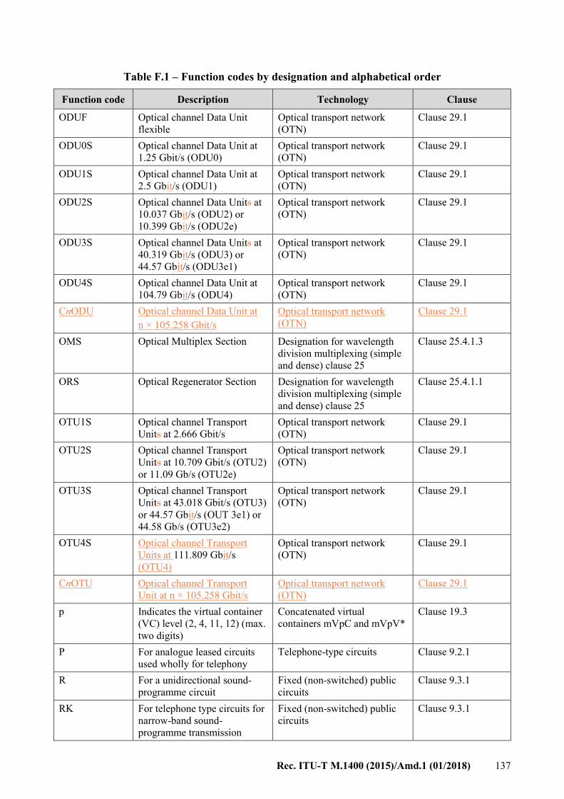
Rec. ITU-T M.1400 (2015)/Amd.1 (01/2018) 137
Table F.1 – Function codes by designation and alphabetical order
Function code Description Technology Clause
ODUF Optical channel Data Unit
flexible
Optical transport network
(OTN)
Clause 29.1
ODU0S Optical channel Data Unit at
1.25 Gbit/s (ODU0)
Optical transport network
(OTN)
Clause 29.1
ODU1S Optical channel Data Unit at
2.5 Gbit/s (ODU1)
Optical transport network
(OTN)
Clause 29.1
ODU2S Optical channel Data Units at
10.037 Gbit/s (ODU2) or
10.399 Gbit/s (ODU2e)
Optical transport network
(OTN)
Clause 29.1
ODU3S Optical channel Data Units at
40.319 Gbit/s (ODU3) or
44.57 Gbit/s (ODU3e1)
Optical transport network
(OTN)
Clause 29.1
ODU4S Optical channel Data Unit at
104.79 Gbit/s (ODU4)
Optical transport network
(OTN)
Clause 29.1
CnODU Optical channel Data Unit at
n × 105.258 Gbit/s
Optical transport network
(OTN)
Clause 29.1
OMS Optical Multiplex Section Designation for wavelength
division multiplexing (simple
and dense) clause 25
Clause 25.4.1.3
ORS Optical Regenerator Section Designation for wavelength
division multiplexing (simple
and dense) clause 25
Clause 25.4.1.1
OTU1S Optical channel Transport
Units at 2.666 Gbit/s
Optical transport network
(OTN)
Clause 29.1
OTU2S Optical channel Transport
Units at 10.709 Gbit/s (OTU2)
or 11.09 Gb/s (OTU2e)
Optical transport network
(OTN)
Clause 29.1
OTU3S Optical channel Transport
Units at 43.018 Gbit/s (OTU3)
or 44.57 Gbit/s (OUT 3e1) or
44.58 Gb/s (OTU3e2)
Optical transport network
(OTN)
Clause 29.1
OTU4S Optical channel Transport
Units at 111.809 Gbit/s
(OTU4)
Optical transport network
(OTN)
Clause 29.1
CnOTU Optical channel Transport
Unit at n × 105.258 Gbit/s
Optical transport network
(OTN)
Clause 29.1
p Indicates the virtual container
(VC) level (2, 4, 11, 12) (max.
two digits)
Concatenated virtual
containers mVpC and mVpV*
Clause 19.3
P For analogue leased circuits
used wholly for telephony
Telephone-type circuits Clause 9.2.1
R For a unidirectional sound-
programme circuit
Fixed (non-switched) public
circuits
Clause 9.3.1
RK For telephone type circuits for
narrow-band sound-
programme transmission
Fixed (non-switched) public
circuits
Clause 9.3.1

138 Rec. ITU-T M.1400 (2015)/Amd.1 (01/2018)
Table F.1 – Function codes by designation and alphabetical order
Function code Description Technology Clause
RP For analogue leased
unidirectional sound-
programme circuits
Telephone-type circuits Clause 9.2.1
RR For a reversible sound-
programme circuit
Fixed (non-switched) public
circuits
Clause 9.3.1
RRP For analogue leased reversible
sound-programme circuits
Telephone-type circuits Clause 9.2.1
SBR Statistical bit rate capability Designation of connections for
asynchronous transfer mode
(ATM)
Clause 22.15
T For circuits providing voice-
frequency telegraph links
Fixed (non-switched) public
circuits
Clause 9.3.1
TD For circuits providing TDM-
telegraph systems
Fixed (non-switched) public
circuits
Clause 9.3.1
TP For analogue leased circuits
used for voice-frequency
telegraphy
Telephone-type circuits Clause 9.2.1
TPD For analogue leased circuits
used for TDM-telegraphy
Telephone-type circuits Clause 9.2.1
V For a unidirectional television
circuit
Fixed (non-switched) public
circuits
Clause 9.3.1
V Defines that it is a virtual
container (one letter )
Concatenated virtual
containers mVpC and mVpV*
Clause 19.3
V* Defines that it is a virtual
concatenated VC (one letter)
Concatenated virtual
containers mVpC and mVpV*
Clause 19.3
VC1 1S For a VC-11 virtual container Designation of virtual
container interconnection
Clause 19.2.1
VC12S For a VC-12 virtual container Designation of virtual
container interconnection
Clause 19.2.1
VC2S For a VC-2 virtual container Designation of virtual
container interconnection
Clause 19.2.1
VC3S For a VC-3 virtual container Designation of virtual
container interconnection
Clause 19.2.1
VC4S For a VC-4 virtual container Designation of virtual
container interconnection
Clause 19.2.1
VCA Virtual channel Designation of connections for
asynchronous transfer mode
(ATM)
Clause 21.4
VP For analogue leased
unidirectional television-
programme circuits
Telephone-type circuits Clause 9.2.1
VPA Virtual path Designation of connections for
asynchronous transfer mode
(ATM)
Clause 21.3

Rec. ITU-T M.1400 (2015)/Amd.1 (01/2018) 139
Table F.1 – Function codes by designation and alphabetical order
Function code Description Technology Clause
VV For a reversible television
circuit
Fixed (non-switched) public
circuits
Clause 9.3.1
VVP For analogue leased reversible
television-programme circuits
Telephone-type circuits Clause 9.2.1
xxxxxA
(bit rate + A)
A = ADSL – maximum bit
rate for an ADSL connection,
x numerical value from 0-9
Designation of connection for
the digital subscriber line
(ADSL/SDSL)
Clause 27.1.1
xxxxxS
(bit rate + S)
S = SDSL – maximum bit rate
for an ADSL connection, x
numerical value from 0-9
Designation of connection for
the digital subscriber line
(ADSL/SDSL)
Clause 27.1.3
xP Number of copper pairs used
for a given SDSL connection.
x numerical value from 0 to 9
Designation of connection for
the digital subscriber line
(ADSL/SDSL)
Clause 27.3.10
XD Interconnecting circuits in the
public switched data network
Telephone-type circuits Clause 7.4
XP For analogue leased circuits
used for multiple type
transmissions
Telephone-type circuits Clause 9.2.1
Y* This code consists of a number
indicating the nominal
maximum number of channels
in the block followed by the
letter Y
Designation of digital block
(bidirectional/unidirectional)
interconnections
Clause 18.1
Z Automatic and semi-automatic
telephone circuits in one-way
operation
Telephone-type circuits Clause 7.2
A* – The function code is formed by adding the A after the number of nominal maximum channels
in the block.
C* – Letter C included in the function code and placed after the nominal number of channels
indicate groups, supergroups, etc., are converted to digital paths. Also, an additional C after the N
indicates digital blocks and paths are converted to analogue groups, supergroups, etc. (see
clauses 16.1.1 and 16.1.2).
M* – In the case of leased circuits connecting three or more locations, the letter M should follow
these function codes (see clause 9.2.12).
(U) – In the case of a unidirectional single destination group, the number is preceded by the letter
(U) in parentheses (see clause 11.3.2).
(MU) – Multiple destination unidirectional (see clause 11.3.1).
Y* – The function code is formed by adding the Y after the number of nominal maximum channels
in the block.

140 Rec. ITU-T M.1400 (2015)/Amd.1 (01/2018)
Bibliography
[b-ITU-T G.Suppl.43] Supplement 43 to ITU-T G-series Recommendations (2011), Transport
of IEEE 10GBASE-R in optical transport networks (OTN).
[b-ATIS-0300097] ATIS Specification ATIS-0300097 (2008), Structure for the
Identification of Telecommunications Connections for Interconnection
Exchange.

Printed in Switzerland Geneva, 2018
SERIES OF ITU-T RECOMMENDATIONS
Series A Organization of the work of ITU-T
Series D Tariff and accounting principles and international telecommunication/ICT economic and
policy issues
Series E Overall network operation, telephone service, service operation and human factors
Series F Non-telephone telecommunication services
Series G Transmission systems and media, digital systems and networks
Series H Audiovisual and multimedia systems
Series I Integrated services digital network
Series J Cable networks and transmission of television, sound programme and other multimedia
signals
Series K Protection against interference
Series L Environment and ICTs, climate change, e-waste, energy efficiency; construction, installation
and protection of cables and other elements of outside plant
Series M Telecommunication management, including TMN and network maintenance
Series N Maintenance: international sound programme and television transmission circuits
Series O Specifications of measuring equipment
Series P Telephone transmission quality, telephone installations, local line networks
Series Q Switching and signalling, and associated measurements and tests
Series R Telegraph transmission
Series S Telegraph services terminal equipment
Series T Terminals for telematic services
Series U Telegraph switching
Series V Data communication over the telephone network
Series X Data networks, open system communications and security
Series Y Global information infrastructure, Internet protocol aspects, next-generation networks,
Internet of Things and smart cities
Series Z Languages and general software aspects for telecommunication systems