ITU-T Rec. T.53 (04/94) Character coded control functions for ...
74
)454 4 TELECOMMUNICATION (04/94) STANDARDIZATION SECTOR OF ITU 4%,%-!4)#3%26)#%3 4%2-).!,%15)0-%.43!.$02/4/#/,3 &/24%,%-!4)#3%26)#%3 #(!2!#4%2#/$%$#/.42/,&5.#4)/.3 &/24%,%-!4)#3%26)#%3 )454Recommendation4 (Previously “CCITT Recommendation”) INTERNATIONAL TELECOMMUNICATION UNION
-
Upload
khangminh22 -
Category
Documents
-
view
1 -
download
0
Transcript of ITU-T Rec. T.53 (04/94) Character coded control functions for ...
)45 4 4���TELECOMMUNICATION (04/94)STANDARDIZATION SECTOROF ITU
4%,%-!4)#��3%26)#%3
4%2-).!,��%15)0-%.43��!.$��02/4/#/,3&/2��4%,%-!4)#��3%26)#%3
#(!2!#4%2��#/$%$��#/.42/,��&5.#4)/.3&/2��4%,%-!4)#��3%26)#%3
)45 4��Recommendation��4���
(Previously “CCITT Recommendation”)
INTERNATIONAL TELECOMMUNICATION UNION
FOREWORD
The ITU-T (Telecommunication Standardization Sector) is a permanent organ of the International TelecommunicationUnion (ITU). The ITU-T is responsible for studying technical, operating and tariff questions and issuing Recommen-dations on them with a view to standardizing telecommunications on a worldwide basis.
The World Telecommunication Standardization Conference (WTSC), which meets every four years, establishes thetopics for study by the ITU-T Study Groups which, in their turn, produce Recommendations on these topics.
The approval of Recommendations by the Members of the ITU-T is covered by the procedure laid down in WTSCResolution No. 1 (Helsinki, March 1-12, 1993).
ITU-T Recommendation T.53 was prepared by ITU-T Study Group 8 (1993-1996) and was approved under the WTSCResolution No. 1 procedure on the 7th of April 1994.
___________________
NOTE
In this Recommendation, the expression “Administration” is used for conciseness to indicate both a telecommunicationadministration and a recognized operating agency.
ITU 1994
All rights reserved. No part of this publication may be reproduced or utilized in any form or by any means, electronic ormechanical, including photocopying and microfilm, without permission in writing from the ITU.
Recommendation T.53 (04/94) i
CONTENTSRecommendation T.53 (04/94)
Page
1 Scope.............................................................................................................................................................. 11.1 General.............................................................................................................................................. 11.2 The ITU-T......................................................................................................................................... 1
2 Normative references ..................................................................................................................................... 22.1 Identical Recommendations | International Standards ...................................................................... 22.2 Paired Recommendations | International Standards equivalent in technical content ........................ 22.3 Additional references........................................................................................................................ 2
3 Definitions...................................................................................................................................................... 3
4 Abbreviations and acronyms.......................................................................................................................... 74.1 Abbreviations.................................................................................................................................... 74.2 Acronyms.......................................................................................................................................... 7
5 Device concepts ............................................................................................................................................. 7
6 Notation and Names ....................................................................................................................................... 76.1 Notation ............................................................................................................................................ 86.2 Names ............................................................................................................................................... 8
7 Code extension techniques ............................................................................................................................. 8
8 Types of control functions ............................................................................................................................. 88.1 Elements of the C0 set ...................................................................................................................... 88.2 Elements of the C1 set ...................................................................................................................... 98.3 Control sequences ............................................................................................................................. 98.4 Independent control functions .......................................................................................................... 98.5 Control strings .................................................................................................................................. 98.6 Not an element of any set ................................................................................................................. 108.7 Notation ............................................................................................................................................ 10
9 Categories of control functions considered in this Recommendation ............................................................ 10
10 Concepts relating to text formatting............................................................................................................... 1110.1 Formatted content / page-image format (PIF)................................................................................... 1110.2 Processable content........................................................................................................................... 1210.3 Formatted processable content (formattable content) ....................................................................... 12
11 Repertoire of control functions ...................................................................................................................... 1211.1 Delimiters ......................................................................................................................................... 1311.2 Device control functions................................................................................................................... 1311.3 Display control functions.................................................................................................................. 1411.4 Format effectors................................................................................................................................ 1411.5 Information separators ...................................................................................................................... 1611.6 Introducers ........................................................................................................................................ 1611.7 Miscellaneous control functions ....................................................................................................... 1711.8 Presentation control functions .......................................................................................................... 1711.9 Shift functions................................................................................................................................... 1911.10 Transmission control functions......................................................................................................... 20
12 Definition of control functions ....................................................................................................................... 2012.1 ACKNOWLEDGE (ACK) ............................................................................................................... 2012.2 AUXILIARY DEVICE OFF (ADF) ................................................................................................ 2012.3 AUXILIARY DEVICE ON (ADO) ................................................................................................. 21
ii Recommendation T.53 (04/94)
Page12.4 ACTIVATE IMPLICIT SCROLLING (AIS)................................................................................... 2112.5 ACTIVE POSITION ADDRESSING (APA)................................................................................... 2112.6 ACTIVE POSITION BACKWARD (APB)..................................................................................... 2112.7 ACTIVE POSITION DOWN (APD) ............................................................................................... 2112.8 ACTIVE POSITION FORWARD (APF)......................................................................................... 2112.9 ACTIVE POSITION HOME (APH) ................................................................................................ 2212.10 ACTIVE POSITION RETURN (APR) ............................................................................................ 2212.11 ACTIVE POSITION SET (APS) ..................................................................................................... 2212.12 ACTIVE POSITION UP (APU)....................................................................................................... 2212.13 BELL (BEL) ..................................................................................................................................... 2212.14 BREAK PERMITTED HERE (BPH)............................................................................................... 2212.15 BACKSPACE (BS) .......................................................................................................................... 2312.16 CANCEL (CAN) .............................................................................................................................. 2312.17 CURSOR OFF (COF) (used only in Recommendation T.101) ........................................................ 2312.18 CURSOR ON (CON) (used only in Recommendation T.101) ......................................................... 2312.19 CARRIAGE RETURN (CR) ............................................................................................................ 2312.20 CLEAR SCREEN (CS) .................................................................................................................... 2412.21 CONTROL SEQUENCE INTRODUCER (CSI) ............................................................................. 2412.22 DEVICE CONTROL ONE (DC1) ................................................................................................... 2412.23 DEVICE CONTROL TWO (DC2)................................................................................................... 2512.24 DEVICE CONTROL THREE (DC3)............................................................................................... 2512.25 DEVICE CONTROL FOUR (DC4) ................................................................................................. 2512.26 DISPLAY DEVICE OFF (DDF)...................................................................................................... 2512.27 DISPLAY DEVICE ON (DDO)....................................................................................................... 2512.28 DELETE (DEL)................................................................................................................................ 2512.29 DEACTIVATE IMPLICIT SCROLLING (DIS) ............................................................................. 2612.30 DATA LINK ESCAPE (DLE) ......................................................................................................... 2612.31 EMPTY BUFFER (EBU) ................................................................................................................. 2612.32 EXTENDED DEVICE CONTROL ONE (EDC1)........................................................................... 2612.33 EXTENDED DEVICE CONTROL TWO (EDC2) .......................................................................... 2612.34 EXTENDED DEVICE CONTROL THREE (EDC3) ...................................................................... 2612.35 EXTENDED DEVICE CONTROL FOUR (EDC4) ........................................................................ 2612.36 ENQUIRY (ENQ) ............................................................................................................................ 2712.37 END OF TRANSMISSION (EOT) .................................................................................................. 2712.38 ESCAPE (ESC) ................................................................................................................................ 2712.39 END OF TRANSMISSION BLOCK (ETB).................................................................................... 2712.40 END OF TEXT (ETX) ..................................................................................................................... 2712.41 FORM FEED (FF)............................................................................................................................ 2712.42 FONT SELECTION (FNT) .............................................................................................................. 2812.43 GRAPHIC CHARACTER COMBINATION (GCC) ...................................................................... 2812.44 GRAPHIC SIZE MODIFICATION (GSM)..................................................................................... 2812.45 GRAPHIC SIZE SELECTION (GSS).............................................................................................. 2912.46 HARD COPY START (HCS) .......................................................................................................... 2912.47 HARD COPY STOP (HCT) ............................................................................................................. 29

Recommendation T.53 (04/94) iii
Page12.48 HARD COPY WAIT (HCW) ........................................................................................................... 2912.49 CHARACTER POSITION BACKWARD (HPB) ........................................................................... 3012.50 CHARACTER POSITION FORWARD (HPR)............................................................................... 3012.51 CHARACTER TABULATION (HT) .............................................................................................. 3012.52 IDENTIFY GRAPHIC SUBREPERTOIRE (IGS) .......................................................................... 3012.53 INFORMATION SEPARATOR ONE (US - UNIT SEPARATOR) (IS1) ...................................... 3112.54 INFORMATION SEPARATOR TWO (IS2) – RECORD SEPARATOR) (RS)............................. 3112.55 INFORMATION SEPARATOR THREE (IS3) [GROUP SEPARATOR (GS)] ............................. 3112.56 INFORMATION SEPARATOR FOUR (IS4) [FILE SEPARATOR (FS)] ..................................... 31
iv Recommendation T.53 (04/94)
SUMMARY
This Recommendation defines the character coded control functions and their coded representation for use in 7-bit and8-bit coded ITU-T Telematic services and related to the text communication part of the Telematic services.
The control functions contained in this Recommendation define the basic meanings which may be common in some(or all) of the Telematic services. The definitions of the control functions are aligned to those in ISO/IEC 6429 andISO/IEC 10538 where possible with the exception of some specific functions defined by particular services.
This Recommendation specifies control functions to handle bi-directional texts in character-imaging devices. Thebi-directional concept is an addition to the uni-directional device concept which was the base for the former ITU-TRecommendations | ISO standards. It means that the control functions which were modified to meet the bi-directionalrequirements can be used for uni-directional devices, as before.
Recommendation T.53 (04/94) 1
Recommendation T.53Recommendation T.53 (04/94)
CHARACTER CODED CONTROL FUNCTIONSFOR TELEMATIC SERVICES
(Geneva, 1994)
1 Scope
1.1 General
This Recommendation defines the character coded control functions and their coded representation for use in 7-bit and8-bit codes, in use by ITU-T Telematic services.
The control functions contained in this Recommendation define the basic meanings which may be common in some (orall) of the Telematic services. The definitions of the control functions are aligned to those in ISO/IEC 6429 and ISO/IEC10538 where possible with the exception of some specific functions defined by particular services for their use. Wherethe control function definitions differ between those in particular existing Telematic services on the one hand, and thosein this Recommendation on the other hand, then the definitions in the particular Telematic services should takeprecedence. For future development, Telematic services should use the control functions defined in thisRecommendation.
This Recommendation specifies control functions to handle bi-directional texts in character-imaging devices. Thebi-directional concept is an addition to the uni-directional device concept which was the base for the former ITU-TRecommendations | ISO Standards. That means that the control functions which were modified to meet the bi-directionalrequirements can be used for uni-directional devices, as before.
1.2 The ITU-T
considering
(a) the increasing interdependence of the various ITU-T character sets and coding schemes in various Telematicservices;
(b) the introduction of new facilities such as code conversion and interworking between various Telematicservices;
(c) the advantage of having relevant control functions and coding schemes compiled in one Recommendation;
(d) that Recommendation T.50 specifies the International Reference Version (IRV) of the 7-bit coded characterset;
(e) that Recommendations T.51 and T.52 define the Latin based, respectively the non-Latin based, coded charactersets for Telematic services;
(f) that Recommendation T.51 defines the code extension mechanisms used in Telematic services;
(g) that Recommendations T.61 and T.101 define the character coding systems for Teletex and Videotex;
(h) that Recommendation T.416 defines the character content architecture in Open Document Architecture (ODA)environments,
(i) that Annex D/T.4 defines an optional character mode of group 3 facsimile apparatus,
provides the following Recommendation as a reference document, from which control functions should be derived forindividual Telematic services.

2 Recommendation T.53 (04/94)
1.3 This Recommendation specifies the character coded control functions related to the text communication part ofTelematic services.
1.4 This Recommendation is open-ended, additional control functions being subject to further inclusion as theneed for such is identified for one or more Telematic services.
2 Normative references
The following ITU-T Recommendations and International Standards contain provisions which, through reference in thistext, constitute provisions of this Recommendation. At the time of publication, the editions indicated were valid. AllRecommendations and Standards are subject to revision, and parties to agreements based on this Recommendation areencouraged to investigate the possibility of applying the most recent edition of the Recommendations and Standardslisted below. Members of IEC and ISO maintain lists of currently valid International Standards. The TSB maintains a listof currently valid ITU-T Recommendations.
2.1 Identical Recommendations | International Standards
None.
2.2 Paired Recommendations | International Standards equivalent in technical content
– CCITT Recommendation T.50 (1992), International Reference Alphabet.
ISO/IEC 646:1991, Information technology – ISO 7-bit coded character set for information technology.
– CCITT Recommendation T.51 (1992), Latin based coded character sets for Telematic services.
ISO/DIS 6937:1991, Information technology – Coded graphic character set for the communication oftexts using the Latin alphabet.
– CCITT Recommendation T.416 (1988) | ISO 8613-6:1988, Open document architecture (ODA) andinterchange format – Character content architecture.
2.3 Additional references
– CCITT Recommendation T.4 (1992), Standardization of Group 3 Facsimile Apparatus for DocumentTransmission, Annex D – Optional Character Mode of Group 3.
– ITU-T Recommendation T.52 (1993), Non-Latin coded character sets for Telematic services.
– ITU-T Recommendation T.61 (1993), Character repertoire and coded character sets for the internationalTeletex service.
– ITU-T Recommendation T.101 (1993), International interworking for Videotex services.
– ISO 1745:1975, Information processing – Basic mode control procedures for data communicationsystems.
– ISO 2022:1986, Information processing – ISO 7-bit and 8-bit coded character sets – Code extensiontechniques (under revision).
– ISO 2375:1985, Data processing – Procedure for registration of escape sequences.
– ISO/IEC 6429:1992, Information processing – Control functions for 7-bit and 8-bit coded character sets.
– ISO/IEC 7350:1991, Information technology – Registration of repertoires of graphic characters fromISO/IEC 10367.
Recommendation T.53 (04/94) 3
– ISO/IEC 10367:1991, Information technology – Standardized coded graphic character sets for use in8-bit codes.
– ISO/IEC 10538:1991, Information technology – Control functions for text communication.
– Standard ECMA-48, Control functions for coded character sets, June 1991.
– ECMA TR/53, Handling of bi-directional texts, June 1992.
– ISO/IEC JTC 1/SC 2 WG 3 N2122 – Guidelines for generating and presenting unique names of thecharacters in SC 2 Standards, December 1990.
3 Definitions
The definitions in this Recommendation assume a bi-directional device model which has both a presentation componentand a data component . In the case of a uni-directional device or a bi-directional device without a data component (onlywith presentation component), all references to active data position, data component, character progression, etc., are tobe read as referring to active presentation position, presentation component, character path, etc., respectively.
The model of handling bi-directional text according to ECMA TR/53 is described in Annex B.
3.1 active data position: In the data component the character position which is to receive the next graphiccharacter or the next control function from the data stream and relative to which certain control functions are to beexecuted.
3.2 active line: The line in the data component is the line which contains the active data position.
The line in the presentation component is the line which contains the active presentation position.
3.3 active page: The page in the data component is the page which contains the active data position.
The page in the presentation component the page which contains the active presentation position.
3.4 active position: The character position which is to image the graphic symbol representing the next graphiccharacter or relative which the next control function is to be executed.
NOTE – In general, the active position is indicated in a display by a cursor.
3.5 active presentation position: In the presentation component the character position which is to receive thenext graphic character for graphic image output and relative to which certain control functions are to be executed.
NOTE – In general, the active presentation position is indicated in a display by a cursor.
3.6 auxiliary device: A device connected to a character-imaging device for the purpose of inputting, storing,retrieving, or imaging data.
3.7 bi-directional data: Data containing text strings which are to be presented in different writing directions, likeleft-to-right and right-to-left.
3.8 bit combination: An ordered set of bits used for the representation of characters.
3.9 byte: A bit string that is operated upon as a unit.
3.10 to cancel: To mark data in such a way that it can be ignored in subsequent processing.
3.11 character: A member of a set of elements used for the organization, control or representation of data.
3.12 character-imaging device: A device that gives a visual representation of data in the form of graphic symbolsusing any technology, for example cathode ray tube or printer.
4 Recommendation T.53 (04/94)
3.13 character path: The sequential order of the character positions along a line of the presentation component.
3.14 character position: The portion of a display that is imaging or is capable of imaging a graphic symbol.
In the data component a position available for receiving graphic characters for further presentation processing.
In the presentation component a position available for receiving graphic characters for the rendering of the graphicimage output.
3.15 character progression: The sequential order of the character positions along a line of the data component.
3.16 to clear: To remove the display of data or the information used for the display of data, for example tabulationstops marking the boundaries between fields.
3.17 code extension: The techniques for the encoding of characters that are not included in the character set of agiven code.
3.18 code table: A table showing the character allocated to each bit combination in a code.
3.19 coded-character-data-element (ICC-data-element): An element of interchanged information that isspecified to consist of a sequence of coded representations of characters, in accordance with one or more identifiedstandards for coded character sets.
NOTES
1 In a communication environment according to the reference model for Open Systems Interconnection of CCITTRec. X.200 | ISO 7498, a CC-data-element will form all or part of the information that corresponds to the Presentation-Protocol-Data-Units (PPDU) defined in those specifications.
2 When information interchange is accomplished by means of interchangeable media, a CC-data-element will form allor part of the information that corresponds to the user data, and not that recorded during formatting and initialization.
3.20 coded character set; code: A set of unambiguous rules that establishes a character set and the one-to-onerelationship between the characters of the set and their bit combination.
3.21 control character: A control function, the coded representation of which consists of a single bit combination.
3.22 control function: An action that affects the recording, processing, transmission, or interpretation of data thathas a coded representation consisting of one or more bit combinations.
3.23 control sequence: A string of bit combinations starting with that representing the control characterCONTROL SEQUENCE INTRODUCER (CSI), used for the coded representation of control functions with or withoutparameters.
3.24 control string: A string of bit combinations which may occur in the data stream as a logical entity for controlpurposes.
3.25 cursor: A special indicator used in a display to mark the active presentation position.
3.26 data component: The device component which is used for storing the received data for further presentationprocessing.
3.27 default: A value or a state that is to be assumed when no value or state is explicitly specified.
3.28 to delete: To remove the contents from character positions and closing the resulting gap by moving adjacentgraphic characters into the empty positions.
3.29 to designate: To identify a set of characters that are to be represented, in some cases immediately and inothers on the occurrence of a further control function, in a prescribed manner.
Recommendation T.53 (04/94) 5
3.30 device: A component of information processing equipment which can transmit, and/or receive, codedinformation within coded-character-data-elements.
NOTE – It may be an input/output device in the conventional sense, or a process such as an application program orgateway function.
3.31 dynamically redefinable character set (DRCS): A graphic character set containing definable characterswhose pattern can be downloaded from the host.
3.32 environment: The characteristic that identifies the number of bits used for representing a character in a dataprocessing or data communication system or in part of such a system.
3.33 to erase: To remove the contents from character positions and leaving the resulting gap open.
3.34 escape sequence: A string of bit combinations that is used for control purposes in code extension procedures.The first of these bit combinations represents the character ESCAPE.
3.35 Explicit movement
See B.3.3.2.
3.36 field: An area consisting of the character position at a character tabulation stop (beginning of the field) andthe character positions up to, but not including, the character position at the following character tabulation stop (end ofthe field).
3.37 Final Byte: The bit combination that terminates an escape sequence or a control sequence.
NOTE – In some specifications appears the term Final Character, with the same meaning.
3.38 formator function: A control function (format effector or presentation control function) describing how theoriginator of the data stream wishes the information to be formatted or presented.
3.39 formatted form: A form of representation of a document that allows the presentation of the document asintended by the originator and does not support editing and (re)formatting (also mentioned as final form).
NOTE – See also page-image format (PIF).
3.40 formatted processable form (formattable form): A form of representation of a document that allows thepresentation of the document as intended by the originator and also supports editing and (re)formatting. For example,Recommendation T.416 defines such a form.
3.41 graphic character: A character, other than a control function, that has a visual representation normallyhandwritten, printed or displayed, and that has a coded representation consisting of one or more bit combinations.
3.42 graphic rendition: The visual style of displaying a set of graphic symbols.
3.43 graphic symbol: A visual representation of a graphic character or of a control function.
3.44 Implicit movement
See Annex B.3.3.1.
3.45 Indirect movement
See Annex B.3.3.3.
3.46 Intermediate byte:
a) In an escape sequence, a bit combination that may occur between the control function ESCAPE (ESC)and the Final Byte.
b) In a control sequence, a bit combination that may occur between the control function CONTROLSEQUENCE INTRODUCER (CSI) and the Final Byte, or between a Parameter Byte and the Final Byte.
NOTE – In some specifications the term Intermediate Character appears with the same meaning.
6 Recommendation T.53 (04/94)
3.47 to invoke: To cause a designated set of characters to be represented by the prescribed bit combinationswhenever those bit combinations occur.
3.48 line: A set of consecutive character positions.
3.49 line home position: A reference position on a line in the data component ahead of which the active dataposition can normally not be moved.
A reference position on a line in the presentation component ahead of which the active presentation position cannormally not be moved.
3.50 line limit position: A reference position on a line in the data component beyond of which the active dataposition can normally not be moved.
A reference position on a line in the presentation component beyond of which the active presentation position cannormally not be moved.
3.51 line orientation: The term used to describe the way in which a line will appear in the graphic image output. Inthis Recommendation line orientation may only be horizontal or vertical.
3.52 line progression: The direction of presentation of successive lines.
3.53 nesting level: The number of ancestors between given substring and the string with no parent.
3.54 page: A set of consecutive lines.
3.55 page home position: A reference position on a page in the data component ahead of which the active line (theline that contains the active data position) can normally not be moved.
A reference position on a page in the presentation component ahead of which the active line (the line that contains theactive presentation position) can normally not be moved.
3.56 page limit position: A reference position on a page in the data component beyond which the active line (theline that contains the active data position) can normally not be moved.
A reference position on a page in the presentation component beyond which the active line (the line that contains theactive presentation position) can normally not be moved.
3.57 page-image format (PIF): A representation of the image of text which is formatted by the sender forpresentation by the recipient and which is not intended to be subjected to reformatting operations by the recipient.
NOTE – Same as “formatted form”. Recommendations T.61 and T.101 (also ISO/IEC 10538) use this term.
3.58 Parameter Byte: In a control sequence, a bit combination that may occur between the control functionCONTROL SEQUENCE INTRODUCER (CSI) and the Final Byte, or between CSI and an Intermediate Byte.
NOTE – In some specifications appears the term Parameter Character, with the same meaning.
3.59 presentation component: The device component which is used for producing the graphic image output.
3.60 repertoire: A specified set of characters that are represented by one or more bit combinations of a codedcharacter set.
3.61 scroll: The action whereby all, or part of, the graphic symbols of a display are moved in a specified direction.
3.62 substring: A string which is nested within another string.
3.63 tabulation: The technique of identifying character positions or lines in a display for the purpose of arranginginformation systematically.
3.64 tabulation stop: The indication that a character position or a line is to be used for tabulation; a charactertabulation stop may also serve as a boundary between fields.
Recommendation T.53 (04/94) 7
3.65 text area: The image of that part of a page on which text may be presented.
3.66 uni-directional text: Data containing text strings which are to be presented in a single writing direction.
4 Abbreviations and acronyms
4.1 Abbreviations
For the purposes of this Recommendation, the following abbrebiations apply:
CCITT International Telegraph and Telephone Consultative Committee
(replaced with ITU-T from 1 March 1993)
ECMA European Computer Manufacturers Association
IEC International Electrotechnical Commission
ISO International Organization for Standardization
ITU International Telecommunication Union
ITU-T ITU Telecommunication Standardization Sector (formerly the CCITT)
ITU-TSB ITU Telecommunication Sector Bureau (formerly the Secretariat of the CCITT)
4.2 Acronyms
See Annex D.
5 Device concepts
The definitions of the control functions in this Recommendation are based on general assumptions about the architectureof a character-imaging device. Examples of devices conforming to these concepts are: an alphanumeric display device, aprinter or a microfilm output device.
A character-imaging device is a device capable of receiving a data stream that consists of coded control functions andgraphic characters, and is capable of producing graphic image output. Such output must be readable by a human beingaccording to the various traditional writing conventions such as left-to-right, right-to-left, top-to-bottom and bottom-to-top. The graphic image output is, in general, produced in the form of one or more rectangular arrays of characterpositions and lines which are called pages.
If the device is an input/output device rather than merely an output device, it is also capable of transmitting a data streamthat consists of coded control functions and graphic characters; the transmitted data stream is, in general, composed of acombination of data which have been sent to the device and data which have been entered locally into the device, forexample by an associated keyboard.
A number of facilities for the organization of the graphic image output and for establishing the direction of presentedtext are provided by this Recommendation. A device may support all of these facilities or only a subset of themappropriate to the application.
The definitions in this Recommendation assume a bi-directional device which has both a presentation component and adata component.
In the case of a uni-directional device or a bi-directional device without a data component, all references to active dataposition, data component, character progression, etc., are to be read as referring to active presentation position,presentation component, character path, etc., respectively. The bi-directional device model is described in Annex B.
6 Notation and Names
The 7-bit and 8-bit code notation and naming rules are described in detail in Recommendation T.52.
8 Recommendation T.53 (04/94)
6.1 Notation
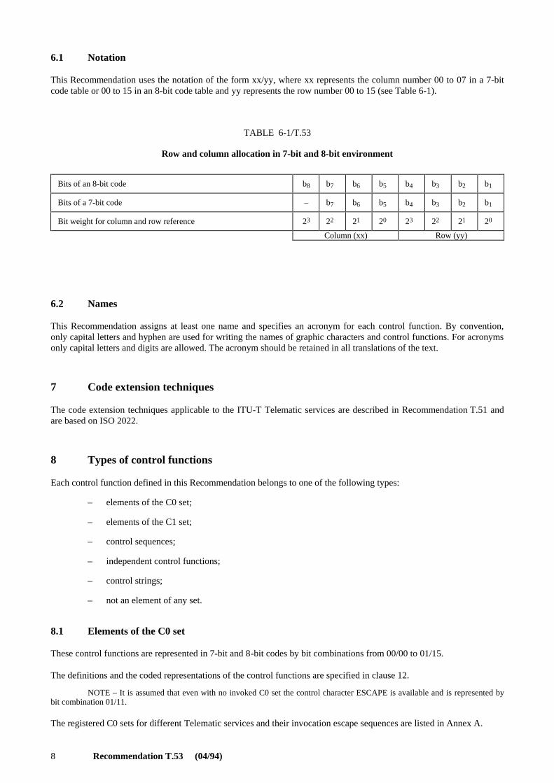
This Recommendation uses the notation of the form xx/yy, where xx represents the column number 00 to 07 in a 7-bitcode table or 00 to 15 in an 8-bit code table and yy represents the row number 00 to 15 (see Table 6-1).
TABLE 6-1/T.53
Row and column allocation in 7-bit and 8-bit environment
6.2 Names
This Recommendation assigns at least one name and specifies an acronym for each control function. By convention,only capital letters and hyphen are used for writing the names of graphic characters and control functions. For acronymsonly capital letters and digits are allowed. The acronym should be retained in all translations of the text.
7 Code extension techniques
The code extension techniques applicable to the ITU-T Telematic services are described in Recommendation T.51 andare based on ISO 2022.
8 Types of control functions
Each control function defined in this Recommendation belongs to one of the following types:
– elements of the C0 set;
– elements of the C1 set;
– control sequences;
– independent control functions;
– control strings;
– not an element of any set.
8.1 Elements of the C0 set
These control functions are represented in 7-bit and 8-bit codes by bit combinations from 00/00 to 01/15.
The definitions and the coded representations of the control functions are specified in clause 12.
NOTE – It is assumed that even with no invoked C0 set the control character ESCAPE is available and is represented bybit combination 01/11.
The registered C0 sets for different Telematic services and their invocation escape sequences are listed in Annex A.
Bits of an 8-bit code b8 b7 b6 b5 b4 b3 b2 b1
Bits of a 7-bit code – b7 b6 b5 b4 b3 b2 b1
Bit weight for column and row reference 23 22 21 20 23 22 21 20
Column (xx) Row (yy)
Recommendation T.53 (04/94) 9
8.2 Elements of the C1 set
These control functions are represented:
a) in a 7-bit code by 2-byte escape sequences of the form ESC Fe, where ESC is represented by bitcombination 01/11 and Final Byte Fe is represented by a bit combination from 04/00 to 05/15;
b) in an 8-bit code by bit combinations from 08/00 to 09/15; however, when the announcer sequenceESC 02/00 04/06 according to ISO 2022 is used, the control functions of the C1 set are represented byESC Fe sequences as in a 7-bit code.
The definitions and the coded representations of the control functions are specified in clause 12.
The unallocated bit combinations are reserved for future standardization and shall not be used.
The registered C1 sets for different Telematic services and their invocation escape sequences are listed in Annex A.
8.3 Control sequences
A control sequence consists of a sequence of bit combinations starting with that representing the control characterCONTROL SEQUENCE INTRODUCER (CSI) followed by one or more bit combinations representing parameters, ifany, and by one or more bit combinations identifying the control function. The control character CSI itself is an elementof the C1 set.
The format of a control sequence is:
CSI P1...Pn I1...In F
where:
a) CSI is represented by bit combination 01/11 (representing ESC) and 05/11 in a 7-bit code or by bitcombination 09/11 in an 8-bit code;
b) P1...Pn are Parameter Bytes, which, if present, consist of bit combinations from 03/00 to 03/15. Theparameter representation, the format of the parameter string, and the types of parameters are specified inISO/IEC 6429;
c) I1...In are Intermediate Bytes, which if present, consist of bit combinations from 02/00 to 02/15. Togetherwith the Final Byte F, they identify the control function;
d) F is the Final Byte; it consists of a bit combination from 04/00 to 07/14; it terminates the control sequenceand together with the Intermediate Bytes, if present, identifies the control function.
8.4 Independent control functions
These control functions are represented in 7-bit and 8-bit codes by two-character ESCAPE sequences of the form ESCFs, where ESC is represented by bit combination 01/11 and Fs is represented by bit combination from 06/00 to 07/14.
8.5 Control strings
A control string is a string of bit combinations which may occur in the data stream as a logical entity for controlpurposes. A control string consists of an opening delimiter, a command string or a character string, and a terminatingdelimiter, the STRING TERMINATOR (ST).
The opening delimiter defined in this Recommendation is START OF STRING (SOS).
A command string is a sequence of bit combinations in the range 00/08 to 00/13 and 02/00 to 07/14.
A character string is a sequence of any bit combinations, except those representing SOS or ST.
The interpretation of the command string or the character string is not defined by this Recommendation, but insteadrequires prior agreement between the sender and the recipient of the data.
NOTE – Control strings are used in CCITT Rec. T.416 | ISO 8613-6.
10 Recommendation T.53 (04/94)
8.6 Not an element of any set
Some Telematic services still make use of the characters SPACE (SP) and DELETE (DEL) which do not belong to anytype. The character SPACE is now definitely defined as a graphic character in ISO and the character DELETE is not acontrol function in the strict sense, both being removed from ISO/IEC 6429. The use of them as control functions isdeprecated. New services shall not implement them, other control functions being available with same functionality.
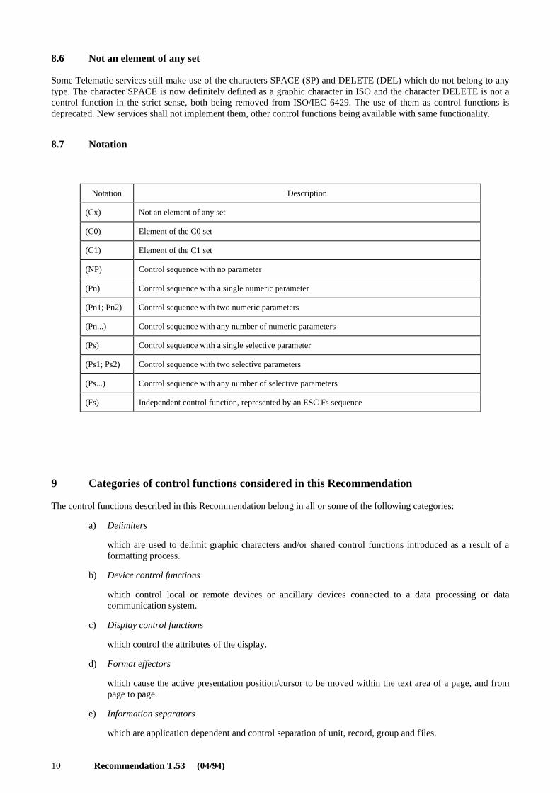
8.7 Notation
9 Categories of control functions considered in this Recommendation
The control functions described in this Recommendation belong in all or some of the following categories:
a) Delimiters
which are used to delimit graphic characters and/or shared control functions introduced as a result of aformatting process.
b) Device control functions
which control local or remote devices or ancillary devices connected to a data processing or datacommunication system.
c) Display control functions
which control the attributes of the display.
d) Format effectors
which cause the active presentation position/cursor to be moved within the text area of a page, and frompage to page.
e) Information separators
which are application dependent and control separation of unit, record, group and files.
Notation Description
(Cx) Not an element of any set
(C0) Element of the C0 set
(C1) Element of the C1 set
(NP) Control sequence with no parameter
(Pn) Control sequence with a single numeric parameter
(Pn1; Pn2) Control sequence with two numeric parameters
(Pn...) Control sequence with any number of numeric parameters
(Ps) Control sequence with a single selective parameter
(Ps1; Ps2) Control sequence with two selective parameters
(Ps...) Control sequence with any number of selective parameters
(Fs) Independent control function, represented by an ESC Fs sequence

Recommendation T.53 (04/94) 11
f) Introducers
which specify controls such as ESC and CSI used to introduce other control functions.
g) Miscellaneous control functions
which do not fit in any of the preceding categories.
h) Presentation control functions
which specify presentation attributes, that is, ways in which subsequent text is to be presented. Examplesof presentation attributes are page format, character rendition and tabulation.
i) Shift functions
which are mainly used in code extension techniques conforming to ISO 2022.
j) Transmission control functions
which are intended to control or facilitate transmission of information over telecommunication networks.
10 Concepts relating to text formatting
10.1 Formatted content / page-image format (PIF)
Formatted content is content for which all the necessary information relating to the layout and imaging of that contenthas been specified. Content in this form is intended to be imaged as specified and is not intended to be revised by anediting process or to be reformatted.
The content of a basic component conforming to a formatted character content architecture consists of one or more linesof characters. Each pair of successive lines is separated by a hard line terminator. The last (or only) line may or may notbe terminated by a hard line terminator; the end of the content of a basic component implicitly terminates the last line.
NOTE – Control functions used in formatted content (but not in processable content), as per CCITT Rec. T.416 |ISO 8613-6, are: BS, HPB, HPR, JFY, SACS, SRCS, SSW.
The communication or interchange of formatted text (page-image format) form implies the transfer of a stream of bitcombinations representing graphic characters in the order in which they appear on the pages of the documents, startingwith the first character in the first line of the text area of the first page of the first document, and proceeding character bycharacter, line by line and page by page until the end of the last document.
Embedded in the data stream, there may be coded representations of control functions for various purposes, including thefollowing:
a) to specify the size and the orientation of a page, and the size and the position of the text area on a page;
b) to specify the location of the next graphic character, if that location is other than at the character positionfollowing the one at which the previous graphic character on the same line was presented;
c) to specify the rendition aspects of graphic characters, such as character style and character emphasis, andthe character spacing and the line spacing;
d) to mark the end of a page or the end of a document.
The interpretation of the control functions and of the coded representations of the graphic characters are unambiguousonly if
– the sequence of the text is followed as specified above;
– no graphic character is located outside the text area;
– no more than one graphic character is located in any one character position on the page, unless aprovision for the superimposition of characters forms part of the coding method for the graphic charactersof the repertoire in use.
NOTE – The page-image format is implemented by Telematic services like Teletex and Videotex.
12 Recommendation T.53 (04/94)
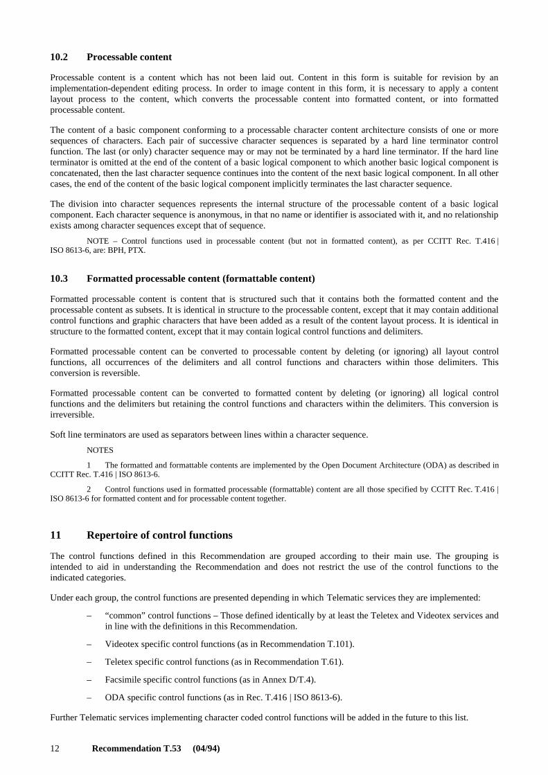
10.2 Processable content
Processable content is a content which has not been laid out. Content in this form is suitable for revision by animplementation-dependent editing process. In order to image content in this form, it is necessary to apply a contentlayout process to the content, which converts the processable content into formatted content, or into formattedprocessable content.
The content of a basic component conforming to a processable character content architecture consists of one or moresequences of characters. Each pair of successive character sequences is separated by a hard line terminator controlfunction. The last (or only) character sequence may or may not be terminated by a hard line terminator. If the hard lineterminator is omitted at the end of the content of a basic logical component to which another basic logical component isconcatenated, then the last character sequence continues into the content of the next basic logical component. In all othercases, the end of the content of the basic logical component implicitly terminates the last character sequence.
The division into character sequences represents the internal structure of the processable content of a basic logicalcomponent. Each character sequence is anonymous, in that no name or identifier is associated with it, and no relationshipexists among character sequences except that of sequence.
NOTE – Control functions used in processable content (but not in formatted content), as per CCITT Rec. T.416 |ISO 8613-6, are: BPH, PTX.
10.3 Formatted processable content (formattable content)
Formatted processable content is content that is structured such that it contains both the formatted content and theprocessable content as subsets. It is identical in structure to the processable content, except that it may contain additionalcontrol functions and graphic characters that have been added as a result of the content layout process. It is identical instructure to the formatted content, except that it may contain logical control functions and delimiters.
Formatted processable content can be converted to processable content by deleting (or ignoring) all layout controlfunctions, all occurrences of the delimiters and all control functions and characters within those delimiters. Thisconversion is reversible.
Formatted processable content can be converted to formatted content by deleting (or ignoring) all logical controlfunctions and the delimiters but retaining the control functions and characters within the delimiters. This conversion isirreversible.
Soft line terminators are used as separators between lines within a character sequence.
NOTES
1 The formatted and formattable contents are implemented by the Open Document Architecture (ODA) as described inCCITT Rec. T.416 | ISO 8613-6.
2 Control functions used in formatted processable (formattable) content are all those specified by CCITT Rec. T.416 |ISO 8613-6 for formatted content and for processable content together.
11 Repertoire of control functions
The control functions defined in this Recommendation are grouped according to their main use. The grouping isintended to aid in understanding the Recommendation and does not restrict the use of the control functions to theindicated categories.
Under each group, the control functions are presented depending in which Telematic services they are implemented:
– “common” control functions – Those defined identically by at least the Teletex and Videotex services andin line with the definitions in this Recommendation.
– Videotex specific control functions (as in Recommendation T.101).
– Teletex specific control functions (as in Recommendation T.61).
– Facsimile specific control functions (as in Annex D/T.4).
– ODA specific control functions (as in Rec. T.416 | ISO 8613-6).
Further Telematic services implementing character coded control functions will be added in the future to this list.
Recommendation T.53 (04/94) 13
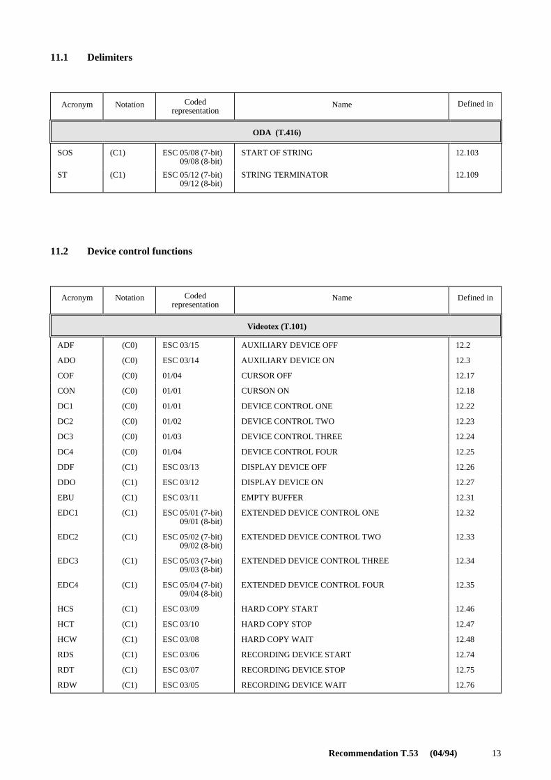
11.1 Delimiters
11.2 Device control functions
Acronym Notation Codedrepresentation
Name Defined in
ODA (T.416)
SOS (C1) ESC 05/08 (7-bit)ESC 09/08 (8-bit)
START OF STRING 12.103
ST (C1) ESC 05/12 (7-bit)ESC 09/12 (8-bit)
STRING TERMINATOR 12.109
Acronym Notation Codedrepresentation
Name Defined in
Videotex (T.101)
ADF (C0) ESC 03/15 AUXILIARY DEVICE OFF 12.2
ADO (C0) ESC 03/14 AUXILIARY DEVICE ON 12.3
COF (C0) 01/04 CURSOR OFF 12.17
CON (C0) 01/01 CURSON ON 12.18
DC1 (C0) 01/01 DEVICE CONTROL ONE 12.22
DC2 (C0) 01/02 DEVICE CONTROL TWO 12.23
DC3 (C0) 01/03 DEVICE CONTROL THREE 12.24
DC4 (C0) 01/04 DEVICE CONTROL FOUR 12.25
DDF (C1) ESC 03/13 DISPLAY DEVICE OFF 12.26
DDO (C1) ESC 03/12 DISPLAY DEVICE ON 12.27
EBU (C1) ESC 03/11 EMPTY BUFFER 12.31
EDC1 (C1) ESC 05/01 (7-bit)ESC 09/01 (8-bit)
EXTENDED DEVICE CONTROL ONE 12.32
EDC2 (C1) ESC 05/02 (7-bit)ESC 09/02 (8-bit)
EXTENDED DEVICE CONTROL TWO 12.33
EDC3 (C1) ESC 05/03 (7-bit)ESC 09/03 (8-bit)
EXTENDED DEVICE CONTROL THREE 12.34
EDC4 (C1) ESC 05/04 (7-bit)ESC 09/04 (8-bit)
EXTENDED DEVICE CONTROL FOUR 12.35
HCS (C1) ESC 03/09 HARD COPY START 12.46
HCT (C1) ESC 03/10 HARD COPY STOP 12.47
HCW (C1) ESC 03/08 HARD COPY WAIT 12.48
RDS (C1) ESC 03/06 RECORDING DEVICE START 12.74
RDT (C1) ESC 03/07 RECORDING DEVICE STOP 12.75
RDW (C1) ESC 03/05 RECORDING DEVICE WAIT 12.76
14 Recommendation T.53 (04/94)
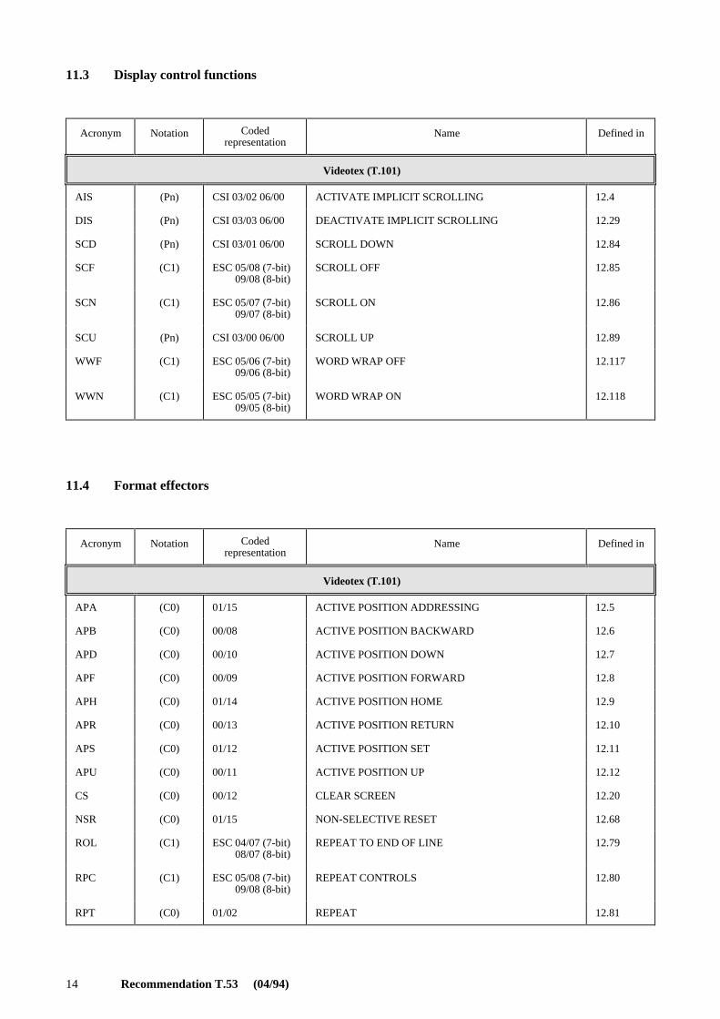
11.3 Display control functions
11.4 Format effectors
Acronym Notation Codedrepresentation
Name Defined in
Videotex (T.101)
AIS (Pn) CSI 03/02 06/00 ACTIVATE IMPLICIT SCROLLING 12.4
DIS (Pn) CSI 03/03 06/00 DEACTIVATE IMPLICIT SCROLLING 12.29
SCD (Pn) CSI 03/01 06/00 SCROLL DOWN 12.84
SCF (C1) ESC 05/08 (7-bit)ESC 09/08 (8-bit)
SCROLL OFF 12.85
SCN (C1) ESC 05/07 (7-bit)ESC 09/07 (8-bit)
SCROLL ON 12.86
SCU (Pn) CSI 03/00 06/00 SCROLL UP 12.89
WWF (C1) ESC 05/06 (7-bit)ESC 09/06 (8-bit)
WORD WRAP OFF 12.117
WWN (C1) ESC 05/05 (7-bit)ESC 09/05 (8-bit)
WORD WRAP ON 12.118
Acronym Notation Codedrepresentation
Name Defined in
Videotex (T.101)
APA (C0) 01/15 ACTIVE POSITION ADDRESSING 12.5
APB (C0) 00/08 ACTIVE POSITION BACKWARD 12.6
APD (C0) 00/10 ACTIVE POSITION DOWN 12.7
APF (C0) 00/09 ACTIVE POSITION FORWARD 12.8
APH (C0) 01/14 ACTIVE POSITION HOME 12.9
APR (C0) 00/13 ACTIVE POSITION RETURN 12.10
APS (C0) 01/12 ACTIVE POSITION SET 12.11
APU (C0) 00/11 ACTIVE POSITION UP 12.12
CS (C0) 00/12 CLEAR SCREEN 12.20
NSR (C0) 01/15 NON-SELECTIVE RESET 12.68
ROL (C1) ESC 04/07 (7-bit)ESC 08/07 (8-bit)
REPEAT TO END OF LINE 12.79
RPC (C1) ESC 05/08 (7-bit)ESC 09/08 (8-bit)
REPEAT CONTROLS 12.80
RPT (C0) 01/02 REPEAT 12.81

Recommendation T.53 (04/94) 15
Acronym Notation Codedrepresentation
Name Defined in
Teletex (T.61)
BS (C0) 00/08 BACKSPACE 12.15
CR (C0) 00/13 CARRIAGE RETURN 12.19
FF (C0) 00/12 FORM FEED 12.41
LF (C0) 00/10 LINE FEED 12.58
PLD (C1) ESC 04/11 (7-bit)ESC 08/11 (8-bit)
PARTIAL LINE FORWARD 12.71
PLU (C1) ESC 04/12 (7-bit)ESC 08/12 (8-bit)
PARTIAL LINE BACKWARD 12.72
RI (C1) ESC 04/13 (7-bit)ESC 08/13 (8-bit)
REVERSE LINE FEED 12.78
SP (Cx) 02/00 SPACE (see 8.6) 12.101
Facsimile (T.4)
CR (C0) 00/13 CARRIAGE RETURN 12.19
FF (C0) 00/12 FORM FEED 12.41
HT (C0) 00/09 CHARACTER TABULATION 12.51
LF (C0) 00/10 LINE FEED 12.58
ODA (T.416)
CR (C0) 00/13 CARRIAGE RETURN 12.19
HPB (Pn) CSI Pn 06/01 CHARACTER POSITION BACKWARD 12.49
HPR (Pn) CSI Pn 06/01 CHARACTER POSITION FORWARD 12.50
LF (C0) 00/10 LINE FEED 12.58
PLD (C1) ESC 04/11 (7-bit)ESC 08/11 (8-bit)
PARTIAL LINE FORWARD 12.71
PLU (C1) ESC 04/12 (7-bit)ESC 08/12 (8-bit)
PARTIAL LINE BACKWARD 12.72
SP (Cx) 02/00 SPACE (see 8.6) 12.101
VPB (Pn) CSI Pn 06/11 LINE POSITION BACKWARD 12.115
VPR (Pn) CSI Pn 06/05 LINE POSITION FORWARD 12.116
(T.53)
REP (Pn) CSI Pn 06/02 REPEAT 12.77

16 Recommendation T.53 (04/94)
11.5 Information separators
11.6 Introducers
Acronym Notation Codedrepresentation
Name Defined in
(T.53)
IS1 (C0) 01/15 INFORMATION SEPARATOR ONE 12.53
(US) (UNIT SEPARATOR)
IS2 (C0) 01/14 INFORMATION SEPARATOR TWO 12.54
(RS) (RECORD SEPARATOR)
IS3 (C0) 01/13 INFORMATION SEPARATOR THREE 12.55
(GS) (GROUP SEPARATOR)
(PT) (PAGE TERMINATOR)
IS4 (C0) 01/12 INFORMATION SEPARATOR FOUR 12.56
(FS) (FILE SEPARATOR)
(DT) (DOCUMENT TERMINATOR)
Videotex (T.101)
US (C0) 00/07 UNIT SEPARATOR 12.53
Acronym Notation Codedrepresentation
Name Defined in
“Common” (T.53)
CSI (C1) ESC 05/11 (7-bit)ESC 09/11 (8-bit)
CONTROL SEQUENCE INTRODUCER 12.21
ESC (C0) 01/11 ESCAPE 12.38
Recommendation T.53 (04/94) 17
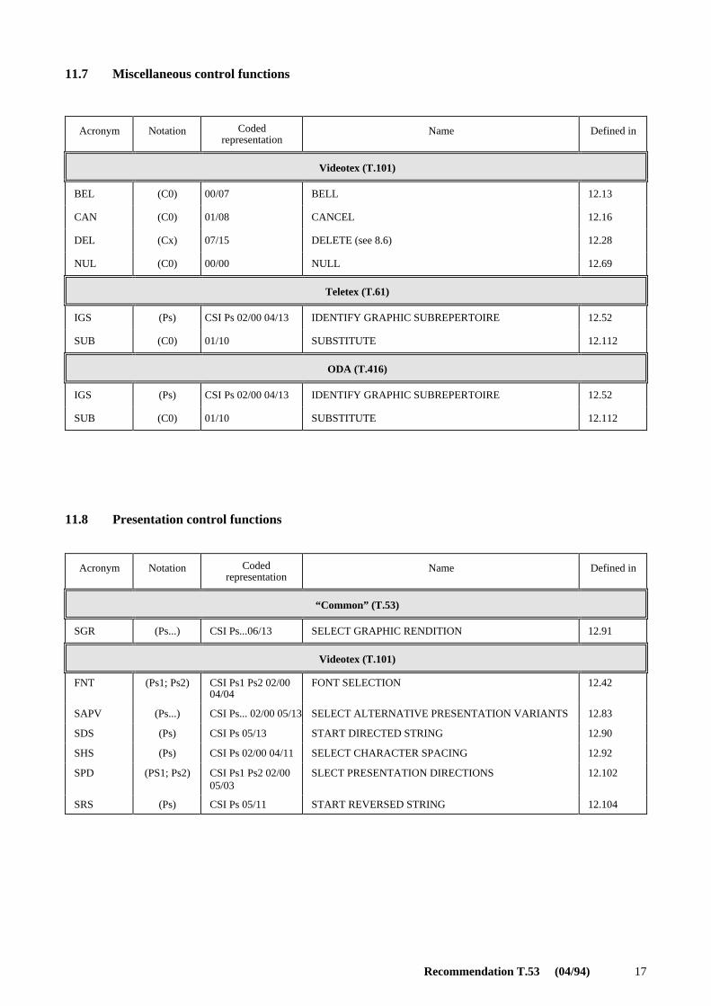
11.7 Miscellaneous control functions
11.8 Presentation control functions
Acronym Notation Codedrepresentation
Name Defined in
Videotex (T.101)
BEL (C0) 00/07 BELL 12.13
CAN (C0) 01/08 CANCEL 12.16
DEL (Cx) 07/15 DELETE (see 8.6) 12.28
NUL (C0) 00/00 NULL 12.69
Teletex (T.61)
IGS (Ps) CSI Ps 02/00 04/13 IDENTIFY GRAPHIC SUBREPERTOIRE 12.52
SUB (C0) 01/10 SUBSTITUTE 12.112
ODA (T.416)
IGS (Ps) CSI Ps 02/00 04/13 IDENTIFY GRAPHIC SUBREPERTOIRE 12.52
SUB (C0) 01/10 SUBSTITUTE 12.112
Acronym Notation Codedrepresentation
Name Defined in
“Common” (T.53)
SGR (Ps...) CSI Ps...06/13 SELECT GRAPHIC RENDITION 12.91
Videotex (T.101)
FNT (Ps1; Ps2) CSI Ps1 Ps2 02/0004/04
FONT SELECTION 12.42
SAPV (Ps...) CSI Ps... 02/00 05/13 SELECT ALTERNATIVE PRESENTATION VARIANTS 12.83
SDS (Ps) CSI Ps 05/13 START DIRECTED STRING 12.90
SHS (Ps) CSI Ps 02/00 04/11 SELECT CHARACTER SPACING 12.92
SPD (PS1; Ps2) CSI Ps1 Ps2 02/0005/03
SLECT PRESENTATION DIRECTIONS 12.102
SRS (Ps) CSI Ps 05/11 START REVERSED STRING 12.104
18 Recommendation T.53 (04/94)
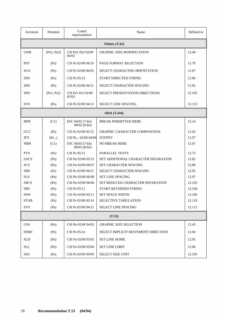
Acronym Notation Codedrepresentation
Name Defined in
Teletex (T.61)
GSM (Pn1; Pn2) CSI Pn1 Pn2 02/0004/02
GRAPHIC SIZE MODIFICATION 12.44
PFS (Ps) CSI Ps 02/00 04/10 PAGE FORMAT SELECTION 12.70
SCO (Ps) CSI Ps 02/00 06/05 SELECT CHARACTER ORIENTATION 12.87
SDS (Ps) CSI Ps 05/13 START DIRECTED STRING 12.90
SHS (Ps) CSI Ps 02/00 04/11 SELECT CHARACTER SPACING 12.92
SPD (Ps1; Ps2) CSI Ps1 Ps2 02/0005/03
SELECT PRESENTATION DIRECTIONS 12.102
SVS (Ps) CSI Ps 02/00 04/12 SELECT LINE SPACING 12.113
ODA (T.416)
BPH (C1) ESC 04/02 (7-bit)ESC 08/02 (8-bit)
BREAK PERMITTED HERE 12.14
GCC (Ps) CSI Ps 02/00 05/15 GRAPHIC CHARACTER COMPOSITION 12.43
JFY (Ps...) CSI Ps... 02/00 04/06 JUSTIFY 12.57
NBH (C1) ESC 04/03 (7-bit)ESC 08/03 (8-bit)
NO BREAK HERE 12.67
PTX (Ps) CSI Ps 05/12 PARALLEL TEXTS 12.73
SACS (Pn) CSI Pn 02/00 05/12 SET ADDITIONAL CHARACTER SEPARATION 12.82
SCS (Pn) CSI Pn 02/00 06/07 SET CHARACTER SPACING 12.88
SHS (Ps) CSI Ps 02/00 04/11 SELECT CHARACTER SPACING 12.92
SLS (Pn) CSI Pn 02/00 06/08 SET LINE SPACING 12.97
SRCS (Pn) CSI Pn 02/00 06/06 SET REDUCED CHARACTER SEPARATION 12.103
SRS (Ps) CSI Ps 05/11 START REVERSED STRING 12.104
SSW (Pn) CSI Pn 02/00 05/11 SET SPACE WIDTH 12.106
STAB (Ps) CSI Ps 02/00 05/14 SELECTIVE TABULATION 12.110
SVS (Ps) CSI Ps 02/00 04/12 SELECT LINE SPACING 12.113
(T.53)
GSS (Pn) CSI Pn 02/00 04/03 GRAPHIC SIZE SELECTION 12.45
SIMD (Ps) CSI Ps 05/14 SELECT IMPLICIT MOVEMENT DIRECTION 12.94
SLH (Pn) CSI Pn 02/00 05/05 SET LINE HOME 12.95
SLL (Pn) CSI Pn 02/00 05/06 SET LINE LIMIT 12.96
SSU (Ps) CSI Ps 02/00 04/09 SELECT SIZE UNIT 12.105
Recommendation T.53 (04/94) 19
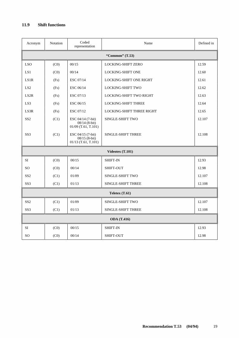
11.9 Shift functions
Acronym Notation Codedrepresentation
Name Defined in
“Common” (T.53)
LSO (C0) 00/15 LOCKING-SHIFT ZERO 12.59
LS1 (C0) 00/14 LOCKING-SHIFT ONE 12.60
LS1R (Fs) ESC 07/14 LOCKING-SHIFT ONE RIGHT 12.61
LS2 (Fs) ESC 06/14 LOCKING-SHIFT TWO 12.62
LS2R (Fs) ESC 07/13 LOCKING-SHIFT TWO RIGHT 12.63
LS3 (Fs) ESC 06/15 LOCKING-SHIFT THREE 12.64
LS3R (Fs) ESC 07/12 LOCKING-SHIFT THREE RIGHT 12.65
SS2 (C1) ESC 04/14 (7-bit)ESC 08/14 (8-bit)01/09 (T.61, T.101)
SINGLE-SHIFT TWO 12.107
SS3 (C1) ESC 04/15 (7-bit)ESC 08/15 (8-bit)01/13 (T.61, T.101)
SINGLE-SHIFT THREE 12.108
Videotex (T.101)
SI (C0) 00/15 SHIFT-IN 12.93
SO (C0) 00/14 SHIFT-OUT 12.98
SS2 (C1) 01/09 SINGLE-SHIFT TWO 12.107
SS3 (C1) 01/13 SINGLE-SHIFT THREE 12.108
Teletex (T.61)
SS2 (C1) 01/09 SINGLE-SHIFT TWO 12.107
SS3 (C1) 01/13 SINGLE-SHIFT THREE 12.108
ODA (T.416)
SI (C0) 00/15 SHIFT-IN 12.93
SO (C0) 00/14 SHIFT-OUT 12.98

20 Recommendation T.53 (04/94)
11.10 Transmission control functions
12 Definition of control functions
The control functions are listed in the alphabetical order of their acronyms. The acronyms shall be retained in alltranslations of the text.
The definitions of the control functions cover bi-directional devices which have both a presentation component and adata component.
In the case of a uni-directional device or a bi-directional device without a data component, all references to active dataposition, data component, character progression, etc., are to be read as referring to active presentation position,presentation component, character path, etc., respectively (see Note). This also means that the use of the controlfunctions in implementations already existing, is not affected by the inclusion of bi-directional capabilities in thisRecommendation.
NOTE – This Recommendation specifies a basic device profile for Telematic services based on a bi-directional device withpresentation component only.
12.1 ACKNOWLEDGE (ACK)
Notation: (C0)Representation: 00/06
ACK is transmitted by a receiver as an affirmative response to the sender.
The use of ACK is defined in ISO 1745.
12.2 AUXILIARY DEVICE OFF (ADF) (used only in Recommendation T.101)
Notation: (C0)Representation: ESC 03/15
Data subsequently received by the terminal is not passed to the auxiliary device.
Acronym Notation Codedrepresentation
Name Defined in
Videotex (T.101)
ACK (C0) 00/06 ACKNOWLEDGE 12.1
DLE (C0) 01/00 DATA LINK ESCAPE 12.30
ENQ (C0) 00/05 ENQUIRY 12.36
EOT (C0) 00/04 END OF TRANSMISSION 12.37
ETB (C0) 01/07 END OF TRANSMISSION BLOCK 12.39
ETX (C0) 00/03 END OF TEXT 12.40
NAK (C0) 01/05 NEGATIVE ACKNOWLEDGE 12.66
SOH (C0) 00/01 START OF HEADING 12.99
STX (C0) 00/02 START OF TEXT 12.111
SYN (C0) 01/06 SYNCHRONOUS IDLE 12.114
NOTE – Some Telematic services do not use control functions for transmission.
Recommendation T.53 (04/94) 21
12.3 AUXILIARY DEVICE ON (ADO) (used only in Recommendation T.101)
Notation: (C0)Representation: ESC 03/14
Data subsequently received by the terminal is passed to the auxiliary device.
12.4 ACTIVATE IMPLICIT SCROLLING (AIS) (used only in Recommendation T.101)
Notation: (Pn)Representation: CSI 03/02 06/00
A device control function which restores the implicit scrolling effect of format effectors.
12.5 ACTIVE POSITION ADDRESSING (APA) (used only in Recommendation T.101)
Notation: (C0)Representation: 01/15
A format effector which causes the active position to move to a defined position on the screen in accordance withparameters following.
12.6 ACTIVE POSITION BACKWARD (APB) (used only in Recommendation T.101)
Notation: (C0)Representation: 00/08
APB causes the active position to move backwards one character position on the same row. At the first characterposition on the row it moves the active position to the last character position of the preceding row. On the first characterposition of the first row it moves the active position to the last character position of the last row in the defined displayarea.
12.7 ACTIVE POSITION DOWN (APD) (used only in Recommendation T.101)
Notation: (C0)Representation: 00/10
APD causes the active position to the equivalent character position on the following row. On the last row it moves theactive position to the equivalent character position on the first row in the defined display area.
12.8 ACTIVE POSITION FORWARD (APF) (used only in Recommendation T.101)
Notation: (C0)Representation: 00/09
APF causes the active position to move forward to the next character position on the same row. At the last position onthe row, it moves the active position to the first character position on the following row. On the last character of the lastrow it moves the active position to the first character position on the first row in the defined display area.
See also CHARACTER POSITION FORWARD (HPR).
22 Recommendation T.53 (04/94)
12.9 ACTIVE POSITION HOME (APH) (used only in Recommendation T.101)
Notation: (C0)Representation: 01/14
APH is used to position the cursor to the upper left character position in the defined display area.
12.10 ACTIVE POSITION RETURN (APR) (used only in Recommendation T.101)
Notation: (C0)Representation: 00/13
APR causes the active position to move to the first character position of the same row.
12.11 ACTIVE POSITION SET (APS) (used only in Recommendation T.101)
Notation: (C0)Representation: 01/12
This character is used to set the cursor position without resetting any parameters or attributes. APS is used to set thecursor position which is specified by two-bytes parameter immediately following an APS. The two bytes shall comefrom columns 02 through 07 or 10 through 15. The first byte represents the row address and the second byte does thecolumn address. The address is obtained by taking the binary values comprising bits b7 through b1 with b7 being theMSB, masking out b8 and subtracting 32. This gives an address range from 0 through 95 inclusive for the row andcolumn addresses. For example, the bit combination 03/06 yields the binary integer 54, which after subtracting 32, givesthe address 22. If either of the characters following the APS character is a C0 or C1 control, the APS is ignored and theC0 or C1 control is executed.
Rows and columns are numbered starting with row 0, column 0, in the lower leftmost character position of the displayarea, and refer to the nominal screen format established by the current character field size (with the default intercharacterand interrow spacing). The cursor is positioned assuming zero character rotation to establish the character field origin.Once the character field origin is established, the character field and cursor are rotated, if necessary.
12.12 ACTIVE POSITION UP (APU) (used only in Recommendation T.101)
Notation: (C0)Representation: 00/11
APU causes the active position to move to the equivalent character position on the preceding row. On the first row itmoves the active position to the equivalent character position on the last row in the defined display area.
12.13 BELL (BEL)
Notation: (C0)Representation: 00/07
BEL is used when there is a need to call for attention; it may control alarm or attention devices.
12.14 BREAK PERMITTED HERE (BPH)
Notation: (C1)Representation: ESC 04/02 (in 7-bit code) or 08/02 (in 8-bit code)
BPH is used to indicate a point where a line break may occur when text is formatted. BPH may occur between twographic characters, either or both of which may be SPACE.

Recommendation T.53 (04/94) 23
12.15 BACKSPACE (BS)
Notation: (C0)Representation: 00/08
BS causes the active data position to be moved one character position in the direction opposite to that of the implicitmovement.
The direction of the implicit movement depends on the parameter value of SELECT IMPLICIT MOVEMENTDIRECTION (SIMD).
The amount of movement depends on the character spacing established by the most recent occurrence of SELECTCHARACTER SPACING (SHS), if any, or otherwise is the default character spacing.
BS shall not be used for combining the images of two or more graphic symbols in a single character position.
NOTES
1 The control function SET SPACE WIDTH (SSW) has no effect on BS.
2 The use of BS in document application profiles based on Recommendation T.416 | ISO 8613-6 is deprecated; it isincluded only for compatibility with Recommendation T.61. Instead, the control function CHARACTER POSITION BACKWARD(HPB) with parameter value Pn = 1 shall be implemented.
12.16 CANCEL (CAN)
Notation: (C0)Representation: 01/08
CAN is used to indicate that the data preceding it in the data stream is in error. As a result, this data shall be ignored. Thespecific meaning of this character shall be defined for each application and/or between sender and recipient.
12.17 CURSOR OFF (COF) (used only in Recommendation T.101)
Notation: (C0)Representation: 01/04
COF terminates the action of CURSOR ON (CON).
NOTE – Recommendation T.101 – DS II defines CURSOR OFF (COF) as an implementation-dependent case of DEVICECONTROL FOUR (DC4).
12.18 CURSOR ON (CON) (used only in Recommendation T.101)
Notation: (C0)Representation: 01/01
CON causes the active position to be indicated.
NOTE – Recommendation T.101 – DS II defines CURSOR ON (CON) as an implementation-dependent case of DEVICECONTROL ONE (DC1).
12.19 CARRIAGE RETURN (CR)
Notation: (C0)Representation: 00/13
The effect of CR depends on the parameter value of SELECT IMPLICIT MOVEMENT DIRECTION (SIMD).
24 Recommendation T.53 (04/94)
For devices with presentation component and with the parameter value of SIMD equal to 0, CR causes the activepresentation position to be moved to the line home position of the same line in the presentation component.
For devices with presentation component and with the parameter value of SIMD equal to 1, CR causes the activepresentation position to be moved to the line limit position of the same line in the presentation component.
For devices with data component and with the parameter value of SIMD equal to 0, CR causes the active data position tobe moved to the line home position of the same line in the data component.
For devices with data component and with the parameter value of SIMD equal to 1, CR causes the active data position tobe moved to the line limit position of the same line in the data component.
The line home position is established by the parameter value of SET LINE HOME (SLH).
The line limit position is established by the parameter value of SET LINE LIMIT (SLL).
CR shall not be used for combining the images of two or more graphic symbols in a single character position.
NOTES
1 The Telematic services do not define the line home position and line limit position, by the SLH, respectively SLLcontrol functions.
2 The line home position for various page formats used in the Teletex service (also in ISO/IEC 10538), is specifiedin C.2.
12.20 CLEAR SCREEN (CS)
Notation: (C0)Representation: 00/12
CS causes the active position to be moved to the first character position of the first row in the defined display area andcauses all character positions to be filled with SPACEs with all attributes set to the default conditions.
12.21 CONTROL SEQUENCE INTRODUCER (CSI)
Notation: (C1)Representation: ESC 05/11 (in 7-bit code) or 09/11 (in 8-bit code)
CSI is used as the first character of a control sequence, to provide representations for additional control functions, inparticular for control functions with parameters, such as presentation control functions.
12.22 DEVICE CONTROL ONE (DC1)
Notation: (C0)Representation: 01/01
DC1 is primarily intended for turning on or starting an ancillary device. If it is not required for this purpose, it may beused to restore a device to the basic mode of operation ( see also DC2 and DC3), or for any other device control functionnot provided by other DC’s.
NOTES
1 When used for data flow control, DC1 is sometimes called “X-ON”.
2 Recommendation T.101 – DS II defines the implementation-dependent specific case of DC1: CURSOR ON (CON).
Recommendation T.53 (04/94) 25
12.23 DEVICE CONTROL TWO (DC2)
Notation: (C0)Representation: 01/02
DC2 is primarily intended for turning on or starting an ancillary device. If it is not required for this purpose, it may beused to set a device to a special mode of operation (in which case DC1 is used to restore the device to the basic mode),or for any other device control function not provided by other DC’s.
12.24 DEVICE CONTROL THREE (DC3)
Notation: (C0)Representation: 01/03
DC3 is primarily intended for turning off or stopping an ancillary device. This function may be a secondary level stop,for example wait, pause, stand-by or halt (in which case DC1 is used to restore normal operation). If it is not required forthis purpose, it may be used for any other ancillary device control function not provided by other DC’s.
NOTE – When used for data flow control, DC3 is sometimes called “X-OFF”.
12.25 DEVICE CONTROL FOUR (DC4)
Notation: (C0)Representation: 01/04
DC4 is primarily intended for turning off, stopping or interrupting an ancillary device. It is not required for this purpose,it may be used for any other device control function not provided by other DC’s.
NOTE – Recommendation T.101 - DS II defines the implementation-dependent specific case of DC4: CURSOR OFF(COF).
12.26 DISPLAY DEVICE OFF (DDF) (used only in Recommendation T.101)
Notation: (C1)Representation: ESC 03/13
DDF causes the subsequently received data by the terminal not to be displayed.
12.27 DISPLAY DEVICE ON (DDO) (used only in Recommendation T.101)
Notation: (C1)Representation: ESC 03/12
DDO causes the subsequently received data by the terminal to be displayed.
12.28 DELETE (DEL) (used only in Recommendation T.101)
Notation: (Cx)Representation: 07/15
A character used primarily to erase or obliterate an erroneous or unwanted character in punched tape. DEL charactersmay also serve to accomplish media-fill or time-fill. They may be inserted into, or removed from, a stream of datawithout affecting the information content of the stream, but such action may affect the information layout and/or thecontrol equipment.
NOTES
1 When a set of 96 graphic characters is invoked into columns 02 to 07, or when the last character of such a set isinvoked by a single-shift function, bit combination 07/15 will not have the meaning of DEL.
2 DEL is not a control function in the strict sense. Its control functionality can be achieved by other control functions.The reason of maintaining it in this Recommendation is only for backward compatibility. The use of DEL is deprecated. It is foreseento remove DEL from the next edition of this Recommendation.
26 Recommendation T.53 (04/94)
12.29 DEACTIVATE IMPLICIT SCROLLING (DIS) (used only in Recommendation T.101)
Notation: (Pn)Representation: CSI 03/00 06/00
DIS deactivates the implicit scrolling, allowing the active presentation position in to move across the border of ascrolling area.
12.30 DATA LINK ESCAPE (DLE)
Notation: (C0)Representation: 01/00
DLE is used exclusively to provide supplementary transmission control functions.
DLE will change the meaning of a limited number of contiguously following bit combinations. Only graphic charactersand transmission control characters may be used in DLE sequences.
The use of DLE is defined in ISO 1745.
12.31 EMPTY BUFFER (EBU) (used only in Recommendation T.101)
Notation: (C1)Representation: ESC 03/11
EBU causes the contents of the terminal buffer to be transmitted to the line.
12.32 EXTENDED DEVICE CONTROL ONE (EDC1) (used only in Recommendation T.101)
Notation: (C1)Representation: ESC 05/01 (in 7-bit code) or 09/01 (in 8-bit code)
The precise meaning of EDC1, is reserved for future standardization, and is executed as NULL.
12.33 EXTENDED DEVICE CONTROL TWO (EDC2) (used only in Recommendation T.101)
Notation: (C1)Representation: ESC 05/02 (in 7-bit code) or 09/02 (in 8-bit code)
The precise meaning of EDC2, is reserved for future standardization, and is executed as NULL.
12.34 EXTENDED DEVICE CONTROL THREE (EDC3) (used only in Recommendation T.101)
Notation: (C1)Representation: ESC 05/03 (in 7-bit code) or 09/03 (in 8-bit code)
The precise meaning of EDC3, is reserved for future standardization, and is executed as NULL.
12.35 EXTENDED DEVICE CONTROL FOUR (EDC4) (used only in Recommendation T.101)
Notation: (C1)Representation: ESC 05/04 (in 7-bit code) or 09/04 (in 8-bit code)
The precise meaning of EDC4, is reserved for future standardization, and is executed as NULL.
Recommendation T.53 (04/94) 27
12.36 ENQUIRY (ENQ)
Notation: (C0)Representation: 00/05
ENQ is transmitted by a sender as a request for a response from a receiver.
The response may include station identification and/or station status. When a “Who are you” function is required on thegeneral switched transmission network, the first use of ENQ after the connection is established shall have the meaning“Who are you” (station identification). Subsequent use of ENQ may, or may not, include the function “Who are you”, asdetermined by agreement.
The use of ENQ is defined in ISO 1745.
12.37 END OF TRANSMISSION (EOT)
Notation: (C0)Representation: 00/04
EOT is used to indicate the conclusion of the transmission of one or more texts.
The use of EOT is defined in ISO 1745.
12.38 ESCAPE (ESC)
Notation: (C0)Representation: 01/11
ESC is used for code extension purposes. It causes the meanings of a limited number of bit combinations following it inthe data stream to be changed.
The use of ESC is defined in ISO 2022.
NOTE – In applications based on Recommendation T.50, it is a transmission control character preceding a text and it isused to terminate a heading.
12.39 END OF TRANSMISSION BLOCK (ETB)
Notation: (C0)Representation: 01/07
ETB is used to indicate the end of a block of data where the data are divided into such blocks for transmission purposes.
The use of ETB is defined in ISO 1745.
12.40 END OF TEXT (ETX)
Notation: (C0)Representation: 00/03
ETX is used to indicate the end of a text.
It is defined in ISO 1745 and Recommendation T.50.
12.41 FORM FEED (FF)
Notation: (C0)Representation: 00/12
FF causes the active presentation position to be moved to the corresponding character position of the line at the pagehome position of the next form or page in the presentation component.
The text area format is that specified by the most recent occurrence of PAGE FORMAT SELECTION (PFS), if any, orotherwise is the default text area format.
28 Recommendation T.53 (04/94)
Following an occurrence of SELECT PRESENTATION DIRECTIONS (SPD) with another than the default parameteror an occurrence of PFS with a parameter value other than 0 to 9, FF shall be followed by CR in order to move the activepresentation position to the line home position of the first line of the new page.
NOTE – Different Recommendations make use of control functions with similar functionality as FF, identical coding butwith a different name and acronym, e.g. Recommendation T.101 defines the control function: CLEAR SCREEN (CS).
12.42 FONT SELECTION (FNT)
Notation: (Ps1;Ps2)Representation: CSI Ps1 Ps2 02/00 04/04
Parameter default values: Ps1 = 0; Ps2 = 0
FNT is used to identify the character font to be selected as primary or alternative font by subsequent occurrences ofSELECT GRAPHIC RENDITION (SGR) in the data stream.
Ps1 specifies the primary or alternative font concerned:
0 Primary font
1 First alternative font
2 Second alternative font
3 Third alternative font
4 Fourth alternative font
5 Fifth alternative font
6 Sixth alternative font
7 Seventh alternative font
8 Eighth alternative font
9 Ninth alternative font
Ps2 identifies the character font according to a register which is to be established.
12.43 GRAPHIC CHARACTER COMBINATION (GCC)
Notation: (Ps)Representation: CSI Ps 02/00 05/15
Parameter default value: Ps = 0
GCC is used to indicate that two or more graphic characters are to be imaged as one single graphic symbol. GCC with aparameter value of 0 indicates that the following two graphic characters are to be imaged as one single graphic symbol;GCC with a parameter value of 1 and GCC with a parameter value of 2 indicate respectively the beginning and the endof a string of graphic characters which are to be imaged as one single graphic symbol.
NOTE – GCC does not explicitly specify the relative sizes or placements of the component parts of a composite graphicsymbol. In the simplest case, two components may be “half-width” and side-by-side. For example, in Japanese text a pair ofcharacters may be presented side-by-side, and occupy the space of a normal-size Kanji character.
12.44 GRAPHIC SIZE MODIFICATION (GSM)
Notation: (Pn1,Pn2)Representation: CSI Pn1 Pn2 02/00 04/02
Parameter default values: Pn1 = 100; Pn2 = 100
Recommendation T.53 (04/94) 29
GSM is used to modify for subsequent text the height and/or the width of all primary and alternative fonts identified byFONT SELECTION (FNT) and established by GRAPHIC SIZE SELECTION (GSS). The established values remain ineffect until the next occurrence of GSM or GSS in the data stream.
Pn1 specifies the height as a percentage of the height established by GSS.
Pn2 specifies the width as a percentage of the width established by GSS.
NOTE – Recommendation T.61 specifies the following parameter values with effect on the character spacing (as specifiedby SHS or SCS) and size, as follows:
a) For horizontal line orientation (SPD parameter Ps1 = 0, 3, 5 or 6)
GSM 100, 50 causes character spacing and width to be halved
GSM 100, 100 has no effect
GSM 100, 200 causes character spacing and width to be doubled.
b) For vertical line orientation (SPD parameter Ps1 = 1, 2, 4 or 7)
GSM 100, 100 has no effect
GSM 100, 200 causes character spacing and height to be doubled.
12.45 GRAPHIC SIZE SELECTION (GSS)
Notation: (Pn)
Representation: CSI Pn 02/00 04/03
Parameter default value: None
GSS is used to establish for subsequent text the height and the width of all primary and alternative fonts identified byFONT SELECTION (FNT). The established values remain in effect until the next occurrence of GSS in the data stream.
Pn specifies the height, the width is implicitly defined by the height.
The unit in which the parameter value is expressed is that established by the parameter value of SELECT SIZE UNIT(SSU).
12.46 HARD COPY START (HCS) (used only in Recommendation T.101)
Notation: (C1)Representation: ESC 03/09
HCS causes the associated hard copy device to start copying data subsequently received by the terminal.
12.47 HARD COPY STOP (HCT) (used only in Recommendation T.101)
Notation: (C1)Representation: ESC 03/10
HCT causes the associated hard copy device to stop.
12.48 HARD COPY WAIT (HCW) (used only in Recommendation T.101)
Notation: (C1)Representation: ESC 03/08
HCW causes the associated hard copy device to wait.
30 Recommendation T.53 (04/94)
12.49 CHARACTER POSITION BACKWARD (HPB)
Notation: (Pn)Representation: CSI Pn 06/10
Parameter default value: Pn = 1 (See Note)
HPB causes the active data position to be moved by n character positions in the data component in the direction oppositeto that of the character progression, where n equals the value of Pn.
NOTE – CCITT Rec. T.416 | ISO 8613-6 defines the parameter default value of HPB as the equivalent of 120 BMUs,where BMU (BASIC MEASUREMENT UNIT) has the value of 1/1200 of 25,4 mm (0,02117 mm).
Also it mentions that the main purposes of HPB are to move the active data position backwards from the line home positionand to provide for the positioning of parallel annotation.
12.50 CHARACTER POSITION FORWARD (HPR)
Notation: (Pn)Representation: CSI Pn 06/01
Parameter default value: Pn = 1 (See Note 1)
HPR causes the active data position to be moved by n character positions in the data component in the direction of thecharacter progression, where n equals the value of Pn.
NOTES
1 CCITT Recommendation T.416 |ISO 8613-6 defines the parameter default value of HPR as the equivalent of 120BMUs, where BMU (BASIC MEASUREMENT UNIT) has the value of 1/1200 of 25,4 mm (0,02117 mm).
Also it mentions that one of the main purposes of HPR is to provide for the positioning of parallel annotation.
2 Although HPR has a control effect similar to that of one or more SPACE characters, it does not have the graphicequivalence of SPACE characters. Therefore, HPR does not cause spaces to be imaged in accordance with the current graphicrendition, such as underlined, possibly specified by a preceding occurrence of the control function SELECT GRAPHIC RENDITION(SGR).
12.51 CHARACTER TABULATION (HT)
Notation: (C0)Representation: 00/09
HT causes the active presentation position to be moved to the following character tabulation stop in the presentationcomponent.
12.52 IDENTIFY GRAPHIC SUBREPERTOIRE (IGS)
Notation: (Ps)Representation: CSI Ps 02/00 04/13
Parameter default value: None
IGS is used to indicate that a subrepertoire of the graphic character repertoire of ISO/IEC 10367 is used in thesubsequent text. All graphic characters needed to represent the indicated subrepertoire shall be explicitly or implicitlydesignated, but need not be invoked, prior to the occurrence of IGS. The identification of the graphic charactersubrepertoire may be changed at any point within the document and takes effect immediately.
The effect of IGS ceases upon the next occurrence of:
a) another IGS;
b) the control function PAGE TERMINATOR (PT);
c) the control function DOCUMENT TERMINATOR (DT);
d) the designation of any graphic character set.
Recommendation T.53 (04/94) 31
The parameter value is the identifier assigned to a subrepertoire of the repertoire of ISO/IEC 10367 in accordance withthe registration procedure specified in ISO/IEC 7350. In the absence of IGS, the entire repertoire of the currentlydesignated graphic character set applies. An occurrence of IGS without a parameter value cancels any subrepertoireidentification by a preceding IGS.
12.53 INFORMATION SEPARATOR ONE (US – UNIT SEPARATOR) (IS1)
Notation: (C0)Representation: 01/15
IS1 is used to separate and qualify data logically; its specific meaning has to be defined for each application. If thiscontrol function is used in hierarchical order, it may delimit a data item called a unit. In this case the control function isnamed UNIT SEPARATOR (US).
12.54 INFORMATION SEPARATOR TWO (IS2) – RECORD SEPARATOR) (RS)
Notation: (C0)Representation: 01/14
IS2 is used to separate and qualify data logically; its specific meaning has to be defined for each application. If thiscontrol function is used in hierarchical order, it may delimit a data item called a record. In this case the control functionis named RECORD SEPARATOR (RS).
12.55 INFORMATION SEPARATOR THREE (IS3) [GROUP SEPARATOR (GS)]
Notation: (C0)
Representation: 01/13
IS3 is used to separate and qualify data logically; its specific meaning has to be defined for each application. If thiscontrol function is used in hierarchical order, it may delimit a data item called a group. In this case the control function isnamed GROUP SEPARATOR (GS).
NOTE – In accordance with ISO/IEC 10538 and ISO/IEC 6429, this control function is given two names. The nameINFORMATION SEPARATOR THREE (IS3) is the general name. The name PAGE TERMINATOR (PT) is the specific name. Theinformation separators in this Recommendation are used in hierarchical order. The ascending order is PT(IS3), DT(IS4).
PAGE TERMINATOR (PT) delimits the text that is to be imaged on a given page and separates it from the text of thenext page, if any, of the same document. The separator is either an occurrence of the control functions PT (IS3) orDOCUMENT TERMINATOR (DT) (INFORMATION SEPARATOR FOUR (IS4)) embedded in the text, or theequivalent function as a protocol element.
This is an application-oriented use of control function IS3, as a page terminator function. It causes all representationattributes to be reset to the default state, causes any graphic character subrepertoire identification, as well as all non-default designations and invocations of graphic character sets to be cancelled, and causes the default character sets, ifany, to be implicitly designated and invoked. Any such attribute, identification, etc. shall be (re)specified at thebeginning of each page.
12.56 INFORMATION SEPARATOR FOUR (IS4) [FILE SEPARATOR (FS)]
Notation: (C0)
Representation: 01/12
IS4 is used to separate and qualify data logically; its specific meaning has to be defined for each application. If thiscontrol function is used in hierarchical order, it may delimit a data item called a file. In this case the control function isnamed FILE SEPARATOR (FS).
NOTE – In accordance with ISO/IEC 10538 and ISO/IEC 6429, this control function is given two names. The nameINFORMATION SEPARATOR FOUR (IS4) is the general name. The name DOCUMENT TERMINATOR (DT) is the specificname. The information separators in this Recommendation are used in hierarchical order. The ascending order is PT(IS3), DT(IS4).

32 Recommendation T.53 (04/94)
DOCUMENT TERMINATOR (DT) is used to indicate the end of the text on a document. This is an application-orienteduse of control function IS4, as a document terminator function. In addition, it has the same effect as the control functionPAGE TERMINATOR (PT), namely it causes all representation attributes to be reset to the default state, causes anygraphic character subrepertoire identification, as well as all non-default designations and invocations of graphiccharacter sets to be cancelled, and causes the default character sets, if any, to be implicitly designated and invoked. Anysuch attribute, identification, etc., shall be (re)specified at the beginning of each page.
12.57 JUSTIFY (JFY)Recommendation T.53 (04/94)
Notation: (Ps...)
Representation: CSI Ps 02/00 04/06
Parameter default value: Ps = 0
JFY is used to indicate the beginning of a string of graphic characters in the presentation component that are to bejustified according to the layout specified by the parameter values:
0 No justification, end of justification of preceding text
1 Word fill
2 Word space
3 Letter space
4 Hyphenation
5 Flush to line home position margin
6 Center between line home position and the line limit position margins
7 Flush to line limit position margin
8 Italian hyphenation
The end of the string to be justified is indicated by the next occurrence of JFY in the data stream.
The line home position is established by the parameter value of SET LINE HOME (SLH). The line limit position isestablished by the parameter value of SET LINE LIMIT (SLL).
NOTE – CCITT Rec. T.416 | ISO 8613-6 names this function “NO JUSTIFY” perhaps because the only allowed parametervalue is the default value Ps = 0.
12.58 LINE FEED (LF)
Notation: (C0)
Representation: 00/10
For devices with presentation component, LF causes the active presentation position to be moved to the correspondingcharacter position of the following line in the presentation component.
For devices with data component, LF causes the active data position to be moved to the corresponding character positionof the following line in the data component.
NOTE – The direction of the line progression depends on the parameter SELECT PRESENTATION DIRECTIONS (SPD),if any, prior to the most recent occurrence of FORM FEED (FF), or otherwise is from top-to-bottom. The amount of movementdepends on the line spacing established by the most recent occurrence of SELECT LINE SPACING (SVS), if any, or otherwise is thedefault line spacing.
12.59 LOCKING-SHIFT ZERO (LS0)
Notation: (C0)
Representation: 00/15
LS0 is used for code extension purposes. It causes the meanings of the bit combinations following it in the data stream tobe changed.

Recommendation T.53 (04/94) 33
The use of LS0 is defined in ISO 2022.
NOTES
1 LS0 is used in 8-bit environments only; in 7-bit environments SHIFT-IN (SI) is used instead.
2 LS0 invokes the currently designated G0 set into positions 02/01 to 07/14.
12.60 LOCKING-SHIFT ONE (LS1)
Notation: (C0)
Representation: 00/14
LS1 is used for code extension purposes. It causes the meanings of the bit combinations following it in the data stream tobe changed.
The use of LS1 is defined in ISO 2022.
NOTES
1 LS1 is used in 8-bit environments only; in 7-bit environments SHIFT-OUT (SO) is used instead.
2 LS1 invokes the currently designated G1 set into positions 02/01 to 07/14.
12.61 LOCKING-SHIFT ONE RIGHT (LS1R)
Notation: (Fs)
Representation: ESC 07/14
LS1R is used for code extension purposes. It causes the meanings of the bit combinations following it in the data streamto be changed.
The use of LS1R is defined in ISO 2022.
NOTES
1 LS1R is used in 8-bit environments only.
2 LS1R invokes the currently designated G1 set into positions 10/01 to 15/14.
12.62 LOCKING-SHIFT TWO (LS2)
Notation: (Fs)
Representation: ESC 06/14
LS2 is used for code extension purposes. It causes the meanings of the bit combinations following it in the data stream tobe changed.
The use of LS2 is defined in ISO 2022.
NOTE – LS2 invokes the currently designated G2 set into positions 02/01 to 07/14.
12.63 LOCKING-SHIFT TWO RIGHT (LS2R)
Notation: (Fs)
Representation: ESC 07/13
LS2R is used for code extension purposes. It causes the meanings of the bit combinations following it in the data streamto be changed.
The use of LS2R is defined in ISO 2022.
NOTES
1 LS2R is used in 8-bit environments only.
2 LS2R invokes the currently designated G2 set into positions 10/01 to 15/14.

34 Recommendation T.53 (04/94)
12.64 LOCKING-SHIFT THREE (LS3)
Notation: (Fs)
Representation: ESC 06/15
LS3 is used for code extension purposes. It causes the meanings of the bit combinations following it in the data stream tobe changed.
The use of LS3 is defined in ISO 2022.
NOTE – LS3 invokes the currently designated G3 set into positions 02/01 to 07/14.
12.65 LOCKING-SHIFT THREE RIGHT (LS3R)
Notation: (Fs)
Representation: ESC 07/12
LS3R is used for code extension purposes. It causes the meanings of the bit combinations following it in the data streamto be changed.
The use of LS3R is defined in ISO 2022.
NOTES
1 LS3R is used in 8-bit environments only
2 LS3R invokes the currently designated G3 set into positions 10/01 to 15/14.
12.66 NEGATIVE ACKNOWLEDGE (NAK)
Notation: (C0)
Representation: 01/05
NAK is transmitted by a receiver as a negative response to the sender.
The use of NAK is defined in ISO 1745.
12.67 NO BREAK HERE (NBH)
Notation: (C1)
Representation: ESC 04/03 (in 7-bit code) or 08/03 (in 8-bit code)
NBH is used to indicate a point where a line break shall not occur when text is formatted. NBH may occur between twographic characters either or both of which may be SPACE.
12.68 NON-SELECTIVE RESET (NSR)
Notation: (C0)
Representation: 01/15
NSR serves two functions. First, NSR resets non-selectively all the display attributes to their default states. Then, NSRsets the cursor position by the two-byte parameter immediately following NSR. The cursor positioning is the same asACTIVE POSITION SET (APS), except that APS sets the cursor according to the current inter-character spacing andinter-row spacing, while NSR sets the cursor according to its default values.
12.69 NULL (NUL)
Notation: (C0)
Representation: 00/00
NUL is used for media-fill or time-fill. NUL characters may be inserted into, or removed from, a data stream withoutaffecting the information content of that stream, but such action may affect the information layout and/or the control ofequipment.

Recommendation T.53 (04/94) 35
12.70 PAGE FORMAT SELECTION (PFS)
Notation: (Ps)
Representation: CSI Ps 02/00 04/10
Parameter default value: Ps = 0
PFS is used to establish the available area for the imaging of text based on paper size. The pages are introduced bysubsequent occurrences of FORM FEED (FF) in the data stream.
The established image area remains in effect until the next occurrence of PFS in the data stream.
The parameter values are:
0 Tall basic text communication format
1 Wide basic text communication format
2 Tall basic A4 format
3 Wide basic A4 format
4 Tall North American letter format
5 Wide North American letter format
6 Tall extended A4 format
7 Wide extended A4 format
8 Tall North American legal format
9 Wide North American legal format
10 A4 short lines format
11 A4 long lines format
12 B5 short lines format
13 B5 long lines format
14 B4 short lines format
15 B4 long lines format
NOTES
1 Dimensions and other properties of the text areas corresponding to the page formats specified by the parameter valuesof PFS are shown in Annex C.
2 “Short lines” page formats have lines of text parallel to the shorter dimension of the text area; “long lines” pageformats have lines of text parallel to the longer dimension of the text area.
3 For the Teletex service the text areas corresponding to these page formats are defined in Recommendation T.60.
TABLE 12-1/T.53
Page orientation
Page orientation
PFS parameter value SPD (Ps1 = 0,3,5 or 6)(horizontal line orientation)
SPD (Ps1 = 1,2,4 or 7)(vertical line orientation)
10, 12, 14 Portrait Landscape
11, 13, 15 Landscape Portrait

36 Recommendation T.53 (04/94)
12.71 PARTIAL LINE FORWARD (PLD)
Notation: (C1)
Representation: ESC 04/11 (in 7-bit code) or 08/11 (in 8-bit code)
PLD causes the active presentation position to be moved in the presentation component to the corresponding position ofan imaginary line with a partial offset in the direction of the line progression. This offset should be sufficient either toimage following characters as subscripts until the first following occurrence of PARTIAL LINE BACKWARD (PLU) inthe data stream, or, if preceding characters were imaged as superscripts, to restore imaging of following characters to theactive line (the line that contains the active presentation position).
If PLD is used to start a subscript image while the graphic rendition aspects “underlined” (singly or doubly) or “crossedout” specified by a parameter of SELECT GRAPHIC RENDITION (SGR) are in effect, the subscript image does notaffect the line or the part of the line in which the relevant graphic rendition aspects are in use.
NOTES
1 The subscript image initiated by PLD may be implemented by using special character fonts and/or by a movement ofthe active presentation position in the direction of the line progression, not exceeding a half line space.
2 This Recommendation does not specify the use of PLD with parameter values of SELECT PRESENTATIONDIRECTIONS (SPD) other than Ps1 = 0,3,5 or 6 (horizontal line orientation). When used in conjunction with other parameter valuesof SPD, PLD may be taken to cause a movement of the active presentation position not exceeding a half line space in the direction ofthe line progression.
3 The control function LINE POSITION FORWARD (VPR) allows subscripting to be specified more precisely than ispossible with PLD.
12.72 PARTIAL LINE BACKWARD (PLU)
Notation: (C1)
Representation: ESC 04/12 (in 7-bit code) or 08/12 (in 8-bit code)
PLU causes the active presentation position to be moved in the presentation component to the corresponding position ofan imaginary line with a partial offset in the direction opposite to that of the line progression. This offset should besufficient either to image following characters as superscripts until the first following occurrence of PARTIAL LINEFORWARD (PLD) in the data stream, or, if preceding characters were imaged as subscripts, to restore imaging offollowing characters to the active line (the line that contains the active presentation position).
If PLU is used to start a superscript image while the graphic rendition aspects “underlined” (singly or doubly) or“crossed out” specified by a parameter of SELECT GRAPHIC RENDITION (SGR) are in effect, the superscript imagedoes not affect the line or the part of the line in which the relevant graphic rendition aspects are in use.
NOTES
1 The superscript image initiated by PLU may be implemented by using special character fonts and/or by a movementof the active presentation position in the direction opposite to that of the line progression, not exceeding a half line space.
2 This Recommendation does not specify the use of PLU with parameter values of SELECT PRESENTATIONDIRECTIONS (SPD) other than Ps1 = 0,3,5 or 6 (horizontal line orientation). When used in conjunction with other parameter valuesof SPD, PLU may be taken to cause a movement of the active presentation position not exceeding a half line space in the directionopposite to that of the line progression.
3 The control function LINE POSITION BACKWARD (VPB) allows superscripting to be specified more preciselythan is possible with PLU.
12.73 PARALLEL TEXTS (PTX)
Notation: (Ps)
Representation: CSI Ps 05/12
Parameter default value: Ps = 0
PTX is used to delimit strings of graphic characters that are communicated one after another in the data stream but thatare intended to be presented in parallel with one another, usually in adjacent lines.
Recommendation T.53 (04/94) 37
The parameter values are:
0 End of parallel texts
1 Beginning of a string of principal parallel text
2 Beginning of a string of supplementary parallel text
3 Beginning of a string of supplementary Japanese phonetic annotation
4 Beginning of a string of supplementary Chinese phonetic annotation
5 End of a string of supplementary phonetic annotation
PTX with a parameter value of 1 indicates the beginning of the principal text intended to be presented in parallel withone or more strings of supplementary text.
PTX with a parameter value of 2, 3 or 4 indicates the beginning of a string of supplementary text that is intended to bepresented in parallel with either a string of principal text or with the immediately preceding string of supplementary text,if any; at the same time it indicates the end of the preceding string of supplementary text, if any. The end of a string ofsupplementary text is indicated by a subsequent occurrence of PTX with a parameter value other than 1.
PTX with a parameter value of 0 indicates the end of the strings of text intended to be presented in parallel with oneanother.
NOTES
1 PTX does not explicitly specify the relative placement of the strings of principal and supplementary texts, or therelative sizes of graphic characters in the strings of parallel texts. A string of supplementary text is normally presented in a lineadjacent to the line containing the string of principal text, or adjacent to the line containing the immediately preceding string ofsupplementary text, if any. The first graphic character of the string of principal text and the first graphic character of the string ofsupplementary text are normally presented in the same character position of their respective lines. However, a string of supplementarytext longer (when presented) than the associated string of principal text may be centered on that string. In the case of long strings oftext, such as the paragraphs in different languages, the strings may be presented in parallel columns, with their beginnings alignedwith one another and the shorter of the paragraphs followed by an appropriate amount of “white space”.
Japanese phonetic annotation typically consists of a few half-size or smaller Kana characters which indicate thepronunciation or interpretation of one or more Kanji characters and that are presented above those Kanji characters if the characterpath is horizontal, or to the right of them if the character path is vertical.
Chinese phonetic annotation typically consists of a few Pinyin characters which indicate the pronunciation of one or moreHanzi characters and that are presented above those Hanzi characters. Alternatively, the Pinyin characters may be presented in thesame line as the Hanzi characters and following the respective Hanzi characters. The Pinyin characters will then be presented withinenclosing pairs of parenthesis.
2 CCITT Recommendation T.416 | ISO 8613-6 provide for alignment of the trailing edges (beginnings) of parallelstrings of text. PTX should not be used where such alternative facilities are available and adequate; it is intended primarily to cater forparallel texts consisting of only a few characters, but could be used for other purposes by systems that handle only simple charactercoded text – perhaps as a means of “signifying intent” to more sophisticated systems.
3 Simple devices may present texts delimited by PTX in series rather than in parallel, with supplementary text(s)merely following the principal text, perhaps with graphic symbols representing PTX to provide visible delimiters, for example: {Kanji| Ruby} or
{ English | Français | Deutsch | Lingua latina },{ thus | ainsi | so | sic }.
12.74 RECORDING DEVICE START (RDS) (used only in Recommendation T.101)
Notation: (C1)
Representation: ESC 03/06
RDS causes the associated recording device to start recording data subsequently received by the terminal.

38 Recommendation T.53 (04/94)
12.75 RECORDING DEVICE STOP (RDT) (used only in Recommendation T.101)
Notation: (C1)
Representation: ESC 03/07
RDT causes the associated recording device to stop.
12.76 RECORDING DEVICE WAIT (RDW) (used only in Recommendation T.101)
Notation: (C1)
Representation: ESC 03/05
RDW causes the associated recording device to wait.
12.77 REPEAT (REP)
Notation: (Pn)
Representation: CSI Pn 06/02 (See Note)
Parameter default value: Pn = 1
REP is used to indicate that the preceding character in the data stream, if it is a graphic character (represented by one ormore bit combinations) including SPACE, is to be repeated n times, where n equals the value of Pn. If the characterpreceding REP is a control function or part of a control function, the effect of REP is not defined by thisRecommendation.
NOTE – Different Recommendations make use of control functions with similar functionality as REP, with similar namesand acronyms, but different coding: Recommendation T.101, DS I defines RPC, and Recommendation T.101, DS II and DS III defineRPT.
12.78 REVERSE LINE FEED (RI)
Notation: (C1)
Representation: ESC 04/13 (in 7-bit code) or 08/13 (in 8-bit code)
For devices with presentation component, RI causes the active presentation position to be moved in the presentationcomponent to the corresponding character position of the preceding line.
For devices with data component, RI causes the active data position to be moved in the data component to thecorresponding character position of the preceding line.
The direction of the movement depends on the direction of the line progression established by the parameter value Ps1 ofSELECT PRESENTATION DIRECTIONS (SPD). The amount of the movement depends on the line spacing selectedby the most recent occurrence of SELECT LINE SPACING (SVS).
NOTE – In the Teletex service in order to use RI, it is first necessary to negotiate the use of an optional supplementarycontrol character set containing RI (in addition to the characters CSI, PLU and PLD shown in Figure 3/T.61 using the controlprocedures of Recommendation T.62). Designation and invocation of this control character set may appear at any position in the text.
The escape sequence for this control set is ESC 02/02 F. The Final Byte is not yet assigned, since no identifiable use forRI could be found. The need for RI is for further study.
12.79 REPEAT TO END OF LINE (ROL) (used only in Recommendation T.101)
Notation: (C1)
Representation: ESC 04/07 (in 7-bit code) or 08/07 (in 8-bit code)
This command causes the immediately preceding byte to be repeated until the last character position of the line, alongthe current character progression direction. This is reached if the byte is SPACE or any spacing character from theprimary, supplementary, DRCS, or mosaic sets. Otherwise the command is in error and shall be executed as a NULL.
Recommendation T.53 (04/94) 39
12.80 REPEAT CONTROL (RPC) (used only in Recommendation T.101)
Notation: (C1)
Representation: ESC 05/08 (in 7-bit code) or 09/08 (in 8-bit code)
RPC causes the following transmitted G-set character, if the following character is a non-spacing character, both thenon-spacing character and the next character, to be displayed as a number of times specified by the byte following it.The byte must be from columns 06-07.
NOTE – This function, defined in Recommendation T.101 DS I, does not correspond to the REPEAT (REP) controlfunction defined in ISO/IEC 6429 although they have similar names, but different acronyms, definitions, coding and functionality.
12.81 REPEAT (RPT) (used only in Recommendation T.101)
Notation: (C0)
Representation: 01/02
A format effector which causes the immediately preceding complete graphic character, including SPACE and DEL, to bedisplayed a number of times as defined by a parameter.
NOTE – This function, defined in Recommendation T.101 DS II and DS III, does not correspond to the REPEAT (REP)control function defined in ISO/IEC 6429 although they have the same name, but different acronyms, definitions, coding andfunctionality.
New Recommendations should use the REPEAT (REP) function.
12.82 SET ADDITIONAL CHARACTER SEPARATION (SACS)
Notation: (Pn)
Representation: CSI Pn 02/00 05/12
Parameter default value: Pn = 0
SACS is used to establish extra inter-character escapement for subsequent text. The established extra escapementremains in effect until the next occurrence of SACS or of SET REDUCED CHARACTER SEPARATION (SRCS) in thedata stream or until it is reset to the default value by a subsequent occurrence of CARRIAGE RETURN / LINE FEED(CR/LF) in the data stream.
Pn specifies the number of units by which the inter-character escapement is enlarged.
The unit in which the parameter value is expressed is that established by the parameter value of SELECT SIZE UNIT(SSU).
NOTES
1 CCITT Rec. T.416 | ISO 8613-6 specifies the parameter default value of SACS as Pn = 0 SMU. The measuring unitSMU (SCALED MEASUREMENT UNIT) is defined directly, without the function SELECT SIZE UNIT (SSU): its value is equal tothe BMU times the unit scaling.
2 ISO/IEC 10538 defines the measuring unit for SACS the BMU (BASIC MEASUREMENT UNIT), the value ofwhich is 1/1200 of 25,4 mm.
12.83 SELECT ALTERNATIVE PRESENTATION VARIANTS (SAPV)
Notation: (Ps...)
Representation: CSI Ps... 02/00 05/13
Parameter default value: Ps = 0
SAPV is used to specify one or more variants for the presentation of subsequent text.

40 Recommendation T.53 (04/94)
The parameter values are:
0 Default presentation (implementation defined); cancels the effect of any preceding occurrence of SAPV inthe data stream.
1 The decimal digits are presented by means of graphic symbols used in the Latin script.
2 The decimal digits are presented by means of graphic symbols used in the Arabic script, i.e. the Hindisymbols.
3 When the direction of the character path is right-to-left, each of the graphic characters in the graphiccharacter set(s) in use which is one of a left/right handed pair (parenthesis, square brackets, curlybrackets, greater-than/less-than signs, etc.) is presented as “mirrored”, i.e. as the other member of the pair.For example, the coded graphic character given the name LEFT PARENTHESIS is presented as RIGHTPARENTHESIS, and vice versa.
4 When the direction of the character path is right-to-left, all graphic characters which represent operatorsand delimiters in mathematical formulae and which are not symmetrical about a vertical axis are presentedas mirrored about that vertical axis.
5 The following graphic character is presented in its isolated form.
6 The following graphic character is presented in its initial form.
7 The following graphic character is presented in its medial form.
8 The following graphic character is presented in its final form.
9 Where the bit combination 02/14 is intended to represent a decimal mark in a decimal number it shall bepresented by means of the graphic symbol FULL STOP.
10 Where the bit combination 02/14 is intended to represent a decimal mark in a decimal number it shall bepresented by means of the graphic symbol COMMA.
11 Vowels are presented above or below the preceding character.
12 Vowels are presented after the preceding character.
13 Contextual shape determination of Arabic scripts, including the LAM-ALEPH ligature but excluding allother Arabic ligature.
14 Contextual shape determination of Arabic scripts, excluding all other Arabic ligature.
15 Cancels the effect of parameter values 3 and 4.
16 Vowels are not presented.
17 When the string direction is right-to-left, the italicized characters are slanted to the left; when the stringdirection is left-to-right, the italicized characters are slanted to the right.
18 Contextual shape determination of Arabic scripts is not used, the graphic characters – including the digits– are presented in the form they are stored (Passthrough).
19 Contextual shape determination of Arabic scripts is not used, the graphic characters – excluding the digits– are presented in the form they are stored (Passthrough).
20 The graphic symbols used to present the decimal digits are device dependent.
21 Establishes the effect of parameter values 5, 6, 7 and 8 for the following graphic characters untilcancelled.
22 Cancels the effect of parameter value 21, i.e. re-establishes the effect of parameter values 5, 6, 7 and 8 forthe next single graphic character only.
12.84 SCROLL DOWN (SCD) (used only in Recommendation T.101)
Notation: (Pn)
Representation: CSI 03/01 06/00
SCD causes a scrolling down of the designated scrolling area. The active position does not move relative to the defineddisplay area.
Recommendation T.53 (04/94) 41
NOTE – This function, defined in Recommendation T.101 DS II, does not correspond to the SCROLL DOWN (SD)control function defined in ISO/IEC 6429 although they have the same name, but different acronyms, definitions, coding andfunctionality.
New Recommendations should use the SCROLL DOWN (SD) function (Representation: CSI Pn 05/14).
12.85 SCROLL OFF (SCF) (used only in Recommendation T.101)
Notation: (C1)
Representation: ESC 05/08 (in 7-bit code) or 09/08 (in 8-bit code)
SCROLL OFF, upon receiving APD, APU or an automatic APR APD that would advance any part of the data out of thedisplay area, causes the data position to be repositioned within the text area such that the character field lies entirelywithin the area or field.
NOTE – This coding of SCF is defined in Recommendation T.101 DS III. The same code position is used for examplein T.101 DS I for REPEAT CONTROL (RPC), or in Recommendation T.416 for START OF STRING (SOS).
12.86 SCROLL ON (SCN) (used only in Recommendation T.101)
Notation: (C1)
Representation: ESC 05/07 (in 7-bit code) or 09/07 (in 8-bit code)
SCROLL ON, upon receiving APD, APU or an automatic APR APD that would advance any part of the data out of thedisplay area, causes the entire display within the area or field to be scrolled.
12.87 SELECT CHARACTER ORIENTATION (SCO)
Notation: (Ps)
Representation: CSI Ps 02/00 06/05
Parameter default value: Ps = 0
SCO is used to establish the amount of rotation of the graphic characters following in the data stream. The establishedvalue remains in effect until the next occurrence of SCO in the data stream.
The parameter values are:
0 0°
1 45°
2 90°
3 135°
4 180°
5 225°
6 270°
7 315°
Rotation is positive, i.e. counter-clockwise and applies to the normal presentation of graphic characters along thecharacter path. The center of rotation of the affected graphic characters is not defined by this Recommendation.
The direction of the character path depends on the parameter of SELECT PRESENTATION DIRECTIONS (SPD), ifany, or otherwise is left-to-right.
NOTE – for Chinese ideogram terminals, the center of character rotation is the center of the character cell.
42 Recommendation T.53 (04/94)
12.88 SET CHARACTER SPACING (SCS)
Notation: (Pn)
Representation: CSI Pn 02/00 06/07
Parameter default value: None (See Note)
SCS is used to establish the character spacing for subsequent text. The established spacing remains in effect until thenext occurrence of SCS or of SELECT CHARACTER SPACING (SHS) in the data stream.
Pn specifies the character spacing. The unit in which the parameter value is expressed is that established by theparameter value of SELECT SIZE UNIT (SSU).
NOTE – CCITT Rec. T.416 | ISO 8613-6 specifies the parameter default value of SCS as Pn = 120 BMU. The measuringunit BMU (BASIC MEASUREMENT UNIT) which is 1/1200 of 25.4 mm, is defined directly, without the function SELECT SIZEUNIT (SSU).
12.89 SCROLL UP (SCU) (used only in Recommendation T.101)
Notation: (Pn)
Representation: CSI 03/00 06/00
SCU causes a scrolling up of the designated scrolling area. The active position does not move relative to the defineddisplay area.
NOTE – This function, defined in Recommendation T.101 DS II, does not correspond to the SCROLL UP (SU) controlfunction defined in ISO/IEC 6429 although they have the same name, but different acronyms, definitions, coding and functionality.
New Recommendations should use the SCROLL UP (SU) function (Representation: CSI Pn 05/03).
12.90 START DIRECTED STRING (SDS)
Notation: (Ps)
Representation: CSI Ps 05/13
Parameter default value: Ps = 0
SDS is used to establish in the data component the beginning and the end of a string of characters as well as the directionof the string. This direction may be different from that currently established. The indicated string follows the precedingtext.
The beginning of a directed string is indicated by SDS with parameter value not equal to 0. A directed string maycontain one or more nested strings. These nested strings may be directed strings, the beginnings of which are indicatedby SDS with a parameter value not equal to 0, or reversed strings the beginnings of which are indicated by STARTREVERSED STRING (SRS) with a parameter value of 1. Every beginning of such a string invokes the next deeper levelof nesting (substring).
This Recommendation does not define the location of the active data position within any such nested string.
The end of a directed string is indicated by SDS with a parameter value of 0. Every end of such a string re-establishesthe next higher level of nesting (the one in effect prior to the string just ended). The direction is re-established to that ineffect prior to the string just ended. The active data position is moved to the character position following the charactersof the string just ended.
The parameter values are:
0 End of a directed string; re-establish the previous direction
1 Start of a directed string; establish the direction left-to-right
2 Start of a directed string; establish the direction right-to-left
NOTE – The effect of receiving HT or SPD control function within an SDS string is not defined by this Recommendation.
Recommendation T.53 (04/94) 43
12.91 SELECT GRAPHIC RENDITION (SGR)
Notation: (Ps...)Representation: CSI Ps... 06/13
Parameter default value: Ps = 0
SGR is used to establish one or more graphic rendition aspects for subsequent text. The established aspects remain ineffect until the next occurrence of SGR in the data stream.
Each graphic rendition aspect is specified by a parameter value:0 Default rendition (implementation-defined), cancels the effect of any preceding occurrence of SGR in the
data stream1 Bold or increased intensity2 Faint, decreased intensity or second colour3 Italicized4 Singly underlined5 Slowly blinking (less then 150 per minute)6 Rapidly blinking (150 per minute or more)7 Negative image8 Concealed characters9 Crossed-out (characters still legible but marked as to be deleted)10 Primary (default) font11 First alternative font12 Second alternative font13 Third alternative font14 Fourth alternative font15 Fifth alternative font16 Sixth alternative font17 Seventh alternative font18 Eighth alternative font19 Ninth alternative font20 Fraktur (Gothic)21 Doubly underlined22 Normal colour or normal intensity (neither bold nor faint)23 Not italicized, not fraktur24 Not underlined (neither singly nor doubly)25 Steady (not blinking)26 (Reserved for proportional spacing as specified in CCITT Recommendation T.61 – see also Note 6)27 Positive image28 Revealed characters29 Not crossed out30 Black display31 Red display32 Green display33 Yellow display34 Blue display35 Magenta display36 Cyan display37 White display38 (Reserved for future standardization; intended for setting character foreground colour as specified in
CCITT Rec. T.416 | ISO 8613-6)39 Default display colour (implementation-defined)40 Black background41 Red background42 Green background43 Yellow background44 Blue background

44 Recommendation T.53 (04/94)
45 Magenta background46 Cyan background47 White background48 (Reserved for future standardization; intended for setting character background colour as specified in
CCITT Rec. T.416 | ISO 8613-6)49 Default background colour (implementation-defined)50 (Reserved for cancelling the effect of the rendering aspect established by parameter value 26)51 Framed52 Encircled53 Overlined54 Not framed, not encircled55 Not overlined56 (Reserved for future standardization)57 (Reserved for future standardization)58 (Reserved for future standardization)59 (Reserved for future standardization)60 Single line below character with horizontal line orientation or single line on the right side of character
with vertical line orientation61 Double line below character with horizontal line orientation or double line on the right side of character
with vertical line orientation62 Single line above character with horizontal line orientation or single line on the left side of character with
vertical line orientation63 Double line above character with horizontal line orientation or double line on the left side of character
with vertical line orientation64 Ideogram stress marking65 Cancels the effect of the rendition aspects established by parameters 60 to 64 and 66 to 6966 Single line below character with horizontal line orientation or single line on the left side of character with
vertical line orientation67 Double line below character with horizontal line orientation or double line on the left side of character
with vertical line orientation68 Single line above character with horizontal line orientation or single line on the right side of character
with vertical line orientation69 Double line above character with horizontal line orientation or double line on the right side of character
with vertical line orientation
When SGR is used to start the graphic rendition aspects “underlined” (singly or doubly), or “crossed out”, while asubscript or a superscript image specified by PARTIAL LINE FORWARD (PLD), or PARTIAL LINE BACKWARD(PLU) is in effect, the relevant graphic rendition aspects also apply - in the appropriate form - to the subscript or thesuperscript image, respectively.
NOTES
1 The usable combinations of parameter values are determined by the implementation.
2 Several parameter values can be used in combination in order to obtain, for example, the graphic rendition aspects“underlined italics”. The maximum number of parameter values is four.
3 The default parameter value cannot be used in combination with any other parameter value.
4 The parameter values 4 and 21 cannot be used in combination with each other.
5 The parameter values 10 to 19 cannot be used in combination with each other.
6 Parameter value 26 (as specified in CCITT Recommendation T.61) indicates that the text that follows may bepresented with variable-spacing graphic symbols, if required by the recipient. When variable-spacing character pitch is invoked, theparameter value of SELECT CHARACTER SPACING (SHS) shall specify the nominal character pitch. For interworking withdevices not capable of variable-spacing character pitch, a line or part of a line with variable-spacing graphic symbols should notcontain more characters than are permitted by the currently effective pitch specified by the parameter value of the most recentoccurrence of SHS.
7 This Recommendation does not specify the use of SGR in conjunction with parameter values of SELECTPRESENTATION DIRECTIONS (SPD) other than the default value. For text consisting of graphic characters ordered other than fromleft-to-right along the lines of the page images, it may be that some parameter values of SGR have no meaning or only a meaninganalogous to but not identical with the meaning defined in this Recommendation. For example, Hebrew or Arabic script (written fromright to left) might appear bold or with increased intensity and/or crossed out, but not italicized; for Japanese Kanji characterspresented in vertical lines, the analogues of singly and doubly underlined may be taken to be straight and wavy vertical lines on theleft of the highlighted characters.

Recommendation T.53 (04/94) 45
12.92 SELECT CHARACTER SPACING (SHS)
Notation: (Ps)
Representation: CSI Ps 02/00 04/11
Parameter default value: Ps = 0
SHS is used to establish the character spacing for subsequent text. The established spacing remains in effect until thenext occurrence of SHS or of SET CHARACTER SPACING (SCS) in the data stream.
The parameter values are:
0 10 characters per 25.4 mm
1 12 characters per 25.4 mm
2 15 characters per 25.4 mm
3 6 characters per 25.4 mm
4 3 characters per 25.4 mm
5 9 characters per 50.8 mm
6 4 characters per 25.4 mm
NOTES
1 The character spacing specified by the parameter values of SHS takes effect immediately. When it is required tospecify the character spacing that will become effective with the beginning of a line, SHS should immediately precede thecombination of CARRIAGE RETURN (CR) and LINE FEED (LF), or CR and FORM FEED (FF), that indicates the beginning of thatline.
2 SHS affects the active presentation position movement caused by subsequent occurrence of graphic charactersincluding SPACE or of the control functions BACKSPACE (BS), or CHARACTER POSITION BACKWARD (HPB), orCHARACTER POSITION FORWARD (HPR).
3 A change of character spacing may be taken to imply an appropriate change in the size of graphic characters forsubsequent text.
4 SHS with a parameter value of 0, 1, or 2 may be taken to imply that graphic characters are to be presented with theirbaseline parallel to the character path.
5 SHS is relevant only for use with constant-spacing graphic characters. When variable-spacing graphic characters areto be used, their spacing along the line will depend on the font in use. This matter is outside the scope of this Recommendation and isimplementation-dependent.
6 CCITT Rec. T.416 | ISO 8613-6 defines the meaning of the parameter values as follows:
0 120 BMUs
1 100 BMUs
2 80 BMUs
3 200 BMUs
4 400 BMUs
where BMU (BASIC MEASUREMENT UNIT) has the value of 1/1200 of 25.4 mm (0.02117 mm).
12.93 SHIFT-IN (SI)
Notation: (C0)
Representation: 00/15
SI is used (in conjunction with SO and ESC) for code extension purposes. It causes the meanings of the bit combinationsfollowing it in the data stream to be changed.
The use of SI is defined in ISO 2022.
NOTES
1 SI is used in 7-bit environments only (in 8-bit environments LS0 is used instead).
2 SI invokes the currently designated G0 set into positions 02/01 to 07/14.
46 Recommendation T.53 (04/94)
12.94 SELECT IMPLICIT MOVEMENT DIRECTION (SIMD)
Notation: (Ps)
Representation: CSI Ps 05/14
Parameter default values: Ps = 0
SIMD is used to select the direction of the implicit movement of the data position relative to the character progression.The direction selected remains in effect until the next occurrence of SIMD.
The parameter values are:
0 The direction of implicit movement is the same as that of the character progression
1 The direction of implicit movement is opposite to that of the character progression.
12.95 SET LINE HOME (SLH)
Notation: (Pn)
Representation: CSI Pn 02/00 05/05
Parameter default value: None
For devices with presentation component only, SLH is used to establish at character position n in the active line (the linethat contains the active presentation position) and lines of subsequent text in the presentation component the position towhich the active presentation position will be moved by subsequent occurrences of CARRIAGE RETURN (CR) in thedata stream; where n equals the value of Pn. In this case it is also the position ahead of which no implicit movement ofthe active presentation position shall occur.
For devices with data component SLH is used to establish at character position n in the active line (the line that containsthe active data position) and lines of subsequent text in the data component the position to which the active data positionwill be moved by subsequent occurrences of CARRIAGE RETURN (CR) in the data stream; where n equals the value ofPn. It is also the position ahead of which no implicit movement of the active data position shall occur.
The established position is called the line home position and remains in effect until the next occurrence of SLH in thedata stream.
NOTE – Present Telematic services do not use this control function but other means to reach the same effect foruni-directional applications. This function is needed for bi-directional applications.
12.96 SET LINE LIMIT (SLL)
Notation: (Pn)
Representation: CSI Pn 02/00 05/06
Parameter default value: None
For devices with presentation component only, SLL is used to establish at character position n in the active line (the linethat contains the active presentation position) and lines of subsequent text in the presentation component the position towhich the active presentation position will be moved by subsequent occurrences of CARRIAGE RETURN (CR) in thedata stream, if the parameter value of SELECT IMPLICIT MOVEMENT DIRECTION (SIMD) is equal to 1; where nequals the value of Pn. In this case it is also the position beyond which no implicit movement of the active presentationposition shall occur.
For devices with data component, SLL is used to establish at character position n in the active line (the line that containsthe active data position) and lines of subsequent text in the data component the position beyond which no implicitmovement of the active data position shall occur. It is also the position in the data component to which the active dataposition will be moved by subsequent occurrences of CARRIAGE RETURN (CR) in the data stream, if the parametervalue of SELECT IMPLICIT MOVEMENT DIRECTION (SIMD) is equal to 1.

Recommendation T.53 (04/94) 47
The established position is called the line limit position and remains in effect until the next occurrence of SLL in the datastream.
NOTE – Present Telematic services do not use this control function but other means to reach the same effect foruni-directional applications. This function is needed for bi-directional applications.
12.97 SET LINE SPACING (SLS)
Notation: (Pn)
Representation: CSI Pn 02/00 06/08
Parameter default value: None (See Note)
SLS is used to establish the line spacing for subsequent text. The established spacing remains in effect until the nextoccurrence of SLS or of SELECT LINE SPACING (SVS) in the data stream.
Pn specifies the line spacing. The unit in which the parameter value is expressed is that established by the parametervalue of SELECT SIZE UNIT (SSU)
NOTE – CCITT Rec. T.416 | ISO 8613-6 specifies the parameter default value of SLS as Pn = 200 BMU. The measuringunit BMU (BASIC MEASUREMENT UNIT) which is 1/1200 of 25.4 mm, is defined directly, without the function SELECT SIZEUNIT (SSU).
12.98 SHIFT-OUT (SO)
Notation: (C0)
Representation: 00/14
SO is used (in conjunction with SI and ESC) for code extension purposes. It causes the meanings of the bit combinationsfollowing it in the data stream to be changed.
The use of SO is defined in ISO 2022.
NOTES
1 SO is used in 7-bit environments only (in 8-bit environments LS1 is used instead).
2 SO invokes the currently designated G1 set into positions 02/01 to 07/14.
12.99 START OF HEADING (SOH)
Notation: (C0)
Representation: 00/01
SOH is used to indicate the beginning of a heading.
The use of SOH is defined in ISO 1745.
12.100 START OF STRING (SOS)
Notation: (C1)
Representation: ESC 05/08 (in 7-bit code) or 09/08 (in 8-bit code) (See Note)
SOS is used as the opening delimiter of a control string. The character string following may consist of a sequence ofcharacters represented by any bit combination (in particular CR, LF introduced as a result of a formatting process),except those representing SOS or STRING TERMINATOR (ST). The control string is closed by the terminatingdelimiter ST. The interpretation of the character string depends on the application.
NOTE – This coding of SOS is used in CCITT Recommendation T.416. The same coding is used in T.101 DS I forREPEAT CONTROL (RPC), and in T.101 DS III for SCROLL OFF (SCF).
48 Recommendation T.53 (04/94)
12.101 SPACE (SP)
Notation: (Cx)
Representation: 02/00
In this Recommendation, SP has the properties of both a graphic character and a control function.
As a logical control function, SP acts as a word delimiter and indicates a potential line breaking point, except when it isimmediately followed by another SP or by an occurrence of NO BREAK HERE (NBH). Any SPs that precede a lineterminating control function and follow the last graphic character of that line, shall be ignored in processing.
As a graphic character, SP has a visual representation consisting of the absence of a graphic symbol. However, anygraphic rendition aspect that is in effect, i.e. “underlined” also applies to SP. SP causes the active data position toadvance by one character position in the direction of the character progression.
NOTE – SP, as per revised CCITT Rec. T.50 | ISO 646, is considered exclusively a non-printing graphic character(therefore not included in ISO/IEC 6429). The reason of maintaining it in this Recommendation is only for backward compatibility.The use of SP as a control function is deprecated. It is foreseen to remove SP from the next edition of this Recommendation.
12.102 SELECT PRESENTATION DIRECTIONS (SPD)
Notation: (Ps1;Ps2)
Representation: CSI Ps1 Ps2 02/00 05/03
Parameter default values: Ps1 = 0; Ps2 = 0
SPD is used to select the line orientation, the line progression, and the character path in the presentation component. It isalso used to update the content of the presentation component and the content of the data component. This takes effectimmediately.
Ps1 specifies the line orientation, the line progression and the character path:
0 Line orientation : horizontal
Line progression: top-to-bottom
Character path : left-to-right
1 Line orientation : vertical
Line progression: right-to-left
character path : top-to-bottom
2 Line orientation : vertical
Line progression: left-to-right
Character path : top-to-bottom
3 line orientation : horizontal
Line progression: top-to-bottom
Character path : right-to-left
4 Line orientation : vertical
Line progression: left-to-right
Character path : bottom-to-top
5 Line orientation : horizontal
Line progression: bottom-to-top
Character path : right-to-left
6 Line orientation : horizontal
Line progression: bottom-to-topCharacter path : left-to-right
7 Line orientation : vertical
Line progression: right-to-left
Character path : bottom-to-top
Recommendation T.53 (04/94) 49
Ps2 specifies the effect on the content of the presentation component and the content of the data component:
0 Undefined (implementation-dependent)
NOTE – This may also permit the effect to take place after the next occurrence of CR, FF, or any control function whichinitiates an absolute movement of the active presentation position or the active data position.
1 The content of the presentation component is updated to correspond to the content of the data componentaccording to the newly established characteristics of the presentation component; the active data positionis moved to the first character position in the first line in the data component, the active presentationposition is updated accordingly
2 The content of the data component is updated to correspond to the content of the presentation componentaccording to the newly established characteristics of the presentation component; the active presentationposition is moved to the first character position in the first line in the presentation component, the activedata position is updated accordingly.
12.103 SET REDUCED CHARACTER SEPARATION (SRCS)
Notation: (Pn)
Representation: CSI Pn 02/00 06/06
Parameter default value: Pn = 0
SRCS is used to establish reduced inter-character escapement for subsequent text. The established reduced escapementremains in effect until the next occurrence of SRCS or of SET ADDITIONAL CHARACTER SEPARATION (SACS)in the data stream or until it is reset to the default value by a subsequent occurrence of CARRIAGE RETURN/LINEFEED (CR/LF) in the data stream.
Pn specifies the number of units by which the inter-character escapement is reduced. The unit in which the parametervalues are expressed is that established by the parameter value of SELECT SIZE UNIT (SSU).
NOTES
1 CCITT Rec. T.416 | ISO 8613-6 specifies the parameter default value of SRCS as Pn = 0 SMU. The measuring unitSMU (SCALED MEASUREMENT UNIT) is defined directly, without the function SELECT SIZE UNIT (SSU): its value is equal tothe BMU times the unit scaling.
2 ISO/IEC 10538 defines the measuring unit for SRCS the BMU (BASIC MEASUREMENT UNIT), the value ofwhich is 1/1200 of 25.4 mm.
12.104 START REVERSED STRING (SRS)
Notation: (Ps)
Representation: CSI Ps 05/11
Parameter default value: Ps = 0
SRS is used to establish in the data component the beginning and the end of a string of characters as well as the directionof the string. This direction is opposite to that currently established. The indicated string follows the preceding text.
The beginning of a reversed string is indicated by SRS with a parameter value of 1. A reversed string may contain one ormore nested strings. These nested strings may be reversed strings, the beginnings of which are indicated by SRS with aparameter value of 1, or directed strings the beginnings of which are indicated by START DIRECTED STRING (SDS)with a parameter value not equal to 0. Every beginning of such a string invokes the next deeper level of nesting.
This Recommendation does not define the location of the active data position within any such nested string.
The end of a reversed string is indicated by SRS with a parameter value of 0. Every end of such a string re-establishesthe next higher level of nesting (the one in effect prior to the string just ended). The direction is re-established to that ineffect prior to the string just ended. The active data position is moved to the character position following the charactersof the string just ended.

50 Recommendation T.53 (04/94)
The parameter values are:
0 End of a reversed string; re-establish the previous direction
1 Beginning of a reversed string; reverse the direction.
NOTE – The effect of receiving an HT or SPD control function within an SRS string is not defined by thisRecommendation.
12.105 SELECT SIZE UNIT (SSU)
Notation: (Ps)
Representation: CSI Ps 02/00 04/09
Parameter default value: Ps = 0
SSU is used to establish the unit in which the numeric parameters of certain control functions are expressed. Theestablished unit remains in effect until the next occurrence of SSU in the data stream.
The parameter values are:
0 CHARACTER – The dimensions of this unit are device-dependent
1 MILLIMETRE
5 BASIC MEASURING UNIT (BMU) – 0,02117 mm (1/1200 of 25.4 mm)
7 PIXEL – The smallest increment that can be specified in a device
NOTES
1 CCITT Rec. T.416 | ISO 8613-6 does not use this control function; instead, it defines directly the measuring unitBMU.
2 ISO/IEC 10538 defines SSU, but with the parameter default value Ps = 5 (which is the BMU).
12.106 SET SPACE WIDTH (SSW)
Notation: (Pn)
Representation: CSI Pn 02/00 05/11
Parameter default value: None
SSW is used to establish for subsequent text the character escapement associated with the character SPACE. Theestablished escapement remains in effect until the next occurrence of SSW in the data stream or until it is reset to thedefault value by a subsequent occurrence of CARRIAGE RETURN / LINE FEED (CR/LF) or CARRIAGE RETURN /FORM FEED (CR/FF) in the data stream.
Pn specifies the escapement. The unit in which the parameter value is expressed is that established by the parametervalue of SELECT SIZE UNIT (SSU).
The default character escapement of SPACE is specified by the most recent occurrence of SET CHARACTERSPACING (SCS) or of SELECT CHARACTER SPACING (SHS) in the data stream if the current font has constantspacing, or is specified by the nominal width of the character SPACE in the current font if that font has proportionalspacing.
NOTE – CCITT Rec. T.416 | ISO 8613-6 specifies for the measuring unit the SMU (SCALED MEASUREMENT UNIT)which is defined directly, without the function SELECT SIZE UNIT (SSU): its value is equal to the BMU times the unit scaling (thevalue of BMU is 1/1200 of 25.4 mm).
12.107 SINGLE-SHIFT TWO (SS2)
Notation: (C1)
Representation: ESC 04/14 (in 7-bit code) or 08/14 (in 8-bit code) (see Note)
SS2 is used for code extension purposes. SS2 causes the bit combination following it in the data stream to be interpretedaccording to the currently designated G2 set.
Recommendation T.53 (04/94) 51
In the case where the characters of the G2 set are represented by more than one bit combination, SS2 changes theinterpretation of the relevant number of following bit combinations.
The bit combination following SS2 shall be one from 02/00 to 07/15.
The use of SS2 is defined in ISO 2022.
NOTE – Recommendations T.101 and T.61 specify for SS2 the representation 01/09.
12.108 SINGLE-SHIFT THREE (SS3)
Notation: (C1)
Representation: ESC 04/15 (in 7-bit code) or 08/15 (in 8-bit code) (see Note)
SS3 is used for code extension purposes. SS3 causes the bit combination following it in the data stream to be interpretedaccording to the currently designated G3 set.
In the case where the characters of the G3 set are represented by more than one bit combination, SS3 changes theinterpretation of the relevant number of following bit combinations.
The bit combination following SS3 shall be one from 02/00 to 07/15.
The use of SS3 is defined in ISO 2022.
NOTE – Recommendations T.101 and T.61 specify for SS3 the representation 01/13.
12.109 STRING TERMINATOR (ST)
Notation: (C1)
Representation: ESC 05/12 (in 7-bit code) or 09/12 (in 8-bit code)
ST is used as the closing delimiter of a control string opened by START OF STRING (SOS).
12.110 SELECTIVE TABULATION (STAB)
Notation: (Ps)
Representation: CSI Ps 02/00 05/14
Parameter default value: None
STAB causes subsequent text in the presentation component to be aligned according to the position and the properties ofa tabulation stop which is selected from a list according to the value of parameter Ps.
The use of this control function and means of specifying a list of tabulation stops to be referenced by the control functionare specified in other Recommendations, for example CCITT Rec. T.416 | ISO 8613-6.
12.111 START OF TEXT (STX)
Notation: (C0)
Representation: 00/02
STX is used to indicate the beginning of a text and the end of a heading.
The use of STX is defined in ISO 1745.
12.112 SUBSTITUTE (SUB)
Notation: (C0)
Representation: 01/10
SUB is used in the place of a character that has been found to be invalid or in error. SUB is intended to be introduced byautomatic means.
NOTE – This Recommendation does not specify a graphical representation for the SUB character.

52 Recommendation T.53 (04/94)
12.113 SELECT LINE SPACING (SVS)
Notation: (Ps)Representation: CSI Ps 02/00 04/12
Parameter default value: Ps = 0
SVS is used to establish the line spacing for subsequent text. The established spacing remains in effect until the nextoccurrence of SVS or of SET LINE SPACING (SLS) in the data stream.
The parameter values are: (See Note 3)
0 6 lines per 25.4 mm
1 4 lines per 25.4 mm
2 3 lines per 25.4 mm
3 12 lines per 25.4 mm
4 8 lines per 25.4 mm
5 6 lines per 30.0 mm
6 4 lines per 30.0 mm
7 3 lines per 30.0 mm
8 12 lines per 30.0 mm
9 2 lines per 25.4 mm
NOTES
1 SVS affects the active presentation position movements caused by subsequent occurrences of LINE FEED (LF), or ofLINE POSITION FORWARD (VPR).
2 When text contains both ideographic and non-ideographic characters, the line spacing should be selected so as toaccommodate the ideographic characters.
3 CCITT Rec. T.416 | ISO 8613-6 defines the meaning of the parameter values as follows:
0 200 BMUs
1 300 BMUs
2 400 BMUs
3 100 BMUs
4 150 BMUs
9 600 BMUs
where BMU (BASIC MEASUREMENT UNIT) has the value of 1/1200 of 25.4 mm (0.02117 mm).
12.114 SYNCHRONOUS IDLE (SYN)
Notation: (C0)Representation: 01/06
SYN is used by a synchronous transmission system in the absence of any other character (idle condition) to provide asignal from which synchronism may be achieved or retained between data terminal equipment.
The use of SYN is defined in ISO 1745.
12.115 LINE POSITION BACKWARD (VPB)
Notation: (Pn)Representation: CSI Pn 06/11
Parameter default value: Pn = 1
VPB causes the active data position to be moved by n line positions in the data component in a direction opposite to thatof the line progression, where n equals the value of Pn.
The unit in which the parameter value is expressed is that established by the parameter value of SELECT SIZE UNIT(SSU); if the unit is CHARACTER, the amount of movement is specified by the most recent occurrence of SET LINESPACING (SLS) or of SELECT LINE SPACING (SVS), if any, or otherwise is the default line spacing.

Recommendation T.53 (04/94) 53
The direction of the line progression depends on the parameter of SELECT PRESENTATION DIRECTIONS (SPD), ifany, or otherwise is from top-to-bottom.
NOTE – CCITT Rec. T.416 | ISO 8613-6 defines the parameter default value of VPB as the equivalent of 100 BMUs,where BMU (BASIC MEASUREMENT UNIT) has the value of 1/1200 of 25.4 mm (0.02117 mm).
Also it mentions that the main purpose of VPB is to provide for positioning of parallel annotation and for explicit controlfor the positioning of superscripts.
12.116 LINE POSITION FORWARD (VPR)
Notation: (Pn)Representation: CSI Pn 06/05
Parameter default value: Pn = 1
VPR causes the active data position to be moved by n line positions in the data component in a direction parallel to theline progression, where n equals the value of Pn.
The unit in which the parameter value is expressed is that established by the parameter value of SELECT SIZE UNIT(SSU); if the unit is CHARACTER, the amount of movement is specified by the most recent occurrence of SET LINESPACING (SLS) or of SELECT LINE SPACING (SVS), if any, or otherwise is the default line spacing.
The direction of the line progression depends on the parameter of SELECT PRESENTATION DIRECTIONS (SPD), ifany, or otherwise is from top-to-bottom.
NOTE – CCITT Rec. T.416 | ISO 8613-6 defines the parameter default value of VPR as the equivalent of 100 BMUs,where BMU (BASIC MEASUREMENT UNIT) has the value of 1/1200 of 25.4 mm (0.02117 mm).
Also it mentions that the main purpose of VPR is to provide for positioning of parallel annotation and for explicit controlfor the positioning of subscripts.
12.117 WORD WRAP OFF (WWF)
Notation: (C1)Representation: ESC 05/06 (in 7-bit code) or 09/06 (in 8-bit code)
WORD WRAP OFF causes the receiving device to exit the word wrap mode.
12.118 WORD WRAP ON (WWN)
Notation: (C1)Representation: ESC 05/05 (in 7-bit code) or 09/05 (in 8-bit code)
WORD WRAP ON causes the receiving device to enter the word wrap mode. In this mode,
subsequently received alphanumeric text is buffered into words.
Annex A
Table of registered control sets(This annex forms an integral part of this Recommendation)
This annex lists the various registered control sets available in ITU-T Recommendations and their invocation functions.
NOTE – This listing is contained also in Annex B/T.51, together with the registered character sets.
The control sets C0 and C1 are invoked using the following sequences:
C0 ESC 02/01 F
C1 ESC 02/02 F
where
F is the Final Byte which identifies the control set.

54 Recommendation T.53 (04/94)
Annex B
Bi-directional text (BDT) model
(This annex forms an integral part of this Recommendation)
B.1 General
This annex describes a model for handling bi-directional text as described in detail in the Technical Report ECMATR/53.
The description of the model is regarding the handling of bi-directional text from the point of view of presentation andcontent directionality but in order to show the context the full bidirectional device model is shown and explained.
A basic example from the report is given to illustrate the working of the model.
B.1.1 Telematic services basic device profile
This Recommendation defines a basic device profile for Telematic applications. In addition to the unidirectional deviceconcept which was considered before a bidirectional device – for the present – with presentation component only is nowassumed. This basic solution for this new profile allows for the easiest transition to bidirectionality being derived fromthe existing “unidirectional” Telematic services.
Reg. No. Name of registered set Final Byte C0 C1
1 Rec. T.50, Primary control set 04/00 X
132 Rec. T.101, Data Syntax IPrimary control set
04/09 X
125 Rec. T.101, Data Syntax ISupplementary control set
04/04 X
134 Rec. T.101, Data Syntax IIPrimary control set
04/10 X
56 Rec. T.101, Data Syntax IISerial supplementary control set
04/00 X
73 Rec. T.101 Data Syntax IIParallel supplementary control set
04/01 X
135 Rec. T.101, Data Syntax IIIPrimary control set
04/11 X
136 Rec. T.101, Data Syntax IIISupplementary control set
04/06 X
106 Rec. T.61, Primary control set 04/05 X
107 Rec. T.61, Supplementary control set 04/08 X
1 ISO/IEC 6429 04/00 X
77 ISO/IEC 6429 (see Note) 04/03 X
NOTE – This C1 set can be designated also by the escape sequence ESC 02/06 04/00.

Recommendation T.53 (04/94) 55
The minimum set of control functions to be used for bidirectionality is as follows:
SAPV SELECT ALTERNATIVE PRESENTATION VARIANTS
SDS START DIRECTED STRING
SPD SELECT PRESENTATION DIRECTIONS
SRS START REVERSED STRING
SIMD SELECT IMPLICIT MOVEMENT DIRECTION
Of this list, only SIMD is a new control function to be introduced to Telematic services. The definitions of the otherfunctions already contained in different Telematic services have been aligned to ISO/IEC 6429. Accordingly, allreferences to the active data position, the data component, character progression, etc. are referring to the activepresentation position, the presentation component, character path, etc, respectively, considering this basic device profile.
This initial introduction of bidirectionality does not prevent future developments of Telematic services to make use ofthe full bidirectional device concept with both a presentation component and a data component to achieve a higher levelof bidirectional support. In this case additional device profiles will be included within this Recommendation.
B.2 Requirements for handling bi-directional text
Many languages, like those using the Latin script, are written and read from left-to-right. Other ones, such as Arabic orHebrew, are written and read from right-to-left. Numbers, in these languages, are written and read from left-to-right.Furthermore, texts of languages with opposite presentation directions can be intermixed. As a result, bi-directionalcharacter-imaging devices should provide support for:
– both left-to-right and right-to-left presentation directions;
– text with embedded (nested) sections with left-to-right and right-to-left presentation directions.
B.2.1 Direction of strings
Many graphic characters have an inherent directionality. Others have no inherent directionality and abide by context.Examples of such characters are: space, punctuation marks, separators, parenthesis, a.s.o.
In order to fully specify the directionality of a string of text constituted of graphic characters with and without inherentdirectionality, control functions need to be embedded in the text string.
Another requirement is to support some presentation variants which depend on the direction of the presented text string:italicized characters, for instance, are right-slanting for strings running from left-to-right, and left slanting for stringsrunning from right-to-left.
B.2.2 Ordering of data
The order in which the graphic characters in a string of bi-directional text (data stream) are interchanged may differ fromthe order in which the graphic characters are presented in the graphic image output. For example, “hello” may bepresented as “olleh” on a right-to-left device.
Such cases, and all their consequences must be handled as part of a bi-directional support.
B.2.3 Transparency
Applications that are designed to handle bi-directional data streams can fully control the functionality of a bi-directionaldevice. Such applications are called “bi-directionality-aware” applications.
On the other hand, there is a need to allow applications not designed to handle bi-directional data streams to functionreasonably well in a bi-directional environment, making this environment “transparent” to the application. Suchapplications are called “bi-directionality-unaware” applications.
B.3 The bi-directional device model
To explain the requirements for and the methods of handling bi-directional texts, a device model is defined in thisRecommendation. This model was also used to extend the uni-directional device concepts supported until now byTelematic services.

56 Recommendation T.53 (04/94)
Different devices complying with the model are represented schematically in Figures B.1, B.2 and B.3.
A character-imaging device, according to this bi-directional device model is a device which is capable of receiving adata stream consisting of graphic characters and control functions and which is capable of producing a graphic imageoutput from the received information. The graphic image output must be readable by a human being according to theapplicable traditional writing conventions such as left-to-right, right-to-left, top-to-bottom and bottom-to-top. Thegraphic image output is, in general, produced in the form of one or more rectangular arrays of character positions andlines which are called pages.
In addition to receiving a data stream, a character-imaging device may also be capable of transmitting a data streamconsisting of graphic characters and control functions. The transmitted data stream is, in general, composed of acombination of data which have been sent to the device and data which have been entered locally into the device, forexample by an associated keyboard.
B.3.1 The device structure
A uni-directional device as referred to in this Recommendation is shown in Figure B.1.
A bi-directional device as described in this model consists of either
– an input component, a data component, a presentation component and a graphic image output as shown inFigure B.2, or
– an input component, a presentation component only, and a graphic image output as shown in Figure B.3.
B.3.1.1 The input component
The input component is used for receiving the data stream. In addition, the input component may receive data from amanual input device such as a keyboard or a mouse.
This Recommendation does not deal with the input component.
B.3.1.2 The data component
The data component is used to store the data stream received from the input component and to make it available to apresentation process that transforms the data stream for the presentation component for subsequent graphic imageoutput. A data component is generally not provided in uni-directional devices.
The data component structures the information in successive lines; each line consisting of successive character positions.
The lines in the data component convey the organizational aspects of the information. In the data component lines haveno orientation; to simplify matters their orientation is considered to be horizontal only.
The sequential order of the lines is called the line progression. In the data component the line progression is consideredto be from top-to-bottom only. The lines are counted in the direction of the line progression and are numberedconsecutively by the numbers 1, 2, 3, ....
The sequential order of the character positions along a line in the data component is called the character progression. Thecharacter progression is considered to be from left-to-right only. The character positions along a line are counted in thedirection of the character progression and are numbered consecutively by the numbers 1, 2, 3, ....
At any time, there is a unique character position in the data component which is available for the next graphic characteror relative to which certain control functions are to be executed. This character position is called the active data position.The active data position can be moved implicitly or explicitly or indirectly.
The line in the data component containing the active data position is called the active data line, the field in the datacomponent containing the active data position is called the active data field, the area in the data component containingthe active data position is called the active data area, the page in the data component containing the active data positionis called the active data page.
Each character position, either is in the erased state or contains a graphic character, or a control function. The initial stateof all character positions is “erased”. Depending on the implementation, there may or may not be a distinction between acharacter position in the erased state and a character position containing SPACE.
Recommendation T.53 (04/94) 57
B.3.1.3 The presentation component
The presentation component is used for receiving the information from the data component through the presentationprocess and for producing the graphic image output. This output may, for example, be rendered on a display or a printer.A presentation component is provided in bi-directional as well as in uni-directional devices.
The presentation component structures the information into successive lines; each line consisting of successive characterpositions.
The lines in the presentation component convey the graphic image output aspects and their orientation can be consideredto be either horizontal or vertical. This Recommendation deals only with horizontal line orientation.
The sequential order of the lines is called the line progression. The lines are counted in the direction of the lineprogression and are numbered consecutively by the numbers 1, 2, 3, .... For horizontal line orientation the direction ofthe line progression can be considered to be either from top-to-bottom or from bottom-to-top. This Recommendationdeals only with the line progression from top-to-bottom.
The sequential order of the character positions along a line in the presentation component is called the character path.For horizontal line orientation the character path can be either from left-to-right or from right-to-left. The characterpositions along a line are counted in the direction of the character path and are numbered consecutively by the numbers1, 2, 3, ....
At any time, there is a unique character position in the presentation component which is available for the next graphiccharacter or relative to which certain control functions are to be executed. This character position is called the activepresentation position. The active presentation position can be moved implicitly or indirectly. In the case where a devicehas no data component, the active presentation position can also be moved explicitly. It is common practice to mark theactive presentation position in a graphic image output by a special visible indicator called the cursor.
The line in the presentation component containing the active presentation position is called the active presentation line,the field in the presentation component containing the active presentation position is called the active presentation field,the area in the presentation component containing the active presentation position is called the active presentation area,the page in the presentation component containing the active presentation position is called the active presentation page.
B.3.1.4 The graphic image output
The graphic image output is regarded as being produced in the form of a continuous stream, but eventually may be madeavailable character-by-character, line-by-line, or page-by-page.
The graphic image output usually consists of pages that are composed of a predetermined number of lines. The lines arecomposed of a predetermined number of character positions. The size of a character position may be fixed or maydepend on the graphic symbol of the character being imaged.
In the case of a character-imaging device with a data component and a presentation component, the graphic image outputis created in the presentation component by the presentation process from the information in the data component.
In the case of a character-imaging device with a presentation component only, the graphic image output is created in thepresentation component from the information in the input component.
B.3.2 Relationship between the active data position and the active presentation position
The relation between the active data position and the active presentation position depends on whether the device is a uni-directional one or a bi-directional one and whether it has both a data and a presentation component or a presentationcomponent only.
In a uni-directional device, no distinction can be made between an active data position and an active presentationposition; they are considered to be equivalent and are referred to as active position only.
In the case where a bi-directional device has a presentation component only, all references to the data component, to theactive data position, to the character progression, etc., are to be considered as if they were references to the presentationcomponent, to the active presentation position, to the character path, etc.

58 Recommendation T.53 (04/94)
In a bi-directional device with a data component and a presentation component, the active presentation position is thecharacter position in the presentation component that corresponds to the active data position in the data component.Because the direction of the character progression (in the data component) may be different from the direction of thecharacter path (in the presentation component) in particular bi-directional applications, the coordinates of the active dataposition in the data component and the active presentation position in the presentation component may also be different.
Some control functions act on and affect the active data position, while other control functions act on and affect theactive presentation position. Examples of such functions are: character insertion, character erasure, reference pointmovements, etc. When one of the active positions is moved, the other is subjected to a corresponding displacement,although not necessarily in the same direction. This displacement is referred to as indirect movement of the “other”position.
B.3.3 Movement of the active positions
As a result of the content of the received data stream, the active data position as well as the active presentation positioncan be moved in their corresponding components. The movement can be implicit, explicit or indirect.
B.3.3.1 Implicit movement
An implicit movement is a movement of the active data position in the data component which is performed afterreceiving a graphic character or after receiving a control function for which a graphical representation is required.
In unidirectional devices the direction of the implicit movement of the active data position in the data component is thesame as the direction of the character progression; in devices without a data component the implicit movement applies tothe active presentation position in the presentation component and is then the same as the direction of the character path.In bi-directional devices, the direction of the implicit movement may be different from the direction of the characterprogression. The direction is the same as the direction of the character progression until it is modified by an appropriatecontrol function.
If the direction of the implicit movement is the same as that of the character progression and the active data position isnot the last character position (line limit position) of the active line, the active data position is moved to the followingcharacter position of that line.
If the direction of the implicit movement is the opposite to that of the character progression and the active data positionis not the first character position (line home position) of the active line, the active data position is moved to the precedingcharacter position of that line.
When the active data position, has been modified by an implicit movement, the active presentation position in thepresentation component is updated accordingly; this is referred to as indirect movement.
In a bi-directional device without a data component the implicit movement applies to the active presentation position inthe presentation component and is then the same as the direction of the character path.
NOTE – In the following situations, the effect of an attempt to move the active data position is not defined by thisRecommendation:
– an attempt to perform an implicit movement when the active data position is the last character position (line limitposition) of a line and the direction of the implicit movement is the same as that of the character progression; or
– when the active data position is the first character position (line home position) of a line and the direction of theimplicit movement is opposite to that of the character progression.
B.3.3.2 Explicit movement
In the data component an explicit movement is a movement the active data position that is performed when a controlfunction is executed which causes the active data position to be moved to a specified character position in the datacomponent. When the active data position has been modified by an explicit movement, the active presentation positionin the presentation component is updated accordingly; this is referred to as indirect movement.
In the presentation component an explicit movement is a movement of the active presentation position that is performedwhen a control function is executed which causes the active presentation position to be moved to a specified characterposition in the data component. When the active presentation position has been modified by an explicit movement, theactive data position in the data component is updated accordingly; this is referred to as indirect movement.

Recommendation T.53 (04/94) 59
NOTE – In the following situations, the effect of an attempt to move the active data position or the active presentationposition is not defined by this Recommendation:
– an attempt to perform an explicit movement to a non-existing character position, for example beyond the lastcharacter position (line limit position) of a line; or
– beyond the last line of a page, i.e. beyond the page limit position .
B.3.3.3 Indirect movement
In the data component, an indirect movement is the movement by which of the active data position is modified to reflectmodification of the active presentation position by an explicit movement in the presentation component.
In the presentation component, an indirect movement is the movement by which the active presentation position ismodified to reflect a modification of the active data position by an implicit movement or by an explicit movement in thedata component.
B.3.4 Data stream and data organization
The data stream is considered to be a continuous stream. It may be structured in messages, records and/or blocks, butthat does not affect the operation of the character-imaging device at the abstract level of description in thisRecommendation.
The text in a data stream can be viewed as being constructed from character strings. Each such string may contain nestedstrings. The graphic characters in the strings are organized in the order in which they are intended to be read by a humanbeing.
Each string has a direction associated with it. This association may be accomplished by using an appropriate controlfunction or by using a higher-level protocol. If the direction of a string is not determined in this way, the direction istaken to be the same as that of the currently established character path.
B.3.5 Simplified presentation of the device model
See Figures B.1, B.2 and B.3.
T0812820-93/d01
Device
Active position
Character path
Implicit movement
Explicit movement
FIGURE B.1/T.53
Uni-directional device
Data stream
Input
component
Image
output
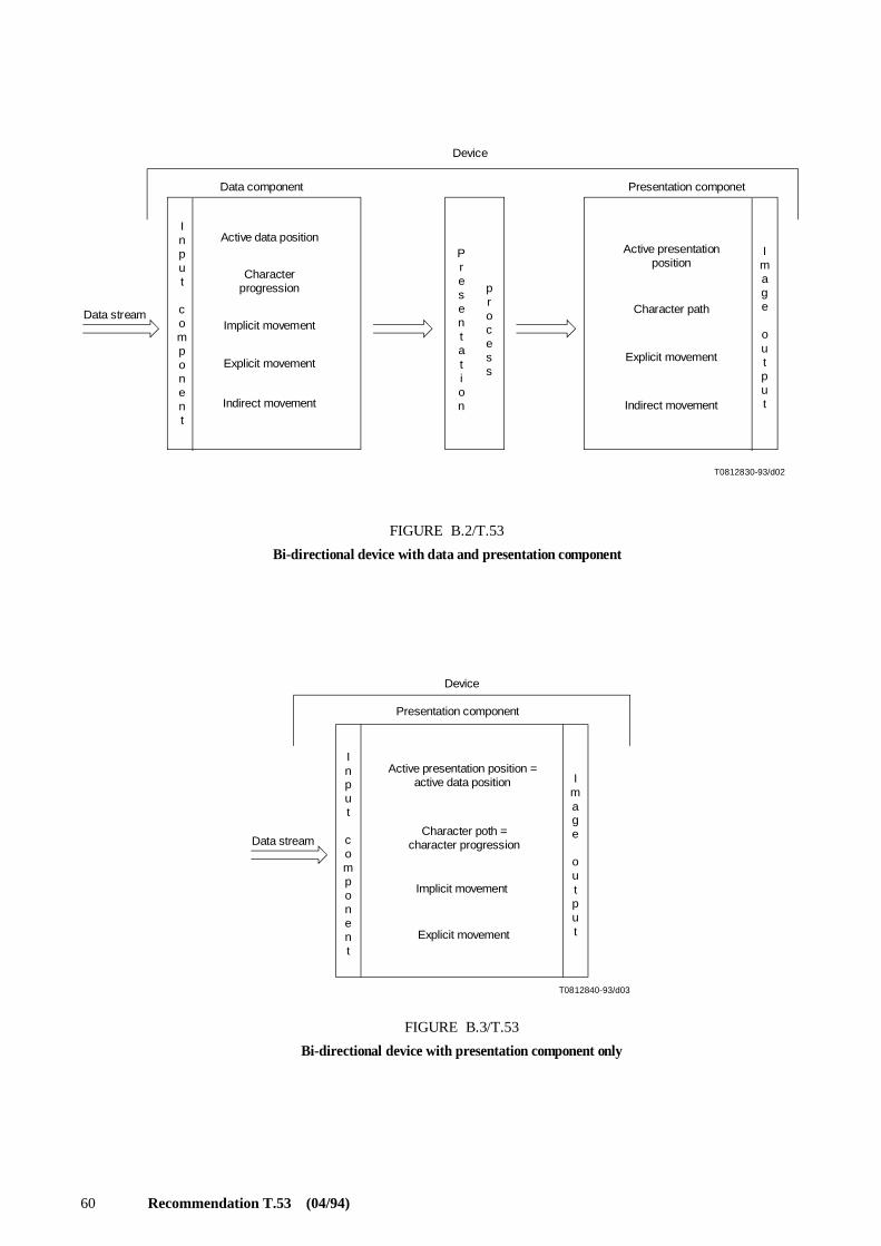
60 Recommendation T.53 (04/94)
T0812830-93/d02
Device
Data component Presentation componet
Active data position
Characterprogression
Implicit movement
Explicit movement
Indirect movement
Active presentationposition
Character path
Indirect movement
Explicit movement
Data stream
Input
component
Presentation
process
Image
output
FIGURE B.2/T.53
Bi-directional device with data and presentation component
T0812840-93/d03
Device
Presentation component
Active presentation position = active data position
Character poth =character progression
Implicit movement
Explicit movement
Data stream
Input
component
Image
output
FIGURE B.3/T.53
Bi-directional device with presentation component only

Recommendation T.53 (04/94) 61
B.3.6 Character path and character progression
Example illustrating the relationship between character path and character progression:
Data Component:
Graphic image output for horizontal left-to-right lines:
Graphic image output for horizontal right-to-left lines:
B.4 Control functions for handling bi-directionality in Telematic services – Bi-directional deviceswith presentation component only
BS BACKSPACE
CR CARRIAGE RETURN
LF LINE FEED
RI REVERSE LINE FEED
SAPV SELECT ALTERNATIVE PRESENTATION VARIANTS
SIMD SELECT IMPLICIT MOVEMENT DIRECTION
SPD SELECT PRESENTATION DIRECTIONS
SDS START DIRECTED STRING
SRS START REVERSED STRING
character progression : 1 2 3 4 5 6 7 8 9 10 11 12 13 14
characters : a b c d _ E F G H _ i j k l
directionality : R R R R R L L L L R R R R R
nesting level : 0 0 0 0 0 1 1 1 1 0 0 0 0 0
14 13 12 11 10 9 8 7 6 5 4 3 2 1 → Characterprogression
l k j i – E F G H – d c b a
1 2 3 4 5 6 7 8 9 10 11 12 13 14 → Character path
14 13 12 11 10 9 8 7 6 5 4 3 2 1 → Characterprogression
l k j i – E F G H – d c b a
14 13 12 11 10 9 8 7 6 5 4 3 2 1 ← Character path

62 Recommendation T.53 (04/94)
B.5 Levels of device support for bi-directionality
Because of the diversity of application and device requirements, different levels of bi-directional support may beconsidered. For the present, this Recommendation specifies a bi-directional device with presentation component only. Inthe future, bi-directional devices with presentation component and data component will be also included.
Annex C
Text area formats
(This annex does not form an integral part of this Recommendation)
The purpose of this annex is to provide supplementary information for the control function PAGE FORMATSELECTION (PFS) defined in 12.70.
C.1 Dimension of the text area
Table C.1 shows the dimensions of the text area corresponding to various values of the parameters of PFS.
NOTES
1 When determining the number of lines per page for the parameter values 0 to 9, account is taken of any additionalspace needed for an optional “call identification line” (see Recommendation T.60). This space is not included in the text area.
2 This annex does not specify the number of lines per page for line spacing of 6 per 30.0 mm used in conjunction withthe North American page formats, or for line spacing of 2 or 12 lines per 25.4 mm or 3, 4 or 12 lines per 30.0 mm used in conjunctionwith any of the page formats.
3 This annex does not specify the number of characters per line for spacing of 10 or 15 characters per 25.4 mm used inconjunction with page formats specified by PFS with parameter values 10 to 15, or for spacing of 3 characters per 25.4 mm used inconjunction with page formats specified by PFS with parameters values 0 to 9.
C.2 Line home position
For the page formats specified by PFS with parameter values 0 to 9 and 10 to 15, the line home position is, depending onthe character spacing, as shown in Table C.2.
NOTES
1 For the page formats specified by PFS with parameter values 0 to 9, the line home position is specified so as toprovide a margin of approximately 20 mm between the line home position and the edge of the paper.
2 For the page formats specified by PFS with parameter values 10 to 15, the line home position is specified so as toprovide a margin of approximately 25 mm between the line home position and the edge of the paper.

Recommendation T.53 (04/94) 63
TABLE C.1/T.53
Dimensions of the text area(for Teletex service)
PFS Number of lines per pagefor spacing of
Number of charactersper line for spacing of
Meaning Dimension 8 6 4 3 6per
3 6 10 12 15
Ps per 25.4 mm 30mm
per 25.4 mm
0 Tall basic textcommunication
73 55 37 28 46 46 77 92 115
1 Wide basic textcommunication
50 38 25 19 32 62 105 125 156
2 Tall basic A4 78 59 39 30 49 46 77 92 115
3 Wide basic A4 50 38 25 19 32 66 110 132 165
4 Tall North American letter 74 56 37 28 48 80 96 120
5 Wide North Americanletter
53 40 27 20 62 105 125 156
6 Tall extended A4 ISO 3535 88 66 44 33 55 46 77 92 115
7 Wide extended A4 ISO 3535 58 44 29 22 36 66 110 132 165
8 Tall North American legal 98 74 49 37 48 80 96 120
9 Wide North American legal 53 40 27 20 80 135 161 201
10 A4 short lines 59 39 30 22 45 89
11 A4 long lines 38 25 19 32 66 131
12 B4 short lines 49 33 24 18 38 75
13 B5 long lines 32 21 16 27 56 111
14 B4 short lines 75 50 38 27 56 111
15 B4 long lines 49 33 25 39 79 157
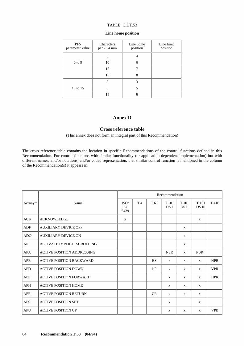
64 Recommendation T.53 (04/94)
TABLE C.2/T.53
Line home position
Annex D
Cross reference table(This annex does not form an integral part of this Recommendation)
The cross reference table contains the location in specific Recommendations of the control functions defined in thisRecommendation. For control functions with similar functionality (or application-dependent implementation) but withdifferent names, and/or notations, and/or coded representation, that similar control function is mentioned in the columnof the Recommendation(s) it appears in.
PFSparameter value
Charactersper 25.4 mm
Line homeposition
Line limitposition
6 4
0 to 9 10 6
12 7
15 8
3 3
10 to 15 6 5
12 9
Recommendation
Acronym Name ISO/IEC6429
T.4 T.61 T.101DS I
T.101DS II
T.101DS III
T.416
ACK ACKNOWLEDGE x x
ADF AUXILIARY DEVICE OFF x
ADO AUXILIARY DEVICE ON x
AIS ACTIVATE IMPLICIT SCROLLING x
APA ACTIVE POSITION ADDRESSING NSR x NSR
APB ACTIVE POSITION BACKWARD BS x x x HPB
APD ACTIVE POSITION DOWN LF x x x VPR
APF ACTIVE POSITION FORWARD x x x HPR
APH ACTIVE POSITION HOME x x x
APR ACTIVE POSITION RETURN CR x x x
APS ACTIVE POSITION SET x x
APU ACTIVE POSITION UP x x x VPB
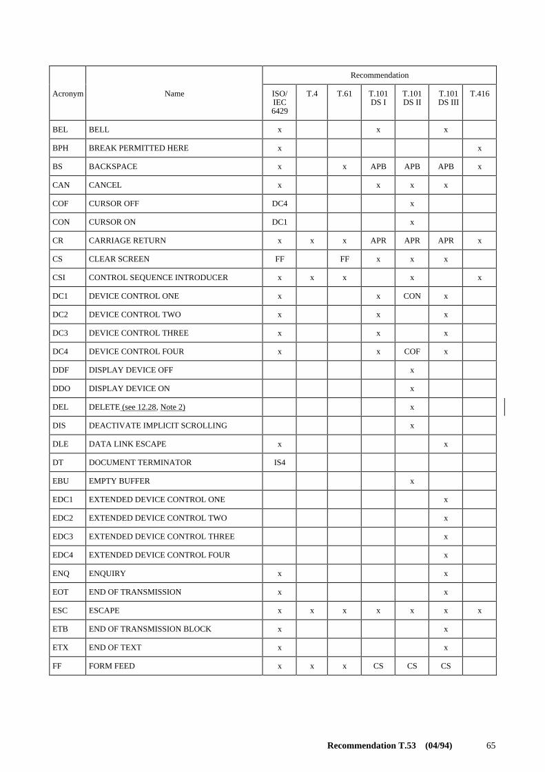
Recommendation T.53 (04/94) 65
Recommendation
Acronym Name ISO/IEC6429
T.4 T.61 T.101DS I
T.101DS II
T.101DS III
T.416
BEL BELL x x x
BPH BREAK PERMITTED HERE x x
BS BACKSPACE x x APB APB APB x
CAN CANCEL x x x x
COF CURSOR OFF DC4 x
CON CURSOR ON DC1 x
CR CARRIAGE RETURN x x x APR APR APR x
CS CLEAR SCREEN FF FF x x x
CSI CONTROL SEQUENCE INTRODUCER x x x x x
DC1 DEVICE CONTROL ONE x x CON x
DC2 DEVICE CONTROL TWO x x x
DC3 DEVICE CONTROL THREE x x x
DC4 DEVICE CONTROL FOUR x x COF x
DDF DISPLAY DEVICE OFF x
DDO DISPLAY DEVICE ON x
DEL DELETE (see 12.28, Note 2) x
DIS DEACTIVATE IMPLICIT SCROLLING x
DLE DATA LINK ESCAPE x x
DT DOCUMENT TERMINATOR IS4
EBU EMPTY BUFFER x
EDC1 EXTENDED DEVICE CONTROL ONE x
EDC2 EXTENDED DEVICE CONTROL TWO x
EDC3 EXTENDED DEVICE CONTROL THREE x
EDC4 EXTENDED DEVICE CONTROL FOUR x
ENQ ENQUIRY x x
EOT END OF TRANSMISSION x x
ESC ESCAPE x x x x x x x
ETB END OF TRANSMISSION BLOCK x x
ETX END OF TEXT x x
FF FORM FEED x x x CS CS CS
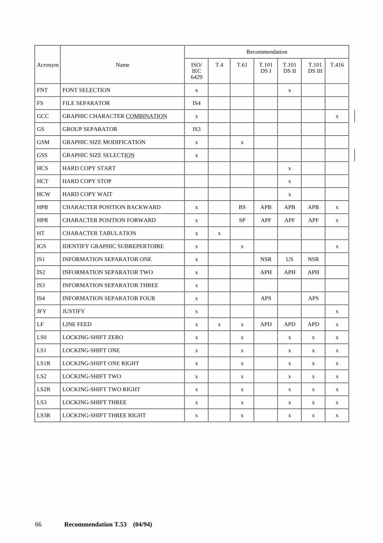
66 Recommendation T.53 (04/94)
Recommendation
Acronym Name ISO/IEC6429
T.4 T.61 T.101DS I
T.101DS II
T.101DS III
T.416
FNT FONT SELECTION x x
FS FILE SEPARATOR IS4
GCC GRAPHIC CHARACTER COMBINATION x x
GS GROUP SEPARATOR IS3
GSM GRAPHIC SIZE MODIFICATION x x
GSS GRAPHIC SIZE SELECTION x
HCS HARD COPY START x
HCT HARD COPY STOP x
HCW HARD COPY WAIT x
HPB CHARACTER POSITION BACKWARD x BS APB APB APB x
HPR CHARACTER POSITION FORWARD x SP APF APF APF x
HT CHARACTER TABULATION x x
IGS IDENTIFY GRAPHIC SUBREPERTOIRE x x x
IS1 INFORMATION SEPARATOR ONE x NSR US NSR
IS2 INFORMATION SEPARATOR TWO x APH APH APH
IS3 INFORMATION SEPARATOR THREE x
IS4 INFORMATION SEPARATOR FOUR x APS APS
JFY JUSTIFY x x
LF LINE FEED x x x APD APD APD x
LS0 LOCKING-SHIFT ZERO x x x x x
LS1 LOCKING-SHIFT ONE x x x x x
LS1R LOCKING-SHIFT ONE RIGHT x x x x x
LS2 LOCKING-SHIFT TWO x x x x x
LS2R LOCKING-SHIFT TWO RIGHT x x x x x
LS3 LOCKING-SHIFT THREE x x x x x
LS3R LOCKING-SHIFT THREE RIGHT x x x x x

Recommendation T.53 (04/94) 67
Recommendation
Acronym Name ISO/IEC6429
T.4 T.61 T.101DS I
T.101DS II
T.101DS III
T.416
NAK NEGATIVE ACKNOWLEDGE x x
NBH NO BREAK HERE x x
NSR NON-SELECTIVE RESET x APA x
NUL NULL x x x
PFS PAGE FORMAT SELECTION x x
PLD PARTIAL LINE FORWARD x x x
PLU PARTIAL LINE BACKWARD x x x
PT PAGE TERMINATOR IS3
PTX PARALLEL TEXTS x x
RDS RECORDING DEVICE START x
RDT RECORDING DEVICE STOP x
RDW RECORDING DEVICE WAIT x
REP REPEAT x RPC RPT RPT
RI REVERSE LINE FEED x x
ROL REPEAT TO END OF LINE x
RPC REPEAT CONTROL REP x RPT RPT
RPT REPEAT REP RPC x x
RS RECORD SEPARATOR IS2
SACS SET ADDITIONAL CHARACTER SEPARATION x x
SAPV SELECT ALTERNATIVE PRESENTATIONVARIANTS
x x
SCD SCROLL DOWN SD x
SCF SCROLL OFF x
SCN SCROLL ON x
SCO SELECT CHARACTER ORIENTATION x x
SCS SET CHARACTER SPACING x x
SCU SCROLL UP SU x
SDS START DIRECTED STRING x x x x
SGR SELECT GRAPHIC RENDITION x x x x x

68 Recommendation T.53 (04/94)
Recommendation
Acronym Name ISO/IEC6429
T.4 T.61 T.101DS I
T.101DS II
T.101DS III
T.416
SHS SELECT CHARACTER SPACING x x x x
SI SHIFT-IN x x x x x
SIMD SELECT IMPLICIT MOVEMENT DIRECTION x
SLH SET LINE HOME x
SLL SET LINE LIMIT x
SLS SET LINE SPACING x x
SO SHIFT-OUT x x x x x
SOH START OF HEADING x x
SOS START OF STRING x x
SP SPACE (see 12.101, Note) x x
SPD SELECT PRESENTATION DIRECTIONS x x x x
SRCS SET REDUCED CHARACTER SEPARATION x x
SRS START REVERSED STRING x x x
SSU SELECT SIZE UNIT x
SSW SET SPACE WIDTH x x
SS2 SINGLE-SHIFT TWO x x x x x x x
SS3 SINGLE-SHIFT THREE x x x x x x
ST STRING TERMINATOR x x
STAB SELECTIVE TABULATION x x
STX START OF TEXT x x
SUB SUBSTITUTE x x x
SVS SELECT LINE SPACING x x x
SYN SYNCHRONOUS IDLE x x
US UNIT SEPARATOR IS1 x
VPB LINE POSITION BACKWARD x APU APU APU x
VPR LINE POSITION FORWARD x APD APD APD x
WWF WORD WRAP OFF x
WWN WORD WRAP ON x