Sample Vessel #3 96" Horizontal Vessel Pressure Vessel Calculations
24
Sample Vessel #3 96" Horizontal Vessel Pressure Vessel Calculations May 21, 2002 Aquacare Inc. 10 East Airport Road Huntsville, Ontario Laurence Brundrett P. Eng. Charles Liu M. Eng. Pressure Vessel Engineering Ltd. PVE-Sample 3 1 of 24
-
Upload
independent -
Category
Documents
-
view
0 -
download
0
Transcript of Sample Vessel #3 96" Horizontal Vessel Pressure Vessel Calculations

Sample Vessel #396" Horizontal Vessel
Pressure Vessel Calculations
May 21, 2002
Aquacare Inc.10 East Airport Road
Huntsville, Ontario
Laurence Brundrett P. Eng.Charles Liu M. Eng.
Pressure Vessel Engineering Ltd.PVE-Sample 3
1 of 24

Table of Contents 21-May-02 Page 2 of 24
Contents PageCover 1Table of Contents 2Summary 3Material Properties 4Pipe and Shell 5Elliptical Head 60.75" Coupling In Top Shell 76" Nozzle B 8 - 96" Nozzle C 10 - 116" Slip On Flange B & C 12Manway D & E 13Manway F 141.5" Coupling In Bottom Shell 15Weight and Volume 16Lifting Lug 17Zick 18 - 19Hor. Vessel Forces 20Flexible Saddle Stress 21Flexible Saddle 22 - 24

Pressure Vessel Design Summary 21-May-02 Page 3 of 24
CustomerVesselPart NumberDrawingJob
96 Outside Diameter [inch]120 straight Shell (not including straight flange on heads)640 Volume [cuft]
Water Fluid6393 Weight Empty [lbs.]
46324 Weight Full46324 Weight Under Test
Maximum Internal pressure, psi Maximum External Pressure, psi At Temperature, ºF
75 0 150Maximum Temperature, ºF Minimum Temperature, ºF At Pressure, psi
150 -20 75Test Pressure, psi At a Minimum Temperature of: ºF For a Minimum Duration of:
98 60 30 min.
3 Seismic Zone1.5 Foundation Factor
SA-516 70 Primary Material of Construction20,000 Allowable Stress0.063 Minimum allowed thickness per UG-16(b)
no Material Normalizedno Material Impact Tested (not required per UG-20(f))
none Radiography required0 Corrosion Allowance
ASME VIII-1 Code2001 Editionnone Addenda
IID Materialsnone Code Cases Required
UG-22 Loadings ConsideredYes (a) Internal pressure - (a) External pressure
Yes (b) Vessel weight full, empty and at hydro test - (c) Weight of attached equipment and piping
Yes (d)(1) Attachment of internalsYes (d)(2) Attachment of vessel supports - (d) Cyclic or dynamic reactions - (f) Wind - (f) Snow
Yes (f) Seismic - (g) Fluid impact shock reactions - (h) Temperature gradients - (h) Differential thermal expansion - (i) Abnormal pressures like deflagration
Hydrostatic Test
Maximum Allowed Working Pressure
Aquacare Inc.
PVE-Sample 3PVE-Sample 3
96" Horizontal VesselSample Vessel #3
Maximum Design Metal Temperature
1 Material Properties ver 1.28 www.pveng.com 21-May-02 Page 4 of 242 ASME VIII, IID 2001 edition no addenda3 Sample Vessel #3 <- vessel4
5 Design Pressure UG-22(a)6 75.0 <- P, internal operating pressure at top of vessel (psig)7 0.0 <- mPa, external operation pressure8 Water <- Operating Fluid9 8 <- h, fluid height (ft) 10 1.00 <- rho, fluid density (1.0 for water) 11 Design Pressure = P + 0.4331*rho*h = 75 + 0.4331 * 1 * 8 mDp = 78.512
13 Hydro Test (UG-99(b)) pressure measured at top of vessel14 Test Press = P * 1.3 * MR = 75 * 1.3 * 1 mTp = 97.515
16 Material Properties (ASME IID)17 150 <- mTemp, design temp ºF Test at ambient temp
18
Where Used Ambient Strength
Design Strength
Strength Ratio
Max ºF Ext Graph
19 Head and Shell 20000 20000 1.000 1000 CS-220 Flanges/couplings 20000 20000 1.000 1000 CS-221 Nozzles 17100 17100 1.000 1000 CS-222 Saddle 17100 17100 1.000 650 CS-223
24
25
26
27
28
29
30
31
32
33 34 35 36 37 38 39 40 41 42 43 44 Min Ratio (MR) = 1.00045
46 Use a Test Pressure of 98 PSI47
48
SA-106 B Seamless PipeSA/CSA-G40.21 44W
SA-105 Forging
Material
SA-516 70 Plate

12 Pipe and Shell ver 2.33 21-May-02 Page 5 of 2413 ASME Code VIII Div I 2001 edition no addenda 14 <- Vessel15 <- Description16
17 Dimensions:18 96.000 <- Do - Outside Diameter19 0.313 <- t - Nominal Wall Thickness20 120.000 <- Le - Effective Length21 120.000 <- Length for volume and weight22 0.000 <- Corr, Corrosion Allowance23
24 Material and Conditions:25 SA-516 70 <- Material26 20,000 <- S, Allowable Stress Level (psi)27 0.7 <- El - Longitudinal Efficiency (circ. stress)28 0.7 <- Ec - Circ. Connecting Efficiency (longitudinal stress)29 0.0% <- UTP, Undertolerance allowance (%) 496.12 <- Volume (cubic ft)30 0.000 <- UTI, Undertolerance allowance (inch) 3,202.2 <- Material Weight (lbs cs)31
32 78.5 <- P, Interior Pressure33 0.0 <- Pa, Exterior Pressure36
37 Variables:38 UT = t*UTP+UTI = 0.313*0+0 undertollerance UT = 0.00039 nt = t-Corr-UT = 0.313-0-0 nominal thick nt = 0.31340 Ri = Do/2-nt = 96/2-0.313 effective inside radius Ri = 47.68741 LDo = Le/Do = 120/96 LDo = 1.25042
43 Interior Pressure UG-27 (c) (1,2)44 ta = P*Ri/(S*El-0.6*P) = 78.465*47.687/(20000*0.7-0.6*78.465) ta = 0.26845 tb = P*Ri/(2*S*Ec+0.4*P) = 78.465*47.687/(2*20000*0.7+0.4*78.465 tb = 0.13346 tmin = Max(ta,tb) <= nt Acceptable tmin = 0.26847 PMaxA = PMaxA = 91.548 PMaxB = PMaxB = 184.349 PMax = Min(PMaxA,PMaxB) Acceptable PMax = 91.550 tr1 = P*Ri/(S*1-0.6*P) = 78.465*47.687/(20000*1-0.6*78.465) tr1 = 0.18851
62 Shell stress relief -UCS-79(d), UNF-79(d), UHA-44(d)63 Rf = (do-t)/2 = (96-0.313)/2 47.843564 % elong = (50*t/Rf)*(1-0) = (50*0.313/47.844)*(1-0) % elongation = 0.365 5.0% <- Max Elongation66 Yes <- Cold formed 0.3% <- Elongation Required no67 no <- Vessel carries lethal substances (Yes/no) no no68 no <- Impact testing is required (Yes/no) no no69 no <- Greater than 10% reduction in thickness no no70 no <- Formed between 250 and 900 Degrees F no no71 no <- Shell is greater than 5/8" thick before forming no no72 Stress Relieve ? no
www.pveng.com
(2*S*Ec*nt)/(Ri-0.4*nt)(S*El*nt)/(Ri+0.6*nt) = (20000*0.7*0.313)/(47.687+0.6*0.313)
= (2*20000*0.7*0.313)/(47.687-0.4*0.313)
Sample Vessel #33/8" Rolled Plate Shell
t
Do
Len g
th
Long
Sea
m

1 Elliptical Head ver 2.16 Page 6 of 242 ASME Code VIII Div I 2001 edition no Addenda3 <- Vessel4 <- Component5
6 Dimensions:7 96.000 <- Do, outside diameter8 23.859 <- h 24.14 <- ho9 0.313 <- tb, thickness before forming10 0.282 <- tf, thickness after forming11 0.000 <- Corr, corrosion allowance12 1.500 <- Skirt, straight skirt length13
14 Material and Conditions: Calculated Properties:15 SA-516 70 <- material 116.440 <- Approximate blank diameter16 20,000 <- S, allowable stress level (psi) 945.3 <- Approximate weight for steel, (lbs)17 0.85 <- E, efficiency 72.06 <- Volume (cuft, includes skirt)18
19 78.5 <- P, interior pressure 76.35 <- Spherical Limit (0.8 * D)20 0.0 <- Pa, exterior pressure23
24 Variables:25 D = Do-2*t = 96-2*0.282 D = 95.4426 ho = h+t = 23.859+0.282 ho = 24.1427 D/2h = D/(2*h) UG-37 & Ap 1-4(c) = 95.437/(2*23.859) D/2h = 2.00028 Do/2ho = Do/(2*ho) UG-37 & Ap 1-4(c) = 96/(2*24.141) Do/2ho = 1.98829 K = Interpolated value from table 1-4.1 D/2h interior K = 1.00030 Kone = Interpolated value from table UG-37 D/2h spherica Kone = 0.90031 Kzero = Interpolated value from table UG-33.1 Do/2ho exterior Kzero = 0.89532 t = tf-corr = 0.282-0 t = 0.28233 Ro = Ko*Do UG-33(d) = 0.895*96 Ro = 85.89634
35 Interior Pressure App 1-4(c)(d), UG-37 1(a)36 TMinI = (P*D*K)/(2*S*E-0.2*P) <= t TMinI (min thickness) = 0.22037 = (78.465*95.437*1)/(2*20000*0.85-0.2*78.465) <= 0.282 Okay38 PMax = (2*S*E*t)/(K*D+0.2*t) >= P PMax = 100.339 = (2*20000*0.85*0.282)/(1*95.437+0.2*0.282) >= 78 Okay40 TSpI = (P*D*Kone)/(2*S*E-0.2*P) TSpI (required sphere zone thick) = 0.16941 = (78.465*95.437*0.9)/(2*20000*1-0.2*78.465)42
51 Head stress relief UCS-79(d), UNF-79(d), UHA-44(d)52 % elong = ((75*t)/h)*(1-0) = ((75*0.282)/23.859)*(1-0) % elong = 1.053 5.0% <- Max Elongation54 Yes <- Cold Formed 1.0% <- Elongation Required no55 no <- Vessel carries lethal substances(Yes/no) no no56 no <- Impact testing is required (Yes/no) no no57 no <- Formed between 250 and 900 Degrees F no no58 no <- Greater than 10% reduction in thickness no no59 no <- Head is greater than 5/8" thick before forming no no60 Stress Relieve ? no
www.pveng.comSample Vessel #3
3/8" Thick Semi Elliptical Head
21-May-02
ThickSkirt
Do
h
D
ho
Sperical Limit

15 Coupling ver 2.02 UW16.1Z1M 21-May-02 Page 7 of 2416 ASME Code VIII Div I 2001 edition, no addenda22 <- Vessel18 <- Description19
20 Shell:23 0.313 <- t, Shell Wall Thick (inch)27 1.500 <- D, Shell Opening Diameter (inch)29 78.5 <- P,design Pressure (psi)30
31 Coupling:32 3/4 inch 3000# <- Coupling33 SA-105 <- Coupling Material34 20,000 <- Sn, Allowable Stress Level (Sn)36 0.250 <- F1, Weld Size38 0.000 <- Corrc, Coupling Corrosion Allowance (inch)39 1.380 <- COD - Coupling OD40 1.050 <- POD - Pipe OD42 14.000 <- n, Treads Per Inch44 0.219 <- pt, Corresponding sch160 Wall Thickness (inch)46 12.5% <- UT, Under Tolerence (%)47
49 Geometry Restrictions Fig. UW-16.150 tcp = (COD-POD)/2-CORRC = (1.38-1.05)/2-0 Tcp = 0.16551 Tmin = Min(0.75,tcp,t) = Min(0.75,0.165,0.313) Tmin = 0.16553 tcmin = Min(0.25,0.7*Tmin) = Min(0.25,0.7*0.165) tcmin = 0.11656 t1 = 0.7*F1 = 0.7*0.25 t1 = 0.17561 t1 > = tcMin = 0.175 >= 0.116 Okay78
79 Required Coupling Wall Thickness B16.11 - 2.1.1 and UG-31 (C) (2)80 Ro = POD/2-0.8/n = 1.05/2-0.8/14 Ro = 0.46881 tp = (1-UT)*pt-Corrc-0.8/n = (1-0.125)*0.219-0-0.8/14 tp = 0.13482 Min Thick = P*Ro/(Sn*1+0.4*P) = 78*0.468/(20000*1+0.4*78.465 Okay trn = 0.00283
84 Pressure Weld Stress UW-18(d) - Pressure Load only UW-16(f)(3)(a)(3)(b)85 Load = COD^2*(PI()/4)*P = 1.38^2*(PI()/4)*78.465 Load = 11786 Weld Area = pi()*((COD+F1)^2-COD^2)/4 Weld Area = 0.59187 = pi()*((1.38+0.25)^2-1.38^2)/492 Max Stress = Min(Sn,Sv) * 0.55 = Min(20000,20000) * 0.55 Max Stress = 1100093 Weld Stress = Load / Area = 117 / 0.591 Weld Stress = 19994 Okay99
100
www.pveng.comSample Vessel #3
3/4" Class 3000 Half Coupling A
F1
Inside Vessel
Outside
t
D
COD
POD
UW-16.1 Z-1 (Modified) Coupling
t1

26 Nozzle Reinforcement ver 3.53 UW16(c)mod 21-May-02 Page 8 of 2427 ASME Code VIII Div I 2001 edition no addenda Manual dh for hillside nozzles22 <- Vessel Automatic Limit Diameter29 <- Desc Curved Shell or Head Section30 Shell:31 SA-516 70 <- Shell material32 20,000 <- Sv, shell allowable stress level, PSI33 1.00 <- Eone, efficiency of shell at nozzle34
35 0.282 <- Vt, shell wall thick, uncorroded, UT removed36 0.220 <- tr, required shell wall thickness int. press.37 0.000 <- trE, required shell wall thickness ext. press.38 0.000 <- sca, shell corrosion allowance39 0.063 <- tmin16b, Min allowed wall per UG-16(b) 40 Nozzle:41 SA-106B <- Nozzle material42 17,100 <- Sn, allowable stress level (Sn)44 1.00 <- E nozzle 45
46 78.5 <- P, internal design pressure47 0.0 <- Pa, external design pressure48
49 6.625 <- Do, outside diameter50 6.500 <- dh, id of hillside nozzle52 0.432 <- Nt, wall thick, uncorroded53 12.5% <- UTp, undertolerance (%)55 0.000 <- nca, nozzle corrosion allowance56
57 2.000 <- L, exterior Projection58 1.000 <- Ip, interior projection60
61 Reinforcing:71 0.313 <- Leg41, size of weld fillet73 0.313 <- Leg43, size of weld fillet74 1.000 <- F77 Variables:78 UT = Nt*UTp = 0.432 * 0.125 Undertolerance UT = 0.05479 Rn = Do/2 - (Nt-nca) + UT = 6.625/2 - (0.432-0) + 0.054 Effective Radius Rn = 2.93584 t = Vt-sca = 0.2817 - 0 Effective Shell Thickness t = 0.28285 ti = Nt-2*nca = 0.432 - 2 * 0 Nom Thick of Int. Proj. ti = 0.43290 tn = Nt-nca = 0.432-0 Avail. Nozzle Thick. No UT tn = 0.43299 fr1 = MIN(Sn/Sv,1) = MIN(17100/20000, 1) fr1 = 0.855102 fr2 = MIN(Sn/Sv,1) = MIN(17100/20000, 1) fr2 = 0.855112 h = MIN(Ip-sca,2.5*t,2.5*ti) = MIN(1-0,2.5*0.282,2.5*0.432) h = 0.704113 tcLeg41 = Min(0.25,0.7*Min(0.75,tn,t)) = Min(0.25,0.7*Min(0.75,0.432,0.282)) tc41 = 0.197115 tcLeg43 = Min(0.25,0.7*Min(0.75,t,tn)) = Min(0.25,0.7*Min(0.75,0.282,0.432)) tc43 = 0.197117 F = Min(Fenterered, 1) F = 1.000125
126 Pipe Required Wall Thickness - trn from internal, trnE from external pressure127 LDo = L/Do LDo = 0.302 Dot = Do/trnE Dot = 0.000128 trn = (P*Rn)/(Sn*E - 0.6*P) <= tn-UT trn = 0.014 Acceptable129 trnE = (3*Do*Pa)/(4*B) <= tn-ut trnE = 0.000 Acceptable130
131 Geometry Constraints:133 0.7*Leg41 >= tc41 0.7*0.313 >= 0.197 0.219 >= 0.197 Acceptable142 0.7*Leg43 >= tc43 0.7*0.313 >= 0.197 0.219 >= 0.197 Acceptable152157
158 Area Replacement: Fig UG-37.1 Pressure From: Internal External159 A = 1.0*d*tr*F + 2*tn*tr*F*(1-frone) A Required (internal) = 1.460160 = 1.0*6.5*0.22*1 + 2*0.432*0.22*1*(1-0.855)163 Ae = 0.5*(d*trE*1 + 2*tn*trE*1*(1-frone)) A Required (external) = 0.000164 = 167 A1 = max(d, 2*(t+tn)) * (E1*t-F*tr)-2*tn*(E1*t-F*tr)*(1-fr1) A1 = 0.391168 = 172 A1e = max(d, 2*(t+tn)) * (Eone*t-F*trE)-2*tn*(Eone*t-F*trE)*(1-frone) A1e = 1.796173 = 179 A2 = min((tn-trn)*fr2*Min(5*t,2*L) , (tn-trn)*fr2*Min(5*tn,2*L)) A2 = 0.504180 = 184 A2e = min((tn-trnE)*frtwo*Min(5*t,2*L) , (tn-trnE)*frtwo*Min(5*tn,2*L)) A2e = 0.520185 = 187 A3 = Min(5*t*ti*frtwo, 5*ti*ti*frtwo, 2*h*ti*frtwo) A3 = 0.520 0.520188 = Min(5*0.282*0.432*0.855, 5*0.432*0.432*0.855, 2*0.704*0.432*0.855)194 A41 = Leg41^2*frTwo A41 = 0.313^2*0.855 A41 = 0.084 0.084201 A43 = (Leg43-nca)^2*frtwo A43 = (0.313-0)^2*0.855 A43 = 0.084 0.084203 Actual Area = 1.583 3.004204 Acceptable Actual-Required = 0.123 3.004
max(6.5, 2*(0.282+0.432)) * (1*0.282-1*0)-2*0.432*(1*0.282-1*0)*(1-0.855)
min((0.432-0.014)*0.855*Min(5*0.282,2*2) , (0.432-0.014)*0.855*Min(5*0.432,2*2))
min((0.432-0)*0.855*Min(5*0.282,2*2) , (0.432-0)*0.855*Min(5*0.432,2*2))
max(6.5, 2*(0.282+0.432)) * (1*0.282-1*0.22)-2*0.432*(1*0.282-1*0.22)*(1-0.855)
www.pveng.com
= (78.5*2.935)/(17100*1 - 0.6*78.5)= (3*6.625*0)/(4*1)
Sample Vessel #36" SCH 80 Nozzle B
0.5*(6.5*0*1 + 2*0.432*0*1*(1-0.855))
UW-16.1 (c) modified
Leg41
OD Nozzle
Nt
Leg41
Leg43
Leg43
Proj
Vt
Noz
zle
Shell
FullPenn.t

298 Sample Vessel #3 6" SCH 80 Nozzle B 21-May-02 Page 9 of 24300 Nozzle301 Tstd = Standard pipe wall thickness from chart Tstd = 0.280302 Swre = tr * Pa / P = 0.22 * 0 / 78.465 Req. Exterior pressure Swre = 0.000303 Nact = Nt * (1-UTp) = 0.432 * (1-0.125) Actual Wall Thick. Nact = 0.378304 Tt = 0.8/Nth = 0.8/0 Ug-31(c)(2) threads Tt = 0.000307
308 UG-45313 UG45 = Max(UG45a, UG45b) <= Nact UG45 = 0.220314 = Max(0.014, 0.22) <= 0.378 Acceptable315
316 UG-45(a)321 UG45a = Max(trn,trnE) + Nca + Tt UG45a = 0.014322 Max(0.014,0) + 0 + 0323
324 UG-45(b)330 UB45b = Min(UG45b1, UG45b2, UG45b3, UG45b4) UB45b = 0.220331 = Min(0.22, , 0.22, 0.245)332
333 UG-45(b)(1)337 UG45b1 = Max(tr + Sca, Tmin16b + Sca) UG45b1 = 0.220338 Max(0.22 + 0, 0.063 + 0)339
340 UG-45(b)(2)345 UG45b2 = Max(Swre + Sca,Tmin + Sca) UG45b2 = 346 Max(0 + 0,0.063 + 0)347
348 UG-45(b)(3)351 UG45b3 = Max(UG45b1,UG45b2) = Max(0.22,) UG45b3 = 0.220352
353 UG-45(b)(4)357 UG45b4 = Tstd*0.875 + Nca = 0.28*0.875 + 0 UG45b4 = 0.245

26 Nozzle Reinforcement ver 3.53 UW16(h)M 21-May-02 Page 10 of 2427 ASME Code VIII Div I 2001 edition no addenda Manual dh for hillside nozzles22 <- Vessel Automatic Limit Diameter29 <- Desc Curved Shell or Head Section30 Shell:31 SA-516 70 <- Shell material32 20,000 <- Sv, shell allowable stress level, PSI33 0.70 <- Eone, efficiency of shell at nozzle34
35 0.282 <- Vt, shell wall thick, uncorroded, UT removed36 0.220 <- tr, required shell wall thickness int. press.37 0.000 <- trE, required shell wall thickness ext. press.38 0.000 <- sca, shell corrosion allowance39 0.063 <- tmin16b, Min allowed wall per UG-16(b) 40 Nozzle:41 SA-106B <- Nozzle material42 17,100 <- Sn, allowable stress level (Sn)44 1.00 <- E nozzle 45
46 78.5 <- P, internal design pressure47 0.0 <- Pa, external design pressure48
49 6.625 <- Do, outside diameter50 6.020 <- dh, id of hillside nozzle52 0.432 <- Nt, wall thick, uncorroded53 12.5% <- UTp, undertolerance (%)55 0.000 <- nca, nozzle corrosion allowance56
57 2.000 <- L, exterior Projection60
61 Reinforcing:63 SA-516 70 <- Reinforcing plate material65 20,000 <- Sp, allowable stress level66 12.000 <- Dp, outside diameter69 0.313 <- te, reinforcement thick71 0.313 <- Leg41, size of weld fillet72 0.250 <- Leg42, size of weld fillet75 0.282 <- LegG, depth of groove77 Variables:78 UT = Nt*UTp = 0.432 * 0.125 Undertolerance UT = 0.05479 Rn = Do/2 - (Nt-nca) + UT = 6.625/2 - (0.432-0) + 0.054 Effective Radius Rn = 2.93580 Dp = Min(2*d,DpEntered) = Min(2*6.02,12) Effective Reinforcing Dp = 12.00084 t = Vt-sca = 0.2817 - 0 Effective Shell Thickness t = 0.28285 ti = Nt-2*nca = 0.432 - 2 * 0 Nom Thick of Int. Proj. ti = 0.43290 tn = Nt-nca = 0.432-0 Avail. Nozzle Thick. No UT tn = 0.43299 fr1 = MIN(Sn/Sv,1) = MIN(17100/20000, 1) fr1 = 0.855102 fr2 = MIN(Sn/Sv,1) = MIN(17100/20000, 1) fr2 = 0.855105 fr3 = MIN(Sn/Sv,Sp/Sv,1) = MIN(17100/20000, 20000/20000,1) fr3 = 0.855106 fr4 = MIN(Sp/Sv,1) = MIN(20000/20000,1) fr4 = 1.000116 F = 1.000 F = 1.000125
126 Pipe Required Wall Thickness - trn from internal, trnE from external pressure128 trn = (P*Rn)/(Sn*E - 0.6*P) <= tn-UT trn = 0.014 Acceptable129 trnE = (3*Do*Pa)/(4*B) <= tn-ut trnE = 0.000 Acceptable130
131 Geometry Constraints:135 0.7*Leg41 >= 0.7*min(0.75,te,tn) 0.7*0.313 >= 0.219 >= 0.219 Acceptable139 0.7*Leg42 >= 0.5*Min(0.75,te,t) 0.7*0.25 >= 0.175 >= 0.141 Acceptable151 UG45 = Long form calculations are not shown in this view UG45 = 0.220 Acceptable152
0.7*Min(0.75,0.313,0.432)
Sample Vessel #36" SCH 80 Nozzle C
www.pveng.com
= (78.5*2.935)/(17100*1 - 0.6*78.5)= (3*6.625*0)/(4*1)
0.5*Min(0.75,0.313,0.282)
Leg42
Leg41
Dp
te
Shell
Noz
zle
Ring
g
UW-16.1 (h) - modified
Leg41
Leg42
tWeld to connectto reinforcing pad
Do
Vt
Nt

156 Sample Vessel #3 6" SCH 80 Nozzle C 0.0135 0.22035 21-May-02 Page 11 of 24157
158 Area Replacement: Fig UG-37.1 Pressure From: Internal External159 A = 1.0*d*tr*F + 2*tn*tr*F*(1-frone) A Required (internal) = 1.354160 = 1.0*6.02*0.22*1 + 2*0.432*0.22*1*(1-0.855)163 Ae = 0.5*(d*trE*1 + 2*tn*trE*1*(1-frone)) A Required (external) = 0.000164 = 167 A1 = max(d, 2*(t+tn)) * (E1*t-F*tr)-2*tn*(E1*t-F*tr)*(1-fr1) A1 = 0.000168 = 172 A1e = max(d, 2*(t+tn)) * (Eone*t-F*trE)-2*tn*(Eone*t-F*trE)*(1-frone) A1e = 1.162173 = 177 A2 = min((tn-trn)*fr2*min(5*t,2*L) , (tn-trn)*(Min(2.5*tn+te,L)*fr1*2) A2 = 0.504178 = 182 A2e = min((tn-trnE)*frtwo*Min(5*t,2*L) , 2*(tn-trnE)*Min(2.5*tn+te,L)*frone) A2e = 0.520183 = 190 A5 = (Dp - d - 2tn)te*fr4 =(12 - 6.02 - 2*0.432)*0.313*1 A5 = 1.601 1.601195 A41 = Leg41^2*frThree A41 = 0.313^2*0.855 A41 = 0.084 0.084198 A42 = Leg42^2*frfour A42 = 0.25^2*1 A42 = 0.063 0.063203 Actual Area = 2.252 3.430204 Acceptable Actual-Required = 0.897 3.430210 Internal Weld Load: (UG-41)211 WmaxI = (A - A1 + 2*Tn*Fr1*(E1*t-F*tr))*Sv, min0 Max value for weld loads WmaxI = 26,740212 = (1.354 - 0 + 2*0.432*0.855*(0.7*0.282-1*0.22))*20000216
217 W1-1 = MIN((A2 + A5 + A41 + A42)*Sv,WmaxI) Weld load W1-1 = 26,740218 = MIN((0.504 + 1.601 + 0.084 + 0.063)*20000,26740)219 W2-2 = Min((A2 + A3 + A41 + A43 + 2*Tn*t*frone)*Sv,WmaxI) Weld load W2-2 = 15,917220 = Min((0.504 + 0 + 0.084 + 0 + 2*0.432*0.282*0.855)*20000,26740)224 W3-3 = Min((A2 + A3 + A5 + A41 + A42 + A43 + 2*Tn*t*fr1)*Sv,WmaxI) Weld load W3-3 = 26,740225 = Min((0.504 + 0 + 1.601 + 0.084 + 0.063 + 0 + 2*0.432*0.282*0.855)*20000,26740)229
230 External Weld Load: (UG-41)231 WmaxE = (Ae - A1e + 2*Tn*Fr1*(E1*t-F*tr))*Sv, min0 Max value for weld loads WmaxE = 0232 = (0 - 1.162 + 2*0.432*0.855*(0.7*0.282-1*0.22))*20000236
237 W1-1 = MIN((A2e + A5 + A41 + A42)*Sv,WmaxE) Weld load W1-1e = 0238 = MIN((0.52 + 1.601 + 0.084 + 0.063)*20000,0)239 W2-2 = Min((A2e + A3 + A41 + A43 + 2*Tn*t*frone)*Sv,WmaxE) Weld load W2-2e = 0240 = Min((0.52 + 0 + 0.084 + 0 + 2*0.432*0.282*0.855)*20000,0)244 W3-3 = Min((A2e + A3 + A5 + A41 + A42 + A43 + 2*Tn*t*fr1)*Sv,WmaxE) Weld load W3-3e = 0245 = Min((0.52 + 0 + 1.601 + 0.084 + 0.063 + 0 + 2*0.432*0.282*0.855)*20000,0)249
255 Component Strength (UG-45(c), UW-15(c))256 A2 shear = PI()/2*(Do-tn)*tn*Sn*0.7 A2s = 50,304257 g tension = PI()/2*Do*LegG*Min(Sv,Sn)*0.74 gt = 43,433258 A41 shear = PI()/2*Do*Leg41*Min(Sn,Sp)*0.49 A41s = 27,292262 A42 shear = PI()/2*DP*Leg42*Min(Sv,Sp)*0.49 A42s = 46,181269
270 Failure mode along strength path (Greater than Weld Load, see App L-7) 273 S1-1 = A42s + A2s >= W1-1 Acceptable S1-1 = 96,485274 = 46181 + 50304 >= 26740283 S2-2 = A41s + gt >= W2-2 Acceptable S2-2 = 70,725284 = 27292 + 43433 >= 15917287 S3-3 = gt + A42s >= W3-3 Acceptable S3-3 = 89,614288 = 43433 + 46181 >= 26740292
293
294
0.5*(6.02*0*1 + 2*0.432*0*1*(1-0.855))
max(6.02, 2*(0.282+0.432)) * (0.7*0.282-1*0.22)-2*0.432*(0.7*0.282-1*0.22)*(1-0.855)
= PI()/2*6.625*0.313*Min(17100,20000)*0.49= PI()/2*12*0.25*Min(20000,20000)*0.49
max(6.02, 2*(0.282+0.432)) * (0.7*0.282-1*0)-2*0.432*(0.7*0.282-1*0)*(1-0.855)
min((0.432-0.014)*0.855*min(5*0.282,2*2) , (0.432-0.014)*(Min(2.5*0.432+0.313,2*2)*0.855*2)
min((0.432-0)*0.855*Min(5*0.282,2*2) , 2*(0.432-0)*Min(2.5*0.432+0.313,2)*0.855)
= PI()/2*(6.625-0.432)*0.432*17100*0.7= PI()/2*6.625*0.282*Min(20000,17100)*0.74

12 B16.5 Slip On Flange Ver 1.35 www.pveng.com 21-May-02 Page 12 of 2413 ASME B16.5-1996 ASME VIII A2001 edition no addenda14
15 <- Comments16 <- Description17
18 Select Flange19 SA <- Category20 Forged <- Material Type21 SA 105 <- Material22 150 <- Pressure Class23 6.00 <- Nominal Size24
25 Nozzle26 0.432 <- tn, Nozzle Wall Thickness (inch)27 0.014 <- tnr, Required Nozzle Wall Thickness (inch)28
29 Operating Conditions30 150 <- T, temperature ºF Max press @100ºF [p1] 28531 78.5 <- P, pressure, psig Max press @150ºF [p2] 273
0.000 <- Corr, corrosion allowance Acceptable33
34 Flange Welds: VIII UW-15 (c)35 0.250 <- F1, pipe fillet size Nominal - C-Si36 0.250 <- Setback37 0.250 <- F2, flange fillet size F2 Table - 2-1.138 17100 <- Sp, allowable stress, pipe Max Temp ºF - 100039 20000 <- Sf, allowable stress, flange Pod, pipe OD - 6.62540
41 Geometry constraint: VIII UW-21 (b)42 c = Min(tn,tx) = Min(0.432,0.027) c = 0.02743 tx = 2*tnr = 2*0.014 tx = 0.02744 wtmin = 0.7*c = 0.7*0.027 wtmin = 0.01945 wt = 0.7*MIN(F1,F2) weld throat wt = 0.17546 = 0.7*MIN(0.25,0.25) Acceptable47
48 Maxsetback = c+0.25 = 0.027+0.25 Maxsetback = 0.27749 Setback = 0.250 Acceptable50
51 Weld Strength:52 Min Sa = MIN(Sp,Sf) = MIN(17100,20000) Min Sa = 17,10053 Max Weld Stress = Sa * 0.49 = 17100 * 0.49 Max S = 8,37954 Weld Load = Pod^2*pi*P/4 = 6.625^2*pi*78.465/4 Load = 2,70555 Weld Area = Pod*pi*(F1-corr + F2) Area = 10.40756 = 6.625*pi*(0.25-0 + 0.25)57 Weld Stress = Load/Area = 2704.808/10.407 Stress = 26058 Acceptable59
60
61
62
Sample Vessel #36" Class 150 RFSO Flange B & C
F1
F1F2
F2F1
F2

26 Nozzle Reinforcement ver 3.53 UW16(c)mod 21-May-02 Page 13 of 2427 ASME Code VIII Div I 2001 edition no addenda Automatic dh - not hillside22 <- Vessel Manually enter Limit Diameter29 <- Desc Curved Shell or Head Section30 Shell:31 SA-516 70 <- Shell material32 20,000 <- Sv, shell allowable stress level, PSI33 1.00 <- Eone, efficiency of shell at nozzle34
35 0.282 <- Vt, shell wall thick, uncorroded, UT removed36 0.169 <- tr, required shell wall thickness int. press.37 0.000 <- trE, required shell wall thickness ext. press.38 0.000 <- sca, shell corrosion allowance39 0.063 <- tmin16b, Min allowed wall per UG-16(b) 40 Nozzle:41 SA-106B <- Nozzle material42 17,100 <- Sn, allowable stress level (Sn)44 1.00 <- E nozzle 45
46 78.5 <- P, internal design pressure47 0.0 <- Pa, external design pressure48
49 17.500 <- Do, outside diameter51 8.110 <- dLr, Limit radius <= d52 0.750 <- Nt, wall thick, uncorroded53 12.5% <- UTp, undertolerance (%)55 0.000 <- nca, nozzle corrosion allowance56
57 1.000 <- L, exterior Projection58 1.000 <- Ip, interior projection60
61 Reinforcing:71 0.313 <- Leg41, size of weld fillet73 0.313 <- Leg43, size of weld fillet74 1.000 <- F77 Variables:78 UT = Nt*UTp = 0.75 * 0.125 Undertolerance UT = 0.09479 Rn = Do/2 - (Nt-nca) + UT = 17.5/2 - (0.75-0) + 0.094 Effective Radius Rn = 8.09484 t = Vt-sca = 0.282 - 0 Effective Shell Thickness t = 0.28285 ti = Nt-2*nca = 0.75 - 2 * 0 Nom Thick of Int. Proj. ti = 0.75090 tn = Nt-nca = 0.75-0 Avail. Nozzle Thick. No UT tn = 0.75093 d = Do-2*tn = 17.5 - 2*0.75 Opening Dia. d = 16.00099 fr1 = MIN(Sn/Sv,1) = MIN(17100/20000, 1) fr1 = 0.855102 fr2 = MIN(Sn/Sv,1) = MIN(17100/20000, 1) fr2 = 0.855112 h = MIN(Ip-sca,2.5*t,2.5*ti) = MIN(1-0,2.5*0.282,2.5*0.75) h = 0.705113 tcLeg41 = Min(0.25,0.7*Min(0.75,tn,t)) = Min(0.25,0.7*Min(0.75,0.75,0.282)) tc41 = 0.197115 tcLeg43 = Min(0.25,0.7*Min(0.75,t,tn)) = Min(0.25,0.7*Min(0.75,0.282,0.75)) tc43 = 0.197117 F = Min(Fenterered, 1) F = 1.000125
126 Pipe Required Wall Thickness - trn from internal, trnE from external pressure127 LDo = L/Do LDo = 0.057 Dot = Do/trnE Dot = 0.000128 trn = (P*Rn)/(Sn*E - 0.6*P) <= tn-UT trn = 0.037 Acceptable129 trnE = (3*Do*Pa)/(4*B) <= tn-ut trnE = 0.000 Acceptable130
131 Geometry Constraints:133 0.7*Leg41 >= tc41 0.7*0.313 >= 0.197 0.219 >= 0.197 Acceptable142 0.7*Leg43 >= tc43 0.7*0.313 >= 0.197 0.219 >= 0.197 Acceptable151 UG45 = Long form calculations are not shown in this view UG45 = 0.169 Acceptable152157
158 Area Replacement: Fig UG-37.1 Pressure From: Internal External159 A = 1.0*d*tr*F + 2*tn*tr*F*(1-frone) A Required (internal) = 2.734160 = 1.0*16*0.169*1 + 2*0.75*0.169*1*(1-0.855)163 Ae = 0.5*(d*trE*1 + 2*tn*trE*1*(1-frone)) A Required (external) = 0.000164 = 167 A1 = max(dLr, 2*(t+tn)) * (E1*t-F*tr)-2*tn*(E1*t-F*tr)*(1-fr1) A1 = 0.895168 = 172 A1e = max(dLr, 2*(t+tn)) * (Eone*t-F*trE)-2*tn*(Eone*t-F*trE)*(1-frone) A1e = 2.226173 = 179 A2 = min((tn-trn)*fr2*Min(5*t,2*L) , (tn-trn)*fr2*Min(5*tn,2*L)) A2 = 0.859180 = 184 A2e = min((tn-trnE)*frtwo*Min(5*t,2*L) , (tn-trnE)*frtwo*Min(5*tn,2*L)) A2e = 0.904185 = 187 A3 = Min(5*t*ti*frtwo, 5*ti*ti*frtwo, 2*h*ti*frtwo) A3 = 0.904 0.904188 = Min(5*0.282*0.75*0.855, 5*0.75*0.75*0.855, 2*0.705*0.75*0.855)194 A41 = Leg41^2*frTwo A41 = 0.313^2*0.855 A41 = 0.084 0.084201 A43 = (Leg43-nca)^2*frtwo A43 = (0.313-0)^2*0.855 A43 = 0.084 0.084203 Actual Area = 2.826 4.202204 Acceptable Actual-Required = 0.093 4.202
Sample Vessel #312" Manway D & E With 3/4"x4" Ring
0.5*(16*0*1 + 2*0.75*0*1*(1-0.855))
min((0.75-0)*0.855*Min(5*0.282,2*1) , (0.75-0)*0.855*Min(5*0.75,2*1))
max(8.11, 2*(0.282+0.75)) * (1*0.282-1*0.169)-2*0.75*(1*0.282-1*0.169)*(1-0.855)
www.pveng.com
= (78.5*8.094)/(17100*1 - 0.6*78.5)= (3*17.5*0)/(4*1)
max(8.11, 2*(0.282+0.75)) * (1*0.282-1*0)-2*0.75*(1*0.282-1*0)*(1-0.855)
min((0.75-0.037)*0.855*Min(5*0.282,2*1) , (0.75-0.037)*0.855*Min(5*0.75,2*1))
UW-16.1 (c) modified
Leg41
OD Nozzle
Nt
Leg41
Leg43
Leg43
Proj
Vt
Noz
zle
Shell
FullPenn.t

26 Nozzle Reinforcement ver 3.53 UW16(c)mod 21-May-02 Page 14 of 2427 ASME Code VIII Div I 2001 edition no addenda Automatic dh - not hillside22 <- Vessel Automatic Limit Diameter29 <- Desc Curved Shell or Head Section30 Shell:31 SA-516 70 <- Shell material32 20,000 <- Sv, shell allowable stress level, PSI33 1.00 <- Eone, efficiency of shell at nozzle34
35 0.313 <- Vt, shell wall thick, uncorroded, UT removed36 0.188 <- tr, required shell wall thickness int. press.37 0.000 <- trE, required shell wall thickness ext. press.38 0.000 <- sca, shell corrosion allowance39 0.063 <- tmin16b, Min allowed wall per UG-16(b) 40 Nozzle:41 SA-106B <- Nozzle material42 17,100 <- Sn, allowable stress level (Sn)44 1.00 <- E nozzle 45
46 78.5 <- P, internal design pressure47 0.0 <- Pa, external design pressure48
49 17.500 <- Do, outside diameter52 0.750 <- Nt, wall thick, uncorroded53 12.5% <- UTp, undertolerance (%)55 0.000 <- nca, nozzle corrosion allowance56
57 1.000 <- L, exterior Projection58 1.000 <- Ip, interior projection60
61 Reinforcing:71 0.375 <- Leg41, size of weld fillet73 0.375 <- Leg43, size of weld fillet74 1.000 <- F77 Variables:78 UT = Nt*UTp = 0.75 * 0.125 Undertolerance UT = 0.09479 Rn = Do/2 - (Nt-nca) + UT = 17.5/2 - (0.75-0) + 0.094 Effective Radius Rn = 8.09484 t = Vt-sca = 0.313 - 0 Effective Shell Thickness t = 0.31385 ti = Nt-2*nca = 0.75 - 2 * 0 Nom Thick of Int. Proj. ti = 0.75090 tn = Nt-nca = 0.75-0 Avail. Nozzle Thick. No UT tn = 0.75093 d = Do-2*tn = 17.5 - 2*0.75 Opening Dia. d = 16.00099 fr1 = MIN(Sn/Sv,1) = MIN(17100/20000, 1) fr1 = 0.855102 fr2 = MIN(Sn/Sv,1) = MIN(17100/20000, 1) fr2 = 0.855112 h = MIN(Ip-sca,2.5*t,2.5*ti) = MIN(1-0,2.5*0.313,2.5*0.75) h = 0.783113 tcLeg41 = Min(0.25,0.7*Min(0.75,tn,t)) = Min(0.25,0.7*Min(0.75,0.75,0.313)) tc41 = 0.219115 tcLeg43 = Min(0.25,0.7*Min(0.75,t,tn)) = Min(0.25,0.7*Min(0.75,0.313,0.75)) tc43 = 0.219117 F = Min(Fenterered, 1) F = 1.000125
126 Pipe Required Wall Thickness - trn from internal, trnE from external pressure127 LDo = L/Do LDo = 0.057 Dot = Do/trnE Dot = 0.000128 trn = (P*Rn)/(Sn*E - 0.6*P) <= tn-UT trn = 0.037 Acceptable129 trnE = (3*Do*Pa)/(4*B) <= tn-ut trnE = 0.000 Acceptable130
131 Geometry Constraints:133 0.7*Leg41 >= tc41 0.7*0.375 >= 0.219 0.263 >= 0.219 Acceptable142 0.7*Leg43 >= tc43 0.7*0.375 >= 0.219 0.263 >= 0.219 Acceptable151 UG45 = Long form calculations are not shown in this view UG45 = 0.188 Acceptable152157
158 Area Replacement: Fig UG-37.1 Pressure From: Internal External159 A = 1.0*d*tr*F + 2*tn*tr*F*(1-frone) A Required (internal) = 3.041160 = 1.0*16*0.188*1 + 2*0.75*0.188*1*(1-0.855)163 Ae = 0.5*(d*trE*1 + 2*tn*trE*1*(1-frone)) A Required (external) = 0.000164 = 167 A1 = max(d, 2*(t+tn)) * (E1*t-F*tr)-2*tn*(E1*t-F*tr)*(1-fr1) A1 = 1.980168 = 172 A1e = max(d, 2*(t+tn)) * (Eone*t-F*trE)-2*tn*(Eone*t-F*trE)*(1-frone) A1e = 4.940173 = 179 A2 = min((tn-trn)*fr2*Min(5*t,2*L) , (tn-trn)*fr2*Min(5*tn,2*L)) A2 = 0.954180 = 184 A2e = min((tn-trnE)*frtwo*Min(5*t,2*L) , (tn-trnE)*frtwo*Min(5*tn,2*L)) A2e = 1.004185 = 187 A3 = Min(5*t*ti*frtwo, 5*ti*ti*frtwo, 2*h*ti*frtwo) A3 = 1.004 1.004188 = Min(5*0.313*0.75*0.855, 5*0.75*0.75*0.855, 2*0.783*0.75*0.855)194 A41 = Leg41^2*frTwo A41 = 0.375^2*0.855 A41 = 0.120 0.120201 A43 = (Leg43-nca)^2*frtwo A43 = (0.375-0)^2*0.855 A43 = 0.120 0.120203 Actual Area = 4.178 7.188204 Acceptable Actual-Required = 1.137 7.188
max(16, 2*(0.313+0.75)) * (1*0.313-1*0)-2*0.75*(1*0.313-1*0)*(1-0.855)
min((0.75-0.037)*0.855*Min(5*0.313,2*1) , (0.75-0.037)*0.855*Min(5*0.75,2*1))
min((0.75-0)*0.855*Min(5*0.313,2*1) , (0.75-0)*0.855*Min(5*0.75,2*1))
max(16, 2*(0.313+0.75)) * (1*0.313-1*0.188)-2*0.75*(1*0.313-1*0.188)*(1-0.855)
www.pveng.com
= (78.5*8.094)/(17100*1 - 0.6*78.5)= (3*17.5*0)/(4*1)
Sample Vessel #312" Manway F With 3/4"x4" Ring
0.5*(16*0*1 + 2*0.75*0*1*(1-0.855))
UW-16.1 (c) modified
Leg41
OD Nozzle
Nt
Leg41
Leg43
Leg43
Proj
Vt
Noz
zle
Shell
FullPenn.t

15 Coupling ver 2.02 UW16.1Z1M 21-May-02 Page 15 of 2416 ASME Code VIII Div I 2001 edition, no addenda22 <- Vessel18 <- Description19
20 Shell:23 0.313 <- t, Shell Wall Thick (inch)27 2.625 <- D, Shell Opening Diameter (inch)29 78.5 <- P,design Pressure (psi)30
31 Coupling:32 1 1/2 inch 3000# <- Coupling33 SA-105 <- Coupling Material34 20,000 <- Sn, Allowable Stress Level (Sn)36 0.313 <- F1, Weld Size38 0.000 <- Corrc, Coupling Corrosion Allowance (inch)39 2.500 <- COD - Coupling OD40 1.900 <- POD - Pipe OD42 11.500 <- n, Treads Per Inch44 0.281 <- pt, Corresponding sch160 Wall Thickness (inch)46 12.5% <- UT, Under Tolerence (%)47
49 Geometry Restrictions Fig. UW-16.150 tcp = (COD-POD)/2-CORRC = (2.5-1.9)/2-0 Tcp = 0.30051 Tmin = Min(0.75,tcp,t) = Min(0.75,0.3,0.313) Tmin = 0.30053 tcmin = Min(0.25,0.7*Tmin) = Min(0.25,0.7*0.3) tcmin = 0.21056 t1 = 0.7*F1 = 0.7*0.313 t1 = 0.21961 t1 > = tcMin = 0.219 >= 0.21 Okay78
79 Required Coupling Wall Thickness B16.11 - 2.1.1 and UG-31 (C) (2)80 Ro = POD/2-0.8/n = 1.9/2-0.8/11.5 Ro = 0.88081 tp = (1-UT)*pt-Corrc-0.8/n = (1-0.125)*0.281-0-0.8/11.5 tp = 0.17682 Min Thick = P*Ro/(Sn*1+0.4*P) = 78*0.88/(20000*1+0.4*78.465) Okay trn = 0.00383
84 Pressure Weld Stress UW-18(d) - Pressure Load only UW-16(f)(3)(a)(3)(b)85 Load = COD^2*(PI()/4)*P = 2.5^2*(PI()/4)*78.465 Load = 38586 Weld Area = pi()*((COD+F1)^2-COD^2)/4 Weld Area = 1.30687 = pi()*((2.5+0.313)^2-2.5^2)/492 Max Stress = Min(Sn,Sv) * 0.55 = Min(20000,20000) * 0.55 Max Stress = 1100093 Weld Stress = Load / Area = 385 / 1.306 Weld Stress = 29594 Okay99
100
Sample Vessel #31 1/2" Class 3000 Half Coupling G
www.pveng.com
F1
Inside Vessel
Outside
t
D
COD
POD
UW-16.1 Z-1 (Modified) Coupling
t1

Vessel Weight and Volume 21-May-02 Page 16 of 24
<- Vessel
Volume:1.00 <- Fluid Specific Gravity
72.06 <- Head each (cuft) 144.11 2 heads496.12 <- Shell (cuft) 496.12
======640.24 <- cuft
3988.03 <- Imp Gallons4789.29 <- US Gallons39,931 <- fluid wt 39,931
Construction:945.29 <- Head (ea, lbs) 1890.58 2 heads
3202.22 <- Shell 3202.221300 <- Misc 1300
=======6,393 <- lbs 6,393
======Total 46,324 lbs
Sample Vessel #3

1 Lifting Lugs ver 1.3 21-May-02 Page 17 of 242
3 <- Vessel4 <- Description5
6 Dimensions (all units inch and lb):7 3,196 <- Load, vessel weight empty8 8.000 <- W, width9 0.750 <- Thick, lug thickness10 2.500 <- H, hole height11 1.500 <- Dia, hole diameter12 2.500 <- OR, outside radius13 0.250 <- Weld, leg size14
15 SA-516 70 <- Material16 20,000 <- SA, allowed stress in tension17
18 All of load assumed carried by one lug19 All load cases analyzed independently20 Never load lug perpendicular to face21 Contour lug to fit vessel22 Do not move or support vessel with this lug when full or pressurized23
24 SB = SA * 1.5 = 20000 * 1.5 Max bending stress SB = 30,00025 SS = SA * 0.8 = 20000 * 0.8 Max Shear Stress SS = 16,00026 SSw = SA * 0.49 = 20000 * 0.49 UW-15 Max Weld Shear SSw = 9,80027
28 Tensile Stress (case 1)29 A1 = Thick*(OR-Dia/2) = 0.75*(2.5-1.5/2) A1 = 1.31330 A = A1 * 2 = 1.313 * 2 A = 2.62531 Stress = Load / A <= SA = 3196.4 / 2.625 <= 20000 Acceptable Stress = 1,21832
33 Pin Bearing Stress (case 1 and 2)34 Area = Dia * Thick = 1.5 * 0.75 Area = 1.12535 Stress = Load / Area <= SA = 3196.4 / 1.125 <= 20000 Acceptable Stress = 2,84136
37 Bending Stress (case 2)38 Moment = Load * H = 3196.4 * 2.5 Moment = 7,99139 I = Thick * W^3 / 12 = 0.75 * 8^3 / 12 I = 32.00040 c = W/2 = 8/2 c = 4.00041 Stress = M*c/I <= SB = 7990.999*4/32 <= 30000 Acceptable Stress = 99942
43 Shear Stress (case 2)44 Area = W*Thick = 8*0.75 Area = 6.00045 Stress = Load/Area <= SS = 3196.4/6 <= 16000 Acceptable Stress = 53346
47 Weld Stress (case 1)48 Circ = W*2+Thick*2+Weld*4 = 8*2+0.75*2+0.25*4 Circ = 18.549 Area = Circ * Weld = 18.5 * 0.25 Area = 4.62550 Stress = Load / Area <= SSw = 3196.4 / 1.125 <= 9800 Acceptable Stress = 69151
52 Weld Stress (case 2)53 Moment = Load * H = 3196.4 * 2.5 Moment = 7,99154 I = (Thick +2*weld)* (W+2*Weld)^3 / 12 - I2 I = 31.97155 = (0.75 +2*0.25)* (8+2*0.25)^3 / 12 - 3256 c = W/2 + Weld = 8/2 + 0.25 c = 4.25057 Stress = M*c/I <= SSw cceptable Stress = 1,06258
59
60
www.pveng.com
Liftlug calculationsSample Vessel #3
= 7990.999*4.25/31.971 <= 9800
H
Load Case 1
Load Case 2
OR
Dia
WeldW

1 Zick Analysis - Unstiffened Vessel ver 1.02 21-May-02 Page 18 of 242 L.P. Zick - 19513
4 <- vessel5 <- Item6
7 123.000 <- L - Length (inch)8 48.000 <- R - Radius of Shell (inch)9 24.000 <- H - depth of Head10 120.000 <- Theta - Saddle Contact Angleº11 12.000 <- b - Saddle Width (inch)12 12.000 <- A - Overhang (inch)13 0.313 <- ts - Nominal Shell Thickness (inch)14 0.313 <- th - Nominal Head Thickness (inch)15
16 23,162 <- Q, Load on one saddle (lbs)17 78.5 <- P, Design Pressure, (psi)18 SA-516 70 <- Shell Material19 20,000 <- Sa, Allowable Shell Stress (psi)20 38,000 <- Sy, Yield Point (psi)21 11,500 <- Comp Limit for Shell, psi22 0.70 <- E, Circ Joint Efficiency23
24 K Factors - From Charts25 K1 = 0.335 K4 = 0.880 K5 = 0.401 K7 = 0.76026 K2 = 1.171 K3 = 0.319 K6 = 0.013 K8 = 0.60327
28 Stress - Longitudinal Bending - Tension29 S1a top saddle = ((Q*A)(K1*Rvar^2*ts))*(*(1-(1-A/L+(Rvar^2-H^2)/(2*A*L))/(1+(4*H)/(3*L)))) S1a = -20830 = (23162.1340737743*12/(0.335*48^2*0.313))*(1-(1-12/123+(48^2-24^2)/(2*12*123)/(1+(4*24)/(3*123)31 S1b bot. saddle = ((Q*A)(K8*Rvar^2*ts))*(*(1-(1-A/L+(Rvar^2-H^2)/(2*A*L))/(1+(4*H)/(3*L)))) S1b = -11532 = (23162.1340737743*12/(0.603*48^2*0.313))*(1-(1-12/123+(48^2-24^2)/(2*12*123)/(1+(4*24)/(3*123)33 S1c midspan = ((Q*L/4)/(Pi()*Rvar^2*ts))*(1+(2*(Rvar^2-H^2)/L^2/(1+(4*H)/(3*L))-(4*A/L)) S1c = 24934 = ((23162.1340737743*123/4)/(3.14*48^2*0.313))*(1+(2*(48^2-24^2)/123^2/(1+(4*24)/(3*123))-(4*12/123))35 S1max = Max(S1a, S1b, S1c) = Max(-208, -115, 249) S1max = 24936 S1from Press. = P*R/(2*ts) = 78.4648*48/(2*0.313) S1p = 6,01637 S1total = S1max + S1p = 249 + 6016 S1total = 6,26538 S1Limit = Sa * E = 20000 * 0.7 S1Limit = 14,00039 Acceptable40 Stress - Longitudinal Bending - Compression41 A = 0.125/(R/t) = 0.125/(48/0.313) A = 0.0008242 Max Comp = max(S1b, S1c) = Max(-115, 249) Max Comp = 24943 Comp Limit = 11,50044 Acceptable45 Stress - Tangential Shear - Shell46 S2a in Shell = ((K2*Q)/(R*ts))*((L-2*A)/(L+4/3*H) S2a = 1,15347 = ((1.171*23162.1340737743)/(48*0.313))*((123-2*12/(123+4/3*24)48 S2b in Shell = ((K3*Q)/(R*ts))*((L-2*A)/(L+4/3*H) S2b = 31449 = ((0.319*23162.1340737743)/(48*0.313))*((123-2*12/(123+4/3*24)50 S2c in Shell = (K4*Q)/(R*ts) = (0.88*23162.1340737743)/(48*0.3 S2c = 1,35751 S2d in Head = (K4*Q)/(R*th) = (0.88*23162.1340737743)/(48*0.3 S2d = 1,35752 S2e (A>R/2) = max(S2a, S2b) = max(1153, 314) S2e = 1,15353 S2f (A<=R/2) = max(S2c, S2d) = max(1357, 1357) S2f = 1,35754 S2 = Use S2f S2 = 1,35755 S2 limit = 0.8*Sa = 0.8*20000 S2 limit = 16,00056 Acceptable
www.pveng.com
Sample Vessel #3Saddle Support Calculations
Q Q
L
R

60 Sample Vessel #3 Saddle Support Calculations 21-May-02 Page 19 of 2461
67 Stress - Circumferential Bending - Saddle Horn68 S4a (L >= 8R) = (Q/(4*ts*(b+1.56*sqrt(R*ts))))-((3*K6*Q)/(2*ts^2)) S4a = 3,61169 = (23162.1340737743/(4*0.313*(12+1.56*sqrt(48*0.313))))-((3*0.013*23162.1340737743)/(2*70 S4b (L < 8R) = (Q/(4*ts*(b+1.56*sqrt(R*ts))))-((12*K6*Q*Rvar)/(2*L*ts^2)) S4b = 6,21271 = (23162.1340737743/(4*0.313*(12+1.56*sqrt(48*0.313))))-((12*0.013*23162.1340737743*4872 S4 = Use S4b S4 = 6,21273 S4 limit = 1.5*Sa = 1.5*20000 S4 limit = 30,00074 Acceptable75 Stress - Circumferential Bending - Bottom of Shell76 S5 = Q*K7/(ts*(b+1.56*sqrt(R*ts))) S5 = 311677 = (23162.1340737743*0.76)/(0.313*(12+1.56*SQRT(48*0.313)))78 S5 limit = 0.5*Sy = 0.5*Sy S5 limit = 19,00079 Acceptable80
81

1 Horizontal Vessel Loads ver1.0 21-May-02 Page 20 of 242 Moss - Pressure Vessel Design Manual3
4 <- Vessel5 <- Item6
7 Vessel:8 48.0 <- R, Radius (inch) 96.0 <- D9 123.0 <- L, Length (inch)10 46,324 <- W, Largest Weight (lbs)11
12 Environment:13 0 <- Exposure Factor (E)14 0 <- Wind velocity (mph)15 1.0 <- Wind Importance factor (I)16 10 <- Highest height above ground, ft (Hmax)17 3 <- Seismic Zone 0.116 <- Coefficient18 1.00 <- Slide Pad Coeficient of Friction (Cf)19
20 Gravity21 Q = W/2 = 46324.2681475486 / 2 Q = 23,16222
23 Wind24 Kz = 0.00 ANSI A58.1 1982
25 Gh = 0.00 ANSI A58.1 1982
26 Area L = pi*R^2/144 = 3.14 * 48 ^ 2 / 144 Area L = 5027 Area T = AreaL + D*L/144 = 50 + 96 * 123 / 144 Area T = 13228 Qz = 0.00256*Kz*(I*V)^2 = 0.00256 * 0 * (1 * 0)^2 Qz = 0.029 WL = AreaL*0.6*Gh*Qz = 50 * 0.6 * 0 * 0 WL = 030 WT = AreaT*0.6*Gh*Qz = 132 * 0.6 * pi*R^2/144 * 0 WT = 031
32 Seismic33 SL = C*W = 0.116 * 46324.2681475486 SL = 5,37434 ST = C*Q = 0.116 * 23162.1340737743 ST = 2,68735
36 Thermal Expansion37 ET = 038 EL = Cf*Q = 0.116 * 23162.1340737743 EL = 23,16239
40 Combined Forces41 Q = Fg Q = 23,16242 Ft = Max(WT,ST) = Max(0 , 2687) Ft = 2,68743 Fl = Max(WL+EL,SL) = Max(0 + 23162 , 5374) Fl = 23,16244
45 No slide pads used - both ends bolted46
www.xlpv.com On line help
Sample Vessel #3Support Loads
QFl
Q
FixedHmax
Mov ing
Weight
L
Ft
R
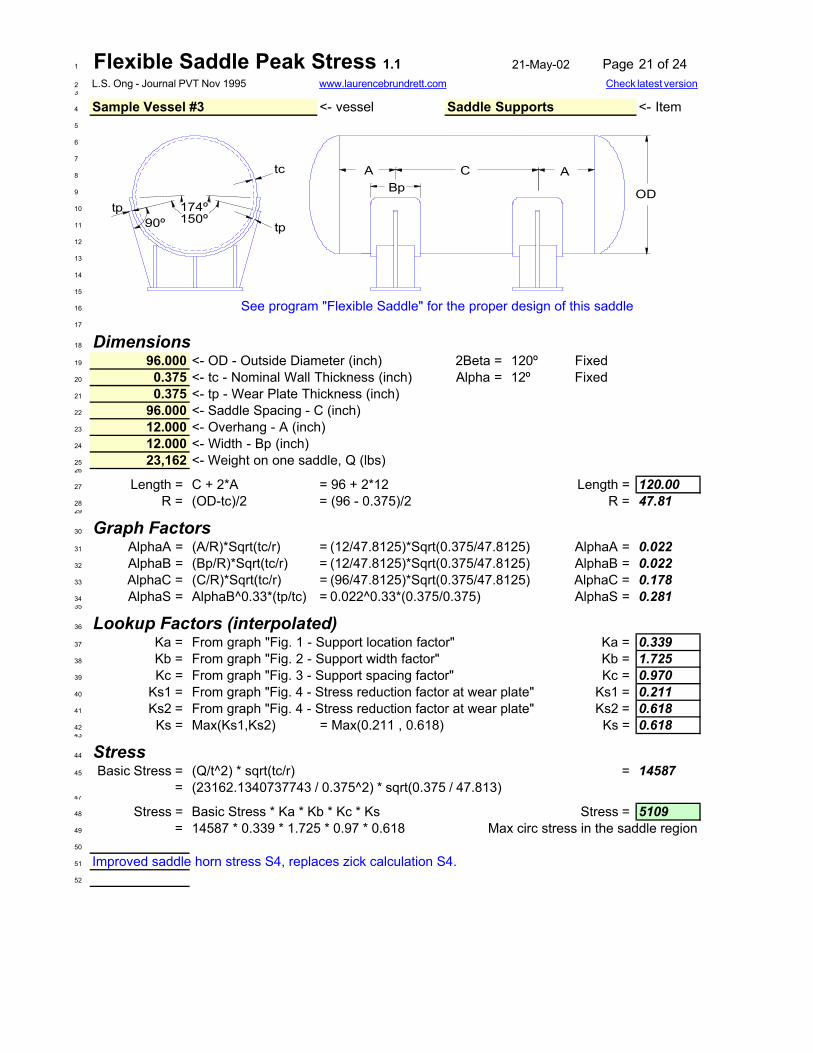
1 Flexible Saddle Peak Stress 1.1 21-May-02 Page 21 of 242 L.S. Ong - Journal PVT Nov 19953
4 Sample Vessel #3 <- vessel Saddle Supports <- Item5
6
7
8
9
10
11
12
13
14
15
16 See program "Flexible Saddle" for the proper design of this saddle17
18 Dimensions19 96.000 <- OD - Outside Diameter (inch) 2Beta = 120º Fixed20 0.375 <- tc - Nominal Wall Thickness (inch) Alpha = 12º Fixed21 0.375 <- tp - Wear Plate Thickness (inch)22 96.000 <- Saddle Spacing - C (inch)23 12.000 <- Overhang - A (inch)24 12.000 <- Width - Bp (inch)25 23,162 <- Weight on one saddle, Q (lbs)26
27 Length = C + 2*A = 96 + 2*12 Length = 120.0028 R = (OD-tc)/2 = (96 - 0.375)/2 R = 47.8129
30 Graph Factors31 AlphaA = (A/R)*Sqrt(tc/r) = (12/47.8125)*Sqrt(0.375/47.8125) AlphaA = 0.02232 AlphaB = (Bp/R)*Sqrt(tc/r) = (12/47.8125)*Sqrt(0.375/47.8125) AlphaB = 0.02233 AlphaC = (C/R)*Sqrt(tc/r) = (96/47.8125)*Sqrt(0.375/47.8125) AlphaC = 0.17834 AlphaS = AlphaB^0.33*(tp/tc) = 0.022^0.33*(0.375/0.375) AlphaS = 0.28135
36 Lookup Factors (interpolated)37 Ka = From graph "Fig. 1 - Support location factor" Ka = 0.33938 Kb = From graph "Fig. 2 - Support width factor" Kb = 1.72539 Kc = From graph "Fig. 3 - Support spacing factor" Kc = 0.97040 Ks1 = From graph "Fig. 4 - Stress reduction factor at wear plate" Ks1 = 0.21141 Ks2 = From graph "Fig. 4 - Stress reduction factor at wear plate" Ks2 = 0.61842 Ks = Max(Ks1,Ks2) = Max(0.211 , 0.618) Ks = 0.61843
44 Stress45 Basic Stress = (Q/t^2) * sqrt(tc/r) = 14587
= (23162.1340737743 / 0.375^2) * sqrt(0.375 / 47.813)47
48 Stress = Basic Stress * Ka * Kb * Kc * Ks Stress = 510949 = 14587 * 0.339 * 1.725 * 0.97 * 0.618 Max circ stress in the saddle region50
51 Improved saddle horn stress S4, replaces zick calculation S4.52
www.laurencebrundrett.com Check latest version
174º150º
tp90ºtp
tc
ODBpC A A

1 Flexible Saddle ver1.0 21-May-02 Page 22 of 242 Moss / Ong3
4 <- Vessel <- Item5
6
7
8
9
10
11
12
13
14
15
16
17
18
19 Vessel Dimensions:20 96.000 <- Vessel OD (R x 2)21 0.313 <- Shell Thickness (tc)22 66.000 <- Height (Hc)23
24 Vessel Loads:25 23,162 <- Fg26 2,687 <- Ft27 23,162 <- Fl28
29 Saddle Dimensions:30 0.375 <- Wear plate thickness (tp)31 12.000 <- Wear plate width (Bp)32 0.375 <- Support Thickness (Ts)33 0.750 <- Base Thickness (Tb)34 5 <- Ribs35 16,600 <- IID Allowable Stress (Sa)36
37 Calculated Dimensions38 R = OD/2 = 96 / 2 R = 48.00039 Rk = R + tp + ts = 48 + 2*0.375 Rk = 48.75040 B = 2 * Rk*Cos(15º) = 2 * 48.75 * 0.9659 B = 94.17841 Hb = Hc - RkSin(15º) - tb = 66 - 48.75 * 0.2588 - 0.75 Hb = 52.63342 Hx = B-2HbTan(15º) = 94.178 - 2 * 52.633 * 0.2579 Hx = 65.97243 A = Hx + 2*tp = 65.972 - 2 * 0.375 A = 67.00044 Xb = Bp/2 - 2*Tp - Ts/2 = 12 / 2 - 2 * 0.375 - 0.375/2 Xb = 5.06345 h = Hc - R + tc = 66 - 48 + 0.313 Saddle hgt inside shell = 18.31346 Es = (A-4*tb-ts)/(n-1) Es = 15.90647 Wp = 0.7*Min(Ts,Tp) = 0.7*Min(0.375,0.375) Min allowed Wp = 0.2648
49 Constraints51 Fbmax = SA*1.5 = 16600 * 1.5 Bending Stress Limit Fb = 2490052 Fsmax = SA*0.8 = 16600 * 0.8 Shear Stress Limit Fs = 1328053 Gt = Bp - 2Tp = 12 - 2 * 0.375 Gt = 11.2554 Gtmin = Sqrt((5.012*Fl/(Ts(n-1)*Fbmax)*(h + a*0.255)) Okay Gtmin = 10.555 = SQRT((5.012 * 23162 /(0.375*(5-1))*24900)*(18.313+67*0.255))
www.laurencebrundrett.com Check latest version
Sample Vessel #3 Saddle Design- 44w cs
Fl
Ft
Fg
tc
tb
R
BpTs
2 x tpXb
Ts / 2
Ts / 2Ts / 2
Wp
typ
typ
Hc
174º150º
tp
tb
90ºtp
EsA
tb

59 Sample Vessel #3 Saddle Design- 44w cs 21-May-02 Page 23 of 2460
61 Foundation Load62 Ba = A * Bp = 67 * 12 Base Area - Ba = 80463 Bs = Fg / Ba = 23162 / 804 Foundation Stress - Bs = 2964 Okay Max 500 psi for concrete65 Moment of Inertia - Saddle Splitting66
67 Width = Bp + 1.56*SQRT(VarR*Ts) Shell Effective Width = 18.668 = 12 + 1.56*SQRT(48*0.375)69
70 Width Height Area Y A*Y A*Y2 Io71 Shell 18.62 0.31 5.83 18.16 106 1921 0.072 Wear Plate 12.00 0.38 4.50 17.81 80 1428 0.173 Saddle 0.38 16.88 6.33 9.19 58 534 150.274 Base 12.00 0.75 9.00 0.38 3 1 0.475 Sum 18.3 25.66 247 3884 150.776
77 C1 = Sum(Ay)/Sum(A) = 247.5 / 25.7 Centroid C1 = 9.678 I = SumAY2 + SumIo - Ci*SumAy79 = 3884.3 + 150.7 - 9.6 * 247.5 I = 1647.880 A5 = SumA-AShell = 25.7 - 5.8 A5 = 19.881
82 Tension Stress - Saddle Splitting83 Fh = K1*Fg = 0.206 * 23162.1 Saddle Splitting force Fh = 4771.484 Tension = 2*Fh/A5 = 2 * 4771 / 20 Tension = 48185
86 Bending Stress - Saddle Splitting87 d = Hc - 0.827*R = 66 - 0.827 * 48 d = 26.388 M = 2*fh*d = 2 * 4771 * 26.3 M = 25101489 fb = MC1/I = 251014 * 10 / 1648 fb = 146990
91 Base plate thickness92 M2 = Q*Bp/8 = 23162*12/8 M2 = 34743.293 Z = A*tb^2/6 = 67*0.75^2/6 Z = 6.28194 fb2 = M/Z = 34743 / 6.2813 fb2 = 553195
96 Moment of Inertia - Longitudinal Direction97 Width Thick Area Y A*Y A*Y2 Io98 Saddle 66.3 0.4 24.8 5.3 130.4 684.8 0.399 Half Ribs 0.4 5.1 9.5 2.5 24.0 60.8 4.1100 Half Ribs 0.4 5.1 9.5 8.0 75.6 602.8 4.1101 Sum 10.5 43.8 230.1 1348.3 8.4102
103 C3 = Sum(Ay)/Sum(A) = 230.1 / 43.8 Centroid C3 = 5.3104 I = SumAY2 + SumIo - C2*SumAy105 = 1348.3 + 8.4 - 5.3 * 230.1 I3 = 148.7106
107 Support Shear - Longitudinal Load108 Shear L = FL / area = 23162 / 44 Shear L = 528109
110 Bending Stress - Longitudinal Load111 Lr = h+0.29*R-tb-ts = 18.313 + 0.29 * 48 - 0.375 - 0.75Longest Rib - Lr = 31.1112 Ls = Hc-R-tb-ts-tp = 66 - 48 - 0.75 - 0.375 - 0.375 Shortest Rib - Ls = 16.5113 Lave = (Lr + Ls)/2 = (31.1 + 16.5)/2 Lave = 23.8114 M3 = fl*Lave = 23162 * 23.8 M3 = 551351115 fb3 = MC2/I2 = 551351 * 5 / 149 fb3 = 19463116
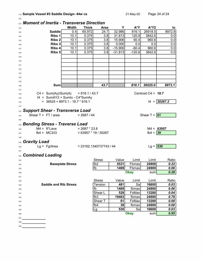
119 Sample Vessel #3 Saddle Design- 44w cs 21-May-02 Page 24 of 24120
121 Moment of Inertia - Transverse Direction122 Width Thick Area Y A*Y A*Y2 Io123 Saddle 0.4 65.972 24.7 32.986 816.1 26918.5 8972.8124 Ribs 1 10.1 0.375 3.8 31.813 120.8 3842.6 0.0125 Ribs 2 10.1 0.375 3.8 15.906 60.4 960.6 0.0126 Ribs 3 10.1 0.375 3.8 0.000 0.0 0.0 0.0127 Ribs 4 10.1 0.375 3.8 -15.906 -60.4 960.6 0.0128 Ribs 5 10.1 0.375 3.8 -31.813 -120.8 3842.6 0.0129
130
131
132
133
134
135
136 Sum 43.7 816.1 36525.0 8973.1137
138 C4 = Sum(Ay)/Sum(A) = 816.1 / 43.7 Centroid C4 = 18.7139 I4 = SumAY2 + SumIo - C4*SumAy140 = 36525 + 8973.1 - 18.7 * 816.1 I4 = 30267.2141
142 Support Shear - Transverse Load143 Shear T = FT / area = 2687 / 44 Shear T = 61144
145 Bending Stress - Traverse Load146 M4 = ft*Lave = 2687 * 23.8 M4 = 63957147 fb4 = MC3/I3 = 63957 * 19 / 30267 fb4 = 39148
149 Gravity Load150 Lg = Fg/Area = 23162.1340737743 / 44 Lg = 530151
152 Combined Loading153 Stress Value Limit Limit Ratio154 Baseplate Stress fb2 5531 Fbmax 24900 0.22155 fb 1469 Fbmax 24900 0.06156 Okay sum 0.28157
158 Stress Value Limit Limit Ratio159 Saddle and Rib Stress Tension 481 Sa 16600 0.03160 fb 1469 fbmax 24900 0.06161 Shear L 528 FsMax 13280 0.04162 fb3 19463 fbmax 24900 0.78163 Shear T 61 FsMax 13280 0.00164 fb4 39 fbmax 24900 0.00165 Lg 530 Sa 16600 0.03166 Okay sum 0.95167
168
169