Operation of the High Flux Reactor - Archive of European ...
104
PROGRAMME PROGRESS REPORT July - December 1980 COMMUNICATION Category 1.0 Nr 3865 WARNING The information contained in this document is communicated confidentially by the Commission of the European Communities to Member States, persons and undertakings and should not be passed on to third parties. lEuratom-Treaty. Article 13, and Regulation (EEC! No 2380/74 of the Council of Ministers). COMMISSION OF THE EUROPEAN COMMUNITIES JOINT RESEARCH CENTRE Petten Establishment The Netherlands O ι ■ Operation of the High Flux Reactor
-
Upload
khangminh22 -
Category
Documents
-
view
0 -
download
0
Transcript of Operation of the High Flux Reactor - Archive of European ...
PROGRAMME
PROGRESS
REPORT
July - December 1980
COMMUNICATION
Category 1.0
Nr 3865
WARNING
The information contained in this document is communicated confidentially by the Commission of the European Communities to Member States, persons and undertakings and should not be passed on to third parties. lEuratom-Treaty. Article 13, and Regulation (EEC! No 2380/74 of the Council of Ministers).
COMMISSION OF THE EUROPEAN COMMUNITIES JOINT RESEARCH CENTRE
Petten Establishment The Netherlands
O ι
■
Operation of the High Flux Reactor

COMMISSION OF THE EUROPEAN COMMUNITIES JOINT RESEARCH CENTRE (JRC)
PETTEN ESTABLISHMENT
HFR DIVISION
Abstract
Within JRC's 1980/83 programme, the materials testing reactor HFR continued its scheduled operation. During the second half year 1980, it reached 67 °/o availability at 45 MW. The occupation by irradiation experiments and radioisotope production devices varied between 73 and 83 °/o.

COMMISSION OF THE EUROPEAN COMMUNITIES JOINT RESEARCH CENTRE
Petten Establishment The Netherlands
Operation of the High Flux Reactor
PROGRAMME PROGRESS REPORT July - December 1980
BEMÆRK
Den viden, som rummes i dette dokument, meddeles som fortrolig fra Kornmissionen for de europæiske Fællesskaber til Medlemsstater, personer og virksomheder og ma ikke videreaives til trediemand. (Euratom-traktatens artikel 13og Minersterrådets forordning(EÛF) N° 2380/74).
Hverken Kommissionen for de Europæiske Fælleskaber eller nogen, som optræder pa Kommissionens vegne er ansvarling for den eventuelle brug af information, som er indeholdt i det følgende .
ZUR BEACHTUNG
Die in diesem Dokument enthaltenen Kenntnisse werden von der Kommission der Europäischen Gemeinschaften den Mitgliedstaaten, Personen und Unternehmen der Gemeinschaft vertraulich mitgeteilt und dürfen nicht an Dritte weitergegeben werden. (Euratom-Vertrag, Art i kel 13, und Beschluss des Ministerrates (EWG) Nr. 2380/74).
Weder die Kommission der Europäischen Gemeinschaften noch Personen, die im Namen dieser Kommission handeln, sind für die etwaige Verwendung der nachstehenden Informationen verantwortl ich.
NOTICE
The information contained in this document is communicated confidentially by the Commission of the European Communities to Member States, persons and undertakings and should not be passed on to third parties. (Euratom-Treaty, Article 13, and Regulation (EEC) No. 2380/74 of the Council of Ministers).
Neither the Commission of the European Communities nor any person acting on behalf of the Commission is responsible for the use which might be made of the following information.
AVERTISSEMENT
Les connaissances contenues dans le présent document sont communiquées confidentiellement par la Commission des Communautées européennes aux Etats membres, personnes et entreprises et ne peuvent être transmises à des tiers. (Traité Euratom, article 13, et règlement (CEE) N° 2380/74 du Conseil de Ministres).
Ni la Commission des Communautés européennes, ni aucune personne agissant au nom de la Commission, n'est responsable de l'usage qui pourrait être fait des informations ci-après.
AVVERTIMENTO
Le cognizioni contenute nel presente documento sono comunicate confidenzialmente dalla Commissione delle Comunità europee agli Stati membri, persone ed imprese e non debbono essere trasmesse a terzi. (Trattato Euratom, articolo 13, e regolamento (CCE) N° 2380/74 del Consiglio dei Ministri).
Né la Commissione delle Comunità europee, né alcuna persona che agisca per suo conto, è responsabile dell'uso che dovesse essere fatto delle informazioni che seguono.
OPMERKING
De kennis, die in dit document is vervat, wordt door de Conmissie van de Europese Gemeenschappen vertrouwelijk aan de Lid-Staten, personen en ondernemingen medegedeeld en mag niet aan derden worden doorgegeven. (Euratom-Verdrag, artikel 13, en het besluit van de Ministerraad (EEG) No. 2380/74).
Noch de Commissie van de Europese Gemeenschappen, noch de personen die namens haar optreden, zijn verantwoordelijk voor het gebruik, dat eventueel van de hiernavolgende informaties wordt gemaakt.
TABLE OF CONTENTS
PROGRAMME PROGRESS REPORT, July - December 1980 page :
1. INTRODUCTION TO THE HFR PROGRAMME 5
2. PROJECTS 13
2.1 HFR Operation and Maintenance 13 2.1.1 Objectives 13 2.1.2 Methods 13 2.1.3 Results 13
2.1.3.1 HFR Operation 13 2.1.3.2 Maintenance and Modifications 22 2.1.3.3 Nuclear Support and Development 25 2.1.3.4 Fuel Cycle 28
r. 2.1.3.5 Miscellaneous Tasks 30 2.1.3.6 Users'Services 30 2.1.3.7 Neutron Dosimetry Methods Development 34 2.1.3.8 HFR Vessel Replacement 36
2.2 Reactor Utilisation 42 2.2.1 Objectives 42 2.2.2 Methods 42 2.2.3 Results 42
2.2.3.1 Graphite 42 2.2.3.2 HTRFuel 51 2.2.3.3 Structural Material 53 2.2.3.4 LWRFuel 64 2.2.3.5 Fast Reactor Fuel 66 2.2.3.6 Miscellaneous 75
2.3 General Activities 78 2.3.1 Objectives 78 2.3.2 Methods 78 2.3.3 Results 79
2.3.3.1 Experiments Control Installations 79 2.3.3.2 Testing and Commissioning 81 2.3.3.3 Dismantling Cell 81 2.3.3.4 Neutron Radiography Installations 81 2.3.3.5 Post-Irradiation Work 82 2.3.3.6 Remote Encapsulation System EUROS 82 2.3.3.7 Standard Irradiation Devices ; Assembly Laboratories 82 2.3.3.8 Development of LWR Fuel Pin Testing Facilities 85 2.3.3.9 Development of a Control System for Swept HTR
Fuel Elements 85 2.3.3.10 Computing Facilities 85 2.3.3.11 Project Management 87 2.3.3.12 Irradiation Technology Support and Development (ECN). 88
3. CONCLUSIONS 93
3.1 HFR Operation and Maintenance 93 3.2 Reactor Utilisation 93 3.3 General Activities 93
4. JRC PUBLICATIONS 94
GLOSSARY 95
LIST OF AUTHORS 97

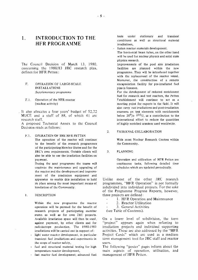
INTRODUCTION TO THE HFR PROGRAMME
The Council Decision of March 13, 1980, concerning the 1980/83 JRC research plan, defines for HFR Petten :
F. OPERATION OF LARGE-SCALE INSTALLATIONS Supplementary programme
F. 1. Operation of the HFR reactor (nuclear activity)
It also allocates a four years' budget of 52,22 MUCE and a staff of 88, of which 41 are research staff. A proposed Technical Annex to the Council Decision reads as follows:
F. l . OPERATION OF THE HFR PETTEN The operation of the reactor will continue to the benefit of the research programmes of the participating Member States and for the JRC's own requirements. Outside clients will also be able to use the irradiation facilities on payment. During the next programme the teams will continue the maintenance and upgrading of the reactor and the development and improvement of the irradiation equipment and apparatus to enable this installation to hold its place among the most important means of irradiation of the Community.
1. DESCRIPTION
Within the new programme the reactor operation will be pursued for the benefit of research projects of participating member states as well as for own JRC projects. Available irradiation space will then be used, against payment, by other clients and for radioisotope production. The 1980-1983 irradiations will be carried out in support of:
- light water reactor development, in particular transient fuel irradiations and experiments in the scope of reactor safety,
- fuel and structural material testing for high temperature reactor development,
- fast reactor fuel development; advanced fuel
tests under stationary and transient conditions as well as structural material irradiations, fusion reactor materials development. The horizontal beam tubes, on the other hand will be used for nuclear physics and solid state physics research. Improvements of the pool side irradiation facilities are planned within the new programme. They will be introduced together with the replacement of the reactor vessel. Moreover, the construction of a remote encapsulation facility for pre-irradiated fuel pins is foreseen. For the development of reduced enrichment fuel for research and test reactors, the Petten Establishment will continue to act as a meeting point for experts in the field. It will also carry out irradiations and post-irradiation examens on test elements with enrichments below 20°/o 235TJ ; a s a contribution to the international effort to reduce the quantities of highly enriched uranium used worldwide.
EXTERNAL COLLABORATION
With most Nuclear Research Centres within the Community.
PLANNING
Operation and utilization of HFR Petten are continuous tasks, following detailed time schedules which are updated periodically.
Unlike most of the other JRC research programmes, "HFR Operation" is not formally subdivided into individual projects. For the sake of the Programme Progress Reports, however, three projects are defined :
1. HFR Operation and Maintenance 2. Reactor Utilization 3. General Activities
(see Table of Contents).
On a lower level of subdivision, the term "project" appears again when referring to irradiation projects and individual supporting activities. These are also addressed by the "HFR Project Cards" which are used as a medium term management tool for JRC staff and reactor users. The following "poster" pages inform about the main aspects of operation, utilisation, and management of HFR Petten.
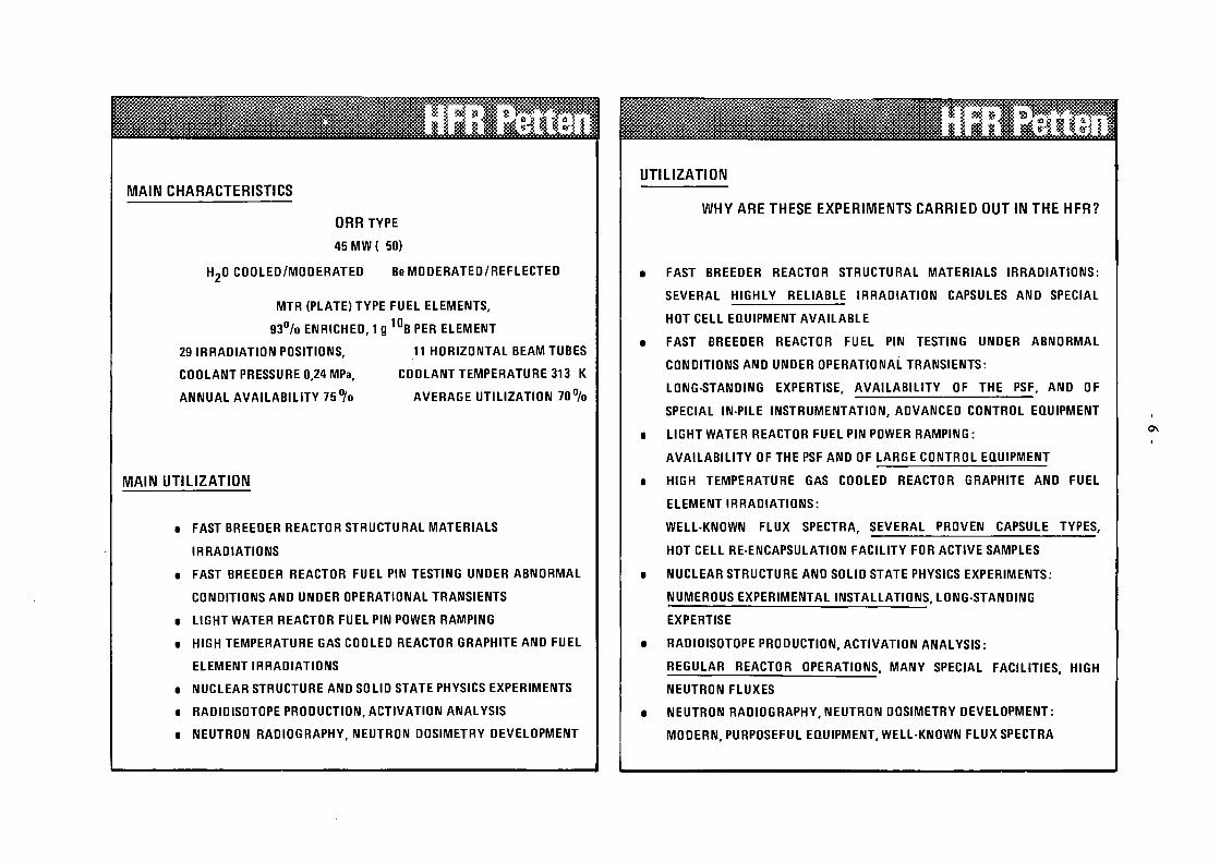
MAIN CHARACTERISTICS
ORRTYPE
45 MW ( 50)
H20 COOLED/MODERATED Be MODERATED/REFLECTED
MTR (PLATE) TYPE FUEL ELEMENTS,
9 3 % ENRICHED, 1 g 10
B PER ELEMENT
29 IRRADIATION POSITIONS, 11 HORIZONTAL BEAM TUBES
COOLANT PRESSURE 0,24 MPa, COOLANT TEMPERATURE 313 K
ANNUAL AVAILABILITY 7 5 % AVERAGE UTILIZATION 7 0 %
MAIN UTILIZATION
• FAST BREEDER REACTOR STRUCTURAL MATERIALS
IRRADIATIONS
• FAST BREEDER REACTOR FUEL PIN TESTING UNDER ABNORMAL
CONDITIONS AND UNDER OPERATIONAL TRANSIENTS
■ LIGHT WATER REACTOR FUEL PIN POWER RAMPING
• HIGH TEMPERATURE GAS COOLED REACTOR GRAPHITE AND FUEL
ELEMENT IRRADIATIONS
• NUCLEAR STRUCTURE AND SOLID STATE PHYSICS EXPERIMENTS
• RADIOISOTOPE PRODUCTION, ACTIVATION ANALYSIS
■ NEUTRON RADIOGRAPHY, NEUTRON DOSIMETRY DEVELOPMENT
UTILIZATION
WHY ARE THESE EXPERIMENTS CARRIED OUT IN THE HFR?
FAST BREEDER REACTOR STRUCTURAL MATERIALS IRRADIATIONS:
SEVERAL HIGHLY RELIABLE IRRADIATION CAPSULES AND SPECIAL
HOT CELL EQUIPMENT AVAILABLE
FAST BREEDER REACTOR FUEL PIN TESTING UNDER ABNORMAL
CONDITIONS AND UNDER OPERATIONAL TRANSIENTS:
LONG-STANDING EXPERTISE, AVAILABILITY OF THE PSF, AND OF
SPECIAL IN-PILE INSTRUMENTATION, ADVANCED CONTROL EQUIPMENT
LIGHT WATER REACTOR FUEL PIN POWER RAMPING :
AVAILABILITY OF THE PSF AND OF LARGE CONTROL EQUIPMENT
HIGH TEMPERATURE GAS COOLED REACTOR GRAPHITE AND FUEL
ELEMENT IRRADIATIONS:
WELL-KNOWN FLUX SPECTRA, SEVERAL PROVEN CAPSULE TYPES,
HOT CELL RE-ENCAPSULATION FACILITY FOR ACTIVE SAMPLES
NUCLEAR STRUCTURE AND SOLID STATE PHYSICS EXPERIMENTS:
NUMEROUS EXPERIMENTAL INSTALLATIONS, LONG-STANDING
EXPERTISE
RADIOISOTOPE PRODUCTION, ACTIVATION ANALYSIS :
REGULAR REACTOR OPERATIONS, MANY SPECIAL FACILITIES, HIGH
NEUTRON FLUXES
NEUTRON RADIOGRAPHY, NEUTRON DOSIMETRY DEVELOPMENT:
MODERN, PURPOSEFUL EQUIPMENT, WELL-KNOWN FLUX SPECTRA
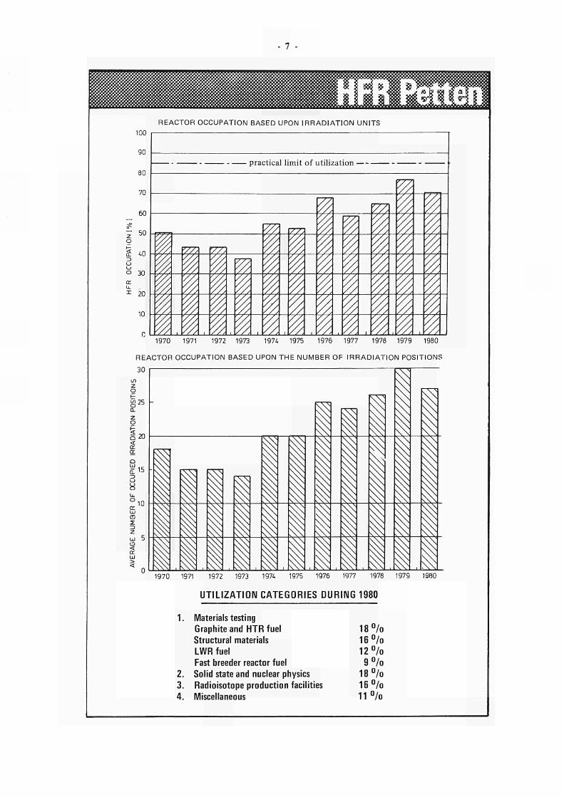
REACTOR OCCUPATION BASED UPON IRRADIAT ION UNITS 100
90
Θ0
70
60
50
2 40
0 30 cc ϋ. 1 20
10
practical limit of utilization
^
%
m ζ
vm w,< 77, &
¥Z
7, 7
1970 1971 1972 1973 1974 1975 1976 1977 197Θ 1979 1980
REACTOR OCCUPATION BASED UPON THE NUMBER OF IRRADIATION POSITIONS
30
Ζ o g25
CL Ζ o
δ 20
15
o cr ω ca Σ ζ ω Ο < cc UJ
10 §à χ
ι -i-h.
&
1
i
s
11
ι
\
l - B
\
^
^
X
1970 1971 1972 1973 1974 1975 1976 1977 1978 1979 1980
UTILIZATION CATEGORIES DURING 1980
2.
3.
4.
Materials testing
Graphite and HTR fuel
Structural materials
LWR fuel
Fast breeder reactor fuel
Solid state and nuclear physics
Radioisotope production facilities
Miscellaneous
1 8 %
1 6 %
1 2 %
9 %
1 8 %
1 6 %
1 1 %
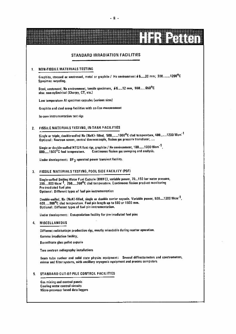
STANDARD IRRADIATION FACILITIES
1. NON-FISSILE MATERIALS TESTING
Graphite, stressed or unstressed, metal or graphite/ He environment i 6 20 mm; 300. Specimen recycling.
Steel, unstressed, Na environment, tensile specimens, i 6 12 mm, 550 650 C
also: non-cylindrical (Charpy, CT, etc.)
Low temperature Al specimen capsules (various sizes)
Graphite and steel creep facilities with on-line measurement
In-core instrumentation test rigs
.1200°C
2. FISSILE MATERIALS TESTING, IN-TANK FACILITIES
Single or triple, double-walled Na (NaK)- filled, 500 1000°C clad temperature, 400 1200 Wem'1
Optional: Neutron screen, central thermocouple, fission gas pressure transducer,....
Single or double-walled HTG R fuel rigs, graphite /He environment, 100 1000 Wem' , 800 1500°C fuel temperature. Continuous fission gas sweeping and analysis.
U nder development : BF3 operated power transient facility.
3. FISSILE MATERIALS TESTING, POOL SIDE FACILITY (PSF)
Single-walled Boiling Water Fuel Capsule (BWFC), variable power, 70...150 bar water pressure, 200....800 Wem'1, 250 350°C clad temperature. Continuous fission product monitoring Pre-irradiated fuel pins Optional : Different types of fuel pin instrumentation
Double-walled, Na (NaK)-filled, single or double carrier capsule. Variable power, 500....1200 Wem"1, 400 800°C clad temperature. Fuel pin length up to 500 or 1600 mm. Optional: Different types of fuel pin instrumentation.
Under development: Encapsulation facility for pre-irradiated fuel pins
4. MISCELLANEOUS
Different radioisotope production rigs, mostly reloadable during reactor operation.
Gamma irradiation facility.
Borosilicate glass pellet capsule
Two neutron radiography installations
Beam tube nuclear and solid state physics equipment: Several diffractometers and spectrometers, mirror and filter systems, with ancillary cryogenic equipment and process computers
5. STANDARD OUT-OF-PILE CONTROL FACILITIES
Gas mixing and control panels Cooling water control circuits Micro-processor based data loggers
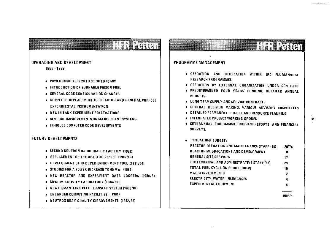
UPGRADING AND DEVELOPMENT
1966-1979
• POWER INCREASES 20 TO 30, 30 TO 45 MW
■ INTRODUCTION OF BURNABLE POISON FUEL
• SEVERAL CORE CONFIGURATION CHANGES
■ COMPLETE REPLACEMENT OF REACTOR AND GENERAL PURPOSE
EXPERIMENTAL INSTRUMENTATION
• NEW IN-TANK EXPERIMENT PENETRATIONS
• SEVERAL IMPROVEMENTS ON MAJOR PLANT SYSTEMS
• IN-HOUSE COMPUTER CODE DEVELOPMENTS
FUTURE DEVELOPMENTS
■ SECOND NEUTRON RADIOGRAPHY FACILITY (1981)
• REPLACEMENT OF THE REACTOR VESSEL (1982/83)
■ DEVELOPMENT OF REDUCED ENRICHMENT FUEL (1981/84)
■ STUDIES FOR A POWER INCREASE TO 60 MW (1982)
■ NEW REACTOR AND EXPERIMENT DATA LOGGERS (1980/81)
t MEDIUM ACTIVITY LABORATORY (1984/85)
■ NEW DISMANTLING CELL TRANSFER SYSTEM (1980/81)
■ ENLARGED COMPUTING FACILITIES (1981)
• NEUTRON BEAM QUALITY IMPROVEMENTS (1982/83)
PROGRAMME MANAGEMENT
OPERATION AND UTILIZATION WITHIN JRC PLURIANNUAL
RESEARCH PROGRAMMES
OPERATION BY EXTERNAL ORGANIZATION UNDER CONTRACT
PREDETERMINED FOUR YEARS' FUNDING, DETAILED ANNUAL
BUDGETS
LONG-TERM SUPPLY AND SERVICE CONTRACTS
CENTRAL DECISION MAKING, VARIOUS ADVISORY COMMITTEES
DETAILED PERMANENT PROJECT AND RESOURCE PLANNING
INTEGRATED PROJECT WORKING GROUPS
SEMI-ANNUAL PROGRAMME PROGRESS REPORTS AND FINANCIAL
SURVEYS.
TYPICAL HFR BUDGET:
REACTOR OPERATION AND MAINTENANCE STAFF (70)
REACTOR MODIFICATIONS AND DEVELOPMENT
GENERAL SITE SERVICES
JRC TECHNICAL AND ADMINISTRATIVE STAFF (88)
TOTAL FUEL CYCLE (IN EQUILIBRIUM)
MAJOR INVESTMENTS
ELECTRICITY, WATER, INSURANCES
EXPERIMENTAL EQUIPMENT
20°/o
8
17
29
15
2
4
5
1 0 0 %


Projects
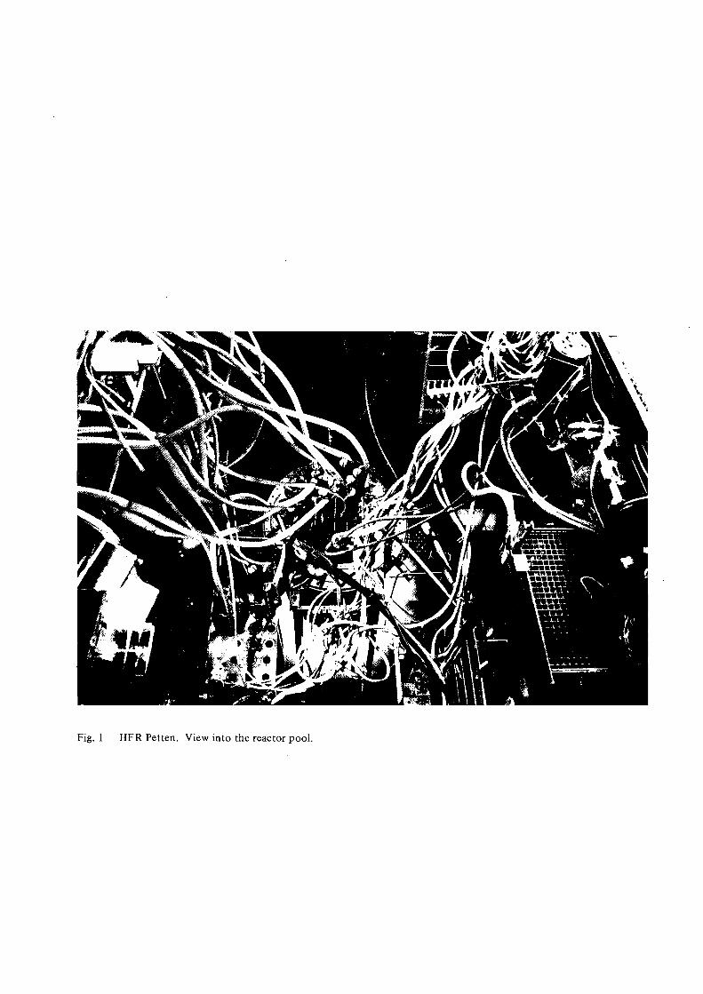
Fig. 1 HFR Petten. View into the reactor pool.
13
PROJECTS
2.1 HFR Operation and Maintenance
2.1.1 Objectives
Reactor operation during the second half year of
1980 aimed at
high availability, in order to satisfy a consistent
irradiation programme,
inspection and maintenance during the summer
outage in order to assure the technical health of the
plant, preparation of the main overhauling work
during the winter outage.
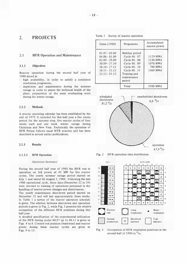
Table 1 Survey of reactor operation
2.1.2 Methods
A precise operating calendar has been established by the
end of 1979. It included for this half year a five weeks
period for the summer stop, five reactor cycles of four
weeks each and one week winter outage during
Christmas and New Year. Technically the operation of
HFR Petten follows usual MTR practice and has been
described in several earlier publications.
2.1.3 Results
Dates (1980)
01.0703.08
04.0801.09
02.0929.09
30.0927.10
28.10 17.11
18.11 21.12
22.1231.12
Programme
Holiday period
Cycle 80 . 07
Cycle 80 . 08
Cycle 80 . 09
Cycle 80 . 10
Cycle 80 . 11
Training and
maintenance
period
Total
Accumulated
reactor power
1129 MWd
1138 MWd
1076 MWd
788 MWd
1369 MWd
5500 MWd
scheduled
shutdowns
31,2 °/o
unscheduled shutdowns
0,9 °/o
operation
67,9 °/o
2.1.3.1 HFR Operation Fig. 2 HFR operation time distribution.
Operation Summary
During the second half year of 1980 the HFR was in
operation on full power of 45 MW for five reactor
cycles. The yearly summer outage period started on
July 1 and lasted till August 3, 1980. Following the last
1980 operational cycle, three days (December 22 to 24)
were devoted to training of operations personnel in the
handling of reactor power changes and disturbances.
The yearly maintenance shutdown period started on
December 22 and will last approximately three weeks.
In Table 1 a survey of the reactor operation schedule
is given. The relation between shutdown and operation
periods is given in Fig. 2, while Fig. 3 presents the relative
occupation of the different HFR positions during this
half year.
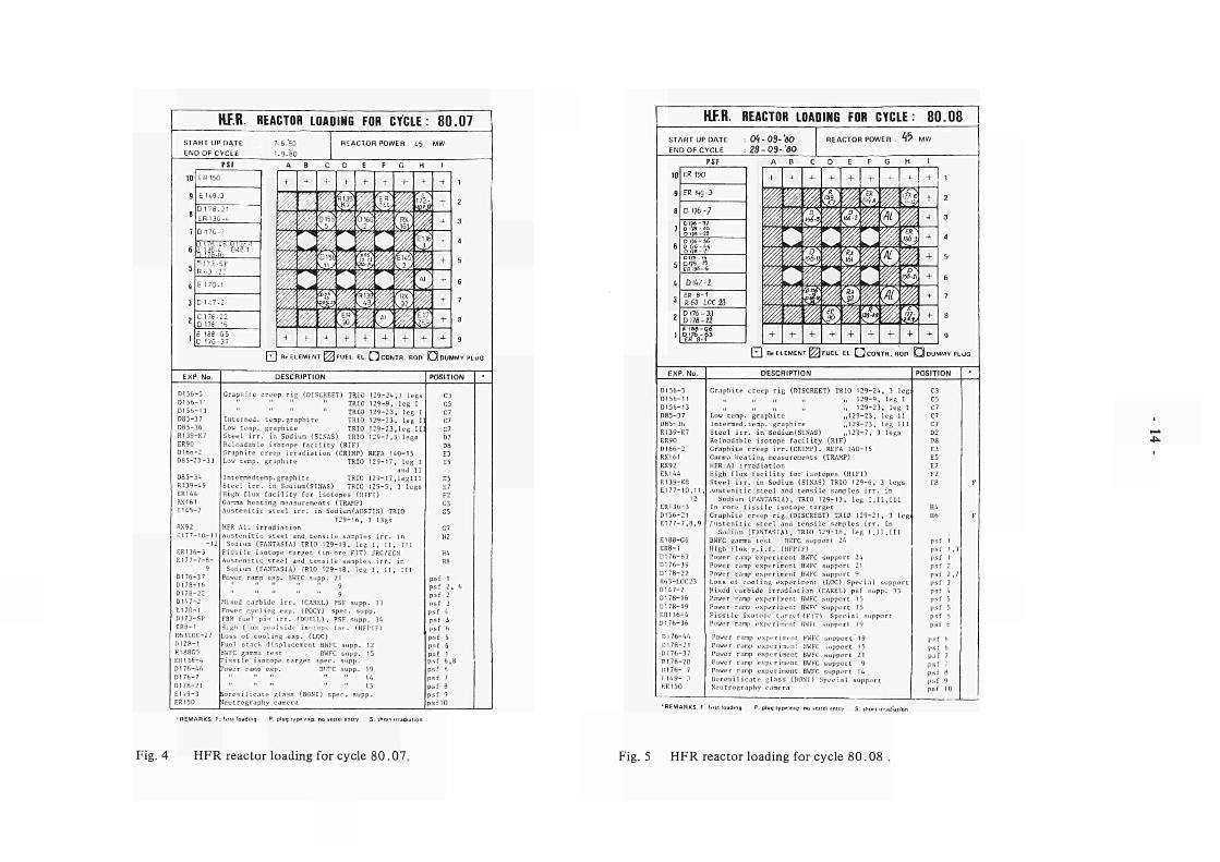
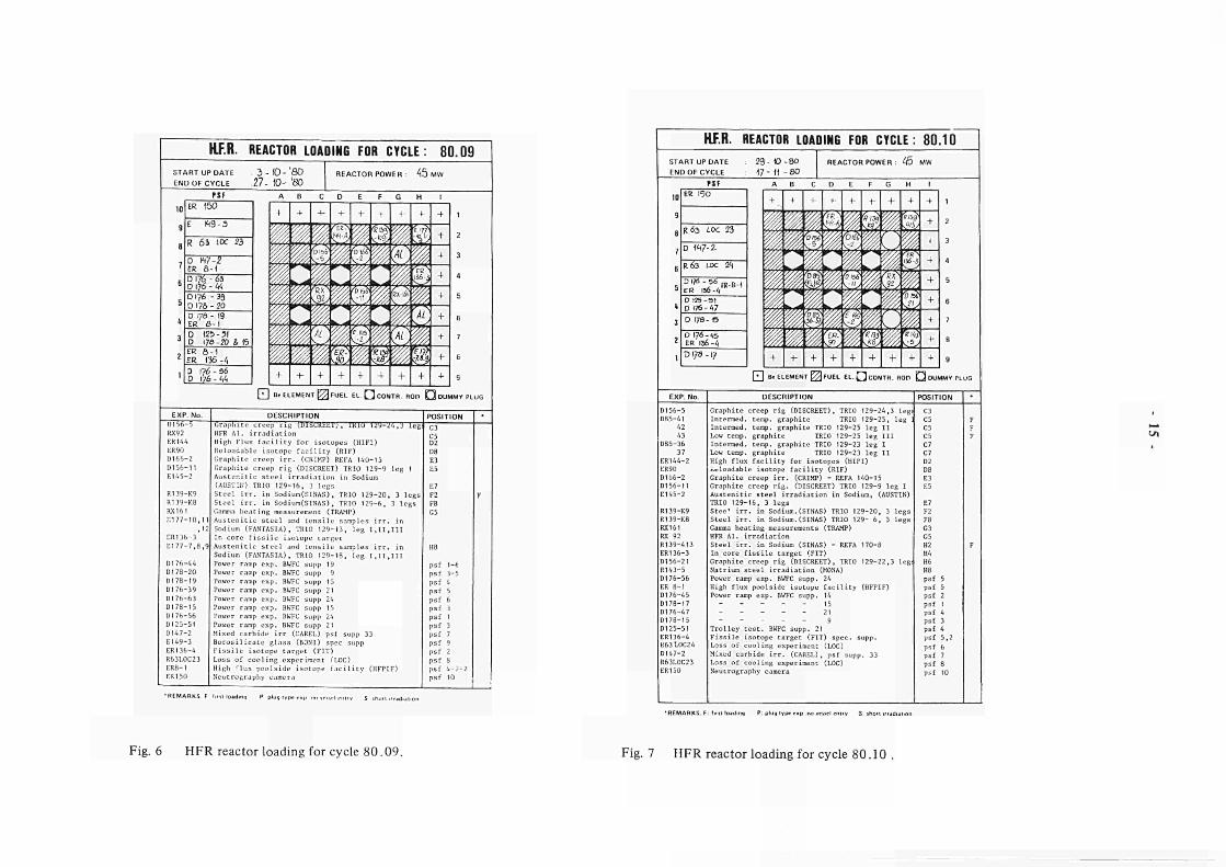
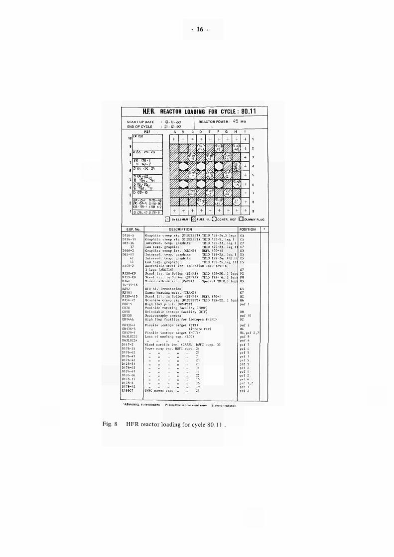
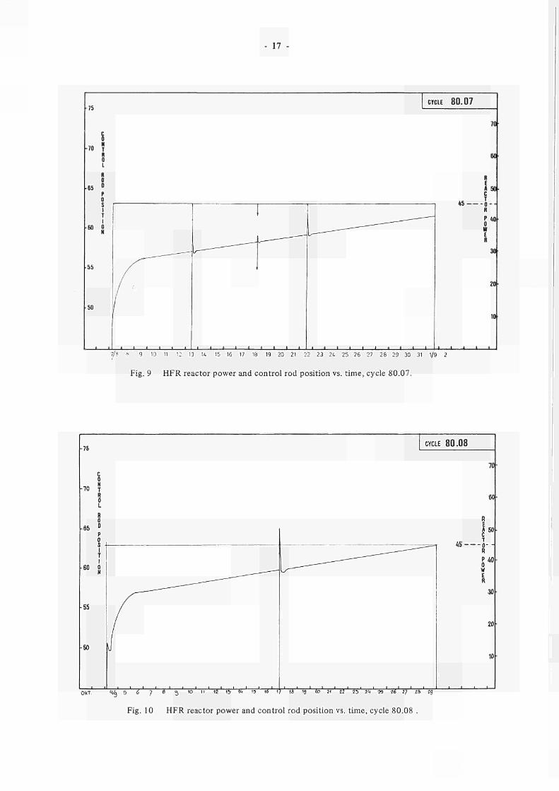
A detailed specification of the experimental utilization
of the HFR during cycles 80.07 up to 80.11 is given in
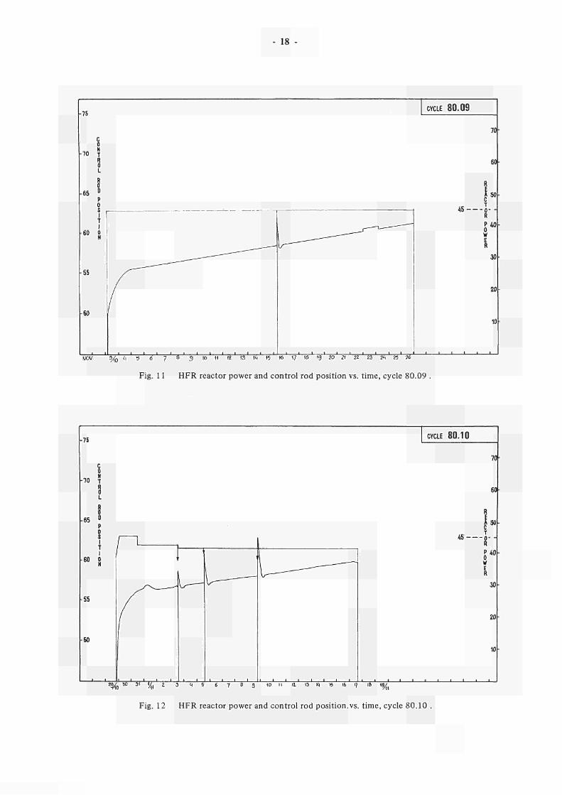
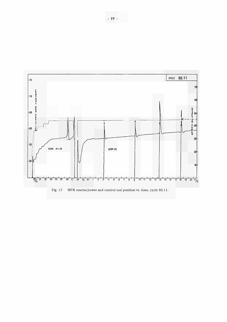
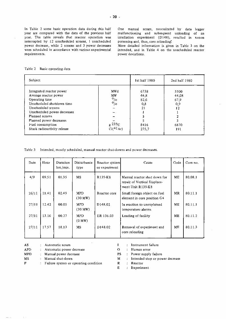
Figs. 4 to 8. Control rod position (bankwise) and reactor
power during these reactor cycles are given in
Figs. 9 to 13.
H.F R.CORE
D E F G
JE ¿J
υ u u
100 ■
60 ·
100 ·
100 ·
100 «
100 a
100 ·
100 ·
100 ·
100 ·
Control
rod
Isotope
production
Long
irradiation
Short
irradiation G Ξ Beryllium I I Fuel
element element
Fig. 3 Occupation of HFR irradiation positions in the
second half of 1980in° /o .
KF.R. REACTOR LOADING FOR CYCLE: 8 0 . 0 7
START UP DATE
END OF CYCLE
7.850
ig.'fio
REACTOR POWER : Lb MW
10
9
β
7
e
5
4
3
2
1
TSF
ER 150
EU93
D178.21
ER I3G6
D 1707
IJ l7h¿b ü l ' ië l ι: 1361 ERBl 1 !7fiir,
P173SP nos 2 :
E 1701
D U72
D17f22 D 17616
é IfieG5 C 17637
DUMMY PLUG
EXP. No. DESCRIPTION
D1565 D1561I
D15613 D853 7
D8536 R139K7 ER90 D16ö2
D852333
D8534 RI3949 ER 144 RX 161 E1452
RX92
£177101 I 12
ER1363 E1 7778
9 D17637 DI 7816 D17822 D I 4 7 2
E1701 D173SP
ER8I R63LOC22
01281 F.188G5 ER1364
D17646
D1767 D17821
E1493 ER150
Graph i t e c r e e p r i g (DISCREET) TRIO 12924,3 legs
TRIO 1299, l e g I
TRIO 12923 , l eg I
TRIO 12923 , leg I
TRIO 12923 , l eg I I ]
TRIO 1297 ,3 l egs
ope f a c i l i t y (RIF)
i r r a d i a t i o n (CRIMP) REFA 14015
C 3
C5
Intermed, temp.graphite
Low temp, graphite
Steel irr. in Sodium (SINAS)
Reloadable
Graphite c
Lou temp, graphite
Intermedtemp.graphite
Steel irr. in Soiiium(SINAS)
High flux facility for isotop·
Canna heating measurements (TRAMP)
Austenitic steel irr. in Sodium(AUSTIN) TRIO
129-16, 3 13gs
HFR Al. irradiation
Austenitic steel and tensile samples irr. in
Sodium (FANTASIA) TRIO 129-13, leg I, II, IT
Fissile isotope target (in._ore FIT) JRC/ECN
Austenitic steel and tensile samples irr. in
TRIO 12917
TRIO 12917
TRIO 1295 , S (HIFI)
leg I and I I
l e g l l l
3 l e g s
E5
E5
E7 F2
Sodium (FANTASIA) TRIO 129-18
Power ramp exp. BWFC supp.
leg I, II, III
Mixed carbide irr. (CAREL) PSF supp. 33
Power cycling exp. (POCY) spec. supp.
FBR fuel pin irr. (DUELL), PSF supp. 14
Ηίμ,π flux poolside isotope fa.-. (HFPIF) Loss of cooling exp. (LOC) Fuel stack displacement BWTC supp. 12 BWFC gamma test . BWFC supp. 15 Fissile isotope target spec. supp. ower ramp exp. 31.TC supp. 19
" 14 15
Borosilicate glass (BONI) spec. supp. "Jeutrography camera
psf 1 psf 2, 6 psf 2 psf J psf 4 psf i psf 6 psf 5 psf 6 psf 1 psf 6,8 psf 6 psf 7 psf 8 psf 9 psflO
•REMARKS F: f . rn loading P: plug typ* " p r
Fig. 4 HFR reactor loading for cycle 80.07.
HFR. REACTOR LOADING FOR CYCLE: 8 0 . 0 8
START UP DATE END OF CYCLE
: 0Ί-03-'6Ο 23-03-'βο
REACTOR POWER <f>
ER Ktg-3
D 176-7
D I M î é D Úí kk Q ifrfl El
D 1/8 ,6
ro ι3ί - 4
DI47-2 ER 8 - 1 R 65 LOC 23 D Í76-3Q D 17fl 22 E IÒO-G6
FUEL EL CcONTR.ROn O DUMMY PLUG
DESCRIPTION
D156-5
DI 56-11
D156-13
D85-3 7
D85-36
R139-K7
ER90
D166-2
RX 1 f> 1
R.\')2
ER144
R139-K8
El 77-10.11
12
ER136-3
D156-21
El 77-7,8,9
E188-C6
ER8-I
D176-63
D176-39
D178-22
R63-LOC23
D147-2
D178-16
DI 78-19
ERI 36-4
0176-36
D176-44
D178-21
D176-37
DI 78-20
1)176- 7
I 149- 3
KR 150
Graphite creep rig (DISCREET) TRIO 129-24, 3 leg
„ 129-9, leg I
„ 129-23, leg 1 Low temp, graphite „129-23, leg II
Interned.temp, graphite „129-23, leg III
Steel irr. in Sodium(SINAS) „129-7, 3 legs
Reloadable isotope facility (RIF)
Graphite creep irr.(CRLMP). REFA 140-15
Gamma heating measurements (TRAMP)
HFR Al irradiation
High flux facility for isotopes (HIFI)
Steel irr. in Sodium (SINAS) TRIO 129-6, 3 legs
Austenitic steel and tensile samples irr. in
Sodium (FANTASIA), TRIO 129-13, leg I,II,III
In core fissile isotope target
Graphite creep rig (DISCREET) TRIO 129-21, 3 leg
/ustenitic steel and tensile samples irr. in
Sodium (FANTASIA), TRIO 129-18, leg 1,11,111
BWFC gamma test Bl.'FC supporr 24
High Flux p.i.f. (HFPIF)
Power ramp experiment BWFC support 24
Power ramp experiment BWFC support 21
Power ramp experiment BWFC support 9
Loss of cooling experiment (L0C) Special support
Mixed carbide irradiation (CAREL) psf supp. 33
Power ramp experiment BWFC support 15
Power ramp experiment BWFC support 15
Fissile isotope target (FIT) Special support
Power ramp experiment BWFl support 19
Power ramp oxperimi-ut BWFC support 19
Power ramp experiment 3WFC .support 15
Power ramp experiment BWFC support 21
Power ramp experiment BWFC support 9
Power ramp experiment BWFC support 14
Borosilicate glass (BONI) Special
Neutrography camera ppn
psf
psf
psf
psf
psf
psf
psf
psf
psf
psf
psf
psf 6 p j f 7
sf 8 sf 9
■ns Ρ plug t y p t * o . e n d emry S: i ho i i
Fig. 5 HFR reactor loading for cycle 80.08 .
HJF.R. REACTOR LOADING FOR CYCLE: 8 0 . 0 9 START UP DATE 3 - 1 0 - 0 0 END OF CYCLE 2 7 - Ό' '80
REACTOR POWER : 4 5 Λ
10
9
β
7
6
S
4
3
2
1
PSF ER 150
E K t 9 - 3
R 6 3 IOC 23
0 W-2 εκ δ - 1 D I76 - 6S D \)6 - « D176 - 39 D 17β - 20 D 17e - 19 ER 8 - 1 D 125-31 D 178-20 & ft ER Ô 1 ER 136 4
D 17(5 96 D 176 IA
EXP. No.
ni5ó5 RX92
ER144
ER 90
D1662
D15611 E1452
R139K9
R139K8
RX161
1:17710,11
. ' 2
ER1363
E 1 7 7 7 . 8 . 9
Dl 76-44
D178-20
D178-19
D176-39
D176-63
D178-15
D176-56
D125-51
D147-2
E149-3
ER136-4
R63LOC23
ER8-1
ER150
DESCRIPTION
Graphite creep rig (DISCREET), ÎKLU 12y"-Ü4,'J leg
HFR Al. irradiation
High Flux facility for isotopes (HIFI)
Reloadable isotope facility (RIF)
Graphite creep irr. (CRIMP) REFA 140-15
Graphite creep rig (DISCREET) TRIO 129-9 leg 1
Austenitic steel irradiation in Sodium
(AUSTIN) TRIO 129-16, 3 legs
Steel irr. in Sodium(SINAS), TRIO 129-20, 3 legs
Steel irr. in Sodium(SINAS), TRIO 129-6, 3 legs
Gamma heating measurement (TRAMP)
Austenitic steel and tensile samples irr. in
Sodium (FANTASIA), TRIO 129-13, leg I,II,III
In core fissile isotope target
Austenitic steel and tensile samples irr. in
Sodium (FANTASIA), TRIO 129-18, leg I,II,III
Power ramp exp. BWFC supp 19
Power ramp exp. BWFC supp 9
Power ramp exp. BWFC supp 15
Power ramp exp. BWFC supp 21
Power ramp exp. BWFC supp 24
Power ramp exp. BWFC supp 15
Power ramp exp. BWFC supp 24
Power ramp exp. BWFC supp 21
Mixed carbide irr (CAREL) psf supp 33
Borosilicate glass (BONI) spec supp
Fissile isotope target (FIT)
Loss of cooling experiment (LOC)
High flux poolside isotope facility (HFPIF)
Neutrography camera
psf
psf
psf
psf
psf
psf
psf
psf
psf
psf
psf
psf 4 7 2
'REMARKS F t ·ι mm Ρ plug ι ν ρ . r
HFR. REACTOR LOADING FOR CYCLE: 80 .10
START UPOATE
END OF CYCLE
2 9 W 8 0
17 (1 8 0
REACTOR POWER : .5 MW
10
9
Β
7
6
5
\ 3
2
1
r i F
ER 150
R a s t o c 23
D 1Ή7-2.
R 6 3 UX V\
0174 -56 „ . „ . . eR 156-1," 9 1
D 125-SI D 176-47 D 178-15
0 176 -« , ER Ií61¡
D 178 17
D156-5
D85-41
D85-36
37
ER144-2
ER90
D166-2
DI 56-11
E145-2
R139-K9
R139-K8
RX161
RX 92
R139-413
ER136-3
D156-21
R143-5
D176-56
ER 8-1
D176-45
D178-17
D176-47
D178-15
D125-51
ER136-4
K63L0C24
D147-2
R63LOC23
ER 150
DESCRIPTION
Graphite creep rig (DISCREET), TRIO 129-24,3 leg
Intermed. temp, graphite TRIO 129-25, leg
Intermed. temp, graphite TRIO 129-25 leg II
Low temp, graphite TRIO 129-25 leg III
Intermed. temp, graphite TRIO 129-23 leg I
Low temp, graphite TRIO 129-23 leg II
High flux facility for isotopes (HIFI)
ut loadable isotope facility (RIF)
Graphite creep irr. (CRIMP) - REFA 140-15
Graphite creep rig. (DISCREET) TRIO 129-9 leg I
Austenitic steel irradiation in Sodium, (AUSTIN)
TRIO 129-16, 3 legs
SteeT irr. in Sodium.(SINAS) TRIO 129-20,
Steel irr. in Sodium.(SINAS) TRIO 129- 6,
Gamma heating measurements (TRAMP)
HFR Al. irradiation
Steel irr. in Sodium (SINAS) - REFA 170-8
In core fissile target (FIT)
Graphite creep rig (DISCREET), TRIO 129-22
Natrium steel irradiation (MONA)
Power ramp exp. BWFC supp. 24
High flux poolside isotope facility (HFPIF)
Power ramp exp. BWFC supp. 14
15
21
- - - - 9
Trolley test. BWFC supp. 21
Fissile isotope target (FIT) spec, supp
Loss of cooling experiment (LOC)
Mixed carbide irr. (CAREL), psf supp. 3
Loss of cooling experiment (LOC)
Neutrography camera
3 l e g s
3 l e g s
, 3 legi
)
F2
F8 G3
G5
U2 114
H6
118
psf 5
psf 5
psf 2
psf 1
psf 4
psf 3
psf 4
psf 5,2
psf 6
psf 7
psf 8
psf 10
Ui
'REMARKS. F: first loading P: plug type t S: ihiir Ι κ r j i î i . i i .o
Fig. 6 HFR reactor loading for cycle 80.09. Fig. 7 HFR reactor loading for cycle 80.10 .
16
RF.R. REACTOR LOADING FOR CYCLE: 8 0 . 1 1
START UP DATE
END OF CYCLE
I9 ll'SO 2li2 '80
REACTOR POWER : 4 5 MW
ER ISO
K 63 IOC 23
ER 1731 D Λ 7 2
8 63 " Χ 24.
§ ' & Ι%% D 7810
ERa l 0176 ΕΚ. 1364; Oq6 eRTa ' f isa
D 17647 D 178
67
ó
DUMMY PLUG
DESCRIPTION
D156-5
56-11
D85-36
37
D166-2
D85-41
42
43
E145-2
R139-K9
R139-K8
D148-
14-15-16
RX92
RX161
Rl 39-413
D156-21
-1
ER70
KR 90
ER150
ER144A
ER136-4
ER136-3
ER179-1
R63LOC23
R63LOC24
D147-2
DI 76-55
D176-62
DI 76-47
D176-42
D125-51
DI76-45
D176-41
DI 76-86
D178-17
D178-6
D178-15
E188G7
Graphite creep rig (DISCFEET) TRIO 129-24,3 legs
creep rig (DISCREET) TRIO 129-9, leg I Graph:
Intermed.
Low temp.
Graphite
Intermed.
Intermed.
Low temp.
temp, graphite
graphite
creep irr. (CRIMP)
temp, graphite
temp, graphite
graphite
TRIO 129-23, leg
TRIO 129-23, leg
REFA 140-15
TRIO 129-25, leg
TRIO 129-24, leg
TRIO 129-25,leg III
Austenitic steel irr. in Sodium TRIO 129'
3 legs (AUSTIN)
Steel irr. in Sodium (SINAS) TRIO 129-20, 3 leg;
Steel irr. in Sodium (SINAS) TRIO 129- 6, 3 legi
Mixed carbide irr. (CATRI) Special TRIO,3 leg:
HFR Al. irradiation
Gamma heating meas. (TRAMP)
Steel irr. in Sodium (SINAS) REFA 170-1
Graphite creep rig (DISCREET) TRIO 129-22, 3 leg:
High flux p.i.f. (HF-PIF)
Poolside rotating facility (PROF)
Reloadable isotope facility (RIF)
Neutrography camera
High flux facility for isotopes (HIFI)
Fissile isotope target (FIT)
„ „ „ (incore FIT)
Fissile isotope target (MOLY)
Loss of cooling exp. (LOC)
Mixed carbide irr. (CAREL} BWFC supp. 33
Power ramp exp. BWFC supp. 24
BWFC gamma test
psf 1
D8
psf 10
psf 2
H4
H4,psf 2,7
psf 8
psf 6
psf 7
psf 4
psf 5
psf 1
psf 5
psf 5
psf 2
psf 4
psf 2
psf 4
psf 1,2
psf 3
'REMARKS. F: first loading Ρ plug type exp. ι mie l entry S; inori irradia
Fig. 8 HFR reactor loading for cycle 80.11
17
CYCLE 80.07
70
0
•70 ?
¡¡ 60
L
R 0
•65 D
Ρ 0
S 1 τ
.60 ¡¡
55
■50
/ r.
■ ' I I I 1
I
ι ι 1 1 ι ι 1 1 I 1 1 1 1 1 1 1 1 1 L_
R E A 50 C
45 0 R
Ρ 40
W E R
30
20
10
J 1 1—..Í. 1. ..
7/5 S 9 10 11 12 13 H 15 16 17 18 19 20 21 22 23 24 25 26 27 2Θ 29 30 31 1/9 2
Fig. 9 HFR reactor power and control rod position vs. time, cycle 80.07.
75
70 T
65
55
50
CYCLE 80 .08
_J , _ ! I I I I I _ 1 ' , '
Οία. % 5 6 ] ( j e n « β * β κ i) « ij » n s ο κ » » c e s
Fig. 10 HFR reactor power and control rod position vs. time, cycle 80.08 .
45 —
70-
60-
A 5 0 C Τ
- o - 1 R f 40h 0 W E R
30 -
20
18
75
70
65
60
55
50
CYCLE 80.09
Ü 1 I I _J 1_ _l 1 I tJ L Ι ι ι KJOV. 'ym ¿, ' 5 2 7 5 3 10 H (2 13 1Ί 19 «S <7 li ? 8 ί ï Β » S »
Fig. 11 HFR reactor power and control rod position vs. time, cycle 80.09 .
45
70
60
Ä 5 0
7 o i R
Ρ 40 0
w E R
30
20
10
76 CYCLE 8 0 . 1 0
70
70 ï
rj 60· L
8 65 °
Ρ 0
s I 1
60 0
■55
50
/ 1
' 1
■ i i i i
ι
L·—
1 I ,
ι ___ ^
I I I I
R
«—i
.1 . 1 .
ρ ω ό w E R
30-
20-
ΙΟ-
ι ' ι ' '
Fig. 12 HFR reactor power and control rod position.vs. time, cycle 80.10 .
19
20/ 21 2 2 Í S 2Ί 25 Z 6 Ì 7 δ i g 30 i 2 3 ¿ ι 5 6 7 8 9 » I l 12 I3 « IS tó 17 IS frç 20 vi.
Fig. 13 HFR reactor power and control rod position vs. time, cycle 80.11.
20
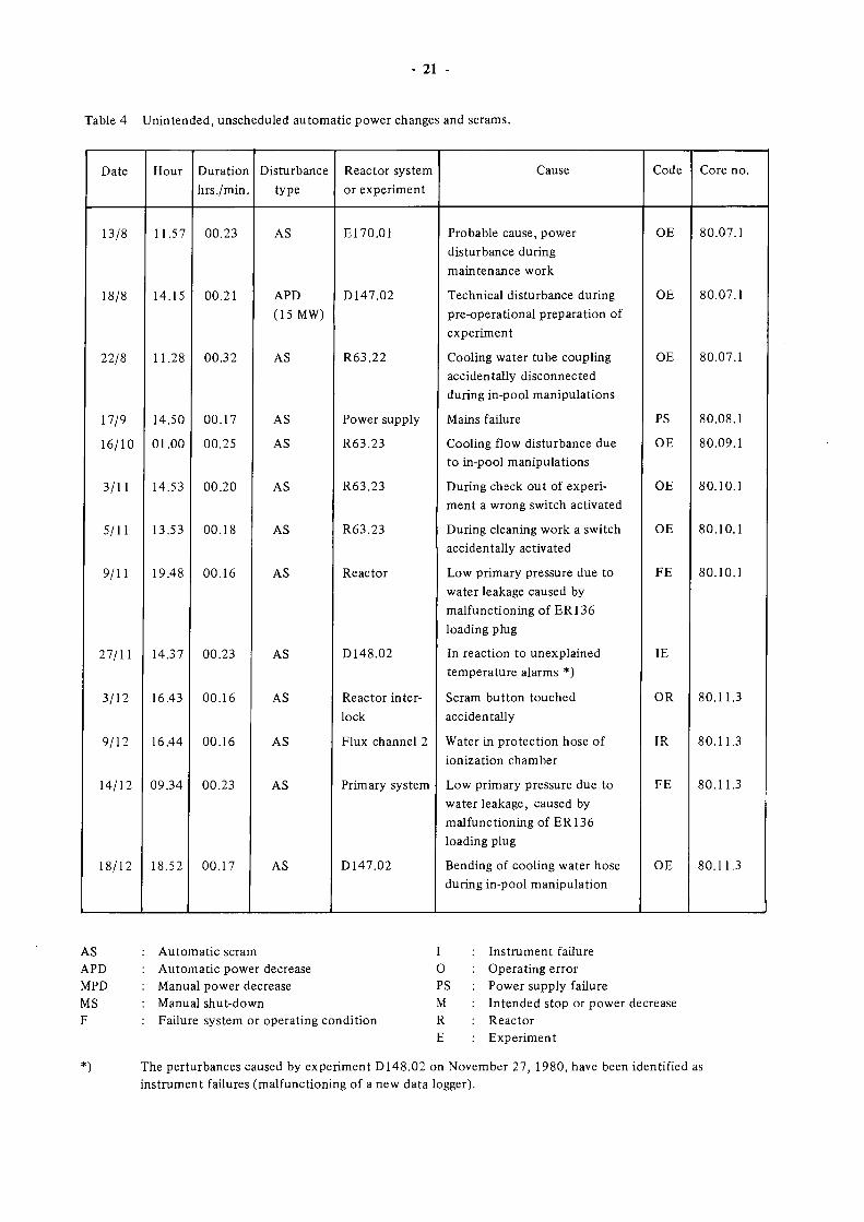
In Table 2 some basic operation data during this half
year are compared with the data of the previous half
year. The table reveals that reactor operation was
interrupted by 12 unscheduled scrams, 1 unscheduled
power decrease, while 2 scrams and 3 power decreases
were scheduled in accordance with various experimental
requirements.
One manual scram, necessitated by data logger
malfunctioning and subsequent unloading of an
irradiation experiment (D148), resulted in xenon
poisoning and, thus, core reloading*
More detailed information is given in Table 3 on the
intended, and in Table 4 on the unscheduled reactor
power deviations.
Table 2 Basic operating data
Subject
Integrated reactor power
Average reactor power
Operating time
Unscheduled shutdown time
Unscheduled scrams
Unscheduled power decreases
Planned scrams
Planned power decreases
Fuel consumption
Stack radioactivity release
MWd
MW
°/o °/o
g235i j
Ci(4lAr)
1st half 1980
6738
44,8
82,6
0,8
21
1
5
5
8416
275,7
2nd half 1980
5500
44,08
67,9
0,9
12
1
2
3
6870
191
Table 3 Intended, mostly scheduled, manual reactor shutdowns and power decreases.
Date
4/9
26/11
27/11
27/11
27/11
Hour
09.51
11.41
12.42
13.16
17.57
Duration
hrs./min.
01.35
02.49
00.05
00.27
18.13
Disturbance
type
MS
MPD
(30 MW)
MPD
(30 MW)
MPD
(0MW)
MS
Reactor system
or experiment
R139K8
Reactor core
D148.02
ER 136.03
D148.02
Cause
Manual reactor shut down for
repair of Vertical Displace
ment Unit R139K8
Small foreign object on fuel
element in core position G4
In reaction to unexplained
temperature alarms
Loading of facility
Removal of experiment and
core reloading
Code
ME
MR
ME
ME
ME
Core no.
80.08.1
80.11.1
80.11.1
80.11.2
80.11.3
■
AS
APD
MPD
MS
F
Automatic scram
Automatic power decrease
Manual power decrease
Manual shutdown
Failure system or operating condition
I
O
PS
M
R
E
Instrument failure
Human error
Power supply failure
Intended stop or power decrease
Reactor
Experiment
- 21 -
Table 4 Unintended, unscheduled automatic power changes and scrams.
Date
13/8
18/8
22/8
17/9
16/10
3/11
5/11
9/11
27/11
3/12
9/12
14/12
18/12
Hour
11.57
14.15
11.28
14.50
01.00
14.53
13.53
19.48
14.37
16.43
16.44
09.34
18.52
Duration hrs./min.
00.23
00.21
00.32
00.17
00.25
00.20
00.18
00.16
00.23
00.16
00.16
00.23
00.17
Disturbance type
AS
APD (15 MW)
AS
AS
AS
AS
AS
AS
AS
AS
AS
AS
AS
Reactor system or experiment
E170.01
D147.02
R63.22
Power supply
R63.23
R63.23
R63.23
Reactor
D148.02
Reactor interlock
Flux channel 2
Primary system
D147.02
Cause
Probable cause, power disturbance during maintenance work
Technical disturbance during pre-operational preparation of experiment
Cooling water tube coupling accidentally disconnected during in-pool manipulations
Mains failure
Cooling flow disturbance due to in-pool manipulations
During check out of experiment a wrong switch activated
During cleaning work a switch accidentally activated
Low primary pressure due to water leakage caused by malfunctioning of ERI36 loading plug
In reaction to unexplained temperature alarms *)
Scram button touched accidentally
Water in protection hose of ionization chamber
Low primary pressure due to water leakage, caused by malfunctioning of ER 136 loading plug
Bending of cooling water hose during in-pool manipulation
Code
OE
OE
OE
PS
OE
OE
OE
FE
IE
OR
IR
FE
OE
Core no.
80.07.1
80.07.1
80.07.1
80.08.1
80.09.1
80.10.1
80.10.1
80.10.1
80.11.3
80.11.3
80.11.3
80.11.3
AS APD MPD MS F
Automatic scram Automatic power decrease Manual power decrease Manual shut-down Failure system or operating condition
I O PS M R E
Instrument failure Operating error Power supply failure Intended stop or power decrease Reactor Experiment
The perturbances caused by experiment D 148.02 on November 27, 1980, have been identified as instrument failures (malfunctioning of a new data logger).
22
2.1.3.2 Maintenance and Modifications
Major activities carried out during the summer holiday
period and during the winter maintenance outage
are summarized hereafter.
a) Mechanical Installations
Reactor vessel and associated structures
o Visual inspection of reactor interior: No specific
observations.
Cooling systems : Heat exchanger (HX)
o The observations, in October, of increased noises
during normal fullpower, fullflow operation at
one of the main heat exchangers (HX 3) has led to a
thorough investigation of the state of health of the
three main heat exchangers.
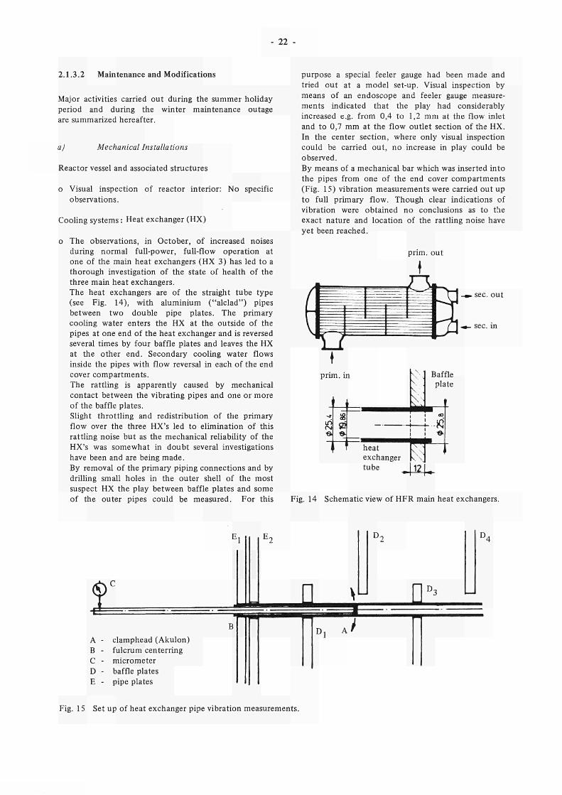
The heat exchangers are of the straight tube type
(see Fig. 14), with aluminium ("alelad") pipes
between two double pipe plates. The primary
cooling water enters the HX at the outside of the
pipes at one end of the heat exchanger and is reversed
several times by four baffle plates and leaves the HX
at the other end. Secondary cooling water flows
inside the pipes with flow reversal in each of the end
cover compartments.
The rattling is apparently caused by mechanical
contact between the vibrating pipes and one or more
of the baffle plates.
Slight throttling and redistribution of the primary
flow over the three HX's led to elimination of this
rattling noise but as the mechanical reliability of the
HX's was somewhat in doubt several investigations
have been and are being made.
By removal of the primary piping connections and by
drilling small holes in the outer shell of the most
suspect HX the play between baffle plates and some
of the outer pipes could be measured. For this
purpose a special feeler gauge had been made and
tried out at a model setup. Visual inspection by
means of an endoscope and feeler gauge measure
ments indicated that the play had considerably
increased e.g. from 0,4 to 1,2 mm at the flow inlet
and to 0,7 mm at the flow outlet section of the HX.
In the center section, where only visual inspection
could be carried out, no increase in play could be
observed.
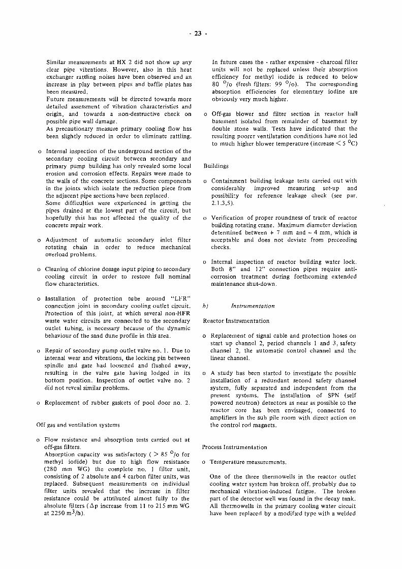
By means of a mechanical bar which was inserted into
the pipes from one of the end cover compartments
(Fig. 15) vibration measurements were carried out up
to full primary flow. Though clear indications of
vibration were obtained no conclusions as to the
exact nature and location of the rattling noise have
yet been reached.
prim, out
. sec. out
heat
exchanger
tube
V 12.
Fig. 14 Schematic view of HFR main heat exchangers.
Î S
A clamphead (Akulon)
Β fulcrum centerring
C micrometer
D baffle plates
E pipe plates
I] \u U
J
Fig. 15 Set up of heat exchanger pipe vibration measurements.
23
Similar measurements at HX 2 did not show up any clear pipe vibrations. However, also in this heat exchanger rattling noises have been observed and an increase in play between pipes and baffle plates has been measured. Future measurements will be directed towards more detailed assessment of vibration characteristics and origin, and towards a non-destructive check on possible pipe wall damage. As precautionary measure primary cooling flow has been slightly reduced in order to eliminate rattling.
o Internal inspection of the underground section of the secondary cooling circuit between secondary and primary pump building has only revealed some local erosion and corrosion effects. Repairs were made to the walls of the concrete sections. Some components in the joints which isolate the reduction piece from the adjacent pipe sections have been replaced. Some difficulties were experienced in getting the pipes drained at the lowest part of the circuit, but hopefully this has not affected the quality of the concrete repair work.
o Adjustment of automatic secondary inlet filter rotating chain in order to reduce mechanical overload problems.
o Cleaning of chlorine dosage input piping to secondary cooling circuit in order to restore full nominal flow characteristics.
In future cases the - rather expensive - charcoal filter units will not be replaced unless their absorption efficiency for methyl iodide is reduced to below 80 °/o (fresh filters: 99 °/o). The corresponding absorption efficiencies for elementary iodine are obviously very much higher.
Off-gas blower and filter section in reactor hall basement isolated from remainder of basement by double stone walls. Tests have indicated that the resulting poorer ventilatation conditions have not led to much higher blower temperature (increase < 5 °C)
Buildings
o Containment building leakage tests carried out with considerably improved measuring set-up and possibility for reference leakage check (see par. 2.1.3.5).
o Verification of proper roundness of track of reactor building rotating crane. Maximum diameter deviation determined between + 7 mm and - 4 mm, which is acceptable and does not deviate from preceeding checks.
o Internal inspection of reactor building water lock. Both 8" and 12" connection pipes require anti-corrosion treatment during forthcoming extended maintenance shut-down.
o Installation of protection tube around "LFR" connection joint in secondary cooling outlet circuit. Protection of this joint, at which several non-HFR waste water circuits are connected to the secondary outlet tubing, is necessary because of the dynamic behaviour of the sand dune profile in this area.
o Repair of secondary pump outlet valve no. 1. Due to internal wear and vibrations, the locking pin between spindle and gate had loosened and flushed away, resulting in the valve gate having lodged in its bottom position. Inspection of outlet valve no. 2 did not reveal similar problems.
o Replacement of rubber gaskets of pool door no. 2.
Off gas and ventilation systems
bj Instrumentation
Reactor Instrumentation
o Replacement of signal cable and protection hoses on start up channel 2, period channels 1 and 3, safety channel 2, the automatic control channel and the linear channel.
o A study has been started to investigate the possible installation of a redundant second safety channel system, fully separated and independent from the present systems. The installation of SPN (self powered neutron) detectors as near as possible to the reactor core has been envisaged, connected to amplifiers in the sub pile room with direct action on the control rod magnets.
Flow resistance and absorption tests carried out at off-gas filters. Absorption capacity was satisfactory ( > 85 °/o for methyl iodide) but due to high flow resistance (280 mm WG) the complete no. 1 filter unit, consisting of 2 absolute and 4 carbon filter units, was replaced. Subsequent measurements on individual filter units revealed that the increase in filter resistance could be attributed almost fully to the absolute filters (Δρ increase from 11 to 215 mm WG at 2250 m3/h).
Process Instrumentation
o Temperature measurements.
One of the three thermowells in the reactor outlet cooling water system has broken off, probably due to mechanical vibration-induced fatigue. The broken part of the detector well was found in the decay tank. All thermowells in the primary cooling water circuit have been replaced by a modified type with a welded
24 -
flange connection and a larger diameter of the mechanically most vulnerable section.
o Hot drain tank level measuring system
After some starting problems the acoustic level measuring system on tank no. 1 proved to be accurate and reliable. Similar measuring systems for the remaining tanks have now been ordered.
Miscellaneous
o Installation of a new air tight penetration block for coaxial cables in the reactor building wall.
c) Electrical Installations
o Supply Systems
- Replacement of burnt transformer unit in VZO-2 (failure-free) power supply unit (caused by a defect controller).
- Local characteristics of high voltage transformers determined. Overload aspects discussed with utilities.
- Relocation of power supply boxes in reactor building and several laboratories.
o Reactor systems and components
- Primary pump field break switch coils rewound, new parts manufactured, wiring renewed. As these switches are of a now obsolete design, commercial spare parts are no longer available.
- Power switches for emergency pumps and emergency lighting systems inspected and overhauled.
- Warm and hot drain pumps interlock systems modified, permitting remote cut-off in case of reactor containment isolation (TMI-2 lesson !).
- Overhaul of secondary cooling pump no. 4, CO2 blower and Reverse Osmose Installation flush pumps.
o Miscellaneous provisions
- New halogen type spotlights installed adjacent to storage pools.
- Various improvements and extensions. - Vehicle airlock switching system overhauled; all
clamping strips renewed.
d) General irradiation facilities
o Isotope production and activation analysis facilities
- Mechanical switch in underground pneumatic rabbit conveyor piping replaced by a photo cell unit.
o Cooling water supply and distribution systems
- Clean up of PSF cooling circuits. Radiation levels reduced from 20 - 40 to < 2 mR/hr.
- New low flow system ordered. The system consists of a central switch and indication panel with the possibility to connect the flow contacts to the reactor safety system in either the scram or the APD action mode. Status indication of the switches and flow contacts is foreseen on the local panel and on the HFR control room panel.
o Gas supply and distribution systems
- "Oxisorb" and associated valves at main gas service station replaced. Preparations for installation of new humidity sensor.
- New TRIO gas-supply panels connected to standard alarm systems.
o PSF support and trolley facilities
- 4 new fast trolleys assembled and installed, 4 defect trolleys renewed and repaired.
- Prototype "push-pull" trolley assembled, installed and tested (see paragr. 2.3.3.7).
o Data acquisition and processing systems
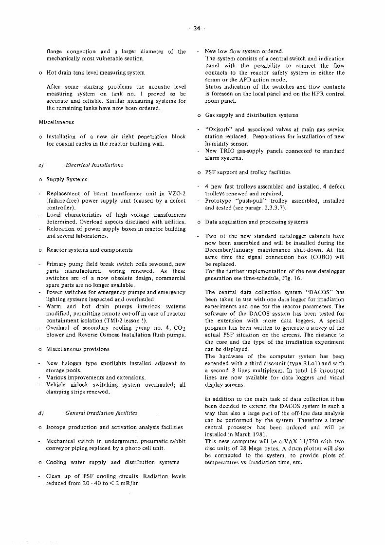
- Two of the new standard datalogger cabinets have now been assembled and will be installed during the December/January maintenance shut-down. At the same time the signal connection box (COBO) will be replaced. For the further implementation of the new datalogger generation see time-schedule, Fig. 16.
The central data collection system "DACOS" has been taken in use with one data logger for irradiation experiments and one for the reactor parameters. The software of the DACOS system has been tested for the extension with more data loggers. A special program has been written to generate a survey of the actual PSF situation on the screens. The distance to the core and the type of the irradiation experiment can be displayed. The hardware of the computer system has been extended with a third disc-unit (type RLol) and with a second 8 lines multiplexer. In total 16 in/output lines are now available for data loggers and visual display screens.
In addition to the main task of data collection it has been decided to extend the DACOS system in such a way that also a large part of the off-line data analysis can be performed by the system. Therefore a larger central processor has been ordered and will be installed in March 1981. This new computer will be a VAX 11/750 with two disc units of 28 Mega bytes. A drum plotter will also be connected to the system, to provide plots of temperatures vs. irradiation time, etc.
ACTIVITY WEEK
1980
49 50 51 52
25
1981 1 2 3 4 5 6 7 8 9 10 11 12 1314 15 16 17 18 19 20 21 222324
Assembling data logger
, System 1 No. 1 +2
Installation, System 1
, System 2 No. 3 + 4
Assembling data logger
Installation, System 2
Assembling data logger
, System 3 No. 5, 6, 7
Installation, System 3
Fig. 16 Data logger installation time schedule.
2.1.3.3 Nuclear and Technical Support and Development
a) 1980 flux density characteristics
The yearly flux density mapping irradiation series has been performed on September 2 , preceding H F R operat ion cycle 80 .08 .
Vertical thermal and fast flux density distr ibutions have been measured with cobalt and nickel wires in all fuel assemblies and 10 exper iment posi t ions (C3 , C5, D8 , E 5 , E 7 , F 2 , G 5 , G 7 , H6 and H8) . The wires were irradiated during 1 hour at an H F R power of 500 kW (control member setting 500 m m ) . During a second irradiation of 1 hour at 500 kW, measurements were performed in all 10 PSF posit ions at distances of 2 5 , 50 , 85 and 135 mm from the core box wall. Cobalt and nickel foils were used as neu t ron activation de tec tor . The control member setting during the second irradiation was 565 m m .
In order to realize a control member setting comparable with the settings during normal H F R operat ion and to realize an accurate power cal ibrat ion, the first irradiation was preceded by an irradiat ion, part ly at 45 MW, part ly at 500 kW, and a waiting t ime thereafter of 6 hours .
Special a t tent ion was given to the flow rate of the primary cooling water and the indicat ion of the linear channel in order to determine an accurate conversion factor from a reactor power of 500 kW to 45 MW. In all posit ions at centre line fuel and in core posit ion D5 and exper iment posit ion E5 in 17 posi t ions , small
foils of 20 ° /o enriched uranium were in t roduced as second thermal neu t ron flux density detector . The results will be presented in the 1981/82 version of repor t EUR 5700 e ( H F R characteristics).
b J Adverse neutron flux condition at certain beam tubes
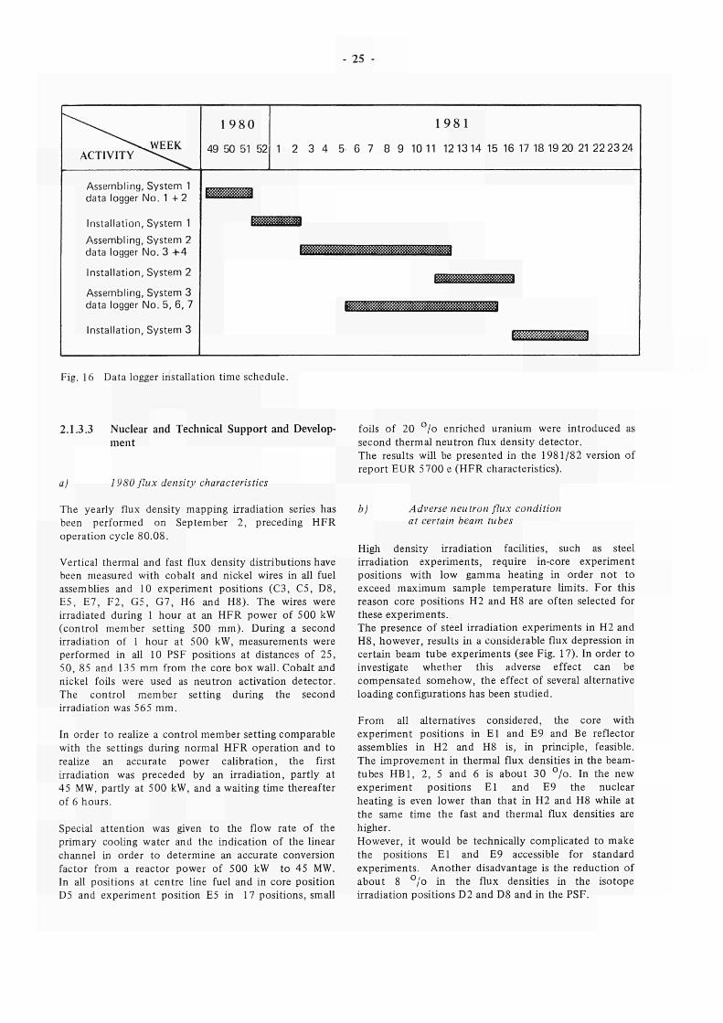
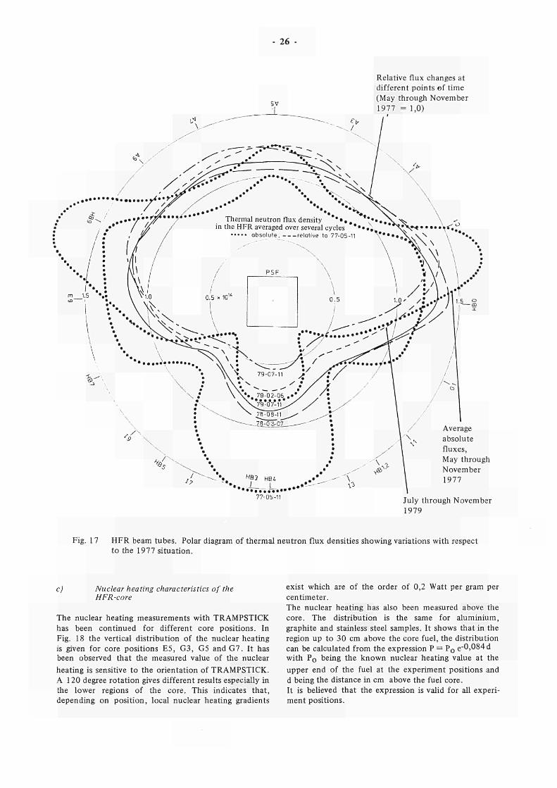
High density irradiation facilities, such as steel irradiation exper iments , require in-core exper iment posi t ions with low gamma heat ing in order no t to exceed max imum sample tempera ture l imits. For this reason core posi t ions H2 and H8 are often selected for these exper iments . The presence of steel irradiation exper iments in H2 and H8 , however , results in a considerable flux depression in certain beam tube exper iments (see Fig. 17). In order to investigate whether this adverse effect can be compensa ted somehow, the effect of several alternative loading configurations has been s tudied.
F r o m all alternatives considered, the core with exper iment posi t ions in E l and E9 and Be reflector assemblies in H2 and H8 is, in principle, feasible. The improvement in thermal flux densities in the beam-tubes H B 1 , 2, 5 and 6 is about 30 ° / o . In the new exper iment posi t ions E l and E9 the nuclear heat ing is even lower than that in H2 and H8 while at the same t ime the fast and thermal flux densities are higher. However, it would be technically complicated to make the posi t ions E l and E9 accessible for s tandard exper iments . Ano the r disadvantage is the reduct ion of about 8 ° /o in the flux densities in the isotope irradiation posi t ions D2 and D8 and in the PSF.
26
Relative flux changes at
different points of time
(May through November
1977 = 1,0)
/ ' <** / ••••....»¿•■■'J^ / . . ·
J^v./ . . . • • / ' • Τ ζ Γ · * * ^ Thermal neutron flux density " * * · . . " * * · · . ^ C > . . · · Iff / in the HFR averaged over several cycles * * · · . , * > ^ ? « · · · · · \ * · ί 3
/ · , jr / absolute. relative to 77-05-11 \ * · · · β \ ν \ Ν \ **··
•Λ I 'A'\ \ -/· Λ \ 1.·· 1 y VW
Tá"/ aiLi
770511
Average
absolute
fluxes,
May through
November
1977
July through November
1979
Fig. 17 HFR beam tubes. Polar diagram of thermal neutron flux densities showing variations with respect
to the 1977 situation.
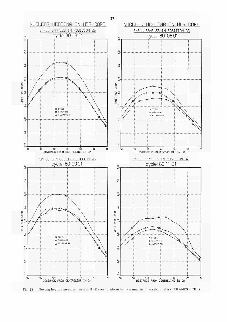
c) Nuclear heating characteristics of the HFR-core
The nuclear heating measurements with TRAMPSTICK
has been continued for different core positions. In
Fig. 18 the vertical distribution of the nuclear heating
is given for core positions E5, G3, G5 and G7. It has
been observed that the measured value of the nuclear
heating is sensitive to the orientation of TRAMPSTICK.
A 120 degree rotation gives different results especially in
the lower regions of the core. This indicates that,
depending on position, local nuclear heating gradients
exist which are of the order of 0,2 Watt per gram per
centimeter.
The nuclear heating has also been measured above the
core. The distribution is the same for aluminium,
graphite and stainless steel samples. It shows that in the
region up to 30 cm above the core fuel, the distribution
can be calculated from the expression Ρ = P 0 e"0»084d
with P 0 being the known nuclear heating value at the
upper end of the fuel at the experiment positions and
d being the distance in cm above the fuel core.
It is believed that the expression is valid for all experi
ment positions.
27
NUCLEñR HEfìTING IN HFR CORE
SMALL SAMPLES IN POSITION E5
o
LO
O
LO
E : cc ce cs
a: o
LU CO
Í"
CE 3
in
o
to
in
o
cycle: 80 08 01
~~Γ~~~*'Ί ■■ "I
! Χ STEEL
! ί D GRAPHITE ; Δ ALUMINIUM
i 1 i 1
^ - _ _ _ V _ _ j
i
NUCLEñR HEñTING IN HFR CORE
SMALL SAMPLES IN POSITION G3
cycle: 80 0801
20 10 0 10 20
DISTANCE FROM CENTRELINE IN CM
SMALL SAMPLES I N POSIT ION G5 O
CD
O
κ "
o
to
a
in "
H cc oz CS
OC a
0
IE a n" "
Q
o
o
cycle: 80 0901
■ f 1 — f 'r ¡
■ ν t—¿zz¿&3*r**zz&j ν"·" 1
! Χ STEEL \ ; \
! D GRAPHITE \ \
| I Δ ALUMINIUM ¡ \ \
¡ . _ J u 'Γ J
1 1 i 1 1
20 10 0 10 20
DISTRNCE FROM CENTRELINE IN CM
SMALL SAMPLES I N POSIT ION G7
cycle: 8011 01 ου
o
Q
Q
LO"
Σ : cc ce CS
cu * :
Q_
i
<r. 3
o r i "
o
o i "
o
o
L j . ί j . L
J I L | |
/ _/ jS< ! χ STEEL ^*^o^. X / ; / ' \ Π GRAPHITE I ^ ^ S . ' \
/ JÍ \ Δ ALUMINIUM ¡ ^ N S » , ' \
■ \ r \ 1 \
20 10 0 10 20
DISTANCE FROM CENTRELINE IN CM
-20 -10 0 10 20
DISTANCE FROM CENTRELINE IN CM
Fig. 18 Nuclear heating measurements in HFR core positions using a smallsample calorimeter ("TRAMPSTICK").
28 -
2.1.3.4 Fuel Cycle ej Low enriched ("LEU") fuel test irradiations (Louise/Ludwig project)
a) Uranium supply
About 40 kg of highly enriched materials have been supplied to Europe in October 1980. They are needed for the 1981 fuel element and control rod manufature.
b) Local fuel element management
During the second half year of 1980, 71 new fuel elements have been delivered (see Table 5) of which 24 elements with the increased uranium contents of 405 g235u .
c) Spent fuel transports
34 depleted fuel elements and 8 depleted control rods have been transferred for reprocessing to the Savannah River reprocessing plant (see Table 5). The decay power of this transport was 1432 W. The next transport will include 13 spent fuel elements from the HOR research reactor in Delft, The Netherlands. These elements have been shipped to Petten on June 24, 1980 under an agreement with the Delft Technical University (I.R.I.). Fig. 19 a and b show the arrival of the Delft element transport in HFR pool no. 2.
d) Compact fuel storage
Specifications for compact storage requirements have been drawn up and several firms will be approached for a quotation for design and fabrication of compact storage racks.
Preparations for the test irradiations of two UA1X -Al and two U3O8-AI plate-type fuel elements, both 20 °/o enriched, have been continued. They consisted of: o Discussion and final approval of the design of the
elements. Special features of the design are : same specific U235 content, slightly thicker fuel plates then present elements, reduced number of plates in order to maintain present cooling channel width, flux monitors incorporated in non-fuelled end plates. square top section in order to facilitate access for neutron dosimetry and cooling channel inspection. Cd-wires in side plates as burnable poison,
o Drafting a design and safety report o Evaluation of flux dosimetry and cooling channel
measurement tooling requirements. A special dosimetry "sword" has been designed for extensive low power measurements. For channel width measurements the acquisition of an ultrasonic channel gauge, developed by EG & G, is being considered,
o Shipment of flux monitor tubes to the fuel element manuf a turers.
The irradiations are now scheduled to start in the summer of 1981. The international situation of reduced enrichment fuel development for research and test reactors has been reviewed in a meeting at the Argonne National Laboratory, on November 12 - 14, 1980.
Table 5 Fuel element and control rod movements, 1979/80.
Transfer of depleted fuel elements Transfer of depleted control rods Average burn-up of transferred fuel elements Average burn-up of transferred control rods Delivery of new fuel elements Delivery of new control rods New fuel elements available for use at end of half year New control rods available for use at end of half year New fuel elements charged to core New control rods charged to core Fuel elements depleted Average burn-up of depleted fuel elements Control rods depleted Average burn-up of depleted control rods
First half 1979
_ ---11 -26 16 36
8 34
5 3 % 6
5 2 %
Second half 1979
73 11
5 1 % 5 5 %
24 -18 8
32 8
22 5 1 %
7 4 9 %
First half 1980
32 10
5 2 % 5 1 %
39 14 27 14 30
8 31
5 2 % 10
4 9 %
Second half 1980
34 8
5 2 % 5 1 %
71 -62
6 36
8 37
5 1 % 7
4 5 %
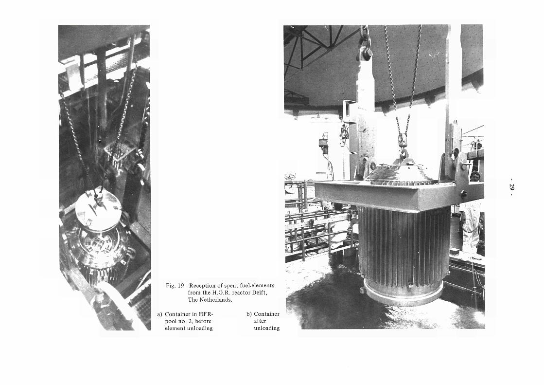
Fig. 19 Reception of spent fuel-elements from the H.O.R. The Netherlands
a) Container in HFR-pool no. 2, before element unloading
reactor Delft,
b) Container after unloading
to
- 30
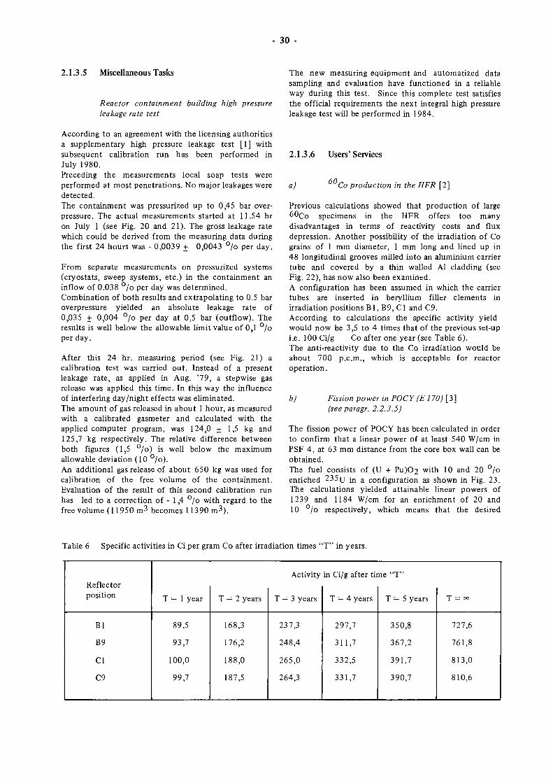
2.1.3.5 Miscellaneous Tasks
Reactor containment building high pressure leakage rate test
The new measuring equipment and automatized data sampling and evaluation have functioned in a reliable way during this test. Since this complete test satisfies the official requirements the next integral high pressure leakage test will be performed in 1984.
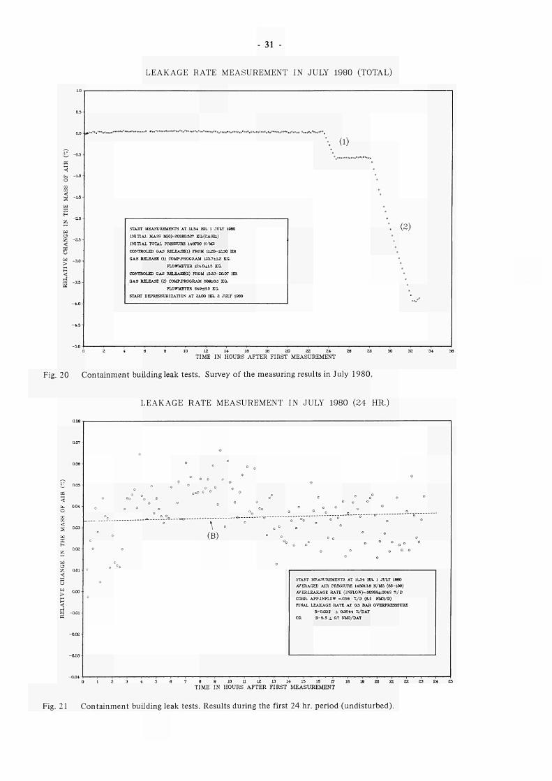
According to an agreement with the licensing authorities a supplementary high pressure leakage test [1] with subsequent calibration run has been performed in July 1980. Preceding the measurements local soap tests were performed at most penetrations. No major leakages were detected. The containment was pressurized up to 0,45 bar overpressure. The actual measurements started at 11.54 hr on July 1 (see Fig. 20 and 21). The gross leakage rate which could be derived from the measuring data during the first 24 hours was - 0,0039 + 0,0043 % per day.
From separate measurements on pressurized systems (cryostats, sweep systems, etc.) in the containment an inflow of 0.038 °/o per day was determined. Combination of both results and extrapolating to 0.5 bar overpressure yielded an absolute leakage rate of 0,035 f 0,004 % per day at 0,5 bar (outflow). The results is well below the allowable limit value of 0,1 °/o per day.
After this 24 hr. measuring period (see Fig. 21) a calibration test was carried out. Instead of a present leakage rate, as applied in Aug. '79, a stepwise gas release was applied this time. In this way the influence of interfering day/night effects was eliminated. The amount of gas released in about 1 hour, as measured with a calibrated gasmeter and calculated with the applied computer program, was 124,0 + 1,5 kg and 125,7 kg respectively. The relative difference between both figures (1,5 °/o) is well below the maximum allowable deviation (10 °/o). An additional gas release of about 650 kg was used for calibration of the free volume of the containment. Evaluation of the result of this second calibration run has led to a correction of - 1,4 °/o with regard to the free volume (11950 m3 becomes 11390 m3).
2.1.3.6 Users'Services
a) 60 Co production in the HFR [2]
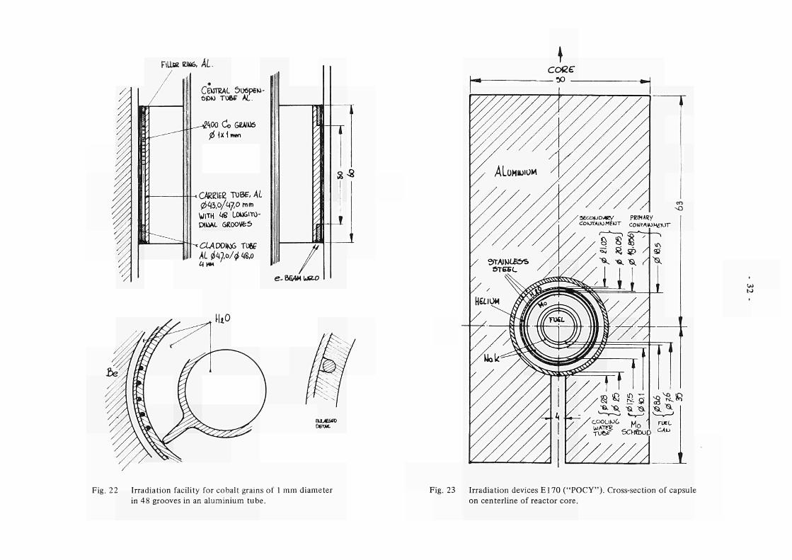
Previous calculations showed that production of large 60Co specimens in the HFR offers too many disadvantages in terms of reactivity costs and flux depression. Another possibility of the irradiation of Co grains of 1 mm diameter, 1 mm long and lined up in 48 longitudinal grooves milled into an aluminium carrier tube and covered by a thin walled Al cladding (see Fig. 22), has now also been examined. A configuration has been assumed in which the carrier tubes are inserted in beryllium filler elements in irradiation positions Bl , B9, CI and C9. According to calculations the specific activity yield would now be 3,5 to 4 times that of the previous set-up i.e. 100 Ci/g Co after one year (see Table 6). The anti-reactivity due to the Co irradiation would be about 700 p.c.m., which is acceptable for reactor operation.
b) Fission power in POCY (E170) [3] (see paragr. 2.2.3.5)
The fission power of POCY has been calculated in order to confirm that a linear power of at least 540 W/cm in PSF 4, at 63 mm distance from the core box wall can be obtained. The fuel consists of (U + Pu)02 with 10 and 20 % enriched 235TJ m a configuration as shown in Fig. 23. The calculations yielded attainable linear powers of 1239 and 1184 W/cm for an enrichment of 20 and 10 °/o respectively, which means that the desired
Table 6 Specific activities in Ci per gram Co after irradiation times " T " in years.
Reflector position
Bl
B9
CI
C9
Τ = 1 year
89,5
93,7
100,0
99,7
Τ = 2 years
168,3
176,2
188,0
187,5
Activity
Τ = 3 years
237,3
248,4
265,0
264,3
in Ci/g after time "T"
Τ = 4 years
297,7
311,7
332,5
331,7
Τ = 5 years
350,8
367,2
391,7
390,7
T = oc
727,6
761,8
813,0
810,6
31
LEAKAGE RATE MEASUREMENT IN JULY 1980 (TOTAL)
w
0 0
^ S oaa < b. Ι Λ Ο
a "Cxi
s H
ζ
υ ζ aa
3 è ω 3ΛK . J J J
5 ω 3 .3
vo
4.3 ■
5 . 0
^ ί . · » . · « ^ « # # · · » β · · · » ο ^ > · · · . . ο . · * « " · β » « β < > ^ · « * β · . ' ' · ο β « β ' ' . β ο . β β . ι ΐ ί 0 · θ ο 0 ι > « β » < ι β β « ο « β ( , ' 1 Β ι > · β ι > < . . β β β ί . ί ΐ > ι 1 . β ο β . ι , β Ι , Ε 1 « ΐ β
STAKT MEASUREMENTS AT 1L34 HR 1 JULY 19Θ0 INITIAL MASS Μ(Ο)=20282Λ27 KG.(CASEl)
INITIAL TOTAL PRESSURE 140790 N/M2 CONTROLED GAS RELEASB<1) FROM 1L20-1EJ0 HR GAS RELEASE (l) COMP .PROGRAM 125.7±L2 KG.
FLOWMETER 124.0±L5 KG. CONTROLED GAS RELEASER) FROM 15Λ3-20.07 HR GAS RELEASE (2) COMPPROGRAM ΘΘΟίβΛ KG.
FLOWMETER β4β±Β.Ο KG. START DEPRESSURIZAT10N AT 2LO0 HR, 2 JULY 1Θ80
\ (D β
" ««»«.«„«»«'«'.o.
*
0
't
'
'. (2)
. ■
• e
oe e°
TIME IN HOURS AFTER FIRST MEASUREMENT
Fig. 20 Containment building leak tests. Survey of the measuring results in July 1980.
LEAKAGE RATE MEASUREMENT IN JULY 1980 (24 HR.)
o
° °
o o o
o °
°o° °0 °°° ° ° ° o° c °
o o 0 o o
° o ° o 0O ° „ ° ° o
k 0
\ ° °
o ° ' (B) ° χ
°
· 1 ' 1 ' 1 ' : ' 1 1 1 ■ ■ τ ■ ■ · τ ■ ι I
o °o ° o °
ο α
° D ° ° o °
o 0
START MEASUREMENTS AT 1L5+ HR 1 JULY 19Θ0
AVERAGED AIR PRESSURE 1439iae N/M2 (38198)
AVERLEAKAGE RATE (INFLOW>=.00388i.00+3 7./D
CORR APP.INFLOW =.039 %/D (8.1 NM3/D)
FINAL LEAKAGE RATE AT OS BAR OVERPRESSSURE
B=0.035 ± 0.0044 7./DAT
OR B=5.5 ± 0.7 NM3/DAT
θ 9 10 11 12 t3 14 15 13 O
TIME IN HOURS AFTER FIRST MEASUREMENT 18 18 20 21 22 23 24
Fig. 21 Containment building leak tests. Results during the first 24 hr. period (undisturbed).
Fill» anu. ÅL.
CENTRAL 5ü6p6M-ÔPK) TU6F AL.
!Ί00 Cío GíAHtó
0 {X\n*n
* CAReiee τυκτ,Λί. 04Ò,O/<ÁJ,O mm
WITH ¿<8 ÜDUfilTÜ
PtkW. 6R00VfcS>
A 4 D D I M 6 TU6C
eB6AML*u>
S *
BXJtífO DETAL
Κ)
Fig. 22 Irradiation facility for cobalt grains of 1 mm diameter
in 48 grooves in an aluminium tube.
Fig. 23 Irradiation devices E170 ("POCY"). Crosssection of capsule
on centerline of reactor core.
- 33
powers can be easily obtained in the mentioned positions. The required irradiation time for a 10 °/o burn up of 235TJ is 121 days (= 4,7 reactor cycles) at a power of 450 W/cm and 101 days ( = 3,9 cycles) at a power of 540 W/cm.
c) Fission power in E138.02 (BEST [ 4 ] , see paragr. 2.2.3.2 )
In the spherical fuel element BEST in the HFR position G7, calculations have been carried out to determine the generated fission power. The fuel consists of 1,4 g 235TJ a n c j 18,5 g 238u m a spherical graphite sample with a diameter of 5,0 cm. The max. density of (U02 + C ) i s 2 g / c m 3 . The calculated fission power is 3095 Watt per spherical fuel element, with a contribution of about 10 °/o from epithermal neutron-induced fissions.
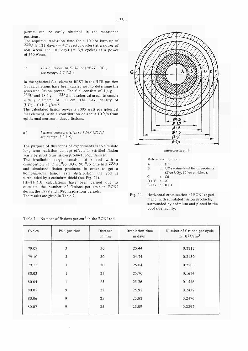
d) Fission characteristics of E149 (BONI, see paragr. 2.2.3.6)
The purpose of this series of experiments is to simulate long term radiation damage effects in vitrified fission waste by short term fission product recoil damage. The irradiation target consists of a rod with a composition of 2 wt.°/o UO2, 90 °/o enriched 235TJ and simulated fission products. In order to get a homogeneous fission rate distribution the rod is surrounded by a cadmium shield (see Fig. 24). HIP-TEDDI calculations have been carried out to calculate the number of fissions per cm 3 in BONI during the 1979 and 1980 irradiations periods. The results are given in Table 7.
(measures in
Material composition : A Β
C D + F E t G
: He UO2 + simi (2°/oU02,
: Cd : Al : H 2 0
cm)
lated fission products 9 0 % enriched).
Fig. 24 Horizontal cross section of BONI experiment with simulated fission products, surrounded by cadmium and placed in the pool side facility.
Table 7 Number of fissions per cm3 in the BONI rod.
Cycles
79.09
79.10
79.11
80.03
80.04
80.05
80.06
80.07
PSF position
3
3
3
1
1
9
9
9
Distance in mm
30
30
30
25
25
25
25
25
Irradiation time in days
25.44
24.74
25.04
25.70
23.36
25.92
25.82
25.09
Number of fissions per cycle in 10l8/cm3
0.2212
0.2130
0.2208
0.1674
0.1546
0.2432
0.2476
0.2392
34
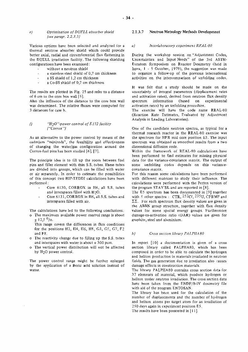
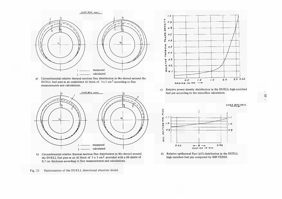
e) Optimization of DUELL absorber shield (see paragr. 2.2.3.5)
2.1.3.7 Neutron Metrology Methods Development
Various options have been selected and analyzed for a thermal neutron absorber shield which could provide better axial, radial and circumferential flux flattening in the DUELL irradiation facility. The following shielding configurations have been examined :
without a neutron shield a stainless steel shield of 0,7 cm thickness a SS shield of 1,2 cm thickness a Co-SS shield of 0,7 cm thickness
The results are plotted in Fig. 25 and refer to a distance of 6 cm to the core box wall [5]. Also the influence of the distance to the core box wall was determined. The relative fluxes were computed for 3 distances for case b.
f) "H20"-power control of E172 facility ("Corrox")
As an alternative to the power control by means of the cadmium "minirods", the feasibility and effectiveness of changing the water/gas configuration around the Corrox-fuel pins has been studied [6], [7].
The principle idea is to fill up the room between fuel pins and filler element with thin S.S. tubes. These tubes are divided into groups, which can be filled with water or air separately. In order to estimate the possibilities of this concept two HIP-TEDDI calculations have been performed :
Core 6130, CORROX in H6, all S.S. tubes and interspaces filled with H2O. Core 6131, CORROX in H6, all S.S. tubesand interspaces filled with air.
The calculations have led to the following conclusions: o The maximum available power control range is about
f 12,5 °/o. This range covers the differences in flux conditions for the positions H2, H4, H6, H8, G3, G5, G7, F2 and F8.
o The reactivity change due to filling up the S.S. tubes and interspaces with water is about + 300 pcm.
o The vertical power distribution will not be affected by H2O power control.
The power control range might be further enlarged by the application of a Boric acid solution instead of water.
a) In t er la boratory experiment REALS 0
During the workshop session on "Adjustment Codes, Uncertainties and Input Needs" of the 3rd ASTM-Euratom Symposium on Reactor Dosimetry (held in Ispra, 1 - 5 October, 1979), the suggestion was made to organize a follow-up of the previous international activities on the intercomparison of unfolding codes.
It was felt that a study should be made on the uncertainty of integral parameters (displacement rates and activation rates), derived from neutron flux density spectrum information (based on experimental activation rates) by an unfolding procedure. The exercise will have the code name REAL-80 (Reaction Rate Estimates, Evaluated by Adjustment Analysis in Leading Laboratories).
One of the candidate neutron spectra, as typical for a thermal research reactor in the REAL-80 exercise was the spectrum for HFR mid core position E5. The input spectrum was obtained as smoothed results from a two dimensional diffusion code. Within the framework of REAL-80 calculations have been performed to find estimates for missing physical data for the variance-covariance matrix. The output of some unfolding codes depends on this variance-covariance matrix. For this reason some calculations have been performed with different matrices to study their influence. The calculations were performed with the Petten version of the program STAY'SL and are reported in [8]. The E5 spectrum has been documented in [9] together with 5 other spectra : CTR, 252cf, 235TJ, CFRMF and ΣΣ . For each spectrum flux density values are given in the ABBN group structure, together with flux density values for some special energy groups. Furthermore damage-to-activation ratio (DAR) values are given for graphite, steel and aluminium.
b) Cross section library Ρ A LP H A 80
In report [10] a documentation is given of a cross section library called PALPHA80, which has been composed in order to be able to calculate the hydrogen and helium production in materials irradiated in neutron fields. The gas generation due to irradiation also causes damage effects in construction materials. The library PALPHA80 contains cross section data for 37 elements of material, which produce hydrogen or helium under neutron irradiation. The cross section data have been taken from the ENDF/B-IV dosimetry file with aid of the program ENTOSAN. The library has been used for the calculation of the number of displacements and the number of hydrogen and helium atoms per target atom for an irradiation of 250 days again in experiment position E5. The results have been presented in [ 11 ].
CORE BOX WALL
2 calculated
a) Circumferential relative thermal neutron flux distribution in Mo shroud around the
DUELL fuel pins in an unshielded Al block of 5 χ 5 cm 2 according to flux
measurements and calculations.
2 calculated
b) Circumferential relative thermal neutron flux distribution in Mo shroud around
the DUELL fuel pins in an Al block of 5 χ 3 cm2 provided with a SS shield of
0,7 cm thickness according to flux measurements and calculations.
1.0
Í; 0-9
¡J 0.8
557
Kr
î »J ύ.ί
< O.Z
ι« o.l
os i.o ΛΑΟ'OS IN rtn — * ·
/■S zo Z.5 ? ά 2
c) Relative power density distribution in the DUELL high-enriched fuel pin according to the microflux calculation.
LT,
d)
1. I
IO
os
___ ·—
¡.Ui - — J) —►. S¿2
cone ao* I/ALL
I.I
I.O
o.s
Λ/^ÙII/S //v u n .
Relative epithermal flux (<p3) distribution in the DUELL
high enriched fuel pin computed by HIPTEDDI.
Fig. 25 Optimisation of the DUELL directional absorber shield.
36 -
2.1.3.8 HFR Vessel Replacement
a) Reactor Vessel Design
The design work on the new vessel is now complete and the final output of design drawings has been submitted by the contractor. A final draft of the design report has been prepared and will be issued, after review early in 1981.
b) Beam Tube Design
Preliminary calculations have been performed to establish the beam tube cooling requirements. The proposed design of the cooling system encloses the beam tube ends in a shroud plate running parallel to the core box wall. The space so formed is forced fed from the pool cooling water system. Work on the remainder of the contract will be completed by June 1981.
c) Hydraulic Tests
Half scale hydraulic tests will be performed on a model of the new reactor vessel in order to optimise the primary coolant inlet baffle geometry and to establish the core flow distribution. The model and test rig were assembled in October and at the end of the reporting period leak tests had been completed and commissioning of the flow and laser doppler instrumentation were well advanced. The core discharge area has now been included in the model because the vessel design in this region is sufficiently changed from the present design to have an effect on the core flow distribution and the overall pressure drop. The first test run is scheduled for January 1981.
d) Reactor Transient Calculations
The ASME code includes requirements to perform calculations demonstrating the safe response of the reactor vessel under upset, emergency and faulted conditions. These abnormal conditions can be conveniently categorised as follows : - reactivity faults (e.g. control rod withdrawal at
power, cold water injection, experiment failure, over power transient due to start-up accident)
- plant failures (e.g. loss of coolant, electrical power supply failure, NaK or Na filled capsule failure)
- maximum credible accident resulting from partial fuel blockage (see below).
For analysing the HFR core behaviour under transient conditions the computer program AIROS II-A was used. AIROS II-A solves the space-independant reactor kinetics equations and in addition provides for the determination of reactivity by solving the discretized equations which represent the spatial heat and mass transfer models for several fuel channels, including fuel melting, coolant boiling, and vaporization and burn-out. In addition the program has also provisions for flow
decay and decay heating. The code calculates power, inverse period and temperatures as a function of time.
In order to assess the safety of a reactor system one has to define a series of upset conditions. Typically these are deviations from normal conditions which are anticipated to occur often enough so that the system should include a capability to withstand the conditions without operational impairment. These conditions include transients from single operation error or equipment malfunction. The table below gives a survey of the various conceivable reactor accidents which have been calculated.
Case
1
2
3
4
5
Description
Control rod withdrawal from full power and runaway of all rods. Cold water incident giving a reactor period of 1,3 seconds. A 5 $ / s reactivity insertion rate inflicted by experimental failure. Start-up accident, control rod withdrawal from a cold clean core. Loss of primary cooling flow to 7 /o of full flow in 1 second.
To investigate the accidents it is further assumed that: the nominal reactor power is 55 MW the only shut-down mechanism is the safety level trip which is set to scram the reactor at 60 MW the mean delay time between the time that the scram- signal is sensed and the release of the control rods is 58 msec, a maximum load channel is defined subject to unfavourable nuclear and hydraulic conditions with the following characteristics : Channel power 110 kW Core pressure drop 0,72 bar Coolant velocity 4,19 m/s Type of flow single phase
Table 8 gives a summary of the comparational results as obtained with the AIROS code. From the results the conclusion can be drawn that, under the circumstances postulated, the fuel plate temperature remains well below the melting point of aluminium and the maximum outlet temperature of the cooling flow remains below the water boiling temperature. The results confirm the conclusion stated in the present safety report.
e) Pool Cooling System
Studies are in hand to investigate the uprating and modification of the pool cooling system with a view to providing a larger and more carefully directed flow which will inhibit the migration of 1 6 N to the pool surface and so reduce the activity level. It will also be necessary to demonstrate the compatibility of the new system with the beam tube and vessel wall cooling requirements.
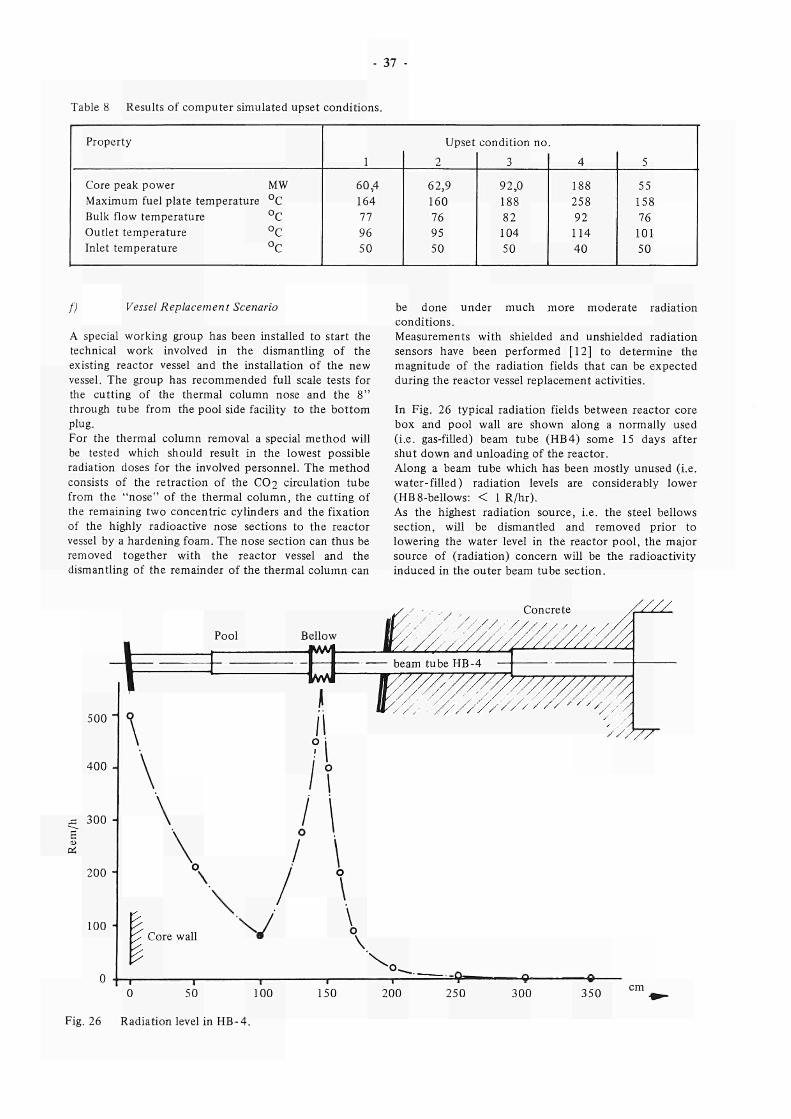
- 37
Table 8 Results of computer simulated upset conditions.
Property
Core peak power MW
Maximum fuel plate temperature °C
Bulk flow temperature °C
Outlet temperature °C
Inlet temperature °C
1
60,4
164
77
96
50
Upset
2
62,9
160
76
95
50
condition no
3
92,0
188
82
104
50
4
188
258
92
114
40
5
55
158
76
101
50
f) Vessel Replacement Scenario
A special working group has been installed to start the
technical work involved in the dismantling of the
existing reactor vessel and the installation of the new
vessel. The group has recommended full scale tests for
the cutting of the thermal column nose and the 8"
through tube from the pool side facility to the bottom
plug.
For the thermal column removal a special method will
be tested which should result in the lowest possible
radiation doses for the involved personnel. The method
consists of the retraction of the CO2 circulation tube
from the "nose" of the thermal column, the cutting of
the remaining two concentric cylinders and the fixation
of the highly radioactive nose sections to the reactor
vessel by a hardening foam. The nose section can thus be
removed together with the reactor vessel and the
dismantling of the remainder of the thermal column can
be done under much more moderate radiation
conditions.
Measurements with shielded and unshielded radiation
sensors have been performed [12] to determine the
magnitude of the radiation fields that can be expected
during the reactor vessel replacement activities.
In Fig. 26 typical radiation fields between reactor core
box and pool wall are shown along a normally used
(i.e. gas-filled) beam tube (HB4) some 15 days after
shut down and unloading of the reactor.
Along a beam tube which has been mostly unused (i.e.
water-filled) radiation levels are considerably lower
(HB8-bellows: < 1 R/hr).
As the highest radiation source, i.e. the steel bellows
section, will be dismantled and removed prior to
lowering the water level in the reactor pool, the major
source of (radiation) concern will be the radioactivity
induced in the outer beam tube section.
-υ
500
400
300 -
200
100 ■
0 50 100
Fig. 26 Radiation level in HB-4.
300 350
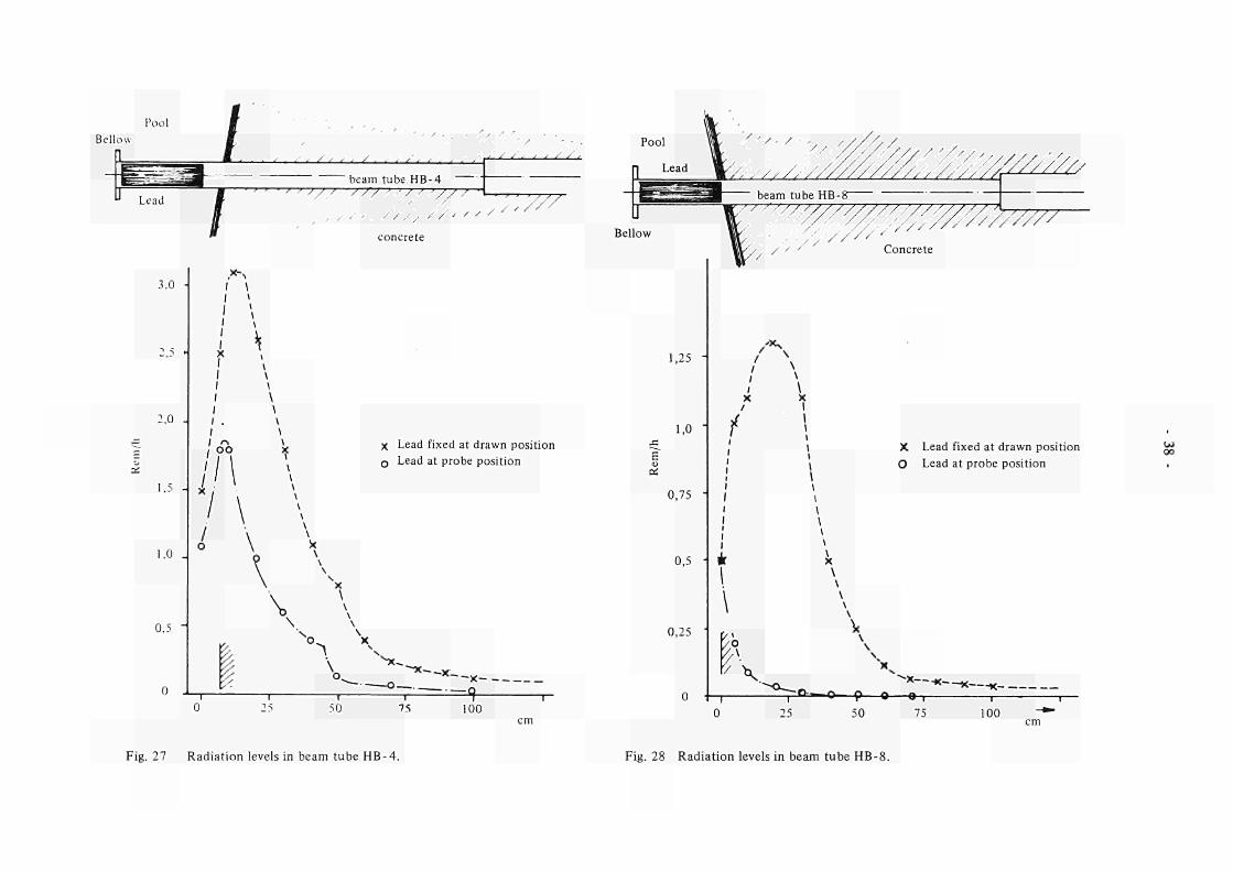
Pool
Bellow L ■■' < / * * ■ / . . ■ / ' ■ s
beam tube HB-4
Lead
7 ' ' ' ' ' W/ "777 ' - v 7 ■'// /
/ /. , , / /.
3.0
2,0 -
.5 -
1,0
0,5 -
/ \
\ \
I \ I rs \
OO X
\ \
I \ ι \
\ \
X \ \
/ / /
concrete
χ Lead fixed at drawn position
Q Lead at probe position
I \ ^ "~"*-~x-.
50
—V
75 100
V///////,
Bellow
/ ' ' Concrete
,25
1,0 J5
ε" Oí
0,75
0,5
0,25
/*v
/ X
f X Lead fixed at drawn position
O Lead at probe position
à \
X
k1
/o
/Λ V " * — K — * —
■o—9—o o -κ-·
25 50 ν
75 100
Fig. 27 Radiat ion levels in beam tube H B - 4 . Fig. 28 Radiat ion levels in beam tube H B - 8 .
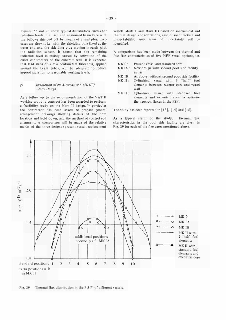
39 -
Figures 27 and 28 show typical distribution curves for
radiation levels in a used and an unused beam tube with
the bellows shielded off by means of a lead plug. Two
cases are shown, i.e. with the shielding plug fixed at the
outer end and the shielding plug moving inwards with
the radiation sensor. It seems that the remaining
radiation level is mainly caused by activation of the
outer centimeters of the concrete wall. It is expected
that lead slabs of a few centimeters thickness, applied
around the beam tubes, will be adequate to reduce
in-pool radiation to reasonable working levels.
g) Evaluation of an Alternative ("ΜΚΠ")
Vessel Design
As a follow up to the recommendation of the VAT II
working group, a contract has been awarded to perform
a feasibility study on the Mark II design. In particular
the contractor has been asked to prepare general
arrangement drawings showing details of the core
location and hold down, and the method of control rod
alignment. A comparison will be made of the relative
merits of the three designs (present vessel, replacement
vessels Mark I and Mark II) based on mechanical and
thermal design considerations, ease of manufacture and
inspectability. Any areas of uncertainty will be
identified.
A comparison has been made between the thermal and
fast flux characteristics of five HFR vessel options, i.e.
MKO:
MKIA :
MKIB:
MKII :
MKII
Present vessel and standard core
New design with second pool side facility
in use
As above, without second pool side facility
Cylindrical vessel with 3 "half" fuel
elements between reactor core and vessel
wall.
Cylindrical vessel with standard fuel
elements and excentric core to optimise
the neutron fluxes in the PSF.
The study has been reported in [13], [14] and [15].
As a typical result of the study, thermal flux
characteristics in the pool side facility are given in
Fig. 29 for each of the five cases mentioned above.
G
e-
+ +■
a o
x χ
Δ Δ
MK 0
ΜΚΙΑ
ΜΚΙΒ
ΜΚ II with 3 " h a l f fuel elements
MK II with standard fuel elements and excentric core
standard positions l
extra positions a b
in MK II
10
Fig. 29 Thermal flux distribution in the Ρ S F of different vessels.
- 40
g) Aluminium Irradiation Testing and Surveillance
The ongoing HFR aluminium surveillance programme (experiment RX 92) has demonstrated that neutron irradiation influences the mechanical properties of the present vessel material. A gradual increase in tensile strength accompanied by a reduction in ductility has been demonstrated and though certain stabilization effects seem apparent, saturation values for these properties have not yet been reached. A property, which is not investigated by the RX 92 programme but which may be of considerable importance for the mechanical reliability of the corebox walls, is the so-called Kic or fracture toughness factor. As any future surveillance programme will probably have to include the effect of irradiation upon this property and as little is known at present about the execution and optimum specimen choice for such investigations an irradiation test called "SURP", (RX 189.0) has been prepared which will address these questions. The "SURP" irradiation facility consists of an aluminium holder which can be placed in a normal filler element of 72 mm diameter. In the middle of this holder the specimen carrier is placed, containing two columns of each six specimens. Cooling takes place by the normal primary cooling flow. The facility will not be instrumented. A draft design and safety report for this irradiation has been made. Material for machinery of the specimen is available. Manufacturing of the samples and execution of the irradiation will take place as soon as ongoing discussions about the sample geometry and configurations have led to a final result.
Published reports, coming mostly from Oak Ridge National Laboratory unequivocally show that the embrittlement and increase in strength of aluminium alloys are to a large extent caused by the transmutation produced silicon due to thermal neutrons. These strength and ductility changes are particularly severe in the solution hardened magnesium containing 5000-series aluminium alloys, because of the formation of Mg2Si precipitates on a very fine scale. Reduction in ductility is likely to continue as long as dissolved magnesium is available for formation of Mg2Si.
As stated above the RX 92 results support this view. Tensile tests on the latest batch of samples, irradiated to approximately </>th = 5,1 χ 1θ22 n/cm2 (E < 0,025 eV), show uniform and total ductilities of only 0,8 and 1,5 °/o at 50 °C and no tendency of saturation. At this thermal fluence level, which is typical for some parts of the HFR vessel at present, it is estimated that only about half the original Mg content has been consumed by Mg2Si precipitates.
Microstructural investigation by means of electron-microscopy is in progress in an attempt to correlate quantitatively the mechanical property changes of 5154 to the size and density of the Mg2Si precipitates.
Based on the literature data, a precipitation-hardened 6000-series aluminium alloy (e.g. 6061, 6063) would be preferable for construction of the replacement vessel.
h) Vessel Manufacture
In preparation for selecting a manufacturer, an informal enquiry was launched in October/November with more than 35 European companies. At present five companies have expressed an interest in receiving a formal call for tenders. Contract specifications are currently being prepared which will define the tasks and responsibilities during the manufacturing phase. The main functions envisaged are:
- fabrication (to include preparation of workshop drawings, supply of material, work test and delivery)
- inspection service (to include supervision, control and/or performance of all quality assurance and inspection requirements laid down by the ASME code and by the licensing authority).
- overall project management (to supervise and progress the total project and to provide an interface with the vessel designers).
Contracts for all three tasks will be placed in the first quarter of 1981.
References to paragr. 2.1
1. H. Pruimboom Integrale lekdichtheidsbeproeving van het HFR insluitingsvat in juli 1980. ECN-80-172
2. E. Merelle, Irradiation of Cobalt in Be-reflector positions Bl, B9.C1 andC9. RA-memo 80-35
3. E. Merelle Fission power calculation in E170-2 (POCY). RA-memo 80-38
4.
5.
E. Merelle Neutron flux and fission power calculations of BEST (El38-2), UO2 fuel in a spherical graphite sample in position G7. RA-memo 80-28.
E. Merelle Reduction of the neutron flux gradients in DUELL (D 173), a PSF rig with two similar high enriched fuel pins. RA memo 81-1.
6. E. Merelle Continuation of fission CORROX, codeE172. Private communication
power calculations of
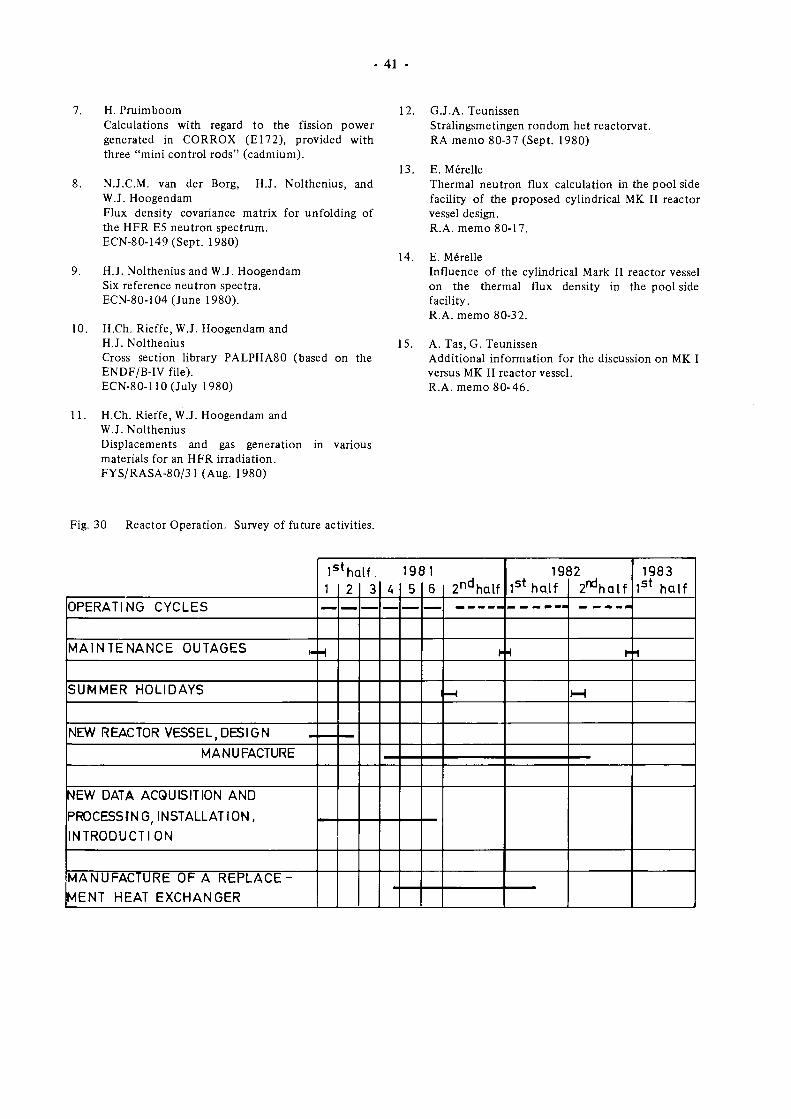
41
7. H. Pruimboom
Calculations with regard to the fission power
generated in CORROX (El72), provided with
three "mini control rods" (cadmium).
8. N.J.CM. van der Borg, H.J. Nolthenius, and
W.J. Hoogendam
Flux density covariance matrix for unfolding of
the HFR E5 neutron spectrum.
ECN80149 (Sept. 1980)
9. H.J. Nolthenius and W.J. Hoogendam
Six reference neutron spectra.
ECN80104(June 1980).
10. H.Ch. Rieffe, W.J. Hoogendam and
H.J. Nolthenius
Cross section library PALPHA80 (based on the
ENDF/BIV file).
ECN80110(July 1980)
12. G.J.A. Teunissen
Stralingsmetingen rondom het reactorvat.
RA memo 8037 (Sept. 1980)
13. E. Merelle
Thermal neutron flux calculation in the pool side
facility of the proposed cylindrical MK II reactor
vessel design.
R.A. memo 8017.
14. E. Merelle
Influence of the cylindrical Mark II reactor vessel
on the thermal flux density in the pool side
facility.
R.A. memo 8032.
15. A. Tas, G. Teunissen
Additional information for the discussion on MK I
versus MK II reactor vessel.
R.A. memo 8046.
11. H.Ch. Rieffe, W.J. Hoogendam and
W.J. Nolthenius
Displacements and gas generation
materials for an HFR irradiation.
FYS/RASA80/31 (Aug. 1980)
in various
Fig. 30 Reactor Operation. Survey of future activities.
OPERATING CYCLES
MAINTENANCE OUTAGES ,.
SUMMER HOLIDAYS
NEW REACTOR VESSEL DESIGN
MANUFACTURE
NEW DATA ACQUISITION AND
PROCESSING, INSTALLATION,
INTRODUCTION
MANUFACTURE OF A REPLACE
MENT HEAT EXCHANGER
Is
1
—
H
♦he
2
—
If,
3
—
U
—
19<
5
—
Π
6
—
2n d
half
γ
—κ
191
1s t half
λ
32
2 ^ al f
Γ
Ι—ι
1983
1s t
half
1
42
2.2 Reactor Utilization 2.2.3 Results
2.2.1 Objectives
The reactor can be considered as a neutron source for
solid state physics (diffraction), nuclear physics (η,γ
reactions), radioisotope production and activation
analysis (activation), fissile material testing (fissions),
and structural material testing (radiation damage).
The work in and around HFR Petten is oriented towards
the conception and implementation of experiments
using the abovementioned interactions of neutrons with
matter.
The key objectives, expressed by the number of experi
ments, for the reporting period have been, according to
the planning of June 19, 1980 :
start of new irradiations 20
continued irradiation throughout the six months 7
unloading after end of irradiation 10
short term transient irradiations 14
8 to 9 horizontal beam tubes in permanent use,
3 isotope facilities in permanent use, 6 facilities in
intermittent operation.
2.2.2 Methods
Technological irradiation projects come into existence
by request of experimenters (JRC or external organiza
tion). They then pass through the following main stages:
Design study (feasibility study), preliminary
planning
Detail design and calculations, detailed planning
Safety analysis and assessment
Machining, purchase of material, instrumentation
Assembly and testing
Commissioning, loading and connection in HFR
Irradiation, surveillance, data acquisition
Unloading, dismantling
Post irradiation examens (PIE)
Reporting.
More detailed project management schemes have been
elaborated, featuring about 100 steps per project.
Considering that about 30 irradiation projects are
handled simultaneously, one can easily judge the work
volume involved. It has turned out during the years
that the reactor occupation by irradiation experiments
is limited by the available staff rather than by
experimenters' request.
For nonenergetic applications (solid state and nuclear
physics experiments, radioisotope production and
activation analysis) the project stages are different from
abovementioned scenarios. Usually, fixed installations
and longterm facilities are used (which do undergo the
complete development cycle) in which the individual
target can be irradiated with a minimum amount of
technical and administrative preparation.
2.2.3.1 Graphite
A large number of graphite samples has been irradiated
since 1962. The HFR graphite irradiation programme
supplies the necessary design base for the nuclear process
heat and the direct cycle concepts of the High Tempera
ture Reactor (HTR).
The irradiation capsules contain unstressed samples
(fundamental properties programme) or creep specimens
under tension or compression. They are irradiated in
three to four fluence steps, with intermediate measure
ment of their changed physical properties. For the
reflector graphite material, irradiation temperatures
range between 300°C and 1100°C, the neutron fluences
will reach 2 χ 1θ22 cm"2 (EDN*) for the most exposed
samples.
D85 Series (Fundamental properties
programme), see Table 9
D8523(300°C):
After the withdrawal of the 500 °C carrier in
April, 1978, and the 400 °C carrier in
September, 1978, the remaining 300 °C TRIO
"leg" continued its very stable and accurate
performance until August 31 , 1980.
With a total of 29 reactor cycles or 732 full
power days, D8523 was the longest lasting
graphite irradiation ever performed in the
HFR[1]
The maximum fast neutron fluence
accumulated was 1,6 χ 1θ22 cm"2 EDN.
In September, the sample holder was
dismantled and the specimens recovered and
sent to Jülich for intermediate examens. They
will go under irradiation again as D8538,
early next year.
Additional investigations are being executed
on the sample carrier itself (aluminium),
which, thanks to the above mentioned high
neutron fluence, forms an interesting object
in the frame of fusion reactor material
research.
D8533(400°C):
continued the irradiation of the samples that
have been irradiated in D8523/400. The
design was that of D8525, i.e. an aluminium
rod with holes containing about 130 graphite
samples [2].
EDN, Equivalent DIDO Nickel, is a traditional
neutron fluence unit for graphite irradiation testing.
For HFR core positions, OKDN œ "fc^lMcV ( s e e
report EUR 5700, 1979/80 edition; pags. 20 and
50).
43
It performed well until August 31 , when the
irradiation ended after 13 cycles or 323 full
power days.
During September it was dismantled and the
samples sent to KFA Jülich for PIE. These
samples will undergo further irradiation, from
February 1981 on, as D8539.
D8534(600°C) :
was the continuation of D8524/600. In
design it was identical to D8531/32; its
irradiation history is similar to D8533. It
started in cycle 7903.
Probably due to the use of nitrogen as a
regulating gas almost all of its twelve thermo
couples were lost. The rig was withdrawn and
dismantled after 2 cycles. The samples were
recovered and continued their irradiation,
since cycle 7907 in a new sample carrier,
identical to the previous one.
Together with D8533, the irradiation ended
after cycle 8007 with a total of 12 cycles or
299 full power days. Similar to D8523 and
33 it was dismantled during September and
the samples were sent for PIE to Jülich [3].
They will continue their irradiation, early in
1981, as number D8540.
D8536(750°C) :
Its design is slightly changed, but in principle
similar to type 33, i.e. D8535.
The experiment schedule foresees 10 reactor
cycles or about 250 days, corresponding to
5 χ 1021 cm"2 EDN. Including the previous
irradiation, the samples will reach a maximum
fluence of 1,6 χ 1θ22 Cm"2 EDN.
The obtained temperature accuracy was,
during the first cycle (8006), very good.
However, during the following cycle an
increasing deformation of the temperature
profile showed up, which after some weeks,
became stable within a margin of + 35 °C.
The only possible explanation we have found
for this phenomenon can be the fact that
residual stresses in the stainless carrier caused
an ovalisation of the carrier tube. This tube
was, for the first time, not drilled from a
solid rod, but a commercial, cold drawn,
high precision tube with a ready made I.D.
which had to be finished only at its
O.D.
During the reporting period the experiment
continued its irradiation with the exception
of cycle 8009, when it was interrupted
because of another irradiation.
D8537(300°C) :
started together with D8536 in position C7
on June 6. It contains most of the samples
irradiated in D8526 which, after the
scheduled 10 cycles, will have accumulated
~ 1,9 χ 1022 c m 2 EDN.
The design of this new sample holder type 15
is very similar to type 12 ( = D8526), the
main difference consisting in the partly
different sample sizes and the corresponding
holes in the allaluminium carrier.
The measured temperature distribution is
satisfactory and steady.
Like D8536, with which it shares a TRIO
thimble, it had to be interrupted during
cycle 8009, for withdrawal of another
experiment placed in the same TRIO.
D8538/39/40 (300/400/600 °C) :
the followup irradiations of D8523/33/34,
have been postponed by three months and are
now scheduled to start in cycle 8102. The
sample holders are of the types 14 (8538 and
39) and 21 (8540). Type 14 is a new version
of the well tested type 11 and actually already
under irradiation as D8543, performing quite
well. Type 21 is an updated issue of the
previous type 21, irradiated several times
quite successfully (D853 1, 32 and 34).
During the reporting period the three sample
holders were manufactured and assembled and
passed reception tests.
D8541/42(500°C) :
are two identical new sample holders of the
type 21 in an improved version. They were
assembled in September and loaded with the
samples irradiated earlier in D8532 and 31,
respectively.
After the startup in cycle 8010, on
November 1, both turned out to be slightly
too warm, due to some inaccuracy in the
thermal calculations. During the major time
of the cycle, the reactor had to be operated
at reduced power (42 instead of 45 MW) in
order to keep the temperatures of D8541 and
42 within the admitted limits.
During the shutdown ( 1 week before the
scheduled date) the TRIO with these experi
ments was placed from the "hottest" position
(C5) to a somewhat "cooler" place (E5),
where during the last cycle of the year, both
performed well.
The irradiation is planned to last 11 cycles,
i.e. until cycle 8109. The fast neutron fluence
will then be 1,4 and 1,6 χ 1θ22 Cm"2 EDN
including the previous irradiations.
D8543 (400 °C)
is the first irradiation of the new low tempera
ture standard sample holder type 14. It has,
against the previous type 11, improvements
on two features :
the number of samples that can be
irradiated has been increased by 12,5 /o.
it makes better use of the neutron flux,
reaching +■ 50 mm deeper into the reactor
core.
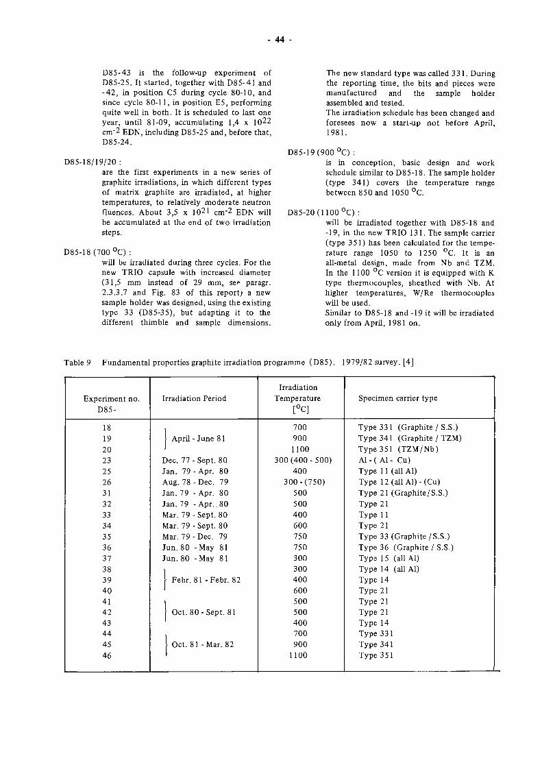
44
D8543 is the followup experiment of
D8525. It started, together with D8541 and
42, in position C5 during cycle 8010, and
since cycle 8011, in position E5, performing
quite well in both. It is scheduled to last one
year, until 8109, accumulating 1,4 χ 1θ22
cm2 EDN, including D8525 and, before that,
D8524.
D8518/19/20 :
are the first experiments in a new series of
graphite irradiations, in which different types
of matrix graphite are irradiated, at higher
temperatures, to relatively moderate neutron
fluences. About 3,5 χ 10^1 cm~2 EDN will
be accumulated at the end of two irradiation
steps.
D8518(700°C) :
will be irradiated during three cycles. For the
new TRIO capsule with increased diameter
(31,5 mm instead of 29 mm, see paragr.
2.3.3.7 and Fig. 83 of this report) a new
sample holder was designed, using the existing
type 33 (D8535), but adapting it to the
different thimble and sample dimensions.
The new standard type was called 331. During
the reporting time, the bits and pieces were
manufactured and the sample holder
assembled and tested.
The irradiation schedule has been changed and
foresees now a startup not before April,
1981.
D8519(900°C) :
is in conception, basic design and work
schedule similar to D8518. The sample holder
(type 341) covers the temperature range
between 850 and 1050 °C.
D8520(1100°C) :
will be irradiated together with D8518 and
19, in the new TRIO 131. The sample carrier
(type 351) has been calculated for the tempe
rature range 1050 to 1250 °C. It is an
allmetal design, made from Nb and TZM.
In the 1100 °C version it is equipped with Κ
type thermocouples, sheathed with Nb. At
higher temperatures, W/Re thermocouples
will be used.
Similar to D8518 and 19 it will be irradiated
only from April, 1981 on.
Table 9 Fundamental properties graphite irradiation programme (D85). 1979/82 survey. [4]
Experiment no.
D85
18
19
20
23
25
26
31
32
33
34
35
36
37
38
39
40
41
42
43
44
45
46
Irradiation Period
| [ April June 81
1 Dec. 77Sept . 80
Jan. 79 Apr. 80
Aug. 78 Dec. 79
Jan. 79 Apr. 80
Jan. 79 Apr. 80
Mar. 79Sept . 80
Mar. 79Sept . 80
Mar. 79Dec . 79
Jun. 80 May 81
Jun. 80 May 81
1 ■ Febr. 81 Febr. 82
I 1
Oct. 80Sept . 81
1
1 Oct. 81 Mar. 82
1
Irradiation
Temperature
[°C]
700
900
1100
300(400500)
400
300(750)
500
500
400
600
750
750
300
300
400
600
500
500
400
700
900
1100
Specimen carrier type
Type 331 (Graphite/ S.S.)
Type 341 (Graphite / TZM)
Type 351 (TZM/Nb)
Al ( Al Cu)
Type 11 (all Al)
Type 12 (all Al)(Cu)
Type 21 (Graphite/S.S.)
Type 21
Type 11
Type 21
Type 33 (Graphite/S.S.)
Type 36 (Graphite / S.S.)
Type 15 (all Al)
Type 14 (all Al)
Type 14
Type 21
Type 21
Type 21
Type 14
Type 331
Type 341
Type 351
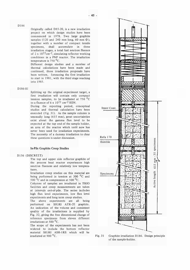
45
D186
D186-01
Originally called D85-20, is a new irradiation project on which design studies have been commenced in 1978. Two large graphite samples (120 and 240 mm long, 60 mm © ), together with a number of compact tensile specimens, shall accumulate in three irradiation stages, a total fast neutron fluence of 2 χ 1022Cm"2, simulating reflector working conditions in a PNP reactor. The irradiation temperature is 750 °C. Different design studies and a number of thermal calculations have been made and continued, three irradiation proposals have been written, foreseeing the first irradiation to start in 1981, with the third stage reaching into 1985.
Splitting up the original experiment target, a first irradiation will contain only compact tension samples, to be irradiated at 750 °C to a fluence of 6 χ 10^1 cm"2 EDN. During the reporting period, conceptual studies and thermal calculation have been executed (Fig. 31). As the sample column is unusually long (615 mm), great uncertainties exist about the gamma flux level to be expected at the top end of the sample holder, an area of the reactor which until now has never been used for irradiation experiments. The necessity of a dummy irradiation to clear these questions is under discussion.
In-Pile Graphite Creep Studies
D156 (DISCREET) The top and upper side reflector graphite of the process heat reactor experiences high neutron fluences and relatively low temperatures. Irradiation creep studies on this material are being performed in tension at 300 °C and 500 °C and in compression at 500 °C. Columns of samples are irradiated in TRIO facilities and creep measurements are taken at intervals out-of-pile. The series includes high flux level experiments, low flux level experiments and long term creep studies. The above experiments are all being performed on SIGRI ATR-2E graphite. An indication of the volume and consistent quality of the irradiations is supplied by Fig. 32, giving the free dimensional change of reference specimens from eleven different irradiations at 500 °C. The scope of the experiments has not been widered to include the bottom reflector material SIGRI ASR-1RS which will be irradiated at 900 °C.
ih ^ ^ 3
«χ·» .XXXX «.XXX VX"
7ZZZZL722ZZ1
Inner Cont. £ —h
Refa 170
thimble
Specimens
%
rr-*-*»
V////Y7777ZL
Fig. 31 Graphite irradiation D186. Design principle of the sample-holder.
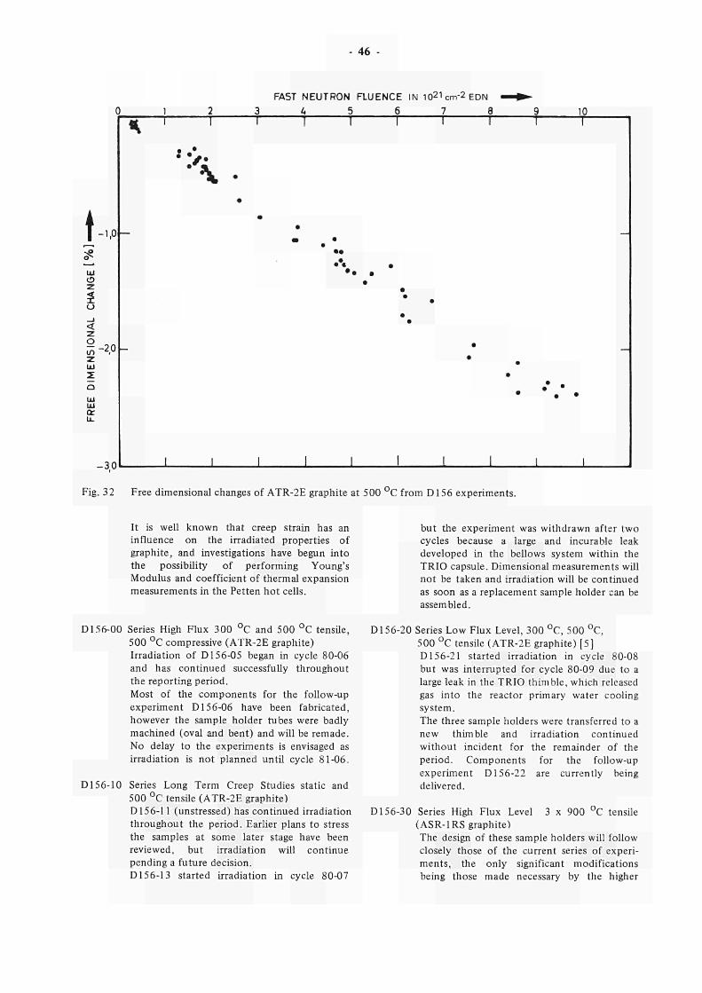
- 46 -
FAST NEUTRON FLUENCE IN 1021cm-2EDN 3 U 5 6 7 8 10
t - 1 . 0 -
o ζ
o
< o m ζ LD Σ
-20 -
-30
<k ι I I
• •
ι ι ι
1
• •
1
1 1
• • · · · · · ·
· · · • • •
• •
ι ι
Γ
•
I
• • •
• •
1 1
• ·
I I
Fig. 32 Free dimensional changes of ATR-2E graphite at 500 °C from D156 experiments.
It is well known that creep strain has an influence on the irradiated properties of graphite, and investigations have begun into the possibility of performing Young's Modulus and coefficient of thermal expansion measurements in the Petten hot cells.
D156-00 Series High Flux 300 °C and 500 °C tensile, 500 °C compressive (ATR-2E graphite) Irradiation of D156-05 began in cycle 80-06 and has continued successfully throughout the reporting period. Most of the components for the follow-up experiment D156-06 have been fabricated, however the sample holder tubes were badly machined (oval and bent) and will be remade. No delay to the experiments is envisaged as irradiation is not planned until cycle 81-06.
D156-10 Series Long Term Creep Studies static and 500 °C tensile (ATR-2E graphite) D156-11 (unstressed) has continued irradiation throughout the period. Earlier plans to stress the samples at some later stage have been reviewed, but irradiation will continue pending a future decision. D156-13 started irradiation in cycle 80-07
but the experiment was withdrawn after two cycles because a large and incurable leak developed in the bellows system within the TRIO capsule. Dimensional measurements will not be taken and irradiation will be continued as soon as a replacement sample holder can be assembled.
D156-20 Series Low Flux Level, 300 °C, 500 °C, 500 °C tensile (ATR-2E graphite) [5] D156-21 started irradiation in cycle 80-08 but was interrupted for cycle 80-09 due to a large leak in the TRIO thimble, which released gas into the reactor primary water cooling system. The three sample holders were transferred to a new thimble and irradiation continued without incident for the remainder of the period. Components for the follow-up experiment D156-22 are currently being delivered.
D156-30 Series High Flux Level 3 χ 900 °C tensile (ASR-1 RS graphite) The design of these sample holders will follow closely those of the current series of experiments, the only significant modifications being those made necessary by the higher
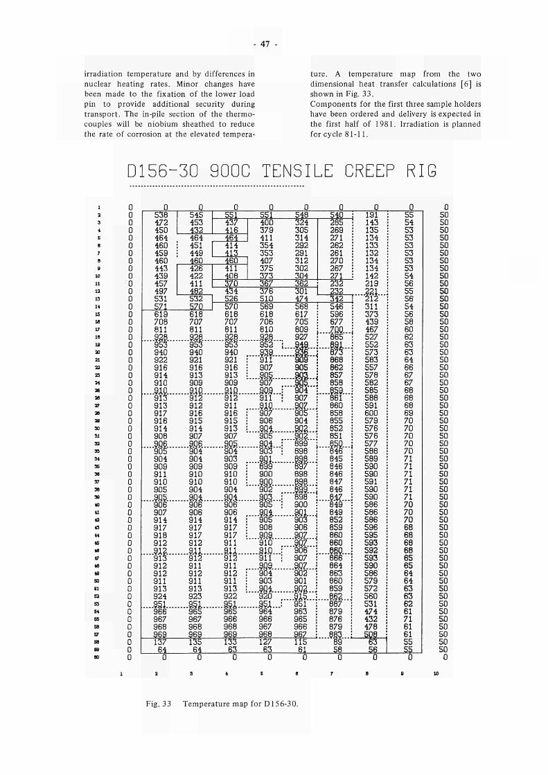
- 47 -
irradiation temperature and by differences in nuclear heating rates. Minor changes have been made to the fixation of the lower load pin to provide additional security during transport. The in-pile section of the thermocouples will be niobium sheathed to reduce the rate of corrosion at the elevated tempera
ture. A temperature map from the two dimensional heat transfer calculations [6] is shown in Fig. 33. Components for the first three sample holders have been ordered and delivery is expected in the first half of 1981. Irradiation is planned for cycle 81-11.
D156-30 900C TENSILE CREEP RIG
1 2
3
i S β
7
S β
10
11 IS 13
14
IS 1«
V 1β
u 30 21
23 23
»1
36 28 27
as 28
30 31
32 33
34 35
3«
37
39 38
10 41
42 43
44
45 4B
47
4S
4» 50
11 52
53
54
55 59
57 59
( 8 90
0 0 0 0 0 0 0 0 0 0 0 0 0 0 0 0 0 0 0 0 0 0 0 0 0 0 0 0 0 0 0 0 0 0 0 0 0 0 0 0 0 0 0 0 0 0 0 0 0 0 0 0 0 0 0 0 0 0 0 0
Fig. 33 Temperature map for D156-30.
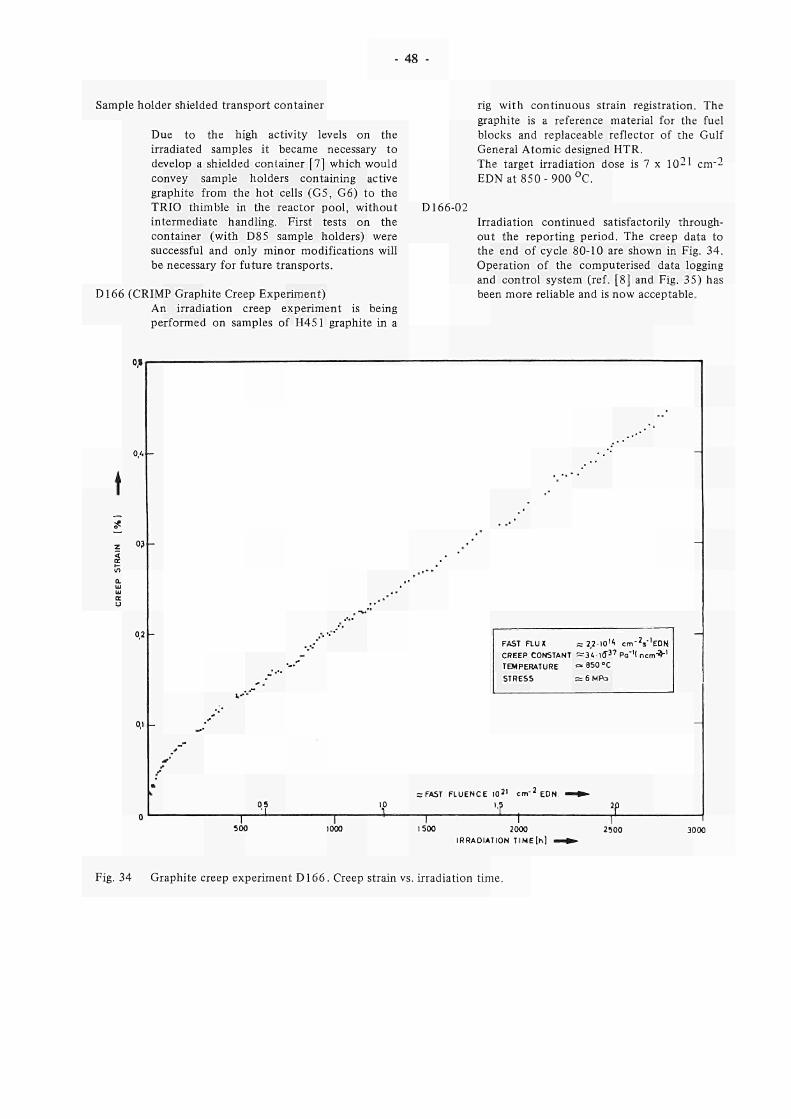
48 -
Sample holder shielded transport container
Due to the high activity levels on the irradiated samples it became necessary to develop a shielded container [7] which would convey sample holders containing active graphite from the hot cells (G5, G6) to the TRIO thimble in the reactor pool, without intermediate handling. First tests on the container (with D85 sample holders) were successful and only minor modifications will be necessary for future transports.
D166 (CRIMP Graphite Creep Experiment) An irradiation creep experiment is being performed on samples of H451 graphite in a
D166-02
rig with continuous strain registration. The graphite is a reference material for the fuel blocks and replaceable reflector of the Gulf General Atomic designed HTR. The target irradiation dose is 7 χ 1θ21 cm-2 EDN at 850-900 °C.
Irradiation continued satisfactorily throughout the reporting period. The creep data to the end of cycle 80-10 are shown in Fig. 34. Operation of the computerised data logging and control system (ref. [8] and Fig. 35) has been more reliable and is now acceptable.
cu
03
°.2
o.i
0
t *
ι - '
I
„ ·
05 Ί
-"
, -*·*
1
. · · '
10 1
·· '
SrFAST F L U E N C E
1
FAST a U X =r 2,2-10"· cm-2s-,EDN. CREEP CONSTANT ^341CT3 7 Pa"'( ncm^"1
TEMPERATURE f»850°C STRESS ;=6MPa
0 J I cm"2 EDN »
1 1
-
1000 1500 2000 IRRADIATION Τ IME [h]
2500
Fig. 34 Graphite creep experiment D166. Creep strain vs. irradiation time.
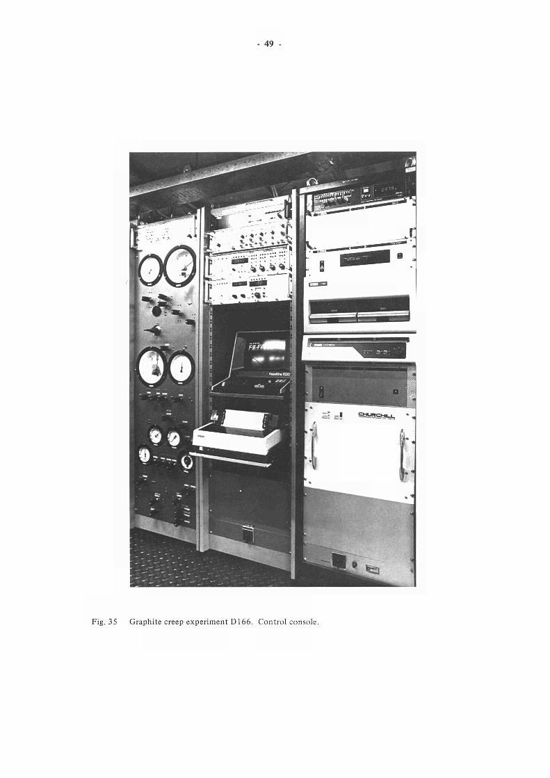
- 49
Fig. 35 Graphite creep experiment D166. Control console.
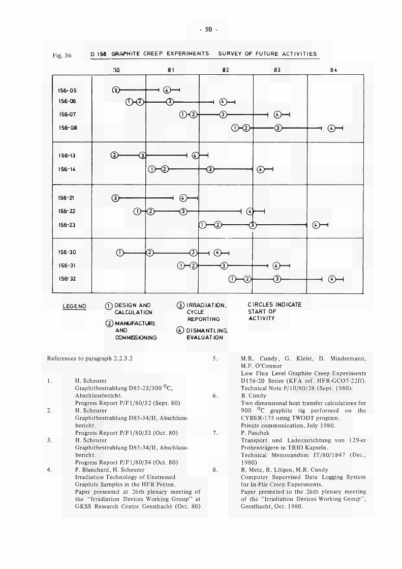
50
Fig. 36 D , 5 β
GRAPHITE CREEP EXPERIMENTS SURVEY OF FUTURE ACTIVITIES
ΓΙΟ 8 1 82 83 8«
15605
15606
15607
156 08
Ci>
dXD — 0
©<D φ—
OKI)
π <£M
—®— Θ·
15613
156U
Φ Q Η (£H
©© < 3 > SM
15621
15622
15623
15630
15631
15632
®
σ>φ π Θ—·
ΦΦ —Φ ©<
Ο Φ φ—ι
(LMD
( *>Η
©0D Θ — Η ( S M
LEGEND 0 DESIGN AND
CALCULATION
φ MANUFACTURE
AND
COMMISSIONING
@ IRRADIATION,
CYCLE
REPORTING
©DISMANTLING.
EVALUAT ION
CIRCLES INDICATE
START OF
ACTIVITY
References to paragraph 2.2.3.2
1. H. Scheurer
Graphitbestrahlung D8523/300 °C,
Abschlussbericht.
Progress Report P/Fl/80/32 (Sept. 80)
2. H. Scheurer
Graphitbestrahlung D8534/II, Abschluss
bericht.
Progress Report P/Fl/80/33 (Oct. 80)
3. H. Scheurer
Graphitbestrahlung D8534/II, Abschluss
bericht.
Progress Report P/Fl/80/34 (Oct. 80)
4. P. Blanchard, H. Scheurer
Irradiation Technology of Unstressed
Graphite Samples in the HFR Petten.
Paper presented at 26th plenary meeting of
the "Irradiation Devices Working Group" at
GKSS Research Centre Geesthacht (Oct. 80)
5. M.R. Cundy, G. Kleist, D. Mindermann,
M.F. O'Connor
Low Flux Level Graphite Creep Experiments
D15620 Series (KFA ref. HFRGC0722ff).
Technical Note P/10/80/28 (Sept. 1980).
6. B. Cundy
Two dimensional heat transfer calculations for
900 °C graphite rig performed on the
CYBER175 using TWODT program.
Private communication, July 1980.
7. P. Puschek
Transport und Ladeeinrichtung von 129er
Probenträgern in TRIO Kapseln.
Technical Memorandum IT/80/1847 (Dec,
1980)
8. R. Metz, R. Lölgen, M.R. Cundy
Computer Supervised Data Logging System
for InPile Creep Experiments.
Paper presented to the 26th plenary meeting
of the "Irradiation Devices Working Group",
Geesthacht, Oct. 1980.
- 51
2.2.3.2 HTR Fuel Special test irradiation E138-02 Prototype rig
High Temperature Reactor fuel testing is performed in HFR Petten on new advanced coated particle systems and production fuel elements with special emphasis on Nuclear Process Heat Reactor irradiation parameters.
The activities were concentrated during the reporting period on the evaluation of post-irradiation results of coated particle and fuel element in-pile tests, on the design of new advanced irradiation devices and on final commissioning of new sweep loops (see paragr. 2.3.3.9) which enable continuous fission gas analysis and temperature control to be carried out [5].
Coated Particles
D162 ARTEMIS, Irradiation of Coated Particle Fuel for Failure Mechanisms Investigation [6].
A second "gradient-experiment" will be carried out in 1981 for testing LEU coated particle fuel at abnormal thermal conditions. The design will be similar to the successcully performed first experiment. An irradiation proposal for KFA is currently under preparation. A report on the irradiation facility has been presented to the 26th plenary meeting of the IDWG, this year [4].
A special in-pile rig has been designed and manufactured for the purpose of fully realistic operational testing of the new sweep loops (see paragr. 2.3.3.9). A "fuel ball' rig design has been selected using standard THTR elements as fissile targets. During the reporting period the irradiation facility has been assembled [2], commissioned and connected as scheduled to the sweep loops. Design and safety report has been issued [1]. The design and operating approval has been given. "Hot" operation will start with cycle 81-01 [3]. Irradiation temperature will be measured in this experiment by thermocouples positioned either onto the fuel elements surface of into bores in the fuel free zone of one fuel element in each capsule. This is shown in Fig. 37, a radiograph of one assembled capsule. The scope of this measure is to obtain consistent reference results on temperature readings of thermocouples positioned onto the surface of the fuel element. Similar experiments in the past showed that after high neutron doses the differential shrinkage of the spherical specimen and the graphite structure created additional gas gaps which could have influence on the contact between thermocouple and fuel element.
D175 PETTICOAT, Irradiation Particle Fuel at 1000 °C
of LEU Coated Fuel Elements
Design and operating approval were given for the TRIO-131 irradiation facility by EAC (Experimental Assessment Committee) and RSC (Reactor Safety Committee). Specimens of standard quality coated particle fuel of LEU fuel cycle will not be available before the second half of 1981. Meanwhile, a mock-up experiment for neutron dosimetry and spectrum measurements will be performed in a TRIO irradiation facility. This experiment is expected to provide a reference data set on nuclear quantities and damage fluxes in azimuthal and vertical distribution for in-core 'graphite' experiments.
This mock-up consists of three all-graphite sample holders, spiked with dosimeters at three radii and over a length from - 300 mm to + 1500 mm with respect to centre line core. Design of the sample holders will start in January 1981. Sponsor of this experiment is KFA Jülich. The dosimeters and evaluation of these will be provided by ECN Petten. Irradiation will be carried out during 2 hours at 100 kW in a central core position.
Irradiation of spherical HTR fuel elements for Nuclear Process Heat Reactor Development
D138-3 A third spherical fuel element irradiation experiment will be sponsored by KFA. A proposal is currently being prepared for a three capsule rig design. Irradiation temperature will be about 1000 °C. Burn-up neutron fluence correlation of the LEU fuel containing elements will be similar to these specimens of the D175 coated particle irradiation experiment. Start of the irradiation is planned for 1981.
A 138-mock-up sample holder, sponsored by KFA Jülich, for extended neutron dosimetry measurements will be irradiated during 200 h at about 100 kW in a Refa 170 irradiation facility. The dosimeters will be provided and evaluated by ECN Petten. Results should give a reference mapping of damage fluxes for a full size HTR fuel element (% 60 mm O), irradiated in a reflector core position. The design is planned to start early in 1981.
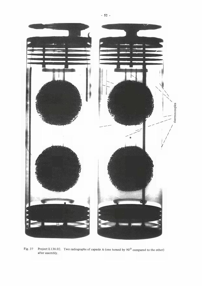
52 -
Fig. 37 Project E 138.02. Two radiographs of capsule A (one turned by 90° compared to the other) after assembly.
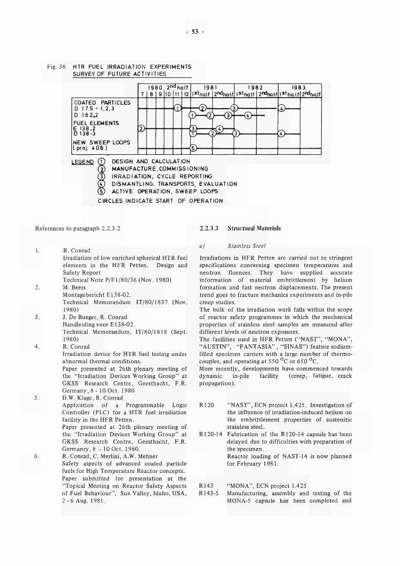
- 53
Fig. 38 HTR FUEL IRRADIATION EXPERIMENTS SURVEY OF FUTURE ACTIVITIES
COATED PARTICLES D 175 - 1,2.3 D 16 2»2 FUEL ELEMENTS E 138-2 D 138-3 NEW SWEEP LOOPS I proj 406 )
LEGEND (V) DESIGN AND CALCULATION MANUFACTURE,COMMISSIONING IRRADIATION, CYCLE REPORTING DISMANTLING, TRANSPORTS, EVALUATION ACTIVE OPERATION, SWEEP LOOPS
CIRCLES INDICATE START OF OPERATION
References to paragraph 2.2.3.2 2.2.3.3 Structural Materials
1. R.Conrad Irradiation of low enriched spherical HTR fuel elements in the HFR Petten. Design and Safety Report Technical Note P/F1/80/36 (Nov. 1980)
2. M. Beers Montagebericht E138-02. Technical Memorandum IT/80/1837 (Nov. 1980)
3. J. De Bueger, R. Conrad Handleiding voor E138-02. Technical Memorandum, IT/80/1818 (Sept. 1980)
4. R. Conrad Irradiation device for HTR fuel testing under abnormal thermal conditions. Paper presented at 26th plenary meeting of the "Irradiation Devices Working Group" at GKSS Research Centre, Geesthacht, F.R. Germany, 8 - 10 Oct. 1980
5. D.W. Klage, R. Conrad Application of a Programmable Logic Controller (PLC) for a HTR fuel irradiation facility in the HFR Petten. Paper presented at 26th plenary meeting of the "Irradiation Devices Working Group" at GKSS Research Centre, Geesthacht, F.R. Germanry,8 - 10 Oct. 1980.
6. R. Conrad, C. Merlini, A.W. Mehner Safety aspects of advanced coated particle fuels for High Temperature Reactor concepts. Paper submitted for presentation at the "Topical Meeting on Reactor Safety Aspects of Fuel Behaviour", Sun Valley, Idaho, USA, 2 - 6 Aug. 1981.
a) Stainless Steel
Irradiations in HFR Petten are carried out to stringent specifications concerning specimen temperatures and neutron fluences. They have supplied accurate information of material embrittlement by helium formation and fast neutron displacements. The present trend goes to fracture mechanics experiments and in-pile creep studies. The bulk of the irradiation work falls within the scope of reactor safety programmes in which the mechanical properties of stainless steel samples are measured after different levels of neutron exposures. The faculties used in HFR Petten ("NAST", "MONA", "AUSTIN", "FANTASIA" , "SINAS") feature sodium-filled specimen carriers with a large number of thermocouples, and operating at 550 °C or 650 °C. More recently, developments have commenced towards dynamic in-pile facility (creep, fatigue, crack propagation).
R120 "NAST", ECN project 1.425. Investigation of the influence of irradiation-induced helium on the embrittlement properties of austenitic stainless steel.
R120-14 Fabrication of the R120-14 capsule has been delayed due to difficulties with preparation of the specimen. Reactor loading of NAST-14 is now planned for February 1981.
R143 "MONA", ECN project 1.425 R143-5 Manufacturing, assembly and testing of the
MONA-5 capsule has been completed and
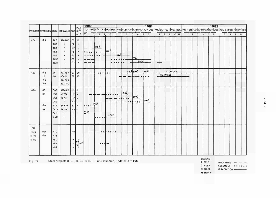
PROJECT
K F *
K 22
14 24
IFO
1425
R120
R 143
SPECIMEN
09
08 10
0 8
09
60
60
09
28
08 09
RIG
TK 5
TK6
TK7
TK8
TK9
TK 10
TK Π
25
26
C47
C50
C51
C52
Τ 49
C 4 I I
αΐ2 Ci. 13
Ν 14
N15
M 4
M 5
M 6
DRAWING
32461 C
33223 A
40424
33223 Β
32212 C
3 2 7 « Β
40734
40731
34 533
39158
POS
E7
F2
0 2
F8
F2
FB
D2
£7
F8
H2
H2
H2
H2
E7
H2
M8
00 .1 10 * · m-2
15
90
20
4
4
4
4
7
4
50 5
•ιυ u
1980 JUL|AUG|SEP|OCT|NOV|DEC
Τ
—
» · *
550å
7
5
8
5WS
¡pj
9
► · Λ
IO
550°:
5 ί
—
I I
• ·
OS
1981 1982 JAN|FEB|MAR|APR|MAY|JUN|JUL[AUG[SEPIOCTINOV|DEC JAN|FEB[MAR|APR|MAY[JUN|JUL|AUG|SEP|OCT|NOV[DEC
I 2
550?
» · 4 •
300?
450?
) 4 5 6
550?
50té
650å
559°
550«
5501
7 8 9
380?
10 I I
20 C CLES
[400°
I 2 3 « 5 6 7 8 9 IO 11
■O
Fig. 39 Steel projects R120, R139, R143. Time schedule, updated 1.7.1980. LEGEND:
Τ TRIO
C REFA
Ν NAST
M MONA
MACHINING
ASSEMBLY
IRRADIATION
55
irradiation has been carried out in core position H8 as scheduled on November 11, 1980. The achieved characteristics were : • neutron fluence — l x l 021 m_2 • irradiation time 1000 sec. at 42,5 MW • sample temperature 550 °C. Evaluation of the thermal behaviour of the capsule shows that seven out of nine specimen in the rig have been irradiated within a + 35 °C range. The irradiation report of MONA-5 has been prepared (ref. [1]).
E167
specified temperature limits as shown on a typical post-cycle computer evaluated temperature plot given on Fig. 46. At the end of cycle 80-11 the experiments reached a maximum damage dose of about 11 d.p.a. The compatible software for the processing of data from punch tape was purchased. Data processing will be carried out, from cycle 80-09, using the desk top computer HP 9845 B.
TRIESTE, Steel Creep Rig
R139 TRIO and REFA capsule irradiations "SINAS" These experiments belong to a large mechanical property R & D programme, together with R120 and R143. They have grown from the limited original scope of irradiating a few cylindrical tensile specimens into a major series which now includes resilience and fracture mechanics test specimens (Fig. 39).
The following activities have been pursued during the reporting period : - Irradiation reports have been completed
and issued on the terminated experiments TK4, -5, -6 and -7, and on T49, C47, C411 andC412.
- the TK series' second extension has been successfully started with TK8 and -9 in September and October 1980 respectively.
- T25 is now ready for irradiation in January 1981 and T26 is scheduled in July 1981.
- T48 and C413 have been successfully irradiated in the second half of 1980 and C50, -51 and -52 are being completed for irradiation in the first half of 1981.
- a systematical review of experimental parameters of all R139 irradiations gives examples of the high degree of temperature efficiency and reliability of the experimental equipment (see Figs. 40 through 45).
Irradiation reports of the capsules R139-47, R139-411, R139-49 and R139-412 have been prepared and edited (refs. [2], [3], [4] and [5]).
E145 AUSTIN, Irradiation of Austenitic Steel Specimens for Strain Rate Studies
Small tensile samples are irradiated at 500 °C + 20 C in sodium-filled capsules for the "dynamic load" project of the JRC Ispra Safety Programme. The irradiation started in October 1978 and has since then been operated without problems. All specimens remained within the
This is a series of irradiation experiments for the JRC Ispra Fusion Reactor Materials Programme. The handling and load-unload procedures of the irradiated specimen stems had to be further examined in view of HFR hot cell working conditions and cell equipment available. Fabrication of dummy sample columns and ancillary equipment had to be delayed because further studies on dimensional measuring techniques by means of neutron radiography became necessary. Detailed experiment design will be continued during the next period.
E177 FANTASIA, Fracture Toughness of Austenitic Steels (JRC Ispra project IDEAS)
To evaluate the neutron enhanced degradation of fracture toughness characteristics in austenitic stainless steel materials for the JRC Ispra Reactor Safety Programme, the irradiation experiment E177-FANTASIA has been designed, in which more than 250 samples (tensile and 3 PB specimens) are irradiated at 350 °C and 550 °C. Five fluence steps between 1019 and 1021 n.cm"2 are envisaged. The first six sample holders of this experiment E177/1 - 6 have been dismantled, and the 3 PB and tensile samples are prepared for transport to the Applied Mechanics Division of JRC Ispra. Irradiation was continued as scheduled in the HFR cycle 80-07 with the three sample holders El77/7 - 9 in HFR position H8 and the three sample holders E177/10 - 12 in position H2. Both irradiations were carried out for three cycles to reach a target fluence in the order of 4,5 χ 1θ20 n.cm-2. Irradiation temperature of the steel samples was kept at 350 °C for the sample holders E177/ 7 - 9, respectively 550 °C for the next irradiation step. After irradiation the six sample holders E177/ 7 - 1 2 were prepared for dismantling. The following sample holders E177/13 - 24 for the next four irradiation steps are presently being manufactured. Irradiation is scheduled for HFR cycles 81-07 till 82-05.
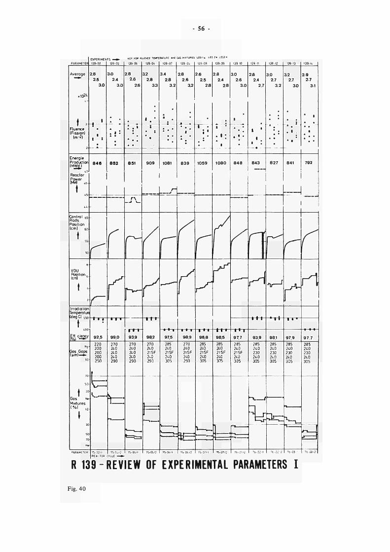
56
PARAMETER
Average
~"*"
«10»
t 3 Fluence IFission)
Im2)
Energie Production (MWd I
EXPERIMENTS — »
13902
2.8
2.5
3.0
t 7 ·
i t
•
Θ4β
4 7J
Reoctor Power MM LÌ,
t
tí>
Control es Rods Position (cm) eo
t 55
50 fl
vou Position. lem)
b
t » 2
Irradiation Tempera tura (deg.C) SSf>
t (.50
Ert ciency
Gas Gaps (μπι)—*
53
t * Gos Ν* Mixtures
ι %} l0
1
50
70
Η *
PARAMETER
0 9 0 3
3Ό 2.4
3.0
* .
. ι : A ·
•
8 5 2
____
r r^
! ■ ·
92.5
220 200 200 200 250
w ^ —
7502/1
REACTOR
____.
f
j
(
1
• 1 ·
99,0
270 240 240 240 290
■ \
i :
75 0 Í 2
KEY FOR FLUENCE TEMPERATURE oM
13906
2.8
2.6
2J6
• • •
A m
831
Γ " ^ 1
I I I
93.9
270 240 240 240 290
^
7505/1
139OÍ.
1 2
2.8
33
1
•
9 0 9
13907
3.4
2.8
3.2
A *
A · *
1081
I
/
r" ι
1 1 1
982
270 240 2I5F 240 290
J 1
1 »__
7505/?
Γ"
f
• ' · 97.5
285 240 215F 240 305
750b / l
¿AS MIXTURES
13903
2.8
2.6
a2
-à .
1 A »
"
8 3 9
•
y f
A
__y r^
\
• > I
98.9
270 240 2I5F 240 290
7506 /?
L E G I . LEG 7 · LEG3 ·
13908
2.6
2.5
2f l
•
I *
; · :
«
1059
13909
2.8
2.4
2.8
i
. I ;
•
1080
f
y
J
/
ν \
νΛ ι
ι · · 98,8
285 240 215F 240 305
\—~
7507/1
i l · 98.5
285 240 2I5F 240 305
J 1
7507/?
139 10
ao 2.6
3.0
t
i · ·
•
8 4 8
" " ——
/
1 ' 1
9 7 7
285 240 215F 240 305
* i ■
7 t OW?
13911
2 8
2.4
2.7
1 '
1
< '.
843
1 j{
r^
I I I
93,9
285 240 230 240 305
* » f
I
' ^ 1—ur
7 Ο - 0 Γ Ί
139-12
3.0 2.7
3.2
* *
827
- ^
Λ Γ - 1
* 1 I
98,1 285 240 230 24 0 305
> -
n-ani
139-13
3 2 2.7
3 0
[ Ì
. 1 .
* ·
841
13914
2.9
2.7
31
* 1
* · •
A
• *
7Θ2
—1 1
1
1
r~
r^ J
I I '
97,9
285 240 230 240 305
χ S
— u
7b03 ■
Ç ¿Λ
r^H
Γ l·
97.7
285 240 230 240 305
Η Γ
75.03/?
R 139REVIEW OF EXPERIMENTAL PARAMETERS I
Fig. 40
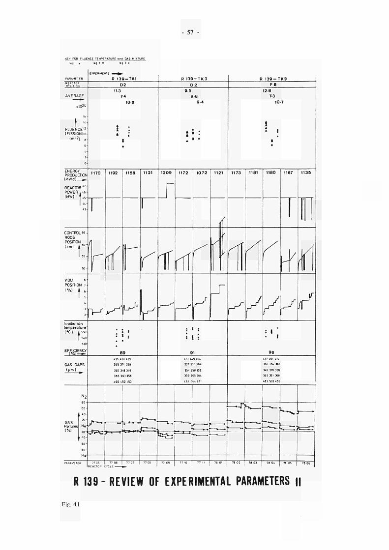
57
KEY FOR FLUENCE TEMPERATURE ond t > 5 MIXTURE
f , 1 A i»g 2 · *■■■, 'i ·
PARAMETER
REACTOR PTKiT i r iN
AVERAGE
xl02¿
16
t FLUENCE"
(FISSION lio
Im"2) j
6
1
2
0
ENERGY PRODUCTION iMwd: w~
REACTOR "_
POWER t6IHW] 1
LL
13
CONTROL 65
RODS POSITON
lem) i6 0
"
1 55
5 0
VDU »■ POSITION 7
'"·' 11: L
3
2
Irrodiation temperatur«' (»CI ¿«Ο
Ι 5A0
530
E F ^ E N Ç Y
GAS GAPS
Ipm 1 __
N2
6 0
GAS Matures ('/.I
1 0
20
Ne
2 0
1 0
6 0
»o
P A R A ^ T E R
EXPERIHENTS
R 1 3 9 T K 1
0 2
113
74
106
* t : » ;
1 •
1170
I I
/
r~~~
Γ I
1192
/ /
rC
y ^
1156
__
l·^
1121
| 1
^* \y \ !
Y . ' « • « :
A
89
135 130 129
365 371. 35»
350 31Θ 310
365 363 356
160 159 153
f ■ .
r^
77 05
REACTOR C
"l ï 1 * * ~ " " '
77 06
YCL
77 07
R 1 3 9 T K 2
D 2
1209
f ·—»1 , ,
Ε^
77 08
L·/ «2=:'
7? 09
9 5
9 8
94
. · . i * ' * · *
1172
<" (
I
ρ
1072
^
Ç
y
1121
/
y
t
/
■'
j"
1 · ί
i ! ; 91
151 119 151
357 370 369
351 356 352
369 365 361
161 361 101
1
R I 3 9 - T K 3 F 8
12-8 7-3
10-7
! » t
ι •
1173
/fÍ f
1181
/
1180
y
1167
y
1135
X / \
Λ I
/
« : I • 1
96
137 191 171
369 361390
316 370 360
363 361 36«
163 503 166
— r *»* . .
* — " 1 , ,' —
, *—IJ
77 10
■ » > — . ·
77 11
— » — ■
7β Ol 78 02
" » Ί . · ^ .
7« 03
~22^z~'
76 01
^ " W
i^r:*=^
78 05 78 06 I
R 139- REVIEW OF EXPERIMENTAL PARAMETERS II
Fig. 41
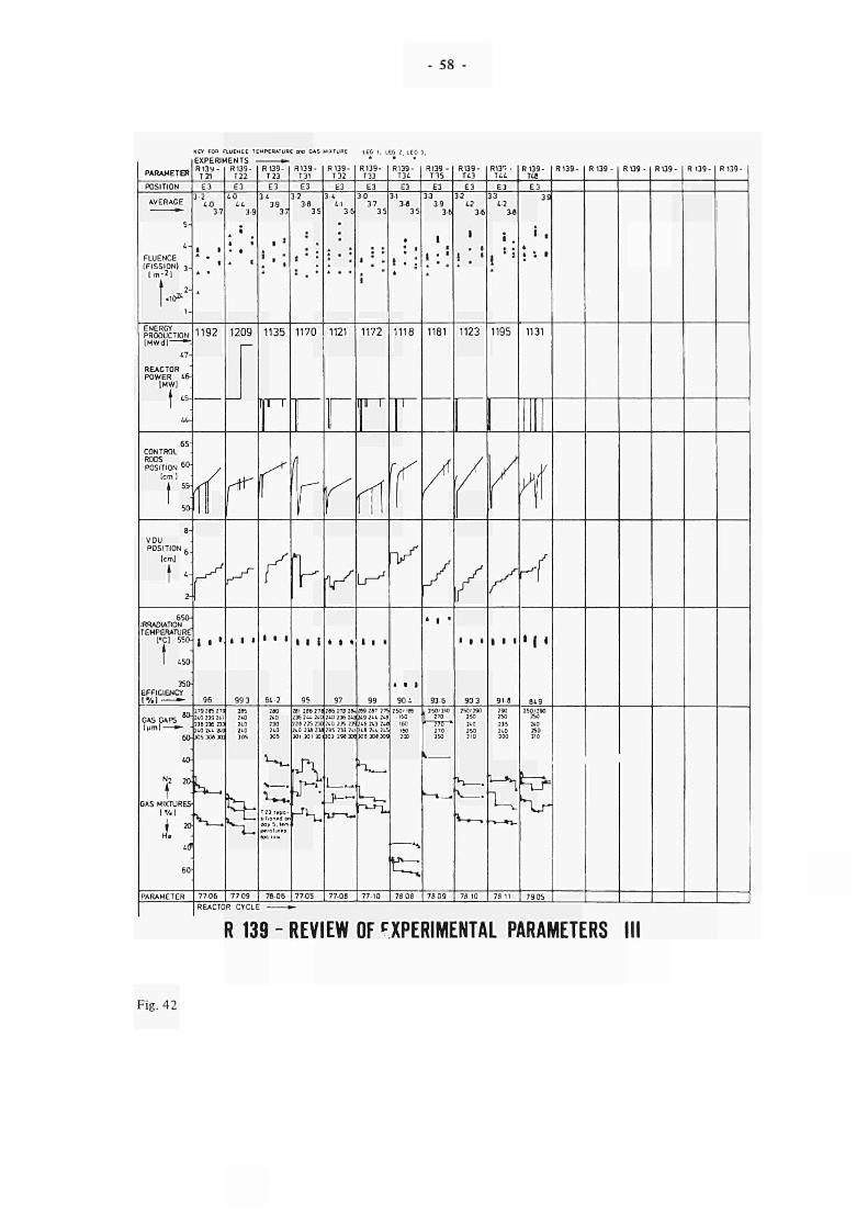
58
KEY FOR FLUEN EE TEMPERATUR ml GAS FIXTURE LEC I, LEG 2. LEG , i vnt n i i i i . iTr ·
PARAMETER
POSITION
AVERAGE
5
FLUENCE IFISSIONI i .
I m7 ' 1 m 1
1 2
.10»
1
ENERGY PRODUCTION IMWdl "
47
REACTOR POWER 45
IMW]
♦ 45
Τ Ur
te-CONTROL RODS POSITION
6 I >
tcml
I * 50
8
VDU POSITION 6
lem)
t '; 2
650IRRA01ATION TEMPERATURE
CCI 550
1 450
350
EFFICIENCY
IV.] —
GAS GAPS W
ΙμτηΙ ^ 60
40
GAS MIXTURESIV.I .
i * t i
60
PARAMETER
R139 R139T21
E3
3 2 4 0
3 7
i f
» . 1
*
1192
/f /
i · ·
96
279 285 279
210 239 211 238 236 233 21.0 2. 210 305 306 303
^
77 06
T22
E3
40 44
3 9
t
i ·
. t
1209
f
ι ι t
993
285 210 210 2 tO 305
^
77 09
REACTOR CYCLÍ
R139T23
E3
3 4 39
37
I >
1 . *
>
1135
igi ι
I
r y Γ
i l l
84 2
280 240 230 140 305
W.
ì~Z day 5. t»m pvrolur*.
7606
R139T31
E3
¡ 2 38
3 5
:
t ' '
1170
(I Γ I
η
l·
I 1 t
95
281 286 27Β. 236 Γ i . 2ι0ι 228 225 230 210 238 230 301 301 X
Λ
7705
RI39Τ32
Ε3
34 41
36
•
i · *
1121
f ι
Κ * ι ·
97
:β& 27β :ιν. 210 236 213 210 235 235 235 233 21 103 298 336
1
7708
R139Τ33
Ε3
3 0 37
35
t :
.
1
1172
1" '
<c 1
A
ι^
t ι ·
99
Γ09 287 27S 219 211 218 216 213 210 218 211 215 308 308 309
U, "^-L·
77 10
R139Τ34
Ε3
31 38
35
• ; «
i . :
1118
I
\ (
Κ/
> ι ι
9 0 1
2501 IBS 160
160 ISO 200
S
^
78 08
R139T35
E3
33 39
36
1 I
ι ; * A * *
1181
/
μ
/
' ι *
936
. 350/310 | 270 1 ¡JS ■
270 3S0
1|
78 09
R139T43
E3
32 42
36
1
• 1
| . '
1123
/
/ Γ
* I *
90 3
250'29O 250
210 250 310
H
\ .
* · »
78 10
R13^ ■ T44
E3
33 42
3ê
• .
ι :î
1195
I
I
{
/
I I «
918
J30 250
235 210 300
1 ^
78 11
R139T4ê
E3
39
i . A
ί *' *
1131
T I
Λ /
y η
' t ·
8¿9 250/29O
250
2*0 250 310
1
Χ,
7905
R139 R I 3 9 R139 R139 R139 R139
R 139 REVIEW OF EXPERIMENTAL PARAMETERS
Fig. 42
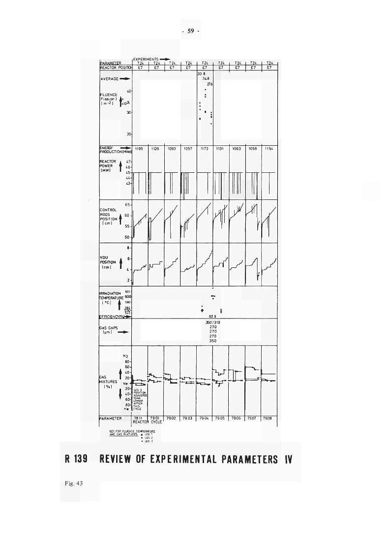
PARAMETER REACTOR POSIT»
FLUENCE Fission ) l m - 2 |
40-
ENERGY — PRODUCTION [MWtl]
REACTOR ι 47 IPOWER f i 6 .
|MW| I ^
44-43-
t 10x
νου POSITION
I c m l t :
RRADIAT10N K 0
TEMPERATURE W* [ • C | A seo
Τ if E F F I C I E N C Y ! ' / ^
GAS GAPS Ιμπιΐ -
EXPERIMENTS-ΤΖ4 Ι τ ; 4 E7
- 59
JIL· 30 8
34-8 276
1195 1126
F ^
E7
1173
/Λ
E7 E7 _L24_
X A
82 9
7Ö11 79 01 7902 | 79 03 | 79 0¿ | 79 05 | 7906 | 79.07 | 7908 REACTOR CYCLE
K€1 FOR FLUENCE TE>*»ERATURE ANO GAS M I X T U R E S A LEG i
• LEG 2 « LEG 3
R 139 REVIEW OF EXPERIMENTAL PARAMETERS IV
Fig. 43
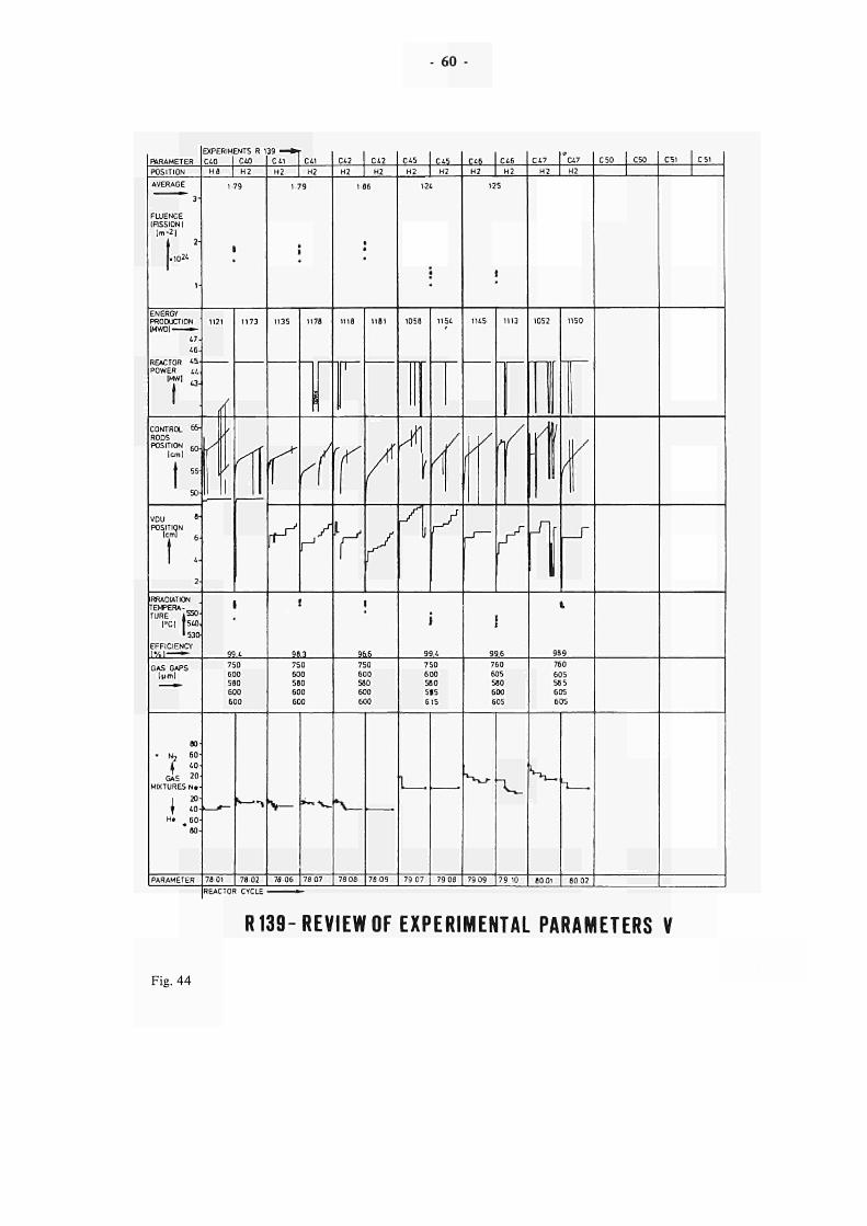
- 60
PARAMETER
POSIT ION
AVERAGE
3-
FUJENCE inssiONi
im-2] 2-
.102'
1-
ENERGY PRODUCTION 1MW0) »
47-4 6 -
Ο Γ ί Γ Τ Λ Ο L^m KtAClUR **■* POWER u
IMW1 , ,
I CONTROL 65
RODS
POSITION 6 r >
lem)
t · I 50
V D U 8
'
POSITION
M 6
4
2
IRRADIATION
TEMPERA
TURE i5 5 0
'
rei tsto. 1530
EFFICIENCY I V . I — »
GAS GAPS Iprnl
80
• Ν, 60
GAS ZOMIXTURES Ν ·
i 20
' If 40
He ^ 6 0 "βο
PARAMETER
EXPERIMENTS R 139 — » |
C40 1 C40
H8 | H2
1 79
1
.
1121
/
y
/
/
1
1173
Λ '
I
99.4
750
600 580
600
600
7801 78 02
REACTOR CYCLE
C 41
H2
C 41
H2
1 79
•
.
1135
S X
^
1178
/
Λ
t
98.3
750
600 580
600
600
V
78 0 6
»™\~
78 07
C42
Η2
C42
Η2
186
■ • •
1118
Ι
Ύ
Υ
1181
/ f S ι
96.6 7S0 600 580 600 600
* \
78 08 7809
C45 I C45 Η2 I H2
1-24
» '
1058
Τ
I A
ι
TT ι
1154
'
A \
/
y r^
i 99.4 750 600 580 5»5 615
L_
79 07 7908
C46 1 C46 H2 1 H2
1-25
1
1145
y κ
^~
1113
y
y"
i 99.6 760 605 580 600 605
79 09
V .
79 10
?
C47 1 C47 Η 2 I H2
1052
I
il
1150
V IH
π I t
989 760 605 585 605 605
^
8001
1
80 02
C50 C50 ,
CS1 C 51
R139-REVIEW OF EXPERIMENTAL PARAMETERS V
Fig. 44
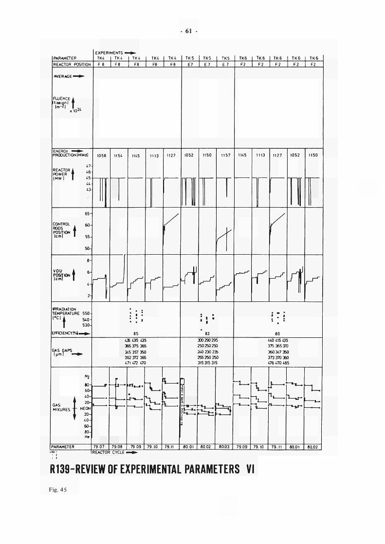
61
RARAMETER
EXPERIMENTS ·
TK4 | TK4 TK4 | TK4 I TK4 TK5 TK5 I TK5 TK6 | TK6 I TK6 I TK6 | TK6
REACTOR POSITION F8 F8 F8 F8 E7 E 7 E 7 F2 F2 I F2 F2 I F2
AVERAGE ■
FUJENCE 1 ! fission) f
lm2| I K>"
ENERGY * PRODUCTION iMWdl 1058
REACTOR i POWER t |MW|
1154 1145 1113 1127 1052
i l
1150 1157 1145 1113 1127 1052 1150
65
CONTROL . RO ROOS i POSITION T lem] · 55
501
VOU
fån·1 4 r 1 «RADIATION TEMPERATURE 550
510
530
•CI i
EFFICIENCY tVJ. 85
t *
83
ί · î A *
80
CAS CAPS ΙμΓη]
435 135 135
365 375 365
345 357 350
362 372 365
471 472 470
300290 295
250250250
240 230 235
255 250 250
315315 315
440 115 435
375 365370
360347 350
373 370 360
176 470 465
GAS
MIXURES I
*2
80
60
40
20
NEON
20
40
60
80
r*—x— >«,_,
?Sfe £3 L' rw
PARAMETER 79 07 I 79 08 [ 79 09 79.10 ] 79.11 ] 80 01 | 8002 | 80.03 | 79.09 | 79.10 79.11 80.01 8O02
REACTOR CYCLE .
R130REVIEW OF EXPERIMENTAL PARAMETERS VI
Fig. 45
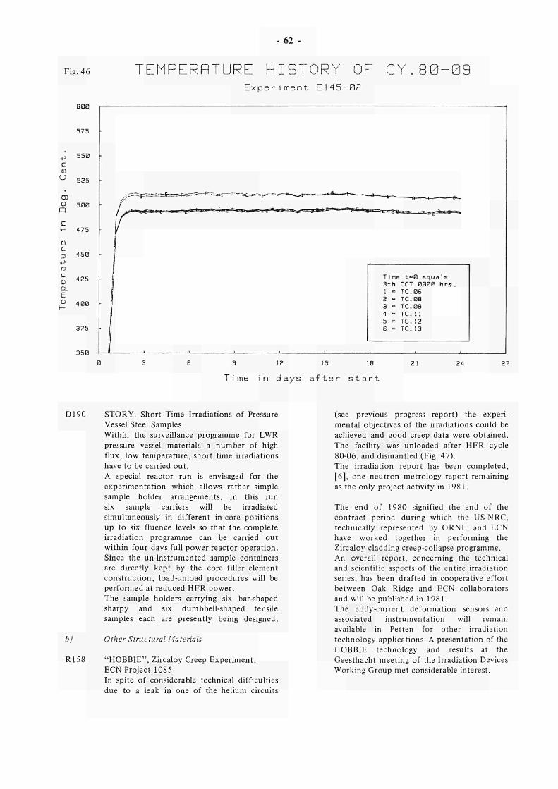
62 -
Fig. 46 TEMPERRTURE HISTORY OE C Y . 8 0 0 9 E x p e r i m e n t E 1 4 5 0 2
•p c ω o
GØØ
5 7 5
5 5 0
5 2 5
ID OJ 5 0 0
η c ■ 475
ω s_ 3 4 5 0 Ρ IT) s_ ω o. ε
,w 4 0 0
3 7 5
4 2 5
3 5 0
' C * » Β
~=r6=^^p=
τι me t" 3th 1 2 3 4 5
ε
= = -= = =
30 equa
OCT 0000 TC TC TC TC TC TC
øe 08 09 11 12 13
Is
hrs.
9 12 15 IB
T i m e i n d a y s a f t e r s t a r t
21 24 27
D190 STORY. Short Time Irradiations of Pressure
Vessel Steel Samples
Within the surveillance programme for LWR
pressure vessel materials a number of high
flux, low temperature, short time irradiations
have to be carried out.
A special reactor run is envisaged for the
experimentation which allows rather simple
sample holder arrangements. In this run
six sample carriers will be irradiated
simultaneously in different incore positions
up to six fluence levels so that the complete
irradiation programme can be carried out
within four days full power reactor operation.
Since the uninstrumented sample containers
are directly kept by the core filler element
construction, loadunload procedures will be
performed at reduced HFR power.
The sample holders carrying six barshaped
sharpy and six dumbbellshaped tensile
samples each are presently being designed.
b) Other Structural Materials
R158 "HOBBIE", Zircaloy Creep Experiment,
ECN Project 1085
In spite of considerable technical difficulties
due to a leak in one of the helium circuits
(see previous progress report) the experi
mental objectives of the irradiations could be
achieved and good creep data were obtained.
The facility was unloaded after HFR cycle
8006, and dismantled (Fig. 47).
The irradiation report has been completed,
[6], one neutron metrology report remaining
as the only project activity in 1981.
The end of 1980 signified the end of the
contract period during which the USNRC,
technically represented by ORNL, and ECN
have worked together in performing the
Zircaloy cladding creepcollapse programme.
An overall report, concerning the technical
and scientific aspects of the entire irradiation
series, has been drafted in cooperative effort
between Oak Ridge and ECN collaborators
and will be published in 1981.
The eddycurrent deformation sensors and
associated instrumentation will remain
available in Petten for other irradiation
technology applications. A presentation of the
HOBBIE technology and results at the
Geesthacht meeting of the Irradiation Devices
Working Group met considerable interest.
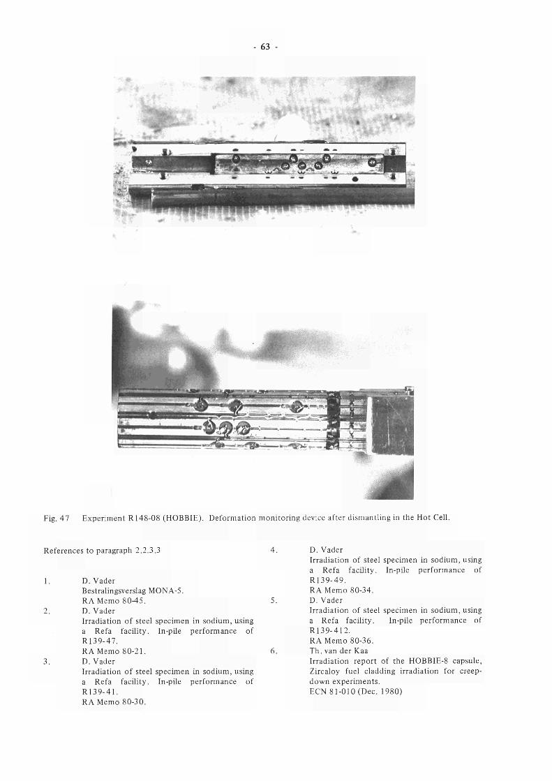
63
m.^
Fig. 47 Experiment R148-08 (HOBBIE). Deformation monitoring device after dismantling in the Hot Cell.
References to paragraph 2.2.3.3
1. D. Vader Bestralingsverslag MONA-5. RA Memo 8045 .
2. D. Vader Irradiation of steel specimen in sodium, using a Refa facility. In-pile performance of R139-47. RA Memo 80-21.
3. D. Vader Irradiation of steel specimen in sodium, using a Refa facility. In-pile performance of R139-41. RA Memo 80-30.
4. D. Vader Irradiation of steel specimen in sodium, using a Refa facility. In-pile performance of R139-49. RA Memo 80-34.
5. D. Vader Irradiation of steel specimen in sodium, using a Refa facility. In-pile performance of R139-412. RA Memo 80-36.
6. Th. van der Kaa Irradiation report of the HOBBIE-8 capsule, Zircaloy fuel cladding irradiation for creep-down experiments. ECN 81-010 (Dec. 1980)
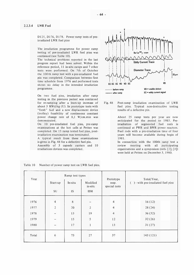
64 -
2.2.3.4 LWRFuel
D125, D176, D178. Power ramp tests of pre-irradiated LWR fuel pins
The irradiation programme for power ramp testing of pre-irradiated LWR fuel pins was continued (see Table 10). The technical problems reported in the last progress report had been solved. Within the reference period, 11 in-situ ramps and 7 other tests were performed. On 7th of October the 100 th ramp test with a pre-irradiated fuel pin was completed. Comparison between first time schedule from 1976 and performed tests shows no delay in the intended irradiation programme.
On two fuel pins, irradiation after ramp testing in the previous period was continued for re-ramping after a burn-up increase of about 3 MWd/kg (U). In prototype tests with "fresh" fuel and a new displacement device (trolley) feasibility of continuous constant power change rate of 0,1 W/cm.min was demonstrated. On 10 pre-irradiated fuel pins, pre-ramp examinations at the hot cells at Petten was completed. On 15 ramp tested fuel pins, post-irradiation examination was terminated. A typical result from these examinations is given in Fig. 48 for a defective fuel pin. Assembly of 3 capsule carriers and 10 irradiations devices was completed.
TFTÌYÌ
ΐ Υ Υ V Eddv Current Trace Eddy Current Trace
20 fun
EC EC EC VD VD EC
- before ramp - after ramp
VD —visible defect EC — eddy current tignai
Fig. 48 Post-ramp irradiation examination of LWR fuel pins. Typical non-destructive testing results of a defective pin.
About 25 ramp tests per year are now anticipated for the period to 1985. Pre-irradiation of segmented fuel rods is continued at PWR and BWR power reactors. Fuel rods with a pre-irradiation time of four years will become available during begin of 1981. In connection with the 100th ramp test a review meeting with all participating organizations and a symposium (refs. [2], [3]) were held at Petten on December 3, 1980.
Table 10 Number of power ramp test on LWR fuel pins.
Year
1976
1977
1978
1979
1980
Total
Start-up
SU
4
2
-
-
-
6
Ramp test types
In-situ
IS
8
20
13
15
17
73
Modified in-situ
ISM
-
2
19
5
1
27
Prototype resp.
special tests
4
4
4
12
13
37
Total/Year, ( ) - with pre-irradiated fuel pins
16(12)
28 (24)
36(32)
32(26)
31 (27)
143(121)
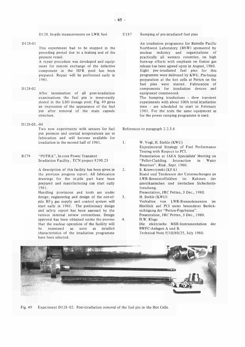
- 65
D128. In-pile measurements on LWR fuel U187 Bumping of pre-irradiated fuel pins
D128-01
D128-02
This experiment had to be stopped in the preceding period due to a leaking seal of the pressure vessel. A repair procedure was developed and equipment for remote exchange of the defective component in the HFR pool has been prepared. Repair will be performed early in 1981.
After termination of all post-irradiation examinations the fuel pin is temporarily stored in the LSO storage pool. Fig. 49 gives an impression of the appearance of the fuel pin after removal of the main capsule structure.
An irradiation programme for Battelle Pacific Northwest Laboratory (BNW) sponsored by nuclear industry and organizations of practically all western countries, on high burn-up effects with emphasis on fission gas release has been agreed upon in August, 1980. Eight pre-irradiated fuel pins for this programme were delivered by KWU. Pre-bump preparation at the hot cells at Petten on the fuel pins were started. Fabrication of components for irradiation devices and equipment commenced. The bumping irradiations - slow transient experiments with about 100h total irradiation time - are scheduled to start in February 1981. For the tests the same equipment as for the power ramping programme is used.
D128-03,-04 Two new experiments with sensors for fuel pin pressure and central temperatures are in fabrication and will become available for irradiation in the second half of 1981.
R174 "POTRA", In-core Power Transient Irradiation Facility, ECN project 8290.23
A description of this facility has been given in the previous progress report. All fabrication drawings for the in-pile part have been prepared and manufacturing can start early 1981. Handling provisions and tools are under design; engineering and design of the out-of-pile BF3 gas supply and control system will start early in 1981. The preliminary design and safety report has been assessed by the various internal review committees. Design approval has been obtained under the proviso that the nuclear operation of the facility will be reassessed as soon as detailed characteristics of the irradiation programme have been selected.
References to paragraph 2.2.3.4
1. W.Vogl.H. Stenle (KWU) Experimental Strategy of Fuel Performance Testing with Respect to PCI. Presentation at IAEA Specialists' Meeting on "Pellet-Cladding Interaction in Water Reactors", Risø, Sept. 1980.
2. S. Krawczynski (KFA) Stand und Tendenzen der Untersuchungen an LWR-Brennstoffstäben im Rahmen der amerikanischen und deutschen Sicherheitsforschung. Presentation, JRC Petten, 3 Dec, 1980.
3. H. Stehle (KWU) Verhalten von LWR-Brennelementen im Hinblick auf PCI unter besonderer Berücksichtigung der "Petten-Ergebnisse". Presentation, JRC Petten, 3 Dec, 1980.
4. D.W. Klage Die elektrische MSR-Instrumentation der BWFC-Anlagen A und B. Technical Note P/10/80/25, July 1980.
Fig. 49 Experiment D128-02. Post-irradiation removal of the fuel pin in the Hot Cells.
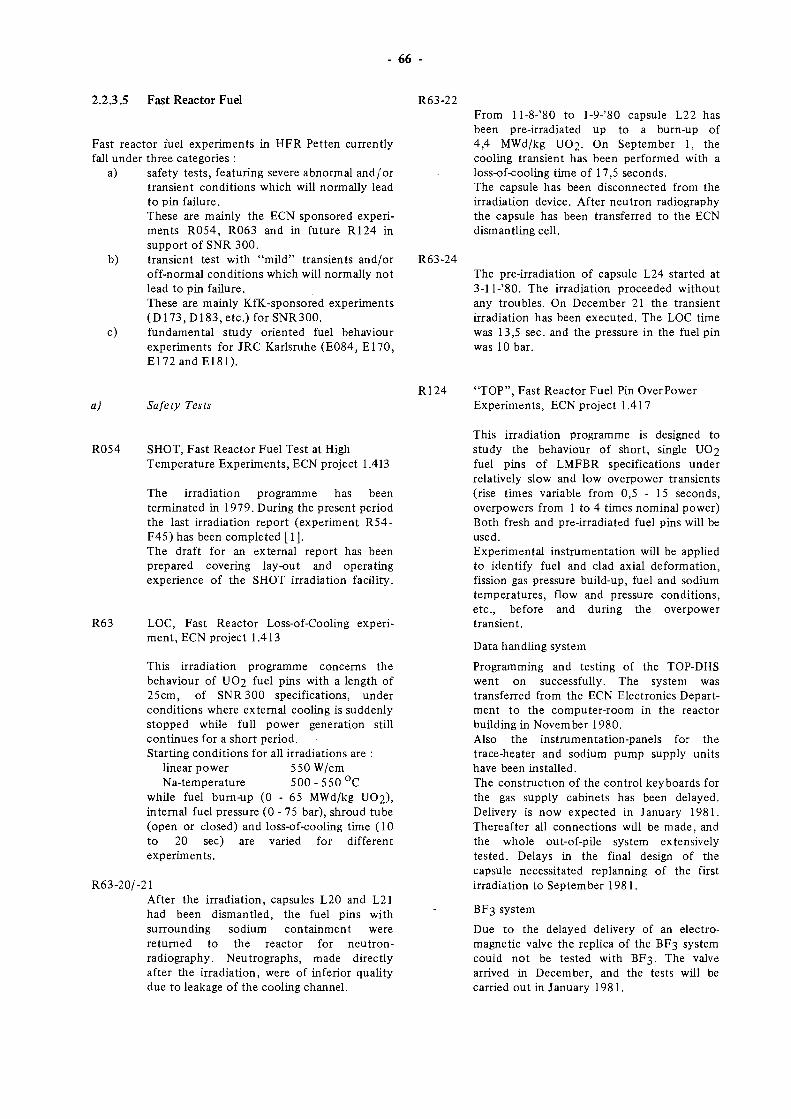
66
2.2.3.5 Fast Reactor Fuel R63-22
Fast reactor fuel experiments in HFR Petten currently fall under three categories :
a) safety tests, featuring severe abnormal and/or transient conditions which will normally lead to pin failure. These are mainly the ECN sponsored experiments R054, R063 and in future R124 in support of SNR 300.
b) transient test with "mild" transients and/or R63-24 off-normal conditions which will normally not lead to pin failure. These are mainly KfK-sponsored experiments (D173, D183, etc.) for SNR300.
c) fundamental study oriented fuel behaviour experiments for JRC Karlsruhe (E084, E l70 , E172andE181) .
From ll-8-'80 to l-9-'80 capsule L22 has been pre-irradiated up to a burn-up of 4,4 MWd/kg UO2. On September 1, the cooling transient has been performed with a loss-of-cooling time of 17,5 seconds. The capsule has been disconnected from the irradiation device. After neutron radiography the capsule has been transferred to the ECN dismantling cell.
The pre-irradiation of capsule L24 started at 3-11-'80. The irradiation proceeded without any troubles. On December 21 the transient irradiation has been executed. The LOC time was 13,5 sec. and the pressure in the fuel pin was 10 bar.
a) Safety Tests R124 "TOP", Fast Reactor Fuel Pin OverPower
Experiments, ECN project 1.417
R054 SHOT, Fast Reactor Fuel Test at High Temperature Experiments, ECN project 1.413
The irradiation programme has been terminated in 1979. During the present period the last irradiation report (experiment R54-F45) has been completed [1]. The draft for an external report has been prepared covering lay-out and operating experience of the SHOT irradiation facility.
R63 LOC, Fast Reactor Loss-of-Cooling experiment, ECN project 1.413
This irradiation programme concerns the behaviour of UO2 fuel pins with a length of 25cm, of SNR 300 specifications, under conditions where external cooling is suddenly stopped while full power generation still continues for a short period. Starting conditions for all irradiations are :
linear power 550 W/cm Na-temperature 5 00 - 5 5 0 °C
while fuel burn-up (0 - 65 MWd/kg UO2), internal fuel pressure (0 - 75 bar), shroud tube (open or closed) and loss-of-cooling time (10 to 20 sec) are varied for different experiments.
R63-20/-21 After the irradiation, capsules L20 and L21 had been dismantled, the fuel pins with surrounding sodium containment were returned to the reactor for neutron-radiography. Neu trographs, made directly after the irradiation, were of inferior quality due to leakage of the cooling channel.
This irradiation programme is designed to study the behaviour of short, single UO2 fuel pins of LMFBR specifications under relatively slow and low overpower transients (rise times variable from 0,5 - 15 seconds, overpowers from 1 to 4 times nominal power) Both fresh and pre-irradiated fuel pins will be used. Experimental instrumentation will be applied to identify fuel and clad axial deformation, fission gas pressure build-up, fuel and sodium temperatures, flow and pressure conditions, etc., before and during the overpower transient.
Data handling system
Programming and testing of the TOP-DHS went on successfully. The system was transferred from the ECN Electronics Department to the computer-room in the reactor building in November 1980. Also the instrumentation-panels for the trace-heater and sodium pump supply units have been installed. The construction of the control keyboards for the gas supply cabinets has been delayed. Delivery is now expected in January 1981. Thereafter all connections will be made, and the whole out-of-pile system extensively tested. Delays in the final design of the capsule necessitated replanning of the first irradiation to September 1981.
BF3 system
Due to the delayed delivery of an electromagnetic valve the replica of the BF3 system could not be tested with BF3. The valve arrived in December, and the tests will be carried out in January 1981.
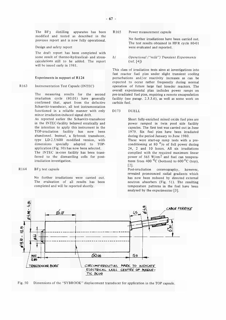
67
The BF3 distilling apparatus has been
modified and tested as described in the
previous report and is now fully operational.
Design and safety report
The draft report has been completed with
some result of thermohydraulical and stress
calculations still to be added. The report
will be issued early in 1981.
Experiments in support of R124
R163 Instrumentation Test Capsule (INTEC)
The measuring results for the second
irradiation cycle (80.01) have generally
confirmed that, apart from the defective
Schaevitztransducer, all test instrumentation
functioned in a reliable manner with only
minor irradiationinduced signal drift.
As reported earlier the Schaevitztransducer
in the INTECfacility behaved erratically and
the intention to apply this instrument in the
TOPirradiation facility has now been
abandoned. Instead, a Sybrook transducer,
type LD2.5/600 modified version, with
dimensions specially adapted to TOP
application (Fig. 50) has now been selected.
The INTEC incore facility has been trans
ferred to the dismantling cells for post
irradiation investigation.
R164 BF3 test capsule
No further irradiations were carried out.
The evaluation of all results has been
completed and will be reported shortly.
R165 Power measurement capsule
No further irradiations have been carried out.
The test results obtained in HFR cycle 8001
were evaluated and reported.
b) Operational ("mild") Transient Experiments
(ref. [4])
This class of irradiation tests aims at investigations into
fast reactor fuel pins under slight transient cooling
perturbations and /or reactivity increases as can be
expected to occur rather frequently during normal
operation of future large fast breeder reactors. The
overall experimental plan includes power ramps on
preirradiated fuel pins, requiring a remote encapsulation
facility (see paragr. 2.3.3.6), as well as some work on
carbide fuel.
D173 DUELL
Short fullyenriched mixed oxide fuel pins are
power ramped in twin pool side facility
capsules. The first test was carried out in June
1979. Six fuel pins have been irradiated
during the period January to June 1980.
These were startup ramp tests with a pre
conditioning at 80 °/o of full power during
24, 2 and 10 hours. All six irradiations
complied with the required maximum linear
power of 565 W/cm2 and fuel can tempera
tures from 400 °C (bottom) to 600 °C (top),
[2]
Postirradiation ceramography, however,
revealed pronounced radial gradients which
has now been reduced by directed external
neutron absorbers (Fig. 51). The resulting
temperature patterns in the fuel have been
analysed by the experimenter [3].
1
S F
«
^
3
1
/
< -
CS
i , .
HAX _
ae ßAJO 3DÜ
&ü
.
L \ -VM*
cefcftoer \ ClRCOMFtFeeiOTlAC MA£*C
ELecTzicAL toou. cewr
TIC 9LU&
ÇJlsssà
55
. το ικ et? O P
IDICWrf
HA6ue-
CA&LC F£(Z£UL£
Fig. 50 Dimensions of the "SYBROOK" displacement transducer for application in the TOP capsule.
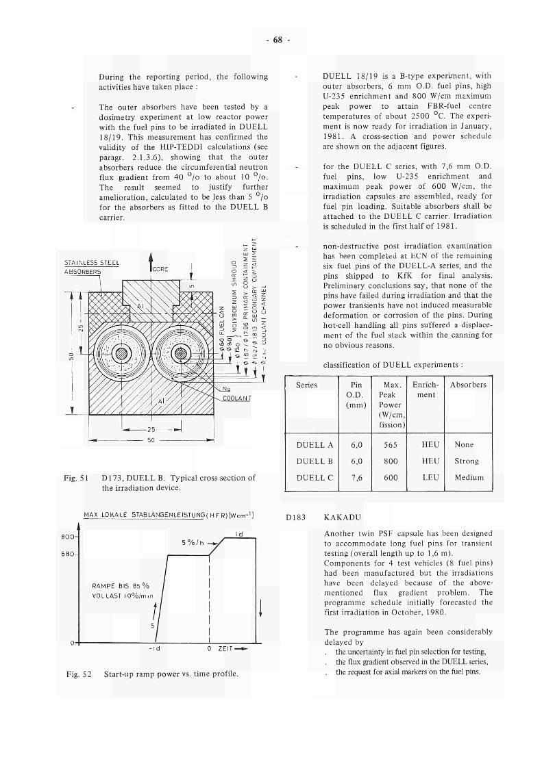
68
During the reporting period, the following
activities have taken place :
The outer absorbers have been tested by a
dosimetry experiment at low reactor power
with the fuel pins to be irradiated in DUELL
18/19. This measurement has confirmed the
validity of the HIPTEDDI calculations (see
paragr. 2.1.3.6), showing that the outer
absorbers reduce the circumferential neutron
flux gradient from 40 °/o to about 10 °/o.
The result seemed to justify further
amelioration, calculated to be less than 5 °/o
for the absorbers as fitted to the DUELL Β
carrier.
DUELL 18/19 is a Btype experiment, with
outer absorbers, 6 mm O.D. fuel pins, high
U235 enrichment and 800 W/cm maximum
peak power to attain FBRfuel centre
temperatures of about 2500 °C. The experi
ment is now ready for irradiation in January,
1981. A crosssection and power schedule
are shown on the adjacent figures.
for the DUELL C series, with 7,6 mm O.D.
fuel pins, low U235 enrichment and
maximum peak power of 600 W/cm, the
irradiation capsules are assembled, ready for
fuel pin loading. Suitable absorbers shall be
attached to the DUELL C carrier. Irradiation
is scheduled in the first half of 1981.
STAINLESS STEEL
nondestructive post irradiation examination
has been completed at ECN of the remaining
six fuel pins of the DUELLΑ series, and the
pins shipped to KfK for final analysis.
Preliminary conclusions say, that none of the
pins have failed during irradiation and that the
power transients have not induced measurable
deformation or corrosion of the pins. During
hotcell handling all pins suffered a displace
ment of the fuel stack within the canning for
no obvious reasons.
classification of DUELL experiments :
Fig. 51 D173, DUELL B. Typical cross section of
the irradiation device.
Series
DUELLA
DUELL Β
DUELL C
Pin
O.D.
(mm)
6,0
6,0
7,6
Max.
Peak
Power
(W/cm,
fission)
565
800
600
Enrich
ment
HEU
HEU
LEU
Absorbers
None
Strong
Medium
MAX LOKALE 5TABLANGENLEISTUNG( H F R) ÎWcrrr1]
8 0 0
6 8 0
RAMPE BIS 8 5 %
VOLLAST 10%/min
l d
i % / h * / "
l d
0 ZEIT ■
Fig. 52 Startup ramp power vs. time profile.
D183 KAKADU
Another twin PSF capsule has been designed
to accommodate long fuel pins for transient
testing (overall length up to 1,6 m).
Components for 4 test vehicles (8 fuel pins)
had been manufactured but the irradiations
have been delayed because of the above
mentioned flux gradient problem. The
programme schedule initially forecasted the
first irradiation in October, 1980.
The programme has again been considerably
delayed by
. the uncertainty in fuel pin selection for testing,
. the flux gradient observed in the DUELL series,
. the request for axial markers on the fuel pins.
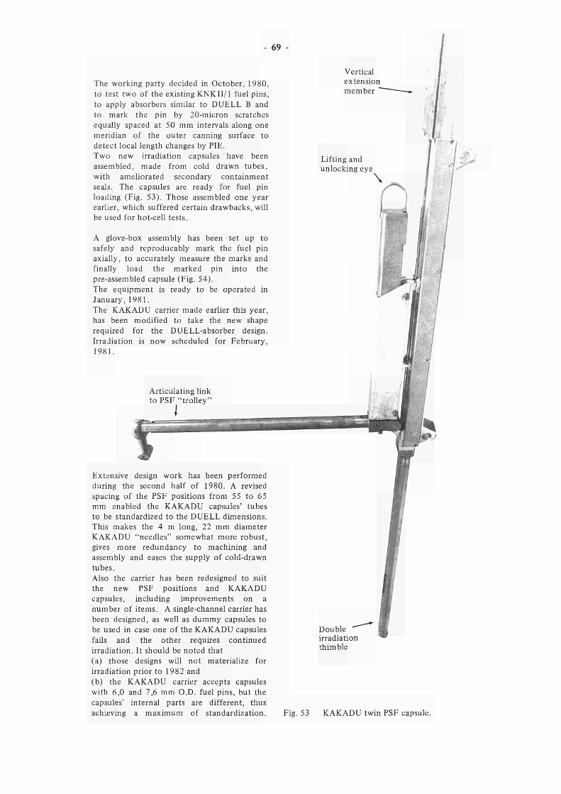
The working party decided in October, 1980, to test two of the existing KNKII/1 fuel pins, to apply absorbers similar to DUELL Β and to mark the pin by 20-micron scratches equally spaced at 50 mm intervals along one meridian of the outer canning surface to detect local length changes by PIE. Two new irradiation capsules have been assembled, made from cold drawn tubes, with ameliorated secondary containment seals. The capsules are ready for fuel pin loading (Fig. 53). Those assembled one year earlier, which suffered certain drawbacks, will be used for hot-cell tests.
A glove-box assembly has been set up to safely and reproducably mark the fuel pin axially, to accurately measure the marks and finally load the marked pin into the pre-assembled capsule (Fig. 54). The equipment is ready to be operated in January, 1981. The KAKADU carrier made earlier this year, has been modified to take the new shape required for the DUELL-absorber design. Irradiation is now scheduled for February, 1981.
Extensive design work has been performed during the second half of 1980. A revised spacing of Lhe PSF positions from 55 to 65 mm enabled the KAKADU capsules' tubes to be standardized to the DUELL dimensions. This makes the 4 m long, 22 mm diameter KAKADU "needles" somewhat more robust, gives more redundancy to machining and assembly and eases the supply of cold-drawn tubes. Also the carrier has been redesigned to suit the new PSF positions and KAKADU capsules, including improvements on a number of items. A single-channel carrier has been designed, as well as dummy capsules to be used in case one of the KAKADU capsules fails and the other requires continued irradiation. It should be noted that (a) those designs will not materialize for irradiation prior to 1982 and (b) the KAKADU carrier accepts capsules with 6,0 and 7,6 mm O.D. fuel pins, but the capsules' internal parts are different, thus achieving a maximum of standardization.
Vertical extension member
Double irradiation thimble
Fig. 53 KAKADU twin PSF capsule.
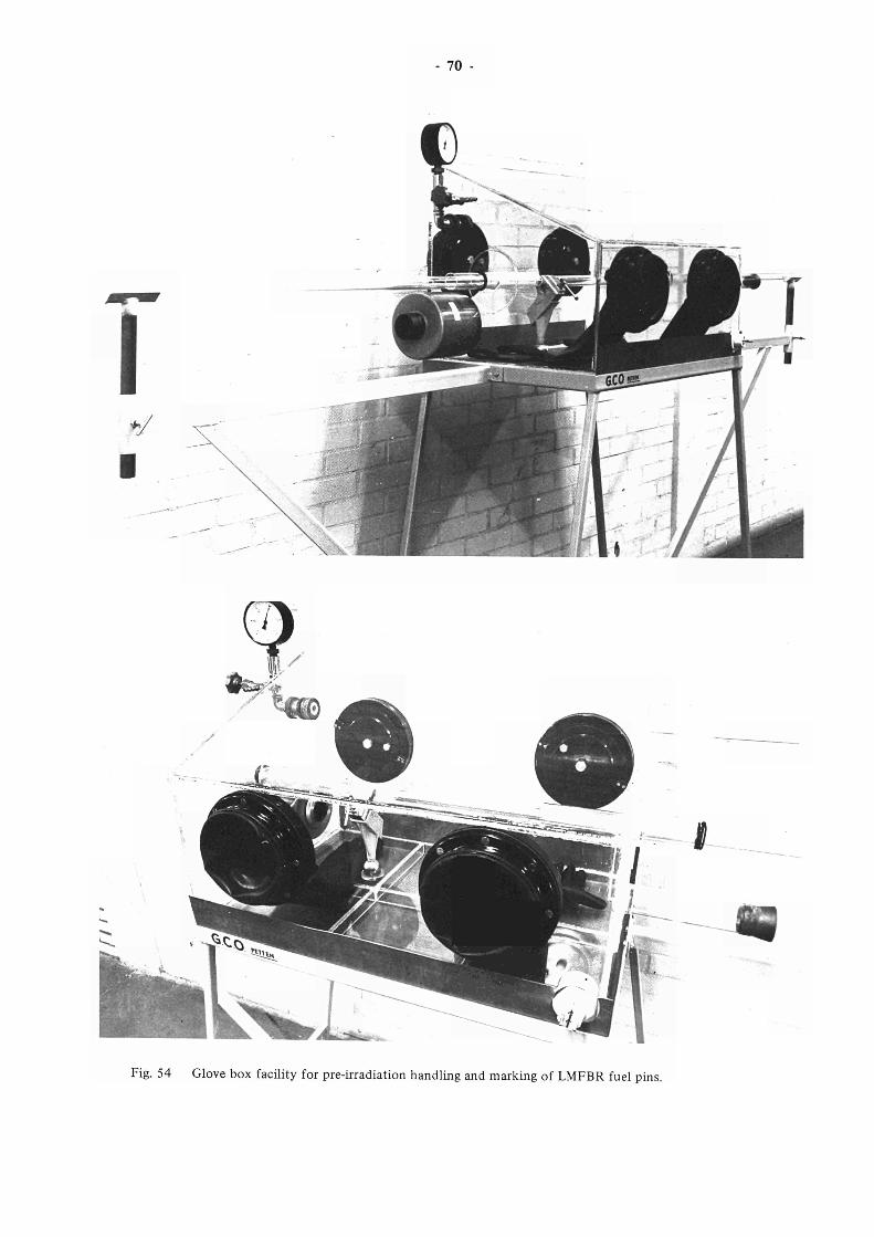
70
"Χ. — * * ■
*/
j £ 0 ^ — —
Τ. \ ■ - Γ "
L
^Ί Y - Ju # 1
È 1
m' L, -̂""' mxúíà
I"
Fig. 54 Glove box facility for pre-irradiation handling and marking of LMFBR fuel pins.
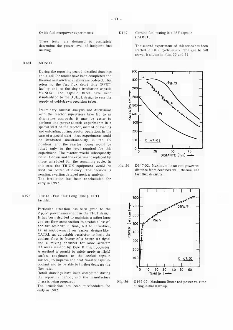
- 71 -
Oxide fuel overpower experiments
These tests are designed to accurately determine the power level of incipient fuel melting.
D147 Carbide fuel testing in a PSF capsule (CAREL)
The second experiment of this series has been started in HFR cycle 80-07. The rise to full power is shown in Figs. 55 and 56.
D184 MONOX
D192
During the reporting period, detailed drawings and a call for tender have been completed and thermal and nuclear analysis are ordered. This refers to the fast flux short time (FFST) facility and to the single irradiation capsule MONOX. The capsule tubes have been standardized to the DUELL design to ease the supply of cold-drawn precision tubes.
Preliminary nuclear analysis and discussions with the reactor supervisors have led to an alternative approach: it may be easier to perform the power-to-melt experiments in a special start of the reactor, instead of loading and unloading during reactor operation. In the case of a special start, three experiments could be irradiated simultaneously in the C5 position and the reactor power would be raised only to the level required for this experiment. The reactor would subsequently be shut down and the experiment replaced by those scheduled for the remaining cycle. In this case the TRIOX equipment would be used for better efficiency. The decision is pending awaiting detailed nuclear analysis. The irradiation has been re-scheduled for early in 1982.
TRIOX - Fast Flux Long Time (FFLT) facility.
Particular attention has been given to the Δ ρ , Δ ί power assessment in the FFLT design. It has been decided to maintain a rather large coolant flow cross-section to stretch a loss-of-coolant accident in time, but to introduce, as an improvement on earlier designs like C ATRI, an adjustable restrictor to limit the coolant flow in favour of a better At signal and a mixing chamber for more accurate At measurement by type Κ thermocouples. A method is sought to safely apply artificial surface roughness to the cooled capsule surface, to improve the heat transfer capsule-coolant and to be able to further decrease the flow rate. Detail drawings have been completed during the reporting period, and the manufacture phase is being prepared. The irradiation has been re-scheduled for early in 1982.
900
800
700
Λ600 E
500 -o: ^Aor
300
200
100
0
1 *
V ^ - X X \ *" — \
- \ >
- >
- D 1A7-02
ι
■ τ I
^ t h / 3
\
\ * \
x\ " \ \
^
ι 25 50 75
DISTANCE [mm] —»
Fig. 56 D14702. Maximum linear rod power vs.
distance from core box wall, thermal and
fast flux densities.
800
| 700
5 600
5 — 500
α UI
* ¿.00 o α
300
200
100
(
l i l i l í
. J r * ' *
* * * * 0,5·/./h
-S* y ι·/./h
Τ : 4 ι
f Γ
D l i .702
l i l i l í
) 10 20 30 AO 50 60
TIME[h ] *
Fig. 56 D14702. Maximum linear rod power vs. time
during initial startup.
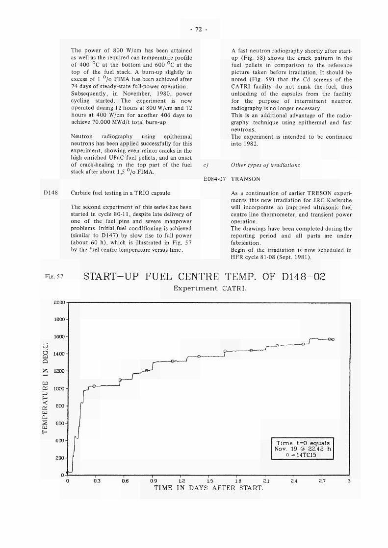
72
The power of 800 W/cm has been attained
as well as the required can temperature profile
of 400 °C at the bottom and 600 °C at the
top of the fuel stack. A burnup slightly in
excess of 1 °/o FIMA has been achieved after
74 days of steadystate fullpower operation.
Subsequently, in November, 1980, power
cycling started. The experiment is now
operated during 12 hours at 800 W/cm and 12
hours at 400 W/cm for another 406 days to
achieve 70.000 MWd/t total burnup.
Neutron radiography using epithermal
neutrons has been applied successfully for this
experiment, showing even minor cracks in the
high enriched UPuC fuel pellets, and an onset
of crackhealing in the top part of the fuel
stack after about 1,5 °/o FIMA.
A fast neutron radiography shortly after start
up (Fig. 58) shows the crack pattern in the
fuel pellets in comparison to the reference
picture taken before irradiation. It should be
noted (Fig. 59) that the Cd screens of the
CATRI facility do not mask the fuel, thus
unloading of the capsules from the facility
for the purpose of intermittent neutron
radiography is no longer necessary.
This is an additional advantage of the radio
graphy technique using epithermal and fast
neutrons.
The experiment is intended to be continued
into 1982.
c) Other types of irradiations
E08407 TRANSON
D148 Carbide fuel testing in a TRIO capsule
The second experiment of this series has been
started in cycle 8011, despite late delivery of
one of the fuel pins and severe manpower
problems. Initial fuel conditioning is achieved
(similar to D147) by slow rise to full power
(about 60 h), which is illustrated in Fig. 57
by the fuel centre temperature versus time.
As a continuation of earlier TRESON experi
ments this new irradiation for JRC Karlsruhe
will incorporate an improved ultrasonic fuel
centre line thermometer, and transient power
operation.
The drawings have been completed during the
reporting period and all parts are under
fabrication.
Begin of the irradiation is now scheduled in
HFR cycle 8108 (Sept. 1981).
Fig. 57 STARTUP FUEL CENTRE TEMP. OF D 1 4 8 0 2 E x p e r i m e n t CATRI.
2000
1800
1600
d ÜJ
Q
¡Ζ — m c¿ D H «tí et ω £X S Lu H
1400
1200
1000
800
600
400
200
T i m e t=0 equals Nov. 19 & 2ZAZ h
o 14TC15
τ — 0.3
—r— 0.9
" I — 12.
—\— 2.7 0.6 1.5 1.8 2.1
TIME IN DAYS AFTER START. 2.4
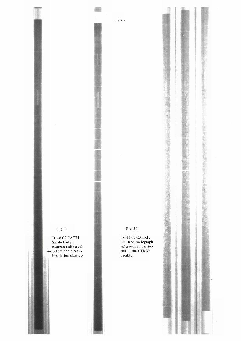
73
S ?
Fig. 58 Fig. 59
D148-02 CATRI.
Single fuel pin
neutron radiograph
·*- before and after —■
irradiation start-up.
D148-02 CATRI.
Neutron radiograph
of specimen carriers
inside their TRIO
facility.
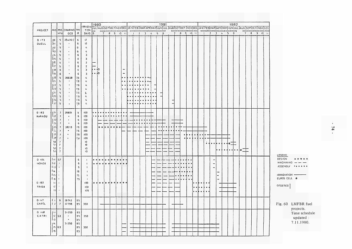
PROJECT
D 173
DUELL
0 183
KAKADU
0 iet.
MONOX
TRIOX
D 1Í.7
CAREL
D IC«
CATRI
RIC
ι: \" lu Γ lis
Ie
1.7 118
u IÎO
bi
1" In Ρ 1» I »
I j7
1" 1»
1" ι:: 1" 1 IS
50 5l
52
5)
l > < l i ;
113
Ικ.
1,5
1.6
1?
13
f 1
1 7
I I
I?
1}
15
'6
POS
H FR
5
5
5
5
5
5
S
5
6
6
S
5
5
5
5
5
5
5
7
7
7
7
7
7
7
7
7
7
7 7
G7
•
•
6
7
G3
G3
DRAWING
GCO
35476 C
• • . • •
• • ■
39839
• • • • •
•
39801
39713
.
28 7 «
37 796
31750
PIN
Φ
6
6
G
6
6
6
6
6
6
6
V 7.S
7.6
7.6
7.6
7.6
7,6
76
6
6
6
6
7.6
7.6
7.6
7.Ö
6
6
6
78
76
7.5
85
8.5
8.5
85
3.5
es
IRRADIA
TION
DAYS
I?
17
ί.
t. 3 3 7 2 3 3 i L,
L.
i. i A 4 A
100 100 100 100 100 100 100 100 10 Κ) IO IO
I
I
I 1 1
100 100 100
350
350
1980 JULIAUGISEPIOCTINOVIDEC
5 7 8 9 10 II
1— ι
> · < 1 · I
# •
D 0
* »
* *
* ♦
* *
♦ *
* *
# *
* *
f ·
—
1981 JAH1FEB|MAR!APR1MAY|JUN|JUL|AUGISEP|OCT |NOV|DEC
1 7 3 L 5 6 7 8 9 10 I I
—
ι —
—
—
1
—
—
—
—
—
—
—
'—
—
—
• ·
• ·
• ·
•
• · «
• · «
• · ■
• ·
• ·
• ■
• ·
1 · <
«·
1982 JAN!FEB|MAR|APR|MAY|JUN|JÜL1AUC|S£P|OCT|NOVICÍC
I ? 3 ¿ S 6 7 8 9 IO li
• ·
» · ' • ·
_
• * * _
* _
J
LEGEND
DESIGN * * * * *
MACHIN ING
ASSEMBLY · . · · · ·
IRRADIATION
EUROS CELL
ORDERED
Fig. 60 LMFBR fuel
projects.
Time schedule
updated :
7.11.1980.
75
E17001 POCY, POwer CYcling experiment with fuel
pin profile gauge
This experiment for JRC Karlsruhe, in which
a mixed highly enriched carbide fuel pin
was irradiated, has now been terminated,
after successfully completing over 250 days of
operation at linear powers of between 150
and 1050 W/cm, with inside clad temperatures
up to 630 °C.
The fuel pin profile gauge performed
effectively for the life of the experiment.
Fuel pin recovery is scheduled to take place in
early 1981.
2.2.3.6 Miscellaneous
a)
b)
HFR vessel material. Surveillance irradia
tions (see paragr. 2.1.3.8).
Specimens have been irradiated in the
existing RX092 facility, during all 5 cycles of
the reporting period.
A new facility (RX189) is presently under
development.
Gamma calorimeter (see paragr. 2.1.3.3)
The nuclear heating probe has been
during 4 cycles.
used
D17002
A similar experiment to POCY is scheduled
to be irradiated for KfK late in 1981 or
early in 1982.
The main differences are smaller pin diameter
(7,6 mm), and lower power (540 W/cm).
D191 Fuel creep rig
A proposal has been made for a device to
measure the fission enhanced creep of a small
stack (20 mm) of fuel pellets, in a PSF
position. The maximum power will be in the
order of 3000 Wcm~3, with fuel temperatures
of around 1000 °C. The sample will operate
with up to 70 MPa of compressive load.
The KfK requirements have now been
finalised and a modified proposal with the
final design should be forwarded in January
1981.
Start of the irradiation is now scheduled for
early in 1982.
References to paragr. 2.2.3.5
1. A.J. Nolten
Bestralingsverslag SHOTcapsule R54F45.
RA Memo 8039.
2. F. Genet, F. Mason, P. Zeisser.
Irradiation of FBR fuel pins for startup ramp
tests. Projekt D173, DUELL Α. Design and
Safety Report.
Technical Note P/Fl /80/35, Nov. 1980.
3. H. Steiner, H. Elbel
Die Berechnung von Temperatur asymmetrien
in gekapselten Brennstäben mit dem Rechen
programm TEXDIFP.
KfK 2961 (June 1980).
4. W. Dienst et al.
Fuelcladding mechanical interaction in fast
breeder fuel pins; observations and analysis.
J. Nucl. Mat. 91 (1980), p. 73 84.
c) Radioisotope production, activation analysis.
1. Standard isotope facilities
Their utilization during the reporting period
is summarized in Table 11, and compared to
previous years.
2. Special isotope facilities
ER 136 9 9 M 0 production from fissile targets (FIT)
These facilities are also mentioned in
Table 11.
During the reporting period, intense
utilization of both PSF and incore facilities
continued. Increasing problems were
experienced with the incoreFIT due to wear
and deformation of handling tool and locking
mechanism. The manufacture of an improved
incore device has started, which will
1) eliminate the aforementioned problems,
2) accommodate 9 instead of 3 samples.
The new facility (ER 13605) is expected to be
operational from about April, 1981.
ER 144 High Flux Isotope Facility (HIFI)
The irradiation of iridium capsules in HIFI02
continued on a routine basis.
ERI 79 9 9 M O production from fissile targets (MOLY)
A new PSF facility, for the irradiation of
fissile targets in form of plates has been
developed. Each plate, with the dimensions
220 χ 40 χ 1,3 mm, contains 4 gr 2 3 5 u ,
93 °/o enriched. Eight plates as a maximum
will be irradiated simultaneously during about
6 days and transported after 24 hours cooling
to the reprocessing plant.
During the reporting period, the irradiation
holder has been manufactured and tested
(Fig. 61). The special transport cask has been
received in Petten for testing of the different
stages of manipulation and for the assembly
of auxialiary handling tools and equipment.
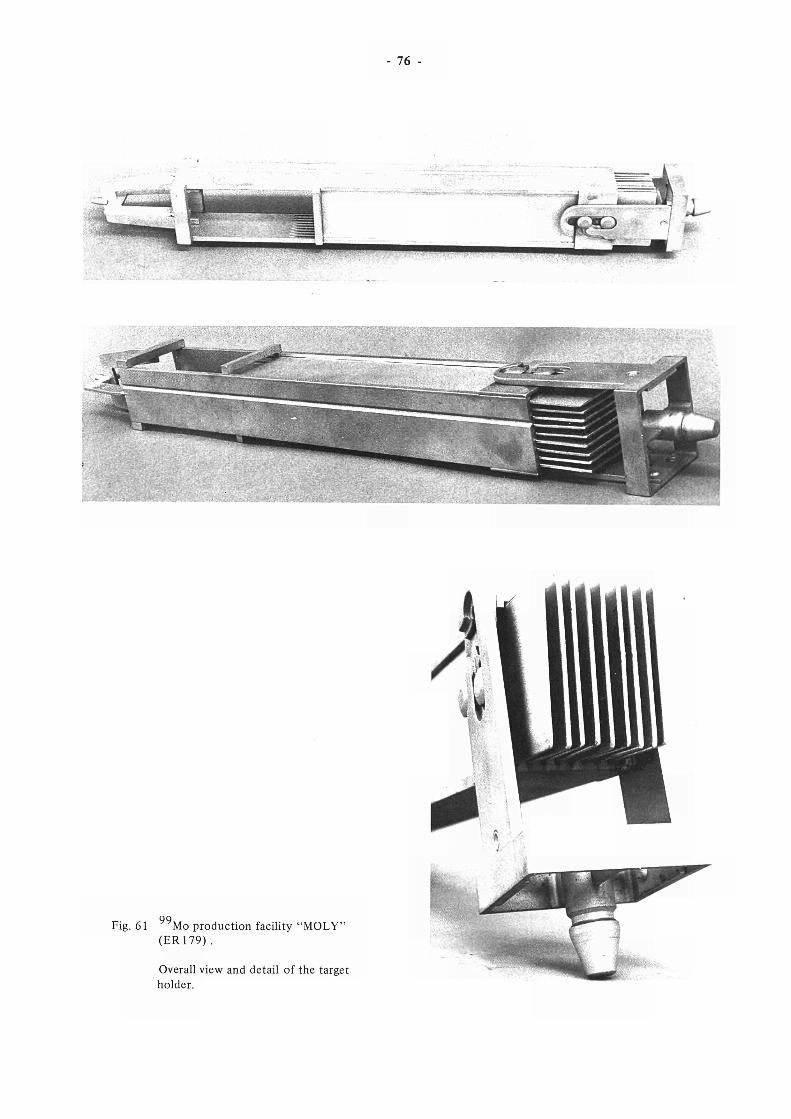
76
. . . . . . . . . · ■ ■ ■ ■ : . ■ · ; ■ : - . - ■ ■ - - : ■■
y ■>■<>. ■^^■■■:iy^y^y-y^yy
:L ;S--^:> . ; : ; . ■ . .;.
99 Fig. 61 Mo production facility "MOLY"
(ER 179) .
Overall view and detail of the target
holder.
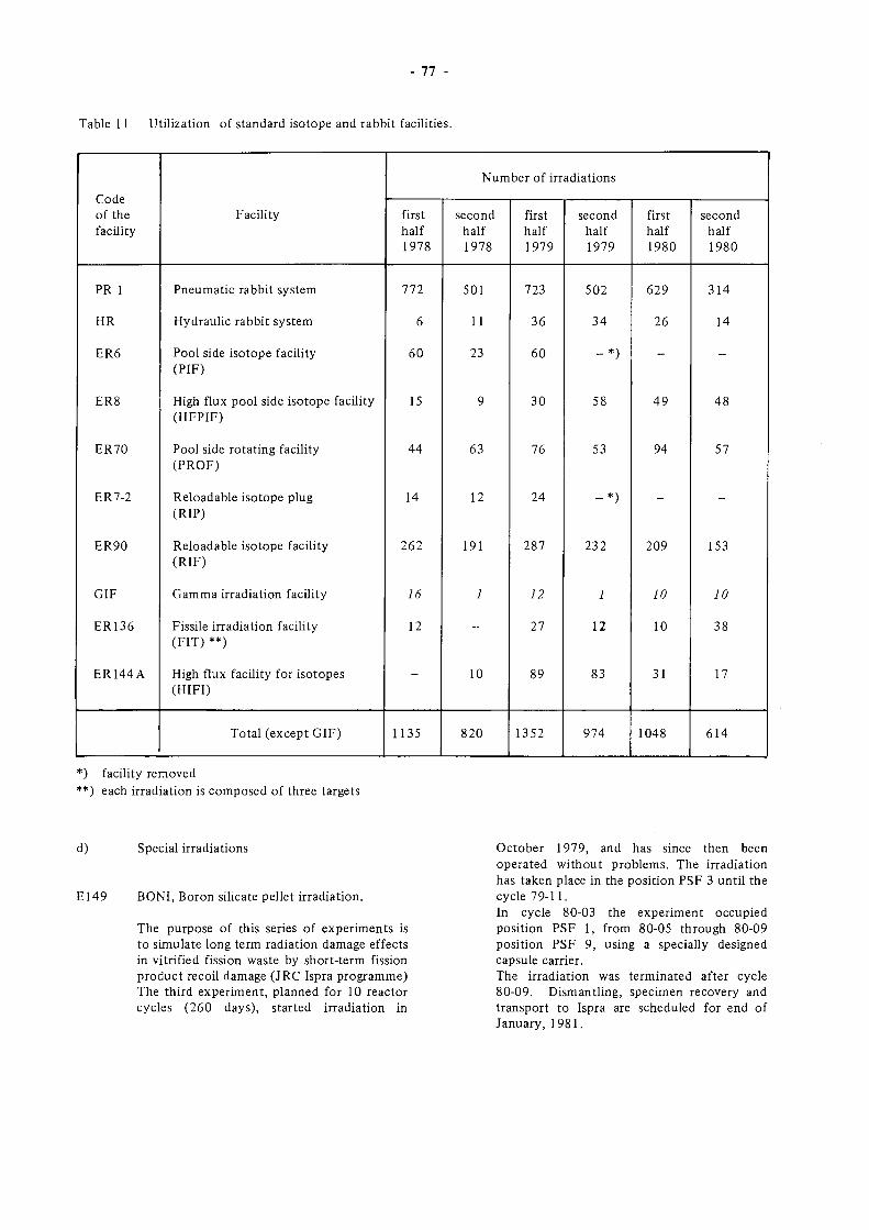
77
Table 11 Utilization of standard isotope and rabbit facilities.
Code of the facility
PR 1
HR
ER6
ER8
ER70
ER7-2
ER90
GIF
ER136
ER144A
Facility
Pneumatic rabbit system
Hydraulic rabbit system
Pool side isotope facility (PIF)
High flux pool side isotope facility (HFPIF)
Pool side rotating facility (PROF)
Reloadable isotope plug (RIP)
Reloadable isotope faculty (RIF)
Gamma irradiation facility
Fissile irradiation facility (FIT) **)
High flux facility for isotopes (HIFI)
Total (except GIF)
Number of irradiations
first half 1978
772
6
60
15
44
14
262
16
12
-
1135
second half 1978
501
11
23
9
63
12
191
1
-
10
820
first half 1979
723
36
60
30
76
24
287
12
27
89
1352
second half 1979
502
34
- * )
58
53
- * )
232
1
12
83
974
first half 1980
629
26
-
49
94
-
209
10
10
31
1048
second half 1980
314
14
-
48
57
-
153
10
38
17
614
*) facility removed **) each irradiation is composed of three targets
d) Special irradiations
E149 BONI, Boron silicate pellet irradiation.
The purpose of this series of experiments is to simulate long term radiation damage effects in vitrified fission waste by short-term fission product recoil damage (JRC Ispra programme) The third experiment, planned for 10 reactor cycles (260 days), started irradiation in
October 1979, and has since then been operated without problems. The irradiation has taken place in the position PSF 3 until the cycle 79-11. In cycle 80-03 the experiment occupied position PSF 1, from 80-05 through 80-09 position PSF 9, using a specially designed capsule carrier. The irradiation was terminated after cycle 80-09. Dismantling, specimen recovery and transport to Ispra are scheduled for end of January, 1981.
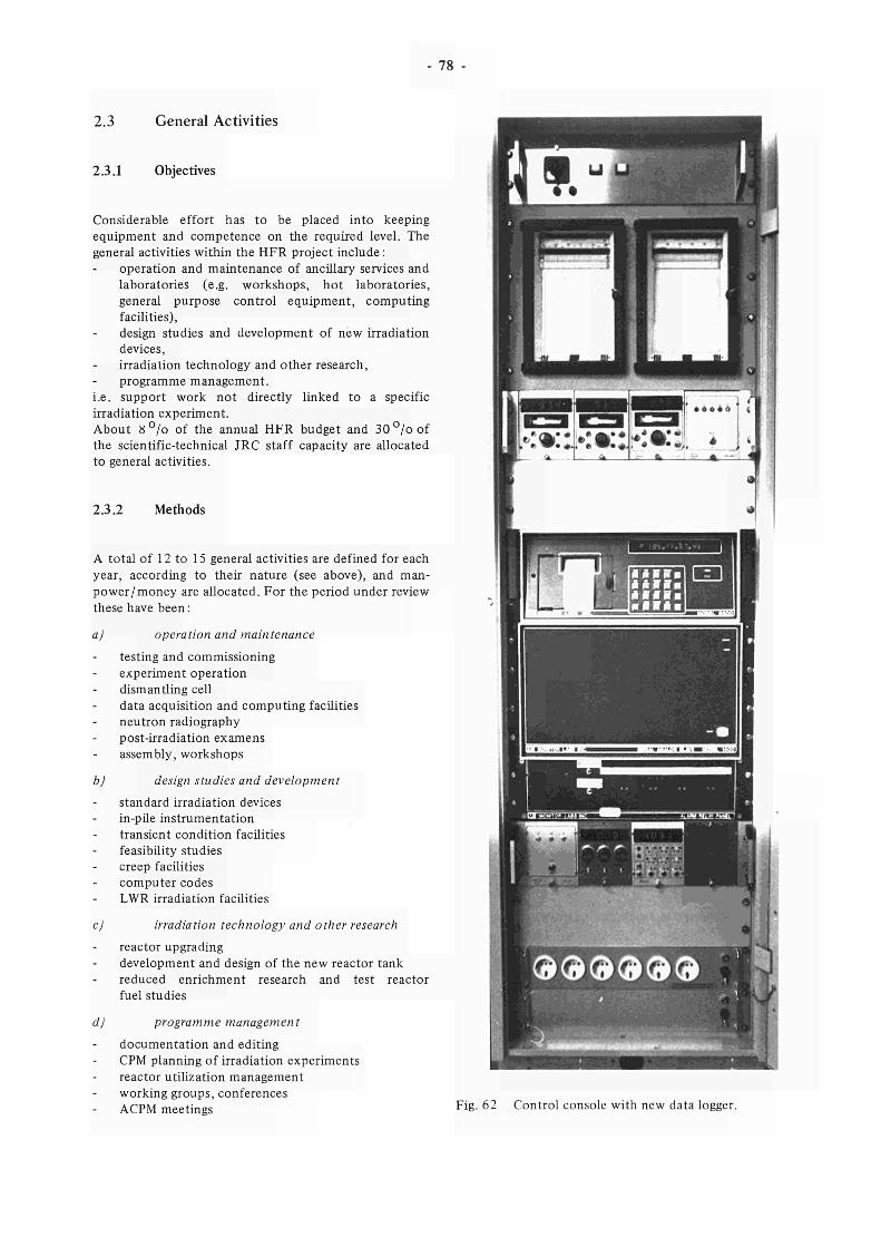
78
2.3 General Activities
2.3.1 Objectives
Considerable effort has to be placed into keeping equipment and competence on the required level. The general activities within the HFR project include :
operation and maintenance of ancillary services and laboratories (e.g. workshops, hot laboratories, general purpose control equipment, computing facilities), design studies and development of new irradiation devices, irradiation technology and other research, programme management,
i.e. support work not directly linked to a specific irradiation experiment. About 8 ° /o of the annual HFR budget and 3 0 ° / o o f the scientific-technical JRC staff capacity are allocated to general activities.
2.3.2 Methods
A total of 12 to 15 general activities are defined for each year, according to their nature (see above), and manpower/money are allocated. For the period under review these have been :
a) operation and maintenance
testing and commissioning experiment operation dismantling cell data acquisition and computing faculties neutron radiography post-irradiation examens assembly, workshops
b) design studies and development standard irradiation devices in-pile instrumentation transient condition facilities feasibility studies creep facilities computer codes LWR irradiation facilities
c) irradiation technology and other research reactor upgrading development and design of the new reactor tank reduced enrichment research and test reactor fuel studies
d) programme management
documentation and editing CPM planning of irradiation experiments reactor utilization management working groups, conferences ACPM meetings Fig. 62 Control console with new data logger.
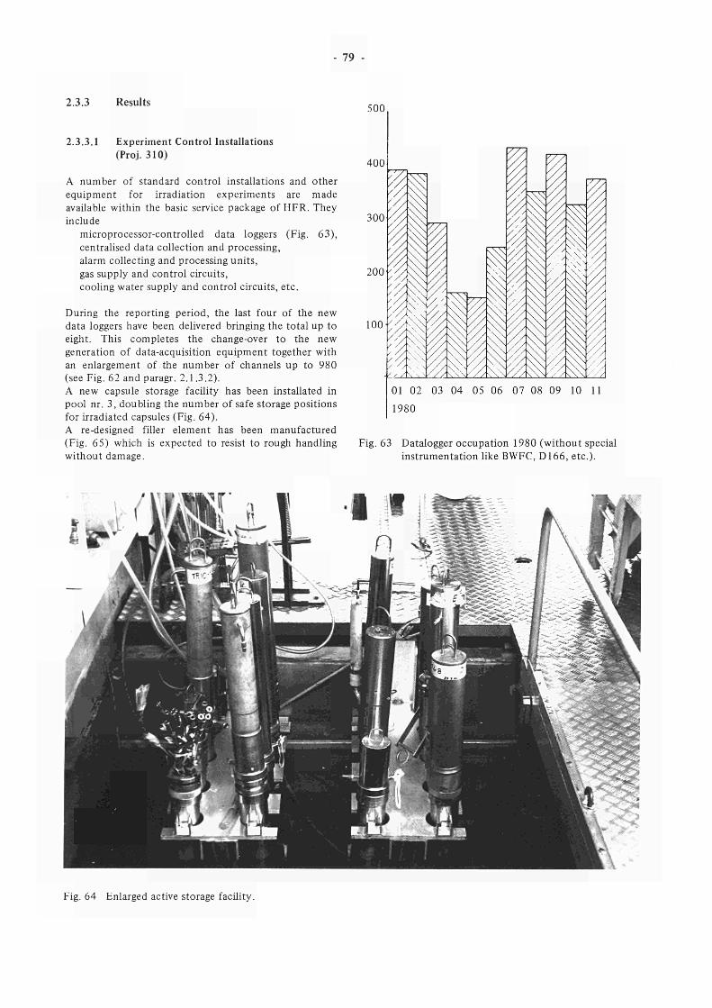
79
2.3.3 Results
2.3.3.1 Experiment Control Installations (Proj. 310)
A number of standard control installations and other equipment for irradiation experiments are made available within the basic service package of HFR. They include
microprocessor-controlled data loggers (Fig. 63), centralised data collection and processing, alarm collecting and processing units, gas supply and control circuits, cooling water supply and control circuits, etc.
During the reporting period, the last four of the new data loggers have been delivered bringing the total up to eight. This completes the change-over to the new generation of data-acquisition equipment together with an enlargement of the number of channels up to 980 (see Fig. 62 and paragr. 2.1.3.2). A new capsule storage facility has been installated in pool nr. 3, doubling the number of safe storage positions for irradiated capsules (Fig. 64). A re-designed filler element has been manufactured (Fig. 65) which is expected to resist to rough handling without damage.
500
400
300
200
100
01 02 03 04 05 06 07 08 09 10 1
1980
Fig. 63 Datalogger occupation 1980 (without special instrumentation like BWFC, D166, etc.).
Fig. 64 Enlarged active storage facility.
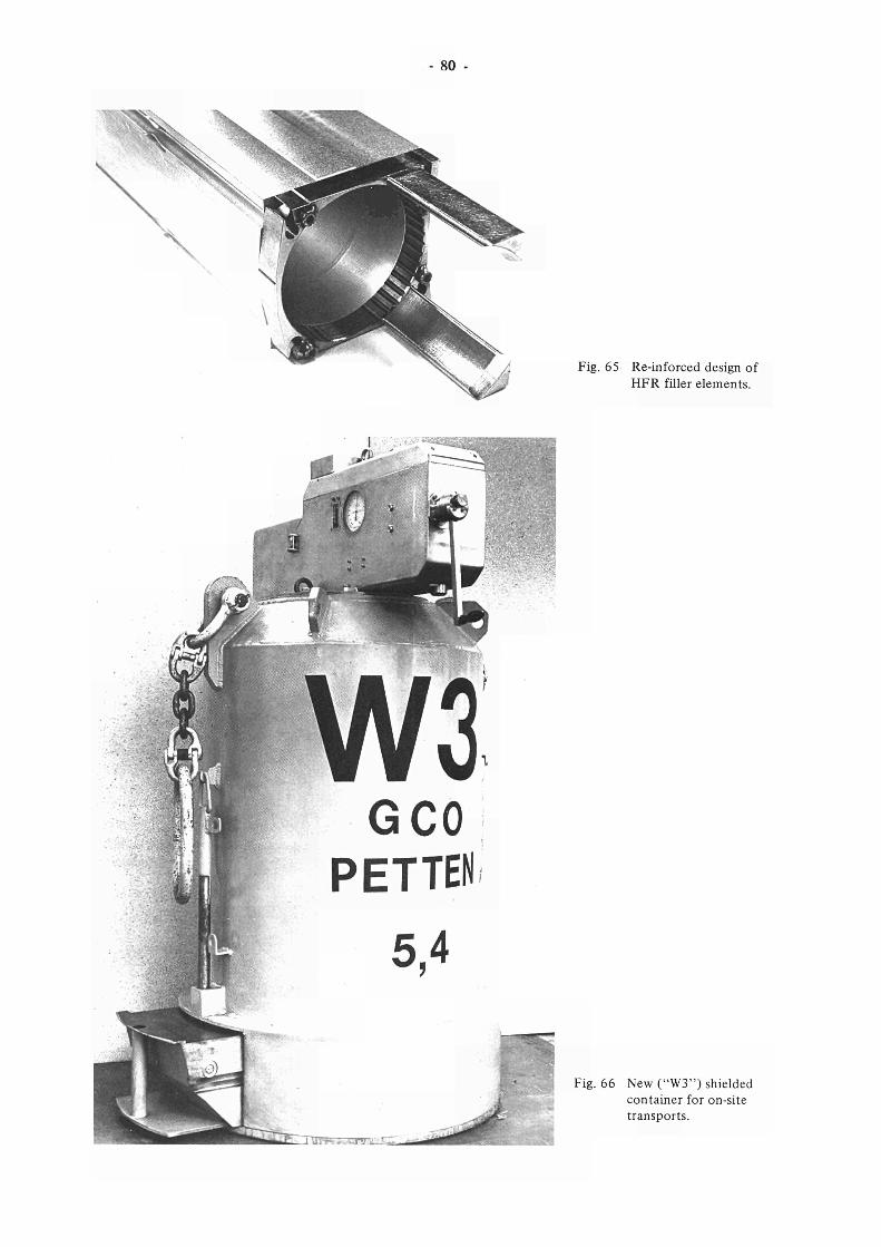
80 -
Fig. 65 Re-inforced design of HFR filler elements.
GCO PETTEN
Fig. 66 New ("W3") shielded container for on-site transports.
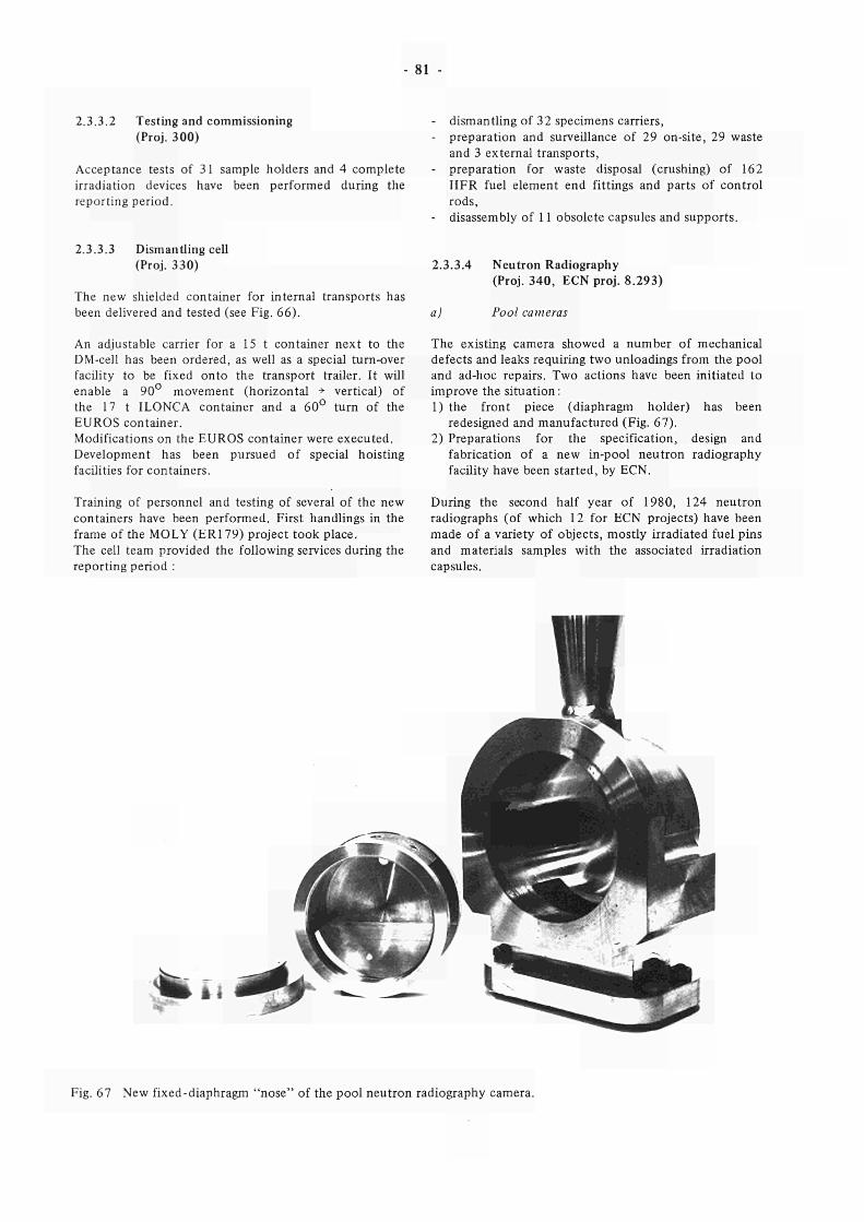
81
2.3.3.2 Testing and commissioning (Proj. 300)
Acceptance tests of 31 sample holders and 4 complete irradiation devices have been performed during the reporting period.
dismantling of 32 specimens carriers, preparation and surveillance of 29 on-site, 29 waste and 3 external transports, preparation for waste disposal (crushing) of 162 HFR fuel element end fittings and parts of control rods, disassembly of 11 obsolete capsules and supports.
2.3.3.3 Dismantling cell (Proj. 330)
The new shielded container for internal transports has been delivered and tested (see Fig. 66).
An adjustable carrier for a 15 t container next to the DM-cell has been ordered, as well as a special turn-over facility to be fixed onto the transport trailer. It will enable a 90° movement (horizontal + vertical) of the 17 t ILONCA container and a 60° turn of the EUROS container. Modifications on the EUROS container were executed. Development has been pursued of special hoisting facilities for containers.
2.3.3.4 Neutron Radiography (Proj. 340, ECN proj. 8.293)
a) Pool cameras
The existing camera showed a number of mechanical defects and leaks requiring two unloadings from the pool and ad-hoc repairs. Two actions have been initiated to improve the situation : 1) the front piece (diaphragm holder) has been
redesigned and manufactured (Fig. 67). 2) Preparations for the specification, design and
fabrication of a new in-pool neutron radiography facility have been started, by ECN.
Training of personnel and testing of several of the new containers have been performed. First handlings in the frame of the MOLY (ERI 79) project took place. The cell team provided the following services during the reporting period :
During the second half year of 1980, 124 neutron radiographs (of which 12 for ECN projects) have been made of a variety of objects, mostly irradiated fuel pins and materials samples with the associated irradiation capsules.
."Ikí.
Fig. 67 New fixed-diaphragm "nose" of the pool neutron radiography camera.
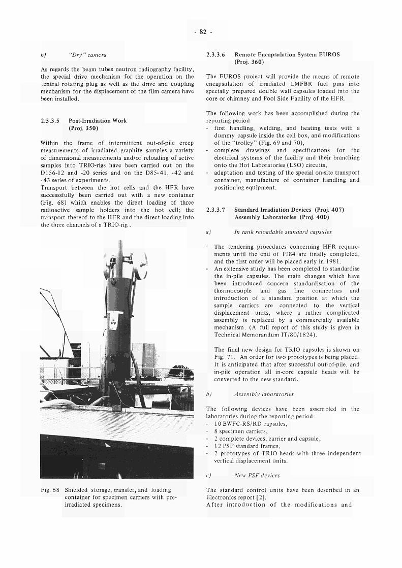
- 82
b) "Dry" camera
As regards the beam tubes neutron radiography facility, the special drive mechanism for the operation on the ,entrai rotating plug as well as the drive and coupling mechanism for the displacement of the film camera have been installed.
2.3.3.5 Post-Irradiation Work (Proj. 350)
Within the frame of intermittent out-of-pile creep measurements of irradiated graphite samples a variety of dimensional measurements and/or reloading of active samples into TRIO-rigs have been carried out on the D156-12 and -20 series and on the D85-41, -42 and -43 series of experiments. Transport between the hot cells and the HFR have successsfully been carried out with a new container (Fig. 68) which enables the direct loading of three radioactive sample holders into the hot cell; the transport thereof to the HFR and the direct loading into the three channels of a TRIO-rig .
2.3.3.6 Remote Encapsulation System EUROS (Proj. 360)
The EUROS project will provide the means of remote encapsulation of irradiated LMFBR fuel pins into specially prepared double wall capsules loaded into the core or chimney and Pool Side Facility of the HFR.
The following work has been accomplished during the reporting period - first handling, welding, and heating tests with a
dummy capsule inside the cell box, and modifications of the "trolley" (Fig. 69 and 70),
- complete drawings and specifications for the electrical systems of the facility and their branching onto the Hot Laboratories (LSO) circuits,
- adaptation and testing of the special on-site transport container, manufacture of container handling and positioning equipment.
2.3.3.7 Standard Irradiation Devices (Proj. 407) Assembly Laboratories (Proj. 400)
a) In tank reloadable standard capsules
- The tendering procedures concerning HFR requirements until the end of 1984 are finally completed, and the first order will be placed early in 1981.
- An extensive study has been completed to standardise the in-pile capsules. The main changes which have been introduced concern standardisation of the thermocouple and gas line connectors and introduction of a standard position at which the sample carriers are connected to the vertical displacement units, where a rather complicated assembly is replaced by a commercially available mechanism. (A full report of this study is given in Technical Memorandum IT/80/1824).
The final new design for TRIO capsules is shown on Fig. 71. An order for two prototypes is being placed. It is anticipated that after successful out-of-pile, and in-pile operation all in-core capsule heads will be converted to the new standard.
b) Assembly laboratories
The following devices have been assembled in the laboratories during the reporting period : - 10 BWFC-RS/RD capsules, - 8 specimen carriers, - 2 complete devices, carrier and capsule, - 12 PSF standard frames, - 2 prototypes of TRIO heads with three independent
vertical displacement units.
c) New PSF devices
Fig. 68 Shielded storage, transfer, and loading container for specimen carriers with pre-irradiated specimens.
The standard control units have been described in an Electronics report [2]. After in t roduc t ion of the modif icat ions and
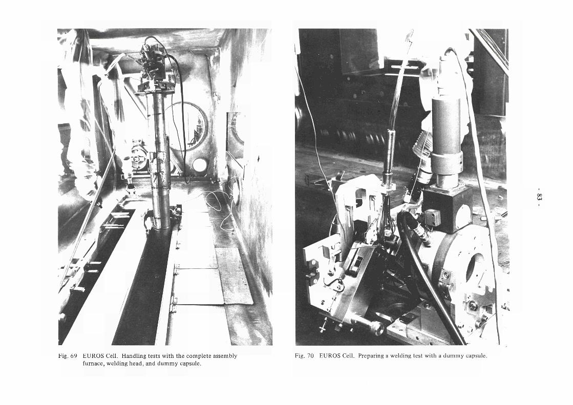
00
Fig. 69 EUROS Cell. Handling tests with the complete assembly furnace, welding head, and dummy capsule.
Fig. 70 EUROS Cell. Preparing a welding test with a dummy capsule.

00 4*.
«41 χ
S c . H l r r Δ- ί . ■ - - L - =- S^HH.IT 3-W
Fig. 71 New TRIO capsule head with three independent vertical displacement mechanisms using commercially available units.
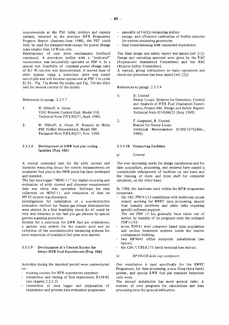
85 -
improvements at the PSF table, trolleys and capsule carriers, reported in the previous HFR Programme Progress Report (January-June 1980), the PSF could fully be used for transient tests except for power change rates smaller than 10 W/cm.min. Development of new drive mechanisms (trolleys) continued. A prototype trolley with a "push-pull" transmission was successfully operated an PSF 4. In a special test, feasibility of constant power change rates of 0,1 W/cm.min was demonstrated. A second type of drive system using a screw/nut drive was tested out-of-pile and will become operational at PSF 5 in cycle 81.01. Fig. 72a shows the trolley and Fig. 72b the drive unit for remote control of the trolley.
- assembly of Ge(Li) measuring station - energy- and efficiency calibration of Ge(Li) detector
for various measuring geometries - final commissioning with connected experiment.
The final design and safety report was issued (ref. [1]). Design and operating approval were given by the EAC (Experiment Assessment Committee) and the RSC (Reactor Safety Committee). A manual, giving instructions on basic operations and check-out procedure has been issued (ref. [2]).
References to paragr. 2.3.3.9
References to paragr. 2.3.3.7
1. W. Olthoff, A. Grosz VDU Remote Control Unit, Model 310. Technical Note P/Fl /80/31 , Sept. 1980.
2. W. Olthoff, A. Grosz, F. Roserot de Melin PSF Trolley Stuureenheid, Model 308. Technical Note P/Fl/80/37, Nov. 1980.
1. R. Conrad Sweep Loops. Systems for Operation, Control and Analysis of HTR Fuel Irradiation Experiments, Project 406. Design and Safety Report. Technical Note P/10/80/23 (July 1980)
F. Gasperini, R. Conrad Manual for Sweep Loops Technical Memorandum 1980).
IT/80/1679,(Dec,
2.3.3.8 Development of LWR fuel pins testing facilities (Proj. 405)
2.3.3.10 Computing Facilities
a) General
A central command unit for the eddy current and diameter measuring device for remote measurements on irradiated fuel pins in the HFR pools has been developed and installed. The fast data logger "MINC-11" for digital recording and evaluation of eddy current and diameter measurement data was taken into operation. Software for data collection on MINC-11, and evaluation of data on HP 45-system was developed. Investigations for installation of a non-destructive evaluation method for fission gas release determination were started. In a first feasibility check Kr-85 could be very well detected in the fuel pin gas plenum by special gamma scanning procedure. Studies for a mini-loop for LWR fuel pin irradiations, a gamma scan system for the reactor pool and an extension of the non-destructive measuring systems for pool inspection of irradiated fuel pins were started.
2.3.3.9 Development of a Control System for Swept HTR Fuel Experiments (Proj. 406)
The ever increasing needs for design calculations and for data acquisition, processing, and retrieval have caused a considerable enlargement of facilities on one hand and the training of more and more staff for computer operation, on the other hand.
In 1980, the hardware used within the HFR programme comprised : - the JRC PDP 11/15 installation with multi-user access
mainly working for BWFC data processing, special heat transfer problems and other tasks requiring specific software support. The old PDP 15 has gradually been taken out of service by transfer of its programs onto the enlarged PDP 11/34.
- seven PDP 11 mini computer based data acquisition and on-line treatment systems inside the reactor containment building.
- two HP9845 office computer installations (see below),
- the CDC CYBER 175 batch terminal (see below).
b) HP9845B desk top computers
Activities during the reported period were concentrated on : - training courses for HFR experiment operators - connection and testing of first experiment, E138-02
(see chapter 2.2.3.2) - connection of data logger and preparation of
experiment and process data evaluation programme
One installation is used specifically for the BWFC Programme, for data processing, a new filing (data bank) system, and special LWR fuel pin transient behaviour code work. The second installation has more general tasks. A number of own programs for calculations and data processing exist for general utilization.
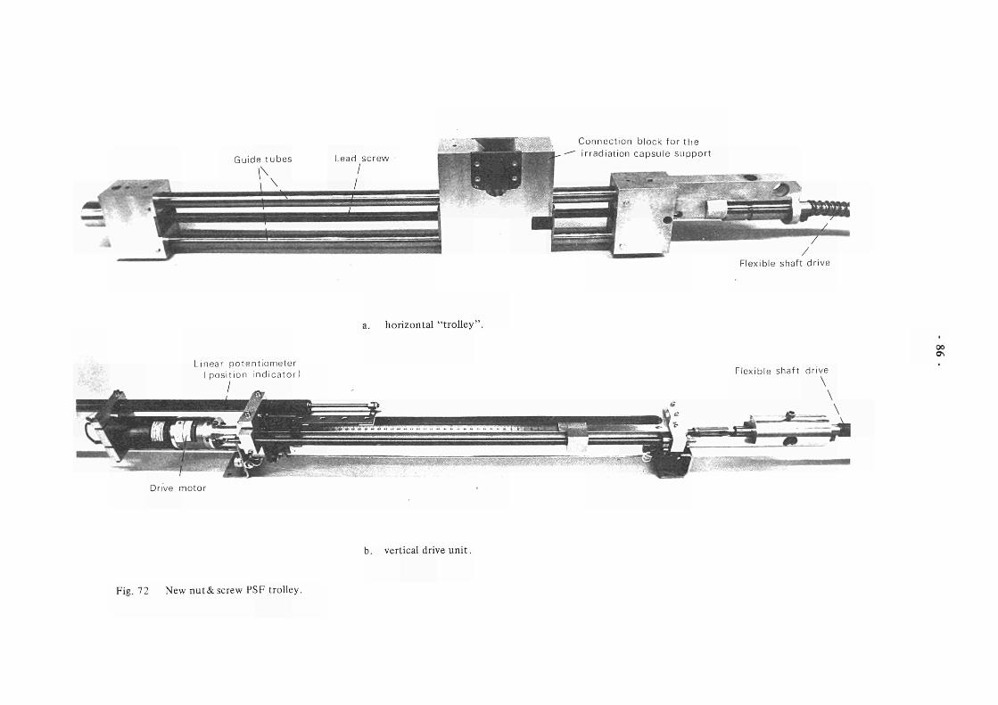
Guide t u b e s
Connec t i on block for t h e i r rad ia t i on capsu le s u p p o r t
Flexible shaft d r i ve
L inear p o t e n t i o m e t e r ( p o s i t i o n i n d i c a t o r
/
a. horizontal "trolley"
Drive mo to r
b. vertical drive unit.
Flexible shaf t d r ive \
oo
Fig. 72 New nut& screw PSF trolley.
87 -
During the reporting period, the following new developments have taken place :
Program: STRESS
Allows the stress analysis (thermal and pressure stress) in a cylindrical geometry (capsule and/or sample holder)
Subprograms for "GRAPHICS"
Consists in a set of 10 subprograms allowing plotting of linear and logarithmic as well as mixed coordinates These procedures save much time if a main program requires a plot on the thermal printer.
Improvement of program TEXPLO
In order to simplify the input instructions, this program was transformed into two different codes : TEXPLO allows the plotting of a text, and BUPLO allows the plotting of a set of blocks. The french and german characters were introduced.
A third HP9845 installation has been ordered by the middle of December 1980.
c) CYBER Batch terminal
The provided facilities include : - line printer 300 lines/min. - card reader 300 cards/min. - paper tape reader 500 characters/sec. - flexible disc drive 253 k bytes - control V.D.U., which selects the input and output
devices required and can also be used interactively with the main frame,
- four satellite V.D.U.'s, which are connected to the batch terminal on four separate circuits through a multi-plexer.
A total of 33 V.D.U. connections are provided for HFR Division personnel in their offices, so that the provided services can be used remotely.
The ready access now obtainable to the main frame, has improved capacity to such an extent that waiting time for terminal usage is obviated.
A PERT type critical path program ("PLANIT") has been implemented, which regularised all the HFR experiments, from inception to dismantling and reporting on completion. As an indication of main frame usage during the reported six month period, over 50.000 central processor seconds were used, and stored information required over 45.000 record block days.
2.3.3.11 Project Management
- Planning
The HFR planning meeting was held twice and two editions of the loading chart (nos. 42 and 43) were issued. The working group of timing schedule and practical aspects for the post-irradiation phase of experiments met twice.
- Documentation
The 14th Newsletter of the "Euratom Working Group on Reactor Dosimetry" was assembled and issued.
A revised edition of the "Handbook of Materials Testing Reactors and Ancillary Hot Laboratories in theEuropean Communities" (EUR 5369, 1977) is under preparation.
The edition 1981/82 of the report "HFR Petten Characteristics of Facilities and Standard Irradiation Devices" (EUR 5700e) is being assembled.
- EWGRD
A first meeting of the EWGRD program committee for the preparation of the 4th ASTM-Euratom Symposium on Reactor Dosimetry, now scheduled for 22/26 March, 1982, at NBS (National Bureau of Standards), Washington, D.C., was held on 6/7 October 1980 at CEA-CEN Grenoble. The subgroup "Irradiation Damage" met on 7 October 1980, also in Grenoble.
- IDWG
The 26th plenary meeting of the Group was held on 8/10 October 1980 at the GKSS Research Centre (F.R. Germany). The interest in the meeting was high and 37 papers were presented to 80 delegates. JRC Petten contributed six papers.
- NRWG
The organization of an international topical -fneeting on neutron radiography has been started, in collaboration with the societies for non-destructive testing of the USA, France, F.R. Germany and the United Kingdom The conference will take place in San Diego, CA, USA, on December 7 - 10, 1981.
- ACPM
The Advisory Committee on Programme Management met in Petten on November 7, 1980. It reviewed status and progress of the HFR Programme on the basis of 10 documents prepared by JRC Petten.
- 88
2.3.3.12 Irradiation Technology Support and Development (ECN)
- In-pile crack-growth measurements
A technical feasibility study has been initiated for the development of an in-core irradiation facility for the on-line measurement of crack-growth during fatigue testing of metal samples. Discussions have been held with the ECN Materials Department in order to specify desired test condition characteristics and possible measuring and control methods and with manufacturers of fatigue-testing equipment on the possibility to adapt their equipment for under-water application within a very confined space. In the first stage of the project, a facility for in-core fatigue testing will be designed. Crack growth measurement feasibility will be taken up at a later stage.
- Heat pipes
A working plan for the development of a heat-pipe controlled irradiation facility has been submitted. Though preliminary technical assessment and thermodynamic calculations seem to support the contention that a heat-pipe facility will be superior in temperature distribution and control characteristics compared to a conventional mixgas-controlled facility, these advantages do not - at present - outweigh the technical and economical uncertainties of the further development of such a facility. Considering that the presently available facility reasonably satisfies experimental requirements it was decided not to pursue the heat-pipe project.
- Thermocouples
During the reporting period 350 mineral-insulated metal sheathed thermocouples have been welded and tested for a variety of in-core and other projects. A new commercial fluidized-bath furnace was
investigated for its applicability as an accurate calibration device. In spite of encouraging results, some improvement in stability turned out to be necessary. Therefore, a design has been drafted for a new and improved fluidized-bath furnace, in which thermocouple calibration can be performed with improved efficiency.
- Na melting in TOP facility
An investigation has been carried out with respect to melting behaviour of the sodium at the bottom of the sodium containment in the TOP capsule. This pocket contains the magnetic core of the fuel clad displacement transducer. For a proper operation of the TOP capsule it is necessary that the sodium between the magnetic core and the pocket wall could be brought into a molten phase by means of the trace heating elements only. In a test facility (Fig. 73) simulating the capsule part under consideration, several configurations have been investigated. The experiments led to the conclusion that the original design had too little resistance between sodium pocket and heat sink to achieve sodium melting by trace heating only. An alternative design has been proposed.
- AUGIAS, Automatic gasmixing system for irradiation experiments
A proposal has been written for a gasmixing system which supplies desired gasmixtures to each irradiation experiment. Making the gasmixture and supply to the capsule and any following changing of the gasmixture are done automatically. In this proposal it is also discussed where t.ie mixing has to be done: outside the irradiation facility or in the capsule itself. If the mixing is done in the capsule itself, both gases are continuously flowing to the capsule. This method of temperature control is used in Harwell with good results.
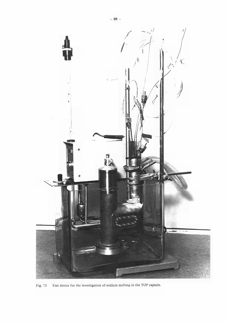
89 -
Fig. 73 Test device for the investigation of sodium melting in the TOP capsule.


Conclusions

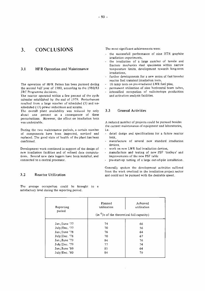
93 -
3.1
CONCLUSIONS
HFR Operation and Maintenance
The operation of HFR Petten has been pursued during the second half year of 1980, according to the 1980/83 JRC Programme decisions. The reactor operated within a few percent of the cycle calendar established by the end of 1979. Perturbances resulted from a large number of scheduled (5) and unscheduled (13) power reductions and scrams. The overall plant availability was reduced by only about one percent as a consequence of these perturbations. However, the effect on irradiation tests was undesirable.
During the two maintenance periods, a certain number of components have been inspected, serviced and replaced. The good state of health of the plant has been confirmed.
Development work continued in support of the design of new irradiation faculties and of refined data computations. Several new data loggers have been installed, and connected to a central processor.
The most significant achievements were: - the successfull performance of nine HTR graphite
irradiation experiments, - the irradiation of a large number of tensile and
fracture mechanics steel specimens within narrow temperature limits, development towards long-term irradiations,
- further developments for a new series of fast breeder reactor fuel transient irradiation tests,
- 18 ramp tests on pre-irradiated LWR fuel pins, - permanent utilisation of nine horizontal beam tubes, - intensified occupation of radioisotope production
and activation analysis facilities.
3.3 General Activities
A reduced number of projects could be pursued besides the current maintenance of equipment and laboratories, i.e. - detail design and specifications for a future reactor
tank, - manufacture of several new standard irradiation
devices, - work on new LWR fuel irradiation devices, - manufacture and testing of new PSF 'trolleys' and
improvements of the new PSF table - pre-start-up testing of a large out-of-pile installation.
3.2 Reactor Utilization
Generally spoken the development activities suffered from the work overload in the irradiation project sector and could not be pursued with the desirable speed.
The average occupation could be brought to a satisfactory level during the reporting period.
Reporting period
Jan./June '77 July/Dec. '77 Jan./June '78 July/Dec. '78 Jan./June '79 July/Dec. '79 Jan./June '80 July/Dec. '80
Planned utilization
Achieved utilization
(in /o of the theoretical full capacity)
74 70 76 70 84 77 85 84
66 56 64 67 76 74 64 79
- 94 -
4. JRC PUBLICATIONS HFR Programme, July - December 1980
Programme Progress Report HFR, Jan. - June 1980. P. von der Hardt COM 3839
Newsletter on Reactor Radiation Metrology, Nr. 14, November 1980. H. Röttger (Ed.)
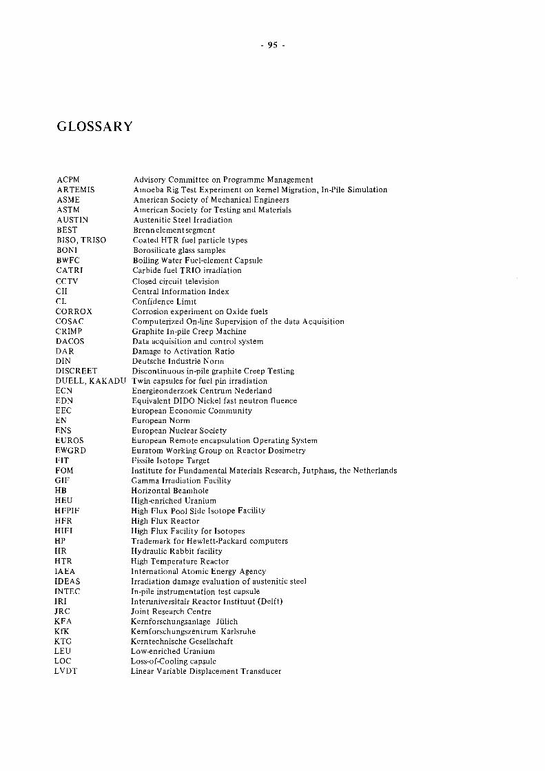
- 95 -
GLOSSARY
ACPM ARTEMIS ASME ASTM AUSTIN BEST BISO, TRISO BONI BWFC CATRI CCTV CII CL CORROX COSAC CRIMP DACOS DAR DIN DISCREET DUELL, KAKADU ECN EDN EEC EN ENS EUROS EWGRD FIT FOM GIF IIB HEU HFPIF HFR HIFI HP HR HTR IAEA IDEAS INTEC IRI JRC KFA KfK KTG LEU LOC LVDT
Advisory Committee on Programme Management Amoeba Rig Test Experiment on kernel Migration, In-Pile Simulation American Society of Mechanical Engineers American Society for Testing and Materials Austenitic Steel Irradiation Brenn element segment Coated HTR fuel particle types Borosilicate glass samples Boiling Water Fuel-element Capsule Carbide fuel TRIO irradiation Closed circuit television Central Information Index Confidence Limit Corrosion experiment on Oxide fuels Computerized On-line Supervision of the data Acquisition Graphite In-pile Creep Machine Data acquisition and control system Damage to Activation Ratio Deutsche Industrie Norm Discontinuous in-pile graphite Creep Testing Twin capsules for fuel pin irradiation Energieonderzoek Centrum Nederland Equivalent DIDO Nickel fast neutron fluence European Economic Community European Norm European Nuclear Society European Remote encapsulation Operating System Euratom Working Group on Reactor Dosimetry Fissile Isotope Target Institute for Fundamental Materials Research, Jutphaas, the Netherlands Gamma Irradiation Faculty Horizontal Beamhole High-enriched Uranium High Flux Pool Side Isotope Faculty High Flux Reactor High Flux Facility for Isotopes Trademark for Hewlett-Packard computers Hydraulic Rabbit facility High Temperature Reactor International Atomic Energy Agency Irradiation damage evaluation of austenitic steel In-pile instrumentation test capsule Interuniversitair Reactor Instituut (Delft) Joint Research Centre Kernforschungsanlage Jülich Kernforschungszentrum Karlsruhe Kerntechnische Gesellschaft Low-enriched Uranium Loss-of-Cooling capsule Linear Variable Displacement Transducer
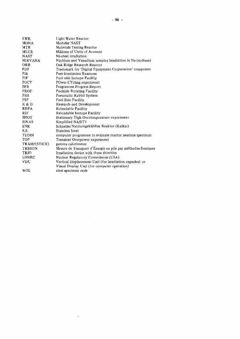
96 -
LWR MONA MTR MUCE NAST NIRVANA ORR PDP PIE PIF POCY PPR PROF PRS PSF R & D REFA RIF SHOT SINAS SNR S.S. TEDDI TOP TRAMP(STICK) TRESON TRIO USNRC VDU
WOL
Light Water Reactor Modular NAST Materials Testing Reactor Millions of Units of Account Na-steel irradiation Niobium and Vanadium samples irradiation in Na (sodium) Oak Ridge Research Reactor Trademark for 'Digital Equipment Corporation' computers Post-Irradiation Examens Pool side Isotope Facility POwer CYcling experiment Programme Progress Report Poolside Rotating Facility Pneumatic Rabbit System Pool Side Facility Research and Development Reloadable Facility Reloadable Isotope Facility Stationary High Overtemperature experiment Simplified NAS(T) Schneller Natriumgekühlter Reaktor (Kalkar) Stainless Steel computer programme to evaluate reactor neutron spectrum Transient Overpower experiment gamma calorimeter Mesure de Transport d'Energie en pile par méthodes Soniques Irradiation device with three thimbles Nuclear Regulatory Commission (USA) Vertical Displacement Unit (for irradiation capsules) or Visual Display Unit (for computer operation) steel specimen code
LIST OF AUTHORS
97
Programme manager :
Contributors JRC :
P. VON DER HARDT
R. CONRAD M. CUNDY F. GENET K. HUSMANN C. JEHENSON R.JOCKSCHAT J. KONRAD
R. LO LG EN J. MARKGRAF F. MASON H. RÖTTGER H. SCHEURER P. ZEISSER
Contributors ECN .
Editor : R. SWANENBURG DE VEYE
HFR Operation and Maintenance J. VE EN EMA J. AAN DE WIEL A. LAST
G. LU ¡F R. VAN DE POL G. OLTHOF
Nuclear Support and Development A. TAS H. PRUIM BOOM E. MERELLE W. ZIJP N. VAN DE BORG H. RIEFFE
F. DEKKER G. TEUNISSEN J. A AL DIJK H. NOLTHENIUS H. VAN DE WER VE W. VAN WITZENBURG
Irradiation Technology (ECN)
Reactor Utilization (ECN Projects)
W. STAM K. VAN OTTERDIJ K
D. VADER TH. VA N DER KA A J. VISSER
W. KLERKS G. VAN DE KOOGH A. NO LT E N
Neutron Radiography : H. LEEFLANG


CDNA08224ENC