Comparing effective-one-body gravitational waveforms to accurate numerical data
Upload
khangminh22Category
view
0download
0
�����������������
Citation: Song, Y.; Wang, Y.; Xie, J.;
Yang, Y.; Tian, B.; Xu, S. Ultra-Low
Sidelobe Waveforms Design for LPI
Radar Based on Joint Complementary
Phase-Coding and Optimized
Discrete Frequency-Coding. Remote
Sens. 2022, 14, 2592. https://doi.org/
10.3390/rs14112592
Academic Editor: Lorenzo Capineri
Received: 23 April 2022
Accepted: 25 May 2022
Published: 28 May 2022
Publisher’s Note: MDPI stays neutral
with regard to jurisdictional claims in
published maps and institutional affil-
iations.
Copyright: © 2022 by the authors.
Licensee MDPI, Basel, Switzerland.
This article is an open access article
distributed under the terms and
conditions of the Creative Commons
Attribution (CC BY) license (https://
creativecommons.org/licenses/by/
4.0/).
remote sensing
Article
Ultra-Low Sidelobe Waveforms Design for LPI Radar Based onJoint Complementary Phase-Coding and Optimized DiscreteFrequency-Coding
Yuxiao Song 1,2 , Yu Wang 1,2,, Jingyang Xie 1,2,, Yiming Yang 1,2,, Biao Tian 1,2,* and Shiyou Xu 1,2
1 School of Electronics and Communication Engineering, Shenzhen Campus, Sun Yat-sen University ,Shenzhen 518107, China; [email protected] (Y.S.); [email protected] (Y.W.);[email protected] (J.X.); [email protected] (Y.Y.); [email protected] (S.X.)
2 School of Electronics and Communication Engineering, Sun Yat-sen University , Guangzhou 510275, China* Correspondence: [email protected]
Abstract: In this paper, in order to reduce the probability of the radar waveform intercepted bythe passive detection system, the time-bandwidth product of the radar waveform is increased, andthe detection probability of the radar waveform to the target is improved. This paper tackles theholographic RF stealth radar and proposes a joint coding waveform based on the linear frequencymodulation (LFM) waveform. Joint coding uses complementary codes to perform phase-coding, andcombines the codewords optimized by genetic algorithm in order to perform discrete frequency-coding waveform. The joint coding waveform model is theoretically analyzed, and the ambiguityfunction, pulse compression and target detection probability of the joint coding waveform are ob-tained by numerical simulation. In addition, the complexity of the algorithm and the low probabilityof intercept (LPI) characteristic of the joint coding waveform are analyzed. The results show thatthe joint coding waveform has an approximate “pushpin” ambiguity function, ultra-low sidelobecharacteristics, better RF stealth and target detection performance. Finally, it has good applicationprospects in the current battlefield environment.
Keywords: RF stealth; joint coded waveform; ambiguity function; pulse compression; ultra-lowsidelobe
1. Introduction
As a kind of radio detection equipment, radar has the advantages of all-weather,all-time and robust penetration ability. It plays a crucial role in war, disaster relief and civiluse [1,2]. It faces an unprecedented substantial threat in modern warfare dominated byscience and technology. The rapid development of high-sensitivity radar signal interceptiontechnologies puts most of the radars at risk of being exposed when they are turned on,which increases the probability of combat mission failure. Therefore, quickly obtainingbattlefield intelligence while reducing the probability of a radar being recognized andintercepted, is a problem that should be urgently solved [3].
In order to reduce the risk of radar signals being detected by interceptors and gainthe initiative on the battlefield, the RF stealth technology has been developed in recentyears [4]. The stealth aims at keeping the enemy in an environment of constant guessing,making it challenging to decipher its active feature information or submerging its informa-tion in a noisy environment. In addition, it cannot be efficiently accumulated for a long time.The method of active feature reduction is referred to as Low Probability of Intercept (LPI)technology [5]. In order to improve the LPI performance of radar, the primary processes atthis stage are the complex radar waveform design and radar peak power control [6].
The radar waveform theory is an essential branch of radar theory. The radar waveformdirectly or indirectly determines the radar’s primary performance and signal processingmethod [7,8]. With the increasing complexity of the current battlefield environment, the
Remote Sens. 2022, 14, 2592. https://doi.org/10.3390/rs14112592 https://www.mdpi.com/journal/remotesensing

Remote Sens. 2022, 14, 2592 2 of 20
radar LPI waveform design has become a meaningful approach to optimize the radarperformance in a radar system. Sun and Lu [9] study the characteristics of UWB signals andrandom signals. They combine the two to propose a UWB random mixed-signal, whichimproves the performance of radar detection and parameter estimation. Witte, E.D. [10]studies the waveform of the ultra-low sidelobes radar signal. The nonlinear frequencymodulated signal has −70 dB sidelobes. However, it is very sensitive to Doppler shift.Dietl G [11] studies a hybrid waveform design method based on the beamforming andspace-time block coding of the dual-channel model. He also compares and analyzes thesignal-to-noise ratio of optimal linear precoding and orthogonal space-time block coding.Kassab R [12] proposes the ambiguity function and signal waveform design algorithm ofquasi-continuous wave radar, which can better solve the shadowing problem of the echosignal of quasi-continuous wave radar. Geroleo F G and Brandt-Pearce M [13] study the LPIperformance of Linear Frequency Modulation (LFM) continuous wave radar signals. Thesoftware degree is low because the traditional radar transmits waveform mode integratedinto its system. In addition, the conventional radar transmits waveform mode integratedinto its design, and the transmit wave technology is relatively single under the existingtechnology. In fact, it is challenging to use frequency-coding or phase-coding waveforms toachieve waveform agility. When the radar transmits large time-bandwidth products, theLPI waveforms become very difficult. They are more likely to intercept the enemy receiversby simple pulse compression, limiting our own radar’s LPI performance.
At present, the radar mainly transmits the LFM waveform, and it is one of the earliestand most widely used LPI pulse compression signals [14]. However, the LFM waveform canobtain a large time-bandwidth product using the pulse compression technology, making thematched filter insensitive to the Doppler frequency shift of the echo signal. A disadvantageis that the output response generates an additional delay proportional to the Dopplershift [15]. Compared with the LFM waveform, the coding waveform is used to improve thesymbol diversity of the modulated carrier frequency signal. The anti-interference ability ofthe phase-coding signal is relatively strong. However, the phase-coding signal is quicklylimited by the width of the sub pulse symbols [16,17]. The simple frequency-coded wave-forms, such as stepped frequency waveforms, have larger equivalent bandwidths. However,compared with the discrete frequency coded waveforms, their spectral modulation lawsare relatively simple, and easily detected by interceptors [18]. The joint modulation wave-form refers to the combined signal waveform modulation using two or more modulationmethods [19]. Hou [20] analyzes the self-ambiguity and mutual-ambiguity functions ofthe hyperbolic frequency hopping-Barker code radar signal. He also verifies the LPI ofthe signal by simulation. The authors in [21,22] study the mixed modulation radar signalbased on linear frequency modulation and Taylor four phase-coding. They analyze thesignal’s range resolution, velocity resolution and LPI performance. In addition, they designan LPI signal with a “pushpin” ambiguity function. Yang [23] proposes a method of mixedmodulation radar signal based on tangent frequency modulation and bi-phase Barker code,while suppressing the spectral sidelobes of the signal. The authors in [24–26] design anew Frequency Shift Keying (FSK)/Phase Shift Keying (PSK) mixed-signal for the highresolution, large time-bandwidth product, anti-interference and low interception of FSKsignal and PSK signal. The simulation results show that the signal has high range andvelocity resolution, as well as a high measurement performance. Compared with a singleFSK signal or PSK signal, its LPI is significantly improved. However, this study uses arelatively mature method to modulate the transmitted waveform. The waveform codingmethod is easy to be deciphered by the intercepting receiver. The advantage of the jointcoding waveform is that it can obtain a large time-bandwidth product. In addition, ithas the characteristics of single modulation between signal waveforms to complementeach other, which improves the distance and speed resolution of the signal waveforms.Moreover, the joint modulation waveform can improve the pseudo-randomness of thesignal, which significantly reduces the probability of the signal being monitored, identifiedand tracked by the intercepted receiver.

Remote Sens. 2022, 14, 2592 3 of 20
In this paper, a phase-frequency joint coding radar LPI waveform is designed usingthe characteristic of complete software of holographic radar [27]. Based on the LFMwaveform, a new LPI radar waveform with a large time-bandwidth product is formed,using complementary code for complementary phase-coding (CPC) and combined withdiscrete frequency-coding (DFC) optimized by the genetic algorithm (GA). The performanceof the waveform is then analyzed. The main contributions of this paper are summarizedas follows:
(1) Using the characteristics of complementary inter-code cancellation and zero autocorre-lation sidelobe, the phase-coding waveform is designed to increase the peak sideloberatio of the transmitted waveform. GA optimizes the DFC to form a new GADFCcodeword, which increases the orthogonality between the codewords and reduces theautocorrelation sidelobe level.
(2) A CPC-GADFC joint coding waveform based on LFM is designed. The joint codingwaveform can make up for the drawbacks of a single modulation waveform, andenhance the radar waveforms’ LPI and anti-interference abilities to ensure the radarrange and speed measuring resolution.
(3) Through the combination of CPC and GADFC, the echo pulse compression of theradar transmit waveform has the characteristics of ultra-low sidelobes, and the mainlobe width is narrower so that the designed waveform has more advantages in targetdetection.
The remainder of this paper is organized as follows. Section 2 introduces the algo-rithm model, which focuses on the phase encoding of the complementary code sequenceand the frequency encoding using the discrete frequency sequence optimized by the GA.Section 3 presents the CPC-GADFC joint coding waveform design, performance analysisand processing method analysis. The CPC-GADFC joint coding waveform expression isalso deduced, and the performance analysis and processing method design are performed.Section 4 details the simulation experiment which verifies the performance of the designedCPC-GADFC joint coding waveform based on LFM. Finally, the conclusions are drawn inSection 5.
2. Algorithm Model
Based on the LFM waveform, this paper designs a CPC-GADFC joint coding wave-form. In phase, the complementary code sequence is used for phase-coding, while infrequency, the discrete frequency sequence optimized by the GA is used for frequency-coding waveform. This section mainly introduces the complementary code phase-codingmodel and GA for DFC optimization.
2.1. Complementary Code Model
Golay and Erickson [28,29] propose a different technique, referred to as complementarycodes, in order to reduce the length of binary sequences of finite length. The complementarysequences are two sequences having the same length, with orthogonal autocorrelationsidelobe levels. When the autocorrelation functions of the two sequences are added, theirpeak level reaches the highest level, and the sidelobe level is zero.
The definition of complementary two-phase code is given by: there are two-phasesequences of length N, positive code cA and complement code cB, where the logarithmof the same element in positive code cA is equal to the logarithm of the same componentin complement code cB, then the positive sequence code cA and the complement codecB form a complementary code, and the length of the complementary code should meetN = 2r10s26t, where r, s and t are non-negative integers, and N should be the sum of thesquares of two integers. The aperiodic autocorrelation functions of positive code cA andcomplement code cB are respectively RcA(m) and RcB(m). If the following relationship issatisfied:

Remote Sens. 2022, 14, 2592 4 of 20
RcA(m) + RcB(m) =
{2N, m = 00, m 6= 0
, (1)
then cA and cB form a complementary code pair. The complementary codewords used inthis paper are:
cA(m) = [1, 1, 1, 1, 1,−1, 1,−1,−1,−1, 1, 1, 1,−1,−1,
1, 1, 1,−1,−1, 1,−1,−1, 1,−1,−1,−1,−1, 1,−1, 1,−1],
cB(m) = [−1,−1,−1,−1,−1, 1,−1, 1, 1, 1,−1,−1,−1,
1, 1,−1, 1, 1,−1,−1, 1,−1,−1, 1,−1,−1,−1,−1, 1,−1, 1,−1].
(2)
The complementary code’s autocorrelation function is determined (cf. Figure 1)according to Equation (1) and the codewords (2) used in this paper.
0 10 20 30 40Length
0
10
20
30
40
50
60
70
Am
plitu
de
Autocorrelation Function
Positive CodeComplement CodeThe Sum of Two Codes
Figure 1. Complementary Code Autocorrelation Function.
It can be seen from Figure 1 that the autocorrelation function of the cA and cBautocorrelation functions at 0 is 2N, which meets the construction requirements of comple-mentary codes.
The characteristics of complementary code have two sequences. In order to reduce theinfluence of the echo performance fluctuation caused by angular scintillation of the targeteffective reflection area, in a pulse group transmitted by radar, the pulse is transmitted byalternating phase modulation of positive code cA and complement code cB, as shown inFigure 2.
τt
cA cA cBcB
Figure 2. Pulse Alternate Transmission Mode.
It can be observed from Figure 2 that in a pulse group, the radar pulse alternatelytransmits the positive code cA phase modulation waveform and the complement code cBphase modulation waveform at a pulse repetition interval of τ. By alternately transmitting,

Remote Sens. 2022, 14, 2592 5 of 20
the echo pulse compresses the sidelobe level using the autocorrelation characteristic of thecomplementary code.
2.2. Genetic Algorithm
The GA is based on Darwin’s theory of evolution and Mendel’s genetics theory.The theory of evolution proposes that species constitute a complex process that is notrandom through step-by-step evolution. This paper uses the GA to find the optimalcodeword combination of DFC, increase the orthogonality between codewords, and reducethe sidelobe level of the GADFC autocorrelation function.
GA is used to represent the problem as a “chromosome” -like representation of stringscoding in binary or floating-point numbers. A group of “chromosomes”, namely theinitial population (hypothetical solution set), is then given. These hypothetical solutionsare placed in the “environment” of the problem. According to the principle of survival,the fittest and its survival, as well as the “chromosomes” that are more suitable for theenvironment, are considered for the process of replication, crossover and variation inorder to produce a new generation of “chromosome” groups that are more suitable forthe environment. It finally converges to a “chromosome” that is most suitable for theenvironment through continuous evolution. After decoding, an approximately optimalsolution to the problem is obtained. The basic steps of the GA are summarized as follows:
(1) Chromosome coding. The optimal arrangement between DFC codewords is con-verted into a search space that the GA can process with Gray encoding. Since thecodewords of DFC are decimal, it is necessary to first convert them into binary repre-sentation. The variation range of the DFC codewords is [a, b], the encoding length is land the encoding precision of the binary encoding is (b− a)/(2l − 1). The conversionrelationship between the DFC binary codewords and its decimal is given by:
a = amin +b
2m − 1(amax − amin), (3)
where a is an argument between [amin, amax] and b is a m-bit binary code representedas B = bmbm−1 · · · b2b1.Using Gray coding can enhance the local search ability of the GA. The Gray codecorresponding to binary code B is G = gmgm−1 · · · g2g1. The conversion equationbetween binary code and Gray code is expressed as:
gi = bi+1 ⊕ bi, bi = bi+1 ⊕ gi, i = m− 1, m− 2, · · · , 1, (4)
where ⊕ denotes the exclusive-or operation, that is, when the two numbers are thesame, it leads to 0, and when they are not, it leads to 1.
(2) Define the fitness function and generate the initialization population. Before using theGA, the fitness function should be used to determine the final goal. In this study, themaximum Euclidean distance of DFC should be found. That is, the objective functionis the optimal codeword combination mode to form a new GADFC codeword andachieve a lower sidelobe autocorrelation level. The objective function is given by:
DGADFC(g∗i , g∗i+1) = maxEud[DDFC(gi, gi+1)], (5)
where maxEud represents the maximum Euclidean distance between two adjacentcodewords after gray coding, DDFC passes through the fitness function, gi is the Graycodeword and g∗i is the target optimal codewords arrangement.In order to ensure the diversity of chromosomes in the population, while ensuringthe regular operation of the genetic algorithm, the dispersion of chromosome fitnessvalues is improved, and the high performance of the GA algorithm is ensured. It isnecessary to transform the objective function into a function of the fitness function byan exponential transformation:

Remote Sens. 2022, 14, 2592 6 of 20
f (Z) = exp(−βZ), (6)
where Z = DGADFC(g∗i , g∗i+1) is the optimization objective function, f (Z) is the fitnessfunction and β is the optimization coefficient which is usually a constant.
(3) Select replication, crossover and mutation operations on the obtained population togenerate the next generation population. This selection is the key to GA. It is basedon the evaluation of individual fitness, while the purpose is to avoid gene deletionand improve the global convergence. The crossover consists in selecting a moresignificant value of the random number than the crossover probability for the nextstep. The mutation first selects some individuals from the population with a certainhigh probability, and performs the inverse operation on each chosen individual. Inthis paper, the probability of mutation is 0.001. The global search ability of the GAis mainly provided by selection, crossover and mutation. The mutation ensures thatthe algorithm can search every point from the problem space to the solution space,making the algorithm have global optimality and enhancing the GA’s robustness.
(4) Determine whether the algorithm satisfies the stopping criterion. If it is not satisfied,then repeat step (3).
(5) The algorithm ends, and the optimal GADFC codewords are obtained.
The DFC coding and GADFC coding autocorrelation functions are then compared (cf.Figure 3).
0 5 10 15 20
Length
0
Aut
ocor
rela
tion
Fun
ctio
n/dB
DFCGADFC
Figure 3. DFC Coding and GADFC Coding Autocorrelation Function Comparison.
Figure 3 shows that the GADFC coding autocorrelation sidelobe level generated bythe GA is significantly lower than that of the DFC coding. The waveform generated byfrequency-coding LFM waveform with GADFC has satisfactory low sidelobe character-istics. Considering that the optimization of the DFC codeword by GA can improve theorthogonality between radar transmitted pulses, the waveform correlation coefficients oftwo adjacent transmitted pulses shown in Figure 2 are used for analysis (cf. Table 1).
Table 1. Correlation Coefficient Between Adjacent Transmitted Pulses.
Radar Waveform Correl. Coeff.
DFC Waveform 0.558GADFC Waveform 0.164
It can be seen from Table 1 that GADFC efficiently reduces the correlation coefficientbetween adjacent pulses, increases the orthogonality, and more efficiently improves theradar waveform target detection performance.

Remote Sens. 2022, 14, 2592 7 of 20
3. Cpc-Gadfc Joint Coding Waveform Design, Performance and Processing MethodAnalysis
The expression of the CPC-GADFC joint coding waveform is deduced, and the perfor-mance analysis and processing method design are performed, according to section II of thecomplementary code phase-coding model and the results of DFC optimization by GA.
3.1. Joint Coding Waveform Expression
Based on the LFM waveform, GADFC is performed on the waveform. The timedomain expression of the waveform is given by:
sGADFC(t) =1√
mTLFMrect
(t√
TLFM
)ejπkt2
ej2π f (m)t, (7)
where f (m) = cGADFC · ∆ f is the frequency modulation of the waveform for the GADFCencoding sequence (the number of codewords in the coding sequence is m = 32), and ∆ fare the frequency intervals.
It can be seen that the GADFC’s envelope is similar to the LFM waveform(uGADFC(t) = uLFM(t)). Since the pulse width of the basic LFM waveform is TLFM, its time-bandwidth product is kT2
LFM. After the frequency-coding, the width of each pulse in thepulse group is TGADFC = m · TLFM. At this time, the time-bandwidth product of the radarwaveform is mTGADFC = m2kT2
LFM. It can be seen that the frequency code modulation ofLFM can increase the time-bandwidth product of the waveform, which is m2 times thatof the LFM waveform. In addition, a larger time-bandwidth product waveform leads to abetter LPI performance.
Based on sGADFC(t), the intra-pulse joint phase-coding is synchronously performed. Inthe joint phase-coding for sGADFC(t), it is assumed that the period of the radar transmissionsignal is Pcomp. Since the phase-coding is similar to the frequency-coding, and the LFMwaveform having a pulse length of TLFM is also encoding, the joint coding pulse width Tcompshould be equal to the GADFC pulse width TGADFC, that is, Tcomp = TGADFC = m · TLFM.Since CPC is composed of positive code and complement code, the envelope of the CPCwaveform can be expressed as:
uCPC−A(t) =
1√Pcomp
P∑
m=1cA(m)δ(t−mTLFM), 0 < t < PcompTLFM
0, others, (8)
uCPC−B(t) =
1√Pcomp
P∑
m=1cB(m)δ(t−mTLFM), 0 < t < PcompTLFM
0, others, (9)
where uCPC−A(t) and uCPC−B(t) are respectively the positive code envelope and comple-ment code envelope in the complementary code sequence, cA(m) and cB(m) are respectivelythe positive code and complement code sequence, and is the length which is similar to thatof the GADFC codes sequence.
At this point, the complex envelope of the joint coding waveform can be expressed as:
ucomp−A(t) =
1√Pcomp
√mTLFM
P∑
m=1cA(m)rect
(t−mTLFM
TLFM
)ejπk(t−kTLFM)2
, 0 < t < PcompTLFM
0, others, (10)
ucomp−B(t) =
1√Pcomp
√mTLFM
P∑
m=1cB(m)rect
(t−mTLFM
TLFM
)ejπk(t−kTLFM)2
, 0 < t < PcompTLFM
0, others. (11)
Equations (10) and (11) show that the envelope form of the joint coding waveform isthe convolution of uGADFC(t) and uCPC(t), which can be expressed as:

Remote Sens. 2022, 14, 2592 8 of 20
u(t) ={
uGADFC(t)⊗ uCPC−A(t)uGADFC(t)⊗ uCPC−B(t)
, (12)
where ⊗ represents the convolution operation.Therefore, the time-domain expression of the CPC-GADFC joint coding waveform
based on LFM, is given by:
scomp(t) =
1√
Pcomp√
mTLFM
P∑
m=1cA(m)rect
(t−mTLFM
TLFM
)ejπk(t−mTLFM)2
ej2π f (m)t
1√Pcomp
√mTLFM
P∑
m=1cB(m)rect
(t−mTLFM
TLFM
)ejπk(t−mTLFM)2
ej2π f (m)t. (13)
Figure 3 and Equation (13) show the radar transmitted waveform and time-frequencydistribution of Figures 4 and 5.
0 20 40 60
0
0.5
1
1.5
Am
plitu
de
Composite-Coded Waveform Pulse Group Time Domain Waveform
0
0.2
0.4
0.6
0.8
1A
mpl
itude
CPC-GADFC Positive Code Phase-Coding Time Domain Waveform
(a) (b)
0
0.2
0.4
0.6
0.8
1
Am
plitu
de
CPC-GADFC Complement Code Phase-Coding Time Domain Waveform
(c)
Figure 4. CPC-GADFC Joint Coding Radar Transmit Waveform, (a) a pulse group is alternatelytransmitted by positive code phase-coding and complementary code phase-coding, (b) the positivecode phase-coding time domain waveform, (c) the complementary code phase-coding time domainwaveform.

Remote Sens. 2022, 14, 2592 9 of 20
Time-Frequency Analysis of Composite-Coded Waveform Pulse Group
10 20 30 40 50 60
Time-Frequency Window
0
2
4
6
Fre
quen
cy/H
z
Figure 5. Time-Frequency Analysis of Joint Coding Waveform.
Figure 4 shows that each pulse in a pulse group is alternately transmitted with thepositive code and complement code of the CPC (cf. Figure 4b,c). Transmitting alternatelyaims at reducing the influence of the fluctuation of echo ability caused by the angularscintillation of the effective reflection area of the target. It can be seen from Figure 5 that,since the GADFC coding sequence performed by each pulse is the same within a pulsegroup, the time-frequency distribution between the pulses is also the same. The design flowof the LFM-based CPC-GADFC joint modulation radar waveform is shown in Figure 6.
CPC-GADFC复合编码波形设计
参数及状态初始化设定
生成DFC码字序列
DFC序列染色体编码
定义GA适应度函数
对DFC序列复制、交叉、变异
DFC序列是否最优排列
生成GADFC码字序列
生成随机二相序列
产生其互补序列
是否满足构造要求
判断所需序列长度
生成CPC码字序列
根据GADFC进行频率编码
根据CPC进行相位编码
生成雷达参考波形
生成雷达波形脉冲串
根据时频图判断是否匹配
生成CPC-GADFC复合编码波形
Design of CPC-GADFC Joint Coding
Waveform
Parameter and State Initialization
Generate DFC Codewords
Sequence
DFC Sequence Chromosome
Coded
Define the GA Fitness Function
Duplication, Crossover, and
Mutation of DFC Sequence
DFC Sequence Optimally Arranged?
Generate GADFC Codewords
Sequence
Generate Random Biphasic
Sequence
Produce its Complementary
Sequence
Construction Requirements
Determine the Required Sequence
Length
Generate CPC Codewords
Sequence
Frequency-coded According to
GADFC
Phase-coded According to CPC
Generate Radar Reference
Waveforms
Generate Radar Waveform Pulse
Whether It Matches According to the Time-
frequency Diagram
Generate CPC-GADFC Joint
Coding Waveform
Y
Y
Y
Y
Y
Y
N
N
N
N
N
N
Figure 6. Design Process of CPC-GADFC Joint Coding Radar Waveform Based on LFM.
Remote Sens. 2022, 14, 2592 10 of 20
According to the Fourier transform properties, the spectrum of the combined signal isthe product of the LFM-GADFC waveform and the CPC waveform spectrum:
Ucomp( f ) ={
UGADFC( f ) ·UCPC−A( f )UGADFC( f ) ·UCPC−B( f )
, (14)
where Ucomp( f ), UGADFC( f ), UCPC−A( f ) and UCPC−B( f )are the spectral expressions of thejoint code waveform, GADFC code waveform, CPC positive code and complement codewaveform, respectively.
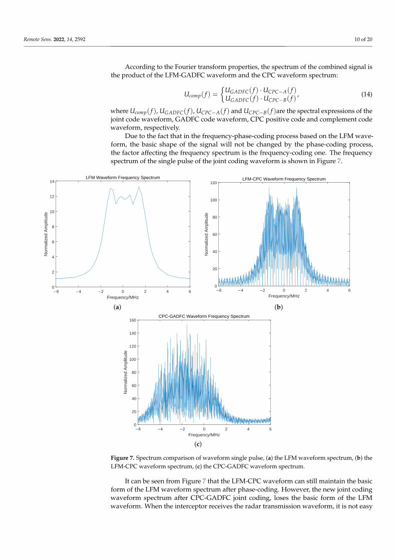
Due to the fact that in the frequency-phase-coding process based on the LFM wave-form, the basic shape of the signal will not be changed by the phase-coding process,the factor affecting the frequency spectrum is the frequency-coding one. The frequencyspectrum of the single pulse of the joint coding waveform is shown in Figure 7.
0 2 4 6
Frequency/MHz
0
2
4
6
8
10
12
14
Nor
mal
ized
Am
plitu
de
LFM Waveform Frequency Spectrum
0 2 4 6
Frequency/MHz
0
20
40
60
80
100
120
Nor
mal
ized
Am
plitu
de
LFM-CPC Waveform Frequency Spectrum
(a) (b)
0 2 4 6
Frequency/MHz
0
20
40
60
80
100
120
140
160
Nor
mal
ized
Am
plitu
de
CPC-GADFC Waveform Frequency Spectrum
(c)
Figure 7. Spectrum comparison of waveform single pulse, (a) the LFM waveform spectrum, (b) theLFM-CPC waveform spectrum, (c) the CPC-GADFC waveform spectrum.
It can be seen from Figure 7 that the LFM-CPC waveform can still maintain the basicform of the LFM waveform spectrum after phase-coding. However, the new joint codingwaveform spectrum after CPC-GADFC joint coding, loses the basic form of the LFMwaveform. When the interceptor receives the radar transmission waveform, it is not easy

Remote Sens. 2022, 14, 2592 11 of 20
to accumulate for a long time. It is easier to consider noise, which improves the radar LPIperformance.
3.2. Performance Analysis and Processing Method Design
Section 3.1 introduced the joint coding waveform’s design process and time-frequencydomain expression. In Section 3.2, the ambiguity function analysis, LPI characteristicanalysis, algorithm complexity analysis and signal processing flow of the joint codingwaveform, are introduced.
3.2.1. Ambiguity Function Analysis
Because the LFM-based CPC-GADFC joint coding waveform uses complementaryphase-coding sequences, it has two sequences of positive code and complement code.Therefore, according to the definition of ambiguity function, the ambiguity function of thejoint coding waveform also consists of two parts:
χcomp−A(τ, fd) =∫ ∞
−∞scomp−A(t)scomp−A(t + τ)ej2π fdtdt, (15)
χcomp−B(τ, fd) =∫ ∞
−∞scomp−B(t)scomp−B(t + τ)ej2π fdtdt. (16)
By substituting Equations (15) and (16) into Equations (10) and (11), the following isobtained:
scomp−A(t) =1√
Pcomp√
mTLFM
P
∑m=1
cA(m)rect(
t−mTLFMTLFM
)ejπk(t−mTLFM)2
ej2π f (m)t
= rect(
1√TLFM
)⊗ 1√
Pcomp√
mTLFM
P
∑m=1
cA(m)δ
(t−mTLFM
TLFM
)ejπk(t−mTLFM)2
ej2π f (m)t
= s1(t)⊗ s2(t),
(17)
scomp−B(t) =1√
Pcomp√
mTLFM
P
∑m=1
cB(m)rect(
t−mTLFMTLFM
)ejπk(t−mTLFM)2
ej2π f (m)t
= rect(
1√TLFM
)⊗ 1√
Pcomp√
mTLFM
P
∑m=1
cB(m)δ
(t−mTLFM
TLFM
)ejπk(t−mTLFM)2
ej2π f (m)t
= s1(t)⊗ s3(t).
(18)
Equations (17) and (18) show that the time-domain expression of the joint codingwaveform can be rewritten as the form of window function and signal impulse convolution.For scomp−A(t), Equation (15) has:
χcomp−A(τ, fd) =∫ ∞
−∞scomp−A(t)scomp−A(t + τ)ej2π fdtdt
=∫ ∞
−∞
[scomp−A(t)ej2π fdt
]scomp−A(τ − (−t))dt
= scomp−A(τ)ej2π fdt ⊗ scomp−A(−τ).
(19)
According to Equation (17), Equation (19) can be further rewritten as:
χcomp−A(τ, fd) = (s1(τ)⊗ s2(τ))ej2π fdt ⊗ (s1(−τ)⊗ s2(−τ))
= s1(τ)ej2π fdt ⊗ s2(τ)ej2π fdt ⊗ s1(−τ)⊗ s2(−τ)
=[s1(τ)ej2π fdt ⊗ s1(−τ)
]⊗[s2(τ)ej2π fdt ⊗ s2(−τ)
]= χ1(τ, fd)⊗ χ2(τ, fd).
(20)

Remote Sens. 2022, 14, 2592 12 of 20
According to Equation (18), the ambiguity function of the complementary phase-coding joint waveform scomp−B(t) can be expressed as:
χcomp−B(τ, fd) = (s1(τ)⊗ s3(τ))ej2π fdt ⊗ (s1(−τ)⊗ s3(−τ))
= s1(τ)ej2π fdt ⊗ s3(τ)ej2π fdt ⊗ s1(−τ)⊗ s3(−τ)
=[s1(τ)ej2π fdt ⊗ s1(−τ)
]⊗[s3(τ)ej2π fdt ⊗ s3(−τ)
]= χ1(τ, fd)⊗ χ3(τ, fd).
(21)
It can be deduced from this equation derivation that the ambiguity function of theCPC-GADFC joint coding waveform based on LFM, is composed of two parts. Each partis composed of the convolution superposition of two ambiguity functions. According tothe autocorrelation property and the ambiguity function expression of complementarycode, the autocorrelation characteristics can be obtained using complementary code forthe phase-coding. Moreover, the influence of the range-Doppler coupling on the signal isreduced. The ambiguity function graph of the joint coding waveform is shown in Figure 8.
Figure 8. Ambiguity Function of the Joint coding Waveform.
It can be seen from Figure 8 that the ambiguity function of the LFM-based CPC-GADFC joint coding waveform presents a good “pushpin” shape. Based on the highDoppler tolerance of the LFM signal, the joint coding waveform reduces the Doppler rangecoupling. It has a high range and velocity resolution, as well as low sidelobe characteristics,which improves the radar’s ability to detect targets. Complex waveforms have highmodulation complexity, and the phase-frequency joint coding increases the difficulty ofdemodulation and accumulation of radar waveforms by interceptors. For the widebandinterception receivers, the intra-pulse phase-frequency agility can make the radar waveformspectral form similar to the noise frequency. This makes the waveform submerged in thenoise and challenging to capture. Due to the complex phase-frequency hopping rulesand moderate hopping performance for narrowband receivers, the joint coding waveformsignificantly improves the LPI performance of the radar system.
3.2.2. Lpi Characteristic Analysis
In order to quantitatively analyze the LPI of the joint coding radar, the perspective ofthe Schleher interception factor can first be used:
α =RiRr
, (22)

Remote Sens. 2022, 14, 2592 13 of 20
where α is the interception factor, Ri is the maximum distance of the interception receiver,and Rr is the maximum action distance of the radar detection.
When the radar parameter settings are the same and the parameter settings of theinterception receiver are certain, the interception factor can be simplified and expressed inthe form of time-bandwidth product:
α = c · 1√BT
. (23)
When the radar uses LFM as the transmitting waveform, since its time-bandwidthproduct is BT2
LFM, the radar interception factor is given by:
αLFM = c · 1√BT2
LFM
. (24)
If the radar uses the LFM-based CPC-GADFC joint coding waveform as the trans-mit waveform, since the phase-coding and the frequency-coding simultaneously encodethe intra-pulse LFM waveform, the impact on the waveform time-bandwidth product isconsistent, which is m2BT2
LFM. The interception factor of the radar is: if the radar usesthe LFM-based CPC-GADFC joint coding waveform as the transmit waveform, since thephase-coding and the frequency-coding processes simultaneously code the intra-pulse LFMwaveform, the impact on the waveform time-bandwidth product (m2BT2
LFM) is consistent.The interception factor of the radar is given by:
αcomp = c · 1√m2BT2
LFM
. (25)
By comparing Equations (24) and (25), it can be seen that the joint coding waveformhas a larger time-bandwidth product, which is m2 times that of the LFM waveform, andαcomp << αLFM, while the joint coding waveform has a better LPI performance.
3.2.3. Analysis of the Algorithm Complexity
The complexity of the radar waveform can reflect the used modulation mode, andthe complexity characteristics of the waveform are less affected by the signal-to-noiseratio. Therefore, the sparsity of the waveform frequency domain can be used to expressthe complexity [30,31]. In the frequency domain of waveform normalization, a windowfunction having a length of N0 is constructed to slide from left to right in the frequencydomain waveform sequence GN . The number of element 1 in the i-th window is Mi. Theaverage coefficient in the window can be expressed as:
µ =1
N/N0
N/N0
∑i=1
Di, i = 1, 2, · · · , N/N0, (26)
where N is the frequency domain waveform length, and Di is given by:
Di =
∣∣∣∣MiM− i
N/N0
∣∣∣∣, i = 1, 2, · · · , N/N0, (27)
where M is the total number of 1 element in the frequency domain waveform.It can be seen that compared with the traditional radar LFM waveform, the CPC-
GADFC waveform carries out phase and frequency joint coding in the pulse. As shownin the spectrum of the single pulse of the joint coding waveform in Figure 7, the sparsecomplexity of the CPC-GADFC frequency domain is higher than that of the LFM waveform.

Remote Sens. 2022, 14, 2592 14 of 20
The time complexity of the CPC-GADFC waveform is higher than those of the LFMwaveform and DFC waveform. This is due to the fact that the CPC-GADFC waveformis simultaneously coded with phase and frequency, and GA is used for DFC codewordoptimization. In addition, compared with the CPC waveform, the CPC-GADFC waveformhas optimized frequency-coding on the basis of the CPC waveform. Therefore, the timecomplexity of the CPC-GADFC is higher. The complex radar waveform can increase theaccumulation and deciphering difficulty of the interceptor, and significantly improve theLPI performance of the radar.
3.2.4. Signal Processing Flow
Because the joint coding waveform uses a complementary code sequence in phasemodulation, the waveform in the pulse group is alternately transmitted with phase-codingpositive code and complementary code in the transmission process. The two codingwaveforms should be processed together in echo processing. When an echo is received, thepositive code and the complement code are first used as a priori to analyze the correlationcoefficient of the echo. This step aims at determining the type of echo phase-coding, whichis convenient for subsequent analysis. Assuming that the echo received at the currentmoment is a joint coding waveform encoding with positive code when performing pulsecompression, the two-phase codes should be subjected to matched filtering. The resultsare simultaneously superimposed. This process is referred to as joint coding echo pulsecompression processing.
The echo pulse compression processing of modern radar mainly uses digital signalprocessing. Two approaches exist for performing it. The time-domain correlation processingmethod is often used when the demand is a small pulse pressure ratio. When a large pulsepressure ratio is required, it is usually performed in the frequency domain by Fouriertransform. Since the matched filter is a linear time-invariant system, it can be determinedfrom the nature of Fourier change:
FFT{
hcomp−A(t)⊗ scomp−A(t + τ)}= Hcomp−A( f ) · Scomp−A( f ), (28)
FFT{
hcomp−B(t)⊗ scomp−B(t + τ)}= Hcomp−B( f ) · Scomp−B( f ), (29)
where τ is the echo delay expressed as τ = 2R/c, R is the distance from the radar to thetarget, c is the speed of light, hcomp−A(t) and hcomp−B(t) are used as the matched filterreference signals of radar echoes that are respected, scomp−A(t) and scomp−B(t) are inverseconjugate shock functions expressed as:
hcomp−A(t) = s∗comp−A(−t),
hcomp−B(t) = s∗comp−B(−t).(30)
When both signals are correctly sampled, the matched filter output signal of thepositive and complement phase joint coding signal can be expressed as:
sm f−A(t) = IFFT{
Hcomp−A( f ) · Scomp−A( f )}
,
sm f−B(t) = IFFT{
Hcomp−B( f ) · Scomp−B( f )}
.(31)
Finally, the matched filter requires to superimpose the sm f−A(t) and sm f−B(t), in orderto obtain the pulse compression results of the CPC-GADFC joint coding waveform basedon LFM. The specific process is shown in Figure 9.
It can be seen from Figure 9 that the pulse compression of the LFM-based CPC-GADFC joint coding waveform consists of a matched filter by the positive phase and thecomplement phase, respectively. The results are then superimposed to obtain the jointcoding waveform pulse compression output. The advantage of the alternately transmittedprocess is that the low sidelobe level of the complementary code autocorrelation can be

Remote Sens. 2022, 14, 2592 15 of 20
used to obtain a pulse compression result with low sidelobe characteristics, in order toachieve a better target detection performance.
雷达发射波形正码相位频率联
合编码信号
雷达回波信号
回波分析
傅里叶变换
雷达发射波形
正码相位频率
联合编码
频谱相乘 逆傅里叶变换脉冲压缩输出
(回波-正码)
补码相位频率
联合编码信号
脉冲压缩滤波器
单位脉冲响应
傅里叶变换
雷达发射波形
补码相位频率
联合编码
频谱相乘 逆傅里叶变换脉冲压缩输出
(补码)镜像共轭
互补码相位、频
率联合编码
脉冲压缩输出
正码、补码
脉冲压缩叠加
Positive Code
Joint Coding
Waveform
Radar Echo
Signal
Echo Analysis
Fourier
Transform
Positive Code
Composite-
Coded Signal
frequency
Spectrum
Multiplication
Inverse Fourier
Transform
Pulse Compression
Output
(Positive Code)
Complement
Code Joint
Coding
Waveform
Pulse
Compression
Filter Unit
Impulse
Response
Fourier
Transform
Complement
Code Composite-
Coded Signal
frequency
Spectrum
Multiplication
Inverse Fourier
Transform
Pulse Compression
Output
(Complement Code)
Mirror Conjugate
Joint Coding
Pulse
Compression
Output
Positive Code,
Complement Code
Pulse Compression
Superposition
Figure 9. Pulse Compression Model of Joint coding Waveform Based on LFM.
4. Result and Discussion
In order to verify the robustness of the LFM-based CPC-GADFC joint coding wave-form, the experiment performs a time-frequency analysis of the waveform from the perspec-tive of a pulse waveform. Pulse compression is performed on the echo, and the obtainedresult is compared with the LFM waveform and CPC-DFC joint coding waveform. Finally,the target detection performance of the joint coding waveform is analyzed. In this paper,the complementary code sequence, DFC sequence and GADFC sequence are all of 32 bits.Their codewords are shown in Table 2.
Table 2. Complementary Code, DFC Sequence and GADFC Sequence Codewords.
Coding Mode Codewords
Positive Code 1, 1, 1, 1, 1, −1, 1, −1, −1, −1, 1, 1, 1, −1, −1, 1, 1, 1, −1, −1, 1, −1,−1, 1, −1, −1, −1, −1, 1, −1, 1, −1
Complement Code −1, −1, −1, −1, −1, 1, −1, 1, 1, 1, −1, −1, −1, 1, 1, −1, 1, 1, −1, −1,1, −1, −1, 1, −1, −1, −1, −1, 1, −1, 1, −1
DFC 12, 13, 25, 15, 6, 10, 19, 9, 18, 16, 5, 22, 7, 30, 32, 1, 11, 24, 27, 17, 14, 31,2, 4, 3, 20, 29, 23, 8, 21, 28, 26
GADFC
31.5455, 31.5152, 10.9091, 20.5455, 28, 9.2424, 31.9091, 5.9394, 20.4848,10.6364, 18.7273, 17.7273, 9, 17.6667, 17.3939, 6, 12.3939, 11.2121, 5,4.8788, 4.5152, 3.1212, 9.7576, 7.0606, 18.0303, 5.2424, 7.6364, 4.9394,12.0606, 28.8181, 16.9394, 31.3636
In one transmission pulse, the time domain waveform and time-frequency analysis ofthe CPC-GADFC joint coding waveform based on LFM, are shown in Figures 10 and 11.

Remote Sens. 2022, 14, 2592 16 of 20
0 20 40 60 80
0
0.2
0.4
0.6
0.8
1
Am
plitu
de
CPC-GADFC Time Domain Waveform
Figure 10. CPC -GADFC Time Domain Waveform.
Time-Frequency Analysis of CPC-GADFC Waveforms
5 10 15 20 25 30
Time-Frequency Window
0
2
4
6
Fre
quen
cy/H
z
Figure 11. Time -Frequency Analysis of CPC-GADFC Waveform.
It can be seen from Figure 10 that the complementary code sequence efficiently en-codes the LFM, and the purpose of increasing the time-bandwidth product is achieved bychanging the phase structure of the signal. Moreover, it can be observed from Figure 11 thatGADFC changes the frequency distribution of the LFM waveform, and simultaneously per-forms frequency-coding based on phase-coding intra-pulse, which increases the complexityof the joint coding waveform.
In order to verify the performance of the designed waveform, the echo pulse compres-sion results of the LFM-DFC waveform, CPC-DFC waveform and CPC-GADFC waveformare compared (cf. Figures 12–14).

Remote Sens. 2022, 14, 2592 17 of 20
0 200 400 600 800
Distance Unit
0
Am
plitu
de/d
B
LFM-DFC Waveform Pulse Compression
X -478.812Y -16.4841
Figure 12. LFM -DFC Waveform Pulse Compression.
0 200 400 600 800
Distance Unit
0
Am
plitu
de/d
B
CPC-DFC Waveform Pulse Compression
X -59.5388Y -36.5959
Figure 13. CPC -DFC Waveform Pulse Compression.
0 200 400 600 800
Distance Unit
0
Am
plitu
de/d
B
CPC-GADFC Waveform Pulse Compression
X 433.782Y -41.0015
Figure 14. CPC -GADFC Waveform Pulse Compression.

Remote Sens. 2022, 14, 2592 18 of 20
It can be seen from Figures 12–14 that the CPC-GADFC joint coding waveform uses thecomplementary code for phase-coding, which can significantly reduce the sidelobe throughthe characteristics of the autocorrelation and sidelobe cancellation of the complementarycode. Compared with DFC, the joint coding GADFC can find the optimal distance betweeneach codeword in DFC encoding by GA, which increases the orthogonality between thecodewords. After coding, the maximum main side ratio can be reduced by 3.5 dB, com-pared with the unoptimized joint coding waveform. The joint coding waveform has thecharacteristics of ultra-low sidelobes, and the distribution of side lobes is more uniform.The jointly coding waveform improves the LPI performance of the signal while improvingthe radar’s ability to detect targets, as shown in Figure 15.
0 200 400 600 800
Distance Unit
0
Am
plitu
de/d
B
Comparison of Several Waveform Pulse Compression
CPC-GADFCLFM-DFCLFM-DFC-winCPC-DFC
0 5 10 15
Distance Unit
0
Am
plitu
de/d
B
Comparison of Several Waveform Pulse Compression
CPC-GADFCLFM-DFCLFM-DFC-winCPC-DFC
(a) (b)
0
Echo SNR
0
0.1
0.2
0.3
0.4
0.5
0.6
0.7
0.8
0.9
1
Det
ectio
n P
roba
bilit
y
CPC-GADFCCPC-DFCPC-DFCDFC
(c)
Figure 15. Comparison Diagram of Several Waveform Pulse Compressions and Target DetectionProbabilities, (a) comparison of the waveform pulse compression, (b) enlarged view of the main lobeposition of the waveform pulse compression, and (c) comparison of the waveform target detectionperformance. Note that “win” denotes the Hamming window.
It can be seen from Figure 15 that the pulse compression sidelobe level of CPC-GADFCwaveform is significantly lower than that of other waveforms and lower than that of theDFC waveform with Hamming window. It can also be seen that the pulse compressionmain lobe of the CPC-GADFC waveform is significantly narrower than other waveforms,which indicates that the waveform designed in this paper can concentrate the radar energyand have more accurate target detection performance. Moreover, it can be observed thatthe detection probability of the CPC-GADFC waveform is much higher than that of the

Remote Sens. 2022, 14, 2592 19 of 20
DFC and PC-DFC waveform, and the detection probability of the CPC-GADFC waveformis higher than that of the CPC-DFC waveform.
5. Conclusions
This paper proposes a CPC-GADFC joint coding holographic RF stealth radar wave-form, based on the LFM waveform. The time-frequency domain and ambiguity functionexpressions of the joint coding waveform are derived. The LPI characteristic of the jointcoding waveform is derived by the interception factor. In addition, the complexity of thealgorithm is analyzed. Finally, a matched filter is designed for the joint coding waveform inorder to achieve echo pulse compression. The experiments show that the CPC-GADFC jointcoding waveform has the advantages of phase-coding waveform and frequency-codingwaveform. This large time-bandwidth product waveform has better LPI and low side-lobe characteristics. Similarly, the CPC-GADFC joint coding waveform has better targetdetection performance and higher practical value.
Author Contributions: Conceptualization, Y.S., B.T. and S.X.; methodology, Y.S. and B.T.; software,Y.S. and Y.W.; validation, Y.S., J.X., Y.Y. and B.T.; formal analysis, Y.S.; investigation, Y.S.; resources, Y.S.and B.T.; data curation, Y.S.; writing—original draft preparation, Y.S., J.X. and B.T.; writing—reviewand editing, Y.S.; visualization, Y.S.; supervision, B.T. and S.X.; project administration, B.T. and S.X.;funding acquisition, B.T. and S.X. All authors have read and agreed to the published version of themanuscript.
Funding: This work was supported in part by Fundamental Research Funds for the Central Uni-versities, Sun Yat-sen University (No. 22lgqb15), Shenzhen Fundamental Research Program (No.JCYJ20180307151430655), Shenzhen Science and Technology Program (No. KQTD20190929172704911),Shenzhen Science and Technology Program (No. GXWD20201231165807008), Hunan Provincial Natu-ral Science Foundation of China (No. 2021JJ20056), Foundation of Pinghu Laboratory (No. 20220362).
Data Availability Statement: Not applicable.
Acknowledgments: The authors acknowledge the funding, equipment and technical support pro-vided by the School of Electronics and Communication Engineering of Sun Yat-sen University.
Conflicts of Interest: The authors declare no conflict of interest.
AbbreviationsThe following abbreviations are used in this paper:
LPI Low Probability of InterceptUWB Ultra-Wide BandLFM Linear Frequency ModulationFSK Frequency Shift KeyingPSK Phase Shift KeyingCPC Complementary Phase-CodingDFC Discrete Frequency-CodingGA Genetic AlgorithmGADFC Discrete Frequency-Coding Optimized by Genetic Algorithm
References1. Giubbolini, L. A multistatic microwave radar sensor for short range anticollision warning. IEEE Trans. Veh. Technol. 2000, 49,
2270–2275. [CrossRef]2. Ahmed, A.; Zhang, Y.D.; Hassanien, A. Joint Radar-Communications Exploiting Optimized OFDM Waveforms. Remote. Sens.
2021, 13, 4376. [CrossRef]3. Shi, C.; Wang, F.; Zhou, J.; Chen, J. Adaptive radar jamming waveform design based on low probability of intercept. In
Proceedings of the 2015 IEEE China Summit and International Conference on Signal and Information Processing (ChinaSIP),Chengdu, China, 12–15 July 2015; pp. 1017–1021.
4. Wang, W.Q. Moving-Target Tracking by Cognitive RF Stealth Radar Using Frequency Diverse Array Antenna. IEEE T. Geosci.Remote 2016, 54, 3764–3773. [CrossRef]

Remote Sens. 2022, 14, 2592 20 of 20
5. Hejazikookamari, F.; Norouzi, Y.; Kashani, E.S.; Nayebi, M.M. A Novel Method to Detect and Localize LPI Radars. IEEE Trans.Signal Process. 2019, 55, 2327–2336. [CrossRef]
6. Kamble, J.; Pasha, I.A.; Madhavilatha, M. Design of HRR detection system for measurement of RF signal power. In Proceedings ofthe 2016 10th International Conference on Intelligent Systems and Control (ISCO), Coimbatore, India, 7–8 January 2016; pp. 1–5.
7. Guey, J.C.; Bell, M.R. Diversity waveform sets for delay-Doppler imaging. IEEE Trans. Inf. Theory 1998, 44, 1504–1522. [CrossRef]8. Abd, M.H.; Al-Suhail, G.A.; Tahir, F.R.; Ali Ali, A.M.; Abbood, H.A.; Dashtipour, K.; Jamal, S.S.; Ahmad, J. Synchronization of
Monostatic Radar Using a Time-Delayed Chaos-Based FM Waveform. Remote. Sens. 2022, 14, 1984. [CrossRef]9. Hongbo, S.; Yilong, L.; Guosui, L. Ultra-wideband technology and random signal radar: An ideal combination. IEEE Aero. El. Sys.
Mag. 2003, 18, 3–7. [CrossRef]10. De Witte, E.; Griffiths, H.D. Improved Waveforms for Satellite-Borne Precipitation Radar; IET Digital Library: London, UK, 2011.11. Dietl, G.; Wang, J.; Ding, P.; Zoltowski, M.D.; Love, D.J.; Utschick, W. Hybrid transmit waveform design based on beam-forming
and orthogonal space-time block coding. In Proceedings of the (ICASSP ’05) IEEE International Conference on Acoustics, Speech,and Signal Processing, Philadelphia, PA, USA, 18–23 March 2005; pp. 893–896.
12. Kassab, R.; Lesturgie, M.; Fiorina, J. Quasi-continuous waveform design for dynamic range reduction. Electron. Lett. 2008, 44,646–647. [CrossRef]
13. Geroleo, F.G.; Brandt-Pearce, M.; Brown, C.L. Detection and estimation of multi-pulse LFMCW radar signals. In Proceedings ofthe 2010 IEEE Radar Conference, Arlington, VA, USA, 10–14 May 2010; pp. 1009–1013.
14. Zhang, Y.X.; Hong, R.J.; Pan, P.P.; Deng, Z.M.; Liu, Q.F. Frequency-Domain Range Sidelobe Correction in Stretch Processing forWideband LFM Radars. IEEE Trans. Aerosp. Electron. Syst. 2017, 53, 111–121. [CrossRef]
15. Bao, H.; Ziemann, A.; He, Z.S. Design and Measurements of MSK-LFM RadCom System. In Proceedings of the 2020 17thEuropean Radar Conference (EuRAD), London, UK, 16–18 February 2021; pp. 9–12.
16. Raghavendra, C.G.; Prajwal, B.R.; Sagar, G.D.; Keerthana, R.; Meghna, S.; Prasad, N.N.S.S.R.K. Reduction of Envelope Fluctuationsin OFDM Radar Signals Using Coding Technique. In Proceedings of the 2018 International Conference on Communication andSignal Processing (ICCSP), Chennai, India, 3–5 April 2018; pp. 802–806.
17. Li, Z.; Perera, S.; Zhang, Y.; Zhang, G.; Doviak, R. Phased-Array Radar System Simulator (PASIM): Development and SimulationResult Assessment. Remote. Sens. 2019, 11, 422. [CrossRef]
18. Suh, J.; Lee, J.; Gil, G.T.; Hong, S. Time-and-Frequency Hybrid Multiplexing for Flexible Ambiguity Controls of DFT-coded MIMOOFDM Radar. IEEE Access 2021, 9, 137793–137808. [CrossRef]
19. Park, B.; Ahn, J.M. Intra-pulse modulation recognition using pulse description words and complex waveforms. In Proceedingsof the 2017 International Conference on Information and Communication Technology Convergence (ICTC), Jeju Island, Korea,18–20 October 2017; pp. 555–560.
20. Hou, J.; Tao, R.; Shan, T.; Qi, L. A novel LPI radar signal based on hyperbolic frequency hopping combined with Barker phasecode. In Proceedings of the 7th International Conference on Signal Processing, Beijing, China, 31 August–4 September 2004;pp. 2070–2073.
21. Saifullah, Y.; Yang, G.; Feng, X.U. A Four-leaf Clover-shaped Coding Metasurface For Ultra-wideband Diffusion-like Scattering. J.Radars 2021, 10, 382–390.
22. Song, X. An Improved Algorithm for Pulse Compression of Taylor Four-phase Coding Signal and Its Simulation. Ship Electron.Eng. 2006, 06, 160–163.
23. Chunhong, Y.; Zengli, L. The Superiority Analysis of Linear Frequency Modulation and Barker Code Composite Radar Signal.In Proceedings of the 2013 Ninth International Conference on Computational Intelligence and Security, Emeishan, China,14–15 December 2013; pp. 182–184.
24. Zhang, T.; Shuai, C.; Zhou, Y. Deep Learning for Robust Automatic Modulation Recognition Method for IoT Applications. IEEEAccess 2020, 1, 117689–117697. [CrossRef]
25. Agrawal, D.; Maheshwari, S. Design and implementation of current mode circuit for digital modulation. Integration 2021, 78,118–123 [CrossRef]
26. Kundu, N.K.; Mallik, R.K.; Mckay, M.R. Signal Design for Frequency-Phase Keying. IEEE Trans. Wirel. Commun. 2020, 1,4067–4079. [CrossRef]
27. Jahangir, M.; Baker, C.J.; Oswald, G.A. Doppler characteristics of micro-drones with L-Band multibeam staring radar. InProceedings of the 2017 IEEE Radar Conference (RadarConf), Seattle, WA, USA, 8–12 May 2017; pp. 1052–1057.
28. Golay, M. Complementary series. Information Theory. IRE Trans. 1961, 7, 82–87.29. Mott, M.H.; Roome, A.T.; Erickson, C.W. Signal Processing System Employing Reference-Signal Controlled-Integrator for
Integrating Resultant of Two Summing-Circuits Having Complementary Inputs. U.S. Patent US3316492 A, 25 April 1967.30. Jing, X.U.; Ming-Hao, H.E.; Chen, C.X.; Zhou, L. Algorithm Complexity Analysis of Radar Emitter Characteristic Parameter
Extraction. J. China Acad. Electron. Inf. Technol. 2013, 8, 43–47.31. Kang, B.; Rangaswamy, M. Radar Waveform Design Under Communication Sum Capacity Constraint. IEEE Trans. Signal Process.
2021, 69, 2795–2806. [CrossRef]
Copyright © 2022 FDOKUMEN