Technical Challenges to Reducing Subsonic Transport Drag
31
Technical Challenges to Reducing Subsonic Transport Drag Dr. Michael M. Rogers Technical Lead, Efficient Aerodynamics NASA Fundamental Aeronautics Program, Subsonic Fixed Wing Project NASA Ames Research Center, Moffett Field, CA
-
Upload
khangminh22 -
Category
Documents
-
view
0 -
download
0
Transcript of Technical Challenges to Reducing Subsonic Transport Drag
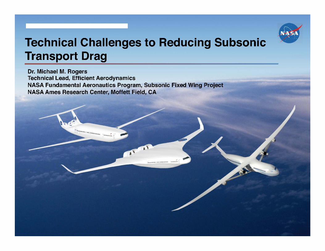
Technical Challenges to Reducing Subsonic Transport Drag Dr. Michael M. Rogers Technical Lead, Efficient Aerodynamics NASA Fundamental Aeronautics Program, Subsonic Fixed Wing Project NASA Ames Research Center, Moffett Field, CA
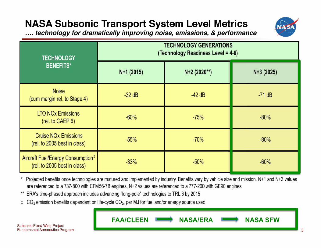
NASA Subsonic Transport System Level Metrics
Noise (cum margin reI. to Stage 4)
LTO NOx Emissions (reI. to CAEP 6)
Cruise NOx Emissions (reI. to 2005 best in class)
Aircraft Fuel/Energy Consumption t
(reI. to 2005 best in class)
N+1 (2015)
-32 dB
-60%
-55%
-33%
TECHNOLOGY GENERATIONS (Technology Readiness Level = 4·6)
N+2 (2020**)
-42 dB
-75%
-70%
-50%
• N+3 (2025)
-71 dB
-80%
-80%
-60%
* Projected benefits once technologies are matured and implemented by industry. Benefits vary by vehicle size and mission. N+1 and N+3 values are referenced to a 737-800 with CFM56-7B engines, N+2 values are referenced to a 777-200 with GE90 engines
** ERA's time-phased approach includes advancing "Iong-pole" technologies to TRL 6 by 2015
+ CO2 emission benefits dependent on life-cycle C02e per MJ for fuel and/or energy source used
Subsonic Fixed Wing Project Fundamental Aeronautics Program
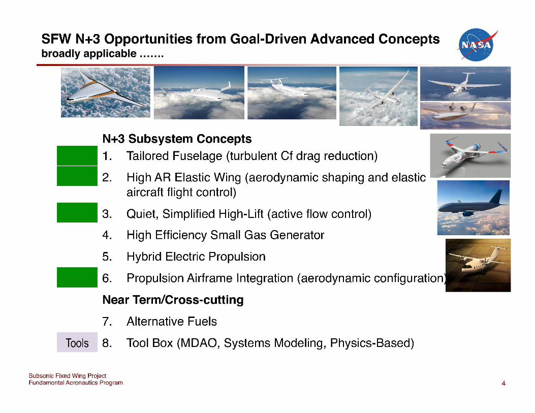
SFW N+3 Opportunities from Goal-Driven Advanced Concepts •
.. ~
N+3 Subsystem Concepts 1. Tailored Fuselage (turbulent Cf drag reduction)
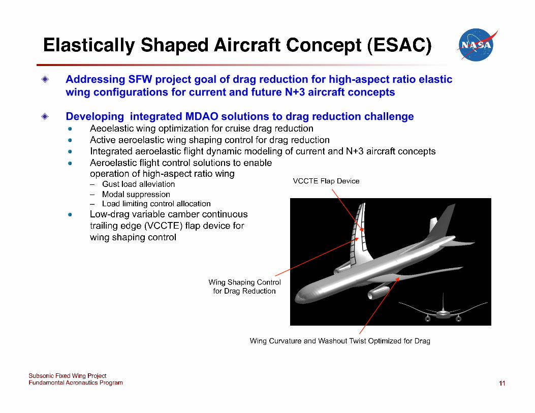
2. High AR Elastic Wing (aerodynamic shaping and elastic ~IO........-__ ------I
aircraft flight control)
3. Quiet, Simplified High-Lift (active flow control)
4. High Efficiency Small Gas Generator
5. Hybrid Electric Propulsion
6. Propulsion Airframe Integration {aerodynamic configuration
Near Term/Cross-cutting
7. Alternative Fuels
Tools 8. Tool Box (MDAO, Systems Modeling, Physics-Based)
Subsonic Fixed Wing Project Fundamental Aeronautics Program 4
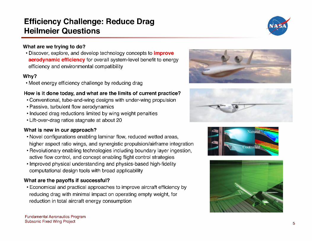
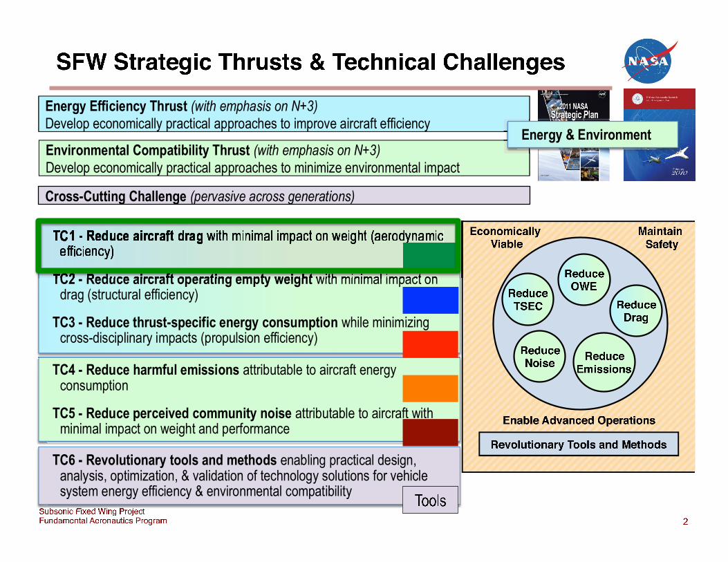
Efficiency Challenge: Reduce Drag Heilmeier Questions
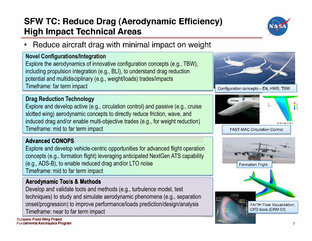
What are we trying to do? • Discover, explore, and develop technology concepts to improve aerodynamic efficiency for overall system-level benefit to energy efficiency and environmental compatibility
Why? • Meet energy efficiency challenge by reducing drag
How is it done today, and what are the limits of current practice? • Conventional, tube-and-wing designs with under-wing propulsion • Passive, turbulent flow aerodynamics • Induced drag reductions limited by wing weight penalties • Lift-over-drag ratios stagnate at about 20
What is new in our approach? • Novel configurations enabling laminar flow, reduced wetted areas, higher aspect ratio wings, and synergistic propulsion/airframe integration
• Revolutionary enabling technologies including boundary layer ingestion, active flow control, and concept enabling flight control strategies
• Improved physical understanding and physics-based high-fidelity computational design tools with broad applicability
What are the payoffs if successful? • Economical and practical approaches to improve aircraft efficiency by
reducing drag with minimal impact on operating empty weight, for reduction in total aircraft energy consumption
Fundamental Aeronautics Program Subsonic Fixed Wing Project 5
Efficient Aerodynamics ---------------------------------------------------
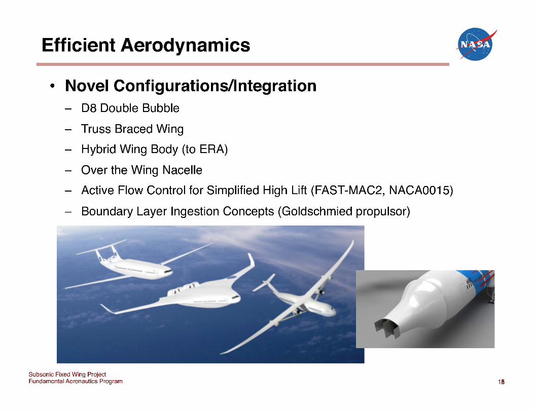
• Novel Configurations/Integration - D8 Double Bubble
- Truss Braced Wing
- Hybrid Wing Body (to ERA)
- Over the Wing Nacelle
- Active Flow Control for Simplified High Lift (FAST-MAC2, NACA0015)
- Boundary Layer Ingestion Concepts (Goldschmied propulsor)
Subsonic Fixed Wing Project Fundamental Aeronautics Program
•
1m
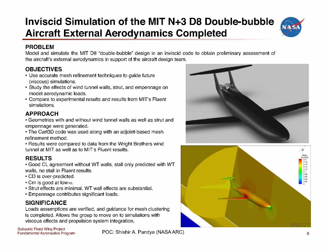
Inviscid Simulation of the MIT N+3 08 Double-bubble Aircraft External Aerod~namics Completed PROBLEM Model and simulate the MIT 08 "double-bubble" design in an inviscid code to obtain preliminary assessment of the aircraft's external aerodynamics in support of the aircraft design team.
OBJECTIVES • Use accurate mesh refinement techniques to guide future
(viscous) simulations. • Study the effects of wind tunnel walls, strut, and empennage on
model aerodynamic loads. • Compare to experimental results and results from MIT's Fluent
simulations.
APPROACH • Geometries with and without wind tunnel walls as well as strut and empennage were generated. • The Cart30 code was used along with an adjoint-based mesh refinement method. • Results were compared to data from the Wright Brothers wind tunnel at MIT as well as to MIT's Fluent results.
RESULTS • Good CL agreement without WT walls, stall only predicted with WT walls, no stall in Fluent results. • CO is over-predicted. • Cm is good at low-a. • Strut effects are minimal, WT wall effects are substantial. • Empennage contributes significant loads.
SIGNIFICANCE Loads assumptions are verified, and guidance for mesh clustering is completed. Allows the group to move on to simulations with viscous effects and propulsion system integration.
Subsonic Fixed Wing Project Fundamental Aeronautics Program poc: Shishir A. Pandya (NASA ARC)
•
9
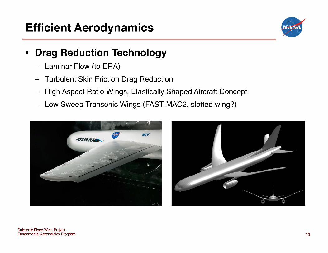
Efficient Aerodynamics -----------------------------------------------------• Drag Reduction Technology
- Laminar Flow (to ERA)
- Turbulent Skin Friction Drag Reduction
- High Aspect Ratio Wings, Elastically Shaped Aircraft Concept
- Low Sweep Transonic Wings (FAST-MAC2, slotted wing?)
Subsonic Fixed Wing Project Fundamental Aeronautics Program
•
1(1)
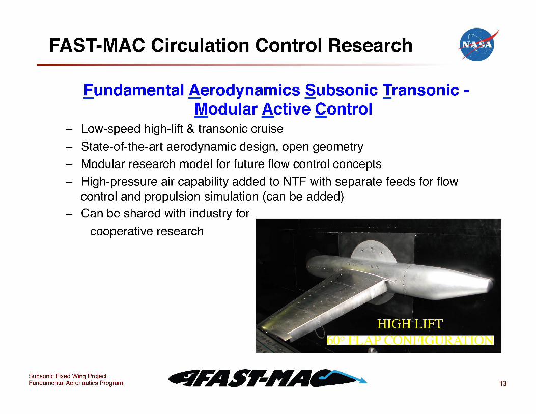
FAST-MAC Circulation Control Research • fundamental ,Aerodynamics §ubsonic Iransonic -
Modular Active Control - Low-speed high-lift & transonic cruise
- State-of-the-art aerodynamic design, open geometry
- Modular research model for future flow control concepts
- High-pressure air capability added to NTF with separate feeds for flow control and propulsion simulation (can be added)
- Can be shared with industry for
cooperative research
Subsonic Fixed Wing Project Fundamental Aeronautics Program 13

FAST-MAC Circulation Control Research • PROBLEM Can circulation control (CC) be used to reduce drag at cruise? How much lift augmentation for takeoff and landing can be achieved with the same CC system?
OBJECTIVES • Explore drag reduction with blown flap in stowed cruise position at transonic speeds and flight Reynolds numbers. • Evaluate a blown short-chord hinged flap high-lift system at takeoff and landing conditions. • Develop a non-proprietary CFD validation database for CC at realistic flight Reynolds numbers.
APPROACH Upgrade National Transonic Facility (NTF) by adding a new highpressure air delivery station and new balance to enable blown semi-span testing. Obtain surface pressure distributions using pressure taps and cryogenic Pressure Sensitive Paint (PSP).
RESULTS
Photo by Scott Goodliff @ NTF
FAST-MAC Model in the NTF
At transonic speeds CC altered the shock pattern on the upper wing surface and affected flow separation. Application of CC to the outboard portion of the wing demonstrated the feasibility of pneumatic-based maneuver control. CC increased the low-speed maximum lift coefficient by 40%. Prior difficulties with cryogenic PSP were successfully overcome. Post-test data analysis is required to remove the thrust contribution and document the drag reduction potential.
SIGNIFICANCE The ability to modify the shock location on the wing surface indicates that CC has the potential to reduce cruise drag and fuel burn. Further analysis of the data followed by a second FAST-MAC test will quantify this benefit.
POCs: William E. Milholen, II, Gregory S. Jones, and David T. Chan (NASA/LaRC) 4!l!TFAS"~ Eundamental8.erodynamics Subsonic/lransonic-Modular 8.ctive .control
14
Efficient Aerodynamics
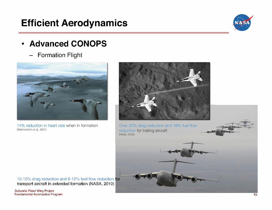
• Advanced CONOPS Formation Flight
14% reduction in heart rate when in formation (Weimerskirch et aI., 2001)
10-15% drag reduction and 8-12% fuel flow reduction transport aircraft in extended formation (NASA, 2010)
Subsonic Fixed Wing Project Fundamental Aeronautics Program
Over 20% drag reduction and 18% fuel flow reduction for trailing aircraft (NASA, 2002)
•
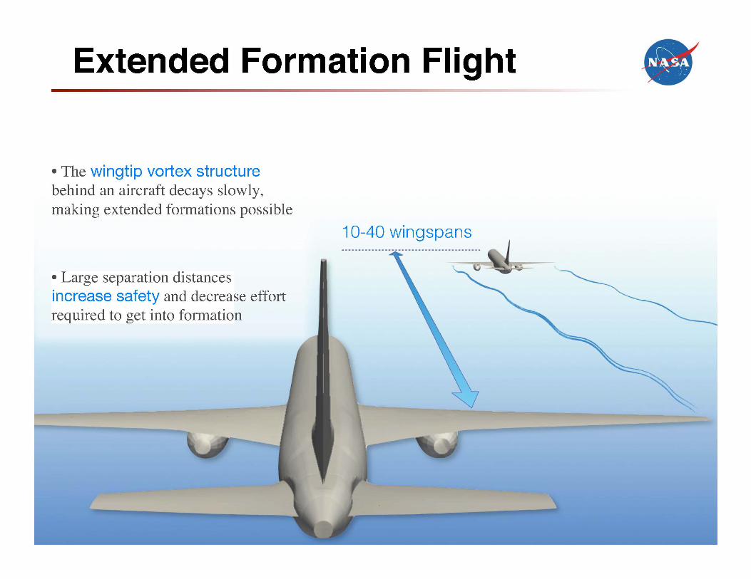
Extended Formation Flight
• The wingtip vortex structure behind an aircraft decays slowly, making extended formations possible
• Large separation distances increase safety and decrease effort required to get into formation
10-40 wingspans
•
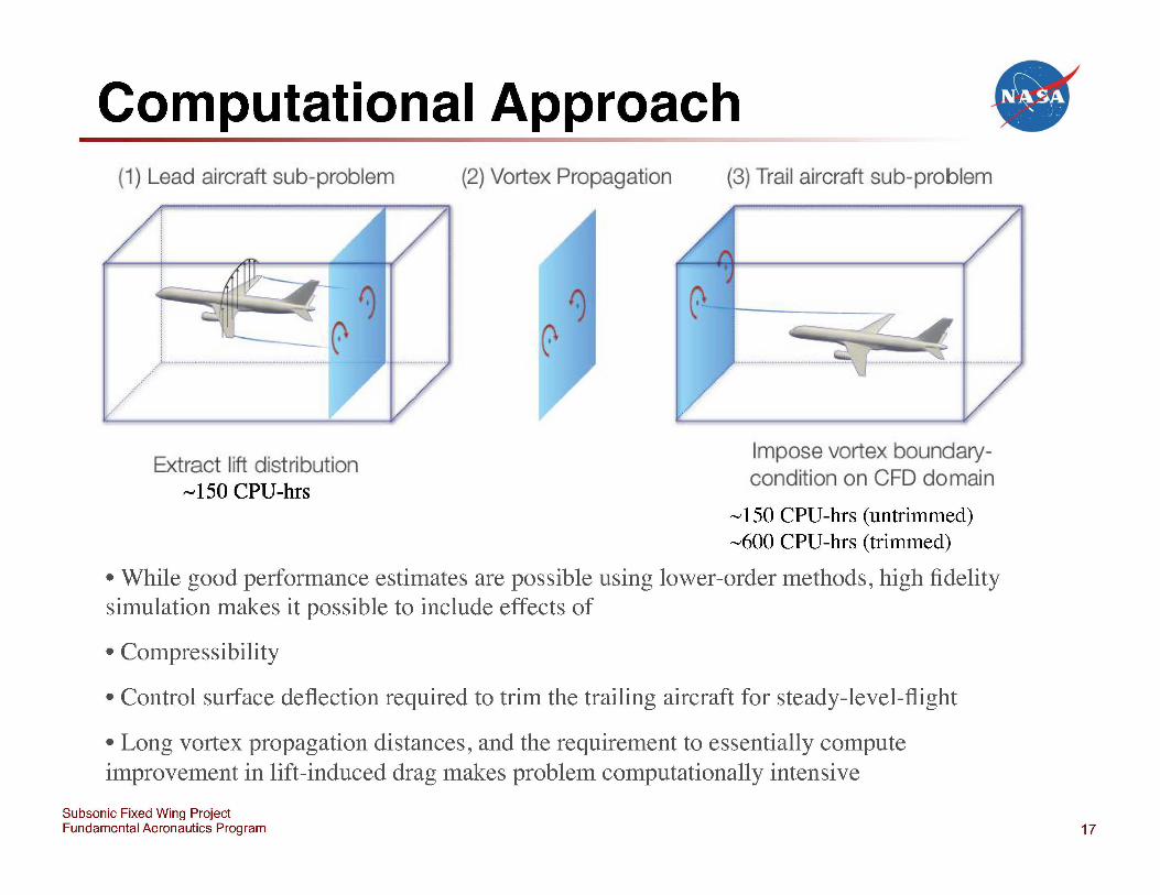
Computational Approach • (1) Lead aircraft sub-problem (2) Vortex Propagation (3) Trail aircraft sub-problem
, ! ! : i i L ___ ... _____ . ___ ...... __ . ___ ... ___ . __ ..... _______ ... .
Extract I'ft distribution ""' 150 CPU-hrs
Impose vortex boundatycondition on CFD domain
'" 150 CPU-hrs (untrimmed) ",600 CPU-hrs (trimmed)
• While good performance estimates are possible using lower-order methods, high fidelity simulation makes it possible to include effects of
• Compressibility
• Control surface deflection required to trim the trailing aircraft for steady-level-flight
• Long vortex propagation distances, and the requirement to essentially compute improvement in lift-induced drag makes problem computationally intensive
Subsonic Fixed Wing Project Fundamental Aeronautics Program 17
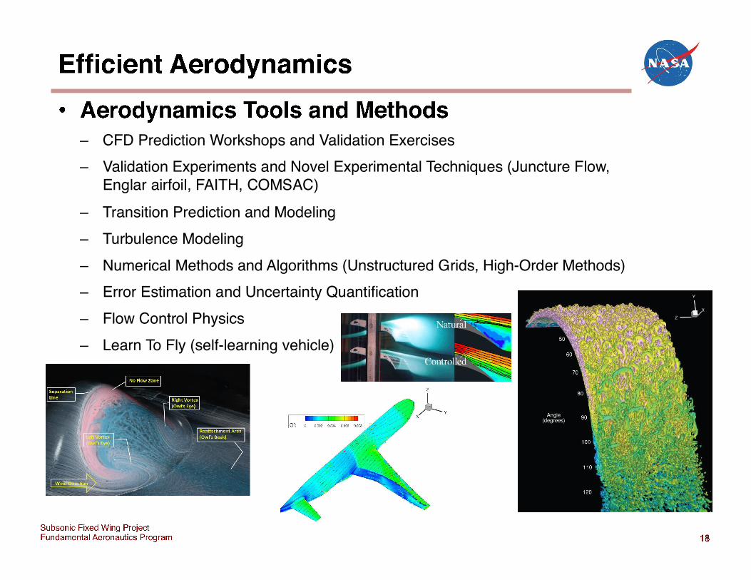
4 (and 5 ) AIAA CFD Drag Prediction Workshop NASA Common Research Model (CRM)
PROBLEM Disagreement among state-of-the-art CFD tools with respect to the prediction of drag and the prediction of the location and extent of separated flow regions (with associated variation in pitching moment prediction) on commercial transports.
OBJECTIVE Identify the reasons for this discrepancy and improve CFD tool capability. Utilize high-quality experimental data from two separate wind tunnels to guide interpretation of CFD results.
APPROACH International Workshop with participants from industry, government, universities, and CFD vendor companies using a variety of state-of-the-art Reynolds-Averaged Navier-Stokes (RANS) solvers and different turbulence models to predict forces, moments, and regions of flow separation on a single open geometry configuration, the NASA Common Research Model (CRM), on standardized common grid families (both structured and unstructured) with experimental validation data gathered after the workshop in both the LaRC National Transonic Facility (NTF) 13 Jan 2010 to 16 Feb 2010 and the ARC 11-foot Transonic Wind Tunnel 16 Mar 2010 to 2Apr 2010.
RESULTS • CFD drag prediction still showing spread of up to 40 counts
Pressure Sensitive Paint
•
• Large scatter in CFD prediction of separated zones and pitching moments Particle Image Velocimetry in 11-foot • Pressure Sensitive Paint (PSP) data gathered in both tunnels • Oil Fringe Interferometry (OFI) skin friction measurements taken in ARC 11-foot • Particle Image Velocimetry (PIV) off-body velocity measurements taken in ARC 11-foot • Reynolds number effects and static aeroelastic effects assessed in LaRC NTF • Configuration effect data (tail, nacelle/pylon) data acquired • Demonstrated ability of new active damper system to acquire data at higher AOA
SIGNIFICANCE Broadly available, extensive computational and experimental database that is enabling progress in CFD predictive capability. Higher confidence in CFD predictions will enable designs with less margin, less weight, less wetted area, and less drag.
Subsonic Fixed Wing Project Fundamental Aeronautics Program 19
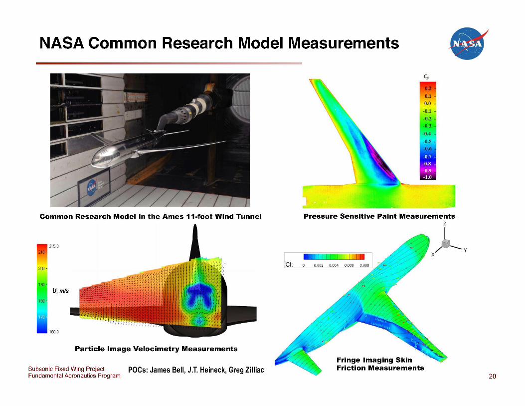
NASA Common Research Model Measurements •
Common Research Model in the Ames 11-foot Wind Tunnel
215,0
200 -
U,m/s
Particle Image Velocimetry Measurements
Subsonic Fixed Wing Project poes: James Bell, J.T. Heineck, Greg Zilliac Fundamental Aeronautics Program
let:
Pressure Sensitive Paint Measurements z
! l l eLl ! ! ! LM I 0,002 0,004 0,006 0,008
Fringe Imaging Skin Friction Measurements
y
20
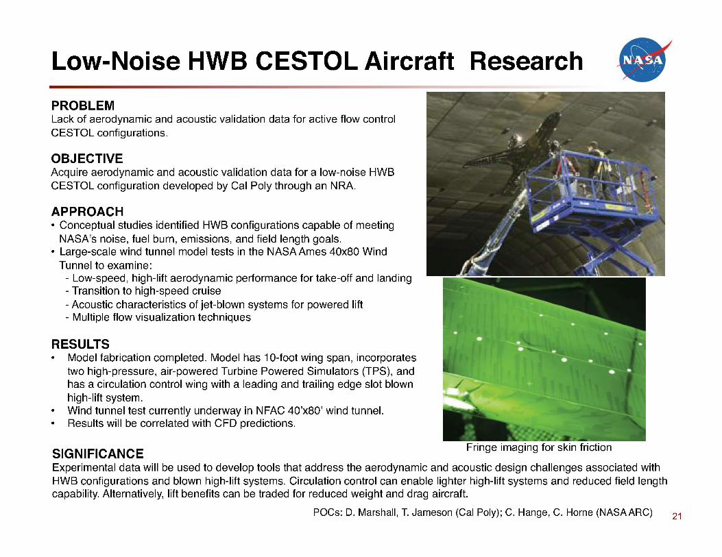
Low-Noise HWB CESTOL Aircraft Research
PROBLEM Lack of aerodynamic and acoustic validation data for active flow control CESTOL configurations.
OBJECTIVE Acquire aerodynamic and acoustic validation data for a low-noise HWB CESTOL configuration developed by Cal Poly through an NRA.
APPROACH • Conceptual studies identified HWB configurations capable of meeting
NASA's noise, fuel burn, emissions, and field length goals. • Large-scale wind tunnel model tests in the NASA Ames 40x80 Wind
Tunnel to examine: - Low-speed, high-lift aerodynamic performance for take-off and landing - Transition to high-speed cruise - Acoustic characteristics of jet-blown systems for powered lift - Multiple flow visualization techniques
RESULTS • Model fabrication completed. Model has 1 O-foot wing span, incorporates
two high-pressure, air-powered Turbine Powered Simulators (TPS), and has a circulation control wing with a leading and trailing edge slot blown high-lift system.
• Wind tunnel test currently underway in NFAC 40'x80' wind tunnel. • Results will be correlated with CFD predictions.
SIGNIFICANCE
•
Experimental data will be used to develop tools that address the aerodynamic and acoustic design challenges associated with HWB configurations and blown high-lift systems. Circulation control can enable lighter high-lift systems and reduced field length capability. Alternatively, lift benefits can be traded for reduced weight and drag aircraft.
POCs: D. Marshall, T. Jameson (Cal Poly); C. Hange, C. Horne (NASA ARC) 21
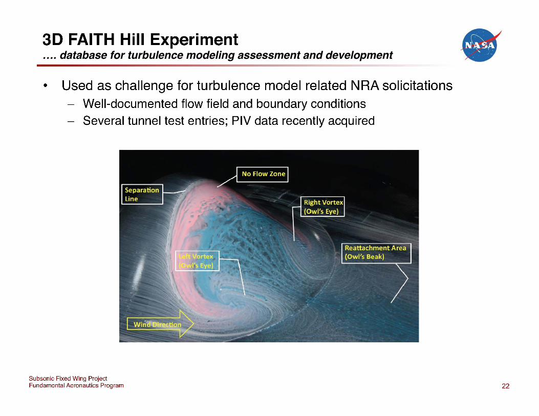
3D FAITH Hill Experiment
• Used as challenge for turbulence model related NRA solicitations Well-documented flow field and boundary conditions Several tunnel test entries; PIV data recently acquired
Subsonic Fixed Wing Project Fundamental Aeronautics Program
•
22
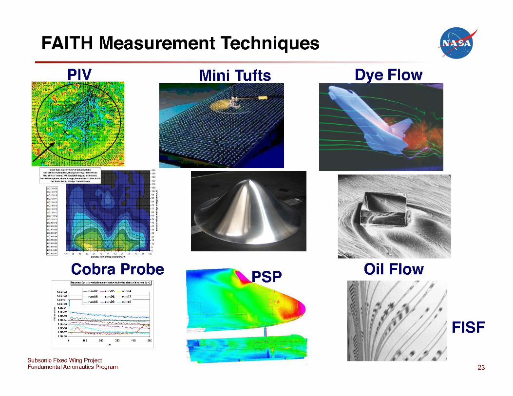
FAITH Measurement Techniques
PIV
Cobra Probe Fi"equencySpeclra:verticallrave'!le,horizwire,behindisland;800hz;runs02-12
1.0E+03 Ej- run02 - run03 run04;1~ 1.0E+02 run05 - run06 - run07
~:~~:~~ - run08 - run09 - run10
1.0E-01
100 200 300 400 500
Subsonic Fixed Wing Project Fundamental Aeronautics Program
Mini Tufts
SP
•
Oil Flow
I FISF
23
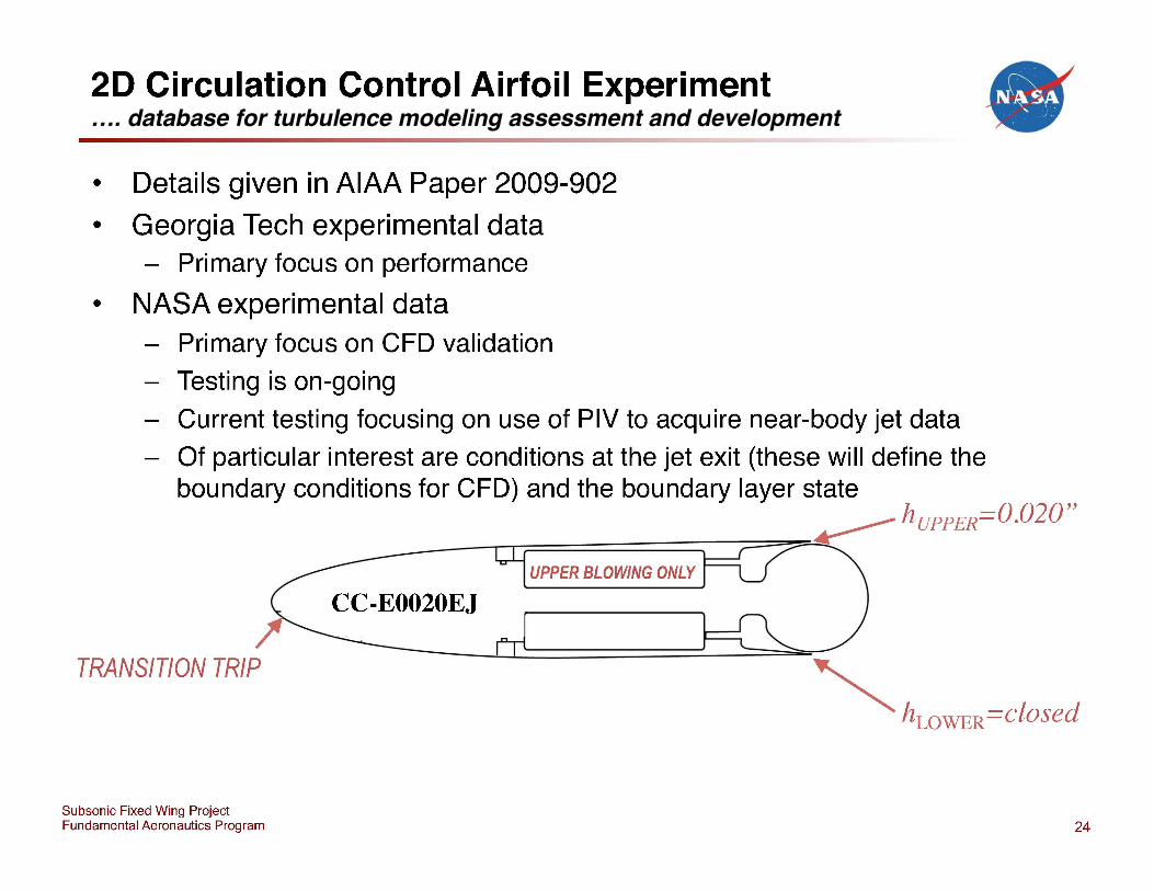
20 Circulation Control Airfoil Experiment
• Details given in AIAA Paper 2009-902
• Georgia Tech experimental data - Primary focus on performance
• NASA experimental data - Primary focus on CFD validation
- Testing is on-going
- Current testing focusing on use of PIV to acquire near-body jet data
•
- Of particular interest are conditions at the jet exit (these will define the boundary conditions for CFD) and the boundary layer state
~ hUPPER=O.020" __ ---.Ir====~==~~~~
TRANSITION TRIP
Subsonic Fixed Wing Project Fundamental Aeronautics Program
CC-E0020EJ UPPER BLOWING ONLY
24
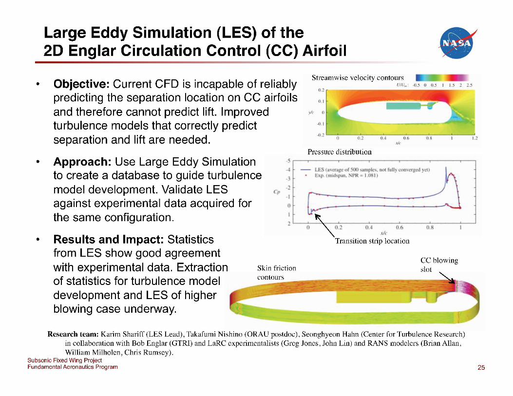
Large Eddy Simulation (LES) of the 20 Englar Circulation Control (CC) Airfoil •
•
•
Objective: Current CFD is incapable of reliably predicting the separation location on CC airfoils and therefore cannot predict lift. Improved turbulence models that correctly predict separation and lift are needed.
Approach: Use Large Eddy Simulation to create a database to guide turbulence model development. Validate LES against experimental data acquired for the same configuration.
c
n
• Results and Impact: Statistics from LES show good agreement with experimental data. Extraction of statistics for turbulence model development and LES of higher blowing case underway.
Skin friction contours
Streamwise velocity contours UIU_ : -05 0 0_5 J 15 :! :!_5
0.2
0. 1
I'Ir 0
-u I
Pressure distribution
411' m~ of I IIf11ph: _ rlOl f ull~ ~ '0 ''--u, ~u • - Iml,l- . r-W : I ,OK I
lif'
Transition strip location
CC blowing slot
Research team: Karim Shariff (LES Lead), Takafumi Nishino (ORAU postdoc), Seonghyeon Hahn (Center for Turbulence Research) in collaboration with Bob Englar (GTRI) and LaRC experimentalists (Greg Jones, John Lin) and RANS modelers (Brian Allan, William Milholen, Chris Rumsey).
Subsonic Fixed Wing Project Fundamental Aeronautics Program 25
Revolutionary Computational Aerosciences •
• "Focused Research in Turbulence Modeling and Advanced CFD" effort - bring additional resources (FTE, NRA) to this research area
- managed as a new sub-project of SFW
- work initiated in FY12
- Revolutionary Computational Aerosciences (RCA)
• Cross-project Fundamental Aeronautics effort - SFW, SRW, sUP, HYP stakeholders
- RCA coordinated with ongoing related turbulence research efforts in all four projects
- A test case for better cross-project integration in specific areas
• Technical Lead: Mujeeb Malik
Subsonic Fixed Wing Project Fundamental Aeronautics Program 27
Round 5 Turbulence Modeling NRA Awards June 2011
• Gianluca laccarino - "Structure Based Modeling of 3D Separated Flows" Stanford University
•
• Hassan Hassan - "Development of TurbulencelTransitional Model and Assessment of Complex Aerodynamic Flows" North Carolina State University
• Sharath Girimaji - "High Fidelity Multi-Resolution Turbulence Computations of Highly Separated Aerodynamic Flows" Texas A&M University
• Parviz Moin - "Large Eddy Simulation with Near-Wall Modeling of Multi-Component Airfoils at Flight Reynolds Numbers" Stanford University
Subsonic Fixed Wing Project Fundamental Aeronautics Program 28
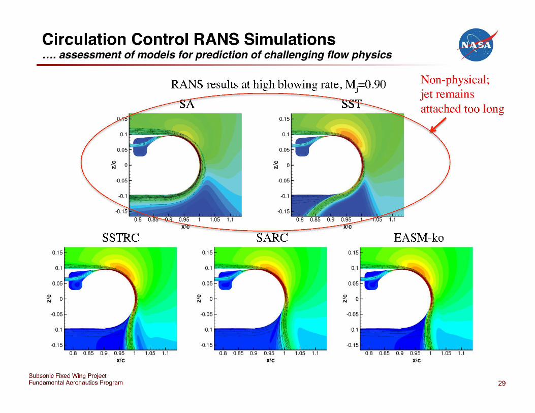
Circulation Control RANS Simulations
RANS results at high blowing rate, Mj=O.90
SSTRC 0.15
Subsonic Fixed Wing Project Fundamental Aeronautics Program
0.15
0.15
~ 0 N
-0.1
SARC 0.15
~ 0 N
-0.05
-0.1
-0.15
1.05 1.1
• Non-physical; jet remains attached too long
EASM-ko
x/c
29
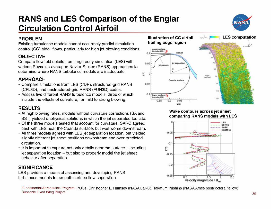
RANS and LES Comparison of the Englar Circulation Control Airfoil • PROBLEM Illustration of CC airfoil '. [ " 1 LES computation
Existing turbulence models cannot accurately predict circulation control (CC) airfoil flows, particularly for high jet-blowing conditions.
trailing edge region
OBJECTIVE Compare flowfield details from large eddy simulation (LES) with various Reynolds-averaged Navier-Stokes (RANS) approaches to determine where RANS turbulence models are inadequate.
APPROACH • Compare simulations from LES (COP), structured-grid RANS -0.0
(CFL30), and unstructured-grid RANS (FUN30) codes. • Assess five different RANS turbulence models, three of which
include the effects of curvature, for mild to strong blowing.
RESULTS • At high blowing rates, models without curvature corrections (SA and
SST) yielded unphysical solutions in which the jet separated too late. • Of the three models tested that account for curvature, SARC agreed
best with LES near the Coanda surface, but was worse downstream. • All three models agreed with LES jet separation location, but yielded
slightly different jet sheet positions downstream and over-predicted circulation.
• It is important to capture not only details near the surface - including jet separation location - but also to properly model the jet sheet behavior after separation.
SIGNIFICANCE LES provides a means of assessing and developing RANS turbulence models for smooth surface flow separation.
u N
c
Wake contours across jet sheet comparing RANS models with LES o
- - - - SSTRC _ ._ ._ -- SARC
----~
O.lt----+
-0. 5
-0.2
-0 250~-O:l.5::---+-1 ---!:;J1.~5 ==~2=====2...r-:5 velocity ma n tude I U""
Fundamental Aeronautics Program POCs: Christopher L. Rumsey (NASA LaRC), Takafumi Nishino (NASA Ames postdoctoral fellow) Subsonic Fixed Wing Project 30

Subsonic Fixed Wing Project Fundamental Aeronautics Program
~ '.' +" .. .
31