Novel method for patterned fabric inspection using Bollinger ...
Upload
universitassemarangCategory
view
0download
0
IEEE TRANSACTIONS ON MAGNETICS, VOL. 47, NO. 7, JULY 2011 1981
Patterned Media and Energy Assisted Recording Study by Drag TesterS. H. Leong, M. J. B. Lim, B. Santoso, C. L. Ong, Z.-M. Yuan, Y. J. Chen, T. L. Huang, and S. B. Hu
Data Storage Institute, Agency for Science, Technology and Research (A*STAR), Singapore 117608, Singapore
A static drag tester was developed for characterization and read/write of patterned and continuous magnetic disk media. To enablewrite synchronization for patterned media application, a scheme for write synchronization was designed and implemented. The resultsfor synchronized writing of patterned bits using a read-while-write approach are presented and they indicate that read-while-write is aviable approach for flexible written-in error tests at drag tester level. Besides application for pattern media, a method suitable for studyof energy assisted media by drag tester was also explored. The results show that the required switching field reduced as the temperatureof the recording medium was increased. The drag tester is thus shown to be a flexible and valuable platform for the study of futuremagnetic recording media.
Index Terms—Energy assisted recording media, patterned media, static drag tester, write synchronization.
I. INTRODUCTION
P ATTERNED media and energy assisted recording arepromising technologies that will push magnetic recording
into the multi-terabit per square inch areal density regime.However, there continues to be many issues to be solved beforethe technologies become ready for commercial hard disk driveapplication.
For patterned media, write synchronization is a problem be-cause it is necessary to synchronize the magnetic field switchingwith physical bit locations on the disk [1], [2], otherwise theerror in write timing can cause problems such as severe signaldegradation. Previously, some work on write-synchronizationstudy was performed at spin-stand level [3] using conventionalcontinuous perpendicular media. Here, in our work, we reporton the development of a static drag tester for use in write-syn-chronization experiments on physically patterned magnetic diskmedia.
To achieve write synchronization, a scheme based on a read-while-write approach was developed, and applied for synchro-nized writing at drag tester level. In addition, modification wasmade to the drag tester to allow exploration of energy assistedmagnetic recording on disk media. With the localized measure-ment capability, the drag tester provides magnetic characteriza-tion at much smaller length scales compared to other standardtools such as the vibrating sample magnetometer and magnetooptical Kerr effect system.
II. DRAG TESTER SETUP
The in-house drag tester is shown in Fig. 1. The 2-D scan-ning piezoelectric stage is from Physik Instrumente (PI) and hasa resolution of 1 nm. This is the ultimate possible resolution ofthe drag tester, subject to other limitations and constraints. Theread/write electronics is developed in-house and provides directread/write connections (via the and lines) tothe head/slider to allow lower frequency read/write (typical of
Manuscript received December 02, 2010; accepted February 28, 2011. Dateof current version June 24, 2011. Corresponding author: S. H. Leong (e-mail:[email protected]).
Color versions of one or more of the figures in this paper are available onlineat http://ieeexplore.ieee.org.
Digital Object Identifier 10.1109/TMAG.2011.2125783
Fig. 1. Drag tester developed in-house. Key components of the tester includepiezoelectric scanning stage, coarse translation stage, load/unload mechanismas well as read/write electronics.
drag tester operation) that is not readily supported by existingcommercial head preamplifiers. Fig. 2 presents the schematicof the in-house developed read electronics. The signal from theread sensor, Rd is first amplified by a differential amplifier (DiffAmp) and is further amplified via a gain stage. Finally, the am-plified signal is acquired by a National Instruments Data Acqui-sition Card (NI DAQ) controlled by a Labview program.
III. DRAG TESTER READ/WRITE PERFORMANCE
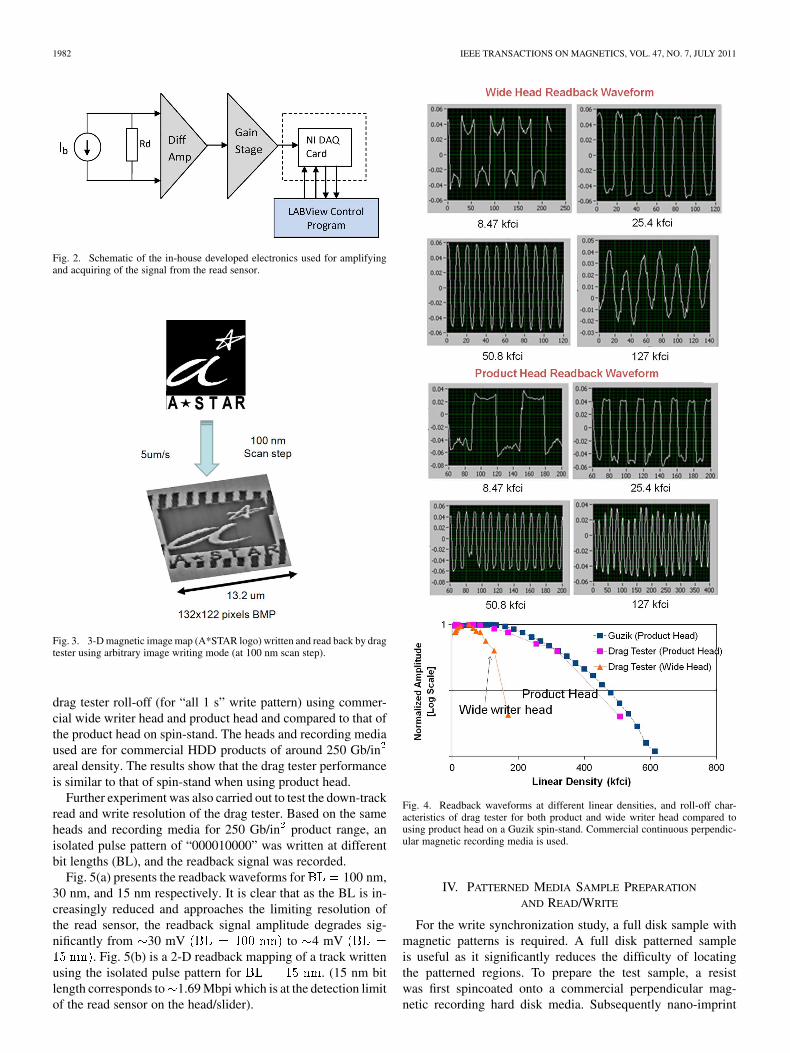
The drag tester supports different operational modes in-cluding single track writing and arbitrary image writing.Fig. 3 shows a 3-D magnetic image map of an arbitrary image(A*STAR logo) written and read back by the drag tester oncommercial perpendicular magnetic recording disk media.
Read/write at different linear densities was carried out to de-termine the roll-off characteristics of the drag tester. The roll-offcharacteristics are also dependent on the head/disk media com-bination. Fig. 4 presents the typical readback waveforms and
0018-9464/$26.00 © 2011 IEEE
1982 IEEE TRANSACTIONS ON MAGNETICS, VOL. 47, NO. 7, JULY 2011
Fig. 2. Schematic of the in-house developed electronics used for amplifyingand acquiring of the signal from the read sensor.
Fig. 3. 3-D magnetic image map (A*STAR logo) written and read back by dragtester using arbitrary image writing mode (at 100 nm scan step).
drag tester roll-off (for “all 1 s” write pattern) using commer-cial wide writer head and product head and compared to that ofthe product head on spin-stand. The heads and recording mediaused are for commercial HDD products of around 250 Gb/inareal density. The results show that the drag tester performanceis similar to that of spin-stand when using product head.
Further experiment was also carried out to test the down-trackread and write resolution of the drag tester. Based on the sameheads and recording media for 250 Gb/in product range, anisolated pulse pattern of “000010000” was written at differentbit lengths (BL), and the readback signal was recorded.
Fig. 5(a) presents the readback waveforms for 100 nm,30 nm, and 15 nm respectively. It is clear that as the BL is in-creasingly reduced and approaches the limiting resolution ofthe read sensor, the readback signal amplitude degrades sig-nificantly from 30 mV to 4 mV
. Fig. 5(b) is a 2-D readback mapping of a track writtenusing the isolated pulse pattern for . (15 nm bitlength corresponds to 1.69 Mbpi which is at the detection limitof the read sensor on the head/slider).
Fig. 4. Readback waveforms at different linear densities, and roll-off char-acteristics of drag tester for both product and wide writer head compared tousing product head on a Guzik spin-stand. Commercial continuous perpendic-ular magnetic recording media is used.
IV. PATTERNED MEDIA SAMPLE PREPARATION
AND READ/WRITE
For the write synchronization study, a full disk sample withmagnetic patterns is required. A full disk patterned sampleis useful as it significantly reduces the difficulty of locatingthe patterned regions. To prepare the test sample, a resistwas first spincoated onto a commercial perpendicular mag-netic recording hard disk media. Subsequently nano-imprint

LEONG et al.: PATTERNED MEDIA AND ENERGY ASSISTED RECORDING STUDY BY DRAG TESTER 1983
Fig. 5. (a) Downtrack readback waveforms for isolated bit pulse pattern(“000010000”) written at different bit lengths of 100 nm, 30 nm, and 15 nm,and (b) 2-D readback mapping of a track written using the isolated pulse patternat �� � �� nm which is at the limit of the read sensor resolution.
lithography (NIL) [4], [5] was performed on an Obducat NILmachine using a two-stage process. First, the DVD mold pat-terns were imprinted onto an intermediate polymer substrate(IPS). Subsequently, a second stage imprint process was usedto transfer the patterns from the IPS to the resist layer. Finally,ion beam etching was used for the final stage of pattern transferfrom resist onto the magnetic layer of the disk media.
Fig. 6 shows the SEM image (top) of a region on the patternedmagnetic disk together with atomic force microscope (AFM)and magnetic force microscope (MFM) images (bottom left andbottom right, respectively). The SEM and AFM images in Fig. 6indicate that the pattern is successfully transferred onto the diskmedia forming discrete tracks, while the MFM images indicatethat magnetic properties of the media are preserved (magnetic
Fig. 6. (a) SEM image of a region on the full disk patterned sample, and (b)indicative AFM and MFM images (bottom left and bottom right, respectively).MFM images demonstrate polarity reversal in contrast to the AFM imageshowing that magnetic properties are preserved after the NIL and patterningprocess.
polarity can be reversed in contrast to the AFM image). Dragtester read/write was then performed on the magnetic discretetracks. Fig. 7 presents typical 2-D magnetic readback imagesand downtrack waveforms of the discrete tracks written by dragtester using an “all 1 s” pattern ( m, , and
).
V. WRITE SYNCHRONIZATION EXPERIMENT
For write synchronization on patterned media to be possible,it is essential to be able to determine when writing should takeplace so as to be in sync with the physical bits. Instead of usingcomplex timing schemes or introducing additional hardware, amuch simpler way would be to attempt to determine the locationby means of the read back signal. In other words, if the dragtester can read/detect the actual physical bits during the writingprocess, the information can be used to synchronize the writingprocess on the go, essentially to perform a “read while write”approach.
Generally, it is difficult to perform read-while-write on a spin-stand or in a HDD as there is coupling of the write signal intothe readback signal [6]. One major source of this coupling isthe suspension interconnect between the preamplifier and theslider whereby there is coupling of the writing signal into theread trace lines during writing operations [7].
This means that when writing is taking place, the weakerreadback signal can be swamped by the much stronger writing

1984 IEEE TRANSACTIONS ON MAGNETICS, VOL. 47, NO. 7, JULY 2011
Fig. 7. Typical 2-D magnetic readback images and readback waveforms formagnetic discrete tracks written by drag tester at �� � ��� �m, ��� �m, and��� �m.
signal that is coupled into the reader lines and thus one is un-able to effectively detect the present physical bit location andthereby synchronize the writing. An experiment was performedto verify whether significant crosstalk and coupling occurred(for the heads and suspension used) due to the writing processand how this would affect drag tester operation. Fig. 8 shows theresults of the experiment. Initially at a high writing frequencyof 50 MHz, there is significant coupling of the high frequencywriting signal into the reader lines—140 mV and 2.4 V respec-tively as measured by the home built differential amplifier cir-cuit and commercial pre-amplifier. However as the frequency isreduced, the amplitude of the crosstalk signal also falls signifi-cantly but in an almost linear fashion. At 5 MHz, the crosstalksignal amplitude has fallen to 5 mV for the case of the dif-ferential amplifier. In contrast, the normal readback amplitude(for a written track) on the drag tester is 50 to 75 mV. Thuswhen the frequency is sufficiently low ( 1 MHz), as in the caseof drag tester operation, crosstalk is no longer a problem, and aread-while-write approach becomes viable.
A read-while-write scheme is thus implemented in thecontrol algorithm to allow synchronization of the writing tothe detected physical bits. The scheme involves first findingthe reader-writer offset (in downtrack direction). This is easilyachieved by writing a special pattern on a non-patterned con-tinuous magnetic disk media and subsequently reading back(scanning over a larger area) to locate the written pattern. Theoffset between the written and subsequent readback position isthe reader-writer distance. The actual location at which writingtakes place can be thus known relative to the reading position.For the commercial head used, the reader-writer distance indown track scan direction is m.
Fig. 8. Oscilloscope waveforms (top) showing writing signal waveform(middle) and coupled readback waveforms from both home built differentialamplifier and commercial pre-amplifier. The graph (bottom) shows that thecrosstalk signal amplitude decreases significantly with writing frequency.
To verify the write synchronization approach, it is essentialto have patterned bits in the downtrack direction of writing.Since the magnetic patterned tracks do not provide these, onealternative is to re-position the read/write head such as from theconventional zero skew position 1 to position 2 as depicted inFig. 9(a). In position 2 as the head is scanned in a left-right di-rection, it is effectively moving across many physical “bits”.
Fig. 9(b) consists of drag tester written and acquired read backwaveforms and single track intensity maps. The lighter (white)waveform and lower left intensity map applies to that of a DCerased track of physical bits while the darker (red) waveformand lower right intensity map is the same track overwritten usinga write pattern with period wider than that of the physical bits.As evident from the waveform and images, the drag tester is ableto effectively write on the patterned media, resulting in a seriesof 1 s, 0 s, and 1 s bits.
Experiments were subsequently performed to demonstratesynchronized read-while-write capability on patterned media.The procedure involves first performing DC erase on a trackof magnetic patterned bits. Subsequently the same track isoverwritten with a write pattern that is either synchronized tobe in phase or deliberately out of phase with the physical bits.
Fig. 10 (top) shows the outcome of the experiment when thewrite-pattern was chosen to be synchronized with the physicalbit edges where the red profile is the DC erased readback signal,the blue profile is the overwritten track and the green waveformis the write pattern. The results indicate that proper synchro-nized writing to actual physically patterned bits is possible.
Fig. 10 (bottom) presents the alternative case whereby thewrite pattern is written deliberately out of phase. The writepattern used also has a period that is not exact multiples of

LEONG et al.: PATTERNED MEDIA AND ENERGY ASSISTED RECORDING STUDY BY DRAG TESTER 1985
Fig. 9. (a) Repositioning the read/write head (red triangle) from position 1 toposition 2 changes discrete tracks to discrete bits for the same direction of scan-ning, (b) readback waveforms and intensity maps for an initially DC erased track(white waveform) that was over-written (red waveform).
Fig. 10. Synchronized writing on a patterned disk media. Track is first DCerased followed by synchronized write using a write field pattern shown.Top: writing field is synchronized, resulting in properly written physical bits;Bottom: deliberately writing out of sync leads to improperly written bits. (e.g.,a half written bit encircled).
the physical patterned bit length, thus resulting in varyingpartial writes of the physical bits (a half written bit is encircled)whereby the writing waveform switches not at the physical bitedge. Due to the large bit length ( 600 nm half pitch for the
Fig. 11. Drag tester setup for heat assisted magnetic recording study. An IRheater provides the thermal energy while a thermocouple probe monitors thetemperature of the disk under test.
discrete tracks), the bits are not single domain, and hence thephenomena of partial writes can be observed. The ability tocarry out both in-phase and out-of-phase partial writing reflectsthe flexibility of the synchronized read-while-write capabilityof the drag tester which can be used for the study of written-inerrors in bit patterned media.
VI. ENERGY ASSISTED RECORDING STUDY
Besides bit patterned media, energy assisted magneticrecording is also another approach to reach the multi-terabitper square inch areal density regime. The two relatively morewell known approaches are heat assisted magnetic recording(HAMR) [8] and microwave assisted magnetic recording(MAMR) [9].
Preliminary investigation of energy assisted recording, in par-ticular HAMR was also carried out on the drag tester. Fig. 11shows a picture of the drag tester setup for HAMR study. SinceHAMR heads are not readily available, the heating is providedinstead by an external Infra-Red (IR) heater that is controlledvia a temperature controller with PID control. The read/write isperformed using heads from commercially available HDDs.
The media under test is conventional perpendicular magneticrecording disk media from commercial HDDs. The temperatureof the media under test is monitored by a thermocouple probesituated in contact with the disk surface. This allows the disktemperature to be known when different heating power is ap-plied. At steady state, the temperature measured by the ther-mocouple probe is expected to be indicative of the temperatureof the disk media under test provided that the probe is suffi-ciently near the testing spot. One issue with using an externalheater (instead of HAMR heads) is that the heating is applied toa large area, and would cause expansion of the disk. The expan-sion of the disk creates problems since it is more difficult uponcooling to locate the region previously written under elevatedtemperatures. (For consistency it is preferred that readback isalways conducted at the same room temperature). Another po-tential issue is that of heat dissipation. Since the disk media onthe static drag tester does not spin, there is no air cooling unlikethat in a drive. Therefore there is possibility for the read sensorto fail if exposed to excessive heat. However the main advan-tage of external heating is that once the temperature of the diskis stabilized, it can be more reliability measured, compared to

1986 IEEE TRANSACTIONS ON MAGNETICS, VOL. 47, NO. 7, JULY 2011
Fig. 12. The testing process for HAMR study by drag tester is presented. Thetrack written by applying increasing reversal write field is first imaged. Subse-quently processing of the cross profile is performed to obtain the switching fieldmeasurement (which is related to the downtrack position).
the case of using a flying HAMR head where there is great dif-ficulty to estimate the temperature of the spinning disk mediaunder the laser spot during writing.
The complete testing procedure involves an initial DC eraseof the target disk region. Subsequently, the temperature of thedisk media is raised by changing the heater power of the IRheater. Once the temperature has stabilized to a desired targetvalue, a special overwrite pattern consisting of increasing re-versal field (direction is opposite to that of the initial DC erasefield) is applied. After writing with the reversal field at the stabi-lized elevated temperature, the IR heater power is switched offand the disk is allowed to cool. Upon cooling to the stabilizedroom temperature, a scan is performed to acquire the image ofthe written track. The magnetic image of the written track is thenprocessed to obtain the switching field (writer voltage). Fig. 12illustrates the steps involved.
The above procedure was repeated for the same test mediaand read/write head but for different stabilized elevated tem-peratures. In each test, the switching field (writer voltage) isrecorded in conjunction with the temperature.
Fig. 13. Two HAMR tests performed at different elevated temperatures ofwriting (35 � and 45 �). When the temperature of writing is higher, therequired field for reversal is less.
Fig. 14. Measured switching fields (in terms of writer voltage) for differentelevated temperatures of writing (20 � to 60 �) are presented. The switchingfield is found to have a linear relationship with the writing temperature for therange of temperatures concerned.
Fig. 13 shows 2 measurements performed at different tem-peratures of 35 and 45 . The two curves are offset fromeach other in the downtrack direction, indicating that the re-quired writing field to reverse the media is different at differentelevated writing temperatures. Clearly, the recording mediareverses magnetic polarity at a lower writing field when thewriting temperature is higher.
The results of the HAMR experiment at different tempera-tures are summarized in Fig. 14. The required switching fieldswere found to decrease linearly with increased temperatures atwhich writing was carried out. The decrease in the requiredswitching field is the result of reduced magnetic anisotropy ofthe disk media at elevated temperatures of writing [10]. The re-sults are in agreement with the concept of HAMR.
VII. COMPARISON OF DRAG TESTER TO CONVENTIONAL
MEASUREMENT APPROACH
Compared to conventional bulk measurements of magneticproperties by tools such as the vibrating sample magnetometerand Kerr Effect magnetometers, the drag tester approach offersdistinct advantages such as localized measurement and good po-sitioning accuracy. In addition, because it uses HDD read/writeheads, it provides a recording situation that is closer to thatof a hard disk drive operation. Compared to the spinstand or

LEONG et al.: PATTERNED MEDIA AND ENERGY ASSISTED RECORDING STUDY BY DRAG TESTER 1987
drive level tests, the drag tester approach also possesses advan-tage as it can accommodate coupon samples, and is not suscep-tible to air flow induced vibrations (such as disk flutter and vi-bration of head-gimbal-assembly) [11]. Since the head is notflying, ambiguity from readback signal variation caused by vi-bration induced fly height change is avoided, so is the require-ment for flyable or planarised disk media (as in the case of BPMon spinstand). The relaxation in terms of the flyability require-ment also means that lubricant issues are less critical. This isextremely helpful in HAMR applications where during rapidheating events, the lubricant is prone to decomposition and des-orption from the surface, leading to degradation of the lubricantfilm [12] that severely impacts experiments involving a flyinghead/slider. The above characteristics make a drag tester basedtesting approach more favorable for the testing of experimentalfuture magnetic recording media and technologies.
VIII. CONCLUSION
A static drag tester was developed and used for the studyof both patterned media and energy assisted recording. It wasshown that a read-while-write approach is viable and allowedvery flexible synchronized writing of patterned bits. This capa-bility is very useful for the study of written-in errors in BPM.The drag tester was also used for the study of energy assistedrecording, and the results of the study show that switching fieldof the media decreases linearly with increased temperature ofmedia during writing.
REFERENCES
[1] H. J. Richter, A. Y. Dobin, O. Heinonen, K. Z. Gao, R. J. M. V. D.Veerdonk, R. T. Lynch, J. Xue, D. Weller, P. Asselen, M. F. Erden,and R. M. Brockie, “Recording on bit-patterned media at densities of1 Tb/in and beyond,” IEEE Trans. Magn., vol. 42, pp. 2255–2260, Oct.2006.
[2] J. Hu, T. M. Duman, E. M. Kurtas, and M. F. Erden, “Bit-patternedmedia with written-in errors: Modeling, detection and theoreticallimits,” IEEE Trans. Magn., vol. 43, pp. 3517–3524, Aug. 2007.
[3] Y. Tang, K. Moon, and H. J. Lee, “Write synchronization in bit-pat-terned media,” IEEE Trans. Magn., vol. 45, pp. 822–827, Feb. 2009.
[4] S. Y. Chou, P. R. Krauss, and P. J. Renstrom, “Imprint of sub-25nm vias and trenches in polymers,” Appl. Phys. Lett., vol. 67, pp.3114–3116, Nov. 1995.
[5] S. Zankovych, T. Hoffmann, J. Seekamp, J.-U. Bruch, and C. M. So-tomayor Torres, “Nanoimprint lithography: Challenges and prospects,”Nanotechnology, vol. 12, pp. 91–95, Jan. 2001.
[6] K. Klaassen, J. Peppen, and X. Xing, “Write-to-read coupling,” IEEETrans. Magn., vol. 38, pp. 61–67, Jan. 2002.
[7] E. Jang and X. Zhang, “Write-to-read coupling study of various inter-connect types,” J. Appl. Phys., vol. 93, pp. 6453–6455, May. 2003.
[8] M. H. Kryder, E. C. Gage, T. W. McDaniel, W. A. Challener, R. E.Rottmayer, G. Ju, Y.-T. Hsia, and M. F. Erden, “Heat assisted magneticrecording,” Proc. IEEE, vol. 96, pp. 1810–1835, Nov. 2008.
[9] J.-G. Zhu, X. Zhu, and Y. Tang, “Microwave assisted magneticrecording,” IEEE Trans. Magn., vol. 44, pp. 125–131, Jan. 2008.
[10] J. J. M. Ruigrok, R. Coehoorn, S. R. Cumpson, and H. W. Kesteren,“Disk recording beyond 100 Gb/in.2: Hybrid recording?,” J. Appl.Phys., vol. 87, pp. 5398–5403, May 2000.
[11] Q. Zhang, T.-H. Yip, and G. X. Guo, “Flow-induced vibration in harddisk drives,” Int. J. Prod. Develop. (IJPD), vol. 5, pp. 390–409, 2008.
[12] M. S. Lim and A. J. Gellman, “Kinetics of laser induced desorption anddecomposition of Fomblin Zdol on carbon overcoats,” Tribol. Int., vol.38, pp. 554–561, Feb. 2005.
Copyright © 2022 FDOKUMEN