Mobile-Based Digital IC Tester
62
Palestine Polytechnic University College of Information Technology and Computer Engineering Mobile-Based Digital IC Tester Team: Amany Taweel Sundos Mujahed Supervisors: Dr. Sami Abu-Snaineh Mr. Elayan Abu-Gharbyeh June 4, 2017
-
Upload
khangminh22 -
Category
Documents
-
view
0 -
download
0
Transcript of Mobile-Based Digital IC Tester

Palestine Polytechnic University
College of Information Technology and ComputerEngineering
Mobile-Based Digital IC Tester
Team:Amany Taweel
Sundos Mujahed
Supervisors:
Dr. Sami Abu-SnainehMr. Elayan Abu-Gharbyeh
June 4, 2017

..
With the name of Allah

Declaration of AuthorshipWe, Amany Taweel and Sundos Mujahed, declare that this thesis titled, ‘Mobile-
Based Digital IC Tester’ and the work presented in it are our own. We confirm that:
� This work was done wholly or mainly while in candidature for a bachelor degreeat this University.
� Where any part of this thesis has previously been submitted for a degree orany other qualification at this University or any other institution, this has beenclearly stated.
� Where we have consulted the published work of others, this is always clearlyattributed.
� Where we have quoted from the work of others, the source is always given.With the exception of such quotations, this thesis is entirely our own work.
� we have acknowledged all main sources of help.
� Where the thesis is based on work done by ourselves jointly with others, wehave made clear exactly what was done by others and what we have contributedourselves.
Signed:
Date:
ii

“An idea is like a virus. Resilient. Highly contagious. And even the smallest seed of an idea cangrow. It can grow to define or destroy you.”
Cobb-Inception Movie

AbstractThe Integrated Circuits (ICs) logic gates are widely used in the electronic circuits.Different values and types from different families are needed to design a circuit forpractical operations. To get the proper output of the circuit, its components musthave accurate values. This can be checked by using IC tester. Nowadays, availableIC testers are very expensive, very big and heavy, thus are not portable, and hard touse.
This project used small and cheap components to solve the previously mentionedproblems. It consists of three main parts: IC socket, Android mobile, and website.The IC socket is built from connecting Arduino Nano and ZIF to test ICs. TheAndroid mobile is connected to this socket via OnTheGo cable to make it worksas the main processor of the project. The website is created in order to add newunsupported ICs to the project’s database and verify coming user’s packages from anAndroid application by JSON.
At the end of the project, it has achieved all its objectives and made digital IC testerbased on mobile, very small, cheap, using mobile interfaces to provide the easiestenvironment for the user and giveing the opportunity to add new ICs to the tester.
iv

Acknowledgements.
All praise and thanks are only for Allah, the one who, by his blessing and favor, helpus to get through this project, and gave us the strength and patience whenever westumbled and faced hardship.
Deeply from our hearts, we would thank everyone who supports us to continue,believe and stand with us to reach here today, everyone with his name.
We start to thank our parents, Amany’s Dad, I know the thanks is not enough butyour words: “I believe you will be a very great person in the world ”, stay with mein every minute to shine my way. Amany’s Mam, nothing as you and how muchI thank you, I believe you deserve more and more. Sundos’s Dad and Mam, whosupport and believe in me, I appreciate all what you did for me till this moment andforever.
We really would thank our devoted supervisor, Dr. Sami Abu-Suninah, for sharinghis experience, ideas and sciences with us. We pray so much for him to get better.Hopefully to be proud of us when seeing this work and read these words.
We really feel grateful to our supervisor Mr. Elayan Abu-Gharbyah who continuesthis project with us in the second semester and for giving us a lot of his time andknowledge.
Our words are not enough to thank Dr. Hani Salah, who shareing us his experienceand giving us a lot of his time.
Special thanks to Dr. Mousa Farajallah, who supported us in the Microsoft composi-tion (Imagine-Cup), and gave us a lot of useful notes and advice to go ahead on thisproject.
To Eng. Wa’el Altakrori for offering the Lab to work in, and helped us on hardwarecomponents. To Eng. Muhammed Al-Qaisi for learning us how to use PIC in thisproject.
For our families and friends, for Sundo’s grandma and finally for a very creative andsupporting team, who helped on video and many other things: Leqa, Haya, Renad,Ala‘, Riham, Raneen, Souhib, Yousef, Amal and Ahlam.
At the end and as the beginning we thank Allah for finding you in our life and hopingto be always very proud of us.
v

Contents
Declaration of Authorship ii
Abstract iv
Acknowledgements v
Contents vi
List of Figures ix
List of Tables x
Abbreviations xi
1 Introduction 11.1 Overview of the Project . . . . . . . . . . . . . . . . . . . . . . . . . . . . . . . . . 11.2 Motivation and Importance . . . . . . . . . . . . . . . . . . . . . . . . . . . . . . . 11.3 Objectives . . . . . . . . . . . . . . . . . . . . . . . . . . . . . . . . . . . . . . . . 11.4 Description of the Project . . . . . . . . . . . . . . . . . . . . . . . . . . . . . . . . 21.5 Economical Benefits of the Project . . . . . . . . . . . . . . . . . . . . . . . . . . . 21.6 Problem Analysis . . . . . . . . . . . . . . . . . . . . . . . . . . . . . . . . . . . . 21.7 List of Requirements . . . . . . . . . . . . . . . . . . . . . . . . . . . . . . . . . . 2
1.7.1 Hardware Requirements . . . . . . . . . . . . . . . . . . . . . . . . . . . . 21.7.2 Software Requirements . . . . . . . . . . . . . . . . . . . . . . . . . . . . . 3
1.8 Project Time Line . . . . . . . . . . . . . . . . . . . . . . . . . . . . . . . . . . . . 41.9 Project Gantt Chart . . . . . . . . . . . . . . . . . . . . . . . . . . . . . . . . . . . 41.10 Report Outline . . . . . . . . . . . . . . . . . . . . . . . . . . . . . . . . . . . . . . 4
2 Literature Review 52.1 Overview . . . . . . . . . . . . . . . . . . . . . . . . . . . . . . . . . . . . . . . . 52.2 IC Testers in the Markets . . . . . . . . . . . . . . . . . . . . . . . . . . . . . . . . 5
2.2.1 Instek Gut-6000A (Digital IC Tester) . . . . . . . . . . . . . . . . . . . . . . 52.2.2 Instek Gut-6600 (Handy Digital IC Tester) . . . . . . . . . . . . . . . . . . . 62.2.3 575A Digital IC Tester . . . . . . . . . . . . . . . . . . . . . . . . . . . . . 72.2.4 DICT-01 Digital IC Tester . . . . . . . . . . . . . . . . . . . . . . . . . . . 82.2.5 DICT-03 Universal IC Tester . . . . . . . . . . . . . . . . . . . . . . . . . . 82.2.6 Integrated Circuit IC Tester for 74 40 45 Series. . . . . . . . . . . . . . . . . 9
2.3 Scientific Theoretical IC Testers Projects . . . . . . . . . . . . . . . . . . . . . . . 92.3.1 First Project . . . . . . . . . . . . . . . . . . . . . . . . . . . . . . . . . . . 92.3.2 Second Project . . . . . . . . . . . . . . . . . . . . . . . . . . . . . . . . . 102.3.3 Third Project . . . . . . . . . . . . . . . . . . . . . . . . . . . . . . . . . . 102.3.4 Fourth Project . . . . . . . . . . . . . . . . . . . . . . . . . . . . . . . . . . 10
vi

2.3.5 Fifth Project . . . . . . . . . . . . . . . . . . . . . . . . . . . . . . . . . . . 102.4 Comparison . . . . . . . . . . . . . . . . . . . . . . . . . . . . . . . . . . . . . . . 11
3 Background 123.1 Overview . . . . . . . . . . . . . . . . . . . . . . . . . . . . . . . . . . . . . . . . 123.2 Theoretical Background . . . . . . . . . . . . . . . . . . . . . . . . . . . . . . . . . 12
OTG Cable . . . . . . . . . . . . . . . . . . . . . . . . . . . . . . . . . . . . . . . 12Android- SQLite DataBase . . . . . . . . . . . . . . . . . . . . . . . . . . . . . . . 12Printed Circuit Board (PCB) . . . . . . . . . . . . . . . . . . . . . . . . . . . . . . 12ATtiny85 . . . . . . . . . . . . . . . . . . . . . . . . . . . . . . . . . . . . . . . . . 13Pic18F2550 . . . . . . . . . . . . . . . . . . . . . . . . . . . . . . . . . . . . . . . 13Digispark USB Development Board . . . . . . . . . . . . . . . . . . . . . . . . . . 13Arduino Nano . . . . . . . . . . . . . . . . . . . . . . . . . . . . . . . . . . . . . . 13
3.3 System Hardware Components . . . . . . . . . . . . . . . . . . . . . . . . . . . . . 133.4 System Software Components . . . . . . . . . . . . . . . . . . . . . . . . . . . . . 14
3.4.1 Software Tools . . . . . . . . . . . . . . . . . . . . . . . . . . . . . . . . . 143.4.2 Used programming Languages . . . . . . . . . . . . . . . . . . . . . . . . . 14
4 System Design 154.1 Overview . . . . . . . . . . . . . . . . . . . . . . . . . . . . . . . . . . . . . . . . 154.2 Flowcharts . . . . . . . . . . . . . . . . . . . . . . . . . . . . . . . . . . . . . . . . 16
4.2.1 Hardware Flowchart . . . . . . . . . . . . . . . . . . . . . . . . . . . . . . 174.2.2 Software Flowchart . . . . . . . . . . . . . . . . . . . . . . . . . . . . . . . 18
4.3 Diagrams . . . . . . . . . . . . . . . . . . . . . . . . . . . . . . . . . . . . . . . . 194.3.1 System Block Diagram . . . . . . . . . . . . . . . . . . . . . . . . . . . . . 194.3.2 Schematic Diagram . . . . . . . . . . . . . . . . . . . . . . . . . . . . . . . 194.3.3 Description Diagram . . . . . . . . . . . . . . . . . . . . . . . . . . . . . . 204.3.4 Class Diagram . . . . . . . . . . . . . . . . . . . . . . . . . . . . . . . . . 21
4.4 Use Case . . . . . . . . . . . . . . . . . . . . . . . . . . . . . . . . . . . . . . . . . 224.5 System DataBase . . . . . . . . . . . . . . . . . . . . . . . . . . . . . . . . . . . . 234.6 Requirement Analysis Tables . . . . . . . . . . . . . . . . . . . . . . . . . . . . . . 25
4.6.1 Android Application Requirements . . . . . . . . . . . . . . . . . . . . . . . 254.6.2 The Website Requirements . . . . . . . . . . . . . . . . . . . . . . . . . . . 26
5 Validation and Testing 285.1 Overview . . . . . . . . . . . . . . . . . . . . . . . . . . . . . . . . . . . . . . . . 285.2 The Chronology of the Testing . . . . . . . . . . . . . . . . . . . . . . . . . . . . . 28
First Test . . . . . . . . . . . . . . . . . . . . . . . . . . . . . . . . . . . . . . . . . 28Second Test . . . . . . . . . . . . . . . . . . . . . . . . . . . . . . . . . . . . . . . 29Third Test . . . . . . . . . . . . . . . . . . . . . . . . . . . . . . . . . . . . . . . . 30Fourth Test . . . . . . . . . . . . . . . . . . . . . . . . . . . . . . . . . . . . . . . 31Conclusion . . . . . . . . . . . . . . . . . . . . . . . . . . . . . . . . . . . . . . . 32
5.3 The Chronology of the Programming . . . . . . . . . . . . . . . . . . . . . . . . . . 32The First one . . . . . . . . . . . . . . . . . . . . . . . . . . . . . . . . . . . . . . 32The Second one . . . . . . . . . . . . . . . . . . . . . . . . . . . . . . . . . . . . . 33The Third one . . . . . . . . . . . . . . . . . . . . . . . . . . . . . . . . . . . . . . 33The Fourth one . . . . . . . . . . . . . . . . . . . . . . . . . . . . . . . . . . . . . 34
5.4 Implementation Issues: . . . . . . . . . . . . . . . . . . . . . . . . . . . . . . . . . 345.5 Implementation Results: . . . . . . . . . . . . . . . . . . . . . . . . . . . . . . . . 34
6 Hardware and Software Implementation 35

6.1 Overview . . . . . . . . . . . . . . . . . . . . . . . . . . . . . . . . . . . . . . . . 356.2 Hardware Implementation . . . . . . . . . . . . . . . . . . . . . . . . . . . . . . . . 35
6.2.1 IC Socket Circuit Design . . . . . . . . . . . . . . . . . . . . . . . . . . . . 356.2.2 Connecting IC Socket to the Mobile . . . . . . . . . . . . . . . . . . . . . . 37
6.3 Software Implementation . . . . . . . . . . . . . . . . . . . . . . . . . . . . . . . . 376.3.1 IC Socket Programming . . . . . . . . . . . . . . . . . . . . . . . . . . . . 376.3.2 Android Implementation . . . . . . . . . . . . . . . . . . . . . . . . . . . . 386.3.3 Website Implementation . . . . . . . . . . . . . . . . . . . . . . . . . . . . 386.3.4 Connecting all Together . . . . . . . . . . . . . . . . . . . . . . . . . . . . . 39
6.4 Interfaces . . . . . . . . . . . . . . . . . . . . . . . . . . . . . . . . . . . . . . . . 406.4.1 Website Interfaces . . . . . . . . . . . . . . . . . . . . . . . . . . . . . . . . 406.4.2 Android Application Activities . . . . . . . . . . . . . . . . . . . . . . . . . 44
7 Conclusion 477.1 Final Results . . . . . . . . . . . . . . . . . . . . . . . . . . . . . . . . . . . . . . . 477.2 Additional Works . . . . . . . . . . . . . . . . . . . . . . . . . . . . . . . . . . . . 477.3 Future Works . . . . . . . . . . . . . . . . . . . . . . . . . . . . . . . . . . . . . . 487.4 Project Achievements . . . . . . . . . . . . . . . . . . . . . . . . . . . . . . . . . . 48
A Arduino Nano 49
Bibliography 50

List of Figures
2.1 Figure 1: Instek Gut-6000A . . . . . . . . . . . . . . . . . . . . . . . . . . . . . . . . . 52.2 Figure 2: Instek Gut-6600 . . . . . . . . . . . . . . . . . . . . . . . . . . . . . . . . . . 62.3 Figure 3: 575A Digital IC Tester . . . . . . . . . . . . . . . . . . . . . . . . . . . . . . 72.4 Figure 4: DICT-01 Digital IC Tester . . . . . . . . . . . . . . . . . . . . . . . . . . . . 82.5 Figure 5: DICT-03 Universal IC Tester . . . . . . . . . . . . . . . . . . . . . . . . . . . 82.6 Figure 6: IC Tester for 74 40 45 Series. . . . . . . . . . . . . . . . . . . . . . . . . . . . 9
4.1 Figure 7: System Flowchart . . . . . . . . . . . . . . . . . . . . . . . . . . . . . . . . . 164.2 Figure 8: Hardware Flowchart . . . . . . . . . . . . . . . . . . . . . . . . . . . . . . . 174.3 Figure 9: Software Flowchart . . . . . . . . . . . . . . . . . . . . . . . . . . . . . . . . 184.4 Figure 10: System Block Diagram . . . . . . . . . . . . . . . . . . . . . . . . . . . . . 194.5 Figure 11: Schematic Diagram . . . . . . . . . . . . . . . . . . . . . . . . . . . . . . . 194.6 Figure 12: Description Diagram . . . . . . . . . . . . . . . . . . . . . . . . . . . . . . 204.7 Figure 13: Class Diagram . . . . . . . . . . . . . . . . . . . . . . . . . . . . . . . . . . 214.8 Figure 14: Use Case Diagram . . . . . . . . . . . . . . . . . . . . . . . . . . . . . . . . 224.9 Figure 15: System Database . . . . . . . . . . . . . . . . . . . . . . . . . . . . . . . . 234.10 Figure 16: SQLite Database . . . . . . . . . . . . . . . . . . . . . . . . . . . . . . . . 25
5.1 Figure 17: PIC18F2550 with USB . . . . . . . . . . . . . . . . . . . . . . . . . . . . . 295.2 Figure 18: PIC18F2550 with Bluetooth Sensor . . . . . . . . . . . . . . . . . . . . . . 305.3 Figure 19: Digispark connect to Android via OTG . . . . . . . . . . . . . . . . . . . . . 315.4 Figure 20: Arduino Nano Connections . . . . . . . . . . . . . . . . . . . . . . . . . . . 32
6.1 Figure 21: Circuit IC Socket Design . . . . . . . . . . . . . . . . . . . . . . . . . . . . 366.2 Figure 22: Connecting IC Socket to the Mobile . . . . . . . . . . . . . . . . . . . . . . 376.3 Figure 23: Home Page . . . . . . . . . . . . . . . . . . . . . . . . . . . . . . . . . . . 406.4 Figure 24: Log-in Page . . . . . . . . . . . . . . . . . . . . . . . . . . . . . . . . . . . 406.5 Figure 25: Registration Page . . . . . . . . . . . . . . . . . . . . . . . . . . . . . . . . 416.6 Figure 26: Admin Verification Packages Page . . . . . . . . . . . . . . . . . . . . . . . 416.7 Figure 27: Admin Editing User Page . . . . . . . . . . . . . . . . . . . . . . . . . . . . 426.8 Figure 28: Add Package Page . . . . . . . . . . . . . . . . . . . . . . . . . . . . . . . . 426.9 Figure 29: Profile Page . . . . . . . . . . . . . . . . . . . . . . . . . . . . . . . . . . . 436.10 Figure 30: Home Activity . . . . . . . . . . . . . . . . . . . . . . . . . . . . . . . . . . 446.11 Figure 31: Test Mode Activity . . . . . . . . . . . . . . . . . . . . . . . . . . . . . . . 456.12 Figure 32: Detect Mode Activity . . . . . . . . . . . . . . . . . . . . . . . . . . . . . . 456.13 Figure 33: Login Activity . . . . . . . . . . . . . . . . . . . . . . . . . . . . . . . . . . 466.14 Figure 34: Registration Activity . . . . . . . . . . . . . . . . . . . . . . . . . . . . . . 466.15 Figure 35: Add Package Activity . . . . . . . . . . . . . . . . . . . . . . . . . . . . . . 466.16 Figure 36: Store Activity . . . . . . . . . . . . . . . . . . . . . . . . . . . . . . . . . . 46
7.1 Figure 37: Resistor Measure . . . . . . . . . . . . . . . . . . . . . . . . . . . . . . . . 48
ix

List of Tables
1.1 Table 1: Project Time Line . . . . . . . . . . . . . . . . . . . . . . . . . . . . . . . . . 41.2 Table 2: Project Gantt Chart . . . . . . . . . . . . . . . . . . . . . . . . . . . . . . . . 4
2.1 Table 3: Comparison Between Testers . . . . . . . . . . . . . . . . . . . . . . . . . . . 11
4.1 Table 4: Description Diagram Table . . . . . . . . . . . . . . . . . . . . . . . . . . . . 204.2 Table 5: Choose Mode . . . . . . . . . . . . . . . . . . . . . . . . . . . . . . . . . . . 254.3 Table 6: Test Mode . . . . . . . . . . . . . . . . . . . . . . . . . . . . . . . . . . . . . 254.4 Table 7: Detect Mode . . . . . . . . . . . . . . . . . . . . . . . . . . . . . . . . . . . . 264.5 Table 8: Application Logging-in . . . . . . . . . . . . . . . . . . . . . . . . . . . . . . 264.6 Table 9: Application Registration . . . . . . . . . . . . . . . . . . . . . . . . . . . . . . 264.7 Table 10: Application Adding Package . . . . . . . . . . . . . . . . . . . . . . . . . . . 264.8 Table 11: Website Adding Package . . . . . . . . . . . . . . . . . . . . . . . . . . . . . 264.9 Table 12: Website Registration . . . . . . . . . . . . . . . . . . . . . . . . . . . . . . . 274.10 Table 13: Website Logging-in . . . . . . . . . . . . . . . . . . . . . . . . . . . . . . . . 274.11 Table 14: Verification . . . . . . . . . . . . . . . . . . . . . . . . . . . . . . . . . . . . 27
x

Abbreviations
App ApplicationCDC Communication Device ClassDB Data BaseDICT Digital Integrated Circuit TesterIC Integrated CircuitICT Integrated Circuit TesterIDE Integrated Development EnvironmentJS JavaScriptJSON JavaScript Object NotationMP MicroProcessorNo. NumberOS Operating SystemOTG On The GoPC Personal ComputerPCB Printed Circuit BoardUSB Universal Serial BusZIF Zero Insertion Force
xi

Chapter 1
Introduction
1.1 Overview of the ProjectIntegrated circuits or ICs are used in almost all electronic devices, which are used today, and haverevolutionized the world of electronics. IC can contain more than one components on it like transistorsand gates. To make sure all the IC pins is functional; we need the tester to verify it. But the availableIC testers are very expensive, not portable nor friendly to use. That makes us think deeply to findIC tester solves all these problems; by using the mobile phone as the main processor connected witha small inventive socket. In addition to making it community supported and gives the users theavailability to add new and unsupported IC packages after connecting the Android application to thewebsite to make verify it and make the testing process completed.
1.2 Motivation and ImportanceThe ICs and the IC testers are very important to use for students, teachers and experiments. But theavailable testers are very heavy and hard to use or have up to their prices. That motives us very much tothink deeply how to solve this problem by exploiting available resources and very daily used devicesto support the education and the experiments by making it very cheap, easy to use and available forall users especially students. This project was built on the mobile as the main processor because it’sfound with all students these days and small inventive socket is connected to it. It’s very important totest and detect the ICs and it’s the first IC tester can keep pace with technological developments byadd IC package feature.
1.3 ObjectivesThe main objective of this project is to make IC tester very small, cheap, user-friendly to use andcommunity-supported by:
1. Using smartPhone device and small hardware socket connected to it.
2. Using Android application to test and detect digital ICs.
3. Adding “Add IC” feature to the application to give the users the opportunity to add unsupportedICs to test.
4. Connect the application with the website to verify the added packages.
1

1.4 Description of the ProjectThis project is mainly built to test digital ICs by connecting them to the Android mobile. It consistof hardware part which includes an inventive socket and Android mobile connecting to each other byOnTheGo (OTG) cable to make the mobile act as the host to be the main processor, and the softwarepart which is a built-in Android application and a website. The software part and hardware part areworking together to provide two modes to the users. The first mode is the “Test Mode”; to test the ICby entering its number, and the second mode is the “Detect Mode”; to find the IC number and its nameby entering its number of pins. The rest of the application includes the main feature of the projectwhich is “Add IC” to give the user the opportunity to add any unsupported ICs to the application byentering its datasheet and verify it after connecting to the website by JSON.
1.5 Economical Benefits of the ProjectOur IC Tester is the first of its type all over the world as our knowledge. It works as community-supported, where all users can add a new package to the system of unsupported ICs. Each acceptedpackage is inserted into the database after verification it by admin or at least two verified users. Inthis step, the user determines price for ICs he added. When any of other users download this package,the user will benefit a percentage of an original price paid. This income will be transferred to hisbank account. Also, the owner of this project will get a percentage of the original price when any userdownloads IC.
We will upload the IC tester application for free in Google play store. Anyone who wants to useIC socket can buy it with a cheap price.
1.6 Problem AnalysisThis project is mainly built to solve the available IC testers’ problems such as being expensive, notportable, hard to use and limited in the number of the ICs which can test. It exploits the new technolo-gies as using available smartPhones, which are used by all people, to make it the main processor. Inthis way, all previous problems are solved and the tester becomes available for all people especiallystudents.
1.7 List of RequirementsThe system should have the following requirements:
1.7.1 Hardware Requirements1. Andriod mobile support OTG feature.
2. Arduino Nano with Serial communication.
3. ZIF with 20 pins and rinted socket.
4. (OTG) cable.
2

1.7.2 Software Requirements• Functional Requirements
Android:
1. Detect type of IC by the application, then user enters pins number, check and displayresult (IC information, not supported).
2. Search by IC number entered by user, then check and display result (good :not Damaged,bad: Damaged, not supported:not found in DB).
3. Insert Packages for not supported ICs. Enter the IC information then the app connectswith website to add this package to website database by using JSON, to verify it by theadmin or verifier user.
4. Download free or paid packages to the application.
5. Create new account for user.
6. Get notification about new ICs in the application store.
Website:
1. Add Package for ICs, which are not supported.
2. Verification: before adding package to android application must admin accept this packageor verified by two verified users at least.
3. Registration: user in the system sign up by himself or added by admin.
4. Update user: user can edit his information.
5. Delete user: admin can delete users from system.
6. Delete IC: admin can delete any incorrect IC from system .
7. Download the android application.
• Non-Functional Requirements
1. Simplicity: Both of application and website should be designed simple enough to be usedby any user.
2. Performance and Quick response: The system must be responsive in a short time.
3. Security: The system must be provided with information that is protect from risks, threat-ens and attack activities like hacking users’ accounts and access their information.
4. Scalability and maintainability: the project design need to have the ability to extend infuture.
3

1.8 Project Time Line
Task No. Task Name Duration(Weeks)1 Project planning 42 Determination project requirements 43 Analyzing and project design 84 Project development 105 Project testing and maintenance 46 Documentation 30
Table 1: Project Time Line
1.9 Project Gantt Chart
TaskDuration(Weeks)
First semester Second semester2 4 6 8 10 12 14 2 4 6 8 10 12 14
PlanningProject require-mentsAnalyzing anddesignProject develop-mentProject testingand maintenanceDocumentation
Table 2: Project Gantt Chart
1.10 Report OutlineGoing further in this report, chapter two talks about the literature review, IC testers are available inmarkets, the main theoretical projects about IC testers and finally make a comparison between allof them. Chapter three talks briefly about the theoretical background of the project, hardware andsoftware components and languages. Chapter four discusses the conceptual design of the system,block diagrams,flowchart, and detailed hardware connection, UseCase and DataBases. Chapter fiveshows the testing which are made until reach the final system design. Chapter six discusses thehardware and software implementations of the project. Finally chapter seven presents the final resultsof the project, the future works and any additional works.
4

Chapter 2
Literature Review
2.1 OverviewThe purpose of the literature review is to convey the knowledge and ideas have been established ona topic and what are the strengths and weaknesses. Literature review has been conducted to obtainthe information on the technology available and the methodologies that has been used by the otherresearchers. This chapter provides the summary of literature reviews on key topics related to the ICtester.
Recently, there are various types of IC testers in the markets, and many topic and scientific re-searches about it. These types of product appears with much kind of features and characters, but withthe same task. In the next two sections, a discussion about the IC testers that exists in the markets andthe scientific topic of them. In addition to make a comparison between all of them.
2.2 IC Testers in the MarketsThis section will show the most famous IC testers in the markets, their specifications, features andlimitations.
2.2.1 Instek Gut-6000A (Digital IC Tester)
Figure 1: Instek Gut-6000A
• DescriptionThe GUT-6000A is a desktop digital IC tester. Oriented toward automating testing tasks, theGUT-6000A contains high-end features such as auto-search and loop testing. Automated pro-cesses provide an intelligent and continuous process for detecting defective ICs. Self-diagnosis
5

functions and over-load protection mechanisms make the GUT-6000A close to maintenance-free, releasing users from unnecessary hassles. The wide device coverage includes the 1800series as well as the ubiquitous TTL and CMOS, providing a one-size fits-all solution for an ICtesting bench area [1].
• FeaturesDigital IC tester, loop Test, auto-search, seif-diagnosis and over-load protection.
• LimitationsVery heavy, not portable, very expansive, hard to use, can’t detect ICs and limited number ofICs which be tested.
2.2.2 Instek Gut-6600 (Handy Digital IC Tester)
Figure 2: Instek Gut-6600
• DescriptionThe Instek GUT-6600 Digital IC Tester is easy-operating tester, particularly designed for thedigital IC. It is small, portable, light and power-saving, and usable with batteries. It has a fastaverage search time: 0.8 second [2].
• FeaturesEasy-Operating tester, particularly be designed for the digital IC, supported device: 74/40/45/41/44Serial, small, portable, light, power-Saving, usable with batteries, average search time: 0.8 sec-ond, display: 16 characters in 1 line LCD and test pins:14 - 24 pins.
• LimitationsVery expansive, hard to use, can’t detect ICs, limited of the number of the ICs which can testand can’t test any IC has more than 24 pins.
6

2.2.3 575A Digital IC Tester
Figure 3: 575A Digital IC Tester
• DescriptionThe Model 575A is able to locate intermittent and temperature related faults by using its un-conditional or conditional loop testing modes. Unknown device identification is easily accom-plished by selecting SEARCH from the menu, selecting the number of pins on the device andactivating Search Mode. The 575A will search its library and identify the device, displayingpossible functional equivalents for replacement. As part of the IC test, the specific IC number,the functional description of the device, and the status of faulty pins are scrolled through on thebuilt-in display [3].
• FeaturesComprehensive device library covers most TTL, CMOS, memory and interface devices, 40pin capability (NAND gates or CPUs), identifies unmarked and house-coded devices, detectsintermittent and temperature related faults, displays diagnostic information for individual pinsand battery operated.
• LimitationsVery expansive, hard to use, can’t detect ICs, limited of the number of the ICs which can testand house-coded (not portable).
7

2.2.4 DICT-01 Digital IC Tester
Figure 4: DICT-01 Digital IC Tester
• FeaturesCan test more than 300+ ICs, tests wide range of Digital IC’s such as 74 Series, 40/45 Series,24 pin DIP ZIF sockets, auto Search facility for listed IC’s and 16 keys and 16 x 1 line LCDdisplay [4].
• LimitationsExpansive, can’t detect ICs, limited of the number of the ICs which can test and can’t test anyIC has more than 24 pins.
2.2.5 DICT-03 Universal IC Tester
Figure 5: DICT-03 Universal IC Tester
• FeaturesCan test more than 1500+ ICs, tests a wide range of Digital IC’s such as 74 Series, 40/45 Series,8085, 8086, Z80 ,8255, 8279, 8253, 8259, 8251, 8155, 6264, 62256, 8288 and 8284, tests awide range of Analog IC’s such as Op-amps, Timers, Transistor Arrays, Analog switches, Opto-couplers, ADC, DAC, Voltage Regulator, etc, tests 7- Segment display of common cathode andcommon anode type, auto search facility of all Digital ICs amd 40 pin DIP ZIF socket, 50cherry keys Key pad and 16 X 2 LCD Display [5].
8

• LimitationsVery expansive, very heavy, not portable, can’t detect ICs, limited of the number of the ICswhich can test and can’t test any IC has more than 40 pins.
2.2.6 Integrated Circuit IC Tester for 74 40 45 Series.
Figure 6: IC Tester for 74 40 45 Series.
• DescriptionTES200 suitable for digital integration testing , mainly to test 74 series and 40 series IC , youcan test more than 200 kinds IC. Simple to use, test logic can also determine which integrateslogic gate is bad [6].
• FeaturesOperating voltage of 7 - 12 VDC, working current <30 mA, operating temperature -40 Celsius-65Celsius, storage temperature -40 Celsius-65 Celsius and Size 70 * 45 * 40 mm Length XWidth X Height.
• LimitationsCan’t detect ICs from 74 series and 40 series , limited of the number of the ICs which can testand can’t test any IC has more than 20 pins.
2.3 Scientific Theoretical IC Testers ProjectsThis section discusses some scientific theoretical IC testers projects, summarize them and make acomparison between them in the next section.
2.3.1 First Project• Project Name: Development of PC-Based Digital IC Tester Using Bluetooth.
• Year: 2015
• Summary: This project focuses on how to design and develop an IC tester using micropro-cessor and PC. It consists of PC, PIC 16F877A (The main processor), Bluetooth and ZIF. It isSmall and friendly user tester [14].
9

2.3.2 Second Project• Project Name: Computer Interfaced Logic IC Tester and R-C Meter.
• Year: 2013
• Summary: It used the computer as a versatile system; by connection the logic IC, resistor orcapacitor to the computer to measure (test), through parallel port [15].
2.3.3 Third Project• Project Name: Digital IC Tester.
• Year: 2009
• Summary: It is implemented by using 89C51 microcontroller. It consists of 89C51 micropro-cessor and LCD. Test the ICs which having max of 24 pins. Test ICs by using their truth tables[16].
2.3.4 Fourth Project• Project Name: Digital IC Tester.
• Year: 2008
• Summary: PIC and PC checks the health of digital logic chips. Use to test the most of 74TTLand COMS ICs. It consists of PIC 16F8777, PC, ZIF [17].
2.3.5 Fifth Project• Project Name: IC Tester Using 89s52 Microprocessor.
• Year: 2005
• Summary: Used to check IC’s of 74TLL series. The test is done using truth table (as ourproject). It consists of 89s52 microprocessor, keyboard, LCD display unit and ZIF. Small,friendly user and inexpensive but it’s very limited (only 74 series) [18].
10

2.4 ComparisonThis section shows a comparison between product IC testers in the markets which are mentioned insection 2.2, and the theoretical IC testers projects which are mentioned in section 2.3.
Price Small andLight
Add new ICsDetermine thebad IC gate
Microprocessor
Instek Gut- 6000A 1132$ * -Instek Gut-6600 513$ ** -575A 1195$ ** -DICT-01 273$ *** -DICT-03 800$ * -Tester for 74 40 45Series
31.5$ **** -
First Project - ***PC and PIC16F877A
Second Project - ** ComputerThird Project - ** 89C51 MP
Fourth Project - ***PIC 16F8777and PC
Fifth Project - ** 89s52 MPThis Project <20$ ***** AndroidMobile
Table 3: Comparison Between Testers
11

Chapter 3
Background
3.1 OverviewThis chapter describes briefly the theoretical background of the project, short description of the hard-ware and software parts which are used in the system.
3.2 Theoretical BackgroundThis section will provide some information about some used technologies in the project.
On The Go(OTG) Cable“USB On-the-Go (OTG) allows two USB devices to talk to each other without requiring the servicesof a personal computer (PC). Although OTG appears to add peer-to-peer connections to the USBworld, it does not. Instead, USB OTG retains the standard USB host/peripheral model, in which asingle host talks to USB peripherals. OTG does introduce, however, the dual-role device, or simplystated, a device capable of functioning as either host or peripheral. Part of the magic of OTG isthat a host and peripheral can exchange roles if necessary.Before OTG, the concept of an embeddedhost was already established in the USB world. Instead of duplicating the full UHCI/OHCI USBcontrollers and drivers built into PCs, most embedded host chips provide limited hosting capabilities.This makes them better suited to the embedded environment than a PC with its huge resources andinfinite capacity for drivers and application software” [7] . In other words, OTG allows the USBdevices to act as a host, allowing other USB devices to be attached to them. It introduces the conceptof a device performing both master and slave roles; the device controlling the link is called the masteror host, while the other is called the slave or peripheral. It will be used to make a mobile as a host,but not all mobiles devices support it, just Android 3.0 or newer version added it to their kernels .
Android- SQLite DataBaseSQLite is an open source database that stores data to a text file on a device. Android comes in withbuilt in SQLite database implementation. SQLite supports all the relational database features. Youdon’t need to establish any kind of connections to access this database as JDBC,ODBC e.t.c . Whenthe developer uses Android studio to build an SQLite database in his own project, the main packageis needed is android.database.sqlite that contains the class to manage the database. In order to createa database all that we need is to call this method openOrCreateDatabase with the database name andmode as a parameter. It returns an instance of SQLite database [8].
12

Printed Circuit Board (PCB)A printed circuit board (PCB) is a self-contained module of interconnected electronic componentsfound in devices ranging from common beepers, or pagers, and radios to sophisticated radar andcomputer systems. A thin layer of conducting material deposited formed the circuits or they areprinted on the surface of an insulating board known as the substrate. Individual electronic componentsare placed on a surface of a substrate and soldered to the interconnecting circuits. Contact fingersalong one or more edges of the substrate act as connectors to other PCBs or to external electricaldevices as on-off switches. A printed circuit board may have circuits that perform a single function,as a signal amplifier or multiple functions.There are three major types of the printed circuit boardconstruction: single-sided, double-sided, and multi-layered. Single-sided boards have the componentson one side of the substrate [9].
ATtiny85The ATtiny85 is a low-power CMOS (Complementary Metal–Oxide–Semiconductor) 8-bit microcon-troller based on the AVR enhanced RISC architecture. By executing powerful instructions in a singleclock cycle, the ATtiny85 achieves throughputs approaching 1 MIPS per MHz to allow the system de-signer to optimize power consumption versus processing speed. It is a great option for running simpleArduino programs; it’s small, cheap and relatively easy to use, but it has some limitations relative tothe ATmega328P. Refer to Appendix A to find more details and features about ATtiny85 [10].
Pic18F2550Is a microchip microcontroller. It’s ideal for very low power and connectivity applications. It has threeserial ports and large amounts of RAM memory for buffering and enhanced flash program memory.Refer to Appendix B to find more details and features about Pic18F2550 [11].
Digispark USB Development BoardThe Digispark is an Attiny85 based microcontroller development board similar to the Arduino line,only cheaper, smaller, and a bit less powerful. With a whole host of shields to extend its functionalityand the ability to use the familiar Arduino IDE the Digispark is a great way to jump into electronics,or perfect for when an Arduino is too big or too much [12].
Arduino NanoThe Arduino Nano is a small, complete, and breadboard-friendly board based on the ATmega328(Arduino Nano 3.x). It has more or less the same functionality of the Arduino Duemilanove, but in adifferent package. It lacks only a DC power jack, and works with a Mini-B USB cable instead of astandard one [13]. Refer to Appendix A to find more details and features about Arduino Nano.
3.3 System Hardware ComponentsThis section shows the hardware components which are used in the project, and how they are used.
1. Android mobile phone: it must use an Android operating system and support OTG feature.
13

2. Arduino Nano: small and light arduino, the main connector and sender/receiver data in thehardware socket side.
3. On The Go (OTG) cable: this cable is used to make phone as host to be able to make processing, send and receive data.
4. 20-pin Zero Insertion Force (ZIF) socket: is a type of IC socket or electrical connector thatrequires very little force for insertion. It is used to connect the IC with the socket.
5. Printed circuit board (PCB): is used to connect electronic components using conductive tracks,pads and other features etched from copper sheets laminated onto a non-conductive substrate.
3.4 System Software Components
3.4.1 Software Tools1. Android Studio: used to develop the Android tester’s application.
2. Wamp Server: used as a host and to run website.
3. Arduino IDE : used to program nano arduino.
3.4.2 Used programming Languages• Android and Java.
• PHP,HTML Markup,CSS.
• Arduino C.
• MySQL.
14
Chapter 4
System Design
4.1 OverviewThis chapter discusses the conceptual design of the system, it shows a system requirement analysis, ablock diagram of the system, flow charts ,a class diagram, database design and schematic diagram.
15

4.2 Flowcharts
Figure 7: System Flowchart
16

4.2.1 Hardware Flowchart
Figure 8: Hardware Flowchart
17

4.2.2 Software Flowchart
Figure 9: Software Flowchart
18

4.3 Diagrams
4.3.1 System Block Diagram
Figure 10: System Block Diagram
4.3.2 Schematic Diagram
Figure 11: Schematic Diagram
19

4.3.3 Description Diagram
Figure 12: Description Diagram
No. Tool Name Task Notes
(1) Smart Phone The main processor.Must use AndroidOS and supportOTG feature.
(2) OTG cableMake the phone as ahost.
(3) Arduino NanoSender/receiver to/fromphone and socket.
(4) ZIFConnect the IC with thesocket.
20 pins.
(5) Tested IC IC need testing. Digital IC.
Table 4: Description Diagram Table
20

4.3.4 Class Diagram
Figure 13: Class Diagram
21
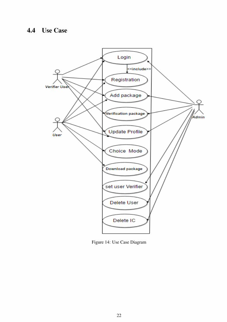
4.4 Use Case
Figure 14: Use Case Diagram
22

4.5 System DataBase
Figure 15: System Database
Description of the system Database:
• IC table: contains information about IC addednumber: number of IC (unique) and this field is primary key.name: name of IC (unique).family: family of IC.price : price determined for sale this IC.output:output determined based on truth table and this output unique for ic based on our Algo-rithm.
23
nopins: number of all pins.output pins : number of output pins.input pins : number of input pins.CreatedAt : date of user added this IC.UpdatedAt :date of admin or verifier user accept this IC.accept: default value 0 , 1 value when IC is correct and user can added it for his app, -1 forreject IC.ver-count: number of user verification this IC and accepted it user-id : id of user added this IC.datasheet: datasheet of this IC.img : image of this IC.
• User table: contains information about user in systemid ( auto-increment).username.email.password (stored as hash).user-type : value=1 for normal user, 2 for verifier user, 3 for admin user.
• IC-pins table:IC-number : number of IC (unique) and this field is primary key for IC-pins table and foreignkey for IC table .pin1-pin16: pins on ICs , value of this field (1:input, 2 :output , 4:VCC, 5: GND).
• user-IC table:user-id : id of user added package, this field is part of primary key for user-IC table and foreignkey for user table.IC-number: number of IC (unique) and this field is part of primary key for user-IC table andforeign key for IC table.accept : 0 or 1 or 2.
• IC-verfication table:IC-number: number of IC (unique) and this field is part of primary key for IC-verfication tableand foreign key for IC table.user-id : id of user verification this package, this field is part of primary key for IC-verficationtable and foreign key for user table.
24

Figure 16: SQLite Database
4.6 Requirement Analysis Tables
4.6.1 Android Application Requirements
Requirement name Choose mode
DescriptionDetermine type of IC test; Detect then display result or enter the IC numberby user then test the IC
Input type of testOutput activity based on choice type of test.
Scenario1- In the main activity , user choose one of the mode2- based on choice .If the “Detection mode” is chosen ,the android applicationmust switch from the current activity to a new one.
Table 5: Choose Mode
Requirement name Test mode
DescriptionEnter IC number, then check and display result(good, bad, not supported).
Input IC number.Output Result of the test.
Scenario
1- Enter IC no. in the input field.2- Application searches in DB of this IC (if not found is the database result, then display not supported).The application sends and receives digital signals with the IC socket,then the application determines result of the test (good or bad).
Table 6: Test Mode
25

Requirement name Detect ModeDescription Insert IC pins’ number, then search and display result (IC information, not supported).Input pins’ number.Output Result of the detect.
Scenario1- Enter the IC pins’ number in the input field.2-The application searches in database for similar ICs ,start testing each IC ,then as a result the application displays information about the ICor it is not supported(not found in the database).
Table 7: Detect Mode
Requirement name Login userDescription Before user add package must login the app.Input Email,password .Output Add package activity ,user profile.Scenario User login to the app by entering email and password, then display his profile or add package .
Table 8: Application Logging-in
Requirement name User registrationDescription To add package , user must register to the system .Input Name,email,password,bank account.Output user profile.
Scenario1-User enter his information in the registration form2-System send confirmation to his email ,then can login in the system and display his profile or add package.
Table 9: Application Registration
Requirement name Add Package
DescriptionFor the ICs that not supported, Enter ICs informationthen the application connects with the website to add this package to the website databaseto verify it by the admin or verifier user.
Input IC name, IC number, truth table ,number of ic pins ,price,description, IC family ,input pins and output pins.Output Display message .
Scenario
1- Click on “Add Package” (after user login ).2- In add package interface: Enter the IC name, IC number, truth table ,number of ic pins ,price,description, IC family ,input pins and output pins in the input fields.3- Click on “Add”, then the android app will display toast message.4- The application connects with the website to send data using JSON.5- Every row in the IC table has a createdate field.In order to update the records for the similar table in mobile app database, the app uses an Android Serviceto check the most recent creation date and send it to the web server. The web server returns all the accept field =1rows that create after the date received from the mobile app, all names and numbersof this ICs display in store activity in the android application, then user choose packages to download it.
Table 10: Application Adding Package
4.6.2 The Website Requirements
Requirement name Add Package
DescriptionFor the ICs that not supported, we can insert package by website by entering ICs information,then the website adds them to the DB to verify it by the admin or verifier user.
Input IC name, IC number, truth table ,number of IC pins ,price,description, IC family ,input pins and output pins.Output -
Scenario
1- In add package page: enter the IC name,IC number, truth table ,number of IC pins ,price,description,IC family ,input pins and output pins in the input fields.2- The website adds package to the database.can’t any user add package before login.
Table 11: Website Adding Package
26

Requirement name User registrationDescription To add package , user must register to the system .Input Name,email,password,bank account.Output Add package interface,user profile.
Scenario1-User enter his information in the registration form .2-System send confirmation to his email ,then can login in the system and display his profile or add package.
Table 12: Website Registration
Requirement name Login userDescription Before user add package must login the website . website has three type of user (admin,normal user , verifier).Input Email,password .Output Admin or user interface .
Scenario
User login to the app by entering email and password, then display based on type of user*User:display his profile or add package ,if user verifier display also package purposed to verify it.*admin1-Display his profile.2-Display all users profiles,can delete any user or set as verifier.3-Add IC package (accept by default).4-Display all packages are proposed by users to determine whether accepting them or not.5- After scanning by admin and determining the packages, update “accept” database field ( accept, not accept),or update any ICs information.6- Using JSON, send the packages to the android application to make them part of the application.
Table 13: Website Logging-in
Requirement name package verificationDescription Before add any package to the android application , must verify it by the admin or two verifier user at least .Input -Output -
Scenario
1-In admin page: display all ICs are purposed by all users and not accept ,then admin or verifier userscan this package and determine accepting or rejecting it .2-When admin accept a package ,”accept ”filed will update and the value will be 1,if reject the ”accept” field will update and the value will be -1.3- When verifier user accept a package ,veraccount will update and increase 1,if the veraccount field value at least =2,the ”accept ” failed will update and the value will be 1.
Table 14: Verification
27
Chapter 5
Validation and Testing
5.1 OverviewBecause this project is the first one of the world of our knowledge which uses the mobile as the mainprocessor to test ICs, we make this chapter to show the chronology of the testing and experiments ofthe connections and tools to find out the last design of the hardware socket system and the series ofprogramming and programming languages which are used up to the microcontrollers and experiments.
5.2 The Chronology of the TestingThis section discusses the series of the hardware and experiments of equipment connection to choosethe suitable microcontroller for this project’s purpose.
First Test:Connect the Pic18F8550 with Android Mobile via USB cable
• Introduction:The first design of the hardware socket consists of: ATtiny85, PIC18F2550 and ZIF. In thisexperiment we tried to connect the PIC18F2550 directly with the Android mobile via USBand OTG cables without ATtiny85. So we connected the PIC18F2550 with the USB cableby connecting D- and D+ from the USB socket with the 15 and 16 pins from the PIC afterprogramming them as in the Figure 16 below:
28

Figure 17: PIC18F2550 with USB
• Objectives:Connect the PIC18F2550 to the Android mobile via USB without the ATtiny85 microprocessorto reduce the number of microprocessors and save resources.
• Results:
1. This experiment didn’t work appropriately because the smartphones devices don’t supportor have a PIC driver, that’s related to the differences between versions (smartphones arevery advanced but the PIC is very old, so hard to match with each other).
2. We decided to change the microprocessor (PIC18F2550) to another one more advancesand matched with the Android mobile or use Bluetooth instead of USB because it did notneed any driver.
Second Test:Connect the PIC18F2550 to the Android Mobile via Bluetooth
• Introduction:Up to the first test’s results and because the Android mobile doesn’t have PIC USB driver. Inthis experiment we tried to connect the PIC18F2550 to the Android mobile via Bluetooth. Sowe connect PX and RX pins of the Bluetooth sensor to the 17 and 18 pins in the PIC18F2550and connect it to the Android Bluetooth after that as the Figure 17 below:
29

Figure 18: PIC18F2550 with Bluetooth Sensor
• Objectives:Try to solve the PIC USB drive and connect the PIC18F2550 to the Android mobile via Blue-tooth without any driver.
• Results:It works and make a connection but we faced two problems because of using Bluetooth; thefirst one is the Android mobile doesn’t work as a host so it doesn’t work as the main processor.The second one is needing additional power source for the hardware socket but using USB themobile will be enough as a power source for the circuit. So the main results are not to useBluetooth connection and try to find an alternative microprocessor and works with the USBconnection.
Third Test:Connect Digispark USB Development Board to the Android Mobile via OTGcable
• Introduction:The digispark USB development board consists of ATtiny85 and 78M07. In this experiment,we tried to connect the ATtiny85 to the Android mobile by its development board via USB andOTG cables after program all of them.
30

Figure 19: Digispark connect to Android via OTG
• Objectives:Connect the ATtiny85 to the Android mobile to make it as the main processor of the socket side(sender/receiver and connecting to the ZIF). In addition to use its development board for lesscomplicated wires connection.
• Results:The digispark doesn’t support serial connection and uses CDCUSB library as a virtual serial.But we faced the same problem with the USB driver which supports serial not virtual serialconnection. In addition the Android studio doesn’t support any CDCUSB library to make anapplication which a make a connection, and we tried to use phonGap or cordova instead of itbut it didn’t work. So the main result is trying to find another alternative of this microprocessor.
Fourth Test:Connect Arduino Nano to the Android via USB and OTG cables
• Introduction:In this test, we connected it directly to the Android mobile via OTG cable to work as the hostand as the main processor of this project system. After program the Arduino and make anAndroid application to connect to each other.
31
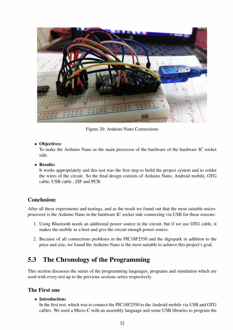
Figure 20: Arduino Nano Connections
• Objectives:To make the Arduino Nano as the main processor of the hardware of the hardware IC socketside.
• Results:It works appropriately and this test was the first step to build the project system and to solderthe wires of the circuit. So the final design consists of Arduino Nano, Android mobile, OTGcable, USB cable , ZIF and PCB.
Conclusion:After all these experiments and testings, and as the result we found out that the most suitable micro-processor is the Arduino Nano in the hardware IC socket side connecting via USB for these reasons:
1. Using Bluetooth needs an additional power source in the circuit, but if we use OTG cable, itmakes the mobile as a host and give the circuit enough power source.
2. Because of all connections problems in the PIC18F2550 and the digispark in addition to theprice and size, we found the Arduino Nano is the most suitable to achieve this project’s goal.
5.3 The Chronology of the ProgrammingThis section discusses the series of the programming languages, programs and simulation which areused with every test up to the previous sections series respectively.
The First one• Introduction:
In the first test, which was to connect the PIC18F2550 to the Android mobile via USB and OTGcables. We used a Micro C with an assembly language and some USB libraries to program the
32
PIC and try to support USB driver, the Android studio with the Android Java language to makean Android application, Proteus 8.0.1 for the PIC and USB simulations and Pickit2 to uploadthe program into the PIC.
• Used Programs:Micro C (programmer), Android studio (programmer), Proteus 8.0.1 (simulator) and pickit2(uploader).
• Used Program Languages:Assembly with some USB libraries and Android java.
The Second one• Introduction:
In the second test, which was to connect the PIC18F2550 to the Android mobile via Bluetooth.We used a Micro C with the assembly language and the Bluetooth libraries to program the PIC,the Android studio with the Android Java language to make an Android application, Proteus8.0.1 for the PIC and USB simulations and Pickit2 to upload the program into the PIC.
• Used Programs:Micro C (programmer), Android studio (programmer), Proteus 8.0.1 (simulator) and pickit2(uploader).
• Used Program Languages:Assembly with some Bluetooth libraries and Android java.
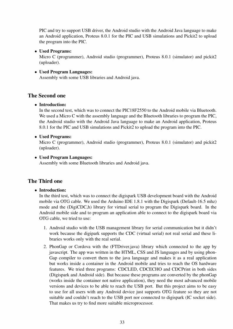
The Third one• Introduction:
In the third test, which was to connect the digispark USB development board with the Androidmobile via OTG cable. We used the Arduino IDE 1.8.1 with the Digispark (Default-16.5 mhz)mode and the (DigiCDC,h) library for virtual serial to program the Digispark board. In theAndroid mobile side and to program an application able to connect to the digispark board viaOTG cable, we tried to use:
1. Android studio with the USB management library for serial communication but it didn’twork because the digipark supports the CDC (virtual serial) not real serial and these li-braries works only with the real serial.
2. PhonGap or Cordova with the (FTDriver.java) library which connected to the app byjavascript. The app was written in the HTML, CSS and JS languages and by using phon-Gap compiler to convert them to the java language and makes it as a real applicationbut works inside a container in the Android mobile and tries to reach the OS hardwarefeatures. We tried three programs: CDCLED, CDCECHO and CDCPrint in both sides(Digispark and Android side). But because these programs are converted by the phonGap(works inside the container not native application), they need the most advanced mobileversions and devices to be able to reach the USB port. But this project aims to be easyto use for all users with any Android device just supports OTG feature so they are notsuitable and couldn’t reach to the USB port nor connected to digispark (IC socket side).That makes us try to find more suitable microprocessor.
33

• Used Programs:Arduino IDE, Android studio, PhoneGap IDE converter, PhoneGap online.
• Used Program Languages:Arduino C with DigiCDC,h library, Android java, HTML, CSS and javascript.
The Fourth one• Introduction:
In the fourth test, which was to connect the Arduino Nano directly to the Android mobile viaUSB and OTG cables. We used the Arduino IDE to program the Arduino Nano and the Androidstudio to program the Android application to connect with the socket. And it was the final andthe most suitable design of the system and achieves all its goals. So it’s discussed in details inthe next chapter.
• Used Programs:Android studio and Arduino IDE.
• Used Program Languages:Arduino C and Android studio.
5.4 Implementation Issues:While working on all the previous testing and tried many microprocessor, we get a lot of results andissues to reach to the most suitable design of the system and have the best properties related to theproject’s aims. As the summary of this issues and results as the following:
1. Use the USB connection not the Bluetooth because:
• The OTG cable is necessary to make the mobile works as the host but the Bluetooth can’t.
• The Bluetooth needs an additional power source for the socket side, but using USB makesthe phone as enough power source for the circuit.
2. We faced many issues up to size, price and efficacy, so we moved from an experiment to anotherto find the most suitable and achievable microprocessor up to the project needs.
5.5 Implementation Results:This section shows the results of all previous testing briefly, and the next chapter discusses in detailsthe circuit connection, software and hardware components and programs. The main results of theprevious testing:
1. The main sender/receiver to/from the hardware IC socket is the Arduino Nano.
2. The 20-pins ZIF will be connected to the Arduino and resistor with all its pins, which representthe IC socket.
3. To test an IC put it into the IC socket after connected it to the Android mobile.
34

Chapter 6
Hardware and Software Implementation
6.1 OverviewThis chapter describes the implementations of the software and the hardware components that areused in this project, such as the circuit connection, microcontroller, the IDEs which used to build theproject codes and the set of tools, libraries and packages that helped us.
6.2 Hardware Implementation
6.2.1 IC Socket Circuit DesignThe main purpose of this project is to exploit resources and make the IC tester as smaller and cheaperas possible. So the circuit connection, soldering wires and the final size were very important to focuson. The Figure 21 below shows in step by step how to connect the PCB circuit and connect the ZIFand Arduino Nano on it after soldering wires.
35

Figure 21: Circuit IC Socket Design
The steps are:(1) The first connection of Arduino Nano to IC in bread board.(2) The circuit connection of two layers on the PCB.(3) Soldering the ZIF to the circuit on the first layer.(4) Soldering the Arduino Nano in the second layer.(5) The final form of the project (ICT).
36

6.2.2 Connecting IC Socket to the MobileThe IC socket will be used to put the IC on its ZIF to test it. After connect it to the Android applicationand choose a “Test Mode” or “Detect Mode” the sending and receiving binary data via USB and OTGcables between mobile and socket, in this way the testing operation done.The Figure 22 below shows the project with its elements, cables and how they are connected to eachother:
Figure 22: Connecting IC Socket to the Mobile
The numbers of the images in the Figure 22 shows:(1) OnTheGo (OTG) cable: for connection and make the mobile works as host to the socket.(2) The Arduino Nano’s cable: to connect the socket with OTG cable.(3) The IC socket: use to connect IC with the mobile.(4) Android-Mobile: the main processor to test and detect ICs.
6.3 Software Implementation
6.3.1 IC Socket ProgrammingThe IC socket consists of Arduino Nano, PCB and ZIF. To program the Arduino Nano to work assender/receiver to/from the socket, we used Arduino IDE with the Arduino C language. In the Arduinocode, it receives an array of integers, from the Android mobile, contains the number of pins, thenumber of gates in the IC and the input/output pins. Up to the number of gates, it calls the suitabletruth table with the input/output pins as the parameters. After connecting to the ZIF which are alreadyconnected to the tested IC and measured values, it sends them back to Android mobile to comparethem with the stored results via USB and OTG cables.
37

6.3.2 Android ImplementationTo develop the application; we used Android language, SQLite, JSON and mySQL. The Androidapplication contains the main activity which views a lot of activities as log-in, registration, store, addpackage, profile, and two modes: “Test Mode” and “Detect Mode”.
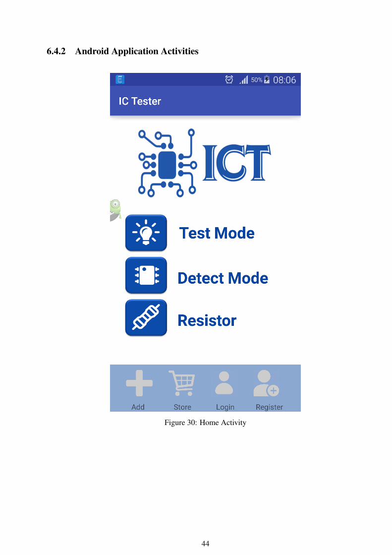
• Choose Mode: user can choose the mode. So he can choose a “Test Mode” to enter IC numberor a “Detect Mode” to enter the number of the IC pins.
• Test Mode Activity: it consists of three steps; the first step is to check the connection. Inthe second and the third steps, the user enters the IC number and waits until searching andcomparing stored results of it in the Database. If searched IC is equaled, the application willdisplay “Good” in the screen. Otherwise it’s bad or not supported.
• Detect Mode Activity: it consists of three steps; the first step is is to check the connection. Inthe second and the third steps, the user should enter the number of the IC pins and wait untilsearching and comparing stored results of it in the Database. If the result is found and equaled,the search will stop and the application will display the IC number, name and datasheet on thescreen. Otherwise it’s bad or not supported.
• The fixed bottom navigation bar of the application consists of:
1. Add Package: for the ICs that are not supported, user can enter the IC’s information (afterbeing logged into the system). After entering the information the application will connectto the website to add it to the online database. To verify it by the admin or verifier user .
2. Store: this activity displays name and number of the ICs. User can choose any package todownload and add it to its application database.
3. Login: to be able to use add package or display profile features, the user must login first.If the user enter the email and password correct, the application redirect the user into hisprofile page. Otherwise the toast message popup on the screen.
4. Registration: to register into the application, the user must enter his information (user-name, email, and password) in the registration form. The system will send confirmationto his email and add him to the database. to be able to login later.
5. Profile: it is displayed only for logged in users. By registration icon after being logged in.
6.3.3 Website ImplementationTo develop the website; we used php language, HTML, CSS ,JavaScript, Ajax technology and mySQL.
The website contains: home page, login and registration models, download page, add packagepage, profile page, admin page and verification page.
• Registration: user enters his information: username, email -make (sure this email and user-name are not found in the database using Ajax), and password (stored hash in database), inthe registration form. the system will send a confirmation to his email and insert user to thedatabase. To be able to login later.
• Login: to be able to use add package or display profile features, the user must login first. If theuser enter the email and password correct, the application redirect the user into his profile page(the system includes three types of users: admin , verifier , normal user). Otherwise the errormessage popup.
38

• Add package: for the ICs that not supported, user can enter the ICs information (after beinglogged into the system). After entering the information the application will connect to thewebsite to add it into the online database. To verify it by the admin or verifier user.
• Package verification: before accept and add the package which are added from user into thedatabase, it must be corrected and verified.
• In the verification page, which displays all ICs are purposed by all users and not accepted. Theverification is done by admin or by at least two versifiers users:
1. Done by admin: admin scan this package and determine accept or reject it.”Accept” filedhave default value, when admin accept a package ”Accept” filed will update and the valuewill be 1. However if he reject it, the ”Accept” field will update and the value will be -1.
2. Done by versifiers: when verifier user accept a package,”ver_account” will update andincrease 1. If the ”ver_account” field value at least =2,the ”Accept” failed will update andthe value will be 1.
• Edit profile: all users can edit their profiles and update some informations, such as passwordand bank account. By click on the edit button, the field will open and the user can edit what hewants,then system update this field in the database.
• Download page: in this page we display the Android application’s activities, such as packagedsupported in the system in addition to be able to download the application from this page.
In the admin page, in addition to display the ICs, which are needed to verify, by tab user candisplay all registered users in the system (by using Ajax the user can select from menu to displaythis user’s information ). In addition to be able to delete any user or set verified.
6.3.4 Connecting all TogetherThe whole system of this project includes three parts: IC socket, Android mobile and the website. theIC socket are connected to the Android mobile and the Android application connects to the website.
The IC socket are connected to the smart-phone Android mobile which supports OTG cable fea-ture, via connecting the OTG cable to the mobile to be able to work as a host to be the main processor.After connecting the OTG cable to the Arduino USB cable, the socket will be already connecting andsending and receiving data by full-duplicate serial. In this way the "Test Mode" and "Detect Mode"work.
The Android application connects to the website by using Json. Every row in the IC table has acreate date field. In order to update the records for the similar table in mobile application database,the app uses an Android service to check the most recent creation date and send it to the web server.The web server returns all the accept field =1 rows that create after the date received from the mobileapp; all names and numbers of this ICs which are displayed into the “Store Activity” of the androidapplication to give the user the availability to choose packages and download them. In the “LoginActivity” after the user entering his user-name and password, the application sends data by usingJSON. And confirmed it in the server to check if they are correct, to make the “Add Package” and“Profile Activity” available for logged in users. In the “Registration Activity” the user must enterusername, email, password and bank account to send this data to the website by using JSON andinsert the new user into the database.
39

6.4 Interfaces
6.4.1 Website Interfaces
Figure 23: Home Page
Figure 24: Log-in Page
40

Figure 25: Registration Page
Figure 26: Admin Verification Packages Page
41

Figure 27: Admin Editing User Page
Figure 28: Add Package Page
42

Figure 29: Profile Page
43
6.4.2 Android Application Activities
Figure 30: Home Activity
44

Figure 31: Test Mode Activity
Figure 32: Detect Mode Activity
45

Figure 33: Login Activity Figure 34: Registration Activity
Figure 35: Add Package Activity Figure 36: Store Activity
46
Chapter 7
Conclusion
7.1 Final ResultsAt the end of this project, we are very glad to say it achieved all its objectives. Now we have aninventive and very small socket which is able to connect to Android mobile and make a testing anddetection.The mobile-based digital IC tester now is very small, cheap, community-supported and friendly touse by using the Android Application.The Android application’s database now stores only 74LS and 40 series. However depending on the"Add package" activity to be able to add more series and ICs to the database to test them.The website works appropriately on the server and connecting with the Android application via Jsonto connect with its database.Very proud of this great achievement to be the first in the world of its type.
7.2 Additional WorksAs an additional works on this project, the tester now is able to measure the resistor’s value and itsoutput voltage. The resistor is connected in the same IC socket but with the analog pins in the ArduinoNano. The Figure 37 below shows in application how to use it to measure the resistor:
47

Figure 37: Resistor Measure
7.3 Future Works• Support more ICs families.
• Online Testing; test ICs using website directly.
• Be able to test other components such as capacitors.
• Be able to connect it to another operating systems as IOS, windows phone, etc.
• Using AI (Artificial intelligence) to detect ICs faster and more accurate.
7.4 Project Achievements• Got the third place in the Microsoft composition (Imagine-Cup) over all universities in Palestine
in April 2017.
• Got the first place in Sixth Students Innovation Conference in May 2017.
• The first of its type in the world (the first IC tester using mobile and Database in testing and hasan availability to add new ICs from users to it).
48
Appendix A
Arduino Nano
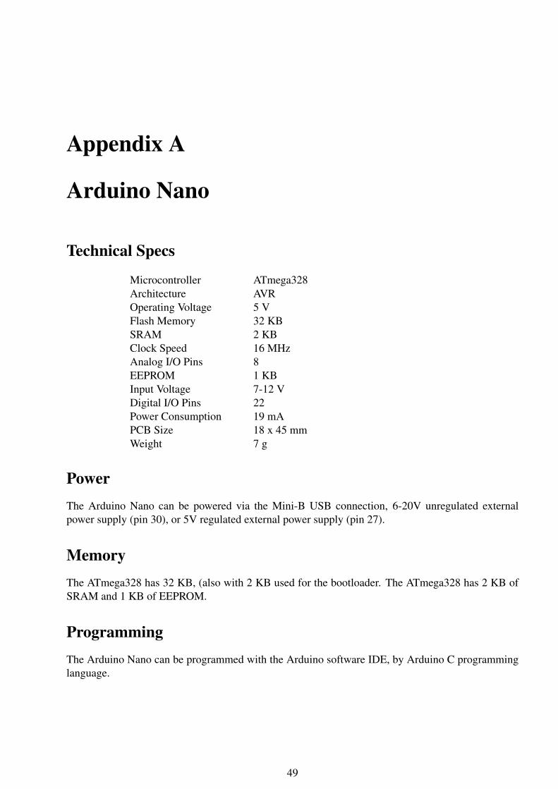
Technical Specs
Microcontroller ATmega328Architecture AVROperating Voltage 5 VFlash Memory 32 KBSRAM 2 KBClock Speed 16 MHzAnalog I/O Pins 8EEPROM 1 KBInput Voltage 7-12 VDigital I/O Pins 22Power Consumption 19 mAPCB Size 18 x 45 mmWeight 7 g
PowerThe Arduino Nano can be powered via the Mini-B USB connection, 6-20V unregulated externalpower supply (pin 30), or 5V regulated external power supply (pin 27).
MemoryThe ATmega328 has 32 KB, (also with 2 KB used for the bootloader. The ATmega328 has 2 KB ofSRAM and 1 KB of EEPROM.
ProgrammingThe Arduino Nano can be programmed with the Arduino software IDE, by Arduino C programminglanguage.
49

Bibliography
[1] https://www.amazon.com/Instek-GUT-6000A-Digital-IC-Tester/dp/B00VTS9YJKAccessed: April 24,2017
[2] https://www.artisantg.com/TestMeasurementAccessed: April 24,2017
[3] http://www.bkprecision.com/products/component-testers/575A-digital-ic-tester.htmlAccessed: April 24,2017
[4] http://www.kitektechnologies.com/KITEK-CATALOGUE/IC%20TESTER/DICT-01.pdfAccessed: April 24,2017
[5] http://www.kitektechnologies.com/KITEK-CATALOGUE/IC%20TESTER/DICT-03.pdfAccessed: April 24,2017
[6] http://www.goodluckbuy.com/integrated-circuit-ic-tester-f-74-40-45-series-logic-gate-tester-digital-meter.htmlAccessed: April 24,2017
[7] https://www.maximintegrated.com/en/app-notes/index.mvp/id/1822 Accessed: Nov 18,2016
[8] https://www.tutorialspoint.com/android/android_sqlite_database.html Accessed: Nov 18,2016
[9] http://www.madehow.com/Volume-2/Printed-Circuit-Board.html Accessed: Nov 18,2016
[10] http://www.atmel.com/Images/Atmel-2586-AVR-8-bit-Microcontroller/-ATtiny25-ATtiny45-ATtiny85_DatasheetSummary.pdf Accessed: Nov 18,2016
[11] http://www.vellemanprojects.eu/downloads/7/pic18f2550.pdf Accessed: Dec 12,2016
[12] http://digistump.com/products/1 Accessed: April 25,2017
[13] https://www.arduino.cc/en/Main/ArduinoBoardNano Accessed: April 25,2017
[14] Yusri, Mohamad, and Ahmad Badarudin. "Development Of PC-Based Digital IC Tester UsingBluetooth." (2015).
[15] Mannaf Hossain, Md. "Computer Interfaced Logic IC Tester and RC Meter." Global Journal ofResearch In Engineering 13.6 (2013).
[16] : Raina, S. U. N. I. L., PIYUSH SONAWANE, and PARIMAL SIKCHI. "Digital IC Tester."IEEE Journal 22.7 (2009): 23-30.
[17] Farr, Joe. "Digital IC tester." Wimborne Publishing Ltd 61.4 (2008): 65-71.
[18] Tarkunde, Miss MA, and Mrs AA Shinde. "IC tester using 89s52 microcontroller." InternationalJournal of Computational Engineering Research 2.7 (2005): 24-27.
50