Broglio Drag Balance for neutral thermosphere density measurement on UNICubeSAT
10
Broglio Drag Balance for neutral thermosphere density measurement on UNICubeSAT F. Santoni a , F. Piergentili b, * , F. Graziani a a Scuola di Ingegneria Aerospaziale, University of Rome “LA SAPIENZA”, Via Eudossiana 18, Roma 00184, Italy b DIEM, II a Facolta ` di Ingegneria, University of Bologna “ALMA MATER STUDIORUM”, Via Fontanelle 40, Forlı ` 47100, Italy Received 4 August 2009; received in revised form 1 October 2009; accepted 2 October 2009 Abstract The nanosatellite UNICubeSAT is described, carrying a Broglio Drag Balance Instrument for neutral thermosphere density in situ measurements. The aim of the mission is to contribute to the development of accurate thermosphere models, achieving in situ, real time measurements of atmosphere density, that could be exploited for global atmosphere model validation and accurate short term (1–3 days) real time space weather forecasts. The satellite is inexpensive and swarms could be easily launched operating as a distributed sensor net- work to get simultaneous in situ local (not orbit averaged) measurements in multiple positions and orbit heights. The nanosatellite is based on the Cubesat standard architecture, weighing about 1 kg for 1-L volume. Atmospheric drag force is measured by the displace- ment of light plates exposed to the incoming particle flux seen by the spacecraft, applying the original three dimensional Broglio Drag Balance concept to a single nanosatellite axis. The instrument concept and its relation to the satellite bus is depicted, showing that many long term potential measurement error sources and biases can be removed in data processing if the spacecraft is spin stabilized. The expected accuracy in density measurements is 20%. The instrument cost is a fraction of that of accurate accelerometers. The onboard systems are based on commercial off the shelf components, in accordance with the short lifetime typical of aeronomy satellites. Ó 2009 COSPAR. Published by Elsevier Ltd. All rights reserved. Keywords: Atmospheric density; Nanosatellite; Broglio Drag Balance; In situ measurements 1. Introduction Atmosphere density evaluation uncertainties are the most relevant error sources in Low Earth Orbit (LEO) high accuracy orbit determination and control, including colli- sion avoidance of active spacecraft with space debris, pre- diction of spacecraft lifetime and debris reentry time, space objects tracking by narrow field of view instruments, orbit control maneuver planning and accurate formation flying maintenance. Atmospheric models account for the essential phenom- ena determining the complex physical and chemical behav- ior of the upper atmosphere, reaching typical thermosphere density prediction accuracies in the order of 10–15% in quiet conditions and 30–60% in highly perturbed condi- tions, as reported by Yurasov et al. (2004). The two-line element data of LEO satellites have been used for calibrating atmospheric models (Pardini and Anselmo, 2001; Cefola et al., 2003; Doornbos and Klink- rad, 2006; Doornbos et al., 2008). Satellite orbital elements variation gives information on orbit average drag effect, and can be used to calibrate atmosphere models on the time scale of one or more days. Density corrections to the NRLMSIS-00 are used by Yurasov et al. (2008) to improve the evaluation of orbiting objects’ reentry time. Improved atmosphere models have been obtained, based on catalogued LEO orbiting objects’ tracking data of the US Space Surveillance Network, which are included 0273-1177/$36.00 Ó 2009 COSPAR. Published by Elsevier Ltd. All rights reserved. doi:10.1016/j.asr.2009.10.001 * Corresponding author. E-mail addresses: [email protected] (F. Santoni), fabrizio. [email protected] (F. Piergentili), fi[email protected] (F. Graziani). www.elsevier.com/locate/asr Available online at www.sciencedirect.com Advances in Space Research 45 (2010) 651–660
Transcript of Broglio Drag Balance for neutral thermosphere density measurement on UNICubeSAT

Available online at www.sciencedirect.com
www.elsevier.com/locate/asr
Advances in Space Research 45 (2010) 651–660
Broglio Drag Balance for neutral thermosphere density measurementon UNICubeSAT
F. Santoni a, F. Piergentili b,*, F. Graziani a
a Scuola di Ingegneria Aerospaziale, University of Rome “LA SAPIENZA”, Via Eudossiana 18, Roma 00184, Italyb DIEM, IIa Facolta di Ingegneria, University of Bologna “ALMA MATER STUDIORUM”, Via Fontanelle 40, Forlı 47100, Italy
Received 4 August 2009; received in revised form 1 October 2009; accepted 2 October 2009
Abstract
The nanosatellite UNICubeSAT is described, carrying a Broglio Drag Balance Instrument for neutral thermosphere density in situmeasurements. The aim of the mission is to contribute to the development of accurate thermosphere models, achieving in situ, real timemeasurements of atmosphere density, that could be exploited for global atmosphere model validation and accurate short term (1–3 days)real time space weather forecasts. The satellite is inexpensive and swarms could be easily launched operating as a distributed sensor net-work to get simultaneous in situ local (not orbit averaged) measurements in multiple positions and orbit heights. The nanosatellite isbased on the Cubesat standard architecture, weighing about 1 kg for 1-L volume. Atmospheric drag force is measured by the displace-ment of light plates exposed to the incoming particle flux seen by the spacecraft, applying the original three dimensional Broglio DragBalance concept to a single nanosatellite axis. The instrument concept and its relation to the satellite bus is depicted, showing that manylong term potential measurement error sources and biases can be removed in data processing if the spacecraft is spin stabilized. Theexpected accuracy in density measurements is 20%. The instrument cost is a fraction of that of accurate accelerometers. The onboardsystems are based on commercial off the shelf components, in accordance with the short lifetime typical of aeronomy satellites.� 2009 COSPAR. Published by Elsevier Ltd. All rights reserved.
Keywords: Atmospheric density; Nanosatellite; Broglio Drag Balance; In situ measurements
1. Introduction
Atmosphere density evaluation uncertainties are themost relevant error sources in Low Earth Orbit (LEO) highaccuracy orbit determination and control, including colli-sion avoidance of active spacecraft with space debris, pre-diction of spacecraft lifetime and debris reentry time,space objects tracking by narrow field of view instruments,orbit control maneuver planning and accurate formationflying maintenance.
Atmospheric models account for the essential phenom-ena determining the complex physical and chemical behav-
0273-1177/$36.00 � 2009 COSPAR. Published by Elsevier Ltd. All rights rese
doi:10.1016/j.asr.2009.10.001
* Corresponding author.E-mail addresses: [email protected] (F. Santoni), fabrizio.
[email protected] (F. Piergentili), [email protected] (F.Graziani).
ior of the upper atmosphere, reaching typical thermospheredensity prediction accuracies in the order of 10–15% inquiet conditions and 30–60% in highly perturbed condi-tions, as reported by Yurasov et al. (2004).
The two-line element data of LEO satellites have beenused for calibrating atmospheric models (Pardini andAnselmo, 2001; Cefola et al., 2003; Doornbos and Klink-rad, 2006; Doornbos et al., 2008). Satellite orbital elementsvariation gives information on orbit average drag effect, andcan be used to calibrate atmosphere models on the timescale of one or more days.
Density corrections to the NRLMSIS-00 are used byYurasov et al. (2008) to improve the evaluation of orbitingobjects’ reentry time.
Improved atmosphere models have been obtained,based on catalogued LEO orbiting objects’ tracking dataof the US Space Surveillance Network, which are included
rved.

652 F. Santoni et al. / Advances in Space Research 45 (2010) 651–660
in the Air Force High Accuracy Satellite Drag Model(HASDM) (Marcos, 2006; Bowman and Storz, 2003; Storzet al., 2005).
A new global atmosphere model has recently beenreleased, introducing new solar and geomagnetic drivingindices, reducing the atmosphere density modeling errorto about 8% in fairly geomagnetically quiet conditionsand to about 16% during major storms (Bowman et al.,2008).
A valuable source of direct atmospheric drag measure-ments is provided by a number of geodetic satellites launchedin the last decade, carrying very accurate on board acceler-ometers (Sutton et al., 2007; Tapley et al., 2007). Thesein situ measurements allow observation of thermospheredensity changes on a short time scale, as opposed to the aver-age orbital effect obtained by orbital elements. However,even if accelerometer accuracy is in the order of 10�8 m/s2,determination of the atmospheric density is still affected byconsiderable error, in the order of 15%, due to poor modelingof the geodesy satellite drag coefficient, which was notdesigned specifically for aeronomy.
The satellite drag coefficient depends on satellite shape,on the attitude with respect to the incoming particle fluxand on the complex physical and chemical phenomenainvolved in the atmosphere particle interaction with thespacecraft surface. Moreover, satellite drag coefficient var-ies considerably with satellite altitude. This has been shownby collecting the results of different experiments measuringthe atmospheric drag of calibration spherical satellites(Bowman and Moe, 2006); by using multiple instrumentsdedicated to atmosphere properties on the S3-1 satellite(Moe and Bowman, 2006); and by correlating orbit dataof many spacecrafts with drag coefficient models (Moeet al., 2004).
This behavior reflects the different way in which particles,and in particular atomic oxygen, accommodates to theexternal surface of spacecraft (Moe and Bowman, 2006).
An instrument capable of directly measuring the dragforce is the Broglio Drag Balance Instrument (DBI), whichwas flown in the five San Marco satellites, weighing about100 kg, designed, built, launched and operated by the Scu-
ola di Ingegneria Aerospaziale in cooperation with NASAbetween 1963 and 1988 (Jacchia and Verniani, 1965; Bro-glio, 1967, 1969; Broglio et al., 1976; Arduini et al., 1993,1996a,b)
The original instrument can be adapted to be flown onboard nanosatellites and, due to recent electronics minia-turization, the hardware can be scaled down to fit insidea standard Cubesat nanosatellite bus, which is a 10 cm sidecube, weighing 1 kg described in Heidt et al. (2000).
Installing the DBI on inexpensive standardized nanosat-ellites, such as Cubesats, offers the opportunity to distrib-ute many of these sensors in different orbits, achievingsimultaneous atmospheric drag measurements in differentlocations. The measurements achieved could contributeto the development of a global, real time, space weatherforecasting service, allowing accurate predictions of LEO
object trajectories and maneuver planning, as suggestedby Yurasov et al. (2004). The whole satellite should be alow cost system, since the lifetime is intrinsically low andthe onboard instruments will give useful data for a shorttime; moreover benefit would accrue from a mass produc-tion unit cost gain.
The Group of Astrodynamics of the University of Rome“La Sapienza” (GAUSS) established the research and edu-cation program UNISAT at the Scuola di Ingegneria Aer-
ospaziale. The four university satellites UNISAT,UNISAT-2, UNISAT-3, UNISAT-4, each weighing about10 kg, have been designed, manufactured, tested andlaunched every other year, since 2000 in the frameworkof this program (Graziani and Santoni, 2002; Grazianiet al., 2008; Santoni et al., 2006). The UNISAT-3 satellite,launched on June 29th 2004 is operating after more thanfive years from launch, and data are regularly received bythe University of Rome Ground Station. The implementa-tion of the DBI in a Cubesat bus led the GAUSS group tothe development of the UNICubeSAT nanosatellite. This isa nanosatellite designed to continue the tradition of aeron-omy studies at the Scuola di Ingegneria Aerospaziale,boarding a renewed version of the Broglio Drag Balancewhich will be launched in the VEGA launcher maidenflight mission, with the mission profile described in Section2. The DBI adaptation to UNICubeSAT is discussed inSection 3, including a preliminary instrument error budget.The resulting accuracy is in the order of 20%. The last sec-tion deals with the design and manufacture of the UNI-CubeSAT satellite bus, showing that it can provide allthe necessary on board resources in support of the DBImission needs.
2. The UNICubeSAT mission
The UNICubeSAT will be hosted on the VEGA maidenlaunch and injected in a 354 � 1447 km, 71� inclinationorbit. The UNICubeSAT’s mechanical lifetime, assumingthe mission starts in January 2011, has been evaluated bymeans of the NASA Debris Assessment Software (DAS2.1), obtaining the apogee and perigee height evolutionshown in Fig. 1. The mechanical lifetime is about 11 years.
The maximum visibility time from the SPIV ground sta-tion in Rome changes due to perigee drift in the orbitalplane. When the apogee is exactly at the Rome latitude,the maximum visibility time from the SPIV ground stationin Rome is about 20 min, with eight to ten useful passagesper day. When the perigee is exactly over Rome, the satel-lite is visible in two orbit portions: for about 10 min. atperigee and for about 15 min. in the other portion, for atotal of about five passages per day.
3. Miniaturization and adaptation of the Broglio Drag
Balance to the Cubesat bus
The DBI instrument concept and its implementation inthe San Marco satellites are briefly depicted in Appendix

Fig. 1. Cubesat apogee and perigee evolution in 354 � 1447 km orbit.
Fig. 2. The UNICubeSAT uni-dimensional implementation of the DragBalance concept.
F. Santoni et al. / Advances in Space Research 45 (2010) 651–660 653
A. The satellite shape was a sphere to assure a constantdrag coefficient. This concept is not suitable for implemen-tation in the UNICubeSAT, because of weight, volume andpower constraints. Thus, a different version of the originalDBI has been obtained by restraining the balance motionto one single degree of freedom, reducing the instrumenta-tion weight and power. This implementation of the dragbalance, suitable for Cubesats, comprises two very lightplates located externally from two opposite Cubesat faces,connected in the center by a light rod, which is in turn con-nected to two flexural springs, as shown in Fig. 2. The bal-ance displacement with respect to the spacecraft’s mainbody is proportional to the aerodynamic force acting onthe external plates. Due to the satellite spin motion, theaerodynamic force component along the balance axis oscil-lates at the spin frequency. The balance displacement, typ-ically in the order of tens of microns, is strongly affected bythe thermal expansion of the central balance rod. Howeverthis thermal expansion can be measured and eliminated,recognizing that the displacement due to the drag is skewwith respect to the balance center, whereas the thermalexpansion is symmetric. The thermal effect can then beeliminated using two displacement sensors close to the bal-ance plates by taking their displacements difference. Toobtain a reasonable accuracy of the drag force measure-ment, the two displacement sensors are needed and mustbe included in the design budgets.
The spin rate must be selected giving sufficient satelliteangular momentum to counteract the aerodynamic torqueeffect on maintenance of the spin axis direction. The appro-priate value for the spin rate has been fixed on the basis of
the numerical simulation of attitude dynamics shown inSection 4.
The balance flexural spring is made of two clamped alu-minum beams of length l and rectangular cross-section ofthickness h and side d, with h << d. By virtue of this lastcondition, the beams allow for one degree of freedom inthe relative translational motion between the central bodyand the balance. The flexural beam stiffness can beevaluated assuming fixed-fixed boundary conditions(Timoshenko and Goodier, 1970), obtaining:
kr ¼ Edhl
� �3
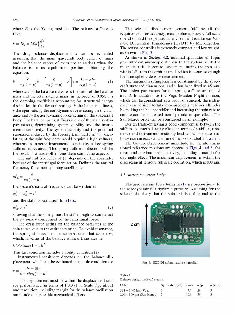
Fig. 3. ISC7001 subminiature controller.
Table 1Balance design trade-off results.
Orbit Spin rate (rpm) xn0=r h (lm) d (mm)
354 � 1447 km (Vega) 1 7.8 20 3250 � 800 km (San Marco) 3 10.8 50 3
654 F. Santoni et al. / Advances in Space Research 45 (2010) 651–660
where E is the Young modulus. The balance stiffness isthen:
k ¼ 2kr ¼ 2Edhl
� �3
The drag balance displacement x can be evaluatedassuming that the main spacecraft body center of massand the balance center of mass are coincident when thebalance is in its equilibrium position, obtaining theequation:
€xþ cmBð1� lÞ _xþ k
mBð1� lÞ � r2
� �x ¼ fB � lfC
mBð1� lÞ ð1Þ
where mB is the balance mass, l is the ratio of the balancemass and the total satellite mass (in the order of 0.05), c isthe damping coefficient accounting for structural energydissipation in the flexural springs, k the balance stiffness,r the spin rate, fB the aerodynamic force acting on the bal-ance and fC the aerodynamic force acting on the spacecraftbody. The balance spring stiffness is one of the main systemparameters, determining system stability and the instru-mental sensitivity. The system stability and the potentialresonance induced by the forcing term (RHS in (1)) oscil-lating at the spin frequency would require a high stiffness,whereas to increase instrumental sensitivity a low springstiffness is required. The spring stiffness selection will bethe result of a trade-off among these conflicting aspects.
The natural frequency of (1) depends on the spin rate,because of the centrifugal force action. Defining the naturalfrequency for a non spinning satellite as:
x2n0 ¼
kmBð1� lÞ
the system’s natural frequency can be written as
x2n ¼ x2
n0 � r2
and the stability condition for (1) is:
x2n0 > r2 ð2Þ
showing that the spring must be stiff enough to counteractthe stationary component of the centrifugal force.
The drag force acting on the balance oscillates at thespin rate r, due to the attitude motion. To avoid resonance,the spring stiffness must be selected such that x2
n >> r2,which, in terms of the balance stiffness translates in:
k >> 2mBð1� lÞr2
This last condition includes stability condition (2).Instrumental sensitivity depends on the balance dis-
placement, which can be evaluated in a static condition as:
x ¼ fB � lfC
k � r2mBð1� lÞThis displacement must be within the displacement sen-
sor performance, in terms of FSO (Full Scale Operation)and resolution, including margin for the balance oscillationamplitude and possible mechanical offsets.
The selected displacement sensor, fulfilling all therequirements for accuracy, mass, volume, power, full scaleoperation and the operational environment is a Linear Var-iable Differential Transformer (LVDT) by MicroEpsilon.The sensor controller is extremely compact and low weight,as shown in Fig. 3.
As shown in Section 4.2, nominal spin rates of 1 rpmgive sufficient gyroscopic stiffness to the system, while themagnetic attitude control system maintains the spin axiswithin 15� from the orbit normal, which is accurate enoughfor atmospheric density measurement.
The maximum spring length is constrained by the space-craft standard dimensions, and it has been fixed at 45 mm.The design parameters for the spring stiffness are then hand d. In addition to the Vega Maiden Flight mission,which can be considered as a proof of concept, the instru-ment can be sized to take measurements at lower altitudesby making the balance stiffer and increasing the spin rate tocounteract the increased aerodynamic torque effect. TheSan Marco orbit will be considered as an example.
Design trade-off giving a good compromise between thestiffness counterbalancing effects in terms of stability, reso-nance and instrument sensitivity lead to the spin rate, sta-bility margin xn0=r and spring dimensions listed in Table 1.
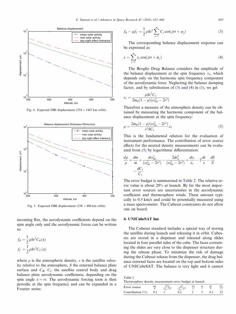
The balance displacement amplitude for the aforemen-tioned reference missions are shown in Figs. 4 and 5, formean and maximum solar activity, including a margin forday night effect. The maximum displacement is within thedisplacement sensor’s full scale operation, which is 800 lm.
3.1. Instrument error budget
The aerodynamic force terms in (1) are proportional tothe aerodynamic flux dynamic pressure. Assuming for thesake of simplicity that the spin axis is orthogonal to the
350 400 450 500 55010
0
101
102
103
Altitude, km
disp
lace
men
t, µ m
Balance displacement
mean solar activitymax solar activityday-night effect tolerance
Fig. 4. Expected DBI displacement (354 � 1447 km orbit).
200 250 300 350100
101
102
103
Altitude, km
disp
lace
men
t, µ
m
Balance displacement (thickness=50microns)
mean solar activitymax solar activityday-night effect tolerance
Fig. 5. Expected DBI displacement (250 � 800 km orbit).
Table 2Thermosphere density measurement error budget at launch.
Error source dmm
dx2n0
x2n0�2r2
dr2
x2n0�2r2
dx1
x1
dvv
dSS
dC1
C1
Contribution (%) 0.1 1 0.1 1 5 0.1 15
F. Santoni et al. / Advances in Space Research 45 (2010) 651–660 655
incoming flux, the aerodynamic coefficients depend on thespin angle only and the aerodynamic forces can be writtenas:
fB ¼1
2qSv2CBðaÞ
fC ¼1
2qSv2CCðaÞ
where q is the atmospheric density, v is the satellite veloc-ity relative to the atmosphere, S the external balance platesurface and CB, CC the satellite central body and dragbalance plate aerodynamic coefficients, depending on thespin angle a = rt. The aerodynamic forcing term is thenperiodic at the spin frequency and can be expanded in aFourier series:
fB � lfC ¼1
2qSv2
X1j¼1
Cj cosðjrt þ ujÞ ð3Þ
The corresponding balance displacement response canbe expressed as
x ¼X1j¼1
xj cosðjrt þ wjÞ ð4Þ
The Broglio Drag Balance considers the amplitude ofthe balance displacement at the spin frequency x1, whichdepends only on the harmonic spin frequency componentof the aerodynamic force. Neglecting the balance dampingfactor, and by substitution of (3) and (4) in (1), we get
x1 ¼qSv2C1
2mBð1� lÞðx2n0 � 2r2Þ
Therefore a measure of the atmosphere density can be ob-tained by measuring the harmonic component of the bal-ance displacement at the spin frequency:
q ¼ 2mBð1� lÞðx2n0 � 2r2Þ
v2SC1
x1 ð5Þ
This is the fundamental relation for the evaluation ofinstrument performance. The contribution of error sourceeffects for the neutral density measurements can be evalu-ated from (5) by logarithmic differentiation:
dqq¼ dm
mþ dx2
n0
ðx2n0 � 2r2Þ �
2dr20
ðx2n0 � 2r2Þ þ
dx1
x1
� 2dvv� dS
S
� dC1
C1
The error budget is summarized in Table 2. The relative er-ror value is about 20% at launch. By far the most impor-tant error sources are uncertainties in the aerodynamiccoefficient and thermosphere winds. These amount typi-cally to 0.5 km/s and could be potentially measured usinga mass spectrometer. The Cubesat constraints do not allowone on board.
4. UNICubeSAT bus
The Cubesat standard includes a special way of storingthe satellite during launch and releasing it in orbit. Cubes-ats are stored in a dispenser and released along slideslocated in four parallel sides of the cube. The faces contain-ing the slides are very close to the dispenser structure dur-ing the release phase. To minimize the risk of damageduring the Cubesat release from the dispenser, the drag bal-ance external faces are located on the top and bottom sidesof UNICubeSAT. The balance is very light and it cannot

Fig. 7. UNICubeSAT drag balance assembly.
Fig. 8. UNICubeSAT electronics packs assembly (drag balance assemblynot shown).
656 F. Santoni et al. / Advances in Space Research 45 (2010) 651–660
withstand the launch phase vibration environment if notproperly sustained. For this reason the balance motion isrestrained during launch by two wrench mechanisms thatwill open in orbit, as shown in Fig. 6. In the stowed config-uration, the wrenches are kept closed by a tiny dynemarope. To release the wrenches a thermal cutter is used,and the wrenches open under the action of a loaded torsionspring.
The thermal cutter was developed for deployment of thede-orbiting system SIRDARIA (Piergentili and Graziani,2006) on board the microsatellite UNISAT-4 and it hasundergone extensive ground testing.
4.1. Structure
The top and bottom faces of the spacecraft contain thedrag balance external surfaces. They are shaped as requiredby the Cubesat standard, including the profile of the fourrails which interface with the Cubesat dispenser duringlaunch. The top and bottom faces provide the supportfor the wrenches, the displacement sensors and the thermalcutter. Each side of the balance is first assembled individu-ally in the closed wrenches configuration, with the ropetightened and the displacement sensors in their location.Then the two sides of the balance are connected: the centralrod is connected to the external surfaces and to the flexuralsprings, whereas the top and bottom faces are connected bya thin plate. The balance system assembly is shown inFig. 7.
After the balance has been assembled, two electronicboards are installed on two opposite sides of the balancecentral rod. One includes the transceiver and the CPUboard, the other includes the battery and magnetic coils.These two packs have approximately the same weight inorder to ensure that the system is correctly balanced. Theassembled packs include a C-shaped aluminum plateencompassing the whole assembly to provide thermal con-tinuity and the support for the solar panels as shown inFig. 8.
4.2. Attitude determination and control
The UNICubeSAT attitude stabilization system is aspin-magnetic system, providing orbit normal pointing ofthe spin axis with a maximum deviation of 15�. Two
Fig. 6. UNICubeSAT drag b
magnetic coils are on board, providing for spin axis point-ing, spin rate regulation and nutation damping. The coilcommands are generated on the basis of three axis magne-tometer (TAM) outputs only, using an extremely simplealgorithm requiring minimal software development, known
alance release sequence.

F. Santoni et al. / Advances in Space Research 45 (2010) 651–660 657
as “minus Bdot law” (Pal and Selby, 1990). The same algo-rithm estimates the spin rate.
Solar cell currents and voltages can be combined withthe TAM data and used for attitude determination onthe ground by post-processing of telemetry data.
Fig. 9 shows the performance of the attitude control sys-tem obtained by numerical simulation, including theexpected magnetic field in orbit and the magnetometernoise.
The magnetometer selected for UNICubeSAT is themagnetoresistive magnetometer HMC2003 by Honeywell,a commercial off the shelf device extensively tested onboard UNISAT-3 (Santoni and Piergentili, 2008).
Fig. 10. UNICubeSAT on board electronic scheme.
4.3. On board data handling and telecommunication system
The UNICubeSAT on board data handling systemincludes ground command decoder, telemetry system, pay-load operation supervision and automatic attitude controland magnetic coil switching, based on the three axis mag-netometer readings.
The telemetry system includes a real time mode, inwhich on board telemetry and drag balance data are orga-nized in packets and transmitted while in view of theground station, and a data store mode, in which up to16 MB of drag balance and telemetry data are stored onboard in a flash memory and selectable memory sector dataare downloaded upon ground station command.
The system block diagram is sketched in Fig. 10. Theprocessor is a PIC microcontroller, supervising all the onboard operations. It is connected to the amateur band
Fig. 9. Attitude motion numerical simu
UHF transceiver by a DTMF tone decoder for groundcommands and a FSK modem for data transmission, at9600 bps.
All of the electronic components, including microcon-troller, modem, tone decoder, flash memory, magnetome-ter and transceiver are commercial off the shelf, withoperative temperature ranging from �40 to 80 �C.
4.4. Power system
The UNICubeSAT power system is based on spacerated triple junction solar cells and NiCd batteries, whichhave been preferred over Li-Ion, being much more reliable,resistant to environmental stresses and with proven longerlifetime, although penalizing in terms of weight and vol-ume. The solar arrays are being assembled in the GAUSSlaboratories, using commercial off the shelf materials(Santoni and Piergentili, 2008). Each solar panel comprises
lation in the 354 � 1447 km orbit.

Fig. 11. UNICubeSAT mock-up.
658 F. Santoni et al. / Advances in Space Research 45 (2010) 651–660
two series connected solar cells glued to a fiber glass sup-port. The top and bottom solar panels are assembled usingsmaller TJ solar cells (2.8 � 5.2 cm), because of the pres-ence of the balance external surface which limits the avail-able lightened surface. Triple junction solar cells have anefficiency of about 27%. These kinds of cells and paneliza-tion process have already been tested on board UNISAT-3showing their capacity to handle launch loads and the inorbit environment. The solar cells are connected, througha blocking diode to two parallel connected strings of NiCdbatteries, each string including three NiCd (1250mAh) bat-tery cells. Each solar array provides 2.3 W maximumpower. The UNICubeSAT mean power consumption isabout 1.7 W. These values are obtained considering thatthe electronics is always switched on, communication datatransmission lasts about 10 min per orbit, the payload andADC system are switched on with a 0.5 duty cycle.
The power budget shows that even the worst illumina-tion conditions guarantee a safety margin of generatedpower with respect to used power.
During peak power consumption the batteries are dis-charged to about one sixth of their total capacity, whichis a stress condition compatible with the battery specifica-tions. A depth of discharge of 15% with respect to totalcapacity guarantees more than three years of operative bat-tery life.
The UNICubeSAT mock-up is shown in Fig. 11.
Fig. A1. The Broglio Dr
5. Conclusions
A drag balance instrument for neutral thermospheredensity measurements suitable for Cubesats has been pro-posed, based on the original Broglio concept implementedon the San Marco satellites. The most important feature ofthis instrument is that it provides local, not orbit averaged,density measurements, as opposed to satellite orbit decaypost-processing methods. The instrument sizing and per-formance have been discussed, showing that the instrumentcan be scaled down to fit in the 10 � 10 � 10 cm size and1 kg mass constraints of the Cubesat standard. The relativeerror in density measurements has been estimated to be inthe order of 20% at launch, mainly due to uncertainties inthe satellite drag coefficient. Even if instrument accuracydoes not seem to be very high, it is inexpensive, suitablefor production of many standardized items and it providesa powerful means to obtain density data at the same time indifferent locations, which is important information at pres-ent lacking in the development of thermosphere models.
Acknowledgements
The authors thank the ESA Education Office for provid-ing a launch opportunity for UNICubeSAT on the VEGAmaiden launch and for technical support to the project.
Appendix A. The Broglio Drag Balance Instrument: concept
and original implementation
The Broglio DBI was the basis for the development ofthe San Marco satellites and it was designed to achieveaccurate instantaneous measurements of the atmospheredrag force acting on the satellite.
A simplified scheme of the drag balance concept, con-sisting basically of two masses connected by a spring, isshown in Fig. A1, including the basic dynamic equationsin the uni-dimensional motion assumption. The m1 andm2 mass positions are x1 and x2, respectively, x is the rela-tive displacement, k the spring stiffness, g the gravitationalacceleration, f2 the non gravitational force acting on m2.The idea is to evaluate the drag force f2, and then the atmo-spheric density, by measuring the spring deflection x.
The spring deflection, after the transient oscillationshave damped out, is given by the last equation, showingthat instrument sensitivity depends on the mass ratio.When m1 << m2 we have the “accelerometer” concept,when m2 >> m1 we have the Broglio Drag Balance concept.
ag Balance concept.

M
mF
a
m Fx
M m k=
+
m
MF
b
M Fx
M m k=
+
Accelerometer Drag
100 1000b
a
x M
x m= = ÷Mass factor
Fig. A2. Mass factor gain comparison between accelerometer and dragbalance concepts.
F. Santoni et al. / Advances in Space Research 45 (2010) 651–660 659
The comparison between the two instruments’ sensitiv-ity is shown in Fig. A2, taken from Arduini (1991), whereM >> m. The mass factor gain is the key element for thesuccess of the drag balance.
The San Marco satellites were spin stabilized. The spinmotion, while providing a simple attitude stabilization sys-tem, has the role of modulating the drag force input at thespin frequency. This means that only perturbations actingat the spin period time scale are relevant for instrumentperformance, while all long term perturbations, such astemperature variations, can be removed by appropriatedata filtering. Moreover the spin almost removes theinstrument zero error effects, since only the amplitude ofthe balance oscillation at spin period is relevant for dragmeasurements.
The drag balance concept was implemented in the SanMarco satellites by splitting the satellite in two parts: a verylight external shell encompassing the whole satellite and aheavy internal part, where on board systems were installed.These two parts were connected by a spring system allow-ing 3D translations and no relative rotations. Three dis-placement measurement systems were used to measureindependently the three components of the displacement.The main reason for measuring all three displacement com-ponents, not strictly necessary in principle, was redundancyin data collection and consequent enhanced achievableaccuracy. Moreover this allowed the measurement of therelative wind velocity component normal to the orbitplane.
References
Arduini, C. Drag balance technique and San Marco V results. Seminar atthe Scuola di Ingegneria Aerospaziale, Rome, Italy, 1991.
Arduini, C., Broglio, L., Ponzi, U. Drag balance measurements in the SanMarco D/L mission. Adv. Space Res. 13 (1), 185–200, 1993.
Arduini, C., Broglio, L., Ponzi, U., Laneve, G. S. Marco V Drag balanceneutral density compared to the models. Adv. Space Res. 18 (9/10),351–360, 1996a.
Arduini, C., Laneve, G., Ponzi, U. The midnight density maximum in theS. Marco V and the S. Marco III equatorial density data sets. Adv.Space Res. 18 (9–10), 361–370, 1996b.
Bowman, B., Storz, M.F. High accuracy satellite drag model (HASDM)review (AAS 03-625). Adv. Astronaut. Sci. 116, 1943–1952, 2003.
Bowman, B.R., Moe, K. Drag coefficient variability at 175–500 km fromthe orbit decay analyses of spheres (AAS 05-257). Adv. Astronaut. Sci.123, 117–136, 2006.
Bowman, B.R., Tobiska, W.K., Marcos, F.A., Huang, C.Y., Chin, S.L.,Burke, W.J. A new empirical thermospheric model JB2008 using newsolar and geomagnetic indices, in: AIAA/AAS Astrodynamics Spe-cialist Conference, Honolulu, Hawaii, AIAA 2008-6438, 18–21 August2008.
Broglio, L. Air density between 200 and 300 km equatorial obtained bySan Marco I satellite. Space Res. VII, 1135–1147, 1967.
Broglio, L. Equatorial atmospheric density obtained from San Marco 2satellite between 200 and 350 km. Space Res. 9, 547–553, 1969.
Broglio, L., Arduini, C., Buongiorno, C., Ponzi, U., Ravelli, G. Diurnaldensity variations measured by the San Marco 3 satellite in theequatorial atmosphere. J. Geophys. Res. 81 (7), 1976.
Cefola, P.J., Proulx, R.J., Nazarenko, A.I., Yurasov, V.S. Atmosphericdensity correction using two line element sets as the observation data(AAS 03-626). Adv. Astronaut. Sci. 116, 1953–1978, 2003.
Doornbos, E., Klinkrad, H. Modeling of space weather effects on satellitedrag”. Adv. Space Res. 37, 1229–1239, 2006.
Doornbos, E., Klinkrad, H., Visser, P. Use of two-line element data forthermosphere neutral density model calibration. Adv. Space Res. 41,1115–1122, 2008.
Graziani, F., Santoni, F. The UNISAT program for space education,Keynote Invited Paper, in: 23rd International Symposium on SpaceTechnology and Science, Matsue, Japan, May 26–June 2, 2002.
Graziani, F., Battagliere, M.L., Piergentili, F., Santoni, F. UNISAT-5,UNICubeSAT, EduSAT: three Italian projects in hands-on education,in: International Workshop on Small Satellites, New Missions andNew Technologies, Instanbul, Turchia, 5–7 Giugno 2008.
Heidt, H., Puig-Suari, J., Moore, A., Nakasuka, S., Twiggs, R. CubeSat: anew generation of picosatellite for education and industry low-costspace experimentation, in: Proceedings of the 14th Annual AIAA/USU Small Satellite Conference, Logan, UT, 21–24 August, 2000.
Jacchia, L.G., Verniani, F., Atmospheric densities and temperatures fromthe drag analysis of the san marco satellite. Research in Space Science,SAO Special Report No. 193, Smithsonian Institution AstrophysicalLaboratory, Cambridge, MA, November 1965.
Marcos, F.A. New satellite drag modeling capabilities, in: 44th AIAAAerospace Sciences Meeting and Exhibit, Paper AIAA 2006-470,Reno, Nevada, 9–12 January 2006.
Moe, K., Moe, M., Rice, C. Simultaneous analysis of multi-instrumentsatellite measurements of atmospheric density. J. Spacecraft Rockets41 (5), 849–853, 2004.
Moe, K., Bowman, B.R. The effects of surface composition and treatmenton drag coefficients of spherical satellites (AAS 05-258). Adv.Astronaut. Sci. 123, 137–152, 2006.
Pal, P.K., Selby, V.H. Magnetic attitude control system for spinning smallspacecraft, in: Fourth Annual AIAA/USU Conference on SmallSatellites, 1990.
Pardini, C., Anselmo, L. Comparison and accuracy assessment of semi-empirical atmosphere models through the orbital decay of sphericalsatellites. J. Astronaut. Sci. 49 (2), 255–268, 2001.
Piergentili, F., Graziani, F. SIRDARIA: a low-cost autonomous deorbit-ing system for microsatellites, in: 57th IAC, International Astronau-tical Congress 2006, Valencia, Spain, IAC-06-B6.4.07, October 2006.
Santoni, F., Piergentili, F., Bulgarelli, F., Graziani, F. The UNISATprogram: lessons learned and achieved results, Paper IAC-06-E1.1.10,in: 57th IAC, International Astronautical Congress 2006, Valencia,Spain, October 2006.
Santoni, F., Piergentili, F. Analysis of the UNISAT-3 solar array in-orbitperformance. J. Spacecraft Rockets 45 (1), 2008.

660 F. Santoni et al. / Advances in Space Research 45 (2010) 651–660
Storz, M.F., Bowman, B.R., Branson, J.I., Casali, S.J., Tobiska, W.K. Highaccuracy satellite drag model (HASDM). Adv. Space Res. 36, 2497–2505, 2005.
Sutton, E.K., Nerem, R.S., Forbes, J.M. Densities and winds in thethermosphere deduced from accelerometer data. J. Spacecraft Rockets44 (6), 1210–1219, 2007.
Tapley, B.D., Ries, J., Bettadpur, S., Cheng, M. Neutral density measure-ments from the gravity recovery and climate experiment accelerometers.J. Spacecraft Rockets 44 (6), 1220–1225, 2007.
Timoshenko, S., Goodier, J.N. Theory of Elasticity, third ed McGraw-Hill, New York, 1970.
Yurasov, V.S., Nazarenko, A.I., Cefola, P.J., Alfriend, K.T. Results andIssues of atmospheric density correction. J. Astronaut. Sci. 52 (3), 281–300, 2004.
Yurasov, V.S., Nazarenko, A.I., Alfriend, K.T., Cefola, P.J.Reentry time prediction using atmospheric density corrections.J. Guidance Control Dyn. 31 (2), 282–289, 2008.