Double-resonant optical materials with embedded metal nanostructures
Upload
independentCategory
view
1download
0
Synthesis and characterization of ruthenium dioxidenanostructures
S. Neupane • G. Kaganas • R. Valenzuela •
L. Kumari • X. W. Wang • W. Z. Li
Received: 1 November 2010 / Accepted: 11 February 2011
� Springer Science+Business Media, LLC 2011
Abstract We report the synthesis of ruthenium dioxide
(RuO2) nanostructures by thermal evaporation of RuO2
powder. RuO2 nanostructures of different shapes were
synthesized at various concentration, flow rate, and pres-
sure of oxygen. At a constant pressure of 3 torr of flowing
oxygen, polygonal prism-like RuO2 nanorods with flat tips
were grown at an O2 flow rate of 100 sccm; club-shaped
nanorods with obelisk tip were formed at 300 and
600 sccm, and hollow rods with square tip were formed at
1800 sccm. A mixture of O2 and Ar at a total flow rate of
600 sccm led to the formation of short club-shaped nano-
rods indicating the suppression effect of Ar on the growth
of nanorods. The pressure also had a significant effect on
the formation of RuO2 nanostructures, at a fixed flow rate
of 600 sccm of O2, a pressure of 3 torr resulted in the
growth of club-shaped RuO2 nanorods, while high pres-
sures of 380 and 760 torr resulted in the formation of both
linear club-shaped and pine tree-like hierarchical RuO2
nanorods. X-ray diffraction and transmission electron
microscopy analysis indicated the formation of tetragonal
phase of RuO2 with high crystallinity. A density functional
calculation on RuO2, RuO3, and RuO4 was performed to
help to explain the experimental results.
Introduction
One-dimensional nanostructures exhibit significantly dif-
ferent properties as compared to their bulk counterparts and
have garnered great interest due to their wide range of
applications. Ruthenium dioxide (RuO2) nanorods hold a
promising future in nanoelectronics application. RuO2, a
rutile-type tetragonal oxide [1], exhibits low resistivity
(*35lX cm) at room temperature [2] and is thermally and
chemically stable over a wide temperature range [3]. RuO2
films are used as resistors [4, 5], electrode for super-
capacitors [6, 7], fatigue resistant ferroelectric RAM, and
dynamic random access memory [8, 9]. RuO2 is also used
as anode coating for chlorine and oxygen production
[10–12] and to provide electronic path in silica aerogels
[13]. RuO2 nanorods are good candidates for field emission
[14] and charge storage materials [15].
Several synthesis methods have been employed to pro-
duce RuO2 in different forms. RuO2 crystals have been
grown from the decomposition of volatile oxides of Ru [2].
Thin films of RuO2 have been produced by chemical vapor
deposition (CVD) of organic compounds of Ru [3], pulsed
laser deposition of pure RuO2 target [16], and electrostatic
spray deposition of RuCl3 [6, 17]. RuO2 nanorods have
been synthesized by reducing RuCl3 over carbon nanotube
templates [18], reactive sputtering of pure Ru in the O2
environment [19], and CVD of Ru containing compounds
with O2 as carrier gas [20]. Thermal decomposition of Ru
containing compounds in a continuous flow of carrier gas
has also resulted in the growth of RuO2 nanorods [21].
In this study, we report the growth of RuO2 nanostruc-
tures by thermal evaporation method under different syn-
thesis conditions which results in good control over
morphology, crystallinity, and purity of the nanostructures.
The experiments are carried out to study the formation of
S. Neupane � G. Kaganas � R. Valenzuela � L. Kumari �X. W. Wang (&) � W. Z. Li (&)
Department of Physics, Florida International University,
Miami, FL 33199, USA
e-mail: [email protected]
W. Z. Li
e-mail: [email protected]
123
J Mater Sci
DOI 10.1007/s10853-011-5390-2
various RuO2 nanostructures at different O2 flow rates,
variable ratios of O2 to Ar, and different pressures. The
crystal structure and surface morphology of the as-grown
RuO2 nanostructures were also investigated. An electronic
structure calculation on RuO2, RuO3, and RuO4 was per-
formed to elucidate the synthesis mechanism of the RuO2
nanostructures.
Experimental
The RuO2 nanostructures were synthesized by thermal
evaporation method. Analytic grade anhydrous Ruthenium
(IV) oxide (99.5%) was used as the precursor material. The
precursor material was heated to 1000 �C in a quartz boat
inside a quartz tube placed at the center of a tube furnace.
A silicon (100) wafer sputtered with gold for 15 s was used
as the substrate and placed at 350 �C in the downstream
flow of the reaction vapor. RuO2 nanostructures were
grown on the Si substrate using the gold as catalyst at
various flow rates and pressures of O2 or mixture of O2/Ar.
The Si substrate was placed at a distance of 22 cm from the
quartz boat, and the average thickness of the gold coating
on the Si substrate was 2.5 nm. The pressure inside the
quartz tube was maintained using a mechanical pump.
Experiments were carried out at O2 flow rates of 100, 300,
600, and 1800 sccm, respectively, with a fixed pressure of
3 torr and a growth time of 5 h to study the effect of O2
flow rate on the morphology of the RuO2 nanostructures.
To investigate the influence of the gas pressure on the
formation of the RuO2 nanostructures, the synthesis was
also performed at working pressures of 3, 380, and 760 torr
at a fixed O2 flow of 600 sccm. Experiments were also done
using 5, 10, and 25% of O2 in Ar at an overall flow rate of
600 sccm and working pressure of 3 torr to understand the
effect of O2 concentration on the growth of the RuO2
nanostructures.
Structural analysis of the synthesized RuO2 nanostruc-
tures was carried out using an X-ray diffractometer (XRD,
D-8 Bruker–AXS) equipped with Cu Ka radiation source
(k = 1.5406 A´
) and a two-dimensional area detector. Sur-
face morphology analysis of the RuO2 nanostructures was
performed by a field emission scanning electron microscope
(SEM, JEOL JSM-6330F) operated at an accelerating
voltage of 15 kV. Transmission electron microscopy
(TEM) images, high resolution TEM (HRTEM) images and
selected-area electron diffraction (SAED) patterns were
obtained from a JEOL-2010F apparatus operated at an
accelerating voltage of 200 kV. For the TEM analysis, the
RuO2 material synthesized on the Si substrate was removed
and dispersed ultrasonically in ethanol and the solution was
dropped on the carbon coated copper TEM grid.
Results and discussion
Crystal structure analysis by X-ray diffraction
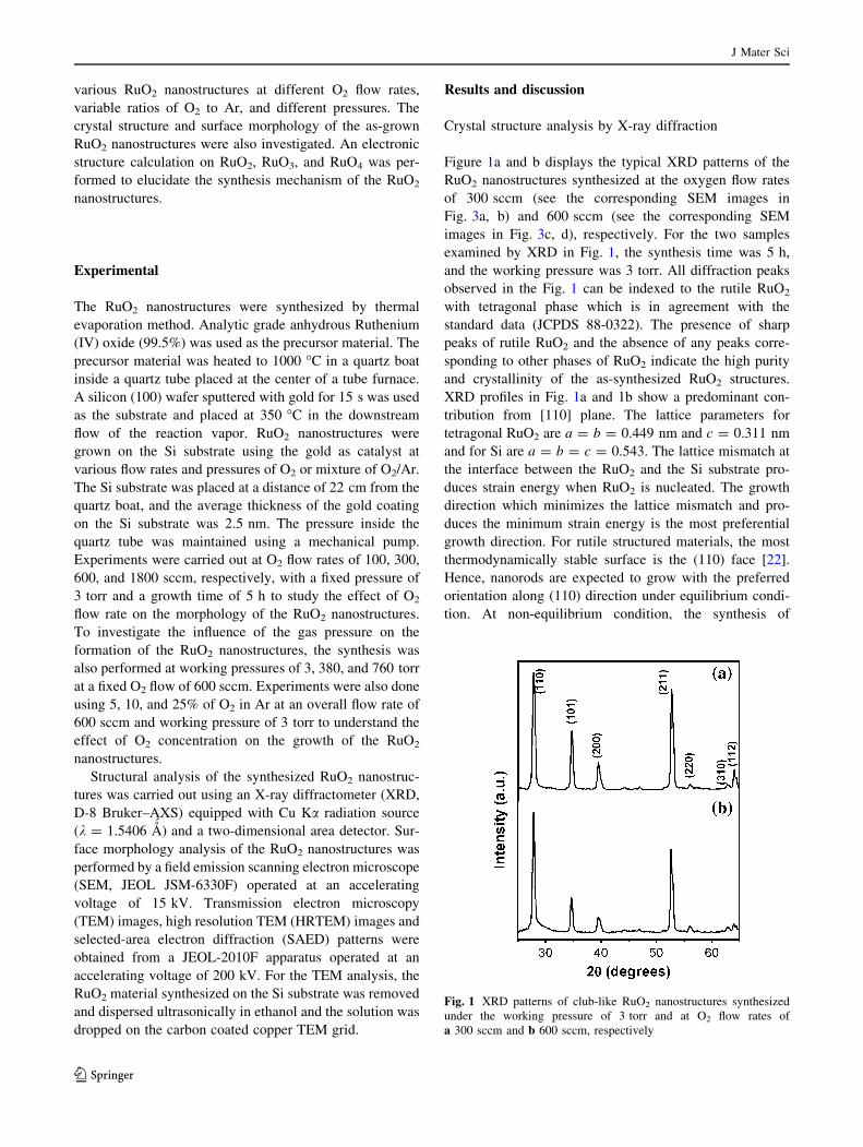
Figure 1a and b displays the typical XRD patterns of the
RuO2 nanostructures synthesized at the oxygen flow rates
of 300 sccm (see the corresponding SEM images in
Fig. 3a, b) and 600 sccm (see the corresponding SEM
images in Fig. 3c, d), respectively. For the two samples
examined by XRD in Fig. 1, the synthesis time was 5 h,
and the working pressure was 3 torr. All diffraction peaks
observed in the Fig. 1 can be indexed to the rutile RuO2
with tetragonal phase which is in agreement with the
standard data (JCPDS 88-0322). The presence of sharp
peaks of rutile RuO2 and the absence of any peaks corre-
sponding to other phases of RuO2 indicate the high purity
and crystallinity of the as-synthesized RuO2 structures.
XRD profiles in Fig. 1a and 1b show a predominant con-
tribution from [110] plane. The lattice parameters for
tetragonal RuO2 are a = b = 0.449 nm and c = 0.311 nm
and for Si are a = b = c = 0.543. The lattice mismatch at
the interface between the RuO2 and the Si substrate pro-
duces strain energy when RuO2 is nucleated. The growth
direction which minimizes the lattice mismatch and pro-
duces the minimum strain energy is the most preferential
growth direction. For rutile structured materials, the most
thermodynamically stable surface is the (110) face [22].
Hence, nanorods are expected to grow with the preferred
orientation along (110) direction under equilibrium condi-
tion. At non-equilibrium condition, the synthesis of
Fig. 1 XRD patterns of club-like RuO2 nanostructures synthesized
under the working pressure of 3 torr and at O2 flow rates of
a 300 sccm and b 600 sccm, respectively
J Mater Sci
123
nanorods is favored along more closely spaced growth
planes. The (101) plane is the next densest plane compared
to the (110) face and is the preferred growth direction
under such condition. From the XRD analysis, it can be
concluded that the RuO2 nanorods show a crystal structure
with preferential crystalline alignment along the [001]
direction indicating the crystal growth along the c-axis.
The XRD profiles of remaining samples synthesized under
other conditions also exhibited the similar pattern.
Morphology analysis by scanning electron microscopy
Effect of oxygen flow rate
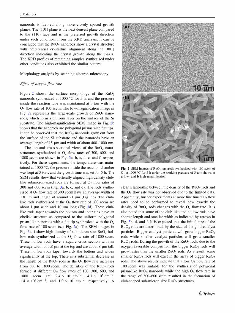
Figure 2 shows the surface morphology of the RuO2
nanorods synthesized at 1000 �C for 5 h, and the pressure
inside the reaction tube was maintained at 3 torr with the
O2 flow rate of 100 sccm. The low-magnification image in
Fig. 2a represents the large-scale growth of RuO2 nano-
rods, which form a uniform layer on the surface of the Si
substrate. The high-magnification SEM image in Fig. 2b
shows that the nanorods are polygonal prisms with flat tips.
It can be observed that the RuO2 nanorods grow out from
the surface of the Si substrate and the nanorods have an
average length of 15 lm and width of about 400–1000 nm.
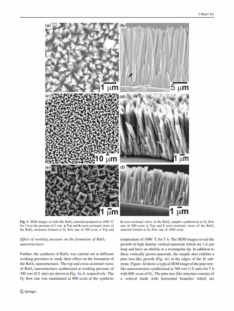
The top and cross-sectional views of the RuO2 nano-
structures synthesized at O2 flow rates of 300, 600, and
1800 sccm are shown in Fig. 3a, b, c, d, e, and f, respec-
tively. For these experiments, the temperature was main-
tained at 1000 �C, the pressure inside the reaction chamber
was kept at 3 torr, and the growth time was set for 5 h. The
SEM results show that vertically aligned high density club-
like submicron-sized rods are formed at O2 flow rates of
300 and 600 sccm (Fig. 3a, b, c, and d). The rods synthe-
sized at O2 flow rate of 300 sccm have an average width of
1.8 lm and length of around 21 lm (Fig. 3b). The club-
like rods synthesized at the O2 flow rate of 600 sccm are
about 1 lm wide and 10 lm long (Fig. 3d). These club-
like rods taper towards the bottom and their tips have an
obelisk structure as compared to the uniform polygonal
prism-like nanorods with a flat tip synthesized with the O2
flow rate of 100 sccm (see Fig. 2a). The SEM images in
Fig. 3e, f show high density of submicron-size RuO2 hol-
low rods synthesized at the O2 flow rate of 1800 sccm.
These hollow rods have a square cross section with an
average width of 1.8 lm at the top and are about 8 lm tall.
These hollow rods taper towards the bottom and widen
significantly at the top. There is a substantial decrease in
the length of the RuO2 rods as the O2 flow rate increases
from 300 to 1800 sccm. The densities of the RuO2 rods
formed at different O2 flow rates of 100, 300, 600, and
1800 sccm are 2.4 9 107 cm-2, 4.7 9 108 cm-2,
1.4 9 106 cm-2, and 1.0 9 107 cm-2, respectively. A
clear relationship between the density of the RuO2 rods and
the O2 flow rate was not observed due to the limited data.
Apparently, further experiments at more fine tuned O2 flow
rates need to be performed to reveal how exactly the
density of RuO2 rods changes with the O2 flow rate. It is
also noted that some of the club-like and hollow rods have
shorter length and smaller width as indicated by arrows in
Fig. 3b, d, and f. It is expected that the initial size of the
RuO2 rods are determined by the size of the gold catalyst
particles. Bigger catalyst particles will grow bigger RuO2
rods while smaller catalyst particles will grow smaller
RuO2 rods. During the growth of the RuO2 rods, due to the
oxygen favorable competition, the bigger RuO2 rods will
grow faster than the smaller RuO2 rods. As a result, some
smaller RuO2 rods will exist in the array of bigger RuO2
rods. The above results indicate that a low O2 flow rate of
100 sccm was suitable for the synthesis of polygonal
prism-like RuO2 nanorods while the high O2 flow rate in
the range of 300–600 sccm resulted in the formation of
club-shaped sub-micron size RuO2 structures.
Fig. 2 SEM images of RuO2 nanorods synthesized with 100 sccm of
O2 at 1000 �C for 5 h under the working pressure of 3 torr shown at
a low- and b high-magnification
J Mater Sci
123
Effect of working pressure on the formation of RuO2
nanostructures
Further, the synthesis of RuO2 was carried out at different
working pressures to study their effect on the formation of
the RuO2 nanostructures. The top and cross-sectional views
of RuO2 nanostructures synthesized at working pressure of
380 torr (0.5 atm) are shown in Fig. 4a, b, respectively. The
O2 flow rate was maintained at 600 sccm at the synthesis
temperature of 1000 �C for 5 h. The SEM images reveal the
growth of high density vertical nanorods which are 1.6 lm
long and have an obelisk or a rectangular tip. In addition to
these vertically grown nanorods, the sample also exhibits a
pine tree-like growth (Fig. 4c) at the edges of the Si sub-
strate. Figure 4d shows a typical SEM image of the pine tree-
like nanostructures synthesized at 760 torr (1.0 atm) for 5 h
with 600 sccm of O2. The pine tree-like structure consists of
a vertical trunk with horizontal branches which are
Fig. 3 SEM images of club-like RuO2 material produced at 1000 �C
for 5 h at the pressure of 3 torr. a Top and b cross-sectional views of
the RuO2 structures formed at O2 flow rate of 300 sccm. c Top and
d cross-sectional views of the RuO2 samples synthesized at O2 flow
rate of 600 sccm. e Top and f cross-sectional views of the RuO2
material formed at O2 flow rate of 1800 sccm
J Mater Sci
123
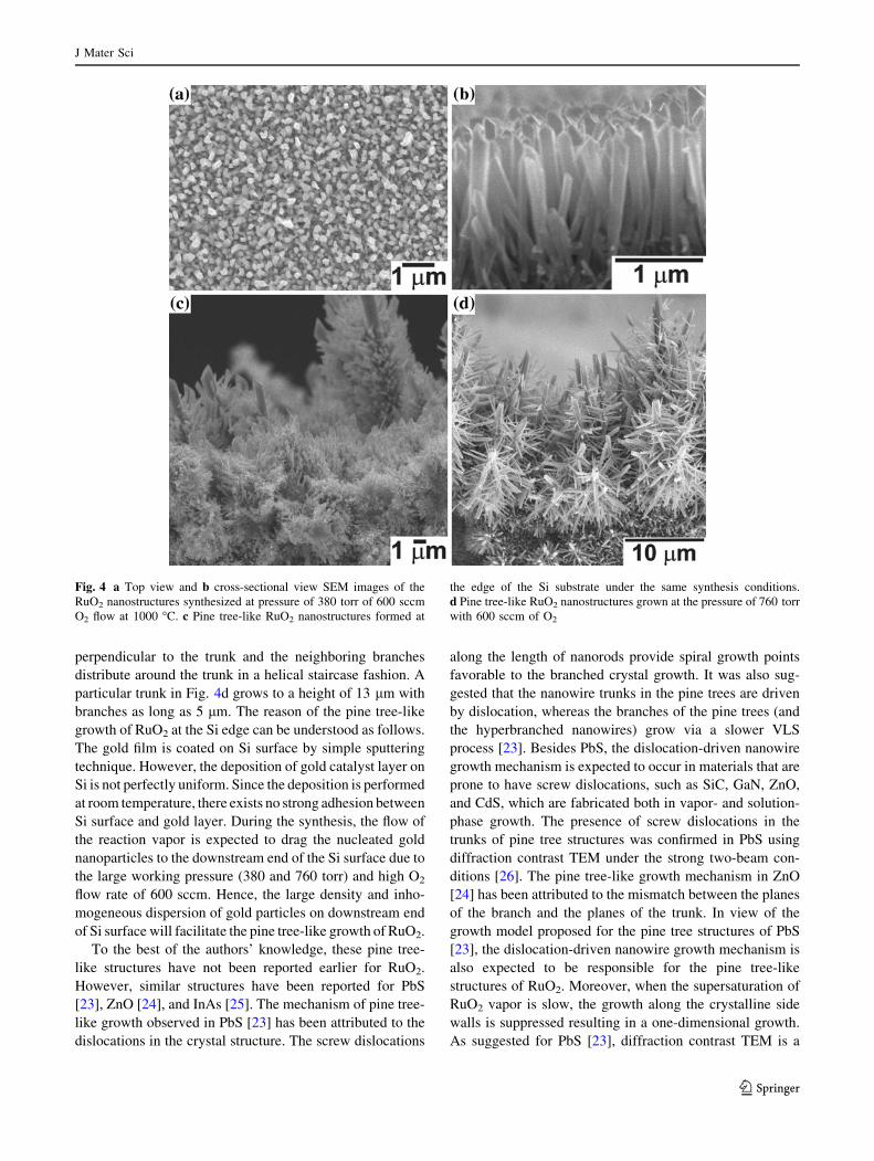
perpendicular to the trunk and the neighboring branches
distribute around the trunk in a helical staircase fashion. A
particular trunk in Fig. 4d grows to a height of 13 lm with
branches as long as 5 lm. The reason of the pine tree-like
growth of RuO2 at the Si edge can be understood as follows.
The gold film is coated on Si surface by simple sputtering
technique. However, the deposition of gold catalyst layer on
Si is not perfectly uniform. Since the deposition is performed
at room temperature, there exists no strong adhesion between
Si surface and gold layer. During the synthesis, the flow of
the reaction vapor is expected to drag the nucleated gold
nanoparticles to the downstream end of the Si surface due to
the large working pressure (380 and 760 torr) and high O2
flow rate of 600 sccm. Hence, the large density and inho-
mogeneous dispersion of gold particles on downstream end
of Si surface will facilitate the pine tree-like growth of RuO2.
To the best of the authors’ knowledge, these pine tree-
like structures have not been reported earlier for RuO2.
However, similar structures have been reported for PbS
[23], ZnO [24], and InAs [25]. The mechanism of pine tree-
like growth observed in PbS [23] has been attributed to the
dislocations in the crystal structure. The screw dislocations
along the length of nanorods provide spiral growth points
favorable to the branched crystal growth. It was also sug-
gested that the nanowire trunks in the pine trees are driven
by dislocation, whereas the branches of the pine trees (and
the hyperbranched nanowires) grow via a slower VLS
process [23]. Besides PbS, the dislocation-driven nanowire
growth mechanism is expected to occur in materials that are
prone to have screw dislocations, such as SiC, GaN, ZnO,
and CdS, which are fabricated both in vapor- and solution-
phase growth. The presence of screw dislocations in the
trunks of pine tree structures was confirmed in PbS using
diffraction contrast TEM under the strong two-beam con-
ditions [26]. The pine tree-like growth mechanism in ZnO
[24] has been attributed to the mismatch between the planes
of the branch and the planes of the trunk. In view of the
growth model proposed for the pine tree structures of PbS
[23], the dislocation-driven nanowire growth mechanism is
also expected to be responsible for the pine tree-like
structures of RuO2. Moreover, when the supersaturation of
RuO2 vapor is slow, the growth along the crystalline side
walls is suppressed resulting in a one-dimensional growth.
As suggested for PbS [23], diffraction contrast TEM is a
Fig. 4 a Top view and b cross-sectional view SEM images of the
RuO2 nanostructures synthesized at pressure of 380 torr of 600 sccm
O2 flow at 1000 �C. c Pine tree-like RuO2 nanostructures formed at
the edge of the Si substrate under the same synthesis conditions.
d Pine tree-like RuO2 nanostructures grown at the pressure of 760 torr
with 600 sccm of O2
J Mater Sci
123
powerful technique to image dislocations in crystals that
relies on additional electron diffraction due to the bending
of atomic planes near the dislocation core. Hence, to find the
exact growth mechanism of the pine tree-like RuO2 struc-
ture, TEM examinations on RuO2 structure with pine tree-
like morphology is necessary. The pine tree-like growth was
not observed in the samples synthesized at O2 flow rate of
600 sccm and pressure of 3 torr (see the corresponding
SEM image of Fig. 3d). In conclusion, the high working
pressure results in the formation of pine tree-like hierar-
chical RuO2 nanostructures, while the low working pressure
suppresses the growth along radial directions and is favor-
able for the formation of club-like structures with an obelisk
tip at the O2 flow rate of 600 sccm.
Effect of Ar/O2 concentration ratio on the formation
of RuO2 nanorods
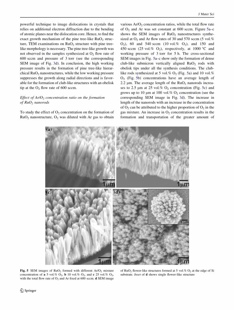
To study the effect of O2 concentration on the formation of
RuO2 nanostructure, O2 was diluted with Ar gas to obtain
various Ar/O2 concentration ratios, while the total flow rate
of O2 and Ar was set constant at 600 sccm. Figure 5a–c
shows the SEM images of RuO2 nanostructures synthe-
sized at O2 and Ar flow rates of 30 and 570 sccm (5 vol.%
O2), 60 and 540 sccm (10 vol.% O2), and 150 and
450 sccm (25 vol.% O2), respectively, at 1000 �C and
working pressure of 3 torr for 5 h. The cross-sectional
SEM images in Fig. 5a–c show only the formation of dense
club-like submicron vertically aligned RuO2 rods with
obelisk tips under all the synthesis conditions. The club-
like rods synthesized at 5 vol.% O2 (Fig. 5a) and 10 vol.%
O2 (Fig. 5b) concentrations have an average length of
2.2 lm. The average length of the RuO2 nanorods increa-
ses to 2.5 lm at 25 vol.% O2 concentration (Fig. 5c) and
grows up to 10 lm at 100 vol.% O2 concentration (see the
corresponding SEM image in Fig. 3d). The increase in
length of the nanorods with an increase in the concentration
of O2 can be attributed to the higher proportion of O2 in the
gas mixture. An increase in O2 concentration results in the
formation and transportation of the greater amount of
Fig. 5 SEM images of RuO2 formed with different Ar/O2 mixture
concentration of a 5 vol.% O2, b 10 vol.% O2, and c 25 vol.% O2,
with the total flow rate of O2 and Ar fixed at 600 sccm. d SEM image
of RuO2 flower-like structures formed at 5 vol.% O2 at the edge of Si
substrate. Inset of d shows single flower-like structure
J Mater Sci
123
volatile oxides of Ru which contribute towards an
increased length of RuO2 nanorods. In other words, the
length of nanorods synthesized in the presence of mixture
of O2 and Ar gas decreases with the increase of the con-
centration of Ar gas in the mixture. This result indicates
that O2 is far more effective than Ar for the synthesis of
RuO2 nanorods. Similar to the RuO2 nanorods synthesized
at different O2 flow rates, some of the RuO2 nanorods
synthesized at different ratios of O2/Ar also have smaller
dimensions than the majority of the nanorods. In addition
to the regular club-like structures formed at 5 vol.% O2,
patches of very high density flower-like structures were
also observed at the edge of the Si substrate (Fig. 5d).
These flower-like structures have width between 1 and
6 lm and are composed of short nanorods of width around
300 nm. The surface of these nanorods is very smooth and
well faceted. The inset in Fig. 5d shows a single flower-
like structure of about 6 lm wide. The high supersaturation
of RuO2 facilitated the homogenous nucleation throughout
the Si substrate. Moreover, the slow reaction due to the
small concentration of O2 allowed a large bundle of
nanorods to grow up from a central nucleus giving rise
to the flower-like growth. The flower-like structures were
not observed on the samples synthesized at the O2 con-
centrations of 10 or 25 vol.%. However, the flower-like
structures are more commonly observed in ZnO materials
[27, 28].
Structural analysis by transmission electron microscopy
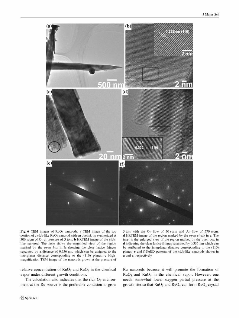
Figure 6a shows the TEM image of the top portion of a
club-like nanorod synthesized at the O2 flow rate of
300 sccm at the pressure of 3 torr (the corresponding SEM
images are shown in Fig. 3a–b). The TEM image clearly
depicts the faceted surface of a 350 nm wide nanorod with
an obelisk tip. The HRTEM image (Fig. 6 b) shows the
equally spaced lattice fringes along the nanorod. The inset
of Fig. 6b shows the magnified view of the region marked
by the open box in Fig. 6b. The lattice fringes are separated
by a distance of 0.336 nm which corresponds to the
interplanar distance of (110) plane of rutile tetragonal
RuO2 crystal. Figure 6c shows the TEM image of the RuO2
nanorods synthesized at 30 sccm of O2 (5 vol.% O2) and
570 sccm of Ar at 3 torr (see the corresponding SEM
image in Fig. 5a). The tiny nanorods are stacked together
to form bundle. Figure 6d shows the HRTEM image of the
nanorods in the region marked by an open circle in Fig. 6c.
The HRTEM image shows the equally spaced lattice frin-
ges separated by 0.332 nm which corresponds to the
interplanar distance of (110) plane of rutile tetragonal
RuO2 suggesting the growth along [001] direction. The
SAED spot patterns of nanorods shown in Fig. 6a and c are
presented in Fig. 6e and f, respectively. HRTEM images
with equally spaced lattice fringes and SAED patterns with
clear bright spots confirm the high purity and crystalline
nature of the as-synthesized nanorods.
Theoretical consideration
Rutile RuO2 crystal is fairly stable. Ruthenium is in nom-
inally ?4 state and oxygen in -2 state. The cohesive
energy is mostly due to oxygen’s planer sp2 hybridization
and ruthenium’s 5s4d hybridization. Each oxygen atom has
three co-planar Ru neighbors, and each Ru atom is at the
center of a slightly deformed octahedron cage formed by
six oxygen atoms. The Ru–O bond length in [110] direction
is only 2% shorter than the other Ru–O bonds. These
structure characteristics considerations show that the indi-
vidual RuO2 molecule has a higher energy and hence
cannot be a major species in the chemical vapor. It is well
known that one must use O2 to form chemical vapor of
RuO3 and RuO4 for transporting Ru to the growth site.
Standard density functional theory for quantum chem-
istry [29] is used to study the energy and stable structures
of molecular ruthenium oxides. The local density approx-
imation [30] is used for the exchange–correlation energy.
The electronic structure and total energies are obtained
using the first-principle self-consistent calculation. A linear
combination of atomic orbitals of Gaussian type centered
on each atom is used to expand the electronic wavefunction
[31, 32]. Three s-type and two p-type orbitals are used for
each oxygen atom, while nine s-type, eight p-type, and one
d-type orbital are used for each Ru atom. This set-up
results in 57 basis orbitals for each RuO2 unit. All structure
parameters (bond lengths and bond angles) are fully
relaxed until residual forces are less than 10-5 Hartree/
Angstrom.
The electronic structure calculation confirms that
RuO2 is higher in energy compared to RuO3 and RuO4.
Because of the sp2 wavefunction of the oxygen, the stable
structure of RuO2 is not linear but forms O–Ru–O angle at
150�. Calculation also shows that the stable structure of
both RuO3 and RuO4 are non-planar, due to the three-
dimensional nature of ruthenium’s d-wavefunction. From
the calculation it can be concluded that 2RuO2 ? O2 ?2RuO3 has an energy gain of 3.4 eV per Ru, and RuO2 ?
O2 ? RuO4 has a larger energy gain of 6.7 eV per Ru.
The structure calculation also suggests that the less stable
RuO3 (as compared to RuO4) may be more suitable for
nanorods growth, because the exposed ruthenium d-orbitals
of RuO3 are ready to bond to oxygen’s sp2 to form a
crystal. Clearly the source temperature will influence
greatly the relative concentration of RuO3 and RuO4 in the
chemical vapor. Previous study [33] reported that at the
synthesis temperature above 1000 �C, formation of RuO4
would dominate. It is desirable to directly investigate the
J Mater Sci
123
relative concentration of RuO3 and RuO4 in the chemical
vapor under different growth conditions.
The calculation also indicates that the rich O2 environ-
ment at the Ru source is the preferable condition to grow
Ru nanorods because it will promote the formation of
RuO3 and RuO4 in the chemical vapor. However, one
needs somewhat lower oxygen partial pressure at the
growth site so that RuO3 and RuO4 can form RuO2 crystal
Fig. 6 TEM images of RuO2 nanorods. a TEM image of the top
portion of a club-like RuO2 nanorod with an obelisk tip synthesized at
300 sccm of O2 at pressure of 3 torr. b HRTEM image of the club-
like nanorod. The inset shows the magnified view of the region
marked by the open box in b showing the clear lattice fringes
separated by a distance of 0.336 nm, which can be assigned to the
interplanar distance corresponding to the (110) planes. c High-
magnification TEM image of the nanorods grown at the pressure of
3 torr with the O2 flow of 30 sccm and Ar flow of 570 sccm.
d HRTEM image of the region marked by the open circle in c. The
inset is the enlarged view of the region marked by the open box in
d indicating the clear lattice fringes separated by 0.336 nm which can
be attributed to the interplanar distance corresponding to the (110)
planes. e and f SAED patterns of the club-like nanorods shown in
a and c, respectively
J Mater Sci
123
and release O2. Our experiments have shown that more
uniform nanorods with less branching and/or tree shape
growth are obtained using various mixtures of O2 and Ar.
In the future, we plan to use a separate source chamber
under higher O2 pressure, and then inject the chemical
vapor into the growth tube under continuous Ar flow to
gain a better control of the growth of the crystalline RuO2
nanorods.
Conclusions
In summary, highly crystalline RuO2 nanorods were syn-
thesized by thermal evaporation of RuO2 powder using
gold as catalyst on silicon substrate. The O2 flow rate,
concentration, and working pressure play significant roles
in the formation of RuO2 nanostructures. Polygonal prisms
with uniform width along the length were synthesized at
the O2 flow rate of 100 sccm, while club-like micron-sized
vertically aligned nanorods with obelisk tips were synthe-
sized at increased O2 flow rates of 300 and 600 sccm. High
flow rate of 1800 sccm of O2 results in the formation of
sub-micron size hollow rods with square-shaped tips. Low
working pressure results in the formation of linear nano-
rods, while high working pressures result in both vertically
aligned nanorods and pine tree-like branched hierarchical
RuO2 nanostructures. The formation of pine tree-like
hierarchical RuO2 nanostructures can be attributed to the
screw dislocation or lattice mismatch. The experimental
results indicate that the decrease of O2 concentrations in
the Ar/O2 mixtures with the total flow rate of 600 sccm
suppresses the growth speed of the RuO2 nanorods. A
flower-like pattern consisting of short RuO2 nanorods was
also observed in the sample synthesized at the O2 con-
centration of 5 vol.%. The as-synthesized RuO2 nano-
structures with obelisk tips can find applications in field
emitters due to their unique morphology.
Acknowledgements This study was supported by the National
Science Foundation under the grant DMR-0548061. We would like to
thank Dr. Dezhi Wang for the TEM measurements.
References
1. Xu JH, Jarlborg T, Freeman AJ (1989) Phys Rev B 40:7939
2. Ryden WD, Lawson AW, Sartian CC (1970) Phys Rev B 1:1494
3. Green ML, Gross ME, Papa LE, Schnoes KJ, Brasen D (1985) J
Electrochem Soc 132:2677
4. Khanna PK, Bhatnagar SK, Sisodia ML (1988) J Phys D 21:1796
5. Dziedzic A, Golonka LJ, Kozlowski J, Licznerski BW, Nitsch K
(1997) Meas Sci Technol 8:78
6. Kim IH, Kim KB (2001) Electrochem Solid State Lett 4:A62
7. Park BO, Lokhande CD, Park HS, Jung KD, Joo OS (2004) J
Mater Sci 39:4313. doi:10.1023/B:JMSC.0000033415.47096.db
8. Norga GJ, Fe L, Wouters DJ, Maes HE (2000) Appl Phys Lett
76:1318
9. Hartmann AJ, Neilson M, Lamb RN, Watanabe K, Scott JF
(2000) Appl Phys A 70:239
10. Kuhn AT, Mortimer CJ (1973) J Electrochem Soc 120:231
11. Ferro S, De Battisti A (2002) J Phys Chem B 106:2249
12. Lister TE, Tolmachev YV, Chu Y, Cullen WG, You H, Yonco R,
Nagy Z (2003) J Electroanal Chem 554:71
13. Ryan JV, Berry AD, Anderson ML, Long JW, Stroud RM, Cepak
VM, Browning VM, Rolison DR, Merzbacher CI (2000) Nature
406:169
14. Hsieh CS, Tsai DS, Chen RS, Huang YS (2004) Appl Phys Lett
85:3860
15. Delmer O, Balaya P, Kienle L, Maier J (2008) Adv Mater 20:501
16. Iembo A, Fuso F, Arimondo E, Ciofi C, Pennelli G, Curro GM,
Neri F, Allegrini M (1997) J Mater Res 12:1433
17. Kim IH, Kim KB (2004) J Electrochem Soc 151:E7
18. Satishkumar BC, Govindaraj A, Nath M, Rao CNR (2000) J
Mater Chem 10:2115
19. Cheng KW, Lin YT, Chen CY, Hsiung CP, Gan JY, Yeh JW,
Hsieh CH, Chou LJ (2006) Appl Phys Lett 88:043115
20. Chen RS, Chen CC, Huang YS, Chia CT, Chen HP, Tsai DS,
Tiong KK (2004) Solid State Commun 131:349
21. Liu YL, Wu ZY, Lin KJ, Huang JJ, Chen FR, Kai JJ, Lin YH,
Jian WB, Lin JJ (2007) Appl Phys Lett 90:013105
22. Vetrone J, Foster CM, Bai GR, Wang A, Patel J, Wu X (1998) J
Mater Res 13:2281
23. Bierman MJ, Lau YKA, Kvit AV, Schmitt AL, Jin S (2008)
Science 320:1060
24. Zhao FH, Li XY, Zheng JG, Yang XF, Zhao FL, Wong KS,
Wang J, Lin WJ, Wu MM, Su Q (2008) Chem Mater 20:1197
25. May SJ, Zheng JG, Wessels BW, Lauhon LJ (2005) Adv Mater
17:598
26. Williams DB, Carter CB (1996) Transmission electron micros-
copy: a textbook for materials science. Plenum, New York
27. Wang Z, Qian XF, Yin J, Zhu ZK (2004) Langmuir 20:3441
28. Zhang H, Yang D, Ma XY, Ji YJ, Xu J, Que DL (2004) Nano-
technology 15:622
29. Jones RO, Gunnarsson O (1989) Rev Mod Phys 61:689
30. Ceperley DM, Alder BJ (1980) Phys Rev Lett 45:566
31. Ditchfield WJH, Pople JA (1971) J Chem Phys 54:724
32. Hariharan PC, Pople JA (1973) Theor Chim Acta 28:213
33. Bell WE, Tagami M (1963) J Phys Chem 67:2432
J Mater Sci
123
Copyright © 2022 FDOKUMEN