Double-resonant optical materials with embedded metal nanostructures
8
Double-resonant optical materials with embedded metal nanostructures Ildar R. Gabitov Department of Mathematics, University of Arizona, 617 North Santa Rita Avenue, Tucson, Arizona 85721, and Theoretical Division, Los Alamos National Laboratory, Los Alamos, New Mexico 87545 Robert A. Indik Department of Mathematics, University of Arizona, 617 North Santa Rita Avenue, Tucson, Arizona 85721 Natalia M. Litchinitser Department of Electrical Engineering and Computer Science, University of Michigan, 1301 Beal Avenue, Ann Arbor, Michigan 48109 Andrei I. Maimistov Department of Solid State Physics, Moscow Engineering Physics Institute, Kashirskoe sh. 31, Moscow, 115409 Russia Vladimir M. Shalaev School of Electrical and Computer Engineering, Purdue University, West Lafayette, Indiana 47907 Joshua E. Soneson Program in Applied Mathematics, University of Arizona, 617 North Santa Rita Avenue, Tucson, Arizona 85721 Received November 3, 2005; accepted November 6, 2005; posted December 8, 2005 (Doc. ID 65763) We derive equations modeling the resonant interaction of electric and magnetic components of light fields with metal nanostructures. This paired resonance was recently shown to produce negative refractive index. The model equations are a generalization of the well-known Maxwell–Lorentz model. We demonstrate that in the case of nonlinear polarization and linear magnetization, these equations are equivalent to a system of equa- tions describing the resonant interaction of light with plasmonic oscillations in metal nanospheres. A family of solitary wave solutions is found that is similar to pulses associated with self-induced transparency in the framework of the Maxwell–Bloch model. The evolution of incident optical pulses is studied numerically, as are the collision dynamics of the solitary waves. These simulations reveal that the collision dynamics vary from near perfectly elastic to highly radiative, depending on the relative phase of the initial pulses. © 2006 Optical Society of America OCIS codes: 190.4400, 260.5740, 250.5530. 1. INTRODUCTION The resonant interaction of light with plasmonic oscilla- tions in metal nanostructures has recently become a focus of considerable interest owing to the potential of harness- ing strong, locally generated fields for a wide variety of applications. 1,2 In addition, it has been recently demon- strated that such structures produce a negative refractive index in the optical domain. 3 The negative refractive in- dex is a consequence of simultaneous resonant electric and magnetic interactions with the nanostructures, which is reminiscent of arrays of LC circuits that demon- strate negative refractive index in the microwave regime. 4–6 The equations that describe the interaction of coherent light with a medium consisting of molecules (considered as harmonic oscillators) is known as the Maxwell–Lorentz model. 7 Taking into account the quan- tum nature of the atoms leads to the Maxwell–Bloch equations in the two-level approximation. 8 The Maxwell– Bloch equations are nonlinear and describe many impor- tant phenomena, such as self-induced transparency, opti- cal pulse amplification, and superfluorescence. In this study we extend the Maxwell–Lorentz system to account for plasmonic and magnetic resonances. These new resonances are due to interaction with plasmonic os- cillations in the metal nanostructures. The interaction of the electric and plasmonic fields leads to strong electric resonance. In addition, nanostructures can mimic the ef- fect of LC circuits to produce a resonant interaction with the magnetic field. Just as nonlinear effects in the Maxwell–Bloch equations (a single resonance) have been Gabitov et al. Vol. 23, No. 3/March 2006/J. Opt. Soc. Am. B 535 0740-3224/06/030535-8/$15.00 © 2006 Optical Society of America
Transcript of Double-resonant optical materials with embedded metal nanostructures
1Ttoiasidawsrc(
Gabitov et al. Vol. 23, No. 3 /March 2006/J. Opt. Soc. Am. B 535
Double-resonant optical materials with embeddedmetal nanostructures
Ildar R. Gabitov
Department of Mathematics, University of Arizona, 617 North Santa Rita Avenue, Tucson, Arizona 85721, andTheoretical Division, Los Alamos National Laboratory, Los Alamos, New Mexico 87545
Robert A. Indik
Department of Mathematics, University of Arizona, 617 North Santa Rita Avenue, Tucson, Arizona 85721
Natalia M. Litchinitser
Department of Electrical Engineering and Computer Science, University of Michigan, 1301 Beal Avenue, Ann Arbor,Michigan 48109
Andrei I. Maimistov
Department of Solid State Physics, Moscow Engineering Physics Institute, Kashirskoe sh. 31, Moscow, 115409Russia
Vladimir M. Shalaev
School of Electrical and Computer Engineering, Purdue University, West Lafayette, Indiana 47907
Joshua E. Soneson
Program in Applied Mathematics, University of Arizona, 617 North Santa Rita Avenue, Tucson, Arizona 85721
Received November 3, 2005; accepted November 6, 2005; posted December 8, 2005 (Doc. ID 65763)
We derive equations modeling the resonant interaction of electric and magnetic components of light fields withmetal nanostructures. This paired resonance was recently shown to produce negative refractive index. Themodel equations are a generalization of the well-known Maxwell–Lorentz model. We demonstrate that in thecase of nonlinear polarization and linear magnetization, these equations are equivalent to a system of equa-tions describing the resonant interaction of light with plasmonic oscillations in metal nanospheres. A family ofsolitary wave solutions is found that is similar to pulses associated with self-induced transparency in theframework of the Maxwell–Bloch model. The evolution of incident optical pulses is studied numerically, as arethe collision dynamics of the solitary waves. These simulations reveal that the collision dynamics vary fromnear perfectly elastic to highly radiative, depending on the relative phase of the initial pulses. © 2006 OpticalSociety of America
OCIS codes: 190.4400, 260.5740, 250.5530.
MteBtc
anctrftM
. INTRODUCTIONhe resonant interaction of light with plasmonic oscilla-ions in metal nanostructures has recently become a focusf considerable interest owing to the potential of harness-ng strong, locally generated fields for a wide variety ofpplications.1,2 In addition, it has been recently demon-trated that such structures produce a negative refractivendex in the optical domain.3 The negative refractive in-ex is a consequence of simultaneous resonant electricnd magnetic interactions with the nanostructures,hich is reminiscent of arrays of LC circuits that demon-
trate negative refractive index in the microwaveegime.4–6 The equations that describe the interaction ofoherent light with a medium consisting of moleculesconsidered as harmonic oscillators) is known as the
0740-3224/06/030535-8/$15.00 © 2
axwell–Lorentz model.7 Taking into account the quan-um nature of the atoms leads to the Maxwell–Blochquations in the two-level approximation.8 The Maxwell–loch equations are nonlinear and describe many impor-
ant phenomena, such as self-induced transparency, opti-al pulse amplification, and superfluorescence.
In this study we extend the Maxwell–Lorentz system toccount for plasmonic and magnetic resonances. Theseew resonances are due to interaction with plasmonic os-illations in the metal nanostructures. The interaction ofhe electric and plasmonic fields leads to strong electricesonance. In addition, nanostructures can mimic the ef-ect of LC circuits to produce a resonant interaction withhe magnetic field. Just as nonlinear effects in theaxwell–Bloch equations (a single resonance) have been
006 Optical Society of America
amw
snieDmcemdf
hMctsn
2NQnsHtuoctctttlart
stdpnwfReteTltt
If
esdcl(t�nmT
mcsm
wasle
wiatfNofirEghefctnictmlir
nacrnep
536 J. Opt. Soc. Am. B/Vol. 23, No. 3 /March 2006 Gabitov et al.
rich source of important physical phenomena, these si-ultaneous magnetic and electric resonances combinedith nonlinear effects may well lead to new physics.In what follows we first investigate the simplest nano-
tructures: nanospheres. In this case, there is no mag-etic resonance, though there is nonlinearity in the polar-
zation response to the electric field.9,10 We derivequations describing this interaction that are of Maxwell–uffing form. Then we consider the case of simultaneousagnetic and electric resonance, where the magnetic sus-
eptibility is linear, but the electric polarization is nonlin-ar. We show that in the latter case, the equation for theagnetic field decouples, and the study of this system re-
uces to that of the Maxwell–Duffing equations we deriveor nanospheres.
We find a family of solitary wave solutions whose be-avior is analogous to self-induced transparency inaxwell–Bloch. We numerically study the evolution of in-
ident optical pulses as well as the collision dynamics ofhe solitary waves. These results are relevant to both theystem of nanospheres and the more complex systems ofano-LC circuits.
. SINGLE-RESONANT MEDIUM:ANOSPHERESuantum effects in metal nanoparticles driven by a reso-ant optical field play an important role in inducing atrong nonlinear response, as was recently shown.9,10
ere we consider the nonlinear resonant interaction of ul-rashort optical pulses with metal nanoparticles distrib-ted uniformly in a host medium. We restrict to the casef composite materials for which the resonance frequen-ies of the host medium are well separated from those ofhe nanoparticles. Examples include silver or gold spheri-al or spheroidal nanoparticles embedded in SiO2. Inhese cases, the plasmonic resonance frequencies are inhe visible part of the spectrum, whereas the resonance ofhe host is in the ultraviolet. For spheroidal particles witharge aspect ratios, the longitudinal plasmon oscillationsre in the infrared so that the difference between theesonant frequencies of the host and the plasmon oscilla-ions is even larger.
Light interaction with metal nanoparticles can be de-cribed by a system consisting of Maxwell’s equations forhe electric field and an oscillator equation describing theisplacement of conduction electrons in the metal nano-articles from equilibrium (plasmonic oscillations). Theanoparticles are much smaller than the optical carrieravelength �0. This allows light scattering and spatial ef-
ects in the nanoparticles to be neglected. As shown byautian9 and Drachev et al.,10 who further developed thearlier work by Hache et al.,11 the response of the conduc-ion electrons in the metal nanoparticles to an externallectric field induces a leading-order cubic nonlinearity.he interaction of the electric field with plasmonic oscil-
ations in nanoparticles with resonance frequency �r inhe presence of this cubic nonlinearity can be described byhe forced Duffing equation
QTT + �r2Q + �Q3 = �e/m�E. �1�
n this expression Q represents plasmon displacementrom equilibrium, T is time; � is the coefficient of nonlin-
arity; e and m are the electron charge and rest mass, re-pectively; and E is the electric field. The tilde is used toenote rapidly varying quantities. The nonlinear coeffi-ient � can be estimated by comparing off-resonance non-inear response in Eq. (1) with the Drude nonlinearity fornonresonant) conduction electrons in metal nanopar-icles. That susceptibility is characterized by9 ��3�
Ne4a2 / �m�2�04�. Here a and N are the radius of the
anoparticle and the conduction electron density of theetal, respectively, and �0 is the optical carrier frequency.his results in the estimate ���ma�0
2 /��2.We are interested in pulse dynamics that vary on auch slower scale than the plasmonic, host atom, and
arrier wave oscillations and can be described using alowly varying envelope approximation. In this approxi-ation Eq. (1) becomes
iQT + ��r − �0�Q + �3�/2�0��Q�2Q = − �e/2m�0�E, �2�
here the slowly varying envelopes of the electric fieldnd plasmonic oscillations are represented by E and Q, re-pectively. Maxwell’s equation couples to the material po-arization induced by the plasmonic oscillations. Thequation for the electric field envelope is
i�EZ +1
vgET� = −
2��0Npe
cn0�Q� −
2��0Na�d�2
cn0��a
�E −2�i�0Na�d�2
cn0��a2 ET, �3�
here Z is the propagation coordinate, vg is group veloc-ty, c is the speed of light, n0 is the refractive index evalu-ted at the carrier frequency �0, and Np is the product ofhe conduction electron density N and the metal-fillingactor p (the fraction of the composite occupied by metal).
a is the concentration of host atoms, d is the projectionf the dipole matrix element in the direction of the electriceld polarization, and �a=�a−�0 is detuning from theesonance frequency of host atoms. The last two terms inq. (3) represent corrections to the, refractive index androup index due to the off-resonance interaction with theost medium, which, for illustration, is considered as annsemble of two-level atoms. This equation is derivedrom the Maxwell–Bloch equations in the nonresonantase by considering �a as a large parameter and applyinghe adiabatic following approximation.12 Additional reso-ances would produce similar terms. We consider the case
n which optical pulse intensity and duration as well asomposite material parameters are such that the charac-eristic length of resonant light interaction with plas-onic oscillations is much smaller than the characteristic
engths for both group velocity dispersion and nonlinear-ty induced by the host medium. Therefore the terms rep-esenting these effects are omitted from Eq. (3).
In a composite material, the sizes and shapes of metalanoparticles vary owing to limited fabrication toler-nces. It is known that the plasmon resonance in spheri-al metal nanoparticles depends weakly on size in theange between 10 and 50 nm,13 so variations in size areot important. However, variations in the shape and ori-ntation of the nanoparticles can significantly changelasmonic resonance frequencies. This results in a broad-
eaeq
wp−=E
Tcpsd
3CTnniM
Ipmt=t
t
ct
wlbdwl
wbw
ag
TTthp�
Fv=
FiTthl
iw
Titqn(
Gabitov et al. Vol. 23, No. 3 /March 2006/J. Opt. Soc. Am. B 537
ning of the resonance line of the bulk composite. Thengle brackets �Q�t ,z ,���=−
Q�t ,z ,��g���d� denote av-raging over the distribution g��� of the resonance fre-uencies (line shape). Defining
E = − E2m�0
3
e 2
3�exp�iksZ�, Q = Q�0 2
3�exp�iksZ�,
�4�
here ks=2��0Na�d�2 /cn0��a, and introducing the co-ropagating coordinate system z= ��p
2 /4cn0�0�Z, t=�0�TZ /u�, u here is shifted group velocity defined as u−1
vg−1+2��0Na�d�2 /cn0��a
2, �p2=4�Npe2 /m, �= ��r−�0� /�0,
qs. (2) and (3) can be reduced to the simpler form
iEz = �Q�, iQt + �Q + �Q�2Q = E. �5�
hese equations represent a generalization of the classi-al Maxwell–Lorentz model. In the case of identical nano-articles, the averaging in Eq. (5) can be reduced to aingle dimensionless frequency � [i.e., detuning frequencyistribution g���=��− ��].
. DOUBLE-RESONANT MEDIUM: NANO-LCIRCUITSo illustrate the equations governing nonlinear wave dy-amics in the presence of both electric and magnetic reso-ance, we consider the simplest case of nonlinear polar-
zation response and linear magnetic susceptibility.axwell’s equations in the general case have the form
� � E = − c−1Bt, � � H = − c−1Dt,
B = H + 4�M, D = E + 4�P. �6�
n real experiments electric and magnetic fields should beroperly aligned with respect to the nanostructure toaximize the resonance interaction. As an example, elec-
ric and magnetic fields of the form E= �E ,0 ,0�, H�0,H ,0� are considered. In the linear case, the Fourier
ransformation may be applied to obtain
Ez = i�c−1����H���, Hz = i�c−1����E���,
hus
Ezz = i��/c�2��������E���. �7�
Assume that polarization is defined by the plasma os-illation electron density so that the equation for polariza-ion has the form
Ptt =�p
2
4�E − P3, �8�
here �p is effective plasma frequency and is the non-inearity coefficient. The origin of this nonlinearity coulde quantum effects in the nanostructures or a nonlinearielectric coating. For a description of the magnetizatione use the simplest model of magnetic resonance as an il-
ustration:
Mtt + �T2M = −
�
4�Htt, �9�
here �T is the Thomson frequency and � is determinedy the geometry of the nanostructures. In the linear casee obtain
�������� =��2 − �p
2���T2 − �2 + ��2�
�2��T2 − �2�
, �10�
nd the linear dispersion relation for wave propagation isiven by
k2 = ��
c �2
��������. �11�
herefore the spectrum of linear waves contains a gap.he high-frequency branch corresponds to plasmons, and
he low-frequency branch corresponds to waves in a left-anded material (LHM),14 i.e., if the phase velocity isositive, then the group velocity is negative. Near �=�p,��p we have the plasmon dispersion relation
�2�k� = �p2 +
�p2 − �T
2
�1 − ���p2 − �T
2 c2k2. �12�
or this branch of the dispersion relation both the phaseelocity and group velocity are positive. Near �=�0
�T /1−�, ���0, we have
�2�k� = �02 −
��T2
�1 − ��2��p2 − �0
2�c2k2. �13�
or this branch of the dispersion relation the phase veloc-ty is positive; however, the group velocity is negative one.hus in this spectral region waves in a linear approxima-
ion are propagated as waves in a LHM. Now that weave seen the linear LHM scenario we return to the non-
inear case.Let us consider a plane electromagnetic wave propagat-
ng in the z direction. For an isotropic medium the Max-ell equations have the following scalar form:
Ez + c−1Ht = − 4�c−1Mt, Ex = 0,
Hz + c−1Et = − 4�c−1Pt, Hy = 0. �14�
his system is closed by two additional equations describ-ng the interaction of the electric and magnetic fields withhe metal nanostructures. To account for dimensionaluantization due to confinement of the plasma in theanostructures the additional term �D
2 P is included in Eq.8):
Ptt + �D2 P + P3 =
�p2
4�E,
Mtt + �T2M = −
�
4�Htt. �15�
Normalization of the variables
tl
w
(
wf
b
A
wpttm
I=wF=−sabftn
�
�
Peb
Tl
D−
w=
mttttc
�
�
Tqkr
Tfi
2
H
538 J. Opt. Soc. Am. B/Vol. 23, No. 3 /March 2006 Gabitov et al.
� = t/T, � = z/L, q = P/P0, m = M/M0,
e = E/E0, h = H/H0,
T = �p−1, L = c�p
−1, P0 = �p/� �,
� = /� �,M0 = P0 = E0/4�
ransforms Eqs. (14) and (15) to the following dimension-ess nonlinear plasmon-LC circuit model:
�� + hr = − mr, h� + er = − q�,
q�� + �2q + �q3 = e, m�� + �T2m = − �h��, �16�
here �2= ��D2 /�p
2� and �T2 = ��T
2 /�p2�.
To find a slowly varying envelope approximation of Eqs.16) the Fourier transform is applied, resulting in
e� − i�h = i�m, h� − i�e = i�q,
��2 − �2�q + �F�q3���� = e, ��T2 − �2�m = − ��2h,
�17�
here F�f� denotes the time Fourier transform of theunction f.
Magnetic susceptibility can be excluded from Eqs. (17)y introducing the magnetic permeability
���� = 1 +��2
�T2 − �2
. �18�
fter substituting Eq. (18), Eqs. (17) reads
e�� + �2����e = − �2����q,
��2 − �2�q + �F�q3���� = e. �19�
Equations (19) describe wave propagation in a mediumhose nonlinear properties are determined only by theolarization. However, the dispersion relation also takeshe magnetic properties of the medium into account. Fur-her, we consider fields in the Eqs. (19) as quasimonochro-atic waves:
q��,�� = q��,��exp�− i�0� + ik0�� + c.c.,
e��,�� = e��,��exp�− i�0� + ik0�� + c.c. �20�
t can be shown that the Fourier component A�k ,��−
A�x , t�exp�i�t− ikx�dtdx of any quasimonochromaticave A�x , t�=a�x , t�exp�−i�0t+ ik0x� can be expressed viaourier amplitude of the envelope a�k ,��−
a�x , t�exp�i�t− ikx�dtdx in the form of A�k ,��=a�kk0 ,�−�0�. If the envelope is slowly varying in time andpace compared with the carrier wave then its Fouriermplitude is localized in the domain of small wave num-ers and frequencies �k−k0 /k0�1,�−�0 /�0�1�. There-ore the system of equations describing the evolution ofhe electric and polarization fields together with the mag-etic field can be presented as
�k0 + k�2 − ��0 + ��2���0 + ���e�k,��
= ��0 + ��2���0 + ��q�k,��,
�k0 + k�2 − ��0 + ��2���0 + ���h�k,��
= ��0 + ���k0 + k�q�k,��,
��2 − ��0 + ��2�q�k,�� + �F�q3��k,�� = e�k,��. �21�
rior to proceeding further it is useful to consider the lin-ar case, in which the medium polarization is describedy
��2 − �2�q�k,�� = e�k,��.
he equations for e and h in the linear case have the fol-owing form:
�k2 − �2�����e�k,�� = �2������2 − �2�−1e�k,��,
�k2 − �2�����h�k,�� = �k��2 − �2�−1e�k,��.
efining the dielectric permittivity as ����= �1+1/ ��2
�2�� we rewrite the equation for e as
�k2 − �2���������e�k,�� = 0,
hich gives the standard dispersion relation k2
�2��������.It should be noted that the variable q corresponds toedium polarization in Eqs. (16) and in the equations
hat follow. Let the variable q�k ,�� describe the contribu-ion of resonance structures–nonlinear oscillators and in-roduce the host medium dielectric permittivity �host��� toake dispersion properties of the host medium into ac-ount. Hence Eqs. (21) should be modified as follows:
�k0 + k�2 − ��0 + ��2�host��0 + �����0 + ���e�k,��
= ��0 + ��2���0 + ��q�k,��,
�k0 + k�2 − ��0 + ��2�host��0 + �����0 + ���h�k,��
= ��0 + ���k0 + k�q�k,��,
��2 − ��0 + ��2�q�k,�� + �F�q3��k,�� = e�k,��. �22�
aking into account that the arguments of the functions�k ,��, e�k ,��, and h�k ,�� are much smaller than �0 and0, we consider only a second-order approximation withespect to � /�0. Let us introduce
k2��� = ��0 + ��2�host��0 + �����0 + ��. �23�
he expression in brackets on the left-hand side of therst two of Eqs. (22) can be replaced by
k0 k − � �k
���
�=�0
� −1
2� �2k
��2 +1
2k0
�k
��
�k
���
�=�0
�2�= 2k0 k −
1
vg0� −
1
2D0�2� .
ere the group velocity v and second-order dispersion
g0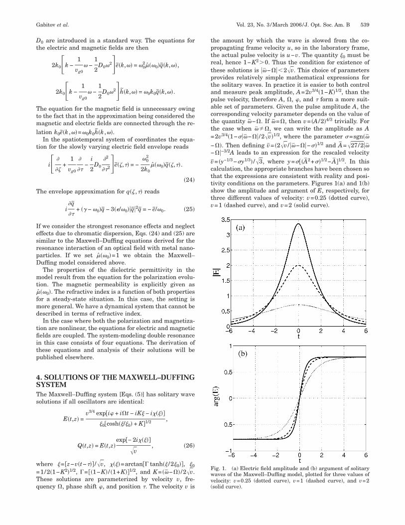
Dt
Ttml
t
T
IesrpD
mt�fmd
tfiitp
4STs
w=Tq
tptrtptapactt=−−vcttstv
Fwv(
Gabitov et al. Vol. 23, No. 3 /March 2006/J. Opt. Soc. Am. B 539
0 are introduced in a standard way. The equations forhe electric and magnetic fields are then
2k0 k −1
vg0� −
1
2D0�2�e�k,�� = �0
2���0�q�k,��,
2k0 k −1
vg0� −
1
2D0�2�h�k,�� = �0k0q�k,��.
he equation for the magnetic field is unnecessary owingo the fact that in the approximation being considered theagnetic and electric fields are connected through the re-
ation k0e�k ,��=�0k0h�k ,��.In the spatiotemporal system of coordinates the equa-
ion for the slowly varying electric field envelope reads
i �
��+
1
vg0
�
��−
i
2D0
�2
��2�e��,�� = −�0
2
2k0���0�q��,��.
�24�
he envelope approximation for q�� ,�� reads
i�q
��+ �� − �0�q − 3��/�0��q�2q = − e/�0. �25�
f we consider the strongest resonance effects and neglectffects due to chromatic dispersion, Eqs. (24) and (25) areimilar to the Maxwell–Duffing equations derived for theesonance interaction of an optical field with metal nano-articles. If we set ���0�=1 we obtain the Maxwell–uffing model considered above.The properties of the dielectric permittivity in theodel result from the equation for the polarization evolu-
ion. The magnetic permeability is explicitly given asˆ ��0�. The refractive index is a function of both propertiesor a steady-state situation. In this case, the setting isore general. We have a dynamical system that cannot be
escribed in terms of refractive index.In the case where both the polarization and magnetiza-
ion are nonlinear, the equations for electric and magneticelds are coupled. The system-modeling double resonance
n this case consists of four equations. The derivation ofhese equations and analysis of their solutions will beublished elsewhere.
. SOLUTIONS OF THE MAXWELL–DUFFINGYSTEMhe Maxwell–Duffing system [Eqs. (5)] has solitary waveolutions if all oscillators are identical:
E�t,z� =v3/4 exp�i� + i�t − iK� − i�����
�0�cosh��/�0� + K�1/2 ,
Q�t,z� = E�t,z�exp�− 2i�����
v, �26�
here �= �z−v�t−��� /v, ����=arctan�� tanh�� /2�0��, �0
1/2�1−K2�1/2, �= ��1−K� / �1+K��1/2, and K= ��−�� /2v.hese solutions are parameterized by velocity v, fre-uency �, phase shift �, and position �. The velocity v is
he amount by which the wave is slowed from the co-ropagating frame velocity u, so in the laboratory frame,he actual pulse velocity is u−v. The quantity �0 must beeal, hence 1−K2�0. Thus the condition for existence ofhese solutions is ��−���2v. This choice of parametersrovides relatively simple mathematical expressions forhe solitary waves. In practice it is easier to both controlnd measure peak amplitude, A=2v3/4�1−K�1/2, than theulse velocity, therefore A, �, �, and � form a more suit-ble set of parameters. Given the pulse amplitude A, theorresponding velocity parameter depends on the value ofhe quantity �−�. If �=�, then v= �A /2�4/3 trivially. Forhe case when ���, we can write the amplitude as A2v3/4�1−���−�� /2v�1/2, where the parameter �=sgn����. Then defining v= �2v / ��−��−��1/2 and A=27/2����−3/2A leads to an expression for the rescaled velocity= �y−1/3−�y1/3� /3, where y=���A2+��1/2− A�1/2. In thisalculation, the appropriate branches have been chosen sohat the expressions are consistent with reality and posi-ivity conditions on the parameters. Figures 1(a) and 1(b)how the amplitude and argument of E, respectively, forhree different values of velocity: v=0.25 (dotted curve),=1 (dashed curve), and v=2 (solid curve).
ig. 1. (a) Electric field amplitude and (b) argument of solitaryaves of the Maxwell–Duffing model, plotted for three values ofelocity: v=0.25 (dotted curve), v=1 (dashed curve), and v=2solid curve).
tsbotsmocd
tticatedmtiaaaoop
mstTtwc
Ft
Fdfc
Fs(
540 J. Opt. Soc. Am. B/Vol. 23, No. 3 /March 2006 Gabitov et al.
In optics it has become standard practice to refer to cer-ain solutions of nonintegrable systems as solitons. Theseolutions are characterized as solitary waves that are ro-ust to external perturbations, including collisions withther solitary waves. In addition, arbitrary initial data forhese “soliton” supporting systems tend to evolve into aum of solitary waves and continuous radiation. The re-ainder of this paper details our numerical investigation
f these properties, in which Eqs. (5) are integrated in thease of delta-distributed resonance frequencies and zeroetuning.Numerical simulations of the evolution of Gaussian ini-
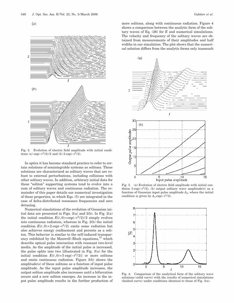
ial data are presented in Figs. 2(a) and 2(b). In Fig. 2(a)he initial condition E�t ,0�=exp�−t2 /2� /2 simply evolvesnto continuous radiation, whereas in Fig. 2(b) the initialondition E�t ,0�=2 exp�−t2 /2� emits some radiation butlso achieves energy confinement and persists as a soli-on. This behavior is similar to the self-induced transpar-ncy exhibited by the Maxwell–Bloch equations,15 whichescribe optical pulse interaction with resonant two-leveledia. As the amplitude of the initial pulse is increased,
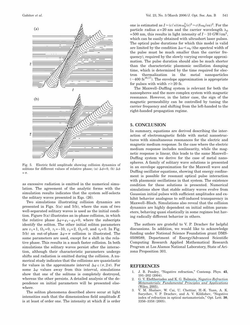
he pulse splits into two [illustrated in Fig. 3(a) for thenitial condition E�t ,0�=5 exp�−t2 /2�] or more solitonsnd emits continuous radiation. Figure 3(b) shows themplitude(s) of these solitons as a function of input pulsemplitude. As the input pulse amplitude increases, theutput soliton amplitude also increases until a bifurcationccurs and a new soliton emerges. An increase in the in-ut pulse amplitude results in the further production of
ig. 2. Evolution of electric field amplitude with initial condi-ions (a) exp�−t2 /2� /2 and (b) 2 exp�−t2 /2�.
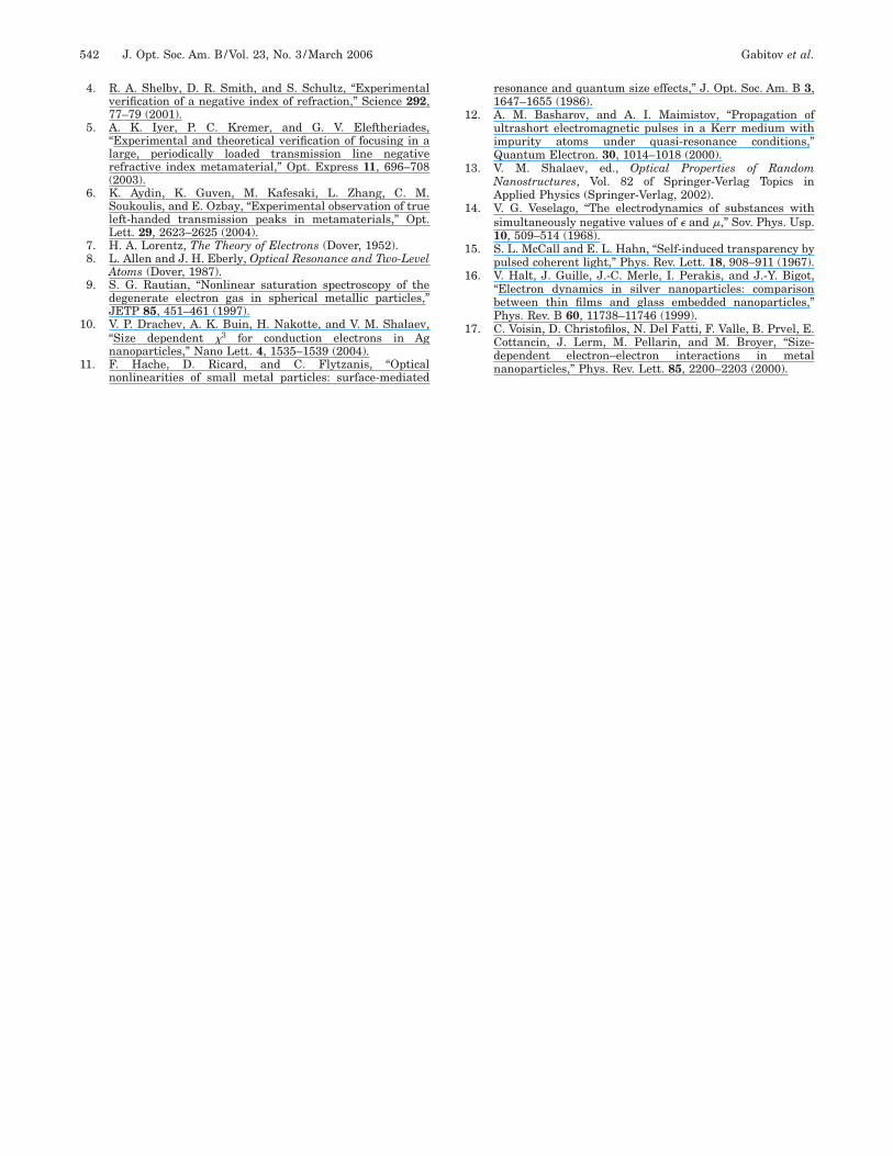
ore solitons, along with continuous radiation. Figure 4hows a comparison between the analytic form of the soli-ary waves of Eq. (26) for E and numerical simulations.he velocity and frequency of the solitary waves are ob-
ained from measurements of their amplitudes and halfidths in our simulation. The plot shows that the numeri-
al solution differs from the analytic forms only inasmuch
ig. 3. (a) Evolution of electric field amplitude with initial con-ition 5 exp�−t2 /2�, (b) output solitary wave amplitude(s) as aunction of Gaussian input pulse amplitude A0, where the initialondition is given by A0 exp�−t2 /2�.
ig. 4. Comparison of the analytical form of the solitary waveolutions (solid curve) with the results of numerical simulationsdashed curve) under conditions identical to those of Fig. 3(a).
alst
pwttia5ststsmfsswpw
ii
op=wTatqmttt(f
nrmcr
5IatmmnDsiDmwcsGhMdei
df0CPz
R
Fs=
Gabitov et al. Vol. 23, No. 3 /March 2006/J. Opt. Soc. Am. B 541
s excessive radiation is emitted in the numerical simu-ation. The agreement of the analytic forms with theimulation results indicates that the system self-selectshe solitary waves presented in Eqs. (26).
Two simulations illustrating collision dynamics areresented in Figs. 5(a) and 5(b), where the sum of twoell-separated solitary waves is used as the initial condi-
ion. Figure 5(a) illustrates an in-phase collision, in whichhe relative phase ��=�1−�2=0, where the subscriptsdentify the soliton. The other initial soliton parametersre v1=1, �1=0, �1=−10, v2=2, �2=0, and �2=0. In Fig.(b) an out-of-phase ��=� collision is illustrated. Theame parameters are used, except for a shift in the rela-ive phase. This results in a much faster collision. In bothimulations the solitary waves persist after the interac-ion, although their characteristic parameters undergohifts and radiation is emitted during the collision. A nu-erical study indicates that the collisions are quasielastic
or values in the approximate interval ��� �� ,2��. Forome �� values away from this interval, simulationshow that one of the solitons is completely destroyed,hereas the other persists. A detailed analysis of the de-endence on initial parameters will be presented else-here.The soliton phenomena described above occur at light
ntensities such that the dimensionless field amplitude Es at least of order one. The intensity at which E is order
ig. 5. Electric field amplitude showing collision dynamics ofolitons for different values of relative phase; (a) ��=0, (b) ���.
ne is estimated as I��c /���m�03 /e�2�c���0 /ea�2. For the
article radius a=20 nm and the carrier wavelength �0500 nm, this results in light intensity of I�10 GW/cm2,hich can be easily obtained with ultrashort laser pulses.he optical pulse durations for which this model is validre limited by the condition ����0 (the spectral width ofhe pulse must be much smaller than the carrier fre-uency), required by the slowly varying envelope approxi-ation. The pulse duration should also be much shorter
han the characteristic plasmonic oscillation dampingime, which is determined by the time required for elec-ron thermalization in the metal nanoparticles�400 fs16,17). The envelope approximation is appropriateor pulses with width ��20 fs.
The Maxwell–Duffing system is relevant for both theanospheres and the more complex system with magneticesonance. However, in the latter case, the sign of theagnetic permeability can be controlled by tuning the
arrier frequency and shifting from the left-handed to theight-handed propagation regime.
. CONCLUSIONn summary, equations are derived describing the inter-ction of electromagnetic fields with metal nanostruc-ures with simultaneous resonances for the electric andagnetic medium response. In the case where the electricedium response includes nonlinearity, while the mag-etic response is linear, this leads to the same Maxwell–uffing system we derive for the case of metal nano-
pheres. A family of solitary wave solutions is presentedn an envelope approximation for the Maxwell wave anduffing oscillator equations, showing that energy confine-ent is possible for resonant optical pulse interactionith plasmonic oscillations in that system. The existence
ondition for these solutions is presented. Numericalimulations show that stable solitary waves evolve fromaussian initial pulses with sufficient amplitudes and ex-ibit behavior analogous to self-induced transparency inaxwell–Bloch. Simulations also reveal that the collision
ynamics are highly dependent on initial soliton param-ters, behaving quasi elastically in some regimes but hav-ng radically different behavior in others.
The authors are grateful to V. P. Drachev for helpfuliscussions. In addition, we would like to acknowledgeunding under National Science Foundation grant DMS-509589, Department of Energy/Advanced Scientificomputing Research Applied Mathematical Researchrogram at Los Alamos National Laboratory, State of Ari-ona Proposition 301.
EFERENCES1. J. B. Pendry, “Negative refraction,” Contemp. Phys. 45,
191–202 (2004).2. G. V. Eleftheriades and K. G. Balmain, Negative-Refraction
Metamaterials: Fundamental Principles and Applications(Wiley, 2005).
3. V. M. Shalaev, W. Cai, U. Chettiar, H.-K. Yuan, A. K.Sarychev, V. P. Drachev, and A. V. Kildishev, “Negativeindex of refraction in optical metamaterials,” Opt. Lett. 30,3356–3358 (2005).
1
1
1
1
1
1
1
1
542 J. Opt. Soc. Am. B/Vol. 23, No. 3 /March 2006 Gabitov et al.
4. R. A. Shelby, D. R. Smith, and S. Schultz, “Experimentalverification of a negative index of refraction,” Science 292,77–79 (2001).
5. A. K. Iyer, P. C. Kremer, and G. V. Eleftheriades,“Experimental and theoretical verification of focusing in alarge, periodically loaded transmission line negativerefractive index metamaterial,” Opt. Express 11, 696–708(2003).
6. K. Aydin, K. Guven, M. Kafesaki, L. Zhang, C. M.Soukoulis, and E. Ozbay, “Experimental observation of trueleft-handed transmission peaks in metamaterials,” Opt.Lett. 29, 2623–2625 (2004).
7. H. A. Lorentz, The Theory of Electrons (Dover, 1952).8. L. Allen and J. H. Eberly, Optical Resonance and Two-Level
Atoms (Dover, 1987).9. S. G. Rautian, “Nonlinear saturation spectroscopy of the
degenerate electron gas in spherical metallic particles,”JETP 85, 451–461 (1997).
0. V. P. Drachev, A. K. Buin, H. Nakotte, and V. M. Shalaev,“Size dependent �3 for conduction electrons in Agnanoparticles,” Nano Lett. 4, 1535–1539 (2004).
1. F. Hache, D. Ricard, and C. Flytzanis, “Optical
nonlinearities of small metal particles: surface-mediatedresonance and quantum size effects,” J. Opt. Soc. Am. B 3,1647–1655 (1986).
2. A. M. Basharov, and A. I. Maimistov, “Propagation ofultrashort electromagnetic pulses in a Kerr medium withimpurity atoms under quasi-resonance conditions,”Quantum Electron. 30, 1014–1018 (2000).
3. V. M. Shalaev, ed., Optical Properties of RandomNanostructures, Vol. 82 of Springer-Verlag Topics inApplied Physics (Springer-Verlag, 2002).
4. V. G. Veselago, “The electrodynamics of substances withsimultaneously negative values of � and �,” Sov. Phys. Usp.10, 509–514 (1968).
5. S. L. McCall and E. L. Hahn, “Self-induced transparency bypulsed coherent light,” Phys. Rev. Lett. 18, 908–911 (1967).
6. V. Halt, J. Guille, J.-C. Merle, I. Perakis, and J.-Y. Bigot,“Electron dynamics in silver nanoparticles: comparisonbetween thin films and glass embedded nanoparticles,”Phys. Rev. B 60, 11738–11746 (1999).
7. C. Voisin, D. Christofilos, N. Del Fatti, F. Valle, B. Prvel, E.Cottancin, J. Lerm, M. Pellarin, and M. Broyer, “Size-dependent electron–electron interactions in metalnanoparticles,” Phys. Rev. Lett. 85, 2200–2203 (2000).


![Resonant Raman effect enhanced by surface plasmon excitation of CdSe nanocrystals embedded in thin SiO[sub 2] films](https://static.fdokumen.com/doc/165x107/634518516cfb3d40640985a1/resonant-raman-effect-enhanced-by-surface-plasmon-excitation-of-cdse-nanocrystals.jpg)