
Proportional flow control valve, with on-board electronics ...
16
1/14 Proportional flow control valve, with on-board electronics (OBE) and inductive position transducer Type 3FREEZ Nominal size 6, 10 Unit series 1X Maximum working pressure 250 bar Nominal flow rate Q nom 10...70 l/min RE 29221/08.05 Overview of Contents Contents Page Features 1 Ordering data 2 Preferred types 2 Symbols 3 Function, sectional diagram 4 and 5 Technical data 6 to 8 On-board trigger electronics 9 and 10 Characteristic curves 11 and 12 Unit dimensions 13 and 14 Features – Directly controlled flow control valves NG6 and NG10 with on-board electronics and inductive position transducer – With position control, minimal hysteresis < 1 %, see Technical Data – The 3-way function is determined by how the hydraulic ports are assigned (residual flow runs through port P, 3 rd way) – Adjustable by means of the controlled solenoid position, the position transducer and the on-board electronics – For subplate attachment, mounting hole configuration NG6 to ISO 4401-03-02-0-94, NG10 to ISO 4401-05-04-0-94 – Subplates as per catalog sheet, RE 45053 for NG6, RE 45055 for NG10 (order separately) – Plug-in connector to DIN 43563-AM6, see catalog sheet RE 08008 (order separately) – Data for the on-board trigger electronics • Complies with CE, EMC directives EN 61000-6-2: 2002-08 and EN 61000-6-3: 2002-08 • U B = 24 V nom DC • Electrical connection 6P+PE • Signal actuation – Standard 0...+10 V (A1) • Valve curve calibrated at the factory
-
Upload
khangminh22 -
Category
Documents
-
view
0 -
download
0
Transcript of Proportional flow control valve, with on-board electronics ...

1/14Proportional flow control valve,
with on-board electronics (OBE)
and inductive position transducer
Type 3FREEZ
Nominal size 6, 10Unit series 1XMaximum working pressure 250 barNominal flow rate Q
nom 10...70 l/min
RE 29221/08.05
Overview of Contents
Contents Page
Features 1
Ordering data 2
Preferred types 2
Symbols 3
Function, sectional diagram 4 and 5
Technical data 6 to 8
On-board trigger electronics 9 and 10
Characteristic curves 11 and 12
Unit dimensions 13 and 14
Features
– Directly controlled flow control valves NG6 and NG10 with
on-board electronics and inductive position transducer
– With position control, minimal hysteresis < 1 %,
see Technical Data
– The 3-way function is determined by how the hydraulic ports
are assigned (residual flow runs through port P, 3rd way)
– Adjustable by means of the controlled solenoid position,
the position transducer and the on-board electronics
– For subplate attachment, mounting hole configuration NG6
to ISO 4401-03-02-0-94, NG10 to ISO 4401-05-04-0-94
– Subplates as per catalog sheet, RE 45053 for NG6,
RE 45055 for NG10 (order separately)
– Plug-in connector to DIN 43563-AM6, see catalog sheet
RE 08008 (order separately)
– Data for the on-board trigger electronics
• Complies with CE, EMC directives
EN 61000-6-2: 2002-08
and EN 61000-6-3: 2002-08
• UB = 24 V
nom DC
• Electrical connection 6P+PE
• Signal actuation
– Standard 0...+10 V (A1)
• Valve curve calibrated at the factory

2/14 Bosch Rexroth AG Hydraulics 3FREEZ RE 29221/08.05
Ordering data
3-way = 3
Proportional flow
control valve, with
position control
With on-board
electronics = E
With inductive position
transducer = Z
NG6 = 60
NG10 = 10
Without external closing fixture
for pressure compensator = B
Unit series 10 to 19 = 1X
(10 to 19: installation and connection
dimensions unchanged)
Nominal flow rate
10 l/min (∆p = 8 bar pressure drop) = 10
35 l/min (∆p = 8 bar pressure drop) = 35
70 l/min (∆p = 8 bar pressure drop) = 70
Flow characteristic (L = linear) = L
Setpoint input +10 V, Q = 0 l/min (NC) = 2
* Version “F1” (4...20 mA version) available on request
Further informa-
tion in plain text
M = NBR seals,
suitable for mineral oils
(HL, HLP) to DIN 51524
M = Without non-return valve
Interface for trigger electronics*
A1 = Setpoint input 0...+10 V
K31 = Electrical connection
without plug-in connector,
with unit plug to DIN 43563-AM6
Order plug-in connector separately
G24 = Voltage supply of trigger electronics
24 V DC
Preferred types
NG6 NG10
Type Material Number Type Material Number
3FREEZ6B–1X/10L2G24–K31A1MM 0 811 403 150 3FREEZ10B–1X/70L2G24–K31A1MM 0 811 403 019
3FREEZ6B–1X/35L2G24–K31A1MM 0 811 403 151
3 FRE E Z B 1X L 2 G24 K31 A1 M M *

Symbols
For on-board electronics
3-way, normally closed
NC
General
Flow control valves are directly actuated throttle valves with
integrated pressure compensator.
3-way flow control valve
A: Supply
B: Discharge
P: Residual flow, capacity
up to 250 bar, or tank
T: Closed
Hydraulics Bosch Rexroth AGRE 29221/08.05 3FREEZ 3/14

4/14 Bosch Rexroth AG Hydraulics 3FREEZ RE 29221/08.05
Function, sectional diagram
General
Type 3FREEZ proportional flow control valves with position
control and on-board electronics are available in nominal sizes
6 and 10. They are actuated by means of a proportional sole-
noid with inductive position transducer. Hysteresis is < 1 %.
The on-board electronics are calibrated at the factory and
enable rapid response times. The design of the valve body is
such that the residual flow runs through port P.
Basic principle
To adjust the oil flow rate from B, a setpoint is set in the
trigger electronics. Based on this setpoint, the electronics
control the solenoid coil as a function of the signal from the
position transducer. The position control ensures very low
hysteresis. The valve opening is determined by the metering
edges on the spool, and the integrated pressure compensa-
tor compares the pressure drop by means of an 8-bar measu-
ring spring. The pressure compensator with measuring spring
regulates the pressure before the throttling edge according to
the simplified formula: “Load pressure plus force of measuring
spring”. In this way, the pressure drop over the metering edge
is maintained at a constant level.
EN 61000-6-2: 2002-08
EN 61000-6-3: 2002-08
NG6
TBPA
Measuring spring
Pressure compensatorMeasuring throttle
* (see page 5)

Hydraulics Bosch Rexroth AGRE 29221/08.05 3FREEZ 5/14
Testing and service equipment
Test box type VT-PE-TB3, see RE 30065
Measuring adapter 6P+PE type VT-PA-2, see RE 30068
EN 61000-6-2: 2002-08
EN 61000-6-3: 2002-08
NG10
TT BPA Measuring spring
Pressure compensatorMeasuring throttle*
Accessories
Type Material Number
(4x) f ISO 4762-M5x30-10.9 Cheese-head bolts NG6 2 910 151 166
(4x) f ISO 4762-M6x35-10.9 Cheese-head bolts NG10 2 910 151 207
* Plug-in connectors 6P+PE,
see also RE 08008
KS 1 834 482 022
KS 1 834 482 026
MS 1 834 482 023
MS 1 834 482 024
KS 90° 1 834 484 252
Function, sectional diagram

6/14 Bosch Rexroth AG Hydraulics 3FREEZ RE 29221/08.05
Technical data
General
Construction Spool-type valve with integrated pressure compensator
Actuation Proportional solenoid with position control and on-board electronics OBE
Connection type Subplate, mounting hole configuration NG6 (ISO 4401-03-02-0-94),
NG10 (ISO 4401-05-04-0-94)
Mounting position Optional
Ambient temperature range °C –20...+50
Weight NG61 kg 3.1
NG10 kg 6.9
Vibration resistance, test condition Max. 25 g, shaken in 3 dimensions (24 h)
Hydraulic (measured with HLP 46, oil
= 40 °C ±5 °C)
Pressure fluid Hydraulic oil to DIN 51524...535, other fluids after prior consultation
Viscosity range, recommended mm2/s 20...100
max. permitted mm2/s 10...800
Pressure fluid temperature range °C –20...+70
Maximum permitted degree of contamina-
tion of pressure fluid
Purity class to ISO 4406 (c)
Class 18/16/13 1)
Direction of flow, see symbol NG6 NG10
Nominal flow rate QB with l/min
closed-loop control
10 35 70
Pressure drop ∆p bar 8 8 8
Supply flow rate QA max
l/min 50 50 100
Minimum pressure drop pA > p
B bar 14 14 14
Max. working pressure bar Port A, B: 250
Port T: Closed
Port P: Closed or residual flow 250 bar
Static/Dynamic
Hysteresis % 1 1
Range of inversion % 0.5 0.5
Manufacturing tolerance % 5 5
Resp. time 100 %/signal change 10 % ms 25/25 35/25
Correction time on max. load change ms
(pressure compensator)
30 45
Conformity EN 61000-6-2: 2002-08
EN 61000-6-3: 2002-08
1) The purity classes stated for the components must be complied with in hydraulic systems.
Effective filtration prevents problems and also extends the service life of components.
For a selection of filters, see catalog sheets RE 50070, RE 50076 and RE 50081.

Hydraulics Bosch Rexroth AGRE 29221/08.05 3FREEZ 7/14
Technical data
Electrical, trigger electronics integrated in valve
Cyclic duration factor % 100
Degree of protection IP 65 to DIN 40050 and IEC 14434/5
Connection Plug-in connector 6P+PE, DIN 43563
Supply voltage
Terminal A:
Terminal B: 0 V
24 V DCnom
Min. 21 V DC/max. 40 V DC
Ripple max. 2 V DC
Power consumption Solenoid 45 mm = 40 VA max.
External fuse 2.5 AF
Input, “standard” version A1
Terminal D: UE
Terminal E:
Differential amplifier, Ri = 100 kΩ
0...+10 V
0 V
Input, “mA signal” version F1*
Terminal D: ID–E
Terminal E: ID–E
Burden, Rsh
= 200 Ω4...20 mA
Current loop ID–E
feedback
Max. voltage to differential inputs over 0 V D B
E B max. 18 V DC
Test signal, “standard” version A1
Terminal F: UTest
Terminal C:
LVDT
0...+10 V
Reference 0 V
Test signal, “mA signal” version F1*
Terminal F: IF–C
Terminal C: IF–C
LVDT signal 4...20 mA at external load 200...500 Ω max.
4...20 mA output
Current loop IF–C
feedback
Safety earth conductor and shield See pin assignment (installation in conformity with CE)
Recommended cable See pin assignment
up to 20 m 7 x 0.75 mm2
up to 40 m 7 x 1 mm2
Calibration Calibrated at the factory, see valve curve
* Version “F1” (4...20 mA version) available on request
Version A1:Standard
* Version F1:mA Signal
Supply 24V =
Signal: 0…+10V
LVDT Signal: 0…+10V(Ri = 100kΩ)
US
A
B
P
A
B
P
Supply 24V =
Signal: 4…20mA
LVDT Signal: 4…20mA(Bürde: 200Ω)
IS
8/14 Bosch Rexroth AG Hydraulics 3FREEZ RE 29221/08.05
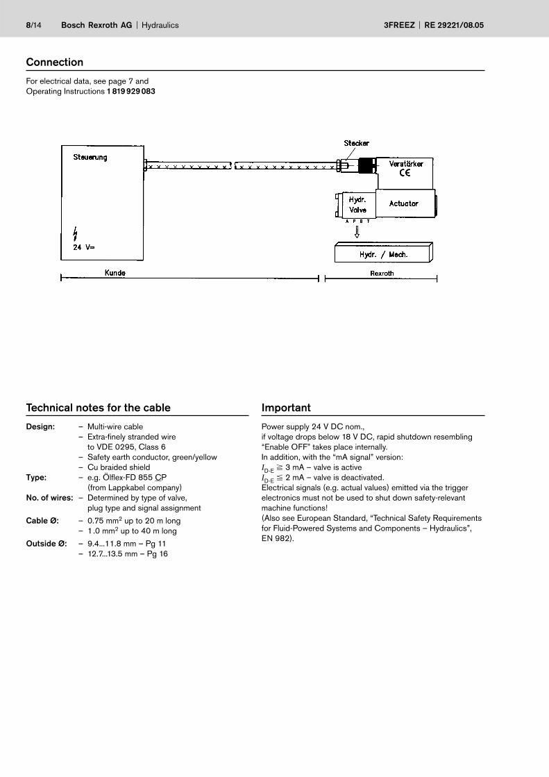
Connection
For electrical data, see page 7 and
Operating Instructions 1 819 929 083
Technical notes for the cable
Design: – Multi-wire cable
– Extra-finely stranded wire
to VDE 0295, Class 6
– Safety earth conductor, green/yellow
– Cu braided shield
Type: – e.g. Ölflex-FD 855 CP
(from Lappkabel company)
No. of wires: – Determined by type of valve,
plug type and signal assignment
Cable Ø: – 0.75 mm2 up to 20 m long
– 1.0 mm2 up to 40 m long
Outside Ø: – 9.4...11.8 mm – Pg 11
– 12.7...13.5 mm – Pg 16
Important
Power supply 24 V DC nom.,
if voltage drops below 18 V DC, rapid shutdown resembling
“Enable OFF” takes place internally.
In addition, with the “mA signal” version:
ID-E
3 mA – valve is active
ID-E
2 mA – valve is deactivated.
Electrical signals (e.g. actual values) emitted via the trigger
electronics must not be used to shut down safety-relevant
machine functions!
(Also see European Standard, “Technical Safety Requirements
for Fluid-Powered Systems and Components – Hydraulics”,
EN 982).

Hydraulics Bosch Rexroth AGRE 29221/08.05 3FREEZ 9/14
On-board trigger electronics
Circuit diagram/pin assignment
Version A1: UD-E
0...+10 V
Pin assignment
Version A1: UD-E
0...+10 V
(Ri = 100 kΩ)
Supply UB
Supply zero
Ref. zero *
Setpoint 0...+10 V
Actual value 0...+10 V
Safety earth conductor
Shield
* Do not connect to supply zero!

10/14 Bosch Rexroth AG Hydraulics 3FREEZ RE 29221/08.05
On-board trigger electronics
Circuit diagram/pin assignment
Version F1: ID-E
4...20 mA
Pin assignment 6P+PE
Version F1: ID-E
4...20 mA
(Rsh
= 200 kΩ)
DC
mA
Diff.amp.
PID
OBE
Rsh200Ω
4…20mA
Logic
+UB
+UB
+
-
+15 V-15 V
DC
S
U
V
A
2.5 AF +24 V=Supply
Safety earth conductor
Shield
Supply zero
Loop IF–C
ID–E 4...20 mA
Test IF–C (4...20 mA)
0 V
B
C
D
E
F

Hydraulics Bosch Rexroth AGRE 29221/08.05 3FREEZ 11/14
Characteristic curves NG6 (measured with HLP 46, oil
= 40 °C ±5 °C)
Qnom
= 10/35 l/min
Basic position closed “NC”
Valve amplifier
1) Factory setting – OBE
±5% manufacturing tolerance
2) Version: UE = 0...+10 V
Hyst. 1%
1)
00 2 4 6 8 +10
2
4
6
8
0
2,5
5
7,5
10
0
10
20
30
Q l
/min
40
UE2)
[V]
3-way version
Qnom
= 10/35 l/min
Residual flow “A–P”
(pressure drop)

12/14 Bosch Rexroth AG Hydraulics 3FREEZ RE 29221/08.05
Characteristic curves NG10 (measured with HLP 46, oil
= 40 °C ±5 °C)
Qnom.
= 70 l/min
Basic position closed “NC”
Valve amplifier
1) Factory setting – OBE
±5% manufacturing tolerance
2) Version: UE = 0...+10 V
Hyst. 1%
00 2 4 6 8 +10
20
40
60
80
10
30
50
70
Q l
/min
UE2)
[V]
1)
3-way version
Qnom
= 70 l/min
Residual flow “A-P”
(pressure drop)

Hydraulics Bosch Rexroth AGRE 29221/08.05 3FREEZ 13/14
Required surface quality
of mating component
Mounting hole configuration: NG6 (ISO 4401-03-02-0-94)
For subplates see catalog sheet RE 45053
1) Deviates from standard2) Thread depth:
Ferrous metal 1.5 x Ø
Non-ferrous 2 x Ø
P A T B F1
F2
F3
F4
21.5 12.5 21.5 30.2 0 40.5 40.5 0
25.9 15.5 5.1 15.5 0 –0.75 31.75 31
8 1) 8 1) 8 1) 8 1) M5 2) M5 2) M5 2) M5 2)
X
Y
Unit dimensions NG6 (nominal dimensions in mm)
Not included in scope of delivery
Bosch Rexroth AG
Hydraulics
Zum Eisengießer 1
97816 Lohr am Main, Germany
Telefon +49 (0) 93 52 / 18-0
Telefax +49 (0) 93 52 / 18-23 58
www.boschrexroth.de
© This document, as well as the data, specifications and other information
set forth in it, are the exclusive property of Bosch Rexroth AG. It may not be
reproduced or given to third parties without its consent.
The data specified above only serve to describe the product. No state-
ments concerning a certain condition or suitability for a certain application
can be derived from our information. The information given does not release
the user from the obligation of own judgement and verification. It must be
remembered that our products are subject to a natural process of wear and
aging.
14/14 Bosch Rexroth AG Hydraulics 3FREEZ RE 29221/08.05
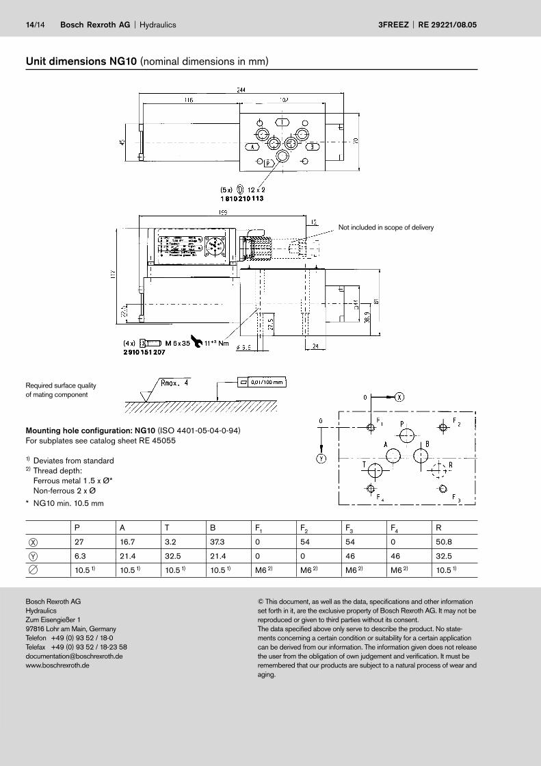
Unit dimensions NG10 (nominal dimensions in mm)
Required surface quality
of mating component
Mounting hole configuration: NG10 (ISO 4401-05-04-0-94)
For subplates see catalog sheet RE 45055
1) Deviates from standard2) Thread depth:
Ferrous metal 1.5 x Ø*
Non-ferrous 2 x Ø
* NG10 min. 10.5 mm
X
Y
P A T B F1
F2
F3
F4
R
27 16.7 3.2 37.3 0 54 54 0 50.8
6.3 21.4 32.5 21.4 0 0 46 46 32.5
10.5 1) 10.5 1) 10.5 1) 10.5 1) M6 2) M6 2) M6 2) M6 2) 10.5 1)
Not included in scope of delivery

Bosch Rexroth AG
Hydraulics
Zum Eisengießer 1
97816 Lohr am Main, Germany
Telefon +49 (0) 93 52 / 18-0
Telefax +49 (0) 93 52 / 18-23 58
www.boschrexroth.de
© This document, as well as the data, specifications and other information
set forth in it, are the exclusive property of Bosch Rexroth AG. It may not be
reproduced or given to third parties without its consent.
The data specified above only serve to describe the product. No state-
ments concerning a certain condition or suitability for a certain application
can be derived from our information. The information given does not release
the user from the obligation of own judgement and verification. It must be
remembered that our products are subject to a natural process of wear and
aging.
Hydraulics Bosch Rexroth AGRE 29221/08.05 3FREEZ
Notes

Bosch Rexroth AG
Hydraulics
Zum Eisengießer 1
97816 Lohr am Main, Germany
Telefon +49 (0) 93 52 / 18-0
Telefax +49 (0) 93 52 / 18-23 58
www.boschrexroth.de
© This document, as well as the data, specifications and other information
set forth in it, are the exclusive property of Bosch Rexroth AG. It may not be
reproduced or given to third parties without its consent.
The data specified above only serve to describe the product. No state-
ments concerning a certain condition or suitability for a certain application
can be derived from our information. The information given does not release
the user from the obligation of own judgement and verification. It must be
remembered that our products are subject to a natural process of wear and
aging.
3FREEZ RE 29221/08.05
Notes
Bosch Rexroth AG Hydraulics