AUTOMATION OF HYDRAULIC TYRE WEAR TESTING MACHINE USING PROPORTIONAL CONTROL VALVE BY INTERFACING...
10
AUTOMATION OF HYDRAULIC TYRE WEAR TESTING MACHINE USING PROPORTIONAL CONTROL VALVE BY INTERFACING PROGRAMMING LOGIC CIRCUIT P. RAJASEKARAN 1 , S. VANANGAMUDI 2 & P. NAVEENCHANDRAN 3 1 Research Scholar, Department of Automobile Engineering, Bharath Institute of Science and Technology, Bharath University, Chennai, Tamil Nadu, India 2 Professor, Department of Automobile Engineering, Bharath Institute of Science and Technology, Bharath University, Chennai, Tamil Nadu, India 3 Professor, HOD Automobile Engineering, Bharath Institute of Science and Technology, Bharath University, Chennai, Tamil Nadu, India ABSTRACT The Research work aims for automation of the hydraulic tyre wear testing machine by using proportional control relief valve through interfacing with programmable logic control called PLC. This research work is an earnest attempt to automate the existing hydraulic system of conventional loading of tyre for analysing its serviceability i.e. the ability of the tyre offers resistance to wear under various load conditions. This research work is suggestion to the MRF Ltd, R&D department. The existing hydraulic system is of conventional type of hydraulic loading system, the tyres are tested for its wear resistance by manual application of load by gradually increasing the system pressure of the conventional relief valve and the pump used in the system is fixed displacement vane pump. This type of manual application of load on tyres consumes more time for testing and also results in non uniformity of applying load on the tyres. Hence, the emanation of thought for complete automation of the system has nurtured. The newer idea of automation of the system replaces the conventional relief valve with proportional control relief valve and fixed displacement vane pump with load sensing piston pump and the automatic method of application of increasing the system pressure i.e. the load on proportional control relief valve is carried out by interfacing the proportional control relief valve with PLC. This automation of the system eventually will eases the burden of manual application of load on the tyres, emphasis in uniformity of loading the tyres for conducting a better wear analysis test and also cut down the ideal time as well more numbers of tyres can be tested from same system by the introduction of load sensing pump. KEYWORDS: Servo Valve, DC Power Supply and Control Amplifier INTRODUCTION For a number of years, most industrial hydraulic systems have been sequenced electrically but manually. In other words, the starting, stopping and direction control of actuators has been achieved using solenoid valves, but the setting of flow rates and pressures has been by means of manually adjusted valves. In many applications this has proved to be satisfactory arrangement and may well continue to do so. There may however be disadvantages with this traditional method of control, for example when several different flow rates or pressures are called for in a system. This can result in a multiplicity of control and switching valves and may not result always in a smooth transition from one condition to another. Also, to achieve to acceleration and deceleration BEST: International Journal of Management, Information Technology and Engineering (BEST: IJMITE) ISSN 2348-0513 Vol. 2, Issue 4, Apr 2014, 29-38 © BEST Journals
-
Upload
independent -
Category
Documents
-
view
2 -
download
0
Transcript of AUTOMATION OF HYDRAULIC TYRE WEAR TESTING MACHINE USING PROPORTIONAL CONTROL VALVE BY INTERFACING...
AUTOMATION OF HYDRAULIC TYRE WEAR TESTING MACHINE U SING
PROPORTIONAL CONTROL VALVE BY INTERFACING
PROGRAMMING LOGIC CIRCUIT
P. RAJASEKARAN 1, S. VANANGAMUDI 2 & P. NAVEENCHANDRAN 3
1Research Scholar, Department of Automobile Engineering, Bharath Institute of Science and Technology,
Bharath University, Chennai, Tamil Nadu, India 2Professor, Department of Automobile Engineering, Bharath Institute of Science and Technology,
Bharath University, Chennai, Tamil Nadu, India 3Professor, HOD Automobile Engineering, Bharath Institute of Science and Technology,
Bharath University, Chennai, Tamil Nadu, India
ABSTRACT
The Research work aims for automation of the hydraulic tyre wear testing machine by using proportional control
relief valve through interfacing with programmable logic control called PLC. This research work is an earnest attempt to
automate the existing hydraulic system of conventional loading of tyre for analysing its serviceability i.e. the ability of the
tyre offers resistance to wear under various load conditions. This research work is suggestion to the MRF Ltd,
R&D department. The existing hydraulic system is of conventional type of hydraulic loading system, the tyres are tested
for its wear resistance by manual application of load by gradually increasing the system pressure of the conventional relief
valve and the pump used in the system is fixed displacement vane pump.
This type of manual application of load on tyres consumes more time for testing and also results in non uniformity
of applying load on the tyres. Hence, the emanation of thought for complete automation of the system has nurtured.
The newer idea of automation of the system replaces the conventional relief valve with proportional control relief valve
and fixed displacement vane pump with load sensing piston pump and the automatic method of application of increasing
the system pressure i.e. the load on proportional control relief valve is carried out by interfacing the proportional control
relief valve with PLC. This automation of the system eventually will eases the burden of manual application of load on the
tyres, emphasis in uniformity of loading the tyres for conducting a better wear analysis test and also cut down the ideal
time as well more numbers of tyres can be tested from same system by the introduction of load sensing pump.
KEYWORDS : Servo Valve, DC Power Supply and Control Amplifier
INTRODUCTION
For a number of years, most industrial hydraulic systems have been sequenced electrically but manually.
In other words, the starting, stopping and direction control of actuators has been achieved using solenoid valves, but the
setting of flow rates and pressures has been by means of manually adjusted valves. In many applications this has proved to
be satisfactory arrangement and may well continue to do so.
There may however be disadvantages with this traditional method of control, for example when several different
flow rates or pressures are called for in a system. This can result in a multiplicity of control and switching valves and may
not result always in a smooth transition from one condition to another. Also, to achieve to acceleration and deceleration
BEST: International Journal of Management, Information Technology and Engineering (BEST: IJMITE) ISSN 2348-0513 Vol. 2, Issue 4, Apr 2014, 29-38 © BEST Journals
30 P. Rajasekaran, S. Vanangamudi & P. Naveenchandran
control of an actuator usually means adding extra valves into the system thus increasing its cost and complexity.
When high performance speed position control is called for, a servo valve has in the past been the only practical solution,
normally used in a closed loop control arrangement.
The servo valve, being the high specification direction and flow control valve, inevitably introduces problems of
high cost, low contamination tolerance and limited serviceability. In application where the full performance capability of
the servo valve is not require, such problems can be major disadvantage. This type of manual application of load on tyres
consumes more time for testing and also results in non uniformity of applying load on the tyres. Hence, the emanation of
thought for complete automation of the system has nurtured.
The newer idea of automation of the system replaces the conventional relief valve with proportional control relief
valve and fixed displacement vane pump with load sensing piston pump and the automatic method of application of
increasing the system pressure i.e. the load on proportional control relief valve is carried out by interfacing the proportional
control relief valve with PLC. This automation of the system eventually will eases the burden of manual application of load
on the tyres, emphasis in uniformity of loading the tyres for conducting a better wear analysis test and also cut down the
ideal time as well more numbers of tyres can be tested from same system by the introduction of load sensing pump.
The development of a range of proportional valve was therefore aimed in part at filling the gap between simple
an/off solenoid valves and sophisticated servo valve systems. Whilst the performance of the proportional valve may not be
as good as a servo valve (in terms of response time, hysteresis etc.), it will prove to be adequate for many application and
can therefore show distinct cost advantages.
The ability of a proportional valve to be adjusted electronically means that several different settings can be
achieved by electrical rather than hydraulic switching devices. Electronic control of acceleration and deceleration is also
easily provided. Very often, the net effect is the substitution of hydraulic control valves by smaller and cheaper electronic
components.
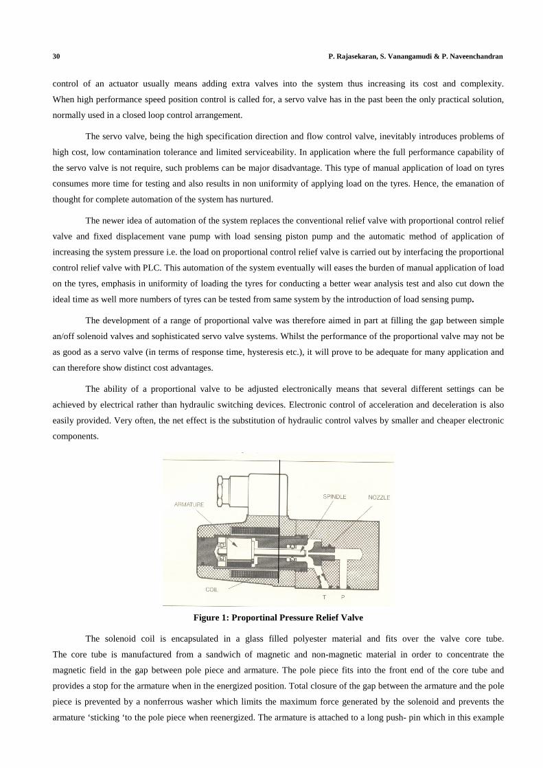
Figure 1: Proportinal Pressure Relief Valve
The solenoid coil is encapsulated in a glass filled polyester material and fits over the valve core tube.
The core tube is manufactured from a sandwich of magnetic and non-magnetic material in order to concentrate the
magnetic field in the gap between pole piece and armature. The pole piece fits into the front end of the core tube and
provides a stop for the armature when in the energized position. Total closure of the gap between the armature and the pole
piece is prevented by a nonferrous washer which limits the maximum force generated by the solenoid and prevents the
armature ‘sticking ‘to the pole piece when reenergized. The armature is attached to a long push- pin which in this example
Automation of Hydraulic Tyre Wear Testing Machine Using Proportional 31 Control Valve by Interfacing Programming Logic Circuit
is supported by a low friction bus in the pole piece and a ball race in the back end of the core tube. This construction
ensures minimum friction and so reduces the valve hysteresis.
The armature has through holes to enable fluid to pass easily from one end to the other when operating.
Alight spring pushes the armature/push-pin assembly into contact with the spool and ensures that all clearances are taken
up even when the valve is mounted vertically. Passing a current through the solenoid coil creates a magnetic force which
pulls the armature towards the pole piece, the magnitude of the force being proportional to the coil current. The solenoid
force created is transmitted to the valve spool or poppet by means by means of the push-pin.
Solenoid current Pressure=
Orifice diameter of valve
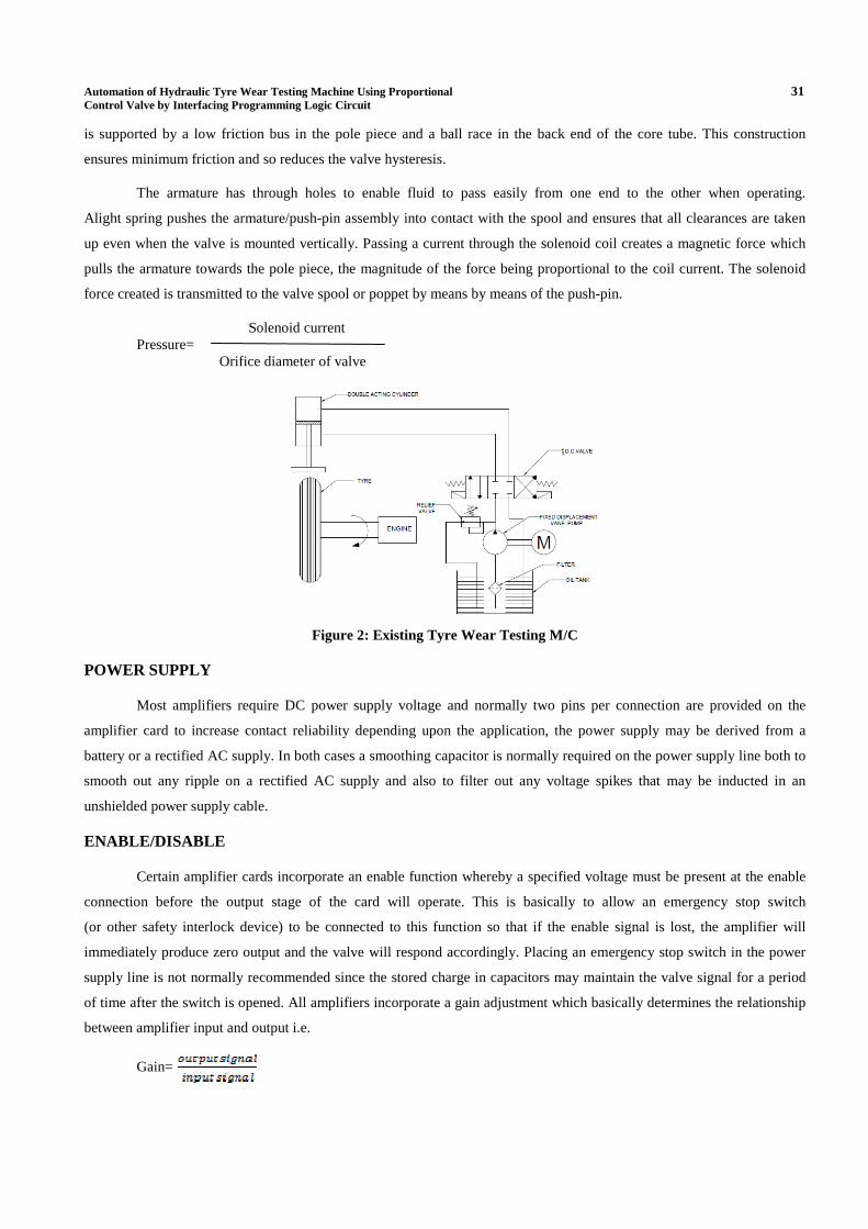
Figure 2: Existing Tyre Wear Testing M/C
POWER SUPPLY
Most amplifiers require DC power supply voltage and normally two pins per connection are provided on the
amplifier card to increase contact reliability depending upon the application, the power supply may be derived from a
battery or a rectified AC supply. In both cases a smoothing capacitor is normally required on the power supply line both to
smooth out any ripple on a rectified AC supply and also to filter out any voltage spikes that may be inducted in an
unshielded power supply cable.
ENABLE/DISABLE
Certain amplifier cards incorporate an enable function whereby a specified voltage must be present at the enable
connection before the output stage of the card will operate. This is basically to allow an emergency stop switch
(or other safety interlock device) to be connected to this function so that if the enable signal is lost, the amplifier will
immediately produce zero output and the valve will respond accordingly. Placing an emergency stop switch in the power
supply line is not normally recommended since the stored charge in capacitors may maintain the valve signal for a period
of time after the switch is opened. All amplifiers incorporate a gain adjustment which basically determines the relationship
between amplifier input and output i.e.
Gain=
32 P. Rajasekaran, S. Vanangamudi & P. Naveenchandran
This can be used for example to adjust the maximum output of the amplifier (and hence valve setting) for full
input signal. Sliding spool type proportional valves will normally have a certain amount of overlap (or dead band) either at
the start of the spool movement (in the case of throttle valves) or around the Centre positions (for directional valves).
This overlap reduces spool leakage in the null position and also provides a greater degree of safety for example in power
failure or emergency stop situations. The effect of spool overlap however means that a certain minimum signal level has to
be provided to the valve solenoid coil before noticeable effect occurs in the system.
CONTROL AMPLIFIER
Another significant difference with this valve is that the control amplifier is integrated into the valve itself rather
than being mounted on the separate card. The power supply to the amplifier is a nominal 244V DC together with
± 15 V DC supply for the linearization network compensates for the hydraulic characteristics of the value to produce the
straight line relationship between input signal and output pressure. Two options for the input signal are provided
i.e.: either 4-20mA or 0-10V.
Potentiometer adjustments are provided on the card for maximum pressure, pressure differential, ramp up and
ramp down. Where the application calls for a variable maximum pressure setting, an external demand signal
(e.g. from a microprocessor) can also be used. Monitor points for solenoid output current and accumulator pressure
(pressure transducer signal) are provided. By using an auxiliary card it is also possible to check the accumulator gas
pre-charger pressure by monitoring the rate of pressure drop during accumulator discharge. (i.e. the point at which the fluid
pressure drops rapidly to zero).
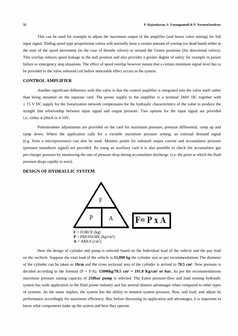
DESIGN OF HYDRAULIC SYSTEM
F = FORCE (kg) P = PRESSURE (kg/cm²) A = AREA (cm2)
Here the design of cylinder and pump is selected based on the Individual load of the vehicle and the pay load
on the vechicle. Suppose the total load of the vehicle is 15,000 kg the cylinder size as per recommendations The diameter
of the cylinder can be taken as 10cm and the cross sectional area of the cylinder is arrived to 78.5 cm². Now pressure is
decided according to the formula (P = F/A). 15000kg/78.5 cm² = 191.8 Kg/cm² or bar. As per the recommendations
maximum pressure raising capacity of 250bar pump is selected. The Eaton pressure-flow and load sensing hydraulic
system has wide application in the fluid power industry and has several distinct advantages when compared to other types
of systems. As the name implies, the system has the ability to monitor system pressure, flow, and load; and adjust its
performance accordingly for maximum efficiency. But, before discussing its application and advantages, it is important to
know what components make up the system and how they operate.
Automation of Hydraulic Tyre Wear Testing Machine Using Proportional 33 Control Valve by Interfacing Programming Logic Circuit
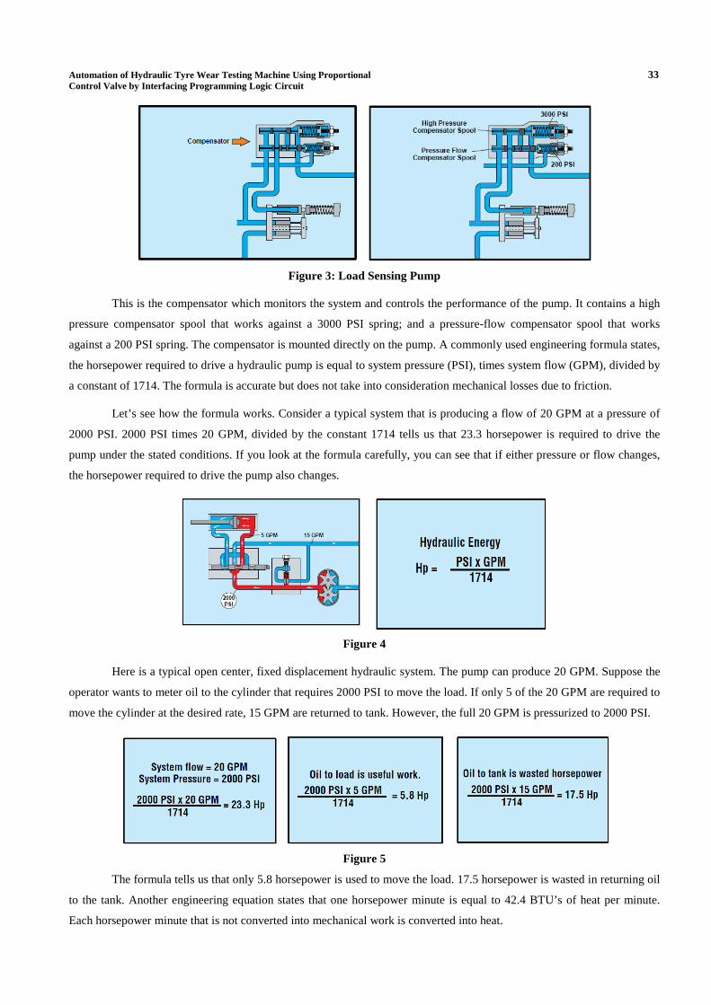
Figure 3: Load Sensing Pump
This is the compensator which monitors the system and controls the performance of the pump. It contains a high
pressure compensator spool that works against a 3000 PSI spring; and a pressure-flow compensator spool that works
against a 200 PSI spring. The compensator is mounted directly on the pump. A commonly used engineering formula states,
the horsepower required to drive a hydraulic pump is equal to system pressure (PSI), times system flow (GPM), divided by
a constant of 1714. The formula is accurate but does not take into consideration mechanical losses due to friction.
Let’s see how the formula works. Consider a typical system that is producing a flow of 20 GPM at a pressure of
2000 PSI. 2000 PSI times 20 GPM, divided by the constant 1714 tells us that 23.3 horsepower is required to drive the
pump under the stated conditions. If you look at the formula carefully, you can see that if either pressure or flow changes,
the horsepower required to drive the pump also changes.
Figure 4
Here is a typical open center, fixed displacement hydraulic system. The pump can produce 20 GPM. Suppose the
operator wants to meter oil to the cylinder that requires 2000 PSI to move the load. If only 5 of the 20 GPM are required to
move the cylinder at the desired rate, 15 GPM are returned to tank. However, the full 20 GPM is pressurized to 2000 PSI.
Figure 5
The formula tells us that only 5.8 horsepower is used to move the load. 17.5 horsepower is wasted in returning oil
to the tank. Another engineering equation states that one horsepower minute is equal to 42.4 BTU’s of heat per minute.
Each horsepower minute that is not converted into mechanical work is converted into heat.

34 P. Rajasekaran, S. Vanangamudi & P. Naveenchandran
Figure 6
That means, in this system, 17.5 horsepower times 42.4 BTU’s or 742 BTU’s of heat per minute must be absorbed
by the hydraulic system and, eventually, dissipated through an oil cooler. In the Eaton system, 5 GPM is metered to the
cylinder and the pump self adjusts to pump only the 5 GPM required at 2000 PSI plus the 200 PSI to actuate the
compensator. Only 5 GPM is pressurized to 2200 PSI so only 6.4 horsepower is required to do the work.
Figure 7
That is a savings of 16.9 horsepower or 716 BTU’minute or 42,960 BTU’s per hour. Another distinct advantage
of the Eaton system is that one pump meets the pressure and flow requirements for several circuits. In the open center,
fixed displacement system, a separate pump is required for each circuit that requires a different flow rate or a flow divider
must be used. In the Eaton system the pump adjusts itself to the flow requirements of each circuit.
Figure 8: Eaton Fixed Displacement Pump Figure 9: Eaton Load Sensing Pump
The PLC interfacing with proportional control relief valve enables to increase the pressure in the system. The PLC
is adopted for our interfacing is “GE FANUC”. 23-point PLC with two analog input and one analog output and 10 digital
inputs and 13 digital outputs.We can obtain as much as inputs &outputs, here we use tyre sensor input, 2d.c valve output,
and load cell 1analog input 0-10v 1 analog output to proportional control D.C.valve The PLC program is carried out
by using versapro software and the necessary PLC ladder diagram is designed as per the requirement.
This program is store in GE FANUC PLC which gives the necessary commands to the systems to functions.
Automation of Hydraulic Tyre Wear Testing Machine Using Proportional 35 Control Valve by Interfacing Programming Logic Circuit
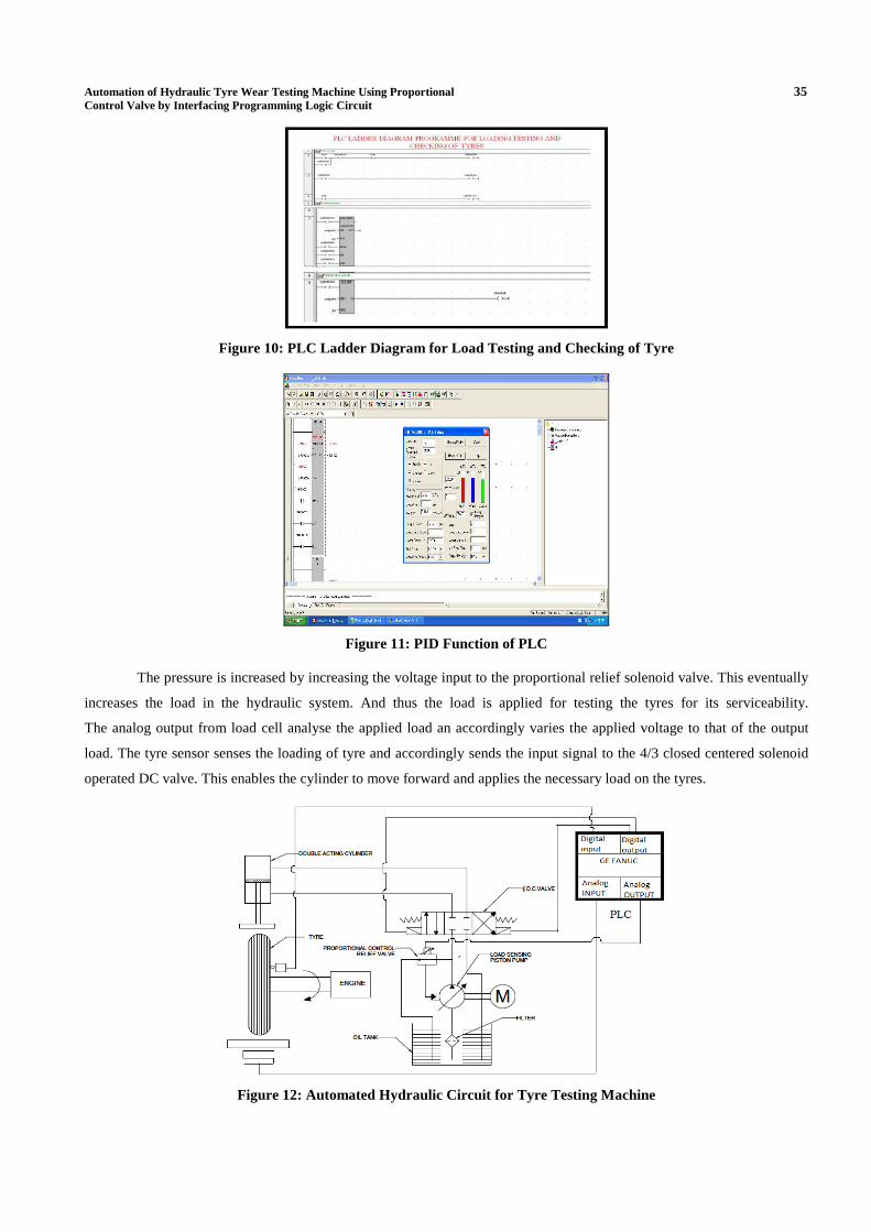
Figure 10: PLC Ladder Diagram for Load Testing and Checking of Tyre
Figure 11: PID Function of PLC
The pressure is increased by increasing the voltage input to the proportional relief solenoid valve. This eventually
increases the load in the hydraulic system. And thus the load is applied for testing the tyres for its serviceability.
The analog output from load cell analyse the applied load an accordingly varies the applied voltage to that of the output
load. The tyre sensor senses the loading of tyre and accordingly sends the input signal to the 4/3 closed centered solenoid
operated DC valve. This enables the cylinder to move forward and applies the necessary load on the tyres.
Figure 12: Automated Hydraulic Circuit for Tyre Testing Machine
36 P. Rajasekaran, S. Vanangamudi & P. Naveenchandran
CONCLUSIONS AND SUGGESTIONS
This automation of the system eventually will eases the burden of manual application of load on the tyres,
emphasis in uniformity of loading the tyres for conducting a better wear analysis test and also cut down the ideal time as
well more numbers of tyres can be tested from same system and huge amount of power is saved which is lost in the form of
heat by introducing load sensing pump.
The proportional control valve can be replaced by Electro hydraulic servo valve (EHSV) for more precise and
much more accurate results can be obtained. The electro hydraulic servo valve has an electrically operated valve that
controls how hydraulic fluid is ported to an actuator. Servo valves and servo-proportional valves are operated by
transforming a changing analogue or digital input signal into a smooth set of movements in a hydraulic cylinder.
Servo valves can provide precise control of position, velocity, pressure and force with good post movement damping
characteristics.
FOOT NOTES
Electro Hydraulic Servo Valve (EHSV)
It is an electrically operated valve that controls how hydraulic fluid is ported to an actuator. Servo valves and
servo-proportional valves are operated by transforming a changing analogue or digital input signal into a smooth set
of movements in a hydraulic cylinder. Servo valves can provide precise control of position, velocity, pressure and force
with good post movement damping characteristics.
DC Power Supply
A power unit that supplies direct current only Examples: Battery, Transformer / Rectifier / Filter Circuit,
DC generator, and Photovoltaic cell.
Control Amplifier
A preamplifier (preamp) is an electronic amplifier that prepares a small electrical signal for further amplification
or processing. A preamplifier is often placed close to the sensor to reduce the effects of noise and interference. It is used
to boost the signal strength to drive the cable to the main instrument without significantly degrading the signal-to-noise
ratio (SNR).
REFERENCES
1. Peter Pudney, Phil Howlett (2002), Critical Speed Control of a Solar Car, Optimization and Engineering,
3, 97–107, 2002.
2. Gomez de Silva, Jaime; Svenson, Ron (1993), Tonatiuh, the Mexican Solar Race Car. A vehicle for technology
Transfer. SAE Special Publications n 984 1993, p 63-67 931797.
3. Seal, Michael R. (1995), Viking 23 - zero emissions in the City, range and performance on the freeway.
Northcon - Conference Record 1995. IEEE, RC-108.p 264- 268.
4. Arsie I., Pianese C., Rizzo G., Santoro M. (2002), Optimal Energy Management in a Parallel Hybrid Vehicle,
Proceedings of ESDA2002 6th Biennial Conference on Engineering Systems Design and Analysis, Istanbul,
July 8-11 2002.
5. Eaton Corporation, hydraulics division 15151, hwy, 5 eden prainie MN 5534.

Automation of Hydraulic Tyre Wear Testing Machine Using Proportional 37 Control Valve by Interfacing Programming Logic Circuit
6. Hydraulic power system analysis, A.Akers, M.Gassman.
7. Eaton Ltd Hydraulics Division Glenrotanthes, Scotland ky74nw
8. A History of industrial power in the united states, 1730-1930 Louis c hunter, Lynwood (19991)
9. Beginners guide to PLC Programming by Neal Babcock.
10. Programmable logic controllers by William Bolton Newness, 2006-Technolog&Engineering.