Interfacing the Cypress Powerline Communication Solution to ...
12
www.infineon.com Please note that Cypress is an Infineon Technologies Company. The document following this cover page is marked as “Cypress” document as this is the company that originally developed the product. Please note that Infineon will continue to offer the product to new and existing customers as part of the Infineon product portfolio. Continuity of document content The fact that Infineon offers the following product as part of the Infineon product portfolio does not lead to any changes to this document. Future revisions will occur when appropriate, and any changes will be set out on the document history page. Continuity of ordering part numbers Infineon continues to support existing part numbers. Please continue to use the ordering part numbers listed in the datasheet for ordering.
-
Upload
khangminh22 -
Category
Documents
-
view
1 -
download
0
Transcript of Interfacing the Cypress Powerline Communication Solution to ...

www.infineon.com
Please note that Cypress is an Infineon Technologies Company.The document following this cover page is marked as “Cypress” document as this is the company that originally developed the product. Please note that Infineon will continue to offer the product to new and existing customers as part of the Infineon product portfolio.
Continuity of document contentThe fact that Infineon offers the following product as part of the Infineon product portfolio does not lead to any changes to this document. Future revisions will occur when appropriate, and any changes will be set out on the document history page.
Continuity of ordering part numbersInfineon continues to support existing part numbers. Please continue to use the ordering part numbers listed in the datasheet for ordering.
www.cypress.com Document No. 001-60685 Rev. *C 1
AN60685
Interfacing the Cypress Powerline Communication Solution to CyFi™ Low-Power RF Module
Author: Aditya Yadav
Associated Project: Yes
Associated Part Family: CY8CPLC20
Software Version: PSoC® Designer™ 5.4
Related Application Note: AN58825
AN60685 describes a firmware project that bridges powerline communication (PLC) across different electrical phases
using an Artaflex AWP24S CyFi™ radio frequency (RF) module. This wireless phase-coupler application works with the
Cypress PLC solution’s network protocol. The project for the CY8CPLC20 is attached.
Introduction
In most buildings, electrical power is divided into phases. For example, in many homes in the U.S., about half of the 110-V lights, appliances, and outlets use one phase and the rest use the other phase. Every home has a small level of coupling between the two phases at the transformer that supplies power to the house. This coupling is inductive; the higher the frequency, the more it attenuates the signal.
Phase-coupling allows the powerline packets to pass through from one phase to another. This is needed because if one node is on one phase and another node is on the other phase, both can communicate with each other.
This document describes the hardware interface and firmware project between the Artaflex AWP24S RF module (CYRF7936) and the CY8CPLC20 chip that accomplishes this application.
A typical usage scenario of the wireless coupler is shown in Figure 1.
The firmware project is optimized for a star network where a master initiates all communication with slave nodes. Therefore, two nodes should never be transmitting data at the same time. Because the RF module is a SPI slave, there is only one project for the coupler based on the programmable CY8CPLC20 platform as the master. The application note has the following sections:
Cypress PLC solution
Artaflex AWP24S CyFi RF module
Hardware design
Firmware project
Evaluating the application note

Interfacing the Cypress Powerline Communication Solution to CyFi™ Low-Power RF Module
www.cypress.com Document No. 001-60685 Rev. *C 2
Figure 1. Wireless Phase Coupling System Diagram
Cypress PLC Solution
Powerlines are a widely available communication medium for PLC technology. The pervasiveness of powerline makes it difficult to predict the characteristics and operation of PLC products. Because of the variable quality of powerlines around the world, implementing robust communication over powerline has been an engineering challenge for years. The Cypress PLC solution enables secure and reliable communication over powerline. Cypress PLC features include:
Integrated powerline PHY modem with optimized filters and amplifiers to operate with high-voltage and low-voltage powerlines.
Powerline optimized network protocol that supports bidirectional communication with optional acknowledgement-based signaling. If there is data packet loss due to louder noise on the powerline, the transmitter has the capability to retransmit the data.
The powerline network protocol also supports an 8-bit cyclic redundancy check (CRC) for error detection.
A carrier sense multiple access (CSMA) scheme is built in the data link layer. It avoids collision between packet transmissions from different nodes on the powerline, supports multiple masters, and enables reliable communication on a bigger network.
A block diagram of the PLC solution with the CY8CPLC20 programmable PLC chip is shown in Figure 2.
Figure 2. Cypress PLC Solution Block Diagram
The CY3274 high-voltage programmable PLC development kit (DVK) is available to evaluate the Cypress PLC solution:
The CY3274 kit is designed with the filtering and power supply circuitry to operate on 110 V to 240 V AC powerlines. They are compliant with the following CENELEC and FCC standards.
Powerline signaling (EN50065-1:2001, FCC Part 15)
Powerline immunity (EN50065-2-1:2003, EN61000-3-2/3)
Safety (EN60950)

Interfacing the Cypress Powerline Communication Solution to CyFi™ Low-Power RF Module
www.cypress.com Document No. 001-60685 Rev. *C 3
The CY3274 kit is used to develop an embedded powerline networking application on the CY8CPLC20 programmable PLC device. It contains user interface options such as I
2C, RS-232, GPIO, analog voltage, LCD
display, and LED to develop a full application.
CyFi Low-Power RF
The AWP24S is available in a small printed circuit board (PCB) design and can be mounted horizontally or vertically to the device PCB through a 12-pin header. It includes the Cypress radio integrated circuit CyFi CYRF7936, integrated PCB trace antenna, and all required external components.
The CYRF7936 IC is designed to implement wireless device links operating in the worldwide 2.4-GHz ISM frequency band. It is intended for systems compliant with worldwide regulations covered by ETSI EN 301 489-1 V1.41, ETSI EN 300 328-1 V1.3.1 (Europe), FCC CFR 47 Part 15 (USA and Industry Canada), and TELEC ARIB_T66_March, 2003 (Japan).
The CYRF7936 IC is designed to implement wireless device links operating in the worldwide 2.4-GHz ISM frequency band. It is intended for systems compliant with worldwide regulations covered by ETSI EN 301 489-1 V1.41, ETSI EN 300 328-1V1.3.1 (Europe), FCC CFR 47 Part 15 (USA and Industry Canada), and TELEC ARIB_T66_March, 2003 (Japan). The CYRF7936 contains a 2.4-GHz CyFi radio modem, which features a 1-Mbps GFSK radio front-end, packet data buffering, packet framer, DSSS baseband controller, and RSSI. The CYRF7936 features an SPI interface for data transfer and device configuration. The CyFi radio modem supports 98 discrete 1-MHz channels (regulations may limit the use of some of these channels in certain jurisdictions). The baseband performs DSSS spreading and despreading, start-of-packet (SOP), end-of-packet (EOP) detection, and CRC16 generation and checking. The baseband may also be configured to automatically transmit ACK handshake packets whenever a valid packet is received. When in receive mode, with packet framing enabled, the device is always ready to receive data transmitted at any of the
supported bit rates. This enables the implementation of mixed-rate systems in which different devices use different data rates. This also enables the implementation of dynamic data rate systems that use high data rates at shorter distances or in a low-moderate interference environment or both. It changes to lower data rates at longer distances or in high interference environments or both. In addition, the CYRF7936 IC has a power management unit (PMU), which allows direct connection of the device to any battery voltage in the range 1.8 V to 3.6 V. The PMU conditions the battery voltage to provide the supply voltages required by the device, and may supply external devices.
Hardware Design
The hardware interface of the wireless coupler is shown in Figure 3 on page 4. It consists of a CY8CPLC20 chip interfaced through SPI to a 2.4-GHz AWP24S Artaflex Wireless Transceiver.
The CY8CPL20 operates at a typical voltage of 5 V and the RF module operates at 3.3 V. Because the kit does not have a 3.3-V power supply, a fixed output voltage regulator is used to generate 3.3 V. The power connections between 5 V, the regulator, and 3.3 V of the RF module are shown in Figure 3. All of this can be implemented on the breadboard space provided on the CY3274.
Five LEDs indicate communication on either network. Three of them indicate activity on the PLC network: receive, transmit, and band-in-use; two LEDs are for RF: transmit and receive. The latter two outputs should be wired to two of the general-purpose LEDs on the kit. The PLC status LEDs already use pins P2[1], P2[3], and P2[5] for BIU, RX, and TX respectively.
An LCD is available to display error messages and the statistics of the number of packets transmitted and received on either network. The pins used for the project are given in Table 1.
Table 1. Pinout of the Wireless Phase Coupler Project
Pin Name Description
P0[1] LP_nSS Connect to the RF slave select (Pin 6) through a 1.2-kΩ resistor.
P0[2] LP_IRQ Connect to the RF interrupt (Pin 3).
P0[4] LP_RST Connect to the RF reset (Pin 4) through a 2.2-kΩ resistor.
P0[7] EXTEN Connect to DIP switch. If the voltage to the pin is low, the FW uses extended logical addressing. This pin has an internal pull-up.
P1[2] RFRX_LEDPin Connect to LED1. Glows when the RF receives data.
P1[5] MOSI Connect to the RF MOSI (Pin 5) through a 2.2-kΩ resistor.
P1[6] MISO Connect to the RF MISO (Pin 8).

Interfacing the Cypress Powerline Communication Solution to CyFi™ Low-Power RF Module
www.cypress.com Document No. 001-60685 Rev. *C 4
Pin Name Description
P1[7] SCK Connect to the RF SCK (Pin 7) through a 2.2-kΩ resistor.
P2[1], P2[3], P2[5] BIU, RX, TX LEDs Already wired to the correct LEDs on the CY3274 boards.
P2[6] RFTX_LEDPin Connect to LED2. Glows when the RF is transmitting data.
P4[0] – P4[6] LCD Connect a LCD to the LCD1 header.
Figure 3. Hardware Interface
Firmware Project
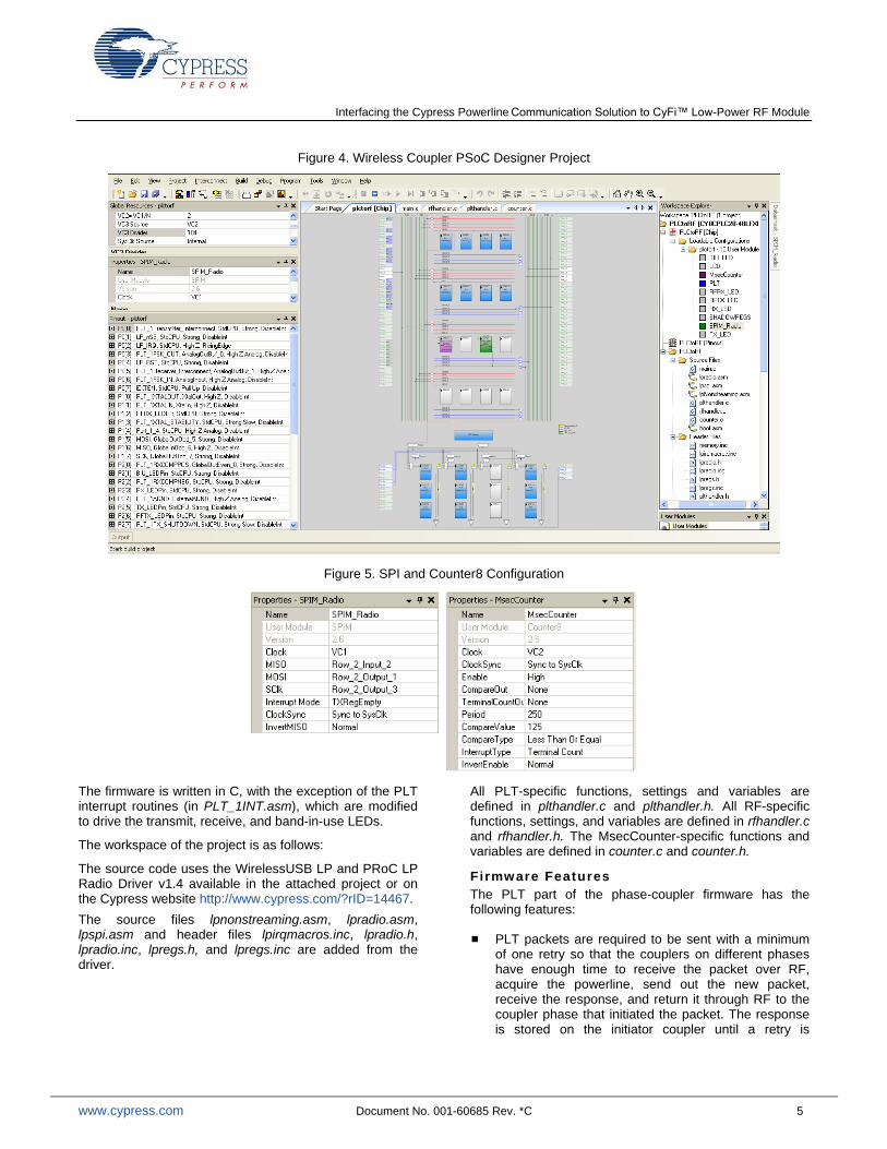
The project is created with PSoC Designer™ 5.4. Figure 4 shows a screen shot of the chip-level view of the project.
The following user modules are used in the project:
Powerline transceiver used in the FSK modem mode.
Counter8: Used to generate a millisecond interrupt used for timeouts. The configuration of the Counter8 user module is shown in Figure 5.
SPI Master: Used to communicate with the RF module through its outputs: MOSI, MISO, and SCK. The
frequency of SCK is set to 4 MHz through VC2. The slave select pin, which is also required by the RF module, is manually controlled by the firmware.
LED: Three LED user modules (TX, RX, BIU) are used to represent when the PLT user module is transmitting, receiving, or has detected a band-in-use timeout condition, respectively. Two LED user modules (RFRX, RFTX) are used to represent when the RF module is receiving or transmitting, respectively.
Interfacing the Cypress Powerline Communication Solution to CyFi™ Low-Power RF Module
www.cypress.com Document No. 001-60685 Rev. *C 5
Figure 4. Wireless Coupler PSoC Designer Project
Figure 5. SPI and Counter8 Configuration
The firmware is written in C, with the exception of the PLT interrupt routines (in PLT_1INT.asm), which are modified to drive the transmit, receive, and band-in-use LEDs.
The workspace of the project is as follows:
The source code uses the WirelessUSB LP and PRoC LP Radio Driver v1.4 available in the attached project or on the Cypress website http://www.cypress.com/?rID=14467.
The source files lpnonstreaming.asm, lpradio.asm, lpspi.asm and header files lpirqmacros.inc, lpradio.h, lpradio.inc, lpregs.h, and lpregs.inc are added from the driver.
All PLT-specific functions, settings and variables are defined in plthandler.c and plthandler.h. All RF-specific functions, settings, and variables are defined in rfhandler.c and rfhandler.h. The MsecCounter-specific functions and variables are defined in counter.c and counter.h.
Firmware Features
The PLT part of the phase-coupler firmware has the following features:
PLT packets are required to be sent with a minimum of one retry so that the couplers on different phases have enough time to receive the packet over RF, acquire the powerline, send out the new packet, receive the response, and return it through RF to the coupler phase that initiated the packet. The response is stored on the initiator coupler until a retry is
Interfacing the Cypress Powerline Communication Solution to CyFi™ Low-Power RF Module
www.cypress.com Document No. 001-60685 Rev. *C 6
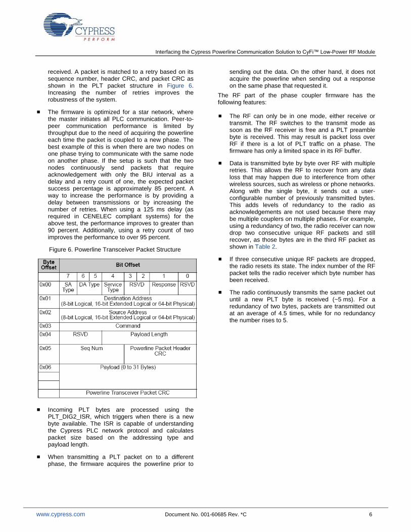
received. A packet is matched to a retry based on its sequence number, header CRC, and packet CRC as shown in the PLT packet structure in Figure 6. Increasing the number of retries improves the robustness of the system.
The firmware is optimized for a star network, where the master initiates all PLC communication. Peer-to-peer communication performance is limited by throughput due to the need of acquiring the powerline each time the packet is coupled to a new phase. The best example of this is when there are two nodes on one phase trying to communicate with the same node on another phase. If the setup is such that the two nodes continuously send packets that require acknowledgement with only the BIU interval as a delay and a retry count of one, the expected packet success percentage is approximately 85 percent. A way to increase the performance is by providing a delay between transmissions or by increasing the number of retries. When using a 125 ms delay (as required in CENELEC compliant systems) for the above test, the performance improves to greater than 90 percent. Additionally, using a retry count of two improves the performance to over 95 percent.
Figure 6. Powerline Transceiver Packet Structure
Incoming PLT bytes are processed using the PLT_DIG2_ISR, which triggers when there is a new byte available. The ISR is capable of understanding the Cypress PLC network protocol and calculates packet size based on the addressing type and payload length.
When transmitting a PLT packet on to a different phase, the firmware acquires the powerline prior to
sending out the data. On the other hand, it does not acquire the powerline when sending out a response on the same phase that requested it.
The RF part of the phase coupler firmware has the following features:
The RF can only be in one mode, either receive or transmit. The RF switches to the transmit mode as soon as the RF receiver is free and a PLT preamble byte is received. This may result is packet loss over RF if there is a lot of PLT traffic on a phase. The firmware has only a limited space in its RF buffer.
Data is transmitted byte by byte over RF with multiple retries. This allows the RF to recover from any data loss that may happen due to interference from other wireless sources, such as wireless or phone networks. Along with the single byte, it sends out a user-configurable number of previously transmitted bytes. This adds levels of redundancy to the radio as acknowledgements are not used because there may be multiple couplers on multiple phases. For example, using a redundancy of two, the radio receiver can now drop two consecutive unique RF packets and still recover, as those bytes are in the third RF packet as shown in Table 2.
If three consecutive unique RF packets are dropped, the radio resets its state. The index number of the RF packet tells the radio receiver which byte number has been received.
The radio continuously transmits the same packet out until a new PLT byte is received (~5 ms). For a redundancy of two bytes, packets are transmitted out at an average of 4.5 times, while for no redundancy the number rises to 5.

Interfacing the Cypress Powerline Communication Solution to CyFi™ Low-Power RF Module
www.cypress.com Document No. 001-60685 Rev. *C 7
Table 2. Example of RF Packet Structure with a Redundancy of 2
Index PLT Data Received
Offset RF Data Transmitted (YY – Random data)
Index # New Data Previous Data 1 Previous Data 2
0 0xab Preamble 0x00 0xab 0xYY 0xYY
1 0x10 TX Config (LA - LA requiring Acknowledgement)
0x01 0x10 0xab 0xYY
2 0x04 Destination Address 0x02 0x04 0x10 0xab
3 0x05 Source Address 0x03 0x05 0x04 0x10
4 0x09 Command ID - Send Message 0x04 0x09 0x05 0x04
5 … … … … … …
Firmware Algori thm
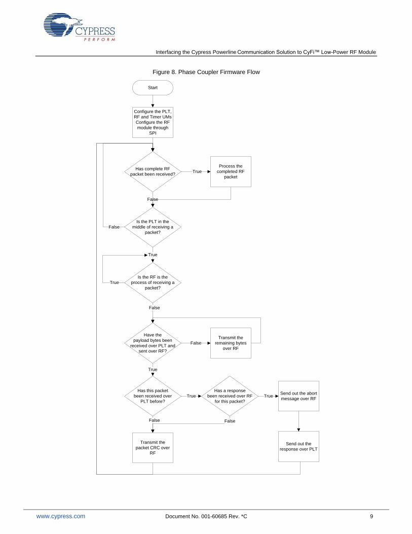
The phase coupler firmware flow is shown in Figure 8. A description of the flowchart is as follows:
On power-up, it initializes the hardware in the following order:
Enables the PLC FSK Modem Only receiver to the default settings. Change the project if any of the modem options need to be adjusted.
Enables the LCD and displays a welcome message.
Checks whether another coupler is on the same phase.
Starts the SPI module and configures the radio to the following settings: Sets the default-end state to idle, data mode to 8DR, uses 64-bit codes for DSSS and the highest signal strength gain setting, and adjusts the radio to use a frequency of 2.442 MHz. More information on these parameters can be found in the CYRF7936 datasheet and the Technical Reference Manual.
If a complete packet has been received over RF, it processes it. If the coupler received a response packet, it stores it in the buffer. Otherwise, it transmits the packet over the powerline.
If the PLT is in the middle of receiving a packet and the RF is free, the coupler switches the radio to transmitter mode and starts sending out the incoming PLT packet bytes over RF. It transmits all the bytes except the packet CRC, which is the last byte. When it receives this byte, it checks whether this packet was received earlier and if the packet has a stored response. If it does, it sends out an abort message over RF telling the receiver couplers not to transmit the packet over the powerline. It then transmits the stored response back on the same powerline phase to the node that requested for it. If the response is not found, it sends out the last byte over RF.
The statistics of the number of complete PLT and RF packets received and transmitted are updated continuously on the LCD module. The comments in the project describe the algorithm in much greater detail.
Evaluating the Application Note
The attached firmware project uses the CY3274 PLC Kit. The kit must be connected to the Artaflex module as shown in Figure 3. A photo of the CY3274 development kit and the module is shown in Figure 7. Make sure that the linear regulator is used to provide a voltage of 3.3 V for the module. The LCD user module should be attached.
The list of components required to make this circuit is given in the following table.
Description Quantity Value Digikey Part No
Artaflex module 1 NA 748-1000-ND
Resistor 4 2.2 kΩ P2.2KBACT-ND
Input capacitor 1 100 nF 478-1831-ND
Output capacitor 1 10 uF 478-1837-ND
Linear regulator 1 NA 497-1492-5-ND
To evaluate the system, two CY3274 are used as nodes, programmed with firmware that can communicate with the PLC control panel GUI through I
2C. If they are on the
same phase, the second coupler attached to the phase displays an error message on the LCD.

Interfacing the Cypress Powerline Communication Solution to CyFi™ Low-Power RF Module
www.cypress.com Document No. 001-60685 Rev. *C 8
Figure 7. CY3274 Kit and Artaflex Module
The PLC control panel GUI can be run on a PC and interfaced to the board with the CY3240 USB-I
2C bridge
board. Use the GUI to set the nodes as follows.
Set each node to a different logical address
2400 bps baud rate
Band-in-use (BIU) detection enabled
Acknowledgment mode
Retry count of at least 1 (each packet is transmitted twice)
Send packets from one node to another
Interfacing the Cypress Powerline Communication Solution to CyFi™ Low-Power RF Module
www.cypress.com Document No. 001-60685 Rev. *C 9
Figure 8. Phase Coupler Firmware Flow
Start
Has complete RF
packet been received?
Configure the PLT,
RF and Timer UMs
Configure the RF
module through
SPI
True
False
Is the PLT in the
middle of receiving a
packet?
True
Is the RF is the
process of receiving a
packet?
False
True
Have the
payload bytes been
received over PLT and
sent over RF?
False
Transmit the
remaining bytes
over RF
False
True
Has this packet
been received over
PLT before?
True
Has a response
been received over RF
for this packet?
Send out the abort
message over RFTrue
False
Transmit the
packet CRC over
RF
False
Send out the
response over PLT
Process the
completed RF
packet

Interfacing the Cypress Powerline Communication Solution to CyFi™ Low-Power RF Module
www.cypress.com Document No. 001-60685 Rev. *C 10
Document History
Document Title: AN60685 - Interfacing the Cypress Powerline Communication Solution to CyFi™ Low-Power RF Module
Document Number: 001-60685
Revision ECN Orig. of Change
Submission Date
Description of Change
** 3043443 RARP 09/30/2010 New application note.
*A 3127419 RARP 01/04/2011 Fixed typos.
Updated resistor values for 2.2 KΩ
Updated firmware project for PSoC Designer 5.1 Production
*B 3389975 ADIY 10/03/2011 Removed reference to CY8CLED16P01, CY3276 and CY3277.
Updated CyFi Low-Power RF section.
Corrected resistor values in Table 1 to 2.2 kΩ.
Corrected the Pin Diagram of Wireless USB LP Radio Module in Figure 3
Updated template.
*C 4547551 ROIT 10/21/2014 Removed reference to obsolete kits: CY3272, CY3273, and CY3275.

Interfacing the Cypress Powerline Communication Solution to CyFi™ Low-Power RF Module
www.cypress.com Document No. 001-60685 Rev. *C 11
Worldwide Sales and Design Support
Cypress maintains a worldwide network of offices, solution centers, manufacturer’s representatives, and distributors. To find the office closest to you, visit us at Cypress Locations.
Products
Automotive cypress.com/go/automotive
Clocks & Buffers cypress.com/go/clocks
Interface cypress.com/go/interface
Lighting & Power Control cypress.com/go/powerpsoc cypress.com/go/plc
Memory cypress.com/go/memory
PSoC cypress.com/go/psoc
Touch Sensing cypress.com/go/touch
USB Controllers cypress.com/go/usb
Wireless/RF cypress.com/go/wireless
PSoC® Solutions
psoc.cypress.com/solutions
PSoC 1 | PSoC 3 | PSoC 4 | PSoC 5LP
Cypress Developer Community
Community | Forums | Blogs | Video | Training
Technical Support
cypress.com/go/support
PSoC is a registered trademark of Cypress Semiconductor Corp. PSoC Designer and CyFi are trademarks of Cypress Semiconductor Corp. All other trademarks or registered trademarks referenced herein are the property of their respective owners.
Cypress Semiconductor 198 Champion Court San Jose, CA 95134-1709
Phone : 408-943-2600 Fax : 408-943-4730 Website : www.cypress.com
© Cypress Semiconductor Corporation, 2014. The information contained herein is subject to change without notice. Cypress Semiconductor Corporation assumes no responsibility for the use of any circuitry other than circuitry embodied in a Cypress product. Nor does it convey or imply any license under patent or other rights. Cypress products are not warranted nor intended to be used for medical, life support, life saving, critical control or safety applications, unless pursuant to an express written agreement with Cypress. Furthermore, Cypress does not authorize its products for use as critical components in life-support systems where a malfunction or failure may reasonably be expected to result in significant injury to the user. The inclusion of Cypress products in life-support systems application implies that the manufacturer assumes all risk of such use and in doing so indemnifies Cypress against all charges. This Source Code (software and/or firmware) is owned by Cypress Semiconductor Corporation (Cypress) and is protected by and subject to worldwide patent protection (United States and foreign), United States copyright laws and international treaty provisions. Cypress hereby grants to licensee a personal, non-exclusive, non-transferable license to copy, use, modify, create derivative works of, and compile the Cypress Source Code and derivative works for the sole purpose of creating custom software and or firmware in support of licensee product to be used only in conjunction with a Cypress integrated circuit as specified in the applicable agreement. Any reproduction, modification, translation, compilation, or representation of this Source Code except as specified above is prohibited without the express written permission of Cypress. Disclaimer: CYPRESS MAKES NO WARRANTY OF ANY KIND, EXPRESS OR IMPLIED, WITH REGARD TO THIS MATERIAL, INCLUDING, BUT NOT LIMITED TO, THE IMPLIED WARRANTIES OF MERCHANTABILITY AND FITNESS FOR A PARTICULAR PURPOSE. Cypress reserves the right to make changes without further notice to the materials described herein. Cypress does not assume any liability arising out of the application or use of any product or circuit described herein. Cypress does not authorize its products for use as critical components in life-support systems where a malfunction or failure may reasonably be expected to result in significant injury to the user. The inclusion of Cypress’ product in a life-support systems application implies that the manufacturer assumes all risk of such use and in doing so indemnifies Cypress against all charges. Use may be limited by and subject to the applicable Cypress software license agreement.