Sexual Orientation, Gender, & Self-Styling - UVM ScholarWorks
Upload
khangminh22Category
view
8download
0
NTN
UN
orw
egia
n U
nive
rsity
of S
cien
ce a
nd T
echn
olog
yFa
culty
of I
nfor
mat
ion
Tech
nolo
gy a
nd E
lect
rical
Engi
neer
ing
Dep
artm
ent o
f Ele
ctro
nic
Syst
ems
Mas
ter’s
thes
is
Eivind Strand Erichsen
Interfacing SystemC inside UVM usingTLM 2.0
Electronics Systems Design and Innovation
Master’s thesis in Electronics Systems Design and Innovation
Supervisor: Trond Ytterdal
June 2020


Eivind Strand Erichsen
Interfacing SystemC inside UVM usingTLM 2.0
Electronics Systems Design and Innovation
Master’s thesis in Electronics Systems Design and InnovationSupervisor: Trond YtterdalJune 2020
Norwegian University of Science and TechnologyFaculty of Information Technology and Electrical EngineeringDepartment of Electronic Systems


Abstract
The possibilities and challenges with simulation-based verification with Universal Verification Method-ology(UVM), SystemC and TLM2.0 are investigated in this thesis. The methodology presented deviatesfrommost UVM environments with the reuse of a SystemCmodel reference model. This model generatesthe expected response from the Design Under Test(DUT) and enables automatic checking. The methodol-ogy use constrained random stimulus that excels at finding unexpected bugs and reduce implementationtime. The DUT is a complex memory controller previously verified with directed test vectors. It is aconfidential Nordic Semiconductor IP recently implemented in their nRF52 System-on-Chip(SoC).
Traditional directed tests specify each test vector to simulate, and the list can grow huge to cover allfunctionality. These lists are very time-consuming to implement and maintain. The DUT has a 3500lines long file with test vectors and is updated over several years. Constrained random stimuli canreplace the time-consuming lists. Test3 presented in the implementation chapter shows how to generateconfiguration and memory transactions concurrently in 19 lines of code in a completed environment. Inaddition to fast stimuli generation, enhances this methodology reuse to decrease implementation time.Protocol components were reused to communicate with the DUT. Only 42% code coverage was reacheddue to an inadequate reference model. However, the implementation show that the technology worksand can be used in verification.
i

Sammendrag
Mulighetene og utfordringene i simulasjons basert verifikasjon med Universal Verification Method-ology(UVM), SystemC og TLM2.0 er analysert i denne masteroppgaven. Denne metodikken avvikerfra de fleste UVM verifikasjon miljø ved gjenbruket av en SystemC referanse model. Denne modellengenererer forventet respons fra Designet Under Test(DUT) og muliggjør automatisk sjekking av respon-sen. Metodikken presentert bruker begrenset randomisert stimuli til å finne uventede feil og redusereimplementasjons tiden. DUTen er en minnekontroller som er tidligere verifisert med direkte tester. Deter en konfidensiell enhet fra Nordic Semiconductor som er nylig brukt i deres nRF52 SoC.
Tradisjonelle tester med bestemt stimuli spesifiserer hver eneste test vektor og listen med bestemtstimuli kan vokse til å bli ekstremt stor for å dekke all funksjonalitet. Listene med stimuli er veldigtidkrevende å utvikle og vedlikeholde. DUTen har en fil med test vektorer som er 3500 linjer langog oppdatert over flere år. Begrenset randomisert stimuli kan erstatte de tidkrevende listene. Test3presentert i implementasjons kapittelet viser hvordan 19 linjer genererer minne og konfigurasjonstransaksjoner samtidig. I tillegg til hurtig stimuli generasjon, muliggjør metodikken gjenbruk av kodesom også reduserer implementasjons tiden. Protokoll komponenter er gjenbrukt for å kommuniseremed DUTen. Bare 42% kode dekning var oppnådd på grunn av ufullstendig referansemodell. Derimot,viser implementasjonen at teknologien fungerer og kan bli brukt til verifikasjon.
ii

Preface and acknowledgements
This thesis builds on the project "Interfacing SystemC inside UVM using TLM 2.0" written by me in thefall of 2019. It was the proof-of-concept for the methodology presented in this thesis. The backgroundchapter in this thesis builds on the background chapter in the project mentioned.
I want to thank Nordic Semiconductor for providing me with the tools and models needed for thisthesis. I also appreciate the weekly meetings that helped to solve problems and encourage me to keepworking.
Another asset that was important to finish this thesis was Mentor Graphics. They helped in initialcompilation and simulation of the complex SystemC model, a lot of time was saved and ensured Ifinished in time.
iii

Contents
List of figures v
List of tables vi
List of listings vii
Abbreviations viii
1 Introduction 1
2 Background 32.1 Simulation-based verification . . . . . . . . . . . . . . . . . . . . . . . . . . . . . . . . . 32.2 Languages and technology . . . . . . . . . . . . . . . . . . . . . . . . . . . . . . . . . . 5
2.2.1 SystemVerilog . . . . . . . . . . . . . . . . . . . . . . . . . . . . . . . . . . . . . 52.2.2 UVM . . . . . . . . . . . . . . . . . . . . . . . . . . . . . . . . . . . . . . . . . . 62.2.3 UVM code generation . . . . . . . . . . . . . . . . . . . . . . . . . . . . . . . . 72.2.4 Transaction-level modelling . . . . . . . . . . . . . . . . . . . . . . . . . . . . . 82.2.5 SystemC . . . . . . . . . . . . . . . . . . . . . . . . . . . . . . . . . . . . . . . . 8
2.3 Coverage-Driven CRV . . . . . . . . . . . . . . . . . . . . . . . . . . . . . . . . . . . . . 9
3 Implementation 113.1 SystemC Reference model . . . . . . . . . . . . . . . . . . . . . . . . . . . . . . . . . . 113.2 UVM . . . . . . . . . . . . . . . . . . . . . . . . . . . . . . . . . . . . . . . . . . . . . . 13
3.2.1 UVM Verification Component . . . . . . . . . . . . . . . . . . . . . . . . . . . . 133.2.2 Scoreboard predictor . . . . . . . . . . . . . . . . . . . . . . . . . . . . . . . . . 133.2.3 TLM 2.0 sockets . . . . . . . . . . . . . . . . . . . . . . . . . . . . . . . . . . . . 153.2.4 UVM Connect . . . . . . . . . . . . . . . . . . . . . . . . . . . . . . . . . . . . . 173.2.5 Scoreboard . . . . . . . . . . . . . . . . . . . . . . . . . . . . . . . . . . . . . . 183.2.6 Code generator . . . . . . . . . . . . . . . . . . . . . . . . . . . . . . . . . . . . 18
3.3 Tests . . . . . . . . . . . . . . . . . . . . . . . . . . . . . . . . . . . . . . . . . . . . . . 213.4 Makefile . . . . . . . . . . . . . . . . . . . . . . . . . . . . . . . . . . . . . . . . . . . . 24
4 Results 26
5 Discussion 29
iv

CONTENTS v
5.1 CRV . . . . . . . . . . . . . . . . . . . . . . . . . . . . . . . . . . . . . . . . . . . . . . . 295.2 UVM . . . . . . . . . . . . . . . . . . . . . . . . . . . . . . . . . . . . . . . . . . . . . . 295.3 SystemC . . . . . . . . . . . . . . . . . . . . . . . . . . . . . . . . . . . . . . . . . . . . 30
6 Conclusion and Future work 326.1 Future work . . . . . . . . . . . . . . . . . . . . . . . . . . . . . . . . . . . . . . . . . . 32
Bibliography 33
A Source code 35

List of Figures
2.1 Traditional directed testing . . . . . . . . . . . . . . . . . . . . . . . . . . . . . . . . . . 32.2 Constrained random stimuli . . . . . . . . . . . . . . . . . . . . . . . . . . . . . . . . . 42.3 Advanced simulation-based test . . . . . . . . . . . . . . . . . . . . . . . . . . . . . . . 52.4 Block scheme of a typical UVC and connections . . . . . . . . . . . . . . . . . . . . . . 7
3.1 Test overview . . . . . . . . . . . . . . . . . . . . . . . . . . . . . . . . . . . . . . . . . 113.2 SystemC reference model block scheme. Figure made by Nordic Semiconductor. . . . . 123.3 Block scheme of the UVCs . . . . . . . . . . . . . . . . . . . . . . . . . . . . . . . . . . 133.4 Block scheme of the predictors and their connections . . . . . . . . . . . . . . . . . . . 143.5 Packing generic payload data . . . . . . . . . . . . . . . . . . . . . . . . . . . . . . . . . 163.6 Non-blocking transaction chart . . . . . . . . . . . . . . . . . . . . . . . . . . . . . . . 163.7 Initial structure . . . . . . . . . . . . . . . . . . . . . . . . . . . . . . . . . . . . . . . . 193.8 Complete structure . . . . . . . . . . . . . . . . . . . . . . . . . . . . . . . . . . . . . . 203.9 Complete block scheme . . . . . . . . . . . . . . . . . . . . . . . . . . . . . . . . . . . . 20
4.1 Time to complete Test2 with different number of transactions . . . . . . . . . . . . . . 28
vi

List of Tables
3.1 List of the reference model’s features . . . . . . . . . . . . . . . . . . . . . . . . . . . . 123.2 List of generic payload attributes . . . . . . . . . . . . . . . . . . . . . . . . . . . . . . . 153.3 List of possible response status . . . . . . . . . . . . . . . . . . . . . . . . . . . . . . . . 17
4.1 Code lines and implementation time . . . . . . . . . . . . . . . . . . . . . . . . . . . . . 27
vii

Listings
3.1 APB constraints to prevent illegal transactions . . . . . . . . . . . . . . . . . . . . . . . 213.2 Test1: Constrained random APB sequences . . . . . . . . . . . . . . . . . . . . . . . . . 213.3 Adding a constraint to target functionality . . . . . . . . . . . . . . . . . . . . . . . . . 223.4 Test2: AHB and APB sequences with only random AHB data . . . . . . . . . . . . . . . 223.5 Test3: Constrained random APB and AHB sequences . . . . . . . . . . . . . . . . . . . 233.6 Summary and description of the makefile . . . . . . . . . . . . . . . . . . . . . . . . . . 24A.1 AHB predictor with both blocking and non-blocking interface implemented . . . . . . 35A.2 AHB predictor with blocking interface implemented . . . . . . . . . . . . . . . . . . . . 39A.3 UVM scoreboard implementation . . . . . . . . . . . . . . . . . . . . . . . . . . . . . . 42
viii

Abbreviations
AHB AMBA High-performance Bus.
APB Advanced Peripheral Bus.
CRV Constrained Random Verification.
DUT Design Under Test.
FIFO First In, First Out.
IP Intellectual Property.
OOP Object-Oriented Programming.
RTL Register-Transfer Level.
SoC System-on-Chip.
TLM Transaction-Level Modelling.
UVC UVM Verification Component.
ix

1 | Introduction
The complexity of System-on-Chip grows every year as the costumers are expecting better performanceand more features. These chips need to be designed and verified with increasingly demanding time-to-market as competition hardens. A significant market share is lost if the time-to-market goal is lost, anda competitor releases similar products first. According to the 2018 Wilson Research Group FunctionalVerification Study, the average total project time spent in verification in 2018 was 53 percent[1]. Adoptingnew verification technology can shorten the verification time, but can also have mandatory expensivetools and training to be efficient.
Verification is an essential part of digital design development, and UVM is a promising verificationmethodology in simulation-based verification. Mentor’s Verification Horizons blog states 71% of all ASICprojects have adopted UVM for testbench development in 2018, and the 2020 projection is 74%[2]. UVMis a new methodology from 2012 and was quickly adopted by companies. UVM is an IEEE standard withguidelines on how to use UVM. This thesis deviates from most UVM testbenches by the use of a SystemCreference model. The UVM scoreboard compares transactions from the DUT and the reference modelto check the DUT’s functionality. A standard technique seen in the UVM guidelines and typical UVMtestbenches, where applicable, is to use a predictor and a memory model as a reference model.
Nordic Semiconductor is in the process of developing virtual platforms in SystemC. The virtual platformis software that can mimic an SoC and enables early software development, architecture exploration,architecture validation and can be used as a reference model in functional verification. A large part ofSoCs consists of already verified blocks, and the connection between blocks are essential in verificationtoday. TLM 2.0 with generic payload transaction object enhances interoperability, meaning it is easy toconnect other blocks. The memory controller is a part of an SoC, and more blocks can be connectedto expand the verification possibilities. Nordic Semiconductor can use their own developed SystemCmodels and buy SystemC models from vendors. ARM processors is typical in SoC today, and a SystemCmodel can be bought from them. Developing and buying SystemC models can be expensive, but can bevery useful in various phases in digital design development.
Traditional testbenches specify each test vector and expected outcome, resulting in thousands of linesof code to test the functionality of complex DUTs. Constrained Random Verification(CRV) eliminatesor drastically reduce the number of manual written test vectors and is a significant advantage for fastto implement and easy to maintain tests. This shift in simulation-based verification is unstoppable asdesigns grow, and the solutions for the new challenges of simulation-based verification is essential forverification engineers. There are significant advantages using CRV methodology, but the disadvantagesin the methodology is the increase of testbench complexity and require resources spent on training
1

CHAPTER 1. INTRODUCTION 2
and tools. This thesis has components from different technologies, and the challenges of implementing,simulating and debugging are present. However, these obstacles will decay as the methodology maturein a company. Unlike traditional testbenches with various structures, UVM testbenches can have verysimilar structure and compilation method, so engineers will quickly become comfortable and efficientwith the methodology.

2 | Background
A detailed verification plan can shorten verification time and is important for releasing complex System-on-Chips before time-to-marked. The verification plan should have details on which systems andsub-systems are tested, test plan, coverage plan, response methodology and much more. The responsemethodology is methods used to check the response from the DUT. The response could be checkedwith pre-defined expected result, manually checked or automatically checked with a reference model.Verification is often performed hierarchically, sub-components are first verified individually, then asystem of these components are verified. Many details should be included for a detailed plan andneeds to be made by a person with a good understanding of the systems. If only the input and outputinterfaces are investigated in the test plan, corner cases may be missed. It is important to have theinternal components in mind, so the sub-systems that are not verified have their corner cases tested.Time invested in the verification plan will reduce the time consumed by the later stages of verification.Simulation-based verification is investigated in this thesis, but other methods as formal verification arealso possible.
2.1 Simulation-based verification
Simulation-based verification is a common verification technique where test vectors are generated andsimulated to verify the DUT. Low-level assertions can verify specific logic and high-level responsechecking can verify the functionality. In figure 2.1 below, test vectors are manually created together withexpected results, simulated and the response are checked with the pre-defined expected results.
Figure 2.1: Traditional directed testing
When the DUT’s response does not match the expected value, the hunt for the bug begins, and it can bechallenging to find the bug with no information from the simulation. It is here assertions are very usefulas they excite an error in the simulation when it detects something has gone wrong. The designersshould make these assertions while they implement the system. The assertions are vital for debugging,and if a test fails while no assertions excites an error, too few assertions are likely implemented. Whileassertions tell where and when an error has occurred, coverage is signalling that something has been
3

CHAPTER 2. BACKGROUND 4
exercised. When the coverage reaches a certain point, the verification can be documented as complete.Code coverage shows which branches, variables, states and statements has been exercised and howmanytimes. It is a good start to show that all individual statements work, but it does not check cross coverage.Functional coverage can cross-check transitions and succeed in describing complex corner cases wherecode coverage fails. Code coverage provide an easy metric of exercised code because simulation toolsoften offer this feature. It is a useful and efficient early verification metric, but functional coverageshould be added to complete the coverage of more complex scenarios.
Generating test vectors with expected results can be efficient in verifying small designs, but labour-intensive and error-prone to unexpected bugs with complex designs. This traditional directed testing canbe insufficient in verifying today’s complex designs and improved tests have automation and reusabilityin mind. CRV has automatic stimuli generation and shown in figure 2.2 below.
Figure 2.2: Constrained random stimuli
The random stimuli is constrained to target certain coverage and prevent illegal stimuli. The constrainedrandom stimuli are simulated on the DUT who generates a response. A predictor is a component thatpredicts the expected result. The actual and expected responses are then automatically checked. Thepredictor can use different methods to get the expected response. The most common methods are usinga UVM register model or a high-level model. A UVM register model is simple to implement and are usedto model registers. A high-level reference model is a model that can describe complex functionality andhas the same functionality as the DUT. The reference model will receive the same data as the DUT andproduce the expected response. The evaluation step is where the system is verified or if more testing isneeded and if the constraints needs adjustment to target certain coverage. These constraint adjustmentsare done manually, but a coverage model could automate this process. The coverage plan should be themain driver of the stimuli to achieve completeness.
The simulation can stop after a certain number of stimuli has been simulated or when a certain coveragelevel has been reached. However, a certain coverage level can require high simulation time with largedesigns and few constraints. Complex RTL models can use hours or days to simulate with directedtesting, and the simulation time could increase with CRV. This increase in simulation time is mainlydue to more test vectors may be required in CRV. The directed tests are manually made efficient, whilethe randomness in CRV can generate less efficient test vectors. CRV would use longer simulation timeto achieve the same coverage. This increase in necessary test vectors can contribute to a very highsimulation time and results in only small sections of designs can be verified with CRV. Some advancedmethods can be implemented to reduce simulation time. High-quality test vectors that excites bugs orhit hard to hit coverage can be reused, a filter can only let through novel test vectors and constraints

CHAPTER 2. BACKGROUND 5
can be adjusted. The figure 2.3 below shows an advanced ways to reduce simulation time.
Figure 2.3: Advanced simulation-based test
Simulation time can be huge when the automated stimuli generator is shooting test vectors from the hip,and each test vector is resource-heavy to simulate. It is common to run tests several times and reuse IPs.With this in mind, essential test scenarios can be saved in a test database and reused, as shown abovein figure 2.3. Test vectors can be reused from previous simulations or previous projects. A scenariowhere disposal tests from a database are first run, followed by constrained random tests can harvest thestrengths from both traditional directed testing and CRV. Expensive expertise is needed in developinghigh-quality scenarios for SoC that trigger edge cases. An initiative (Portable Stimulus Working Group)defines a standardise description language of scenarios to maximise reusability across abstraction levels[3]. Lowering verification time is important to meet deadlines, and supplying high-quality tests arebecoming important as simulation times increases with large systems. Applying these directed testsshould not remove the advantages we are trying to achieve with CRV, but instead add the efficiency ofsome high-quality directed tests.
The use of filter and test database shown in figure 2.3 is not essential in CRV, but it can solve the problemof high simulation time. CRV can often only be applied to a small section of a design as the simulationtime would be too high to test an entire SoC. A paper from 2012 claims a four days simulation wasreduced to below six hours by applying novel test detection to a constrained random test generation andsimulation environment for a power architecture-compliant processor core[4]. The novel test detectorwill filter out the tests that are of little or no value, and CRV can be used in more scenarios by ensuringhigh-quality test vectors.
2.2 Languages and technology
Different languages and technology has different strengths and companies are often combining technol-ogy to obtain all the best features. Combining several languages and technology can be beneficial, butcan also contribute to complex implementation and debugging.
2.2.1 SystemVerilog
SystemVerilog is called the industry’s first Hardware Description and Verification Language (HDVL)because it combines the features of Hardware Description Languages such as Verilog and VHDLwith features from specialised Hardware Verification Languages [5]. It is used in RTL development,

CHAPTER 2. BACKGROUND 6
implementing SystemVerilog Assertions and in building coverage-driven verification environmentsusing constrained random techniques. SystemVerilog has object-oriented features from c and c++ whichmakes the language richer that is especially useful in testbenches.
2.2.2 UVM
The UVM standard is developed by the UVMWorking Group and improves interoperability and reducesthe cost of repurchasing and rewriting IP for each new project or electronic design automation tool[6][7].Mentor Graphics, a technology leader in electronic design automation, claims UVM represents the latestadvancements in verification technology and is designed to enable the creation of robust, reusable,interoperable verification IP and testbench components[8]. UVM is an open-source SystemVeriloglibrary developed independently by the simulator vendors with support from Aldec, Cadence, MentorGraphics, and Synopsys. This thesis uses Mentor Graphics’ Questasim verification tool to compile andsimulate UVM, SystemVerilog, SystemC and TLM 2.0 together.
UVM communicates on transaction-level and is used for testbench development. Two important featuresis the object-oriented programming(OOP), and polymorphism that enables reuse and configuration ofclasses. A standard library of UVM classes is recommended to be used in the testbench. This means thedesigner does not need to be an expert in OOP since the recommended classes is already developed,and just extending these classes can be the best practise. Pure SystemVerilog testbenches are writtenspecifically for a single purpose use and often with little guidelines. These testbenches have low or nonereusability, high maintenance cost and hard to understand. All UVM testbenches should use the samebase classes and are easily understandable for engineers worked with UVM before.
UVMwas designed with reuse in mind and encourage the use of the standard classes that can encapsulatebehaviour. While UVM enables reuse, it is not guaranteed that something can be reused betweenenvironments, hierarchies or projects. It is the verification engineers responsibility to design componentsthat can be reused. The most common reuse is verification components between environments, butentire verification environments can also be used between different projects or in the same tests. Acommon practice is to instantiate umv_environmentmultiple times in the same test, but with a differentconfiguration.
A reusable UVMVerification Component(UVC) for a particular interface can be used in many testbenches.A protocol UVC can, for example, generate an AHB transaction item and drive it on the DUT’s interface. Aspecific UVC is created for each of the DUT’s interfaces and usually with a uvm_sequencer, uvm_driverand uvm_monitor components inside as figure 2.4 shows. The dashed line is marking what is includedin the UVC. The role of a UVM agent is to encapsulate the sequencer, driver and monitor into asingle container to enable reuse. Other components as protocol checker, coverage monitoring or othercomponents can also be added to the agent.

CHAPTER 2. BACKGROUND 7
Figure 2.4: Block scheme of a typical UVC and connections
A sequence consists of sequence items that are passed by the test to the sequencer who communicate withthe driver. The driver drives a particular the interface like AHB or APB. The DUT and the uvm_monitoris connected to the interface and receives these transactions. The monitor should not set any signal onthe interface, but only listen and broadcast completed transactions.
The high abstraction enables UVM components to be compact with a lot of functionality, but a con-sequence can be a steep learning curve. A single line of code connects a sequencer with a driver andestablish a handshaking protocol. This is an example of UVM that abstracts away details and forceengineers to implement best practices. This abstraction can contribute to confusion in what is happen-ing during the simulation, but enables engineers to implement tests quick and reliable when they arecomfortable with UVM.
UVM Connect is an open-source UVM-based library from Mentor Graphics that enable TLM 1.0 andTLM 2.0 communication between UVM and SystemC. It is used by SystemC designers who want toleverage SystemVerilog and UVM functionality and opposite where verification engineers wants toleverage SystemC[9].
2.2.3 UVM code generation
UVM has its upsides, but one of the downside are large base structure needed to start simulating. Whilethere can be a lot of code, a similar structure is used for every testbench with repeating patterns. UVMcode generators are made to enhance productivity and remove the tedious process of writing the basestructure. Script generated files remove pitfalls done by new and experienced designers and give a"flying start" to the verification. Using a code generator can further enable cooperation as it is mucheasier to understand a structure a designer has previously work with. Many code generators exist, andNordic Semiconductor may make their own to suit their needs. Two well-known examples of codegenerators is Doulous Easier UVM and Mentor UVM Framework.

CHAPTER 2. BACKGROUND 8
Doulos Easier UVM[10] is a UVM code generator written in Perl that converts files describing thecomponents and the DUT into basic UVM structure with components and connections. Usually, onlythe necessary functions are implemented, and it is up to the designer to implement further functionality.www.edaplayground.com is an online generator with many examples that simplifying the learningprocess.
Mentor’s UVM Framework (UVMF) is a code generator written in Python that promise best-practicesUVM on the code generated. The designer write a YAML file describing the testbench and the generatorcreate UVM infrastructure that is ready to run and guarantees good model reuse possibilities.
2.2.4 Transaction-level modelling
Transaction-level modelling(TLM) is a communication abstraction where transactions are sent as acommunication object. UVM uses TLM communication between components and a driver to convert thetransactions to signal toggling for the RTL DUT interfaces. The UVM monitor translate signal togglingon the DUT’s interfaces back to transactions. SystemC is also communicating on a TLM abstraction, butnot compatible with UVM without any bridge between them.
TLM 2.0 is an Open SystemC Initiative transaction-level modelling standard and can together withUVM Connect connect UVM with SystemC. TLM 2.0 is focused towards the modelling of on-chipmemory-mapped busses and ensures high speed by sending the reference of the object. The genericpayload is the standard transaction object, but an extension can be attached if some attributes are lackingor it can be replaced by another transaction object. The SystemC reference model used in this thesisattach an extension on the generic payload to distinguish transactions sent from different sockets. Abus model can be implemented with an initiator socket at the master and target socket at the slave, andthe generic payload as a transaction object enable maximum interoperability.
High abstraction TLM models can simulate many order of magnitudes times faster than the RTL modelsand can be an important factor for reach deadlines. When RTL models are simulated, the simulator isexamining every event or clock cycle and results in slow simulation speed. TLM use function calls forinter-module communication which ensures high simulation speed.
2.2.5 SystemC
SystemC[11] is an extension of C++ and provides an event-driven simulation interface that was releasedin 2000 and had waves with popularity and new releases. It is an IEEE standard that only requires a C++compiler to simulate, and this is usually an advantage over proprietary technology. SystemC deliberatelymimics the hardware description languages, but at a system-level which makes it an excellent referencemodel that is faster to implement and simulate than RTL. SystemC is applied in system-level modelling,abstract analogue/mixed-signal modelling, architectural exploration, architectural validation, perfor-mance modelling, software development, functional verification and high-level synthesis[12].
SystemC is used in software-based systems that can fully mirror the functionality of a complex SoC, andthis is called virtual platforming. System architect engineers design the virtual platform and can be usedby several groups in several design phases. Software engineers can use it for application software andsoftware development, system architect engineers can use it in architecture exploration, and hardware

CHAPTER 2. BACKGROUND 9
engineers can use it as a golden reference model in testbenches. This exchange in executable code be-tween engineers can also replace or be added to traditional paper specification between teams. Cadenceclaims their Virtual System Platform can shave months off system development schedule by facilitatingearly software development, higher software developer productivity, and continuous hardware/soft-ware integration validation[13]. The fact that Cadence, a respected semiconductor company, buildvirtual prototypes with SystemC and TLM 2.0 technology, backs up the importance of this technologytoday[14].
SystemC TLM models can be untimed, loosely timed or approximately timed, meaning different level ofcorrect performance representation of an implementation. The real transaction times can be estimatedand specified in the TLM model resulting in an approximately timed model, and the performance of thesystem can be analysed. Many SoCs are targeted to embedded system applications which have real-timeconstraints. It is often necessary to verify real-time performance goals by simulating complex scenarioswith hardware and software components. Verifying such scenarios can be as important as verifyingthe logic design. High-speed transaction-level models with the appropriate level of timing accuracycan be an excellent way of verifying that performance requirements are met in certain scenarios[15].Timing accurate SystemC models enable simulation of performance and architecture exploration, butthis thesis uses only the functionality of the model. Therefore, the timing is not essential in this thesis.A system-level model can be used as a golden reference model regardless of the timing, and only thefunctionality has to be correct. By sending the test vectors to the DUT and the system-level model,functional equivalence check can be performed to verify the functionality of the DUT.
It is possible to make a reference model in RTL, but it is a complex task and will increase time-to-marketversus implementing the reference model with a high abstraction level. Some language options fordesigning a high-level reference model is Matlab, Python, C or SystemC, all with different pros andcons. Python makes it very easy to implement the model, but has a relatively slow simulation speedand is difficult to interface to SystemVerilog. Matlab makes it easy to implement the model, has a fastsimulation speed and has better interface opportunities than Python, but is not open source and makesit difficult with reusability. C is fast and have a good interface, but lacks the mimic opportunities thatSystemC has. SystemC is fast, moderate interface difficulty, moderate implementation difficulty andsuitable hardware mimicking. It requires time and effort to implement a reference model in SystemC,but it has fast simulation speed and mimics the real implementation well [16].
A company can implement TLM models for new IPs to gradually building up a library of TLM modelsor implement TLM methodology for all major existing IP blocks. Architectural exploration can be doneearly and efficiently when a pool of relevant TLM models is available.
2.3 Coverage-Driven CRV
The two cornerstones of CRV is the automatic check of the DUT’s response and coverage which is themetric-based completeness. Both features can be challenging to implement and use. The automaticcheck of the response can be implemented in different ways. A UVM register model is a common way topredict values in registers and can be used to produce the expected response from the DUT. The registermodel can not predict all types of responses from a DUT that a reference model can. The register model

CHAPTER 2. BACKGROUND 10
is commonly used in simpler DUT’s with registers, and a reference model is implemented to mimica more complex DUT. The reference model can be implemented in different languages, as discussedin chapter 2.2.5. A SystemC reference model is used in this thesis to enable automatic checking. Achallenge arises when the reference model and DUT does not have the same functionality. This scenariois present in this thesis because the reference model has only the basic functionality of the DUT. Theresult is a restriction in what features that can be tested and limitation on the stimulus generation. Thisreference model can not be used in complete verification before more functionality is added. This thesisfocuses on the possibilities with this methodology and not the verification of the DUT.
Another challenge is to decide when we are done simulating. A coverage plan monitors exercisedfunctionality and determine the completeness. Ensuring the completeness with the tests can be difficultwith a complex DUT. Guiding tests with constraints can be mandatory to hit specific functionality, andachieving boundary scenarios can be non-trivial in complex systems.

3 | Implementation
The DUT is a verified complex memory controller with an existing testbench implemented with directedtest vectors. It is a confidential Nordic Semiconductor IP used in their nRF52 SoC and other products.The main purpose of the IP is to translate AHB bus-accesses into flash accesses. Internal registers in thememory controller enables write, read or erase of the flash memory. The internal registers are accessedwith the APB bus-accesses. The flash memory simulated in this thesis is 1MB large and is a detailed RTLmodel.
UVM uses transaction-level communication between all UVM components, but the UVM scoreboardpredictors convert the transactions to be able to communicate with the SystemC reference model. Thetransactions are converted to TLM2.0 generic payloads and sent over TLM2.0 sockets to the referencemodel. Figure 3.1 shows an overview of the test structure.
Figure 3.1: Test overview
3.1 SystemC Reference model
The SystemC reference model is intended to have similar functionality as the DUT, but at a highabstraction level. It uses function calls as communication method and simulate must faster than RTL.The model uses TLM 2.0 blocking and non-blocking interface that enables communication to UVM orother SystemC blocks. The model was designed with the purpose to test the possibilities with a SystemCreference model in UVM. It has only the basic functionality of the DUT. The functionality is listed intable 3.1.
11

CHAPTER 3. IMPLEMENTATION 12
Table 3.1: List of the reference model’s features
Configuration registers (APB) Flash memory (AHB)Write enable Write to memoryRead enable Read from memoryErase enableErase all
A SystemC model can be approximately timed when the functionality is fully developed with non-blocking communication and approximate timing inserted. The non-blocking can enhance the timingof the model to approximately timed because it does not block the simulation and has more phases tomodel a transaction accurately. The non-blocking has more phases that make it more resource-heavyand thus slower simulation speed than blocking, but much faster than RTL simulation. Approximatetiming is important for performance modelling and architectural exploration. The reference modelhas non-blocking communication implemented, but not the needed details to approximately modelthe performance of the memory controller. Both blocking and non-blocking interface is implementedin UVM, but blocking interface is preferred because it has faster simulation speeds and is easier toimplement. SystemC reference model is shown below in figure 3.2.
Figure 3.2: SystemC reference model block scheme. Figure made by Nordic Semiconductor.
The SystemC model was developed with SystemC and compiler versions not available in the MentorGraphics’ Questasim verification tool and never tested for compatibility. It was a challenge to compile,and different tool versions had different problems. Some functionality as accessing the generic payloadextension exits the simulation without any warning or error from the simulator. Specific obstacles showup in new methodologies, but can be evaded or fixed as the technology matures in the company.

CHAPTER 3. IMPLEMENTATION 13
3.2 UVM
3.2.1 UVM Verification Component
A Verification IP is commonly known as a component used in testbenches. Similarly, a UVM VerificationComponent(UVC) is a component used in UVM testbenches. This thesis uses two protocol UVCs thathave the main purpose of driving transactions to the DUT’s interfaces. The main components inside theUVCs are uvm_sequencer, uvm_monitor and uvm_driver and shown below in figure 3.3.
Figure 3.3: Block scheme of the UVCs
The sequencer controls the flow of request and response sequence items between sequences and thedriver. The driver has knowledge how to drive signals on a particular interface. The AHB UVC hasa driver for the AHB interface, and the APB UVC has a driver for the APB interface. A monitor is acomponent that observes DUT pin level activity and converts its observations into transactions. It alsosends these transactions to analysis components through an analysis port. The UVCs used in this thesisare made by Nordic Semiconductors and have more features as the choice between master and slave,protocol checker, coverage monitor and library of sequences. It is a component that can be used as itis, but it is common to write sequences specially made for the DUT. The sequence library has basicsequences as random base transaction, burst transfer and pipeline transfers. Custom sequences areeasily made when they are extended from one of these sequences in the library as these have a lot of thefunctionality needed.
3.2.2 Scoreboard predictor
The scoreboard predictors are the main components implemented that enables the unique flow presentedin this thesis, the use of a SystemC reference model. The UVCs broadcast their completed transactionsthrough a uvm_analysis_port. A predictor is implemented for each UVC to receive these transactionsthrough a uvm_analysis_imp. The APB predictor receives the completed APB transactions, and theAHB predictor receives the completed AHB transactions. These transactions are transformed into TLM2.0 uvm_tlm_generic_payload to be compatible with the reference model. Using the generic payloadas a transaction object improves interoperability between blocks because many blocks are compatible.

CHAPTER 3. IMPLEMENTATION 14
When a transaction reaches a predictor, the transaction has already been executed by the DUT meaningthe read transactions have the DUT’s response. The read transactions are converted to two separategeneric payloads objects. The first object has the address and the data; this object represents the actualresponse from the DUT and is sent to the scoreboard. The second, has only the address and is sentto the reference model to retrieve the reference data. This object represents the predicted expectedresponse and is also sent to the scoreboard. A write transaction is only transformed to one genericpayload since these are only sent to the reference model, not to the scoreboard. Two methods oftransaction-level communication with the reference model are implemented. A simple and fast blockingsocket is implemented with uvm_tlm_b_initiator_socket and a more complex non-blocking socketis implemented with uvm_tlm_nb_initiator_socket. Only one socket is needed to communicate withthe SystemC reference model, but they demonstrate the possibilities. A compilation flag determinewhich socket type is compiled and simulated. Figure 3.4 shows a block scheme of the predictors.
Figure 3.4: Block scheme of the predictors and their connections
The predictors were implemented as separate components to keep the behaviour simple and encapsulatedto enable reuse. An implementation where a predictor received transactions from both UVCs can beefficient for this testbench, but can be too complex for easy reuse. The predictors can easily be reusedin a test that uses the respective UVC and a reference model with TLM 2.0 sockets with genericpayload.
The non-blocking interface has a unique opportunity to model a transaction accurately and thus, modelperformance. The DUT could have a performance demand that arguable can be just as important as logicbugs. The SystemC model has an opportunity to model these performance demands and can be usedto validate the performance of the DUT. The reference model can provide the information about theexpected response, but could, in theory, give information about expected performance. The scoreboardcould compare the performance and is a reason for the demonstration of non-blocking communicationand why it is included in the predictor despite blocking is almost always best in functional verification.The non-blocking have advanced features as the possibility to send a new transaction before the previousis completed. There is a conflict between having as many features as possible versus a simple and easyto understand component. Every code line written increases complexity, the possibility of bugs andextra code that decrease simulation speed. The AHB predictor with both blocking and non-blockingis presented in appendix A.1. This version of the predictor has all the functionality, but is complex. Aversion of the AHB predictor with only blocking can be found in appendix A.2. This version has thefunctionality needed to use the reference model in functional verification and is simple and easy to

CHAPTER 3. IMPLEMENTATION 15
understand. The predictors was written with reusability in mind, and a simple and easy to comprehendpredictor would decrease implementation time, debugging time and reduce maintenance cost. The APBpredictor is implemented similarly as the AHB predictor.
3.2.3 TLM 2.0 sockets
The generic payload transaction object represents a generic bus read/write access. It is used as thedefault transaction in TLM 2.0 blocking and non-blocking transport interfaces. It has common busattributes listed in the table 3.2 below.
Table 3.2: List of generic payload attributes
Attribute Explanationbit [63:0] m_address Address for bus operation.uvm_tlm_command_em_command
Bus operation type.
byte unsigned m_data[] Data read or to be written.int m_length Number of data bytes.int m_dmi Not yet supported.int m_byte_enable Indicates valid m_data array elements.int m_byte_enable_length m_byte_enable length.int m_streaming_width Number of bytes transferred on each
beat.uvm_tlm_response_status_em_response_status Status of the bus operation.
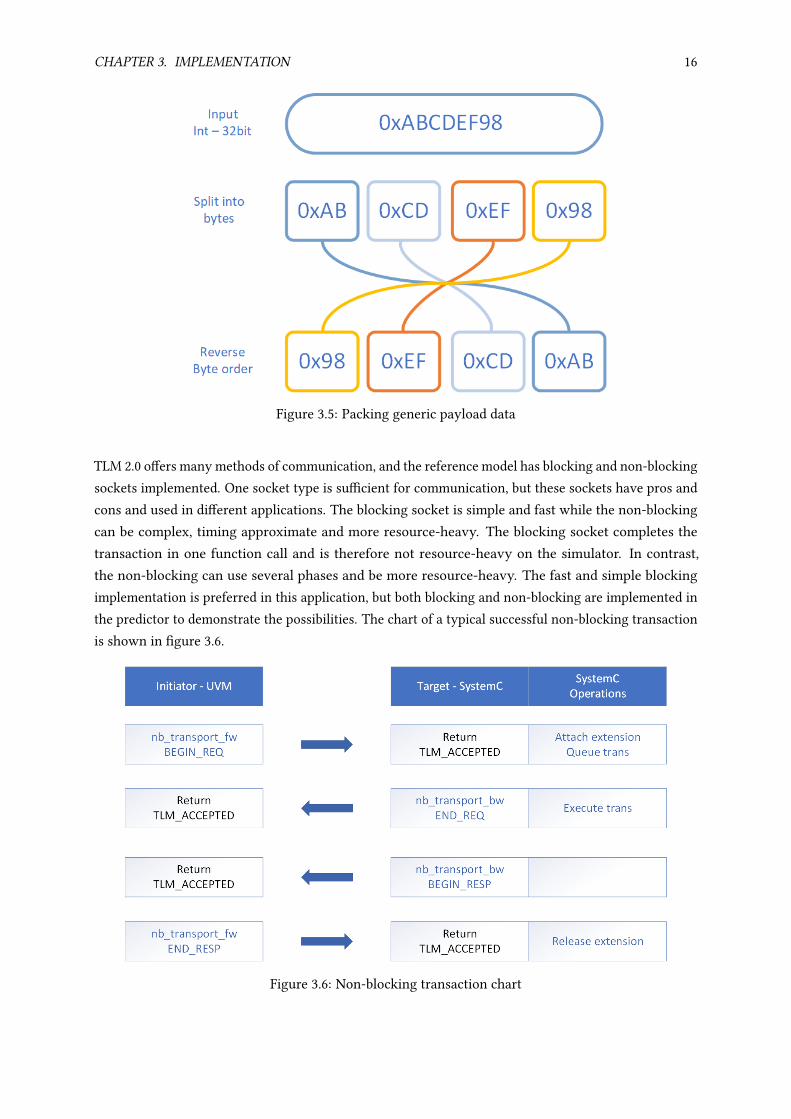
The data attribute in the generic payload is a byte array, and the data in a testbench is rarely this formatfor practical reasons. A transformation is needed to match the testbench data to the m_data[] genericpayload attribute. The data in this testbench is a 32-bit int and the first transformation performed isdividing the int into 4 bytes with the SystemVerilog streaming operator "»". The bytes is then switchedto reverse order since SystemC reads the bytes from left to right. The transformation is done in twosteps and shown in the figure 3.5 below. The data returned from SystemC has its byte order switch backto be comparable.
CHAPTER 3. IMPLEMENTATION 16
Figure 3.5: Packing generic payload data
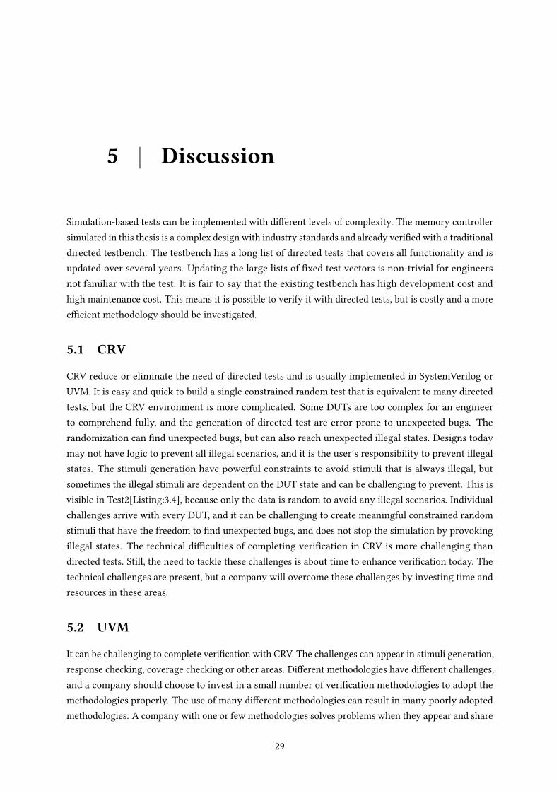
TLM 2.0 offers many methods of communication, and the reference model has blocking and non-blockingsockets implemented. One socket type is sufficient for communication, but these sockets have pros andcons and used in different applications. The blocking socket is simple and fast while the non-blockingcan be complex, timing approximate and more resource-heavy. The blocking socket completes thetransaction in one function call and is therefore not resource-heavy on the simulator. In contrast,the non-blocking can use several phases and be more resource-heavy. The fast and simple blockingimplementation is preferred in this application, but both blocking and non-blocking are implemented inthe predictor to demonstrate the possibilities. The chart of a typical successful non-blocking transactionis shown in figure 3.6.
Figure 3.6: Non-blocking transaction chart

CHAPTER 3. IMPLEMENTATION 17
The blue arrow represents a function call and can either be in the forward direction or the backwardsdirection. In this protocol, TLM_ACCEPTED is returned to proceed the transaction and TLM_COMPLETED
is returned to terminate the transaction early. If TLM_ACCEPTED is always returned, the transactionstops after the fourth phase, which is the end response. This means TLM_COMPLETED is not needed tocomplete a transaction, but can terminate a completed transaction. The reference model has severalsockets for different access types and uses an extension on the generic payload to specify which socketthe transaction was sent through. An APB and AHB have both address and data, but it is important todifferentiate that one sends data to registers and one to memory.
More detailed information about the transaction can be found in the generic payload transaction object.The generic payload m_response_status attribute shown in the attributes table above 3.2 has severalstates that can be used to determine what to do next. The possible states are shown in table 3.3.
Table 3.3: List of possible response status
UVM TLM generic payload response statusOK_RESPONSE Bus operation completed successfullyINCOMPLETE_RESPONSE Transaction was not delivered to targetGENERIC_ERROR_RESPONSE Bus operation had an errorADDRESS_ERROR_RESPONSE Invalid address specifiedCOMMAND_ERROR_RESPONSE Invalid command specifiedBURST_ERROR_RESPONSE Invalid burst specifiedBYTE_ENABLE_ERROR_RESPONSE Invalid byte enabling specified
The default state is INCOMPLETE_RESPONSE, and the target should only change the state. If the trans-action has status OK_RESPONSE, the target has completed the transaction and the transaction can insome cases end early with TLM_COMPLETED. An error will in many scenarios stop the simulation, but forexample, theADDRESS_ERROR_RESPONSE can be solved by terminating the transaction and send a transaction withdifferent address instead. Implementing different solutions to different errors can make a robust simula-tion.
3.2.4 UVM Connect
UVM Connect connects the SystemC model with UVM in a relatively straightforward process. Thesockets are compiled separately, but with a look up string to later connect them during the link phase.The AHB transactions are sent through the socket called data_socket, and APB transactions are sentthrough the socket called config_socket. SystemC implement target sockets using the tlm.h library withthe following code:tlm_utils :: simple_target_socket <memctrl , DATA_BUSWIDTH > data_socket;
This target socket in SystemC can be used as blocking or non-blocking by registering local call-backfunctions for data interface:data_socket.register_b_transport(this , &memctrl :: data_b_transport);
data_socket.register_nb_transport_fw(this , &memctrl :: data_nb_transport_fw);

CHAPTER 3. IMPLEMENTATION 18
The SystemC data socket is registered in UVM Connect using the uvmc.h library. The last argument is alookup string used for connecting the socket to the UVM socket.
uvmc_connect(mem.data_socket ," data_trans ");
The UVM predictors implement blocking and non-blocking initiator sockets with:
uvm_tlm_b_initiator_socket #() data_socket;
uvm_tlm_nb_initiator_socket #( ahb_predictor) nb_data_socket;
The sockets in the UVM predictors are registered in UVM Connect with identical lookup strings tothe corresponding SystemC socket. Only one of the sockets should be instantiated, either blocking ornon-blocking.
uvmc_tlm #():: connect(m_ahb_pred.nb_data_socket , "data_trans ");
uvmc_tlm #():: connect(m_ahb_pred.data_socket , "data_trans ");
Above is the description of connecting the data socket for AHB and similar is implemented for the APBconfig socket.
3.2.5 Scoreboard
Each predictor broadcast two generic payloads through two uvm_analysis_port and the scoreboardreceive these through four uvm_analysis_imp. Four queues implemented as FIFOs are used to storethe incoming transactions. The APB transactions are compared when the queues with the actualresponse from the DUT and expected response from the reference model are not empty, and similarwith AHB.
The scoreboard ensures correct functionality on a high-level and have no information about low-levelspecific protocol execution or RTL behavior. Assertions check the RTL behaviour and a protocol checkerchecks the protocol. The UVCs includes protocol checkers that monitors the interface and signalsan error if an error occurs, similar to assertions. The generic payload is only a summary of the realtransaction, but it is enough to say if the functionality is correct.
The desired number of AHB and APB transactions generated and compared is stored in the UVMconfiguration database and retrieved by the scoreboard. If the number of transactions is above zero,the scoreboard raises an objection that prevents the simulation from ending before all transactionsintended is compared. The scoreboard is almost always tailored towards the test and the DUT, and thusnot entirely reusable. The implementation of the scoreboard is presented in appendix A.3.
3.2.6 Code generator
The UVM structure is made with Easier UVM code generator by Doulus and includes generation of files,components, the connection between components and an initial script to run the simulation. EasierUVM gave the project a flying start, and a code generator should always be considered when starting aUVM project. The result of a company encourage engineers to use this technology are many testbencheswith similar structure. This will enable fast cooperation as every engineer is comfortable with thestructure. The files and generated structure is shown below in figure 3.7.

CHAPTER 3. IMPLEMENTATION 19
Top environment
top_env.sv
top_seq_lib.sv
top_config.sv
top_test_pkg.sv
Top test bench
top_tb.sv
top_th.sv
Top test
top_test.sv
top_test_pkg.sv
Figure 3.7: Initial structure
The initial structure has built a solid foundation were more components can be added. The "Topenvironment" is where the UVM components belong and the "Top testbench" is where the RTL modelsbelong. The "Top test" wraps "Top environment" and can instantiate different configurations of theenvironment and start different tests. The package files is used to decide what files are compiled andmarked with "pkg.sv" in the file name. "top_env.sv" is the only UVM environment in this test and allthe UVM components are instantiate here. "top_seq_lib.sv is a virtual sequence that generates othersequences, AHB and APB sequences in this case. Details about the virtual sequencer is described later insection 3.3. "top_config" is a UVM object that has interfaces and variables that can be accessed globallythrough the UVM config database.
The UVCs are instantiated in "top_env.sv", the RTL models is instantiated in "top_th.sv". Stimuli cannow be generated in the virtual sequencer to exercise the DUT, but we need additional componentsto complete the test environment. The predictors are developed as described in section 3.2.2 andinstantiated in "top_env.sv". Similar with the scoreboard, it is developed as described in section 3.2.5and instantiated in "top_env.sv". The DUT is a memory controller, and the memory it is controlling isan RTL flash memory model from one of Nordic Semiconductors vendors. It is 1MB in size and is acomplex memory model with many features. A power and clock module from Nordic Semiconductor isinstantiated to control the supply of power and clock. It will ensure low power consumption by turningoff the supply when not needed. top_seq_lib.sv is a virtual UVM sequence and is used to generateAHB and APB sequences. The virtual sequencer is described in the next section. The overview of thecomplete structure is shown in figure 3.8.

CHAPTER 3. IMPLEMENTATION 20
Top environment
top_env.sv
top_seq_lib.sv
top_config.sv
top_test_pkg.sv
APB UVC
apb_predictor.sv
AHB UVC
ahb_predictor.sv
scoreboard.sv
Top test bench
top_tb.sv
top_th.sv
DUT
Power and clock
Flash memory
Top test
top_test.sv
top_test_pkg.sv
Figure 3.8: Complete structure
The code generator accelerated the development and implemented best practices. Writing the structuremanually would be time-consuming and error-prone. The SystemC model is in another folder and iscompiled separately, but connects through UVM Connect in the link stage. The block scheme of thestructure with the SytemC model, UVM and the DUT is shown in figure 3.9
Figure 3.9: Complete block scheme
The constrained random stimuli are generated in the virtual sequencer and simulated on the DUT. It

CHAPTER 3. IMPLEMENTATION 21
generates two types of stimuli, APB transactions to the configuration registers and AHB transaction tothe flash memory. The test is complete when the DUT’s features have been exercised thoroughly, andthis is measured by the coverage. The predictors receive the executed transactions from the UVCs andsimulate them on the reference model and uses the response to produce the expected response. Theresponses in this test are the APB and AHB read transactions. Both the expected response and the actualresponse are sent to the scoreboard for comparison.
3.3 Tests
The CONFIG register in the memory controller can be read and written to, and it has three states thateither enable read(state 0), write(state 1) or erase(state 2) of flash memory. This means a random stimulimust be constrained only to write 0, 1 or 2 to the register. The ERASE_ALL register in the memorycontroller is a write-only register. The flash memory is erased when 1 is written to the ERASE_ALLregister, and erase is enabled in the CONFIG register. This means random stimuli must be constrainedonly to write if the address is the ERASE_ALL register. The constraints on the APB stimuli to preventillegal stimuli are:
1 rand bit [DATA_BUS_WIDTH -1:0] data;
2 rand bit [ADDR_WIDTH -1:0] addr;
3 rand bit pwrite; // 1 -> WRITE , 0 -> READ
4
5 constraint c_addr {
6 addr inside { CONFIG_REG , ERASE_ALL_REG };
7 }
8 constraint c_data {
9 data inside { 'h0, 'h1, 'h2};
10 }
11 // Constraint to not read from ERASE_ALL_REG , only write
12 constraint c_pwrite {
13 addr inside {ERASE_ALL_REG} -> pwrite == 1;
14 }
Listing 3.1: APB constraints to prevent illegal transactions
With the constraints mentioned above, an exhaustive constrained random test can be performed onthe registers. Test1 creates a desired number of stimuli with the following code in the virtual se-quencer:
1 begin // APB - SEND RANDOM READ/WRITE TRANS //
2 apb_rand_seq=apb_transfer #(32 ,32):: type_id :: create("apb_rand_seq");
3 for(int i = 0; i < NUM_APB_TRANS; i++) begin
4 if ( !apb_rand_seq.randomize () )
5 `uvm_error(get_type_name (), "Failed to randomize sequence")
6 apb_rand_seq.start(m_apb_uvc_agent.sqr , this);
7 end
8 end
Listing 3.2: Test1: Constrained random APB sequences

CHAPTER 3. IMPLEMENTATION 22
The range of possible input combinations to the ERASE_ALL and CONFIG registers are small andsimulating some constrained random sequences could test all combinations, but the coverage shouldconfirm this. Constraints can easily be added to target functionality with the following addition to therandomization:
1 if ( !apb_rand_seq.randomize ()
2 with {apb_rand_seq.addr = CONFIG_REG ;})
Listing 3.3: Adding a constraint to target functionality
Constraining the randomization can be important in large tests to target functionality. Test1 exercisea small part of the DUT and the Questa verification tool recorded only 24% code coverage. It is easyto apply efficient constrained random stimuli to the registers since they can be accessed at any time.The flash memory is more difficult to access because there are many illegal scenarios. The operationsallowed are: Read from memory if the read is enabled, write to the flash memory if write is enabled andthe memory location is erased, erase memory if erase is enabled. The reference model have not modelledillegal transactions, and performing these illegal transactions can result in unpredictable behaviour. Thescoreboard could ignore illegal transactions if the reference model recognized the illegal transactionsand flagged them. The specification sheet lists legal transactions, and it is up to the user to avoid illegaltransactions that could lead to unpredictable behaviour. The restrictions of legal flash transactionsresults in a manual made test where only the AHB data is random. Test2 tests the memory controllerand the flash memory with the following virtual sequence:
1 begin // APB - ERASE ALL AND ENABLE WRITE //
2 apb_write_seq=apb_write_transfer #(32 ,32):: type_id :: create("apb_write_seq");
3 apb_write_seq.ta_enable_erase(m_apb_uvc_agent.sqr);
4 apb_write_seq.ta_erase_all(m_apb_uvc_agent.sqr);
5 apb_write_seq.ta_enable_write(m_apb_uvc_agent.sqr);
6 end
7
8 begin // AHB - SEND WRITE TRANS //
9 ahb_write_seq = ahb_write_sequental_reg #(32):: type_id :: create("ahb_write_seq");
10 if ( !ahb_write_seq.randomize () )
11 `uvm_error(get_type_name (), "Failed to randomize sequence")
12 ahb_write_seq.start(m_ahb_agent.sqr , this);
13 end
14
15 begin // APB - ENABLE READ //
16 apb_write_seq.ta_enable_read(m_apb_uvc_agent.sqr);
17 end
18
19 begin // AHB - SEND READ TRANS //
20 ahb_read_seq = ahb_read_sequental_reg #(32):: type_id :: create("ahb_read_seq");
21 if ( !ahb_read_seq.randomize () )
22 `uvm_error(get_type_name (), "Failed to randomize sequence")
23 ahb_read_seq.start(m_ahb_agent.sqr , this);
24 end
Listing 3.4: Test2: AHB and APB sequences with only random AHB data
The first sequence created is apb_write_seq, which has pre-defined tasks for specific transactions. The

CHAPTER 3. IMPLEMENTATION 23
three first APB transactions are started by tasks and enable erase, erase all flash-memory and enablewrite. The next sequence created is ahb_write_sequental_reg, and this sequence writes random datato a pre-defined number of addresses. The address is incremented to prevent two writes to an address.Writing multiple times to a memory address without erasing results in corrupted data not modelledby the reference model. Simulating such transactions will provoke error that is not caused by a bug,but user error. The next sequence simulated is an APB sequence started by a task and enable read fromflash memory. The following sequence created is ahb_read_sequental_reg, and this sequence readsdata from the addresses previously written to. The stimuli from Test2 resulted in 42% code coverage,meaning a lot of the DUT is still not exercised, but this is expected as the reference model has only thebasic functionality of the DUT.
Test2 consist mostly of determined tests testing specific functionality and is similar to the existingtraditional testbench with directed tests. Adding sequences to reach specific coverage will inherit someof the same weaknesses of a directed test. Instead of developing manual tests, the reference modelshould be developed to have the same functionality as the DUT and flag illegal transactions. The virtualsequencer could then be reduced to constrained random APB and AHB sequences:
1 fork
2 begin
3 APB_SEQ=apb_transfer #(32 ,32):: type_id :: create("APB_SEQ");
4 for(int i = 0; i < NUM_APB_TRANS; i++) begin
5 if ( !APB_SEQ.randomize () )
6 `uvm_error(get_type_name (), "Failed to randomize sequence")
7 APB_SEQ.start(m_apb_uvc_agent.sqr , this);
8 end
9 end
10
11 begin
12 AHB_SEQ = ahb_transger #(32):: type_id :: create("seq");
13 for(int i = 0; i < NUM_AHB_TRANS; i++) begin
14 if ( !AHB_SEQ.randomize () )
15 `uvm_error(get_type_name (), "Failed to randomize sequence")
16 AHB_SEQ.start(m_ahb_agent.sqr , this);
17 end
18 end
19 join
Listing 3.5: Test3: Constrained random APB and AHB sequences
Test3 is not simulated, but is an example of a test that can be performed with an adequate referencemodel and test environment. Test3 create constraint random APB and AHB sequences in two concurrentprocesses.

CHAPTER 3. IMPLEMENTATION 24
3.4 Makefile
The makefile of a multi-language environment can be complex and an obstacle for engineers new tothe technology and methodology. The engineer will eventually become comfortable with the makefileas test environments have a similar structure. Executing "make all" will delete old files, compile, link,optimize and simulate. A summary and description of the makefile is shown below in listing 3.6.
1 all: clean comp sccom vopt qsim
2
3 # comp sccom vopt qsim are operations from Mentor 's Questasim verification tool
4
5 comp:
6 # create work folder
7 vlib work
8
9 # vlog compiles SystemVerilog and UVM
10 # files.f specify UVM and SystemVerilog files for compilation
11 # +define+NON_BLOCKING_TRANSPORT or +define+BLOCKING_TRANSPORT compilation flag
decide TLM socket technology
12 vlog -f ../ files.f -sv +define+BLOCKING_TRANSPORT
13
14 sccom:
15 # sccom compiles SystemC
16 sccom
17
18 # include SystemC library and UVM Connect
19 I../ systemc/sys_lib/src/connect/sc
20
21 # include SystemC source file s
22 -I ref_model/src
23
24 # compile cpp files
25 all_cpp_files ,cpp
26
27 # link the registered SystemC sockets with registered UVM sockets
28 sccom -link -uvmc -lib work
29
30 vopt:
31 # vopt optimize design and enable coverage collection
32 vopt sc_main top_tb -o DesignOpt +cover=sbecft
33
34 qsim:
35 # vsim starts the simulation
36 vsim -64 -gui DesignOpt $(UVMC_LIB) -l questa.log
37
38 clean:
39 rm -rf work $(designfile) $(wavefile) UVM_MESSAGES
40 mkdir UVM_MESSAGES
Listing 3.6: Summary and description of the makefile
Controlling tests from the makefile can be a useful abstraction. The choice between blocking and non-

CHAPTER 3. IMPLEMENTATION 25
blocking communication between SystemC and UVM is controlled with a compilation flag. Implementingvariables in the makefile reduced knowledge acquired of the testbench to operate it. The engineer cancontrol the variable from the makefile without the need of modifying the complex testbench.

4 | Results
Simulation with UVM and SystemC was successfully demonstrated. The functionality tested was limitedby the reference model’s lack of functionality, and only 42% code coverage was reached. Adding morefunctionality to the reference model would enable greater coverage and completeness.
The system developed enabled the SystemC reference model to provide the expected response fromthe DUT. One key component developed are the predictors that predicts the expected response withthe use of the reference model. It is not the exact transaction that the DUT received, but a high-levelrepresentation of the transaction with data and address. The predictor was developed to be reusable inother tests and demonstrate the possibilities with both blocking and non-blocking TLM2.0 sockets. Thescoreboard was explicitly designed for this test and succeeded in comparing the response from the DUTand the reference model. This thesis is the first large scale simulation of SystemC and UVM at NordicSemiconductor, and provides the groundwork that this methodology can be used in verification.
The SystemC model was successfully compiled and simulated, but with some obstacles, because it wasnot compatible with the verification tool. It was designed with different gcc compiler and SystemClanguage version than what was available in the verification tool. Future SystemC models must beimplemented with compatibility to all tools. The SystemC model was not specifically designed to becompatible with the verification tool, and a lot of time were used to modify it, so it compiled andsimulated. UVM is a well-established technology and compiled without many obstacles. The verificationtool was generous about giving UVM information in compilation and simulation. However, SystemCinformation were sometimes misguiding or non-existing. The use of the SystemC reference model canbe time-consuming when not correctly adapted to tools. The methodology can be efficient in performingfunctional verification, but obstacles as SystemC adaptation can limit the efficiency.
A factor in deciding verification methodology is the implementation time. The DUT was previouslyverified with a traditional directed test that uses 3500 lines to implement test vectors. Removing the needto write enormous lists is a motivation to adopt CRV and reduce implementation time. In Test3[Listing:3.5], 19 code lines is enough to create a test with constrained random APB and AHB sequence when thereference model is adequate and can replace many directed tests. However, this test requires a largeeffort made in the test environment. The reason this is still a promising methodology is the fact thata lot of the environment is reusable or automatically generated. Chapter 3.2.6 about code generationdemonstrates how to give the any UVM development a flying start. The structure is standardized andenable effective cooperation. UVM and CRV can drastically decrease development time of test structureand test generation, and a SystemC model should give no extra implementation time as it should alreadyexist.
26

CHAPTER 4. RESULTS 27
A simple method of calculating implementation time is counting the number of code lines written. Table4.1 shows the approximate number of code lines in the files. 100% percentage written means I wrote itmyself, 50% means the code generator wrote some of it and 0% means it is reused.
Table 4.1: Code lines and implementation time
Percentage written File(s) Code lines100% apb_predictor.sv 220100% ahb_predictor.sv 220100% scoreboard.sv 16050% top_env.sv 14050% top_seq_lib.sv 11550% top_config.sv 3050% top_tb.sv 5050% top_th.sv 44050% top_test.sv 2050% pkg 450% APB UVC 27000% AHB UVC 23000% SystemC 900
The number of code lines multiplied with the percentage gives approximately the code lines written byme. I have written 1000 of the total 7200 lines, or 86%. A project similar to this project can reuse thepredictors and achieve even lower implementation time with 92% reuse. A low implementation time ispossible with UVM, code generator and reusable components.
Another factor in deciding verification methodology is the simulation time. Simulation time is a limitingfactor in simulation-based verification. The test environment in traditional directed test are usuallysimple, and the DUT’s complexity is the main contributor for high simulation time. UVM has aninfrastructure more significant than a traditional directed test and also a SystemC reference model tosimulate, this means a slightly higher simulation time is expected. UVM and SystemC use transaction-level communication that are many times faster than RTL simulation. UVM and SystemC could usemore simulation resources than a traditional directed test, but the DUT is the main contributor to thesimulation time. A more significant reason for the rise in simulation time with this methodology isthat CRV would increase the number of test vectors needed for completeness. Measures to decreasethe number of test vectors required are presented in the background chapter, but would still not be asefficient as manual made test vectors. Figure 4.1 shows how many minutes to compile and simulateTest2 with different amounts of test vectors. Different transactions use different simulate time, andthe APB erase all transaction has the highest simulation time. The x-axis shows how many AHB readand write are performed. Ten thousand on the x-axis include four APB transactions, 5000 AHB writetransactions and 5000 AHB read transactions. The y-axis shows the time in minutes.

CHAPTER 4. RESULTS 28
0 0.2 0.4 0.6 0.8 1·104
0
1
2
3
4
5
6
Number of transactions
Time[m
in]
Figure 4.1: Time to complete Test2 with different number of transactions
Many thousands of transactions can be simulated in a couple of minutes on the Nordic Semiconductorsservers and can quickly achieve exhausting testing of a small system. Simulating complex SoC cansignificantly increase the simulation time as each transaction takes longer to simulate, and the test needsmore test vectors to test all sub-components. Features discussed in the background as high-qualityreusable tests, novel test detection and constraints adjustment can reduce simulation time and achievehigher coverage.
5 | Discussion
Simulation-based tests can be implemented with different levels of complexity. The memory controllersimulated in this thesis is a complex design with industry standards and already verified with a traditionaldirected testbench. The testbench has a long list of directed tests that covers all functionality and isupdated over several years. Updating the large lists of fixed test vectors is non-trivial for engineersnot familiar with the test. It is fair to say that the existing testbench has high development cost andhigh maintenance cost. This means it is possible to verify it with directed tests, but is costly and a moreefficient methodology should be investigated.
5.1 CRV
CRV reduce or eliminate the need of directed tests and is usually implemented in SystemVerilog orUVM. It is easy and quick to build a single constrained random test that is equivalent to many directedtests, but the CRV environment is more complicated. Some DUTs are too complex for an engineerto comprehend fully, and the generation of directed test are error-prone to unexpected bugs. Therandomization can find unexpected bugs, but can also reach unexpected illegal states. Designs todaymay not have logic to prevent all illegal scenarios, and it is the user’s responsibility to prevent illegalstates. The stimuli generation have powerful constraints to avoid stimuli that is always illegal, butsometimes the illegal stimuli are dependent on the DUT state and can be challenging to prevent. This isvisible in Test2[Listing:3.4], because only the data is random to avoid any illegal scenarios. Individualchallenges arrive with every DUT, and it can be challenging to create meaningful constrained randomstimuli that have the freedom to find unexpected bugs, and does not stop the simulation by provokingillegal states. The technical difficulties of completing verification in CRV is more challenging thandirected tests. Still, the need to tackle these challenges is about time to enhance verification today. Thetechnical challenges are present, but a company will overcome these challenges by investing time andresources in these areas.
5.2 UVM
It can be challenging to complete verification with CRV. The challenges can appear in stimuli generation,response checking, coverage checking or other areas. Different methodologies have different challenges,and a company should choose to invest in a small number of verification methodologies to adopt themethodologies properly. The use of many different methodologies can result in many poorly adoptedmethodologies. A company with one or few methodologies solves problems when they appear and share
29

CHAPTER 5. DISCUSSION 30
them so coworkers can use the solutions. It is up to the company to enable advanced methodologiessince it can be too much for a few persons to solve all challenges in a reasonable amount of time. UVM isa new promising standard verification methodology that is built on SystemVerilog and implements bestpractises. Company guidelines enhances the benefits from the use of a standard methodology. UVM has alot of freedom in implementation, but UVM with strict company guidelines enables efficient cooperationbetween coworkers because many test environments are similar. These test environments will arguablybe improved after each project as engineers find smart solutions and share with coworkers.
Some downsides of UVM is complexity and expensive training. SystemVerilog can indeed provideall features an engineer need. The transition from SystemVerilog to UVM is arguably not worth theresources spent if only a small percentage of verification engineers do the transition. The result then isjust more unique testbenches with unique problems. The goal should be to standardize the verificationmethodology used in the company. Also, the simulation time can be expected to grow since thetest environments are more resource-heavy, and more test vectors are maybe required to completeverification. Both implementation time and simulation time are important in reaching the requiredverification time.
UVM did not invent reuse, but enhances it. The UVCs used in this thesis provoked no challenges, butthat was after some trial and error with bad UVCs. At the start of this thesis, no standard AHB or APBwere made at nordic and the first I tried lacked features, had no documentation and I had to read throughall of the code to understand if I could use it or not. The difference between an excellent reusable UVCand a bad UVC are huge. One reduces the implementation time, and one increases implementation time.This is one more example of a whole company must make verification efficient together as a team, andremove time-consuming tasks.
Starting with UVM is a daunting process where object-oriented programming and polymorphism isessential, and a whole bunch of standard classes must be understood. However, arguably all the standardclasses are intuitive, and the best-practise classes are already made, so the object-oriented part arefeasible to learn. The tedious process of making the large infrastructure needed to simulate anything ismade easy with code generators, and make UVM usable for everyone. A lot of investment is needed tobe efficient in UVM.
Several techniques of enabling CRV with automatic checking are possible, a high-level model or registermodel are the most used. UVM register models are simple and can be the most efficient when modellingDUTs with registers. The DUT in this thesis could be modelled with a register model and predictor toproduce expected result. This would be efficient in is this scenario, but this thesis is investigating theSystemC technology and not the DUT. A company that uses SystemC and UVM in verification can alsouse other setups as register models and directed testing where it is efficient. However, a lot must beinvested in the technology presented in this thesis to make it efficient, and it would then make sense touse it widely across the company.
5.3 SystemC
Of the CRV challenges are the prediction of the response the most challenging. A high-level modelcan be implemented in various languages, as described in chapter 2.2.5. They have different challenges

CHAPTER 5. DISCUSSION 31
and opportunities. SystemC is arguably the most challenging and most rewarding solution. It is mostrewarding because it can be used in many design phases by different groups. It has unique hardwaremimicking opportunities that can perform functional verification.
The SystemC model compiled easily with the gcc compiler it was designed for, but was a challenge tocompile in the verification tool. The model was developed with different language and compiler versionsthan available in the verification tool, and it was developed without the intended use in mind. It is acomplex task to compile the SystemC model that includes c++, SystemC, TLM2.0 and UVM Connect. Averification tool has approximately four major updates a year, and nearly every version gave differenterrors. UVM is the main use in this verification tool and has matured, but the SystemC is a long wayfrom the same level of consistency. The SystemC compilation and simulation information was oftenmisguiding or non-existent. It gave errors on internal compiler files inaccessible by the user and couldend the simulation without error. Resources must be spent to investigate what are the possibilities onwhat versions. The SystemC technology must be matured and show consistency to be efficient. Justas the undocumented UVCs increase the implementation time, increase an undocumented SystemCmodel the implementation time. The SystemC model had documented gcc compatibility, but none ofthe verification tool versions. Again, a company must use considerable resources to make the modelusable because a verification engineer does not have time to read and understand a complex SystemCmodel.

6 | Conclusion and Future work
Developing a test with SystemC and UVM from the ground up to verify the functionality of an RTLmodelis undoubtedly a resource-heavy task for verification engineers. SystemC modelling is time-consuming,UVM development is complex and compiling and simulating together introduce different challenges.However, this thesis describes implementing tests when the use of UVM and SystemC is the standardmethodology in a company and resources are available. System architects develop SystemC modelsfor multi-purpose, reusable UVCs are available, and a standard method of compiling, simulating andachieving completeness is developed. These prerequisites are necessary to achieve completeness quickly.Companies unable to create the essential infrastructure this methodology needs, should arguably notdepend their verification on this methodology.
Nordic Semiconductor’s UVCs ensured easy and quick connection between UVM and the DUT, andmade it easy to generate stimuli in the desired protocol. UVM has matured in the company and resultedin easy use of the technology. The SystemC technology provided difficulties because it has not maturedas a technology in verification. Firstly, the model was not designed for use in verification tools, andinitial compilation was a big challenge. Secondly, the model had only the basic functionality of the DUT,making it impossible to complete the verification. The verification methodology presented in this thesisshows great promise in reducing verification time by eliminating the process of manually writing testvectors and enabling reuse. The SystemC model can be a limiting factor as a considerable amount ofresources must be invested in SystemC development to enable this methodology.
6.1 Future work
• Further develop SystemC model to complete verification of the DUT.
• Investigate the challenges and solutions to illegal scenarios in the DUT.
• Investigate coverage methods to indicate completeness.
• Investigate TLM 2.0 interoperability and easy connection to additional blocks.
• Apply novel test detection to decrease the number of test vectors.
• Implement a test database for high-quality tests.
32
Bibliography
[1] H. Foster, “Part 8: The 2018 Wilson Research Group Functional Verification Study,”https://blogs.mentor.com/verificationhorizons/blog/2019/01/29/part-8-the-2018-wilson-research-group-functional-verifi- cation-study/(visited: 6.6.2020).
[2] ——, “How do you spell UVM? Opportunities in professional development.,”https://blogs.mentor.com/verificationhorizons/blog/2020/03/31/how-do-you-spell-uvm-opportunities-in-professional-development/ (visited: 19.05.2020).
[3] A. S. Initiative, “Portable Stimulus Working Group,”https://www.accellera.org/activities/working-groups/portable-stimulus(visited: 19.05.2020).
[4] “Novel test detection to improve simulation efficiency — a commercial experiment,” IEEE 6386595,Dec. 2012.
[5] Doulos, “What is SystemVerilog?,”https://www.doulos.com/knowhow/sysverilog/whatissv/ (visited: 6.6.2020).
[6] A. S. Initiative, “Universal Verification Methodology,”https://www.mentor.com/products/fv/uvm (visited: 19.05.2020).
[7] A. standards, “UVM,”https://www.accellera.org/downloads/standards/uvm (visited: 19.05.2020).
[8] M. Graphics, “Universal Verification Methodology (UVM),”https://www.mentor.com/products/fv/uvm (visited: 19.05.2020).
[9] ——, “UVM Connect,”https://www.mentor.com/products/fv/multimedia/uvm-connect(visited: 19.05.2020).
[10] Doulus, “Easier UVM,”https://www.doulos.com/content/events/easierUVM.php (visited: 19.05.2020).
[11] “Ieee standard for standard systemc language reference manual,” IEEE Std 1666-2011 (Revision of
IEEE Std 1666-2005), pp. 1–638, 2012.
33
BIBLIOGRAPHY 34
[12] A. standards, “SystemC and TLM2.0,”www.accellera.org/downloads/standards/systemc (visited: 19.05.2020).
[13] Accellera, “Virtual System Platform,”https://www.cadence.com/en_US/home/tools/system-design-and-verification/software-driven-verification/virtual-system-platform.html (visited: 19.05.2020).
[14] Cadence, “Cadence Virtual System Platform virtual prototyping solution,”https://www.cadence.com/en_US/home/tools/system-design-and-verification/software-driven-verification/virtual-system-platform.html (visited: 19.05.2020).
[15] S. Swan, “Systemc transaction level models and rtl verification,” IEEE 1688767, Jul. 2006.
[16] A. Moursi, R. Samhoud, Y. Kamal, M. Magdy, S. El-Ashry, and A. Shalaby, “Different referencemodels for uvm environment to speed up the verification time,” IEEE 8746056, Dec. 2018.

A | Source code
1 import uvm_pkg ::*;
2
3 class ahb_predictor extends uvm_component;
4 `uvm_component_utils (ahb_predictor)
5
6 // - output port with the actual DUT response - //
7 uvm_analysis_port #( uvm_tlm_gp) broadcast_AHB_actual;
8
9 // - output port with the expected refence response - //
10 uvm_analysis_port #( uvm_tlm_gp) broadcast_AHB_expected;
11
12 // - input port with UVC trans - //
13 uvm_analysis_imp #(ahb_item , ahb_predictor) imp_trans;
14
15 // - sockets to connect to SC - //
16 `ifdef NON_BLOCKING_TRANSPORT
17 uvm_tlm_nb_initiator_socket #( ahb_predictor) nb_data_socket;
18 `endif
19 `ifdef BLOCKING_TRANSPORT
20 uvm_tlm_b_initiator_socket #() data_socket;
21 `endif
22
23 uvm_tlm_gp trans_ahb_queue[$];
24 bit sc_is_ready = 1;
25 bit end_resp_phase;
26 virtual in_ahb vif;
27 top_config m_config;
28
29 function new (string name = "ahb_predictor", uvm_component parent= null);
30 super.new (name , parent);
31 broadcast_AHB_actual = new("broadcast_AHB_actual", this);
32 broadcast_AHB_expected = new("broadcast_AHB_expected", this);
33 imp_trans = new("imp_trans", this);
34
35 `ifdef BLOCKING_TRANSPORT
36 data_socket = new("data_socket", this);
37 `endif
38 `ifdef NON_BLOCKING_TRANSPORT
39 nb_data_socket = new("nb_data_socket", this);
40 `endif
35

APPENDIX A. SOURCE CODE 36
41
42 endfunction
43
44
45 virtual function void build_phase(uvm_phase phase);
46 super.build_phase(phase);
47 `uvm_info(get_type_name (), "..is alive!", UVM_DEBUG)
48
49 if (! uvm_config_db #( top_config)::get(this , "", "m_config", m_config))
50 `uvm_error(get_type_name (), "ahb config not found")
51
52 if(m_config != null) begin
53 if(m_config.ahb_vif != null) begin
54 $cast(vif , m_config.ahb_vif);
55 end
56 end
57
58 endfunction
59
60 `ifdef NON_BLOCKING_TRANSPORT
61 virtual function uvm_tlm_sync_e nb_transport_bw( uvm_tlm_gp data_trans , ref
uvm_tlm_phase_e ph, uvm_tlm_time delay);
62
63 if(ph == END_REQ) begin
64 `uvm_info(get_type_name (), $sformatf("nb_transport_bw END_REQ phase ,
return UVM_TLM_ACCEPTED"), UVM_HIGH)
65 return UVM_TLM_ACCEPTED;
66 end else if(ph == BEGIN_RESP && data_trans.is_response_ok ()) begin
67
68 if(data_trans.get_command == UVM_TLM_READ_COMMAND) begin
69 fu_reverse_byte_order(data_trans);
70 broadcast_AHB_expected.write(data_trans);
71 end
72
73 end_resp_phase = 1;
74 return UVM_TLM_ACCEPTED;
75 end
76
77 `uvm_error(get_type_name (), $sformatf("ERROR , incorrect state with phase: %
s, and response %s.", ph, data_trans.get_response_string ()))
78
79 endfunction
80 `endif
81
82 // - RECEIVE COMPLETED TRANS FROM APB UVC MONITOR - //
83 virtual function void write(ahb_item trans);
84 uvm_tlm_gp gp_to_ref_model = new;
85 uvm_tlm_gp gp_to_scrb = new;
86 uvm_tlm_gp t_copy = new;
87
88 bit is_write;
89 is_write = trans.ahbHWrite;

APPENDIX A. SOURCE CODE 37
90
91 // if WRITE transactions make generic payload for ref model
92 if(is_write == 1) begin
93 fu_set_gp_for_ref_model(trans , gp_to_ref_model);
94
95 // else if READ transactions make seperate generic payloads for ref model and
scoreboard
96 end else if (is_write == 0) begin
97 fu_set_gp_for_ref_model(trans , gp_to_ref_model);
98 fu_set_gp_for_scrb(trans , gp_to_scrb);
99 broadcast_AHB_actual.write(gp_to_scrb);
100 end else begin
101 `uvm_error(get_type_name (), "apb trans not read or write")
102 end
103
104 // Systemc has different endian
105 fu_reverse_byte_order(gp_to_ref_model);
106 trans_ahb_queue.push_back(gp_to_ref_model);
107 `uvm_info(get_type_name (), $sformatf("TRANS QUEUED = %s ;", gp_to_ref_model.
convert2string ()), UVM_DEBUG)
108 endfunction
109
110 function void fu_reverse_byte_order(uvm_tlm_gp data_trans);
111 byte unsigned temp_data [];
112 int reverse;
113
114 data_trans.get_data(temp_data);
115 reverse = {<<8{ temp_data }};
116 temp_data = {>>{reverse }};
117 data_trans.set_data(temp_data);
118 endfunction
119
120 // - set generic payload attributes to be sendt to ref model - //
121 function void fu_set_gp_for_ref_model(ahb_item ahb_trans , uvm_tlm_gp gp_trans);
122 bit [127:0] bit_data;
123 int int_data;
124 byte unsigned byte_data [];
125 int address;
126 bit is_write;
127
128 is_write = ahb_trans.ahbHWrite;
129 address = ahb_trans.ahbHAddr;
130
131 bit_data = {>>{ahb_trans.ahbHWData }};
132 int_data = bit_data;
133 byte_data = {>>{int_data }}; // stream data
134
135 gp_trans.set_data_length (4);
136 gp_trans.set_streaming_width (4); // = data_length to indicate no streaming
137 gp_trans.set_address(address);
138
139 if(is_write == 1) begin

APPENDIX A. SOURCE CODE 38
140 gp_trans.set_data(byte_data);
141 gp_trans.set_command(UVM_TLM_WRITE_COMMAND);
142 end else if (is_write == 0) begin
143 gp_trans.set_command(UVM_TLM_READ_COMMAND);
144 end else begin
145 `uvm_error(get_type_name (), "apb trans not read or write")
146 end
147 endfunction
148
149 // - set generic payload attributes to be sendt to scoreboard - //
150 function void fu_set_gp_for_scrb(ahb_item ahb_trans , uvm_tlm_gp gp_trans);
151 bit [127:0] bit_data;
152 int int_data;
153 byte unsigned byte_data [];
154 int address;
155
156 address = ahb_trans.ahbHAddr;
157
158 bit_data = {>>{ahb_trans.ahbHRData }};
159 int_data = bit_data;
160 byte_data = {>>{int_data }}; // stream data
161
162 gp_trans.set_data_length (4);
163 gp_trans.set_streaming_width (4); // = data_length to indicate no streaming
164 gp_trans.set_address(address);
165 gp_trans.set_data(byte_data);
166 gp_trans.set_command(UVM_TLM_READ_COMMAND);
167 gp_trans.set_response_status(UVM_TLM_OK_RESPONSE);
168 endfunction
169
170 virtual task run_phase (uvm_phase phase);
171 uvm_tlm_time delay = new;
172 uvm_tlm_gp trans_to_SC = new;
173
174 uvm_tlm_sync_e status;
175 uvm_tlm_phase_e phase1;
176
177 byte unsigned temp_data [];
178 int reverse;
179
180 forever begin
181 @(posedge vif.ckAhb);
182
183 if(end_resp_phase ==1) begin
184 `ifdef NON_BLOCKING_TRANSPORT
185 end_resp_phase = 0;
186 sc_is_ready = 1;
187 phase1 = END_RESP;
188 //`uvm_info(get_type_name (), $sformatf ("APB before nb_transport_fw
= %s.", trans_to_SC.convert2string ()), UVM_HIGH)
189 status = nb_data_socket.nb_transport_fw( trans_to_SC , phase1 ,
delay);

APPENDIX A. SOURCE CODE 39
190 `uvm_info(get_type_name (), $sformatf("after nb_data_socket = %s,
and status: %s, and data_trans.get_response_string () %s.", trans_to_SC.
convert2string (), status , trans_to_SC.get_response_string ()), UVM_HIGH)
191 `endif
192 end
193 else if(sc_is_ready == 1 && trans_ahb_queue.size() > 0) begin
194 `uvm_info(get_type_name (), $sformatf("AHB PREDICTOR STARTING TO SEND
TRANS TO SC, queue size = %x", trans_ahb_queue.size()), UVM_HIGH)
195
196 trans_to_SC = trans_ahb_queue.pop_front ();
197
198 `ifdef NON_BLOCKING_TRANSPORT
199 sc_is_ready = 0;
200 phase1 = BEGIN_REQ;
201 status = nb_data_socket.nb_transport_fw( trans_to_SC , phase1 ,
delay);
202 `uvm_info(get_type_name (), $sformatf("after nb_data_socket = %s,
and status: %s, and data_trans.get_response_string () %s.", trans_to_SC.
convert2string (), status , trans_to_SC.get_response_string ()), UVM_HIGH)
203 `endif
204
205 `ifdef BLOCKING_TRANSPORT
206 // Send transaction to SC model
207 data_socket.b_transport( trans_to_SC , delay);
208 `uvm_info(get_type_name (), $sformatf("after b_transport = %s.",
trans_to_SC.convert2string ()), UVM_HIGH)
209
210 // Brodcast READ transaction to SCOREBOARD
211 if (trans_to_SC.is_read ()) begin
212
213 // Systemc has different endian
214 fu_reverse_byte_order(trans_to_SC);
215
216 broadcast_AHB_expected.write(trans_to_SC);
217 end
218 `endif
219 end
220 end
221
222 endtask
223
224 endclass
Listing A.1: AHB predictor with both blocking and non-blocking interface implemented
1 import uvm_pkg ::*;
2
3 class ahb_predictor extends uvm_component;
4 `uvm_component_utils (ahb_predictor)
5
6 // - output port with the actual DUT response - //
7 uvm_analysis_port #( uvm_tlm_gp) broadcast_AHB_actual;
8

APPENDIX A. SOURCE CODE 40
9 // - output port with the expected refence response - //
10 uvm_analysis_port #( uvm_tlm_gp) broadcast_AHB_expected;
11
12 // - input port with UVC trans - //
13 uvm_analysis_imp #(ahb_item , ahb_predictor) imp_trans;
14
15 // - socket to connect to SC - //
16 uvm_tlm_b_initiator_socket #() data_socket;
17
18 uvm_tlm_gp trans_ahb_queue[$];
19 virtual in_ahb vif;
20 top_config m_config;
21
22 function new (string name = "ahb_predictor", uvm_component parent= null);
23 super.new (name , parent);
24 broadcast_AHB_actual = new("broadcast_AHB_actual", this);
25 broadcast_AHB_expected = new("broadcast_AHB_expected", this);
26 imp_trans = new("imp_trans", this);
27 data_socket = new("data_socket", this);
28 endfunction
29
30 virtual function void build_phase(uvm_phase phase);
31 super.build_phase(phase);
32 `uvm_info(get_type_name (), "..is alive!", UVM_DEBUG)
33
34 if (! uvm_config_db #( top_config)::get(this , "", "m_config", m_config))
35 `uvm_error(get_type_name (), "ahb config not found")
36
37 endfunction
38 // - RECEIVE COMPLETED TRANS FROM APB UVC MONITOR - //
39 virtual function void write(ahb_item trans);
40 uvm_tlm_gp gp_to_ref_model = new;
41 uvm_tlm_gp gp_to_scrb = new;
42 uvm_tlm_gp t_copy = new;
43
44 bit is_write;
45 is_write = trans.ahbHWrite;
46
47 // if WRITE transactions make generic payload for ref model
48 if(is_write == 1) begin
49 fu_set_gp_for_ref_model(trans , gp_to_ref_model);
50
51 // else if READ transactions make seperate generic payloads for ref model and
scoreboard
52 end else if (is_write == 0) begin
53 fu_set_gp_for_ref_model(trans , gp_to_ref_model);
54 fu_set_gp_for_scrb(trans , gp_to_scrb);
55 broadcast_AHB_actual.write(gp_to_scrb);
56 end else begin
57 `uvm_error(get_type_name (), "apb trans not read or write")
58 end
59
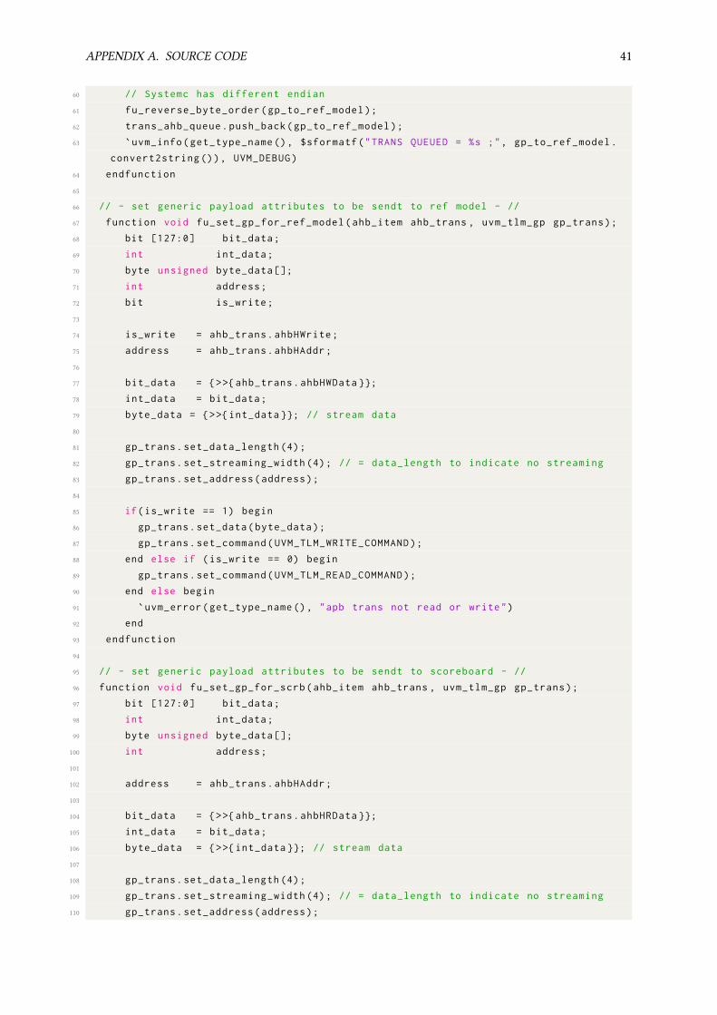
APPENDIX A. SOURCE CODE 41
60 // Systemc has different endian
61 fu_reverse_byte_order(gp_to_ref_model);
62 trans_ahb_queue.push_back(gp_to_ref_model);
63 `uvm_info(get_type_name (), $sformatf("TRANS QUEUED = %s ;", gp_to_ref_model.
convert2string ()), UVM_DEBUG)
64 endfunction
65
66 // - set generic payload attributes to be sendt to ref model - //
67 function void fu_set_gp_for_ref_model(ahb_item ahb_trans , uvm_tlm_gp gp_trans);
68 bit [127:0] bit_data;
69 int int_data;
70 byte unsigned byte_data [];
71 int address;
72 bit is_write;
73
74 is_write = ahb_trans.ahbHWrite;
75 address = ahb_trans.ahbHAddr;
76
77 bit_data = {>>{ahb_trans.ahbHWData }};
78 int_data = bit_data;
79 byte_data = {>>{int_data }}; // stream data
80
81 gp_trans.set_data_length (4);
82 gp_trans.set_streaming_width (4); // = data_length to indicate no streaming
83 gp_trans.set_address(address);
84
85 if(is_write == 1) begin
86 gp_trans.set_data(byte_data);
87 gp_trans.set_command(UVM_TLM_WRITE_COMMAND);
88 end else if (is_write == 0) begin
89 gp_trans.set_command(UVM_TLM_READ_COMMAND);
90 end else begin
91 `uvm_error(get_type_name (), "apb trans not read or write")
92 end
93 endfunction
94
95 // - set generic payload attributes to be sendt to scoreboard - //
96 function void fu_set_gp_for_scrb(ahb_item ahb_trans , uvm_tlm_gp gp_trans);
97 bit [127:0] bit_data;
98 int int_data;
99 byte unsigned byte_data [];
100 int address;
101
102 address = ahb_trans.ahbHAddr;
103
104 bit_data = {>>{ahb_trans.ahbHRData }};
105 int_data = bit_data;
106 byte_data = {>>{int_data }}; // stream data
107
108 gp_trans.set_data_length (4);
109 gp_trans.set_streaming_width (4); // = data_length to indicate no streaming
110 gp_trans.set_address(address);

APPENDIX A. SOURCE CODE 42
111 gp_trans.set_data(byte_data);
112 gp_trans.set_command(UVM_TLM_READ_COMMAND);
113 gp_trans.set_response_status(UVM_TLM_OK_RESPONSE);
114 endfunction
115
116 // - Reverse byte order of data - //
117 function void fu_reverse_byte_order(uvm_tlm_gp data_trans);
118 byte unsigned temp_data [];
119 int reverse;
120
121 data_trans.get_data(temp_data);
122 reverse = {<<8{ temp_data }};
123 temp_data = {>>{reverse }};
124 data_trans.set_data(temp_data);
125 endfunction
126
127 virtual task run_phase (uvm_phase phase);
128 uvm_tlm_time delay = new;
129 uvm_tlm_gp trans_to_SC = new;
130
131 uvm_tlm_sync_e status;
132 uvm_tlm_phase_e phase1;
133
134 byte unsigned temp_data [];
135 int reverse;
136
137 forever begin
138 @(posedge trans_ahb_queue.size());
139 if(trans_ahb_queue.size() > 0) begin
140 trans_to_SC = trans_ahb_queue.pop_front ();
141
142 // Send trans_to_SC to the Reference model
143 data_socket.b_transport( trans_to_SC , delay);
144 //`uvm_info(get_type_name (), $sformatf ("after b_transport = %s.",
trans_to_SC.convert2string ()), UVM_HIGH)
145
146 // Brodcast READ transaction to SCOREBOARD
147 if (trans_to_SC.is_read ()) begin
148
149 // Systemc has different endian
150 fu_reverse_byte_order(trans_to_SC);
151 broadcast_AHB_expected.write(trans_to_SC);
152 end
153 end
154 end
155 endtask
156 endclass
Listing A.2: AHB predictor with blocking interface implemented
1 `ifndef SCOREBOARD_SV
2 `define SCOREBOARD_SV
3

APPENDIX A. SOURCE CODE 43
4 import uvm_pkg ::*;
5 `include "uvm_macros.svh"
6
7 `uvm_analysis_imp_decl(_ahb_expected)
8 `uvm_analysis_imp_decl(_ahb_actual)
9 `uvm_analysis_imp_decl(_apb_expected)
10 `uvm_analysis_imp_decl(_apb_actual)
11
12 class scoreboard extends uvm_scoreboard;
13
14 int num_ahb_compares;
15 int num_apb_compares;
16 int num_successfull_ahb_compares;
17 int num_successfull_apb_compares;
18
19 int NUM_AHB_TRANS;
20 int NUM_APB_TRANS;
21
22 uvm_tlm_gp queue_ahb_expected[$];
23 uvm_tlm_gp queue_ahb_actual[$];
24 uvm_tlm_gp queue_apb_expected[$];
25 uvm_tlm_gp queue_apb_actual[$];
26
27 uvm_analysis_imp_ahb_expected #(uvm_tlm_gp ,scoreboard) ahb_expected;
28 uvm_analysis_imp_ahb_actual #(uvm_tlm_gp ,scoreboard) ahb_actual;
29 uvm_analysis_imp_apb_expected #(uvm_tlm_gp ,scoreboard) apb_expected;
30 uvm_analysis_imp_apb_actual #(uvm_tlm_gp ,scoreboard) apb_actual;
31
32 `uvm_component_utils(scoreboard)
33
34 uvm_phase run_ph;
35 top_config m_config;
36
37 function new(string name , uvm_component parent=null);
38 super.new(name ,parent);
39 ahb_expected = new("ahb_expected", this);
40 ahb_actual = new("ahb_actual", this);
41 apb_expected = new("apb_expected", this);
42 apb_actual = new("apb_actual", this);
43 run_ph = uvm_run_phase ::get();
44 endfunction : new
45
46 function void build_phase(uvm_phase phase);
47 `uvm_info(get_type_name () ,"Building scoreboard", UVM_MEDIUM)
48
49 if (! uvm_config_db #( top_config)::get(this , "", "m_config", m_config))
50 `uvm_error(get_type_name (), "ahb config not found")
51
52 NUM_AHB_TRANS = m_config.NUM_AHB_TRANS;
53 NUM_APB_TRANS = m_config.NUM_APB_TRANS;
54 endfunction
55

APPENDIX A. SOURCE CODE 44
56 virtual function void write_ahb_expected(uvm_tlm_gp trans);
57 uvm_tlm_gp t_copy;
58 $cast(t_copy ,trans.clone());
59 `uvm_info(get_type_name (), $sformatf("SB/AHB_expected/RECV = %s ;", t_copy.
convert2string ()), UVM_HIGH)
60 queue_ahb_expected.push_back(t_copy);
61 endfunction
62
63 virtual function void write_ahb_actual(uvm_tlm_gp trans);
64 uvm_tlm_gp t_copy;
65 $cast(t_copy ,trans.clone());
66 `uvm_info(get_type_name (), $sformatf("SB/AHB_ACTUAL/RECV = %s ;", t_copy.
convert2string ()), UVM_HIGH)
67 queue_ahb_actual.push_back(t_copy);
68 endfunction
69
70 virtual function void write_apb_expected(uvm_tlm_gp trans);
71 uvm_tlm_gp t_copy;
72 $cast(t_copy ,trans.clone());
73 `uvm_info(get_type_name (), $sformatf("SB/APB_expected/RECV = %s ;", t_copy.
convert2string ()), UVM_HIGH)
74 queue_apb_expected.push_back(t_copy);
75 endfunction
76
77 virtual function void write_apb_actual(uvm_tlm_gp trans);
78 uvm_tlm_gp t_copy;
79 $cast(t_copy ,trans.clone());
80 `uvm_info(get_type_name (), $sformatf("SB/APB_ACTUAL/RECV = %s ;", t_copy.
convert2string ()), UVM_HIGH)
81 queue_apb_actual.push_back(t_copy);
82 endfunction
83
84 virtual task run_phase(uvm_phase phase);
85 // The transction later compared
86 uvm_tlm_gp excpected_ahb_trans , actual_ahb_trans;
87 uvm_tlm_gp excpected_apb_trans , actual_apb_trans;
88
89 // raise objection to ensure all trans compared
90 if(NUM_AHB_TRANS > 0) begin
91 phase.raise_objection(this);
92 end
93
94 //if(NUM_APB_TRANS > 0) begin
95 // phase.raise_objection(this);
96 //end
97
98 // - FORK APB AND AHB PROCESS - //
99 fork
100 forever begin
101 @(queue_ahb_actual.size() && queue_ahb_expected.size());
102
103 if (queue_ahb_actual.size() && queue_ahb_expected.size()) begin

APPENDIX A. SOURCE CODE 45
104 excpected_ahb_trans = queue_ahb_expected.pop_front ();
105 actual_ahb_trans = queue_ahb_actual.pop_front ();
106 num_ahb_compares = num_ahb_compares + 1;
107
108 if (! actual_ahb_trans.compare(excpected_ahb_trans)) begin
109 `uvm_error("SB/MISCOMPARE", $sformatf("Miscompares\nexpect =%s\nactual
=%s",excpected_ahb_trans.convert2string (),actual_ahb_trans.convert2string ()))
110 end else begin
111 `uvm_info("SB/AHB/COMPARE","Actual and expected is equvalent",UVM_HIGH
)
112 num_successfull_ahb_compares = num_successfull_ahb_compares + 1;
113 end
114 end
115
116 `uvm_info(get_type_name (), $sformatf("Number of succesfull compares: %x, of
total compares: %x",num_successfull_ahb_compares , num_ahb_compares), UVM_HIGH)
117
118 if(num_ahb_compares == NUM_AHB_TRANS) begin
119 if(num_successfull_ahb_compares == NUM_AHB_TRANS) begin
120 `uvm_info(get_type_name (),$sformatf("ALL %d(dec) AHB TEST PASSED.",
num_successfull_ahb_compares),UVM_LOW)
121 `uvm_info(get_type_name (),$sformatf("Number of succesfull APB tests %d(
dec).", num_successfull_apb_compares),UVM_LOW)
122 end else begin
123 `uvm_error(get_type_name (), $sformatf("Not all test passed. %x passed of
%x tests.",num_successfull_ahb_compares , num_ahb_compares))
124 end
125
126 `uvm_info(get_type_name (),"Done comparing AHB. Dropping objection.",
UVM_LOW)
127 phase.drop_objection(this);
128 end
129 end // AHB - end forever begin //
130
131 forever begin
132 @(queue_apb_actual.size() && queue_apb_expected.size());
133
134 if (queue_apb_actual.size() && queue_apb_expected.size()) begin
135 excpected_apb_trans = queue_apb_expected.pop_front ();
136 actual_apb_trans = queue_apb_actual.pop_front ();
137 num_apb_compares = num_apb_compares + 1;
138
139 if (! actual_apb_trans.compare(excpected_apb_trans)) begin
140 `uvm_error("SB/MISCOMPARE", $sformatf("Miscompares\nexpect =%s\nactual
=%s",excpected_apb_trans.convert2string (),actual_apb_trans.convert2string ()))
141 end else begin
142 `uvm_info("SB/APB/COMPARE", $sformatf("Actual and expected is
equvalent , Trans: %s",actual_apb_trans.convert2string ()),UVM_HIGH)
143 num_successfull_apb_compares = num_successfull_apb_compares + 1;
144 end
145 if(num_apb_compares == NUM_APB_TRANS) begin
146 if(num_successfull_apb_compares == NUM_APB_TRANS) begin

APPENDIX A. SOURCE CODE 46
147 `uvm_info(get_type_name (),$sformatf("ALL %d(dec) APB TEST PASSED.",
num_successfull_apb_compares),UVM_LOW)
148 end else begin
149 `uvm_error(get_type_name (), $sformatf("Not all test passed. %x passed of
%x tests.",num_successfull_apb_compares , num_apb_compares))
150 end
151
152 `uvm_info(get_type_name (),"Done comparing ABP. Dropping objection.",
UVM_LOW)
153 phase.drop_objection(this);
154 end
155 end
156 end // APB - end forever begin //
157
158 join_none // - END FORK - //
159 endtask
160 endclass
161
162 `endif // SCOREBOARD_SV
Listing A.3: UVM scoreboard implementation

NTN
UN
orw
egia
n U
nive
rsity
of S
cien
ce a
nd T
echn
olog
yFa
culty
of I
nfor
mat
ion
Tech
nolo
gy a
nd E
lect
rical
Engi
neer
ing
Dep
artm
ent o
f Ele
ctro
nic
Syst
ems
Mas
ter’s
thes
is
Eivind Strand Erichsen
Interfacing SystemC inside UVM usingTLM 2.0
Electronics Systems Design and Innovation
Master’s thesis in Electronics Systems Design and Innovation
Supervisor: Trond Ytterdal
June 2020
Copyright © 2022 FDOKUMEN