CTM-200 MANUAL - Cypress Solutions
58
CTM-200 MANUAL Model CTM-200 R2 Revision Revision 1.4 MANUAL: CTM-200 R2 3066 Beta Avenue | Burnaby, B.C. | V5G 4K4 © 2021 Cypress Solutions
-
Upload
khangminh22 -
Category
Documents
-
view
0 -
download
0
Transcript of CTM-200 MANUAL - Cypress Solutions

CTM-200 MANUAL
Model
CTM-200 R2
Revision
Revision 1.4
MANUAL: CTM-200 R2
3066 Beta Avenue | Burnaby, B.C. | V5G 4K4 © 2021 Cypress Solutions

Revision Control 1
© 2021 Cypress Solutions Complete Manual: CTM-200 R2 (Revision 1.4)
Revision Control
Description Initials Rev Date Initial Release mm 1.0 16-Apr-2014 Updated Screenshots of new Web GUI mm 1.1 24-Apr-2014 Updated more Screenshots of new Web GUI sor 1.2 2-Feb-2016 Command Cleanup js 1.2 11-Feb-2016 Updates sor/js 1.3 9-Jan-2017 Document Reformatting kl 1.4 7-Oct-2021

Table of Contents 2
© 2021 Cypress Solutions Complete Manual: CTM-200 R2 (Revision 1.4)
Table of Contents 1. Notice ............................................................................................................................................................................... 5
1.1 Operation in hazardous environments ................................................................................................................. 5
1.2 Regulatory restrictions ............................................................................................................................................ 6
1.3 Electromagnetic Interference (EMI) – United States FCC Information ......................................................... 6
1.4 Electromagnetic Interference (EMI) – Canada Information .............................................................................. 7
1.5 Trademarks ................................................................................................................................................................. 7
2. Physical Interfaces ........................................................................................................................................................ 8
2.1 Ethernet ...................................................................................................................................................................... 8
2.2 General Purpose Input and Outputs ..................................................................................................................... 8
2.3 RS-232 serial port .................................................................................................................................................... 8
2.4 USB OTG (On-The-Go) port .................................................................................................................................... 8
2.5 CAN Bus port ............................................................................................................................................................. 9
2.6 Locking 3 Wire power connector with ignition sense ....................................................................................... 9
2.7 Multiple RF connectors (SMA/RP-SMA) .............................................................................................................. 9
3. SIM Card Installation .....................................................................................................................................................10
4. Connecting the CTM-200 ............................................................................................................................................ 11
4.1 Connect Power ......................................................................................................................................................... 11
4.2 Connect External Antennas .................................................................................................................................. 12
4.2.1 Cellular .............................................................................................................................................................. 12
4.2.2 GPS .................................................................................................................................................................... 13
4.2.3 Wi-Fi/Bluetooth .............................................................................................................................................. 13
4.2.4 Satellite (Optional) ......................................................................................................................................... 13
4.2.5 Short Range Wireless or WPAN (Optional) ................................................................................................. 13
5. Installing the CTM-200 ................................................................................................................................................14
5.1 Mounting ...................................................................................................................................................................14
5.2 Connecting the Ethernet Cables .......................................................................................................................... 15
5.3 Serial Data Cable Connection ............................................................................................................................... 15
5.4 General Purpose I/O (GPIO) ................................................................................................................................... 16
5.4.1 Output Connection ........................................................................................................................................ 17
5.4.2 Input Connection ...........................................................................................................................................18
5.5 CAN2.0B Bus ........................................................................................................................................................... 20
6. Configuring the CTM-200 .......................................................................................................................................... 22
6.1 Login .......................................................................................................................................................................... 22
6.2 Web Interface .......................................................................................................................................................... 23
6.3 Command Line Interface....................................................................................................................................... 26
6.4 Configuring, Cellular Wireless Network Parameters........................................................................................ 27

Table of Contents 3
© 2021 Cypress Solutions Complete Manual: CTM-200 R2 (Revision 1.4)
6.5 Wi-Fi Networks ........................................................................................................................................................ 29
6.5.1 Access Point .................................................................................................................................................. 30
6.5.2 Client ................................................................................................................................................................ 30
7. Additional Features ..................................................................................................................................................... 32
7.1 Automatic Power Control ..................................................................................................................................... 32
7.2 Power Consumption .............................................................................................................................................. 33
7.3 Device Reset ............................................................................................................................................................ 33
7.4 LED Indicators ......................................................................................................................................................... 34
8. General Troubleshooting Operation ......................................................................................................................... 35
9. Time ................................................................................................................................................................................ 36
9.1 Time Synchronization ............................................................................................................................................ 36
9.2 Time zones ............................................................................................................................................................... 36
10. Device Management .............................................................................................................................................. 36
10.1 Upgrading and Configuring ............................................................................................................................ 36
10.2 How to access the CTM-200 remotely ......................................................................................................... 37
10.3 SMS ...................................................................................................................................................................... 37
10.4 SNMP ................................................................................................................................................................... 39
10.5 CCM Manager ..................................................................................................................................................... 39
11. Reporting .................................................................................................................................................................. 40
11.1 Regular Interval Reports (AVL)....................................................................................................................... 40
11.2 Irregular Interval Reports ................................................................................................................................ 42
11.3 Infrequent Interval Reports ............................................................................................................................ 43
11.4 Triggers or event conditions ........................................................................................................................... 43
11.5 Report Definition ............................................................................................................................................... 44
11.6 Report Messages ............................................................................................................................................... 45
11.7 Report Triggered Scripts ................................................................................................................................. 47
11.8 File Based Reporting ........................................................................................................................................ 48
11.9 Store and Forward ............................................................................................................................................ 48
12. System and Event logs .......................................................................................................................................... 49
13. Connection monitoring tools ............................................................................................................................... 50
14. Security .................................................................................................................................................................... 50
14.1 Remote Access Control ................................................................................................................................... 50
14.2 Friends list .......................................................................................................................................................... 50
14.3 LAN Friends ........................................................................................................................................................ 50
14.4 Radius .................................................................................................................................................................. 50
15. Networking ................................................................................................................................................................ 51
15.1 VPN ....................................................................................................................................................................... 51
15.1.1 IPSec ............................................................................................................................................................. 51

Table of Contents 4
© 2021 Cypress Solutions Complete Manual: CTM-200 R2 (Revision 1.4)
15.1.2 VPNC ............................................................................................................................................................. 51
16. Engine Diagnostics Support ................................................................................................................................. 52
17. Geo-Routing ............................................................................................................................................................ 53
18. Accessory or 3rd party product support............................................................................................................. 53
18.1 PAD Mode ........................................................................................................................................................... 53
18.2 MODBUS .............................................................................................................................................................. 53
18.3 Man Down Pendant .......................................................................................................................................... 53
18.4 Garmin® Personal Navigation Devices ........................................................................................................ 54
18.5 Miscellaneous external devices, salt spreader controllers, etc ............................................................... 54
18.6 Access Control .................................................................................................................................................. 55
18.7 RF Switch ............................................................................................................................................................ 56
18.8 CTM-200 with integrated Iridium™ ISU module.......................................................................................... 56
18.9 CTM-200 with integrated battery backup ................................................................................................... 57

Notice 5
© 2021 Cypress Solutions Complete Manual: CTM-200 R2 (Revision 1.4)
1. Notice
Due to the nature of wireless communication, the reception or transmission of data can never be
guaranteed. Data may be delayed, corrupted, or never received. Data transfer problems are rare with well-
constructed and configured wireless networks used in conjunction with devices such as the CTM-200
wireless data device. Cypress Solutions Inc. accepts no responsibility for damages of any kind including, but
not limited to personal injury, death, or loss of property due to the delay or loss of data resulting from the
use of the CTM-200 wireless data device.
1.1 Operation in hazardous environments
THIS EQUIPMENT IS SUITABLE FOR USE IN CLASS I DIVISION 2 GROUPS A, B,C AND D OR NON-
HAZARDOUS LOCATIONS ONLY.
Wireless transmitters can cause interference with some critical operation equipment. For this reason, it is
required that the RF portion of the CTM-200 wireless data device be turned off when in the vicinity of
blasting operations, medical equipment, life support equipment, or any other equipment that is susceptible
to radio interference. The CTM-200 wireless data device must be turned off when on-board or in the vicinity
of any aircraft. The FAA prohibits the use of wireless transmitter equipment at any time during aircraft flight.

Notice 6
© 2021 Cypress Solutions Complete Manual: CTM-200 R2 (Revision 1.4)
1.2 Regulatory restrictions CAUTION: Any modifications to the CTM-200 wireless data device not expressly authorized by Cypress
Solutions Inc. may cause its regulatory approval status to become invalidated, thereby voiding your
authority to use the product.
The CTM-200 wireless data device contains a wireless device approved under FCC CFR 47 part 2.1091 and
Industry Canada RSS-102 rules for operation as a mobile or fixed device with its specified antenna of gain
≤6dBi and from which a separation distance of at least 20 cm (8”) must be maintained from all persons at all
times and during all modes of operation. The antenna used must not be co-located or operated in
conjunction with any other antenna or transmitter. These rules are in place to prevent any possible hazard
due to personal exposure to electromagnetic radiation.
CTM-200 devices are designed to operate with approved wireless modules installed. These cards will have
their own FCC and Industry Canada approval ID numbers.
1.3 Electromagnetic Interference (EMI) – United States FCC Information
This equipment has been tested and found to comply with limits for a class A digital device, pursuant to part
15 of the FCC rules. These limits are designed to provide reasonable protection against harmful interference
in a commercial installation. This equipment generates, uses, and can radiate radio frequency energy, and if
not installed and used in accordance with the instructions, may cause harmful interference to radio
communication. However, there is no guarantee that harmful interference will not occur in a particular
installation. If this equipment does cause harmful interference to radio or television reception, which can be
determined by turning the equipment off and on, the user is encouraged to try to correct the interference by
one or more of the following measures:
• Reorient or relocate the receiving antenna
• Increase the separation between the equipment and receiver
• Connect the equipment into an outlet on a circuit different from that to which the receiver is
connected
• Consult the dealer or an experienced radio/TV technician for help

Notice 7
© 2021 Cypress Solutions Complete Manual: CTM-200 R2 (Revision 1.4)
1.4 Electromagnetic Interference (EMI) – Canada Information This digital apparatus does not exceed the class B limits for radio noise emissions from digital apparatus as
set out in the interference causing equipment standard entitles “Digital Apparatus”, ICES-003 of the
Department of Communications.
Cet appareil numérique respecte les limites de bruits radioélectriques applicables aux appareils numériques
de Classe B prescrites dans la norme sur le matériel brouilleur: “Appareils Numériques”, NMB-003 édictée
par le Ministre des Communications.
1.5 Trademarks All brand or product names, trademarks, logos, etc. used in this manual are owned by their respective
companies.

Physical Interfaces 8
© 2021 Cypress Solutions Complete Manual: CTM-200 R2 (Revision 1.4)
2. Physical Interfaces
2.1 Ethernet • Two Ethernet ports (bridged/non-bridged)
• Ethernet services can be disabled
• Ethernet ports can use DHCP or static IP addresses, DHCP can be configured to a single IP address
• Gateway support when an Ethernet port is used to connect to the Internet through another router
• Static NAT support
• Multi-wan support for special packet routing configurations
2.2 General Purpose Input and Outputs • One General Purpose 18 position Input and Output interface
• Inputs x 6 (2 differential)
• Outputs x 4
• Wiegand/iButton™ interface
2.3 RS-232 serial port • Console, Command Line Interface access
• PPP, dial up over serial (legacy)
• PAD host interface (2 available), Virtual Serial Line replacement
• MODBUS host interface, MODBUS interface
• Serial Access Control (RFID) interface, Access control hardware interface
• Various Spreader Controller models, Spreader controller interface
• External GPS receiver, Add a high precision GPS receiver input
• Garmin™ Personal Navigation Devices, Interface for in vehicle display
• Auxiliary Equipment Interface
• Inputs x 2
• Outputs x 2
2.4 USB OTG (On-The-Go) port • For future implementation

9
© 2021 Cypress Solutions Complete Manual: CTM-200 R2 (Revision 1.4)
2.5 CAN Bus port • OBDII (ISO15765 -4)
• J1939
2.6 Locking 3 Wire power connector with ignition sense • 6-36 VDC with Transient (spike) protection
• 2 mA @ 12 Volts low power mode
2.7 Multiple RF connectors (SMA/RP-SMA) • Threaded SMA style for all RF connections

SIM Card Installation 10
© 2021 Cypress Solutions Complete Manual: CTM-200 R2 (Revision 1.4)
3. SIM Card Installation
In most cases the device will ship with a pre-configured, installed SIM card. In this case, SIM card installation
is not required.
SIM card access is via the removal of the top cover plate by removing the 4 top cover #8 socket head cap
screws using a 9/64” Allen key driver.

Connecting the CTM-200 11
© 2021 Cypress Solutions Complete Manual: CTM-200 R2 (Revision 1.4)
4. Connecting the CTM-200
4.1 Connect Power
The CTM-200 can be paired with a DC power cable for direct connection to a DC power supply or with an
optional AC Wall Plug adaptor that allows quick and easy connection to standard 120V AC Power.
Red +5.5V to +36V DC
Black 0V return (GND)
White Standby / Ignition (+V for operation, Off for standby)
A 5 Amp “slow-blow” fuse is recommended in the +V supply line.
When the operate/standby line is used, the CTM-200 can take advantage of the state of this line using its
“ignition sense” features. When the ignition line is wired the CTM-200 does not completely shutdown, a very
small amount of power is used (2 mA) which allows a small microprocessor to monitor the status of various
inputs so the device can “wake on events” that occur when the device is in low power mode.
Advantages of connecting power using the vehicle operate/standby or ignition line:
• Ignition ON/OFF events can be reported and logged.
• Shutdown based on a timer can be activated, for example, turn CTM-200 off 10 mins after ignition
has been switched off.
• GPS re-acquisition time is minimized

Connecting the CTM-200 12
© 2021 Cypress Solutions Complete Manual: CTM-200 R2 (Revision 1.4)
Events that can trigger the device to enter full operating mode:
• Wake on an acceleration condition
• Wake on an onboard geo-fence violation.
• Wake on real time clock conditions.
• Wake up when a GPS monitored speed is met.
• Wake up based on a temperature (as monitored by the internal temperature sensor)
• Wake the CTM-200 an input being triggered via the GPIO interface.
• Wake on Man-Down Pendant alert
Before any external cables are connected (GPS, Cellular RF, Wi-Fi RF, WPAN RF, serial, Ethernet,
GPIO, CAN), verify that the power cable is wired correctly on the battery side. In certain cases,
reversely connected battery input may cause damage which is not covered under warranty.
4.2 Connect External Antennas
The CTM-200 is designed to operate with external antennas. Antennas vary a great deal and should be
selected based on the application the device is going to be used. All antenna connectors utilize SMA jacks
with the exception of Wi-Fi/ Bluetooth which require reverse polarity SMA (RP-SMA).
For optimum performance antennas should be mounted in a vertical orientation as high up as possible and
with clear line of sight in all directions. For regulatory purposes it must be mounted in such a position as to
maintain a separation distance from any person of at least 20cm (8”).
4.2.1 Cellular
The cellular connection supports MIMO (multi-in multi-out). For best performance ensure both primary and
secondary cellular antenna connections are made to an antenna that supports diversity or to two separate
antennas. If only one antenna connection is available, use the connection labeled “PRI-RF”.
Technology Frequency Range (MHz) LTE 700(B17), (B13) / 850, (B5) / 1700/2100(B4) AWS, 1900, (B2) PCS / 2500(B41)
Note: LTE frequencies are RF module dependent and can change based on carrier/region
WCDMA 850/1900/2100 CDMA 1xRTT/EV-DO 800/1900 GSM/GPRS/EDGE 850/900/1800/1900

Connecting the CTM-200 13
© 2021 Cypress Solutions Complete Manual: CTM-200 R2 (Revision 1.4)
4.2.2 GPS
The GPS antenna should be an active type of antenna with a gain of at least 26dB and compatible with a 3.3
volt DC supply provided directly by the CTM-200 via the coax cable. The antenna installation should typically
be on an upper horizontal surface of a vehicle or building with a clear 360-degree view of the sky.
Connect a suitable GPS antenna to the port labeled “GPS”. For best performance select a GPS antenna that
supports GPS/Glonass/Galileo(GNSS) constellations.
Technology Frequency Range (MHz) GPS/GLONASS/Galileo L1 Band 1559-1610
4.2.3 Wi-Fi/Bluetooth
Local Wireless via Wi-Fi (802.11bgn) and Bluetooth (802.15.1) requires an external Wi-Fi antenna connected
via a reverse polarity SMA connector
Technology Frequency Range (MHz) Wi-Fi 2400 Bluetooth 2400
4.2.4 Satellite (Optional) The Chameleon CTM-200 “Dual Mode” Gateway features an Iridium Subscriber Unit (ISU) satellite module
(SBD9602) and a mini-PCI express/NGFF form factor cellular wireless module. With the internal ISU,
reports, cmd commands and Packet Assembly/Disassembly (PAD) can all be sent via satellite. The CTM-200
offers remote configuration dual mode features, where It can be set to smart switching, using cellular when
available, and where cellular coverage is marginal, it switches to satellite (resulting in 100% coverage).
For more details regarding satellite configuration, visit the Cypress CTM-200 Application Notes page online,
at https://www.cypress.bc.ca/resources/ and click on the ‘Application Notes’ link in the CTM-200 section.
4.2.5 Short Range Wireless or WPAN (Optional) Short-range wireless for “Man-Down Pendant” accessories using the 802.15.4 standard
Technology Frequency Range (MHz) WPAN 2400

Installing the CTM-200 14
© 2021 Cypress Solutions Complete Manual: CTM-200 R2 (Revision 1.4)
5. Installing the CTM-200
5.1 Mounting The CTM-200 includes a flexible mounting bracket that has eight 5mm mounting holes suitable for #10
screws, use 4 of the 8 available mounting holes. Take care not to over-tighten these screws and damage
the bracket. Once this has been installed in the required location, clip the CTM-200 into the 4 tabs of the
bracket. The bracket can be used as drill guide template. There are a total of 8 mounting holes (2, 4-hole
patterns, 2” x 5.5” and 1.75” x 3.75”).
The CTM-200 should be mounted in an area where it is free from dust and liquids.
173 mm
10
3 m
m
50
mm

Installing the CTM-200 15
© 2021 Cypress Solutions Complete Manual: CTM-200 R2 (Revision 1.4)
5.2 Connecting the Ethernet Cables Plug one end of a standard Ethernet patch cable into the CTM-200’s Ethernet port(s), and the other end into
the LAN device, PC or Ethernet peripheral. The Ethernet port is compatible with 10Base-T or 100Base-T
connection types. The Ethernet ports on the CTM-200 are non-switched, each having their own unique IP
address. The Ethernet ports support auto MDI/MDIX, meaning no Ethernet crossover cable will be needed
regardless of whether the CTM-200 is connected to a router or to a computer.
Ethernet Port Default IP LAN0 192.168.1.1 LAN1 192.168.2.1
5.3 Serial Data Cable Connection The serial data port is a standard DB9 female connector configured as Data Communication Equipment
(DCE) and is wired as per the table below.
DB9 Pin Signal Name Direction
1 DOUT5 Digital Output 5
2 RxD Received Data (by DTE) CTM-200 to PC
3 TxD Transmitted Data (by DTE) PC to CTM-200
4 INPUT7 Input 7
5 GND Signal Ground
6 DOUT6 Digital Output 6
7 RTS Request To Send PC to CTM-200
8 CTS Clear To Send CTM-200 to PC
9 INPUT8 Input 8
Serial data ports on most computer equipment are configured as Data Terminal Equipment (DTE) with a DB9
male connector. A standard serial data cable will allow for direct connection of the CTM-200 to most
computer and terminal equipment. In some cases, it may be necessary to insert a “null modem” or “gender
changer” in the serial data line in order to correctly connect between the devices.
As an option on the CTM-200 a second serial port is available as a 3 pin DCE connection:
PIN1: RxD
PIN2: TxD
PIN3: GND

Installing the CTM-200 16
© 2021 Cypress Solutions Complete Manual: CTM-200 R2 (Revision 1.4)
1
3
5
7
9
11
13
15
17
2
4
6
8
10
12
14
16
18
5.4 General Purpose I/O (GPIO)
The GPIO connector is a 2 x 9 position 3.5 mm pitch connector. Single or double row connectors can be
used.
In addition to the 4 outputs and 6 inputs on the GPIO connector an extra 2 outputs and 2 single ended inputs
are available on the RS-232 port.
Digital inputs have pull-down resistors. All general purpose I/O (GPIO) pins (i.e. all input and outputs) have
transient protection.
Phoenix Combicon connector #:
Part Number Description Locking Tab
1952092 Single Row YES
1952335 Single Row NO
1738872 Dual Row NO
The I/O port provides for the control of 4 external devices and for monitoring 6 external sensors and
interfacing to RFID systems.

Installing the CTM-200 17
© 2021 Cypress Solutions Complete Manual: CTM-200 R2 (Revision 1.4)
GPIO Block Pin Signal Name 1 DOUT1 Output 1 2 DOUT2 Output 2 3 DOUT3 Output 3 4 DOUT4 Output 4 5 GND Common Ground for power 6 VCC Power (Power supply output – fused) 7 INPUT1+ Differential input 1 positive 8 INPUT2+ Differential input 2 positive 9 INPUT1- Differential input 1 negative 10 INPUT2- Differential input 2 negative 11 INPUT3 Single ended input 3 12 INPUT4 Single ended input 4 13 INPUT5 Single ended input 5 14 INPUT6 Single ended input 6 15 – 18 RFID Wiegand/iButton™ Interface
Additional GPIO pins available on the DB9 serial port connector:
DB9 Pin Signal Name
1 DOUT5 Output 5
4 INPUT7 Single ended input 7
6 DOUT6 Output 6
9 INPUT8 Single ended input 8
5.4.1 Output Connection
The 4 outputs are configured as “open drain” which means that they can be directly connected to energize
external relays, lamps or other DC devices.
Maximum supply voltage is 36 volts, with a maximum load current of 500mA.

Installing the CTM-200 18
© 2021 Cypress Solutions Complete Manual: CTM-200 R2 (Revision 1.4)
Recommended wire gauge for use with the connector is 16AWG. Note that the OUT GND connection is
connected to the CTM-200’s supply ground.
Power (Common Ground)
Switched Load
5.4.2 Input Connection
The 8 inputs may be configured in the CTM-200 for monitoring a digital DC voltage state or an analog DC
voltage. Six of the inputs are single ended and two are differential.
For digital state monitoring the minimum input voltage is 0 volts while the maximum is 36 volts.
The threshold detection voltage is 2.5 volts with 1 volt of hysteresis. Note that the IN GND connection is
referenced to the CTM-200’s supply ground.
Analog input values will be sampled and can be reported at a maximum frequency of 10Hz.
36VDC Max
Power (Common Ground)
Sensor switch
18
16
14
12
10
8
6
4
2
17
15
13
11
9
7
5
3
1
1 3 5 7 9 11 13 15 17
2
4
6
8
10
12
14
16
18

Installing the CTM-200 19
© 2021 Cypress Solutions Complete Manual: CTM-200 R2 (Revision 1.4)
Example of Digital Input wiring:
36VDC Max
For analog voltage monitoring the measurement range is 0 to +10 volts with 10mV resolution. The input can
withstand up to 36 volts. Note that the IN GND connection is referenced to the CTM-200’s supply ground.
Example of single ended analog input wiring:
Power (Common Ground)
0 to 10 V Analog Sensor
10 VDC
(36VDC Max)
7
5
Power (Common Ground)
Sensor switch
18
16
14
12
10
8
6
4
2
17
15
13
11
9
7
5
3
1
18
16
14
12
10
17
15
13
11
9
4
2
3
1
8
6

Installing the CTM-200 20
© 2021 Cypress Solutions Complete Manual: CTM-200 R2 (Revision 1.4)
18
16
14
12
10
8
6
4
2
17
15
13
11
9
7
5
3
1
Example of Differential analog input wiring
5.5 CAN2.0B Bus
The CAN interface is used primarily to interface to Vehicle sub-systems that support CAN communications.
This includes all small and light duty vehicles manufactured in 2008 and later (ISO15765-4) and heavy-duty
vehicles that support J1939.
An accessory CAN cable + OBDII or J1939 “Y Cable” is required to interface to a vehicle Engine Control Unit
(ECU).
OBDII or J1939 Y-Cable
Installing the CTM-200 21
© 2021 Cypress Solutions Complete Manual: CTM-200 R2 (Revision 1.4)
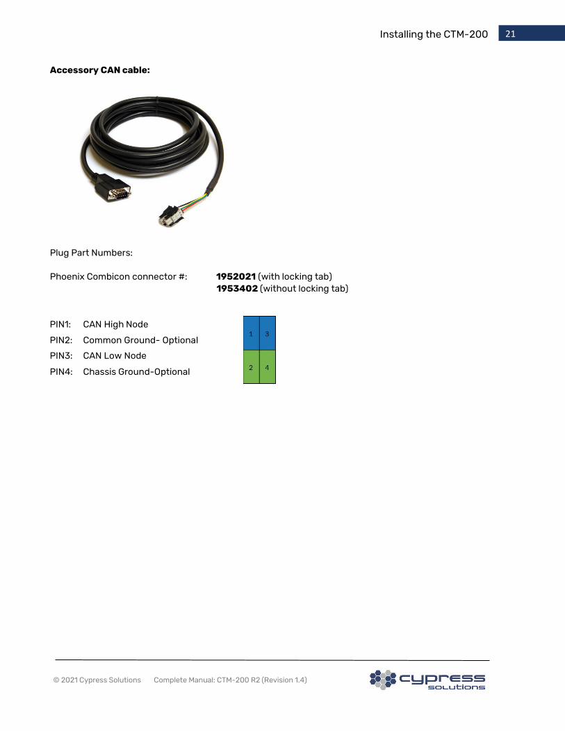
Accessory CAN cable:
Plug Part Numbers:
Phoenix Combicon connector #: 1952021 (with locking tab)
1953402 (without locking tab)
PIN1: CAN High Node
PIN2: Common Ground- Optional
PIN3: CAN Low Node
PIN4: Chassis Ground-Optional

Configuring the CTM-200 22
© 2021 Cypress Solutions Complete Manual: CTM-200 R2 (Revision 1.4)
Login Default value Username admin Password Chameleon
6. Configuring the CTM-200
The CTM-200 will be ready for access and configuration 30-40 seconds after applying power.
A CTM-200 with factory default configuration provides 4 different ways of gaining access to its internal
control interface. Once access has been obtained, the CTM-200 can then be configured either by command
line or by using the built-in web interface:
Access Method: Default Port Configuration Your Device’s Configuration
Ethernet Port 0
(LAN0)
192.168.1.1/24 192.168.1.2/24 or use DHCP
Ethernet Port 1 (LAN1) 192.168.2.1/24 192.168.2.2/24 or use DHCP
Wi-Fi 192.168.1.1/24 (bridged to LAN0) 192.168.1.2/24 or use DHCP
Serial port RS232 DCE, 115200 8N1 RS232 DTE, 115200 8N1
Note: Serial connections require a terminal program such as ‘COM 7.5’, ‘PuTTy’ or ‘minicom’.
The following paragraphs describe how to use the CTM-200’s built-in web interface to configure the CTM-
200. However, the web interface only provides a small subset of all available configuration options. To fully
utilize the CTM-200’s advanced options; it is required to use the command line interface. The full range of
commands is beyond the scope of this document; however the most important ones will be presented here.
6.1 Login
To configure the CTM-200, the user must first login to the CTM-200 either via the WebGUI or terminal
session. Both login methods use the same username and password.

Configuring the CTM-200 23
© 2021 Cypress Solutions Complete Manual: CTM-200 R2 (Revision 1.4)
Setting the Telnet, SSH or Web GUI
password is controlled using the cmd
telnetpswd command
6.2 Web Interface After logging in, the CTM-200 will show an overview screen with the most important device and network
statistics, as well as links to configuration pages and documentation. The Web GUI is designed with a menu
on the left and a series of “Tiles” that reflect the features of the product. As you resize your browser window
the tiles will automatically move to match your browser size.

Configuring the CTM-200 24
© 2021 Cypress Solutions Complete Manual: CTM-200 R2 (Revision 1.4)
The Web GUI can easily be displayed on tablets and mobile devices that support web browsing, tiles will
automatically resize to the browser window size.

Configuring the CTM-200 25
© 2021 Cypress Solutions Complete Manual: CTM-200 R2 (Revision 1.4)
Any changes that are made on the Web Interface the user will be prompted with a “Save Configuration”
button. The “Save Configuration” will remain persistent as you navigate from one Tile to the next, requiring
you only to save the configuration after all changes are complete.
To apply the configuration, press the “Restart Device” button on the left menu.
Name Description
Dashboard Returns you to home screen from any nested Tile view
Cellular View Connection Status and configure Cellular Settings
Admin Setup User Authentication and Access Control
Wired Display Network Status, setup LAN and Serial Port
Network Configure Port Forwarding and Static Routes
Wireless Configure WIFI, Captive Portal, and Bluetooth
Remote MGMT Configure Dynamic DNS, SNMP, and VUE Remote Management
System Upload Firmware, view System Logging, enter Command Line, and Show Configuration
AVL Reporting Setup Time Based, Distance and Speed, and Time, Distance, Heading reports
Documents View User Manual, Alphabetical & Categorical Command Reference, Report Messages, and OBD2-J1939 Reference

Configuring the CTM-200 26
© 2021 Cypress Solutions Complete Manual: CTM-200 R2 (Revision 1.4)
6.3 Command Line Interface
Command line interface offers quick command entry but requires knowledge of the command structure.
The above section that describes the Web GUI offers a user-friendly interface, and allows easy configuration
of standard device features and simple AVL reports but is limited in scope.
There are approximately 400+ CTM specific commands. All CTM commands are prefixed with “cmd”. The
CTM-200 is running a linux™ operating system based on the 3.2 Linux kernel.
Command line configuration is accomplished by following the steps:
• Input the appropriate command(s) “cmd ......... ”
• After entering commands issue a save command “cmd save”
• Reboot by physically removing power or entering the command “cmd pwr mode 2”
The Documentation tab of the Web GUI shows the command reference guide. These commands can be
entered in the “Enter command:” box or they can be entered in separate console session using tools like
“Putty” terminal emulator.
In addition to the CTM configuration commands, the CTM-200 provides common GNU/Linux shell and file
utilities accessible through console, telnet or SSH sessions. Shell scripts can be used for custom control and
management and can be integrated with the CTM-200 to enable triggering of scripts on device-generated
events. The system supports both a FTP server and client, an SSH/SCP server, and a HTTP webserver.

Configuring the CTM-200 27
© 2021 Cypress Solutions Complete Manual: CTM-200 R2 (Revision 1.4)
6.4 Configuring, Cellular Wireless Network Parameters Cellular configuration is accessed by the “Cellular” select button on the left of the Web GUI.
For most devices, the following information is required:
• An activated SIM card needs to be installed in the CTM-200.
• The correct installed module must be selected
• The mobile APN or Access Point Name.
• In almost all cases, ‘Username’ and ‘Password’ can be left empty
Contact Cypress Solutions if the module you are trying to install is not shown in the drop-down list
on the Web interface.
Enter the APN and select the embedded module name from the “Module” drop down list.
Press the “OK” button, “Save Configuration” to reboot the CTM-200.
After the device powers on the CTM-200 will have an IP address as shown in the “status” window.

Configuring the CTM-200 28
© 2021 Cypress Solutions Complete Manual: CTM-200 R2 (Revision 1.4)
If the IP address displayed is 0.0.0.0 or the online state is “NO” then the CTM-200 was unable to negotiate a
wireless connection. Check that the APN was entered correctly, and the account is active.
The CTM-200 is designed to operate as an “always on, always connected” device. After successful
configuration the CTM-200 will attempt to maintain a network connection at all times. If the connection is
lost due to out of coverage or other reasons, the CTM-200 has internal logic to attempt to quickly reconnect
to the network. During loss of cellular connectivity report data destined for Fleet tracking servers is stored
in non-volatile memory. This data will be automatically forwarded when network connectivity is re-
established.

Configuring the CTM-200 29
© 2021 Cypress Solutions Complete Manual: CTM-200 R2 (Revision 1.4)
Note: If the cellular device is incorrectly configured the CTM-200 will automatically power cycle
approximately every 4 minutes until it is configured for the correctly installed module.
6.5 Wi-Fi Networks
Wi-Fi configuration is accessed by the “Wi-Fi Access Point” or “Wi-Fi Client” select button on the left of the
Web GUI
Wi-Fi support is based on 2.4 GHz IEEE 802.11 b/g/n technology. Access Point and Client configurations are
supported with standard features such as SSID, Channel, WEP/WPA/WPA2/PSK/PSK2/TKIP Encryption, key
and RADIUS server support. EAP PEAP/TTLS and RADIUS authentication is also supported.
If Wi-Fi is configured as an Access Point the wireless connection is available by default at 192.168.1.1.
The Wi-Fi can be un-bridged from LAN0 interface if you wish to have the WLAN on its own subnet, for
example, 192.168.0.1/24
Default Wi-Fi configuration is to have the Wi-Fi configured as an access point. Default SSID is CTM200-
XX:XX where XX:XX are the last 4 digits of the CTM-200 mac address, for example: CTM200-02:9B
and the default password is CypressAccess.
There are two modes of operation for Wi-Fi, Access Point or AP provides connectivity to connected devices.
Client mode uses another AP to provide connectivity for the CTM-200:

Configuring the CTM-200 30
© 2021 Cypress Solutions Complete Manual: CTM-200 R2 (Revision 1.4)
6.5.1 Access Point
CTM-200 serves as an internet access point to other Wi-Fi enabled devices, up to 7 devices can be
connected to the CTM-200 Wi-Fi access point at any one time.
6.5.2 Client
CTM-200 can take advantages of existing Wi-Fi networks for data communications. Client configuration can
co-exist with cellular data connections, or the device can function as a Wi-Fi client with no cellular module
installed. The CTM-200 has internal logic to manage the “priority” of the connection so in the cases where
two wireless networks are available, cellular and Wi-Fi. The priority is set by the WI-FI mode chosen. With Wi-
Fi client enabled, this means first the CTM uses your Wi-Fi client connection, and if that is not available it
searches for cellular.
Use the device cell, device Wi-Fi, and the device priority commands to define the device priority for Cell
and Wi-Fi client configurations.

Configuring the CTM-200 31
© 2021 Cypress Solutions Complete Manual: CTM-200 R2 (Revision 1.4)
For more detailed information on device priority visit the online Cypress CTM-200 Command Reference
Guide: https://cypress.bc.ca/docs/cmd_ref/

Additional Features 32
© 2021 Cypress Solutions Complete Manual: CTM-200 R2 (Revision 1.4)
7. Additional Features
7.1 Automatic Power Control The CTM-200 supports supply voltages ranging between 5.5 VDC and 36 VDC. At default settings power
supply voltage must be a minimum of 9VDC for the CTM-200 to operate.
Note: In some vehicle operation, when starting the engine, the vehicle supply voltage will dip below 9VDC
momentarily. The CTM-200 can handle power dips below 9VDC down to 6VDC. If continual operation is
required below 9.0 V, the CTM-200 needs to be configured using the “cmd pwr vcct” command.
The Chameleon CTM-200 gateway has three power modes:
Mode Current
@ 12V
Description Mode change event
Operation 300 mA In this mode the device is
fully powered up and ready
to receive or make network
connections
The device will go back into shutdown/standby
mode when the ignition/standby signal is
deactivated or upon expiry of the power ON timer if
configured.
Shutdown < 3mA Only the CTM-200’s power
management circuits are
operating.
The device will go back into operation mode when
the ignition/standby signal is activated, wake on
event occurs (e.g., input, temperature, motion), or
upon expiry of the power OFF timer as configured.
The CTM-200 can be configured to remain on for a defined period after the standby/ignition signal has been
turned off. This enables the gateway to continue sending position reports or be used for data operations
even after the vehicle ignition has been switched off – e.g., for short duration driver breaks.
When in its power shutdown mode, the gateway may be configured to resume full operation by monitoring
events such as:
• Acceleration
• GPS location (on board Geo-Fence)
• Time
• Speed
• Temperature
• Voltage
• Input events

Additional Features 33
© 2021 Cypress Solutions Complete Manual: CTM-200 R2 (Revision 1.4)
• Man Down Pendant alarms
7.2 Power Consumption The power consumption of the CTM-200 gateway will depend on its supply voltage, its current operating
function and its RF environment.
The following table is provided to assist application integrators in defining the power requirements for their
specific application.
Power Consumption Weak RF
signal(12V)
Strong RF
signal(12V)
Weak RF
signal(24V)
Strong RF
signal(24V)
Shutdown Mode 2 mA typical 2 mA typical 3 mA typical 3 mA typical
Downloading (Receive
data)
450mA max 350mA max 220mA max 195mA max
Uploading (Transmit
data)
500mA max 390mA max 260mA max 210mA max
7.3 Device Reset The CTM-200 gateway may be manually reset via the front panel using a <1mm diameter (0.04”) wire tool (a
standard paper clip). This can be used to cause the gateway to reset its operation, to reset the LAN IP
settings, or to reset the gateway's configuration to the factory shipped configuration.
Power reset: Press and hold for 1 to 3 seconds
LAN IP reset: Press and hold for 3 to 10 seconds
• The PWR LED will turn off at the 3-second mark and start flashing slowly once the button is released.
It keeps flashing until the LAN IP reset is complete.
• LAN IP addresses will be reset as follows:
o LAN0 Ethernet port: 192.168.1.1
o LAN1 Ethernet port: 192.168.2.1
Shipped configuration reset: Press and hold for 10 or more seconds

Additional Features 34
© 2021 Cypress Solutions Complete Manual: CTM-200 R2 (Revision 1.4)
• The PWR LED will turn off at the 3-second mark
and start flashing rapidly at the 10-second mark. It
keeps flashing until the configuration reset is
complete. The CTM-200 will be restored to the
configuration that was loaded on the unit at the
time of shipping to the customer.
7.4 LED Indicators There are seven LED indicators on the CTM-200 top. These are used to show the status and operation of the
device. For wireless data devices that provide network diagnostic information:
LED Description Solid Blinking Off
Wi-Fi
Wi-Fi status CTM-200 serving as an Access Point or connected as a Client
CTM-200 configured as a Client but not connected
Wi-Fi not enabled
BLUETOOTH
Bluetooth status Connected with another Bluetooth device
Bluetooth enabled but not paired
Bluetooth not enabled
MODE
Indicates the type of wireless data connection
3G Connection (EV-DO/HSPA)
4G Connection (LTE) No cellular registration or 2G only or not available due to RF module limitations
GPS
Status of the GPS module or external GPS device
GPS module or external GPS device has a valid position fix
GPS module or external GPS device does not have a valid position fix
IP/DATA
Data is being transmitted or received
Solid on if CTM- 200 has an IP address on the wireless network
Flashing intermittently if data packets are sent/received via the wireless network
No data being transmitted, not connected to the wireless network
RF
Status of the device on the wireless network
Very good signal > 75% signal quality
Slow blink 0-35% quality Med. blink 35-55% quality Fast blink 55-75% quality
Device is not detecting a valid RF signal or is not registering on the wireless network
PWR
Power status of the device
Full operating mode and able to connect
Device is in standby mode Device has no power
Reset Type Hold Duration (sec)
Power Reset >1 to <3
LAN IP Reset 3 to <10
Shipped Configuration Reset 10+

General Troubleshooting Operation 35
© 2021 Cypress Solutions Complete Manual: CTM-200 R2 (Revision 1.4)
8. General Troubleshooting Operation
All LEDs remain off when the device is powered
• No power is being applied to the CTM-200 • Check power supply make sure min. 9 VDC is being supplied
PWR LED flashing • The device is in standby mode • Ensure the standby signal is connected to greater than 9VDC • Ensure the supply voltage is greater than 9VDC. • Remember that the device is designed to go into standby
mode if the standby signal is off after a configured time period (e.g. 10 seconds by default)
PWR LED ON all other LED OFF
• Device is booting Linux
Device is constantly rebooting every 4 minutes with no user input. Only PWR LED and GPS LED (solid or flashing) are on.
• Incorrect cellular device is configured. The CTM-200 is configured by default to auto connect to a cellular network. If the CTM-200 determines that communication with the internal cellular radio module or device is not working, it will attempt to reset the communication port; this will result in continual system reboots if incorrect module/device is selected.
GPS LED flashing • No valid GPS fix. The GPS antenna requires a clear view of the sky to obtain a valid GPS fix. The time to fix can vary from a few seconds to several minutes depending on conditions.
• GPS LED flashing has no impact on cellular connectivity.
RF LED OFF MODE LED OFF IP/DATA LED OFF
• RF signal may not be available; CTM-200 is located in an area of no cellular activity.
• Cellular device is not registered on the network; make sure radio module/device/SIM has been activated on the network.
• Incorrect configuration of internal radio module, ensure correct device has been configured
IP/DATA LED OFF RF LED (solid or flashing) MODE LED (solid or flashing)
• CTM-200 is registered on the network and is in an area of 3G or 4G coverage but device has not obtained an IP address
• cmd ipadr will return 0.0.0.0
MODE LED OFF All other LED’s ON (solid or flashing)
• CTM-200 is in an area where no 3G or 4G connection is available (2G only)
• Cellular module/device does not support diagnostics so MODE LED is disabled. Device may still perform at 3G or 4G levels

Time 36
© 2021 Cypress Solutions Complete Manual: CTM-200 R2 (Revision 1.4)
9. Time The CTM-200 has an onboard real time clock. The real time clock is used to provide timestamp information
for system generated events and reports. The real time clock is capable of keeping system time with all
power removed from the CTM-200 between 30 and 40 hours at room temperature.
9.1 Time Synchronization
The real time clock (RTC) will synchronize with external sources. External time sources are time from GPS
satellites, Time from the Cellular network and time from an NTP server.
Available features:
• Set the period for time synchronization to external sources
• GPS, NTP server or cellular network can be used as a time synchronization source
9.2 Time zones The default time zone is UTC but is user configurable.
10. Device Management
10.1 Upgrading and Configuring
The CTM-200 firmware can be upgraded locally or remotely over the wireless connection. Firmware images
“.tar” files can be downloaded from the Cypress Solutions repository or hosted on customer supplied
repositories or locally on computer on a local network. In most cases it is not necessary to upgrade firmware
unless a specific feature or enhancement has been added. The firmware update process uses a redundant
firmware image system. If for any reason the firmware upgrade fails, the previous firmware will load
allowing the process to be repeated.
Notes:
• It is highly recommended to test all device configuration and operation before deploying devices to
remote locations.

Device Management 37
© 2021 Cypress Solutions Complete Manual: CTM-200 R2 (Revision 1.4)
• Not all wireless networks offer "public" IP addresses that are remotely accessible; some are firewall
protected to allow access from either the same IP pool only or restricted IP addresses. Contact your
wireless network provider or administrator to determine what options are available.
Some device management options can work with dynamic/non-routable IP addresses.
• Some networks will force device IP addresses to change at regular intervals. Without proper
configuration, this could cause a remote device to become inaccessible if the device IP address is
not known. The CTM-200 can be configured to generate a report when the IP address of the device
changes.
• Incorrectly configuring the device could cause the device to become inaccessible, use caution when
issuing commands via any remote mechanism.
10.2 How to access the CTM-200 remotely
There are multiple ways to access and configure a CTM-200 remotely:
• SMS (allows commands to be sent to the CTM-200 via SMS; this command only applies to devices
that support SMS, contact Cypress Solutions for more details
• SNMP Simple Network Management protocol support
• Telnet and SSH (secure shell) (access to command line interface (CLI))
• Device Embedded Web Page (access to web page/browser based configuration)
• ULCP (allows configuration of digital outputs only using ULCP binary format)
• CTM Manager device management software available from Cypress Solutions.
10.3 SMS The CTM-200 gateway has the capability of setting up SMS reports and using SMS commands to perform
general tasks of processing sent and received SMS messages. These SMS messages can be sent to or
received from a carrier’s SMS web portal or a mobile phone.
For more details on the use of SMS with the CTM 200, refer to the CTM 200 Application Notes page online at
https://www.cypress.bc.ca/resources/ and refer to Application Notes in CTM-200 section.
Note: SMS support is dependent on the embedded radio module, carrier and account options; please
contact Cypress Solutions if you have questions regarding SMS functionality
There are two types of SMS commands that the CTM-200 gateway accepts: (1) $0cmd - command that
does not require the response to be sent back to the sender and (2) $1cmd - command that does require

Device Management 38
© 2021 Cypress Solutions Complete Manual: CTM-200 R2 (Revision 1.4)
the response to be sent back to the sender. Both commands can act as a remote management and
configuration tool for CTM-200 gateways.
Any of the CTM-200 commands can be appended after $0/$1 except for the following commands, which are
discarded by the SMS command processor:
cmd event dump
cmd showconfig
cmd factory
No configuration of the CTM-200 is required for it to accept SMS commands
Message format:
$1<ctm command> if the command provides feedback.
$0<ctm command> if the command does not provide feedback.
The first two characters of the message should always be $0 or $1. Any of the CTM-200 commands can be
appended after $0 or $1 except for the commands discarded by the SMS command processor (See list
above.). Moreover, multiple commands separated by <CR> or <CR><LF> can be sent in a single SMS
message\
Examples:
1. Return firmware version to SMS sender
$1cmd ver
Returns: 5555551212:r2.0.5.2779-144
2. Issue command to power cycle only
$0cmd pwr mode 2
Note: commands that output more than 160 characters will not generate feedback.
sendsms –P<PHONE #> -T<$0 or $1 ctm command> sends ctm command to another CTM-200

Device Management 39
© 2021 Cypress Solutions Complete Manual: CTM-200 R2 (Revision 1.4)
All CCM traffic is fully SSL encrypted.
Note: By default, CCM functionality is turned on. The CTM 200 will attempt to contact Cypress Solution’s
CCM server. This allows Cypress support staff to access the unit remotely for troubleshooting and support
purposes. If you do not wish to permit access, please disable CCM.
SMS features:
• Define an SMS “friends list” whichlimits incoming SMS commands received to a specific set
of phone numbers
• simple sms send of a text string from a CTM-200
10.4 SNMP
The CTM-200 supports the Simple Network management Protocol. The CTM-200 can act as an SNMP
(Simple Network Management Protocol) agent to report device information to an SNMP manager. SNMP
version 2 allows a user to retrieve CTM-200 information such as model, device ID, IMEI, RSSI, PAD IP, PAD
port, GPS coordinates, WLAN and LAN MAC and IP addresses, etc.
The CTM-200 listens on UDP port 161 for SNMP requests.
For more details on SNMP support please contact [email protected]
10.5 CCM Manager
All CTM 200s have the ability to be managed remotely, thereby simplifying management of large fleets. For
this purpose, Cypress Solutions offers Cypress Cloud Manager (CCM) as a configuration and management
platform. Cypress Cloud Manager (CCM) is part of Cypress’s suite of cloud-based services called Cypress
Cloud Services (CCS).
Communication between the CTM 200 and the CCM server is always initiated by the CTM 200. This allows
management even when the CTM 200 uses a dynamic IP address or in cases where the wireless carrier
deploys Network Address Translation (NAT). This implies that there is a time delay between scheduling a
configuration change or firmware upgrade server-side, and the time when these actions are executed on
the CTM 200.

Reporting 40
© 2021 Cypress Solutions Complete Manual: CTM-200 R2 (Revision 1.4)
11. Reporting Reports are generated by the CTM-200 and are linked to events or triggers. The CTM-200 uses an event-
report-message based system to send data to AVL or fleet management servers. Reports consist of
messages that provide information about the event or trigger. The most common and widely used report is
a GPS report. A GPS report can be triggered by a number of conditions, for example, time, speed, distance,
and heading. Reports are typically delivered via the wireless link (UDP or TCP), but they can also be
delivered via Serial, Ethernet, and email, SMS or stored in files for file based reporting.
The type and a and nature of reports from the CTM-200 can be broken down into 3 main categories
• Regular Interval AVL (Automatic Vehicle Location)
• Irregular or event trigger based (Rapid deceleration or acceleration, tire blowout (, Man Down Alert
• Infrequent Interval (data that is not required in real time, fuel values, odometer values, engine hours,
idle time)
11.1 Regular Interval Reports (AVL)
A regular interval report is normally an AVL (Automatic Vehicle Location) type report containing location
(lat/long), heading, and speed.
AVL reports are triggered on a frequent basis to match the needs of the business unit. More frequent
reports provide a more detailed path of the vehicle but consumes more data. Less frequent reports have
less detail but consume less data.
The best compromise is a event trigger mechanism that utilizes, time, speed, distance and heading as logic
to determine the best interval to send a report. For example, if a vehicle is stationary there is no need to
send AVL reports every few seconds as the report is not changing
The CTM-200 Web GUI provides a quick mechanism for configuring a regular AVL Interval report.

Reporting 41
© 2021 Cypress Solutions Complete Manual: CTM-200 R2 (Revision 1.4)
Time Based Reports
Distance and Speed Reports

Reporting 42
© 2021 Cypress Solutions Complete Manual: CTM-200 R2 (Revision 1.4)
Time, Distance, Heading Reports
11.2 Irregular Interval Reports
An Irregular interval report is typically a report generated by a sensor or switch that triggers an event. The
event is random in nature by that there may be no pattern as to when the event triggers, but there is a
requirement from the business unit that identifies the event in real time to facilitate an action. Irregular
reports can trigger as frequently as Regular reports but the trigger is not typically AVL based.
Examples of Irregular reports are:
• Acceleration
• Driver ID
• Engine parameters
• Auxiliary equipment such as Tire pressure Monitors, spreader controller data, weight systems

Reporting 43
© 2021 Cypress Solutions Complete Manual: CTM-200 R2 (Revision 1.4)
For example to send a “hard acceleration” event or “hard brake” event an “accelcond” would be set to define
the “trigger” points. The CTM-200 monitors the acceleration in real time and when the condition is met a
report is generated that sends the message, in this case a message containing relevant acceleration data
11.3 Infrequent Interval Reports
An Infrequent interval report is typically a report generated by an event that is infrequent. In many cases
“ignition” is considered infrequent as there can be long periods between ignition events. The idea behind
the Infrequent Interval report is that these reports typically contain information is useful but not required in
a real time environment
Examples of Infrequent reports are:
• Odometer
• Fuel
• Idle
• Engine Hours
• Wireless Data consumed
An ignition condition “igncond” is typically used to trigger an infrequent report. The ignition condition
triggers based on the state of the ignition, OFF/ON etc.
11.4 Triggers or event conditions • Acceleration trigger condition
• Data event trigger
• Geo-route violation conditions
• GPS trigger condition (Speed, Distance travelled, heading change, time)
• Idle trigger condition
• Ignition trigger condition
• GPIO trigger condition
• MODBUS exception condition
• Engine diagnostics trigger condition
• Power up trigger condition
• Supply voltage trigger condition

Reporting 44
© 2021 Cypress Solutions Complete Manual: CTM-200 R2 (Revision 1.4)
Irregular and Infrequent reports are triggered by the below conditions, the GPS condition will typically
trigger a regular AVL type report.
Triggers or events Description Event
Label GPS 8 available conditions can be triggered on time, speed (low
speed, high speed), distance travelled, heading change. GPSx
Input Condition 8 available conditions, time based, alarm based on input states of 6 inputs, up to 2 inputs can be compared in each condition. IP change trigger
GPIOx
Ignition 8 available conditions, triggers on ignition going off, on or transition.
IGNx
OBDII or J1939 8 available conditions. Time based, or based on a valid OBDII or J1939 parameter being =,>,< the reported value from the vehicle ECU
OBDx
Power Up 8 available conditions, triggers on the device being powered up.
PUPx
Voltage 8 available conditions, trigger when a supply voltage is below, above or a supply threshold is passed.
VCCx
Acceleration 8 available conditions, triggers when an acceleration, deceleration or lateral acceleration threshold has been met.
ACCELx
Geo Route In Zone or Out of Zone trigger, or alarm triggers based on crossing of zone threshold.
GEOx
Idle Trigger a report when an idle time is exceeded IDLExSTART IDLExEND
Data Triggers when a pre-configured threshold is exceeded. DATAx MODBUS Trigger MODBUS or MODBUS exception reports
Man Down Triggers when Man-Down Accessory device generates an event (CTM-200 must be configured to listen for traffic and optional WPAN Gateway must be installed)
MANDOWNx
Boomtracker Triggers when short range wireless asset tracker accessory comes within range of CTM-200 (CTM-200 must be configured to listen for traffic and optional WPAN Gateway must be installed).
BOOMx
Proximity Card/RFID/I- Button
Triggers when a compatible RFID device sends a message to the CTM-200 via external peripheral, RFID reader, etc. (uses modified message 114, $PGPS for payload)
RFIDx
External Equipment Triggers when supported external equipment sends data to CTM-200 serial port. Typical External equipment include salt spreader, weigh systems, etc. (uses modified message 114, $PGPS for payload)
EXTz
11.5 Report Definition
A report definition consists of:
• Transport protocol (UDP, TCP, SMS, email, asynchronous, file based)
• Destination IP address

Reporting 45
© 2021 Cypress Solutions Complete Manual: CTM-200 R2 (Revision 1.4)
• Destination Port address
• Group of messages to deliver.
Each report definition is capable of delivering up to 4 messages per report. 8 unique report definitions each
can be associated to GPS and GPIO conditions. All other event conditions can have up to 999 report
definitions shared between the various report triggers or events.
An example of an “acceleration report” definition:
cmd accelcond 1 5 -30 0 5 #set the acceleration condition or trigger, in this case condition #1
cmd accelreport 1 99 # bind acceleration condition #1 to report definition #99
cmd reptype 99 0 3 1 # use UDP protocol with SNF enabled
cmd repaddmes 99 114 136 # include a GPS with ID message(114) and acceleration message (136)
cmd repremip 99 65.61.200.71 # destination IP address
cmd repremport 99 8300 # destination Port number
11.6 Report Messages Messages are defined using a standard NMEA message format; some messages are available in a binary
format.
ASCII Description
$ Start character ABC... or PABC Message type. Messages starting with P are non-standard proprietary. <string>,<string> Message body. Multiple strings are separated with commas. * Message terminator hh Message checksum <CR><LF> Carriage return, line feed

Reporting 46
© 2021 Cypress Solutions Complete Manual: CTM-200 R2 (Revision 1.4)
Standard NMEA Sentences
Decimal ID Message Name
Message Type
Message description
16 $GPGLL Standard NMEA GPS NMEA GLL Geographic position, latitude / longitude message 80 $GPGGA Standard NMEA GPS NMEA GGA Fix Data message- $GPGGA 82 $GPRMC Standard NMEA GPS NMEA RMC Recommended minimum specific GPS/Transit data message 83 $GPVTG Standard NMEA GPS NMEA VTG Track made good and ground speed message 84 $GPGSA Standard NMEA GPS NMEA GSA GPS DOP and active satellites message 118 $GPGSV Standard NMEA GPS NMEA GSV GPS Satellites in view message 127 $GLGSV Standard NMEA GLONASS NMEA GSV message-$GLGSV 128 $QZGSV Standard NMEA QZSS NMEA GSV message-$QZGSV
Cypress Solutions Proprietary NMEA Sentences
Decimal ID
Message Name
Message Type
Message description
3 $PMID Cypress Proprietary NMEA Modem ID 4 $PAID Cypress Proprietary NMEA Asset IDs 19 $POUTD Cypress Proprietary NMEA Digital Output States 20 $PIND Cypress Proprietary NMEA Digital Input States 21 $PINA Cypress Proprietary NMEA Analog Input #1 status 22 $PINA Cypress Proprietary NMEA Analog Input #2 status 23 $PINA Cypress Proprietary NMEA Analog Input #3 status 24 $PINA Cypress Proprietary NMEA Analog Input #4 status 25 $PINA Cypress Proprietary NMEA Analog Input #5 status 26 $PINA Cypress Proprietary NMEA Analog Input #6 status 27 $PINA Cypress Proprietary NMEA Analog Input #7 status 28 $PINA Cypress Proprietary NMEA Analog Input #8 status 29 $PNETD Cypress Proprietary NMEA Detailed Network status (output of RFSTATS) 30 $PCTM Cypress Proprietary NMEA Network status 31 $PDATA Cypress Proprietary NMEA Wireless link TX/RX data count, proprietary NMEA message- $PDATA 32 $PSNF Cypress Proprietary NMEA Store and Forward messages 33 $PWIFI Cypress Proprietary NMEA Wifi Client Network status 34 $PSIG Cypress Proprietary NMEA Signal Quality Message (output of RFSTATS) 35 $PNETD1 Cypress Proprietary NMEA Detailed LTE dynamic Network parameters (output of RFSTATS) 36 $PNETD2 Cypress Proprietary NMEA Detailed LTE static Network parameters (output of RFSTATS) 114 $PGPS Cypress Proprietary NMEA GPS with modem ID (based on RMC) 115 $PKML Cypress Proprietary NMEA NMEA Message for Google Earth application (kmlserver) 116 $PPWR Cypress Proprietary NMEA Power status 117 $PRFI Cypress Proprietary NMEA CDMA/EV-DO Network diagnostic report 119 $POBDA Cypress Proprietary NMEA OBD II Group A 120 $POBDB Cypress Proprietary NMEA OBD II Group B 121 $POBDC Cypress Proprietary NMEA OBD II Group C 122 $POBDD Cypress Proprietary NMEA OBD II Group D 123 $POBDE Cypress Proprietary NMEA OBD II Group E (CTM-200 only) 124 $POBDF Cypress Proprietary NMEA OBD II Group F (CTM-200 only) 125 $POBDG Cypress Proprietary NMEA OBD II Group G (CTM-200 only) 126 $POBDH Cypress Proprietary NMEA OBD II Group H (CTM-200 only) 135 $PACC Cypress Proprietary NMEA X/Y/Z Acceleration 136 $PACCEL Cypress Proprietary NMEA Acceleration/Deceleration with Modem ID 137 $PODO Cypress Proprietary NMEA GPS Odometer with Modem ID 138 $PACCEL2 Cypress Proprietary NMEA Acceleration/Deceleration (2nd source) with Modem ID 139 $PLACCEL Cypress Proprietary NMEA Lateral Acceleration with Modem ID (CTM-200 only) 140 $PFUEL Cypress Proprietary NMEA FUEL ECONOMY with Modem ID (CTM-200 only)
141
$PIDLE
Cypress Proprietary NMEA
IDLE TIME with Modem ID, proprietary NMEA message- $PIDLE (CTM- 200 only)
142 $PFUELR Cypress Proprietary NMEA FUEL RATE(L/100Km) with Modem ID (CTM-200 only) 150 $PMEX Cypress Proprietary NMEA Modbus Master Exception (CTM-200 only) 151 $PMBM Cypress Proprietary NMEA Modbus slave device 1's state queried by Modbus Master (CTM-200 only) 152 $PMBM Cypress Proprietary NMEA Modbus slave device 2's state queried by Modbus Master (CTM-200 only) 153 $PMBM Cypress Proprietary NMEA Modbus slave device 3's state queried by Modbus Master (CTM-200 only) 154 $PMBM Cypress Proprietary NMEA Modbus slave device 4's state queried by Modbus Master (CTM-200 only)

Reporting 47
© 2021 Cypress Solutions Complete Manual: CTM-200 R2 (Revision 1.4)
X $PEVENT Cypress Proprietary NMEA Trigger/event message - $PEVENT (CTM-200 only) X $PGRT Cypress Proprietary NMEA Geo-Route alarm/alert message with Modem ID - $PGRT (CTM-200 only) 1000- 1999
$PCYP
Cypress Proprietary NMEA
PCYP message
Other Vendor Proprietary NMEA Sentences
Decimal ID
Message Name
Message Type
Message description
129 $BTVEG Vendor Properietary NMEA Intergraph's GPS message
Cypress Solutions ULCP Messages
Decimal ID
Message Name
Message Type
Message description
40 Cypress Proprietary Binary Device phone number, PAD Port/Type, serial port baud 85 ULCP Cypress Proprietary Binary ULCP binary format GPS data message 86 ULCP Cypress Proprietary Binary ULCP binary format GPS lat/lon message
88
ULCP
Cypress Proprietary Binary
ULCP binary format acceleration/decleration event data with GPS
89
ULCP
Cypress Proprietary Binary
ULCP binary format Modem ID/firmware revision/odometer data
90 ULCP Cypress Proprietary Binary ULCP binary format odometer data
92
ULCP
Cypress Proprietary Binary ULCP binary format wireless Link TX/RX Data Count with Modem ID
93 ULCP Cypress Proprietary Binary ULCP binary message for panicreport (CTM-200 only) 97 ULCP Cypress Proprietary Binary ULCP binary format digital I/O with GPS (no events) 98 ULCP Cypress Proprietary Binary ULCP binary format digital input event data with GPS 99 ULCP Cypress Proprietary Binary ULCP binary format MIL status with number of DTC
111
ULCP
Cypress Proprietary Binary
ULCP binary format with msg 112, CID, RPM, fuel level, seatbelt, speed, rssi, sqi, accel, pdop
112 ULCP Cypress Proprietary Binary ULCP binary format modem ID with GPS
113
ULCP
Cypress Proprietary Binary ULCP binary format digital input/output (IO), modem ID, with minimal GPS (time,lat/lon,validity) (CTM-200 only)
255 ULCP Cypress Proprietary Binary ULCP Custom Message- Flexible Format
255
ULCP
Cypress Proprietary Binary ULCP Custom Message for spreader controllers (CTM- 200 only)
Other Message Types
Decimal ID
Message Name
Message Type
Message description
100 TAIP PV Standard TAIP GPS TAIP PV message 101 TAIP LN Standard TAIP GPS TAIP LN message
11.7 Report Triggered Scripts
The CTM-200 can be configured to execute a script or list of actions when a report is triggered. With report-
triggered scripts enabled a series of commands can be executed by the CTM-200 that can perform a series
of simple or complex tasks involving logic. The script is a linux shell script file (.sh) file that resides in the
CTM-200 non-volatile memory. The name of the script correlates to a specific report so whenever the
report is triggered, the script will execute if script execution is enabled.

Reporting 48
© 2021 Cypress Solutions Complete Manual: CTM-200 R2 (Revision 1.4)
Reports need to be located in the /var/data/reports/scripts directory on the CTM-200. The file naming
convention is reportN.sh where N is the report number, for example report9.sh would be a script that would
execute based on general report 9 being triggered.
Note: For standard GPS and Input/Output reports the corresponding file based report number for GPS report
1 is report1020 and for IO report 1 is report1040.
The format for the script file
#!/bin/sh
…………….
………………………..
…………………………………..
…………………
Shell scripts must also respect Unix line endings. If written using a windows editor CR/LF must be stripped
from the file, this can be performed after the file is copied across to the CTM-200 using the “dos2unix”
utility.
Shell scripts must have their mode changed to executable, this is accomplished by using the chmod
command, ie chmod +x “filename.sh”
11.8 File Based Reporting
In addition to providing real time reporting, reports can be stored in files. One advantage to file based
reporting is that the trigger mechanism or reporting interval can be set to a high frequency above practical
means for real time reporting. The reports can be compressed into a “zip” format for easy archival and
delivery.
11.9 Store and Forward
All reports can be enabled to utilize the “store and forward” feature of the CTM-200. Store and forward
allows the CTM-200 to store reports in non-volatile system memory when the device is out of Wireless
coverage (Cellular or Wi-Fi). The CTM-200 uses internal logic that determines when the wireless signal is at
a level where the real time delivery of data would be compromised. When it detects this condition, the

System and Event logs 49
© 2021 Cypress Solutions Complete Manual: CTM-200 R2 (Revision 1.4)
reports are stored in memory. When the logic detects that the wireless signal is once again acceptable the
stored reports are forwarded.
12. System and Event logs The CTM-200 logs operating system events as they happen. The most verbose log is the system log or
syslog. The syslog captures all device events as they occur. The system log is volatile; the contents of the
system log are lost on a power reset. Syslog can be captured to a file or connected computer for persistent
logging
The Event log is a non-volatile log that logs and optionally reports all important firmware events such as
cellular/wifi network connectivity, firmware generated power cycle, firmware updates, etc.
The event log will grow until cleared or it will roll over when its memory capacity is reached (> 1 year of
logging). Event logs can be automatically delivered via the CTM-200 reporting system.
An example of a partial event log:
Mon Jan 13 08:47:22 PST 2014 [36]:POWER_UP:00000001
Mon Jan 13 08:47:22 PST 2014 [36]:IGN_ON
Mon Jan 13 08:47:22 PST 2014 [36]:WIFI_AP_UP
Mon Jan 13 08:47:22 PST 2014 [36]:CELL_ONLINE 0 mins 36 secs after POWER_UP, RF Quality: 17%
Mon Jan 13 12:46:46 PST 2014 [14400]:HEALTH
Mon Jan 13 16:37:28 PST 2014 [28241]:CMD_DATA_RESET:OK
Mon Jan 13 16:46:46 PST 2014 [28800]:HEALTH
Mon Jan 13 20:46:46 PST 2014 [43200]:HEALTH
Mon Jan 13 20:47:08 PST 2014 [43222]:CELL_OFFLINE after 719 mins 46 secs online, RF Quality: 32%
Mon Jan 13 20:47:26 PST 2014 [43240]:CELL_ONLINE after 0 mins 18 secs offline, RF Quality: 31%
Tue Jan 14 00:46:45 PST 2014 [57600]:HEALTH
Tue Jan 14 04:46:46 PST 2014 [72000]:HEALTH
Tue Jan 14 08:46:45 PST 2014 [86400]:HEALTH
Tue Jan 14 08:47:19 PST 2014 [86433]:CELL_OFFLINE after 719 mins 53 secs online,
Tue Jan 14 08:47:32 PST 2014 [86446]:CELL_ONLINE after 0 mins 13 secs offline, RF Quality: 30%
The event log can be configured for different levels of verbosity, an example of a partial event log is shown
above. POWER_UP:00000001 indicates a power on condition and the nature of the power, ignition, reset,

Connection monitoring tools 50
© 2021 Cypress Solutions Complete Manual: CTM-200 R2 (Revision 1.4)
etc. CELL_ONLINE events record when cellular connections are established and CELL_OFFLINE record
when offline conditions occur. HEALTH events are messages that indicate the CTM-200 operating system is
operating normally. The default configuration for a HEALTH message is once every 4 hours.
13. Connection monitoring tools Watch dog timers are used to monitor network connectivity and reset the network connection or CTM-200 if
a timer expires indicating a network connectivity issue.
• Setup a ping target to generate network traffic
• Configure the network watchdog for cellular traffic
• Configure a watchdog timer for the Wi-Fi network.
14. Security
14.1 Remote Access Control Remote access control can limit remote access to the CTM-200 embedded Web pages or command line
consoles (Telnet/SSH). Telnet and SSH connections are password protected with a configurable password.
14.2 Friends list Block incoming packets from an IP address that is not defined as a “friend”. Eight Friends list IP addresses
can be defined.
14.3 LAN Friends LAN Friends is used to control access to PC devices connected via the CTM-200 Ethernet ports. Up to 8
MAC addresses can be allowed Ethernet access, all other devices will be denied packet forwarding and
routing.
14.4 Radius The CTM-200 LAN ports and Wi-Fi interface supports 802.1x Radius authentication servers.

Networking 51
© 2021 Cypress Solutions Complete Manual: CTM-200 R2 (Revision 1.4)
15. Networking
15.1 VPN
15.1.1 IPSec
The CTM-200 supports IPSec VPN communications.
The CTM-200 uses the KAME IPSec-tools: setkey tool to manipulate the Security Policy Database
(SPD) and Security Association Database (SAD), and the raccoon Internet Key Exchange (IKE)
daemon within the OpenCTM Linux 3.2 environment.
To successfully setup an IPSec communication tunnel between a CTM-200 and other VPN hardware a
variety of settings must be configured. A partial list required to begin to create a test environment is
below:
• server public IP
• server LAN IP subnet / netmask
• a pre-shared key for IPSec
• transport type : ESP / AH
• IKE Encryption and Diffie-Hellman Group eg. 3DES with Group 2 (1024-bit prime)
• encryption algorithm eg AES256, DES, 3DES
• hash algorithm eg. MD5, SHA1
15.1.2 VPNC
VPNC is a simplified IPSec/VPN client application that was developed as a Linux alternative to the Cisco
Easy VPN Client software for PCs. VPNC was initially developed to interoperate with Cisco VPN
Concentrators and PIX/IOS routers, but may work with other similar equipment.
• Authentication method using Pre-Shared-Key + XAUTH is known to be insecure. For more details
see the Cisco Security Notice at www.cisco.com/warp/public/707/cisco-sn-20040415-
grppass.shtml
• Limited configuration options, may not work with all equipment
• Limited routing capabilities: VPNC is used to create a tunnel between the client (CTM-200) and the
server; it is not a site-to-site solution such as Racoon/IPsec which can be used to connect remote
subnets.

Engine Diagnostics Support 52
© 2021 Cypress Solutions Complete Manual: CTM-200 R2 (Revision 1.4)
16. Engine Diagnostics Support
As part of the general reporting system, the CTM-200 is capable of monitoring a variety of Engine
Diagnostic parameters. These parameters can be used as events or triggers to generate reports. In addition
to the reporting of real time Engine parameters the CTM-200 processes key parameters to deliver
accumulated values for fuel consumption, fuel rate, Idle time and engine hours. Engine Diagnostic support is
available via the CTM-200 on board CAN interface. The CAN interface supports vehicles using the ISO-
15765-4 (2008 and newer small and light duty vehicles) protocol and the J1939 protocol (heavy duty
vehicles). Vehicles that do not support the CAN interface can be supported using the Cypress Solutions E-
VDT (Engine vehicle diagnostics transmitter).
When CAN support has been enabled on the CTM-200 and the cables connected. Engine/vehicle
parameters will be available to the CTM-200. The CTM-200 can use the available Engine/Vehicle
parameters for accurate real time calculation of:
• Total Fuel1
• Fuel Rate1
• Total Engine Hours
• Total Idle Time
• Odometer2
1 Fuel calculation is dependent on the vehicle ECU providing a parameter that can be used to
determine fuel consumption such as MAF (mass air flow) sensor or fuel tank level values.
2 In some cases Vehicle odometer is available from the vehicle ECU, in cases where this is not
available the on board odometer on the CTM-200 can be set to match the vehicle odometer
The above values are stored in non-volatile internal memory on the CTM-200 are available to AVL tracking
applications.
In addition many other Engine/vehicle parameters are available. Engine/vehicle parameters vary based on
vehicle make, model, and year of manufacture. Contact Cypress Solutions for a complete list of supported
vehicles.
For vehicles where the connection to the vehicle ECU is not possible or not available the CTM-200 can take
advantage of GPS sensor information and calculate an accurate GPS based odometer value.

Geo-Routing 53
© 2021 Cypress Solutions Complete Manual: CTM-200 R2 (Revision 1.4)
17. Geo-Routing The CTM200 has the ability to generate reports based on a mobile asset or vehicle location with respect to a
list of pre-defined routes stored locally on the CTM-200. Up to 32 routes can be defined; each route can be
either series of points defining a route, a series of points defining an area, or a single point. The trigger event
is when the vehicle enters or leaves the route or area. When a geo route trigger occurs a report is generated
that is appended to an existing general report.
18. Accessory or 3rd party product support
18.1 PAD Mode PAD Mode or Packet Assembly or Disassembly is used to allow the CTM-200 to act as a “virtual serial port”
and route data from devices such as PLC (programmable logic controllers), etc. to server applications where
the data can be viewed as native serial data for analysis. Serial data can be bi-directional from the remote
side to the server or vice versa.
18.2 MODBUS For devices that support MODBUS communications the CTM-200 supports MODBUS Slave, MODBUS Slave
Gateway and MODBUS Master Gateway, MODBUS Master
18.3 Man Down Pendant The CTM-200 has integrated support for the Cypress Solutions Man Down Pendant.
The Man Down system uses a 2.4 Ghz 802.15.4 wireless personal area network (WPAN)
to communicate with the CTM-200. With the optional 802.15.4 2.4 Ghz radio installed
the CTM-200 can act as a cellular gateway for the Man Down Pendant. Messages
received from the pendant can be relayed to remote servers; in addition remote
servers can “page” the Man Down Pendant from the remote server. Each Man Down
pendant has a unique 16 digit hexadecimal ID that identifies the Man Down Pendant.
Acknowledgements to Man Down alerts can be gateway acknowledged for server
acknowledged for true closed loop operation. Up to 16 Man Down pendants can be
supported by one CTM-200
Note: The CTM-200 requires an optional WPAN radio module to be installed to communicate with the Man-
Down Accessory.

Accessory or 3rd party product support 54
© 2021 Cypress Solutions Complete Manual: CTM-200 R2 (Revision 1.4)
18.4 Garmin® Personal Navigation Devices
The CTM-200 supports Garmin® products that support the Fleet Management Interface (FMI). When
connected to the CTM-200 via serial link the CTM-200 manages the local connection between the Garmin®
and the CTM-200 and the wireless link between the CTM-200 and the remote server. The CTM-200 notifies
the remote server when the Garmin is connected or disconnected.
The CTM-200 support for the Garmin® product uses a modification of the standard PAD (Packet Assembly
Disassembly) feature of the CTM-200. Default configuration set by the selecting the Garmin® mode on the
CTM-200 can be over ridden by individual configuration of the CTM-200 PAD settings.
Remote Server < --- > Internet <--WAN--> CTM-200 <--Serial-->Garmin
Note: The CTM-200 communicates with Garmin® (NUVI) products which support the Garmin FMI interface
and the associated Garmin USB to serial cable.
18.5 Miscellaneous external devices, salt spreader controllers, etc.
In some cases, specialized auxiliary equipment are connected to the serial port(s)/CANBus on the CTM-200.
Output from this equipment can be added as a “message payload” and delivered to the monitoring server.
This allows applications to receive data from the connected devices. The data payload is appended to the
$PGPS report message (114) or as binary payloads. The $PGPS message or binary messages are generated
when the data is received on the CTM-200 serial port either via polling or when data is received by the CTM-
200.
Auxiliary device support is a highly configurable feature of the CTM-200. Parameters such as device name,
leading characters, terminating characters, number of bytes to read, polling or non-polling or whether any
processing of the incoming data is required can be configured.
Example 1:
A Salt spreader controller is connected to the CTM-200, The output from the spreader controller is:
131213141516171819202122232425262728293031
The Corresponding report message:

Accessory or 3rd party product support 55
© 2021 Cypress Solutions Complete Manual: CTM-200 R2 (Revision 1.4)
$PGPS,000000.00,V,0000.0000,N,00000.0000,E,000.0,000.0,000000,+00000,0,1312131415161718192021
222324252627228293031*7E
Example 2:
A weight sensing interface is connected to the CTM-200, The output from the weight sensor is:
LBFF55;iiiii;cccc;aaaaaa;u;rrrrrrrrrrrrrrrr;SGGG.GGGGGG;STTT.TTTTTT;xx<CR><LF>
The corresponding report message:
$PGPS,002349.00,V,0000.0000,N,00000.0000,E,000.0,000.0,060180,+00000,0,1234567890,LBFF55;iiiii;c
ccc;aaaaaa;u;rrrrrrrrrrrrrrrr;SGGG.GGGGGG;STTT.TTTTTT;xx*53
18.6 Access Control
The CTM-200 supports the I-Button® and HID® proximity card systems for access control. The access
control devices can be connected via serial or GPIO connector on the CTM-200. The CTM-200 supports
both wiegand and serial protocols. The CTM-200 can be configured to execute “scripts” on lock and unlock.
For example, an unlock script may trigger an output to control a relay that enables vehicle ignition. The
CTM-200 can also store an “Access control list” which is a list of ID’s that are “valid” . When an access
control request is made, the ID from the button or card is compared against a stored list on the CTM-200. If
the ID is valid an unlock script would execute, unlocking a door, or enabling ignition. When an attempt is
made at access control the CTM-200 generates a report message containing the ID of the button or card
and whether the card is a valid or invalid card based on the stored list on the CTM-200. The ID payload is
appended to the end of the $PGPS message, message 114. The message is automatically generated when
an access control attempt is performed.

Accessory or 3rd party product support 56
© 2021 Cypress Solutions Complete Manual: CTM-200 R2 (Revision 1.4)
Example:
An access control attempt is made using a button or card. The ID of the button/card is:
039-30391
The corresponding message is:
$PGPS,171134.00,A,4915.3868,N,12259.8049,W,000.0,000.0,170609,+00004,5,09604890958,039-
30391,V*33
where “V” indicates the ID is a valid ID as compared against an internal list stored on the CTM-200. “F” would
indicate an invalid ID.
18.7 RF Switch
The CTM-200 supports an accessory RF switch/speed buzzer that is used to disable radio communications
in areas where radio emissions are prohibited (blasting areas). The accessory has a super bright LED
indicating when the CTM-200 radio(s) are off and a buzzer that can be triggered when a speed threshold
has been exceeded.
18.8 CTM-200 with integrated Iridium™ ISU module The CTM-200 supports an integrated Iridium Satellite module for communications when cellular coverage is
not available. The CTM-200 has internal logic that manages the transition from Cellular to Satellite and back
to Cellular. Standard CTM-200 reports, Packet Assembly/Disassembly (PAD) data and console commands
and Man Down alerts can be transmitted via Satellite.

Accessory or 3rd party product support 57
© 2021 Cypress Solutions Complete Manual: CTM-200 R2 (Revision 1.4)
Cypress Solutions Service
Support Group
1.844.462.9773 or 778.372.4603
5.00am to 5.00pm PST
www.cypress.bc.ca
18.9 CTM-200 with integrated battery backup An optional internal battery is available for the CTM-200 that allows it to operate for 2-3 hours if the main
power supply has been disconnected from the CTM-200. This is useful for applications where the main
power is not reliable.
Technical Support