Cavity Control System – Optimization Methods For Single Cavity Driving and Envelope Detection
Upload
independentCategory
view
3download
0
http://jvc.sagepub.com/Journal of Vibration and Control
http://jvc.sagepub.com/content/early/2014/06/25/1077546314533585The online version of this article can be found at:
DOI: 10.1177/1077546314533585
published online 26 June 2014Journal of Vibration and ControlZamri Mohamed, Xu Wang and Reza Jazar
Structural-acoustic coupling study of tyre-cavity resonance
Published by:
http://www.sagepublications.com
can be found at:Journal of Vibration and ControlAdditional services and information for
http://jvc.sagepub.com/cgi/alertsEmail Alerts:
http://jvc.sagepub.com/subscriptionsSubscriptions:
http://www.sagepub.com/journalsReprints.navReprints:
http://www.sagepub.com/journalsPermissions.navPermissions:
http://jvc.sagepub.com/content/early/2014/06/25/1077546314533585.refs.htmlCitations:
What is This?
- Jun 26, 2014OnlineFirst Version of Record >>
by guest on June 28, 2014jvc.sagepub.comDownloaded from by guest on June 28, 2014jvc.sagepub.comDownloaded from
XML Template (2014) [23.5.2014–12:07pm] [1–17]//blrnas3/cenpro/ApplicationFiles/Journals/SAGE/3B2/JVCJ/Vol00000/140099/APPFile/SG-JVCJ140099.3d (JVC) [PREPRINTER stage]
Article
Structural-acoustic coupling study oftyre-cavity resonance
Zamri Mohamed1,2, Xu Wang1 and Reza Jazar1
Abstract
The tyre cavity resonance induced cabin noise has been a major unsolved customer complaint issue for a long time. A
study of coupled tyre-cavity structural-acoustic system using impedance compact mobility matrix is presented in this
paper. This method offers a better physical interpretation and numerical prediction about a coupled tyre-cavity system
than previous models. It can calculate the sound pressure inside the tyre cavity as well as the tread wall vibration velocity
at the same time. The analytical results have been verified by the results of the VAOne vibro-acoustic model. The VAOne
software was also validated by the results from a case study of a rectangular box-cavity system in previous literature.
From the analytical calculation, the tyre cavity coupling modal frequency is found to be split into two close resonance
frequencies if the tyre structural natural frequency is close to the fluid cavity resonance frequency. The geometric
coupling coefficient has been calculated using Matlab code. This study provides a better insight into the resonance
coupling phenomenon of the tyre cavity to the tyre structure and its root causes. It demonstrates more clear physical
meaning of the tyre cavity coupling model and its inherent characteristics than that from ‘black box’ finite element
software. This develops a better understanding of the problem and its root causes facilitates effective solutions for the
problem. Even though the study was conducted in a tyre-cavity system, the solution and methodology are applicable to
other toroidal shape structural-acoustic systems.
Keywords
Tyre cavity resonance, structural-acoustic coupling
1. Introduction
Noise from tyre-road interactions is one of the domi-nating Noise, Vibration, and Harshness (NVH) sourceswhich depend on speed and road condition. Qatu et al.(2009) and Qatu (2012) gave an overview of the aspectsand recent research in automotive noise and vibrationfrom the factors such as sound quality, powertrainnoise, tyre-road noise, wind noise, squeak and rattle,and brake mechanism. Of all the tyre-road noise mech-anisms, tyre cavity resonance is one of the contributingfactors to the tonal noise perceived in car passengercabin. This is caused by the transfer of tyre cavity-induced vibration from the hub to the body structure.This noise effect is undesirable in automotive engineer-ing as it translates to discomfort and low quality prod-uct in the aftermarket. Several studies have carried outresearch to mitigate the effect of tyre cavity resonance.The first literature to uncover this phenomenon wasfrom Sakata et al. (1990) where they measured vibra-tion at the tyre hub and the noise in the passenger com-partment and found their peaks around the first tyre
cavity natural frequency. Other researchers also per-formed analytical and experiment work to investigatethe noise mechanism and the possible countermeasuresto reduce the induced noise. Yamauchi and Akiyoshi(2002) proposed a change in tyre wheel shape thatproved to be effective in eliminating the resonancepeaks. Others include a comprehensive experimentalstudy with regard to the use of absorbing materialinside the tyre cavity to mitigate the noise(Fernandez, 2006). A more recent study was fromFeng et al. (2009) and Feng and Gu (2011) wherethey used a wireless microphone inside the tyre cavity
1School of Aerospace, Mechanical and Manufacturing Engineering, RMIT
University, Bundoora East, Australia2Faculty of Mechanical Engineering, Universiti Malaysia Pahang, Pekan,
Malaysia
Corresponding author:
Zamri Mohamed, Faculty of Mechanical Engineering, Universiti Malaysia
Pahang, Pekan, Malaysia.
Email: [email protected]
Received: 17 January 2014; accepted: 31 March 2014
Journal of Vibration and Control
1–17
! The Author(s) 2014
Reprints and permissions:
sagepub.co.uk/journalsPermissions.nav
DOI: 10.1177/1077546314533585
jvc.sagepub.com
by guest on June 28, 2014jvc.sagepub.comDownloaded from
XML Template (2014) [23.5.2014–12:07pm] [1–17]//blrnas3/cenpro/ApplicationFiles/Journals/SAGE/3B2/JVCJ/Vol00000/140099/APPFile/SG-JVCJ140099.3d (JVC) [PREPRINTER stage]
to measure the sound pressure of static and rolling tyre(for a more comprehensive review, please readMohamed et al., 2013).
The interaction of sound and structure in the tyre-cavity system is generally similar to that of the struc-tural-acoustic with flexible boundary problem in acous-tics. With regard to the latter case, Dowell and Gorman(1977) presented a comprehensive theoretical model forcoupled response of structural-acoustic system. Thecoupled response was obtained from the modal charac-teristics of the uncoupled system. Kim and Brennan(1999) introduced the impedance mobility method(IMCM) to solve the same system as in Dowell andGorman (1977). The advantage of this method comesfrom its formulation simplicity and results in a compactmatrix which can be easily solved in numerical computersoftware. As described in Nefske and Sung (2006), flex-ible wall in a structural-acoustic system may exhibit thestructural resonances together with the acoustic reson-ances as sound source and boundary impedance. Theseroles of the flexible wall may occur at the same timewhich requires the use of coupled solution to predictthe cavity sound pressure level. Following Kim andBrennan (1999), Venkatesham et al. (2008) implementeda similar method to study the breakout noise from arectangular cavity with a compliant wall. Du andZhang (2012) also adopted the same formulation tostudy the structural-acoustic characteristics of doublelight-weight flexible wall layers and its effects to theNVH performance of vehicle. As seen in other studies,most of them if not all utilize the rectangular box-cavitysystem model to realize the numerical solution.
Tyre cavity resonance studies also deal with theeffect of structural coupling from the tyre tread andside wall to the cavity acoustic pressure. One suchstudy was by Molisani et al. (2003) where they pro-posed a simplified analytical tyre model which includesthe effect of tyre cavity resonance together with theprediction of spindle forces reaction. Another studywas done by Gunda et al. (2000) where they imple-mented finite element based methodology to obtainthe coupled response. The said studies were complexin formulation and not easy to be applied thoughgiving acceptable results. In this work, a toroid cavitywith a flexible wall is investigated following the simpli-fication of the tyre-wheel-cavity system. By theapproach of impedance-mobility compact matrix(IMCM), the acoustic pressure inside the tyre and thecompliant wall vibration displacement are obtained.The result will help to understand the coupling phe-nomenon and its effect to both individual subsystems(tyre and cavity). In Molisani et al. (2003), the coupledresponse resulted in additional cavity resonance peak ofthe tyre radial modal response amplitude. There was noparticular calculation for the tyre inside acoustic
pressure as well as analysis of the different effectsusing structural and acoustic excitation. In this study,both the structural and acoustic responses are includedwhere the effects of the point force excitation andacoustic source are studied. Due to the coincidence ofthe structural and acoustic mode in the coupled solu-tion, it was found that the modal peak was split aroundthe first tyre cavity resonance frequency. This exhibitsthe effect of high fluid loading on the structural modenear the first tyre cavity resonance. A similar result hasbeen obtained using the vibroacoustic software VAOne.For a box-cavity system, results from the software havebeen verified by the experimental results from Kim andBrennan (1999) as well as the results from other soft-ware (Sysnoise) from Venkatesham et al. (2008).
2. Tyre-cavity resonance theory
2.1. Cavity mode shape and natural frequency
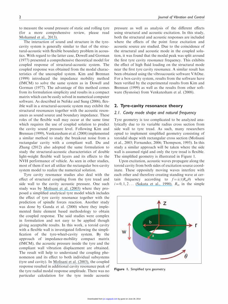
Tyre geometry is too complicated to be analyzed ana-lytically due to its variable radius cross section fromside wall to tyre tread. As such, many researchersopted to implement simplified geometry consisting oftoroidal shape with rectangular cross section (Molisaniet al., 2003; Fernandez, 2006; Thompson, 1995). In thisstudy a similar approach will be taken where the sidewall is assumed rigid and only the tyre tread is flexible.The simplified geometry is illustrated in Figure 1.
Upon excitation, acoustic waves propagate along thetoroid cavity from both sides of excitation source coord-inate. These oppositely moving waves interfere witheach other and therefore creating standing wave at cer-tain frequency according to f¼ ic/(Rm�) wherei¼ 0, 1, 2 . . . (Sakata et al., 1990). Rm in the simple
Figure 1. Simplified tyre geometry.
2 Journal of Vibration and Control
by guest on June 28, 2014jvc.sagepub.comDownloaded from
XML Template (2014) [23.5.2014–12:07pm] [1–17]//blrnas3/cenpro/ApplicationFiles/Journals/SAGE/3B2/JVCJ/Vol00000/140099/APPFile/SG-JVCJ140099.3d (JVC) [PREPRINTER stage]
formula is the centre cavity radius (aþ b)/2, � is 2p, andc is the speed of sound. Assuming the fluid in cavity ishomogenous, inviscid, isotropic and compressible, the‘sound pressure field’ p in the cavity satisfies the inhomo-geneous wave equation in equation (1) (rectangularcoordinates) or equation (2) (cylindrical coordinate).
@2p
@x2þ@2p
@y2þ@2p
@z2¼
1
c2@2p
@t2ð1Þ
@2p
@r2þ1
r
@p
@rþ
1
r2@2p
@�2þ@2p
@z2þ k2p ¼ 0 ð2Þ
where k¼!/c. k is the wavenumber, ! is circular fre-quency in radian/second, and c is the speed of sound at343m/s. Using separation of variables and to letpðr, �, z,!Þ ¼
Ps Ds’sðr, �, zÞ where Ds is the acoustic
modal amplitude and ’(r, �, z)¼R(r)�(�)Z(z) whichleads to three differential systems related to axial,radial, and azimuthal direction, a general solution canbe written as
�s r, �, zð Þ ¼ Vmnl AnJn kmnrð Þ þ BnYn kmnrð Þ½ �
e�im� þ d0eim�
� �e�iklz þ c0e
iklz� �
ð3Þ
where Jm and Ym are respectively the Bessel functionsof the first and second kind, both of order m. Vmnl is aconstant, while An and Bn are constants for all the threesound wave components which depend on the bound-ary conditions. For this work, all the annulus surfacesare considered rigid except the outer shell. The 2nd and3rd systems are reduced to single term such as
�s r, �, zð Þ ¼ Vmnl AnJn kmnrð Þ þ BnYn kmnrð Þ½ �
cosðm�Þ cosl�z
W
� �ð4Þ
An and Bn are given by An ¼ Y0nð��Þ and Bn ¼ �J0nð��Þ.
In equation (4), the coefficient d0 of the 2nd sound wavecomponent becomes unity due to the continuity of thetyre tread shell in the circumferential direction, whilethe coefficient c0 for the 3rd sound wave componentbecomes unity due to the velocity Z0(0)¼ 0. The wavenumber of kl ¼
l�W is due to the velocity Z0ðWÞ ¼ 0.
Implementing boundary conditions such as R0(a)¼ 0and R0(b)¼ 0 where �¼ b/a and letting ka¼ x, thefirst system simplifies the relationship to
J0m xð ÞY0m �xð Þ � Y0m xð ÞJ0m �xð Þ ¼ 0 ð5Þ
Equation (5) is one of the common Bessel characteristicequations in the physical problem. For this case, it isused for calculation of modal oscillation frequencies ofthe incompressible liquid in an annulus container.
Solving the equation for its roots will allow us to cal-culate the cavity natural frequency which is given by
f ¼c
2�
ffiffiffiffiffiffiffiffiffiffiffiffiffiffiffiffiffiffiffiffiffiffiffiffiffiffiffix
a
� �2þ
l�
W
� �2s
where l ¼ 0, 1, 2, . . . ð6Þ
The acoustic wavenumber k is given by
k2 ¼ k2mn þ k2l ð7Þ
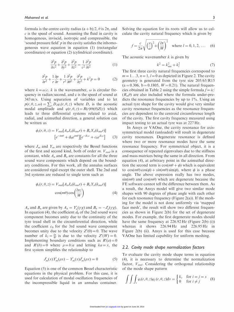
The first three cavity natural frequencies correspond tom¼ 1. . .3, n¼ 1, l¼ 0 as depicted in Figure 2. The cavitygeometry is generated from the tyre size 205/65/R15(a¼ 0.306, b¼ 0.1805, W¼ 0.21). The natural frequen-cies obtained in Table 2 using the simple formula f¼ ic/(Rm�) are also included where the formula under-pre-dicts the resonance frequencies by up to 1%. Using anactual tyre shape for the cavity would give very similarcavity resonance frequencies as the resonance frequen-cies are dependent to the centroid circumference lengthof the cavity. The first cavity frequency measured usingimpact testing to an actual tyre was at 227Hz.
In Ansys or VAOne, the cavity resonance for axis-symmetrical model (unloaded) will result in degeneratecavity resonances. Degenerate resonance is definedwhere two or more resonance modes have the sameresonance frequency. For symmetrical object, it is aconsequence of repeated eigenvalues due to the stiffnessand mass matrices being the same in all direction. Fromequation (4), at arbitrary point in the azimuthal direc-tion the second term is cos m� þ �ð Þ which is equivalentto cos m�ð Þ cos �ð Þ þ sin m�ð Þ sin �ð Þ, where � is a phaseangle. The above expression really has two modes,sin m�ð Þ and cos m�ð Þ which are degenerate because theFE software cannot tell the difference between them. Asa result, the Ansys model will give two similar modeshapes with 90 degrees of phase angle with each otherfor each resonance frequency (Figure 2(a)). If the mesh-ing for the model is not done uniformly via ‘mappedface mesh’, the result will show two different frequen-cies as shown in Figure 2(b) for the set of degeneratemodes. For example, the first degenerate modes shouldhave the same frequency at 226.92Hz (Figure 2(b) (i))whereas it shows 226.94Hz and 226.95Hz inFigure 2(b) (ii). Ansys is used for this case becauseVAOne has limited capability for uniform meshing.
2.2. Cavity mode shape normalization factors
To evaluate the cavity mode shape terms in equation(4), it is necessary to determine the normalizationfactor, Vmnl. Considering the orthogonal relationshipof the mode shape patternZ Z Z
v
’iðr, �, zÞ’j ðr, �, zÞdv ¼ks for i ¼ j ¼ s0 for i 6¼ j
ð8Þ
Mohamed et al. 3
by guest on June 28, 2014jvc.sagepub.comDownloaded from
XML Template (2014) [23.5.2014–12:07pm] [1–17]//blrnas3/cenpro/ApplicationFiles/Journals/SAGE/3B2/JVCJ/Vol00000/140099/APPFile/SG-JVCJ140099.3d (JVC) [PREPRINTER stage]
Hence for i¼ j, ’iðr, �, zÞ ¼ ’j ðr, �, zÞ ¼ ’sðr, �, zÞ,
U2mnl
Z a
b
Y0n kmnDi
2
� �Jn kmnrð Þ�J0n kmn
Di
2
� �Yn kmnrð Þ
�2dr
Z 2�
0
cosðm�ð Þ2d�
Z W
0
cosl�z
L
� �� �2
dz¼ ks ð9Þ
Letting
Qmn ¼
Z a
b
Y0m kmn
Di
2
� �JmðkmnrÞ
� J0m kmnDi
2
� �YmðkmnrÞ
�2r dr
where a¼Do/2; b¼Di/2. It follows that
Umnl ¼
ffiffiffiffiffiffiffiffiffiffiffiffiffiffiffiffiffiffiffiffiffiffiffiffiffiffiffiffiffiffiffiffiffiffiffiffiffiffiffiffiks= ðQmnÞð�Þ L=2ð Þ
� qfor m ¼ 1 . . .N�,
n ¼ 1 . . .Nr, l ¼ 1 . . .Nz ð10Þ
It is assumed that Vmnl ¼Umnlffiffiffi
ksp where Vmnl is the normal-
ized mode shape coefficient and given in Table 1 form¼ 1. . .N�, n¼ 0. . .Nr, l¼ 0. . .Nz. m represents theroot number of the Bessel’s function which start from1. In the table, Qmn is only calculated for m¼ 1,2 whilethe rests of the terms are shown as Vmnl.
2.3. Structure natural frequency and mode shape
Tyre tread can be treated as a thin finite cylindrical shellfor adopting thin shell theory due to tyre tread thick-ness is less than 10% of the shell radius (Blevins, 1995).There are several shell theories in literature since Love’swork (1888) but they are different because of the vari-ous assumptions on the order and form of small termsin them. The Donnel-Mushtari shell theory is by far thesimplest and has been adopted in other tyre case studiesfor the simply supported condition (Molisani et al.,2003).
Figure 2. (a) The first tyre cavity mode shape at 226.9 Hz (Ansys). (b). Effect of mesh types on the degenerate modes.
4 Journal of Vibration and Control
by guest on June 28, 2014jvc.sagepub.comDownloaded from
XML Template (2014) [23.5.2014–12:07pm] [1–17]//blrnas3/cenpro/ApplicationFiles/Journals/SAGE/3B2/JVCJ/Vol00000/140099/APPFile/SG-JVCJ140099.3d (JVC) [PREPRINTER stage]
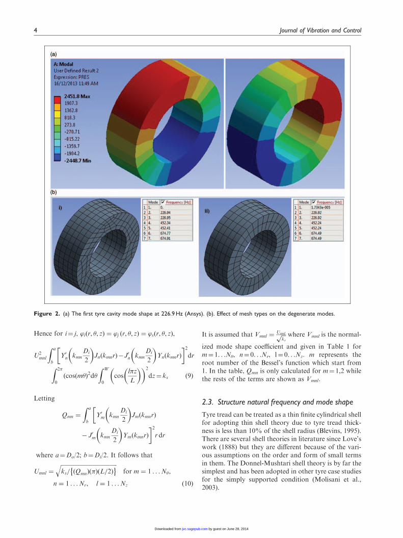
Figure 3 illustrates the cylindrical shell showing a r,�, z coordinate and the displacements in u, v, wdirections. The solution forms for midsurface deform-ation are
uz ¼ Az cosl�z
L
� �cos m�ð Þ cos !tð Þ
v� ¼ A� sinl�z
L
� �sin m�ð Þ cos !tð Þ
wr ¼ Ar sinl�z
L
� �cos m�ð Þ cos !tð Þ,
l ¼ 1, 2, 3 . . . ; m ¼ 1, 2, 3::
ð11Þ
where Ar, A�, Az are the coefficients that describe theamplitudes of the deformation and L is the shell length
where k¼ h2/12R2, r4¼r2r2, r2 ¼ @2
@z2þ @2
@�2, �s is the
shell density, n is Poisson’s ratio, R is mid-shell radius,E is the Young’s modulus, h is the shell thickness.
Applying Donnel-Mushtari operator in equation (12)to the shell directional displacement in equation (11)will result in a system of matrices in equation (13)whose determinant equal to zero where the dimension-less parameter specifying the cylinder shell natural fre-quency V will be solved. V then can be plugged inequation (14) for the shell natural frequency flm. Inthe matrix, V2 term for the first two diagonal terms isignored due to retaining only the inertia term asso-ciated with radial deformation (wr) whereas the inertiaterm associated with in-plane deformation (uz and v�)are neglected (Blevins, 1995). This is also supported bythe fact that the tread natural frequencies from 180Hz
@2
@z2þ
1� �ð Þ
2
@2
@�2� �s
1� �2� �
R2
E
@2
@t2
1þ �ð Þ
2
@2
@z@��@
@z
1þ �ð Þ
2
@2
@z@�1� �ð Þ
2
@2
@z2þ@2
@�2� �s
1� �2� �
R2
E
@2
@t2
@
@�
�@
@z
@
@�1þ kr4 þ �s
1� �2� �
R2
E
@2
@t2
266666664
377777775
uz
v�
wr
264
375
¼
0
0
0
264
375 ð12Þ
Figure 3. Circular cylinder shell.
Table 1. Normalized mode shape coefficients.
Vmnl(m�1.5) Qmn(m) m n lffiffiffiffiffiffiffiffiffiffiffiffiffiffiffiffiffiffiffiffiffiffiffiffiffiffiffiffiffiffiffiffiffiffi
1= ðQmnÞð�Þ Wð Þ� q
8.207 1 0 0ffiffiffiffiffiffiffiffiffiffiffiffiffiffiffiffiffiffiffiffiffiffiffiffiffiffiffiffiffiffiffiffiffiffi1= ðQmnÞð�Þ Wð Þ
� q15.705 2 0 0ffiffiffiffiffiffiffiffiffiffiffiffiffiffiffiffiffiffiffiffiffiffiffiffiffiffiffiffiffiffiffiffiffiffi
1= ðQmnÞð�Þ Wð Þ� q
1. . .N� 0 0ffiffiffiffiffiffiffiffiffiffiffiffiffiffiffiffiffiffiffiffiffiffiffiffiffiffiffiffiffiffiffiffiffiffi1= ðQmnÞð�Þ Wð Þ
� q1. . .N� 0 1. . .Nzffiffiffiffiffiffiffiffiffiffiffiffiffiffiffiffiffiffiffiffiffiffiffiffiffiffiffiffiffiffiffiffiffiffi
1= ðQmnÞð�Þ Wð Þ� q
1. . .N� 1. . .Nr 0ffiffiffiffiffiffiffiffiffiffiffiffiffiffiffiffiffiffiffiffiffiffiffiffiffiffiffiffiffiffiffiffiffiffi2= ðQmnÞð�Þ Wð Þ
� q1. . .N� 1. . .Nr 1. . .Nz
Table 2. First three tyre cavity resonances.
Tyre size
Cavity
outer
radius
Cavity
inner
radius
f
(Bessel root
method) f ¼ ic/(Rm�) Ansys
205/65/R15 306 180.5 226.8 224.4 226.9
452.1 448.8 452.2
674.4 673.2 674.5
Mohamed et al. 5
by guest on June 28, 2014jvc.sagepub.comDownloaded from
XML Template (2014) [23.5.2014–12:07pm] [1–17]//blrnas3/cenpro/ApplicationFiles/Journals/SAGE/3B2/JVCJ/Vol00000/140099/APPFile/SG-JVCJ140099.3d (JVC) [PREPRINTER stage]
to 250Hz are all those with radial modes (Wang et al.,2014)
det
�2� 1�v2
� �i2 i1þv
2 v
i1þv2 � 1�v
2
� �2� i2 �i
�v i��2þ1þ h2
12R2
� �2þ i2� �2
8<:
9=;
2666664
3777775
¼ 0 ð13Þ
where ¼ jpR/L and i, j are mode order numbers.
flm ¼�
2�R
E
�s 1� �2ð Þ
�1=2ð14Þ
To identify which modes are relevant to the frequencyrange in this paper, modal analysis is performed to thecylinder shell with R 0.3135m, L 0.21m and h 0.015m.Material specification is taken from the results of thetyre tread cut-out tensile test done in-house followingthe method described in Yang et al. (2010). The ten-sile test specimen was taken from Bridgestone RE92205/65/R15. The measured Young’s modulus is2.61E8Pa with Poisson ratio of 0.45 and density of1230 kg/m3.
The natural frequencies calculated using equation(14) are compared with those obtained from VAOnefor uncoupled case and listed in Table 3 for the rangebetween 180–250Hz. It is seen that for the lower radialmode numbers, Donnel-Mushtari shell theory givesacceptable results in comparison with finite elementsoftware. In order to match the mode numbers fromthe FE software with those from the analytical method,careful observation is needed because from equation(14), a number of radial modes may have a lower res-onance frequency than the lower radial mode number.In FE software however, the order of the modes arefrom low to high frequency. So in the FE result, themode shapes has to be visually inspected to match themodes from equation (14). For an actual tyre consistsof tyre tread and side wall, the structural resonancefrequencies would differ than shown in Table 3.However, the vibration modes of an actual tyre arevery similar to the tread-only model as observed inanother study (Wang et al., 2014).
The mode shapes function for thin circular cylin-drical shell with simply supported boundary isdefined by
’ml �, zð Þ ¼ B2mlsin
l�z
L
� �cos m�ð Þ ð15Þ
Bml is the normalized plate mode shape coefficient andlisted in Table 4 where m and l are modal truncationnumber in the � and z directions.
3. Tyre cavity structural-acousticcoupling
In this study, tyre tread is considered flexible whichtakes the excitation from the tyre-road interaction aswell as fluid loading from the inside cavity. Due to thefluid loading, a fully coupled solution is needed todescribe the structural-acoustic response of the tyre-cavity system. As described in Fahy and Gardonio(2006), for a coupled system, if the natural frequencyof the structure equals the natural frequency of thecavity, the coupled natural frequency will split intotwo: one above uncoupled frequency and one below.
3.1. Impedance mobility approach
As in Kim and Brennan (1999), for single input acousticsystem, the uncoupled mobility Y and impedance Z aredefined as
ZA ¼ p=Q, YA ¼ Q=p ð16Þ
While for single input structural system, they aredefined as
ZS ¼ F=u, YS ¼ u=F ð17Þ
where F is the applied force, u is the resulting velocity, pis the acoustic pressure, and Q is the source strength.For coupled mobility ZCA and impedance ZCS, theyrelates to the uncoupled terms by
ZCA ¼ C2ZA, YCS ¼ C2YS ð18Þ
Table 3. Tread natural frequencies for 180–380 Hz.
Analytical (Hz) VAOne (Hz) Mode (m,l)
192.9 178.4 (4,1)
200.2 191.2 (3,1)
202.1 182.5 (5,1)
219.0 215.3 (2,1)
227.7 204.1 (6,1)
238.6 239.9 (1,1)
266.8 240.1 (7,1)
316.7 287.4 (8,1)
375.8 343.7 (9,1)
Table 4. Normalized plate mode shape coefficients.
Bml m l
1=ffiffiffiffiffiffi�Lp
0 1. . .. . .NZffiffiffi2p=ffiffiffiffiffiffi�Lp
1. . .. . . N� 1. . .. . .NZ
6 Journal of Vibration and Control
by guest on June 28, 2014jvc.sagepub.comDownloaded from
XML Template (2014) [23.5.2014–12:07pm] [1–17]//blrnas3/cenpro/ApplicationFiles/Journals/SAGE/3B2/JVCJ/Vol00000/140099/APPFile/SG-JVCJ140099.3d (JVC) [PREPRINTER stage]
C is the coupling factor that relates the structural andacoustic response. The acoustic pressure and structuralvelocity are related to source strength and appliedforce by
u ¼1
1þ YSZCAYS F� SZAQð Þ,
p ¼1
1þ ZAYCSZA Qþ SYSFð Þ
ð19Þ
For a weakly coupled system, where the structure or theacoustic response behave independently of the other,the above equations are given by
u ¼ YS F� SZAQð Þ, p ¼ ZA Qþ SYSFð Þ ð20Þ
From equation (2), the acoustic pressure in thetyre cavity at location (r,�,z) and flexible wall vibra-tion velocity at location (�,z) on the shell can beexpressed as
p r, �, z,!ð Þ ¼XNn¼1
’n r, �, zð Þan !ð Þ ¼ Ta ð21Þ
u �, z,!ð Þ ¼XMm¼1
�m �, zð Þbm !ð Þ ¼ rTb ð22Þ
where a and b are the complex amplitude of the pres-sure modes and the vibration velocity modes in matrixform. For the case whereby the system receives bothacoustic and structural excitation, the complex ampli-tudes are given as
an !ð Þ ¼�0c
2
Vn !ð Þ qn þ
XNn¼1
Cmnbm !ð Þ
!ð23Þ
bm !ð Þ ¼1
�shS�m !ð Þ gm �
XNn¼1
CTmnan !ð Þ
!ð24Þ
gm ¼RS �mð�, zÞÞ f ð�, z,!ÞdS and qn ¼
RV ’nðr, �, zÞ �
sðr, �, z,!ÞdV are respectively the generalized modalforce and acoustic strength. �0 is the air density, �s isthe tyre tread mass density, V is the tyre cavity volume,S is the tyre tread surface area, and h is the tyre treadthickness. The resonance terms n(!) and �m(!) aregiven by
1 !ð Þ ¼1
1=T60 þ i!for n ¼ 1 ð25aÞ
n !ð Þ ¼i!
!2n � !
2 þ j2�n!n!for n 6¼ 1 ð25bÞ
�m !ð Þ ¼i!
!2m � !
2 þ j2�m!m!ð26Þ
T60 is the reverberation time to 60 dB and � is thedamping loss factor. If only one source of excitationis present then either gm or qn is zero. Cmn representsa dimensionless coupling coefficient between theuncoupled structural and acoustic mode shapes overthe vibrating structure surface where it is expressed as
Cmn ¼
ZS
’n r, �, zð Þ�m r, �, zð ÞdS ð27Þ
Cmn is a measure of spatial match between the tyretread and cavity modes. For rectangular box-cavitythis coupling coefficient can be simplified according toformula in Kim and Brennan (1999). For cylinder shellstructure, this can be calculated in numerical softwaresuch as Matlab.
Equations (23) and (24) can be written in matrixform as
a ¼ Za qþ Cbð Þ ð28aÞ
b ¼ Ys g� CTa� �
ð28bÞ
The coupled acoustic modal impedance and mobilitymatrix are written as
Zca ¼ CTZaC, Ycs ¼ CYsCT
ð29Þ
Solving simultaneous matrix equation from equations(28a) and (28b) will result in the form of coupledresponses for the tyre-cavity system consisting of
a ¼ Iþ ZaYcsð Þ�1Za qþ CYsgð Þ ð30Þ
b ¼ Iþ YaZcað Þ�1Ys q� CTZaq
� �ð31Þ
Equations (30) and (31) can be replaced in equations(21) and (22) to obtain the acoustic pressure in the tyrecavity or the structural velocity of the tyre tread.
For this structurally excited tyre-cavity system, if thetyre tread responds as if it was in vacuo then thecoupled acoustic impedance has a minor effect onthe tyre tread. In the same way this system is to besaid as weakly coupled. Detail argument and derivationon this matter can be found in Kim and Brennan(1999). For the case of weak coupling equations (30)and (31) become
a ¼ Za qþ CYsgð Þ ð32Þ
b ¼ Ys q� CTZaq� �
ð33Þ
Mohamed et al. 7
by guest on June 28, 2014jvc.sagepub.comDownloaded from
XML Template (2014) [23.5.2014–12:07pm] [1–17]//blrnas3/cenpro/ApplicationFiles/Journals/SAGE/3B2/JVCJ/Vol00000/140099/APPFile/SG-JVCJ140099.3d (JVC) [PREPRINTER stage]
The degree of coupling between tyre structure and tyrecavity is dependent on the ratio of the acoustic cavitybulk stiffness to the tyre tread mass, the normalizedcoupling coefficient, and the acoustic mode and thestructural mode resonance terms n, �m (Kim andBrennan, 1999).
4. Numerical simulation
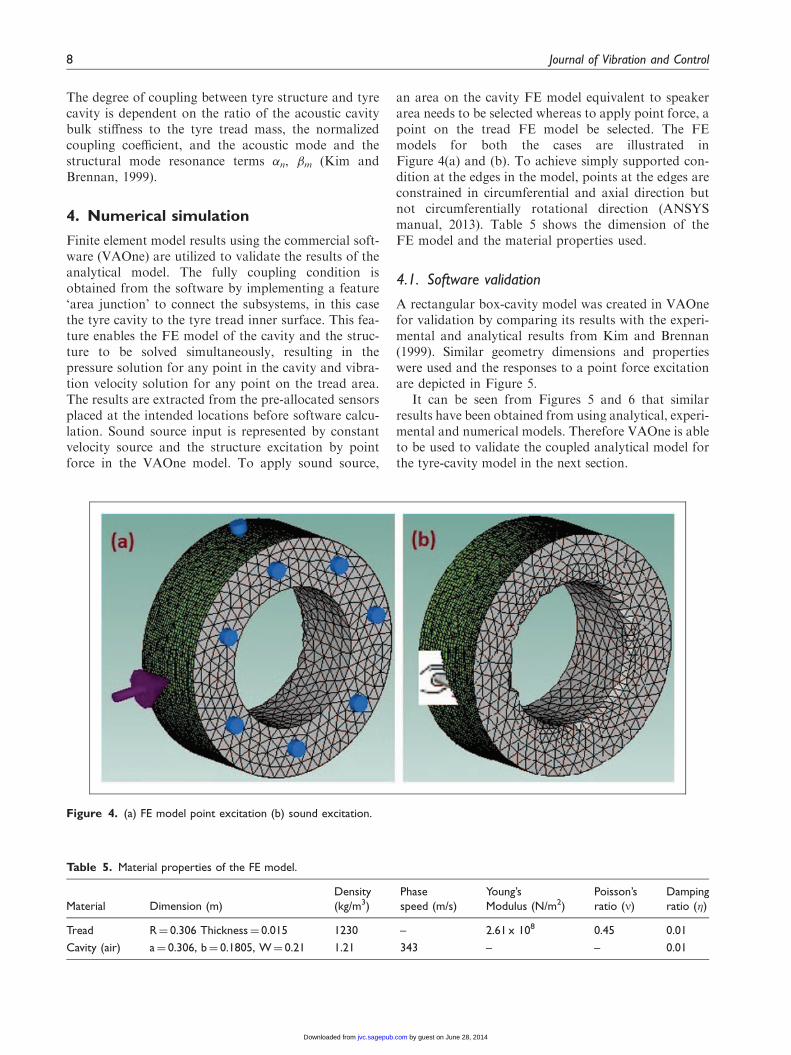
Finite element model results using the commercial soft-ware (VAOne) are utilized to validate the results of theanalytical model. The fully coupling condition isobtained from the software by implementing a feature‘area junction’ to connect the subsystems, in this casethe tyre cavity to the tyre tread inner surface. This fea-ture enables the FE model of the cavity and the struc-ture to be solved simultaneously, resulting in thepressure solution for any point in the cavity and vibra-tion velocity solution for any point on the tread area.The results are extracted from the pre-allocated sensorsplaced at the intended locations before software calcu-lation. Sound source input is represented by constantvelocity source and the structure excitation by pointforce in the VAOne model. To apply sound source,
an area on the cavity FE model equivalent to speakerarea needs to be selected whereas to apply point force, apoint on the tread FE model be selected. The FEmodels for both the cases are illustrated inFigure 4(a) and (b). To achieve simply supported con-dition at the edges in the model, points at the edges areconstrained in circumferential and axial direction butnot circumferentially rotational direction (ANSYSmanual, 2013). Table 5 shows the dimension of theFE model and the material properties used.
4.1. Software validation
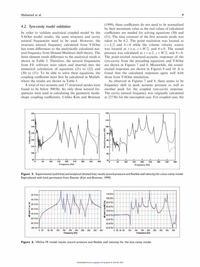
A rectangular box-cavity model was created in VAOnefor validation by comparing its results with the experi-mental and analytical results from Kim and Brennan(1999). Similar geometry dimensions and propertieswere used and the responses to a point force excitationare depicted in Figure 5.
It can be seen from Figures 5 and 6 that similarresults have been obtained from using analytical, experi-mental and numerical models. Therefore VAOne is ableto be used to validate the coupled analytical model forthe tyre-cavity model in the next section.
Figure 4. (a) FE model point excitation (b) sound excitation.
Table 5. Material properties of the FE model.
Material Dimension (m)
Density
(kg/m3)
Phase
speed (m/s)
Young’s
Modulus (N/m2)
Poisson’s
ratio (n)
Damping
ratio (�)
Tread R¼ 0.306 Thickness¼ 0.015 1230 – 2.61 x 10⁸ 0.45 0.01
Cavity (air) a¼ 0.306, b¼ 0.1805, W¼ 0.21 1.21 343 – – 0.01
8 Journal of Vibration and Control
by guest on June 28, 2014jvc.sagepub.comDownloaded from
XML Template (2014) [23.5.2014–12:07pm] [1–17]//blrnas3/cenpro/ApplicationFiles/Journals/SAGE/3B2/JVCJ/Vol00000/140099/APPFile/SG-JVCJ140099.3d (JVC) [PREPRINTER stage]
4.2. Tyre-cavity model validation
In order to validate analytical coupled model by theVAOne model results, the same structure and cavitynatural frequencies need to be used. However, thestructure natural frequency calculated from VAOnehas some differences to the analytically calculated nat-ural frequency from Donnel-Mushtari shell theory. Thefinite element result difference to the analytical result isshown in Table 3. Therefore, the natural frequenciesfrom FE software were taken and inserted into thenumerical calculation of equations (21) to (22) and(30) to (31). To be able to solve these equations, thecoupling coefficient must first be calculated in Matlab,where the results are shown in Table 5.
A total of two acoustic and 17 structural modes werefound to be below 500Hz. So only these natural fre-quencies were used in calculating the geometric mode-shape coupling coefficients. Unlike Kim and Brennan
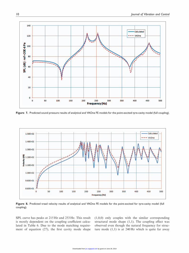
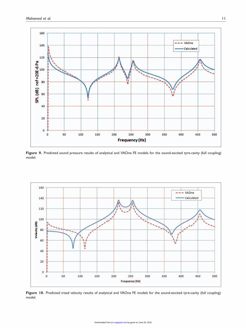
(1999), these coefficients do not need to be normalizedby their maximum value as the real values of calculatedcoefficients are needed for solving equations (30) and(31). The time constant of the first acoustic mode wastaken to be 0.2. The point excitation was located atz¼L/2 and �¼ 0 while the volume velocity sourcewas located at r¼ a, z¼W/2, and �¼ 0. The soundpressure was calculated at r¼ a/2, z¼W/2, and �¼ 0.The point-excited structural-acoustic responses of thetyre-cavity from the preceding equations and VAOneare shown in Figures 7 and 8. Meanwhile, the sound-excited responses are shown in Figures 9 and 10. It isfound that the calculated responses agree well withthose from VAOne simulation.
As observed in Figures 7 and 8, there seems to befrequency shift in peak acoustic pressure as well asanother peak for the coupled tyre-cavity response.The cavity natural frequency was originally calculatedat 227Hz for the uncoupled case. For coupled case, the
Figure 5. Experimental (solid line) and analytical (dotted line) results (sound pressure and flexible wall velocity) for a box-cavity model.
Reproduced with kind permission from Elsevier (Kim and Brennan, 1999).
Figure 6. VAOne FE model results (sound pressure and flexible wall velocity) for the box-cavity model.
Mohamed et al. 9
by guest on June 28, 2014jvc.sagepub.comDownloaded from
XML Template (2014) [23.5.2014–12:07pm] [1–17]//blrnas3/cenpro/ApplicationFiles/Journals/SAGE/3B2/JVCJ/Vol00000/140099/APPFile/SG-JVCJ140099.3d (JVC) [PREPRINTER stage]
SPL curve has peaks at 215Hz and 253Hz. This resultis mostly dependent on the coupling coefficient calcu-lated in Table 6. Due to the mode matching require-ment of equation (27), the first cavity mode shape
(1,0,0) only couples with the similar correspondingstructural mode shape (1,1). The coupling effect wasobserved even though the natural frequency for struc-ture mode (1,1) is at 240Hz which is quite far away
Figure 7. Predicted sound pressure results of analytical and VAOne FE models for the point-excited tyre-cavity model (full coupling).
Figure 8. Predicted tread velocity results of analytical and VAOne FE models for the point-excited for tyre-cavity model (full
coupling).
10 Journal of Vibration and Control
by guest on June 28, 2014jvc.sagepub.comDownloaded from
XML Template (2014) [23.5.2014–12:08pm] [1–17]//blrnas3/cenpro/ApplicationFiles/Journals/SAGE/3B2/JVCJ/Vol00000/140099/APPFile/SG-JVCJ140099.3d (JVC) [PREPRINTER stage]
Figure 9. Predicted sound pressure results of analytical and VAOne FE models for the sound-excited tyre-cavity (full coupling)
model.
Figure 10. Predicted tread velocity results of analytical and VAOne FE models for the sound-excited tyre-cavity (full coupling)
model.
Mohamed et al. 11
by guest on June 28, 2014jvc.sagepub.comDownloaded from
XML Template (2014) [23.5.2014–12:08pm] [1–17]//blrnas3/cenpro/ApplicationFiles/Journals/SAGE/3B2/JVCJ/Vol00000/140099/APPFile/SG-JVCJ140099.3d (JVC) [PREPRINTER stage]
from the cavity mode (1,0,0) at 227Hz. Other couplingcoefficients are mostly zero except for the acousticmode (2,0,0) to structural mode (2,1). However, thestructural natural frequency at mode (2,1) is 215Hz,far away from the acoustic mode (2,0,0) at 455Hz.Hence no frequency shift in acoustic pressure wasobserved for the second cavity mode.
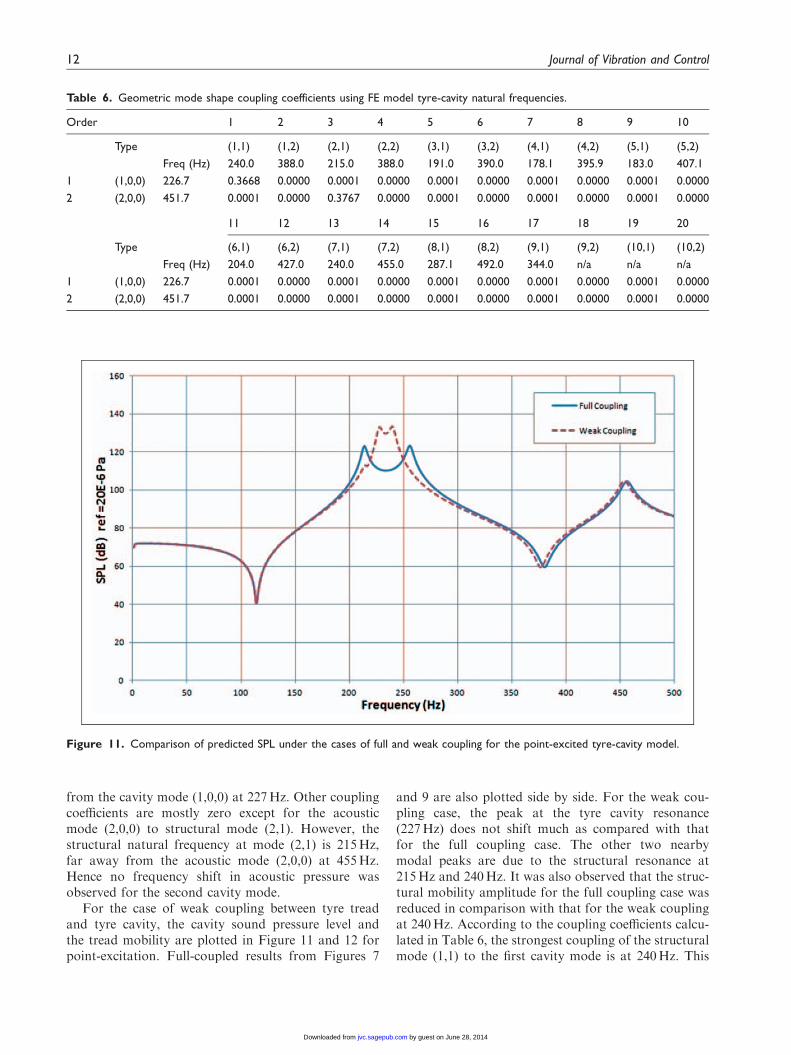
For the case of weak coupling between tyre treadand tyre cavity, the cavity sound pressure level andthe tread mobility are plotted in Figure 11 and 12 forpoint-excitation. Full-coupled results from Figures 7
and 9 are also plotted side by side. For the weak cou-pling case, the peak at the tyre cavity resonance(227Hz) does not shift much as compared with thatfor the full coupling case. The other two nearbymodal peaks are due to the structural resonance at215Hz and 240Hz. It was also observed that the struc-tural mobility amplitude for the full coupling case wasreduced in comparison with that for the weak couplingat 240Hz. According to the coupling coefficients calcu-lated in Table 6, the strongest coupling of the structuralmode (1,1) to the first cavity mode is at 240Hz. This
Figure 11. Comparison of predicted SPL under the cases of full and weak coupling for the point-excited tyre-cavity model.
Table 6. Geometric mode shape coupling coefficients using FE model tyre-cavity natural frequencies.
Order 1 2 3 4 5 6 7 8 9 10
Type (1,1) (1,2) (2,1) (2,2) (3,1) (3,2) (4,1) (4,2) (5,1) (5,2)
Freq (Hz) 240.0 388.0 215.0 388.0 191.0 390.0 178.1 395.9 183.0 407.1
1 (1,0,0) 226.7 0.3668 0.0000 0.0001 0.0000 0.0001 0.0000 0.0001 0.0000 0.0001 0.0000
2 (2,0,0) 451.7 0.0001 0.0000 0.3767 0.0000 0.0001 0.0000 0.0001 0.0000 0.0001 0.0000
11 12 13 14 15 16 17 18 19 20
Type (6,1) (6,2) (7,1) (7,2) (8,1) (8,2) (9,1) (9,2) (10,1) (10,2)
Freq (Hz) 204.0 427.0 240.0 455.0 287.1 492.0 344.0 n/a n/a n/a
1 (1,0,0) 226.7 0.0001 0.0000 0.0001 0.0000 0.0001 0.0000 0.0001 0.0000 0.0001 0.0000
2 (2,0,0) 451.7 0.0001 0.0000 0.0001 0.0000 0.0001 0.0000 0.0001 0.0000 0.0001 0.0000
12 Journal of Vibration and Control
by guest on June 28, 2014jvc.sagepub.comDownloaded from
XML Template (2014) [23.5.2014–12:08pm] [1–17]//blrnas3/cenpro/ApplicationFiles/Journals/SAGE/3B2/JVCJ/Vol00000/140099/APPFile/SG-JVCJ140099.3d (JVC) [PREPRINTER stage]
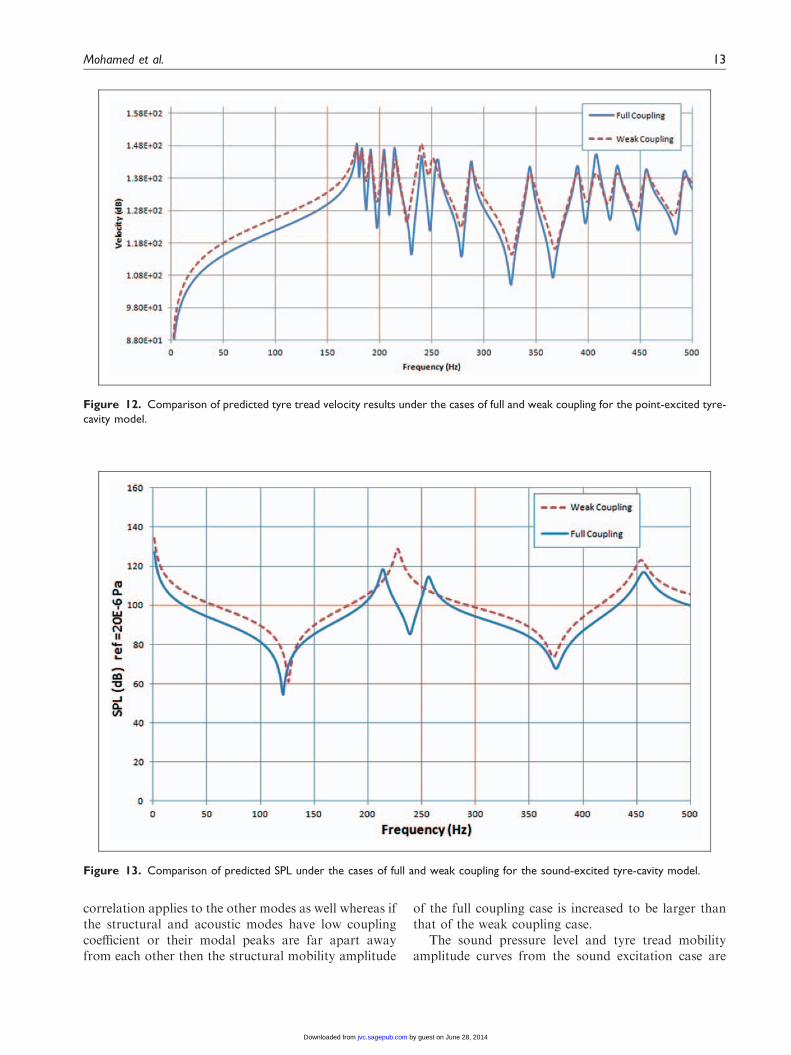
correlation applies to the other modes as well whereas ifthe structural and acoustic modes have low couplingcoefficient or their modal peaks are far apart awayfrom each other then the structural mobility amplitude
of the full coupling case is increased to be larger thanthat of the weak coupling case.
The sound pressure level and tyre tread mobilityamplitude curves from the sound excitation case are
Figure 13. Comparison of predicted SPL under the cases of full and weak coupling for the sound-excited tyre-cavity model.
Figure 12. Comparison of predicted tyre tread velocity results under the cases of full and weak coupling for the point-excited tyre-
cavity model.
Mohamed et al. 13
by guest on June 28, 2014jvc.sagepub.comDownloaded from
XML Template (2014) [23.5.2014–12:08pm] [1–17]//blrnas3/cenpro/ApplicationFiles/Journals/SAGE/3B2/JVCJ/Vol00000/140099/APPFile/SG-JVCJ140099.3d (JVC) [PREPRINTER stage]
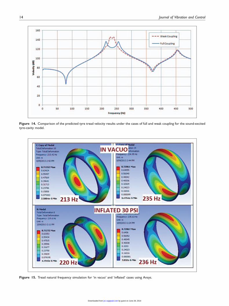
Figure 15. Tread natural frequency simulation for ‘in vacuo’ and ‘inflated’ cases using Ansys.
Figure 14. Comparison of the predicted tyre tread velocity results under the cases of full and weak coupling for the sound-excited
tyre-cavity model.
14 Journal of Vibration and Control
by guest on June 28, 2014jvc.sagepub.comDownloaded from
XML Template (2014) [23.5.2014–12:08pm] [1–17]//blrnas3/cenpro/ApplicationFiles/Journals/SAGE/3B2/JVCJ/Vol00000/140099/APPFile/SG-JVCJ140099.3d (JVC) [PREPRINTER stage]
depicted in Figures 13 and 14. It is seen that the soundpressure level for the weak coupling case correlates tothe single peak of first tyre cavity resonance at 227Hz,whereas only for the full coupling case, there are twopeaks. These two peaks correlate to the two modalpeaks in the tread velocity plot. It is clear that the struc-tural resonances cannot be excited as much using thesound excitation than the point excitation. One pointneeds to be noted that if the sound pressure fluctuationis contributing to the force transfer to the spindle, thenthe coupling of the tyre-cavity actually helps to reducethe vibration effect since the sound pressure level in fullcoupling case is lower than that of the weak couplingcase (Figure 13). Previously, the force to spindle wascalculated from the tyre structure vibration through thecylinder shell boundaries (Molisani et al., 2003).
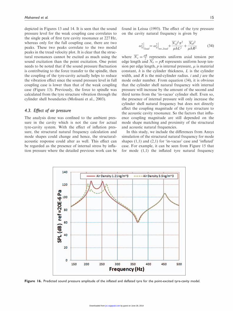
4.3. Effect of air pressure
The analysis done was confined to the ambient pres-sure in the cavity which is not the case for actualtyre-cavity system. With the effect of inflation pres-sure, the structural natural frequency calculation andmode shapes could change and hence, the structural-acoustic response could alter as well. This effect canbe regarded as the presence of internal stress by infla-tion pressure where the detailed previous work can be
found in Leissa (1993). The effect of the tyre pressureon the cavity natural frequency is given by
!2ij
���load¼ !2
ij
���no load
þNxj
2�2
hL2þ
N�i2
hR2ð34Þ
where Nx ¼pR2 represents uniform axial tension per
edge length and N� ¼ pR represents uniform hoop ten-sion per edge length, p is internal pressure, is materialconstant, h is the cylinder thickness, L is the cylinderwidth, and R is the mid-cylinder radius. i and j are themode order number. From equation (34), it is obviousthat the cylinder shell natural frequency with internalpressure will increase by the amount of the second andthird terms from the ‘in-vacuo’ cylinder shell. Even so,the presence of internal pressure will only increase thecylinder shell natural frequency but does not directlyaffect the coupling magnitude of the tyre structure tothe acoustic cavity resonance. So the factors that influ-ence coupling magnitude are still depended on themode shape matching and proximity of the structuraland acoustic natural frequencies.
In this study, we include the differences from Ansyssimulation of the structural natural frequency for modeshapes (1,1) and (2,1) for ‘in-vacuo’ case and ‘inflated’case. For example, it can be seen from Figure 15 thatfor mode (1,1) the inflated tyre natural frequency
Figure 16. Predicted sound pressure amplitude of the inflated and deflated tyre for the point-excited tyre-cavity model.
Mohamed et al. 15
by guest on June 28, 2014jvc.sagepub.comDownloaded from
XML Template (2014) [23.5.2014–12:08pm] [1–17]//blrnas3/cenpro/ApplicationFiles/Journals/SAGE/3B2/JVCJ/Vol00000/140099/APPFile/SG-JVCJ140099.3d (JVC) [PREPRINTER stage]
increases to 236Hz from 235Hz whereas for mode(2,1), it increases to 220Hz from 213Hz. The naturalfrequencies calculated by Ansys have some differencesfrom those in Table 3. However, one can choose anyother shell theories that could give the best results vali-dated by experimental data. All of the ‘inflated’ struc-tural natural frequencies within intended frequencyrange can then be substituted in equation (26) to evalu-ate the coupled structural-acoustic response for inflatedtyre-cavity system.
The addition of tyre inflation will also cause the airdensity to increase accordingly. For 30 psi inflation pres-sure, the air density will increase from 1.21 kg/m3 toapproximately 3.5 kg/m3. This effect of air densityincrease on the sound pressure level inside the cavity isshown in Figure 16. It is seen that the air density increaseis equivalent to increasing the coupling from weak tostrong coupling, the corresponding modal peaks are fur-ther separated apart, the SPL amplitude is reduced in thefrequency range of the coupling. This coincides with theresults in Figure 11. The air density inside the cavityincreases, the uncoupled cavity natural frequencyshould decrease, whereas the lower split coupling nat-ural frequency decreases, the higher split coupling nat-ural frequency increases as shown in Figure 16.
5. Conclusions
An analytical steady state solution of a coupled tyre-cavity system has been presented based on previouslyfounded IMCM approach. A simpler method of pre-dicting the sound pressure inside the cavity as well asthe enclosing structure wall vibration has been intro-duced. The coupled solution has been verified by usingthe VAOne simulation. VAOne solution was validatedby the analytical and experimental results of a rect-angular box-cavity system model from previous litera-ture. This coupled solution gives an improved insightinto the resonance coupling phenomenon of the tyrecavity to the tyre structure and its root causes. Thecoupled tyre cavity resonance frequency has beenfound to be split into two resonance frequencies if thetyre structural resonance frequency is close to the cavitynatural frequency.
Acknowledgement
Support from ESI Group is acknowledged in giving the trialversion for the VAOne software. Helpful discussion from B.
Venkatesham is fully acknowledged.
Funding
The first author would like to thank Universiti Malaysia
Pahang and Ministry of Education Malaysia for the post-graduate funding.
References
ANSYS� Academic Research (2013) Release 14.0, Help
System, Static Structural Analysis Guide, ANSYS, Inc.Blevins RD (1995) Formulas for Natural Frequency and Mode
Shape. Krieger Pub Co.
Dowell EH and Gorman GF (1977) Acoustoelasticity: gen-
eral theory, acoustic modes and forced response to sinus-
oidal excitation, including comparisons with experiment.
Journal of Sound and Vibration 52: 519–542.Du Y and Zhang J (2012) Structural-acoustic coupling char-
acteristics of a rectangular enclosure with lightweight
design considerations. Noise Control Engineering Journal
60: 726–739.Fahy F and Gardonio P (2006) Sound and Structural
Vibration 2nd Edition. London: Academic Press.Feng ZC and Gu P (2011) Modeling and Experimental
Verification of Vibration and Noise Caused by the
Cavity Modes of a Rolling Tire under Static Loading.
SAE paper 2011-01-1581.
Feng ZC, Gu P, Chen Y and Li Z (2009) Modeling and
Experimental Investigation of Tire Cavity Noise
Generation Mechanisms for a Rolling Tire. SAE paper
2009-01-2104.Fernandez ET (2006) The Influence of Tyre Air Cavities on
Vehicle Acoustics. PhD Thesis, KTHUniversity, Stockholm.Gunda R, Gau S and Dohrmann C (2000) Analytical model
of tire cavity resonance and coupled tire/cavity modal
model. Tire Science and Technology 28: 33–49.Kim SM and Brennan MJ (1999) A compact matrix formu-
lation using the impedance and mobility approach for the
analysis of structural-acoustic systems. Journal of Sound
and Vibration 223: 97–113.Leissa A (1993) Vibration of Shells. Acoustical Society of
America.
Love AEH (1888) The small free vibrations and deformations
of a thin elastic shell. Philosophical Transactions of the
Royal Society London, Series A 179: 491–549.Mohamed Z, Wang X and Jazar R (2013) A survey of wheel
tyre cavity resonance Noise. International Journal of
Vehicle Noise and Vibration 9: 276–293.Molisani LR, Burdisso RA and Tsihlas D (2003) A coupled
tire structure/acoustic cavity model. International Journal
of Solids and Structures 40: 5125–5138.Nefske DJ and Sung SH (2006) Sound in Small Enclosures.
In: Noise and Vibration Control Engineering Principles and
Applications. New Jersey: John Wiley & Sons, Inc,
pp. 145–179.Qatu MS (2012) Recent research on vehicle noise and vibra-
tion. International Journal of Vehicle Noise and Vibration
8: 289–301.Qatu MS, Abdelhamid MK, Pang J and Sheng G (2009)
Overview of automotive noise and vibration. International
Journal of Vehicle Noise and Vibration 5: 1–35.
Sakata T, Morimura H and Ide H (1990) Effects of tire cavity
resonance on vehicle road noise. Tire Science and
Technology 18: 68–79.
Thompson J (1995) Plane wave resonance in the air cavity as
a vehicle interior noise source. Tire Science and Technology
23: 2–10.
16 Journal of Vibration and Control
by guest on June 28, 2014jvc.sagepub.comDownloaded from
XML Template (2014) [23.5.2014–12:08pm] [1–17]//blrnas3/cenpro/ApplicationFiles/Journals/SAGE/3B2/JVCJ/Vol00000/140099/APPFile/SG-JVCJ140099.3d (JVC) [PREPRINTER stage]
Venkatesham B, Tiwari M and Munjal ML (2008) Analyticalprediction of the breakout noise from a rectangular cavitywith one compliant wall. Journal of the Acoustical Society
of America 124: 2952–2962.Yamauchi H and Akiyoshi Y (2002) Theoretical analysis of
tire acoustic cavity noise and proposal of improvementtechnique. JSAE Review 23: 89–94.
Yang X, Olatunbosun OA and Bolanriwa EO (2010) Materialtesting for finite element tyre model. SAE Int. J. Mater.Manuf 3: 211–220.
Wang X, Mohamed Z, Ren H, Liang X and Shu H (2014) Astudy of tyre, cavity and rim coupling resonance inducednoise. International Journal of Vehicle Noise andVibration 10: 25–50.
Mohamed et al. 17
by guest on June 28, 2014jvc.sagepub.comDownloaded from
Copyright © 2022 FDOKUMEN