Survey of Acoustic Frequency Use for Underwater Acoustic ...
21
1. Introduction The growing interest in marine space has highlighted the significance of marine resource development, maritime exploration, and maritime defense. Consequently, underwater exploratory missions are becoming more complex and diverse. Accordingly, various mission-specific underwater acoustic equipment (UAE) has been developed, including underwater navigation, underwater mapping exploration, underwater image acquisition, marine physical quantity measurement, and data exchange. Depending on the operating characteristics and required functions, the frequency band used by such UAE vary. However, because there is no permit or restriction on frequency use in open frequency bands, such as those underwater, a variety of acoustic equipment is mixed, causing the issue of frequency overlaps between artificial interferences. Acoustic communication systems and acoustic positioning systems are integral acoustic equipment, particularly in systems equipped with sonar equipment for seabed mapping or image acquisition, such as unmanned surface vehicles (USVs), autonomous surface vehicles (ASVs), autonomous underwater vehicle (AUVs), and remotely operated vehicles (ROVs). When such acoustic equipment operates simultaneously, signal interferences occur between communication, navigation, and sonar devices. In addition to man-made acoustic interferences, underwater marine animals cause natural acoustic interferences. For example, some marine mammals use sound waves to communicate between themselves and analyze reflected sound waves to avoid obstacles and determine the proceeding direction (echolocation), and when these signals interfere with artificial signals, it can cause severe damage. There have been reports of cases where interferences between artificial signals produced from equipment and naturally occurring signals have led to dolphins colliding with ships and getting beached after losing their heading, leading to the destruction of marine life. Numerous cases and studies are underway to solve the aforementioned problems caused by acoustic signal interferences. Kongsberg’s K-Sync equipment (Kongsberg, 2020) allows the user to set signal generating time, cycles, and intervals for each piece of equipment when operating different acoustic equipment. It prevents different pieces of equipment from generating signals simultaneously to avoid signal interferences. Studies have been conducted to investigate the frequency bands of marine mammals to avoid natural Journal of Ocean Engineering and Technology 36(1), 61-81 February, 2022 https://doi.org/10.26748/KSOE.2021.073 pISSN 1225-0767 eISSN 2287-6715 Technical Article Survey of Acoustic Frequency Use for Underwater Acoustic Cognitive Technolog y A-ra Cho 1 , Youngchol Choi 2 and Changho Yun 2 1 Senior Engineer, Ocean System Engineering Research Division, KRISO, Daejeon, Korea 2 Principal Researcher, Ocean System Engineering Research Division, KRISO, Daejeon, Korea KEY WORDS: Underwater acoustic networks, Cognitive networks, Underwater acoustic equipment, Frequency band, Marine animals, Interference avoidance ABSTRACT: The available underwater acoustic spectrum is limited. Therefore, it is imperative to avoid frequency interference from overlapping frequencies of underwater acoustic equipment (UAE) for the co-existence of the UAE. Cognitive technology that senses idle spectrum and actively avoids frequency interference is an efficient method to facilitate the collision-free operation of multiple UAE with overlapping frequencies. Cognitive technology is adopted to identify the frequency usage of UAE to apply cognitive technology. To this end, we investigated two principle underwater acoustic sources: UAE and marine animals. The UAE is classified into five types: underwater acoustic modem, acoustic positioning system, multi-beam echo-sounder, side-scan sonar, and sub-bottom profiler. We analyzed the parameters of the frequency band, directivity, range, and depth, which play a critical role in the design of underwater acoustic cognitive technology. Moreover, the frequency band of several marine species was also examined. The mid-frequency band from 10 - 40 kHz was found to be the busiest. Lastly, this study provides useful insights into the design of underwater acoustic cognitive technologies, where it is essential to avoid interference among the UAE in this mid-frequency band. Received 7 October 2021, revised 5 November 2021, accepted 16 December 2021 Corresponding author Youngchol Choi: +82-42-866-3833, [email protected] ⓒ 2022, The Korean Society of Ocean Engineers This is an open access article distributed under the terms of the creative commons attribution non-commercial license (http://creativecommons.org/licenses/by-nc/4.0) which permits unrestricted non-commercial use, distribution, and reproduction in any medium, provided the original work is properly cited. 61
-
Upload
khangminh22 -
Category
Documents
-
view
0 -
download
0
Transcript of Survey of Acoustic Frequency Use for Underwater Acoustic ...

1. Introduction
The growing interest in marine space has highlighted the
significance of marine resource development, maritime exploration,
and maritime defense. Consequently, underwater exploratory missions
are becoming more complex and diverse. Accordingly, various
mission-specific underwater acoustic equipment (UAE) has been
developed, including underwater navigation, underwater mapping
exploration, underwater image acquisition, marine physical quantity
measurement, and data exchange. Depending on the operating
characteristics and required functions, the frequency band used by
such UAE vary. However, because there is no permit or restriction on
frequency use in open frequency bands, such as those underwater, a
variety of acoustic equipment is mixed, causing the issue of frequency
overlaps between artificial interferences. Acoustic communication
systems and acoustic positioning systems are integral acoustic
equipment, particularly in systems equipped with sonar equipment for
seabed mapping or image acquisition, such as unmanned surface
vehicles (USVs), autonomous surface vehicles (ASVs), autonomous
underwater vehicle (AUVs), and remotely operated vehicles (ROVs).
When such acoustic equipment operates simultaneously, signal
interferences occur between communication, navigation, and sonar
devices. In addition to man-made acoustic interferences, underwater
marine animals cause natural acoustic interferences. For example,
some marine mammals use sound waves to communicate between
themselves and analyze reflected sound waves to avoid obstacles and
determine the proceeding direction (echolocation), and when these
signals interfere with artificial signals, it can cause severe damage.
There have been reports of cases where interferences between artificial
signals produced from equipment and naturally occurring signals have
led to dolphins colliding with ships and getting beached after losing
their heading, leading to the destruction of marine life.
Numerous cases and studies are underway to solve the
aforementioned problems caused by acoustic signal interferences.
Kongsberg’s K-Sync equipment (Kongsberg, 2020) allows the user to
set signal generating time, cycles, and intervals for each piece of
equipment when operating different acoustic equipment. It prevents
different pieces of equipment from generating signals simultaneously
to avoid signal interferences. Studies have been conducted to
investigate the frequency bands of marine mammals to avoid natural
Journal of Ocean Engineering and Technology 36(1), 61-81 February, 2022https://doi.org/10.26748/KSOE.2021.073
pISSN 1225-0767eISSN 2287-6715
Technical Article
Survey of Acoustic Frequency Use for Underwater Acoustic Cognitive Technology
A-ra Cho 1, Youngchol Choi 2 and Changho Yun 2
1Senior Engineer, Ocean System Engineering Research Division, KRISO, Daejeon, Korea2Principal Researcher, Ocean System Engineering Research Division, KRISO, Daejeon, Korea
KEY WORDS: Underwater acoustic networks, Cognitive networks, Underwater acoustic equipment, Frequency band, Marine animals, Interference avoidance
ABSTRACT: The available underwater acoustic spectrum is limited. Therefore, it is imperative to avoid frequency interference from overlapping frequencies of underwater acoustic equipment (UAE) for the co-existence of the UAE. Cognitive technology that senses idle spectrum and actively avoids frequency interference is an efficient method to facilitate the collision-free operation of multiple UAE with overlapping frequencies. Cognitive technology is adopted to identify the frequency usage of UAE to apply cognitive technology. To this end, weinvestigated two principle underwater acoustic sources: UAE and marine animals. The UAE is classified into five types: underwater acoustic modem, acoustic positioning system, multi-beam echo-sounder, side-scan sonar, and sub-bottom profiler. We analyzed the parameters of the frequency band, directivity, range, and depth, which play a critical role in the design of underwater acoustic cognitive technology. Moreover, the frequency band of several marine species was also examined. The mid-frequency band from 10 - 40 kHz was found to be the busiest. Lastly, this study provides useful insights into the design of underwater acoustic cognitive technologies, where it is essential to avoid interference among the UAE in this mid-frequency band.
Received 7 October 2021, revised 5 November 2021, accepted 16 December 2021
Corresponding author Youngchol Choi: +82-42-866-3833, [email protected]
ⓒ 2022, The Korean Society of Ocean EngineersThis is an open access article distributed under the terms of the creative commons attribution non-commercial license (http://creativecommons.org/licenses/by-nc/4.0) which permits
unrestricted non-commercial use, distribution, and reproduction in any medium, provided the original work is properly cited.
61

62 A-ra Cho, Youngchol Choi and Changho Yun
acoustic interferences (Ferguson and Cleary, 2001; Richardson et al.,
2013) and predict the frequencies used by marine animals to prevent
signal interference (Moore et al., 2012; Cheng 2017). The
communication and network fields are leading the research on
underwater signal interference avoidance techniques, and studies have
been actively conducted to avoid interferences by applying multiple
media access control methods and using orthogonal times,
frequencies, codes, and phases between signals, or avoid signal
interferences using a directional antenna-applied transceiving method
and an idle listening method before transmission (Ali et al., 2020;
Chitre et al., 2008; Goyal et al., 2019; Murad et al., 2015; Jiang 2008;
Zolich et al., 2019).
As the use of UAE increases, their frequencies also increase, making
underwater frequency bands increasingly chaotic. Therefore, network
technology for frequency interference avoidance also becomes
increasingly significant. Network technology is adopted to avoid
signal interferences while using the limited underwater frequency
bands more efficiently. The process of avoiding signal interferences
requires the application of underwater cognitive acoustic network
technology to actively avoid the occupied frequency bands by
detecting idle underwater frequency bands and dynamically allocating
frequency bands (Li et al., 2016; Luo et al., 2014; Luo et al., 2016a;
Luo et al., 2016b; Cheng et al., 2017). To apply the cognitive network
technology, The application of the cognitive network technology
requires recognizing which underwater frequency bands are available
temporally and spatially, which prerequisites the investigation of
underwater acoustic frequency usage status.
In this study, we investigate and analyze UAE that uses sound waves
and marine animals that communicate using sound waves. Moreover,
we summarize and describe the main frequency bands used by marine
animals and the frequency usages of commercial products for distinct
UAE to use them as basic data for underwater wireless cognitive
network technology. The investigated and analyzed acoustic
equipment is classified according to the model of each manufacturer
based on the purpose of use, and devices used primarily for marine
exploration and investigation are chosen. The chosen equipment types
include an underwater acoustic modem, acoustic positioning system,
multi-beam echo-sounder (MBES), side-scan sonar (SSS), and
sub-bottom profiler (SBP). We describe the equipment operating
characteristics according to the equipment type to determine the
temporal and spatial availability of frequency bands and introduce the
required specifications based on the described equipment
characteristics. In this study, the frequency bands of the marine
equipment and marine animals are investigated and illustrated in
graphs, and the major frequency bands of each piece of equipment and
marine animals are combined and illustrated in graphs for comparison
and analysis.
This study is organized as follows: In Section 2, status of underwater
acoustic equipment frequencies is summarized and plotted. In Section
3, the frequencies used by marine animals are analyzed and
summarized. Lastly, Section 4 provides the conclusion of this study.
2. Status of Underwater Acoustic
Equipment Frequencies
2.1 Underwater Acoustic Modems
Table 1 lists the specifications of product models for each
manufacturer of commercial underwater acoustic telemetry modems.
The commercial underwater acoustic telemetry modems use a
frequency band from 2.5–180 kHz; however, depending on the
transmission distance, the frequency range varies. A frequency band of
20–180 kHz is used in a communication range of 1 km or less, 7.5–78
kHz in a communication range of 1–5 km, 7–31 kHz in a
communication range of 5–10 km, and 2.5–31 kHz in a communication
range of over 10 km. As shown in Fig. 1, the primary frequency bands
Manufacturer Model Freq. band
(kHz) Comm. range
(m)Operating depth
(m)Baud rate
(bps)
AquaSeNT.(AquaSeNT, 2020)
AM-OFDM-13A 21–27 5000 200 1500, 3000, 4500, 6000, 9000
AM-D2000 9–15 5000 2000 375–1500
AM-AUV 21–27 5000 - 375, 750, 1,500
Aquatec (Aquatec, 2020)
AQUAmodem 500 27–31 250 200 25–100
AQUAmodem 1000 7.5–12 5000 1000 300–2000
Blueprint Subsea(Blueprint Subsea, 2020)
Sea Trac X150 24–32 1000 100–2000 100
Sea Trac X110 24–32 1000 100–2000 100
Sea Trac X110 24–32 1000 300 100
Desert Star Systems (Desert Star Systems, 2020).
SAM-1 33.8–42, 65–75
1000 300 5–150
DiveNET(DiveNET, 2020)
Microlink 10–30 1000 300 78
Sealink C 0–20 8000 300–400 88
Sealink R 10–45 2500 300 560, 1200
Sealink S 0–20 8000 300–400 80
Table 1 Specifications of underwater acoustic telemetry modems (Zia et al., 2021)

Survey of Acoustic Frequency Use for Underwater Acoustic Cognitive Technology 63
Manufacturer Model Freq. band
(kHz) Comm. range
(m)Operating depth
(m)Baud rate
(bps)
DSPComm (DSPComm, 2020)
AquaComm 16–30 3000–5000 - 100, 240, 480
AquaComm Gen2 16–30 8000 - 100–1000
AquaNetwork 16–30 3000 - 100, 480
EvoLogics (Evologics, 2020)
S2CR 48/78 48–78 1000 200–2000 31200
S2CR 42/65 42–65 1000 200–2000 31200
S2CR 18/34 18–34 3500 200–2000 / 6000 13900
S2CR 15/27 15–27 6000 200–6000 9.2
S2CR 12/24 13–24 6000 200–6000 9.2
S2CR 7/17 7–17 6000 / 10000 200–6000 / 10000 6900
S2CM 48/78 48–78 1000 200, 2000 31200
S2CM 42/65 42–65 1000 200–2000 3,200
S2CM 18/34 18–34 3500 200, 2000 13900
S2CM 15/27 15–27 6000 200, 2000 9.2
S2CM HS 120–180 300 200, 2000 62500
S2CT 42/65 42–65 100 200 31200
S2CT 18/34 18–34 3500 200 13900
Kongsberg(Kongsberg, 2020)
cNODE Modem MiniS 34-180
21–31 1000 4000 6000
cNODE Modem MiniS 34-40V
21–31 4000 4000 6000
Linkquest(LinkQuest, 2020)
UWM1000 26.77–44.62 350 200 17800
UWM2000 26.77–44.62 1200 / 1500 2000 / 4000 17800
UWM2000H 26.77–44.62 1200 / 1500 2000 17800
UWM2200 53.55–89.25 1000 1000 / 2000 35700
UWM3000 7.5–12.5 3000 / 5000 7000 5000
UWM3000H 7.5–12.5 3000 / 6000 2000 / 4000 / 7000 5000
UWM4000 12.75–21.25 4000 3000 / 7000 8500
UWM10000 7.5–12.5 7000 / 10000 2000 / 4000 / 7000 5000
Sercel(Sercel, 2020)
MATS 3G 12kHz 10–15 15000 6000 850 / 2100 / 3600 / 5500 / 7400
MATS 3G 34kHz 30–39 15000 6000 1000 / 3000 / 6400 / 9200 / 13000
/ 16500 / 24600
Sonardyne(Sonardyne, 2020)
MODEM6 Transceiver (Surface)
21–32.5 7000 - 200–9000
MODEM6 Transceiver (Surface)_1
14–19 12000 - 200–9000
MODEM6 Standard 21–32.5 5000 3000 / 5000 200–9000
Teledyne Marine(Teledyne Marine, 2020)
ATM-903(OEM)9–1416–2122–27
2000–6000 500 / 2000 / 600080 for frequency hopped
140–2400 for MFSK2560–15360 for PSK
ATM-915/9169–1416–2122–27
2000–6000 500 140–15360
ATM-925/9269–1416–2122–27
2000–6000 2000 140–15360
ATM-965/966 9–1416–2122–27
2000–6000 6000 140–15360
Table 1 Specifications of underwater acoustic telemetry modems (Zia et al., 2021) (Continuation)

64 A-ra Cho, Youngchol Choi and Changho Yun
of commercial acoustic telemetry modems are concentrated in the 10–30 kHz band because underwater acoustic signals propagate most
smoothly in this band. As shown in Fig. 2, the communication range of
the commercial acoustic telemetry modems is mostly around 5 km,
and a small number of long-range acoustic telemetry models of 10 km
or longer exists. Remarkably, Thales TUMM-6 has a communication
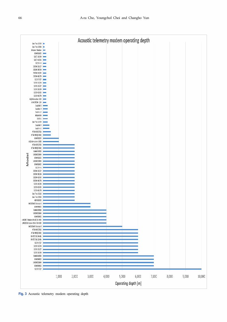
range of 37 km. Fig. 3 illustrates a graph for the operating depths of the
commercial underwater acoustic telemetry modems distributed
randomly according to the product characteristics and purpose, and it
can be seen that a maximum operating depth of 10 km is achievable.
2.2 Acoustic Positioning Systems
An acoustic positioning system tracks the relative position of a
vehicle being tracked. Generally, an underwater acoustic sensor,
which becomes a baseline, is installed on the ship or seabed, and after
installing underwater acoustic sensors for response (transponders) on
the tracking-target vehicle, the acoustic signals are transmitted and
received between the underwater acoustic sensors at both ends. The
system can be linked to a satellite navigation system to track the
absolute position of an object.
Acoustic positioning systems are essential for tracking the position
of underwater vehicles, such as underwater robots, and, based on the
tracking method, acoustic positioning systems are classified as long
baseline (LBL), short baseline (SBL), and ultrashort baseline (USBL).
LBL refers to estimating the position by installing the baseline at a
fixed position on the seabed and measuring the slant range from the
widely spaced transponder. SBL refers to estimating the position by
installing the baseline at a fixed position on the seabed and measuring
the relative arrival time from three or more transponders installed on a
ship (Vickery, 1998). USBL involves estimating the position by
installing the baseline on a ship or an underwater vehicle that performs
the role of the mother ship and measuring the relative phase of the
Manufacturer Model Freq. band
(kHz) Comm. range
(m)Operating depth
(m)Baud rate
(bps)
TriTech (Tritech, 2020)
Micron Modem 20–28 500 150 40
Subnero Pte Ltd(Subnero Pte Ltd, 2020)
M25M 20–32 3000–5000 - 15000
Thales (Thales, 2020)
TUUM-5 8–11 15000
25–40 15000
TUUM-6 1–60 37000 200
Wärtsilä ELAC Nautik (Wärtsilä)
(Wartsila, 2020)
UT2200 8.087–42 - - -
UT3000 1–60 - - -
Fig. 1 Acoustic telemetry modem frequency chart
Table 1 Specifications of underwater acoustic telemetry modems (Zia et al., 2021) (Continuation)

Survey of Acoustic Frequency Use for Underwater Acoustic Cognitive Technology 65
Fig. 2 Acoustic telemetry modem communication range
66 A-ra Cho, Youngchol Choi and Changho Yun
Fig. 3 Acoustic telemetry modem operating depth

Survey of Acoustic Frequency Use for Underwater Acoustic Cognitive Technology 67
acoustic signals received using the array sensors embedded in the
single transponder (Soppet, 2011).
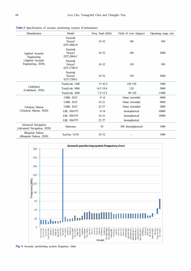
Table 2 lists the specifications of product models for different
acoustic positioning system manufacturers. Numerous acoustic
positioning system models use SSBL, USBL, and LBL
simultaneously, and many models also use USBL and acoustic
telemetry functions simultaneously. In Table 2, the field of view
indicates the angle for the zone where the acoustic positioning system
Manufacturer Model Freq. band (kHz) Field of view (degree) Operating range (m)
Evologics(Evologics, 2020)
S2C R 7/17W 7–17 hemispherical 8000
S2C R 7/17D 7–17 80 10000
S2C R 7/17 7–17 hemispherical 8000
S2C R 12/24 13–24 70 6000
S2C R 15/27 15–27 120 6000
S2C R 18/34H 18–34 hemispherical 3000
S2C R 18/34 18–34 Horizontally Omni 3500
S2C R 42/65 42–65 100 1000
S2C R 48/78 48–78 Horizontally Omni 1000
S2C M HS 12–180 Omni 300
Kongsberg(Kongsberg, 2020)
HiPAP 502 21–31 200 5000
HiPAP 452 21–31 120 5000
HiPAP 352 21–31 120 5000
HiPAP 352P 21–31 120 4000
HiPAP 102 10–15 120 10000
MicroPAP 200 0.005–0.1 160 4000
MicroPAP 200-NEL 21–31 160 995
MicroPAP 201-2 21–31 160 4000
MicroPAP 201-3 21–31 160 4000
MicroPAP 201-3-NEL 21–31 160 995
MicroPAP 201-H 21–31 160 4000
Sonardyne(Sonardyne, 2020)
AVTRAK 6Type8220-3111
19–34 Omni 3000
AVTRAK 6Type8220-7212
19–34 Directional 7000
Dunker 6Type8309.1351
21–32.5 Omni 1000
Dunker 6Type8309.1353
21–32.5 Directional 1000
Dunker 6Type8309.1355
14–19 Omni 1000
Dunker 6Type8309.1356
14–19 Directional 1000
HPT 5000/7000Type8142-001
19–34 180 7000
HPT 5000/7000Type8142-002
19–34 180 7000
GYRO IUSBL 19–34 180 7000
Marker 6 19–34 Omni, 260 4000
iXBlue(iXBlue, 2020).
Posidonia 8–18 70, 100 10000
Posidonia2 8–14 70, 100 10000
Gaps M5 20–30 200 995
Gaps M7 20–30 200 4000
Ramses 18–36 Omni 4000
Table 2 Specifications of acoustic positioning systems
68 A-ra Cho, Youngchol Choi and Changho Yun
Manufacturer Model Freq. band (kHz) Field of view (degree) Operating range (m)
Applied Acoustic Engineering
(Applied Acoustic Engineering, 2020).
EasytrakNexus2
EZT-2886-N18–32 180 995
EasytrakNexus2
EZT-2886-C18–32 180 2000
EasytrakNexus2
EZT-2780-N18–32 150 995
EasytrakNexus2
EZT-2780-C18–32 150 3000
LinkQuest(LinkQuest, 2020)
TrackLink 1500 31–43.2 120–150 1000
TrackLink 5000 14.2–19.8 120 5000
TrackLink 1000 7.5–12.5 90–120 11000
Teledyne Marine(Teledyne Marine, 2020)
USBL DAT 9–14 Omni (toroidal) 6000
USBL DAT 16–21 Omni (toroidal) 4000
USBL DAT 22–27 Omni (toroidal) 2000
LBL SM-975 9–14 hemispherical 10000
LBL SM-975 16–21 hemispherical 10000
LBL SM-975 22–27 hemispherical
Advanced Navigation(Advanced Navigation, 2020)
Subsonus 30 300 (hemispherical) 1000
Blueprint Subsea(Blueprint Subsea, 2020)
SeaTrac X150 24–32 - 1000
Fig. 4 Acoustic positioning system frequency chart
Table 2 Specifications of acoustic positioning systems (Continuation)
Survey of Acoustic Frequency Use for Underwater Acoustic Cognitive Technology 69
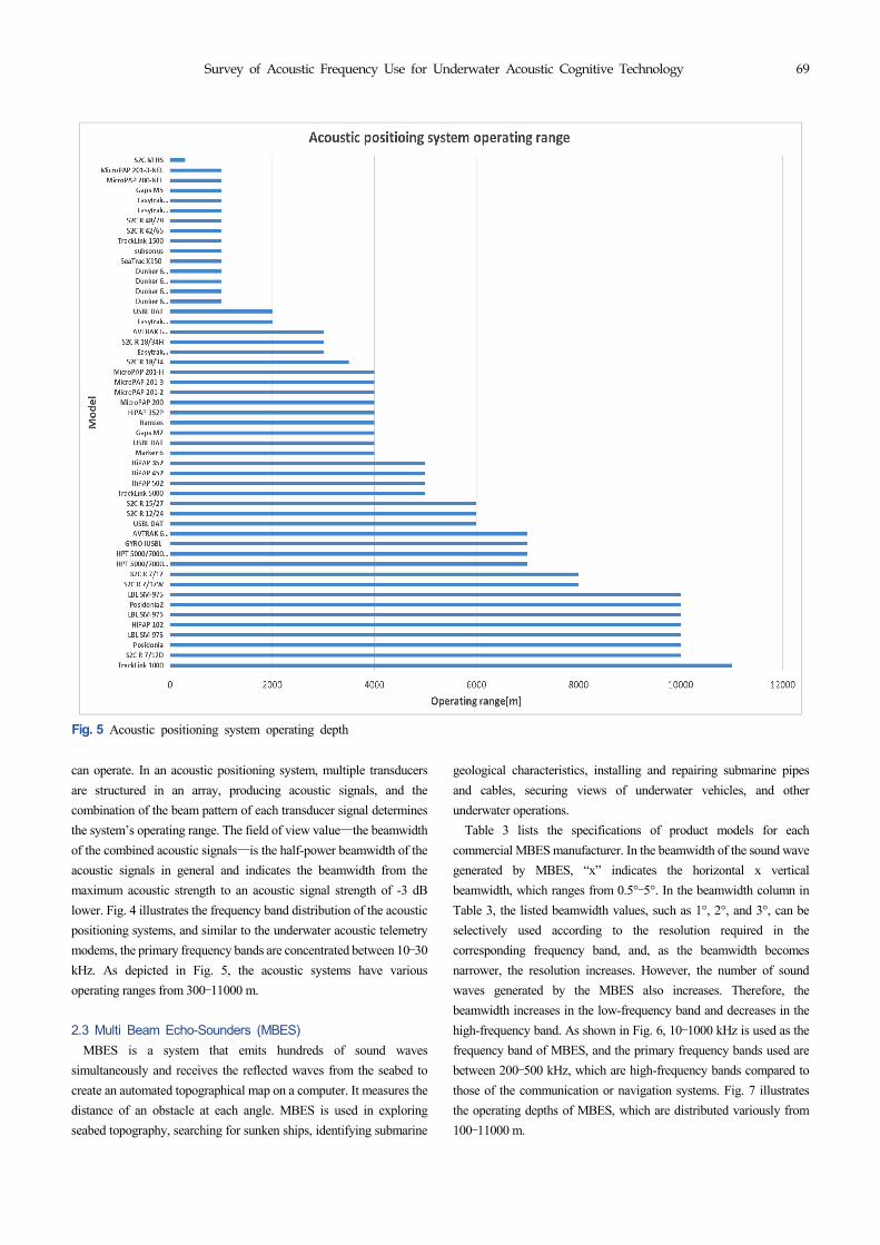
can operate. In an acoustic positioning system, multiple transducers
are structured in an array, producing acoustic signals, and the
combination of the beam pattern of each transducer signal determines
the system’s operating range. The field of view value―the beamwidth
of the combined acoustic signals―is the half-power beamwidth of the
acoustic signals in general and indicates the beamwidth from the
maximum acoustic strength to an acoustic signal strength of -3 dB
lower. Fig. 4 illustrates the frequency band distribution of the acoustic
positioning systems, and similar to the underwater acoustic telemetry
modems, the primary frequency bands are concentrated between 10–30
kHz. As depicted in Fig. 5, the acoustic systems have various
operating ranges from 300–11000 m.
2.3 Multi Beam Echo-Sounders (MBES)
MBES is a system that emits hundreds of sound waves
simultaneously and receives the reflected waves from the seabed to
create an automated topographical map on a computer. It measures the
distance of an obstacle at each angle. MBES is used in exploring
seabed topography, searching for sunken ships, identifying submarine
geological characteristics, installing and repairing submarine pipes
and cables, securing views of underwater vehicles, and other
underwater operations.
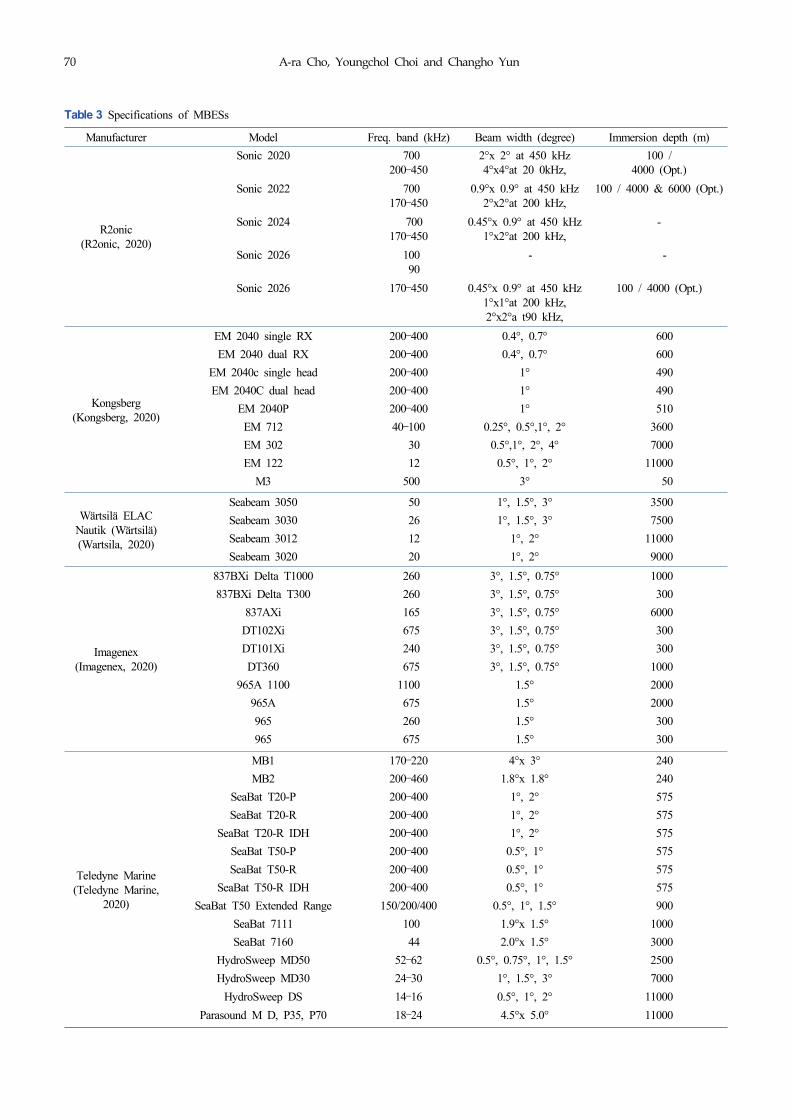
Table 3 lists the specifications of product models for each
commercial MBES manufacturer. In the beamwidth of the sound wave
generated by MBES, “x” indicates the horizontal x vertical
beamwidth, which ranges from 0.5°–5°. In the beamwidth column in
Table 3, the listed beamwidth values, such as 1°, 2°, and 3°, can be
selectively used according to the resolution required in the
corresponding frequency band, and, as the beamwidth becomes
narrower, the resolution increases. However, the number of sound
waves generated by the MBES also increases. Therefore, the
beamwidth increases in the low-frequency band and decreases in the
high-frequency band. As shown in Fig. 6, 10–1000 kHz is used as the
frequency band of MBES, and the primary frequency bands used are
between 200–500 kHz, which are high-frequency bands compared to
those of the communication or navigation systems. Fig. 7 illustrates
the operating depths of MBES, which are distributed variously from
100–11000 m.
Fig. 5 Acoustic positioning system operating depth
70 A-ra Cho, Youngchol Choi and Changho Yun
Manufacturer Model Freq. band (kHz) Beam width (degree) Immersion depth (m)
R2onic(R2onic, 2020)
Sonic 2020 700200–450
2°x 2° at 450 kHz4°x4°at 20 0kHz,
100 / 4000 (Opt.)
Sonic 2022 700170–450
0.9°x 0.9° at 450 kHz2°x2°at 200 kHz,
100 / 4000 & 6000 (Opt.)
Sonic 2024 700170–450
0.45°x 0.9° at 450 kHz1°x2°at 200 kHz,
-
Sonic 2026 100 90
- -
Sonic 2026 170–450 0.45°x 0.9° at 450 kHz1°x1°at 200 kHz,2°x2°a t90 kHz,
100 / 4000 (Opt.)
Kongsberg(Kongsberg, 2020)
EM 2040 single RX 200–400 0.4°, 0.7° 600
EM 2040 dual RX 200–400 0.4°, 0.7° 600
EM 2040c single head 200–400 1° 490
EM 2040C dual head 200–400 1° 490
EM 2040P 200–400 1° 510
EM 712 40–100 0.25°, 0.5°,1°, 2° 3600
EM 302 30 0.5°,1°, 2°, 4° 7000
EM 122 12 0.5°, 1°, 2° 11000
M3 500 3° 50
Wärtsilä ELACNautik (Wärtsilä)(Wartsila, 2020)
Seabeam 3050 50 1°, 1.5°, 3° 3500
Seabeam 3030 26 1°, 1.5°, 3° 7500
Seabeam 3012 12 1°, 2° 11000
Seabeam 3020 20 1°, 2° 9000
Imagenex(Imagenex, 2020)
837BXi Delta T1000 260 3°, 1.5°, 0.75° 1000
837BXi Delta T300 260 3°, 1.5°, 0.75° 300
837AXi 165 3°, 1.5°, 0.75° 6000
DT102Xi 675 3°, 1.5°, 0.75° 300
DT101Xi 240 3°, 1.5°, 0.75° 300
DT360 675 3°, 1.5°, 0.75° 1000
965A 1100 1100 1.5° 2000
965A 675 1.5° 2000
965 260 1.5° 300
965 675 1.5° 300
Teledyne Marine(Teledyne Marine,
2020)
MB1 170–220 4°x 3° 240
MB2 200–460 1.8°x 1.8° 240
SeaBat T20-P 200–400 1°, 2° 575
SeaBat T20-R 200–400 1°, 2° 575
SeaBat T20-R IDH 200–400 1°, 2° 575
SeaBat T50-P 200–400 0.5°, 1° 575
SeaBat T50-R 200–400 0.5°, 1° 575
SeaBat T50-R IDH 200–400 0.5°, 1° 575
SeaBat T50 Extended Range 150/200/400 0.5°, 1°, 1.5° 900
SeaBat 7111 100 1.9°x 1.5° 1000
SeaBat 7160 44 2.0°x 1.5° 3000
HydroSweep MD50 52–62 0.5°, 0.75°, 1°, 1.5° 2500
HydroSweep MD30 24–30 1°, 1.5°, 3° 7000
HydroSweep DS 14–16 0.5°, 1°, 2° 11000
Parasound M D, P35, P70 18–24 4.5°x 5.0° 11000
Table 3 Specifications of MBESs

Survey of Acoustic Frequency Use for Underwater Acoustic Cognitive Technology 71
Fig. 6 MBES frequency chart
Fig. 7 MBES immersion depth
72 A-ra Cho, Youngchol Choi and Changho Yun
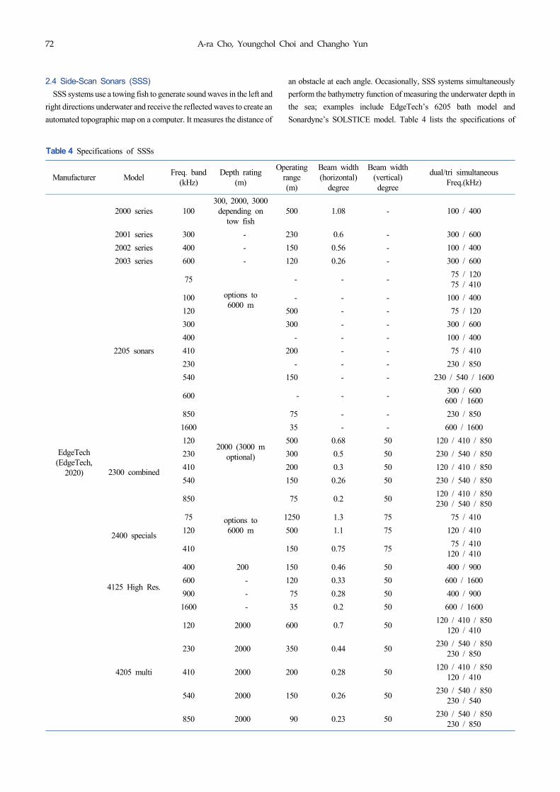
2.4 Side-Scan Sonars (SSS)
SSS systems use a towing fish to generate sound waves in the left and
right directions underwater and receive the reflected waves to create an
automated topographic map on a computer. It measures the distance of
an obstacle at each angle. Occasionally, SSS systems simultaneously
perform the bathymetry function of measuring the underwater depth in
the sea; examples include EdgeTech’s 6205 bath model and
Sonardyne’s SOLSTICE model. Table 4 lists the specifications of
Manufacturer ModelFreq. band
(kHz)Depth rating
(m)
Operating range (m)
Beam width (horizontal)
degree
Beam width (vertical)degree
dual/tri simultaneous Freq.(kHz)
EdgeTech(EdgeTech,
2020)
2000 series 100300, 2000, 3000
depending on tow fish
500 1.08 - 100 / 400
2001 series 300 - 230 0.6 - 300 / 600
2002 series 400 - 150 0.56 - 100 / 400
2003 series 600 - 120 0.26 - 300 / 600
2205 sonars
75
options to 6000 m
- - - 75 / 120 75 / 410
100 - - - 100 / 400
120 500 - - 75 / 120
300 300 - - 300 / 600
400 - - - 100 / 400
410 200 - - 75 / 410
230 - - - 230 / 850
540 150 - - 230 / 540 / 1600
600 - - -300 / 600 600 / 1600
850 75 - - 230 / 850
1600 35 - - 600 / 1600
2300 combined
1202000 (3000 m
optional)
500 0.68 50 120 / 410 / 850
230 300 0.5 50 230 / 540 / 850
410 200 0.3 50 120 / 410 / 850
540 150 0.26 50 230 / 540 / 850
850 75 0.2 50120 / 410 / 850 230 / 540 / 850
2400 specials
75 options to 6000 m
1250 1.3 75 75 / 410
120 500 1.1 75 120 / 410
410 150 0.75 75 75 / 410 120 / 410
4125 High Res.
400 200 150 0.46 50 400 / 900
600 - 120 0.33 50 600 / 1600
900 - 75 0.28 50 400 / 900
1600 - 35 0.2 50 600 / 1600
4205 multi
120 2000 600 0.7 50120 / 410 / 850
120 / 410
230 2000 350 0.44 50230 / 540 / 850
230 / 850
410 2000 200 0.28 50120 / 410 / 850
120 / 410
540 2000 150 0.26 50230 / 540 / 850
230 / 540
850 2000 90 0.23 50230 / 540 / 850
230 / 850
Table 4 Specifications of SSSs

Survey of Acoustic Frequency Use for Underwater Acoustic Cognitive Technology 73
product models for each SSS system manufacturer. SSS systems use
dual or triple frequency bands simultaneously. In Table 4, “230/540
with 540 kHz Bath” shown for the 6205 bath model means that SSS and
bathymetry functions are performed simultaneously by using
dual-frequency bands of 230 and 540 kHz for SSS and a frequency
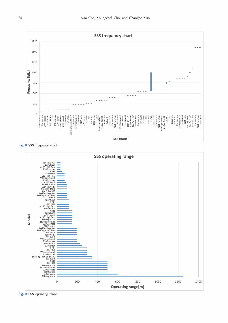
band of 540 kHz for bathymetry. As illustrated in Fig. 8, the frequency
bands of SSS are distributed between 75–1600 kHz, and the primary
frequency bands are concentrated between 100–1000 kHz. The
horizontal beamwidth of SSS is distributed between 0.26°–1.8°, and the
vertical beamwidth is distributed between 30°–90°. Fig. 9 illustrates the
operating ranges of SSS, and SSS systems operate in various ranges
from 35–1250 m.
Manufacturer ModelFreq. band
(kHz)Depth rating
(m)
Operating range (m)
Beam width (horizontal)
degree
Beam width (vertical)degree
dual/tri simultaneous Freq.(kHz)
6205 bath
230 100 250 0.54 -230/540 with 540kHz Bath 230/540 with 230kHzBath
550 100 150 0.36 -540/1600 with 540kHz Bath540/850 with 540 kHz Bath
850 100 75 0.29 - 540/850 with 540kHz Bath
1600 100 35 0.2 - 540/1600 with 540kHz Bath
Imagenex(Imagenex,
2020)
BlackFin 1100 1100 1000 - 0.25 60 -
878 RGB
120 1000 500 1 60 120/260/540 Tri. Freq. simultaneous
260 1000 300 1 60
540 1000 120 1 60
878260 1000 300 1 60
260/540 dual or single540 1000 120 0.5 60
SportScan330 30 120 1.8 60 single
800 30 0.7 30 330/800 dual
YellowFin
260 300 200 2.2 75 260/330/800 Tri. Freq.
330 300 200 1.8 60
800 300 200 0.7 30
Kongsberg(Kongsberg,
2020)PulSAR 550–1000 100
100 @550 kHz
0.5 50 -
Sonardyne(Sonardyne,
2020)SOLSTICE 725–775 300 200 0.15 with bathymetry
C-MAX (C-MAX, 2020)
CM2
100 2000 500 1 90 100/325 dual
325 2000 150 0.3 90325/780 dual 100/325 dual
780 2000 50 0.2 90 325/780 dual
Tritech(Tritech, 2020)
SeaKing AUV/ROV
325 4000 200 1 30 -
675 4000 100 0.5 30 -
SeaKing Towfish325 40 200 1.7 30 -
675 40 100 1 30 -
SeaKing Towfish SK150
150 120 350 1.4 60 -
StarFish 450F 450 50 100 1.7 60 -
StarFish 450H 450 50 100 1.7 60 -
StarFish 452F 450 50 100 0.8 60 -
StarFish AUV 450 300 100 0.5 60 -
StarFish 990F 1000 50 35 0.3 60 -
Innomar(Innomar, 2020)
SES-2000 sss 100 50 0.9 35 -
Table 4 Specifications of SSSs (Continuation)
74 A-ra Cho, Youngchol Choi and Changho Yun
Fig. 8 SSS frequency chart
Fig. 9 SSS operating range

Survey of Acoustic Frequency Use for Underwater Acoustic Cognitive Technology 75
2.5 Sub-Bottom Profilers (SBP)
SBP systems generate low-frequency sound waves to a submerged-
body underwater and receive the reflected waves from the seabed to
create a topographic map and sub-bottom profiles on a computer. It is
used to investigate submerged artifacts, explore buried naval mines,
and investigate marine and inland water geology, the conditions of
buried submarine pipelines and cables, and marine and inland water
sub-bottom profiles.
Table 5 lists the specifications of product models for each SBP
manufacturer. As shown in Fig. 10, SBP uses the primary frequency band
(generally 90–110 kHz) and the secondary frequency band (≤ 30 kHz)
simultaneously. The frequency bands are lower than 120 kHz, which is
comparatively lower than those of MBES or SSS. Moreover, SBP
produces the loudest noise among the acoustic equipment, which may
interfere with other acoustic equipment. Fig. 11 illustrates the operating
depths of SBP, which are distributed variously between 30–11000 m.
Manufacturer Model Freq. band (kHz) Operating depth (m)
EdgeTech(EdgeTech, 2020)
2000-ccs 0.5–12 3000
2000-dss 2–16 3000
2000-tvd 1–10 3000
2205 DW-424 4–24 6000
2205 DW-216 2–16 6000
2205 DW-106 1–10 6000
2300 4xDW-106 1–10 6000
2400 DW-106 1–10 6000
2400 DW-216 2–16 6000
2400 DW-424 4–24 6000
3300 (2x2 array) 2–16 300
3300 (3x3 array) 2–16 1500
330 0(4x4 array) 2–16 3000
3300 (5x5 array) 2–16 5000
3300 (triangle) 1–10 1500
3300 (“dice 5”) 1–10 3000
3300 (hexagonal) 1–10 5000
Innomar(Innomar, 2020)
SES-2000 smart90–110 100
5–15
SES-2000 compact85–115 400
2–22
SES-2000 light85–115 400
2–22
SES-2000 standard85–115 500
2–22
SES-2000 quattro (4array)85–115 30
2–22
SES-2000 quattro (single)85–115 500
2–22
SES-2000 sixpack (6array)85–115 30
2–22
SES-2000 sixpack (single)85–115 1000
2–22
SES-2000 medium-10085–115 2000
2–22
SES-2000 medium-7060–80 2500
0.5–15
SES-2000 deep-3630–42 6000
1–10
Table 5 Specifications of SBPs

76 A-ra Cho, Youngchol Choi and Changho Yun
Manufacturer Model Freq. band (kHz) Operating depth (m)
Innomar(Innomar, 2020)
SES-2000 deep-1510–20 11000
0.5–5.5
SES-2000 ROV85–115 1000/2000
4–22
SES-2000 AUV85–115 2000
4–18
iXBlue(iXBlue, 2020)
Echoes 1500 0.5–2.5 400
Echoes 3500 T1 1.7–5.5 shallow
Echoes 3500 T3 1.7–5.5 Continental
Echoes 3500 T7 1.7–5.5 deep
Echoes 5000 2–6 6000
Echoes 10000 5–15 shallow
Kongsberg(Kongsberg, 2020)
TOPAS PS 1815–21 11000
0.5–6TOPAS PS 40
35–45
1–10 2000
TOPAS PS 12070–100 2–500
2–30 400
SBP 27 2–9 11000
SBP120 2.5–6.5 11000
SBP300 2.5–6.5 11000
GeoPulse 2–12 3000
GeoPulse Plus 1.5–18 2000–4000
Fig. 10 SBP frequency chart
Table 5 Specifications of SBPs (Continuation)

Survey of Acoustic Frequency Use for Underwater Acoustic Cognitive Technology 77
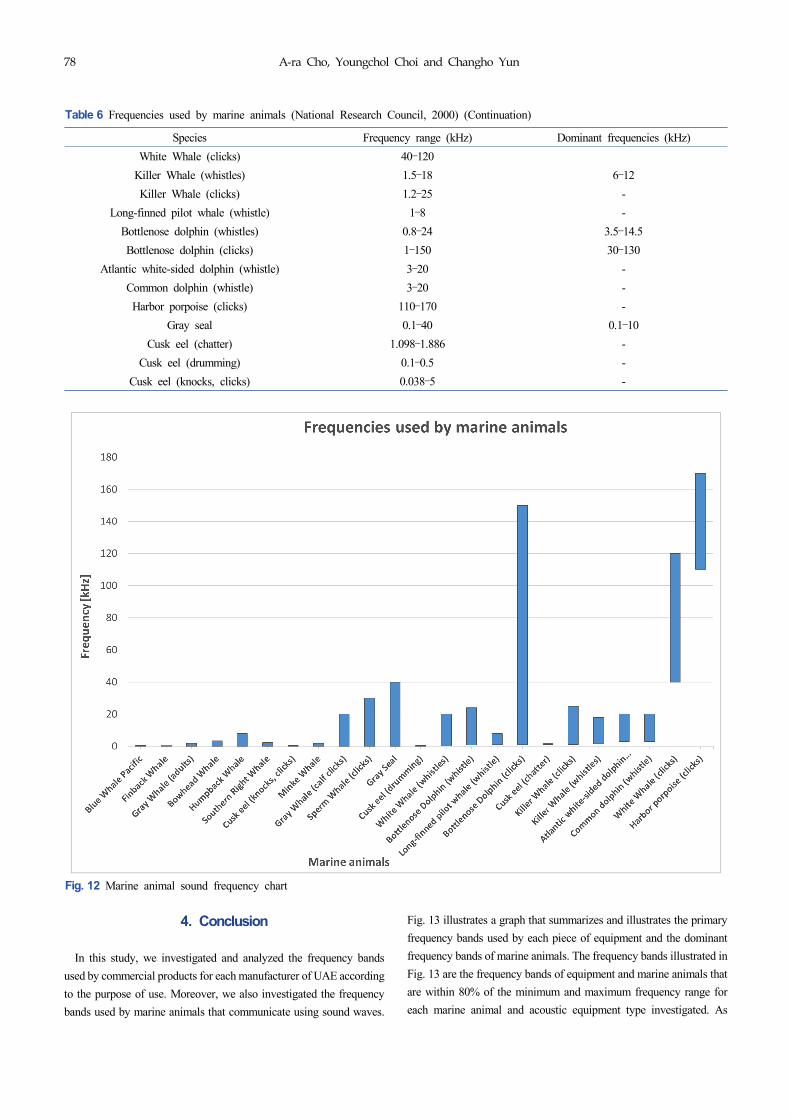
3. Frequencies Used by Marine Animals
The spatial characteristics of major habits or ecological
characteristics of marine animals should be considered to determine
whether the frequency bands of marine animals using sound waves are
available spatiotemporally. However, it is skipped in this study
because it is outside the research scope, and we will only deal with the
status of the frequency bands used by marine animals. Table 6
summarizes the frequency ranges and the dominant frequency ranges
used by marine animals that communicate using sound waves. As
shown in Fig. 12, underwater marine animals generate frequencies in
the 0.01–170 kHz band, and the dominant frequencies are below 20
kHz. These frequencies match the primary frequency bands generated
by UAE, such as underwater acoustic modems and acoustic
positioning systems, which may cause communication collisions
between acoustic equipment and marine animals.
Fig. 11 SBP operating depth
Species Frequency range (kHz) Dominant frequencies (kHz)
Gray Whale (adults) 0.02–2 0.02–1.2
Gray Whale (calf clicks) 0.1–20 3.4–4Humpback Whale 0.03–8 0.12–4
Finback Whale 0.014–0.75 0.02–0.04
Mink Whale 0.04–2 0.06–0.14
Southern Right Whale 0.03–2.2 0.05–0.5
Bowhead Whale 0.02–3.5 0.1–0.4
Blue Whale Pacific 0.01–0.39 0.016–0.024
Blue Whale Atlantic - 0.01–0.02
Sperm Whale (clicks) 0.1–30 2–16
White Whale (whistles) 0.26–20 2–5.9
Table 6 Frequencies used by marine animals (National Research Council, 2000)
78 A-ra Cho, Youngchol Choi and Changho Yun
4. Conclusion
In this study, we investigated and analyzed the frequency bands
used by commercial products for each manufacturer of UAE according
to the purpose of use. Moreover, we also investigated the frequency
bands used by marine animals that communicate using sound waves.
Fig. 13 illustrates a graph that summarizes and illustrates the primary
frequency bands used by each piece of equipment and the dominant
frequency bands of marine animals. The frequency bands illustrated in
Fig. 13 are the frequency bands of equipment and marine animals that
are within 80% of the minimum and maximum frequency range for
each marine animal and acoustic equipment type investigated. As
Species Frequency range (kHz) Dominant frequencies (kHz)
White Whale (clicks) 40–120
Killer Whale (whistles) 1.5–18 6–12
Killer Whale (clicks) 1.2–25 -
Long-finned pilot whale (whistle) 1–8 -
Bottlenose dolphin (whistles) 0.8–24 3.5–14.5
Bottlenose dolphin (clicks) 1–150 30–130
Atlantic white-sided dolphin (whistle) 3–20 -
Common dolphin (whistle) 3–20 -
Harbor porpoise (clicks) 110–170 -
Gray seal 0.1–40 0.1–10
Cusk eel (chatter) 1.098–1.886 -
Cusk eel (drumming) 0.1–0.5 -
Cusk eel (knocks, clicks) 0.038–5 -
Fig. 12 Marine animal sound frequency chart
Table 6 Frequencies used by marine animals (National Research Council, 2000) (Continuation)

Survey of Acoustic Frequency Use for Underwater Acoustic Cognitive Technology 79
shown in Fig. 13, the frequencies overlap most in the mid-frequency
range (10–40 kHz) because both acoustic equipment and marine
animals use these frequencies. In the case of acoustic telemetry
modems and acoustic positioning systems, the primary frequency
bands are almost identical and overlap in a range of 10–30 kHz,
meaning that a collision avoidance method is required to prevent
signal interference. The frequency band of MBES is a high-frequency
band compared to that of the above equipment and is concentrated
between 50–500 kHz. The frequency band of SSS is primarily
distributed between 150–850 kHz, and the same model can use dual or
triple frequency bands simultaneously. SBP uses the primary
frequency band (60–110 kHz) and the secondary frequency band (45
kHz or lower) simultaneously and produces the largest noise among
acoustic equipment, which increases the likelihood of causing
interferences in other acoustic equipment. Meanwhile, marine animals
primarily generate acoustic signals in the range of 0.1–20 kHz, and
measures should be in place to avoid frequency overlaps with the
secondary frequency bands of acoustic modems, acoustic positioning
systems, and SBP. Moreover, the frequency bands of the analyzed
acoustic equipment and marine animals can be used as reference data
to avoid signal interferences when operating multiple pieces of UAE
simultaneously. Finally, the frequency bands of UAE and marine
animals can be used to develop technology for underwater spectral
sensing, sharing, and frequency band determination in underwater
acoustic cognitive technology, where it is crucial to avoid underwater
signal interferences.
Funding
This research was supported by a grant from the Endowment Project
of “Development of core technology for cooperative navigation of
multiple marine robots and underwater wireless cognitive network”
funded by the Korea Research Institute of Ships and Ocean
engineering (PES4370).
References
Advanced Navigation. (2020). Acoustic Positioning System. Retrieved
December 2020 from https://www.advancednavigation.com/
acoustic-navigation/
Ali, M.F., Jayakody, D.N.K., Chursin, Y.A., Affes, S., & Dmitry, S.
(2020). Recent Advances and Future Directions on Underwater
Wireless Communications. Archives of Computational Methods
in Engineering, 27(5), 1379-1412. https://doi.org/10.1007/
s11831-019-09354-8
Applied Acoustic Engineering. (2020). Acoustic Positioning
Systems. Retrieved December 2020 from https://www.
aaetechnologiesgroup.com/applied-acoustics/products/easytrak
-usbl-systems
AquaSeNT (2020). Underwater Acoustic Modems. Retrieved
December 2020 from http://www.aquasent.com/acoustic-modems
Aquatec (2020). Underwater Acoustic Modems. Retrieved December
2020 from http://www.aquatecgroup.com/19-solutions/109-
solutions-home
Blueprint Subsea. (2020). Underwater Acoustic Modems and
Acoustic Positioning Systems. Retrieved December 2020 from
https://www.blueprintsubsea.com/seatrac/
Cheng, W., Luo, Y., Peng, Z., & Cui, J.H. (2017, November).
ECO-Friendly Underwater Acoustic Communications: Channel
Availability Prediction for Avoiding Interfering Marine
Mammals. In Proceedings of the International Conference on
Underwater Networks & Systems, 1–6.
Chitre, M., Shahabudeen, S., & Stojanovic, M. (2008). Underwater
Acoustic Communications and Networking: Recent Advances
and Future Challenges. Marine Technology Society Journal,
42(1), 103–116. https://doi.org/10.4031/002533208786861263
C-MAX. (2020). Side Scan Sonars. Retrieved December 2020 from
http://www.cmaxsonar.com/Brochure2019.pdf
Desert Star Systems. (2020). Underwater Acoustic Modems.
Fig. 13 The frequency bands for the acoustic equipment and marineanimals

80 A-ra Cho, Youngchol Choi and Changho Yun
Retrieved December 2020 from https://www.desertstar.com/
page/sam-1
DiveNET. (2020). Underwater Acoustic Modems. Retrieved
December 2020 from https://www.divenetgps.com/sealink
DSPComm. (2020). Underwater Acoustic Modems. Retrieved
December 2020 from https://www.dspcommgen2.com/aquacomm-
underwater-wireless-modem/
EdgeTech. (2020). Multi Beam Echo-sounders, Side Scan Sonars,
Sub-bottom Profilers. Retrieved December 2020 from https://
www.edgetech.com
Evologics. (2020). Underwater Acoustic Modems and Acoustic
Positioning Systems. Retrieved December 2020 from https://
evologics.de
Ferguson, B.G., & Cleary, J.L. (2001). In Situ Source Level and Source
Position Estimates of Biological Transient Signals Produced by
Snapping Shrimp in an Underwater Environment. The Journal of
the Acoustical Society of America, 109(6), 3031–3037.
https://doi.org/10.1121/1.1339823
Goyal, N., Dave, M., & Verma, A.K. (2019). Protocol Stack of
Underwater Wireless Sensor Network: Classical Approaches and
New Trends. Wireless Personal Communications, 104(3), 995–1022. https://doi.org/10.1007/s11277-018-6064-z
Imagenex. (2020). Multi Beam Echo-sounders and Side Scan Sonars.
Retrieved December 2020 from https://imagenex.com/
Innomar. (2020). Side Scan Sonars and Sub-bottom Profilers.
Retrieved December 2020 from https://www.innomar.com/
index.php
iXBlue. (2020). Acoustic Positioning Systems and Sub-bottom
Profilers. Retrieved December 2020 from https://www.ixblue.
com/
Jiang, Z. (2008). Underwater Acoustic Networks–Issues and
Solutions. International Journal of Intelligent Control and
Systems, 13(3), 152–161.
Kongsberg. (2020). K-sync, Underwater Acoustic Modems, Acoustic
Positioning Systems, Multi Beam Echo-Sounders, Side Scan
Sonars, and Sub-Bottom Profilers. Retrieved December 2020
from https://www.kongsberg.com/maritime/
LinkQuest. (2020). Underwater Acoustic Modems and Acoustic
Positioning Systems. Retrieved December 2020 from https://
www.link-quest.com/
Li, X., Sun, Y., Guo, Y., Fu, X., & Pan, M. (2016). Dolphins First:
Dolphin-Aware Communications in Multi-hop Underwater
Cognitive Acoustic Networks. IEEE Transactions on Wireless
Communications, 16(4), 2043–2056. https://doi.org/10.1109/
TWC.2016.2623604
Luo, Y., Pu, L., Zuba, M., Peng, Z., & Cui, J. H. (2014). Challenges and
Opportunities of Underwater Cognitive Acoustic Networks.
IEEE Transactions on Emerging Topics in Computing, 2(2), 198–211. https://doi.org/10.1109/TETC.2014.2310457
Luo, Y., Pu, L., Mo, H., Zhu, Y., Peng, Z., & Cui, J.H. (2016a).
Receiver-Initiated Spectrum Management for Underwater
Cognitive Acoustic Network. IEEE Transactions on Mobile
Computing, 16(1), 198–212. https://doi.org/10.1109/TMC.2016.
2544757
Luo, Y., Pu, L., Peng, Z., & Cui, J.H. (2016b, April). Dynamic Control
Channel MAC for Underwater Cognitive Acoustic Networks. In
IEEE INFOCOM 2016-The 35th Annual IEEE International
Conference on Computer Communications, 1–9. https://doi.org/
10.1109/INFOCOM.2016.7524554
Moore, S.E., Reeves, R.R., Southall, B.L., Ragen, T.J., Suydam, R.S.,
& Clark, C.W. (2012). A New Framework for Assessing the
Effects of Anthropogenic Sound on Marine Mammals in a
Rapidly Changing Arctic. BioScience, 62(3), 289–295.
https://doi.org/10.1525/bio.2012.62.3.10
Murad, M., Sheikh, A.A., Manzoor, M.A., Felemban, E., & Qaisar, S.
(2015). A Survey on Current Underwater Acoustic Sensor
Network Applications. International Journal of Computer
Theory and Engineering, 7(1), 51.
National Research Council. (2000). Marine Mammals and
Low-Frequency Sound: Progress since 1994.
Richardson, W.J., Greene Jr, C.R., Malme, C.I., & Thomson, D.H.
(2013). Marine Mammals and Noise. Academic Press.
R2onic. (2020). Multi Beam Echo-Sounders. Retrieved December
2020 from https://www.r2sonic.com/wp-content/uploads/2021/
05/MBES-Spec-US-03-2020.pdf/
Sercel. (2020). Underwater Acoustic Modems. Retrieved December
2020 from http://www.sercel.com/products/Lists/ProductSpecification/
Mats3G_specifications_Sercel_EN.pdf
Sonardyne. (2020). Underwater Acoustic Modems, Acoustic
Positioning Systems, and Side Scan Sonars. Retrieved December
2020 from https://www.sonardyne.com/
Soppet, T.J. (2011). Ultra-Short Baseline Acoustic Positioning
System.
Subnero Pte Ltd (2020). Underwater Acoustic Modems. Retrieved
December 2020 from https://subnero.com/products/modem.html
Teledyne Marine (2020). Underwater Acoustic Modems, Acoustic
Positioning Systems, and Multi Beam Echo-Sounders. Retrieved
December 2020 from http://www.teledynemarine.com/
Thales. (2020). Underwater Acoustic Modems. Retrieved December
2020 from https://www.thalesgroup.com/en
Tritech. (2020). Underwater Acoustic Modems and Side Scan sonars.
Retrieved December 2020 from https://www.tritech.co.uk/
Vickery, K. (1998, August). Acoustic Positioning Systems. A
Practical Overview of Urrent Systems. In Proceedings of the
1998 Workshop on Autonomous Underwater Vehicles (Cat. No.
98CH36290), 5–17.
Wartsila. (2020). Underwater Acoustic Modems and Multi Beam
Echo-Sounders. Retrieved December 2020 from https://www.
wartsila.com/
Zia, M.Y.I., Poncela, J., & Otero, P. (2021). State-of-the-Art
Underwater Acoustic Communication Modems: Classifications,
Analyses and Design Challenges. Wireless Personal

Survey of Acoustic Frequency Use for Underwater Acoustic Cognitive Technology 81
Communications, 116(2), 1325-1360. https://doi.org/10.1007/
s11277-020-07431-x
Zolich, A., Palma, D., Kansanen, K., Fjørtoft, K., Sousa, J., Johansson,
K.H., & Johansen, T.A. (2019). Survey on Communication and
Networks for Autonomous Marine Systems. Journal of
Intelligent & Robotic Systems, 95(3), 789–813. https://doi.org/
10.1007/s10846-018-0833-5
Author ORCIDs
Author name ORCID
Cho, A-ra 0000-0001-5078-4497
Choi, Youngchol 0000-0002-1837-2692
Yun, Changho 0000-0002-9495-1282