MIMO-OFDM for High-Rate Underwater Acoustic Communications
11
IEEE JOURNAL OF OCEANIC ENGINEERING (TO APPEAR) 1 MIMO-OFDM for High Rate Underwater Acoustic Communications Baosheng Li, Student Member, IEEE, Jie Huang, Shengli Zhou, Member, IEEE, Keenan Ball, Milica Stojanovic, Member, IEEE, Lee Freitag, Member, IEEE, and Peter Willett, Fellow, IEEE Abstract—Multiple-input multiple-output (MIMO) techniques have been actively pursued in underwater acoustic communica- tions recently to increase the data rate over the bandwidth-limited channels. In this paper, we present a MIMO system design, where spatial multiplexing is applied with OFDM signals. The proposed receiver works on a block-by-block basis, where null subcarriers are used for Doppler compensation, pilot subcarriers are used for channel estimation, and a MIMO detector consisting of a hybrid use of successive interference cancellation and soft MMSE equalization is coupled with LDPC channel decoding for iterative detection on each subcarrier. The proposed design has been tested using data recorded from three different experiments. A spectral efficiency of 3.5 bits/sec/Hz was approached in one experiment, while a data rate of 125.7 kb/s over a bandwidth of 62.5 kHz was achieved in another. These results suggest that MIMO-OFDM is an appealing solution for high data rate transmissions over underwater acoustic channels. I. I NTRODUCTION To enhance the transmission rate over communication links, either the bandwidth, or the spectral efficiency in the unit of bits/sec/Hz, or both, need to be increased. Multi-input multi-output (MIMO) techniques can drastically increase the spectral efficiency via parallel transmissions over multiple transmitters [3], [4], hence are attractive to underwater acoustic communications which are inherently bandwidth-limited. Recently, several different approaches have been investi- gated for MIMO underwater acoustic communications, in- cluding those for single carrier transmissions [5]–[11] and those for multicarrier transmissions in the form of orthogonal- frequency-division-multiplexing (OFDM) [1], [2], [12], [13]. Specifically, adaptive multichannel decision-feedback equal- ization (DFE) has been used in [5], [6] while a time-reversal preprocessing followed by a single channel equalizer has been B. Li and S. Zhou are supported by the ONR YIP grant N00014-07-1-0805, the NSF grant ECCS-0725562, and the NSF grant CNS-0721834. J. Huang and P. Willett are supported by the ONR grant N00014-07-1-0429. K. Ball and L. Freitag are supported by the ONR grant N00014-07-1-0229. M. Stojanovic is supported by the ONR grants N00014-07-1-0202 and N00014-07-1-0738. Partial results have been presented in the MTS/IEEE OCEANS conference, Vancouver, Canada, Oct. 2007 [1] and the MTS/IEEE OCEANS conference, Quebec City, Canada, Sept. 2008 [2]. Associate Editor: H. Song. B. Li, J. Huang, S. Zhou, and P. Willett are with the Dept. of Elec. and Computer Engr., University of Connecticut, Storrs, CT 06269; Emails: ({baosheng,jhuang,shengli,willett}@engr.uconn.edu). K. Ball and L. Freitag are with the Woods Hole Oceanographic Institution, Woods Hole, MA 02543. Emails: ([email protected], [email protected]). M. Stojanovic is with the Dept. of Elec. and Computer Engr., Northeastern University, MA. Email: ([email protected]). Publisher Item Identifier used in [7], [8]. In [5], [6] and [7], [8], parameter adaptation is performed on a symbol by symbol basis. Adaptive block equalization techniques have been proposed in time domain [9] and in frequency domain [10], where parameter adaptation is carried over successive blocks. Using basis expansion models (BEM) to parameterize underwater acoustic channels, block- differential space time coding has been investigated in [11]. For multicarrier systems, a non-adaptive block-by-block de- sign was presented in [1], [2], which is built upon the receiver developed for single-transmitter OFDM in [14], while a block- adaptive approach was developed in [12], which is built upon the single-transmitter OFDM system in [15], [16]. In [13], experimental results were presented for both coherent and differential designs in an OFDM system with two transmitters. The objective of this paper is to present a MIMO-OFDM system design [1], [2] and report on the performance results with data recorded from various experiments. The proposed MIMO-OFDM design consists of the following key compo- nents: (1) null subcarriers are inserted at the transmitter to facilitate the compensation of Doppler shifts at the receiver; (2) pilot tones are used for MIMO channel estimation, and (3) an iterative receiver structure is adopted that couples MIMO detection with channel decoding. The MIMO detector applied on each OFDM subcarrier consists of a hybrid successive interference canceller and MMSE equalizer with a priori information [17], while the codes used are the nonbinary low-density parity-check (LDPC) codes from [18]. Note that an iterative receiver has been investigated in [19] for an underwater OFDM system with one transmitter, where carrier synchronization, channel estimation, and channel decoding are coupled. Our receiver does not include carrier synchronization and channel estimation in the loop. It rather focuses on the iterative processing between the MIMO detection and channel decoding. The proposed design has been tested using data recorded from three different experiments: i) the AUV Fest, Panama City, FL, June 2007, ii) the RACE experiment in the Nar- ragansett Bay, Rhode Island, March 2008, and iii) the VHF experiment conducted at the Buzzards Bay, MA, April 2008. For convenience, we will term these experiments as AUV07, RACE08, and VHF08 hereafter. With QPSK modulation, rate 1/2 coding, and a 12 kHz bandwidth, the achieved data rate in AUV07 was 12.18 kb/s. For the RACE08 experiment, we report MIMO-OFDM performance results of QPSK/8-QAM/16-QAM/64-QAM with two transmitters, 0000–0000/00$00.00 c 2009 IEEE
Transcript of MIMO-OFDM for High-Rate Underwater Acoustic Communications
IEEE JOURNAL OF OCEANIC ENGINEERING (TO APPEAR) 1
MIMO-OFDM for High Rate Underwater AcousticCommunications
Baosheng Li,Student Member, IEEE, Jie Huang, Shengli Zhou,Member, IEEE, Keenan Ball,Milica Stojanovic,Member, IEEE, Lee Freitag,Member, IEEE, and Peter Willett,Fellow, IEEE
Abstract—Multiple-input multiple-output (MIMO) techniqueshave been actively pursued in underwater acoustic communica-tions recently to increase the data rate over the bandwidth-limitedchannels. In this paper, we present a MIMO system design, wherespatial multiplexing is applied with OFDM signals. The proposedreceiver works on a block-by-block basis, where null subcarriersare used for Doppler compensation, pilot subcarriers are usedfor channel estimation, and a MIMO detector consisting of ahybrid use of successive interference cancellation and soft MMSEequalization is coupled with LDPC channel decoding for iterativedetection on each subcarrier. The proposed design has been testedusing data recorded from three different experiments. A spectralefficiency of 3.5 bits/sec/Hz was approached in one experiment,while a data rate of 125.7 kb/s over a bandwidth of62.5 kHz wasachieved in another. These results suggest that MIMO-OFDMis an appealing solution for high data rate transmissions overunderwater acoustic channels.
I. I NTRODUCTION
To enhance the transmission rate over communication links,either the bandwidth, or the spectral efficiency in the unitof bits/sec/Hz, or both, need to be increased. Multi-inputmulti-output (MIMO) techniques can drastically increase thespectral efficiency via parallel transmissions over multipletransmitters [3], [4], hence are attractive to underwater acousticcommunications which are inherently bandwidth-limited.
Recently, several different approaches have been investi-gated for MIMO underwater acoustic communications, in-cluding those for single carrier transmissions [5]–[11] andthose for multicarrier transmissions in the form of orthogonal-frequency-division-multiplexing (OFDM) [1], [2], [12], [13].Specifically, adaptive multichannel decision-feedback equal-ization (DFE) has been used in [5], [6] while a time-reversalpreprocessing followed by a single channel equalizer has been
B. Li and S. Zhou are supported by the ONR YIP grant N00014-07-1-0805,the NSF grant ECCS-0725562, and the NSF grant CNS-0721834. J. Huangand P. Willett are supported by the ONR grant N00014-07-1-0429. K. Ball andL. Freitag are supported by the ONR grant N00014-07-1-0229.M. Stojanovicis supported by the ONR grants N00014-07-1-0202 and N00014-07-1-0738.Partial results have been presented in the MTS/IEEE OCEANS conference,Vancouver, Canada, Oct. 2007 [1] and the MTS/IEEE OCEANS conference,Quebec City, Canada, Sept. 2008 [2].
Associate Editor: H. Song.B. Li, J. Huang, S. Zhou, and P. Willett are with the Dept. of Elec.
and Computer Engr., University of Connecticut, Storrs, CT 06269; Emails:({baosheng,jhuang,shengli,willett}@engr.uconn.edu).
K. Ball and L. Freitag are with the Woods Hole Oceanographic Institution,Woods Hole, MA 02543. Emails: ([email protected], [email protected]).
M. Stojanovic is with the Dept. of Elec. and Computer Engr., NortheasternUniversity, MA. Email: ([email protected]).
Publisher Item Identifier
used in [7], [8]. In [5], [6] and [7], [8], parameter adaptationis performed on a symbol by symbol basis. Adaptive blockequalization techniques have been proposed in time domain [9]and in frequency domain [10], where parameter adaptation iscarried over successive blocks. Using basis expansion models(BEM) to parameterize underwater acoustic channels, block-differential space time coding has been investigated in [11].For multicarrier systems, a non-adaptive block-by-block de-sign was presented in [1], [2], which is built upon the receiverdeveloped for single-transmitter OFDM in [14], while a block-adaptive approach was developed in [12], which is built uponthe single-transmitter OFDM system in [15], [16]. In [13],experimental results were presented for both coherent anddifferential designs in an OFDM system with two transmitters.
The objective of this paper is to present a MIMO-OFDMsystem design [1], [2] and report on the performance resultswith data recorded from various experiments. The proposedMIMO-OFDM design consists of the following key compo-nents: (1) null subcarriers are inserted at the transmittertofacilitate the compensation of Doppler shifts at the receiver;(2) pilot tones are used for MIMO channel estimation, and (3)an iterative receiver structure is adopted that couples MIMOdetection with channel decoding. The MIMO detector appliedon each OFDM subcarrier consists of a hybrid successiveinterference canceller and MMSE equalizer witha prioriinformation [17], while the codes used are the nonbinarylow-density parity-check (LDPC) codes from [18]. Note thatan iterative receiver has been investigated in [19] for anunderwater OFDM system with one transmitter, where carriersynchronization, channel estimation, and channel decoding arecoupled. Our receiver does not include carrier synchronizationand channel estimation in the loop. It rather focuses on theiterative processing between the MIMO detection and channeldecoding.
The proposed design has been tested using data recordedfrom three different experiments: i) the AUV Fest, PanamaCity, FL, June 2007, ii) the RACE experiment in the Nar-ragansett Bay, Rhode Island, March 2008, and iii) the VHFexperiment conducted at the Buzzards Bay, MA, April 2008.For convenience, we will term these experiments as AUV07,RACE08, and VHF08 hereafter. With QPSK modulation,rate 1/2 coding, and a 12 kHz bandwidth, the achieveddata rate in AUV07 was 12.18 kb/s. For the RACE08experiment, we report MIMO-OFDM performance resultsof QPSK/8-QAM/16-QAM/64-QAM with two transmitters,
0000–0000/00$00.00c© 2009 IEEE
IEEE JOURNAL OF OCEANIC ENGINEERING (TO APPEAR) 2
QPSK/8-QAM/16-QAM with three transmitters, and QPSK/8-QAM with four transmitters where a bandwidth of4.9 kHz isused. A spectral efficiency of 3.5 bits/sec/Hz was approachedwith various configurations. In the VHF08 experiment, a datarate of 125.7 kb/s was achieved with two transmitters, 16-QAM modulation, rate 1/2 coding, and a bandwidth of62.5kHz. These results suggest that MIMO-OFDM is an appealingsolution for very high data rate transmissions over underwateracoustic channels.
The rest of the paper is organized as follows. We describethe transmitter design in Section II and present the receiveralgorithms in Section III. Performance results for differentexperiments are summarized in Sections IV, V, and VI.Conclusions are drawn in Section VII.
Notation: Bold upper and lower letters denote matricesand column vectors, respectively;(·)T , (·)∗, and(·)H denotetranspose, conjugate, and Hermitian transpose, respectively;IN is theN × N identity matrix.
II. T RANSMITTER DESIGN
We consider MIMO-OFDM transmission with spatial mul-tiplexing on Nt transmitters. The basic signalling format iszero-padded (ZP) OFDM [14]. Specifically, letB denote thebandwidth andK the number of subcarriers. The subcarrierspacing is∆f = B/K and the OFDM block duration isT = 1/∆f = K/B. Each OFDM block is followed by aguard time of durationTg to avoid interblock interference. Outof the totalK subcarriers,Kn subcarriers are null subcarrierswhere no information will be transmitted,Kp subcarriersare pilot subcarriers carrying known symbols, and the restKd = K − Kn − Kp subcarriers are data subcarriers.
The signals are generated as follows. Letrc denote thecode rate of channel code andM the size of the constellation,which could be 4, 8, 16, or 64 in our experiments. For eachOFDM block, we generateNt independent bit streams eachof lengthrcKd log2 M and encode them separately using thenonbinary low-density-parity-check (LDPC) codes [18]. Eachcoded bit stream of lengthKd log2 M is mapped into a symbolsequence of lengthKd. A total of Nt OFDM blocks areformed with each block carryingKd symbols from one symbolsequence. After proper pilot insertions, theNt OFDM blocksare transmitted fromNt transmitters simultaneously. The nextNt blocks then follow.
Accounting for all the overheads due to the guard interval,channel coding, pilot, and null subcarriers, the overall spectralefficiency in terms of bits per second per Hz (bits/s/Hz) is:
α = Nt ·T
T + Tg·Kd
K· rc · log2 M. (1)
With a bandwidthB, the data rate in the unit of bits/s is
R = αB. (2)
In this paper, we will include experimental results withNt = 2, 3, 4 transmitters. The total number of pilot subcarriersfor all transmitters isKp. Specifically, we will use a total ofKp = K/4 pilot subcarriers in our experimental results. Tosimplify channel estimation, each transmitter will be allocateda set of non-overlapping pilot subcarriers to transmit nonzero
pilot symbols, while zeros are transmitted on those subcarriersthat belong to other transmitters. WhenNt = 2 andNt = 4,each transmitterµ will be assignedKp/Nt = K/(4Nt)subcarriers that are equally spaced. For example, one as-signment on the pilot indexes to theµth transmitter, whereµ = 1, . . . , Nt, could be
{
4Nt(i− 1)+4(µ− 1)+2}K/(4Nt)
i=1.
WhenNt = 3, the pilot positions are identical to theNt = 4case, simply turning off one transmitter from the 4-transmittersystem. The null subcarrier positions are identical for alltransmitters. Half of null tones are placed at the edges ofthe frequency band, while the other half are randomly drawnfrom the available subcarrier positions. The positions of nullsubcarriers are fixed for all blocks after being picked duringthe design phase.
III. R ECEIVER ALGORITHMS
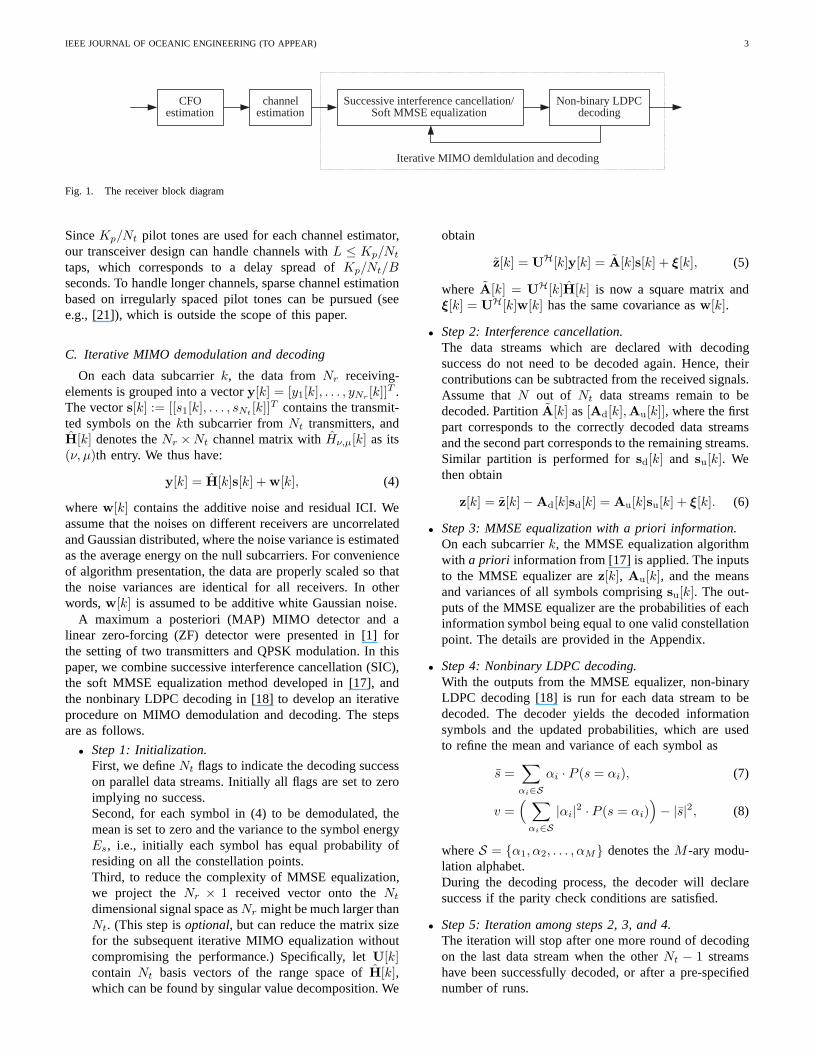
The receiver algorithms should be well designed for theunderwater acoustic communications. For stationary MIMO-OFDM tests, no resampling operation as described in [14] wasneeded. The key processing steps at the receiver are depictedin Fig. 1, and will be described next.
A. Doppler estimation
The channel Doppler effect can be viewed as caused bycarrier frequency offsets (CFO) among the transmitters andthereceivers [14]. On each receiver, we assume a common CFOrelative to all transmitters, as in [20, Chapter 11.5]. Hence,the CFO estimation algorithm presented in [14, Eqns. (14)and (15)] is directly applicable, where the energy on the nullsubcarriers is used as the objective function to search for thebest CFO estimate.
After Doppler shift estimation and compensation, the av-erage energy on the null subcarriers is used to computethe variance of the additive noise and residual inter-carrier-interference (ICI). This quantity is needed for the soft MMSEequalization in Section III-C.
B. Channel estimation
After CFO compensation, pilot tones are used for channelestimation. Note that at each receive antennaν, a total ofNt
channels{hν,µ := [hν,µ(0), . . . , hν,µ(L − 1)]T }Nt
µ=1 need tobe estimated, whereL is the channel length andhν,µ(l) is thelth channel tap of the baseband equivalent model.
Since each transmitter is assigned with an exclusive set ofpilot subcarriers, channel estimation is carried out for eachtransmitter-receiver pair separately. With equally-spaced pilottones, the least-square (LS) channel estimator does not involvematrix inversion and can be implemented by anKp/Nt-point inverse fast Fourier transform (FFT), as described in[14, eqns. (18) and (19)]. Once the channel estimateshν,µ,µ = 1, . . . , Nt, ν = 1, . . . , Nr, are available, the channelfrequency response on each data subcarrierk is evaluated as
Hν,µ[k] =
L−1∑
l=0
hν,µ(l)e−j2πkl/K . (3)
IEEE JOURNAL OF OCEANIC ENGINEERING (TO APPEAR) 3
Iterative MIMO demldulation and decoding
CFO estimation
channel estimation
Successive interference cancellation/ Soft MMSE equalization
Non-binary LDPC decoding
Fig. 1. The receiver block diagram
SinceKp/Nt pilot tones are used for each channel estimator,our transceiver design can handle channels withL ≤ Kp/Nt
taps, which corresponds to a delay spread ofKp/Nt/Bseconds. To handle longer channels, sparse channel estimationbased on irregularly spaced pilot tones can be pursued (seee.g., [21]), which is outside the scope of this paper.
C. Iterative MIMO demodulation and decoding
On each data subcarrierk, the data fromNr receiving-elements is grouped into a vectory[k] = [y1[k], . . . , yNr
[k]]T .The vectors[k] := [[s1[k], . . . , sNt
[k]]T contains the transmit-ted symbols on thekth subcarrier fromNt transmitters, andH[k] denotes theNr ×Nt channel matrix withHν,µ[k] as its(ν, µ)th entry. We thus have:
y[k] = H[k]s[k] + w[k], (4)
wherew[k] contains the additive noise and residual ICI. Weassume that the noises on different receivers are uncorrelatedand Gaussian distributed, where the noise variance is estimatedas the average energy on the null subcarriers. For convenienceof algorithm presentation, the data are properly scaled so thatthe noise variances are identical for all receivers. In otherwords,w[k] is assumed to be additive white Gaussian noise.
A maximum a posteriori (MAP) MIMO detector and alinear zero-forcing (ZF) detector were presented in [1] forthe setting of two transmitters and QPSK modulation. In thispaper, we combine successive interference cancellation (SIC),the soft MMSE equalization method developed in [17], andthe nonbinary LDPC decoding in [18] to develop an iterativeprocedure on MIMO demodulation and decoding. The stepsare as follows.
• Step 1: Initialization.First, we defineNt flags to indicate the decoding successon parallel data streams. Initially all flags are set to zeroimplying no success.Second, for each symbol in (4) to be demodulated, themean is set to zero and the variance to the symbol energyEs, i.e., initially each symbol has equal probability ofresiding on all the constellation points.Third, to reduce the complexity of MMSE equalization,we project theNr × 1 received vector onto theNt
dimensional signal space asNr might be much larger thanNt. (This step isoptional, but can reduce the matrix sizefor the subsequent iterative MIMO equalization withoutcompromising the performance.) Specifically, letU[k]contain Nt basis vectors of the range space ofH[k],which can be found by singular value decomposition. We
obtain
z[k] = UH[k]y[k] = A[k]s[k] + ξ[k], (5)
where A[k] = UH[k]H[k] is now a square matrix andξ[k] = UH[k]w[k] has the same covariance asw[k].
• Step 2: Interference cancellation.The data streams which are declared with decodingsuccess do not need to be decoded again. Hence, theircontributions can be subtracted from the received signals.Assume thatN out of Nt data streams remain to bedecoded. PartitionA[k] as[Ad[k],Au[k]], where the firstpart corresponds to the correctly decoded data streamsand the second part corresponds to the remaining streams.Similar partition is performed forsd[k] and su[k]. Wethen obtain
z[k] = z[k] − Ad[k]sd[k] = Au[k]su[k] + ξ[k]. (6)
• Step 3: MMSE equalization with a priori information.On each subcarrierk, the MMSE equalization algorithmwith a priori information from [17] is applied. The inputsto the MMSE equalizer arez[k], Au[k], and the meansand variances of all symbols comprisingsu[k]. The out-puts of the MMSE equalizer are the probabilities of eachinformation symbol being equal to one valid constellationpoint. The details are provided in the Appendix.
• Step 4: Nonbinary LDPC decoding.With the outputs from the MMSE equalizer, non-binaryLDPC decoding [18] is run for each data stream to bedecoded. The decoder yields the decoded informationsymbols and the updated probabilities, which are usedto refine the mean and variance of each symbol as
s =∑
αi∈S
αi · P (s = αi), (7)
v =(
∑
αi∈S
|αi|2 · P (s = αi)
)
− |s|2, (8)
whereS = {α1, α2, . . . , αM} denotes theM -ary modu-lation alphabet.During the decoding process, the decoder will declaresuccess if the parity check conditions are satisfied.
• Step 5: Iteration among steps 2, 3, and 4.The iteration will stop after one more round of decodingon the last data stream when the otherNt − 1 streamshave been successfully decoded, or after a pre-specifiednumber of runs.
IEEE JOURNAL OF OCEANIC ENGINEERING (TO APPEAR) 4
IV. PERFORMANCERESULTS: AUV07
The experimental data for this test was collected during theAUV Fest held in Panama City, FL, June 2007. The waterdepth was 20 meters. Two transmitters were deployed about 9meters below a surface buoy. The receiving array was about9 meters below a boat. The vertical array was 2 meters inaperture with 16 hydrophones, out of which we used four.Here we report performance results for transmission distancesof 500 and 1500 meters. The key system parameters are listedin Table I.
TABLE ISYSTEM PARAMETERS FORAUV07
Sampling rate fs = 96 kHzCenter frequency fc = 32 kHzSignal bandwidth B = 12 kHzOFDM block duration T = 85.33 msGuard interval Tg = 25 msSubcarrier spacing ∆f = 11.72 HzNumber of subcarriers K = 1024
Number of data carriers Kd = 672
Number of pilot carriers Kp = K/4 = 256
Number of null subcarriers Kn = 96
Spectral efficiency (two transmitters, α = 1.015 bits/s/HzQPSK modulation, rate 1/2 coding)Data rate R = 12.18 kb/s
A. Channel profiles via preamble correlation
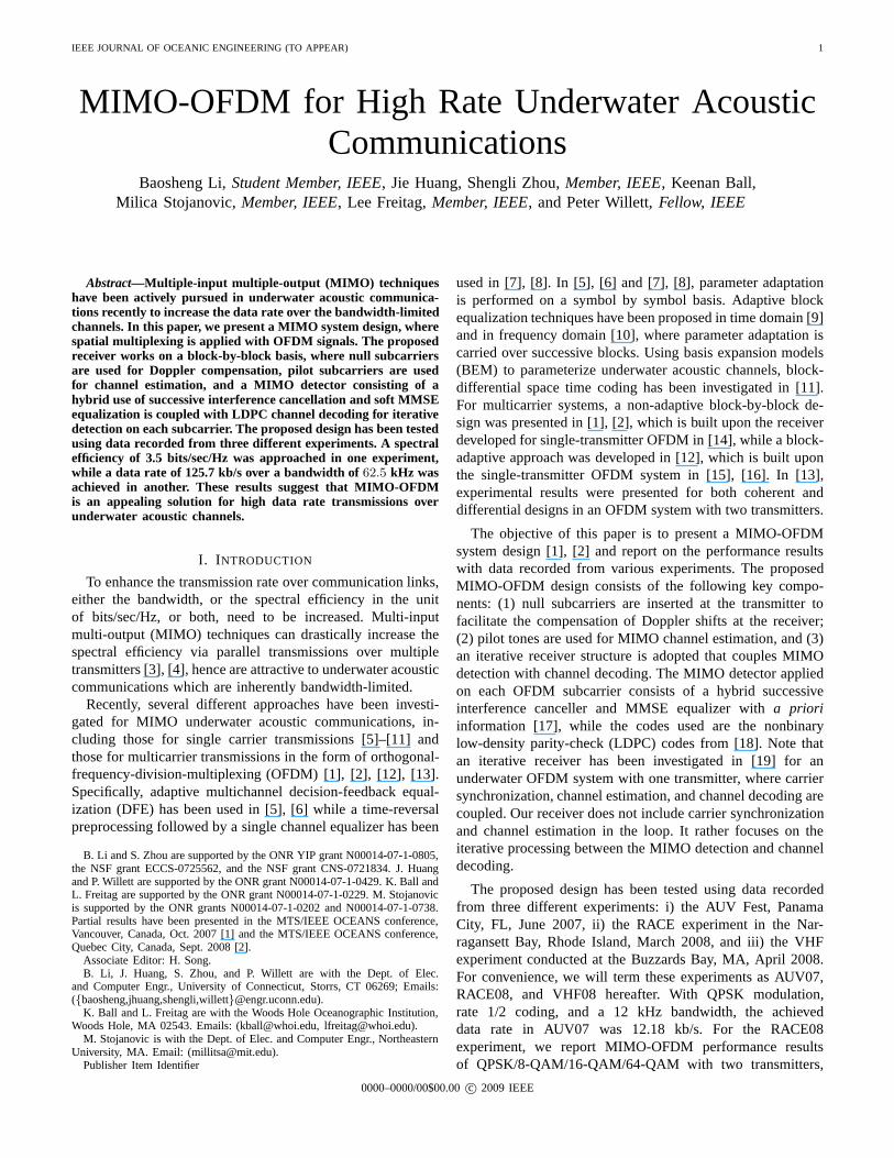
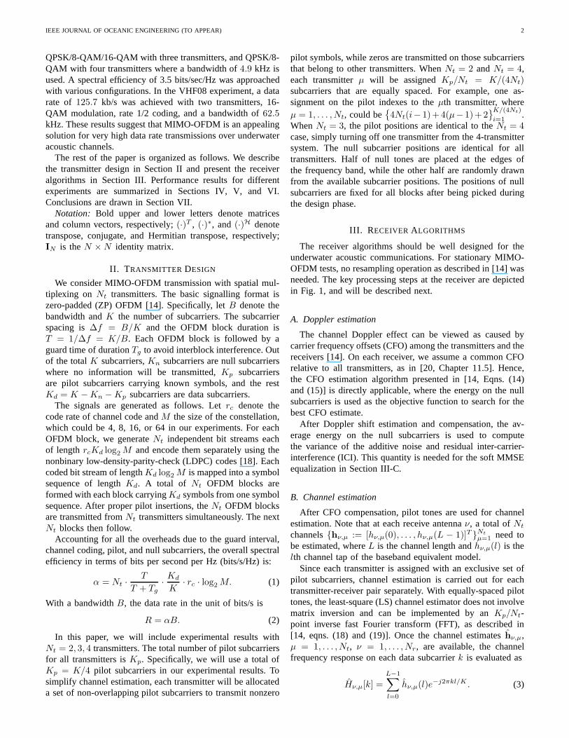
A linearly-frequency-modulated (LFM) signal is used asa preamble for synchronization. The correlation results areshown in Fig. 2 for the 500 m case, and in Fig. 3 for the1500 m case. It can be seen that the channel at 500 m has alarger delay spread than the channel at 1500 m, as expected.
B. CFO and channel estimation
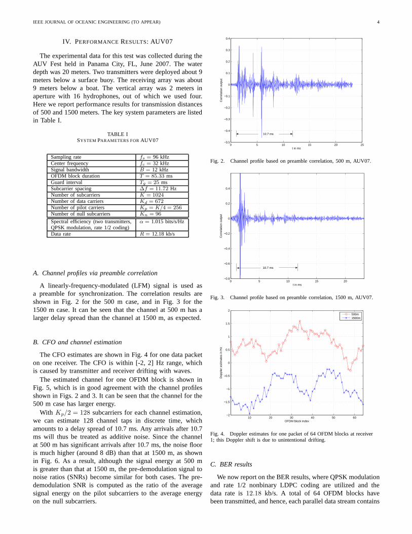
The CFO estimates are shown in Fig. 4 for one data packeton one receiver. The CFO is within [-2, 2] Hz range, whichis caused by transmitter and receiver drifting with waves.
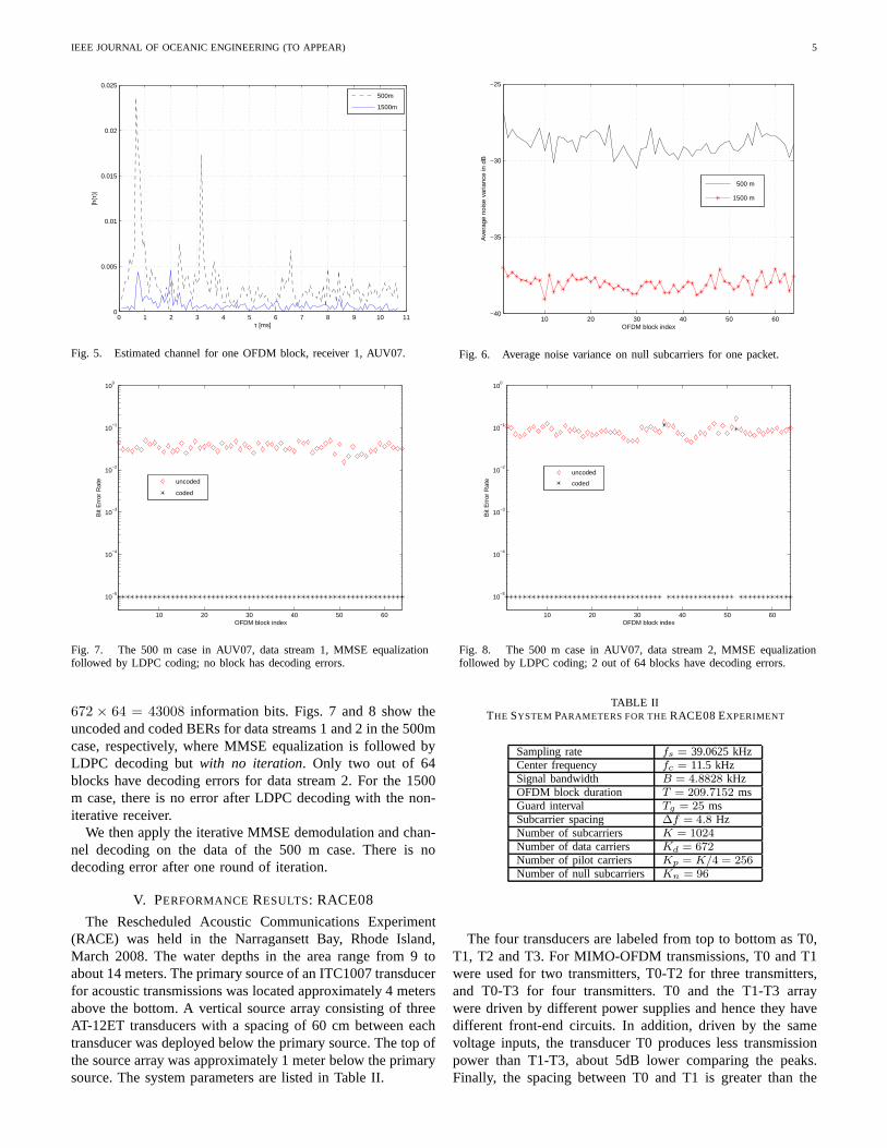
The estimated channel for one OFDM block is shown inFig. 5, which is in good agreement with the channel profilesshown in Figs. 2 and 3. It can be seen that the channel for the500 m case has larger energy.
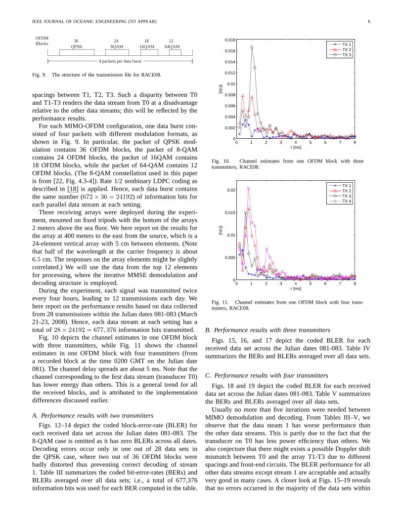
With Kp/2 = 128 subcarriers for each channel estimation,we can estimate 128 channel taps in discrete time, whichamounts to a delay spread of 10.7 ms. Any arrivals after 10.7ms will thus be treated as additive noise. Since the channelat 500 m has significant arrivals after 10.7 ms, the noise flooris much higher (around 8 dB) than that at 1500 m, as shownin Fig. 6. As a result, although the signal energy at 500 mis greater than that at 1500 m, the pre-demodulation signal tonoise ratios (SNRs) become similar for both cases. The pre-demodulation SNR is computed as the ratio of the averagesignal energy on the pilot subcarriers to the average energyon the null subcarriers.
0 5 10 15 20 25−0.5
−0.4
−0.3
−0.2
−0.1
0
0.1
0.2
0.3
0.4
t in ms
Cor
rela
tion
outp
ut
10.7 ms
Fig. 2. Channel profile based on preamble correlation, 500 m,AUV07.
0 5 10 15 20−0.8
−0.6
−0.4
−0.2
0
0.2
0.4
t in ms
Cor
rela
tion
outp
ut
10.7 ms
Fig. 3. Channel profile based on preamble correlation, 1500 m, AUV07.
10 20 30 40 50 60−2
−1.5
−1
−0.5
0
0.5
1
1.5
2
OFDM block index
Dop
pler
est
imat
es in
Hz
500m1500m
Fig. 4. Doppler estimates for one packet of 64 OFDM blocks at receiver1; this Doppler shift is due to unintentional drifting.
C. BER results
We now report on the BER results, where QPSK modulationand rate 1/2 nonbinary LDPC coding are utilized and thedata rate is12.18 kb/s. A total of 64 OFDM blocks havebeen transmitted, and hence, each parallel data stream contains
IEEE JOURNAL OF OCEANIC ENGINEERING (TO APPEAR) 5
0 1 2 3 4 5 6 7 8 9 10 110
0.005
0.01
0.015
0.02
0.025
τ [ms]
|h(τ
)|
500m
1500m
Fig. 5. Estimated channel for one OFDM block, receiver 1, AUV07.
10 20 30 40 50 60−40
−35
−30
−25
OFDM block index
Ave
rage
noi
se v
aria
nce
in d
B
500 m
1500 m
Fig. 6. Average noise variance on null subcarriers for one packet.
10 20 30 40 50 60
10−5
10−4
10−3
10−2
10−1
100
OFDM block index
Bit
Err
or R
ate
uncoded
coded
Fig. 7. The 500 m case in AUV07, data stream 1, MMSE equalizationfollowed by LDPC coding; no block has decoding errors.
10 20 30 40 50 60
10−5
10−4
10−3
10−2
10−1
100
OFDM block index
Bit
Err
or R
ate
uncoded
coded
Fig. 8. The 500 m case in AUV07, data stream 2, MMSE equalizationfollowed by LDPC coding; 2 out of 64 blocks have decoding errors.
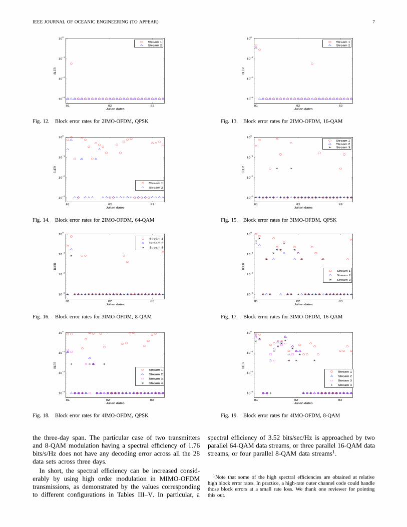
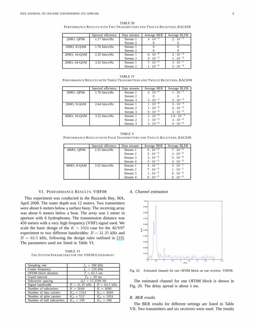
672 × 64 = 43008 information bits. Figs. 7 and 8 show theuncoded and coded BERs for data streams 1 and 2 in the 500mcase, respectively, where MMSE equalization is followed byLDPC decoding butwith no iteration. Only two out of 64blocks have decoding errors for data stream 2. For the 1500m case, there is no error after LDPC decoding with the non-iterative receiver.
We then apply the iterative MMSE demodulation and chan-nel decoding on the data of the 500 m case. There is nodecoding error after one round of iteration.
V. PERFORMANCERESULTS: RACE08
The Rescheduled Acoustic Communications Experiment(RACE) was held in the Narragansett Bay, Rhode Island,March 2008. The water depths in the area range from 9 toabout 14 meters. The primary source of an ITC1007 transducerfor acoustic transmissions was located approximately 4 metersabove the bottom. A vertical source array consisting of threeAT-12ET transducers with a spacing of 60 cm between eachtransducer was deployed below the primary source. The top ofthe source array was approximately 1 meter below the primarysource. The system parameters are listed in Table II.
TABLE IITHE SYSTEM PARAMETERS FOR THERACE08 EXPERIMENT
Sampling rate fs = 39.0625 kHzCenter frequency fc = 11.5 kHzSignal bandwidth B = 4.8828 kHzOFDM block duration T = 209.7152 msGuard interval Tg = 25 msSubcarrier spacing ∆f = 4.8 HzNumber of subcarriers K = 1024
Number of data carriers Kd = 672
Number of pilot carriers Kp = K/4 = 256
Number of null subcarriers Kn = 96
The four transducers are labeled from top to bottom as T0,T1, T2 and T3. For MIMO-OFDM transmissions, T0 and T1were used for two transmitters, T0-T2 for three transmitters,and T0-T3 for four transmitters. T0 and the T1-T3 arraywere driven by different power supplies and hence they havedifferent front-end circuits. In addition, driven by the samevoltage inputs, the transducer T0 produces less transmissionpower than T1-T3, about 5dB lower comparing the peaks.Finally, the spacing between T0 and T1 is greater than the
IEEE JOURNAL OF OCEANIC ENGINEERING (TO APPEAR) 6
OFDM Blocks
QPSK 8QAM 16QAM 64QAM 36 24 18 12
4 packets per data burst
Fig. 9. The structure of the transmission file for RACE08.
spacings between T1, T2, T3. Such a disparity between T0and T1-T3 renders the data stream from T0 at a disadvantagerelative to the other data streams; this will be reflected by theperformance results.
For each MIMO-OFDM configuration, one data burst con-sisted of four packets with different modulation formats, asshown in Fig. 9. In particular, the packet of QPSK mod-ulation contains 36 OFDM blocks, the packet of 8-QAMcontains 24 OFDM blocks, the packet of 16QAM contains18 OFDM blocks, while the packet of 64-QAM contains 12OFDM blocks. (The 8-QAM constellation used in this paperis from [22, Fig. 4.3-4]). Rate 1/2 nonbinary LDPC coding asdescribed in [18] is applied. Hence, each data burst containsthe same number (672 × 36 = 24192) of information bits foreach parallel data stream at each setting.
Three receiving arrays were deployed during the experi-ment, mounted on fixed tripods with the bottom of the arrays2 meters above the sea floor. We here report on the results forthe array at 400 meters to the east from the source, which is a24-element vertical array with 5 cm between elements. (Notethat half of the wavelength at the carrier frequency is about6.5 cm. The responses on the array elements might be slightlycorrelated.) We will use the data from the top 12 elementsfor processing, where the iterative MMSE demodulation anddecoding structure is employed.
During the experiment, each signal was transmitted twiceevery four hours, leading to 12 transmissions each day. Wehere report on the performance results based on data collectedfrom 28 transmissions within the Julian dates 081-083 (March21-23, 2008). Hence, each data stream at each setting has atotal of 28 × 24192 = 677, 376 information bits transmitted.
Fig. 10 depicts the channel estimates in one OFDM blockwith three transmitters, while Fig. 11 shows the channelestimates in one OFDM block with four transmitters (froma recorded block at the time 0200 GMT on the Julian date081). The channel delay spreads are about 5 ms. Note that thechannel corresponding to the first data stream (transducer T0)has lower energy than others. This is a general trend for allthe received blocks, and is attributed to the implementationdifferences discussed earlier.
A. Performance results with two transmitters
Figs. 12–14 depict the coded block-error-rate (BLER) foreach received data set across the Julian dates 081-083. The8-QAM case is omitted as it has zero BLERs across all dates.Decoding errors occur only in one out of 28 data sets inthe QPSK case, where two out of 36 OFDM blocks werebadly distorted thus preventing correct decoding of stream1. Table III summarizes the coded bit-error-rates (BERs) andBLERs averaged over all data sets; i.e., a total of 677,376information bits was used for each BER computed in the table.
0 1 2 3 4 5 6 7 80
0.002
0.004
0.006
0.008
0.01
0.012
0.014
0.016
0.018
τ [ms]
|h(τ
)|
TX 1TX 2TX 3
Fig. 10. Channel estimates from one OFDM block with threetransmitters, RACE08.
0 1 2 3 4 5 6 7 80
0.005
0.01
0.015
0.02
τ [ms]
|h(τ
)|
TX 1TX 2TX 3TX 4
Fig. 11. Channel estimates from one OFDM block with four trans-mitters, RACE08.
B. Performance results with three transmitters
Figs. 15, 16, and 17 depict the coded BLER for eachreceived data set across the Julian dates 081-083. Table IVsummarizes the BERs and BLERs averaged over all data sets.
C. Performance results with four transmitters
Figs. 18 and 19 depict the coded BLER for each receiveddata set across the Julian dates 081-083. Table V summarizesthe BERs and BLERs averaged over all data sets.
Usually no more than five iterations were needed betweenMIMO demodulation and decoding. From Tables III–V, weobserve that the data steam 1 has worse performance thanthe other data streams. This is partly due to the fact that thetransducer on T0 has less power efficiency than others. Wealso conjecture that there might exists a possible Doppler shiftmismatch between T0 and the array T1-T3 due to differentspacings and front-end circuits. The BLER performance for allother data streams except stream 1 are acceptable and actuallyvery good in many cases. A closer look at Figs. 15–19 revealsthat no errors occurred in the majority of the data sets within
IEEE JOURNAL OF OCEANIC ENGINEERING (TO APPEAR) 7
81 82 83
10−3
10−2
10−1
100
Julian dates
BLER
Stream 1Stream 2
Fig. 12. Block error rates for 2IMO-OFDM, QPSK
81 82 83
10−3
10−2
10−1
100
Julian dates
BLER
Stream 1Stream 2
Fig. 13. Block error rates for 2IMO-OFDM, 16-QAM
81 82 83
10−3
10−2
10−1
100
Julian dates
BLER
Stream 1
Stream 2
Fig. 14. Block error rates for 2IMO-OFDM, 64-QAM
81 82 83
10−3
10−2
10−1
100
Julian dates
BLER
Stream 1Stream 2Stream 3
Fig. 15. Block error rates for 3IMO-OFDM, QPSK
81 82 83
10−3
10−2
10−1
100
Julian dates
BLER
Stream 1
Stream 2
Stream 3
Fig. 16. Block error rates for 3IMO-OFDM, 8-QAM
81 82 83
10−3
10−2
10−1
100
Julian dates
BLER
Stream 1
Stream 2
Stream 3
Fig. 17. Block error rates for 3IMO-OFDM, 16-QAM
81 82 83
10−3
10−2
10−1
100
Julian dates
BLER
Stream 1
Stream 2
Stream 3
Stream 4
Fig. 18. Block error rates for 4IMO-OFDM, QPSK
81 82 83
10−3
10−2
10−1
100
Julian dates
BLER
Stream 1
Stream 2
Stream 3
Stream 4
Fig. 19. Block error rates for 4IMO-OFDM, 8-QAM
the three-day span. The particular case of two transmittersand 8-QAM modulation having a spectral efficiency of 1.76bits/s/Hz does not have any decoding error across all the 28data sets across three days.
In short, the spectral efficiency can be increased consid-erably by using high order modulation in MIMO-OFDMtransmissions, as demonstrated by the values correspondingto different configurations in Tables III–V. In particular,a
spectral efficiency of 3.52 bits/sec/Hz is approached by twoparallel 64-QAM data streams, or three parallel 16-QAM datastreams, or four parallel 8-QAM data streams1.
1Note that some of the high spectral efficiencies are obtainedat relativehigh block error rates. In practice, a high-rate outer channel code could handlethose block errors at a small rate loss. We thank one reviewerfor pointingthis out.
IEEE JOURNAL OF OCEANIC ENGINEERING (TO APPEAR) 8
TABLE IIIPERFORMANCERESULTS WITH TWO TRANSMITTERS AND TWELVE RECEIVERS, RACE08
Spectral efficiency Data streams Average BER Average BLER2IMO, QPSK 1.17 bits/s/Hz Stream 1 4 · 10−4 2 · 10−3
Stream 2 0 02IMO, 8-QAM 1.76 bits/s/Hz Stream 1 0 0
Stream 2 0 02IMO, 16-QAM 2.35 bits/s/Hz Stream 1 6 · 10−3 3 · 10−2
Stream 2 3 · 10−3 1 · 10−2
2IMO, 64-QAM 3.52 bits/s/Hz Stream 1 7 · 10−2 4 · 10−1
Stream 2 1 · 10−2 5 · 10−2
TABLE IVPERFORMANCERESULTS WITH THREE TRANSMITTERS AND TWELVE RECEIVERS, RACE08
Spectral efficiency Data streams Average BER Average BLER3IMO, QPSK 1.76 bits/s/Hz Stream 1 2 · 10−2 1 · 10−1
Stream 2 0 0
Stream 3 5 · 10−4 2 · 10−3
3IMO, 8-QAM 2.64 bits/s/Hz Stream 1 1 · 10−2 5 · 10−2
Stream 2 1 · 10−3 6 · 10−3
Stream 3 8 · 10−4 3 · 10−3
3IMO, 16-QAM 3.52 bits/s/Hz Stream 1 4 · 10−2 1.6 · 10−1
Stream 2 1 · 10−2 4 · 10−2
Stream 3 2 · 10−2 8 · 10−2
TABLE VPERFORMANCERESULTS WITH FOUR TRANSMITTERS AND TWELVE RECEIVERS, RACE08
Spectral efficiency Data streams Average BER Average BLER4IMO, QPSK 2.35 bits/s/Hz Stream 1 8 · 10−2 7 · 10−2
Stream 2 2 · 10−3 4 · 10−2
Stream 3 3 · 10−3 3 · 10−2
Stream 4 3 · 10−3 3 · 10−2
4IMO, 8-QAM 3.52 bits/s/Hz Stream 1 4 · 10−1 2 · 10−1
Stream 2 7 · 10−3 1 · 10−1
Stream 3 1 · 10−2 8 · 10−2
Stream 4 8 · 10−3 8 · 10−2
VI. PERFORMANCERESULTS: VHF08
This experiment was conducted in the Buzzards Bay, MA,April 2008. The water depth was 12 meters. Two transmitterswere about 6 meters below a surface buoy. The receiving arraywas about 6 meters below a boat. The array was 1 meter inaperture with 6 hydrophones. The transmission distance was450 meters with a very high frequency (VHF) signal used. Wescale the basic design of theK = 1024 case for the AUV07experiment to two different bandwidths:B = 31.25 kHz andB = 62.5 kHz, following the design rules outlined in [23].The parameters used are listed in Table VI.
TABLE VITHE SYSTEM PARAMETERS FOR THEVHF08 EXPERIMENT
Sampling rate fs = 500 kHzCenter frequency fc = 110 kHzOFDM block duration T = 65.5 msGuard interval Tg = 20 msSubcarrier spacing ∆f = 15.2588 HzSignal bandwidth B = 31.25 kHz B = 62.5 kHzNumber of subcarriers K = 2048 K = 4096
Number of data carriers Kd = 1344 Kd = 2688
Number of pilot carriers Kp = 512 Kp = 1024
Number of null subcarriers Kn = 198 Kn = 396
A. Channel estimation
0 0.5 1 1.5 2 2.5 3 3.5 4 4.50
0.001
0.002
0.003
0.004
0.005
0.006
0.007
0.008
0.009
0.01
τ [ms]
|h(τ
)|
Fig. 20. Estimated channel for one OFDM block on one receiver, VHF08.
The estimated channel for one OFDM block is shown inFig. 20. The delay spread is about4 ms.
B. BER results
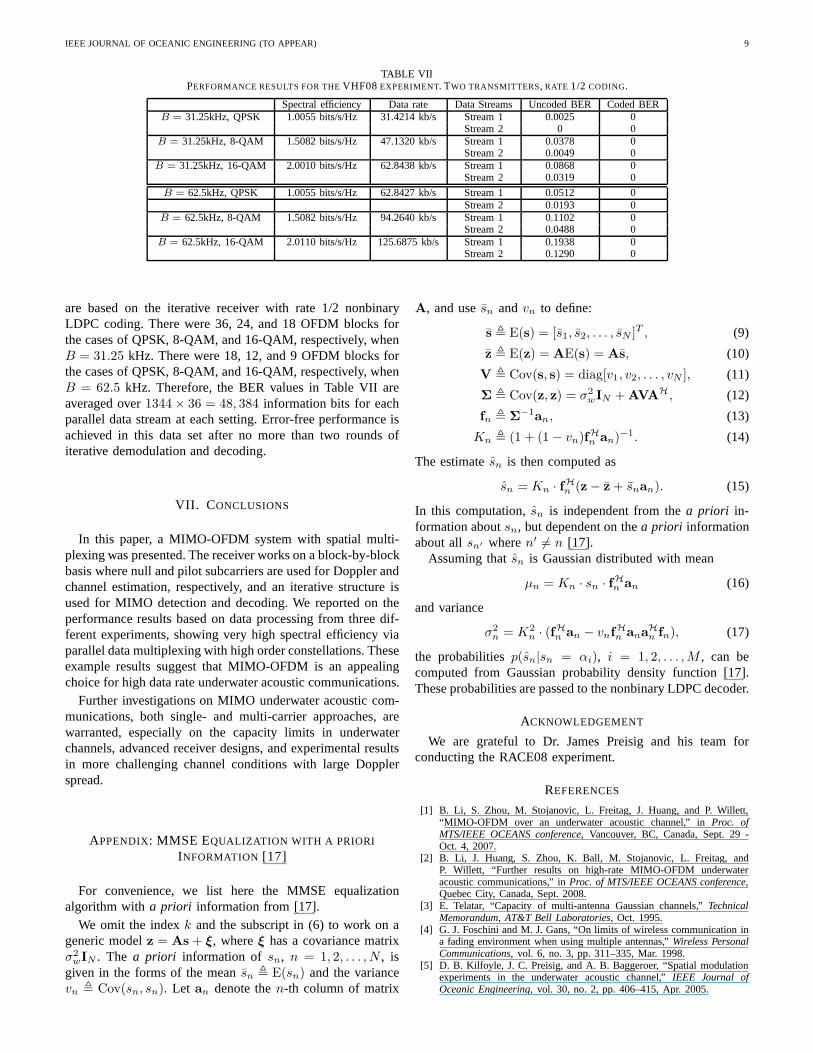
The BER results for different settings are listed in TableVII. Two transmitters and six receivers were used. The results
IEEE JOURNAL OF OCEANIC ENGINEERING (TO APPEAR) 9
TABLE VIIPERFORMANCE RESULTS FOR THEVHF08 EXPERIMENT. TWO TRANSMITTERS, RATE 1/2 CODING.
Spectral efficiency Data rate Data Streams Uncoded BER Coded BERB = 31.25kHz, QPSK 1.0055 bits/s/Hz 31.4214 kb/s Stream 1 0.0025 0
Stream 2 0 0B = 31.25kHz, 8-QAM 1.5082 bits/s/Hz 47.1320 kb/s Stream 1 0.0378 0
Stream 2 0.0049 0B = 31.25kHz, 16-QAM 2.0010 bits/s/Hz 62.8438 kb/s Stream 1 0.0868 0
Stream 2 0.0319 0
B = 62.5kHz, QPSK 1.0055 bits/s/Hz 62.8427 kb/s Stream 1 0.0512 0Stream 2 0.0193 0
B = 62.5kHz, 8-QAM 1.5082 bits/s/Hz 94.2640 kb/s Stream 1 0.1102 0Stream 2 0.0488 0
B = 62.5kHz, 16-QAM 2.0110 bits/s/Hz 125.6875 kb/s Stream 1 0.1938 0Stream 2 0.1290 0
are based on the iterative receiver with rate 1/2 nonbinaryLDPC coding. There were 36, 24, and 18 OFDM blocks forthe cases of QPSK, 8-QAM, and 16-QAM, respectively, whenB = 31.25 kHz. There were 18, 12, and 9 OFDM blocks forthe cases of QPSK, 8-QAM, and 16-QAM, respectively, whenB = 62.5 kHz. Therefore, the BER values in Table VII areaveraged over1344 × 36 = 48, 384 information bits for eachparallel data stream at each setting. Error-free performance isachieved in this data set after no more than two rounds ofiterative demodulation and decoding.
VII. C ONCLUSIONS
In this paper, a MIMO-OFDM system with spatial multi-plexing was presented. The receiver works on a block-by-blockbasis where null and pilot subcarriers are used for Doppler andchannel estimation, respectively, and an iterative structure isused for MIMO detection and decoding. We reported on theperformance results based on data processing from three dif-ferent experiments, showing very high spectral efficiency viaparallel data multiplexing with high order constellations. Theseexample results suggest that MIMO-OFDM is an appealingchoice for high data rate underwater acoustic communications.
Further investigations on MIMO underwater acoustic com-munications, both single- and multi-carrier approaches, arewarranted, especially on the capacity limits in underwaterchannels, advanced receiver designs, and experimental resultsin more challenging channel conditions with large Dopplerspread.
APPENDIX: MMSE EQUALIZATION WITH A PRIORI
INFORMATION [17]
For convenience, we list here the MMSE equalizationalgorithm witha priori information from [17].
We omit the indexk and the subscript in (6) to work on ageneric modelz = As + ξ, whereξ has a covariance matrixσ2
wIN . The a priori information of sn, n = 1, 2, . . . , N , isgiven in the forms of the meansn , E(sn) and the variancevn , Cov(sn, sn). Let an denote then-th column of matrix
A, and usesn andvn to define:
s , E(s) = [s1, s2, . . . , sN ]T , (9)
z , E(z) = AE(s) = As, (10)
V , Cov(s, s) = diag[v1, v2, . . . , vN ], (11)
Σ , Cov(z, z) = σ2wIN + AVAH, (12)
fn , Σ−1an, (13)
Kn , (1 + (1 − vn)fHn an)−1. (14)
The estimatesn is then computed as
sn = Kn · fHn (z − z + snan). (15)
In this computation,sn is independent from thea priori in-formation aboutsn, but dependent on thea priori informationabout allsn′ wheren′ 6= n [17].
Assuming thatsn is Gaussian distributed with mean
µn = Kn · sn · fHn an (16)
and variance
σ2n = K2
n · (fHn an − vnfHn anaHn fn), (17)
the probabilitiesp(sn|sn = αi), i = 1, 2, . . . , M , can becomputed from Gaussian probability density function [17].These probabilities are passed to the nonbinary LDPC decoder.
ACKNOWLEDGEMENT
We are grateful to Dr. James Preisig and his team forconducting the RACE08 experiment.
REFERENCES
[1] B. Li, S. Zhou, M. Stojanovic, L. Freitag, J. Huang, and P.Willett,“MIMO-OFDM over an underwater acoustic channel,” inProc. ofMTS/IEEE OCEANS conference, Vancouver, BC, Canada, Sept. 29 -Oct. 4, 2007.
[2] B. Li, J. Huang, S. Zhou, K. Ball, M. Stojanovic, L. Freitag, andP. Willett, “Further results on high-rate MIMO-OFDM underwateracoustic communications,” inProc. of MTS/IEEE OCEANS conference,Quebec City, Canada, Sept. 2008.
[3] E. Telatar, “Capacity of multi-antenna Gaussian channels,” TechnicalMemorandum, AT&T Bell Laboratories, Oct. 1995.
[4] G. J. Foschini and M. J. Gans, “On limits of wireless communication ina fading environment when using multiple antennas,”Wireless PersonalCommunications, vol. 6, no. 3, pp. 311–335, Mar. 1998.
[5] D. B. Kilfoyle, J. C. Preisig, and A. B. Baggeroer, “Spatial modulationexperiments in the underwater acoustic channel,”IEEE Journal ofOceanic Engineering, vol. 30, no. 2, pp. 406–415, Apr. 2005.
IEEE JOURNAL OF OCEANIC ENGINEERING (TO APPEAR) 10
[6] S. Roy, T. M. Duman, V. McDonald, and J. G. Proakis, “High rate com-munication for underwater acoustic channels using multiple transmittersand space-time coding: Receiver structures and experimental results,”IEEE Journal of Oceanic Engineering, vol. 32, no. 3, pp. 663–688, July2007.
[7] H. C. Song, W. S. Hodgkiss, W. A. Kuperman, T. Akal, and M. Steven-son, “Multiuser communications using passive time reversal,” IEEEJournal of Oceanic Engineering, vol. 32, no. 4, pp. 915–926, October2007.
[8] A. Song, M. Badiey, and V. K. McDonald, “Multi-channel combiningand equalization for underwater acoustic MIMO channels,” in Proc.of MTS/IEEE OCEANS conference, Quebec City, Canada, Sept. 15-18,2008.
[9] J. Tao, Y. R. Zheng, C. Xiao, T. C. Yang, and W.-B. Yang, “Time-domainreceiver design for MIMO underwater acoustic communications,” inProc. of MTS/IEEE OCEANS conference, Quebec City, Canada, Sept.15-18, 2008.
[10] J. Zhang, Y. R. Zheng, and C. Xiao, “Frequency-domain equalizationfor single carrier MIMO underwater acoustic communications,” in Proc.of MTS/IEEE OCEANS conference, Quebec City, Canada, Sept. 15-18,2008.
[11] F. Qu and L. Yang, “Basis expansion model for underwateracousticchannels?” inProc. of MTS/IEEE OCEANS conference, Quebec City,Canada, Sept. 15-18, 2008.
[12] P. Carrascosa and M. Stojanovic, “Adaptive MIMO detection of OFDMsignals in an underwater acoustic channel,” inProc. of MTS/IEEEOCEANS conference, Quebec City, Canada, Sept. 15-18, 2008.
[13] Y. Emre, V. Kandasamy, T. M. Duman, P. Hursky, and S. Roy,“Multi-input multi-output OFDM for shallow-water UWA communications,” inAcoustics’08 Conference, Paris, France, July 2008.
[14] B. Li, S. Zhou, M. Stojanovic, L. Freitag, and P. Willett, “Multicarriercommunication over underwater acoustic channels with nonuniformDoppler shifts,” IEEE Journal of Oceanic Engineering, vol. 33, no. 2,pp. 198–209, Apr. 2008.
[15] M. Stojanovic, “Low complexity OFDM detector for underwater chan-nels,” in Proc. of MTS/IEEE OCEANS conference, Boston, MA, Sept.18-21, 2006.
[16] ——, “OFDM for underwater acoustic communications: Adaptive syn-chronization and sparse channel estimation,” inProc. of Intl. Conf. onASSP, Las Vegas, NV, Mar. 30 – Apr. 4, 2008.
[17] M. Tuchler, A. C. Singer, and R. Koetter, “Minimum mean squared errorequalization using a priori information,”IEEE Transactions on SignalProcessing, vol. 50, no. 3, pp. 673–683, Mar. 2002.
[18] J. Huang, S. Zhou, and P. Willett, “Nonbinary LDPC coding formulticarrier underwater acoustic communication,”IEEE J. Select. AreasCommun., vol. 26, no. 9, pp. 1684–1696, Dec. 2008.
[19] T. Kang and R. A. Iltis, “Iterative carrier frequency offset and channelestimation for underwater acoustic OFDM systems,”IEEE J. Select.Areas Commun., vol. 26, no. 9, pp. 1650–1661, Dec. 2008.
[20] G. B. Giannakis, Z. Liu, X. Ma, and S. Zhou,Space Time Coding forBroadband Wireless Communications. John Wiley & Sons, Inc., Dec.2006.
[21] C. R. Berger, S. Zhou, J. C. Preisig, and P. Willett, “Sparse channelestimation for multicarrier underwater acoustic communication: Fromsubspace methods to compressed sensing,” inProc. of MTS/IEEEOCEANS conference, Bremen, Germany, May 11-14, 2009.
[22] J. G. Proakis,Digital Communications, McGraw-Hill, 4th edition, 2001.[23] B. Li, S. Zhou, J. Huang, and P. Willett, “Scalable OFDM design for
underwater acoustic communications,” inProc. of Intl. Conf. on ASSP,Las Vegas, NV, Mar. 30 – Apr. 4, 2008.
Baosheng Li (S’05) received the B.S. and theM.S. degrees in the electronic and communicationsengineering from the Harbin Institute of Technology,Harbin, China, in 2002 and 2004, respectively. Hereceived his Ph.D. degree in electrical engineeringfrom the University of Connecticut, Storrs, in 2009.He is currently a postdoctoral research fellow atNortheastern University, Boston, MA.
His research interests lie in the areas of commu-nications and signal processing, currently focusingon multi-transceiver and multi-carrier modulation
algorithms for underwater acoustic communications.
Jie Huang received the B.S. degree in 2001 andthe Ph. D. degree in 2006, from the University ofScience and Technology of China (USTC), Hefei,both in electrical engineering and information sci-ence. He was a post-doctoral researcher with theDepartment of Electrical and Computer Engineeringat the University of Connecticut (UCONN), Storrs,from July 2007 to June 2009, and is now a researchassistant professor at the University of Connecticut(UCONN), Storrs.
His general research interests lie in the areas ofcommunications and signal processing, specifically error control coding theoryand coded modulation. His recent focus is on signal processing, channelcoding and network coding for underwater acoustic communications andnetworks.
Shengli Zhou (M’03) received the B.S. degreein 1995 and the M.Sc. degree in 1998, from theUniversity of Science and Technology of China(USTC), Hefei, both in electrical engineering andinformation science. He received his Ph.D. degreein electrical engineering from the University of Min-nesota (UMN), Minneapolis, in 2002. He has beenan assistant professor with the Department of Elec-trical and Computer Engineering at the Universityof Connecticut (UCONN), Storrs, 2003-2009, andnow is an associate professor. He holds a United
Technologies Corporation (UTC) Professorship in Engineering Innovation,2008-2011.
His general research interests lie in the areas of wireless communicationsand signal processing. His recent focus is on underwater acoustic communi-cations and networking. Dr. Zhou has served as an associate editor for IEEETransactions on Wireless Communications from Feb. 2005 to Jan. 2007, andis now an associate editor for IEEE Transactions on Signal Processing. Hereceived the 2007 ONR Young Investigator award and the 2007 PresidentialEarly Career Award for Scientists and Engineers (PECASE).
Keenan Ballholds a BS from Wentworth Institute ofTechnology in Electromechanical Engineering andan MS from the University of Massachusetts Dart-mouth in Electrical Engineering which he receivedin 2000 and 2002 respectively. He is currently a Re-search Engineer at the Woods Hole OceanographicInstitution where he has worked on projects relatedto underwater acoustics. The programs that he workson focus on underwater acoustic communicationand navigation for UUVs, moored systems, and theassociated hardware designs for these applications.
Milica Stojanovic (M’93) graduated from the Uni-versity of Belgrade, Serbia, in 1988, and receivedthe M.S. and Ph.D. degrees in electrical engineer-ing from Northeastern University, Boston, MA, in1991 and 1993. After a number of years with theMassachusetts Institute of Technology, where shewas a Principal Scientist, she joined the faculty ofElectrical and Computer Engineering Departmentat Northeastern University in 2008. She is also aGuest Investigator at the Woods Hole OceanographicInstitution, and a Visiting Scientist at MIT.
Her research interests include digital communications theory, statisticalsignal processing and wireless networks, and their applications to mobileradio and underwater acoustic communication systems. Milica is an AssociateEditor for the IEEE Journal of Oceanic Engineering and the IEEE Transactionson Signal processing.
IEEE JOURNAL OF OCEANIC ENGINEERING (TO APPEAR) 11
Lee Freitag (M’88) holds BS and MS degreesin Electrical Engineering from the University ofAlaska, Fairbanks, which he received in 1986 and1987 respectively. He is currently a Senior Engineerat the Woods Hole Oceanographic Institution wherehe has worked on projects related to underwateracoustics for 15 years.
His research programs focus on underwater acous-tic communication and navigation with a strongfocus on UUVs, sensors and submarine systems. Heis a member of IEEE and MTS.
Peter Willett (F’03) received his BASc (Engineer-ing Science) from the University of Toronto in 1982,and his PhD degree from Princeton University in1986. He has been a faculty member at the Univer-sity of Connecticut ever since, and since 1998 hasbeen a Professor. His primary areas of research havebeen statistical signal processing, detection, machinelearning, data fusion and tracking. He has interests inand has published in the areas of change/abnormalitydetection, optical pattern recognition, communica-tions and industrial/security condition monitoring.
He is editor-in-chief for IEEE Transactions on Aerospace and ElectronicSystems, and until recently was associate editor for three active journals:IEEE Transactions on Aerospace and Electronic Systems (forData Fusion andTarget Tracking) and IEEE Transactions on Systems, Man, andCybernetics,parts A and B. He is also associate editor for the IEEE AES Magazine,editor of the AES Magazine periodic Tutorial issues, associate editor for ISIFelectronic Journal of Advances in Information Fusion, and is a member of theeditorial board of IEEE Signal Processing Magazine. He has been a memberof the IEEE AESS Board of Governors since 2003. He was GeneralCo-Chair (with Stefano Coraluppi) for the 2006 ISIF/IEEE Fusion Conferencein Florence, Italy, Program Co-Chair (with Eugene Santos) for the 2003IEEE Conference on Systems, Man, and Cybernetics in Washington DC, andProgram Co-Chair (with Pramod Varshney) for the 1999 FusionConferencein Sunnyvale.