Characteristics of MIMO-OFDM Channels in Indoor Environments
10
Hindawi Publishing Corporation EURASIP Journal on Wireless Communications and Networking Volume 2007, Article ID 19728, 9 pages doi:10.1155/2007/19728 Research Article Characteristics of MIMO-OFDM Channels in Indoor Environments Hajime Suzuki, Thi Van Anh Tran, and Iain B. Collings Wireless Technologies Laboratory, CSIRO ICT Centre, P.O. Box 76, Epping NSW 1710, Australia Received 1 April 2006; Revised 16 October 2006; Accepted 19 October 2006 Recommended by Merouane Debbah We present the results of multiple-input multiple-output orthogonal frequency-division multiplexing (MIMO-OFDM) chan- nel measurements. The measurements were performed in indoor environments using four transmitters and four receivers with 40 MHz bandwidth at 5.25 GHz. Our measurements reveal two-dimensional small-scale fading, and correlation between MIMO subchannels. In the line-of-sight (LoS) case, the MIMO-OFDM channel capacity is found to be strongly dependent on the local scattering environment; and much less dependent in the non-LoS (NLoS) case. Also, MIMO channel capacity is found to be largely uncorrelated over 20 MHz in NLoS, while a strong correlation is found over 40 MHz in some LoS environments. The validity of the conventional Kronecker correlation channel model is tested, along with a recently proposed joint correlation model. The effects of varying antenna element spacing are also investigated, taking into account such effects as mutual coupling, radiation efficiency, and radiation pattern. Copyright © 2007 Hajime Suzuki et al. This is an open access article distributed under the Creative Commons Attribution License, which permits unrestricted use, distribution, and reproduction in any medium, provided the original work is properly cited. 1. INTRODUCTION Multiple-input multiple-output orthogonal frequency- division multiplexing (MIMO-OFDM) is currently being considered as a strong candidate for the physical layer transmission scheme of next generation wireless commu- nication systems [1]. A commercial product utilizing two transmit antennas and three receive antennas (denoted by 2 3) achieving 6 bps/Hz bandwidth efficiency for wireless local area networks (WLAN) is currently available, while the WLAN standardization group is aiming to achieve 15 bps/Hz bandwidth efficiency using four transmitters (Txs) [2]. In this paper, we focus on measuring and characteriz- ing practical MIMO-OFDM channels in indoor environ- ments. Extensive narrowband indoor MIMO channel mea- surements have been performed by several groups (e.g., [3, 4]); however MIMO-OFDM system design requires an understanding of MIMO channels as a function of frequency. Channel measurements for a 2 2 MIMO-OFDM system at 3.65 GHz with 20 MHz bandwidth have been performed by Motorola in an indoor laboratory environment, as reported in [5]. They provided plots of MIMO subchannel frequency responses showing the differences in line-of-sight (LoS) and non-LoS (NLoS). A full-rank channel matrix was observed across the entire 20 MHz band, even for the case of the LoS path, which the authors regarded was due to many reflectors inside their laboratory. In [6], 8 8 MIMO-OFDM channels were measured at 5.2 GHz with 120 MHz of bandwidth, at 20 locations in an open-plan office. While the measured channels were utilized in packet error rate simulation to investigate the performance of different modulation and coding schemes, no analysis on the channels, in terms of fading character- istics or MIMO subchannel correlation properties, was re- ported. A wideband 8 8 MIMO channel measurement was also reported in [7] where five NLoS paths were analyzed to de- velop a wideband MIMO channel model. Although full 8 8 MIMO channels were obtained, the authors utilized only their subsets (2 2 and 3 3) in developing the channel model. A2 2 MIMO-OFDM channel measurement conducted by NTT at 5.2 GHz using 10 MHz bandwidth is reported in [8], where the channels were measured every 5 mm along measurement routes in an anechoic chamber and four dif- ferent indoor environments. The measured channels were analyzed in terms of Demmel condition number [9], with smaller Demmel condition number (more suitable for spatial
Transcript of Characteristics of MIMO-OFDM Channels in Indoor Environments

Hindawi Publishing CorporationEURASIP Journal on Wireless Communications and NetworkingVolume 2007, Article ID 19728, 9 pagesdoi:10.1155/2007/19728
Research ArticleCharacteristics of MIMO-OFDM Channelsin Indoor Environments
Hajime Suzuki, Thi Van Anh Tran, and Iain B. Collings
Wireless Technologies Laboratory, CSIRO ICT Centre, P.O. Box 76, Epping NSW 1710, Australia
Received 1 April 2006; Revised 16 October 2006; Accepted 19 October 2006
Recommended by Merouane Debbah
We present the results of multiple-input multiple-output orthogonal frequency-division multiplexing (MIMO-OFDM) chan-nel measurements. The measurements were performed in indoor environments using four transmitters and four receivers with40 MHz bandwidth at 5.25 GHz. Our measurements reveal two-dimensional small-scale fading, and correlation between MIMOsubchannels. In the line-of-sight (LoS) case, the MIMO-OFDM channel capacity is found to be strongly dependent on the localscattering environment; and much less dependent in the non-LoS (NLoS) case. Also, MIMO channel capacity is found to be largelyuncorrelated over 20 MHz in NLoS, while a strong correlation is found over 40 MHz in some LoS environments. The validity of theconventional Kronecker correlation channel model is tested, along with a recently proposed joint correlation model. The effectsof varying antenna element spacing are also investigated, taking into account such effects as mutual coupling, radiation efficiency,and radiation pattern.
Copyright © 2007 Hajime Suzuki et al. This is an open access article distributed under the Creative Commons Attribution License,which permits unrestricted use, distribution, and reproduction in any medium, provided the original work is properly cited.
1. INTRODUCTION
Multiple-input multiple-output orthogonal frequency-division multiplexing (MIMO-OFDM) is currently beingconsidered as a strong candidate for the physical layertransmission scheme of next generation wireless commu-nication systems [1]. A commercial product utilizing twotransmit antennas and three receive antennas (denoted by2 � 3) achieving 6 bps/Hz bandwidth efficiency for wirelesslocal area networks (WLAN) is currently available, while theWLAN standardization group is aiming to achieve 15 bps/Hzbandwidth efficiency using four transmitters (Txs) [2].
In this paper, we focus on measuring and characteriz-ing practical MIMO-OFDM channels in indoor environ-ments. Extensive narrowband indoor MIMO channel mea-surements have been performed by several groups (e.g.,[3, 4]); however MIMO-OFDM system design requires anunderstanding of MIMO channels as a function of frequency.Channel measurements for a 2� 2 MIMO-OFDM system at3.65 GHz with 20 MHz bandwidth have been performed byMotorola in an indoor laboratory environment, as reportedin [5]. They provided plots of MIMO subchannel frequencyresponses showing the differences in line-of-sight (LoS) andnon-LoS (NLoS). A full-rank channel matrix was observed
across the entire 20 MHz band, even for the case of the LoSpath, which the authors regarded was due to many reflectorsinside their laboratory.
In [6], 8 � 8 MIMO-OFDM channels were measured at5.2 GHz with 120 MHz of bandwidth, at 20 locations inan open-plan office. While the measured channels wereutilized in packet error rate simulation to investigate theperformance of different modulation and coding schemes,no analysis on the channels, in terms of fading character-istics or MIMO subchannel correlation properties, was re-ported.
A wideband 8� 8 MIMO channel measurement was alsoreported in [7] where five NLoS paths were analyzed to de-velop a wideband MIMO channel model. Although full 8�8MIMO channels were obtained, the authors utilized onlytheir subsets (2 � 2 and 3 � 3) in developing the channelmodel.
A 2� 2 MIMO-OFDM channel measurement conductedby NTT at 5.2 GHz using 10 MHz bandwidth is reported in[8], where the channels were measured every 5 mm alongmeasurement routes in an anechoic chamber and four dif-ferent indoor environments. The measured channels wereanalyzed in terms of Demmel condition number [9], withsmaller Demmel condition number (more suitable for spatial

2 EURASIP Journal on Wireless Communications and Networking
multiplexing) being observed when polarization diversitywas utilized.
Preliminary 2 � 2 MIMO-OFDM channel measurementresults at 2.4 GHz with 16 MHz bandwidth are reported in[10]. Graphs of frequency responses within short time scale(200 milliseconds) measured in NLoS office environmentwere presented.
In [11], 2 � 2 MIMO-OFDM channels were measuredat 5.25 GHz with a bandwidth of 25 MHz for 200 locationsalong traveling paths indoors, with steps larger than a wave-length in order to obtain independent channel realizations.Within a laboratory environment, the LoS and NLoS chan-nels did not show significant differences in terms of the con-dition number, which is the ratio of the smallest and largestsingular values of MIMO channel matrix. The authors pos-tulate that this is consistent with the intuition that there aremany reflectors in a laboratory environment which make thechannels independently frequency-selective.
In this paper, we consider 4 � 4 MIMO-OFDM with40 MHz bandwidth. Interestingly, there is a complete lack ofcurrently available measurement sets for this scenario. Thisis particularly surprising considering that this is precisely thecombination which is suggested for providing the maximumdata rate in the new IEEE 802.11n standard [2]. In this paper,we systematically investigate the spatial characteristics of thechannels in a number of indoor local areas. We show that thechannel can change as a function of antenna location in theorder of a fraction of a wavelength in these multipath envi-ronments. Our measurements reveal two-dimensional small-scale fading, and correlation between MIMO subchannels.The validity of the conventional Kronecker correlation chan-nel model is tested, along with a recently proposed joint cor-relation model. We show certain inconsistencies in the case ofLoS environments, which point to the need for further modeldevelopment. The effects of varying antenna element spacingare also investigated, taking into account such effects as mu-tual coupling, radiation efficiency, and radiation pattern.
The paper is organized as follows. The description of themeasurement equipment and the measurement site is givenin Section 2. Section 3 provides the definition of a MIMO-OFDM channel and its associated theoretical capacity. Theresults of the MIMO-OFDM channel measurement and cor-responding analysis are given in Section 4, followed by theconclusions in Section 5.
2. MEASUREMENT EQUIPMENT AND SITE
The CSIRO ICT Centre has recently developed a 4� 4MIMO-OFDM hardware demonstrator as shown in Fig-ure 1. It operates at 5.25 GHz and supports an operationalbandwidth of up to 40 MHz. The receiving antennas are con-nected to an antenna array positioner controlled by a PC. Forchannel measurements, the antenna positioner moves the re-ceiving antenna array within a horizontal two-dimensionalarea of 4 wavelengths � 4 wavelengths with 0.05 wavelengthincrement, resulting in 6400 locations. We found that theseparameters provided an adequate spatial sampling, based onour observation that from a statistical point of view, the
(a) Multichannel transmitter
(b) Multichannel receiver
Figure 1: CSIRO ICT Centre MIMO-OFDM demonstrator.
measured results are relatively insensitive to coverage areaand wavelength spatial sampling distance.
There is a flexibility to allow a user to perform not onlythe channel sounding but also testing of different modulationand coding schemes of MIMO-OFDM transmission [12].Identical off-the-shelf omnidirectional loop antennas (Sky-Cross SMA-5250-UA) are used as both Tx and Rx antenna ar-ray elements for all MIMO-OFDM measurements describedin this paper. The antenna elements are arranged to form auniform square array on the horizontal plane. The spacingof the antenna elements is set to 3 wavelengths at Tx and 2wavelengths at Rx (except for the measurements described inSection 4.6).
For MIMO-OFDM channel sounding purposes, typicallya packet consists of a preamble (for performing packet de-tection, frame synchronization, and frequency offset correc-tion [13]) and a channel training sequence is sent. The chan-nel training sequence is designed to estimate the frequencyresponse over 117 OFDM subcarriers in a 40 MHz band-width with the subcarrier spacing of 312.5 kHz. The choiceof OFDM subcarriers is consistent with [2], except that thethree middle null carries are also used. To avoid the interfer-ence of signals transmitted from different transmitting an-tennas, the channel training sequence is sent from each trans-mitting antenna at different times [13]. In order to reducethe effect of noise, the channel training sequence is sent tentimes at each location while the estimation of the channel isperformed ten times and the averaged results are used for theanalysis. A detailed calibration of the system was performedprior to the measurement by directly connecting each of theTxs to each of the Rxs via cables and an attenuator, andmeasuring the frequency response of each pair of Tx andRx. The frequency response of the system is subtracted fromthe measured over-the-air MIMO-OFDM channels. This re-moves any effects of RF front-end filters in Tx and Rx devices.

Hajime Suzuki et al. 3
(a) Laboratory (b) Atrium (c) Lecture theater
Figure 2: Photographs of measurement sites.
The transmitting power used during the measurementwas varied from �10 dBm to 10 dBm per transmitting an-tenna, depending on the environment and the distance be-tween Tx and Rx. Observed signal-to-noise ratio (SNR) wasbetter than 25 dB in average over frequency. A set of MIMO-OFDM channels in a local area consists of the channel coeffi-cients of 16 MIMO subchannels at 117 OFDM subcarriers at6400 locations, which amounts to approximately 12 millionchannels per local area measurement. Currently, this mea-surement takes approximately 6 hours. The measurementwas performed during the night or over the weekend in orderto avoid possible temporal variation due to human activities.
The measurements were performed in the CSIRO ICTCentre Laboratory in Marsfield, Sydney. Six propagationlinks covering both LoS path and NLoS path were establishedas follows.
(i) LoS 1: both Tx and Rx are located in a laboratory withLoS. Direct distance between Tx and Rx is 5 m.
(ii) LoS 2: both Tx and Rx are located in an atrium withLoS, 7 m.
(iii) LoS 3: both Tx and Rx are located in a lecture theaterwith LoS, 9 m.
(iv) NLoS 1: Tx is located in an office environment whileRx is located in the laboratory with no LoS, 5 m.
(v) NLoS 2: Tx is located in an office environment whileRx is located in the atrium with no LoS, 10 m.
(vi) NLoS 3: both Tx and Rx are located in office environ-ment with each end in different rooms with no LoS,9 m.
Photographs of the laboratory, atrium, and lecture the-ater are shown in Figure 2, by way of example.
3. DEFINITION OF MIMO-OFDM CHANNELAND CAPACITY
The MIMO-OFDM channel is characterized by its coefficientg(i, j, k, l) defined as the complex ratio of the signal outputfrom the ith receiving antenna over the signal input to thejth transmitting antenna, at the kth OFDM subcarrier, andat the lth receiving antenna array location. The number oftransmitting antennas, receiving antennas, OFDM subcarri-ers, and the receiving antenna array locations is nt, nr , n f ,and nx, respectively. It is convenient to work on the nor-malized channel coefficient h(i, j, k, l) so that the Shannon
capacity of the MIMO channel can be derived as a functionof SNR per receiving antenna, averaged over all MIMO sub-channels, OFDM subcarriers, and receiving antenna array lo-cations. The convention is to perform normalization at eachreceiving antenna array location [14], which assumes that thetransmitting power can be adjusted without limitations toprovide fixed average SNR per Rx. For a practical situationwhere the transmitting power is limited [3], it is more con-venient to define the average SNR per Rx over a local area. Inthis case, the normalization is performed over a local area asfollows:
h(i, j, k, l)
= g(i, j, k, l)√(1/ntnrn f nx
)∑nri=1
∑ntj=1
∑n f
k=1
∑nxl=1
∣∣g(i, j, k, l)∣∣2
.
(1)
For the current measurement, nt = 4, nr = 4, n f = 117,and nx = 6400. The normalized channel matrix at the kthOFDM subcarrier at the lth receiving antenna array loca-tion is given by the channel coefficient matrix H(k, l) whoseith row and jth column element is h(i, j, k, l). When theMIMO channel is completely known by Rx but is unknownto Tx, the Shannon capacity of the MIMO channel at the kthOFDM subcarrier at the lth receiving antenna array locationis given by [15]
C(k, l) =nt∑
m=1
log2
(1 +
ρ
ntλm(k, l)
), (2)
where ρ is the average SNR per Rx over MIMO subchannels,OFDM subcarriers, and a local area, λm(k, l) is the mth eigen-value of H(k, l)HH(k, l), and superscript H denotes complexconjugate transpose. In the following, the MIMO channel ca-pacity is calculated at each OFDM subcarrier using the aboveequation, while the MIMO-OFDM channel capacity is calcu-lated as an average of MIMO channel capacity over all OFDMsubcarriers.
4. MEASUREMENT RESULTS AND ANALYSIS
4.1. Measured MIMO-OFDM channels
Figure 3 shows an example of measured MIMO-OFDMchannels. Sets of MIMO-OFDM channels obtained at eight

4 EURASIP Journal on Wireless Communications and Networking
�40
�20
0
20
�40
�20
0
20
Rel
ativ
ep
ower
(dB
)
Tx1-Rx1 Tx2-Rx1 Tx3-Rx1 Tx4-Rx1 Tx1-Rx2 Tx2-Rx2 Tx3-Rx2 Tx4-Rx2
Tx1-Rx3 Tx2-Rx3 Tx3-Rx3 Tx4-Rx3 Tx1-Rx4 Tx2-Rx4 Tx3-Rx4 Tx4-Rx4
�20 0 20 �20 0 20 �20 0 20 �20 0 20 �20 0 20 �20 0 20 �20 0 20 �20 0 20
Frequency (MHz)
Figure 3: An example of measured MIMO-OFDM frequency response, NLoS 3 (office rooms) path.
0123
4
0123
4
0123
4
0123
4
y(w
avel
engt
h)
Tx1-Rx1 Tx2-Rx1 Tx3-Rx1 Tx4-Rx1
Tx1-Rx2 Tx2-Rx2 Tx3-Rx2 Tx4-Rx2
Tx1-Rx3 Tx2-Rx3 Tx3-Rx3 Tx4-Rx3
Tx1-Rx4 Tx2-Rx4 Tx3-Rx4 Tx4-Rx4
0 1 2 3 4 0 1 2 3 4 0 1 2 3 4 0 1 2 3 4
x (wavelength)
�30 �25 �20 �15 �10 �5 0 5 10 15
Relative power (dB)
(a) NLoS 3 (office rooms) path
0123
4
0123
4
0123
4
0123
4
y(w
avel
engt
h)
Tx1-Rx1 Tx2-Rx1 Tx3-Rx1 Tx4-Rx1
Tx1-Rx2 Tx2-Rx2 Tx3-Rx2 Tx4-Rx2
Tx1-Rx3 Tx2-Rx3 Tx3-Rx3 Tx4-Rx3
Tx1-Rx4 Tx2-Rx4 Tx3-Rx4 Tx4-Rx4
0 1 2 3 4 0 1 2 3 4 0 1 2 3 4 0 1 2 3 4
x (wavelength)
�30 �25 �20 �15 �10 �5 0 5 10 15
Relative power (dB)
(b) LoS 3 (lecture theater) path
Figure 4: Examples of measured MIMO subchannel fading maps.
consecutive Rx antenna array locations with 0.05-wavelengthspacing are plotted (from light gray curves to solid blackcurves) showing typical variation in space and in fre-quency. As expected from a multipath environment, severefrequency-selective fading is observed in most MIMO sub-channels.
Figure 4 shows examples of the small-scale spatial fadingpattern measured with NLoS 3 link and LoS 3 link, respec-tively, at one of the OFDM subcarriers. (Interested readersare referred to [16] or [17] for the small-scale spatial fad-ing plots in other environments.) Deep fading in the orderof 30 dB is commonly observed in both cases, which is a
characteristic of the narrowband small-scale spatial fading.An apparent correlation of the different MIMO subchan-nels is observed in the case of LoS path, for example Tx3-Rx3 and Tx3-Rx4. Such a correlation of MIMO subchan-nels is known to reduce the MIMO channel capacity [18].A similar fading pattern was observed for different OFDMsubcarriers.
4.2. MIMO subchannel correlations
Correlation analysis is a useful tool in assessing MIMO chan-nels [19]. The complex correlation coefficient ρ of two
Hajime Suzuki et al. 5
�1
�0.5
0
0.5
1
Imag
inar
y
�1 �0.5 0 0.5 1
Real
(a) NLoS 2 (atrium)
�1
�0.5
0
0.5
1
Imag
inar
y
�1 �0.5 0 0.5 1
Real
(b) LoS 2 (atrium)
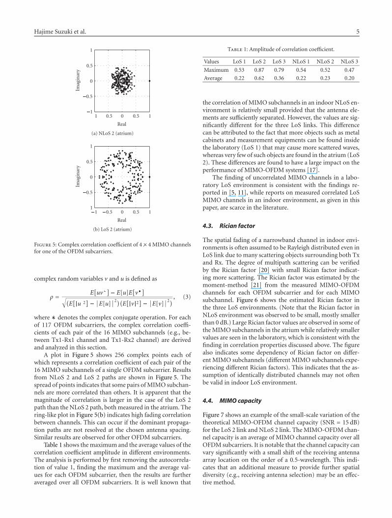
Figure 5: Complex correlation coefficient of 4� 4 MIMO channelsfor one of the OFDM subcarriers.
complex random variables v and u is defined as
ρ = E[uv�
]� E[u]E
[v�]
√(E[�u�2
]�∣∣E[u]
∣∣2)(E[�v�2
]�∣∣E[v]
∣∣2) , (3)
where � denotes the complex conjugate operation. For eachof 117 OFDM subcarriers, the complex correlation coeffi-cients of each pair of the 16 MIMO subchannels (e.g., be-tween Tx1-Rx1 channel and Tx1-Rx2 channel) are derivedand analyzed in this section.
A plot in Figure 5 shows 256 complex points each ofwhich represents a correlation coefficient of each pair of the16 MIMO subchannels of a single OFDM subcarrier. Resultsfrom NLoS 2 and LoS 2 paths are shown in Figure 5. Thespread of points indicates that some pairs of MIMO subchan-nels are more correlated than others. It is apparent that themagnitude of correlation is larger in the case of the LoS 2path than the NLoS 2 path, both measured in the atrium. Thering-like plot in Figure 5(b) indicates high fading correlationbetween channels. This can occur if the dominant propaga-tion paths are not resolved at the chosen antenna spacing.Similar results are observed for other OFDM subcarriers.
Table 1 shows the maximum and the average values of thecorrelation coefficient amplitude in different environments.The analysis is performed by first removing the autocorrela-tion of value 1, finding the maximum and the average val-ues for each OFDM subcarrier, then the results are furtheraveraged over all OFDM subcarriers. It is well known that
Table 1: Amplitude of correlation coefficient.
Values LoS 1 LoS 2 LoS 3 NLoS 1 NLoS 2 NLoS 3
Maximum 0.53 0.87 0.79 0.54 0.52 0.47
Average 0.22 0.62 0.36 0.22 0.23 0.20
the correlation of MIMO subchannels in an indoor NLoS en-vironment is relatively small provided that the antenna ele-ments are sufficiently separated. However, the values are sig-nificantly different for the three LoS links. This differencecan be attributed to the fact that more objects such as metalcabinets and measurement equipments can be found insidethe laboratory (LoS 1) that may cause more scattered waves,whereas very few of such objects are found in the atrium (LoS2). These differences are found to have a large impact on theperformance of MIMO-OFDM systems [17].
The finding of uncorrelated MIMO channels in a labo-ratory LoS environment is consistent with the findings re-ported in [5, 11], while reports on measured correlated LoSMIMO channels in an indoor environment, as given in thispaper, are scarce in the literature.
4.3. Rician factor
The spatial fading of a narrowband channel in indoor envi-ronments is often assumed to be Rayleigh distributed even inLoS link due to many scattering objects surrounding both Txand Rx. The degree of multipath scattering can be verifiedby the Rician factor [20] with small Rician factor indicat-ing more scattering. The Rician factor was estimated by themoment-method [21] from the measured MIMO-OFDMchannels for each OFDM subcarrier and for each MIMOsubchannel. Figure 6 shows the estimated Rician factor inthe three LoS environments. (Note that the Rician factor inNLoS environment was observed to be small, mostly smallerthan 0 dB.) Large Rician factor values are observed in some ofthe MIMO subchannels in the atrium while relatively smallervalues are seen in the laboratory, which is consistent with thefinding in correlation properties discussed above. The figurealso indicates some dependency of Rician factor on differ-ent MIMO subchannels (different MIMO subchannels expe-riencing different Rician factors). This indicates that the as-sumption of identically distributed channels may not oftenbe valid in indoor LoS environment.
4.4. MIMO capacity
Figure 7 shows an example of the small-scale variation of thetheoretical MIMO-OFDM channel capacity (SNR = 15 dB)for the LoS 2 link and NLoS 2 link. The MIMO-OFDM chan-nel capacity is an average of MIMO channel capacity over allOFDM subcarriers. It is notable that the channel capacity canvary significantly with a small shift of the receiving antennaarray location on the order of a 0.5-wavelength. This indi-cates that an additional measure to provide further spatialdiversity (e.g., receiving antenna selection) may be an effec-tive method.

6 EURASIP Journal on Wireless Communications and Networking
�20
�10
0
10
�20
�10
0
10
Ric
ian
fact
or(d
B)
Tx1-Rx1 Tx2-Rx1 Tx3-Rx1 Tx4-Rx1 Tx1-Rx2 Tx2-Rx2 Tx3-Rx2 Tx4-Rx2
Tx1-Rx3 Tx2-Rx3 Tx3-Rx3 Tx4-Rx3 Tx1-Rx4 Tx2-Rx4 Tx3-Rx4 Tx4-Rx4
�20 0 20 �20 0 20 �20 0 20 �20 0 20 �20 0 20 �20 0 20 �20 0 20 �20 0 20
Frequency (MHz)
LaboratoryAtriumLecture theater
Figure 6: Measured Rician factor for LoS paths in the laboratory, atrium, and lecture theater.
0
1
2
3
4
y(w
avel
engt
h)
0 1 2 3 4
x (wavelength)
13 14 15 16 17 18 19
Capacity (bps/Hz)
(a) NLoS 2 (atrium)
0
1
2
3
4
y(w
avel
engt
h)
0 1 2 3 4
x (wavelength)
10 11 12 13 14 15 16
Capacity (bps/Hz)
(b) LoS 2 (atrium)
Figure 7: Theoretical 4 � 4 MIMO-OFDM channel capacity(SNR = 15 dB).
4.5. Frequency correlation
With the MIMO-OFDM system in a frequency-selectivefading environment, additional diversity may be obtainedby spreading coded signal in frequency. Figure 8 shows anaverage correlation of MIMO subchannel amplitude andMIMO channel capacity as a function of OFDM subcarrierfrequency differences. The average is performed over differ-ent frequency pairs and over different MIMO subchannelsin the case of channel amplitude, while it is performed overdifferent frequency pairs in the case of MIMO channel capac-ity. It is observed that the MIMO channel capacity is largelyuncorrelated with a frequency difference of 20 MHz in thecase of NLoS paths. However the correlation of the LoS pathin the atrium is found to be large over a 40 MHz difference.
4.6. Effects of antenna spacing
The effects of antenna spacing on the performance of MIMOcapacity have been investigated by several researchers (e.g.,
0
0.2
0.4
0.6
0.8
1
Cor
rela
tion
0 10 20 30 40
Frequency difference (MHz)
NLoS 1NLoS 2NLoS 3
LoS 1LoS 2LoS 3
(a) Amplitude
0
0.2
0.4
0.6
0.8
1
Cor
rela
tion
0 10 20 30 40
Frequency difference (MHz)
NLoS 1NLoS 2NLoS 3
LoS 1LoS 2LoS 3
(b) Capacity
Figure 8: Correlation in frequency.
[22–24]). However the complex interaction of mutual cou-pling between the antenna elements and changes in radia-tion pattern make an analytical approach difficult. Here wedirectly measure MIMO-OFDM channels while varying an-tenna element spacing of the uniform square array from 0.5wavelengths to 2 wavelengths with 0.5-wavelength steps of(1) both Tx and Rx antenna arrays (referred as Both), and (2)only Rx antenna array (referred as Rx Only). For the secondcase, the antenna element spacing of the Tx antenna arrayis fixed at 3 wavelengths. The measurement was performedin LoS 1 and NLoS 1 paths as described in Section 2. Foreach local area measured, the normalization is performedover all antenna spacings. This method is employed so thatin comparing different antenna spacings, the effects of radia-tion efficiency, mutual coupling, and antenna pattern are allincluded in the final MIMO-OFDM channel capacity results.
Figure 9 shows cumulative distribution functions (CDFs)of measured MIMO-OFDM channel capacity for differ-ent antenna spacings. When the antenna element spacingsof both the Tx and Rx antenna arrays are reduced to 1

Hajime Suzuki et al. 7
0
0.2
0.4
0.6
0.8
1
CD
F
10 12 14 16 18 20 22
Capacity (bps/Hz)
0.5λ1λ
1.5λ2λ
(a) LoS, Both
0
0.2
0.4
0.6
0.8
1
CD
F
10 12 14 16 18 20 22
Capacity (bps/Hz)
0.5λ1λ
1.5λ2λ
(b) NLoS, Both
0
0.2
0.4
0.6
0.8
1
CD
F
10 12 14 16 18 20 22
Capacity (bps/Hz)
0.5λ1λ
1.5λ2λ
(c) LoS, Rx Only
0
0.2
0.4
0.6
0.8
1
CD
F
10 12 14 16 18 20 22
Capacity (bps/Hz)
0.5λ1λ
1.5λ2λ
(d) NLoS, Rx Only
Figure 9: Theoretical 4 � 4 MIMO-OFDM channel capacity (SNR= 15 dB) for different antenna spacing.
wavelength or less, significant degradation of MIMO-OFDMcapacity is observed. This contradicts the popular assump-tion that 0.5 wavelength is sufficient for omnidirectional an-tennas to obtain close to optimum MIMO channel capacityin indoor environments. In the case where one end has largeantenna element separation, 1 wavelength of antenna ele-ment spacing for the other end seems to achieve good MIMOchannels. Note that the MIMO-OFDM channel capacity isobserved to be larger for 1.5-wavelength spacing than for 2-wavelength spacing in the case of LoS Both and NLoS RxOnly. Table 2 shows the average correlation coefficient ampli-tude (as described in Section 4.2) and average channel gain(over all MIMO subchannels, OFDM subcarriers, and Rxantenna array locations, normalized to the value at 2 wave-length) for different antenna spacings. For those two cases, itcan be seen from the table that the average correlation am-plitude at 1.5-wavelength spacing is not smaller than that at2-wavelength spacing, while the average channel gain at 1.5-wavelength spacing is larger than that at 2-wavelength spac-ing. This indicates that more power was received with 1.5-wavelength spacing, contributing to the gain in the MIMO-OFDM channel capacity. To identify the exact cause of thisphenomenon requires a further investigation. However, ingeneral, it can be seen that both the average correlation
amplitude and channel gain are less affected in the case ofNLoS with larger antenna separation at one end, while a sig-nificant variation is observed in the LoS path when the an-tenna spacings of both Tx and Rx were changed.
4.7. Comparison with stochastic channel models
Stochastic channel models based on correlation propertiesof MIMO subchannels have been used to simulate realisticcorrelated MIMO channels. Recently, the suitability of thepopular Kronecker model [14, 25, 26] has been questionedfor indoor environments [27] when significant correlation ispresent or the number of Tx/Rx pairs exceed 3 � 3. A newstochastic model based on joint correlation of both link ends(herein called joint correlation model) has been proposed in[28] in order to remedy these deficiencies. However, bothmodels assume that the MIMO subchannels are complex-normal distributed with zero mean, that is, Rayleigh fading.Our analysis on the Rician factor in Section 4.3 shows thatthe channels in some indoor LoS environments deviate froma Rayleigh distribution. Hence the suitability of the Kro-necker model and the novel joint correlation model for LoSand NLoS paths is examined based on the measured chan-nels in this section. MIMO channel realization at 117 OFDMsubcarriers and 6400 locations is used to generate the cumu-lative distribution of MIMO channel capacity in the follow-ing analysis.
Figure 10 shows the CDF of measured MIMO channelcapacity together with the prediction by the Kronecker andjoint correlation models. As previously reported [7], the Kro-necker model predicts the MIMO channel capacity relativelywell in the case of NLoS paths. However, differences betweenthe Kronecker model and the measured results become ap-parent for LoS path cases where significant correlation wasfound (LoS 2 and 3 paths). This confirms the findings re-ported in [28] that the Kronecker model tends to underesti-mate the MIMO capacity in LoS path or the number of an-tennas used in each end becomes larger than 3. While theprediction results from the joint correlation model are al-ways closer to the measured results than those from the Kro-necker model, underestimation of the MIMO capacity is stillobserved. This is attributed to the fact that some of the cur-rent measured channels are Rician-distributed. While reportson modeling correlated Rician MIMO channels are appear-ing in the literature (e.g., [29–31]), those models assume theknowledge of the dominant component, which is difficultto obtain from the current measurement results. Further in-vestigation of a suitable channel model for correlated Ricianchannel and the method to obtain its parameters from themeasurement are called for.
5. CONCLUSIONS
In this paper, the results of MIMO-OFDM channel measure-ments performed in indoor environments are reported andanalyzed. The MIMO-OFDM channel capacity in a local areawas found to be strongly dependent on the local scatteringenvironment in the case of an LoS situation, while it is lessaffected in the case of NLoS situation. The exact structural

8 EURASIP Journal on Wireless Communications and Networking
Table 2: MIMO channel parameters for different antenna spacings.
Spacing (wavelength)Average correlation Average channel gain
0.5 1.0 1.5 2.0 0.5 1.0 1.5 2.0
NLos, Rx Only 0.22 0.20 0.19 0.18 1.00 1.04 1.07 1.00
LoS, Rx Only 0.30 0.30 0.30 0.32 0.88 0.96 1.02 1.00
NLoS, Both 0.28 0.25 0.23 0.19 0.79 0.97 1.06 1.00
LoS, Both 0.41 0.31 0.40 0.28 1.01 0.84 1.16 1.00
0
0.2
0.4
0.6
0.8
1
CD
F
10 12 14 16 18 20
Capacity (bps/Hz)
Measured capacityKronecker modelJoint correlation modeli.i.d. Rayleigh capacity
(a) NLoS 1 (laboratory)
0
0.2
0.4
0.6
0.8
1
CD
F
10 12 14 16 18 20
Capacity (bps/Hz)
Measured capacityKronecker modelJoint correlation modeli.i.d. Rayleigh capacity
(b) NLoS 2 (atrium)
0
0.2
0.4
0.6
0.8
1
CD
F
10 12 14 16 18 20
Capacity (bps/Hz)
Measured capacityKronecker modelJoint correlation modeli.i.d. Rayleigh capacity
(c) NLoS 3 (office)
0
0.2
0.4
0.6
0.8
1
CD
F
10 12 14 16 18 20
Capacity (bps/Hz)
Measured capacityKronecker modelJoint correlation modeli.i.d. Rayleigh capacity
(d) LoS 1 (laboratory)
0
0.2
0.4
0.6
0.8
1
CD
F
10 12 14 16 18 20
Capacity (bps/Hz)
Measured capacityKronecker modelJoint correlation modeli.i.d. Rayleigh capacity
(e) LoS 2 (atrium)
0
0.2
0.4
0.6
0.8
1
CD
F
10 12 14 16 18 20
Capacity (bps/Hz)
Measured capacityKronecker modelJoint correlation modeli.i.d. Rayleigh capacity
(f) LoS 3 (lecture theater)
Figure 10: Comparison of measured, Kronecker model, joint correlation model, and i.i.d. Rayleigh capacity CDF.
arrangements that would cause correlation of the MIMOsubchannel in indoor LoS environments are still largely un-known. Further measurements with various geometries arerequired to develop a general model to predict the MIMO-OFDM channel capacity in indoor environments.
REFERENCES
[1] G. L. Stuber, J. R. Barry, S. W. Mclaughlin, Y. E. Li, M. A. In-gram, and T. G. Pratt, “Broadband MIMO-OFDM wirelesscommunications,” Proceedings of the IEEE, vol. 92, no. 2, pp.271–293, 2004.
[2] S. Coffey, A. Kasher, and A. Stephens, “Joint Proposal: highthroughput extension to the 802.11 Standard: PHY,” IEEE802.11-05/1102r4, January 2006.
[3] P. Kyritsi, D. C. Cox, R. A. Valenzuela, and P. W. Wolniansky,“Effect of antenna polarization on the capacity of a multiple
element system in an indoor environment,” IEEE Journal onSelected Areas in Communications, vol. 20, no. 6, pp. 1227–1239, 2002.
[4] J. W. Wallace, M. A. Jensen, A. L. Swindlehurst, and B. D. Jeffs,“Experimental characterization of the MIMO wireless chan-nel: data acquisition and analysis,” IEEE Transactions on Wire-less Communications, vol. 2, no. 2, pp. 335–343, 2003.
[5] M. D. Batariere, J. F. Kepler, T. P. Krauss, S. Mukthavaram,J. W. Porter, and F. W. Vook, “An experimental OFDM sys-tem for broadband mobile communications,” in Proceedingsof 54th IEEE Vehicular Technology Conference (VTC ’01), vol. 4,pp. 1947–1951, Atlantic City, NJ, USA, October 2001.
[6] R. Piechocki, P. Fletcher, A. Nix, N. Canagarajah, and J.McGeehan, “A measurement based feasibility study of space-frequency MIMO detection and decoding techniques for nextgeneration wireless LANs,” IEEE Transactions on ConsumerElectronics, vol. 48, no. 3, pp. 732–737, 2002.

Hajime Suzuki et al. 9
[7] K. Yu, M. Bengtsson, B. Ottersten, D. McNamara, P. Karlsson,and M. Beach, “Modeling of wide-band MIMO radio channelsbased on NLoS indoor measurements,” IEEE Transactions onVehicular Technology, vol. 53, no. 3, pp. 655–665, 2004.
[8] N. Kita, W. Yamada, A. Sato, D. Mori, and S. Uwano, “Mea-surement of Demmel condition number for 2 � 2 MIMO-OFDM broadband channels,” in Proceedings of 59th IEEE Ve-hicular Technology Conference (VTC ’04), vol. 1, pp. 294–298,Milan, Italy, May 2004.
[9] R. W. Heath Jr. and A. J. Paulraj, “Switching between diver-sity and multiplexing in MIMO systems,” IEEE Transactionson Communications, vol. 53, no. 6, pp. 962–968, 2005.
[10] A. Gupta, A. Forenza, and R. W. Heath Jr., “Rapid MIMO-OFDM software defined radio system prototyping,” in Pro-ceedings of IEEE Workshop on Signal Processing Systems Designand Implementation, pp. 182–187, Austin, Tex, USA, October2004.
[11] R. M. Rao, S. Lang, and B. Daneshrad, “Indoor field measure-ments with a configurable multi-antenna testbed,” in Proceed-ings of IEEE Global Telecommunications Conference (GLOBE-COM ’04), vol. 6, pp. 3952–3956, Dallas, Tex, USA, November-December 2004.
[12] H. Suzuki, R. Kendall, M. Hedley, G. Daniels, and D. Ryan,“Demonstration of 4� 4 MIMO data transmission on CSIROICT Centre MIMO testbed,” in Booklet of Abstracts for the 6thAustralian Communications Theory Workshop, p. 35, Brisbane,Australia, February 2005.
[13] A. Van Zelst and T. C. Schenk, “Implementation of a MIMOOFDM-based wireless LAN system,” IEEE Transactions on Sig-nal Processing, vol. 52, no. 2, pp. 483–494, 2004.
[14] K. Yu, M. Bengtsson, B. Ottersten, D. McNamara, P. Karlsson,and M. Beach, “Second order statistics of NLOS indoor MIMOchannels based on 5.2 GHz measurements,” in Proceedings ofIEEE Global Telecommunicatins Conference (GLOBECOM ’01),vol. 1, pp. 156–160, San Antonio, Tex, USA, November 2001.
[15] J. H. Winters, “On the capacity of radio communication sys-tems with diversity in a Rayleigh fading environment,” IEEEJournal on Selected Areas in Communications, vol. 5, no. 5, pp.871–878, 1987.
[16] H. Suzuki, “Characteristics of 4 � 4 MIMO-OFDM channelsin indoor environments,” in Proceedings of the ClimDiff ’05,Diff-13, Cleveland, Ohio, USA, September 2005.
[17] H. Suzuki, M. Hedley, G. Daniels, and J. Yuan, “Perfor-mance of MIMO-OFDM-BICM on measured indoor chan-nels,” in Proceedings of 63rd IEEE Vehicular Technology Confer-ence (VTC ’06), vol. 5, pp. 2073–2077, Melbourne, Australia,May 2006.
[18] D.-S. Shiu, G. J. Foschini, M. J. Gans, and J. M. Kahn, “Fadingcorrelation and its effect on the capacity of multielement an-tenna systems,” IEEE Transactions on Communications, vol. 48,no. 3, pp. 502–513, 2000.
[19] P. Kyritsi, D. C. Cox, R. A. Valenzuela, and P. W. Wolniansky,“Correlation analysis based on MIMO channel measurementsin an indoor environment,” IEEE Journal on Selected Areas inCommunications, vol. 21, no. 5, pp. 713–720, 2003.
[20] T. S. Rappaport, Wireless Communications, Principles & Prac-tice, Prentice Hall PTR, Upper Saddle River, NJ, USA, 1996.
[21] L. J. Greenstein, D. G. Michelson, and V. Erceg, “Moment-method estimation of the Ricean K-factor,” IEEE Communi-cations Letters, vol. 3, no. 6, pp. 175–176, 1999.
[22] R. Janaswamy, “Effect of element mutual coupling on the ca-pacity of fixed length linear arrays,” IEEE Antennas and Wire-less Propagation Letters, vol. 1, no. 1, pp. 157–160, 2002.
[23] P. N. Fletcher, M. Dean, and A. R. Nix, “Mutual couplingin multi-element array antennas and its influence on MIMOchannel capacity,” Electronics Letters, vol. 39, no. 4, pp. 342–344, 2003.
[24] J. W. Wallace and M. A. Jensen, “Mutual coupling in MIMOwireless systems: a rigorous network theory analysis,” IEEETransactions on Wireless Communications, vol. 3, no. 4, pp.1317–1325, 2004.
[25] K. I. Pedersen, J. B. Andersen, J. P. Kermoal, and P. Mogen-sen, “Stochastic multiple-input-multiple-output radio chan-nel model for evaluation of space-time coding algorithms,”in Proceedings of 52nd IEEE Vehicular Technology Conference(VTC ’00), vol. 2, pp. 893–897, Boston, Mass, USA, September2000.
[26] J. P. Kermoal, L. Schumacher, K. I. Pedersen, P. E. Mogensen,and F. Frederiksen, “A stochastic MIMO radio channel modelwith experimental validation,” IEEE Journal on Selected Areasin Communications, vol. 20, no. 6, pp. 1211–1226, 2002.
[27] H. Ozcelik, M. Herdin, W. Weichselberger, J. Wallace, andE. Bonek, “Deficiencies of ‘Kronecker’ MIMO radio chan-nel model,” Electronics Letters, vol. 39, no. 16, pp. 1209–1210,2003.
[28] W. Weichselberger, M. Herdin, H. Ozcelik, and E. Bonek, “Astochastic MIMO channel model with joint correlation ofboth link ends,” IEEE Transactions on Wireless Communica-tions, vol. 5, no. 1, pp. 90–100, 2006.
[29] S. K. Jayaweera and H. V. Poor, “On the capacity of multiple-antenna systems in Rician fading,” IEEE Transactions on Wire-less Communications, vol. 4, no. 3, pp. 1102–1111, 2005.
[30] M. R. McKay and I. B. Collings, “General capacity boundsfor spatially correlated Rician MIMO channels,” IEEE Trans-actions on Information Theory, vol. 51, no. 9, pp. 3121–3145,2005.
[31] M. Kang and M.-S. Alouini, “Capacity of MIMO Rician chan-nels,” IEEE Transactions on Wireless Communications, vol. 5,no. 1, pp. 112–122, 2006.

Photograph © Turisme de Barcelona / J. Trullàs
Preliminary call for papers
The 2011 European Signal Processing Conference (EUSIPCO 2011) is thenineteenth in a series of conferences promoted by the European Association forSignal Processing (EURASIP, www.eurasip.org). This year edition will take placein Barcelona, capital city of Catalonia (Spain), and will be jointly organized by theCentre Tecnològic de Telecomunicacions de Catalunya (CTTC) and theUniversitat Politècnica de Catalunya (UPC).EUSIPCO 2011 will focus on key aspects of signal processing theory and
li ti li t d b l A t f b i i ill b b d lit
Organizing Committee
Honorary ChairMiguel A. Lagunas (CTTC)
General ChairAna I. Pérez Neira (UPC)
General Vice ChairCarles Antón Haro (CTTC)
Technical Program ChairXavier Mestre (CTTC)
Technical Program Co Chairsapplications as listed below. Acceptance of submissions will be based on quality,relevance and originality. Accepted papers will be published in the EUSIPCOproceedings and presented during the conference. Paper submissions, proposalsfor tutorials and proposals for special sessions are invited in, but not limited to,the following areas of interest.
Areas of Interest
• Audio and electro acoustics.• Design, implementation, and applications of signal processing systems.
l d l d d
Technical Program Co ChairsJavier Hernando (UPC)Montserrat Pardàs (UPC)
Plenary TalksFerran Marqués (UPC)Yonina Eldar (Technion)
Special SessionsIgnacio Santamaría (Unversidadde Cantabria)Mats Bengtsson (KTH)
FinancesMontserrat Nájar (UPC)• Multimedia signal processing and coding.
• Image and multidimensional signal processing.• Signal detection and estimation.• Sensor array and multi channel signal processing.• Sensor fusion in networked systems.• Signal processing for communications.• Medical imaging and image analysis.• Non stationary, non linear and non Gaussian signal processing.
Submissions
Montserrat Nájar (UPC)
TutorialsDaniel P. Palomar(Hong Kong UST)Beatrice Pesquet Popescu (ENST)
PublicityStephan Pfletschinger (CTTC)Mònica Navarro (CTTC)
PublicationsAntonio Pascual (UPC)Carles Fernández (CTTC)
I d i l Li i & E hibiSubmissions
Procedures to submit a paper and proposals for special sessions and tutorials willbe detailed at www.eusipco2011.org. Submitted papers must be camera ready, nomore than 5 pages long, and conforming to the standard specified on theEUSIPCO 2011 web site. First authors who are registered students can participatein the best student paper competition.
Important Deadlines:
P l f i l i 15 D 2010
Industrial Liaison & ExhibitsAngeliki Alexiou(University of Piraeus)Albert Sitjà (CTTC)
International LiaisonJu Liu (Shandong University China)Jinhong Yuan (UNSW Australia)Tamas Sziranyi (SZTAKI Hungary)Rich Stern (CMU USA)Ricardo L. de Queiroz (UNB Brazil)
Webpage: www.eusipco2011.org
Proposals for special sessions 15 Dec 2010Proposals for tutorials 18 Feb 2011Electronic submission of full papers 21 Feb 2011Notification of acceptance 23 May 2011Submission of camera ready papers 6 Jun 2011