ABSTRACT PAPR REDUCTION IN OFDM USING HYBRID ...
43
ABSTRACT PAPR REDUCTION IN OFDM USING HYBRID METHOD Yeshwanth Reddy Aendapally, M.S. Department of Electrical Engineering Northern Illinois University, 2014 Dr. Mansour Tahernezhadi, Director Orthogonal frequency division multiplexing (OFDM) is a modulation technique which revolutionized the field of communications and paved the way for the modern-day 4G LTE communications. OFDM technique is used in both wired and wireless communications. This type of modulation technique offers low intersymbol interference and provides high data rates. Due to these advantages of OFDM it is used in various applications like 4G LTE communications, wireless networks and digital TV. Besides these advantages, a major disadvantage of OFDM system is high peak to average power ratio due to addition of sinusoidal waves in communication which result in peaks in the output and cause signal degradation. In order to reduce the PAPR, a hybrid technique which combines Hadamard transform and Hamming peak windowing is developed. This technique is compared with the PAPR results obtained for OFDM, Hamming windowing, and companding. The bit error rates of all the above methods are compared passing the OFDM signal through AWGN (additive white Gaussian noise) channel.
-
Upload
khangminh22 -
Category
Documents
-
view
2 -
download
0
Transcript of ABSTRACT PAPR REDUCTION IN OFDM USING HYBRID ...

ABSTRACT
PAPR REDUCTION IN OFDM USING HYBRID METHOD Yeshwanth Reddy Aendapally, M.S. Department of Electrical Engineering
Northern Illinois University, 2014
Dr. Mansour Tahernezhadi, Director
Orthogonal frequency division multiplexing (OFDM) is a modulation technique which
revolutionized the field of communications and paved the way for the modern-day 4G LTE
communications. OFDM technique is used in both wired and wireless communications. This
type of modulation technique offers low intersymbol interference and provides high data rates.
Due to these advantages of OFDM it is used in various applications like 4G LTE
communications, wireless networks and digital TV. Besides these advantages, a major
disadvantage of OFDM system is high peak to average power ratio due to addition of sinusoidal
waves in communication which result in peaks in the output and cause signal degradation. In
order to reduce the PAPR, a hybrid technique which combines Hadamard transform and
Hamming peak windowing is developed. This technique is compared with the PAPR results
obtained for OFDM, Hamming windowing, and companding. The bit error rates of all the above
methods are compared passing the OFDM signal through AWGN (additive white Gaussian
noise) channel.

NORTHERN ILLINOIS UNIVERSITY
DEKALB, ILLINOIS
DECEMBER 2014
PAPR REDUCTION IN OFDM USING HYBRID METHOD
BY
YESHWANTH REDDY AENDAPALLY
©2014 Yeshwanth Reddy Aendapally
A THESIS SUBMITTED TO THE GRADUATE SCHOOL
IN PARTIAL FULFILLMENT OF THE REQUIREMENTS
FOR THE DEGREE
MASTER OF SCIENCE
DEPARTMENT OF ELECTRICAL ENGINEERING
Thesis Director:
Dr. Mansour Tahernezhadi
ACKNOWLEDGEMENTS
I am extremely grateful to my advisor, Dr. Mansour Tahernezhadi, for his consistent
guidance, patience, encouragement and valuable advice during my master’s program. It has been
a great learning and enjoyable experience to be a Master of Science student in the Department of
Electrical Engineering at Northern Illinois University.
I would like to thank Dr. Abhijit Guptha and Dr. Donald Zinger, my research committee
members, for their valuable suggestions and precious time.
I would like to thank my parents for their unconditional love and support. Special thanks
to my brothers and friends for their constant motivation.

TABLE OF CONTENTS
PAGE
LIST OF FIGURES .................................................................................................................. V
CHAPTER 1: INTRODUCTION ........................................................................................1
1.1Background. .............................................................................................................................. 1
1.2 Problem Statement. ................................................................................................................. 2
1.3Thesis Structure ........................................................................................................................ 3
CHAPTER 2: OFDM SYSTEM ................................................................................................. 4
2.1 Frequency Division Multiplexing ......................................................................................... 4
2.2 Single Carrier Communication System ............................................................................... 5
2.3 Multicarrier Modulation ........................................................................................................ 5
2.3.1 Multicarrier Transmission and Reception ................................................................ 6
2.4 Orthogonal Frequency Division Multiplexing .................................................................... 7
2.4.1 OFDM Transmitter ....................................................................................................... 7
2.4.2 OFDM Receiver ............................................................................................................ 8
2.5 Cyclic Prefix ............................................................................................................................ 9
2.6 Advantages of OFDM .......................................................................................................... 11
2.7 Drawbacks of OFDM ........................................................................................................... 11
2.8 Applications of OFDM…………………………………………………………… ....... ……..12
CHAPTER 3: PEAK TO AVERAGE POWER RATIO ....................................................... 13
3.1 PAPR Definition ................................................................................................................... 13

v
3.2 Effects of PAPR in OFDM .................................................................................................. 13
3.3 CCDF Function ..................................................................................................................... 14
3.4 Factors Influencing PAPR ...........................................................................................15
3.5 PAPR Reduction Techniques. ............................................................................................. 16
3.5.1 Signal Distortion Techniques ................................................................................... 16
CHAPTER 4: PAPR REDUCTION IN OFDM USING COMPANDING ......................... 18
4.1 U Law Companding ............................................................................................................. 18
4.1.1 Transmission Phase ................................................................................................... 18
4.1.2 Receiver Phase ........................................................................................................... 19
4.2 Simulation steps………………………………………………… .. …………………………...20
CHAPTER 5: HYBRID MODEL FOR PAPR REDUCTION IN OFDM ........................... 22
5.1 Hadamard Transform ........................................................................................................... 22
5.2 Peak Windowing ................................................................................................................... 23
5.3 Hybrid Model ........................................................................................................................ 25
5.3.1 Hybrid Model Transmitter ......................................................................................... 25
5.3.2 Hybrid Model Receiver .............................................................................................. 25
CHAPTER 6: SIMULATION RESULTS AND COMPARISION ..................................... 28
6.1 Companding Techniques ..................................................................................................... 28
6.2 Hybrid Method ...................................................................................................................... 28
6.3 Simulation Results of Hybrid Method ............................................................................... 32
CHAPTER 7: CONCLUSION AND FUTURE WORK ....................................................... 35
7.1 Conclusion ............................................................................................................................. 35

vi
7.2 Future work ................................................................................................................................. 35
REFERENCES ................................................................................................................................. 36

LIST OF FIGURES PAGE
Figure 2.1 Spectrum of frequency division multiplexing system ........................................... 4
Figure 2.2 Schematic of subcarrier mapping .......................................................................5
Figure 2.3: Block diagram of multicarrier transmitter. .................................................................... 6
Figure 2.4: Block diagram of multicarrier receiver. ........................................................................ 6
Figure 2.5: Schematic of OFDM transmitter .................................................................................. 7
Figure 2.6 Schematic of OFDM receiver ....................................................................................... 8
Figure 2.7 Intersymbol interference due to multipath fading .......................................................... 9
Figure 2.8: OFDM transmitter with cyclic prefix .......................................................................... 10
Figure 2.9: OFDM receiver with cyclic prefix .............................................................................. 10
Figure: 3.1 CCDF plot of PAPR .................................................................................................... 14
Figure 3.2: Comparison of PAPR reduction for different modulation schemes ............................ 15
Figure 3.3: Comparison of PAPR reduction for different values of N .......................................... 16
Figure 4.1 Block diagram of PAPR reduction of OFDM using companding ..................... 20
Figure 5.1: Block diagram of hybrid model ............................................................................ 26
Figure 6.1: Comparison of PAPR reduction for different schemes for 128 symbols .................... 29
Figure 6.2: Comparison of PAPR reduction for different schemes for 256 symbols .................... 30
Figure 6.3: Comparison of PAPR reduction for different schemes for 512 symbols .................... 31
Figure 6.4 Comparison of BER for different schemes for 128 symbols ........................................ 32
Figure 6.5 Comparison of BER for different schemes for 256 symbols ........................................ 33
Figure 6.6: Comparison of BER for different schemes for 512 symbols ....................................... 34

CHAPTER 1: INTRODUCTION
1.1 Background
The field of communication has been part of great revolution in the later parts of
twentieth century. It has switched from wired communications to wireless communications.
Wireless communication started with the introduction of photo phone by Alexander Graham Bell
and has come so far to smart phones used today. Wireless communications are used in many
fields such as satellite communications, telephony, medical and military.
The hierarchy of the wireless communications starts with the 2G (2nd generation)
wireless communication systems such as GSM (global system for mobile
communications),CDMA (code division for multiple access),GPRS (general packet radio
service) and EDGE (enhanced data for GSM revolution) .From the above standards GSM and
CDMA were used for mobile calling with voice data rate of 10 kbps and GPRS and EDGE were
used for internet access with data rates ranging from 50 kbps to 200 kbps. The need for high data
rates led to the introduction of 3G (3rd generation) wireless communication which offers data
rates as high as 384 kbps to 30 mbps. CDMA forms the base for the 3G communications, which
have various wireless standards such as WCDMA (wideband CDMA), CDMA 2000 and
HSDPA/HSUPA (high-speed down link/uplink packet access). The desire for more bandwidth
and data rates led to the development of the 4G (4th generation) communications which have
wireless standards such as LTE (long-term evolution) and WIMAX (worldwide interoperability
for microwave access) and offer data rates from 100 -200 mbps.
2
Orthogonal frequency division multiplexing (OFDM) is the modulation technique used to
realize the 4G standards. In the OFDM scheme of modulation a single carrier is divided into
subcarriers to carry information. The sub carriers are closely spaced and orthogonal to each
other.
The subcarriers are modulated using IFFT (inverse fast Fourier transform)at the
transmitter and demodulated using FFT (fast Fourier transform) which is very simple compared
to bank of modulators and demodulators in MCM (multicarrier modulation)systems, which
reduces the complexity of system in OFDM. The introduction of cyclic prefix in OFDM system
reduces ISI (intersymbol interference).
Besides the advantages of OFDM systems such as low complexity, better spectral
efficiency and low intersymbol interference, one major setback is high peak to average power
ratio which arises due to the peaks in the output due to constructive addition of sinusoidal
signals.
1.2 Problem Statement
PAPR is the ratio between the instantaneous powers to the average powers of the signals
in the OFDM systems. PAPR occurs during the preprocessing phase of the OFDM where the
signals are enhanced and they add up constructively to produce peaks and deviate from average
power. PAPR occurs in multicarrier system if different subcarriers are out of phase with each
other; at that instant when all the points achieve maximum value and add up constructively, this
leads to the peaks in the output envelope of the OFDM system. This drives the power amplifier
into saturation and causes intercarrier interference. High PAPR leads to the application of the

3
high-power amplifiers which increases the complexity of the system. There are many methods
for the reduction of PAPR such as clipping and companding, which degrades the bit error rate
and introduces self-interference. Hence a hybrid model is developed combining the Hadamard
transform and advanced peak windowing to reduce PAPR significantly. The hybrid model is
compared with companding and windowing in this thesis.
1.3 Thesis Structure
This thesis is organized as follows
• Chapter 2 explains basic communication systems. The basic OFDM system and its
advantages are discussed.
• Chapter 3 discusses peak to average power ratio (PAPR) problem and its effects on
OFDM systems. CCDF function used to represent PAPR is also discussed
• Chapter 4 briefly describes the technique of companding.
• Chapter 5 describes the hybrid model which includes the description of Hadamard
transform and advanced peak windowing.
• Chapter 6 contains the simulation parameters and results of PAPR reduction techniques
mentioned in Chapters 4 and 5.
• Chapter 7 concludes the thesis and suggests future work .
CHAPTER 2: OFDM SYSTEM
Efficient utilization of a communication system depends on the efficient utilization of the
signal bandwidth. The quest for the effective utilization of the channel bandwidth led to the birth
of OFDM systems. The idea for the implementation of OFDM systems evolved from the
traditional FDM technique.
2.1 Frequency Division Multiplexing
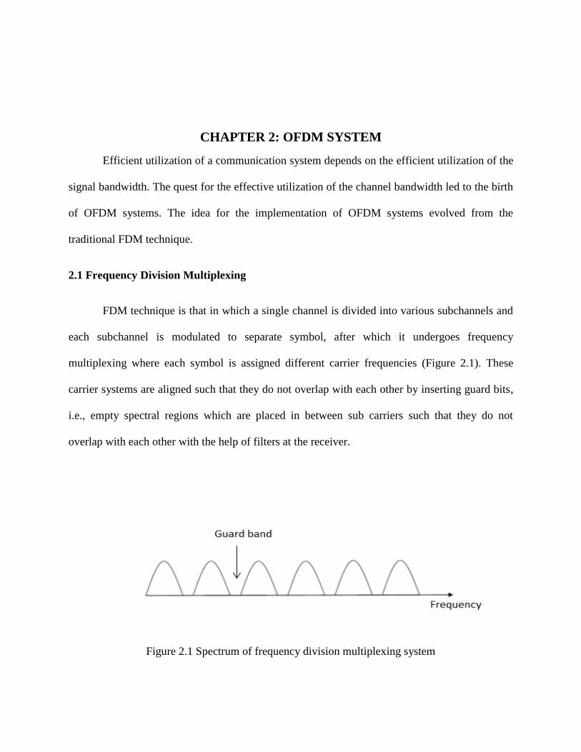
FDM technique is that in which a single channel is divided into various subchannels and
each subchannel is modulated to separate symbol, after which it undergoes frequency
multiplexing where each symbol is assigned different carrier frequencies (Figure 2.1). These
carrier systems are aligned such that they do not overlap with each other by inserting guard bits,
i.e., empty spectral regions which are placed in between sub carriers such that they do not
overlap with each other with the help of filters at the receiver.
Figure 2.1 Spectrum of frequency division multiplexing system
5
The major drawback of frequency division multiplexing is poor spectral efficiency of
system compared to the single wideband transceiver due to the addition of the guard bits. Besides
this the implementation of the system is complex and requires high implementation expenditure.
This wideband scheme is prone to inter-symbol interference caused by distortion in the
frequency band.
2.2 Single Carrier Communication System
In a single carrier communication system, entire bandwidth is occupied by a single
carrier.
Let us consider the channel bandwidth as 'B' and symbol time as 'T'.
Symbol time (T) =1/B
Symbol rate=B
In a single carrier system one symbol is transmitted for every 'T 'sec.
2.3 Multicarrier Modulation
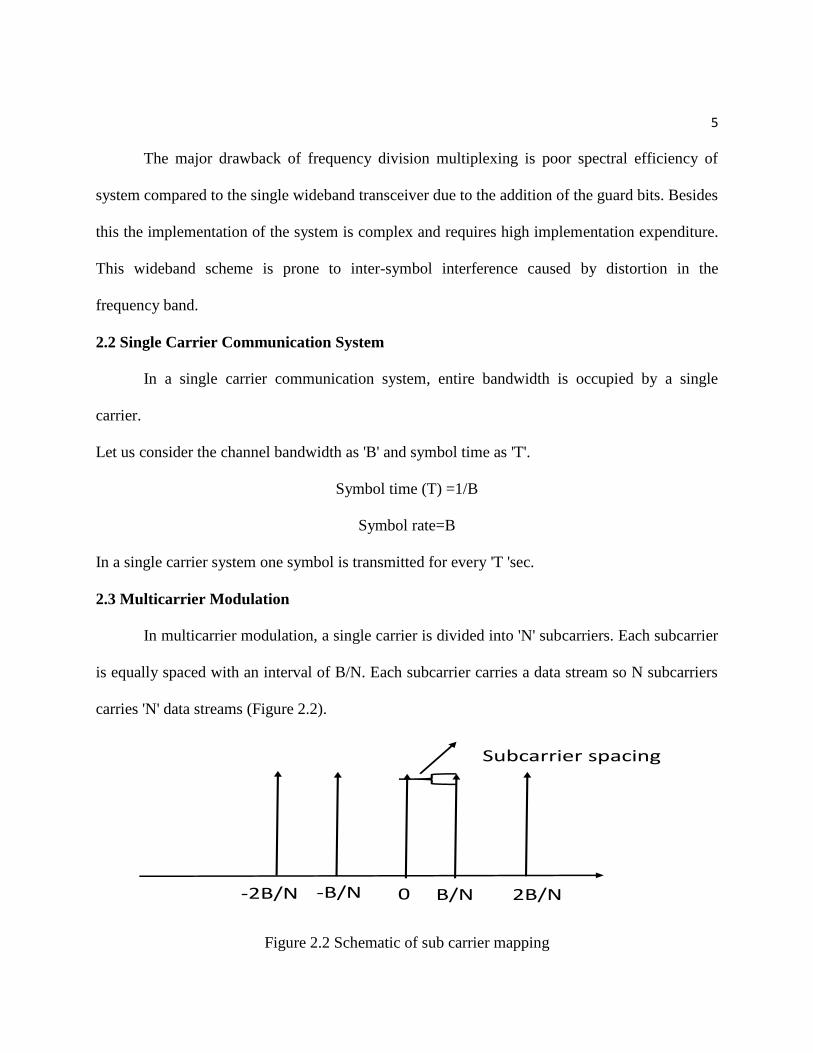
In multicarrier modulation, a single carrier is divided into 'N' subcarriers. Each subcarrier
is equally spaced with an interval of B/N. Each subcarrier carries a data stream so N subcarriers
carries 'N' data streams (Figure 2.2).
B/N 2B/N0-B/N-2B/N
Subcarrier spacing
Figure 2.2 Schematic of sub carrier mapping
6
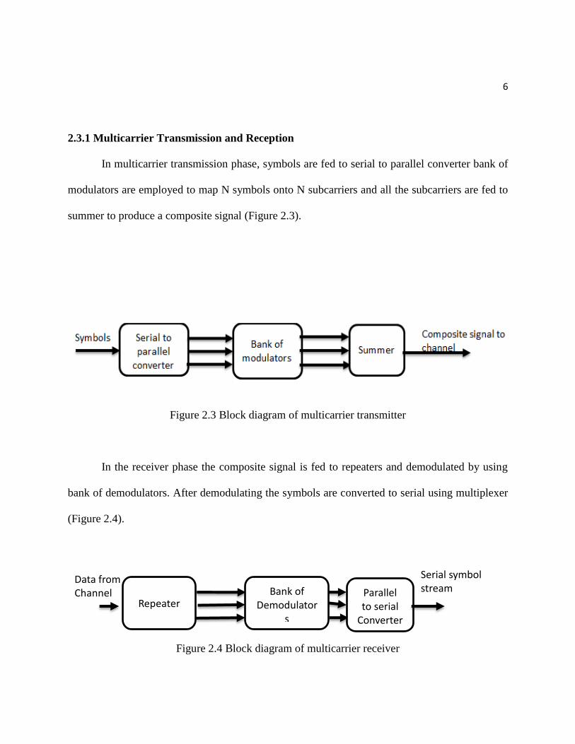
2.3.1 Multicarrier Transmission and Reception
In multicarrier transmission phase, symbols are fed to serial to parallel converter bank of
modulators are employed to map N symbols onto N subcarriers and all the subcarriers are fed to
summer to produce a composite signal (Figure 2.3).
Figure 2.3 Block diagram of multicarrier transmitter
In the receiver phase the composite signal is fed to repeaters and demodulated by using
bank of demodulators. After demodulating the symbols are converted to serial using multiplexer
(Figure 2.4).
Figure 2.4 Block diagram of multicarrier receiver
Data from
Channel Repeater
Bank of Demodulator
s
Parallel to serial
Converter
Serial symbol stream
7
2.4 Orthogonal Frequency Division Multiplexing
The idea of OFDM was developed from the publications of Weinstein and Ebert in
1970 [1].According to them, a composite signal which is obtained from the multicarrier system
can be obtained by using IDFT and DFT at the transmitter and receiver respectively instead of
bank of modulators and demodulators. This reduces the complexity of the system and decreases
costs for implementation.
OFDM system is a special case of multicarrier systems in which a single carrier is
divided into large number of closely spaced orthogonal subcarriers. Data is transmitted on
different parallel data streams with low signal rate. The total signal rate of the system the same as
single carrier system.
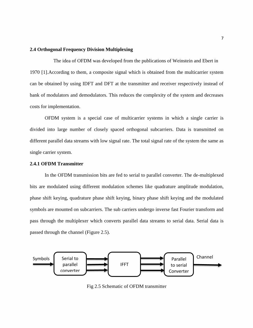
2.4.1 OFDM Transmitter
In the OFDM transmission bits are fed to serial to parallel converter. The de-multiplexed
bits are modulated using different modulation schemes like quadrature amplitude modulation,
phase shift keying, quadrature phase shift keying, binary phase shift keying and the modulated
symbols are mounted on subcarriers. The sub carriers undergo inverse fast Fourier transform and
pass through the multiplexer which converts parallel data streams to serial data. Serial data is
passed through the channel (Figure 2.5).
Fig 2.5 Schematic of OFDM transmitter
Symbols Serial to parallel
converter IFFT
Parallel to serial
Converter
Channel

8
2.4.2 OFDM Receiver
In the OFDM receiver the data which comes from the channel is converted to parallel
data using de-multiplexer. The de-multiplexed data undergoes fast Fourier transform operation to
coherently detect the symbols on each subcarrier. The detected symbols received which are in
parallel are converted to serial using a multiplexer. The serial data is received at the mobile
station by the user (Figure 2.6).
Fig 2.6 Schematic of OFDM receiver
In OFDM the subcarriers are closely spaced and orthogonal. The condition of
orthogonality is very important in transmission of the symbols in OFDM. When the subcarriers
are closely spaced and overlapping there is chance for the carrier frequency offset. Presence of
frequency offset can introduce severe distortions in an OFDM system and lead to the loss of
orthogonality among sub carriers. The overlapping of subcarriers may lead to the intersymbol
interference. This problem introduces the concept of cyclic prefix in an OFDM system.
Data from
Channel De multiplexer
FFT Parallel to serial
Converter
To user
9
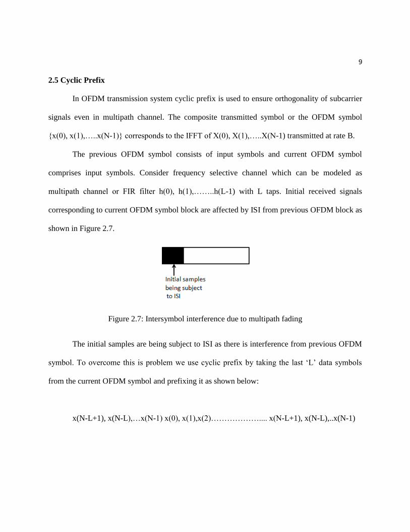
2.5 Cyclic Prefix
In OFDM transmission system cyclic prefix is used to ensure orthogonality of subcarrier
signals even in multipath channel. The composite transmitted symbol or the OFDM symbol
{x(0), x(1),…..x(N-1)} corresponds to the IFFT of X(0), X(1),…..X(N-1) transmitted at rate B.
The previous OFDM symbol consists of input symbols and current OFDM symbol
comprises input symbols. Consider frequency selective channel which can be modeled as
multipath channel or FIR filter h(0), h(1),……..h(L-1) with L taps. Initial received signals
corresponding to current OFDM symbol block are affected by ISI from previous OFDM block as
shown in Figure 2.7.
Figure 2.7: Intersymbol interference due to multipath fading
The initial samples are being subject to ISI as there is interference from previous OFDM
symbol. To overcome this is problem we use cyclic prefix by taking the last ‘L’ data symbols
from the current OFDM symbol and prefixing it as shown below:
x(N-L+1), x(N-L),…x(N-1) x(0), x(1),x(2)……………….... x(N-L+1), x(N-L),..x(N-1)
10
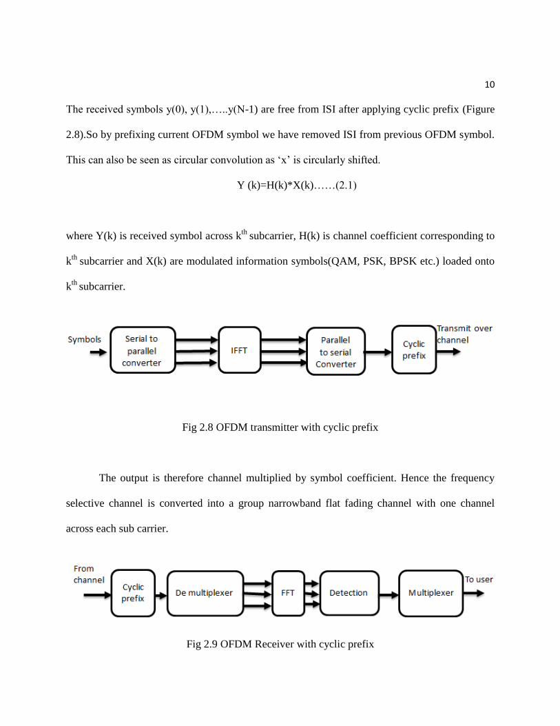
The received symbols y(0), y(1),…..y(N-1) are free from ISI after applying cyclic prefix (Figure
2.8).So by prefixing current OFDM symbol we have removed ISI from previous OFDM symbol.
This can also be seen as circular convolution as ‘x’ is circularly shifted.
Y (k)=H(k)*X(k)……(2.1)
where Y(k) is received symbol across kth
subcarrier, H(k) is channel coefficient corresponding to
kth
subcarrier and X(k) are modulated information symbols(QAM, PSK, BPSK etc.) loaded onto
kth
subcarrier.
Fig 2.8 OFDM transmitter with cyclic prefix
The output is therefore channel multiplied by symbol coefficient. Hence the frequency
selective channel is converted into a group narrowband flat fading channel with one channel
across each sub carrier.
Fig 2.9 OFDM Receiver with cyclic prefix

11
A simple detection scheme can now be employed for X(k) using zero forcing (ZF),
minimum mean squared error equalizer (MMSE) or matched filter. The length of cyclic prefix
should be greater than delay spread of channel. Since we are repeating the symbol, there is low
transmitter efficiency.
Hence as N increases, the loss in efficiency becomes closer to zero and only a smaller
fraction is affected by ISI, but OFDM symbol time also increases, leading to decoding delay of
the system. In order to overcome multipath fading, cyclic prefix time should be more than the
delay spread.
2.6 Advantages of OFDM
• OFDM system has overlapping orthogonal subcarriers compared to multicarrier systems
which have guard bits separating them so it uses spectrum efficiently.
• In OFDM a frequency selective channel is converted to parallel flat fading channels
which increases transmission rate.
• Intersymbol interference is removed by adding cyclic prefix.
• In OFDM we use FFT operation which coherently detects the bits which makes channel
equalization simple compared to multicarrier systems which use bank of demodulators.
12
2.7 Drawbacks of OFDM
• Carrier frequency offset can introduce severe distortion in OFDM system resulting in loss
of orthogonal behavior among subcarriers [2].
• The high peak to average power ratio (PAPR) of transmitted signals reduces the system
efficiency and affects the sensitivity of power amplifier which increases the need for
high-power amplifiers which in turn increases system cost.
2.8 Applications of OFDM
OFDM has been adopted in many wireless communication standards listed below [3]:
IEEE 802.11a/g/ n (Wi-Fi) Wireless LANs
IEEE 802.15.3a Ultra Wideband (UWB) Wireless PAN
IEEE 802.16d/e (WiMAX), WiBro, and HiperMAN, Wireless MANs
IEEE 802.20 Mobile Broadband Wireless Access (MBWA)
DVB (Digital Video Broadcast), DAB (Digital Audio Broadcast) systems
Downlink of 3GPP UMTS, 3GPP LTE (Long-Term Evolution), and 4G communication
systems.
CHAPTER 3: PEAK TO AVERAGE POWER RATIO (PAPR)
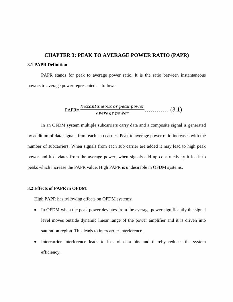
3.1 PAPR Definition
PAPR stands for peak to average power ratio. It is the ratio between instantaneous
powers to average power represented as follows:
PAPR= 𝐼𝑛𝑠𝑡𝑎𝑛𝑡𝑎𝑛𝑒𝑜𝑢𝑠 𝑜𝑟 𝑝𝑒𝑎𝑘 𝑝𝑜𝑤𝑒𝑟
𝑎𝑣𝑒𝑟𝑎𝑔𝑒 𝑝𝑜𝑤𝑒𝑟………… (3.1)
In an OFDM system multiple subcarriers carry data and a composite signal is generated
by addition of data signals from each sub carrier. Peak to average power ratio increases with the
number of subcarriers. When signals from each sub carrier are added it may lead to high peak
power and it deviates from the average power; when signals add up constructively it leads to
peaks which increase the PAPR value. High PAPR is undesirable in OFDM systems.
3.2 Effects of PAPR in OFDM:
High PAPR has following effects on OFDM systems:
In OFDM when the peak power deviates from the average power significantly the signal
level moves outside dynamic linear range of the power amplifier and it is driven into
saturation region. This leads to intercarrier interference.
Intercarrier interference leads to loss of data bits and thereby reduces the system
efficiency.
14
In order to overcome the high PAPR we have to employ high-power amplifiers which
increase system costs.
It reduces efficiency of RF power amplifiers as they have to operate with large backoffs.
It increases the complexity of the multiplexers and de-multiplexers.
PAPR in OFDM is characterized using CCDF function.
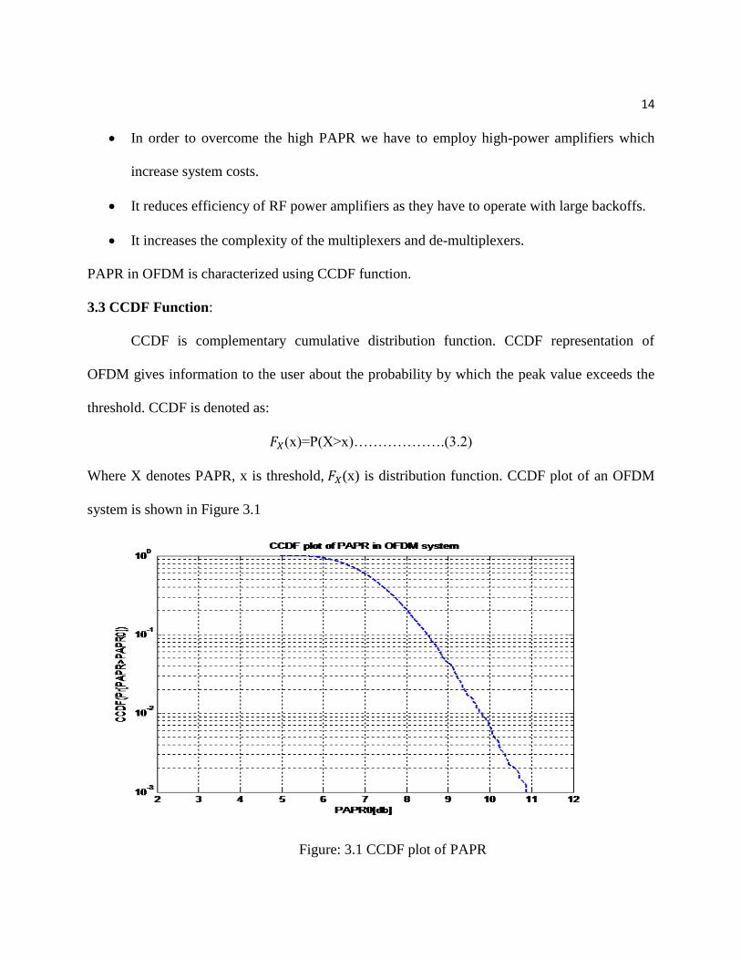
3.3 CCDF Function:
CCDF is complementary cumulative distribution function. CCDF representation of
OFDM gives information to the user about the probability by which the peak value exceeds the
threshold. CCDF is denoted as:
𝐹𝑋(x)=P(X>x)……………….(3.2)
Where X denotes PAPR, x is threshold, 𝐹𝑋(x) is distribution function. CCDF plot of an OFDM
system is shown in Figure 3.1
Figure: 3.1 CCDF plot of PAPR
15
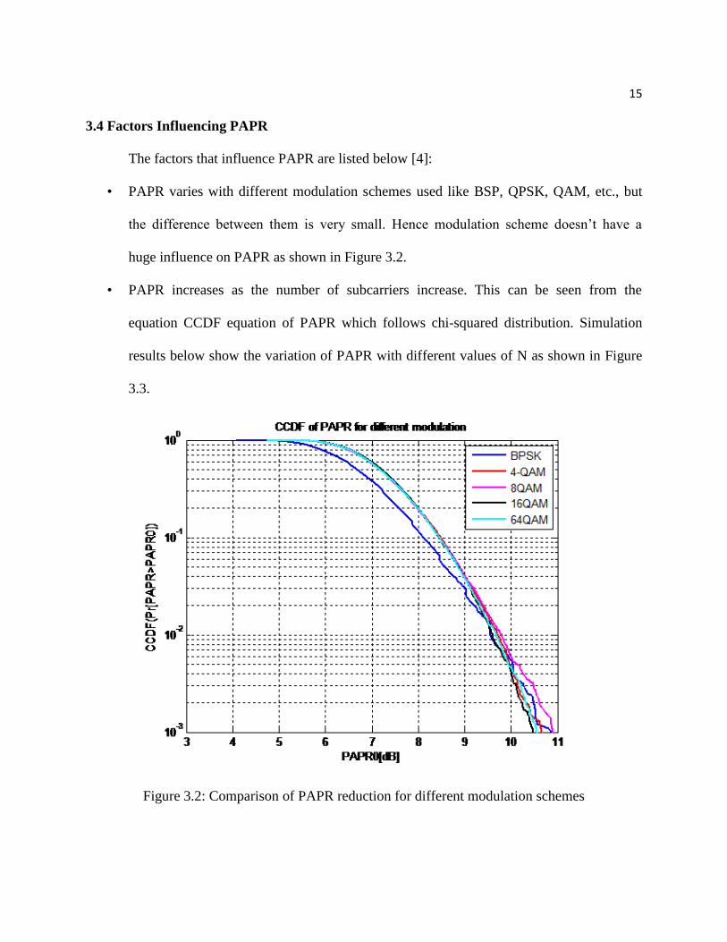
3.4 Factors Influencing PAPR
The factors that influence PAPR are listed below [4]:
• PAPR varies with different modulation schemes used like BSP, QPSK, QAM, etc., but
the difference between them is very small. Hence modulation scheme doesn’t have a
huge influence on PAPR as shown in Figure 3.2.
• PAPR increases as the number of subcarriers increase. This can be seen from the
equation CCDF equation of PAPR which follows chi-squared distribution. Simulation
results below show the variation of PAPR with different values of N as shown in Figure
3.3.
Figure 3.2: Comparison of PAPR reduction for different modulation schemes

16
Figure 3.3: Comparison of PAPR reduction for different values of N
3.5 PAPR Reduction Techniques
Many techniques have been proposed to reduce the PAPR problem in OFDM. They are
classified into different approaches as follows:
• Signal distortion technique
• Coding technique
• Scrambling technique
3.5.1 Signal Distortion Techniques
Signal distortion techniques distort the signal. Signal distortion techniques include
clipping, filtering, companding and windowing.
Clipping is the simplest of distortion methods where the signal peaks are clipped are
beyond a certain threshold. The drawback of clipping is the loss of the signal information.

17
Filtering is a technique where the signal is passed through a filter. Only frequencies which
are in pass band range of filter are passed and other frequencies are attenuated. Filtering also has
the same disadvantage as clipping where information is lost.
Companding is a technique where the signal is compressed and sent. This method may
induce self-interference in the system and may lead to loss of information bits.
Windowing is a method where the signal is passed through the windows such as
rectangular, Kaiser, Hanning and Hamming window; the major drawback of windowing is the
signal deteriorates with increase of window size. The system also fails when the peaks exceed
half of window size.
To overcome the drawbacks of windowing technique where the entire envelope is
multiplied with the window, an alternate method of peak windowing was proposed. In the peak
windowing method when the signal exceeds its threshold then it is multiplied with the window.
This method improves the margin of signal degradation.

CHAPTER 4: PAPR REDUCTION IN OFDM USING COMPANDING
PAPR in OFDM system can be reduced by using companding transform. In the method
of companding the data is compressed using a compander at the transmitter and expander at the
receiver where the signals are recovered.
There are many companding methods like U law companding and A law companding.
4.1 U Law Companding
In the U law companding, a compressor is used at the transmitter end after the IFFT
phase and an expander is used at the receiver end before the FFT process to expand the
compressed signal from the channel. U law coefficient gives information about the extent of
companding done to the signal.
4.1.1Transmission Phase:
The input signal is converted from serial to parallel and mapped using 4 QAM
constellations. The mapped data is mounted on parallel subcarriers and sent to IFFT phase. The
input signal after the IFFT phase passes through companding. The transformed signal after the
IFFT phase as follows:
C{x(n)}=𝑣𝑥(𝑛)
ln(1+𝑢)|𝑥(𝑛)|ln(1+
𝑢
𝑣(|x(n)|)……………..(4.1)
where x(n) is the input signal, v is the average amplitude of the signal and u is the companding
factor.

19
The companding transform should satisfy following conditions for the implementation:
E (|𝑠(𝑛)|2) = E(|𝑥(𝑛)|2)
|s(n)|≥|x(n)| when |x(n)≤v|
|s(n)| ≤|x(n)| when |x(n) ≥v|
4.1.2 Receiver Phase
The signal which comes from the transmitter phase passes through the channel and at the
receiver the signal undergoes inverse operation to that of transmitter. The signal at the receiver
after inverse companding transform is:
𝐶′{x(n)}= 𝑣𝑟(𝑛)
𝑢|𝑟(𝑛)|[𝑒𝑥𝑝(
|𝑟(𝑛)| ln(1+𝑢)|
𝑣-1)]…………(4.2)
where x(n) is the input signal and v is the average amplitude of the signal.
Companding is a decent method for reducing PAPR; however, there are major
disadvantages using the method: signal completely loses its shape from the transmitted signal at
the receiver end, which leads to loss in the information.
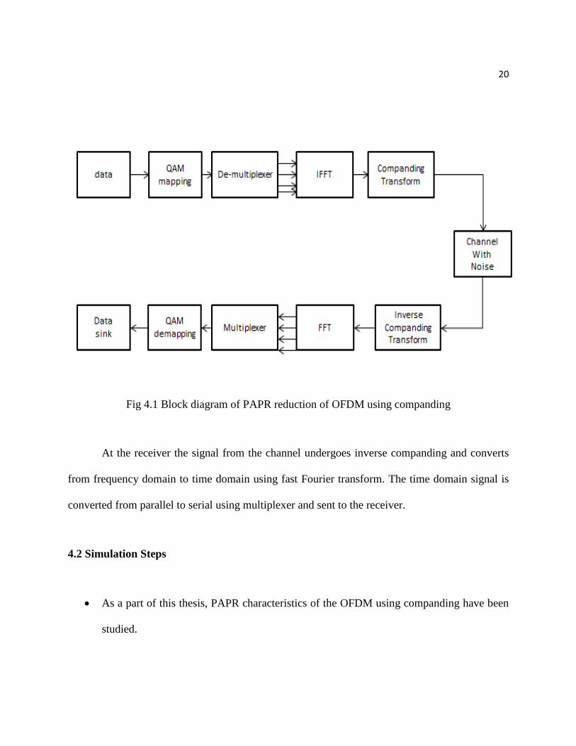
In Figure 4.1, the symbol from the transmitter is converted from serial to parallel and
then undergoes inverse fast Fourier transform which converts the frequency domain signal to
time domain and then the signal undergoes companding and passes through the AWGN channel.
20
Fig 4.1 Block diagram of PAPR reduction of OFDM using companding
At the receiver the signal from the channel undergoes inverse companding and converts
from frequency domain to time domain using fast Fourier transform. The time domain signal is
converted from parallel to serial using multiplexer and sent to the receiver.
4.2 Simulation Steps
As a part of this thesis, PAPR characteristics of the OFDM using companding have been
studied.

21
In the simulation 128 symbols are mapped on to 16 sub carriers using 4 QAM
modulations and are IFFT sampled.
The OFDM signal after IFFT undergoes companding with a companding factor (u=2).
The signal after companding passes through an AWGN channel which then is expanded
using inverse companding transform at the receiver.
The signal after compression is 128 FFT sampled and sent to the receiver.

CHAPTER 5: HYBRID MODEL FOR PAPR REDUCTION IN OFDM
In this section we discuss the hybrid model for PAPR reduction in OFDM using
Hadamard transform and Hamming peak windowing. Before discussing the model we will
discuss the Hadamard transform and Hamming peak windowing.
5.1 Hadamard Transform:
Hadamard transform is also known as Walsh-Hadamard transform. It transforms 2𝑛 real
numbers or complex numbers into 2𝑛 real numbers using a normalizing factor. Hadamard
transform is done using a Hadamard matrix, which is an orthogonal matrix of order 2𝑚 ∗ 2𝑛
which consists of 1 and -1 as its elements. The Hadamard matrix of order 2*2 is given as
follows:
𝐻1=1
√2 [
1 11 −1
]……………(5.1)
The generalized equation can be written as:
(𝐻𝑛)=1
2𝑛2
(−1)𝑚.𝑛……………..(5.2)
where ‘m’ and’ n’ are the subscripts of the matrix, m.n is the bitwise dot product of elements of
m, n.

23
The reason for the use of the Hadamard transform is that Hadamard matrix has one
similar characteristic with OFDM, orthogonality. The elements in the Hadamard matrix are
orthogonal to each other.
H*𝐻𝑇=I……………..(5.3)
where H is the Hadamard matrix, 𝐻𝑇is transpose of the Hadamard matrix and 𝐼 is the Identity
matrix.
The input signal at the transmitter which is mapped and modulated is transformed using
Hadamard transform before the IFFT sampling and at the receiver the signal is recovered using
inverse Hadamard transform which converts Hadamard transformed signal back to the original
signal. Inverse Hadamard transform is performed after FFT sampling at the receiver. Hadamard
matrix is used in the proposed method to reduce the input correlation of the input signal which
reduces the peaks at the transmission. Reduction of peaks at the transmitter reduces the peak to
average power ratio.
5.2 Peak Windowing:
Peak windowing is one of the signal distortion techniques which are used for the PAPR
reduction in OFDM. It is extensively used in the PAPR reduction applications due to its
advantages over the other signal distortion techniques like clipping, companding and windowing.
24
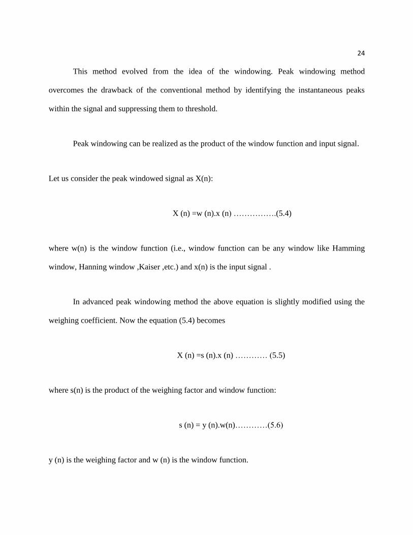
This method evolved from the idea of the windowing. Peak windowing method
overcomes the drawback of the conventional method by identifying the instantaneous peaks
within the signal and suppressing them to threshold.
Peak windowing can be realized as the product of the window function and input signal.
Let us consider the peak windowed signal as X(n):
X (n) =w (n).x (n) …………….(5.4)
where w(n) is the window function (i.e., window function can be any window like Hamming
window, Hanning window ,Kaiser ,etc.) and x(n) is the input signal .
In advanced peak windowing method the above equation is slightly modified using the
weighing coefficient. Now the equation (5.4) becomes
X (n) =s (n).x (n) ………… (5.5)
where s(n) is the product of the weighing factor and window function:
s (n) = y (n).w(n)…………(5.6)
y (n) is the weighing factor and w (n) is the window function.
25
To apply the scaling factor s(n) the input signal value should be set to the threshold so
that window function can be applied to it to reduce the peaks.
5.3 Hybrid Model
Hybrid model of PAPR reduction in OFDM uses both Hadamard transform and advanced
peak windowing.
5.3.1 Hybrid Model Transmitter
At the transmitter the input signal is mapped onto the subcarriers and then modulated
using 4 QAM or QPSK modulation technique. The QPSK modulated signal is Hadamard
transformed before IFFT operation. The signal which is Hadamard transformed is then IFFT
sampled. IFFT sampling converts the signal from the frequency domain to the time domain. The
signal in time domain undergoes Hamming peak windowing. The peak windowed signal passes
through AWGN (additive white gaussian noise) channel.
5.3.2 Hybrid Model Receiver:
The time domain windowed signal from the channel is converted back to frequency
domain by FFT operation at the receiver. The signal is decoded at the receiver using inverse
Hadamard transform at the receiver. Now the signal is demapped and demodulated. The
demodulated signal is given to the base station.
26
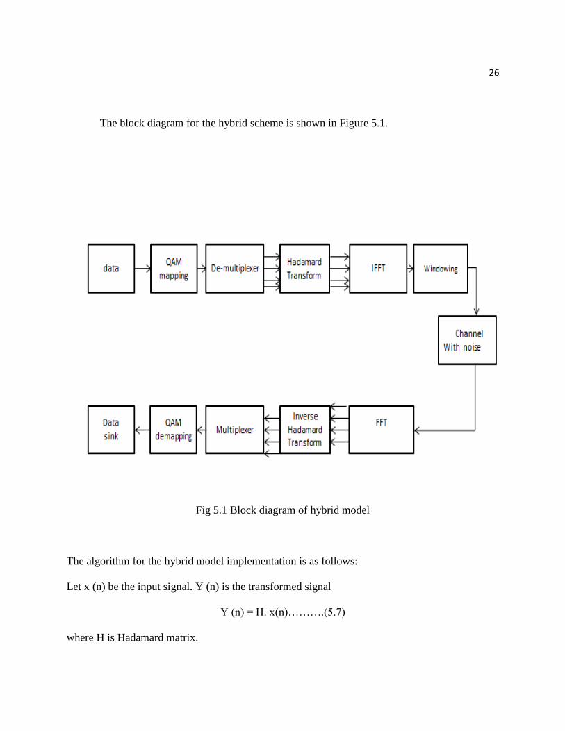
The block diagram for the hybrid scheme is shown in Figure 5.1.
Fig 5.1 Block diagram of hybrid model
The algorithm for the hybrid model implementation is as follows:
Let x (n) be the input signal. Y (n) is the transformed signal
Y (n) = H. x(n)……….(5.7)
where H is Hadamard matrix.
27
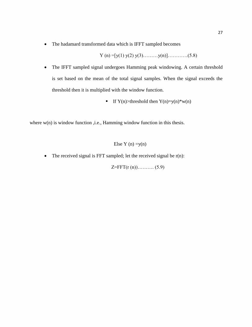
The hadamard transformed data which is IFFT sampled becomes
Y (n) =[y(1) y(2) y(3)………y(n)]…………(5.8)
The IFFT sampled signal undergoes Hamming peak windowing. A certain threshold
is set based on the mean of the total signal samples. When the signal exceeds the
threshold then it is multiplied with the window function.
If Y(n)>threshold then Y(n)=y(n)*w(n)
where w(n) is window function ,i.e., Hamming window function in this thesis.
Else Y (n) =y(n)
The received signal is FFT sampled; let the received signal be r(n):
Z=FFT(r (n))………. (5.9)

CHAPTER 6: SIMULATION RESULTS AND COMPARISON
The PAPR reduction performance of OFDM systems using Companding techniques and
hybrid techniques discussed in Chapters 4 and 5 were simulated and analyzed using MATLAB
R2012b.
6.1 Companding Techniques
In the simulation of companding method of PAPR reduction of OFDM at the transmitter,
128 symbols are mapped onto the 16 subcarriers and modulated using 4 QAM or QPSK
modulation. The modulated subcarriers undergo inverse fast Fourier transform. The IFFT
sampled signals are sent to compander where they are compressed with companding factor of
2(u=2) and then passed to the AWGN channel. The signal from AWGN channel at the receiver
undergoes inverse of companding operation and it is FFT sampled. The FFT-sampled signal is
converted from parallel to serial to transmit it to the receiver. The PAPR characteristics are
plotted using CCDF function. The PAPR characteristics are compared with that of OFDM,
windowing and Hadamard transform.
6.2 Hybrid Method:
In the simulation of companding method of PAPR reduction of OFDM at the transmitter
the symbols are converted from serial to parallel then 128 symbols are mapped onto the 16
subcarriers and modulated using 4 QAM or QPSK modulation. The modulated subcarriers
undergo Hadamard transform. They are multiplied with Hadamard matrix. The Hadamard-
transformed symbols are IFFT sampled and then passed to the AWGN channel. The signal from
29
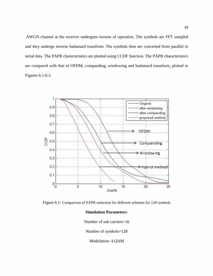
AWGN channel at the receiver undergoes inverse of operation. The symbols are FFT sampled
and they undergo inverse hadamard transform. The symbols then are converted from parallel to
serial data. The PAPR characteristics are plotted using CCDF function. The PAPR characteristics
are compared with that of OFDM, companding, windowing and hadamard transform, plotted in
Figures 6.1-6.3.
Figure 6.1: Comparison of PAPR reduction for different schemes for 128 symbols
Simulation Parameters:
Number of sub carriers=16
Number of symbols=128
Modulation: 4 QAM

30
Fig 6.2 Comparison of PAPR reduction for different schemes for 256 symbols
Simulation Parameters:
Number of sub carriers=16
Number of symbols=256
Modulation: 4 QAM
31
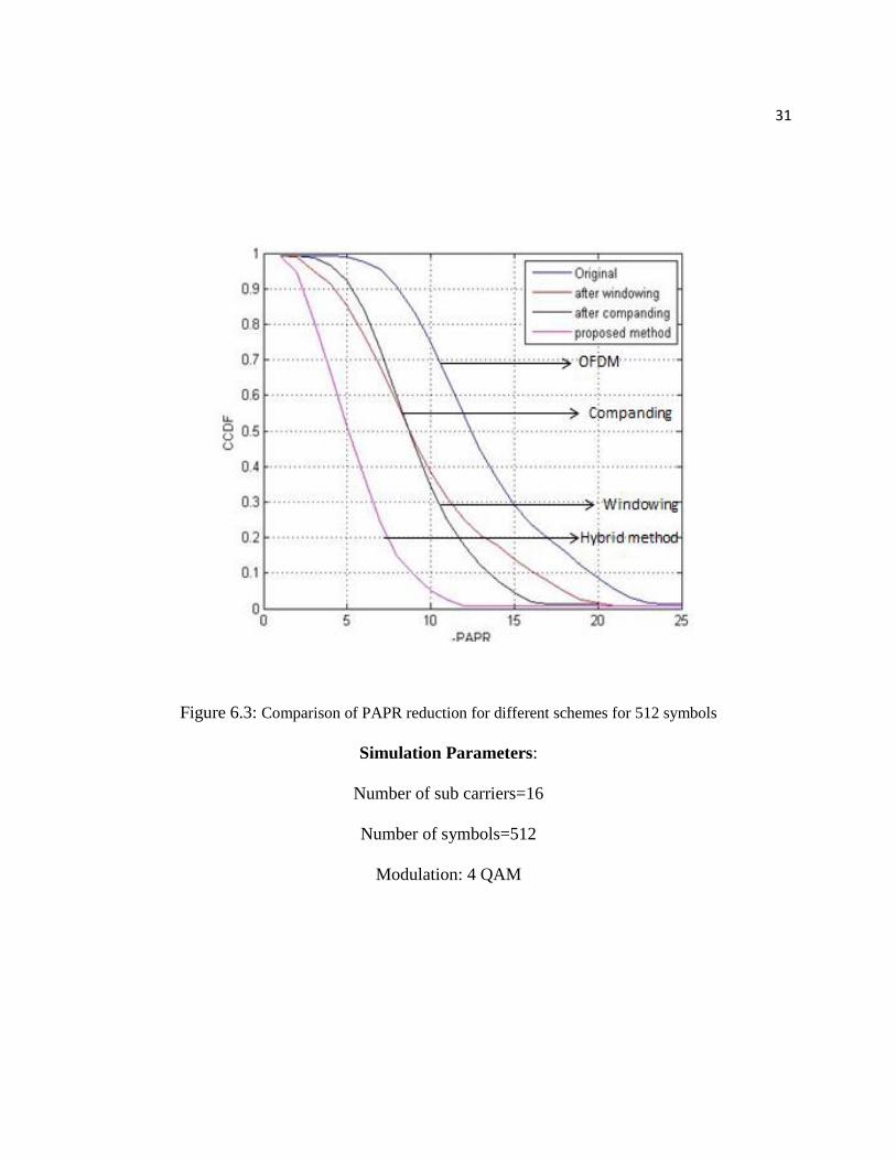
Figure 6.3: Comparison of PAPR reduction for different schemes for 512 symbols
Simulation Parameters:
Number of sub carriers=16
Number of symbols=512
Modulation: 4 QAM
32
6.3 Simulation Results of Hybrid Method
In the simulation of companding method of PAPR reduction of OFDM at the transmitter,
the symbols are converted from serial to parallel then 128 symbols are mapped onto the 128
subcarriers and modulated using 4 QAM or QPSK modulation. The modulated subcarriers
undergo Hadamard transform. They are multiplied with Hadamard matrix. The Hadamard-
transformed symbols are IFFT sampled and then passed to the AWGN channel. The signal from
AWGN channel at the receiver undergoes inverse of operation. The symbols are FFT sampled
and they undergo inverse Hadamard transform. The symbols then are converted from parallel to
serial to transmit it to the receiver. The PAPR characteristics are plotted using CCDF function.
The PAPR characteristics are compared with that of OFDM, companding and windowing.
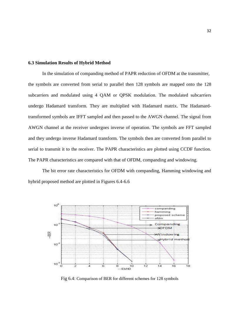
The bit error rate characteristics for OFDM with companding, Hamming windowing and
hybrid proposed method are plotted in Figures 6.4-6.6
Fig 6.4: Comparison of BER for different schemes for 128 symbols

33
Simulation Parameters:
Number of sub carriers=16
Number of symbols=128
Modulation: 4 QAM
Fig 6.5: Comparison of BER for different schemes for 256 symbols
Simulation Parameters:
Number of sub carriers=16
34
Number of symbols=256
Modulation: 4 QAM
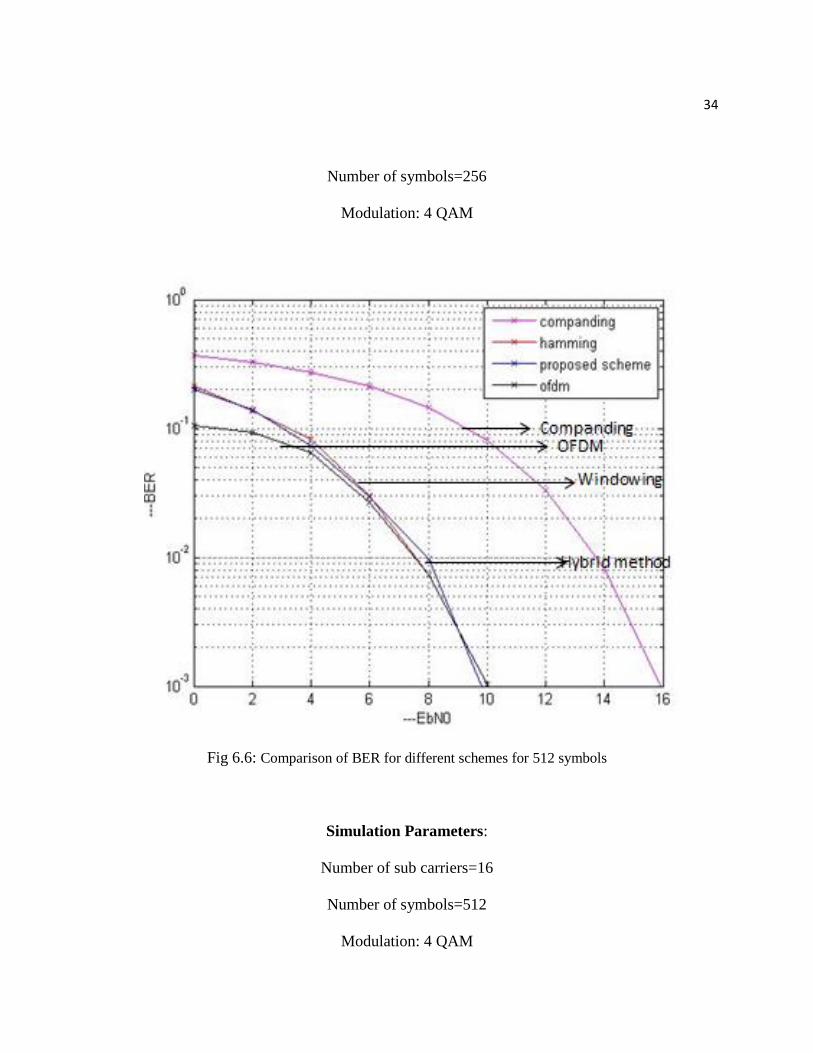
Fig 6.6: Comparison of BER for different schemes for 512 symbols
Simulation Parameters:
Number of sub carriers=16
Number of symbols=512
Modulation: 4 QAM
Chapter 7 CONCLUSION AND FUTURE WORK
7.1 Conclusion
PAPR reduction techniques for OFDM system are simulated and compared. The hybrid
technique gave better PAPR reduction when compared to companding and windowing technique.
Hybrid scheme gave the best PAPR reduction among all the techniques. The use of Hadamard
transform at the transmitter reduces the peaks significantly due to the reduction of the input
correlation and further the use of peak windowing gives better signal characteristics compared to
conventional windowing methods.
The bit error rate (BER) of companding, windowing and hybrid schemes were simulated
and compared. From the simulation we observe
number of points exceeding threshold in case of 128 symbols and 16 subcarriers=697 out
of 2048
number of points exceeding threshold in case of 256 symbols and 16 subcarriers=1228
out of 4096
number of points exceeding threshold in case of 512 symbols and 16 subcarriers= 2051
out of 8192
7.2 Future Work
The future work may include the use of different combinations of signal scrambling and
signal distortion techniques. Channel estimation can be done.

REFERENCES
[1] S. Weinstein, P. Ebert, "Data Transmission by Frequency-Division Multiplexing Using the
Discrete Fourier Transform," Communication Technology, IEEE Tran., vol.19, no.5, pp.628,
634, October 1971.
[2] A.K. Jagannatham, Online Lecture, Topic: “OFDM schematic and cyclic prefix” Faculty of
Electrical Engineering, Indian Institute of Technology Kanpur, Kanpur, Uttar Pradesh, retrieved
online.http://youtu.be/eWGqTggZMVk?list=PLbMVogVj5nJSi8FUsvglRxLtN1TN9y4nx
published on June 10,2013
[3] X.Li and L.J.Cimini,“ Effects of Clipping and Filtering on the Performance of OFDM,” IEEE
Communication Letters, Vol.2, No.5, May 1998, pp.131-133.
[4] Chen, James C., and Jeffrey M. Gilbert. "Measured performance of 5-GHz 802.11 a wireless
LAN systems." Atheros communications 8 (2001): 27.