Circuits and Systems for RF-MIMO WLAN
14
-
Upload
independent -
Category
Documents
-
view
1 -
download
0
Transcript of Circuits and Systems for RF-MIMO WLAN

� �No está permitida la reproducción total o de este libro, su tratamiento informático, la transmisión de ninguna otra forma por cualquier medio, ya sea Electrónico, mecánico, por fotocopia, por registro u otros métodos, sin el permiso previo y por escrito de los titulares del Copyright.
International Institute of Innovation and Technology E.I.R.L. (IIITEC) Avenida Los Gorriones 373 E-402 Chorrillos Lima 09, Perú Î Teléfono (+51)1 252 0782
Editor Responsable: Mario Chauca Saavedra (IIITEC, PERU)
Coordinador: Miguel Ángel Gómez Martínez MEXICO
International Institute of Innovation and Technology E.I.R.L. Avenida Los Gorriones 373 E-402 Chorrillos Lima 09, Perú Lima, Noviembre del 2011 Producido en Lima (PERU)
� � � � � � � � � � � � � � � � � � � � � � � � � � � � �� � � � � � � � � � � � � � � !" � # � � $ � � % � � � & � � ' � � ( � � � � � � ) � ( � � � & � # * + � & � � � � , � � � � � � � �� � � � � & � # * � � & - � � � . /0 � ( � # � � � % � � � ) � � � & � � � ' � ' 1 � 2 ' � � � � " 3 4 ) ( & � 5 � � � � � � 6 � 7 & � � � �3 ( � � � � � � � � � # � � � � � 6 + & � � � � � � � � � � ( � � � � � � � � � 8 � � � � � % �9 & � � � � � � � + � � ( � 0 � , � � � 7 ( � � � � � � � � � � � � � & 0 � � � � ( � # � � % � 6 # � * � � & 9 � ( � � � � � � & � � ) � ( � � � � � � 6 ( : � � ; � � � � � � � & 3 < 0 � < 0 � = 1 � � � ) � � � � � � �3 � � ( � � � � % � 9 > � � ( � � ( � �0 � + � � ( � � � � � & � � 3 � � # � � � � � ( � � � & � � � � 6 � � � � � ( � � % � � � & � � 3 � � # � � �� � 0 � # � � � � � * ) � � � & � � � & � � � � , � � � � � � , � � � � � � � � � � � � & � 6 � � � � � + � & � � � � & � � % � � � 9 � ( � � & � � � � � � � � ( � � � .; � � � � � 6 � " < ; ? . " @ = + � & 9 � � � A � $ � � 8 � � + � � � ( � � � � � � � � & � � ( � % � � � � �� � � � � � � � 3 & � � � � � !9 > + � � � � � � � � � � 9 � & � � � % � � � 3 � � 1 � � ( � � � � 9 � � � # * � @ � � � � � & � �6 + & � � � � � � � � � � 9 & � � ( � % � 1 � � � ( � � � 0 � � ? � � + � , � � � � � � % � 1 6 � 7 & � � � � � �� � � � � � � � � � ( � � 1 8 � � + � � � ( � � � � 3 & � � � � � � � �' � � � � � ( � � 1 � � � ( � � � + � @ 4 5 ) 0 ) " - 6 �' � � � � � � � � � 0 � � # � � � � % �) � ( � � � B � � � � � � � � � � �� � � � � � � � � � � � � � � !) � ( � � � � � � � � & � � % � + � ) � � � & � � � � 6 � ( % � ( � � & � & �8 � � � A � � � � � � ( � � � ) � & ( � 5 6 # � � ( � 1 � � � � � � � � � � � � � � 0 � ( � & � # � � � � 6 � ( � , � � � &6 + & � � � & ' � & ( � � � � � 3 & � ( �6 � 7 & � � � � 9 � ( � � � ( � � & � � 3 � � � � � � ) ( � � � � � 3 � & � � � � � � � + � 0 � # � � � � � * � �� � C � � � � ; ( � & � $ � � � ) � � , � & � # * ) ( � � 7 ( � � 1 @ � � � � � ( � � � � � % � D 86 � 7 & � � � � 9 � � � % � � � � � � & ) � ( � � � & � # * � � 3 � � ( � � + � � � � � � � � � � � � � � �4 � � � ( � � � 9 � � � # * @ � � � � � & �8 � � � A � � � � � � � � ( � � � � 8 � � � , � � � � % � + � 8 � � ( � � � � � � % � 0 � ( � & � # � � ( � � �4 � � ( � & � $ � ( � � 9 & � � � � � � � � � � � � ( � � � � � � � # � ( & � , � � � � � ( � 1 � , � � $8978-612-45917-1-6 © 2011 IIITEC ISIT2011
E F G H I H J K I L H M N O H I L H J G H P H I Q R S I T U VV W F W R L H F N X W R N Y I G H M V S Z [ S F L W Z N H I L S P N O F W L S F N S G H T H \ F S I W J ] Z ^ F N S I W F N W JZ H G N W I L H P S F _ S M S O ` W P W L H Z a L N R W bc S M \ R N S I H J G H W \ L S J H F d N R N S e f W O S g h H O N J L F S G H M J H O Z H I L S h H L W N M g i W I R Wc H J N S I H J f M H I W F N W J e] R S J N J L H Z W J G H K I I S d W R N Y I e ] j [ H F N H I R N W J H I U M S F N G W V H I L F W M g P S G H M S J] R S I Y Z N R S J i W J W G S J H I c N J L H Z W J V S Z [ M H k S J] _ N R N H I L H J V N F R \ N L S J l I W M Y O N R S J V P m c [ W F W M W f F Y j N Z W n H I H F W R N Y I G Hc N J L H Z W J G H c S _ L o W F H p H _ N I N G W [ S F H M h W G N S q P Y d N M e r H I G H I R N W J s h H L S J g c S M \ R N S I H JK Z [ M H Z H I L W R N Y I G H \ I c N J L H Z W n H S q K I L H M N O H I L H P \ M L N J H I J S F l d W I X W G S [ W F W H Mp H J W _ ` S G H M W t N O N M W I R N W V S I L N I \ W G H M W l Z W X S I W J f H F \ W I W bP N u F R S M H J v w G H T S d N H Z ^ F Hc H J N S I H J r u R I N R W J ep H J W F F S M M S G H m ^ k H L S J G H l [ F H I G N X W k H J S ^ F H l R R H J N ^ N M N G W G x H ^ e y I R W J S G H] J L \ G N S V S Z [ W F W I G S G S J Z H L S G S M S O ` W J G H p N J H z Sl I a M N J N J V S Z [ W F W L N d S G H M W h H G T H \ F S I W M P { f g f V l [ W F W M W V M W J N _ N R W R N Y I G Ht N I S i M W I R S g t N I S h S k SP S G H M S G H l F | \ N L H R L \ F W c m l [ W F W P N I H F ` W G H p W L S J H I i W J H J G H p W L S Jh H M W R N S I W M H J p N J L F N ^ \ N G W Jc N J L H Z W G H V S I L F S M ] M H R L F S Z H R a I N R S W L F W d u J G H M W h H G ] M u R L F N R Wh H R S I J L F \ R R N Y I t N J \ W M v q p e y I W f H F J [ H R L N d W G H M c N J L H Z W} H F F W Z N H I L W r H R I S M Y O N R W [ W F W H M r F W L W Z N H I L S G H M W J p N _ N R \ M L W G H J H I H Ml [ F H I G N X W k H | \ H f F H J H I L W I M S J T N z S J g T N z W J R S I p N J M H j N W H I f W I W Z al R F H G N L W R N Y I e V W J S y I N d H F J N G W G r H R I S M Y O N R W G H M f H F Qc N J L H Z W J G H J H O \ F N G W G s G N J H z S g _ W ^ F N R W R N Y I e c H O \ F N G W G f Q ^ M N R W V W J Sf H F \ W I Sc H J N S I H J f M H I W F N W J er t G H y M L F W l M L W p H _ N I N R N Y I s V N I H p N O N L W M g r H M H Z H G N R N I W J S ^ F H M W F H G Y [ L N R W~ l F O H I L N I W V S I H R L W G W ~ b� w W z S J G H N I d H J L N O W R N Y I H I N I O H I N H F ` W e T W I S L H R I S M S O ` WV N F R \ N L S J g c N J L H Z W J G H h W G N S J p H _ N I N G W J [ S F c S _ L o W F HV H F H Z S I N W G H V M W \ J \ F W b9978-612-45917-1-6 © 2011 IIITEC ISIT2011
---------------------------------------------------------------------------------------------------------------------------------------------------
IIITEC-Perú Avenida Los Gorriones 373 E-402 Chorrillos Lima-9 Perú
Teléfono (+51)12520782 [email protected] [email protected] www.iiitec.org
"Centennial Year of Machu Picchu to the World" Lima, August 30, 2011. Letter-30082011_27IAF Ph.D. Zoran Stamenkovic
IHP - Frankfurt
GERMANY
On behalf of Technical Program Committee of the 2nd Symposium IIITEC International Symposium on Innovation and Technology ISIT2011, we thank you for accept our invitation to participate as a reviewer, member of Technical Committee and as Speaker in Special Session. It is noteworthy that our Organizing Committee invited specialists of recognized professional and academic, who according to the criteria established by the Committee ISIT 2011 to choose the most representative. In addition to his valuable participation in the Conferences, take this opportunity to invite you to attend the final competition of papers as Chair Session, where the finalists will make an oral presentation of their work. The session papers contest will take place from November 28 to 30 November this year in the city of Lima, Peru, where he has scheduled oral presentation assisted by a chair session appointed by the Committee ISIT 2011. We are aware of the level and area of their work considering these qualities and others for the benefit of students and general public attendees, so we believe it is an ideal person to participate in this event and would be happy to have you. We hope your presence in the ISIT2011. Sincerely Mario Chauca General Chair ISIT2011 IIITEC
978-612-45917-1-6 © 2011 IIITEC 12 ISIT2011
802.11
Data Link LLC
MAC
MIMAX
PHY PLCP
PMD
802.11
Data Link LLC
MAC
802.11a
PHY PLCP
PMD
CIRCUITS AND SYSTEMS FOR RF-MIMO WLAN
Z. Stamenkovic*, K. Tittelbach-Helmrich*, R. Kraemer*, S. Ruiz**, O. Gago**, J. Ibanez
à, I. Santamaria
à,
M. Wickertàà
, and R. Eickhoffàà
Abstract - This paper describes the concept of a MIMO RF
front-end based wireless LAN system (called MIMAX), the
ver ification of the individual subsystems and the results of the
final tests. The MAC and baseband processors have been
designed, implemented, and ver ified. The transmitter and
receiver of the analog front-end have been designed, fabr icated,
and separately ver ified. The system demonstrator in laptop
form factor has been presented.
Index Terms Î Communications, Microelectronics,
Design, Test.
1 INTRODUCTION
We introduce a concept based on the multiple-input,
multiple-output (MIMO) communication and the signal
combining near the transmitting and receiving antennas in
the analog front-end [1]-[3]. Therefore, synergies between
front-end, and antenna array are described. Finally, the
integration and test aspects are discussed and the complete
system demonstrator is presented.
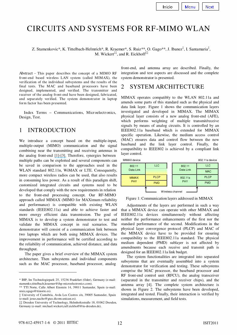
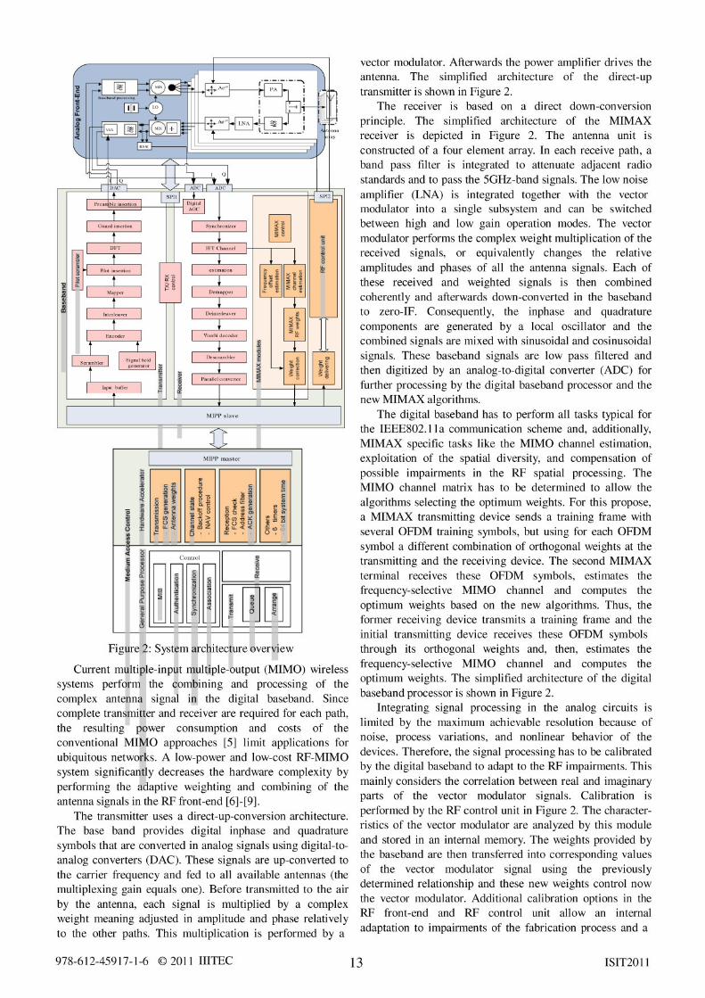
2 SYSTEM ARCHITECTURE MIMAX operates compatibly to the WLAN 802.11a and
amends some parts of this standard such as the physical and
data link layer. Figure 1 shows the communication layers
investigated and developed in MIMAX. The MIMAX
physical layer consists of a new analog front-end (AFE),
which performs weighting of multiple transmit/receive
signals by means of analog circuits. It is controlled by an
IEEE802.11a baseband which is extended for MIMAX
specific operation. Likewise, the medium access control
(MAC) ensures data and control flow between the new
baseband and the link layer control. Finally, the
compatibility to IEEE802 is achieved by a compliant link
layer control.
multiple paths can be exploited and several components can
be saved in comparison to the approaches used in the
WLAN standard 802.11n, WiMAX or LTE. Consequently,
more compact wireless radios can be used, that also results
in consuming less power. As a result of this paradigm shift,
customized integrated circuits and systems need to be
developed that comply with the new requirements in relation
to the front-end processing concept. Our RF-MIMO
MIMAX device
Wireless channel
802.11a device
approach called MIMAX (MIMO for MAXimum reliability
and performance) is compatible with existing WLAN
standards (IEEE802.11a) and able to achieve faster and
more energy efficient data transmission. The goal of
MIMAX is to develop a system demonstrator to test and
validate the MIMAX concept in real scenarios. The
demonstrator will consist of a communication link between
two laptops which are both using MIMAX devices. The
improvement in performance will be certified according to
the reliability of communication, achieved distance, and data
throughput.
The paper gives a brief overview of the MIMAX system
architecture. Then subsystems and individual components
such as the MAC processor, baseband processor, analog
* IHP, Im Technologiepark 25, 15236 Frankfurt (Oder), Germany (e-mail:
stamenko,tittelbach,[email protected]).
** TTI Norte, Calle Albert Einstein 14, 39011 Santander, Spain (e-mail:
sruiz,[email protected]).
à University of Cantabria, Avda Los Castros s/n, 39005 Santander, Spain
(e-mail: jesus,[email protected]).
àà Dresden University of Technology, Helmholtzstraße 18, 01062 Dresden,
Germany (e-mail: michael.wickert,[email protected]).
Figure 1: Communication layers addressed in MIMAX
Adjustments of the layers are performed in such a way
that a MIMAX device can operate with other MIMAX and
IEEE802.11a devices simultaneously without affecting
neither the performance enhancements of the first nor the
standard performance of the second. Modifications in the
physical layer convergence protocol (PLCP) and MAC of
the MIMAX device have to be provided for ensuring
compatibility to the IEEE802.11a standard. The physical
medium dependent (PMD) sublayer is not affected by
amendments because each receive and transmit path is
designed for an IEEE802.11a link budget.
The system functionalities are integrated into separated
subsystems that are eventually assembled into a system
demonstrator for verification and testing. These subsystems
comprise the MAC processor, the baseband processor and
RF front-end control unit (RFCU), the analog transceiver
(separated in the transmitter and receiver chips), and the
antenna array [4]. The complete system architecture is
shown in Figure 2. The subsystems have been developed,
integrated and tested. Finally, their interaction is verified by
simulations, measurement, and field tests.
� � � � � � � �� � � �
978-612-45917-1-6 © 2011 IIITEC 14 ISIT2011
feedback to the baseband processing. These techniques are
based on look-up tables. The vector modulator is connected
to the RF control unit by a serial peripheral interface (SPI).
For the MIMAX data link layer, the standard IEEE802.2
link layer control is used on top of the IEEE802.11 medium
access control protocol. The new functionalities of the
MIMAX baseband processor impose some changes on the
MAC processor. It is necessary to know the configuration of
the transceiver including the number of antennas at
transmitter and receiver side and to maintain a database of
active and available users (MAC addresses, last optimum
weights, etc.). These tasks and the storage are related to
MAC because no memory is available at the baseband
processor. The MAC processor has to control the data flow and
specific instructions to the baseband processor depend-
ing on the communication scheme. It also initiates the MIMAX
channel estimation procedure, which normally consists
of a pair of training frames, exchanged between two stations.
Another important MIMAX feature is the transmission
of an RTS frame before each regular 802.11 frame. This is to
allow the receiver to identify the transmitter of the frame and
to set its receiver antenna configuration to the optimum weights
for that connection before receiving the regular frame. There is
a single RTS frame before each multicast or broadcast
frame, and a RTC / CTS pair before each unicast frame.
The MAC layer has been developed using the state
machine approach and the Specification and Description
Language (SDL). Functionally complex or rarely used parts of
the MAC protocol have been implemented in software. Time
critical or software inefficient functions are swapped to dedicated
hardware [10]. The MAC processor consists of a 32-bit RISC
processor and a hardware accelerator. The hardware
accelerator functionality for the transmit direction includes
a buffer for the next frame, cyclic redundancy check
(CRC) and an optional encryption. In the receive
direction, it performs CRC checking, frame address filtering,
generation of acknowledgements and CTS frames, and
optionally decryption. Furthermore, tracking channel state
(busy/idle) including back-off for sending frames, 6 timers
(32bit), a system timer (64 bit) and several interfaces are
provided as hardware modules. The interfaces include a 16-
bit interface to the physical layer (MIPP), a CardBus
interface to the host computer, a serial RS232 interface and
general purpose I/Os. A simplified architecture of the MAC
processor is shown in Figure 2.
3 COMPONENTS AND CIRCUITS The developed algorithms, components, and subsystems have been implemented in hardware (except the MAC pro-
cessor, which is a hardware/software co-design). The
MIMAX modem prototype assembles the following hardware:
" An antenna array made up of 4 multiband micro- strip-fed planar F-shaped monopoles,
" An analog front-end that uses vector modulators as an analog weighting circuitry,
" An OFDM baseband processor that supports the new analog front-end, and
" An enhanced MAC processor for MIMAX specific tasks and compatibility to 802.11a.
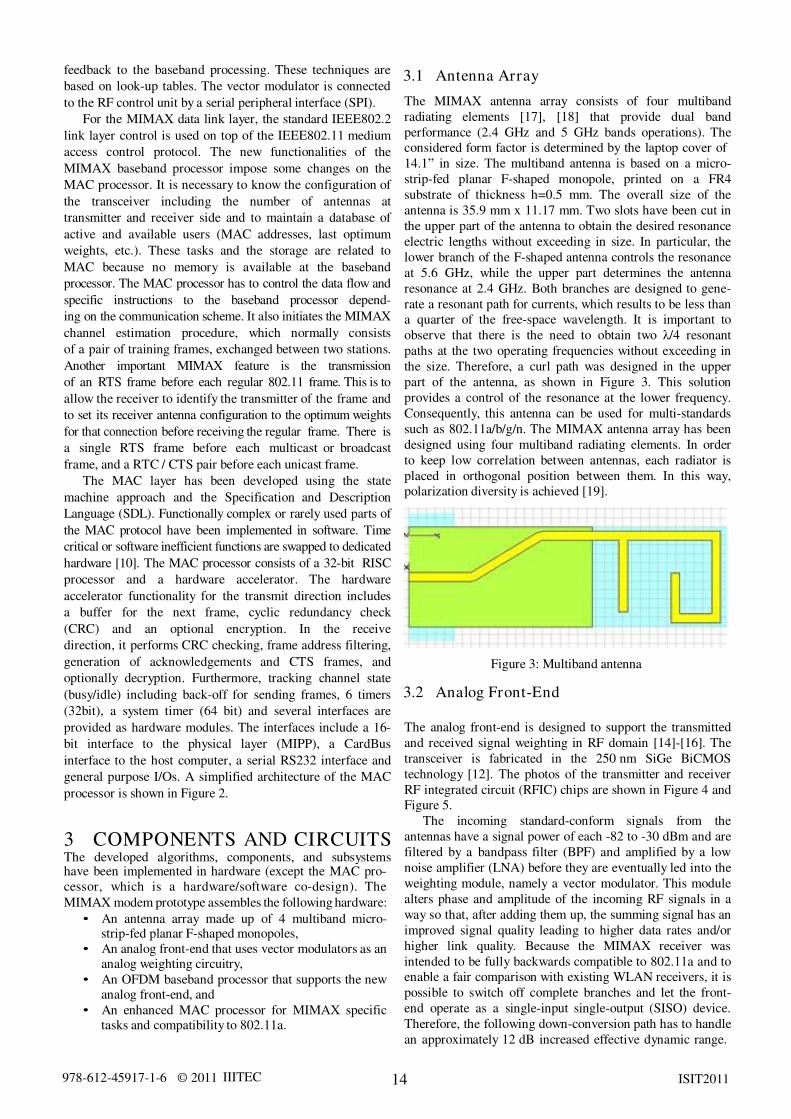
3.1 Antenna Array
The MIMAX antenna array consists of four multiband
radiating elements [17], [18] that provide dual band
performance (2.4 GHz and 5 GHz bands operations). The
considered form factor is determined by the laptop cover of
14.1Ñ in size. The multiband antenna is based on a micro-
strip-fed planar F-shaped monopole, printed on a FR4
substrate of thickness h=0.5 mm. The overall size of the
antenna is 35.9 mm x 11.17 mm. Two slots have been cut in
the upper part of the antenna to obtain the desired resonance
electric lengths without exceeding in size. In particular, the
lower branch of the F-shaped antenna controls the resonance
at 5.6 GHz, while the upper part determines the antenna
resonance at 2.4 GHz. Both branches are designed to gene-
rate a resonant path for currents, which results to be less than
a quarter of the free-space wavelength. It is important to
observe that there is the need to obtain two そ/4 resonant
paths at the two operating frequencies without exceeding in
the size. Therefore, a curl path was designed in the upper
part of the antenna, as shown in Figure 3. This solution
provides a control of the resonance at the lower frequency.
Consequently, this antenna can be used for multi-standards
such as 802.11a/b/g/n. The MIMAX antenna array has been
designed using four multiband radiating elements. In order
to keep low correlation between antennas, each radiator is
placed in orthogonal position between them. In this way,
polarization diversity is achieved [19].
Figure 3: Multiband antenna
3.2 Analog Front-End
The analog front-end is designed to support the transmitted
and received signal weighting in RF domain [14]-[16]. The
transceiver is fabricated in the 250 nm SiGe BiCMOS
technology [12]. The photos of the transmitter and receiver
RF integrated circuit (RFIC) chips are shown in Figure 4 and
Figure 5.
The incoming standard-conform signals from the
antennas have a signal power of each -82 to -30 dBm and are
filtered by a bandpass filter (BPF) and amplified by a low
noise amplifier (LNA) before they are eventually led into the
weighting module, namely a vector modulator. This module
alters phase and amplitude of the incoming RF signals in a
way so that, after adding them up, the summing signal has an
improved signal quality leading to higher data rates and/or
higher link quality. Because the MIMAX receiver was
intended to be fully backwards compatible to 802.11a and to
enable a fair comparison with existing WLAN receivers, it is
possible to switch off complete branches and let the front-
end operate as a single-input single-output (SISO) device.
Therefore, the following down-conversion path has to handle
an approximately 12 dB increased effective dynamic range.

978-612-45917-1-6 © 2011 IIITEC 16 ISIT2011
" VGA monitor output: to be connected to the standard
computer monitor for debugging purposes.
" Some components for future extension: user flash, RS
232 interface, temperature sensor, etc.
" Power supply, clock generator, flash storing the
Virtex FPGA configuration, etc.
Figure 6: Baseband board
3.4 MAC Processor
The MAC hardware platform [11] is based on two major
digital chips located on a printed-circuit board in CardBus
form factor (Figure 7):
" The MAC processor is an ASIC fabricated in IHP's
250 nm CMOS technology [12]. It provides a MIPS
4KEp 32-bit microprocessor core and the CardBus
(or PCMCIA) interface to a host PC.
" A Xilinx Virtex-5 LX50 FPGA implements the MAC
hardware accelerator and the MACÎPHY interface
(MIPP).
Figure 7: MAC board in CardBus form factor
The board contains many other components such as 4
MByte of processor flash memory and 1 MByte of RAM,
clock generator, power supply for FPGA, configuration flash
for FPGA, debugging and programming interfaces (UART /
RS232 for MAC firmware download, logic analyzer inter-
face), status LEDs, etc.
The MIMAX MAC protocol is fully compatible with the
IEEE 802.11a standard (5 GHz band). Although there are
some special MIMAX features such as training frames and
request-to-send (RTS) frames being transmitted before
multicast frames, these are compatible with the standard and
do not disturb normal WLAN traffic. Special MAC features
for coexistence with the IEEE 802.11n standard will be
considered. The features of the IEEE 802.11h standard such
as the dynamic frequency selection (DFS) and the transmit
power control (TPC) are included in the required extent.
4 SYSTEM TESTING
This section describes the subsystem integration and testing
of different components and circuits composing the final
MIMAX demonstrator: the antenna array, the analog front-
end, the baseband board with the integrated RF control unit,
and the MAC board. The components and subsystems of the
final MIMAX demonstrator have been tested and their
functionalities have been verified.
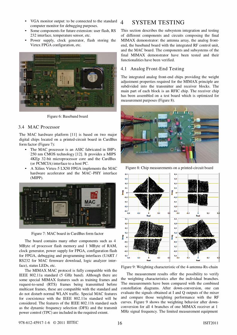
4.1 Analog Front-End Testing
The integrated analog front-end chips providing the weight
adjustment properties required for the MIMAX principle are
subdivided into the transmitter and receiver blocks. The
main part of each block is an RFIC chip. The receiver chip
has been assembled on a test board which is optimized for
measurement purposes (Figure 8).
Figure 8: Chip measurements on a printed-circuit board
Figure 9: Weighting characteristic of the 4-antenna-Rx-chain
The measurement results offer the possibility to verify
the weighting characteristics after the individual branches.
The measurements have been compared with the combined
constellation diagrams. After down-conversion, one can
evaluate the signals obtained at I and Q outputs of the mixer
and compare those weighting performance with the RF
curves. Figure 9 shows the weighting behavior after down-
conversion for all 4 branches of one MIMAX receiver at 1
MHz signal frequency. The limited measurement equipment
978-612-45917-1-6 © 2011 IIITEC 17 ISIT2011
did not allow a correct evaluation of phase and amplitude in
close proximity around zero. That is why the X and Y axis
are surrounded by an area with no data points. This
measurement uses a 6-bit stepping in the real and imaginary
direction, which can be extended up to 8-bit. It is visible that
a reasonable square shaped area can be accessed by each
antenna with a good homogeneity. The different orientation
angle comes from the different physical path lengths in
receiver. Those effects are transferred into the channel
transfer function and are compensated by the baseband
algorithms.
For the final integration in the MIMAX system, a
customized printed-circuit board containing those chips has
been developed. The highest integration level is offered by
the final demonstrator which employs both developed
integrated front-ends (Tx and Rx). Both RFIC chips are
assembled as single chips on the demonstrator board. The
separated chip solution is favored to prevent strong coupling
between the Tx and the Rx paths. Because of the high Rx
sensitivity, a good isolation between both branches is
required that can be achieved with less effort by using two
chips instead of a single chip solution. Besides RFIC chips,
the supplementary components to initialize the board and
control the data flow between the analog front-end and the
digital baseband are assembled.
4.2 Baseband Testing
For testing the MIMAX baseband board and its processor,
we have built a test setup consisting of two stations.
Bypassing the analog front-ends and the wireless channel,
both baseband boards are connected by a cross-cable,
connecting each DAC output to the respective ADC input on
the other board. Hence, this scenario uses a perfect wired
channel.
With this test setup, we have verified the correct reading,
changing, and re-reading of a few configuration parameters.
Afterwards, we sent beacons, data and training frames and
checked the display at the receiving station. For short frames
(< 50 bytes), the transfer was successful even for the 64-
QAM modulation. For longer frames, minor problems
occurred, which are probably due to inadequate timing
(insufficient speed) of the USB interface. We also expect
robustness and stability issues for larger amounts of data.
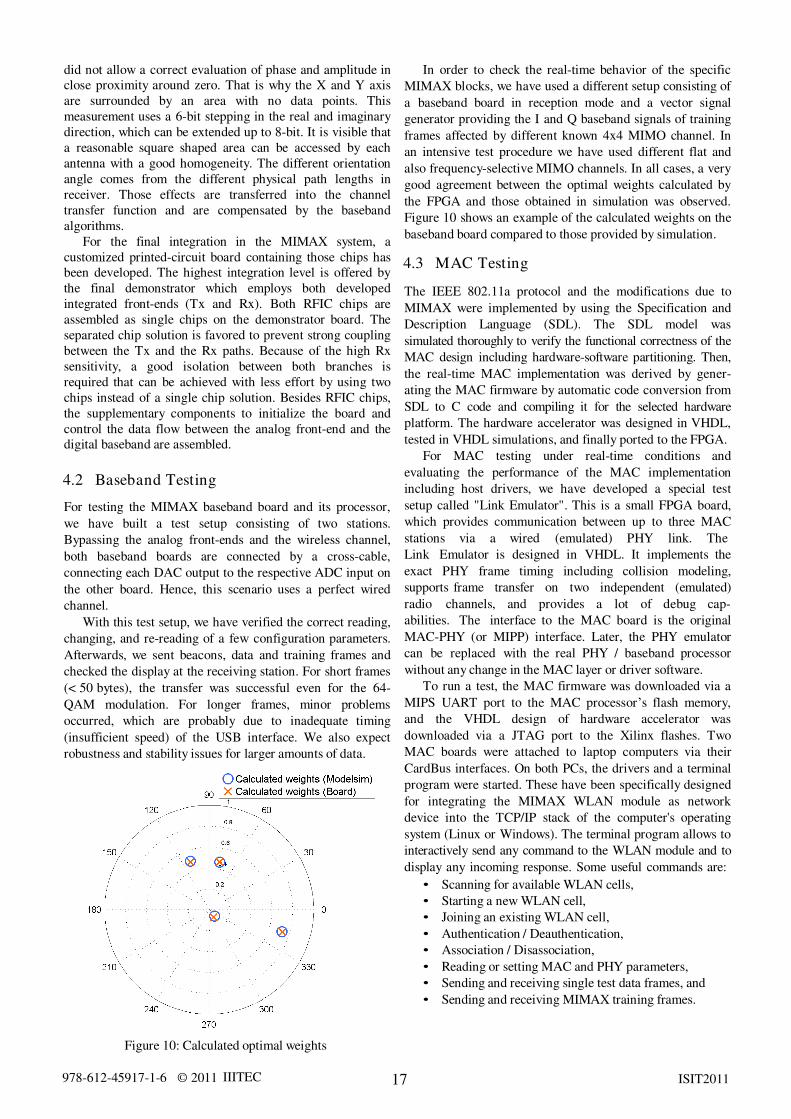
Figure 10: Calculated optimal weights
In order to check the real-time behavior of the specific
MIMAX blocks, we have used a different setup consisting of
a baseband board in reception mode and a vector signal
generator providing the I and Q baseband signals of training
frames affected by different known 4x4 MIMO channel. In
an intensive test procedure we have used different flat and
also frequency-selective MIMO channels. In all cases, a very
good agreement between the optimal weights calculated by
the FPGA and those obtained in simulation was observed.
Figure 10 shows an example of the calculated weights on the
baseband board compared to those provided by simulation.
4.3 MAC Testing
The IEEE 802.11a protocol and the modifications due to
MIMAX were implemented by using the Specification and
Description Language (SDL). The SDL model was
simulated thoroughly to verify the functional correctness of the
MAC design including hardware-software partitioning. Then,
the real-time MAC implementation was derived by gener-
ating the MAC firmware by automatic code conversion from
SDL to C code and compiling it for the selected hardware
platform. The hardware accelerator was designed in VHDL,
tested in VHDL simulations, and finally ported to the FPGA.
For MAC testing under real-time conditions and
evaluating the performance of the MAC implementation
including host drivers, we have developed a special test
setup called "Link Emulator". This is a small FPGA board,
which provides communication between up to three MAC
stations via a wired (emulated) PHY link. The
Link Emulator is designed in VHDL. It implements the
exact PHY frame timing including collision modeling,
supports frame transfer on two independent (emulated)
radio channels, and provides a lot of debug cap-
abilities. The interface to the MAC board is the original
MAC-PHY (or MIPP) interface. Later, the PHY emulator
can be replaced with the real PHY / baseband processor
without any change in the MAC layer or driver software.
To run a test, the MAC firmware was downloaded via a
MIPS UART port to the MAC processorÓs flash memory,
and the VHDL design of hardware accelerator was
downloaded via a JTAG port to the Xilinx flashes. Two
MAC boards were attached to laptop computers via their
CardBus interfaces. On both PCs, the drivers and a terminal
program were started. These have been specifically designed
for integrating the MIMAX WLAN module as network
device into the TCP/IP stack of the computer's operating
system (Linux or Windows). The terminal program allows to
interactively send any command to the WLAN module and to
display any incoming response. Some useful commands are:
" Scanning for available WLAN cells,
" Starting a new WLAN cell,
" Joining an existing WLAN cell,
" Authentication / Deauthentication,
" Association / Disassociation,
" Reading or setting MAC and PHY parameters,
" Sending and receiving single test data frames, and
" Sending and receiving MIMAX training frames.
978-612-45917-1-6 © 2011 IIITEC 18 ISIT2011
When a WLAN connection has been set up, it is possible
to activate a TAP device to integrate the WLAN link as
network connection into the operating system's network
stack. Then, the remote PC can be reached with all normal
network commands like ping, sftp, ssh, etc. Our standard test
application was the transfer of a video stream from one PC
to the other.
4.4 Demonstrator Testing
A laptop demonstrator for trying out the complete MIMAX
system (antenna array, analog front-end board, baseband
board, MAC board, and WLAN driver) has finally been
assembled. The purpose is to debug, improve, and verify the
system in real-time conditions and to prove its better
performance (as well as, the compatibility) in comparison
with the standard 802.11a WLAN. The baseband and analog
front-end boards have been mounted into the housing which
was developed to make the MIMAX demonstrator laptop-
compact and small. A photo of the system test setup is
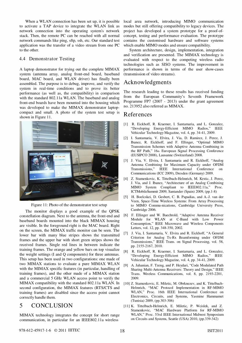
shown in Figure 11.
Figure 11: Photo of the demonstrator test setup
The monitor displays a good example of the QPSK
constellation diagram. Next to the antenna, the front-end and
baseband boards mounted into the black MIMAX housing
are visible. In the foreground right is the MAC board. Right
on the screen, the MIMAX traffic monitor can be seen. The
lower bar with many blue stripes shows the transmitted
frames and the upper bar with short green stripes shows the
received frames. Single red lines in between indicate the
training frames. The orange and yellow bars on top visualize
the weight settings (I and Q components) for three antennas.
This setup has been used in two configurations: one made of
two MIMAX stations to evaluate a pure MIMAX WLAN
with the MIMAX specific features (in particular, handling of
training frames), and the other made of a MIMAX station
and a commercial 5 GHz WLAN access point to verify the
MIMAX compatibility with the standard 802.11a WLAN. In
second configuration, the MIMAX features (RTS/CTS and
training frames) are disabled since the access point cannot
correctly handle them.
5 CONCLUSION
MIMAX technology integrates the concept for short range
communication, in particular for an IEEE802.11a wireless
local area network, introducing MIMO communication
modes but still offering compatibility to legacy devices. The
project has developed a system prototype for a proof-of-
concept, testing and performance evaluation. The prototype
contains the customised hardware and software systems
which enable MIMO modes and ensure compatibility.
System architecture, design, implementation, integration
and verification are presented. The MIMAX technology is
evaluated with respect to the competing wireless radio
technologies such as SISO systems. The improvement in
performance is shown in terms of the user show-cases
(transmission of video streams).
Acknowledgments
The research leading to these results has received funding
from the European CommunityÓs Seventh Framework
Programme FP7 (2007 - 2013) under the grant agreement
no. 213952 also referred as MIMAX.
References [1] R. Eickhoff, R. Kraemer, I. Santamaria, and L. Gonzalez,
ÐDeveloping Energy-Efficient MIMO Radios,Ñ IEEE
Vehicular Technology Magazine, vol. 4, pp. 34-41, 2009.
[2] I. Santamaria, V. Elvira, J. Via, D. Ramirez, J. Perez, J.
Ibanez, R. Eickhoff, and F. Ellinger, ÐOptimal MIMO
Transmission Schemes with Adaptive Antenna Combining in
the RF Path,Ñ 16th European Signal Processing Conference (EUSIPCO 2008), Lausanne (Switzerland) 2008.
[3] J. Via, V. Elvira, I. Santamaria and R. Eickhoff, ÐAnalog Antenna Combining for Maximum Capacity under OFDM
Transmissions,Ñ IEEE International Conference on
Communications (ICC 2009), Dresden (Germany) 2009.
[4] Z. Stamenkovic, K. Tittelbach-Helmrich, M. Krstic, J. Perez, J. Via, and J. Ibanez, ÐArchitecture of an Analog Combining
MIMO System Compliant to IEEE802.11a,Ñ Proc.
ICTMobileSummit 2009, Santander (Spain) 2009, (pp.1-8)
[5] H. Boelcskei, D. Gesbert, C. B. Papadias, and A.-J. van der Veen, Space-Time Wireless Systems: From Array Processing
to MIMO Commu-nications, Cambridge University Press,
Cambridge 2006.
[6] F. Ellinger and W. Baechtold, ÐAdaptive Antenna Receiver Module for WLAN at C-Band with Low Power
Consumption,Ñ IEEE Microwave and Wireless Components Letters, vol. 12, pp. 348-350, 2002.
[7] J. Via, I. Santamaria, V. Elvira and R. Eickhoff, ÐA General
Criterion for Analog Tx-Rx Beamforming under OFDM Transmissions,Ñ IEEE Trans. on Signal Processing, vol. 58,
pp. 2155-2167, 2010.
[8] R. Eickhoff, R. Kraemer, I. Santamaria, and L. Gonzalez, ÐDeveloping Energy-Efficient MIMO Radios,Ñ IEEE
Vehicular Technology Magazine, vol. 4, pp. 34-41, 2009.
[9] A. Jahanian, F. Tzeng, and P. Heydari, ÐCode Modulated Path
Sharing Multi-Antenna Receivers: Theory and Design,Ñ IEEE
Trans. Wireless Communications, vol. 8, pp. 2193-2201,
2009.
[10] Z. Stamenkovic, E. Miletic, M. Obrknezev, and K. Tittelbach- Helmrich, ÐMAC Protocol Implementation in RF-MIMO
WLAN,Ñ" Proc. 16th IEEE International Conference on
Electronics, Circuits, and Systems, Yasmine Hammamet
(Tunisia) 2009, (pp.303-306)
[11] K. Tittelbach-Helmrich, E. Miletic, P. Wcislek, and Z. Stamenkovic, ÐMAC Hardware Platform for RF-MIMO
WLAN,Ñ Proc. 53rd IEEE International Midwest Symposium
on Circuits and Systems, Seattle (USA) 2010, (pp.339-342)
978-612-45917-1-6 © 2011 IIITEC 19 ISIT2011
[12] Innovations for High Performance microelectronics,
http://www.ihp-microelectronics.com
[13] V. Elvira, J. Ibanez, I. Santamaria, M. Krstic, K. Tittelbach- Helmrich, and Z. Stamenkovic, ÐBaseband Processor for RF-
MIMO WLAN,Ñ" uubmitted to 17th IEEE International
Conference on Electronics, Circuits, and Systems, Athens
(Greece), December 2010.
[14] F. Gholam, J. Via, I. Santamaria, M. Wickert, and R. Eickhoff, ÐSimplified Architectures for Analogue Antenna
Combining,Ñ"" Proc. 18th ICT MobileSummit, Santander
(Spain) 2009.
[15] N. Joram, U. Mayer, R. Eickhoff, and F. Ellinger, ÐFully Integrated Active CMOS Vector Modulator for 802.11a
Compliant Diversity Transceivers,Ñ Proc. International IEEE
Conference on Microwaves, Communications, Antennas and
Electronic System, Tel-Aviv (Israel) 2009.
[16] R. Eickhoff, K. Tittelbach-Helmrich, M. Wickert, J. Wagner,
U. Mayer, V. Elvira, J. Ibanez, Z. Stamenkovic, and F.
Ellinger, ÐPhysical Layer Amendments for MIMO Features in
802.11cÑ, Proc. Future Network and MobileSummit 2011,
Warsaw (Poland) 2011, (pp.1-8)
[17] O. Gago, L. Gonzalez, and R. Eickhoff, ÐStudy of the Optimum Number of Radiating Elements for Different
Portable Devices Operating in a MIMO System,Ñ" Proc. the
European Wireless Conference, Aalborg (Denmark) 2009.
[18] O. Gago, L. Gonzalez, R. Eickhoff, and I. Santamaria,
ÐMIFA: Modified IFA Radiating Element for Small Handheld Devices,Ñ" Proc. the 18th ICT MobileSummit, Santander
(Spain) 2009.
[19] Cushcraft Corporation, ÐAntenna Polarization Considerations in Wireless Communications Systems,Ñ"1999-2002.