Filter Bank Multicarrier in Massive MIMO - CORE
14
IEEE TRANSACTIONS ON SIGNAL PROCESSING, VOL. 66, NO. 15, AUGUST 1, 2018 3987 Filter Bank Multicarrier in Massive MIMO: Analysis and Channel Equalization Amir Aminjavaheri , Arman Farhang , and Behrouz Farhang-Boroujeny , Senior Member, IEEE Abstract—We perform an asymptotic study of the performance of filter bank multicarrier in the context of massive multi-input multi-output. We show that the effects of channel distortions, i.e., intersymbol interference and intercarrier interference, do not vanish as the base station (BS) array size increases. As a result, the signal-to-interference-plus-noise ratio (SINR) cannot grow un- boundedly by increasing the number of BS antennas, and is upper bounded by a certain deterministic value. We show that this phe- nomenon is a result of the correlation between the multiantenna combining tap values and the channel impulse responses between the mobile terminals and the BS antennas. To resolve this problem, we introduce an efficient equalization method that removes this correlation, enabling us to achieve arbitrarily large SINR values by increasing the number of BS antennas. We perform a thorough analysis of the proposed system and find analytical expressions for both equalizer coefficients and the respective SINR. Index Terms—Massive MIMO, FBMC/OQAM, OFDM, SINR, channel equalization, asymptotic analysis. I. INTRODUCTION M ASSIVE multiple-input multiple-output (MIMO) is one of the primary technologies currently considered for the next generation of wireless networks, [2]. In a massive MIMO system, the base station (BS) is equipped with a large number of antenna elements, in the order of hundreds or more, and is simultaneously serving tens of mobile terminals (MTs). By coherent processing of the signals over the BS antennas, the effects of uncorrelated noise and multiuser interference can be made arbitrarily small as the BS array size increases, [3], [4]. Hence, unprecedented network capacities can be achieved. Filter bank multicarrier (FBMC) is a waveform that has gained an increased attention in the recent years due to its im- proved spectral properties compared to orthogonal frequency di- vision multiplexing (OFDM), [5]–[7]. The application of FBMC Manuscript received June 17, 2017; revised April 4, 2018 and May 10, 2018; accepted June 5, 2018. Date of publication June 15, 2018; date of current version June 22, 2018. The associate editor coordinating the review of this manuscript and approving it for publication was Prof. Marios Kountouris. This work was supported in part by a research grant from Science Foundation Ireland (SFI) and in part by the European Regional Development Fund under Grant 13/RC/2077. This paper was presented in part at the IEEE International Conference on Com- munications, Paris, May 2017 [1]. (Corresponding author: Amir Aminjavaheri.) A. Aminjavaheri and B. Farhang-Boroujeny are with the Electrical and Com- puter Engineering Department, University of Utah, Salt Lake City, UT 84112 USA (e-mail:, [email protected]; [email protected]). A. Farhang is with the School of Electrical and Electronic Engineering, University College Dublin, Dublin4, Ireland (e-mail:, [email protected]). Color versions of one or more of the figures in this paper are available online at http://ieeexplore.ieee.org. Digital Object Identifier 10.1109/TSP.2018.2846263 to massive MIMO channels has been recently studied in [8], where its so-called self-equalization property leading to a chan- nel flattening effect was reported through simulations. Accord- ing to this property, the effects of channel distortions (i.e., inter- symbol interference and intercarrier interference) will diminish by increasing the number of BS antennas. The authors in [9] obtain the asymptotic mean squared error (MSE) performance of FBMC in massive MIMO channels. Their analysis shows that the MSE becomes uniform across different subcarriers as a result of the channel hardening effect. In [10], multi-tap equalization per subcarrier is proposed for FBMC-based massive MIMO sys- tems to improve the equalization accuracy as compared to the single-tap equalization at the expense of a higher computational complexity. The authors in [11] show that the pilot contami- nation problem in multi-cellular massive MIMO networks, [3], can be resolved in a straightforward manner with FBMC signal- ing due to its special structure. These studies prove that FBMC is an appropriate match for massive MIMO and vice versa as they can both bring pivotal properties into the picture of the next generations of wireless systems. Specifically, this combination is of a great importance as not only the same spectrum is being simultaneously utilized by all the users but it is also used in a more efficient manner compared to OFDM. Since the literature on FBMC-based massive MIMO is not mature yet, these systems need to go through meticulous anal- ysis and investigation. In particular, in this paper, we perform an in-depth analysis on the performance of FBMC in massive MIMO channels. The focus of this paper is on the uplink trans- mission, while the theories and proposed techniques are trivially applicable to the downlink as well. We consider single-tap equal- ization per subcarrier, and investigate the performance of three most prominent linear combiners, namely, maximum-ratio com- bining (MRC), zero-forcing (ZF), and minimum mean-square error (MMSE). We show that the self-equalization property shown through simulations and claimed in [8] and [10] is not very accurate. More specifically, by increasing the number of BS antennas, the channel distortions average out only up to a certain extent, but not completely. Thus, the SINR saturates at a certain deterministic level. This determines an upper bound for the SINR performance of the system. Our main contributions in this paper are the following; (i) We derive an analytical expression for the SINR saturation level using MRC, ZF, and MMSE combiners. (ii) We propose an effective equalization method to resolve the saturation problem. With the proposed equalizer in place, SINR grows without a bound by increasing the BS array size, and arbitrarily large 1053-587X © 2018 IEEE. Personal use is permitted, but republication/redistribution requires IEEE permission. See http://www.ieee.org/publications standards/publications/rights/index.html for more information. Authorized licensed use limited to: Maynooth University Library. Downloaded on August 31,2020 at 10:36:42 UTC from IEEE Xplore. Restrictions apply. brought to you by CORE View metadata, citation and similar papers at core.ac.uk provided by MURAL - Maynooth University Research Archive Library
-
Upload
khangminh22 -
Category
Documents
-
view
1 -
download
0
Transcript of Filter Bank Multicarrier in Massive MIMO - CORE

IEEE TRANSACTIONS ON SIGNAL PROCESSING, VOL. 66, NO. 15, AUGUST 1, 2018 3987
Filter Bank Multicarrier in Massive MIMO:Analysis and Channel Equalization
Amir Aminjavaheri , Arman Farhang , and Behrouz Farhang-Boroujeny , Senior Member, IEEE
Abstract—We perform an asymptotic study of the performanceof filter bank multicarrier in the context of massive multi-inputmulti-output. We show that the effects of channel distortions,i.e., intersymbol interference and intercarrier interference, do notvanish as the base station (BS) array size increases. As a result,the signal-to-interference-plus-noise ratio (SINR) cannot grow un-boundedly by increasing the number of BS antennas, and is upperbounded by a certain deterministic value. We show that this phe-nomenon is a result of the correlation between the multiantennacombining tap values and the channel impulse responses betweenthe mobile terminals and the BS antennas. To resolve this problem,we introduce an efficient equalization method that removes thiscorrelation, enabling us to achieve arbitrarily large SINR valuesby increasing the number of BS antennas. We perform a thoroughanalysis of the proposed system and find analytical expressions forboth equalizer coefficients and the respective SINR.
Index Terms—Massive MIMO, FBMC/OQAM, OFDM, SINR,channel equalization, asymptotic analysis.
I. INTRODUCTION
MASSIVE multiple-input multiple-output (MIMO) is oneof the primary technologies currently considered for the
next generation of wireless networks, [2]. In a massive MIMOsystem, the base station (BS) is equipped with a large numberof antenna elements, in the order of hundreds or more, andis simultaneously serving tens of mobile terminals (MTs). Bycoherent processing of the signals over the BS antennas, theeffects of uncorrelated noise and multiuser interference can bemade arbitrarily small as the BS array size increases, [3], [4].Hence, unprecedented network capacities can be achieved.
Filter bank multicarrier (FBMC) is a waveform that hasgained an increased attention in the recent years due to its im-proved spectral properties compared to orthogonal frequency di-vision multiplexing (OFDM), [5]–[7]. The application of FBMC
Manuscript received June 17, 2017; revised April 4, 2018 and May 10, 2018;accepted June 5, 2018. Date of publication June 15, 2018; date of current versionJune 22, 2018. The associate editor coordinating the review of this manuscriptand approving it for publication was Prof. Marios Kountouris. This work wassupported in part by a research grant from Science Foundation Ireland (SFI) andin part by the European Regional Development Fund under Grant 13/RC/2077.This paper was presented in part at the IEEE International Conference on Com-munications, Paris, May 2017 [1]. (Corresponding author: Amir Aminjavaheri.)
A. Aminjavaheri and B. Farhang-Boroujeny are with the Electrical and Com-puter Engineering Department, University of Utah, Salt Lake City, UT 84112USA (e-mail:,[email protected]; [email protected]).
A. Farhang is with the School of Electrical and Electronic Engineering,University College Dublin, Dublin4, Ireland (e-mail:,[email protected]).
Color versions of one or more of the figures in this paper are available onlineat http://ieeexplore.ieee.org.
Digital Object Identifier 10.1109/TSP.2018.2846263
to massive MIMO channels has been recently studied in [8],where its so-called self-equalization property leading to a chan-nel flattening effect was reported through simulations. Accord-ing to this property, the effects of channel distortions (i.e., inter-symbol interference and intercarrier interference) will diminishby increasing the number of BS antennas. The authors in [9]obtain the asymptotic mean squared error (MSE) performanceof FBMC in massive MIMO channels. Their analysis shows thatthe MSE becomes uniform across different subcarriers as a resultof the channel hardening effect. In [10], multi-tap equalizationper subcarrier is proposed for FBMC-based massive MIMO sys-tems to improve the equalization accuracy as compared to thesingle-tap equalization at the expense of a higher computationalcomplexity. The authors in [11] show that the pilot contami-nation problem in multi-cellular massive MIMO networks, [3],can be resolved in a straightforward manner with FBMC signal-ing due to its special structure. These studies prove that FBMCis an appropriate match for massive MIMO and vice versa asthey can both bring pivotal properties into the picture of the nextgenerations of wireless systems. Specifically, this combinationis of a great importance as not only the same spectrum is beingsimultaneously utilized by all the users but it is also used in amore efficient manner compared to OFDM.
Since the literature on FBMC-based massive MIMO is notmature yet, these systems need to go through meticulous anal-ysis and investigation. In particular, in this paper, we performan in-depth analysis on the performance of FBMC in massiveMIMO channels. The focus of this paper is on the uplink trans-mission, while the theories and proposed techniques are triviallyapplicable to the downlink as well. We consider single-tap equal-ization per subcarrier, and investigate the performance of threemost prominent linear combiners, namely, maximum-ratio com-bining (MRC), zero-forcing (ZF), and minimum mean-squareerror (MMSE). We show that the self-equalization propertyshown through simulations and claimed in [8] and [10] is notvery accurate. More specifically, by increasing the number ofBS antennas, the channel distortions average out only up to acertain extent, but not completely. Thus, the SINR saturates at acertain deterministic level. This determines an upper bound forthe SINR performance of the system.
Our main contributions in this paper are the following; (i)We derive an analytical expression for the SINR saturation levelusing MRC, ZF, and MMSE combiners. (ii) We propose aneffective equalization method to resolve the saturation problem.With the proposed equalizer in place, SINR grows without abound by increasing the BS array size, and arbitrarily large
1053-587X © 2018 IEEE. Personal use is permitted, but republication/redistribution requires IEEE permission.See http://www.ieee.org/publications standards/publications/rights/index.html for more information.
Authorized licensed use limited to: Maynooth University Library. Downloaded on August 31,2020 at 10:36:42 UTC from IEEE Xplore. Restrictions apply.
brought to you by COREView metadata, citation and similar papers at core.ac.uk
provided by MURAL - Maynooth University Research Archive Library

3988 IEEE TRANSACTIONS ON SIGNAL PROCESSING, VOL. 66, NO. 15, AUGUST 1, 2018
SINR values are achievable. (iii) An efficient implementation ofthe proposed equalization method through using some conceptsfrom multi-rate signal processing is also presented. (iv) Finally,we perform a thorough analysis of the proposed system, andfind the analytical expressions for the SINR in the cases ofMRC and ZF detectors. All the above analyses are evaluatedand confirmed through numerical simulations.
It is worth mentioning that although the theories developed inthis paper are applicable to all types of FBMC systems, the for-mulations are based on the most common type in the literaturethat was developed by Saltzberg, [12], and is known by differentnames including OFDM with offset quadrature amplitude mod-ulation (OFDM/OQAM), FBMC/OQAM, and staggered multi-tone (SMT), [5]. Throughout this paper, we refer to it as FBMCfor simplicity.
The rest of the paper is organized as follows. To pave theway for the derivations presented in the paper, we review theFBMC principles in Section II. In Section III, we present theasymptotic equivalent channel model between the mobile ter-minals and the BS in an FBMC massive MIMO setup. Thisanalysis will lead to an upper bound for the SINR performanceof the system. Our proposed equalization method is introducedin Section IV. In Section V, we study the FBMC in massiveMIMO from a frequency-domain perspective, leading to someinsightful remarks regarding these systems. In Section VI, wefind the SINR performance of the FBMC system incorporatingthe proposed equalization method. The mathematical analysisof the paper as well as the efficacy of the proposed filter designtechnique are numerically evaluated in Section VII. Finally, weconclude the paper in Section VIII.
Notations: Matrices, vectors and scalar quantities are denotedby boldface uppercase, boldface lowercase and normal letters,respectively. Am,n represents the element in the mth row andthe nth column of A and A−1 signifies the inverse of A. IM
is the identity matrix of size M × M , and D = diag{a} is adiagonal matrix whose diagonal elements are formed by theelements of the vector a. The superscripts (·)T , (·)H and (·)∗ in-dicate transpose, conjugate transpose, and conjugate operations,respectively. The linear convolution is denoted by �. The realand imaginary parts of a complex number are denoted by �{·}and �{·}, respectively. E{·} denotes the expected value of arandom variable, and tr{·} is the matrix trace operator. The no-tation CN (0, σ2) represents the circularly-symmetric complexnormal distribution with zero mean and variance σ2 . Finally, δij
represents the Kronecker delta function.
II. FBMC PRINCIPLES
We present the theory of FBMC in discrete time. Let dm,n
denote the real-valued data symbol transmitted over the mthsubcarrier and the nth symbol time index. The total number ofsubcarriers is assumed to be M . In order to avoid interferencebetween the symbols and, thus, maintain the orthogonality, thedata symbol dm,n is phase adjusted using the phase term ejθm , n ,where θm,n = π
2 (m + n). Accordingly, each symbol has a ± π2
phase difference with its adjacent neighbors in both time andfrequency. The symbols are then pulse-shaped using a prototypefilter f [l], which has been designed such that q[l] = f [l] � f ∗[−l]
is a Nyquist pulse with zero crossings at M sample intervals.The length of the prototype filter, f [l], is usually expressed asLf = κM , where κ is called the overlapping factor.1 To expressthe above procedure in a mathematical form, the discrete-timeFBMC waveform can be written as, [13],
x[l] =+∞∑
n=−∞
M −1∑
m=0
dm,nam,n [l], (1)
where
am,n [l] = fm [l − nM/2]ejθm , n . (2)
Here, fm [l] � f [l]ej 2 π m lM is the prototype filter modulated to
the center frequency of the mth subcarrier, and the functionsam,n [l], for m ∈ {0, . . . , M − 1} and n ∈ {−∞, . . . ,+∞},can be thought as a set of basis functions that are used to modu-late the data symbols. Note that the spacing between successivesymbols in the time domain is M/2 samples. In the frequencydomain, the spacing between successive subcarriers is 1/M innormalized frequency scale. It can be shown that the basis func-tions am,n [l] are orthogonal in the real domain, [13], i.e.,
〈am,n [l], am ′,n ′ [l]〉� = �{ +∞∑
l=−∞am,n [l]a∗
m ′,n ′ [l]}
= δmm ′δnn ′ . (3)
As a result, the data symbols can be extracted from the synthe-sized signal, x[l], according to
dm,n = 〈x[l], am,n [l]〉�. (4)
Fig. 1 shows the block diagram of the FBMC transceiver. Notethat considering the transmitter prototype filter f [l], and the re-ceiver prototype filter f ∗[−l], the overall effective pulse shapeq[l] = f [l] � f ∗[−l] is a Nyquist pulse by design. Also, in prac-tice, in order to efficiently implement the synthesis (transmitterside) and analysis (receiver side) filter banks, one can incorpo-rate the polyphase implementation to reduce the computationalcomplexity, [5].
The presence of a frequency-selective channel leads to somedistortion in the received signal. Thus, one may adopt some sortof equalization to retrieve the transmitted symbols at the receiverside. In this paper, we limit our study to a case where the channelimpulse response remains time-invariant over the interval ofinterest. Accordingly, the received signal at the receiver can beexpressed as
y[l] = h[l] � x[l] + ν[l], (5)
where h[l] represents the channel impulse response, and ν[l]is the additive white Gaussian noise (AWGN). We denote thelength of the channel impulse response by Lh .
At the receiver, after matched filtering and phase compensa-tion, and before taking the real part (see Fig. 1), the demodulatedsignal ym,n can be expressed as
ym,n =+∞∑
n ′=−∞
M −1∑
m ′=0
Hmm ′,nn ′dm ′,n ′ + νm,n , (6)
1The overlapping factor indicates the number of adjacent FBMC symbolsoverlapping in the time domain.
Authorized licensed use limited to: Maynooth University Library. Downloaded on August 31,2020 at 10:36:42 UTC from IEEE Xplore. Restrictions apply.

AMINJAVAHERI et al.: FILTER BANK MULTICARRIER IN MASSIVE MIMO: ANALYSIS AND CHANNEL EQUALIZATION 3989
Fig. 1. Block diagram of the FBMC transceiver in discrete time.
Fig. 2. The equivalent channel between the transmitted data symbol at time-frequency point (m′, n′) and the demodulated symbol at time-frequency point(m, n).
where νm,n is the noise contribution, and the interference coef-ficient Hmm ′,nn ′ can be calculated according to
Hmm ′,nn ′ = hmm ′ [n − n′]ej (θm ′ , n ′−θm , n ) , (7a)
hmm ′ [n] =(fm ′ [l] � h[l] � f ∗
m [−l])
↓M2
. (7b)
The symbol ↓ M2 denotes M
2 -fold decimation. In (7), hmm ′ [n] isthe equivalent channel impulse response between the transmit-ted symbols at subcarrier m′ and the received ones at subcarrierm. This includes the effects of the transmitter filtering, the mul-tipath channel, and the receiver filtering; see Fig. 2. Accordingto (6), the demodulated symbol ym,n suffers from interferenceoriginating from other time-frequency symbols. In practice, theprototype filter f [l] is designed to be well localized in timeand frequency. As a result, the interference is limited to a smallneighborhood of time-frequency points around the desired point(m,n).
In order to devise a simple equalizer to combat the frequency-selective effect of the channel, it is usually assumed that thesymbol period M/2 is much larger than the channel lengthLh , or equivalently, the channel frequency response is approxi-mately flat over each subcarrier band. With this assumption, thedemodulated signal ym,n can be expressed as, [14],
ym,n ≈ Hm
(dm,n + um,n
)+ νm,n , (8)
where Hm �∑Lh −1
l=0 h[l]e−j 2 π m lM is the channel frequency re-
sponse at the center of the mth subcarrier. The term um,n iscalled the intrinsic interference and is purely imaginary. Thisterm represents the contribution of the intersymbol interference(ISI) and intercarrier interference (ICI) from the adjacent time-frequency symbols around the desired point (m,n). Based on(8), the effect of channel distortions can be compensated using asingle-tap equalizer per subcarrier. After equalization, what re-mains is the real-valued data symbol dm,n , the imaginary term
um,n , and the noise contribution. By taking the real part fromthe equalized symbol, one can remove the intrinsic interferenceand obtain an estimate of dm,n .
It should be noted that the performance of the above single-tapequalization primarily depends on the validity of the assumptionthat the symbol duration is much larger than the channel length,or equivalently, the frequency response of the channel is approx-imately flat over the pass-band of each subcarrier. On the otherhand, in highly frequency-selective channels, where the aboveassumption is not accurate any more, more advanced multi-tap equalization methods (see [6], [15]) should be deployed tocounteract the multipath channel distortions.
III. MASSIVE MIMO FBMC: ASYMPTOTIC ANALYSIS
In this section, we first extend the formulation of the previoussection to massive MIMO channels. Then, we show that linearcombining of the signals received at the BS antennas using thechannel frequency coefficients leads to a residual interferencethat does not fade away even with an infinite number of BSantennas. Hence, we conclude, the SINR is upper bounded bya certain deterministic value, and arbitrarily large SINR per-formances cannot be achieved as the number of BS antennasgrows.
We consider a single-cell massive MIMO setup [3], withK single-antenna MTs that are simultaneously communicatingwith a BS equipped with an array of N antenna elements. Asmentioned earlier, in this paper, we consider the uplink transmis-sion while the results and our proposed technique are triviallyapplicable to the downlink transmission as well.
Let xk [l] represent the transmit signal of the terminal k. Thereceived signal at the ith BS antenna can be expressed as
yi [l] =K−1∑
k=0
xk [l] � hi,k [l] + νi [l], (9)
Authorized licensed use limited to: Maynooth University Library. Downloaded on August 31,2020 at 10:36:42 UTC from IEEE Xplore. Restrictions apply.

3990 IEEE TRANSACTIONS ON SIGNAL PROCESSING, VOL. 66, NO. 15, AUGUST 1, 2018
where hi,k [l] is the channel impulse response between the kthterminal and the ith BS antenna, and νi [l] is the additive noiseat the input of the ith BS antenna. We assume that the samplesof the noise signal νi [l] are a set of independent and identicallydistributed (i.i.d.) CN (0, σ2
ν ) random variables.For a given terminal k, we model the corresponding chan-
nel responses using the channel power delay profile (PDP)pk [l], l = 0, . . . , Lh − 1. In particular, we assume that the chan-nel tap hi,k [l], l ∈ {0, . . . , Lh − 1}, follows a CN (0, pk [l]) dis-tribution, and different taps are assumed to be independent. Theabove assumption implies that the BS antenna array is suffi-ciently compact so that the channel responses corresponding toa particular user and different BS antennas are subject to thesame channel PDP. We also assume that the channels corre-sponding to different terminals and different BS antennas areindependent. Moreover, for each terminal, the average transmit-ted power is assumed to be equal to one, i.e., E{|xk [l]|2} = 1.To simplify the analysis throughout the paper, we assume thatthe BS has a perfect knowledge of the channel state information(CSI).
Following (9), we can extend (6) to the MIMO case accordingto
ym,n =+∞∑
n ′=−∞
M −1∑
m ′=0
Hmm ′,nn ′dm ′,n ′ + νm,n , (10)
where ym,n is an N × 1 vector containing the demodulatedsymbols corresponding to different BS antennas, dm,n is aK × 1 vector containing the real-valued data symbols of allthe K terminals transmitted at the mth subcarrier and the nthtime instant, νm,n is the noise contribution across different BSantennas, and Hmm ′,nn ′ is an N × K channel matrix. The ele-ment (i, k) of Hmm ′,nn ′ can be calculated according to
Hi,kmm ′,nn ′ = hi,k
mm ′ [n − n′]ej (θm ′ , n ′−θm , n ) , (11a)
hi,kmm ′ [n] =
(fm ′ [l] � hi,k [l] � f ∗
m [−l])
↓M2
. (11b)
We assume that the BS uses a single-tap equalizer per antennaper subcarrier. Accordingly, combining the elements of ym,n
using an N × K matrix Wm , and taking the real part from theresulting signal, the estimate of the transmitted data symbols forall the terminals can be obtained as
dm,n = �{WHmym,n
}
= �{
+∞∑
n ′=−∞
M −1∑
m ′=0
WHmHmm ′,nn ′dm ′,n ′ + WH
mνm,n
}
= �{
+∞∑
n ′=−∞
M −1∑
m ′=0
Gmm ′,nn ′dm ′,n ′ + ν ′m,n
}, (12)
where Gmm ′,nn ′ � WHmHmm ′,nn ′ , and ν ′
m,n � WHmνm,n .
Here, we examine MRC, ZF, and MMSE linear combiners.These combiners can be formed as
Wm =
⎧⎪⎨
⎪⎩
HmD−1m , for MRC,
Hm
(HH
mHm
)−1, for ZF,
Hm
(HH
mHm + σ2ν IK
)−1, for MMSE,
(13)
where Hm is the channel coefficient matrix at the center of themth subcarrier, i.e., Hi,k
m �∑Lh −1
l=0 hi,k [l]e−j 2 π m lM . In MRC,
Dm is a K × K diagonal matrix with the kth diagonal elementgiven by Dk,k
m =∑N −1
i=0 |Hi,km |2 . The role of Dm is to normal-
ize the amplitude of the MRC output. Without this term, theamplitude grows linearly without a bound as the number of BSantennas increases.
We note that for large number of BS antennas N and usingthe law of large numbers, Dm tends to NIK . Similarly, when Ngrows large and due to the law of large numbers, HH
mHm tendsto NIK , [16]. Hence, all of the above combiners tend to 1
N Hm ,i.e., matched filter, as the number of BS antennas increases, [16].Therefore, in the following, to find the various interference termsin the asymptotic regime, i.e., as the number of BS antennasN approaches infinity, we consider matched filter (MF) multi-antenna combining according to Wm = 1
N Hm .Before we continue, we recall the following result from
probability theory, paving the way for our upcoming deriva-tions. Let a = [a1 , . . . , an ]T and b = [b1 , . . . , bn ]T be two ran-dom vectors each containing i.i.d. elements. Moreover, assumethat the ith elements of a and b are correlated according toE{a∗
i bi
}= Cab , i = 1, . . . , n. Consequently, according to the
law of large numbers, the sample mean 1n aHb = 1
n
∑ni=1 a∗
i bi
converges almost surely to the distribution mean Cab as n tendsto infinity.
In the asymptotic regime, i.e., as N tends to infinity, theelements of Gmm ′,nn ′ = WH
mHmm ′,nn ′ can be calculated usingthe law of large numbers. In particular, as N grows large, theelement (k, k′) of Gmm ′,nn ′ converges almost surely to
Gk,k ′mm ′,nn ′ → E
{(Hi,k
m
)∗Hi,k ′
mm ′,nn ′
}. (14)
To calculate the right hand side of (14), we first find the equiva-lent time-domain channel impulse response after multi-antennacombining. In particular, let gk,k ′
mm ′ [n] denote the equivalent chan-nel impulse response between the transmitted symbols at sub-carrier m′ of terminal k′ and the received ones at subcarrierm of BS output corresponding to terminal k after combining.2
Following (11), we have
gk,k ′mm ′ [n] =
1N
N −1∑
i=0
(Hi,k
m
)∗(fm ′ [l] � hi,k ′ [l] � f ∗
m [−l])↓M
2.
(15)
Hence, as the number of BS antennas grows large, the asymp-totic equivalent channel response can be obtained using the lawof large numbers according to
gk,k ′mm ′ [n] → E
{(Hi,k
m
)∗ (fm ′ [l] � hi,k ′ [l] � f ∗
m [−l])↓M
2
}
=(fm ′ [l] � E
{(Hi,k
m
)∗hi,k ′ [l]
}� f ∗
m [−l])
↓M2
.
(16)
The above expression includes a correlation between the channelfrequency coefficient Hi,k
m and the channel impulse response
2Note that we have used the letters g and G, respectively, to denote theequivalent time and frequency channel coefficients after combining. On theother hand, letters h and H have been used in (11), to refer to the respectivechannel coefficients before combining.
Authorized licensed use limited to: Maynooth University Library. Downloaded on August 31,2020 at 10:36:42 UTC from IEEE Xplore. Restrictions apply.

AMINJAVAHERI et al.: FILTER BANK MULTICARRIER IN MASSIVE MIMO: ANALYSIS AND CHANNEL EQUALIZATION 3991
Fig. 3. Block diagram of the proposed receiver structure to resolve the saturation issue. Here, only the portion of the receiver corresponding to subcarrier m andterminal k is shown.
hi,k ′ [l]. This correlation can be calculated as
E{(
Hi,km
)∗hi,k ′ [l]
}=
Lh −1∑
=0
E{h∗
i,k []hi,k ′ [l]}
ej 2 π mM
= pk [l]ej 2 π l mM δkk ′ = pk,m [l]δkk ′ , (17)
where pk,m [l] � pk [l]ej 2 π l mM is the channel PDP of terminal k
modulated to the center frequency of the mth subcarrier. Theresult in (17) shows the correlation between the combiner tapsat the receiver and the channel impulse responses between MTsand the BS antennas. The following proposition states the impactof this correlation on the SINR at the receiver outputs.
Proposition 1: In an FBMC massive MIMO system, as thenumber of BS antennas tends to infinity, the effects of multiuserinterference and noise vanish. However, some residual ISI andICI from the same user remain even with infinite number ofBS antennas. In particular, for a given user k, the equivalentchannel impulse response between the transmitted data symbolsat subcarrier m′ and the received ones at subcarrier m tends to
gk,kmm ′ [n] →
(fm ′ [l] � pk,m [l] � f ∗
m [−l])
↓M2
, (18)
which is dependent on the channel PDP. As a result, the SINRconverges almost surely to
SINRkm,n → �2
{Gk,k
mm,nn
}∑+∞
n ′=−∞∑M −1
m ′=0(m ′,n ′) =(m,n)
�2{Gk,k
mm ′,nn ′} , (19)
where Gk,kmm ′,nn ′ = gk,k
mm ′ [n − n′]ej (θm ′ , n ′−θm , n ) . The abovevalue constitutes an upperbound for the SINR performanceof the system. Hence, arbitrarily large SINR values cannot beachieved by increasing the BS array size.
Proof: As suggested by (17), when k′ = k, the channel re-sponse tends to zero. Thus, multiuser interference tends to zero.A similar argument can be made for the additive noise. Thisresults from the law of large numbers and the fact that thecombiner coefficients are uncorrelated with the filtered noisesamples. When k′ = k, which implies the interference fromthe same user on itself, the channel response tends to (18).Notice that due to the presence of pk,m [l], the orthogonalitycondition of (3) does not hold anymore even with an infinitenumber of BS antennas. Consequently, some residual ISI andICI remain and cause the SINR to saturate at a deterministiclevel given in (19). �
We note that according to (14), the asymptotic SINR satura-tion results from the statistical correlation between the multi-antenna combiner taps and the interference coefficients. Thiscorrelation is an inherent property of FBMC-based massiveMIMO systems and is due to the transients of the channelimpulse response since no cyclic prefix (CP) is used. In par-ticular, when the multi-antenna combining is performed in thefrequency domain according to (13), such correlation appearsas a result of the leakage due to the absence of CP. This resultis general as a similar phenomenon also emerges in massiveMIMO systems based on OFDM without CP, [17].
IV. EQUALIZATION
As discussed in the previous section, even with an infinitenumber of BS antennas, some residual ICI and ISI remain dueto the correlation between the combiner taps and the channelimpulse responses between the MTs and the BS antennas. As asolution to this problem, in this section, we propose an efficientequalization method to remove the above correlation.
In (18), the problematic term that leads to the saturation is-sue is the modulated channel PDP, pk,m [l]. In the absence ofthis term, the channel response gk,k
mm ′ [n] =(fm ′ [l] � f ∗
m [−l])↓M
2
does not incur any interference provided that q[l] = f [l] �f ∗[−l] is a Nyquist pulse. This observation suggests that we canresolve the saturation issue by equalizing the effect of pk,m [l].Let Pk (ω) denote the discrete-time Fourier transform (DTFT) ofpk [l]. Similarly, we define Pk,m (ω) = Pk (ω − 2πm/M) as theDTFT of pk,m [l]. This observation implies that one can equalizethe effect of pk,m [l] by introducing a filter φk,m [l] with transferfunction
Φk,m (ω) =1
Pk,m (ω), (20)
in cascade with f ∗m [−l] to achieve the desired equivalent chan-
nel response gk,kmm ′ [n] → (
fm ′ [l] � f ∗m [−l]
)↓M
2in the asymptotic
regime. This modifies the receiver structure as illustrated inFig. 3.
Proposition 2: In an FBMC massive MIMO system, as thenumber of BS antennas tends to infinity and by using the pro-posed equalization method, the channel distortions, i.e., ICI andISI, as well as MUI and noise effects will disappear, and arbi-trarily large SINR performances can be achieved.
Authorized licensed use limited to: Maynooth University Library. Downloaded on August 31,2020 at 10:36:42 UTC from IEEE Xplore. Restrictions apply.
3992 IEEE TRANSACTIONS ON SIGNAL PROCESSING, VOL. 66, NO. 15, AUGUST 1, 2018
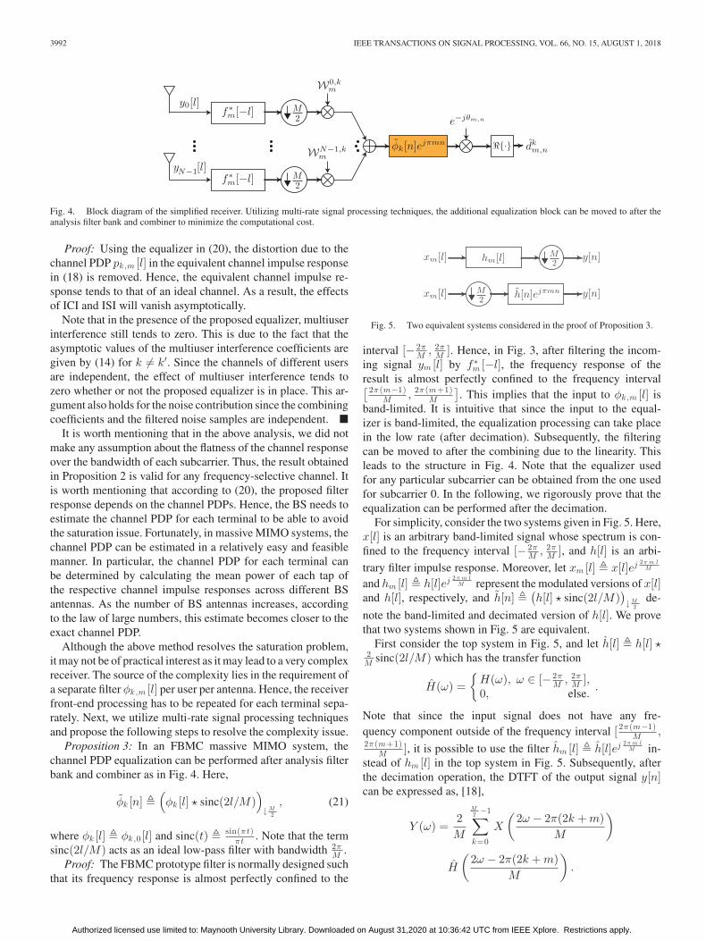
Fig. 4. Block diagram of the simplified receiver. Utilizing multi-rate signal processing techniques, the additional equalization block can be moved to after theanalysis filter bank and combiner to minimize the computational cost.
Proof: Using the equalizer in (20), the distortion due to thechannel PDP pk,m [l] in the equivalent channel impulse responsein (18) is removed. Hence, the equivalent channel impulse re-sponse tends to that of an ideal channel. As a result, the effectsof ICI and ISI will vanish asymptotically.
Note that in the presence of the proposed equalizer, multiuserinterference still tends to zero. This is due to the fact that theasymptotic values of the multiuser interference coefficients aregiven by (14) for k = k′. Since the channels of different usersare independent, the effect of multiuser interference tends tozero whether or not the proposed equalizer is in place. This ar-gument also holds for the noise contribution since the combiningcoefficients and the filtered noise samples are independent. �
It is worth mentioning that in the above analysis, we did notmake any assumption about the flatness of the channel responseover the bandwidth of each subcarrier. Thus, the result obtainedin Proposition 2 is valid for any frequency-selective channel. Itis worth mentioning that according to (20), the proposed filterresponse depends on the channel PDPs. Hence, the BS needs toestimate the channel PDP for each terminal to be able to avoidthe saturation issue. Fortunately, in massive MIMO systems, thechannel PDP can be estimated in a relatively easy and feasiblemanner. In particular, the channel PDP for each terminal canbe determined by calculating the mean power of each tap ofthe respective channel impulse responses across different BSantennas. As the number of BS antennas increases, accordingto the law of large numbers, this estimate becomes closer to theexact channel PDP.
Although the above method resolves the saturation problem,it may not be of practical interest as it may lead to a very complexreceiver. The source of the complexity lies in the requirement ofa separate filter φk,m [l] per user per antenna. Hence, the receiverfront-end processing has to be repeated for each terminal sepa-rately. Next, we utilize multi-rate signal processing techniquesand propose the following steps to resolve the complexity issue.
Proposition 3: In an FBMC massive MIMO system, thechannel PDP equalization can be performed after analysis filterbank and combiner as in Fig. 4. Here,
φk [n] �(φk [l] � sinc(2l/M)
)
↓M2
, (21)
where φk [l] � φk,0 [l] and sinc(t) � sin(πt)πt . Note that the term
sinc(2l/M) acts as an ideal low-pass filter with bandwidth 2πM .
Proof: The FBMC prototype filter is normally designed suchthat its frequency response is almost perfectly confined to the
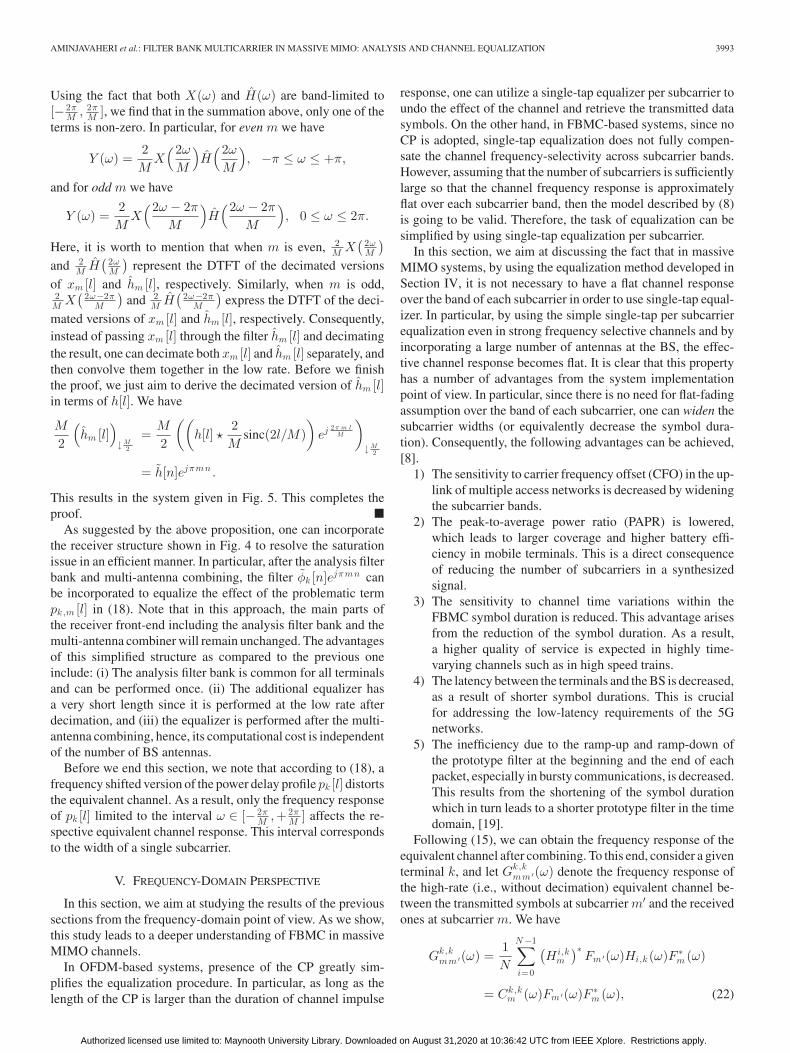
Fig. 5. Two equivalent systems considered in the proof of Proposition 3.
interval [− 2πM , 2π
M ]. Hence, in Fig. 3, after filtering the incom-ing signal ym [l] by f ∗
m [−l], the frequency response of theresult is almost perfectly confined to the frequency interval[ 2π (m−1)
M , 2π (m+1)M
]. This implies that the input to φk,m [l] is
band-limited. It is intuitive that since the input to the equal-izer is band-limited, the equalization processing can take placein the low rate (after decimation). Subsequently, the filteringcan be moved to after the combining due to the linearity. Thisleads to the structure in Fig. 4. Note that the equalizer usedfor any particular subcarrier can be obtained from the one usedfor subcarrier 0. In the following, we rigorously prove that theequalization can be performed after the decimation.
For simplicity, consider the two systems given in Fig. 5. Here,x[l] is an arbitrary band-limited signal whose spectrum is con-fined to the frequency interval [− 2π
M , 2πM ], and h[l] is an arbi-
trary filter impulse response. Moreover, let xm [l] � x[l]ej 2 π m lM
and hm [l] � h[l]ej 2 π m lM represent the modulated versions of x[l]
and h[l], respectively, and h[n] �(h[l] � sinc(2l/M)
)↓M
2de-
note the band-limited and decimated version of h[l]. We provethat two systems shown in Fig. 5 are equivalent.
First consider the top system in Fig. 5, and let h[l] � h[l] �2M sinc(2l/M) which has the transfer function
H(ω) ={
H(ω), ω ∈ [− 2πM , 2π
M ],0, else.
.
Note that since the input signal does not have any fre-quency component outside of the frequency interval [ 2π (m−1)
M ,2π (m+1)
M ], it is possible to use the filter hm [l] � h[l]ej 2 π m lM in-
stead of hm [l] in the top system in Fig. 5. Subsequently, afterthe decimation operation, the DTFT of the output signal y[n]can be expressed as, [18],
Y (ω) =2M
M2 −1∑
k=0
X
(2ω − 2π(2k + m)
M
)
H
(2ω − 2π(2k + m)
M
).
Authorized licensed use limited to: Maynooth University Library. Downloaded on August 31,2020 at 10:36:42 UTC from IEEE Xplore. Restrictions apply.
AMINJAVAHERI et al.: FILTER BANK MULTICARRIER IN MASSIVE MIMO: ANALYSIS AND CHANNEL EQUALIZATION 3993
Using the fact that both X(ω) and H(ω) are band-limited to[− 2π
M , 2πM ], we find that in the summation above, only one of the
terms is non-zero. In particular, for even m we have
Y (ω) =2M
X(2ω
M
)H(2ω
M
), −π ≤ ω ≤ +π,
and for odd m we have
Y (ω) =2M
X(2ω − 2π
M
)H(2ω − 2π
M
), 0 ≤ ω ≤ 2π.
Here, it is worth to mention that when m is even, 2M X
( 2ωM
)
and 2M H
( 2ωM
)represent the DTFT of the decimated versions
of xm [l] and hm [l], respectively. Similarly, when m is odd,2M X
( 2ω−2πM
)and 2
M H( 2ω−2π
M
)express the DTFT of the deci-
mated versions of xm [l] and hm [l], respectively. Consequently,instead of passing xm [l] through the filter hm [l] and decimatingthe result, one can decimate both xm [l] and hm [l] separately, andthen convolve them together in the low rate. Before we finishthe proof, we just aim to derive the decimated version of hm [l]in terms of h[l]. We have
M
2
(hm [l]
)
↓M2
=M
2
((h[l] �
2M
sinc(2l/M))
ej 2 π m lM
)
↓M2
= h[n]ejπmn .
This results in the system given in Fig. 5. This completes theproof. �
As suggested by the above proposition, one can incorporatethe receiver structure shown in Fig. 4 to resolve the saturationissue in an efficient manner. In particular, after the analysis filterbank and multi-antenna combining, the filter φk [n]ejπmn canbe incorporated to equalize the effect of the problematic termpk,m [l] in (18). Note that in this approach, the main parts ofthe receiver front-end including the analysis filter bank and themulti-antenna combiner will remain unchanged. The advantagesof this simplified structure as compared to the previous oneinclude: (i) The analysis filter bank is common for all terminalsand can be performed once. (ii) The additional equalizer hasa very short length since it is performed at the low rate afterdecimation, and (iii) the equalizer is performed after the multi-antenna combining, hence, its computational cost is independentof the number of BS antennas.
Before we end this section, we note that according to (18), afrequency shifted version of the power delay profile pk [l] distortsthe equivalent channel. As a result, only the frequency responseof pk [l] limited to the interval ω ∈ [− 2π
M ,+2πM ] affects the re-
spective equivalent channel response. This interval correspondsto the width of a single subcarrier.
V. FREQUENCY-DOMAIN PERSPECTIVE
In this section, we aim at studying the results of the previoussections from the frequency-domain point of view. As we show,this study leads to a deeper understanding of FBMC in massiveMIMO channels.
In OFDM-based systems, presence of the CP greatly sim-plifies the equalization procedure. In particular, as long as thelength of the CP is larger than the duration of channel impulse
response, one can utilize a single-tap equalizer per subcarrier toundo the effect of the channel and retrieve the transmitted datasymbols. On the other hand, in FBMC-based systems, since noCP is adopted, single-tap equalization does not fully compen-sate the channel frequency-selectivity across subcarrier bands.However, assuming that the number of subcarriers is sufficientlylarge so that the channel frequency response is approximatelyflat over each subcarrier band, then the model described by (8)is going to be valid. Therefore, the task of equalization can besimplified by using single-tap equalization per subcarrier.
In this section, we aim at discussing the fact that in massiveMIMO systems, by using the equalization method developed inSection IV, it is not necessary to have a flat channel responseover the band of each subcarrier in order to use single-tap equal-izer. In particular, by using the simple single-tap per subcarrierequalization even in strong frequency selective channels and byincorporating a large number of antennas at the BS, the effec-tive channel response becomes flat. It is clear that this propertyhas a number of advantages from the system implementationpoint of view. In particular, since there is no need for flat-fadingassumption over the band of each subcarrier, one can widen thesubcarrier widths (or equivalently decrease the symbol dura-tion). Consequently, the following advantages can be achieved,[8].
1) The sensitivity to carrier frequency offset (CFO) in the up-link of multiple access networks is decreased by wideningthe subcarrier bands.
2) The peak-to-average power ratio (PAPR) is lowered,which leads to larger coverage and higher battery effi-ciency in mobile terminals. This is a direct consequenceof reducing the number of subcarriers in a synthesizedsignal.
3) The sensitivity to channel time variations within theFBMC symbol duration is reduced. This advantage arisesfrom the reduction of the symbol duration. As a result,a higher quality of service is expected in highly time-varying channels such as in high speed trains.
4) The latency between the terminals and the BS is decreased,as a result of shorter symbol durations. This is crucialfor addressing the low-latency requirements of the 5Gnetworks.
5) The inefficiency due to the ramp-up and ramp-down ofthe prototype filter at the beginning and the end of eachpacket, especially in bursty communications, is decreased.This results from the shortening of the symbol durationwhich in turn leads to a shorter prototype filter in the timedomain, [19].
Following (15), we can obtain the frequency response of theequivalent channel after combining. To this end, consider a giventerminal k, and let Gk,k
mm ′(ω) denote the frequency response ofthe high-rate (i.e., without decimation) equivalent channel be-tween the transmitted symbols at subcarrier m′ and the receivedones at subcarrier m. We have
Gk,kmm ′(ω) =
1N
N −1∑
i=0
(Hi,k
m
)∗Fm ′(ω)Hi,k (ω)F ∗
m (ω)
= Ck,km (ω)Fm ′(ω)F ∗
m (ω), (22)
Authorized licensed use limited to: Maynooth University Library. Downloaded on August 31,2020 at 10:36:42 UTC from IEEE Xplore. Restrictions apply.

3994 IEEE TRANSACTIONS ON SIGNAL PROCESSING, VOL. 66, NO. 15, AUGUST 1, 2018
Fig. 6. Illustration of the equivalent channel response. Here, we assume M = 512, and consider an exponentially decaying channel PDP with the decayingfactor of 0.06 and the length of Lh = 50. (a) The equivalent channel, Ck ,k
m (ω), for subcarrier m = 0, without the proposed equalizer. (b) The equivalent channel,C k ,k
m (ω), for subcarrier m = 0, with the proposed equalizer. As the number of BS antennas increases, the equivalent channel becomes flat only when the proposedequalizer is in place.
where
Ck,km (ω) =
1N
N −1∑
i=0
(Hi,k
m
)∗Hi,k (ω). (23)
In (22), Fm ′(ω) and F ∗m (ω) are two modulated square-root
Nyquist filters, i.e., Q(ω) = |F (ω)|2 is a Nyquist pulse, andCk,k
m (ω) is due to the multipath channel. Ideally, Ck,km (ω) should
be flat over the pass band of the subcarrier m so that the sym-bols of subcarrier m can be perfectly reconstructed without anyinterference. However, when there exists a frequency-selectivechannel, the term Ck,k
m (ω) may incur some distortion over thepass band of subcarrier m and, accordingly, lead to some inter-ference in the detected symbols. As the number of BS antennasgrows large, using the law of large numbers and according to(17), Ck,k
m (ω) tends to Pk,m (ω). Therefore, the flat-fading con-dition may not be achieved by just increasing the BS array size.
On the other hand, when the equalizer in (20) is utilized, theequivalent channel in the frequency domain can be expressed as
Gk,kmm ′(ω) = Ck,k
m (ω)Fm ′(ω)F ∗m (ω), (24)
where
Ck,km (ω) =
1N
∑N −1i=0
(Hi,k
m
)∗Hi,k (ω)
Pk,m (ω)=
Ck,km (ω)
Pk,m (ω). (25)
Therefore, since Ck,km (ω) asymptotically tends to Pk,m (ω),
Ck,km (ω) will in turn tend to a frequency flat channel. Thus,
no interference is expected in large antenna regime. This chan-nel flattening effect of FBMC-based massive MIMO systems isillustrated in Fig. 6.
VI. SINR ANALYSIS
In this section, we analyze the SINR performance of anFBMC-based massive MIMO system in the uplink incorporat-ing the proposed equalization method. We limit our study to thetwo most prominent linear combiners namely, MRC and ZF. Asmentioned earlier, in the large antenna regime, all the combinersin (13) tend to 1
N Hm , and hence, the same asymptotic SINRperformance as in MRC and ZF is expected for the MMSE com-biner. As mentioned earlier, the equalization approaches givenin Figs. 3 and 4 are equivalent. Although the method given inFig. 4 is preferred for implementation, here, for the purpose ofanalysis, we consider the approach given in Fig. 3. Through-out this section, we consider normalized channel PDPs for eachterminal such that
Lh −1∑
l=0
pk [l] = 1, k ∈ {0, . . . , K − 1}. (26)
In Fig. 3, the receiver filter f ∗m [−l] and the equalizer φk,m [l]
can be combined together as a single filtering block with im-pulse response f ∗
k,m [−l] � f ∗m [−l] � φk,m [l]. Therefore, we can
consider having the new receiver filter f ∗k,m [−l] in place, and
use (12) to obtain the estimated data symbols. To this end, letHk
mm ′,nn ′ be an N × K matrix with elements given by (11)
but with the new filter f ∗k,m [−l] in place instead of f ∗
m [−l].Moreover, we form the K × K matrix Gmm ′,nn ′ similar toGmm ′,nn ′ . In particular, the kth row of Gmm ′,nn ′ can be cal-culated as wH
m,kHkmm ′,nn ′ , where wm,k is the kth column of
the combiner matrix Wm . Following the above definitions, theinterference coefficients are determined by the real part of the
Authorized licensed use limited to: Maynooth University Library. Downloaded on August 31,2020 at 10:36:42 UTC from IEEE Xplore. Restrictions apply.

AMINJAVAHERI et al.: FILTER BANK MULTICARRIER IN MASSIVE MIMO: ANALYSIS AND CHANNEL EQUALIZATION 3995
elements of Gmm ′,nn ′ . In order to pave the way for our SINRanalysis, we desire to find the elements of Gmm ′,nn ′ in a matrixform. Towards this end and based on (11) and (12), the con-volution, downsampling, multi-antenna combining, and phasecompensation operations can all be expressed compactly as
Gk,k ′mm ′,nn ′ =
(ψk
mm ′,nn ′)Hgk,k ′
m , (27)
where
gk,k ′m =
N −1∑
i=0
(W i,km
)∗hi,k ′ , (28)
and(ψk
mm ′,nn ′)H = ej (θm ′ , n ′−θm , n )eT
nn ′Fk,mFm ′ . (29)
The vector gk,k ′m is the effective multipath channel impulse
response between terminals k and k′ at subcarrier m, afterthe combining operation. hi,k �
[hi,k [0], . . . , hi,k [Lh − 1]
]T
is the vector of channel impulse response between ith BS an-tenna and kth terminal. Fm ′ and Fk,m are two Toeplitz matri-ces that are defined in (30a) and (30b), respectively, and sig-nify the synthesis filter at subcarrier m′ and the new analysisfilter at subcarrier m, respectively. Note that the size of thematrix Fm ′ is (Lf + Lh − 1) × Lh . To determine the size ofFk,m , we follow (20) to note that fm [l] = fk ,m [l] � p∗k,m [−l].Hence, the length of the new filter fk ,m [l] can be obtained asLf = Lf − Lh + 1. As a result, the size of Fk,m can be calcu-lated as (2Lf − 1) × (Lf + Lh − 1). The (2Lf − 1) × 1 vectorenn ′ is accounted for the downsampling operation and containszeros except on its (Lf + (n − n′)M
2 )th entry which is equal toone. Finally, ej (θm ′ , n ′−θm , n ) is due to the phase compensation.
Fm ′ =
⎛
⎜⎜⎜⎜⎜⎝
fm ′ [0] 0 · · · 0 0fm ′ [1] fm ′ [0] · · · 0 0
......
......
...0 0 · · · fm ′ [Lf − 1] fm ′ [Lf − 2]0 0 · · · 0 fm ′ [Lf − 1]
⎞
⎟⎟⎟⎟⎟⎠,
(30a)
Fk,m =
⎛
⎜⎜⎜⎜⎜⎜⎝
f ∗k,m [Lf − 1] 0 · · · 0 0
f ∗k,m [Lf − 2] f ∗
k,m [Lf − 1] · · · 0 0...
......
......
0 0 · · · f ∗k,m [0] f ∗
k,m [1]0 0 · · · 0 f ∗
k,m [0]
⎞
⎟⎟⎟⎟⎟⎟⎠.
(30b)
Note that in (27), the termψkmm ′,nn ′ is completely determinis-
tic, whereas gk,k ′m is a random vector. Therefore, in this equation,
we have decomposed the interference coefficients into randomand deterministic components. Moreover, while ψk
mm ′,nn ′ doesnot depend on the type of combining, gk,k ′
m is directly related tothe combining method and should be evaluated for each com-biner separately.
A. MRC
In MRC, as the number of BS antennas grows large, Dm in(13) tends to NIK . Therefore, we can write gk,k ′
m = 1N
∑N −1i=0
(Hi,km )∗hi,k ′ . In the Appendix, we have calculated the first and
second order statistics of the complex random vector gk,k ′m . The
result is
μk,k ′m � E
{gk,k ′
m
}= δkk ′pk,m , (31a)
Γk,k ′m � E
{(gk,k ′
m − μk,k ′m
)(gk,k ′
m − μk,k ′m
)H}
=1N
Dpk ′ ,
(31b)
Kk,k ′m � E
{(gk,k ′
m − μk,k ′m
)(gk,k ′
m − μk,k ′m
)T}
=1N
δkk ′pk,mpTk,m , (31c)
where Dpk� diag
{[pk [0], pk [1], . . . , pk [Lh− 1]
]T}, and pk,m
�[pk,m [0], pk,m [1], . . . , pk,m [Lh − 1]
]T.
Let γk,k ′m be a zero-mean random vector defined as γk,k ′
m �gk,k ′
m − μk,k ′m . Thus, from (27) and (31a) we have
Gk,k ′mm ′,nn ′
=(ψk
mm ′,nn ′)Hγk,k ′
m + δkk ′(ψk
mm ′,nn ′)Hpk,m
=(ψk
mm ′,nn ′)Hγk,k ′
m + δkk ′(δmm ′δnn ′ + jAmm ′,nn ′
), (32)
where Amm ′,nn ′ � �{∑+∞l=−∞ am ′,n ′ [l]a∗
m,n [l]}
. The secondline of (32) follows from the real-orthogonality property ofFBMC given in (3). We recall that by incorporating theequalizer φk,m [l], the effect of the modulated channel PDPpk,m [l] is removed and the real-orthogonality condition issatisfied. Hence, the term (ψk
mm ′,nn ′)Hpk,m = ej (θm ′ , n ′−θm , n )
eTnn ′Fk,mFm ′pk,m is equal to δmm ′δnn ′ + jAmm ′,nn ′ since the
matrix Fk,m compensates the effect of pk,m .As mentioned above, the interference coefficients are given
by the real part of the elements of Gmm ′,nn ′ . Let Rmm ′,nn ′ ��{Gmm ′,nn ′ }, and ν ′′
m,n � �{ν ′m,n}. Accordingly, (12) can
be reformulated as
dm,n =+∞∑
n ′=−∞
M −1∑
m ′=0
Rmm ′,nn ′dm ′,n ′ + ν ′′m,n . (33)
By stacking the real and imaginary parts of the matrices andvectors that constitute the elements of Gmm ′,nn ′ , it is possibleto find an expression for the elements of Rmm ′,nn ′ . In partic-ular, for an arbitrary complex matrix or vector a, we definea � [�{aT},�{aT}]T . Thus, following (32) we can find theelements of Rmm ′,nn ′ as
Rk,k ′mm ′,nn ′ =
(ψ
kmm ′,nn ′
)Tγk,k ′
m + δkk ′δmm ′δnn ′ . (34)
Authorized licensed use limited to: Maynooth University Library. Downloaded on August 31,2020 at 10:36:42 UTC from IEEE Xplore. Restrictions apply.

3996 IEEE TRANSACTIONS ON SIGNAL PROCESSING, VOL. 66, NO. 15, AUGUST 1, 2018
We note that the real-valued random vector γkk ′m is zero-mean
and its covariance matrix can be determined using (31) as
Ck,k ′m � E
{(γk,k ′
m − E{γk,k ′
m
})(γk,k ′
m − E{γk,k ′
m
})T}
=12
[�{Γk,k ′
m + Kk,k ′m } �{−Γk,k ′
m + Kk,k ′m }
�{Γk,k ′m + Kk,k ′
m } �{Γk,k ′m − Kk,k ′
m }
]
=1N
(Dpk ′ + δkk ′Pk,m
), (35)
where Dpk ′ � 12 [Dp
k ′0
0Dp
k ′] and Pk,m � 1
2 [�{pk , m pTk , m }
�{pk , m pTk , m }
�{pk , m pTk , m }
−�{pk , m pTk , m } ].
Following (34), the instantaneous power corresponding toRk,k ′
mm ′,nn ′ can be calculated as
Pk,k ′mm ′,nn ′ =
(Rk,k ′
mm ′,nn ′
)2
=(γk,k ′
m
)TΨkmm ′,nn ′ γk,k ′
m + δkk ′δmm ′δnn ′
+ 2δkk ′δmm ′δnn ′(ψ
kmm ′,nn ′
)Tγk,k ′
m ,
where Ψkmm ′,nn ′ � ψ
kmm ′,nn ′(ψ
kmm ′,nn ′)T . From the above
equation, the average power, with averaging over different chan-nel realizations, can be calculated according to [20, p. 53],
P k,k ′mm ′,nn ′
= tr{Ck,k ′
m Ψkmm ′,nn ′
}+ δkk ′δmm ′δnn ′
=1N
tr{(Dpk ′ + δkk ′Pk,m )Ψk
mm ′,nn ′}
+ δkk ′δmm ′δnn ′ .
(36)
Thus, the SINR can be calculated as given in the followingproposition.
Proposition 4: In the uplink of an FBMC massive MIMOsystem with MRC combiner and the proposed PDP equalizer,the effective SINR can be calculated according to (37) shown atthe bottom of this page.
Proof: This follows from (36), and noting that unnumberedequation shown at the bottom of this page. �
B. ZF
In the Appendix, it is shown that for the ZF combiner, pro-vided that N ≥ K + 1, the first and second order statistics ofthe random vector gk,k ′
m can be calculated according to
μk,k ′m = δkk ′pk,m , (39a)
Γk,k ′m =
1N − K
(Dpk ′ − pk ′,mpH
k ′,m), (39b)
Kk,k ′m = 0. (39c)
Hence, the covariance matrix of γk,k ′m is determined by
Ck,k ′m =
1N − K
(Dpk ′ − Pk ′,m), (40)
where Pk,m � 12 [�{pk , m pH
k , m }�{pk , m pH
k , m }−�{pk , m pH
k , m }�{pk , m pH
k , m } ].
Proposition 5: In the uplink of an FBMC massive MIMOsystem with ZF combiner and the proposed PDP equalizer, andprovided that N ≥ K + 1, the effective SINR can be calculatedaccording to (38).
Proof: This follows from the covariance matrix given in (40)and similar analysis as in the MRC case. �
VII. NUMERICAL RESULTS
In this section, we deploy computer simulations to evaluatethe efficacy of the proposed equalization method as well asthe analysis of the previous sections. For all the simulations inthis section, we let M = 512 and assume K = 10 terminals inthe network. We consider the PHYDYAS prototype filter, [21],with the overlapping factor κ = 4. Normalized exponentiallydecaying channel PDPs pk [l] = e−αk l/
(∑Lh −1=0 e−αk
), l =
0 . . . , Lh − 1 for k = 0, · · · ,K − 1 with different decayingfactors αk = (k + 1)/20 for different terminals and length
MRC:
SINRkm,n =
N + tr{(Dpk
+ Pk,m
)Ψk
mm,nn
}∑K−1
k ′=0k ′ =k
∑+∞n ′=−∞
∑M −1m ′=0tr
{Dpk ′Ψkmm ′,nn ′
}+
∑+∞n ′=−∞
∑M −1m ′=0
(m ′,n ′) =(m,n)tr{(Dpk
+ Pk,m
)Ψk
mm ′,nn ′}
+ σ2ν
(37)
ZF:
SINRkm,n =
N − K∑K−1
k ′=0∑+∞
n ′=−∞∑M −1
m ′=0(m ′,n ′) =(m,n)
tr{(Dpk ′ − Pk ′,m
)Ψk
mm ′,nn ′}
+ σ2ν
(38)
SINRkm,n �
P k,kmm,nn∑+∞
n ′=−∞∑M −1
m ′=0(m ′,n ′) =(m,n)
P k,k ′mm ′,nn ′ +
∑+∞n ′=−∞
∑M −1m ′=0
∑K−1k ′=0k ′ =k
P k,k ′mm ′,nn ′ + σ2
ν
.
Authorized licensed use limited to: Maynooth University Library. Downloaded on August 31,2020 at 10:36:42 UTC from IEEE Xplore. Restrictions apply.

AMINJAVAHERI et al.: FILTER BANK MULTICARRIER IN MASSIVE MIMO: ANALYSIS AND CHANNEL EQUALIZATION 3997
Fig. 7. SINR performance comparison for the case that the proposed equalizeris not utilized.
Lh = 50 are assumed.3 Notice that the channel PDPs are nor-malized, i.e.,
∑Lh −1l=0 pk [l] = 1, for k = 0, . . . , K − 1. Hence,
following the channel model in Section III, the average signal-to-noise ratio (SNR) at the BS antennas input can be calculatedas SNR = 1/σ2
ν . We present the SINR performance correspond-ing to terminal k = 0.
First, we show the SINR for the case where the proposedequalization is not incorporated at the BS. Fig. 7 shows the av-erage SINR performance (with averaging over different channelrealizations) of MRC, ZF, and MMSE combiners as a functionof different number of BS antennas. The noise level is selectedsuch that the SNR at the input of the BS antennas is equal to10 dB. From Fig. 7, we can see that without the proposed equal-ization, the SINR performance of all three linear detectors, i.e.,MRC, ZF, and MMSE, tend to the saturation level predictedby (19) as N grows large. Accordingly, arbitrarily large SINRvalues cannot be achieved by increasing the BS array size. Also,the SINR performance of ZF and MMSE combiners convergesfaster to the saturation level as compared to the one in MRC. Inpractice, when considering a finite number of BS antennas, theimpact of SINR saturation depends on the combining methodused as well as the channel PDP and noise level.
In the next set of simulations, we evaluate the performanceof FBMC with the proposed equalizer in place. Fig. 8 showsthe SINR performance of MRC, ZF, and MMSE combiners asa function of different number of BS antennas. The noise levelis selected such that the SNR at the input of the BS antennas isequal to 10 dB. As it is shown, using the proposed equalizationmethod, the saturation problem of the conventional FBMC sys-tems in massive MIMO channels is avoided and arbitrarily largeSINR values can be achieved by increasing N . In Fig. 8, we havealso shown the theoretical SINR values for MRC and ZF com-biners, as calculated in (37) and (38), respectively. This figure
3A similar approach has been taken in [22] to choose the channel PDPs fordifferent terminals.
Fig. 8. SINR performance comparison for the case that the proposed equalizeris utilized.
Fig. 9. SINR performance comparison as a function of different SNR values.In the case of FBMC, the proposed equalizer is incorporated at the BS. HereN = 100 BS antennas is considered.
confirms that the theoretical SINR values match the simulatedones. This verifies the accuracy of the analysis of Section VI.
Fig. 9 shows the theoretical SINR performance of the MRCand ZF combiners and with the proposed equalization as a func-tion of different input SNR values. Moreover, the SINR perfor-mance of OFDM with MRC and ZF combiners is shown as abenchmark; see [16] for the SINR expressions of OFDM. In thisfigure, we consider N = 100 BS antennas. As the figure shows,OFDM and FBMC have almost identical SINR performancewhen MRC is utilized. On the other hand, in the case of ZFcombiner, although the performance of OFDM and FBMC arevery close in the low SNR regime, a better SINR is expected forOFDM in the high SNR region. The reason for this phenomenonis that in OFDM, the interference is entirely removed using theCP. Hence, by increasing the input SNR, a better SINR at the
Authorized licensed use limited to: Maynooth University Library. Downloaded on August 31,2020 at 10:36:42 UTC from IEEE Xplore. Restrictions apply.

3998 IEEE TRANSACTIONS ON SIGNAL PROCESSING, VOL. 66, NO. 15, AUGUST 1, 2018
Fig. 10. SINR performance comparison for different values of the FBMCsubcarrier spacing ΔF � 1/M .
output is also expected. In contrast, the FBMC waveform is de-signed to increase the bandwidth efficiency by excluding the CPoverhead and providing much lower out-of-band emission thanOFDM. Hence, due to the absence of CP, some residual interfer-ence remains after the ZF combining. This residual interferencebecomes noticeable only in the very high SNR regime.
As discussed in Section V, by incorporating a large numberof BS antennas, one can widen the subcarrier bands in an FBMCsystem. This, in turn, brings a number of advantages, e.g., ro-bustness to CFO and channel time variations, lower PAPR, lowerlatency, higher bandwidth efficiency. These benefits are crucialfor the next generation of wireless systems. In the next experi-ment, we aim at evaluating the SINR performance as we widenthe subcarrier bands. Fig. 10 shows the SINR for different valuesof FBMC subcarrier spacings, ΔF � 1/M . In this experiment,the input SNR of 0 dB is considered. To use the simple single-tapequalizer per subcarrier, the design norm is to choose the symbolspacing to be about an order of magnitude larger than the chan-nel length. In this case, with Lh = 50, this leads to the symbolspacing of around M/2 = 500, which in turn yields the subcar-rier spacing of ΔF = 0.001. However, as the figure shows, byincorporating a large number of BS antennas as well as the pro-posed equalizer, one can considerably increase the subcarrierspacing while the SINR performance has a slight degradation.In particular, increasing the subcarrier spacing by an order ofmagnitude leads to about 0.7 dB SINR degradation when usingZF combiner. In MRC, the degradation is negligible, i.e., lessthan 0.3 dB.
Fig. 11 presents the uncoded bit error rate (BER) perfor-mance comparison. In this experiment, N = 100 BS antennasis considered. Moreover, the transmitted symbols belong to a64 quadrature amplitude modulation (QAM) constellation. Wecompare the performance of FBMC with and without our pro-posed channel PDP equalizer. We also show the performance ofOFDM as a benchmark. For all cases, ZF combiner is utilized.
Fig. 11. BER performance comparison. Here, N = 100 BS antennas and theZF combiner are considered.
As the figure shows, the BER performance is improved signif-icantly when the proposed channel PDP equalizer is in place.Furthermore, we achieve the same performance as in OFDM,where the channel frequency response is completely flat overeach individual subcarrier band.
VIII. CONCLUSION AND DISCUSSION
In this paper, we studied the performance of FBMC trans-mission in the context of massive MIMO. We consideredsingle-tap-per-subcarrier equalization using the conventionallinear combiners, i.e., MRC, ZF, and MMSE. It was shownthat the correlation between the multi-antenna combiningtap weights and the channel impulse responses leads to aninterference which does not fade away even with an infinitenumber of BS antennas. Hence, arbitrarily large SINR valuescannot be achieved, and the SINR is upper-bounded by a certaindeterministic value. We derived a closed-form expression forthis upper bound, identified the source of SINR saturation,and proposed an efficient equalization method to remove theabove correlation and resolve the problem. We mathematicallyanalyzed the performance of the FBMC system incorporatingthe proposed equalization method and derived closed-formexpressions for the SINR in the cases of MRC and ZF.
Throughout this paper, we assumed a co-located BS antennaarray that is sufficiently compact so that the channel responsescorresponding to a particular user and different BS antennasare subject to the same channel PDP. It is worth mentioningthat there exist another type of massive MIMO setup in whichthe elements of the BS array are distributed in a large area. Thissetup, which is out of the scope of this paper, is called distributedor cell-free massive MIMO, [23]. In this scenario, for a givenuser, channel responses corresponding to different BS antennasundergo different PDPs. This is a completely different problemthan what we are considering in this paper. Thus, it remains asa future study.
Authorized licensed use limited to: Maynooth University Library. Downloaded on August 31,2020 at 10:36:42 UTC from IEEE Xplore. Restrictions apply.

AMINJAVAHERI et al.: FILTER BANK MULTICARRIER IN MASSIVE MIMO: ANALYSIS AND CHANNEL EQUALIZATION 3999
The analyses in this paper was based on single-tap per sub-carrier equalization. However, we note that as mentioned inSection III, the asymptotic SINR saturation is an inherent prop-erty of FBMC-based massive MIMO systems due to the absenceof CP. As a result, one may expect the SINR saturation issue toappear also in FBMC systems incorporating multi-tap per sub-carrier equalization methods such as those in [10] and [15] ifwe do not equalize the channel PDP. Using multi-tap equalizers,however, can increase the saturation level in expense of a highercomputational cost. We can also realize this point from the re-sults of [10], where the performance of multi-tap and single-tapequalizers are compared with each other for different number ofBS antennas. Therefore, our proposed channel PDP equalizercan also be adopted in multi-tap systems to further improve theperformance.
APPENDIX
PROOF OF (31) AND (39)
A. MRC
In the case of MRC, we have gk,k ′m = 1
Dk , km
∑N −1i=0 (Hi,k
m )∗
hi,k ′ . Moreover, for large values of N , Dk,km tends to N due to
the law of large numbers. Hence, the mean of the th elementof gk,k ′
m , for ∈ {0, . . . , Lh − 1}, can be calculated as
E{gk,k ′m []} =
1N
N −1∑
i=0
Lh −1∑
l=0
E{h∗i,k [l]hi,k ′ []}ej 2 π l m
M
= δkk ′pk,m [].
This leads to (31a). We now calculate the correlation betweengk,k ′
m [] and gk,k ′m [′], for , ′ ∈ {0, . . . , Lh − 1}. We consider
the case that k = k′. Hence,
E{gk,k ′
m [](gk,k ′
m [′])∗}
=1
N 2
N −1∑
i=0
N −1∑
i ′=0
E{ (
Hi,km
)∗Hi ′,k
m hi,k ′ []h∗i ′,k ′ [′]
}
=1
N 2
N −1∑
i=0
N −1∑
i ′=0
Lh −1∑
l=0
Lh −1∑
l ′=0
E{h∗i,k [l]hi ′,k [l′]hi,k ′ []h∗
i ′,k ′ [′]}
× ej2 π ( l−l ′)m
M =1N
δ ′pk ′ [], for k = k′.
The above correlation for the case of k = k′ can be determinedusing a similar line of derivations. The result is
E{gk,k
m [](gk,k
m [′])∗} =
1N
δ ′pk [] + pk,m []p∗k,m [′].
This leads to (31b). Moreover, the pseudo-covariance matrixKk,k ′
m in (31c) can be derived using the same line of derivationsas above.
B. ZF
Here, we use similar techniques as in [24]. We have gk,k ′m [] =
wHm,khk ′ [], where wm,k is the kth column of the combiner
matrix Wm , and hk ′ [] is an N × 1 vector with its ith elementequal to hi,k ′ []. In the case of ZF equalizer, we have Wm =
Hm (HHmHm )−1 . Also, let hm,k denote the kth column of Hm .
Hence, the mean of gk,k ′m [] can be determined as follows.
E{gk,k ′m []} = E{wH
m,khk ′ []}
=1M
M −1∑
m ′=0
E{wHm,khm ′,k ′ }ej 2 π m ′
M
(a)=
1M
M −1∑
m ′=0
Lh −1∑
l=0
E{wHm,khm,k ′ }pk ′,m [l]ej
2 π m ′( −l )M
(b)=
1M
M −1∑
m ′=0
Lh −1∑
l=0
δkk ′pk,m [l]ej2 π m ′( −l )
M = δkk ′pk,m [].
This results in (39a). In the above equation, (a) follows from thefact the channel frequency response hm ′,k ′ can be expressed asa combination of a term that is correlated with hm,k ′ and a termthat is independent of hm,k ′ , i.e.,
hm ′,k ′ = αmm ′,k ′hm,k ′ + hindepmm ′,k ′ , (41)
where hindepmm ′,k ′ is independent of hm,k ′ and the correlation co-
efficient αmm ′,k ′ can be calculated as
αmm ′,k ′ = E{Hi,k ′
m ′(Hi,k ′
m
)∗} = Pk ′ [m′ − m],
where Pk [m] �∑Lh −1
l=0 pk [l]e−j 2 π m lM is the mth coefficient of
the M -point discrete Fourier transform of the channel PDP pk [l].The step (b) above follows from the fact that in the case of ZFequalization, we have wH
m,khm,k ′ = δkk ′ , which results from
WHmHm = Ik .
In order to calculate the covariance matrix Γk,k ′m in (39b),
we now find the correlation between gk,k ′m [] and gk,k ′
m [′], for, ′ ∈ {0, . . . , Lh − 1}. We have,
E{gk,k ′
m [](gk,k ′
m [′])∗} = E{wH
m,khk ′ []hHk ′ [′]wm,k}
(a)= δkk ′pk,m []p∗k,m [′] +
1M 2
M −1∑
m ′=0
M −1∑
m ′′=0
E{wHm,kh
indepmm ′,k ′
(hindep
mm ′′,k ′)Hwm,k}ej 2 π m ′
M e−j 2 π m ′′ ′M
(b)= δkk ′pk,m []p∗k,m [′] +
1M 2(N − K)
M −1∑
m ′=0
M −1∑
m ′′=0(Pk ′ [m′ − m′′] − Pk ′ [m′ − m]Pk ′ [m − m′′]
)ej
2 π (m ′−m ′′ ′)M
(c)= δkk ′pk,m []p∗k,m [′] +
1N−K
(δ ′pk ′ [] − pk ′,m[]p∗k ′,m[′]
).
This results in (39b). In the above equation, equality (a) followsfrom (41). Then, equality (b) follows from the independence ofwm,k from hindep
mm ′,k ′ and hindepmm ′′,k ′ , the correlation
E{hindep
mm ′,k ′(hindep
mm ′′,k ′)H
}
=(Pk ′ [m′ − m′′] − Pk ′ [m′ − m]Pk ′ [m − m′′]
)IN ,
and the identity
E[tr{(WH
m Wm
)−1}] = E[tr{(
HHmHm
)−1}] =K
N − K,
Authorized licensed use limited to: Maynooth University Library. Downloaded on August 31,2020 at 10:36:42 UTC from IEEE Xplore. Restrictions apply.

4000 IEEE TRANSACTIONS ON SIGNAL PROCESSING, VOL. 66, NO. 15, AUGUST 1, 2018
for N ≥ K + 1. The latter identity is based on the fact thatHH
mHm is a K × K complex central Wishart matrix with Ndegrees of freedom and covariance IK , [25]. Finally, the equality(c) above follows using some straightforward algebraic manipu-lations. We note that using a similar line of derivations as above,one can find the pseudo-covariance matrix given in (39c).
REFERENCES
[1] A. Aminjavaheri, A. Farhang, L. Doyle, and B. Farhang-Boroujeny, “Pro-totype filter design for FBMC in massive MIMO channels,” in Proc. IEEEInt. Conf. Commun., May 2017, pp. 1–6.
[2] F. Boccardi, R. W. Heath, A. Lozano, T. L. Marzetta, and P. Popovski,“Five disruptive technology directions for 5G,” IEEE Commun. Mag.,vol. 52, no. 2, pp. 74–80, Feb. 2014.
[3] T. L. Marzetta, “Noncooperative cellular wireless with unlimited numbersof base station antennas,” IEEE Trans. Wireless Commun., vol. 9, no. 11,pp. 3590–3600, Nov. 2010.
[4] F. Rusek et al., “Scaling up MIMO: Opportunities and challenges withvery large arrays,” IEEE Signal Process. Mag., vol. 30, no. 1, pp. 40–60,Jan. 2013.
[5] B. Farhang-Boroujeny, “OFDM versus filter bank multicarrier,” IEEESignal Process. Mag., vol. 28, no. 3, pp. 92–112, May 2011.
[6] A. I. Perez-Neira et al., “MIMO signal processing in offset-QAM basedfilter bank multicarrier systems,” IEEE Trans. Signal Process., vol. 64,no. 21, pp. 5733–5762, Nov. 2016.
[7] A. Aminjavaheri, A. Farhang, A. RezazadehReyhani, and B. Farhang-Boroujeny, “Impact of timing and frequency offsets on multicarrier wave-form candidates for 5G,” in Proc. IEEE Signal Process. Signal Process.Edu. Workshop, 2015, pp. 178–183.
[8] A. Farhang, N. Marchetti, L. E. Doyle, and B. Farhang-Boroujeny, “Filterbank multicarrier for massive MIMO,” in Proc. IEEE 80th Veh. Technol.Conf., 2014, pp. 1–7.
[9] F. Rottenberg, X. Mestre, F. Horlin, and J. Louveaux, “Performance analy-sis of linear receivers for uplink massive MIMO FBMC-OQAM systems,”IEEE Trans. Signal Process., vol. 66, no. 3, pp. 830–842, Feb. 2018.
[10] A. Aminjavaheri, A. Farhang, N. Marchetti, L. E. Doyle, and B. Farhang-Boroujeny, “Frequency spreading equalization in multicarrier massiveMIMO,” in Proc. IEEE Int. Conf. Commun. Workshop, 2015, pp. 1292–1297.
[11] A. Farhang, A. Aminjavaheri, N. Marchetti, L. E. Doyle, and B. Farhang-Boroujeny, “Pilot decontamination in CMT-based massive MIMO net-works,” in Proc. IEEE 11th Int. Symp. Wireless Commun. Syst., 2014,pp. 589–593.
[12] B. Saltzberg, “Performance of an efficient parallel data transmission sys-tem,” IEEE Trans. Commun. Technol., vol. COM-15, no. 6, pp. 805–811,Dec. 1967.
[13] B. Farhang-Boroujeny, “Filter bank multicarrier modulation: A waveformcandidate for 5G and beyond,” Adv. Elect. Eng., vol. 2014, 2014, Art no.482805.
[14] C. Lele, J.-P. Javaudin, R. Legouable, A. Skrzypczak, and P. Siohan,“Channel estimation methods for preamble-based OFDM/OQAM modu-lations,” Eur. Trans. Telecommun., vol. 19, no. 7, pp. 741–750, 2008.
[15] T. Ihalainen, A. Ikhlef, J. Louveaux, and M. Renfors, “Channel equal-ization for multi-antenna FBMC/OQAM receivers,” IEEE Trans. Veh.Technol., vol. 60, no. 5, Jun. 2011.
[16] H. Q. Ngo, E. G. Larsson, and T. L. Marzetta, “Energy and spectralefficiency of very large multiuser MIMO systems,” IEEE Trans. Commun.,vol. 61, no. 4, pp. 1436–1449, Apr. 2013.
[17] A. Aminjavaheri, A. Farhang, A. RezazadehReyhani, L. E. Doyle, and B.Farhang-Boroujeny, “OFDM without CP in massive MIMO,” IEEE Trans.Wireless Commun., vol. 16, no. 11, pp. 7619–7633, Nov. 2017.
[18] M. Vetterli, J. Kovacevic, and V. K. Goyal, Foundations of Signal Pro-cessing. Cambridge, U.K.: Cambridge Univ. Press, 2014.
[19] B. Farhang-Boroujeny, A. Farhang, A. RezazadehReyhani, A. Aminjava-heri, and D. Qu, “A comparison of linear FBMC and circularly shapedwaveforms,” in Proc. IEEE/ACES Int. Conf. Wireless Inf. Technol. Syst.,Appl. Comput. Electromagn., 2016, pp. 1–2.
[20] A. M. Mathai and S. B. Provost, Quadratic Forms in Random Variables:Theory and Applications. New York, NY, USA: Marcel Dekker, 1992.
[21] M. Bellanger et al., “FBMC physical layer: A primer,” PHYDYAS, vol. 25,no. 4, pp. 7–10, 2010.
[22] A. Pitarokoilis, S. K. Mohammed, and E. G. Larsson, “On the optimality ofsingle-carrier transmission in large-scale antenna systems,” IEEE WirelessCommun. Lett., vol. 1, no. 4, pp. 276–279, Aug. 2012.
[23] H. Q. Ngo, A. Ashikhmin, H. Yang, E. G. Larsson, and T. L. Marzetta,“Cell-free massive MIMO versus small cells,” IEEE Trans. Wireless Com-mun., vol. 16, no. 3, pp. 1834–1850, Mar. 2017.
[24] R. Corvaja and A. G. Armada, “SINR degradation in MIMO-OFDM sys-tems with channel estimation errors and partial phase noise compensation,”IEEE Trans. Commun., vol. 58, no. 8, pp. 2199–2203, Aug. 2010.
[25] A. M. Tulino and S. Verdu, Random Matrix Theory and Wireless Commu-nications, vol. 1. Breda, The Netherlands: Now Publishers, 2004.
Amir Aminjavaheri received the B.Sc. degree inelectrical engineering fromthe Isfahan University ofTechnology, Isfahan, Iran, in 2013, and the M.Sc.degree in electrical and computer engineering fromUniversity of Utah, Salt Lake City, UT, USA, in 2016.He is currently working toward the Ph.D. degreewith the Electrical and Computer Engineering De-partment, University of Utah. During Summer 2017,he worked as a Research Intern with Cadence DesignSystems, San Jose, CA, USA, on signal processingalgorithm development for 5G systems. His research
interests include signal processing, wireless communications, machine learning,and information theory.
Arman Farhang received the B.Sc. degree intelecommunications engineering from the IslamicAzad University, Najafabad, Iran, in 2007, the M.Sc.degree in telecommunications engineering from theSadjad University of Technology, Mashhad, Iran, in2010, and the Ph.D. degree from the Trinity CollegeDublin, Dublin, Ireland, in 2016. Since then, he wasa Research Fellow with the Irish National Telecom-munications Research Centre (CONNECT), TrinityCollege Dublin, Ireland until 2018. He is currently aLecturer with the School of Electrical and Electronic
Engineering, University College Dublin. His areas of research include wirelesscommunications, digital signal processing for communications, multiuser com-munications, multiantenna and multicarrier systems.
Behrouz Farhang-Boroujeny (M’84–SM’90) re-ceived the B.Sc. degree in electrical engineering fromTehran University, Tehran, Iran, in 1976, the M.Eng.degree from the University of Wales Institute of Sci-ence and Technology, South Glamorgan, U.K., in1977, and the Ph.D. degree from Imperial College,University of London, London, U.K., in 1981.
From 1981 to 1989, he was with the Isfahan Uni-versity of Technology, Isfahan, Iran. From 1989 to2000, he was with the National University of Sin-gapore. Since August 2000, he has been with the
University of Utah.He is an expert in the general area of signal processing. His current scientific
interests are adaptive filters, multicarrier communications, detection techniquesfor space-time coded systems, and cognitive radio. In the past, he has workedand has made significant contribution to areas of adaptive filters theory, acousticecho cancellation, magnetic/optical recoding, and digital subscriber line tech-nologies. He authored or coauthored of the books Adaptive Filters: theory andapplications, John Wiley and Sons, 1998 and 2013 (second edition), and SignalProcessing Techniques for Software Radios, self published at Lulu publishinghouse, 2009 and 2010 (second edition).
Dr. Farhang-Boroujeny was the recipient of UNESCO Regional Office ofScience and Technology for South and Central Asia Young Scientists Awardin 1987. He was an Associate Editor of the IEEE TRANSACTION ON SIGNAL
PROCESSING from July 2002 to July 2005, and an Associate Editor of the IEEE
SIGNAL PROCESSING LETTERS from April 2008 to March 2010. He has also beeninvolved in various IEEE activities, including the chairmanship of the SignalProcessing/Communications chapter of IEEE of Utah in 2004 and 2005.
Authorized licensed use limited to: Maynooth University Library. Downloaded on August 31,2020 at 10:36:42 UTC from IEEE Xplore. Restrictions apply.