The Powerful Alamouti Code in MIMO -OFDM Improvement for the Next Generation of Terrestrial...
10
International Journal of Engineering & Technology IJET-IJENS Vol:14 No:01 33 140801-7575-IJET-IJENS © February 2014 IJENS I J E N S The Powerful Alamouti Code in MIMO -OFDM Improvement for the Next Generation of Terrestrial Television Broadcasting Systems El Miloud Ar reyouchi 1 ,Kamal Ghoumid 1,2 , Koutaiba Ameziane 1 and Otman El Mrabet 1 1 Department of physique, faculty of Science, Abdelmalek Essaadi University, Tetouan, Morroco. [email protected] 2 Department of Electronics, Informatics and Telecommunications, ENSAO, Mohammed I University, Oujda, Morocco. [email protected] Abstract— This paper proposes and analyses an efficient wireless telecommunication system with multiple antennas to the emission and reception MIMO (multiple input multiple output) with space diversity in an OFDM (Orthogonal Frequency Di vision Multiplex). The proposed system consists to add modified Alamouti encoder to the system OFDM to improve the performance of the destination by intimately collaborating with the antennas system. We analyse the performance of a DTT (Digital Terrestrial Television) broadcasting system that includes MIMO encoder, associate with OFDM techniques, which can improve the appreciation of the quality of transmission bit error rate (BER) in terms of (C/N) carrier-to- noise ratio. Different propagation channel models and configurations are considered for each diversity scheme. This study has been carried out in the context of MIMO -OFDM improvement for the next generation of Digital Terrestrial Television broadcasting systems. Index Term-- MIMO, Next generation DVB, Alamouti Code. 1. INTRODUCTION The multi-antenna systems in the broadcast (emission) and in the reception (Multi-input Multi-output MIMO) is a key technique For the wireless cellular communications of the generation (WRAN, WIMAX .., as well as the broadcasting (DVB) [1] allow in theory to increase the capacity of the links for wireless communications, with regard to the systems consisted of a single antenna in the emission and in the reception (Single input Single output SISO). By making the hypothesis, where the routes between every antenna emission and reception are independent. Foshini [2] and Telatar [3] demonstrated that the theoretical capacity of the channel MIMO with N t antennas in the emission and the N r antennas in the reception believes linearly with min (N t ,N r ). The MIMO systems are one of the main axes of development to increase the bit rate of data transmission of the wireless communications. The MIMO systems are proposed for example for the future standard of wireless local area network The MIMO systems [4] present two major advantages with regard to the systems SISO 1- Thanks to the contribution of the spatial diversity, they allow to improve the quality of the link by franking from faints, fading of channels. 2- By spatial multiplexing, they allow to increase the bit rate of information, without increasing the bandwidth or the power transmitted. The basic principle of MIMO systems is to combine the signals appropriately on transmission and reception, therefore to exploit space diversity and thus reduce the effects of fading or to increase the bit rate of transmission. Since DVB-T system [5] was designed, modulation techniques and error coding methods have suffered from an important development [6]. Moreover, it is now possible to add much more sophisticated technology in receivers maintaining costs. These facts together with a larger capacity requirement for HDTV (High Definition Television) have led to the necessity of the next generation DVB-T called DVB-T2 [7]. The inclusion of MIMO techniques in DVB-T2 seems to be a fact. At the moment, in the first draft specification of DVBT2 [7] MISO techniques are considered, which could be the beginning for a complete diversity support by a further inclusion of MIMO techniques. In OFDM systems the most used techniques to include MIMO support are the space-time and space-frequency coding techniques [8]. The proposed codification technique for MISO in the DVB-T2 draft [7] is based on the Alamouti's code [9] and the proposed method is a space-frequency code, derived from a modified coding matrix of the original Alamouti space-time code. The modifications to Alamouti‟s code proposed in this paper are the necessary ones to allow the expansion of the MISO scheme to a full MIMO diversity scheme. This will allow, with the help of polarization diversity, backward compatibility with SISO receivers that have no MIMO decoding logic.
-
Upload
independent -
Category
Documents
-
view
4 -
download
0
Transcript of The Powerful Alamouti Code in MIMO -OFDM Improvement for the Next Generation of Terrestrial...

International Journal of Engineering & Technology IJET-IJENS Vol:14 No:01 33
140801-7575-IJET-IJENS © February 2014 IJENS I J E N S
The Powerful Alamouti Code in MIMO -OFDM
Improvement for the Next Generation of Terrestrial
Television Broadcasting Systems El Miloud Ar reyouchi
1 ,Kamal Ghoumid
1,2, Koutaiba
Ameziane
1 and Otman El Mrabet
1
1 Department of physique, faculty of Science, Abdelmalek Essaadi University, Tetouan, Morroco.
[email protected] 2 Department of Electronics, Informatics and Telecommunications, ENSAO, Mohammed I University, Oujda, Morocco.
Abstract— This paper proposes and analyses an efficient
wireless telecommunication system with multiple antennas to the
emission and reception MIMO (multiple input multiple output)
with space diversity in an OFDM (Orthogonal Frequency Di
vision Multiplex). The proposed system consists to add modified
Alamouti encoder to the system OFDM to improve the
performance of the destination by intimately collaborating with
the antennas system. We analyse the performance of a DTT
(Digital Terrestrial Television) broadcasting system that
includes MIMO encoder, associate with OFDM techniques,
which can improve the appreciation of the quality of
transmission bit error rate (BER) in terms of (C/N) carrier-to-
noise ratio. Different propagation channel models and
configurations are considered for each diversity scheme. This
study has been carried out in the context of MIMO -OFDM
improvement for the next generation of Digital Terrestrial
Television broadcasting systems.
Index Term-- MIMO, Next generation DVB, Alamouti Code.
1. INTRODUCTION
The multi-antenna systems in the broadcast (emission) and
in the reception (Multi-input Multi-output MIMO) is a key
technique For the wireless cellular communications of the
generation (WRAN, WIMAX .., as well as the broadcasting
(DVB) [1] allow in theory to increase the capacity of the links
for wireless communications, with regard to the systems
consisted of a single antenna in the emission and in the
reception (Single input Single output SISO). By making the
hypothesis, where the routes between every antenna emission
and reception are independent. Foshini [2] and Telatar [3]
demonstrated that the theoretical capacity of the channel
MIMO with Nt antennas in the emission and the Nr antennas
in the reception believes linearly with min (Nt,Nr).
The MIMO systems are one of the main axes of development
to increase the bit rate of data transmission of the wireless
communications.
The MIMO systems are proposed for example for the
future standard of wireless local area network
The MIMO systems [4] present two major advantages with
regard to the systems SISO
1- Thanks to the contribution of the spatial diversity, they
allow to improve the quality of the link by franking from
faints, fading of channels.
2- By spatial multiplexing, they allow to increase the bit rate
of information, without increasing the bandwidth or the
power transmitted.
The basic principle of MIMO systems is to combine the
signals appropriately on transmission and reception, therefore
to exploit space diversity and thus reduce the effects of fading
or to increase the bit rate of transmission.
Since DVB-T system [5] was designed, modulation
techniques and error coding methods have suffered from an
important development [6]. Moreover, it is now possible to
add much more sophisticated technology in receivers
maintaining costs.
These facts together with a larger capacity requirement for
HDTV (High Definition Television) have led to the necessity
of the next generation DVB-T called DVB-T2 [7].
The inclusion of MIMO techniques in DVB-T2 seems to be
a fact. At the moment, in the first draft specification of
DVBT2 [7] MISO techniques are considered, which could be
the beginning for a complete diversity support by a further
inclusion of MIMO techniques.
In OFDM systems the most used techniques to include
MIMO support are the space-time and space-frequency
coding techniques [8]. The proposed codification technique
for MISO in the DVB-T2 draft [7] is based on the Alamouti's
code [9] and the proposed method is a space-frequency code,
derived from a modified coding matrix of the original
Alamouti space-time code.
The modifications to Alamouti‟s code proposed in this
paper are the necessary ones to allow the expansion of the
MISO scheme to a full MIMO diversity scheme. This will
allow, with the help of polarization diversity, backward
compatibility with SISO receivers that have no MIMO
decoding logic.

International Journal of Engineering & Technology IJET-IJENS Vol:14 No:01 34
140801-7575-IJET-IJENS © February 2014 IJENS I J E N S
Fig. 1. Wireless Transmission system MIMO
In order to use MISO techniques it is necessary to increase
the number of transmit antennas, modify the transmission and
reception equipment. Additionally, in the case of MIMO, it
is also necessary to add antennas to the receivers. All this
means an important investment in infrastructure. So, a study
must be carried to see if the improvement in the system
performance justifies it.
The following figure (Fig. 2) shows a real and practical area
of region northern of MOROCCO in which we perform
measurements of MIMO systems and are consequently used
in this article. Over the figure illustrious the presence of
several central transmitters broadcast TV (DTT).
Fig. 2. Part of the region where measurements are made.
In the following of this paper we are interested in MIMO–
OFDM Encoder system of the next generation DVB-T/H for
the proposed system (Fig 2) but may also be applicable for
the future standard WRAN which operates also in TV bands
[10] where in MIMO-OFDM Encoder: will improve
performance of BER as well as reduce feedback information
and Improve spectral efficiency of CR system.
This paper is organized into six sections including
introduction. Section 2 gives a main of objectives of our
experiment. Section 3 describes an overview of general
scheme for MIMO system conventional and system proposed
with (encoder MIMO) for a next generation DVB-T. Section
4 we show the experimentation used in this application. For
the section five it will presents the results of measurements.
Conclusion is given in Section 6.
2. OBJECTIVES
The main objective is to compare the reception quality in
the most current configuration of antenna system SISO,
MISO and MIMO of DVB-T broadcasting scheme (Fig: 3) ,
without MIMO Encoder, with the new proposed MISO and
MIMO diversity , with MIMO Encoder, in OFDM technique
schemes (Fig:6)
It should be noted that the system of figure (3) is the most
currently used method, without encoder MIMO, in all
countries of the worlds
As one of the proposed modified Alamouti‟s code
characteristic is the fact that it allows backward compatibility,
when we using polarization diversity,
It is also important to study if the proposed modification to
the Alamouti‟s code for the MIMO configuration affects the
system efficiency, comparing it to the one of the original
Alamouti‟s coding matrix.
The results in this paper are shown as bit error rate (BER)
plotted in terms of Carrier/Noise (C/N).
2.1. Principle of the Antenna diversity for MIMO system.
The spatial diversity is becoming more and more popular
today. It is also called antenna diversity and it‟s represent an
effective method for combating multipath fading. In this
scheme, replicas of the same transmitted signal are provided
across different antennas of the receiver. We can apply it in
cases where antenna spacing is larger than the coherent
distance to ensure independent fades across different
antennas. The traditional types of spatial diversity are
selective combining, maximum ratio combining, and equal
gain combining [11].
Spatial diversity [12] [9] can also be classified according
to whether diversity is applied to the transmitter or to the
receiver. With regard to receive diversity, it often employs
maximum ratio combining to improve signal quality. But in a
mobile receiver, such as cell phones, it becomes costly and
cumbersome to deploy this scheme. This is one main reason
that transmit diversity becomes popular, since it is easier to
implement at the base station side. With transmit diversity,
controlled redundancies are introduced at the transmitter, and
then exploited by appropriate signal processing techniques at
the receiver. Particularly, with space-time coding schemes
like Alamouti‟s scheme [9], it becomes Possible to implement
transmit diversity without knowledge of the channel.
2.2. Diversity Coding for MIMO-OFDM. Diversity Coding
is the spatial coding techniques for a MIMO system in
wireless channels. Wireless channels suffer a lot from fading
phenomena, which causes unreliability in data decoding.
Fundamentally, diversity coding sends multiple copies
through multiple transmit antennas, so as to improve the
reliability of the data reception. If one of them fails to receive,
the others are used for data decoding.

International Journal of Engineering & Technology IJET-IJENS Vol:14 No:01 35
140801-7575-IJET-IJENS © February 2014 IJENS I J E N S
The powerful attractive combination of MIMO and
OFDM techniques, or MIMO-OFDM, will impact the
evolution of wireless LANs, and is a leading candidate for
future fourth generation (4G), DVB-T2 and WRAN wireless
communications systems. The MIMO-OFDM advantage is
very high capacity and spectral efficiency achieved by
simultaneously employing the time, space and frequency
domains. A key component of a practical MIMO-OFDM
system [13] is improved communications reliability, i.e.,
reduced bit error rate (BER) [14], achieved at reasonable
computational complexity.
No multi-antenna technology is implemented in the DVB-
T standard [15].
3. SYSTEM
3.1. Common and ordinary System. The standard of
broadcasting DVB.T most common and ordinary in several
countries is represented by the following figure (3).
Fig. 3. MIMO system without encoder MIMO: Block diagram of a COFDM
Transceiver: It is the synoptic plan of a TV broadcasting station (Digital Terrestrial Television DTT).
At the transmitter, the system is defined as functional
block of equipment performing the adaptation of TV signals
in the baseband at the output of the multiplexer of MPEG-2
transport, to the terrestrial channel characteristics.
The following treatment is applied to the data stream:
Mux Adaptation Energy Dispersal.
Outer coder, Code Reed-Solomon (204,188, T= 8).
Outer interleaver.
Inner coder (Convolutional Encoder).
Inner interleaver.
Mapping and modulation.
Transmission OFDM
The figure (3) represents the block diagram of transmitter
of DTT with multiple antennas to the emission with space
diversity in an OFDM, but without MIMO encoder.
The RF splitter is used to distribute the power output from
the different broadcasting antennas.
From the model above (figure 3) we will make practical
measurements in Non-Line-of-Sight (NLOS) propagation
condition, Rayleigh channel [16] (see figure 4) and then we
will represent them in section 5.
Fig. 4. MIMO System Rayleigh Channel: Transmitter without MIMO
encoder.
The (Figure 5) shows the relation between BER and quality
of service (QoS).
Fig. 5. relation between BER and quality of service
To carry a fast and precise BER measurement, it is
preferable to place before the Reed Solomon decoder, where
errors are more numerous.
3.2. System proposed. A simulator of the proposed system
has been developed in Matlab to carry out all the studies. This
simulator includes a transmission and reception DVB-T
International Journal of Engineering & Technology IJET-IJENS Vol:14 No:01 36
140801-7575-IJET-IJENS © February 2014 IJENS I J E N S
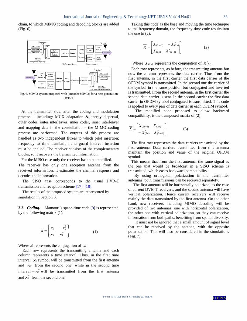
chain, to which MIMO coding and decoding blocks are added
(Fig. 6).
Fig. 6. MIMO system proposed with (encoder MIMO) for a next generation
DVB-T.
At the transmitter side, after the coding and modulation
process – including: MUX adaptation & energy dispersal,
outer coder, outer interleaver, inner coder, inner interleaver
and mapping data in the constellation – the MIMO coding
process are performed. The outputs of this process are
handled as two independent fluxes to which pilot insertion;
frequency to time translation and guard interval insertion
must be applied. The receiver consists of the complementary
blocks, so it recovers the transmitted information.
For the MISO case only the receiver has to be modified.
The receiver has only one reception antenna from the
received information, it estimates the channel response and
decodes the information.
The SISO case corresponds to the usual DVB-T
transmission and reception scheme [17], [18].
The results of the proposed system are represented by
simulation in Section 5.
3.3. Coding. Alamouti‟s space-time code [9] is represented
by the following matrix (1):
*12
*21
xx
xxx (1)
Where *ix represents the conjugation of ix .
Each row represents the transmitting antenna and each
column represents a time interval. Thus, in the first time
interval 1x symbol will be transmitted from the first antenna
and 2x from the second one, while in the second time
interval *2x will be transmitted from the first antenna
and *1x from the second one.
Taking this code as the base and moving the time technique
to the frequency domain, the frequency-time code results into
the one in (2).
*)12()2(
*)2()12(
nn
nn
XX
XXX (2)
Where )2( nX represents the conjugation of )2( nX .
Each row represents, as before, the transmitting antenna but
now the column represents the data carrier. Thus from the
first antenna, in the first carrier the first data carrier of the
OFDM symbol is transmitted. In the second one the carrier of
the symbol in the same position but conjugated and inverted
is transmitted. From the second antenna, in the first carrier the
second data carrier is sent. In the second carrier the first data
carrier in OFDM symbol conjugated is transmitted. This code
is applied to every pair of data carrier in each OFDM symbol.
The modified code proposed to allow backward
compatibility, is the transposed matrix of (2).
*)12(
*)2(
)2()12(
nn
nn
XX
XXX (3)
The first row represents the data carriers transmitted by the
first antenna. Data carriers transmitted from this antenna
maintain the position and value of the original OFDM
symbol.
This means that from the first antenna, the same signal as
the one that would be broadcast in a SISO scheme is
transmitted, which eases backward compatibility.
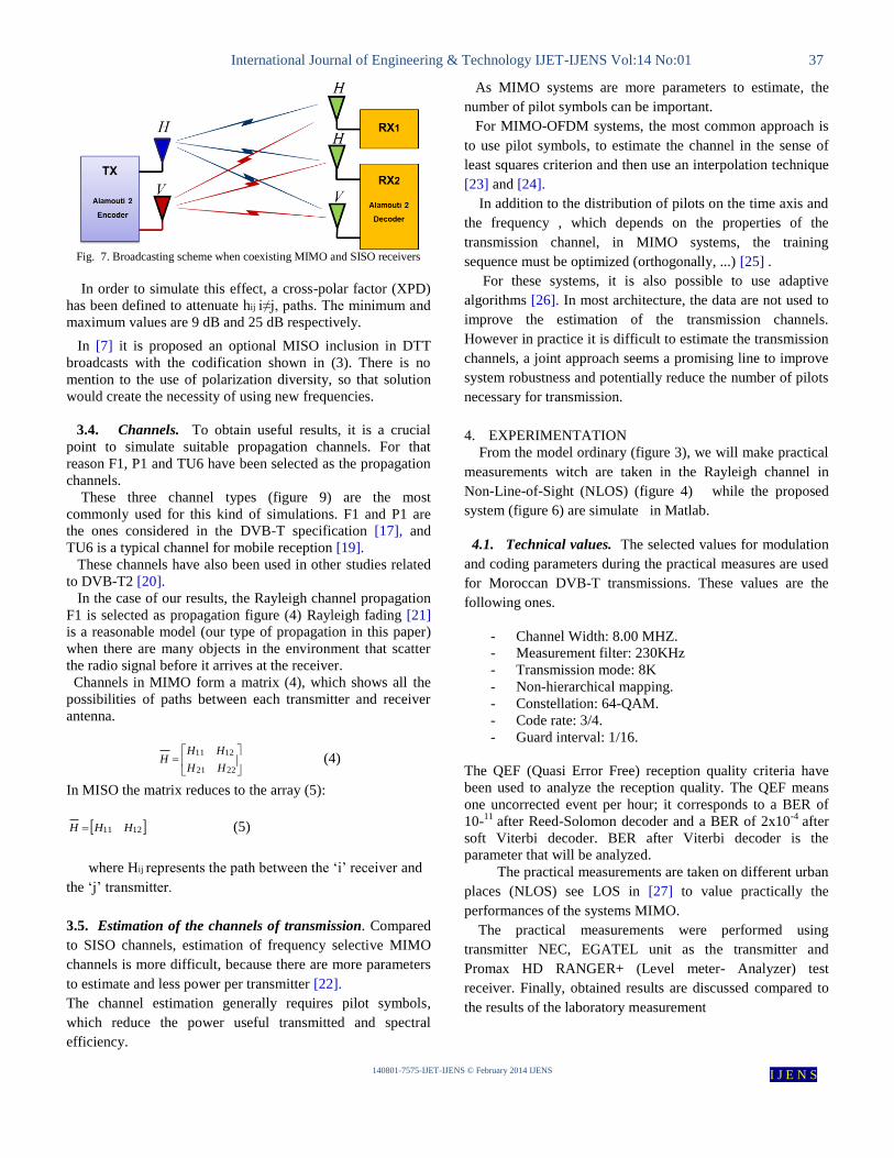
By using orthogonal polarization in the transmitter
antennas, both transmissions can be received separately.
The first antenna will be horizontally polarized, as the case
of current DVB-T receivers, and the second antenna will have
vertical polarization. Hence current receivers will receive
mainly the data transmitted by the first antenna. On the other
hand, new receivers including MIMO decoding will be
provided of two antennas, one with horizontal polarization,
the other one with vertical polarization, so they can receive
information from both paths, benefiting from spatial diversity.
It must not be ignored that a small amount of signal level
that can be received by the antenna, with the opposite
polarization. This will also be considered in the simulations
(Fig. 7).
International Journal of Engineering & Technology IJET-IJENS Vol:14 No:01 37
140801-7575-IJET-IJENS © February 2014 IJENS I J E N S
Fig. 7. Broadcasting scheme when coexisting MIMO and SISO receivers
In order to simulate this effect, a cross-polar factor (XPD)
has been defined to attenuate hij i≠j, paths. The minimum and
maximum values are 9 dB and 25 dB respectively.
In [7] it is proposed an optional MISO inclusion in DTT
broadcasts with the codification shown in (3). There is no
mention to the use of polarization diversity, so that solution
would create the necessity of using new frequencies.
3.4. Channels. To obtain useful results, it is a crucial
point to simulate suitable propagation channels. For that
reason F1, P1 and TU6 have been selected as the propagation
channels.
These three channel types (figure 9) are the most
commonly used for this kind of simulations. F1 and P1 are
the ones considered in the DVB-T specification [17], and
TU6 is a typical channel for mobile reception [19].
These channels have also been used in other studies related
to DVB-T2 [20].
In the case of our results, the Rayleigh channel propagation
F1 is selected as propagation figure (4) Rayleigh fading [21]
is a reasonable model (our type of propagation in this paper)
when there are many objects in the environment that scatter
the radio signal before it arrives at the receiver.
Channels in MIMO form a matrix (4), which shows all the
possibilities of paths between each transmitter and receiver
antenna.
2221
1211
HH
HHH (4)
In MISO the matrix reduces to the array (5):
1211 HHH (5)
where Hij represents the path between the „i‟ receiver and
the „j‟ transmitter.
3.5. Estimation of the channels of transmission. Compared
to SISO channels, estimation of frequency selective MIMO
channels is more difficult, because there are more parameters
to estimate and less power per transmitter [22].
The channel estimation generally requires pilot symbols,
which reduce the power useful transmitted and spectral
efficiency.
As MIMO systems are more parameters to estimate, the
number of pilot symbols can be important.
For MIMO-OFDM systems, the most common approach is
to use pilot symbols, to estimate the channel in the sense of
least squares criterion and then use an interpolation technique
[23] and [24].
In addition to the distribution of pilots on the time axis and
the frequency , which depends on the properties of the
transmission channel, in MIMO systems, the training
sequence must be optimized (orthogonally, ...) [25] .
For these systems, it is also possible to use adaptive
algorithms [26]. In most architecture, the data are not used to
improve the estimation of the transmission channels.
However in practice it is difficult to estimate the transmission
channels, a joint approach seems a promising line to improve
system robustness and potentially reduce the number of pilots
necessary for transmission.
4. EXPERIMENTATION
From the model ordinary (figure 3), we will make practical
measurements witch are taken in the Rayleigh channel in
Non-Line-of-Sight (NLOS) (figure 4) while the proposed
system (figure 6) are simulate in Matlab.
4.1. Technical values. The selected values for modulation
and coding parameters during the practical measures are used
for Moroccan DVB-T transmissions. These values are the
following ones.
- Channel Width: 8.00 MHZ.
- Measurement filter: 230KHz
- Transmission mode: 8K
- Non-hierarchical mapping.
- Constellation: 64-QAM.
- Code rate: 3/4.
- Guard interval: 1/16.
The QEF (Quasi Error Free) reception quality criteria have
been used to analyze the reception quality. The QEF means
one uncorrected event per hour; it corresponds to a BER of
10-11
after Reed-Solomon decoder and a BER of 2x10⁻⁴
after
soft Viterbi decoder. BER after Viterbi decoder is the
parameter that will be analyzed.
The practical measurements are taken on different urban
places (NLOS) see LOS in [27] to value practically the
performances of the systems MIMO.
The practical measurements were performed using
transmitter NEC, EGATEL unit as the transmitter and
Promax HD RANGER+ (Level meter- Analyzer) test
receiver. Finally, obtained results are discussed compared to
the results of the laboratory measurement

International Journal of Engineering & Technology IJET-IJENS Vol:14 No:01 38
140801-7575-IJET-IJENS © February 2014 IJENS I J E N S
4.2. Equipment used:
4.2.1. Broadcasting side
- Two transmitters DVB brand NEC UHF channel 24
(498 MHz) power from 0 to Watts 1000Watts..
- A transmitter DVB brand EGATEL UHF Channel:
31 (554 MHz) power from 0 to Watts 1000Watts.
- Three panel antennas of horizontal polarization.
- Three antennas/Power Distribution System, 470-
952 MHz UHF (a input- a output) (input-two output)
(input-three outputs)
4.2.2. Receiving case.
- HD RANGER+ (The HD RANGER+ is a universal
analyser that covers a comprehensive mix of broadcast
standards around the globe. The latest developments in
broadcast technology such as DVB-T2/C2/S2 (DVB-
T/C/S also included) with MPEG-2 as well as MPEG-4
video are managed effortlessly within the product).
- 3 Antennas (AMC / 1) UHF (470 MHz to 860 MHz)
at a height of 2m from the ground.
- Two power couplers (one has two inputs and one
output while the other has three inputs and a one
output.
In this practical work we have taken the following steps:
- MER (Modulation Error Ratio), which represents all
the problems affecting the constellation diagram
- C / N
- BER after Viterbi VBER (Bit Error Rate) for
appreciation the quality of transmission
The measurements obtained are verified in the laboratory,
TV/FM broadcasting center, with the following:
- Agilent E4402B (3 GHz). Spectrum Analyzer.
- Generator Rohde and Schwarz DVB SFQ.
- Demodulator measurement DVB EFA-T Rohde and
Schwarz.
- HF generator Hewlett-Packard 8656 B.
- 3 dB coupler measuring Radiall 500-1000 MHz.
- Load of 50 ohm load.
The signals used are supplied by a generator DVB Rohde
and Schwarz SFQ. This ensures a perfect control of various
parameters characterizing a DVB-T signal and simulates
various defects that may occur in transmission. Signal
measurement is performed with a spectrum analyzer and
Agilent E4402B with a demodulator measures Rohde and
Schwarz EFA-T.
Fig. 8. HD RANGER+ TV & Satellite analyser –PROMAX
5. Results
5.1. Channel. In order to validate the performance of the
practical measurements, we started with the measurements
that show the effect of all the propagation channels
considered in the case of a SISO transmission (Fig. 9).
Required C/N value to achieve a BER of 2·10-4
after Viterbi
decoder can be compared in Gaussian, F1 and P1 channels,
with the C/N thresholds in [17].
The C/N thresholds obtained are approximately 2 dB
higher, which is due to the linear channel estimation used
instead of using the optimal 2-D Wiener estimation in the
equalizer. This is not a significant difference for the
comparative study as all the techniques considered use the
same equalizer.
10 15 20 25 30 3510
-7
10-6
10-5
10-4
10-3
10-2
10-1
100
BE
R
C/N (dB)
Practice : BER after Viterbi for different simulation channels
Gaussian channel
Ricean channel(F1)
Rayleigh channel (P1)
TU6
Fig. 9. Measurement results BER after Viterbi for different channels
We see that the measured values satisfy the theoretical four
types of the channels.
5.2. Simulated bit-error rate Diagrams. Below are bit-error
rate diagrams for the various modulations, using both short
and long FEC codes.
International Journal of Engineering & Technology IJET-IJENS Vol:14 No:01 39
140801-7575-IJET-IJENS © February 2014 IJENS I J E N S
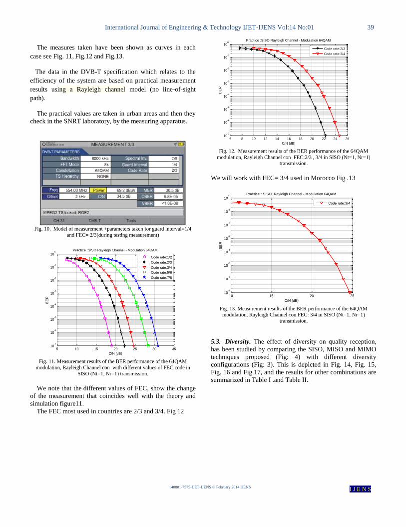
The measures taken have been shown as curves in each
case see Fig. 11, Fig.12 and Fig.13.
The data in the DVB-T specification which relates to the
efficiency of the system are based on practical measurement
results using a Rayleigh channel model (no line-of-sight
path).
The practical values are taken in urban areas and then they
check in the SNRT laboratory, by the measuring apparatus.
Fig. 10. Model of measurement +parameters taken for guard interval=1/4
and FEC= 2/3(during testing measurement)
5 10 15 20 25 30 3510
-7
10-6
10-5
10-4
10-3
10-2
10-1
100
Practice :SISO Rayleigh Channel - Modulation 64QAM
BE
R
C/N (dB)
Code rate:1/2
Code rate:2/3
Code rate:3/4
Code rate:5/6
Code rate:7/8
Fig. 11. Measurement results of the BER performance of the 64QAM
modulation, Rayleigh Channel con with different values of FEC code in
SISO (Nt=1, Nr=1) transmission.
We note that the different values of FEC, show the change
of the measurement that coincides well with the theory and
simulation figure11.
The FEC most used in countries are 2/3 and 3/4. Fig 12
6 8 10 12 14 16 18 20 22 24 2610
-7
10-6
10-5
10-4
10-3
10-2
10-1
100
Practice :SISO Rayleigh Channel - Modulation 64QAM
C/N (dB)
BE
R
Code rate:2/3
Code rate:3/4
Fig. 12. Measurement results of the BER performance of the 64QAM
modulation, Rayleigh Channel con FEC:2/3 , 3/4 in SISO (Nt=1, Nr=1) transmission.
We will work with FEC= 3/4 used in Morocco Fig .13
10 15 20 2510
-7
10-6
10-5
10-4
10-3
10-2
10-1
100
Practice : SISO Rayleigh Channel - Modulation 64QAM
C/N (dB)
BE
R
Code rate:3/4
Fig. 13. Measurement results of the BER performance of the 64QAM modulation, Rayleigh Channel con FEC: 3/4 in SISO (Nt=1, Nr=1)
transmission.
5.3. Diversity. The effect of diversity on quality reception,
has been studied by comparing the SISO, MISO and MIMO
techniques proposed (Fig: 4) with different diversity
configurations (Fig: 3). This is depicted in Fig. 14, Fig. 15,
Fig. 16 and Fig.17, and the results for other combinations are
summarized in Table I .and Table II.
International Journal of Engineering & Technology IJET-IJENS Vol:14 No:01 40
140801-7575-IJET-IJENS © February 2014 IJENS I J E N S
10 15 20 2510
-7
10-6
10-5
10-4
10-3
10-2
10-1
100
C/N (dB)
BE
R
Performance of Diversity Technique(Rayleigh Channel)
Practice SISO (1Tx,1Rx) 64 QAM
Practice MISO (2Tx, 1Rx) 64 QAM
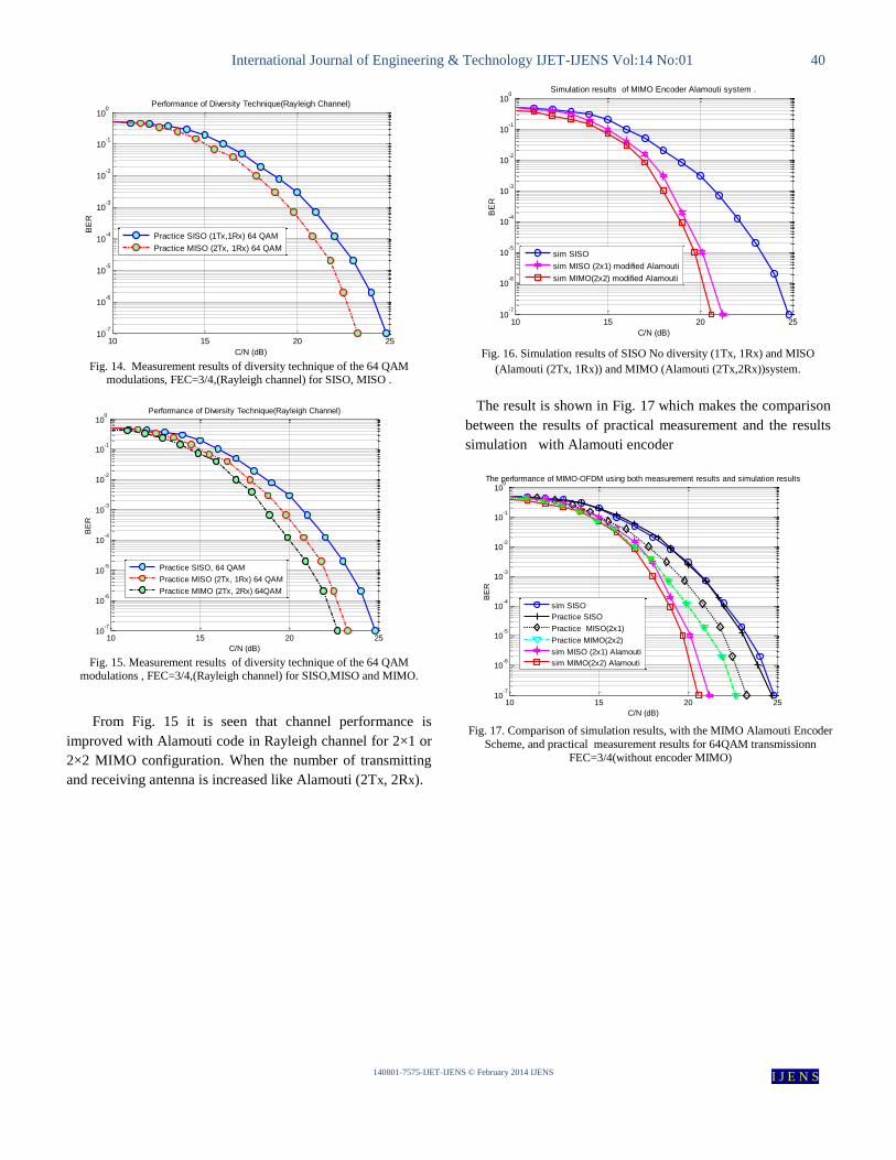
Fig. 14. Measurement results of diversity technique of the 64 QAM
modulations, FEC=3/4,(Rayleigh channel) for SISO, MISO .
10 15 20 2510
-7
10-6
10-5
10-4
10-3
10-2
10-1
100
C/N (dB)
BE
R
Performance of Diversity Technique(Rayleigh Channel)
Practice SISO, 64 QAM
Practice MISO (2Tx, 1Rx) 64 QAM
Practice MIMO (2Tx, 2Rx) 64QAM
Fig. 15. Measurement results of diversity technique of the 64 QAM
modulations , FEC=3/4,(Rayleigh channel) for SISO,MISO and MIMO.
From Fig. 15 it is seen that channel performance is
improved with Alamouti code in Rayleigh channel for 2×1 or
2×2 MIMO configuration. When the number of transmitting
and receiving antenna is increased like Alamouti (2Tx, 2Rx).
10 15 20 2510
-7
10-6
10-5
10-4
10-3
10-2
10-1
100
C/N (dB)
BE
R
Simulation results of MIMO Encoder Alamouti system .
sim SISO
sim MISO (2x1) modified Alamouti
sim MIMO(2x2) modified Alamouti
Fig. 16. Simulation results of SISO No diversity (1Tx, 1Rx) and MISO
(Alamouti (2Tx, 1Rx)) and MIMO (Alamouti (2Tx,2Rx))system.
The result is shown in Fig. 17 which makes the comparison
between the results of practical measurement and the results
simulation with Alamouti encoder
10 15 20 2510
-7
10-6
10-5
10-4
10-3
10-2
10-1
100
BE
R
C/N (dB)
The performance of MIMO-OFDM using both measurement results and simulation results
sim SISO
Practice SISO
Practice MISO(2x1)
Practice MIMO(2x2)
sim MISO (2x1) Alamouti
sim MIMO(2x2) Alamouti
Fig. 17. Comparison of simulation results, with the MIMO Alamouti Encoder
Scheme, and practical measurement results for 64QAM transmissionn
FEC=3/4(without encoder MIMO)
International Journal of Engineering & Technology IJET-IJENS Vol:14 No:01 41
140801-7575-IJET-IJENS © February 2014 IJENS I J E N S
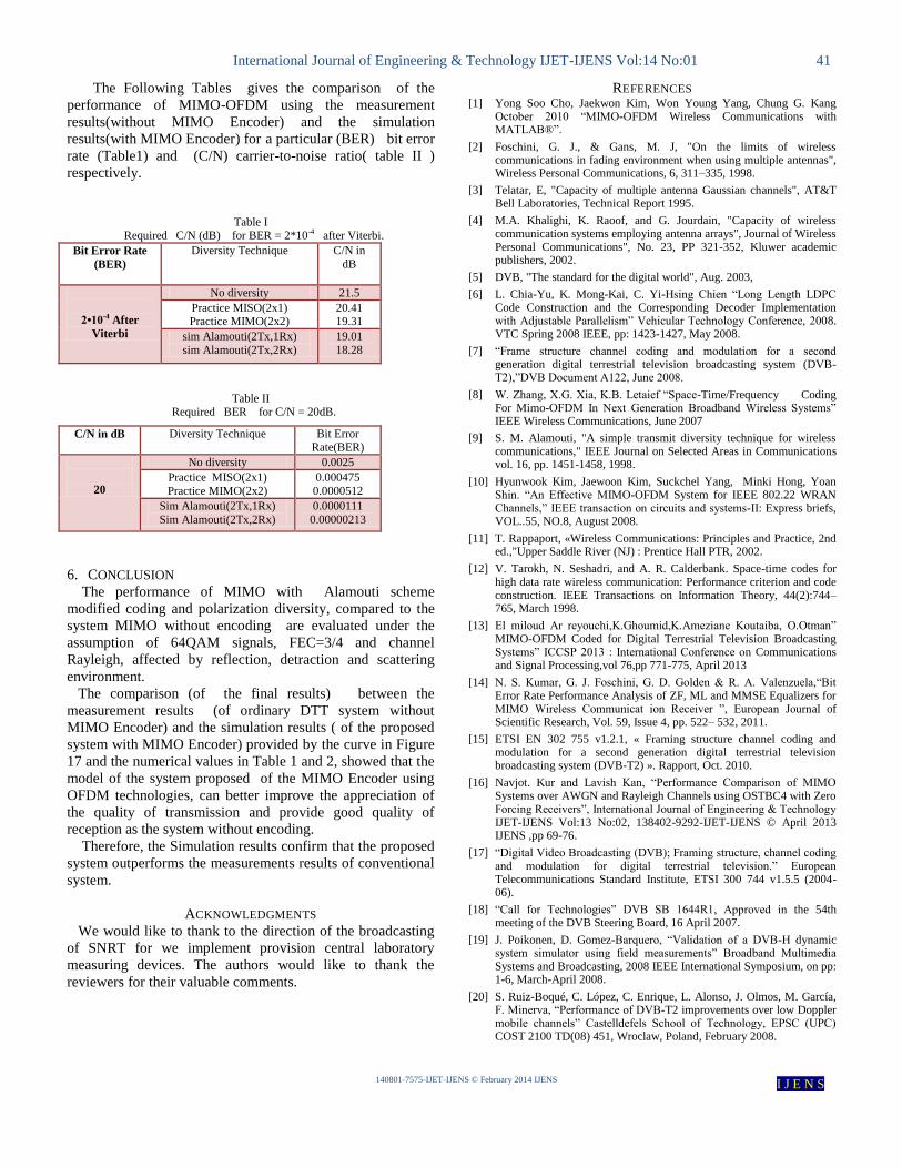
The Following Tables gives the comparison of the
performance of MIMO-OFDM using the measurement
results(without MIMO Encoder) and the simulation
results(with MIMO Encoder) for a particular (BER) bit error
rate (Table1) and (C/N) carrier-to-noise ratio( table II )
respectively.
Table I
Required C/N (dB) for BER = 2*10-4 after Viterbi.
Bit Error Rate
(BER)
Diversity Technique C/N in
dB
2•10-4 After
Viterbi
No diversity 21.5
Practice MISO(2x1) Practice MIMO(2x2)
20.41
19.31
sim Alamouti(2Tx,1Rx)
sim Alamouti(2Tx,2Rx)
19.01
18.28
Table II Required BER for C/N = 20dB.
C/N in dB Diversity Technique Bit Error Rate(BER)
20
No diversity 0.0025
Practice MISO(2x1)
Practice MIMO(2x2)
0.000475
0.0000512
Sim Alamouti(2Tx,1Rx)
Sim Alamouti(2Tx,2Rx)
0.0000111
0.00000213
6. CONCLUSION
The performance of MIMO with Alamouti scheme
modified coding and polarization diversity, compared to the
system MIMO without encoding are evaluated under the
assumption of 64QAM signals, FEC=3/4 and channel
Rayleigh, affected by reflection, detraction and scattering
environment.
The comparison (of the final results) between the
measurement results (of ordinary DTT system without
MIMO Encoder) and the simulation results ( of the proposed
system with MIMO Encoder) provided by the curve in Figure
17 and the numerical values in Table 1 and 2, showed that the
model of the system proposed of the MIMO Encoder using
OFDM technologies, can better improve the appreciation of
the quality of transmission and provide good quality of
reception as the system without encoding.
Therefore, the Simulation results confirm that the proposed
system outperforms the measurements results of conventional
system.
ACKNOWLEDGMENTS
We would like to thank to the direction of the broadcasting
of SNRT for we implement provision central laboratory
measuring devices. The authors would like to thank the
reviewers for their valuable comments.
REFERENCES
[1] Yong Soo Cho, Jaekwon Kim, Won Young Yang, Chung G. Kang October 2010 “MIMO-OFDM Wireless Communications with MATLAB®”.
[2] Foschini, G. J., & Gans, M. J, "On the limits of wireless communications in fading environment when using multiple antennas", Wireless Personal Communications, 6, 311–335, 1998.
[3] Telatar, E, "Capacity of multiple antenna Gaussian channels", AT&T Bell Laboratories, Technical Report 1995.
[4] M.A. Khalighi, K. Raoof, and G. Jourdain, "Capacity of wireless communication systems employing antenna arrays", Journal of Wireless Personal Communications", No. 23, PP 321-352, Kluwer academic publishers, 2002.
[5] DVB, "The standard for the digital world", Aug. 2003,
[6] L. Chia-Yu, K. Mong-Kai, C. Yi-Hsing Chien “Long Length LDPC Code Construction and the Corresponding Decoder Implementation with Adjustable Parallelism” Vehicular Technology Conference, 2008. VTC Spring 2008 IEEE, pp: 1423-1427, May 2008.
[7] “Frame structure channel coding and modulation for a second generation digital terrestrial television broadcasting system (DVB-T2),”DVB Document A122, June 2008.
[8] W. Zhang, X.G. Xia, K.B. Letaief “Space-Time/Frequency Coding For Mimo-OFDM In Next Generation Broadband Wireless Systems” IEEE Wireless Communications, June 2007
[9] S. M. Alamouti, "A simple transmit diversity technique for wireless communications," IEEE Journal on Selected Areas in Communications vol. 16, pp. 1451-1458, 1998.
[10] Hyunwook Kim, Jaewoon Kim, Suckchel Yang, Minki Hong, Yoan Shin. “An Effective MIMO-OFDM System for IEEE 802.22 WRAN Channels,” IEEE transaction on circuits and systems-II: Express briefs, VOL..55, NO.8, August 2008.
[11] T. Rappaport, «Wireless Communications: Principles and Practice, 2nd ed.,"Upper Saddle River (NJ) : Prentice Hall PTR, 2002.
[12] V. Tarokh, N. Seshadri, and A. R. Calderbank. Space-time codes for high data rate wireless communication: Performance criterion and code construction. IEEE Transactions on Information Theory, 44(2):744–765, March 1998.
[13] El miloud Ar reyouchi,K.Ghoumid,K.Ameziane Koutaiba, O.Otman” MIMO-OFDM Coded for Digital Terrestrial Television Broadcasting Systems” ICCSP 2013 : International Conference on Communications and Signal Processing,vol 76,pp 771-775, April 2013
[14] N. S. Kumar, G. J. Foschini, G. D. Golden & R. A. Valenzuela,“Bit Error Rate Performance Analysis of ZF, ML and MMSE Equalizers for MIMO Wireless Communicat ion Receiver ”, European Journal of Scientific Research, Vol. 59, Issue 4, pp. 522– 532, 2011.
[15] ETSI EN 302 755 v1.2.1, « Framing structure channel coding and modulation for a second generation digital terrestrial television broadcasting system (DVB-T2) ». Rapport, Oct. 2010.
[16] Navjot. Kur and Lavish Kan, “Performance Comparison of MIMO Systems over AWGN and Rayleigh Channels using OSTBC4 with Zero Forcing Receivers”, International Journal of Engineering & Technology IJET-IJENS Vol:13 No:02, 138402-9292-IJET-IJENS © April 2013 IJENS ,pp 69-76.
[17] “Digital Video Broadcasting (DVB); Framing structure, channel coding and modulation for digital terrestrial television.” European Telecommunications Standard Institute, ETSI 300 744 v1.5.5 (2004-06).
[18] “Call for Technologies” DVB SB 1644R1, Approved in the 54th meeting of the DVB Steering Board, 16 April 2007.
[19] J. Poikonen, D. Gomez-Barquero, “Validation of a DVB-H dynamic system simulator using field measurements” Broadband Multimedia Systems and Broadcasting, 2008 IEEE International Symposium, on pp: 1-6, March-April 2008.
[20] S. Ruiz-Boqué, C. López, C. Enrique, L. Alonso, J. Olmos, M. García, F. Minerva, “Performance of DVB-T2 improvements over low Doppler mobile channels” Castelldefels School of Technology, EPSC (UPC) COST 2100 TD(08) 451, Wroclaw, Poland, February 2008.
International Journal of Engineering & Technology IJET-IJENS Vol:14 No:01 42
140801-7575-IJET-IJENS © February 2014 IJENS I J E N S
[21] P. Sanghoi & L. Kansal, “Analysis of WIMAX Physical layer Using Spatial Diversity under different Fading Channels”, International Journal of Computer Applicat ion, Vol. 44, no. 20, May 2012.
[22] C. Komninakis and C. Fragouli and A. H. Sayed and R.D Wesel, "Multi-input Multi-output Fading channel tracking and equalization using Kalman estimation", IEEE Journal on Selected Areas on Communications, vol.20, pp.1211-1226, 2002 .
[23] S. Liang and W. Wu, "Channel estimation based on pilot subcarrier in space-time block coded OFDM system", Proceedings of IEEE ICCT, vol.2, pp.1795-1798, 2003 .
[24] D. M. Teran and R. P. T. Jimenez, "Channel estimation for STBC-OFDM systems", Proceedings of 5th IEEE SPAWC", pp.688-691, 2004.
[25] Barhumi, L., Leus, G., & Moonen, M, "Optimal training design for MIMO-OFDM systems in mobile wireless channels", IEEE Transaction on Signal Processing, 51, 1615–1624, 2003.
[26] T. Roman and M. Enescu and V. Koivunen,"Time domain method for tracking dispersive channels in MIMO-OFDM systems",Proceedings of IEEE ICASSP, vol.4,pp.393-396, 2003.
[27] El miloud Ar reyouchi , K. Ghoumid , K. Ameziane ,and O. El Mrabet,” Performance Analysis of Round Trip Time in Narrowband RF Networks For Remote WirelessCommunications” International Journal of Computer Science & Information Technology (IJCSIT) Vol 5, No 5, October 2013 pp 1-20