Acoustic ink printing
8
ACOUSTIC INK PRINTING B. Hadimioglu, S.A. Elrod, D. L. Steinmetz, M. Lim, J.C. Zesch, B. T. Khuri-Yakub*, E. G. Rawson, and C. F. Quate Xerox Palo Alto Research Center 3333 Coyote Hill Road Palo Alto, CA. 94304 ABSTRACT We have used an acoustic beam focused on a free liquid surface to eject discrete ink droplets of controlled diameter. Nozzles are not emplo ed. The of a suitable focusing element, is excited with a burst of acoustic energy. Spherical PZT shells, acoustic microscope lenses, spherical lenses etched in silicon, and Fresnel acoustic lenses have been used successfully to eject droplets. Droplet diameter scales directly with the focal spot size, and hence inversely with the acoustic frequency. Droplet formation has been experimentally demonstrated over the frequency range of 5 to 300 MHz, with corresponding droplet diameters from 300 to 5 microns. This droplet ejection process has been successfully utilized for printin application by using ink as the liquid medium. In %is report we describe Acoustic Ink Printing with a single lens and with an array of lenses. The size of the printed spot can be changed by changing the droplet size or by placing multiple droplets of ink on the same pixel. Our results show that Acoustic Ink Printing is a promising technology for high resolution, high quality printing. liquid surface, adjusted to be at the focal pane Y INTRODUCTION High resolution printing requires the ability to mark small spots on paper with high precision. Modern printers have capabilities to print at resolutions as high as 600 spots per inch (SPI) which requires a spot size of only 42.5 pm. Several print technologies are in use toda for electronic publishing. Laser printers are capagle of producing very high resolution and good uality images. Color laser printing, however, is costly ! ue to color registration problems. Thermal transfer printers produce high quality color prints but they are expensive and slow. Bubble and piezo type ink jet printers are good candidates for low cost printing but they require droplet defining nozzles which are prone to clogging. It has been shown that focused, high-intensity sound beams can be used for ejecting droplets from free liquid surfaces.1 This process is capable of producing drops as small as a few microns without the need for nozzles. The drops are stable in size and directionality. Here we describe the use of this process for high resolution printing applications. This new printing concept appears to be more favorable over other *E. L. Ginzton Laboratory, Stanford University, Stanford, CA. 94305 1051-0117/92/0000-0929 $1.00 0 1992 IEEE printing technologies because of the capability of good quality printing at a relatively high speed. It also holds promise for high reliability, long lifetime and high degree of integration for low-cost manufacturing. ULTRASONIC DROPLET EJECTION WITH FOCUSED SOUND BEAMS We have previously shown1 that a burst of acoustic energy focused to a diffraction-limited spot at a liquid surface can result in droplet ejection from the surface. The geometry of interest is shown in Fig. 1. A iezoelectric transducer is attached to one end of a E uffer rod. On the other end of the rod, a spherical cavity filled with a liquid is located and this cavity serves as the lens element. When the transducer is excited with a tone burst of RF energy, it generates sound waves which propa ate in the buffer rod towards the liquid surface which is adjusted to be at the focal plane of the converging beam. Impact of the sound burst will cause a mound of liquid to rise from the surface due to the radiation pressure of the acoustic waves. If the energy of the incident sound beam is high enou h, Rayleigh-Taylor instability2 will droplet breaks free. The droplet IS expelled away from the surface at a velocit of several meters per second. generated near the mound propagate radially outwards. The ejected droplets have been found to be very stable in size, velocity and directionality. towards the lens. The lens 9 ocuses the sound waves cause the top of t R e mound to neck down until a After ejection, the sur Y ace relaxes as capillary waves3 0 PULSE INPUT rf U Fig. 1. A single acoustic ejector 1992 ULTRASONICS SYMPOSIUM - 929
Transcript of Acoustic ink printing

ACOUSTIC INK PRINTING
B. Hadimioglu, S.A. Elrod, D. L. Steinmetz, M. Lim, J.C. Zesch, B. T. Khuri-Yakub*, E. G. Rawson, and C. F. Quate
Xerox Palo Alto Research Center 3333 Coyote Hill Road Palo Alto, CA. 94304
ABSTRACT We have used an acoustic beam focused on a free l iquid surface t o eject discrete ink droplets o f controlled diameter. Nozzles are not emplo ed. The
of a suitable focusing element, is excited with a burst of acoustic energy. Spherical PZT shells, acoustic microscope lenses, spherical lenses etched in silicon, and Fresnel acoustic lenses have been used successfully t o eject droplets. Droplet diameter scales directly with the focal spot size, and hence inversely wi th the acoustic frequency. Droplet format ion has been experimentally demonstrated over the frequency range of 5 to 300 MHz, with corresponding droplet diameters from 300 to 5 microns. This droplet ejection process has been successfully utilized for printin application by using ink as the liquid medium. In %is report we describe Acoustic Ink Printing with a single lens and with an array of lenses. The size of the printed spot can be changed by changing the droplet size or by placing multiple droplets of ink on the same pixel. Our results show that Acoustic Ink Printing i s a promising technology for high resolution, high quality printing.
liquid surface, adjusted to be a t the focal pane Y
INTRODUCTION High resolution printing requires the ability to mark small spots on paper with high precision. Modern printers have capabilities to print a t resolutions as high as 600 spots per inch (SPI) which requires a spot size of only 42.5 pm. Several print technologies are in use toda for electronic publishing. Laser printers are capagle of producing very high resolution and good
uality images. Color laser printing, however, is costly ! ue to color registration problems. Thermal transfer printers produce high quality color prints but they are expensive and slow. Bubble and piezo type ink jet printers are good candidates for low cost printing but they require droplet defining nozzles which are prone to clogging. It has been shown that focused, high-intensity sound beams can be used for ejecting droplets from free liquid surfaces.1 This process is capable of producing drops as small as a few microns without the need for nozzles. The drops are stable in size and directionality. Here we describe the use of this process for high resolution printing applications. This new printing concept appears to be more favorable over other
*E. L. Ginzton Laboratory, Stanford University, Stanford, CA. 94305
1051-0117/92/0000-0929 $1.00 0 1992 IEEE
printing technologies because of the capability of good quality printing a t a relatively high speed. It also holds promise for high reliability, long lifetime and high degree of integration for low-cost manufacturing.
ULTRASONIC DROPLET EJECTION WITH FOCUSED SOUND BEAMS
We have previously shown1 that a burst of acoustic energy focused to a diffraction-limited spot a t a liquid surface can result in droplet ejection from the surface. The geometry of interest i s shown in Fig. 1. A
iezoelectric transducer is attached to one end of a E uffer rod. On the other end of the rod, a spherical cavity filled with a liquid is located and this cavity serves as the lens element. When the transducer is excited with a tone burst of RF energy, it generates sound waves which propa ate in the buffer rod
towards the liquid surface which is adjusted to be at the focal plane of the converging beam. Impact of the sound burst will cause a mound of liquid to rise from the surface due to the radiation pressure of the acoustic waves. If the energy of the incident sound beam is high enou h, Rayleigh-Taylor instability2 will
droplet breaks free. The droplet IS expelled away from the surface a t a velocit of several meters per second.
generated near the mound propagate radial ly outwards. The ejected droplets have been found to be very stable in size, velocity and directionality.
towards the lens. The lens 9 ocuses the sound waves
cause the top of t R e mound to neck down until a
After ejection, the sur Y ace relaxes as capillary waves3
0
PULSE INPUT r f U
Fig. 1. A single acoustic ejector
1992 ULTRASONICS SYMPOSIUM - 929

It should be noted here that the geometry used for drop ejection is very similar to that used in acoustic microscopy,4 with the exception of the liquidisample interface replaced by the liquid/air interface. In fact most of the single ejector experiments in this study were done using acoustic microscope lenses. Typically these lenses are fabricated by grinding and polishing a spherical cavity in the buffer rod. Isotropically etched spherical lenses in silicon,5 spherical PZT shells and Fresnel acoustic lenses6 have also been used for focusing the sound waves. PZT shells are very efficient for enerating sound waves but they are mostly limited to frequencies of 20 MHz and below due t o the fabrication d i f f i cu l t ies w i t h th inner devices. Isotropically etched spherical lenses in silicon and plasma etched Fresnel lenses can be fabricated using batch processing. Therefore, they are suitable for applications that require the fabrication of an array of lenses a t low cost. The time evolution of dro let formation is shown in Fig.2 for an RF frequency or5 MHz. a pulse width of 20 s, and a pulse energy of 58 pJ. Water is used as the
data are referenced to the arrival of the midpoint of the acoustic pulse a t the liquid surface. Observations were mad e by stroboscopica I ly i I I u m i nati ng the process from behind and viewing through a microscope. Each photograph represents a superposition of 30 successive droplets, thus the image sharpness at tests t o the stability of drop formation process. For lenses with F- number of 1, the diameter of the droplet is found to scale inversely with the acoustic frequency, f. We find the process is qualitatively similar over the entire f requenc range f r o m 5 t o 300 MHz w i t h
r iquid medium. Times quoted for the experimental
correspon d' ing dropdiametersfrom 300 pm to 5 pm.
120 ps
0
550 ps
40 ps
280 ps
0
~
690 ps
THE PHYSICS OF ULTRASONIC DROPLET EJECTION
The pressure field for the sound beam propagating in the liquid can be written as
The first term in Eqn. 1 is the acoustic pressure and the second is the DC radiation resistance given by
2 1 Q = -
C
where I is the intensity of the acoustic beam and c is the velocity of sound. This radiation pressure imparts to the liquid in the focal region an initial momentum Mjnjt=RT, where T is the pulse duration. I t i s this momentum which acts t o overcome the restraining force of surface tension and expel the droplet. For the 5 MHz experiment described above, the threshold energy Eth to create a free droplet having zero velocity is measured to be 50 pJ, This implies that the intensity of the acoustic beam is 3.5 kWicm2 assuming that the acoustic power i s concent ra ted i n an area approximately one wavelength in diameter (A = 300 pm). The radiation pressure a t this intensity level is about 0.4 atm as compared to the acoustic pressure of nearly 70 atm. The energy required to break the surface free is on the order of 0.5 where a is the surface tension and 5 is the surface area of the drop.7 For water, with surface tension 74x10-3 N/m, we find the surface energy to be 20 nJ. This result is consistent with the fact that most of the acoustic energy is reflected from the liquid surface. The droplet ejection process was also analyzed using numerical simulation.l.8 Fig. 3 shows the t ime evolution of droplet ejection at 5 MHz obtained from simulations. The results of the computation compares
1 .Omm 4 1 A
20ps 6 0 ~ s
L 120ps
38Ops
A 240ps
Fig. 2. Photos of ejection a t 5 MHz Fig. 3. Simulation of ejection a t 5 MHz
930 - 1992 ULTRASONICS SYMPOSIUM
favorably with the experimental observations in Fig. 2. A more detailed account of the physics of droplet ejection and modeling of this process can be found in Ref. 1.
ACOUSTIC INK PRINTING
We have used the droplet ejection process described above for printing applications. Ink was used as the liquid medium and the recordin medium, typically
approximately 1 mm from the ink surface. Upon impacting the paper, the ink droplets spread out t o cover an area approximatel twice the cross sectional area of the droplets. Thererore, changing the droplet size wi l l change the spot size on paper and the resolution of the printer. Table 1 shows the scaling of the printer resolution in SPI as a function of the RF frequency. It can be seen from Table 1 that Acoustic Ink Printing is capable o f producing very high resolution images. Table 2 makes a comparison of energy required for marking a 100 m diameter spot for various direct marking technokgies. The low and high numbers in Table 2 for Acoustic Ink Print ing correspond to transducer to lens focal point efficiency of 10 and 20 des, respectively. It can be seen that Acoustic Ink Printing compares favorably against other marking techniques. I t should also be noted that the energy required for ejection1 in Acoustic Ink Printing varies as f-2.3. Therefore, we can expect the energy requirement to be even lower a t higher frequencies for higher resolution pri n t i ng .
silica coated paper, is scanne 1 a t a distance of
70
300
3: I ',": 1 42 I 50 30 420 Typical laser printer
300 Typical ink jet resolution
20 600 Best laser printer
5 2500 Photo quality
Impact printer
Thermal transfer
Print technology I R,ef. I I 10-2 9
10-3 10
Bubble jet
Acoustic Ink Printing
Piezo ink jet printer
10-4 - 10-5 11
10-5 - 10-6 1
10-5 - 10-7 12
Acoustic Ink Printing does not have a requirement to boil the ink as needed in bubble je t printing. Hence, a wider range of admissible ink properties can be expected for Acoustic Ink Printing. Furthermore, the absence of drop defining nozzles suggests reliable operation.
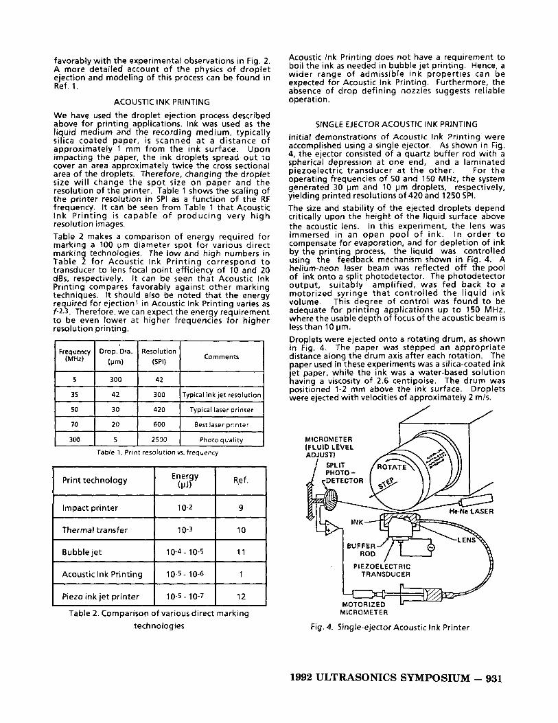
SINGLE EJECTOR ACOUSTIC INK PRINTING Initial demonstrations of Acoustic Ink Printing were accomplished using a single ejector. As shown in Fig. 4, the ejector consisted of a quartz buffer rod with a spherical depression a t one end, and a laminated piezoelectric transducer a t the other. For the operating frequencies of 50 and 150 MHz, the system generated 30 pm and 10 prn droplets, respectively, yielding printed resolutions of 420 and 1250 SPI. The size and stability of the ejected droplets depend critically upon the height of the liquid surface above the acoustic lens. In this experiment, the lens was immersed in an open pool of ink. In order t o compensate for evaporation, and for depletion of ink by the printing process, the liquid was controlled using the feedback mechanism shown in Fi helium-neon laser beam was reflected off t e pool of ink onto a split photodetector. The photodetector output, suitably amplified, was fed back t o a motorized syringe that controlled the l iquid ink volume. This degree of control was found t o be adequate for printing applications up to 150 MHz, where the usable depth of focus of the acoustic beam i s lessthan 10 pm. Droplets were ejected onto a rotating drum, as shown in Fig. 4. The paper was stepped an appropriate distance along the drum axis after each rotation. The paper used in these experiments was a silica-coated ink jet paper, while the ink was a water-based solution having a viscosity of 2.6 centipoise. The drum was positioned 1-2 mm above the ink surface. Droplets were ejected with velocities of approximately 2 m/s.
t4. A
MICROMETER (FLUID LEVEL
. I PIEZOELECTRIC TRANSDUCER I
MICROMETER
Fig. 4. Single-ejector Acoustic Ink Printer
1992 ULTRASONICS SYMPOSIUM - 931
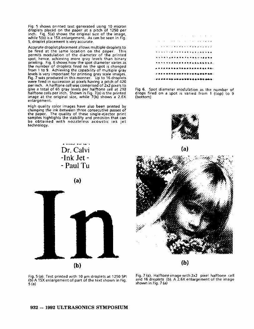
Fig. 5 shows printed tex t generated using 10 micron droplets placed on the paper a t a pitch of 1250 per inch. Fig. 5(a) shows the original size of the image, while 5(b) is a 15X enlargement. As can be seen in Fig. 5, droplet placement is very accurate. Accurate droplet placement allows multiple droplets to be fired a t the same location on the paper. This permits modulation of the diameter of the printed spot, hence, achieving more gray levels than binary printing. Fig. 6 shows how the spot diameter varies as the number of droplets fired on the spot i s changed from 1 to 9. Achieving the capability of multiple gray levels is very important for printing gray scale images. Fig. 7 was produced in this manner. Up to 16 droplets were fired in succession a t pixels having a pitch of 420 per inch. A halftone cell was comprised of 2x2 pixels to give a total of 65 gray levels per halftone cell a t 210 halftone cells per inch. Shown in Fig. 7(a) is the printed image a t the original size, while 7(b) shows a 2.6X enlargement. High quality color images have also been printed by changing the ink between three consecutive passes of the paper. The quality of these single-ejector print samples highlights the stability and precision that can be obtained w i t h nozzleless acoustic ink j e t technology.
Dr. Calvi -Ink Jet - - Paul Tu
I. 5 (a). Text printed with 10 prn droplets at 1250 SPI A 15X enlargement of part of the tex t shown in Fig. 4
Fig 6. Spot diameter modulation as the number of drops fired on a spot is varied from 1 (top) to 9 (bottom)
Fig. 7 (a). Halftone image with 2x2 pixel halftone cell and 16 droplets (b). A 2.6X enlargement of the image shown in Fig. 7 (a)
932 - 1992 ULTRASONICS SYMPOSIUM
DESIGN OF AN EXPERIMENTAL PRINT HEAD WITH A
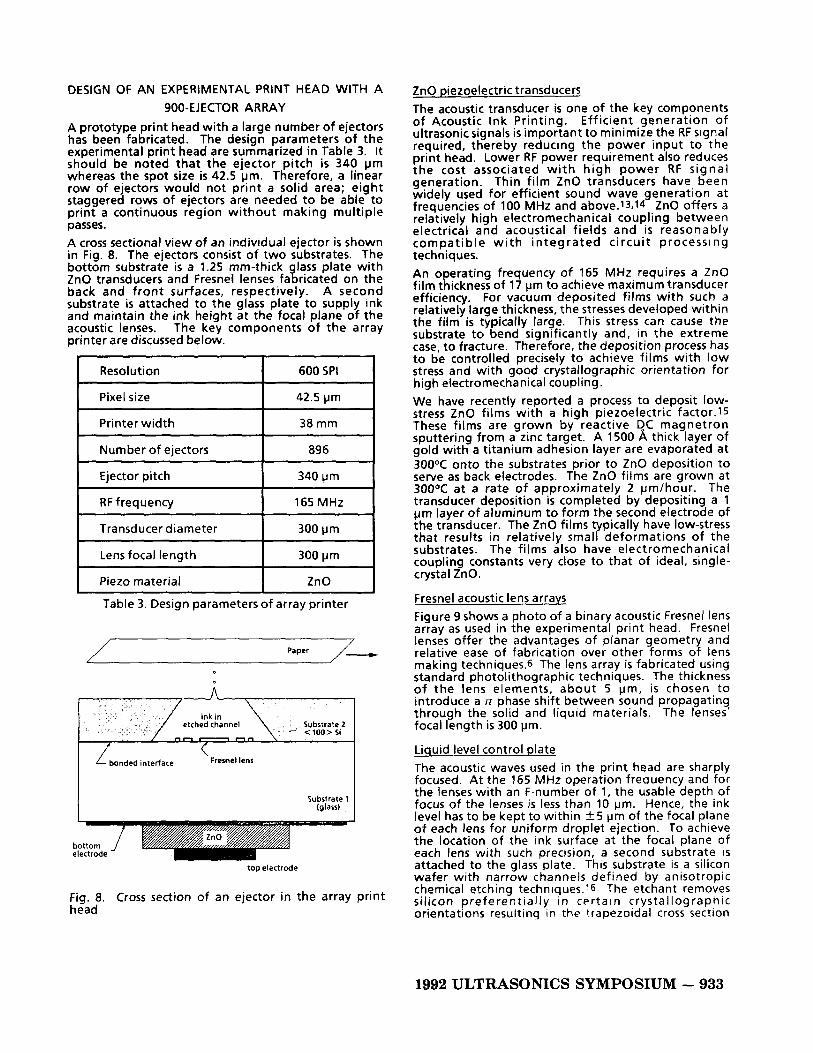
A prototype print head with a large number of ejectors has been fabricated. The design parameters of the experimental print head are summarized in Table 3. It should be noted that the ejector pitch i s 3 4 0 pm whereas the spot size is 42.5 pm. Therefore, a linear row of ejectors would not print a solid area; eight staggered rows of ejectors are needed t o be able t o print a continuous region without making multiple passes. A cross sectional view of an individual ejector is shown in Fig. 8. The ejectors consist of two substrates. The bottom substrate is a 1.25 mm-thick lass plate with
back and front surfaces, respectively. A second substrate i s attached to the glass plate to supply ink and maintain the ink height at the focal plane of the acoustic lenses. The key components of the array printer are discussed below.
900-EJECTOR ARRAY
ZnO transducers and Fresnel lenses fa % ricated on the
Resolution I 600 SPI 1 Pixel size 42.5 pm
Printer width
Number of ejectors
300 pm
I Lens focal length I 300pm I
Table 3. Design parameters of array printer
- Paper
bonded interface L bonded interface Fresnel lens
bottom electrode
top electrode
Fig. 8. Cross section of an ejector in the array print head
ZnO piezoelectric transducers The acoustic transducer is one of the key components of Acoustic Ink Printing. Efficient generation of ultrasonicsignals is important t o minimize the RF signal required, thereby reducing the power input t o the print head. Lower RF power requirement also reduces the cost associated with high power RF signal generation. Thin film ZnO transducers have been widely used for efficient sound wave generation at frequencies of 100 MHz and above.13.14 ZnO offers a relatively high electromechanical coupling between electrical and acoustical fields and is reasonably compatible w i t h in tegrated circui t processing techniques. An operating frequency of 165 MHz requires a ZnO film thickness of 17 pm t o achieve maximum transducer efficiency. For vacuum deposited films with such a relatively large thickness, the stresses developed within the film is typically large. This stress can cause the substrate to bend significantly and, in the extreme case, t o fracture. Therefore, the deposition process has to be controlled precisely to achieve films with low stress and with good crystallographic orientation for high electromechanical coupling. We have recently reported a process to deposit low- stress ZnO films with a high piezoelectric factor.15 These films are grown by reactive QC magnetron sputtering from a zinc target. A 1500 A thick layer of gold with a titanium adhesion layer are evaporated at 3OOOC onto the substrates prior t o ZnO deposition to serve as back electrodes. The ZnO films are grown at 3OOOC at a rate of approximately 2 pm/hour. The transducer deposition i s completed by depositing a 1 pm layer of aluminum t o form the second electrode of the transducer. The ZnO films t pically have low-stress
substrates. The films also have electromechanical coupling constants very close to that of ideal, single- crystal ZnO.
that results in relatively smal Y deformations of the
Fresnel acoustic lens arrays Figure 9 shows a photo of a binary acoustic Fresnel lens array as used in the experimental print head. Fresnel lenses offer the advantages of planar geometry and relative ease of fabrication over other forms of lens making techniques.6 The lens array is fabricated using standard photolithographic techniques. The thickness o f the lens elements, about 5 pm, i s chosen to introduce a n phase shift between sound propagating through the solid and liquid materials. The lenses focal length is 300 pm.
Liquid level control plate The acoustic waves used in the print head are sharply focused. At the 165 MHz operation frequency and for the lenses with an F-number of 1, the usable depth of focus of the lenses is less than 10 pm. Hence, the ink level has to be kept to within +5 pm of the focal plane of each lens for uniform droplet ejection. To achieve the location of the ink surface a t the focal plane of each lens with such precision, a second substrate i s attached to the glass plate. This substrate is a silicon wafer with narrow channels defined by anisotropic chemical etching techniques.16 The etchant removes silicon preferen t ial ly in c p r t ain crystal log rap hic orientations resulting in the trapezoidal cross section
1992 ULTRASONICS SYMPOSIUM - 933

array Fig. 10. Photograph of 900ejector print head
shown in Fig. 8. The bottom opening of each channel is 540 pm wide, larger than the size of the Fresnel lenses. The width of the s l i t on the top side of the silicon wafer is approximately 100 pm. When the channels are filled with ink, the surface tension of the ink across this narrow opening holds the liquid level near the top surface of the silicon. The thickness of the silicon wafer, therefore, is chosen to match the focal length of the acoustic lenses. The level of the liquid can also be adjusted slightly with the application of an external back pressure. I t should also be noted that the slit opening (100 pm) is much larger than the diameter of the ejected drops (10 pm). Hence, these slits have no significant impact on the size and. directionality of the droplets.
Assem b I y The glass/silicon assembl is mounted on a 12.5 cm square printed circuit i o a r d (PCB) to bring the electrical signals into the print head. A photograph of a finished print head assembly is shown in Fig. 10. The ink is supplied to the channels through holes a t both ends of the PCB. The paper i s mounted on a flat computer-controlled translation stage assembly and scanned unidirectionally a t a distance of approximately 1 mm from the print head.
PRINTING WITH AN ARRAY OF EJECTORS A typical print and a 2.5X enlargement are shown in Fig. 11. The ink and paper are the same as those used in the Xerox 4020 ink ‘et printer. Gray scale in the ima e is achieved by defining halftone cells with 4 pixeys each, arranged as a 2x2 array, each of the 4 ixels
levels is 33, and the resolution is 300 halftone cells per inch. Most of the defects in the print are due to slight non-uniformities in the array and particles on the lens surfaces. The print clearly shows uniform droplet ejection from over 90% of the ejectors in the array.
receiving up to 8 droplets. Thus the number o P gray
CONCLUSION We have described a novel printing technology called Acoustic Ink Printing. Acoustic Ink Printing has many advantages including: 1) the absence of a droplet- defining nozzle; 2) the absence of a requirement to boil the ink to achieve ejection (which implies a wider latitude of admissible ink properties); 3) the precision with which uniform small droplets o f ink can be ejected; and 4) the potential for a high degree of integration in the print head structure, including the use of multiple colors in a single print head. Given these advantages, Acoustic Ink Printing has a potential for high quality, high resolution printing.
ACKNOWLEDGEMENTS The authors wish to thank R. Lujan, W. Meuli, S . Akamine, J. Mikkelsen and J. Ho for their contributions to this work
REFERENCES 1. S. A. Elrod, B. Hadimioglu, B. T. Khuri-Yakub, E. G.
Rawson, E. Richley, C. F. Quate, N. N. Mansour, and T. S. Lundgren, “Nozzleless droplet formation with focused acoustic beams,” J. Appl. Phys., 65, 3441 (1989).
2. J. W. S. Rayleigh, The Theory of Sound, 2nd Ed., Ch. 20, Dover Publications, New York (1945).
3, W. Eisenmenger, Acustica 9, 327 (1 959). 4. C. F. Quate, A. Atalar and H. K. Wickramasinghe,
Proc. IEEE 67, 1092. (1979). 5. H. Yamamoto, S. Tanaka and K. Sato, ” Silicon
Acoustic Lens for Scanning Acoustic Microscope (SAM), ” 1991 International Conference on Solid- State Sensors and Actuators, Digest of Technical Papers, 853 (1991).
934 - 1992 ULTRASONICS SYMPOSIUM

Fig. 11. (a) Image printed with a 900 ejector array Acoustic Ink Printer print head (b) A 2.5X enlargement of the print shown in Fig. 11 (a)
6. K. Yamada, H. Shimuzi and M. Minakata, "Planar- Structure Focusing Lens for Operation a t 200 MHz and I ts Application to the Reflection-Mode Acoustic Microscope," Proc. 1986 IEEE Ultrason. Symp., 745 (1986).
7. H. Rouse, "Elementary Mechanics of Fluids," Chapter 10, Dover Publications, New York (1946).
8. T. 5 . Lundgren and N. N. Mansour, J. Fluid Mech. 194,479 (1988).
9. J. S. Craven, "Dot Matrix Print-Bar Design," Hewlett- Packard Journal, 36(5), 6 (1985).
10.K. S . Pennington and W. Crooks, "Resistive Ribbon Thermal Transfer Printing," IBM Jour. of Res. and Dev. 29,449 (1 985).
l l . N . J . Nielsen, "History of Thinkjet Print Head Development," Hewlett-Packard Journal, 36(6), 4 (1985).
12.J. Heinzl and C. H. Hertz, "Ink-Jet Printing," in Advances in Electronics and Electron Physics, P. W. Hawkes and B. Kazan eds., vol. 65, 91, Academic Press, New York (1985).
13.F. 5 . Hickernel l , "Z inc Oxide Films fo r Acoustoelectric Device Applications," IEEE Trans. Sonics and Ultrason. SU-32, 634 (1985).
14.6. T. KhurilYakub, J. G. Smits, and T. Barbee, "Reactive Magnetron Sputtering of ZnO," J. Appl. Phys., 52,4772 (1981).
15.J. C. Zesch, B. Hadimioglu, B. T. Khuri-Yakub, M. Lim, R. Lujan, J. Ho, S. Akamine, D. Steinmetz, C. F. Quate and E. G. Rawson, "Deposition of Highly Oriented Low-stress ZnO Films," Proc. 1991 IEEE Ultrason. Symp. 445 (1991).
16. K. E. Peterson, "Silicon as a Mechanical Material," Proc. of IEEE, 70,420 (1982).
1992 ULTRASONICS SYMPOSIUM - 935