
Automotive tyre cavity noise modelling and reduction - CORE
11
Automotive tyre cavity noise modelling and reduction Dan J. O’Boy 1 and Stephen J. Walsh 2 Department of Aeronautical and Automotive Engineering, Loughborough University, Loughborough, Leicestershire LE11 3TU, UK ABSTRACT Noise and vibration in automotive vehicles relates to a feeling of luxury. Noise, Vibration and Harshness engineers spend significant time tuning designs to achieve this. Low noise must be achieved against a requirement to reduce weight, installation time, manufacturing complexity, achieve a carbon reduction and an increase in fuel economy. One particularly annoying noise originates in the pressurised air cavity bounded by the metal wheel and tyre rubber surfaces and is referred to as “tyre cavity noise”. It is a particularly problematic resonance due to the low frequency (approximately 200 - 250Hz) and the low loss factor of air, causing high amplitude sound. Traditionally, this is addressed through the careful choice of suspension natural frequencies to avoid coupling resonances and addition of mass damping layers to the cabin and transmission paths. In this paper, a numerical model of the tyre cavity is shown with passive resonators to reduce the noise. Complications that arise due to wheel loading, speed, temperature changes and manufacturing durability are discussed, with an optimisation routine used to obtain tuned Helmholtz resonators for inclusion in wheel spokes. A stationary experimental rig is introduced as a validation tool, with an array of microphones used to find the actual sound pressures. Keywords: Tyre, tire, sound, automotive, cavity, noise, wheel, design, resonators, Helmholtz. I-INCE Classification of Subject Number(s): 11.7.1, 13.2.1, 34.3, 1. INTRODUCTION Modern vehicle design for developed countries requires attention to reducing noise and vibration, to produce feelings of luxury and high quality. Many of the traditional noise sources have had significant research conducted, such as engine and transmission noise. The source of many of these noises can be addressed directly by changes to the vehicle components. The noise and vibration which occurs inside the passenger cabin can be attributed to frequencies below approximately 550Hz, being structure borne and of interest to the vehicle designer, as opposed to higher frequencies which are associated with exterior noise. Sakata suggests that frequencies below 300Hz are dominated by transmission through structural members (1). One particularly noticeable noise occurs when acoustic waves travel around the enclosed volume bounded by the rubber tyre and metal wheel surfaces. As the tyre rolls on the rough ground, the bottom surface of the tyre vibrates radially, producing an excitation source. The acoustic waves can travel around the tyre circumference producing equivalent standing waves. For a non-rotating tyre out of contact with the ground, the waves can travel around the tyre circumference in either direction, hence the occurrence of two degenerate natural frequencies, see Figure 1. The circumference of modern automobile tyres leads to one particular natural frequency of approximately 170-250Hz and due to the loss low factor of air and an efficient and continuous excitation source, the frequency tends to be rather narrow band and tonal, therefore noticeable and potentially irritating, especially on electric vehicles where the traditional engine cannot be relied on to mask the sound. Assuming a pressure which is dependence on the circular position around the tyre t n e e r p t r p ω θ θ i i ) ( ) , , ( − = where n is the angular order and the circumferential angle is θ , then it can be shown that the mode shapes of standing waves are as illustrated in Figure 2. Only the n=1 mode 1 [email protected] 2 [email protected] brought to you by CORE View metadata, citation and similar papers at core.ac.uk provided by Loughborough University Institutional Repository
-
Upload
khangminh22 -
Category
Documents
-
view
3 -
download
0
Transcript of Automotive tyre cavity noise modelling and reduction - CORE
Automotive tyre cavity noise modelling and reduction
Dan J. O’Boy 1 and Stephen J. Walsh 2 Department of Aeronautical and Automotive Engineering, Loughborough University, Loughborough,
Leicestershire LE11 3TU, UK
ABSTRACT Noise and vibration in automotive vehicles relates to a feeling of luxury. Noise, Vibration and Harshness engineers spend significant time tuning designs to achieve this. Low noise must be achieved against a requirement to reduce weight, installation time, manufacturing complexity, achieve a carbon reduction and an increase in fuel economy. One particularly annoying noise originates in the pressurised air cavity bounded by the metal wheel and tyre rubber surfaces and is referred to as “tyre cavity noise”. It is a particularly problematic resonance due to the low frequency (approximately 200 - 250Hz) and the low loss factor of air, causing high amplitude sound. Traditionally, this is addressed through the careful choice of suspension natural frequencies to avoid coupling resonances and addition of mass damping layers to the cabin and transmission paths. In this paper, a numerical model of the tyre cavity is shown with passive resonators to reduce the noise. Complications that arise due to wheel loading, speed, temperature changes and manufacturing durability are discussed, with an optimisation routine used to obtain tuned Helmholtz resonators for inclusion in wheel spokes. A stationary experimental rig is introduced as a validation tool, with an array of microphones used to find the actual sound pressures. Keywords: Tyre, tire, sound, automotive, cavity, noise, wheel, design, resonators, Helmholtz. I-INCE Classification of Subject Number(s): 11.7.1, 13.2.1, 34.3,
1. INTRODUCTION Modern vehicle design for developed countries requires attention to reducing noise and vibration,
to produce feelings of luxury and high quality. Many of the traditional noise sources have had significant research conducted, such as engine and transmission noise. The source of many of these noises can be addressed directly by changes to the vehicle components.
The noise and vibration which occurs inside the passenger cabin can be attributed to frequencies below approximately 550Hz, being structure borne and of interest to the vehicle designer, as opposed to higher frequencies which are associated with exterior noise. Sakata suggests that frequencies below 300Hz are dominated by transmission through structural members (1).
One particularly noticeable noise occurs when acoustic waves travel around the enclosed volume bounded by the rubber tyre and metal wheel surfaces. As the tyre rolls on the rough ground, the bottom surface of the tyre vibrates radially, producing an excitation source. The acoustic waves can travel around the tyre circumference producing equivalent standing waves. For a non-rotating tyre out of contact with the ground, the waves can travel around the tyre circumference in either direction, hence the occurrence of two degenerate natural frequencies, see Figure 1.
The circumference of modern automobile tyres leads to one particular natural frequency of approximately 170-250Hz and due to the loss low factor of air and an efficient and continuous excitation source, the frequency tends to be rather narrow band and tonal, therefore noticeable and potentially irritating, especially on electric vehicles where the traditional engine cannot be relied on to mask the sound. Assuming a pressure which is dependence on the circular position around the tyre
tn eerptrp ωθθ ii)(),,( −= where n is the angular order and the circumferential angle is θ , then it can be shown that the mode shapes of standing waves are as illustrated in Figure 2. Only the n=1 mode 1 [email protected] 2 [email protected]
brought to you by COREView metadata, citation and similar papers at core.ac.uk
provided by Loughborough University Institutional Repository

produces a net force on the wheel hub, such that only this frequency is heard inside the passenger cabin.
Figure 1 – Generation of acoustic waves inside the tyre cavity
Figure 2 - Angular modes in the tyre cavity, where only the n=1 mode produces a net force on the wheel hub.
In order to understand how to mitigate the tyre cavity noise by including a series of passive
resonators, a numerical model of the problem has been developed, validated using a static experimental rig so that the exact bandwidth of potential Helmholtz resonators can be understood. The paper includes a brief background in the subject with examples of methods used to mitigate the noise at present in section 1.1. In section 2, the numerical model is presented, which takes the form of a 1D waveguide with periodic boundary conditions approximating an annular tyre cavity. An experimental rig has been designed to replicate the outer rubber surface of the tyre with the inner steel surface of the wheel and thus produce the same degenerate natural frequency as the actual tyre cavity. Using a loudspeaker and a series of microphones, the equivalent circular mode shape can be identified when Helmholtz resonators are included into the cavity. In section 3, the experimental rig is described and key features illustrated. The comparisons of the numerical predictions against experimental measurements are given in section 4 where the bandwidth of the resonators is clearly shown, to assist in further optimisation of the final resonator design. Conclusions are given in section 5 supporting the use of Helmholtz resonators to reduce the noise at source.
The overall aim of the paper is to illustrate the complexity of the problem, demonstrate the occurrence of the sharp tyre cavity resonance and show how a simple experimental rig can be used to identify the changes to the natural frequency and mode shape which occur when Helmholtz resonators are included into the cavity volume.
1.1 Industrial methods to mitigate the cavity noise problem Traditionally, the methods employed to mitigate the tyre cavity noise included the application of
damping material (which attenuates sound over a broad frequency range) between the source and receiver, also to attenuate all other noise sources such as engine, tyre rolling noise, aerodynamic and various squeaks and rattles. The engine, as a dominant noise source, also provided a certain masking of the other noise sources. With the move towards quieter vehicles, including electric and hybrid ones, the tyre cavity noise becomes relatively more important.
The tyre cavity resonance will exist whenever an excitation source is applied to the bottom of the tyre from the road surface and this excitation will be more problematic if a textured pattern such as brushed concrete has a wavelength or multiple of the wavelength similar to the tyre circumference. The vehicle designer cannot rely on changes to road surfaces, although future material changes such as poro-elastic surfaces may provide greater sound absorption (2).

Instead, the designer must rely on addressing the noise at source or by changing the transmission path. Numerical predictions of the suspension brackets and chassis can be made using tools such as finite element method programs and alterations made to the design to tune these away from the tyre cavity frequency to avoid coupling coincident frequencies between tyre, wheel suspension strut, chassis, seat rail and finally passenger, see Scavuzzo et al. for examples (3). Although this can be an effective method to reduce the cabin amplitude, it relies heavily on data being available early in the design phase, or early prototypes being consistent with the final design.
Viscoelastic damping layers are used to mitigate noise, often added at a late stage to minimise production issues which may have arisen in early experimental testing or customer surveys. This material would be present for petrol and diesel engine vehicles anyway but not in such quantities for electric vehicles and they reduce the transmission of noise over a wide frequency range. However, manufacturers require a focus on reducing vehicle mass (due to the impact on emissions and lifecycle carbon impact) and wish to reduce manufacturing complexity such as the number of manual processes and time taken to install components on a production line. Therefore, a sound reduction method closer to the source would be more appealing, specifically where the wheel cavity is modified to prevent the resonance building up in the first place.
The application of damping material into the tyre cavity has been proven to eliminate the noise. By filling the tyre with polyurethane and thus blocking the acoustic medium, Nilsson (4) showed that the amplitude of a single resonance can be reduced to zero (a useful method to verify the origin of the sound), replicated by Sakata (1) and Jessop (5). This greatly increases the mass and moment of inertia of the tyre, unsuitable for high performance vehicles. The handling of the vehicle is also significantly affected. Instead, thin strips of lossy material can be attached either to the metal wheel or the rubber tyre surface, relying on the shear flow on the surface of the material to reduce the noise (6-7). If the material becomes dislodged, it can cause additional noise issues, not to mention practicality issues surrounding kerb strike forces and tyre replacement by non-oem suppliers.
The introduction of quarter wavelength resonators into the wheel cavity has initial advantages, as the target is the noise amplitude at one narrow frequency (see complexity of the solution for the frequency split with vehicle speed). However, the low frequency requires a long length which even if wrapped around the wheel can take up significant room. The problems of reinforcements in the event of a kerb strike are still apparent.
Helmholtz resonators are a proven solution for noise problems in pipes and ducts and offer the advantage of small packaging, where it is possible to utilise the existing wheel casting. Many wheels incorporate hollow spokes for weight saving, where the volume of the spoke becomes the volume of air in the main Helmholtz chamber and a small hole drilled into the tyre cavity then becomes the neck volume. Alternatively, small plastic volumes can be strapped around the tyre circumference, although the problems of kerb strike, rotational forces at high vehicle speed and suspension movement can lead to durability design requirements.
For typical pipe, the introduction of a Helmholtz resonator in the path of an incident acoustic wave is designed to produce a sharp change of impedance when the resonator is tuned to the same frequency as the incident wave. When this occurs, the incident wave is reflected back towards the source and little acoustic energy is transmitted past the resonator (when the incident frequency is different from the tuning, no reflected energy is produced and a large transmitted wave occurs). The one fundamental problem with this setup in the tyre cavity is that as the tyre is circular and the cavity continuous, the reflected wave simply circles all the way around the tyre, hence the reflection from an impedance change doesn’t help at all. The principal method that causes the Helmholtz resonator to be effective is that the movement of air in the neck of the resonator causes a thermo-acoustic conversion of energy from acoustic sound to heat as vortices are produced, providing an overall loss factor to reduce the amplitude of the resonance.
The use of Helmholtz resonators is also advantageous for logistical reasons, as the wheel dimensions and mitigating solution can be linked, meaning that different wheels can be fitted to the development / pre-production car without worrying about changes to specifications later on.
Commercial solutions can be found of resonators in the wheel well (8-9), but with limited application in mainstream vehicle fleets across all developed countries. For example, Honda and Lexus provide wheel well solutions in terms of resonators.

1.2 Complexity of the noise reduction solution Designing a passive resonator solution for a generic wheel size would be trivial except that the
parameters change during vehicle use. For a stationary wheel that is out of contact with the ground, the acoustic circumference leads to two degenerate natural frequencies. The two n=1 mode-shapes shown in Figure 2 are arbitrary but can be considered 90 degrees apart. As soon as the tyre rubber is in contact with the road, the rolling radius changes and the two frequencies split slightly. Therefore, any passive resonator design will be a compromise between competing frequencies. The greater the loading, the larger this change becomes.
The temperature of the tyre is a key factor, influencing the speed of sound, which is also independent of inflation pressure. To eliminate and isolate the tyre cavity noise at a development stage, it is possible to fill the tyre with Helium, which moves the natural frequency of the tyre cavity resonance from around 200Hz to around 700Hz, well outside of the range of interest for structure borne interior noise. As the temperature of the tyre rises, so too does the natural frequency. A solution developed for one temperature will certainly not be as effective at a different temperature. Whilst an adaptive or semi-active system might be advantageous to address these, the cost then rises due to a more complex solution, with durability issues from operation in such a harsh environment.
When the tyre rotates, and the air inside also rotates with zero slip between wheel rim and tyre rubber (considered a steady state condition), the acoustic waves travelling around the tyre cavity in one direction experience a bias flow relative to the fixed ground excitation. Effectively, this leads to a Doppler shift in the natural frequency which becomes more pronounced the faster the vehicle travels.
Finally and perhaps most importantly, the environment in the wheel cavity is particularly harsh, with vibrations, shock loading due to potholes, kerb strikes, high loading with large angular velocity, not to mention issues surrounding non-oem maintenance and tyre changes. The durability of the solution must be very high, to prevent customer complaints becoming greater than those the problem is trying to solve. For the vehicle designer, the prototype vehicle and wheel / tyre choices are often made at a time when changes to suppliers or parts may not be practical.
2. NUMERICAL MODEL AND WAVEGUIDE REPRESENTATION The numerical model which predicts not just the tyre cavity noise but also any potential reductions
in sound pressure when a series of periodic passive resonators are included in the design is shown in this section. The tyre cavity is effectively unwrapped, similar to Sakata’s model (1), however the tyre is split into a series of short 1D waveguides. At the ends of the sections, the boundary conditions of pressure and particle velocity are maintained as continuous, except where resonators or junctions are included.
An illustration of the numerical model is shown in Figure 3 with the tyre out of contact with the road surface (effectively, the sound source is a point excitation at the base of the tyre).
Figure 3 - Numerical waveguide model of the tyre cavity
The waveguide in Cartesian coordinates is described in terms of the average radius of the tyre, R, and wheel surfaces with acoustic waves in the positive and negative x directions along the waveguide given in terms of amplitude constants c1 and c2. Each section has constant cross section area A, speed of sound c, with pressure and mass flux given by,

( )
( )
−=
+
−
2
1/
/
0011
)()(
cc
ee
cA
cA
xmxp
cxti
cxti
ω
ω
(1)
The pressure and mass flux in adjacent sections can be described using linked matrices as shown in Figure 3 and equation (1). The adjacent waveguide sections are shown in Figure 4.
Figure 4 - Adjacent sections of a waveguide model
The pressure and mass flux at the start of the waveguide x=0 (where the source is located) can be
related to the pressure and mass flux at the periodic end of the circumferential waveguide x = 2πR using a product of each matrix section j to the number of sections N that make up the waveguide.
( )
( )
( )
( )
==
−
−=
==
−
+=
−
+=+
−
=+
−
=
=
=∏ )2(
)2(11
00
0011
)0()0(
1
1
1
1/
/
/
/
1 RxmRxp
cA
cA
ee
ee
cA
cA
xmxp
jxjxcxti
cxti
jxcxti
cxti
jx
Nj
j pp
ω
ω
ω
ω
(2) A point source is provided in eq (2) which yields two of the known boundary conditions, which can
then be used to obtain the other two unknowns. In the tyre model, it is assumed that the dimensions equate to the same dimensions shown in the next section. The tyre is considered just out of contact with the ground. A rotation is implied by alteration to the speed of sound in the two directions. The gas inside the volume is normal air at 20 degrees Celcius and as a gauge pressure of 30psi. A loss factor for air is introduced as a complex frequency with 42 −= Eη and the value of the sound source calibrated to give a peak amplitude at the tyre cavity resonance of 110dB.
The Helmholtz resonators are included as a discrete section into the product of matrices in eq. (2). The geometrical illustration is shown in Figure 5, where the pressure and mass flux on one side of the resonator junction are related to those on the other using eq. (3). The area of the section is given by A, while lengths are given the notation L. The speed of sound in the resonator is ch and the acoustical resistance term in the pipe is denoted Res.
Figure 5 -Incorporation of Helmholtz resonators into the waveguide as a discrete section.
==
++=
+=+= −
)()(
1Res
01
)1()1( 1
22
2
1
1 jxmjxp
LAic
ALi
jxmjxp
hh
h
h
h ω
ω (3)

3. STATIC EXPERIMENTAL DEVELOPMENT RIG The inclusion of any passive resonators into the tyre cavity requires knowledge of the specific loss
factors and neck correction factors for different shapes. Whilst these factors are available for general pipe and grazing flow, the inclusion into annular structures is generally limited to research into gas turbine acoustics with mean circumferential flow. In this case, it is preferable to conduct scale experiments to understand how the degenerate modes alter once resonators are included in the tyre cavity.
The tyre cavity rig, shown in Figure 3 provides an annular cavity bounded by outer and inner steel sheets representing rubber tyre surfaces and wheel surfaces respectively. The back panel is thick MDF and the front is a removable thick plastic sheet (not shown in the photo). The outer radius is 28.5cm with an inner radius of 18cm leading to an average circumference of 1.46m. The width is 19cm.
Figure 6 - Tyre cavity rig with loudspeaker excitation, microphone array and resonator attachment holes.
Calculating the natural frequency for the n=1 mode based on Cartesian coordinates as detailed in
Sakata (1) yields a value of 245.43Hz, which compares favourably with the value found by using an annular periodic boundary condition geometry in cylindrical coordinates of 246.86Hz (10). The nearly identical values are found due to the large radius of curvature.
The detachable plastic front (not shown in the image) is held securely against a rubber sealing ring with a series of clips. The interior of the cavity, while not pressurised, is airtight.
In order to measure the sound pressure in the cavity volume, two types of microphones were employed; a highly accurate and calibrated GRAS pre-polarised 1/4inch CCP microphone set positioned at the top of the annular chamber and eight electret microphones spaced equally around the circumference. The former is calibrated using a GRAS type 42AB pistonphone producing 114dB at 1kHz while the latter are all mounted to a PCB with a built in pre-amplifier as shown in Figure 4. Although inexpensive, it was found that the resolution and linearity was good for frequencies less than 1kHz and over approximately 30Hz. Although only one microphone could be employed and moved around the circumference, it is easier to mount the eight electret microphones equi-distant around the circumference. Without any resonators in the rig, there are two degenerate modes which form (practically, they form around the nodes / anti-nodes from the loudspeaker excitation source), so the eight microphones can detect the maximum and minimum sound pressure magnitude and phase. As soon as a resonator is included into the rig, one mode can rotate so that the resonator locates on an anti-node. Without multiple microphones, it would not be possible to identify this phenomena. This is also the reason that one resonator is ineffective, as while it can address the maximum sound pressure at one node of one mode, the other mode is typically rotated by 90 degrees and thus still produces a high sound pressure.
Inner surface
Amplifier and power pack
for electret microphones
Prepolarised microphone
Loudspeaker excitation
Front cover clips
Space for resonator
Outer surface
Electret microphone

Figure 7 - Commercial electret microphone and built in amplifier
The eight electret microphone signals are passed through a high pass filter which also provides a
DC voltage to the circuits. The outputs of these microphones and the GRAS microphone are connected to a National Instruments DAQ chassis with three NI-9234, four channel, 24 bit analogue input channels sampling at 1.5kHz.
To provide an acoustic excitation representative of the road surface input to the tyre, an oval shaped loudspeaker was mounted with the cone pointing towards the centre of the annular rig. This is shown at the bottom of the cavity rig (dimensions 5cm cone in the circumferential direction and 12cm across the rig width) connected to a power amplifier and Minirator MR2 signal generator operating in white noise mode.
Whilst the cavity rig and microphones allow the numerical model to be validated and provides an indication of how the amplitude of the sound pressure at resonance decreases with a small change in frequency, it does not allow the validation of the model when passive resonators are connected. To this end, several holes are drilled into the circumference of the outer shell, at 90 degree spacings, which can be fitted with plastic 3D printed Helmholtz resonator assemblies. These are illustrated in Figure 5 where the resonator body is a thin airtight space with a volume of 1.8909x105 mm3. The neck joint has a volume of 4.0212x103 mm3 which yields a resonator frequency of approximately 270Hz, depending on the uncertain amount of neck correction. By making the resonator natural frequency slightly higher than the natural frequency of the rig, it is possible to identify what sort of reduction might occur in practice when the tyre cavity heats up, or the vehicle changes speed.
One interesting feature of the excitation when compared to the numerical model is the difficulty in obtaining a point source. In the experimental rig, despite attempts to minimise the area of the loudspeaker, the point source becomes one that is distributed over a slight area, which alters the effective wavelength of the cavity and spreads the natural frequency over a small range.
Whilst the pre-polarised microphone can be calibrated using the pistonphone, the electret microphones cannot fit into this device. Therefore, in order to ensure a common amplitude is obtained relating voltage generated to sound pressure, a small loudspeaker was used to generate a 300Hz tone at a known amplitude at a specified distance from each electret microphone. By comparing the output of this measurement with the accurate microphone, a calibration value was obtained. It is assumed that the electret microphones are linear across the frequency range of interest.
Figure 8 - 3D printed Helmholtz resonators with attachment panels.
4. DISCUSSION OF PREDICTIONS AND MEASUREMENTS The results of sound pressure in the tyre cavity against frequency are shown in this section, for the
case where resonators are included and also where the cavity is empty. The experimental measurements are initially shown, providing confidence in the predictions made by the numerical model.
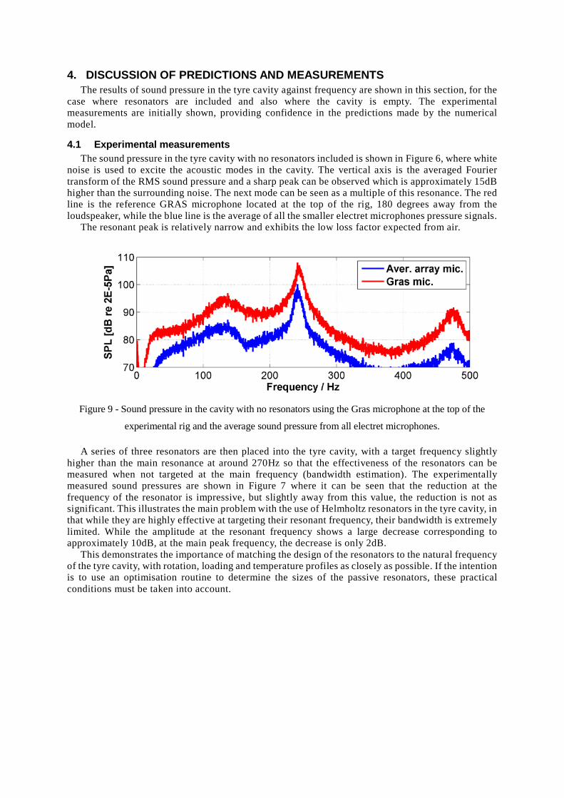
4.1 Experimental measurements The sound pressure in the tyre cavity with no resonators included is shown in Figure 6, where white
noise is used to excite the acoustic modes in the cavity. The vertical axis is the averaged Fourier transform of the RMS sound pressure and a sharp peak can be observed which is approximately 15dB higher than the surrounding noise. The next mode can be seen as a multiple of this resonance. The red line is the reference GRAS microphone located at the top of the rig, 180 degrees away from the loudspeaker, while the blue line is the average of all the smaller electret microphones pressure signals.
The resonant peak is relatively narrow and exhibits the low loss factor expected from air.
Figure 9 - Sound pressure in the cavity with no resonators using the Gras microphone at the top of the
experimental rig and the average sound pressure from all electret microphones. A series of three resonators are then placed into the tyre cavity, with a target frequency slightly
higher than the main resonance at around 270Hz so that the effectiveness of the resonators can be measured when not targeted at the main frequency (bandwidth estimation). The experimentally measured sound pressures are shown in Figure 7 where it can be seen that the reduction at the frequency of the resonator is impressive, but slightly away from this value, the reduction is not as significant. This illustrates the main problem with the use of Helmholtz resonators in the tyre cavity, in that while they are highly effective at targeting their resonant frequency, their bandwidth is extremely limited. While the amplitude at the resonant frequency shows a large decrease corresponding to approximately 10dB, at the main peak frequency, the decrease is only 2dB.
This demonstrates the importance of matching the design of the resonators to the natural frequency of the tyre cavity, with rotation, loading and temperature profiles as closely as possible. If the intention is to use an optimisation routine to determine the sizes of the passive resonators, these practical conditions must be taken into account.

Figure 10 - Sound pressure in the cavity with three equally spaced resonators tuned slightly off the main
frequency. The reduction at the tuned resonator value is around 10dB while the reduction at the main peak is
only around 2dB. Although the electret microphones are extremely inexpensive, they still provide an acceptable
measurement and could be used in a real world rig where rotation occurs. Further work is required to investigate the overall efficiency and optimisation of the Helmholtz
resonators. For example, the computer program running the waveguide simulation could include many iterations of different neck cross sectional areas, to both maximise the loss factor and thus sound reduction in the tyre volume and also reduce many different frequencies in the volume.
4.2 Numerical Predictions The numerical prediction of the sound pressure inside a car tyre when it is not rotating (but still
with the same level of excitation source inside) is shown in Figure 10. It can be seen that the shape of the resonance, the multiples and overall bandwidth compare favourably with the experimental measurements. The numerical results use the maximum sound pressure anywhere in the cavity, unlike the experimental measurements which show the average of all array microphones and the sound pressure measured using the Gras microphone positioned at the very top of the cavity rig.
Figure 11 - Numerical predictions of the sound pressure inside a tyre cavity volume when not rotating and
just out of contact with the ground surface. When the tyre is rotated so that the air reaches a steady state velocity, it can be shown that the
natural frequency of the degenerate modes splits into a slightly higher and lower frequency based on the vehicle speed. This is illustrated in Figure 11 where the tyre is rotating with a vehicle speed of 20m/s. An approximate 25Hz split is generated, with each individual amplitude proportionately smaller. A passive resonator design would only be able to target one of these resonances with the bandwidth of the resonator (as demonstrated in the experimental results) dictating the resulting sound
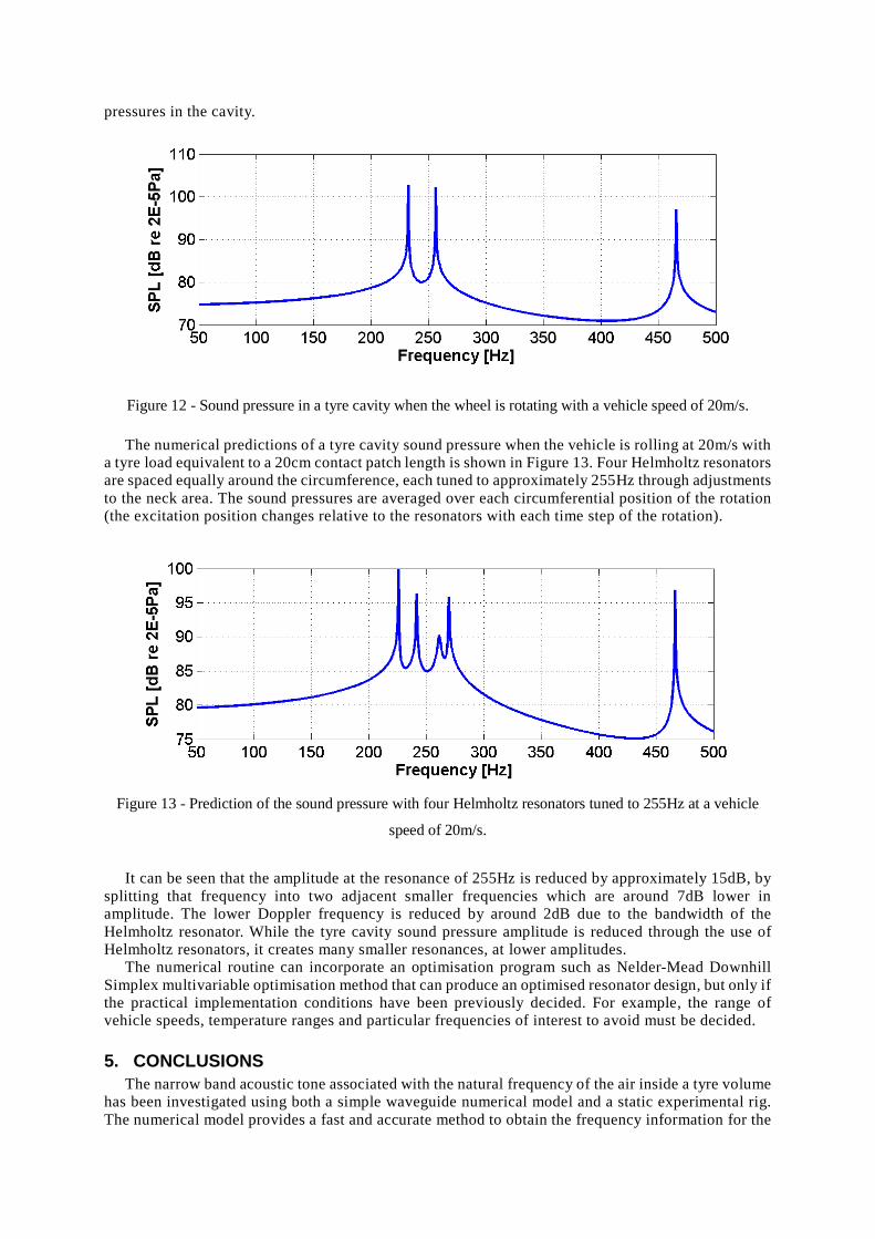
pressures in the cavity.
Figure 12 - Sound pressure in a tyre cavity when the wheel is rotating with a vehicle speed of 20m/s. The numerical predictions of a tyre cavity sound pressure when the vehicle is rolling at 20m/s with
a tyre load equivalent to a 20cm contact patch length is shown in Figure 13. Four Helmholtz resonators are spaced equally around the circumference, each tuned to approximately 255Hz through adjustments to the neck area. The sound pressures are averaged over each circumferential position of the rotation (the excitation position changes relative to the resonators with each time step of the rotation).
Figure 13 - Prediction of the sound pressure with four Helmholtz resonators tuned to 255Hz at a vehicle
speed of 20m/s.
It can be seen that the amplitude at the resonance of 255Hz is reduced by approximately 15dB, by
splitting that frequency into two adjacent smaller frequencies which are around 7dB lower in amplitude. The lower Doppler frequency is reduced by around 2dB due to the bandwidth of the Helmholtz resonator. While the tyre cavity sound pressure amplitude is reduced through the use of Helmholtz resonators, it creates many smaller resonances, at lower amplitudes.
The numerical routine can incorporate an optimisation program such as Nelder-Mead Downhill Simplex multivariable optimisation method that can produce an optimised resonator design, but only if the practical implementation conditions have been previously decided. For example, the range of vehicle speeds, temperature ranges and particular frequencies of interest to avoid must be decided.
5. CONCLUSIONS The narrow band acoustic tone associated with the natural frequency of the air inside a tyre volume
has been investigated using both a simple waveguide numerical model and a static experimental rig. The numerical model provides a fast and accurate method to obtain the frequency information for the
problem. An array of inexpensive electret microphones has been used to determine the sound pressure in an equivalent annular volume to the tyre and wheel assembly.
The loss factor of the resonance has been visually demonstrated. One method to reduce the amplitude of the sound pressure at the narrow band resonance is the introduction of Helmholtz resonators. At the resonant frequency of the Helmholtz resonator, the reduction is approximately 10dB, while at a location 25-50Hz away, only approximately 2dB is obtained.
The numerical model can be used to obtain values of the sound pressure and mode shapes inside the cavity volume for a range of vehicle speeds, axle loading, temperature changes and gas types. It can also produce the changes which occur when arbitrary passive resonators are included into the volume.
The use of the numerical program within a multivariable optimisation routine such as a Nelder Mead Downhill Simplex method can produce an optimised resonator design, but only if the practical implementation conditions have been previously decided e.g. speed range, temperature range of use.
REFERENCES 1. Sakata T, Morimura H, Ide H. Effect of tire cavity resonance on vehicle road noise. Tire
Science and Technology. 1990; 18:68-79. 2. Biligiri K P, Kalman B, Samuelsson A. Understanding the fundamental material properties of
low-noise poroelastic road surfaces. International Journal of Pavement Engineering. 2013; 14(1):12-23.
3. Scavuzzo R W, Charek L T, Sandy P M, Shteinhauz P M. Influence of wheel resonance on tire acoustic cavity noise. SAE Technical Paper 940533 1994.
4. Nilsson N-A. Possible Methods of Reducing External Tire Noise. International Tire Noise Conference. Stockholm, 1979.
5. Jessop A M, Bolton J S. Tire surface vibration and sound radiation resulting from the tire cavity mode. Proceedings of the 20th International Congress on Acoustics. Sydney, 2010.
6. Layfield J, McKinley A. Tyre Cavity Noise Absorber. 2011; US Patent App. 13/818,867. 7. Yukawa N, Nishikawa M, Nakajima T, Aoki C, Sugihara H. Tire noise reducing system. 2004;
US Patent 6,755,483. 8. Kamiyama Y, Ishii K, Takagi H. Vehicle wheel. 2012; US Patent 8,286,679. 9. Svedhem S. Method and arrangement for sound suppression in wheels. 2001; US Patent
6,309,026. 10. O’Boy D J, Dowling A P. A 3D viscoelastic multilayer model of a tyre belt. Journal of Sound
and Vibration. 2009; 322: 829-850.