Gas gain in proportional counters - University of Tasmania
158
GAS GAIN IN PROPORTIONAL COUNTERS by K. G. White, B.Sc.(Hons), University of Tasmania Submitted in fulfilment of the requirements for the degree of Doctor of Philosophy UNIVERSITY OF TASMANIA HOBART March, 1988.
-
Upload
khangminh22 -
Category
Documents
-
view
1 -
download
0
Transcript of Gas gain in proportional counters - University of Tasmania

GAS GAIN IN
PROPORTIONAL COUNTERS
by K. G. White, B.Sc.(Hons), University of Tasmania
Submitted in fulfilment of the requirements for the degree of
Doctor of Philosophy
UNIVERSITY OF TASMANIA HOBART
March, 1988.

ACKNOWLEDGEMENTS
I wish to thank Dr K. B. Fenton and Dr A. G. Fenton for their helpful advice and assistance throughout this study. I would particularly like to thank Dr K. B. Fenton for suggesting using 2,3 dimethyl-2-butene as an additive and also for suggesting the idea behind the circuit presented in chapter 7.
Thanks are also due to Mr M. Mason and Mr B. T. Wilson for their technical support and I would also like to thank the other Ph.D. students for their assistance.

This thesis contains no material which has been submitted or accepted for the award of any other degree or diploma in any university.
To the best of my knowledge and belief, this thesis contains no material previously published or written by another person, except where due acknowledgement is made in the text
J~ !5.w~ Kenneth G. White

CONTENTS
ABSTRACT 1 CHAPTER 1 INTRODUCTION 3
1.1 The energy resolution of a proportional counter 3 1.2 The Penning effect 5 1.3 Single electron spectra 7 1.4 Penning mixtures and gas scintillation proportional counters 12 1.5 Proportional counters with uniform fields 13 References 16
CHAPTER 2 THE EXPERIMENT AL APPARATUS 1 7 2.1 Introduction 17 2.2 The detectors 17 2.3 The current measurements 19 2.4 Background current 21 References 24
CHAPTER 3 THE MEASUREMENT OF GAS GAIN BY CURRENT COMPARISON 2 5 3.1 Current measurements using the 55Fe source 25 3.2 The measurement of gas gain 26 3.3 Determination ofW-values 28 References 29
CHAPTER 4 THE ION SATURATION CURVE 30 4.1 Introduction 30 4.2 The physics of the saturation curve 30, 4.3 Factors affecting the choice of radiation source 47 4.4 Conclusion 51 References 52
CHAPTER 5 VARIATIONS IN THE BEHAVIOUR OF XENON SAMPLES 5 3 5.lintroduction 53 5.2 Observations of energy resolution 53 5.3 Gas gain properties of the "two types" of xenon 60 5.4 Conclusion 62 References 62
CHAPTER 6 THE PULSE MATCHING METHOD 63 6.1 Introduction 63 6.2 An outline of the history of the pulse matching method 65 6.3 Conclusion 73 References 73


References 152

ABSTRACT
Gas gain measurements were made for nitrogen, xenon and x~non with 2,3 dimethyl-2-butene (DMB) as an additive. Two different methods of measuring gas gain were examined, pulse matching methods and current comparison methods.
A preliminary investigation was made into a new approach to the pulse matching method. Previous authors had shaped their test pulses to the same shape as their detector pulses or used a calibration factor to correct for the difference between the shape of the test pulses and the detector pulses. These approaches would be valid only if the detector pulses were always the same shape. The pulses from the detector vary in shape depending upon where the primary ion pairs are formed in the detector sensitive volume. The new approach' I have investigated shapes the detector pulses and the test pulses to the same shape so that the variation in the detector pulse shape becomes irrelevant. This method of measuring gas gain was tested using P-10 and 148Gd as an alpha particle sourceand gave similar results to gas gains determined by current comparisons.
The measurements of gas gain finally used to obtain the data were all performed using the current comparison technique. When the electrons were collected at the central wire and 55f e was used as the radiation source the ion saturation curves for xenon showed no definite plateaus, only points of inflexion. I found that ion saturation currents could be determined by fitting the observed currents and associated operating voltages to an expression proposed by Johnson. This expression also enabled me to determine the voltage region where· gas gain began.
The gas gain characteristics of nitrogen and xenon were measured for a range of gas densities. From these measurements it was shown that the gas gain of a cylindrical proportional counter operating in the proportional region is a function only of the reduced field strength at the surface of the anode.
Aoyama has proposed an expression for the first Townsend coefficient and he has been able to show that previously proposed expressions are only special cases of his expression. I was able to obtain an excellent fit to Aoyama's expression using my gas gain data for xenon and a value for one of the parameters determined by Kowalski.
It is widely held that the mechanism of gas gain in proportional counters is primarily by electron impact. Ionization may also occur in binary mixtures by the

2
non-metastable Penning effect, and the metastable Penning effect. A binary mixture of xenon and DMB was used to investigate these effects. It was found that the gas gain in xenon could be greatly increased by the addition of a small quantity of DMB. A broad peak in gas gain appeared when the concentration of additive was between - 0.4% and - 0.75% and the molecular number density of the gas filling was 2.7 x 1Q25 m-3 ( - 1 atm ). When the gas density was reduced to 1.4 x 10²s m-3 ( - 0.5 atm ) the peak became sharper and better defined and
reached its maximum when the concentration of additive was - 0.43%. Lowering the density to 7 x 1Q24m-3 ( ,.:, 0.26 atm ) resulted in a very sharp well
defined peak centred on an additive concentration of - 0.23%. The gas gains
used to define these peaks were of the order of 105, whilst in pure xenon at identical anode potentials the gas gain was of the order of 10. The mechanisms
proposed for these increased gas gains were the non-metastable Penning effect
and the metastable Penning effect in the case of high density mixtures, the Pennning effect in the' case of the intermediate density mixtures and for the low
density mixtures it was suggested that doubly excited xenon molecules were
ionizing the additive.
The W-values of the low density xenon plus DMB mixtures were also measured to 5% accuracy. The trend in the mean values of these measurements indicates that the Penning effect is occuring and the minimum value in the W-value occurs at - 0.4% which suppports the above proposed mechanisms for the increased gas gains.
Detectors filled with mixtures of xenon plus large concentrations of DMB developed double full energy peaks in a relatively short amount of time using the 55Fe source. Passing a large current through the anode removed these double
peaks demonstrating that the cause was uneven deposits on the anode. These
deposits were probably due to polymerization of free radicals formed in the
electron avalanche. Small percentages of DMB did not result in double peaks but
drops in gain were observed when the detector was subjected to prolonged
usage. The absence of double peaks is attributed to the diffuse nature of the avalanches. If the Penning effect or ionization of the additive by UV photons is taking place the avalanche activity would always completely surround the anode
giving rise 'to uniform coatings around the entire circumference of the anode.

,..----------CHAPTER-----------
1 ----------INTRODUCTION----------"
1.1 The energy resolution of a proportional counter
The total number of electrons produced in a proportional counter as a result of the formation of primary ion pairs in the counter gas and subsequent multiplication of the,se ion pairs by electron avalanches can be expressed by,
Q =Gn0 (1)
where G is the gas gain, n0 t.lie number of primary ion pairs resulting from an
energy loss E, and Q the total number of electrons.
Since G and n0 are independent of each other and the errors in G and n0 are of a
statistical nature the error propagation formula can be applied to (1). Hence
(2)
Now G is the average gas gain of n0 electron avalanches,i.e.
1~ -G=-2..A =A
no i=l 1
(3)
where Ai is the gain in the ith electron avalanche and A is the average gain.
Applying the error propagation formula to (3) we obtain for the variance of G,
1 a2 =-a2 G n A
0 (4) where <JA 2 is the variance of the gas gain in a typical avalanche due to a single
electron originating outside the region of gas gain.
Substituting (4) into (2) we obtain

4
(5)
The fluctuations in the number of primary ion pairs, n0 , for a given energy loss
E may be expected to follow Poisson statistics with the variance of n0 equal to
n0 . However, Fano in 1947 [l] showed from theoretical considerations that the
fluctuations should be smaller than predicted by Poisson statistics. Kirkwood et
al. in 1948 [2] and Hanna et al. in 1949 [3] showed from measurements of energy resolution, that the fluctuations were smaller. The Fano-factor has been
introduced to relate the observed variation with the Poisson predicted
variation,i.e.
2 a =Fn
1b 0
This gives
(6)
Now the number of primary ion pairs,n0 , depends upon the W-value, defined as
the mean energy expended to form an ion pair in the gas.
E n =- . -
0 w ,where E is the energy lost in the gas. Substituting into
equation ( 6) gives
(7)
If the relative variance in the gas gain of an avalanche due to a single electron
(a JA)2 is denoted by f equation (1) becomes
'( crQQ)
2
Wf FW =-E-+E
(8)

5
Thus if E/W is sufficiently large the values of Q will follow a gaussian distribution with standard deviation
The resolution R of a proportional counter is usually expressed in terms of the full width at half maximum (FWHM) of the distribution of pulse heights obtained for a given absorbed energy, E, and is therefore defined as the ratio of the FWHM to the mean pulse height. The FWHM of a gaussian distribution is
2.35crand therefore
(9)
Equation (9) gives the parameters upon which the energy resolution of a proportional counter depend[ 4,5].
1.2 The Penning effect
The parameters F and W are constants characteristic of each particular gas or mixture of gases. In the case of xenon with electrons as the ionizing particles F is s 0.17 and W is 21.5 eV/ion pair [5]. It has been found that both of these parameters can be reduced under special circumstances. Some of the energy a particle loses in the counter gas goes into the formation of ion pairs and some is lost to excitation of the gas atoms or molecules. If an additive with an ionization potential lower than some ~f the excited states of the main gas is added to the gas the energy of these excited states might be transferred to the additive in collisions resulting in the ionization of the additive. This type of ionization is referred to as Penning ionization and the effect is called the Penning effect There are two types of Penning effects, the metastable Penning effect (MPE) and the non-metastable Penning effect (NMPE). The MPE is the ionization of the additive by the long lived metastable states of the main counter gas and the NMPE is the ionization of the additive by the short lived non-metastable excited or resonance levels [6,7]. The Penning effect reduces the W-value and leads to a larger number of primary ion pairs for a given energy loss in the gas. This in turn will give larger pulses because each pulse will result from more electron avalanches. If the Penning effect also occurs in the electron avalanche the gas gain G will also increase. Of cours_e to show that an increase in gas gain might be due to the Penning effect the values of both G and W should be measured for the particular gas mixture.

6
I
Sometimes a gas or vapour used as an additive to take advantage of the MPE or NMPE will have a larger W-value than the main gas, for example if0.5% C2H2
is added to Ar the W-value drops from 26.2 eV/ip (for ionization by electrons in pure Ar) to 20.3 eV/ip [8]. If a large concentration of C2H2 is added on the
other hand the W-value of the mixture will tend towards the W-value of C2H2•
In this particular case, if the additive takes part directly in the primary ionization process the W-value of the mixture will tend to increase rather than decrease. For
the MPE to be effective in reducing the W-value the ionization must take place
via the excited states of the Ar.
If the additive takes part directly in the ionization process the W-value of the
mixture will assume some sort of "average" of the W-values of the components of the mixture. The value of this "average" will depend upon the relative
concentrations of the two components. Valentine and Curran [9] report that in 1950 Huber, Baldinger and Haeberli proposed an expression for the variation of the W-value of a mixture of gases as a function of the partial pressures of the component gases,
(10)
where S1,S2 and P1, P2 are the stopping powers for the charged particles and
partial pressures of the component gases respectively. Huber et al used aparticles to obtain their experimental results and the stopping powers for these are approximately given by S1 = EJR.1 and S2 = EJR.2 where R1 and R2 are the
ranges of the a-particles in each component gas and Ea. is the a-particle energy.
Equation (10) assumes that the two gases act independently of each other. That is, a fast electron produced by the ionization of one of the atoms or molecules of
one of the component gases does not ionize atoms or molecul~s of the other
component gas. This assumption _is unlikely to be valid. If we replace S1P1/(S 1Pl+S2P2) with Z (an effective atomic number) we obtain
_1_= (~ -~)z+-1 Wm 1 2 W2
(11)
That is, the reciprocal of the value of the W-value for the mixture should be linearly dependent on the effective atomic number Z. Equation (11) was found to hold for only a few mixtures. Huber et al assumed that the disagreement between their results and equation (11) was due to the~ assumption that the delta

7
rays from one component gas did no~ ionize the other component gas. To correct for this they introduced an additional term into equation (11 ). Valentine et. al. [9] note that Bortner and Hurst in 1954 modified the expression for the effective atomic number to Z = P1/(P1 +aP2) where the constant a has to be experimentally determined for each gas mixture. In the cases in which the previous expression for Z held a= S2/Sl. The above expressions all ignore the Penning effect and therefore cannot be giving a correct description of the ionization processes in gas mixtures but might be useful in estimating the Wvalues of mixtures.
Thus, we may define a Penning mixture as a gas mixture in whiCh ionization takes place via the excited states of the main gas. A Penning mixture, in addition to being characterized by a lower W-value also shows a lower variance in the number of primary ion pairs produced for a given energy loss. That is, a Penning mixture will have a lower Pano-factor [8]. So a Penning mixture would appear to be the ideal mixture from the point of view of energy resolution of a proportional counter.
Unfortunately, for cylindrical coaxial proportional counters, the value off, the relative variance of the gas gain in equation (9), completely dominates the resolution for gas gains greater than 10 [5].
The relative variance, f can be investigated by 109.king at the distributions of amplitudes of the electron avalanches due to single electrons.
1.3 Single electron spectra
The earliest model of an electron avalanche predicted that the distribution of avalanche sizes would follow a Furry distribution [4,10,11]. The basic ~ssumptions of this model are: the probability of ionization by an electron during the electrons path from when it was formed until the next ionizing impact remains constant, and the energy gained from the field in one mean free path is much less than the ionization energy. With a Furry distribution the probability of a particular number of electrons being produced in an avalanche is given by,
A-1
p(A) ~ (1 -4:) A (12)

8
If the average size of the avalanche is about 100 or larger as is usually the case then
(13)
The relative variance of this distribution is,
(14)
For an average gas gain A of 20 equation (12) predicts that 5% of all avalanches
will consist of only one electron.
This situation was investigated experimentally by Curran et al in 1949 [12]. Their method enabled them to separate the variance in the number of primary ion
pairs from the variance in the gas gain. This method consisted of using proportional counters with aluminium cathodes and illuminating the cathodes with UV light releasing individual photo-electrons. The cathodes were constructed in two alternative ways, by evaporating aluminium onto a quartz envelope so that the result was a semi-transparent cathode or using polished aluminium foil and inserting a quartz window to admit the UV light. The gas mixture they used consisted of a 50% Ar, 50% CH4 mixture at a pressure of 500
torr.
The efficiency of the production of electrons was about -10-3 per quantum at
UV wavelengths of 3000 to 3500 angstroms. Signals from the light source
began to stand out above the noise at operating voltages of 3000 volts, and a plateau on their curve was obtained between 3700 volts and 3900 volts. Proportionality was established by comparing the pulse height spectra obtained at
four different operating voltages 3145, 3280, 3550, and 3685 volts. These spectra could all be fitted closely with each other; if proportionality was being lost the pulse height distributions would have diverged from each other. The gas gain at 3550 volts was determined by other means to be 1.46x10⁵.
Curran et al found that the distribution of amplitudes corresponded closely with 1(2 .
the curve x exp(-x) with mean values,
- 3 X=2

and
2 15 x =-
4
cr2 = .1 x 2
9
Therefore the ·relative variance ( crxfx )2 is 0.666 compared with the relative
variance of the experimentally determined distribution of amplitudes ( for A =
1.46xl05) which is 0.696. This is different from the Furry distribution which has a relative variance of 1. Other authors have also found departures from the exponential shape predicted by the Furry distribution[9]. At low field strengths the Furry distribution seems to give a correct description of th~ distribution of pulse amplitudes but at high field strengths the distribution rises to a maximum value and then falls towards zero. The spread in the distribution of amplitudes is less than that predicted by the Furry distribution.
The first Townsend coefficient, ex is the number of ion pairs produced in a gas per unit path length by an elctron moving under the influence of an electric field.
It has been shown experimentally that the value of cx/N is a function only of the reduced field strength E/N where N is the molecular number density of the gas
[13]. The functional form of cx(E) for xenon is shown in Chapter 9 (see Figure 9.1.1 ).
For a particular value of E the mean path for ionization is given by 1/cx. The distance an electron must travel to gain enough energy from the field to ionize is given by U/E where Ui is the ionization potential of the gas and E is the electric
field strength. If U/E is much less than l/cx, the energy to ionize must have been
gained and lost in many collisions before ionization has taken place. This means
that for field strengths where U/E << 1/cx, the assumption that the probability of
ionization is constant over the mean path for ionization is valid. This will occur
in weak fields. In strong field strengths, U /E - 1/cx the assumption is no longer
valid. The quantity cxU /E is a measure of the ionization efficiency and for
values of - 1 the probability of an ionizing impact will depend upon how far the electron has travelled since the last ionizing impact [15].
Alkhazov [10] and-Sephton et. al. [15] have noted that Legler proposed a model in which the distance the electron had travelled since the last ionization impact was considered. His model gave the probability distribution as

10
P(A>=G~(~) (15)
where <I> is a function which depends upon cxU0/E where Uo is the 11 model
parameter 11 and <I> must be evaluated numerically. The value of U0 agrees with
the value of ui to within 20% [15].
Byrne [16] proposed a model in which the mean ionization coefficient, a.(A,x) decreased as the number of electrons in the avalanche increased. The mean
ionization coefficient is given by cx(A,x) = a.(x)[l + 8/A] where x is the distance through which the avalanche has been developing, A the number of electrons in
the avalanche, and 8 is an empirically determined parameter. This model gave a Polya distribution as a description of the pulse amplitudes for avalanches due to single electrons in a strong field.
(16) and
(O' )
2
1 -1 .; =x+(1+0)
(17)
According to Byrne [16] the experimental evidence as a whole tends to support
equation (16). The parameter (1 + 8)-1 in equation (16) is the fraction of electrons above a particular threshold. This threshold is between two and three times the ionization potential of the gas [ 16]. The assumption of this model, that the ionization cefficient decreases as the number of electrons in the avalanche increases, is difficult to reconcile with the experimental evidence [15]. From the point of view of the detector builder the model is not particularly useful since the probability distribution is not expressed in terms of the detector parameteis.
Alkazov [ 10, 17] has proposed a model which gives the relative variance of the gas gain in a uniform electric field as
f=f0(1- ~) (18)

11
Equation (18) shows that for small values of A, f can be reduced. For large values of A , f tends towards f0 .
(2b- 1)2
f=----0 4b- 2b2
- 1 (19)
where
(-au) b= exp -T (20)
The form of equation (19) is shown in figure 1.3.1.
4
3
2
1
0 -1
-2 ------------------
-3
-4
I I I I
-----~-----------' I I I I I I -5 .__ __ _._ ____ ......_ __ ____....._ __ _._ ____ ..&-I __ __.. __ _,__.__,_ __ ..__ __ _._ __ ~~
-5 -4 -3 -2 -1 0 1 2 3 4 5
Figure 1.3.l The form of equation (19); f0 is zero at b = 1/2.
b
12
From equation (20) it can be seen that f0 will have a fixed value in a uniform
field but will be constantly changing in a cylindrical field. Equation (18) through to (20) are useful for the detector designer because they contain parameters which are related to the dimensions of the detector and the gas filling [17].
From Alkazov's work the following conclusions can be drawn; the smaller the gas gain the less the variance in the gas gain; the product of the radius of the anode wire and the gas density should be as small as possible; Penning mixtures will give reduced W-values and Pano-factors [5].
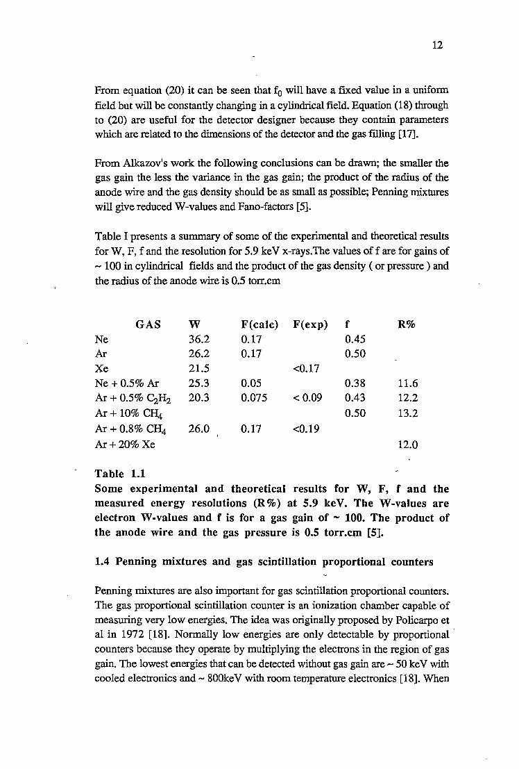
Table I presents a summary of some of the experimental and theoretical results for W, F, f and the resolution for 5.9 ke V x-rays.The values off are for gains of ..... 100 in cylindrical fields and the product of the gas density (or pressure) and the radius of the anode wire is 0.5 torr.cm
GAS w Ne 36.2 Ar 26.2 Xe 21.5 Ne +0.5% Ar 25.3 Ar+0.5% ~H2 20.3
Ar+ 10% CfI4
Ar+0.8% CH4 26.0
Ar+20% Xe
Table 1.1
F(calc) F(exp) 0.17 0.17
<0.17 0.05 0.075 <0.09
0.17 <0.19
f 0.45 0.50
0.38 0.43
0.50
R%
11.6 12.2
13.2
12.0
Some experimental and theoretical results for W, F, f and the measured energy resolutions (R%) at 5.9 keV. The W-values are electron W-values and f is for a gas gain of - 100. The product of the anode wire and the gas pressure is 0.5 torr.cm [5].
1.4 Penning mixtures and gas scintillation proportional counters
Penning mixtures are also important for gas scintillation proportional counters. The gas proportional scintillation counter is an ionization chamber capable of measuring very low energies. The idea was originally proposed by Policarpo et al in 1972 [18]. Normally low energies are only detectable by proportional · counters because they operate by multiplying the electrons in the region of gas gain. The lowest energies that can be detected without gas gain are ..... 50 ke V with cooled electronics and ..... 800keV with room temperature electronics [18]. When

13
the primary ion pairs are formed by the energy loss from an ionizing particle or x-ray in the absorbing medium light is produced. This light signal, referred to as the primary light, is characterized by an extremely fast rise time ( of the order of nanoseconds ). If an electric field is applied to the chamber the electrons will drift under the influence of the applied field from points of low electrostatic potential to points of higher potential. When the electrons reach a region of a particular field strength secondary light will be produced. This secondary light is much more intense than the primary light and is characterized by a much slower rise time ( of the order of microseconds ). If the chamber voltage is increased or decreased the intensity of the secondary light will also increase or decrease. The secondary light, in the case of noble gas filled detectors, is the result of the deexcitation of excited noble gas molecules [19] and can be detected by a photomultiplier tube. The variance due to the photomultiplier tube is less than the variance due to gas gain when the counter is operated in the proportional mode. As a consequence of this the gas proportional scintillation counter has an energy resolution about half that of a proportional counter. The relative variance of the secondary light pulses produced by a gas proportional scintillation counter working in the ion chamber region can be expressed as
where N is the mean value of the light amplitude, N 1 the number of primary ion pairs and V T2 the
relative variance due to the photomultiplier tube ( VT oc 1/N ) [20]. If the
secondary light can be detected by a more efficient means than a photomultiplier tube the lowering of the Pano-factor may be the foremost means of improving the resolution of this class of detectors. Several other techniques for detecting the secondary light are being investigated elsewhere i.e., photoionization chambers, vacuum photodiodes, and microchannel plates [21].
1.5 Proportional counters with uniform fields
Sipila has shown [17] that for Ne - Ar Penning mixtures with 0.1 % and 1.0% Ar the relative variance of the gas gain ( using equation (9) ) will drop to very small values for particular reduced field strengths. For the 1.0% Ar Penning mixture the relative variance drops to - 0.1 and in the case of 0.1 % Ar to -0.01. This impli.es that the electric field strength in the region of the electron avalanche should be uniform so that the reduced field strength remains constant at the optimum value. Sipila also shows that the diffusion of metastable Ne atoms has no significant effect on this minimum. He shows this by comparing the diffusion of excited atoms with that of slow neutrons in a weakly absorbing medium [17].

14
Marzec and Pawlowski [22] extended the work of Sipila. They found that they could get an energy resolution of 10.5% FWHM at 5.9 keV using a mixture of Ne + 1.0% CH4 and a uniform field in the region of the electron avalanche. This gas filling was at a pressure of 150 torr. This resolution is not as good as the theoretically predicted resolutions for this type of detector using Penning mixtures. The theoretically predicted resolution for Ne + 0.5% Ar at 5.9 ke V is 5.0%. They attribute the difference between their experimental result and the theoretical predictions to the production of secondary electrons at the cathode due to positive ion bombardment.
Sephton, Turner and Leake [15] found that the energy resolution of the Penning mixture Ne + 0.1 % Ar using a uniform electric field in the region of gas multiplication was about 13% at 5.9keV. This energy resolution is of course very good but not as good as some of the predictions.
Detectors in which the avalanche is broken up into stages were developed to cope with _the problems associated with Cherenkov ring imaging in high energy physics. With this type of imaging as a means of particle identification in high energy physics it became necessary to develop detectors that were capable of detecting single UV photons with great efficiency. Ultraviolet windows have a high frequency cut-off which necessitates a gas or vapour filling with a low ionization potential. Also large gas gains must be obtainable. The requirements are contradictory since large gas gains will result in the prodution of UV photons and the gas filling has to be sensitive to UV photons. The multistep proportional chamber is a method-of obtaining large gas gains. In this type of proportional counter the avalanche is broken up into two stages. The ion pairs are formed in a conversion region where they drift into a preamplification region and undergo some amplification. Some of these electrons are then transferred to a inultiwire proportional counter where they undergo further amplification. Gas gains of about 1Q6 are obtainable with this arrangement [23].
In x-ray astronomy, good spectral resolution and good spatial resolution are both required. A uniform field gives good energy resolution but there are problems in obtaining stable operation of the detector at the gas gains ( 104 to 105) required for good spatial resolution. A multiwire proportional counter on the other hand gives good spatial resolution. Schwarz and Mason [24] have constructed a detector they call the Penning gas imager ( PGI ). This detector combines Penning mixtures, two stage avalanches and uniform fields all in the one detector. They have obtained resolutions of 12% FWHM at 6 ke V and gas gains of 550 using Ar + 0.5% C2H2• This gas gain and resolution is achieved in the
first stage. The second stage can boost the overall gain to > 105 to give the necessary gains required for imaging.

15
Ramsay and Weisskopf [25] have constructed a multistep detector incorporating both a uniform field and a multiwire proportional counter. Spectral information is obtained from the uniform field stage and the imaging information comes from the multiwire proportional counter. Figure 1.5.1 is schematic representation of their detector.
32mm
4mm
15mm
WINDOW
ABSORPTION AND DRIFT REGION
PREAMPLIFICATION
TRANSFER
MWPC .-.-.-.-.-.-.-.-.-.-.-.-.-.-.-.-.-.-.-.-.-.-.-.-.-.-.-.-.-.-.-.-.-.-.-.-.-.-.-.-.-.-.-.-.-.-.-.-
Figure 1.5.1 •" A multistep detector taken from Ramsay and Weisskopf [25]
These authors experimented with a range of gas mixtures. For example at a gas gain of 6x10³ they obtained an energy resolution of 13.0% at 5.9 keV using 95% Ar+ 5% isobutane at apressure of one atmosphere. They obtained an energy resolution of 7.5% at 22.2 keV using a mixture of 90% Xe + 10% trimethylamine at a pressure of 0.5 atm and a gas gain of 3.5x10³. Using equation (9) this implies an energy resolution of 14.5% at 5.9 keV.The preamplification grid separation was 4 mm and the field required to obtain a gain of 1Q3 was 7.3 kV cm-1.
This thesis presents the results obtained from studying the effects of a particular additive on the gas gain of a xenon filled proportional counter. The two approaches to the study of gas gain are to look at the single electron spectra or to look at the amount of charge that is formed by the multiplication mechanism after a certain amount of energy has been deposited in the counter by a charged particle, x-ray, or gamma ray. In this thesis the second approach is the one used. The gas gain of each particular mixture was compared with the W-value to determine whether or not a relationship existed. The W-value measurements were absolute measurements of about 5% accuracy.

16
References [1] U. Fano, Phys. Rev. 72 (1947) 26. [2] D. H. W. Kirkwood, B. Pontecorvo, and G. C. Hanna, Phys. Rev. 74
(1948) 497. [3] G. C. Hanna, D. H. W. Kirkwood and B. Pontecorvo, Phys. Rev. 75
(1949) 985. [4] G. F. Knoll, Radiation and Measurement, John Wiley & Sons, Chapters 3
and 6. [5] H. Sipila, Nucl. Instr. and Meth. 133 (1976) 251. [6] S. Kubota, J. Phys. Soc. Japan 29 (1970) 1017.
[7] H. Sipila, Nucl. Instr. and Meth. 140 (1977) 389. [8] G. D. Alkhazov, A. P. Komar and A. A. Vorob'ev, Nucl. lnstr. and Meth.
48 (1967) 1.
[9] J.M. Valentine and S. C. Curran, Reports on Progress in Physics Volume XXI (1958) 25.
[10] G. D. Alkhazov, Nucl. Instr. and Meth. 89 (1970) 155.
[11] R. A. Wijsman, Phys. Rev. 75 (1949) 833. [12] S. C. Curran, A. L. Cockroft and J. Angus, Phil. Mag. 40 (1949) 929. [13] L.B. Loeb, Fundamental Processes of Electrical Discharge in Gases, John
Wiley & Sons, Inc. (1939) 342. [14] J. H. Carver and P. Mitchell, Nucl. Instr. and Meth. 52 (1967) 130. [15] J. P. Sephton, M. J. L. Turner and J. W. Leake, Nucl. Instr. and Meth.
219 (1984) 534.
[16] J. Byrne, Nucl. lnstr. and ;Meth. 74 (1969) 291. [17] H. Sipila, IEEE Transactions on Nucl. Sci. NS-26 (1979) 181. [18] A. J.P. L. Policarpo, M.A. F. Alves, M. C. M. Das Santos and M. J. T.
Carvalho, Nucl. Instr. and Meth. 102 (1972) 337. ·
[19] M. Suzuki and S. Kubota, Nucl. Instr. and Meth. 164 (1979) 197.
[20] M. M. Ribeirete, A. J.P. L. Policarpo, M. Salete, S. C. P. Leite, M.A. F. Alves and E. P. De Lima, Nucl. Instr. and Meth. 214 (1983) 561.
[21] E. P. De Lima, M. Salete, S. C. P. Leite, M.A. F. Alves and A. J.P. L. Policarpo, Nucl. Instr. and Meth. 192 (1982) 575.
[22] J. Marzec and Z. Pawlowski, Nucl. Instr. and Meth. 200 ( 1982) 355. [23] F. Sauli, Nucl..lnstr. and Meth. A248 (1986) 143.
[24] H. E. Schwarz and I. M. Mason, Nature 309 (1984) 532. [25] B. D. Ramsay and M. C. Weisskopf, Nucl. Instr. and Meth. A248 (1986)
550.

2 .__~~~~--THE EXPERIMENTAL APPARATUS~~~~~~
2.1 Introduction
There are two well known methods of measuring the gas gain of a proportional counter when the gas gain is due to the formation of n0 electron avalanches
where n0 is the number of primary ion pairs. These methods are current
comparisons ( discussed in chapter 3 ) and pulse matching methods ( discussed in chapter 6 ) There is another method mentioned in the literature involving measurements of pulse heights at different fill gas densities and operating voltages which will not be discussed in this thesis [1,2] The two techniques that I investigated are independent of any properties of the gas gain and are suitable for any type of proportional counter ( i.e. the sealed type or the flow types ).
2.2 The detectors
Two detectors were used to obtain the data presented in this thesis. Both were constructed from brass tubing of approximately the same diameter. These detectors will be ref erred to as detector 1 and detector 2.
Detector 1 was - 50 cm long with a cathode of internal diameter 3.8 cm and a 70
µm diameter tungsten anode. The detector had two beryllium windows in the cylindrical brass wall located at the centre and at one end of the detector. The detector was fitted with kovar guard rings to prevent leakage currents flowing between the cathode and anode. Detector 1 is shown schematically in Figure 2.2.1.

18
Beryllium windows
--
Figure 2.2.1 Detector 1 is a cylindrical coaxial proportional counter with a cathode 50 cm long constructed from brass tubing. The internal
diameter is 3.8 cm and the. anode diameter is 70 µm.
This counter was designed to be used with a 55Fe source which produces 5.9
keV Ka and 6.4 keV K~ manganese x-rays.
Detector 2 was also constructed from brass tubing - 50 cm long with an internal
diameter of 4.42 cm and a 70 µm diameter tungsten anode. This detector was
fitted with ceramic insulators and had a 148Gd a-particle source attached to the
cylindrical wall. The source emits a-particles of energy 3.18 MeV without
emitting any y-rays. The section of the wall containing the 148Gd source could be
removed and replaced with an aluminium plug. In either case the source or plug formed part of the cylindrical wall so that minimum field distortion occurred. This detector was also fitted with guards to prevent leakage currents between the cathode and anode. Detector 2 is shown schematically in Figure 2.2.2.

Brass tubing
Tungsten wire
Tungsten
Gd radiation source
eramic insulation
wire.........._ -..--..... ------..... ---.----
The guards
Figure 2.2.2
19
Brass plug
I I
1_ - -
A sectional view of detector 2. The 148Gd radiation source was attached to the inside of the brass cylindrical wall about halfway along the length of the outer electrode. The internal diameter of the brass tubing was 4.42 cm and the diameter of the tungsten wire
was 70 µm. The guards were earthed because the HV was on the brass tube.
2.3 The current measurements
The electrometer used to measure the ionization currents was a Keithley model
616 digital electrometer. As an ammeter the accuracy was± 5% of the reading
plus 0.1 % of the range. Therefore on the 10-11 ampere range, the accuracy
---~

20
would be ± 5% of the reading plus 10-14 ampere. The manufacturer's
specifications give the noise as 2x10⁻¹s ampere peak to peak and the offset current as less than 5x10⁻¹s ampere.
If the count rate is extremely high the current will be steady and the electrometer can be used as an ammeter. At low count rates the current might tend to pulse so in this situation it seemed better to operate the electrometer as a coulombmeter. The current is then determined from the rate of change of charge. The errors in the current measurements made in this way are also about 5%.
As an ammeter, when measuring currents of less than 10-s amps the input resistance of the electrometer is kept at a very low value since the range resistor is connected to the voltage amplifier in a feedback loop. ( Rin = Rf/ A where A is
the open loop gain and typically about 10,000. )
When making current measurements the central wire of the detector was used as the collecting electrode and the outer electrode was attached to the high voltage supply. The following diagram is a schematic representation of the experimental set up.
Detector Charge Transfer
- HV
Figure 2.3.1 Schematic representation of the experimental arrangement for measuring currents using the electrometer as a coulombmeter. If the capacitor is replaced by a resistor the electrometer becomes an ammeter.

21
2.4 Background current
The background current referred to is the current recorded when the detector is being operated in the ion chamber region ( or at an operating voltage that would not result in complete charge collection ) without a radiation source. This current appears to be constant and independent of the operating voltage or its polarity unless the detector is being operated in a region of gas gain. Detector 2 had an inbuilt radiation source and a background current was not measured directly. The background current recorded using detector 1 appears to be due to the establishing of a contact potential difference somewhere in the system. A
constant background of - +lQ-13 amps was recorded over a period of 14 months. The central wire was then replaced and the background was measured to be - -lQ-13 amps independent of the operating voltage or its polarity. About 107
days later the background was observed to change from--lQ-13 amps to -+10-14 amps during the course of an experiment. This new background seems to be
permanent and identical to the background recorded prior to any changes in the central wire. The cosmic ray background and radiation from the walls of the
biulding should produce an ionization current of <L2x1Q-15 amps which would not be measurable using a Keithley 616 electrometer.

........... 0
0 -I 0 .,-j
>< ..........,
(I)
~ M ttS
..c:: 0
1.2
1.0
0.8
0.6
0.4
0.2
0.0
-0.2
-0.4 0
Figure 2.4.1
200 400
22
600 800 1000 1200 1400 1600 Time (seconds)
An example of a background current. This background measurement was obtained using detector 1 with the outer electrode at +800 volts with respect to the inner electrode. The current is taken from the central wire which is now the cathode. The gas filling is Xe + 3.6 % DMB ( 2,3 dimethyl - 2 - butene ) at a total pressure of 200.35 torr at ooc.
Figure 2.4.1 shows an example of how the background can change with time. If
the last 100 seconds is taken to evaluate the current it becomes +8.88xIQ-14
amps.

23
-0.5
s-i.o 0 ..... I
0 ...-j
~ -1.5 Q)
bD J..t ct1
8 -2.0
-2.5
-3.0 ..._~ ........ ~--'-~~-'-~-'-~~....._~_._~__.~~_.__~___._~~_.._~-0 100 200 300 400 500 600 700 800 900 1000 1100
Time (seconds)
Figure 2.4.2 An example of the background after the central wire had been replaced. The outer electrode was +1,000 volts with respect to the inner electrode. The current is collected from the inner electrode and the detector is filled with xenon at a pressure of 757.48 torr at ooc. The discontinuity in the line is due to the electrometer readout changing scales.
Since the only time the background changes is when the central wire is replaced it is possible that there exists a contact potential difference between the central wire and some other surface somewhere in the system. The background current would then be the flow of charge responsible for establishing this potential difference. When the central wire was changed it was changed for a wire of the
same diameter ( 70 µm ) and the same material ( tungsten ). The new central wire would probably have had different surface conditions e.g. oxide layers etc. which would mean a different work function. This would mean a different contact potential difference and consequently a different current. Given time, the

24
changes in detector fillings and eva_cuations of the counter might change these surf ace conditions to resemble those of the old wire. The background seemed to change in a single step whereas the above reasoning implies a gradual change.
References
[l] A. J. Campbell, Brit. J. Appl. Phys. 14 (1963) 221. [2] R. W. Hendricks, Nucl. Instr. and Meth. 106 (1973) 579.

....-----------CHAPTER----------....,
3 ~--THE MEASUREMENT OF GAS GAIN BY CURRENT--
COMPARISON
3.1 Current measurements u~ing the 55Fe source
Current measurements using the 55Fe source were made with the high voltage connected to the outer electrode and the electrometer connected to the central wire. Figure 3.1.1 below shows the results obtained using operating voltages from -500 volts through to +500 volts.
r + + + + 5 --
+ + - 0 I- * <
N
* .... I
0 + .-I
~ >I -5 --- + + ....,
i::: + QJ S.. S..
8 -10 -- -t +
-15 -
-20 I I I I I I I I I
-
-
-
-
-500 -400 -300 -200 -100 0 100 200 300 400 500 Operating voltage
Figure 3.1.1 The current as a function of operating voltage from -500 volts to +500 volts using detector 1, and SSFe. The gas filling is xenon at a pressure of 200.4 torr at 0°C.

26
The region in the left hand corner is a region of gas gain. Moving to the right there is no real plateau for negative voltages but a point of inflexion seems to occur at about -30 volts. The graph then turns towards zero at zero volts. For positive voltages a definite plateau seems to occur at voltages above + 150 volts. This is referred to as the saturation current and is discussed more fully in chapter 4.
3.2 The measurement of gas gain
The gas gain of a cylindrical coaxial proportional counter can be determined by plotting the ionization current as a function of operating voltages. With my experimental arrangement this would mean negative operating voltages since gas gain does not occur for positive operating voltages in the range covered in my experiments [l]. If there is a region of complete charge collection prior to the onset of gas gain then curves similar to those shown in Figures 3.2.1 and 3.2.2 will be obtained. In these figures the moduli of the currents and voltages are shown. The ratio of the current at a particular operating voltage to the saturation ion current gives the gas gain at that particular operating voltage.

27
4 . i/is - gas gain
+)
s:: 93 CD 1318 + ....
$.o 3 ::s
0
CD +)
::s ........ 0 fll
2 ,Q cd -bO 0 ........
1
ion saturation current is
0 L-~---lL.._~--1:__~--1.~~---1:..~~~~---:--=1:":-----:-~ 0 200 400 600 800 1000 1200 1400
Absolute operating voltage
Figure 3.2.1
The ionization current as a function of operating voltage . for Xe. The pressure of the gas is 206.16(26) torr at ooc, the radiation source is ssFe. The detector is cylindrical and coaxial with a cathode radius of 1.9 cm and an anode radius of 3.Sxl0-3 cm (detector 1).

28
8
7
- 6 < --I 0 5 ..... >: -~ 4 s:::: CD s.. s.. ::1 3 CJ
C2) ~
::1 2 -0 Ill .c < 1
0
-1 0 50 100 150 200 250 300 350
Absolute operating voltage
Figure 3.2.2 The same curve as shown in Figure 3.2.1 but with a linear vertical scale.
To minimise space charge effects when making the measurements to obtain the curves shown in Figures 3.2.1 and 3.2.2 the count rate was reduced whenever
the current increased to values of 45-75x10-11A. Since there is no distinct plateau ( see Figure 3.2.2 ) complete charge collection is assumed to occur at the point of inflexion, that is at an absolute operating voltage of about 50 volts. It will be shown in the next chapter that there is a small error incurred in taking this _ value. -,
3.3 Determination of W-values
If the count rate and energy deposited per count is known then the W-value (mean energy expended to produce an ion pair) can be determined. If the Wvalue and count rate are both known then the gain at any operating voltage can be
determined by measuring the current at that voltage.
400

where
. GnEe l=--w
G = the gas gain n = the count rate E = energy of the radiation e = the electronic charge ,
29
As an example, using the data I collected to produce the curves shown in Figures 3.2.1 and 3.2.2
6 -19 w = 1318 x 9.58 x 10 x 1.602 x 10
9.40 x 10 -11
= 21.52 ± 1.87 e V /i.p. '
The current of 9.4x10-l l amps was measured at an operating voltage of 1,200
volts. The count rate was 1555.4 + 1.2 cts/sec in the full energy peak and
181.05 + 0.43 cts/sec in the L escape peak. This corresponds to 9584442.2 eV/sec deposited in the detector.
The W-value obtained above compares well with the W-values for electrons in Xe given by Lyons et al [2] and.Myers [3] which are 21.5 ± 0.4 eV/ip and 21.9 ± 0.3 eV/ip respectively. This topic will be discussed in greater detail in chapter 11.
References
[1] L.B. Loeb, Fundamental Processes of Electrical Discharge in Gases, John Wiley & Sons, Inc., (1947) 377.
[2] P. B. Lyons, J. A. Baran and J. H. Mc Crary, Nucl. Instr. and Meth. 95 (1971) 571.
[3] I. T. Myers, Ionisation, in Radiation Dosimetry, Editors; F. H. Attix and W. C. Roesch, Academic Press 1 (1968) 321.

r------------CHAPTER ------------.
4 -------THE ION SATURATION CURVE--------"
4.1 Introduction
This chapter discusses the various factors that can effect the ionization current such as space charge effects, polarity effects, backdiffusion and the choice of radiation source.
4.2 The physics of the saturation curve
The saturation curve is the current - voltage characteristic from zero volts to the region of ion saturation. Ideally the saturation curve should show a rise in the absolute current for absolute operating voltages from 0 volts upwards until the region of saturation is reached. In this region further increases in operating voltages should not result in increases in current, hence the term ion saturation. If the electrons are being collected on the central wire eventually a region of gas gain will be encountered. Here the electrons will gain enough energy from the field in one mean free path to ionize other gas atoms or molecules. When positive ions are being collected at the central wire it is found that there is no region of gas gain [1]. The ion saturation current should be the same irrespective of whether the electrons or the positive ions are being collected on the central wire. If there are differences then there must be other physical processes adding to or subtracting from the observed saturation currents.
An example of a saturation curve obtained using the central wire as an anode is shown in Figure 4.2.1.

8
7
- 6 < .... .... I
0 5 ..-I
M -~ 4 ~ Q) s.. s.. .:::1 3 0
Q) ~
:::1 2 -0 rn
..c 1 <
0
-1 0
Figure 4.2.1
50 100 150 200 250" 300 Absolute operating voltage
31
350
A saturation curve obtained using detector 1 filled with xeqon at a pressure of 206.16 ±. 0.26 torr at 0°C. The radiation source is 55Fe and the central wire is the anode
In obtaining this curve the xenon pressure was chosen as -200 torr at 0°C so that the 5.9 keV x-rays would not all be absorbed close to the beryllium window. At a distance of 1 cm the x-ray beam will be attenuated by a factor of 0.35 and at the central wire the initial intensity will be reduced by a factor of 0.13. Only 1. 76x1 Q-2 of the initial beam intensity will strike the opposite wall of the detector.
As can be seen in Figure 4.2.1 the saturation curves I obtained from using negative operating voltages ( i.e. collecting the electrons at the central wire ) had no plateaus, just points of inflexion. One option available to me was to choose these points of inflexion on the current-voltage characteristics as corresponding to the saturation currents. For positive operating voltages ( i.e. collection of
400

32
electrons on the outer electrode ) an ion saturation curve should be obtained with no possibility of gas gain [l]. This curve should show the same saturation current as that obtained from negative operating voltages.
Figure 4.2.2 shows a comparison between the ionization curves obtained by first using the central electrode as the anode and then as the cathode.
5
4 -< --I 0 3 P4
>: -~ = 2 Q) S.. S.. ~ u
1
0
-1 0
Figure 4.2.2
50
B
100 150 200 250 300 350 400 450 500 Operating voltage
Curve A was obtained using the central electrode as the anode while curve B was obtained using the central electrode as the cathode. The measurements were obtained using SSFe, detector 1, and xenon at a pressure of 206.16 ± 0.26 torr at ooc.
At voltages below - 100 V curve B shows a much poorer charge collection efficiency than curve A. Curve B is the collection of positive ions at the central wire. Lapsley [2] attributes this phenonemon to space charge effects. At low operating voltages the slowly moving positive charges moving towards the inner electrode shield the central wire from the outer electrode. When the electrons are

33
moving towards the central wire they are collected so quickly that relatively no build up of charge occurs and consequently insignificant shielding effects occur. If this description is correct then reducing the magnitude of the currents or reducing the count rate from the source ought to remove these space charge effects and both curves should look the same.
20
18
16 -N ... < I 14
0 ...... ~12 .. s:: ' f 10 s.. ~ (J 8 Q) ~
~ 0 6 fll
..c < 4
2
0 0 50
Figure 4.2.3
100 150 200 250 300 350 400 450 500 Absolute operating voltage
Saturation curves using detector 1, the 55Fe source and xenon at a pressure of 200.4 torr at 0°C.
The curves shown in Figure 4.2.3 were obtained about two years after the curves shown in Figure 4.2.2. The 55Fe source has a half life orapproximately 2.6 years and so had decayed by an appreciable amount. In addition to the.lower count rate the source was provided with some slight collimation. The saturation current has changed from - 4x1Q-11 amps to -5x1Q-12 amps. Both curves now rise at the same rate demonstrating that the differences in the initial rises of the curves shown in Figures 4.2.2 are indeed due to space charge effects.
For the curves shown in both Figures 4.2.2 and 4.2.3 the ion saturation currents

34
obtained by choosing the points of inflexion (curves A ) is -20% lower than the ion saturation currents obtained by choosing the plateau regions on the other curves ( curves B ). This would indicate that either the point of inflexion is a bad choice or the current is different when the polarity is changed.
There are three dominant physical processes that must be overcome before ion saturation occurs: two different recombination mechanisms and diffusion of the charge against the field. The two types of recombination are initial or columnar and general or volume.
Columnar recombination occurs mainly along the high density track of ionization created by alpha particles, heavy charged ions or electrons in high pressure gases. It is important for alpha particles in gases of pressures above one atmosphere. After the initial track structure is destroyed by thermal diffusion and ionic drift volume recombination becomes the main recombination mechanism. This is where charges of the opposite sign meet and neutralize each other generally throughout the volume. Volume recombination depends upon the count rate or the current intensity whereas initial or columnar recombination depends upon the density of ionization along a particle track. These two types of recombination can be distinguished from each other by fitting the data to the following relationships;
1 1 constant -=-+---i i
8 V
(1)
1 1 constant -=-+---i i
5 y2
(2)
where i is the measured current , V is the operating voltages and is is the ion
saturation' current [3]. The first relationship should hold for columnar recombination and the second for volume recombination. Of course if there are other mechanisms in addition to these removing charge from the collected current a linear fit to 1/i vs IN or l/i vs 1N2 will not be obtained.
I do not believe either of these mechanisms is affecting the collection of charge for the curves shown in Figures 4.2.2 and 4.2.3. Columnar recombination is important for alpha particles in gases at pressures above one atmosphere and I was using x-rays at pressures of -200 torr at 0°C. Also at this pressure the xrays are absorbed in quite a large volume making volume recombination relatively unimportant. Increasing the gas pressure would make volume recombination important an4 this will be demonstrated later in this chapter.

35
The x-rays from the SSpe source interact with xenon by the photoelectric effect producing photoelectrons, fluorescence photons and Auger electrons. The 55Fe source emits Mn x-rays of energy 5.88765 keV, 5.89875 keV and 6.49 keV. The weighted mean value of the energy of the x-rays produced is 5.9657 4 ke V. Xenon has three Ledges at 5.453 keV, 5.107 keV and 4.787 keV. If a 5.89875 keV x-ray interacts with the 5.453 keV Ledge the result can be a 0.4458 keV photoelectron and a 4.4510 keV fluorescence photon or a -3.5 keV Auger electron. The 4.4510 keV fluorescence photon can produce a -3.5 keV photoelectron from the M shell of a xenon atom elsewhere in the detector. Therefore the electrons produced by the absorption of x-rays will range in energy from- 0.5 keV to - 3.5 keV, the most energetic electrons being Auger electrons. Since the L - fluorescent yield of xenon is 0.23 [ 4] most interactions will result in the production of Auger electrons.
The practical range of electrons in xenon can be approximated by
. 172 range = 0.71 E h h . . 2 d E · · M y [5] w ere t e range is 10 g cm- an is 10 e .
Using this relationship the range of a 3.5 keV Auger electron will be 4.237xlQ-5 g cm-2 . The density of the xenon used in obtaining the curves shown in Figures 4.1.1, 4.1.2 and 4.1.3 was - l.5x1Q-3 g cm-3 hence the maximum range of a
3.5 keV Auger electron will be 2.7xlQ-2 cm. So all the electrons produced will travel less than 0.27 mm, after which their trajectories will be determined by the thermal agitation and the influence of any electric fields present.
If the electrons are in thermal equilibrium with the gas at temperature T, their mean energy is 3kT/2 leading to a mean speed at 20 °C of v - 10 7 cm s -1. If an electric field is applied a drift velocity will be superimposed upon this mean speed. Classically this drift velocity is given by
where v is the mean speed, A. the mean free path, E the electric field strength and
e the electronic charge [6,7]. The cross section appropiate for the calculation __ of A. is the momentum transfer cross section at the appropiate energy [6]. The drift velocity for electrons in xenon over a range of reduced field strengths ( E/N where N is the molecular number density ) can be obtained from Peisert and Sauli [7] who give the experimental results of Christophorou.
Xenon is a "hot" gas in contrast to molecular gases or noble gases with additives which are referred to as "cool" gases. If an electron drifts under the influence of an electric field in xenon its temperature will increase. If the reduced field

36
strength is continually incre-ased 'the electron drift velocity will not saturate. With molecular gases, or mixtures of noble gases and molecular gases the drift velocity of the electrons will saturate at modest field strengths. For example, electrons drifting in xenon hydrocarbon mixtures will have a constant drift velocity for reduced field strengths above 0.5 kV/cm.atm or 1.86x10⁻⁶ Td ( 1 Td = lQ-17 volt cm2) whereas the drift velocity of electrons in pure xenon is still increasing at 3.04 kV/cm.atm or l.13x10-5 Td [7]. Xenon has negligible cross sections for ionization and excitation for energies below 15 eV. At 15 eV the total collision cross section is - 37x1Q-16 cm2 ,the excitation cross section is 2.14xl0-16 cm2 and the ionization cross section is 0.906x1Q-16 cm2 [8]. Of
course some electrons must lose energy in inelastic collisions at energies of 8.32 e V ( the lowest excited state of xenon ) [9] but the elastic cross section remains large at much higher energies. Consequently the electron temperature will continually increase as the reduced field strength increases up to energies above 15 eV.
Consider curve A shown in Figure 4.2.2 . A point of inflexion occurs at 50 volts. The field strength at any point inside the sensitive volume of the detector is
given by
v E=----
rln(~) 1
where Vis the applied voltage r is the distance from the centre of the anode, b the inner radius of the cathode, and a the radius of the anode. The gas filling is xenon at a pressure of 206.16 ± 0.26 torr at 0°C which gives a molecular number density of 7.28x1Q24 m-3 or 7.28xl018 cm-3. The.
reduced field strength can then be given in volt cm2 or townsend's where 1 Td = lQ-17 volt cm2. At an operating voltage of 50 volts the reduced field strength just
inside the cathode will be 5. 74x1Q-2 Td. The drift velocity of the electrons due to the field is 6.5x104 cm sec-1[7]. This drift velocity will be superimposed upon the mean speed due to the electron temperature. The energies of the electrons drifting under the influence of electric fields are usually specified as characteristic
energies EK where EK= kT. For a reduced field strength of 0.060 Td EK= 1.19
eV [10]. This gives an electron temperature of 13800 Kand a mean speed of
7.92x107 cm sec-1 i.e. 1219 times the drift velocity! Moving inwards a distance of 1 cm the reduced field strength becomes l.21x1Q-1 Td and the characteristic
energy EK = 2.18 e V [ 1 O] giving an electron temperature of 25300 K and a mean
speed of l.07x108 cm sec-1 i.e. 1190 times the drift velocity.
Therefore in the region within 1 cm of the window the drift velocity of the electrons has superimposed upon it a mean speed which is - 1,200 times greater

37
than the drift velocity. As the electrons drift closer in towards the anode, the electron temperatures continue to rise until the excitation and ionization cross sections have grown sufficiently large to cool the drifting electrons. The fraction of energy lost by the drifting electrons in elastic collisions is given by
f= (~)(~) where m is the mass of an electron and Mis the mass of a xenon atom [11]. The value off is ,.., 1 Q-5 and so the loss of energy in elastic collisions can be cosidered negligible. By naively extrapolating the data of Koizumi et al [10] the field strengths corresponding to characteristic energies of 8.32 eV, 12.13 eV and 15 e V can be estimated. This will enable a rough estimate to be made of the radii at which these energies are attained. At a radius of ,.., 1 mm the electron characteristic energy is 8.32 eV (energy level of the lowest excited state), at,.., 0.55 mm the energy rises to 12.13 eV (ionization potential of xenon) and at 0.43 mm the energy reaches 15 eV. From then on the elastic cross section begins to decrease, the inelastic and ionization cross sections begin to increase and presumbably electron cooling takes place. It follows from this that some additional ionization must occur near the anode as a result of the high electron temperatures. If a xenon atom is ionized by, for example, a 15 eV electron the result should be two low energy electrons since the ionization potential of xenon is 12.13 eV. One of these electrons must immediately recombine since it will be
shown that diffusion with the field is probably the main process affecting
saturation.
Gas gain, in the usual sense in which the term is understood, does not occur at 50 V since an electron can obtain only a minute amount of energy from the field in one mean free path. The momentum transfer cross section for an electron in
xenon, with energy between 4 - 10 eV is between 20 - 30 xio-16 cm2 [8]. This gives a mean free path of about l.6xl0-4 cm. For a mean free path that ended at the surface of the anode such an electron would gain only a maximum of 0.354 eV.
This first centimetre is also the region where most of the absorption of the ,.., 6 keV x-rays takes place. The beam is attenuated by a factor of 0.35 at 1 cm inside the detector. In the absence of an electric field the greatest concentration of electrons is always near the cylindrical wall. The application of an electric field will change this concentration. If the central wire is the anode the greatest concentration of electrons will be in the vicinity of the central wire. A diffusion current of electrons should flow in the direction opposite to the concentration gradient of electrons which in this case will be away from the central wire i.e. in the same direction as the field. Therefore, there will be a loss of electrons to the cylindrical wall which presents a large surface area.

38
There should be no loss of positive charge due to back diffusion. At the surf ace of the central wire at an operating voltage of 50 volts the field strength is 2271.4 volts cm-1 and the reduced field strength is 31.2 Td! Considering' the large surface area of the brass cylindrical wall and the small surface area of the central wire and the intense electric field at the surf ace of the wire it is unlikely that a positive ion would diffuse to the central wire (anode).
Consequently, considering curve A of Figure 4.2.2 the point of inflexion at 50 volts is unlikely to represent the saturation current. The gently sloping section. of the curve from 50 volts upwards probably represents a decrease in the diffusion of the electrons with the field and the subsequent loss of charge when these electrons collide with the cathode.
Diffusion of electrons in the same direction as the field seems to be the main process affecting saturation. Morton [12] found that he could not measure the ion saturation current for pressures above 4 torr for a central electrode of 1.11 cm diameter and 10 torr for a central ele~trode of diameter 0.32 cm. In his experiments the central electrode was operated as the cathode and the outer electrode was 8.89 cm in diameter. The ionization chamber was filled with hydrogen and the current was provided by the action of UV light on the central electrode. He was interested in studying the ionization produced by electrons in a diverging field.
Johnson [13] using a theoretical expression derived by Rice [14] which took account of the back diffusion of electons found that he was able to measure the saturation currents in hydrogen and air for pressures in the range 0.01 torr·to 760 torr. Johnson's experiments were basically an extension of the work of Morton to higher pressures. The theoretical expression he used to account for back diffusion of electrons was
AV V=--B
i where V is the operating voltage and i the
measured current. A and B are constants, A being the saturated ion current and B a constant whose value is related to the mobility of the electrons.
Applying this theoretical expression to my data straight line fits are obtained indicating that it could be a correct description of the data. The position at which departure from the straight line occurs indicates the onset of gas gain.

CD bO ID
200 +
+ +
39
+ +
+ +
~ 150 0 > bO t: .... ~
~ 100 Q) p..
0
50
0 .__~~~--'~~-'-~--L~~..J-~--'-~~L-~_i_~--'~~-'-~-' 0.0 0.5 1.0 1.5 2.0 2.5 3.0 3.5 4.0 4.5 5.0 5.5 x 10¹²
V/i
Figure 4.2.4 A plot of operating voltage vs V /i using the data for curve A in Figure 4.2.2, where V is the c)perating voltage and i the observed current. The graph is linear with a corrrelation. coefficient r = 0~9998 until the operating voltage reaches 150 volts.
For instance, in Figure 4.2.4, where the operating voltage is plotted against the quotient of the operating voltage and the observed current using the data from curve A shown in Figure 4.2.2 ( see Figure 4.2.4 ) the resulting graph is perfectly linear until an operating voltage of 150 volts is reached. This indicatesthat 150 volts marks the onset of gas gain. The reduced field strength at this operating voltage is 96 Td. The ion saturation current is the slope of the linear segment and the value is 4.09xl0-11 amps. If the point of inflexion of curve A,
. which occurs at 50 V, ( see Figure 4.2.2 ) is taken as the point of complete charge collection the ion saturation current would be 3.86x1Q-11 amps, a difference of about 6%.

Q)
40
Since curve B ( see Figure 4.2.2 ) is distorted by space charge effects the current is limited by both space charge effects and backdiffusion.
: 150 +> ....... 0 > bO i:: .....
+>
~ 100 Q) p.. 0
",
a.> +> ::l ....... 0
] 50 <
0 0 5 10
Figure 4.2.5
15 20 V/i
25 30 35
A plot of operating voltage vs the quotient of operating voltage and observed current for the data used to obtain curve A in Figure 4.1.3.
A perfectly linear plot is also obtained ( see Figure 4.2.5 ) when plotting the operating voltage against the quotient of the operating voltage and the observed current using the data for curve A in Figure 4.2.3. This indicates that the observed current is limited only by back diffusion. The point of inflexion for curve A in Figure 4.2.3 occurs at about 30 volts and if this is taken as the point of complete charge collection the ion saturation current would be about 4.7x1Q-12 amps. The slope of the linear segment is 5.27x1Q-12 amps, this is interpreted to be the ion saturation current.
Reversing the polarity ( see curve B in Figure 4.2.3 ) gives a curve with a good flat plateau from about 100 volts onwards. At 100 volts the observed current is
40 x 1012

41
5.93xl0-12 amps. Between 100 volts and 500 volts the current only increases by 1.26x 10⁻¹³ amps or 2.12 % . A plot of the operating voltage vs the quotient of the operating voltage and the observed current is shown below ( see Figure 4.2.6 ). This plot shows a region of changing slope which indicates that the current may be limited by other effects in addition to backdiffusion.
80
Q)
bO l'iS ~ 60 -0 ~
bO ~ ...... ~ «S 40 M Q)
0-4 0
20
0 '--~-=-....1....--~~-'-~~-L-~~-L-~~-'-~~--~~-'-~~~~~~ 0 2 4 6 8 10 12 14 16 18 x 1012
V/i
Figure 4.2.6 A plot of operating voltage vs the quotient of operating voltage and observed current using data from curve B of Figure 4.2.3.
For both curve A and curve B of Figure 4.2.3 the source was left in the same position and so the ultimate saturation ion currents should be identical. From Figure 4.2.5 the saturation ion current from curve A of Figure 4.1.3 is 5.25x1Q-12 A while from Figure 4.2.6 the saturation ion current for curve B of
Figure 4.2.3 is 6.l 7x1Q-12 A. This current of 6.17x1Q-12 A is obtained from the upper linear segment from Figure 4.2.6 (above the region of changing slope). Curve B from Figure 4.2.3 has as already stated, a well defined plateau, and the maximum value at 500 volts is 6.05x1Q-12 A. The agreement between the

42
predicted ion saturation current from Figure 4.2.6 and the plateau value is good, a difference of only 1.88%.
Associated with this detector is a definite polarity effect that cannot be accounted for by back diffusion. It will be shown that this polarity effect only exists for "pure" xenon. The ion saturation current with electrons collected at the central wire is 5.25x1Q-12 A while the ion saturation current with positive ions collected at the central wire is 6.17x1Q-12 A. The current when the central wire is the cathode is 17 .5% greater.
If the counter is being operated with the inner tungsten electrode as the anode and the brass outer electrode as the cathode electrons will strike the tungsten and positive ions will strike the brass. If electrons are liberated from either of these surfaces additional currents may flow between anode and cathode. The work function of a clean tungsten surface in a vacuum of lQ-9 or 10-10 torr is about 5 e V and depends to some extent on the crystal structure of the tungsten. This work function will be different if other atoms and molecules have been adsorbed on the surface. Since the counter is filled with xenon and had been filled with a range of other gases the work function of the tungsten anode is unknown. An electron incident on the anode can be reflected or if its energy exceeds the work function of the anode a secondary electron can be emitted. Since both reflected electrons and emitted electrons are in a high field region it is expected that all electrons will eventually be collected by the anode even if they are initially reflected or emitted from the surface as secondaries.
Positive xenon ions will neutralize themselves at the brass cathode by extracting an electron from the surface. If the suin of the kinetic and potential energy of the incident xenon positive ion exceeds twice the work function of the brass a secondary electron can be emitted. I think this situation will always be the case.
The work function of a clean Cu or Zn surface in a lQ-9 torr or 10-10 torr vacuum
is about 4.5 - 5 e V depending upon the crystal structures of the Cu or Zn. The work function of brass will of course be different and will also have adsorbed gases in its surface. Consequently the work function is unknown. How the xenon ion neutralizes itself at the surface appears to be unknown. Von Engel [15] gives the following possible sequence of events; when the positive xenon l.on is a few atomic radii from the surf ace it extracts an electron from the brass. The now neutral xenon atom is in a metastable state for a short period of time and then it tranfers its energy of excitation to the brass wall ejecting an electron by the photoelectric effect. This means that the ejected electrons should follow the
Einstein E = hv - W law ( where E is the energy, h Planck's constant, v frequency and W is the work function ) but the ejected electrons do not appear to follow this law [15]. It appears more than likely that the Xe ions do ca_µse

43
secondary emission at the brass wall. These electrons will have low energy and will be in a very low field region. The brass wall presents a large surface area and I feel that most of these electrons will return to the wall.
When the counter is operated with the central electrode as the anode any secondary currents will most likely be negligible. This will not be so if the polarity is reversed. If the positive ions neutralize themselves at the central wire the secondary electrons will be produced in a high field region and will be accelerated away from the wire ( cathode ). Since the positive xenon ions will always have sufficient potential energy to produce secondary emission it seems likely that an additional current will flow from the central cathode to the outer anode. Consequently it seems reasonable to expect a polarity effect.
As has already been stated a polarity effect is in fact observed. The saturation ion currents for curve A and curve B of Figure 4.2.3 are 5.25xl0-12 A and 6.17xl0-12 A, i.e. the current when the central wire is the cathode is 17.5% greater. If the above explanation of this is correct then the addition of an organic quenching agent should remove this polarity effect. If the additive has an ionization potential lower than the ionization ·potential of the xenon then the positive ions will transfer their charge to the additive in collisions. The molecules of the additive will then become the positive charge carriers. If the additive is a complex organic molecule with many modes of excitation and vibration it will -neutralize itself at the cathode absorbing the excess energy in radiationless transitions or breaking into fragments [16].
I chose 2,3 dimethyl - 2 - butene ( DMB ) as an additive because it has an ionization potential of 8.30 ± 0.02 eV [17] which is lower than the lowest excited state of xenon which is at 8.315 ± 0.010 eV [9]. This means that the energy from xenon atoms in metastable states can be transferred in collisions to the additive, ionizing the additive and increasing the ionization produced by the absorption of an x-ray by the gas. The DMB may not necessarily become ionized since there are other inelastic channels. For example the C-C, C-H and C=C bonds have bond energies of only 3.6 eV, 4.3 eV and 6.4 eV respectively [18], consequently dissociation of the DMB molecules into free radicals is possible.
Figure 4.2.7 below shows the current-voltage characteristic for xenon+ 0.2% DMB. This amount of additive was found to have a dramatic effect on the gas gain characteristics of xenon and will be discussed in more detail in chapter 10.

-< ... ... I
0 -~ -~ ~ CD s... s... ::J 0
CD ~
::J -0 f1.I
,.c <
44
6
5
4
3
2
1
0 __ __.~_,_~_.._~_._~-'-~.l.------'l..--..L~--L~-1...~....1-~..J___J 0 20 40 60 80 100 120 140 160 180 200 220 240 260
Absolute operating voltage
Figure 4.2.7 The current-voltage characteristic for xenon + 0.2% I;>MB in detector 1 using a 55Fe x-ray source. The voltages are negative and applied to the ~uter electrode.
As can be seen from Figure 4.2.7 the addition of 0.2% DMB gives even less of a plateau than was obtainable with "pure" xenon.
Figure 4.2.8 below shows the results obtained from plotting the operating voltage against the quotient of the operating voltage and the observed current. Since the plot does not possess an initial linear segment it appears that the ionization current may not be limited only by backdiffusion.

140 ....
Q)
~ 120 -~ -0
> 100 .... till s:: .... ~
~ 80 -Q)
At 0 Q) ~ ::s -0
60 ....
rn ~ 40 -
20 - ++ + +
+ +
+ +
+ +
+
+
+ +
45
+ +
+ -
-
-
-
-
-
-
_l + I 0 '--~--==-~~..__·~~..__~--l''--~--L'~~~·~~~·~~.........l.'~~__...I 0.5 1.0 1.5 2.0 2.5 3.0 3.5 4.0 4.5 5.0 x 10¹²
V/i
Figure 4.2.8 A plot of absolute operating voltage against the abs~lute val0:es of the quotient of the operating voltage and the observed current. The data are the same data as presented in Figure 4.2.7.
In this situation where neither columnar recombination nor volume
recombination is likely to occur and the ion current appears not to be limited only
by backd.iffusion there is little option but to choose the point of inflexion as the point of complete charge collection. By choosing this point and calculating the
gas gain at an operating voltage of 200 volts a result of 2.27 is obtained. If the current at 200 volts using the central wire as the anode is compared with the current that results from reversing the polarity and using the cenral wire as the cathode another figure for the gas gain can be determined. This results in a yalue for the gas gain of 2.16, a difference of about 5% which is the same as the
accuracy of the electrometer.
The addition of the 2,3 dimethyl - 2 - butene (DMB) to the gas will have the

46
effect of lowering the electron temperature. The drift velocity of the electrons should now saturate. Since the DMB has many modes of vibration and excitation it should neutralize itself at an electrode via a radiationless transition or alternatively dissociate. I measured the W-value of this particular mixture by operating the counter as a proportional counter and measuring the count rate and then reversing the polarity of the detector and measuring the current associated with that count rate. The value I arrived at was 21.7 ± 1.2 eV. This is similar to the W-value for pure xenon and, in the absence of any Penning effect would appear reasonable.
Increasing the gas pressure to 753.36 torr at 0°C and using a mixture of xenon+ 0.25% DMB and 226Ra as the radiation source gives the current-voltage
characteristic shown below in Figure 4.2.9. High energy"(- rays from the 226Ra
source produce fluorescence x-rays from the brass outer wall of the detector
ionizing the gas. A small percentage of the "( - rays also interact directly with the gas by the photoelectric effect and compton scattering. With xenon the
photoelectric effect is dominant at the r- ray energies produced by the 226Ra

47
0. 7 ,----r-----.-----,---.------.-----.
-< --I 0 ->< -~ c:: Q) J.. J.. ::s (J
Q) ~ ::s -0 l1l ,!l <
0.6
0.5
0.4
0.3
0.2
0.1 I
I I
0.0 :-----:----...1..__----L--_...L_ __ __J, ___ _J 0 100 200 300 400 500
Absolute operating voltage
Figure 4.2.9 Ion saturation curve for detector 1 filled with xenon + 0.25 % DMB at a pressure of 753.36 torr at 0°C. The radiation source is 226Ra.
As can be seen in Figure 4.2.9, a distinct plateau is obtained extending fyom about 70 volts to 130 volts. The ion saturation current obtained from this plateau is 1.62xl0-12 ± 7.5x1Q-14 A. At an operating voltage of 500 volts this gives a
gas gain of 2.54. The gas gain at 500 volts obtained by reversing the polarity is 2.62, a difference of only 3.1 % .
In summary, the addition of DMB to xenon seems to reduce the polarity effect to a value that is so small as to be undetectable considering the 5% accuracy of the cutTent measurement.
4.3 Factors affecting the choice of radiation source
If the 55pe is used with detector 1 filled with xenon to a pressure of 751.5 torr at
600

48
0°C, 32% of all x-rays will be absorbed in the first 1 mm and 98% of all the xrays will be absorbed in the first 1 cm. Most of the x-rays will be absorbed close to the beryllium window in a relatively small volume. If the source is also sufficiently intense volume recombination should occur. In addition to volume recombination back diffusion will also affect the value of the observed current.
.......... < --I 0 ->< -~ s:: Q) s.. s.. ::::s 0
Q) ~
::::s -0 rn
.,Q <
6
5
4 +
3
:+-++ +-t=
2
1
0 -..:.~_._~~-'--~--'L--~.......L.~~_._~__.~~-'-~~......_~___.~~--' 0 50 100 150 200 250 aoo 350 400 400 500
Absolute operating voltage
Figure 4.3.1 The ion saturation curve for detector 1 filled with xenon + 0.25% DMB at a total pressure of 753.4 torr at 0°C. The central wire is the anode and the radiation source is 55Fe. The discontinuity at 220 volts indicates a change in the electr~meter sensitivity.
Figure 4.3.1 shows an ion saturation curve obtained using the 55Fe source with a mixture of xenon+ 0.25% DMB at a total pressure of 753.4 torr at ()<>C. The central wire is the anode and consequently gas gain is possible. As can be seen no plateau or point of inflexion occurs. Plotting V vs V /i does not produce a straight line indicating that processes other than back diffusion are operative.

3.0
-< ... i' 2.5
0 ..-4
>C -~ 2.0 = G> s.. s.. ::s 0 1.5 G> ~ ::s -~ 1.0 .c <
0.5
+ + +
+ +
,_ +
49
+ + + +
o.o 0 100 200 300 400 500 600 700 800 900 1000 Ab$olute operating voltage
Figure 4.3.2 An ion saturation curve for detector 1 filled with xenon t 0.25% DMB to a total pressure of 753.4 torr at 0°C. The radiation source is 55Fe and the central wire is the cathode. Once again the discontinuity at 310 volts indicates a change in the electrometer sensitivity.
Reversing the polarity of the detector so that the central wire is the cathode and using the 55Fe source does not give an ion saturation curve with a plateau ( see Figure 4.3.2 above ) I feel that the lack of saturation is due to volume recombination. If this is the case then using a source that does not require the beryllium window would solve the problem. The 226Ra source which consists of 226Ra and its daughter products produces x-rays of-15.5 keV and-75 keV and
a range of y- rays from 185 keV upwards. Gamma rays as energetic as 1750
ke V have been detected from the source. These high energy y- rays penetrate the brass outer cylinder and produce fluorescence x-rays in the brass walls of the counter. These fluorescence x-rays are only slightly more energetic than the 55Fe

50
x-rays but they will be produced along the entire length of the detector, whereas the 55Fe x-rays had to emerge from the 3mm diameter beryllium window. The photoelectrons and Compton scattered electrons from the walls of the detector will be very energetic and the subsequent ionization of the gas filling of the
detector should be uniform across the diameter of the detector.The"(- rays and x - rays from the source can also interact with the gas filling itself producing ionization by pair production, photoelectric effect and Compton scattering.
0.6
-< ... I 0.5
0 ...... ~ +I 0.4 s::
Cl) . s... 3 0 0.3 Cl) ' ~ ::s -0 0.2 rn ,.Q <
0.1
0.0
I I I
0
Figure 4.3.3
100 200 300 400 - - 500 600 Absolute operating voltage
The effect of changing the radiation source from 55Fe to 226Ra. The conditions are identical to those for Figure 4.3.1.
Figure 4.3.3 above shows the change in shape of the ion saturation curve that results from changing the radiation source from 55Fe to 226R.a. The central wire is being operated ~s the anode and the conditions are the same as those for Figure 4.3.1. The change is quite dramatic suggesting that volume recombination may well be the reason for the lack of saturation in Figure 4.3 .1.

51
Figure 4.3.3 is in fact identical to Figure 4.2.9 and the comments cocerning Figure 4.2.9 apply once again. There is a plateau from which an ion saturation current can be determined. From this saturation current gas gains can be determined which agree to within 3.1 % with the gas gains determined by reversing the polarity. Since the accuracy of the final current measurement is 5% this is consideredto be adequate agreement.
4.4 Conclusion
Space charge effects were observed, using detector 1, 55Fe and a xenon filling of
- 200 torr at 0°C, when the positive ions were collected at the central wire, and
the saturation ion current was - 4x10-11 A. Reducing the current to - 5x1Q-12A
removed these space charge effects.
With xenon as a filling polarity effects are sometimes observed. The ion
saturation current will be different depending upon whether the electrons or
positive ions are collected at the central wire. This is probably due to positive ion
bombardment producing secondary electron,s at the central wire.
If the ion saturation cur,ve has no definite plateau and the only effect removing
charge from the current is backdiffusion then the ion saturation current can be determined by fitting the data for the operating voltages, V and the observed
currents, i to the relationship V = (A V)/i - B where A is the saturated ion current
and B a constant whose value is related to the mobility of the electrons. If the relationship holds a linear fit will be obtained except where gas gain begins,
consequently this relationship can also be used to determine the onset of gas
gain.
The above relationship did not give a good fit with xenon plus DMB mixtures at
low density ( 200 torr at OOC ). I found that choosing the point of inflexion when
the electrons were being collected at the central wire gave a gas gain, at an
operating voltage of 200 volts, of 2.27. If I reversed the polarity at 200 volts to
detennine the ion saturation current I obtained a value of 2.16 for the gas gain. Consequently, with these mixtures, choosing the point of inflexion does not lead
to significant errors. There seem to be no significant polarity effects with xenon plus DMB mixtures.
With xenon plus DMB mixtures at pressures of - 1 atm 55Fe does not give good ion saturation curves and it is necessary to use a more penetrating source like 226Ra.

52
References
[1] L.B. Loeb, Fundamental Processes of Discharge in Gases, John Wiley & Sons Inc., (1947) 377.
[2] A. C. Lapsley, Rev. Sci. Instr. 24 (1953) 602. [3] J. W. Boag, Ionization Chambers, in Radiation Dosimetry ( 2nd edition)
Editors: Attix. and Roesch Academic Press 2 (1966) 12. [4] P. Gorenstein, H. Gursky and G. Garmire, Ap. J. 153 (1968) 885 [5] E. J. Kobetich and R. Katz, Phys. Rev. 170 (1968) 391. [6] V. Palladino and B. Sadoulet, Nucl. Instr. and Meth. 128 (1975) 323. [7] A. Peisert and F. Sauli, Drift and Diffusion of Electrons in Gases: A
Compilation Cern 84-08 Experimental Physics Division (1984). [8] M. Hayashi, J. Phys. D: Appl. Phys., 16 (1983) 581. [9] S. J. Buckman, P. Hammond, G. C. King and F. H. Read, J. Phys. B: At.
Mol. Phys. 16 (1983) 4219. [10] T. Koizumi, E. Shirakawa and I. Ogawa, J. Phys. B: At. Mol. Phys. 19
(1986) 2331. [11] L.B. Loeb, Fundamental Processes of Electrical Discharges in Gases, John
Wiley and Sons, Inc. (1947)183. [12] P. L~ Morton, Phys. Rev. 70 (1946) 358. [13] G. W. Johnson, Phys. Rev. 73 (1948) 284. [14] C. W. Rice, Phys. Rev. 70 (1946) 228. [15] A. von Engel, Ionised Gases, Oxford University Press, (1965) 94. [16] S. A. Korff, Electron and Nuclear Counters, Van Nostrand, New York
(1947). [17] R. Bralsford, P. V. Harris and W. C. Price, Proc. Roy. Soc. A258 (1960)
459. [18] J. Va'vra, Nucl. Instr. and Meth. A252 (1986) 547.

5 ---VARIATIONS IN THE BEHAVIOUR OF XENON SAMPLES
5.1 Introduction
Differences in energy resolution were obtained from different fillings of xenon. Sometimes the energy resolution was as good as- 17% FWHM at 5.97 keV and on other occasions it was - 50% FWHM at 5.97 ke V with xenon fillings of -200 torr at 0°C. The samples of xenon that gave bad energy resolution may have been very pure, the bad resolution being the result of secondary electron production by xenon atoms in metastable states [l]. The xenon that gave good energy resolution may have contained some trace impurity which quenched these metastable states.
The xenon for most of the experimental work was removed from the supply company's cylinder and stored in a cylinder attached to the gas filling manifold used for evacuating and filling the detector. This cylinder had to be refilled several times from the supply company's cylinder during the experimental work.
5.2 Observations of energy resolution
After passing a current through the anode sufficient to cause it to glow red ( 500 mA ) while the detector was under vacuum and after considerable pumping the detector was filled with xenon to a pressure of 204 torr at 0°C. The spectrum shown in Figure 5.2.1 was obtained using the 55fe source.

no. of pulses
Figure S.2.1
54
channel number _____ .,.
Differential pulse height distribution for xenon at a pressure of 204 torr at 0°C using 55Fe and detector 1.
The count rate for the above spectrum was 565 counts per second and the energy resolution is excellent ( - 17% FWHM ). The operating voltage was 1200 volts. The current voltage characteristic is shown in Figure 5.2.2. The gas gain at 1200 volts is about 1700. The point of inflexion occurs on the current voltage characteristic at about 90 volts rather than the - 50 volts that is usually observed.

... ... I
55
0 ....... >< 10
1
.._.
10-1 L..~~~~~~..L-~~-..L~~~....L..-~~~~~~....i......~~--'
0 200 400 600 800 1000 1200 1400 Absolute operating voltage
Figure 5.2.2 The current voltage characteristic for the xenon sample that gave the spectrum shown in Figure 5.2.1.
Even at a gas gain of -12000. (operating voltage 1300 volts ) and a count rate of
17000 counts per second the energy resolution at 5.97 keV was - 18% FWHM. The W-value (mean energy expended to produce an ion pair) was measured to
be 21.4 ± 1.2 eV/ip which compares well with the published value of 21.5 ± 0.4 eV/ip [2]. This W-value measurement was obtained by reversing the polarity of , the electrodes to obtain the ion saturation current.
The xenon for the above results, came from a cylinder attached to the manifold and showed no polarity effects. The gas gains determined by reversing the polarity to obtain ion saturation currents were identical ( to within - 6% ) to those obtained by comparing the currents shown in Figure 5.2.2.

56
The xenon cylinder attached to the manifold was then subjected to prolonged freezing with liquid nitrogen and pumping, refreezing and pumping to remove any non-condensables. After this process a series of experiments was performed, using the detector with mixtures of the xenon and 2,3 dimethyl-2-butene. During the course of this work the cylinder on the manifold had to be replenished with xenon from the supply company's cylinder. At the conclusion of these experiments the counter was evacuated. A current large enough to cause the anode to glow red was passed through the anode to "bum off' any deposit on the anode. The counter was then filled with xenon from the cylinder on the· manifold. The differential pulse height distribution obtained using this filling was quite different
counts
~s 45 53
channel number )
Figure 5.2.3 The differential pulse height distribution for xenon at a pressure of 204 torr at 0°C using detector 1, and 55Fe. The operating voltage is 1000 volts and the energy resolution is 40 % FWHM.
The resolution had suddenly become 40% FWHM at 5.97 keV and the detector appeared unstable at 1100 volts. The count rate was 11700 counts/sec and there was a small amount of pulse pile up ( about 3.5% of the pulses ).
The detector was evacuated and filled to a pressure of 200 torr at 0°C with xenon suspected of being contaminated with traces of methane and air. The count rate

57
was approximately the same but the energy resolution was -20% FWHM at an operating voltage of 1200 volts. The gas gain at this operating voltage was about 2,863.
The xenon cylinder on the manifold was evacuated and heated moderately to -5Q<>C then refilled with xenon from the supply company's cylinder. The counter was then filled from the cylinder on the manifold to a pressure of 201 torr at 0°C. This time a differential pulse height distribution was obtainable at an operating voltage of 1200 volts but the full energy peak appeared as a double peak.
The detector was filled with xenon suspected of containing traces of methane and oxygen. Prior to filling, the cylinder was frozen and pumped in an attempt to remove any non-condensables present such as methane and air. The detector was filled to a pressure of 208 torr at 0°C. A differ_ential pulse height distribution for 55Fe was obtained at an operating voltage of 1200 volts and is shown below in
Figure 5.3.1. The energy resolution was 20.5% FWHM and the gas gain was 2563.3.
counts
channel number-----...
Figure 5.3.l The differential pulse height distribution for xenon at a pressure of 208 torr at 0°C. The radiation source is ssFe and the operating voltage is 1200 volts giving a gas gain of about 2563.

58
The count rate for the above spectrum was about 24700 counts/sec and the pulse pile up is about 5.7%. The L escape peak appears at about 1450 eV (the energy of this peak should be - 1720 e V [3] ) and the L fluorescent yield for the detector is 0.076.
The W-value of this xenon was measured by reversing the polarity to obtain an
ion saturation current. The result was 22.2 ± 1.2 eV/ip which is consistent with published values [2].
The saturation curve for this gas is excellent with a point of inflexion at about 50 volts.
The detector was then evacuated and ( about six months later ) filled with xenon that gave 11 bad 11 resolution. The detector was filled to a pressure of 199 torr at 0°C. The differential pulse height distribution for the 55Fe source is shown below in Figure 5.3.2.
channel number -------')
Figure 5.3.2 The differential pulse height distribution for xenon at a pressure of 199 torr at 0°C. The radiation source is 55Fe and the operating voltage is 1100 volts.
The above pulse height distribution was obtained at an operating voltage of 1100

59
volts. The gas gain at that operating voltage was determined by current comparisons to be 320.6. The count rate was 8190 counts/sec.
If the operating voltage is increased to 1200 volts the shape of the pulse height distribution changes slightly. The peak at the higher channel number now seems to contain more pulses so that the double peaks are approximately the same , height. The pulse height distribution is shown below in Figure 5.3.3.
counts
''\. ... -. I ' I
• ' --- -..
Figure 5.3.3
channel number
A differential pulse height distribution for xenon at a pressure of 199 torr at 0°C. The radiation source was SSFe and the operating voltage 1200 volts.
The resolution appears to be a meaningless concept when two full energy peaks are present in the spectrum. The count rate for the above spectrum was 8317
counts/sec. The gas gain at this operating voltage (1200 volts ) as determined by - curent comparisons was 1033.8 compared with 2563 for the sample of xenon
thought to contain traces of methane and air. This means that the electron avalanches are starting approximately one mean path fodonization closer to the anode. Since the pressure was slightly lower (199 torr at OOC compared with 208 torr at OOC ) the gas gain should have been slightly higher.
At an operating voltage of 1300 volts the twin peaks seem to merge, probably as
a result of a deterioration in the energy resolution.

60
counts
~ .. S"lo
channel number
Figure 5.3.4 The differential pulse height distribution the xenon at an operating voltage of 1300 volts. The count rate is 8265 counts/sec.
On the oscilloscope, at an operating of 1300 volts, the radiation pulses seem to ' '
be followed by secondary pulses and at 1400 volts each pulse is followed by many large secondary pulses. This suggests that the positive ions might be producing secondary electrons from the brass cathode when they neutrali~e themselves.
5.3 Gas gain properties of the " two types " of xenon
Figure 5.3.5 below shows the current voltage characteristic for both gas fillings on the same set of axes. Both are, of course, over the region where gas gain occurs. Curve A shows a slightly larger ionization current than curve B, which may be a result of the decay of the source ( 55Fe ) since the data for curve B was collected six months after the data for curve A. It is also unlikely that the source would have been placed in exactly the same position. The difference in pressure between the two xenon fillings would have also contributed to the difference. At 500 volts in the case of curve A and 400 volts in the case of curve B the count rate was reduced to avoid space charge effects. At 750 volts in the case of curve A and 700 volts in the case of curve B the radiation source was changed from

61
55fe to 226Ra also to minimise space charge effects. The gamma rays from the 226Ra irradiated the detector along its entire length.
10-----~~~---~~--'--~~--''--~~--'~~~--'~~~__.~~~--' 0 200
Figure 5.3.5
400 600 800 1000 Absolute operating. voltage
1200
A comparison of the current voltage characteristics of xenon that gives " good " energy resolution, curve A, witb xenon that gives " bad " energy resolutic:>n, curve B. Both graphs are identical up to operating voltages near 1200 volts. The pressure for curve A was 208 torr and for curve B was 199 torr both at 0°C. Both curves were drawn as if the ionization current had not been weakened to avoid space charge effects in the region of gas gain.
The curves shown in Figure 5.3.5 seem to indicate that whether or not the xenon filling gives good energy resolution or poor energy resolution with double peaks the gas gain properties are similar except at the gas gains occurring near 1200 volts. The difference in the gas gains of the two fillings at this operating voltage is a factor of - 2.5. Current measurements in this region were made using 226Ra so the difference should not be the result of space charge effects. At the lower
- operating voltages the gas gains are almost identical. For example, at an
1400

62
operating voltage of 1000 volts the gas gains are 242.5 for curve A and 247 .3 for curve B.
For the purpose of modelling the gas gain behaviour of xenon, data from either filling should be adequate.
5.4 Conclusion
It appears that trace amounts of contaminates might drastically alter the energy resolution obtained from fillings of pure xenon but these contaminants do not significantly alter the gas gain properties of the xenon. References
[1] S. A. Korff, Electron and Nuclear Counters, D. Van Nostrand, Inc. (1946) 83
[2] P. B. Lyons, J. A. Baran and J. H. McCrary, Nucl. Instr. and Meth. 95 (1971) 571.
[3] P. Gorenstein and H. Gursky, Ap. J. 153 (1968) 885.

6 -------THE PULSE MATCIDNG METHOD------
6.1 Introduction
An alternative method of measuring gas gain is the pulse matching method. This technique consists of obtaining a differential pulse height distribution and then removing the radiation source and applying a test pulse to a small capacitor connected to the input of the charge sensitive preamplifier and in parallel with the detector. The voltage amplitude of the test pulse is adjusted until the charge sensitive preamplifier is producing pulses of the same amplitude as the amplitude of the pulses that form a particular peak in the pulse height spectrum. If the capacitance of the test capacitor is small compared with the preamplifier input capacitance, and the value of the test capacitor and the voltage amplitude of the test pulses are both known, then the amount of charge required to produce the pulses for that particular peak can be calculated. Then using the W-value for the gas filling and the value for the energy of the radiation producing the peak the gas gain can be calculated. If the gas gain can be determined by an alternative method, e.g. current comparisons, then this technique can be used to determine W-values. The technique is shown schematically in Figure 6.1.1 below.
Detector
Figure 6.1.1
Test~ capacitor I
Charge sensitive preamplifier
_I _I_ Test pulse
Schematic diagram of the pulse matching method.
to PH
Amplitude of the test pulse is adjusted until the preamp. produces pulses of this amplitude

64
6.2 An outline of the history of the pulse matching method
Rose and Korff [1] used this method in 194lto obtain gas gains. They used a proportional counter with a voltage amplifier and a discriminator. The primary
ionization in the counter was produced by Po a-particles travelling parallel to the anode. To obtain the number of primary ion pairs they integrated Bragg curves taken from the literature. This gave them the number of ions produced as a function of residual range. The depth of penetration or residual range in their case was the length of the sensitive part of the counter. The discriminator was adjusted to record the largest pulses at each operating voltage. They calibrated their voltage amplifier using a test pulse generator consisting of a potential
divider connected across a battery and a key connected to the amplifier input via a capacitor. This capacitor may have been a de blocking capacitor rather than a test
capacitor. The gas gain was then determined from
G = CP _ (1) en0
where C is the preamplifier input capacitance, P the pulse size, e the charge on an electron and n0 the number of primary ion pairs.
The detector pulses would have had a rise time determined by the drift velocity of the positive ions in the gas. Furthermore the preamplifier input capacitance and the bias resistor together form a differentiator that would have differentiated the pulse. This would have reduced the amplitude of the pulse. This reduction in amplitude is called the " ballistic deficit "[2]. On the other hand their pulse
generator consisted of a potential divider with a key. This would have produced a step voltage. Their amplifier may have had a different gain for the relatively slowly rising detector pulse compared with the fast rising pulse generator pulse.
Rose and Ramsey [3] in 1942 developed a radically new method of measuring gas gains. This new method is the previously described current comparison
technique. They point out in their 1942 paper that the pulse matching method did
not permit investigation of very low gas gains whilst the current comparison method does.
Hanna et al [4] in 1949 used the pulse matching method to measure gas gains and they seemed to have used a test capacitor to measure the amount of charge injected into the system.
Diethom [5] in 1956 studied the gas gain of proportional counters filled with methane. He determined the gas gain from the equation
V= EeAG (2) we
where V is the amplitude of the preamplifier output pulse, E is the energy lost in

65
the counter gas, A is the voltage gain of the preamplifier, C the total capacitance of the detector etc., W the mean energy expended to produce an ion pair in methane ( 28.5 e V /ip ) and G the gas gain. The capacitance, C, was measured using a bridge. Diethorn used a single channel analyser and a 55Fe Mn x-ray source as a calibration source. The amplitude of the voltage pulse at the preamplifier input necessary to produce the same peak as the 55Fe source was determined and from this he was able to obtain values of V.
Kiser [6] in 1959 used the pulse matching method with a pulse generator that produced pulses of the same shape as those of the detector. His paper gives no
details of his pulse generator or how he knew the pulses were the same shape as
the detector pulses. One method would be to vary the shape of the pulses until the pulses produced by the preamplifier were similar to those produced by the
absorption of radiation by the detector/preamplifier combination. He did not use
a test capacitor but determined the distributed capacitance of the detector and cables. He calculated the capacitance of the detector, Cc, from
c = 0.556L (3)
c In(~) where L is the length of the detector, b the cathode radius, a the anode radius and Cc is in pF. The calculated value agreed with experimentally determined values to
within the experimental errors. The capacitance of the signal cable between the detector and the preamplifier was determined by altering the length of the cable and observing the amplitude of the output pulses as a function of cable length at constant operating voltage. The cable was known to have a capacitance of 6.5 pF per foot.
The voltage amplitude of a proportional counter pulse at the output of the detector can be expressed by[7]
where'
where
and
V(t) = Ymaxln[ 1 + t:] (4)
V(t) =voltage across the bias resistor after a time t V max = n0eG/C _
n0 = number of primary ion pairs
e = electronic charge G =gas gain C =detector, cable and stray capacitance.
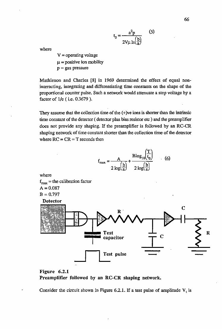
where V = operating voltage
µ = positive ion mobility p = gas pressure
66
a2p (5)
to= 2VµIn(~j
Mathieson and Charles [8] in 1969 determined the effect of equal noninteracting, integrating and differentiating time constants on the shape of the
proportional counter pulse. Such a network would attenuate a step voltage by a factor of l/e ( i.e. 0.3679 ).
They assume that the collection time of the ( + )ve ions is shorter than the intrinsic
time constant of the detector ( detector plus bias resistor etc ) and the preamplifier
does not provide any shaping. If the preamplifier is followed by an RC-CR
shaping network of time constant shorter than the collection time of the detector
where RC = CR = T seconds then
where
~ax = the calibration factor
A =0.087 B = 0.797
Detector
Figure 6.2.1
--•Test j capacitor
~tpulse
Preamplifier followed by an RC-CR shaping network.
. (6)
c
Consider the circuit shown in Figure 6.2.1. If a test pulse of amplitude Vt is
R

67
applied to the test capacitor of capacitance Ct then a charge Qt will be injected
into the detector plus stray capacitance etc .. The value of Ct is chosen to be small
compared to input capacitance of the amplifier so that the total capacitance is effectively Ct. The pulse at the output of the RC-CR network due to the injection
of Qt from the pulse generator will go into a particular pulse height analyzer
channel ,say Pt. Now if Qt electronic charge is formed in the detector as a result
of an energy loss E in the detector sensitive volume and the detector gas gain then the resulting pulse, because of its different rise time, will go into a different channel, say PE. The relationship between PE and Pt will be given by
PE= fmax e pt where e = 2.718 ...... .
If the mobility of the positive ions is not known f cannot be calculated, and . max
the W-value must be known if the gas gain is to be determined.
Gott and Charles [9] have used the above expression for fmax to determine the
high field mobilities of the positive ions in various gas mixtures and then, by comparing the mobilities they obtained with published high field mobilities for various ions in the particular gas mixtures, they have been able to identify the positive charge carriers near the anode in some proportional counter gases. Since
fmax is a function of the positve ion mobility they obtained theoretical curves
using unit positive ion mobilities. They then obtained experimental points and the departure of their experimental points from their theoretical curves was a measure of the departure of the positve ion mobilities from unity. For example, they determined that in Xe + 5% CH4 that the positive charge carrier was the Xe+ ion
in the high field region near the anode.
Hendricks [10] in 1972 extended the work of Mathieson and Charles by considering the effect of the additional differentiators existing in the signal
processing chain. Consider a detector followed by preamplifier, decoupling capacitor, a differentiator and then an integrator as shown in Figure 6.2.2.

68
Cf
Detector
Co
TCt 't= RC
f f
J Test pulse
xl xl xl
- - -
Figure 6.2.2 Detector, preamplifier, decoupling capacitor Ct, with a differentiation stage followed by an integration stage.
Consider the circuit shown in Figure 6.2.2. Hendricks showed that the response
of the system to a step voltage which places a charge Qt across the test capacitor

69
where 'C = 'C2 = 'C3 , and 'C<< 'Cf, and 'C1 is the decoupling time constant. Also the
time 1Jn to reach the maximum pulse amplitude is given by
If the preamplifier plus amplifier employ pole-zero cancellation [11] a step voltage at the test capacitor input will be attenuated by l/e where e = 2.718 ... as
in the work of Mathieson and Charles [8].
The pulse from the proportional counter is not a step function but may be
expressed as
where
no = the number of primary ion pairs and is given by E/W
G =-gas gain
e = the electronic charge
a = anode radius
b = cathode radius V = operating voltage ·
µ = the mobility of the positive ions p = gas pressure
Equation (9) assumes that all the electrons from the primary ion pairs begin avalanches at the same time, all the positive ions are formed at the central wire, and there is no recombination. The first assunption would be valid for low energy electrons ( < 10 keV) in heavy noble gases, and the second assumption
is reasonable for gas gains greater than 10 [10].

70
where [7]
t = a2p (11)
o 2VµIn(~j The only part of equation (10) which varies with time is the ln(t/to + 1) which
means that the voltage at the output of the circuit can be expressed by
y~)= Qpc ~t,t;t1 ,tf,to) (12)
2Cfln(~j where Qpc = n 0eG
The function f(t,t,t1,tf,to) is determined by the operation of the differential
equations which describe the circuit on ln(t/to + 1) and Qpc.The maximum
voltage output may be expressed as
v(tm) = Qpc K(t,to) (13)
2cf1n(~j
To calculate G the gas gain from all this, the pulse at the output of the circuit from the pulse generator is matched on an oscilloscope screen with the pulses from a source i.e.55Fe, then equation (7) and (13) can be set equal to ~ach other.
Qpc=A(t,t0,~jQt (14)
where the calibration factor
A( t,t •• bi= 21n(~) <1 r .-1 -[ <r+<1h [1 - e-111 (15) a K(t,to) ~ tJt1 -t) J
The calibration factor A shown in equations (14) and(l5) is typically in the range 3 to 5.
Now the charge at the test pulse input is given by
Qt= ctvt (16) Combining (14),(15) and(l6) the gas gain G is given by
A( t,to,~CtVt G= (~}
(17)
- There are two quantities that need to be known in order to apply Hendrick's

71
calibration factor; the drift time t0 of the positive ions and the W-value of the
counter gas. The drift time to depends upon the positive ion mobility and both
W-values and positive ion mobilities can be found in the literature.
The drift time to can also be determined from the oscilloscope trace of the
proportional counter pulse taken from the preamplifier output. This pulse can be expressed as
") - n0Ge ( t ~ V\t ::: (b ~ In ~) (18)
2Cfln a)
A photograph of the oscilloscope trace will give V(t), then plotting V(t) against
ln(t) should give a straight line with ln(to) as an intercept.
The method of calibrating the charge - sensitive preamplifier with a test pulse
was most recently used by Miyahara et al [12] to determine the gas gains of90%
Ar - 10% Cf4 ( P - 10) over a range of pressures from 0.1 - 1.6 MPa (1 - 16
atmospheres) and for pure CH4 over the range 0.1 - 0.5 MPa. The diameters of
the cathodes and anodes were varied. Three cylindrical coaxial detectors were
constructed from brass for the experiments. They were; 3 cm in diameter,15 cm long, 5 cm in diameter, 22 cm long and a third detector with a removable cathode
for testing cathode diameters from 3 cm downwards. This last detector was 14
cm long. The anodes were made from stainless steel and were 22, 30, and 50
µm in diameter. The gas in the detector was continually flowing.
The approach of Miyahara et al [12] was to build a test pulse generator that
produced a pulse that was the same shape as the proportional counter pulse.
Their test capacitance was 1.27 ± 0.05 pF which immediately introduced a 4 %
error into their results. The circuit for their test pulse generator is shown in Figure 6.2.3.

D.C. supply
Figure 6.2.3
72
Mercury relay
D.C. voltmeter
:r: O.OOlµF
120.Q
100.Q
-• 1000 .Q
120 .Q
T 0.02µF
-
Attenuator I-et
1.27 ± 0.05 pF
A test pulse generator that produces a pulse of the same shape as the proportional counter pulse.
The mercury relay in their circuit was operated at the mains frequency. The opening and closing of the switch switched off and on a de power supply which produced a train of rectangular pulses. The value of the voltage produced by the de power supply presumably could be read to a high degree of accuracy. The pulse generated square pulses were then shaped by two different RC circuits. The resulting pulses from these two RC circuits were then added together to
· produce a pulse of approximately the same shape as that produced by a proportional counter.
In response to a step voltage of V in the 0.001 µF capacitor will charge to
(120/l 120)Vin volts with a time constant of 't = 107x0.001x10-6 seconds and
the 0.02 µF capacitor will charge to (100/220)Yin volts with a time constant of 't
= 54.5x0.02xlo-6 seconds. These two charging curves will add together to

73
produce a final curve of approximately the same shape as the proportional counter pulse, the short time constant providing a fast rising section and the long time constant producing a slow rising section. They checked that this was the same shape as the detector pulse by shaping the pulses with two amplifiers with
different time constants ( 0.5 µseconds and 3 µseconds ). If the two different time constants had the same effect on the test pulses as on the proportional counter pulses, the pulses must be the same shape.
, All the approaches so far have either involved shaping the pulse so that it is the ~ame shape as the detector pulse or calculating the calibration factor for the difference in the response of the preamplifier, amplifiers etc to the detector pulses and the pulse generator pulses.
6.3 Conclusion
Gas gain measurements can be made by the pulse matching method with accuracy provided the difference in shape between the test pulse and the detector pulse is taken into account. Some authors shape their test pulses to the same shape as the detector pulses while others use a calibration factor to correct for the differences. Calibration factors have been determined by Mathieson and Charles [8] and Hendricks [10] and a simple circuit for shaping the test pulses to the same shape as the detector pulses has been developed by Miyahara [12].
Both of the above approaches assume that the time spread in the formation of the electron avalanches from the primary ion pairs is small and all the positive ions are formed in the vicinity of the anode.
References
[1] M. E. Rose and S. A. Korff, Phys. Rev. 59 (1941) 850. [2] G. F. Knoll, Radiation Detection and Measurement, John Wiley & Sons
(1979) 205. [3] M. E. Rose and W. E. Ramsey, Phys. Rev. 61 (1942) 198. [4] G. C. Hanna, D. H. W. Kirkwood, and B. Pontecorvo, Phys. Rev. 75
(1949) 985. [5] W. Diethom, Report Number NYO - 6628, United States Atomic Energy
Commision (1956) 64. [6] R. W. Kiser Appl. Sci. Res. B8 (1960) 183. [7] G. F. Knoll, Radiation Detection and Measurement, John Wiley & Sons
(1979)'204. [8] E. Mathieson and M. W. Charles, Nucl. Instr. and Meth. 72 (1969) 155. [9] R. Gott and M. W. Charles 72 (1969) 157.

74
[10] R. W. Hendricks, Nucl. Instr. and Meth. 106 (1973) 579. [11] G. F. Knoll, Radiation Detection and Measurement, John Wiley & Sons
(1979) 623. [12] H. Miyahara, M. Watanabe and T. Watanabe, Nucl. Instr. and Meth. A241
(1985) 186.

7 AN ALTERNATIVE APPROACH TO THE PULSE MATCHING
1\1ETHOD
7 .1 Introduction
This chapter describes a different approach to the pulse matching method. Instead of shaping the pulse generator pulse so that it has the same shape as the average pulse from the detector, I have constructed a circuit whic~ shapes both the detector pulse and the pulse generator pulse to the the same shape.The basic idea is shown in Figure 7 .1.1 .
Detector pulse
(+)ve HV
Detector
Figure 7 .1.1
Cathode
Test ptdse
-
·Switch I closed T
100
Pulse inverted
An alternative approach to the pulse matching method would be to shape both the detector and pulse generator pulses to the same shape.

76
After the detector pulse has fully developed, the cathode is shorted by a switch and the resulting pulse is inverted so that the region of the pulse where the switch was closed becomes the pulse,i.e. the detector pulse is tranformed into a step voltage at the input to the preamplifier. The switch is also closed on the test pulse in the same fashion so that both detector and test pulses are the same shape.
With the circuit shown in Figure 7 .1.1 the rise time of the detector pulse is irrelevant so that it does not matter where the primary ion pairs are formed in the detector sensitive volume. This circuit, in principle at least, can be used to measure very small gas gains since it is not necessary for all the positive ions to
be formed near the anode.
The accuracy of the circuit should only depend upon the precision with which the
voltage amplitude of the test pulses, capacitance of the test capacitor, the Wvalues, and the energy loss in the detector are known.
7 .2 The electronic circuit
The circuit is shown in Figure 7 .2.1.

Cathode HV
Test pulse
Detector output
lOOM
HEF 4016B
8
lK
9
77
6
Switch enabled when control line goes high
lK
0.1
Output
lOK lOK lK
- -- -Control line for switch (HEF 4016B)
HEF HEF LF 356N 4047B 4047B
LF 356N
8
Figure 7.2.1 A circuit which shapes the detector pulse and the test pulse to precisely the same shape. The capacitance units not shown are in
µF's.
Because the semiconductor switch (HEF 4016B) requires a signal pulse between zero and +5 V, the counter pulse is taken from the cathode. The anode is
0 10
() 11

78
connected directly to the high voltage, not via a high resistance.
The cathode is connected to ground via a 100 MQ resistor, giving the detector a long differentiation time constant of - 7.5 ms. Other resistances to ground e.g. the insulation in the coaxial cable connecting the amplifier and detector, will have
the effect of reducing the value of the 100 M.Q. The integration time constant will be the product of the resistance of the detector gas filling and the central capacitance.
The switch ( HEF 4016B) wheq. closed shorts out the cathode after the pulse has had time to fully develop, the rest of the circuit amplifies and inverts the pulse which is then received by the multichannel pulse height analyser. The pulse height analyser only accepts the ( + )ve going edge of the pulse which has a height equal to the maximum pulse amplitude. This positively going section will be a step voltage with a fast rise time. The sequence is shown schematically in Figure? .2.2.

Volts Volts
0 Time
Pulse from the detector cathode
Volts
• 0
•••••• E .......... ~ ....................................... ~
The pulse is inverted and the capacitive coupling causes it to take on the shape indicated by the solid line
Figure 7 .2.2
0
79
Time
Pulse shape after the cathode has been shorted by the switch ( HEF 4016B )
The pulse height analyser only accepts the positively going edge
The shaping sequence the pulse undergoes during its passage through the circuit.
The positive ions and electrons must be completely collected before the cathode is shorted out. The cathode should be shorted out after a period of time equal to the time it takes for the positive ions to drift from the anode to the cathode. When all the charge is collected the pulse will have attained its maximum amplitude. In order to make sure that the pulse had developed to its maximum amplitude the period of time from the detection of the pulse until the shorting of the cathode was adjustable. This time was controlled by two monostable multivibrators (HEF 4047B's). The first monostable is turned on by the detector pulse and produces a pulse with an adjustable length. The adjustment is achieved by changing the value of the variable resistor controlling the time constant of the

80
monostable. The inverting output of this monostable is connected to the noninverting input of a second monostable. At the conclusion of the pulse from the first monostable the second monostable produces a brief positively going pulse which enables the switch and consequently shorts out the cathode.
The experimental technique for obtaining the maximum pulse amplitude is therefore as follows; initially the length of the pulse from the first monostable is set at some small value and a pulse height distribution is obtained. Then the
length of the monostable pulse is increased and another pulse height distribution is obtained. The peak of interest in the spectrum should move to a higher channel. This procedure should be repeated until the peak of interest has moved to a channel such that further repetition of the procedure causes it to move to a lower channel. Of course the count rate should be so low that no pulse pile up
occurs. A 148Gd source with a low count rate ( - 100 Bq) was chosen for the data presented in this thesis for this circuit. A monostable pulse length greater
than - 0.4 ms was never attempted and since this gave the same pulse height distribution as a pulse length of - 0.2 ms it was assumed that the maximum pulse amplitude had occurred within - 0.2 ms.
The capacitive coupling between some of the amplification stages was necessary
so that any de voltages present were not amplified saturating subsequent amplifying stages. The first stage was a buffer amplifier providing a large input
impedance ( 1012 Q ). This stage together with the 100 MQ resistor to ground helped to create a large time constant so that the detector pulse could develop to
its full amplitude without any clippirig due to differentiation. After the buffer is a
high pass filter with a corner frequency of f0 = 1/(21tRC) = 1591.5 Hz. This will
allow the shorted section of the pulse to pass through whilst attenuating any 50 Hz pick up that might undergo amplification and subsequently trigger the
monostables. The 0.01 µF capacitor also acts as de blocking capacitor. Another similar differentiation network with the same corner frequency can be seen later on in the circuit performing a similar function.
7 .3 The test pulse generator
The test pulse generator consisted of a 9 volt battery connected to a,_ mercury wetted relay which was opened and closed 50 times a second by the mains voltage.The battery plus mercury switch were connected across a potential divider so that the pulse amplitude could be varied. The circuit is shown in Figure 7.3.1 .
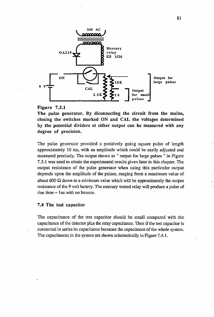
OA210
Figure 7 .3.1
Mercury relay EB 1526
J Output for small pulses
Output for large pulses
81
The pulse generator. By diconnecting the circuit from the mains, closing the switches marked ON and CAL the voltages determined by the potential dividers at either output can be measured with any degree of precision.
The pulse generator provided a positively going square pulse of length approximately 10 ms, with an amplitude which could be easily adjusted and measured precisely. The output shown as " output for large pulses " in Figure 7.3.1 was used to obtain the experimental results given later in this chapter. The output resistance of the pulse generator when using this particular output depends upon the amplitude of the pulses, ranging from a maximum value of
about 600 n down to a minimum value which will be approximately the output resistance of the 9 volt battery. The mercury wetted relay will produce a pulse of rise time - lns with no bounce.
7.4 The test capacitor
The capacitance of the test capacitor should be small compared with the capacitance of the detector plus the stray capacitance. Then if the test capacitor is connected in series its capacitance becomes the capacitance of the whole system. The capacitances, in the system ~e shown schematically in Figure 7.4.1.

Test capacitor Stray capacitance
--I._---------~, ......... Detector
Output resistance
100 M
1K
82
, ,, .·,,:-. HEF '-~' ' -. 4016B
.,, ,"'""'~,----------
High voltage
Figure 7.4.1 -
.... .. . . ....... . .... · .
........... : .... :. ....... -: ...... -:-.... : ' ' '
The capacitances of the system. If the capacitance of the test capacitor ( CT ) is small it becomes the capacitance of the whole
system.
A 1 pF test capacitor was constructed by connecting two 2.2 pF ± 0.1 pF NPO temperature compensated capacitors in series. This arrangement introduced some stray capacitance that added to the value of the second capacitor as shown schematically in Figure 7.4.2.
2.2, pF 2.'2 pF
--ll-r-fl-11111111ul111111111
""""l"""" 0.2 pF 1111111111111111111i1111111111111111111
11111111111
Figure 7 .4.2 A 1.15 pF capacitor was constructed from two 2.2 pF capacitors.
The stray capacitance was estimated to be - 0.2 pF ± 0.1 pF, therefore the capacitance of the test capacitor was 1.15 pF ± 0.07 pF.
A rough estimate of the dete~tor plus stray capacitance i~ - 7 5 pF. Therefore the

83
capacitance of the whole system with the test capacitor connected in series is ==
1.13 pF.
The test pulse generator produces a square wave with a period of 20 ms. By disconnecting the pulse generator from the mains and closing the two switches marked ON and CAL ( see Figure 7 .3.1 ) the voltage set by the potential divider can be measured at the output with the Keithley 616 electrometer used as a
voltmeter. When used in this way the input impedance is greater than 2x1Q14 n and the accuracy is 0.2 % of the reading plus 0.1 % of the range.
At the test pulse input the circuit is essentially a 1.13 pF capacitor. If a known voltage, VT is placed across this input the charge injected into the system, Q can
be calculated from Q = CTVT. This charge charges up the detector capacitance
and the stray capacitance. After a preset time period the switch HEP 4016B ( see Figure 7.3.1) shorts the cathode in precisely the same way as if the detector had
been charged up by the absorption of an a-particle. Consequently the test pulse is shaped in exactly the same way as the detector pulse.
In addition to this shorting of the cathode by the circuit the positively going square pulse from the pulse generator also has a negative edge which will appear at the input of the pulse height analyser as a positively going pulse. This second pulse always had a smaller amplitude as seen on the oscilloscope and therefore appears in a lower channel. As the amplitude of the test pulse is increased the peak formed by the pulses from the negative edge moves closer to the peak formed by the pulses from shorting the cathode.
7.5 Results from the new technique
When the pulses are too small to trigger the monostables they are seen at the output as negatively going pulses. At anode potentials of+ 100 volts and + 200 volts the output pulses from' the circuit were of amplitude - 4 millivolts with what appears to be ringing on the leading edge. As the amplitude of the detector pulses is increased by increasing the anode potential the monostables begin to trigger. Both the detector pulse, and the monostable pulse which controls the length of the detector pulse, can be seen simultaneously on a double beam oscilloscope. The oscillograms below in the figures show the oscilloscope traces for anode potentials of + 200 volts, + 1000 volts and + 1,500 volts and some samples of traces obtained from test pulses.

84
Figure 7 .5.1 Oscillogram for an anode potential of + 200 volts. The linear amplifier is not connected and the output is taken directly from the output of the circuit. The oscilloscope is being triggered by the negative edge of the detector pulse.

85
Figure 7.5.2 Two oscillograms for an anode potential of +1000 volts. The top trace shows the pulse that results from shorting the cathode. The bottom trace shows the monostable pulse.

86
Figure 7 .5.3 An oscillogram for an anode potential of +1500 · volts. As in the preceding oscillograms the top trace shows the positively going pulse at the circuit output that results from shorting out the cathode. The bottom trace shows the monostable pulse.
The next series of oscillograms show how the circuit affects the pulse generator pulse. As already mentioned the pulse generator pulses are square pulses 10 ms long. Once again the top traces show the test pulse at the circuit output. Each test pulse at the test input should result in two positive output pulses, one from the shorting of the cathode and one from the negative edge of the input square pulse. The first two oscillograms (figure 7.5.4) show only the pulse that results from shorting the cathode while the next oscillogram (figure 7.5.5) also shows the pulse that results from the negative edge.

87
Figure 7.5.4 Oscillograms of the test pulse at the circuit output. The top trace in each oscillogram show the effect of shorting the cathode on the test pulse. The bottom trace shows the monostable pulse.

88
Figure 7 .S.S Oscillogram for the test pulse at the circuit output. Two positively going pulses are visible. The first positive pulse is due to shorting the cathode whilst the second is due to the negative edge of the square pulse.
In all of the oscillograms both traces are being triggered by the negative edge at the output ( i.e. positive edge at the input) of either the detector pulse or the test pulse. The signal is taken directly from the circuit, i.e. there is no linear amplifier.
The major fault with the circuit is obvious in the above oscillograms (see figures 7.5.2 to 7.5.5 ). The monostable sees the decaying edge of the pulse formed by shorting the cathode as another positive pulse at the input and triggers again producing a secondary pulse. This secondary pulse can also trigger the monostable again.
On the leading edge of the decaying pulse a transient can be seen ( it does not show up in the oscillograms ). This transient has an amplitude of= 0.02 volts at the circuit output and this amplitude seems to remain constant irrespective of the amplitude of the primary pulse. The secondary pulse seems to be about 0.1 of the amplitude of the radiation pulses. These idiosyncrasies do not appear to affect the results for gas gains above about 20.
For gas gains above = 20 this circuit gave results which agreed with those

89
determined by the current comparison technique to within a few percent. For ex.particle pulses and gas gains above 20 the accuracy of the final figure for the gas gain probably depends only on the accuracy to which the capacitance of the test capacitor is known and the accuracy to which the amplitude of the pulse from the pulse generator can be measured. This is assuming the capacitance of the test capacitor is small compared with the central capacitance of the system i.e. the
input capacitance of the circuit. For gas gains below 20 using 148Qd ex-particles the results did no.t compare very well with the results obtained by current comparisons. In spite of this the results indicate that the technique is worth consideration. The only genuine fault with the circuit was that the pulses had to be large.
The detector used for all the following measurements was detector 2 ( see chapter 2) and the gas filling was always P-10 at a pressure of 758.5 torr at 0°C. The series of pulse height distributions shown below illustrate the effect of letting the pulse develop for different periods of time.

counts
channel number
counts
4'U
channel number
counts
3 ,,.J channel number
Figure 7 .5.6
90
monostable pulse length = 0.2 ms anode potential =+1300 volts pulse height distribution obtained over lk sees counts between channel 256 and 477 = 56969
monostable pulse length =I ms anode potential
= +1300 volts pulse height distribution obtained over lk sees counts between channel 293 and 488 = 47906
monostable pulse length, = lms ,
anode potential = + 1300 volts , pulse height distribution obtained over lk sees
The above differential pulse height distributions show the effect of increasing the monostable pulse length from 0.2 ms· to 1 ms.
(,

91
Since the a-particles from 148Gd are monoertergetic ( 3.182787 ± 0.000024 MeV ) there should be one single peak due to the alpha's that are completely absorbed by the gas. This peak corresponds to the highest energy and most prominant peak in the spectrum. The channel for this peak remains constant from one spectrum to the next. Any variation is probably due to electronic drift. It occupies channel 408, 404 and 409 in the above three spectra (see Figure 7 .5.6 above ). This would indicate that a monostable pulse length of 0.2 ms is sufficient to allow the detector pulse to develop to its maximum amplitude. It also means that the pulse does not decay to any measurable extent during the next 0.8 ms. Thus the detector differentiation time constant is long enough.
The increase in pulse length seems to have the effect of developing a ridge on the
low energy side of the main peak in the spectrum. The slope of the low energy
side is probably the result of numerous a-particles depositing part of their energy in the wall of the counter. This distortion in the low energy side may be the result of pulse pile up among these low energy pulses. This idea is supported by the decrease in the number of counts in the main peak 56969 counts/sec decreased to 47Q06 counts/sec. The larger pulse length would certainly increase pulse pile up. The pulse matching technique gives a gas gain at + 1300 volts of 21.66 ± 1.40
while current comparisons give 23.01±1.47.
The following pulse height distributions show the effect of monostable pulse
lengths of 50 µs, 0.2 ms and 0.4 ms for an operating voltage of + 1700 volts. The data were collected over a period of two days and the spectra were not obtained in the order shown.

92
ALPHA- PARTICLES monostable pulse length
=SO µs counts anode potential
= +1700 volts pulse height distribution obtained over lk sees counts between channel S9S and 3S2 = S23S9 cts
?S'2 S"lo S''tS"'
channel number
TEST PULSES ,- pulse height ;distribution
obtained over 100 sees
counts amplitude of test pulse = 3.26 volts charge injected
= 3.26xl.13xlo-12 C gas gain
~ ' l = 187.82±12.18 Slo
channel number
Figure 7.S.7
If the monostable pulse length is set at SO µs and the W-value for 3.182787(24) MeV alpha particles in P-10 is taken as 26.0 eV/ip ± 0.5 eV/ip the gas gain given by the pulse matching method is 187.82±12.18. Current comparisons give a value of 228.77 ± 14.64.

counts
counts .
Figure 7.5.8
ALPHA PARTICLES
channel number
TEST PULSES
si; I
channel number
93
monostable pulse length = 0.2 ms anode potential = +1700 volts pulse height distribution obtained over lk sees counts between channel 355 and 609 = 51582 cts
pulse height distribution obtained over 100 s counts between channel 546 and 558 = 5009 cts amplitude of test pulse . = 3.65 volts charge injected = 3.65xl.13xl0-12C gas gain= 210.29±13.64
The monostable pulse length is increased to 0.2 ms. The gas gain given by the pulse matching method is 210.29 ± 13.64. Current comparisons give a value of 228.77 ± 14.64.

ALPHA PARTICLES
counts
)1to ~5'2 Si4-channel number
Figure 7.5.9
94
monostable pulse length = 0.4 ms anode potential = +1700 volts pulse height distribution obtained over lk sees
The monostable pulse length increased to 0.4 ms. A distortion now appears on the low energy side but the position of the peak does not change.
The test pulse spectrum illustrated in figures 7.5.7 and 7.5.8 show two peaks. As already mentioned the peak in the lower energy channel corresponds to the negative edge of the input square wave and the other corresponds to the shorting of the cathode by the circuit. These test pulse peaks are only a few channels wide.
As the monostable pulse width is increased from 50 µs to 0.2 ms the position of the peak changes from channel= 510 to= 550. This is a significant change. The gas gain as calculated by the pulse matching method changes from 187.82 to 210.29. The errors in the values are due to the uncertainties in the test capacitor and the W value which of course remain constant. This test capacitor is NPO temperature compensated. The errors in the gas gains can therefore be ignored and the two figures can be compared directly. Increasing the monostable pulse
length from 50 µs to 0.2 ms results in a 11.96% increase in the value for the gas gain.
Increasing the monostable pulse length from 0.2 ms to 0.4 ms makes no difference to the position of the main peak ( see Figures 7.5.8 and 7.5.9 ). Consequently a monostable pulse length of 0.2 ms is sufficient to allow the detector pulse to develop to its full amplitude. Once again a distortion has developed on the low energy side which is most likely a pulse pile up effect. The peak shown in figure 7.5.9 has a much sharper sloping edge on the high energy side than the peak shown in figure 7 .5 8.
The following figures show some of the differential pulse height distributions

95
obtained for 3.182787(24) MeV a-particles corresponding to various operating voltages together with the calibration pulse spectra. The results were repeatable. The gas used was always P-10 at a pressure of 758.5 torr at Q<>C and the W value used to determine the gas gains was 26.0 eV{lp ± 0.5 eV{lp[l].
counts
counts
Figure 7 .5.10
ALPHA PARTICLES
4111- .. go;
channel number TEST PULSES
channel number
operating voltage = + 1300 volts monostable pulse length = 0.2 ms time = lk seconds counts between channel 248 and 485 = 68162 cts linear amplifier input attenuator = 1
time = 100 seconds counts between channel 399 and 429 = 5011 test pulse amplitude = 0.376 volts gas gain = 21.66±1.40
The differential pulse height distribution for 3.182787(24) MeV aparticles at an operating voltage of +1300 volts and the test pulse spectrum. The gas gain as determined by the pulse matching method was 21.66 ± 1.40. Current comparison give a value of 23.01 ± 1.47.

ALPHA PARTICLES
counts
S'lll
channel number
TEST PULSES
counts.
-~..___A..__ 1+1'!. ,00
channel number
Figure 7.5.11
96
operating voltage ·= +1400 volts monostable pulse length = 0.2 ms time = lk seconds counts between channel 444 and 657 = 57428 cts linear amplifier input attenuator = 2
time = 100 seconds counts between channel 508 and 611 = 4976 cts test pulse ampl~tude· = 0.625 volts gas gain = 36.01 ± 2.34
The differential pulse height distribution for 3.182787(24) MeV cxparticles at an operating voltage of + 1400 volts, and the test pulse spectrum. The gas gain obtained by the pulse matching method was 36.01 ± 2.34. Current comparisons give a value of 39.81 ± 2.55.

ALPHA PARTICLES
counts
:l' 3 1(,'f lf.O'
channel number
TEST PULSES
counts
I I \._~~-'.J 2', 170
channel number
Figure 7.5.12
97
operating voltage = +1500 volts monostable pulse length = 0.2 ms time = lk seconds counts between channel 293 and 406 = 54373 cts linear amplifier input attenuator= 5
time = 100 seconds counts between channel 357 and 383 = 5008 cts test pulse amplitude-· = 1.096 volts gas gain = 63.15 ± 4.10
The differential pulse height distribution for 3.182787(24) Me V aparticles . at an operating voltage of + 1500 volts and the test pulse spectrum. The gas gain obtained ~y the pulse matching method was 63.15 ± 4.10. Current comparisons give a value of 68.96 ± 4.41.

counts
counts
Figure 7.5.13
ALPHA PARTICLES
4lr'Z.
channel number
TEST PULSES
f:.2f(
channel number
98
operating voltage = +1600 volts monostable pulse length = 0.2 ms time = lk seconds counts between channels 482 and 687 = 51650 cts linear amplifier input attenuator = 5
- time = 100 seconds counts between channels 619 and 638 = 5010 cts test pulse amplitude = 1.950 volts gas gain = 112.35±7 .29
The differential pulse height distribution for 3.182787(24) MeV aparticles at an operating voltage of +1600 volts and the test pulse spectrum. The gas gain obtained by the pulse matching method was 112.35 ± 7.29. Current comparisons give a value of 124.83±7.99.

counts
counts
Figure 7.5.14
ALPHA PARTICLES
1s~ ~so
channel number '0
'
TEST PULSES
)~I
channel number
99
operating voltage = +1700 volts monostable pulse width = 0.2 ms time = lK seconds counts between channels 355 and 609 = 51582 cts linear amplifier input attenuator = 10
- time = 100 seconds counts between channels 546 and 558 = 5009 cts test pulse amplitude = 3.65 volts gas gain= 210.29±13.64
The differential pulse height distribution for 3.182787 MeV aparticles at an operating voltage of +1700 volts and the test pulse spectrum. The gas gain obtained by the pulse matching method was 210.29 ± 13.64. Current comparisons give a value of 228.77 ± 14.64.
In the above figures (see Figures 7.5.10 - 7.5.14) the test pulse peaks used to calculate the gas gains were a fraction of a percent FWHM. A summary of the results obtained by the test pulse method is given in figure 7 .5.1.

100
operating gas gain gas gain % difference voltage by pulse by current between
matching comparison mean values
+1300volts 21.66 ± 1.40 ' 23.01±1.47 +6.2% +1400 volts 36.01±2.33 39.81±2.55 + 10.6% +1500 volts 63.13 ± 4.09 68.96 ± 4.41 +9.2%
+1600 volts 113.88± 7.39 124.83 ± 7 .99 +9.6%
+1700 volts 210.21 ± 13.63 228.77 ± 14.64 +8.8%
Table 7.5.1 The results obtained by the pulse matching method compared with the results obtained by the current comparison method using the same detector, radiation source an~ gas filling.Within the experimental errors the results are in agreement.
The current comparison and pulse matching results shown above were obtained using the same detector, same radiation source and same gas filling. The value of the gas gains detennined by current comparisons were always larger than those detennined by pulse matching, this is indicated in the last column of Table 7 .5.1 by the + sign and indicates the presence of a systematic error.
7.6 Conclusion
Previous authors using pulse matching methods have either shaped their pulse generator pulses to the same shape as their detector pulses or they have determined calibration factors to correct for the difference in pulse shapes ( see chapter 6 ). Both of these approaches assume that the proportional counter pulses are always the same shape. This assumption is probably valid for electrons of< 10 keV in heavy noble gases but for high energy electrons the shapes of the pulses will depend upon the orientation of the ionization tracks formed by the primary ionization. The methods discussed in chapter 6 also assume that all the positive charge is formed in the vicinity of the anode. This assumption will only be true for gas gains greater than - 10. With- the method I have developed both the shapes of the detector and pulse generator pulses become irrelevant although
it is necessary for the pulse generator pulses to be rectangular so their precise amplitudes at the moment the cathode is shorted are known.
The pulse matching method by shorting the cathode gave results which agreed with current comparison measurements performed on the same detector with the same gas filling and the same radiation source.

101
The accuracy of the pulse matching method using circuits similar to the circuit I have constructed may ultimately depend only on the precision to which the capacitance of the test capacitor, the volts function on the electrometer, the Wvalue, and the energy lost in the detector are known. With the above circuit the pulses had to be large before reliable results were obtained. In fact only for 3.2
Me V ex.:. particles at a gas gain of 20 were reliable results obtained. Since a 3.2
MeV ex-particle releases 1.2x10⁵ ion p~s in P-10 ( W-value 26.0 eV/ip) and the central capacitance of the system was= 75 p~, the pulses at the input of the
circuit at a gas gain of 20 were = 5.1lx1 o-3 volts. If the circuit is to be useful it will have to be more sensitive. It may be possible to improve the circuit by taking the pulse which closes the switch (REF 4016B) from the central wire.
Alpha particles are not really suitable for the study of gas gain since so much
charge is formed by the absorption of an a-particle the resulting· pulse may be affected by intrinsic space charge effects giving smaller values for the gas gain than would be obtained by using x-rays or electrons to produce the primary ionization. X-rays or electrons would, of course, produce much smaller pulses so the circuit would need to be more sensitive. Gas gains of less than 20 are also of interest and should be studied.
All the other results presented in this thesis were obtained by the current
comparison.method using x-rays oryrays.
References
[t] M. Jarvinen and H. Sipila, Nucl. Instr. and Meth. 217(1983) 282 ..

8 --------PROPERTIES OF GAS GAIN-------
8.1 Gas gain and the reduced field strength
It was suggested by Zastawny in 1966 [1] that the gas gain of a cylindrical proportional counter operating in the proportional region will be a function only
of the reduced field strength at the surface of the anode.
In the electron avalanche the increase in the initial number of ion pairs, n, is
given by dn = nadr, where a is the first Tewnsend coefficient, and r is the
distance from the axis of the detector. The first Townsend coefficient is defined
as the number of ion pairs produced per unit path length by an electron· moving
under the influence of an electric field and therefore in the opposite direction to
the field. It follows that the reciprocal of the first Townsend coefficient should be
the mean path for ionization. It has been shown experimentally that a/N is a
function only of the reduced field strength E/N where N is the molecular number density and E the electric field strength [2].
The gas gain, G is given by
c
In G =Ja dr (1)
a
where a is the anode radius and c the radius at which gas gain begins. An
electron moving in equilibrium with the field may not have gained all its energy in the last mean free path but may have gained and lost energy in collisions over
several mean free paths before actually ionizing a gas atom. Over these several mean free paths the probability of ionization would have remained constant. The radius c would correspond to a distance from the central axis of the detector of one mean path for ionization plus the radius of the anode wire when the gas gain just equals two. When the radius of the anode wire is the same as c, G = 1 and In G = 0, if c is greater than the anode wire radius G will always be greater than 1.
In a cylindrical proportional counter the field strength is given by

103
E = V (2)
rin(~j where V is the operating voltage, r the distance from the central axis of the detector, b the cathode radius and a the anode radius. Following the notation of Zastawny [l] and Aoyama [3] the reduced field strength is given by
S=~= V
N rNin(~j
dr = - as dS (3) a 2 -S
where Sa is the reduced field strength at the surface of the anode. Therefore,
changing variables in equation (1) using equation (3), we have Sc
lnG = - J cxaSa d~ s s
a
where Sc is the reduced field strength at the onset of gas gain. Therefore Sc
lnG = -J.!!.as dS N N a 2
s s a
and since aJN is a function of the reduced field strength
Sa
lnG = J_g_ dS (4) NaSa N 8 2
Sc
If Sc is a constant for a given gas or mixture of gases we have
lnG = p(sa) (5) NaSa
Thus if the gas gain is measured for a range of detector parameters e.g. gas, density, anode radius, a graph oflnG/NaSa against Sa should yield the same
function.
Zastawny verified this for proportional counters filled with C02 by measuring
the gas gain at four different gas densities [1]. He was also able to show that it
held for P-10 ( 90% Ar plus 10% CH4 ) by using the data obtained by Williams
and Sara [4]. According to Zastawny these authors had kep~ the gas density -

104
constant but varied the anode radius [4].
Equation (5) was verified for nitrogen and xenon by obtaining values of gas gain for a range of gas densities.
8.2 Experimental results for nitrogen
, Data for nitrogen was obtained at three different gas densities. These data are shown below in Figure 8.2.1
0.025 .------.------,---,.----,---.----,----,.--.-----,
0.020
00 0
0
0
0 0
0
..0.015 l"/l 0
0
~o IXS z ......... ~ r::: -0.010
0.005
0.000 '------1---L-----L-----1--....L--__.. __ _.__ _ __._ ___
0.0 0.2 0.4 0.6 0.8 1.0 1.2 1.4 1.6 1.8 x 10⁻¹⁸
s. Vm2
Figure 8.2.1 A plot of (InG)/(NaS ) against Sa for nitrogen. The molecular
a
number dens.ities used to obtain the gas gains were 2.56x25 m-3, l.62xl025m-3 and 6.5lxl024 m-3.
The above plot of (lnG)/(NaS ) against Sa for nitrogen at three different densities a
verifies equation (5) for nitrogen. The points for the measurements at the different densities show virtually no scatter, sitting directly on top of each other.

105
The readings for the gas gains at the different densities were carried out successively, first the gas gains at the higher density were recorded and then the gas density was reduced and new gas gain measurements recorded and so on for three different gas densities. The gas gains for a particular gas density were, of course, recorded at the one sitting but several days elapsed before the gas density was reduced for the next set of readings. Overall the readings were recorded over a period of about four weeks. Since the same gas ( at different densities ) was being used to obtain the values any impurities present would remain constant. This probably helps to explain the absence of scatter in the values.
8.3 Experimental results for xenon
Data for xenon at two molecular number densities are shown in Figure 8.3.1.
0.05 I I I I I I I I
* 0.04 .... *
* *
* 110.03 .... UJ * Cd z
* '-.. 0 i::
er* -0.02 ....
od* ~o
0.01 - 00 ~o
& o9
0.00 ,....,.0, I I I I I I I
0 100 200 300 400 500 600 700 800 Sa Vm
2
Figure 8.3.1 A plot of (lnG)/(NaS3 ) against Sa for xenon. The molecular
number densities were 7.03x1024 m-3 and 2.68xl025 m-3 •
-
-
-
-
900 x 10-21

106
The results for each density were collected on two different occasions about five months apart and are for two different xenon fillings, i.e. the detector was evacuated and refilled. The range of gas gains for the high density filling are from - 1.01 to 732 and for the low density filling -1.1 to 2272 but since reduced field strength is E/N the high molecular number density results cover a much smaller range of reduced field strengths. The results shown in Figure 8.3.1 once again confirm equation (5).
It seems possible to determine the reduced field strength for the onset of gas gain by extrapolating the function in Figure 8.3.1 to (lnG)/(NaSJ = 0. The best set of results to use would be those taken for the highest molecular number density because these results would have the the largest gas gains for the lowest values of the reduced field strengths at the surf ace of the anode. The highest gas density shown in Figure 8.3.1 is 2.68xl025 m-3 and gas gains as low as 1.01, 1.1 and
1.3 were measured for this gas density.

107
+ +
+ 0.015 +
+ +
+ +
0.005
0.000 '--.a-~-'--~~---'-~~~-'--~~-'-~~----'-~~~-'--~~--' 50 100 150 200 250 300 350, 400 x 10-21
Sa Vm2
Figure 8.3.2 The value for Sc, the reduced field strength for the onset of gas gain can be determined by extrapolating F(Sa) to point where lnG = 0. This value for the above set of results is - 6x10-20 Vm2.
Figure 8.3.2 shows lnG/NaSa vs Sa for xenon at a molecular number density of
2.68x1Q25 m-3. If the results are extrapolated to lnG = 0 they intercept the Sa
axis at approximately 6x1Q-20 Vm2. This gives a rough estimate for the reduced
field strength at the onset of gas gain.
A naive model of an electron avalanche would consist of a single electron eventually gaining enough energy from the electric field to ionize a gas atom or molecule, losing all its energy in the impact, then both electrons starting from rest gaining enough energy in one mean path to ionize two gas atom or molecules and so on. If the value of - 6x1Q-20 Vm2 for the onset of gas gain is reliable, then using detector 1 with xenon at a molecular number density of - 7 .03x1Q24 m-3 (199 torr at 0°C) and an operating voltage of 400 volts the gas gain has a

108
value of 2.2, i.e. - 2. A gas gain of - 2 means that one mean path for ionization exists between the point where the reduced field strength is - 6x1Q-20 Vm2 and the surface of the anode. At an operating voltage of 400 volts, Sa has the value of 2.59x1Q-19 Vm2 and the point with reduced field strength - 6x10-20 Vm2, i.e. Sc
is at a distance of l.51xl0-4 m from the central axis of the detector. This implies
that the mean path for ionization is 1.16x10⁻⁴ m or 0.116 mm.
A gas gain of 3.79, i.e. - 4 occurs for an operating voltage of 500 volts. A gas gain of 4 would mean two mean paths for ionization. At 500 volts the value of Sa
has increased to 3.23x1Q-19 Vm2. The point at which Sc occurs has now moved
outward from the central axis of the detector a distance of 1.88x10⁴ m or 0.188 mm. This would make the second mean path for ionization 3.7x10⁻⁵ m or 0.037 mm. Consequently the mean path for ionization grows progressively shorter as the avalanche develops.
At an operating voltage of 1,200 volts the electron avalanche must begin at a distance of about 12.9 anode radii froni the axis of the detector or- 4.2xl0-4 m from the anode. The gas gain at this operating voltage is 2272 which means that about eleven mean paths for ionization must exist in that- 4.2x10⁻⁴ m. The first mean path will be the largest with each successive mean path being progressively smaller. The large size of the first mean path for ionization suggests that the conditions for the Furry distribution exist ( see chapter 1 ) in the initial stages of the electron avalanche.
Half of all the charge is created in the last mean path for ionization, so if we. take a certain sized avalanche ( or gas gain ) then increase the voltage so that the avalanche ( or gas gain ) doubles in size it should be possible to calculate the mean path for ionization that produced half of the charge. At an operating voltage of 600 V the gas gain (with N = 7.03xl024 m-3) is 7.44 and at 700 V the gas gain has increased to 15.94. This gives a mean path for the formation of half the charge in the avalanche of about 5.8x10⁻⁶ m. This implies an ionization cross section for xenon of 2.45x1Q-20 m2. If an electron starts from rest a distance of 5.8x1Q-6 m from the anode it will gain 17.2 eV from the field before striking the anode. Hayashi gives the ionizatio_n cross section for xenon at 20 e V as 2.28x1Q-20 m2 [5]which agrees well with the above calculations.
8.4 Conclusion
The results for nitrogen and xenon presented in this chapter indicate that for these two gases the gas gain is a function only of the reduced field strength at the surface of the anode. Zastawny presented experimental rseults for C02 in 1966
also verifying this relationship. This means that equation (5) has been verified

109
for atomic and molecular gases with both two and three atoms. It seems reasonable to assume that it holds for all gases.
References
[l] A. Zastawny, J. Sci. Instrum., 43 (1966) 917. [2] L. B. Loeb, Fundamental Processes of Electrical Discharge in Gases, John
Wiley & Sons, Inc. (1939) 342. [3] Takahiko Aoyama, Nucl. Instr. and Meth. A234 (1985) 125.
[4] A. Zastawny, J. Sci. Instrum., 44 (1967) 395. [5] Makoto Hayashi, J. Phys. D: Appl. Phys., 16 (1983) 58.

9 '--------THE PHYSICS OF GAS GAIN------~
9.1 Introduction In designing a proportional counter for a particular task it would be useful to be able to predict its characteristics froni its geometry, operating voltage or fill gas density. The object of this chapter is to show that an equation proposed by Aoyama seems to do this satisfactorily for xenon over a wide range of densities. In chapter 8 it was shown experimentally that the gas gain of a proportional counter is a function only of the reduced field strength at the surface of the anode
s. i e lnG = J J!..@_ (1) .. NaSa N
52
Sc
The various formulae proposed for the purpose of predicting gas gain vary only
in the fo_rm of a/N, which has been shown experimentally to be a function only
of E/N. A typical curve of a/N vs E/N is given in Figure 9.1.1 below.
a N
a
Figure 9.1.1
S (=E/N)
A typical graph of a/N vs E/N, taken from Charles [1].
The curve shown in Figure 9.1.1 above consists of an initial exponential rise followed by a linear region and then a region where the graph turns over.

Author Rose and Korff Die thorn Williams and Sara Zastawny
Charles
Aoyama
Table 9.1.1
a.IN HSl/2
DS Aexp(-B/S) Z(S-S
0)
I exp(-J/S112)
m 1-m KS exp(-L/S ), 0 ~ m ~ 1
111
A list of the various proposed forms for a.IN taken from Aoyama [2].
Consider Figure 9.1.1, Diethorns form would describe a straight line through the origin and tangential to point c, and so should fit over a very limited range of reduced field strengths. Zastawny's form would fit the curve over the region b-c.
Charles' form would fit the curve over a much wider range of reduced. field strengths from b through to d.
The fact that the proposed forms of a/N listed in Table 9.1.1 fit the curve shown in Figure 9.1.1 in some regions explains to some extent how the various authors were able to obtain data to support their models. In addition to being partly
"correct in their forms for a.IN the previous authors usually had poor data. Charles [l] has shown that the pulse matching method most often used to obtain -the data can be out by as much as a factor of 10 if the difference in pulse shape of the detector and test pulses is not taken into account. Most authors did not consider this.
9.2 Aoyama's equation
Aoyama [2] has proposed that a/N can be expressed in terms of the reduced field strength as KSmexp(-L/Sl-m) where K, Land mare constants characteristic of the gas. The value of m must lie between 0 and 1. He shows that the forms of
a.IN proposed by other authors are just special cases of his form. For example if m = 1/2 his form reduces to a combination of Rose and Korff s and Charles. If m = 0 Aoyama's form reduces to that of Williams and Sara and if m = 1 it reduces to that of Diethorn.
Aoyama arrived at his form for a.IN from theoretical considerations. The first
Townsend coefficient a. can be expressed in the following way;
(number of mean J (the probability of a mean free J
a. = free paths in x path being larger than the · the field direction mean free path for ionization

112
= (~~xp(- ~) (2)
where ~ is a mean free path in the field direction and Ai is the mean free path for
ionization.
At any radius r1 from the axis of the counter ri +A.i
eJEdr+E0 =Vi (3)
where Eo is the initial electron energy, e the electronic charge and Vi the
ionization potential of the gas.
After electron impact if the electron loses all its energy or is scattered
isotropically the average value of Eo will be zero. If the electron has a tendency to
be scattered in the forward direction it will be greater than zero. The electric field strength in the proportional counter at the radius r is given by
E= V (4)
rln(~j where V is the operating voltage, b the cathode radius and a the anode radius. If we assume that after an ionizing collision the electron is scattered isotropically
and therefore Eo = 0 and combine (3) and (4) we obtain
rl +A;
eJ V dr=eV. r1 r In(~j 1
~r, ~).')= ~<1n(~ (5)
Hence the ratio of the field strengths at points separated by a radial distance Ai is
using (4) and (5)
R = p{r, J - exp{ v, m(~J} (6)
E(rl +\) V
This equation is very useful because it gives a value for the change in field

113
strength over the mean free path for ionization, A.i. For instance for detector 1
filled with xenon to a pressure of 198.84 torr at 0°C a gas gain of 2271.8 is obtained at an operating voltage of 1200 volts. Using equation (6)
R = exp{~i in(~)}
- { 12.13 (. t.9 ~l - exp 1200 lnl3.495xlff3 )f
= 1.066 This means that over one mean free path for ionization the field only deviates
from being a uniform field by 6.6%. Under these conditions the field can be
considered uniform over a A.i interval. Therefore we can say that;
Ai= ~i (7) I
Now substituting (7) in (2) we have for(the ~stJTownsend coefficient
1 --1- (8) a = Ar exp A.i E
The relationship between mean free path and cross section is given by 1
A.r = Ncr
where a is the collision cross section or
Ar = h~cr (9)
where h is a small dimensionless constant. Substituting (9) in (8) we obtain.
( haV.]
~=ha exp -TJ (10)
The collision cross section for electrons is in fact a function of energy. All that is
now required is the relationship betweel?- cr and S. Since this will be unknown we assume
(j::; csm (11) where C and m are constants depending upon the gas and the values of S, the reduced field strength over which the counter is operating.
Substituting equation (11) into equation (10) we obtain;
,.., m ( hCSmv.j N = hCS exp - S 1)
Amalgamating some of the constants gives;
~ = KSm exp(S~~) (12)
where K =hC and L = hCVi = KVi. Recalling equation(~) we have

Sa
InG = J_g_ as (1) NaSa N S2
Sc
Substituting equation n2) into equation (1) gives
which is very simple to integrate.
Now
Hence
lnG = fs~Sm exp( ~m ~ dS NaSa S ) S2
Sc
m-1 Sm-2 dS = _d_S _
m-1
114
lnG = - K exp( - Ls:-1) + K exp( - Ls:-1) NaSa L(m-1) L(m-1)
1 1 ( m-1) 1 1 ( m-1) =----exp - LSa - ----exp - LSc 1-m V. m-1 V.
1 1
The term in the second bracket containing Sc can be ignored because Sc will
always be much smaller than Sa in normal proportional counter operation.
lnG = (. l!m ~.)exp(- LSa) NaSa l i
Therefore expressing the equation in a form that should yield a straight line gives;
( lnG J m-1
In NaSa)= - LSa - M (13)

,......., Ill
I'll Id z
.......... t.!J i:: -.......... i:: -
115
where M =In {(1-m)Vd.
Kowalski [3] has determined the values of KL and m for argon, krypton and xenon and a range of gas mixtures consisting of these noble gases with various organic and inorganic additives. The values he obtained for xenon are 3.9666xl0-12 [Vm2]0.580[eV]-l, 4.2048xl0-11 [Vm2]0.sso, and 0.420 for K, L and m respectively. Using Kowalski's value form and Aoyama's equation ( equation (13) ) I have been able to obtain excellent fits with my gas gain measurements for xenon.
-3.0
-3.5
-4.0
-4.5
-5.0
-5.5
-6.0 20
+
30
Figure 9.2.1
40 80 90
A fit of data obtained at a pressure of 198.9 torr at 0°C of xenon to Aoyama's equation.
The data for xenon at a pressure of 198.8 torr at 0°C fits Aoyama's equation very well (see Figure 9.2.1). Kowalski's value for the constant m appears to be accurate. The equation holds for gas gains ranging from 1.45 to 2271.83. At very high gas gall!s electron multiplication may not be proceeding by electron impact which might explain why the two points at high gas gains show a departure from the straight line. The points that do not lie on the line at low gas
100 x 109

116
gains are for gas gains of only 1.10 and 1.23 and at these gas gain it may not be valid to assume that Sc is large compared with Sa.
Over the range of gas gains for which the equation holds (i.e. -1.4 to -2300) the correlation coefficient is 0.9999. The two points at large gas gains which lie above the line are values of gas gain of 11061.34 and 4777493. The values obtained for the constants are
L = 4.17x10⁻¹¹ [V m2]0.580
and V. = 11.26 eV.
I
in close agreement with Kowalski's values[3]. The ionization potential for xenon is 12.13 e V so the value of Vi is out by 0.87
eV. This means that the value for Eo in equation (3) is not zero as assumed.
Aoyama found a similar effect for P-10 which he attributes to scattering in the forward direction rather than isotropic scattering[2].
I have also obtained data which verifies Aoyama's equation at pressures of -latm, these results are shown in Figure 9.2.2.

,.-, al
U) Id z
.......... 0 i:: .-..
............ i:: .-..
117
-4
-5
-6
-7
-8
+ -9 '--~--'--~~-'-~---l.~~--1-~~L-~__L~~_L_~-1.~~
50 60 70 80 90 100 110 120 130 140 x 109
s:i-1 [Vm Jm-1
Figure 9.2.2 Aoyama's equation fitted to data obtained at a xenon gas pressure
of 757.5 torr at 0°C.
The constants for the results shown in Figure 9 .2.2 are
Vi= 10.95 eV and L = 4.13x10-ll [Vm2]0.580
A curve of a.IN vs S can be obtained using the values derived from the data presented in Figure 9.2.1 or Figure 9.2.2. This is shown in Figure 9.2.3 in which equation (11) is plotted using the values of Kand L obtained from Figure 9.2.1 and taking Kowalski's value of m, i.e. m=0.420.

118
2.5 I I I I I I I
tlJ
s - + 0 tlJ I
2.0 - + 0 ...-! + ~ ......., +
'l::i + Cl> 0 0 1.5 - +
"d + ~ + Ql rtJ + ~ 1.0 '""" + 0
E-i + .jo) + O'l s.. + ~
"d 0.5'"""
+ Cl> + 0 :::3 + "d + Cl> ~ +
0,0 II I I -1r + I I I I I I
0 10 20 30 40 50 -20 60 2 70 Reduced field strength (x10 ) Vm
Figure 9.2.3
The reduced first Townsend coeffic_ient a/N as a function of the
reduced field strength. The values of a/N were calculated from the constants derived from the experimental results used to obtain the data for Figure 9.2.1. The range of the values of S were chosen to correspond to the reduced field strengths at the surface of the anode using detector 1 with a gas filling of xenon at 200 torr at 0°C for op~rating voltages from 0 volts to 1200 volts.
9.3 Conclusion
Aoyama's equation seems to be a good description of gas gain in proportional counters provided ionization proceeds by electron impact and the variation in field strength over a mean free path for ionization in the region of the electron avalanche is small enough for the field to be approximated to a uniform field.
+ +
-
-
-
-
80

119
References
[1] M. W. Charles, J. Phys. E 5 ( 1972) 95. [2] T. Aoyama, Nucl. Instr. and Meth. A234 ( 1985 ) 125. [3] T. Z. Kowalski, Nucl. Instr. and Meth. A244 ( 1986) 533.

10 GAS GAIN IN XENON + 2,3 DIMETHYL-2-BUTENE FILLED
PROPORTIONAL COUNTERS
10.1 Introduction
Experiments were performedusing 2,3 dimethyl-2-butene ( DMB ) as an additive to xenon and it was found that at certain concentrations of additive dramatic increases in gas gain occurred.
In a proportional counter containing xenon (ionization potential 12.13 eV) the amount of ionization produced for a given particle energy loss or for a given operating voltage may be increased by using an additive whose ionization potential is lower than the excited states of xenon. For example, in the primary ionization and also in the electron avalanche the energy contained in the xenon metastable states may be transferred to the additive in collisions, resulting in the ionization of the additive ( the Penning effect ). The increased ionization would be expected to result in larger pulses and improved energy resolution [l] depending upon the geometry of the chamber and the gas gains used[2,3].
With polyatomic additives the Penning effect may not necessarily occur since there are other inelastic channels in addition to Penning ionization ( PI ). The bond energies of the C-C and C-H bonds are only 3.6 and 4.3 eV respectively so, of course, a hydrocarbon can break up into free radicals as an alternative to PI and there are other inelastic channels as well [ 4].
I chose 2,3 dimethyl-2-butene as an additive because its published ionization potential of ( 8.30 ± 0.02 ) e V [5] is just below the lowest excited state of xenon which is ( 8.315 ± 0.010) eV [6].
10.2 Experiment
Detector 1 was used for these experiments (see Chapter 2 ). The experiments were carried out at three different molecular number densities, 2.7x1025 m-3 ( -1 atm ), l.4x1Q25 m-3 ( - 0.5 atm) and 7.0x1Q24 m-3 ( - 0.26 atm ).
At low gas density ( - 7.0x1024 nr3 ) absolute values of the gas gains were

121
determined using the electrometer to obtain current-voltage characteristic curves as in Figure 10.3.1. Guard rings prevented leakage currents between cathode and anode ( see Chapter 2 ). The experiments were carried out using an 55Fe source and the central beryllium window for low gas gains, ~d a radium source for large gas gains in order to reduce space charge effects. When the current rose towards - 10-10 A in the low gas gain region, the count rate was reduced to minimize space charge effects and increase the accuracy of measurements. The radium source required no beryllium window and irradiated the detector along its entire length so that avalanches were not cofined to a small section of the anode. A density of - 7 .Ox1024 m-3 was chosen to allow absorption of the x-rays ( 5.9 ke V ) across the whole diameter of the counter instead of near the counter window, giving good charge collection in the ion chamber region. The DMB was placed in a sample tube attached to a vacuum system, frozen and pumped to remove air, then released into a flask containing sodium to remove water vapour and from there introduced to the detector. The pressure of the DMB vapour was measured to be 76.5 torr at room temperature ( 24°C ). The detector was then filled with xenon to the required density. The mixtures ranged from 35.12% DMB down to pure xenon.
The higher density experiments were performed using the radium source because it was found that a good ion saturation curve could not be obtained with the 55Fe
source ( see Chapter 4 ). The use of radium gave a more uniform absorption of y - rays throughout the volume of the detector. To reduce the number of observations and speed up the experiment~ the ion saturation current was determined by reversing the polarity of the electrodes and measuring the current at a high voltage to ensure complete charge collection.
The range of mixtures for the 2.7x1Q25 m-3 density fillings was from 1.26% down to pure xenon, and in the case of the 1.4x 1Q25 m-3 density fillings the range was from 1.33% to pure xenon. In all cases, the method of changing the concentration of additive con~isted of removing some of the gas from the detector after each set of measurements and replacing it with pure xenon to obtain a new concentration of additive.
10.3 Results
Some of the results of the investigation are shown in the figures. Figure 10.3.1 shows the ionization current as a function of anode potential for pure xenon and for xenon plus 0.23% DMB, both curves being obtained for a gas density of 7.0xl024 m-3.

107
106
105
-en c. 104
E ro ,..
1o3 "i 0 -y-
x -102
I-z w 101 a: a: ::>
10° 0
10-1
10-2
0
/ I
I I I I I I I I I I I
I
//
XENON-:f:0.23%DM 8 //
'/ ,,,/ ,,
--- ,,..,,,. _ ....
200
,.; ,.;
.,,,..,,,.
400 600 800
ANODE POTENTIAL (volts)
Figure 10.3.l
122
1000
The current measured as a function of absolute operating voltage for pure xenon and xenon+0.23%DMB, at low density ( - 0.26 atm). The central wire is the anode.
Figures 10.3.2, 10.3.3 and 10.3.4 show the gas gains as a function of additive for several different operating voltages for the three different densities used (2.7xl025, 1.4xl025 and 7.0x1Q24 m-3). Gas gains of more than 105 were obtained at operating voltages for which pure xenon exhibits a gas gain of order 10. These curves are for low percentages of the additive and show a rapid rise of gas gain for very small amounts of DMB and marked peaks in gas gain vs percentages of DMB, particularly for low gas density fillings.
1200

z <( (!:J
(/) <( (!:J
123
104
1300V
103 1200V
1100V
102 1000V
10° '-~~--L-~~-..i.~~~J.-~~-l-~~---1.~~~.__~~-o.o 0.2 0.4 0.6 0.8 1.0 1.2 1.4
% OF ADDITIVE
Figure 10.3.2 The gas gain for mixtures at approximately 1 atm ranging from 1.26 % DMB through to pure xenon.
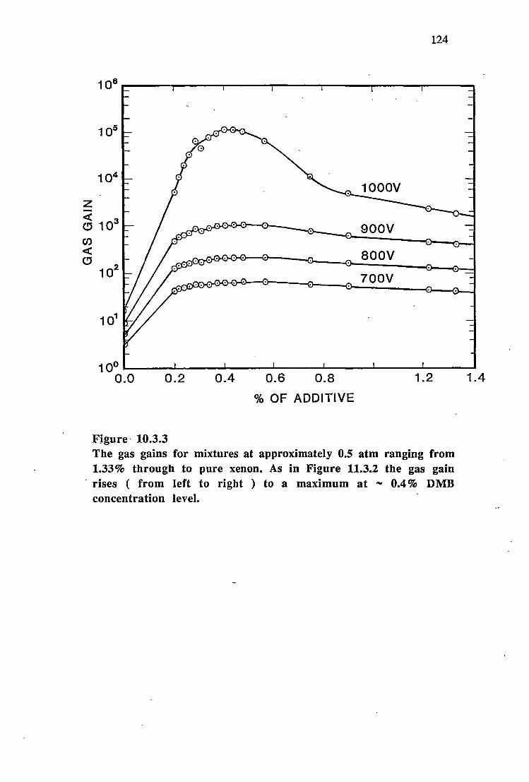
104
z <( C!:J 103
Cl) <(
C!:J 10
2
124
900V
aoov 700V
10°.._~~....i...~~~~~~...i......~~--'~~~_._~~---1.~~~~
0.0 0.2 0.4 0.6 0.8 1.2
% OF ADDITIVE
Figure- 10.3.3 The gas gains for mixtures at approximately 0.5 atm ranging from 1.33 % through to pure xenon. As in Figure 11.3.2 the gas gain
- rises ( from left to right ) to a maximum at - 0.4 % DMB concentration level.
1.4

z <( c:J (/) <( c:J
125
103
650V
102 600V
soov
101 400V
0.0 0.1 0.2 0.3 0.4 0.5 0.6 0. 7 0.8 0.9 1.0 1.1
% OF ADDITIVE
Figure 10.3.4 The gas gains for mixt~res at approximately 0.26 atm ranging from 1.06% additive through to pure xenon.
Figure 10.3.5 shows the gas gain at 600 V over the whole range of percentage of additive investigated for the low density case ( 7.0x1Q24 m·3 ). At the peak ( 0.23% DMB ), the gas gain is 461.5 compared with - 8 in pure xenon under identical conditions. To obtain a similar gas gain with pure xenon the anode potential has to be raised to - 1050 V.

z <( CJ Cl) <(
CJ
126
10°--~.__ ........ _._. ........ ..._~.._---................ i..i.....~..i.... .............. ...i...i..r..i.i..~---i....i... ........ ~ 1 0-2 1 0-1 1 o0 1 o 1 1 0 2
% OF ADDITIVE
Figure 10.3.5 The gas gain over the whole range of low density mixtures ( "' 0.26 atm ) tested. The peak represents a gas gain of about 460 at an anode potential of 600 V compared with a gas gain for pure xenon of about 8 at the same anode potential.
With the low density filling with ,... 0.2% DMB a good pulse height distribution is obtained at 600 V ( FWHM ,... 16% at 5.9 keV ). However, this is not appreciably different from the resolution obtained with conventional mixtures (e.g. Xe + Cf4). The relative variance of the gas gain at gas gains above,... 10
would off set any beneficial effects of the additive on the resolution of the detector [ 1]. ·
10.4 Discussion
The peaks in gas gain for the ,... 1 and ,... 0.5 atm mixtures have in common the rise from 0% DMB to a maximum at ,... 0.4% DMB suggesting that the same

127
process is operating at both gas densities in this region. As the concentration level is further increased the peak for the higher pressure mixtures is flat-topped whereas that for the - 0.5 atm mixtures is more rounded. When the pressure is -0.26 atm the peak becomes much better defined and occurs at a lower DMB concentration level. The peaks shown in Figures 10.3.2, 10.3.3 and 10.3.4 are defined at gas gains of the order of 10s.
At a density of 2.7x10²s m-3 ( - 1 atm) (see Figure 10.3.2) the peak is flattopped and there is no fall-off in gas gain until the concentration ofDMB reaches approximately 0.75%. Two different mechanisms may be responsible for this peak: at higher concentrations of additive the nonmetastable Penning effect (NMPE) is operative [7 ,8] and at around 0.4% DMB the metastable Penning effect ( MPE ) is responsible for the increased ionization yield. The MPE is the increase in ionization due to collisions between xenon atoms in long-lived metastable states and DMB molecules. As noted earlier, the DMB molecule has an ionization potential lower than the lowest excited state of xenon and in the collisions the energy from the metastable states may be transferred to the DMB molecules. The NMPE is the ionization of the additive by collisions with xenon atoms excited to nonmetastable energy levels. These nonmetastable energy levels are shorter lived, and if the energy is to be transferred to the additive by collisions, a greater concentration of additive is needed. Under the conditions shown in Figure 10.3.2 the higher density xenon traps resonance photons from excited xenon atoms [9], extending the effective lifetimes of the excited xenon resonance states. For additive concentrations greater than about 0.4% these longer-lived nonmetastable states are able to transfer their energy to the DMB in collisions, thereby increasing the ionization yield within the detector. The DMB may also have the effect of lowering the electron temperature, so that as the DMB concentration is increased, larger anode potentials are required to achieve identical gas gains. This process would compete with the NMPE and as the concentration of additive rises above 0.75% the lowering of the ele('.tron temperature may be having the dominant effect and the gas gain begins to fall. If the concentration of additive is reduced the probability of ionization by nonmetastable states must also, and eventually the MPE must be the dominant process. At even lower concentrations of DMB the MPE becomes less significant and the gas gains_ fall toward the pure xenon values.
At a density of l.4xlQ25 m-3 ( see Figure 10.3.3 ) the peak is much sharper and reaches a maximum at - 0.43% DMB concentration. The reduced xenon density shortens the effective lifetimes of the metastable states in the xenon, diminishing the importance of the NMPE. The MPE must occur at all gas densities and the rise in gas gain from 0% DMB to about 0.4% DMB is common to both Figure 10.3.2 and Figure 10.3.3, so the peak shown in Figure 10.3.3 may be due

128
almost entirely to the MPE.
A different process may be responsible for the results shown in Figure 10.3.4 (representing the lowest gas density tested). At the position of the peak, the concentration of DMB is so low that there may be insufficient additive for the MPE to occur, and the metastable atoms then form vibrationally excited xenon molecules in three-body collisions which radiate UV photons of energy - 8.3 eV [10]. These molecules ionize the additive with great efficiency causing the very sharp peak at about 0.23% DMB. As the gas density increases so does the rate at which these molecules lose their vibrational excitation in two-body collisions [10]; vibrationally relaxed excited molecules are unable to ionize the DMB which could explain the absence of any features in Figure 10.3.2 and Figure 10.3.3 at the 0.2% DMB concentration level.
The above idea could be tested by separating the xenon from the DMB and observing whether or not avalanches in the xenon triggered avalanches in the DMB. This would require a detector with two anode wires and a UV transparent wall between the anode wires creating two compartments. The xenon density could be varied and the effects studied.
10.5 Conclusion
The addition of a small quantity of 2,3 dimethyl-2-butene to xenon results in peaks in gas gain, and the shape and position of these peaks depend upon the density of the detector filling. The increase in gain can easily be of the order of 104 and one application is the operation of proportional counters at lower operating voltages than with conventional fillings like Xe + C02•
The above results were published in Nuclear Instruments and Methods in Physics Research [11] . All experimental measurements were made by K. G. White, Dr K. B. Fenton suggested using 2,3 dimethyl-2-butene as an additive, and Dr A. G. Fenton provided the additive in vapour form in a flask so that it could be attached to the gas filling manifold after removal of air and water vapour.
Experiments were also carried out using tetramethyltin ( CH3 )4Sn as an ·additive to xenon and the results obtained were similar to those obtained for DMB. Unfortunately there are some doubts concerning these results and consequently they have not been presented in this thesis.
References
[1] H. Sipila, Nucl. Instr. and Meth. 133 (1976) 251.

129
[2] H. E. Schwarz and I. M. Mason, Nature 309 (1984) 532. [3] J. P. Sephton, M. J. L. Turner and J. W. Leake, Nucl. Instr. and Meth. 219
(1984) 534. [4] D. H. Stedman and D. W. Setser, Prog. React. Kinet. 6 (1971) 193. [5] R. Bralsford, P. V. Harris and W. C. Price, Proc. Roy. Soc. A258 (1960)
459. [6] S. J. Buckman, P. Hammond, G. C. King and F. H. Read, J. Phys. B: At.
Mol. Phys.16 (1983) 4219. [7] S. Kubota, J. Phys. Soc. 29 (1970) 1017. [8] H. Sipila, Nucl. Instr. and Meth. 140 (1977) 389. [9] T. Holstein, Phys. Rev. 72 (1947) 1212. [10] R. Brodmann and G. Zimmere, J. Phys. B: At. Mol. Phys. 10 (1977)
3395. [11] K. G. White, A. G. Fenton and K. B. Fenton, Nucl. Instr. and Meth.
A260 ( 1987 ) 443.

11 ---THEW-VALUES OF XENON PLUS DMB MIXTURES----'
11.1 Introduction
The W-value of a gas or mixture of gases is the mean energy expended to form an ion pair in the gas. If E is the energy loss in the gas and n0 the number of ion pairs formed in the gas then W = E/n0• If there is a region in which the mean
energy expended to produce an ion pair is a function of the energy E it should be denoted by a different symbol, say w(E).
Then the relationship between W and w(E) will be given by E.nax
W = l Jw(E) dE (1) Emax-E.
mm~
Since w(E) will increase asymptotically towards+ oo as Emin approaches the
ionization potential of the gas or mixture of gases, Emin must be chosen so that the above integral converges. If w(E) is a constant, equation (1) reduces to W=w [l].
For the gases used in proportional counters W seems to be independent of energy or these detectors would not be proportional.
As discussed in chapter 1 the energy resolution of a proportional counter, R, can be expressed as
R = 2.35J (F +Ef)W (2)
where F is the Fano factor and f the relative variance of the gas gain [2]. The energy resolution is normally expressed as a percentage FWHM. From equation (2) it can be seen that a reduction in W should result in an improvement in energy resolution provided the other constants remain the same. In practice f tends to dominate the above expression but it should be possible to improve the energy resolution of a proportional counter by lowering the W-value provided low gas gains are used [2] or the electric field in the region of the electron avalanches is uniform[3].

131
11.2 The W-values for xenon
Only the W-values for electrons in xenon will be considered. Since xenon filled proportional counters seem to be proportional the W-value should be constant independent of energy. W-values for xenon widely accepted in the literature are
21.9 ± 0.3 [4] and 21.5 ± 0.4 eV/ip [5]. Combecher [6] has obtained results which show an energy dependence for low energy electrons and these results are given in Figure 11.2.1. According to Combecher, even at 1 ke V the w-value for electrons in xenon has risen to 23.78 eV/ip [6].
- --· - \ - -
+++ ++ ++
+ + + ++ + +
102 103
Electron energy (eV)
Figure 11.2.1 The energy dependence of the w-value for low energy electrons in xenon. The measurements were taken from Combecher [6] and are accurate to within 2 % •
'
11.3 Experimental results using xenon plus DMB mixtures
I measured the W-values of xenon plus DMB mixtures for concentrations of DMB ranging from 35.11 % DMB through to pure xenon. These measurements

132
were made using 55Fe and detector 1. The technique consisted of measuring the ionisation current due to the source and then measuring the count rate from the source. The W-value is then given by
W= NEe (3) is
where N is the count rate, E is the energy absorbed by the gas, e the electronic charge and is the ion saturation current.
I obtained the ion saturation currents by reversing the polarity of the electrodes so that the central wire became the cathode. The operating voltage was made high - 700 - 1000 volts to ensure complete charge collection occurred.The charge carriers for the positive charges in these gas mixtures would have been the DMB molecules because of their lower ionisation potential (8.30 e V [7]) compared with xenon ( 12.13 e V). The positively charged xenon ions would have transferred their positive charges fo the DMB molecules in collisions. A DMB molecule neutralizing itself at the cathode would either dissociate or absorb the ' excess energy in radiationless transitions. Because of this absence of secondary electron production at the cathode, reversing the polarity of the electrodes and using the central wire as the cathode should permit complete charge collection without gas gain and with no secondary currents.
The background current, probably due to contact potential differences ( see chapter 2) was recorded first and then the source was put in place and the ionisation current was recorded. The current due to the source could then be determined by subtracting the current due to the background. The source was left in place and a differential pulse height distribution was obtained by operating the detector as a proportional counter. The source was then removed and the background count rate was recorded and subtracted from the previous spectrum due to the source plus background. The values obtained were then substituted into equation (3) to obtain the value for W. The W values obtained for xenon seem to suggest that the results might be more accurate than the error bars on the graphs indicate.

25
24
..-.6' 23 ?;-
Q) ..........
Q) 22 ::1 ..... ~
~ 21 ~
20
19
Figure 11.3.l
133
3 of admixture
The W-values for xenon plus DMB for mixtures ranging from 35.11 % through to pure xenon. The total gas pressure for each mixture was kept constant at .... 200 torr at 0°C
Figure 11.3.1 shows the results obtained for mixtures ranging from 35.11 % through to pure xenon. The large errors on the values make it difficult to determine if the Penning effect ( discussed in chapter 1 ) is occurring but there
does seem to be a trend in the results suggesting that it may be occurring.
Figure 11.3.2 show the results for mixtures ranging from - 4.9% DMB to pure xenon on an expanded scale.
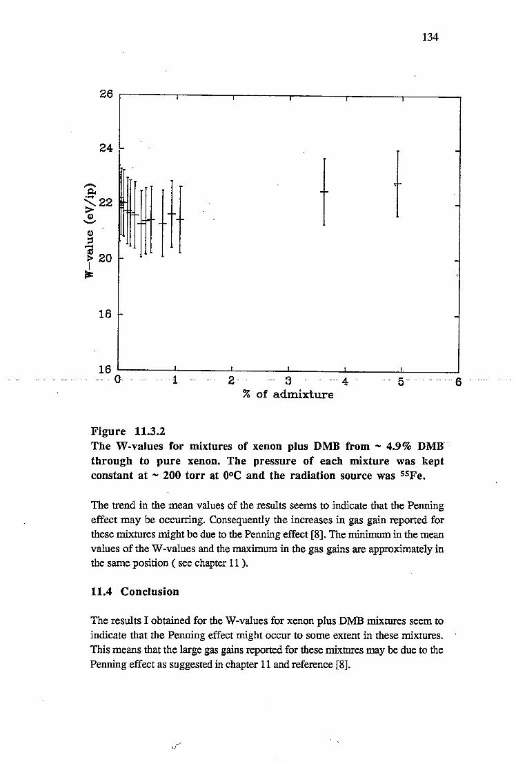
134
26
24
-~ ..... ~22
Q) -
18
2- - --- 3 - --- 4 - - 5-- -- - - -- --- 6 - ---- - --
% of admixture
Figure 11.3.2 The W-values for mixtures of xenon plus DMB from - 4.9% DMRthrough to pure xenon. The pressure of each mixture was kept constant at - 200 torr at 0°C and the radiation source was 55Fe.
The trend in the mean values of the results seems to indicate that the Penning effect may be occurring. Consequently the increases in gas gain reported for these mixtures might be due to the Penning effect [8]. The minimum in the mean values of the W-values and the maximum in the gas gains are approximately in the same position ( see chapter 11 ).
11.4 Conclusion
The results I obtained for the W-values for xenon plus DMB mixtures seem to indicate that the Penning effect might occur to some extent in these mixtures. This means that the large gas gains reported for these mixtures may be due to the Penning effect as suggested in chapter 11 and reference [8].

135
The errors in the above measurements were due to the 5% accuracy in making current measurements with the Keithley electrometer. This problem could have been overcome by using two detectors, one detector containing the gas mixture under investigation and the other containing a reference gas or gas mixture with an accurately known W-value. The detectors should be initially operated in the proportional mode and the count rate from the 55Fe source or sources adjusted so that it is the same for both detectors. This can be accomplished by using Al absorbers, or by altering the distance between the counters and the sources. When the count rates are identical the counters should be operated in current mode and the ion saturation currents measured, the unknown W-value can then be determined from the ratio of the ion saturation currents and the known Wvalue of the reference mixture. Jarvinen and Sipila [9], using Ar-C02 as a
reference mixture ( W = 26.0 e V /ip ), have measured the W-values of several gas mixtures using this technique.
References
[l] R. H. Thomas, J. T. Lyman and T. M. De Casiro, Radiat. Res. 82 (1980) 1. [2] H. Sipila, Nucl. Instr. and Meth. 133 (1976) 251. [3] H. Sipila, IEEE Trans. on Nucl. Sci. NS-26 (1979) 181. [4] I. T. Myers, Ionization in Radiation Dosimetry Editors; F. H. Attix and W.
C. Roesch, Academic Press 1(1968)321. [5] P. B. Lyons, J. D. Baran and J. H. McCrary, Nucl. Instr. and Meth. 95
(1971) 571. [6] D. Combecher, Radiat. Res. 84 ( 1980) 189 [7] R. Bralsford, P. V. Harris and W. C. Price, Proc. Roy. Soc. A258 (1960)
459. [8] K. G. White, A. G. Fenton and K. B. Fenton, Nucl. Instr. and Meth. A260
(1987) 443 .. [9] M. Jarvinen, and H. Sipila, Nucl. Instr. and Meth. 217 (1983) 282.

12 ..__ ____ PROPORTIONAL COUNTER AGEING ____ __.
12.1 Introduction
When detector 1 was filled with xenon plus large concentrations of DMB and operated using the 55Fe source at the central beryllium window particular ageing effects would occur. These consisted of a distortion of the full energy peak eventually leading to the development of a second peak.
The differential pulse height distribution shown below was obtained using xenon as the fill gas and 55Fe as the radiation source. Prior to this particular gas filling the detector had been in use over a long period of time wit}) several different gas fillings.
counts
77 channel number
Figure 12.1.1 The differential pulse _!!eight distribution for xenon at a pressure of 201.2 torr at 0°C using detector 1. The radiation -source was SSF e and the op-erating voltage was 1300 volts.
The spectrum shown above was obtained at a gas gain of = 4840 and the energy resolution was 24.45 % FWHM. The point of inflexion on the ion saturation curve was at - 50 volts The above pulse height distribution has a distortion on the high energy side. The radiation source emits Mn K x-rays of- 5.9 keV and
- a -Mn K~ x-rays of 6.49 keV. The energy resolution of the detector was 24.45 %

137
FWHM which means that two peaks have to be about 1.44 ke V apart to be resolved, consequently the detector would not be expected to resolve the 6.49 keV x-rays. Considering that for every 20.3 K~'s the source emits 150.5 Ka's
the spectrum should show a slight deviation from the gaussian shape. It will be shown that the distortion of the above spectrum-( see Figure 12.1.1 ) on the high
energy side is actually due to a build up of material on the anode.
The detector was evacuated and filled with a mixture of xenon plus 2,3 dimethyl - 2 - butene ( DMB ). The pressure of the DMB was 49 torr at 25.2°C and the
0 final total pressure was 222 torr at 25.0 C or 203 torr at 0°C. The percentage of DMB was therefore 22 %. This mixture gave an ion saturation curve with a point of inflexion at about 120 volts. The most interesting aspect of this gas filling is
the differential pulse height distribution. The differential pulse height distribution
is shown in Figure 12.1.2.
counts
channel number
Figure 12.1.2 The differential pulse height distribution for xenon plus 22 % DMB at a pressure of 203 torr at 0°C. The detector is detector 1 and the radiation source is 55Fe. The pulse heig~t distribution was obtained at an operating voltage of 1500 volts.
The pulse height distribution for this particular gas mixture gave a curious second peak at what appeared to be twice the energy of the full energy peak. The count rate was only 126.4 counts per second so it is difficult to believe that the peak was the result of pulse pile up.
The concentration of DMB was reduced several times ( keeping the total pres~ure constant ) and for each mixture the differential pulse height distibution for 55Fe was recorded. Each pulse height distribution showed the extra peak. Detector 1

138
also had a beryllium window located in the cylindrical wall close to one end. This window was never used for the experimental work presented in this thesis (except when specifically mentioned) because the electric field might have been distorted by the proximity to the end. When the concentration of DMB had been reduced to 11.26 % the differential pulse height distributions from both windows were compared.The results are shown in Figure 12.1.3 below.
counts
channel number -- -- - channel number
central window end window
Figure 12.1.3 The pulse height distributions for the central and end windows for detector 1. The gas mixture is xenon plus 11.26 % DMB at a total
pressure of 205 torr at 0°C. The radiation source is 55Fe and the operating voltage is 1200 volts.
As can be seen the double peak appears to be absent from the end window. The
count rates are low for both pulse height distributions being 209.8 ± 0.5 cts per
sec for the central window and 641.2 :;!:: 0.8 cts for the end window.
The absence of a double peak at the end window is evidence that the double peak is not due to the gas or the radiation source since these are the same for both distributions. The differences must be due to a build up of material on the anode (central wire ).The detector (detector 1) with the central wire used for most of the work described in this thesis had been in use for some time before any of the work described in this thesis had begun. The distortion of the full energy peak

139
shown in Figure 12.1.1 was probably the result of previous usage, not a result of the particular xenon filling and due to a build up of material on the anode. Large percentages of DMB appear to have caused a rapid growth in this build up. The two peaks in the pulse height distributions shown in Figures 12.1.2 and 12.1.3 are probably due to avalanches on one side of the anode undergoing a different gain to avalanches on the other side of the anode or elswhere in the detector. The number of counts recorded in lK seconds are 24522 for the peak in the highest energy position and 94257 counts for the other peak. The L escape peak has 7660 counts. The ratio of the sizes of the two full energy peaks is 3.84 and this corresponds to the ratio of the number of x - ray photons absorbed each side of the anode which is 3.70. The avalanche activity each side of the anode need not correspond to the ratio of the number of photons absorbed each side of the anode. For example, xenon has an L fluorescent yield of 0.23 [2] and if 55Fe is used the fluorescence photons will be more energetic than the photoelectrons and these photons can start avalanches elsewhere in the detector. Since the ratio of the sizes of the peaks closely corresponds to the ratio Of X-rays absorbed each side of the anode then this ratio probably closely corresponds to the intensity of the avalanche activity This also shows, for that particular percentage of DMB and under those operating conditions, that the avalanches do not spread around the circumference of the anode. ""'
_ 'I:P remove ~is quild up 9~ ma~erial ~ current of - 800 mA was p_assed throug~ __ _ the anode ( central wire ). The 22 % DMB mixture had been left in the detector. The pro(iess of " burning " the deposit off the anode or "flashing" the anode changed the properties of the gas so that it was not possibl~ to obtain a full energy peak using -the 55Fe source and the counter had to be evacuated. A current sufficient to cause the anode to glow red (500 mA) was once again passed through the anode while the detector was under vacuum. After considerable pumping the detector was filled with xenon to a pressure of 204 torr at 0°C. A
full energy peak was obtained (see Figure 12.1.4 below) using the 55Fe source and there was no distortion on the high energy side. The energy resolution was -17 % FWHM. It seems that the distortion in the pulse height distribution shown in Figure 12.1.1 was the result of a deposit on the anode.

no. of pulses
Figure 12.1.4 -
140
channel number
Differential pulse height distribution for xenon at a pressure of 204 torr at 0°C using 55Fe and detector 1. Prior to filling with xenon large currents had been passed through the anode to remove any build up of material on the anode.
12.2 Ageing experiments
In the first ageing experiment the detector was filled to a molecular number -- - - - - - 24 - -- - --- - - - - - - - - - -
·· density of 7.28x10 m-3 (i.e. 206 torr at 0°C) with 27.14 % DMB and 72.86 % xenon. The operating voltage was 1400 volts giving a gas gain of about 2,500. This gas gain was measured at the conclusion of the ageing experiment so that it did not contribute to the ageing of the detector. The gas gain was measured by operating the detector in current mode rather than in pulse mode and
comparing the current generated by the 55Fe count rate used for the experiment with the current obtained by reversing the polarity of the electrodes. The first current was measured with the central wire ( the .anode ) at + 1400 volts with respect to the cathode and the second with the central wire ( now the cathode ) at -1000 volts with respect to the anode. The background currents were subtracted so that an accurate gas gain for the source was obtained. The gas gain obtained from these measurements was adjusted for the change that had occurred in the position of the peak of the differential pulse height distribution during the ageing experiment. The fluorescent yield was approximately 0.057. The energy resolution was approximately 20 % FWHM at 5.9 keV. The geometry of the situation is shown in Figure 12.2.1.

Detector dimensions: outside diameter = 4.14 cm inside diameter = 3.78 cm wall thickness = 1. 70 mm beryllium window = 3 mm diameter source diameter = 12.5 mm source-window separation = 6 cm
Figure 12.2.1
Brass cathode
141
Anode
A plan of the detector source geometry for the ageing experiment.
There was some collimation of the x-rays, the longest possible path length in the gas being 3.83 cm and the shortest being 3.8 cm. The x-rays absorbed in Region
_ 1_ ( see Figure 12.2.1 _) w~ll_ result in av~an~he activity on the side _of the anode facing the window and the x-rays absorbed in Region 2 will give rise to avalanche activity on the side of the anode facing away from the window. In the proportional region the avalanches are restricted to less than half the circumference of the anode whilst in the semiproportional region the avalanches are believed to completely surround the anode [1]. Very few avalanches will
approach the anode from a position perpendicular to the x-ray beam. Since the intensity of an x-ray beam in xenon follows an exponential decrease with distance more x-rays will be absorbed in Region 1 than in Region 2. Thus the
7. 7 mm of the anode facing the window in the path of the beam will receive more avalanches than the 12.4 mm of the anode facing away from the beam (see Figure 12.2.1 ). Unfortunately this does not mean that avalanche activity will be confined to the 7. 7 mm and 12.4 mm regions of anode. The L fluorescent yield of xenon is 0.23 [2] which means that 23 % of all x-rays absorbed result in the emission of characteristic x-rays as well as photoelectrons. The photoelectrons and Auger electrons will have "ranges" of a fraction of a millimeter but the characteristic x-rays will have large mean free paths for absorption in xenon and will start electron avalanches far from the point of origin. The mean free paths for absorption are roughly 30 mm [3]. Table 12.2.1 gives the energies and relative intensities of these characteristic x-rays.

Fluorescence energy (ke V) Relative intensities
Table 12.2.1
La.1 4.093 100
La.2 4.094 12
L~1
4.403 58
L~2
4.58 20
142
L~3
4.498 9
Xenon x~ray fluorescence lines and relative intensities after excitation by 5.9 ke V x-rays taken from Gorenstein et al [2].
Most of the escape photons would originate from absorption ~vents near the window, the energy left in the counter forming the pulses of the escape peak
seen in the pulse height disribution.
The pressure of xenon at 0°C was 150.1 torr and the absorption coefficient of 6 keV x-rays in xenon is 6.69x1Q2 cm2/g; using this information - 77% of the
photons will be absorbed in Region 1 and a further - 77% of the beam will be absorbed in Region 2. This means that 3.35 photons are_ absorbed in Region 1
for every photon that is absorbed in Region 2. Overall the beam will be
attenuated by - 99.5%. The weighted mean value of the Mn x-rays from the source is 5 .97 ke V [ 4] and the weighted mean value of the xenon L fluorescence
x-rays is 4.25 keV, so if it is assumed that all the xenon fluorescence x-rays, -from Region 1- leave the_region_ completely ~d st~ avalanches_ elsewhere, th_e energy left in Region 1 will have a mean value of 1.72 keV. Consequently -77% of the beam will be absorbed in Region 1, 23% of these events will have an energy of 1.72 keV and the remainder will have an energy' of 5.97 keV.
The observed ageing effects consist of a drop in gas gain followed by a distortion in the shape of the full energy peak and eventually the development of
two peaks. Similar observations have been made in the past with regards to
noble gas plus hydrocarbon mixtures [5,6,7 ,8]. These effects are widely held to
be due to the build up of deposits on the anode. Experimental work has been performed by den Baggende et al [5] demonstrating that the twin peaks can be
the result of uneven deposits on the anode. The gas gain of a proportional counter depends exponentially on the radius of the anode [9] consequently if this varies only slightly from one region to another, avalanches on these different regions will undergo different gas gains. In the case of detector 1 a greater build up of deposit on the portion of the anode facing the window would result in a lower gas gain for those avalanches reaching that part of the anode.
The ageing of proportional counters filled with noble gas/hydrocarbon mixtures has been shown to be function only of the total number of electrons arriving at
the anode ( or positive ions arriving at the cathode ) [5]. The mean energy

143
expended to produce an ion pair ( the W-value ) in the xenon plus 27 .14 % DMB was determined to be approximately 25 eV (see chapter 12 ). The determination of the W-value was carried out using the same detector but a different gas filling of similar composition. A new gas filling was used for the ageing experiments. Each full energy pulse will be due to ,.., 239 avalanches each resulting in the formation of,.., 2,500 electrons, consequently the pulse at the detector output will be due to ,.., 596600 electrons. Similarly pulses due to an energy loss of 1.72 ke V will result from 172,000 electrons collected at the anode. The total count rate was 12700 counts/sec, 77% of these are absorbed in Region 1 and 23% excite L fluorescence x-rays which will be assumed to have left Region 1. This gives about 6.34xl09 electrons per second on the 7.7mm of anode wire facing the beryllium window, or 8.23x1Q8 electrons per second per mm of anode wire. It is assumed that the avalanche activity is uniform over this 7.7 mm of anode.
At the begining of the-experiment the full energy peak was centred on channel 123 and the energy resolution was 19.5% FWHM. After about 3 hours the peak had dropped to channel 116. The distribution had lost its symmetry after 9 hours and the peak had dropped to channel 106. The increasing distortion of the differential pulse height distribution with time is illustrated in Figure 13.2.2 below.

d)
~)
144
b) c) crq
I o I
€)
Figure 12.2.2 The progressio~ of the deterioration of the differential pulse height distribution, a) after 9 hours of irradiation, b) 10 hours, c) llhours, d) 12 hours, e) 13 hours, f) 14 hours, g) 15 hours.
The counter was irradiated for a total of - 4.76x10⁴ seconds and during this time the full energy peak split up into two peaks with the larger of the two dropping in gain by- 0.675. It is assumed that the larger peak is due to a build up of material on the 7. 7 mm of anode facing the source. The first signs of dist~rtion in the differential pulse height distribution were seen after about 3.2x10⁴ seconds or 8.88 hours. Taking 2,300 as the av.erage gas gain over this period, the number of bombarding electrons would be - 2.4xl013 per mm of anode facing the entrance window. Figure 13.2.3 below shows the channel number as a function of time. After about 9 hours of irradiation the drop in height is constant at about 5.5 channels per hour.

145
125
120 + +
115 +
J.. 110 Q)
.c § 105 + i:: - + Q)
100 i:: + ~ «S
.t:; 95 + (.)
90 +
+ 85
80 5 0 10 15 20 25 30 35 40 45 50-
Time (x1000 seconds)
Figure 12.2.3 The channel number of _the full energy peak as a function of time for xenon plus 27.14% DMB.
At the conclusion of the experiment the ratio of the number of counts in the two full energy peaks was approximately 1.8:1.If it is assumed that the avalanche activity on the 7 .7 mm of anode facing the beryllium window is responsible for the largest peak, and the smaller peak is due to avalanches caused by the absorption of xenon L fluorescence x-rays elsewhere in the counter and avalanche activity on the other side of the anode, then the ratio of the sizes of the two peaks should be 1.5:1. The discrepancy between the experimental and theoretical results may be due to the assumption that all the xenon L fluorescence x-rays originating in Region 1 cause avalanches elsewhere in the counter, some are certain to be absorbed in Region 1 contributing to the avalanche activity there. The source was off axis with the detector in the horizontal plane during this experiment but this does not appear to have affected the results. During the
' collection of the data presented in Figure 12.;2.3 there was no attempt to
+
55 - - ~ - .

146
determine whether or not there was any drift in the electronics.
After about 15 hours of irradiation a current, large enough to cause the anod~ to glow red was passed through the anode. This current was measured to be -0.885 A r.m.s., and the voltage across the anode required to produce this current was about 40 V r.m.s .. The pulse height distribution returned to normal with energy resolution of 19.5% FWHM. The centroid of the full energy peak occurred in channel 113 where previously it had occurred in channel 123. This could be due to an increase in the fill gas pressure as a result of outgassing from the anode or alternatively electronegative impurities may have been added by the
heating process. A current of about 0.9 A r.m.s. was passed through the anode a second time and the centroid of the full energy peak moved to channel 105, the
result of further outgassing.
Other authors [6] have used Diethorn's equation [9] to determine the thickness of the anode coating. Diethorn's equation could also be u·sed to determine the
increase in gas density due to outgassing from the anode. In using Diethorn's
equation in this situation care should be taken to make sure the detector is being operated in a region of gas gain where Diethorn's equation applies (see chapter
9).
Two ~ore_ experiments were pe:rf9rmed with much smaller perce11tages of PMB_. In the first of these experiments the detector ( always detector 1 ) was filled with xenon plus 0.23% DMB to a pressure of 200.4 torr at 0°C. This gas mixture gave the maximum gas gains for a particular range of operating voltages of any
xenon plus DMB mixture at this particular gas density ( see chapter-10 ). Throughout the experiment the operating voltage for the detector was 600 volts giving an initial gas gain of - 562. The radiation source was 55Fe and the count
rate for the full energy peak was 9567 counts per second. The preamplifier and
pulse height analyser were connected when pulse height distributions were required and were left connected for long periods of time but often the detector anode was connected directly to the high voltage and the cathode was connected
directly to ground. The detector was irradiated for 232 hours and 11 minutes, approximately 10 days and during this time the peak in the pulse height distribution moved from channel 528 to channel 350. The resolution of the detector at 5.9 ke V changed from - 26% to - 30% and the pulse height distribution seemed to retain its gaussian shape. There was no sign of a double peak. The channel number as a function of time is shown below in Figure 12.2.4.

147
540
520 ~ 500 + +.
\if_+ 480
s.. • + Q)
.0 460 "* ;\; § s:= - 440 ~ + Q)
s:= + s:= 420 + as ..c: u
400
+ 380 ~ 360 \ + 340
0 100 -- 200 300 - 400 500 600 700 800 --Time (xlOOO seconds)
Figure 12.2.4 The channel number as a function of time for the full energy peak. The gas mixture was xenon plus 0.23 % DMB at a pressure of 200.4 torr at 0°C, the radiation source was SSFe and the count rate was - 9,600 counts per second. The operating voltage for the detector was 600 volts.
The points seem to show a daily variation superimposed upon a general downward trend. In the mornings there was a rapid drop in the channel number for the full energy peak and in the afternoons there was virtually no change at all. The daily variation was probably due to drift in the electronics. To test out this idea a test pulse of fixed amplitude was applied at various times during the day and a pulse height distribution of the test pulses obtained. The test pulses gave a pulse height distribution of - 18% FWHM and showed a variation of seven channels between 9.25 am and 2.15 pm. Between 9.15 am and 2.20 pm the full energy peak of the pulse height spectrum due to the radiation source changed from channel 367 to channel 351, consequently when electronic drift is allowed
900 -- -

148
for, the real change would be a change of 9 channels rather than 16 channels. The general downward trend apparent in the data points should be a reasonably accurate indication of the rate at which_ the detector gain drops with time as a result of constant irradiation. After 232 hours and 11 minutes of irradiation the anode was "flashed" without removing the gas filling. A voltage of 33 V r.m.s was applied across the anode causing a current of - 0.7 A r.m.s.to pass through the anode and a red glow was observed. The effect of flashing the anode was to reduce the gas gain even further. The full energy peak moved from channel 350 to channel 286 and the energy resolution changed from - 30% to - 33% FWHM. The anode was flashed a second time without removing the gas filling. This time 20 V r.m.s was applied and a current of - 0.7 A r.m.s was measured flowing through the anode. A red glow was once again observed with what appeared to be red flashes. After the second flashing the full energy peak moved to channel 248 and the resolution changed to - 36% FWHM at 5.9 keV. At this stage the experiment was concluded and the anode was replaced.
For the next experiment the detector ( with a new 70 µm diameter anode ) was . filled with a mixture of xenon plus 4.19% DMB to a pressure of 201.5 torr at 0°C. The detector was operated at 800 volts for 239 hours and 14 minutes. The operating voltage of 800 volts gave a gas gain similar to that obtained at 600 volts with the previous mixture. The radiation source was 55Fe and the count rate was 9577 counts per second. This means that the initial gas· gain, duration-of experiment and count rates for this mixture and the previous mixture are roughly the same allowing a comparison to be drawn. Figure 12.2.5 shows the channel .number of the full energy peak as a function of time.

J.. CD
,.Q
E ~ ~ -CD ~ s:= as
..c:= u
149
- 520
510
500
490
480
* 470 -HF
460 ¥ ~ -tff- -t* 450
+-F 440
0 - 100 200 300 -400 500 600 700 800 Time (xlOOO seconds)
Figure 12.2.5 The channel number of. the full energy peak as a function of time. The gas mixture was xenon plus 4.19% DMB at a pressure of 201.5 torr at 0°C, the radiation source was 55Fe, the count rate was - 9,600 counts per second and the operating voltage was 800 volts .
900
With xenon plus 4.19% DMB the decrease in channel number as a function of , time talces on an almost exponential appearance ( see Figure 12.2.5 above ). Over the - 10 day period the energy resolution changed from - 23.6% FWHM to - 28.1 % FWHM and the full energy peak moved from channel 512 to channel 445. This represents a change in gain of only 13% compared with the 0.23% DMB mixture which underwent a change in gain of 33.7%. Once again this mixture did not develop double full energy peaks.
The results from the experiments given in this section indicate that mixtures of xenon plus 27.14% DMB at pressures of - 200 torr at 0°C will give rise to

150
double full energy peaks whereas mixtures of xenon plus 0.23% DMB and mixtures of xenon plus 4.19% DMB at similar densities do not. This indicates that with the mixture with the largest concentration of DMB the electron avalanches are cofined to a small region of the anode despite the gas gains of -
2,500 whereas in the mixtures consisting of smaller concentrations of DMB the electron avalanches probably totally surround the anode even though the gas gain is approximately 500 -600. This would support the view presented in chapter 11.
In this chapter it was suggested that the large gas gains observed in xenon plus
small concentrations of DMB was due to the formation of vibrationally excited
xenon molecules in three body collisions which radiate UV photons or energy -
8 eV. These UV photons ionize the DMB with great efficiency. If this were an
accurate description of what occurs in these gas mixtures then the electron
avalanches might totally surround the anode.
The above results are considered to be only preliminary results in this a:ea of
investigation.
12.3 Simple theory of detector ageing
The simple theory of detector ageing presented here assumes that the gas filling
contains a component or components with covalent bonds. The ageing of such a detector may be the result of the formation of free radicals in the gas filling [10]
as a result of the primary ionization or in the electron avalanche. The energy
required to break covalent bonds can be considerably less than the ionization potential of the particular molecule, for example the energy required to break the
C-C bond is only 3.6 eV, the C-H bond requires 4.3 eV and a C=C bond
requires 6.4 eV [10]. A DMB molecule possesses all these bonds but has an ionization potential of 8.30 e V [11]. As little as 3.60 e V is required to break up
the molecule. The fragments formed will be free radicals which are highly
reactive. According to Bell et. al., as noted by Va'vra [10], under plasma
chemistry conditions, which seem to be different in many respects to the
conditions thought to exist in electron avalanches, the concentrations of free
radicals can be 5 or 6 orders of magnitude greater than the concentration of ions.
The plasma chemistry conditions referred to involve similar energies to those that
seem to occur in electron avalanches ( - 10 e V ) but much larger effective
volumes, smaller typical electron densities, and much lower gas densities. The free radicals are usually deformed and as a consequence have large electric dipole
moments. As a result of the strength of the electric field the free radicals will align themselves with the field. In proportional counters with the central wire as the anode the field will have a strong gradient near the anode and as a
consequence the free radicals will drift towards the anode. At the anode th~ free
radicals will be held by electrostatic attraction and because these molecules are
highly reactive requiring an activation energy of zero to take part in a chemical

151
reaction they polymerize on the surface of the anode. When a molecule, which is not a free radical itself, reacts with a free radical the product can be another free radical so chain propagation results.
The above description probably descibes the ageing effects observed in the experiments presented in the preceding section. If some sort of " free radical
' '
trap" or" scavenger" molecule can be added to the gas the polymerization might be halted.
Sipila et. al. [12] has been able to extend the lifespan of detectors filled with P-10 by adding a small amount of hydrogen gas. In the electron avalanches with P-10 the CH4 molecule can dissociate into various products. The main dissociation ,
product might be CH2 [13], and CH [14] has also been identified in an optical
spectrum of avalanches. Sipila et. al. [12] gives the following possible sequence of events for the polymerization process.
CH2 + Cf4 ~ C2H6
C2H6 + CH2 ~ C3Hs They suggests that the above process continues until the deposit becomes solid and consequently cannot diffuse away from the surface of the anode. Sipila et. al. [12] point out that the above process is oversimplified since other radicals and ,their excited states are also present. They assumed that adding hydrogen to the gas would slow down the polymerization process. The amount of hydrogen added was small, from 0.1 to 0.5%. The effect was to extend the lifespan of detectors filled with P-10 by a factor of 20.
Of course it would be even better if the process of ageing could be halted altogether.
12.4 Immortal mixtures
Dwurazny et. al. [15] hav~ reported gas mixtures which show no ageing below -5xl018 electrons per cm of anode. Unfortunately Sipila et. al. [12] do not
, express their results in electrons per cm of anode so it is difficult to compare these results with theirs. Theoretically Dwurazny et. al.'s mixtl1fes should be immortal mixtures. They found that Ar+ 8% N2 and Ar+ 10%Kr + 3.5%IJ2 sh'owed no deterioration after accumulating 5x10¹⁸ electrons/cm of anode whilst deterioration was observed in At+ 4%iso-C5H12 after collecting-2x1Q17 e/cm.
Ostrowski et. al. [16] give Xe + Kr + H2 as a long lived mixture. According to
these authors, in the above mixture complexes of the form XeKrH2 + are the
charge carriers for the positive charges. These complexes neutralize themselves

152
at the cathode and dissociate into neutral components, i.e. Xe, Kr' and H2. These complexes form as a result of two or more three body collisions, and have stable·
lifetimes of -200 µseconds.
12.5 Conclusion
If proportional counters are to be used on long space missions it seems desirable for them to have long lifespans. Very little is known about the ageing of detectors at the moment but Sipila et. al.'s [12] success with adding H2 to P-10
seems to suggest that something positive can be done to lengthen the lifespan of cylindrical pi:oportional counters. Ageing studies with detectors with uniform fields in the region of the avalanche remain to be done.
References
[1] M. Matoba, T. Hirose, T. Sakoe, H. Kametani, H. Ijiri and T. Shintoke, IEEE Trans. on Nucl. Sc. NS - 32 1 (1985) 541.
[2] P. Gorenstein, H. Gursky, G. Garmire, Ap. J. 153 (1968) 885. [3] F. Sauli, Principles of Operation of Multiwire Proportional and Drift
Chambers, CERN 77-09 (1977) 13. [4] Editors; C. M. Lederer and V. S. Shirley, Table of Isotopes, John Wiley &
Sons, Inc (1978). [5] A. J. F. den Baggende, A. C. Brinkman and W. de Graabb, J. Sci. Instrum.
2 (1969) 701. [6] A. Smith and M. J. L. Turner, Nucl. Instr. and Meth. 192 (1982) 475: [7] J. Adams, C. Baird, D. Cockerill, P. K. Frandsen, H. J. Hilke, H.
Hofmann, T. Ludlam, E. Rosso, D. Soria and D. Vaughan, Nucl. Instr. and Meth. 217 (1983) 291.
[8] R. Kotthaus, Nucl. Instr. and Meth. A252 (1986) 531. [9] W. Diethorn, US AEC Report NYO - 6628. [10] J. Va'vra, Nucl. Instr. and Meth. A252 (1986) 547. [11] R. Bralsford, P. V. Harris and W. C. Price, Proc. Roy. Soc. A258 (1960)
459. [12] H. Sipila and M. Jarvinen, Nucl. Instr. and Meth. 217 (1983) 298. [13] N. Spielberg and D. I. Tsarnas, Rev. Sci. Instr. 46 (1975) 1086. [14] T. J. Summer, G. K. Rochester, P. D. Smith, J. P. Cooch and R. K.
Sood, IEEE NS -29 (1982) 1410. [15] A. Dwurazny, K. Jelen, E. Rulikowska Zarebska, Nucl. Instr. and Meth.
217 (1983) 301. [16] K. W. Ostrowski, T. Z. Kowalski and J. Zajac, Nucl. Instr. and Meth.
A252 (1986) 545.