Photovoltaic and Thermoelectric Generator Combined Hybrid ...
Upload
khangminh22Category
view
0download
0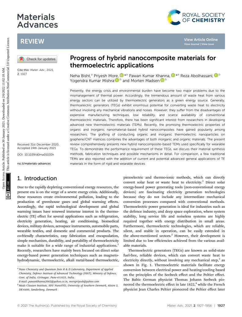
© 2021 The Author(s). Published by the Royal Society of Chemistry Mater. Adv., 2021, 2, 1927–1956 | 1927
Cite this: Mater. Adv., 2021,
2, 1927
Progress of hybrid nanocomposite materials forthermoelectric applications
Neha Bisht,a Priyesh More, *a Pawan Kumar Khanna, *a Reza Abolhassani, b
Yogendra Kumar Mishra b and Morten Madsen b
Presently, the energy crisis and environmental burden have become two major problems due to the
mismanagement of thermal power. Accordingly, the tremendous amount of waste heat from various
energy sectors can be utilized by thermoelectric generators as a green energy source. Generally,
thermoelectric generators (TEGs) exhibit enormous potential for converting waste heat to electricity
without involving any mechanical vibrations and noises. However, they suffer from the disadvantages of
expensive manufacturing techniques, low reliability, and scarce availability of conventional
thermoelectric materials. Therefore, there has been significant interest from researchers in developing
advanced new thermoelectric materials (TEMs). Recently, the promising thermoelectric properties of
organic and inorganic nanomaterial-based hybrid nanocomposites have gained popularity among
researchers. The grafting of conducting organic and inorganic thermoelectric nanoparticles on
graphene/CNT matrices combines the advantages of both inorganic and organic materials. The present
review comprehensively presents new hybrid nanocomposite-based TEMs used specifically for wearable
TEGs. To demonstrate the performance requirement of these TEGs, we discuss their material synthesis
methods, fabrication techniques and possible mechanisms in detail. For comparison, a few traditional
TEMs are also reported with the addition of current and potential advanced general applications of TE
materials in the form of rigid and wearable devices.
1. Introduction
Due to the rapidly depleting conventional energy resources, thepresent era is on the verge of a severe energy crisis. Additionally,these resources create environmental pollution, leading to theproduction of greenhouse gases and global warming effects.Accordingly, the rapid technological development and globalwarming issues have renewed immense interest in the thermo-electric (TE) effect for several applications such as refrigeration,electricity generation, heating, air conditioning, biomedicaldevices, military devices, aerospace instruments, automobile parts,wearable textiles, and domestic and commercial products. Theco-friendly characteristics, easy fabrication and encapsulation,simple mechanism, durability, and portability of thermoelectricitymake it suitable for a wide range of industrial applications.1
Recently, researchers have mainly been focused on direct solarenergy-based power generation techniques such as magneto-hydrodynamic, thermoelectric, alkali metal-based thermoelectric,
piezoelectric and thermo-ionic methods, which can directlyconvert solar heat or waste heat to electricity.2 Direct solarenergy-based power generating tools (non-conventional energydevices) are fascinating electricity generation technologiesbecause they do not include any intermediate mechanicalconversion processes compared with conventional methods.Thermoelectric power generation is ideal for industries such asthe defence industry, and deep space exploration, where systemstability, long service life and noiseless systems are highlyrequired together with energy distribution in small areas.Furthermore, thermoelectric technologies, which are reliable,silent, and stable in operation, can be easily extended inthe above-mentioned sectors.2 However, their development islimited due to low efficiencies achieved from the various avail-able materials.
Thermoelectric generators (TEGs) are known as solid-statefuel-free, reliable devices, which can convert waste heat toelectricity directly, without involving any mechanical step,3 asshown in Fig. 1. Thermoelectric materials facilitate energyconversion between electrical power and heating/cooling basedon the principles of the Seebeck effect and the Peltier effect.The Baltic German physicist Thomas Johann Seebeck pio-neered the thermoelectric effect in late 1822,4 while the Frenchphysicist Jean Charles Peltier pioneered the Peltier effect later
a Nano Chemistry and Quantum Dots R & D Laboratory, Department of Applied
Chemistry, Defence Institute of Advanced Technology (DIAT), Ministry of Defence,
Govt. of India, Girinagar, Pune-411025, India.
E-mail: [email protected], [email protected] Mads Clausen Institute, SDU NanoSYD, University of Southern Denmark, Alsion 2,
DK-6400, Sønderborg, Denmark
Received 31st December 2020,Accepted 24th January 2021
DOI: 10.1039/d0ma01030h
rsc.li/materials-advances
MaterialsAdvances
REVIEW
Ope
n A
cces
s A
rtic
le. P
ublis
hed
on 3
0 Ja
nuar
y 20
21. D
ownl
oade
d on
2/6
/202
2 11
:02:
18 A
M.
Thi
s ar
ticle
is li
cens
ed u
nder
a C
reat
ive
Com
mon
s A
ttrib
utio
n-N
onC
omm
erci
al 3
.0 U
npor
ted
Lic
ence
.
View Article OnlineView Journal | View Issue
1928 | Mater. Adv., 2021, 2, 1927–1956 © 2021 The Author(s). Published by the Royal Society of Chemistry
in 1834.5 According to Seebeck, when a temperature differenceis applied between two different electrical conductors or semi-conductors in a closed circuit, it will produce a voltage
difference between the two substances. Here, the proportion-ality constant is known as thermopower or Seebeck coefficient:a = �DV/DT2. The reverse phenomenon is known as the Peltier
Neha Bisht
Neha Bisht obtained her BTechDegree in Chemical Engineeringfrom BT Kumaon Institute ofTechnology (BTKIT), Dwarahat,Uttarakhand India in 2014.Continuing her studies, shereceived MTech Degree inMaterials Science and ChemicalTechnology from the DefenceInstitute of Advanced Technology,Pune, India in the Department ofApplied Chemistry in 2019, whereshe was a Gold medalist. Duringher study for her Master’s Degree,
she received the All India Council Technical Education (AICTE)Fellowship through Graduate Aptitude Test in Engineering (GATE).She is currently working as a Project Assistant under the guidance ofProf. P. K. Khanna at DIAT, Pune, India. She is a life member of the‘‘Society for Materials and Chemistry (SMC)’’, BARC, Mumbai. She is alifetime member of ‘‘DIAT Alumni Association’’. Her research interestsinclude nanomaterials, hybrid nanocomposites, thermoelectricmaterials, metal oxides, ternary metal chalcogenides and theirenergy applications.
Priyesh More
Dr Priyesh was a faculty memberof the Department of AppliedChemistry, Defence Institute ofAdvanced Technology (DIAT),Pune, India. He is now anentrepreneur and also works asa consultant in the field ofnanotechnology. He has aMaster’s Degree in PolymerScience (2008) from University ofPune. He was awarded a PhD inthe major ‘‘NanomaterialsScience and Engineering’’ fromthe University of Science and
Technology, KRICT campus, Daejeon, South Korea. He wasawarded with the prestigious ‘‘DST INSPIRE Faculty Award’’ bythe Department of Science and Technology, Govt. of India in 2013.His primary research interests are quantum dot technology andcustomized nanomaterials for advanced applications such asthermoelectrics, sensors, and photocatalysis. He has published 48research articles in various international journals in the area ofnanomaterials.
Pawan Kumar Khanna
Dr Pawan Khanna received hisPhD in Organometallic Chemistryof Se & Te from the Indian Instituteof Technology, Bombay in 1989–90. He went to Queens’ Universityof Belfast and University of Walesat Swansea (UK) for his post-doctoral research in the group ofProf. Christopher P Morley during1989–92. Later, he joined C-MET,Pune. He was awarded theBOYSCAST fellowship of DST,Govt of India during 1998–99 towork on quantum dots driven by
organometallic chemistry at University of St. Andrews, Scotland (UK)with Professor David J Cole-Hamilton. He is currently a Professor inthe Dept. of Applied Chemistry at the Defence Institute of AdvancedTechnology, Pune, India. His research interests include organometallicchemistry, materials chemistry, nanochemistry of biologicalimportance, quantum dots, nano-inks, nano-fluids and photo-catalysis. He has published over 200 research papers. He hasrecently been named as the top 1% materials’ scientist in the worldby a study conducted by Stanford University, USA. He has guided morethan 60 masters, doctoral and post-doctoral researchers andcompleted 20 research projects funded by Govt. Agencies.
Reza Abolhassani
Reza Abolhassani is a PhD studentunder the supervision of ProfessorYogendra Kumar Mishra atSmart Materials Group, NanoSYD,Mads Clausen Institute, Universityof Southern Denmark (SDU),Sønderborg, Denmark. Heobtained his BSc in ElectricalEngineering from K.N.T. Univer-sity of Technology, Iran, and hisMSc in Nanotechnology fromUniversity of Southern Denmark.In the Smart Materials Groupin NanoSYD, he is developing
complex-shaped nanostructures based on 3D nanomaterials forapplications in smart technologies.
Review Materials Advances
Ope
n A
cces
s A
rtic
le. P
ublis
hed
on 3
0 Ja
nuar
y 20
21. D
ownl
oade
d on
2/6
/202
2 11
:02:
18 A
M.
Thi
s ar
ticle
is li
cens
ed u
nder
a C
reat
ive
Com
mon
s A
ttrib
utio
n-N
onC
omm
erci
al 3
.0 U
npor
ted
Lic
ence
.View Article Online
© 2021 The Author(s). Published by the Royal Society of Chemistry Mater. Adv., 2021, 2, 1927–1956 | 1929
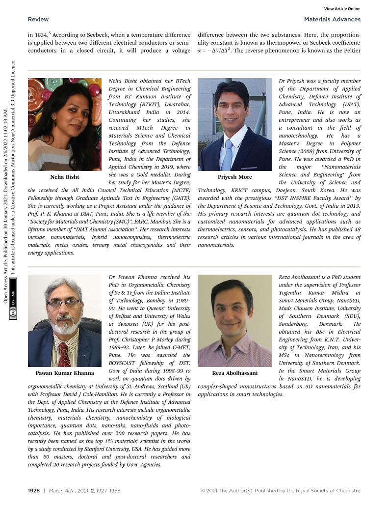
effect, which is shown in Fig. 2. The performance of thermo-electric materials can be calculated using two parameters,namely the figure of merit (ZT) and power factor (PF). ZTdepends on three basic materials properties, including the
thermopower or Seebeck coefficient (a), electrical conductivity (s),and thermal conductivity (k). Here, the total thermal conductivityis k = ke + kph, where ke and kph represent the heat carried byelectrons and phonons.
ZT can be defined as: ZT ¼ a2sTk
and the power factor can becalculated by PF = a2s
Additionally, the thermoelectric device efficiency (ZTE) canbe represented as
ZTE ¼ ZC
ffiffiffiffiffiffiffiffiffiffiffiffiffiffiffi1þ ZTp
� 1ffiffiffiffiffiffiffiffiffiffiffiffiffiffiffi1þ ZTp
þ TH � TC
� �
where ZC denotes the Carnot efficiency, ZC = (TH � TC)/TH andTH and TC signify the hot and cold side temperatures,respectively.6 A survey of the literature shows that the efficiencyand power output of a TEG produced by different methods isquite challenging to achieve.
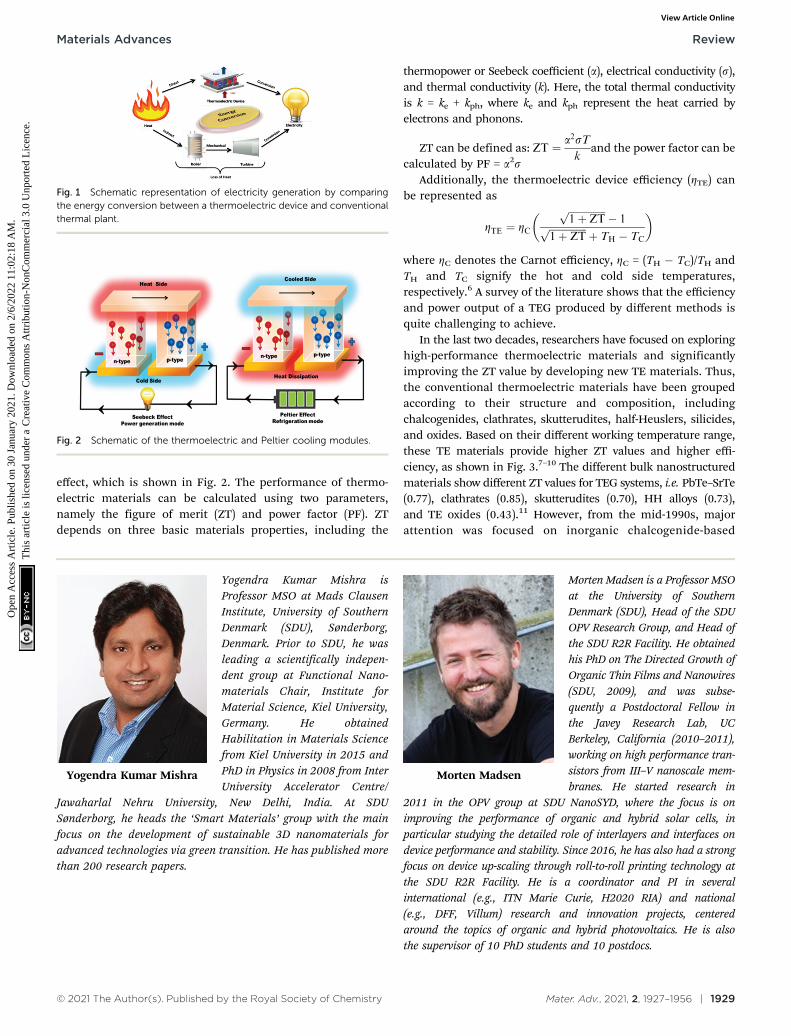
In the last two decades, researchers have focused on exploringhigh-performance thermoelectric materials and significantlyimproving the ZT value by developing new TE materials. Thus,the conventional thermoelectric materials have been groupedaccording to their structure and composition, includingchalcogenides, clathrates, skutterudites, half-Heuslers, silicides,and oxides. Based on their different working temperature range,these TE materials provide higher ZT values and higher effi-ciency, as shown in Fig. 3.7–10 The different bulk nanostructuredmaterials show different ZT values for TEG systems, i.e. PbTe–SrTe(0.77), clathrates (0.85), skutterudites (0.70), HH alloys (0.73),and TE oxides (0.43).11 However, from the mid-1990s, majorattention was focused on inorganic chalcogenide-based
Fig. 1 Schematic representation of electricity generation by comparingthe energy conversion between a thermoelectric device and conventionalthermal plant.
Fig. 2 Schematic of the thermoelectric and Peltier cooling modules.
Yogendra Kumar Mishra
Yogendra Kumar Mishra isProfessor MSO at Mads ClausenInstitute, University of SouthernDenmark (SDU), Sønderborg,Denmark. Prior to SDU, he wasleading a scientifically indepen-dent group at Functional Nano-materials Chair, Institute forMaterial Science, Kiel University,Germany. He obtainedHabilitation in Materials Sciencefrom Kiel University in 2015 andPhD in Physics in 2008 from InterUniversity Accelerator Centre/
Jawaharlal Nehru University, New Delhi, India. At SDUSønderborg, he heads the ‘Smart Materials’ group with the mainfocus on the development of sustainable 3D nanomaterials foradvanced technologies via green transition. He has published morethan 200 research papers.
Morten Madsen
Morten Madsen is a Professor MSOat the University of SouthernDenmark (SDU), Head of the SDUOPV Research Group, and Head ofthe SDU R2R Facility. He obtainedhis PhD on The Directed Growth ofOrganic Thin Films and Nanowires(SDU, 2009), and was subse-quently a Postdoctoral Fellow inthe Javey Research Lab, UCBerkeley, California (2010–2011),working on high performance tran-sistors from III–V nanoscale mem-branes. He started research in
2011 in the OPV group at SDU NanoSYD, where the focus is onimproving the performance of organic and hybrid solar cells, inparticular studying the detailed role of interlayers and interfaces ondevice performance and stability. Since 2016, he has also had a strongfocus on device up-scaling through roll-to-roll printing technology atthe SDU R2R Facility. He is a coordinator and PI in severalinternational (e.g., ITN Marie Curie, H2020 RIA) and national(e.g., DFF, Villum) research and innovation projects, centeredaround the topics of organic and hybrid photovoltaics. He is alsothe supervisor of 10 PhD students and 10 postdocs.
Materials Advances Review
Ope
n A
cces
s A
rtic
le. P
ublis
hed
on 3
0 Ja
nuar
y 20
21. D
ownl
oade
d on
2/6
/202
2 11
:02:
18 A
M.
Thi
s ar
ticle
is li
cens
ed u
nder
a C
reat
ive
Com
mon
s A
ttrib
utio
n-N
onC
omm
erci
al 3
.0 U
npor
ted
Lic
ence
.View Article Online
1930 | Mater. Adv., 2021, 2, 1927–1956 © 2021 The Author(s). Published by the Royal Society of Chemistry
nanostructured materials because of their higher ZT (41)and lower thermal conductivity value compared to their bulkinorganic counterparts for widespread use in TE applications,where bismuth telluride12,13 and lead telluride14 alloys were themost prominent. Lead telluride generally demonstrates super-ior TE properties at a higher temperature (nearly 500–600 1C).However, due to its toxic nature, it was replaced by antimony-and selenium-based materials.15 Additionally, the scarcity oftellurium in nature led its use as tellurides only for someexceptional applications.
Furthermore, the conventional thermoelectric materials,which are rare, expensive, brittle, and toxic in nature, exhibitprocessability issues.16 Thus, to date, for practical applications,the achieved higher efficiencies of these materials are stilllagging behind the maximum possible Carnot efficiency.17
Besides, thermoelectric generators require an assembly ofdozens or even hundreds of thermoelectric modules to achievehigher performance. Thus, a large gap exists between theefficacy of TE materials and their modules for advancedapplications.18 Hence, for the efficient use of TE materials inpractical applications for energy conversion, we may have toconsider: (a) the stability of TE materials under a large tem-perature gradient, (b) change in their mechanical propertiesunder thermal cycling, and (c) large interfacial contact resis-tances such as thermal and electrical.11
Recently, due to technological challenges, researchersstarted developing advanced materials with enhanced thermo-electric properties, e.g. binary hybrid nanocomposites of organic-conducting polymer and ternary hybrid nanocompositescomprised of organic–inorganic nanoparticles-conducting poly-mer to augment the thermoelectric performance. In general,organic materials such as graphene (GR), carbon nanotubes(CNT), multi-walled carbon nanotubes (MWCNTs), and reducedgraphene oxide (RGO) possess higher thermal conductivitiesand poor thermoelectric conversion efficiency in comparison totheir inorganic counterparts.19 However, carbon-based organicmaterials are abundant, non-toxic and show superior mechanicalproperties such as low mass density (B1 g cm�3), which is almostseven times less than that of bulk inorganic Bi2Te3 (7.86 g cm�3).19,20
Therefore, the limitations of single-phase thermoelectric materialscan be overcome by blending organic–inorganic nano-materialsto achieve superior tensile strength and controllable Seebeckcoefficients in nanocomposite materials.19,21 In addition, con-ducting polymers such as polyaniline (PANI), polypyrrole (PP),polythiophene (PT), polyacetylene (PA), poly(3,4-ethylenedi-oxythiophene) (PEDOT), polystyrene sulfonate (PSS), andpoly(3-hexylthiophene) (P3HT) possess modest electrical conduc-tivity and lower thermal conductivity.22 The maximum reportedTE properties of the conducting polymer PEDOT:PSS near roomtemperature is a power factor of 469 mW mK�2 with a ZT valueof 0.42.23 Accordingly, impregnating conducting polymers intocarbon-based materials can increase the Seebeck coefficientand overall power factor by lowering the thermal conductivityof carbon materials.24 However, embedding nanoparticles ofinorganic materials alone in a conducting polymer matrix mayadversely affect the overall electrical conductivity of the compo-site due to the poor interconnectivity between the particlescompared to their inorganic counterparts.25 Furthermore, thesensitive nature of the charge transport properties of conductingpolymers to oxygen and inorganic nanostructures to di-oxygen(formation of an oxide layer) has been shown to potentiallydamage the electrical conductivity of conducting polymers, whichlimits the use of this type of material for TE application.26
Additionally, the solution processability of conducting polymersat a low temperature has a great advantage in the large-scaleproduction of hybrid nanocomposites. Therefore, the use offascinating printing methods such as aerosol jet printing,24
screen printing,27,28 drop-casting, ink-jet printing,29,30 spincoating,31 slot-die coating,32 spray coating,33 and dispenserprinting34 makes it possible to fabricate fully flexible TEdevices. For example, polyacetylene exhibits the highestthermoelectric properties with the highest power factor of10�4 W m�1 K�2 due to its excellent electrical conductivityamong the conducting polymers, but its ageing and environ-mental instability exclude it from the TE list.35 In contrast,other conducting polymers such as PEDOT:PSS and PANI areprospective candidates for TE applications. PANI exhibits alarge electrical conductivity of 105 S m�1.36 Furthermore,conducting polymers are used widely because of their easyprocessing32 and environmental stability.37 However, thereduced electrical conductivity and lower power factor in theorder of 10�5 to 10�8 W m�1 K�2 limit the use of conductingpolymers as single-phase materials in TE applications.26
Furthermore, hybrid nanocomposites furnish lightweight,flexible, low cost, easily processable and scalable TE materials.Therefore, the attractive features of organic–inorganic-conductingpolymer composites such as superior mechanical strength, goodthermoelectric properties, and solution processability are favor-able for highly efficient wearable thermoelectric generators.
Generally, there are three types of thermoelectric generators(TEGs) as follows: (1) bulk TEGs are useful for high powerapplication such as in automobiles, power plants, aerospace,and various factories. (2) Thin-film TEGs, which may behandy for low power applications such as electronic andbiomedical devices. Thin-film TEGs require a thickness of
Fig. 3 ZT values of different materials in different temperature ranges (a)for n-type and (b) for p-type materials. Commercial alloys of bismuth andantimony tellurides from Marlow industries (unpublished data); types ofdoped PbTe;7 skutterudite alloys of CoSb3 and CeFe4Sb12 from JPL,Caltech (unpublished data); TAGS;8 doped SiGe;9 Yb14MnSb11;
10 Redrawnfrom ref. 8.
Review Materials Advances
Ope
n A
cces
s A
rtic
le. P
ublis
hed
on 3
0 Ja
nuar
y 20
21. D
ownl
oade
d on
2/6
/202
2 11
:02:
18 A
M.
Thi
s ar
ticle
is li
cens
ed u
nder
a C
reat
ive
Com
mon
s A
ttrib
utio
n-N
onC
omm
erci
al 3
.0 U
npor
ted
Lic
ence
.View Article Online
© 2021 The Author(s). Published by the Royal Society of Chemistry Mater. Adv., 2021, 2, 1927–1956 | 1931
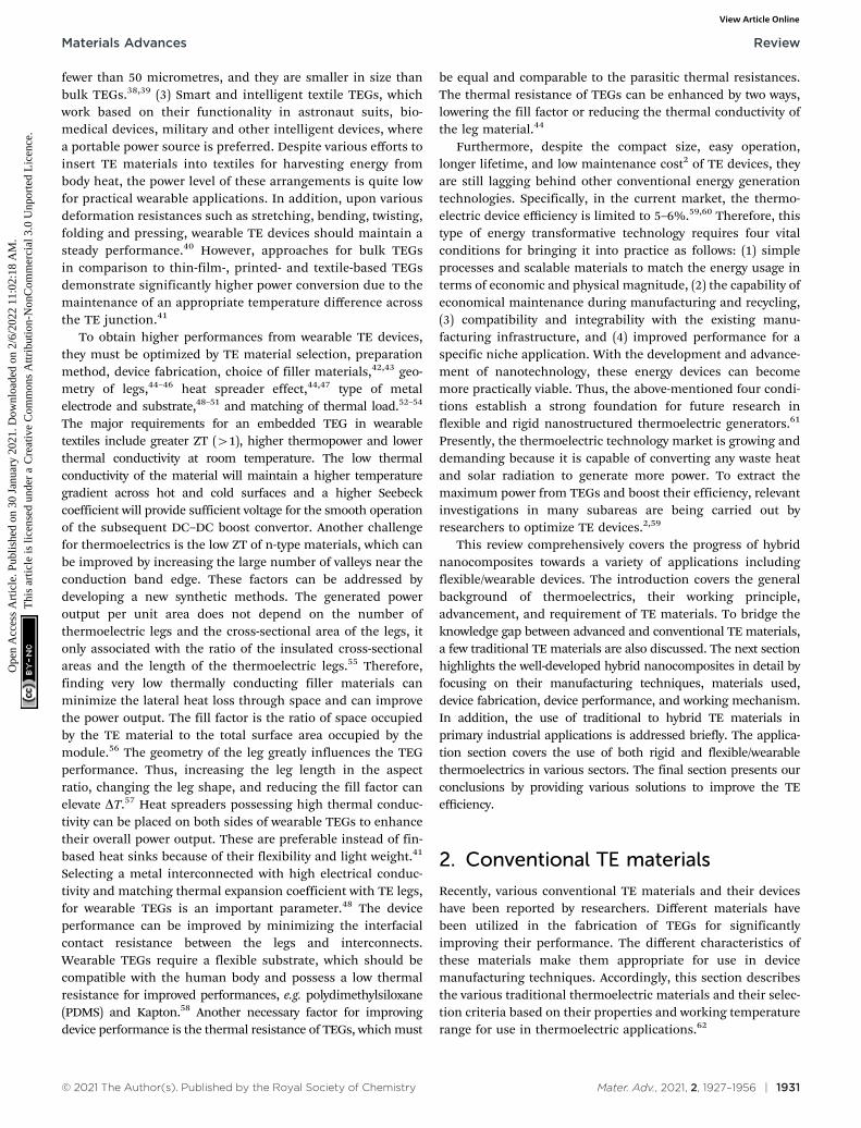
fewer than 50 micrometres, and they are smaller in size thanbulk TEGs.38,39 (3) Smart and intelligent textile TEGs, whichwork based on their functionality in astronaut suits, bio-medical devices, military and other intelligent devices, wherea portable power source is preferred. Despite various efforts toinsert TE materials into textiles for harvesting energy frombody heat, the power level of these arrangements is quite lowfor practical wearable applications. In addition, upon variousdeformation resistances such as stretching, bending, twisting,folding and pressing, wearable TE devices should maintain asteady performance.40 However, approaches for bulk TEGsin comparison to thin-film-, printed- and textile-based TEGsdemonstrate significantly higher power conversion due to themaintenance of an appropriate temperature difference acrossthe TE junction.41
To obtain higher performances from wearable TE devices,they must be optimized by TE material selection, preparationmethod, device fabrication, choice of filler materials,42,43 geo-metry of legs,44–46 heat spreader effect,44,47 type of metalelectrode and substrate,48–51 and matching of thermal load.52–54
The major requirements for an embedded TEG in wearabletextiles include greater ZT (41), higher thermopower and lowerthermal conductivity at room temperature. The low thermalconductivity of the material will maintain a higher temperaturegradient across hot and cold surfaces and a higher Seebeckcoefficient will provide sufficient voltage for the smooth operationof the subsequent DC–DC boost convertor. Another challengefor thermoelectrics is the low ZT of n-type materials, which canbe improved by increasing the large number of valleys near theconduction band edge. These factors can be addressed bydeveloping a new synthetic methods. The generated poweroutput per unit area does not depend on the number ofthermoelectric legs and the cross-sectional area of the legs, itonly associated with the ratio of the insulated cross-sectionalareas and the length of the thermoelectric legs.55 Therefore,finding very low thermally conducting filler materials canminimize the lateral heat loss through space and can improvethe power output. The fill factor is the ratio of space occupiedby the TE material to the total surface area occupied by themodule.56 The geometry of the leg greatly influences the TEGperformance. Thus, increasing the leg length in the aspectratio, changing the leg shape, and reducing the fill factor canelevate DT.57 Heat spreaders possessing high thermal conduc-tivity can be placed on both sides of wearable TEGs to enhancetheir overall power output. These are preferable instead of fin-based heat sinks because of their flexibility and light weight.41
Selecting a metal interconnected with high electrical conduc-tivity and matching thermal expansion coefficient with TE legs,for wearable TEGs is an important parameter.48 The deviceperformance can be improved by minimizing the interfacialcontact resistance between the legs and interconnects.Wearable TEGs require a flexible substrate, which should becompatible with the human body and possess a low thermalresistance for improved performances, e.g. polydimethylsiloxane(PDMS) and Kapton.58 Another necessary factor for improvingdevice performance is the thermal resistance of TEGs, which must
be equal and comparable to the parasitic thermal resistances.The thermal resistance of TEGs can be enhanced by two ways,lowering the fill factor or reducing the thermal conductivity ofthe leg material.44
Furthermore, despite the compact size, easy operation,longer lifetime, and low maintenance cost2 of TE devices, theyare still lagging behind other conventional energy generationtechnologies. Specifically, in the current market, the thermo-electric device efficiency is limited to 5–6%.59,60 Therefore, thistype of energy transformative technology requires four vitalconditions for bringing it into practice as follows: (1) simpleprocesses and scalable materials to match the energy usage interms of economic and physical magnitude, (2) the capability ofeconomical maintenance during manufacturing and recycling,(3) compatibility and integrability with the existing manu-facturing infrastructure, and (4) improved performance for aspecific niche application. With the development and advance-ment of nanotechnology, these energy devices can becomemore practically viable. Thus, the above-mentioned four condi-tions establish a strong foundation for future research inflexible and rigid nanostructured thermoelectric generators.61
Presently, the thermoelectric technology market is growing anddemanding because it is capable of converting any waste heatand solar radiation to generate more power. To extract themaximum power from TEGs and boost their efficiency, relevantinvestigations in many subareas are being carried out byresearchers to optimize TE devices.2,59
This review comprehensively covers the progress of hybridnanocomposites towards a variety of applications includingflexible/wearable devices. The introduction covers the generalbackground of thermoelectrics, their working principle,advancement, and requirement of TE materials. To bridge theknowledge gap between advanced and conventional TE materials,a few traditional TE materials are also discussed. The next sectionhighlights the well-developed hybrid nanocomposites in detail byfocusing on their manufacturing techniques, materials used,device fabrication, device performance, and working mechanism.In addition, the use of traditional to hybrid TE materials inprimary industrial applications is addressed briefly. The applica-tion section covers the use of both rigid and flexible/wearablethermoelectrics in various sectors. The final section presents ourconclusions by providing various solutions to improve the TEefficiency.
2. Conventional TE materials
Recently, various conventional TE materials and their deviceshave been reported by researchers. Different materials havebeen utilized in the fabrication of TEGs for significantlyimproving their performance. The different characteristics ofthese materials make them appropriate for use in devicemanufacturing techniques. Accordingly, this section describesthe various traditional thermoelectric materials and their selec-tion criteria based on their properties and working temperaturerange for use in thermoelectric applications.62
Materials Advances Review
Ope
n A
cces
s A
rtic
le. P
ublis
hed
on 3
0 Ja
nuar
y 20
21. D
ownl
oade
d on
2/6
/202
2 11
:02:
18 A
M.
Thi
s ar
ticle
is li
cens
ed u
nder
a C
reat
ive
Com
mon
s A
ttrib
utio
n-N
onC
omm
erci
al 3
.0 U
npor
ted
Lic
ence
.View Article Online
1932 | Mater. Adv., 2021, 2, 1927–1956 © 2021 The Author(s). Published by the Royal Society of Chemistry
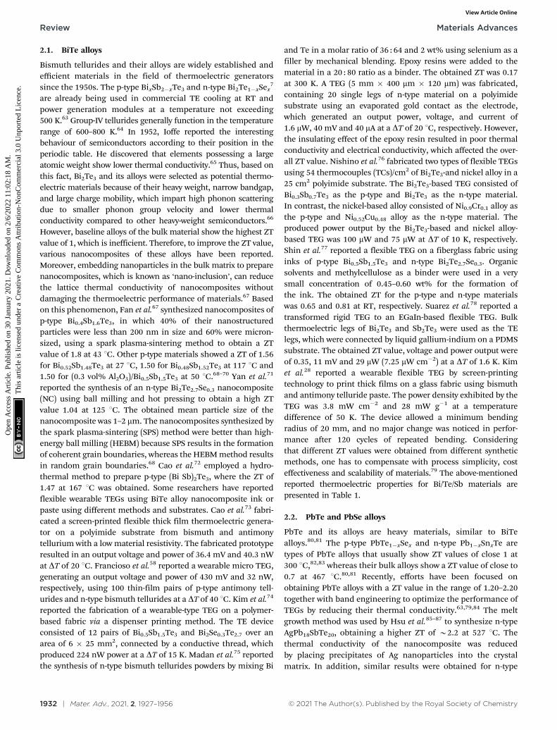
2.1. BiTe alloys
Bismuth tellurides and their alloys are widely established andefficient materials in the field of thermoelectric generatorssince the 1950s. The p-type BixSb2�xTe3 and n-type Bi2Te1�xSex
7
are already being used in commercial TE cooling at RT andpower generation modules at a temperature not exceeding500 K.63 Group-IV tellurides generally function in the temperaturerange of 600–800 K.64 In 1952, Ioffe reported the interestingbehaviour of semiconductors according to their position in theperiodic table. He discovered that elements possessing a largeatomic weight show lower thermal conductivity.65 Thus, based onthis fact, Bi2Te3 and its alloys were selected as potential thermo-electric materials because of their heavy weight, narrow bandgap,and large charge mobility, which impart high phonon scatteringdue to smaller phonon group velocity and lower thermalconductivity compared to other heavy-weight semiconductors.66
However, baseline alloys of the bulk material show the highest ZTvalue of 1, which is inefficient. Therefore, to improve the ZT value,various nanocomposites of these alloys have been reported.Moreover, embedding nanoparticles in the bulk matrix to preparenanocomposites, which is known as ‘nano-inclusion’, can reducethe lattice thermal conductivity of nanocomposites withoutdamaging the thermoelectric performance of materials.67 Basedon this phenomenon, Fan et al.67 synthesized nanocomposites ofp-type Bi0.4Sb1.6Te3, in which 40% of their nanostructuredparticles were less than 200 nm in size and 60% were micron-sized, using a spark plasma-sintering method to obtain a ZTvalue of 1.8 at 43 1C. Other p-type materials showed a ZT of 1.56for Bi0.52Sb1.48Te3 at 27 1C, 1.50 for Bi0.48Sb1.52Te3 at 117 1C and1.50 for (0.3 vol% Al2O3)/Bi0.5Sb1.5Te3 at 50 1C.68–70 Yan et al.71
reported the synthesis of an n-type Bi2Te2.7Se0.3 nanocomposite(NC) using ball milling and hot pressing to obtain a high ZTvalue 1.04 at 125 1C. The obtained mean particle size of thenanocomposite was 1–2 mm. The nanocomposites synthesized bythe spark plasma-sintering (SPS) method were better than high-energy ball milling (HEBM) because SPS results in the formationof coherent grain boundaries, whereas the HEBM method resultsin random grain boundaries.68 Cao et al.72 employed a hydro-thermal method to prepare p-type (Bi Sb)2Te3, where the ZT of1.47 at 167 1C was obtained. Some researchers have reportedflexible wearable TEGs using BiTe alloy nanocomposite ink orpaste using different methods and substrates. Cao et al.73 fabri-cated a screen-printed flexible thick film thermoelectric genera-tor on a polyimide substrate from bismuth and antimonytellurium with a low material resistivity. The fabricated prototyperesulted in an output voltage and power of 36.4 mV and 40.3 nWat DT of 20 1C. Francioso et al.58 reported a wearable micro TEG,generating an output voltage and power of 430 mV and 32 nW,respectively, using 100 thin-film pairs of p-type antimony tell-urides and n-type bismuth tellurides at a DT of 40 1C. Kim et al.74
reported the fabrication of a wearable-type TEG on a polymer-based fabric via a dispenser printing method. The TE deviceconsisted of 12 pairs of Bi0.5Sb1.5Te3 and Bi2Se0.3Te2.7 over anarea of 6 � 25 mm2, connected by a conductive thread, whichproduced 224 nW power at a DT of 15 K. Madan et al.75 reportedthe synthesis of n-type bismuth tellurides powders by mixing Bi
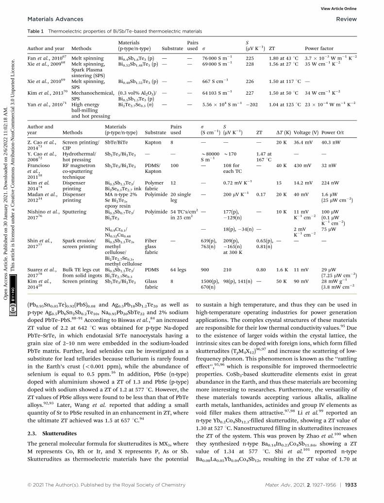
and Te in a molar ratio of 36 : 64 and 2 wt% using selenium as afiller by mechanical blending. Epoxy resins were added to thematerial in a 20 : 80 ratio as a binder. The obtained ZT was 0.17at 300 K. A TEG (5 mm � 400 mm � 120 mm) was fabricated,containing 20 single legs of n-type material on a polyimidesubstrate using an evaporated gold contact as the electrode,which generated an output power, voltage, and current of1.6 mW, 40 mV and 40 mA at a DT of 20 1C, respectively. However,the insulating effect of the epoxy resin resulted in poor thermalconductivity and electrical conductivity, which affected the over-all ZT value. Nishino et al.76 fabricated two types of flexible TEGsusing 54 thermocouples (TCs)/cm2 of Bi2Te3-and nickel alloy in a25 cm2 polyimide substrate. The Bi2Te3-based TEG consisted ofBi0.3Sb0.7Te3 as the p-type and Bi2Te3 as the n-type material.In contrast, the nickel-based alloy consisted of Ni0.9Cr0.1 alloy asthe p-type and Ni0.52Cu0.48 alloy as the n-type material. Theproduced power output by the Bi2Te3-based and nickel alloy-based TEG was 100 mW and 75 mW at DT of 10 K, respectively.Shin et al.77 reported a flexible TEG on a fiberglass fabric usinginks of p-type Bi0.5Sb1.5Te3 and n-type Bi2Te2.7Se0.3. Organicsolvents and methylcellulose as a binder were used in a verysmall concentration of 0.45–0.60 wt% for the formation ofthe ink. The obtained ZT for the p-type and n-type materialswas 0.65 and 0.81 at RT, respectively. Suarez et al.78 reported atransformed rigid TEG to an EGaIn-based flexible TEG. Bulkthermoelectric legs of Bi2Te3 and Sb2Te3 were used as the TElegs, which were connected by liquid gallium-indium on a PDMSsubstrate. The obtained ZT value, voltage and power output wereof 0.35, 11 mV and 29 mW (7.25 mW cm�2) at a DT of 1.6 K. Kimet al.28 reported a wearable flexible TEG by screen-printingtechnology to print thick films on a glass fabric using bismuthand antimony telluride paste. The power density exhibited by theTEG was 3.8 mW cm�2 and 28 mW g�1 at a temperaturedifference of 50 K. The device allowed a minimum bendingradius of 20 mm, and no major change was noticed in perfor-mance after 120 cycles of repeated bending. Consideringthat different ZT values were obtained from different syntheticmethods, one has to compensate with process simplicity, costeffectiveness and scalability of materials.79 The above-mentionedreported thermoelectric properties for Bi/Te/Sb materials arepresented in Table 1.
2.2. PbTe and PbSe alloys
PbTe and its alloys are heavy materials, similar to BiTealloys.80,81 The p-type PbTe1�xSex and n-type Pb1�xSnxTe aretypes of PbTe alloys that usually show ZT values of close 1 at300 1C,82,83 whereas their bulk alloys show a ZT value of close to0.7 at 467 1C.80,81 Recently, efforts have been focused onobtaining PbTe alloys with a ZT value in the range of 1.20–2.20together with band engineering to optimize the performance ofTEGs by reducing their thermal conductivity.63,79,84 The meltgrowth method was used by Hsu et al.85–87 to synthesize n-typeAgPb18SbTe20, obtaining a higher ZT of B2.2 at 527 1C. Thethermal conductivity of the nanocomposite was reducedby placing precipitates of Ag nanoparticles into the crystalmatrix. In addition, similar results were obtained for n-type
Review Materials Advances
Ope
n A
cces
s A
rtic
le. P
ublis
hed
on 3
0 Ja
nuar
y 20
21. D
ownl
oade
d on
2/6
/202
2 11
:02:
18 A
M.
Thi
s ar
ticle
is li
cens
ed u
nder
a C
reat
ive
Com
mon
s A
ttrib
utio
n-N
onC
omm
erci
al 3
.0 U
npor
ted
Lic
ence
.View Article Online
© 2021 The Author(s). Published by the Royal Society of Chemistry Mater. Adv., 2021, 2, 1927–1956 | 1933
(Pb0.95Sn0.05Te)0.92(PbS)0.08 and Ag0.5Pb18Sb1.2Te20 as well asp-type Ag0.5Pb6Sn2Sb0.2Te10, Na0.95Pb20SbTe22 and 2% sodiumdoped PbTe–PbS.88–91 According to Biswas et al.,84 an increasedZT value of 2.2 at 642 1C was obtained for p-type Na-dopedPbTe–SrTe, in which endotaxial SrTe nanocrystals having agrain size of 2–10 nm were embedded in the sodium-loadedPbTe matrix. Further, lead selenides can be investigated as asubstitute for lead tellurides because tellurium is rarely foundin the Earth’s crust (o0.001 ppm), while the abundance ofselenium is equal to 0.5 ppm.16 In addition, PbSe (n-type)doped with aluminium showed a ZT of 1.3 and PbSe (p-type)doped with sodium showed a ZT of 1.2 at 577 1C. However, theZT values of PbSe alloys were found to be less than that of PbTealloys.92,93 Later, Wang et al. reported that adding a smallquantity of Sr to PbSe resulted in an enhancement in ZT, wherethe ultimate ZT achieved was 1.5 at 657 1C.94
2.3. Skutterudites
The general molecular formula for skutterudites is MX3, whereM represents Co, Rh or Ir, and X represents P, As or Sb.Skutterudites as thermoelectric materials have the potential
to sustain a high temperature, and thus they can be used inhigh-temperature operating industries for power generationapplications. The complex crystal structures of these materialsare responsible for their low thermal conductivity values.95 Dueto the existence of larger voids within the crystal lattice, theintrinsic sites can be doped with foreign ions, which form filledskutterudites (TyM4X12)96,97 and increase the scattering of low-frequency phonon. This phenomenon is known as the ‘‘rattlingeffect’’,95,96 which is responsible for improved thermoelectricproperties. CoSb3-based skutterudite elements exist in greatabundance in the Earth, and thus these materials are becomingmore interesting to researches. Furthermore, the versatility ofthese materials towards accepting various alkalis, alkalineearth metals, lanthanides, actinides and group IV elements asvoid filler makes them attractive.97,98 Li et al.99 reported ann-type Yb0.2Co4Sb12.3-filled skutterudite, showing a ZT value of1.30 at 527 1C. Nanostructured filling in skutterudites increasesthe ZT of the system. This was proven by Zhao et al.100 whenthey synthesized n-type Ba0.14In0.23Co4Sb11.84, showing a ZTvalue of 1.34 at 577 1C. Shi et al.101 reported n-typeBa0.08La0.05Yb0.04Co4Sb12, resulting in the ZT value of 1.70 at
Table 1 Thermoelectric properties of Bi/Sb/Te-based thermoelectric materials
Author and year MethodsMaterials(p-type/n-type) Substrate
Pairsused s
S(mV K�1) ZT Power factor
Fan et al., 201067 Melt spinning Bi0.4Sb1.6Te3 (p) — — 76 000 S m�1 225 1.80 at 43 1C 3.7 � 10�3 W m�1 K�2
Xie et al., 200968 Melt spinning,Spark Plasmasintering (SPS)
Bi0.52Sb1.48Te3 (p) — — 69 000 S m�1 228 1.56 at 27 1C 35 W cm�1 K�2
Xie et al., 201069 Melt spinning,SPS
Bi0.48Sb1.52Te3 (p) — — 667 S cm�1 226 1.50 at 117 1C —
Kim et al., 201370 Mechanochemical,SPS
(0.3 vol% Al2O3)/Bi0.5Sb1.5Te3 (p)
— — 64 103 S m�1 227 1.50 at 50 1C 34 W cm�1 K�2
Yan et al., 201071 High energyball-millingand hot pressing
Bi2Te2.7Se0.3 (n) — — 5.56 � 104 S m�1 �202 1.04 at 125 1C 23 � 10�4 W m�1 K�2
Author andyear Methods
Materials(p-type/n-type) Substrate
Pairsused
s(S cm�1)
S(mV K�1) ZT DT (K) Voltage (V) Power O/t
Z. Cao et al.,201473
Screen printing/CIP
SbTe/BiTe Kapton 8 — — — 20 K 36.4 mV 40.3 nW
Y. Cao et al.,200872
Hydrothermal/hot pressing
Sb2Te3/Bi2Te3 — — B80000S m�1
B170 1.47 at167 1C
— —
Franciosoet al.,201158
RF magnetronco-sputteringtechnique
Sb2Te3/Bi2Te3 PDMS/Kapton
100 — 108 foreach TC
— 40 K 430 mV 32 nW
Kim et al.201474
Dispenserprinting
Bi0.5Sb1.5Te3/Bi2Se0.3Te2.7 ink
Polymerfabric
12 — 0.72 mV K�1 15 14.2 mV 224 nW
Madan et al.,201234
Dispenserprinting
MA n-type 2%Se Bi2Te3,epoxy resin
Polyimide 20 singleleg
— 200 mV K�1 0.17 20 K 40 mV 1.6 mW(25 mW cm�2)
Nishino et al.,201776
Sputtering Bi0.3Sb0.7Te3/Bi2Te3
Polyimide 54 TC’s/cm2
in 25 cm2— 177(p),
�129(n)— 10 K 11 mV
K�1 cm�2100 mW(0.1 mWK�1 cm�2)
Ni0.9Cr0.1/Ni0.52Cu0.48
— 18(p), �34(n) — 2 mVK�1 cm�2
75 mW
Shin et al.,201777
Spark erosion/screen printing
Bi0.5Sb1.5Te3,methylcellulose/Bi2Te2.7Se0.3,methyl cellulose
Fiberglassfabric
— 639(p),763(n)
209(p),�165(n)at 300 K
0.65(p),0.81(n)
— — —
Suarez et al.,201778
Bulk TE legs cutfrom solid ingots
Bi0.5Sb1.5Te3/Bi2Te2.7Se0.3
PDMS 64 legs 900 210 0.80 1.6 K 11 mV 29 mW(7.25 mW cm�2)
Kim et al.,201428
Screen printing Sb2Te3/Bi2Te3 Glassfabric
8 1500(p),670(n)
98(p), 141(n) — 50 K 90 mV 28 mW g�1
(3.8 mW cm�2
Materials Advances Review
Ope
n A
cces
s A
rtic
le. P
ublis
hed
on 3
0 Ja
nuar
y 20
21. D
ownl
oade
d on
2/6
/202
2 11
:02:
18 A
M.
Thi
s ar
ticle
is li
cens
ed u
nder
a C
reat
ive
Com
mon
s A
ttrib
utio
n-N
onC
omm
erci
al 3
.0 U
npor
ted
Lic
ence
.View Article Online
1934 | Mater. Adv., 2021, 2, 1927–1956 © 2021 The Author(s). Published by the Royal Society of Chemistry
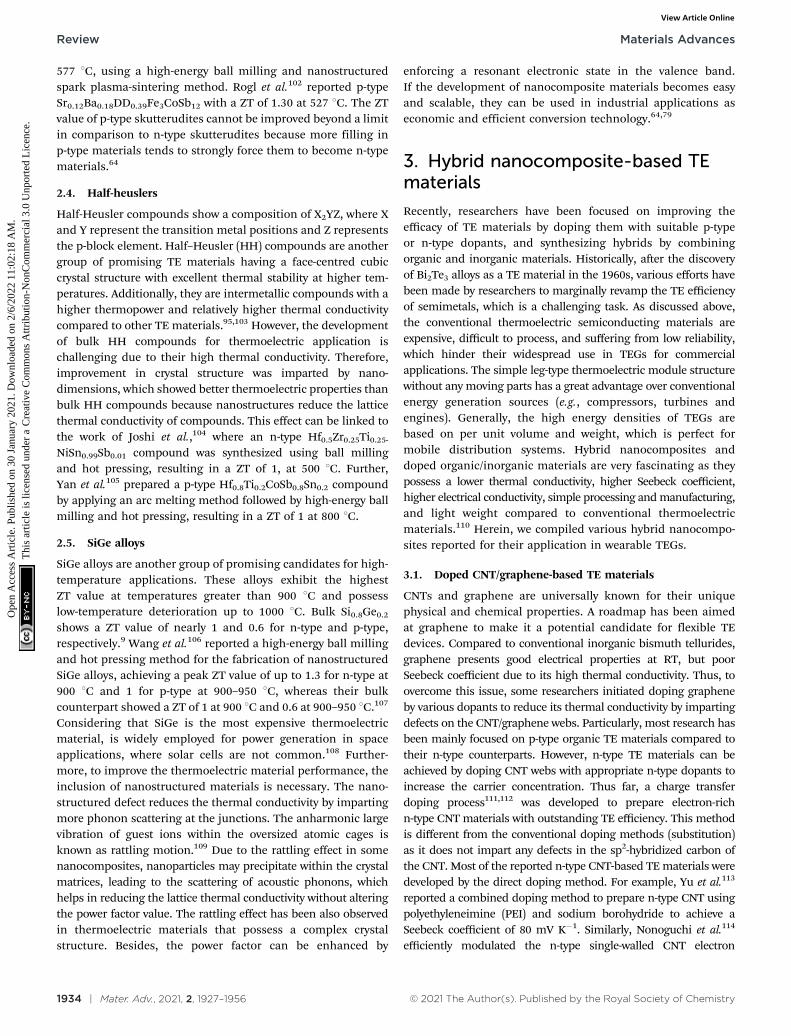
577 1C, using a high-energy ball milling and nanostructuredspark plasma-sintering method. Rogl et al.102 reported p-typeSr0.12Ba0.18DD0.39Fe3CoSb12 with a ZT of 1.30 at 527 1C. The ZTvalue of p-type skutterudites cannot be improved beyond a limitin comparison to n-type skutterudites because more filling inp-type materials tends to strongly force them to become n-typematerials.64
2.4. Half-heuslers
Half-Heusler compounds show a composition of X2YZ, where Xand Y represent the transition metal positions and Z representsthe p-block element. Half–Heusler (HH) compounds are anothergroup of promising TE materials having a face-centred cubiccrystal structure with excellent thermal stability at higher tem-peratures. Additionally, they are intermetallic compounds with ahigher thermopower and relatively higher thermal conductivitycompared to other TE materials.95,103 However, the developmentof bulk HH compounds for thermoelectric application ischallenging due to their high thermal conductivity. Therefore,improvement in crystal structure was imparted by nano-dimensions, which showed better thermoelectric properties thanbulk HH compounds because nanostructures reduce the latticethermal conductivity of compounds. This effect can be linked tothe work of Joshi et al.,104 where an n-type Hf0.5Zr0.25Ti0.25-
NiSn0.99Sb0.01 compound was synthesized using ball millingand hot pressing, resulting in a ZT of 1, at 500 1C. Further,Yan et al.105 prepared a p-type Hf0.8Ti0.2CoSb0.8Sn0.2 compoundby applying an arc melting method followed by high-energy ballmilling and hot pressing, resulting in a ZT of 1 at 800 1C.
2.5. SiGe alloys
SiGe alloys are another group of promising candidates for high-temperature applications. These alloys exhibit the highestZT value at temperatures greater than 900 1C and possesslow-temperature deterioration up to 1000 1C. Bulk Si0.8Ge0.2
shows a ZT value of nearly 1 and 0.6 for n-type and p-type,respectively.9 Wang et al.106 reported a high-energy ball millingand hot pressing method for the fabrication of nanostructuredSiGe alloys, achieving a peak ZT value of up to 1.3 for n-type at900 1C and 1 for p-type at 900–950 1C, whereas their bulkcounterpart showed a ZT of 1 at 900 1C and 0.6 at 900–950 1C.107
Considering that SiGe is the most expensive thermoelectricmaterial, is widely employed for power generation in spaceapplications, where solar cells are not common.108 Further-more, to improve the thermoelectric material performance, theinclusion of nanostructured materials is necessary. The nano-structured defect reduces the thermal conductivity by impartingmore phonon scattering at the junctions. The anharmonic largevibration of guest ions within the oversized atomic cages isknown as rattling motion.109 Due to the rattling effect in somenanocomposites, nanoparticles may precipitate within the crystalmatrices, leading to the scattering of acoustic phonons, whichhelps in reducing the lattice thermal conductivity without alteringthe power factor value. The rattling effect has been also observedin thermoelectric materials that possess a complex crystalstructure. Besides, the power factor can be enhanced by
enforcing a resonant electronic state in the valence band.If the development of nanocomposite materials becomes easyand scalable, they can be used in industrial applications aseconomic and efficient conversion technology.64,79
3. Hybrid nanocomposite-based TEmaterials
Recently, researchers have been focused on improving theefficacy of TE materials by doping them with suitable p-typeor n-type dopants, and synthesizing hybrids by combiningorganic and inorganic materials. Historically, after the discoveryof Bi2Te3 alloys as a TE material in the 1960s, various efforts havebeen made by researchers to marginally revamp the TE efficiencyof semimetals, which is a challenging task. As discussed above,the conventional thermoelectric semiconducting materials areexpensive, difficult to process, and suffering from low reliability,which hinder their widespread use in TEGs for commercialapplications. The simple leg-type thermoelectric module structurewithout any moving parts has a great advantage over conventionalenergy generation sources (e.g., compressors, turbines andengines). Generally, the high energy densities of TEGs arebased on per unit volume and weight, which is perfect formobile distribution systems. Hybrid nanocomposites anddoped organic/inorganic materials are very fascinating as theypossess a lower thermal conductivity, higher Seebeck coefficient,higher electrical conductivity, simple processing and manufacturing,and light weight compared to conventional thermoelectricmaterials.110 Herein, we compiled various hybrid nanocompo-sites reported for their application in wearable TEGs.
3.1. Doped CNT/graphene-based TE materials
CNTs and graphene are universally known for their uniquephysical and chemical properties. A roadmap has been aimedat graphene to make it a potential candidate for flexible TEdevices. Compared to conventional inorganic bismuth tellurides,graphene presents good electrical properties at RT, but poorSeebeck coefficient due to its high thermal conductivity. Thus, toovercome this issue, some researchers initiated doping grapheneby various dopants to reduce its thermal conductivity by impartingdefects on the CNT/graphene webs. Particularly, most research hasbeen mainly focused on p-type organic TE materials compared totheir n-type counterparts. However, n-type TE materials can beachieved by doping CNT webs with appropriate n-type dopants toincrease the carrier concentration. Thus far, a charge transferdoping process111,112 was developed to prepare electron-richn-type CNT materials with outstanding TE efficiency. This methodis different from the conventional doping methods (substitution)as it does not impart any defects in the sp2-hybridized carbon ofthe CNT. Most of the reported n-type CNT-based TE materials weredeveloped by the direct doping method. For example, Yu et al.113
reported a combined doping method to prepare n-type CNT usingpolyethyleneimine (PEI) and sodium borohydride to achieve aSeebeck coefficient of 80 mV K�1. Similarly, Nonoguchi et al.114
efficiently modulated the n-type single-walled CNT electron
Review Materials Advances
Ope
n A
cces
s A
rtic
le. P
ublis
hed
on 3
0 Ja
nuar
y 20
21. D
ownl
oade
d on
2/6
/202
2 11
:02:
18 A
M.
Thi
s ar
ticle
is li
cens
ed u
nder
a C
reat
ive
Com
mon
s A
ttrib
utio
n-N
onC
omm
erci
al 3
.0 U
npor
ted
Lic
ence
.View Article Online
© 2021 The Author(s). Published by the Royal Society of Chemistry Mater. Adv., 2021, 2, 1927–1956 | 1935
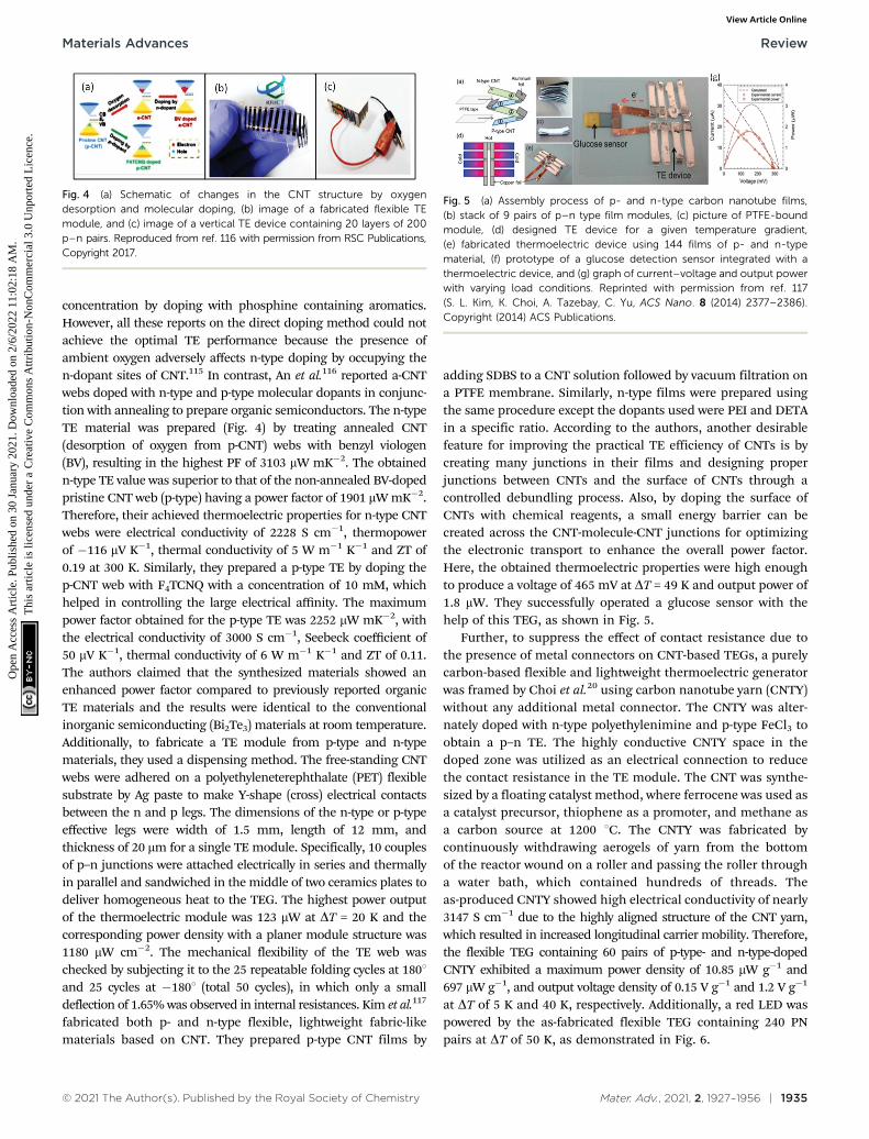
concentration by doping with phosphine containing aromatics.However, all these reports on the direct doping method could notachieve the optimal TE performance because the presence ofambient oxygen adversely affects n-type doping by occupying then-dopant sites of CNT.115 In contrast, An et al.116 reported a-CNTwebs doped with n-type and p-type molecular dopants in conjunc-tion with annealing to prepare organic semiconductors. The n-typeTE material was prepared (Fig. 4) by treating annealed CNT(desorption of oxygen from p-CNT) webs with benzyl viologen(BV), resulting in the highest PF of 3103 mW mK�2. The obtainedn-type TE value was superior to that of the non-annealed BV-dopedpristine CNT web (p-type) having a power factor of 1901 mW mK�2.Therefore, their achieved thermoelectric properties for n-type CNTwebs were electrical conductivity of 2228 S cm�1, thermopowerof �116 mV K�1, thermal conductivity of 5 W m�1 K�1 and ZT of0.19 at 300 K. Similarly, they prepared a p-type TE by doping thep-CNT web with F4TCNQ with a concentration of 10 mM, whichhelped in controlling the large electrical affinity. The maximumpower factor obtained for the p-type TE was 2252 mW mK�2, withthe electrical conductivity of 3000 S cm�1, Seebeck coefficient of50 mV K�1, thermal conductivity of 6 W m�1 K�1 and ZT of 0.11.The authors claimed that the synthesized materials showed anenhanced power factor compared to previously reported organicTE materials and the results were identical to the conventionalinorganic semiconducting (Bi2Te3) materials at room temperature.Additionally, to fabricate a TE module from p-type and n-typematerials, they used a dispensing method. The free-standing CNTwebs were adhered on a polyethyleneterephthalate (PET) flexiblesubstrate by Ag paste to make Y-shape (cross) electrical contactsbetween the n and p legs. The dimensions of the n-type or p-typeeffective legs were width of 1.5 mm, length of 12 mm, andthickness of 20 mm for a single TE module. Specifically, 10 couplesof p–n junctions were attached electrically in series and thermallyin parallel and sandwiched in the middle of two ceramics plates todeliver homogeneous heat to the TEG. The highest power outputof the thermoelectric module was 123 mW at DT = 20 K and thecorresponding power density with a planer module structure was1180 mW cm�2. The mechanical flexibility of the TE web waschecked by subjecting it to the 25 repeatable folding cycles at 1801and 25 cycles at �1801 (total 50 cycles), in which only a smalldeflection of 1.65% was observed in internal resistances. Kim et al.117
fabricated both p- and n-type flexible, lightweight fabric-likematerials based on CNT. They prepared p-type CNT films by
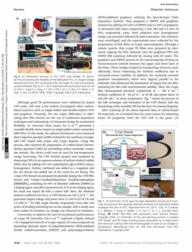
adding SDBS to a CNT solution followed by vacuum filtration ona PTFE membrane. Similarly, n-type films were prepared usingthe same procedure except the dopants used were PEI and DETAin a specific ratio. According to the authors, another desirablefeature for improving the practical TE efficiency of CNTs is bycreating many junctions in their films and designing properjunctions between CNTs and the surface of CNTs through acontrolled debundling process. Also, by doping the surface ofCNTs with chemical reagents, a small energy barrier can becreated across the CNT-molecule-CNT junctions for optimizingthe electronic transport to enhance the overall power factor.Here, the obtained thermoelectric properties were high enoughto produce a voltage of 465 mV at DT = 49 K and output power of1.8 mW. They successfully operated a glucose sensor with thehelp of this TEG, as shown in Fig. 5.
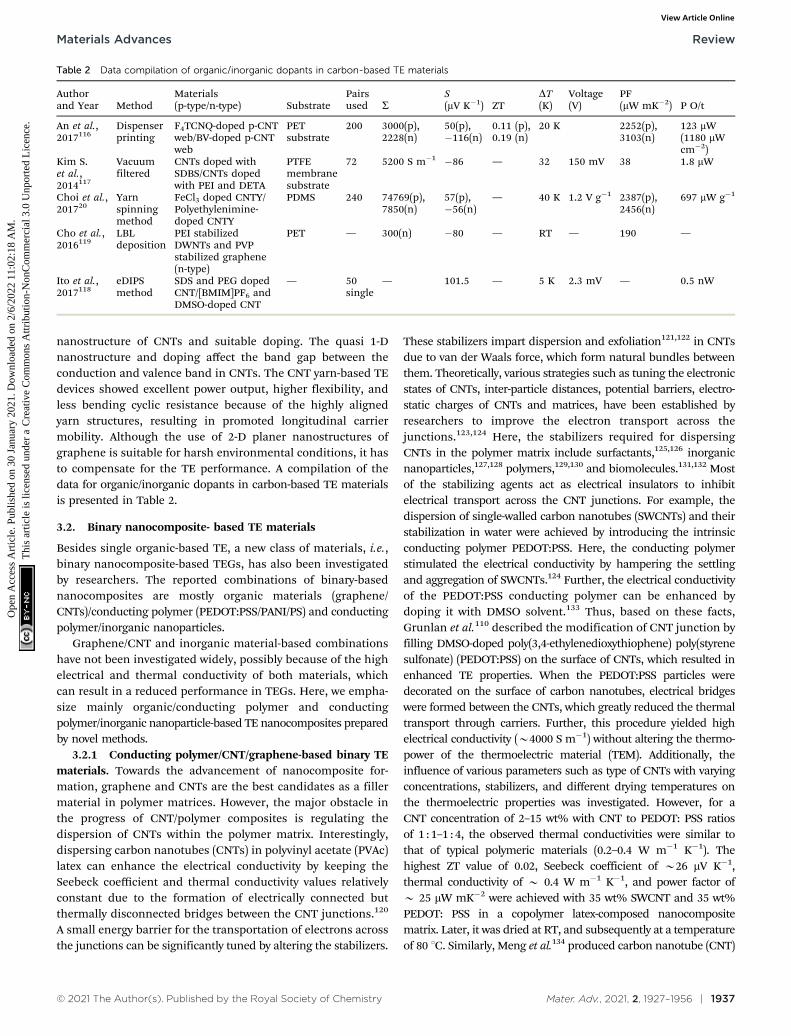
Further, to suppress the effect of contact resistance due tothe presence of metal connectors on CNT-based TEGs, a purelycarbon-based flexible and lightweight thermoelectric generatorwas framed by Choi et al.20 using carbon nanotube yarn (CNTY)without any additional metal connector. The CNTY was alter-nately doped with n-type polyethylenimine and p-type FeCl3 toobtain a p–n TE. The highly conductive CNTY space in thedoped zone was utilized as an electrical connection to reducethe contact resistance in the TE module. The CNT was synthe-sized by a floating catalyst method, where ferrocene was used asa catalyst precursor, thiophene as a promoter, and methane asa carbon source at 1200 1C. The CNTY was fabricated bycontinuously withdrawing aerogels of yarn from the bottomof the reactor wound on a roller and passing the roller througha water bath, which contained hundreds of threads. Theas-produced CNTY showed high electrical conductivity of nearly3147 S cm�1 due to the highly aligned structure of the CNT yarn,which resulted in increased longitudinal carrier mobility. Therefore,the flexible TEG containing 60 pairs of p-type- and n-type-dopedCNTY exhibited a maximum power density of 10.85 mW g�1 and697 mW g�1, and output voltage density of 0.15 V g�1 and 1.2 V g�1
at DT of 5 K and 40 K, respectively. Additionally, a red LED waspowered by the as-fabricated flexible TEG containing 240 PNpairs at DT of 50 K, as demonstrated in Fig. 6.
Fig. 4 (a) Schematic of changes in the CNT structure by oxygendesorption and molecular doping, (b) image of a fabricated flexible TEmodule, and (c) image of a vertical TE device containing 20 layers of 200p–n pairs. Reproduced from ref. 116 with permission from RSC Publications,Copyright 2017.
Fig. 5 (a) Assembly process of p- and n-type carbon nanotube films,(b) stack of 9 pairs of p–n type film modules, (c) picture of PTFE-boundmodule, (d) designed TE device for a given temperature gradient,(e) fabricated thermoelectric device using 144 films of p- and n-typematerial, (f) prototype of a glucose detection sensor integrated with athermoelectric device, and (g) graph of current–voltage and output powerwith varying load conditions. Reprinted with permission from ref. 117(S. L. Kim, K. Choi, A. Tazebay, C. Yu, ACS Nano. 8 (2014) 2377–2386).Copyright (2014) ACS Publications.
Materials Advances Review
Ope
n A
cces
s A
rtic
le. P
ublis
hed
on 3
0 Ja
nuar
y 20
21. D
ownl
oade
d on
2/6
/202
2 11
:02:
18 A
M.
Thi
s ar
ticle
is li
cens
ed u
nder
a C
reat
ive
Com
mon
s A
ttrib
utio
n-N
onC
omm
erci
al 3
.0 U
npor
ted
Lic
ence
.View Article Online
1936 | Mater. Adv., 2021, 2, 1927–1956 © 2021 The Author(s). Published by the Royal Society of Chemistry
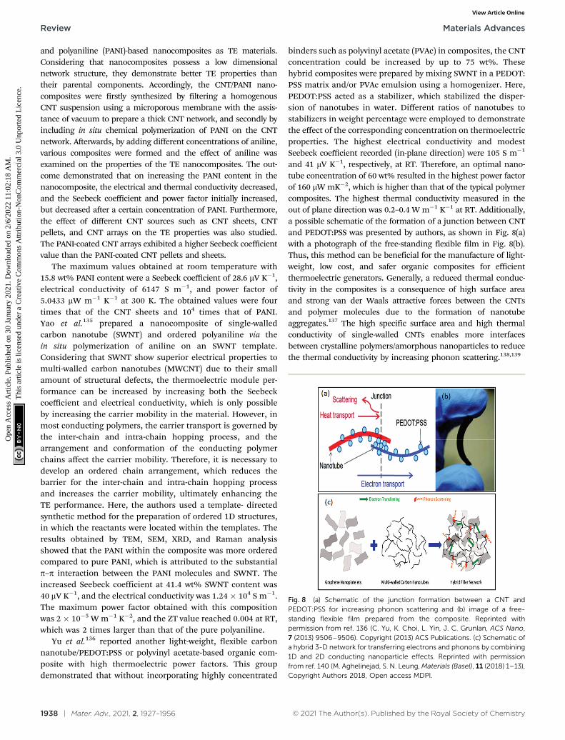
Although good TE performances were validated by dopedCNT webs, still only a few studies investigated other carbon-based matrices such as single-walled and double-walled CNTsand graphene. Presently, the two major difficulties in fabri-cating thin film devices are the use of traditional depositiontechniques and maintaining 3-D structural design for mechanicalflexibility. To overcome these issues, Ito et al.118 presented awearable flexible device based on single-walled carbon nanotubes(SWCNTs). In this study, the authors introduced a new enhanceddirect-injection pyrolytic (eDIP) method for the synthesis of single-wall CNT doped with p-type and n-type dopants. Using thisprocess, they reported the preparation of a fabric-based thermo-electric generator (TEG) by assembling carbon nanotube compo-site threads. The device could even be used for low-temperatureenergy harvesting. The CNT threads (p-type) were prepared bydispersing CNTs in an aqueous solution of sodium dodecyl sulfate(SDS), then by adding 0.01 wt% polyethylene glycol (PEG) using ahomogenizer. Further, methanol was added as a coagulant andthe wet thread was pulled out of the vessel for air drying. Then-type CNT thread was prepared by partially doping the CNT/PEGthread with 1-butyl-3-methylimidazolium hexafluorophosphate([BMIM]PF6) consisting 10 wt% of dimethyl sulfoxide (DMSO) asa doping agent, and after immersion for 24 h in the doping agent,the tread was wiped off with a cotton ball. Here, the obtainedSeebeck coefficient for the p–n CNT thread was 101.5 mV K�1. Thegenerated output voltage and power were 2.3 mV at DT of 5 K and1.6 mW m�2 for fifty single threads, respectively. Even after 160cycles of bending-stretching test on the sample, with a nearly zeroinner radius of curvature, no change was observed in resistance.
Conversely, to address the lack of exceptional performancesof n-type TE materials, Cho et al.119 explored a highly ordered3-D conjugated network of n-type organic TE nanocomposite bydepositing alternate layers of polyethyleneimine (PEI)-stabilizeddouble walled-nanotubes (DWNT) and polyvinylpyrrolidone
(PVP)-stabilized graphene utilizing the layer-by-layer (LbL)deposition method. They prepared a DWNT and graphenesolution by adding 0.03 wt% of DWNT and 0.2 wt% of graphenein deionized (DI) water comprising 1 wt% PEI and 0.1 wt% ofPVP, respectively. Later, both solutions were homogenizedusing a tip sonicator followed by bath sonication. The solutionswere centrifuged, and the supernatants were collected for thepreparation of thin films of n-type nanocomposite. Through arobotic system, thin n-type TE films were prepared by alter-nately dipping the PET substrate into the graphene–PVP andDWNT–PEI solutions followed by rinsing with DI water. Thegraphene and DWNT present in the nanocomposite formed aninterconnected network between the upper and lower layer ofthe films. These bridges helped in transporting electrons moreefficiently, hence enhancing the Seebeck coefficient due toincreased carrier mobility. In addition, the randomly orientedgraphene nanoplatelets, which were aligned parallel to thesubstrate, had obstructed the penetration of oxygen into the film,endowing the film with environmental stability. Thus, the n-typefilm demonstrated electrical conductivity of B 300 S cm�1,Seebeck coefficient of �80 mV K�1 at 80 BL and power factor of190 mW mK�2 at room temperature. Fig. 7 shows the process ofthe LBL technique and formation of the CNT thread, with thefunctioning of the wearable TEG by the heat of a human fingertip.
After scanning all the above-reported data of carbon-basedTE materials, we concluded that the main reason for obtainingbetter TE properties from the CNT web is the quasi 1-D
Fig. 6 (a) Fabrication process of the CNTY and flexible TE device.(b) Picture showing the flexibility of the fabricated TEG. (c) Output voltageobtained from the TEG using body heat. (d) Image of a red LED poweredusing the flexible TEG at DT = 50 K. Reprinted with permission from ref. 20(J. Choi, Y. Jung, S. J. Yang, J. Y. Oh, J. Oh, K. Jo, J. G. Son, S. E. Moon, C. R.Park, H. Kim, 11 (2017) 7608–7614). Copyright (2017) ACS Publications.
Fig. 7 (a) Schematic of the layer-by-layer deposition process and mole-cular structures of the materials used and (b) photo of a fully dried, flexiblemultilayer thin film on PET. Reprinted from ref. 119 (C. Cho, M. Culebras,K. L. Wallace, Y. Song, K. Holder, J. H. Hsu, C. Yu, J. C. Grunlan, NanoEnergy, 28 (2016) 426–432) with permission from Science Elsevier,Copyright 2016. (c) Schematic of the wet-spinning process to prepareCNT thread, and (d) image showing power generation by a finger touchand natural air cooling, with inset showing graph of open circuit voltage vs.temperature. Reproduced from ref. 118 with permission from RSCPublications, Copyright 2017.
Review Materials Advances
Ope
n A
cces
s A
rtic
le. P
ublis
hed
on 3
0 Ja
nuar
y 20
21. D
ownl
oade
d on
2/6
/202
2 11
:02:
18 A
M.
Thi
s ar
ticle
is li
cens
ed u
nder
a C
reat
ive
Com
mon
s A
ttrib
utio
n-N
onC
omm
erci
al 3
.0 U
npor
ted
Lic
ence
.View Article Online
© 2021 The Author(s). Published by the Royal Society of Chemistry Mater. Adv., 2021, 2, 1927–1956 | 1937
nanostructure of CNTs and suitable doping. The quasi 1-Dnanostructure and doping affect the band gap between theconduction and valence band in CNTs. The CNT yarn-based TEdevices showed excellent power output, higher flexibility, andless bending cyclic resistance because of the highly alignedyarn structures, resulting in promoted longitudinal carriermobility. Although the use of 2-D planer nanostructures ofgraphene is suitable for harsh environmental conditions, it hasto compensate for the TE performance. A compilation of thedata for organic/inorganic dopants in carbon-based TE materialsis presented in Table 2.
3.2. Binary nanocomposite- based TE materials
Besides single organic-based TE, a new class of materials, i.e.,binary nanocomposite-based TEGs, has also been investigatedby researchers. The reported combinations of binary-basednanocomposites are mostly organic materials (graphene/CNTs)/conducting polymer (PEDOT:PSS/PANI/PS) and conductingpolymer/inorganic nanoparticles.
Graphene/CNT and inorganic material-based combinationshave not been investigated widely, possibly because of the highelectrical and thermal conductivity of both materials, whichcan result in a reduced performance in TEGs. Here, we empha-size mainly organic/conducting polymer and conductingpolymer/inorganic nanoparticle-based TE nanocomposites preparedby novel methods.
3.2.1 Conducting polymer/CNT/graphene-based binary TEmaterials. Towards the advancement of nanocomposite for-mation, graphene and CNTs are the best candidates as a fillermaterial in polymer matrices. However, the major obstacle inthe progress of CNT/polymer composites is regulating thedispersion of CNTs within the polymer matrix. Interestingly,dispersing carbon nanotubes (CNTs) in polyvinyl acetate (PVAc)latex can enhance the electrical conductivity by keeping theSeebeck coefficient and thermal conductivity values relativelyconstant due to the formation of electrically connected butthermally disconnected bridges between the CNT junctions.120
A small energy barrier for the transportation of electrons acrossthe junctions can be significantly tuned by altering the stabilizers.
These stabilizers impart dispersion and exfoliation121,122 in CNTsdue to van der Waals force, which form natural bundles betweenthem. Theoretically, various strategies such as tuning the electronicstates of CNTs, inter-particle distances, potential barriers, electro-static charges of CNTs and matrices, have been established byresearchers to improve the electron transport across thejunctions.123,124 Here, the stabilizers required for dispersingCNTs in the polymer matrix include surfactants,125,126 inorganicnanoparticles,127,128 polymers,129,130 and biomolecules.131,132 Mostof the stabilizing agents act as electrical insulators to inhibitelectrical transport across the CNT junctions. For example, thedispersion of single-walled carbon nanotubes (SWCNTs) and theirstabilization in water were achieved by introducing the intrinsicconducting polymer PEDOT:PSS. Here, the conducting polymerstimulated the electrical conductivity by hampering the settlingand aggregation of SWCNTs.124 Further, the electrical conductivityof the PEDOT:PSS conducting polymer can be enhanced bydoping it with DMSO solvent.133 Thus, based on these facts,Grunlan et al.110 described the modification of CNT junction byfilling DMSO-doped poly(3,4-ethylenedioxythiophene) poly(styrenesulfonate) (PEDOT:PSS) on the surface of CNTs, which resulted inenhanced TE properties. When the PEDOT:PSS particles weredecorated on the surface of carbon nanotubes, electrical bridgeswere formed between the CNTs, which greatly reduced the thermaltransport through carriers. Further, this procedure yielded highelectrical conductivity (B4000 S m�1) without altering the thermo-power of the thermoelectric material (TEM). Additionally, theinfluence of various parameters such as type of CNTs with varyingconcentrations, stabilizers, and different drying temperatures onthe thermoelectric properties was investigated. However, for aCNT concentration of 2–15 wt% with CNT to PEDOT: PSS ratiosof 1 : 1–1 : 4, the observed thermal conductivities were similar tothat of typical polymeric materials (0.2–0.4 W m�1 K�1). Thehighest ZT value of 0.02, Seebeck coefficient of B26 mV K�1,thermal conductivity of B 0.4 W m�1 K�1, and power factor ofB 25 mW mK�2 were achieved with 35 wt% SWCNT and 35 wt%PEDOT: PSS in a copolymer latex-composed nanocompositematrix. Later, it was dried at RT, and subsequently at a temperatureof 80 1C. Similarly, Meng et al.134 produced carbon nanotube (CNT)
Table 2 Data compilation of organic/inorganic dopants in carbon-based TE materials
Authorand Year Method
Materials(p-type/n-type) Substrate
Pairsused S
S(mV K�1) ZT
DT(K)
Voltage(V)
PF(mW mK�2) P O/t
An et al.,2017116
Dispenserprinting
F4TCNQ-doped p-CNTweb/BV-doped p-CNTweb
PETsubstrate
200 3000(p),2228(n)
50(p),�116(n)
0.11 (p),0.19 (n)
20 K 2252(p),3103(n)
123 mW(1180 mWcm�2)
Kim S.et al.,2014117
Vacuumfiltered
CNTs doped withSDBS/CNTs dopedwith PEI and DETA
PTFEmembranesubstrate
72 5200 S m�1 �86 — 32 150 mV 38 1.8 mW
Choi et al.,201720
Yarnspinningmethod
FeCl3 doped CNTY/Polyethylenimine-doped CNTY
PDMS 240 74769(p),7850(n)
57(p),�56(n)
— 40 K 1.2 V g�1 2387(p),2456(n)
697 mW g�1
Cho et al.,2016119
LBLdeposition
PEI stabilizedDWNTs and PVPstabilized graphene(n-type)
PET — 300(n) �80 — RT — 190 —
Ito et al.,2017118
eDIPSmethod
SDS and PEG dopedCNT/[BMIM]PF6 andDMSO-doped CNT
— 50single
— 101.5 — 5 K 2.3 mV — 0.5 nW
Materials Advances Review
Ope
n A
cces
s A
rtic
le. P
ublis
hed
on 3
0 Ja
nuar
y 20
21. D
ownl
oade
d on
2/6
/202
2 11
:02:
18 A
M.
Thi
s ar
ticle
is li
cens
ed u
nder
a C
reat
ive
Com
mon
s A
ttrib
utio
n-N
onC
omm
erci
al 3
.0 U
npor
ted
Lic
ence
.View Article Online
1938 | Mater. Adv., 2021, 2, 1927–1956 © 2021 The Author(s). Published by the Royal Society of Chemistry
and polyaniline (PANI)-based nanocomposites as TE materials.Considering that nanocomposites possess a low dimensionalnetwork structure, they demonstrate better TE properties thantheir parental components. Accordingly, the CNT/PANI nano-composites were firstly synthesized by filtering a homogenousCNT suspension using a microporous membrane with the assis-tance of vacuum to prepare a thick CNT network, and secondly byincluding in situ chemical polymerization of PANI on the CNTnetwork. Afterwards, by adding different concentrations of aniline,various composites were formed and the effect of aniline wasexamined on the properties of the TE nanocomposites. The out-come demonstrated that on increasing the PANI content in thenanocomposite, the electrical and thermal conductivity decreased,and the Seebeck coefficient and power factor initially increased,but decreased after a certain concentration of PANI. Furthermore,the effect of different CNT sources such as CNT sheets, CNTpellets, and CNT arrays on the TE properties was also studied.The PANI-coated CNT arrays exhibited a higher Seebeck coefficientvalue than the PANI-coated CNT pellets and sheets.
The maximum values obtained at room temperature with15.8 wt% PANI content were a Seebeck coefficient of 28.6 mV K�1,electrical conductivity of 6147 S m�1, and power factor of5.0433 mW m�1 K�1 at 300 K. The obtained values were fourtimes that of the CNT sheets and 104 times that of PANI.Yao et al.135 prepared a nanocomposite of single-walledcarbon nanotube (SWNT) and ordered polyaniline via thein situ polymerization of aniline on an SWNT template.Considering that SWNT show superior electrical properties tomulti-walled carbon nanotubes (MWCNT) due to their smallamount of structural defects, the thermoelectric module per-formance can be increased by increasing both the Seebeckcoefficient and electrical conductivity, which is only possibleby increasing the carrier mobility in the material. However, inmost conducting polymers, the carrier transport is governed bythe inter-chain and intra-chain hopping process, and thearrangement and conformation of the conducting polymerchains affect the carrier mobility. Therefore, it is necessary todevelop an ordered chain arrangement, which reduces thebarrier for the inter-chain and intra-chain hopping processand increases the carrier mobility, ultimately enhancing theTE performance. Here, the authors used a template- directedsynthetic method for the preparation of ordered 1D structures,in which the reactants were located within the templates. Theresults obtained by TEM, SEM, XRD, and Raman analysisshowed that the PANI within the composite was more orderedcompared to pure PANI, which is attributed to the substantialp–p interaction between the PANI molecules and SWNT. Theincreased Seebeck coefficient at 41.4 wt% SWNT content was40 mV K�1, and the electrical conductivity was 1.24 � 104 S m�1.The maximum power factor obtained with this compositionwas 2 � 10�5 W m�1 K�2, and the ZT value reached 0.004 at RT,which was 2 times larger than that of the pure polyaniline.
Yu et al.136 reported another light-weight, flexible carbonnanotube/PEDOT:PSS or polyvinyl acetate-based organic com-posite with high thermoelectric power factors. This groupdemonstrated that without incorporating highly concentrated
binders such as polyvinyl acetate (PVAc) in composites, the CNTconcentration could be increased by up to 75 wt%. Thesehybrid composites were prepared by mixing SWNT in a PEDOT:PSS matrix and/or PVAc emulsion using a homogenizer. Here,PEDOT:PSS acted as a stabilizer, which stabilized the disper-sion of nanotubes in water. Different ratios of nanotubes tostabilizers in weight percentage were employed to demonstratethe effect of the corresponding concentration on thermoelectricproperties. The highest electrical conductivity and modestSeebeck coefficient recorded (in-plane direction) were 105 S m�1
and 41 mV K�1, respectively, at RT. Therefore, an optimal nano-tube concentration of 60 wt% resulted in the highest power factorof 160 mW mK�2, which is higher than that of the typical polymercomposites. The highest thermal conductivity measured in theout of plane direction was 0.2–0.4 W m�1 K�1 at RT. Additionally,a possible schematic of the formation of a junction between CNTand PEDOT:PSS was presented by authors, as shown in Fig. 8(a)with a photograph of the free-standing flexible film in Fig. 8(b).Thus, this method can be beneficial for the manufacture of light-weight, low cost, and safer organic composites for efficientthermoelectric generators. Generally, a reduced thermal conduc-tivity in the composites is a consequence of high surface areaand strong van der Waals attractive forces between the CNTsand polymer molecules due to the formation of nanotubeaggregates.137 The high specific surface area and high thermalconductivity of single-walled CNTs enables more interfacesbetween crystalline polymers/amorphous nanoparticles to reducethe thermal conductivity by increasing phonon scattering.138,139
Fig. 8 (a) Schematic of the junction formation between a CNT andPEDOT:PSS for increasing phonon scattering and (b) image of a free-standing flexible film prepared from the composite. Reprinted withpermission from ref. 136 (C. Yu, K. Choi, L. Yin, J. C. Grunlan, ACS Nano,7 (2013) 9506–9506). Copyright (2013) ACS Publications. (c) Schematic ofa hybrid 3-D network for transferring electrons and phonons by combining1D and 2D conducting nanoparticle effects. Reprinted with permissionfrom ref. 140 (M. Aghelinejad, S. N. Leung, Materials (Basel), 11 (2018) 1–13),Copyright Authors 2018, Open access MDPI.
Review Materials Advances
Ope
n A
cces
s A
rtic
le. P
ublis
hed
on 3
0 Ja
nuar
y 20
21. D
ownl
oade
d on
2/6
/202
2 11
:02:
18 A
M.
Thi
s ar
ticle
is li
cens
ed u
nder
a C
reat
ive
Com
mon
s A
ttrib
utio
n-N
onC
omm
erci
al 3
.0 U
npor
ted
Lic
ence
.View Article Online
© 2021 The Author(s). Published by the Royal Society of Chemistry Mater. Adv., 2021, 2, 1927–1956 | 1939
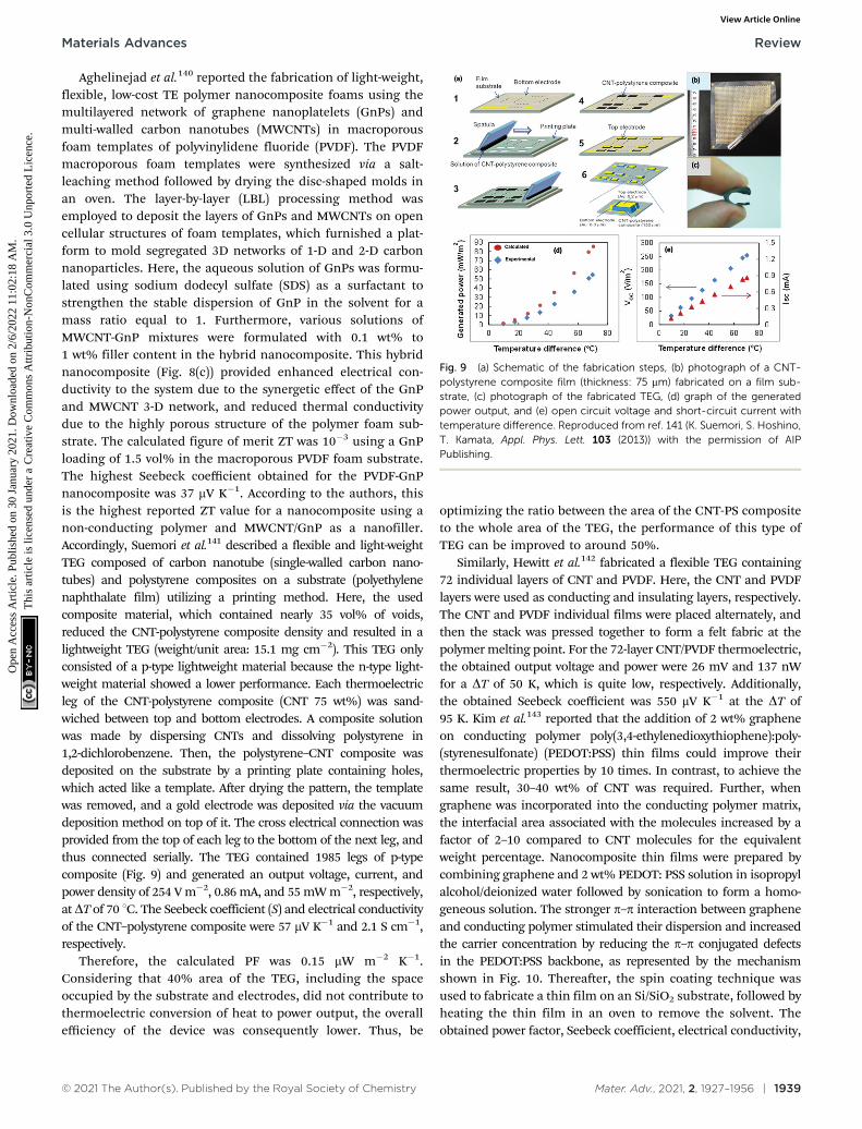
Aghelinejad et al.140 reported the fabrication of light-weight,flexible, low-cost TE polymer nanocomposite foams using themultilayered network of graphene nanoplatelets (GnPs) andmulti-walled carbon nanotubes (MWCNTs) in macroporousfoam templates of polyvinylidene fluoride (PVDF). The PVDFmacroporous foam templates were synthesized via a salt-leaching method followed by drying the disc-shaped molds inan oven. The layer-by-layer (LBL) processing method wasemployed to deposit the layers of GnPs and MWCNTs on opencellular structures of foam templates, which furnished a plat-form to mold segregated 3D networks of 1-D and 2-D carbonnanoparticles. Here, the aqueous solution of GnPs was formu-lated using sodium dodecyl sulfate (SDS) as a surfactant tostrengthen the stable dispersion of GnP in the solvent for amass ratio equal to 1. Furthermore, various solutions ofMWCNT-GnP mixtures were formulated with 0.1 wt% to1 wt% filler content in the hybrid nanocomposite. This hybridnanocomposite (Fig. 8(c)) provided enhanced electrical con-ductivity to the system due to the synergetic effect of the GnPand MWCNT 3-D network, and reduced thermal conductivitydue to the highly porous structure of the polymer foam sub-strate. The calculated figure of merit ZT was 10�3 using a GnPloading of 1.5 vol% in the macroporous PVDF foam substrate.The highest Seebeck coefficient obtained for the PVDF-GnPnanocomposite was 37 mV K�1. According to the authors, thisis the highest reported ZT value for a nanocomposite using anon-conducting polymer and MWCNT/GnP as a nanofiller.Accordingly, Suemori et al.141 described a flexible and light-weightTEG composed of carbon nanotube (single-walled carbon nano-tubes) and polystyrene composites on a substrate (polyethylenenaphthalate film) utilizing a printing method. Here, the usedcomposite material, which contained nearly 35 vol% of voids,reduced the CNT-polystyrene composite density and resulted in alightweight TEG (weight/unit area: 15.1 mg cm�2). This TEG onlyconsisted of a p-type lightweight material because the n-type light-weight material showed a lower performance. Each thermoelectricleg of the CNT-polystyrene composite (CNT 75 wt%) was sand-wiched between top and bottom electrodes. A composite solutionwas made by dispersing CNTs and dissolving polystyrene in1,2-dichlorobenzene. Then, the polystyrene–CNT composite wasdeposited on the substrate by a printing plate containing holes,which acted like a template. After drying the pattern, the templatewas removed, and a gold electrode was deposited via the vacuumdeposition method on top of it. The cross electrical connection wasprovided from the top of each leg to the bottom of the next leg, andthus connected serially. The TEG contained 1985 legs of p-typecomposite (Fig. 9) and generated an output voltage, current, andpower density of 254 V m�2, 0.86 mA, and 55 mW m�2, respectively,at DT of 70 1C. The Seebeck coefficient (S) and electrical conductivityof the CNT–polystyrene composite were 57 mV K�1 and 2.1 S cm�1,respectively.
Therefore, the calculated PF was 0.15 mW m�2 K�1.Considering that 40% area of the TEG, including the spaceoccupied by the substrate and electrodes, did not contribute tothermoelectric conversion of heat to power output, the overallefficiency of the device was consequently lower. Thus, be
optimizing the ratio between the area of the CNT-PS compositeto the whole area of the TEG, the performance of this type ofTEG can be improved to around 50%.
Similarly, Hewitt et al.142 fabricated a flexible TEG containing72 individual layers of CNT and PVDF. Here, the CNT and PVDFlayers were used as conducting and insulating layers, respectively.The CNT and PVDF individual films were placed alternately, andthen the stack was pressed together to form a felt fabric at thepolymer melting point. For the 72-layer CNT/PVDF thermoelectric,the obtained output voltage and power were 26 mV and 137 nWfor a DT of 50 K, which is quite low, respectively. Additionally,the obtained Seebeck coefficient was 550 mV K�1 at the DT of95 K. Kim et al.143 reported that the addition of 2 wt% grapheneon conducting polymer poly(3,4-ethylenedioxythiophene):poly-(styrenesulfonate) (PEDOT:PSS) thin films could improve theirthermoelectric properties by 10 times. In contrast, to achieve thesame result, 30–40 wt% of CNT was required. Further, whengraphene was incorporated into the conducting polymer matrix,the interfacial area associated with the molecules increased by afactor of 2–10 compared to CNT molecules for the equivalentweight percentage. Nanocomposite thin films were prepared bycombining graphene and 2 wt% PEDOT: PSS solution in isopropylalcohol/deionized water followed by sonication to form a homo-geneous solution. The stronger p–p interaction between grapheneand conducting polymer stimulated their dispersion and increasedthe carrier concentration by reducing the p–p conjugated defectsin the PEDOT:PSS backbone, as represented by the mechanismshown in Fig. 10. Thereafter, the spin coating technique wasused to fabricate a thin film on an Si/SiO2 substrate, followed byheating the thin film in an oven to remove the solvent. Theobtained power factor, Seebeck coefficient, electrical conductivity,
Fig. 9 (a) Schematic of the fabrication steps, (b) photograph of a CNT-polystyrene composite film (thickness: 75 mm) fabricated on a film sub-strate, (c) photograph of the fabricated TEG, (d) graph of the generatedpower output, and (e) open circuit voltage and short-circuit current withtemperature difference. Reproduced from ref. 141 (K. Suemori, S. Hoshino,T. Kamata, Appl. Phys. Lett. 103 (2013)) with the permission of AIPPublishing.
Materials Advances Review
Ope
n A
cces
s A
rtic
le. P
ublis
hed
on 3
0 Ja
nuar
y 20
21. D
ownl
oade
d on
2/6
/202
2 11
:02:
18 A
M.
Thi
s ar
ticle
is li
cens
ed u
nder
a C
reat
ive
Com
mon
s A
ttrib
utio
n-N
onC
omm
erci
al 3
.0 U
npor
ted
Lic
ence
.View Article Online
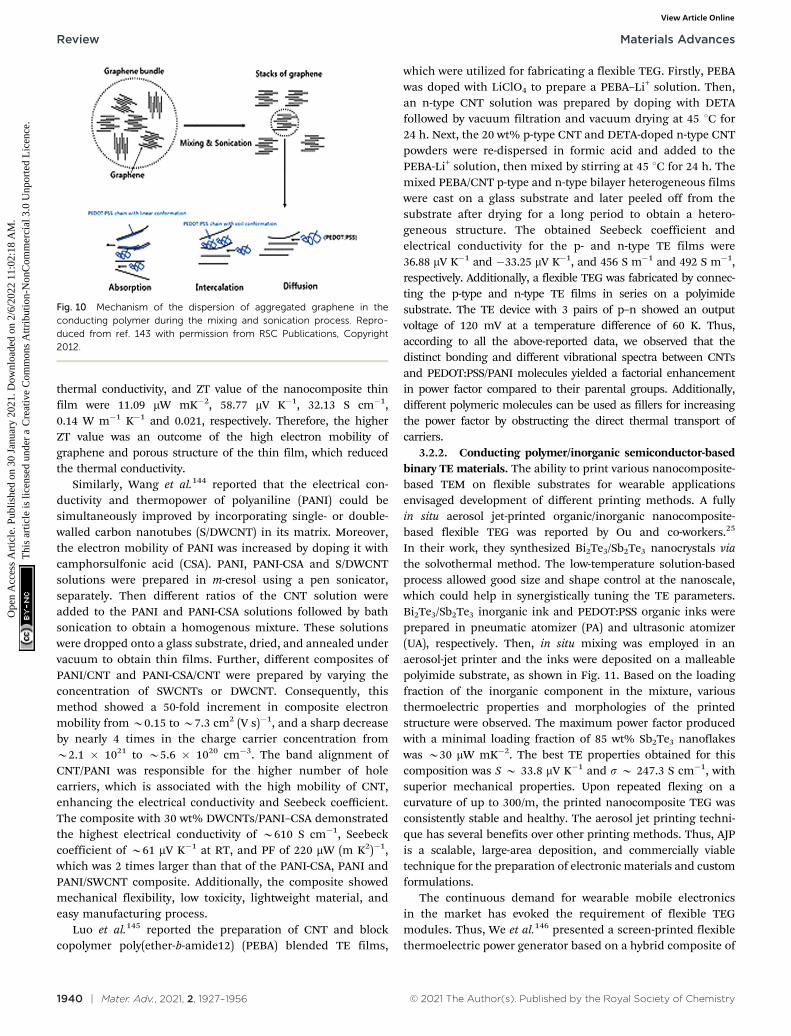
1940 | Mater. Adv., 2021, 2, 1927–1956 © 2021 The Author(s). Published by the Royal Society of Chemistry
thermal conductivity, and ZT value of the nanocomposite thinfilm were 11.09 mW mK�2, 58.77 mV K�1, 32.13 S cm�1,0.14 W m�1 K�1 and 0.021, respectively. Therefore, the higherZT value was an outcome of the high electron mobility ofgraphene and porous structure of the thin film, which reducedthe thermal conductivity.
Similarly, Wang et al.144 reported that the electrical con-ductivity and thermopower of polyaniline (PANI) could besimultaneously improved by incorporating single- or double-walled carbon nanotubes (S/DWCNT) in its matrix. Moreover,the electron mobility of PANI was increased by doping it withcamphorsulfonic acid (CSA). PANI, PANI-CSA and S/DWCNTsolutions were prepared in m-cresol using a pen sonicator,separately. Then different ratios of the CNT solution wereadded to the PANI and PANI-CSA solutions followed by bathsonication to obtain a homogenous mixture. These solutionswere dropped onto a glass substrate, dried, and annealed undervacuum to obtain thin films. Further, different composites ofPANI/CNT and PANI-CSA/CNT were prepared by varying theconcentration of SWCNTs or DWCNT. Consequently, thismethod showed a 50-fold increment in composite electronmobility from B0.15 to B7.3 cm2 (V s)�1, and a sharp decreaseby nearly 4 times in the charge carrier concentration fromB2.1 � 1021 to B5.6 � 1020 cm�3. The band alignment ofCNT/PANI was responsible for the higher number of holecarriers, which is associated with the high mobility of CNT,enhancing the electrical conductivity and Seebeck coefficient.The composite with 30 wt% DWCNTs/PANI–CSA demonstratedthe highest electrical conductivity of B610 S cm�1, Seebeckcoefficient of B61 mV K�1 at RT, and PF of 220 mW (m K2)�1,which was 2 times larger than that of the PANI-CSA, PANI andPANI/SWCNT composite. Additionally, the composite showedmechanical flexibility, low toxicity, lightweight material, andeasy manufacturing process.
Luo et al.145 reported the preparation of CNT and blockcopolymer poly(ether-b-amide12) (PEBA) blended TE films,
which were utilized for fabricating a flexible TEG. Firstly, PEBAwas doped with LiClO4 to prepare a PEBA–Li+ solution. Then,an n-type CNT solution was prepared by doping with DETAfollowed by vacuum filtration and vacuum drying at 45 1C for24 h. Next, the 20 wt% p-type CNT and DETA-doped n-type CNTpowders were re-dispersed in formic acid and added to thePEBA-Li+ solution, then mixed by stirring at 45 1C for 24 h. Themixed PEBA/CNT p-type and n-type bilayer heterogeneous filmswere cast on a glass substrate and later peeled off from thesubstrate after drying for a long period to obtain a hetero-geneous structure. The obtained Seebeck coefficient andelectrical conductivity for the p- and n-type TE films were36.88 mV K�1 and �33.25 mV K�1, and 456 S m�1 and 492 S m�1,respectively. Additionally, a flexible TEG was fabricated by connec-ting the p-type and n-type TE films in series on a polyimidesubstrate. The TE device with 3 pairs of p–n showed an outputvoltage of 120 mV at a temperature difference of 60 K. Thus,according to all the above-reported data, we observed that thedistinct bonding and different vibrational spectra between CNTsand PEDOT:PSS/PANI molecules yielded a factorial enhancementin power factor compared to their parental groups. Additionally,different polymeric molecules can be used as fillers for increasingthe power factor by obstructing the direct thermal transport ofcarriers.
3.2.2. Conducting polymer/inorganic semiconductor-basedbinary TE materials. The ability to print various nanocomposite-based TEM on flexible substrates for wearable applicationsenvisaged development of different printing methods. A fullyin situ aerosol jet-printed organic/inorganic nanocomposite-based flexible TEG was reported by Ou and co-workers.25
In their work, they synthesized Bi2Te3/Sb2Te3 nanocrystals viathe solvothermal method. The low-temperature solution-basedprocess allowed good size and shape control at the nanoscale,which could help in synergistically tuning the TE parameters.Bi2Te3/Sb2Te3 inorganic ink and PEDOT:PSS organic inks wereprepared in pneumatic atomizer (PA) and ultrasonic atomizer(UA), respectively. Then, in situ mixing was employed in anaerosol-jet printer and the inks were deposited on a malleablepolyimide substrate, as shown in Fig. 11. Based on the loadingfraction of the inorganic component in the mixture, variousthermoelectric properties and morphologies of the printedstructure were observed. The maximum power factor producedwith a minimal loading fraction of 85 wt% Sb2Te3 nanoflakeswas B30 mW mK�2. The best TE properties obtained for thiscomposition was S B 33.8 mV K�1 and s B 247.3 S cm�1, withsuperior mechanical properties. Upon repeated flexing on acurvature of up to 300/m, the printed nanocomposite TEG wasconsistently stable and healthy. The aerosol jet printing techni-que has several benefits over other printing methods. Thus, AJPis a scalable, large-area deposition, and commercially viabletechnique for the preparation of electronic materials and customformulations.
The continuous demand for wearable mobile electronicsin the market has evoked the requirement of flexible TEGmodules. Thus, We et al.146 presented a screen-printed flexiblethermoelectric power generator based on a hybrid composite of
Fig. 10 Mechanism of the dispersion of aggregated graphene in theconducting polymer during the mixing and sonication process. Repro-duced from ref. 143 with permission from RSC Publications, Copyright2012.
Review Materials Advances
Ope
n A
cces
s A
rtic
le. P
ublis
hed
on 3
0 Ja
nuar
y 20
21. D
ownl
oade
d on
2/6
/202
2 11
:02:
18 A
M.
Thi
s ar
ticle
is li
cens
ed u
nder
a C
reat
ive
Com
mon
s A
ttrib
utio
n-N
onC
omm
erci
al 3
.0 U
npor
ted
Lic
ence
.View Article Online
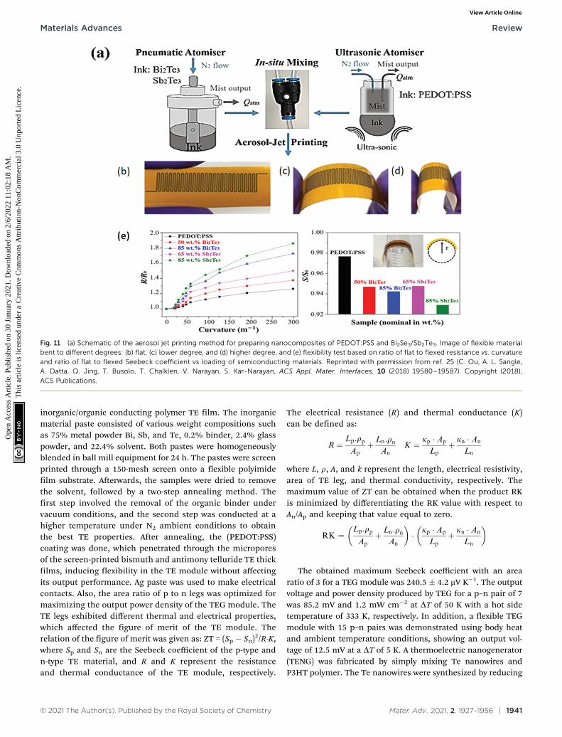
© 2021 The Author(s). Published by the Royal Society of Chemistry Mater. Adv., 2021, 2, 1927–1956 | 1941
inorganic/organic conducting polymer TE film. The inorganicmaterial paste consisted of various weight compositions suchas 75% metal powder Bi, Sb, and Te, 0.2% binder, 2.4% glasspowder, and 22.4% solvent. Both pastes were homogeneouslyblended in ball mill equipment for 24 h. The pastes were screenprinted through a 150-mesh screen onto a flexible polyimidefilm substrate. Afterwards, the samples were dried to removethe solvent, followed by a two-step annealing method. Thefirst step involved the removal of the organic binder undervacuum conditions, and the second step was conducted at ahigher temperature under N2 ambient conditions to obtainthe best TE properties. After annealing, the (PEDOT:PSS)coating was done, which penetrated through the microporesof the screen-printed bismuth and antimony telluride TE thickfilms, inducing flexibility in the TE module without affectingits output performance. Ag paste was used to make electricalcontacts. Also, the area ratio of p to n legs was optimized formaximizing the output power density of the TEG module. TheTE legs exhibited different thermal and electrical properties,which affected the figure of merit of the TE module. Therelation of the figure of merit was given as: ZT = (Sp � Sn)2/R�K,where Sp and Sn are the Seebeck coefficient of the p-type andn-type TE material, and R and K represent the resistanceand thermal conductance of the TE module, respectively.
The electrical resistance (R) and thermal conductance (K)can be defined as:
R ¼Lp:rpApþ Ln:rn
AnK ¼ kp � Ap
Lpþ kn � An
Ln
where L, r, A, and k represent the length, electrical resistivity,area of TE leg, and thermal conductivity, respectively. Themaximum value of ZT can be obtained when the product RKis minimized by differentiating the RK value with respect toAn/Ap and keeping that value equal to zero.
RK ¼Lp:rpApþ Ln:rn
An
� �� kp � Ap
Lpþ kn � An
Ln
� �
The obtained maximum Seebeck coefficient with an arearatio of 3 for a TEG module was 240.5 � 4.2 mV K�1. The outputvoltage and power density produced by TEG for a p–n pair of 7was 85.2 mV and 1.2 mW cm�2 at DT of 50 K with a hot sidetemperature of 333 K, respectively. In addition, a flexible TEGmodule with 15 p–n pairs was demonstrated using body heatand ambient temperature conditions, showing an output vol-tage of 12.5 mV at a DT of 5 K. A thermoelectric nanogenerator(TENG) was fabricated by simply mixing Te nanowires andP3HT polymer. The Te nanowires were synthesized by reducing
Fig. 11 (a) Schematic of the aerosol jet printing method for preparing nanocomposites of PEDOT:PSS and Bi2Se3/Sb2Te3. Image of flexible materialbent to different degrees: (b) flat, (c) lower degree, and (d) higher degree, and (e) flexibility test based on ratio of flat to flexed resistance vs. curvatureand ratio of flat to flexed Seebeck coefficient vs loading of semiconducting materials. Reprinted with permission from ref. 25 (C. Ou, A. L. Sangle,A. Datta, Q. Jing, T. Busolo, T. Chalklen, V. Narayan, S. Kar-Narayan, ACS Appl. Mater. Interfaces, 10 (2018) 19580–19587). Copyright (2018),ACS Publications.
Materials Advances Review
Ope
n A
cces
s A
rtic
le. P
ublis
hed
on 3
0 Ja
nuar
y 20
21. D
ownl
oade
d on
2/6
/202
2 11
:02:
18 A
M.
Thi
s ar
ticle
is li
cens
ed u
nder
a C
reat
ive
Com
mon
s A
ttrib
utio
n-N
onC
omm
erci
al 3
.0 U
npor
ted
Lic
ence
.View Article Online
1942 | Mater. Adv., 2021, 2, 1927–1956 © 2021 The Author(s). Published by the Royal Society of Chemistry
TeO2 with hydrazine hydrate at room temperature underconstant stirring. When Te nanowires were grown on the surfaceof Te nanocrystallites by depositing Te atom, the solutionexhibited a colour change from colourless to blue at the end ofthe reaction. For device fabrication, a composite of Te nanowiresand poly(3-hexylthiophene) (P3HT) polymer was prepared inbenzene chloride solution. The composite solution was droppedon a flexible Kapton substrate and silver paste was used as theelectrode. The fabricated TENG was packaged by a thin layerof poly(dimethylsiloxane) (PDMS) to protect it from ambientconditions. The produced output voltage/current was 14 mV/254 nA at a DT of 50 K. A linear variation between the tempera-ture difference and the output voltage was observed duringtesting. Yang’s group reported that when two are TENGs con-nected in series, the output voltage of 38 mV and current densityof 320 nA in parallel connection at a DT of 55 K were achieved.The calculated Seebeck coefficient was 285 mV K�1. By utilizingthe temperature of the human body as a heat source, thesethermoelectric nanogenerators (TENGs) could be used as awearable energy harvester. Additionally, they were used as aself-powered temperature sensor, which displayed a responsetime of 17 s and reset time of 9 s. Under ambient conditions, thedetection sensitivity of the sensor reached up to 0.15 K.147
Wang et al.148 reported PEDOT: PSS-based aerogel films anda PEDOT:PSS/TeNW-based composite aerogel film for a flexiblethermoelectric power generator because of their high flexibilityand ultralow thermal conductivity. With different organicsolvents, the PEDOT:PSS aerogel films were cast by vacuumfreeze-drying followed by pressing. Similarly, PEDOT:PSS/TeNW (PPT) films were prepared using the same method,together with the hydrothermal method, which was used forTeNW. Finally, vapour annealing of the PPT composite aerogelfilms was done with DMSO solvent in a Teflon-lined stainlesssteel autoclave. The PEDOT:PSS/30 wt% Te-NW aerogel compo-site film was treated with DMSO vapour for 20 min, resulting ina PF of 11.3 mW m�1 K�1, ZT of 2.0 � 10-2, electrical conduc-tivity of B 100 S cm�1, and Seebeck coefficient of B 32.1 mV K�1.The device was fabricated by connecting the PEDOT:PSS-basedaerogel films as the p-type leg and carbon nanotube fibres (CNFs)as the n-type leg in series with silver paste. The maximum outputvoltage, output current, and output power obtained were 31.2 mV,B0.17 mA and 1.28 mW at DT of 60 K, respectively. The optimizedcomposite aerogel films provided an efficient TE generator withhigh-performance values. Wang and coworkers149 fabricated ahighly flexible.
Solution-printable n-type hybrid TE based on a fullerene/TiS2 organic/inorganic material. TiS2 powder was exfoliated to2D nanosheets and intercalated with N-methyl-2-pyrrolidone(NMP) by grinding it in a mortar-pestle. Then, the powder wassonicated in isopropyl alcohol (IPA) followed by centrifugationto remove the bulk particles. Thereafter, a C60 (fullerene)solution prepared in toluene was added slowly to the TiS2
supernatant in various amounts. The mixing of both solutionsprovided a path to deposit C60 particles on the surface ofnanosheets. Then, the final solution was passed subjected tovacuum filtration with the help of membranes to obtain hybrid
flexible films, followed by vacuum drying and annealing. Thissolution was used as an n-type ink for the fabrication of a TEG.Additionally, the p-type ink was developed by dispersing andsonicating 50 wt% SWNTs in PEDOT:PSS. Further, by usingboth inks, a flexible TEG was printed on a plastic substrate. Then-type C60/TiS2 showed a ZT value of B0.3 at 400 K. For 1 wt%concentration of C60, the obtained thermoelectric properties forthe n-type hybrid were a Seebeck coefficient of �101 mV K�1,electrical conductivity of B390 S cm�1, and power factor of B400 mW mK�2 at 300 K. The obtained data for the flexible TEGwas an output voltage of B4.8 mV, maximum power output of335 nW, and power density of 1.68 W m�2 at a temperaturedifference of 20 K. Hence, these hybrid nanocomposites arebetter than the previously reported nanocomposites because ofthe higher thermopower of the inorganic particles and lowthermal conductivity of the conducting polymer. The novelaerosol jet printing technique can provide a versatile, eco-nomic, and easily scalable method for printing flexiblenanocomposite-based TEGs. In addition, other factors such asoptimization of the TE legs and TE area show great impact onthe performance of TEGs. The reported data for binary hybridnanocomposite-based TE materials is summarized in Table 3.
3.3. Ternary hybrid nanocomposite-based TE materials
Even after covering all the binary hybrid nanocomposites,achieving high electrical conductivity in nanocomposites stillremains a challenging task. Thus, to overcome this difficulty,the ternary hybrid nanocomposite-based TE materials werecombined to obtain the benefit of all the three componentsin a nanocomposite. A prospective strategy to enhance theSeebeck coefficient and electrical conductivity of hybrid nano-composites can be developed by integrating higher S inorganicNPs and higher s conducting elements.31,150–153 However, thepower factor of these hybrids cannot exceed the values of theirindividual constitutes. Besides, the limitations have beenalleviated by providing large energy carriers filtering at hybridhetrojunctions.154,155
Generally, ternary nanocomposites are composed of anorganic-based matrix on which surface inorganic nanoparticlesand conducting polymers are grown by either physical mixingor in situ polymerization. Therefore, Ou et al.24 used a ternarynanocomposite ink as a thermoelectric material with differentviscosities and ratios to fabricate flexible TEGs with varioussubstrates using a modified aerosol-jet printing method. Highlydispersible antimony telluride nanoflakes and multi-walledcarbon nanotubes (MWCNTs) were incorporated into poly(3,4-ethylenedioxythiophene) polystyrene sulphonate (PEDOT:PSS)structures to enlarge the TE properties of the conductingpolymer on the flexible polyimide substrates. The PEDOT:PSSink and MWCNT ink were formulated by dispersing them in DIwater and loading in an ultrasonic atomizer and pneumaticatomizer, respectively. To prepare a stable dispersion ofMWCNT in DI water, 0.1 wt% of sodium dodecyl sulphate(SDS), and 0.5 wt% of polyvinylpyrrolidone (PVP) as surfactantswere used. The Sb2Te3 nanoflakes were prepared via the solvo-thermal synthesis method and added to the atomizer to
Review Materials Advances
Ope
n A
cces
s A
rtic
le. P
ublis
hed
on 3
0 Ja
nuar
y 20
21. D
ownl
oade
d on
2/6
/202
2 11
:02:
18 A
M.
Thi
s ar
ticle
is li
cens
ed u
nder
a C
reat
ive
Com
mon
s A
ttrib
utio
n-N
onC
omm
erci
al 3
.0 U
npor
ted
Lic
ence
.View Article Online
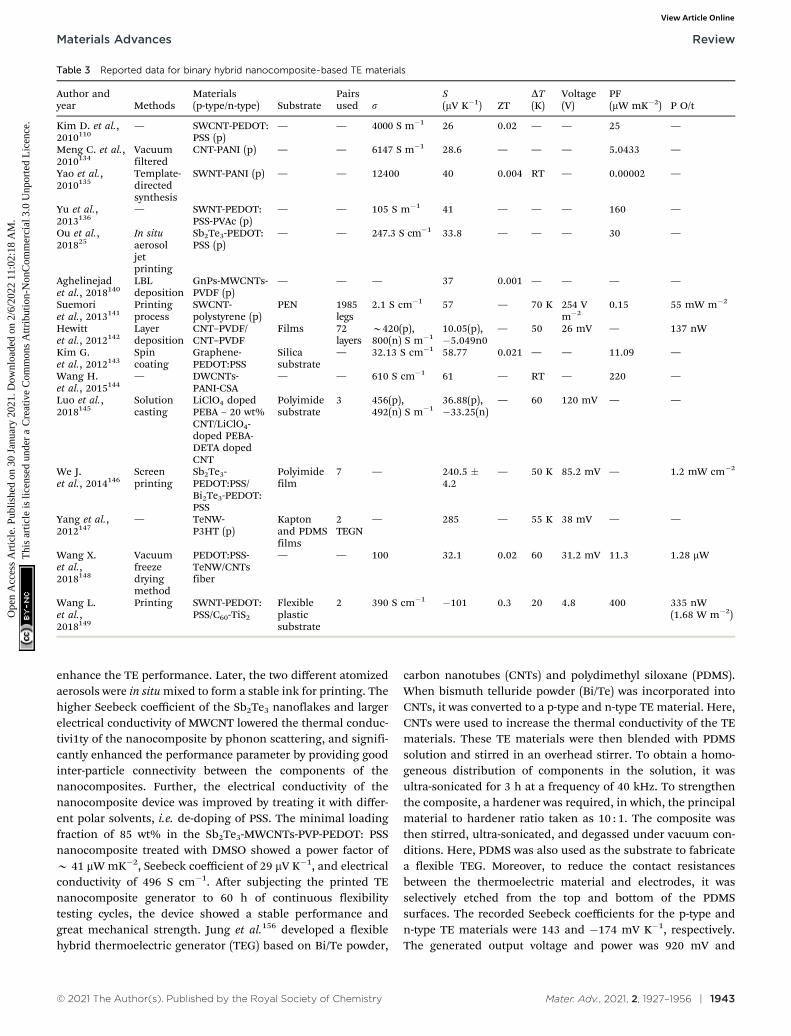
© 2021 The Author(s). Published by the Royal Society of Chemistry Mater. Adv., 2021, 2, 1927–1956 | 1943
enhance the TE performance. Later, the two different atomizedaerosols were in situ mixed to form a stable ink for printing. Thehigher Seebeck coefficient of the Sb2Te3 nanoflakes and largerelectrical conductivity of MWCNT lowered the thermal conduc-tivi1ty of the nanocomposite by phonon scattering, and signifi-cantly enhanced the performance parameter by providing goodinter-particle connectivity between the components of thenanocomposites. Further, the electrical conductivity of thenanocomposite device was improved by treating it with differ-ent polar solvents, i.e. de-doping of PSS. The minimal loadingfraction of 85 wt% in the Sb2Te3-MWCNTs-PVP-PEDOT: PSSnanocomposite treated with DMSO showed a power factor ofB 41 mW mK�2, Seebeck coefficient of 29 mV K�1, and electricalconductivity of 496 S cm�1. After subjecting the printed TEnanocomposite generator to 60 h of continuous flexibilitytesting cycles, the device showed a stable performance andgreat mechanical strength. Jung et al.156 developed a flexiblehybrid thermoelectric generator (TEG) based on Bi/Te powder,
carbon nanotubes (CNTs) and polydimethyl siloxane (PDMS).When bismuth telluride powder (Bi/Te) was incorporated intoCNTs, it was converted to a p-type and n-type TE material. Here,CNTs were used to increase the thermal conductivity of the TEmaterials. These TE materials were then blended with PDMSsolution and stirred in an overhead stirrer. To obtain a homo-geneous distribution of components in the solution, it wasultra-sonicated for 3 h at a frequency of 40 kHz. To strengthenthe composite, a hardener was required, in which, the principalmaterial to hardener ratio taken as 10 : 1. The composite wasthen stirred, ultra-sonicated, and degassed under vacuum con-ditions. Here, PDMS was also used as the substrate to fabricatea flexible TEG. Moreover, to reduce the contact resistancesbetween the thermoelectric material and electrodes, it wasselectively etched from the top and bottom of the PDMSsurfaces. The recorded Seebeck coefficients for the p-type andn-type TE materials were 143 and �174 mV K�1, respectively.The generated output voltage and power was 920 mV and
Table 3 Reported data for binary hybrid nanocomposite-based TE materials
Author andyear Methods
Materials(p-type/n-type) Substrate
Pairsused s
S(mV K�1) ZT
DT(K)
Voltage(V)
PF(mW mK�2) P O/t
Kim D. et al.,2010110
— SWCNT-PEDOT:PSS (p)
— — 4000 S m�1 26 0.02 — — 25 —
Meng C. et al.,2010134
Vacuumfiltered
CNT-PANI (p) — — 6147 S m�1 28.6 — — — 5.0433 —
Yao et al.,2010135
Template-directedsynthesis
SWNT-PANI (p) — — 12400 40 0.004 RT — 0.00002 —
Yu et al.,2013136
— SWNT-PEDOT:PSS-PVAc (p)
— — 105 S m�1 41 — — — 160 —
Ou et al.,201825
In situaerosoljetprinting
Sb2Te3-PEDOT:PSS (p)
— — 247.3 S cm�1 33.8 — — — 30 —
Aghelinejadet al., 2018140
LBLdeposition
GnPs-MWCNTs-PVDF (p)
— — — 37 0.001 — — — —
Suemoriet al., 2013141
Printingprocess
SWCNT-polystyrene (p)
PEN 1985legs
2.1 S cm�1 57 — 70 K 254 Vm�2
0.15 55 mW m�2
Hewittet al., 2012142
Layerdeposition
CNT–PVDF/CNT–PVDF
Films 72layers
B420(p),800(n) S m�1
10.05(p),�5.049n0
— 50 26 mV — 137 nW
Kim G.et al., 2012143
Spincoating
Graphene-PEDOT:PSS
Silicasubstrate
— 32.13 S cm�1 58.77 0.021 — — 11.09 —
Wang H.et al., 2015144
— DWCNTs-PANI-CSA
— — 610 S cm�1 61 — RT — 220 —
Luo et al.,2018145
Solutioncasting
LiClO4 dopedPEBA – 20 wt%CNT/LiClO4-doped PEBA-DETA dopedCNT
Polyimidesubstrate
3 456(p),492(n) S m�1
36.88(p),�33.25(n)
— 60 120 mV — —
We J.et al., 2014146
Screenprinting
Sb2Te3-PEDOT:PSS/Bi2Te3-PEDOT:PSS
Polyimidefilm
7 — 240.5 �4.2
— 50 K 85.2 mV — 1.2 mW cm�2
Yang et al.,2012147
— TeNW-P3HT (p)
Kaptonand PDMSfilms
2TEGN
— 285 — 55 K 38 mV — —
Wang X.et al.,2018148
Vacuumfreezedryingmethod
PEDOT:PSS-TeNW/CNTsfiber
— — 100 32.1 0.02 60 31.2 mV 11.3 1.28 mW
Wang L.et al.,2018149
Printing SWNT-PEDOT:PSS/C60-TiS2
Flexibleplasticsubstrate
2 390 S cm�1 �101 0.3 20 4.8 400 335 nW(1.68 W m�2)
Materials Advances Review
Ope
n A
cces
s A
rtic
le. P
ublis
hed
on 3
0 Ja
nuar
y 20
21. D
ownl
oade
d on
2/6
/202
2 11
:02:
18 A
M.
Thi
s ar
ticle
is li
cens
ed u
nder
a C
reat
ive
Com
mon
s A
ttrib
utio
n-N
onC
omm
erci
al 3
.0 U
npor
ted
Lic
ence
.View Article Online
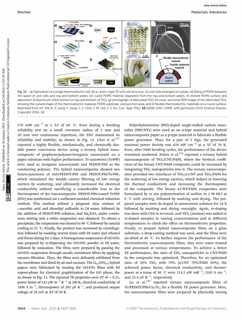
1944 | Mater. Adv., 2021, 2, 1927–1956 © 2021 The Author(s). Published by the Royal Society of Chemistry
570 mW cm�2 at a DT of 60 1C. Even during a bendingreliability test on a small curvature radius of 5 mm and20 mm over continuous repetition, the TEG maintained itsreliability and stability, as shown in Fig. 12. Choi et al.157
reported a highly flexible, mechanically, and chemically dur-able power conversion device using a ternary hybrid nano-composite of graphene/polymer/inorganic nanocrystal on apaper substrate with higher performance. Te nanowires (TeNW)were used as inorganic nanocrystals and PEDOT:PSS as theconducting polymer. The hybrid nanocomposite showed twohetero-junctions of rGO/PEDOT:PSS and PEDOT:PSS/TeNW,which stimulated the double carrier filtering of low energycarriers by scattering, and ultimately increased the electricalconductivity without sacrificing a considerable loss in thethermopower of the nanocomposite. PEDOT:PSS-coated TeNW(DTe) was synthesized via a surfactant-assisted chemical reductionmethod. This method utilized a prepared clear mixture ofL-ascorbic acid and dimethyl sulfoxide in DI water, followed bythe addition of PEDOT:PSS solution, and Na2TeO3 under contin-uous stirring unit a white suspension was obtained. To obtain aprecipitate, the suspension was heated to 90 1C followed by naturalcooling to 25 1C. Finally, the product was recovered by centrifuga-tion followed by washing several times with DI water and ethanoland freeze-drying for 2 days. A homogenous suspension of GO-DTewas prepared by re-dispersing the GO-DTe powder in DI water,followed by sonication. The films were prepared by passing theGO-DTe suspension through anodic membrane filters by applyingvacuum filtration. Then, the films were delicately exfoliated fromthe membrane and dried by air and vacuum. The G0.1DTe0.9 hybridpapers were fabricated by treating the GO-DTe films with HIvapour-phase for chemical graphitization of the GO phase, theas shown in Fig. 13. The reported TE properties were ZT of B0.21,power factor of 143 mW m�1 K�1 at 300 K, electrical conductivity of3496 S m�1, thermopower of 202 mV K�1, and produced outputvoltage of 58 mV at DT of 50 K.
Polyethyleneimine (PEI)-doped single-walled carbon nano-tubes (SWCNTs) were used as an n-type material and hybridnanocomposite paper as a p-type material to fabricate a flexiblepower generator. Thus, for a pair of 5 legs, the generatedmaximal power density was 650 nW cm�2 at a DT of 50 K.Even, after 1000 bending cycles, the performance of the deviceremained unaltered. Erden et al.158 reported a ternary hybridnanocomposite of TiO2/CNT/PANI, where the Seebeck coeffi-cient of the binary CNT/PANI composite could be increased byintegrating TiO2 nanoparticles into it. The ternary nanocompo-sites provided two interfaces of TiO2/a-CNT and TiO2/PANI forthe scattering of low energy carriers, which helped in loweringthe thermal conductivity and increasing the thermopowerof the composite. The binary a-CNT/PANI composites wereformulated by in situ polymerization of aniline in 1 M HCl at0 1C with stirring, followed by washing and drying. The pre-pared samples were de-doped in ammonium solution for 24 hfollowed by washing and drying overnight. Again, re-dopingwas done with CSA in m-cresol, and TiO2 (anatase) was added tore-doped samples in varying concentrations and at differenttemperatures to check the effect on thermoelectric properties.Finally, to prepare hybrid nanocomposite films on a glasssubstrate, a drop-casting method was used, and the films wereair-dried at 40 1C. To further improve the performance of thethermoelectric nanocomposite films, they were water treatedand processed at various temperatures. To achieve a betterTE performance, the ratio of TiO2 nanoparticles to CNT/PANIin the composite was optimized. Therefore, for an optimizedratio of 30% TiO2 with 70% (a-CNT 70%/PANI 30%), theachieved power factor, electrical conductivity, and thermo-power at a temp of 40 1C were 114.5 mW mK�2, 2183 S cm�1,and 22.9 mV K�1, respectively.
Lu et al.159 reported ternary nanocomposite films ofTe/PEDOT:PSS/Cu7Te4 for a flexible TE power generator. Here,the nanocomposite films were prepared by physically mixing
Fig. 12 (a) Fabrication of a single thermoelectric cell, (b) p- and n-type TE unit cell structure, (c) unit cells arranged on a plate, (d) filling of PDMS betweenthe space of unit cells and top and bottom plates, (e) cured PDMS material separated from the top and bottom plates, (f) etched PDMS surface anddeposition of aluminium interconnect on top and bottom of TEG, (g) photograph of fabricated TEG, (h) cross-sectional SEM image of the fabricated TEG,showing the curved shape of the thermoelectric material, PDMS substrate, and junction area; and (i) flexible thermoelectric materials on a round surface.Reprinted from ref. 156 (K. K. Jung, Y. Jung, C. J. Choi, J. M. Lee, J. S. Ko, Curr. Appl. Phys. 16 (2016) 1442–1448), with permission from Science Elsevier,Copyright 2016. (d).
Review Materials Advances
Ope
n A
cces
s A
rtic
le. P
ublis
hed
on 3
0 Ja
nuar
y 20
21. D
ownl
oade
d on
2/6
/202
2 11
:02:
18 A
M.
Thi
s ar
ticle
is li
cens
ed u
nder
a C
reat
ive
Com
mon
s A
ttrib
utio
n-N
onC
omm
erci
al 3
.0 U
npor
ted
Lic
ence
.View Article Online
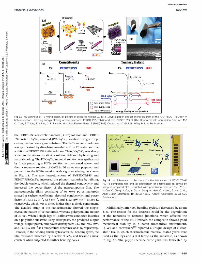
© 2021 The Author(s). Published by the Royal Society of Chemistry Mater. Adv., 2021, 2, 1927–1956 | 1945
the PEDOT:PSS-coated Te nanorod (PC-Te) solution and PEDOT:PSS-coated Cu7Te4 nanorod (PC-Cu7Te4) solution using a drop-casting method on a glass substrate. The Pc-Te nanorod solutionwas synthesized by dissolving ascorbic acid in DI water and theaddition of PEDOT:PSS to the solution. Then, Na2TeO3 was slowlyadded to the vigorously stirring solution followed by heating andnatural cooling. The PC-Cu7Te4 nanorod solution was synthesizedby firstly preparing a PC-Te solution as mentioned above, andthen a separate solution of CuCl in DI water was prepared andpoured into the PC-Te solution with vigorous stirring, as shownin Fig. 14. The two heterojunctions of Te/PEDOT:PSS andPEDOT:PSS/Cu7Te4 increased the phonon scattering by refiningthe double carriers, which reduced the thermal conductivity andincreased the power factor of the nanocomposite film. Thenanocomposite films consisting of 95 wt% PC-Te nanorodsshowed a Seebeck coefficient, electrical conductivity, and powerfactor of 163.5 mV K�1, 42 S cm�1, and 112.3 mW mK�2 at 380 K,respectively, which was 5 times higher than a single component.The detailed study of the nanocomposite showed the single-crystalline nature of Te nanorods, whereas polycrystalline natureof Cu7Te4. When 8 single legs of TE films were connected in serieson a polyimide substrate using silver paste, the produced outputvoltage, output power, and power density were 31.2 mV, 94.7 nW,and 39.5 mW cm�2 at a temperature difference of 39 K, respectively.However, in the bending reliability test after 350 bending cycles, thefilm resistance increased by a factor of 55% and became almostconstant when subjected to further bending cycles.
Additionally, after 500 bending cycles, S decreased by about21%. The reason for the decrease could be the degradationof the nanorods to nanorod junctions, which affected theperformance of the TE. However, the composite showed goodmechanical stability in a harsh mechanical environment.Q. Wu and co-workers160 reported a unique design of a wear-able TEG, in which thermoelectric material-coated yarns wereused as the legs and a 3-D fabric as the substrate, as shownin Fig. 15. The p-type thermoelectric yarn was fabricated by
Fig. 13 (a) Synthesis of TE hybrid paper, (b) picture of prepared flexible G0.1DTe0.9 hybrid paper, and (c) energy diagram of the rGO/PEDOT:PSS/TeNWheterojunctions showing energy filtering at two junctions: PEDOT:PSS/TeNW and rGO/PEDOT:PSS of DTe. Reprinted with permission from ref. 157(J. Choi, J. Y. Lee, S. S. Lee, C. R. Park, H. Kim, Adv. Energy Mater. 6 (2016) 1–8). Copyright (2016) John Wiley & Sons Publications.
Fig. 14 (a) Schematic of the steps for the fabrication of PC-Cu7Te4/PC-Te composite film and (b) photograph of a fabricated TE device byusing as-prepared film. Reprinted with permission from ref. 159 (Y. Lu,Y. Qiu, Q. Jiang, K. Cai, Y. Du, H. Song, M. Gao, C. Huang, J. He, D. Hu,Appl. Mater. Interfaces. 10 (2018) 42310–42319). Copyright (2018) ACSPublications.
Materials Advances Review
Ope
n A
cces
s A
rtic
le. P
ublis
hed
on 3
0 Ja
nuar
y 20
21. D
ownl
oade
d on
2/6
/202
2 11
:02:
18 A
M.
Thi
s ar
ticle
is li
cens
ed u
nder
a C
reat
ive
Com
mon
s A
ttrib
utio
n-N
onC
omm
erci
al 3
.0 U
npor
ted
Lic
ence
.View Article Online
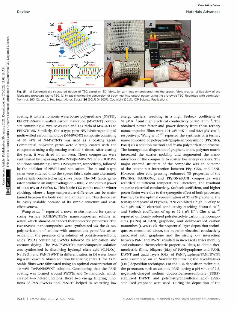
1946 | Mater. Adv., 2021, 2, 1927–1956 © 2021 The Author(s). Published by the Royal Society of Chemistry
coating it with a nonionic waterborne polyurethane (NWPU)/PEDOT:PSS/multi-walled carbon nanotube (MWCNT) compo-site containing 20 wt% MWCNTs and 1 : 4 ratio of MWCNTs toPEDOT:PSS. Similarly, the n-type yarn NWPU/nitrogen-dopedmulti-walled carbon nanotube (N-MWCNT) composite consistingof 30 wt% of N-MWCNTs was used as a coating agent.Commercial polyester yarns were directly coated with thecomposites using a dip-coating method 5 times. After coatingthe yarn, it was dried in an oven. These composites weresynthesized by dispersing MWCNTs/(N-MWCNT) in PEDOT:PSSsolutions containing 5 wt% DMSO/water, respectively, followedby the addition of NWPU and sonication. The p- and n-typeyarns were stitched onto the spacer fabric substrate alternatelyand serially connected using silver paste. The 3-D fabric gene-rator produced an output voltage of B800 mV and output powerof B2.6 nW at DT of 66 K. This fabric TEG can be used in winterclothing, where a large temperature difference can be main-tained between the body skin and ambient air. This device canbe easily scalable because of its simple structure and cost-effectiveness.
Wang et al.161 reported a novel in situ method for synthe-sizing ternary PANI/SWNT/Te nanocomposites soluble inwater, which showed enhanced thermoelectric properties. ThePANI/SWNT nanocomposites were synthesized via the in situpolymerization of aniline with ammonium persulfate as anoxidant in the presence of a solution of poly(styrenesulfonicacid) (PSSA) containing SWNTs followed by sonication andvacuum drying. The PANI/SWNT/Te nanocomposite solutionwas synthesized by dissolving hydroxyl citric acid (C6H8O8),Na2TeO3, and PANI/SWNT in different ratios in DI water form-ing a milky-white bluish solution by stirring at 90 1C for 15 h.Stable films were fabricated using an optimal concentration of10 wt% Te/PANI/SWNT solution. Considering that the PANIcoating was formed around SWNTs and Te nanorods, whichcreated two heterojunctions, these two energy filtering junc-tions of PANI/SWNTs and PANI/Te helped in scattering low
energy carriers, resulting in a high Seebeck coefficient of54 mV K�1 and high electrical conductivity of 345 S cm�1. Theobtained power factor and power density from these ternarynanocomposite films were 101 mW mK�2 and 62.4 mW cm�2,respectively. Wang et al.162 reported the synthesis of a ternarynanocomposite of polypyrrole/graphene/polyaniline (PPy/GNs/PANI) via a solution method and in situ polymerization process.The homogenous dispersion of graphene in the polymer matrixincreased the carrier mobility and augmented the nano-interfaces of the composite to scatter low energy carriers. Themajor ordered structure of the composite was an outcomeof the potent p–p interaction between PPy, GNs, and PANI.However, after cold pressing, enhanced TE properties of thePPy/GNs, PANI/GNs, and PPy/GNs/PANI composites wererecorded at different temperatures. Therefore, the resultantsuperior electrical conductivity, Seebeck coefficient, and higherpower factor were due to the synergetic effect of both processes.Further, for the optimal concentration of 32 wt% graphene, theternary composite of PPy/GNs/PANI exhibited a high PF of up to52.5 mW mK�2, electrical conductivity reaching 50000 S m�1,and Seebeck coefficient of up to 32.4 mV K�1. Cho et al.163
reported uniformly ordered polyelectrolyte carbon nanocompo-sites (PCNs) of PANI, graphene, and double-walled carbonnanotubes (DWNT) via the sequential layer deposition techni-que. As mentioned above, the superior electrical conductivityassociated with graphene and the strong p–p interactionbetween PANI and DWNT resulted in increased carrier mobilityand enhanced thermoelectric properties. Thus, to obtain ther-moelectric films, bilayers (BLs) of PANI/graphene and PANI/DWNT and quad layers (QLs) of PANI/graphene/PANI/DWNTwere assembled on an Si-wafer by utilizing the layer-by-layer(LBL) deposition technique. For the LBL deposition technique,the precursors such as cationic PANI having a pH value of 2.5,negatively-charged sodium dodecylbenzenesulfonate (SDBS)-stabilized DWNT, and poly(4-stryrenesulfonic acid) (PSS)-stabilized graphene were used. During the deposition of the
Fig. 15 (a) Systematically structured design of TEG based on 3D fabric, (b) yarn legs embroidered into the spacer fabric matrix, (c) flexibility of thefabricated prototype fabric TEG, (d) image showing the conversion of body heat into output power using the prototype TEG. Reprinted with permissionfrom ref. 160 (Q. Wu, J. Hu, Smart Mater. Struct. 26 (2017) 045037). Copyright (2017), IOP Science Publications.
Review Materials Advances
Ope
n A
cces
s A
rtic
le. P
ublis
hed
on 3
0 Ja
nuar
y 20
21. D
ownl
oade
d on
2/6
/202
2 11
:02:
18 A
M.
Thi
s ar
ticle
is li
cens
ed u
nder
a C
reat
ive
Com
mon
s A
ttrib
utio
n-N
onC
omm
erci
al 3
.0 U
npor
ted
Lic
ence
.View Article Online
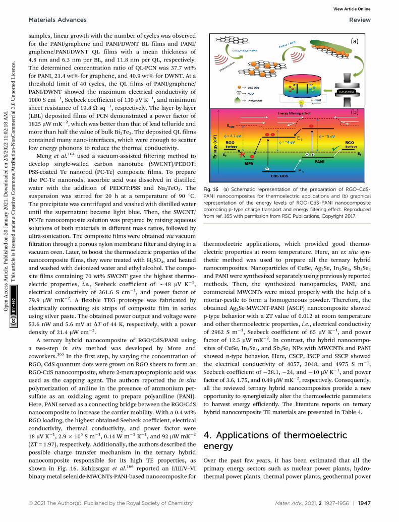
© 2021 The Author(s). Published by the Royal Society of Chemistry Mater. Adv., 2021, 2, 1927–1956 | 1947
samples, linear growth with the number of cycles was observedfor the PANI/graphene and PANI/DWNT BL films and PANI/graphene/PANI/DWNT QL films with a mean thickness of4.8 nm and 6.3 nm per BL, and 11.8 nm per QL, respectively.The determined concentration ratio of QL-PCN was 37.7 wt%for PANI, 21.4 wt% for graphene, and 40.9 wt% for DWNT. At athreshold limit of 40 cycles, the QL films of PANI/graphene/PANI/DWNT showed the maximum electrical conductivity of1080 S cm�1, Seebeck coefficient of 130 mV K�1, and minimumsheet resistance of 19.8 O sq�1, respectively. The layer-by-layer(LBL) deposited films of PCN demonstrated a power factor of1825 mW mK�2, which was better than that of lead telluride andmore than half the value of bulk Bi2Te3. The deposited QL filmscontained many nano-interfaces, which were enough to scatterlow energy phonons to reduce the thermal conductivity.
Meng et al.164 used a vacuum-assisted filtering method todevelop single-walled carbon nanotube (SWCNT)/PEDOT:PSS-coated Te nanorod (PC-Te) composite films. To preparethe PC-Te nanorods, ascorbic acid was dissolved in distilledwater with the addition of PEDOT:PSS and Na2TeO3. Thesuspension was stirred for 20 h at a temperature of 90 1C.The precipitate was centrifuged and washed with distilled wateruntil the supernatant became light blue. Then, the SWCNT/PC-Te nanocomposite solution was prepared by mixing aqueoussolutions of both materials in different mass ratios, followed byultra-sonication. The composite films were obtained via vacuumfiltration through a porous nylon membrane filter and drying in avacuum oven. Later, to boost the thermoelectric properties of thenanocomposite films, they were treated with H2SO4, and heatedand washed with deionized water and ethyl alcohol. The compo-site films containing 70 wt% SWCNT gave the highest thermo-electric properties, i.e., Seebeck coefficient of B48 mV K�1,electrical conductivity of 361.6 S cm�1, and power factor of79.9 mW mK�2. A flexible TEG prototype was fabricated byelectrically connecting six strips of composite film in seriesusing silver paste. The obtained power output and voltage were53.6 nW and 5.6 mV at DT of 44 K, respectively, with a powerdensity of 21.4 mW cm�2.
A ternary hybrid nanocomposite of RGO/CdS/PANI usinga two-step in situ method was developed by More andcoworkers.165 In the first step, by varying the concentration ofRGO, CdS quantum dots were grown on RGO sheets to form anRGO-CdS nanocomposite, where 2-mercaptopropionic acid wasused as the capping agent. The authors reported the in situpolymerization of aniline in the presence of ammonium per-sulfate as an oxidizing agent to prepare polyaniline (PANI).Here, PANI served as a connecting bridge between the RGO/CdSnanocomposite to increase the carrier mobility. With a 0.4 wt%RGO loading, the highest obtained Seebeck coefficient, electricalconductivity, thermal conductivity, and power factor were18 mV K�1, 2.9 � 105 S m�1, 0.14 W m�1 K�1, and 92 mW mK�2
(ZT = 1.97), respectively. Additionally, the authors described thepossible charge transfer mechanism in the ternary hybridnanocomposite responsible for its high TE properties, asshown in Fig. 16. Kshirsagar et al.166 reported an I/III/V–VIbinary metal selenide-MWCNTs-PANI-based nanocomposite for
thermoelectric applications, which provided good thermo-electric properties at room temperature. Here, an ex situ syn-thetic method was used to prepare all the ternary hybridnanocomposites. Nanoparticles of CuSe, Ag2Se, In2Se3, Sb2Se3
and PANI were synthesized separately using previously reportedmethods. Then, the synthesized nanoparticles, PANI, andcommercial MWCNTs were mixed properly with the help of amortar-pestle to form a homogeneous powder. Therefore, theobtained Ag2Se-MWCNT-PANI (ASCP) nanocomposite showedp-type behavior with a ZT value of 0.012 at room temperatureand other thermoelectric properties, i.e., electrical conductivityof 2962 S m�1, Seebeck coefficient of 65 mV K�1, and powerfactor of 12.5 mW mK�2. In contrast, the hybrid nanocompo-sites of CuSe, In2Se3, and Sb2Se3 NPs with MWCNTs and PANIshowed n-type behavior. Here, CSCP, ISCP and SSCP showedthe electrical conductivity of 4057, 3048, and 4975 S m�1,Seebeck coefficient of �28.1, �24, and �10 mV K�1, and powerfactor of 3.6, 1.75, and 0.49 mW mK�2, respectively. Consequently,all the reviewed ternary hybrid nanocomposites provide a newopportunity to synergistically alter the thermoelectric parametersto harvest energy efficiently. The literature reports on ternaryhybrid nanocomposite TE materials are presented in Table 4.
4. Applications of thermoelectricenergy
Over the past few years, it has been estimated that all theprimary energy sectors such as nuclear power plants, hydro-thermal power plants, thermal power plants, geothermal power
Fig. 16 (a) Schematic representation of the preparation of RGO-CdS-PANI nanocomposites for thermoelectric applications and (b) graphicalrepresentation of the energy levels of RGO-CdS-PANI nanocompositepromoting p-type charge transport and energy filtering effect. Reproducedfrom ref. 165 with permission from RSC Publications, Copyright 2017.
Materials Advances Review
Ope
n A
cces
s A
rtic
le. P
ublis
hed
on 3
0 Ja
nuar
y 20
21. D
ownl
oade
d on
2/6
/202
2 11
:02:
18 A
M.
Thi
s ar
ticle
is li
cens
ed u
nder
a C
reat
ive
Com
mon
s A
ttrib
utio
n-N
onC
omm
erci
al 3
.0 U
npor
ted
Lic
ence
.View Article Online
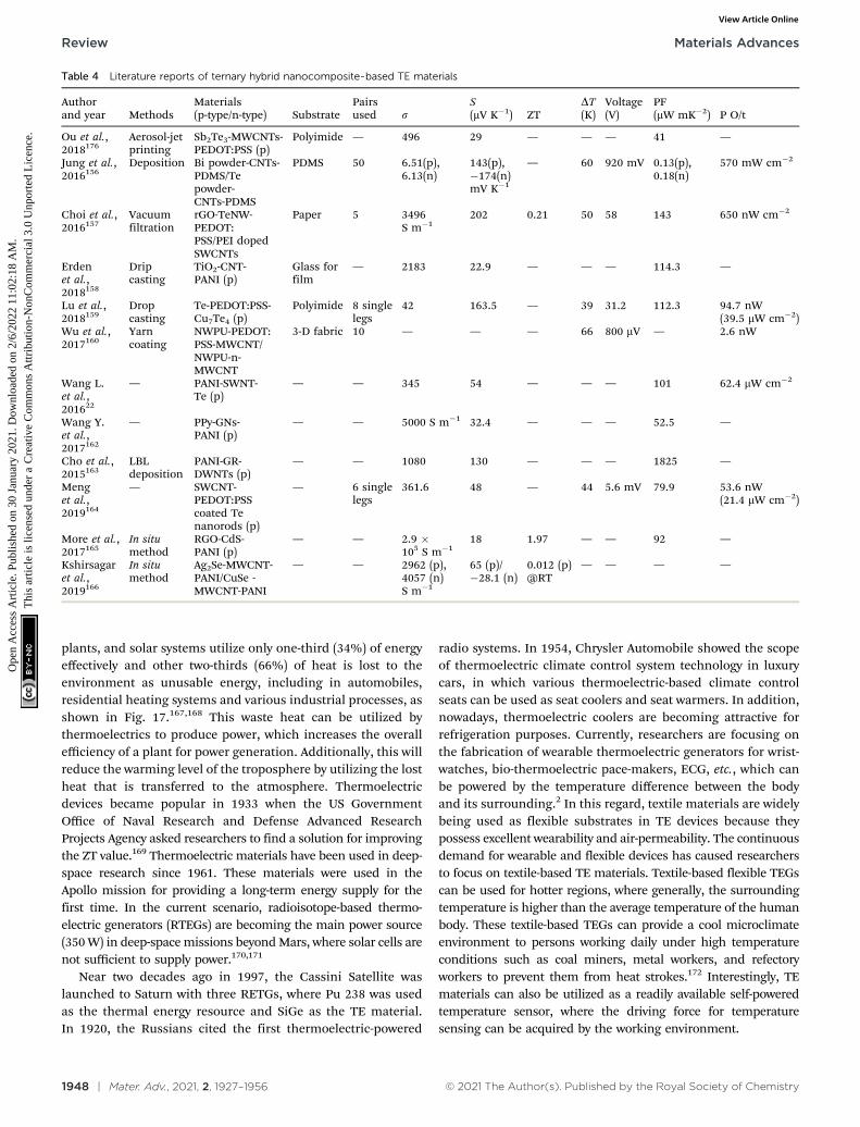
1948 | Mater. Adv., 2021, 2, 1927–1956 © 2021 The Author(s). Published by the Royal Society of Chemistry
plants, and solar systems utilize only one-third (34%) of energyeffectively and other two-thirds (66%) of heat is lost to theenvironment as unusable energy, including in automobiles,residential heating systems and various industrial processes, asshown in Fig. 17.167,168 This waste heat can be utilized bythermoelectrics to produce power, which increases the overallefficiency of a plant for power generation. Additionally, this willreduce the warming level of the troposphere by utilizing the lostheat that is transferred to the atmosphere. Thermoelectricdevices became popular in 1933 when the US GovernmentOffice of Naval Research and Defense Advanced ResearchProjects Agency asked researchers to find a solution for improvingthe ZT value.169 Thermoelectric materials have been used in deep-space research since 1961. These materials were used in theApollo mission for providing a long-term energy supply for thefirst time. In the current scenario, radioisotope-based thermo-electric generators (RTEGs) are becoming the main power source(350 W) in deep-space missions beyond Mars, where solar cells arenot sufficient to supply power.170,171
Near two decades ago in 1997, the Cassini Satellite waslaunched to Saturn with three RETGs, where Pu 238 was usedas the thermal energy resource and SiGe as the TE material.In 1920, the Russians cited the first thermoelectric-powered
radio systems. In 1954, Chrysler Automobile showed the scopeof thermoelectric climate control system technology in luxurycars, in which various thermoelectric-based climate controlseats can be used as seat coolers and seat warmers. In addition,nowadays, thermoelectric coolers are becoming attractive forrefrigeration purposes. Currently, researchers are focusing onthe fabrication of wearable thermoelectric generators for wrist-watches, bio-thermoelectric pace-makers, ECG, etc., which canbe powered by the temperature difference between the bodyand its surrounding.2 In this regard, textile materials are widelybeing used as flexible substrates in TE devices because theypossess excellent wearability and air-permeability. The continuousdemand for wearable and flexible devices has caused researchersto focus on textile-based TE materials. Textile-based flexible TEGscan be used for hotter regions, where generally, the surroundingtemperature is higher than the average temperature of the humanbody. These textile-based TEGs can provide a cool microclimateenvironment to persons working daily under high temperatureconditions such as coal miners, metal workers, and refectoryworkers to prevent them from heat strokes.172 Interestingly, TEmaterials can also be utilized as a readily available self-poweredtemperature sensor, where the driving force for temperaturesensing can be acquired by the working environment.
Table 4 Literature reports of ternary hybrid nanocomposite-based TE materials
Authorand year Methods
Materials(p-type/n-type) Substrate
Pairsused s
S(mV K�1) ZT
DT(K)
Voltage(V)
PF(mW mK�2) P O/t
Ou et al.,2018176
Aerosol-jetprinting
Sb2Te3-MWCNTs-PEDOT:PSS (p)
Polyimide — 496 29 — — — 41 —
Jung et al.,2016156
Deposition Bi powder-CNTs-PDMS/Tepowder-CNTs-PDMS
PDMS 50 6.51(p),6.13(n)
143(p),�174(n)mV K�1
— 60 920 mV 0.13(p),0.18(n)
570 mW cm�2
Choi et al.,2016157
Vacuumfiltration
rGO-TeNW-PEDOT:PSS/PEI dopedSWCNTs
Paper 5 3496S m�1
202 0.21 50 58 143 650 nW cm�2
Erdenet al.,2018158
Dripcasting
TiO2-CNT-PANI (p)
Glass forfilm
— 2183 22.9 — — — 114.3 —
Lu et al.,2018159
Dropcasting
Te-PEDOT:PSS-Cu7Te4 (p)
Polyimide 8 singlelegs
42 163.5 — 39 31.2 112.3 94.7 nW(39.5 mW cm�2)
Wu et al.,2017160
Yarncoating
NWPU-PEDOT:PSS-MWCNT/NWPU-n-MWCNT
3-D fabric 10 — — — 66 800 mV — 2.6 nW
Wang L.et al.,201622
— PANI-SWNT-Te (p)
— — 345 54 — — — 101 62.4 mW cm�2
Wang Y.et al.,2017162
— PPy-GNs-PANI (p)
— — 5000 S m�1 32.4 — — — 52.5 —
Cho et al.,2015163
LBLdeposition
PANI-GR-DWNTs (p)
— — 1080 130 — — — 1825 —
Menget al.,2019164
— SWCNT-PEDOT:PSScoated Tenanorods (p)
— 6 singlelegs
361.6 48 — 44 5.6 mV 79.9 53.6 nW(21.4 mW cm�2)
More et al.,2017165
In situmethod
RGO-CdS-PANI (p)
— — 2.9 �105 S m�1
18 1.97 — — 92 —
Kshirsagaret al.,2019166
In situmethod
Ag2Se-MWCNT-PANI/CuSe -MWCNT-PANI
— — 2962 (p),4057 (n)S m�1
65 (p)/�28.1 (n)
0.012 (p)@RT
— — — —
Review Materials Advances
Ope
n A
cces
s A
rtic
le. P
ublis
hed
on 3
0 Ja
nuar
y 20
21. D
ownl
oade
d on
2/6
/202
2 11
:02:
18 A
M.
Thi
s ar
ticle
is li
cens
ed u
nder
a C
reat
ive
Com
mon
s A
ttrib
utio
n-N
onC
omm
erci
al 3
.0 U
npor
ted
Lic
ence
.View Article Online
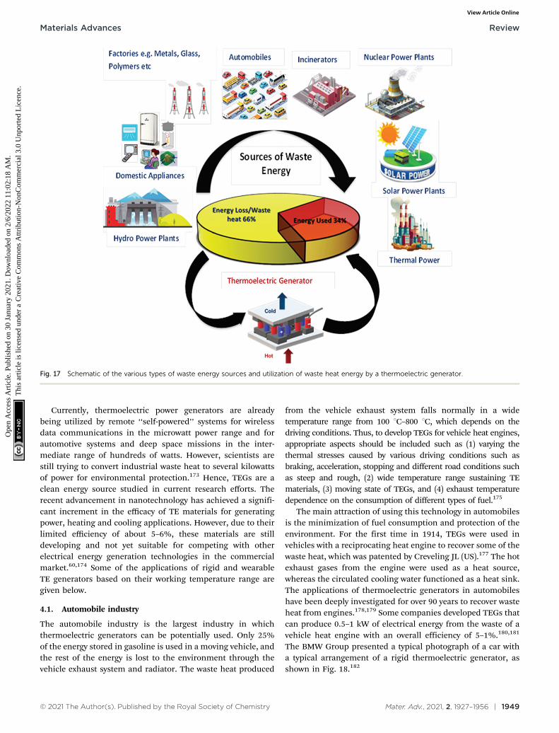
© 2021 The Author(s). Published by the Royal Society of Chemistry Mater. Adv., 2021, 2, 1927–1956 | 1949
Currently, thermoelectric power generators are alreadybeing utilized by remote ‘‘self-powered’’ systems for wirelessdata communications in the microwatt power range and forautomotive systems and deep space missions in the inter-mediate range of hundreds of watts. However, scientists arestill trying to convert industrial waste heat to several kilowattsof power for environmental protection.173 Hence, TEGs are aclean energy source studied in current research efforts. Therecent advancement in nanotechnology has achieved a signifi-cant increment in the efficacy of TE materials for generatingpower, heating and cooling applications. However, due to theirlimited efficiency of about 5–6%, these materials are stilldeveloping and not yet suitable for competing with otherelectrical energy generation technologies in the commercialmarket.60,174 Some of the applications of rigid and wearableTE generators based on their working temperature range aregiven below.
4.1. Automobile industry
The automobile industry is the largest industry in whichthermoelectric generators can be potentially used. Only 25%of the energy stored in gasoline is used in a moving vehicle, andthe rest of the energy is lost to the environment through thevehicle exhaust system and radiator. The waste heat produced
from the vehicle exhaust system falls normally in a widetemperature range from 100 1C–800 1C, which depends on thedriving conditions. Thus, to develop TEGs for vehicle heat engines,appropriate aspects should be included such as (1) varying thethermal stresses caused by various driving conditions such asbraking, acceleration, stopping and different road conditions suchas steep and rough, (2) wide temperature range sustaining TEmaterials, (3) moving state of TEGs, and (4) exhaust temperaturedependence on the consumption of different types of fuel.175
The main attraction of using this technology in automobilesis the minimization of fuel consumption and protection of theenvironment. For the first time in 1914, TEGs were used invehicles with a reciprocating heat engine to recover some of thewaste heat, which was patented by Creveling JL (US).177 The hotexhaust gases from the engine were used as a heat source,whereas the circulated cooling water functioned as a heat sink.The applications of thermoelectric generators in automobileshave been deeply investigated for over 90 years to recover wasteheat from engines.178,179 Some companies developed TEGs thatcan produce 0.5–1 kW of electrical energy from the waste of avehicle heat engine with an overall efficiency of 5–1%.180,181
The BMW Group presented a typical photograph of a car witha typical arrangement of a rigid thermoelectric generator, asshown in Fig. 18.182
Fig. 17 Schematic of the various types of waste energy sources and utilization of waste heat energy by a thermoelectric generator.
Materials Advances Review
Ope
n A
cces
s A
rtic
le. P
ublis
hed
on 3
0 Ja
nuar
y 20
21. D
ownl
oade
d on
2/6
/202
2 11
:02:
18 A
M.
Thi
s ar
ticle
is li
cens
ed u
nder
a C
reat
ive
Com
mon
s A
ttrib
utio
n-N
onC
omm
erci
al 3
.0 U
npor
ted
Lic
ence
.View Article Online
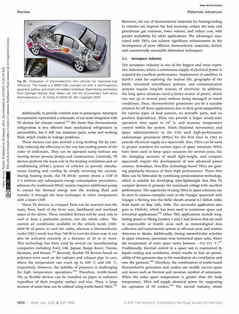
1950 | Mater. Adv., 2021, 2, 1927–1956 © 2021 The Author(s). Published by the Royal Society of Chemistry
Additionally, to provide comfort zone to passengers, AmerigonIncorporated represented a schematic of car seats integrated withTE devices for climate control.183 We know that thermoelectricrefrigeration is less efficient than mechanical refrigeration inautomobiles, but it still can maintain parts, noise and workingfluid, which results in leakage problems.
These devices can also provide a long working life by care-fully reducing the efficiency to the very low cooling power of theorder of milli-watts. They can be operated easily without anymoving device process design and construction. Currently, TEdevices perform the main role in the heating ventilation and airconditioning (HVAC) system of vehicles to provide simulta-neous heating and cooling by simply reversing the current.During heating mode, the TE HVAC system shows a COP of2–3 without any subsequent energy consumption procedures,whereas the traditional HVAC system requires additional pumpto extract the thermal energy into the working fluid andtransfer it through the heat exchanger to other componentswith a lower COP.
These TE devices in compact form can be inserted into theseats, floor, back of the front seat, dashboard and overheadspace of the driver. These installed devices will be used only tocool or heat a particular person, not the whole cabin. Thecurrent air conditioner available in the vehicle needs 3500–4000 W of power to cool the cabin, whereas a thermoelectriccooler (TEC) needs less than 700 W to cool the driver seat. It canalso be activated remotely at a distance of 50 m or more.This technology has been used by several car manufacturingcompanies including Ford, GM, Jaguar, Range Rover, Toyota,Hyundai, and Nissan.183 Recently, flexible TE devices based onpolymers were used on the radiator and exhaust pipe in cars,where the temperature can reach up to 500 1C and 100 1C,respectively. However, the stability of polymers is challengingfor high temperature operations.184 Therefore, textile-basedTEs as flexible devices can be installed on pipes or radiatorsregardless of their irregular surface and size. Thus, a largeamount of waste heat can be utilized using textile-based TEGs.185
Moreover, the use of thermoelectric materials for heating/coolingin vehicles can improve the fuel economy, reduce the toxic andgreenhouse gas emission, lower volume, and reduce cost, withgreater availability for other applications. The advantages asso-ciated with TEGs can achieve significant enhancement in thedevelopment of more efficient thermoelectric materials, devicesand commercially executable fabrication techniques.
4.2. Aerospace industry
The aerospace industry is one of the biggest and most expen-sive industries, where a continuous supply of electrical power isrequired for excellent performance. Deployment of satellites inEarth’s orbit for exploring the marine life, geography of theEarth, terrestrial surveillance systems, and communicationsystems require long-life sources of electricity. In addition,the long space missions need a better source of power, whichcan run up to several years without being damaged in harshconditions. Thus, thermoelectric generators can be a suitablesolution for all these applications due to their good adaptabilityfor various types of heat sources, no movable parts, and noposition dependency. TEGs can provide a larger steady-stateoperation time equal to 105 h, and accurate temperaturecontrol within the system. NASA (National Aeronautics andSpace Administration) in the USA used high-performanceradioisotope generators (RTGs) for the first time in 1961 toprovide electrical supply to a spacecraft. Also, TEGs can be usedin greater numbers for various types of space missions. RTGshave been used in deep space missions for several years, butthe changing scenario of small light-weight, and compactspacecraft require the development of new advanced powersources. Nowadays, thin-film technology-based TEGs are gain-ing popularity because of their high performance. These thinfilms can be fabricated by combining semiconductor technology,which is suitable for developing ultra-lightweight thin film TEcompact devices to generate the maximum voltage with excellentperformance. The superiority of using TEGs in space missions canbe seen in various examples such as the Voyager spacecraft withVoyager 1 fleeting into the Helio sheath around 8.3 billion milesfrom Earth on May 24th, 2006. The successful application alsogoes to TAGS-85, which has been used in numerous space andterrestrial applications.186 Other TEG applications include long-lasting power to Viking Landers 1 and 2 and devices that are usedin inaccessible or hostile areas such as meteorological datacollection and transmission system in off-coast areas and seismicdetectors in Alaska. Additionally, during extravehicular activitiesin space missions, astronauts wear hermetical space suits, wherethe temperature of outer space varies between �233–212 1C.187
Traditionally, thermal control in a space suit is maintained byliquid cooling and ventilation, which results in bad air perme-ability of the garments due to the installation of a ventilation unitover the garment.188 Therefore, the combination of textile-basedthermoelectric generators and coolers can modify current spacesuit issues such as thermal and moisture comfort of astronauts.When the outer space temperature is greater than the bodytemperature, TEGs will supply electrical power for supportingthe operation of TE coolers.189 The aircraft industry, which
Fig. 18 Integration of thermoelectrics into vehicles for improved fuelefficiency. The image is a BMW 530i concept car with a thermoelectricgenerator (yellow; and inset) and radiator (red/blue). Reprinted by permissionfrom (Springer Nature), (Nat. Mater.) ref. 182 (An inconvenient truth aboutthermoelectrics, C. B. Vining, 8 (2009) 83–85), Copyright 2009.
Review Materials Advances
Ope
n A
cces
s A
rtic
le. P
ublis
hed
on 3
0 Ja
nuar
y 20
21. D
ownl
oade
d on
2/6
/202
2 11
:02:
18 A
M.
Thi
s ar
ticle
is li
cens
ed u
nder
a C
reat
ive
Com
mon
s A
ttrib
utio
n-N
onC
omm
erci
al 3
.0 U
npor
ted
Lic
ence
.View Article Online
© 2021 The Author(s). Published by the Royal Society of Chemistry Mater. Adv., 2021, 2, 1927–1956 | 1951
includes both commercial and military aircrafts, can use thermo-electric devices to capture waste heat produced from the engineand supply the generated electric power to the whole aircraftsystem without affecting the engine performance. This will cutdown fuel consumption and ultimately reduce the cost to passen-gers and cargo airlines.190
4.3. Electronic devices
Considering the shorter service life of portable batteries, thescientific community is keen to develop low-cost solutions ofportable power generators for autonomous energy and wear-able biometric monitoring sensors, which can extract energyfrom different waste heat resources and convert it to usefulelectricity. Hence, the technological transformation of theseadvanced microsystems onto flexible substrates can lead to lowcost, unobtrusive, and wearable omnipresent integrateddevices for monitoring health and biometric parameters.191
Many electronic devices such as power amplifiers and micro-processors are operated at high temperatures, which affect theperformance, reliability, and lifetime of the device. Thus, toovercome these issues, thermoelectric coolers (TEC) can beutilized as cooling media to eliminate the generated excessheat during the process. Conventional cooling devices are notfeasible here due to the requirement of a large cooling area.TECs can couple with the surface of electronic devices toprovide effective local cooling. TECs do not make any noisebecause they have no moving parts. Min et al.192 showed anelectronic component of infrared arrays integrated with ther-moelectric micro-coolers to lower the thermal noise and cur-rent leakage produced from an electronic device. Bale et al.193
showed the cooling of CdZnTe detector between temperaturesof�30 to�40 1C, which is used in X-ray astronomy. The coolingof the detector can minimize the current leakage and permitthe usage of a pulsed reset preamplifier and long pulse shapingtimes, which significantly enhance the energy solution. For thissmall application, only 3 W of electrical power was used.Thermoelectric coolers/generators can also be used in conjuga-tion with solar photovoltaics (PV) to cool or generate electricalpower from them, respectively. To obtain the maximum per-formance from solar PV and to reduce the cost of the panel,thermoelectric coolers should be used to cool the solar PVrather than recovering heat through a thermoelectricgenerator.194 In addition, several attempts were made to attachPeltier modules in residential doors and windows to generatewarmer air inside homes in colder regions, although the heatsupply was not enough to keep the residential space warm.Presently, e-textiles based on the conducting polymer PEDOT:PSS are getting popular among wearable TEGs. A fabricated 3-Dtextile as an out—of-plane TE device generated a power outputof 1.2 mW at a DT of 65 K, which can be used in biomedicaldevices.195
4.4. Biomedical industry
In the medical industry, refrigeration of medicine, bloodserum, vaccines, and other biological products is necessary toprevent degradation. The properties of these products will only
be stabilized in a certain temperature range for excellentresults. Here, thermoelectric coolers can be used as a micro-processor-based controlled portable-type medical cooling kitfor protecting medical products during storage conditions andfreightage, which require 12 V and 4 A DC for a smoothoperation.196 In remote areas of developing countries, the on-site medical services can be provided with sufficient medicinesby these TE refrigerators. In addition, doctors can deal withemergency issues by getting the right vaccines on time. TErefrigerators can also work in the food industry where foodproducts need a certain temperature during transportation andstorage to preserve their shelf life. Flexible or wearable types ofthermoelectric generators (TEGs) can be used in medicaldevices to provide real-time monitoring of patient health. Thesewearable devices can be easily wrapped and bent onto thecurved skin surface to utilize a large amount of body heat asan energy source. By using a large surface area TEG, the contactbetween the TEG and skin surface can be enhanced to producemore power. This increased surface area of TEGs can extinguishthe necessity of a boost converter. Several small lightweightTEG-based medical sensors with wireless communication canbe attached to a patient’s body to form a wireless body areanetwork (WBAN), which can provide remote health careservices.197,198 These devices can perform health monitoringactivities such as EEG, ECG, blood pressure,85 respirationrate,199 heart rate, pulse oximetry,200,201 body temperature,and sleep period (actigraphy)202 at different locations on thewearer’s body.203 The data collected by medical sensors can betransmitted through various short-range wireless communica-tion protocols such as ANT, Bluetooth, and Zigbee, andcollected on a personal server such as a cell phone. Then,health service providers can collect this data from the internetto provide real-time health monitoring. Therefore, integrationof short-range wireless communication technology with TEG-based medical sensors can provide efficient and ultra-lowpower consumption devices. Dementyev et al. reported a Blue-tooth low energy (BLE) wireless technique that requires only35 mW at 3.3 V supply in 120 s transmission intervals.204
Recently, Rose et al.205 developed a band-type wearable sensorfor sensing heat stress and hydration through the electrolytespresent in the wearer’s sweat by using battery-free passive radiofrequency identification (RFID) and paper microfluidic technol-ogy. Further, the technological advancement in integratedcircuits, wireless communications, and medical sensors hasenabled the fabrication of miniaturized, light-weight, ultra-lowpowering, and wearable health monitoring devices.
5. Conclusion and future scope
It is understood that the traditional inorganic TE materialsdeliver high output but possesses poor processability, highcost, and severe toxicity. In comparison, organic-based TEmaterials such as conducting polymers can be advantageousin terms of low-cost, environmentally friendly nature, andlow intrinsic thermal conductivity. However, the reported TE
Materials Advances Review
Ope
n A
cces
s A
rtic
le. P
ublis
hed
on 3
0 Ja
nuar
y 20
21. D
ownl
oade
d on
2/6
/202
2 11
:02:
18 A
M.
Thi
s ar
ticle
is li
cens
ed u
nder
a C
reat
ive
Com
mon
s A
ttrib
utio
n-N
onC
omm
erci
al 3
.0 U
npor
ted
Lic
ence
.View Article Online

1952 | Mater. Adv., 2021, 2, 1927–1956 © 2021 The Author(s). Published by the Royal Society of Chemistry
performances of organic TE materials are relatively low, andthus, researchers have combined them with other semiconductingmaterials to develop better performing hybrid nanocomposites.These hybrid nanocomposites showed drastic improvementsin Seebeck coefficient, power factor, and ZT values owing tothe resultant ‘‘band engineering’’ and energy filtering effect.The formation of extra heterojunctions within the hybrid TEmaterials leads to scattering of low energy charge carriers infavoured directions to give an energy filtering effect. Thealignment of energy levels of these component materials mayresult in the selective transfer of charges, delivering either p- orn-type behaviour for the entire hybrid nanocomposite. The use ofternary systems allows researchers to overcome the disadvantagesof single components to achieve better TE performances. However,for practical applications, the development of outstanding TEperforming materials is a persisting challenge as better controlof charge carrier in these composites remains elusive. The use ofcommon conducting polymers limits the high-temperature TEapplications of these hybrid nanocomposites as the thermalstability of conducting polymers is limited. Additionally, the costof graphene CNTs and other semiconductor nanoparticles stillremains relatively high, creating another issue in their technolo-gical transfer. Thus, effective synthetic methods are needed todevelop hybrid nanocomposites with controlled structures andrefined heterojunctions for better TE efficiency. In terms ofthermoelectric devices, their performances can be enhanced invarious ways as follows:
1. Improving the properties of thermoelectric materialsby computational screening. Here, the synthesis of nanoscalematerials, doping of inorganic/organic materials, and formation ofhybrid composites are very promising routes to improve the TEconversion efficiency.
2. Thermal matching of materials, the effect of heat transferlaw, the temperature dependency of the material properties,and the greater temperature difference between the two sides ofthe TE device are possible routes for improvement.
3. Geometrical design including leg length, the thickness ofthe generator, and the size of hot and cold side substrate has astrong impact on the efficiency of TEGs. Contact quality andresistance also become important parameters for improvement.
4. Fixing the working temperature range for TE materials byenforcing potential heat dissipaters on the cold side.
5. Design optimization of device structure through compu-ter simulations, including the arrangement of the TE elementsand device to amend the improved packaging technologyfor TEGs.
Conflicts of interest
The authors declare no conflict of interest.
Acknowledgements
The authors thank the Vice-Chancellor, Defence Institute ofAdvanced Technology (DIAT), Girinagar, Pune for encouragement.
PKK thanks DMSRDE (DRDO) Kanpur and DIAT, Pune India for thesupport. Neha thanks Priyanka for fruitful discussion.
Notes and references
1 S. Patidar, International Journal for Research in AppliedScience & Engineering Technology, 2018, 6, 1992–1996,DOI: 10.22214/ijraset.2018.5325.
2 J. T. Jarman, E. E. Khalil and E. Khalaf, Open Journal ofEnergy Efficiency, 2013, 2, 143–153.
3 R. Ahiska and H. Mamur, Int. J. Renewable Energy Res.,2014, 4, 128–136.
4 X. Qiu, Western Reverse University, Cleveland, 2008.5 D. E. Demirocak, Middle East Technical University,
Ankara, 2008.6 Y. Gelbstein, Thermoelectric Energy Conversion: Basic
Concepts and Device Applications, 2017, vol. 1, pp. 1–13.7 G. J. Snyder and E. S. Toberer, Nat. Mater., 2008, 7, 105–114.8 ed. D. M. Rowe, Thermoelectrics Handbook, CRC Press,
2018.9 C. B. Vining, W. Laskow, J. O. Hanson, R. R. Van der Beck
and P. D. Gorsuch, J. Appl. Phys., 1991, 69, 4333–4340.10 S. R. Brown, S. M. Kauzlarich, F. Gascoin and G. J. Snyder,
Chem. Mater., 2006, 18, 1873–1877.11 N. V. Nong and L. T. Hung, Thermoelectric Energy Conversion,
Basic Concepts and Device Applications, 2017, vol. 1, pp. 15–35.12 R. Venkatasubramanian, E. Siivola, T. Colpitts, K. The,
G. Kanatzidis, T. Zt and B. Vining, Nature, 2001, 413,597–602.
13 Y. Ma, G. Chen, M. S. Dresselhaus, B. Poudel, B. Yu,D. Vashaee, D. Wang, X. Yan, Z. Ren, A. Minnich,A. Muto, X. Chen, J. Liu, Q. Hao and Y. Lan, Science,2008, 320, 634–638.
14 T. C. Harman, M. P. Walsh, B. E. Laforge and G. W. Turner,J. Electron. Mater., 2005, 34, L19–L22.
15 Y. Pei, X. Shi, A. Lalonde, H. Wang, L. Chen andG. J. Snyder, Nature, 2011, 473, 66–69.
16 R. Amatya and R. J. Ram, J. Electron. Mater., 2012, 41,1011–1019.
17 G. J. Snyder, Int. Conf. Thermoelectr. ICT, Proc., 2008,2002-Janua, 424–426.
18 Y. Du, J. Xu, B. Paul and P. Eklund, Appl. Mater. Today,2018, 12, 366–388.
19 J. Yang, H. L. Yip and A. K. Y. Jen, Adv. Energy Mater., 2013,3, 549–565.
20 J. Choi, Y. Jung, S. J. Yang, J. Y. Oh, J. Oh, K. Jo, J. G. Son,S. E. Moon, C. R. Park and H. Kim, ACS Nano, 2017, 11,7608–7614.
21 M. S. Dresselhaus, G. Chen, M. Y. Tang, R. Yang, H. Lee,D. Wang, Z. Ren, J. P. Fleurial and P. Gogna, Adv. Mater.,2007, 19, 1043–1053.
22 L. Wang, Y. Liu, Z. Zhang, B. Wang, J. Qiu, D. Hui andS. Wang, Composites, Part B, 2017, 122, 145–155.
23 G.-H. Kim, L. Shao, K. Zhang and K. P. Pipe, Nat. Mater.,2013, 12, 719–723.
Review Materials Advances
Ope
n A
cces
s A
rtic
le. P
ublis
hed
on 3
0 Ja
nuar
y 20
21. D
ownl
oade
d on
2/6
/202
2 11
:02:
18 A
M.
Thi
s ar
ticle
is li
cens
ed u
nder
a C
reat
ive
Com
mon
s A
ttrib
utio
n-N
onC
omm
erci
al 3
.0 U
npor
ted
Lic
ence
.View Article Online
© 2021 The Author(s). Published by the Royal Society of Chemistry Mater. Adv., 2021, 2, 1927–1956 | 1953
24 C. Ou, A. L. Sangle, T. Chalklen, Q. Jing, V. Narayan andS. Kar-Narayan, APL Mater., 2018, 6, 096101.
25 C. Ou, A. L. Sangle, A. Datta, Q. Jing, T. Busolo,T. Chalklen, V. Narayan and S. Kar-Narayan, ACS Appl.Mater. Interfaces, 2018, 10, 19580–19587.
26 O. Bubnova and X. Crispin, Energy Environ. Sci., 2012, 5,9345–9362.
27 Q. Wei, M. Mukaida, K. Kirihara, Y. Naitoh and T. Ishida,RSC Adv., 2014, 4, 28802–28806.
28 S. J. Kim, J. H. We and B. J. Cho, Energy Environ. Sci., 2014,7, 1959–1965.
29 O. Bubnova, Z. U. Khan, A. Malti, S. Braun, M. Fahlman,M. Berggren and X. Crispin, Nat. Mater., 2011, 10, 429–433.
30 Z. Lu, M. Layani, X. Zhao, L. P. Tan, T. Sun, S. Fan, Q. Yan,S. Magdassi and H. H. Hng, Small, 2014, 10, 3551–3554.
31 G. H. Kim, L. Shao, K. Zhang and K. P. Pipe, Nat. Mater.,2013, 12, 719–723.
32 E. Destouesse, M. Top, J. Lamminaho, H.-G. Rubahn,J. Fahlteich and M. Madsen, Flexible Printed Electron.,2019, 4, 045004.
33 E. Yvenou, M. Sandroni, A. Carella, M. N. Gueye, J. Faure-Vincent, S. Pouget, R. Demadrille and J. P. Simonato,Mater. Chem. Front., 2020, 4, 2054–2063.
34 A. Chen, D. Madan, P. K. Wright and J. W. Evans,J. Micromech. Microeng., 2011, 21, 104006, DOI: 10.1088/0960-1317/21/10/104006.
35 Y. Nogami, H. Kaneko, T. Ishiguro, A. Takahashi,J. Tsukamoto and N. Hosoito, Solid State Commun., 1990,76, 583–586.
36 Q. Wang, Q. Yao, J. Chang and L. Chen, J. Mater. Chem.,2012, 22, 17612.
37 N. Nandihalli, C.-J. Liu and T. Mori, Nano Energy, 2020,78, 105186.
38 C.-T. Hsu, D.-J. Yao, K.-J. Ye and B. Yu, J. RenewableSustainable Energy, 2010, 2, 013105.
39 W. Glatz and C. Hierold, IEEE 20th International Conferenceon Micro Electro Mechanical Systems (MEMS), Hyogo, Japan,2007, pp. 89–92, DOI: 10.1109/MEMSYS.2007.4433021.
40 Z. Fan, Y. Zhang, L. Pan, J. Ouyang and Q. Zhang, Renew-able Sustainable Energy Rev., 2020, 110448.
41 A. Nozariasbmarz, H. Collins, K. Dsouza, M. H. Polash,M. Hosseini, M. Hyland, J. Liu, A. Malhotra, F. M. Ortiz,F. Mohaddes, V. P. Ramesh, Y. Sargolzaeiaval, N. Snouwaert,M. C. Ozturk and D. Vashaee, Appl. Energy, 2020, 258, 114069.
42 J.-H. Bahk, H. Fang, K. Yazawa and A. Shakouri, J. Mater.Chem. C, 2015, 3, 10362–10374.
43 M. T. Dunham, M. T. Barako, S. LeBlanc, M. Asheghi,B. Chen and K. E. Goodson, Energy, 2015, 93, 2006–2017.
44 F. Suarez, A. Nozariasbmarz, D. Vashaee and M. C. Ozturk,Energy Environ. Sci., 2016, 9, 2099–2113.
45 A. Z. Sahin and B. S. Yilbas, Energy Convers. Manage., 2013,65, 26–32.
46 K. Yazawa and A. Shakouri, Environ. Sci. Technol., 2011, 45,7548–7553.
47 M. Hyland, H. Hunter, J. Liu, E. Veety and D. Vashaee,Appl. Energy, 2016, 182, 518–524.
48 D. K. Aswal, R. Basu and A. Singh, Energy Convers. Manage.,2016, 114, 50–67.
49 W. Glatz, S. Muntwyler and C. Hierold, Sens. Actuators, A,2006, 132, 337–345.
50 W. Glatz, E. Schwyter, L. Durrer and C. Hierold,J. Microelectromech. Syst., 2009, 18, 763–772.
51 G. Liang, J. Zhou and X. Huang, Appl. Energy, 2011, 88,5193–5199.
52 V. Leonov and R. J. M. Vullers, J. Renewable SustainableEnergy, 2009, 1, 062701.
53 V. Leonov, J. Micromech. Microeng., 2011, 21, 125013.54 V. Leonov and R. J. M. Vullers, J. Electron. Mater., 2009, 38,
1491–1498.55 K. Purohit, Int. J. Innov. Res. Eng. Manag., 2016, 3, 259–263.56 S. K. Yee, S. LeBlanc, K. E. Goodson and C. Dames, Energy
Environ. Sci., 2013, 6, 2561–2571.57 M. Lossec, B. Multon, H. Ben Ahmed and C. Goupil, Eur.
Phys. J. Appl. Phys., 2010, 52, 11103.58 L. Francioso, C. De Pascali, I. Farella, C. Martucci, P. Cretı,
P. Siciliano and A. Perrone, J. Power Sources, 2011, 196,3239–3243.
59 Y.-G. Deng and J. Liu, J. Renewable Sustainable Energy,2009, 1, 052701.
60 S. A. K., Solar energy engineering processes and systems,2009.
61 Y. Wu, S. W. Finefrock and H. Yang, Nano Energy, 2012, 1,651–653.
62 S. Twaha, J. Zhu, Y. Yan and B. Li, Renewable SustainableEnergy Rev., 2016, 65, 698–726.
63 H. J. Goldsmid and R. W. Douglas, Br. J. Appl. Phys., 1954,5, 386–390.
64 Z. Tian, S. Lee and G. Chen, J. Heat Transfer, 2013,135, 061605.
65 A. F. Ioffe, Physics of Semiconductors, Academic, 1960,pp. 282–282.
66 A. Bulusu and D. G. Walker, Superlattices Microstruct.,2008, 44, 1–36.
67 S. Fan, J. Zhao, J. Guo, Q. Yan, J. Ma and H. H. Hng, Appl.Phys. Lett., 2010, 96, 182104.
68 W. Xie, X. Tang, Y. Yan, Q. Zhang and T. M. Tritt, Appl.Phys. Lett., 2009, 94, 102111.
69 W. Xie, J. He, H. J. Kang, X. Tang, S. Zhu, M. Laver,S. Wang, J. R. D. Copley, C. M. Brown, Q. Zhang andT. M. Tritt, Nano Lett., 2010, 10, 3283–3289.
70 K. T. Kim and G. H. Ha, J. Nanomater., 2013, 2013, 821657,DOI: 10.1155/2013/821657.
71 X. Yan, B. Poudel, Y. Ma, W. S. Liu, G. Joshi, H. Wang,Y. Lan, D. Wang, G. Chen and Z. F. Ren, Nano Lett., 2010,10, 3373–3378.
72 Y. Q. Cao, X. B. Zhao, T. J. Zhu, X. B. Zhang and J. P. Tu,Appl. Phys. Lett., 2008, 92, 143106.
73 Z. Cao, E. Koukharenko, R. N. Torah, J. Tudor andS. P. Beeby, J. Phys. Conf. Ser., 2014, 557, 6–11.
74 M. K. Kim, M. S. Kim, S. Lee, C. Kim and Y. J. Kim, SmartMater. Struct., 2014, 23, 105002, DOI: 10.1088/0964-1726/23/10/105002.
Materials Advances Review
Ope
n A
cces
s A
rtic
le. P
ublis
hed
on 3
0 Ja
nuar
y 20
21. D
ownl
oade
d on
2/6
/202
2 11
:02:
18 A
M.
Thi
s ar
ticle
is li
cens
ed u
nder
a C
reat
ive
Com
mon
s A
ttrib
utio
n-N
onC
omm
erci
al 3
.0 U
npor
ted
Lic
ence
.View Article Online

1954 | Mater. Adv., 2021, 2, 1927–1956 © 2021 The Author(s). Published by the Royal Society of Chemistry
75 D. Madan, A. Chen, P. K. Wright and J. W. Evans,J. Electron. Mater., 2012, 41, 1481–1486.
76 T. Nishino and T. Suzuki, J. Micromech. Microeng., 2017, 27, 1–8.77 S. Shin, R. Kumar, J. W. Roh, D. S. Ko, H. S. Kim, S. Il Kim,
L. Yin, S. M. Schlossberg, S. Cui, J. M. You, S. Kwon,J. Zheng, J. Wang and R. Chen, Sci. Rep., 2017, 7, 1–9.
78 F. Suarez, D. P. Parekh, C. Ladd, D. Vashaee, M. D. Dickeyand M. C. Ozturk, Appl. Energy, 2017, 202, 736–745.
79 P. Sundarraj, D. Maity, S. S. Roy and R. A. Taylor, RSC Adv.,2014, 4, 46860–46874.
80 T. M. Tritt and M. A. Subramanian, MRS Bull., 2006, 31,188–198.
81 Z. H. Dughaish, Phys. B, 2002, 322, 205–223.82 H. J. Goldsmid, Introduction to Thermoelectricity, Springer
Berlin Heidelberg, Berlin, Heidelberg, 2010, vol. 121.83 G. Chen, M. S. Dresselhaus, G. Dresselhaus, J.-P. Fleurial
and T. Caillat, Int. Mater. Rev., 2003, 48, 45–66.84 K. Biswas, J. He, I. D. Blum, C.-I. Wu, T. P. Hogan,
D. N. Seidman, V. P. Dravid and M. G. Kanatzidis, Nature,2012, 489, 414–418.
85 K. F. Hsu, S. Loo, F. Guo, W. Chen, J. S. Dyck, C. Uher,T. Hogan, E. K. Polychroniadis and M. G. Kanatzidis,Science, 2004, 303, 818–821.
86 B. A. Cook, M. J. Kramer, J. L. Harringa, M.-K. Han,D.-Y. Chung and M. G. Kanatzidis, Adv. Funct. Mater.,2009, 19, 1254–1259.
87 D. L. Medlin and G. J. Snyder, Curr. Opin. Colloid InterfaceSci., 2009, 14, 226–235.
88 J. Androulakis, C.-H. Lin, H.-J. Kong, C. Uher, C.-I. Wu,T. Hogan, B. A. Cook, T. Caillat, K. M. Paraskevopoulos andM. G. Kanatzidis, J. Am. Chem. Soc., 2007, 129, 9780–9788.
89 J. Androulakis, K. F. Hsu, R. Pcionek, H. Kong, C. Uher,J. J. D’Angelo, A. Downey, T. Hogan and M. G. Kanatzidis,Adv. Mater., 2006, 18, 1170–1173.
90 P. F. P. Poudeu, J. D’Angelo, A. D. Downey, J. L. Short,T. P. Hogan and M. G. Kanatzidis, Angew. Chem., Int. Ed.,2006, 118, 3919–3923.
91 S. N. Girard, J. He, X. Zhou, D. Shoemaker, C. M. Jaworski,C. Uher, V. P. Dravid, J. P. Heremans and M. G. Kanatzidis,J. Am. Chem. Soc., 2011, 133, 16588–16597.
92 Q. Zhang, H. Wang, W. Liu, H. Wang, B. Yu, Q. Zhang,Z. Tian, G. Ni, S. Lee, K. Esfarjani, G. Chen and Z. Ren,Energy Environ. Sci., 2012, 5, 5246–5251.
93 H. Wang, Y. Pei, A. D. LaLonde and G. J. Snyder, Adv.Mater., 2011, 23, 1366–1370.
94 H. Wang, Z. M. Gibbs, Y. Takagiwa and G. J. Snyder, EnergyEnviron. Sci., 2014, 7, 804–811.
95 W. Liu, X. Yan, G. Chen and Z. Ren, Nano Energy, 2012, 1,42–56.
96 Thermal Conductivity, ed. T. M. Tritt, Springer, US, 2004.97 S. Q. Bai, X. Shi and L. D. Chen, Appl. Phys. Lett., 2010,
96, 202102.98 Z.-G. Chen, G. Han, L. Yang, L. Cheng and J. Zou, Prog. Nat.
Sci.: Mater. Int., 2012, 22, 535–549.99 H. Li, X. Tang, Q. Zhang and C. Uher, Appl. Phys. Lett.,
2008, 93, 252109.
100 W. Zhao, P. Wei, Q. Zhang, C. Dong, L. Liu and X. Tang,J. Am. Chem. Soc., 2009, 131, 3713–3720.
101 X. Shi, J. Yang, J. R. Salvador, M. Chi, J. Y. Cho, H. Wang,S. Bai, J. Yang, W. Zhang and L. Chen, J. Am. Chem. Soc.,2012, 134, 2842.
102 G. Rogl, A. Grytsiv, P. Rogl, E. Bauer, M. B. Kerber,M. Zehetbauer and S. Puchegger, Intermetallics, 2010, 18,2435–2444.
103 W. Xie, A. Weidenkaff, X. Tang, Q. Zhang, J. Poon andT. Tritt, Nanomaterials, 2012, 2, 379–412.
104 G. Joshi, T. Dahal, S. Chen, H. Wang, J. Shiomi, G. Chenand Z. Ren, Nano Energy, 2013, 2, 82–87.
105 X. Yan, W. Liu, H. Wang, S. Chen, J. Shiomi, K. Esfarjani,H. Wang, D. Wang, G. Chen and Z. Ren, Energy Environ.Sci., 2012, 5, 7543.
106 X. W. Wang, H. Lee, Y. C. Lan, G. H. Zhu, G. Joshi,D. Z. Wang, J. Yang, A. J. Muto, M. Y. Tang, J. Klatsky,S. Song, M. S. Dresselhaus, G. Chen and Z. F. Ren, Appl.Phys. Lett., 2008, 93, 193121.
107 G. Joshi, H. Lee, Y. Lan, X. Wang, G. Zhu, D. Wang,R. W. Gould, D. C. Cuff, M. Y. Tang, M. S. Dresselhaus,G. Chen and Z. Ren, Nano Lett., 2008, 8, 4670–4674.
108 M. S. El-Genk, H. H. Saber and T. Caillat, Energy Convers.Manage., 2003, 44, 1755–1772.
109 S. Narazu, Y. Hadano, T. Takabatake and H. Sugawara,J. Phys. Soc. Jpn., 2008, 77, 238–241.
110 J. Grunlan, C. Yu, Y. Kim, K. Choi and D. Kim, ACS Nano,2010, 4, 513–523.
111 R. S. Lee, H. J. Kim, J. E. Fischer, A. Thess and R. E.Smalley, Nature, 1997, 388, 255–257.
112 Y. Nonoguchi, M. Nakano, T. Murayama, H. Hagino,S. Hama, K. Miyazaki, R. Matsubara, M. Nakamura andT. Kawai, Adv. Funct. Mater., 2016, 26, 3021–3028.
113 C. Yu, A. Murali, K. Choi and Y. Ryu, Energy Environ. Sci.,2012, 5, 9481.
114 Y. Nonoguchi, K. Ohashi, R. Kanazawa, K. Ashiba, K. Hata,T. Nakagawa, C. Adachi, T. Tanase and T. Kawai, Sci. Rep.,2013, 3, 3344.
115 P. G. Collins, Science, 2000, 287, 1801–1804.116 C. J. An, Y. H. Kang, H. Song, Y. Jeong and S. Y. Cho,
J. Mater. Chem. A, 2017, 5, 15631–15639.117 S. L. Kim, K. Choi, A. Tazebay and C. Yu, ACS Nano, 2014, 8,
2377–2386.118 M. Ito, T. Koizumi, H. Kojima, T. Saito and M. Nakamura,
J. Mater. Chem. A, 2017, 5, 12068–12072.119 C. Cho, M. Culebras, K. L. Wallace, Y. Song, K. Holder,
J. H. Hsu, C. Yu and J. C. Grunlan, Nano Energy, 2016, 28,426–432.
120 C. Yu, Y. S. Kim, D. Kim and J. C. Grunlan, Nano Lett., 2009,9, 1283.
121 L. Vaisman, H. D. Wagner and G. Marom, Adv. ColloidInterface Sci., 2006, 128–130, 37–46.
122 R. Bandyopadhyaya, E. Nativ-Roth, O. Regev andR. Yerushalmi-Rozen, Nano Lett., 2002, 2, 25–28.
123 E. Kymakis and G. A. J. Amaratunga, J. Appl. Phys., 2006,99, 084302.
Review Materials Advances
Ope
n A
cces
s A
rtic
le. P
ublis
hed
on 3
0 Ja
nuar
y 20
21. D
ownl
oade
d on
2/6
/202
2 11
:02:
18 A
M.
Thi
s ar
ticle
is li
cens
ed u
nder
a C
reat
ive
Com
mon
s A
ttrib
utio
n-N
onC
omm
erci
al 3
.0 U
npor
ted
Lic
ence
.View Article Online
© 2021 The Author(s). Published by the Royal Society of Chemistry Mater. Adv., 2021, 2, 1927–1956 | 1955
124 M. C. Hermant, B. Klumperman, A. V. Kyrylyuk, P. van derSchoot and C. E. Koning, Soft Matter, 2009, 5, 878.
125 N. R. Tummala and A. Striolo, ACS Nano, 2009, 3, 595–602.126 H. Wang, W. Zhou, D. L. Ho, K. I. Winey, J. E. Fischer,
C. J. Glinka and E. K. Hobbie, Nano Lett., 2004, 4,1789–1793.
127 L. Liu and J. C. Grunlan, Adv. Funct. Mater., 2007, 17,2343–2348.
128 Y.-C. Tsai, C.-C. Chiu, M.-C. Tsai, J.-Y. Wu, T.-F. Tseng,T.-M. Wu and S.-F. Hsu, Carbon, 2007, 45, 2823–2827.
129 J. C. Grunlan, L. Liu and O. Regev, J. Colloid Interface Sci.,2008, 317, 346–349.
130 Y. Dror, W. Pyckhout-Hintzen and Y. Cohen, Macromolecules,2005, 38, 7828–7836.
131 R. Haggenmueller, S. S. Rahatekar, J. A. Fagan, J. Chun,M. L. Becker, R. R. Naik, T. Krauss, L. Carlson, J. F. Kadla,P. C. Trulove, D. F. Fox, H. C. DeLong, Z. Fang, S. O. Kelleyand J. W. Gilman, Langmuir, 2008, 24, 5070–5078.
132 M. Zheng, A. Jagota, E. D. Semke, B. A. Diner, R. S. Mclean,S. R. Lustig, R. E. Richardson and N. G. Tassi, Nat. Mater.,2003, 2, 338–342.
133 J. Y. Kim, J. H. Jung, D. E. Lee and J. Joo, Synth. Met., 2002,126, 311–316.
134 C. Meng, C. Liu and S. Fan, Adv. Mater., 2010, 22, 535–539.135 Q. Yao, L. Chen, W. Zhang, S. Liufu and X. Chen, ACS
Nano, 2010, 4, 2445–2451.136 C. Yu, K. Choi, L. Yin and J. C. Grunlan, ACS Nano, 2013,
7, 9506.137 M. Nakano, Y. Nonoguchi, T. Nakashima, K. Hata and
T. Kawai, RSC Adv., 2016, 6, 2489–2495.138 Y. Mamunya, A. Boudenne, N. Lebovka, L. Ibos, Y. Candau
and M. Lisunova, Compos. Sci. Technol., 2008, 68,1981–1988.
139 Y. Agari, A. Ueda, Y. Omura and S. Nagai, Polymer, 1997,38, 801–807.
140 M. Aghelinejad and S. N. Leung, Materials, 2018, 11, 1–13.141 K. Suemori, S. Hoshino and T. Kamata, Appl. Phys. Lett.,
2013, 103, 1–4, DOI: 10.1063/1.4824648.142 C. A. Hewitt, A. B. Kaiser, S. Roth, M. Craps, R. Czerw and
D. L. Carroll, Nano Lett., 2012, 12, 1307–1310.143 G. H. Kim, D. H. Hwang and S. I. Woo, Phys. Chem. Chem.
Phys., 2012, 14, 3530–3536.144 H. Wang, S. I. Yi, X. Pu and C. Yu, ACS Appl. Mater.
Interfaces, 2015, 7, 9589–9597.145 T. Luo and K. Pan, ACS Appl. Energy Mater., 2018, 1,
1904–1912.146 J. H. We, S. J. Kim and B. J. Cho, Energy, 2014, 73, 506–512.147 Y. Yang, Z. H. Lin, T. Hou, F. Zhang and Z. L. Wang, Nano
Res., 2012, 5, 888–895.148 X. Wang, P. Liu, Q. Jiang, W. Zhou, J. Xu, J. Liu, Y. Jia,
X. Duan, Y. Liu, Y. Du and F. Jiang, ACS Appl. Mater.Interfaces, 2019, 11, 2408–2417.
149 L. Wang, Z. Zhang, L. Geng, T. Yuan, Y. Liu, J. Guo,L. Fang, J. Qiu and S. Wang, Energy Environ. Sci., 2018,11, 1307–1317.
150 M. He, F. Qiu and Z. Lin, Energy Environ. Sci., 2013, 6, 1352.
151 N. Xiao, X. Dong, L. Song, D. Liu, Y. Tay, S. Wu, L.-J. Li,Y. Zhao, T. Yu, H. Zhang, W. Huang, H. H. Hng,P. M. Ajayan and Q. Yan, ACS Nano, 2011, 5, 2749–2755.
152 T. O. Poehler and H. E. Katz, Energy Environ. Sci., 2012,5, 8110.
153 Y. Du, S. Z. Shen, K. Cai and P. S. Casey, Prog. Polym. Sci.,2012, 37, 820–841.
154 A. J. Minnich, M. S. Dresselhaus, Z. F. Ren and G. Chen,Energy Environ. Sci., 2009, 2, 466.
155 J. R. Szczech, J. M. Higgins and S. Jin, J. Mater. Chem., 2011,21, 4037–4055.
156 K. K. Jung, Y. Jung, C. J. Choi, J. M. Lee and J. S. Ko, Curr.Appl. Phys., 2016, 16, 1442–1448.
157 J. Choi, J. Y. Lee, S. S. Lee, C. R. Park and H. Kim, Adv.Energy Mater., 2016, 6, 1–8.
158 F. Erden, H. Li, X. Wang, F. K. Wang and C. He, Phys.Chem. Chem. Phys., 2018, 20, 9411–9418.
159 Y. Lu, Y. Qiu, Q. Jiang, K. Cai, Y. Du, H. Song, M. Gao,C. Huang, J. He and D. Hu, ACS Appl. Mater. Interfaces,2018, 10, 42310–42319.
160 Q. Wu and J. Hu, Smart Mater. Struct., 2017, 26, 045037.161 L. Wang, Q. Yao, W. Shi, S. Qu and L. Chen, Mater. Chem.
Front, 2017, 1, 741–748.162 Y. Wang, J. Yang, L. Wang, K. Du, Q. Yin and Q. Yin, ACS
Appl. Mater. Interfaces, 2017, 9, 20124–20131.163 C. Cho, B. Stevens, J. H. Hsu, R. Bureau, D. A. Hagen,
O. Regev, C. Yu and J. C. Grunlan, Adv. Mater., 2015, 27,2996–3001.
164 Q. Meng, K. Cai, Y. Du and L. Chen, J. Alloys Compd., 2019,163–169.
165 P. V. More, C. Hiragond, A. Dey and P. K. Khanna, Sustain-able Energy Fuels, 2017, 1, 1766–1773.
166 A. S. Kshirsagar, C. Hiragond, A. Dey, P. V. More andP. K. Khanna, ACS Appl. Energy Mater., 2019, 2, 2680–2691.
167 Thermoelectric Nanomaterials, ed. K. Koumoto and T. Mori,Springer Berlin Heidelberg, Berlin, Heidelberg, 2013,vol. 182.
168 M. Hamid Elsheikh, D. A. Shnawah, M. F. M. Sabri, S. B. M.Said, M. Haji Hassan, M. B. Ali Bashir and M. Mohamad,Renewable Sustainable Energy Rev., 2014, 30, 337–355.
169 L. E. Bell, Science, 2008, 321, 1457–1461.170 C. B. Vining, in Proceedings of the 5th European Confer-
ence on Thermoelectrics, ECT, Odessa Ukraine, 2007.171 NASA.172 A. Myers, R. Hodges and J. S. Jur, MRS Advances, 2016, 1,
2665–2670.173 S. A. Omer and D. G. Infield, Energy Convers. Manage.,
2000, 41, 737–756.174 D. C. Talele, D. S. Deshmukh and P. M. Solanki, Pratibha:
International Journal of Science, Spirituality, Business andTechnology, 2015, 3, 26–31.
175 X. F. Zheng, C. X. Liu, Y. Y. Yan and Q. Wang, RenewableSustainable Energy Rev., 2014, 32, 486–503.
176 C. Ou, A. L. Sangle, T. Chalklen, Q. Jing, V. Narayan andS. Kar-Narayan, APL Mater., 2018, 6, 1–8, DOI: 10.1063/1.5043547.
Materials Advances Review
Ope
n A
cces
s A
rtic
le. P
ublis
hed
on 3
0 Ja
nuar
y 20
21. D
ownl
oade
d on
2/6
/202
2 11
:02:
18 A
M.
Thi
s ar
ticle
is li
cens
ed u
nder
a C
reat
ive
Com
mon
s A
ttrib
utio
n-N
onC
omm
erci
al 3
.0 U
npor
ted
Lic
ence
.View Article Online
1956 | Mater. Adv., 2021, 2, 1927–1956 © 2021 The Author(s). Published by the Royal Society of Chemistry
177 J. L. Creveling, US Pat., 1914, 1118269.178 J. Bass, Proceedings of the 13th International Conference
on Thermoelectrics, American Institute of Physics, NewYork, Kansas City USA, 1994.
179 B. L. Embry, Proceedings of the intersociety energy conversionengineering conference, IEEE, Boulder, CO, New York, 1968.
180 K. Matsubara, in Twenty-First International Conference onThermoelectrics, 2002, Proceedings ICT ’02., IEEE, pp. 418–423.
181 D. M. Rowe, Thermoelectrics Handbook: Macro to Nano,2006, Boca Raton, CRC Press, p. 1008, DOI: 10.1201/9781420038903.
182 C. B. Vining, Nat. Mater., 2009, 8, 83–85.183 J. Lofy, Proceedings of the 21st IEEE International Con-
ference on Thermoelectrics, ICT’02, Long Beach CA, 2002,pp. 471–476.
184 J. Yang and T. Caillat, MRS Bull., 2006, 31, 224–229.185 K. Ebrahimi, G. F. Jones and A. S. Fleischer, Renewable
Sustainable Energy Rev., 2014, 31, 622–638.186 M. K. Ewert, in International Solar Energy Conference,
ASME, Solar Energy Division, Albuquerque, NM, 1998,pp. 375–382.
187 K. S. Thomas and H. J. McMann, U. S. Spacesuits, SpringerNew York, New York, NY, 2012.
188 K. Tanaka, K. Nakamura and T. Katafuchi, Acta Astronaut.,2014, 104, 260–265.
189 L. Zhang, S. Lin, T. Hua, B. Huang, S. Liu and X. Tao, Adv.Energy Mater., 2017, 8, 1–18, DOI: 10.1002/aenm.201700524.
190 D. M. Rowe, Hand Book of Thermoelectrics, FL CRC Press,Baco Raton, 1995.
191 L. Francioso, C. De Pascali, P. Siciliano, A. De Risi, C. Veriand M. Pasca, 5th IEEE Int. Workshop on Advances in Sensors
and Interfaces IWASI, Bari, Italy, 2013, pp. 104–107, DOI:10.1109/IWASI.2013.6576100.
192 G. Min and D. M. Rowe, Solid. State. Electron., 1999, 43,923–929.
193 G. Bale, A. Holland, P. Seller and B. Lowe, Nucl. Instrum.Methods Phys. Res., Sect. A, 1999, 436, 150–154.
194 E. G. M. Najarian, MSE, 2006, 226.195 A. Lund, Y. Tian, S. Darabi and C. Muller, J. Power Sources,
2020, 480, 228836.196 N. F. Guler and R. Ahiska, Appl. Therm. Eng., 2002, 22,
1271–1276.197 M. V. Bavel, Sens. Transducers J., 2008, 94, 103–115.198 S. Ullah, H. Higgins, B. Braem, B. Latre, C. Blondia,
I. Moerman, S. Saleem, Z. Rahman and K. S. Kwak, J. Med.Syst., 2012, 36, 1065–1094.
199 L. D. Hicks and M. S. Dresselhaus, Phys. Rev. B: Condens.Matter Mater. Phys., 1993, 47, 12727–12731.
200 G. Chen, in Semiconductors and Semimetals, Elsevier, 2001,vol. 71, pp. 203–259.
201 J. Heremans and C. M. Thrush, Phys. Rev. B: Condens.Matter Mater. Phys., 1999, 59, 12579–12583.
202 J. F. Behnke, A. L. Prieto, A. M. Stacy and T. Sands, inEighteenth International Conference on Thermoelectrics.Proceedings, ICT’99 (Cat. No. 99TH8407), IEEE, pp. 451–453.
203 L. E. Bell, J. Electron. Mater., 2009, 38, 1344–1349.204 A. Dementyev, S. Hodges, S. Taylor and J. Smith, in 2013
IEEE International Wireless Symposium (IWS), IEEE, 2013,pp. 1–4.
205 D. P. Rose, M. E. Ratterman, D. K. Griffin, L. Hou, N. Kelley-Loughnane, R. R. Naik, J. A. Hagen, I. Papautsky and J. C.Heikenfeld, IEEE Trans. Biomed. Eng., 2015, 62, 1457–1465.
Review Materials Advances
Ope
n A
cces
s A
rtic
le. P
ublis
hed
on 3
0 Ja
nuar
y 20
21. D
ownl
oade
d on
2/6
/202
2 11
:02:
18 A
M.
Thi
s ar
ticle
is li
cens
ed u
nder
a C
reat
ive
Com
mon
s A
ttrib
utio
n-N
onC
omm
erci
al 3
.0 U
npor
ted
Lic
ence
.View Article Online
Copyright © 2022 FDOKUMEN