
Solar-Powered Thermoelectric-Based Cooling and Heating ...
16
energies Article Solar-Powered Thermoelectric-Based Cooling and Heating System for Building Applications: A Parametric Study Mohadeseh Seyednezhad and Hamidreza Najafi * Citation: Seyednezhad, M.; Najafi, H. Solar-Powered Thermoelectric-Based Cooling and Heating System for Building Applications: A Parametric Study. Energies 2021, 14, 5573. https://doi.org/10.3390/en14175573 Academic Editor: Wei-Hsin Chen Received: 8 August 2021 Accepted: 1 September 2021 Published: 6 September 2021 Publisher’s Note: MDPI stays neutral with regard to jurisdictional claims in published maps and institutional affil- iations. Copyright: © 2021 by the authors. Licensee MDPI, Basel, Switzerland. This article is an open access article distributed under the terms and conditions of the Creative Commons Attribution (CC BY) license (https:// creativecommons.org/licenses/by/ 4.0/). Department of Mechanical and Civil Engineering, Florida Institute of Technology, Melbourne, FL 32901, USA; mseyednezhad2015@my.fit.edu * Correspondence: hnajafi@fit.edu; Tel.: +1-321-674-8408 Abstract: Thermoelectric (TE) based cooling and heating systems offer significant advantages over conventional vapor compression systems including no need for refrigeration or major moving parts, high controllability, and scalability. The purpose of the present study is to provide an energy and economic assessment of the performance of a TE-based radiant cooling and heating system for building applications. It is considered that TE modules are integrated in the ceiling to lower/increase the ceiling temperature through the Peltier effect during the hot/cold season to provide thermal comfort for the occupants via radiation and convection. The study explores the possibility of using rooftop PV panels to produce electricity required for the operation of TE modules. An actual office building located in Melbourne, FL, USA is considered for a test study, and the hourly cooling and heating loads of the building are calculated through building energy simulation in eQuest. Various operating conditions, including different input voltages and temperature gradient across TE modules, are considered, and the system is sized to properly address the year-around cooling/heating demand. It is shown that a nominal cooling capacity of 112.8 W and a nominal PV capacity of 31.35 W per unit area of the building is required to achieve the target goal when the system operates at the optimal condition. An economic analysis is also performed, and estimated cost, as well as potential savings, are calculated for each operating condition. The optimal operating condition with minimum cost is selected accordingly. The results demonstrated that the initial cost of the proposed system is considerably higher than conventional heating/cooling systems. However, the system offers other benefits that can potentially make it an attractive option for building cooling/heating applications. Keywords: building energy; Peltier effect; photovoltaic panels; and sustainable buildings 1. Introduction The growth of the worldwide energy demand in light of the depletion of conven- tional sources of energy have accelerated the urge to pursue energy-efficient systems and use of alternative energies. Buildings are responsible for nearly 40% of total electricity consumption and one-third of global gas emissions [1]. Cooling and heating systems are among the largest energy end-users in buildings [2,3] and, therefore, innovative cooling and heating techniques that potentially lead to energy savings and reducing emissions are of great significance. Thermoelectric (TE) systems, as an alternative cooling/heating sys- tem, through the Peltier effect, offer several attractive characteristics including no need for refrigeration or major moving parts, quiet operation, high controllability, stability, and min- imum maintenance [4–6]. TE modules consist of n-type and p-type doped semiconductor elements that are connected thermally in parallel and electrically in series [7]. TE modules are capable of generating power as the result of having a temperature gradient between the two sides of them (Seebeck effect) and producing a temperature gradient between the sides when supplied by DC electricity (Peltier effect). TE modules have been used in a variety of applications including cooling electronic devices [8,9], heat recovery [10,11], water treatment [12], solar stills [13], and thermal management of solar panels [14,15]. Energies 2021, 14, 5573. https://doi.org/10.3390/en14175573 https://www.mdpi.com/journal/energies
-
Upload
khangminh22 -
Category
Documents
-
view
3 -
download
0
Transcript of Solar-Powered Thermoelectric-Based Cooling and Heating ...
energies
Article
Solar-Powered Thermoelectric-Based Cooling and HeatingSystem for Building Applications: A Parametric Study
Mohadeseh Seyednezhad and Hamidreza Najafi *
�����������������
Citation: Seyednezhad, M.; Najafi, H.
Solar-Powered Thermoelectric-Based
Cooling and Heating System for
Building Applications: A Parametric
Study. Energies 2021, 14, 5573.
https://doi.org/10.3390/en14175573
Academic Editor: Wei-Hsin Chen
Received: 8 August 2021
Accepted: 1 September 2021
Published: 6 September 2021
Publisher’s Note: MDPI stays neutral
with regard to jurisdictional claims in
published maps and institutional affil-
iations.
Copyright: © 2021 by the authors.
Licensee MDPI, Basel, Switzerland.
This article is an open access article
distributed under the terms and
conditions of the Creative Commons
Attribution (CC BY) license (https://
creativecommons.org/licenses/by/
4.0/).
Department of Mechanical and Civil Engineering, Florida Institute of Technology, Melbourne, FL 32901, USA;[email protected]* Correspondence: [email protected]; Tel.: +1-321-674-8408
Abstract: Thermoelectric (TE) based cooling and heating systems offer significant advantages overconventional vapor compression systems including no need for refrigeration or major moving parts,high controllability, and scalability. The purpose of the present study is to provide an energy andeconomic assessment of the performance of a TE-based radiant cooling and heating system forbuilding applications. It is considered that TE modules are integrated in the ceiling to lower/increasethe ceiling temperature through the Peltier effect during the hot/cold season to provide thermalcomfort for the occupants via radiation and convection. The study explores the possibility of usingrooftop PV panels to produce electricity required for the operation of TE modules. An actual officebuilding located in Melbourne, FL, USA is considered for a test study, and the hourly cooling andheating loads of the building are calculated through building energy simulation in eQuest. Variousoperating conditions, including different input voltages and temperature gradient across TE modules,are considered, and the system is sized to properly address the year-around cooling/heating demand.It is shown that a nominal cooling capacity of 112.8 W and a nominal PV capacity of 31.35 W per unitarea of the building is required to achieve the target goal when the system operates at the optimalcondition. An economic analysis is also performed, and estimated cost, as well as potential savings,are calculated for each operating condition. The optimal operating condition with minimum costis selected accordingly. The results demonstrated that the initial cost of the proposed system isconsiderably higher than conventional heating/cooling systems. However, the system offers otherbenefits that can potentially make it an attractive option for building cooling/heating applications.
Keywords: building energy; Peltier effect; photovoltaic panels; and sustainable buildings
1. Introduction
The growth of the worldwide energy demand in light of the depletion of conven-tional sources of energy have accelerated the urge to pursue energy-efficient systems anduse of alternative energies. Buildings are responsible for nearly 40% of total electricityconsumption and one-third of global gas emissions [1]. Cooling and heating systems areamong the largest energy end-users in buildings [2,3] and, therefore, innovative coolingand heating techniques that potentially lead to energy savings and reducing emissions areof great significance. Thermoelectric (TE) systems, as an alternative cooling/heating sys-tem, through the Peltier effect, offer several attractive characteristics including no need forrefrigeration or major moving parts, quiet operation, high controllability, stability, and min-imum maintenance [4–6]. TE modules consist of n-type and p-type doped semiconductorelements that are connected thermally in parallel and electrically in series [7]. TE modulesare capable of generating power as the result of having a temperature gradient betweenthe two sides of them (Seebeck effect) and producing a temperature gradient betweenthe sides when supplied by DC electricity (Peltier effect). TE modules have been used ina variety of applications including cooling electronic devices [8,9], heat recovery [10,11],water treatment [12], solar stills [13], and thermal management of solar panels [14,15].
Energies 2021, 14, 5573. https://doi.org/10.3390/en14175573 https://www.mdpi.com/journal/energies
Energies 2021, 14, 5573 2 of 16
Applications of TE systems are thoroughly reviewed by Zhao and Tan [5] and Twahaet al. [7].
One of the emerging applications of TE systems is the use of Peltier modules forbuilding cooling and heating, either through integration into building envelope or asseparate units [16]. Various configurations have been proposed and studied for integratedTE modules in windows [17–20] and walls [17,21–25] demonstrated promising results. Afew previous studies have also been focused on incorporating TE modules in the ceiling.
The TE modules integrated into the ceiling provide means for radiant cooling. Theconcept is basically making a cold/hot radiating surface by lowering/increasing the surfacetemperature of the ceiling. The radiant ceiling panels provide thermal comfort for theoccupants through radiant heat exchange between the radiating surface and the humanbody. Based on ASHRAE’s definition [26], radiant ceiling panel systems are the systemsfor which at least half of the total heat exchange is occurring through radiation. Radiantcooling systems have received a lot of attention in recent years, owing to the advantagessuch as improved thermal comfort and reduced energy consumption [27–29]. The energyperformance of radiant systems in comparison with conventional systems is investigated inseveral studies [30–32]. Most of the studies that have been done on radiant cooling/heatingsystems were focused on applications of chilled/hot water tubing behind the ceiling,and the study of thermoelectric based radiant cooling and heating systems is still in theearly stages.
Lertsatitthanakorn et al. [33,34] investigated the performance of a TE system integratedin the ceiling for cooling purposes. They used a constant temperature heat sink and studiedthe impact of heat sink temperature on the performance of a TE based cooling system ina 1.5 m × 1.5 m × 2 m chamber. As expected, a lower temperature heat sink resultedin a better performance of the system. Lertsatitthanakorn et al. [35] also looked into thethermal comfort aspects of their proposed system in the test chamber and reported thatthe system was capable of maintaining an indoor temperature of 27 ◦C with a COP of 0.75.In a similar study by Cheng et al. [36], a constant temperature heat sink (copper waterchannel) was used for the hot side of TE modules and a copper plate was used as the ceilingattached to the cold side of the TE modules. They studied the variation of COP with watertemperature by maintaining a constant input current. They showed that their new designis capable of providing an acceptable thermal comfort for the occupants. Bhargava andNajafi [6] conducted a study to evaluate the performance of a solar-powered TE systemintegrated in the ceiling for space cooling and demonstrated that the system is capable ofmaintaining a comfort level temperature for the simulated room. The performance of asolar-powered TE based cooling and heating system integrated into the ceiling is studied byHe et al. [37]. They developed a model for both cooling and heating modes of operation andvalidated the results experimentally via a small apparatus for the summer season, wherea COP of 0.45 was achieved. Liu et al. [38] proposed a solar-powered TE based systemfor cooling, heating, and dehumidification purposes. The TE modules were integratedinto the ceiling to provide cooling for the building. They assessed the performance ofthe system under various input voltage, ambient temperature, and indoor temperatureconditions and reported a COP of 0.9 under operating voltage 5 V in the cooling mode anda COP of 1.9 with an input voltage of 4 V in the heating mode. An analysis of a buildingenvelope integrated with thermoelectric modules and radiative sky cooler is performedby [39]. They optimized the system and achieved cooling capacity of 25.49 W/m2 and aCOP of 2 in the presence of 1000 W/m2 of solar irradiation and ambient temperature of35 ◦C. An investigation of the dynamic thermal characteristics of thermoelectric radiantcooling panel system is conducted by Luo et al. [40]. They developed a new system modelby combining finite difference method and state-space matrix. They also used an artificialneural network for fast evaluation under dynamic conditions.
Lim et al. [41] studied application of a phase change material layer as energy storage fora thermoelectric ceiling radiant cooling panel through numerical modeling and experiment.They showed that a 10-mm-thick PCM layer when combined with fins (>five per unit length
Energies 2021, 14, 5573 3 of 16
of the panel) was the most desirable case among all cases that they studied. Duan et al. [42]developed a model and performed a sensitivity analysis to provide a clear vision on theoptimization of thermoelectric materials and how they can be improved to increase energyperformance of thermoelectric cooling systems. They considered three major properties ofthermoelectric modules including Seebeck coefficient, electrical conductivity, and thermalconductivity, and the results showed that COP of cooling is a stronger function of theSeebeck coefficient.
A comprehensive review of the application of TE systems for building cooling, heating,and ventilation is conducted by Zuazua-Ros et al. [16]. They reviewed TE based systems,integrated and non-integrated in a building envelope. More recently, a detailed review ofradiative cooling systems (integrated in buildings), including thermoelectric systems, ispresented by [43]. They summarized and discussed recent applications of thermoelectriccooling systems for building applications along with other radiative cooling technologies.
Most of the previous studies indicated a strong correlation between the performanceof the TE system, the input electricity, and the heat sink in use. A detailed parametric studyis much needed, however, to provide insights regarding the optimal operating conditions.This becomes more important particularly when a full scale building model is in use, whichis scarce in the literature.
The purpose of the present paper is to conduct a feasibility study on using TE-basedcooling/heating systems for the real-world scale from an energy and economic standpoint.In this regard, the cooling and heating load of an office building located in Melbourne, FL,USA is determined via building energy simulation in eQuest. A TE-based cooling andheating system, integrated into the ceiling, is sized to satisfy the thermal loads for variousoperating conditions accordingly. It is assumed that the system is powered by solar PVpanels. The total number of TE modules, as well as the required number of PV panels tosupply the system, is evaluated for multiple input voltages and temperature gradientsbetween the two sides of the TE modules associated with different thermal resistances.The energy performance of the system as well as the estimated savings and cost for eachoperating condition, are evaluated for both heating and cooling modes of operations. Theresults are thoroughly discussed to provide a picture regarding the energy, and cost aspectsof TE based cooling and heating systems. The major practical challenges are also discussed.
2. System Description and Method
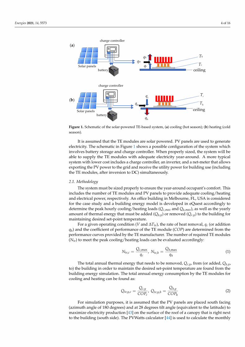
Figure 1 shows the schematic of the solar powered TE-based system integrated inthe ceiling. It is considered that TE modules from the bottom side are attached to analuminum sheet that serves as the ceiling. In hot and cold seasons, the bottom side of theTE modules cools down and heats up respectively, forming a cool/warm ceiling surface toallow the transfer of heat via radiation and convection to the occupants and provide thedesired comfort level. It should be noted that by switching the direction of the electricalcurrent supplied to TE modules the hot and cold sides of the module are switched aswell. Therefore, a set of TE modules can potentially be used for both heating and coolingpurposes, even though this will introduce practical challenges which will be discussed inthe next section.
Energies 2021, 14, 5573 4 of 16Energies 2021, 14, x FOR PEER REVIEW 4 of 17
Figure 1. Schematic of the solar-powered TE-based system, (a) cooling (hot season); (b) heating (cold
season).
It is assumed that the TE modules are solar powered. PV panels are used to generate
electricity. The schematic in Figure 1 shows a possible configuration of the system which
involves battery storage and charge controller. When properly sized, the system will be
able to supply the TE modules with adequate electricity year-around. A more typical sys-
tem with lower cost includes a charge controller, an inverter, and a net-meter that allows
exporting the PV power to the grid and receive the utility power for building use (includ-
ing the TE modules, after inversion to DC) simultaneously.
2.1. Methodology
The system must be sized properly to ensure the year-around occupant’s comfort.
This includes the number of TE modules and PV panels to provide adequate cooling/heat-
ing and electrical power, respectively. An office building in Melbourne, FL, USA is con-
sidered for the case study and a building energy model is developed in eQuest accord-
ingly to determine the peak hourly cooling/heating loads (Qc,max and Qh,max), as well as the
yearly amount of thermal energy that must be added (Qh,y) or removed (Qc,y) to the build-
ing for maintaining desired set-point temperature.
For a given operating condition (V and ΔTte), the rate of heat removal, qc (or addition
qh) and the coefficient of performance of the TE module (COP) are determined from the
performance curves provided by the TE manufacturer. The number of required TE mod-
ules (Nte) to meet the peak cooling/heating loads can be evaluated accordingly:
,max
,
c
te c
c
QN
q,
,max
,
h
te h
h
QN
q (1)
The total annual thermal energy that needs to be removed, Qc,y, from (or added, Qh,y,
to) the building in order to maintain the desired set-point temperature are found from the
building energy simulation. The total annual energy consumption by the TE modules for
cooling and heating can be found as:
,
, ,
c y
te y c
c
COP ,
,
, ,
h y
te y h
h
COP (2)
For simulation purposes, it is assumed that the PV panels are placed south facing
(azimuth angle of 180 degrees) and at 28 degrees tilt angle (equivalent to the latitude) to
maximize electricity production [43] on the surface of the roof of a canopy that is right
Th
Tc qc ceiling
qte qh
Tc
Th
qc
ceiling
qte
qh
(a)
(b)
charge controller
battery Solar panels
charge controller
battery Solar panels
Figure 1. Schematic of the solar-powered TE-based system, (a) cooling (hot season); (b) heating (coldseason).
It is assumed that the TE modules are solar powered. PV panels are used to generateelectricity. The schematic in Figure 1 shows a possible configuration of the system whichinvolves battery storage and charge controller. When properly sized, the system will beable to supply the TE modules with adequate electricity year-around. A more typicalsystem with lower cost includes a charge controller, an inverter, and a net-meter that allowsexporting the PV power to the grid and receive the utility power for building use (includingthe TE modules, after inversion to DC) simultaneously.
2.1. Methodology
The system must be sized properly to ensure the year-around occupant’s comfort. Thisincludes the number of TE modules and PV panels to provide adequate cooling/heatingand electrical power, respectively. An office building in Melbourne, FL, USA is consideredfor the case study and a building energy model is developed in eQuest accordingly todetermine the peak hourly cooling/heating loads (Qc,max and Qh,max), as well as the yearlyamount of thermal energy that must be added (Qh,y) or removed (Qc,y) to the building formaintaining desired set-point temperature.
For a given operating condition (V and ∆Tte), the rate of heat removal, qc (or additionqh) and the coefficient of performance of the TE module (COP) are determined from theperformance curves provided by the TE manufacturer. The number of required TE modules(Nte) to meet the peak cooling/heating loads can be evaluated accordingly:
Nte,c =Qc,max
qc, Nte,h =
Qh,max
qh(1)
The total annual thermal energy that needs to be removed, Qc,y, from (or added, Qh,y,to) the building in order to maintain the desired set-point temperature are found from thebuilding energy simulation. The total annual energy consumption by the TE modules forcooling and heating can be found as:
Qte,y,c =Qc,y
COPc, Qte,y,h =
Qh,y
COPh(2)
For simulation purposes, it is assumed that the PV panels are placed south facing(azimuth angle of 180 degrees) and at 28 degrees tilt angle (equivalent to the latitude) tomaximize electricity production [43] on the surface of the roof of a canopy that is right nextto the building (south side). The PVWatts calculator [44] is used to calculate the monthly
Energies 2021, 14, 5573 5 of 16
electricity production by one panel. The number of PV panels are then calculated to coverthe energy required to operate the TE modules, as described in the previous section. Thenumber of required PV panels to provide adequate energy for the TE modules in coolingand heating modes can be then calculated as:
Npv,c =Qte,y,c
PPV, Npv,h =
Qte,y,h
PPV(3)
The performance of the proposed system and the required number of TE and PVpanels are strong functions of input voltage (V) and temperature gradient between thehot and cold sides of the TE modules (∆Tte). Therefore, a parametric study is performedto compare the energy performance, required size, and cost of the system under variousoperating conditions.
2.2. Building Energy Model
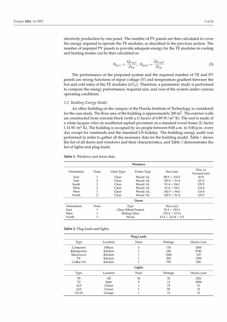
An office building on the campus of the Florida Institute of Technology is consideredfor the case study. The floor area of the building is approximately 200 m2. The exterior wallsare constructed from concrete block (with a U-factor of 0.89 W/m2 K). The roof is made ofa white lacquer color on weathered asphalt pavement on a standard wood frame (U-factor1.14 W/m2 K). The building is occupied by six people between 8:00 a.m. to 5:00 p.m. everyday except for weekends and the standard US holiday. The building energy audit wasperformed in order to gather all the necessary data for the building model. Table 1 showsthe list of all doors and windows and their characteristics, and Table 2 demonstrates thelist of lights and plug-loads.
Table 1. Windows and doors data.
Windows
Orientation Num Glass Type Frame Type Size (cm) Dist. toGround (cm)
East 1 Clear Wood/AL 88.9 × 124.5 83.8East 2 Clear Wood/AL 182.9 × 91.4 121.9
South 2 Clear Wood/AL 91.4 × 94.0 129.5West 2 Clear Wood/AL 91.4 × 94.0 116.8West 1 Clear Wood/AL 182.9 × 94.0 116.8
North 2 Clear Wood/AL 182.9 × 91.4 129.5
Doors
Orientation Num Type Size (cm)East 1 Glass (Metal Frame) 76.2 × 181.6West 1 Sliding Glass 152.4 × 213.4North 1 Wood 91.4 × 213.4 × 4.5
Table 2. Plug loads and lights.
Plug Loads
Type Location Num Wattage Hours/year
Computer Offices 4 130 2000Refrigerator Kitchen 1 180 8742Microwave Kitchen 1 1200 125
TV Kitchen 1 300 1250Coffee Pot Kitchen 1 750 500
Lights
Type Location Num Wattage Hours/year
T8 All 56 32 1821T2 Bath 9 13 4500
A19 Closet 1 75 15A15 Closet 1 55 15
GU24 Garage 1 13 15
Energies 2021, 14, 5573 6 of 16
A cooling and heating set-point temperature of 298 K and 292 K are considered,respectively, for the occupied hours. The building model was developed in eQuest, andthe hourly cooling/heating loads are determined for a one-year period. The highest hourlycooling and heating loads are found as 10.4 kW (Qc,max ≈ 3 tons of regrigeration) for3:00–4:00 p.m. on 8 July and 6.74 kW (Qh,max ≈ 2 tons of refrigeration) for 7:00–8:00 a.m. on26 January for the hot and cold seasons, respectively.
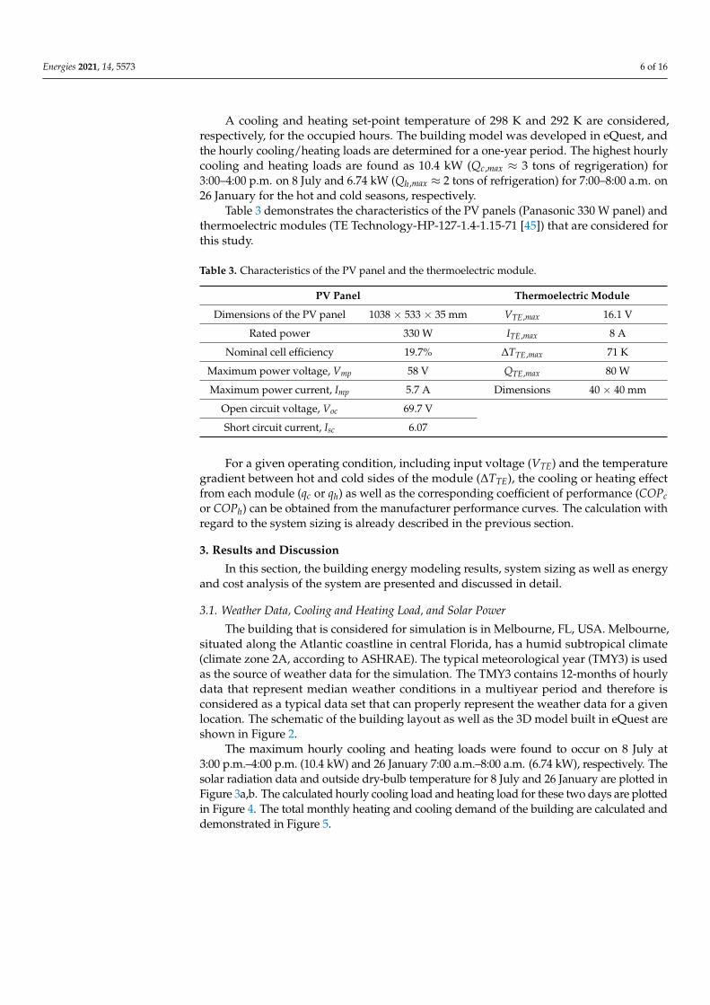
Table 3 demonstrates the characteristics of the PV panels (Panasonic 330 W panel) andthermoelectric modules (TE Technology-HP-127-1.4-1.15-71 [45]) that are considered forthis study.
Table 3. Characteristics of the PV panel and the thermoelectric module.
PV Panel Thermoelectric Module
Dimensions of the PV panel 1038 × 533 × 35 mm VTE,max 16.1 V
Rated power 330 W ITE,max 8 A
Nominal cell efficiency 19.7% ∆TTE,max 71 K
Maximum power voltage, Vmp 58 V QTE,max 80 W
Maximum power current, Imp 5.7 A Dimensions 40 × 40 mm
Open circuit voltage, Voc 69.7 V
Short circuit current, Isc 6.07
For a given operating condition, including input voltage (VTE) and the temperaturegradient between hot and cold sides of the module (∆TTE), the cooling or heating effectfrom each module (qc or qh) as well as the corresponding coefficient of performance (COPcor COPh) can be obtained from the manufacturer performance curves. The calculation withregard to the system sizing is already described in the previous section.
3. Results and Discussion
In this section, the building energy modeling results, system sizing as well as energyand cost analysis of the system are presented and discussed in detail.
3.1. Weather Data, Cooling and Heating Load, and Solar Power
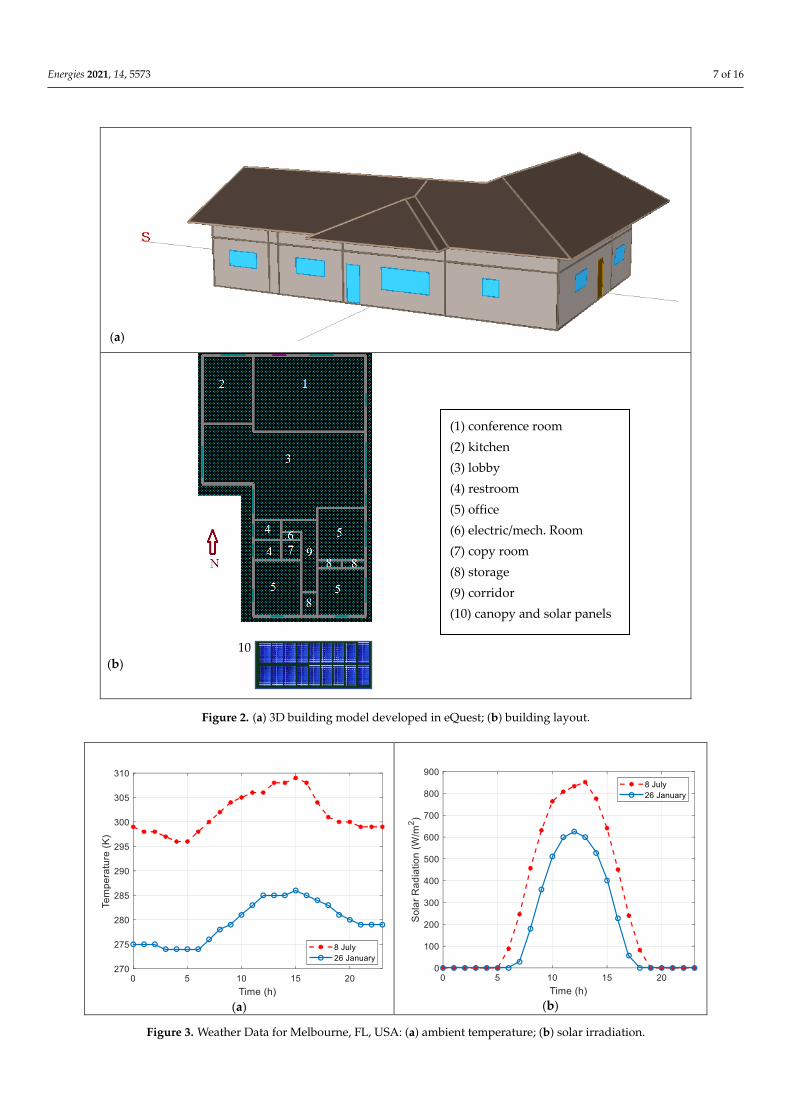
The building that is considered for simulation is in Melbourne, FL, USA. Melbourne,situated along the Atlantic coastline in central Florida, has a humid subtropical climate(climate zone 2A, according to ASHRAE). The typical meteorological year (TMY3) is usedas the source of weather data for the simulation. The TMY3 contains 12-months of hourlydata that represent median weather conditions in a multiyear period and therefore isconsidered as a typical data set that can properly represent the weather data for a givenlocation. The schematic of the building layout as well as the 3D model built in eQuest areshown in Figure 2.
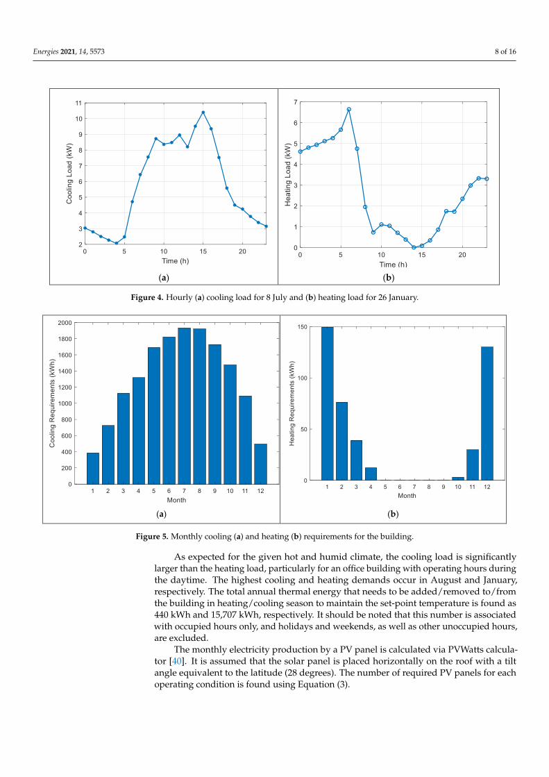
The maximum hourly cooling and heating loads were found to occur on 8 July at3:00 p.m.–4:00 p.m. (10.4 kW) and 26 January 7:00 a.m.–8:00 a.m. (6.74 kW), respectively. Thesolar radiation data and outside dry-bulb temperature for 8 July and 26 January are plotted inFigure 3a,b. The calculated hourly cooling load and heating load for these two days are plottedin Figure 4. The total monthly heating and cooling demand of the building are calculated anddemonstrated in Figure 5.
Energies 2021, 14, 5573 7 of 16Energies 2021, 14, x FOR PEER REVIEW 7 of 17
(a)
10 (b)
Figure 2. (a) 3D building model developed in eQuest; (b) building layout.
The maximum hourly cooling and heating loads were found to occur on 8 July at 3:00
p.m.–4:00 p.m. (10.4 kW) and 26 January 7:00 a.m.–8:00 a.m. (6.74 kW), respectively. The
solar radiation data and outside dry-bulb temperature for 8 July and 26 January are plot-
ted in Figure 3a,b. The calculated hourly cooling load and heating load for these two days
are plotted in Figure 4. The total monthly heating and cooling demand of the building are
calculated and demonstrated in Figure 5.
(1) conference room
(2) kitchen
(3) lobby
(4) restroom
(5) office
(6) electric/mech. Room
(7) copy room
(8) storage
(9) corridor
(10) canopy and solar panels
Figure 2. (a) 3D building model developed in eQuest; (b) building layout.
Energies 2021, 14, x FOR PEER REVIEW 8 of 17
(a)
(b)
Figure 3. Weather Data for Melbourne, FL, USA: (a) ambient temperature; (b) solar irradiation.
(a) (b)
Figure 4. Hourly (a) cooling load for 8 July and (b) heating load for 26 January.
Figure 3. Weather Data for Melbourne, FL, USA: (a) ambient temperature; (b) solar irradiation.
Energies 2021, 14, 5573 8 of 16
Energies 2021, 14, x FOR PEER REVIEW 8 of 17
(a)
(b)
Figure 3. Weather Data for Melbourne, FL, USA: (a) ambient temperature; (b) solar irradiation.
(a) (b)
Figure 4. Hourly (a) cooling load for 8 July and (b) heating load for 26 January. Figure 4. Hourly (a) cooling load for 8 July and (b) heating load for 26 January.
Energies 2021, 14, x FOR PEER REVIEW 9 of 17
(a) (b)
Figure 5. Monthly cooling (a) and heating (b) requirements for the building.
As expected for the given hot and humid climate, the cooling load is significantly
larger than the heating load, particularly for an office building with operating hours dur-
ing the daytime. The highest cooling and heating demands occur in August and January,
respectively. The total annual thermal energy that needs to be added/removed to/from the
building in heating/cooling season to maintain the set-point temperature is found as 440
kWh and 15,707 kWh, respectively. It should be noted that this number is associated with
occupied hours only, and holidays and weekends, as well as other unoccupied hours, are
excluded.
The monthly electricity production by a PV panel is calculated via PVWatts calcula-
tor [40]. It is assumed that the solar panel is placed horizontally on the roof with a tilt
angle equivalent to the latitude (28 degrees). The number of required PV panels for each
operating condition is found using Equation (3).
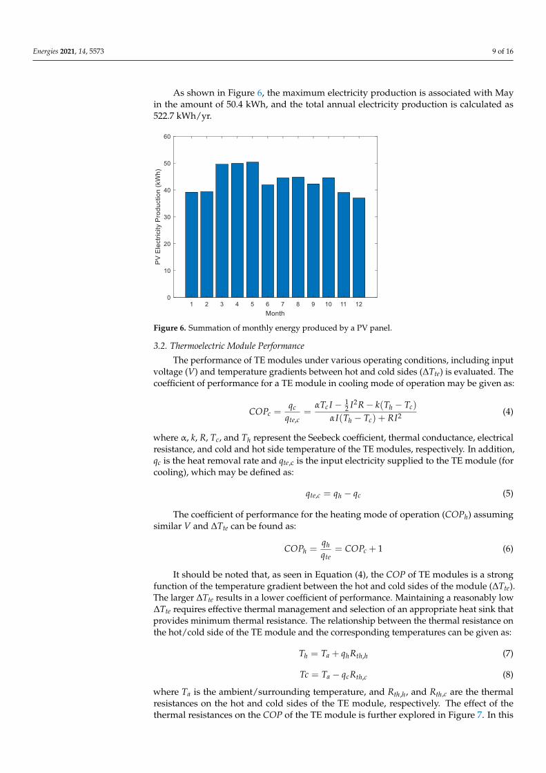
As shown in Figure 6, the maximum electricity production is associated with May in
the amount of 50.4 kWh, and the total annual electricity production is calculated as 522.7
kWh/yr.
Figure 6. Summation of monthly energy produced by a PV panel.
Figure 5. Monthly cooling (a) and heating (b) requirements for the building.
As expected for the given hot and humid climate, the cooling load is significantlylarger than the heating load, particularly for an office building with operating hours duringthe daytime. The highest cooling and heating demands occur in August and January,respectively. The total annual thermal energy that needs to be added/removed to/fromthe building in heating/cooling season to maintain the set-point temperature is found as440 kWh and 15,707 kWh, respectively. It should be noted that this number is associatedwith occupied hours only, and holidays and weekends, as well as other unoccupied hours,are excluded.
The monthly electricity production by a PV panel is calculated via PVWatts calcula-tor [40]. It is assumed that the solar panel is placed horizontally on the roof with a tiltangle equivalent to the latitude (28 degrees). The number of required PV panels for eachoperating condition is found using Equation (3).
Energies 2021, 14, 5573 9 of 16
As shown in Figure 6, the maximum electricity production is associated with Mayin the amount of 50.4 kWh, and the total annual electricity production is calculated as522.7 kWh/yr.
Energies 2021, 14, x FOR PEER REVIEW 9 of 17
(a) (b)
Figure 5. Monthly cooling (a) and heating (b) requirements for the building.
As expected for the given hot and humid climate, the cooling load is significantly
larger than the heating load, particularly for an office building with operating hours dur-
ing the daytime. The highest cooling and heating demands occur in August and January,
respectively. The total annual thermal energy that needs to be added/removed to/from the
building in heating/cooling season to maintain the set-point temperature is found as 440
kWh and 15,707 kWh, respectively. It should be noted that this number is associated with
occupied hours only, and holidays and weekends, as well as other unoccupied hours, are
excluded.
The monthly electricity production by a PV panel is calculated via PVWatts calcula-
tor [40]. It is assumed that the solar panel is placed horizontally on the roof with a tilt
angle equivalent to the latitude (28 degrees). The number of required PV panels for each
operating condition is found using Equation (3).
As shown in Figure 6, the maximum electricity production is associated with May in
the amount of 50.4 kWh, and the total annual electricity production is calculated as 522.7
kWh/yr.
Figure 6. Summation of monthly energy produced by a PV panel. Figure 6. Summation of monthly energy produced by a PV panel.
3.2. Thermoelectric Module Performance
The performance of TE modules under various operating conditions, including inputvoltage (V) and temperature gradients between hot and cold sides (∆Tte) is evaluated. Thecoefficient of performance for a TE module in cooling mode of operation may be given as:
COPc =qc
qte,c=
αTc I − 12 I2R − k(Th − Tc)
αI(Th − Tc) + RI2 (4)
where α, k, R, Tc, and Th represent the Seebeck coefficient, thermal conductance, electricalresistance, and cold and hot side temperature of the TE modules, respectively. In addition,qc is the heat removal rate and qte,c is the input electricity supplied to the TE module (forcooling), which may be defined as:
qte,c = qh − qc (5)
The coefficient of performance for the heating mode of operation (COPh) assumingsimilar V and ∆Tte can be found as:
COPh =qhqte
= COPc + 1 (6)
It should be noted that, as seen in Equation (4), the COP of TE modules is a strongfunction of the temperature gradient between the hot and cold sides of the module (∆Tte).The larger ∆Tte results in a lower coefficient of performance. Maintaining a reasonably low∆Tte requires effective thermal management and selection of an appropriate heat sink thatprovides minimum thermal resistance. The relationship between the thermal resistance onthe hot/cold side of the TE module and the corresponding temperatures can be given as:
Th = Ta + qhRth,h (7)
Tc = Ta − qcRth,c (8)
where Ta is the ambient/surrounding temperature, and Rth,h, and Rth,c are the thermalresistances on the hot and cold sides of the TE module, respectively. The effect of thethermal resistances on the COP of the TE module is further explored in Figure 7. In this

Energies 2021, 14, 5573 10 of 16
analysis, it is assumed that the thermal resistances on both sides of the TE modules areequal.
Energies 2021, 14, x FOR PEER REVIEW 11 of 17
Figure 7. Variation of COP with a thermal resistance of the two sides of the TE module.
As seen, an increase in thermal resistance for a given input electrical current results
in a significant reduction of COP. It is also observed that higher electricity input results in
lower COP for the TE modules. These results further emphasize the importance of heat
sink design and the adjustment of electricity input to the TE modules for achieving opti-
mal performance. The detailed design of the heat sink, however, is outside the scope of
the present study.
3.3. Parametric Study
The procedure for system sizing is already described in Section 2.1 . For the selected
TE module, five different ΔTte are considered, including 9.6, 12, 19.2, 28.8, and 38.3 °C. For
each particular ΔTte, a number of possible input voltages are considered, and the corre-
sponding COP, heat removal/addition rate (qc or qh), and energy consumed by a TE mod-
ule (qte) operating under these conditions are evaluated and listed in Table 4. As an exam-
ple, consider the first row of Table 4, in the cooling mode operation, for ΔTte = 9.6 °C and
V = 2.9 V, the values of COPc, qc, and qte,c are determined as 3, 14 W, and 4.67 W, respec-
tively. Similarly, for the first row, in the heating mode operation, the values of COPh and
qh are evaluated as 4 and 18.67 W, respectively.
Using the building energy model, the maximum cooling and heating loads (sensible
and latent load) are found as 10.4 kW and 6.74 kW, respectively. The required number of
TE modules for the hot and cold seasons are then calculated using Equation (1) for each
operating condition. For the ΔTte = 9.6 °C and V = 2.9 V (first row in Table 4), these values
are determined as 743 and 358, respectively. Note that, since the building under study is
located in a hot and humid climate zone, the cooling load is much more significant than
the heating load. Therefore, assuming each TE module can operate in both cooling and
heating mode by switching the direction of input electricity, the system must be sized
based on the cooling needs.
As mentioned, the total annual heat that must be removed and added to the building
for maintaining the comfort conditions during the hot and cold seasons are found as
15,770 kWh and 447 kWh, respectively. These values are substituted in Equation (3) to
evaluate the number of PV panels that are needed to provide sufficient electricity for the
modules. For the first row of Table 4 (ΔTte = 9.6 °C and V = 2.9 V), 11 PV panels are needed
to provide sufficient electricity for TE modules in the cooling mode operation. In contrast,
Figure 7. Variation of COP with a thermal resistance of the two sides of the TE module.
As seen, an increase in thermal resistance for a given input electrical current results ina significant reduction of COP. It is also observed that higher electricity input results inlower COP for the TE modules. These results further emphasize the importance of heatsink design and the adjustment of electricity input to the TE modules for achieving optimalperformance. The detailed design of the heat sink, however, is outside the scope of thepresent study.
3.3. Parametric Study
The procedure for system sizing is already described in Section 2.1. For the selectedTE module, five different ∆Tte are considered, including 9.6, 12, 19.2, 28.8, and 38.3 ◦C.For each particular ∆Tte, a number of possible input voltages are considered, and thecorresponding COP, heat removal/addition rate (qc or qh), and energy consumed by a TEmodule (qte) operating under these conditions are evaluated and listed in Table 4. As anexample, consider the first row of Table 4, in the cooling mode operation, for ∆Tte = 9.6 ◦Cand V = 2.9 V, the values of COPc, qc, and qte,c are determined as 3, 14 W, and 4.67 W,respectively. Similarly, for the first row, in the heating mode operation, the values of COPhand qh are evaluated as 4 and 18.67 W, respectively.
Table 4. Summary of the results for various operating conditions.
Cooling Heating
CaseNum
∆T(◦C) V COPc
qc(W)
qte ,c(W) Ntec
Qtec ,y(kWh/yr) Npv ,c
Cinit ,c($) COPh
qh(W) Nteh
Qteh ,y(kWh/yr)
1 9.6 2.9 3 14 4.67 743 5236 11 22,700 4 18.67 358 1102 9.6 5.9 1.7 37 21.76 282 9239 18 13,800 2.7 58.76 114 1633 9.6 8.8 1 45 45.00 232 15,707 31 17,425 2 90.00 75 2204 9.6 11.7 0.8 52 65.00 200 19,634 38 19,250 1.8 117.00 58 2445 12 5.9 1.62 38 23.46 274 9696 19 13,975 2.62 61.46 109 1686 12 8.8 1.14 45 39.47 232 13,778 27 15,925 2.14 84.47 79 2067 12 11.7 0.78 52 66.67 200 20,137 39 19,625 1.78 118.67 57 2478 19.2 5.9 1.3 23 17.69 453 12,082 24 20,325 2.3 40.69 164 1919 19.2 8.8 0.9 36 40.00 289 17,452 34 19,975 1.9 76.00 88 23210 19.2 11.7 0.6 44 73.33 237 26,178 51 25,050 1.6 117.33 57 27511 28.8 5.9 0.8 10 12.50 1040 19,634 38 40,250 1.8 22.50 297 24412 28.8 8.8 0.7 26 37.14 400 22,439 43 26,125 1.7 63.14 106 25913 28.8 11.7 0.5 34 68.00 306 31,414 61 30,525 1.5 102.00 66 29314 38.3 8.8 0.5 16 32.00 650 31,414 61 39,125 1.5 48.00 139 29315 38.3 11.7 0.4 24 60.00 434 39,268 76 39,350 1.4 84.00 80 314
Energies 2021, 14, 5573 11 of 16
Using the building energy model, the maximum cooling and heating loads (sensibleand latent load) are found as 10.4 kW and 6.74 kW, respectively. The required number ofTE modules for the hot and cold seasons are then calculated using Equation (1) for eachoperating condition. For the ∆Tte = 9.6 ◦C and V = 2.9 V (first row in Table 4), these valuesare determined as 743 and 358, respectively. Note that, since the building under study islocated in a hot and humid climate zone, the cooling load is much more significant than theheating load. Therefore, assuming each TE module can operate in both cooling and heatingmode by switching the direction of input electricity, the system must be sized based on thecooling needs.
As mentioned, the total annual heat that must be removed and added to the buildingfor maintaining the comfort conditions during the hot and cold seasons are found as15,707 kWh and 440 kWh, respectively. These values are substituted in Equation (3) toevaluate the number of PV panels that are needed to provide sufficient electricity for themodules. For the first row of Table 4 (∆Tte = 9.6 ◦C and V = 2.9 V), 11 PV panels are neededto provide sufficient electricity for TE modules in the cooling mode operation. In contrast,only four PV panels are required to cover the electrical energy for the TE modules in theheating mode of operation. Note that the sizing must be performed based on the coolingdemands since the cooling load is significantly higher than the heating load.
It can be seen from Table 4 that COP values decline as the temperature gradientbetween the hot and cold sides increases. The performance of the TE modules can beimproved if they are integrated with proper heat sinks in order to have effective heatdissipation. A closer look at the trend of the results in Table 4 also shows that, at agiven temperature gradient, for most cases, each module operates more efficiently (higherCOP) when supplied with lower input voltages. However, at lower input voltages, theheat removal/addition rate by the TE module is smaller. As a result, a more efficientcooling/heating system requires a larger number of TE modules to satisfy the load. Inother words, a lower operating cost requires a higher initial investment in TE modules.
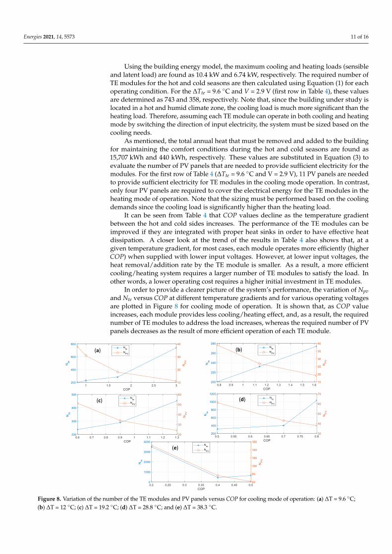
In order to provide a clearer picture of the system’s performance, the variation of Npvand Nte versus COP at different temperature gradients and for various operating voltagesare plotted in Figure 8 for cooling mode of operation. It is shown that, as COP valueincreases, each module provides less cooling/heating effect, and, as a result, the requirednumber of TE modules to address the load increases, whereas the required number of PVpanels decreases as the result of more efficient operation of each TE module.
Energies 2021, 14, x FOR PEER REVIEW 13 of 17
Figure 8. Variation of the number of the TE modules and PV panels versus COP for cooling mode of operation: (a) ΔT =
9.6 °C; (b) ΔT = 12 °C; (c) ΔT = 19.2 °C; (d) ΔT = 28.8 °C; and (e) ΔT = 38.3 °C.
An important observation can be made by reviewing the range of COP values that
are obtained. For the majority of operating conditions, the COP is very small and not com-
parable with conventional high-efficiency heating (heat pump) and air conditioning sys-
tems. As previously discussed, a well-designed heat sink would allow efficient operation
by maintaining a low ΔTte. The cases with reasonably high COP are associated with the
lowest ΔTte values (9.6 °C and 12 °C). It should be noted that the COP should not be the
only parameter when it comes to the energy efficiency of the proposed system. The TE
based cooling/heating system allows individual control over each module, which facili-
tates cooling and heating based on occupancy of a certain area within each room. This will
reduce the overall energy used for cooling/heating since not all the areas are always occu-
pied.
3.4. Economic Analysis
A basic cost model is developed to provide a perspective on the economic aspects of
the proposed system. The initial cost of the system, assuming the cost of instrumentation
and installation is roughly 25% of the major parts, can be estimated as:
Cinit = (NteCte + NpvCpv) (1 + 0.25) (9)
where Cinit refers to the total initial cost of the system and Cte and Cpv are the price of one
TE module and one PV panel, respectively. The estimated price for each TE module is $20,
and the cost of each PV panel is obtained from the manufacturer at $300.
As mentioned, the system must be sized based on the cooling mode of operation as
the cooling load is significantly higher than the heating load. The estimated initial cost of
the system for each mode of operation is shown in Figure 9.
It can be seen from Figure 9 that case 2 (closely followed by case 5) offers the lowest
initial cost of $13,800. Case 2 demonstrated the second-highest COP (1.7) among all the
cases. A higher COP lowers the number of required PV panels, which significantly brings
the initial cost down. The second case is, therefore, selected as the optimal operating con-
dition. It should be noted that, although the Case 1 conditions show a higher COP, it is
(a) (b)
(c) (d)
(e)
Figure 8. Variation of the number of the TE modules and PV panels versus COP for cooling mode of operation: (a) ∆T = 9.6 ◦C;(b) ∆T = 12 ◦C; (c) ∆T = 19.2 ◦C; (d) ∆T = 28.8 ◦C; and (e) ∆T = 38.3 ◦C.
Energies 2021, 14, 5573 12 of 16
An important observation can be made by reviewing the range of COP values thatare obtained. For the majority of operating conditions, the COP is very small and notcomparable with conventional high-efficiency heating (heat pump) and air conditioningsystems. As previously discussed, a well-designed heat sink would allow efficient operationby maintaining a low ∆Tte. The cases with reasonably high COP are associated with thelowest ∆Tte values (9.6 ◦C and 12 ◦C). It should be noted that the COP should not bethe only parameter when it comes to the energy efficiency of the proposed system. TheTE based cooling/heating system allows individual control over each module, whichfacilitates cooling and heating based on occupancy of a certain area within each room. Thiswill reduce the overall energy used for cooling/heating since not all the areas are alwaysoccupied.
3.4. Economic Analysis
A basic cost model is developed to provide a perspective on the economic aspects ofthe proposed system. The initial cost of the system, assuming the cost of instrumentationand installation is roughly 25% of the major parts, can be estimated as:
Cinit = (NteCte + NpvCpv) (1 + 0.25) (9)
where Cinit refers to the total initial cost of the system and Cte and Cpv are the price of oneTE module and one PV panel, respectively. The estimated price for each TE module is $20,and the cost of each PV panel is obtained from the manufacturer at $300.
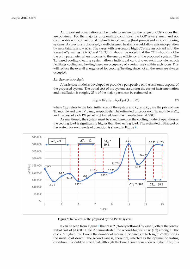
As mentioned, the system must be sized based on the cooling mode of operation asthe cooling load is significantly higher than the heating load. The estimated initial cost ofthe system for each mode of operation is shown in Figure 9.
Energies 2021, 14, x FOR PEER REVIEW 14 of 17
not cost-effective since it requires a much large number of TE modules to provide ade-
quate cooling.
Figure 9. Initial cost of the proposed hybrid PV-TE system.
For Case 2, it is determined that 282 TE modules and 18 PV panels are needed. This
is nearly 1.41 TE module (rated at 80 W) and 0.09 PV panel (rated at 330 W) per unit of
area of the building, when the system operates at an approximate COP of 1.7. In other
words, a nominal cooling capacity of 112.8 W and a nominal PV capacity of 31.35 W per
unit area of the building is required to achieve the target goal when the system operates
at the optimal condition.
Since the system is solar-powered, cost savings will be realized as the result of a re-
duction in the electricity bill. Assuming an average COPHP,c of 3 and COPHP,h of 4 for cool-
ing and heating by a heat pump, the electricity consumption by such a system is evaluated
as 5,346 kWh using Equation (10):
, ,
, ,
c y h y
HP
HP c HP h
Q QEC
COP COP (10)
Assuming an average usage rate of $0.12/kWh, the annual cost savings is found as
$641.5 using:
HPCS EC UR (11)
The installed cost of a comparable size commercial heat pump system (excluding
ductwork) is approximately $5000–$6000. This indicates that, at first look, the proposed
system is significantly more expensive than conventional heat pump systems with an es-
timated simple payback period of over 12 years. However, there are other cost considera-
tions that need to be discussed. It is expected that the maintenance cost of the proposed
system is significantly lower than the conventional air conditioning systems and they also
offer a longer lifecycle. The lifespan of a conventional air conditioning unit is about 12–15
years while this value is over 20 years for the solar panels and TE modules. Accounting
for the lifecycle, the payback period of using the proposed system versus conventional
units can further reduce to about 8.6 years.
$-
$5,000
$10,000
$15,000
$20,000
$25,000
$30,000
$35,000
$40,000
$45,000
1 3 5 7 9 11 13 15
Co
st (
$)
Case
ΔTte = 9.6 ΔTte = 12 ΔTte =
19.2
ΔTte = 28.8 ΔTte = 38.3
2.9 V
5.9 V
8.8 V
11.7 V
11.7 V
5.9 V
8.8 V 5.9 V
8.8 V
11.7 V
5.9 V
8.8 V
11.7 V
8.8 V 11.7 V
Figure 9. Initial cost of the proposed hybrid PV-TE system.
It can be seen from Figure 9 that case 2 (closely followed by case 5) offers the lowestinitial cost of $13,800. Case 2 demonstrated the second-highest COP (1.7) among all thecases. A higher COP lowers the number of required PV panels, which significantly bringsthe initial cost down. The second case is, therefore, selected as the optimal operatingcondition. It should be noted that, although the Case 1 conditions show a higher COP, it is
Energies 2021, 14, 5573 13 of 16
not cost-effective since it requires a much large number of TE modules to provide adequatecooling.
For Case 2, it is determined that 282 TE modules and 18 PV panels are needed. This isnearly 1.41 TE module (rated at 80 W) and 0.09 PV panel (rated at 330 W) per unit of areaof the building, when the system operates at an approximate COP of 1.7. In other words, anominal cooling capacity of 112.8 W and a nominal PV capacity of 31.35 W per unit area ofthe building is required to achieve the target goal when the system operates at the optimalcondition.
Since the system is solar-powered, cost savings will be realized as the result of areduction in the electricity bill. Assuming an average COPHP,c of 3 and COPHP,h of 4for cooling and heating by a heat pump, the electricity consumption by such a system isevaluated as 5,346 kWh using Equation (10):
ECHP =Qc,y
COPHP,c+
Qh,y
COPHP,h(10)
Assuming an average usage rate of $0.12/kWh, the annual cost savings is found as$641.5 using:
CS = ECHP × UR (11)
The installed cost of a comparable size commercial heat pump system (excluding duct-work) is approximately $5000–$6000. This indicates that, at first look, the proposed systemis significantly more expensive than conventional heat pump systems with an estimatedsimple payback period of over 12 years. However, there are other cost considerations thatneed to be discussed. It is expected that the maintenance cost of the proposed system issignificantly lower than the conventional air conditioning systems and they also offer alonger lifecycle. The lifespan of a conventional air conditioning unit is about 12–15 yearswhile this value is over 20 years for the solar panels and TE modules. Accounting for thelifecycle, the payback period of using the proposed system versus conventional units canfurther reduce to about 8.6 years.
Additional cost savings may be achieved through the reduction of regular maintenancecosts and accurate control that allows for operating the system only when the area withinthe coverage is occupied. Given the function of the considered building (office), manyareas remain unoccupied during working hours. By automatic shut-down of the system inthe unoccupied areas, significant energy/cost savings can be realized. Considering Case 2,a conservative estimate of a 25% reduction in operating hours will result in a decrease inthe number of required PV panels down to 14, which will reduce the initial cost by $1875.This will bring down the payback period to just below six years. Additionally, for theeconomic analysis, the cost savings is calculated using an average usage rate of $0.12 whichis estimated based on electricity cost in Florida. This number could be much larger in otherareas which will significantly decrease the payback period.
4. Prospects and Challenges
The TE-based cooling/heating system is a promising technology owing to severalmajor advantages that it offers. In comparison with conventional heat pump systems,besides the green nature of the TE system due to eliminating the need for refrigerantand ability to use DC electricity (i.e., through solar PV), the system does not require anymajor moving parts and requires minimum maintenance. The individual control over TEmodules provides opportunities for smart control based on occupancy in each area, whichholds the potential for significant improvement in energy efficiency and occupants’ thermalcomfort. Additionally, with the continuous improvement in material sciences, any increasein the efficiency of thermoelectric materials will result in a more cost-effective system. Itshould be also noted that optimization of the building and hybridizing the TE technologywith passive techniques [46,47] can also significantly reduce the energy demands, priorimplementation of the TE-bases system and as a result reduces the overall system cost.
Energies 2021, 14, 5573 14 of 16
There are also several challenges that must be addressed to pave the road in commer-cializing the TE-based cooling/heating systems. A major challenge is the optimal design ofheat sinks for both hot and cold sides of the module to ensure a low-temperature gradientbetween the two sides and maintain a reasonably high COP. Harvesting the waste heatfrom the TE modules and using it for applications such as preheating water or powergeneration via thermoelectric generators (Seebeck effect) is another challenge that must bethoroughly studied. Optimal control of the system is also a critical task to maintain highenergy efficiency and ensure occupants’ comfort. The installation of the system, includingmodules, wiring, and control system, must also be explored. Additionally, the properventilation system must be incorporated in the design to provide fresh air. The overallpayback period of the system may be reduced by improving thermoelectric materials andthe use of a well-designed system with optimal control.
5. Conclusions
In the present paper, the feasibility of using solar powered TE-based cooling andheating system for an office building is investigated. The system consists of solar-poweredTE modules that are integrated into the ceiling and lower/increase the temperature of theceiling in the hot/cold season to provide year-around thermal comfort for the occupantsvia radiation and convection. A test study is performed for a building in Melbourne,FL, USA with a hot and humid climate. The building model is developed in eQuest, thehourly cooling and heating load values are evaluated, and an algorithm is developed forsizing the system. A parametric study is performed, and the size and performance ofthe system under various operating conditions are evaluated. A basic cost model is alsodeveloped, and the initial cost of the system, as well as the resulted savings, are estimatedand compared against conventional heat pump systems. The conditions which led to thelowest initial cost of the system are selected as the optimal conditions and thoroughlydiscussed. It was shown that, while the system offers major benefits including no needfor refrigeration or major moving parts, high controllability, and reasonably high COP,the cost of the system is significantly higher than conventional heat pumps with a simplepayback period of about 9–12 years, assuming a usage rate of $12/kWh. Considering themuch longer lifespan of TE and PV systems and their relatively low maintenance cost incomparison with conventional air conditioning systems, the payback period may reducedown to about six years. Further improvement in thermoelectric materials with a higherfigure of merit and the use of smart control based on occupancy can significantly decreasethe cost of the system and introduce it as a green and cost-effective alternative cooling andheating system.
Author Contributions: Formal analysis, writing—original draft preparation, M.S.; Conceptualization,methodology, investigation, writing—review and editing, H.N. All authors have read and agreed tothe published version of the manuscript.
Funding: This research was supported by the Florida Institute of Technology.
Conflicts of Interest: The authors declare no conflict of interest.
References1. Ruparathna, R.; Hewage, K.; Sadiq, R. Improving the energy efficiency of the existing building stock: A critical review of
commercial and institutional buildings. Renew. Sustain. Energy Rev. 2015, 53, 1032–1045. [CrossRef]2. Global Energy Assessment Writing Team. Energy End-Use-Buildings. In Global Energy Assessment Writing Team; Cambridge
University Press: Cambridge, UK, 2012; Chapter 10-IIASA.3. Betharte, O.; Najafi, H.; Nguyen, T. Towards Net-Zero Energy Buildings: A Case Study in Humid Subtropical Climate. In
Proceedings of the ASME 2018 International Mechanical Engineering Congress and Exposition, Pittsburgh, PA, USA, 9–15November 2018. [CrossRef]
4. Riffat, S.; Ma, X. Thermoelectrics: A review of present and potential applications. Appl. Therm. Eng. 2003, 23, 913–935. [CrossRef]5. Zhao, D.; Tan, G. A review of thermoelectric cooling: Materials, modeling and applications. Appl. Therm. Eng. 2014, 66, 15–24.
[CrossRef]

Energies 2021, 14, 5573 15 of 16
6. Bhargava, A.; Najafi, H. Photovoltaic-Thermoelectric Systems for Building Cooling Applications: A Preliminary Study. InProceedings of the ASME 2016 International Mechanical Engineering Congress and Exposition, Phoenix, AZ, USA, 11–17November 2016. [CrossRef]
7. Twaha, S.; Zhu, J.; Yan, Y.; Li, B. A comprehensive review of thermoelectric technology: Materials, applications, modelling andperformance improvement. Renew. Sustain. Energy Rev. 2016, 65, 698–726. [CrossRef]
8. Liu, D.; Zhao, F.-Y.; Yang, H.; Tang, G.-F. Thermoelectric mini cooler coupled with micro thermosiphon for CPU cooling system.Energy 2015, 83, 29–36. [CrossRef]
9. Ahammed, N.; Asirvatham, G.; Wongwises, S. Thermoelectric cooling of electronic devices with nanofluid in a multiportminichannel heat exchanger. Exp. Therm. Fluid Sci. 2016, 74, 81–90. [CrossRef]
10. Zhang, H.; Kong, W.; Dong, F.; Xu, H.; Chen, B.; Ni, M. Application of cascading thermoelectric generator and cooler for wasteheat recovery from solid oxide fuel cells. Energy Convers. Manag. 2017, 148, 1382–1390. [CrossRef]
11. Najafi, H.; Woodbury, K.A. Modeling and Analysis of a Combined Photovoltaic-Thermoelectric Power Generation System. J. Sol.Energy Eng. 2013, 135, 031013. [CrossRef]
12. Tan, Y.Z.; Han, L.; Chew, N.G.P.; Chow, W.H.; Wang, R.; Chew, J.W. Membrane distillation hybridized with a thermoelectric heatpump for energy-efficient water treatment and space cooling. Appl. Energy 2018, 231, 1079–1088. [CrossRef]
13. Rahbar, N.; Esfahani, J.A. Experimental study of a novel portable solar still by utilizing the heatpipe and thermoelectric module.Desalination 2012, 284, 55–61. [CrossRef]
14. Najafi, H.; Woodbury, K.A. Optimization of a cooling system based on Peltier effect for photovoltaic cells. Sol. Energy 2013, 91,152–160. [CrossRef]
15. Najafi, H. Evaluation of Alternative Cooling Techniques for Photovoltaic Panels; University of Alabama: Tuscaloosa, AL, USA, 2012.16. Zuazua-Ros, A.; Martín-Gómez, C.; Ibañez-Puy, E.; Vidaurre-Arbizu, M.; Gelbstein, Y. Investigation of the thermoelectric potential
for heating, cooling and ventilation in buildings: Characterization options and applications. Renew. Energy 2018, 131, 229–239.[CrossRef]
17. Liu, Z.; Zhang, L.; Gong, G.; Luo, Y.; Meng, F. Evaluation of a prototype active solar thermoelectric radiant wall system in winterconditions. Appl. Therm. Eng. 2015, 89, 36–43. [CrossRef]
18. Birthwright, R.-S.; Messac, A.; Harren-Lewis, T.; Rangavajhala, S. Heat Compensation in Buildings Using ThermoelectricWindows: An Energy Efficient Window Technology. In Proceedings of the ASME 2008 International Design Engineering TechnicalConferences and Computers and Information in Engineering Conference, Brooklyn, NY, USA, 3–6 August 2008; Volume 1, pp.977–987. [CrossRef]
19. Van Dessel, S.; Foubert, B. Active thermal insulators: Finite elements modeling and parametric study of thermoelectric modulesintegrated into a double pane glazing system. Energy Build. 2010, 42, 1156–1164. [CrossRef]
20. Zhang, J.; Messac, A.; Zhang, J.; Chowdhury, S. Adaptive optimal design of active thermoelectric windows using surrogatemodeling. Optim. Eng. 2013, 15, 469–483. [CrossRef]
21. Liu, Z.; Zhang, L.; Gong, G.; Han, T. Experimental evaluation of an active solar thermoelectric radiant wall system. EnergyConvers. Manag. 2015, 94, 253–260. [CrossRef]
22. Luo, Y.; Zhang, L.; Liu, Z.; Wang, Y.; Meng, F.; Wu, J. Thermal performance evaluation of an active building integrated photovoltaicthermoelectric wall system. Appl. Energy 2016, 177, 25–39. [CrossRef]
23. Martín-Gómez, C.; Ibáñez-Puy, M.; Bermejo-Busto, J.; Fernández, J.A.S.; Ramos, J.C.; Rivas, A. Thermoelectric cooling heatingunit prototype. Build. Serv. Eng. Res. Technol. 2015, 37, 431–449. [CrossRef]
24. Irshad, K.; Habib, K.; Basrawi, F.; Saha, B. Study of a thermoelectric air duct system assisted by photovoltaic wall for spacecooling in tropical climate. Energy 2017, 119, 504–522. [CrossRef]
25. Piantanida, P. PV & Peltier Façade: Preliminary Experimental Results. Energy Procedia 2015, 78, 3477–3482. [CrossRef]26. American Society of Heating, Refrigerating and Air-Conditioning Engineers. 2012 ASHRAE Handbook: Heating, Ventilating, and
Air-Conditioning Systems and Equipment; ASHRAE: Atlanta, GA, USA, 2012.27. Rhee, K.-N.; Kim, K.W. A 50 year review of basic and applied research in radiant heating and cooling systems for the built
environment. Build. Environ. 2015, 91, 166–190. [CrossRef]28. Zhao, K.; Liu, X.-H.; Jiang, Y. Application of radiant floor cooling in large space buildings—A review. Renew. Sustain. Energy Rev.
2016, 55, 1083–1096. [CrossRef]29. Chiang, W.-H.; Wang, C.-Y.; Huang, J.-S. Evaluation of cooling ceiling and mechanical ventilation systems on thermal comfort
using CFD study in an office for subtropical region. Build. Environ. 2012, 48, 113–127. [CrossRef]30. Kazanci, O.B.; Shukuya, M.; Olesen, B.W. Theoretical analysis of the performance of different cooling strategies with the concept
of cool exergy. Build. Environ. 2016, 100, 102–113. [CrossRef]31. Bojic, M.; Cvetkovic, D.; Marjanovic, V.; Blagojevic, M.; Djordjevic, Z. Performances of low temperature radiant heating systems.
Energy Build. 2013, 61, 233–238. [CrossRef]32. Li, R.; Yoshidomi, T.; Ooka, R.; Olesen, B.W. Field evaluation of performance of radiant heating/cooling ceiling panel system.
Energy Build. 2015, 86, 58–65. [CrossRef]33. Lertsatitthanakorn, C.; Tipsaenprom, W.; Srisuwan, W.; Atthajariyakul, S. Study on the Cooling Performance and Thermal
Comfort of a Thermoelectric Ceiling Cooling Panel System. Indoor Built Environ. 2008, 17, 525–534. [CrossRef]
Energies 2021, 14, 5573 16 of 16
34. Lertsatitthanakorn, C.; Srisuwan, W.; Atthajariyakul, S. Experimental performance of a thermoelectric ceiling cooling panel. Int. J.Energy Res. 2008, 32, 950–957. [CrossRef]
35. Lertsatitthanakorn, C.; Wiset, L.; Atthajariyakul, S. Evaluation of the Thermal Comfort of a Thermoelectric Ceiling Cooling Panel(TE-CCP) System. J. Electron. Mater. 2009, 38, 1472–1477. [CrossRef]
36. Cheng, T.-C.; Cheng, C.-H.; Huang, Z.-Z.; Liao, G.-C. Development of an energy-saving module via combination of solar cellsand thermoelectric coolers for green building applications. Energy 2011, 36, 133–140. [CrossRef]
37. He, W.; Zhou, J.; Hou, J.; Chen, C.; Ji, J. Theoretical and experimental investigation on a thermoelectric cooling and heating systemdriven by solar. Appl. Energy 2013, 107, 89–97. [CrossRef]
38. Liu, Z.; Zhang, L.; Gong, G. Experimental evaluation of a solar thermoelectric cooled ceiling combined with displacementventilation system. Energy Convers. Manag. 2014, 87, 559–565. [CrossRef]
39. Su, X.; Zhang, L.; Liu, Z.; Luo, Y.; Chen, D.; Li, W. Performance evaluation of a novel building envelope integrated withthermoelectric cooler and radiative sky cooler. Renew. Energy 2021, 171, 1061–1078. [CrossRef]
40. Luo, Y.; Yan, T.; Zhang, N. Study on dynamic thermal characteristics of thermoelectric radiant cooling panel system through ahybrid method. Energy 2020, 208, 118413. [CrossRef] [PubMed]
41. Lim, H.; Kang, Y.-K.; Jeong, J.-W. Application of a phase change material to a thermoelectric ceiling radiant cooling panel as aheat storage layer. J. Build. Eng. 2020, 32, 101787. [CrossRef]
42. Duan, M.; Sun, H.; Lin, B.; Wu, Y. Evaluation on the applicability of thermoelectric air cooling systems for buildings withthermoelectric material optimization. Energy 2021, 221, 119723. [CrossRef]
43. Chen, J.; Lu, L. Development of radiative cooling and its integration with buildings: A comprehensive review. Sol. Energy 2020,212, 125–151. [CrossRef]
44. National Renewable Energy Laboratory. PVWatts Calculator. Available online: https://pvwatts.nrel.gov/ (accessed on 20 April2021).
45. TE Technology. Hp-127-1.4-1.15-71. 2018. Available online: https://tetech.com/product/hp-127-1-4-1-15-71/ (accessed on 1April 2021).
46. Ford, B.; Schiano-Phan, R.; Vallejo, J.A. The Architecture of Natural Cooling, 2nd ed.; Routledge: London, UK, 2019. [CrossRef]47. Widera, B. Bioclimatic Architecture. J. Civ. Eng. Archit. Res. 2015, 2, 567–578.