Powered Lower Limb Prostheses
163
Powered Lower Limb Prostheses Angetriebene Prothesen für die untere Extremität Zur Erlangung des Grades eines Doktors der Naturwissenschaften (Dr. rer. nat.) genehmigte Dissertation von Dipl.-Sportwiss. Martin Grimmer aus Gera Tag der Einreichung: 10. Dezember 2014, Tag der Prüfung: 05. Februar 2015 Darmstadt — D 17, Darmstadt 2015 1. Gutachten: Prof. Dr. André Seyfarth 2. Gutachten: Prof. Dr. Thomas Sugar Fachbereich Humanwissenschaften Institut für Sportwissenschaft Sportbiomechanik
-
Upload
khangminh22 -
Category
Documents
-
view
10 -
download
0
Transcript of Powered Lower Limb Prostheses

Powered Lower LimbProsthesesAngetriebene Prothesen für die untere ExtremitätZur Erlangung des Grades eines Doktors der Naturwissenschaften (Dr. rer. nat.)genehmigte Dissertation von Dipl.-Sportwiss. Martin Grimmer aus GeraTag der Einreichung: 10. Dezember 2014, Tag der Prüfung: 05. Februar 2015Darmstadt — D 17, Darmstadt 2015
1. Gutachten: Prof. Dr. André Seyfarth2. Gutachten: Prof. Dr. Thomas Sugar
Fachbereich HumanwissenschaftenInstitut für SportwissenschaftSportbiomechanik

Powered Lower Limb ProsthesesAngetriebene Prothesen für die untere Extremität
Genehmigte Dissertation von Dipl.-Sportwiss. Martin Grimmer aus Gera
1. Gutachten: Prof. Dr. André Seyfarth2. Gutachten: Prof. Dr. Thomas Sugar
Tag der Einreichung: 10. Dezember 2014Tag der Prüfung: 05. Februar 2015
Darmstadt — D 17
Bitte zitieren Sie dieses Dokument als:URN: urn:nbn:de:tuda-tuprints-43820URL: http://tuprints.ulb.tu-darmstadt.de/4382
Dieses Dokument wird bereitgestellt von tuprints,E-Publishing-Service der TU Darmstadthttp://[email protected]
Die Veröffentlichung steht unter folgender Creative Commons Lizenz:Namensnennung – Keine kommerzielle Nutzung – Keine Bearbeitung 3.0 Deutschlandhttp://creativecommons.org/licenses/by-nc-nd/3.0/de/

Erklärung zur Dissertation
Hiermit versichere ich, die vorliegende Dissertation ohne Hilfe Dritter nur mit den angegebenenQuellen und Hilfsmitteln angefertigt zu haben. Alle Stellen, die aus Quellen entnommen wur-den, sind als solche kenntlich gemacht. Diese Arbeit hat in gleicher oder ähnlicher Form nochkeiner Prüfungsbehörde vorgelegen.
Darmstadt, den 10. Dezember 2014
Martin Grimmer
1

Zusammenfassung
Der aufrechte Gang des Menschen entstand vor etwa 6 Millionen Jahren. Er wird durch ei-ne komplexe Interaktion von Körperaufbau und Gangkontrolle ermöglicht. Knochen, Muskeln,Sehen, zentralnervöse Befehle und Reflexmechanismen befähigen zu einer robusten und ef-fizienten zweibeinigen Fortbewegung wie dem Gehen und Rennen. Neben diesen Arten derFortbewegung sind dem Menschen auch komplexe Bewegungen wie Klettern, Tanzen oderSpringen möglich. Die Identifikation der relevanten Grundprinzipien des Baus und der Kontrolleseines Bewegungsapparates kann bei der Konstruktion von zweibeinigen Robotern, Exoskelet-ten, Orthesen und Prothesen helfen. Krankheiten oder Unfälle können zum Verlust von Teilender unteren Extremität oder deren Ansteuerung führen. Der älteste Bericht über ein künstlichesBein ist etwa 5000 Jahre alt und beschreibt den Verlust eines Beines von Königin Vishpla. Umauf das Schlachtfeld zurückzukehren, wurde sie mit einem eisernen Bein versorgt. Seit dieserZeit haben Fortschritte den Aufbau, das Material und die Funktion prothetischer Versorgungendeutlich verbessert. Zunehmend werden biologische Wirkmechanismen durch technische Kom-ponenten imitiert. Die Verwendung von Kohlefasern in Prothesenfüßen ermöglicht eine Unter-stützung im Gang durch den elastischen Rückstoß vergleichbar einer Achillessehne. Dämpfer inKnieprothesen ermöglichen die Abbildung von exzentrischer Muskelarbeit im Gang. Kupplungs-mechanismen werden zum Blockieren der Kniebeugung im Stand eingesetzt. Diese Funktionist vergleichbar mit isometrischer Muskelarbeitsweise. Semi-aktive Kniegelenke erlauben eineVariation der Dämpfung und passen ihre Systemeigenschaften den Anforderungen an. UnterZuhilfenahme der eingebauten Kraft- oder Inertialsensoren kann die Bewegungsabsicht identi-fiziert werden. So wird eine Anpassung der Dämpfung auf verschiedene Gehgeschwindigkeiten,auf Steigungen oder Treppen möglich.
All diese Entwicklungen haben das Gangbild der Amputierten näher an das natürliche Gang-bild herangeführt. Jedoch war keines der Systeme in der Lage konzentrische Muskelarbeit abzu-bilden. Die bereitgestellte positive Muskelarbeit wird benötigt, um Energieverluste bei der Fort-bewegung auszugleichen. Zum Steigen von Treppen und Begehen von Steigungen muss nichtnur das Sprunggelenk, sondern auch das Kniegelenk positive Arbeit zum Anheben des Körper-schwerpunktes verrichten. Zur Umsetzung der angestrebten Gelenkbewegung ist ein Antriebnötig, welcher einen Energieeintrag ermöglicht und damit die konzentrische Funktionsweisevon Muskelfasern nachbilden kann.
Die Dissertation analysiert Gelenkanforderungen, evaluiert aktuelle prothetische Konzepteund entwickelt Modelle für künstliche Muskeln, um die Biomechanik der unteren Extremitätenbeim Gehen und Rennen abzubilden. Die entwickelten Modelle sind biologisch inspiriert, wobeiMotoren die Funktion von Muskelfasern und Federn die Funktion von Sehnen nachbilden. DieSysteme sind dabei nach Kriterien wie einer minimalen Motorleistung oder einem minimalenEnergieverbrauch optimiert. Die Resultate zeigen, dass elastische Strukturen deutlich zur Redu-zierung von Motoranforderungen beitragen können. Federn sind in der Lage, Energie in einerPhase des Gangzyklus aufzunehmen, um diese dann bei hohen Anforderungen wieder abzuge-ben. Ohne die elastische Unterstützung ist das Nachahmen des menschlichen Gelenkverhaltensmit aktueller Motorentechnologie nur eingeschränkt möglich. Die im Model optimierte Interak-tion von Motor und Feder wird mit einer angetriebenen Fußprothese (Walk-Run ankle, Spring-active) beim Gehen und Rennen untersucht. Neben Experimenten mit einem Nichtamputierten,
2
bei dem die Prothese parallel zu einem fixierten Sprunggelenk angebracht war (Bypass), wur-den auch Studien mit einer einseitig Unterschenkelamputierten durchgeführt. Das optimierteModellverhalten zeigt eine gute Übereinstimmung mit den experimentellen Daten. Ein Konzeptzur Verbesserung eines optimierten Motorverhaltens wurde erfolgreich geprüft. Durch die Ver-einfachung der Motortrajektorie auf grundlegende Verlaufsmerkmale (Filter) war es möglichdie mechanische Energieabgabe und die Effizienz der Prothese zu steigern und den elektrischenEnergieaufwand und die Geräuschemission zu reduzieren.
Um das Verhalten der Prothese weiter zu verbessern sollten das Timing für den Fußab-druck und Gründe für die Geräuschemission analysiert werden. Eine Gewichtsreduktion undpsychoakustische Analysen können helfen die Akzeptanz bei Amputierten zu erhöhen. Zusätz-lich müssen Trainingseffekte bei der Nutzung von aktiven Prothesen untersucht werden. Umden Leistungsbedarf und den Energieverbrauch zusätzlich zu reduzieren ist eine Steigerung derEffizienz von aktiven Prothesen sinnvoll. Dies kann durch effizientere Komponenten und durcheine Optimierung des Interaktionsverhaltens zwischen Prothese und Prothesennutzer erreichtwerden. Die Mensch - Maschine Interaktion ist von der bereitgestellten Mechanik und dem An-steuerungskonzept abhängig. Vergleichbar mit zweigelenkigen Muskeln könnte eine Kopplungvon gesunden zu künstlichen Gelenken zusätzliche Vorteile bringen. Bei Oberschenkelampu-tierten wäre solch eine Kopplung auch zwischen dem künstlichen Knie- und dem künstlichenSprunggelenk möglich. Muskeln von existierenden proximalen Gelenken wären in der Lage,Energie zu den distalen Gelenken zu übertragen. Durch die geometrisch bedingte Verspannungkönnte der Aufwand für die grundlegende Beinkontrolle beim Gang reduziert werden.
Die Ergebnisse der Dissertation, zur effizienten Interaktion von Motoren und Federn, kön-nen zur Verbesserung vom Aufbau und der Ansteuerung angetriebener Prothesen beitragen.Vergleichbare Konzepte können aber auch zur Verbesserung von Exoskeletten eingesetzt wer-den. Diese könnten ältere Mitmenschen und Personen mit Mobilitätseinschränkungen bei derFortbewegung unterstützen. Eine Verstärkung der menschlichen Physis für den Alltag oder dasArbeitsumfeld wäre denkbar. Neben der Unterstützung des Menschen könnten elastische Aktua-toren zudem das Gangverhalten, die Robustheit und die Laufzeit von zweibeinigen Roboternverbessern. Damit sind die Ergebnisse der Arbeit Powered Lower Limb Prostheses - AngetriebeneProthesen für die untere Extremität nicht nur auf das Anwendungsfeld der Prothetik limitiertsondern auch relevant für die Entwicklung von Exoskeletten und Robotern.
3

Abstract
Human upright locomotion emerged about 6 million years ago. It is achieved by a complexinteraction of the biological infrastructure and the neural control. Bones, muscles, tendons, cen-tral nervous commands and reflex mechanisms interact to provide robust and efficient bipedalmovement patterns like walking or running. Next to these locomotion tasks humans can alsoperform complex movements like climbing, dancing or jumping. Diseases or traumatic eventsmay cause the loss of parts of the biological infrastructure or the ability to control the lowerlimbs. Thus an identification of the required framework helps to improve on the artificial lowerlimb design and the control for bipedal robots, exoskeletons, orthoses or prostheses. A first ar-tificial leg design was reported about 5000 years ago. After losing one leg in a battle an ironleg was fitted to Queen Vishpla to get her back on the battlefield. Since this time major changesin the structure, the material and the functionality led to improved prosthetic restoration ofphysically disabled. The characteristics of the biological leg structure are imitated by technicalcomponents. Using carbon fiber for the design of prosthetic feet made it possible to benefit fromthe elastic recoil like in the Achilles tendon in stance phase. Dampers in prosthetic knee jointsare able to mimic eccentric muscle work during the gait cycle. Clutch-like mechanisms are usedto lock the knee during stance. Such a function is comparable to isometric muscle work. Semi-active knee joints allow changes in damping ratio to adapt the mechanical joint properties tothe requirements. Using integrated force or inertial sensors, movement tasks can be identified.An adaptation of damping to different walking speeds and conditions, such as walking inclines,declines, or climbing stairs is possible.
All these developments permitted that amputees gait got closer to the natural human gaitpattern. However, until the end of the 20th century prostheses were not able to reproduceconcentric muscle work. External positive energy is required to compensate for energy lossesduring locomotion. For climbing stairs or walking inclines not only the ankle, but also the kneejoint contributes net positive work to lift the body center of mass. To achieve desired jointmotion, a power source like a motor would be required that can inject energy to mimic theconcentric function of the muscle fascicles.
The thesis comprises an analysis of joint requirements, it evaluates the current prosthetic de-sign approaches and develops models on artificial muscles to mimic lower limb biomechanics inwalking and running. The developed models are biologically inspired, while motors representthe function of muscle fibers and springs represent the function of the tendons. These systemsare optimized for criteria like minimum joint peak power or minimum required energy for thepower source (motor). Results demonstrate that elastic elements can highly decrease the ac-tuator requirements. The springs are able to store energy in one phase of the gait cycle and torelease it later when high peak power is required. Without the elastic assistance the reproduc-tion of human joint behavior is hardly possible using current motor technology. The optimizedinteraction of motor and elasticity is evaluated in walking and running, using a prototype ofa powered ankle prosthesis (Walk-Run ankle, Springactive). Next to experiments with a non-amputee, where the prosthesis was fitted in parallel to the fixed healthy ankle joint (Bypass),also experiments with a female unilateral transtibial amputee were performed. The optimizedmodel behavior was compared to experimental observations and showed good agreement.
4

Furthrmore, a concept on the improvement of an optimized walking motor pattern was suc-cessfully tested. By smoothening the motor curve to the main characteristics (low-pass filter) itwas possible to increase the mechanical work output, to improve the system efficiency, and todecrease the electrical energy consumption and the noise.
To further improve the prosthetic performance, the push off timing and the causes for pros-thesis noise should be analyzed. Weight reductions and psychoacoustic analysis can additionallyhelp to improve on the amputees acceptance. In addition it must be evaluated how training caneffect amputees gait patterns when using powered prostheses. To further reduce the power andthe energy requirements, an improvement on the powered prosthesis efficiency is recommen-ded. The efficiency can be further increased by using higher efficiency parts and improving theinteraction of the prosthesis and the amputee. The human - machine interaction depends onthe prosthesis mechanics and the control algorithm. Similar to the human biarticular muscles,couplings from biological to artificial joints may provide additional benefits for the amputee.The muscles from existing proximal joints would be able to transfer energy to the distal artificialjoints. Also the inverse of this principle would be possible. A coupling between the hip and theknee (transfemoral amputees) and between the knee and the ankle (transfemoral and trans-tibial amputees) would be possible. Due to geometrical constraints, the elemental locomotioncontrol might improve.
The results of the thesis, on the efficient cooperation of motors and springs, can be used toimprove the design and the control of powered lower limb prostheses. Similar technologiescan be used to improve on exoskeleton design to assist elderly and subjects with mobility im-pairments. Elastic exoskeletons may also augment human performance in daily life or workersenvironments. Next to assisting the human movement, the elastic actuators may advance thegait performance, the gait robustness, and the operation time of bipedal robots. Thus the resultsof the thesis Powered Lower Limb Prostheses are not limited to the specific field of prosthetics butmay also be useful for applications like exoskeletons and legged robots.
5

Inhaltsverzeichnis
1 Introduction and Motivation 8
2 Overview 11
3 Manuscript I: Mimicking Human-like Leg Function in Prosthetic Limbs 193.1 ABSTRACT . . . . . . . . . . . . . . . . . . . . . . . . . . . . . . . . . . . . . . . . 203.2 HUMAN LOCOMOTION . . . . . . . . . . . . . . . . . . . . . . . . . . . . . . . . 203.3 PROSTHETICS . . . . . . . . . . . . . . . . . . . . . . . . . . . . . . . . . . . . . 203.4 PASSIVE PROSTHETICS . . . . . . . . . . . . . . . . . . . . . . . . . . . . . . . . 213.5 SEMI-ACTIVE PROSTHETICS . . . . . . . . . . . . . . . . . . . . . . . . . . . . 323.6 POWERED PROSTHETICS . . . . . . . . . . . . . . . . . . . . . . . . . . . . . . 373.7 TECHNOLOGY TRANSFER . . . . . . . . . . . . . . . . . . . . . . . . . . . . . . 533.8 SUMMARY AND OUTLOOK . . . . . . . . . . . . . . . . . . . . . . . . . . . . . . 543.9 AUTHOR CONTRIBUTIONS . . . . . . . . . . . . . . . . . . . . . . . . . . . . . 553.10 ABBREVIATIONS . . . . . . . . . . . . . . . . . . . . . . . . . . . . . . . . . . . . 563.11 REFERENCES . . . . . . . . . . . . . . . . . . . . . . . . . . . . . . . . . . . . . . 573.12 APPENDIX . . . . . . . . . . . . . . . . . . . . . . . . . . . . . . . . . . . . . . . . 70
4 Manuscript II: A Comparison of Parallel- and Series Elastic Elements in anActuator for Mimicking Human Ankle Joint in Walking and Running 754.1 ABSTRACT . . . . . . . . . . . . . . . . . . . . . . . . . . . . . . . . . . . . . . . . 764.2 INTRODUCTION . . . . . . . . . . . . . . . . . . . . . . . . . . . . . . . . . . . . 764.3 METHODS . . . . . . . . . . . . . . . . . . . . . . . . . . . . . . . . . . . . . . . . 774.4 RESULTS . . . . . . . . . . . . . . . . . . . . . . . . . . . . . . . . . . . . . . . . . 804.5 DISCUSSION . . . . . . . . . . . . . . . . . . . . . . . . . . . . . . . . . . . . . . . 834.6 CONCLUSION . . . . . . . . . . . . . . . . . . . . . . . . . . . . . . . . . . . . . . 864.7 ACKNOWLEDGMENTS . . . . . . . . . . . . . . . . . . . . . . . . . . . . . . . . 874.8 AUTHOR CONTRIBUTIONS . . . . . . . . . . . . . . . . . . . . . . . . . . . . . 874.9 REFERENCES . . . . . . . . . . . . . . . . . . . . . . . . . . . . . . . . . . . . . . 87
5 Manuscript III: Stiffness Adjustment of a Series Elastic Actuator in a Knee Pros-thesis for Walking and Running: The Trade-off between Energy and Peak PowerOptimization 895.1 ABSTRACT . . . . . . . . . . . . . . . . . . . . . . . . . . . . . . . . . . . . . . . . 905.2 INTRODUCTION . . . . . . . . . . . . . . . . . . . . . . . . . . . . . . . . . . . . 905.3 METHODS . . . . . . . . . . . . . . . . . . . . . . . . . . . . . . . . . . . . . . . . 905.4 RESULTS . . . . . . . . . . . . . . . . . . . . . . . . . . . . . . . . . . . . . . . . . 925.5 DISCUSSION . . . . . . . . . . . . . . . . . . . . . . . . . . . . . . . . . . . . . . . 955.6 ACKNOWLEDGMENTS . . . . . . . . . . . . . . . . . . . . . . . . . . . . . . . . 985.7 AUTHOR CONTRIBUTIONS . . . . . . . . . . . . . . . . . . . . . . . . . . . . . 985.8 REFERENCES . . . . . . . . . . . . . . . . . . . . . . . . . . . . . . . . . . . . . . 98
6 Manuscript IV: Energetic and Peak Power Advantages of Series Elastic Actua-tors in an Actuated Prosthetic Leg for Walking and Running 1016.1 ABSTRACT . . . . . . . . . . . . . . . . . . . . . . . . . . . . . . . . . . . . . . . . 102
6

6.2 INTRODUCTION . . . . . . . . . . . . . . . . . . . . . . . . . . . . . . . . . . . . 1026.3 METHODS . . . . . . . . . . . . . . . . . . . . . . . . . . . . . . . . . . . . . . . . 1036.4 RESULTS . . . . . . . . . . . . . . . . . . . . . . . . . . . . . . . . . . . . . . . . . 1086.5 DISCUSSION . . . . . . . . . . . . . . . . . . . . . . . . . . . . . . . . . . . . . . . 1116.6 CONCLUSIONS . . . . . . . . . . . . . . . . . . . . . . . . . . . . . . . . . . . . . 1176.7 ACKNOWLEDGMENTS . . . . . . . . . . . . . . . . . . . . . . . . . . . . . . . . 1176.8 AUTHOR CONTRIBUTIONS . . . . . . . . . . . . . . . . . . . . . . . . . . . . . 1176.9 CONFLICT OF INTEREST . . . . . . . . . . . . . . . . . . . . . . . . . . . . . . . 1186.10 REFERENCES . . . . . . . . . . . . . . . . . . . . . . . . . . . . . . . . . . . . . . 118
7 Manuscript V: A powered prosthetic ankle joint for walking and running 1217.1 ABSTRACT . . . . . . . . . . . . . . . . . . . . . . . . . . . . . . . . . . . . . . . . 1227.2 INTRODUCTION . . . . . . . . . . . . . . . . . . . . . . . . . . . . . . . . . . . . 1227.3 METHODS . . . . . . . . . . . . . . . . . . . . . . . . . . . . . . . . . . . . . . . . 1237.4 RESULTS . . . . . . . . . . . . . . . . . . . . . . . . . . . . . . . . . . . . . . . . . 1277.5 DISCUSSION . . . . . . . . . . . . . . . . . . . . . . . . . . . . . . . . . . . . . . . 1327.6 CONCLUSION . . . . . . . . . . . . . . . . . . . . . . . . . . . . . . . . . . . . . . 1337.7 OUTLOOK . . . . . . . . . . . . . . . . . . . . . . . . . . . . . . . . . . . . . . . . 1347.8 ACKNOWLEDGEMENTS . . . . . . . . . . . . . . . . . . . . . . . . . . . . . . . . 1347.9 AUTHOR CONTRIBUTIONS . . . . . . . . . . . . . . . . . . . . . . . . . . . . . 1347.10 CONFLICT OF INTEREST . . . . . . . . . . . . . . . . . . . . . . . . . . . . . . . 1347.11 REFERENCES . . . . . . . . . . . . . . . . . . . . . . . . . . . . . . . . . . . . . . 135
8 Manuscript VI: Simplified ankle control decreases powered prosthetic noiseand improves performance and efficiency 1378.1 ABSTRACT . . . . . . . . . . . . . . . . . . . . . . . . . . . . . . . . . . . . . . . . 1388.2 INTRODUCTION . . . . . . . . . . . . . . . . . . . . . . . . . . . . . . . . . . . . 1388.3 METHODS . . . . . . . . . . . . . . . . . . . . . . . . . . . . . . . . . . . . . . . . 1398.4 RESULTS . . . . . . . . . . . . . . . . . . . . . . . . . . . . . . . . . . . . . . . . . 1448.5 DISCUSSION . . . . . . . . . . . . . . . . . . . . . . . . . . . . . . . . . . . . . . . 1508.6 CONCLUSION . . . . . . . . . . . . . . . . . . . . . . . . . . . . . . . . . . . . . . 1548.7 ACKNOWLEDGEMENTS . . . . . . . . . . . . . . . . . . . . . . . . . . . . . . . . 1548.8 AUTHOR CONTRIBUTIONS . . . . . . . . . . . . . . . . . . . . . . . . . . . . . 1548.9 CONFLICT OF INTEREST . . . . . . . . . . . . . . . . . . . . . . . . . . . . . . . 1548.10 INSTITUTIONAL REVIEW . . . . . . . . . . . . . . . . . . . . . . . . . . . . . . . 1548.11 REFERENCES . . . . . . . . . . . . . . . . . . . . . . . . . . . . . . . . . . . . . . 155
9 Conclusion 157
7
1 Introduction and Motivation
Current state of the art lower limb prosthetic technology allows amputees to master most dai-ly life tasks. However, compared to non-amputees the metabolic energy consumption and thusthe movement effort is increased (Waters and Mulroy, 1999). Studies on the locomotion pat-terns show clear differences between non-amputees and amputees (Schaarschmidt et al., 2012;Waters and Mulroy, 1999). The differences in joint kinematics and kinetics increase with theincreased level of amputation (Waters and Mulroy, 1999). Long term sequelae like back painor arthritis might be caused by asymmetric gait and the dominating use of the intact limb forunilateral amputees (Gailey et al., 2008; Robbins et al., 2009). At the end of the last centurytwo major developments improved amputee walking performance. The development of passiveelastic carbon feet (e.g. Seattle foot) in the early 80s, made it possible to recover stored elasticenergy from the leaf spring during push off (Czerniecki et al., 1991). Especially for running, theelastic prosthetic feet like the Flex-Foot Cheetah (Ossur) enable achieving almost non-amputeerunning performance (Brüggemann et al., 2008).
Mechanical knee joints for transfemoral amputees made a huge step in performance and safe-ty when introducing the semi-active devices like the C-Leg or the Genium knee (both Ottobock)(Blumentritt et al., 2012). Sensors and micro controllers allow gait detection and adaptations towalking speed by changing the rate of damping in the artificial knee. In addition, these prosthe-ses can prevent falls that occured in the previous generation of passive knee joints (Blumentrittand Bellmann, 2010; Blumentritt et al., 2009). These completely passive systems required fullknee extension before touch down to lock the knee for the stance phase. Too early touchdownsled to collapse. In more recent years, efforts have been made to develop semi-active ankleprostheses to similarly improve the artificial ankle performance (Meridium, Ottobock).
When analyzing the amputee gait kinematics and kinetics, differences in joint angles and tor-ques can be identified (Schaarschmidt et al., 2012; Waters and Mulroy, 1999). For the artificialleg, deficiencies can be traced back to a missing power source, but also by limitations to therange of motion. To overcome both limitations, powered prostheses like the Power Knee, Sparkyor the Power Foot were developed during the last years (Bellman et al., 2008; Highsmith et al.,2010; Au et al., 2009). All of them use a motor to provide external energy for joint actuation si-milar to the human muscle fibers. Next to the motor the Power Foot and Sparky use springs thatare optimized to assist the motor to reduce peak power requirement and energy consumption.The springs are used to mimic the elastic function of the Achilles tendon. Only by including theelasticity it is possible to build compact powered ankles that can mimic the human ankle jointbehavior for daily activities like walking with current motor technology.
Biomechanical gait analysis conducted in 2006 (Schaarschmidt et al., 2012) on multiple trans-femoral unilateral amputees using passive and semi-active parts provided the scientific groundsfor the thesis at hand. The differences between the residual and the intact limb clearly de-monstrated that for level walking a major advancement in design and control is required at theprosthetic ankle joint to achieve similar amputee kinetics, kinematics, and symmetry in gait likenon-amputees. Similar results were observed by other researchers too, when investigating thegait performance using different passive and semi-active prosthetic knee and foot components(Waters and Mulroy, 1999; Johansson et al., 2005; Segal et al., 2006).
8
Considering the outcome of these studies the following questions were deduced:
• What are the biomechanical requirements at the ankle joint to achieve human like gait?
• How can biomechanical ankle joint behavior be mimicked by an appropriate actuatordesign?
• How can artificial lower limb devices be controlled?
First studies on the improvement of amputee gait were done by the author in 2007 to 2008(Grimmer, 2008; Grimmer and Seyfarth, 2009). It was proven if it is possible to improve the an-kle push off by transferring energy from the intact knee of a transtibial amputee to the artificialfoot using an elastic biarticular coupling. The study demonstrated that stiffness of mono- andbiarticular springs, used to represent ankle function, clearly affects amputees gait performance.Thus it is an important design feature that should be exploited to provide maximum possibleadvantages for the amputee. An improved concept for choosing an optimal spring stiffness wasrequired for further studies. It was not possible to achieve healthy ankle joint behavior due tolimitations in push off energy injection and limitations in adjusting engagement timing of biar-ticular and monoarticular springs. As a consequence it was planned to include a series elasticactuator that can solve both issues by adjusting the resting length of the serial spring for furtherenhancement of artificial ankle performance.
When analyzing human ankle joint biomechanics for higher walking speeds and running,demanding requirements for the joint velocity, the torque and the acceleration can be identified.No off-the-shelf motor can match the required specifications. Therefore, a method to overcomethe limitations of the current motor technology is required. As suggested by previous generationsof prosthetic feet it might be possible that springs are able to assist the gait, to reduce themotor requirements. Such an arrangement of motors with springs was already used to actuatea powered ankle orthosis (Blaya and Herr, 2004). The arrangement is in line with the humanmuscle-tendon structure (Hill, 1938; Hof and Van den Berg, 1981). The series spring mimics thefunction of the Achilles tendon and the motor the function of the calf muscle fibers. Using theSparky powered ankle prosthesis, Hitt et al. (2007) demonstrated that a series spring can clearlyreduce the motor requirements. We used the same approach to determine the mechanical powerrequirements for the drive at multiple speeds in walking and running (Grimmer and Seyfarth,2011). It was demonstrated that such a concept (motor assisted by a spring) is not limited toan average level walking speed. Especially for running the potential for assistance of elasticstructures in a series elastic actuator (SEA) is enormous. To achieve the optimal assistance, gaitand speed dependent variations in spring stiffness are required. A single compromising stiffnessvalue for all speeds in walking and running is possible but reduces the system efficiency.
An open question was which optimization criteria are best suited to select the spring stiffness.The Sparky prosthesis was optimized to minimize peak power of the motor (Hitt et al., 2007;Hollander and Sugar, 2005). We introduced an alternative optimization criterion, namely mini-mizing the energy requirements (Grimmer and Seyfarth, 2011). The reduction of the necessarymotor peak power makes it possible to use smaller motors and with that to reduce the systemweight. The reduction of the energy consumption makes it possible to decrease the battery sizeand to increase the the runtime of an autonomous prosthetic system. For the ankle joint Grim-mer and Seyfarth (2011) could demonstrate that the optimization for minimum peak poweris the better choice as it results in almost the same energy consumption like the optimizationfor minimum energy. At the same time it reduces considerably the peak power. In contrast, the
9

energy minimization increased the required motor peak power but could not achieve majorimprovements in the energy consumption compared to the peak power optimization.
Next to the optimization approach, the alignment of the motor and the elastic componentsmay be important for the powered ankle design. Similar to the Hill type muscle concepts (Hill,1938; Hof and Van den Berg, 1981) parallel or combinations of parallel and series springs maybe beneficial to reduce the actuator requirements.
Concepts for the alignment of motors and springs, including the criterion for an appropriatespring stiffness, are discussed in the theoretical part of the thesis (Manuscript II to IV). Later,these concepts are used to perform gait studies on amputees and non-amputees to prove thetheoretical results (Manuscript V and VI). Manuscript I gives the reader a detailed introductionto the amputee and the non-amputee gait biomechanics, previous and state-of-the-art prosthetictechnology and introduces various control approaches for different gait and terrain.
10

2 Overview
The dissertation contains six manuscripts. Manuscripts I to IV are published articles. Informati-on on each publisher and the original publication can be found at each manuscripts cover page.Manuscripts V and VI are submitted to journals and are currently under review. Each manuscriptcontains its own summary of the references.
In the following paragraphs the contents of each manuscript is summarized. The relationshipsbetween the different publications are illustrated.
Manuscript I: Mimicking Human-like Leg Function in Prosthetic Limbs
The first chapter gives an introduction to the joint kinematics and the kinetics of the humangait. The presented data were recorded by Lipfert in 2005 in the Lauflabor Locomotion Labora-tory. They are used as non-amputee subject reference for the whole thesis (Lipfert, 2010). Thejoint requirements for walking and running gait were distinguished using this data set. Subse-quently, the chapter explains the state-of-the-art passive and semi-active lower limb prosthetictechnology. The reasons and the prevalence for amputations are presented. Lower limb ampu-tee walking biomechanics are described and limitations using unpowered devices are discussed.After focusing on previous generations of prosthetic limbs, the manuscript contains a summaryof powered lower limb prosthetics systems which were developed until 2012. It explains designapproaches and summarizes control approaches for different gaits and terrains.
The Manuscript I gives the reader an introduction to the state-of-the-art of lower limb pros-theses, relevant problems, and ways to improve amputee gait performance. After introducingthe overall topic in the first chapter, the following manuscripts II to VI will address differentquestions on powered joint biomechanics in more detail.
Manuscript II: A Comparison of Parallel- and Series Elastic Elements in an Actuator forMimicking Human Ankle Joint in Walking and Running
The second chapter is based on the outcomes of the authors diploma thesis (Grimmer, 2008;Grimmer and Seyfarth, 2009) and the results of a first analysis of a series elastic actuator con-cept to improve artificial ankle push off performance (Grimmer and Seyfarth, 2011). It is shownthat this concept can be further extended to include parallel elastic structures to reduce on theactuator peak power requirements but interestingly not the energy consumption.
Results of the first theoretical study on elastic structures to assist the motor (Grimmer andSeyfarth, 2011) were promising because the spring helps to overcome current limitations inthe motor technology. As the simple concept of the series spring already had a huge effect itwas planned to test possible extensions including also parallel springs. The previous conceptfor determining optimal stiffness to assist the motor (Hollander and Sugar, 2005) was usedand extended in the Manuscript II to evaluate an actuator using a motor and a parallel spring(PEA). In addition a combination of parallel and series spring was evaluated (SE+PEA). Similaractuation concepts exist for the Hill type muscle model (Hill, 1938; Hof and Van den Berg, 1981)and might be beneficial to reduce the actuator requirements for a powered ankle prosthesis. Thejoint power is defined by joint velocity times joint torque. In contrast to the series spring that is
11
able to reduce actuator velocity, a parallel spring is able to reduce the torque. The ManuscriptII demonstrates that there is a potential to decrease the peak power for multiple walking andrunning speeds when applying the parallel spring (PEA) compared to the SEA. To benefit fromthe torque reduction during push off, the parallel spring must be loaded during the flight phase.This loading requires energy. As a result, the energy consumption can not be reduced to levelsachieved when using SEA. The combination of both structures (SE+PEA) combined the positiveand the negative effects of the parallel and the series spring. The peak power is minimal, butthe energy consumption is higher compared to an SEA. Next to the stiffness of each springan additional constant, the parallel spring slack length, was introduced for the simulations.When keeping the stiffness and the slack length constant for all walking and running speeds,benefits for the peak power requirements and the energy consumption decrease. Thus for aspecial scenario (walking at a defined speed) such an approach might be worth to use. But for aversatile design performing multiple tasks like walking, running or stair climbing this approachmight limit the required flexibility of the system. The additional weight for the mechanicalstructures for SE+PEA will decrease the system efficiency and reduce the possible advantages.
Manuscript III: Stiffness Adjustment of a Series Elastic Actuator in a Knee Prosthesis forWalking and Running: The Trade-off between Energy and Peak PowerOptimization
After evaluating possible elastic motor assistance approaches for a powered prosthetic anklejoint in Grimmer and Seyfarth (2011) and the Manuscript II, it was analyzed whether similareffects are also possible for a powered knee joint.
To challenge urban environments, several movement tasks like level walking, walking incli-nes, climbing stairs or crossing obstacles are required. Also, while struggling with limitations,transtibial amputees can challenge most of the required tasks. Transfemoral amputees with pas-sive artificial knee and ankle joint require increased hip effort, compared to non-amputees, butalso additional compensating strategies. For example, they climb the stairs with the compen-satory step-by-step lead-leg strategy where the healthy lead-leg always steps up the stair first.In addition they use the handrail for stabilization. A powered knee joint may enable amputeesto reduce the user effort and to avoid compensating strategies. The first commercially availa-ble active knee joint is Ossurs Power Knee. It assists walking, climbing stairs, and standing upfrom a seated position. The Power Knee includes an elasticity to allow some degree of stancephase flexion. In contrast to the methods introduced by Hollander et al. (2005) the knee springstiffness was here not optimized to assist the motor to reduce the peak power or the energyrequirements. It is included in the design to allow some degrees of stance phase flexion underthe amputees load.
The Manuscript III analyzes possibilities to decrease both the required motor peak power andthe energy consumption in a powered knee prosthesis by optimizing spring stiffness. It is thefirst work that analyzes the effects of a series spring on the motor actuation for multiple walkingand running speeds at the knee. It was found that especially running strongly benefits from aseries knee elasticity. Almost no positive energy is required at the knee motor. A peak powerreduction in walking can be achieved at higher speeds by a series spring. In contrast to the anklejoint, minimizing energy consumption was more useful than minimizing peak power in walking.Similar to the ankle joint it seems to be possible that a constant serial spring stiffness can be
12

used for all conditions (gaits and speeds). Compared to the gait and speed specific stiffnessvalues, the constant stiffness will result in decreased efficiency for most of the conditions.
Manuscript IV: Energetic and Peak Power Advantages of Series Elastic Actuators in anActuated Prosthetic Leg for Walking and Running
After analyzing the possible series elastic benefits to mimic the joint behavior of the ankle andthe knee joint in Manuscripts II and III, the Manuscript IV investigates if also a powered hipjoint might benefit from elasticity. In addition it should be answered which of leg joint is usedto inject the most positive energy. Previous works used the overall joint positive work to answerthis question. Here, we neglected the positive work that can be provided by passive elastic struc-tures. The insights are relevant for the development of lower limb prostheses, but also for theconstruction of bipedal robots and exoskeletons. Finally, the chapter analyzes to which extentindividual actuator optima (stiffness, peak power, energy) may differ from the subject groupmeans. The results show the potential of the model approach and demonstrate chances for ad-apting a powered device to individual gait characteristics.
Methods used in Hollander and Sugar (2005) and Grimmer and Seyfarth (2011) were appliedto a hip model including an SEA for actuation. The results demonstrate that, compared to theknee and the ankle joint, only minor reductions can be achieved regarding the peak power re-quirements and the energy consumption in walking. In running, no elastic benefits are predictedfor the hip. The applied SEA is attached to the hip model in a monoarticular way. In contrast,humans have multiple biarticular muscles coupling the pelvis and the shank. It is assumed thatthe tendons of these structures are able to assist in actuation of the hip joint. Future studiesshould include these structures for coupling multiple joints including hip, knee and ankle.
The study showed that the positive energy supply during walking and running is reduced forthe knee and the ankle joint when excluding the work of the series monoarticular springs. Thusthe relevance to propel the legs for walking and running is shifted towards the hip joint. Theauthors guess that this shift will increase if also biarticular SEAs are included in the model. Amajor role of the hip joint to propel the legs in human locomotion can explain why transtibialand transfemoral amputees using passive knee and ankle joints are still able to walk and run.
The stiffness of a joint can be estimated using the slope of the torque-angle curve. Such astiffness must not be optimal to assist the motor of an SEA. The methods used in Grimmer andSeyfarth (2011) and the Manuscripts II to IV have demonstrated that it is possible to determineoptimal stiffness values minimizing the peak power requirements or the energy consumption.These methods should be preferred to design a powered artificial joint.
The optimal stiffness values that were determined in the Manuscripts II to IV base on the meanmeasurement data (joint tourque, angle, time for a gait cycle) of two groups of up to 21 subjects.Multiple steps of the left and right leg were averaged for each subject. These values were used tocalculate a grand mean of all the subjects. The final part of Manuscript IV shows that individualoptimal stiffness values for the ankle joint differ from the mean value. The standard deviationof the optimal stiffness for walking (29%) is almost twice that of running (16%). These resultsdemonstrate that an individualization of the stiffness for each amputee might help to improvethe powered prosthetic performance.
13

Manuscript V: A powered prosthetic ankle joint for walking and running
This chapter describes the first experiments of a powered prosthetic ankle joint for walkingand running. It compares the model estimations of the spring and the motor behavior withthe experimental observations. In the performed study, a control concept for changing gait andspeed and the durability of the mechanical structure were tested.
Without performing experiments on a real powered prosthetic ankle the relevance of themodel predictions of Manuscripts II to IV remain unclear. It might be possible that the user of apowered prosthesis is disturbed by the weight of the system, implemented motor patterns, or thestiffness of the included spring. If the ankle angle and the torque are not in line with the modelassumptions (i.e. the torque-time and angle-time subject data underlying the optimization), thespring deflection and thus the elastic benefits might be reduced. The study performed in theManuscript V should show how the user interacts with the artificial powered ankle. For the firstevaluation, a healthy subject walked and ran on a treadmill with a powered prosthesis up to aspeed of 4 m/s. The prosthesis was mounted at the subjects shank, using a bypass system thatfixes the prosthesis in parallel to the blocked natural ankle joint.
The results demonstrate that the model assumption for the exchange of the power for themotor and the series spring are largely in line with the experimental observations for walkingbut not for running. The observed differences occur through the test setup and limitations inthe motor power.
The non-amputee reference ankle angle and ankle torque tracings could be closely matchedfor 1.6 m/s walking with the powered ankle. In 2.6 m/s running the shapes of the joint angleand the torque patterns were roughly similar to the reference data. At 4 m/s running the peakankle joint torque could not be achieved. As the stiffness of the powered ankle was optimizedfor 2.6 m/s running it was too soft for the 4 m/s. The simulated required mechanical peak mo-tor power output was more than twice the motor continuous power. The low efficiency of themotor and the inertial effects of the mechanical parts will increase these requirements in ad-dition. Model calculations predict that the optimal stiffness for 4 m/s running would decreasethe mechanical peak power requirements to the half of the observed values. This highlights theimportance of an adaptation of stiffness.
During the stance phase of 4 m/s running, the desired ankle kinematics (angle) could beachieved, the desired ankle kinetics (torque) were insufficient. Differences between the kineticswere mainly caused by limitations of the motor to follow the desired nut pattern. The authorsassume that it may be possible to change the motor trajectories, predicted by the optimizedmodel, to further improve the interaction of the powered and the passive joint movement ifthe motor power is limited. By this approach it may be possible to increase the powered ankleefficiency and the performance.
Manuscript VI: Simplified ankle control decreases powered prosthetic noise and improvesperformance and efficiency
The Manuscript VI describes experiments of transtibial amputee walking using the Walk-Runankle. The study shows that the peak power optimized motor patterns can be simplified (bylow-pass filtering) to improve the powered ankle performance. It is demonstrated that the sys-tem efficiency and the push off power can be improved while the noise of the prosthesis can bereduced. Next to the measured improvements the amputee reported to feel most comfortable
14
using the most simplified pattern.
In the Manuscript IV we demonstrated that individual optimal stiffness values differ in acertain range from the subject group mean. As a consequence, model assumptions of spring andmotor interaction need not necessarily to represent users preferred patterns. In a certain rangeof stiffness values the main structure of the related optimal motor curve remains similar. Thisstudy was designed to test whether a simplification of the determined optimal motor pattern tothe most prominent events of the structure can result in similar push off power. During amputeewalking, the model assumptions for the power optimized motor and spring patterns show highagreement. Thus the principle concept to benefit from the elastic recoil was proved to work notonly with the Bypass device (Manuscript V) but also for a unilateral transtibial amputee.
A zero-lag second order 4 Hz and a 2 Hz Butterworth filter were used to simplify applied mo-tor patterns. The filter changes curves to avoid the high accelerations and reduces the changesin motor turning direction. Thus it was possible to reduce the electrical energy consumption foreach step with the Walk-Run ankle. In addition, the positive mechanical power output of thespring and the motor increased. The overall system efficiency (mechanical output divided byelectrical input) increased from 37% to 60.3%. The reduction in acceleration decreased the in-ertia and the friction effects. As a consequence, the prosthetic noise decreased with the increaseof filter level.
Next to the observed potential of the applied methods the Manuscript VI leaves some questionsopen. Gait kinematics of the knee and the hip joint stayed almost equal for all applied motorpatterns. Even the passive trial, where the motor did not change position, had almost similarkinematics. Training effects and the large passive push off may be a reason for the unchangedproximal joint behavior.
REFERENCES
Au, S., Weber, J., and Herr, H. (2009). Powered Ankle–Foot Prosthesis Improves Walking Meta-bolic Economy. IEEE Transactions on Robotics, 25(1):51–66.
Bellman, R. D., Holgate, M. A., and Sugar, T. G. (2008). Sparky 3: Design of an active roboticankle prosthesis with two actuated degrees of freedom using regenerative kinetics. In Biome-dical Robotics and Biomechatronics, 2008. BioRob 2008. 2nd IEEE RAS & EMBS InternationalConference on, pages 511–516. IEEE.
Blaya, J. A. and Herr, H. (2004). Adaptive control of a variable-impedance ankle-foot orthosisto assist drop-foot gait. Neural Systems and Rehabilitation Engineering, IEEE Transactions on,12(1):24–31.
Blumentritt, S. and Bellmann, M. (2010). Potenzielle Sicherheit von aktuellen nicht-mikroprozessor-und mikroprozessorgesteuerten Prothesenkniegelenken. Orthopädie-Tech nik,61:788–799.
Blumentritt, S., Bellmann, M., Ludwigs, E., and Schmalz, T. (2012). Zur biomechanik des mi-kroprozessorgesteuerten prothesenkniegelenks genium. Orthopädie Technik, 01:24–35.
Blumentritt, S., Schmalz, T., and Jarasch, R. (2009). The safety of c-leg: Biomechanical tests.JPO: Journal of Prosthetics and Orthotics, 21(1):2.
15
Brüggemann, G., Arampatzis, A., Emrich, F., and Potthast, W. (2008). Biomechanics of doubletranstibial amputee sprinting using dedicated sprinting prostheses. Sports Technology, 1(4-5):220–227.
Czerniecki, J., Gitter, A., and Munro, C. (1991). Joint moment and muscle power output cha-racteristics of below knee amputees during running: the influence of energy storing prostheticfeet. Journal of biomechanics, 24(1):63–65.
Gailey, R., Allen, K., Castles, J., Kucharik, J., and Roeder, M. (2008). Review of secondary phy-sical conditions associated with lower-limb amputation and long-term prosthesis use. Journalof rehabilitation research and development, 45(1):15.
Grimmer, M. (2008). Biomechanik des Ganges bei Ober- und Unterschenkelamputation - Ana-lyse und mechanische Intervention. Diplomarbeit, Friedrich Schiller University Jena.
Grimmer, M. and Seyfarth, A. (2009). Biarticular structures to strengthen the push-off in lowerleg prosthesis. Dynamic Walking.
Grimmer, M. and Seyfarth, A. (2011). Stiffness adjustment of a series elastic actuator in anankle-foot prosthesis for walking and running: The trade-off between energy and peak poweroptimization. In IEEE International Conference on Robotics and Automation (ICRA), pages1439–1444. IEEE.
Highsmith, M. J., Kahle, J. T., Carey, S. L., Lura, D. J., Dubey, R. V., and Quillen, W. S. (2010).Kinetic differences using a power knee and c-leg while sitting down and standing up: a casereport. JPO: Journal of Prosthetics and Orthotics, 22(4):237–243.
Hill, A. (1938). The heat of shortening and the dynamic constants of muscle. Proceedings of theRoyal Society of London. Series B, Biological Sciences, pages 136–195.
Hitt, J. K., Bellman, R., Holgate, M., Sugar, T. G., and Hollander, K. W. (2007). The sparky (springankle with regenerative kinetics) project: Design and analysis of a robotic transtibial prosthe-sis with regenerative kinetics. In Design Engineering Technology Conferences and Computers inInformation and Engineering Conference (IDETC/CIE). ASME.
Hof, A. L. and Van den Berg, J. (1981). Emg to force processing i: an electrical analogue of thehill muscle model. Journal of Biomechanics, 14(11):747–758.
Hollander, K. and Sugar, T. (2005). Design of the robotic tendon. In Design of Medical DevicesConference (DMD).
Johansson, J., Sherrill, D., Riley, P., Bonato, P., and Herr, H. (2005). A clinical comparisonof variable-damping and mechanically passive prosthetic knee devices. American Journal ofPhysical Medicine & Rehabilitation, 84(8):563.
Lipfert, S. (2010). Kinematic and dynamic similarities between walking and running. Verlag Dr.Kovac, Hamburg. ISBN: 978-3-8300-5030-8.
Robbins, C., Vreeman, D., Sothmann, M., Wilson, S., and Oldridge, N. (2009). A review ofthe long-term health outcomes associated with war-related amputation. Military medicine,174(6):588–592.
16
Schaarschmidt, M., Lipfert, S. W., Meier-Gratz, C., Scholle, H.-C., and Seyfarth, A. (2012).Functional gait asymmetry of unilateral transfemoral amputees. Human movement science,31(4):907–917.
Segal, A., Orendurff, M., Klute, G., McDowell, M., Pecoraro, J., Shofer, J., and Czerniecki, J.(2006). Kinematic and kinetic comparisons of transfemoral amputee gait using C-Leg® andMauch SNS® prosthetic knees. Journal of rehabilitation research and development, 43(7):857.
Waters, R. L. and Mulroy, S. (1999). The energy expenditure of normal and pathologic gait.Gait & posture, 9(3):207–231.
17


3 Manuscript I: Mimicking Human-like Leg Functionin Prosthetic Limbs
Authors:
Martin Grimmer and André Seyfarth
Technische Universität Darmstadt
64289 Darmstadt, Germany
Published as a book chapter in
Neuro-Robotics, From Brain Machine Interfaces to RehabilitationRobotics, Springer Science+Business Media Dordrecht, 2014
Reprinted with kind permission of all authors and Springer Science+BusinessMedia. ©2014 Springer Science+Business Media.
19

3.1 ABSTRACT
Human upright locomotion is a complex behavior depending on manifold requirements. Bones,muscles, cartilage and tendons provide mechanical infrastructure. Central nervous commands,reflex mechanisms from the spinal cord level or also preflexes defined by actuator propertiesprovide input to create motion patterns like walking or running. Due to dysvascularity, infecti-ons or traumatic events parts of the biological framework can get lost. Until the end of the 20thcentury mostly passive structures were used to replace amputees lower limbs. Full functionalitylike in the biological system can not be provided because of missing sensory information andpower source. Innovations in actuator, battery and micro electronics technology make it possibleto improve prosthetic design. A first innovation was introduced with semi-active devices usingmicroprocessor controlled dampers to modulate prosthetic joint behavior similar to isometricor eccentric muscle function. A further step is to power the joints to emulate concentric musclefunction. Combined with ingenious control mechanisms this could potentially provide everypossible movement task. 26 powered prosthetic systems and further passive prototypes are pre-sented in this work. Mechanical and control solutions are introduced. Amputee gait in variousdaily life situations using passive, semi-active and powered prostheses is compared. Areas forimprovements are discussed.
3.2 HUMAN LOCOMOTION
Upright humanoid locomotion emerged about 6 million years ago (Niemitz, 2010). The ol-dest humanoid footprints with evidence of bipedal locomotion are about 3.7 million years old(Crompton et al., 2012). As a result of evolutionary changes of the neural, the skeletal and themuscular system several upright human locomotion patterns were developed. In daily life com-monly walking is performed. More dynamic gait patterns are skipping or running. A preferredwalking speed is about 1.3 m/s (Dal et al., 2010). Running, especially sprinting gives the pos-sibility to move faster (up to 12.27 m/s, Usain Bolt, (Sauren et al., 2010) compared to walking(4.3 m/s, Vladimir Kanaykin, mean value of World Record 20 km Race Walking). While wal-king with passive carbon fiber prosthetic ankle joints, amputees have still a lack in performancecompared to healthy people. Whereas in running with passive carbon fiber feet internationalscientists and sport officials discussing about advantages for amputee sprinters compared tohealthy athletes.
In the following pages requirements for mimicking healthy humanoid gait patterns are pre-sented. Current state of the art lower limb prosthetic technology is discussed. Newest prototypesto improve amputee gait are introduced. Mechanical and control solutions are presented andfields for improvements are discussed.
3.3 PROSTHETICS
First lower limb prosthetics were reported in an Indian sacred book called the Rig Veda thatwas written between 3500 to 1800 B.C. There it is mentioned that the leg of Queen Vishpla wasamputated in a battle. Afterwards an iron leg was fitted to her to walk and to get her back to thebattlefield (Duraiswami et al., 1971). Still 2000 A.C. war is a reason for amputations. The An-nual Report of the Red Cross (Verhoeff, 2002) reports 16,501 prosthetics manufactured in their40 centers (14 selected countries) for 2001. 9,779 of them were made for mine victims. For theUS Forces from 2000 to 2011, 6,144 traumatic amputations among 5,694 soldiers were reali-zed. About 2,037 of them had major amputations like the loss of foot, hand or more (O’Donnell
20

et al., 2012). In comparison 185,000 amputations are estimated for the US in total each year.In total 1.6 million people with lost limbs were estimated for the U.S. for 2005 (Ziegler-Grahamet al., 2008). Even higher numbers related to the population are documented in Germany. Inthe year 2003 about 61,000 amputations at 45,000 patients were made only for the lower ex-tremity (Heller et al., 2005). These values are including all surgeries including toe to whole legamputations. The main reason for lower limb amputations in the United Kingdom is dysvascu-larity (72%). Nearly half of it is related to diabetes mellitus. Also infections (8%), trauma (7%),neoplasia (3%) or neurological disorder (1%) can be a cause. In 4% of cases no specified causewas identified. Other reasons together account for 5% (NASDAB, 2009). Lower limb referralsaccounting more than 90% of all new amputees. 53% of them were transtibial amputees in theUK. Another 39% are transfemoral amputees. The Amputee Statistical Database for the UnitedKingdom reports that over one half of the new amputees referred to prosthetics centers are agedover 65 and one fourth is over 75 years old. Only one fourth is younger than 54 years (Amputeestatistical database UK, 2006).
The function of prosthetics is on the one hand to provide a cosmetic part to cover the loss ofthe limb. On the other hand it should provide functionalities of the lost limb. For example with alower limb prosthesis the amputee should be able to perform at least standing and slow walking.Additional functionalities for daily life are required. Two strategies are used to provide them forthe amputees. Special prostheses for specific purposes like swimming (Colombo et al., 2011)or running (Webster et al., 2001) were designed. A second way is to include more functions inexisting prosthetic systems. For example, a special foot design with a manual ankle joint clutchmakes it possible to use different kinds of shoes like sport shoes or high heels with one prostheticfoot (e.g. Runway, Freedom Innovations ).
From an energetic point of view, prosthetics can be divided into three groups. Complete pas-sive, semi-active and active devices. Complete passive devices are using passive clutch mecha-nisms, springs and dampers to mimic human gait behavior. They are the most common group.Semi-active devices are equipped with microprocessors to control the mechanical parts (e.g.hydraulic dampers) depending on gait phase. In the 3rd group, active prosthetics can providepositive net work, mostly by motors, to assist the amputee in walking or climbing stairs.
3.4 PASSIVE PROSTHETICS
3.4.1 Ankle Joint
Design characteristicsPassive prosthetic ankle joints can be classified by their functionality. A first group are the non-
elastic feet (e.g. SACH feet - solid ankle cushioned heel). Materials like wood and plastics areused to design them. Low costs make them still attractive for amputees and paying authorities.In third world countries manufacturing costs of less than US$150 can be realized for an artificiallimb. For example in Vietnam the ICRC (International Committee of the Red Cross) estimatedmanufacturing costs of between US$38 and US$64 per polypropylene prosthesis (Coupland,1997).
A step further in functionality are ESAR (energy store and return) feet. They are able to storeand release energy during the gait cycle by spring-like structures. Using the elastic capability ofthe forefoot they can mimic to some extend the function of the Achilles tendon which resultsin a more natural ankle joint behavior. For some prosthetic ankle joints one carbon heel part
21

with a different stiffness than the forefoot (e.g. Vari-Flex - Ossur) is used to mimic the eccentrictibialis anterior muscle function during touch down. After loading this leaf spring during loadingresponse, energy from unloading for shank forward rotation is provided. Composite materialsare mainly used for designing the elastic structures in ESAR feet.
Another difference between prosthetic feet can be made by the provided degrees of freedom.SACH feet have a solid ankle and a cushioned heel. No ankle joint rotation is possible. Singleaxis feet like the 1H38 (Ottobock) providing one degree of freedom limited by soft or rigidbumpers. Multi-axial feet (e.g. Multiflex DR - Endolite) can move in more than one plane.Inversion or eversion and adduction or abduction can be realized. Adaptations to ground whilewalking curves or uneven terrain are possible. Potentially torsional forces for higher joints canbe reduced. Similar functions can be provided by prosthetic torsion adapters integrated betweenfoot and socket or artificial knee joint.
Quite often a lot of these functionalities are combined in one prosthetic foot design. For ex-ample the Echolon VT (Endolite) provides a heel and a forefoot spring. In addition it has ashock absorbing torsional element. To improve ground contact while Eversion or Inversion theforefoot spring has a separate left and a right part.
Gait BiomechanicsAsymmetries in abled-bodied gait could be identified by various gait studies (Sadeghi et al.,
2000). Even more pronounced are asymmetries for unilateral amputees. Transfemoral ampu-tations cause higher biomechanical differences between affected and unaffected leg than fortranstibial amputees (Nolan et al., 2003). For the second group only the missing biological an-kle joint effects the gait pattern. Differences in kinematics and kinetics can be identified betweenaffected and unaffected side. Various gait studies on amputee gait showing the effects for diffe-rent prosthetic feet (Hafner, 2005; Prinsen et al., 2011; Rusaw and Ramstrand, 2011; van derLinde et al., 2004).
The natural Range of Motion (RoM) of the ankle joint while walking on a treadmill is between20 to 38 increasing for speed from 0.5 m/s to 2.6 m/s (Fig. 1). For running the RoM is between26 and 40 considering speeds from 0.5 m/s to 4 m/s (Fig. 3). For Sprinting values up to 50
are possible (Kuitunen et al., 2002).Using a passive prosthetic foot the RoM is about 16.8 to 21.2 for 1.35 m/s walking (Postema
et al., 1997; Vanicek et al., 2009). 11 to 23 were reported in (Hafner et al., 2002). TherebyESAR feet could almost double RoM in comparison to SACH feet that provided only up to 14
dorsiflexion. Prosthetic feet with mechanical ankle joint (Lager or 1H38, Ottobock) can providegreater ROM than SACH or ESAR feet (Postema et al., 1997).
For amputees running with a Flex-foot (Ossur) at 2.7 m/s, a RoM of about 11 was achieved(Sanderson and Martin, 1996).
RoM is especially a topic on slopes or stairs. Limitations enforce compensating motion of theother leg joints. In (Vickers et al., 2008) 8 ankle RoM was identified for unilateral amputeeswalking up a slope of 5 (SACH foot). The control group had a RoM of about 24. Descending thesame slope the amputees had an ankle RoM of about 9, while the control group had about 20.In addition ankle angle at touch down differs significant between the control and the amputeegroup.
The lag for amputee ankle joint RoM is caused by rigid prosthetic foot mechanisms. Softermechanisms like ESAR feet could improve performance and may also increase stride length ofthe residual limb (Hafner et al., 2002). On the other hand the plantarflexion of a prosthetic
22

150
160
170
180
190Angle [°]
Hip
Joint kinematics in human walking (0.5 − 2.6 m/s)
2.6m/s
2.1m/s
1.6m/s
1.1m/s
0.5m/s
120
140
160
180
Knee
0 20 40 60 80 100
100
110
120
130
140take off
Ankle
gait cycle [%]
−200
−100
0
100
200
Angle Velocity [°/s]
−500
0
500
0 20 40 60 80 100
−200
−100
0
100
200
300
gait cycle [%]
Figure 1: Angle and angle velocity of human hip, knee and ankle in treadmill walking. Hip ankleis calculated between the seventh spine bone, trochanter major and a assumed rota-tional point at the knee (two centimeter above the lateral meniscus at lateral femurcondyle). Knee angle is calculated between trochanter major, the rotational point ofthe knee and the lateral malleolus. Ankle angle is calculated by the rotational pointof the knee, the lateral malleolus and the fifth metartasal joint of the foot. Dots areindicating take off for the individual speeds. Mean values of 21 subjects (25.4 years,1.73 m, 70.9 kg). Data from (Lipfert, 2010).
23

−1
−0.5
0
0.5
1
1.5
Torque [Nm/kg]
Joint kinetics in human walking (0.5 − 2.6 m/s)
Hip
−0.5
0
0.5
1
1.5
Knee
0 20 40 60 80 100
0
0.5
1
1.5
Ankle
gait cycle [%]
2.6m/s
2.1m/s
1.6m/s
1.1m/s
0.5m/s
−2
−1
0
1
2
3
Power [W/kg]
−4
−2
0
2
0 20 40 60 80 100
0
1
2
3
4
gait cycle [%]
take off
Figure 2: Joint torque and power for human hip, knee and ankle in treadmill walking. Jointtorques are calculated using inverse dynamics. Power is the product of joint velocityand joint torque. Both values are normalized to body mass. Dots are indicating take offfor the individual speeds. Mean values of 21 subjects (25.4 years, 1.73 m, 70.9 kg). Datafrom (Lipfert, 2010).
24

140
160
180
200
Hip
Angle [°]
Joint kinematics in human running (0.5 − 4.0 m/s)
80
100
120
140
160
Knee
0 20 40 60 80 100
100
110
120
130
140take off
Ankle
gait cycle [%]
−400
−200
0
200
Angle Velocity [°/s]
−500
0
500
0 20 40 60 80 100
−200
0
200
400
gait cycle [%]
4.0m/s3.0m/s2.6m/s2.1m/s1.6m/s1.1m/s0.5m/s
Figure 3: Angle and angle velocity of human hip, knee and ankle in treadmill running. Meanvalues of 21 healthy subjects for speeds 0.5 m/s to 2.6 m/s. Mean values of 7 subjectsfor 3 m/s and 4 m/s (23.7 years, 1.8 m, 77.5 kg). Data from (Lipfert, 2010). For moreinformation see caption of Fig. 1.
25

−1
−0.5
0
0.5
1
Torque [Nm/kg]Joint kinetics in human running (0.5 − 4.0 m/s)
Hip
0
1
2
Knee
0 20 40 60 80 100
0
1
2
3
gait cycle [%]
Ankle
4.0m/s3.0m/s2.6m/s2.1m/s1.6m/s1.1m/s0.5m/s
−2
0
2
4
Power [W/kg]
−10
−5
0
5
0 20 40 60 80 100
−5
0
5
10
gait cycle [%]
take off
Figure 4: Joint torque and power for human hip, knee and ankle in treadmill running. Meanvalues of 21 healthy subjects for speeds 0.5 m/s to 2.6 m/s. Mean values of 7 subjectsfor 3 m/s and 4 m/s (23.7 years, 1.8 m, 77.5 kg). Data from (Lipfert, 2010). For moreinformation see caption of Fig. 2.
26

Table 1: Positive and Negative Peak Power [W/kg] and work [J/kg] at the ankle joint duringwalking and running.
Gait Walking Running
Speed [m/s] 0.5 1.1 1.6 2.1 2.6 0.5 1.1 1.6 2.1 2.6 3.0 4.0
Positive Peak Power 0.9 2.0 3.2 4.3 4.6 5.3 6.0 6.1 7.1 8.7 10.0 14.1Negative Peak Power 0.5 0.4 0.4 0.5 0.8 4.8 4.3 3.6 3.7 4.4 5.1 7.0
Positive Work 0.12 0.20 0.29 0.45 0.54 0.54 0.60 0.60 0.64 0.70 0.80 0.98Negative Work 0.14 0.13 0.07 0.04 0.05 0.48 0.42 0.31 0.27 0.29 0.32 0.39
ankle during push off is limited to the ankle rest position. Further changes in the ankle anglecould only be realized by energy injecting systems. For realizing this in a passive device energyhas to be stored first in another phase of the gait cycle.
In a novel semi-passive ankle prototype (Energy Recycling Foot, (Collins and Kuo, 2010))energy storage is realized during heel contact. Afterwards it is used to support push off. For pushoff in walking at preferred speed (Dal et al., 2010) between 0.2 J/kg and 0.29 J/kg of positiveankle work is required (Tab. 1). For a 75 kg person this would be about 15 J to 22 J. In (Zeliket al., 2011) the system returned about 19 J to 25 J in unilateral amputees. The Energy RecyclingFoot could double push of energy in comparison to a conventional prosthetic foot. Also net rateof metabolic consumption could be reduced from 23% above normal (conventional prosthesis)to 14% (Energy Recycling Foot) using a prosthetic simulator (Collins and Kuo, 2010). But morepush off work not necessarily results in better gait performance. In (Zelik et al., 2011) it wasshown that with the same device softer spring stiffness values could improve positive push offwork. This outcome was different to the results for the metabolic rate. It was best for a mediumstiffness condition. As reasons excessive heel displacement and center of mass (CoM) collisionlosses were assumed.
Lower stiffness values also seem to reduce efficiency of the ESAR feet (Fey et al., 2011).Similar tendencies could be identified by the hysteresis of different ESAR feet in a materialtesting machine (Geil, 2001).
Transtibial amputees can get between 0.04 J/kg to 0.26 J/kg positive ankle work from theirprosthesis during walking (Tab. 2). Medium values for preferred walking speed are about 0.06 to0.11 J/kg (Tab. 2). Energy storage and release is increasing with walking speed (Schneider et al.,1993; Silverman et al., 2008). SACH feet can store and release less energy in comparison toESAR feet (Prince et al., 1998; Schneider et al., 1993; Gitter et al., 1991; Czerniecki et al., 1991).Efficiencies related to energy storage and dissipation and final push off recovery are between39% and 89%. Calculation methods (Prince et al., 1998) and material properties contribute tothe wide range (Geil, 2001). SACH feet seem to be less efficient than ESAR feet (Gitter et al.,1991; Czerniecki et al., 1991). However nearly similar values were identified in (Prince et al.,1998) when comparing both designs.
When running (2.8 m/s) using walking feet a similar range for prosthetic foot efficiency (31%- 84%) compared to walking (Tab. 2) was identified.
At the ankle joint PP around preferred walking speed in healthy subject gait is about 2.0 W/kgto 3.2 W/kg (Tab. 1, Fig. 2). In comparison 0.34 W/kg - 3.6 W/kg can be realized using pros-thetic feet in transtibial amputees. Mean values for transfemoral amputees are about 0.6 W/kg
27

(Tab. 2). Comparing amputation level much higher values could be identified for transtibialamputees (Schneider et al., 1993; Gitter et al., 1991). Similar to increasing energy storage andreturn also PP is increasing with speed (Silverman et al., 2008).
Highest PP values could be identified in running (e.g. 5.5 W/kg at 2.8 m/s (Czerniecki et al.,1991)). At a similar speed healthy subjects would have a PP of about 9.4 W/kg (estimated fromTab. 1, Fig. 4).
Also when providing more positive work and higher PP, ambiguous outcomes for oxygen con-sumption with SACH feet in comparison to ESAR feet were identified by (Hafner et al., 2002).Only 3 out of 9 studies showed an improved energy expenditure when using ESAR feet. Benefitsseem to be possible for higher walking speeds (Nielsen et al., 1988; Schmalz et al., 2002).
A reason for the discrepancy between oxygen consumption, positive work and PP could bea wrong timing and the wrong angular displacement of the leg segments at a certain event incomparison to non-amputees (Fig. 6 and 7). A primary contribution to the segment interactioncould be created by biarticular structures coupling the joints. For example the gastrocnemiusmuscle has the potential for adjusting knee flexion and ankle plantarflexion during push off(van Ingen Schenau et al., 1987). By this it could be possible to set push off direction in anappropriate manner.
Ideas of biarticular structures, coupling the knee and the ankle joint, exist since the HydraCadence Knee in the late 1940’s (Wilson, 1992). Already there the positive effects of the syn-chronized joints were reported. This concept is now used in a novel prototype to increase pushoff power in walking (Unal et al., 2012). While extending the knee in flight phase the biarticulardesign enables to load a spring passively. This energy is released during take off and helps tobend the knee and to extend the ankle (plantarflexion). As a disadvantage this feature excludesthe possibility of knee stance phase flexion. Due to the design the amputee has to walk with anextended knee, which is in contrast to the natural bending behavior used for shock absorption.
To overcome missing positive net work at the prosthetic ankle joint a compensating motion ofthe body is required. This results in 23% higher oxygen consumption for speeds from 0.6 m/sto 1.4 m/s compared to non-amputees. Variations could be possible by different alignments ofthe foot (Schmalz et al., 2002). For the cost of transport (CoT) increased speed dependent(0.75 m/s to 1.75 m/s) values between 11% to 25% were identified for transtibial amputees(Herr and Grabowski, 2012).
In addition to no positive net work, higher metabolic rates, reduced RoM and reduced peakpower further biomechanical characteristics could be identified caused by the artificial passiveankle joint.
Additional gait characteristics for transtibial amputees
• reduced first vertical ground reaction force peak at residual limb (RL) (Nolan et al., 2003)
• reduced impulse at RL (Nolan et al., 2003)
• increased impulse at intact limb (IL) (Nolan et al., 2003)
• reduced stance time at RL (Nolan et al., 2003)
• increased stance time at IL (Nolan et al., 2003)
• increased swing time at RL (Nolan et al., 2003)
28

• reduced swing time at IL (Nolan et al., 2003)
• reduced lower preferred walking speed (18%) (Herr and Grabowski, 2012)
• reduced stride length (Powers et al., 1998)
• increased EMG amplitude and duration for knee flexors and extensors at RL (Powers et al.,1998)
• increased EMG for hip extensor in early stance phase (Winter and Sienko, 1988)
• increased early stance hip peak power, work and moment for compensation (Silvermanet al., 2008)
Further objects which are criticized by transtibial amputees testing ESAR and SACH feet can befound in (Hafner et al., 2002).
3.4.2 Knee Joint
Design characteristicsIn contrast to the ankle joint, the knee joint performs more negative than positive work during
level walking (Fig. 2). Thus it requires less actuation compared to the ankle joint. Dampers areable to modulate swing phase and by mechanical design the knee is locked to secure stancephase. Using these features passive prosthetic knee joints can perform level walking at a similarlevel compared to semi-active devices (Schaarschmidt et al., 2012).
There is a variety of mechanical features that differs between the passive joints. The num-ber of axis (single, polycentric), the mechanism to lock the knee in stance phase or the wayto provide damping during stance and swing are the most fundamental differences. First versi-ons of hydraulic dampers were implemented in prosthetics in the late 1940’s. A combination ofhydraulic knee-ankle unit the Stewart-Vickers Hydraulic Above-Knee Leg, today known as theHydra Cadence Knee, used a hydraulic mechanism to lock the knee at touch down. In additionit synchronized the behavior between the knee and ankle by a biarticular structure during theswing phase. In 1951 the Mauch S’n’S (Swing and Stance) system was developed by Henschkeand Mauch. A hydraulic swing phase damper was introduced that worked together with a sys-tem to ensure stance phase (Wilson, 1992). In addition to hydraulics (e.g. 3R60, Ottobock) alsopneumatics (e.g. ESK, Endolite) are used. Both joints the 3R60 and the ESK are using differentlocking mechanisms. The 3R60 uses a polycentric joint that secures stance by geometry. TheESK is a single axis knee that uses a drum brake that works progressively in relation to the ap-plied load. Further differences are components that allow yielding (up to 15 in 3R60, ModularKnee Joint booklet, Ottobock) or to lock and unlock the knee joint manually for higher safety(e.g. 1M10, Proteor). A feasible set of knee components is offered for each level of activity bycombining the required features in different combinations. As a result Ottobock provides over40 different knee joints (Modular Knee Joint booklet).
Gait BiomechanicsTransfemoral amputees suffer not only from the missing natural knee function. In addition
they have to deal with the artificial ankle function. As a result asymmetric behavior is muchmore pronounced than for transtibial amputees (Nolan et al., 2003). This requires an increasedstep width in walking to keep balance in comparison to non-amputees (Hof et al., 2007). Most
29

Table 2: Energy, efficiency and peak power values for different passive prosthetic feet in transti-bial (TT) and transfemoral (TF) amputees for walking (W) and running (R). For authorsmarked with ∗ energy and peak power values are estimated from published figures.Various studies used self-selected preferred walking speed (PWS).
Article Prosthesis Energy Efficiency Peak Power Gait / Subjects /absorbed / absorbed / Speed Level ofreturned returned amputation[J/kg] [%] [W/kg] [m/s]
(Czerniecki et al., 1991) Flex Foot 0.45 / 0.38 84 6.7 / 5.5 R / 2.8 5x TTSeattle Foot 0.49 / 0.25 52 8.2 / 4.1SACH Foot 0.26 / 0.08 31 5.3 / 1.5
(Gitter et al., 1991) ∗ Flex Foot 0.29 / 0.26 89 1.4 / 3.6 W / 1.5 5x TTSeattle Foot 0.15 / 0.11 71 0.8 / 1.6SACH Foot 0.1 / 0.04 39 0.5 / 0.7
(Seroussi et al., 1996) ∗ Seattle Light Foot 0.09 / 0.07 75 0.39 / 0.6 W / PWS 8x TFMauch SNS Knee
(Silverman et al., 2008) ∗ SACH or ESAR Foot 0.11 / 0.05 45 0.3 / 0.23 W / 0.6 14x TT0.148 / 0.06 41 0.48 / 0.47 W / 0.90.149 / 0.068 46 0.67 /0.63 W / 1.20.152 / 0.074 49 0.78 / 0.72 W / 1.5
(Prince et al., 1998) Golden Foot 0.27 / 0.11 41 W / 0.9 5x TTSeattle Foot 0.17 / 0.064 39 to 1.4SACH Foot 0.15 / 0.057 37
(Schaarschmidt et al., 2012) C-Walk 0.11 / 0.065 59 0.36 / 0.53 W / 1.1 4x TF(unpublished data)
(Schneider et al., 1993) Flex Foot 0.98 / 1.29 W / 0.9 12x TTSACH 0.57 / 0.29 (children)
Flex Foot 1.51 / 1.94 W / 1.3SACH 0.78 / 0.34
(Nolan and Lees, 2000) Multiflex or 0.81 / 0.86 W / 1.2 4x TTSACH
Flex/Intelligent or 0.99 / 1.74 W / 1.2 4x TFFlex/Hydraulic
(Johansson et al., 2005) Allurion Foot with W / PWS 8x TFRheo Knee 0.7 /0.75
C-Leg 0.7 /0.75Mauch SNS 0.55 /0.75
(Segal et al., 2006) Dynamic Plus, C- 0.6 / 0.6 W / 1.3 8x TFWalk, LuXon Max
with C-LegSeattle Light, 0.8 / 0.66 W / 1.3
Flex Footwith Mauch SNS
(Vanicek et al., 2009) Multiflex, Faller W / PWS 11x TTVariflex, 0.55 / 0.4
Dynamic or Non FallerCenterus Foot 0.4 / 0.45
30

of the transtibial characteristics (Sect. 3.4.1) are even more pronounced. In comparison to theartificial ankle joints RoM is not restricted for the knee joint (Knee angle Fig. 6) during walkingin swing phase. Depending on Mobility Grade and preferred walking speed an adequate modulecan be applied. Ottobock provides joints with a range of 110 to 175 (Modular Knee Jointbooklet). Especially devices with lower RoM values can cause discomfort during daily activitieslike sitting.
Kinematic deficits for the knee joint are found in the stance phase (Seroussi et al., 1996;Johansson et al., 2005; Segal et al., 2006). In addition no positive work is provided for a kneeflexion during swing leg retraction (Seyfarth et al., 2003). Various prosthetic knee joints arelocking the knee in an extended position at touch down. As a result natural shock reduction(elastic or damping) by the knee is not possible. Subsequently no or only little knee flexionduring stance is possible for the amputee. Advanced passive knee joint technology providessolutions for the missing shock absorption. Individual adaptive spring-damper systems like inthe EBS system (Ottobock) allow stance phase flexion of up to 15. Even though the technicalfeature to permit yielding is also implemented in the C-Leg, only a small part of the users is usingit (Seroussi et al., 1996; Johansson et al., 2005; Segal et al., 2006), (Fig. 6). Missing yieldingcould be explained by already existing movement patterns used to handle previous versions ofpassive knee joints. Also missing positive work which could be introduced by elastic or activecomponents could explain it. Why to reduce vertical hip position by knee flexion when thereis no mechanism in the knee joint to extend it again. This limitation could be compensated bymuscle work of hip extensors or monoarticular artificial ankle plantarflexors.
Interestingly forward propulsion is mainly generated by the prosthetic limb. This phenome-non can be explained by the CoM behavior. The intact limb is increasing CoM height and thepotential energy. During the contact of the prosthetic limb this energy is transformed into hori-zontal kinetic energy. The height of the CoM is decreasing. By this interaction of both limbs theprosthetic limb creates a net forward impulse without providing positive work at the knee ornet positive work at the ankle joint (Schaarschmidt et al., 2012).
The resulting preferred walking speed for transfemoral amputees (1.04 m/s) is lower thanfor amputees with knee disarticulation (1.19 m/s, (Boonstra et al., 1993)). 1.45 m/s (Boon-stra et al., 1993) or 1.41 m/s (Herr and Grabowski, 2012) were identified for control groups. Incomparison to the transtibial amputees (18% reduction) the preferred speed reduction would beabout 27% for transfemoral amputees. Waters and Mulroy (Waters and Mulroy, 1999) showedthe opposing trend of oxygen consumption and preferred speed for different levels of ampu-tation (Fig. 5). When amputees are forced to walk at similar speeds like non-amputees higheroxygen consumption during walking can also be identified. For transfemoral amputees the ad-ditional expenses are increasing with speed (0.6 m/s to 1.4 m/s) by 55% to 64%. In comparisonto transtibial amputees (23% higher than non-amputee) the increase is nearly tripled (Schmalzet al., 2002).
The reasons for this energetic increase are manifold. Compensating structures (muscles, ten-dons) to realize gait seem not to work at their most efficient operating point (e.g. muscle force- length relationship). Increased hip extensor torques were identified to be the reason for incre-ased metabolic rates in different prosthetic alignments (Schmalz et al., 2002). Higher extensormuscle activity (Winter and Sienko, 1988) was mentioned as a reason in (Schmalz et al., 2002).In addition the elastic behavior of the artificial ankle and the knee joint is not used in an appro-priate way. Optimal stiffness values can decrease energetic requirements dramatically (Grimmerand Seyfarth, 2011a,b). Also biarticular couplings are missing (e.g. gastrocnemius), which could
31

0
0.5
1
1.5P
refe
rred
wal
king
spe
ed [m
/s]
0
0.125
0.25
0.375
O2
Cos
t [m
l/kg*
m]
Ref TT KD TF HD HP
Increasing amputation height
Figure 5: Preferred walking velocity (black) and oxygen consumption (white) for different levelsof amputation. Ref, reference non amputee; TT, transtibial; KD, knee disarticulation;TF, transfemoral; HD, hip disarticulation; HP, hemi-pelvectomy : figure adapted from(Waters and Mulroy, 1999)
transfer energy between the joints. For saving energy, joint couplings seem to be highly benefi-cial (Van den Bogert, 2003). Without, also loading these tendons in one phase of the gait cycleand releasing this energy in other parts is not possible. This would directly influence energe-tic effort. Furthermore with such two-joint structures also the coordination between the jointscould be facilitated. Co-contraction of antagonistic muscles at the prosthetic and also at thecontra-lateral site could help to stabilize gait without these structures. Also this would result inincreased metabolic rates.
3.5 SEMI-ACTIVE PROSTHETICS
3.5.1 Ankle Joint
Design characteristicsCompared to passive designs, semi-active feet provide an increased functionality. They are
using passive mechanical principles controlled by active adjustable valves. Hydraulic conceptsare used for the Raize ankle/foot system (Hosmer) or the élan foot (Endolite). The Raize ankleprovides an adjustable planter/dorsiflexion range. In addition resistance is adaptable manual-ly. Reduced damaging forces on the residual limb and greatly enhanced stability on slopes orslippery surfaces are promised (Hosmer). Both mechanisms should provide better ground ad-aptation especially at inclines and declines. The élan foot uses sensor feedback as an input foradaptive control depending on slope during walking. Foot characteristics should be adapted tothe most comfortable and energy efficient response. For this the hydraulics allow adjustmentsof up to 6 plantarflexion and 3 dorsalextension which adds to the RoM of the carbon foot. 24hours of operation should be possible.
Gait BiomechanicsThe élan foot aims at supporting the push off while ascending slopes by stiffening the ankle
damper at touch down. In addition, at descending slopes loading is reduced by a decreased ankle
32

−10
0
10
20
30
Hip
Unilateral transfemoral amputee walking (1.1 m/s)Angle [°]
−60
−40
−20
0
Kneetake off
0 20 40 60 80 100
−10
0
10
20
gait cycle [%]
Ankle
−200
−100
0
100Angle Velocity [°/s]
−400
−200
0
200
400
ControlIntact LegResidual Leg
0 20 40 60 80 100
−100
0
100
200
gait cycle [%]
Figure 6: Angle and angle velocity of human unilateral, transfemoral amputees for the hip, kneeand ankle in walking at 1.1 m/s. The solid black line indicates the residual prostheticleg (C-Leg knee and C-Walk foot, Ottobock), the dashed grey line represents the intactamputee leg. Dots are indicating take off for the separate conditions. Reference data(grey solid, (Lipfert, 2010)) is presented with standard deviation. Amputee data is themean value of 4 subjects taken from (Schaarschmidt et al., 2012), (42.3 years, 1.86 m,91.3 kg).
33

−0.5
0
0.5
1
Torque [Nm/kg]
Hip
Unilateral transfemoral amputee walking (1.1 m/s)
−0.4
−0.2
0
0.2
0.4
0.6
Knee
0 20 40 60 80 100
0
0.5
1
1.5
gait cycle [%]
Ankle
−0.5
0
0.5
1Power [W/kg]
−1.5
−1
−0.5
0
0.5
1
0 20 40 60 80 100
−0.5
0
0.5
1
1.5
2
gait cycle [%]
take off
ControlIntact LegResidual Leg
Figure 7: Joint torque and power for human human unilateral, transfemoral amputees for thehip, knee and ankle in treadmill walking at 1.1 m/s. Joint torques are calculated usinginverse dynamics. Power is the product of joint velocity and joint torque. Both valuesare normalized to body mass. The solid black line indicates the residual prosthetic leg(C-Leg knee and C-Walk foot, Ottobock), the dashed grey line represents the intactamputee leg. Dots are indicating take off for the separate conditions. Reference data(grey solid, (Lipfert, 2010)) is presented with standard deviation. Amputee data is themean value of 4 subjects taken from (Schaarschmidt et al., 2012), (42.3 years, 1.86 m,91.3 kg).
34

damping. This results in an increased RoM compared to simple carbon fibre feet and providesmore stability.
3.5.2 Knee Joint
Design characteristicsThe most popular semi-active knee device is the C-Leg. After the introduction in 1997 over
40000 (Advanced Prosthetic Knee Technology booklet, Ottobock) of them were sold worldwide.Using different sensors (angle sensors, strain gauges) the knee joint can identify the gait phase.By this information and an individual patient depending gain adaptation of the prosthesis, themicroprocessor can control the damping of a hydraulic joint. Primary targets like damping kneeflexion or extension (negative knee power) in swing phase can be achieved (Fig. 7). Howe-ver, the created patterns are only partially matching non-amputee data (Seroussi et al., 1996;Johansson et al., 2005; Segal et al., 2006).
Using the compensatory mechanism of the hip extensor muscles, the Genium knee (Ottobock)makes it possible to walk up stairs in an alternating stepping pattern. About two and five days ofbattery life are stated for the C-Leg and the Genium knee respectively. Up to two days of batterylife are also envisioned for the Rheo Knee (Ossur). Damping is realized by a magnetorheologicalfluid. By varying the magnetic field intensity damping could be adapted comparable to the C-Leg. Similar technology is used in (Nandi et al., 2009; Nandy et al., 2012). Other examples formicroprocessor controlled knee joints are the Plié 2.0 (Freedom Innovations) or the Orion knee(Endolite). Both knees are working with hydraulic mechanisms. In addition the Orion uses apneumatic system to control swing phase.
Gait BiomechanicsA key advantage for microprocessor controlled knee joints to purely mechanical devices is the
possibility to adapt to different conditions. For instance an adaptation for different slopes orspeeds can be realized.
In a comparison for level walking only little differences between a passive (Mauch SNS) anda semi-active prosthesis (C-Leg) could be identified (Segal et al., 2006). Also when comparing3R80 (passive) to the C-Leg at different speeds hardly any differences were observed (Schaar-schmidt et al., 2012). Thus semi-active knee joints do not necessarily outperform passive me-chanism at level walking in laboratory condition. More important seem to be non-steady dailylife tasks as addressed in (Theeven, 2012). A daily activity test for amputees was used to com-pare passive with semi-active knee joints. Time was measured for different tasks. Using the semiactive prosthesis all investigated scenarios were finished faster. A higher confidence of the usersdue to lower risk of falling could be a reason for this result (Blumentritt and Bellmann, 2010;Blumentritt et al., 2009).
Passive knee joints like the 3R80 need a sufficient knee extension to be capable of supportingload. If this angle is not reached like when tripping on uneven ground the amputee would fall.Sensors in the semi-active knee joints can detect such events and provide an increased dampinge.g. by closing the corresponding hydraulic valve. Such a mechanism can to some extend preventfalling.
This can clearly increase the amputees confidence. It is of key importance since nearly 50%of amputees (including transfemoral and transtibial amputees) suffer from the fear of falling(Miller et al., 2001). About the same amount of amputees (50%) are indeed falling at leastonce a year (Greitemann and Bui-Khac, 2006; Kulkarni et al., 1996; Miller et al., 2001). Nearly
35
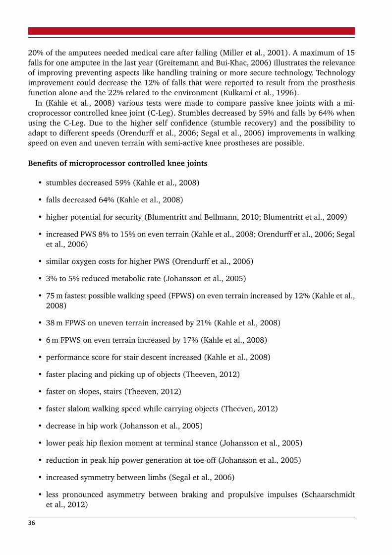
20% of the amputees needed medical care after falling (Miller et al., 2001). A maximum of 15falls for one amputee in the last year (Greitemann and Bui-Khac, 2006) illustrates the relevanceof improving preventing aspects like handling training or more secure technology. Technologyimprovement could decrease the 12% of falls that were reported to result from the prosthesisfunction alone and the 22% related to the environment (Kulkarni et al., 1996).
In (Kahle et al., 2008) various tests were made to compare passive knee joints with a mi-croprocessor controlled knee joint (C-Leg). Stumbles decreased by 59% and falls by 64% whenusing the C-Leg. Due to the higher self confidence (stumble recovery) and the possibility toadapt to different speeds (Orendurff et al., 2006; Segal et al., 2006) improvements in walkingspeed on even and uneven terrain with semi-active knee prostheses are possible.
Benefits of microprocessor controlled knee joints
• stumbles decreased 59% (Kahle et al., 2008)
• falls decreased 64% (Kahle et al., 2008)
• higher potential for security (Blumentritt and Bellmann, 2010; Blumentritt et al., 2009)
• increased PWS 8% to 15% on even terrain (Kahle et al., 2008; Orendurff et al., 2006; Segalet al., 2006)
• similar oxygen costs for higher PWS (Orendurff et al., 2006)
• 3% to 5% reduced metabolic rate (Johansson et al., 2005)
• 75 m fastest possible walking speed (FPWS) on even terrain increased by 12% (Kahle et al.,2008)
• 38 m FPWS on uneven terrain increased by 21% (Kahle et al., 2008)
• 6 m FPWS on even terrain increased by 17% (Kahle et al., 2008)
• performance score for stair descent increased (Kahle et al., 2008)
• faster placing and picking up of objects (Theeven, 2012)
• faster on slopes, stairs (Theeven, 2012)
• faster slalom walking speed while carrying objects (Theeven, 2012)
• decrease in hip work (Johansson et al., 2005)
• lower peak hip flexion moment at terminal stance (Johansson et al., 2005)
• reduction in peak hip power generation at toe-off (Johansson et al., 2005)
• increased symmetry between limbs (Segal et al., 2006)
• less pronounced asymmetry between braking and propulsive impulses (Schaarschmidtet al., 2012)
36
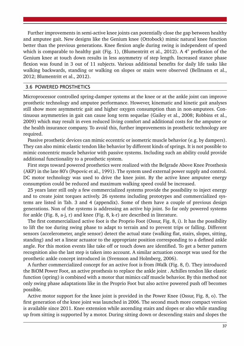
Further improvements in semi-active knee joints can potentially close the gap between healthyand amputee gait. New designs like the Genium knee (Ottobock) mimic natural knee functionbetter than the previous generations. Knee flexion angle during swing is independent of speedwhich is comparable to healthy gait (Fig. 1), (Blumentritt et al., 2012). A 4 preflexion of theGenium knee at touch down results in less asymmetry of step length. Increased stance phaseflexion was found in 3 out of 11 subjects. Various additional benefits for daily life tasks likewalking backwards, standing or walking on slopes or stairs were observed (Bellmann et al.,2012; Blumentritt et al., 2012).
3.6 POWERED PROSTHETICS
Microprocessor controlled spring-damper systems at the knee or at the ankle joint can improveprosthetic technology and amputee performance. However, kinematic and kinetic gait analysesstill show more asymmetric gait and higher oxygen consumption than in non-amputees. Con-tinuous asymmetries in gait can cause long term sequelae (Gailey et al., 2008; Robbins et al.,2009) which may result in even reduced living comfort and additional costs for the amputee orthe health insurance company. To avoid this, further improvements in prosthetic technology arerequired.
Passive prosthetic devices can mimic eccentric or isometric muscle behavior (e.g. by dampers).They can also mimic elastic tendon like behavior by different kinds of springs. It is not possible tomimic concentric muscle behavior with passive systems. Including such an ability could provideadditional functionality to a prosthetic system.
First steps toward powered prosthetics were realized with the Belgrade Above Knee Prosthesis(AKP) in the late 80’s (Popovic et al., 1991). The system used external power supply and control.DC motor technology was used to drive the knee joint. By the active knee amputee energyconsumption could be reduced and maximum walking speed could be increased.
25 years later still only a few commercialized systems provide the possibility to inject energyand to create joint torques actively. 26 systems including prototypes and commercialized sys-tems are listed in Tab. 3 and 4 (appendix). Some of them have a couple of previous designgenerations. Non of the systems is addressing an active hip joint. So far only powered systemsfor ankle (Fig. 8, a-j, r) and knee (Fig. 8, k-r) are described in literature.
The first commercialized active foot is the Proprio Foot (Ossur, Fig. 8, i). It has the possibilityto lift the toe during swing phase to adapt to terrain and to prevent trips or falling. Differentsensors (accelerometer, angle sensor) detect the actual state (walking flat, stairs, slopes, sitting,standing) and set a linear actuator to the appropriate position corresponding to a defined ankleangle. For this motion events like take off or touch down are identified. To get a better patternrecognition also the last step is taken into account. A similar actuation concept was used for theprosthetic ankle concept introduced in (Svensson and Holmberg, 2006).
A further commercialized concept for an active foot is from iWalk (Fig. 8, f). They introducedthe BiOM Power Foot, an active prosthesis to replace the ankle joint . Achilles tendon like elasticfunction (spring) is combined with a motor that mimics calf muscle behavior. By this method notonly swing phase adaptations like in the Proprio Foot but also active powered push off becomespossible.
Active motor support for the knee joint is provided in the Power Knee (Ossur, Fig. 8, o). Thefirst generation of the knee joint was launched in 2006. The second much more compact versionis available since 2011. Knee extension while ascending stairs and slopes or also while standingup from sitting is supported by a motor. During sitting down or descending stairs and slopes the
37

a) b) c) d)
e) f) g) h)
j) k) l) m)
n) o) p)
i)
q) r)
Figure 8: Active prosthetics for the ankle (a - j) the knee (k - q) and for both joints (r). For a moredetailed description see Tab. 3 for the ankle and Tab. 4 for the knee joints (appendix).
38

motor can dissipate energy. During take off the motor rises the heel actively for swing flexion.In addition it assists at stairs or slopes for positioning the knee adequately for touch down.Like in the BiOM Foot a spring is assisting the motor to some extend by storing energy in aspecific phase (yielding, stance phase flexion) and releasing it later. The same approach is usedin (Martinez-Villalpando et al., 2011). A powered knee joint prototype with an antagonistic SEAdesign (Fig. 8, n) could increase amputee’s average self-selected walking speed by 17% from1.12 m/s to 1.31 m/s compared to a C-Leg. At fixed speed (1.3 m/s) metabolic costs decreasedby 6.8% using the powered prototype in comparison to the semi-active knee joint.
Various powered prototypes (Tab. 3, 4) are in commercial or university development. Con-cepts are including single ankle and knee prosthetics but also approaches combining both jointsactuated in one design. At the Vanderbilt University (Nashville) a combination of powered kneeand ankle was developed (Sup et al., 2009), (Fig. 8, r). The concept will be further developedand commercialized by Freedom Innovations.
A concept using electrical motors to do cheap design knee prosthetics is introduced in (Islamet al., 2013; Latif et al., 2008), (Fig. 8, l). The motor should not replicate torque profiles ofwalking or stair climbing but it should enable the person to flex or extend the knee in low loador no load conditions.
Powered ankle joints for walking (Odyssey Ankle, Fig. 8, a) and running (Fig. 8, c and d)were developed at Springactive and Westpoint Military Academy (Hitt et al., 2010a) based onprevious designs (Sparky, Fig. 8, b) from the Arizona State University (Bellman et al., 2008).
Walking should also be achieved with the PANTOE 1 (Fig. 8, g) foot prosthesis developed atthe Peking University (Yuan et al., 2011; Zhu et al., 2010). In addition to the common conceptsan activated toe joint is integrated in the design.
A mixture of prosthetic and orthotic design is developed at the TU Darmstadt. The PoweredAnkle Knee Orthoprosthesis (PAKO, Fig. 8, j) should be used to evaluate elastic actuator designand control concepts for humanoid locomotion. Therefore a mechanism to change stiffness of aspring in the SEA is included in the design.
3.6.1 Mechanics
Actuator ConceptsAll commercial available active prosthetics and the most of the prototypes use electrical motor
technology for driving the ankle or the knee joint. In addition some of them include differentkinds of elastic concepts. Series, parallel or unidirectional parallel alignments of motor and ela-stic element are used aiming at a reduction of motor requirements. Peak power (PP), whichcorresponds to motor size and energy requirements (ER), which defines battery size and opera-tion time are characteristics to be decreased in comparison to direct drive (DD) systems.
Most of the active prosthetic prototypes try to mimic torque ankle profiles of the ankle andknee joint. Some of them are only acting with minimal power efforts (Fradet et al., 2010; Svens-son and Holmberg, 2006) to change for example ankle angle for ground clearance in flight phaseor to adapt ankle angle to slopes.
In order to get a higher power density than in electrical motors also hydraulic or pneumaticactuators could be used. In (Pillai et al., 2011) a design is introduced that provides energyinjection for the ankle and the knee joint by linear hydraulic actuators driven by a single pump.So push off can be supported at the ankle, early swing at the knee and the ankle joint. Duringstair climbing and late swing the knee can be powered. A special feature of the prosthesis is towork in active mode or also as a semi-active device like the C-Leg.
39

Pneumatic actuation was demonstrated with the pleated pneumatic artificial muscles (PPAM)concept (Versluys et al., 2009). The system was able to produce required torques for an arti-ficial ankle joint in walking. PPAM pressure was generated by a stationary compressor in thelaboratory.
Using PPAM, a stiffness adaptation for different speeds was possible. Required stiffness wasestimated by a linear regression on human ankle torque-angle curves.
Similar pneumatic concepts are used for experiments with orthotic structures (Ferris et al.,2005; Sawicki and Ferris, 2009).
Pneumatic actuation can also be found in a knee prosthesis (Waycaster et al., 2011), (Fig. 8,m). To become independent of external pneumatic supply this group investigates liquid propel-lants as energy source. The monopropellant, a reaction product of a catalytically decomposedliquid, should be able to provide large power output and long operation times. For a mobi-le solution the compact energy storage of the propellant will be beneficial (Shen and Christ,2011).
The high power density of the pneumatic system (Waycaster et al., 2011) can help to impro-ve prosthetic design. Similar advantages in power to weight ratio are identified for hydraulicsolutions (Durfee et al., 2011).
Spring ConfigurationsFor the different leg joints and also different tasks optimal elastic actuator configurations
can be identified. The challenge is to identify a most multifunctional solution that can providebenefits in various daily life activities. In terms of energy consumption the primary focus shouldbe on the most common daily life activities like walking or just standing in place. But also energyand power requirements in stair climbing, standing up, sitting down, walking slopes or runningcould be included in the choice for an elastic actuation concept.
Inspired by muscle modeling different actuator solutions can be considered. Solutions withseries elastic elements (SE) were used in (Pierrynowski and Morrison, 1985). Parallel elements(PE) to the contractil element (CE) were omitted in this study because many authors reportedonly negligible passive parallel forces. In contrast the Hill Model includes a SE and a PE. Diffe-rent solutions exist with the CE and the SE together in parallel to the PE (Zajac et al., 1989),(Fig. 9, e) or only the CE in parallel to the PE (Nigg et al., 1994), (Fig. 9, c). In addition to theconventional elastic concepts unidirectional springs, coming into action at a defined condition(kinematic, kinetic), can be considered.
Such an approach is used in (Sup et al., 2009) where the spring comes into action at anankle angle of about five degrees of plantarflexion. The BiOM ankle prosthesis (Eilenberg et al.,2010) includes an SEA in addition, to extend the system to a scheme similar to Fig. 9, i. Inan earlier version of the device the unidirectional spring is mentioned to be engaged at zerodegrees (Au et al., 2009). A spring in series (Fig. 9, b) with a much smaller stiffness than inthe BiOM ankle is included in the Robotic Tendon approach of Sparky. Stiffness is defined usingpower optimization calculations (Hollander and Sugar, 2005). Especially the long lever armbetween ankle joint and actuator causes this design difference (Grimmer and Seyfarth, 2011b).In contrast, in the BiOM ankle series stiffness is chosen based on open-loop force bandwidth (Auet al., 2009). An extended version of the Robotic Tendon approach is introduced in (Hitt et al.,2010a; Schinder et al., 2011). For running two parallel elastic actuators were included in thedesign to achieve the required power demands.
40

A series spring approach is also used for the AMP foot 2.0 (Cherelle et al., 2012), (Fig. 8, e).In contrast to the approaches using motors with over 150 W the design requires only a 60 Wmotor. This solution is possible by combining two basic mechanisms. A series spring, which isdecoupled from ankle motion, is loaded with a constant power by the small motor during theentire stance phase. A second spring is saving energy in a similar way like the forefoot part inESAR feet. During push off the passive spring returns its energy. In addition a clutch is used torelease the energy from the motor-spring combination (Fig. 9, f). On the one hand this approachprovides the advantage of less peak power requirements for the motor. This could potentiallysave space and weight if the required clutch mechanism is small enough. In contrast to themechanisms used in (Eilenberg et al., 2010) and (Hitt et al., 2010b) the energy return cannotbe modulated in the same way. It is like a catapult that just releases the energy if the triggeris pulled. The interaction with the amputee must be programmed carefully to match desiredpatterns. To which extend this approach can handle different daily life situations like differentspeeds, slopes and stairs should be further investigated.
Two SEA’s are used in the PANTOE 1 (Yuan et al., 2011; Zhu et al., 2010). The ankle prosthesisincludes one SEA for ankle plantar and dorsiflexion. Another SEA modulates toe joint motion.It is envisioned that the active prosthetic toe joint can improve several biomechanical parame-ters for the foot like RoM, angle velocity and energy output. Higher walking speeds should beachieved in comparison to rigid foot design.
Systematic analysis on elastic actuator concepts that reduce energy requirements (ER) orpeak power (PP) were published for the ankle (Grimmer and Seyfarth, 2011b; Wang et al.,2011; Eslamy et al., 2012; Grimmer et al., 2012), the knee (Grimmer and Seyfarth, 2011a;Wang et al., 2011) and the hip (Wang et al., 2011) joint. Methods for calculations base on(Hollander and Sugar, 2005). In order to decrease power, actuator velocity or actuator forcecould be reduced. A series spring has the capability to decrease motor velocity. A parallel springhas the capability to reduce motor force.
Especially for the ankle joint high benefits could be identified for the motor when using aseries spring with optimal stiffness in comparison to a direct drive. In terms of ER the meanadvantage for 5 different speeds between 0.5 m/s and 2.6 m/s was about 64.7% for runningand 25.8% in walking using an SEA. A PEA (Fig. 9, c) could reduce ER to less extent. 45%and 12.2% were possible respectively. A combination of both elastic structures (SE+PEA, Fig. 9,d) results in an energetic advantage of 52.8% in running and 17.9% in walking for the elasticactuator.
In terms of peak power highest reductions were identified for the SE+PEA system (81.8%) inrunning. The force reduction by the parallel spring contributes most to reduce power require-ments. A single PEA had already a mean advantage for the five speeds of 79%. An SEA couldreduce PP by 68.5% in running.
For walking a similar trend was identified. An SE+PEA had highest benefits (70.4%). Loweradvantages were identified for the PEA (62.5% and the SEA (48.3%).
Unidirectional parallel springs at the ankle joint (Fig. 9, g, h, i) can have similar power ad-vantages like the PEA. In addition it is possible for some speeds to get lower ER than in PEA(Eslamy et al., 2012).
At the knee joint energetic benefits of 5% to 29% could be achieved by an SEA in comparisonto a DD in walking (0.5 m/s to 2.6 m/s). Little or no PP (high speeds up to 31%) reductionswere possible in walking, when considering that negative work has to be done by the motor (no
41
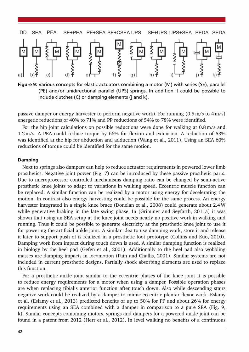
SEA PEA SE+PEA
M M M
PE+SEA
M
DD
M
a) b) c) d) e)
UPS
M
SE+UPS
M
g) h)
UPS+SEA
M
i)
M
f)
SE+CSEA
C
PEDA
M
j)
SEDA
M
k)
Figure 9: Various concepts for elastic actuators combining a motor (M) with series (SE), parallel(PE) and/or unidirectional parallel (UPS) springs. In addition it could be possible toinclude clutches (C) or damping elements (j and k).
passive damper or energy harvester to perform negative work). For running (0.5 m/s to 4 m/s)energetic reductions of 40% to 71% and PP reductions of 54% to 78% were identified.
For the hip joint calculations on possible reductions were done for walking at 0.8 m/s and1.2 m/s. A PEA could reduce torque by 66% for flexion and extension. A reduction of 53%was identified at the hip for abduction and adduction (Wang et al., 2011). Using an SEA 60%reductions of torque could be identified for the same motion.
DampingNext to springs also dampers can help to reduce actuator requirements in powered lower limb
prosthetics. Negative joint power (Fig. 7) can be introduced by these passive prosthetic parts.Due to microprocessor controlled mechanisms damping ratio can be changed by semi-activeprosthetic knee joints to adapt to variations in walking speed. Eccentric muscle function canbe replaced. A similar function can be realized by a motor using energy for decelerating themotion. In contrast also energy harvesting could be possible for the same process. An energyharvester integrated in a single knee brace (Donelan et al., 2008) could generate about 2.4 Wwhile generative braking in the late swing phase. In (Grimmer and Seyfarth, 2011a) it wasshown that using an SEA setup at the knee joint needs nearly no positive work in walking andrunning. Thus it could be possible to generate electricity at the prosthetic knee joint to use itfor powering the artificial ankle joint. A similar idea to use damping work, store it and releaseit later to support push of is realized in a prosthetic foot prototype (Collins and Kuo, 2010).Damping work from impact during touch down is used. A similar damping function is realizedin biology by the heel pad (Gefen et al., 2001). Additionally to the heel pad also wobblingmasses are damping impacts in locomotion (Pain and Challis, 2001). Similar systems are notincluded in current prosthetic designs. Partially shock absorbing elements are used to replacethis function.
For a prosthetic ankle joint similar to the eccentric phases of the knee joint it is possibleto reduce energy requirements for a motor when using a damper. Possible operation phasesare when replacing tibialis anterior function after touch down. Also while descending stairsnegative work could be realized by a damper to mimic eccentric plantar flexor work. Eslamyet al. (Eslamy et al., 2013) predicted benefits of up to 50% for PP and about 26% for energyrequirements using an SEA combined with a damper in comparison to a pure SEA (Fig. 9,k). Similar concepts combining motors, springs and dampers for a powered ankle joint can befound in a patent from 2012 (Herr et al., 2012). In level walking no benefits of a continuous
42

acting damper could be identified for the evaluated systems (Eslamy et al., 2013). Controllabledampers that are active only for some gait phases might change the results.
If the damper that assists the motor is only required for some phases of the gait cycle itshould be switchable to avoid negative effects for other phases. A damper mimicking heel pador wobbling mass function can be active the entire gait cycle.
3.6.2 Control
Control of prosthetic devices can be classified by the source of input data. On the one handcomputational intrinsic control (CIC) on the other hand interactive extrinsic control (IEC) arepossible (Martin et al., 2010), (Fig. 10). CIC has no connection to the user, whereas IEC allows acommunication between brain and user. This interaction can happen on the efferent commandbut also on the afferent feedback site. A commonly used signal in commercial arm prostheticsat the efferent site is EMG (electromyography). But also other signals could be possible for in-terfacing the peripheral and central nervous systems with the prosthetic system (Navarro et al.,2005). At the afferent feedback site up to now no sensor signals are transferred back to the brainfrom the prosthetic parts itself. Only sensory organs from the remaining parts of the limb provideinformation. For example mechanoreceptors of the skin can provide prosthetic socket pressureinformation or existing knee muscles in transtibial amputees can give information about forceand position. A main benefit of IEC can be to provide intent control signals already before themovement occurs. In contrast CIC can only react on current motion where for example clas-sification algorithms detect the intention of the user. A reaction on current motion like in theCIC is also found naturally. Reflex like mechanisms can create basic motion patterns withoutbrain interaction. In cat (decerebrated) and dog (decapitated) experiments it was shown thatthe spinal cord is able to produce reflex stepping after suppression of all afferent inputs fromthe brain (Goltz et al., 1875; Sherrington, 1910).
Thus it seems to be useful to have both approaches CIC and IEC combined in prosthetic controlto get advantages of decentralized primary locomotion functions and in addition intend basedcontrol. Especially for cyclic motions like walking less brain control effort would be requiredwith independent reflex like mechanisms. Using CIC or IEC different levels of prosthetic controlare required. Referring to (Sup et al., 2009) the highest level is the intent recognizer that detectsthe basic movement behavior of the amputee. Activities like standing, climbing stairs, level orinclined walking can be distinguished. On a mid-level the movement control is realized. Heremovement phase is detected and an appropriate output for the powered joint is created. At thelow level torque, speed or position control is used to generate required motor trajectory.
Various concepts are used to detect users intent and generate required motion patterns. In thefollowing some of them are explained with a focus on unique parts of each approach.
Muscle reflex controlMuscle reflex control can be a way to control a system independent from central motor com-
mands (Geyer et al., 2003). Sensory feedback from muscle spindles and Golgi tendon organs isused as an input for an appropriate control output. These organs can measure length, speed orforce in the biological actuators. In (Geyer et al., 2003) it was shown that positive length andforce feedback could be used to stabilize hopping in a computer simulation model. This basicidea is used and transferred to a complex multi-segmented bipedal muscle model (Geyer andHerr, 2010). The model is able to perform walking with human kinematics and dynamics, by
43

1. Sensor Information
1. Brain
2. Microprocessor
3. Actuator
4. Movement
2. Efferent Sensor
Communication
3. Microprocessor
4. Actuator
5. Movement
6. Haptic / Afferent
Feedback Interactiv
Extrinsic
Control (IEC)
Computational
Intrinsic
Control (CIC)
Figure 10: Components of computational intrinsic control (CIC) and interactive extrinsic control(IEC) for prosthetic devices (modified from (Martin et al., 2010))
using proprioreceptive feedback related to the body, muscle and ground interaction. Also it isable to deal with shallow slopes and small ground disturbances.
This concept is transferred to a powered ankle prosthesis (Eilenberg et al., 2010). An ankleangle sensor and an implemented spring force strain gauge can generate the input for the forceand length feedback controller. Together with the strain gauge at the pyramid adapter the sen-sors detect also the gait phase and transitions to set a state machine (stance or swing). Jointtorque is generated depending on torque delivered already by the mechanics (unidirectionalparallel spring) to match human level walking. Using the neuromuscular model the intrinsicsystem characteristics will increase net work at the ankle when increasing speed (Markowitzet al., 2011).
Finite state impedance controlThe finite state impedance control is used in a combined active knee and ankle prosthesis.
A first version was implemented in a power-tethered pneumatically actuated prototype (Supet al., 2008). Later the control was implemented in a brushless motor driven design (Sup et al.,2009). First an intent recognizer is detecting the amputees behavior. Prosthetic sensor datais compared to a database that classifies different activities like walking, sitting, standing orclimbing stairs. For this classification a Gaussian Mixture Model is used (Varol et al., 2010). Inaddition for example in walking a state machine is separating different phases of the gait cycle.For these phases an impedance is created to match human reference joint torque trajectories. Bygenerating torque instead of position trajectories the controller should provide a more naturalperformance. The output signal is generated by the amputee and the prosthesis and not only bythe prosthesis like in a position based control (Sup et al., 2009).
Phase plane controlPhase plane control of a robotic ankle joint was introduced in (Holgate et al., 2009). Various
prosthetic prototypes are using this concept (Hitt et al., 2010a,b). The controller needs a gyro
44

Figure 11: Phase plane trajectories of shank velocity and shank angle for walking and running.Shank velocities are scaled (divided by 10) to create more functional graphs for calcu-lating the Polar angle phi and the Polar radius r. Polar angle is used for gait percentdetermination. Polar radius for speed determination. Touch down is visualized by across, take off by a circle for each speed.
sensor at the tibia to measure shank rotational velocity. By integration, shank angle in relation tothe ground is determined. A transfer function is used to eliminate integration errors. Using shankvelocity and shank angle a phase plot can be generated. This was made for different step lengthsin (Holgate et al., 2009). Another possibility is to do it for different speeds (Fig. 11). The radiusof the polar curves can determine step length or gait velocity. The angle phi is used to determinegait percent. Both information are required to set the right motor position calculated by therobotic tendon approach (Grimmer et al., 2012; Hollander and Sugar, 2005). An advantage ofthis control approach is the possibility for automatic speed or step length adaptation during thegait cycle. When stopping walking shank velocity gets zero and the motor stops automatically.No states are required. Also backwards walking is possible with such a control approach. Slopes,stairs and uneven terrain can be handled by the interaction of the controller and the springintegrated in the mechanical design of the Sparky prosthesis.
Control based on residual joints, segments or organsIn (Parsan and Tosunoglu, 2012) a control method is introduced that uses the knee motion
of a transtibial amputee to control ankle motion. For this a rotary potentiometer is measuringthe knee angle that is used to calculate knee angle velocity. In addition a force sensor at theheel is used for contact information. Based on the sensory signals 4 states related to positiveor negative velocity and heel contact or heel in flight phase can be defined. Based on the stateankle angle is adjusted. Depending on amputation level also thigh (Thomas and Simon, 2012)or shank (Holgate et al., 2009) can be instrumented with sensors to control the prosthetic leg.In (Thomas and Simon, 2012) instead of a transfer function (Holgate et al., 2009) data fromaccelerometers and a Kalman filter is used to eliminate drift when calculating segment angle.
A method to determine knee and ankle motion by measured hip behavior is introduced in(Mutlu et al., 2011). Recursive Newton-Euler computation and inverse dynamics are used toobtain the joint behavior in walking.
45

Fuzzy logic as control approach is used for a motor driven knee joint (Alzaydi et al., 2011;Borjian, 2009; Lim, 2008). As an input a potentiometer at the knee and an accelerometer at thefemur was used.
Prosthetic control on the basement of eye motion was proposed in (Duvinage et al., 2011). Atthe highest control level user intent like starting of walking, stopping or changing of speed canbe transmitted to the prosthesis.
A neural network-based gait pattern classifier together with a rule-based gait phase detectorwas introduced in (Mai and Commuri, 2011). Inner socket forces of a transfemoral amputeewere identified and used to establish a control scheme for a prosthetic foot.
EMG based controlEMG based control approaches for prosthetics are tested since the 40’s for arms and legs
(Battye et al., 1955; Childress, 1985; Dyck et al., 1975; Horn, 1972). Commercially availableare so far only prosthetic arms. EMG signals of upper arm muscles are used to flex or extendthe elbow, for closing of the hand or also pronation of the wrist (Cutti et al., 2007). Variousresearch groups try to use this biological signal also for powered prosthetic control at the knee(Hargrove et al., 2011; Hoover et al., 2013; Islam et al., 2013) or also at the ankle (Au et al.,2005). EMG as a control signal for powered legs seems to be possible. Similar errors could beachieved while EMG based following of a trajectory with a prosthetic knee joint compared to ahealthy knee (Ha et al., 2011).
A key problem in EMG control is safety. Especially with a prosthetic leg falls caused by measu-rement and classification errors could be possible. In (Zhang et al., 2012) it was tested to whichextend intent recognition errors based on EMG will influence safety of gait. For this purpose 0.1s, 0.2 s and 0.3 s lasting errors were applied in different phases of the gait. Errors applied usedcontrol signals for standing or ramp descent at level walking. For errors of 0.1 s no instabilitywas reported. Also for longer error times during swing knee extension no critical safety issueswere reported by the amputee. For 0.2 and 0.3 seconds during stance phase critical errors arereported. As a reason for the unsafe condition energetic differences between real and appliedstate were identified.
In (Hoover et al., 2013) an impedance control approach was combined with myoelectric con-trol signals. Evaluation of a single subject with transfemoral amputation showed robust andrepeatable performance for ascending stairs. Using also an EMG based control, combined withthe active ankle and knee prosthesis described by (Lawson et al., 2013), in 2012 Zac Vawterclimbed the 103 floors of Chicago’s Willis Tower.
Neuromuscular - Mechanical FusionIn addition to pure EMG based control also a fusion between biomechanical sensor signals
(CIC) and EMG (IEC) could be possible. In (Huang et al., 2011) a classifier for gait was deve-loped based on gluteal (2x) and residual thigh (9x) muscle EMG. Neuromuscular signals werecombined with GRF and torques measured by a load cell on the prosthetic pylon. Insole pres-sure sensors were used for gait event detection. Using the combined method resulted in higheraccuracy of gait mode prediction. 99% could be achieved in stance, 95% in swing phase. Toincrease swing phase accuracy authors propose to add kinematic sensors. Transitions betweendifferent gait modes (obstacle crossing) were recognized using the sensor fusion with a sufficientprediction time.
46

Sensor fusion was also used in (Delis et al., 2011). Here the desired knee angle was esti-mated based on gyro sensor and EMG data. The authors demonstrated that combining bothsignals could increase estimation precision and it reduces artifacts of purely EMG based controlstrategies (Delis et al., 2010).
Control with sound limb signalsProsthetic control with the sound limb named “echo control“ was already discussed in (Grimes
et al., 1977). In (Au et al., 2005) it was tested if it is possible to generate motion patternsfor a prosthetic foot by EMG signals of the residual limb. Both, a neural network based and abiomimetic based control approach could predict desired ankle movement patterns qualitatively.Using angle and angular velocity sensors of the sound limb (Vallery et al., 2011) it was possibleto control a prosthetic knee in walking. Ascending stairs was possible but required balanceassistance. Descending was anticipated to be insecure and was less smooth compared to theC-Leg.
Grimes described that asymmetric behavior of the legs can cause problems in this approach(Grimes, 1979). Especially the sound limb of the amputee that is doing a compensating motioncannot be the reference for the residual limb. To overcome this problem healthy subject datawas used in (Vallery et al., 2011).
3.6.3 Prosthetic challenges
Wearing a lower limb prosthesis causes several challenges in daily life situations. Less RoM, nopower support, no direct control but also things like water proofed design can be a reason. Fora comparison of passive and semi-active microprocessor controlled knee joints a daily activityperformance test was developed (Theeven, 2012). Special test situations were created to beexecuted by the subjects. Tasks like normal walking, walking sideways, sitting down, standingup, carrying loads or also picking up objects are included. In addition tasks like dressing, puttingon or taking off the prosthetic device are tested. The complexity of the test shows the require-ments for a prosthetic development. Some of the requirements are addressed in the followingsubsections.
TerrainMost prosthetic prototypes are first designed to be capable of standing and level walking.
Due to additional daily life requirements like slopes, stairs or rough terrain further functionalityshould be included. Also tasks like standing up, sitting down, driving a bicycle or a car could beachievements to take into account.
Level ground: Level ground walking is one of the primary achievements for prosthetic design.Healthy people realize about 6,500 walking steps per day (Tudor-Locke and Bassett, 2004)with a preferred walking speed of about 1.3 m/s (Dal et al., 2010). In comparison to passiveprosthetic parts active ankle or knee joints should be able to reduce amputee metabolic costs,increase speed and reduce asymmetries in the gait pattern of the amputees.
With the BiOM ankle prosthesis ankle push off is supported. For a study of 11 amputees theankle prosthesis generated significantly greater peak ankle power (35%) in comparison to he-althy controls (Ferris et al., 2012). In comparison to passive ESAR feet an increase of 125%was possible. For a second study the increase of PP was about 54% compared to an ESAR foot(Mancinelli et al., 2011). Referring to (Zelik et al., 2011) higher peak power values, comparedto normal condition, may not result in better gait performance. Using the motor also higher
47

RoM could be achieved in comparison to the ESAR feet (30%) (Ferris et al., 2012). Howeverthe control group was still 20% better. The difference is caused by the ankle motion shortlyafter push-off. Here the healthy ankle joint is highly accelerated when leaving the ground. Thefast stretching of the dorsal extensors is possible for muscles but for a prosthesis doing dorsalextension and plantarflexion by one structure it is hard to realize. High power values and lessinertia would be required for the motor. The prosthesis is maybe not capable to mimic humanbehavior at this event. Also it could be possible that the desired motor trajectory is on a compro-mise solution to save energy at this point. The change of motor turning direction shortly afterthis event is strengthening the argument for a compromise solution. Here again higher powerdemands depending on required braking and acceleration of motor must be considered.
In addition to the effects at the ankle joint differences at knee and hip joint were identifiedfor the control group and the powered prosthetic leg. Effects of a missing biarticular structurebetween the ankle joint and the knee joint are mentioned as a possible reason. Also higher anklePP of the BiOM foot, compared to healthy subjects, could be a reason for pattern differences. Incomparison to (Herr and Grabowski, 2012; Au et al., 2009) (5% and 23% increase) an increaseof about 6% in self-selected walking speed from 1.32 m/s to 1.4 m/s was identified using thepowered foot compared to the ESAR foot (Ferris et al., 2012). Self selected walking speedalso increased with the Sparky prototype compared to a passive foot (Hitt et al., 2010b) forone tested amputee. Desired ankle angle could be achieved in stance. In swing phase desiredprosthetic ankle angle was reached too late. As a reason control properties can be assumedbecause electrical power consumption was not a limiting factor at this phase.
Typical amputee residual limb behavior with shorter stance and longer swing phases was notmeasured using the BiOM ankle. User recognition, reflected by the biomechanical data, resultedin higher user satisfaction using the powered foot.
Oxygen consumption in level walking could be reduced by 8.4% using the BiOM ankle com-pared to an ESAR foot (Mancinelli et al., 2011). 14% reduction could be achieved in a studywith a previous ankle design (Au et al., 2009).
Self-selected walking speed was about 24% higher for one transfemoral amputee using anpowered knee combined with a powered ankle joint (Sup et al., 2009). Level ground walkingspeed increased from 1.14 m/s to 1.41 m/s. Peak power at the ankle joint was at about 250 W,about 50 W were realized at the knee joint. At the ankle 0.2 J/kg of net energy is delivered eachstep which is very close to non-amputee data (0.22 J/kg Tab. 1). In total 66 Watts (45 ankle, 18knee, 3 embedded system) were required doing one step with powered knee and ankle for a70 kg amputee. Using the 0.62 kg (lipo 29.6 V, 4000 mAh) battery the prosthesis could be usedover 9 km of powered level ground walking.
In comparison to most semi-active knee joints, stance phase flexion could be realized using thepowered knee (Sup et al., 2009). Positive power could be delivered. In contrast to (Martinez-Villalpando et al., 2011) the system is not using springs at the knee joint to assist the motor.Partially negative joint power could be used to load the spring and to get positive power backto assist the motor. Additional reductions in energy requirements can potentially be achieved(see Sect. 3.6.1). Using an antagonistic SEA setup at the knee joint (Martinez-Villalpando et al.,2011) in combination with an ESAR foot already results in metabolic reductions of about 7%.Self-selected speed also increased with this setup from 1.12 m/s to 1.31 m/s (+ 17%) whenusing the active device compared to the C-Leg. Mean power consumption was about 11 W / gaitcycle (Martinez Villalpando, 2012) for 4 subjects (mean weight 93.3 kg, mean speed 1.37 m/s).Even though the achieved knee angle - torque profiles are not similar to results achieved in (Sup
48

et al., 2009) mean power requirements for the device using springs are 0.12 W/kg compared to0.26 W/kg - 0.3 W/kg (1.42 m/s, 70 kg) when using direct drive. Contrary results for walkingspeed and metabolic costs were identified in (Cutti et al., 2008) for the first version of the PowerKnee. In a preliminary study with two amputees the powered device caused higher metabolicsand reduced walking speed in comparison to the subjects with a semi-active prosthetic kneejoint (C-Leg).
Slopes: Due to limited RoM and power generation amputees struggle to walk especially incli-nes (Vickers et al., 2008). Similar to level walking transtibial amputees show less deficits thantransfemoral amputees (Vrieling et al., 2008). To improve gait performance authors proposeto improve control of prosthetic knee flexion without stability reductions. Using active prosthe-tics this criterion can be addressed. In order to set the right control slope has to be detected.Slope estimation could be realized by an accelerometer at the prosthetic foot (Svensson andHolmberg, 2006). An accuracy of 0.5 to 1.0 degrees could be achieved for indoor experiments.Combining the accelerometer with a gyro sensor (at foot) resulted in an accuracy of about 1.5degrees (Sabatini et al., 2005). Also strain sensors could be a possible solution. An error ofabout 1.5 degrees was identified when using these sensors to detect the slope at various speeds(Svensson and Holmberg, 2010). Instead of placing sensors at the foot segment also other loca-tions were considered. In (Aminian et al., 1995) slope was estimated based on accelerometersplaced at a waist belt. A neural network was trained and could predict slope with a standard de-viation of about 2.3%. The possibility to adapt to slopes was shown for an active knee and ankleprosthesis (Sup et al., 2011). When a heel and a ball load sensors are detecting ground contact,slope angle is estimated by an accelerometer. 12, 15, and 17 J per stride were measured for theconditions level ground, 5 incline and 10 incline. For the active ankle-knee device 12.2 km ofworking range were estimated for level walking. Walking a slope of 5 or 10 would result in adecreased capability of 9.2 km and 7.7 km respectively. Compared to the semi-active C-Leg theauthors identified various differences when using the powered device in upslope walking.
• stance knee flexion during heel strike and mid-stance
• ankle plantarflexion during heel strike
• ankle plantarflexion during push-off
• increased knee flexion with increased slope after heel strike
• net knee extension during stance phase
• increasing bias towards ankle dorsiflexion with increasing slope
Stairs: How many stairs people climb each day hardly depends on living and working condi-tions. For a study among 2,539 men (mean age, 57 years) on longevity (Lee and Paffenbarger,2000) 31% of subjects reported less than 10 floors per week. Between 10 and 20 floors werereported by 20%. Between 20 and 30 by 19% and more than 35 floors by 30%. Assuming amean of 22 floors a week and 15 stairs per floor this would result in about 47 stairs a day. Thisvalue is less than the value reported in (Purath et al., 2004). A group of 151 women (mean age,43 years) reported 4.4 flights of stairs a day. At 15 stairs a flight this would be 66 stairs a day.In comparison to 6,500 walking steps per day (Tudor-Locke and Bassett, 2004) 47 to 66 stairsa day are only a very small amount. Ascending stairs requires a higher power effort than level
49
walking (Sup et al., 2011). Descending seems to need higher control effort because 76% of stairfalls happen while descending (Svanström, 1974).
Stair ascent with a powered foot was analyzed in (Aldridge et al., 2012). In comparison toan ESAR foot the powered version could improve peak plantarflexion and push off power. Itwas found that peak power did not differ between the prosthetic foot and the ankle joint of acontrol group. Surprisingly the hip strategy to support stair ascent used by transtibial amputeeswith a passive foot is not influenced by additional RoM and push off power. Hip strategy ischaracterized by increased prosthetic limb hip extensor torque and power, reduced knee torqueand power and a more extended residual limb knee in stance phase (Aldridge et al., 2012). Acombination of powered knee and ankle was tested in stair ascent and descent (Lawson et al.,2013). The authors could show that using the powered prosthesis healthy gait was reflectedbetter in comparison to a semi-active device (C-Leg). Similar characteristics were identified forthe Power Knee in (Wolf et al., 2012). Without the possibility to inject energy knee extensionat the semi-active knee joint in stair ascent is impossible. To ascend stairs a different strategywas used by the amputee including support of the hand rail (Lawson et al., 2013). Knee jointremained extended for the whole step. This causes high differences between healthy control,powered knee and the semi-active knee device. For stair descent less difference was identifiedfor semi-active and powered knee joint whereas at the ankle joint the powered one showedmuch better performance in RoM.
Rough Terrain: Walking uneven terrain requires adaptation mechanisms for secure foot pla-cement. This includes an angle adaptation to match ground slope that can vary with each stepfor example in rocky surfaces. Possible mechanisms for such adaptations could be active con-trolled or also passive like dampers or springs. To adapt contact area of the foot to the ground,a healthy foot can do inversion and eversion. For passive prosthetic feet this function could bepartially represented by multiaxial joints or also splitted feet (Echolon VT). Powered solutionsto increase amputee balance may provide additional benefits (Panzenbeck and Klute, 2012). In(Gates et al., 2013) it is shown, that an amputee wearing a powered foot prosthesis providingplantarflexion, has a 10% higher self-selected walking speed compared to an ESAR foot on arocky surface. In comparison, on level ground a mean increase of about 5% (3 subjects) to 23%(7 subjects) was identified in (Herr and Grabowski, 2012; Au et al., 2009).
Sitting down - sitting - standing upSemi-active prosthetic knee joints like the C-Leg are able to secure sitting down by the me-
chatronic hydraulic stance phase safety system. The knee joint is damped to avoid collapse. Incomparison standing up can not be supported by the passive mechanics of these devices. Intel-ligent mechanisms with springs, storing energy while bending the knees during sitting down,similar to the mechanism in (Collins and Kuo, 2010), could potentially improve this. Standingup could be facilitated by powered knee devices. In (Varol et al., 2009) a finite state based im-pedance controller is designed to solve the specific task of sitting down and standing up. Thesubject reported easier standing up and he felt more support from the prosthesis compared tothe C-Leg which he uses daily. Up to 0.7 W/kg of peak power was delivered by the poweredknee during standing up and sitting down. Also the Power Knee (Ossur) can provide support inboth sitting down and standing up. A comparison between C-Leg and Power Knee was made in(Highsmith et al., 2010). The authors analyzed hip torques, knee torques and vertical GRF forsymmetry at one subject. While standing up for all conditions except for GRF the Power Kneeshowed improvements. However, still high asymmetries between the sound limb and the residu-
50
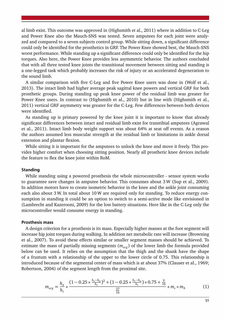
al limb exist. This outcome was approved in (Highsmith et al., 2011) where in addition to C-Legand Power Knee also the Mauch-SNS was tested. Seven amputees for each joint were analy-zed and compared to a seven subjects control group. While sitting down, a significant differencecould only be identified for the prosthetics in GRF. The Power Knee showed best, the Mauch-SNSworst performance. While standing up a significant difference could only be identified for the hiptorques. Also here, the Power Knee provides less asymmetric behavior. The authors concludedthat with all three tested knee joints the transitional movement between sitting and standing isa one-legged task which probably increases the risk of injury or an accelerated degeneration tothe sound limb.
A similar comparison with five C-Leg and five Power Knee users was done in (Wolf et al.,2013). The intact limb had higher average peak sagittal knee powers and vertical GRF for bothprosthetic groups. During standing up peak knee power of the residual limb was greater forPower Knee users. In contrast to (Highsmith et al., 2010) but in line with (Highsmith et al.,2011) vertical GRF asymmetry was greater for the C-Leg. Few differences between both deviceswere identified.
As standing up is primary powered by the knee joint it is important to know that alreadysignificant differences between intact and residual limb exist for transtibial amputees (Agrawalet al., 2011). Intact limb body weight support was about 64% at seat off events. As a reasonthe authors assumed less muscular strength at the residual limb or limitations in ankle dorsalextension and plantar flexion.
While sitting it is important for the amputees to unlock the knee and move it freely. This pro-vides higher comfort when choosing sitting position. Nearly all prosthetic knee devices includethe feature to flex the knee joint within RoM.
StandingWhile standing using a powered prosthesis the whole microcontroller - sensor system works
to guarantee save changes in amputee behavior. This consumes about 3 W (Sup et al., 2009).In addition motors have to create isometric behavior in the knee and the ankle joint consumingeach also about 3 W. In total about 10 W are required only for standing. To reduce energy con-sumption in standing it could be an option to switch to a semi-active mode like envisioned in(Lambrecht and Kazerooni, 2009) for the low battery situations. Here like in the C-Leg only themicrocontroller would consume energy in standing.
Prosthesis massA design criterion for a prosthesis is its mass. Especially higher masses at the foot segment will
increase hip joint torques during walking. In addition net metabolic rate will increase (Browninget al., 2007). To avoid these effects similar or smaller segment masses should be achieved. Toestimate the mass of partially missing segments (mseg) of the lower limb the formula providedbelow can be used. It relies on the assumption that the thigh and the shank have the shapeof a frustum with a relationship of the upper to the lower circle of 0.75. This relationship isintroduced because of the segmental center of mass which is at about 37% (Clauser et al., 1969;Robertson, 2004) of the segment length from the proximal site.
mseg =ha
ht∗(1− 0.25 ∗ ht−ha
ht)2 + (1− 0.25 ∗ ht−ha
ht) ∗ 0.75+ 9
16
3716
∗ms ∗mb (1)
51
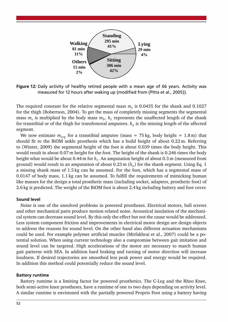
Standing 295 min
41%
Sitting 306 min
42%
Lying 29 min
4%
Walking 81 min
11%
Others 15 min
2%
Figure 12: Daily activity of healthy retired people with a mean age of 66 years. Activity wasmeasured for 12 hours after waking up (modified from (Pitta et al., 2005)).
The required constant for the relative segmental mass ms is 0.0435 for the shank and 0.1027for the thigh (Robertson, 2004). To get the mass of completely missing segments the segmentalmass ms is multiplied by the body mass mb. ht represents the unaffected length of the shankfor transtibial or of the thigh for transfemoral amputees. ha is the missing length of the affectedsegment.
We now estimate mseg for a transtibial amputee (mass = 75 kg, body height = 1.8 m) thatshould fit to the BiOM ankle prosthesis which has a build height of about 0.22 m. Referringto (Winter, 2009) the segmental height of the foot is about 0.039 times the body height. Thiswould result in about 0.07 m height for the foot. The height of the shank is 0.246 times the bodyheight what would be about 0.44 m for ht . An amputation height of about 0.3 m (measured fromground) would result in an amputation of about 0.23 m (ha) for the shank segment. Using Eq. 1a missing shank mass of 1.5 kg can be assumed. For the foot, which has a segmental mass of0.0147 of body mass, 1.1 kg can be assumed. To fulfill the requirements of mimicking humanlike masses for the design a total prosthetic mass (including socket, adapters, prosthetic foot) of2.6 kg is predicted. The weight of the BiOM foot is about 2.4 kg including battery and foot cover.
Sound levelNoise is one of the unsolved problems in powered prostheses. Electrical motors, ball screws
and other mechanical parts produce motion related noise. Acoustical insulation of the mechani-cal system can decrease sound level. By this only the effect but not the cause would be addressed.Less system component friction and improvements in electrical motor design are design objectsto address the reasons for sound level. On the other hand also different actuation mechanismscould be used. For example polymer artificial muscles (Mirfakhrai et al., 2007) could be a po-tential solution. When using current technology also a compromise between gait imitation andsound level can be targeted. High accelerations of the motor are necessary to match humangait patterns with SEA. In addition hard braking and turning of motor direction will increaseloudness. If desired trajectories are smoothed less peak power and energy would be required.In addition this method could potentially reduce the sound level.
Battery runtimeBattery runtime is a limiting factor for powered prosthetics. The C-Leg and the Rheo Knee,
both semi-active knee prostheses, have a runtime of one to two days depending on activity level.A similar runtime is envisioned with the partially powered Proprio Foot using a battery having
52
26.6 Wh. The Power Knee should provide a runtime of about five to seven hours using a batterycapacity of 66.5 Wh (0.49 kg). All four systems use Lithium-Ion technology.
A former version of the BiOM Ankle is using a lithium polymer battery (0.22 kg) having anenergy density of 165 Wh/kg. In a first study with 3 participants the prosthesis required about31.4 Joule electrical energy per step to get 17.5 Joule per step net mechanical energy at 1.6 m/swalking speed (Au et al., 2009). This results in a system efficiency of 56%. Using a 36.3 Wh(130.68 kJ) battery (Eilenberg et al., 2010), about 4,162 steps could be realized consuming the31.4 Joule (Au et al., 2009) used by MIT’s PowerFoot.
In daily life people realize about 6,500 walking steps per day (Tudor-Locke and Bassett, 2004)with a preferred walking speed of about 1.3 m/s (Dal et al., 2010). As walking is one of theprimary targets for powered prosthetics it can be a criterion for the dimensioning of a powereddevice. As the 6,500 steps are a result of two legs for unilateral amputees half of the steps needto be considered for the calculation of one day.
In addition ascending and descending of about 47 to 66 stairs and slopes should be conside-red. During these tasks ankle and knee joint behavior differs from level walking (DeVita et al.,2007). Thus it is required to estimate elastic actuator requirements similar to approaches usedin (Grimmer and Seyfarth, 2011b) (ankle) and (Grimmer and Seyfarth, 2011a) (knee) for levelwalking and running.
Also while standing energy is required for a prosthetic device. For the electronics, the kneeand the ankle motor a mean of 10 W was required in (Sup et al., 2009). Assuming the value ofabout 295 min of standing a day (Pitta et al., 2005), such a system needs 49.2 Wh only for thistask. Less energy should be required while sitting or lying. Especially while lying motors requirenearly no torque. About 3 W of electrical power consumption are measured for standing andwalking for the electronics in (Sup et al., 2009). As between these two tasks is only little diffe-rence a similar value can be assumed for the sitting or laying down condition. These conditionsare relevant because a huge amount of time (306 min) is spent for sitting (Fig. 12). Lying wasexecuted for about 29 min. Both tasks together will need about 16.8 Wh at 3 W for 335 min. Aslevel walking requires about 66 W for the powered knee and ankle joint and subjects performedabout 81 min each day (Pitta et al., 2005), 89.1 Wh of battery is required for this task using apowered device at both legs. A single powered leg would require about 44.6 Wh. In total about110.6 Wh are required to perform one day of a retired 66 years old person. This assumptionis not including tasks like ascending or descending stairs or slopes which can increase require-ments additionaly. Actually the device is using a 118 Wh lithium polymer battery which couldbe potentially enough to perform one day for a retired person based on this estimation.
3.7 TECHNOLOGY TRANSFER
The technology developed for leg prosthetics could potentially also be used in other roboticdesigns, including exoskeletons or rehabilitation platforms like the Lokomat (Hocoma). Exoske-letons are powered orthotic systems which can assist people with muscle weakness or otherdeficits that affect locomotion. But also healthy people can potentially benefit from assistan-ce similar to pedelecs or e-bikes. They allow to set an percentage to amplify the own powerintroduced to the bicycle. Especially at inclines or stair but also while carrying heavy loads apowered system could be beneficial. Systems like the Lokomat can be used to train people witha neurological or orthopedic impairment with a robotic orthesis operating the legs on a tread-mill. Basically walking can be performed. Exoskeleton technology could be a way to provide
53
flexible training conditions in each possible environment. A mobile device could also be usedfor locomotion training at home.
Also possible are combinations of powered or passive orthoses and prosthetics. This permitsto include joint coupling structures that can transfer energy from a still existing to an artificialjoint. With this, coordination in between the remaining limb and the artificial joints could beimproved.
3.8 SUMMARY AND OUTLOOK
Based on advances in motor, battery and microprocessor technology there is an increasing effortin developments of powered lower limb prosthetics over the last years. First active devices forreplacing the knee or the ankle joint are already commercialized. Powered prosthetics have thepotential to increase amputee performance compared to passive or semi-active devices. Whencomparing them to natural movements a lack can still be identified. Especially when changingbetween movement tasks or during non steady state motions systems get to their limits.
These deficits can result from the technical system. Biologically inspired highly efficient elasticdesign approaches can improve actuator performance. In contrast to semi-active and passivedevices most powered prostheses are so far not including passive dampers. They could furtherreduce requirements. Instead of wasting energy by dampers the energy could also be harvested.By this especially at the knee energy could be stored and reused at the ankle joint to supportpush off.
Next to the hardware design, also control has to be improved. Anticipation of the environmentand the selected movement task are key aspects for an appropriate control. Prosthetic devicesshould at least handle all basic tasks like ascending and descending stairs or slopes, walkingand standing. Multiple types of controllers were developed to address these conditions. Suddenevents like stumbling should be detected and handled similar to the way used in semi-activesystems. An improved level of control should recognize user intention. Thus voluntary motions,like flexing the knee while sitting, could be performed. Also adaptations to walking speed orlevel of slope could be possible. Changes in movement tasks (from walking to stair climbing)could be initiated intuitively by the amputee. In contrast to intrinsic control (CIC), that reacts oncurrent motion, a kind of pre-positioning of the joint similar to pre-activation in muscles wouldbe possible.
A feature that is less addressed in prosthetics so far are adaptable mechanical properties inthe prosthesis. Stiffness of elastic elements could be changed to reduce actuator requirements orto improve stability. Increased weight while carrying loads, different movement tasks or speedscould benefit from a variable mechanical design. Damping ratio could also be considered asa controllable parameter. These features should be combined with an intelligent control thatis finding the optimal mechanical adjustment (“sweet spot“) for the individual subject. As anoptimization criteria energy requirements or symmetry for cyclical motions could be considered.
So far only limited user adjustment of the prosthesis are possible for commercial systems. Con-trol and by this system behavior is pre-designed by the developers. Partially an individual gaitcan be configured while calibrating the system using software tools like in the C-Leg. Dampingratio for different phases of the gait cycle can be changed. Adaptations are made by the orthope-dic technician. A further step could be to provide a software where each amputee could calibratethe system on his own. To ensure security only a safe region for possible changes in damping orpower assistance should be considered. Exchange in internet communities could enhance userknowledge for creating their preferred personal settings. Even more potential would have an
54
open source library of prostheses software based on predefined standards. Universities but alsoprivate people could work on improved control algorithms for various daily life conditions.
Up to now a valid comparison of different powered but also passive prosthetics is difficult.Different subjects, measurement setups or also amputation condition and histories make it hardto compare systems. Results presented in different papers are using various biomechanical para-meters, different units and also different normalization. To evaluate prosthetic systems it wouldbe beneficial to have an institute that evaluates prosthetic systems under well-defined conditi-ons similar to the TÜV, Germany. Such an independent institute could provide sufficient data tohealth insurance companies regarding the benefits of different prosthetic systems. With this itcould be easier and better justified to select an adequate prosthesis matching users requirements.
3.9 AUTHOR CONTRIBUTIONS
Martin Grimmer is the main author of the book chapter. He was responsible for the conceptionand design, analysis and interpretation of data and writing of the manuscript. André Seyfarthassisted for the revision of the book chapter.
55

3.10 ABBREVIATIONS
CE contractile element
CIC computational intrinsic control
CoM center of mass
EMG electromyography
ER energy requirements
ESAR energy storage and return
FPWS fastest possible walking speed
GRF ground reaction force
IEC interactive extrinsic control
IL intact limb
PE parallel element
PEA parallel elastic actuator
PP peak power
PWS preferred walking speed
RL residual prosthetic limb
RoM range of motion
SACH solid ankle cushioned heel
SE series element
SEA series elastic actuator
TF transfemoral
TT transtibial
UPS unidirectional parallel spring
56

3.11 REFERENCES
Agrawal, V., Gailey, R., Gaunaurd, I., Gailey III, R., and O’Toole, C. (2011). Weight distributionsymmetry during the sit-to-stand movement of unilateral transtibial amputees. Ergonomics,54(7):656–664.
Aldridge, J. M., Sturdy, J. T., and Wilken, J. M. (2012). Stair ascent kinematics and kinetics witha powered lower leg system following transtibial amputation. Gait & Posture, 36(2):291–295.
Alzaydi, A. A., Cheung, A., Joshi, N., and Wong, S. (2011). Active Prosthetic Knee Fuzzy Logic-PID Motion Control, Sensors and Test Platform Design. International Journal of Scientific &Engineering Research, 2:1–17.
Aminian, K., Robert, P., Jequier, E., and Schutz, Y. (1995). Estimation of speed and inclineof walking using neural network. IEEE Transactions on Instrumentation and Measurement,44(3):743–746.
Au, S., Weber, J., and Herr, H. (2009). Powered Ankle–Foot Prosthesis Improves Walking Meta-bolic Economy. IEEE Transactions on Robotics, 25(1):51–66.
Au, S. K., Bonato, P., and Herr, H. (2005). An emg-position controlled system for an active ankle-foot prosthesis: an initial experimental study. In 9th International Conference on RehabilitationRobotics (ICORR), Chicago, pages 375–379. IEEE.
Battye, C., Nightingale, A., and Whillis, J. (1955). The use of myo-electric currents in theoperation of prostheses. Journal of Bone & Joint Surgery, British Volume, 37(3):506–510.
Bellman, R. D., Holgate, M. A., and Sugar, T. G. (2008). Sparky 3: Design of an active roboticankle prosthesis with two actuated degrees of freedom using regenerative kinetics. In 2nd IEEERAS & EMBS International Conference on Biomedical Robotics and Biomechatronics (BioRob),Scottsdale, pages 511–516. IEEE.
Bellmann, M., Schmalz, T., Ludwigs, E., and Blumentritt, S. (2012). Stair ascent with an inno-vative microprocessor-controlled exoprosthetic knee joint. Biomed Tech, 57:435–444.
Blumentritt, S. and Bellmann, M. (2010). Potenzielle Sicherheit von aktuellen nicht-mikroprozessor-und mikroprozessorgesteuerten Prothesenkniegelenken. Orthopädie Technik,61:788–799.
Blumentritt, S., Bellmann, M., Ludwigs, E., and Schmalz, T. (2012). Zur Biomechanik des mi-kroprozessorgesteuerten Prothesenkniegelenks Genium. Orthopädie Technik, 01:24–35.
Blumentritt, S., Schmalz, T., and Jarasch, R. (2009). The safety of C-Leg: Biomechanical tests.JPO: Journal of Prosthetics and Orthotics, 21(1):2.
Boonstra, A., Fidler, V., and Eisma, W. (1993). Walking speed of normal subjects and amputees:aspects of validity of gait analysis. Prosthetics and Orthotics International, 17(2):78–82.
Borjian, R. (2009). Design, modeling, and control of an active prosthetic knee. Master’s thesis,University of Waterloo.
57

Browning, R., Modica, J., Kram, R., and Goswami, A. (2007). The effects of adding mass to thelegs on the energetics and biomechanics of walking. Medicine & Science in Sports & Exercise,39(3):515.
Budaker, B. (2012a). Active driven prosthesis using a bevel helical gearbox in combination witha brushless DC-motor. In Proceedings BMT 2012, 46. DGBMT Jahrestagung, Track R. Preventionand Rehabilitation Engineering, Jena.
Budaker, B. (2012b). Auslegung von Multidomänen-Systemen-Analyse, Modellierung und Rea-lisierung von mechatronischen Systemen am Beispiel einer aktiven Knieprothese. PhD thesis,Fraunhofer-Institut für Produktionstechnik und Automatisierung (IPA) Stuttgart.
Cherelle, P., Matthys, A., Grosu, V., Brackx, B., Van Damme, M., Vanderborght, B., and Lefeber, D.(2012). The AMP-Foot 2.0: a powered transtibial prosthesis that mimics intact ankle behavior.In 9th National Congress on Theoretical and Applied Mechanics, Brussels.
Childress, D. S. (1985). Historical aspects of powered limb prostheses. Clinical prosthetics andorthotics, 9(1):2–13.
Clauser, C. E., McConville, J. T., and Young, J. W. (1969). Weight, volume, and center of massof segments of the human body. Technical report, DTIC Document.
Collins, S. and Kuo, A. (2010). Recycling energy to restore impaired ankle function duringhuman walking. PloS one, 5(2):e9307.
Colombo, C., Marchesin, E., Vergani, L., Boccafogli, E., and Verni, G. (2011). Design of an ankleprosthesis for swimming and walking. Procedia Engineering, 10:3503–3509.
Coupland, R. (1997). Assistance for victims of anti-personnel mines: needs, constraints andstrategy. Geneva: International Committee of the Red Cross, 5:1–18.
Crompton, R., Pataky, T., Savage, R., D’Août, K., Bennett, M., Day, M., Bates, K., Morse, S.,and Sellers, W. (2012). Human-like external function of the foot, and fully upright gait,confirmed in the 3.66 million year old laetoli hominin footprints by topographic statistics,experimental footprint-formation and computer simulation. Journal of The Royal Society In-terface, 9(69):707–719.
Cutti, A., Raggi, M., Garofalo, P., Giovanardi, A., Filippi, M., and Davalli, A. (2008). The effectsof the ’Power Knee’ prosthesis on amputees metabolic cost of walking and symmetry of gait–preliminary results. Gait & Posture, 28:S38.
Cutti, A. G., Garofalo, P., Janssens, K., Davalli, A., Sacchetti, R., and Cutti, A. G. (2007). Biome-chanical analysis of an upper limb amputee and his innovative myoelectric prosthesis: A casestudy concerning the otto bock dynamic arm. Dynamic Arm, Orthopaedie-Technik Quarterly,(1)pp, pages 6–15.
Czerniecki, J., Gitter, A., and Munro, C. (1991). Joint moment and muscle power output cha-racteristics of below knee amputees during running: the influence of energy storing prostheticfeet. Journal of Biomechanics, 24(1):63–65.
58
Dal, U., Erdogan, T., Resitoglu, B., and Beydagi, H. (2010). Determination of preferred wal-king speed on treadmill may lead to high oxygen cost on treadmill walking. Gait & Posture,31(3):366–369.
Delis, A. L., Carvalho, J., Seisdedos, C. V., Borges, G. A., and da Rocha, A. F. (2010). Myoelectriccontrol algorithms for leg prostheses based on data fusion with proprioceptive sensors. InProceedings ISSNIP Biosignals and Biorobotics Conference 2010, pages 137–142.
Delis, A. L., Carvalho, J. L., da Rocha, A. F., Nascimento, F. A., and Borges, G. A. (2011). Myo-electric knee angle estimation algorithms for control of active transfemoral leg prostheses.Intechopen.com.
DeVita, P., Helseth, J., and Hortobagyi, T. (2007). Muscles do more positive than negative workin human locomotion. Journal of Experimental Biology, 210(19):3361–3373.
Donelan, J., Li, Q., Naing, V., Hoffer, J., Weber, D., and Kuo, A. (2008). Biomechanicalenergy harvesting: generating electricity during walking with minimal user effort. Science,319(5864):807–810.
Duraiswami, P., Orth, M., and Tuli, S. (1971). 5000 years of orthopaedics in India. Clinicalorthopaedics and related research, 75:269.
Durfee, W., Xia, J., and Hsiao-Wecksler, E. (2011). Tiny hydraulics for powered orthotics. InIEEE International Conference on Rehabilitation Robotics (ICORR), Zurich, pages 1–6. IEEE.
Duvinage, M., Castermans, T., and Dutoit, T. (2011). Control of a lower limb active prosthesiswith eye movement sequences. In IEEE Symposium on Computational Intelligence, CognitiveAlgorithms, Mind, and Brain (CCMB), Paris, pages 1–7. IEEE.
Dyck, W., Onyshko, S., Hobson, D., Winter, D., and Quanbury, A. (1975). A voluntarily controlledelectrohydraulic above-knee prosthesis. Bulletin of prosthetics research, 10(23-26):169.
Eilenberg, M., Geyer, H., and Herr, H. (2010). Control of a powered ankle–foot prosthesisbased on a neuromuscular model. IEEE Transactions on Neural Systems and RehabilitationEngineering, 18(2):164–173.
Endolite (2012). www.endolite.com.
Eslamy, M., Grimmer, M., Rinderknecht, S., and Seyfarth, A. (2013). Does it pay to have adamper in a powered ankle prosthesis? a power-energy perspective. In IEEE InternationalConference on Rehabilitation Robotics (ICORR).
Eslamy, M., Grimmer, M., and Seyfarth, A. (2012). Effects of unidirectional parallel springs onrequired peak power and energy in powered prosthetic ankles: Comparison between diffe-rent active actuation concepts. In IEEE International Conference on Robotics and Biomimetics(ROBIO).
Ferris, A. E., Aldridge, J. M., Rábago, C. A., and Wilken, J. M. (2012). Evaluation of a poweredankle-foot prosthetic system during walking. Archives of physical medicine and rehabilitation,93(11):1911–1918.
59
Ferris, D. P., Czerniecki, J. M., Hannaford, B., et al. (2005). An ankle-foot orthosis powered byartificial pneumatic muscles. Journal of Applied Biomechanics, 21(2):189.
Fey, N., Klute, G., and Neptune, R. (2011). The influence of energy storage and return footstiffness on walking mechanics and muscle activity in below-knee amputees. Clinical Biome-chanics, 26(10):1025–1032.
Fradet, L., Alimusaj, M., Braatz, F., and Wolf, S. I. (2010). Biomechanical analysis of rampambulation of transtibial amputees with an adaptive ankle foot system. Gait & Posture,32(2):191–198.
Freedom Innovations (2012). www.freedom-innovations.com.
Gailey, R., Allen, K., Castles, J., Kucharik, J., and Roeder, M. (2008). Review of secondary phy-sical conditions associated with lower-limb amputation and long-term prosthesis use. Journalof Rehabilitation Research and Development, 45(1):15.
Gates, D. H., Aldridge, J. M., and Wilken, J. M. (2013). Kinematic comparison of walking onuneven ground using powered and unpowered prostheses. Clinical Biomechanics, 28(4):467–472.
Gefen, A., Megido-Ravid, M., and Itzchak, Y. (2001). In vivo biomechanical behavior of thehuman heel pad during the stance phase of gait. Journal of Biomechanics, 34(12):1661–1665.
Geil, M. (2001). Energy loss and stiffness properties of dynamic elastic response prosthetic feet.JPO: Journal of Prosthetics and Orthotics, 13(3):70.
Geng, Y., Yang, P., Xu, X., and Chen, L. (2012). Design and simulation of active transfemoralprosthesis. In 24th Chinese Control and Decision Conference (CCDC), Taiyuan, pages 3724–3728. IEEE.
Geyer, H. and Herr, H. (2010). A muscle-reflex model that encodes principles of legged mecha-nics produces human walking dynamics and muscle activities. IEEE Transactions on NeuralSystems and Rehabilitation Engineering, 18(3):263–273.
Geyer, H., Seyfarth, A., and Blickhan, R. (2003). Positive force feedback in bouncing gaits?Proceedings of the Royal Society of London. Series B: Biological Sciences, 270(1529):2173–2183.
Gitter, A., Czerniecki, J., and DeGroot, D. (1991). Biomechanical analysis of the influence ofprosthetic feet on below-knee amputee walking. American Journal of Physical Medicine &Rehabilitation, 70(3):142.
Goltz, F., Freusberg, A., and Gergens, E. (1875). Ueber gefässerweiternde Nerven. PflügersArchiv European Journal of Physiology, 11(1):52–99.
Greitemann, B. and Bui-Khac, H. (2006). Wie haufig stürzen an der unteren Extremitat ampu-tierte Patienten? Medizinisch Orthopädische Technik, 126(5):81.
Grimes, D., Flowers, W., and Donath, M. (1977). Feasibility of an active control scheme forabove knee prostheses. Journal of Biomechanical Engineering, 99:215.
Grimes, D. L. (1979). An active multi-mode above knee prosthesis controller. PhD thesis, Massa-chusetts Institute of Technology.
60

Grimmer, M., Eslamy, M., Gliech, S., and Seyfarth, A. (2012). A comparison of parallel-and serieselastic elements in an actuator for mimicking human ankle joint in walking and running. InIEEE International Conference on Robotics and Automation (ICRA), St. Paul, pages 2463–2470.IEEE.
Grimmer, M. and Seyfarth, A. (2011a). Stiffness adjustment of a series elastic actuator in aknee prosthesis for walking and running: The trade-off between energy and peak power opti-mization. In IEEE/RSJ International Conference on Intelligent Robots and Systems (IROS), SanFrancisco, pages 1811–1816. IEEE.
Grimmer, M. and Seyfarth, A. (2011b). Stiffness adjustment of a series elastic actuator in anankle-foot prosthesis for walking and running: The trade-off between energy and peak poweroptimization. In IEEE International Conference on Robotics and Automation (ICRA), Shanghai,pages 1439–1444. IEEE.
Ha, K. H., Varol, H. A., and Goldfarb, M. (2011). Volitional control of a prosthetic knee usingsurface electromyography. IEEE Transactions on Biomedical Engineering, 58(1):144–151.
Hafner, B. (2005). Clinical prescription and use of prosthetic foot and ankle mechanisms: areview of the literature. JPO: Journal of Prosthetics and Orthotics, 17(4):S5.
Hafner, B., Sanders, J., Czerniecki, J., and Fergason, J. (2002). Energy storage and return pros-theses: does patient perception correlate with biomechanical analysis? Clinical Biomechanics,17(5):325–344.
Hargrove, L., Simon, A. M., Finucane, S. B., and Lipschutz, R. D. (2011). Myoelectric controlof a powered transfemoral prosthesis during non-weight-bearing activities. In Proceedingsof the 2011 MyoElectric Controls/Powered Prosthetics Symposium, Fredericton, New Brunswick.Myoelectric Symposium.
Heller, G., Günster, C., and Swart, E. (2005). Über die Häufigkeit von Amputationen untererExtremitäten in Deutschland–About the frequency of lower limb amputations. Dtsch MedWochenschr, 130(28/29):1689–1690.
Herr, H. and Grabowski, A. (2012). Bionic ankle–foot prosthesis normalizes walking gaitfor persons with leg amputation. Proceedings of the Royal Society B: Biological Sciences,279(1728):457–464.
Herr, H. M., Au, S. K., Dilworth, P., and Paluska, D. J. (2012). Artificial ankle-foot systemwith spring, variable-damping, and series-elastic actuator components. US Patent App.13/348,570.
Highsmith, M. J., Kahle, J. T., Carey, S. L., Lura, D. J., Dubey, R. V., Csavina, K. R., and Quillen,W. S. (2011). Kinetic asymmetry in transfemoral amputees while performing sit to stand andstand to sit movements. Gait & Posture, 34(1):86–91.
Highsmith, M. J., Kahle, J. T., Carey, S. L., Lura, D. J., Dubey, R. V., and Quillen, W. S. (2010).Kinetic differences using a power knee and c-leg while sitting down and standing up: a casereport. JPO: Journal of Prosthetics and Orthotics, 22(4):237–243.
Hitt, J., Merlo, J., Johnston, J., Holgate, M., Boehler, A., Hollander, K., and Sugar, T. (2010a).Bionic running for unilateral transtibial military amputees. Technical report, DTIC Document.
61
Hitt, J., Sugar, T., Holgate, M., and Bellman, R. (2010b). An active foot-ankle prosthesis withbiomechanical energy regeneration. Journal of Medical Devices, 4:011003.
Hitt, J. K., Bellman, R., Holgate, M., Sugar, T. G., and Hollander, K. W. (2007). The sparky (springankle with regenerative kinetics) project: Design and analysis of a robotic transtibial prosthe-sis with regenerative kinetics. In Design Engineering Technology Conferences and Computers inInformation and Engineering Conference (IDETC/CIE). ASME.
Hocoma (2012). www.hocoma.com.
Hof, A. L., van Bockel, R. M., Schoppen, T., and Postema, K. (2007). Control of lateral balance inwalking: experimental findings in normal subjects and above-knee amputees. Gait & Posture,25(2):250–258.
Holgate, M., Sugar, T., and Bohler, A. (2009). A novel control algorithm for wearable roboticsusing phase plane invariants. In IEEE International Conference on Robotics and Automation(ICRA), pages 3845–3850. IEEE.
Hollander, K. and Sugar, T. (2005). Design of the robotic tendon. In Design of Medical DevicesConference (DMD).
Hoover, C. and Fite, K. (2010). Preliminary evaluation of myoelectric control of an active trans-femoral prosthesis during stair ascent. In Proceedings ASME Dynamic Systems and ControlsConference, Cambridge, MA, Paper No. DSCC2010-4158.
Hoover, C. D., Fulk, G. D., and Fite, K. B. (2013). Stair ascent with a powered transfemoralprosthesis under direct myoelectric control. TRANSACTIONS ON MECHATRONICS.
Horn, G. (1972). Electro-control: am EMG-controlled A/K prosthesis. Medical and BiologicalEngineering and Computing, 10(1):61–73.
Hosmer (2012). www.hosmer.com.
Huang, H., Zhang, F., Hargrove, L. J., Dou, Z., Rogers, D. R., and Englehart, K. B. (2011).Continuous locomotion-mode identification for prosthetic legs based on neuromuscular–mechanical fusion. IEEE Transactions on Biomedical Engineering, 58(10):2867–2875.
Islam, M. R., Haque, A. M., Amin, S., and Rabbani, K. (2013). Design and development ofan emg driven microcontroller based prosthetic leg. Bangladesh Journal of Medical Physics,4(1):107–114.
iWalk (2012). www.iwalkpro.com.
Johansson, J., Sherrill, D., Riley, P., Bonato, P., and Herr, H. (2005). A clinical comparisonof variable-damping and mechanically passive prosthetic knee devices. American Journal ofPhysical Medicine & Rehabilitation, 84(8):563.
Kahle, J. T., Highsmith, M., and Hubbard, S. (2008). Comparison of nonmicroprocessor kneemechanism versus c-leg on prosthesis evaluation questionnaire, stumbles, falls, walking tests,stair descent, and knee preference. Journal of Rehabilitation Research and Development,45(1):1.
62

Kuitunen, S., Komi, P., Kyröläinen, H., et al. (2002). Knee and ankle joint stiffness in sprintrunning. Medicine and Science in Sports and Exercise, 34(1):166.
Kulkarni, J., Wright, S., Toole, C., Morris, J., and Hirons, R. (1996). Falls in patients with lowerlimb amputations: prevalence and contributing factors. Physiotherapy, 82(2):130–136.
Lambrecht, B. G. and Kazerooni, H. (2009). Design of a semi-active knee prosthesis. In Roboticsand Automation, 2009. ICRA’09. IEEE International Conference on, pages 639–645. IEEE.
Lambrecht, B. G. A. (2008). Design of a Hybrid Passive-active Prosthesis for Above-knee Amputees.ProQuest.
Latif, T., Ellahi, C., Choudhury, T., and Rabbani, K. (2008). Design of a cost-effective emg drivenbionic leg. In International Conference on Electrical and Computer Engineering (ICECE), Dhaka,pages 80–85. IEEE.
Lawson, B., Varol, H. A., Huff, A., Erdemir, E., and Goldfarb, M. (2013). Control of stair ascentand descent with a powered transfemoral prosthesis. Neural Systems and Rehabilitation Engi-neering, IEEE Transactions on, 21(3):466–473.
Lee, I.-M. and Paffenbarger, R. S. (2000). Associations of light, moderate, and vigorous inten-sity physical activity with longevity the harvard alumni health study. American Journal ofEpidemiology, 151(3):293–299.
Lim, J. (2008). The mechanical design and analysis of an active prosthetic knee. Master’s thesis,University of Waterloo.
Lipfert, S. (2010). Kinematic and dynamic similarities between walking and running. Verlag Dr.Kovac, Hamburg. ISBN: 978-3-8300-5030-8.
Liu, M., Datseris, P., and Huang, H. H. (2012). A prototype for smart prosthetic legs-analysisand mechanical design. Advanced Materials Research, 403:1999–2006.
Mai, A. and Commuri, S. (2011). Gait identification for an intelligent prosthetic foot. In IEEEInternational Symposium on Intelligent Control (ISIC), Denver, pages 1341–1346. IEEE.
Mancinelli, C., Patritti, B. L., Tropea, P., Greenwald, R. M., Casler, R., Herr, H., and Bonato,P. (2011). Comparing a passive-elastic and a powered prosthesis in transtibial amputees. InAnnual International Conference of the IEEE Engineering in Medicine and Biology Society (EMBC), Boston, pages 8255–8258. IEEE.
Markowitz, J., Krishnaswamy, P., Eilenberg, M. F., Endo, K., Barnhart, C., and Herr, H. (2011).Speed adaptation in a powered transtibial prosthesis controlled with a neuromuscular model.Philosophical Transactions of the Royal Society B: Biological Sciences, 366(1570):1621–1631.
Martin, J., Pollock, A., and Hettinger, J. (2010). Microprocessor lower limb prosthetics: Reviewof current state of the art. JPO: Journal of Prosthetics and Orthotics, 22(3):183–193.
Martinez-Villalpando, E. and Herr, H. (2009). Agonist-antagonist active knee prosthesis: A pre-liminary study in level-ground walking. J Rehabil Res Dev, 46:361–374.
Martinez Villalpando, E. C. (2012). Design and evaluation of a biomimetic agonist-antagonistactive knee prosthesis. PhD thesis, Massachusetts Institute of Technology.
63

Martinez-Villalpando, E. C., Mooney, L., Elliott, G., and Herr, H. (2011). Antagonistic active kneeprosthesis. a metabolic cost of walking comparison with a variable-damping prosthetic knee.In Annual International Conference of the IEEE Engineering in Medicine and Biology Society(EMBC), Boston, pages 8519–8522. IEEE.
Miller, W. C., Speechley, M., and Deathe, B. (2001). The prevalence and risk factors of fal-ling and fear of falling among lower extremity amputees. Archives of Physical Medicine andRehabilitation, 82(8):1031–1037.
Mirfakhrai, T., Madden, J. D., and Baughman, R. H. (2007). Polymer artificial muscles. MaterialsToday, 10(4):30–38.
Mutlu, L., Uyar, E., Baser, O., and Cetin, L. (2011). Modelling of an under-hip prosthesis withankle and knee trajectory control by using human gait analysis. In 18th IFAC World CongressMilano (Italy), pages 9672–9673.
Nandi, G., Ijspeert, A., Chakraborty, P., and Nandi, A. (2009). Development of adaptive mo-dular active leg (amal) using bipedal robotics technology. Robotics and Autonomous Systems,57(6):603–616.
Nandy, A., Mondal, S., Chakraborty, P., and Nandi, G. C. (2012). Development of a robustmicrocontroller based intelligent prosthetic limb. In Contemporary Computing, pages 452–462. Springer.
NASDAB (2009). The amputee statistical database for the united kingdom 2006/07.
Navarro, X., Krueger, T. B., Lago, N., Micera, S., Stieglitz, T., and Dario, P. (2005). A criticalreview of interfaces with the peripheral nervous system for the control of neuroprosthesesand hybrid bionic systems. Journal of the Peripheral Nervous System, 10(3):229–258.
Nielsen, D. H., Shurr, D. G., Golden, J. C., and Meier, K. (1988). Comparison of energy cost andgait efficiency during ambulation in below-knee amputees using different prosthetic feet-apreliminary report. JPO: Journal of Prosthetics and Orthotics, 1(1):24.
Niemitz, C. (2010). The evolution of the upright posture and gait–a review and a new synthesis.Naturwissenschaften, 97(3):241–263.
Nigg, B. M., Herzog, W., and Herzog, W. (1994). Biomechanics of the musculo-skeletal system.Wiley New York.
Nolan, L. and Lees, A. (2000). The functional demands on the intact limb during walkingfor active trans-femoral and trans-tibial amputees. Prosthetics and Orthotics International,24(2):117–125.
Nolan, L., Wit, A., Dudzinski, K., Lees, A., Lake, M., and Wychowanski, M. (2003). Adjust-ments in gait symmetry with walking speed in trans-femoral and trans-tibial amputees. Gait& Posture, 17(2):142–151.
O’Donnell, F., Brundage, J., Wertheimer, E., Olive, D., and Clark, L. (2012). Medical surveillancemonthly report. volume 19, number 6. Technical report, DTIC Document.
64
Orendurff, M. S., Segal, A. D., Klute, G. K., McDowell, M. L., Pecoraro, J. A., and Czerniecki, J. M.(2006). Gait efficiency using the c-leg. Journal of Rehabilitation Research and Development,43(2):239.
Ossur (2012). www.ossur.com.
Ottobock (2012). www.ottobock.com.
Pain, M. T. and Challis, J. H. (2001). The role of the heel pad and shank soft tissue duringimpacts: a further resolution of a paradox. Journal of Biomechanics, 34(3):327–333.
Panzenbeck, J. T. and Klute, G. K. (2012). A powered inverting and everting prosthetic footfor balance assistance in lower limb amputees. JPO: Journal of Prosthetics and Orthotics,24(4):175–180.
Parsan, A. and Tosunoglu, S. (2012). A novel control algorithm for ankle-foot prosthesis. FloridaConference on Recent Advances in Robotics.
Pierrynowski, M. R. and Morrison, J. B. (1985). A physiological model for the evaluation of mus-cular forces in human locomotion: theoretical aspects. Mathematical Biosciences, 75(1):69–101.
Pillai, M. V., Kazerooni, H., and Hurwich, A. (2011). Design of a semi-active knee-ankle pros-thesis. In IEEE International Conference on Robotics and Automation (ICRA), Shanghai, pages5293–5300. IEEE.
Pitta, F., Troosters, T., Spruit, M. A., Probst, V. S., Decramer, M., and Gosselink, R. (2005).Characteristics of physical activities in daily life in chronic obstructive pulmonary disease.American Journal of Respiratory and Critical Care Medicine, 171(9):972–977.
Popovic, D., Tomovic, R., Tepavac, D., and Schwirtlich, L. (1991). Control aspects of activeabove-knee prosthesis. International Journal of Man-Machine Studies, 35(6):751–767.
Postema, K., Hermens, H., De Vries, J., Koopman, H., and Eisma, W. (1997). Energy storage andrelease of prosthetic feet part 1: Biomechanical analysis related to user benefits. Prostheticsand Orthotics International, 21(1):17–27.
Powers, C. M., Rao, S., and Perry, J. (1998). Knee kinetics in trans-tibial amputee gait. Gait &Posture, 8(1):1–7.
Prince, F., Winter, D., Sjonnensen, G., Powell, C., and Wheeldon, R. (1998). Mechanical effi-ciency during gait of adults with transtibial amputation: a pilot study comparing the SACH,Seattle, and Golden-Ankle prosthetic feet. Development, 35(2):177–185.
Prinsen, E. C., Nederhand, M. J., and Rietman, J. S. (2011). Adaptation strategies of the lowerextremities of patients with a transtibial or transfemoral amputation during level walking: asystematic review. Archives of Physical Medicine and Rehabilitation, 92(8):1311–1325.
Proteor (2012). www.proteor.com.
Purath, J., Michaels, M. A., McCabe, G., and Wilbur, J. (2004). A brief intervention to in-crease physical activity in sedentary working women – une intervention ponctuelle en vue
65

daccroitre lactivite physique chez les travailleuses sedentaires. CJNR: Canadian Journal ofNursing Research, 36(1):76–91.
Robbins, C., Vreeman, D., Sothmann, M., Wilson, S., and Oldridge, N. (2009). A review ofthe long-term health outcomes associated with war-related amputation. Military Medicine,174(6):588–592.
Robertson, D. G. E. (2004). Research methods in biomechanics. Human Kinetics Publishers.
Rusaw, D. and Ramstrand, N. (2011). Motion-analysis studies of transtibial prosthesis users: asystematic review. Prosthetics and Orthotics International, 35(1):8–19.
Sabatini, A. M., Martelloni, C., Scapellato, S., and Cavallo, F. (2005). Assessment of walkingfeatures from foot inertial sensing. IEEE Transactions on Biomedical Engineering, 52(3):486–494.
Sadeghi, H., Allard, P., Prince, F., and Labelle, H. (2000). Symmetry and limb dominance inable-bodied gait: a review. Gait & Posture, 12(1):34.
Sanderson, D. and Martin, P. (1996). Joint kinetics in unilateral below-knee amputee patientsduring running. Archives of Physical Medicine and Rehabilitation, 77(12):1279–1285.
Sauren, J., Lieby, B., et al. (2010). Motion analysis of the 2009 men’s 100 m world record.PhyDid B-Didaktik der Physik-Beiträge zur DPG-Frühjahrstagung.
Sawicki, G. S. and Ferris, D. P. (2009). A pneumatically powered knee-ankle-foot orthosis (KA-FO) with myoelectric activation and inhibition. Journal of Neuroengineering and Rehabilitati-on, 6(1):23.
Schaarschmidt, M., Lipfert, S. W., Meier-Gratz, C., Scholle, H.-C., and Seyfarth, A. (2012).Functional gait asymmetry of unilateral transfemoral amputees. Human Movement Science,31(4):907–917.
Schinder, A., Genao, C., and Semmelroth, S. (2011). Methodology for control and analysis of anactive foot-ankle prosthesis. Proceedings of The National Conference on Undergraduate Research(NCUR) 2011 Ithaca College, New York, pages 2011 –2018.
Schmalz, T., Blumentritt, S., Jarasch, R., et al. (2002). Energy expenditure and biomechanicalcharacteristics of lower limb amputee gait: the influence of prosthetic alignment and differentprosthetic components. Gait & Posture, 16(3):255.
Schneider, K., Hart, T., Zernicke, R., Setoguchi, Y., and Oppenheim, W. (1993). Dynamicsof below-knee child amputee gait: SACH foot versus Flex foot. Journal of Biomechanics,26(10):1191–1204.
Segal, A., Orendurff, M., Klute, G., McDowell, M., Pecoraro, J., Shofer, J., and Czerniecki, J.(2006). Kinematic and kinetic comparisons of transfemoral amputee gait using C-Leg®and Mauch SNS® prosthetic knees. Journal of Rehabilitation Research and Development,43(7):857.
Seroussi, R., Gitter, A., Czerniecki, J., and Weaver, K. (1996). Mechanical work adaptati-ons of above-knee amputee ambulation. Archives of Physical Medicine and Rehabilitation,77(11):1209–1214.
66

Seyfarth, A., Geyer, H., and Herr, H. (2003). Swing-leg retraction: a simple control model forstable running. Journal of Experimental Biology, 206(15):2547–2555.
Shen, X. and Christ, D. (2011). Design and control of chemomuscle: A liquid-propellant-powered muscle actuation system. Journal of Dynamic Systems, Measurement, and Control,133(2):021006–021006.
Sherrington, C. S. (1910). Flexion-reflex of the limb, crossed extension-reflex, and reflex step-ping and standing. The Journal of Physiology, 40(1-2):28.
Silverman, A., Fey, N., Portillo, A., Walden, J., Bosker, G., and Neptune, R. (2008). Compensa-tory mechanisms in below-knee amputee gait in response to increasing steady-state walkingspeeds. Gait & Posture, 28(4):602–609.
Springactive (2012). www.springactive.com.
Sup, F., Bohara, A., and Goldfarb, M. (2008). Design and control of a powered transfemoralprosthesis. The International Journal of Robotics Research, 27(2):263–273.
Sup, F., Varol, H., Mitchell, J., Withrow, T., and Goldfarb, M. (2009). Self-contained poweredknee and ankle prosthesis: Initial evaluation on a transfemoral amputee. In IEEE InternationalConference on Rehabilitation Robotics (ICORR), Kyoto, pages 638–644. IEEE.
Sup, F., Varol, H. A., and Goldfarb, M. (2011). Upslope walking with a powered knee and ankleprosthesis: initial results with an amputee subject. IEEE Transactions on Neural Systems andRehabilitation Engineering, 19(1):71–78.
Suzuki, R., Sawada, T., Kobayashi, N., and Hofer, E. (2011). Control method for powered ankleprosthesis via internal model control design. In International Conference on Mechatronics andAutomation (ICMA), pages 237–242. IEEE.
Svanström, L. (1974). Falls on stairs: an epidemiological accident study. Scandinavian Journalof Public Health, 2(3):113–120.
Svensson, W. and Holmberg, U. (2006). An autonomous control system for a prosthetic footankle. In 4th IFAC Symposium on Mechatronic Systems (2006), pages 856–861. InternationalFederation of Automatic Control (IFAC).
Svensson, W. and Holmberg, U. (2010). Estimating ground inclination using strain sensors withfourier series representation. Journal of Robotics, 2010.
Theeven, P. J. R. (2012). Functional added value of microprocessor-controlled prosthetic kneejoints. PhD thesis, Maastricht University.
Thomas, G. and Simon, D. J. (2012). Inertial thigh angle sensing for a semi-active knee prosthe-sis. Proceedings of the IASTED International Symposia Imaging and Signal Processing in HealthCare and Technology (ISPHT 2012), Baltimore.
Tudor-Locke, C. and Bassett, J. (2004). How many steps/day are enough?: Preliminary pedo-meter indices for public health. Sports Medicine, 34(1):1–8.
67

Unal, R., Carloni, R., Behrens, S., Hekman, E., Stramigioli, S., and Koopman, H. (2012). To-wards a fully passive transfemoral prosthesis for normal walking. In 4th IEEE RAS & EMBSInternational Conference on Biomedical Robotics and Biomechatronics (BioRob), Rome, pages1949–1954. IEEE.
Vallery, H., Burgkart, R., Hartmann, C., Mitternacht, J., Riener, R., and Buss, M. (2011). Com-plementary limb motion estimation for the control of active knee prostheses. BiomedizinischeTechnik/Biomedical Engineering, 56(1):45–51.
Van den Bogert, A. J. (2003). Exotendons for assistance of human locomotion. BiomedicalEngineering Online, 2(17):1–8.
van der Linde, H., Hofstad, C. J., Geurts, A. C., Postema, K., Geertzen, J. H., Van Limbeek, J.,et al. (2004). A systematic literature review of the effect of different prosthetic componentson human functioning with a lower-limb prosthesis. Journal of Rehabilitation Research andDevelopment, 41(4):555–570.
van Ingen Schenau, G. v., Bobbert, M., and Rozendal, R. (1987). The unique action of bi-articularmuscles in complex movements. Journal of Anatomy, 155:1.
Vanicek, N., Strike, S., McNaughton, L., and Polman, R. (2009). Gait patterns in transtibial am-putee fallers vs. non-fallers: Biomechanical differences during level walking. Gait & Posture,29(3):415–420.
Varol, H., Sup, F., and Goldfarb, M. (2009). Powered sit-to-stand and assistive stand-to-sit frame-work for a powered transfemoral prosthesis. In IEEE International Conference on RehabilitationRobotics (ICORR), Kyoto, pages 645–651. IEEE.
Varol, H. A., Sup, F., and Goldfarb, M. (2010). Multiclass real-time intent recognition of apowered lower limb prosthesis. IEEE Transactions on Biomedical Engineering, 57(3):542–551.
Verhoeff, T. (2002). ICRC Physical Rehabilitation Programmes, Annual Report 2001. AnnualReport.
Versluys, R., Lenaerts, G., Van Damme, M., Jonkers, I., Desomer, A., Vanderborght, B., Peeraer,L., Van der Perre, G., and Lefeber, D. (2009). Successful preliminary walking experiments ona transtibial amputee fitted with a powered prosthesis. Prosthetics and Orthotics International,33(4):368–377.
Vickers, D. R., Palk, C., McIntosh, A., and Beatty, K. (2008). Elderly unilateral transtibial ampu-tee gait on an inclined walkway: a biomechanical analysis. Gait & posture, 27(3):518–529.
Vrieling, A., Van Keeken, H., Schoppen, T., Otten, E., Halbertsma, J., Hof, A., and Postema, K.(2008). Uphill and downhill walking in unilateral lower limb amputees. Gait and Posture,28(2):235–242.
Wang, S., van Dijk, W., and van der Kooij, H. (2011). Spring uses in exoskeleton actuationdesign. In IEEE International Conference on Rehabilitation Robotics (ICORR), pages 1–6. IEEE.
Waters, R. L. and Mulroy, S. (1999). The energy expenditure of normal and pathologic gait.Gait & Posture, 9(3):207–231.
68
Waycaster, G., Wu, S.-K., and XIANGRONG, S. (2011). Design and control of a pneumaticartificial muscle actuated above-knee prosthesis. Journal of Medical Devices, 5(3).
Webster, J., Levy, C., Bryant, P., and Prusakowski, P. (2001). Sports and recreation for personswith limb deficiency. Archives of Physical Medicine and Rehabilitation, 82(3):S38–S44.
Wilson, A. B. (1992). History of amputation surgery and prosthetics. At las of Limb Prosthetics:Surgical, Prosthetic, and Rehabilitation Principles. Mosby-Year Book, pages 3–16.
Winter, D. A. (2009). Biomechanics and motor control of human movement. John Wiley & Sons,Inc., Hoboken, New Jersey.
Winter, D. A. and Sienko, S. E. (1988). Biomechanics of below-knee amputee gait. Journal ofBiomechanics, 21(5):361–367.
Wolf, E. J., Everding, V. Q., Linberg, A. A., Czerniecki, J. M., and Gambel, C. (2013). Comparisonof the power knee and c-leg during step-up and sit-to-stand tasks. Gait & Posture, 38(3):397–402.
Wolf, E. J., Everding, V. Q., Linberg, A. L., Schnall, B. L., Czerniecki, J. M., Gambel, J. M., et al.(2012). Assessment of transfemoral amputees using c-leg and power knee for ascending anddescending inclines and steps. Journal of Rehabilitation Research and Development, 49(6):831–842.
Yuan, K., Zhu, J., Wang, Q., and Wang, L. (2011). Finite-state control of powered below-kneeprosthesis with ankle and toe. In Proc. 18th IFAC World Congress, pages 2865–2870.
Zajac, F. E. et al. (1989). Muscle and tendon: properties, models, scaling, and application tobiomechanics and motor control. Critical Reviews in Biomedical Engineering, 17(4):359.
Zelik, K., Collins, S., Adamczyk, P., Segal, A., Klute, G., Morgenroth, D., Hahn, M., Orendurff,M., Czerniecki, J., and Kuo, A. (2011). Systematic variation of prosthetic foot spring affectscenter-of-mass mechanics and metabolic cost during walking. IEEE Transactions on NeuralSystems and Rehabilitation Engineering, 19(4):411–419.
Zhang, F., Liu, M., and Huang, H. (2012). Preliminary study of the effect of user intent re-cognition errors on volitional control of powered lower limb prostheses. In Engineering inMedicine and Biology Society (EMBC), 2012 Annual International Conference of the IEEE, pages2768–2771. IEEE.
Zhu, J., Wang, Q., and Wang, L. (2010). Pantoe 1: Biomechanical design of powered ankle-footprosthesis with compliant joints and segmented foot. In IEEE/ASME International Conferenceon Advanced Intelligent Mechatronics (AIM), pages 31–36. IEEE.
Ziegler-Graham, K., MacKenzie, E., Ephraim, P., Travison, T., Brookmeyer, R., et al. (2008). Esti-mating the prevalence of limb loss in the united states: 2005 to 2050. Archives of PhysicalMedicine and Rehabilitation, 89(3):422.
69

3.12 APPENDIX
Table 3: Overview on active prosthetic ankle developments
Item Details
Device ankle, Odyssey, Springactive, USA || Picture: a)Actuator motor-parallel spring complexBattery external batterySensors motor encoder, gyro sensorControl continuous control without states
Device ankle, Sparky, (Hitt et al., 2010b, 2007), Arizona State University and Springacti-ve, USA || Picture: b)
Actuator Robotic Tendon (SEA), Maxon RE-40, 150 W, lead screw, planetary gear boxBattery external batterySensors motor and ankle angle encoder, optical switch at heel or gyro sensorControl position control or phase plane control (Holgate et al., 2009)
Device Bionic Foot, (Hitt et al., 2010a; Schinder et al., 2011), Military Academy WestPoint, USA || Picture: c)
Actuator ankle, Robotic Tendon (SEA), 2x Maxon RE-40, lead screwBattery external batterySensors motor encoder, gyro sensorControl phase plane control
Device ankle, Walk-Run Ankle, Springactive, USA (design) and TU Darmstadt, Germany(control) || Picture: d)
Actuator elastic motor spring combinationBattery external batterySensors motor encoder, gyro sensor, acceleration sensorControl for standing, walking, running and gait transitions
Device ankle AMP-Foot 2.0, (Cherelle et al., 2012) Vrije Universiteit Brussel, Belgium,about 2.5 kg || Picture: e)
Actuator series spring and clutched SEA, Maxon RE 30, 60 W, transmission, ball screwBattery external power supplySensors force sensing resistor at toe and heel, strain gauges at two springs, two magnetic
encoders at ankle joint,Control nothing stated
Device ankle, BiOM - Power Foot (Eilenberg et al., 2010; Au et al., 2009), MassachusettsInstitute of Technology and iWalk (iWalk, 2012), USA || Picture: f)
Actuator SEA+UPS, Maxon EC-30, 200 W, 48 V at 24 V, belt drive transmission, ballscrewBattery 0.22 kg lipo at 165 Wh/kg for 5000 steps, internalSensors hall-effect ankle angle joint sensor, stain gauges for spring force, pyramid strain
gauge for GRF, motor encoderControl neuromuscolar reflex model
Continued on next page
70

Table 3 – Continued from previous page
Item Details
Device ankle and toe, PANTOE 1, (Yuan et al., 2011; Zhu et al., 2010), Peking University,China, 1.47kg || Picture: g)
Actuator ankle - 83 W Faulhaber brushed DC, toe - 45 W Faulhaber DC, ballscrewBattery Li, 1 kg, externalSensors motor angle encoder, touch and force sensor at heel and toe, potentiometer at
ankle and toe joint, potentiometer for ankle spring displacement sensorControl finite state control (Yuan et al., 2011)
Device ankle, (Suzuki et al., 2011), Kanazawa Institute of Technology, Japan 3.8kg inclu-ding battery || Picture: h)
Actuator unidirectional spring for controlling touch down plantarflexion with antagonisticunidirectional DD (assumed from figure), DC motor
Battery internalSensors ankle angle encoderControl internal model control including last step, ankle angle position control
Device ankle, Proprio Foot, Ossur, Iceland, 1.5 kg with Pyramid and Foot cover || Picture:i)
Actuator stepper motorBattery Lithium Ion 1800 mAh, 14.8 VSensors Accelerometers, ankle angle sensorControl artificial intelligence including last step
Device ankle, (Svensson and Holmberg, 2006), Halmstad University, Sweden || Picture:see publication
Actuator DC motor, only powered in swing phase, ball screwBattery nothing statedSensors accelerometer at foot for slope estimation and gait phase detectionControl finite state control
Device ankle, (Versluys et al., 2009), Vrije Universiteit Brussel, Belgium || Picture: seepublication
Actuator antagonistic pleated pneumatic artificial muscles (PPAM)Battery external power sourceSensors ankle joint angle encoder, footswitch at forefoot, midfoot and hindfoot, pressure
sensorControl feedforward torque control timed by foot switches
Device ankle, PAKO - Orthoprosthesis, Technical University Darmstadt, Lauflabor - Loco-motion Lab, Germany || Picture: j)
Actuator SEA with variable stiffness, 1025 W Thingap 2320 brushless DC motor 80 V at 48 VBattery external power supplySensors knee and ankle joint encoder, SEA force sensor, GRF sensor in foot, gyro and acce-
lerometer at shankControl speed related phase plane control similar to (Holgate et al., 2009)
71
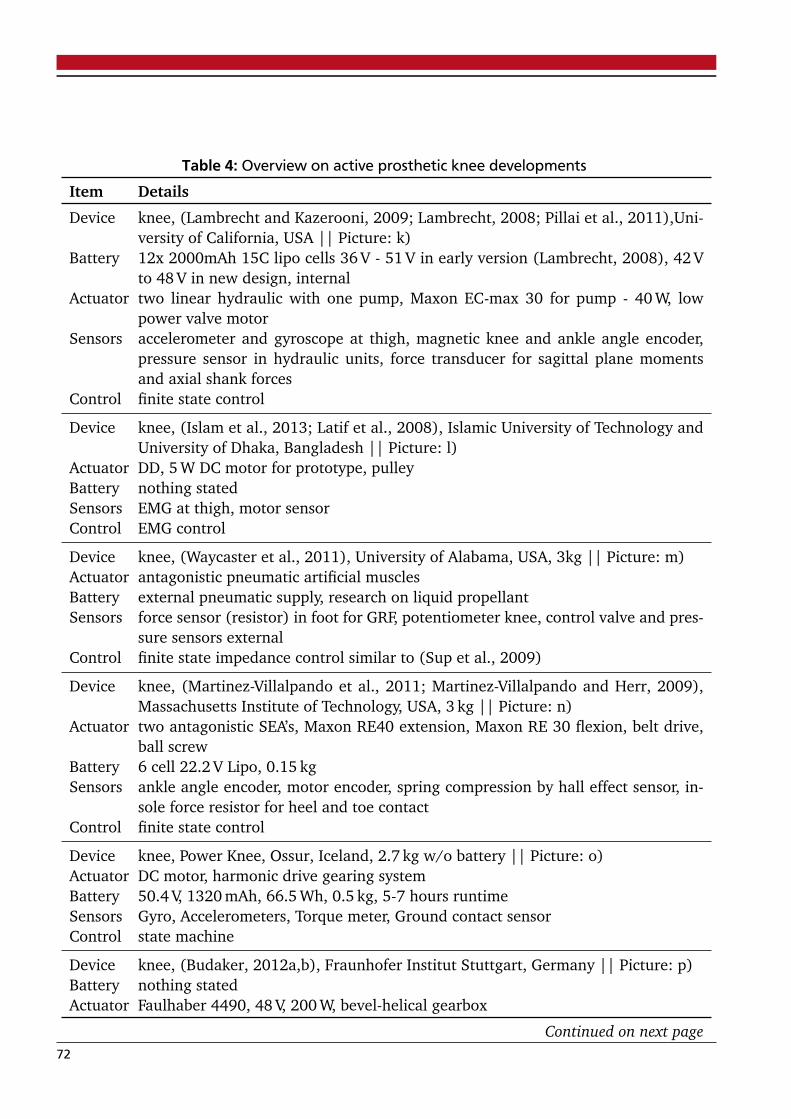
Table 4: Overview on active prosthetic knee developments
Item Details
Device knee, (Lambrecht and Kazerooni, 2009; Lambrecht, 2008; Pillai et al., 2011),Uni-versity of California, USA || Picture: k)
Battery 12x 2000mAh 15C lipo cells 36 V - 51 V in early version (Lambrecht, 2008), 42 Vto 48 V in new design, internal
Actuator two linear hydraulic with one pump, Maxon EC-max 30 for pump - 40 W, lowpower valve motor
Sensors accelerometer and gyroscope at thigh, magnetic knee and ankle angle encoder,pressure sensor in hydraulic units, force transducer for sagittal plane momentsand axial shank forces
Control finite state control
Device knee, (Islam et al., 2013; Latif et al., 2008), Islamic University of Technology andUniversity of Dhaka, Bangladesh || Picture: l)
Actuator DD, 5 W DC motor for prototype, pulleyBattery nothing statedSensors EMG at thigh, motor sensorControl EMG control
Device knee, (Waycaster et al., 2011), University of Alabama, USA, 3kg || Picture: m)Actuator antagonistic pneumatic artificial musclesBattery external pneumatic supply, research on liquid propellantSensors force sensor (resistor) in foot for GRF, potentiometer knee, control valve and pres-
sure sensors externalControl finite state impedance control similar to (Sup et al., 2009)
Device knee, (Martinez-Villalpando et al., 2011; Martinez-Villalpando and Herr, 2009),Massachusetts Institute of Technology, USA, 3 kg || Picture: n)
Actuator two antagonistic SEA’s, Maxon RE40 extension, Maxon RE 30 flexion, belt drive,ball screw
Battery 6 cell 22.2 V Lipo, 0.15 kgSensors ankle angle encoder, motor encoder, spring compression by hall effect sensor, in-
sole force resistor for heel and toe contactControl finite state control
Device knee, Power Knee, Ossur, Iceland, 2.7 kg w/o battery || Picture: o)Actuator DC motor, harmonic drive gearing systemBattery 50.4 V, 1320 mAh, 66.5 Wh, 0.5 kg, 5-7 hours runtimeSensors Gyro, Accelerometers, Torque meter, Ground contact sensorControl state machine
Device knee, (Budaker, 2012a,b), Fraunhofer Institut Stuttgart, Germany || Picture: p)Battery nothing statedActuator Faulhaber 4490, 48 V, 200 W, bevel-helical gearbox
Continued on next page72
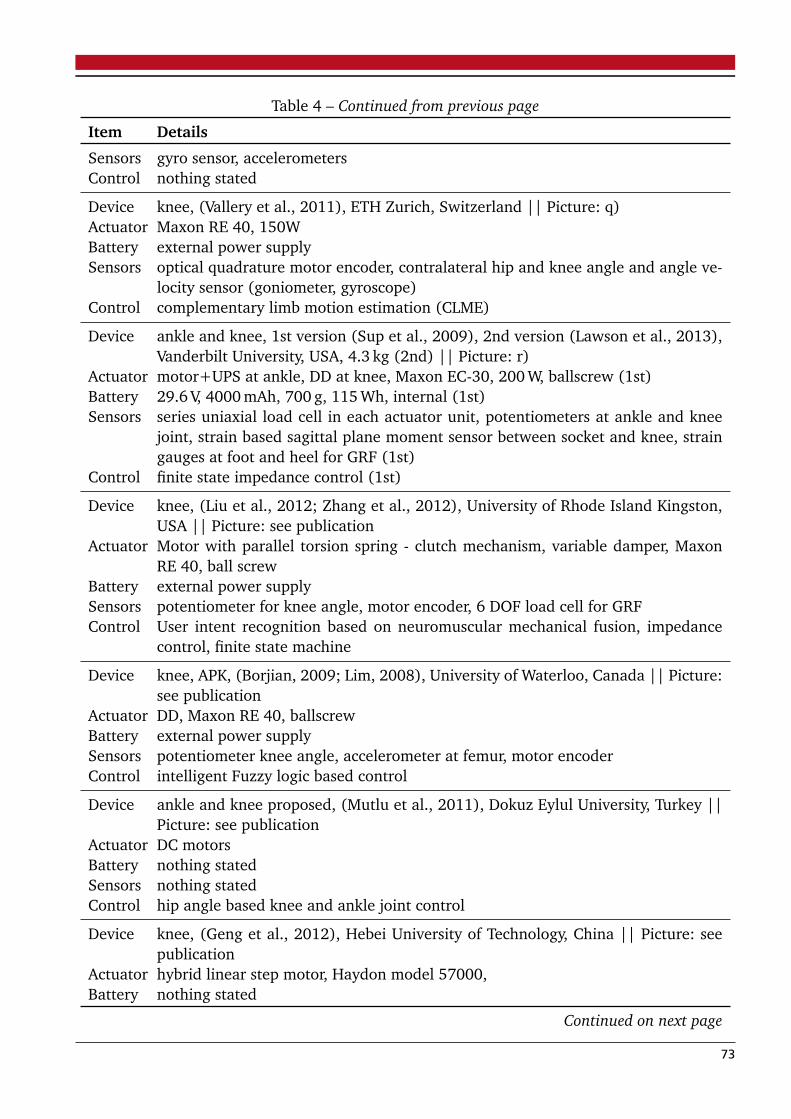
Table 4 – Continued from previous page
Item Details
Sensors gyro sensor, accelerometersControl nothing stated
Device knee, (Vallery et al., 2011), ETH Zurich, Switzerland || Picture: q)Actuator Maxon RE 40, 150WBattery external power supplySensors optical quadrature motor encoder, contralateral hip and knee angle and angle ve-
locity sensor (goniometer, gyroscope)Control complementary limb motion estimation (CLME)
Device ankle and knee, 1st version (Sup et al., 2009), 2nd version (Lawson et al., 2013),Vanderbilt University, USA, 4.3 kg (2nd) || Picture: r)
Actuator motor+UPS at ankle, DD at knee, Maxon EC-30, 200 W, ballscrew (1st)Battery 29.6 V, 4000 mAh, 700 g, 115 Wh, internal (1st)Sensors series uniaxial load cell in each actuator unit, potentiometers at ankle and knee
joint, strain based sagittal plane moment sensor between socket and knee, straingauges at foot and heel for GRF (1st)
Control finite state impedance control (1st)
Device knee, (Liu et al., 2012; Zhang et al., 2012), University of Rhode Island Kingston,USA || Picture: see publication
Actuator Motor with parallel torsion spring - clutch mechanism, variable damper, MaxonRE 40, ball screw
Battery external power supplySensors potentiometer for knee angle, motor encoder, 6 DOF load cell for GRFControl User intent recognition based on neuromuscular mechanical fusion, impedance
control, finite state machine
Device knee, APK, (Borjian, 2009; Lim, 2008), University of Waterloo, Canada || Picture:see publication
Actuator DD, Maxon RE 40, ballscrewBattery external power supplySensors potentiometer knee angle, accelerometer at femur, motor encoderControl intelligent Fuzzy logic based control
Device ankle and knee proposed, (Mutlu et al., 2011), Dokuz Eylul University, Turkey ||Picture: see publication
Actuator DC motorsBattery nothing statedSensors nothing statedControl hip angle based knee and ankle joint control
Device knee, (Geng et al., 2012), Hebei University of Technology, China || Picture: seepublication
Actuator hybrid linear step motor, Haydon model 57000,Battery nothing stated
Continued on next page
73
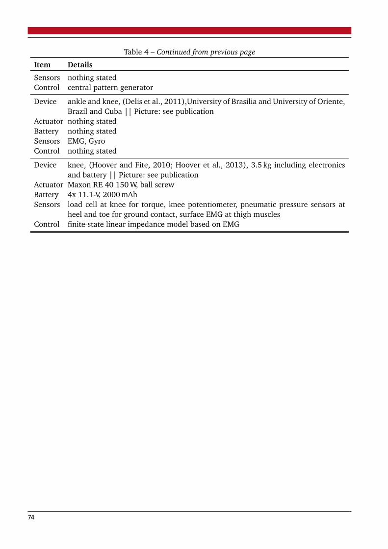
Table 4 – Continued from previous page
Item Details
Sensors nothing statedControl central pattern generator
Device ankle and knee, (Delis et al., 2011),University of Brasilia and University of Oriente,Brazil and Cuba || Picture: see publication
Actuator nothing statedBattery nothing statedSensors EMG, GyroControl nothing stated
Device knee, (Hoover and Fite, 2010; Hoover et al., 2013), 3.5 kg including electronicsand battery || Picture: see publication
Actuator Maxon RE 40 150 W, ball screwBattery 4x 11.1-V, 2000 mAhSensors load cell at knee for torque, knee potentiometer, pneumatic pressure sensors at
heel and toe for ground contact, surface EMG at thigh musclesControl finite-state linear impedance model based on EMG
74

4 Manuscript II: A Comparison of Parallel- and Se-ries Elastic Elements in an Actuator for MimickingHuman Ankle Joint in Walking and Running
Authors:
Martin Grimmer, Mahdy Eslamy, Stefan Gliech andAndré Seyfarth
Friedrich Schiller Universität07743 Jena, Germany
andTechnische Universität Darmstadt
64289 Darmstadt, Germany
Published as a paper at the
2012 IEEE International Conference on Robotics and Automation(ICRA)
Reprinted with permission of all authors and IEEE. ©2012 IEEE
In reference to IEEE copyrighted material which is used with permission in this thesis, the IEEE does not endorse any of TU Darm-
stadt’s products or services. Internal or personal use of this material is permitted. If interested in reprinting/republishing IEEE copy-
righted material for advertising or promotional purposes or for creating new collective works for resale or redistribution, please go to
http://www.ieee.org/publications_standards/publications/rights/rights_link.html to learn how to obtain a License from RightsLink.
4.1 ABSTRACT
Elastic elements in prosthetic devices can help to reduce peak power (PP) and energy require-ments (ER) for the actuators. Calculations showed that it is impossible with current commercialmotor technology to mimic human ankle behavior in detail for higher walking and runningspeeds with single motor solutions using a Serial Elastic Actuator (SEA). Concerning this resultwe checked the requirements of a parallel elastic actuator (PEA) and a combination of serialand parallel (SE+PEA) springs. We found that a PEA can reduce PP additionally in comparisonto the SEA by pre-loading the spring in the flight phase. This reduces also peak torque. But thisloading needs additional energy so that the ER increase in comparison to the SEA. The SE+PEAconcept can further decrease PP. With that, the ER are less than the PEA but higher than for theSEA. The results show less benefit for the PEA and the SE+PEA when a constant stiffness and afixed parallel spring slack length is used for both gaits and all speeds. All concepts show that mi-micking human ankle joint behavior in running and walking at higher speeds is still challengingfor single motor devices.
4.2 INTRODUCTION
Actual research shows that powered prosthetic feet, mimicking the human ankle angle-torqueprofile, are capable of improving amputees performance. Delivering positive net work at theankle joint results in multiple advantages. In comparison to passive carbon fiber feet, lower costof transport (Au et al., 2009) can be achieved for similar walking speeds. In unilateral amputeesthe biological leg can be unloaded and the preferred walking speed increased to values similarto non-amputees (Herr and Grabowski, 2011; Sup et al., 2009). In addition the more naturalgait of the amputees, reflected in biomechanical parameters (Herr and Grabowski, 2011; Hittet al., 2010; Sup et al., 2009), may provide advantages in terms of long-term sequelae.
To mimic the torque profile of the human ankle joint with a direct drive (DD) system for a75 kg subject a peak power (PP) of 241 W in walking (1.6 m/s) and a PP of 651 W in running(2.6 m/s) is necessary (Fig. 5). Different approaches can help to reduce these requirements. Acommon solution is to use springs that can assist the motor by storing and releasing energy.Serial assemblies (Grimmer and Seyfarth, 2011; Hollander and Sugar, 2005) and unidirectionalassemblies (Eilenberg et al., 2010; Sup et al., 2009) of the spring to the motor are used toreduce PP or ER. In (Grimmer and Seyfarth, 2011) it was shown how much an ankle prosthesiscan benefit from a SEA in running and walking for a wide variation of speeds. The theoreticaldata showed that it is possible to get the desired ankle behavior with currently available motortechnology but especially for higher speeds, mechanical couplings of two or more motors like inthe Bionic Running Ankle (Hitt et al., 2010a) are required. To mimic human gait in detail witha single motor solution novel concepts for further reductions are essential.
In this paper we investigate if it is possible to get further reductions by using a Parallel ElasticActuator (PEA) instead of a Series Elastic Actuator (SEA). Additionally, we want to check if acombination of both systems to a Series+Parallel Elastic Actuator (SE+PEA) can reduce addi-tionally actuator requirements. The calculations for the parallel springs depending on systemrelated model values like the spring stiffness and the slack length (when spring force is zero) ofthe parallel spring. In a first step we want to show the results for the case of optimized modelparameters, which are partially restricted (partially restricted case, PRC). In a 2nd step we wantto show which benefits can be achieved with constant model parameters (strict-restricted case,SRC).
76
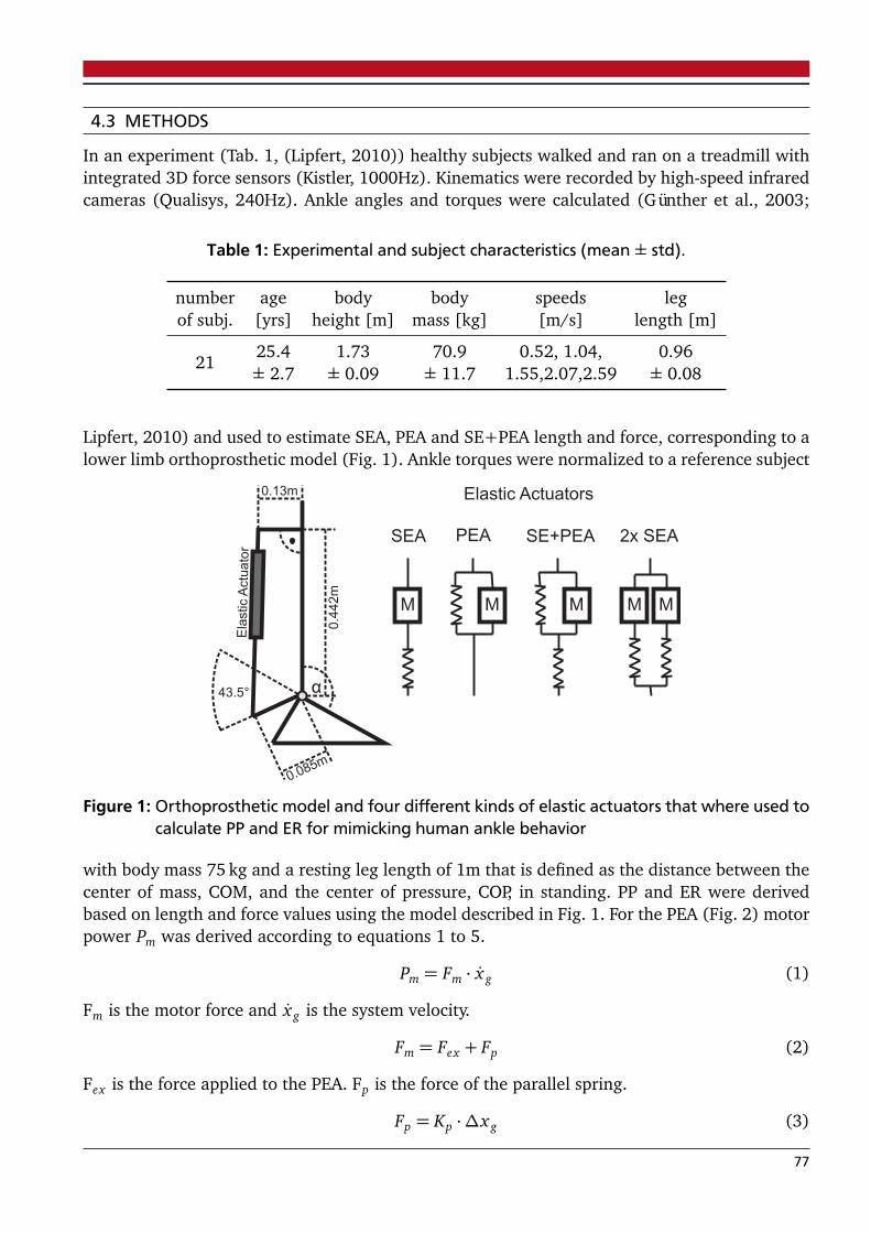
4.3 METHODS
In an experiment (Tab. 1, (Lipfert, 2010)) healthy subjects walked and ran on a treadmill withintegrated 3D force sensors (Kistler, 1000Hz). Kinematics were recorded by high-speed infraredcameras (Qualisys, 240Hz). Ankle angles and torques were calculated (Günther et al., 2003;
Table 1: Experimental and subject characteristics (mean ± std).
number age body body speeds legof subj. [yrs] height [m] mass [kg] [m/s] length [m]
2125.4 1.73 70.9 0.52, 1.04, 0.96± 2.7 ± 0.09 ± 11.7 1.55,2.07,2.59 ± 0.08
Lipfert, 2010) and used to estimate SEA, PEA and SE+PEA length and force, corresponding to alower limb orthoprosthetic model (Fig. 1). Ankle torques were normalized to a reference subject
43.5°
0.085m
0.13m
0.4
42m
Ela
stic
Actu
ato
r
SEA PEA SE+PEA
M M M
Elastic Actuators
2x SEA
M M
Figure 1: Orthoprosthetic model and four different kinds of elastic actuators that where used tocalculate PP and ER for mimicking human ankle behavior
with body mass 75 kg and a resting leg length of 1m that is defined as the distance between thecenter of mass, COM, and the center of pressure, COP, in standing. PP and ER were derivedbased on length and force values using the model described in Fig. 1. For the PEA (Fig. 2) motorpower Pm was derived according to equations 1 to 5.
Pm = Fm · x g (1)
Fm is the motor force and x g is the system velocity.
Fm = Fex + Fp (2)
Fex is the force applied to the PEA. Fp is the force of the parallel spring.
Fp = Kp ·∆x g (3)
77
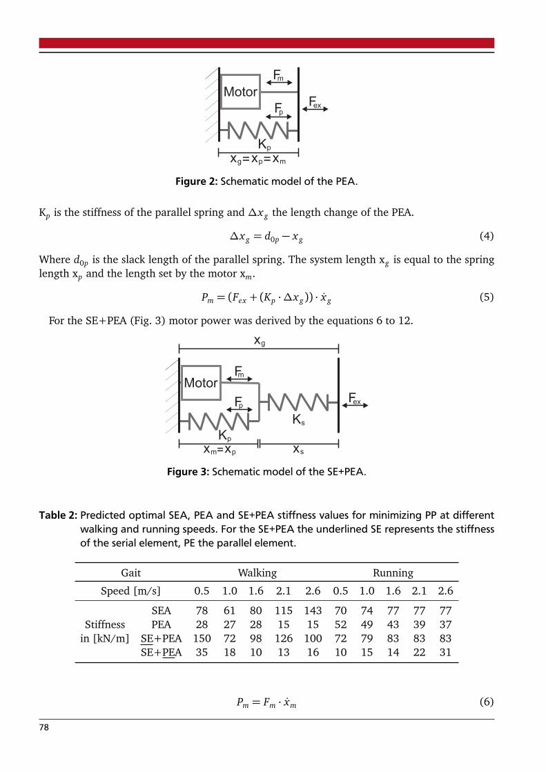
Motor
xg xp= =xm
Fm
Fex
Kp
Fp
Figure 2: Schematic model of the PEA.
Kp is the stiffness of the parallel spring and ∆x g the length change of the PEA.
∆x g = d0p − x g (4)
Where d0p is the slack length of the parallel spring. The system length xg is equal to the springlength xp and the length set by the motor xm.
Pm = (Fex + (Kp ·∆x g)) · x g (5)
For the SE+PEA (Fig. 3) motor power was derived by the equations 6 to 12.
Motor
xg
xsxm
Fm
Fex
Ks
Kp
xp=
Fp
Figure 3: Schematic model of the SE+PEA.
Table 2: Predicted optimal SEA, PEA and SE+PEA stiffness values for minimizing PP at differentwalking and running speeds. For the SE+PEA the underlined SE represents the stiffnessof the serial element, PE the parallel element.
Gait Walking Running
Speed [m/s] 0.5 1.0 1.6 2.1 2.6 0.5 1.0 1.6 2.1 2.6
SEA 78 61 80 115 143 70 74 77 77 77Stiffness PEA 28 27 28 15 15 52 49 43 39 37
in [kN/m] SE+PEA 150 72 98 126 100 72 79 83 83 83SE+PEA 35 18 10 13 16 10 15 14 22 31
Pm = Fm · xm (6)
78
Fm is the motor force and xm the motor velocity. Fm is influenced by the parallel and xm by theserial element.
Fm = Fex + Fp (7)
Fex is the force applied to the SE+PEA. Fp is the force of the parallel spring.
Fp = Kp ·∆xm (8)
Kp is the stiffness of the parallel spring and ∆xm the length change by the motor.
∆xm = xm − d0p (9)
Where xm is the length set by the motor (position of ball screw nut) and d0p is the slack lengthof the parallel spring. The length xp is equal to xm.
xm = x g +Fex
Ks− d0s (10)
The derivation of equation 10 can be found in (Hollander and Sugar, 2005). The system lengthxg is the sum of the serial (xs) and the parallel spring length (xp). Ks is the stiffness and d0s theslack length of the serial spring.
xm = x g +Fex
Ks(11)
Motor power is finally the product of motor force Fm and motor velocity xm.
Pm = (Fex + (Kp ·∆xm)) · ( x g +Fex
Ks) (12)
All equations rely on the method and similar input data like for the calculation of PP in a SEA(Hollander and Sugar, 2005). ER was calculated as the sum of positive and the amount ofnegative work by integrating the positive and the negative power curve, respectively (Grimmerand Seyfarth, 2011). PP is the maximum of the absolute motor power. It is important to note,that the systems can introduce pushing and pulling forces to represent the function of both ankleextensors and flexors. Therefore, no antagonistic structure is required. The estimated PP and ERwas normalized to body mass. Additionally ER was normalized to distance traveled during thegait cycle representing the cost of transport. By checking various settings optimal spring stiffnessvalues (1 kN/m - 1000 kN/m, 1 kN/m step size) and parallel element slack length (0.3 m - 0.5 m,1 mm step size) for minimal PP were determined for each walking and running speed. FinallyPP was compared to the direct drive (DD) configuration.
The calculations were done for a strictly-restrictive (SRC) and a partially-restrictive case (PRC)to get only results that are mechanically feasible (space, parameter variability) for an ankleprosthesis.
In the PRC (Fig. 5) we set the maximum deflection of the parallel spring to 0.05 m (com-pression or elongation allowed) to limit system length. Solutions with very low stiffness valuesrequiring high pretension to get the right force were excluded.
In the SRC (Fig. 6) the stiffness of the serial element (SE) and/or the parallel element (PE)was set to a constant value for all running and walking speeds. For this, we searched for thestiffness (by comparing PP values for a stiffness of 1 kN/m - 1000 kN/m, 1 kN/m step size) thatresults in minimum PP for both gaits up to 2.6 m/s. Additionally in this optimization a constantvalue for the slack length of the PE regarding both speeds was identified by checking a range ofvalues around the optimum PRC slack length solutions. Also the maximum spring deflection islimited to 0.05 m like in the PRC.
79

4.4 RESULTS
better
worse
ER ER
PP PP
ER - Energy RequirementsS - Speed
A - AccelerationF - Force
PP - Peak Power
Figure 4: Motor requirements regarding peak power, energy, peak force, max. linear speed andmax. linear acceleration to mimic human ankle behavior in walking (1.6m/s) and run-ning (2.6m/s). The data is shown in relation to the requirements of a DD. Maximumspeed and force must not occur at the same time. The results belong to the PRC.
4.4.1 Partial-restrictive case (PRC)
For this case we wanted to know which reductions in terms of PP and ER are possible by chan-ging the slack length for the PE and the stiffness (PE and SE) in the calculation model.
Energy RequirementsFor the SEA, PEA and the SE+PEA it is possible to reduce ER in comparison to the DD (Fig. 5,
7). With the SEA the mean benefit of all speeds in running (64.7%) is even higher than inwalking (25.8%). For the PEA we got also higher reductions in running (45%) than in walking(12.2%). A SE+PEA can reduce the ER by 52.8% in running and 17.9% in walking comparedto the DD.
Peak PowerAlso the peak power can be reduced for all three systems compared to the DD (Fig. 5, 7) . In
running we got the highest mean benefit by the SE+PEA (81.8%). The PEA system can reducethe PP by 79% and the SEA by a mean of 68.5%. A similar tendency is observed in walking(SE+PEA 70.4%, PEA 62.5% and SEA 48.3%).
StiffnessThe stiffness values of a SEA are higher compared to the PEA. Also the combination of both
springs in one system (SE+PEA) shows this tendency (Tab. 2).
80
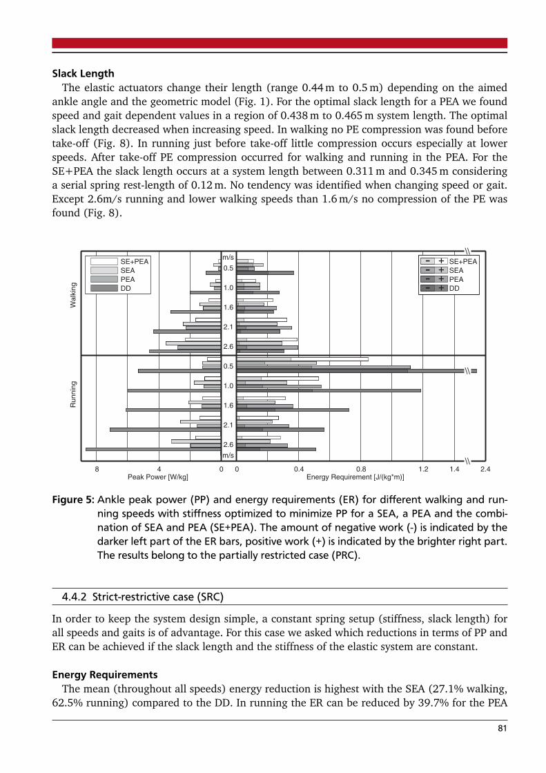
Slack LengthThe elastic actuators change their length (range 0.44 m to 0.5 m) depending on the aimed
ankle angle and the geometric model (Fig. 1). For the optimal slack length for a PEA we foundspeed and gait dependent values in a region of 0.438 m to 0.465 m system length. The optimalslack length decreased when increasing speed. In walking no PE compression was found beforetake-off (Fig. 8). In running just before take-off little compression occurs especially at lowerspeeds. After take-off PE compression occurred for walking and running in the PEA. For theSE+PEA the slack length occurs at a system length between 0.311 m and 0.345 m consideringa serial spring rest-length of 0.12 m. No tendency was identified when changing speed or gait.Except 2.6m/s running and lower walking speeds than 1.6 m/s no compression of the PE wasfound (Fig. 8).
Figure 5: Ankle peak power (PP) and energy requirements (ER) for different walking and run-ning speeds with stiffness optimized to minimize PP for a SEA, a PEA and the combi-nation of SEA and PEA (SE+PEA). The amount of negative work (-) is indicated by thedarker left part of the ER bars, positive work (+) is indicated by the brighter right part.The results belong to the partially restricted case (PRC).
4.4.2 Strict-restrictive case (SRC)
In order to keep the system design simple, a constant spring setup (stiffness, slack length) forall speeds and gaits is of advantage. For this case we asked which reductions in terms of PP andER can be achieved if the slack length and the stiffness of the elastic system are constant.
Energy RequirementsThe mean (throughout all speeds) energy reduction is highest with the SEA (27.1% walking,
62.5% running) compared to the DD. In running the ER can be reduced by 39.7% for the PEA
81

Figure 6: Ankle peak power (PP) and energy requirements (ER) for different walking and run-ning speeds with a constant stiffness independent of speed and gait for each elasticsystem (SEA, PEA, SE+PEA). Additionally a constant parallel spring slack length is usedin the PEA and SE+PEA. PP and ER are shown for the constants that minimize PP forboth gaits up to 2.6 m/s most. The amount of negative work (-) is indicated by the dar-ker left part of the ER bars, positive work (+) is indicated by the brighter right part. Theresults belong to the strict-restricted case (SRC).
and by 52.8% for the SE+PEA. In contrast the ER increases for walking by 9% for the PEA and3.4% for the SE+PEA (Fig. 6).
Peak PowerFor the PP we found the highest mean reductions compared to the DD in the SE+PEA (76.2%
running, 48% walking). The PP reductions for the SEA and the PEA for running (59.7%, 62.6%)and walking (41%, 40.9%) are comparable. At the PP demanding higher speeds the PEA hasadvantages (Fig. 6).
StiffnessThe optimal stiffness of the SEA to reduce PP for all speeds in running and walking up to
2.6 m/s is 90 kN/m. As an optimal value for the PEA a stiffness of 29kN/m was identified. Forthe SE+PEA the serial stiffness was 95 kN/m and the parallel 17 kN/m.
Slack LengthThe optimal slack length of the PE in the PEA was 0.455 m. At touch-down the spring is elon-
gated. Just before and after take-off we found PE compression for speeds higher than 1 m/s. Forthe SE+PEA the optimal slack length is about 0.319 m with a serial spring rest-length of 0.12 m.
82

This length occurs for walking only at 2.6 m/s directly after take-off. For all other walking andrunning speeds the PE in the SE+PEA is always elongated.
Walking 1.6m/s Running 2.6m/s
take-offDDMotorSEPE
SEA SEA
PEA
SE+PEA
PEA
SE+PEA
Pre-Loading PE
Figure 7: Power of the whole system (DD, solid black), the motor (Motor, solid dark grey), theserial element (SE, dotted grey) and/or the parallel element (PE, dashed grey) of thedifferent elastic actuators SEA, PEA and SE+PEA for walking at 1.6 m/s and running at2.6 m/s. The solid vertical lines represent the take-off. The results belong to the PRC.
4.5 DISCUSSION
4.5.1 Peak power and energy requirements.
We found that a SEA, a PEA and a SE+PEA can reduce PP and ER in comparison to a DD.A parallel element (PE) can decrease PP more than a serial element (SE) but a SE has theadvantage to decrease ER more than a PE. A combination of serial and parallel element can giveadditional advantages in PP but lower benefits in ER than the single SE. By setting the stiffnessand the PE slack length to a optimized constant value all the tested elastic actuators result in anincrease of PP and partially in ER. For fast walking speeds the ER are higher than for the DD.
The reason for the decreased PP in the elastic systems can be the decrease of actuator forceand/or actuator speed. Avoiding high forces and high speeds at the same time can also helpto reduce the power requirements of a motor. Checking these parameters SE can only reducemotor-speed, PE the forces on the motor (Fig. 4, 9). So a combination (SE+PEA) provides bothadvantages (Fig. 4, 9).
In order to take advantage of the PE it must be pre-loaded in the swing-phase by the motor(Fig. 7, 8, 9). This energy can then be released later during push-off to support the motorplantarflexing the ankle-joint.
83
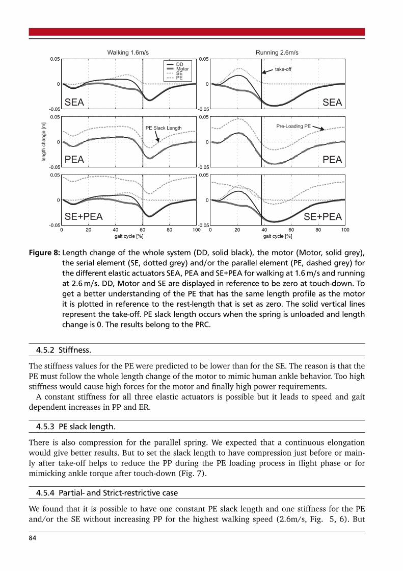
Walking 1.6m/s Running 2.6m/s
len
gth
ch
an
ge
[m
]
Pre-Loading PEPE Slack Length
take-offDDMotorSEPE
SEA SEA
PEA
SE+PEA
PEA
SE+PEA
Figure 8: Length change of the whole system (DD, solid black), the motor (Motor, solid grey),the serial element (SE, dotted grey) and/or the parallel element (PE, dashed grey) forthe different elastic actuators SEA, PEA and SE+PEA for walking at 1.6 m/s and runningat 2.6 m/s. DD, Motor and SE are displayed in reference to be zero at touch-down. Toget a better understanding of the PE that has the same length profile as the motorit is plotted in reference to the rest-length that is set as zero. The solid vertical linesrepresent the take-off. PE slack length occurs when the spring is unloaded and lengthchange is 0. The results belong to the PRC.
4.5.2 Stiffness.
The stiffness values for the PE were predicted to be lower than for the SE. The reason is that thePE must follow the whole length change of the motor to mimic human ankle behavior. Too highstiffness would cause high forces for the motor and finally high power requirements.
A constant stiffness for all three elastic actuators is possible but it leads to speed and gaitdependent increases in PP and ER.
4.5.3 PE slack length.
There is also compression for the parallel spring. We expected that a continuous elongationwould give better results. But to set the slack length to have compression just before or main-ly after take-off helps to reduce the PP during the PE loading process in flight phase or formimicking ankle torque after touch-down (Fig. 7).
4.5.4 Partial- and Strict-restrictive case
We found that it is possible to have one constant PE slack length and one stiffness for the PEand/or the SE without increasing PP for the highest walking speed (2.6m/s, Fig. 5, 6). But
84

Figure 9: Calculated actuator speed and actuator force for the SE+PEA (dash + double dot, darkgrey), the SEA (dotted, light grey), the PEA (dashed, grey) and the DD (solid black)to mimic human ankle joint behavior for walking (1.6 m/s, left) and running (2.6 m/s,right). The DD data for actuator speed is identical to the speed of the PEA actuator.The DD force is identical to the SEA actuator force. The results belong to the PRC.
by setting constant values the PP in all other conditions increases. ER only increasing for theactuators with PE at low speeds. In conclusion a change of stiffness and PE slack length canbe avoided to get a simple mechanical system. A possibility to change the parameters can saveenergy for lower speeds and reduces the PP requirements almost for all conditions.
4.5.5 Motor selection
If we want to build a robotic ankle-joint that is capable of human like walking up to 1.6 m/sand running up to 2.6 m/s in a DD linear acceleration of 11.7 m/s2, a linear speed of 0.57 m/s,a force of 31.5 N/kg and a power of 8.7 W/kg are necessary (Fig. 4). When we select a rollerscrew with a lead of 2 mm to transfer the linear to rotary motor motion the motor must havea speed of 1790 rad/sec. The acceleration should be 36757 rad/sec2. Considering a roller-screwefficiency of 85% and a subject weight of 75 kg the motor must handle 0.88 Nm peak torqueand a PP of 768 W for the DD.
Taking the same criteria into account (85%, 75 kg, 1.6 m/s walking and 2.6 m/s running) aparallel element can reduce the PP to 171 W and the peak torque to 0.39 Nm. The serial elementcan reduce PP to 282 W, acceleration to 32672 rad/sec2 (10.4 m/s2) and speed to 1037 rad/sec(0.33 m/s).
As an example the Maxon EC-4pole 30 (0.3 kg) can handle about 200 W and 0.12 Nm con-tinuous. A nominal speed of about 1655 rad/sec and an acceleration of 36000 rad/sec2 (conti-nuous torque/rotor inertia) is possible. So the primary limitation for the inrunner Maxon motoris that it is not delivering sufficient torque. Outrunner motors (Sensinger et al., 2011) like theThinGap TG2320 (0.48 kg) can provide higher torque. For a voltage of 48 V it can provide about0.58 Nm and about 618 W. The nominal speed at 48 V is about 1025 rad/sec, the acceleration3558 rad/sec2. Especially the slow acceleration caused by the inertia would limit the function ofthe elastic actuator.
85
Both motor examples can not full-fill the estimated requirements of the elastic actuators ina single motor solution. To get a system that can handle the requirements given by humanmeasurement data other or additional mechanical approaches are necessary.
Comparing the two motor solution 2x SEA with the SE+PEA (Fig. 4) shows that in runningthe requirements are nearly equal. Only the ER of the SE+PEA are higher because of the PE. Inwalking the ER and the force of the SE+PEA is higher than in the 2x SEA solution. From themechanical point of view the 2x SEA solution has less complexity but maybe a higher weight.Higher complexity (PE+SE) can limit the variability and increases the sensitivity of the system.From this point of view especially a system like the Bionic Running Ankle (Hitt et al., 2010a)with two SEA’s seems to be a good solution to achieve system requirements.
Taking heating into account, short time overloading of the motors can provide better feasi-bility. So two Maxon RE40, each rated at 150 W continious power, were able to handle about550 W electrical peak power in running experiments with the Bionic Running Ankle (Hitt et al.,2010a). Considering the efficiency of the motor, a higher output power than the continuouspower seems to be possible. If similar effects are possible for the continuous torque values ofthe Maxon EC-4pole motors, mentioned as an example, it could be a solution to achieve walkingand running at higher speeds with a double motor system.
4.5.6 Further concepts
If two motors are used they can also be integrated in different locations to mimic human m.soleus and m. gastrocnemius function. Further improvements in leg control might also be achie-ved by this. Maybe the biological function of slow Type I fibers in the m. soleus and the fast TypeII fibers in the m. gastrocnemius (Gollnick et al., 1974) can also be represented by the slowpowerful ThinGap and the fast Maxon motors respectively. So a combination of the strengths oftwo motors could solve the desired requirements.
Other options to reduce the requirements can be to use non-linear springs which representbetter the non-linear tendon function of the plantar-flexors (Alexander, 1992; Shin et al., 2008).This can also be realized by adding unilateral springs to the system. Another approach, to de-crease the system requirements, is to mimic the measured human joint function not in detail. Towhich extend such a method works without clearly affecting the ankle function must be proofedin experiments.
In addition catapult like pre-loading (swing) and releasing (during push-off) similar to theparallel spring in the PEA or passive ankle-knee couplings (Unal et al., 2010) can help to improveankle push-off performance.
Improvements in motor technology can also solve the limitations.
4.6 CONCLUSION
The theoretical calculations showed that a SEA, a PEA and a SE+PEA can reduce peak powerand energy requirements in comparison to a DD. Parallel elements can give advantages in peakpower in comparison to the serial elements. On the other hand serial elements having advanta-ges in minimizing energy requirements. A combination of both elastic structures in an SE+PEAcan further decrease peak power. With that, the energy requirements are less than the PEA buthigher than for the SEA. The results show less benefit for the PEA and the SE+PEA when a con-stant stiffness and a fixed parallel spring slack length is used for all walking and running speeds.The proofed concepts show that mimicking human ankle joint behavior in running and walking
86

at higher speeds is still challenging for single motor devices. Improvements in motor technologyor additional novel concepts for further reductions are required. As our investigation shows adouble motor solution seems to be currently the best way to fully reproduce human ankle func-tion for both gaits. For this, the best arrangement of mono- or biarticular elastic actuators hasto be identified.
4.7 ACKNOWLEDGMENTS
This work was supported by the DFG grant SE1042/8. The authors acknowledge S.W. Lipfertfor providing human data.
4.8 AUTHOR CONTRIBUTIONS
Martin Grimmer is the main author of the article. He was responsible for the conception anddesign, analysis and interpretation of data and writing of the manuscript. Mahdy Eslamy wascontributing to the discussion of the results and for the revision of the article. Stefan Gliechassisted to perform first calculations on parallel elastic structures. André Seyfarth assisted forthe revision of the article.
4.9 REFERENCES
Alexander, R. (1992). Exploring biomechanics. animals in motion. Scientific American Library,New York, 247.
Au, S., Weber, J., and Herr, H. (2009). Powered Ankle–Foot Prosthesis Improves Walking Meta-bolic Economy. Robotics, IEEE Transactions on, 25(1):51–66.
Eilenberg, M., Geyer, H., and Herr, H. (2010). Control of a powered ankle–foot prosthesis basedon a neuromuscular model. Neural Systems and Rehabilitation Engineering, IEEE Transactionson, 18(2):164–173.
Gollnick, P., Sjödin, B., Karlsson, J., Jansson, E., and Saltin, B. (1974). Human soleus muscle: acomparison of fiber composition and enzyme activities with other leg muscles. Pflügers ArchivEuropean Journal of Physiology, 348(3):247–255.
Grimmer, M. and Seyfarth, A. (2011). Stiffness adjustment of a series elastic actuator in anankle-foot prosthesis for walking and running: The trade-off between energy and peak poweroptimization. In IEEE International Conference on Robotics and Automation (ICRA), pages1439–1444. IEEE.
Günther, M., Sholukha, V., Keßler, D., Wank, V., and Blickhan, R. (2003). Dealing with skin mo-tion and wobbling masses in inverse dynamics. Journal of Mechanics in Medicine and Biology,3(3-4):309–335.
Herr, H. and Grabowski, A. (2011). Bionic ankle–foot prosthesis normalizes walking gait forpersons with leg amputation. Proceedings of the Royal Society B: Biological Sciences.
Hitt, J., Merlo, J., Johnston, J., Holgate, M., Boehler, A., Hollander, K., and Sugar, T. (2010a).Bionic running for unilateral transtibial military amputees.
87

Hitt, J., Sugar, T., Holgate, M., and Bellman, R. (2010b). An active foot-ankle prosthesis withbiomechanical energy regeneration. Journal of Medical Devices, 4:011003.
Hollander, K. and Sugar, T. (2005). Design of the robotic tendon. In Design of Medical DevicesConference (DMD 2005).
Lipfert, S. (2010). Kinematic and dynamic similarities between walking and running. Verlag Dr.Kovac, Hamburg. ISBN: 978-3-8300-5030-8.
Sensinger, J., Clark, S., and Schorsch, J. (2011). Exterior vs. interior rotors in robotic brushlessmotors. In IEEE International Conference on Robotics and Automation (ICRA), pages 2764–2770. IEEE.
Shin, D., Finni, T., Ahn, S., Hodgson, J., Lee, H., Edgerton, V., and Sinha, S. (2008). In vivoestimation and repeatability of force–length relationship and stiffness of the human achillestendon using phase contrast mri. Journal of Magnetic Resonance Imaging, 28(4):1039–1045.
Sup, F., Varol, H., Mitchell, J., Withrow, T., and Goldfarb, M. (2009). Self-contained poweredknee and ankle prosthesis: Initial evaluation on a transfemoral amputee. In RehabilitationRobotics, 2009. ICORR 2009. IEEE International Conference on, pages 638–644. IEEE.
Unal, R., Carloni, R., Hekman, E., Stramigioli, S., and Koopman, H. (2010). Conceptual designof an energy efficient transfemoral prosthesis. In Intelligent Robots and Systems (IROS), 2010IEEE/RSJ International Conference on, pages 343–348. IEEE.
©2012 IEEE. Reprinted, with permission, from Martin Grimmer, Mahdy Eslamy, Stefan Gliechand André Seyfarth. A Comparison of Parallel- and Series Elastic Elements in an Actuator for Mi-micking Human Ankle Joint in Walking and Running. IEEE International Conference on Roboticsand Automation (ICRA). 2012.
88

5 Manuscript III: Stiffness Adjustment of a SeriesElastic Actuator in a Knee Prosthesis for Walkingand Running: The Trade-off between Energy andPeak Power Optimization
Authors:
Martin Grimmer and André Seyfarth
Friedrich Schiller Universität
07743 Jena, Germany
Published as a paper at the
2011 IEEE International Conference on Intelligent Robots andSystems (IROS)
Reprinted with permission of all authors and IEEE. ©2011 IEEE
In reference to IEEE copyrighted material which is used with permission in this thesis, the IEEE does not endorse any of TU Darm-
stadt’s products or services. Internal or personal use of this material is permitted. If interested in reprinting/republishing IEEE copy-
righted material for advertising or promotional purposes or for creating new collective works for resale or redistribution, please go to
http://www.ieee.org/publications_standards/publications/rights/rights_link.html to learn how to obtain a License from RightsLink.
89

5.1 ABSTRACT
In ankle-foot prostheses a serial spring can assist the motor to reduce peak power (PP) andenergy requirements (ER) during locomotion. Similar benefits can be expected for an active kneeprosthesis. We compare the situation of a direct drive with a series elastic actuator optimizedfor minimal ER or for minimal PP. The simulations indicate that at the knee joint a serial springcan highly reduce ER and PP in running and fast walking. Around preferred walking speed(1.3 m/s) only a reduction in ER is found. The optimal stiffness changes with speed and gait.Still it is possible to use one constant stiffness for a huge range of walking and running speedswith only moderate increases of ER and PP in comparison to speed and gait optimized values.
5.2 INTRODUCTION
In comparison to a direct drive (DD), a Series Elastic Actuator (SEA) (Pratt and Williamson,2002) or a Robotic Tendon (Hollander and Sugar, 2005) at the ankle joint can reduce peakpower (PP) and the energy requirements (ER) for walking and running (Grimmer and Seyfarth,2011; Hollander and Sugar, 2005). Several prototypes of ankle-foot prostheses are already usingthis mechanisms (Hitt et al., 2009; Sup et al., 2009; Au et al., 2009). There is one active kneejoint prototype operated as an DD (Varol et al., 2009) and one with an antagonistic SEA-system(Martinez-Villalpando and Herr, 2009). The first commercial active knee (Power Knee, Ossur)uses a DD system. For a 75 kg subject walking at 1.6 m/s a PP of 127 W would be required witha DD at the knee joint (Fig. 5). For running at this speed the required PP increases to 490W(Fig. 5). Considering the limitations of current motor technology such high PP can be hardlyrealized in a prosthesis. Especially for running, it seems to be important to use springs at theknee to assist the motor to reduce PP (smaller motor) and ER (smaller battery) like at the anklejoint (Grimmer and Seyfarth, 2011). Such a knee spring could potentially also reduce the ER inwalking as indicated in a recent study with a switchable knee spring (Endo et al., 2009).
Here, we aim at estimating to what extent a SEA knee spring can reduce PP and ER for walkingand running over a large range of speeds. We want to compare both optimization goals and askif it is possible to use one stiffness for all walking and running speeds without considerableincreases in PP or ER. We expect that like at the ankle joint (Grimmer and Seyfarth, 2011) aspring can assist the motor in mimicking human knee behavior during different walking andrunning speeds. We expect different optimal stiffness values when changing speed and that thebenefit for walking is not as high as in running.
Additionally we want to compare the human muscle tendon behavior with the knee SEA andcurrent prosthetic knee joints. We aim at better understanding the limits of prosthetic knee jointsand at defining the conditions (gait, timing) for which structures providing positive knee powerare required.
5.3 METHODS
In two experiments (Tab. 1, (Lipfert, 2010)) subjects walked (Exp. I) and ran (Exp. I, II) ona treadmill with integrated 3D force sensors (Kistler, 1000Hz). Kinematics were recorded byhigh-speed infrared cameras (Qualisys, 240Hz).Surface EMG (only Exp. I) was measured (Delsys) for the knee flexors m. biceps femoris (BCF),m. semitendinosus (SMT), m. gastrocnemius medialis (GSM) and knee extensors m. rectus fe-moris (RCF), m. vastus medialis (VSM). The raw EMG signals were band-pass filtered (20-450
90

Table 1: Experimental and subject characteristics (mean ± std).
number age body body speeds legof subj. [yrs] height [m] mass [kg] [m/s] length [m]
Exp.21
25.4 1.73 70.9 0.52, 1.04, 0.96I ± 2.7 ± 0.09 ± 11.7 1.55,2.07,2.59 ± 0.08
Exp.7
23.7 1.80 77.53.0, 4.0
1.02II ± 1.1 ± 0.10 ± 8.8 ± 0.07
Figure 1: Concept of the active knee prosthesis used to estimate the minimal ER and PP require-ments to mimic human locomotion. Lengths and forces of the SEA are estimated basedon knee angle (α) and torque data for human walking and running. β is a constant an-gle (135) between the thigh and the upper linkage of the SEA.
Hz), rectified and smoothed (40 Hz, 4th order Butterworth filter). Each individual trial thenwas normalized to the maximum value (100%) determined by the median of the top one permille values. For both studies, knee angles and torques were calculated (Günther et al., 2003;Lipfert, 2010) and used to estimate SEA length and force, corresponding to a knee SEA concept(Fig. 1). Knee torques were normalized to a reference subject with body mass 75 kg and a res-ting leg length of 1m. The resting leg length is defined as the distance between the center ofmass, COM, and the center of pressure, COP, in standing. Based on SEA length and force, actua-tor ER and PP are derived as described in (Hollander and Sugar, 2005) based on the prosthesismodel concept described in Fig. 1. It is important to note, that the SEA can introduce pushingand pulling forces to represent the function of both knee extensors and flexors. Therefore, noantagonistic structure is required. ER was calculated as the sum of positive and the amount ofnegative work (Grimmer and Seyfarth, 2011). The estimated power and ER was normalizedto body mass. Additionally ER was normalized to distance travelled during the gait cycle re-presenting the cost of transport related to the SEA. Optimal spring stiffness values for minimalenergy (SEA-E) and minimal peak power (SEA-P) were determined for each walking and run-ning speed by checking the requirements for stiffness values between 1 kN/m and 1000 kN/m
91

(1 kN/m step size). The minimum ER and PP values were compared to the direct drive (DD)configuration (Fig. 5).
5.4 RESULTS
Figure 2: SEA force versus SEA length change (left) and knee power (right, similar to DD) duringthe gait cycle at 1.6 m/s walking. TD represents the touch down, TO the take off. A toG represent prominent phases during gait cycle in respect to knee power.
Figure 3: EMG of biarticular knee flexing muscles m. biceps femoris (BCF), m. semitendinosus(SMT), m. gastrocnemius medialis (GSM), the biarticular knee extending muscle m. rec-tus femoris (RCF) and the monoarticular m. vastus medialis (VSM) during gait cyclein walking and running at different speeds (light gray to black 0.5 m/s, 1 m/s, 1.6 m/s,2.1 m/s, 2.6 m/s). The dots represent the take off at each speed. Phases A to G see Fig. 2and 4.
92

Figure 4: Knee power during gait cycle in walking (1.6 m/s) and running (2.6 m/s) for a directdrive system (black solid line) and the SEA motor (gray dotted line) optimized for SEA-E. TO represents the take off. A to G represent prominent phases during gait cycle inrespect to knee power.
5.4.1 Knee joint and muscle function
Fig. 2 shows the calculated knee SEA force-length function and the required knee power tomimic human walking. During the gait cycle, phases A to G can be distinguished to explainthe resulting knee function similar to Winter (Winter, 1983). The understanding may help fortransferring the functionality to a technical system and to understand the limited performance ofactual prosthetic knee joints. In phase A, swing-leg retraction (Seyfarth et al., 2003) is initiatedby knee flexors (BCF, SMT, GSM only in running, Fig. 3) guaranteeing knee flexion for the LoadResponse (phase B). In phase B the energy is absorbed by eccentric work of knee extensors(RCF, VSM, Fig. 3). Similar to the patella tendon, part of this energy could be saved in theSEA spring (Fig. 4). Phase C (Mid Stance) is characterized by knee extension supported by aconcentric shortening of the knee extensors (RCF, VSM, Fig. 3) and by release of elastic energystored in phase B. For running, almost no positive work of the SEA motor is needed to assistthe spring (Fig. 4). The motor even damps the spring to get human-like behavior. After reachingmaximum knee extension in phase D, knee flexion restarts. The small negative and positivepower could be generated by the biarticular knee flexor GSM (Fig. 3). Phase E is characterizedby substantial negative work (eccentric operation of RCF, Fig. 3). During the Pre-Swing andthe Initial Swing (phase E) RCF absorbs energy and decelerates the knee flexion. As there is nosubstantial positive power peak in phase F, no elastic energy of knee extensors is used to supportleg extension during swing phase. In phase G, knee extension and thus the forward motion ofthe shank is decelerated by the hamstring muscles (BCF, SMT) and additionally the GSM inrunning (Fig. 3). A part of the energy could be saved and reused to flex the knee before touchdown in phase A.
5.4.2 Optimizing SEA stiffness depending on speed and gait.
In Fig. 5, ER (right panel) and PP (left panel) are presented for SEA-E and the SEA-P configu-rations. Here spring stiffness was optimized individually for each walking and running speed.With such optimized SEA configurations, both ER and PP requirements can be clearly reducedin fast walking (2.1 m/s, 2.6 m/s) and running compared to the DD system. For slow walking(up to 1.6m/s) only energy reductions and no power reductions could be achieved.
Energy requirements: In walking, ER (Fig. 5) can be reduced (SEA-E) by 5% (0.5 m/s) to29% (2.1 m/s). For running the benefit in energy is decreasing with speed (71% at 0.5 m/s
93

and 40% at 4 m/s). In comparison to SEA-P, ER can be further reduced with SEA-E by up to11% in running and up to 25% in walking. For running above 1m/s only negative SEA workwas predicted. Also in walking the negative work was dominating (e.g. 20% positive vs. 80%negative ER at 1.6m/s). This general behavior holds also for the DD.
Peak Power: In fast walking (2.1 m/s and 2.6 m/s), PP can be reduced (SEA-P) by 31%. Forslower walking no or only little reductions (11% at 0.5 m/s) are found. In running, PP requi-rements are reduced between 78% (0.5 m/s) and 54% (4 m/s). The benefit is decreasing withspeed. As compared to SEA-E, PP can be further reduced with SEA-P by up to 24% (1.6 m/srunning). For all other running speeds and in walking the reduction is lower than 10%.
Optimal Stiffness (Tab. 2): For SEA-E, the stiffness increases with walking speed (122 kN/m-160 kN/m) except for 0.5 m/s (290 kN/m). In running, the stiffness is decreasing (162 kN/m-138kN/m) until 1.6 m/s and again increasing for higher speeds (147 kN/m-179 kN/m). Incontrast, when optimizing PP (SEA-P), the stiffness first increases up to 2.6 m/s running anddecreases for higher speeds. There is no such tendency in walking where stiffness values arewidely spread (65 kN/m-363 kN/m). At 1.0 m/s and 1.6 m/s walking no PP reduction could befound.
Figure 5: Knee PP and ER for different walking and running speeds with SEA stiffness optimizedto minimize energy requirement (SEA-E), or peak power requirement (SEA-P), respec-tively. The amount of negative work is the darker left part of the ER bars, positive workis the brighter right part.
5.4.3 Constant SEA stiffness across speeds and gaits.
A constant SEA stiffness of around 155 kN/m can be used throughout all speeds and both gaitswithout substantial increases in ER and PP (Fig. 6). Especially lower stiffness values lead to
94

Table 2: Predicted optimal SEA stiffness values for minimizing ER (SEA-E) or PP (SEA-P) at diffe-rent walking and running speeds.
Gait Walking Running
Speed [m/s] 0.5 1.0 1.6 2.1 2.6 0.5 1.0 1.6 2.1 2.6 3.0 4.0
SEA Stiffness SEA-E 290 122 142 157 160 162 146 138 147 153 167 179in [kN/m] SEA-P 65 rigid rigid 363 176 143 144 154 155 156 153 135
increases in PP. Little or no increases in PP and ER are found when increasing SEA stiffness inwalking.
Figure 6: Peak power and energy requirements versus SEA spring stiffness for walking (left) andrunning (right) at different speeds. The dashed vertical line shows the preferred value(around 155 kN/m) for a constant stiffness.
5.5 DISCUSSION
5.5.1 Peak Power and Energy requirements.
In this study we investigated how tuning the spring stiffness of a serial elastic actuator (SEA)can lower both energy requirements (ER) and peak power (PP) of an actuated knee prosthesisat different walking and running speeds. In both gaits, large reductions in ER (up to 71% inrunning, up to 29% in walking) and PP were predicted (up to 78% in running, up to 31% inwalking) by selecting appropriate stiffness values. During the gait cycle the SEA is mostly doingnegative work (SEA-E and SEA-P) in running and also for some speeds in walking (SEA-E). Thisis in contrast to the ankle joint, where the net work was positive (Grimmer and Seyfarth, 2011).
95

For running, we found that adjusting the SEA stiffness for minimizing energy (SEA-E) resultsin almost no additional energy reductions compared to PP optimization (SEA-P) whereas forwalking ER reductions with SEA-E are possible compared to SEA-P. In both gaits there is onlya small increase of PP when optimizing for energy compared to SEA-P. Hence, it is equallyappropriate to optimize for PP or for ER when designing the knee SEA. The results are differentto similar calculations for the ankle joint (Grimmer and Seyfarth, 2011) in which optimizingPP was the better approach. As there is no optimal stiffness when optimizing PP for moderatewalking speeds 1.0m/s and 1.6m/s, SEA-E should be preferred. Then ER benefits of up to 25%could be achieved during walking, the most frequently used gait pattern.
Surprisingly, it was not possible to reduce PP by tuning the SEA spring for walking at 1.0 m/sand 1.6 m/s. This can be explained using the power curve (1.6 m/s walking) in Fig. 2 whereno PP reduction in phase E could be achieved by the spring. A PP reduction in phase E is alsonot possible for SEA-E (Fig. 4). Also for faster walking, PP can be reduced with SEA-P only tothe maximum PP measured in phase E (DD). The observed knee flexion during this phase isnot spring-like as there is no energy return during knee extension (phase F, see power curve inFig. 2). To reduce ER or PP by tuning a serial spring, a synchronous increase and subsequentsynchronous decrease of both SEA force and SEA length would be required (Fig. 2). Such abehavior occurs in phase B (loading) and C (undloading). Other examples are phase D and thetransition from phase G (loading) to phase A (unloading). In contrast, in phase E the increaseand decrease of SEA force is found in parallel to an on-going increase in length. This action cannot benefit from a SEA spring.
At the knee joint, running above 1m/s could be realized even without a motor if the requirednegative work is performed by a damping mechanism (Fig. 4). For walking a small motor isrequired to provide the remaining positive energy, mainly for enforcing initial knee flexion aftertouch down (Fig. 4). These findings are comparable to results of (Martinez-Villalpando andHerr, 2009). The need for a knee motor in walking could further be reduced by consideringcoupling effects with other leg joints, e.g. by elastic or damping biarticular structures (Endo andHerr, 2009). Thus, in a knee prosthesis the knee motor could mainly manage joint damping andadjust SEA length to mimic human knee behavior.
5.5.2 Stiffness.
When optimizing for ER or PP, knee stiffness values for running are between 135 kN/m and 179kN/m. At the ankle joint, this stiffness range is even smaller (Grimmer and Seyfarth, 2011). Forwalking, the knee stiffness increases with speed when optimizing for ER (except for 0.5 m/s).This is in contrast to the ankle joint (Grimmer and Seyfarth, 2011) where the SEA-E optimizedstiffness decreases with speed. With SEA-P optimization, no benefits at the knee joint werepredicted for 1.0 m/s and 1.6 m/s walking. This indicates that a DD would be sufficient withrespect to required peak power. To keep the prosthetic system simple we would prefer to useone stiffness for the knee joint. Our results show that this is possible. With SEA-E optimizationthe optimal value for each walking and running speed can be determined. By averaging a meanstiffness value (in our model a stiffness around 155 kN/m) can be obtained that allows to handleall speeds with only little increases in PP or ER.
5.5.3 Passive prosthetic knee joints.
Passive prosthetic knee joints like the C-Leg (Ottobock), the Rheo-Knee or the Mauch SNS (bothOssur) cannot mimic human knee behavior in detail (Seroussi et al., 1996; Johansson et al.,
96

Figure 7: Desired length change of motor (dashed line), the spring (dotted line) and the wholeSEA (solid line) during gait cycle in walking (left 1.6 m/s) and running (right, 2.6 m/s)to mimic the human knee behavior. In both cases the spring stiffness is optimized forenergy (SEA-E).
2005; Segal et al., 2006). Especially in phase A (Fig. 2) knee flexion before touch down ismissing as this requires positive work. This could be realized by a motor or by springs thatstore breaking energy in phase G and release it in phase A. Also, there is no negative andpositive power in phases B and C, respectively (Seroussi et al., 1996; Johansson et al., 2005;Segal et al., 2006). The reasons are manifold. Some older prosthetic knee joints are not capableof performing knee flexion in the stance phase. The C-Leg provides this ability, however onlyfew amputees are using it. One reason could be that the knee has no spring (tendons) andno motor (knee extensor) that could help to return to an extended position. Alternatively, hipextensors or an active foot (m. soleus) could support extension of the passive knee joint. Thismay cause side-effects such as gait asymmetries resulting in long-term sequelae (Robbins et al.,2009). In running, the knee SEA motor (Fig. 4) is mainly damping the spring and providesalmost no positive energy during phase C. This negative work could equally be generated bya biarticular GSM structure (Fig. 3) as discussed in (Lipfert, 2010). The GSM would transferthe energy to the ankle joint in phases B and C for running and at the beginning of phase E inwalking (Fig. 4). The positive power in phase D (Fig. 2) can be mimicked by a biarticular springconnected to the hip (m. sartorius, hip + knee flexor) or to the ankle joint (GSM). The damping(yielding) observed in phase E can be achieved in current knee prostheses. For instance, theMauch SNS hydraulic knee joint (Seroussi et al., 1996) can mimic such a knee function duringPre-Swing and Initial Swing. However, according to Segal et al. (Segal et al., 2006) the C-Leg and the Mauch SNS generate nearly twice the negative energy that was found in the nonamputee group. In some knee prostheses (e.g. Rheo-Knee) a torsion spring is supporting kneeextension in Mid Swing (E to F), which is different to what is suggested by our experimentaldata (Fig. 2). With current knee prostheses, phase G can partially be reproduced, howeverdifferent observations with respect to the breaking energy are found (Seroussi et al., 1996;Segal et al., 2006). One reason could be that joint deceleration of the swing leg is controlledonly by monoarticular structures at the hip and the knee joint. In humans, the biarticular BCF,streched by hip flexion and knee extension, can decelerate the swing-leg (thigh + shank) verygradually. A similar process, caused by the biarticular RCF, can help to control the initiation ofthe swing phase in phase E by damping the knee flexion.
In summary, passive prosthetic knee joints without springs cannot generate positive powerin phases A, C and D. With a passive knee, compensating mechanisms like an active ankleprosthesis or an adaptation in hip function can support a more functional gait. Knee dampingby passive knee prostheses in phases E and G remains still challenging. This issue could be
97

resolved by improved adaptation strategies matching different walking patterns or by addingbiarticular connections in prosthetic limbs.
5.5.4 Technical realization.
To mimic human knee behavior during walking and running, the SEA motor has to reproducea defined profile (Fig. 7). Using a ball screw the rotation of the motor can be transferred totranslation in a technical muscle. Considering the efficiency of the motor and the ball screw,motors can be selected that can handle the desired acceleration, speed and torque to reproducepositive and negative power without other damping mechanisms. Our calculations indicate thatthe motor requirements for walking with speeds up to 2.6 m/s are similar to those of the anklejoint (Grimmer and Seyfarth, 2011) and could be realized in a prosthetic system. For running,the torques requirements are more critical and could be achieved by temporarily overclockingactual brushless motors with high specific power.
5.6 ACKNOWLEDGMENTS
This work was supported by the DFG grant SE1042/8. The authors acknowledge S.W. Lipfertfor providing human data.
5.7 AUTHOR CONTRIBUTIONS
Martin Grimmer is the main author of the article. He was responsible for the conception and de-sign, analysis and interpretation of data and writing of the manuscript. André Seyfarth assistedfor the revision of the article.
5.8 REFERENCES
Au, S., Weber, J., and Herr, H. (2009). Powered Ankle–Foot Prosthesis Improves Walking Meta-bolic Economy. Robotics, IEEE Transactions on, 25(1):51–66.
Endo, K. and Herr, H. (2009). A model of muscle-tendon function in human walking. In Roboticsand Automation, 2009. ICRA’09. IEEE International Conference on, pages 1909–1915. IEEE.
Endo, K., Swart, E., and Herr, H. (2009). An artificial gastrocnemius for a transtibial prosthesis.In Engineering in Medicine and Biology Society, pages 5034–5037.
Grimmer, M. and Seyfarth, A. (2011). Stiffness adjustment of a series elastic actuator in anankle-foot prosthesis for walking and running: The trade-off between energy and peak poweroptimization. In Robotics and Automation, 2011. ICRA’11. IEEE International Conference on.
Günther, M., Sholukha, V., Keßler, D., Wank, V., and Blickhan, R. (2003). Dealing with skin mo-tion and wobbling masses in inverse dynamics. Journal of Mechanics in Medicine and Biology,3(3-4):309–335.
Hitt, J., Sugar, T., Holgate, M., Bellman, R., and Hollander, K. (2009). Robotic transtibial pros-thesis with biomechanical energy regeneration. Industrial Robot: An International Journal,36(5):441–447.
98

Hollander, K. and Sugar, T. (2005). Design of the robotic tendon. In Design of Medical DevicesConference (DMD 2005).
Johansson, J., Sherrill, D., Riley, P., Bonato, P., and Herr, H. (2005). A clinical comparisonof variable-damping and mechanically passive prosthetic knee devices. American Journal ofPhysical Medicine & Rehabilitation, 84(8):563.
Lipfert, S. (2010). Kinematic and dynamic similarities between walking and running. Verlag Dr.Kovac, Hamburg. ISBN: 978-3-8300-5030-8.
Martinez-Villalpando, E. and Herr, H. (2009). Agonist-antagonist active knee prosthesis: A pre-liminary study in level-ground walking. J Rehabil Res Dev, 46:361–374.
Pratt, G. and Williamson, M. (2002). Series elastic actuators. In Intelligent Robots and Systems95.’Human Robot Interaction and Cooperative Robots’, Proceedings. 1995 IEEE/RSJ Internatio-nal Conference on, volume 1, pages 399–406. IEEE.
Robbins, C., Vreeman, D., Sothmann, M., Wilson, S., and Oldridge, N. (2009). A review ofthe long-term health outcomes associated with war-related amputation. Military medicine,174(6):588–592.
Segal, A., Orendurff, M., Klute, G., McDowell, M., Pecoraro, J., Shofer, J., and Czerniecki, J.(2006). Kinematic and kinetic comparisons of transfemoral amputee gait using C-Leg® andMauch SNS® prosthetic knees. Journal of rehabilitation research and development, 43(7):857.
Seroussi, R., Gitter, A., Czerniecki, J., and Weaver, K. (1996). Mechanical work adaptationsof above-knee amputee ambulation* 1. Archives of physical medicine and rehabilitation,77(11):1209–1214.
Seyfarth, A., Geyer, H., and Herr, H. (2003). Swing-leg retraction: a simple control model forstable running. Journal of Experimental Biology, 206(15):2547–2555.
Sup, F., Varol, H., Mitchell, J., Withrow, T., and Goldfarb, M. (2009). Self-contained poweredknee and ankle prosthesis: Initial evaluation on a transfemoral amputee. In RehabilitationRobotics, 2009. ICORR 2009. IEEE International Conference on, pages 638–644. IEEE.
Varol, H., Sup, F., and Goldfarb, M. (2009). Powered sit-to-stand and assistive stand-to-sit fra-mework for a powered transfemoral prosthesis. In Rehabilitation Robotics, 2009. ICORR 2009.IEEE International Conference on, pages 645–651. IEEE.
Winter, D. (1983). Moments of force and mechanical power in jogging. Journal of Biomechanics,16(1):91–97.
©2011 IEEE. Reprinted, with permission, from Martin Grimmer and André Seyfarth. StiffnessAdjustment of a Series Elastic Actuator in a Knee Prosthesis for Walking and Running: The Trade-off between Energy and Peak Power Optimization. IEEE International Conference on IntelligentRobots and Systems (IROS). 2011.
99


6 Manuscript IV: Energetic and Peak Power Advanta-ges of Series Elastic Actuators in an Actuated Pros-thetic Leg for Walking and Running
Authors:
Martin Grimmer, Mahdy Eslamy and André Seyfarth
Technische Universität Darmstadt
64289 Darmstadt, Germany
Published as a paper in
Actuators, Multidisciplinary Digital Publishing Institute, 2014
Reprinted with permission of all authors and MDPI. ©2014 MDPI
101

6.1 ABSTRACT
A monoarticular series elastic actuator (SEA) reduces energetic and peak power requirementscompared to a direct drive (DD) in active prosthetic ankle-foot design. Simulation studies ha-ve shown that similar advantages are possible for the knee joint. The aims of this paper wereto investigate the advantages of a monoarticular SEA driven hip joint and to quantify energe-tic benefit of an SEA driven leg (with monoarticular hip, knee and ankle SEAs) assuming thatdamping (negative power) is passively achieved. The hip SEA provided minor energetic advan-tages in walking (up to 29%) compared to the knee and the ankle SEA. Reductions in requiredpeak power were observed only for speeds close to preferred walking speed (18 to 27%). Noenergetic advantages were found in running where a DD achieved the best performance whenoptimizing for energy. Using an SEA at each leg joint in the sagittal plane reduced positive workby 14 to 39% for walking and by 37 to 75% for running. When using an SEA instead of a DD,the contribution of the three leg joints to doing positive work changed: the knee contributedless, the hip contributed more positive work. For monoarticular SEAs the ankle joint motor didmost of the positive work.
Keywordsseries elastic actuator, prosthetics, human, walking, running, peak power, energy, joint work
6.2 INTRODUCTION
Powered prosthetics that actively support the amputee in movement tasks require a great bat-tery capacity. While semi active (adjust damping) prosthetics such as the C-Leg (Ottobock) orthe Rheo Knee (Ossur) have a runtime of 1 to 2 days the active Power Knee (Ossur) has a run-time of about 5 to 7 hours. Because longer charging intervals will improve amputees qualityof life, prolonging runtime should be addressed in the development process. Adding batteriesis not feasible due to weight constraints. The favorable approach should be to reduce energyrequirements (ER) by improving system efficiency.
In addition to low energy consumption, the capability of the active prosthesis to reproducehuman limb movements characterized by high angular acceleration, velocity and torque posesfurther important design goals. Finding an appropriate motor for mimicking the required jointprofiles in prostheses is difficult. Direct drives (including appropriate transmission to complywith velocity and torque requirements) are a major contributor to system mass (Mathijssenet al., 2013). One way to reduce the motor’s mass is to increase the mechanical efficiency of e.g.gear boxes or ball screws. Another way to achieve this goal is to reduce motor requirements byintroducing elastic structures complementing the motor. For instance, design approaches usingsprings in series, in parallel or a mixture of both are utilized to exploit elastic recoil and decre-ase motor peak power requirements. Such bio-inspired solutions mimic the function of musclefibers (motor), ligaments and tendons (springs). Several prosthetic foot designs based on elasticconcepts have been developed (Cherelle et al., 2012; Ferris et al., 2012; Herr and Grabow-ski, 2012; Hitt et al., 2010; Sup et al., 2009; Suzuki et al., 2011; Zhu et al., 2010). However,complex elastic solutions with limited adaptability can decrease system variability, and soluti-ons utilizing many mechanical parts can increase system weight, cost and failure rate. Hence,a compromise between design complexity to achieve energy and peak power requirements andsystem variability must be made.
102

A simple system design for mimicking muscle behavior is using series elastic actuators (SEA,(Pratt and Williamson, 2002)). Calculations for the ankle joint have shown that a linear springin series (mimicking the Achilles tendon) can reduce energy requirements by 41% and peakpower requirements by 69% for walking at normal speed compared to a direct drive (Hollanderand Sugar, 2005). To validate the theoretical method, the results of calculations for the motortrajectory and optimal stiffness was included in a prosthetic foot design (Hitt et al., 2010).Walking tests showed that the method successfully overcame motor limitations. In another study,the same method including an SEA at the ankle joint was used for estimating energy and peakpower requirements for a range of walking and running speeds (Grimmer and Seyfarth, 2011b).Especially in running high reductions could be identified when comparing SEA and direct drive.Results were almost comparable when using the same theoretical approach for a prosthetic knee(Grimmer and Seyfarth, 2011a). Including a hip SEA did not result in benefits in the sagittalplane (walking at 0.8m/s and 1.2m/s, (Wang et al., 2011)).
The authors of (Grimmer and Seyfarth, 2011a,b) calculated energy requirements as the sumof positive and the absolute of negative motor work and compared their values to those achie-ved with a direct drive. Negative joint work can be realized by passive damping mechanisms.This technology has been already implemented in several prosthetic knees (e.g., C-Leg or 3R80,Ottobock). The torque required for stopping knee extension before touch-down and for stoppingknee flexion after take-off (TO) and after touch-down is generated by the integrated mechanicaldampers (Johansson et al., 2005; Segal et al., 2006). When excluding this negative work, redu-cing energy beyond the values calculated in (Grimmer and Seyfarth, 2011b) and (Grimmer andSeyfarth, 2011a) should be possible. Moreover, during these breaking phases, the motor couldalso be used to harvest energy for charging the batteries. This approach has been implementedin a orthotic knee (Donelan et al., 2008) for walking and could be applied to further reducebattery requirements.
The current study addressed two specific aims. First, we investigated if energetic and peakpower benefits observed for the ankle and knee SEA are also possible for a hip SEA. Energyand peak power requirements were compared between direct drive and SEA driven joints. Thecombination of an energy (hip, knee) or peak power (ankle) optimized series spring stiffnessand motor angle change that best matches biological torque angle profiles was identified.
Second, results on reductions for the ankle (Grimmer and Seyfarth, 2011b) and knee (Grim-mer and Seyfarth, 2011a) were combined with novel results for the hip to identify the energeticrequirements necessary for an actuated prosthetic or orthotic leg with three degrees of free-dom. Energy requirements were calculated for situations with only positive mechanical work.We assumed that negative joint work can be generated by passive dampers.
6.3 METHODS
6.3.1 Model Input Data
Previously collected data (Lipfert, 2010) was used as model input data. Subjects walked (expe-riment I) and ran (experiments I and II, Tab. 1) on a treadmill with integrated 3D force sensors(Kistler, 1000Hz) and synchronized high-speed infrared cameras (Qualisys, 240Hz). In experi-ment I, speeds were determined for each subject depending on the preferred transition speed(PTS). The mean PTS for all subjects was 2.07 m/s and represented 100%. Subjects walked andran at 25, 50, 75, 100 and 125% PTS. In experiment II, subjects ran at fixed speeds of 3 m/s and
103

4 m/s. Although running speeds below 1.6 m/s are untypical in human gait, slower speeds andrunning-like motion in place can be performed. To analyze trends and to compare walking andrunning at the same speed we decided to include running speeds down to 0.5 m/s.
Table 1: Experimental and subject characteristics (mean ± std).
number age body body speeds legof subj. [yrs] height [m] mass [kg] [m/s] length [m]
Exp.21
25.4 1.73 70.9 0.52, 1.04, 0.96I ± 2.7 ± 0.09 ± 11.7 1.55,2.07,2.59 ± 0.08
Exp.7
23.7 1.80 77.53.0, 4.0
1.02II ± 1.1 ± 0.10 ± 8.8 ± 0.07
For both experiments, hip, knee and ankle angles and corresponding torques (Fig. 1) werecalculated from force and camera data (Günther et al., 2003; Lipfert, 2010). Torques werenormalized to body mass and a resting leg length of 1 m defined as the distance between thecenter of mass (COM) and the center of pressure (COP) during stance. Joint angular velocitieswere calculated by numerical differentiation and multiplied by the torque to obtain referencejoint power curves (Fig. 2).
6.3.2 Power and Energy Calculation
Actuator energy and peak power requirements were derived similar to (Grimmer and Seyfarth,2011b; Hollander and Sugar, 2005). In contrast to previous studies, a rotational SEA modelwas used to model stiffness independent of geometry and lever arm. The specified motor powerrepresents only the necessary mechanical work and did not include system efficiencies andinertia. It was assumed that the motor needs the same amount of energy for thrusting (positivework) and damping (negative work).
Motor power Pm was calculated as
Pm = Mm · θm (1)
Where Mm is the motor torque and θm is the motor angular velocity. Mm is equal to the torsionalspring torque Ms, and both are oppose of the external torque Mex . θm is the derivative of themotor angle θm calculated from total actuator angle θg and spring angle θs.
θm = θg − θs (2)
The spring angle was calculated based on the Hooke’s law.
Mex = Ks ·∆θs (3)
Where Ks is the spring constant. The deflection of the spring ∆xs was calculated by subtractingthe instantaneous spring angle θs from the spring angle at rest θ0.
∆θs = θ0 − θs (4)
104
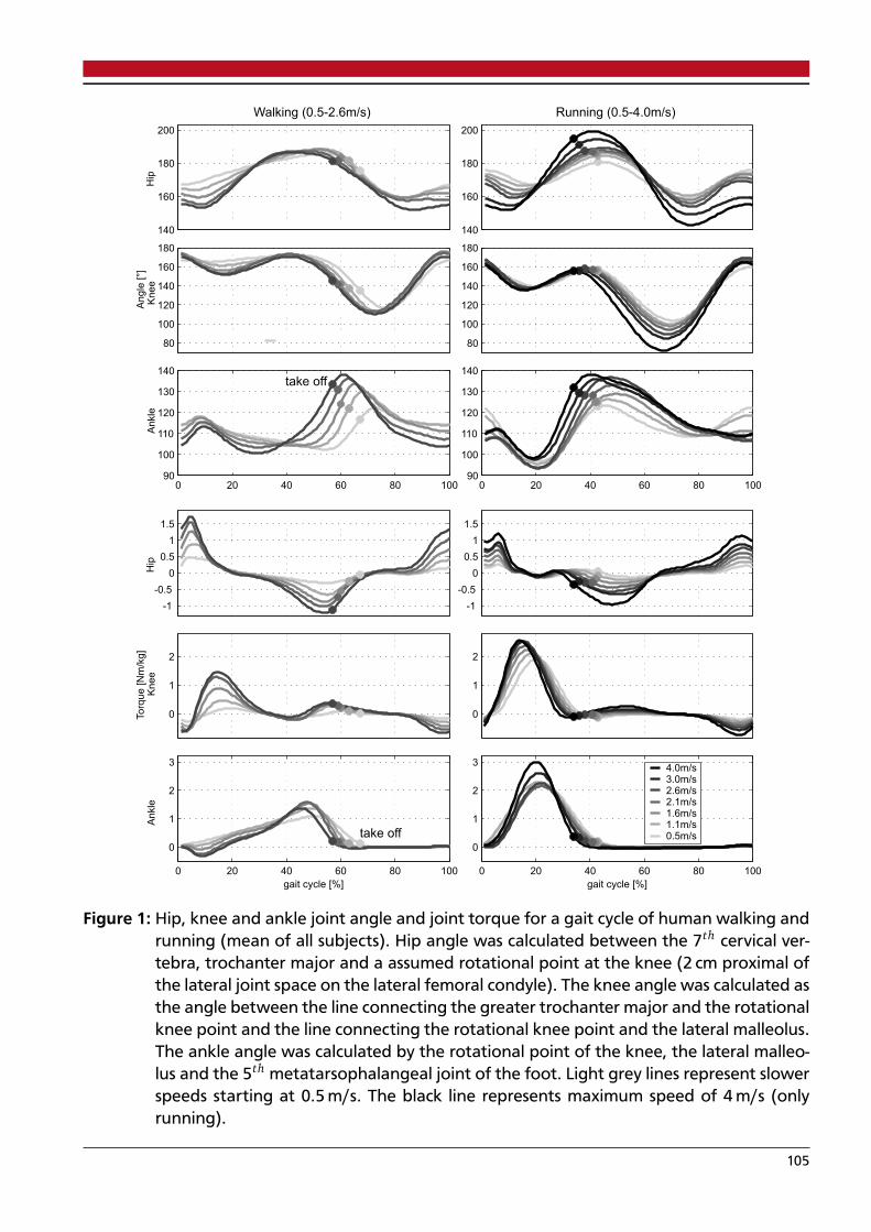
-1
-0.5
0
0.5
1
1.5
-1
-0.5
0
0.5
1
1.5
0
1
2
Torq
ue [N
m/k
g]
0
1
2
0 20 40 60 80 100
0
1
2
3
gait cycle [%]
take off
0 20 40 60 80 100
0
1
2
34.0m/s3.0m/s2.6m/s2.1m/s1.6m/s1.1m/s0.5m/s
gait cycle [%]
140
160
180
200
Walking (0.5-2.6m/s)
Hip
140
160
180
200
Running (0.5-4.0m/s)
80
100
120
140
160
180
Kn
ee
An
gle
[°]
80
100
120
140
160
180
0 20 40 60 80 10090
100
110
120
130
140take off
An
kle
0 20 40 60 80 10090
100
110
120
130
140
An
kle
Kn
ee
Hip
Figure 1: Hip, knee and ankle joint angle and joint torque for a gait cycle of human walking andrunning (mean of all subjects). Hip angle was calculated between the 7th cervical ver-tebra, trochanter major and a assumed rotational point at the knee (2 cm proximal ofthe lateral joint space on the lateral femoral condyle). The knee angle was calculated asthe angle between the line connecting the greater trochanter major and the rotationalknee point and the line connecting the rotational knee point and the lateral malleolus.The ankle angle was calculated by the rotational point of the knee, the lateral malleo-lus and the 5th metatarsophalangeal joint of the foot. Light grey lines represent slowerspeeds starting at 0.5 m/s. The black line represents maximum speed of 4 m/s (onlyrunning).
105
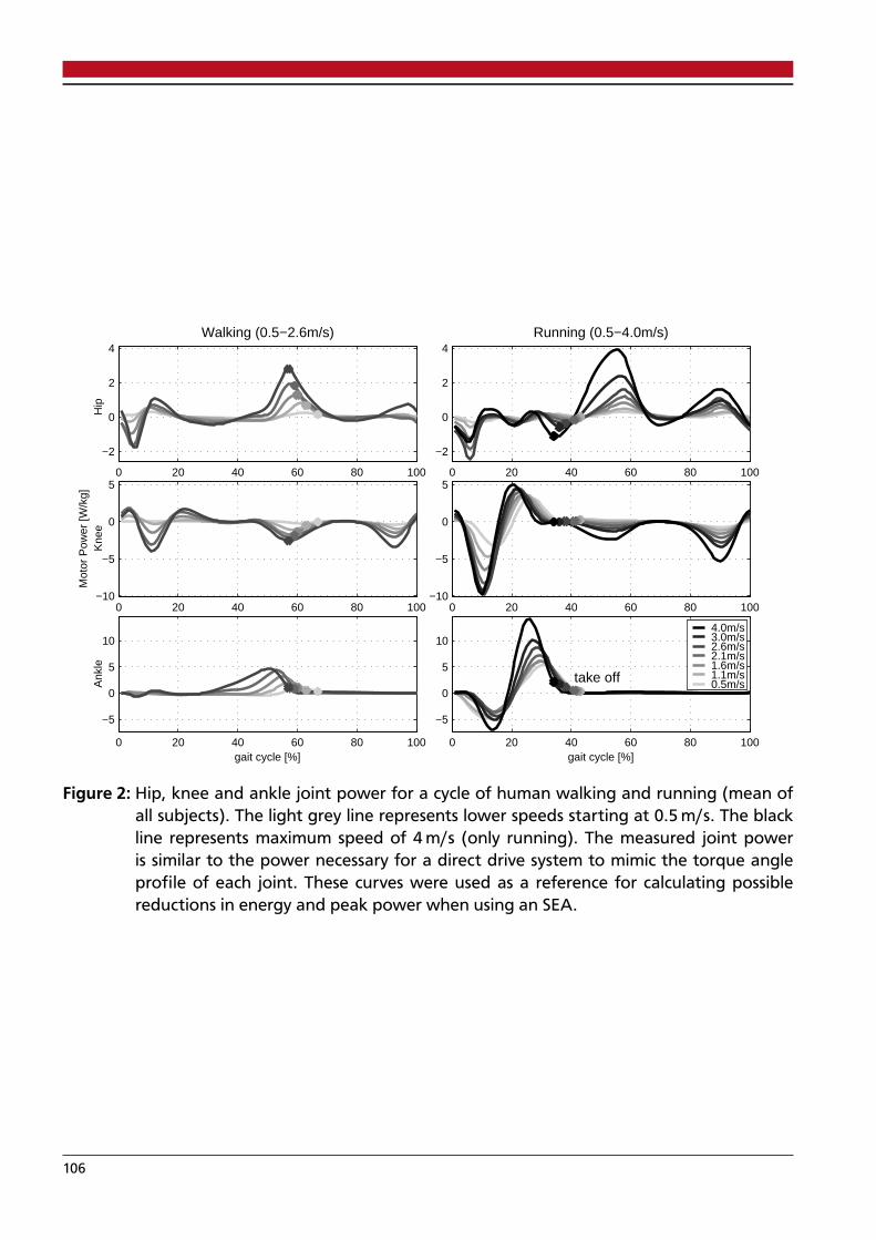
0 20 40 60 80 100
−2
0
2
4Walking (0.5−2.6m/s)
Hip
0 20 40 60 80 100
−2
0
2
4Running (0.5−4.0m/s)
0 20 40 60 80 100−10
−5
0
5
Mot
or P
ower
[W/k
g]K
nee
0 20 40 60 80 100−10
−5
0
5
0 20 40 60 80 100
−5
0
5
10
gait cycle [%]
Ank
le
0 20 40 60 80 100
−5
0
5
10
gait cycle [%]
take off
4.0m/s3.0m/s2.6m/s2.1m/s1.6m/s1.1m/s0.5m/s
Figure 2: Hip, knee and ankle joint power for a cycle of human walking and running (mean ofall subjects). The light grey line represents lower speeds starting at 0.5 m/s. The blackline represents maximum speed of 4 m/s (only running). The measured joint poweris similar to the power necessary for a direct drive system to mimic the torque angleprofile of each joint. These curves were used as a reference for calculating possiblereductions in energy and peak power when using an SEA.
106
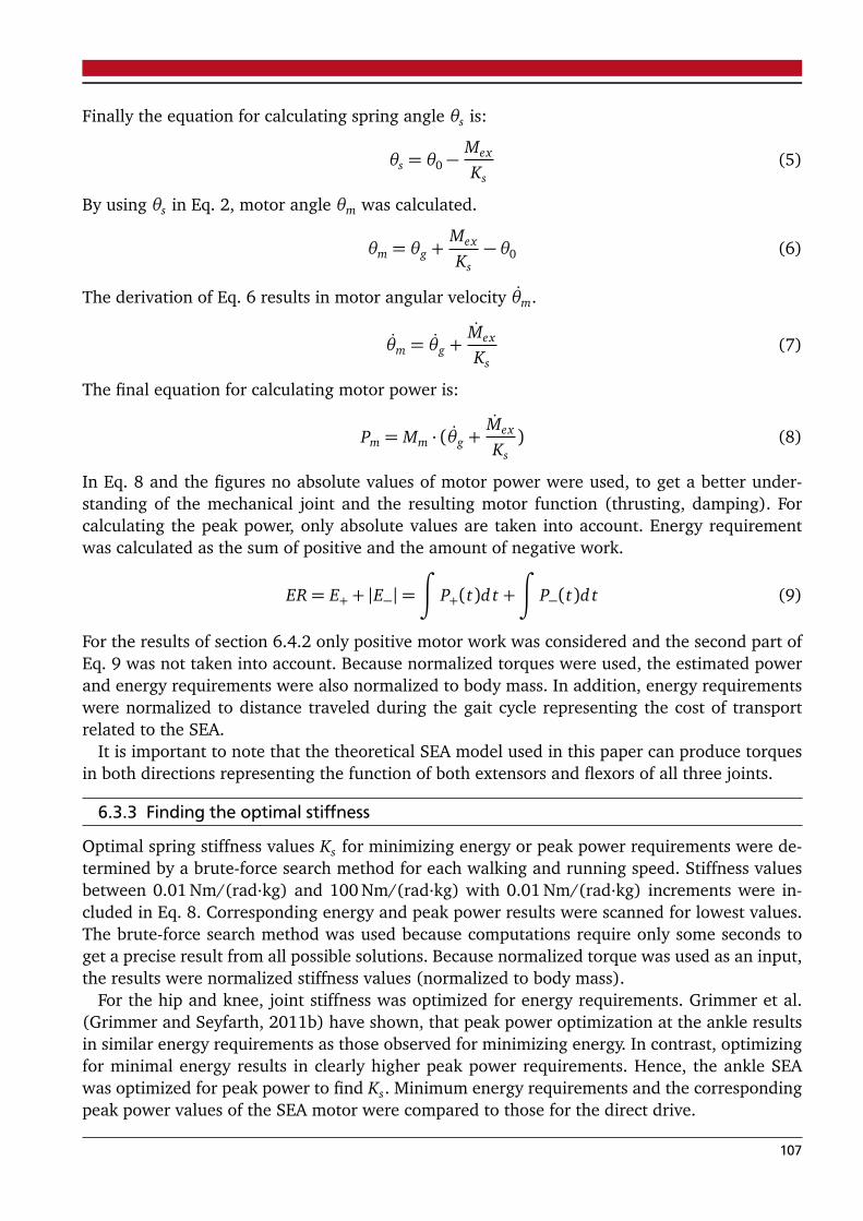
Finally the equation for calculating spring angle θs is:
θs = θ0 −Mex
Ks(5)
By using θs in Eq. 2, motor angle θm was calculated.
θm = θg +Mex
Ks− θ0 (6)
The derivation of Eq. 6 results in motor angular velocity θm.
θm = θg +Mex
Ks(7)
The final equation for calculating motor power is:
Pm = Mm · (θg +Mex
Ks) (8)
In Eq. 8 and the figures no absolute values of motor power were used, to get a better under-standing of the mechanical joint and the resulting motor function (thrusting, damping). Forcalculating the peak power, only absolute values are taken into account. Energy requirementwas calculated as the sum of positive and the amount of negative work.
ER= E+ + |E−|=∫
P+(t)d t +
∫
P−(t)d t (9)
For the results of section 6.4.2 only positive motor work was considered and the second part ofEq. 9 was not taken into account. Because normalized torques were used, the estimated powerand energy requirements were also normalized to body mass. In addition, energy requirementswere normalized to distance traveled during the gait cycle representing the cost of transportrelated to the SEA.
It is important to note that the theoretical SEA model used in this paper can produce torquesin both directions representing the function of both extensors and flexors of all three joints.
6.3.3 Finding the optimal stiffness
Optimal spring stiffness values Ks for minimizing energy or peak power requirements were de-termined by a brute-force search method for each walking and running speed. Stiffness valuesbetween 0.01 Nm/(rad·kg) and 100 Nm/(rad·kg) with 0.01 Nm/(rad·kg) increments were in-cluded in Eq. 8. Corresponding energy and peak power results were scanned for lowest values.The brute-force search method was used because computations require only some seconds toget a precise result from all possible solutions. Because normalized torque was used as an input,the results were normalized stiffness values (normalized to body mass).
For the hip and knee, joint stiffness was optimized for energy requirements. Grimmer et al.(Grimmer and Seyfarth, 2011b) have shown, that peak power optimization at the ankle resultsin similar energy requirements as those observed for minimizing energy. In contrast, optimizingfor minimal energy results in clearly higher peak power requirements. Hence, the ankle SEAwas optimized for peak power to find Ks. Minimum energy requirements and the correspondingpeak power values of the SEA motor were compared to those for the direct drive.
107

6.4 RESULTS
The main results of this theoretical investigation can be found in Fig. 3 and 4. Fig. 3 showsthe effect of series elastic elements on energy and peak power requirements for the hip, kneeand ankle at various speeds for walking and running. Fig. 4 shows a comparison of positivemotor work between SEA and direct drive motors. It was assumed that negative work can beperformed by passive dampers. The sum of positive work performed at the hip, knee and anklewas used to investigate energy requirements of the leg in the sagittal plane.
6.4.1 Peak Power and Energy Requirements at Joint Level
HipWhen optimizing the hip SEA for minimum energy, benefits in peak power (18%-27%, Fig. 3)
were identified only for speeds close to preferred walking speed (Dal et al., 2010). Peak powerwas drastically higher for the SEA than for the direct drive at very slow walking speed (172%).In addition, reductions in energy requirements of up to 29% were achieved for walking. Forrunning, no considerable benefits in energy or peak power were found when using an SEA.Optimal stiffness for a hip SEA in running goes to infinity causing the second term of Eq. 8 tobecome zero. Consequently, θm is equal to θg resulting in identical power curves for SEA anddirect drive motors (Fig. 6).
KneeThe stiffness of the knee SEA was optimized to minimize energy. Energy requirements were
lower for the knee SEA compared to the direct drive for all walking (5%-28%) and running(39%-71%) speeds (Fig. 3). Peak power was lower for the SEA at all running speeds (51%-78%). For walking, peak power for the SEA was higher for preferred speeds (8%-11%) andlower for speeds equal or above than PTS (about 29%).
AnkleThe ankle SEA was optimized to minimize peak power. Using an appropriate stiffness reduced
peak power by 21% to 68% for the ankle SEA compared to the direct drive for walking and by70% to 86% for running. In addition, energy requirements were lower for the ankle SEA thanthe direct drive for all walking (3%-52%) and running speeds (56%-87%, (Fig. 3)).
6.4.2 Positive Sagittal Leg Work
Direct DrivePositive work increased with increasing walking speed (0.32-0.55 J/(kg·m)). For running, po-
sitive work decreased with increasing speeds up to 2.6 m/s (2.04-0.66 J/(kg·m)) and increasedslightly for speeds beyond (Fig. 4).
The main contribution to the required energy was generated by the ankle joint (47%-61%).For walking, the hip was a more important energy source than the knee, especially at lowerand higher speeds. In contrast for running, the knee was a more important energy source thanthe hip for speeds up to 2.6 m/s while the hip played an increasingly role for speeds exceeding2.6 m/s (Fig. 4).
108

Speed [m/s]Change [%] Change [%]
0.5
1.0
1.6
2.1
2.6
0.5
1.0
1.6
2.1
2.6
3.0
4.0
Wal
king
Run
ning
Hip Direct DriveSEA
Direct DriveSEA
− +− +
−19.9%
−29.2%
−15.5%
−4.4%
−0.8%
0.3%
0.5%
−0.4%
−0.2%
−0.6%
−0.6%
0.2%
171.9%
−26.6%
−17.5%
−0.5%
−1%
1.3%
0.9%
0.8%
0.2%
0.1%
0.1%
0.1%
0.5
1.0
1.6
2.1
2.6
0.5
1.0
1.6
2.1
2.6
3.0
4.0
Wal
king
Run
ning
Knee−4.5%
−15.2%
−24.7%
−28.2%
−26.4%
−71%
−68.5%
−58.4%
−50.8%
−46.6%
−45.2%
−39.1%
−3.6%
10.9%
7.8%
−29.6%
−28.7%
−78.3%
−76.9%
−69.8%
−69%
−69.4%
−67.1%
−51.2%
0.5
1.0
1.6
2.1
2.6
0.5
1.0
1.6
2.1
2.6
3.0
4.0
*2.35
Wal
king
Run
ning
Ankle
15 10 5 0 0 0.5 1.0 1.5Peak Power [W/kg] Energy Requirement [J/(kg*m)]
−52.1%
−48.2%
−26.1%
−5.6%
−3.4%
−86.9%
−78.5%
−67.8%
−58.9%
−57.3%
−56.4%
−56.3%
−52.3%
−68.2%
−59.7%
−44.1%
−21.4%
−86.1%
−79.3%
−73.2%
−70.4%
−70.5%
−71.7%
−72.2%
Figure 3: Hip, knee and ankle joint peak power (left side) and energy requirements (right side)for different walking and running speeds for SEAs and direct drives. SEA spring stiffnesswas optimized to minimize energy requirements at the hip and the knee. At the ankle,spring stiffness was optimized to minimize peak power. The amount of negative workis shown as darker parts of the energy requirement bars, and the amount of positivework is shown as lighter parts of the energy requirement bars. The outer columns listthe difference in energy and peak power requirements between the SEA and the directdrive (SEA/DD*100; in percent). The middle column lists the corresponding walking orrunning speeds.
109

0
20
40
60
80
100
3833 27 25
33
7 9 13 15 18 2330
10 21 25 2316
32 30 28 26 24 2117
51 47 48 52 5161 61 59 59 57 56 53
Pos
itive
Mot
or W
ork
[%]
W 0
.5
W 1
.0
W 1
.6
W 2
.1
W 2
.6
R 0.5
R 1.0
R 1.6
R 2.1
R 2.6
R 3.0
R 4.0
0
20
40
60
80
100
5440
31 2938 28 29 30 30 34 40
48
16
22
1812
6 27
94 3
22
2
3038
5159 57
44
62 67 67 64 5951
W 0
.5
W 1
.0
W 1
.6
W 2
.1
W 2
.6
R 0.5
R 1.0
R 1.6
R 2.1
R 2.6
R 3.0
R 4.0
0
0.5
1
1.5
2
Walking Running
0.320.350.410.480.55
2.04
1.13
0.80.670.630.630.66
Pos
itive
Mot
or W
ork
[J/(
kg*m
)]
DD−Motor
0
0.5
1
1.5
2
Walking Running
0.2 0.230.31
0.4 0.470.510.360.350.340.340.370.42
SEA−Motor
Hip
Knee
Ankle
Figure 4: Absolute (top) and relative (bottom) positive motor work for a direct drive (DD, left)driven leg (hip, knee and ankle) compared to a series elastic actuator (SEA, right) drivenleg for mimicking walking (W 0.5 m/s - W 2.6 m/s) and running (R 0.5 m/s - R 4.0 m/s).The preferred transition speed (PTS) where subjects typically change gait between wal-king and running was 2.1 m/s. Note that for some speeds, the total positive motor workdoes not add up to 100% because relative motor work values were rounded to integers.
Series Elastic ActuatorCompared to a direct drive, the total required positive motor work was lower for the SEA dri-
ven joints (14% to 39% walking) especially for running (37% to 75%, Fig. 4). For both walkingand running, the differences in total required work between the SEA and the direct drive decre-ased with increasing speed. The main reduction in total required work for the SEA compared tothe direct drive was observed at the ankle and knee. With an SEA knee, no positive work wasrequired for running. The ratio for providing overall positive leg work increases drastically forthe hip joint.
Beyond the preferred transition speed (PTS, 2.1 m/s), less positive work was required forrunning (0.34 J/(kg·m)) than for walking (0.4 J/(kg·m), Fig. 4).
6.4.3 Stiffness
For walking, hip SEA stiffness increased with speed (optimized to minimize energy, Tab. 2).Least energy consumption at highest walking and all running speeds was achieved using a rigiddirect drive hip.
110

At the knee, joint stiffness increased with increasing walking speed above 0.5 m/s (optimizedto minimize energy requirements). For running, joint stiffness decreased with increasing speedsup to 1.6 m/s and increased for speeds beyond 1.6 m/s up to 4 m/s.
At the ankle, joint stiffness increased with increasing speeds for walking (above 0.5 m/s) andrunning (optimized to minimize peak power). Compared to walking, joint stiffness remainedrelatively constant across running speeds.
Table 2: Predicted optimal SEA stiffness values Kr (Nm/(deg·kg)) for minimizing peak power atthe ankle and minimizing energy requirements at the knee and the hip (Fig. 3) for wal-king and running at a wide range of speeds. Rotational stiffness values were normalizedto body mass.
Gait Walking Running
Speed[m/s] 0.5 1.0 1.6 2.1 2.6 0.5 1.0 1.6 2.1 2.6 3.0 4.0
Hip .0712 .1817 .4238 .9821 rigid rigid rigid rigid rigid rigid rigid rigidKnee .1848 .0873 .1058 .1215 .1274 .137 .1223 .1159 .1234 .1292 .141 .1508Ankle .1136 .0857 .1208 .1822 .2536 .0887 .0929 .0937 .0941 .0946 .1152 .1239
6.5 DISCUSSION
In this study, we estimated the reduction in motor requirements for monoarticular SEAs compa-red to direct drives at the hip, knee and ankle during walking and running. While large energyand peak power benefits were identified for the ankle and the knee, for the hip smaller bene-fits were observed for walking and none for running. Wang et al. (Wang et al., 2011) reportedpeak power reductions of up to 79% for slow to preferred walking speeds for a series springat the ankle, which are higher than reductions predicted in our calculations (68%). Similar toour results, Wang et al. found no peak power benefits at the knee at these speeds. In contrastto our findings (27% reduction), no benefits in peak power at the hip were identified aroundpreferred walking speed (Wang et al., 2011). Moreover, Wang et al. observed peak power be-nefits at the hip of up to 60% for abduction and adduction. Because both methods are similar,the observed differences are likely mainly caused by differences in the torque and angle inputdata. In our study, we observed large differences between subjects (see subsection 6.5.3), andhence it is possible that the differences in results between our study and Wang et al. are causedby differences in study cohorts (Wang et al., N=8 subjects; 24 yrs, 1.8 m, 69 kg).
6.5.1 Reason for the SEA benefits
Interestingly, peak power and energy requirements were not reduced by tuning the SEA springat the hip at any running speed. In contrast to the ankle, for walking none or small reductionswere observed for the hip and the knee. Especially running largely benefits from a serial springat the knee and the ankle joint. Motor power is the product of required motor torque and motorvelocity, and hence at least one of the parameters must be reduced to increase system efficiency.As discussed by Grimmer et al. (Grimmer et al., 2012), motor torque can be reduced by a parallelspring and motor velocity can be reduced by a series spring. Reductions in motor velocity are
111

-150 -100 -50 0 50 100 150 200 250
0
0.2
0.4
0.6
0.8
1
1.2
1.4
1.6
Angular velocity [deg/s]
Torq
ue [N
m/k
g]
-300 -200 -100 0 100 200 300
0
0.5
1
1.5
2
Angular velocity [deg/s]
touch down
take off
max. power
Direct Drive
SEA-Motor
SEA-Spring
Figure 5: Ankle torque - angular velocity curves for walking at 1.6 m/s and running at 2.6m/s.The solid line represents human data, which is similar to that for a direct drive. Thedotted line represents data for the SEA motor and the dashed line data for the SEAspring. Stance phase is indicated by a black line and flight phase by a grey line. Stancephase starts with touch down and ends with take off. Maximum power during pushoff is indicated for each case. Arrows indicate the path direction during the gait cycle.The series spring helps to reduce motor velocity resulting in lower peak power.
shown in Fig. 5 for an SEA at the ankle. Because the spring generates some of the joint rotation,the motor has a smaller range of motion to match joint torque-angle curves and motor velocitydecreases. Using this effect, peak power and energy requirements can be reduced for the SEAmotor as shown in Fig. 6. Both parameters benefit from the elastic properties of the spring:energy can be stored and released by spring deflection. For instance, for the ankle for walking,the spring is elongated between 30% and 50% of the gait cycle. Energy is saved in the spring tobe released during push off to support the motor. Similar effects can be identified for the kneeand the hip for walking. For running, only the ankle and the knee benefit from using a seriesspring.
The largest reductions in motor peak power and energy requirements are achieved when theseries spring stiffness matches the slope of the torque-angle curves. The results of our opti-mization showed that stiffness values were within the ascending and descending parts of thetorque-angle profiles (dashed lines, Fig. 7). For example, for running the ankle torque increasesand ankle angle decreases in the first 20% of the gait cycle. During this phase, the spring isloaded which can be also observed for the power curves (Fig. 6). The opposite happens from20% to 40% of the gait cycle where the torque decreases and the angle increases and the springis unloaded and releases the energy for push off.
The stiffness results show that optimal joint stiffness can be approximated by estimating themean slope of the joint torque-angle profile during the stance phase as illustrated by the dashedlines in Fig. 7. This stiffness closely resembles the smallest peak power and energy requirements.In contrast to an approximation, the optimization method used in our study provided a moreaccurate stiffness value because it is optimized for a selected criteria such as peak power orenergy requirement.
112

0 20 40 60 80 100
-1
-0.5
0
0.5
1
Walking 1.6m/sH
ip
0 20 40 60 80 100
-2
-1
0
1
Running 2.6m/s
0 20 40 60 80 100
-1
0
1
Mo
tor
Po
we
r [W
/kg
]K
ne
e
0 20 40 60 80 100-10
-5
0
5
0 20 40 60 80 100
-1
0
1
2
3
gait cycle [%]
An
kle
0 20 40 60 80 100
-5
0
5
gait cycle [%]
take off
Direct DriveSEA-MotorSEA-Spring
Figure 6: Hip, knee and ankle power for the gait cycle in human walking at 1.6 m/s and runningat 2.6 m/s (mean of all subjects). The power is shown for the direct drive (black solid)and when an SEA drives the joint. For the latter, power is shared between SEA motor(dark grey dotted) and SEA spring (light grey dashed). The combination of the SEAmotor and the SEA spring matches the direct drive situation. For the hip for runninga rigid system without a spring requires the least energy. As a result the SEA motormatches direct drive behavior.
The brute-force method scanned only the positive stiffness region. However, we also identifiedoptimal negative solutions for K for settings where a rigid system provided the best performancein the positive region (Tab. 2). While a spring with positive stiffness will first store the energyand release it later (Fig. 8), a spring with negative stiffness would first release the energy tothe system and subsequently energy is required to return it to the original state. Because latterbehavior is not realistic for a simple SEA, all negative stiffness solutions were not included inthis investigation.
We believe that the mechanism of releasing energy first and subsequently returning it backmay be realized through joint coupling. For instance, biarticular springs could be loaded by theknee, and this energy could be transferred to the hip. Hence, a resultant torque at the hip maybehave similar to a spring with negative stiffness.
In addition to biarticular structures, non-linear elastic behavior, which is also found in nature,may contibute to the system’s efficiency. Non-linear elastic behavior could be implemented bychanging the length of the lever arm or introducing non-linear stiffness. A progressive springbehavior could help to use the same design (no tuning of stiffness) for mimicking speed depen-dent increases in optimal stiffness values identified for walking and running at all three joints(Tab. 2).
113
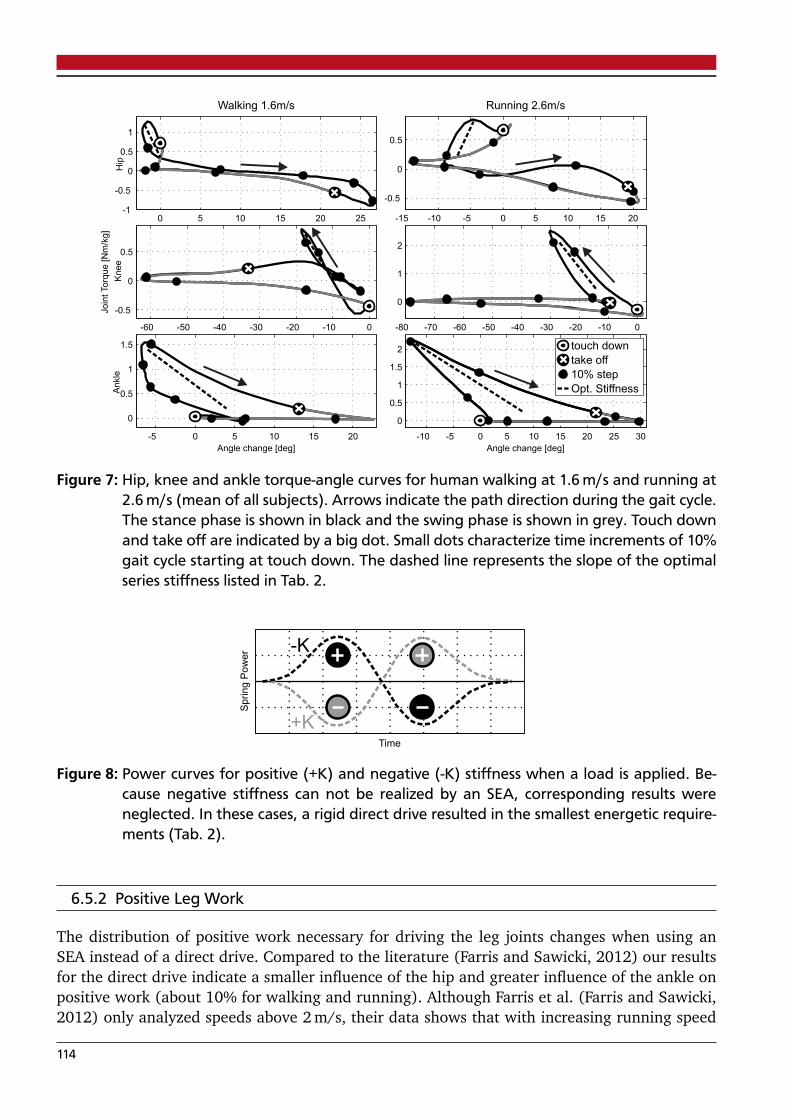
0 5 10 15 20 25-1
-0.5
0
0.5
1
Walking 1.6m/sH
ip
-15 -10 -5 0 5 10 15 20
-0.5
0
0.5
Running 2.6m/s
-60 -50 -40 -30 -20 -10 0
-0.5
0
0.5
Join
tTorq
ue [N
m/k
g]
Knee
-80 -70 -60 -50 -40 -30 -20 -10 0
0
1
2
-5 0 5 10 15 20
0
0.5
1
1.5
Angle change [deg]
Ankle
-10 -5 0 5 10 15 20 25 30
0
0.5
1
1.5
2
Angle change [deg]
touch down
take off
10% step
Opt. Stiffness
Figure 7: Hip, knee and ankle torque-angle curves for human walking at 1.6 m/s and running at2.6 m/s (mean of all subjects). Arrows indicate the path direction during the gait cycle.The stance phase is shown in black and the swing phase is shown in grey. Touch downand take off are indicated by a big dot. Small dots characterize time increments of 10%gait cycle starting at touch down. The dashed line represents the slope of the optimalseries stiffness listed in Tab. 2.
Time
Sp
rin
g P
ow
er -K
+K
Figure 8: Power curves for positive (+K) and negative (-K) stiffness when a load is applied. Be-cause negative stiffness can not be realized by an SEA, corresponding results wereneglected. In these cases, a rigid direct drive resulted in the smallest energetic require-ments (Tab. 2).
6.5.2 Positive Leg Work
The distribution of positive work necessary for driving the leg joints changes when using anSEA instead of a direct drive. Compared to the literature (Farris and Sawicki, 2012) our resultsfor the direct drive indicate a smaller influence of the hip and greater influence of the ankle onpositive work (about 10% for walking and running). Although Farris et al. (Farris and Sawicki,2012) only analyzed speeds above 2 m/s, their data shows that with increasing running speed
114

the ankle and knee become less important contributors of positive energy and the hip becomesan increasingly important contributor of positive energy (32% at 2 m/s to 39% at 3.25 m/s).
Farris et al. (Farris and Sawicki, 2012) proposed in vivo studies to distinguish between thepositive work done by the muscle fascicles and the positive work done by the tendons. Our ap-proach may represent an alternative approach for estimating possible effects of work performedby the tendons. SEAs require up to 75% less absolute positive work than direct drives (Fig. 4).
In our model, all the elastic actuators are monoarticular. We assume that biarticular SEAscan further decrease positive work provided by motors, which is supported by simulations thatuse similar structures in principle (Van Den Bogert, 2003) and with a muscle-like arrangement(Sasaki et al., 2009).
For running with SEA the knee requires almost no positive work indicating that a dampingmechanism combined with a spring can provide nearly all the work required for mimicking theknee torque angle behavior.
We observed an interesting phenomenon for the positive work at preferred transition speed(PTS) of 2.1 m/s. For direct drives running required more positive work than walking at allspeeds (Fig. 4). However, for the SEAs, a change happens at PTS where running needs less posi-tive mechanical energy than walking. This behavior was also observed for the total mechanicalwork of ankle and knee (Fig. 3). A similar phenomenon has been previously observed in oxygenconsumption experiments (Hreljac et al., 2002) and for more complex humanoid models (Sasa-ki and Neptune, 2006). Hence, in agreement to (Sasaki and Neptune, 2006) the results of ourstudy suggest that muscle mechanical energy expenditure may not be the only determinant butit could be one important determinant for the preferred gait mode at a given speed.
6.5.3 Sensitivity of results
Requirements for the joints were calculated from mean joint angle and mean joint torque dataof up to 21 subjects (grand mean). For single subject mean torque and mean angle curves, anindividual optimal K for minimizing peak power and energy requirements can be calculated.Exemplary results for the ankle of the 21 subject are presented in (Fig. 9). Similar results canbe obtained for the knee and the hip. In the worst case, individual peak power at the ankle wasmore than twice (231%) the grand mean. Corresponding standard deviation (STD) for peakpower was approximately 32% for walking at 1.6 m/s and approximately 27% for running at2.6 m/s. The corresponding energy requirements could increase to approximately 145% (STD18% for walking and running). In addition, stiffness varied between subjects, and the STD foroptimal stiffnesses was 29% for walking and 16% for running.
The large STD of the overall mean stiffness indicates that peak power and energy require-ments may be rather high for some amputees when using it. The V-shape of the power-stiffnesscurve compared to the energy-stiffness curve (Fig. 9) suggests that especially for running energyrequirement is less sensitive to a suboptimal stiffness than peak power. Both energy and peakpower are more sensitive to below than to above optimal stiffness values.
The predicted optimal SEA stiffness values (Tab. 2) depended on speed and gait. A simplemechanism suitable for all speeds for walking and running should ensure a constant stiffness.Grimmer et al. (Grimmer and Seyfarth, 2011b) showed how a constant stiffness influencespeak power and energy requirements at the ankle and identified an optimal configuration thatentailed only minor increases in peak power and energy requirements. Similar results have beenreported for the knee (Grimmer and Seyfarth, 2011a).
115

0 0.05 0.1 0.15 0.2 0.25 0.30
2
4
6
8
10
12
14
Stiffness [Nm/(deg*kg)]
Pow
er [W
/kg]
Walking 1.6m/s
0 0.05 0.1 0.15 0.2 0.25 0.30
2
4
6
8
10
12
14
Stiffness [Nm/(deg*kg)]
Running 2.6m/s
0
0.05
0.1
0.15
0.2
0.25
0.3
0.35
Ene
rgy
[J/(
kg*m
)]
PP vs. K for Grand MeanER vs. K for Grand MeanIn. PP Opt. related ERIndividual PP Opt.
Figure 9: Peak power (black) and energy requirements (grey) in relation to spring stiffness K forwalking at 1.6 m/s (left) and running at 2.6 m/s (right). The solid curves represent thevalues represent values for mean joint angle and mean joint torque as an input (21subjects; grand mean). Single subject torque and angle curves were used to identifyindividual peak power optimum (small circles) and related stiffness. Corresponding in-dividual energy requirement is indicated by a grey rectangle. In the worst case, peakpower is more than two times the grand mean (231%) and energy requirement is upto 145% of the grand mean.
For powered prosthetic prototypes (Au et al., 2007; Sup et al., 2008) mean values of jointtorque and joint angle are used to estimate required stiffness. Various studies (Ferris et al., 2012;Hitt et al., 2010) have shown remarkable gait performances using these values. We believe thatperformance could be further improved when using stiffness values optimized to individuals.Further investigating this paradigm would require a prosthetic foot design with changeablestiffness and a learning algorithm. Optimization criteria for the learning procedure could be legsymmetry to the healthy side combined with peak power or energy requirements. Joint behaviorof the healthy side could be measured with sensors placed on a brace.
6.5.4 Methodological Considerations
For the results presented in Fig. 3, absolute peak power was minimized. By using a dampingmechanism, only the peak power resulting from positive work should be considered. Especiallyat the knee this approach can change the peak power results dramatically.
Net joint torques shown in Fig. 1 may result from activation of antagonistic muscles whichwould lead to a systematic underestimation of energy comparing our results with values forhuman locomotion (Sasaki et al., 2009).
While in this paper we only considered the mechanical energy, the efficiency of the motor andthe power train must be included for estimating the electrical energy. System characteristicsincluding frictional losses, damping, heat, structural deflection and other power losses (Hittet al., 2010) that are not considered will influence the estimation in addition. Depending on
116

the type of gait, motor speed and motor efficiency will change. A more detailed motor andmechanical system model and experimental results on powered prosthetics are required to makevalid energetic predictions. As every prosthetic system uses different mechanical parts, gears andmotors electrical requirements will be very design specific. The mechanical data presented inthis work gives a good hint to what is possible for both gaits at various speed when using aseries spring to assist the motor at the hip, knee and ankle joint.
6.6 CONCLUSIONS
In this paper we investigated the amount of reductions in energy and peak power requirementsat the hip, knee and ankle for walking and running at various speeds with monoarticular serieselastic actuators (SEAs) compared to a direct drive system. Large reductions in peak power andenergy requirements were observed at the ankle. At the knee, comparable reductions were onlyobserved for running. For walking, energy reductions were much smaller and peak power didnot change at preferred speeds. At the hip, an SEA reduced energy requirements for all and peakpower around preferred walking speeds. For running, there were no reductions. Based on theseresults, we recommend the use of elastic elements in artificial foot prostheses and for runninga spring should be considered at the knee. In walking, including a series elastic spring at theknee and the hip would decrease energy requirements. In addition to the analyzed parameters,elastic structures may increase gait robustness to uneven terrain or sudden changes in ground.Also if the benefits in energy or peak power requirements are small, this could be a reason toconsider the elastic structures for the system design.
When using an SEA instead of a direct drive, an interchange of providing positive work bythe three leg joints was identified: the contribution of the knee decreased and the contributionof the hip increased. For monoarticular SEAs, the ankle motor generates most of the positivework. We assume that biarticular structures could shift the main contribution proximal towardsthe hip by coupling joints similar to what is achieved by human muscles. It is possible thatthe lack of these structures in our design resulted in small benefits in peak power and energyrequirements with a monoarticular SEA at the hip. Hence, this inter-joint coupling should beconsidered in an extended analysis of leg function in human walking and running. Anticipatedreductions in peak power and energy requirements could lead to advanced designs of prostheticsystems utilizing both monoarticular and biarticular SEAs. This concept could be realized witha prosthetic device extended by an orthosis to couple the intact joints via biarticular structuresto the replaced joints in the prosthesis, resulting in a hybrid ortho-prosthesis.
6.7 ACKNOWLEDGMENTS
This work was supported by the DFG grant SE1042/8. The authors acknowledge S.W. Lipfertfor providing human data.
6.8 AUTHOR CONTRIBUTIONS
Martin Grimmer is the main author of the article. He was responsible for the conception anddesign, analysis and interpretation of data and writing of the manuscript. Mahdy Eslamy wascontributing on methodological questions, to the discussion of the results and for the revisionof the article. André Seyfarth assisted for the revision of the article.
117

6.9 CONFLICT OF INTEREST
The authors declare no conflict of interest.
6.10 REFERENCES
Au, S. K., Herr, H., Weber, J., and Martinez-Villalpando, E. C. (2007). Powered ankle-foot pros-thesis for the improvement of amputee ambulation. In Engineering in Medicine and BiologySociety, 2007. EMBS 2007. 29th Annual International Conference of the IEEE, pages 3020–3026.IEEE.
Cherelle, P., Matthys, A., Grosu, V., Vanderborght, B., and Lefeber, D. (2012). The AMP-Foot2.0: Mimicking intact ankle behavior with a powered transtibial prosthesis. In 4th IEEE RAS& EMBS International Conference on Biomedical Robotics and Biomechatronics (BioRob), pages544–549. IEEE.
Dal, U., Erdogan, T., Resitoglu, B., and Beydagi, H. (2010). Determination of preferred wal-king speed on treadmill may lead to high oxygen cost on treadmill walking. Gait & posture,31(3):366–369.
Donelan, J., Li, Q., Naing, V., Hoffer, J., Weber, D., and Kuo, A. (2008). Biomechanicalenergy harvesting: generating electricity during walking with minimal user effort. Science,319(5864):807–810.
Farris, D. and Sawicki, G. (2012). The mechanics and energetics of human walking and running:a joint level perspective. Journal of The Royal Society Interface, 9(66):110–118.
Ferris, A. E., Aldridge, J. M., Rábago, C. A., and Wilken, J. M. (2012). Evaluation of a poweredankle-foot prosthetic system during walking. Archives of physical medicine and rehabilitation,93(11):1911–1918.
Grimmer, M., Eslamy, M., Gliech, S., and Seyfarth, A. (2012). A comparison of parallel-and serieselastic elements in an actuator for mimicking human ankle joint in walking and running. InRobotics and Automation (ICRA), 2012 IEEE International Conference on, pages 2463–2470.IEEE.
Grimmer, M. and Seyfarth, A. (2011a). Stiffness adjustment of a series elastic actuator in a kneeprosthesis for walking and running: The trade-off between energy and peak power optimi-zation. In IEEE/RSJ International Conference on Intelligent Robots and Systems (IROS), pages1811–1816. IEEE.
Grimmer, M. and Seyfarth, A. (2011b). Stiffness adjustment of a series elastic actuator in anankle-foot prosthesis for walking and running: The trade-off between energy and peak poweroptimization. In IEEE International Conference on Robotics and Automation (ICRA), pages1439–1444. IEEE.
Günther, M., Sholukha, V., Keßler, D., Wank, V., and Blickhan, R. (2003). Dealing with skin mo-tion and wobbling masses in inverse dynamics. Journal of Mechanics in Medicine and Biology,3(3-4):309–335.
118
Herr, H. and Grabowski, A. (2012). Bionic ankle–foot prosthesis normalizes walking gaitfor persons with leg amputation. Proceedings of the Royal Society B: Biological Sciences,279(1728):457–464.
Hitt, J., Sugar, T., Holgate, M., and Bellman, R. (2010). An active foot-ankle prosthesis withbiomechanical energy regeneration. Journal of Medical Devices, 4:011003.
Hollander, K. and Sugar, T. (2005). Design of the robotic tendon. In Design of Medical DevicesConference (DMD).
Hreljac, A., Parker, D., Quintana, R., Abdala, E., Patterson, K., and Sison, M. (2002). Energeticsand perceived exertion of low speed running and high speed walking. Facta UniversitatisSeries: Physical Education and Sport, 1(9):27–35.
Johansson, J., Sherrill, D., Riley, P., Bonato, P., and Herr, H. (2005). A clinical comparisonof variable-damping and mechanically passive prosthetic knee devices. American Journal ofPhysical Medicine & Rehabilitation, 84(8):563.
Lipfert, S. (2010). Kinematic and dynamic similarities between walking and running. Verlag Dr.Kovac, Hamburg. ISBN: 978-3-8300-5030-8.
Mathijssen, G., Cherelle, P., Lefeber, D., and Vanderborght, B. (2013). Concept of a series-parallel elastic actuator for a powered transtibial prosthesis. In Actuators, volume 2, pages59–73. Multidisciplinary Digital Publishing Institute.
Ossur (2013). www.ossur.com.
Ottobock (2013). www.ottobock.com.
Pratt, G. and Williamson, M. (2002). Series elastic actuators. In IEEE/RSJ International Con-ference on Intelligent Robots and Systems 95.’Human Robot Interaction and Cooperative Ro-bots’,Proceedings. 1995, volume 1, pages 399–406. IEEE.
Sasaki, K. and Neptune, R. (2006). Muscle mechanical work and elastic energy utilization duringwalking and running near the preferred gait transition speed. Gait & posture, 23(3):383–390.
Sasaki, K., Neptune, R., and Kautz, S. (2009). The relationships between muscle, external,internal and joint mechanical work during normal walking. Journal of Experimental Biology,212(5):738–744.
Segal, A., Orendurff, M., Klute, G., McDowell, M., Pecoraro, J., Shofer, J., and Czerniecki, J.(2006). Kinematic and kinetic comparisons of transfemoral amputee gait using C-Leg® andMauch SNS® prosthetic knees. Journal of rehabilitation research and development, 43(7):857.
Sup, F., Varol, H., Mitchell, J., Withrow, T., and Goldfarb, M. (2009). Self-contained poweredknee and ankle prosthesis: Initial evaluation on a transfemoral amputee. In IEEE InternationalConference on Rehabilitation Robotics (ICORR), pages 638–644. IEEE.
Sup, F., Varol, H. A., Mitchell, J., Withrow, T., and Goldfarb, M. (2008). Design and control of anactive electrical knee and ankle prosthesis. In Biomedical Robotics and Biomechatronics, 2008.BioRob 2008. 2nd IEEE RAS & EMBS International Conference on, pages 523–528. IEEE.
119
Suzuki, R., Sawada, T., Kobayashi, N., and Hofer, E. (2011). Control method for powered ankleprosthesis via internal model control design. In International Conference on Mechatronics andAutomation (ICMA), pages 237–242. IEEE.
Van Den Bogert, A. (2003). Exotendons for assistance of human locomotion. Biomedical engi-neering online, 2(17).
Wang, S., van Dijk, W., and van der Kooij, H. (2011). Spring uses in exoskeleton actuationdesign. In IEEE International Conference on Rehabilitation Robotics (ICORR), pages 1–6. IEEE.
Zhu, J., Wang, Q., and Wang, L. (2010). Pantoe 1: Biomechanical design of powered ankle-footprosthesis with compliant joints and segmented foot. In IEEE/ASME International Conferenceon Advanced Intelligent Mechatronics (AIM), pages 31–36. IEEE.
120
7 Manuscript V: A powered prosthetic ankle joint forwalking and running
Authors:
Martin Grimmer, Matthew Holgate, Robert Holgate,Alexander Boehler, Jeff Ward, Kevin Hollander,
Thomas Sugar and André Seyfarth
Technische Universität Darmstadt
64289 Darmstadt, Germany
Submitted for publication in 2014
121
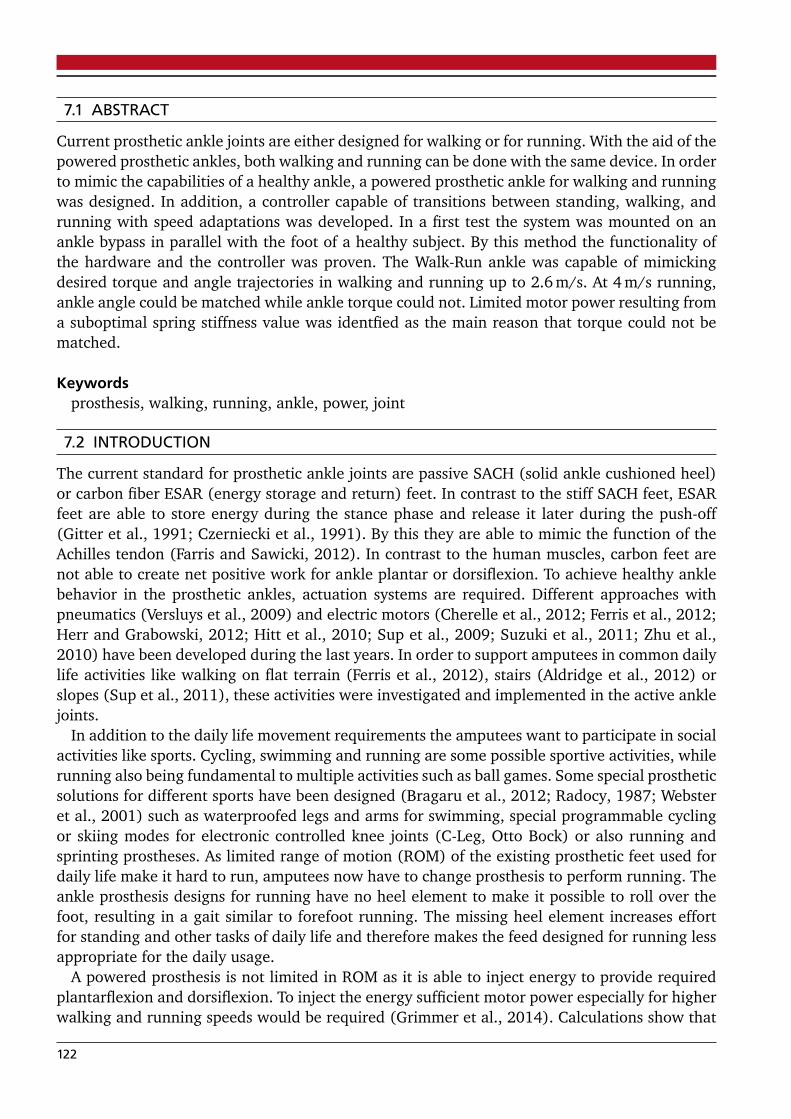
7.1 ABSTRACT
Current prosthetic ankle joints are either designed for walking or for running. With the aid of thepowered prosthetic ankles, both walking and running can be done with the same device. In orderto mimic the capabilities of a healthy ankle, a powered prosthetic ankle for walking and runningwas designed. In addition, a controller capable of transitions between standing, walking, andrunning with speed adaptations was developed. In a first test the system was mounted on anankle bypass in parallel with the foot of a healthy subject. By this method the functionality ofthe hardware and the controller was proven. The Walk-Run ankle was capable of mimickingdesired torque and angle trajectories in walking and running up to 2.6 m/s. At 4 m/s running,ankle angle could be matched while ankle torque could not. Limited motor power resulting froma suboptimal spring stiffness value was identfied as the main reason that torque could not bematched.
Keywordsprosthesis, walking, running, ankle, power, joint
7.2 INTRODUCTION
The current standard for prosthetic ankle joints are passive SACH (solid ankle cushioned heel)or carbon fiber ESAR (energy storage and return) feet. In contrast to the stiff SACH feet, ESARfeet are able to store energy during the stance phase and release it later during the push-off(Gitter et al., 1991; Czerniecki et al., 1991). By this they are able to mimic the function of theAchilles tendon (Farris and Sawicki, 2012). In contrast to the human muscles, carbon feet arenot able to create net positive work for ankle plantar or dorsiflexion. To achieve healthy anklebehavior in the prosthetic ankles, actuation systems are required. Different approaches withpneumatics (Versluys et al., 2009) and electric motors (Cherelle et al., 2012; Ferris et al., 2012;Herr and Grabowski, 2012; Hitt et al., 2010; Sup et al., 2009; Suzuki et al., 2011; Zhu et al.,2010) have been developed during the last years. In order to support amputees in common dailylife activities like walking on flat terrain (Ferris et al., 2012), stairs (Aldridge et al., 2012) orslopes (Sup et al., 2011), these activities were investigated and implemented in the active anklejoints.
In addition to the daily life movement requirements the amputees want to participate in socialactivities like sports. Cycling, swimming and running are some possible sportive activities, whilerunning also being fundamental to multiple activities such as ball games. Some special prostheticsolutions for different sports have been designed (Bragaru et al., 2012; Radocy, 1987; Websteret al., 2001) such as waterproofed legs and arms for swimming, special programmable cyclingor skiing modes for electronic controlled knee joints (C-Leg, Otto Bock) or also running andsprinting prostheses. As limited range of motion (ROM) of the existing prosthetic feet used fordaily life make it hard to run, amputees now have to change prosthesis to perform running. Theankle prosthesis designs for running have no heel element to make it possible to roll over thefoot, resulting in a gait similar to forefoot running. The missing heel element increases effortfor standing and other tasks of daily life and therefore makes the feed designed for running lessappropriate for the daily usage.
A powered prosthesis is not limited in ROM as it is able to inject energy to provide requiredplantarflexion and dorsiflexion. To inject the energy sufficient motor power especially for higherwalking and running speeds would be required (Grimmer et al., 2014). Calculations show that
122

different arrangements of elastic elements can decrease these requirements, especially in run-ning gait (Eslamy et al., 2012; Grimmer et al., 2012). When considering the assisting effect of aseries elastic actuator (SEA) to mimic the ankle joint function, about 0.6 W/kg to 1.3 W/kg me-chanical peak power should be provided for normal walking (1.1 m/s - 1.6 m/s) and 2.6 W/kgto 2.8 W/kg (Grimmer et al., 2014) for medium marathon running speeds of 2.6 m/s - 3 m/s(Leyk et al., 2007). A running speed of 4 m/s would require four times (3.9 W/kg) the peakpower of the preferred walking speed.
Along with reduced power demands, the elastic elements can also reduce the energy require-ments. Walking requires about 0.14 J/(kg·m) to 0.18 J/(kg·m) (1.1 m/s - 1.6 m/s) and runningabout 0.22 J/(kg·m) (2.6 m/s, 3 m/s and 4 m/s) (Grimmer et al., 2014) when using a seriesspring. This is an increase of about 22% to 57%. The system design should be adapted to theseincreased requirements for running.
In addition to the power and the energetic requirements, the control needs an adaptation todistinguish between walking and running as well as a measure of the desired speed. This couldbe critical when amputees want to run below or walk above preferred transition speed (2.1 m/s,PTS, (Lipfert, 2010)). Transitions from walking to running and running to walking must berealized quickly to support accelerating or decelerating during the transition process. Also, thetransition between movement and standing is critical for the safety.
To investigate these topics, a powered prosthetic ankle was designed to be capable of walkingand medium speed running. A controller to change between standing, walking, and runningwith speed adaptation was developed. For a first proof of concept the system was evaluated withone able bodied subject using a bypass system that is in parallel to the fixed healthy foot. Resultsare compared to healthy subject data and the corresponding prosthetic model estimations.
7.3 METHODS
7.3.1 Design of the Walk-Run ankle
The Walk-Run ankle (Fig. 1) is an active ankle prosthesis that is designed to perform walkingand running in lab conditions. It is the first generation of a series of improved powered anklesfor substantial load demands. The system uses a 200 W brushless DC motor as a power sourceand a spring to benefit from the elastic energy storage and release during walking and runninggaits. The stiffness of the spring is about 445 kN/m and is optimized for a subject weight of61 kg in a medium running speed of 2.6 m/s. To minimize the influence of the additional serieselastic carbon foot the stiffest possible version of the Pacifica LP foot (Freedom Inovations) wasselected.
The current design has a weight of 1.9 kg not including the battery and the electronics. Boththe PC-104 for the control and the 4400 mAh 25.9 V battery (powering ankle and PC-104)are stationary on a test bench. For a subject (61 kg, 1.7 m height) with an amputation heightof 0.31 m, the amputated limb mass is estimated to be about 2.3 kg according to calculationsusing the equation from (Grimmer and Seyfarth, 2014). Thus, the weight of the artificial foot,including adapters and socket, is only slightly higher compared to the healthy condition. A beltdrive is used as a transmission between the motor and the roller-screw.
7.3.2 Control of the Walk-Run ankle
A controller for standing, walking, running, and transitions was designed using Simulink (Ma-thWorks) to test the prosthetic prototype (Fig. 2). Two sensors, fixed at the upper part of the
123

aaaaaaaaaaaaaaaaaaaaaaaaaaaaaaaaaaaaaaaaaaaaaaaaaaaaaaaaaaaaaaaaaaaaaaaaaaaaaaaaaaaaaaaaaaaaaaaaaaaaaaaaaaaaaaaaaaaaaaaaaaaaaaaaaaaaaaaaaaaaaaaaaaaaaaaaaaaaaaaaaaaaaaaaaaaaaaaaaaaaaaaaaaaaaaaaaaaaaaaaaaaaaaaaaaaaaaaaaaaaaaaaaaaaaaaaaaaaaaaaaaaaaaaaaaaaaaaaaaaaaaaaaaaaaaaaaaaaaaaaaaaaaaaaaaaaaaaaaaaaaaaaaaaaaaaaaaaaaaaaaaaaaaaaaaaaaaaaaaaaaaaaaaaaaaaaaaaaaaaaaaaaaaaaaaaaaaaaaaaaaaaaaaaaaaaaaaaaaaaaaaaaaaaaaaaaaaaaaaaaaaaaaaaaaaaaaaaaaaaaaaaaaaaaaaaaaaaaaaaaaaaaaaaaaaaaaaaaaaaaaaaaaaaaaaaaaaaaaaaaaaaaaaaaaaaaaaaaaaaaaaaaaaaaaaaaaaaaaaaaaaaaaaaaaaaaaaaaaaaaaaaaaaaaaaaaaaaaaaaaaaaaaaaaaaaaaaaaaaaaaaaaaaaaaaaaaaaaaaaaaaaaaaaaaaaaaaaaaaaaaaaaaaaa
Moto
r
Joint
Roller Screw
aaaaaaaaaaaaaaaaaaaaaaaaaaaaaaaaaaaaaaaaaaaaaaaaa
Belt Drive
Nut
Figure 1: Walk-Run Ankle (Springactive): A motor powered prosthesis to investigate on walkingand running.
prototype, are implemented for the gait control. A rate gyro sensor (θ shank), to measure shankvelocity, is combined with a two axis accelerometer. For the accelerometer x shank is orientedforward and yshank is oriented vertically when the subject is standing. All the sensors measuremotion in the sagittal plane.
All three signals (1000 Hz) where converted from voltage to acceleration or velocity in theRaw Signal Processing block. In addition all the data was filtered for Gait Determination with a2nd order Butterworth filter using a cutoff frequency of 4.
Three parameters must be determined in order to calculate the appropriate motor position:the current gait mode, the gait speed, and the gait progression percent. To determine theseparameters, first a Gait Cycle Detection is done. The beginning of the gait cycle is identifiedby rate gyro sensor data from the shank. When shank angular velocity crosses from negative(swinging forward) to positive velocity (swinging backward) the beginning of the gait cycle isdefined (Fig. 3). At some walking and running speeds the same zero crossing can occur duringthe midstance. To avoid errors in the step detection a second condition was defined. Duringthe swing phase, angular velocity reaches a maximum. For slower speeds the maximum valuedecreases. At 0.5 m/s walking the maximum was about -200 /s. A hit crossing condition of -150 /s needs to be fulfilled before the shank velocity zero crossing can be used to identify thebeginning of a step. The output of the Gait Cycle Detection is the current frame and by this thestart time of the gait cycle. In combination with the start time of the last gait cycle the time ofthe last step can be determined.
In the Gait Determination the incoming three sensor signals are compared to the sensor re-ference trajectories starting at the beginning of the gait cycle. The most similar reference isidentified calculating a cumulative sum of error between the curves. This results in a measure-ment of the current gait mode and the movement speed.
The Gait Percent Detection block uses a lookup table of times, tcyc (s), of gait cycles fromdifferent speeds of walking and running (Lipfert, 2010). The gait percent G% is determined bydividing the current step time tcur (s) by the reference step time tcyc (s) from the lookup table.
124

Raw Signal Processing
Gait Cycle Detection
Gait Determination
Gait Percent Determination
Motor Trajectory Generation
Lookup Table
Lookup Table
Lookup Table
𝑥𝑠𝑠𝑠𝑠𝑠𝑠𝑠𝑠𝑠𝑦𝑠𝑠𝑠𝑠𝑠𝑠𝑠𝑠𝑠𝜃𝑠𝑠𝑠𝑠𝑠𝑠𝑠𝑠𝑠
Sensor Data
[V][V][V]
ReferenceTimes GC
ReferenceMotor
Trajectories
𝜃𝑠𝑠𝑠𝑠𝑠𝑠𝑠𝑠𝑠 [°/s]𝑥𝑠𝑠𝑠𝑠𝑠𝑠𝑠𝑠𝑠𝑦𝑠𝑠𝑠𝑠𝑠𝑠𝑠𝑠𝑠𝜃𝑠𝑠𝑠𝑠𝑠𝑠𝑠𝑠𝑠
𝑚𝑚𝑠𝑠
2
Filtered:Raw
:
[°/s]
Framecurrent GC
Time last GC [s]
Start time GC [s]
Gait percent [%]
Gait [stand,walk, run]
Speed [m/s]
𝑥𝑠𝑠𝑠𝑠𝑠𝑠𝑠𝑠𝑠𝑦𝑠𝑠𝑠𝑠𝑠𝑠𝑠𝑠𝑠𝜃𝑠𝑠𝑠𝑠𝑠𝑠𝑠𝑠𝑠
MotorPosition
[rev]
Figure 2: Controller Flowchart: Input for the control is shank angular velocity θ shank and shankacceleration x shank and y shank. Five main steps of data processing are required to definethe right motor pattern for the Walk-Run ankle. In addition three lookup tables fromexperimental gait studies are required. One as reference for detecting the gait, one forthe calculating of gait percent and one as reference for the motor trajectories.
G% = (tcur/tcyc) · 100 % (1)
Due to individual differences in tcyc from the reference lookup table, tcyc of the last step isalso taken into account as long as the gait mode and the speed are not changed. This results inmore precise gait percent detection.
As a last step, the gait mode, the speed, and the gait percent are used in the Motor TrajectoryGeneration block to determine the motor trajectory using a reference lookup table.
The desired motor trajectory is followed by the implementation of PD control. As previous-ly described, a belt drive is used in conjunction with a roller-screw to effect dorsiflexion orplantarflexion at the prosthetic ankle joint.
125
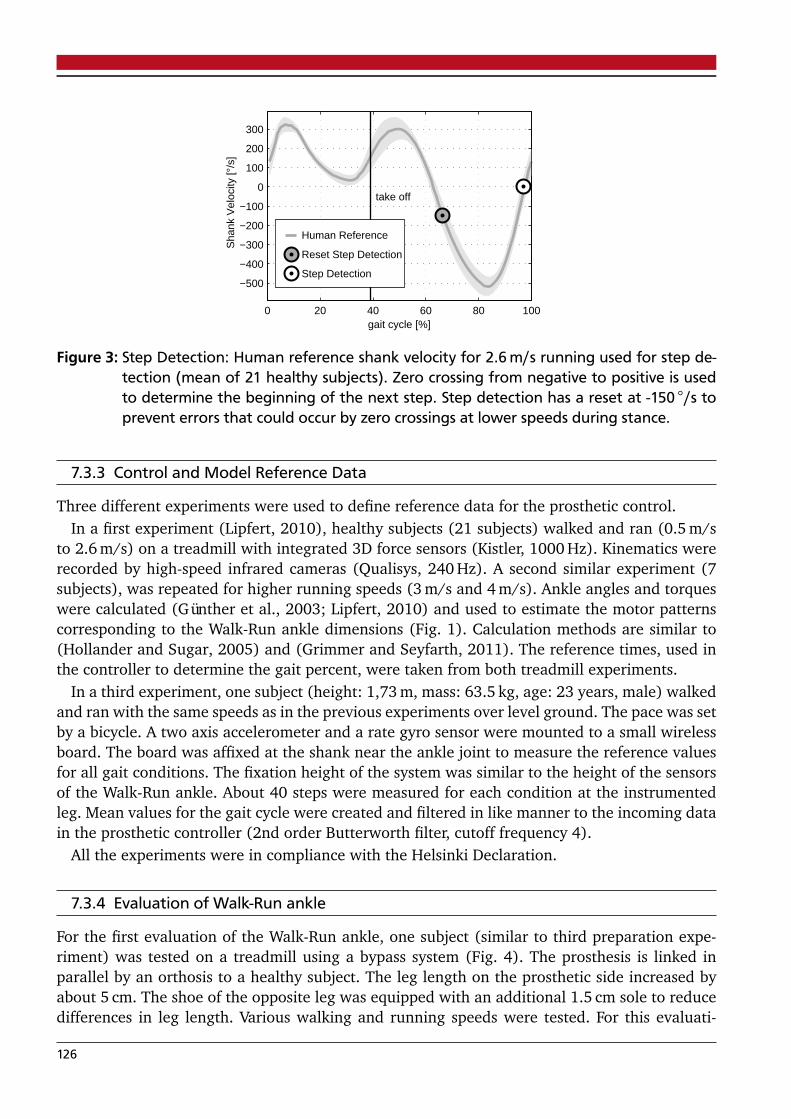
0 20 40 60 80 100
−500
−400
−300
−200
−100
0
100
200
300
gait cycle [%]
take off
Sha
nk V
eloc
ity [°
/s]
Human Reference
Reset Step Detection
Step Detection
Figure 3: Step Detection: Human reference shank velocity for 2.6 m/s running used for step de-tection (mean of 21 healthy subjects). Zero crossing from negative to positive is usedto determine the beginning of the next step. Step detection has a reset at -150 /s toprevent errors that could occur by zero crossings at lower speeds during stance.
7.3.3 Control and Model Reference Data
Three different experiments were used to define reference data for the prosthetic control.In a first experiment (Lipfert, 2010), healthy subjects (21 subjects) walked and ran (0.5 m/s
to 2.6 m/s) on a treadmill with integrated 3D force sensors (Kistler, 1000 Hz). Kinematics wererecorded by high-speed infrared cameras (Qualisys, 240 Hz). A second similar experiment (7subjects), was repeated for higher running speeds (3 m/s and 4 m/s). Ankle angles and torqueswere calculated (Günther et al., 2003; Lipfert, 2010) and used to estimate the motor patternscorresponding to the Walk-Run ankle dimensions (Fig. 1). Calculation methods are similar to(Hollander and Sugar, 2005) and (Grimmer and Seyfarth, 2011). The reference times, used inthe controller to determine the gait percent, were taken from both treadmill experiments.
In a third experiment, one subject (height: 1,73 m, mass: 63.5 kg, age: 23 years, male) walkedand ran with the same speeds as in the previous experiments over level ground. The pace was setby a bicycle. A two axis accelerometer and a rate gyro sensor were mounted to a small wirelessboard. The board was affixed at the shank near the ankle joint to measure the reference valuesfor all gait conditions. The fixation height of the system was similar to the height of the sensorsof the Walk-Run ankle. About 40 steps were measured for each condition at the instrumentedleg. Mean values for the gait cycle were created and filtered in like manner to the incoming datain the prosthetic controller (2nd order Butterworth filter, cutoff frequency 4).
All the experiments were in compliance with the Helsinki Declaration.
7.3.4 Evaluation of Walk-Run ankle
For the first evaluation of the Walk-Run ankle, one subject (similar to third preparation expe-riment) was tested on a treadmill using a bypass system (Fig. 4). The prosthesis is linked inparallel by an orthosis to a healthy subject. The leg length on the prosthetic side increased byabout 5 cm. The shoe of the opposite leg was equipped with an additional 1.5 cm sole to reducedifferences in leg length. Various walking and running speeds were tested. For this evaluati-
126
Figure 4: Bypass test orthosis: The Walk-Run ankle was mounted at an orthotic bypass to test itat healthy subjects
on, 44 continuous steps of 1.6 m/s walking, 60 continuous steps of 2.6 m/s running, and 37continuous steps of 4.0 m/s running were used.
7.3.5 Calculation of biomechanical parameters
The biomechanical parameters of the Walk-Run ankle were calculated using the motor encoderand the ankle angle encoder. The length of the spring was determined by the position of thenut (motor) in combination with the ankle angle. Using Hooke’s law, the spring force couldbe calculated. The spring and the nut velocity were determined by numerical differentiation.By using the lever arm of the spring towards the ankle joint, the ankle torque was calculated.The ankle torque could be related to the force applied by the nut using the lever arm of theankle joint towards the roller screw. By multiplying the spring velocity and the spring force themechanical power was calculated. The nut output power was calculated by multiplying the nutforce and the nut velocity. The sum of the spring power and the nut power is equal to the anklejoint power.
The step length of the bypass site was calculated using the speed of the treadmill and the timerequired for the gait cycle.
7.4 RESULTS
7.4.1 Gait quality
Walking 1.6 m/sThe ankle angle sensor output and the calculated torque of the Walk-Run ankle were compa-
red to the healthy subject data. We found that for walking at 1.6 m/s the controller identifieda mean speed of 1.6 m/s during the gait cycle. Step length (1.72 m) on the prosthetic side wasa little higher compared to the mean of the able body subjects (1.51 m). The angle and thetorque matched almost perfectly (Fig. 5) to reference data. Power curves and related energy ofthe model calculations (0.17 J/(kg·m)) differ to some extent from the values measured by the
127

Walk-Run ankle (0.14 J/(kg·m)). During the loading phase we could identify small differencesbetween the desired nut reference and the robotic nut trajectory (Fig. 6). As a result the peakpower exerted by the motor to load the spring is smaller than in the model (Fig. 8 at 45%). As aconsequence, the energy saved and released by the spring (0.11 J/(kg·m)) is also less comparedto the model (0.15 J/(kg·m)).
−10
0
10
20
30
take offRun
ning
4.0
m/s
Ankle Angle [°]
−10
0
10
20
30
Run
ning
2.6
m/s
0 20 40 60 80 100
−10
0
10
20
30
gait cycle [%]
Wal
king
1.6
m/s
0
1
2
3
Ankle Torque [Nm/kg]
0
1
2
3
Human Reference
Robotic Ankle
0 20 40 60 80 100
0
1
2
3
gait cycle [%]
Figure 5: Angle and torque: Ankle angle (left) and ankle torque (right) for the mean of multiplesteps using the Walk-Run ankle (black) and the mean of up to 21 health human refe-rence subjects (gray). For the reference data also standard deviation is shown. Data ispresented for the gait cycle of 1.6 m/s walking, 2.6 and 4.0 m/s running. The take off isindicated by a vertical line. An increase of the ankle angle implies plantarflexion.
The maximum power output of 3 W/kg is almost equal, but the timing of the maximum powerof the Walk-Run ankle is later compared to the model curve.
128

-0.02
-0.01
0
0.01
Ru
nn
ing
4.0
m/s
Length Change [m]
take off
-0.02
-0.01
0
0.01
Ru
nn
ing
2.6
m/s
0 20 40 60 80 100-0.02
-0.01
0
0.01
gait cycle [%]
Wa
lkin
g 1
.6 m
/s
Nut ModelNut RefNut RASpring ModelSpring RA
Figure 6: Nut and spring length change: Length change of the nut (dotted) and the spring (das-hed) for the mean of multiple steps using the Walk-Run ankle (black) and the mean ofup to 21 health human reference subjects (gray). Data is presented for the gait cycleof 1.6 m/s walking, 2.6 and 4.0 m/s running. The take off is indicated by a vertical line.Positive values imply lengthening. Light gray color indicates the pattern for the theore-tical model. As detected locomotion speed is different from the desired model and thetreadmill speed real nut reference (dark gray) curves differ from the model trajectory.
Running 2.6 m/sWhile running at a treadmill speed of 2.6 m/s, the Walk-Run ankle identified a mean speed
of about 2.8 m/s when using the bypass. The step length of the subject’s prosthetic side was1.92 m compared to 1.94 m for the reference data. When comparing the ankle angle and thetorque to reference data from 2.6 m/s, especially at touch down and take off, differences couldbe identified. The ankle angle begins dorsiflexion earlier (0-10%) and plantarflexion later (30%-50%) compared to reference running data (Fig. 5). The difference in the shape of the torque
129

-0.2
-0.1
0
0.1
0.2
Ru
nn
ing
4.0
m/s
Velocity [m/s]
take off
-0.2
-0.1
0
0.1
0.2
Ru
nn
ing
2.6
m/s
0 20 40 60 80 100-0.2
-0.1
0
0.1
0.2
gait cycle [%]
Wa
lkin
g 1
.6 m
/s
Nut ModelNut RefNut RASpring ModelSpring RA
Figure 7: Nut and spring velocity: Velocity of the nut (dotted) and the spring (dashed) for themean of multiple steps using the Walk-Run ankle (black) and the mean of up to 21health human reference subjects (gray). Data is presented for the gait cycle of 1.6 m/swalking, 2.6 and 4.0 m/s running. The take off is indicated by a vertical line. Positivevalues imply lengthening. Light gray color indicates the pattern for the theoretical mo-del. As detected locomotion speed is different from the desired model and the treadmillspeed real nut reference (dark gray) curves differ from the model trajectory.
is in line with the observed changes in the ankle angle. The nut did not follow the referencetrajectory closely during the stance phase (Fig. 6). The length of the spring increases earlierand decreases later compared to the reference data. This behavior is reflected also in the springvelocity (Fig. 7). The power curves differ in the shape from the model data. The amount ofwork provided by the robotic ankle motor (0.21 J/(kg·m)) and by the spring (0.23 J/(kg·m))is similar but not exactly that of the model (0.22 nut output and 0.25 J/(kg·m) spring). The
130
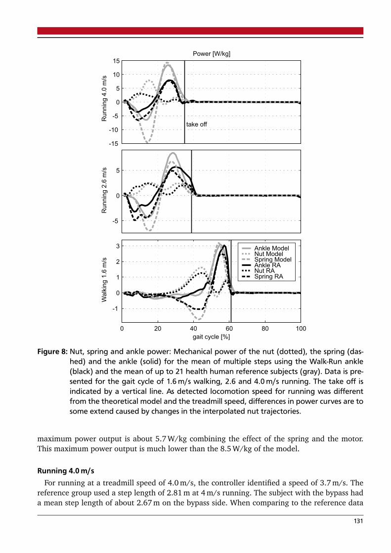
-15
-10
-5
0
5
10
15
Ru
nn
ing
4.0
m/s
Power [W/kg]
take off
-5
0
5
Ru
nn
ing
2.6
m/s
0 20 40 60 80 100
-1
0
1
2
3
gait cycle [%]
Wa
lkin
g 1
.6 m
/s
Ankle ModelNut ModelSpring ModelAnkle RANut RASpring RA
Figure 8: Nut, spring and ankle power: Mechanical power of the nut (dotted), the spring (das-hed) and the ankle (solid) for the mean of multiple steps using the Walk-Run ankle(black) and the mean of up to 21 health human reference subjects (gray). Data is pre-sented for the gait cycle of 1.6 m/s walking, 2.6 and 4.0 m/s running. The take off isindicated by a vertical line. As detected locomotion speed for running was differentfrom the theoretical model and the treadmill speed, differences in power curves are tosome extend caused by changes in the interpolated nut trajectories.
maximum power output is about 5.7 W/kg combining the effect of the spring and the motor.This maximum power output is much lower than the 8.5 W/kg of the model.
Running 4.0 m/sFor running at a treadmill speed of 4.0 m/s, the controller identified a speed of 3.7 m/s. The
reference group used a step length of 2.81 m at 4 m/s running. The subject with the bypass hada mean step length of about 2.67 m on the bypass side. When comparing to the reference data
131

of 4.0 m/s, we identified the same ankle angle behavior as in 2.6 m/s running. The dorsiflexionhappens earlier and the plantarflexion later compared to the model. After takeoff, a larger diffe-rence between the model and the system ankle angle occurs. Fluctuations in spring velocity arealso seen after the takeoff. Similar fluctuations after takeoff with less amplitude can be foundfor 2.6 m/s running and 1.6 m/s walking. Similar to running at 2.6 m/s, there is a gap betweenthe reference nut position and the real nut position in the the stance phase. The spring is notelongated in the same way as the model (Fig. 6). As a result of the nut position and the springlength, the ankle torque is less compared to the model values (Fig. 5). In addition, the peakpower and the work (nut output: 0.12, spring: 0.17 J/(kg·m)) is less compared to the model da-ta (nut output: 0.22, spring: 0.31 J/(kg·m)). The joint peak power should be about 13.4 W/kg.The robotic ankle can provide about 8 W/kg in total combining the effect of the spring and themotor.
7.5 DISCUSSION
7.5.1 Replication of human gait
The Walk-Run ankle could mimic the reference subject walking and running behavior whentesting using a bypass system on a healthy subject. When comparing the reference and the realdata only subtle differences could be identified in walking. For running, especially at 4.0 m/s,the behavior of the Walk-Run ankle differs from the model. To some extend this could be causedby the difference of the detected speed (2.8 instead of 2.6 m/s, 3.7 instead of 4.0 m/s) and theresulting difference in the desired motor trajectory. In running, a gap between the desired nutreference (Nut Ref) and the achieved nut position of the robotic ankle (Nut RA) between 10%and 43% of gait cycle exists.
As the motor current is not at its maximum (almost reached between 16% to 28%) duringsome part of this period, it could be possible to reduce the difference by an adaptation of thecontrol parameters. During midstance (4 m/s), the motor was not able to deliver enough torqueto move the nut. But motor torque was enough to hold position. It could be tested to whichextent an earlier pretensioning of the motor, when less torque is applied, could improve theelastic recoil.
The differences in the nut trajectory during stance cannot explain the difference in ankleangle mainly caused by the spring deflection at the beginning of the stance phase. The spring iselongated faster than the model predicts. For a comparable joint torque, such a behavior couldappear when the spring stiffness is too low. We assume that at 4 m/s, the stiffness could be acause for differences in the slope of the ankle angle. Also, as the torque increases for the 2.6 m/sexperiment, the same assumption cannot be made for this speed. The reason for the increase inthe torque at 2.6 m/s running could be a subject specific pattern but also asymmetries causedby the bypass system. The shank velocity data and video shows that the subject is touching theground while the shank is in forward rotation. This is in contrast to the natural pattern whereat touch down the shank is already in backward motion. The so called leg retraction (Seyfarthet al., 2003) is used to avoid impacts. The longer leg (about 3.5 cm) of the bypass system seemsto cause an increased impact that results in higher ankle torques compared to the referencedata. For a more detailed analysis on the reason motion capturing and force measurements ofboth legs would be required.
132

7.5.2 Spring fluctuations after take off
After takeoff, fluctuations of the spring occurred. This was more distinctive for the higher speeds.It is unclear how much these fluctuations in the early flight phase affect the gait stability. Itcould be worthwhile to investigate if it is possible to reduce fluctuations by using the motor fordamping. As a result of the fluctuations, the ankle angle after takeoff differs from reference dataespecially at 4.0 m/s running.
7.5.3 Touch down detection
For the ankle torque and the ankle angle in running, small changes happen slightly before thedetected start of the gait cycle. This could indicate that the gait cycle is not detected correctly.The shank velocity is used as an indicator for detecting the beginning of each new step. Forthe reference data, the zero crossing of the shank velocity data happens 3% before the touchdown (running 2.6 m/s, Fig. 3). As a result, the beginning of the gait cycle should be detectedslightly before the ground contact. In the experimental data it seems to be the opposite. Ankletorque can be calculated before a new gait cycle is detected. The change in the ankle angleshortly before the detected touch down is about 3 for both running speeds. As the nut positionis almost constant in this phase, the spring deflection (relative to change of the ankle anglesensor) causes the torque based on Hooke’s law. As already discussed for subsection 7.5.1, theshank velocity and video indicate that the bypass touches the ground while the shank is stillin forward rotation. Thus the control approach to use gyro data only for the step detection isinadequate. To avoid this phenomenon, future tests that include the bypass test bed should havea similar leg length. Another way to improve Gait Cycle Detection could be to use the calculatedforces from the spring deflection as an indicator of the beginning of a gait cycle. In additionto the method of using only the gyro data, the stance and the swing phase can potentially beidentified (Fig. 5).
7.5.4 Limitations of the Walk-Run ankle
The Walk-Run ankle nut was able to deliver about 3 W/kg mechanical peak power for a subjectweight including bypass and prosthesis of about 67 kg. This 200 W maximum was almost rea-ched for 2.6 m/s running. For running at 4.0 m/s the model predicted for the chosen stiffness arequired nut peak power output of 8 W/kg. The motor was not able to deliver these 536 W. Usingan optimal stiffness could reduce the requirements for running at 4 m/s to 3.9 W/kg (Grimmeret al., 2014). This could greatly improve the performance for the fastest running speed. Alsowhile the motor desired and achieved trajectory for 4 m/s running were not matching, the finalankle angle was almost equal (neglecting angle caused by fluctuations after takeoff ) to thereference data. Thus we assume there could be a better solution that is a compromise betweenfollowing of the desired motor trajectory and the gait quality. The precise following will requirea large amount of energy but the gait quality may only improve slightly. Investigations on thistopic could be made by using a motion capture system and force plates to compare symmetryand by using a spiroergometry system to measure user effort.
7.6 CONCLUSION
For the first preliminary study on the Walk-Run ankle, we found that it is possible to mimicthe human reference ankle joint behavior for walking and running up to a speed of 2.6 m/s.
133

Compared to the reference data, at 4 m/s running, the ankle torque from the prosthesis wasnot adequate. As the desired ankle angle was almost achieved even without the correct torque,the authors think that it is worthwhile to investigate the compromise between following thecalculated optimal motor trajectories and the gait quality. The authors believe that there is ahigh potential to decrease the peak power requirements and the energy consumption whenmotor trajectories are manipulated in a way to have reduced acceleration and less changes indirection.
Some hardware and control issues, like the differences in motor desired and achieved tra-jectory, the fluctuations of the spring, and touch down detection, could be identified. Some ofthese may occur due to the bypass setup. Thus, the next step would be to test the ankle on anamputee to avoid larger differences in leg length or mass distribution in between the legs.
7.7 OUTLOOK
The data collected and presented in the paper was derived from the controller M. Grimmer de-veloped for this system. This information is being used to influence the design of a ruggedizedpowered ankle that also has running capability. The new and improved design is being upda-ted by Springactive to include weight reducing titanium springs that have a longer life, higherefficiency bearings that increased system efficiency, and embedded electronics.
7.8 ACKNOWLEDGEMENTS
Research reported in this publication was supported by the the DFG grant SE1042/8 and the Eu-nice Kennedy Shriver National Institute of Child Health & Human Development of the NationalInstitutes of Health under award number R43HD072402. The content is solely the responsibilityof the authors and does not necessarily represent the official views of the National Institutes ofHealth. The authors acknowledge S.W. Lipfert for providing human data.
7.9 AUTHOR CONTRIBUTIONS
M. Grimmer was responsible for programming the high and medium level gait control. In ad-dition he was in the lead for drafting of the manuscript and experiments. M. Holgate was inthe lead for project planing, prosthesis design specifications and organization. R. Holgate wasresponsible for the design of the Walk-Run ankle, sensor integration, wiring and assembling.A. Boehler was responsible for the setup of the PC-104 platform, including sensor and motorinterfaces, used to control the robotic ankle. In addition he was programming the main frame-work for the prosthetic controller including the low level control. J. Ward provided supervisionon control developments. In addition he assisted for interpretation on results to improve futureprosthetic developments. M. Holgate, R. Holgate and A. Boehler and J. Ward assisted for expe-riments. A. Seyfarth assisted for the biomechanical analysis. Depending on there special field ofknowledge, all authors including K. Hollander and T. Sugar participated in the critical discussionof the results and helped for revision of the manuscript.
7.10 CONFLICT OF INTEREST
Matthew Holgate, Alexander Boehler, Jeff Ward, Kevin Hollander and Thomas Sugar are ownersof SpringActive. Robert Holgate was previously an employee of SpringActive. SpringActive, Inc.
134
supplied the Walk-Run ankle for this research and is currently developing commercial powe-red ankle prostheses. Martin Grimmer and Andre Seyfarth are with the Technical University ofDarmstadt and have no competing interests.
7.11 REFERENCES
Aldridge, J. M., Sturdy, J. T., and Wilken, J. M. (2012). Stair ascent kinematics and kinetics witha powered lower leg system following transtibial amputation. Gait & Posture.
Bragaru, M., Dekker, R., and Geertzen, J. (2012). Sport prostheses and prosthetic adaptationsfor the upper and lower limb amputees: an overview of peer reviewed literature. Prostheticsand Orthotics International, 36(3):290–296.
Cherelle, P., Matthys, A., Grosu, V., Brackx, B., Van Damme, M., Vanderborght, B., and Lefeber, D.(2012). The amp-foot 2.0: A powered transtibial prosthesis that mimics intact ankle behavior.In 9th National Congress on Theoretical and Applied Mechanics.
Czerniecki, J., Gitter, A., and Munro, C. (1991). Joint moment and muscle power output cha-racteristics of below knee amputees during running: the influence of energy storing prostheticfeet. Journal of biomechanics, 24(1):63–65.
Eslamy, M., Grimmer, M., and Seyfarth, A. (2012). Effects of unidirectional parallel springs onrequired peak power and energy in powered prosthetic ankles: Comparison between diffe-rent active actuation concepts. In IEEE International Conference on Robotics and Biomimetics(ROBIO).
Farris, D. and Sawicki, G. (2012). Human medial gastrocnemius force–velocity behavior shiftswith locomotion speed and gait. Proceedings of the National Academy of Sciences, 109(3):977–982.
Ferris, A. E., Aldridge, J. M., Rábago, C. A., and Wilken, J. M. (2012). Evaluation of a poweredankle-foot prosthetic system during walking. Archives of physical medicine and rehabilitation,93(11):1911–1918.
Gitter, A., Czerniecki, J., and DeGroot, D. (1991). Biomechanical analysis of the influence ofprosthetic feet on below-knee amputee walking. American Journal of Physical Medicine &Rehabilitation, 70(3):142.
Grimmer, M., Eslamy, M., Gliech, S., and Seyfarth, A. (2012). A comparison of parallel-and serieselastic elements in an actuator for mimicking human ankle joint in walking and running. InRobotics and Automation (ICRA), 2012 IEEE International Conference on, pages 2463–2470.IEEE.
Grimmer, M., Eslamy, M., and Seyfarth, A. (2014). Energetic and peak power advantages ofseries elastic actuators in an actuated prosthetic leg for walking and running. In Actuators,volume 3, pages 1–19. Multidisciplinary Digital Publishing Institute.
Grimmer, M. and Seyfarth, A. (2011). Stiffness adjustment of a series elastic actuator in anankle-foot prosthesis for walking and running: The trade-off between energy and peak poweroptimization. In IEEE International Conference on Robotics and Automation (ICRA), pages1439–1444. IEEE.
135

Grimmer, M. and Seyfarth, A. (2014). Mimicking human-like leg function in prosthetic limbs.In Neuro-Robotics, pages 105–155. Springer.
Günther, M., Sholukha, V., Keßler, D., Wank, V., and Blickhan, R. (2003). Dealing with skin mo-tion and wobbling masses in inverse dynamics. Journal of Mechanics in Medicine and Biology,3(3-4):309–335.
Herr, H. and Grabowski, A. (2012). Bionic ankle–foot prosthesis normalizes walking gaitfor persons with leg amputation. Proceedings of the Royal Society B: Biological Sciences,279(1728):457–464.
Hitt, J., Sugar, T., Holgate, M., and Bellman, R. (2010). An active foot-ankle prosthesis withbiomechanical energy regeneration. Journal of Medical Devices, 4:011003.
Hollander, K. and Sugar, T. (2005). Design of the robotic tendon. In Design of Medical DevicesConference (DMD).
Leyk, D., Erley, O., Ridder, D., Leurs, M., Ruther, T., Wunderlich, M., Sievert, A., Baum, K.,and Essfeld, D. (2007). Age-related changes in marathon and half-marathon performances.International journal of sports medicine, 28(6):513–517.
Lipfert, S. (2010). Kinematic and dynamic similarities between walking and running. Verlag Dr.Kovac, Hamburg. ISBN: 978-3-8300-5030-8.
Radocy, B. (1987). Upper-extremity prosthetics: Considerations and designs for sports and re-creation. Clin Prosthet Orthot, 11(3):131–153.
Seyfarth, A., Geyer, H., and Herr, H. (2003). Swing-leg retraction: a simple control model forstable running. Journal of Experimental Biology, 206(15):2547–2555.
Sup, F., Varol, H., Mitchell, J., Withrow, T., and Goldfarb, M. (2009). Self-contained poweredknee and ankle prosthesis: Initial evaluation on a transfemoral amputee. In IEEE InternationalConference on Rehabilitation Robotics (ICORR), pages 638–644. IEEE.
Sup, F., Varol, H. A., and Goldfarb, M. (2011). Upslope walking with a powered knee andankle prosthesis: initial results with an amputee subject. Neural Systems and RehabilitationEngineering, IEEE Transactions on, 19(1):71–78.
Suzuki, R., Sawada, T., Kobayashi, N., and Hofer, E. (2011). Control method for powered ankleprosthesis via internal model control design. In International Conference on Mechatronics andAutomation (ICMA), pages 237–242. IEEE.
Versluys, R., Lenaerts, G., Van Damme, M., Jonkers, I., Desomer, A., Vanderborght, B., Peeraer,L., Van der Perre, G., and Lefeber, D. (2009). Successful preliminary walking experiments ona transtibial amputee fitted with a powered prosthesis. Prosthetics and orthotics international,33(4):368–377.
Webster, J., Levy, C., Bryant, P., and Prusakowski, P. (2001). Sports and recreation for personswith limb deficiency. Archives of physical medicine and rehabilitation, 82(3):S38–S44.
Zhu, J., Wang, Q., and Wang, L. (2010). Pantoe 1: Biomechanical design of powered ankle-footprosthesis with compliant joints and segmented foot. In IEEE/ASME International Conferenceon Advanced Intelligent Mechatronics (AIM), pages 31–36. IEEE.
136

8 Manuscript VI: Simplified ankle control decrea-ses powered prosthetic noise and improves perfor-mance and efficiency
Authors:
Martin Grimmer, Antje Grebel, Matthew Holgate, JeffWard, Alexander Boehler, Tobias Melz and André
Seyfarth
Technische Universität Darmstadt
64289 Darmstadt, Germany
Submitted for publication in 2014
137

8.1 ABSTRACT
Powered ankle prostheses are demonstrated to be capable of performing kinematic and kineticjoint patterns similar to natural human biomechanics. For a better integration in amputees’ dailylife prosthesis operating times should be further increased and noise levels decreased. Motorassistance is designed in order to benefit from elastic structures. Model assumptions on theinteraction of motor and springs do not necessarily represent the most preferred pattern of theamputee. The peak power optimized motor curves were filtered using a zero-lag second-order4 Hz and a 2 Hz Butterworth low pass filter. The study shows the influence of these filtered motorpatterns on the powered ankle noise, efficiency, and effects on 1.1 m/s walking kinematics.For ankle joint torque almost no differences could be observed between the optimized andthe filtered patterns. The ankle angle showed reduced plantarflexion for the filtered curves inflight phase. Minor differences in both angle and torque caused highest push off peak powerand efficiency for the 2 Hz filtered motor trajectory. Noise and electrical power consumptiondecreased when applying the filter. The subject felt most comfortable using the 2 Hz pattern.
Keywordspowered prosthesis, amputee walking, energy efficiency, gait performance, bionic limb, ankle
angle, ankle torque
8.2 INTRODUCTION
Using passive prosthetic devices, transtibial amputees are not able to perform net positive workat the ankle joint (Czerniecki et al., 1991; Grimmer and Seyfarth, 2014). Resulting gait asymme-tries may lead to long-term sequelae (Gailey et al., 2008; Robbins et al., 2009). Powered ankleprostheses allow the performance of joint patterns similar to natural human biomechanics. Cur-rent systems are able to mimic joint kinematics and kinetics of level walking and running butalso of climbing stairs and walking inclines and declines (Aldridge et al., 2012; Au et al., 2009;Lawson et al., 2013; Sup et al., 2011; Ward et al., 2014). However, several user requests areleft to improve on powered ankle acceptance and performance. To increase the operation timeof the system, efficiency needs to be improved. Current designs are made to perform for about5000 level walking steps per leg without charging the battery (Au et al., 2009). About 6500steps a day are performed by healthy people in daily life using both legs (Tudor-Locke and Bas-sett, 2004). Powered systems should be able to cover at least one day, including also higherdemanding activities like walking stairs and inclines. Next to the advancements in operatingtime, an improved efficiency (less friction) may cause less system noise. Amputees may perceivemechanical noise as annoying. They will be noticed to be an amputee when using such a systemin daily life. Particularly, females reported the importance of preventing the prosthesis from ma-king noise (Legro et al., 1999). Thus, improving the subjective user-experience should be one ofthe key elements for prosthetic developments (Beckerle, 2014).
To enhance powered ankle performance the efficiency of the drive (belt drive, bearings, rollerscrew, motor) can be increased. In addition dampers or springs are able to assist the powersource (motor) to increase system efficiency. Simulations on various configurations showed thehigh potential of these structures (Eslamy et al., 2013; Grimmer et al., 2012, 2014). In (Grimmeret al., 2014), the stiffness of a series spring was optimized for minimum ankle motor peak powerfor different walking and running speeds. The outcome of the optimization are motor patternsthat interact in a mechanically optimal way with the spring to reduce motor requirements. An
138

open question to these simulations is the reaction of the amputee to the given motor curves. Aseach subject is different and provided patterns are calculated based on subject group means ofthe joint angle and the joint torque, individual variations of the patterns may provide a betterperformance for the amputee. Next to an individualization, a generalization to main events inthe gait cycle of the reference curves may also help to improve amputee acceptance. Optimizedmotor curves include, depending on speed and gait, several changes in motor direction that arerequired to match joint biomechanics. The motor complements the length change of the springto achieve the reference ankle angle. Due to the inertia of motor and mechanics these changesin the sign of motor velocity may lead to increased power and energy demands.
In this study we will investigate to which extent smoother motor patterns, reducing peakacceleration and frequent changes in motor turning direction, can reduce power and energydemands of a powered ankle prosthesis in walking. By this approach, efficiency of the prosthesisshould be increased and system noise decreased. As motor patterns change, amputee movementmay differ. Using a motion capture system and an instrumented treadmill it will be proven towhich extent the smoothing of the reference pattern affects the motion of a unilateral transtibialamputee.
8.3 METHODS
8.3.1 Walk-Run ankle design
The Walk-Run ankle (WRA, Fig. 1) is a powered ankle prosthesis that uses a 200 W brushlessDC motor to perform walking and running. Next to the motor the system benefits from theelastic energy reuse of a spring that is optimized for a subject weight of 61 kg and a mediumrunning speed of 2.6 m/s (Grimmer et al., 2014). The stiffest possible version of the Pacifica LPfoot (Freedom Innovations) was selected to avoid further elasticity that is not included in themotor optimization model. A belt drive and a roller-screw are used to realize ankle dorsiflexionor plantarflexion.
Moto
r
Joint
Roller Screw
Belt Drive
Nut
Figure 1: Walk-Run ankle (WRA) prosthesis (SpringActive)
For control an external PC-104 is used. The WRA has a weight of 1.9 kg not including the25.9 V battery. The subject of this study (55 kg, 1.68 m height) has an amputation height of
139

0.34 m. The amputated limb mass is calculated to be about 2.3 kg (equation from (Grimmer andSeyfarth, 2014)). In combination with adapters (0.4 kg), socket and liner (0.75 kg) the weightof the lower limb prosthesis is above the healthy condition.
8.3.2 Walk-Run ankle control
An extended controller of the WRA was designed to distinguish between standing, walking,running, and transitions. A rate gyro sensor (θ shank), to measure shank angular velocity, and atwo-axis linear accelerometer ( x shank is oriented forward and yshank vertically when the subjectis standing) are used to mimic healthy ankle biomechanics. Sensors data is readout at 1000 Hzusing Simulink (MathWorks).
For the performed experiments a simplified control algorithm was used that fixes gait mode towalking and gait speed to the treadmill speed of 1.1 m/s. Small differences in detected walkingspeed during the gait cycle normally cause adaptations of the motor trajectory. Avoiding thisallows a better comparison to the model predictions. The beginning of the gait cycle is identifiedby rate gyro sensor data from the shank. When the shank angular velocity crosses from negative(swinging forward) to positive velocity (swinging backward) the beginning of the gait cycle isdefined (Fig. 2). At some walking and running speeds the same zero crossing can occur duringmidstance. To avoid errors in step detection a second condition was defined. During the swingphase, angular velocity reaches a maximum. For lower speeds the maximum value decreases. At0.5 m/s walking the maximum was about –200 /s. A hit crossing condition of –150 /s needsto be fulfilled before shank velocity zero crossing can be used to identify the beginning of astep. The output of the gait cycle detection is the step time and the start time of the current gaitcycle. In combination with the start time of the last gait cycle the time of the last step can bedetermined.
0 20 40 60 80 100-400
-300
-200
-100
0
100
200
Gait Cycle [%]
take off
Sh
an
k V
elo
city [
°/s]
Reference STD+-
Reset Step Detection
Step Detection
Figure 2: Human reference shank velocity curve (1.1 m/s walking, mean of 21 healthy subjects)used for step detection. Zero crossing from negative to positive is used to determinethe beginning of the next step. Step detection starts below a threshold of –150 /s toavoid errors that could occur by zero crossings at lower speeds during stance.
140

Figure 3: Unilateral transtibial amputee walking on an instrumented treadmill using the Walk-Run ankle (WRA).
The gait percent detection uses a lookup table of times of gait cycles from different speeds ofwalking and running (Lipfert, 2010). The gait percent G% is determined by dividing the currentstep time tcur (s) by the reference step time tcyc (s) from the lookup table.
G% = (tcur/tcyc) · 100 % (1)
Due to individual differences in tcyc from the reference lookup table, tcyc of the last step isalso taken into account. This results in more precise gait percent detection. Depending on gaitpercent, the optimized motor reference position is readout from a lookup table. The desiredmotor trajectory is achieved by PD control.
8.3.3 Control and model reference data
Reference data from healthy subjects (Lipfert, 2010) was used to calculate optimal motor trajec-tories and to perform WRA control. In the reference experiment 21 subjects walked and ran (0.5– 2.6 m/s) on a treadmill with integrated 3D force sensors (Kistler, 1000 Hz). Kinematics wererecorded by high-speed infrared cameras (Qualisys, 240 Hz). Ankle angles and torques werecalculated (Günther et al., 2003; Lipfert, 2010) and used to estimate motor patterns correspon-ding to the WRA dimensions (Fig. 1). Calculation methods are similar to (Hollander and Sugar,2005) and (Grimmer and Seyfarth, 2011). Reference times, used in the controller to determinethe gait percent, were also taken from this experiment.
For this study only the data of 1.1 m/s walking is relevant.
8.3.4 Evaluation of Walk-Run ankle on an amputee
For the first evaluation of the WRA on an amputee, one female subject (55 kg, 17 years) wasanalyzed on an instrumented treadmill during walking at 1.1 m/s (Fig. 3). The subject has aunilateral transtibial amputation since birth.
141

0 20 40 60 80 100
-8
-6
-4
-2
0
x 10-3
take off
Gait Cycle [%]
Nu
t L
en
gth
Ch
an
ge
[m
]
OPT
OPT4
OPT2
Figure 4: Using the calculation methods from (Grimmer and Seyfarth, 2011; Hollander and Sugar,2005) a motor trajectory to actuate the powered ankle prosthesis can be calculated.This pattern is predicted to use the elastic properties of a spring in an optimized wayto assist the motor (OPT, black). The calculated pattern was filtered with a 4 Hz (OPT4,dark gray) and a 2 Hz (OPT2, light gray) low pass filter. Take off is indicated by a verticalline.
Four different measurements, lasting 2 minutes each, were performed. In the first trial motorposition was locked in neutral standing condition. Using this method, the powered prosthesisworks purely passively (Passive). This trial is used for an estimation of the unpowered ankleperformance. For the second trial a peak power optimized unfiltered motor pattern was used(OPT). It was determined using the methods presented in (Grimmer et al., 2014), to guaranteehighest assistance of the series spring to power the artificial ankle joint. This motor patternincludes frequent changes in turning direction that are also reflected by the nut of the rollerscrew when moving the ankle joint (Fig. 4). In addition, acceleration values of the nut patternare high. The nut pattern consists of 100 data points representing one gait cycle in percent. Thetime for this gait cycle is about 1.14 s. By smoothing the nut curve electrical energy consumptionand system noise might be reduced. In a first approach a zero-lag second-order Butterworth lowpass filter was used to simplify the pattern. The cut-off frequency was selected to avoid the littleturn in the nut movement at 55% of gait cycle. This could be achieved using a cut-off frequencyof 4 Hz. Next to the changes in this phase of the gait cycle also the nut movement after touchdown and in the flight phase will be reduced. The resulting curve (OPT4) was used for the thirdexperimental trial. To explore the limitations of the approach half of it (2 Hz, OPT2) was usedfor the fourth trial.
During the 2 minutes the subject performed between 80 to 97 valid steps that could be usedfor analysis. Ground reaction forces were measured at 1000 Hz by the Kistler sensors in thetreadmill. Motion kinematics were captured at 250 Hz using a Qualisys system. The hip anglewas calculated between the 7th cervical vertebra, trochanter major and an assumed center ofrotation at the knee (2 cm proximal of the joint space on the lateral femoral condyle). Theknee angle was calculated as the angle between the line connecting the greater trochanter
142

major, and the rotational knee point and the line connecting the rotational knee point and thelateral malleolus. The ankle angle was calculated by the rotational point of the knee, the lateralmalleolus and the 5th metatarsophalangeal joint of the foot. All angles were calculated for thesagittal plane. Ankle joint torque was calculated using a static analysis (Günther et al., 2003).Joint angular velocities were calculated by numerical differentiation and multiplied by the jointtorque to obtain joint power.
8.3.5 Walk-Run ankle parameter calculation
The motor encoder and the ankle angle encoder of the WRA provide the main input for furtherbiomechanical calculations. Using both encoder positions the deflection of the spring can bedetermined. Hook’s law and the spring deflection are used to calculate the spring force. Thespring and nut (motor encoder) velocity were determined by numerical differentiation. Theankle torque is calculated by using the lever arm of the spring towards the ankle joint. The forceat the nut is determined using ankle torque and the lever arm of the ankle joint towards theroller screw. The spring velocity and the spring force are multiplied to calculate the mechanicalspring power. The nut velocity and the nut force are multiplied to calculate the nut outputpower. The sum of spring power and nut power is equal to the ankle joint power.
The mechanical energy requirement of the drive output at the nut was calculated as thesum of positive and the amount of negative work (Grimmer et al., 2014). Mechanical energyrequirement of the system represents the total ankle joint work adding up the nut and springpower curve.
Power and torque are normalized to the body mass for the reference and the observed ampu-tee data.
Electrical motor power Pel (W) is estimated using motor current I (A) and motor angularvelocity ω (rpm). In addition the speed constant kn of the Maxon EC 30 motor (710 min–1 ·V–1) and its terminal resistance R (0.102 Ω) is required.
Pel =ω/kn · I + R · I2 W (2)
8.3.6 Efficiency calculations
The system efficiency ηsystem describes the overall efficiency of the WRA including the effects ofthe elastic element. It is calculated by the electrical energy input Eelectrical and the mechanicalsystem output Esystem.
ηsystem = Esystem/Eelectrical (3)
The drive efficiency ηdrive describes the efficiency of the mechanical drive. It is calculated usingthe electrical energy input Eelectrical and the mechanical energy output at the nut Enut of theroller screw.
ηdrive = Enut/Eelectrical (4)
143

8.3.7 Acoustical measurements
Young humans can hear sound in a frequency range of 20 Hz up to 20 kHz (Lerch et al., 2009).The ability to hear in the whole spectrum decreases with rising age (Frings and Müller, 2014). Atime signal of a sound can be analyzed with respect to its frequency components by using a FastFourier Analysis (FFT) algorithm (Müller and Möser, 2013). Since the amplitude range betweenthe hearing threshold and the pain threshold is very large, the logarithmic scale decibel (dB) iscommonly used in acoustics. It expresses the ratio between the physical measurement data andthe reference value (Rossing, 2007). As a sound pressure level, which can be easily measuredwith any sound level meter, always depends on the surrounding environment, sound power wastaken for this investigation. Sound power is the rate of acoustic energy flow across a specifiedarea emitted by a specific sound source and is absolutely independent of the surrounding envi-ronment. The sound power measurement was carried out in a hemi-anechoic room, which is aroom with a hard reflecting floor and all other surfaces anechoic. The sound power level LW canbe calculated from sound pressure levels that are measured on positions on a hemisphere overthe measurement object according to ISO 3745:2012 using
LW = Lp + 10 · lg
Sm
S0
dB, (5)
where Lp is the time-averaged and area-averaged sound pressure level, Sm is the surface of themeasurement hemisphere, and S0 is the reference surface of 1 m2.
For sound power measurements the amputee walked on a treadmill (Schmidt Sportsworld,GM 2011) that was placed in the center of the hemi-anechoic chamber. The passive, the peakpower optimized, and both filtered setups were tested. In the passive trial (Passive) the amputeewalked without motor assistance. Thus, it represents the noise of the treadmill that can be usedto calculate the sound power emitted by the prosthesis only for the powered trials.
8.4 RESULTS
8.4.1 General observations
Ankle angle and ankle torque of the WRA were calculated by two different methods. The firstmethod used the sensors at the prosthesis (Sens. WRA), the second the kinematic data fromthe Qualisys motion capture system and the kinetics measured by the instrumented treadmill(Meas. WRA). When comparing both methods the motion capture system shows a larger Rangeof Motion (RoM) for the ankle angle. This is caused by the additional elasticities of the carbonfoot and the shoe (Fig. 5, left). The ankle angle encoder cannot measure these deflections. Onthe other hand the torque calculation method by the WRA sensors shows a larger increase andhigher peak values (Fig. 5, right). Due to these opposing trends, both methods result in almostequal mechanical power (Fig. 7, left). The peak mechanical power of the passive trial is lowercompared to the powered trials.
Compared to the powered conditions (Org, Filter 4 Hz, Filter 2 Hz) the passive WRA trial(Passive) could not mimic the ankle joint kinematics of the reference data for the push off andthe flight phase (Fig. 5, left). The ankle joint torque for the passive trial increased much laterand is less compared to the powered trials. Both powered and passive trial did not reach thepeak joint torque of the reference (Fig. 5, right). Times for the gait cycle increased when using
144

-10
0
10
20
take offPassive
Ankle Angle [°]
-10
0
10
20OPT
-10
0
10
20OPT4
0 20 40 60 80 100
-10
0
10
20
Gait Cycle [%]
OPT2
0
0.5
1
1.5
Ankle Torque [Nm/kg]
Passive Ref STD+-Sens. WRA
Meas. WRA
0
0.5
1
1.5OPT
0
0.5
1
1.5OPT4
0 20 40 60 80 100
0
0.5
1
1.5
Gait Cycle [%]
OPT2
Figure 5: Ankle angle (left) and normalized ankle torque (right) for the mean of multiple stepsusing the Walk-Run ankle and the mean of healthy subjects as reference (gray). Thedata was determined using the sensors of the WRA (black, solid) and external measu-rement systems for kinematics and kinetics (black, dashed). For the reference data alsothe standard deviation is shown. Data is presented for the gait cycle of 1.1 m/s walking.The take off of the reference is indicated by a gray dot. An increase of the ankle angleimplies plantarflexion.
145
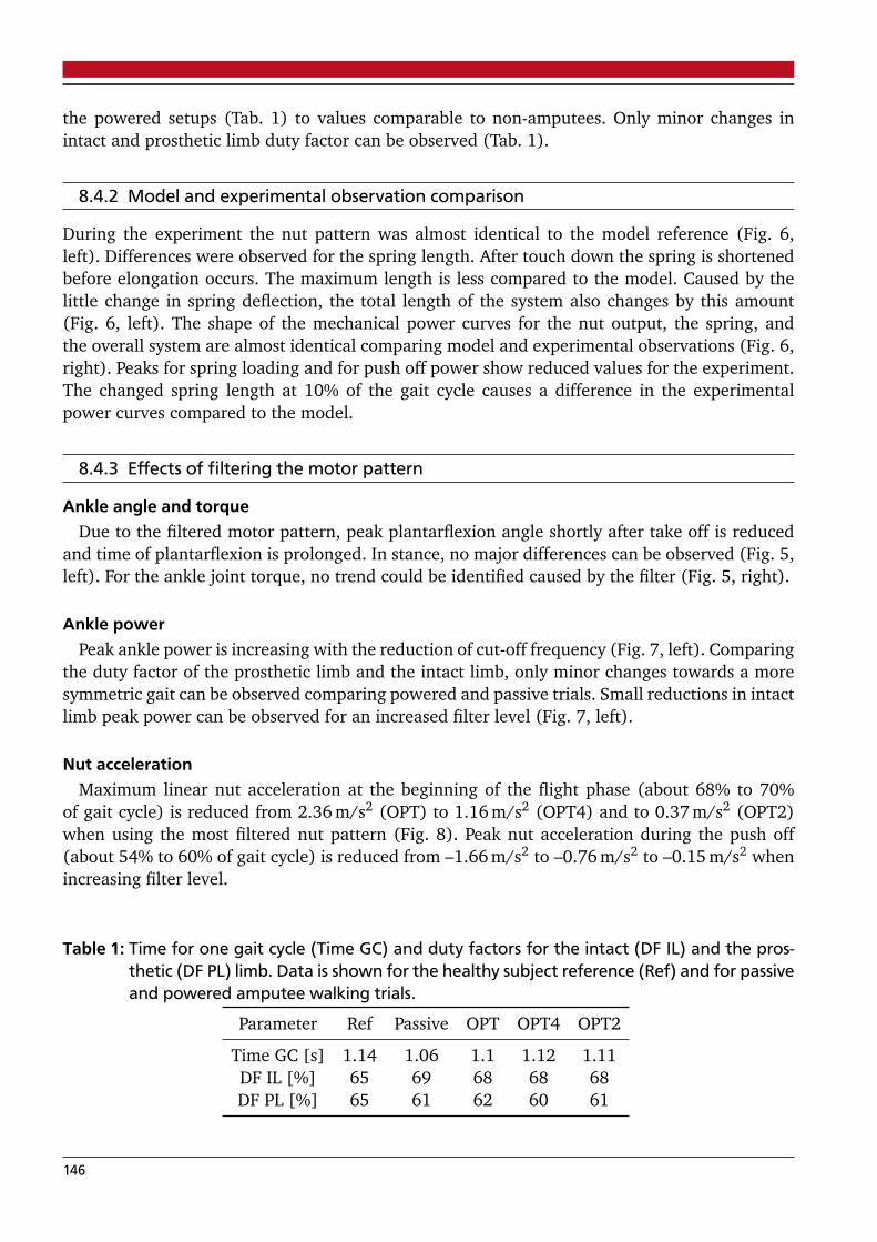
the powered setups (Tab. 1) to values comparable to non-amputees. Only minor changes inintact and prosthetic limb duty factor can be observed (Tab. 1).
8.4.2 Model and experimental observation comparison
During the experiment the nut pattern was almost identical to the model reference (Fig. 6,left). Differences were observed for the spring length. After touch down the spring is shortenedbefore elongation occurs. The maximum length is less compared to the model. Caused by thelittle change in spring deflection, the total length of the system also changes by this amount(Fig. 6, left). The shape of the mechanical power curves for the nut output, the spring, andthe overall system are almost identical comparing model and experimental observations (Fig. 6,right). Peaks for spring loading and for push off power show reduced values for the experiment.The changed spring length at 10% of the gait cycle causes a difference in the experimentalpower curves compared to the model.
8.4.3 Effects of filtering the motor pattern
Ankle angle and torqueDue to the filtered motor pattern, peak plantarflexion angle shortly after take off is reduced
and time of plantarflexion is prolonged. In stance, no major differences can be observed (Fig. 5,left). For the ankle joint torque, no trend could be identified caused by the filter (Fig. 5, right).
Ankle powerPeak ankle power is increasing with the reduction of cut-off frequency (Fig. 7, left). Comparing
the duty factor of the prosthetic limb and the intact limb, only minor changes towards a moresymmetric gait can be observed comparing powered and passive trials. Small reductions in intactlimb peak power can be observed for an increased filter level (Fig. 7, left).
Nut accelerationMaximum linear nut acceleration at the beginning of the flight phase (about 68% to 70%
of gait cycle) is reduced from 2.36 m/s2 (OPT) to 1.16 m/s2 (OPT4) and to 0.37 m/s2 (OPT2)when using the most filtered nut pattern (Fig. 8). Peak nut acceleration during the push off(about 54% to 60% of gait cycle) is reduced from –1.66 m/s2 to –0.76 m/s2 to –0.15 m/s2 whenincreasing filter level.
Table 1: Time for one gait cycle (Time GC) and duty factors for the intact (DF IL) and the pros-thetic (DF PL) limb. Data is shown for the healthy subject reference (Ref) and for passiveand powered amputee walking trials.
Parameter Ref Passive OPT OPT4 OPT2
Time GC [s] 1.14 1.06 1.1 1.12 1.11DF IL [%] 65 69 68 68 68DF PL [%] 65 61 62 60 61
146

0 20 40 60 80 100-10
-5
0
5
x 10-3
Gait Cycle [%]
Le
ng
th C
ha
ng
e [
m]
0 20 40 60 80 100
0
1
2
Gait Cycle [%]
Me
ch
an
ica
l P
ow
er
[W/k
g]
N+S ModelN ModelS ModelN+S WRAN WRAS WRA
Figure 6: Length change (left) and normalized mechanical power (right) of the nut (N, dotted),the spring (S, dashed), and the combination of both (N+S, solid) for the Walk-Run ankle(black, mean of multiple steps) and the corresponding model prediction (gray, meanof 21 healthy human reference subjects). Data is presented for the gait cycle of 1.1 m/swalking for the unfiltered optimized motor pattern. As spring stiffness is sub-optimalfor the amputee weight and the walking speed both model prediction and experimen-tal observations differ from optimal model curves published in (Grimmer et al., 2014).Positive length values imply lengthening. For comparison the model reference valuesare shifted towards the left (3% of the gait cycle) to match the asymmetric gait patternof the amputee.
Electrical powerThe OPT motor pattern causes the highest peaks for the electrical power consumption (Fig. 7,
right). Using the filtered curves these peaks can be reduced dramatically. Having the filter of 2 Hzthe power peaks due to motor direction change after touch down and after take off can be almosteliminated. The double hump in the stance phase, originally observed for the mechanical andthe electrical power, is converted to a single hump when applying the 2 Hz filter (Fig. 7, right).
Energy and efficiencyWhen using the filter of 4 Hz and 2 Hz, spring loading and mechanical energy output of the
nut could be increased (Tab. 2). As a result the system output energy increased to values similarto the model. With the increase in mechanical output energy the electrical input decreased,
Table 2: Energy exchange [J/kg] and efficiencies
Mech. Energy Spring Mech. Energy Nut Mech. Energy System Elec. Energy Motor Efficiency
Tot Pos Neg Tot Pos Neg Tot Pos Neg Tot Pos Neg Drive System
Model 0.324 0.162 –0.162 0.138 0.103 –0.035 0.323 0.196 –0.127 - - - - -Opt 0.24 0.12 –0.12 0.096 0.08 –0.016 0.243 0.154 –0.089 0.657 0.579 –0.078 0.146 0.37Opt4 0.224 0.112 –0.112 0.113 0.109 –0.004 0.282 0.193 –0.088 0.559 0.536 –0.023 0.202 0.504Opt2 0.25 0.125 –0.125 0.117 0.11 –0.006 0.299 0.202 –0.097 0.495 0.493 –0.002 0.235 0.603Passive 0.206 0.103 –0.103 - - - 0.206 0.103 –0.103 - - - - -
147

0
1
2Passive
Ankle Power [W/kg]
Ref STD+-Sens. WRAMeas. WRAMeas. IL
0
1
2
take off
OPT
0
1
2OPT4
0 20 40 60 80 100
0
1
2
Gait Cycle [%]
OPT2
-1
0
1
2
3
4
Ankle Power [W/kg]
Passive System WRASpring WRANut WRAElectr. WRA
-1
0
1
2
3
4OPT
-1
0
1
2
3
4OPT4
0 20 40 60 80 100
-1
0
1
2
3
4
Gait Cycle [%]
OPT2
Figure 7: Mechanical and electrical power requirements for 1.1 m/s walking using the Walk-Runankle. The passive trial is compared to the optimal (OPT) and the 4 Hz and 2 Hz filte-red (OPT4, OPT2) pattern. On the left the reference (Ref+STD, gray solid) is comparedto the mechanical output calculated by the sensors of the WRA (Sens. WRA, black so-lid) and the value calculated by measured kinematics and kinetics (Meas. WRA, blackdashed). The mechanical output of the intact limb (Meas. IL) is displayed by the blackdotted line. On the right the system mechanical output (Ankle WRA, black solid, simi-lar to Sens. WRA), consisting of motor power (Motor WRA, black dotted) and springpower (gray dashed), is shown. Electrical energy consumption (Electr, WRA) is visuali-zed by the dark gray solid line.
148
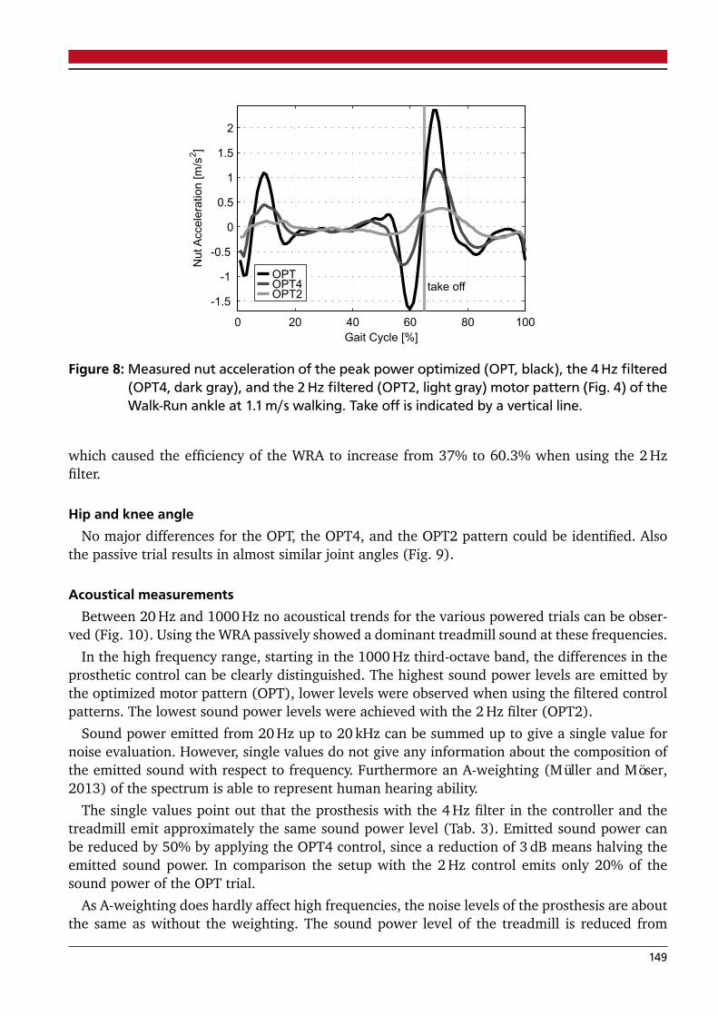
0 20 40 60 80 100
-1.5
-1
-0.5
0
0.5
1
1.5
2
take off
Gait Cycle [%]
Nu
tA
cce
lera
tio
n [
m/s
2]
OPTOPT4OPT2
Figure 8: Measured nut acceleration of the peak power optimized (OPT, black), the 4 Hz filtered(OPT4, dark gray), and the 2 Hz filtered (OPT2, light gray) motor pattern (Fig. 4) of theWalk-Run ankle at 1.1 m/s walking. Take off is indicated by a vertical line.
which caused the efficiency of the WRA to increase from 37% to 60.3% when using the 2 Hzfilter.
Hip and knee angleNo major differences for the OPT, the OPT4, and the OPT2 pattern could be identified. Also
the passive trial results in almost similar joint angles (Fig. 9).
Acoustical measurementsBetween 20 Hz and 1000 Hz no acoustical trends for the various powered trials can be obser-
ved (Fig. 10). Using the WRA passively showed a dominant treadmill sound at these frequencies.
In the high frequency range, starting in the 1000 Hz third-octave band, the differences in theprosthetic control can be clearly distinguished. The highest sound power levels are emitted bythe optimized motor pattern (OPT), lower levels were observed when using the filtered controlpatterns. The lowest sound power levels were achieved with the 2 Hz filter (OPT2).
Sound power emitted from 20 Hz up to 20 kHz can be summed up to give a single value fornoise evaluation. However, single values do not give any information about the composition ofthe emitted sound with respect to frequency. Furthermore an A-weighting (Müller and Möser,2013) of the spectrum is able to represent human hearing ability.
The single values point out that the prosthesis with the 4 Hz filter in the controller and thetreadmill emit approximately the same sound power level (Tab. 3). Emitted sound power canbe reduced by 50% by applying the OPT4 control, since a reduction of 3 dB means halving theemitted sound power. In comparison the setup with the 2 Hz control emits only 20% of thesound power of the OPT trial.
As A-weighting does hardly affect high frequencies, the noise levels of the prosthesis are aboutthe same as without the weighting. The sound power level of the treadmill is reduced from
149
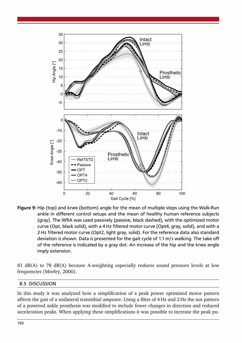
-5
0
5
10
15
20
25
30
35
Hip
An
gle
[°]
IntactLimb
ProstheticLimb
0 20 40 60 80 100
-60
-50
-40
-30
-20
-10
0
Gait Cycle [%]
Kn
ee
An
gle
[°]
IntactLimb
ProstheticLimbRef STD+-
Passive
OPT
OPT4
OPT2
Figure 9: Hip (top) and knee (bottom) angle for the mean of multiple steps using the Walk-Runankle in different control setups and the mean of healthy human reference subjects(gray). The WRA was used passively (passive, black dashed), with the optimized motorcurve (Opt, black solid), with a 4 Hz filtered motor curve (Opt4, gray, solid), and with a2 Hz filtered motor curve (Opt2, light gray, solid). For the reference data also standarddeviation is shown. Data is presented for the gait cycle of 1.1 m/s walking. The take offof the reference is indicated by a gray dot. An increase of the hip and the knee angleimply extension.
81 dB(A) to 78 dB(A) because A-weighting especially reduces sound pressure levels at lowfrequencies (Morfey, 2000).
8.5 DISCUSSION
In this study it was analyzed how a simplification of a peak power optimized motor patternaffects the gait of a unilateral transtibial amputee. Using a filter of 4 Hz and 2 Hz the nut patternof a powered ankle prosthesis was modified to include fewer changes in direction and reducedacceleration peaks. When applying these simplifications it was possible to increase the peak pu-
150
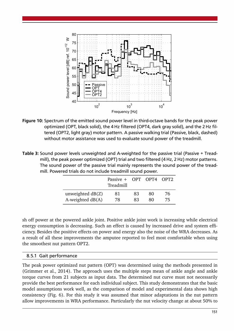
102
103
104
40
45
50
55
60
65
70
75
80
Frequency [Hz]
So
un
d p
ow
er
leve
l [d
B]
ref.
10
12
W
PassiveOPTOPT4OPT2
Figure 10: Spectrum of the emitted sound power level in third-octave bands for the peak poweroptimized (OPT, black solid), the 4 Hz filtered (OPT4, dark gray solid), and the 2 Hz fil-tered (OPT2, light gray) motor pattern. A passive walking trial (Passive, black, dashed)without motor assistance was used to evaluate sound power of the treadmill.
Table 3: Sound power levels unweighted and A-weighted for the passive trial (Passive + Tread-mill), the peak power optimized (OPT) trial and two filtered (4 Hz, 2 Hz) motor patterns.The sound power of the passive trial mainly represents the sound power of the tread-mill. Powered trials do not include treadmill sound power.
Passive + OPT OPT4 OPT2Treadmill
unweighted dB(Z) 81 83 80 76A-weighted dB(A) 78 83 80 75
sh off power at the powered ankle joint. Positive ankle joint work is increasing while electricalenergy consumption is decreasing. Such an effect is caused by increased drive and system effi-ciency. Besides the positive effects on power and energy also the noise of the WRA decreases. Asa result of all these improvements the amputee reported to feel most comfortable when usingthe smoothest nut pattern OPT2.
8.5.1 Gait performance
The peak power optimized nut pattern (OPT) was determined using the methods presented in(Grimmer et al., 2014). The approach uses the multiple steps mean of ankle angle and ankletorque curves from 21 subjects as input data. The determined nut curve must not necessarilyprovide the best performance for each individual subject. This study demonstrates that the basicmodel assumptions work well, as the comparison of model and experimental data shows highconsistency (Fig. 6). For this study it was assumed that minor adaptations in the nut patternallow improvements in WRA performance. Particularly the nut velocity change at about 50% to
151

60% of the gait cycle seems to cause the difference in powered push off for the OPT, the OPT4,and the OPT2 pattern (Fig. 4). The OPT curve is elongating the system by 0.5 mm in this phase.Such a behavior occurs because the stiffness of the spring is predicted to be too high for therequired ankle angle change. As a result less energy is saved or already saved energy is releasedfrom the spring. In contrast, the OPT2 pattern increases spring loading already starting at 50%.As a consequence more mechanical energy is saved in the spring and less energy is wasted bythe motor for damping.
The reduction in motor acceleration during push off provides benefits in electrical energyconsumption. A similar effect can be observed during the flight phase. Inertia is less relevantusing the filtered patterns, which leads to the increase in drive and system efficiency. Due to thechange in nut pattern for the flight phase a clear difference can be observed for the referenceand the WRA ankle angle. To which extent such a change influences gait is unknown. Futurestudies have to proove to which extend the model patterns can be changed without interferingthe aimed amputee gait patterns. For the current study knee and hip motion stayed almostunchanged for all powered trials.
Almost similar hip and knee joint angle patterns were identified for the passive and the powe-red trials. Two reasons may cause this phenomenon. In contrast to most other published data(Grimmer and Seyfarth, 2014) push off peak power of the passive WRA is distinctive (Fig. 8).Provided positive energy is half of the reference (Tab. 2). Thus, the reduced enhancement mayresult in minor changes in angle patterns.
In addition training effects using the powered ankle may be a reason. The amputee walked 2minutes with each configuration. No additional training was done before. For an exoskeleton itwas shown that 3 days of 30 minutes training could stepwise reduce metabolic costs for walking(Wiggin et al., 2012). It is assumed that an immediate adaptation of the amputee might notoccur due to steady biological motor patterns.
8.5.2 Electrical requirements for powered walking
Using the results of this study a first rough battery capacity and weight estimation for an au-tonomous prosthetic ankle can be performed. Using the 2 Hz filtered motor pattern a poweredankle would require about 37 J per step (1.1 m/s walking) for a 75 kg person. As only one ankleshould be replaced, the powered system should be capable to cover half of the 6500 steps/perday (Tudor-Locke and Bassett, 2004). About 33 Wh (120 kJ) will be required to cover one day oflevel walking. Referring to an energy density of lithium polymer batteries of about 150 Wh/kg(Thackeray et al., 2012) a battery mass of about 0.22 kg would be required. As the prefer-red walking speed is about 0.2 m/s higher and inclines require increased energy support, anenlargement of the battery capacity should be considered.
8.5.3 Touch down detection and push off timing
For the experiment a very simple algorithm was used for gait control that could not adapt timingduring stance. When touch down was identified, nut patterns followed the defined referencepattern depending on the current and the previous step time. Touch down is detected whenzero crossing of the shank angular velocity occurs (Fig. 3). For our reference data this happenedabout 2% to 3% of the gait cycle before touch down. As it was not known how the amputee willbehave, no adaptations were made for the control. The amputee walking trials identified zerocrossing also early before the real touch down. 3% of gait cycle were observed for the passive
152

and the OPT, 6% for the OPT4, and 4% for the OPT2 pattern. As a result powered push offwill happen 3% to 6% earlier compared to the reference data. Some part of the still existingdifference between the time for intact limb push off and the time of prosthetic leg push offmight result from this control issue. Malcolm et al. (Malcolm et al., 2013) demonstrated thatpush off timing is highly relevant to assist human walking gait using a powered exoskeleton.Further studies using the WRA should show how these results are in alignment with push offtiming in powered prosthetic amputee walking. A reason for the gap of 6% may be the changein motor direction early before touch down in the OPT4 pattern (Fig. 4). It may cause the shankto change direction of angular velocity earlier than in the other trials.
To solve the control issue a phase shift adaptation of 3% should be included for follow upstudies. To avoid gaps like the 6% for the OPT4 curve the adaptation of the motor curve aroundtouch down must be proven. To get more independent of different amputee gait patterns animproved gait detection for experiments would be required. Next to the adaptation for thetouch down event it could include an adaptation for the duty factor which is currently definedby the reference data set. Forces, calculated by the motor and the ankle angle encoder or alsothe accelerometers can provide required information for improvements.
8.5.4 Model stiffness
The optimal stiffness for the WRA was derived from human treadmill walking and running data.During the reference experiments the subjects used athletic footwear (Lipfert, 2010). Markersto determine reference ankle angle were placed at the shoe. The optimal motor pattern wascalculated from these data. When including the pattern in the powered prosthesis the stiffnessof the shoe and the carbon foot were not taken into account. The stiffness of the Pacifica LPfoot was the maximum available to reduce possible effects on the overall system behavior. Thisstudy demonstrated that the difference between ankle angle encoder and the kinematic analysisis in the maximum 4 in stance and 3 during flight phase. Including the movement of the footin the shoe and the shoe stiffness may result in lower differences between observed torquesand angles. As a consequence, an adaptation of motor curves would be required when changingshoes in daily life.
By simplifying the motor patterns such an individual adaptation gets lost. The authors assumethat a more general pattern is able to deal better with changed footwear but also changedground stiffness conditions.
8.5.5 Acoustical measurements
Applying changes in the control of the active ankle prosthesis does highly influence the radiatedsound power. The emitted sound of the active ankle prosthesis is dominated by frequencies over1000 Hz. As the human ear is highly sensitive to theses frequencies it is important to find waysto reduce sound emissions in this frequency range. Our research demonstrates that it is possibleto reduce sound power by 80% by reducing motor acceleration and changes in motor turningdirection.
Future research needs to be done on the acoustics of controlled electric motors and alsoto identify sound emitted by mechanical parts (belt drive, roller screw drive). Another rese-arch area might be the psychoacoustics of active prostheses. Psychoacoustic metrics can give ameasure for the annoyance of a sound.
153

8.6 CONCLUSION
The study on the Walk-Run ankle demonstrated that it is possible to improve powered push offby simplifying peak power optimized motor patterns. Changed nut curves lead to increased effi-ciency and decreased system noise. Study findings lead to an assumption for an opposing trend.On the one hand, a more general motor pattern, representing main events, improves poweredankle performance. On the other hand further individualization seems to be required for patterntiming. Additional research must show how push off timing can be used to improve amputeesgait. Training with the prosthesis, including changing push off timing, may also help to retrainamputees knee and hip movements. In parallel to developments concerning the functionalityof powered ankle prostheses, improvements for system noise are required. Modifications onnoise producing mechanical parts and psychoacoustic analysis can help to enhance amputeesacceptance.
8.7 ACKNOWLEDGEMENTS
Research reported in this publication was supported by the the DFG grant SE1042/8 and the Eu-nice Kennedy Shriver National Institute of Child Health & Human Development of the NationalInstitutes of Health under award number R43HD072402. The content is solely the responsibilityof the authors and does not necessarily represent the official views of the National Institutes ofHealth.
The authors acknowledge Kevin Hollander for applying the NIH grant. The authors acknow-ledge Robert Holgate for assisting with the Walk-Run ankle design, sensor integration, wiring,and assembling. The authors acknowledge S.W. Lipfert for providing human reference data.
8.8 AUTHOR CONTRIBUTIONS
Mechanical design: M. HolgateElectrical design: A. BoehlerStudy concept and design: M. Grimmer, A. GrebelAcquisition of biomechanical and robotic data: M. GrimmerAcquisition of acoustical data: A. GrebelAnalysis and interpretation of biomechanical data: M. Grimmer, A. Seyfarth, J. Ward, M. HolgateAnalysis and interpretation of electrical data: M. Grimmer, A. BoehlerAnalysis and interpretation of acoustical data: A. Grebel, M. GrimmerDrafting of manuscript: M. Grimmer, A. GrebelRevision:A. Seyfarth, T. Melz, J. Ward, M. Holgate, A. Boehler
8.9 CONFLICT OF INTEREST
M. Holgate, A. Boehler, J. Ward are owners of SpringActive. SpringActive, Inc. supplied the Walk-Run ankle for this research and is actively researching and developing powered ankle prostheses.M. Grimmer, A. Seyfarth and A. Grebel are with the Technische Universität Darmstadt and haveno competing interests.
8.10 INSTITUTIONAL REVIEW
The subject who participated in the study gave informed consent according to the guidelines ofthe ethic commission of the Technische Universität Darmstadt. Experiments were in compliancewith the Helsinki Declaration.
154

The authors will notify the single study subject of the publication of this article.
8.11 REFERENCES
Aldridge, J. M., Sturdy, J. T., and Wilken, J. M. (2012). Stair ascent kinematics and kinetics witha powered lower leg system following transtibial amputation. Gait & posture, 36(2):291–295.
Au, S., Weber, J., and Herr, H. (2009). Powered Ankle–Foot Prosthesis Improves Walking Meta-bolic Economy. IEEE Transactions on Robotics, 25(1):51–66.
Beckerle, P. (2014). Human-machine-centered design and actuation of lower limb prosthetic sys-tems. Shaker Verlag.
Czerniecki, J., Gitter, A., and Munro, C. (1991). Joint moment and muscle power output cha-racteristics of below knee amputees during running: the influence of energy storing prostheticfeet. Journal of Biomechanics, 24(1):63–65.
DIN EN ISO 3745:2012-07 (2012). Acoustics – Determination of sound power levels and soundenergy levels of noise sources using sound pressure – Precision methods for anechoic roomsand hemi-anechoic rooms (ISO 3745:2012), German version EN ISO 3745:2012.
Eslamy, M., Grimmer, M., Rinderknecht, S., and Seyfarth, A. (2013). Does it pay to have adamper in a powered ankle prosthesis? a power-energy perspective. In IEEE InternationalConference on Rehabilitation Robotics (ICORR), volume 2013, pages 1–8.
Frings, S. and Müller, F. (2014). Biologie der Sinne: Vom Molekül zur Wahrnehmung. Springer-Verlag Berlin Heidelberg.
Gailey, R., Allen, K., Castles, J., Kucharik, J., and Roeder, M. (2008). Review of secondary phy-sical conditions associated with lower-limb amputation and long-term prosthesis use. Journalof Rehabilitation Research and Development, 45(1):15.
Grimmer, M., Eslamy, M., Gliech, S., and Seyfarth, A. (2012). A comparison of parallel-and serieselastic elements in an actuator for mimicking human ankle joint in walking and running. InIEEE International Conference on Robotics and Automation (ICRA), St. Paul, pages 2463–2470.IEEE.
Grimmer, M., Eslamy, M., and Seyfarth, A. (2014). Energetic and peak power advantages ofseries elastic actuators in an actuated prosthetic leg for walking and running. In Actuators,volume 3, pages 1–19. Multidisciplinary Digital Publishing Institute.
Grimmer, M. and Seyfarth, A. (2011). Stiffness adjustment of a series elastic actuator in anankle-foot prosthesis for walking and running: The trade-off between energy and peak poweroptimization. In IEEE International Conference on Robotics and Automation (ICRA), Shanghai,pages 1439–1444. IEEE.
Grimmer, M. and Seyfarth, A. (2014). Mimicking human-like leg function in prosthetic limbs.In Neuro-Robotics, pages 105–155. Springer.
Günther, M., Sholukha, V., Keßler, D., Wank, V., and Blickhan, R. (2003). Dealing with skin mo-tion and wobbling masses in inverse dynamics. Journal of Mechanics in Medicine and Biology,3(3-4):309–335.
155
Hollander, K. and Sugar, T. (2005). Design of the robotic tendon. In Design of Medical DevicesConference (DMD).
Lawson, B., Varol, H. A., Huff, A., Erdemir, E., and Goldfarb, M. (2013). Control of stair ascentand descent with a powered transfemoral prosthesis. IEEE Transactions on Neural Systems andRehabilitation Engineering, 21(3):466–473.
Legro, M. W., Reiber, G., Aguila, M., Ajax, M. J., Boone, D. A., Jerrie, L., Smith, D. G., andSangeorzan, B. (1999). Issues of importance reported by persons with lower limb amputationsand prostheses. Journal of Rehabilitation Research and Development, 36(3).
Lerch, R., Sessler, G., and Wolf, D. (2009). Technische Akustik: Grundlagen und Anwendungen.Springer Berlin Heidelberg.
Lipfert, S. (2010). Kinematic and dynamic similarities between walking and running. Verlag Dr.Kovac, Hamburg. ISBN: 978-3-8300-5030-8.
Malcolm, P., Derave, W., Galle, S., and De Clercq, D. (2013). A simple exoskeleton that assistsplantarflexion can reduce the metabolic cost of human walking. PloS one, 8(2):e56137.
Morfey, C. L. (2000). Dictionary of acoustics. Academic Press.
Müller, G. and Möser, M. (2013). Handbook of engineering acoustics. Springer-Verlag BerlinHeidelberg.
Robbins, C., Vreeman, D., Sothmann, M., Wilson, S., and Oldridge, N. (2009). A review ofthe long-term health outcomes associated with war-related amputation. Military Medicine,174(6):588–592.
Rossing, T. D. (2007). Springer handbook of acoustics. Springer.
Sup, F., Varol, H. A., and Goldfarb, M. (2011). Upslope walking with a powered knee and ankleprosthesis: initial results with an amputee subject. IEEE Transactions on Neural Systems andRehabilitation Engineering, 19(1):71–78.
Thackeray, M., Wolverton, C., and Isaacs, E. (2012). Electrical energy storage for transporta-tionUapproaching the limits of, and going beyond, lithium-ion batteries. Energy & Environ-mental Science.
Tudor-Locke, C. and Bassett, J. (2004). How many steps/day are enough?: Preliminary pedo-meter indices for public health. Sports Medicine, 34(1):1–8.
Ward, J., Schroeder, K., Vehon, D., Holgate, R., and Grimmer, M. (2014). A microprocessorcontrolled ankle-foot prosthesis that supports fill powered running. In American Orthotic &Prosthetic Association (AOPA).
Wiggin, M., Collins, S. H., and Sawicki, G. S. (2012). A passive elastic ankle exoskeleton usingcontrolled energy storage and release to reduce the metabolic cost of walking. In Proceedings7th Annual Dynamic Walking Conference, pages 24–25.
156

9 Conclusion
The thesis Powered Lower Limb Prostheses aimed at improvements in lower limb prostheses. Forthis, biomechanical requirements to mimic the human ankle joint behavior in walking and run-ning were analyzed. Models of elastic actuators were developed to mimic human joint behaviorusing mechanical structures. Different alignments of motors and springs were evaluated to re-present the function of muscle fibers and tendons of the muscle-tendon complex. It was the aimto develop a controller for walking and running for testing the model predictions on the motor- spring interaction using a powered prosthetic ankle.
Next to the main targets, the thesis analyzed requirements for an artificial knee and hip joint.In addition, optimized walking control patterns were simplified to evaluate improvements onthe powered ankle performance, the energy efficiency and the noise generation.
Modeling of elastic ankle actuationAnalyzes on human joint behavior in walking and running revealed that it is challenging to
achieve required acceleration, velocity and torque with current motor technology. Thus the bio-logically inspired interaction of a motor and springs was investigated with respect to its ability toachieve human ankle gait biomechanics. Theoretical calculations demonstrated that series andparallel springs can help to decrease the peak power requirements and the energy consumpti-on of a motor. Complex systems, including parallel and series springs, allow to achieve higherbenefits for a single condition like walking at 1.6 m/s. However, if changes in the speed or thegait are required, complex mechanical solutions are less efficient and may cause disadvanta-ges. Thus a simple actuation mechanism like a series elastic actuator seems to be preferable toachieve flexibility for human ankle requirements in daily life.
Experimental model evaluationA powered ankle prosthesis prototype was used to evaluate the model predictions of the motor
- spring interaction. It was tested if the user of the artificial ankle interacts with the system inthe expected way. The spring stiffness may be inappropriate and the motor patterns may disturbdorsal flexion or plantar flexion of the foot. Also, the users’ timing and the loading of the artificialankle may differ from the values determined using healthy reference subject means. It was foundthat the optimized model behavior showed surprisingly good agreement with the experimentalobservations for walking gait. For a medium running speed, the joint angle and the torquetracings could be almost reproduced with the prosthesis. Higher running speeds could not beevaluated successfully due to suboptimal stiffness values and limitations in the motor poweroutput. Results of the Manuscripts V and VI demonstrated that the model predictions on theassistance achieved by the spring worked quite well for walking and running. The use of springsmakes it possible to assist the motor to achieve human-like ankle angle, power, and torquepatterns in an artificial ankle.
Alignment of prosthesis actuatorsIn addition to the ankle, biomechanical requirements were also evaluated for artificial human
knee and hip joints. The studies showed that a knee actuator can clearly benefit from a seriesspring, while a series spring for a hip actuator is less beneficial. The results for the hip series
157
elastic actuator raised the question on the alignment of the actuators. Current approaches usedmonoarticular actuators to mimic human like joint function for walking and running. In con-trast, humans use both mono- and biarticular muscles coupling the hip, the knee and the anklejoint. It is assumed that these multi-joint linkages can further improve artificial leg functionby reducing peak power and energy requirements, and by reducing the effort for locomotioncontrol. Further analysis must resolve how these couplings may help to improve artificial legefficiency for different gaits and speeds.
Prosthesis performance improvementsThe peak power optimized motor patterns for the ankle actuator accomplish the deformation
of the spring to match required joint ankle and torque behavior. The optimization is not inclu-ding motor model parameters like electrical efficiency, friction, and inertia. Depending on thereference data (gait, speed) the motor trajectories can be unfavorable for the motor, e.g. chan-ges in motor turning direction and high accelerations can be demanded. In Manuscript VI it wasshown that by reducing these demands, improvements for the powered ankle are possible. Asimplified motor walking control pattern can help to improve the powered ankle performance,the energy efficiency and to reduce the noise. The study also demonstrated that the hip andthe knee angle tracings did not change considerably between the trial where the powered anklewas used actively or just passively. Also the gait asymmetry between the intact and the prosthe-tic limb of the amputee was not much affected by additional actuation of the WR ankle. It isassumed that changes in push off timing and training may further improve the amputee gait.Future studies need to be done to investigate if it is possible to retrain biological motor patternsof the proximal muscles actuating the knee and the hip joint. This was not possible during theshort experimental trials in the gait lab. It may be realized by an increased time of usage. Onthe other hand it is possible that user movement patterns are fixed to the strategies used overseveral years with the passive daily life prosthesis. By varying push off timing of the artificialankle it may be possible to retrain the locomotion motor patterns to reduce gait asymmetries.In combination with biarticular couplings differences of affected and unaffected leg kinematicsand kinetics may be reduced.
Prosthesis weight, noise and user perceptionWalking studies with the female amputee (55 kg) also brought up additional points for powe-
red ankle improvements.When walking through the lab after the measurements with her passive daily life prosthesis,
the transtibial amputee reported to miss the powered push off with the Walk-Run ankle. Onthe other hand the amputee appreciated the reduced system weight of the passive carbon foot.In combination with the socket and the liner, the weight of the powered prosthesis is morethan 1 kg above the biological leg. Including embedded electronics and a battery will furtherincrease this difference. Thus an additional optimization for system weight should be includedin upcoming designs. Alternatively, an improved fitting of the socket and the residual part of theshank may reduce this perception.
By smoothing the motor curves, the noise output of the prosthesis decreased dramatically.Further studies should analyze the components that mainly cause the noise. Improvements onefficiency and using insulation can further reduce the noise. If it is possible to modify occurringsound frequencies, psychoacoustic analyzes can help to identify less annoying frequencies toimprove the amputee’s acceptance.
158

Aside from the noise and the function also the design of the prosthesis was discussed withthe 17 years old female amputee. The Walk-Run ankle prototype was perceived to appear totechnical. Designs like the Odyssey ankle (Springactive), using a colored housing, may achievehigher acceptance. Apart from the visual effects, a full cover of the prosthesis can make such asystem less noisy, more secure, and waterproof.
Prosthesis controlIn the study of Manuscript V a controller for walking and running was developed. To perform
the experiments and to guarantee a secure handling of the Walk-Run ankle also a standing modewas included in the control approach. The control makes it possible to change from walking torunning at each desired speed up to a limit of 2.6 m/s. The motor assistance is adapted until4 m/s running. Higher speeds only include an adaptation of the timing. To avoid jumps in themotor pattern, the gait changes from walking to running were not made directly when changinggait. The control waits until the touch down of the next step to adapt the motor trajectory. Incontrast, stopping results in a direct response to ensure users safety. Further research and testingis required to improve the transitions between walking and running. Currently, the hip has toinject more than the usual energy for the gait transition to running. An improved assistance ofthe ankle joint for transition, but also changes in speed, would decrease the users’ effort.
Improvements on the powered prosthetic control is one major field for upcoming research.Most of the lower limb prostheses use computational intrinsic control that works on the basisof force, angle, or inertial sensors at the prosthesis. The user intention is not directly distin-guished from brain signals. The computational intrinsic control works well for continuous cyclicmovements like walking or climbing stairs. Interactive extrinsic control would allow to use theprosthesis like a healthy part of the body. Voluntary powered ankle prosthesis movements, likepressing the gas pedal of a car, would be initiated by the users direct movement command. Firststeps to such a technology are tested using EMG sensors, similar to powered prosthetic hands(e.g. Michelangelo, Ottobock). Combining the methods, regarding intrinsic control for conti-nuous locomotion and extrinsic control to adapt to a changing user intention, could bring theadvantages of both control strategies together.
Research context
The thesis identified a huge potential for springs to assist motors to mimic the human lowerlimb joint kinematics and kinetics during gait. The results on the reductions of motor peakpower requirements and energy consumption help to understand how human muscles may beused efficient to benefit as much as possible from the elastic tendon function.
The observed insights on the efficient cooperation can be used to improve the design andthe control of powered lower limb prostheses. In contrast to passive prostheses, movementperformance and thus amputees assistance and quality of life may improve.
Similar technologies can be used to improve exoskeleton design to assist elderly and subjectswith mobility impairments. In addition elastic exoskeletons may augment human performancein daily life or workers environments.
Next to assisting human movement, the elastic actuators may advance the gait performance,the gait robustness, and the operation time of bipedal robots.
Thus the results of the thesis Powered Lower Limb Prostheses are not limited to the specific fieldof prosthetics but may also be useful for applications like exoskeletons and legged robots.
159


Martin GrimmerCurriculum Vitae
Education
02/2015 Phd, Dr. rer. nat. at Technische Universität Darmstadt (D)Grade: summa cum laude - excellent
Dissertation: Powered Lower Limb Prostheses
09/2008Diploma in Sports Science at Friedrich Schiller Universität JenaGrade: very good
Thesis:Biomechanik des Ganges bei Ober- und Unterschenkelamputation -Analyse und mechanische Intervention
Experience
03/2015 - 10/2015Researcher at Harvard Biodesign Lab, Harvard University, School ofEngineering and Applied Sciences, Cambridge (USA)
10/2011 - 03/2015Researcher at Lauflabor Locomotion Laboratory and University Lec-turer, Institute of Sports Science, Technische Universität Darmstadt(D)
07/2012 - 09/2012Research Internship at Arizona State University and Springactive(USA)
02/2009 - 12/2011Researcher at Lauflabor Locomotion Laboratory, Institute of SportsScience, Friedrich Schiller Universität Jena (D)
10/2008 - 01/2009Research Assistant at Lauflabor Locomotion Laboratory, Institute ofSports Science, Friedrich Schiller Universität Jena (D)
Fellowships
03/2015 - 10/2015Robert Bosch Fellowship on Aging Research at Harvard Bio-design Lab, Harvard University, School of Engineering and AppliedSciences, Cambridge (USA)
161