Smart Solar Powered Street Light
27
Smart Solar Powered Street Light ECE 445 Spring 2019 Final Report Group 10: Brian Keegan Joshua Song Corey Weil TA: Anthony Caton
-
Upload
khangminh22 -
Category
Documents
-
view
0 -
download
0
Transcript of Smart Solar Powered Street Light

Smart Solar Powered Street Light
ECE 445 Spring 2019 Final Report
Group 10 Brian Keegan Joshua Song Corey Weil
TA Anthony Caton
Abstract This document describes the design and testing for a conceptual solar powered street-light utilizing radar sensing The radar is used to detect vehicles and pedestrians to alter light intensity and increase energy savings The four modules in the system include the power generation radar sensor microcontroller to change intensity and the lighting module The power generation module consists of both a solar power system and grid connection The solar power system is the main source that will be used to power the light module while the grid connection is the secondary source to be used in non-ideal and emergency situations The radar sensing and microcontroller communicate with each other in order to change the intensity of the light when a vehicle or pedestrian is detected The concept was proved successful in short range detection and an efficient way to increase power savings
2
1 Introduction 5 11 Objective 5 12 Background 6 13 High-Level Requirements 6 14 Block Diagram 7
2 Design 7 21 Power Generation 8
211 Solar Panel 8 212 Grid Power 8
22 Power Regulation 8 221 Flooded Lead Acid 12V Battery 9 222 Charge Controller 9 223 Voltage Regulator 10
23 Power Source Selection 10 231 Power Relay 10
24 Intensity Control 11 241 Radar Sensor 11 242 Light Fixture 11 243 Microcontroller 12 244 Gate Driver 12
3 Design Verification 14 31 Light Intensity Control 14 32 Power Generation 15
321 Solar Power and Battery System 15 322 Grid Connection and Power Relay 15
33 Power Measurements 15
4 Costs 16 41 Components 16 42 Labor 17
5 Conclusion 17 51 Accomplishments 18 52 Uncertainties 18 53 Safety and Ethics 19 54 Future Work 20
References 21
Appendix A - Requirements and Verifications 23
3
Appendix B - EAGLE Printed Circuit Board Layouts 27
4
1 Introduction 11 Objective Humanity currently faces many challenges that will depend on new developments and techniques to create a sustainable future With one of the biggest challenges being energy consumption there is a reason that renewable energy sources such as solar and wind are seeing dramatic growth While the demand for energy is expected to keep increasing there is a need for technological developments to improve the efficiency of devices that use large amounts of energy In order to help with this problem we are proposing a change to the current outdoor lighting systems to illuminate streetlights With advancements in semiconductor technology Light Emitting Diodes (LEDs) have become more suitable for various uses like outdoor lighting [5] These lights have been known to have energy savings costs of around 50 which is beneficial not only because they save energy but because half of the street lights in the US are operated using public funding [2] This means by using more efficient street light fixtures less taxpayer money will need to be spent on the energy cost to utilize these lights Our group saw that there was an opportunity to make these LED street lights even more efficient by equipping them with solar panelsenergy storage along with sensors to indicate when there is someone approaching the vicinity Using solar panels the street lights will be able to harness their own energy during the hours that the light fixture is not functioning and utilize that stored energy at night to illuminate our streets Cost reductions in solar photovoltaics have led to an increase in the use of solar energy which had lead to the development of different solar powered devices like street lights These street lights are becoming more common and have many advantages like using green energy independence from the grid and energy savings costs They do come with disadvantages like higher installation cost battery replacement cost and susceptibility to reduced energy production from moisture snow or dust In order to combat some of these challenges with solar street lights we are proposing to use sensors in order to detect when the lights need to be on at full intensity and when they can idle at a lower intensity for energy savings Also we believe it would be beneficial for the design to incorporate a connection to the grid for safety reasons during events that the solar power generation does not meet the needs of the lighting system This can occur when the solar photovoltaics are damaged or incapable of harnessing energy due to coverage or weather conditions (including areas with limited sunlight exposure) 12 Background With the worldrsquos energy usage on the rise and not slowing down there is a need to improve efficiency in order to reduce usage and operating costs This rising trend can be seen in Figure 1 coming from the US Energy Information Administration [10] One of the new technologies being implemented today is the solar street light that uses LEDs to illuminate streets parking lots and neighborhoods We plan to incorporate this technology and develop a way for these
5
lights to consume even less energy using doppler sensing With this method the streetlights will be even more energy efficient and cost-effective
Figure 1 World Energy Consumption Trends and Projections
13 High-Level Requirements
The streetlight must be able to supply and sustain at least 12 hours of continuous use with at least 03 average luminance for the entire durationdmc 2
Radar sensing method must be capable of detecting a typical United States road-legal passenger vehicle cyclist or pedestrian at a maximum of 40MPH speed toward the sensor within an average United States residential lane width of 12 feet
Intensity control must maintain at least an average 03 (minimum legal luminancedmc 2 as specified by Illinois Department of Transportation [4]) at all times while also increasing brightness as necessary based on radar detection
14 Block Diagram The block diagram in Figure 2 illustrates the integration between the power and control subsystems for our project The power subsystem is responsible for the generation and regulation of our solar power source as well as the stepping-down of grid voltage to 12V DC The charge controller for the 12V battery is responsible for determining the battery state of charge is too low and actuating the power source selection relay in order to power the streetlight from the grid The gate driver circuit that was added to our design belongs in the light intensity control block since it takes the PWM output from the microcontroller and boosts this signal in order to drive the Power MOSFET
6
Figure 2 Block Diagram
2 Design Each streetlight is responsible for generating electricity through its solar panel as well as being tied to the grid in order to make up for any deficiencies in solar generation As a result there are both AC and DC power inputs which must be taken into consideration before supplying power to the light fixture On the control side the voltage will be stepped down in order to operate the microcontroller and sensors necessary to correctly adjust intensity based on vehicle detection Radar sensors will communicate with the microcontroller in order to perform this intensity control 21 Power Generation Streetlights are powered by the local electrical infrastructure in various daisy-chain configurations To make our streetlight proof-of-concept comparable to real street lights grid connection capabilities will be built-in The other form of generation will come from the DC solar panel on top of our streetlight both of these forms of generation will provide a minimum of 40W for our light 211 Solar Panel A solar panel will be placed above our streetlight and angled in an appropriate manner In the Northern Hemisphere fixed panels should be oriented towards ldquotrue southrdquo For increased panel efficiency the angle would need to change based on the season (summer vs winter) For our application the panels will be oriented according to the summer scenario which begins on
7
March 30th and lasts until September 29 UIUC sits at a longitude of and according to04 deg common solar panel tilt equations [1]
latitude 93) 1 ilt Angle ( minus 2 = T (1)
This results in a tilt angle of This angle and longitude result in an average Solar62 1 deg Insolation according to [1] of It is also understood that this insolation must be verified0 6 m2
kw and losses must be taken into account With this angle 75 of the energy output of the solar panels is possible when compared to a sun-tracking system Ideally the minimum solar panel top-side surface area is 833m 8 2 212 Grid Power The other power source that our project uses is grid power which will be converted from 120V AC to 12V DC While a traditional streetlight in the United States typically operates at 50V this causes unnecessary safety risks for our application as well as requiring higher voltage ratings for components The converter that will be used will be able to connect directly to a common 120V AC outlet and have a minimum rating of 40W 22 Power Regulation The solar panel will output DC power during the day in order to charge the batteries which will output 12V DC and the converter will also output 12V DC Both these outputs will be inputs for the power relay where the appropriate power input will be selected based on the state-of-charge (SoC) of the batteries 221 Flooded Lead Acid 12V Battery In order to utilize our solar photovoltaics the energy harnessed during the day must be properly stored in order to power the street light during the night To do this we must use rechargeable batteries that can output 12V DC and store enough energy to run our lighting system for 12 hours continuously Similar systems use lead acid gel cell or lithium-ion deep-cycle batteries in order to charge and discharge properly This battery must be able to charge during the day and then run the lighting system for approximately 12 hours at night when the street lights are turned on In order to achieve this the approximate size of our battery would be 480 watt-hours (Wh) For the battery system we will be using a charge controller to monitor how our solar panels charge the batteries 222 Charge Controller Since the solar panels will charge the battery a charge controller must be implemented to prevent overcharging This device regulates the output voltage and current of the solar panel and is used to charge the battery Solar panels have a voltage rating that is lower than the
8
panelrsquos theoretical maximum output This is due to the panel being used under certain conditions such as sunlight and temperature exposure The charge regulator is used to make sure the desired output voltage for charging the battery is kept and also prevents damage to the battery during the charging process [8] The charge controller also prevents power from the battery draining through the solar panels at night when the panels are not in use The schematic for our charge controller can be seen in Figure 3 Equation 2 shows how we will determine at what current our batteries will charge According to the datasheet ldquoit is generally recommended to charge batteries 1-3 times the batteryrsquos maximum current ratingrdquo [16]
Battery Max Current)(3) ICHRG = ( (2)
24 A)(3) 72A ICHRG = ( = (3)
Figure 3 Schematic for Pulse Charging Lead Acid Battery [16]
223 Voltage Regulator The control subsystem for our project which includes the microcontroller and radar sensor will primarily operate at 5V In order to supply this voltage a voltage regulator will be used with the 12V battery as the input This regulator will step-down the voltage from our battery to the appropriate voltage to be used by these modules The regulator must be compatible with the different range of output voltages that it may see from the battery
9
23 Power Source Selection The power relay must be able to switch between the 12V DC from the rectifier and 12V DC from the battery since the battery may fall below its recommended state-of-charge during operation This relay will transfer the streetlight to grid power in order to provide uninterrupted light to the roadway 231 Power Relay The power relay is responsible for properly and safely changing the power source for the streetlights This relay will be a single-pole double-throw relay which refers to having two inputs and one output The relay coil will be actuated from the charge controller when it is necessary to switch the source from the battery to grid power and released when there is sufficient charge for battery use Figure 4 shows the schematic for proper usage of the power relay
Figure 4 Power Relay Schematic
24 Intensity Control In order to properly illuminate a standard residential roadway a minimum of 03 must bedmc 2 maintained as specified by the Illinois Department of Transportation (IDOT) roadway lighting regulations [4] Depending on the light fixture chosen it is possible to reduce the brightness of the light by upwards of 30 [6] The control of the light intensity relies on the PWM signal generated by the ATmega328P microcontroller and the gate driver circuit 241 Radar Sensor The radar sensor is the detection method for intensity control it must be able to communicate with the microprocessor to cause a direct change in light intensity based on the detection of an oncoming vehicle or pedestrian For this project the K-LD2 radar transceiver from RFbeam Microwave GmbH was chosen due to its advertised range and relatively low cost The sensor specifies a detection range of 30 meters for vehicles and 15 meters for pedestrians and includes adjustable settings for hold time and sensitivity
10
242 Light Fixture The light fixture is the overall output of the power generation and intensity control subsystems It was simpler to use an off-the-shelf light fixture rated at 12V 20W to reduce development time The light will be raised to a height of 10 feet in order for the purposes of this project while a road-legal streetlight would be placed at a height of 25 feet 243 Microcontroller The microcontroller that was chosen for this project was the ATmega328P due to its availability and simplicity For our specific application there were a number of IO pins on the microcontroller that were not used The circuit schematic in Figure 5 shows the connections from the radar sensor to the microcontroller and the PWM output from this board to our gate driver circuit For the crystal 20pF capacitors were used For the sensitivity and hold time setting various configurations of resistors were utilized For both of these settings the maximum value occurs when 3V is placed across the pin and the minimum value occurs when the pin is grounded (0V)
Figure 5 Control Board Schematic
244 Gate Driver During the testing period of our project it was determined that the PWM signal from the ATmega328P was not sufficient to drive our power MOSFET This is due to the threshold voltage of the power MOSFET which hinders the ability to drive the MOSFET with a 5V gate signal when the difference from drain to source is 12V The gate driver circuit seen in Figure 6 amplifies the PWM signal from the microcontroller with a gain of 2 doubling the peak-to-peak voltage to 10V The IRS2183 Half-Bridge Driver was used in conjunction with the IRF540 Power MOSFET in order to boost the PWM signal and direction control the output voltage of the light
11
Figure 7 shows the associated waveforms through the use of our gate driver circuit Channel 2 represents the output PWM of the microcontroller while Channel 1 shows the boosted signal from the IRS2183 Channel 3 represented the output voltage to the lights which are a non-linear load during 50 PWM operation The R_GATE was held at 300Ω and the values for C1 and C2 were 1uF and 01uF respectively
Figure 6 Gate Driver Circuit Schematic
Figure 7 Gate Driver Waveforms
12
3 Design Verification 31 Light Intensity Control During our demonstration the intensity control of our streetlight was shown successfully operating at a base intensity of 50 and at the full 100 intensity based on the valid detection of a passenger vehicle a motorcycle a cyclist and a pedestrian The equations below show luminance calculations at both intensity values which is necessary to stay above roadway-legal average luminance values At full intensity one of our lights outputs 20W with a luminous flux value of 2000 lumen
(4)
(5)
(6)
(7)
(8)
(9)
(10)
13
At a height of 10 feet and operating at full intensity each of our 12V 20W lights meets the legal luminance requirement of 03 Since the value of lumen scales linearly with wattage eachdmc 2 light operating under the same conditions at 50 intensity would still satisfy the minimum luminance value For the luminance calculations the surface area accounts for the two-dimensional area on the roadway that is illuminated The square radian (steradian) calculation accounts for the perceived brightness of the light from the driverrsquos perspective 32 Power Generation 321 Solar Power and Battery System Our solar panel and charge controller worked as needed for our prototype Our panel under no-load conditions produced an output of 224V at the 16deg angle specified in our original design When the solar panel was connected to our charge controller the panel supplied 115 V 55A and 6325 W of power This was sufficient for the required power to run our light at full intensity Therefore the panel and controller met the associated requirements The charge controller was also able to charge both of our lead-acid batteries and prevent overcharge and undercharge conditions which was shown during our demonstration 322 Grid Connection and Power Relay The grid connection was a large safety feature that was considered extremely important to ensure consistent output lighting in the absence of sufficient solar power generation The grid connection was tested using the 120V 60Hz converter that had an output of 12VDC which would be used to power the control subsystem This backup system was verified in testing by using the power relay with the solar source and grid source connected as inputs and a 5V signal actuating the relay coil When the 5V signal was removed the coil switched seamlessly to the grid power and the light remained in the operating state as if no change occurred While there was no visual sign of a power input source change due to the light remaining on as expected it was clear that the coil made a clicking sound when the switching operation occurs To further conclude this the battery was disconnected completely and the system remained unchanged 33 Power Measurements Another goal for our project was to increase energy savings for streetlights by using solar power generation and radar intensity control In order to verify that our system does this the Yokogawa WT310 power meters were used to measure the power consumption of the entire system at high and low intensities Figures 8 and 9 show the measurements taken on the Yokogawa meters for both the low and high-intensity settings of our system The microcontroller set the PWM signal at 50 and 100 which resulted in approximately half the power consumption for low intensity Using this information it can been observed that the power consumption trend is linearly dependent on the PWM signal which can easily be adjusted if necessary This shows that by having the ability to lower the light intensity there is an
14
opportunity to lower energy consumption and provide cost-savings by decreasing the battery size needed to operate these lights or decreasing the energy that would be pulled from the grid
Figure 8 Input Total Power at 50 Intensity
Figure 9 Input Total Power at 100 Intensity
4 Costs 41 Components
Part Cost (prototype)
Cost (bulk)
Solar Panels RNG-100P 100W 12V solar panel $125 $100
Battery BC35-12 12V 100Ah flooded lead acid $300 $200
Charge Control BQ24650 MPPT Charge Controller $552 $407
AC-DC Converter LS50-12 $2294 $2294
Voltage Regulator LM1084IT-50NOPB-ND $260 $128
15
PCBs PCBWay (class bulk order) $620 $020
Microcontroller ATmega328P $196 $163
Radar Sensor K-LD2-RFB-00H-02 $5304 $3617
Power Relay G5LE-14 DC12 $144 $108
Light Fixture Coolkun-copp1 (20W) (Amazon) $25 $25
Power MOSFET IRF540 $191 $140
Gate Driver IRS2183 $260 $188
Crystal CTX1084-ND $039 $027
Passives $200 $200
Total $55060 $39792
42 Labor Using the information provided by the Department of Electrical Engineering we can quantify the labor cost for this project According to the department the salary of an Electrical Engineer graduating with a bachelorrsquos degree is on average $67000 With this number in mind the salary equates to around $32hour For three engineers working approximately 10 hours per week for 9 weeks the cost would come to $8640 which is $2880 per engineer
(11)
5 Conclusion 51 Accomplishments Overall we were able to implement the high-level requirements that we set at the beginning of the semester While maintaining the legal luminance value at all times our intensity control system was able to adjust the output intensity of the light from 50 base intensity to 100 max intensity during vehicle detection Through the use of our power source selection relay our light is able to stay on without a lapse in output when switching from the battery to the grid This allows for greater safety in a real-world application preventing moments when the streetlight is completely off Our solar power generation system LED light fixture and intensity control all
16
provide avenues for cost savings many major cities are already making efforts to convert streetlights from compact fluorescent lights (CFLs) to energy-efficient LEDs 52 Uncertainties While soldering and testing our charge controller from 222 we found two major problems with our design To start our schematic required the use of a pack thermistor sensor This sensor would supply our TI chip with constant data on the temperature of our battery When designing the PCB our team only incorporated the voltage divider and not this sensor Due to this misstep the chip received a signal that represented an overheating state This was determined from the LED communication and the chip outputs If LED 1 is on while LED 2 is off the chip is not in charge mode due to battery temperature or overvoltage protection The second problem we had with our charge controller was how the high side and low side switching in the buck converter were designed This chip uses a bootstrap converter ldquoSimple in structure a bootstrap circuit is a step-up charge pump composed of a switch a capacitor and a diode where a voltage equal to the switch voltage (Vin) plus the internal supply voltage is used as the gate drive for the high-side N-ch MOSFETrdquo [17] However when this was designed the sizing of the capacitor only allowed for a Vgs voltage that was marginally higher than the high side N-ch FET In Figure 10 the waveform shows the large voltage swing output from the buck converter Since the proper voltage was unable to be generated the high side and low side FET didnrsquot switch as designed Therefore the voltage going to the load was much higher than the 12V specified in our design the controller was outputting close to 18V The topology of our charge controller was more similar to that of a boost due to improper switching In future designs the bootstrap converter will be appropriately sized in order to ensure the voltage from the diode-capacitor combination will be significantly greater than Vgs as well as mitigating large ripple voltage values In Figure 10 the waveform in yellow shows the output of our high-side FET Vgs and the ripple voltage experienced The waveform in green shows the bootstrap output which is significantly lower than Vgs
17
Figure 10 Bootstrap Voltage and High Side FET Vgs Output
The radar sensor that was used for this project did not perform as specified on the componentrsquos datasheet The sensor had a specification of 30 meters detection range for vehicles and 15 meters detection range for pedestrians During testing the maximum range for vehicles that we able to be achieved was only upwards of 25-35 feet to put this into perspective 30 meters is nearly 100 feet For budget considerations our project was limited to this $60 radar sensor since radar modules that would have provided a more consistent response would have pushed our expenses into the hundreds or even thousands In practice the radar sensor for a specific streetlight would be placed well ahead of the area that the light is illuminating Since streetlights are typically 50-75 feet apart with a 25 feet height placing a specific sensor 2-3 lights ahead would provide ample response time for the intensity control 53 Safety and Ethics Whenever power electronics are being built safety is of utmost importance To prevent excessive interaction with high voltages our project will ensure that voltage lines never reach above 24V However since our light is rated at 20W the currents that our project will handle is in the order of a few amps Another safety precaution that was taken was to perform modifications only when all power was disconnected This would mitigate misplaced connections accidental shorts or loose wires Our project will also be dealing with lead-acid batteries which can be dangerous when used improperly These batteries when fully charged and combined with high temperatures can cause stress on individual battery cells Constant stress can lead to battery damage or in the worst case an explosion or fire Battery stress can also cause the batteries to charge or discharge at a faster speed which can result in overcharging batteries To avoid putting high-stress on our batteries a charge regulator was used to monitor the state of the battery and prevent situations of overcharging or undercharging of our batteries
18
For testing our design our team used vehicles of different sizes to ensure sensor functionality and consistency These tests were performed in a controlled environment with extreme caution for surroundings other cars and the safety of the driver When using the radar sensor there must be no chance of getting in the way of normal traffic flow In terms of ethics we must remember during this project that 1 ldquoTo hold paramount the safetyrdquo[9] is our top ethical dilemma Streetlights are used for public safety at night That is why regardless of our energy storage and doppler radar our project was connected to the grid and ready to output full power and light intensity as a backup condition Also since our project will provide cost-saving measures principle 2 would be called into question It states ldquoto avoid real or perceived conflicts of interest whenever possiblehelliprdquo and our project would determine the cost savings that could be provided to any given county Many parties could be interested in our data and we need to maintain our ethics and not give away private data 54 Future Work Although we are satisfied with our working prototype our group understands that a significant number of lights would need to be deployed to reach full functionality With more lights costs will increase maintenance will increase and charge density will become more important That is why our group would switch to lithium-ion batteries moving forward To start a lead-acid battery has limited usable capacity This means that at a full charge only 30-50 of the battery can be used before needing to be recharged [18] this is due to the risk of boiling in the battery Due to our lights needing to be on all night every amp-hour of our batteries is required A lithium-ion battery allows 90 of the charge to be used Another factor that pushes our project towards lithium-ion technology is the concept of wasted energy Since our batteries will charge throughout the day a battery that does not lose a substantial percentage of its charge over time is preferred Lead-acid batteries leak 15 of their charge when not used a 100Ah battery now operates as an 85Ah battery when not used for an extended period of time In contrast a lithium-ion battery does not lose charge due to the chemical makeup of its cells[18] Lastly the cycle life of each battery type should be considered A lead-acid battery can run through 500-1000 cycles If such a battery charges and discharges once a day this battery will last 13-27 years until a replacement is needed A lithium-ion battery will last 2000-5000 cycles which would result in 55-136 years until replacement Lithium-ion will save quite a large sum of money in the long-term Also due to solar panels and batteries being the most expensive part of this project our team would select the smallest possible panel that would satisfy our required wattage the same rationale can be applied to our battery However our group also discussed the feasibility of a central battery storage system All of the lights would be connected to a battery hub this hub would derive its energy from a local solar farm This could allow more consistency in how much power is being consumed and generated
19
References [1] C Landau ldquoOptimum Tilt of Solar Panelsrdquo Optimum Tilt of Solar Panels 2017 [Online] Available httpswwwsolarpaneltiltcom [Accessed 07-Feb-2019] [2] ldquoThe Light Postrdquo Office of Energy Efficiency amp Renewable Energy May-2012 [Online] Available httpswww1eereenergygovbuildingspublicationspdfssslmsslc_enews_may2012pdf [Accessed 07-Feb-2019] [3] R Gray ldquoFuture - The biggest energy challenges facing humanityrdquo BBC News 13-Mar-2017 [Online] Available httpwwwbbccomfuturestory20170313-the-biggest-energy-challenges-facing-humanity [Accessed 07-Feb-2019] [4] ldquoHighway Lightingrdquo Illinois Department of Transportation May-2015 [Online] Available httpwwwidotillinoisgovassetsuploadsfilesdoing-businessmanuals-splitdesign-and-environmentbde-manualchapter 56 highway lightingpdf [Accessed 07-Feb-2019] [5] ldquoDimming of LED Street Lightingrdquo Northcliffe [Online] Available httpnorthcliffeorgDIMMING_OF_LED_STREET_LIGHTING [Accessed 07-Feb-2019] [6] ldquoThe Future of Roadway Lightingrdquo US Department of TransportationFederal Highway Administration 2015 [Online] Available httpswwwfhwadotgovpublicationspublicroads15novdec06cfm [Accessed 07-Feb-2019] [7] B Spiller ldquoAll Electricity is Not Priced Equally Time-Variant Pricing 101rdquo Environmental Defense Fund 21-Dec-2015 [Online] Available httpblogsedforgenergyexchange20150127all-electricity-is-not-priced-equally-time-variant-pricing-101 [Accessed 08-Feb-2019] [8] ldquoWhat is a Solar Charge Controllerrdquo altEstorecom [Online] Available httpswwwaltestorecomstoreinfosolar-charge-controller [Accessed 08-Feb-2019] [9] ldquoIEEE Code of Ethicsrdquo IEEE - Advancing Technology for Humanity [Online] Available httpswwwieeeorgaboutcorporategovernancep7-8html [Accessed 08-Feb-2019] [10] L Doman ldquoUS Energy Information Administration - EIA - Independent Statistics and Analysisrdquo Factors Affecting Gasoline Prices - Energy Explained Your Guide To Understanding Energy - Energy Information Administration 14-Sep-2017 [Online] Available httpswwweiagovtodayinenergydetailphpid=32912 [Accessed 18-Feb-2019]
20
[11] ldquoK-LD2 Datasheetrdquo RFbeam Microwave GmbH St Gallen Switzerland Sep-2018
[12] ldquoChapter 1 Traffic Detector Handbook Third Edition-Volume Irdquo US Department of TransportationFederal Highway Administration May-2006 [Online] Available httpswwwfhwadotgovpublicationsresearchoperationsits0610801cfm [Accessed 21-Feb-2019]
[13] ldquoWhat Is A Charge Controllerrdquo Wholesale Solar Blog [Online] Available httpswwwwholesalesolarcomsolar-informationcharge-controller-article [Accessed 22-Feb-2019]
[14] ldquoBattery Maintenance | Trojan Battery Companyrdquo Trojan Battery Company [Online] Available httpswwwtrojanbatterycomtech-supportbattery-maintenance [Accessed 22-Feb-2019]
[15] ldquoLead Acid Battery Charging Basics and Chargersrdquo Lead Acid Battery Charging Basics and Chargers 17-Nov-2017 [Online] Available httpswwwpowerstreamcomSLAhtml [Accessed 22-Feb-2019]
[16] Falin J Mauney C and Nortman S (2011) Using the bq24650 to Charge a Sealed Lead-Acid Battery 1st ed [ebook] Texas Instruments p6 Available at httpwwwticomproductBQ24650technicaldocuments [Accessed 22 Feb 2019]
[17] ROHM TECH WEB Technical Information Site of Power Supply Design (2019) Switching Regulator Basics Bootstrap | Basic Knowledge [online] Available at httpsmicrorohmcomentechwebknowledgedcdcdcdc_srdcdc_sr01829 [Accessed 2 May 2019]
[18]ldquoLithium-Ion Discharge Curves Lead Acid battery Downsides amp Maintenancerdquo PowerTech Systems - PowerTech Systems [Online] Available httpswwwpowertechsystemseuhometech-cornerlead-acid-battery-downsides [Accessed 02-May-2019]
Appendix A - Requirements and Verifications Solar Power
Requirement Verification
21
The solar panel must be continuously held at the correct tilt angle of with a tolerance of
The solar panel will be initially set up on its mounting structure which will be built to support the weight of the panels and tilt them at The angle will be measured prior to each test to confirm the desired angle is met
The solar panel must be capable of properly supplying power in order to charge the 12V battery while maintaining proper circuit protection precautions
Using a multimeter or another battery voltage monitoring device observe the battery voltage at an initial state as well as in 30-minute intervals A steady increase in battery voltage is a sign of charging and the full-charge voltage may also be observed
Grid Power
Requirement Verification
The converter must be capable of handling input of 120V AC at 60 Hz from the United States grid and convert this voltage to 12V DC with a minimum of 40W
Since the input voltage is the responsibility of the supplying utility company the converter must be able to accept the voltage supplied The output of the converter will be verified by a test conducted in a laboratory setting with proper safety measures in place The output voltage must be linear with an average voltage of 12V and a tolerance of
01V Battery
Requirement Verification
The battery must hold a charging voltage of 143V to 15V at It must2V plusmn 5 C 2 deg also not drop below 11V [16]2V plusmn
After the battery has been properly charged (or is currently at a sufficient charge) the output of the battery will be measured through the use of a voltmeter This will be repeated in 30-minute intervals during the 12 hour period it needs to be running overnight The battery must hold a voltage of
22
From a full charge the battery must be able to power the light fixture for a minimum of 12 hours continuously while maintaining the proper power to keep lights on
When the battery is at full charge it will be connected to the lighting system From this time it must power the light with the required luminance (03 ) for atdm c 2 least 12 hours To verify this we will use a Light Meter (Lux Luxmeter) to ensure our luminance stays within the legal limit as stated before (3 )dm c 2
Charge Controller
Requirement Verification
The charge controller circuit must be able to perform pulse charging operations for a sealed lead acid battery It must also maintain rated voltages as said in 221 requirements
We will create a constant voltage supply from the lab to simulate our solar panels Then use an o-scope to record the voltage and current and determine if the PCB matches the specs on the TI Spec sheet We would use the o-scope to ensure the shape of current waveforms matches the 3 phases of pulse charging Secondly an ammeter will show us that the current does not exceed Refer ICHRG to equation (3) Then we would ensure the charge controller is at when our ITERM battery is at peak charge voltage This is at 2 mA
Voltage Regulator
Requirement Verification
The voltage regulator must be able to provide 5V +- 5 from an 11-16V source with a current output between 0-3 A
Perform stress testing on the voltage regulator using a DC power source in the range of 11V minus 16V and with loads ranging from 0A - 3A Use the current limit on the DC source for safety
23
The voltage regulator must maintain thermal stability below 125degC
During stress testing use an IR thermometer to monitor the IC temperature Test with and without a heat sink
Power Relay
Requirement Verification
The relay must have contact switches that are rated for our maximum voltage and power from both the converter and battery sources
The relay used for design must be rated for a maximum of 16V switching voltage and 40W
Ability to switch between sources with microcontroller signal in under 20ms
Release and operate times must be under 20ms Turn on and turn off voltages must be between 0-5V
Intensity Control
Requirement Verification
The light must maintain at least 03 dm c 2 (minimum legal luminance) on average during the full period of operation
The light must be able to maintain at least 03 for 12 hours continuous (thedm c 2 average time from 30 minutes after sunset to 30 minutes before sunrise in Chicago during summer)
The light must be capable of adjusting the intensity based on detection of an oncoming vehicle and return to baseline intensity after the vehicle has passed
The light must be able to reach peak intensity from its base intensity after a vehicle is detected and return to its base intensity when no vehicle is detected Intensity will be measured using a lux meter
Radar Sensor
Requirement Verification
The radar sensor must be able to detect an oncoming motor vehicle at a maximum of 30 meters away traveling at a
The signal received by the sensor must be decipherable and reportable in a consistent manner that represents positive detection of a vehicle as
24
maximum of 40 miles per hour on a United States standard 12-foot residential roadway lane with a positive detection rate of 95
described by the requirement
Light Fixture
Requirement Verification
The light fixture must be rated for at least the power output that is driven by our battery or grid connection
The rating of the light fixture must be at minimum 40W 12V
The light fixture must be able to maintain at least the minimum required brightness while also having the capability of adjusting the brightness to below maximum
The light must maintain at least 03 dm c 2 average luminance during operation and be able to reduce its intensity to its base value during no detection
Appendix B - EAGLE Printed Circuit Board Layouts
25
Figure 11 Control Board Layout
Figure 12 Power Relay Board Layout
Figure 13 Radar Breakout Board Layout
26
Figure 14 Gate Driver Board Layout
Figure 15 Solar Charge Controller
27
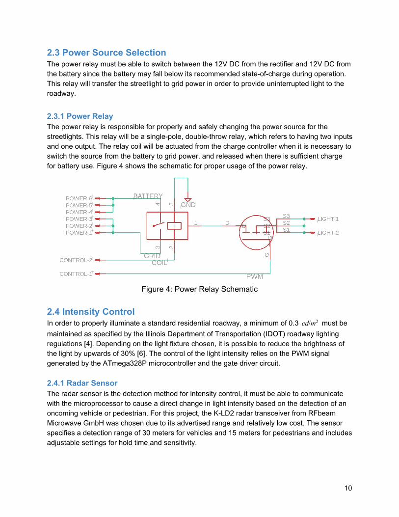

Figure 11 Control Board Layout
Figure 12 Power Relay Board Layout
Figure 13 Radar Breakout Board Layout
26
Figure 14 Gate Driver Board Layout
Figure 15 Solar Charge Controller
27

Figure 14 Gate Driver Board Layout
Figure 15 Solar Charge Controller
27