Protein Linear Molecular Motor-Powered Nanodevices
19
RESEARCH FRONT CSIRO PUBLISHING Review Aust. J. Chem. 2007, 60, 314–332 www.publish.csiro.au/journals/ajc Protein Linear Molecular Motor-Powered Nanodevices David J. G. Bakewell A and Dan V. Nicolau A,B,C A Department of Electrical Engineering and Electronics, University of Liverpool, Brownlow Hill, Liverpool L69 3GJ, UK. B Centre for Green Chemistry, Monash University, ClaytonVIC 3800, Australia. C Corresponding author. Email: [email protected] Myosin–actin and kinesin–microtubule linear protein motor systems and their application in hybrid nanodevices are reviewed. Research during the past several decades has provided a wealth of understanding about the fundamentals of pro- tein motors that continues to be pursued. It has also laid the foundations for a new branch of investigation that considers the application of these motors as key functional elements in laboratory-on-a-chip and other micro/nanodevices. Current mod- els of myosin and kinesin motors are introduced and the effects of motility assay parameters, including temperature, toxicity, and in particular, surface effects on motor protein operation, are discussed. These parameters set the boundaries for glid- ing and bead motility assays. The review describes recent developments in assay motility confinement and unidirectional control, using micro- and nano-fabricated structures, surface patterning, microfluidic flow, electromagnetic fields, and self-assembled actin filament/microtubule tracks. Current protein motor assays are primitive devices, and the developments in governing control can lead to promising applications such as sensing, nano-mechanical drivers, and biocomputation. Manuscript received: 1 December 2006. Final version: 8 February 2007. 1. Introduction Protein molecular motors are naturally evolved nanosized machines responsible for mechanical movement, which is essen- tial for many biological functions, including cell division and movement, transport of vesicles, and muscle contraction. Protein molecular motors vary considerably in terms of their struc- ture, complexity, motion, and biological function. The past four decades have witnessed extensive investigations into the molec- ular mechanisms that underpin the operation of these motors, which are central to biology. These fundamental investigations have been (i) experimental—aided by advances in molecular imaging, single molecule manipulation techniques, such as optical trapping, and development of motility assays, [1–18] and (ii) theoretical—analyzing and attempting to explain the David Bakewell received a B.E.E. in electrical engineering (first-class honours) from the University of Melbourne in 1983 and a Ph.D. from the University of Glasgow in 2003 for his research on dielectrophoresis of colloids and polyelectrolytes. He joined the AustralianTelecommunications Commission in 1984, and from 1985 to 1996 he conducted research into the performance of radio and optical fibre digital transmission systems and networks. From 2002 to 2005 David was with the Beatson Cancer Research Laboratories, Bearsden, UK, where he developed statistical methods for improving microarray gene expression estimation. He is currently with the Department of Electrical Engineering and Electronics, University of Liverpool. Professor Dan Nicolau holds the Chair in BioNanoEngineering in the Department of Electrical Engineering and Electronics at the University of Liverpool. He is also a Professorial Fellow at the Centre for Green Chemistry at Monash University, Melbourne, Australia. Dan is a Fellow of the International Society of Optical Engineering (SPIE), and has degrees in Chemical Engineering (Ph.D.), Cybernetics (M.Sc.), and Polymer Science and Engineering (M.Eng.). He has published 80 contributions in peer-reviewed scientific journals, a similar number of full papers in conference proceedings, and six book chapters. He has edited one book (with U. Muller; on microarray technology and applications), edited or co-edited the proceedings of 15 conferences (out of 20 that he has chaired since 2000), and was the Guest Editor of an issue of Biosensors & Bioelectronics. He is also an Editorial Board member of Journal of Bionanotechnology. operation of motors according to established physical, chemical, and biological principles. [19–28] The research has expanded our understanding of molecular motors, nonetheless, there remains considerable scope for elucidating molecular mechanisms and their impact on biology and medicine. [14,29] During recent years, a new avenue of research has evolved from these fundamental inquiries that investigates motors in a more device-oriented context. [30–43] Developments during the past several years have integrated the confinement and manipu- lation of protein molecular motors in micro- and nano-fabricated structures with other means of motility control, for example, fluid flow and electromagnetic (EM) fields. [44–48] This research effort, therefore, focusses on design issues and characteristics of molecular motors operating in a device context rather than © CSIRO 2007 10.1071/CH06456 0004-9425/07/050314
-
Upload
independent -
Category
Documents
-
view
0 -
download
0
Transcript of Protein Linear Molecular Motor-Powered Nanodevices

RESEARCH FRONT
CSIRO PUBLISHINGReview
Aust. J. Chem. 2007, 60, 314–332 www.publish.csiro.au/journals/ajc
Protein Linear Molecular Motor-Powered Nanodevices
David J. G. BakewellA and Dan V. NicolauA,B,C
ADepartment of Electrical Engineering and Electronics, University of Liverpool,Brownlow Hill, Liverpool L69 3GJ, UK.
BCentre for Green Chemistry, Monash University, Clayton VIC 3800, Australia.CCorresponding author. Email: [email protected]
Myosin–actin and kinesin–microtubule linear protein motor systems and their application in hybrid nanodevices arereviewed. Research during the past several decades has provided a wealth of understanding about the fundamentals of pro-tein motors that continues to be pursued. It has also laid the foundations for a new branch of investigation that considers theapplication of these motors as key functional elements in laboratory-on-a-chip and other micro/nanodevices. Current mod-els of myosin and kinesin motors are introduced and the effects of motility assay parameters, including temperature, toxicity,and in particular, surface effects on motor protein operation, are discussed. These parameters set the boundaries for glid-ing and bead motility assays. The review describes recent developments in assay motility confinement and unidirectionalcontrol, using micro- and nano-fabricated structures, surface patterning, microfluidic flow, electromagnetic fields, andself-assembled actin filament/microtubule tracks. Current protein motor assays are primitive devices, and the developmentsin governing control can lead to promising applications such as sensing, nano-mechanical drivers, and biocomputation.
Manuscript received: 1 December 2006.Final version: 8 February 2007.
1. Introduction
Protein molecular motors are naturally evolved nanosizedmachines responsible for mechanical movement, which is essen-tial for many biological functions, including cell division andmovement, transport of vesicles, and muscle contraction. Proteinmolecular motors vary considerably in terms of their struc-ture, complexity, motion, and biological function. The past fourdecades have witnessed extensive investigations into the molec-ular mechanisms that underpin the operation of these motors,which are central to biology. These fundamental investigationshave been (i) experimental—aided by advances in molecularimaging, single molecule manipulation techniques, such asoptical trapping, and development of motility assays,[1–18]
and (ii) theoretical—analyzing and attempting to explain the
David Bakewell received a B.E.E. in electrical engineering (first-class honours) from the University of Melbourne in 1983 and aPh.D. from the University of Glasgow in 2003 for his research on dielectrophoresis of colloids and polyelectrolytes. He joined theAustralian Telecommunications Commission in 1984, and from 1985 to 1996 he conducted research into the performance of radioand optical fibre digital transmission systems and networks. From 2002 to 2005 David was with the Beatson Cancer ResearchLaboratories, Bearsden, UK, where he developed statistical methods for improving microarray gene expression estimation. Heis currently with the Department of Electrical Engineering and Electronics, University of Liverpool.
Professor Dan Nicolau holds the Chair in BioNanoEngineering in the Department of Electrical Engineering and Electronics atthe University of Liverpool. He is also a Professorial Fellow at the Centre for Green Chemistry at Monash University, Melbourne,Australia. Dan is a Fellow of the International Society of Optical Engineering (SPIE), and has degrees in Chemical Engineering(Ph.D.), Cybernetics (M.Sc.), and Polymer Science and Engineering (M.Eng.). He has published 80 contributions in peer-reviewedscientific journals, a similar number of full papers in conference proceedings, and six book chapters. He has edited one book(with U. Muller; on microarray technology and applications), edited or co-edited the proceedings of 15 conferences (out of 20that he has chaired since 2000), and was the Guest Editor of an issue of Biosensors & Bioelectronics. He is also an EditorialBoard member of Journal of Bionanotechnology.
operation of motors according to established physical, chemical,and biological principles.[19–28] The research has expanded ourunderstanding of molecular motors, nonetheless, there remainsconsiderable scope for elucidating molecular mechanisms andtheir impact on biology and medicine.[14,29]
During recent years, a new avenue of research has evolvedfrom these fundamental inquiries that investigates motors in amore device-oriented context.[30–43] Developments during thepast several years have integrated the confinement and manipu-lation of protein molecular motors in micro- and nano-fabricatedstructures with other means of motility control, for example,fluid flow and electromagnetic (EM) fields.[44–48] This researcheffort, therefore, focusses on design issues and characteristicsof molecular motors operating in a device context rather than
© CSIRO 2007 10.1071/CH06456 0004-9425/07/050314

RESEARCH FRONT
Protein Linear Molecular Motor-Powered Nanodevices 315
solely understanding their mechanisms per se. These devicesare hybrids: consisting of naturally evolved protein motors,biochemically interfaced and housed in glass or polymericmicrostructures, possibly with external (fluidic or EM) con-trol of motility. The motivation for such devices stems from thehigh chemical-to-mechanical energy efficiency these motors canattain[49,50] and their naturally occurring, small-scale, bottom-upfabrication.
This short review focusses on the hybrid devices that usemyosin and kinesin cytoskeletal linear motors, which are moreextensively studied in comparison with other linear motors,such as dynein. In general, the synthesis and handling ofdynein is not trivial and so far dynein-based nanodevices havenot been reported. Similarly, actin and tubulin polymerizationcan yield useful mechanical work for hybrid devices[51–54] butthey do not constitute molecular motors, as such. Althoughrotary motors[55–59] have been considered, rotary motion is cur-rently less applicable than linear, translational motion in hybriddevices, particularly for shuttling and transportation.[60] There-fore, we have not included dynein, polymerization (actin andtubulin), and rotary motors in this short review.
The following section summarizes our current understand-ing of myosin–actin and kinesin–microtubule motor systems.In-vitro motility assays, extensively used for studying linearmyosin and kinesin motors, are reviewed in section 3, in whichdevice environmental effects are described including factorssuch as motor density, surface interface effects, toxicity, andtemperature. These environmental parameters set the boundariesfor successful motor operation in a hybrid device. Recent devel-opments in assays, in terms of motility confinement and direc-tion control using fluids and electromagnetic (EM) fields, and‘on–off’ switching, is discussed in section 4. These parameterslead towards the requirements for realising a functional device,presented in section 5, which includes sensing, nano-mechanicalactuation, and biocomputation. The review concludes in sec-tion 6 with perspectives on molecular-motor-powered devicesin relation to other nano electro-mechanical systems (NEMS).The issues discussed include fuel supply, endurance, assaydevelopment, cargo handling, integration, external control, andmonitoring.
2. Linear Protein Molecular Motors
Linear molecular motors, which work either in tandem oras a pair of proteins, essentially transform chemical energy,through the hydrolysis of ATP (adenosine triphosphate), intomechanical energy. The tandem comprises the actual motor(myosin or kinesin) and the molecular track (F-actin filamentor microtubule), respectively. Linear molecular motors are actu-ally organized into superfamilies so that myosin and kinesinmotors can vary considerably in their structure and detailedoperation.[14]
2.1. Myosin–Actin SystemThe myosin–actin system comprises a myosin motor and an actinfilament, which has a cable-like structure. Myosin–actin motorsare responsible for many processes, in particular, muscle con-traction, which is a result of the concerted action of many myosincrossbridges pulling on actin filaments.The building block of theactin filament is the actin monomer (G-actin), which is a globu-lar protein of molecular weight (MW) 45 kDa.The filament has adiameter of ∼6 nm and can be viewed as consisting of two, right-handed helical protofilaments wrapped round each other, with a
period of ∼72 nm.[25] There are extensive contacts between theprotofilaments. Since the actin monomers are asymmetrical, theactin filament is polar with structurally different ends. A con-sequence of this polarity is that the polymerization is faster atone end and slower at the other. The faster-growing end is calledthe plus (+) end, whereas the slower-growing end is the minus(−) end. Actin filaments range in length from 35 nm to 100 µmin cells and muscles, whereas in in-vitro experiments the fila-ments range up to 20 µm. Therefore, the filaments are modelledas slender rods and the mechanical properties of the filamentsare estimated according to this physical model.
The myosin motor protein is a large protein with MW ≈500 kDa. The operation of myosin, which hydrolyzes ATP at arate that dramatically increases upon interaction with actin, hasbeen the subject of intense research and debate. One approachis to describe the operation of myosin through a biomolecularperspective. Figure 1A (left) illustrates a full cycle of myosinoperation—taken from a comparative review.[61] It is importantto emphasize that the following description is illustrative andthat there are many different members of the myosin family,with very distinct behaviour. Essentially, as shown in frame (1),the myosin comprises two identical motor heads (blue: catalyticcores; yellow: lever arms in the prestroke state) anchored to athick filament (top) by a coiled coil (gray rod extending to theupper right). In the ADP-Pi-bound state, the catalytic core bindsweakly to actin. One head then docks onto an actin-binding site(green, frame (2)). Since myosin II is a non-processive motor,the two heads act (quasi)independently. In support of this inde-pendent operation, it has been demonstrated[12] that one myosinhead (actually the S1 unit) is sufficient to achieve motility, albeitat lower velocities. However, there are geometrical considera-tions that would suggest that the myosin heads cannot operate ina fully independent manner, and indeed there are studies[62,63]
that have demonstrated a certain level of cooperativity. Actindocking (3) is associated with phosphate release from the activesite and the lever arm swings to the poststroke, ADP-bound state(red). This moves the actin filament by ∼10 nm. After complet-ing the stroke (4), ADP dissociates and ATP binds to the activesite, which rapidly reverts the catalytic core to its weak-bindingactin state. The lever arm will then re-cock back to its prestrokestate, i.e., back to (1).
The second model of the myosin–actin system, which relieson thermodynamic reasoning, has been denominated as a ‘ther-mal ratchet model’[19]—for a recent review see ref. [54]. Essen-tially, a thermodynamically favourable position of myosin, whichis in general a result of thermally generated fluctuations, iscaptured by formation of the bond with actin. Subsequent relax-ation of the spring provides the enthalpy necessary to performmechanical work in the power stroke. The tight myosin–actinbond at the end of the power stroke is broken by ATP binding.In this way the binding cycle, controlled by ATP, rectifies (hencethe thermal ratchet character) random thermal fluctuations intounidirectional mechanical work.
Irrespective of the precise details of the model, from a hybriddevice point of view the operational parameters of the motorsystem are more relevant. Elaborate experiments derived frommotility assays,[64,65] which involve optical traps,[4,7] micro-needles,[8] or atomic force microscopy (AFM)[66] providedgeneral engineering-relevant parameters. Apart from physicaldimensions,[61] the velocity, the force generated, and ATP con-sumption are of prime interest. Among the myosin family, thefastest motor is myosin XI, which can achieve a velocity of60 µm s−1.[67] Myosin II, which is used in most experiments,

RESEARCH FRONT
316 D. J. G. Bakewell and D. V. Nicolau
A B1
2
3
4
1
2
3
4
Myosin Kinesin
ADP-Pi
ADP-Pi
ADP-Pi
ADP
ADP
ADP
ADP
ADP
ATP
ATP
ATP
ATP
Fig. 1. Detailed cycles of the operation of non-processive myosin (A) and kinesin (B) (reprinted with permission fromref. [61]; © 2000 AAAS; see text for explanation). The scale bars are 6 nm (A) and 4 nm (B).
tends to be much slower—typically moving at velocities of∼6 µm s−1 and with an actomyosin ATPase kinetic constant of∼20 s−1.[25] A lower limit for the force generated by the myosincrossbridge has been determined to be 1 pN, but forces up to10 pN have also been measured, with a value of 1.5 pN percrossbridge most likely for myosin II.[25]
2.2. Kinesin–Microtubule SystemThe kinesin–tubulin motor complex utilizes microtubules asmolecular tracks. Microtubules are formed by the polymer-ization of the globular protein tubulin, instead of actin. Thekinesin–tubulin motor performs, for example, transport of mate-rial inside cells, with vesicles being attached to the two-headedkinesin molecule as it moves along the microtubule. Micro-tubules have a structure that resembles a pipe with an innerdiameter of ∼18 nm and an outer diameter of ∼25 nm.[68] Thebuilding block of the microtubule is the αβ tubulin heterodimerwith a MW of 50 kDa and a length of 8 nm. The dimers associatehead to tail to form a protofilament. Most microtubules have 13protofilaments, which associate laterally to form a sheet thatcloses to form a cylindrical tube: the microtubule. As is the case
for actin filaments, contacts exist between the protofilaments.Similar to actin filaments, microtubules have ‘+’ and ‘−’ endsand range in length from less than 1 µm to more than 100 µm.
The kinesin molecule[69] is rod-shaped with two globularheads (Fig. 1B, right[61]), similar to the myosin molecule. Thestructural similarities between myosin and kinesin suggest thatnucleotide binding, hydrolysis, and release may trigger similarmotions in the motor domain. Theories regarding myosin oper-ation are equally applied to kinesin, in particular, the rotatingcrossbridge model.[70,71] In conventional kinesin, unlike in non-processive myosin, the two heads work in a highly coordinatedmanner, moving hand-over-hand,[25] or processively along thetrack as shown. Essentially, (1) the coil (gray) extends towardthe top and leads up to the kinesin cargo. Each catalytic core(blue) is bound to a tubulin heterodimer (green and white) alonga microtubule protofilament (13 protofilament tracks composethe microtubule). The neck linker points forward to the trailinghead (orange) and rearward on the leading head (red). ATP bind-ing to the leading head initiates neck linker docking (2), whichis completed by the leading head (yellow), and throws the otherhead forward by 16 nm (arrow) toward the next tubulin bindingsite. After a random diffusional search (3), the new leading head

RESEARCH FRONT
Protein Linear Molecular Motor-Powered Nanodevices 317
Table 1. Mechanical properties of actin filaments and microtubules[166]
Component Young’s modulus Approximate Persistence[×109 N m−2] flexural rigidityA lengthB
[×10−27 N m2] [µm]
Actin filaments 2.3 60 15Microtubules 1.9 30 000 6000
AFlexural rigidity is a material constant, which is an analogue for the springconstant but for bending moment, not for the elastic force: the bigger theflexural rigidity, the more difficult it is to bend a slender rod (which in thiscase is a physical model for the filament).BPersistence length has the intuitive meaning of the length over which thebending as a result of random (thermal) fluctuations becomes appreciable,or the length over which the bending of one point influences the bending ofanother point.
Table 2. Experimental data on myosin II and conventional kinesin[25]
For further in depth discussion see refs [70,71]
Parameter Myosin II Kinesin
Force/head at V = 0 µm s−1 [pN] 1.5 3Speed (high ATP, no force) [µm s−1] 6 0.8Mechanical work [pN nm] 50 50Cycle time (at Vmax) [ms] 40 20Distance per ATP [nm] 200–400 16Work distance [nm] 5 8Next binding site [nm] 36 8
docks tightly onto the binding site, completing the 8 nm motionof the attached cargo. Polymer binding also accelerates ADPrelease, and during this time, the trailing head hydrolyzes ATP.After ADP dissociates (4), ATP binds to the leading head andthe neck linker begins to zipper onto the core (partially dockedneck indicated by the orange colour). The trailing head, whichhas released its Pi and detached its neck linker (red) from thecore, is in the process of being thrown forward.
The single-molecule experiments performed with kinesinhave shown that some members of the kinesin molecular motorfamily can develop velocities up to 1.8 µm s−1.[4] The con-ventional kinesin can develop velocities up to 0.8 µm s−1,[25]
moving toward the plus end of the microtubule, like myosin. Asthe working distance of kinesin is 8 nm, it moves from one het-erodimer to the next along the protofilament, with the bindingsites being ∼8 nm apart. Since kinesin is a processive motor,a single kinesin molecule is able to pull a 0.2 µm diameterglass bead for hundreds of nanometres.[2] The maximum forcekinesin can work against is ∼6 pN and the velocity of the move-ment decreases approximately linearly with the increase of theopposing force.[25] The main parameters of actin filaments andmicrotubules, and myosin and kinesin motors, are compared inTables 1 and 2, respectively.
3. Methods for Studying Motors
Two important experimental techniques for understandingand characterizing molecular motors are (i) in-vitro motilityassays, and (ii) single molecule visualization, manipulation, andmeasurement.
Fig. 2. Types of motility assays: A, Gliding motility assays. A1, Classicalgliding motility assay in which actin filaments or microtubules slide on asurface covered with molecular motors (a protein in the myosin or kinesinfamily). A2, Bead tailed gliding motility assays in which a bead function-alized with gelsolin is attached at the trailing, barbed end of the filament.Small beads are more likely to be bound to a single filament, but larger beadswill statistically have more than one filament attached, effectively arrestingthe motility. B, Bead motility assays. B1, Classical bead motility assay inwhich a bead is functionalized with motor protein (proteins in myosin orkinesin family, or motor fragments) and runs unidirectionally, according tomotor type, on single filaments or microtubule immobilized on the surface.B2, Single molecule studies using optical traps or microneedles apply aforce in the opposite direction of the movement, thus offering the possibilityto measure the force generated by the motor. C, Possible bidirectionalityassays. C1, Beads with functionalized with anti-parallel directionality, e.g.,kinesin and Ncd, move in opposite directions on parallel tracks (micro-tubules). C2, Payloads functionalized with antiparallel motors move in onedirection according to the result of the ‘tug of war’ between motors. C3, The‘tug of war’ mechanism is replaced by the coordination between motors, inthe sense that one motor works (right) the other is blocked (left).
3.1. Motility Assays and Single Molecule TechniquesThe motility assay, with various architectures presented in Fig. 2,is based on observation of the motile element of the motor systemin the presence of ATP on a surface, which is functionalized (fordual protein systems) with its complementary protein. There aretwo possible configurations for in-vitro motility assays of linearmotors: (i) the gliding assay, which consists of actin filaments ormicrotubules sliding on myosin- or kinesin-functionalized sur-faces; and (ii) the bead assay, which consists of objects (e.g.,a microbead, typically 1 µm in diameter) functionalized withthe motor protein (i.e., myosin or kinesin) sliding along actinfilaments or microtubules that have been immobilized on thesurface.[70,72,73] The gliding assay for both myosin–actin[64,74]
and kinesin–microtubule[75] systems is generally used more fre-quently than the bead assay because it is simpler to set upand operate. It also offers, potentially, unlimited distances oftransport.

RESEARCH FRONT
318 D. J. G. Bakewell and D. V. Nicolau
Motility experiments occur in a flow cell, which comprisestwo parallel surfaces, at least one being transparent, which areseparated by a thin approx. 100 µm spacer, typically grease ordouble sided tape. The motility flow cell is mounted on a micro-scope, which is used to observe the movement of the motileelement, either by fluorescence if the motile element is fluores-cently tagged, or using differential interference contrast (DIC)for larger microtubules, or other elaborate methods, such as,tailing the gliding actin filaments with beads.[76] The motilityhas been observed using AFM with a fast procedure protocol[66]
and using a variety of optical microscopy methods, for exam-ple, fluorescence interference contrast (FLIC) microscopy.[18]
In-vitro motility assays have also been developed for rotarymotors (for example see ref. [55]) and actin and microtubulepolymerization.[77,78]
Single molecule techniques, (for example seerefs [4,7,12,16,17,79]), which are modifications of the in-vitromotility assays, have been used to measure the distances movedby single molecules and the forces they generate. In the filamentassay, the filament or microtubule is held in a force transducerand presented to a motor that is fixed to a surface. In the beadassay, the motor is attached to a bead held in a force trans-ducer and the bead is presented to a filament that is fixed toa surface. The force transducers, for example, cantilever rods,AFM tips, or optical tweezers, must be able to produce andmonitor forces in the pN range. The motion produced when themotor interacts with the filament is measured using photodiodescapable of sensing nanometer displacements with millisecondresolution.[25]
3.2. Motility Assays: Interaction of Motors withTheir Environment
Protein molecular motors are quite robust in cells but they aresensitive to environmental conditions imposed by in-vitro assays.These environmental conditions include surface material effects,concentration of motor protein, toxicity, and temperature.
3.2.1. Surface EffectsTraditionally, the gliding motility assays have been run on
surfaces that are covered by a mixture of motor protein and ablocking protein, usually bovine serum albumin (BSA) or casein.Regarding the motile proteins, the blocking of the sites not occu-pied by a motor protein will cancel the non-specific bindingof the F-actin or microtubule to the surface and, hence, theirsurface-induced denaturation. On the motor protein side, themolecular confinement of isolated motor proteins in a block-ing protein ‘sea’ is expected to decrease the surface-induceddeactivation of the motors, which would increase with time.As the optimum ratio between motor and blocking proteins isdifficult to find, there have been attempts to use engineered anti-bodies to ‘decouple’ the contact of the motor proteins from thesurface[33,80,81] but these methods are far from trivial.
The motility of actin filaments powered by myosin or itsfragments, such as heavy meromyosin (HMM), has been demon-strated on various surfaces, which include nitrocellulose,[72,76]
glass,[33,64] poly(methyl methacrylate) (PMMA),[32] poly(tert-butyl methacrylate) (PtBuMA), poly(methacrylic acid)(PMAA),[34] poly(tetrafluoroethylene) (PTFE),[31] O-acryloylacetophenone oxime (AAPO) copolymer,[82,83] printable cross-linkable UV-resist (MRL-6000),[84] and glass surfaces deriva-tized with trimethylchlorosilane (TMCS).[85,86] Similarly, themotility of microtubules powered by kinesin has also beendemonstrated on surfaces, such as glass,[75,87–91] PTFE,[35]
deepUV resist (SAL601),[37] silicon,[87] PMMA,[88]
poly(dimethylsiloxane) (PDMS),[88] ethylene–vinyl alcoholcopolymer (EVOH),[88] thermoresponsive poly(N-isopropylacrylamide) (PNIPAM) grafted onto polyglycidylmethacrylate (PGMA),[92] and reconstituted microtubules.[93]
Some features worth noting are that different surfaces inducedifferential adsorption of proteins (i.e., BSA and motors) andsmall variations in experimental conditions can lead to entirelydifferent motilities. For instance, several authors[32,34] demon-strated the motility of actin filaments on patterned PMMA,whereas others[84] used PMMA for patterns that do not supportmotility. The difference in experimental results, which is lessevident for hard surfaces, such as glass and silicon, derives fromthe complex character of polymers and their surfaces. Indeed,the same polymer, but with different polymer physico-chemistry(e.g., MW), processed under different conditions (e.g., differentcast solvents, baking temperatures, and durations) and exposedto different buffer conditions (e.g., duration, temperature, ionicstrength) will present different surfaces to the motor proteinsand thereby induce different motility behaviour. In addition, thepolymer surfaces, especially for non-crosslinked polymers andpolymers with a low glass transition temperature (i.e., in a rub-ber state) swell in contact with the buffer, which leads to theinteraction of the top polymeric chains with the motor proteins.For this reason, PDMS and poly(urethane) (PU) do not supportmotility for myosin–actin systems[94] while the use of thermore-sponsive PNIPAM[92] exploits the effect of polymer swelling toachieve spatiotemporal control of kinesin–microtubule motors.In the latter case, hydrated PNIPAM polymer chains, below acritical temperature (32–33◦C) form extended structures thatrepel gliding microtubules, but become compact when heated,thus enabling motility. Finally, the critical failure mechanism formotility assays is the denaturation of the motor protein[34,83] anddegradation of the filaments and microtubules.[88]
Since the bead motility assay is used less frequently, dataregarding the surfaces that support motility are less extensive.An optimum bead motility assay would entail a compact car-pet of aligned actin filaments, or microtubules, immobilized onthe surface. Indeed, the first motility assays used naturally self-assembled actin filaments in the algae Nitella[72] and later arti-ficially self-assembled F-actin paracrystals on lipid surfaces.[95]
Early[4,30] and later work[90] demonstrated that microtubulesadhere strongly to amine-terminated surfaces while retainingthe ability to act as substrates for kinesin-coated beads. The crit-ical issue of microtubule deactivation has also been addressedthrough stabilization with taxol[96] or glutaraldehyde.[97]
3.2.2. Protein–Surface Interaction: BiomolecularConsiderations
Proteins often change their conformation on surfaces onwhich they are immobilized,[98] which in turn affects their bioac-tivity and performance as motors. An optimum single surfacethat preserves reasonable bioactivity levels when many differentproteins are immobilized on it is almost a ‘Holy Grail’.Althoughmolecular motor proteins are nominally a single molecule, theyare ‘multiple’ proteins in the sense that they present differ-ent molecular structures for each stage in the power strokecycle—separated by time intervals on the order of nanoseconds.Figure 3A, for example, presents the structure of the molecularsurface of the S1 unit of myosin in two states (structures collectedfrom the Protein Data Base, at www.pdb.org), i.e., rigor state(2MYS, left) and flexed state (1DFK, right), as probed by a probeball with a large radius (1 nm) using Connolly’s method.[99–101]

RESEARCH FRONT
Protein Linear Molecular Motor-Powered Nanodevices 319
1HZH
10
8
A
1IGT1IGY
1BM01AO61E78
1UOR1E7I
1B7T2MYS1DFK1HLU1YVN4CHA1CHO2HBS1C7D1A0Z1A0U2HHB1A0V1A001A0Y1A01
1A0W1A0X
1BUW2DHB2HCO1HHO1AFU3RN31RBX8RAT1LYD1L352LZT2LYM135L1LYZ1BEB1EXS1A4V
B
6
4
2
0
Fig. 3. Molecular motor comparisons (reprinted with permission from ref. [104]). A, Molecular surface of the S1 unit of a myosin head in the rigor andworking state, left and right, respectively. B, Similarity comparison between these two S1 states (1DFK and 1MYS, respectively, from the Protein Data Base,www.pdb.org) and another 40 proteins. Perfectly similar proteins (self-similar, identical proteins, on the diagonal) in red; most dissimilar proteins in purple.
It was found[102] that with this large value of the probing ball,the properties of the protein molecular surface do not vary, asthe ball is essentially a flat surface. The two structures of thesame biomolecule presented in Fig. 3A[103] are starkly different.
First, the S1 region of the myosin rigor state presents a muchlarger molecular area, particularly in the neck region. Second, themolecular surface of the S1 region of myosin in a working statepresents ‘hot spots’ of hydrophobicity and hydrophilicity (red

RESEARCH FRONT
320 D. J. G. Bakewell and D. V. Nicolau
and blue, respectively), particularly in the ATP pocket region. Asimilarly large difference can possibly be found for other motorproteins (e.g., kinesin). The method used to visualize the distri-bution of hydrophobicity on the molecular surface can also beused to quantify other properties (e.g., charges) in terms of meanvalues and densities. Figure 3B[104] compares the similarity ofthe molecular surfaces of 42 proteins according to a cluster anal-ysis (nearest neighbour, simple Euclidian distance) using meanvalues, density (e.g., total hydrophobicity per total area), and spe-cific density (e.g., hydrophobicity per hydrophobic area) for thefollowing properties: hydrophobicity, hydrophilicity, and posi-tive and negative charges. The dissimilarity between S1 myosin-rigor (2MYS) and S1 myosin-working (1DFK) is clearly verylarge (red rectangles on the first diagonal represent self-identicalstructures; white circle focusses on S1 structures). More impor-tantly, this difference is at least as large as the difference betweenthe former structure and all other 40 proteins, which are indeedextremely different (i.e., lysozyme, haemoglobin in the middleof the cluster, IgG, albumin, and so on).
3.2.3. Motor Protein ConcentrationThe concentration of motor protein in the solution used for
immobilization also governs the active (i.e., non-denatured) andthe total number of motor molecules on the device surface. Theimpact of the surface density of active motors is markedly moredifferent for processive (e.g., kinesin and myosin V) than fornon-processive motors (e.g., myosin II). For instance, myosin Vvelocities are found not to vary over several decades of myosindensity,[11] a behaviour similar to kinesin. This density inde-pendence is in contrast to the behaviour of myosin II, whichexhibits a drop in velocity as the density is decreased.[3] Anotherstudy[105] demonstrated that the sliding velocity of actin fil-aments decreased non-linearly with reduced density of HMMfrom myosin II molecules. This is consistent with the unloadedfilament sliding velocity being limited by the number of cyclingcross-bridges so that the maximal velocity is attained at a critical,low level of actin–myosin interactions. Such data are understand-able in view of myosin II having a low duty ratio (ratio of thestrongly bound state time to the total actin activatedATPase cycletime) and myosinV having a high duty ratio.A high-duty ratio formyosin V correlates with the property of processivity, in whichcase the duty ratio for a given myosin head need be at least 0.5.
3.2.4. ToxicityThe extreme sensitivity of protein molecular motor proteins
requires minimization of chemical species toxic to motility, forexample, radical species produced in situ by the photobleachingof fluorophores. Some of these are removed by oxygen scav-engers (e.g., amines). Other toxic chemical species, for example,small organic molecules, can ex-diffuse from the polymeric wallsof the flow cell. This is especially true of polymers in an elas-tomeric state, and a recent comparative study[88] regarding themotility of microtubules in flow cells made of different polymers(i.e., PU, PMMA, PDMS, and EVOH) demonstrated the complexrelationship between the fluid environment, building materials,and operation conditions. Essentially, without illumination, onlyPU had a substantial negative impact on microtubule motility,while PMMA, PDMS, and EVOH showed stabilities comparableto glass. Under the influence of light, however, the microtubulesdegraded rapidly on PDMS or PMMA, similarly with motil-ity experiments in glass flow cells if oxygen scavengers werenot added to the medium.[88] Strong photobleaching of the fluo-rophores, which occurs mainly on the polymer surface, coincided
with accelerated microtubule depolymerization. Although thesensitivity of the kinesin–microtubule system can be addressedby correct operating conditions and appropriate materials or fix-ation with glutaraldehyde for gliding and bead motility assays,the sensitivity of the myosin–actin system is more difficult totreat. Traditionally, the use of well-controlled motility assay con-ditions and addition of phalloidin, a pentapeptide present in atoxic mushroom that blocks the depolymerization of actin,[106]
allows for several hours of gliding motility.Scenarios where the problem of environmental sensitivity
is less relevant can also be considered. These include devicesthat operate in fluid environments that have very few, non-deactivating, chemical species (e.g., oligonucleotides[89]), andwhich operate under controlled conditions (e.g., temperature andpH). Alternatively, one can consider applications where it is pre-cisely the deactivation of the motility by the fluid environmentthat constitutes the function of the device (e.g., detection byheavy metal ions[107]).
3.2.5. TemperatureSince motility is the mechanical expression of a chemi-
cal reaction, the rate of operation (motility speed) of proteinmotors will increase with the operating temperature. However,excessive temperature will result in a decrease of the opera-tion rate as a result of protein denaturation. Other operationalparameters (e.g., force) could, in principle, also be affected bytemperature, but the processivity of the motors is an impor-tant parameter. Indeed, a study[108] using bead motility assaysof kinesin (a processive motor) demonstrated that the glidingvelocity of kinesin-coated beads increases with temperature fol-lowing anArrhenius law between 15 and 35◦C, whereas the forcegenerated remained essentially the same (7.3 pN). The authorsconcluded that the force generation could be attributed to thetemperature insensitive nucleotide-binding state(s) and/or con-formational change(s) of the kinesin–tubulin complex, whereasthe gliding velocity is determined by the ATPase rate. Similarstudies on non-processive myosin and kinesin also demonstratedthat the sliding force increased moderately with temperatureover the approximate range of 5 to 40◦C, whereas the velocityincreased by an order of magnitude.[109,110]
4. Towards Hybrid-Nanodevices: Controlling theOperation of Motors in Motility Assays
Motility assays can be viewed as primitive dynamic hybrid nan-odevices, and the factors discussed above set operational bound-aries. Conceivably, the success of future nanodevices based onlinear molecular motors will depend on resolving at least someof the following challenges: (i) precise positioning of the motorson designed areas, (ii) confinement of the movement of motileelements exclusively on fabricated paths for gliding assays,(iii) achievement of unidirectional polarity of the movement ofthe motile elements, and (iv) the on–off control of their operation.
4.1. Lateral Confinement of Movement forMotile Elements
For devices using the gliding architecture, the lateral confine-ment of the filaments/microtubules motility can be achievedby (i) mechanical confinement in micro- or nano-fabricatedconduits, for example, channels, or (ii) selective patterning ofprotein motors, assuming that the filaments or microtubule willpreferentially stay on motor tracks, or (iii) both of these methodssimultaneously.

RESEARCH FRONT
Protein Linear Molecular Motor-Powered Nanodevices 321
Initial studies focussed on mechanical confinement only.For instance, it has been demonstrated that parallel nano-scratches fabricated in PTFE can effectively confine the move-ment of actin filaments[31] and microtubules.[35] More recentstudies have demonstrated the confinement of microtubules inmicro-channels fabricated in kinesin-adhesive PU and AZ5214photoresist.[60,111] Mechanical-only confinement within deepchannels and walls with retrograde slopes has been successful formicrotubules[60] but less likely for small and very flexible actinfilaments,[112] although the retrograde slope should in principlebe effective.
The patterning of linear motors on micro- and nano-fabricatedtracks, which is expected to significantly improve the confine-ment of the motility of motile filaments or microtubules, hasbeen achieved by preferential adsorption of motor proteins (i)on flat, adhesive patterns in a non-adhesive background, (ii) onadhesive microfeatures elevated from a non-adhesive base, and(iii) in microchannels with non-adhesive walls. The motor pat-terning on flat tracks has been achieved for HMM on hydropho-bic PtBuMA tracks on a less-adhesive PMMA background, i.e.,unexposed areas left after deep-UV or e-beam negative tonelithography,[34] and for kinesin on adhesive glass areas on a non-adhesive poly(ethylene oxide) (PEO)-coated background.[111]
The second technological choice was implemented in an earlystudy[32] by preferential adsorption of HMM on PMMA-microfabricated features on a non-adhesive glass background.Most studies, however, couple the patterning of motor pro-teins with the mechanical confinement of motility in profiledmicrofabricated micro-channels, which has been achieved forHMM/myosin for several architectures, e.g., (i) floor: hydropho-bic glass, walls: PMMA;[33] (ii) floor: hydrophobic glass, walls:BSA-coated ablated AAPO copolymer;[82,83] (iii) floor: UV-resist (MRL-6000), walls: PMMA;[84] (iv) floor: glass, walls:metal electrodes;[113] and more recently (v) floor: TMCS–SiO2, walls: lift-off resist (LOR070A) and PMMA.[112,114]
Similarly, kinesin immobilization in micro-channels has beendemonstrated for (i) floor: SiO2, walls: PEO-coated SU8(photoresist);[111] (ii) floor: glass, walls: SAL601 (e-beamresist);[37] and (iii) floor: glass, walls: SU8.[90] Figure 4 presentsalternative strategies that ensure lateral confinement of motileelements in gliding motility assays.
The challenges of confining the motility of motor-coatedbeads stems from the difficulty of patterning and aligning actinfilaments and microtubules. Nonetheless, an early study[30]
demonstrated confinement of the movement of kinesin-coatedbeads on microtubules that had been pre-aligned in a flowfield and immobilized on aminosilane patterns. More recently,microfabricated electrodes and flow fields were used to transver-sally align filaments.[113] In addition, studies regarding tubulinpolymerization demonstrated the transversal alignment,[78] andstar-shaped features in microfabricated chambers.[115]
4.2. Control of Unidirectional Movement byExternal Means
The most straightforward method for the direction control ofmotile elements is the alignment of actin filaments and micro-tubules by fluid flow that occurs in microfabricated structureseither intentionally (e.g., microfluidics) or unintentionally (e.g.,higher evaporation rate at one end of the flow cell). For instance,microtubules[87] and actin filaments[94] have been aligned by afluid flow when exiting a motility chamber connected with theflow current area. The control of unidirectional movement by
flow can also be used for the operation of bead geometry assays,but the more specific unidirectional control exerted by the polar-ity of the actin filament or microtubule is hindered. It is, there-fore, more likely that the alignment of filaments/microtubuleswill be useful for the fabrication of devices based on beadgeometry.
The most popular method for achieving directional control ingliding geometry devices is based on the mechanical guidanceby microfabricated ‘molecular selectors’. These were initiallyfabricated,[116] and then demonstrated for a kinesin–microtubulesystem[37] using e-beam fabricated arrow-shaped channels. Thechannels connected two reservoirs of microtubules so as to statis-tically select and redirect the motility in a preferential direction,depleting one ‘pool’ of microtubules and enriching the other.This extremely elegant work has been followed by several fab-rication improvements. These include the use of SU8 and UVlithography instead of SAL600 and e-beam lithography,[90] andthe development of more efficient rectifiers with gold floorsand PEG-coated SiO2 surfaces that block unwanted motility.[44]
Practical improvements for achieving unidirectional motilityinclude the fabrication of large-area loading zones where fila-ments can be conveniently deposited.[112,117] Once deposited, theloading zones feed filaments to the channels that are sufficientlynarrow so the filaments cannot make U-turns. The implementa-tion of mechanically controlled unidirectionality has been alsosupported by extensive statistical work regarding the mechanicsof microtubules colliding with microfabricated obstacles.[91,111]
It is very likely that mechanically controlled unidirectionalityfor actin filaments will be less successful, or at least it willhave to use different, more rounded shapes of the molecularselector. This is because actin filaments are much more flex-ible compared with microtubules so that they are capable ofovercoming rigid mechanical walls when approached directly.Using rounded shapes means the filaments approach the wallsat slighter angles and are subsequently guided by them. Indeed,early work regarding motility confinement of actin filaments[32]
demonstrated the smooth movement of filaments on ∞-shapedfeatures. Figure 5 presents several molecular selector geome-tries. More recent work has demonstrated the above points, forexample, the use of circular molecular selectors[118] and the lesseffective directionality control for actin filaments.[86,112]
An alternative method to achieve unidirectional control usesEM fields, predominately either magnetic or electric, the lat-ter spanning radio and optical frequencies. Motors or filaments/microtubules by themselves do not respond to magnetic fields.However, it has been recently shown[119,120] that functionalizingmicrotubules with cobalt ferrite nanoparticles enables them to bealigned by magnets located under the flow cell.The microtubulesretain their gliding motility but the direction of their movementbecomes oriented parallel to the lines of the magnetic field.While motor systems respond very little to magnetic fields, andneed appropriate attachment to ferrites or the like, they are veryresponsive to electric fields.There are two ways in which electricfields, established by electrodes immersed in the assay buffer,orient the movement of electrically charged actin filaments ormicrotubules. One technique uses direct current (DC) electricfields to act on the charged actin filament or microtubule (typi-cally negative at neutral pH[121])—the Coulombic forces causeelectrophoretic (EP) movement. The electrokinetics of move-ment is not straightforward: the electric field also acts on thecounter-ions (typically cations) that surround the microtubuleand the supporting substrate, which yields electroosmotic flowthat hydrodynamically acts against the moving filament or

RESEARCH FRONT
322 D. J. G. Bakewell and D. V. Nicolau
A CD
B
A C D
B
a
�b
Fig. 4. Mechanisms for lateral confinement of motile elements using micro/nano-fabrication. A, Actin filaments andmicrotubules slide on motor-functionalized stripes (green) on flat surfaces. Colour coded trajectory of actin filaments onHMM-functionalized tracks (adapted from ref. [34]); red: beginning of the sequence; purple: end of the 4s sequence). B, Thefilaments (and in principle, microtubules) slide on top of motor-functionalized microstructures. The inset presents an overlapof images of actin filaments (from ref. [32]; reproduced with permission from the Biophysical Society). C, Confinement offilaments or microtubules in microchannels with a motor-functionalized floor. The inset presents the colour-coded trajectories,with an enlargement, for actin filaments sliding in 3 µm channels in a 5s sequence (adapted from ref. [83]). D, Confinement ofthe movement of motor-functionalized beads in micro-channels that have filaments or microtubules aligned on the floor of thechannel. The filaments/microtubules are parallel aligned, but have random directionalities. The inset presents the colour-codedtrajectory of a HMM-coated bead on an actin bundle self-assembled in a microchannel (adapted from ref. [50]).
microtubule. In addition, the net movement must overcome therandomizing effects of thermal (Brownian) motion. The electricfield strengths required to successfully orient actin motility fila-ments parallel to the electric field range are 1–10 kV m−1[33,122]
and are higher for microtubules, 10–100 kV m−1.[46,121,122]
The other electrical technique uses the non-uniformity ofthe field to induce a net dipole moment in the filamentsor microtubules, which yields a force that is proportionalto the gradient of the electric field squared. Consequently,alternating current (AC) electric fields can be used instead
of DC, thus avoiding electrochemical reactions at the buffer–electrode interface. The resulting movement is called dielec-trophoresis (DEP),[123] and typically uses radio frequencies(10 kHz–10 MHz). DEP depends on the dielectric polarizabil-ity of the filaments, or microtubules, relative to the surroundingbuffer and is, therefore, frequency dependent. The polarizabil-ity of filaments and microtubules over a wide range of radiofrequencies has been found to be greater than that of the bufferso that they move to regions where the non-uniformity is greatest,called positive DEP. Recently, a study[113] of the effect of DEP

RESEARCH FRONT
Protein Linear Molecular Motor-Powered Nanodevices 323
A1 A2 B1
B2
A4
A5
A3
1
2 21
45
Upperloop
Bottomloop
Detail
3
3A B
Fig. 5. Control of directionality with microfabricated structures (molecular selectors) functionalized with motorproteins. A, Microfabricated arrowheads rectify microtubule movements (from ref. [37]; reproduced with permissionfrom the Biophysical Society). A microtubule entering the arrowhead feature from the left (A1) passes through therectifier, but when entering from the right (A2) it is statistically biased to turn back. Two microfabricated ‘pools’separated by three rectifiers (A3) are equally filled with microtubules (A4) but after a while the left pool has themajority of microtubules (A5). B, Microfabricated rounded routers. B1, The ‘figure 8’-shaped track comprises twocircular loops that form a tangential crossing junction and is decorated with unidirectional reflectors for microtubules(from ref. [91]; reproduced with permission of the Royal Society of Chemistry). B2, Spiral shaped router conduitsfor actin filaments (from ref. [118]; reproduced with permission).
forces on the motility of actin filaments, using microfabricatedquadrupole planar electrodes, showed actin filaments glided ina manner that was aligned parallel to the electric field—usingstrengths of 1.5 × 10⁶ V m−1 (7Vrms) and a frequency range of100 kHz–30 MHz, values that are readily generated by standardlaboratory-on-a-chip type supplies. Filaments longer than 1 µmwere attracted to regions where the DEP force was greatest, i.e.,electrode edges, whereas other particles, such as 500 nm diame-ter latex spheres, were repelled (negative DEP) at the same fre-quency (2 MHz). This demonstrated that DEP can convenientlymodulate, in real-time, the direction of actin motility.
Confined electric fields at optical frequencies, in the formof optical (laser) tweezers, can also be used to direct movement.Optical tweezers, for example, were used recently to pull kinesinmotors with bead cargoes away from one microtubule rail andtransfer them onto another where they continued to move towardsa new, predetermined destination.[124] The demonstrated prin-ciple of macromolecular sorting again shows how combiningmotility with real-time, non-contact, electric-field control canyield new functionalities for hybrid devices.
4.3. Control of Unidirectional Movement bySelf-Assembled Tracks
Unidirectional movement of the motile elements is an inher-ent feature of the bead architecture assays at the filament/microtubule level. Once the actin-filament or microtubule is
immobilized on the surface, motility of the motor can occurin one direction only, but the challenge is laying down the fil-aments/microtubules in an organized fashion. Therefore, thechallenges are not operational but fabrication, as filament/microtubules have to be patterned in stripes or in channels,perfectly aligned, parallel, and with the same polarity. Theneed is more critical for non-processive systems, e.g., myosinII–actin. Apart from the inherent unidirectionality, this approachhas important advantages over the gliding architecture, namely(i) the possibility to engineer the motor protein to carry differentpayloads; and importantly (ii) the possibility to run objects inopposite directions when functionalized with motors that movewith opposite polarities (e.g., kinesin and Ncd).
Conceptually, the simplest method to fabricate parallel, uni-directional tracks with microtubules is to use the flow-inducedalignment in combination with surface immobilization. Earlywork demonstrated that the flow-oriented actin filaments havenearly the same high degree of alignment as the actin fila-ments in muscle fibres.[125] This general approach has beenused to orient microtubules by end-specific immobilizationwith minus-end specific antibodies followed by flow-inducedalignment.[126] An array of aligned microtubules has also beenfabricated by the immobilization of short microtubule polymer-ization seeds at the beginning of microchannels followed bymicrotubule polymerization in flow.[127] Recently, we also usedthis method to fabricate bundles of actin filaments on whichHMM-functionalized beads moved unidirectionally.[50]
RESEARCH FRONT
324 D. J. G. Bakewell and D. V. Nicolau
Apart from the mechanical-based alignment methodsdescribed above, electrical fields can be used to align filamentsas discussed above for motility gliding assays. This approachhas also been demonstrated using microtubules,[90] again theuse of AC DEP rather than DC electrophoresis avoids heat-ing of (uncoated) gold electrodes. It is important to note thatwhereas DC electric fields tend to generate long-range EP forces,DEP, which is generated by the electric field non-uniformity,tends to be short range and localized near dielectric disconti-nuities. It is possible, therefore, that both electric forces couldbe used to complement each other, for example, using insulat-ing posts to focus a pre-existing electric field thus creating DEPwithout the need for electrodes that require electrical supplybuses.[128,129] In addition, it is not only the direct (EP and/orDEP) action of these forces that can be used, but the indirectinteraction of filaments with (i) the surrounding solvent, i.e.,using electrohydrodynamic movement to align filaments, and(ii) with each other, for example, dipole–dipole interactions thatcause filaments to bridge with each other end-on so as to span adistance much greater than each of their separate lengths (pearl-chaining effect). These effects have been recently reported forother biological macromolecules, such as DNA.[130]
However, all of the above methods ignore an intrinsically use-ful property of actin filaments and microtubules, that is, theirability to self-assemble on molecularly or nano-organized sur-faces. This has been achieved by deposition of actin filamentson lipid monolayers through a simplified Langmuir–Blodgetttechnique,[95,131] and more recently on mica and highly ori-ented pyrolithic graphite (HOPG).[132] It has been found that,apart from the unidirectionality of movement, the velocity ofmyosin-coated beads increased linearly (up to 100 µm s−1) withbead diameter (up to 60 µm in diameter), a counterintuitivefinding with important potential for future nanodevices. Themost exciting technological avenue would be to design and‘write’ complex tracks that comprise individual actin filamentsand/or microtubules for motor-functionalized objects to run onand perform designed functions (e.g., transport, load–unload)in particular locations. Several works have demonstrated thatactin filaments self-assemble in two-dimensional paracrystalcircular shapes when deposited on phospholipid layers.[133–135]
More recently, almost perfect circular shapes have been demon-strated when depositing F-actin from a solution on mica.[132]
The self-assembly of individual microtubules in tracks with asmall curvature radius would be more difficult given their rigid-ity and dimensions. Fig. 6 presents methods for patterning andthe self-assembly of actin filaments and microtubules.[132]
4.4. On–Off Control of the Operation of ProteinMolecular Motors Devices
There are several ‘off-switches’, but many of these willshut down the devices permanently and, therefore, are notuseful unless a one-off function is envisaged, e.g., somebiosensors.[89,107] The inhibition of microtubule-based kinesinmotility using local anaesthetics has been demonstrated[136] anda pausing effect can be provided by electric fields that are capableof docking microtubules.[137] Microtubules have been shown tobe repelled by thermoresponsive PNIPAM when the surface wascooled and re-permitted to glide when heated.[92] In that work,the temperature was transferred by a Peltier element in contactwith the PNIPAM and reversible on–off switching took ∼20 sto take effect. Recently, photolysis of caged inhibitor peptides,located at the kinesin C-terminus domain and which interfere
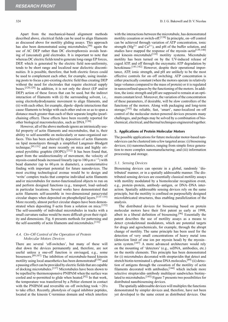
with the interactions between the microtubule, has demonstratedmotility cessation or switch-off.[138] In principle, on–off controlcan be achieved through variation of ATP concentration, ionicstrength (Mg2+ and Ca2+), and pH of the buffer solution, andstudies have mapped the response of the myosin–actin[139,140]
and kinesin–microtubule[110] motility systems. Microtubulemotility has been turned on by the UV-induced release ofcaged ATP, and off through the enzymatic ATP degradation byhexokinase.[141,142] However, despite their operational impor-tance, ATP, ionic strength, and pH are unlikely to be the mosteffective controls for on–off switching. ATP concentration iseither practically constant (when the motors operate in relativelylarge volumes compared to the mass of protein) or it is regulatedin nanoconfined spaces by the functioning of the motors. In addi-tion, the ionic strength and pH are supposed to remain at an opti-mum constant level. Moreover, the variation of the concentrationof these parameters, if desirable, will be slow controllers of thefunctions of the motors. Along with packaging and long-termstorage,[143] the reliable, fast, ‘smart’, nano-localized on–offcontrol of the molecular motor-powered devices presents manychallenges, and perhaps may be solved by a combination of bio-chemical, electrical, and thermal techniques engineered together.
5. Applications of Protein Molecular Motors
The possible applications for future molecular motor-based nan-odevices can be clustered into a few targeted areas: (i) biosensingdevices; (ii) nanomechanics, ranging from simple force genera-tion to more complex nanomanufacturing; and (iii) informationprocessing and storage.
5.1. Sensing DevicesBiosensing devices can operate in a global, randomly ‘dis-tributed’ manner, or in a spatially addressable manner. The dis-tributed sensing devices are essentially classical motility assayswith motility modulated by a biomolecular recognition event,e.g., protein–protein, antibody–antigen, or DNA–DNA inter-action. Spatially addressable sensing devices rely on the sameprinciple, but the motility is confined on purposefully designedmicrofabricated structures, thus enabling parallelization of theanalysis.
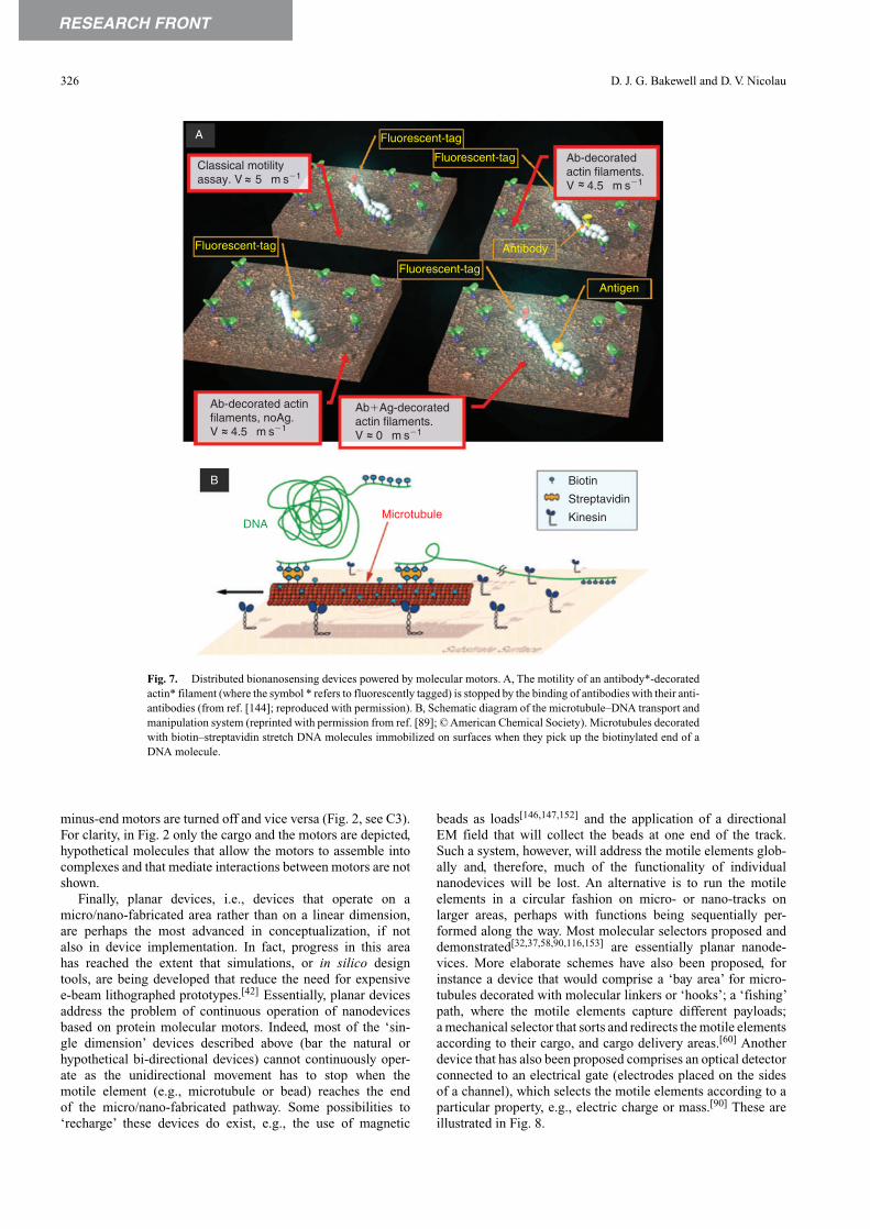
The distributed devices for biosensing based on proteinmolecular motors have their first patent as early as 1998,albeit in a liberal definition of biosensing.[96] Essentially thepatent describes the use of motility assays as a means todetect cytoskeletonal modulators, which are potential targetsfor drugs and agrochemicals, for example, through the abruptchange of motility. The same principle has been used for thedetection of very small concentrations of heavy metal ions(detection limit of one ion per myosin head) by the myosin–actin system.[107] A more advanced architecture would relyon the mounting of ‘detectors’ (e.g., ssDNA, antibodies, etc.)on the motile elements. This principle has been demonstratedfor (i) microtubules decorated with streptavidin that detect andstretch biotin-terminated λ-phase DNA molecules,[89] (ii) detec-tion of antigens through the cessation of the motility of actinfilaments decorated with antibodies,[144] which include moreselective streptavidin–antibody multilayer sandwiches biotiny-lated to microtubules.[145] Figure 7 presents two possibilities fordistributed nanobiosensing devices.
The spatially addressable devices will multiplex the functionsdemonstrated by simpler devices and, therefore, have not beenyet developed to the same extent as distributed devices. One

RESEARCH FRONT
Protein Linear Molecular Motor-Powered Nanodevices 325
A
B
D E
Ca
b
d
c
500
500
400
400
300
300
200
200 100
0.00
1000.00
11.9
800
800
600
600
400
400200200
0.00
0.00
6.41
Size 520 � 520 nm0.000 V0.000 V
Tip referenceSample bias
Fig. 6. Methods for patterning and self-assembly of actin filaments and microtubules. A, Alignment of actin filamentsin flow conditions. B, Alignment of actin filaments between microfabricated electrodes (reprinted with permission fromref. [113]; © American Chemical Society). C, Arrays of actin filaments (from ref. [165]; reproduced with permission ©Rockefeller University Press) cross-linked with a-actinin from (a) skeletal muscle, (b) smooth muscle, (c) cardiac muscle,and (d) dictyostelium discoidium, a non-muscle isoform. In all cases the morphology of the bundles is similar. D, Circularshape of actin filaments (imaged with AFM) deposited on hydrophilic mica (from ref. [132]; reproduced with permission).E, Parallel actin features on hydrophobic HOPG, aligned (∼200 nm) longitudinally (from ref. [132]; reproduced withpermission).
device that relies on the modulation of motility by antibody–antigen recognition and the transduction of motility in EMsignals has also been proposed.[116,146]
5.2. Nanomechanical DevicesMost bead motility assays are primitive self-propelled nan-odevices with inherent directionality control. An early studydemonstrated the high speed of large beads functionalized withHMM running on paracrystal actin filaments self-assembledon a lipid monolayer mounted on glass.[95] This study, whichunfortunately was not followed up, is important because itdemonstrates the benefits of using self-aligned nano-tracksin terms of both directionality and amplification of force.In addition, the transport of micro-objects has been demon-strated for (i) myosin-coated (e.g., magnetic) beads walkingon actin bundles of Nitella [147]; (ii) gelsolin-functionalized40 nm gold nanoparticles attached at one end of actinfilaments[148]; (iii) transportation of quantum dots using actinfilaments,[15] and (iv) HMM-functionalized beads travelling onactin bundles self-assembled in microfabricated channels.[50]
The kinesin–microtubule system was also used for the (i) trans-port, rotation, and flip-over of kinesin-powered micro-chipsmade of silicon along flow-aligned microtubules immobilized onthe surface of a flow cell,[126] (ii) formation of membrane tubesand tubular networks by lipid giant unilamellar vesicles, dec-orated with kinesin-functionalized polystyrene beads,[149] (iii)capture and transport of streptavidin-coated beads by biotin-decorated microtubules,[141,150] and (iv) transport of quantumdots linked to microtubules[145] and also to kinesin for imagingsingle molecule movement.[43]
Bi-directional devices have not yet been demonstratedin vitro, but they have been recently examined and describedin vivo. Two possible mechanisms that explain the bidirec-tional movement of cargo in natural processes, e.g., axonalvesicles, mitochondria, melanosomes, etc., are ‘tug of war’ andcoordination.[151] In the tug of war model, opposite-polaritymotors are active simultaneously (Fig. 2 C2). Net motion resultswhen one set of motors successfully competes against the oppos-ing motors. On the other hand, in the motor coordination model,competition is avoided because when plus-end motors are active,
RESEARCH FRONT
326 D. J. G. Bakewell and D. V. Nicolau
A
B
Fluorescent-tag
Fluorescent-tag
Fluorescent-tag
Fluorescent-tag
Antibody
Antigen
Biotin
Streptavidin
KinesinDNA
Microtubule
Classical motilityassay. V 5 µm s�1~~
Ab-decoratedactin filaments.V 4.5 µm s�1~~
Ab-decorated actinfilaments, noAg.V 4.5 µm s�1~~
Ab�Ag-decoratedactin filaments.V 0 µm s�1~~
Fig. 7. Distributed bionanosensing devices powered by molecular motors. A, The motility of an antibody*-decoratedactin* filament (where the symbol * refers to fluorescently tagged) is stopped by the binding of antibodies with their anti-antibodies (from ref. [144]; reproduced with permission). B, Schematic diagram of the microtubule–DNA transport andmanipulation system (reprinted with permission from ref. [89]; © American Chemical Society). Microtubules decoratedwith biotin–streptavidin stretch DNA molecules immobilized on surfaces when they pick up the biotinylated end of aDNA molecule.
minus-end motors are turned off and vice versa (Fig. 2, see C3).For clarity, in Fig. 2 only the cargo and the motors are depicted,hypothetical molecules that allow the motors to assemble intocomplexes and that mediate interactions between motors are notshown.
Finally, planar devices, i.e., devices that operate on amicro/nano-fabricated area rather than on a linear dimension,are perhaps the most advanced in conceptualization, if notalso in device implementation. In fact, progress in this areahas reached the extent that simulations, or in silico designtools, are being developed that reduce the need for expensivee-beam lithographed prototypes.[42] Essentially, planar devicesaddress the problem of continuous operation of nanodevicesbased on protein molecular motors. Indeed, most of the ‘sin-gle dimension’ devices described above (bar the natural orhypothetical bi-directional devices) cannot continuously oper-ate as the unidirectional movement has to stop when themotile element (e.g., microtubule or bead) reaches the endof the micro/nano-fabricated pathway. Some possibilities to‘recharge’ these devices do exist, e.g., the use of magnetic
beads as loads[146,147,152] and the application of a directionalEM field that will collect the beads at one end of the track.Such a system, however, will address the motile elements glob-ally and, therefore, much of the functionality of individualnanodevices will be lost. An alternative is to run the motileelements in a circular fashion on micro- or nano-tracks onlarger areas, perhaps with functions being sequentially per-formed along the way. Most molecular selectors proposed anddemonstrated[32,37,58,90,116,153] are essentially planar nanode-vices. More elaborate schemes have also been proposed, forinstance a device that would comprise a ‘bay area’ for micro-tubules decorated with molecular linkers or ‘hooks’; a ‘fishing’path, where the motile elements capture different payloads;a mechanical selector that sorts and redirects the motile elementsaccording to their cargo, and cargo delivery areas.[60] Anotherdevice that has also been proposed comprises an optical detectorconnected to an electrical gate (electrodes placed on the sidesof a channel), which selects the motile elements according to aparticular property, e.g., electric charge or mass.[90] These areillustrated in Fig. 8.

RESEARCH FRONT
Protein Linear Molecular Motor-Powered Nanodevices 327
Kinesin Track surface
CargoLinkers
Assembly A1Cargodelivery
Cargodelivery
Sample Optical detector
Optical source
B1
PD
OLED
E�
�
�
Collection
Cargoloading Transporting
Sor
ting
Shuttledetail
Shuttle system
Shuttle detail
Microtubule
A2 B2
BA
Fig. 8. Planar nanomechanical devices. A, Projected system for loading, transport, sorting, and assemble (reprinted withpermission from ref. [60]; © American Chemical Society). A1, Molecular shuttle system with subsystems connected by tracks.A2, Shuttle design ‘hooks’ for cargo. B, Projected system for detection and purification (from ref. [90]; reproduced with kindpermission of Springer Science and Business Media). B1, Integrated system, comprising sample chamber with microtubulesand analyte molecules, motor-functionalized channels, organic LED exciter and photodiode (PD) detector, and electrodes (E) todirect cargo-laden microtubules to the collection chamber. B2, Image of the electrode controlled gate.
5.3. Information Storage and ProcessingMolecular motor-powered devices for information storage andprocessing are in their infancy, despite the fact that this is oneof the main functions of linear natural molecular motors. Forinstance, a kinesin–microtubule system is the workhorse oftransporting information in neuronal systems and the dynein–microtubule system is instrumental in bio-camouflage.
Because of their very small dimensions, the motile ele-ments can hypothetically visit and detect very small and perhapsconcealed nanostructures on surfaces—a principle that can beused for very high-density information storage. A device thatimages microscopic surface properties has been proposed.[154]
The information about surface properties such as topographyis obtained by repeated acquisition of an optical signal (e.g.,fluorescence) from a large number of motile elements (e.g.,microtubules) moving on random paths across a micro/nano-structured surface. These self-propelled probes sample the sur-face in a statistical process in contrast to the deterministic,linear sampling performed by a scanning probe microscope.The spatial distribution of hydrophobicity on a nano-patternedsurface, as opposed to topography, can also be mapped withvery high resolution using the observation that the fluorescenceof rhodamine-phaloidin-tagged actin filaments varies with thenature of the surface.[34]
More opportunities, but also more challenges, will arise inthe area of biocomputation devices. One prospect would beto use the possible, unusual ferroelectric properties of micro-tubules and/or the formation of travelling kink solitons,[155,156]
for example, for new quantum electronic devices. A more imme-diate application would arise from DNA-based computation[157]
and from maze-solving with microfluidics devices,[158] or byamoeboid cells.[159] Essentially, it is entirely possible that themotility of actin filaments, or microtubules, can be used toexplore mazes or other more elaborate micro- or nano-fabricatednetworks that code a mathematical problem,[160] as illustratedin Fig. 9. Many advancements in the area of nanomechanicaldevices, e.g., electrode-controlled gates,[90] molecular rectifiers,selectors, and sorters[37,44,46,154,161,162] will be useful modulesfor a molecular motor-based calculator.
6. Perspectives
Protein molecular motors offer many promises for the design,fabrication, and operation of dynamic nanodevices. Neverthe-less, many challenges for the future molecular motor-basednanodevices still remain open, in particular, to give a realisticanswer to the following questions:
Competitive edge. What is the benefit, exactly, of proteinmolecular motors compared to other alternative devices? Molec-ular motor-based sensing devices offer a clear technological pathfor single molecule-based biomolecular recognition, but muchmore work has to be done to transform this possible advantageinto a competitive one. It would be expected that this, potential,single molecule detection will translate to extremely sensitiveand fast devices.This advantage is indeed critical to bioterrorismapplications or very early detection of pandemics where speedof detection is essential, and it could be that all other issues (e.g.,cost) would be less relevant. Similar analysis has to be made forother groups of applications, i.e., nanomechanical or biocom-putation devices. As a general rule of thumb, high value-added

RESEARCH FRONT
328 D. J. G. Bakewell and D. V. Nicolau
Inlet in thegraph
Gates
Pool of ‘solutions’
Network of channels that confine the movement of biological agents • 2D (xy) network – interconnected channels • 3D (xyz) network – channels connected at different levels • 4D (xyzt) network – gates open and close
Pool of motile biologicalagents: • Actin filaments (or microtubules) • Myosin (or kinesin) functionalized beads • Motile bacteria, flagellum propelled • Fungi, filaments ‘propelled’ by cell division
A computation devicebased on the motility ofbiological couriers.
Fig. 9. A possible scheme of a biocomputation device using biological agents, e.g., actin filaments or microtubules; or even molecularmotor-propelled whole organisms (bacteria or fungi). Reprinted with permission from ref. [160].
uses, where the costs are less important, are more likely to offer‘killer applications’.
Endurance. How can the endurance of protein molecularmotors be dramatically improved to a level where they wouldbecome competitive in fabrication and operation costs withother, non-protein-based dynamic devices, e.g., NEMS? Woulda ‘quantum leap’search for inherently robust proteins, e.g., thosepresent in living beings that exist in extreme environments (ther-mophiles or arctic temperatures) or motor proteins that workin extreme conditions (e.g., from sharks) yield the answer tothis problem? Or would a more gradual improvement based ona better understanding of the impact of operating conditions,i.e., surfaces, temperature, etc. be more productive? Alterna-tively, would the use of molecular motor-based devices be betterrestricted to those applications that are environmentally con-trolled, e.g., laboratory-only applications, such as genomics orbiocomputation? This is also in view of device storage wherevery recent demonstrations of snap freezing and lyophilizationof kinesin–microtubule motor systems show that motility can beretained after thawing or rehydration.[163]
Linear motors: to bead or not to bead? Is the simplicity ofimplementation of the gliding geometry a good trade-off againstthe loss of information regarding directionality, which is builtin actin filaments/microtubules, for bead geometry? In certainapplications, e.g., distributed sensing devices, the gliding geom-etry has important advantages, but for more advanced devices,where control of directionality is essential, careful design andaccurate fabrication of loading zones, selectors, and channels isneeded so that the devices operate with sufficiently low errorrates. On the other hand, the bead geometry, despite long-termadvantages, raises important and immediate technological prob-lems. If the inherently unidirectional tracks are to be laid in adesigned manner, how would this be achieved? A solution wouldbe to locally control the actin and tubulin polymerization on anano-structured surface using multi-photon stereo-lithographyand caged compounds that initiate polymerization. The issuethen arises as to how to orient the structures on that surface in thedesired manner. Alternatively, one could manipulate fluid-flowand/or local electric fields to capture filaments or microtubulesin desired positions and orientations.
Linear motors: cargo blues. In most if not all devices pro-posed so far, a cargo, i.e., a biomolecule (antibody, streptavidinor biotin, DNA), a bead, or a rod, is transported by the motoror filament/microtubule. With the exception of devices based onrotary motors and possibly others (e.g., those for power gener-ation or detection of movement) the cargo has to be unloadedsometime and in precise locations, in particular if a continuousmode of operation is envisaged. Although many schemes havebeen devised regarding the attachment of payloads, the muchmore difficult issue of controlled loading and unloading deservesmore work. A less important, but also a less challenging issueis the use of rods instead of beads as carried objects. Rods havethe advantage of being easier to functionalize differently at theirends as well as being able to improve the direction of movement.
Fuel. Where is the ATP coming from? If a continuous oper-ation is envisaged, the fuel for the dynamic nanodevices hasto be continuously provided. At the limit, these nanodevicescan operate in large (relative to protein mass) volumes and,therefore, the ATP concentration would be quasi-constant. Amore sustainable solution would be to synthesis ATP in a sep-arate chamber (‘ATP factory’) and re-circulate ADP through amicrofluidics network. ATP can be provided by bacteria,[164]
in which case careful filtering has to be arranged between theATP factory and the operational area that comprises the molecu-lar motor-powered devices. Perhaps the most sustainable, albeitchallenging, solution is to integrate other motors, such as ATP-ases, for fuel production and recirculation as well as for theirmechanical capabilities.
Integration. Most of the primitive devices demonstrated sofar use the kinesin–microtubule system, with a few impor-tant exceptions that use rotary motors, myosin–actin, and actinpolymerization systems. The relative robustness and proces-sive nature of kinesin and the rigidity and larger dimensionsof microtubules assists demonstration of prototypes, but themyosin–actin filament system has advantages, in particular,higher velocities and in some applications (e.g., biocomputa-tion) flexibility. Moreover, if continuous operation is envisaged,which will require bi-directionality, we need at least two types ofmotor proteins to work in the same device, possibly on the samecargo. Finally, there are applications where actin and possibly

RESEARCH FRONT
Protein Linear Molecular Motor-Powered Nanodevices 329
microtubule polymerization, e.g., fabrication of tracks, is essen-tial. It appears that future efforts have to be directed towardsthe integration of several types of motors on the same device. Itis possible that other types of motors are used in conjunction,not in competition, with the ‘micro’ linear motors, for example,micro rotary motors, just as macro mechanical rotary and lineardevices are synergistically used in explosion engines.
External control. The operation of molecular motor systems,myosin–actin and kinesin–microtubule, inside hybrid nanode-vices should be capable of being externally controlled andmonitored. How would this be achieved? It depends on thepurpose of the hybrid nanodevice and the context in which itoperates: whether it is stand alone, or part of a larger system (e.g.,laboratory-on-a-chip). The most likely transmission method forrapidly communicating signals to, and from, the motors wouldbe EM fields (radio or optical frequencies), fluid flow, or both.Control of individual motors and/or their filaments/microtubulesinside nanodevices can be exercized in two ways: (i) directly,for example, using forces generated by EM fields (e.g., elec-trophoresis, DEP, magnetophoresis), fluid-flow, or mechanical(such as thermocoiling polymer) to act on the motor systemsthemselves, and (ii) indirectly, for example, using EM fields tosignal an intermediate agent which then influences the motors(e.g., optically induced uncaging of peptides in kinesin, whichswitches it off ).
The control can be defined in terms of its spatiotemporaldistribution, i.e., either broadcast over the entire device or con-fined to particular regions or sub cells, and for programmed timeperiods. Separately addressable, micrometer or nanometer-sizedelectrodes, for example, could be used to achieve electrophoreticor AC DEP movement and positioning, particularly the lat-ter, which uses electric field inhomogeneities and can generatealmost point-like forces. Needless to say, these options need con-sideration in terms of the force strengths generated that willsurely compete with the randomising effects of thermal motionand interfering viscous forces from nearby motors and otherhydrodynamic sources. Control can also be individualized tomotility systems with an established identity, for example, byattaching beads with particular electric or magnetic properties.Likewise, the monitoring of motor systems can be direct (e.g.,optical detection of microtubule presence), or indirect (e.g.,microtubule unloading of cargo that is then detected) with spa-tiotemporal definition. An example of the latter would again usenano-electrodes, but instead of generating controlling forces,they detect changes in localized electric fields, or dielectric per-mittivity, thus inferring the presence of nearby motor systems.As with control, monitoring will require careful technical con-sideration regarding signal-to-noise ratios and other unwantedeffects in order to avoid, or lessen, the chances of false detection.
In order for hybrid nanodevices to be strong technology con-tenders, aspects such as fuel supply, endurance, motor and assaymethods, cargo handling, integration, external control, and reli-able monitoring will need considerable advancement and willprovide ample opportunities for novel research. In addition,in parallel to nanodevice advancement, new opportunities forapplications in mainstream or niche sectors will also need to beidentified.
7. Conclusions
Although several aspects regarding the fundamentals of molec-ular motors and associated proteins are still the subject ofintense study, the molecular biology and biophysics-oriented
research has reached critical mass where many fundamentalparameters necessary for the engineering design of molecularmotor-powered nanodevices are already available. A separateline of research, focussed on molecular motor-based devices,which has developed in the last half a decade, also providessome answers regarding the possible engineering options fortheir design, fabrication, and operation. Many important chal-lenges still remain to be resolved, but the primitive prototypesalready demonstrated offer useful benchmarks in the develop-ment of robust and continuous-operation devices and systemsfor biosensing, mechanical work, and possibly biocomputation.
AcknowledgmentsThis paper is the result of many discussions with colleagues working inthe molecular motors area. In particular, many of the ideas presented herehave been sparked by hearty discussions with Hitoshi Suzuki and KazuOiwa at Kansai Advanced Research Center; Takahisa Taguchi and NoburuYumoto at AIST in Japan; Rob Cross at Marie Curie Research Institute, UK;Cris dos Remedios at the University of Sydney, Australia; Gerry Pollack atWashington University; Henry Hess at University of Florida; and Fran Liglerat Naval Research Laboratories.
References[1] J. Howard, A. J. Hudspeth, R. D. Vale, Nature 1989, 342, 154.
doi:10.1038/342154A0[2] S. M. Block, L. S. B. Goldstein, B. J. Schnapp, Nature 1990, 348,
348. doi:10.1038/348348A0[3] T. Q. P. Uyeda, H. M. Warrick, S. J. Kron, J.A. Spudich, Nature 1991,
352, 307. doi:10.1038/352307A0[4] K. Svoboda, C. F. Schmidt, B. J. Schnapp, S. M. Block, Nature 1993,
365, 721. doi:10.1038/365721A0[5] I. Rayment, H. M. Holden, Curr. Opin. Struct. Biol. 1993, 3, 944.
doi:10.1016/0959-440X(93)90160-M[6] K. Svoboda, S. M. Block, Cell 1994, 77, 773. doi:10.1016/0092-
8674(94)90060-4[7] J. T. Finer, R. M. Simmons, J. A. Spudich, Nature 1994, 368, 113.
doi:10.1038/368113A0[8] A. Ishijima, H. Kojima, H. Higuchi, Y. Harada, T. Funatsu,
T. Yanagida, Biophys. J. 1996, 70, 383.[9] R. D. Vale, T. Funatsu, D. W. Pierce, L. Romberg, Y. Harada,
T. Yanagida, Nature 1996, 380, 451. doi:10.1038/380451A0[10] Y. Imafuku, Y. Y. Toyoshima, K. Tawada, Biophys. J. 1996, 70, 878.[11] R. S. Rock, M. Rief,A. D. Mehta, J.A. Spudich, Meth.A: Companion
Methods Enzymol. 2000, 22, 373. doi:10.1006/METH.2000.1089[12] T. Yanagida, K. Kitamura, H. Tanaka, A. H. Iwane, S. Esaki, Curr.
Opin. Cell Biol. 2000, 12, 20. doi:10.1016/S0955-0674(99)00052-6[13] A. Ishijima, T. Yanagida, Trends Biochem. Sci. 2001, 26, 438.
doi:10.1016/S0968-0004(01)01860-6[14] M. Schliwa, G. Woehlke, Nature 2003, 422, 759. doi:10.1038/
NATURE01601[15] A. Mansson, M. Sundberg, M. Balaza, R. Bunk, I. A. Nicholls,
P. Omling, S. Tågerud, L. Montelius, Biochem. Biophys. Res.Commun. 2004, 314, 529. doi:10.1016/J.BBRC.2003.12.133
[16] A. Yildiz, Science 2004, 303, 676. doi:10.1126/SCIENCE.1093753[17] J. E. Molloy, S. Schmitz, Nature 2005, 435, 285. doi:10.1038/
435285A[18] J. Kerssemakers, J. Howard, H. Hess, S. Diez, Proc. Natl. Acad. Sci.
USA 2006, 103, 15812. doi:10.1073/PNAS.0510400103[19] A. F. Huxley, Prog. Biophys. Mol. Biol. 1957, 7, 255.[20] A. F. Huxley, R. M. Simmons, Nature 1971, 233, 533.
doi:10.1038/233533A0[21] T. L. Hill, E. Eisenberg, L. Greene, Proc. Natl. Acad. Sci. USA 1980,
77, 3186. doi:10.1073/PNAS.77.6.3186[22] E. Eisenberg, T. L. Hill, Y. Chen, Biophys. J. 1980, 29, 195.

RESEARCH FRONT
330 D. J. G. Bakewell and D. V. Nicolau
[23] N. J. Cordova, B. Ermentrout, G. F. Oster, Proc. Natl. Acad. Sci. USA1992, 89, 339. doi:10.1073/PNAS.89.1.339
[24] Y. Imafuku, Y. Y. Toyoshima, K. Tawada, Biophys. Chem. 1996, 59,139. doi:10.1016/0301-4622(95)00123-9
[25] J. Howard, Mechanics of Motor Proteins and the Cytoskeleton 2001(Sindauer: Sunderland, MA).
[26] H. Wang, G. Oster,Appl. Phys.A: Mater. Sci. Process. 2002, 75, 315.doi:10.1007/S003390201340
[27] K. B. Zeldovich, J. F. Joanny, J. Prost, Eur. Phys. J. E 2005, 17, 155.doi:10.1140/EPJE/I2004-10137-6
[28] P. J. Atzberger, C. S. Peskin, Bull. Math. Biol. 2006, 68, 131.doi:10.1007/S11538-005-9003-6
[29] T. Henry, J. P. Gorvel, S. Meresse, Cell. Microbiol. 2006, 8, 23.doi:10.1111/J.1462-5822.2005.00649.X
[30] D. C. Turner, C.-Y. Chang, K. Fang, S. L. Brandow, D. B. Murphy,Biophys. J. 1995, 69, 2782.
[31] H. Suzuki, K. Oiwa, A. Yamada, H. Sakakibara, H. Nakayama,S. Mashiko, Jpn J. Appl. Phys., Part 1 1995, 34, 3937. doi:10.1143/JJAP.34.3937
[32] H. Suzuki,A.Yamada, K. Oiwa, H. Nakayama, S. Mashiko, Biophys.J. 1997, 72, 1997.
[33] D. Riveline, A. Ott, F. Julicher, D. A. Winkelmann, O. Cardoso,J. J. Lacapere, S. Magnusdottir, J. L. Viovy, L. Gorre-Talini, J. Prost,Eur. Biophys. J. Biophys. Lett. 1998, 27, 403.
[34] D. V. Nicolau, H. Suzuki, S. Mashiko, T. Taguchi, S. Yoshikawa,Biophys. J. 1999, 77, 1126.
[35] J. R. Dennis, J. Howard, V. Vogel, Nanotechnology 1999, 10, 232.doi:10.1088/0957-4484/10/3/302
[36] R. K. Soong, G. D. Bachand, H. P. Neves, A. G. Olkhovets,H. G. Craighead, C. D. Montemagno, Science 2000, 290, 1555.doi:10.1126/SCIENCE.290.5496.1555
[37] Y. Hiratsuka,T.Tada, K. Oiwa,T. Kanayama,T. Q. P. Uyeda, Biophys.J. 2001, 81, 1555.
[38] H. Hess, G. D. Bachand, V. Vogel, Chem. Eur. J. 2004, 10, 2110.doi:10.1002/CHEM.200305712
[39] Y. M. Huang, M. Uppalapati, W. O. Hancock, T. N. Jackson,IEEE Trans. Adv. Pack. 2005, 28, 564. doi:10.1109/TADVP.2005.858330
[40] A. Mansson, M. Sundberg, R. Bunk, M. Balaz, I. A. Nicholls,P. Omling, J. O. Tegenfeldt, S. Tagerud, L. Montelius, IEEE Trans.Adv. Pack. 2005, 28, 547. doi:10.1109/TADVP.2005.858309
[41] V. Verma, W. O. Hancock, J. M. Catchmark, IEEE Trans. Adv. Pack.2005, 28, 584. doi:10.1109/TADVP.2005.858302
[42] T. Nitta, A. Tanahashi, M. Hirano, H. Hess, Lab Chip 2006, 6, 881.doi:10.1039/B601754A
[43] G. Muthukrishnan, B. M. Hutchins, M. E. Williams, W. O. Hancock,Small 2006, 2, 626. doi:10.1002/SMLL.200500223
[44] M. G. L. van den Heuvel, C. T. Butcher, R. M. M. Smeets, S. Diez,C. Dekker, Nano Lett. 2005, 5, 1117. doi:10.1021/NL0506554
[45] T. Nitta, H. Hess, Nano Lett. 2005, 5, 1337. doi:10.1021/NL050586T[46] M. G. L. van den Heuvel, M. P. De Graaff, C. Dekker, Science 2006,
312, 910. doi:10.1126/SCIENCE.1124258[47] D. V. Nicolau, Dynamic Nanodevices Based on Protein Molec-
ular Motors. BioMEMS and Biomedical Nanotechnology (Ed.M. Ferrari) 2006, Vol. 1, Biological and Biomedical Nanotechnol-ogy (Eds A. P. Lee, J. Lee, M. Ferrari) Ch. 2, in print (Springer:New York, NY).
[48] H. Hess, Soft Matter 2006, 2, 669. doi:10.1039/B518281F[49] R. Ait-Haddou, W. Herzog, Cell Biochem. Biophys. 2003, 38, 191.
doi:10.1385/CBB:38:2:191[50] D. V. Nicolau, H. G. Brinkies, M. Ilkov, I. Sbarski, V. Buljan,
D. K. Pham, E. P. Ivanova,Y. V. Alexeeva, Nanobiotechnology 2005,1, 379. doi:10.1385/NBT:1:4:379
[51] R. A. Walker, E. T. O’Brien, N. K. Pryer, M. F. Soboeiro, W. A. Voter,H. P. Erickson, E. D. Salmon, J. Cell Biol. 1988, 107, 1437.doi:10.1083/JCB.107.4.1437
[52] T. D. Pollard, L. Blanchoin, R. D. Mullins, Annu. Rev. Biophys.Biomol. Struct. 2000, 29, 545. doi:10.1146/ANNUREV.BIOPHYS.29.1.545
[53] J. A. Theriot, Traffic 2000, 1, 19. doi:10.1034/J.1600-0854.2000.010104.X
[54] R. Cooke, J. Gen. Physiol. 2004, 123, 643. doi:10.1085/JGP.200409089
[55] H. Noji, R. Yasuda, M. Yoshida, K. Kinosita, Jr, Nature 1997, 386,299. doi:10.1038/386299A0
[56] P. Dimroth, H. Wang, M. Grabe, G. Oster, Proc. Natl.Acad. Sci. USA1999, 96, 4924. doi:10.1073/PNAS.96.9.4924
[57] C. Montemagno, G. Bachand, Nanotechnology 1999, 10, 225.doi:10.1088/0957-4484/10/3/301
[58] G. D. Bachand, R. K. Soong, H. P. Neves, A. Olkhovets,H. G. Craighead, C. D. Montemagno, Nano Lett. 2001, 1, 42.doi:10.1021/NL005513I
[59] H. C. Berg, Annu. Rev. Biochem. 2003, 72, 19. doi:10.1146/ANNUREV.BIOCHEM.72.121801.161737
[60] H. Hess, C. M. Matzke, R. K. Doot, J. Clemmens, G. D. Bachand,B. C. Bunker, V. Vogel, Nano Lett. 2003, 3, 1651. doi:10.1021/NL0347435
[61] R. D. Vale, R. A. Milligan, Science 2000, 288, 88. doi:10.1126/SCIENCE.288.5463.88
[62] P. B. Conibear, M. A. Geeves, Biophys. J. 1998, 75, 926.[63] M. J. Tyska, D. E. Dupuis, W. H. Guilford, J. B. Patlak, G. S. Waller,
K. M. Trybus, D. M. Warshaw, S. Lowey, Proc. Natl. Acad. Sci. USA1999, 96, 4402. doi:10.1073/PNAS.96.8.4402
[64] S. J. Kron, J. A. Spudich, Proc. Natl. Acad. Sci. USA 1986, 83, 6272.doi:10.1073/PNAS.83.17.6272
[65] Y. Y. Toyoshima, S. J. Kron, E. M. McNally, K. R. Niebling,C. Toyoshima, J. A. Spudich, Nature 1987, 328, 536. doi:10.1038/328536A0
[66] T. Ando, N. Kodera, E. Takai, D. Maruyama, K. Saito, A. Toda,Proc. Natl. Acad. Sci. USA 2001, 98, 12468. doi:10.1073/PNAS.211400898
[67] M. Morimatsu, A. Nakamura, H. Sumiyoshi, N. Sakaba,H. Taniguchi, K. Kohama, S. Higashi-Fujime, Biochem. Biophys.Res. Commun. 2000, 270, 147. doi:10.1006/BBRC.2000.2391
[68] D. Chretien, R. H. Wade, Biol. Cell 1991, 71, 161. doi:10.1016/0248-4900(91)90062-R
[69] R. D. Vale, T. S. Reese, M. P. Sheetz, Cell 1985, 42, 39. doi:10.1016/S0092-8674(85)80099-4
[70] J. Howard, Annu. Rev. Physiol. 1996, 58, 703. doi:10.1146/ANNUREV.PH.58.030196.003415
[71] J. Howard, Nature 1997, 389, 561. doi:10.1038/39247[72] M. P. Sheetz, J. A. Spudich, Nature 1983, 303, 31. doi:10.1038/
303031A0[73] J. A. Spudich, S. J. Kron, M. P. Sheetz, Nature 1985, 315, 584.
doi:10.1038/315584A0[74] T. Yanagida, M. Nakase, K. Nishiyama, F. Oosawa, Nature 1984,
307, 58. doi:10.1038/307058A0[75] J. Howard, A. Hunt, S. Baek, Methods Cell Biol. 1993, 39, 137.[76] N. Suzuki, H. Miyata, S. Ishiwata, K. Kinoshita, Biophys. J. 1996,
70, 401.[77] L. A. Cameron, M. J. Footer, A. van Oudenaarden, J. A. Theriot,
Proc. Natl. Acad. Sci. USA 1999, 96, 4908. doi:10.1073/PNAS.96.9.4908
[78] M. Dogterom, B. Yurke, Science 1997, 278, 856. doi:10.1126/SCIENCE.278.5339.856
[79] A. Ishijima, H. Kojima, T. Funatsu, M. Tokunaga, H. Higuchi,H. Tanaka, T. Yanagida, Cell 1998, 92, 161. doi:10.1016/S0092-8674(00)80911-3
[80] D. A. Winkelmann, L. Bourdieu, A. Ott, F. Kinose, A. Libchaber,Biophys. J. 1995, 68, 2444.
[81] L. Bourdieu, M. O. Magnasco, D. A. Winkelmann, A. Libchaber,Phys. Rev. E 1995, 52, 6573. doi:10.1103/PHYSREVE.52.6573
[82] J. Wright, D. Pham, C. Mahanivong, D. V. Nicolau, M. Kekic,C. G. dos Remedios, Biomed. Microdevices 2002, 4, 205.doi:10.1023/A:1016048413944
[83] C. Mahanivong, J. P. Wright, M. Kekic, D. K. Pham,C. dos Remedios, D. V. Nicolau, Biomed. Microdevices 2002, 4,111. doi:10.1023/A:1014631130726

RESEARCH FRONT
Protein Linear Molecular Motor-Powered Nanodevices 331
[84] R. Bunk, J. Klinth, L. Montelius, I. A. Nicholls, P. Omling,S. Tågerud, A. Månsson, Biochem. Biophys. Res. Commun. 2003,301, 783. doi:10.1016/S0006-291X(03)00027-5
[85] M. Sundberg, J. P. Rosengren, R. Bunk, J. Lindahl, I. A. Nicholls,S. Tågerud, P. Omling, L. Montelius, A. Månsson, Anal. Biochem.2003, 323, 127. doi:10.1016/J.AB.2003.07.022
[86] M. Sundberg, M. Balaz, R. Bunk, J. P. Rosengren-Holmberg,L. Montelius, I. A. Nicholls, P. Omling, S. Tågerud, A. Månsson,Langmuir 2006, 22, 7302. doi:10.1021/LA060365I
[87] R. Stracke, K. J. Böhm, J. Burgold, H.-J. Schacht, E. Unger,Nanotechnology 2000, 11, 52. doi:10.1088/0957-4484/11/2/302
[88] C. Brunner, K.-H. Ernst, H. Hess, V. Vogel, Nanotechnology 2004,15, S540. doi:10.1088/0957-4484/15/10/008
[89] S. Diez, C. Reuther, C. Dinu, R. Seidel, M. Mertig, W. Pompe,J. Howard, Nano Lett. 2003, 3, 1251. doi:10.1021/NL034504H
[90] L. L. Jia, S. G. Moorjani, T. N. Jackson, W. O. Hancock, Biomed.Microdevices 2004, 6, 67. doi:10.1023/B:BMMD.0000013368.89455.8D
[91] J. Clemmens, H. Hess, J. Howard,V.Vogel, Langmuir 2003, 19, 1738.doi:10.1021/LA026155X
[92] L. Ionov, M. Stamm, S. Diez, Nano Lett. 2006, 6, 1982.doi:10.1021/NL0611539
[93] C. Reuther, L. Hajdo, R. Tucker, A. A. Kasprzak, S. Diez, Nano Lett.2006, 6, 2177. doi:10.1021/NL060922L
[94] D. V. Nicolau, unpublished.[95] H. Suda, A. Ishikawa, Biochem. Biophys. Res. Commun. 1997, 237,
427. doi:10.1006/BBRC.1997.7048[96] R. D. Vale, H. Hotani, J. Cell Biol. 1988, 107, 2233.
doi:10.1083/JCB.107.6.2233[97] D. Turner, C. Chang, K. Fang, P. Cuomo, D. Murphy, Anal. Biochem.
1996, 242, 20. doi:10.1006/ABIO.1996.0422[98] K. Nakanishi, T. Sakiyama, K. Imamura, J. Biosci. Bioeng. 2001, 91,
233. doi:10.1263/JBB.91.233[99] M. L. Connolly, Science 1983, 221, 709. doi:10.1126/SCIENCE.
6879170[100] M. L. Connolly, J. Appl. Crystallogr. 1983, 16, 548. doi:10.1107/
S0021889883010985[101] M. L. Connolly, J. Mol. Graph. 1986, 4, 3. doi:10.1016/0263-
7855(86)80086-8[102] D.V. Nicolau, Jr, F. Fulga, D.V. Nicolau, Biomed. Microdevices 2003,
5, 227. doi:10.1023/A:1025712326321[103] D. V. Nicolau, G. Solana, M. Kekic, E. P. Ivanova, C. dos Remedios,
Surface Hydrophobicity Modulates the Operation of Protein Molec-ular Motors, in International Conference on Nanoscience andNanotechnology 2006 (Brisbane QLD, Australia).
[104] D. V. Nicolau, Nanodevices Based on Linear Protein Molecu-lar Motors: Challenges and Opportunities, in Foundations ofNanoscience 2004: Self-Assembled Architectures and Devices 2004(ScienceTechnica: Snowbird, UT).
[105] B. Liang,Y. Chen, C. K.Wang, X.-Z. Luo, M. Regnier,A. M. Gordon,P. B. Chase, Biophys. J. 2003, 85, 1775.
[106] P. VanBuren, K. Begin, D. M. Warshaw, J. Mol. Cell. Cardiol. 1998,30, 2777. doi:10.1006/JMCC.1998.0856
[107] R. Martinez-Neira, M. Kekic, D. Nicolau, C. G. dos Remedios,Biosens. Bioelectron. 2005, 20, 1428. doi:10.1016/J.BIOS.2004.04.021
[108] K. Kawaguchi, S. Ishiwata, Biochem. Biophys. Res. Commun. 2000,272, 895. doi:10.1006/BBRC.2000.2856
[109] M. Kawai, K. Kawaguchi, M. Saito, S. Ishiwata, Biophys. J. 2000,78, 3119A.
[110] K. J. Bohm, R. Stracke, E. Unger, Cell Biol. Int. 2000, 24, 335.doi:10.1006/CBIR.1999.0515
[111] J. Clemmens, H. Hess, R. Lipscomb, Y. Hanein, K. F. Böhringer,C. M. Matzke, G. D. Bachand, B. C. Bunker, V. Vogel, Langmuir2003, 19, 10967. doi:10.1021/LA035519Y
[112] M. Sundberg, R. Bunk, N. Albet-Torres, A. Kvennefors,F. Persson, L. Montelius, I. A. Nicholls, S. Ghatnekar-Nilsson,P. Omling, S. Tågerud, A Månsson, Langmuir 2006, 22, 7286.doi:10.1021/LA060854I
[113] S. B. Asokan, L. Jawerth, R. Lloyd Carroll, R. E. Cheney,S. Washburn, R. Superfine, Nano Lett. 2003, 3, 431. doi:10.1021/NL0259434
[114] R. Bunk, M. Sundberg, A. Månsson, I. A. Nicholls, P. Omling,S. Tågerud, L. Montelius, Nanotechnology 2005, 16, 710.doi:10.1088/0957-4484/16/6/014
[115] T. E. Holy, M. Dogterom, B.Yurke, S. Leibler, Proc. Natl. Acad. Sci.USA 1997, 94, 6228. doi:10.1073/PNAS.94.12.6228
[116] D. V. Nicolau, R. Cross, Biosens. Bioelectron. 2000, 15, 85.doi:10.1016/S0956-5663(99)00072-X
[117] R. Bunk, P. Carlberg, A. Månsson, I. A. Nicholls, P. Omling,M. Sundberg, S. Tågerud, L. Montelius, Jpn J. Appl. Phys., Part1 2005, 44, 3337. doi:10.1143/JJAP.44.3337
[118] K. Oiwa, Protein Motors:Their Mechanical Properties andApplica-tion to Nanometer-Scale Devices, in Thermec’ 2003, Pts 1–5 2003,pp. 2339–2344 (Trans Tech Publications Ltd: Zurich-Uetikon).
[119] M. Platt, G. Muthukrishnan, W. O. Hancock, M. E. Williams, J. Am.Chem. Soc. 2005, 127, 15686. doi:10.1021/JA055815S
[120] B. M. Hutchins, W. O. Hancock, M. E. Williams, Phys. Chem. Chem.Phys. 2006, 8, 3507. doi:10.1039/B605399H
[121] R. Stracke, K. J. Böhm, L. Wollweber, J. A. Tuszynski, E. Unger,Biochem. Biophys. Res. Commun. 2002, 293, 602. doi:10.1016/S0006-291X(02)00251-6
[122] K. L. Hanson, G. Solana, D. V. Nicolau, Electrophoretic controlof actomyosin motility, in 2005 3rd IEEE/EMBS Special TopicConference on Microtechnology in Medicine and Biology 2005,pp. 205–206 (IEEE: New York, NY).
[123] H. A. Pohl, Dielectrophoresis 1978 (Cambridge University Press:Cambridge).
[124] K. J. Bohm, J. Beeg, G. Meyer zu Horste, R. Stracke, E. Unger,IEEE Trans. Adv. Pack. 2005, 28, 571. doi:10.1109/TADVP.2005.858314
[125] E. M. Ostap, T. Yanagida, D. D. Thomas, Biophys. J. 1992, 63, 966.[126] L. Limberis, R. J. Stewart, Nanotechnology 2000, 11, 47.
doi:10.1088/0957-4484/11/2/301[127] T. B. Brown, W. O. Hancock, Nano Lett. 2002, 2, 1131.
doi:10.1021/NL025636Y[128] C. F. Chou, J. O. Tegenfeldt, O. Bakajin, S. S. Chan, E. C.
Cox, N. Darnton, T. Duke, R. H. Austin, Biophys. J. 2002, 83,2170.
[129] K. H. Kang, L. H. Lewis, Y. F. Hu, Q. Li, A. R. Moodenbaugh,Y. S. Choi, J. Appl. Phys. 2006, 99, 8. doi:10.1063/1.2158692
[130] D. J. Bakewell, H. Morgan, IEEE Trans. Nanobiosci. 2006, 5, 139.doi:10.1109/TNB.2005.864012
[131] D. Shi, A. V. Shomlyo, A. P. Somlyo, Z. Shao, J. Microsc. Oxford2001, 201, 377. doi:10.1046/J.1365-2818.2001.00844.X
[132] G. S.Watson, C. Cahill, J. Blach, S. Myhra,Y.Alexeeva, E. P. Ivanova,D. V. Nicolau, Actin Nanotracks for Hybrid Nanodevices Based onLinear Protein Molecular Motors, in Nanoengineered Assembliesand Advanced Micro/Nanosystems (Mater. Res. Soc. Symp. Proc.820) (Eds D. P. Taylor, J. Liu, D. McIlroy, L. Merhari, J. P. Pendry,J. T. Borenstein, P. Grodzinski, L. P. Lee, Z. L. Wang) 2004, pp.25–35 (San Francisco, CA).
[133] K. A. Taylor, D. W. Taylor, J. Struct. Biol. 1992, 108, 140.doi:10.1016/1047-8477(92)90013-Z
[134] K. A. Taylor, D. W. Taylor, Biophys. J. 1994, 67, 1976.[135] H. C. Taylor, M. E. J. Holwill, Nanotechnology 1999, 10, 237.
doi:10.1088/0957-4484/10/3/303[136] Y. Miyamoto, E. Muto, T. Mashimo, A. H. Iwane, I. Yoshia,
T. Yanagida, Biophys. J. 2000, 78, 940.[137] M. G. L. van den Heuvel, C. T. Butcher, S. G. Lemay, S. Diez,
C. Dekker, Nano Lett. 2005, 5, 235. doi:10.1021/NL048291N[138] A. Nomura, T. Q. P. Uyeda, N. Yumoto, Y. Tatsu, Chem. Commun.
2006, 3588. doi:10.1039/B606538D[139] M. S. Z. Kellermayer, G. H. Pollack, Biochim. Biophys. Acta 1996,
1277, 107. doi:10.1016/S0005-2728(96)00089-8[140] F. Wang, L.-F. Chen, O. Arcucci, E. V. Harvey, B. Bowers, Y. Xu,
J. A. Hammer, III, J. R. Sellers, J. Biol. Chem. 2000, 275, 4329.doi:10.1074/JBC.275.6.4329
RESEARCH FRONT
332 D. J. G. Bakewell and D. V. Nicolau
[141] H. Hess, J. Clemmens, D. Qin, J. Howard, V. Vogel, Nano Lett. 2001,1, 235. doi:10.1021/NL015521E
[142] D. Wu, R. Tucker, H. Hess, IEEE Trans. Adv. Pack. 2005, 28, 594.doi:10.1109/TADVP.2005.858327
[143] T. J. Grove, K. A. Puckett, N. M. Brunet, G. Mihajlovic,L. A. McFadden, X. Peng, S. von Molnar, T. S. Moerland,P. B. Chase, IEEE Trans. Adv. Pack. 2005, 28, 556. doi:10.1109/TADVP.2005.858341
[144] M. Kekic, R. Martinez, C. dos Remedios, D. Nicolau, Biophys. J.2005, 88, 503A.
[145] S. Ramachandran, K.-H. Ernst, G. D. Bachand, V. Vogel, H. Hess,Small 2006, 2, 330. doi:10.1002/SMLL.200500265
[146] F. Fulga, S. Myhra, D. V. Nicolau, Jr, D. V. Nicolau, Smart Mater.Struct. 2002, 11, 722. doi:10.1088/0964-1726/11/5/315
[147] H.Yamasaki, H. Nakayama, Biochem. Biophys. Res. Commun. 1996,221, 831. doi:10.1006/BBRC.1996.0682
[148] H. Nakayama, T. Yamaga, Y. Kunioka, Biochem. Biophys. Res.Commun. 1998, 246, 261. doi:10.1006/BBRC.1998.8594
[149] A. Roux, G. Cappello, J. Cartaud, J. Prost, B. Goud, P. Bassereau,Proc. Natl. Acad. Sci. USA 2002, 99, 5394. doi:10.1073/PNAS.082107299
[150] H. Hess, V. Vogel, Rev. Mol. Biotechnol. 2001, 82, 67. doi:10.1016/S1389-0352(01)00029-0
[151] S. P. Gross, M. A. Welte, S. M. Block, E. F. Wieschaus, J. Cell Biol.2002, 156, 715. doi:10.1083/JCB.200109047
[152] G. Uchida, Y. Mizukami, T. Nemoto, Y. Tsuchiya, J. Phys. Soc. Jpn.1998, 67, 345. doi:10.1143/JPSJ.67.345
[153] H. Hess, J. Clemmens, C. M. Matzke, G. D. Bachand, B. C. Bunker,V. Vogel, Appl. Phys. A Mater. Sci. Process. 2002, 75, 309.doi:10.1007/S003390201339
[154] H. Hess, J. Clemmens, J. Howard, V. Vogel, Nano Lett. 2002, 2, 113.doi:10.1021/NL015647B
[155] M. V. Satari, J. A. Tuszynski, R. B. Zakula, Phys. Rev. E 1993, 48,589. doi:10.1103/PHYSREVE.48.589
[156] M. V. Sataric, J. A. Tuszynski, Phys. Rev. E 2003, 67, 11.[157] L. M. Adleman, Science 1994, 266, 1021. doi:10.1126/SCIENCE.
7973651[158] D. T. Chiu, E. Pezzoli, H. Wu,A. D. Stroock, G. M. Whitesides, Proc.
Natl.Acad. Sci. USA 2001, 98, 2961. doi:10.1073/PNAS.061014198[159] T. Nakagaki, H. Yamada, A. Toth, Nature 2000, 407, 470.
doi:10.1038/35035159[160] D. V. Nicolau, D. V. Nicolau, Jr, G. Solana, K. L. Hanson,
L. Filipponi, L. Wang,A. P. Lee, Microelectron. Eng. 2006, 83, 1582.doi:10.1016/J.MEE.2006.01.198
[161] J. Clemmens, H. Hess, R. Doot, C. M. Matzke, G. D. Bachand,V. Vogel, Lab Chip 2004, 4, 83. doi:10.1039/B317059D
[162] K. J. Bohm, N. E. Mavromatos, A. Michette, R. Stracke, E.Unger, Electromagn. Biol. Med. 2005, 24, 319. doi:10.1080/15368370500380010
[163] R. Seetharam, Y. Wada, S. Ramachandran, H. Hess, P. Satir, LabChip 2006, 6, 1239. doi:10.1039/B601635A
[164] E. P. Ivanova, Y. V. Alexeeva, J. P. Wright, D. V. Nicolau, Int.Microbiol. 2006, 9, 37.
[165] K. A. Taylor, D. W. Taylor, F. Schachat, J. Cell Biol. 2000, 149, 635.doi:10.1083/JCB.149.3.635
[166] F. Oosawa, S. Asakura, Thermodynamics of Polymerization ofProtein 1975 (Academic Press: New York, NY).