PROVISIONAL - FLIGHT MANUAL for Powered Sailplane
173
SCHEMPP-HIRTH FLUGZEUGBAU GmbH., KIRCHHEIM/TECK P R O V I S I O N A L FLIGHT MANUAL for Powered Sailplane Model: A R C U S M Serial-No.: Registr.-No.: Date of issue: O c t o b e r 2 0 1 1 Pages as indicated by „ app r .“ are approved by This powered sailplane is to be operated in compliance with information and limitations contained herein. Approval of translation has been done by best knowledge and judgement. In any case the original text in German language is authoritative.
-
Upload
khangminh22 -
Category
Documents
-
view
1 -
download
0
Transcript of PROVISIONAL - FLIGHT MANUAL for Powered Sailplane

SCHEMPP-HIRTH FLUGZEUGBAU GmbH., KIRCHHEIM/TECK
P R O V I S I O N A L
FLIGHT MANUAL
for Powered Sailplane
Model: A R C U S M
Serial-No.: Registr.-No.: Date of issue: O c t o b e r 2 0 1 1 Pages as indicated by „appr.“ are approved by
This powered sailplane is to be operated in compliance with information and limitations contained herein.
Approval of translation has been done by best knowledge and judgement. In any case the original text in German language is authoritative.

SCHEMPP-HIRTH FLUGZEUGBAU GmbH., KIRCHHEIM/TECK
Arcus M FLIGHT MANUAL 0.1 Record of revisions
Any revisions of the present manual, except actual weighing data, must be recorded in the following table and in the case of approved sections be en-dorsed by the responsible airworthiness authority.
The new or amended text in the revised page will be indicated by a black vertical line in the left hand margin, and the revision number and the date will be shown on the bottom left hand side of the page.
0.1.1

SCHEMPP-HIRTH FLUGZEUGBAU GmbH., KIRCHHEIM/TECK Arcus M FLUGHANDBUCH / FLIGHT MANUAL 0.1 Erfassung der Berichtigungen / Records of revisions Lfd. Nr. der Berichtigung
Abschnitt
Seiten
Datum der Berichtigung
Bezug
Datum der Anerkennung
Datum der Ein- arbeitung
Zeichen /Unter- schrift
Revision No.
Affected section
Affected page
Date of issue
Reference
Date of Approval
Date of Insertion
Signature
MB: Modification Bulletin – Änderungsblatt TN : Technical Note – Technische Mitteilung
0.1.2

SCHEMPP-HIRTH FLUGZEUGBAU GmbH, KIRCHHEIM/TECK Arcus M FLUGHANDBUCH / FLIGHT MANUAL
0.2 Verzeichnis der Seiten / List of affected pages
Abschnitt Affected section
Seite Affected pages
Ausgabe-Datum Date of issue
Bezug Reference
0
0.1.1 0.1.2 0.2.1 0.2.2 0.2.3 0.2.4 0.2.5 0.2.6 0.2.7 0.2.8 0.3.1
0.2.1

SCHEMPP-HIRTH FLUGZEUGBAU GmbH, KIRCHHEIM/TECK Arcus M FLUGHANDBUCH / FLIGHT MANUAL
0.2 Verzeichnis der Seiten / List of affected pages
Abschnitt Affected section
Seite Affected pages
Ausgabe-Datum Date of issue
Bezug Reference
1 2
1.1.1 1.1.2 1.2 1.3 1.4.1 1.4.2 1.4.3 1.5 2.1.1 2.1.2 anerk. 2.2.1 anerk. 2.2.2 anerk. 2.3 anerk. 2.4 anerk. 2.5 anerk. 2.6 anerk. 2.7 anerk. 2.8 anerk. 2.9 anerk. 2.10 anerk. 2.11 anerk. 2.12.1 anerk. 2.12.2 anerk. 2.13 anerk. 2.14 anerk. 2.15
Oktober 2011 Oktober 2011 Oktober 2011 Oktober 2011 Oktober 2011 Oktober 2011 Oktober 2011 Oktober 2011
Oktober 2011 Oktober 2011 Oktober 2011 Oktober 2011 Oktober 2011 Oktober 2011 Oktober 2011 Oktober 2011 Oktober 2011 Oktober 2011 Oktober 2011 Oktober 2011 Oktober 2011 Oktober 2011 Oktober 2011 Oktober 2011 Oktober 2011 Oktober 2011
0.2.2

SCHEMPP-HIRTH FLUGZEUGBAU GmbH, KIRCHHEIM/TECK Arcus M FLUGHANDBUCH / FLIGHT MANUAL
0.2 Verzeichnis der Seiten / List of affected pages
Abschnitt Affected section
Seite Affected pages
Ausgabe-Datum Date of issue
Bezug Reference
3
4
3.1.1
3.1.2
anerk. 3.2
anerk. 3.3
anerk. 3.4
anerk. 3.5
anerk. 3.6
anerk. 3.7.1
anerk. 3.7.2
anerk. 3.7.3
anerk. 3.7.4
anerk. 3.8
anerk. 3.9.1
anerk. 3.9.2
4.1.1
4.1.2
anerk. 4.2.1.1
anerk. 4.2.1.2
anerk. 4.2.1.3
anerk. 4.2.2.1
anerk. 4.2.2.2
anerk. 4.2.2.3
anerk. 4.2.2.4
anerk. 4.2.2.5
anerk. 4.2.2.6
anerk. 4.3.1
anerk. 4.3.2
anerk. 4.3.3
anerk. 4.3.4
anerk. 4.3.5
anerk. 4.4
Oktober 2011
Oktober 2011
Oktober 2011
Oktober 2011
Oktober 2011
Oktober 2011
Oktober 2011
Oktober 2011
Oktober 2011
Oktober 2011
Oktober 2011
Oktober 2011
Oktober 2011
Oktober 2011
Oktober 2011
Oktober 2011
Oktober 2011
Oktober 2011
Oktober 2011
Oktober 2011
Oktober 2011
Oktober 2011
Oktober 2011
Oktober 2011
Oktober 2011
Oktober 2011
Oktober 2011
Oktober 2011
Oktober 2011
Oktober 2011
Oktober 2011
0.2.3

SCHEMPP-HIRTH FLUGZEUGBAU GmbH, KIRCHHEIM/TECK Arcus M FLUGHANDBUCH / FLIGHT MANUAL
0.2 Verzeichnis der Seiten / List of affected pages
Abschnitt Affected section
Seite Affected pages
Ausgabe-Datum Date of issue
Bezug Reference
4
anerk. 4.5.1.1
anerk. 4.5.1.2
anerk. 4.5.1.3
anerk. 4.5.1.4
anerk. 4.5.1.5
anerk. 4.5.2.1
anerk. 4.5.2.2
anerk. 4.5.3.1
anerk. 4.5.3.2
anerk. 4.5.3.3
anerk. 4.5.3.4
anerk. 4.5.3.5
anerk. 4.5.3.6
anerk. 4.5.3.7
anerk. 4.5.3.8
anerk. 4.5.3.9
anerk. 4.5.3.10
anerk. 4.5.4.1
anerk. 4.5.4.2
anerk. 4.5.5
anerk. 4.5.6.1
anerk. 4.5.6.2
anerk. 4.5.6.3
anerk. 4.5.6.4
anerk. 4.5.6.5
anerk. 4.5.7.1
anerk. 4.5.7.2
anerk. 4.5.8
anerk. 4.5.9.1
anerk. 4.5.9.2
anerk. 4.5.9.3
Oktober 2011
Oktober 2011
Oktober 2011
Oktober 2011
Oktober 2011
Oktober 2011
Oktober 2011
Oktober 2011
Oktober 2011
Oktober 2011
Oktober 2011
Oktober 2011
Oktober 2011
Oktober 2011
Oktober 2011
Oktober 2011
Oktober 2011
Oktober 2011
Oktober 2011
Oktober 2011
Oktober 2011
Oktober 2011
Oktober 2011
Oktober 2011
Oktober 2011
Oktober 2011
Oktober 2011
Oktober 2011
Oktober 2011
Oktober 2011
Oktober 2011
0.2.4

SCHEMPP-HIRTH FLUGZEUGBAU GmbH, KIRCHHEIM/TECK Arcus M FLUGHANDBUCH / FLIGHT MANUAL
0.2 Verzeichnis der Seiten / List of affected pages
Abschnitt Affected section
Seite Affected pages
Ausgabe-Datum Date of issue
Bezug Reference
5
6
5.1.1
5.1.2
anerk. 5.2.1
anerk. 5.2.2
anerk. 5.2.3
anerk. 5.2.4
5.3.1
5.3.2.1
5.3.2.2
5.3.2.3
5.3.3
6.1.1
6.1.2
6.2.1
6.2.2
6.2.3
6.2.4
6.2.5
6.2.6
6.2.7
6.2.8
Oktober 2011
Oktober 2011
Oktober 2011
Oktober 2011
Oktober 2011
Oktober 2011
Oktober 2011
Oktober 2011
Oktober 2011
Oktober 2011
Oktober 2011
Oktober 2011
Oktober 2011
Oktober 2011
Oktober 2011
Oktober 2011
Oktober 2011
Oktober 2011
Oktober 2011
Oktober 2011
Oktober 2011
0.2.5

SCHEMPP-HIRTH FLUGZEUGBAU GmbH, KIRCHHEIM/TECK Arcus M FLUGHANDBUCH / FLIGHT MANUAL
0.2 Verzeichnis der Seiten / List of affected pages
Abschnitt Affected section
Seite Affected pages
Ausgabe-Datum Date of issue
Bezug Reference
7
7.1.1
7.1.2
7.2.1
7.2.2
7.2.3
7.2.4
7.2.5
7.2.6
7.2.7
7.2.8
7.3.1
7.3.2
7.3.3
7.3.4
7.3.5
7.3.6
7.3.7
7.3.8
7.3.17
7.3.18
7.3.19
7.3.20
7.3.21
Oktober 2011
Oktober 2011
Oktober 2011
Oktober 2011
Oktober 2011
Oktober 2011
Oktober 2011
Oktober 2011
Oktober 2011
Oktober 2011
Oktober 2011
Oktober 2011
Oktober 2011
Oktober 2011
Oktober 2011
Oktober 2011
Oktober 2011
Oktober 2011
Oktober 2011
Oktober 2011
Oktober 2011
Oktober 2011
Oktober 2011
0.2.6

SCHEMPP-HIRTH FLUGZEUGBAU GmbH, KIRCHHEIM/TECK Arcus M FLUGHANDBUCH / FLIGHT MANUAL
0.2 Verzeichnis der Seiten / List of affected pages
Abschnitt Affected section
Seite Affected pages
Ausgabe-Datum Date of issue
Bezug Reference
7
7.4
7.5
7.6
7.7
7.8
7.9.1
7.9.2
7.9.3
7.10
7.11.1
7.11.2
7.11.3
7.12.1
7.12.2
7.12.4
7.13.1
7.13.2
Oktober 2011
Oktober 2011
Oktober 2011
Oktober 2011
Oktober 2011
Oktober 2011
Oktober 2011
Oktober 2011
Oktober 2011
Oktober 2011
Oktober 2011
Oktober 2011
Oktober 2011
Oktober 2011
Oktober 2011
Oktober 2011
Oktober 2011
0.2.7

SCHEMPP-HIRTH FLUGZEUGBAU GmbH, KIRCHHEIM/TECK Arcus M FLUGHANDBUCH / FLIGHT MANUAL 0.2 Verzeichnis der Seiten / List of affected pages Abschnitt Affected section
Seite Affected pages
Ausgabe-Datum Date of issue
Bezug Reference
8 9
8.1.1 8.1.2 8.2.1 8.2.2 8.3 8.4 8.5.1 8.5.2 9.1.1 9.1.2 9.2
Oktober 2011 Oktober 2011 Oktober 2011 Oktober 2011 Oktober 2011 Oktober 2011 Oktober 2011 Oktober 2011
Oktober 2011 Oktober 2011
0.2.8

SCHEMPP-HIRTH FLUGZEUGBAU GmbH., KIRCHHEIM/TECK
Arcus M FLIGHT MANUAL 0.3 Table of contents
Section General 1
(a non-approved section) Limitations 2 (an approved section) Emergency procedures 3 (an approved section) Normal procedures 4
(an approved section) Performance 5
(a partly approved section) Weight & balance 6
(a non-approved section) Powered sailplane and systems description 7
(a non-approved section) Powered sailplane handling, care and maintenance 8
(a non-approved section)
Supplements 9
0.3.1
SCHEMPP-HIRTH FLUGZEUGBAU GmbH., KIRCHHEIM/TECK
Arcus M FLIGHT MANUAL
Section 1 1. General
1.1 Introduction
1.2 Certification basis
1.3 Warnings, cautions and notes
1.4 Descriptive data
1.5 Three-side view
October 2011 Revision -- 1.1.1

SCHEMPP-HIRTH FLUGZEUGBAU GmbH., KIRCHHEIM/TECK
Arcus M FLIGHT MANUAL
1.1 Introduction
The Flight Manual for this powered sailplane has been prepared to provide pilots and instructors with information for the safe and efficient operation of the "Arcus M". This manual includes the material required to be furnished to the pilot by CS 22. It also contains supplemental data supplied by the manufacturer of the aircraft.
October 2011 Revision -- 1.1.2

SCHEMPP-HIRTH FLUGZEUGBAU GmbH., KIRCHHEIM/TECK
Arcus M FLIGHT MANUAL 1.2 Certification basis
This self launching powered sailplane, model designation
A r c u s M
has been approved by the EASA in compliance with “CS 22", effective on November 14th, 2003.
The Type Certificate is No. EASA.A.532 and was issued on
XX.XX.XXXX
Category of Airworthiness: UTILITY Noise Certification Basis : Neufassung der Lärmvorschriften für Luftfahrzeuge (LVL)", effective on August 1st, 2004 (Aircraft Noise Protection Requirements)
October 2011 Revision -- 1.2

SCHEMPP-HIRTH FLUGZEUGBAU GmbH., KIRCHHEIM/TECK
Arcus M FLIGHT MANUAL 1.3 Warnings, cautions and notes
The following definitions apply to warnings, cautions and notes used in this Flight Manual:
"WARNING" means that the non-observation of the corresponding procedure leads to an immediate or important degradation of the flight safety "CAUTION" means that the non-observation of the corresponding procedure leads to a minor or to a more or less long term degradation of the flight safety "NOTE" draws the attention on any special item not directly related to safety, but which is important or unusual.
October 2011 Revision -- 1.3

SCHEMPP-HIRTH FLUGZEUGBAU GmbH., KIRCHHEIM/TECK
Arcus M FLIGHT MANUAL 1.4 Descriptive data
The "Arcus M" is a two-seat, high-performance powered sailplane, constructed from fiber reinforced plastic (FRP), featuring camber-changing flaps and a T-tail (with fixed horizontal stabilizer and elevator).
Wing
The four piece wing including winglets has 4 distinct trapezoidal sections. On the innermost section of each wing, the leading edge sweeps slightly forward, then from the second section on, the wing tapers more and more aft. The flaps span evenly along the entire length of the wing and simultaneously serve as ailerons. The ‘Schempp-Hirth’ style airbrakes have 3 panels and rise from the upper wing surface. The water tanks are integrated in the wing and can hold approx. 185 Litres (48.9 US Gal., 40.7 IMP Gal.). The wing skin is a CFRP foam sandwich, the wing spar caps are made from carbon fibre rovings and the spar shear web is a GFRP foam sandwich.
Fuselage
The cockpit is comfortable and features two tandem seats. The one-piece canopy hinges sideways and opens to the right. For high energy absorption the cockpit region is constructed as an aramid/carbon fibre laminate, which is reinforced by a steel tube transverse frame and a double skin on the sides with integrated canopy coaming frame and seat pan mounting flanges. The aft fuselage section is a pure carbon fibre (non-sandwich) shell of high strength, stiffened by CFRP-sandwich bulkheads and webs. The main wheel is retractable with shock absorber struts and features a hydraulic disc brake. The nose wheel (if installed) and tail wheel (or skid) are fixed. Horizontal tailplane
The horizontal tailplane consists of a fixed stabilizer with elevator. The stabilizer is a GFRP/foam-sandwich construction with CFRP-reinforcements, the elevator halves are a pure CFRP/GFRP shell. The spring trim is gradually adjustable by a lever resting against a threaded rod. Vertical tail
The fin and rudder are constructed as a GFRP/foam-sandwich. Optionally a water ballast trim tank with a capacity of 11 Litres (2.9 US Gal., 2.4 IMP Gal.) is provided in the fin. Controls
All controls are automatically hooked up when the Arcus M is rigged.
October 2011 Revision -- 1.4.1

SCHEMPP-HIRTH FLUGZEUGBAU GmbH., KIRCHHEIM/TECK
Arcus M FLIGHT MANUAL Power plant The „Arcus M“ was developed from the non-self-launching powered sailplane model “Arcus T” by integrating a more powerful engine and a larger propeller.
The “Arcus M” is powered by an liquid-cooled 50 kW (68 HP) SOLO engine - type 2625-02i - having a programmable fuel injection.
The power plant is housed in the fuselage aft of the wing, and an electrical spindle drive pivots it such that the propeller pylon extends from the engine bay.
To stop the power plant, turn off the ignition and reduce the airspeed. After turning off the ignition, the retraction process is conducted automatically by the engine control unit MCU II.
With the engine control unit MCU II apart from the ignition switch, the RPM indicator, the fuel valve and the throttle control no more controls have to be considered. The fuel level in the control unit is displayed in LITERS.
In its appearance the “Arcus M” differs from the model “Arcus T” only by having longer doors covering the engine compartment.
Flight characteristics and performances are identical with those of a correspon- dingly loaded “Arcus T” (by means of water ballast).
October 2011 Revision -- 1.4.2

SCHEMPP-HIRTH FLUGZEUGBAU GmbH., KIRCHHEIM/TECK
Arcus M FLIGHT MANUAL TECHNICAL DATA Wing Span 20.00 m 65.62 ft Area 15.59 m² 167.81 ft² Aspect ratio 25.7 MAC 0.824 m 2.70 ft Fuselage Length 8.73 m 28.64 ft Width 0.71 m 2.33 ft Height 1.00 m 3.28 ft Weight (mass) Empty mass from approx. 530 kg 1169 lb Maximum all-up mass 800 kg 1764 lb 38.5 - 51.3 kg/m² Wing loading 7.9 - 10.5 lb/ft²
Engine Model: SOLO 2625-02 i Manufacturer: Fa. Solo Kleinmotoren GmbH. Germany Power at 6600 rpm 50 kW (68 hp) Propeller Model: KS-1G-160-R-120 Manufacturer: Fa. Technoflug Leichtflugzeugbau GmbH. / Germany
or (optional) Model: BM-G-160-R120-1 Manufacturer: Fa. Binder Motorenbau / Germany
October 2011 Revision -- 1.4.3

SCHEMPP-HIRTH FLUGZEUGBAU GmbH., KIRCHHEIM/TECK
Arcus M FLIGHT MANUAL 1.5 Three-side view
October 2011 Revision -- 1.5

SCHEMPP-HIRTH FLUGZEUGBAU GmbH., KIRCHHEIM/TECK
Arcus M FLIGHT MANUAL Section 2
2. Limitations
2.1 Introduction
2.2 Airspeed
2.3 Airspeed indicator markings
2.4 Power plant, fuel and oil
2.5 Power plant instrument markings
2.6 Weights (masses)
2.7 Center of gravity
2.8 Approved maneuvers
2.9 Maneuvering load factors
2.10 Flight crew
2.11 Kinds of operation
2.12 Minimum equipment
2.13 Aerotow and winch launch
2.14 Other limitations
2.15 Limitation placards
October 2011 Revision -- 2.1.1

SCHEMPP-HIRTH FLUGZEUGBAU GmbH., KIRCHHEIM/TECK
Arcus M FLIGHT MANUAL 2.1 Introduction
Section 2 includes operating limitations, instrument markings and basic placards necessary for safely operating the powered sailplane, its standard systems and standard equipment. The limitations included in this section and in section 9 have been approved by EASA.
October 2011 Revision -- 2.1.2

SCHEMPP-HIRTH FLUGZEUGBAU GmbH., KIRCHHEIM/TECK
Arcus M FLIGHT MANUAL 2.2 Airspeed
Airspeed limitations and their operational significance are shown below:
SPEED (IAS)
REMARKS
VNE
Never exceed speed in calm air. Flaps set at "0", "-1", "-2" ,"S"
280 km/h 151 kts 174 mph
Do not exceed this speed in any operation and do not use more than 1/3 of control deflection
VRA
Rough air speed
180 km/h 97 kts 112 mph
Do not exceed this speed except in smooth air, and then only with caution. Rough air is met in lee-wave rotors, thunderclouds etc.
VA
Maneuvering speed
180 km/h 97 kts 112 mph
Do not make full or abrupt control movements above this speed as the aircraft structure might get overstressed.
VFE
Maximum “flap extended” speed Flaps set at "+2", "+1", "L"
180 km/h 97 kts 112 mph
Do not exceed this speed with the given flap setting.
VT
Maximum speed on aerotow
180 km/h 97 kts 112 mph
Do not exceed this speed during an aerotow.
VW
Maximum winch launch speed
150 km/h 81 kts 93 mph
Do not exceed this speed during a winch launch.
VLO
Maximum landing gear operating speed
180 km/h 97 kts 112 mph
Do not extend or retract the landing gear above this speed.
October 2011 Revision -- appr. 2.2.1

SCHEMPP-HIRTH FLUGZEUGBAU GmbH., KIRCHHEIM/TECK
Arcus M FLIGHT MANUAL Airspeed (ctd.)
Speed (IAS)
Remarks
Vmax
Maximum speed with propeller extended
180 km/h 97 kt 112 mph
Do not exceed this speed with propeller extended
VPOmax
Maximum speed for extending / retracting the propeller
120 km/h 65 kt 75 mph
Do not extend / retract the propeller outside this speed range
VPOmin
Minimum speed for extending / retracting the propeller
90 km/h 49 kt 56 mph
October 2011 Revision -- appr. 2.2.2

SCHEMPP-HIRTH FLUGZEUGBAU GmbH., KIRCHHEIM/TECK
Arcus M FLIGHT MANUAL 2.3 Airspeed indicator markings
Airspeed indicator markings and their colour code significance are shown below:
MARKING VALUE OR RANGE
(IAS) SIGNIFICANCE
White arc
88 - 180 km/h 48 - 97 kts 55 - 112 mph
Positive flap operating range
(lower limit is the speed 1.1VS0 at maximum mass and in landing configuration; upper limit is the max. permissible speed with flaps extended positive).
Green arc
96 - 180 km/h 52 - 97 kts 60 - 112 mph
Normal operating range
(lower limit is the speed 1.1VS1 at maximum mass, c/g at the most for- ward position and flaps at the neutral "0" position; upper limit is the max. permissible speed in rough air).
Yellow arc
180 - 280 km/h 97 - 151 kts 112 - 174 mph
Manoeuvres must be conducted with caution and operating in rough air is not permitted.
Red line at
280 km/h 151 kts 174 mph
Maximum permitted speed
Blue line at
95 km/h 51 kts 59 mph
Speed of the best climbing VY
Yellow triangle at
105 km/h 57 kts 65 mph
Approach speed at maximum mass without water ballast.
October 2011 Revision -- appr. 2.3

SCHEMPP-HIRTH FLUGZEUGBAU GmbH., KIRCHHEIM/TECK
Arcus M FLIGHT MANUAL 2.4 Power plant, fuel and oil
Engine manufacturer: Solo Kleinmotoren GmbH. D-71050 Sindelfingen, Germany
Engine model: SOLO 2625-02i Take-off power at 6600 RPM (MSL, ISA): 50 kW (68 HP)
Max. continuous power at 6700 RPM: 50 kW (68 HP)
Maximum permitted coolant liquid temperature: 115° C (240° F) Fuel: premium unleaded not below RON 95, AVGAS 100LL, or mixtures of the two fuels Oil (lubrication): Fuel / oil mixture 1 : 50 (2%) Oils according to the specification JASO FC or FD, recommended oil Castrol ACT>EVO Propeller manufacturer: Technoflug Leichtflugzeugbau GmbH. D-78713 Schramberg, Germany
Propeller model: KS-1G-160-R-120
or Propeller manufacuter: Binder Motorenbau GmbH D-97645 Ostheim v.d. Rhön, Germany
Propeller model: BM-G-160-R-120-1
Reduction ratio: 1 : 2.75
Fuel capacity: See table below
Tank in fuselage Tank(s) in inboard wing panels
Total capacity incl. optional tank
starbd. side
port side - OPTION -
US IMP US IMP US IMP US IMP
Liter Gal Gal Liter Gal Gal Liter Gal Gal Liter Gal Gal
Fuel capacity 15.9 4.2 3.5 13.0 3.4 2.9 13.0 3.4 2.9 41.9 11.1 9.2
Usable fuel 15.7 4.1 3.5 12.5 3.3 2.7 12.5 3.3 2.7 40.7 11.5 9.6
Non-usable fuel 0.2 0.05 0.04 0.5 0.13 0.11 0.5 0.13 0.11 1.2 0.3 0.3
October 2011 Revision -- appr. 2.4

SCHEMPP-HIRTH FLUGZEUGBAU GmbH., KIRCHHEIM/TECK
Arcus M FLIGHT MANUAL 2.5 Power plant instrument markings Power plant instrument markings and their colour code significant are shown below:
Instrument Normal RangeCaution Range
Maximum Limit
Tachometer RPM-Indicator *)
- min -1
Signal green yellow red
Range 2500-6600 6600-6700 6700
5 min > 6600
Coolant Liquid Temperature Indicator *)
- °C
Signal --- --- ---
Range 25 - 115 --- 115
(flashing)
Fuel Quantity Indicator *)
LTR
Signal --- yellow ---
Range
- 6 >6 – 0 --- tanks in wing
and fuselage fuselage tank
only
*) Indicated by the ILEC multi-function engine control unit October 2011 Revision -- appr. 2.5

SCHEMPP-HIRTH FLUGZEUGBAU GmbH., KIRCHHEIM/TECK
Arcus M FLIGHT MANUAL 2.6 Weights (masses) Maximum permitted take-off weight (mass): 800 kg (1764 lb) Maximum permitted landing weight (mass): 800 kg (1764 lb) Maximum permitted take-off and landing weight (mass) w i t h o u t water ballast:
Power plant installed: 785 kg (1731 lb)
Power plant removed: 765 kg (1687 lb) Maximum permitted weight (mass) of all non-lifting parts:
Power plant installed: 550 kg (1213 lb)
Power plant removed: 470 kg (1036 lb) Maximum permitted weight (mass) in baggage compartment: 2 kg (4 lb) (see page 7.8)
October 2011 Revision -- appr. 2.6

SCHEMPP-HIRTH FLUGZEUGBAU GmbH., KIRCHHEIM/TECK
Arcus M FLIGHT MANUAL 2.7 Centre of gravity Centre of gravity in flight Aircraft attitude: Tail raised up such that a wedge-shaped block, 100 : 4.5, placed on the rear top fuse- lage, is horizontal along its upper edge Datum: Wing leading edge at root rib Maximum forward c/g position: 75 mm ( 2.95 in.) aft of datum (power plant removed) 100 mm ( 3.94 in.) aft of datum plane (power plant installed) Maximum rearward c/g position 290 mm ( 11.42 in.) aft of datum plane It is extremely important that the maximum rearward c/g position is not exceeded. This requirement is met when the minimum front seat load is observed. The minimum front seat load is given in the loading table and is shown by a placard in the cockpit. A lower front seat load must be compensated by ballast – see section 6.2 "Weight and Balance Record / Permitted Payload Range".
October 2011 Revision -- appr. 2.7

SCHEMPP-HIRTH FLUGZEUGBAU GmbH., KIRCHHEIM/TECK
Arcus M FLIGHT MANUAL 2.8 Approved manoeuvres The powered sailplane model Arcus M is certified in category U T I L I T Y, (self-launching)
The following aerobatic manoeuvres are only permitted
„ without wing water ballast, „ up to a maximum all-up mass of 690 kg (1521 lb) „ with power plant removed
a) inside loops b) stalled turns c) lazy eight d) spinning
It is recommended that in addition to the instrumentation recommended in section 2.12 an accelerometer (3 hands, resettable) is installed.
October 2011 Revision -- appr. 2.8

SCHEMPP-HIRTH FLUGZEUGBAU GmbH., KIRCHHEIM/TECK
Arcus M FLIGHT MANUAL 2.9 Manoeuvring load factors The following manoeuvring load factors must not be exceeded: a) With airbrakes locked and at VA = 180 km/h, 97 kts, 112 mph n = + 5.3
n = - 2.65
With airbrakes locked and at VNE = 280 km/h, 151 kts, 174 mph n = + 4.0
n = - 1.5 b) With airbrakes extended, the maximum manoeuvring load factor is n = + 3.5 n = - 1.5
October 2011 Revision -- appr. 2.9

SCHEMPP-HIRTH FLUGZEUGBAU GmbH., KIRCHHEIM/TECK
Arcus M FLIGHT MANUAL 2.10 Flight crew When flown solo, the Arcus M is controlled from the front seat. Observe the minimum load on the front seat – if necessary, ballast must be installed to bring the load up to a permissible figure. See also section 6.2: “Weight and Balance Record / Permitted Payload Range”.
When flown with two pilots, the Arcus M can be operated from the rear seat as Pilot in command in compliance with the following requirements:
„ All necessary control elements and instruments, including engine control unit,
must be installed for the rear seat. The priority selector switch must be switched with the key up (engine control unit in the rear panel active).
„ The responsible pilot needs sufficient experience and practice in flying
from the rear seat The person in the front seat must be sufficiently pre-briefed in order that there is no negative affect on flight safety.
„ No water ballast in the wings (because the water dump control is only accessible from the front seat)
October 2011 Revision -- appr. 2.10

SCHEMPP-HIRTH FLUGZEUGBAU GmbH., KIRCHHEIM/TECK
Arcus M FLIGHT MANUAL 2.11 Kinds of operation With the prescribed minimum equipment installed (see page 2.12), the “Arcus M” is approved for VFR-flying in daytime
October 2011 Revision -- appr. 2.11

SCHEMPP-HIRTH FLUGZEUGBAU GmbH., KIRCHHEIM/TECK
Arcus M FLIGHT MANUAL 2.12 Minimum equipment
Instruments and other basic equipment must be of an approved type and should be selected from the list in the Maintenance Manual.
a) Normal operations 2 Airspeed indicator (range up to 300 km/h, 162 kts, 186 mph) with colour markings according to page 2.3 2 Altimeter 1 Outside air temperature indicator (OAT) with sensor (when flying with water ballast – red line at + 2° C [35,6° F]) 1 Magnetic compass 1 Engine control unit MCU II indicating
„ RPM
„ Coolant liquid temperature (°C)
„ Fuel quantity (Liter)
„ Engine time
„ Warning signals 1 Rear-view mirror 2 Four-piece safety harnesses (symmetrical) 2 Automatic or manual parachutes
or
2 Back cushions (thickness approx. 8 cm / 3.15 in when compressed) CAUTION:
The sensor for the OAT must be installed in the ventilation air intake. For structural reasons the mass of each instrument panel with instruments in place must not exceed 10 kg (22 lb). October 2011 Revision -- appr. 2.12.1

SCHEMPP-HIRTH FLUGZEUGBAU GmbH., KIRCHHEIM/TECK
Arcus M FLIGHT MANUAL
b) Cloud flying only permissible
„ without wing water ballast „ up to a maximum all-up mass of 690 kg (1521 lb)
In addition to the minimum equipment listed under a) the following is required:
1 Turn & bank indicator with slip ball 1 Variometer 1 VHF-Transceiver
NOTE: From experience gained to date it appears that the airspeed indicator system installed remains fully operational when flying in clouds. Recommended additional equipment for cloud flying: 1 Artificial horizon 1 Clock
c) Restricted aerobatics only permissible
„ without wing water ballast „ up to a maximum all-up mass of 690 kg (1521 lb) „ flap setting "0"
Recommended additional equipment for restricted aerobatics 1 Accelerometer (3 hands, resettable)
October 2011 Revision -- appr. 2.12.2

SCHEMPP-HIRTH FLUGZEUGBAU GmbH., KIRCHHEIM/TECK
Arcus M FLIGHT MANUAL 2.13 Aerotow and winch launch Aerotow (propeller retracted)
Only permissible on the nose tow release and with retracted propeller! Maximum towing speed: 180 km/h (97 kts, 112 mph) Weak link in tow rope: max. 850 daN (1911 lb) Minimum length of tow rope: 30 m (98 ft) Tow rope material Hemp or Nylon Winch launch (propeller retracted)
Only permissible on the c/g tow release and with retracted propeller! Maximum launching speed: 150 km/h (81 kts, 93 mph) Weak link in winch cable: max. 1000 daN (2248 lb)
October 2011 Revision -- appr. 2.13

SCHEMPP-HIRTH FLUGZEUGBAU GmbH., KIRCHHEIM/TECK
Arcus M FLIGHT MANUAL 2.14 Other limitations Below 2°C outside temperature no water ballast may be used!
Inspection program for the extension of the service time 1. Service Limits
When the sailplane (or the powered sailplane) has reached a service time of 6000 hours, an inspection must be done in accordance with the inspection program mentioned under chapter 3. If the results of this inspection are satisfactory or if any defects found have been duly repaired, the service time of the sailplane (or powered sailplane) is extended by another 3000 hours to a total of 9000 hours (first step). The afore-said inspection program must be repeated when the sailplane (or the powered sailplane) has reached a service time of 9000 hours.
If the results of this inspection are satisfactory or if any defects found have been duly repaired, the time in service may be extended by another 1000 hours to 10.000 hours (second step) after a further 1000 hours inspection to 11.000 hours (third step), and finally – after another 1000 hour inspection – to 12.000 hours (fourth step).
2. The relevant inspection program may be obtained from Schempp-Hirth,
Flugzeugbau GmbH. 3. The inspections may only be accomplished by the manufacturer or by a
certified repair station.
October 2011 Revision -- appr. 2.14

October 2011Revision -- appr. 2.15
SCHEMPP-HIRTH FLUGZEUGBAU GmbH, KIRCHHEIM/TECK
Arcus M FLIGHT MANUAL
*) As the actual minimum or maximum load onthe seats of this "Arcus M" (to which this manualrefers) may differ from these typical weights, theplacards in the cockpit must always show theactual weights, which are also to be entered inthe log chart - see section 6.2.
**)Enter number of batteries installed at weighingand enlisted in equipment list.
Note:
Further placards are shown in the Maintenance Manual.
2.15 Limitations placards
WEAK LINK FOR TOWING
Nose wheel : 3.0 bar (43 psi)
Main wheel : 4.0 bar (57 psi)
Tail wheel: 3.0 bar (43 psi)
for Aerotow: max. 850 daN (1910 lb)
for Winch launch: max. 1000 daN (2248 lb)
TIRE PRESSURE
Operating Conditions: See Flight Manual
(A) Inside loops (C) Lazy eight
(B) Stalled turns (D) Spins
A E R O B A T I C S
WITH MAX. PERMITTED A.U. WEIGHT OF 690 kg / 1521 lb,
WITHOUT WATER BALLAST AND WITH POWER PLANT
REMOVED THE FOLLOWING MANEUVERS ARE PERMITTED:
1 batt. engine battery (E)**
2 batt. in front of rear stick mounting frame (C1, C2)**
1 batt. in fin (F1)**
frontseat load
rearseat load
LOAD ON THE SEATS
(crew incl. parachutes)
70* kg154* lb
Maximum cockpit load (load on both seats) may not beexceeded. For seat loads below the placarded minimumrefer to Flight manual - section 6.2.
SEATLOAD
TWO PERSONS min. max.
atchoice
ONE PERSON min. max.
115* kg254* lb
Maximum cockpit seat load 230* kg / 507* lb
Fuel atmaximumseat load
kg lb Ltr. US. Gal. IMP. Gal.
12 26.5 15.9 4.20 3.50
valid for the following battery location(s):
115* kg254* lb
70* kg154* lb
115* kg254* lb
PERMITTED ALL-UP MASS: 800 kg / 1764 lb
Flap setting 0, -1, -2, S 280 151 174
Flap setting +2, +1, L 180 97 112
Rough air speed 180 97 112
Maneuvering speed 180 97 112
Aerotowing speed 180 97 112
Winch launching speed 150 81 93
Landing gear operating speed 180 97 112
For power plant extension/retraction 120 65 74
Power plant extended speed 180 97 112
Max. permitted speed
0
1000
2000
3000
4000
5000
6000
7000
8000
9000
10000
Altitude[m]
280 151 174
280 151 174
280 151 174
280 151 174
263 142 163
245 132 152
232 125 144
220 119 137
207 112 129
195 105 121
182 98 113
VNE
(IAS)
km/h kt mphMAXIMUM PERMITTED SPEEDS (IAS): km/h kt mph
PERMISSIBLE MINIMUM SPEED (IAS):
For power plant extension/retraction 90 49 56

SCHEMPP-HIRTH FLUGZEUGBAU GmbH., KIRCHHEIM/TECK
Arcus M FLIGHT MANUAL Section 3 3 Emergency procedures 3.1 Introduction 3.2 Canopy jettisoning 3.3 Bailing out 3.4 Stall recovery 3.5 Spin recovery 3.6 Spiral dive recovery 3.7 Engine failure (carburettor icing) 3.8 Fire 3.9 Other emergencies
October 2011 Revision -- 3.1.1

SCHEMPP-HIRTH FLUGZEUGBAU GmbH., KIRCHHEIM/TECK
Arcus M FLIGHT MANUAL 3. Emergency procedures 3.1 Introduction
Section 3 provides check lists and amplifies procedures for coping with emergencies that may occur. Emergency situations can be minimized by proper pre-flight inspections and maintenance.
October 2011 Revision -- 3.1.2

SCHEMPP-HIRTH FLUGZEUGBAU GmbH., KIRCHHEIM/TECK
Arcus M FLIGHT MANUAL 3.2 Jettisoning the canopy
The canopy is to be jettisoned as follows: Swing b a c k one of the red locking levers provided on the left side of the canopy frame up to the stop (approx. 90°) and swing canopy sideways fully open. The canopy will then be torn out from its hinges by the airstream and get carried away.
October 2011 Revision -- appr. 3.2
SCHEMPP-HIRTH FLUGZEUGBAU GmbH., KIRCHHEIM/TECK
Arcus M FLIGHT MANUAL 3.3 Bailing out
If possible, first stop the engine (iginition off) and retract propeller (manual control switch "Retraction" resp. press emergency system switch DOWN). Then jettison canopy (see section 3.2) and release harness.
When leaving the cockpit, the person in the front seat should bend his upper body slightly forward, grab the canopy coaming frame of the fuselage with both hands and lift himself up. The instrument panel is pushed up by the legs. The person in the rear seat should grab the handels on either side of the instru- ment panel and use the canopy coaming frame or the arm rest of the seat pan for support. Leave the cockpit to the left.
The rip cord of a manual parachute should be pulled at a safe distance and height.
October 2011 Revision -- appr. 3.3

SCHEMPP-HIRTH FLUGZEUGBAU GmbH., KIRCHHEIM/TECK
Arcus M FLIGHT MANUAL 3.4 Stall recovery
a) Propeller retracted
When stalling during straight and level fight or in a banked turn, normal flying attitude is regained by firmly easing the control stick forward and, if necessary, applying opposite rudder and aileron.
b) Propeller extended
With the power plant extended, there are no significant differences in the stall behaviour, but the turbulent airflow produced by the propeller superimposes any vibration in the controls.
IMPORTANT NOTE: If, on stalling, the vibration in the controls and in the cockpit becomes more pronounced, with controls getting spongy and engine noise increasing, immediately release the back pressure on the stick and, if necessary, apply opposite rudder and aileron.
October 2011 Revision -- appr. 3.4

SCHEMPP-HIRTH FLUGZEUGBAU GmbH., KIRCHHEIM/TECK
Arcus M FLIGHT MANUAL 3.5 Spin recovery A safe recovery from a spin is accomplished by the following method: a) Hold aileron neutral
b) Apply opposite rudder (i.e. against the direction of rotation of the spin).
c) Ease control stick forward until rotation ceases and the airflow is restored.
d) Level the wings, neutralize rudder, and pull gently out of dive.
With the center of gravity in the mid to rearward position, a steady spinning motion is possible.
After having applied the standard recovery method, the Arcus M will stop rotating after about ½ to ¾ turn, depending on the flap position.
The loss of height - from the point at which recovery is initiated to the point at which horizontal flight is first regained - can be up to 250 m (590 ft) and the recovery speeds are between 130 and 210 km/h (70 – 113 kts, 81 – 130 mph). Therefore, when recovering using a positive flap position, make sure the maximum speed for that flap setting is not exceeded. It is recommended for positive flap settings to change the flap setting to "0" during spin recoveries. With the center of gravity in the foremost position, a steady spinning motion is not possible. The Arcus M stops rotating after a half to a full turn and usually ends in a spiral dive. In a spiral dive the sailplane accelerates very rapidly. Therefore a spiral dive should be ended immediately. Recovery is by normal use of opposite controls.
Note: Should the “Arcus M” enter a spin with its engine running, then - in addition to the actions required by the above recovery method - the
throttle must immediately be closed.
Spinning may be safely avoided by following the actions given in section 3.4 “Stall recovery”.
Recovery from a spin with a positive flap setting can be hastened by adjusting the flaps to a negative setting.
In extreme configurations outside the allowable limits (e.g. accidental extreme rearward c/g position or extreme asymmetric water ballast) it may be necessary, especially in positive flap settings, to change the flap setting to "S" to stop the rotation.
October 2011 Revision -- appr. 3.5

SCHEMPP-HIRTH FLUGZEUGBAU GmbH., KIRCHHEIM/TECK
Arcus M FLIGHT MANUAL 3.6 Spiral dive recovery
Depending on the use of the controls, a spin may turn into a spiral dive if the centre of gravity is in forward positions. This is indicated by a rapid increase in speed and acceleration.
Recovery from a spiral dive is achieved by easing the control stick forward and applying opposite rudder and aileron.
WARNING:
When pulling out of a dive, the permissible maximum speed of the respective flaps position and the permissible control surface deflections at VA / VNE are to be observed! (if necessary use flap position"0" when pulling out.) See also page 2.2.
October 2011 Revision -- appr. 3.6

SCHEMPP-HIRTH FLUGZEUGBAU GmbH., KIRCHHEIM/TECK
Arcus M FLIGHT MANUAL 3.7 Engine failure Engine failure on take-off Ease the control stick forward immediately to obtain sufficient airspeed. Ignition OFF. Should the engine fail on take-off from a runway of sufficient length, land straight ahead.
If the runway is too short for this, the procedure for a proper landing approach will depend on height, position and terrain.
If the safety of the selected landing procedure is improved, the propeller should at least be partly retracted – regardless of the position of the prop blades – (Ignition OFF and press manual control switch "retraction" resp. press emergency system switch DOWN). Even with partly retracted engine the glide ratio will improve considerably. Thereafter close fuel shut-off valve and set engine master switch at OFF.
WARNING:
With power plant fully extended, the rate of descend increases to a value of about 2.25 m/s (443 fpm) at 105 km/h (57 kt, 65 mph) and the L/D deteriorates to about 13 : 1 – therefore use airbrakes with caution!
October 2011 Revision -- appr. 3.7.1

SCHEMPP-HIRTH FLUGZEUGBAU GmbH., KIRCHHEIM/TECK
Arcus M FLIGHT MANUAL Engine failure in flight Should the engine fail in flight, check
„ fuel quantity and
„ fuel shut-off valve (OPEN?)
Should it be impossible to restart the engine, land with the propeller retracted. Emergency procedure for starting the engine in flight despite a defective starter motor Follow the normal checklist until the item “depress starter button”. Set flaps at “0” and accelerate to 150 km/h (81 kt, 93 mph) so that the engine
Revs will quickly build up (with an audible prop noise). Pull up with about 2g und reduce speed to approx. 95 km/h (51 kt, 59 mph). Maintain this speed until the engine has definitely fired. The loss of height from the moment of acceleration to the point where the aircraft is leveled off is in the order of 100 m (328 ft). For this reason, the emergency procedure should not applied at altitudes below 400 m (1312 ft) over ground. Carburetor icing From experience gained to date, no carburetor icing has yet occurred on the engine model installed. Should the engine fail in flight due to the lack of fuel or a defect, retract the propeller as quickly as possible to avoid any unnecessary deterioration of the flight performance (for more precise data refer to section 5).
October 2011 Revision -- appr. 3.7.2

SCHEMPP-HIRTH FLUGZEUGBAU GmbH., KIRCHHEIM/TECK
Arcus M FLIGHT MANUAL Extending / Retracting the propeller in spite of a defective electronic control unit
The emergency extension/retraction switch is accessible by tilting up its red guard (located at the base of the front instrument panel). With the key of this switch held up at “EXTD”, the propeller pylon swings up – held down at “RETR”, it swings down. On lifting the red switch guard, automatically a bridging of the pylon limit switch extended takes place (which normally cut off the spindle drive). Therefore the final position of the extended propeller pylon has to be checked visual or can be recognized when the 15 A circuit breaker is released. To start the engine (by following the standard procedure), the emergency system is not required.
NOTE:
In the extreme “down” position the spindle is stopped by the limit switch “retracted” and is shown by the green signal.
Failure of the engine control
The engine SOLO 2625-02i is developed with a redundancy system, which has to be manually activated if the normal engine control system breaks down. This system consists of a simple electronic device programmed with a fixed engine operating map and controls two additional injection valves. Under operation with the redundancy system the engine power will be decreased because the adaption of the engine operation map to altitude and temperature is missing. The engine operational data and limitations remain.
Warning:
Self-launch is not approved under operation withthe redundancy system
Failure of the electric power supply for the engine
A defect of the electric power supply is displayed with an error message on the control unit MCU II. The electric power for the engine control and fuel injection will then be only provided by the engine battery. As soon as the engine battery capacity is depleted the engine will stop running and the retraction of the engine is no more possible. For this reason, as soon as a failure of the electric power supply is indicated, quickly stop and retract the engine.
October 2011 Revision -- appr. 3.7.3

SCHEMPP-HIRTH FLUGZEUGBAU GmbH., KIRCHHEIM/TECK
Arcus M FLIGHT MANUAL Starting the engine despite a flat batteries
(via the optional ground service receptacle)
Plug in special starting cable into the receptacle provided below the aft seat on the left hand side.
Clamp negative ground strap to proper terminal of an external 12 V power source, then clamp power strap to positive terminal.
Thereafter follow normal starting procedure with master switch ON.
Caution: When connecting an external power source, a bridging of the master switch (circuit breaker) takes place so that even with master switch OFF the electrical system is in working order as displayed by the engine control unit.
WARNING:
BEWARE OF THE PROPELLER !
October 2011 Revision -- appr. 3.7.4
SCHEMPP-HIRTH FLUGZEUGBAU GmbH., KIRCHHEIM/TECK
Arcus M FLIGHT MANUAL 3.8 Fire
„ CLOSE fuel shut-off valve
„ Open throttle fully
„ If the engine stops: master switch at “OFF”
„ Leave propeller in extended position This sequence should be followed – if possible – (a) on the ground (b) on take-off (c) in flight
WARNING: Discontinue flight and land immediately ! Avoid any manoeuvres causing a high stressing of the fuselage !
October 2011 Revision -- appr. 3.8

SCHEMPP-HIRTH FLUGZEUGBAU GmbH., KIRCHHEIM/TECK
Arcus M FLIGHT MANUAL 3.9 Other emergencies
Flying with uneven water ballast If, on dumping water ballast, the wing tanks are emptying unevenly or on one side only - which is recognized at lower speeds by having to apply opposite aileron for normal flying attitude -entering a stall must be avoided. When landing in this condition, the touch down speed must be increased by about 10 km/h (5 kts, 6 mph) and the pilot must be prepared for the powered sailplane to veer off course as the heavier wing tends to drop somewhat sooner than normal (apply opposite aileron). Jammed elevator or flap control While jammed flaps will just result in a "fixed profile flight behaviour", a jammed elevator control is more serious. The pilot, however, should take into consideration that the powered sailplane is still controllable to at least some extent by using its flaps for longitudinal controls Flap lever pulled back = slower Flap lever pushed forward = faster This may allow the pilot to move over to a more favourable bail-out area or he may even avoid an emergency exit. Loss of directional control Should a rudder control cable break in flight, the powered sailplane may quickly start yawing and rolling. An ensuing spiral dive, however, may possibly be avoided by resetting the flaps immediately at “O". If the yawing/rolling motion cannot be stopped by normal opposite aileron, then briefly apply aileron in the direction of the roll so that the wing will level with the aid of the adverse aileron yaw. Shallow turns can also be effected by using only the aileron in the described manner.
October 2011 Revision -- appr. 3.9.1

SCHEMPP-HIRTH FLUGZEUGBAU GmbH., KIRCHHEIM/TECK
Arcus M FLIGHT MANUAL
Emergency landing with retracted undercarriage An emergency landing with the main wheel retracted is on principle not recommended, because the potential energy absorption of the landing gear is many times higher as compared to the fuselage shell. Should the wheel fail to extend, the powered sailplane should be landed at a flat angle, with flaps set at “L”' and without pan caking. Ground-loop If there is the danger of the powered sailplane overshooting the boundary of the landing field in mind, a decision whether or not to initiate a controlled ground loop should be made at least 40 m (131 ft) away from the boundary: - If possible, always turn into the wind
and
- as the wing tip is forced down, push the control stick forward simultaneously.
Emergency water landing
From experience gained from composite sailplane landings on water following recommendations can be given:
Approach:
- landing pattern parallel to the shore - undercarriage extended - ventilation closed - water ballast tanks valves closed - main switch OFF Landing:
- Touch down with minimum speed and airbrakes retracted.
October 2011 Revision -- appr. 3.9.2

SCHEMPP-HIRTH FLUGZEUGBAU GmbH., KIRCHHEIM/TECK
Arcus M FLIGHT MANUAL Section 4 4. Normal operating procedures 4.1 Introduction 4.2 Assembly
4.2.1 Rigging and de-rigging
4.2.2 Refuelling
4.2.3 Power plant, removal and reinstallation 4.3 Inspections
a) Daily inspection
b) Inspection after reinstalling the power plant 4.4 Pre-flight inspection 4.5 Normal procedures and recommended speed
4.5.1 Methods of launching
4.5.2 Take-off and climb
4.5.3 Flight / Cross country flight (including in-flight engine stop / start procedures)
4.5.4 Approach 4.5.5 Landing 4.5.6 Flight with water ballast 4.5.7 High altitude flight 4.5.8 Flight in rain 4.5.9 Aerobatics
October 2011 Revision -- 4.1.1

SCHEMPP-HIRTH FLUGZEUGBAU GmbH., KIRCHHEIM/TECK
Arcus M FLIGHT MANUAL 4. Normal operating procedures 4.1 Introduction
Normal procedures associated with optional equipment are found in section 9. This section provides checklists and amplified procedures for conducting the daily and pre-flight inspection. Furthermore this section includes normal operating procedures and recommended speeds.
October 2011 Revision -- 4.1.2

SCHEMPP-HIRTH FLUGZEUGBAU GmbH., KIRCHHEIM/TECK
Arcus M FLIGHT MANUAL 4.2.1 Rigging and de-rigging Rigging
The Arcus M can be rigged by two people if a wing stand or trestle is used under one wing tip. Prior to rigging, all pins and their corresponding bearings on fuselage, wing panels and tailplane should be cleaned and greased. Inboard wing panels Unlock the airbrake lever and set water ballast control lever to “CLOSED” - flap position "L". Insert the left wing panel first. It is important that the helper on the wing tip should concentrate on lifting the trailing edge of the wing panel more than the leading edge, so that the rear wing attachment pin does not jam into the fuselage bearing. Check that the spar stub tip is located correctly in the cut-out on the far side of the fuselage and that the fuel- and vent pipes are located correctly in the corresponding cut-out in the fuselage (if necessary, tilt the fuselage or move the wing gently up and down to help it home). Check that the angular levers on the wing root rib are properly inserted into their corresponding funnels on the fuselage. Push the main wing pin in approx. 3 cm (1.2 in.) so that the wing panel is prevented from sliding out by the cut-out in the vertical rim of the GFRP-panel covering the front wing locating tube. The wing tip can now be placed on a wing stand. Next insert the right wing panel – the procedure is the same as for the left wing. As soon as the pin on the right wing spar stub has engaged in its corresponding bearing on the opposing wing panel (recognized by a sudden extension of the unlocked airbrakes), the right wing panel can be pushed fully home under some pressure. If it is difficult / impossible to push fully home, remove the main wing pin and draw the panels together with the aid of the rigging lever (use flat side only). Finally push the main wing pin fully home and secure its handle (depress locking pin and let it engage in the metal fitting on the fuselage inner skin).
October 2011 Revision -- appr. 4.2.1.1

SCHEMPP-HIRTH FLUGZEUGBAU GmbH., KIRCHHEIM/TECK
Arcus M FLIGHT MANUAL Wing tip extensions (outboard. panels)
Insert the spar of the wing tip extension – with locking pin pushed down and aileron deflected upwards – into the spar tunnel of the corresponding inboard wing panel. When fully home, the spring-loaded pin must have engaged (snapped up) in the corresponding opening on the inboard wing panel(s). Make sure that the coupling lap on the lower side of the inner aileron has correctly slid under the adjacent outer aileron. With the rigging pin, make sure the locking bolt is snapped. Horizontal tailplane Take the round-headed rigging tool (to be stored in the side-pocket) and screw into the front tailplane locating pin on the leading edge of the fin. Thereafter slide the tailplane aft onto the two elevator actuating pins, pull rigging tool and its pin forward, seat stabilizer nose and push locating pin home into the front tailplane attachment fitting. Remove rigging tool – locating pin must not protrude in front of the leading edge of the fin. Check whether the elevator actuating pins are really located (by moving the elevator) and check that the nose of the stabilizer is properly mated with the top of the fin. After rigging
Connect the fuel line(s) of the wing tank(s) (option) to the fuselage tank with the aid of the quick disconnect coupling(s) and connect the small coupling of the vent line(s) from the wing tank(s) to the appropriate line(s) of the fuselage tank. Check – with the aid of a helper – the controls for full and free movement in the correct sense. Use tape to seal off the wing / fuselage joint and the joint between main wing panels and their tip extension.
CAUTION: Do not seal off the aileron gap between inner wing and wing tip extension.
Seal off the opening for the front tailplane attachment pin and also the joint between fin and horizontal stabilizer (only necessary if there is no rubber sealing on the upper end of the fin). Sealing with tape is beneficial in terms of performance and it also serves to reduce the noise level.
October 2011 Revision -- appr. 4.2.1.2

SCHEMPP-HIRTH FLUGZEUGBAU GmbH, KIRCHHEIM/TECK
Arcus M FLIGHT MANUAL
De-rigging Remove sealing tape from wing panels and tailplane, disconnect fuel line and vent line of wing tank(s). Draining fuel from wing tank(s): Connect fuel hose to the wing tank(s). Raise respective wing and empty wing tank(s) into a separate canister. Wing tip extensions (outbd. panels) Push the locking pin down (using rigging pin) and carefully pull out each tip extension. Horizontal tailplane Using the threaded rigging tool, pull out the front tailplane attachment pin, lift the stabilizer leading edge slightly and pull the tailplane forward and off. Main wing panels Unlock airbrakes, set the water dump valve control lever to the "CLOSED" position and unlock the handle of the main wing pin. With a helper on the tip of each wing panel, pull out the main wing pin till the last 20 to 30 mm (0.8 -1.2 in.) and withdraw the right wing panel by gently pulling and rocking it backwards and forwards if necessary. Thereafter, remove the main wing pin and withdraw the left wing panel.
October 2011 Revision -- appr. 4.2.1.3

SCHEMPP-HIRTH FLUGZEUGBAU GmbH, KIRCHHEIM/TECK
Arcus M FLIGHT MANUAL 4.2.2 Refueling
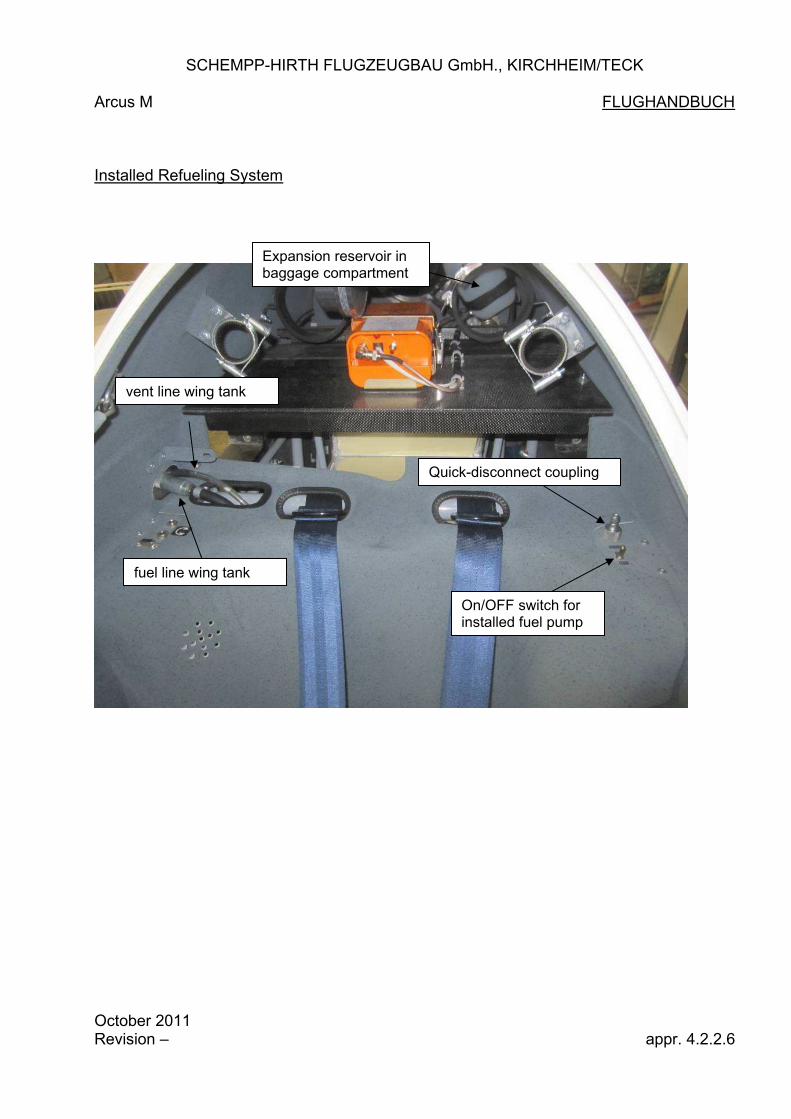
The Arcus M is equipped with a rigid fuselage tank and optional with up to two flexible wing tanks. The electrical fuel pump installed to the fuselage allows the fuelling of the fuselage tank with the aid of a fuel hose equipped with a quick-disconnect coupling. The connection point and the ON/OFF switch of the refuelling system is located in the aft cockpit above the back cover on the left side of the airplane, see also sketch on page 4.2.2.6. Prior to refuelling the fuselage tank, drain the tank first (in the fuselage on the left side of the gear cover). Furthermore mind that the central vent line between the expansion reservoir and the respective opening on the left side of the vertical stabilizer is not blocked. While refuelling the fuselage and/or the wing tank(s) monitor the fuel level of the expansion reservoir in the baggage compartment. The fuselage tank is completely filled as soon as the fuel level in the expansion reservoir is rising. Refuelling of fuselage and wing tank(s) has then to be stopped, because otherwise the expansion reservoir will run over. Caution: The engine is supplied with fuel from the fuselage tank. Therefore always fill sufficiently the fuselage tank first and only afterwards the wing tank(s). a) Fuselage tank
Connect the external fuel hose to the respective fitting in the fuselage, see sketch on page 4.2.2.6. Place the other end of the external fuel hose in a fuel canister. By actuating the ON/OFF switch the fuel pump is activated and the refuelling of the fuselage tank is started. As soon as the expansion reservoir fills with fuel, the fuselage tank is full.
October 2011 Revision -- appr. 4.2.2.1

SCHEMPP-HIRTH FLUGZEUGBAU GmbH., KIRCHHEIM/TECK
Arcus M FLIGHT MANUAL
b) Wing tank(s) (Option)
Refuelling of the wing tank(s) has to be done at the rigged glider. The wing tank(s) don’t have an own fuel level indication. Therefore it is recommended to use calibrated fuel canisters for refuelling the wing tank(s). This way the amount of fuel filled into the wing tank(s) is known. Furthermore the fuselage tank has to be completely filled before the refuelling of the wing tank(s) starts. Keep the wings levelled while refuelling the wing tank(s). This way the ventilation of the wing tank(s) is improved and the work load on the fuel pump is decreased. Prior to refuelling the wing tank(s) at the rigged glider always connect the vent lines of the wing tanks to the respective connections in the fuselage first. While refuelling the wing tank monitor the fuel level of the expansion reservoir in the baggage compartment. The wing tank is completely filled as soon as the fuel level in the expansion reservoir is rising. The vent lines of the wing tank(s) are equipped with a pressure-relief valve. Thus under normal conditions bleeding of fuel through the vent lines is avoided. But if the wing tank is overfilled or the fuel in the wing tank(s) is heated, some bleeding of fuel from the wing tank(s) into the expansion reservoir in the fuselage through the vent lines can occur. As soon as the expansion reservoir in completely filled, subsequent fuel will be drained from the fuselage through the overflow pipe. Caution: After the connection of the wing tanks with the fuselage tank, also both wing tanks are connected. Therefore, if the wing tanks are not completely filled, fuel of one wing tank can overflow to the other wing tank, if one wing will be lowered. Because of the overflow there will be also asymmetric loading of the wings. This asymmetric loading has to be considered before taking off. Parking the rigged glider with filled wing tank(s) over a longer period is not allowed, because there is risk of leakage in the wing tank(s).
October 2011 Revision -- appr. 4.2.2.2
SCHEMPP-HIRTH FLUGZEUGBAU GmbH., KIRCHHEIM/TECK
Arcus M FLIGHT MANUAL
b) Wing tank(s) (Option) (continued)
Refuelling with external fuel pump Connect the external fuel hose of the external filling pump directly with the fuel
line of the respective wing tank at the root rib in front of the spare stubs and start the external filling pump.
Stop the refuelling at the latest when the maximum amount of fuel for the wing tank has been reached.
While refuelling the wing tank monitor the fuel level of the expansion reservoir in the baggage compartment. The wing tank and the fuselage tank are completely filled as soon as the fuel level in the expansion reservoir is rising.
After refuelling the wing tank reconnect the wing tank with the fuselage tank. Refuelling with installed fuel pump
Connect the fuel and the vent lines of the respective wing tank with the connections in the fuselage. Connect the external fuel hose to the respective fitting in the fuselage, see sketch on page 4.2.2.6. Place the other end of the external fuel hose in a fuel canister. By actuating the ON/OFF switch the fuel pump is activated and the refuelling of the wing is started. Refuelling of the wing tank takes place through the fuselage tank. If wing tanks are in installed in both wings, for refuelling of one wing tank the fuel line of the other wing tank has to be disconnected. Start the refuelling only afterwards. Stop the refuelling when the maximum amount of fuel for the wing tank is reached. While refuelling the wing tank monitor the fuel level of the expansion reservoir in the baggage compartment. The respective wing tank and the fuselage tank are completely filled as soon as the fuel level in the expansion reservoir is rising. After refuelling the wing tank reconnect the fuel line of the other wing tank with the fuselage tank.
October 2011 Revision -- appr. 4.2.2.3

SCHEMPP-HIRTH FLUGZEUGBAU GmbH., KIRCHHEIM/TECK
Arcus M FLIGHT MANUAL
Determination of fuel contents
a) fuselage tank The fuel content of the fuselage tank is measured with a capacitive sensor.
The panel mounted engine control unit MCU II displays the fuel content of the fuselage tank (max. 15,9 l) in full liters (16 l).
When the fuel content in the fuselage tank drops below the reserve volume (6 l, allows approx. 15 min engine running time with max. Power), the displayed value for the fuel content is blinking and an audio warning sounds. You can switch of the warning temporarily by pressing the Menu-button.
The warning will reappear when the fuel content is decreased by another liter. Calibration of fuel quantity indicator If you use a different grade of fuel (i.e. AVGAS instead of MOGAS/Premium)
or a new capacitive sensor is installed, the fuel quantity indicator has to be recalibrated.
Requirements for the calibration: - plane sits on even ground with main and tail wheel - wings are levelled - fuselage tank is completely filled - power plant is retracted (limit switch for engine retracted active) Scroll through the display of the engine control unit MCU II with the Menu-
button until “Calibr.?” is displayed. Release the Menu-button shortly and then press the button again for 5 s to start the calibration of the fuselage tank.
If the value for the fuel content, determined by the calibration, is beyond the approved limits, the calibration is not valid. The engine control unit MCU II displays then the error massage “ERRORCAL”. Prior to the next calibration the reason for this error massage has to be eliminated.
An error during the calibration of the fuel quantity indicator may occur for example, if the fuselage tank is not completely filled or if the capacitive sensor for the fuel content measurement is contaminated or broken.
CAUTION: During level flight the fuel quantity indicator is sufficiently accurate. On the
ground with one wing layed down or in the air at extreme pitch attitude deviations in the indication of the fuel content may occur.
October 2011 Revision -- appr. 4.2.2.4

SCHEMPP-HIRTH FLUGZEUGBAU GmbH., KIRCHHEIM/TECK
Arcus M FLIGHT MANUAL
Determination of fuel contents (continued)
b) Wing tank(s) (option) The fuel content of the wing tank(s) is not measured. Therefore the amount of
fuel filled into the wing tank(s) has to be determined during refuelling. Entering total amount of fuel filled into all tanks It is possible to consider the amount of fuel filled into the wing tank(s) at the
amount of fuel displayed on the engine control unit MCU II. To do so, scroll through the display of the engine control unit MCU II with the
Menu-button until “FUEL” is displayed while the power plant is retracted. Release the Menu-button shortly and then press the button again for 5 s as done for the calibration of the fuselage tank to select this menu item.
Subsequently the total amount of fuel in the wing tank(s) and the fuselage tank can be entered by further pressing the menu-button. If the menu-button isn’t pressed for at least 5 s, the entered amount of fuel will be adopted and displayed on the engine control unit MCU II.
The fuel consumption of the power plant is measured with a flow rate meter
while the engine is running. The indicated total fuel content of wing and fuselage tank(s) on the MCU II considers the amount of fuel consumed while the engine is running.
If the fuel content of the fuselage tank drops below 6 l, only the fuel content of
the fuselage tank will be displayed on the engine control unit. If the fuel content in the fuselage tank will climb again over 6 l (because of bleeding fuel out of the wing tank(s) into the fuselage tank), the total amount of fuel in all tanks will be displayed again.
October 2011 Revision -- appr. 4.2.2.5
SCHEMPP-HIRTH FLUGZEUGBAU GmbH., KIRCHHEIM/TECK
Arcus M FLUGHANDBUCH Installed Refueling System
Expansion reservoir in baggage compartment
vent line wing tank
fuel line wing tank
On/OFF switch for installed fuel pump
Quick-disconnect coupling
October 2011 Revision – appr. 4.2.2.6

SCHEMPP-HIRTH FLUGZEUGBAU GmbH, KIRCHHEIM/TECK
Arcus M FLIGHT MANUAL
4.3 INSPECTION Daily inspection
The importance of inspecting the powered sailplane after rigging and before the day’s flying cannot be over-emphasized, as accidents often occur when these daily inspections are neglected or carried out carelessly.
9
1
2 3 4
5
6
7 8
When walking around the Arcus M, check all surfaces for paint cracks, dents and unevenness. In case of doubt, ask an expert for advice.
(1) a) Open canopy
b) Check that the main wing pin is properly secured
c) Make a visual Check of all accessible control circuits in the
cockpit
d) Check for full and free movements of the control elements
e) Check batteries for firm attachment and accordance with the loading chart October 2011 Revision -- appr. 4.3.1

SCHEMPP-HIRTH FLUGZEUGBAU GmbH, KIRCHHEIM/TECK
Arcus M FLIGHT MANUAL
f) Check for the presence of foreign objects
g) Check fuel quantity h) Check fuel line(s) and vent line(s) – especially those for the wing
tank(s) - for proper connection
i) Check tire pressure: Nose wheel: 3.0 bar (43 psi) Main wheel: 4.0 bar (57 psi)
j) Check tow release mechanism(s) for proper condition and function
(2) a) Check upper and lower wing surface for damage
b) Clean and grease water ballast dump valves (if necessary)
c) Check wing tip extensions for proper connection
d) Check that the flaperons are in good condition and operate freely. Check for any unusual play by gently shaking the flaperons.
Check flaperon hinges for damage
(3) a) Check airbrakes for proper condition, fit and locking
October 2011 Revision -- appr. 4.3.2

SCHEMPP-HIRTH FLUGZEUGBAU GmbH, KIRCHHEIM/TECK
Arcus M FLIGHT MANUAL (4) a) Check fuselage for damage, especially on its lower side
b) Check that the Static pressure ports for the airspeed indicator on the tail boom are clear (1.02 m / 3.35 ft forward of the base of the fin)
Visual inspection of the power plant (see also engine manual) CAUTION: IGNITION TO BE SWITCHED OFF!
c) Check propeller during extension for sufficient clearance to the rim of the engine compartment d) Check propeller for damage e) Check power plant for loose bolts and nuts, check all locks and stops
f) Check exhaust system and engine mounting structure and propeller pylon for cracks (check metal parts especially at the welding joints) g) Check all components, lines, hoses, pipes and wires etc. for chafing
marks
h) Check pylon arresting wire and its attachment for proper function. i) Check engine door actuating mechanism for proper function.
j) Check for proper function: Throttle control and propeller arresting device. k) Check ignition system incl. harness and lead ends for proper seating
l) Check drive belt for wear
m) Rotate propeller by hand repeatedly and listen for abnormal noise. Check for engine binding.
n) Actuate fuel drain (l.h.s. of u/c housing) and discharge condensed water. Check that drain outlet is clear o) Check function of water pump with ignition ON. Check pump, plug and hoses for proper attachment p) Check coolant liquid quantity. Check cap of expansion reservoir for firm attachment
October 2011 Revision -- appr. 4.3.3

SCHEMPP-HIRTH FLUGZEUGBAU GmbH, KIRCHHEIM/TECK
Arcus M FLIGHT MANUAL
(5) a) Check condition of tall skid or wheel. If the latter is installed, check tire pressures
3.0 bar (44 psi)
b) Should a total energy compensation probe be used, mount it (head
pointing upwards) and check the line (when blowing gently into the probe, the variometer(s) connected should read "climb")
c) Check that the fin-mounted Pitot tube is clear.
d) Check that the opening for the fuel tank vent line (at the upper end of the fin) is clear
Should a water ballast fin tank be installed (option):
e) Check that the fin tank spill holes are clear f) Check water ballast level in fin tank (in case of doubt, discharge ballast) g) Check that the dump hole for the fin tank in the tail wheel fairing is clear
October 2011 Revision -- appr. 4.3.4

SCHEMPP-HIRTH FLUGZEUGBAU GmbH, KIRCHHEIM/TECK
Arcus M FLIGHT MANUAL
(6) a) Check correct battery installation in vertical tail according to loading chart b) Check horizontal tailplane for proper attachment and locking c) Check elevator and rudder for free movement d) Check trailing edge of elevator and rudder for damage e) Check elevator and rudder for any unusual play by gently shaking the
trailing edge (7) See (3) (8) See (2) (9) Check that the Pitot pressure head in the nose cone is clear. When blowing gently into the tube, the airspeed indicators must register After heavy landings or after the powered sailplane has been subjected to excessive loads, the resonant wing vibration frequency should be checked (its value to be extracted from the last inspection report for this serial number). Check the entire aircraft thoroughly for surface cracks and other damage. For this purpose it should be de-rigged. If damage is discovered (e.g. surface cracks in the fuselage tail boom or tailplane, or if delamination is found at the wing roots or at the bearings in the root ribs), then the aircraft must be grounded until the damage has been repaired by a qualified person. This inspection must also include a complete check of the power plant system.
October 2011 Revision -- appr. 4.3.5

SCHEMPP-HIRTH FLUGZEUGBAU GmbH, KIRCHHEIM/TECK
Arcus M FLIGHT MANUAL 4.4 Preflight inspection
O Water ballast in fin tank ? (if installed)O Loading charts checked ?O Parachute securely fastened ?O Safety harness secured and tight ?O Seat back, head rest and pedals in
comfortable position ?O All controls and instruments easily accessible ?O Airbrakes checked and locked ?O All control surfaces checked with assistant
for full and free movement in correct sense ?O Trim correctly set ?O Flaps set for take-off ?O Canopy closed and locked ?
CHECK LIST BEFORE TAKE-OFF
O Fuel quantity checked ?O Function of water pump checked ?
(NO flashing red signal)O Coolant liquid temperature checked ?O Ignition circuits checked ?O Redundant engine control system checked ?O Take-off RPM checked ?O Rear-view mirror properly adjusted ?
CHECK LIST FOR SELF-LAUNCHING
October 2011 Revision -- appr. 4.4

SCHEMPP-HIRTH FLUGZEUGBAU GmbH, KIRCHHEIM/TECK
Arcus M FLIGHT MANUAL
4.5 Normal operating procedures and recommended speeds
4.5.1 Methods of launching
Aerotow ONLY PERMISSIBLE ON THE NOSE TOW RELEASE AND POWER PLANT RETRACTED
Maximum permitted towing speed:
VT = 180 km/h (97 kt, 112 mph)
For aerotow only the nose tow release may be used - hemp and nylon ropes of between 30 and 40 m length (98-131 ft) were tested. Prior to take-off set elevator trim as follows: • Rearward c/g positions: Lever full forward • Other c/g positions: Lever 1/3 of its travel from forward
As the tow rope tightens, apply the wheel brake gently (by actuating the stick-mounted lever) to prevent the Arcus M from over running the rope. In crosswind conditions, keep in mind that at the beginning of the take off roll, there is an increase of the lift generated on the downwind wing from the tug’s prop wake, which drifts with the wind. Therefore it may be necessary to hold downwind aileron to start. For intermediate to forward c/g positions the elevator control should be slightly back for the ground run; in the case of rearward c/g positions it is recommended that neutral elevator is maintained until the tail lifts. After lift-off the elevator trim can be set for minimum control stick loads. An aerotow can be made with a flap setting of "+2". Although it is recom-mended, especially in a crosswind takeoff or on rugged surface, to start the takeoff roll with a flap setting of "-1 or -2", when sufficient aileron control is attained, at about 50 km/h (26 kts, 30 mph), the flap position should be moved to "+2" for lift off. With a negative flap setting during takeoff roll the effectiveness of the ailerons will be increased and it will be easier to keep track behind the towplane.
October 2011 Revision -- appr. 4.5.1.1

SCHEMPP-HIRTH FLUGZEUGBAU GmbH, KIRCHHEIM/TECK
Arcus M FLIGHT MANUAL
After lift off at 80 to 90 km/h (43-49 kts, 50-56 mph) – depending on loading and flap setting – the trim can be set so that minimal force is felt in the elevator control. Normal towing speed is 110 to 130 km/h (59-70 kts, 68-80mph) with a flap setting "+2". At higher flying masses the towing speed is about 120 to 140 km/h (65-76 kts,75-87 mph). At higher towing speeds, negative flap settings as far as flap setting "S" can be used. The flap setting can be chosen so that pleasant high control forces can be adjusted with the trim.
+1-1
-1
+2 +1
-1+2 +1
-1
Only small control surface deflections are normally necessary to keep position behind the tug. In gusty conditions or when flying into the propeller slip stream of a powerful tug correspondingly greater control stick movements are required.
The undercarriage may be retracted during the tow; this is not, however, recommended at low altitude, as changing hands on the stick could easily cause the Arcus M to lose station behind the tug. When releasing the tow rope, pull the yellow T-shaped handle fully multiple times and turn only after the rope has definitely disconnected.
October 2011 Revision -- appr. 4.5.1.2

SCHEMPP-HIRTH FLUGZEUGBAU GmbH, KIRCHHEIM/TECK
Arcus M FLIGHT MANUAL
Winch launch ONLY PERMISSIBLE ON C/G TOW RELEASE AND POWER PLANT RETRACTED Maximum permitted launching speed:
VW = 150 km/h (81 kts, 93 mph)
For winch launching only the c/g tow release and the flap settings "+1" or "+2" must be used.
With only one seat occupied and no water ballast or with an aft cg, a flap setting of “+1” should be used. With both seats occupied or when water ballast is used, a flap setting of “+2” should be used.
Prior to take-off set elevator trim as follows:
• Rearward c/g Positions Lever full forward • Intermediate c/g Positions Lever full forward • Forward c/g positions Lever neutral
As the cable tightens, apply the wheel brake gently (by actuating the stick-mounted lever) to prevent the Arcus M from overrunning the winch cable. Ground run and lift-off are normal - there is no tendency to veer-off or to climb excessively steeply on leaving the ground. Depending on the load on the seats, the Arcus M is lifted off with the control stick pushed slightly forward in the case of aft c/g positions and pulled slightly back with the c/g in a forward position. After climbing to a safe height, the transition into a typical steep winch launch attitude is effected by pulling the control stick slightly further back. At normal all-up masses, i.e. both seats occupied, the launch speed should not be less than 100 km/h (54 kts, 62 mph). At maximum takeoff mass, the launch speed should not be less than 110 km/h (59 kts, 68 mph). Normal launch speed is about 110 to 120 km/h (59-65 kts, 68-75 mph) with two occupants. At maximum take off mass this speed is about 125 km/h (67 kts, 78 mph). At the top of the launch the cable will normally back-release automatically; the cable release handle should, nevertheless, be pulled firmly multiple times to ensure that the cable is actually gone.
October 2010 Revision -- appr. 4.5.1.3

SCHEMPP-HIRTH FLUGZEUGBAU GmbH, KIRCHHEIM/TECK
Arcus M FLIGHT MANUAL
CAUTION: Winch launching at the maximum permitted all-up mass should only be done if there is an appropriately powerful winch and a cable in perfect condition available. Furthermore, there is not much point in launching by winch for a soaring flight if the release height gained is less than 300 m (984 ft). In case of doubt, reduce the all-up mass.
WARNING: It is explicitly advised against winch launching with a tail wind!
CAUTION: Prior to launching by winch, it must be ensured that the crew is properly seated and able to reach all control elements. Particularly when using seat cushions it must be made sure that during the initial acceleration and while in the steep climbing attitude the occupants are not able to slide backwards and up.
October 2011 Revision -- appr. 4.5.1.4
SCHEMPP-HIRTH FLUGZEUGBAU GmbH., KIRCHHEIM/TECK
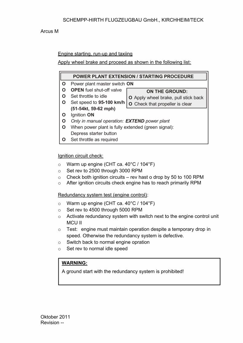
Arcus M
Engine starting, run-up and taxiing
Apply wheel brake and proceed as shown in the following list:
POWER PLANT EXTENSION / STARTING PROCEDURE
ON THE GROUND:
O Apply wheel brake, pull stick back
O Check that propeller is clear
O Power plant master switch ON
O OPEN fuel shut-off valveO Set throttle to idleO Set speed to 95-100 km/h
(51-54kt, 59-62 mph)
O Ignition ON
O Only in manual operation: EXTEND power plant
O When power plant is fully extended (green signal):Depress starter button
O Set throttle as required
Ignition circuit check:
o Warm up engine (CHT ca. 40°C / 104°F) o Set rev to 2500 through 3000 RPM o Check both ignition circuits – rev hast o drop by 50 to 100 RPM o After ignition circuits check engine has to reach primarily RPM
Redundancy system test (engine control):
o Warm up engine (CHT ca. 40°C / 104°F) o Set rev to 4500 through 5000 RPM o Activate redundancy system with switch next to the engine control unit
MCU II o Test: engine must maintain operation despite a temporary drop in
speed. Otherwise the redundancy system is defective. o Switch back to normal engine opration o Set rev to normal idle speed
WARNING:
A ground start with the redundancy system is prohibited!
Oktober 2011 Revision --

SCHEMPP-HIRTH FLUGZEUGBAU GmbH., KIRCHHEIM/TECK
FLUGHANDBUCH
Starting the engine in flight
o Set speed to 95 through 100 km/h for extending the powerplant and starting the engine
The starting process of the engine in flight is the same as on the ground.
Engine run-up
Advance to full throttle prior to or during take-off run. At a minimum speed of about 6300 RPM the engine runs smoothly. Taxiing If the wings are equipped with the respective wheels, the powered sailplane can be operated independently with the steerable tail wheel on the ground. Nevertheless you have to take care, that the lowered wing will not be damaged by i.e. bigger stones. While Taxiing pull the elevator all the way back. Operate the wheel brake with the right hand on the stick.
appr. 4.5.1.5

SCHEMPP-HIRTH FLUGZEUGBAU GmbH., KIRCHHEIM/TECK
Arcus M FLIGHT MANUAL 4.5.2 Take off (on own power) and climb
Conduct take-off check (see page 4.4) and observe page 5.2.3 (take-off distances).
For take-off the wing should be held level by an assistant. Compensate an asymmetric fuel load in the wing tanks by applying opposite aileron when commencing the take-off run.
NOTE: When commencing the take-off run with the throttle fully opened, the thrust of the prop will force the aircraft down too heavily onto its small nose wheel, thus increasing ground roll drag and take-off distance (disadvantageous on grass fields). As a general principle it is therefore recommended that for the first 10 m (33 ft) the throttle is only gradually advanced to about 70% power – particularly in the case of heavy occupants (forward c/g positions) and/or uneven fields - resulting in the following take-off procedure: „ Set elevator trim at its aft range
„ Set flaps at “0” (or “-1” in crosswind conditions)
„ Pull control stick fully back and
„ Advance gradually to full throttle
„ On reaching a speed of about 40 km/h (22 kt, 25 mph), reset flaps at “+ 2” (or “L” on soft ground)
„ With the c/g in forward position, lift off aircraft at a speed of about 85 km/h (46 kt, 53 mph) with the stick fully pulled back. In the case of aft c/g positions slightly less back pressure is applied. If flap setting “L” was used for lift off, reset flaps at “+2”
„ Ease control stick forward until reaching the speed for best climb VY = 95 km/h (51 kt, 59 mph)
Observe coolant liquid temperature while climbing. When reaching the maximum permitted temperature, reduce power to avoid exceeding the limit.
October 2011 Revision -- appr.4.5.2.1

SCHEMPP-HIRTH FLUGZEUGBAU GmbH., KIRCHHEIM/TECK
Arcus M FLIGHT MANUAL
WARNING: Taking-off in rain, with wet or iced-up wings is not permitted, as the take-off distance increases considerably. Furthermore the climb performance is adversely affected!
Caution: If, at high ambient temperatures, the coolant liquid temperature rises too high, the cause may also be the anti-freeze proportion being too much for such temperatures. The effectiveness of coolant liquid with less anti-freeze is significantly better!
October 2011 Revision -- appr.4.5.2.2

SCHEMPP-HIRTH FLUGZEUGBAU GmbH., KIRCHHEIM/TECK
Arcus M FLIGHT MANUAL 4.5.3 Flight / Cross country flight a) Powerplant retracted
The Arcus M has pleasant flight characteristics and can be flown effortlessly at all speeds, loading conditions (with or without water ballast), configurations, and c/g positions.
With a mid-point c/g position the maximum speed range covered by the elevator trim is from about 70 km/h (38 kts, 43 mph) (flap L) to about 200 km/h (108 kts, 124 mph) (flap S).
Flying characteristics are pleasant and the controls are well harmonized. Turn reversal from + 45° to - 45° can be accomplished without any noticeable skidding. Ailerons and rudder may be used to the limits of their travel.
All-up mass 600 kg
1323 lb
Flaps at L 98 km/h
Speed 53 kts 61 mph
Reversal time 4.8 sec Note: Flights in conditions conducive to lightning strikes must be avoided.
October 2011 Revision -- appr. 4.5.3.1

SCHEMPP-HIRTH FLUGZEUGBAU GmbH., KIRCHHEIM/TECK
Arcus M FLIGHT MANUAL High speed flying
At high speeds up to VNE = 280 km/h (151 kts, 174 mph) the Arcus M is easily controllable. Full deflections of control surfaces may only be applied up to VA = 180 km/h (97 kts, 112 mph). At VNE = 280 km/h (151 kts, 174 mph) only one third (1/3) of the full deflection range is permissible. Avoid especially sudden elevator control movements. In strong turbulence, i.e. in wave rotor, thunderclouds, visible whirlwinds or when crossing mountain ridges, the speed in rough air VRA = 180 km/h (97 kts, 112 mph) must not be exceeded. With the c/g at an aft position, the control stick movement from the point of stall to maximum permissible speed is relatively small, though the change in speed will be noticed through a perceptible change in control stick loads. The airbrakes may be extended up to VNE = 280 km/h (151 kts, 174 mph). However, they should only be used at such high speeds in an emergency or if the maximum permitted speed is being exceeded inadvertently. When extending the airbrakes suddenly, the deceleration forces are noticeable. WARNING:
Consequently it is wise to check in advance that the seat harnesses are tight and that the control stick is not inadvertently jarred forwards when the airbrakes are extended. There should be no loose objects in the cockpit. At speeds above 180 km/h (97 kts, 112 mph) extend the airbrakes only gradually (allow 2 seconds).
WARNING:
It is strictly noted that in a dive with the airbrakes extended, the Arcus M has to be pulled out less abruptly (maximum 3.5 g) than with retracted brakes (5.3 g), see section 2.9 "Manoeuvring Load Factors". Therefore pay attention when pulling out with airbrakes extended at higher speeds!
A dive at VNE with the airbrakes fully extended is limited to an angle to the horizon
of 38° at maximum permitted all-up mass of 800 kg (1764 lb). At an all-up mass of up to 690 kg (1521 lb) an angle to the horizon is more than 45°.
October 2011 Revision -- appr. 4.5.3.2

SCHEMPP-HIRTH FLUGZEUGBAU GmbH., KIRCHHEIM/TECK
Arcus M FLIGHT MANUAL
Optimum flap positions The camber-changing flaps alter the wing section such that the laminar bucket is always well suited to the actual flying speed. Use of flaps for
flaps
at
units
AUW = 625 kg
1378 lbs
AUW = 800 kg
1764 lbs
Low speed flying (straight and level)
L km/h kts mph
84 45 52
95 51 59
+2 km/h kts mph
84 – 88 45 – 48 52 - 55
95 – 100 51 – 54 59 - 62
+1 km/h kts mph
88– 100 48 – 54 55 - 62
100 – 113 54 – 61 62 - 70
Best L/D 0
km/h kts mph
100 – 132 54 – 71 62 - 82
113 – 150 61 – 81 70 - 93
Flying between thermals and high speed flying
-1 km/h kts mph
132 – 152 71 – 82 82 - 94
150 – 172 81 – 93 93 - 107
-2 km/h kts mph
152 – 175 82 – 94 94 - 109
172 – 198 93 – 107 107 - 123
S km/h kts mph
175 – 280 94 – 151 109 - 174
198 – 280 107 – 151 123 - 174
For a speed polar diagram refer to section 5.3.2. For smooth thermals flap setting and while climbing in slow straight flight "+2" is recommended; in turbulent thermals, which require a quick aileron response, flap setting "+1" is advantageous. Near the lower end of the optimum circle in thermal speeds the pilot may even use flap setting "L", especially at high all-up masses or in updrafts with hardly any variation in flying speed. Best glide and moderate inter-thermal speeds are covered by flap setting "0" and "-1" – for high cruise the optimum performance is achieved with the more negative settings.
October 2011 Revision -- appr. 4.5.3.3

SCHEMPP-HIRTH FLUGZEUGBAU GmbH., KIRCHHEIM/TECK
Arcus M FLIGHT MANUAL
Low speed flight and stall behaviour (power plant retracted) In order to become familiar with the powered sailplane it is recommended to explore its low speed and stall characteristics at a safe height. This should be done using the various flap settings while flying straight ahead and also in a 45° banked turn. Wings level stall The first signs of a stall usually occur 5 to 10 km/h (3-5 kts, 3-6 mph) above stalling speed. It begins with a slight rolling motion and vibration in the controls. If the stick is pulled further back, these effects become more pronounced, the ailerons get spongy and the powered sailplane sometimes tends to slight pitching motions (speed increases again and will then drop to stalling speed). NOTE:
Before reaching a stalled condition, depending on C.G. position, the ASI reading drops quickly by 5 to 10 km/h (3-5 kts, 3-6 mph).
When reaching a stalled condition with the c/g in middle and rearward positions, the stick reaches the stop and the powered sailplane remains in deep stall or drops the wing respectively the nose. A normal flight attitude is regained by easing the stick firmly forward and, if necessary, applying opposite rudder and aileron. The loss of height from the beginning of the stall until regaining a normal level flight attitude is up to 60 m (200 ft) In the case of forward c/g positions and stick fully pulled back, the powered sailplane just continues to fly in a mushed condition without the nose or wing dropping. Normal flying attitude is regained by easing the stick forward.
October 2011 Revision -- appr. 4.5.3.4

SCHEMPP-HIRTH FLUGZEUGBAU GmbH., KIRCHHEIM/TECK
Arcus M FLIGHT MANUAL
Turning flight stalls
(power plant retracted)
When stalled during a coordinated 45° banked turn and a forward c/g, the Arcus M - with the control stick pulled fully back -will continue to fly in a stalled condition. With aft c/g during the turning stall, the inside wing will drop and the nose will drop below the horizon. The stall can be stopped immediately by relieving the back pressure on the control stick. There is no uncontrollable tendency to enter a spin. The transition into a normal flight attitude is conducted by an appropriate use of the controls. The loss of height from the beginning of the stall until regaining a normal level flight attitude is approx. 150 m (492 ft). Influence of water ballast Apart from higher stall speeds - caused by the higher mass in flight - water ballast in the wing tanks has no negative influence on the stall characteristics. With water ballast in the fin tank (option), stall characteristics are like those found in an aft c/g position.
October 2011 Revision -- appr. 4.5.3.5

SCHEMPP-HIRTH FLUGZEUGBAU GmbH., KIRCHHEIM/TECK
Arcus M FLIGHT MANUAL Flight (ctd.) b) Power plant extended As the propeller used is mainly pitched for good climb (rather than for high cruise), the speed attained in level flight at 6600 RPM is approx. 150 km/h (81 kt, 93 mph) with flaps set at “-1”. At this speed the “Arcus M” shows a stable behaviour and is easy to control.
Flown in a shallow dive, the maximum permitted engine speed of 6600 RPM must not be exceeded! Idling only in emergency
With engine idling (throttle closed), descending flights are only allowed for short periods. Long idling periods must be strictly avoided to prevent the danger of an engine failure due to carbon accumulation on the spark plugs! CAUTION:
On longer flights with the throttle closed it is therefore necessary to open it momentarily at least once every minute to keep the engine clean! NOTE:
Flight conditions under lightning strikes must be avoided!
October 2011 Revision -- appr. 4.5.3.6

SCHEMPP-HIRTH FLUGZEUGBAU GmbH., KIRCHHEIM/TECK
Arcus M FLIGHT MANUAL Cruising on own power
As clearly shown by the figures of section “Flight Performance”, the longest range results from the “sawtooth method”, which consists of the following flight sections being repeated as required:
„ a climb at a speed of about 95 km/h (51 kt, 59mph)
„ a glide in “clean” sailplane configuration Thereby the height to be consumed in glide should not be less than 500 m (1640 ft). The maximum range in glide is achieved at a speed of approx. 110 to 120 km/h
(59-65 kt. 68-75 mph), resulting in an average speed of about 100 km/h (54 kt, 62 mph). Should the “sawtooth method” be impracticable due to low clouds ceiling or because of airspace restrictions, the cruising in level flight at a speed of approx. 150 km/h (81 kt, 93 mph) is also possible. The range, however, is then considerable less – see section 5.3.2. For cruising flight, the “sawtooth method” should always be preferred as – besides the longer range – the crew is also less exposed to engine noise.
October 2011 Revision -- appr. 4.5.3.7

SCHEMPP-HIRTH FLUGZEUGBAU GmbH., KIRCHHEIM/TECK
Arcus M FLIGHT MANUAL Stopping the engine, retracting the propeller
See also the following checklist:
Remarks regarding the vertical positioning of the propeller
- If the propeller hasn’t reach its vertical position after the engine has stopped, the movement of the propeller can be accelerated by:
- increasing the flight speed or - pressing the starter button - If the propeller has to turn only about 15° until reaching its vertical position,
don’t use the starter anymore - If the propeller was not caught in its vertical position by the automatic propeller
brake for the last three attempts, support the vertical positioning of the propeller with the manual propeller brake during the next attempt.
CAUTION:
Through the mirror observe the propeller retracting to check if the propeller rotates further.
The propeller retracts within about 14 seconds, but the entire process from stopping the engine to the moment the prop. has fully retracted takes about 90 seconds and consumes a height of about 100 m (328 ft).
October 2011 Revision -- appr. 4.5.3.8

SCHEMPP-HIRTH FLUGZEUGBAU GmbH., KIRCHHEIM/TECK
Arcus M FLIGHT MANUAL Extending the prop, starting the engine in flight 1. With the prop extended and engine off, the rate of descent is approx.
2.25 m/s (443 fpm) at a speed of 105 km/h (57 kt, 65 mph), resulting in a glide ratio of only about 13 : 1 – contrary to the best L/D of 49 : 1 in clean configuration (prop retracted). Therefore the engine should only be restarted over terrain suitable for an off-field landing and that, if possible, n o t below 300 m (984 ft) AGL. But extending the prop to restart the engine at a height of 200 m (656 ft) AGL on the down-wind leg to a suitable landing field is safer then e.g. restarting it at 500 m (1640 ft) AGL above a forest or the like. Should a flight be planned over long distance without any acceptable landing fields, the prop should be extended at a height giving sufficient time for all emergency procedures and, if necessary, for re-retracting the propeller.
2. Starting procedures - see also check list on page 4.5.1.5
The loss of height from extending the propeller to the moment the engine is running is about 40 to 50 m (131-164 ft) and needs 35 to 45 seconds.
October 2011 Revision -- appr. 4.5.3.9
SCHEMPP-HIRTH FLUGZEUGBAU GmbH., KIRCHHEIM/TECK
Arcus M FLIGHT MANUAL Low speed flight and stall behaviour
(propeller extended) Compared with the stall behaviour in “clean” configuration (prop retracted), there are no significant differences when aircraft stalls from straight and level or from turning flight. On stalling the turbulent airflow produced by the propeller superimposes the vibration in the controls. Furthermore the noise of the propeller increases considerably.
WARNING:
When stalling with extended propeller with engine idling or with ignition off the turbulent airflow produced by the propeller super- imposes the vibration in the controls, so that in this case a stall warning is not noticeable.
October 2011 Revision -- appr. 4.5.3.10

SCHEMPP-HIRTH FLUGZEUGBAU GmbH., KIRCHHEIM/TECK
Arcus M FLIGHT MANUAL 4.5.4 Approach
a) Power plant retracted / power plant removed
Normal approach speed with airbrakes fully extended, flap position L and wheel down is 95 km/h (51 kts, 59 mph) without water ballast and flown solo, or 105 km/h (57 kts, 65 mph) at maximum permitted all-up mass.
The yellow triangle on the ASI at 105 km/h (57 kts, 65 mph) is the recommended approach speed for the maximum all-up mass without water ballast (785 kg (1731 lb) with power plant installed / 765 kg (1687 lb) with removed power plant.
The airbrakes open smoothly and are very effective. The landing flare with the airbrakes fully opened, must be flown with care and very precisely. It is not recommended to leave the airbrakes fully opened while flaring. There is no noticeable change in trim.
During approach and landing flap setting +2 can also be used. Other than a 5 km/h (3 kts, 3 mph) speed increase, there are no other differences in the landing characteristics.
Side slipping is also a useful aid for landing. It is possible to maintain a straight line with the rudder deflected up to about 30 - 50 % of its travel resulting in a yaw angle of about 25° and a bank angle of about 10 - 20°. The rudder must be held with perceptible counter-pedal pressure because of the control force reversal. To return to level flight, normal opposite controls are required. CAUTION:
With rudder fully deflected, side slips in a straight flight path are not possible - the sailplane will slowly turn in the direction of the displaced rudder.
- Side slipping causes the ASI to read lower than the actual speed.
- During side slip with water ballast some water escapes through the vent hole of the water tank filler cap of the lower wing. Prolonged slips with water ballast are therefore not recommended.
WARNING:
Both the performance and the aerodynamic characteristics of the ARCUS M are affected adversely by rain or ice on the wing. Be cautious when landing! Increase the approach speed at least 5 to 10 km/h (3-5 kts, 3-6 mph).
October 2011 Revision -- appr. 4.5.4.1
SCHEMPP-HIRTH FLUGZEUGBAU GmbH, KIRCHHEIM/TECK
Arcus M FLIGHT MANUAL b) Power plant extended
(only permissible with ignition switched OFF and in emergency case)
With power plant extended (and ignition OFF), the “Arcus M” can be landed in a similar manner as in “clean configuration” (prop retracted). However the disturbances of the extended power plant influence the airflow around the fin, whereby a manipulation of the effectiveness of rudder and elevator control is possible. On approach it must be taken into account that the flight performance has considerably deteriorated due to the extended power plant:
All-up weight (mass) 600 kg 1543 lb
800 kg 1764 lb
Approach speed 95 km/h 51 kts
59 mph
105 km/h 57 kts
65 mph
Rate of descent Approx.
2.0 m/s 394 fpm
2.25 m/s 443 fpm
L/D approx. 13 13
However, the performance, though reduced, is sufficient to conduct approaches with the same techniques as in "clean" configuration.
WARNING:
1. Be cautious when extending the airbrakes . Due to the additional drag of the extended power plant, more forward stick must be applied for maintaining the above approach speeds.
2. On stalling with extended power plant and ignition off, the turbulent airflow produced by the propeller superimposes the vibration in the controls, so that in this case no noticeable stall warning exists.
NOTE:
Approaches and landings are normally conducted in “clean configuration” (power plant retracted).
October 2011 Revision -- appr. 4.5.4.2
SCHEMPP-HIRTH FLUGZEUGBAU GmbH., KIRCHHEIM/TECK
Arcus M FLIGHT MANUAL 4.5.5 Landing
a) Propeller retracted
For off-field landings the undercarriage should always be extended, as the protection of the crew is much better, especially from vertical impacts on landing. Main wheel and tail wheel resp. skid should touch down simultaneously. After touch-down the flaps must always be set at “0” or “-1” for improved aileron response during the landing run. To avoid a long ground run, make sure that the aircraft touches down at minimum speed. A touch-down at 90 km/h (49 kt, 56 mph) instead of 75 km/h (40 kt, 47 mph) means that the kinetic energy to be dissipated by braking is increased by a factor of 1.44 and therefore the ground run is lengthened considerably. As the effectiveness of the hydraulic wheel brake is good, the landing run is considerably shortened (the elevator control should be kept fully back).
b) Power plant extended (Ignition switched OFF) Landings with power plant extended should only conducted in case of emergency.
October 2011 Revision -- appr. 4.5.5

SCHEMPP-HIRTH FLUGZEUGBAU GmbH, KIRCHHEIM/TECK
Arcus M FLIGHT MANUAL 4.5.6 Flight with water ballast
Water ballast is required for reaching the maximum permitted all-up mass.
Wing ballast tanks The water tanks are integral compartments in the nose section of the main wing panels. The tanks are to be filled with plain water only, through round openings in the upper wing surface featuring a strainer. Tank openings are closed with plugged-in filler caps having a 6 mm (0.24 in.) female thread for lifting and venting. Lifting these caps is done with the aid of the tailplane rigging tool.
WARNING:
As the threaded hole in the filler cap also serves for venting the tank, it must always be kept open!
Never place tape over the hole.
Each wing tank has a capacity of approx. 92 Litres (24.30 US Gal., 20.24 IMP Gal.). Dumping the water from full tanks takes approx. 3.5 minutes.
When filling the tanks it must be ensured that the maximum permitted all-up mass is not exceeded - see page 6.2.5.
October 2011 Revision -- appr. 4.5.6.1

SCHEMPP-HIRTH FLUGZEUGBAU GmbH, KIRCHHEIM/TECK
Arcus M FLIGHT MANUAL
The tank on either side must always be filled with the same amount of water to prevent any lateral imbalance. Before taking off with partially full tanks, ensure that the wings are held level to allow the water to be equally distributed so that the wings are balanced. Because of the additional mass in the wing panels, the wing tip runner should continue running for as long as possible during the launch. Water ballast is dumped through an opening on the lower side of the main wing panels, 3.75 m (12.30 ft) away from the inbd. root rib. When dumping water, make sure that water is flowing at the same rate from both wings (see below). If that is not the case, stop dumping in order to avoid unbalanced wings. The dump valves are hooked up automatically on rigging the powered sailplane (with, ballast control knob to be set at "CLOSED). Thanks to baffles inside the ballast tanks there is no perceptible movement of the water ballast when flying with partially filled tanks. When flying at maximum permitted all-up mass, the low speed and stall behaviour of the Arcus M is slightly different from its flight characteristics without water ballast: The stall speeds are higher (see section 5.2.2) and for correcting the flight attitude larger control surface deflections are required. Furthermore, more height is lost before a normal flight attitude can be regained.
WARNING: In the unlikely event that the tanks empty unevenly or that only one of them empties (recognized by having to apply significant opposite aileron during straight flight, particulary at low speed), it is necessary to fly somewhat faster to take into account the higher mass and also to avoid stalling the Arcus M. During the landing run the heavier wing should be kept somewhat higher (if permitted by the terrain) so that it touches down only at the lowest possible speed. This reduces the danger of the Arcus M veering off course.
October 2011 Revision -- appr. 4.5.6.2

SCHEMPP-HIRTH FLUGZEUGBAU GmbH., KIRCHHEIM/TECK
Arcus M Water ballast fin tank
To ensure optimum performance in circling flight, a forward centre of gravity, caused by water ballast in the wing nose and/or by a crew member in the rear seat, may be compensated by carrying water ballast in the fin tank. For details concerning the quantities to be filled refer to page 6.2.8. The water ballast tank is an integral compartment in the fin with a capacity of 11.0 kg/Litres (2.91 US Gal., 2.42 IMP Gal.). This tank is filled as follows (with the horizontal tailplane in place or removed): Set elevator trim to the rear. Insert one end of a flexible plastic hose (outer diameter 8.0 mm/0.31 in.) into the tube (internal diameter 10.0 mm/0.39 in.) protruding from the rudder gap at the top of the fin on the left hand side. The other end of this hose is then connected to a suitable container which is to be filled with the required amount of clean water. The fin tank has eleven (11) spill holes, all properly marked, on the right hand side of the fin, which indicate the water level – see accompanying sketch. The venting of the tank is through the uppermost 11.0 kg/Litres hole (which always remains open – even with a full tank). The ballast quantity to be filled depends on the water load in the wing tanks and/or on the load on the aft seat – see loading table on page 6.2.8. Before filling the tank always tape closed one hole less than the load required, measured in kg/Litres. If, for instance, a fin ballast load of 3.0 kg /Liters is required, only the lower two holes (1 and 2) are taped closed, any excessive water then escapes through the third spill hole, thus preventing overloading.
October 2011 Revision –
FLIGHT MANUAL The tank label is on the right hand side of the fin.
1 kg/Ltr.
2
3
4
5
6
7
8
9
10
11
appr. 4.5.6.3

SCHEMPP-HIRTH FLUGZEUGBAU GmbH, KIRCHHEIM/TECK
Arcus M FLIGHT MANUAL
Water is dumped from the fin tank through an opening on the underside of the fuselage tail boom - adjacent to the rudder. The fin tank dump valve is linked to the torsional drive for the valves in the main wing panels so that these three tanks are always emptying simultaneously.
The time required to dump the ballast from a fuII fin tank is about two (2) minutes, therefore draining the full tanks of the main wing panels always takes longer.
Contd. on page 4.5.6.5 October 2011 Revision -- appr. 4.5.6.4

SCHEMPP-HIRTH FLUGZEUGBAU GmbH, KIRCHHEIM/TECK
Arcus M FLIGHT MANUAL
G E N E R A L
WARNING: 1. On longer flights at air temperatures near 0° C (32° F), water ballast must always be dumped when reaching. 2. Before the wing water tanks are filled, it should be checked (with dump valves opened) that both drain plugs rise up equally.
Clean and grease the plugs and their seats. Close the dump valves with the lever in the cockpit and check the
tight sealing of both valves. Slightly dripping leakages can be corrected by pulling the drain plugs home with the threaded tool used to attach the horizontal tailplane.
CAUTION: 3. There is little point in loading much water ballast if the average rate of climb
expected does not exceed 1.0 m/s (197 fpm). The same applies to flights in narrow thermals requiring steep bank angles. 4. If possible, all water ballast should be dumped before conducting an off-field
landing. WARNING: 5. Never pressurize the tanks - for instance by filling them directly from a water
hose – and always pour in clean water only. 6. The Arcus M, should never be parked with full ballast tanks if there is any danger whatsoever of them freezing. Even in normal temperatures the parking period with full tanks should not exceed a few days. Optimally, for parking, all water ballast should be completely drained and filler caps removed to allow the tanks to dry out. 7. Before the fin tank is filled, check that those spill holes not being taped
closed are indeed clear.
October 2011 Revision -- appr. 4.5.6.5

SCHEMPP-HIRTH FLUGZEUGBAU GmbH, KIRCHHEIM/TECK
Arcus M FLIGHT MANUAL 4.5.7 High altitude flight
When flying at high altitude it should be noted that true airspeed (TAS) increases in relation to indicated airspeed (IAS). This difference does not af-fect the structural integrity or load factors, but to avoid any risk of flutter, the following indicated values (IAS) must not be exceeded
Altitude VNE (IAS) Altitude VNE (IAS)
m ft km/h kts mph m ft km/h kts mph
0-2000 0-6562 280 151 174
3000 9843 270 146 168 7000 22966 220 119 137
4000 13123 263 142 163 8000 26247 207 112 129
5000 16404 245 132 152 9000 29528 195 105 121
6000 19685 232 125 144 10000 32808 182 98 113
Flying at temperatures below freezing point
When flying at temperatures below 0° C (32° F), as in wave or during the winter months, it is possible that the usual ease and smoothness of the control circuits is reduced. It must therefore be ensured that all control elements are free from moisture so that there is no danger of them freezing solid. This applies especially to the airbrakes! From previous experience, it has been found to be beneficial to cover the mating surfaces of the airbrakes with “Vaseline” along their full length so that they cannot freeze together. Furthermore the control surfaces should be moved frequently.
When flying with water ballast observe the instructions given in section 4.5.6.
October 2011 Revision -- appr. 4.5.7.1

SCHEMPP-HIRTH FLUGZEUGBAU GmbH., KIRCHHEIM/TECK
Arcus M FLIGHT MANUAL Note:
From many years of experience, the polyester finish on this aircraft is known to become very brittle at low temperature. Particularly when flying in wave at altitudes in excess of about 6000 m (approx. 20000 ft), where temperatures below - 30°C (- 22°F) may occur, the gel-coat, depending on its thickness and the stressing of the aircraft’s components, is prone to cracking! Initially, cracks will only appear in the polyester coating, however, with time and changing environment, cracks can eventually reach the Epoxy/glass cloth matrix. Cracking is obviously enhanced by quick descents from high altitudes with associated very low temperatures. WARNING:
For the preservation of a proper surface finish free from cracking, the manufacturer strongly advises against high altitude flights with temperatures below - 20°C (- 4°F)!
Also, a steep descent with the airbrakes extended should only be conducted in
case of emergency (instead of the airbrakes the undercarriage may also be extended to increase the rate of sink).
October 2011 Revision -- appr. 4.5.7.2

SCHEMPP-HIRTH FLUGZEUGBAU GmbH, KIRCHHEIM/TECK
Arcus M FLIGHT MANUAL 4.5.8 Flight in rain a) Power plant retracted:
When flying the “Arcus M” with a wet surface or in rain, the water drops adhering to the wings cause a deterioration of its flight performance which cannot be expressed in numerical values due to the difficulties involved with such measurements. Often the air mass containing the moisture is also descending so that - compared with a wet powered sailplane in calm air - the sink rates encountered are higher.
Flight tests in rain, conducted by the manufacturer, did not reveal any significant differences in the stalling behaviour or stalling speeds.
It cannot be excluded, however, that excessive alterations of the airfoil (as caused by snow, ice or heavy rain) may result in higher minimum speeds.
Approach in rain: See page 4.5.4
b) Power plant extended, engine running:
The approved propellers didn’t show any defects after operation in light rain so far.
Nevertheless, the use of the engine in rain is not recommended.
October 2011 Revision -- appr. 4.5.8

SCHEMPP-HIRTH FLUGZEUGBAU GmbH, KIRCHHEIM/TECK
Arcus M FLIGHT MANUAL
4.5.9 Aerobatics
Only allowed without water ballast in the wings, up to an all-up mass of 690 kg (1521 lb) and with flap position "0": The following aerobatic manoeuvres are allowed:
(a) inside loop (b) stall turn (c) lazy eight (d) spinning
WARNING:
The Arcus M is a high performance powered sailplane. Therefore the Arcus M will gain speed very rapidly in dive. Aerobatic manoeuvres with the Arcus M should only be performed if you can handle these aerobatic manoeuvres safely with similar sailplane types or if you’ve been briefed in detail by a pilot experienced in aerobatic manoeuvres with the Arcus M. The permitted operating limits, see section 2, must be observed.
Compensation for the influence of the pilot in the rear seat on the centre of gravity of the powered sailplane for aerobatic manoeuvres is allowed.
October 2011 Revision -- appr. 4.5.9.1

SCHEMPP-HIRTH FLUGZEUGBAU GmbH, KIRCHHEIM/TECK
Arcus M FLIGHT MANUAL
Inside loop
Enter manoeuvres at a speed between 180 km/h and 210 km/h (recommended). The speed during the recovery of this manoeuvre should remain in the same speed range. The load factor during the manoeuvre depends on the selected entering speed. The higher the entering speed is, the lower the needed maximum load factors are. Lazy eight
Enter manoeuvre at a speed of about 180 km/h. After pulling up in a 45°-climb enter the turn at about 120 km/h. The speed during recovery: about 180 km/h. Stalled turn
Enter manoeuvre at a speed between 180 km/h and 210 km/h. Pull up continuously into the vertical climb. It is recommended to enter the manoeuvre at a speed of 200 km/h because then you will have more time to establish the vertical climb and you will not have to apply the maximum permitted load factor. During the vertical climb you can let the outside wing drag, so to speak. At an indicated airspeed of about 140 km/h to 150 km/h, apply continuous but smooth full rudder deflection in the desired direction, respectively against the dragged wing. During the turn apply aileron deflection in the opposite direction, to turn as cleanly as possible in one plane. If you have induced the turn too late or too weakly, the turn may no longer be able to be executed as planned and the powered sailplane will fall backwards or sideward. If this occurs, the control surfaces could slam to one side and be dam-aged as the sailplane accelerates backwards. This must be avoided. Hold all the control surfaces firmly to their stops to avoid this knock over. Once the sailplane is moving in a forward direction again, roll level and pull out to recover to normal flight.
October 2011 Revision -- appr. 4.5.9.2

SCHEMPP-HIRTH FLUGZEUGBAU GmbH, KIRCHHEIM/TECK
Arcus M FLIGHT MANUAL
Spinning
Stationary spinning is possible with middle to rear centre of gravity positions and is only allowed with flap position "0". Spinning is induced with the standard method:
Stall the powered sailplane slowly until the first signs of separated airflow can be recognized, i.e. vibration in the controls. Then jerkily pull back the control stick and apply full rudder deflection into the desired direction of rotation. Depending on the position of the centre of gravity, the pitch attitude will differ widely. Spinning is terminated with the standard method:
Apply full rudder deflection in the opposite direction as that of the rotation and neutralize elevator deflection. After the rotation has stopped return all control surfaces to neutral and pull out into normal flight. The loss of height during the recovery to normal flight is about 100m (300ft.), the maximum speed is about 180 km/h. With forward centre of gravity positions no stationary spinning is possible. The sailplane will switch over into a spiral dive very rapidly. This has to be stopped immediately. With middle centre of gravity positions stationary spinning is possible if induced with the standard method. But if the spinning is induced with rudder deflection into the direction of rotation and aileron deflection against the direction of rotation, then the sailplane will switch over into the spiral dive after a half to one turn. The spiral dive has to be ended immediately. You can detect the spiral dive because of the increase of the indicated airspeed and the increasing load factor on the pilots. It is not recommended to attempt a spin with a forward centre of gravity because the spin will change to a spiral dive almost immediately upon being initiated.
October 2011 Revision -- appr. 4.5.9.3

SCHEMPP-HIRTH FLUGZEUGBAU GmbH., KIRCHHEIM/TECK
Arcus M FLIGHT MANUAL Section 5 5. Performance 5.1 Introduction 5.2 LBA-approved data
5.2.1 Airspeed indicator system calibration
5.2.2 Stall speeds
5.2.3 Take-off distances
5.2.4 Additional information 5.3 Additional information – LBA approval not required
5.3.1 Demonstrated crosswind performance
5.3.2 Flight polar / Range
5.3.3 Noise data October 2011 Revision -- 5.1.1

SCHEMPP-HIRTH FLUGZEUGBAU GmbH, KIRCHHEIM/TECK
Arcus M FLIGHT MANUAL
5.1 Introduction
This section provides approved data for airspeed calibration, stall speeds and non-approved additional information.
The data in the charts has been computed from actual flight tests with a Arcus M in good condition and using average piloting techniques.
October 2011 Revision -- 5.1.2
SCHEMPP-HIRTH FLUGZEUGBAU GmbH, KIRCHHEIM/TECK
Arcus M FLIGHT MANUAL
5.2 Approved data 5.2.1 Airspeed indicator system calibration
Errors in indicated airspeed (IAS) caused by Pitot/Static pressure errors may be read off from the calibration chart below. These charts are applicable to free flight.
PITOT pressure source: Fuselage nose cone STATIC pressure ports: Fuselage tail boom, approx. 1.02 m (40.16 in.) forward of the base of the fin
All airspeeds shown in this manual are indicated airspeeds (IAS) as registered by the airspeed indicator.
October 2011 Revision -- appr. 5.2.1
6060
80 100 120 140 160 180 200
kalibrierte Geschwindigkeit [CAS] km/h
80
100
120
140
160
180
200
an
ge
ze
igte
Ges
ch
win
dig
ke
it [
IAS
] k
m/h
Triebwerk ausgefahrenPitot in Rumpfnase, Lüftung AUFWK +2, m=800 kg ( )
Triebwerk ausgefahrenPitot in Rumpfnase, Lüftung ZUWK +2, m=800 kg ( )
ventilation closed, flaps +2
ventilation open, flaps +2
calibrated airspeed [km/h]
ind
ica
ted
air
sp
ee
d [
km
/h]

SCHEMPP-HIRTH FLUGZEUGBAU GmbH., KIRCHHEIM/TECK
Arcus M FLIGHT MANUAL 5.2.2 Stall speeds
The following stall speeds (IAS) at various flap settings were determined in straight and level flight:
Configuration POWER PLANT RETRACTED
All-up mass (approx.)
800 kg 1764 lb
800 kg 1764 lb
C/G position (aft of datum)
50 mm
2 in. 290 mm
11 in.
Stall speed, airbrakes closed
flaps at "+2"
km/h kts mph
82 44 51
69 ± 2 37 ± 1 43 ± 1
flaps at "0" km/h kts mph
85 46 53
69 ± 2 37 ± 1 43 ± 1
flaps at "S" km/h kts mph
90 49 56
80 ± 2 43 ± 1 50 ± 1
airbrakes extended
flaps at “L” km/h kts mph
80 ± 2 43 ± 1 50 ± 1
73 ± 2 39 ± 1 45 ± 1
Configuration POWER PLANT EXTENDED
All-up mass (approx.)
800 kg 1764 lb
800 kg 1764 lb
C/G position (aft of datum)
75 mm 2.5 in.
290 mm 11 in.
Stall speed, airbrakes closed, full speed
flaps at "+2"
km/h kts mph
82 44 51
78 42 48
airbrakes extended standing prop
flaps at “L” km/h kts mph
82 44 51
82 44 51
Airspeed indication near the stall speed oscillating especially with rearward c/g positions.
The loss of height from the beginning of the stall until regaining a normal level flight attitude is up to 60 m (197 ft).
October 2011 Revision -- appr. 5.2.2

SCHEMPP-HIRTH FLUGZEUGBAU GmbH, KIRCHHEIM/TECK
Arcus M FLIGHT MANUAL 5.2.3 Take-off distances (at calm air)
All figures shown below refer to ICAO standard atmosphere and are based on the maximum permitted all-up mass of 800 kg (1764 lb).
Ground run distance: 233 m ( 764 ft)
Total distance over 15 ft obstacle: 450 m (1476 ft)
Lift-off speed approx: 82 km/h (44 kt, 51 mph)
Speed over 50 ft obstacle: 98 km/h (53 kt, 61 mph)
Field elevation above MSL
OUTSIDE AIR TEMPERATURE - 15° C 5 ° F
0° C 32 ° F
+ 15° C 59 ° F
+ 30° C 86 ° F
Ground run distance till lift-off
m ft m ft m ft m ft m ft 0 0 183 600 207 679 233 764 260 853
500 1640 199 653 225 738 253 830 283 929 1000 3281 216 709 245 804 275 902 308 10111500 4921 235 771 266 873 300 984 335 10992000 6562 257 843 291 955 327 1073 365 1198
Total distance over 50 ft obstacle
0 1640 354 1161 400 1312 450 1476 504 1654500 3281 384 1260 435 1427 490 1608 548 17981000 4921 418 1371 474 1555 533 1749 596 19551500 6562 456 1496 516 1693 580 1903 649 21292000 1640 497 1631 562 1844 633 2077 707 2320
The above distances are for take-off from a paved runway.
Taking-off from a level hard grass runway lengthens the above ground run distances by about 20%.
WARNING:
Wet and/or soft ground lengthens the take-off distance considerably.
October 2011 Revision -- appr. 5.2.3

SCHEMPP-HIRTH FLUGZEUGBAU GmbH, KIRCHHEIM/TECK
Arcus M FLIGHT MANUAL 5.2.4 Additional information
N o n e
October 2011 Revision -- appr. 5.2.4

SCHEMPP-HIRTH FLUGZEUGBAU GmbH, KIRCHHEIM/TECK
Arcus M FLIGHT MANUAL
5.3 Non-approved additional- information
5.3.1 Demonstrated crosswind performance
The maximum crosswind velocity, at which take-offs and landings have been demonstrated, is
20 km/h (11 kts ).
October 2011 Revision -- 5.3.1

SCHEMPP-HIRTH FLUGZEUGBAU GmbH., KIRCHHEIM/TECK
Arcus T FLIGHT MANUAL 5.3.2 Flight polar
All values shown below refer to MSL (0 m) and 15° C (59° F). a) Power plant retracted (or removed)
All-up weight (mass) 620*) kg 1367 lb
800*) kg 1764 lb
Wing loading kg/m² lb/ft²
Minimum rate of sink m/s fpm
Best L/D
at a speed of
km/h kts mph
*) aircraft performance not yet measured
b) Power plant extended – iginition switched OFF
(engine not running)
All-up weight (mass)
800 kg 1764 lb
Rate of sink approx.
2.25 m/s 443 fpm
at a speed of approx.
105 km/h 57 kts 65 mph
Best L/D ( - ) 13
Power plant extended – maximum power applied
All-up weight (mass)
680 kg 1499 lb
800 kg 1764 lb
Best rate of climb
at a speed of
90 km/h 49 kts 56 mph
95 km/h 51 kts 59 mph
A level flight attitude is attained at a speed VH = 150 km/h ( 81 kts, 93 mph).
October 2011 Revision -- 5.3.2.1

SCHEMPP-HIRTH FLUGZEUGBAU GmbH., KIRCHHEIM/TECK
Arcus M FLIGHT MANUAL
October 2011 Revision -- 5.3.2.2

SCHEMPP-HIRTH FLUGZEUGBAU GmbH, KIRCHHEIM/TECK
Arcus M FLIGHT MANUAL
Range (without influence of wind) a) Values below refer to level flight at cruising power (continuous RPM):
Cruising speed approx.: 150 km/h (81 kt, 93 mph) Fuel consumption approx.: 24.50 Liter/h (6.47 US Gal./h, 5.39 IMP Gal./h)
Fuel supplied from
Optional
Usable fuel:
US IMP Liter Gal. Gal
fuselage tank starboard
wing tank port
wing tank
level flight endurance
Range
15.7 4.1 3.5 X 38 min 95 km 51 nm
28.2 7.4 6.2 X X 69 min 173 km 93 nm
40.7 10.7 8.9 X X X 100 min 250 km 135 nm
b) The following values are based on the “sawtooth"-method (see page 4.5.3.7) at an all-up mass of 800 kg(1764 lb) and the climb effected at
max. continuous power:
Average cruising speed approx.: 100 km/h (54 kt, 62 mph) Fuel consumption approx.: 24.50 Liter/h (6.47 US Gal./h, 5.39 IMP Gal./h)
Fuel supplied from
Optional
Usable fuel:
US IMP Liter Gal. Gal
fuselage tank starboard
wing tank port
wing tank
level flight endurance
Range
15.7 4.1 3.5 X min km nm
28.2 7.4 6.2 X X min km nm
40.7 10.7 8.9 X X X min km nm
The range determined is based on climbs from 1000 m (3281 ft), starting at a height of 500 m (1640 ft) above MSL. Climb performance: See diagram on page 5.3.2.4 established for a mass of
800 kg (1764 lb).
October 2011 Revision -- 5.3.2.3

SCHEMPP-HIRTH FLUGZEUGBAU GmbH., KIRCHHEIM/TECK
Arcus M FLIGHT MANUAL 5.3.3 Noise data
In a climb according to chapter X of the Aircraft Noise Protection Require- ments (LSL), the measured noise level of the „Arcus M“ equipped with the Solo engine 2625-02i is
xxx dB(A)
and is thus far below (- dB(A)) the noise level limit of 73.4 dB(A).
The "Arcus M" therefore complies with the “Noise Regulation for Aircraft” (LVL) dated August 1, 2004”. It is recommended to wear a head set while the engine is running.
October 2011 Revision -- 5.3.3

SCHEMPP-HIRTH FLUGZEUGBAU GmbH., KIRCHHEIM/TECK
Arcus M FLIGHT MANUAL Section 6 6. Weight (mass) and balance 6.1 Introduction 6.2 Weight (mass) and balance record and permitted payload range Determination of:
„ Water ballast in wing tanks
„ Water ballast in fin tank
October 2011 Revision -- 6.1.1

SCHEMPP-HIRTH FLUGZEUGBAU GmbH, KIRCHHEIM/TECK
Arcus M FLIGHT MANUAL
6.1 Introduction
This section contains the seat load range within which the Arcus M may be safely operated. Procedures for weighing the powered sailplane and the calculation method for establishing the permitted payload range and a comprehensive list of all equipment available are contained in the Arcus M Maintenance Manual. The equipment actually installed during the last weighing of the powered sail-plane is shown in the “'Equipment List" to which page 6.2.3 and 6.2.4 refer to.
October 2011 Revision -- 6.1.2

SCHEMPP-HIRTH FLUGZEUGBAU GmbH, KIRCHHEIM/TECK
Arcus M FLIGHT MANUAL 6.2 Weight and balance record / Permitted seat load range
The following loading chart (page 6.2.3) shows the maximum and minimum Ioad on the seats - with the fuel load in the fuselage already taken into account. For configuration ”power plant removed" refer to the loading chart on page 6.2.4. These charts are established with the aid of the last valid weighing report - the required data and diagrams are found in the Maintenance Manual. Both loading charts (weight & balance log sheets) are only applicable for this particular Arcus M, the serial number of which is shown on the title page. A front seat Ioad of less than the required minimum is to be compensated by ballast - there are three (3) methods: 1. By attaching ballast (lead or sand cushion) firmly to the lap belt
mounting brackets.
Optional trim ballast mounting provision(s)
2. a) By installing ballast (by means of lead plates) at the base of the front instrument panel
(for further information refer to page 6.2.2)
b) By attaching, ballast (in addition to method 2 a) by means of lead plates to the front control stick mounting frame on the starboard side near the
base of the instrument panel (for further details refer to page 6.2.2).
3. When flown with two occupants, the minimum load on the front seat can be reduced by 25% of the load on the rear seat. This reduction of the minimum load on the front seat is allowed only if the nose heavy moment of the load in the rear seat is not compensated by water ballast in the fin.
October 2011 Revision -- 6.2.1
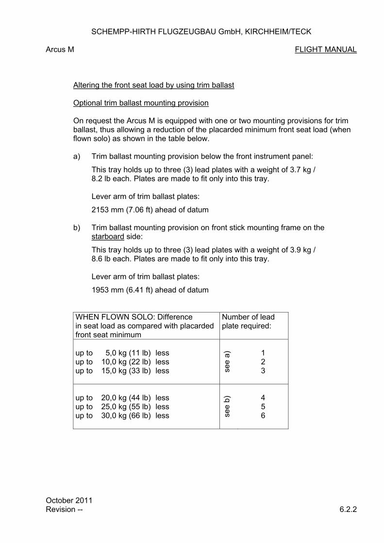
SCHEMPP-HIRTH FLUGZEUGBAU GmbH, KIRCHHEIM/TECK
Arcus M FLIGHT MANUAL
Altering the front seat load by using trim ballast Optional trim ballast mounting provision
On request the Arcus M is equipped with one or two mounting provisions for trim ballast, thus allowing a reduction of the placarded minimum front seat load (when flown solo) as shown in the table below.
a) Trim ballast mounting provision below the front instrument panel:
This tray holds up to three (3) lead plates with a weight of 3.7 kg / 8.2 lb each. Plates are made to fit only into this tray.
Lever arm of trim ballast plates:
2153 mm (7.06 ft) ahead of datum
b) Trim ballast mounting provision on front stick mounting frame on the starboard side:
This tray holds up to three (3) lead plates with a weight of 3.9 kg / 8.6 lb each. Plates are made to fit only into this tray. Lever arm of trim ballast plates:
1953 mm (6.41 ft) ahead of datum
WHEN FLOWN SOLO: Difference in seat load as compared with placarded front seat minimum
Number of lead plate required:
up to 5,0 kg (11 lb) less up to 10,0 kg (22 lb) less up to 15,0 kg (33 lb) less
see a
)
1 2 3
up to 20,0 kg (44 lb) less up to 25,0 kg (55 lb) less up to 30,0 kg (66 lb) less
see b
)
4 5 6
October 2011 Revision -- 6.2.2

SCHEMPP-HIRTH FLUGZEUGBAU GmbH, KIRCHHEIM/TECK
Arcus M FLIGHT MANUAL WEIGHT AND BALANCE LOG SHEET (loading chart) FOR S/N ........... POWER PLANT INSTALLED
Date of weighing:
Empty mass [kg]
Equipment list dated
Installed batteries 2)
count count count count
E E E E
C1/C2 C1/C2 C1/C2 C1/C2
F1/F2 F1/F2 F1/F2 F1/F2
Empty mass c/g position aft of datum
Max. useable load [kg] in fuselage
Load [kg] on the seats (crew including parachute):
Front seat load when flown solo:
with two occupants:
max. 115 115 115 115
max. 115 115 115 115
Rear seat load with two occupants:
max.
Water ballast fin tank installed (YES / NO)
Front seat load regard- less of load on rear seat
min.1)
Inspector Signature / Stamp
Note:
1. If fin tank installed, the pilot must either dump all water ballast prior of take-off, or ensure that the ballast quantity in the fin tank is compensated by an appropriate load in the wing tanks and/or on the aft seat.
2. Installed batteries (see page 7.12.2):
(E) engine battery (C1/C2) batteries in front of rear stick mounting frame (F1/F2) batteries in fin
For the determination of the water ballast quantity permitted in the wing tanks refer to page 6.2.5.
For the determination of the water ballast quantity permitted in the fin tank refer to page 6.2.6 through 6.2.8.
October 2011 Revision -- 6.2.3

SCHEMPP-HIRTH FLUGZEUGBAU GmbH, KIRCHHEIM/TECK
Arcus M FLIGHT MANUAL WEIGHT AND BALANCE LOG SHEET (loading chart) FOR S/N ........... POWER PLANT REMOVED
Date of weighing:
Empty mass [kg]
Equipment list dated
Installed batteries 2)
count count count count
E E E E
C1/C2 C1/C2 C1/C2 C1/C2
F1/F2 F1/F2 F1/F2 F1/F2
Empty mass c/g position aft of datum
Max. useable load [kg] in fuselage
Load [kg] on the seats (crew including parachute):
Front seat load when flown solo:
with two occupants:
max. 115 115 115 115
max. 115 115 115 115
Rear seat load with two occupants:
max.
Water ballast fin tank installed (YES / NO)
Front seat load regard- less of load on rear seat
min.1)
Inspector Signature / Stamp
Note:
1. If fin tank installed, the pilot must either dump all water ballast prior of take-off, or ensure that the ballast quantity in the fin tank is compensated by an appropriate load in the wing tanks and/or on the aft seat.
2. Installed batteries (see page 7.12.2):
(E) engine battery (C1/C2) batteries in front of rear stick mounting frame (F1/F2) batteries in fin
For the determination of the water ballast quantity permitted in the wing tanks refer to page 6.2.5.
For the determination of the water ballast quantity permitted in the fin tank refer to page 6.2.6 through 6.2.8.
October 2011 Revision -- 6.2.4

SCHEMPP-HIRTH FLUGZEUGBAU GmbH., KIRCHHEIM/TECK
Arcus M FLIGHT MANUAL
Maximum water ballast load
Maximum all-up mass 800 kg including water ballast: 1764 lb
C/G position of water ballast 17 mm in wing tanks (forward of datum): 0.70 in.
Total capacity of wing tanks: 185 Litre (48.9 US. Gal /40.7 IMP Gal)
Table of water ballast loads at various empty masses and seat loads:
Empty mass + fin ballast
+ fuel
L O A D O N T H E S E A T ( k g / l b )
kg lb kg lb kg lb kg lb kg lb kg lb kg lb kg lb kg lb kg lb
kg lb 70 154 80 176 100 220 120 264 140 308 160 353 180 396 200 441 220 485 230 507
450 991 185 48.9 40.7 185 48.9 40.7 185 48.9 40.7 185 48.9 40.7 185 48.9 40.7 185 48.9 40.7 170 44.9 37.4 150 39.6 33.0 130 34.3 28.6 120 31.7 26.4
460 1013 185 48.9 40.7 185 48.9 40.7 185 48.9 40.7 185 48.9 40.7 185 48.9 40.7 180 47.6 39.6 160 42.3 35.2 140 36.9 30.8 120 31.7 26.4 110 29.1 24.2
470 1035 185 48.9 40.7 185 48.9 40.7 185 48.9 40.7 185 48.9 40.7 185 48.9 40.7 170 44.9 37.4 150 39.6 33.0 130 34.3 28.6 110 29.1 24.2 100 26.4 22.0
480 1057 185 48.9 40.7 185 48.9 40.7 185 48.9 40.7 185 48.9 40.7 180 47.6 39.6 160 42.3 35.2 140 36.9 30.8 120 31.7 26.4 100 26.4 22.0 90 23.8 19.8
490 1079 185 48.9 40.7 185 48.9 40.7 185 48.9 40.7 185 48.9 40.7 170 44.9 37.4 150 39.6 33.0 130 34.3 28.6 110 29.1 24.2 90 23.8 19.8 80 21.1 17.6
500 1101 185 48.9 40.7 185 48.9 40.7 185 48.9 40.7 180 47.6 39.6 160 42.3 35.2 140 36.9 30.8 120 31.7 26.4 100 26.4 22.0 80 21.1 17.6 70 18.5 15.4
510 1101 185 48.9 40.7 185 48.9 40.7 185 48.9 40.7 170 44.9 37.4 150 39.6 33.0 130 34.3 28.6 110 29.1 24.2 90 23.8 19.8 70 18.5 15.4 60 15.9 13.2
520 1147 185 48.9 40.7 185 48.9 40.7 180 47.6 39.6 160 42.3 35.2 140 36.9 30.8 120 31.7 26.4 100 26.4 22.0 80 21.1 17.6 60 15.9 13.2 50 13.2 11.0
530 1169 185 48.9 40.7 185 48.9 40.7 170 44.9 37.4 150 39.6 33.0 130 34.3 28.6 110 29.1 24.2 90 23.8 19.8 70 18.5 15.4 50 13.2 11.0 40 10.6 8.8
540 1191 185 48.9 40.7 180 47.6 39.6 160 42.3 35.2 140 36.9 30.8 120 31.7 26.4 100 26.4 22.0 80 21.1 17.6 60 15.9 13.2 40 10.6 8.8 30 7.9 6.6
550 1213 180 47.6 39.6 170 44.9 37.4 150 39.6 33.0 130 34.3 28.6 110 29.1 24.2 90 23.8 19.8 70 18.5 15.4 50 13.2 11.0 30 7.9 6.6 20 5.3 4.4
560 1235 170 44.9 37.4 160 42.3 35.2 140 36.9 30.8 120 31.7 26.4 100 26.4 22.0 80 21.1 17.6 60 15.9 13.2 40 10.6 8.8 20 5.3 4.4 10 2.6 2.2
570 1257 160 42.3 35.2 150 39.6 33.0 130 34.3 28.6 110 29.1 24.2 90 23.8 19.8 70 18.5 15.4 50 13.2 11.0 30 7.9 6.6 10 2.6 2.2 0 0 0
Litre US Gal.
IMP Gal.
Litre US Gal.
IMP Gal.
Litre US Gal.
IMP Gal.
Litre US Gal.
IMP Gal.
Litre US Gal.
IMP Gal.
Litre US Gal.
IMP Gal.
Litre US Gal.
IMP Gal.
Litre US Gal.
IMP Gal.
Litre
US Gal.
IMP Gal.
Litre
US Gal.
IMP Gal.
W A T E R B A L L A S T I N W I N G T A N K S
Note: When determining the max. permitted wing water ballast load, allowance must be made for water ballast in the fin tank (see page 6.2.7 and 6.2.8) and fuel , i.e. this load must be added to the empty mass shown on the above table. Empty mass as per page 6.2.3 resp. 6.2.4, fin ballast as per page 6.2.8.
October 2011 Revision -- 6.2.5

SCHEMPP-HIRTH FLUGZEUGBAU GmbH, KIRCHHEIM/TECK
Arcus M FLIGHT MANUAL Water ballast in (optional) fin tank In order to shift the centre of gravity close to its aft limit (favourable in terms of performance), water ballast may be carried in the fin tank (mFT) to compensate for the nose-heavy moment of:
„ water ballast in main wing panels (mWT) and/or „ loads on the aft seat (mP2) Compensating water ballast in main wing panels The determination of the ballast quantity in the fin tank (mFT) is done with the aid of the diagram shown on page 6.2.8. Compensating loads on the aft seat Pilots wishing to fly with the centre of gravity close to the aft limit may compensate the nose-heavy moment of loads on the aft seat with the aid of the diagram shown on page 6.2.8. Note: When using fin ballast to compensate for the nose - heavy moment of wing
ballast and loads on the aft seat, then both values resulting from the diagrams on page 6.2.8 must be taken into account.
The maximum amount of water ballast, available for compensating the above mentioned nose-heavy moments, is 11 Litres (2.91 US Gal., 2.42 IMP Gal.), which is the maximum capacity of the fin tank.
WARNING:
Compensation for masses exceeding the placarded minimum front seat load by the use of water ballast in fin tank is n o t allowed!
If the influence of the load on the rear seat is taken into account for the minimum load on the front seat, the nose-heavy moment of the load on the rear seat may not be compensated with water ballast in the fin tank.
October 2010 Revision -- 6.2.6

SCHEMPP-HIRTH FLUGZEUGBAU GmbH, KIRCHHEIM/TECK
Arcus M FLIGHT MANUAL Water ballast in (optional) fin tank
Important Note:
When determining the maximum usable load in the fuselage, the quantity of water ballast in the fin does not need to be taken in account because of flight mechanic reasons.
In order to avoid exceeding the maximum permitted all-up weight (mass), the ballast in the fin tank must also be taken into account when determining the maximum allowable ballast quantity for the wing tanks.
Example:
Assumed ballast load in wing tanks: 40 kg/Litres (88 lb/10.6 US Gal) Assumed load on aft seat: 75 kg (165 lb) According to the diagrams on page 6.2.8 the following loads in the fin tank are permissible (fill only full Litres): For ballast in wing tank : m FT = 2 kg/Litre (4.4 lb/0.53 US Gal) For load on aft seat : Fm FT = 8 kg/Litres (17.6 lb/2.11 US Gal) Total ballast in fin tank : m FT + Fm FT = 10 kg/Litres (22.1 lb/2.64 US Gal)
October 2011 Revision -- 6.2.7

SCHEMPP-HIRTH FLUGZEUGBAU GmbH., KIRCHHEIM/TECK Arcus M FLIGHT MANUAL
NOTE: Always full Liters are to be filled. Where value jumps, either the higher or the lower amount of ballast may be used.
00
Lever arm of water ballast in fin tank (m ):
Fin tank capacity: 11 kg/Liter (2.91 US Gal., 2.42 IMP Gal.)
FT
5292 mm (17.36 ft) aft of datum plane
Max. water ballast in main wing panels
10.260.22
20.530.44
30.790.66
41.060.88
51.321.10
61.591.32
71.851.54
82.111.76
92.381.98
102.642.20
112.912.42
LiterUS Gal.IMP Gal
Max
. fi
n t
an
k c
ap
acit
y
Win
g w
ate
r b
allas
t m
WT
4.40 5.28 20
IMP. G
al.
US
. G
al.
Lit
er
8.58 10.30 39
12.76 15.32 58
17.16 20.61 78
21.34 25.62 97
25.52 30.64 116
29.92 35.93 136
34.10 40.95 155
38.06 45.70 173
40.70 48.87 185
Max
. fi
n t
an
k c
ap
acit
y
Max. load on rear seat
0 10.260.22
20.530.44
30.790.66
41.060.88
51.321.10
61.591.32
71.851.54
82.111.76
92.381.98
102.642.20
112.912.42
LiterUS Gal.IMP Gal
mFT Water ballast in fin tank
mFT Water ballast in fin tank
loa
d o
n r
ear
seat
m (
kg
)P
2
19.8 9
lb kg
0
37.4 17
57.3 2675.0 3492.6 42
112.5 51130.1 59147.7 67
167.6 76185.2 84
205.1 93
1 L
iter
= 1
kg
(2.2
lb
)
October 2011 Revision -- 6.2.8

SCHEMPP-HIRTH FLUGZEUGBAU GmbH., KIRCHHEIM/TECK
Nimbus-4DM FLIGHT MANUAL Section 7 7. Description of the aircraft and its system 7.1 Introduction 7.2 Cockpit-Description 7.3 Instrument panels 7.4 Undercarriage 7.5 Seats and restraint systems 7.6 Static pressure and Pitot pressure system 7.7 Airbrake system 7.8 Baggage compartment 7.9 Water ballast system(s) 7.10 Power plant system 7.11 Fuel system 7.12 Electrical system 7.13 Miscellaneous equipment (removable ballast, oxygen, ELT etc.)
November 2008 Revision -- 7.1.1

SCHEMPP-HIRTH FLUGZEUGBAU GmbH, KIRCHHEIM/TECK
Arcus M FLIGHT MANUAL 7.1 Introduction
This section provides a description of the powered sailplane including the operation of its systems. For details concerning optional- systems and equipment refer to section 9 "Supplements". For further descriptions of components and systems refer to section 1 of the Maintenance Manual.
October 2011 Revision -- 7.1.2

SCHEMPP-HIRTH FLUGZEUGBAU GmbH., KIRCHHEIM/TECK
Arcus M FLIGHT MANUAL 7.2 Cockpit-Description
October 2011 Revision -- 7.2.1
1
2
4a
3a
4b 5
6
8
12
14
9
15
16
17 18
19
20
21
1
2
3b
4b
5
6
8
14
15
16
17
18
19
20 21
SCHEMPP-HIRTH FLUGZEUGBAU GmbH, KIRCHHEIM/TECK
Arcus M FLIGHT MANUAL
All instruments and control elements are within easy reach of the crew. (1) Instrument panels
With canopy opened, the instruments for either seat are easily accessible. The front instrument panel can be pivoted upwards if the canopy is open. The front instrument panel covering is attached to the front instrument panel with two bolts. The rear panel is mounted to the steel tube transverse frame between the seats. Both instrument panels and their glare shields are easily detached after removing the mounting bolts.
(2) Tow release handles
T-shaped handles, actuating the tow release(s) installed (c/g and/or nose hook)
Front seat: Yellow handle at the base of the control stick on the left Rear seat: Yellow handle on the lower left hand side of the instrument panel
The winch cable/aerotow rope is released by pulling one of the handles.
October 2011 Revision -- 7.2.2

SCHEMPP-HIRTH FLUGZEUGBAU GmbH, KIRCHHEIM/TECK
Arcus M FLIGHT MANUAL
(3a) Rudder pedal adjustment (front seat)
Black T-shaped handle on the right hand side near the base of the control stick.
Forward adjustment: Release locking device by pulling the handle,
push pedals to desired position with the heels and let them engage.
Backward adjustment: Pull handle back until pedals have reached
desired position. Forward pressure with heels (not the toes) engages pedals in near-est notch with an audible click.
An adjustment of the rudder pedals is possible on the ground and in the air.
(3b) Rudder pedal adjustment (rear seat)
Locking device on pedal mounting structure on the cockpit floor. Forward or backward adjustment: Pull up locking pin by its ring, slide pedal as-
sembly to desired forward or backward posi-tion and push locking pin down into nearest recess.
An adjustment of the rudder pedals is possible on the ground and in the air.
October 2011 Revision -- 7.2.3

SCHEMPP-HIRTH FLUGZEUGBAU GmbH, KIRCHHEIM/TECK
Arcus T FLIGHT MANUAL
(4) Ventilation
a) Small black knob on the front instrument panel on the right: (Ventilation air quantity)
Pull to open ventilator nozzle Push to close ventilator nozzle
b) Adjustable bull-eye-type ventilator starboard of the right:
Turned clockwise: Ventilator closed Turned anti-clockwise: Ventilator open
Additionally the clear vision panels or the air scoop in the panels may be opened for ventilation.
(5) Wheel brake
A wheel brake handle is mounted on either control stick.
(6) Airbrake levers
Levers (with blue marking), projecting downwards, below cockpit inner skin on the left.
Forward position: Airbrakes closed and locked Pulled back about 40 mm ( 1.6 in. ): Airbrakes unlocked Pulled fully back: Airbrakes fully extended
(7) Head rests
a) Front seat (not illustrated): Head rest is an integrated component of the seat back and is adjusted with the seat back. b) Rear seat (not illustrated):
Mounting rail on upper fuselage skin. Head rest is gradually and horizontally adjustable: Depress locking tap, slide head rest in desired position and let locking tap engage into nearest recess.
October 2011 Revision -- 7.2.4

SCHEMPP-HIRTH FLUGZEUGBAU GmbH, KIRCHHEIM/TECK
Arcus M FLIGHT MANUAL (8) Elevator trim
Green knob (for either seat) at the seat pan mounting flange on the left. The spring-operated elevator trim is gradually adjustable by swinging the knob slightly inwards, sliding it to the desired position and swinging it outwards to lock.
Forward position - nose-heavy Backward position - tail-heavy
(9) Control- lever for dumping water ballast from wing tanks and (optional) fin tank
Black lever on the front seat rest on the right.
Forward position - dump valves closed Backward position - dump valves opened
The lever is held in the respective final positions
Fin tank (option) The fin tank dump valve control is connected to the torque tube actuating the valves in the wing so that all three valves open and close simultaneously.
(10) Seat back (front seat) (not illustrated)
Sliding black knob on the cockpit inner skin on the right.
Adjustment: Tilt front end of grip slightly inwards,
slide grip to desired position and let engage by tilting it outwards.
In addition, the lower attachment position can be varied in the seat rest.
October 2011 Revision -- 7.2.5

SCHEMPP-HIRTH FLUGZEUGBAU GmbH, KIRCHHEIM/TECK
Arcus M FLIGHT MANUAL
(11) Rip cord anchorage (not illustrated)
Front seat: Red steel ring on tubular frame between the seats on the left
Rear seat: Red steel ring at the front of the steel tube center (not illustrated) frame on the left
(12) Canopy
The one-piece plexiglass canopy hinges sideways on flush fittings. Take care that the cable restraining the open canopy is properly hooked up.
(13) Canopy locking and jettisoning levers (not illustrated)
Lever with red grip for either seat on the canopy frame on the left. Forward position: canopy locked
To open or jettison the canopy, swing one of the levers back up to the stop (approx. 90°) and raise canopy.
(14) Canopy release Black lever (for front and rear seat) in the canopy frame on the right. To open or jettison the canopy, push one of the levers back up to the stop, disconnect the holding rope and raise canopy.
October 2011 Revision -- 7.2.6

SCHEMPP-HIRTH FLUGZEUGBAU GmbH, KIRCHHEIM/TECK
Arcus M FLIGHT MANUAL
Undercarriage
(15 ) Front / Rear seat
Retracting : Disengage black handle below the cockpit inner skin on the right, pull it back and lock in rear recess
Extending: Disengage handle, push it forward and lock in front recess
(16) Flap lever
Black lever, projecting upwards, on cockpit inner skin on the left. Swing lever slightly inwards, move to desired setting and let engage in
appropriate notch. Forward position: High speed range Backward position: Low speed range
October 2011 Revision -- 7.2.7

SCHEMPP-HIRTH FLUGZEUGBAU GmbH., KIRCHHEIM/TECK
Arcus M FLIGHT MANUAL
(17) Prop arresting device Black T-shaped handle on the front of the left cockpit inner skin (for either seat) T-shaped pulled back: brake operation (for manual stopping and holding prop) (18) Fuel shut-off valve Black knob on cockpit inner skin on the right (for either seat) Forward position: Valve opened Rearward position: Valve closed (19) Rear-view mirror This is provided in the front cockpit on the right side and in the rear cockpit on the instrument glare shield. (20) Starter button (red) (21) Throttle control Pivoting lever on the port side of the cockpit (for either seat)
Fully forward position: Full throttle
Fully aft position: Idle
October 2011 Revision -- 7.2.8

SCHEMPP-HIRTH FLUGZEUGBAU GmbH, KIRCHHEIM/TECK
Arcus M FLIGHT MANUAL 7.3 Instrument panels
Front panel:
For a description of components No. I through VII refer to the following pages: 7.3.2 through 7.3.18. A description of the instrumentation and an illustration of the rear instrument panel is not deemed necessary.
October 2011 Revision -- 7.3.1
I
VI
IV
V
III
II
VII

SCHEMPP-HIRTH FLUGZEUGBAU GmbH, KIRCHHEIM/TECK
Arcus M FLIGHT MANUAL
I Engine Control Unit MCU II
1 2 3
The engine control unit MCU II is build up out of the operating unit in the instrument panel (see picture above) and a control unit (below the rear seat pan). With the MCU II the operation of the engine and the extension- resp. the retraction of the power plant run automatically to a great extend. Furthermore the MCU II supplies the Pilot with information regarding the most important operational parameters of the engine. The operational state of the engine and the position of the power plant and the propeller are determined processing the information of the control unit, of the two limit switches, of the RPM-sensor and of the two sensors for the vertical positioning of the propeller. The extension and the retraction of the power plant is automated to a great extend and connected to the ignition switch. Logical inquiries secure the engine control against accidental operating errors. In addition also a largely manual operation of the power plant is possible.
October 2011 Revision -- 7.3.2
4
5
9
4
8
6
7

SCHEMPP-HIRTH FLUGZEUGBAU GmbH, KIRCHHEIM/TECK
Arcus M FlLIGHT MANUAL
ヮ Engine control unit MCU II (continued) a) Overview of readouts and control elements (1) RPM Indicator:
No signal - RPM below 2500 or engine not running
Green light - RPM between 2500 and 6600 (normal operating range)
Yellow light - RPM greater than 6600
Flashing yellow light - RPM for more than 5 min between 6600 and 6700 or RPM greater than 6700.
(2) Warning signal:
The red warning signal lights - for operating instructions - if limitations are exceeded - for error messages
At the same time the LCD-Display shows the respective information or error message and an audible warning signal sounds (buzzer).
(3) Signal for battery voltage and generator function:
Red light - no charging current
No light - charging current available
Flashing red light - Voltage of engine battery below 11,5 V
(4) Position indicator power plant:
a) Upper LED
Flashing green light - Power plant is being extended
Green light - Power plant completely extended b) Lower LED
Flashing green light - Power plant is being retracted
Green light - Power plant completely retracted
October 2011 Revision -- 7.3.3

SCHEMPP-HIRTH FLUGZEUGBAU GmbH, KIRCHHEIM/TECK
Arcus M FLIGHT MANUAL
ヮ Engine control unit MCU II (continued)
a) Overview of readouts and control elements (continued)
(5) Manual operation switch (Pylon drive switch)
The manual operation switch is used to extend and retract the power plant: - on the ground or - if the control unit has switched off from automatic mode in case of
missing or incorrect information concerning the position of the power plant or the engine speed. (Manual mode, display shows “MAN.MODE”)
The manual operation switch has three positions:
UP - The power plant extends while the switch is held up
(rocker switch). The pylon spindle drive is cut off by a micro limit switch when the power plant reaches the fully extended position.
MIDDLE - Automatic mode DOWN - The power plant retracts while the switch is held down
(rocker switch). The spindle drive is cut off by a micro limit switch in the fully retracted position of the power plant.
Note:
When the engine control unit is operating normally in the automatic mode, it is not necessary to use the manual operation switch in flight. In the manual mode the pilot must execute and control the extension and retraction procedure of the power plant with the manual operation switch! The power plant can only be retracted with the manual operation switch if the ignition is switched off. If the power plant is extended by using the ignition switch, the extension process stops when the manual operation switch is held down. Then the automatic mode is switched off. If the power plant is retracted by using the ignition switch, the retraction process stops if the manual operation switch is held up. Then the automatic mode is switched off.
October 2011 Revision -- 7.3.4

SCHEMPP-HIRTH FLUGZEUGBAU GmbH, KIRCHHEIM/TECK
Arcus M FLIGHT MANUAL
ヮ Engine control unit MCU II (continued) a) Overview of readouts and control elements (6) Menu push-button:
Features:
- Scroll through the menu of the LCD display
- Affirmation of warnings and error messages
- Rset of short period elapsed-time counter
- Start calibration of fuel capacity indication
- Input of complete fuel capacity (fuselage and wing tank(s)) (7) Ignition switch:
UP: - Ignition ON
- Power plants extends completely (automatic mode)
- electrical fuel pump and electrical water pump are
switched on
DOWN: - Ignition OFF
- Power plant retracts completely (automatic mode)
- Electrical fuel pump is switched off. Electrical water pump is switched off, depending on temperature of cooling fluid
October 2011 Revision -- 7.3.5

SCHEMPP-HIRTH FLUGZEUGBAU GmbH, KIRCHHEIM/TECK
Arcus M FLIGHT MANUAL
ヮ Engine control unit MCU II (continued) a) Overview of readouts and control elements
(7) Ignition switch: (continued)
Note:
To start the automatic retraction process of the power plant with switching off the ignition the rpm of the engine has to meet the following conditions: - the engine rpm has to be greater than 4000 for at least 10 s before
switching off the ignition and - the engine rpm has to be greater than 2000 while switching off the
ignition If one of these conditions is not met, the automatic retraction process of the power plant will be stopped and on the LCD-Display the message “BRAKE?” appears. If this message is confirmed by pushing the Menu push-button, the automatic retraction process will be continued.
Note:
To retract the power plant automatically after the propeller stops, the propeller has to be in its vertical position: - During the automatic retraction process of the power plant the
position of the propeller is monitored by proximity sensors on the upper belt pulley. The propeller is hold in its vertical position with the aid of an electrical driven brake servo.
- With a defective brake servo and/or defective proximity sensors the pilot can stop and hold the propeller in its vertical position by actuating the manual propeller brake. The position of the propeller has to be checked with the rear-view mirror.
Oktober 2011 Revision -- 7.3.6

SCHEMPP-HIRTH FLUGZEUGBAU GmbH, KIRCHHEIM/TECK
Arcus M FLIGHT MANUAL
ヮ Engine control unit MCU II (continued) a) Overview of readouts and control elements
(8) Test switch for Ignition circuits I – II:
Rocker switch for testing both ignition circuits. In upper position ignition circuit 1 is active, in lower position ignition circuit 2 is active. With the switch is in its middle position both ignition circuits are active.
October 2011 Revision -- 7.3.7

SCHEMPP-HIRTH FLUGZEUGBAU GmbH, KIRCHHEIM/TECK
Arcus M FLIGHT MANUAL
Ι Engine control unit MCU II (contd.) a) Overview about the readouts and control elements (contd.) (9) LCD-Display
In the eight-digit LCD-display the following values are displayed in the auto-matic mode when the engine is extended and running (powered sailplane mode):
- Engine speed (RPM) and cooling liquid temperature (°C): 6250 090
- Every 5 sec the fuel quantity (Litre) is displayed for a short time: 6250 12L
For the display of these values the LCD display switches back automatically. By pushing the menu-push-button (6) additionally the following indications are possible:
- Fuel quantity (Litre): FUEL_12L
- Battery voltage (engine battery only) (Volt) BAT13,0V
- Charging current from the controller (A) CC_5,43A
- Current through the cooling water pump WPC1,12A
- Elapsed-time counter (h:min) (min in decimal notation) __13,09h
- Resettable short period elapsed-time minute counter 83:09M:S
(min and sec in decimal notation)
- actual calibration factor for fuel quantity indication fuselage tank [100]___
With completely retracted power plant (sailplane mode) the following values are displayed:
- Battery voltage (engine battery only) (Volt) and fuel quantity (Litre):
13,0_12L
For the display of these values the LCD display switches back automatically. By pushing the menu-push-button (6) the same values as in the powered sail-plane mode can be displayed. Additionally there are the following indications:
- Option for new calibration of the fuel quantity indication
fuselage tank CALIBR.?
Moreover the following information is shown:
- Advice for operation, warnings and error messages
Operation advice, warnings and error messages always come to the front. In this case the LCD-display also starts blinking.
Warnings and error messages must be affirmed with the menu push-button. The warning indication then disappears from the LCD-display.
When the reason for the warning or error message continues, the messages will be repeated.
Oktober 2011 Revision -- 7.3.8

SCHEMPP-HIRTH FLUGZEUGBAU GmbH., KIRCHHEIM/TECK
Arcus M FLIGHT MANUAL (II) ON/OFF switch for the redundancy engine control system
Upward position: Engine operation with redundancy system Downward position: regular Engine operation (III) Pneumatic valve
Panel-mounted two-way cock (should a total energy compensation probe be used).
T.E. = Variometer(s) fed from T.E. Compensation probe STATIC = Variometer(s) fed from Static Pressure ports
With engine running and valve switched to “STATIC” or “T.E. slow”, the reading of the variometer(s) is steadier.
(IV) Outside air temperature indicator
When carrying water ballast, the outside air temperature (OAT) must not drop below 2° C / 36° F.
(V) Stick mounted starter button
The starter motor is cut off - with propeller not fully extended (watch signal) - with an engine speed exceeding 2000 RPM - with ignition off:
However it is possible to support the vertical positioning of the propeller with the starter although the ignition is switched off. The propeller moves in small steps by pressing the starter button. In this process an engine start is not possible.
(VI) Fire warning signal (with test button)
With fire inside the engine compartment, signal starts flashing.
October 2011 Revision -- 7.3.17

SCHEMPP-HIRTH FLUGZEUGBAU GmbH, KIRCHHEIM/TECK
Arcus M FLIGHT MANUAL
VII Fuse console (at panel base): 2 3 4 51 1 Engine master switch 2 Avionic master switch 3 Circuit breaker-Generator 4 Circuit breaker-Spindle drive
5 Circuit breaker-Power plant system
6 Circuit breaker-Emergency system
7 Circuit breaker-Injection sys-tem
8 Circuit breaker-Fuel pump 9 Circuit breaker-Relay 10 Circuit breaker-Avionic M 11 Battery-Selector switch 12 Priority switch 13 Emergency switch
10
1. ENGINE MASTER SWITCH - CIRCUIT BREAKER 50 A
This circuit breaker disconnects the power plant wiring from its power source (battery M). For the gliding avionics a separate main switch is provided – see (2).
2. AVIONIC MASTER SWITCH – CIRCUIT BREAKER 7.5 A
This circuit breaker disconnects the power supply for avionics at operation with avionic batteries (C1, C2, S).
3. GENERATOR - Circuit breaker 40A
With engine running, this circuit breaker must always be depressed, otherwise the power plant battery will not be recharged by the generator.
October 2011 Revision -- 7.3.18
6 8 9 7
11
12
13

SCHEMPP-HIRTH FLUGZEUGBAU GmbH, KIRCHHEIM/TECK
Arcus M FLIGHT MANUAL
4. Circuit breaker-Spindle drive 12 A
Protection of spindle drive used for extending and retraction of the power plant.
5 Circuit breaker-Power plant system 7,5 A
Protection of power plant system 6. Circuit breaker-Emergency system 7,5 A
Protection of spindle drive actuated via the emergency system 7. Circuit breaker-Injection system 7,5 A
Protection of Trijekt-Injection-system. 8. Circuit breaker-Fuel pump 7,5 A
Protection of fuel pump 9. Circuit breaker-Relay 7,5 A
Protection of relay 10. Circuit breaker-Avionic 7,5 A
Protection of Avionic operated with avionic batteries (see also 11.). 11. Battery selector switch Battery selector switch for Avionic: C1/C2: Batteries in front of rear stick mounting frame E: Engine battery F1/F2: Batteries in fin
Oktober 2011 Revision -- 7.3.19

SCHEMPP-HIRTH FLUGZEUGBAU GmbH, KIRCHHEIM/TECK
Arcus M FLIGHT MANUAL
12. Priority selector switch (optional)
Key down: engine control unit in front panel active
Key up: engine control unit in rear panel active
Note:
The inactive engine control unit retains all its indicating functions – the commanding functions, however, are cut off. To avoid an interruption of the automatic engine control during the switch over the following conditions should be met before activating the Priority selector switch:
„ both ignition switches have to be in the same position „ engine has to be fully retracted or fully extended „ both manual operation switches have to be in the middle position
Warning:
With power on, the priority may only be changed if the ignition on both control units is “ON”, otherwise the engine will stop running. With power off, the priority may only be changed if the ignition on both control units is “OFF” in order to prevent the ignition from being switched on inadvertently.
13. Emergency switch
(activating the electrical spindle drive which extends the propeller pylon)
In case of a failure of the electrical power plant extension/retraction control system, the pylon drive may still be activated with the aid of an emergency switch. With the pylon reaching the extreme “extended” position, however, the spin-dle drive is no longer automatically cut off by the limit switch as the latter is overridden on actuating the emergency switch. Therefore the starter motor will function even in the case of a failure of the limit switch “propeller ex-tended”. The emergency switch is situated below the main instrument panel and is covered by a red guard.
Key held up: Power plant extends (green “extended” signal permanently on).
Key held down: Power plant retracts.
October 2011 Revision -- 7.3.20

SCHEMPP-HIRTH FLUGZEUGBAU GmbH, KIRCHHEIM/TECK
Arcus M FLIGHT MANUAL
13. Emergency switch (ctd.)
The extreme pylon positions are recognized as follows:
Extended: Pivoting motion of pylon is stopped by arresting wire (watch rear-view mirror) and the circuit breaker will trip.
(If spindle drive circuit breaker trips, reset it instantly).
Retracted: On reaching the extreme position, the green “retracted” lights comes on. Spindle drive is cut off by limit switch. Note that when extending the power plant via emergency switch, some measures against operating errors while starting are still in working order, so for starting the engine it is required that
„ the ignition is switched “ON”
„ the manually propeller brake must not be operated
CAUTION:
With the red switch guard in “up” position, the starter motor will function re-gardless of the pylon position – so be cautious on the ground and in the air! Never actuate the emergency switch with ignition “ON” !
October 2011 Revision -- 7.3.21
SCHEMPP-HIRTH FLUGZEUGBAU GmbH, KIRCHHEIM/TECK
Arcus M FLIGHT MANUAL
7.4 Undercarriage
The main wheel of the Arcus M is retractable with shock absorber struts and features a hydraulic disc brake. The nose wheel (if installed) and tail wheel (or skid) are fixed. The extension/retraction process of the main wheel is described on page 7.2.7 (cockpit description). The operation of the main wheel brake is given on page 7.2.4. For a technical description of the retractable undercarriage including its wheel brake system see also page 1.2.3 of the Arcus M Maintenance Manual.
October 2011 Revision -- 7.4

SCHEMPP-HIRTH FLUGZEUGBAU GmbH, KIRCHHEIM/TECK
Arcus M FLIGHT MANUAL
7.5 Seats and restraint systems
The seat pans are bolted to mounting flanges provided on both sides of the cockpit. The front seat features a back rest, which is adjustable in flight - see also page 7.2.5 concerning the procedure for its adjustment. For each seat the lap straps are anchored to the seat pan. While the shoulder straps for the front seat are attached to the steel tube transverse frame, those for the rear seat are anchored to the steel tube center frame. A list of approved restraint systems is provided in section 7.1 of the Arcus M Maintenance Manual.
October 2011 Revision -- 7.5

SCHEMPP-HIRTH FLUGZEUGBAU GmbH, KIRCHHEIM/TECK
Arcus M FLIGHT MANUAL
7.6 Static pressure and Pitot pressure system
Static pressure sources a) Static pressure ports are on either side of the fuselage tail boom, 1.02 m /
40.16 in. forward of the base of the fin. b) On request a special static pressure probe can be installed near the top of
the fin (for other instruments besides the ASI). c) On request additional static pressure ports can be provided on either side
of the fuselage skin next to the front instrument panel.
Pitot pressure sources a) Pitot pressure head situated in the fuselage.
ASI
ALTIMETER
STATIC pressure
October 2011 Revision -- 7.6

SCHEMPP-HIRTH FLUGZEUGBAU GmbH, KIRCHHEIM/TECK
Arcus M FLIGHT MANUAL 7.7 Airbrake system
Schempp-Hirth type airbrakes are employed on the upper surface of the main wing panels. A schematic view of the airbrake system is given in the Maintenance Manual.
October 2011 Revision -- 7.7

SCHEMPP-HIRTH FLUGZEUGBAU GmbH, KIRCHHEIM/TECK
Arcus M FLIGHT MANUAL
7.8 Baggage compartment
An enclosed baggage compartment is not provided. For soft objects (like jackets etc.), however, there is space above the spar stubs. Any such items must be taken into account when determining the permissible load on the seats.
October 2011 Revision -- 7.8

SCHEMPP-HIRTH FLUGZEUGBAU GmbH, KIRCHHEIM/TECK
Arcus M FLIGHT MANUAL 7.9 Water ballast system(s)
A steel cable connects the operating lever in the cockpit to the dump valve of the (optional) fin tank and a further steel cable to the torque tube actuating the wing tanks - see page 7.9.3. On rigging the main wing panels, the torque tube in the fuselage is automatically hooked up to the torsional drive of the dump valve plugs. The torque tube is rotated to the "CLOSED" position by spring force - see page 7.9.2. The operating lever locks in its respective final positions.
October 2011 Revision -- 7.9.1
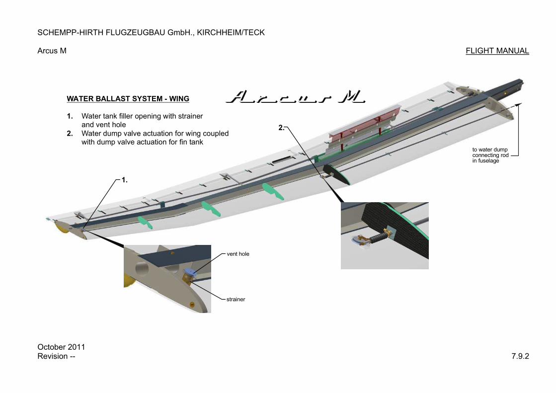
SCHEMPP-HIRTH FLUGZEUGBAU GmbH., KIRCHHEIM/TECK
Arcus M FLIGHT MANUAL
WATER BALLAST SYSTEM - WING
1.
2.
Water tank filler opening with strainerand vent holeWater dump valve actuation for wing coupledwith dump valve actuation for fin tank
2.
1.
vent hole
strainer
to water dumpconnecting rodin fuselage
October 2011 Revision -- 7.9.2

SCHEMPP-HIRTH FLUGZEUGBAU GmbH, KIRCHHEIM/TECK
Arcus M FLUGHANDBUCH
1.
3.
4.
5.
6.
7.
8.
2.
WASSERBALLASTSYSTEM-SEITENFLOSSENTANK
1.
2. 3. 4.
5. 6. 7.
8.
Wasserablaßbetätigung-FlügelWasserablaß-VerbindungsstangeWasserablaßantrieb-SeitenflossentankAblaßventilEntwässerungsbohrungEinfüllöffnungAblaßbohrungWasserstandsanzeige
Oktober 2011 Revision -- 7.9.3

SCHEMPP-HIRTH FLUGZEUGBAU GmbH, KIRCHHEIM/TECK
Arcus M FLIGHT MANUAL 7.10 Power plant system
Engine and propeller (for a description and relevant data refer to the engine and propeller manual) are accommodated in a special CFRP mounting structure (pylon), which is pivoted to the fuselage steel tube center frame by means of two rubber shock mounts (vibration isolators). The arresting wire is attached to the pylon. An electrical spindle drive, anchored to the fuselage deck and linked to the pylon, extends and retracts the latter. The doors of the engine compartment are automatically opened and closed by a linkage while the pylon extends / retracts. The panel-mounted engine control unit MCU II combines a number of functions required for operation of the power plant, a description of this unit is given on page 7.3.2 and the following. Other additional controls for the power plant are just the fuel shut-off valve, the throttle lever and if necessary the manually operated propeller brake.
Octpber 2011 Revision -- 7.10

SCHEMPP-HIRTH FLUGZEUGBAU GmbH, KIRCHHEIM/TECK
Arcus M FLIGHT MANUAL 7.11 Fuel system
A view of the fuel system is given on page 7.11.2 – for a specification of the fuel to be used refer to page 2.4 Up to two flexible tanks may be used inside left and right wing optionally. Instructions on how to refuel the aircraft are found on page 4.2.2.1 through 4.2.2.3. Fuel from the fuselage tank is drained via a valve situated on the right side of the u/c housing. Fuel to the engine is always supplied from the fuselage tank, which is filled by the optional wing tanks by means of an interconnecting line featuring a quick-disconnect coupling. Fuel from the fuselage tank is fed via a strainer, the electrical pump, a flow meter, a filter element and the shut-off valve to the injection system, which is connected to the carburetors on the engine. Total fuel contents (in fuselage and wing panel(s)) are displayed by the engine control unit MCU II – its fuel quantity indicator is adjustable. The vent line of the fuselage tank extends via an expansion reservoir overboard at the top of the fin (on the right side).
WARNING: In order to prevent that the engine stops due to the lack of the fuel, the opening of the vent line must never be taped closed!
Each wing tank has a vent line – routed to the expansion tank – featuring a pressure relief valve and a connecting nipple for the coupling on the fuselage. Refueling system The connecting point (with ON/OFF switch) for the refueling system is on the left side of the GFRP panel above the front transverse tube. The additional electrical fuel pump (with strainer) is found below the seat pan – see page 7.11.2.
October 2011 Revision -- 7.11.1

SCHEMPP-HIRTH FLUGZEUGBAU GmbH., KIRCHHEIM/TECK Arcus M FLIGHT MANUAL
October 2011 Revision -- 7.11.2
2120
shut-off valve co
ntrol
FUEL SYSTEM M09 RT 882
1
2
34
4
16
5
6
6
7
89
11
10
23
12
1114
1518
17
13
19
19
22
22
21 20

SCHEMPP-HIRTH FLUGZEUGBAU GmbH, KIRCHHEIM/TECK
Arcus M FLUGHANDBUCH Stückliste zur Seite 7.11.2
O P T I O N E N 23 1 T-Stück T5 NORMA 22 1 Schlauchkupplung LP-002-0-SL006-23-2 WALTHER 21 1 Stecknippel LP-002-1-SL006-23 WALTHER 20 1 Schlauchkupplung SP-006-0(2)-SL006-11-2 WALTHER 19 2 Zugentlastung SHK 18 1 Flügeltank li. (1500 x 250) HFK-W-TLF HEIMANN Teil Stück Benennung Bezeichnung Hersteller/Lieferant
17 1 Durchflußmesser DFM-1 ILEC 16 1 Schlauchkupplung LP-002-0-SL006-23-2 WALTHER 15 1 Stecknippel LP-002-1-SL006-23 WALTHER 14 1 Schlauchkupplung SP-006-0(2)-SL006-11-2 WALTHER 13 2 Zugentlastung SHK 12 1 Flügeltank re. (1500 x 250) HFK-W-TLF HEIMANN 11 1 Ausgleichsbehälter 1 Liter SHK 10 1 T-Stück T5 NORMA 9 1 Schlauchkupplung SP-004-2-SL WALTHER 8 1 Schlauchkupplung SP-006-0(2)-SL WALTHER 7 1 Kugelhahn 4932 08 13AC LEGRIS 6 1 Drainagehahn 30-0179 KARCOMA 5 3 Kraftstoff-Filter 99.106/8-100 KARCOMA 4 2 Elektrische Kraftstoffpumpe 40 105 FACET 3 2 Kraftstoffhahn-Betätigung M07 RT 876 SHK 2 1 Tankfühler TF 0/0300 ILEC 1 1 Alu-Tank Rumpf M07 RT 863 SHK Teil Stück Benennung Bezeichnung Hersteller/Lieferant
KRAFTSTOFFSYSTEM
mit optionalem Flügeltank M07 RT 880
Oktober 2011 Revision-- 7.11.3

SCHEMPP-HIRTH FLUGZEUGBAU GmbH, KIRCHHEIM/TECK
Arcus M FLIGHT MANUAL 7.12 Electrical system
Gliding avionics
When operated in the plain sailplane configuration, the minimum instrumentation prescribed does not require an electrical power source. Additional- equipment is to be wired as shown on page 7.12.3 and 7.12.4 “ELECTRICAL SYSTEM – AVIONICS” and must comply with the manufacturer’s instructions for the relevant instrument(s). Power for the avionics is supplied by one or more batteries, see pages 7.12.3 and 7.12.4. It is possible to use different battery types which need to have appropriate security mechanisms: Sealed Lead-Acid-Batteries resp. Nickel-Metallhydride-Batteries: These battery types have to be equipped with an appropriate circuit breaker. If these batteries are to be charged during flight by solar cells, a suitable charge controller has to be toggled between the solar cells and the batteries. Lithium-Ion-, Lithium-Iron-Phosphate batteries or similar types: These battery-types need to have a security level comparable to the normally used sealed lead-acid batteries: - there has to be an intern protection against short-circuit, that reacts in a short
time interval (approx. 100 ms) if the electric current is too high (> 40 A). - if problems due to increased temperatures can occur with the used battery
type (i.e. Lithium-Ion-batteries), the battery has to have a temperature-monitoring system of all single cells, that will deactivate the battery at high temperatures.
- if problems due to defects of one single cell can occur with the used battery type (i.e. Lithium-Ion-batteries), the voltage stage of each individual cell within the battery pack has to be monitored and the battery has to be deactivated, if a defect in one cell will occur.
- if problems due to total discharge can occur with the used battery type, the battery has to be equipped with a respective deep discharge protection, that will deactivate the battery before the critical voltage state will be reached.
Furthermore it is recommended to monitor the charging voltage, so that overcharging of the battery and thus destruction of the battery will be avoided. If the battery will be charged during flight with solar cells, a adequate charge controller has to be used.
October 2011 Revision -- 7.12.1
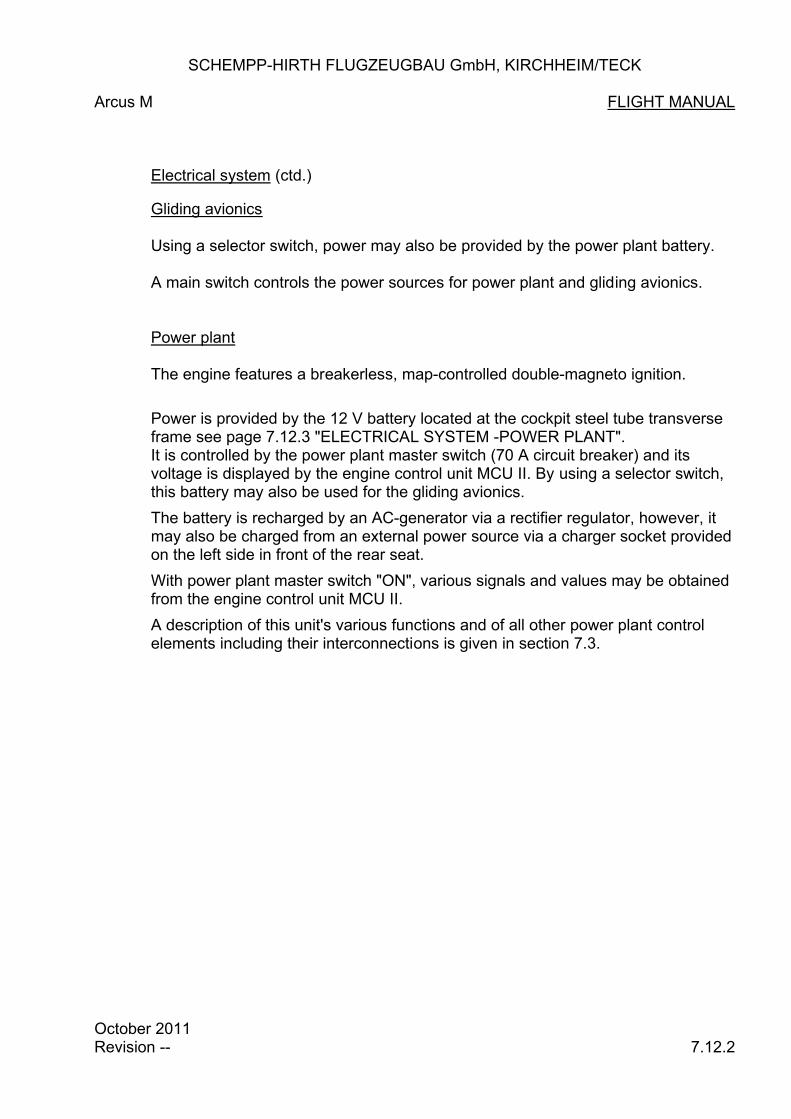
SCHEMPP-HIRTH FLUGZEUGBAU GmbH, KIRCHHEIM/TECK
Arcus M FLIGHT MANUAL Electrical system (ctd.)
Gliding avionics
Using a selector switch, power may also be provided by the power plant battery. A main switch controls the power sources for power plant and gliding avionics. Power plant The engine features a breakerless, map-controlled double-magneto ignition.
Power is provided by the 12 V battery located at the cockpit steel tube transverse frame see page 7.12.3 "ELECTRICAL SYSTEM -POWER PLANT". It is controlled by the power plant master switch (70 A circuit breaker) and its voltage is displayed by the engine control unit MCU II. By using a selector switch, this battery may also be used for the gliding avionics.
The battery is recharged by an AC-generator via a rectifier regulator, however, it may also be charged from an external power source via a charger socket provided on the left side in front of the rear seat.
With power plant master switch "ON", various signals and values may be obtained from the engine control unit MCU II.
A description of this unit's various functions and of all other power plant control elements including their interconnections is given in section 7.3.
October 2011 Revision -- 7.12.2
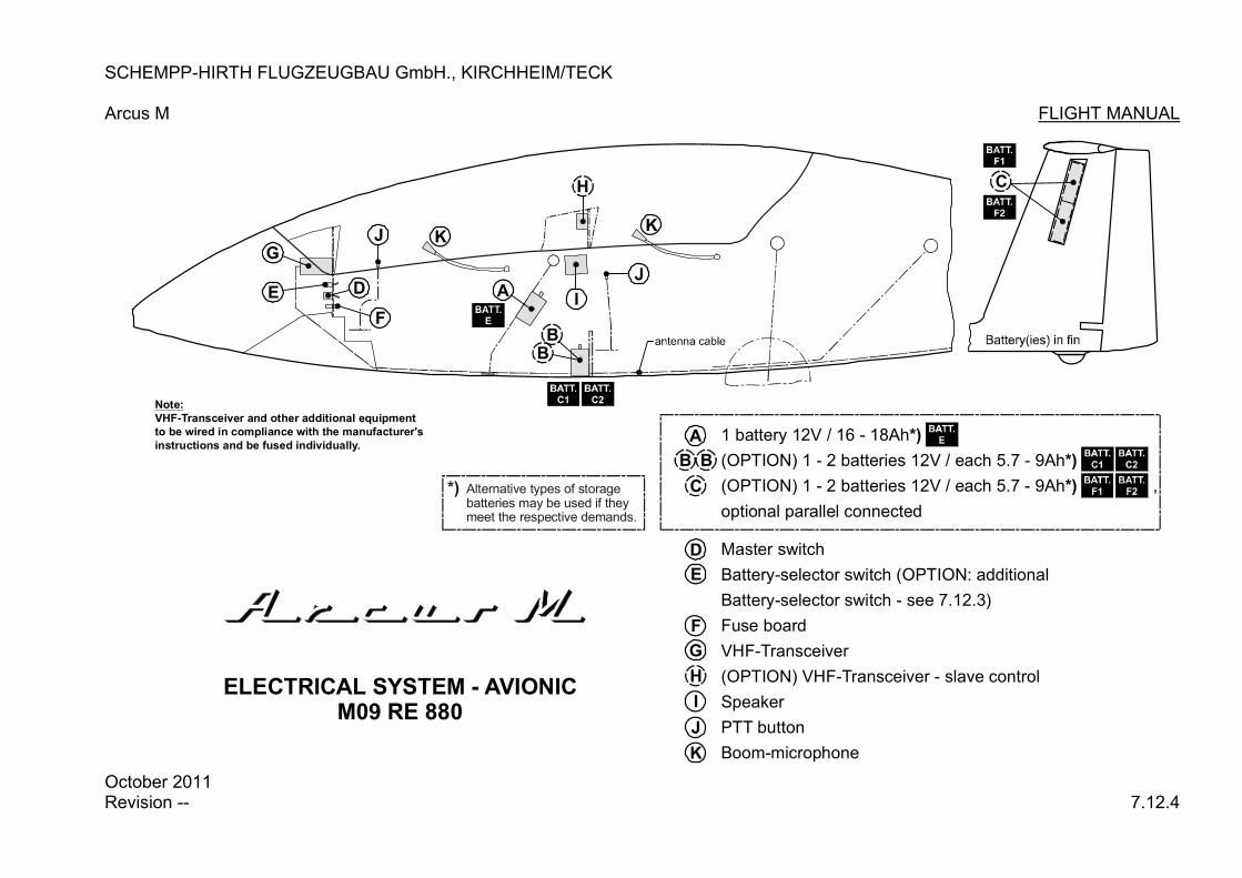
SCHEMPP-HIRTH FLUGZEUGBAU GmbH., KIRCHHEIM/TECK
Arcus M FLIGHT MANUAL
C
A
BB
DE
F
G
H
I
J KK
J
Note:
VHF-Transceiver and other additional equipment
to be wired in compliance with the manufacturer's
instructions and be fused individually.
Alternative types of storagebatteries may be used if theymeet the respective demands.
*)
ELECTRICAL SYSTEM - AVIONIC M09 RE 880
Master switch
Battery-selector switch (OPTION: additional
Battery-selector switch - see 7.12.3)
Fuse board
VHF-Transceiver
(OPTION) VHF-Transceiver - slave control
Speaker
PTT button
Boom-microphone
1 battery 12V / 16 - 18Ah
(OPTION) 1 - 2 batteries 12V / each 5.7 - 9Ah
(OPTION) 1 - 2 batteries 12V / each 5.7 - 9Ah ,
optional parallel connected
*)
*)
*)
A
BB
C
D
E
F
G
H
I
J
K
October 2011 Revision -- 7.12.4

SCHEMPP-HIRTH FLUGZEUGBAU GmbH, KIRCHHEIM/TECK
Arcus M FLIGHT MANUAL
7.13 Miscellaneous equipment
Removable ballast (optional) A mounting provision for removable ballast (trim ballast weights) is provided at the base of the front instrument panel. A second ballast mounting provision is found on the starboard side of the front stick mounting frame. The trim ballast weights (lead plates) are to be secured in place by bolts. For information on how to alter the minimum front seat load refer to section 6.2.
Oxygen systems Attachment points for the mounting brackets for oxygen bottles are provided on the fuselage skin above spar joint on the left and right sides. To prevent injuries, a hood must be installed covering each valve.
For the installation of oxygen systems, drawings may be obtained from the manufacturer. Note: After oxygen systems are installed, it is necessary to re-establish the
empty mass c/g position of the concerned Arcus M to ensure that the centre of gravity is still within the permitted range.
A List of oxygen regulators, currently approved, is found in the Arcus M Maintenance Manual.
October 2011 Revision -- 7.13.1

SCHEMPP-HIRTH FLUGZEUGBAU GmbH, KIRCHHEIM/TECK
Arcus M FLIGHT MANUAL
ELT-installation
The installation of an Emergency Locator Transmitter is possible in the following places and must comply with the instructions obtained from Schempp-Hirth:
„ In the region of the rear seat on either seat pan mounting flange
„ beside the top of the main wheel housing
October 2011 Revision -- 7.13.2

SCHEMPP-HIRTH FLUGZEUGBAU GmbH, KIRCHHEIM/TECK
Arcus M FLIGHT MANUAL Section 8 8. Handling, care and maintenance 8.1 Introduction 8.2 Inspection periods 8.3 Alterations or repairs 8.4 Ground handling / road transportation 8.5 Cleaning and care
October 2011 Revision -- 8.1.1

SCHEMPP-HIRTH FLUGZEUGBAU GmbH, KIRCHHEIM/TECK
Arcus M FLIGHT MANUAL 8.1 Introduction
This section contains manufacturer’s recommended procedures for proper ground handling and servicing of the powered sailplane.
It also identifies certain inspection and maintenance requirements which must be followed if the powered sailplane is to retain optimal performance and dependability.
CAUTION:
It is wise to follow a planned schedule of lubrication and preventative maintenance based on climate and flying conditions encountered -see section 3.2 of the Arcus M Maintenance Manual.
October 2011 Revision -- 8.1.2

SCHEMPP-HIRTH FLUGZEUGBAU GmbH, KIRCHHEIM/TECK
Arcus M FLIGHT MANUAL
8.2 Powered sailplane inspection periods
(for details concerning the maintenance of this powered sailplane refer to its Maintenance Manual)
Airframe maintenance
Under normal operating conditions no airframe maintenance work is required between the annual inspection, except for the routine greasing of the spigots and ball bearings of the wing and tailplane attachment fittings.
Should the control system become heavy to operate, lubricate those places in the fuselage and in the wing panels where plain bearings are used (sliding control rods like u/c- and airbrake linkage). Cleaning and greasing the wheels and the tow release mechanism(s) depends on the accumulation of dirt.
Rudder cables
After every 200 flying hours and at every annual inspection, the rudder cables are to be inspected at the point where they feed through the S-shaped guides in the pedals, especially at the points of maximum pedal adjustment. If the rudder cables are damaged, worn or corroded, they must be replaced. lt is permissible for individual strands of the cables to be worn up to 25 %.
October 2011 Revision -- 8.2.1

SCHEMPP-HIRTH FLUGZEUGBAU GmbH, KIRCHHEIM/TECK
Arcus M FLIGHT MANUAL
Power plant maintenance
Propeller:
Maintenance work on the propeller is required after every 25 hours of engine time or at least once every year and must comply with the instructions given in propeller manual. Engine:
Maintenance work on the engine is required after every 25 hours of engine time or at least once every year and must comply with the instructions given in the engine manual. For all other power plant accessories (pylon, pivoting mechanism, fuel system etc.), maintenance work is also required after every 25 hours of engine time or at least once every year.
October 2011 Revision -- 8.2.2
SCHEMPP-HIRTH FLUGZEUGBAU GmbH, KIRCHHEIM/TECK
Arcus M FLIGHT MANUAL
8.3 Alterations or repairs
Alterations Alterations on the approved model, which might affect its airworthiness, must be reported to the responsible airworthiness authorities p r i o r to their accomplishment. The authorities will then determine whether and to what extent a “supplemental type approval” is to be conducted. In any case, the manufacturer’s opinion about the alteration(s) must be obtained. This ensures that the airworthiness does not become adversely affected and enables the aircraft owner/ operator to demonstrate at any time that the powered sailplane concerned complies with an LBA-approved version. Amendments of the LBA-approved sections of the Flight- and/or Maintenance Manual must in any case be approved by the Luftfahrt Bundesamt (LBA). Repairs Abbreviations:
CFRP: carbon-fibre reinforced plastic GFRP: glass-fibre reinforced plastic
Before every take-off and especially after the powered sailplane has not been used for a while, it should be checked on the ground as shown in section 4.3.
Check for any sign of a change in the condition of the aircraft, such as cracks in the surface, holes, or delamination in the CFRP/GFRP structure etc.
If there is any uncertainty whatsoever regarding the significance of damage discovered, the Arcus M should always be inspected by a CFRP/GFRP expert. There is no objection to minor damage - which does not affect the airworthiness in any way - being repaired on site. A definition of such damage is included in the “REPAIR INSTRUCTIONS" which are found in the appendix to the Arcus M Maintenance Manual. Major repairs may only be conducted by a certified repair station having appropriate authorization.
October 2011 Revision -- 8.3

SCHEMPP-HIRTH FLUGZEUGBAU GmbH, KIRCHHEIM/TECK
Arcus T FLIGHT MANUAL 8.4 Ground handling / road transportation
a) Towing / pushing
When towing the powered sailplane behind a car, a tail dolly should always be used to avoid unnecessary tailplane vibration on the fittings - especially in tight turns. When pushing the aircraft by hand, it should not be pushed at its wing tips, but as near to the fuselage as possible.
b) Hangaring
The powered sailplane should always be hangared or kept in well ventilated conditions. If it is kept in a closed trailer, there must be adequate ventilation. The water ballast tanks and the wing fuel tanks must always be left completely empty. The powered sailplane must never be subjected to loads when not in use, especially in the case of high ambient temperatures.
c) Tie-down
In the case of a powered sailplane remaining rigged permanently, it is important that the maintenance program includes rust prevention for the fittings on fuselage, wing panels and tailplane. Tie-down kits common in trade may be used to anchor the aircraft. Dust covers should be regarded as essential for the powered sailplane.
d) Preparing for road transport
As the wing panels have a thin airfoil section, it is important that they are properly supported, i.e. leading edge down, with support at the spar stubs and at the outer portion in cradles of correct airfoil section. The fuselage can rest on a broad cradle just forward of the u/c doors and on its tail wheel (or skid). The horizontal tailplane should be kept leading edge down in two cradles of correct airfoil section or placed horizontally on a padded support. Under no circumstances should the tailplane be supported by its fittings in the trailer. For the road transport the wing fuel tanks must always be drained completely.
October 2011 Revision -- 8.4

SCHEMPP-HIRTH FLUGZEUGBAU GmbH, KIRCHHEIM/TECK
Arcus M FLIGHT MANUAL 8.5 Cleaning and care
Although the surface coating of a composite aircraft is robust and resistant, always take care to maintain a perfect surface. For cleaning and caring the following is recommended: o Clean the surface (especially the leading edge of wing panels, horizontal
stabilizer and fin) with clear water, a sponge and a chamois leather. o Do not use rinsing additives common in trade too often. o Polish and polishing materials may be used. o Petrol and alcohol may be used momentarily only, thinners of
any kind are not recommended. o Never use chlorine hydrogen (i.e. Tri, Tetra, Per etc.). o The best polishing method is the buffing of the surface by means of an edge
buffing wheel, fitted to a drilling or polishing machine. Thereby hard wax is applied to the rotating disc and distributed crosswise over the surface.
WARNING:
To avoid localized overheating, the buffing wheel should be moved constantly! o For cleaning those fuselage and tailplane areas that are facing the wake of
the propeller, the use of a water soluble degreaser (e.g. FLEET - MAGIC EXTRA by Messrs. Chemsearch) is recommended.
Note: Polishes, wax and additives containing silicone should not be used because this might cause additional work in the case of repairs of the coating.
October 2011 Revision -- 8.5.1

SCHEMPP-HIRTH FLUGZEUGBAU GmbH, KIRCHHEIM/TECK
Arcus M FLIGHT MANUAL
o The canopy should be cleaned with a plexiglass cleaner (e.g. "Mirror Glaze", "Plexiklar” or similar) or with warm water if necessary. The canopy should be wiped down with a soft clean chamois leather or a very soft material such as cotton. N e v e r rub the canopy when it is dry!
o The powered sailplane should always be protected from the wet.
If water is found inside, the components should be stored in a dry environment and turned frequently to eliminate the water.
o The powered sailplane should not be exposed unnecessarily to intense
sunlight or heat and should not be subjected to continual mechanical loads.
WARNING: All external portions of the powered sailplane exposed to sunlight must be painted white with the exception of the areas for the registration and anti-collision markings. Colours other than white can lead to the CFRP/ GFRP overheating in direct sunlight, resulting in insufficient strength.
ctober 2011 8.5.2
ORevision --
SCHEMPP-HIRTH FLUGZEUGBAU GmbH, KIRCHHEIM/TECK
Arcus M FLIGHT MANUAL Section 9 9. Supplements
9.1 Introduction 9.2 List of inserted supplements
October 2011 Revision -- 9.1.1

SCHEMPP-HIRTH FLUGZEUGBAU GmbH, KIRCHHEIM/TECK
Arcus T FLIGHT MANUAL 9.1 Introduction
This section contains the appropriate supplements necessary to safely and efficiently operate the Arcus T when equipped with various optional systems and equipment not provided with the standard aircraft.
October 2010 Revision -- 9.1.2

SCHEMPP-HIRTH FLUGZEUGBAU GmbH, KIRCHHEIM/TECK
Arcus M FLIGHT MANUAL 9.2 List of inserted supplements
Date Section Title of inserted supplements
-- --
9.2