432 Rodney Street
374
432 Rodney Street BROOKLYN, NEW YORK Site Management Plan NYSDEC BCP Site Number: C224216 Prepared for: Rodney Street Investors LLC 123 Hope Street Owner LLC Keap Retail Owner LLC 850 Third Avenue, Suite 16B New York, New York 10022 Prepared by: Langan Engineering, Environmental, Surveying and Landscape Architecture, D.P.C. 360 W 31 st Street, New York, NY 10001 (212) 479-5400 Revisions to Final Approved Site Management Plan: Revision # Submitted Date Summary of Revision DEC Approval Date DECEMBER 14, 2017
-
Upload
khangminh22 -
Category
Documents
-
view
0 -
download
0
Transcript of 432 Rodney Street

432 Rodney Street
BROOKLYN, NEW YORK
Site Management Plan
NYSDEC BCP Site Number: C224216
Prepared for:
Rodney Street Investors LLC
123 Hope Street Owner LLC
Keap Retail Owner LLC
850 Third Avenue, Suite 16B
New York, New York 10022
Prepared by:
Langan Engineering, Environmental, Surveying and Landscape
Architecture, D.P.C.
360 W 31st Street, New York, NY 10001
(212) 479-5400
Revisions to Final Approved Site Management Plan:
Revision # Submitted Date Summary of Revision DEC Approval Date
DECEMBER 14, 2017

Site Management Plan
432 Rodney Street
Brooklyn, New York
Langan Project No. 170357801
December 14, 2017
TABLE OF CONTENTS
EXECUTIVE SUMMARY ................................................................................................................. i
1.0 INTRODUCTION ................................................................................................................. 1
1.1 General ........................................................................................................................... 1 1.2 Revisions ........................................................................................................................ 3 1.3 Notifications ................................................................................................................... 3
2.0 SUMMARY OF PREVIOUS INVESTIGATIONS AND REMEDIAL ACTIONS .................. 5
2.1 Site Location and Description ...................................................................................... 5 2.2 Physical Setting ............................................................................................................. 5
2.2.1 Land Use ................................................................................................................. 5
2.2.2 Geology................................................................................................................... 7
2.2.3 Hydrogeology ......................................................................................................... 8
2.3 Investigation and Remedial History ............................................................................ 8 2.3.1 Site History ............................................................................................................. 8
2.3.2 Previous Environmental Reports ....................................................................... 10
2.3.3 Summary of Remedial Investigation Findings ................................................. 14
2.4 Remedial Action Objectives ....................................................................................... 16 2.4.1 IRMWP, Addenda, and Remedial Action Implementation .............................. 16
2.4.2 Removal of Contaminated Materials from Lots 1 and 31 ................................ 18
2.4.3 Removal of Aboveground Storage Tanks ......................................................... 19
2.4.4 Removal of Underground Storage Tanks ......................................................... 19
2.4.5 Groundwater Treatment ..................................................................................... 19
2.5 Remaining Contamination .......................................................................................... 20 2.5.1 Remaining Soil Contamination .......................................................................... 20
2.5.2 Remaining Groundwater Contamination.......................................................... 21
2.5.3 Remaining Soil Vapor Contamination ............................................................... 22
3.0 INSTITUTIONAL AND ENGINEERING CONTROL PLAN............................................... 23
3.1 General ......................................................................................................................... 23 3.2 Institutional Controls .................................................................................................. 23 3.3 Engineering Controls................................................................................................... 26
3.3.1 Composite Cover System ................................................................................... 26
3.3.2 Vapor Barrier Membrane .................................................................................... 27
3.3.3 Sub-Membrane Depressurization System ........................................................ 27
3.3.4 Groundwater Treatment System ....................................................................... 28
3.3.5 Criteria for Completion of Remediation/Termination of Remedial Systems 28
4.0 MONITORING AND SAMPLING PLAN ........................................................................... 30
4.1 General ......................................................................................................................... 30 4.2 Site-Wide Inspection ................................................................................................... 30 4.3 Engineering Control Monitoring ................................................................................ 32

Site Management Plan
432 Rodney Street
Brooklyn, New York
Langan Project No. 170357801
December 14, 2017
4.3.1 Composite Cover System Inspections .............................................................. 32
4.3.2 SMDS Monitoring ................................................................................................ 32
4.4 Post-Remediation Monitoring and Sampling ........................................................... 33 4.4.1 Soil Vapor Intrusion Evaluation Sampling........................................................ 33
4.4.2 Groundwater Monitoring and Sampling ........................................................... 34
5.0 OPERATION AND MAINTENANCE PLAN ...................................................................... 37
5.1 Introduction .................................................................................................................. 37 5.2 SMDS Operation and Maintenance ........................................................................... 37
5.2.1 Scope .................................................................................................................... 37
5.2.2 System Start-Up and Testing ............................................................................. 37
5.2.3 System Operation ................................................................................................ 38
5.2.4 System Maintenance ........................................................................................... 38
5.3 SMDS Performance Monitoring ................................................................................. 39 5.3.1 Monitoring Schedule ........................................................................................... 39
5.3.2 General Equipment Monitoring ......................................................................... 40
5.3.3 Sampling Event Protocol .................................................................................... 40
5.4 Maintenance and Performance Monitoring Reporting Requirements ................... 40 5.4.1 Routine Maintenance Reports ............................................................................ 40
5.4.2 Non-Routine Maintenance Reports ................................................................... 41
5.5 Groundwater Treatment System Operation and Maintenance ............................. 41
6.0 PERIODIC ASSESSMENTS/EVALUATION .................................................................... 42
6.1 Climate Change Vulnerability Assessment .............................................................. 42 6.2 Green Remediation Evaluation .................................................................................. 42
6.2.1 Timing of Green Remediation Evaluations ....................................................... 43
6.2.2 Mitigation Systems ............................................................................................. 43
6.2.3 Frequency of System Checks, Sampling and Other Periodic Activities ........ 43
6.3 Mitigation System Optimization ............................................................................... 43
7.0 REPORTING REQUIREMENTS ........................................................................................ 45
7.1 Site Management Reports .......................................................................................... 45 7.2 Periodic Review Report ............................................................................................... 46
7.2.1 Certification of Engineering and Institutional Controls ................................... 48
7.3 Corrective Measures Plan ........................................................................................... 49 7.4 Remedial Site Optimization Report ........................................................................... 49
8.0 REFERENCES .................................................................................................................... 50

Site Management Plan
432 Rodney Street
Brooklyn, New York
Langan Project No. 170357801
December 14, 2017
TABLES
Table 1 Groundwater Elevation Data Summary
Table 2 Track 2 Restricted Residential Use Soil Cleanup Objectives
Table 3 Protection of Groundwater Soil Cleanup Objectives
Table 4 Performance Monitoring and Injection Well Construction Summary
Table 5 Documentation Sample Detection Summary
Table 6 Track 4 Site-Specific Soil Cleanup Objectives
FIGURES
Figure 1 Site Location Map
Figure 2 Site Layout Plan
Figure 3A Subsurface Profile A-A’
Figure 3B Subsurface Profile B-B’
Figure 4A Shallow Groundwater Contour Map
Figure 4B Deep Groundwater Contour Map
Figure 5 Treatment Area Location Plan and Performance Monitoring Well
Locations
Figure 6 Documentation Sample Location
Figure 7 Engineering Controls Map
Figure 8 SMDS Layout Plan
APPENDICES
Appendix A Environmental Easements
Appendix B Remedial Investigation Soil Boring Logs
Appendix C Remedial Investigation Monitoring Well Construction Logs
Appendix D Groundwater Treatment System Design
Appendix E Excavation Work Plan
Appendix F Sample Health and Safety Plan
Appendix G Vapor Barrier Manufacturer Details
Appendix H SMDS As-built Drawing and Design Details
Appendix I Quality Assurance Protection Plan
Appendix J Inspection Forms and Checklists
Appendix K Sample Groundwater Sampling Log
Appendix L SMDS Operation and Maintenance Manuals

Site Management Plan
432 Rodney Street
Brooklyn, New York
Langan Project No. 170357801
December 14, 2017
LIST OF ACRONYMS
AGV Air Guidance Value
AST Aboveground Storage Tank
AWQS Ambient Water Quality Standards
BCA Brownfield Cleanup Agreement
BCP Brownfield Cleanup Program
bgs Below Grade Surface
BTEX Benzene, Toluene, Ethylbenzene, and Xylene
CAMP Community Air Monitoring Plan
COC Certificate of Completion
CU Commercial Use
CVOC Chlorinated Volatile Organic Compound
DO Dissolved Oxygen
EC Engineering Control
ECL Environmental Conservation Law
ELAP Environmental Laboratory Accreditation Program
ESA Environmental Site Assessment
ESI Environmental Site Investigation
EWP Excavation Work Plan
FEMA Federal Emergency Management Agency
GPR Ground-Penetrating Radar
HASP Health and Safety Plan
HDPE High Density Polyethylene
IC Institutional Control
IRMWP Interim Remedial Measures Work Plan
ISCO In-Situ Chemical Oxidation
µg/L Microgram Per Liter
µg/m3 Microgram Per Cubic Meter
mg/kg Milligram Per Kilogram
mg/L Milligram Per Liter
MSO Mitigation System Optimization
NAVD88 North American Vertical Datum of 1988
NYCDEP New York City Department of Environmental Protection
NYS New York State
NYSDEC New York State Department of Environmental Conservation
NYSDOH New York State Department of Health
NYCRR New York Codes, Rules and Regulations
O&M Operation and Maintenance
ORP Oxidation/Reduction Potential
PAH Polycyclic Aromatic Hydrocarbons
PCB Polychlorinated Biphenyl
PCE Tetrachloroethene
PG Protection of Groundwater
PID Photoionization Detector
ppm Parts Per Million

Site Management Plan
432 Rodney Street
Brooklyn, New York
Langan Project No. 170357801
December 14, 2017
PRR Periodic Review Report
PVC Polyvinyl Chloride
QAPP Quality Assurance Project Plan
QA/QC Quality Assurance/Quality Control
RAO Remedial Action Objective
RAWP Remedial Action Work Plan
RCRA Resource Conservation and Recovery Act
REC Recognized Environmental Condition
RI Remedial Investigation
RIR Remedial Investigation Report
RRU Restricted Use – Restricted Residential
SCG Standards, Criteria, and Guidance
SCO Soil Cleanup Objective
SOD Soil Oxidant Demand
SGV Standards and Guidance Values
SMDS Sub-Membrane Depressurization System
SMP Site Management Plan
SVOC Semivolatile Organic Compound
TCE Trichloroethene
TCLP Toxicity Characteristic Leaching Procedure
TOGS Technical and Operational Guidance Series
µg/m3 Microgram Per Cubic Meter
UST Underground Storage Tank
UU Unrestricted Use
VOA Volatile Organic Analysis
VOC Volatile Organic Compound

Site Management Plan December 14, 2017
432 Rodney Street Page i
Brooklyn, New York
Langan Project No. 170357801
EXECUTIVE SUMMARY
The following provides a brief summary of the controls implemented for the site, as well
as the inspections, monitoring, maintenance and reporting activities required by this Site
Management Plan (SMP).
Site Identification: C224216 432 Rodney Street
Institutional Controls: 1. The property may only be used for restricted residential,
commercial, and industrial uses provided the Engineering
Controls (ECs) and Institutional controls (ICs) included in
this SMP are employed.
2. The property may not be used for a higher level of use,
such as residential or unrestricted use, without additional
remediation and amendment of the Environmental
Easements, as approved by the New York State
Department of Environmental Conservation (NYSDEC).
3. All future activities on the property that will disturb
residual contaminated material must be conducted in
accordance with this SMP.
4. The use of the groundwater underlying the property is
prohibited without necessary water quality treatment as
determined by the New York State Department of Health
(NYSDOH) or the New York City Department of Health
and Mental Hygiene, or the New York City Department of
Environmental Protection (NYCDEP).
5. Vegetable gardens and farming in residual Site soil are
prohibited.

Site Management Plan December 14, 2017
432 Rodney Street Page ii
Brooklyn, New York
Langan Project No. 170357801
Site Identification: C224216 432 Rodney Street
Institutional Controls:
(continued)
6. The remedial party will submit to NYSDEC a written
statement that certifies, under penalty of perjury, that:
a. Property controls are unchanged from the previous
certification or that any changes to the controls were
NYSDEC-approved; and,
b. Nothing has occurred that impairs the ability of the
controls to protect public health and environment or
that constitute a violation or failure to comply with the
SMP. NYSDEC retains the right to access the property
at any time to evaluate the maintenance of any and all
engineering controls.
7. Compliance with the Environmental Easements by the
Grantor and the Grantor’s successors and assigns, and
compliance with this SMP by the remedial party and its
successors and assigns.
8. All ECs must be operated and maintained as specified in
this SMP.
9. All ECs on the Controlled Property must be inspected at a
frequency and in a manner defined in the SMP.
10. Data and information pertinent to site management must
be reported at the frequency and in a manner defined in
this SMP.
Engineering Controls: 1. Composite Cover System
2. Vapor Barrier
3. Sub-membrane Depressurization System
4. Groundwater Treatment System

Site Management Plan December 14, 2017
432 Rodney Street Page iii
Brooklyn, New York
Langan Project No. 170357801
Site Identification: C224216 432 Rodney Street
Inspections: Frequency:
1. Site-wide Inspection Annually
2. Composite Cover System Inspection Annually
3. Vapor Barrier Inspection Annually
4. Sub-membrane Depressurization System
Inspection
Annually
5. Groundwater Treatment System Inspection Annually
Maintenance:
1. Sub-membrane Depressurization System
Maintenance
As Needed
2. Groundwater Treatment System Maintenance As Needed
Reporting:
1. Groundwater Monitoring Report Quarterly during the first
year after the injection
event and semi-annually
thereafter
2. Site Management Report Included in Periodic
Review Report (PRR)
3. PRR Annually
4. Remedial Site Optimization Report If requested by NYSDEC
Further descriptions of the requirements are provided in detail in the latter sections of
this Site Management Plan.

Site Management Plan December 14, 2017
432 Rodney Street Page 1
Brooklyn, New York
Langan Project No. 170357801
1.0 INTRODUCTION
1.1 General
This Site Management Plan (SMP) is a required element of the remedial program at 432
Rodney Street in Brooklyn, New York (hereinafter referred to as the “site”). The Site is
in the New York State (NYS) Brownfield Cleanup Program (BCP), Brownfield Cleanup
Agreement (BCA) Index #C224216-09-30, Site #C224216, which is administered by the
New York State Department of Environmental Conservation (NYSDEC).
Rodney Street Investors LLC (the “Volunteer”) executed a BCA with NYSDEC on
September 30, 2015, to investigate and remediate the site. On April 8, 2016, 123 Hope
Street Owner LLC and Keap Retail Owner LLC were added as Volunteers to the BCA.
The site is identified as Block 2374, Lots 1, 27, 28 and 31 on the Brooklyn Borough Tax
Map and occupies an area of about 27,160 square feet (±0.6235 acres). A Site Location
Map and Site Plan are provided as Figures 1 and 2, respectively. The boundaries of the
site are more fully described in the metes and bounds site descriptions that are part of
the recorded Environmental Easements, included in Appendix A.
Remediation was performed in accordance with the NYSDEC-approved Remedial Action
Work Plan (RAWP), dated March 23, 2017, the NYSDEC-approved Interim Remedial
Measures Work Plan (IRMWP), dated March 22, 2016, and the NYSDEC-approved
IRMWP Addenda #1 and #2, dated January 9, 2017. Under these plans, a Track 2
remedy was implemented on Lots 1 and 31 and Lots 27 and 28 follow a Track 4
remedy. Site remediation included:
Lots 1 and 31
Removal of two aboveground storage tanks (ASTs) and four underground
storage tanks (USTs);
Excavation of soil to the groundwater table;
Import of acceptable materials used for backfill and cover;
Installation of pressurized injection wells and groundwater monitoring wells for
post-construction groundwater treatment;
Direct-injection of base-activated sodium persulfate to pretreat petroleum-related
volatile organic compounds (VOCs) in groundwater;
Injection of PlumeStop® to address residual petroleum-related VOC and
chlorinated volatile organic compound (CVOC) impacts to groundwater through
the network of pressurized injection wells; and

Site Management Plan December 14, 2017
432 Rodney Street Page 2
Brooklyn, New York
Langan Project No. 170357801
Installation of a soil vapor mitigation system.
Lots 27 and 28
Direct-injection of PlumeStop® to address residual petroleum-related VOC and
CVOC impacts to groundwater
Installation of a soil vapor mitigation system as part of this SMP
Following completion of the NYSDEC-approved remedy, residual contamination was left
in place, which is hereafter referred to as “remaining contamination.” Institutional
Controls (ICs) and Engineering Controls (ECs) have been incorporated into the site
remedy to control exposure to remaining contamination to ensure protection of public
health and the environment. Environmental Easements were filed with NYSDEC on
October 27, 2017, and recorded with the Kings County Clerk on November 27, 2017, for
Lots 27 and 28, and on November 29, 2017, for Lots 1 and 31. The Environmental
Easements require compliance with this SMP and all ECs and ICs placed on the site.
This SMP was prepared to manage the remaining contamination in accordance with
Environmental Conservation Law (ECL) Article 71, Title 36. This SMP, which details the
site-specific implementation procedures required under the Environmental Easements,
has been approved by the NYSDEC, and compliance with the SMP is required by the
grantor of the Environmental Easements and the grantor’s successors and assigns.
This SMP may be revised only with the approval of the NYSDEC. Failure to properly
implement the SMP is a violation of the Environmental Easements, which is grounds for
revocation of the COC. Failure to comply with this SMP is also a violation of
Environmental Conservation Law, Title 6 of the Official Compilation of the New York
Codes, Rules and Regulations (6 NYCRR) Part 375, and the BCA (Index #C224216-09-
30, Site #C224216) for the site, and thereby subject to applicable penalties.
All reports associated with the site can be viewed by contacting the NYSDEC or its
successor agency managing environmental issues in New York State.
This SMP was prepared by Langan Engineering, Environmental, Surveying and
Landscape Architecture, D.P.C (Langan), on behalf of the Volunteer, in accordance with
the requirements in the NYSDEC DER-10 Technical Guidance for Site Investigation and
Remediation, dated May 3, 2010, and the guidelines provided by NYSDEC. This SMP
addresses the means for implementing the ICs and ECs required by the Environmental
Easements.

Site Management Plan December 14, 2017
432 Rodney Street Page 3
Brooklyn, New York
Langan Project No. 170357801
1.2 Revisions
SMP revisions will be proposed in writing to the NYSDEC’s project manager. Revisions
will be necessary upon, but not limited to, the following occurring: a change in media
monitoring requirements, upgrades to or shut-down of a remedial system, post-remedial
removal of contaminated sediment or soil, or other significant change to site conditions.
In accordance with the Environmental Easements, the NYSDEC will provide a notice of
any approved changes to the SMP, and append these notices to the SMP retained in its
files.
1.3 Notifications
Notifications will be submitted by the Volunteer to the NYSDEC, as needed, in
accordance with NYSDEC’s DER-10 for the following reasons:
60-day advance notice of any proposed changes in site use as required under the
terms of the BCA, 6 NYCRR Part 375 and/or Environmental Conservation Law.
7-day advance notice of any field activity associated with the remedial program.
15-day advance notice of any proposed ground-intrusive activity pursuant to the
Excavation Work Plan.
Notice within 48-hours of any damage or defect to the foundation, structures or
ECs that reduces or has the potential to reduce the effectiveness of an EC, and
likewise, any action to be taken to mitigate the damage or defect.
Verbal notice by noon of the following day of any emergency, such as a fire,
flood, or earthquake, that reduces or has the potential to reduce the
effectiveness of ECs, with written confirmation within 7 days that includes a
summary of actions taken, or to be taken, and the potential impact to the
environment and the public.
Follow-up status reports on actions taken to respond to any emergency event
requiring ongoing responsive action submitted to the NYSDEC within 45 days
describing and documenting actions taken to restore the effectiveness of the
ECs.
Any change in the ownership of the site or the responsibility for implementing this SMP
will include the following notifications:

Site Management Plan December 14, 2017
432 Rodney Street Page 4
Brooklyn, New York
Langan Project No. 170357801
At least 60 days prior to the change, the NYSDEC will be notified in writing of
the proposed change. This will include a certification that the prospective
purchaser/Remedial Party has been provided with a copy of the BCA and all
approved work plans and reports, including this SMP.
Within 15 days after the transfer of all or part of the site, the new owner’s name,
contact representative, and contact information will be confirmed in writing to
the NYSDEC.
The following table includes contact information for the above notification. The
information on this table will be updated as necessary to provide accurate contact
information.
Program Manager: Michael D. Burke (212) 479-5413
Project Manager: Brian Gochenaur, (212) 479-5479
New York State Department of
Health (NYSDOH) Project
Manager:
Steven Berninger, (518) 402-7860
NYSDEC Project Manager: Kerry Maloney, (518) 402-9622
Owner Representative: Jesse Dorfman, (646) 439-6000 x623

Site Management Plan December 14, 2017
432 Rodney Street Page 5
Brooklyn, New York
Langan Project No. 170357801
2.0 SUMMARY OF PREVIOUS INVESTIGATIONS AND REMEDIAL ACTIONS
2.1 Site Location and Description
The site is located at 432 Rodney Street in the Williamsburg neighborhood of Brooklyn,
New York and is identified as Block 2374, Lots 1, 27, 28 and 31 on the Brooklyn
Borough Tax Map. The 27,160-square-foot (±0.6235 acres) parcel is bound by a vacant
lot and residential and commercial buildings followed by Ainslie Street to the north,
Hope Street to the south, Keap Street to the east, and Rodney Street to the west. The
boundaries of the site are described in the metes and bounds site description that is
provided in the Environmental Easements included as Appendix A. A Site Location Map
and Site Plan are presented as Figures 1 and 2, respectively.
2.2 Physical Setting
2.2.1 Land Use
The site is located in an urban setting characterized by residential, commercial, and light
industrial buildings. The following is a summary of adjoining and surrounding property
usage:
Direction Block Lot Adjoining Properties Surrounding Properties
North 2374
7 Gravel-covered vacant lot
(442 Rodney Street)
Multiple-story mixed-use
residential and commercial
buildings and vacant lots
16 2-story commercial building
(52-54 Ainslie Street)
23 Three 3-story residential
buildings
(449 Keap Street)
25 3-story residential building
(445 Keap Street)
26 3-story residential building
(443 Keap Street)
South 2386
4 Three 2-story residential
buildings
(428 Rodney Street) Multiple-story mixed-use
residential and commercial
buildings and industrial
buildings
7 1-story industrial building
(118 Hope Street)
12 1-story commercial building
(130 Hope Street)
14 1-story industrial building
(138 Hope Street)
East 2375 1 2-story residential building
(450 Keap Street)
Multiple-story industrial
buildings

Site Management Plan December 14, 2017
432 Rodney Street Page 6
Brooklyn, New York
Langan Project No. 170357801
Direction Block Lot Adjoining Properties Surrounding Properties
West 2370 1
Undeveloped land followed by
the Brooklyn-Queens
Expressway
Multiple-story mixed-use
residential and commercial
buildings and industrial
buildings
Land use within a half mile of the site is urbanized and includes mixed use buildings,
subway tunnels, park land, and school facilities. The nearest ecological receptor is
McCarren Park, located about 2,000 feet north of the site. Sensitive receptors located
within a half-mile of the site are listed in the following table:
Number Name
(Approximate distance from site) Address
1 Jamie Campiz Playground
(approximately 300 feet northwest)
Southeast corner of
Metropolitan Ave and Marcy
Ave
Brooklyn, NY 11211
2 Rodney Playground North
(approximately 500 feet southwest)
West of Rodney Street
(between S 1st Street and
Division Avenue)
Brooklyn, NY 11211
3 Macri Triangle
(approximately 0.12 miles north)
Northwest corner of
Metropolitan Avenue and
Union Avenue
Brooklyn, NY 11211
4 La Guardia Playground
(approximately 0.3 miles southwest)
West of Havemeyer Street
(between S 4th Street and S
5th Street)
Brooklyn, NY 11211
5 Martinez Playground
(approximately 0.5 miles southeast)
195 Graham Avenue
Brooklyn, NY 11206
6 Sternberg Park
(approximately 0.5 miles southeast)
Between Montrose Ave and
Boerum Street and Between
Lorimer Street and Leonard
Street
Brooklyn, NY 11206
7 McCarren Park
(approximately 0.5 miles north)
North of Bayard Street and N
12th Street between
Manhattan Avenue and Berry
Street
Brooklyn, NY 11122

Site Management Plan December 14, 2017
432 Rodney Street Page 7
Brooklyn, New York
Langan Project No. 170357801
Number Name
(Approximate distance from site) Address
8 Two By Two Childcare and Preschool
(approximately 415 feet southeast)
418 Keap St,
Brooklyn, NY 11211
9 PS 319
(approximately 0.2 miles south)
360 Keap St,
Brooklyn, NY 11211
10 PS 19 Roberto Clemente
(approximately 0.2 miles south)
325 South 3rd St,
Brooklyn, NY 11211
11 Harry Van Arsdale High School
(approximately 0.2 miles northwest)
257 North 6th St,
Brooklyn, NY 11211
12 Williamsburg Northside School
(approximately 0.2 miles northwest)
70 Havemeyer St,
Brooklyn, NY 11211
13 PS 17 Henry D Woodworth
(approximately 0.25 miles northwest)
208 North 5th St,
Brooklyn, NY 11211
14 Nuestros Ninos Day Care Center
(approximately 0.3 miles southwest)
243 South 2nd Street,
Brooklyn, NY 11211
15 New York United Day Care
(approximately 0.3 miles south)
349 Keap St,
Brooklyn, NY 11211
16 Williamsburg Northside School
(approximately 0.4 miles northwest)
152 North 5th St,
Brooklyn, NY 11211
17 Stagg Street Center for Children
(approximately 0.4 miles southeast)
77 Stagg St #83,
Brooklyn, NY 11206
18 El Puente Academy
(approximately 0.5 miles southwest)
211 South 4th Street,
Brooklyn, New York 11211
19 JHS 50 John D Wells
(approximately 0.5 miles southwest)
183 South 3rd St,
Brooklyn, NY 11211
20 PS 18 Edward Bush
(approximately 0.5 miles southeast)
101 Maujer St,
Brooklyn, NY 11206
21 PS 132 Conselya
(approximately 0.5 miles northeast)
320 Manhattan Ave,
Brooklyn, NY 11211
22 Nuestros Ninos Day Care Center
(approximately 0.5 miles west)
161 South 3rd Street,
Brooklyn, NY 11211
23 Jonathan Williams Childcare Center
(approximately 0.5 miles southwest)
321 Roebling St,
Brooklyn, NY 11211
2.2.2 Geology
Soil borings completed during Langan’s Remedial Investigation (RI) identified a layer of
historic fill to depths ranging from 4 to 11 feet below surface grade (bgs). The fill
material generally consisted of brown, fine to medium sand with varying amounts of
gravel, brick, concrete, asphalt, silt, glass, wood and slag. Historic fill material was

Site Management Plan December 14, 2017
432 Rodney Street Page 8
Brooklyn, New York
Langan Project No. 170357801
underlain by glacial moraine followed by a lacustrine unit throughout the site. The
moraine typically consists of silty sand, predominantly composed of loose brownish
medium sands, with no observable distinct bedding. The lacustrine unit is likely a
former lake depositional area as it is composed of interbedded hard gray clay and dense
light gray fine sands. Bedrock was not encountered during Langan’s RI or any of the
previous investigations.
Subsurface cross sections are shown in Figures 3A and 3B. RI soil boring logs are
provided in Appendix B.
2.2.3 Hydrogeology
Synoptic groundwater level measurements were collected on June 15, 16, and 17,
2016. Observations of the shallow wells indicated that the water table is generally flat
across the site. The shallow groundwater contours suggest shallow water flow across
the site to the northeast (likely due to a perched water table), while deep wells indicate
groundwater flows towards the southwest. Further north and east, the perched water
table is absent revealing the nearly flat water table defining the rest of the site. Shallow
and deep groundwater contour maps are shown in Figures 4A and 4B, respectively.
Groundwater elevation data is provided in Table 1. Groundwater monitoring well
construction logs are provided in Appendix C.
There are no wetlands on or immediately adjacent to the site. Groundwater in this area
of New York City is not used as a potable (drinking) water source. New York City
residents receive their drinking water supply from surface reservoirs located in upstate
New York.
2.3 Investigation and Remedial History
The following narrative provides a remedial history timeline and a brief summary of the
available project records to document key investigative and remedial milestones for the
site. Full titles for each of the reports referenced below are provided in Section 8.0 -
References.
2.3.1 Site History
According to historical documentation, including Sanborn Fire Insurance Maps, aerial
photographs, and city directories, the site was developed with several multi-level
residential and commercial buildings as early as 1887.
Lot 1: The lot was developed for residential purposes from at least 1887.
Between 1905 and 1916 a portion of the lot transitioned uses between a wagon
Site Management Plan December 14, 2017
432 Rodney Street Page 9
Brooklyn, New York
Langan Project No. 170357801
shed and storage facility. By 1942, the lot was developed as a poultry market
and automotive garage with three gasoline tanks (one located in the
southeastern corner and two located along the western perimeter). By 1951,
one of the two gasoline tanks along the western perimeter had been removed.
In 1965 the building was used as a machine shop and two USTs remained. By
1972, the building was used as a sugar warehouse and existed as such until its
demolition in 2016. The USTs were not depicted on Sanborn maps after 1972,
but there is no clear evidence that they were removed. Ground-penetrating
radar (GPR) performed as a part of the waste characterization investigation,
conducted by Langan in April 2016, did not identify anomalies indicative of buried
tanks.
Lot 27: The lot was occupied by a store as early as 1887. On the 1942 Sanborn
Map, the store had been demolished and replaced with a new building that
housed a smoked fish facility. The building was used as a transportation depot
by 1978 and was converted to its present use as a warehouse by 1989. The
warehouse is currently vacant awaiting redevelopment.
Lot 28: The lot was developed for residential purposes as early as 1887. By
1942, the dwellings were demolished and replaced with an automotive garage
with one gasoline tank. The building was converted to its most recent use as a
warehouse by 1989. The warehouse is currently vacant awaiting
redevelopment.
Lot 31: The lot was developed with several residential buildings and a
commercial building as early as 1887. The commercial building was identified as
“Mason’s Materials” in 1887 and an office in 1916. The buildings were
demolished and replaced with an automotive garage with a gasoline tank
between 1916 and 1942. The automotive garage occupied the lot until at least
2007. The building, having been used in conjunction with the sugar warehouse
operation on Lot 1 after automotive operations had ceased, was demolished in
2016.
Adjoining properties were also historically used for residential, commercial, and
industrial operations. Historical records indicate several automotive-related facilities,
and commercial and industrial properties were located in the vicinity of the site,
including a municipal electric light company (1905), a printing facility (1905), transformer
stations (1916-present), a factory to the north (1916); and garages with gasoline tanks
(1942-1951), factories (1942-2007), and a dry cleaning facility (at least 1998-2006) were
located to the south.
Site Management Plan December 14, 2017
432 Rodney Street Page 10
Brooklyn, New York
Langan Project No. 170357801
One NYSDEC spill remains open at the site. Spill No. 1500614 was reported on April
14, 2015, when petroleum contamination was identified during the Hydro Tech Phase II
ESI (dated April 16, 2015).
2.3.2 Previous Environmental Reports
The following is a list of previous environmental documents that were reviewed:
Phase I Environmental Site Assessment(ESA), dated February 2, 2015, prepared
by Hydro Tech
Phase II ESI, dated April 16, 2015, prepared by Hydro Tech
Waste Characterization Report, dated May 5, 2016, prepared by Langan
A summary of each report is provided below:
Phase I Environmental Site Assessment, prepared by Hydro Tech, dated February 2,
2015
According to Hydro Tech, the Phase I ESA report was prepared in accordance with the
ASTM International (ASTM) E 1527-13 for the properties located at 432 Rodney Street,
123 Hope Street, 129 Hope Street, and 441 Keap Street in Brooklyn, New York. The
Phase I ESA included a review of historical information, a site and vicinity
reconnaissance, a review of available regulatory agency databases, and a review of local
environmental records.
At the time that the Phase I was performed, the site was occupied by a one-story
packaged food distribution warehouse and shipping facility with two partial basements
owned and operated by Quaker Sugar Company, Inc. According to historical
documentation, including Sanborn Fire Insurance Maps, aerial photographs and city
directories, the site was developed with several multi-level residential and commercial
buildings as early as 1887. Based on their assessment, Hydro Tech identified the
following Recognized Environmental Conditions (RECs):
Suspect presence of USTs
Historical use of the site as a “Mason’s Materials” shop and a motor freight
station
The hazardous materials “E” Designation assigned to the property
Presence of a potential vapor encroachment condition
Presence of suspect lead-based paint

Site Management Plan December 14, 2017
432 Rodney Street Page 11
Brooklyn, New York
Langan Project No. 170357801
Phase II ESI, prepared by Hydro Tech, dated April 16, 2015
The Phase II ESI was completed to evaluate potential impacts to soil, groundwater and
soil vapor from the RECs identified in the Phase I ESA. The Phase II ESI included: a
geophysical survey using GPR, advancement of 10 soil borings (SP-1 through SP-10),
installation of five groundwater wells and seven soil vapor probes, and collection of 20
grab soil samples, five groundwater samples, and seven soil vapor samples.
Soil borings were advanced to depths ranging from about 4 to 16 feet bgs.
Groundwater wells were installed to about 24 feet bgs and constructed with 1-inch
diameter, 15 foot well screens. Soil vapor probes were installed at a minimum depth of
6 feet bgs.
Langan reviewed the Phase II ESI in August 2015 as a part of the preparation of the
IRMWP and noted the following:
The GPR survey identified two anomalies consistent with USTs on Lots 28 and
31. These USTs were likely the gasoline tanks documented on the Sanborn
maps.
Historic fill material was encountered below the existing building slab to depths
of up to 14 feet bgs. Soil beneath historic fill was generally characterized as light
brown sand, with varying amounts of clay.
Depth to groundwater ranged from about 15.80 to 17.34 feet bgs. Groundwater
flow direction was inferred to the north. No free product was documented
during groundwater sampling. NOTE – Groundwater was encountered at a
depth of roughly 10 feet during Langan’s RI
Petroleum-like odors and photoionization detector (PID) readings up to 430 parts
per million (ppm) were identified in several borings located in the south-central
portion of the site in Lots 28 and 31 to depths of up to 14 feet bgs.
No polychlorinated biphenyls (PCBs) or pesticides were detected in soil samples
collected.
Soil analytical results were compared to the NYSDEC 6 NYCRR Part 375
Unrestricted Use (UU) and Restricted Use – Restricted Residential (RRU) SCOs.
The results indicated soil samples contained impacts associated with historic fill
material, petroleum use and chlorinated solvents.
o Semivolatile organic compounds (SVOCs) primarily polycyclic aromatic
hydrocarbons (PAHs), and metals (arsenic, barium, chromium, copper,
lead, mercury and zinc) were detected above their respective UU and
Site Management Plan December 14, 2017
432 Rodney Street Page 12
Brooklyn, New York
Langan Project No. 170357801
RRU SCOs in the surface samples from SP-1, SP-3 and SP-9. These
detections are attributed to the historic fill quality. Because of the total
lead concentrations detected in soil samples SP-3_0-2, SP-8_0-2 and SP-
9_0-2, these samples were also analyzed for lead by the toxicity
characteristic leaching procedure (TCLP). Based on the TCLP lead
concentration detected in SP-3_0-2 (29.4 milligrams per liter [mg/L]), soil
near the central portion of Lot 1 contains a hazardous concentration of
lead and was considered a Resource Conservation and Recovery Act
(RCRA) hazardous waste when excavated.
o Petroleum-related VOCs, including benzene, toluene, ethylbenzene, and
total xylene (collectively referred to as BTEX), 1,2,4-trimethylbenzene and
1,3,5-trimethylbenzene, were detected at concentrations above their
respective UU and RRU SCOs in soil samples SP-1_14-16, SP-7_12-14
and SP-8_2-4 collected from the southern portion of the site in Lots 31
and 28. In addition, a gasoline derived SVOC, naphthalene, was detected
above its UU SCO in SP-1_14-16.
o CVOCs, including tetrachloroethene (PCE), trichloroethene (TCE), cis-1,2-
dichlorethene, trans-1,2-dichloroethene and vinyl chloride, were detected
in surficial soil samples collected from SP-1, SP-4, SP-5, and SP-9 near
the south-central portion of the site.
Groundwater analytical results were compared to the NYSDEC Technical and
Operational Guidance Series (TOGS) 1.1.1 Ambient Water Quality Standards
(AWQS) for Class GA (drinking) water.
o Petroleum-related VOCs (including BTEX, 1,2,4-trimethylbenzene and
1,3,5-trimethylbenzene) were detected in groundwater samples above
their respective AWQS in MW-2 through MW-5.
o CVOCs were detected in groundwater samples above their respective
AWQS in all groundwater samples.
o PAHs were detected in groundwater from MW-1 and MW-4 and
chromium was detected in groundwater from MW-2 at concentrations
above their AWQS.
o The metals iron, manganese and sodium were detected in groundwater
above their respective AWQS in all groundwater samples, and are
considered naturally occurring.

Site Management Plan December 14, 2017
432 Rodney Street Page 13
Brooklyn, New York
Langan Project No. 170357801
Soil vapor analytical results were compared to NYSDOH decision matrices for
PCE, TCE, 1,1,1-dichloroethane and carbon tetrachloride. Results indicated the
presence of gasoline related VOCs, including BTEX, 1,2,4-trimethylbenzene and
1,3,5-trimethylbenzene, and CVOCs. Total VOC concentrations ranged from
773.45 micrograms per cubic meter (µg/m3) in SV-7 to 225,380.94 µg/m3 in SV-4.
PCE concentrations ranged from non-detect to 90,200 µg/m3 in SV-5. TCE
concentrations ranged from not detected to 13,500 µg/m3 in SV-3. Based on a
comparison of the maximum concentrations for PCE and TCE to the NYSDOH
decision matrices, soil vapor intrusion mitigation was recommended.
Waste Characterization Report, prepared by Langan, dated May 5, 2016
The waste characterization investigation was performed to provide information to assist
in evaluating construction costs related to the handling and disposal of excess soil
generated during site development, to assist the excavation contractor in obtaining off-
site receiving facility pre-approvals for soil disposal, and to assist the contractor in
obtaining a New York City Department of Environmental Protection (NYCDEP) sewer
discharge permit. The waste characterization included a geophysical survey using GPR,
advancement of eighteen soil borings, and the installation of one temporary
groundwater well. Soil borings were advanced to depths ranging from 15 to 20 feet
bgs. The groundwater well was installed to about 17 feet bgs and constructed with a 1-
inch diameter, 10-foot well screen.
The waste characterization identified the following:
Historic fill material was encountered below the former building slab to depths of
between 5 and 10 feet bgs. Soil beneath historic fill was generally characterized
as light brown silt with varying amounts of sand and clay.
Visual, olfactory, and instrumental indications of a potential petroleum release
were apparent in eight of the eighteen borings, typically beginning at about 10
feet bgs (groundwater interface).
Groundwater was encountered in soil borings at about 10-13 feet bgs. The
depth to water was gauged at 9.25 feet bgs. Petroleum-like odors and a
headspace PID reading of 55.1 ppm were apparent during sampling.
Soil analytical results were compared to the NYSDEC UU SCOs. The results
indicated soil samples contained impacts associated with historic fill material,
petroleum use and chlorinated solvents. PCBs, pesticides, and herbicides were
not detected above their respective UU SCOs. The compounds exceeding their
respective UU SCOs are listed below:

Site Management Plan December 14, 2017
432 Rodney Street Page 14
Brooklyn, New York
Langan Project No. 170357801
o VOCs: acetone, PCE, TCE, cis-1,2-dichloroethene, 2-butanone, and 1,2,4-
trimethylbenzene
o SVOCs: benzo(a)anthracene, benzo(a)pyrene, benzo(b)fluoranthene,
benzo(k)fluoranthene, chrysene, dibenzo(a,h)anthracene, and
indeno(1,2,3-cd)pyrene
o Metals: copper, lead, mercury, nickel, silver, and zinc
Groundwater analytical results were compared to the NYCDEP Sewer Discharge
Parameters Daily Limits, exceeding only the suspended solids parameter.
2.3.3 Summary of Remedial Investigation Findings
RI findings and conclusions, as presented in Langan’s October 11, 2016 Remedial
Investigation Report (RIR), are described below:
1. Stratigraphy: A historic fill layer was encountered from surface grade to depths
ranging from about 4 feet bgs in SB10 to 11 feet bgs in SB20. The fill material
generally consisted of brown fine-to-medium sand with varying amounts of
gravel, brick, concrete, asphalt, silt, glass, wood, and slag. The fill layer was
underlain by native soils typically consisting of fine to coarse sands, silty sands,
and silts. A confining clay layer was encountered at depths ranging from 41 feet
bgs to 51 feet bgs. Bedrock was not encountered in any of the soil borings.
2. Hydrogeology: Groundwater was encountered at about 10 feet bgs across the
site, with the exception of MW06, in which groundwater was observed at about
4 feet bgs. The shallow groundwater contours demonstrate a generally flat
gradient, but slight flow to the northeast is influenced by the shallower high-
permeability confining lens beneath MW06. Hydraulic contour maps indicate
that the upper and lower strata of the aquifer are moving in different directions,
which could be attributed to channels caused by subsurface soil conditions.
3. Historic Fill: Fill material was identified below surface cover to depths of up to
about 11 feet bgs. SVOCs, metals, and pesticides attributable to historic fill
were detected at concentrations above UU and/or RRU SCOs within this layer.
The RI characterized the historic fill layer and also defined the native soil horizon
beneath the fill, which was encountered at depths ranging from about 4 to 11
feet bgs. The detected contaminant concentrations are considered typical of
historic fill found in New York City. VOCs were also identified within the historic
fill, but are associated with potential historical gasoline and CVOC releases and
are not related to historic fill quality.
Site Management Plan December 14, 2017
432 Rodney Street Page 15
Brooklyn, New York
Langan Project No. 170357801
4. Petroleum-Impacted Soil, Groundwater, and Soil Vapor: Petroleum impacts,
evidenced by odors, staining, and/or PID readings above background levels,
were apparent in soils to depths up to 17 feet bgs across the site, excluding the
western portion, where very few impacts were observed. Based on the VOC
and SVOC analytical results, petroleum-related constituents were detected at
concentrations above UU and/or RRU SCOs in soil samples collected from
depths up to about 15 feet bgs. Dissolved petroleum-related VOCs were
detected at concentrations exceeding their respective AWQS in groundwater
near the center of the site, concentrated in Lots 28 and 31 around areas of
historical auto repair and gasoline USTs. Concentrations of petroleum-related
compounds in deep well samples above the AWQS are typically orders of
magnitudes smaller than the shallow results, indicating residual impacts of
shallower source material and are not suggestive of a separate deeper release.
Petroleum-related VOC impacts to soil vapor were identified in the Hydro Tech
Phase II ESI above background concentrations in soil vapor samples across the
site. The presence of petroleum-impacted VOCs in soil, groundwater, and soil
vapor is attributable to historical releases associated with the former auto repair
facilities and historical USTs.
5. CVOC-Impacted Soil, Groundwater, and Soil Vapor: Analytical data identified
concentrations of CVOCs exceeding their respective UU SCOs in soil samples to
depths of up to about 8 feet bgs, and in shallow, and to a lesser extent deep,
groundwater samples that exceed their respective AWQS throughout Lots 27,
28, and 31. CVOC impacts to soil vapor were identified in the Hydro Tech Phase
II ESI above background concentrations in soil vapor samples across the site at
levels requiring mitigation. The presence of CVOCs in soil, groundwater, and soil
vapor is attributed to historical releases associated with the former auto repair
facilities.
6. Sufficient analytical data were gathered during the RI, together with previous
studies, to establish soil cleanup levels and to develop a remedy for the site.
Portions of the remedy have been described in the IRMWP and its associated
addenda and the final remedy is detailed in the RAWP, which was prepared in
accordance with BCP guidelines.

Site Management Plan December 14, 2017
432 Rodney Street Page 16
Brooklyn, New York
Langan Project No. 170357801
2.4 Remedial Action Objectives
Based on the results of the RI, the following Remedial Action Objectives (RAOs) were
identified:
Soil
RAOs for Public Health Protection
Prevent ingestion/direct contact with contaminated soil
Prevent inhalation of, or exposure to, contaminants volatilizing from
contaminated soil or contaminated soil in particulate form
RAOs for Environmental Protection
Prevent migration of contaminants that would results in groundwater or
surface water contamination
Groundwater
RAOs for Public Health Protection
Prevent ingestion of groundwater containing contaminant levels
exceeding drinking water standards
Prevent contact with, or inhalation of, volatiles emanating from
contaminated groundwater through the implementation of groundwater
treatment system
RAOs for Environmental Protection
Restore the aquifer, to the extent practicable, to pre-release conditions
Soil Vapor
RAOs for Public Health Protection
Mitigate impacts to public health resulting from existing, or the potential
for, soil vapor intrusion into buildings at the site
2.4.1 IRMWP, Addenda, and Remedial Action Implementation
The following remedial actions were performed in accordance with these documents:
IRMWP and Addenda
1. Decommissioning, closure, and removal of two registered ASTs;
2. Decommissioning, closure, and removal of 4 USTs and associated materials
encountered during remedial excavation;

Site Management Plan December 14, 2017
432 Rodney Street Page 17
Brooklyn, New York
Langan Project No. 170357801
3. Excavation of petroleum-impacted soil on Lots 1 and 31 to the water table (about
el 3 NAVD88 or 10 feet bgs);
4. Screening for indications of contamination (by visual means, odor, and
monitoring with PID) of all excavated soil during any intrusive site work;
5. Appropriate off-site disposal of excavated material removed from the site in
accordance with federal, state, and local rules and regulations for handling,
transport, and disposal;
6. Import of materials to be used for backfill and cover in compliance with: (1)
applicable chemical limits and other specifications, and (2) federal, state and local
rules and regulations for handling and transport of material;
7. Responsibilities associated with the Remedial Action, including permitting
requirements and pretreatment requirements, will be addressed in accordance
with applicable federal, state and local rules and regulations;
8. Collection of documentation soil samples in accordance with DER-10;
9. Installation of ECs on Lots 1 and 31 consisting of an open-air parking garage,
vapor barrier, sub-membrane depressurization system (SMDS), and composite
cover (concrete building slab and concrete sidewalk;
10. Direct-injection of base-activated sodium persulfate in the southeast corner of
Lot 31 to pretreat petroleum-related VOCs in the groundwater;
11. Installation of a network of pressurized injection wells and groundwater
monitoring wells for post-construction groundwater treatment; and
12. Development and excavation of a site-specific Health and Safety Plan (HASP)
and Community Air Monitoring Program (CAMP) for the protection of on-site
workers, the general public, and the environment during remediation and
construction activities.
RAWP
1. Implementation of a groundwater treatment program to treat residual petroleum-
related VOCs and CVOCs, consisting of direct injections of PlumeStop® on Lots
27 and 28 and an application of PlumeStop® through the network of pre-installed
pressurized injection wells on Lots 1 and 31
2. Installation of a soil vapor mitigation system on Lots 27 and 28
3. Rehabilitation of the composite site cap (building slabs) on Lots 27 and 28

Site Management Plan December 14, 2017
432 Rodney Street Page 18
Brooklyn, New York
Langan Project No. 170357801
4. Performance monitoring of the groundwater treatment system with quarterly
sampling at the five monitoring wells on Lots 1 and 31 and the two monitoring
wells installed on Lots 27 and 28
5. Recording of an Environmental Easement, including ICs, to prevent future
exposure to any residual contamination remaining at the site
6. Development of a Site Management Plan for long term management of residual
contamination as required by the Environmental Easement, including plans for:
(1) ICs and ECs, (2) monitoring, (3) operation and maintenance and (4) reporting
The vacant buildings on Lots 27 and 28 are being redeveloped separately from Lots 1
and 31. Redevelopment plans, which will incorporate a soil vapor mitigation system, are
currently in design, and will be installed pursuant to this SMP prior to the issuance of
any temporary or final Certificate of Occupancy.
2.4.2 Removal of Contaminated Materials from Lots 1 and 31
The following table provides a summary of excavated material removed from the site:
Material Type Mass of Material
Excavated (tons) Disposal Facility
Historic fill, native soil and non-
hazardous contaminated soil 2,436.74
Capitol Development Facility
Bangor, Pennsylvania
Petroleum-contaminated fill and
historic fill 14,022.74
Bayshore Recycling Corporation
Keasbey, New Jersey
Historic fill 53.69 Vanbro Richmond Recycling Center
Staten Island, New York
Hazardous lead-contaminated
soil 51.24
Clean Earth of North Jersey (CENJ)
Carteret, New Jersey
PCE-contaminated hotspot
material 75.10
Environmental Quality Company (EQ)
Belleville, Michigan
After soil excavation on Lots 1 and 31 was completed to the development depth, which
corresponds to the depth of the groundwater table, documentation samples were
collected to record the remaining contamination. All but four of the samples achieved
the desired Track 2 SCOs (lower of RRU and PG SCOs, shown in Tables 2 and 3,
respectively). Soil was over-excavated around the samples EP01, EP19, EP25, and
EP26, and the samples were re-collected. Although one sample (EP01_122916) still

Site Management Plan December 14, 2017
432 Rodney Street Page 19
Brooklyn, New York
Langan Project No. 170357801
contained cis-1,2-dichloroethene above the PG SCO, residual CVOCs remaining in the
saturated soil were treated with the injection of PlumeStop®.
2.4.3 Removal of Aboveground Storage Tanks
Two 275-gallon ASTs were removed from an exposed concrete vault on April 28, 2016,
during building demolition. AST removal was completed in accordance with applicable
federal, state, and local regulations and the NYSDEC-approved IRMWP. The sludge
removed from the ASTs was disposed of off-site at Clean Water of New York in Staten
Island, New York, and oily water contained within the concrete vault was disposed of at
Advanced Waste and Water Technology, Inc. in Farmingdale, New York. The cleaned
tanks were disposed of at TNT Scrap in Brooklyn, New York.
2.4.4 Removal of Underground Storage Tanks
Four 550-gallon USTs containing gasoline were cleaned and removed on July 15, July
19, and November 9, 2016, during remedial excavation. UST removal was completed in
accordance with applicable federal, state, and local regulations and the NYSDEC-
approved IRMWP. The contents of the USTs were disposed of off-site at Enviro Waste
Oil Recovery, LLC in Mahopac, New York, and the cleaned tanks were disposed of at
TNT Scrap in Brooklyn, New York. Two additional anomalies were identified on Lot 28
during a geophysical survey performed on November 13, 2017, prior to direct push
injections. The anomalies were further investigated via the excavation of three test pits
on November 16, 2017; however no USTs were identified.
2.4.5 Groundwater Treatment
A two-phase groundwater treatment system was chosen as the remedy to treat
groundwater impacted with petroleum-related VOCs and CVOCs. The treatment design
includes a preliminary in-situ chemical oxidation (ISCO) direct-injection of base-activated
sodium persulfate, followed by the application of a liquid activated carbon, PlumeStop®,
through a sub-slab network of pressurized injection wells.
Based on the conceptual site model, soil oxidant demand (SOD) and treatment volume,
about 11,800 pounds of a base-activated sodium persulfate was direct-injected within
saturated soil in the southeast corner of Lot 31 between February 21 and March 2,
2017, to treat groundwater contaminated with petroleum-related VOCs. Based on the
contaminant concentration and distribution, about 56,400 pounds of PlumeStop® was
applied through the well network on Lots 1 and 31 between November 8 and December
6, 2017, and about 15,600 pounds of PlumeStop® was direct-injected on Lots 27 and 28
between November 27 and December 6, 2017.
Site Management Plan December 14, 2017
432 Rodney Street Page 20
Brooklyn, New York
Langan Project No. 170357801
Five performance monitoring wells (MW-1, MW-2, MW-3, MW-4 and MW-5) were
installed within the well network on Lots 1 and 31 and two monitoring wells (MW-6 and
MW-7) were installed on Lots 27 and 28 to monitor post-injection groundwater
conditions. The monitoring plan consists of baseline sampling, which was conducted
prior to injection during the RI, and post-injection sampling, which will be conducted
quarterly during the first year following the injections and semi-annually during each
subsequent year. Performance monitoring well locations and groundwater treatment
areas are shown on Figure 5, and the groundwater treatment system design is
presented in Appendix D. A summary of the performance monitoring and injection well
construction details are presented in Table 4.
2.5 Remaining Contamination
2.5.1 Remaining Soil Contamination
Following the excavation and disposal of soil and tanks on Lots 1 and 31, 26
documentation samples (plus QA/QC samples) were collected to confirm Track 2 SCOs
were achieved. Per NYSDEC DER-10 policy, documentation soil sample collection was
completed from the excavation base at a frequency of one sample per 900 square feet.
Sidewall samples were not collected as site-wide excavation support created a barrier to
collection of samples along the walls of the site perimeter. The locations of
documentation samples are shown in Figure 6. Documentation samples were analyzed
for Part 375 VOCs, SVOCs, and metals, and the results were compared to RRU and PG
SCOs (shown in Tables 2 and 3, respectively). All but one sample met the Track 2
SCOs. The VOC cis-1,2-dichloroethene was detected in EP01, near the southeastern
part of Lot 31, at 0.98 milligrams per kilogram (mg/kg), which is above its PG SCO (0.25
mg/kg) but below its RRU SCO (100 mg/kg); however, this residual CVOC concentration
was detected in a sample collected within the water table, and was subsequently
treated via PlumeStop® injection. Table 5 shows the complete analytical results of the
documentation soil samples.
The buildings on Lots 27 and 28 are slated to remain in place and undergo interior
renovation into commercial retail spaces; therefore, subsurface material will remain in
place and site-specific SCOs (shown in Table 6) were developed for the Track 4 remedy.
The remaining contamination that exceeds Commercial Use (CU) SCOs on Lots 27 and
28 is summarized as follows:
SVOCs

Site Management Plan December 14, 2017
432 Rodney Street Page 21
Brooklyn, New York
Langan Project No. 170357801
Benzo(a)anthracene concentrations ranging from 5.7 mg/kg to 110 mg/kg (CU
SCO of 5.6 mg/kg)
Benzo(a)pyrene concentrations ranging from 2.6 mg/kg to 64 mg/kg (CU SCO of
1 mg/kg)
Benzo(b)fluoranthene concentrations ranging from 5.9 mg/kg to 110 mg/kg (CU
SCO of 5.6 mg/kg)
Chrysene concentration of 63 mg/kg (CU SCO of 56 mg/kg)
Dibenzo(a,h)anthracene concentrations ranging from 0.79 mg/kg to 11 mg/kg
(CU SCO of 0.56 mg/kg)
Indeno(1,2,3-cd)pyrene concentration of 39 mg/kg (CU SCO of 5.6 mg/kg)
Metals
Arsenic concentration of 18 mg/kg (CU SCO of 16 mg/kg)
Lead concentration of 12,000 mg/kg (CU SCO of 1,000 mg/kg)
2.5.2 Remaining Groundwater Contamination
Petroleum-related VOCs and CVOCs were identified in groundwater at concentrations
above the AWQS. After the installation of the injection network infrastructure on Lots 1
and 31 and the direct-push injection of base-activated persulfate in the southeast corner
of Lot 31, one groundwater sample was collected from each of the proposed monitoring
wells and analyzed for VOCs in order to provide a baseline for performance monitoring.
Contamination remaining in groundwater as of the baseline sampling event is
summarized as follows:
Petroleum-Related VOCs
1,2,4-trimethylbenzene concentration of 5.1 µg/L (AWQS of 5 µg/L)
Benzene concentration of 95 µg/L (AWQS of 1 µg/L)
Ethylbenzene concentration of 49 µg/L (AWQS of 5 µg/L)
Isopropylbenzene concentration of 6 µg/L (AWQS of 5 µg/L)
n-Propylbenzene concentration of 13 µg/L (AWQS of 5 µg/L)
p/m-Xylene concentration of 9.3 µg/L (AWQS of 5 µg/L)
Toluene concentration of 8.3 µg/L (AWQS of 5 µg/L)

Site Management Plan December 14, 2017
432 Rodney Street Page 22
Brooklyn, New York
Langan Project No. 170357801
CVOCs
1,2-Dichloroethane concentration of 0.88 µg/L (AWQS of 0.6 µg/L)
cis-1,2-Dichloroethene concentrations ranging from 36 µg/L to 120 µg/L in
(AWQS of 5 µg/L)
PCE concentrations ranging from 9.7 µg/L to 62 µg/L (AWQS of 5 µg/L)
TCE concentrations ranging from 7.2 µg/L to 11 µg/L (AWQS of 5 µg/L)
Vinyl chloride concentrations ranging from 3 µg/L to 6.8 µg/L (AWQS of 2 µg/L)
PlumeStop® was then injected through the injection network infrastructure on Lots 1
and 31 and via direct-push on Lots 27 and 28. Performance monitoring will be
conducted on a quarterly basis for one year following the PlumeStop® injection event
and on a semi-annual basis thereafter.
2.5.3 Remaining Soil Vapor Contamination
Petroleum-related VOCs and CVOCs were identified at concentrations above NYSDOH
Decision Matrix Values that require mitigation. Soil vapor concentrations exceeding the
NYSDOH Air Guidance Values (AGVs) are listed below:
PCE concentrations ranging from non-detect to 90,200 micrograms per cubic
meter (µg/m3)
TCE concentrations ranging from non-detect to 13,500 µg/m3

Site Management Plan December 14, 2017
432 Rodney Street Page 23
Brooklyn, New York
Langan Project No. 170357801
3.0 INSTITUTIONAL AND ENGINEERING CONTROL PLAN
3.1 General
Because remaining contamination exists at the site, ICs and ECs are required to protect
human health and the environment. This IC/EC Plan describes the procedures for the
implementation and management of all IC/ECs. The IC/EC Plan is one component of
the SMP and is subject to revision by the NYSDEC.
This IC/EC plan provides:
A description of all EC/ICs associated with the site;
The basic implementation and intended role of each EC/IC;
A description of the key components of the ICs set forth in the Environmental
Easements;
A description of the controls to be evaluated during each required inspection and
periodic review;
A description of plans and procedures to be followed for implementation of
EC/ICs, such as the implementation of the Excavation Work Plan (EWP) (as
provided in Appendix E) for the proper handling of remaining contamination that
may be disturbed during maintenance or redevelopment work on the site; and
Any other provisions necessary to identify or establish methods for
implementing the EC/ICs required by the site remedy, as determined by the
NYSDEC.
3.2 Institutional Controls
A series of ICs is required by the RAWP and Decision Document to:
1. Implement, maintain, and monitor EC systems;
2. Prevent future exposure to remaining contamination by controlling
subsurface disturbances; and
3. Limit the use and development of the site to restricted residential,
commercial, and industrial uses only.
Adherence to these ICs is required by the Environmental Easements and will be
implemented under this SMP. ICs identified in the Environmental Easements may not
be discontinued without an amendment to or extinguishment of the Environmental
Easements. These ICs are:

Site Management Plan December 14, 2017
432 Rodney Street Page 24
Brooklyn, New York
Langan Project No. 170357801
The site may be used for restricted residential use as described in 6 NYCRR Part
375-1.8(g)(2)(ii) and commercial use as described in 6 NYCRR Part 375-
1.8(g)(2)(iii);
All ECs must be operated and maintained as specified in the SMP;
All ECs must be inspected at a frequency and in a manner defined in the SMP;
The use of groundwater underlying the property is prohibited without necessary
water quality treatment as determined by the NYSDOH or the New York City
Department of Health and Mental Hygiene to render it safe for use as drinking
water or for industrial purposes, and the user must first notify and obtain written
approval to do so from the Department;
Groundwater and other environmental or public health monitoring must be
performed as defined in the SMP;
Data and information pertinent to management of the site must be reported at
the frequency and in a manner defined in the SMP;
All future activities on the property that will disturb remaining contaminated
material must be conducted in accordance with the SMP;
Monitoring to assess the performance and effectiveness of the remedy must be
performed as defined in the SMP;
Operation, maintenance, monitoring, inspection, and reporting of any mechanical
or physical components of the remedy shall be performed as defined in the
SMP;
Access to the site must be provided to agents, employees, or other
representatives of the State of New York with reasonable prior notice to the
Volunteer and property owner to ensure compliance with the restrictions
identified by these Environmental Easements;
The site shall not be used for residential purposes as defined in 6 NYCRR 375-
1.8(g)(2)(i), and the ECs described in the following section may not be
discontinued without extinguishing the Environmental Easements;
Vegetable gardens and farming on the site are prohibited;
The potential for vapor intrusion must be evaluated for any buildings developed
in the area within the site boundary noted on Figure 2, and any potential impacts
that are identified must be monitored or mitigated;

Site Management Plan December 14, 2017
432 Rodney Street Page 25
Brooklyn, New York
Langan Project No. 170357801
The SMP describes obligations the Volunteer assumes on behalf of Volunteer,
its successors and assigns. The Volunteer’s assumption of the obligations
contained in the SMP, which may include sampling, monitoring, and/or operating
a treatment system, and providing certified reports to the NYSDEC, is and
remains a fundamental element of the NYSDEC’s determination the site is safe
for specific uses, but not all uses. The SMP may be modified in accordance with
the NYSDEC’s statutory and regulatory authority. The Volunteer and all
successors and assigns assume the burden of complying with the SMP and
obtaining an up-to-date version of the SMP from:
NYSDEC
Division of Environmental Remediation
Site Control Section
625 Broadway
Albany, New York 12233
Phone: (518) 402-9553
The Volunteer must provide all persons who acquire any interest in the site a
true and complete copy of the SMP the NYSDEC approves for the site and all
NYSDEC-approved amendments to that SMP
The Volunteer has covenanted and agreed that, until such time as the
Environmental Easements are extinguished in accordance with the requirements
of ECL, the property deed and all subsequent instruments of conveyance
relating to the site shall state in at least fifteen-point bold-faced type: This
property is subject to an Environmental Easement held by the NYSDEC pursuant
to ECL Article 71, Title 36
The Grantor has covenanted and agreed that these Environmental Easements
shall be incorporated in full or by reference in any leases, licenses, or other
instruments granting a right to use the site
The Volunteer covenants and agrees that it shall, at such time as NYSDEC may
require, submit to NYSDEC a written statement by an expert the NYSDEC may
find acceptable certifying under penalty of perjury, in such form and manner as
the NYSDEC may require, that:
o The inspection of the site to confirm the effectiveness of the ICs and ECs
required by the remedial program was performed under the direction of
the individual set forth at 6 NYCRR Part 375-1.8(h)(d).
o The ICs and/or ECs employed at the site:

Site Management Plan December 14, 2017
432 Rodney Street Page 26
Brooklyn, New York
Langan Project No. 170357801
Are in-place
Are unchanged from the previous certification, or that any
identified changes to the controls employed were approved by
the NYSDEC and that all controls are in the NYSDEC-approved
format
o Nothing has occurred that would impair the ability of such controls to
protect the public health and environment
o The owner will continue to allow access to such real property to evaluate
the continued maintenance of such controls
o Nothing has occurred that would constitute a violation or failure to
comply with any site management plan for such controls
o The report and all appendices were prepared under the direction of, and
reviewed by, the party making the certification
o To the best of his/her knowledge and belief, the work and conclusions
described in this certification are in accordance with the requirements of
the site remedial program, and generally accepted engineering practices
o The information presented is accurate and complete
3.3 Engineering Controls
Engineering controls include a composite cover system, vapor barrier, SMDS, and a
groundwater treatment system. Locations of ECs are shown on Figure 7.
3.3.1 Composite Cover System
Exposure to residual impacted soil on Lots 27 and 28 is prevented by a composite cover
system, which consists of the existing concrete building slab. Any breach in the
composite cover will be repaired in accordance with this SMP. The EWP in Appendix E
outlines the procedures required to be implemented in the event the cover system is
breached, penetrated or temporarily removed, and any underlying remaining
contamination is disturbed. Procedures for the inspection of this cover are provided in
the Monitoring and Sampling Plan included in Section 4.0 of this SMP. Any work
conducted pursuant to the EWP must also be conducted in accordance with the
procedures defined in a HASP (Appendix F) and associated CAMP.

Site Management Plan December 14, 2017
432 Rodney Street Page 27
Brooklyn, New York
Langan Project No. 170357801
3.3.2 Vapor Barrier Membrane
A seamless vapor barrier membrane was installed beneath the cellar floor slab and
along the cellar level walls on Lots 1 and 31, in accordance with the IRMWP, as a
contingency to prevent soil vapor intrusion. Grace Preprufe 300R was installed beneath
the cellar foundation, Grace Preprufe 160R was installed along the cellar foundation
walls, and Florprufe 120 was used to seal penetrations through the foundation slabs.
Vapor barrier manufacturer’s details are provided in Appendix G. The EWP included in
Appendix E outlines the procedures required to be implemented in the event the vapor
barrier membrane is breached, penetrated, or temporarily removed. Procedures for the
inspection and maintenance of this cover are provided in the Monitoring and Sampling
Plan included in Section 4.0 of this SMP.
3.3.3 Sub-Membrane Depressurization System
Procedures for system start-up, operation, and maintenance of the SMDS on Lots 1 and
31 are included in the Monitoring and Sampling Plan (Section 4.0 of this SMP) and the
Operation and Maintenance Plan (Section 5.0 of this SMP). The Monitoring and
Sampling Plan also specifies inspections in the event that a severe weather condition
occurs, which may affect controls at the site.
The SMDS installed on Lots 1 and 31 consists of horizontal, interconnected, 4-inch
diameter perforated high density polyethylene (HDPE) piping placed in a minimum of an
8-inch layer of clean ¾-inch stone. The stone was obtained from a Tilcon-operated
quarry located in Wharton, New Jersey. The system underlies the vapor barrier
membrane only beneath portions of the cellar that are not occupied by an open-air
parking lot. Three discrete systems of horizontal piping were connected to three
vertical riser pipes located in the southwest part of the site. All three riser pipes
penetrate the first-floor slab, after which the western risers manifold together. The two
remaining risers extend through the building and penetrate the roof, where they each
connect to a regenerative blower. Each of the three initial risers includes a sample port
above the floor slab. The SMDS piping layout plan is provided as Figure 8, and the as-
built drawing of underground pipe layout is provided as Appendix H.
The vacant buildings on Lots 27 and 28 are being redeveloped separately from Lots 1
and 31. Redevelopment plans, which will incorporate a soil vapor mitigation system, are
currently in design, and will be installed under this SMP prior to the issuance of any
temporary or final Certificate of Occupancy.
Site Management Plan December 14, 2017
432 Rodney Street Page 28
Brooklyn, New York
Langan Project No. 170357801
3.3.4 Groundwater Treatment System
In the event that monitoring data indicates that additional groundwater treatment is
required, a corrective measures plan will be submitted to NYSDEC for approval. This
plan will provide the details and schedule for performing work necessary for additional
remediation and/or treatment. The additional treatment may consist of injecting
PlumeStop® into the subsurface via the previously installed injection pipe network
beneath the building slab of Lots 1 and 31.
3.3.5 Criteria for Completion of Remediation/Termination of Remedial Systems
Remedial processes are typically considered complete when effectiveness monitoring
indicates that the remedial action objectives, as identified in the decision document,
have been achieved. The framework for determining when remedial processes are
complete is provided in Section 6.4 of NYSDEC DER-10.
3.3.5.1 Composite Cover System
The composite cover system is a permanent control. The quality and integrity of this
system will be inspected at defined, regular intervals in perpetuity.
3.3.5.2 Vapor Barrier Membrane
The seamless vapor barrier membrane is a permanent control. The quality and integrity
of this system will be inspected at defined, regular intervals in perpetuity.
3.3.5.3 SMDS
If the initial vapor intrusion evaluation determines that an active SMDS is required, the
system will remain in operation until monitoring data demonstrates that the active
system is no longer required. The active system will not be discontinued without prior
written approval by the NYSDEC. If future vapor intrusion evaluation testing
demonstrates that the active system is no longer required, a proposal to discontinue the
active SMDS will be submitted by the Volunteer to the NYSDEC and NYSDOH.
3.3.5.4 Monitoring Wells Associated With Groundwater Treatment
Groundwater monitoring to assess petroleum-related VOC and CVOC concentrations in
groundwater will continue, as determined by the NYSDEC with consultation with
NYSDOH, until residual groundwater concentrations are found to have become
asymptotic at an acceptable level over an extended period. The decision to
decommission the network of groundwater treatment infrastructure will be made in
consultation with NYSDEC and will consider the following criteria:

Site Management Plan December 14, 2017
432 Rodney Street Page 29
Brooklyn, New York
Langan Project No. 170357801
Reduction of 90% of contaminant concentrations in monitoring wells
VOC concentrations measured via laboratory analysis of samples from the
monitoring wells have indicated that AWQS have been achieved
In the event monitoring data indicates monitoring for VOCs may no longer be required, a
proposal to discontinue the system will be submitted by the Volunteer. Monitoring will
continue until permission to discontinue is granted in writing by the NYSDEC. If
permission to discontinue monitoring is granted, injection and monitoring wells will be
permanently closed-in-place in accordance with the NYSDEC CP-43 Groundwater
Monitoring Well Decommissioning Policy.

Site Management Plan December 14, 2017
432 Rodney Street Page 30
Brooklyn, New York
Langan Project No. 170357801
4.0 MONITORING AND SAMPLING PLAN
4.1 General
This Monitoring and Sampling Plan describes the measures for evaluating the overall
performance and effectiveness of the remedy. This Monitoring and Sampling Plan may
be revised only with the approval of the NYSDEC. Details regarding the sampling
procedures, data quality usability objectives, analytical methods, etc. for all samples
collected as part of site management for the site are included in the Quality Assurance
Project Plan (QAPP) (Appendix I).
This Monitoring and Sampling Plan describes the methods to be used for:
Sampling and analysis of all appropriate media (e.g., groundwater, indoor air, soil
vapor, soil)
Assessing compliance with applicable NYSDEC Standards, Criteria, and
Guidance (SCGs), particularly groundwater standards and Part 375 SCOs for soil
Evaluating site information periodically to confirm that the remedy continues to
be effective in protecting public health and the environment
To adequately address these issues, this Monitoring and Sampling Plan provides
information on:
Sampling locations, protocol and frequency
Information on all designed monitoring systems
Analytical sampling program requirements
Inspection and maintenance requirements for monitoring wells
Monitoring well decommissioning procedures
Annual inspection and periodic certification
Reporting requirements are provided in Section 7.0.
4.2 Site-Wide Inspection
Site-wide inspections will be performed annually. Modification to the frequency or
duration of inspections will require approval from NYSDEC. Site-wide inspections will
also be performed after all severe weather conditions that may affect ECs or monitoring
devices. Inspection forms (Appendix J) will be completed for every inspection event.
The forms will compile sufficient information to assess the following:

Site Management Plan December 14, 2017
432 Rodney Street Page 31
Brooklyn, New York
Langan Project No. 170357801
Compliance with all ICs, including site usage
An evaluation of the condition and continued effectiveness of ECs
General site conditions at the time of the inspection
The site management activities being conducted including, where appropriate,
documentation sampling and a health and safety inspection
Compliance with permits and schedules included in the Operation and
Maintenance Plan
Whether site records are up to date
All remedial installed components will be inspected during the comprehensive site-wide
inspection, which will be conducted and documented according to the SMP schedule,
regardless of the frequency of the Periodic Review Report (PRR). The inspections will
determine and document the following:
Whether ECs continue to perform as designed
If these controls continue to be protective of human health and the environment
Compliance with requirements of this SMP and the Environmental Easements
Achievement of remedial performance criteria
If site records are complete and up to date
Inspections will also be performed in the event of an emergency. If an emergency,
such as a natural disaster or an unforeseen failure of any of the ECs occurs that reduces
or has the potential to reduce the effectiveness of ECs in place, verbal notice to the
NYSDEC must be given by noon of the following day. In addition, an inspection of the
site will be conducted within 5 days of the event to verify the effectiveness of the
IC/ECs implemented at the site by a qualified environmental professional, as determined
by the NYSDEC. Written confirmation that includes a summary of actions taken, or to
be taken, and the potential impact to the environment and the public, must be provided
to the NYSDEC within 7 days of the event.

Site Management Plan December 14, 2017
432 Rodney Street Page 32
Brooklyn, New York
Langan Project No. 170357801
4.3 Engineering Control Monitoring
* The frequency of events will be conducted as specified until otherwise approved by NYSDEC and
NYSDOH
4.3.1 Composite Cover System Inspections
The composite cover system serves as a protective barrier on Lots 27 and 28 to
mitigate the risk of exposure to residual contaminated soil. The extent of the composite
cover system is presented on the EC map included as Figure 7. Inspection of the
composite cover system by a professional engineer, or a qualified environmental
professional under the direction of a professional engineer, is required at least once per
year and following severe weather or other conditions that could affect the cover.
During these inspections, a composite cover inspection form (Appendix J) will be
completed. The inspection requires sufficient information to certify that all elements of
the cover system are functional and should document any cover system disturbances.
Any damage to the composite cover system identified during the inspection will be
repaired in kind and in compliance with this SMP.
4.3.2 SMDS Monitoring
Inspections will be conducted on a quarterly basis during the first year after startup to
establish the SMDS on Lots 1 and 31 is operational and performing within the design
specifications. Thereafter, the frequency will be determined by NYSDEC and NYSDOH,
but is assumed to be annually. A visual inspection of the above-ground system
components will be conducted during the monitoring event. SMDS components to be
Monitoring/Inspection Schedule
Monitoring Program Frequency* Analysis
Composite Cover System
Inspection Annually
Visual inspection of composite cover
system components
SMDS Inspections
Quarterly during the first year
of operation, then annually
thereafter
Visual inspection of above-ground
system components and alarm testing
Performance Monitoring
Quarterly during the first years
after the injection event and
semi-annually thereafter
VOCs; geochemical parameters
evaluated through on-site monitoring:
dissolved oxygen (DO), oxidation-
reduction potential (ORP), specific
conductivity, pH, temperature, and
turbidity
Site-wide Inspections Annually Visual inspection of general site
conditions and ECs

Site Management Plan December 14, 2017
432 Rodney Street Page 33
Brooklyn, New York
Langan Project No. 170357801
monitored include, but are not limited to, the regenerative fan blowers and the general
system piping.
A complete list of components to be checked is provided in the SMDS Inspection
Checklist, included in Appendix J. If any equipment readings are not within their typical
range, any equipment is observed to be malfunctioning, or the system is not performing
within specifications, applicable maintenance and repairs will be conducted per the
Operation and Maintenance Plan, and the SMDS will be restarted.
Inspection requirements for the soil vapor mitigation system installed on Lots 27 and 28
will be tailored to suit the specifications of the design once it has been finalized and will
be included in an updated SMP, to be submitted to NYSDEC, as this SMP may be
modified only with the approval of NYSDEC. Unscheduled inspections and/or sampling
may take place when a suspected failure of the SMDS and/or soil vapor mitigation
system has been reported or an emergency occurs that is deemed likely to affect the
operation of the systems. Monitoring deliverables for the SMDS on Lots 1 and 31 are
included in Section 7.0.
4.4 Post-Remediation Monitoring and Sampling
4.4.1 Soil Vapor Intrusion Evaluation Sampling
The active SMDS on Lots 1 and 31 and the soil vapor mitigation system on Lots 27 and
28 will be installed and operated before the buildings become occupied. Soil vapor
intrusion sampling will be performed following completion of the new building on Lots 1
and 31 and the renovation of the existing buildings on Lots 27 and 28 to demonstrate
that the SMDS and soil vapor mitigation systems are effective at preventing
contaminated soil vapor from impacting indoor air. The operational status of the SMDS
on Lots 1 and 31 will be verified on at least a monthly basis and reported in the Routine
Maintenance Reports described in Section 5.4.1.
The vapor intrusion evaluation will be completed in the lowest building level in both the
new and renovated buildings with the exception of the open-air parking garage. The
evaluation will be completed in accordance with applicable guidelines in the NYSDOH
Guidance for Evaluating Soil Vapor Intrusion in the State of New York, October 2006.
The investigation will include:
Lots 1 and 31
Completion of a pre-sampling inspection

Site Management Plan December 14, 2017
432 Rodney Street Page 34
Brooklyn, New York
Langan Project No. 170357801
Collection of three soil vapor samples from the sampling ports at the base of the
SMDS riser pipe
Collection of three indoor air samples collocated directly adjacent to the soil
vapor samples, and two additional indoor air samples collected in other selected
basement locations
Collection of one ambient air sample (AA) for quality assurance and quality
control (QA/QC) purposes
Samples will be collected into laboratory-supplied, batch-certified 6-Liter Summa®
canisters calibrated for an 8-hour sampling period and transported via courier following
standard chain-of-custody protocols to a NYSDOH Environmental Laboratory Approval
Program (ELAP)-certified laboratory. All samples will analyzed for VOCs via United
States Environmental Protection Agency (USEPA) Method TO-15. Sample results will be
compared to the NYSDOH AGVs and Guidance Document decision matrices to
determine if further action is required.
Deliverables for the soil vapor intrusion sampling program are specified in Section 7.0 –
Reporting Requirements.
Lots 27 and 28
Considering that the vapor mitigation measures for Lots 27 and 28 are dependent on
the future design, an effective method for vapor intrusion evaluation cannot yet be
defined. Once an appropriate vapor mitigation system is selected, a proposed vapor
intrusion evaluation will be submitted to NYSDEC.
4.4.2 Groundwater Monitoring and Sampling
The groundwater performance monitoring program consists of baseline and post-
injection sampling events. The baseline sampling was conducted after the injection of
the base-activated persulfate in the southeast corner of Lot 31 and prior to the injection
of PlumeStop®. Post-injection sampling will be conducted quarterly during the first year
following the injections and semi-annually during each subsequent year from the
performance monitoring wells (MW-1 through MW-7) to assess the performance of the
in-situ groundwater remedy. Modification to the frequency or sampling requirements
will require approval from the NYSDEC. Detailed sample collection and analytical
procedures and protocols are provided in the following sections. Performance
monitoring well locations are presented on Figure 5, and well construction details are
provided on Table 4.

Site Management Plan December 14, 2017
432 Rodney Street Page 35
Brooklyn, New York
Langan Project No. 170357801
4.4.2.1 Groundwater Sampling Protocol
Monitoring well sampling will be recorded in a field book and a groundwater-sampling
log presented in Appendix K. Other observations (e.g., well/well stub condition, etc.)
will be noted on the well sampling log. The well sampling log will serve as the
inspection form for the groundwater monitoring well network. Prior to sampling of the
monitoring wells on Lots 27 and 28 (MW-6 and MW-7), the static water level will be
measured to the nearest 0.01 foot from the surveyed well elevation mark on the top of
the polyvinyl chloride (PVC) casing with a decontaminated water level indicator.
Because the monitoring wells on Lots 1 and 31 (MW-1 through MW-5) are located in
the fixed well network beneath the building slab, those wells cannot be gauged. Water
levels in MW-6 and MW-7 will be recorded and converted to elevations relative to the
North American Vertical Datum of 1988 (NAVD88). The depth to the bottom of the
wells will also be recorded.
Each monitoring well on Lots 1 and 31 (MW-1 through MW-5) contains a dedicated
Geotech bladder pump and sample tubing that will be used to purge and sample the
wells in accordance with low-flow sampling techniques. The monitoring wells on Lots
27 and 28 (MW-6 and MW-7) will be purged and sampled using external submersible
pumps that will be decontaminated with Alconox© between each sample location.
Purging will consist of pumping water through a water quality meter (e.g., Horiba U-52)
until either the physical and chemical parameters (e.g., temperature, DO, ORP, turbidity)
stabilize within the ranges specified in the EPA’s Low Stress Purging and Sampling
Procedure for the Collection of Groundwater Samples From Monitoring Wells (dated
July 30, 1996, and revised January 19, 2010) or one hour of time elapses. Groundwater
samples will be collected directly from the pump discharge line after the purge is
complete. Samples will be collected in the appropriate number of hydrochloric acid-
preserved volatile organic analysis (VOA) bottles. The sample containers will then be
labeled, placed in a cooler, packed on ice (to maintain a temperature of 4°C), and
shipped to the laboratory under proper chain of custody protocol for analysis.
Groundwater samples will be submitted to a NYSDOH Environmental Laboratory
Approval Program (ELAP)-certified laboratory for the following analyses:

Site Management Plan December 14, 2017
432 Rodney Street Page 36
Brooklyn, New York
Langan Project No. 170357801
Sampling Requirements/ Schedule
Sampling Location Analytical Parameters* Schedule*
Performance Monitoring
Wells MW-1 through MW-7
VOCs (EPA Method 8260)
Quarterly during the
first year after the
injection event and
semi-annually
thereafter
* The frequency of sampling events and analytical parameters will be conducted as specified until
otherwise approved by NYSDEC and NYSDOH
This sampling frequency may be modified only with the approval of NYSDEC. Any
sampling plan modifications shall be reflected in an updated SMP.
4.4.2.2 Monitoring Well Repairs, Replacement, and Decommissioning
Repairs and/or replacement of well components in the monitoring well network will be
performed based on assessments of structural integrity and overall performance. If
biofouling or silt accumulation occurs in the monitoring wells on Lots 27 and 28 (MW-6
and MW-7), the wells will be physically agitated/surged and redeveloped. Because the
monitoring wells on Lots 1 and 31 (MW-1 through MW-5) are located in the fixed well
network beneath the building slab, those wells cannot be accessed for repairs or
redevelopment. Accessible monitoring wells will be properly decommissioned and
replaced if an event renders the wells unusable. Monitoring wells that are
decommissioned because they have been rendered unusable will be replaced in the
nearest available location, unless otherwise approved by the NYSDEC. If the objectives
of the groundwater treatment system are met, the wells may be decommissioned and
removed or abandoned with prior approval of NYSDEC. Well abandonment will be
performed in accordance with NYSDEC’s “Groundwater Monitoring Well
Decommissioning Procedures.” Well decommissioning, abandonment, replacement, or
removal will be done only with the prior approval of NYSDEC, and the process will be
documented in the subsequent PRR.

Site Management Plan December 14, 2017
432 Rodney Street Page 37
Brooklyn, New York
Langan Project No. 170357801
5.0 OPERATION AND MAINTENANCE PLAN
5.1 Introduction
This Operation and Maintenance (O&M) Plan describes the measures necessary to
operate, monitor, and maintain the mechanical components of the remedy selected for
the site. This O&M Plan includes:
Procedures for SMDS start-up and testing
Steps necessary to allow individuals unfamiliar with the site to operate and
maintain the SMDS and the groundwater treatment system
An operation and maintenance contingency plan
The O&M Plan will be updated periodically to reflect changes in site conditions or the
manner in which the SMDS on Lots 1 and 31 is operated and maintained and will be
revised to cover the inspection requirements for the forthcoming soil vapor mitigation
system to be installed on Lots 27 and 28.
Information on non-mechanical ECs (i.e., vapor barrier) is provided in Section 3.0 -
Institutional and Engineering Control Plan. A copy of this O&M Plan, along with the
complete SMP, will be kept at the site. This O&M Plan is not to be used as a stand-
alone document, but as a component document of the SMP.
5.2 SMDS Operation and Maintenance
5.2.1 Scope
This section provides operation and maintenance requirements for the SMDS on Lots 1
and 31. The Operation and Maintenance Program has been prepared based on the
NYSDOH Guidance and EPA guidance document EPA/625/R-92/016 concerning active
depressurization of large buildings and schools (June 1994).
Details of the SMDS design and layout are provided in the Institutional and Engineering
Control Plan section of the SMP. An SMDS layout plan is provided as Figure 8.
5.2.2 System Start-Up and Testing
Prior to initial start-up of the SMDS, all accessible components will be inspected. The
system will then be started in accordance with the blower manufacturer’s
recommendations. The regenerative blower manuals are included as Appendix L. After
startup, a Mitigation System Installation Record form (included in Appendix J) will be
completed and included as an attachment to the subsequent PRR. System testing
following the initial system start-up will be performed as follows:

Site Management Plan December 14, 2017
432 Rodney Street Page 38
Brooklyn, New York
Langan Project No. 170357801
While the system is operating, smoke tubes will be used to check for leaks
through concrete cracks, floor joints, and at the suction points. Any leaks
identified then will be properly sealed.
Riser pipe sampling ports will be tested with a magnehelic to demonstrate that a
negative pressure is being maintained.
The blower-malfunction warning device will be tested.
Shortly after installation of the system and completion of building construction,
indoor air and SMDS sample port samples will be collected. Samples will be
analyzed for the constituents of concern (i.e., VOCs) to confirm concentrations in
indoor air are below the air guideline values derived by the NYSDOH, and to test
sub-membrane air concentrations. If the sampling results indicate a
concentration in indoor air above the air guideline values, the source or cause
(e.g., indoor or outdoor sources, improper operation of the SMDS, etc.) will be
identified and corrected as necessary.
The system testing described above will be conducted if, in the course of the SMDS
lifetime, significant changes are made to the system and the system is restarted.
5.2.3 System Operation
5.2.3.1 Routine Operating Procedures
The vacuum blowers will operate continuously after initial startup. All equipment will be
operated in accordance with manufacturer’s recommendations (see Appendix L).
5.2.3.2 Trouble Shooting
During the course of operation for the active SMDS, especially immediately after start-
up, some technical difficulties may be encountered and the SMDS may not operate
within design specifications. Any required maintenance, adjustments, or repairs to the
system will be conducted as per manufacturer’s recommendations and Section 5.2.4 of
this O&M Plan.
5.2.4 System Maintenance
5.2.4.1 Routine Maintenance
Routine equipment maintenance (e.g., replacing vent fans), repairs, and/or adjustments
will be determined based on the life expectancy and warranty for the specific part as
well as visual observations over time. The need for repairs and/or adjustments will
depend upon the results of a specific activity compared to the results obtained when
system operations were initiated. Routine maintenance activities and minimum

Site Management Plan December 14, 2017
432 Rodney Street Page 39
Brooklyn, New York
Langan Project No. 170357801
schedules are provided in the SMDS blower manual (Appendix L). Routine maintenance
of the accessible, non-mechanical SMDS components (i.e., riser) is not anticipated.
5.2.4.2 Non-Routine Maintenance
Non-routine maintenance may also be required during the operation of the SMDS,
including the following situations:
The building's owner or occupants report the warning device indicates the
SMDS is not operating properly;
The SMDS becomes damaged; or
The building has undergone renovations that may reduce the effectiveness of
the SMDS.
Activities conducted during non-routine maintenance visits will vary. NYSDEC will be
informed of SMDS failure by noon of the following day. Repairs or adjustments will be
made to the system as appropriate and as per manufacturer guidelines within 7 days of
the equipment failure, whenever possible (i.e., pending availability of parts). If
necessary, the system will be redesigned and restarted.
5.3 SMDS Performance Monitoring
Performance monitoring will be conducted to determine whether the SMDS is operating
as designed.
5.3.1 Monitoring Schedule
A baseline inspection of the blower and other equipment will be conducted within 24
hours following initial start-up of the system. Inspections will be conducted on a
quarterly basis during the first year of implementation to establish that it is operational
and performing within the design specifications. Thereafter, inspections will be
conducted on an annual basis. Inspection frequency is subject to change with the
approval of the NYSDEC and NYSDOH. Unscheduled inspections or sampling may take
place when a suspected failure of the SMDS has been reported or an emergency occurs
that is deemed likely to affect the operation of the system. SMDS monitoring
deliverables are specified in Section 5.4.

Site Management Plan December 14, 2017
432 Rodney Street Page 40
Brooklyn, New York
Langan Project No. 170357801
5.3.2 General Equipment Monitoring
A visual inspection of the above-ground components of the SMDS will be conducted
during the monitoring event. SMDS components to be monitored include, but are not
limited to, the following:
Vacuum blower
Pressure gauges
Rate of discharge
General system piping
A complete list of components to be checked is provided in the Inspection Checklist,
presented in Appendix J. If any equipment readings are not within their typical range,
any equipment is observed to be malfunctioning, or the system is not performing within
specifications, maintenance and repair as per the O&M Plan are required immediately,
and the SMDS shall be restarted.
5.3.3 Sampling Event Protocol
Based on the NYSDOH Final Guidance for Evaluating Soil Vapor Intrusion in the State of
New York (October 2006), air monitoring is not necessary once the SMDS has been
properly installed and is maintaining a vacuum underneath the depressed portions of the
slab (i.e., areas that are not overlain by a ventilated parking garage). However, some
repairs and adjustments will be made during the lifetime of the SMDS. SMDS testing,
as outlined in Section 5.2 of the Operation and Maintenance Plan, will be conducted in
case of redesign and start-up or to determine the need to continue SMDS operation.
5.4 Maintenance and Performance Monitoring Reporting Requirements
Maintenance reports and any other information generated during regular operations will
be filed on-site. Reports, forms, and other relevant information generated will be
available to the NYSDEC and submitted as part of the PRR, as specified in the Section
7.0 of this SMP.
5.4.1 Routine Maintenance Reports
Checklists or forms (see Appendix J) will be completed during each routine
maintenance event. Checklists and forms will include the following information:
Date
Name, company, and position of person(s) conducting maintenance activities

Site Management Plan December 14, 2017
432 Rodney Street Page 41
Brooklyn, New York
Langan Project No. 170357801
Maintenance activities conducted
Any modifications to the system
Photographs or sketches showing the approximate location of any problems or
incidents noted
Other relevant documentation (e.g., maintenance invoices, replacement
equipment receipts, contractor logs, etc.)
5.4.2 Non-Routine Maintenance Reports
Completed non-routine maintenance forms will include the following information:
Date
Name, company, and position of person(s) conducting non-routine maintenance
or repair activities
Presence of leaks
Date of leak repair
Other repairs or adjustments made to the system
Photographs or sketches showing the approximate location of any problems or
incidents noted
Other relevant documentation (e.g., maintenance invoices, replacement
equipment receipts, contractor logs, etc.)
5.5 Groundwater Treatment System Operation and Maintenance
The accessible components of the fixed well network of the groundwater treatment
system shall be inspected during every performance monitoring event. The inspections
shall serve to evaluate the conditions of the following components of the access vault:
The cover should be in good condition, flush to the ground surface, and locked
Locks should be operable and in good condition
Well stub-ups should be in good condition (no damage to PVC or joints)
Monitoring well stub-ups should be covered with intact J-plugs
Injection well stub-ups should be covered with functioning Camlocks

Site Management Plan December 14, 2017
432 Rodney Street Page 42
Brooklyn, New York
Langan Project No. 170357801
6.0 PERIODIC ASSESSMENTS/EVALUATION
6.1 Climate Change Vulnerability Assessment
Increases in both the severity and frequency of storms/weather events, an increase in
sea level elevations along with accompanying flooding impacts, shifting precipitation
patterns and wide temperature fluctuation, resulting from global climactic change and
instability, have the potential to significantly impact the performance, effectiveness and
protectiveness of a given site and associated remedial systems. Vulnerability
assessments provide information so that the site and associated remedial systems are
prepared for the impacts of the increasing frequency and intensity of severe
storms/weather events and associated flooding.
This section provides a summary of vulnerability assessments that will be conducted for
the site, and briefly summarizes the vulnerability of the site and/or ECs to severe
storms/weather events and associated flooding.
As stated in Section 4.2, site-wide inspections, including inspections of all ECs, will be
performed after severe weather events. According to the National Flood Insurance Rate
map for the City of New York published by the Federal Emergency Management
Agency (FEMA) (Community Panel No. 3604970204F, dated September 5, 2007), most
of the site is located in Zone X, which is designated for areas determined to be outside
the 0.2 percent annual chance of flood. The western end of the site is designated to
have a 0.2%-1% annual chance of flood, with average depths of less than 1 foot. In the
event of a power loss, SMDS operation would be disrupted, and prevention of soil vapor
intrusion is anticipated to be maintained by the vapor barrier/waterproofing membrane
until power is restored.
6.2 Green Remediation Evaluation
NYSDEC’s DER-31 Green Remediation requires that green remediation concepts and
techniques be considered during all stages of the remedial program including site
management, with the goal of improving the sustainability of the cleanup and
summarizing the net environmental benefit of any implemented green technology. This
section of the SMP provides a summary of any green remediation evaluations to be
completed for the site during site management, and as reported in the PRR.
Should the vapor intrusion evaluation determine that an active SMDS is not required, or
should the active system be decommissioned in the future, then energy use for
mitigation will be greatly reduced.

Site Management Plan December 14, 2017
432 Rodney Street Page 43
Brooklyn, New York
Langan Project No. 170357801
6.2.1 Timing of Green Remediation Evaluations
For major remedial system components, green remediation evaluations and
corresponding modifications will be undertaken as part of a formal Mitigation System
Optimization (MSO), or at any time that the Project Manager feels appropriate, e.g.
during significant maintenance events or in conjunction with storm recovery activities.
Modifications resulting from green remediation evaluations will be routinely
implemented and scheduled to occur during planned/routine operation and maintenance
activities. Reporting of these modifications will be presented in the PRR.
6.2.2 Mitigation Systems
Mitigation Systems will be operated properly considering the current site conditions to
conserve materials and resources to the greatest extent possible. Consideration will be
given to operating rates and use of reagents and consumables. Spent materials will be
sent for recycling, as appropriate.
6.2.3 Frequency of System Checks, Sampling and Other Periodic Activities
Transportation to and from the site and use of consumables in relation to visiting the
site in order to conduct system checks and or collect samples and shipping samples to
a laboratory for analyses have direct and/or inherent energy costs. The schedule and/or
means of these periodic activities have been prepared so that these tasks can be
accomplished in a manner that does not impact remedy protectiveness but reduces
expenditure of energy or resources.
6.3 Mitigation System Optimization
An MSO study will be conducted any time that the NYSDEC or the Volunteer requests
such an evaluation of the remedy. An MSO may be appropriate if any of the following
occur:
The remedial actions have not met or are not expected to meet RAOs in the
time frame estimated in the Decision Document
The management and operation of the remedial system is exceeding the
estimated costs
The remedial system is not performing as expected or as designed
Previously unidentified source material may be suspected

Site Management Plan December 14, 2017
432 Rodney Street Page 44
Brooklyn, New York
Langan Project No. 170357801
Site conditions change due to development, change of use, change in
groundwater use, etc.
There is an anticipated transfer of the site management to another remedial
party or agency
A new and applicable remedial technology becomes available.
An MSO will provide a critique of a site’s conceptual model, give a summary of past
performance, document current cleanup practices, summarize progress made toward
the site’s cleanup goals, gather additional performance or media specific data and
information and provide recommendations for improvements to enhance the ability of
the present system to reach RAOs or to provide a basis for changing the remedial
strategy.

Site Management Plan December 14, 2017
432 Rodney Street Page 45
Brooklyn, New York
Langan Project No. 170357801
7.0 REPORTING REQUIREMENTS
7.1 Site Management Reports
Site management inspection, maintenance and monitoring events will be recorded on
the appropriate site management forms provided in Appendix J. These forms are
subject to NYSDEC revision.
Applicable inspection forms and other records, including media sampling data and
system maintenance reports, generated for the site during the reporting period will be
provided in electronic format to the NYSDEC in accordance with the requirements of
the table below and summarized in the PRR.
* The frequency of events will be conducted as specified until otherwise approved by NYSDEC
All interim monitoring/inspections reports will include, at a minimum:
Date of event or reporting period
Name, company, and position of person(s) conducting monitoring/inspection
activities
Description of the activities performed
Where appropriate, color photographs or sketches showing the approximate
location of any problems or incidents noted (included either on the checklist/form
or on an attached sheet)
Type of samples collected (e.g., sub-slab vapor, indoor air, outdoor air, etc.)
Copies of all field forms completed (e.g., well sampling logs, chain-of-custody
documentation, etc.)
Sampling results in comparison to appropriate standards/criteria
A figure illustrating sample type and sampling locations
Copies of all laboratory data sheets and the required laboratory data deliverables
required for all points sampled (to be submitted electronically in the NYSDEC-
identified format)
Schedule of Monitoring/Inspection Reports
Monitoring Program Reporting Frequency*
SMDS Inspections Quarterly in the first year of operation and annually thereafter
Vapor Intrusion Evaluation Prior to building occupancy
Groundwater Performance
Monitoring
Quarterly during the first year after the injection event and
semi-annually thereafter
Site-wide Inspections Annually

Site Management Plan December 14, 2017
432 Rodney Street Page 46
Brooklyn, New York
Langan Project No. 170357801
Observations, conclusions, or recommendations
A determination as to whether contaminant conditions have changed since the
last reporting event
Routine maintenance event reporting forms will include, at a minimum:
Date of event
Name, company, and position of person(s) conducting maintenance
Description of maintenance performed
System modifications
Where appropriate, color photographs or sketches showing the approximate
location of any problems or incidents noted (included either on the checklist/form
or on an attached sheet)
Documentation such as copies of invoices for maintenance work, receipts for
replacement equipment, etc. (attached to the checklist/form)
Non-routine maintenance event reporting forms will include, at a minimum:
Date of event
Name, company, and position of person(s) conducting non-routine
maintenance/repair
Description of non-routine activities performed
Where appropriate, color photographs or sketches showing the approximate
location of any problems or incidents (included either on the form or on an
attached sheet)
Documentation such as copies of invoices for repair work, receipts for
replacement equipment, etc. (attached to the checklist/form)
Data will be reported in digital format as determined by the NYSDEC. Currently, data is
to be supplied electronically and submitted to the NYSDEC EQuISTM database in
accordance with the requirements found at this link:
http://www.dec.ny.gov/chemical/62440.html.
7.2 Periodic Review Report
A PRR will be submitted to the Department beginning sixteen months after the COC is
issued. After submittal of the initial PRR, subsequent PRRs shall be submitted annually
to the Department or at another frequency as may be required by the Department. In

Site Management Plan December 14, 2017
432 Rodney Street Page 47
Brooklyn, New York
Langan Project No. 170357801
the event the site is subdivided into separate parcels with different ownership, a single
PRR will be prepared that addresses the site described in Appendix A – Environmental
Easements. The report will be prepared in accordance with NYSDEC’s DER-10 and
submitted within 30 days of the end of each certification period. Media sampling
results will also be incorporated into the PRR. The report will include:
Identification, assessment and certification of all ECs/ICs required by the remedy
for the site
Results of the required annual site inspections and severe condition inspections,
if applicable
Applicable site management forms and other records generated for the site
during the reporting period in the NYSDEC-approved electronic format, if not
previously submitted
Data summary tables and graphical representations of contaminants of concern
by media (groundwater, soil vapor, etc.), which include a listing of all compounds
analyzed, along with the applicable standards, with all exceedances highlighted.
These will include a presentation of past data as part of an evaluation of
contaminant concentration trends
Results of all analyses, copies of all laboratory data sheets, and the required
laboratory data deliverables for all samples collected during the reporting period
will be submitted in digital format as determined by the NYSDEC
A site evaluation, which includes the following:
o The compliance of the remedy with the requirements of the site-specific
RAWP or Decision Document
o The operation and the effectiveness of all treatment units, etc., including
identification of any needed repairs or modifications
o Any new conclusions or observations regarding site contamination based on
inspections or data generated by the Monitoring and Sampling Plan for the
media being monitored
o Recommendations regarding any necessary changes to the remedy and/or
Monitoring and Sampling Plan
o Trends in contaminant levels in the affected media will be evaluated to
determine if the remedy continues to be effective in achieving remedial goals
as specified by the Decision Document

Site Management Plan December 14, 2017
432 Rodney Street Page 48
Brooklyn, New York
Langan Project No. 170357801
o The overall performance and effectiveness of the remedy.
7.2.1 Certification of Engineering and Institutional Controls
After the last inspection of the reporting period, a New York State-licensed Professional
Engineer will include in the PRR the following certification per NYSDEC DER-10:
For each IC or EC identified for the site, I certify that to the best of my knowledge all of
the following statements are true:
The inspection of the site to confirm the effectiveness of the ICs and ECs
required by the remedial program was performed under my direction
The ICs and/or ECs employed at this site is unchanged from the date the control
was put in place, or last approved by the Department
Nothing has occurred that would impair the ability of the control to protect the
public health and environment
Nothing has occurred that would constitute a violation or failure to comply with
any site management plan for this control
Access to the site will continue to be provided to the Department to evaluate the
remedy, including access to evaluate the continued maintenance of this control
If a financial assurance mechanism is required under the oversight document for
the site, the mechanism remains valid and sufficient for the intended purpose
under the document
Use of the site is compliant with the environmental easements
The EC systems are performing as designed and are effective
To the best of my knowledge and belief, the work and conclusions described in
this certification are in accordance with the requirements of the site remedial
program and generally accepted engineering practices
The information presented in this report is accurate and complete.
I certify that all information and statements in this certification form are true. I
understand that a false statement made herein is punishable as a Class “A”
misdemeanor, pursuant to Section 210.45 of the Penal Law.
I, Jason Hayes, P.E., of Langan, have been authorized and designated by the Volunteer
to sign this certification for the site.

Site Management Plan December 14, 2017
432 Rodney Street Page 49
Brooklyn, New York
Langan Project No. 170357801
Every five years the following certification will be added:
The assumptions made in the qualitative exposure assessment remain valid;
The PRR will be submitted, in electronic format, to the NYSDEC Central Office, the
Regional Office in which the site is located, and the NYSDOH Bureau of Environmental
Exposure Investigation. The PRR may need to be submitted in hard-copy format if
requested by the NYSDEC project manager.
7.3 Corrective Measures Plan
If any remedial component fails, or if the periodic certification cannot be provided due to
the failure of an IC or EC, a corrective measures plan will be submitted to the NYSDEC
for approval. This plan will explain the failure and provide the details and schedule for
correcting the failure. Unless an emergency condition exists, no work will be performed
pursuant to the corrective measures plan until NYSDEC approval.
7.4 Remedial Site Optimization Report
In the event an MSO is to be performed (see Section 6.3), upon completion of an MSO,
an Remedial Site Optimization Report must be submitted to the Department for
approval. The Remedial Site Optimization Report will document the
research/investigation and data gathering conducted, evaluate the results and facts
obtained, present a revised conceptual site model, and provide recommendations.
Remedial Site Optimization recommendations are to be implemented upon approval
from the NYSDEC. Additional work plans, design documents, HASPs, etc., may still be
required to implement the recommendations, based upon the actions that need to be
taken. A final engineering report and update to the SMP also may be required.
The Remedial Site Optimization Report will be submitted, in electronic format, to the
NYSDEC Central Office, Regional Office in which the site is located, Site Control and
the NYSDOH Bureau of Environmental Exposure Investigation.

Site Management Plan December 14, 2017
432 Rodney Street Page 50
Brooklyn, New York
Langan Project No. 170357801
8.0 REFERENCES
1) 6NYCRR Part 375, Environmental Remediation Programs, dated December 14,
2006.
2) Hydro Tech, Phase I Environmental Site Assessment, dated February 2, 2015.
3) Hydro Tech, Phase II Environmental Site Investigation, dated April 16, 2015.
4) Langan Engineering, Environmental, Surveying, and Landscape Architecture, D.P.C.,
Waste Characterization Report, dated May 5, 2016.
5) Langan Engineering, Environmental, Surveying, and Landscape Architecture, D.P.C.,
Remedial Investigation Report, dated October 11, 2016.
6) Geo Tech Consultants, LLC, Supplemental Geotechnical Recommendation Report,
dated June 9, 2016.
7) Langan, Interim Remedial Measures Work Plan Addendum #1, dated January 9,
2017.
8) Langan, Interim Remedial Measures Work Plan Addendum #2, dated January 9,
2017.
9) New York State Department of Health, Final Guidance for the Evaluation of Soil
Vapor Intrusion in the State of New York, dated October 2006.
10) New York State Department of Environmental Conservation, Division of
Environmental Remediation, Draft Brownfield Cleanup Program Guide, dated May
2004.
11) New York State Department of Environmental Conservation, Draft DER-10 Technical
Guidance for Site Investigation and Remediation, dated May 3, 2010; effective June
18, 2010.
12) New York State Department of Environmental Conservation, Part 375 of Title 6 of
the New York Compilation of Codes, Rules, and Regulations, Effective December
14, 2006.
13) New York State Division of Water Technical and Operational Guidance Series
(TOGS) (1.1.1) dated June 1998.
14) United States Environmental Protection Agency, Low-Flow (Minimal Drawdown)
Ground-Water Sampling Procedures, “EPA/540/S-95/504, April 1996.

TABLES

Table 1
Groundwater Elevation Data Summary
Site Management Plan
432 Rodney Street, Brooklyn, NY
Langan Project No. 170357801
Depth to Water Water Elevation Depth to Water Water Elevation Depth to Water Water Elevation
MW01 12.6 8.73 3.87 8.74 3.86 8.73 3.87
MW02S 14.12 10.3 3.82 10.2 3.92 10.25 3.87
MW02D 14.06 10.24 3.82 10.25 3.81 10.24 3.82
MW03 15.53 11.67 3.86 11.7 3.83 11.68 3.85
MW04 13.13 9.21 3.92 9.21 3.92 9.23 3.9
MW05 13.42 9.27 4.15 9.27 4.15 9.26 4.16
MW06 13.22 4.28 8.94 4.23 8.99 4.25 8.97
MW07S 14.26 9.73 4.53 9.68 4.58 9.68 4.58
MW07D 14.16 10.73 3.43 10.7 3.46 10.81 3.35
MW08S 14.83 11.01 3.82 10.98 3.85 10.99 3.84
MW08D 15.02 11.19 3.83 11.21 3.81 11.21 3.81
MW09 15.27 11.4 3.87 11.33 3.94 11.37 3.9
MW10 14.81 10.97 3.84 10.95 3.86 10.99 3.82
MW11 14.46 10.67 3.79 10.65 3.81 10.61 3.85
MW12 14.43 10.6 3.83 10.64 3.79 10.64 3.79
MW13 14.48 10.6 3.88 10.62 3.86 10.62 3.86
MW15S 14.17 10.3 3.87 10.3 3.87 10.26 3.91
MW15D 14.16 10.29 3.87 10.28 3.88 10.28 3.88
MW16S 15.2 11.35 3.85 11.33 3.87 11.34 3.86
MW16D 15.15 11.41 3.74 11.31 3.84 11.28 3.87
Notes:
1. Well elevations are based on a survey performed by Langan on June 20, 2016.
2. All elevations are in reference to the North American Vertical Datum of 1988 (NAVD88).
3. Well elevations and depth to water readings were measured to a notched location at the top of each well casing.
4. Depth to water readings are measured in feet below top of the casing.
Well ID Well Elevation 6/15/2016 6/16/2016 6/17/2016

Table 2
Track 2 Restricted Residential Use SCOs
Site Management Plan
432 Rodney Street, Brooklyn, New York
Langan Project No. 170357801
VOCS (mg/kg) SVOCS (mg/kg)
1,1,1-Trichloroethane 100 Acenaphthene 100
1,1-Dichloroethane 26 Acenaphthylene 100
1,1-Dichloroethene 100 Anthracene 100
1,2-Dichlorobenzene 100 Benzo(a)anthracene 1
1,2-Dichloroethane 3.1 Benzo(a)pyrene 1
cis-1,2-Dichloroethene 100 Benzo(b)fluoranthene 1
trans-1,2-Dichloroethene 100 Benzo(g,h,i)perylene 100
1,3-Dichlorobenzene 49 Benzo(k)fluoranthene 3.9
1,4-Dichlorobenzene 13 Chrysene 3.9
1,4-Dioxane 13 Dibenzo(a,h)anthracene 0.33
Acetone 100 Fluoranthene 100
Benzene 4.8 Fluorene 100
Carbon tetrachloride 2.4 Indeno(1,2,3-cd)pyrene 0.5
Chlorobenzene 100 m-Cresol 100
Chloroform 49 Naphthalene 100
Ethyl Benzene 41 o-Cresol 100
Hexachlorobenzene 1.2 p-Cresol 100
Methyl ethyl ketone 100 Pentachlorophenol 2.4
Methyl tert-butyl ether (MTBE) 100 Phenanthrene 100
Methylene chloride 100 Phenol 100
n-Propylbenzene 100 Pyrene 100
sec-Butylbenzene 100
tert-Butylbenzene 100 2,4,5-TP Acid (Silvex) 100
Tetrachloroethylene 19 4,4'-DDE 8.9
Toluene 100 4,4'-DDT 7.9
Trichloroethylene 21 4,4'-DDD 13
1,2,4-Trimethylbenzene 52 Aldrin 0.097
1,3,5-Trimethylbenzene 52 alpha-BHC 0.48
Vinyl Chloride 0.9 beta-BHC 0.36
Xylenes, Total 100 Chlordane (alpha) 4.2
delta-BHC 100
Arsenic 16 Dibenzofuran 59
Barium 400 Dieldrin 0.2
Beryllium 72 Endosulfan I 24
Cadmium 4.3 Endosulfan II 24
Chromium, hexavalent 110 Endosulfan sulfate 24
Chromium, trivalent 180 Endrin 11
Copper 270 Heptachlor 2.1
Lead 400 Lindane 1.3
Manganese 2000 Polychlorinated biphenyls 1
Mercury 0.81
Nickel 310
Selenium 180
Silver 180
Zinc 10000
Notes:
SCO: Soil Cleanup Objective
SVOC: semivolatile organic compound
VOC: volatile organic compound
PCB: polychlorinated biphenyl
mg/kg: milligram per kilogram
PCBs/Pesticides (mg/kg)
Metals (mg/kg)

Table 3
Protection of Groundwater SCOs
Site Management Plan
432 Rodney Street, Brooklyn, New York
Langan Project No. 170357801
VOCS (mg/kg) SVOCS (mg/kg)
1,1,1-Trichloroethane 0.68 Acenaphthene 98
1,1-Dichloroethane 0.27 Acenaphthylene 107
1,1-Dichloroethylene 0.33 Anthracene 1000
1,2-Dichlorobenzene 1.1 Benzo(a)anthracene 1
1,2-Dichloroethane 0.02 Benzo(a)pyrene 22
cis-1,2-Dichloroethene 0.25 Benzo(b)fluoranthene 1.7
trans-1,2-Dichloroethene 0.19 Benzo(g,h,i)perylene 1000
1,3-Dichlorobenzene 2.4 Benzo(k)fluoranthene 1.7
1,4-Dichlorobenzene 1.8 Chrysene 1
1,4-Dioxane 0.1 Dibenzo(a,h)anthracene 1000
2-Butanone 0.12 Fluoranthene 1000
Acetone 0.05 Fluorene 386
Benzene 0.06 Indeno(1,2,3-cd)pyrene 8.5
Butylbenzene 12 m-Cresol 0.33
Carbon tetrachloride 0.76 Naphthalene 12
Chlorobenzene 1.1 o-Cresol 0.33
Chloroform 0.37 p-Cresol 0.33
Ethyl Benzene 1 Pentachlorophenol 0.8
Hexachlorobenzene 3.2 Phenanthrene 1000
Methyl tert-butyl ether (MTBE) 0.93 Phenol 0.33
Methylene chloride 0.05 Pyrene 1000
n-Propylbenzene 3.9
sec-Butylbenzene 11 2,4,5-TP Acid (Silvex) 3.8
tert-Butylbenzene 5.9 4,4'-DDE 17
Tetrachloroethylene 1.3 4,4'-DDT 136
Toluene 0.7 4,4'-DDD 14
Trichloroethylene 0.47 Aldrin 0.19
1,2,4-Trimethylbenzene 3.6 alpha-BHC 0.02
1,3,5-Trimethylbenzene 8.4 beta-BHC 0.09
Vinyl Chloride 0.02 Chlordane (alpha) 2.9
Xylenes, Total 1.6 delta-BHC 0.25
Dibenzofuran 210
Arsenic 16 Dieldrin 0.1
Barium 820 Endosulfan I 102
Beryllium 47 Endosulfan II 102
Cadmium 7.5 Endosulfan sulfate 1000
Chromium, hexavalent 19 Endrin 0.06
Copper 1720 Heptachlor 0.38
Cyanide 40 Lindane 0.1
Lead 450 Polychlorinated biphenyls 3.2
Manganese 2000
Mercury 0.73
Nickel 130
Selenium 4
Silver 8.3
Zinc 2,480
Notes:
SCO: Soil Cleanup Objective
SVOC: semivolatile organic compound
VOC: volatile organic compound
PCB: polychlorinated biphenyl
mg/kg: milligram per kilogram
PCBs/Pesticides (mg/kg)
Metals (mg/kg)

Table 4
Performance Monitoring and Injection Well Construction Summary
Site Management Plan
432 Rodney Street, Brooklyn, NY
Langan Project No. 170357801
Well TypeInner Well
Diameter Well Length
Screened
IntervalScreen Length
Screen
MaterialRiser Interval Riser Material
Sand Pack
Interval
Bentonite Seal
IntervalSpecifications
(inches) (feet) (el. NAVD88) (feet) (el. NAVD88) (el. NAVD88) (el. NAVD88)
Injection Wells 2 13 �10 to 0 100.020�inch
slotted PVC1 to 3
Schedule 40
PVC�10.5 to 1 1 to 3 Injection wells relay back to a central access vault.
Monitoring Wells 2 13 �10 to 0 100.010�inch
slotted PVC1 to 3
Schedule 40
PVC�10.5 to 1 1 to 3
Monitoring wells relay to a central access vault and include dedicated tubing
connected to a fixed�depth bladder pump within the screened interval.
Notes:
1. PVC = Polyvinyl Chloride
2. NAVD88 = North American Vertical Datum of 1988
3. el. = elevation
4. Does not include construction summary for MW�6 and MW�7, which will serve as performance monitoring wells on Lots 27 and 28.

Table 5
Documentation Sample Detections Summary
Site Management Plan
432 Rodney Street, Brooklyn, NY
Langan Project No. 170357801
Sample Location
Sample ID
Sample Date
Lab Sample IDSample Depth (feet bgs)
Volatile Organic Compounds (mg/kg)
1,1�Dichloroethane 0.27 PG 0.0034 0.36 U 0.0017 U 0.0016 U 0.002 U 0.0017 U 0.095 U 0.0016 U 0.12 U 0.0025 U 0.1 U 0.0018 U 0.0018 U 0.0014 U
1,2,3�Trichlorobenzene ~ 0.0059 U 1.2 U 0.0056 U 0.0052 U 0.0065 U 0.0056 U 0.32 U 0.0055 U 0.39 U 0.0082 U 0.34 U 0.006 U 0.0059 U 0.0049 U
1,2,4,5�Tetramethylbenzene ~ 0.0014 J 5.6 0.072 0.0042 U 0.0052 U 0.0045 U 0.059 J 0.0044 U 0.24 J 0.0066 U 0.76 0.0048 U 0.0017 J 0.0011 J
1,2,4�Trimethylbenzene 3.6 PG 0.036 25 0.2 0.0052 U 0.0065 U 0.0056 U 0.03 J 0.0055 U 0.62 0.0082 U 1.6 0.006 U 0.0015 J 0.00083 J
1,2�Dichloroethane 0.02 PG 0.0028 0.24 U 0.0011 U 0.001 U 0.0013 U 0.0011 U 0.063 U 0.0011 U 0.079 U 0.0016 U 0.068 U 0.0012 U 0.0012 U 0.00097 U
1,2�Dichloroethene, Total ~ 0.98 J 0.05 J 0.013 0.001 U 0.0013 U 0.0011 U 0.039 J 0.00054 J 0.17 0.00086 J 0.068 U 0.0012 U 0.0012 U 0.014
1,3,5�Trimethylbenzene 8.4 PG 0.0091 4.7 0.03 0.0052 U 0.0065 U 0.0056 U 0.021 J 0.0055 U 0.23 J 0.0082 U 0.44 0.006 U 0.00028 J 0.0049 U
1,4�Dichlorobenzene 1.8 PG 0.0059 U 1.2 U 0.00034 J 0.0052 U 0.0065 U 0.0056 U 0.32 U 0.0055 U 0.39 U 0.0082 U 0.34 U 0.006 U 0.0059 U 0.0049 U
Acetone 0.05 PG 0.016 2.4 U 0.0049 J 0.01 U 0.013 U 0.011 U 0.63 U 0.011 U 0.79 U 0.016 U 0.68 U 0.012 U 0.029 0.0084 J
Benzene 0.06 PG 0.056 0.036 J 0.0011 U 0.001 U 0.0013 U 0.0011 U 0.063 U 0.0011 U 0.079 U 0.0016 U 0.068 U 0.0012 U 0.0012 U 0.00097 U
Bromomethane ~ 0.0024 U 0.48 U 0.0022 U 0.0021 U 0.0026 U 0.0022 U 0.13 U 0.0022 U 0.16 U 0.0033 U 0.14 U 0.0024 U 0.0024 U 0.0019 U
cis�1,2�Dichloroethene 0.25 PG 0.98 0.05 J 0.013 0.001 U 0.0013 U 0.0011 U 0.039 J 0.00054 J 0.17 0.00086 J 0.068 U 0.0012 U 0.0012 U 0.014
Ethylbenzene 1 PG 0.029 3.3 0.0049 0.001 U 0.0013 U 0.0011 U 0.063 U 0.0011 U 0.069 J 0.0016 U 0.083 0.0012 U 0.00022 J 0.00097 U
Isopropylbenzene 2.3 PG 0.004 1.8 0.011 0.001 U 0.0013 U 0.0011 U 0.063 U 0.0011 U 0.031 J 0.0016 U 0.043 J 0.0012 U 0.00064 J 0.0006 J
Methylene chloride 0.05 PG 0.012 U 2.4 U 0.0013 J 0.01 U 0.013 U 0.0013 J 0.63 U 0.011 U 0.79 U 0.016 U 0.68 U 0.012 U 0.012 U 0.0097 U
n�Butylbenzene 12 PG 0.0014 4.3 0.033 0.001 U 0.0013 U 0.0011 U 0.017 J 0.0011 U 0.11 0.0016 U 0.26 0.0012 U 0.0004 J 0.002
n�Propylbenzene 3.9 PG 0.0066 5.9 0.032 0.001 U 0.0013 U 0.0011 U 0.0071 J 0.0011 U 0.11 0.0016 U 0.18 0.0012 U 0.00022 J 0.00097 U
Naphthalene 12 PG 0.006 8.2 0.082 0.00015 J 0.0065 U 0.0056 U 0.05 J 0.0055 U 0.25 J 0.0082 U 1 0.00098 J 0.002 J 0.003 J
o�Xylene ~ 0.022 0.59 0.00093 J 0.0021 U 0.0026 U 0.0022 U 0.13 U 0.0022 U 0.16 U 0.0033 U 0.14 U 0.0024 U 0.001 J 0.00091 J
p�Diethylbenzene ~ 0.004 J 11 0.083 0.0042 U 0.0052 U 0.0045 U 0.11 J 0.0044 U 0.61 0.0066 U 1.3 0.0048 U 0.0017 J 0.0026 J
p�Ethyltoluene ~ 0.022 6.4 0.04 0.0042 U 0.0052 U 0.0045 U 0.021 J 0.0044 U 0.19 J 0.0066 U 0.4 0.0048 U 0.00085 J 0.00046 J
p�Isopropyltoluene 10 PG 0.00022 J 1.5 0.012 0.001 U 0.0013 U 0.0011 U 0.0085 J 0.0011 U 0.045 J 0.0016 U 0.093 0.0012 U 0.00069 J 0.00069 J
p/m�Xylene ~ 0.076 2.8 0.01 0.0021 U 0.0026 U 0.0022 U 0.13 U 0.0022 U 0.09 J 0.0033 U 0.14 0.0024 U 0.0024 U 0.0019 U
sec�Butylbenzene 11 PG 0.0011 J 2.5 0.022 0.001 U 0.0013 U 0.0011 U 0.063 U 0.0011 U 0.058 J 0.0016 U 0.11 0.0012 U 0.00067 J 0.0022
tert�Butylbenzene 5.9 PG 0.0059 U 0.12 J 0.0013 J 0.0052 U 0.0065 U 0.0056 U 0.32 U 0.0055 U 0.39 U 0.0082 U 0.34 U 0.006 U 0.0059 U 0.0049 U
Tetrachloroethene 1.3 PG 0.012 0.16 J 0.1 0.0011 0.00057 J 0.0013 0.28 0.0019 1.1 0.0012 J 0.021 J 0.00021 J 0.0012 U 0.0014
Toluene 0.7 PG 0.0091 0.36 U 0.0017 U 0.0016 U 0.002 U 0.0017 U 0.095 U 0.0016 U 0.12 U 0.0025 U 0.1 U 0.0018 U 0.0018 U 0.0014 U
trans�1,2�Dichloroethene 0.19 PG 0.00038 J 0.36 U 0.0017 U 0.0016 U 0.002 U 0.0017 U 0.095 U 0.0016 U 0.12 U 0.0025 U 0.1 U 0.0018 U 0.0018 U 0.0014 U
Trichloroethene 0.47 PG 0.0032 0.24 U 0.0033 0.00022 J 0.0013 U 0.00018 J 0.038 J 0.00036 J 0.14 0.0016 U 0.068 U 0.00048 J 0.0012 U 0.00043 J
Vinyl chloride 0.02 PG 0.016 0.48 U 0.00024 J 0.0021 U 0.0026 U 0.0022 U 0.13 U 0.0022 U 0.16 U 0.0033 U 0.14 U 0.0024 U 0.0024 U 0.0019
Xylenes, Total 1.6 PG 0.098 3.4 0.011 J 0.0021 U 0.0026 U 0.0022 U 0.13 U 0.0022 U 0.09 J 0.0033 U 0.14 0.0024 U 0.001 J 0.00091 J
Semivolatile Organic Compounds (mg/kg)
2�Methylnaphthalene 36.4 PG 0.24 U 0.74 0.04 J 0.078 J 0.25 U 0.23 U 0.22 U 0.15 J 0.042 J 0.24 U 4.5 0.22 U 0.22 U 0.22 U
3�Methylphenol/4�Methylphenol 0.33 PG 0.29 U 0.28 U 0.28 U 0.28 U 0.3 U 0.27 U 0.27 U 0.27 U 0.27 U 0.29 U 0.27 U 0.27 U 0.27 U 0.27 U
Acenaphthene 98 PG 0.16 U 0.069 J 0.021 J 0.23 0.075 J 0.15 U 0.15 U 0.34 0.031 J 0.16 U 0.27 0.15 U 0.15 U 0.09 J
Acenaphthylene 100 RRU 0.16 U 0.15 U 0.16 U 0.15 U 0.16 U 0.15 U 0.15 U 0.053 J 0.15 U 0.16 U 0.15 U 0.15 U 0.15 U 0.15 U
Anthracene 100 RRU 0.12 U 0.12 U 0.069 J 0.54 0.12 0.11 U 0.11 U 0.42 0.053 J 0.12 U 0.081 J 0.11 U 0.11 U 0.054 J
Benzo(a)anthracene 1 SAME 0.12 U 0.12 U 0.17 0.8 0.26 0.11 U 0.1 J 0.93 0.11 0.026 J 0.11 U 0.11 U 0.11 U 0.11
Benzo(a)pyrene 1 RRU 0.16 U 0.15 U 0.14 J 0.55 0.19 0.15 U 0.1 J 0.74 0.091 J 0.16 U 0.15 U 0.15 U 0.15 U 0.11 J
Benzo(b)fluoranthene 1 RRU 0.12 U 0.12 U 0.18 0.7 0.2 0.11 U 0.11 0.96 0.1 J 0.12 U 0.11 U 0.11 U 0.11 U 0.13
Benzo(ghi)perylene 100 RRU 0.16 U 0.15 U 0.094 J 0.26 0.098 J 0.15 U 0.066 J 0.44 0.05 J 0.16 U 0.15 U 0.15 U 0.15 U 0.073 J
Benzo(k)fluoranthene 1.7 PG 0.12 U 0.12 U 0.071 J 0.25 0.097 J 0.11 U 0.047 J 0.25 0.041 J 0.12 U 0.11 U 0.11 U 0.11 U 0.046 J
Biphenyl ~ 0.47 U 0.066 J 0.44 U 0.44 U 0.47 U 0.43 U 0.42 U 0.058 J 0.43 U 0.45 U 0.49 0.43 U 0.43 U 0.12 J
Bis(2�ethylhexyl)phthalate 435 PG 0.2 U 0.19 U 0.19 U 0.19 U 0.2 U 0.19 U 0.18 U 0.18 U 0.19 U 0.2 U 0.15 J 0.19 U 0.19 U 0.18 U
Carbazole ~ 0.2 U 0.19 U 0.19 U 0.29 0.059 J 0.19 U 0.18 U 0.24 0.018 J 0.2 U 0.18 U 0.19 U 0.19 U 0.18 U
Chrysene 1 PG 0.12 U 0.12 U 0.19 0.77 0.23 0.11 U 0.12 1 0.12 0.12 U 0.024 J 0.11 U 0.11 U 0.11
Dibenzo(a,h)anthracene 0.33 RRU 0.12 U 0.12 U 0.024 J 0.089 J 0.025 J 0.11 U 0.11 U 0.1 J 0.11 U 0.12 U 0.11 U 0.11 U 0.11 U 0.11 U
Dibenzofuran 6.2 PG 0.2 U 0.19 U 0.19 U 0.25 0.05 J 0.19 U 0.18 U 0.26 0.028 J 0.2 U 0.18 U 0.19 U 0.19 U 0.18 U
Fluoranthene 100 RRU 0.12 U 0.12 U 0.34 1.6 0.55 0.11 U 0.22 2.5 0.27 0.035 J 0.086 J 0.11 U 0.11 U 0.25
Fluorene 100 RRU 0.2 U 0.13 J 0.032 J 0.22 0.057 J 0.19 U 0.036 J 0.32 0.035 J 0.2 U 0.64 0.19 U 0.19 U 0.24
Indeno(1,2,3�cd)pyrene 0.5 RRU 0.16 U 0.15 U 0.1 J 0.32 0.11 J 0.15 U 0.069 J 0.48 0.056 J 0.16 U 0.15 U 0.15 U 0.15 U 0.074 J
Naphthalene 12 PG 0.2 U 0.28 0.19 U 0.062 J 0.036 J 0.19 U 0.18 U 0.22 0.19 U 0.2 U 0.79 0.19 U 0.19 U 0.18 U
Phenanthrene 100 RRU 0.12 U 0.22 0.3 2 0.58 0.11 U 0.15 3.1 0.3 0.12 U 1.4 0.11 U 0.11 U 0.68
Pyrene 100 RRU 0.12 U 0.043 J 0.33 1.3 0.46 0.11 U 0.22 2.2 0.24 0.036 J 0.19 0.11 U 0.11 U 0.25
Metals (mg/kg)
Aluminum ~ 8400 9000 9500 9600 3700 10000 9700 6600 9500 6200 7400 4800 7800 9300
Arsenic 16 SAME 3.5 1.8 2.5 4.1 0.91 J 1.3 3.2 1.9 4.1 1.7 3 1.5 2.4 3.1
Barium, Total 400 RRU 57 40 46 58 25 33 46 38 62 30 38 29 50 50
Beryllium, Total 47 PG 0.44 J 0.34 J 0.36 J 0.4 J 0.16 J 0.34 J 0.36 J 0.33 J 0.34 J 0.29 J 0.41 J 0.27 J 0.44 J 0.5
Cadmium, Total 4.3 RRU 0.96 U 0.92 U 0.93 U 0.89 U 0.98 U 0.87 U 0.88 U 0.88 U 0.9 U 0.94 U 0.85 U 0.86 U 0.89 U 0.9 U
Calcium, Total ~ 480 570 1600 2600 700 580 16000 430 2300 390 880 390 470 1100
Chromium, Total ~ 17 19 17 17 10 20 17 13 17 12 18 11 18 21
Cobalt, Total ~ 10 7.2 10 7.2 3.9 7.3 6.3 5.5 6.4 5.9 6.2 4.7 7.4 7.6
Copper, Total 270 RRU 18 16 17 31 11 17 27 13 23 14 16 10 15 21
Iron, Total ~ 19000 20000 18000 20000 9800 20000 18000 18000 20000 17000 19000 12000 19000 20000
Lead, Total 400 RRU 8.4 12 32 120 6.8 8.2 42 12 79 6.8 26 3.2 J 4.9 43
Magnesium, Total ~ 2400 2300 2000 2100 1300 2700 3200 1400 2100 1500 1600 1300 2200 2100
Manganese, Total 2000 SAME 560 330 360 340 210 410 320 460 310 380 250 320 660 300
Mercury, Total 0.73 PG 0.09 U 0.05 J 0.11 0.34 0.03 J 0.03 J 0.11 0.06 J 0.2 0.02 J 0.04 J 0.07 U 0.08 U 0.11
Nickel, Total 130 PG 14 11 12 13 8.1 12 12 9 11 12 11 8.6 12 12
Potassium, Total ~ 1600 1600 1100 1100 490 1900 1500 860 1100 620 1100 650 1600 1700
Silver, Total 8.3 PG 0.96 U 0.92 U 0.93 U 0.58 J 0.98 U 0.87 U 0.88 U 0.88 U 0.9 U 0.94 U 0.85 U 0.86 U 0.89 U 0.9 U
Sodium, Total ~ 73 J 76 J 100 J 140 J 100 J 59 J 160 J 56 J 100 J 54 J 84 J 66 J 54 J 74 J
Vanadium, Total ~ 29 29 28 26 15 31 32 26 28 29 30 17 29 31
Zinc, Total 2480 PG 38 35 39 64 19 38 62 26 47 25 36 19 36 46
Notes and Qualifiers:
1. Soil sample analytical results are compared to the New York State Department of Environmental Conservation (NYSDEC) Title 6 of the Official Compilation of New York Codes, Rules, and Regulations (NYCRR) Part 375 Restricted Use � Restricted Residential (RRU) and Protection of Groundwater (PG) Soil Cleanup Objectives (SCOs) .
2. Samples exceeding the lower of the PG/RRU SCOs are shaded.
3. Only detected compounds are shown in the table.
4. mg/kg = milligrams per kilogram
5. bgs = below grade surface
6. ~ = Criterion does not exist for this compound.
7. EPDUP01_110116 is a duplicate of sample EP01_110116.
8. EPDUP02_110916 is a duplicate of sample EP26_110916.
9. J = The analyte was detected above the Method Detection Limit (MDL), but below the Reporting Limit (RL); therefore, the result is an estimated concentration.
10. U = The analyte was analyzed for, but was not detected at a level greater than or equal to the RL; the value shown in the table is the RL.
11. PG = The lower of the two SCOs for this analyte is the PG SCO
12. RRU = The lower of the two SCOs for this analyte is the RRU SCO
13. SAME = The RRU and PG SCOs for this analyte are the same
14. EP01, EP19, EP25, and EP26 were resampled on December 29, 2016, after excavation of additional material in order to meet SCOs.
Lower of RRU/PG
EP02 EP03 EP04 EP05 EP06 EP07 EP08 EP09EP01 EP10 EP11 EP12 EP13EP01
EP08_110116 EP09_110116 EP13_110316EPDUP01_110116 EP10_110316 EP11_110316 EP12_110316EP02_110116 EP03_110116 EP04_110116 EP05_110116 EP06_110116 EP07_110116EP01_122916
11/1/2016 11/1/2016 11/1/2016 11/1/201611/1/2016 11/3/2016 11/3/2016 11/3/201611/1/2016 11/1/2016 11/1/2016 11/1/2016 11/3/201612/29/2016
L1635327<02 L1635327<03 L1635327<04 L1635327<05 L1635327<06 L1635327<07 L1635327<08 L1635327<09L1635327<10 L1635645<01 L1635645<02 L1635645<03 L1635645<04L1642437<0110 10 10 10 10 10 10 1010 10 10 10 1012
Page 1 of 2
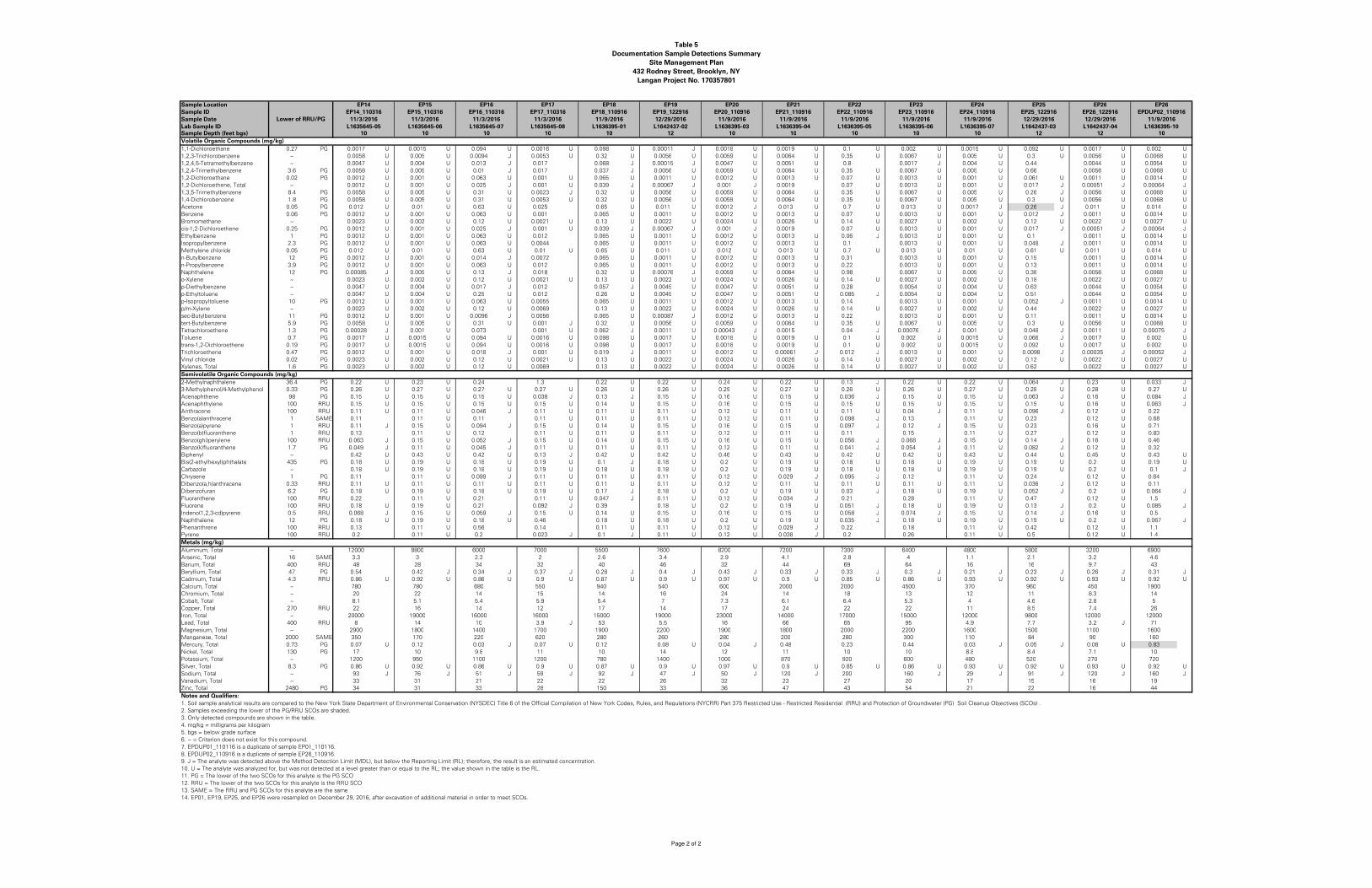
Table 5
Documentation Sample Detections Summary
Site Management Plan
432 Rodney Street, Brooklyn, NY
Langan Project No. 170357801
Sample Location
Sample ID
Sample Date
Lab Sample IDSample Depth (feet bgs)
Volatile Organic Compounds (mg/kg)
1,1�Dichloroethane 0.27 PG 0.0017 U 0.0015 U 0.094 U 0.0016 U 0.098 U 0.00011 J 0.0018 U 0.0019 U 0.1 U 0.002 U 0.0015 U 0.092 U 0.0017 U 0.002 U
1,2,3�Trichlorobenzene ~ 0.0058 U 0.005 U 0.0094 J 0.0053 U 0.32 U 0.0056 U 0.0059 U 0.0064 U 0.35 U 0.0067 U 0.005 U 0.3 U 0.0056 U 0.0068 U
1,2,4,5�Tetramethylbenzene ~ 0.0047 U 0.004 U 0.013 J 0.017 0.068 J 0.00015 J 0.0047 U 0.0051 U 0.8 0.0017 J 0.004 U 0.44 0.0044 U 0.0054 U
1,2,4�Trimethylbenzene 3.6 PG 0.0058 U 0.005 U 0.01 J 0.017 0.037 J 0.0056 U 0.0059 U 0.0064 U 0.35 U 0.0067 U 0.005 U 0.66 0.0056 U 0.0068 U
1,2�Dichloroethane 0.02 PG 0.0012 U 0.001 U 0.063 U 0.001 U 0.065 U 0.0011 U 0.0012 U 0.0013 U 0.07 U 0.0013 U 0.001 U 0.061 U 0.0011 U 0.0014 U
1,2�Dichloroethene, Total ~ 0.0012 U 0.001 U 0.025 J 0.001 U 0.039 J 0.00067 J 0.001 J 0.0019 0.07 U 0.0013 U 0.001 U 0.017 J 0.00051 J 0.00064 J
1,3,5�Trimethylbenzene 8.4 PG 0.0058 U 0.005 U 0.31 U 0.0023 J 0.32 U 0.0056 U 0.0059 U 0.0064 U 0.35 U 0.0067 U 0.005 U 0.26 J 0.0056 U 0.0068 U
1,4�Dichlorobenzene 1.8 PG 0.0058 U 0.005 U 0.31 U 0.0053 U 0.32 U 0.0056 U 0.0059 U 0.0064 U 0.35 U 0.0067 U 0.005 U 0.3 U 0.0056 U 0.0068 U
Acetone 0.05 PG 0.012 U 0.01 U 0.63 U 0.025 0.65 U 0.011 U 0.0012 J 0.013 U 0.7 U 0.013 U 0.0017 J 0.26 J 0.011 U 0.014 U
Benzene 0.06 PG 0.0012 U 0.001 U 0.063 U 0.001 0.065 U 0.0011 U 0.0012 U 0.0013 U 0.07 U 0.0013 U 0.001 U 0.012 J 0.0011 U 0.0014 U
Bromomethane ~ 0.0023 U 0.002 U 0.12 U 0.0021 U 0.13 U 0.0022 U 0.0024 U 0.0026 U 0.14 U 0.0027 U 0.002 U 0.12 U 0.0022 U 0.0027 U
cis�1,2�Dichloroethene 0.25 PG 0.0012 U 0.001 U 0.025 J 0.001 U 0.039 J 0.00067 J 0.001 J 0.0019 0.07 U 0.0013 U 0.001 U 0.017 J 0.00051 J 0.00064 J
Ethylbenzene 1 PG 0.0012 U 0.001 U 0.063 U 0.012 0.065 U 0.0011 U 0.0012 U 0.0013 U 0.06 J 0.0013 U 0.001 U 0.1 0.0011 U 0.0014 U
Isopropylbenzene 2.3 PG 0.0012 U 0.001 U 0.063 U 0.0044 0.065 U 0.0011 U 0.0012 U 0.0013 U 0.1 0.0013 U 0.001 U 0.048 J 0.0011 U 0.0014 U
Methylene chloride 0.05 PG 0.012 U 0.01 U 0.63 U 0.01 U 0.65 U 0.011 U 0.012 U 0.013 U 0.7 U 0.013 U 0.01 U 0.61 U 0.011 U 0.014 U
n�Butylbenzene 12 PG 0.0012 U 0.001 U 0.014 J 0.0072 0.065 U 0.0011 U 0.0012 U 0.0013 U 0.31 0.0013 U 0.001 U 0.15 0.0011 U 0.0014 U
n�Propylbenzene 3.9 PG 0.0012 U 0.001 U 0.063 U 0.012 0.065 U 0.0011 U 0.0012 U 0.0013 U 0.22 0.0013 U 0.001 U 0.13 0.0011 U 0.0014 U
Naphthalene 12 PG 0.00085 J 0.005 U 0.13 J 0.018 0.32 U 0.00076 J 0.0059 U 0.0064 U 0.98 0.0067 U 0.005 U 0.38 0.0056 U 0.0068 U
o�Xylene ~ 0.0023 U 0.002 U 0.12 U 0.0021 U 0.13 U 0.0022 U 0.0024 U 0.0026 U 0.14 U 0.0027 U 0.002 U 0.18 0.0022 U 0.0027 U
p�Diethylbenzene ~ 0.0047 U 0.004 U 0.017 J 0.012 0.057 J 0.0045 U 0.0047 U 0.0051 U 0.28 0.0054 U 0.004 U 0.63 0.0044 U 0.0054 U
p�Ethyltoluene ~ 0.0047 U 0.004 U 0.25 U 0.012 0.26 U 0.0045 U 0.0047 U 0.0051 U 0.085 J 0.0054 U 0.004 U 0.51 0.0044 U 0.0054 U
p�Isopropyltoluene 10 PG 0.0012 U 0.001 U 0.063 U 0.0055 0.065 U 0.0011 U 0.0012 U 0.0013 U 0.14 0.0013 U 0.001 U 0.052 J 0.0011 U 0.0014 U
p/m�Xylene ~ 0.0023 U 0.002 U 0.12 U 0.0069 0.13 U 0.0022 U 0.0024 U 0.0026 U 0.14 U 0.0027 U 0.002 U 0.44 0.0022 U 0.0027 U
sec�Butylbenzene 11 PG 0.0012 U 0.001 U 0.0096 J 0.0056 0.065 U 0.00087 J 0.0012 U 0.0013 U 0.22 0.0013 U 0.001 U 0.11 0.0011 U 0.0014 U
tert�Butylbenzene 5.9 PG 0.0058 U 0.005 U 0.31 U 0.001 J 0.32 U 0.0056 U 0.0059 U 0.0064 U 0.35 U 0.0067 U 0.005 U 0.3 U 0.0056 U 0.0068 U
Tetrachloroethene 1.3 PG 0.00028 J 0.001 U 0.073 0.001 U 0.062 J 0.0011 U 0.00043 J 0.0015 0.04 J 0.00076 J 0.001 U 0.048 J 0.0011 U 0.00075 J
Toluene 0.7 PG 0.0017 U 0.0015 U 0.094 U 0.0016 U 0.098 U 0.0017 U 0.0018 U 0.0019 U 0.1 U 0.002 U 0.0015 U 0.066 J 0.0017 U 0.002 U
trans�1,2�Dichloroethene 0.19 PG 0.0017 U 0.0015 U 0.094 U 0.0016 U 0.098 U 0.0017 U 0.0018 U 0.0019 U 0.1 U 0.002 U 0.0015 U 0.092 U 0.0017 U 0.002 U
Trichloroethene 0.47 PG 0.0012 U 0.001 U 0.018 J 0.001 U 0.019 J 0.0011 U 0.0012 U 0.00061 J 0.012 J 0.0013 U 0.001 U 0.0098 J 0.00035 J 0.00052 J
Vinyl chloride 0.02 PG 0.0023 U 0.002 U 0.12 U 0.0021 U 0.13 U 0.0022 U 0.0024 U 0.0026 U 0.14 U 0.0027 U 0.002 U 0.12 U 0.0022 U 0.0027 U
Xylenes, Total 1.6 PG 0.0023 U 0.002 U 0.12 U 0.0069 0.13 U 0.0022 U 0.0024 U 0.0026 U 0.14 U 0.0027 U 0.002 U 0.62 0.0022 U 0.0027 U
Semivolatile Organic Compounds (mg/kg)
2�Methylnaphthalene 36.4 PG 0.22 U 0.23 U 0.24 1.3 0.22 U 0.22 U 0.24 U 0.22 U 0.13 J 0.22 U 0.22 U 0.064 J 0.23 U 0.033 J
3�Methylphenol/4�Methylphenol 0.33 PG 0.26 U 0.27 U 0.27 U 0.27 U 0.26 U 0.26 U 0.29 U 0.27 U 0.26 U 0.26 U 0.27 U 0.28 U 0.28 U 0.27 U
Acenaphthene 98 PG 0.15 U 0.15 U 0.15 U 0.038 J 0.13 J 0.15 U 0.16 U 0.15 U 0.036 J 0.15 U 0.15 U 0.063 J 0.16 U 0.084 J
Acenaphthylene 100 RRU 0.15 U 0.15 U 0.15 U 0.15 U 0.14 U 0.15 U 0.16 U 0.15 U 0.15 U 0.15 U 0.15 U 0.15 U 0.16 U 0.063 J
Anthracene 100 RRU 0.11 U 0.11 U 0.046 J 0.11 U 0.11 U 0.11 U 0.12 U 0.11 U 0.11 U 0.04 J 0.11 U 0.096 J 0.12 U 0.22
Benzo(a)anthracene 1 SAME 0.11 0.11 U 0.11 0.11 U 0.11 U 0.11 U 0.12 U 0.11 U 0.098 J 0.13 0.11 U 0.23 0.12 U 0.68
Benzo(a)pyrene 1 RRU 0.11 J 0.15 U 0.094 J 0.15 U 0.14 U 0.15 U 0.16 U 0.15 U 0.097 J 0.12 J 0.15 U 0.23 0.16 U 0.71
Benzo(b)fluoranthene 1 RRU 0.13 0.11 U 0.12 0.11 U 0.11 U 0.11 U 0.12 U 0.11 U 0.11 0.15 0.11 U 0.27 0.12 U 0.83
Benzo(ghi)perylene 100 RRU 0.063 J 0.15 U 0.052 J 0.15 U 0.14 U 0.15 U 0.16 U 0.15 U 0.056 J 0.068 J 0.15 U 0.14 J 0.16 U 0.46
Benzo(k)fluoranthene 1.7 PG 0.049 J 0.11 U 0.045 J 0.11 U 0.11 U 0.11 U 0.12 U 0.11 U 0.041 J 0.054 J 0.11 U 0.082 J 0.12 U 0.32
Biphenyl ~ 0.42 U 0.43 U 0.42 U 0.13 J 0.42 U 0.42 U 0.46 U 0.43 U 0.42 U 0.42 U 0.43 U 0.44 U 0.45 U 0.43 U
Bis(2�ethylhexyl)phthalate 435 PG 0.18 U 0.19 U 0.18 U 0.19 U 0.1 J 0.18 U 0.2 U 0.19 U 0.18 U 0.18 U 0.19 U 0.19 U 0.2 U 0.19 U
Carbazole ~ 0.18 U 0.19 U 0.18 U 0.19 U 0.18 U 0.18 U 0.2 U 0.19 U 0.18 U 0.18 U 0.19 U 0.19 U 0.2 U 0.1 J
Chrysene 1 PG 0.11 0.11 U 0.099 J 0.11 U 0.11 U 0.11 U 0.12 U 0.029 J 0.095 J 0.12 0.11 U 0.24 0.12 U 0.64
Dibenzo(a,h)anthracene 0.33 RRU 0.11 U 0.11 U 0.11 U 0.11 U 0.11 U 0.11 U 0.12 U 0.11 U 0.11 U 0.11 U 0.11 U 0.036 J 0.12 U 0.11
Dibenzofuran 6.2 PG 0.18 U 0.19 U 0.18 U 0.19 U 0.17 J 0.18 U 0.2 U 0.19 U 0.03 J 0.18 U 0.19 U 0.052 J 0.2 U 0.064 J
Fluoranthene 100 RRU 0.22 0.11 U 0.21 0.11 U 0.047 J 0.11 U 0.12 U 0.034 J 0.21 0.28 0.11 U 0.47 0.12 U 1.5
Fluorene 100 RRU 0.18 U 0.19 U 0.21 0.092 J 0.39 0.18 U 0.2 U 0.19 U 0.051 J 0.18 U 0.19 U 0.13 J 0.2 U 0.085 J
Indeno(1,2,3�cd)pyrene 0.5 RRU 0.068 J 0.15 U 0.059 J 0.15 U 0.14 U 0.15 U 0.16 U 0.15 U 0.058 J 0.074 J 0.15 U 0.14 J 0.16 U 0.5
Naphthalene 12 PG 0.18 U 0.19 U 0.18 U 0.46 0.18 U 0.18 U 0.2 U 0.19 U 0.035 J 0.18 U 0.19 U 0.19 U 0.2 U 0.067 J
Phenanthrene 100 RRU 0.13 0.11 U 0.56 0.14 0.11 U 0.11 U 0.12 U 0.029 J 0.22 0.18 0.11 U 0.42 0.12 U 1.1
Pyrene 100 RRU 0.2 0.11 U 0.2 0.023 J 0.1 J 0.11 U 0.12 U 0.038 J 0.2 0.26 0.11 U 0.5 0.12 U 1.4
Metals (mg/kg)
Aluminum, Total ~ 12000 8800 6000 7000 5500 7600 8200 7200 7300 6400 4800 5800 3200 6900
Arsenic, Total 16 SAME 3.3 3 2.3 2 2.6 3.4 2.9 4.1 2.8 4 1.1 2.1 3.2 4.6
Barium, Total 400 RRU 48 28 34 32 40 46 32 44 69 64 16 16 9.7 43
Beryllium, Total 47 PG 0.54 0.42 J 0.34 J 0.37 J 0.28 J 0.4 J 0.43 J 0.33 J 0.33 J 0.3 J 0.21 J 0.23 J 0.26 J 0.31 J
Cadmium, Total 4.3 RRU 0.86 U 0.92 U 0.86 U 0.9 U 0.87 U 0.9 U 0.97 U 0.9 U 0.85 U 0.86 U 0.93 U 0.92 U 0.93 U 0.92 U
Calcium, Total ~ 780 780 680 550 940 540 600 2000 2000 4500 370 960 450 1900
Chromium, Total ~ 20 22 14 15 14 16 24 14 18 13 12 11 8.3 14
Cobalt, Total ~ 8.1 5.1 5.4 5.9 5.4 7 7.3 6.1 6.4 5.3 4 4.6 2.8 5
Copper, Total 270 RRU 22 16 14 12 17 14 17 24 22 22 11 8.5 7.4 26
Iron, Total ~ 20000 19000 16000 16000 15000 19000 23000 14000 17000 15000 12000 9800 12000 12000
Lead, Total 400 RRU 8 14 10 3.9 J 53 5.5 16 66 65 95 4.9 7.7 3.2 J 71
Magnesium, Total ~ 2900 1800 1400 1700 1900 2200 1900 1800 2000 2200 1600 1500 1100 1600
Manganese, Total 2000 SAME 350 170 220 620 280 260 280 200 280 300 110 84 90 160
Mercury, Total 0.73 PG 0.07 U 0.12 0.03 J 0.07 U 0.12 0.08 U 0.04 J 0.48 0.23 0.44 0.03 J 0.05 J 0.08 U 0.83
Nickel, Total 130 PG 17 10 9.8 11 10 14 12 11 10 10 8.8 8.4 7.1 10
Potassium, Total ~ 1200 950 1100 1200 780 1400 1000 870 920 600 480 520 270 720
Silver, Total 8.3 PG 0.86 U 0.92 U 0.86 U 0.9 U 0.87 U 0.9 U 0.97 U 0.9 U 0.85 U 0.86 U 0.93 U 0.92 U 0.93 U 0.92 U
Sodium, Total ~ 93 J 76 J 51 J 59 J 92 J 47 J 50 J 120 J 200 160 J 29 J 91 J 120 J 160 J
Vanadium, Total ~ 33 31 21 22 22 26 32 23 27 20 17 15 16 19
Zinc, Total 2480 PG 34 31 33 28 150 33 36 47 43 54 21 22 16 44
Notes and Qualifiers:
1. Soil sample analytical results are compared to the New York State Department of Environmental Conservation (NYSDEC) Title 6 of the Official Compilation of New York Codes, Rules, and Regulations (NYCRR) Part 375 Restricted Use � Restricted Residential (RRU) and Protection of Groundwater (PG) Soil Cleanup Objectives (SCOs) .
2. Samples exceeding the lower of the PG/RRU SCOs are shaded.
3. Only detected compounds are shown in the table.
4. mg/kg = milligrams per kilogram
5. bgs = below grade surface
6. ~ = Criterion does not exist for this compound.
7. EPDUP01_110116 is a duplicate of sample EP01_110116.
8. EPDUP02_110916 is a duplicate of sample EP26_110916.
9. J = The analyte was detected above the Method Detection Limit (MDL), but below the Reporting Limit (RL); therefore, the result is an estimated concentration.
10. U = The analyte was analyzed for, but was not detected at a level greater than or equal to the RL; the value shown in the table is the RL.
11. PG = The lower of the two SCOs for this analyte is the PG SCO
12. RRU = The lower of the two SCOs for this analyte is the RRU SCO
13. SAME = The RRU and PG SCOs for this analyte are the same
14. EP01, EP19, EP25, and EP26 were resampled on December 29, 2016, after excavation of additional material in order to meet SCOs.
Lower of RRU/PG
EP14 EP19 EP25 EP26EP15 EP16 EP17 EP18 EP20 EP21 EP22 EP23 EP24 EP26
EP14_110316 EP19_122916 EP25_122916 EP26_122916EP15_110316 EP16_110316 EP17_110316 EP18_110916 EP20_110916 EP21_110916 EP22_110916 EP23_110916 EP24_110916 EPDUP02_110916
11/3/2016 11/3/2016 11/3/2016 11/3/2016 11/9/2016 11/9/2016 11/9/2016 11/9/2016 11/9/2016 11/9/2016 11/9/201612/29/2016 12/29/2016 12/29/2016
L1635645<05 L1635645<06 L1635645<07 L1635645<08 L1636395<01 L1636395<03 L1636395<04 L1636395<05 L1636395<06 L1636395<07 L1636395<10L1642437<02 L1642437<03 L1642437<0410 10 10 10 10 1012 1210 10 10 10 10 12
Page 2 of 2

Table 6
Site-Specific SCOs
Site Management Plan
432 Rodney Street, Brooklyn, New York
Langan Project No. 170357801
VOCS (mg/kg) SVOCS (mg/kg)
1,1,1-Trichloroethane 500 Acenaphthene 500
1,1-Dichloroethane 240 Acenaphthylene 500
1,1-Dichloroethylene 500 Anthracene 500
1,2-Dichlorobenzene 500 Benzo(a)anthracene 110
1,2-Dichloroethane 30 Benzo(a)pyrene 64
cis-1,2-Dichloroethene 500 Benzo(b)fluoranthene 110
trans-1,2-Dichloroethene 500 Benzo(g,h,i)perylene 500
1,3-Dichlorobenzene 280 Benzo(k)fluoranthene 56
1,4-Dichlorobenzene 130 Chrysene 63
1,4-Dioxane 130 Dibenzo(a,h)anthracene 11
Acetone 500 Fluoranthene 500
Benzene 44 Fluorene 500
Butylbenzene 500 Indeno(1,2,3-cd)pyrene 39
Carbon tetrachloride 22 m-Cresol 500
Chlorobenzene 500 Naphthalene 500
Chloroform 350 o-Cresol 500
Ethyl Benzene 390 p-Cresol 500
Hexachlorobenzene 6 Pentachlorophenol 6.7
Methyl tert-butyl ether (MTBE) 500 Phenanthrene 500
Methylene chloride 500 Phenol 500
n-Propylbenzene 500 Pyrene 500
sec-Butylbenzene 500
tert-Butylbenzene 500 2,4,5-TP Acid (Silvex) 500
Tetrachloroethylene 150 4,4'-DDE 62
Toluene 500 4,4'-DDT 47
Trichloroethylene 200 4,4'-DDD 92
1,2,4-Trimethylbenzene 190 Aldrin 0.68
1,3,5-Trimethylbenzene 190 alpha-BHC 3.4
Vinyl Chloride 13 beta-BHC 3
Xylenes, Total 500 Chlordane (alpha) 24
delta-BHC 500
Arsenic 18 Dibenzofuran 350
Barium 400 Dieldrin 1.4
Beryllium 590 Endosulfan I 200
Cadmium 9.3 Endosulfan II 200
Chromium, hexavalent 400 Endosulfan sulfate 200
Chromium, trivalent 1500 Endrin 89
Copper 270 Heptachlor 15
Cyanide 27 Lindane 9.2
Lead 12000 Polychlorinated biphenyls 1
Manganese 10000
Mercury 2.8
Nickel 310
Selenium 1500
Silver 1500
Zinc 10000
Notes:
SCO: Soil Cleanup Objective
SVOC: semivolatile organic compound
VOC: volatile organic compound
PCB: polychlorinated biphenyl
mg/kg: milligram per kilogram
Shaded SCOs are site-specfic criteria based on the Remedial
Investigation data; all other SCOs listed are generic Commercial Use SCOs.
PCBs/Pesticides (mg/kg)
Metals (mg/kg)

FIGURES

SITE
Filename: \\langan.com\data\NYC\data8\170357801\Cadd Data - 170357801\SheetFiles\SMP\Figure 1 - Site Location Map.dwg Date: 7/11/2017 Time: 14:56 User: wkim Style Table: Langan.stb Layout: SLM
21 Penn Plaza, 360 West 31st Street, 8th Floor
New York, NY 10001
T: 212.479.5400 F: 212.479.5444 www.langan.com
© 2
01
7 L
an
ga
n
NOTE: BASE MAP IS REFERENCED FROM UNITED STATES GEOLOGIC SURVEY 7.5 MINUTE MAPS, BROOKLYN QUADRANGLE.

SIDEWALK
ROD
NEY
STR
EET
KEA
P ST
REET
HOPE STREET
AINSLIE STREET
Filename: \\langan.com\data\NYC\data8\170357801\Cadd Data - 170357801\SheetFiles\SMP\Figure 2 - Site Layout Plan.dwg Date: 7/11/2017 Time: 14:59 User: wkim Style Table: Langan.stb Layout: Figure 2 - Site Plan
21 Penn Plaza, 360 West 31st Street, 8th Floor
New York, NY 10001
T: 212.479.5400 F: 212.479.5444 www.langan.com
© 2
01
7 L
an
ga
n
LEGEND:
APPROXIMATE SITE BOUNDARY
APPROXIMATE AREA OF PROPOSED NEW BUILDING
GENERAL NOTES:
1. BASE MAP IS THE TOPOGRAPHIC SURVEY PREPARED BYROGUSKI LAND SURVEYING, P.C., DATED MARCH 17, 2015
2. ELEVATIONS AND LEGAL GRADES SHOWN HEREON REFER TOTHE NORTH AMERICAN VERTICAL DATUM ON 1988 (NAVD88).

SIDEWALK
ROD
NEY
STR
EET
KEA
P ST
REET
HOPE STREET
B'
B
A
A'
S
S
S
P
L
P
L
NOTES:
1. BASE MAP IS A TOPOGRAPHIC SURVEY PREPARED BY ROGUSKI LANDSURVEYING, P.C., DATED 17 MARCH 2015.
2. NAVD88 = NORTH AMERICAN VERTICAL DATUM OF 1988C
M
S
SM
Filename: \\langan.com\data\NYC\data8\170357801\Cadd Data - 170357801\SheetFiles\SMP\Figure 3 - Subsurface Profiles.dwg Date: 7/11/2017 Time: 15:00 User: wkim Style Table: Langan.stb Layout: Figure 3A- Subsurface Profile A-A
21 Penn Plaza, 360 West 31st Street, 8th Floor
New York, NY 10001
T: 212.479.5400 F: 212.479.5444 www.langan.com
© 2
01
7 L
an
ga
n

P
L
P
L
S
S
S
S
SIDEWALK
ROD
NEY
STR
EET
KEA
P ST
REET
HOPE STREET
B'
B
A
A'
NOTES:
1. BASE MAP IS A TOPOGRAPHIC SURVEY PREPARED BY ROGUSKI LANDSURVEYING, P.C., DATED 17 MARCH 2015.
2. NAVD88 = NORTH AMERICAN VERTICAL DATUM OF 1988C
M
S
SM
Filename: \\langan.com\data\NYC\data8\170357801\Cadd Data - 170357801\SheetFiles\SMP\Figure 3 - Subsurface Profiles.dwg Date: 7/11/2017 Time: 15:01 User: wkim Style Table: Langan.stb Layout: Figure 3B- Subsurface Profile B-B
21 Penn Plaza, 360 West 31st Street, 8th Floor
New York, NY 10001
T: 212.479.5400 F: 212.479.5444 www.langan.com
© 2
01
7 L
an
ga
n

SIDEWALK
ROD
NEY
STR
EET
KEA
P ST
REET
HOPE STREET
Filename: \\langan.com\data\NYC\data8\170357801\Cadd Data - 170357801\SheetFiles\SMP\Figure 4A - Shallow Groundwater Contour Map.dwg Date: 7/11/2017 Time: 15:07 User: wkim Style Table: Langan.stb Layout: GROUNDWATER CONTOURS
21 Penn Plaza, 360 West 31st Street, 8th Floor
New York, NY 10001
T: 212.479.5400 F: 212.479.5444 www.langan.com
LEGEND:
SITE BOUNDARY
SOIL BORING/MONITORING WELL LOCATION
SOIL BORING/CLUSTER MONITORING WELL LOCATION(SHALLOW/DEEP)
GROUNDWATER CONTOURS WITH ELEVATION
GROUNDWATER FLOW DIRECTION
GROUNDWATER ELEVATIONS IN WELLS
PRESUMED PERCHED SYSTEM
NOTES:
1. BASE MAP IS A TOPOGRAPHIC SURVEY PREPARED BY ROGUSKILAND SURVEYING, P.C., DATED 17 MARCH 2015
2. ELEVATIONS ARE DERIVED FROM A SURVEY BY LANGAN,DATED 20 JUNE 2016, OF THE INSTALLED MONITORING WELLS.ONLY SURVEYED WELLS ARE SHOWN.
3. ALL ELEVATIONS ARE IN REFERENCE TO THE NORTHAMERICAN VERTICAL DATUM OF 1988 (NAVD88).
4. AN "S" QUALIFIER ON MONITORING WELLS INDICATES ASHALLOW MONITORING WELL. A "D" QUALIFIER INDICATES ADEEP MONITORING WELL. WELLS WITHOUT QUALIFIERS ARESHALLOW.
5. ONLY SHALLOW WELL GROUNDWATER ELEVATIONS ARESHOWN IN THIS MAP.
© 2
01
7 L
an
ga
n

SIDEWALK
ROD
NEY
STR
EET
KEA
P ST
REET
HOPE STREET
Filename: \\langan.com\data\NYC\data8\170357801\Cadd Data - 170357801\SheetFiles\SMP\Figure 4B - Deep Groundwater Contour Map.dwg Date: 7/11/2017 Time: 15:08 User: wkim Style Table: Langan.stb Layout: GROUNDWATER CONTOURS
21 Penn Plaza, 360 West 31st Street, 8th Floor
New York, NY 10001
T: 212.479.5400 F: 212.479.5444 www.langan.com
LEGEND:
SITE BOUNDARY
SOIL BORING/CLUSTER MONITORING WELL LOCATION(SHALLOW/DEEP)
GROUNDWATER CONTOURS WITH ELEVATION
GROUNDWATER FLOW DIRECTION
GROUNDWATER ELEVATIONS IN WELLS
NOTES:
1. BASE MAP IS A TOPOGRAPHIC SURVEY PREPARED BY ROGUSKILAND SURVEYING, P.C., DATED 17 MARCH 2015
2. ELEVATIONS ARE DERIVED FROM A SURVEY BY LANGAN,DATED 20 JUNE 2016, OF THE INSTALLED MONITORING WELLS.ONLY SURVEYED WELLS ARE SHOWN.
3. ALL ELEVATIONS ARE IN REFERENCE TO THE NORTHAMERICAN VERTICAL DATUM OF 1988 (NAVD88).
4. AN "S" QUALIFIER ON MONITORING WELLS INDICATES ASHALLOW MONITORING WELL. A "D" QUALIFIER INDICATES ADEEP MONITORING WELL. WELLS WITHOUT QUALIFIERS ARESHALLOW.
5. ONLY DEEP WELL GROUNDWATER ELEVATIONS ARE SHOWN INTHIS MAP.
© 2
01
7 L
an
ga
n
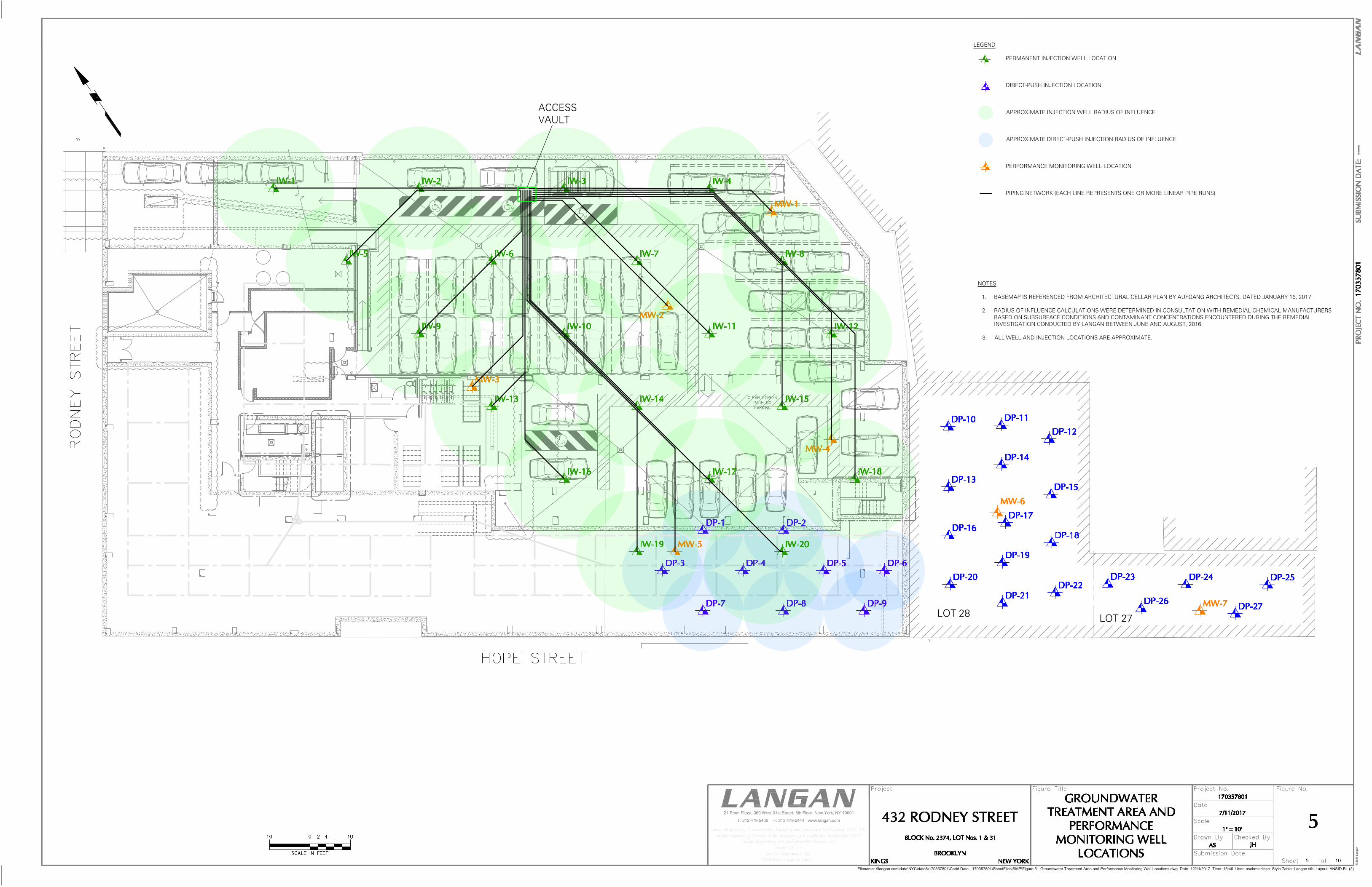
VITREOUS CHINATOILETCIMARRONK-3828
ACCESSVAULT
LOT 28 LOT 27
Filename: \\langan.com\data\NYC\data8\170357801\Cadd Data - 170357801\SheetFiles\SMP\Figure 5 - Groundwater Treatment Area and Performance Monitoring Well Locations.dwg Date: 12/11/2017 Time: 16:40 User: aschmiedicke Style Table: Langan.stb Layout: ANSID-BL (2)
21 Penn Plaza, 360 West 31st Street, 8th Floor, New York, NY 10001
T: 212.479.5400 F: 212.479.5444 www.langan.com
LEGEND
PERMANENT INJECTION WELL LOCATION
DIRECT-PUSH INJECTION LOCATION
APPROXIMATE INJECTION WELL RADIUS OF INFLUENCE
APPROXIMATE DIRECT-PUSH INJECTION RADIUS OF INFLUENCE
PERFORMANCE MONITORING WELL LOCATION
PIPING NETWORK (EACH LINE REPRESENTS ONE OR MORE LINEAR PIPE RUNS)
NOTES
1. BASEMAP IS REFERENCED FROM ARCHITECTURAL CELLAR PLAN BY AUFGANG ARCHITECTS, DATED JANUARY 16, 2017.
2. RADIUS OF INFLUENCE CALCULATIONS WERE DETERMINED IN CONSULTATION WITH REMEDIAL CHEMICAL MANUFACTURERSBASED ON SUBSURFACE CONDITIONS AND CONTAMINANT CONCENTRATIONS ENCOUNTERED DURING THE REMEDIALINVESTIGATION CONDUCTED BY LANGAN BETWEEN JUNE AND AUGUST, 2016.
3. ALL WELL AND INJECTION LOCATIONS ARE APPROXIMATE.
© 2
01
7 L
an
ga
n
DisclaimerThis electronic communication has been prepared by “Langan Engineering, Environmental, Surveying andLandscape Architecture, D.P.C.”, or “Langan Engineering and Environmental Services, Inc.”, or “Langan International,LLC”, or “Treadwell & Rollo, a Langan Company”, or “Langan Engineering & Environmental Services, Inc., PC.”,collectively “Langan”, and is being provided solely as a convenience to the recipient. Langan makes norepresentation regarding the suitability for the intended use of the recipient. In addition to Langan's ownership andcopyright interests of these electronic files, Langan makes no representation regarding fitness for any particularpurpose, or suitability for use with any software or hardware. It is the recipient's obligation to understand the designintent and to use this digital data appropriately.Due to the alterable nature of electronic documents, Langan does not make any expressed or implied warrantyfor the accuracy or completeness of this information. The information, design and ideas contained in this file areproprietary and shall not be copied or used for any purpose that is not authorized, in writing, by Langan.Only current, signed and sealed plans shall be considered valid construction documents. Because ofthe constantly changing nature of construction documents, it is the recipient's responsibility to request the latestdocuments from Langan for their particular task.If any discrepancies are discovered, the recipient must notify Langan immediately in writing.Viewing the contents of this file shall serve as your acknowledgement of acceptance of the above terms andconditions. To view the graphic contents of this file, you must type "Zoom Extent". By opening this file or through theuse of the information contained herein, the recipient agrees to indemnify and hold Langan harmless from any loss,damage, liability or cost, including reasonable attorney's fees that Langan incurs defending such claims, arising fromany use or reuse of this electronic document or information. DisclaimerThis electronic communication has been prepared by “Langan Engineering, Environmental, Surveying andLandscape Architecture, D.P.C.”, or “Langan Engineering and Environmental Services, Inc.”, or “Langan International,LLC”, or “Treadwell & Rollo, a Langan Company”, or “Langan Engineering & Environmental Services, Inc., PC.”,collectively “Langan”, and is being provided solely as a convenience to the recipient. Langan makes norepresentation regarding the suitability for the intended use of the recipient. In addition to Langan's ownership andcopyright interests of these electronic files, Langan makes no representation regarding fitness for any particularpurpose, or suitability for use with any software or hardware. It is the recipient's obligation to understand the designintent and to use this digital data appropriately.Due to the alterable nature of electronic documents, Langan does not make any expressed or implied warrantyfor the accuracy or completeness of this information. The information, design and ideas contained in this file areproprietary and shall not be copied or used for any purpose that is not authorized, in writing, by Langan.Only current, signed and sealed plans shall be considered valid construction documents. Because ofthe constantly changing nature of construction documents, it is the recipient's responsibility to request the latestdocuments from Langan for their particular task.If any discrepancies are discovered, the recipient must notify Langan immediately in writing.Viewing the contents of this file shall serve as your acknowledgement of acceptance of the above terms andconditions. To view the graphic contents of this file, you must type "Zoom Extent". By opening this file or through theuse of the information contained herein, the recipient agrees to indemnify and hold Langan harmless from any loss,damage, liability or cost, including reasonable attorney's fees that Langan incurs defending such claims, arising fromany use or reuse of this electronic document or information.

SIDEWALK
ROD
NEY
STR
EET
KEA
P ST
REET
HOPE STREET
Filename: \\langan.com\data\NYC\data8\170357801\Cadd Data - 170357801\SheetFiles\SMP\Figure 6 - Excavation Extents and Documentation Sample Location Map.dwg Date: 7/21/2017 Time: 09:19 User: aschmiedicke Style Table: Langan.stb Layout: Figure 1 -
Excavation And Endpoints
21 Penn Plaza, 360 West 31st Street, 8th Floor
New York, NY 10001
T: 212.479.5400 F: 212.479.5444 www.langan.com
LEGEND:
APPROXIMATE SITE BOUNDARY
APPROXIMATE EXTENT OF EXCAVATION
APPROXIMATE AREA OF SLOPED EXCAVATION
DOCUMENTATION SAMPLE LOCATION
NOTES:
1. BASE MAP IS A TOPOGRAPHIC SURVEY PREPARED BY ROGUSKILAND SURVEYING, P.C., DATED 17 MARCH 2015. SAMPLELOCATIONS WERE SURVEYED BY EMPIRE STATE LAYOUT, INC. ON30 NOVEMBER 2016.
2. SAMPLES ARE NUMBERED IN THE ORDER THEY WERE COLLECTED.
3. DOCUMENTATION SAMPLES WERE COLLECTED IN THE LOCATIONSNOTED TO DOCUMENT THE QUALITY OF SOIL LEFT IN PLACE.SAMPLES EP01, EP19, EP25, AND EP26 WERE RE-COLLECTED TOCOMPLY WITH TARGET CLEANUP OBJECTIVES
4. ALL ELEVATIONS ARE IN REFERENCE TO THE NORTH AMERICANVERTICAL DATUM OF 1988 (NAVD88).
5. DUPLICATE SAMPLES WERE COLLECTED FOR QUALITY ASSURANCEPURPOSES AT EP01 (EPDUP01) AND EP26 (EPDUP02).
6. ALL DOCUMENTATION SAMPLES WERE COLLECTED AT ABOUT 10 -12 FEET BELOW GRADE SURFACE.
© 2
01
7 L
an
ga
n

VITREOUS CHINATOILETCIMARRONK-3828
Filename: \\langan.com\data\NY\data8\170357801\Cadd Data - 170357801\SheetFiles\SMP\Figure 7 - Engineering Controls Map.dwg Date: 8/1/2017 Time: 16:17 User: aharrold Style Table: Langan.stb Layout: ANSID-BL (2)
21 Penn Plaza, 360 West 31st Street, 8th Floor, New York, NY 10001
T: 212.479.5400 F: 212.479.5444 www.langan.com
© 2
01
7 L
an
ga
n
LEGEND
APPROXIMATE AREA OF COMPOSITE CAP ON LOTS 27 & 28
APPROXIMATE AREA OF VAPOR BARRIER/WATERPROOFING ON LOTS 1 & 31
SUB-MEMBRANE DEPRESSURIZATION SYSTEM ON LOTS 1 & 31
GROUNDWATER TREATMENT SYSTEM
APPROXIMATE SITE BOUNDARY AND LOT LINES
MANIFOLD
NOTES
1. BASEMAP IS REFERENCED FROM ARCHITECTURAL CELLAR PLAN BY AUFGANG ARCHITECTS, DATED SEPTEMBER 26, 2016.
2. ALL ELEVATIONS ARE REFERENCED TO THE NORTH AMERICAN VERTICAL DATUM OF 1988 (NAVD88).

VITREOUS CHINATOILETCIMARRONK-3828
Filename: \\langan.com\data\NYC\data8\170357801\Cadd Data - 170357801\SheetFiles\SMP\Figure 8 - SMD Layout_NEW.dwg Date: 7/21/2017 Time: 09:21 User: aschmiedicke Style Table: Langan.stb Layout: ANSID-BL
·
·
··
·
21 Penn Plaza, 360 West 31st Street, 8th Floor, New York, NY 10001
T: 212.479.5400 F: 212.479.5444 www.langan.com
© 2
01
7 L
an
ga
n

APPENDIX A
ENVIRONMENTAL EASEMENTS


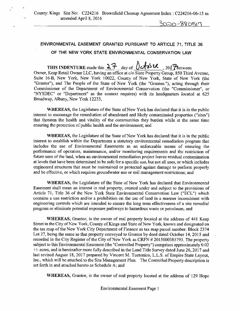


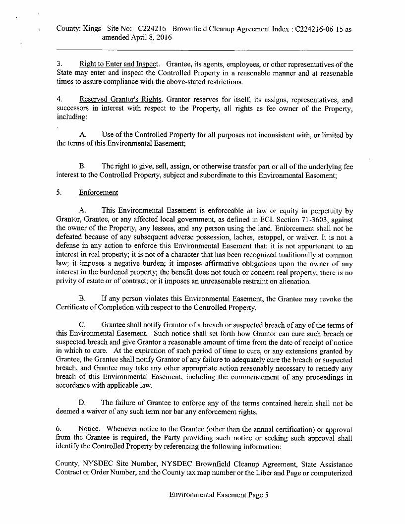


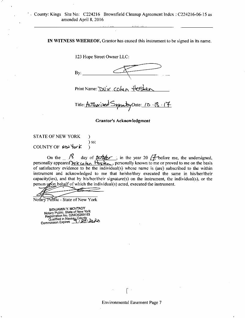


APPENDIX B
REMEDIAL INVESTIGATION BORING LOGS

18/4
810
/48
36/4
848
/48
48/4
8
0-6" Loose medium brown SAND, trace mica, fine round gravel,metal, concrete [FILL] (dry)6-18" Crushed concrete [FILL] (dry)
0-10" Soft brown to black sandy SILT, trace mica, fine round gravel,concrete, metal [FILL] (moist)
0-12" Dense mottled brown gray fine SAND, some silt, somemedium sand, trace mica (moist)12-32" Dense mottled brown/gray medium SAND, some silt, tracemica (wet)32-36" Orange-brown coarse SAND, trace mica (wet)
0-16" Soft mottled brown/gray sandy SILT, trace mica, fine roundpebbles (wet)
16-30" Loose brown to dark brown medium SAND, trace silt, tracemica, fine round pebbles, rock fragments (wet)30-35" Loose tan coarse SAND, rock fragments (wet)
35-48" Dense mottled brown/gray medium SAND, trace mica (wet)
0-48" Medium dense brown to mottled brown/gray medium SAND,trace mica, fine rounded pebbles, rock fragments (wet)
MA
CR
OC
OR
EM
AC
RO
CO
RE
MA
CR
OC
OR
EM
AC
RO
CO
RE
MA
CR
OC
OR
E
S1
S2
S3
S4
S5
0.0
0.0
0.0
0.0
0.0
0.0
0.0
0.0
0.0
0.0
0.0
0.0
0.0
0.0
0.0
0.0
0.0
0.0
0.0
0.0
0.0
0.0
0.0
0.0
0.0
0.0
8:30 - Begin drilling
9:10 - Collect grab sampleSB01_0-1
9:30 - Collect grab sampleSB01_4-5
9:45 - Collect grab sampleSB01_9-10
End of boring at 20 feet bgs,install monitoring well MW01to 19 feet bgs with manholecover.
First
Disturbed
4' Macrocore
AARCO
N/AN/A
N/A
N/A
N/A
Core
N/A
Weight (lbs)
Drilling Company
2" Direct PushCasing Depth (ft)
Tim Kelly
Anna Schmiedicke
Completion Depth
Number of Samples
Drilling Foreman10 -
6/6/16
Date Started
6/6/16
-
-
20 ft
Field Engineer
Size and Type of Bit
Completion
Sampler Hammer
Date Finished
Undisturbed
Drop (in)
Sampler
Weight (lbs)
N/ACasing Hammer
N/A
3Casing Diameter (in)
Geoprobe 7822DT
24 HR.
Drilling Equipment Rock Depth
Drop (in)
Water Level (ft.)
-
N/A
Pen
etr.
resi
stB
L/6i
n
Num
ber
0
Typ
e
Rec
ov.
(in)
SB01
Sample DescriptionDepthScale
1
2
3
4
5
6
7
8
9
10
11
12
13
14
15
16
17
18
19
Project
Log of Boring
Location
20
Project No.
13.08 -
Sheet 1
432 Rodney Street
Brooklyn, New York
of 1
MA
TE
RIA
LS
YM
BO
L
Elevation and Datum
\\LA
NG
AN
.CO
M\D
AT
A\N
YC
\DA
TA
8\17
035
780
1\E
NG
INE
ER
ING
DA
TA
\EN
VIR
ON
ME
NT
AL\
GIN
TLO
GS
\432
RO
DN
EY
_201
6-0
6-10
.GP
J ...
9/8
/201
6 9
:25:
51
AM
... R
epor
t: Lo
g -
LAN
GA
N
(Drilling Fluid, Depth of Casing,Fluid Loss, Drilling Resistance, etc.)
RemarksPID
Reading(ppm)
Sample Data

26/6
054
/60
60/6
060
/60
0-26" Mottled gray/light brown fine SAND, trace silt, brick [FILL](dry)
0-30" Medium dense mottled gray/light brown clayey fine SAND,trace silt [FILL] (dry)
30-54" Medium dense light brown clayey fine SAND, trace silt [FILL](dry)
0-60" Medium dense light brown clayey fine SAND, trace silt (moist)
0-60" Loose light brown medium SAND, coarse gravel (wet)
SO
NIC
SO
NIC
SO
NIC
SO
NIC
S1
S2
S3
S4
5.1
0.0
0.0
0.0
0.0
0.0
0.0
0.0
0.0
0.0
0.0
0.0
0.0
0.0
0.0
0.0
0.0
0.0
0.0
0.0
0.0
0.0
0.0
0.0
0.0
0.0
0.0
0.0
0.0
1
0.0
0.0
0.0
8:20 - Hand auger top 2 ft, drillwith 6" bit
8:25 - Collect grab sampleSB02_1-2
11:30 - Collect grab sampleSB02_7-8
9:10 - Field sudan test02_1_6616: Negative
9:45 - Collect grab sampleSB02_13-14
First
Disturbed
5' Plastic Bag
AARCO
N/AN/A
N/A
N/A
N/A
Core
N/A
Weight (lbs)
Drilling Company
4"/6" SonicCasing Depth (ft)
Tom Seickel
Jordan Lee
Completion Depth
Number of Samples
Drilling Foreman14 -
6/6/16
Date Started
6/6/16
-
-
55 ft
Field Engineer
Size and Type of Bit
Completion
Sampler Hammer
Date Finished
Undisturbed
Drop (in)
Sampler
Weight (lbs)
N/ACasing Hammer
N/A
4Casing Diameter (in)
Geoprobe 8140LC
24 HR.
Drilling Equipment Rock Depth
Drop (in)
Water Level (ft.)
-
N/A
Pen
etr.
resi
stB
L/6i
n
Num
ber
0
Typ
e
Rec
ov.
(in)
SB02
Sample DescriptionDepthScale
1
2
3
4
5
6
7
8
9
10
11
12
13
14
15
16
17
18
19
Project
Log of Boring
Location
20
Project No.
14.48 -
Sheet 1
432 Rodney Street
Brooklyn, New York
of 3
MA
TE
RIA
LS
YM
BO
L
Elevation and Datum
\\LA
NG
AN
.CO
M\D
AT
A\N
YC
\DA
TA
8\17
035
780
1\E
NG
INE
ER
ING
DA
TA
\EN
VIR
ON
ME
NT
AL\
GIN
TLO
GS
\432
RO
DN
EY
_201
6-0
6-10
.GP
J ...
9/8
/201
6 9
:25:
56
AM
... R
epor
t: Lo
g -
LAN
GA
N
(Drilling Fluid, Depth of Casing,Fluid Loss, Drilling Resistance, etc.)
RemarksPID
Reading(ppm)
Sample Data

24/6
060
/60
48/6
060
/60
60/6
0
0-24" Loose light brown medium SAND, some fine sand, coarsegravel, trace silt (wet)
0-60" Loose light brown medium SAND, some coarse sand, coarsegravel, fine gravel (wet)
0-32" Loose light brown medium SAND, coarse gravel (wet)
32-36" Medium dense light brown CLAY, some medium sand (wet)36-48" Loose light brown medium SAND, coarse gravel (wet)
0-18" Loose light brown medium SAND, coarse gravel (wet)
18-24" Loose light brown coarse SAND, trace medium sand, coarsepebbles (wet)
24-60" Loose yellow/orange coarse SAND, some medium sand,coarse pebbles (wet)
0-48" Loose yellow/orange coarse SAND, fine pebbles (wet)
48-60" Dense light brown fine SAND, some clay, trace silt (wet)
SO
NIC
SO
NIC
SO
NIC
SO
NIC
SO
NIC
S5
S6
S7
S8
S9
0.0
0.0
0.0
0.0
0.0
0.0
0.0
0.0
0.0
0.0
0.0
0.0
0.0
0.0
0.0
0.0
0.0
0.0
0.0
0.0
0.0
0.0
0.0
0.0
0.0
0.0
0.0
0.0
0.0
0.0
0.0
0.0
0.0
0.0
0.0
0.0
0.0
0.0
0.0
0.0
0.0
0.0
0.0
10:40 - Switch to 4" bit due torunning sands
Pen
etr.
resi
stB
L/6i
n
Num
ber
20
Typ
e
Rec
ov.
(in)
SB02
Sample DescriptionDepthScale
21
22
23
24
25
26
27
28
29
30
31
32
33
34
35
36
37
38
39
40
41
42
43
44
Project
Log of Boring
Location
45
Project No.
14.48 -
Sheet 2
432 Rodney Street
Brooklyn, New York
of 3
MA
TE
RIA
LS
YM
BO
L
Elevation and Datum
\\LA
NG
AN
.CO
M\D
AT
A\N
YC
\DA
TA
8\17
035
780
1\E
NG
INE
ER
ING
DA
TA
\EN
VIR
ON
ME
NT
AL\
GIN
TLO
GS
\432
RO
DN
EY
_201
6-0
6-10
.GP
J ...
9/8
/201
6 9
:25:
57
AM
... R
epor
t: Lo
g -
LAN
GA
N
(Drilling Fluid, Depth of Casing,Fluid Loss, Drilling Resistance, etc.)
RemarksPID
Reading(ppm)
Sample Data

60/6
060
/60
0-6" Dense light brown fine SAND, some clay, trace silt (wet)6-60" Medium dense gray fine SAND, some silt, trace clay (wet)
0-12" Medium dense gray fine SAND, some silt, trace clay (wet)
12-30" Hard gray CLAY, trace fine sand, trace silt (wet)
30-36" Medium dense gray fine SAND, some silt, trace clay (wet)
36-60" Hard gray CLAY, trace fine sand, trace silt (wet)S
ON
ICS
ON
IC
S10
S11
0.0
0.0
0.0
0.0
0.0
0.0
0.0
0.0
0.0
0.0
0.0
0.0
0.0
0.0
0.0
0.0
0.0
0.0
0.0
0.0
0.0
14:05 - Collect grab sampleSB02_52-53
End of boring at 55 feet bgs,install nested monitoring wellwith manhole cover: MW02Dto 53.5 feet bgs and MW02Sto 20 feet bgs.
Pen
etr.
resi
stB
L/6i
n
Num
ber
45
Typ
e
Rec
ov.
(in)
SB02
Sample DescriptionDepthScale
46
47
48
49
50
51
52
53
54
55
56
57
58
59
60
61
62
63
64
65
66
67
68
69
Project
Log of Boring
Location
70
Project No.
14.48 -
Sheet 3
432 Rodney Street
Brooklyn, New York
of 3
MA
TE
RIA
LS
YM
BO
L
Elevation and Datum
\\LA
NG
AN
.CO
M\D
AT
A\N
YC
\DA
TA
8\17
035
780
1\E
NG
INE
ER
ING
DA
TA
\EN
VIR
ON
ME
NT
AL\
GIN
TLO
GS
\432
RO
DN
EY
_201
6-0
6-10
.GP
J ...
9/8
/201
6 9
:25:
58
AM
... R
epor
t: Lo
g -
LAN
GA
N
(Drilling Fluid, Depth of Casing,Fluid Loss, Drilling Resistance, etc.)
RemarksPID
Reading(ppm)
Sample Data

17/4
816
/48
33/4
821
/48
34/4
8
0-17" Loose black-brown medium SAND, some silt, trace mica,concrete, coarse round pebbles, brick, asphalt, slag [FILL] (dry)
0-8" Loose black-brown medium SAND, some silt, trace mica,concrete, fine round pebbles, brick, asphalt, slag [FILL] (dry)8-16" Medium dense brown fine SAND, some silt, trace mica,coarse subangular gravel, concrete, wood [FILL] (moist)
0-12" Loose black-brown medium SAND, some silt, trace mica,concrete, brick, asphalt, slag, fine angular gravel [FILL] (moist)
12-33" Dense brown fine SAND, some silt, trace mica, coarsesubangular pebbles (moist-wet)
0-11" Medium dense brown fine SAND, some silt, trace mica, rockfragments (wet)
11-21" Dense brown fine SAND, some silt, trace mica (wet)
0-34" Loose brown coarse SAND, some silt, trace mica, finesubround pebbles (wet)
MA
CR
OC
OR
EM
AC
RO
CO
RE
MA
CR
OC
OR
EM
AC
RO
CO
RE
MA
CR
OC
OR
E
S1
S2
S3
S4
S5
0.0
0.5
0.0
0.0
0.5
0.1
0.7
0.2
0.0
0.0
0.0
0.0
0.0
0.0
0.0
0.0
0.0
0.0
0.0
9:15 - Begin drilling
9:25 - Collect grab sampleSB03_0-1 (redrill)
10:10 - Collect grab sampleSB03_5-10 (redrill) (TS)
9:45 - Collect grab sampleSB03_8-9
9:55 - Collect SB03_10-11
10:15 - Collect grab sampleSB03_10-15 (redrill) (TS)
10:10 - Collect grab sampleSB03_17-18
End of boring at 20 feet bgs,install monitoring well MW03to 15 feet bgs with manholecover.
First
Disturbed
4' Macrocore
AARCO
N/AN/A
N/A
N/A
N/A
Core
N/A
Weight (lbs)
Drilling Company
2" Direct PushCasing Depth (ft)
Tim Kelly
Anna Schmiedicke
Completion Depth
Number of Samples
Drilling Foreman10 -
6/6/16
Date Started
6/6/16
-
-
20 ft
Field Engineer
Size and Type of Bit
Completion
Sampler Hammer
Date Finished
Undisturbed
Drop (in)
Sampler
Weight (lbs)
N/ACasing Hammer
N/A
6Casing Diameter (in)
Geoprobe 7822DT
24 HR.
Drilling Equipment Rock Depth
Drop (in)
Water Level (ft.)
-
N/A
Pen
etr.
resi
stB
L/6i
n
Num
ber
0
Typ
e
Rec
ov.
(in)
SB03
Sample DescriptionDepthScale
1
2
3
4
5
6
7
8
9
10
11
12
13
14
15
16
17
18
19
Project
Log of Boring
Location
20
Project No.
15.78 -
Sheet 1
432 Rodney Street
Brooklyn, New York
of 1
MA
TE
RIA
LS
YM
BO
L
Elevation and Datum
\\LA
NG
AN
.CO
M\D
AT
A\N
YC
\DA
TA
8\17
035
780
1\E
NG
INE
ER
ING
DA
TA
\EN
VIR
ON
ME
NT
AL\
GIN
TLO
GS
\432
RO
DN
EY
_201
6-0
6-10
.GP
J ...
9/8
/201
6 9
:26:
04
AM
... R
epor
t: Lo
g -
LAN
GA
N
(Drilling Fluid, Depth of Casing,Fluid Loss, Drilling Resistance, etc.)
RemarksPID
Reading(ppm)
Sample Data

37/4
838
/48
37/4
832
/48
48/4
8
0-8" Dense brown-gray fine SAND, some silt, trace mica, brick,concrete, slag, asphalt, fine angular gravel [FILL] (dry)8-12" Crushed stone [FILL] (dry)12-23" Dense mottled brown/gray find SAND, some silt, trace mica,brick, concrete, slag, asphalt [FILL] (dry)23-31" Loose black medium SAND, slag, asphalt, concrete [FILL](dry)31-37" Dense mottled brown/gray fine SAND, some silt, trace mica,asphalt [FILL] (dry)0-23" Loose brown fine SAND, trace mica, concrete, asphalt, slag[FILL] (dry)
23-38" Dense brown fine SAND, some silt, fine angular pebbles(moist)
0-22" Soft mottled brown/gray sandy SILT, trace mica (moist-wet)
22-37" Dense mottled brown/gray fine SAND, trace silt, trace mica(wet)
0-32" Loose brown medium SAND, trace mica, fine angular pebbles(wet)
0-48" Loose-dense medium SAND, trace silt, trace mica, fine roundpebbles (wet)
MA
CR
OC
OR
EM
AC
RO
CO
RE
MA
CR
OC
OR
EM
AC
RO
CO
RE
MA
CR
OC
OR
E
S1
S2
S3
S4
S5
0.0
0.0
5.7
3.4
0.1
0.0
0
.4
0.0
0.0
0.0
0.0
0.0
0.0
0.0
0.0
0.0
0.0
0.0
0.0
0.0
0.0
0.0
0.0
0.0
0.0
0.0
0.0
0.0
0.0
0.0
0.0
11:02 - Begin drilling
11:15 - Collect grab sampleSB04_1-2
12:10 - Collect grab sampleSB04_5-6
12:20 - Collect grab sampleSB04_9-10
Collect grab sampleSBDUP01_060616
End of boring at 20 feet bgs,install monitoring well MW04to 15 feet bgs with manholecover.
First
Disturbed
4' Macrocore
AARCO
N/AN/A
N/A
N/A
N/A
Core
N/A
Weight (lbs)
Drilling Company
2" Direct PushCasing Depth (ft)
Tim Kelly
Anna Schmiedicke
Completion Depth
Number of Samples
Drilling Foreman10 -
6/6/16
Date Started
6/6/16
-
-
20 ft
Field Engineer
Size and Type of Bit
Completion
Sampler Hammer
Date Finished
Undisturbed
Drop (in)
Sampler
Weight (lbs)
N/ACasing Hammer
N/A
4Casing Diameter (in)
Geoprobe 7822DT
24 HR.
Drilling Equipment Rock Depth
Drop (in)
Water Level (ft.)
-
N/A
Pen
etr.
resi
stB
L/6i
n
Num
ber
0
Typ
e
Rec
ov.
(in)
SB04
Sample DescriptionDepthScale
1
2
3
4
5
6
7
8
9
10
11
12
13
14
15
16
17
18
19
Project
Log of Boring
Location
20
Project No.
13.43 -
Sheet 1
432 Rodney Street
Brooklyn, New York
of 1
MA
TE
RIA
LS
YM
BO
L
Elevation and Datum
\\LA
NG
AN
.CO
M\D
AT
A\N
YC
\DA
TA
8\17
035
780
1\E
NG
INE
ER
ING
DA
TA
\EN
VIR
ON
ME
NT
AL\
GIN
TLO
GS
\432
RO
DN
EY
_201
6-0
6-10
.GP
J ...
9/8
/201
6 9
:26:
08
AM
... R
epor
t: Lo
g -
LAN
GA
N
(Drilling Fluid, Depth of Casing,Fluid Loss, Drilling Resistance, etc.)
RemarksPID
Reading(ppm)
Sample Data

30/4
832
/48
34/4
838
/48
16/4
8
0-25" Loose black-brown coarse SAND, trace mica, wood, concrete,slag, brick [FILL] (dry)
25-30" Dense brown fine SAND, trace clay, trace mica, concrete[FILL] (dry)
0-13" Loose brown medium silty SAND, trace fine sand, trace clay,trace mica, concrete [FILL] (dry)
13-32" Dense brown fine silty SAND, trace clay, trace mica, brick(moist)
0-34" Dense to loose brown medium SAND, some silt, trace coarsesand, trace mica, coarse subangular pebbles (moist-wet)
0-38" Loose brown coarse silty SAND, fine subangular pebbles, rockfragments (wet)
0-16" Loose brown fine SAND, some silt, trace medium sand, tracemica, fine round pebbles (wet)
MA
CR
OC
OR
EM
AC
RO
CO
RE
MA
CR
OC
OR
EM
AC
RO
CO
RE
MA
CR
OC
OR
E
S1
S2
S3
S4
S5
32.2
0.4
72.9
14.1
0.5
0.1
0.0
0.5
0.0
0.0
0.0
0.0
0.0
0.0
0.0
0.0
0.0
0.0
0.0
0.0
0.0
0.0
0.0
7:55 - Begin drilling
8:05 - Collect grab sampleSB05_1-2
8:35 - Collect grab sampleSB05_5-6
8:40 - Collect grab sampleSB05_10-11
8:55 - Collect grab sampleSB05_16-17 (TS)
End of boring at 20 feet bgs,install monitoring well MW05to 15 feet bgs with manholecover.
First
Disturbed
4' Macrocore
AARCO
N/AN/A
N/A
N/A
N/A
Core
N/A
Weight (lbs)
Drilling Company
2" Direct PushCasing Depth (ft)
Tim Kelly
Anna Schmiedicke
Completion Depth
Number of Samples
Drilling Foreman10 -
6/7/16
Date Started
6/7/16
-
-
20 ft
Field Engineer
Size and Type of Bit
Completion
Sampler Hammer
Date Finished
Undisturbed
Drop (in)
Sampler
Weight (lbs)
N/ACasing Hammer
N/A
4Casing Diameter (in)
Geoprobe 7822DT
24 HR.
Drilling Equipment Rock Depth
Drop (in)
Water Level (ft.)
-
N/A
Pen
etr.
resi
stB
L/6i
n
Num
ber
0
Typ
e
Rec
ov.
(in)
SB05
Sample DescriptionDepthScale
1
2
3
4
5
6
7
8
9
10
11
12
13
14
15
16
17
18
19
Project
Log of Boring
Location
20
Project No.
13.8 -
Sheet 1
432 Rodney Street
Brooklyn, New York
of 1
MA
TE
RIA
LS
YM
BO
L
Elevation and Datum
\\LA
NG
AN
.CO
M\D
AT
A\N
YC
\DA
TA
8\17
035
780
1\E
NG
INE
ER
ING
DA
TA
\EN
VIR
ON
ME
NT
AL\
GIN
TLO
GS
\432
RO
DN
EY
_201
6-0
6-10
.GP
J ...
9/8
/201
6 9
:26:
11
AM
... R
epor
t: Lo
g -
LAN
GA
N
(Drilling Fluid, Depth of Casing,Fluid Loss, Drilling Resistance, etc.)
RemarksPID
Reading(ppm)
Sample Data

20/4
830
/48
36/4
844
/48
48/4
8
0-20" Loose dark brown medium SAND, trace mica, brick, concrete,asphalt, slag [FILL] (moist)
0-22" Loose gray to brown medium SAND, some silt, trace mica,brick, concrete, asphalt, slag [FILL] (moist)
22-30" Soft brownish gray sandy SILT, trace mica, fine roundpebbles (moist)
0-7" Loose brown medium SAND, some silt, trace mica, woodmaterial, fine round pebbles (moist)7-26" Loose gray silty fine SAND, trace mica, fine rounded pebbles(wet)
26-36" Dense orangish-brown medium SAND, trace coarse sand,trace mica, rock fragments (wet)
0-44" Dense mottled brown/gray fine SAND, some medium sand,trace silt, trace mica, fine round pebbles (wet)
0-48" Loose brown coarse SAND, trace silt, trace mica, coarseround pebbles (wet)
MA
CR
OC
OR
EM
AC
RO
CO
RE
MA
CR
OC
OR
EM
AC
RO
CO
RE
MA
CR
OC
OR
E
S1
S2
S3
S4
S5
0.0
0.0
0.0
0.0
0.0
0.0
0.0
0.0
0.0
0.0
0.0
0.0
0.0
0.0
0.0
0.0
0.0
0.0
0.0
0.0
0.0
0.0
0.0
0.0
0.0
0.0
13:05 - Begin drilling
13:10 - Collect grab sampleSB06_1-2
13:50 - Collect grab sampleSB06_5-6
14:00 - Collect grab sampleSB06_8-9
End of boring at 20 feet bgs,install monitoring well MW06to 15 feet bgs with manholecover.
First
Disturbed
4' Macrocore
AARCO
N/AN/A
N/A
N/A
N/A
Core
N/A
Weight (lbs)
Drilling Company
2" Direct PushCasing Depth (ft)
Tim Kelly
Anna Schmiedicke
Completion Depth
Number of Samples
Drilling Foreman9 -
6/6/16
Date Started
6/6/16
-
-
20 ft
Field Engineer
Size and Type of Bit
Completion
Sampler Hammer
Date Finished
Undisturbed
Drop (in)
Sampler
Weight (lbs)
N/ACasing Hammer
N/A
3Casing Diameter (in)
Geoprobe 7822DT
24 HR.
Drilling Equipment Rock Depth
Drop (in)
Water Level (ft.)
-
N/A
Pen
etr.
resi
stB
L/6i
n
Num
ber
0
Typ
e
Rec
ov.
(in)
SB06
Sample DescriptionDepthScale
1
2
3
4
5
6
7
8
9
10
11
12
13
14
15
16
17
18
19
Project
Log of Boring
Location
20
Project No.
13.54 -
Sheet 1
432 Rodney Street
Brooklyn, New York
of 1
MA
TE
RIA
LS
YM
BO
L
Elevation and Datum
\\LA
NG
AN
.CO
M\D
AT
A\N
YC
\DA
TA
8\17
035
780
1\E
NG
INE
ER
ING
DA
TA
\EN
VIR
ON
ME
NT
AL\
GIN
TLO
GS
\432
RO
DN
EY
_201
6-0
6-10
.GP
J ...
9/8
/201
6 9
:26:
15
AM
... R
epor
t: Lo
g -
LAN
GA
N
(Drilling Fluid, Depth of Casing,Fluid Loss, Drilling Resistance, etc.)
RemarksPID
Reading(ppm)
Sample Data

30/6
059
/60
60/6
036
/60
0-18" Loose light brown silty fine SAND, trace coarse gravel,crushed red brick, asphalt, slag [FILL] (dry)
18-30" Loose red silty fine SAND, coarse gravel, crushed brick,ashpalt, slag [FILL] (dry)
0-6" Loose brown silty fine SAND, coarse gravel, crushed brick,wood, asphalt [FILL] (dry)6-30" Loose red silty fine SAND, coarse gravel, crushed brick,ashpalt, slag [FILL] (dry)
30-59" Medium dense light brown silty fine SAND, coarse gravel(dry)
0-6" Medium dense grayish light brown silty find SAND (moist)
6-60" Medium dense light brown silty fine SAND (moist)
0-24" Dense light brown silty fine SAND (wet)
24-36" Loose dark grayish light brown medium SAND, coarse gravel(wet)
SO
NIC
SO
NIC
SO
NIC
SO
NIC
S1
S2
S3
S4
0.0
0.0
0.0
0.0
0.0
0.0
0.0
0.0
0.0
0.0
0.0
0.0
0.0
0.0
0.0
32.3
10.1
5.6
0.0
0.0
0.0
0.0
0.0
0.0
0.0
0.0
0.0
0.0
0.0
0.0
0.0
0.0
9:30 - Begin drilling; handauger top 2 ft9:40 - Collect grab sampleSB07_1-2
9:40 (6/8/16) - Collect grabsample SB07_7-8
Petroleum-like odor
10:35 - Collect grab sampleSB07_10-11
10:50 - Collect grab sampleMS-SS01_060716
10:55 - Collect grab sampleMSD-SS01_060716
First
Disturbed
5' Plastic Bag
AARCO
N/AN/A
N/A
N/A
N/A
Core
N/A
Weight (lbs)
Drilling Company
4"/6" SonicCasing Depth (ft)
Tom Seickel
Jordan Lee
Completion Depth
Number of Samples
Drilling Foreman12 -
6/8/16
Date Started
6/7/16
-
-
60 ft
Field Engineer
Size and Type of Bit
Completion
Sampler Hammer
Date Finished
Undisturbed
Drop (in)
Sampler
Weight (lbs)
N/ACasing Hammer
N/A
7Casing Diameter (in)
Geoprobe 8140LC
24 HR.
Drilling Equipment Rock Depth
Drop (in)
Water Level (ft.)
-
N/A
Pen
etr.
resi
stB
L/6i
n
Num
ber
0
Typ
e
Rec
ov.
(in)
SB07
Sample DescriptionDepthScale
1
2
3
4
5
6
7
8
9
10
11
12
13
14
15
16
17
18
19
Project
Log of Boring
Location
20
Project No.
14.6 -
Sheet 1
432 Rodney Street
Brooklyn, New York
of 3
MA
TE
RIA
LS
YM
BO
L
Elevation and Datum
\\LA
NG
AN
.CO
M\D
AT
A\N
YC
\DA
TA
8\17
035
780
1\E
NG
INE
ER
ING
DA
TA
\EN
VIR
ON
ME
NT
AL\
GIN
TLO
GS
\432
RO
DN
EY
_201
6-0
6-10
.GP
J ...
9/8
/201
6 9
:26:
20
AM
... R
epor
t: Lo
g -
LAN
GA
N
(Drilling Fluid, Depth of Casing,Fluid Loss, Drilling Resistance, etc.)
RemarksPID
Reading(ppm)
Sample Data

48/6
060
/60
48/6
060
/60
60/6
0
0-48" Loose dark grayish light brown medium SAND, coarse gravel(wet)
0-36" Loose dark grayish light brown medium SAND, coarse gravel(wet)
36-42" Loose yellow orange medium SAND, coarse pebbles (wet)
42-60" Loose yellow orange medium SAND, coarse pebbles, finepebbles (wet)
0-6" Loose yellow orange medium SAND, coarse pebbles, finepebbles (wet)6-24" Loose yellow orange medium SAND, some fine sand, finepebbles (wet)
24-48" Loose yellow orange fine SAND, some medium sand, finepebbles (wet)
0-24" Loose yellow orange medium SAND, some fine sand, coarsegravel (wet)
24-36" Loose yellow orange medium SAND, trace fine sand, coarsegravel, coarse pebbles (wet)
36-60" Loose yellow orange medium SAND, some fine sand, coarsegravel (wet)
0-60" Loose orange to yellow-orange medium SAND, some finesand, coarse gravel (wet)
SO
NIC
SO
NIC
SO
NIC
SO
NIC
SO
NIC
S5
S6
S7
S8
S9
0.0
0.0
0.0
0.0
0.0
0.0
0.0
0.0
0.0
0.0
0.0
0.0
0.0
0.0
0.0
0.0
0.0
0.0
0.0
0.0
0.0
0.0
0.0
0.0
0.0
0.0
0.0
0.0
0.0
0.0
0.0
0.0
0.0
0.0
0.0
0.0
0.0
0.0
0.0
0.0
0.0
0.0
0.0
0.0
0.0
11:35 - Collect grab sampleSB07_20-21 (TS)
Slight petroleum-like odor: NoPID hits
Pen
etr.
resi
stB
L/6i
n
Num
ber
20
Typ
e
Rec
ov.
(in)
SB07
Sample DescriptionDepthScale
21
22
23
24
25
26
27
28
29
30
31
32
33
34
35
36
37
38
39
40
41
42
43
44
Project
Log of Boring
Location
45
Project No.
14.6 -
Sheet 2
432 Rodney Street
Brooklyn, New York
of 3
MA
TE
RIA
LS
YM
BO
L
Elevation and Datum
\\LA
NG
AN
.CO
M\D
AT
A\N
YC
\DA
TA
8\17
035
780
1\E
NG
INE
ER
ING
DA
TA
\EN
VIR
ON
ME
NT
AL\
GIN
TLO
GS
\432
RO
DN
EY
_201
6-0
6-10
.GP
J ...
9/8
/201
6 9
:26:
21
AM
... R
epor
t: Lo
g -
LAN
GA
N
(Drilling Fluid, Depth of Casing,Fluid Loss, Drilling Resistance, etc.)
RemarksPID
Reading(ppm)
Sample Data

48/6
060
/60
60/6
0
0-8" Loose orange fine SAND, some medium sand, trace silt (wet)8-14" Medium dense yellow orange fine SAND, some medium sand,trace silt (wet)14-26" Medium dense light brown fine SAND, some silt, trace clay(wet)
26-48" Medium dense gray fine SAND, some silt, trace clay (wet)
0-6" Medium dense gray fine SAND, some silt, trace clay (wet)
6-12" Medium dense gray fine SAND, some silt, trace clay, coarsegravel (wet)
12-48" Hard gray CLAY, trace fine sand, trace silt (wet)
48-60" Medium dense gray fine SAND, some silt, trace clay (wet)
0-24" Medium dense gray fine SAND, some silt, trace clay (wet)
24-28" Hard gray CLAY, trace fine sand, trace silt (wet)
28-40" Medium dense gray fine SAND, some silt, trace clay (wet)
40-60" Hard gray brown CLAY, trace silt plastic (wet)
SO
NIC
SO
NIC
SO
NIC
S10
S11
S12
0.0
0.0
0.0
0.0
0.0
0.0
0.0
0.0
0.0
0.0
0.0
0.0
0.0
0.0
0.0
0.0
0.0
0.0
0.0
0.0
0.0
0.0
0.0
0.0
0.0
0.0
0.0
14:30 - Collect grab sampleSB07_57-58
End of boring at 60 feet bgs,install nested monitoring wellwith manhole cover: MW07Dto 54 feet bgs and MW07S to20 feet bgs.
Pen
etr.
resi
stB
L/6i
n
Num
ber
45
Typ
e
Rec
ov.
(in)
SB07
Sample DescriptionDepthScale
46
47
48
49
50
51
52
53
54
55
56
57
58
59
60
61
62
63
64
65
66
67
68
69
Project
Log of Boring
Location
70
Project No.
14.6 -
Sheet 3
432 Rodney Street
Brooklyn, New York
of 3
MA
TE
RIA
LS
YM
BO
L
Elevation and Datum
\\LA
NG
AN
.CO
M\D
AT
A\N
YC
\DA
TA
8\17
035
780
1\E
NG
INE
ER
ING
DA
TA
\EN
VIR
ON
ME
NT
AL\
GIN
TLO
GS
\432
RO
DN
EY
_201
6-0
6-10
.GP
J ...
9/8
/201
6 9
:26:
22
AM
... R
epor
t: Lo
g -
LAN
GA
N
(Drilling Fluid, Depth of Casing,Fluid Loss, Drilling Resistance, etc.)
RemarksPID
Reading(ppm)
Sample Data

40/6
060
/60
54/6
054
/60
0-18" Loose light brown silty fine SAND, coarse gravel, brick, slag,asphalt [FILL] (dry)
18-40" Medium dense light brown silty fine SAND, coarse gravel,crushed brick, slag, asphalt [FILL] (dry)
0-18" Medium dense light brown silty fine SAND, coarse gravel, slag(dry)
18-60" Medium dense brown to light brown silty fine SAND, coarsepebbles, slag (dry)
0-54" Medium dense light brown silty fine SAND, coarse pebbles(moist)
0-54" Loose light brown medium SAND, some fine sand, trace silt,coarse gravel (wet)
SO
NIC
SO
NIC
SO
NIC
SO
NIC
S1
S2
S3
S4
0.0
0.0
0.0
0.0
0.0
0.0
0.0
0.0
0.0
0.0
0.0
0.0
0.0
0.0
0.0
0.0
0.0
0.0
0.0
0.0
0.0
0.0
0.0
0.0
0.0
0.0
0.0
0.0
0.0
0.0
0.0
0.0
0.0
0.0
0.0
9:40 - Begin drilling; handauger top 2 ft9:50 - Collect grab sampleSB08_1-2
10:30 - Collect grab sampleSB08_7-8
11:10 - Collect grab sampleSB08_17-18
First
Disturbed
5' Plastic Bag
AARCO
N/AN/A
N/A
N/A
N/A
Core
N/A
Weight (lbs)
Drilling Company
4"/6" SonicCasing Depth (ft)
Tom Seickel
Jordan Lee
Completion Depth
Number of Samples
Drilling Foreman13 -
6/8/16
Date Started
6/8/16
-
-
45 ft
Field Engineer
Size and Type of Bit
Completion
Sampler Hammer
Date Finished
Undisturbed
Drop (in)
Sampler
Weight (lbs)
N/ACasing Hammer
N/A
4Casing Diameter (in)
Geoprobe 8140LC
24 HR.
Drilling Equipment Rock Depth
Drop (in)
Water Level (ft.)
-
N/A
Pen
etr.
resi
stB
L/6i
n
Num
ber
0
Typ
e
Rec
ov.
(in)
SB08
Sample DescriptionDepthScale
1
2
3
4
5
6
7
8
9
10
11
12
13
14
15
16
17
18
19
Project
Log of Boring
Location
20
Project No.
15.25 -
Sheet 1
432 Rodney Street
Brooklyn, New York
of 2
MA
TE
RIA
LS
YM
BO
L
Elevation and Datum
\\LA
NG
AN
.CO
M\D
AT
A\N
YC
\DA
TA
8\17
035
780
1\E
NG
INE
ER
ING
DA
TA
\EN
VIR
ON
ME
NT
AL\
GIN
TLO
GS
\432
RO
DN
EY
_201
6-0
6-10
.GP
J ...
9/8
/201
6 9
:26:
30
AM
... R
epor
t: Lo
g -
LAN
GA
N
(Drilling Fluid, Depth of Casing,Fluid Loss, Drilling Resistance, etc.)
RemarksPID
Reading(ppm)
Sample Data

54/6
048
/60
60/6
054
/60
60/6
0
0-38" Loose brown to orange yellow medium SAND, some finesand, trace silt, coarse gravel (wet)
38-40" Loose yellow orange coarse SAND, some medium sand,trace fine sand, trace silt (wet)
40-54" Loose yellow orange medium SAND, trace fine sand, coarsegravel (wet)0-18" Loose yellow orange medium SAND, some fine sand, tracecoarse gravel (wet)
18-48" Loose light brown medium SAND, coarse gravel, coarsepebbles (wet)
0-42" Loose light brown medium SAND, coarse gravel (wet)
42-45" Loose brown medium SAND, some fine sand (wet)45-48" Loose yellow orange medium SAND, trace fine sand, coarsegravel (wet)48-60" Dense yellow orange silty fine SAND, trace clay (wet)0-24" Dense yellow/orange silty fine SAND, some coarse gravel(wet)
24-54" Loose orange medium SAND, trace fine sand, coarse gravel(wet)
0-6" Medium dense light brown medium SAND, trace fine sand, finepebbles (wet)
6-18"Medium dense gray medium SAND, some fine sand, trace clay(wet)
18-54" Hard gray clay, trace silt (wet)
54-60" Medium dense gray fine SAND, trace clay (wet)
SO
NIC
SO
NIC
SO
NIC
SO
NIC
SO
NIC
S5
S6
S7
S8
S9
0.0
0.0
0.0
0.0
0.0
0.0
0.0
0.0
0.0
0.0
0.0
0.0
0.0
0.0
0.0
0.0
0.0
0.0
0.0
0.0
0.0
0.0
0.0
0.0
0.0
0.0
0.0
0.0
0.0
0.0
0.0
0.0
0.0
0.0
0.0
0.0
0.0
0.0
0.0
0.0
0.0
0.0
0.0
0.0
0.0
0.0
13:40 - Collect grab sampleSB08_40-41
End of boring at 45 feet bgs,install nested monitoring wellwith manhole cover: MW08Dto 44 feet bgs and MW08S to20 feet bgs
Pen
etr.
resi
stB
L/6i
n
Num
ber
20
Typ
e
Rec
ov.
(in)
SB08
Sample DescriptionDepthScale
21
22
23
24
25
26
27
28
29
30
31
32
33
34
35
36
37
38
39
40
41
42
43
44
Project
Log of Boring
Location
45
Project No.
15.25 -
Sheet 2
432 Rodney Street
Brooklyn, New York
of 2
MA
TE
RIA
LS
YM
BO
L
Elevation and Datum
\\LA
NG
AN
.CO
M\D
AT
A\N
YC
\DA
TA
8\17
035
780
1\E
NG
INE
ER
ING
DA
TA
\EN
VIR
ON
ME
NT
AL\
GIN
TLO
GS
\432
RO
DN
EY
_201
6-0
6-10
.GP
J ...
9/8
/201
6 9
:26:
31
AM
... R
epor
t: Lo
g -
LAN
GA
N
(Drilling Fluid, Depth of Casing,Fluid Loss, Drilling Resistance, etc.)
RemarksPID
Reading(ppm)
Sample Data

28/4
830
/48
40/4
836
/48
48/4
8
0-28" Loose brown to orange-brown fine SAND, some silt, tracemica, glass, concrete, asphalt, slag, coarse angular gravel, brick[FILL] (dry)
0-10" Loose dark brown fine SAND, some silt, trace medium sand,trace mica, concrete, asphalt, slag, brick [FILL] (dry)
10-17" Loose gray silty fine SAND, fine angular gravel, concrete[FILL] (dry)17-30" Dense brown silty fine SAND, trace mica [FILL] (moist)
0-8" Loose dark brown fine SAND, some silt, trace medium sand,trace mica, concrete, slag, brick [FILL] (moist)
8-19" Nonplastic brown sandy SILT, trace mica (moist-wet)
19-40" Dense mottled dark brown/light brown silty SAND, tracemica, fine rounded pebbles (wet)
0-18" Nonplastic mottled brown/gray sandy SILT, trace mica, wood,fine round pebbles (wet)
18-36" Medium dense brown silty fine SAND, trace mica (wet)
0-48" Loose brown silty medium SAND, trace coarse sand, tracemica, fine rounded pebbles (wet)
MA
CR
OC
OR
EM
AC
RO
CO
RE
MA
CR
OC
OR
EM
AC
RO
CO
RE
MA
CR
OC
OR
E
S1
S2
S3
S4
S5
0.2
0.0
0.1
0.0
0.0
0.0
0.2
1.0
0.4
0.0
0.0
0.0
0.0
0.0
0.0
0.0
0.0
0.0
0.0
0.0
0.0
0.0
0.0
5.6
13.2
15.1
3.3
4.7
5.0
0.3
11:20 - Begin drilling
11:40 - Collect grab sampleSB09_1-2
12:00 - Collect grab sampleSB09_5-6
12:10 - Collect grab sampleSB09_9.5-10.5
Collect grab sampleSBDUP02_060716
12:30 - Collect grab sampleSB09_17-18 (TS)
End of boring at 20 feet bgs,install monitoring well MW09at 15 feet bgs with manholecover.
First
Disturbed
4' Macrocore
AARCO
N/AN/A
N/A
N/A
N/A
Core
N/A
Weight (lbs)
Drilling Company
2" Direct PushCasing Depth (ft)
Tim Kelly
Anna Schmiedicke
Completion Depth
Number of Samples
Drilling Foreman9.5 -
6/7/16
Date Started
6/7/16
-
-
20 ft
Field Engineer
Size and Type of Bit
Completion
Sampler Hammer
Date Finished
Undisturbed
Drop (in)
Sampler
Weight (lbs)
N/ACasing Hammer
N/A
5Casing Diameter (in)
Geoprobe 7822DT
24 HR.
Drilling Equipment Rock Depth
Drop (in)
Water Level (ft.)
-
N/A
Pen
etr.
resi
stB
L/6i
n
Num
ber
0
Typ
e
Rec
ov.
(in)
SB09
Sample DescriptionDepthScale
1
2
3
4
5
6
7
8
9
10
11
12
13
14
15
16
17
18
19
Project
Log of Boring
Location
20
Project No.
15.43 -
Sheet 1
432 Rodney Street
Brooklyn, New York
of 1
MA
TE
RIA
LS
YM
BO
L
Elevation and Datum
\\LA
NG
AN
.CO
M\D
AT
A\N
YC
\DA
TA
8\17
035
780
1\E
NG
INE
ER
ING
DA
TA
\EN
VIR
ON
ME
NT
AL\
GIN
TLO
GS
\432
RO
DN
EY
_201
6-0
6-10
.GP
J ...
9/8
/201
6 9
:26:
37
AM
... R
epor
t: Lo
g -
LAN
GA
N
(Drilling Fluid, Depth of Casing,Fluid Loss, Drilling Resistance, etc.)
RemarksPID
Reading(ppm)
Sample Data

26/4
832
/48
33/4
848
/48
48/4
8
0-26" Dense dark brown fine SAND, some silt, trace mica, concrete,slag, asphalt, brick, glass, metal [FILL] (moist)
0-5" Dense dark brown medium SAND, some silt, trace mica,concrete, slag, brick [FILL] (moist)
5-32" Dense mottled light brown/dark brown silty fine SAND, tracemedium sand, trace mica (moist)
0-15" Medium dense mottled brown/orange silty fine SAND, tracemica, brick, concrete, rock fragments (moist)
15-33" Dense gray fine SAND, some silt, trace mica (moist)
0-48" Medium dense gray-brown silty fine SAND, trace mica, rockfragments, fine round pebbles (moist)
0-36" Loose brown silty fine SAND, trace mica, coarse subangularpebbles (wet)
36-48" Loose brown coarse SAND, some silt, trace mica, fine roundpebbles (wet)
MA
CR
OC
OR
EM
AC
RO
CO
RE
MA
CR
OC
OR
EM
AC
RO
CO
RE
MA
CR
OC
OR
E
S1
S2
S3
S4
S5
0.0
0.1
0.0
0.0
0.0
0.2
0.3
0.0
0.0
0.1
0.0
0.2
13.1
15.7
79.1
96.7
71.3
8.2
4.2
5.2
20.3
14.7
5.9
2.9
5.1
6.1
4.7
25.0
24.3
10.0
8.3
13:40 - Begin drilling
14:10 - Collect SB10_1-2
Petroleum-like odor
14:20 - Collect grab sampleSB10_10-11
14:30 - Collect grab sampleSB10_16-17
14:35 - Collect grab sampleSB10_19-20 (TS)
End of boring at 20 feet bgs,install monitoring well MW10to 15 feet bgs with manholecover.
First
Disturbed
4' Macrocore
AARCO
N/AN/A
N/A
N/A
N/A
Core
N/A
Weight (lbs)
Drilling Company
2" Direct PushCasing Depth (ft)
Tim Kelly
Anna Schmiedicke
Completion Depth
Number of Samples
Drilling Foreman16 -
6/7/16
Date Started
6/7/16
-
20 ft
Field Engineer
Size and Type of Bit
Completion
Sampler Hammer
Date Finished
Undisturbed
Drop (in)
Sampler
Weight (lbs)
N/ACasing Hammer
N/A
4Casing Diameter (in)
Geoprobe 7822DT
24 HR.
Drilling Equipment Rock Depth
Drop (in)
Water Level (ft.)
N/A
Pen
etr.
resi
stB
L/6i
n
Num
ber
0
Typ
e
Rec
ov.
(in)
SB10
Sample DescriptionDepthScale
1
2
3
4
5
6
7
8
9
10
11
12
13
14
15
16
17
18
19
Project
Log of Boring
Location
20
Project No.
15.1 -
Sheet 1
432 Rodney Street
Brooklyn, New York
of 1
MA
TE
RIA
LS
YM
BO
L
Elevation and Datum
\\LA
NG
AN
.CO
M\D
AT
A\N
YC
\DA
TA
8\17
035
780
1\E
NG
INE
ER
ING
DA
TA
\EN
VIR
ON
ME
NT
AL\
GIN
TLO
GS
\432
RO
DN
EY
_201
6-0
6-10
.GP
J ...
9/8
/201
6 9
:26:
41
AM
... R
epor
t: Lo
g -
LAN
GA
N
(Drilling Fluid, Depth of Casing,Fluid Loss, Drilling Resistance, etc.)
RemarksPID
Reading(ppm)
Sample Data

33/4
831
/48
31/4
831
/48
48/4
8
0-13" Crushed concrete [FILL] (dry)
13-33" Medium dense to dense brown fine SAND, some silt, tracemica, slag, concrete, asphalt [FILL] (dry)
0-18" Loose dark brown fine SAND, some medium sand, some silt,trace mica, brick, concrete, asphalt, slag [FILL] (dry)
18-31" Dense brown silty fine SAND, trace mica (moist)
0-18" Medium dense brown fine SAND, some silt, trace mica,crushed rock (moist)
18-31" Dense gray fine SAND, trace silt, trace mica, coarse roundpebbles (moist)
0-18" Medium dense gray fine SAND, trace silt, trace mica, coarseangular pebbles (moist-wet)
18-31" Loose brown silty fine SAND, some medium sand, tracemica, fine angular pebbles (wet)
0-48" Loose brown coarse SAND, some silt, fine rounded pebbles(wet)
MA
CR
OC
OR
EM
AC
RO
CO
RE
MA
CR
OC
OR
EM
AC
RO
CO
RE
MA
CR
OC
OR
E
S1
S2
S3
S4
S5
0.0
0.0
0.0
0.0
0.1
0.0
0.0
0.0
0.0
0.0
1.4
5.7
75.8
92.9
184.2
28.2
30.1
60.3
14.2
5.0
6.7
8.1
12.2
5.1
14.3
8.7
4.3
7:20 - Begin drilling
7:30 - Collect grab sampleSB11_1-2
7:50 - Collect grab sampleSB11_9.5-10.5
Petroleum-like odor
8:00 - Collect grab sampleSB11_13-14
8:10 - Collect grab sampleSB11_18-19 (TS)End of boring at 20 feet bgs,install monitoring well MW11to 20 feet bgs with manholecover.
First
Disturbed
4' Macrocore
AARCO
N/AN/A
N/A
N/A
N/A
Core
N/A
Weight (lbs)
Drilling Company
2" Direct PushCasing Depth (ft)
Tim Kelly
Anna Schmiedicke
Completion Depth
Number of Samples
Drilling Foreman13 -
6/9/16
Date Started
6/9/16
-
20 ft
Field Engineer
Size and Type of Bit
Completion
Sampler Hammer
Date Finished
Undisturbed
Drop (in)
Sampler
Weight (lbs)
N/ACasing Hammer
N/A
4Casing Diameter (in)
Geoprobe 7822DT
24 HR.
Drilling Equipment Rock Depth
Drop (in)
Water Level (ft.)
N/A
Pen
etr.
resi
stB
L/6i
n
Num
ber
0
Typ
e
Rec
ov.
(in)
SB11
Sample DescriptionDepthScale
1
2
3
4
5
6
7
8
9
10
11
12
13
14
15
16
17
18
19
Project
Log of Boring
Location
20
Project No.
14.87 -
Sheet 1
432 Rodney Street
Brooklyn, New York
of 1
MA
TE
RIA
LS
YM
BO
L
Elevation and Datum
\\LA
NG
AN
.CO
M\D
AT
A\N
YC
\DA
TA
8\17
035
780
1\E
NG
INE
ER
ING
DA
TA
\EN
VIR
ON
ME
NT
AL\
GIN
TLO
GS
\432
RO
DN
EY
_201
6-0
6-10
.GP
J ...
9/8
/201
6 9
:26:
44
AM
... R
epor
t: Lo
g -
LAN
GA
N
(Drilling Fluid, Depth of Casing,Fluid Loss, Drilling Resistance, etc.)
RemarksPID
Reading(ppm)
Sample Data

30/4
826
/48
38/4
829
/48
48/4
8
0-7" Crushed concrete [FILL] (dry)7-30" Loose brown medium SAND, some fine sand, trace silt, tracemica, brick, asphalt, slag, coarse subangular gravel [FILL] (dry)
0-26" Loose to medium dense silty fine SAND, trace mica, coarsesubangular gravel, brick, concrete, slag [FILL] (dry)
0-12" Loose dark brown medium SAND, some silt, trace mica, rockfragments, slag, brick, coarse round gravel [FILL] (dry)
12-26" Medium dense orangish-brown silty fine SAND, trace mica,fine subangular pebbles (dry)26-38" Dense gray fine SAND, some silt, trace mica (moist)
0-8" Medium dense mottled brown/gray sandy SILT, trace mica, fineangular pebbles (moist)
8-29" Medium dense brown to black fine SAND, trace silt, tracemica, rock fragments (wet)
0-48" Loose brown coarse SAND, trace silt, trace mica, fine roundpebbles (wet)
MA
CR
OC
OR
EM
AC
RO
CO
RE
MA
CR
OC
OR
EM
AC
RO
CO
RE
MA
CR
OC
OR
E
S1
S2
S3
S4
S5
0.0
0.0
0.0
0.0
0.0
0.0
0.0
0.0
0.0
0.0
0.0
0.5
97.1
143
25.7
55.3
697
1264
1594
663
780
850
55.0
68.1
255
156
121
60.3
55.2
10:45 - Begin drilling
11:15 - Collect grab sampleSB12_1-2
11:50 - Collect grab sampleSB12_5-10 (redrill) (TS)
Petroleum-like odor
11:35 - Collect grab sampleSB12_10-11
12:00 - Collect grab sampleSB12_10-15 (redrill) (TS)
Petroleum-like odor
11:40 - Collect grab sampleSB12_13-14
Collect grab sampleSBDUP03_060916
End of boring at 20 feet bgs,install monitoring well MW12to 20 feet bgs with manholecover.
First
Disturbed
4' Macrocore
AARCO
N/AN/A
N/A
N/A
N/A
Core
N/A
Weight (lbs)
Drilling Company
2" Direct PushCasing Depth (ft)
Tim Kelly
Anna Schmiedicke
Completion Depth
Number of Samples
Drilling Foreman13 -
6/9/16
Date Started
6/9/16
-
20 ft
Field Engineer
Size and Type of Bit
Completion
Sampler Hammer
Date Finished
Undisturbed
Drop (in)
Sampler
Weight (lbs)
N/ACasing Hammer
N/A
6Casing Diameter (in)
Geoprobe 7822DT
24 HR.
Drilling Equipment Rock Depth
Drop (in)
Water Level (ft.)
N/A
Pen
etr.
resi
stB
L/6i
n
Num
ber
0
Typ
e
Rec
ov.
(in)
SB12
Sample DescriptionDepthScale
1
2
3
4
5
6
7
8
9
10
11
12
13
14
15
16
17
18
19
Project
Log of Boring
Location
20
Project No.
14.75 -
Sheet 1
432 Rodney Street
Brooklyn, New York
of 1
MA
TE
RIA
LS
YM
BO
L
Elevation and Datum
\\LA
NG
AN
.CO
M\D
AT
A\N
YC
\DA
TA
8\17
035
780
1\E
NG
INE
ER
ING
DA
TA
\EN
VIR
ON
ME
NT
AL\
GIN
TLO
GS
\432
RO
DN
EY
_201
6-0
6-10
.GP
J ...
9/8
/201
6 9
:26:
48
AM
... R
epor
t: Lo
g -
LAN
GA
N
(Drilling Fluid, Depth of Casing,Fluid Loss, Drilling Resistance, etc.)
RemarksPID
Reading(ppm)
Sample Data

26/4
825
/48
28/4
834
/48
26/4
8
0-12" Crushed concrete, foam insulation, PVC fragments [FILL](dry)12-26" Loose dark brown fine SAND, trace silt, trace mica, slag,concrete, fine angular gravel [FILL] (dry)
0-22" Loose dark brown to light brown fine SAND, trace silt, tracemica, trace medium sand, brick, concrete, slag [FILL] (dry)
22-25" Medium dense brown silty fine SAND, trace mica (moist)
0-5" Medium dense brown silty fine SAND, trace mica (moist)
5-28" Medium dense to dense brown fine SAND, some silt, tracemica, rock fragments (moist)
0-34" Loose brown medium SAND, some silt, trace mica, coarsesubangular pebbles, fine round pebbles (wet)
0-36" Loose brown medium SAND, some silt, trace mica, coarseround pebbles, fine round pebbles (wet)
MA
CR
OC
OR
EM
AC
RO
CO
RE
MA
CR
OC
OR
EM
AC
RO
CO
RE
MA
CR
OC
OR
E
S1
S2
S3
S4
S5
0.0
0.0
0.0
0.0
1.2
0.0
0.0
0.0
0.0
0.0
0.0
0.0
0.0
0.0
0.0
0.0
0.0
0.0
0.0
0.0
0.1
0.1
0.3
0.2
0.0
7:35 - Begin drilling; corethrough concrete floor (~12").8:05 - Collect grab sampleSB13_1-2
8:10 - Collect grab sampleSB13_8-9
Collect grab sampleMS-SS03_061016
Collect grab sampleMSD-SS03_061016
8:30 - Collect grab sampleSB13_12-13
End of boring at 20 feet bgs,install monitoring well to 20feet bgs with manhole cover.
First
Disturbed
4' Macrocore
AARCO
N/AN/A
N/A
N/A
N/A
Core
N/A
Weight (lbs)
Drilling Company
2" Direct PushCasing Depth (ft)
Tim Kelly
Anna Schmiedicke
Completion Depth
Number of Samples
Drilling Foreman12 -
6/10/16
Date Started
6/10/16
-
20 ft
Field Engineer
Size and Type of Bit
Completion
Sampler Hammer
Date Finished
Undisturbed
Drop (in)
Sampler
Weight (lbs)
N/ACasing Hammer
N/A
5Casing Diameter (in)
Geoprobe 7822DT
24 HR.
Drilling Equipment Rock Depth
Drop (in)
Water Level (ft.)
N/A
Pen
etr.
resi
stB
L/6i
n
Num
ber
0
Typ
e
Rec
ov.
(in)
SB13
Sample DescriptionDepthScale
1
2
3
4
5
6
7
8
9
10
11
12
13
14
15
16
17
18
19
Project
Log of Boring
Location
20
Project No.
14.78 -
Sheet 1
432 Rodney Street
Brooklyn, New York
of 1
MA
TE
RIA
LS
YM
BO
L
Elevation and Datum
\\LA
NG
AN
.CO
M\D
AT
A\N
YC
\DA
TA
8\17
035
780
1\E
NG
INE
ER
ING
DA
TA
\EN
VIR
ON
ME
NT
AL\
GIN
TLO
GS
\432
RO
DN
EY
_201
6-0
6-10
.GP
J ...
9/8
/201
6 9
:26:
52
AM
... R
epor
t: Lo
g -
LAN
GA
N
(Drilling Fluid, Depth of Casing,Fluid Loss, Drilling Resistance, etc.)
RemarksPID
Reading(ppm)
Sample Data

22/4
822
/48
22/4
834
/48
48/4
8
0-9" Crushed concrete, foam insulation [FILL] (dry)
9-22" Loose dark brown fine SAND, trace silt, trace mica, brick,slag, concrete [FILL] (dry)
0-14" Loose dark brown fine SAND, trace silt, trace mica, brick,slag, concrete [FILL] (dry)
14-22" Dense brown sandy SILT, trace mica, rock fragments (dry)
0-22" Loose brown medium SAND, some silt, trace mica, fine roundpebbles, coarse subangular pebbles (moist)
0-34" Loose brown medium SAND, some silt, some fine sand, tracemica, fine round pebbles, coarse round pebbles (moist)
0-48" Loose coarse brown SAND, trace silt, trace mica, fine roundpebbles, coarse subangular pebbles (wet)
MA
CR
OC
OR
EM
AC
RO
CO
RE
MA
CR
OC
OR
EM
AC
RO
CO
RE
MA
CR
OC
OR
E
S1
S2
S3
S4
S5
0.5
0.0
0.0
0.0
0.0
0.0
0.0
0.0
0.0
0.0
0.0
0.0
0.0
0.0
0.0
0.0
0.0
0.0
0.0
0.0
0.0
0.0
0.0
0.0
0.0
0.0
8:45 - Begin drilling
9:00 - Collect grab sampleSB14_1-2
9:15 - Collect grab sampleSB14_13-14
9:10 - Collect grab sampleSB14_15-16
End of boring at 20 feet bgs,grout to floor surface.
First
Disturbed
4' Macrocore
AARCO
N/AN/A
N/A
N/A
N/A
Core
N/A
Weight (lbs)
Drilling Company
2" Direct PushCasing Depth (ft)
Tim Kelly
Anna Schmiedicke
Completion Depth
Number of Samples
Drilling Foreman12 -
6/10/16
Date Started
6/10/16
-
20 ft
Field Engineer
Size and Type of Bit
Completion
Sampler Hammer
Date Finished
Undisturbed
Drop (in)
Sampler
Weight (lbs)
N/ACasing Hammer
N/A
3Casing Diameter (in)
Geoprobe 7822DT
24 HR.
Drilling Equipment Rock Depth
Drop (in)
Water Level (ft.)
N/A
Pen
etr.
resi
stB
L/6i
n
Num
ber
0
Typ
e
Rec
ov.
(in)
SB14
Sample DescriptionDepthScale
1
2
3
4
5
6
7
8
9
10
11
12
13
14
15
16
17
18
19
Project
Log of Boring
Location
20
Project No.
-
Sheet 1
432 Rodney Street
Brooklyn, New York
of 1
MA
TE
RIA
LS
YM
BO
L
Elevation and Datum
\\LA
NG
AN
.CO
M\D
AT
A\N
YC
\DA
TA
8\17
035
780
1\E
NG
INE
ER
ING
DA
TA
\EN
VIR
ON
ME
NT
AL\
GIN
TLO
GS
\432
RO
DN
EY
_201
6-0
6-10
.GP
J ...
9/8
/201
6 9
:26:
56
AM
... R
epor
t: Lo
g -
LAN
GA
N
(Drilling Fluid, Depth of Casing,Fluid Loss, Drilling Resistance, etc.)
RemarksPID
Reading(ppm)
Sample Data

24/6
036
/60
48/6
048
/60
0-6" Concrete
6-24" Loose light brown silty fine SAND, crushed brick, crushedconcrete [FILL] (dry)
0-24" Medium dense mottled light brown/brown to gray silty fineSAND, coarse gravel (dry)
24-36" Medium dense gray silty fine SAND, trace clay (dry)
0-48" Medium dense light brown to brown silty fine SAND, coarsegravel (moist)
0-24" Medium dense mottled gray/light brown to brown silty fineSAND, coarse gravel (wet)
24-40" Medium dark gray fine SAND, some silt (wet)
40-48" Loose light brown fine SAND, trace silt (wet)
SO
NIC
SO
NIC
SO
NIC
SO
NIC
S1
S2
S3
S4
0.0
0.0
0.0
0.0
0.0
0.0
0.0
0.0
0.0
0.0
31.1
52.3
28.1
0.0
0.0
0.0
0.0
0.0
202
1632
806
50.0
0.0
0.0
0.0
0.0
9:10 - Begin drilling
9:20 - Collect grab sampleSB15_1-2
Slight petroleum-like odor: noPID hits
9:30 - Collect grab sampleSB15_9-10
Petroleum-like odor andstaining
9:50 - Collect grab sampleSB15_11-12
10:00 - Field sudan test15_1_6916: Positive (pinkbead)
10:10 - Field sudan test15_2_6916: Positive (red onthe sides and red bead)
10:20 - Field sudan test15_3_6916: Negative
First
Disturbed
5' Plastic Bag
AARCO
N/AN/A
N/A
N/A
N/A
Core
N/A
Weight (lbs)
Drilling Company
4"/6" SonicCasing Depth (ft)
Tom Seickel
Jordan Lee
Completion Depth
Number of Samples
Drilling Foreman13 -
6/9/16
Date Started
6/9/16
-
50 ft
Field Engineer
Size and Type of Bit
Completion
Sampler Hammer
Date Finished
Undisturbed
Drop (in)
Sampler
Weight (lbs)
N/ACasing Hammer
N/A
4Casing Diameter (in)
Geoprobe 8140LC
24 HR.
Drilling Equipment Rock Depth
Drop (in)
Water Level (ft.)
N/A
Pen
etr.
resi
stB
L/6i
n
Num
ber
0
Typ
e
Rec
ov.
(in)
SB15
Sample DescriptionDepthScale
1
2
3
4
5
6
7
8
9
10
11
12
13
14
15
16
17
18
19
Project
Log of Boring
Location
20
Project No.
14.53 -
Sheet 1
432 Rodney Street
Brooklyn, New York
of 3
MA
TE
RIA
LS
YM
BO
L
Elevation and Datum
\\LA
NG
AN
.CO
M\D
AT
A\N
YC
\DA
TA
8\17
035
780
1\E
NG
INE
ER
ING
DA
TA
\EN
VIR
ON
ME
NT
AL\
GIN
TLO
GS
\432
RO
DN
EY
_201
6-0
6-10
.GP
J ...
9/8
/201
6 9
:27:
00
AM
... R
epor
t: Lo
g -
LAN
GA
N
(Drilling Fluid, Depth of Casing,Fluid Loss, Drilling Resistance, etc.)
RemarksPID
Reading(ppm)
Sample Data

60/6
036
/60
40/6
060
/60
60/6
0
0-20" Loose light brown to brown medium SAND, some fine sand,trace silt (wet)
20-24" Loose light brown coarse SAND, some medium sand, tracefine sand (wet)
24-48" Medium dense light brown fine SAND, trace silt (wet)
48-60" Loose yellow/orange medium SAND, some fine sand, tracesilt (wet)
0-24" Loose yellow/orange medium SAND, some fine sand, trace silt(wet)
24-30" Loose yellow/orange coarse SAND, some medium sand,trace fine sand, fine pebbles (wet)
30-36" Loose yellow/orange medium SAND, some fine sand, tracesilt (wet)
0-24" Loose yellow/orange medium SAND, some fine sand, trace silt(wet)
24-30" Medium dense fine SAND, trace silt (wet)
30-40" Loose yellow/orange medium SAND, some fine sand, coarsepebbles (wet)
0-60" Loose yellow/orange medium SAND, trace fine sand, coarsepebbles, (wet)
0-12" Loose orange medium SAND, trace fine sand, coarse pebbles(wet)
12-60" Medium dense to dense gray fine SAND, some silt, traceclay (wet)
SO
NIC
SO
NIC
SO
NIC
SO
NIC
SO
NIC
S5
S6
S7
S8
S9
20.4
12.8
0.0
0.0
0.0
0.0
0.0
0.0
0.0
0.0
5.0
0.0
0.0
0.0
0.0
0.0
0.0
0.0
0.0
0.0
0.0
0.0
0.0
0.0
0.0
0.0
0.0
0.0
0.0
0.0
0.0
0.0
0.0
0.0
0.0
0.0
0.0
0.0
0.0
0.0
0.0
0.0
10:30 - Field sudan test15_4_6916: Negative
10:40 - Field sudan test15_5_6916: Negative
13:20 - Collect grab sampleSB15_42-43
Pen
etr.
resi
stB
L/6i
n
Num
ber
20
Typ
e
Rec
ov.
(in)
SB15
Sample DescriptionDepthScale
21
22
23
24
25
26
27
28
29
30
31
32
33
34
35
36
37
38
39
40
41
42
43
44
Project
Log of Boring
Location
45
Project No.
14.53 -
Sheet 2
432 Rodney Street
Brooklyn, New York
of 3
MA
TE
RIA
LS
YM
BO
L
Elevation and Datum
\\LA
NG
AN
.CO
M\D
AT
A\N
YC
\DA
TA
8\17
035
780
1\E
NG
INE
ER
ING
DA
TA
\EN
VIR
ON
ME
NT
AL\
GIN
TLO
GS
\432
RO
DN
EY
_201
6-0
6-10
.GP
J ...
9/8
/201
6 9
:27:
01
AM
... R
epor
t: Lo
g -
LAN
GA
N
(Drilling Fluid, Depth of Casing,Fluid Loss, Drilling Resistance, etc.)
RemarksPID
Reading(ppm)
Sample Data

60/6
0
0-6" Dense mottled light brown/brown silty fine SAND, rockfragments (moist)
6-30" Dense gray fine SAND, some clay, trace silt (wet)
30-60" Hard brown/gray CLAY (wet)
SO
NIC
S10
0.0
0.0
0.0
0.0
0.0
0.0
0.0
0.0
0.0
0.0
0.0
End of boring at 50 feet bgs,install nested monitoring wellwith manhole cover: MW15Dto 48 feet bgs, MW15S to 20feet bgs.
Pen
etr.
resi
stB
L/6i
n
Num
ber
45
Typ
e
Rec
ov.
(in)
SB15
Sample DescriptionDepthScale
46
47
48
49
50
51
52
53
54
55
56
57
58
59
60
61
62
63
64
65
66
67
68
69
Project
Log of Boring
Location
70
Project No.
14.53 -
Sheet 3
432 Rodney Street
Brooklyn, New York
of 3
MA
TE
RIA
LS
YM
BO
L
Elevation and Datum
\\LA
NG
AN
.CO
M\D
AT
A\N
YC
\DA
TA
8\17
035
780
1\E
NG
INE
ER
ING
DA
TA
\EN
VIR
ON
ME
NT
AL\
GIN
TLO
GS
\432
RO
DN
EY
_201
6-0
6-10
.GP
J ...
9/8
/201
6 9
:27:
02
AM
... R
epor
t: Lo
g -
LAN
GA
N
(Drilling Fluid, Depth of Casing,Fluid Loss, Drilling Resistance, etc.)
RemarksPID
Reading(ppm)
Sample Data

54/6
060
/60
24/6
042
/60
0-24" Loose dark brown/black silty fine SAND, fine pebbles, crushedbrick, slag [FILL] (dry)
24-28" Loose light brown silty fine SAND, trace silt, slag (dry)
28-54" Loose dark brown/black silty fine SAND, fine pebbles,crushed brick [FILL] (dry)
0-12" Loose dark brown/black silty fine SAND, coarse pebbles, slag[FILL] (dry)
12-24" Medium dark brown silty fine SAND, slag [FILL] (dry)
24-60" Medium dense mottled light brown/brown silty fine SAND,coarse pebbles (dry)
36-54" Medium dense mottled light brown/brown silty fine SAND(moist)
54-60" Dense mottled light brown/brown cilty fine SAND, rockfragments (moist)
18-24" Medium dense brown find SAND, some silt, some finepebbles (wet)
24-42" Loose light brown silty fine SAND, trace fine pebbles,
42-60" Loose light brown medium SAND, some fine pebbles, tracecoarse cobbles (wet)
SO
NIC
SO
NIC
SO
NIC
SO
NIC
S1
S2
S3
S4
0.0
0.0
0.0
0.0
0.0
0.0
0.0
0.0
0.0
0.0
0.0
0.0
0.0
0.0
0.0
0.0
0.0
0.0
0.0
0.0
22.8
49.1
44.0
0.0
0.0
0.0
0.0
0.0
0.0
0.0
8:30 - Begin drilling
8:40 - Collect grab sampleSB16_1-2
10:05 - Field sudan test16_2_61016: Negative
10:10 - Field sudan test16_3_61016: Negative
9:10 - Collect grab sampleSB16_14-15
10:00 - Field sudan test16_1_61016: Positive (redbead)
9:30 - Collect grab sampleSB16_19-20
First
Disturbed
5' Plastic Bag
AARCO
N/AN/A
N/A
N/A
N/A
Core
N/A
Weight (lbs)
Drilling Company
4"/6" SonicCasing Depth (ft)
Tom Seickel
Jordan Lee
Completion Depth
Number of Samples
Drilling Foreman15 -
6/10/16
Date Started
6/10/16
-
50 ft
Field Engineer
Size and Type of Bit
Completion
Sampler Hammer
Date Finished
Undisturbed
Drop (in)
Sampler
Weight (lbs)
N/ACasing Hammer
N/A
6Casing Diameter (in)
Geoprobe 8140LC
24 HR.
Drilling Equipment Rock Depth
Drop (in)
Water Level (ft.)
N/A
Pen
etr.
resi
stB
L/6i
n
Num
ber
0
Typ
e
Rec
ov.
(in)
SB16
Sample DescriptionDepthScale
1
2
3
4
5
6
7
8
9
10
11
12
13
14
15
16
17
18
19
Project
Log of Boring
Location
20
Project No.
15.52 -
Sheet 1
432 Rodney Street
Brooklyn, New York
of 3
MA
TE
RIA
LS
YM
BO
L
Elevation and Datum
\\LA
NG
AN
.CO
M\D
AT
A\N
YC
\DA
TA
8\17
035
780
1\E
NG
INE
ER
ING
DA
TA
\EN
VIR
ON
ME
NT
AL\
GIN
TLO
GS
\432
RO
DN
EY
_201
6-0
6-10
.GP
J ...
9/8
/201
6 9
:27:
10
AM
... R
epor
t: Lo
g -
LAN
GA
N
(Drilling Fluid, Depth of Casing,Fluid Loss, Drilling Resistance, etc.)
RemarksPID
Reading(ppm)
Sample Data

48/6
054
/60
60/6
060
/60
60/6
0
0-14" Loose light brown medium SAND, some fine sand, trace silt(wet)
14-20" Loose yellow/orange coarse SAND, some medium sand,trace fine sand, fine pebbles (wet)20-42" Loose yellow/orange medium SAND, some fine sand, tracecoarse sand (wet)
42-48" Loose yellow/orange fine SAND, some medium sand, tracesilt (wet)
0-60" Loose yellow/orange medium SAND, trace fine sand, finepebbles (wet)
0-48" Loose yellow/orange medium SAND, trace fine sand, finepebbles (wet)
48-60" Medium dense yellow/orange fine SAND, some silt, traceclay (wet)
0-18" Loose light brown medium SAND, fine pebbles, coarsepebbles (wet)
18-30" Loose yellow/orange medium SAND, some fine sand, tracefine pebbles (wet)
30-60" Loose orange medium SAND, some fine sand, trace coarsesand (wet)
0-36" Loose orange medium SAND, some fine sand, fine pebbles(wet)
36-60" Dense gray silty fine SAND, trace clay (wet)
SO
NIC
SO
NIC
SO
NIC
SO
NIC
SO
NIC
S5
S6
S7
S8
S9
0.0
0.0
0.0
0.0
0.0
0.0
0.0
0.0
0.0
0.0
0.0
0.0
0.0
0.0
0.0
0.0
0.0
0.0
0.0
0.0
0.0
0.0
0.0
0.0
0.0
0.0
0.0
0.0
0.0
0.0
0.0
0.0
0.0
0.0
0.0
0.0
0.0
0.0
0.0
0.0
0.0
0.0
0.0
0.0
0.0
0.0
0.0
0.0
9:40 - Collect grab sampleMS-SS02_061016
9:50 - Collect grab sampleMSD-SS02_061016
11:30 - Collect grab sampleSB16_43-44
Pen
etr.
resi
stB
L/6i
n
Num
ber
20
Typ
e
Rec
ov.
(in)
SB16
Sample DescriptionDepthScale
21
22
23
24
25
26
27
28
29
30
31
32
33
34
35
36
37
38
39
40
41
42
43
44
Project
Log of Boring
Location
45
Project No.
15.52 -
Sheet 2
432 Rodney Street
Brooklyn, New York
of 3
MA
TE
RIA
LS
YM
BO
L
Elevation and Datum
\\LA
NG
AN
.CO
M\D
AT
A\N
YC
\DA
TA
8\17
035
780
1\E
NG
INE
ER
ING
DA
TA
\EN
VIR
ON
ME
NT
AL\
GIN
TLO
GS
\432
RO
DN
EY
_201
6-0
6-10
.GP
J ...
9/8
/201
6 9
:27:
11
AM
... R
epor
t: Lo
g -
LAN
GA
N
(Drilling Fluid, Depth of Casing,Fluid Loss, Drilling Resistance, etc.)
RemarksPID
Reading(ppm)
Sample Data

60/6
0
0-24" Hard gray CLAY, trace silt (wet)
24-36" Medium dense gray fine SAND, some silt, trace clay (wet)
36-60" Hard light brown CLAY, some fine sand (wet)
SO
NIC
S10
0.0
0.0
0.0
0.0
0.0
0.0
0.0
0.0
0.0
0.0
0.0
11:20 - End of boring at 50feet bgs, install nestedmonitoring well with manholecover: MW16D to 49 feet bgs,MW16S to 20 feet bgs.
Pen
etr.
resi
stB
L/6i
n
Num
ber
45
Typ
e
Rec
ov.
(in)
SB16
Sample DescriptionDepthScale
46
47
48
49
50
51
52
53
54
55
56
57
58
59
60
61
62
63
64
65
66
67
68
69
Project
Log of Boring
Location
70
Project No.
15.52 -
Sheet 3
432 Rodney Street
Brooklyn, New York
of 3
MA
TE
RIA
LS
YM
BO
L
Elevation and Datum
\\LA
NG
AN
.CO
M\D
AT
A\N
YC
\DA
TA
8\17
035
780
1\E
NG
INE
ER
ING
DA
TA
\EN
VIR
ON
ME
NT
AL\
GIN
TLO
GS
\432
RO
DN
EY
_201
6-0
6-10
.GP
J ...
9/8
/201
6 9
:27:
12
AM
... R
epor
t: Lo
g -
LAN
GA
N
(Drilling Fluid, Depth of Casing,Fluid Loss, Drilling Resistance, etc.)
RemarksPID
Reading(ppm)
Sample Data

32/6
042
/60
40/6
036
/60
0-12" Loose brown medium SAND, some fine sand, trace silt,concrete, fine round pebbles, brick, asphalt [FILL] (dry)
12-20" Loose fine gravel [FILL] (dry)
20-28" Medium dense light brown fine SAND, trace silt, brick,asphalt, slag [FILL] (dry)
28-32" Medium dense dark gray fine SAND, trace silt, fine gravel,asphalt [FILL] (dry)
0-12" Loose light brown fine SAND, trace silt, fine gravel, asphalt,slag, [FILL] (dry)
12-42" Medium dense mottled light brown/brown fine SAND, tracesilt, coarse pebbles (moist)
0-6" Medium dense mottled light brown/brown fine SAND, trace silt(moist)6-24" Dense gray fine SAND, trace silt, coarse pebbles (wet)
24-40" Dense mottled light brown/gray fine SAND, trace silt, coarsepebbles (wet)
0-12" Dense mottled light brown/brown fine SAND, trace silt (wet)
12-14" Medium dense fine pebbles (wet)14-36" Dense light brown fine SAND, trace silt (wet)
MA
CR
OC
OR
EM
AC
RO
CO
RE
MA
CR
OC
OR
EM
AC
RO
CO
RE
S1
S2
S3
S4
0.0
0.1
0.3
1.9
0.0
0.0
0.0
0.0
0.6
0.8
5.6
6.2
51.6
57.8
0.0
26.2
58.1
121.9
139.9
141
78.2
25.6
0.0
0.0
0.0
0.0
0.0
0.0
8:10 - Begin drilling
11:20 - Collect sampleSB17_1-2
11:35 - Collect sampleSB17_9-10
Petroleum-like odors
11:50 - Collected sampleSB17_13-14
End of boring at 20 feet bgs,install monitoring well MW17to 20 feet bgs with stickup.
First
Disturbed
5' Macrocore
AARCO
N/AN/A
N/A
N/A
N/A
Core
N/A
Weight (lbs)
Drilling Company
2" Direct PushCasing Depth (ft)
Tom Seickel
Jordan Lee
Completion Depth
Number of Samples
Drilling Foreman11
6/28/16
Date Started
6/28/16
20 ft
Field Engineer
Size and Type of Bit
Completion
Sampler Hammer
Date Finished
Undisturbed
Drop (in)
Sampler
Weight (lbs)
N/ACasing Hammer
N/A
3Casing Diameter (in)
Geoprobe 7822DT
24 HR.
Drilling Equipment Rock Depth
Drop (in)
Water Level (ft.)
N/A
Pen
etr.
resi
stB
L/6i
n
Num
ber
0
Typ
e
Rec
ov.
(in)
SB17
Sample DescriptionDepthScale
1
2
3
4
5
6
7
8
9
10
11
12
13
14
15
16
17
18
19
Project
Log of Boring
Location
20
Project No.
-
Sheet 1
432 Rodney Street
Brooklyn, New York
of 1
MA
TE
RIA
LS
YM
BO
L
Elevation and Datum
\\LA
NG
AN
.CO
M\D
AT
A\N
YC
\DA
TA
8\17
035
780
1\E
NG
INE
ER
ING
DA
TA
\EN
VIR
ON
ME
NT
AL\
GIN
TLO
GS
\432
RO
DN
EY
_201
6-0
6-10
.GP
J ...
9/8
/201
6 9
:27:
18
AM
... R
epor
t: Lo
g -
LAN
GA
N
(Drilling Fluid, Depth of Casing,Fluid Loss, Drilling Resistance, etc.)
RemarksPID
Reading(ppm)
Sample Data
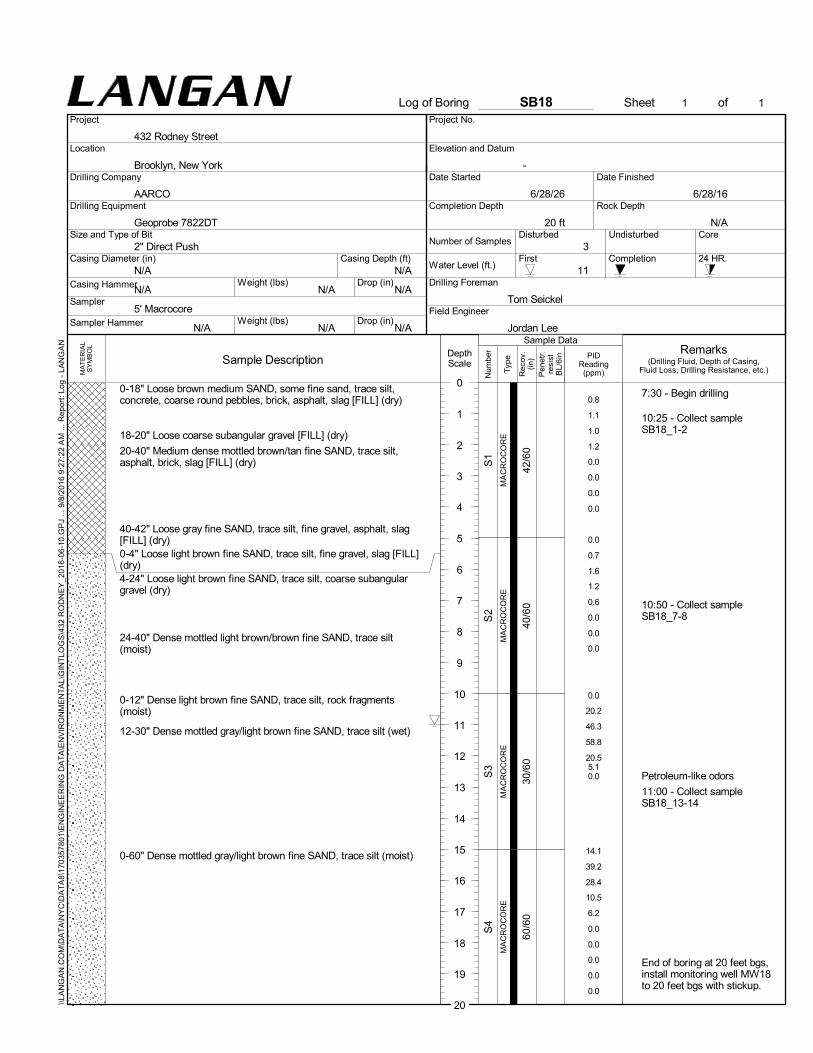
42/6
040
/60
30/6
060
/60
0-18" Loose brown medium SAND, some fine sand, trace silt,concrete, coarse round pebbles, brick, asphalt, slag [FILL] (dry)
18-20" Loose coarse subangular gravel [FILL] (dry)
20-40" Medium dense mottled brown/tan fine SAND, trace silt,asphalt, brick, slag [FILL] (dry)
40-42" Loose gray fine SAND, trace silt, fine gravel, asphalt, slag[FILL] (dry)0-4" Loose light brown fine SAND, trace silt, fine gravel, slag [FILL](dry)4-24" Loose light brown fine SAND, trace silt, coarse subangulargravel (dry)
24-40" Dense mottled light brown/brown fine SAND, trace silt(moist)
0-12" Dense light brown fine SAND, trace silt, rock fragments(moist)
12-30" Dense mottled gray/light brown fine SAND, trace silt (wet)
0-60" Dense mottled gray/light brown fine SAND, trace silt (moist)
MA
CR
OC
OR
EM
AC
RO
CO
RE
MA
CR
OC
OR
EM
AC
RO
CO
RE
S1
S2
S3
S4
0.8
1.1
1.0
1.2
0.0
0.0
0.0
0.0
0.0
0.7
1.6
1.2
0.6
0.0
0.0
0.0
0.0
20.2
46.3
58.8
20.55.10.0
14.1
39.2
28.4
10.5
6.2
0.0
0.0
0.0
0.0
0.0
7:30 - Begin drilling
10:25 - Collect sampleSB18_1-2
10:50 - Collect sampleSB18_7-8
Petroleum-like odors
11:00 - Collect sampleSB18_13-14
End of boring at 20 feet bgs,install monitoring well MW18to 20 feet bgs with stickup.
First
Disturbed
5' Macrocore
AARCO
N/AN/A
N/A
N/A
N/A
Core
N/A
Weight (lbs)
Drilling Company
2" Direct PushCasing Depth (ft)
Tom Seickel
Jordan Lee
Completion Depth
Number of Samples
Drilling Foreman11
6/28/16
Date Started
6/28/26
20 ft
Field Engineer
Size and Type of Bit
Completion
Sampler Hammer
Date Finished
Undisturbed
Drop (in)
Sampler
Weight (lbs)
N/ACasing Hammer
N/A
3Casing Diameter (in)
Geoprobe 7822DT
24 HR.
Drilling Equipment Rock Depth
Drop (in)
Water Level (ft.)
N/A
Pen
etr.
resi
stB
L/6i
n
Num
ber
0
Typ
e
Rec
ov.
(in)
SB18
Sample DescriptionDepthScale
1
2
3
4
5
6
7
8
9
10
11
12
13
14
15
16
17
18
19
Project
Log of Boring
Location
20
Project No.
-
Sheet 1
432 Rodney Street
Brooklyn, New York
of 1
MA
TE
RIA
LS
YM
BO
L
Elevation and Datum
\\LA
NG
AN
.CO
M\D
AT
A\N
YC
\DA
TA
8\17
035
780
1\E
NG
INE
ER
ING
DA
TA
\EN
VIR
ON
ME
NT
AL\
GIN
TLO
GS
\432
RO
DN
EY
_201
6-0
6-10
.GP
J ...
9/8
/201
6 9
:27:
22
AM
... R
epor
t: Lo
g -
LAN
GA
N
(Drilling Fluid, Depth of Casing,Fluid Loss, Drilling Resistance, etc.)
RemarksPID
Reading(ppm)
Sample Data

36/6
050
/60
46/6
034
/60
0-8" Loose brown medium SAND, some fine sand, trace silt,concrete, coarse round pebbles, brick, asphalt, slag [FILL] (dry)
8-10" Loose coarse subangular gravel [FILL] (dry)
10-16" Loose light brown fine SAND, trace silt [FILL] (dry)
16-36" Medium dense light brown fine SAND, trace silt, coarseround pebbles, asphalt, slag [FILL] (dry)
0-4" Loose brown fine SAND, trace silt, fine pebbles (dry)
4-24" Dense light brown fine SAND, trace silt (dry)
24-26" Loose coarse subangular gravel, some fine sand, trace silt(dry)26-50" Dense mottled light brown/brown fine SAND, trace silt(moist)
0-12" Dense light brown fine SAND, trace silt, rock fragments(moist)
12-46" Dense light brown fine SAND, trace silt (wet)
0-6" Medium dense mottled light brown/brown fine SAND, trace silt(wet)6-24" Medium dense light brown fine SAND, some silt (wet)
24-34" Dense light brown medium SAND, some fine sand, trace silt(wet)
MA
CR
OC
OR
EM
AC
RO
CO
RE
MA
CR
OC
OR
EM
AC
RO
CO
RE
S1
S2
S3
S4
1.0
2.4
5.1
4.3
3.01.00.8
1.8
2.1
3.2
5.8
5.0
2.6
2.0
0.0
0.0
0.0
0.0
0.0
0.0
0.0
0.0
0.0
0.0
0.0
0.0
0.0
0.0
0.0
0.0
7:10 - Begin drilling
8:05 - Collect sampleSB19_1-2
9:20 - Collect sampleSB19_7-8
9:50 - Collect sampleSB19_12-13
End of boring at 20 feet bgs,backfill to grade surface withbentonite.
First
Disturbed
5' Macrocore
AARCO
N/AN/A
N/A
N/A
N/A
Core
N/A
Weight (lbs)
Drilling Company
2" Direct PushCasing Depth (ft)
Tom Seickel
Jordan Lee
Completion Depth
Number of Samples
Drilling Foreman11
6/28/16
Date Started
6/28/16
20 ft
Field Engineer
Size and Type of Bit
Completion
Sampler Hammer
Date Finished
Undisturbed
Drop (in)
Sampler
Weight (lbs)
N/ACasing Hammer
N/A
3Casing Diameter (in)
Geoprobe 7822DT
24 HR.
Drilling Equipment Rock Depth
Drop (in)
Water Level (ft.)
N/A
Pen
etr.
resi
stB
L/6i
n
Num
ber
0
Typ
e
Rec
ov.
(in)
SB19
Sample DescriptionDepthScale
1
2
3
4
5
6
7
8
9
10
11
12
13
14
15
16
17
18
19
Project
Log of Boring
Location
20
Project No.
-
Sheet 1
432 Rodney Street
Brooklyn, New York
of 1
MA
TE
RIA
LS
YM
BO
L
Elevation and Datum
\\LA
NG
AN
.CO
M\D
AT
A\N
YC
\DA
TA
8\17
035
780
1\E
NG
INE
ER
ING
DA
TA
\EN
VIR
ON
ME
NT
AL\
GIN
TLO
GS
\432
RO
DN
EY
_201
6-0
6-10
.GP
J ...
9/8
/201
6 9
:27:
26
AM
... R
epor
t: Lo
g -
LAN
GA
N
(Drilling Fluid, Depth of Casing,Fluid Loss, Drilling Resistance, etc.)
RemarksPID
Reading(ppm)
Sample Data

16/4
837
/48
24/4
833
/48
36/4
8
CONCRETE
0-3" medium loose brown fine SAND, trace gray fine gravel, slag,brick, rock fragments [FILL] (moist)3-16" medium dense brown fine SAND, trace gray fine gravel, brick,rock fragments [FILL] (moist)
0-10" Medium dense brown fine SAND, trace brown fine gravel,trace gray silt, slag, brick [FILL] (moist)
10-14" Medium dense grayish brown SILT, brick, ceramic [FILL](moist)14-31" Medium dense reddish brown SILT, trace brown find sand,brick, [FILL] (moist)31-37" Medium dense reddish brown fine SAND, brick, slag [FILL](moist)
0-9" Medium dense reddish brown fine SAND, trace brown silt, slag,brick [FILL] (moist)
9-24" Medium dense grayish brown fine SAND, trace red and grayfine gravel (wet)
0-18" Medium dense grayish brown fine SAND, trace gray andreddish brown medium sand (wet)
18-33" Medium dense brown fine SAND, trace gray, red, and brownfine gravel (wet)
0-36" Medium loose brown, red, and black medium SAND (wet)
MA
CR
OC
OR
EM
AC
RO
CO
RE
MA
CR
OC
OR
EM
AC
RO
CO
RE
MA
CR
OC
OR
E
R1
R2
R3
R4
R5
0.0
0.0
0.0
0.0
0.0
0.0
0.0
0.0
0.0
0.0
78.4
98.7
82.384.1
23.233.4
60.0
58.2
24.2
2.4
0.0
0.0
0.0
0.0
0.0
0.0
10:10 - SB20_1-2 collected.
Petroleum-like odor, blackstaining, elevated PID.
GW table approx. 12' bgs.10:00 - SB20_11-12 collected.
Petroleum-like odor, blackstaining, elevated PID.
Well set at 18 ft bgs, 10 ftscreen to 8 ft bgs.
First
Disturbed
5' Macrocore
AARCO
N/AN/A
N/A
N/A
N/A
Core
N/A
Weight (lbs)
Drilling Company
2" Direct PushCasing Depth (ft)
Jose Garcia
Woo Kim
Completion Depth
Number of Samples
Drilling Foreman12
7/29/16
Date Started
7/29/16
-
20 ft
Field Engineer
Size and Type of Bit
Completion
Sampler Hammer
Date Finished
Undisturbed
Drop (in)
Sampler
Weight (lbs)
N/ACasing Hammer
N/A
5Casing Diameter (in)
Geoprobe 7822DT
24 HR.
Drilling Equipment Rock Depth
Drop (in)
Water Level (ft.)
-
N/A
Pen
etr.
resi
stB
L/6i
n
Num
ber
0
Typ
e
Rec
ov.
(in)
SB20
Sample DescriptionDepthScale
1
2
3
4
5
6
7
8
9
10
11
12
13
14
15
16
17
18
19
Project
Log of Boring
Location
20
Project No.
-
Sheet 1
432 Rodney Street
Brooklyn, New York
of 1
MA
TE
RIA
LS
YM
BO
L
Elevation and Datum
\\LA
NG
AN
.CO
M\D
AT
A\N
YC
\DA
TA
8\17
035
780
1\E
NG
INE
ER
ING
DA
TA
\EN
VIR
ON
ME
NT
AL\
GIN
TLO
GS
\432
RO
DN
EY
_201
6-0
6-10
.GP
J ...
9/8
/201
6 9
:27:
30
AM
... R
epor
t: Lo
g -
LAN
GA
N
(Drilling Fluid, Depth of Casing,Fluid Loss, Drilling Resistance, etc.)
RemarksPID
Reading(ppm)
Sample Data

APPENDIX C
REMEDIAL INVESTIGATION MONITORING WELL
CONSTRUCTION LOGS

WELL CONSTRUCTION SUMMARY
Well No. MW01
PROJECT PROJECT NO.
432 Rodney Street
LOCATION ELEVATION AND DATUM
Brooklyn, NY --
DRILLING AGENCY DATE STARTED DATE FINISHED
AARCO 6/6/2016
DRILLING EQUIPMENT DRILLER
Geoprobe® 7822 DT
SIZE AND TYPE OF BIT INSPECTOR
3" Direct Push
METHOD OF INSTALLATION
METHOD OF WELL DEVELOPMENT
Surge block cycled up and down before purging with submersible whale pump until water appears clear.
TYPE OF CASING DIAMETER TYPE OF BACKFILL MATERIAL
Schedule-40 PVC 2" #2 Filter Sand
TYPE OF SCREEN DIAMETER TYPE OF SEAL MATERIAL
Schedule-40 PVC 2" Hydrated bentonite chips
BOREHOLE DIAMETER TYPE OF FILTER MATERIAL
3" #2 Filter Sand
TOP OF CASING ELEVATION DEPTH (ft) WELL DETAILS DEPTH
SUMMARY SOIL (FT)
-- At grade CLASSIFICATION
TOP OF SEAL ELEVATION DEPTH (ft) See boring log
-- 2
TOP OF FILTER ELEVATION DEPTH (ft)
-- 3
TOP OF SCREEN ELEVATION DEPTH (ft)
-- 5
BOTTOM OF BORING ELEVATION DEPTH (ft) Cover 0.0
-- 19.5
SCREEN LENGTH
14' 2.0
SLOT SIZE Seal 3.0
0.01" 5.0
GROUNDWATER ELEVATIONS
ELEVATION DATE DEPTH TO WATER
-- 6/6/2016 9.83'
ELEVATION DATE DEPTH TO WATER PVC
Screen
ELEVATION DATE DEPTH TO WATER
Sand
ELEVATION DATE DEPTH TO WATER Pack
ELEVATION DATE DEPTH TO WATER 19.0
19.5
ELEVATION DATE DEPTH TO WATER
LANGAN Engineering, Environmental, Surveying and Landscape Architecture, D.P.C.
21 Penn Plaza, 360 West 31st Street, 8th Floor, New York
170357801
6/6/2016
Tim Kelly
Anna Schmiedicke
Drill to 19.5' bgs with 3" casing; install 2" diameter well with 14' screen at 19' bgs. Backfill annulus with filter sand to
3' bgs. Create seal of hydrated benonite chips to 2' bgs; backfill remainder of annulus with filter sand. Finish well
with manhole cover and concrete pad.

WELL CONSTRUCTION SUMMARY
Well No. MW02S/D
PROJECT PROJECT NO.
432 Rodney Street
LOCATION ELEVATION AND DATUM
Brooklyn, NY --
DRILLING AGENCY DATE STARTED DATE FINISHED
AARCO 6/7/2016
DRILLING EQUIPMENT DRILLER
Geoprobe® 8140 LC
SIZE AND TYPE OF BIT INSPECTOR
6" Sonic
METHOD OF INSTALLATION
METHOD OF WELL DEVELOPMENT
Surge block cycled up and down before purging with submersible whale pump until water appears clear.
TYPE OF CASING DIAMETER TYPE OF BACKFILL MATERIAL
2" #2 Filter Sand
TYPE OF SCREEN DIAMETER TYPE OF SEAL MATERIAL
2" Hydrated bentonite chips
BOREHOLE DIAMETER TYPE OF FILTER MATERIAL
6" #2 Filter Sand
TOP OF CASING ELEVATION DEPTH (ft) WELL DETAILS DEPTH
SUMMARY SOIL (FT)
-- At grade CLASSIFICATION
TOP OF SEAL ELEVATION DEPTH (ft) See boring log
-- 0
TOP OF FILTER ELEVATION DEPTH (ft)
-- 3
TOP OF SCREEN ELEVATION DEPTH (ft)
-- 5/41.5
BOTTOM OF BORING ELEVATION DEPTH (ft) Cover 0.0
-- 55
SCREEN LENGTH
Shallow: 15'
Deep: 10'
SLOT SIZE Seal Seal 3.0
0.01" 5.0
GROUNDWATER ELEVATIONS
ELEVATION DATE DEPTH TO WATER
-- 6/7/2016 10.3/10.25
ELEVATION DATE DEPTH TO WATER PVC 20.0
Screen 22.0
ELEVATION DATE DEPTH TO WATER
Seal 39.5
ELEVATION DATE DEPTH TO WATER 41.5
Sand
ELEVATION DATE DEPTH TO WATER Pack
51.5
ELEVATION DATE DEPTH TO WATER Seal 52.5
Sump 53.5
Grout 55.0
LANGAN Engineering, Environmental, Surveying and Landscape Architecture, D.P.C.
21 Penn Plaza, 360 West 31st Street, 8th Floor, New York
Shallow: Schedule-40 PVC
Deep: Schedule-80 PVC
170357801
6/6/2016
Tom Seickel
Jordan Lee
Drill to 55' bgs with 6" casing; install deep well with 2' sump from 53.5' to 51.5' bgs followed by 10' riser. Create seal of
bentonite from 51.5' to 50.5' bgs. Backfill annulus with filter sand to 39.5' bgs. Create second seal of hydrated benonite
chips to 22' bgs. Backfill annulus with filter sand to 20' bgs; install shallow well with 15' riser to 5' bgs. Backfill annulus
with filter sand to 3' bgs. Fill remainder of annulus with bentonite seal to surface. Finish well with manhole cover and
concrete pad.
Shallow: Schedule-40 PVC
Deep: Schedule-80 PVC

WELL CONSTRUCTION SUMMARY
Well No. MW03
PROJECT PROJECT NO.
432 Rodney Street
LOCATION ELEVATION AND DATUM
Brooklyn, NY --
DRILLING AGENCY DATE STARTED DATE FINISHED
AARCO 6/7/2016
DRILLING EQUIPMENT DRILLER
Geoprobe® 7822 DT
SIZE AND TYPE OF BIT INSPECTOR
3" Direct Push
METHOD OF INSTALLATION
METHOD OF WELL DEVELOPMENT
Surge block cycled up and down before purging with submersible whale pump until water appears clear.
TYPE OF CASING DIAMETER TYPE OF BACKFILL MATERIAL
Schedule-40 PVC 2" #2 Filter Sand
TYPE OF SCREEN DIAMETER TYPE OF SEAL MATERIAL
Schedule-40 PVC 2" Hydrated bentonite chips
BOREHOLE DIAMETER TYPE OF FILTER MATERIAL
3" #2 Filter Sand
TOP OF CASING ELEVATION DEPTH (ft) WELL DETAILS DEPTH
SUMMARY SOIL (FT)
-- At grade CLASSIFICATION
TOP OF SEAL ELEVATION DEPTH (ft) See boring log
-- 2
TOP OF FILTER ELEVATION DEPTH (ft)
-- 3
TOP OF SCREEN ELEVATION DEPTH (ft)
-- 5
BOTTOM OF BORING ELEVATION DEPTH (ft) Cover 0.0
-- 15.5
SCREEN LENGTH
10' 2.0
SLOT SIZE Seal 3.0
0.01" 5.0
GROUNDWATER ELEVATIONS
ELEVATION DATE DEPTH TO WATER
-- 6/7/2016 11.5'
ELEVATION DATE DEPTH TO WATER PVC
Screen
ELEVATION DATE DEPTH TO WATER
Sand
ELEVATION DATE DEPTH TO WATER Pack
ELEVATION DATE DEPTH TO WATER 15.0
15.5
ELEVATION DATE DEPTH TO WATER
LANGAN Engineering, Environmental, Surveying and Landscape Architecture, D.P.C.
21 Penn Plaza, 360 West 31st Street, 8th Floor, New York
170357801
6/7/2016
Tim Kelly
Anna Schmiedicke
Drill to 15.5' bgs with 3" casing; install 2" diameter well with 10' screen at 15' bgs. Backfill annulus with filter sand to
3' bgs. Create seal of hydrated benonite chips to 2' bgs; backfill remainder of annulus with filter sand. Finish well
with manhole cover and concrete pad.

WELL CONSTRUCTION SUMMARY
Well No. MW04
PROJECT PROJECT NO.
432 Rodney Street
LOCATION ELEVATION AND DATUM
Brooklyn, NY --
DRILLING AGENCY DATE STARTED DATE FINISHED
AARCO 6/6/2016
DRILLING EQUIPMENT DRILLER
Geoprobe® 7822 DT
SIZE AND TYPE OF BIT INSPECTOR
3" Direct Push
METHOD OF INSTALLATION
METHOD OF WELL DEVELOPMENT
Surge block cycled up and down before purging with submersible whale pump until water appears clear.
TYPE OF CASING DIAMETER TYPE OF BACKFILL MATERIAL
Schedule-40 PVC 2" #2 Filter Sand
TYPE OF SCREEN DIAMETER TYPE OF SEAL MATERIAL
Schedule-40 PVC 2" Hydrated bentonite chips
BOREHOLE DIAMETER TYPE OF FILTER MATERIAL
3" #2 Filter Sand
TOP OF CASING ELEVATION DEPTH (ft) WELL DETAILS DEPTH
SUMMARY SOIL (FT)
-- At grade CLASSIFICATION
TOP OF SEAL ELEVATION DEPTH (ft) See boring log
-- 2
TOP OF FILTER ELEVATION DEPTH (ft)
-- 3
TOP OF SCREEN ELEVATION DEPTH (ft)
-- 5
BOTTOM OF BORING ELEVATION DEPTH (ft) Cover 0.0
-- 15.5
SCREEN LENGTH
10' 2.0
SLOT SIZE Seal 3.0
0.01" 5.0
GROUNDWATER ELEVATIONS
ELEVATION DATE DEPTH TO WATER
-- 6/6/2016 9'
ELEVATION DATE DEPTH TO WATER PVC
Screen
ELEVATION DATE DEPTH TO WATER
Sand
ELEVATION DATE DEPTH TO WATER Pack
ELEVATION DATE DEPTH TO WATER 15.0
15.5
ELEVATION DATE DEPTH TO WATER
LANGAN Engineering, Environmental, Surveying and Landscape Architecture, D.P.C.
21 Penn Plaza, 360 West 31st Street, 8th Floor, New York
170357801
6/6/2016
Tim Kelly
Anna Schmiedicke
Drill to 15.5' bgs with 3" casing; install 2" diameter well with 10' screen at 15' bgs. Backfill annulus with filter sand to
3' bgs. Create seal of hydrated benonite chips to 2' bgs; backfill remainder of annulus with filter sand. Finish well
with manhole cover and concrete pad.

WELL CONSTRUCTION SUMMARY
Well No. MW05
PROJECT PROJECT NO.
432 Rodney Street
LOCATION ELEVATION AND DATUM
Brooklyn, NY --
DRILLING AGENCY DATE STARTED DATE FINISHED
AARCO 6/7/2016
DRILLING EQUIPMENT DRILLER
Geoprobe® 7822 DT
SIZE AND TYPE OF BIT INSPECTOR
3" Direct Push
METHOD OF INSTALLATION
METHOD OF WELL DEVELOPMENT
Surge block cycled up and down before purging with submersible whale pump until water appears clear.
TYPE OF CASING DIAMETER TYPE OF BACKFILL MATERIAL
Schedule-40 PVC 2" #2 Filter Sand
TYPE OF SCREEN DIAMETER TYPE OF SEAL MATERIAL
Schedule-40 PVC 2" Hydrated bentonite chips
BOREHOLE DIAMETER TYPE OF FILTER MATERIAL
3" #2 Filter Sand
TOP OF CASING ELEVATION DEPTH (ft) WELL DETAILS DEPTH
SUMMARY SOIL (FT)
-- At grade CLASSIFICATION
TOP OF SEAL ELEVATION DEPTH (ft) See boring log
-- 2
TOP OF FILTER ELEVATION DEPTH (ft)
-- 3
TOP OF SCREEN ELEVATION DEPTH (ft)
-- 5
BOTTOM OF BORING ELEVATION DEPTH (ft) Cover 0.0
-- 15.5
SCREEN LENGTH
10' 2.0
SLOT SIZE Seal 3.0
0.01" 5.0
GROUNDWATER ELEVATIONS
ELEVATION DATE DEPTH TO WATER
-- 6/7/2016 9'
ELEVATION DATE DEPTH TO WATER PVC
Screen
ELEVATION DATE DEPTH TO WATER
Sand
ELEVATION DATE DEPTH TO WATER Pack
ELEVATION DATE DEPTH TO WATER 15.0
15.5
ELEVATION DATE DEPTH TO WATER
LANGAN Engineering, Environmental, Surveying and Landscape Architecture, D.P.C.
21 Penn Plaza, 360 West 31st Street, 8th Floor, New York
170357801
6/7/2016
Tim Kelly
Anna Schmiedicke
Drill to 15.5' bgs with 3" casing; install 2" diameter well with 10' screen at 15' bgs. Backfill annulus with filter sand to
3' bgs. Create seal of hydrated benonite chips to 2' bgs; backfill remainder of annulus with filter sand. Finish well
with manhole cover and concrete pad.

WELL CONSTRUCTION SUMMARY
Well No. MW06
PROJECT PROJECT NO.
432 Rodney Street
LOCATION ELEVATION AND DATUM
Brooklyn, NY --
DRILLING AGENCY DATE STARTED DATE FINISHED
AARCO 6/6/2016
DRILLING EQUIPMENT DRILLER
Geoprobe® 7822 DT
SIZE AND TYPE OF BIT INSPECTOR
3" Direct Push
METHOD OF INSTALLATION
METHOD OF WELL DEVELOPMENT
Surge block cycled up and down before purging with submersible whale pump until water appears clear.
TYPE OF CASING DIAMETER TYPE OF BACKFILL MATERIAL
Schedule-40 PVC 2" #2 Filter Sand
TYPE OF SCREEN DIAMETER TYPE OF SEAL MATERIAL
Schedule-40 PVC 2" Hydrated bentonite chips
BOREHOLE DIAMETER TYPE OF FILTER MATERIAL
3" #2 Filter Sand
TOP OF CASING ELEVATION DEPTH (ft) WELL DETAILS DEPTH
SUMMARY SOIL (FT)
-- At grade CLASSIFICATION
TOP OF SEAL ELEVATION DEPTH (ft) See boring log
-- 2
TOP OF FILTER ELEVATION DEPTH (ft)
-- 3
TOP OF SCREEN ELEVATION DEPTH (ft)
-- 5
BOTTOM OF BORING ELEVATION DEPTH (ft) Cover 0.0
-- 15.5
SCREEN LENGTH
10' 2.0
SLOT SIZE Seal 3.0
0.01" 5.0
GROUNDWATER ELEVATIONS
ELEVATION DATE DEPTH TO WATER
-- 6/6/2016 9.2'
ELEVATION DATE DEPTH TO WATER PVC
Screen
ELEVATION DATE DEPTH TO WATER
Sand
ELEVATION DATE DEPTH TO WATER Pack
ELEVATION DATE DEPTH TO WATER 15.0
15.5
ELEVATION DATE DEPTH TO WATER
LANGAN Engineering, Environmental, Surveying and Landscape Architecture, D.P.C.
21 Penn Plaza, 360 West 31st Street, 8th Floor, New York
170357801
6/6/2016
Tim Kelly
Anna Schmiedicke
Drill to 15.5' bgs with 3" casing; install 2" diameter well with 10' screen at 15' bgs. Backfill annulus with filter sand to
3' bgs. Create seal of hydrated benonite chips to 2' bgs; backfill remainder of annulus with filter sand. Finish well
with manhole cover and concrete pad.

WELL CONSTRUCTION SUMMARY
Well No. MW07S/D
PROJECT PROJECT NO.
432 Rodney Street
LOCATION ELEVATION AND DATUM
Brooklyn, NY --
DRILLING AGENCY DATE STARTED DATE FINISHED
AARCO 6/8/2016
DRILLING EQUIPMENT DRILLER
Geoprobe® 8140 LC
SIZE AND TYPE OF BIT INSPECTOR
6" Sonic
METHOD OF INSTALLATION
METHOD OF WELL DEVELOPMENT
Surge block cycled up and down before purging with submersible whale pump until water appears clear.
TYPE OF CASING DIAMETER TYPE OF BACKFILL MATERIAL
2" #2 Filter Sand
TYPE OF SCREEN DIAMETER TYPE OF SEAL MATERIAL
2" Hydrated bentonite chips
BOREHOLE DIAMETER TYPE OF FILTER MATERIAL
6" #2 Filter Sand
TOP OF CASING ELEVATION DEPTH (ft) WELL DETAILS DEPTH
SUMMARY SOIL (FT)
-- At grade CLASSIFICATION
TOP OF SEAL ELEVATION DEPTH (ft) See boring log
-- 0
TOP OF FILTER ELEVATION DEPTH (ft)
-- 3
TOP OF SCREEN ELEVATION DEPTH (ft)
-- 5/47
BOTTOM OF BORING ELEVATION DEPTH (ft) Cover 0.0
-- 60
SCREEN LENGTH
Shallow: 15'
Deep: 5'
SLOT SIZE Seal Seal 3.0
0.01" 5.0
GROUNDWATER ELEVATIONS
ELEVATION DATE DEPTH TO WATER
-- 6/8/2016 9.75/10.81
ELEVATION DATE DEPTH TO WATER PVC 20.0
Screen 22.0
ELEVATION DATE DEPTH TO WATER
Seal 45.0
ELEVATION DATE DEPTH TO WATER 47.0
Sand
ELEVATION DATE DEPTH TO WATER Pack
Seal 52.0
ELEVATION DATE DEPTH TO WATER 53.0
Sump 54.0
Grout 60.0
LANGAN Engineering, Environmental, Surveying and Landscape Architecture, D.P.C.
21 Penn Plaza, 360 West 31st Street, 8th Floor, New York
Shallow: Schedule-40 PVC
Deep: Schedule-80 PVC
170357801
6/7/2016
Tom Seickel
Jordan Lee
Drill to 60' bgs with 6" casing; install deep well with 2' sump from 54' to 52' bgs followed by 5' riser. Create seal of
bentonite from 52' to 51' bgs. Backfill annulus with filter sand to 45' bgs. Create second seal of hydrated benonite chips to
22' bgs. Backfill annulus with filter sand to 20' bgs; install shallow well with 15' riser to 5' bgs. Backfill annulus with filter
sand to 3' bgs. Fill remainder of annulus with bentonite seal to surface. Finish well with manhole cover and concrete pad.
Shallow: Schedule-40 PVC
Deep: Schedule-80 PVC

WELL CONSTRUCTION SUMMARY
Well No. MW08S/D
PROJECT PROJECT NO.
432 Rodney Street
LOCATION ELEVATION AND DATUM
Brooklyn, NY --
DRILLING AGENCY DATE STARTED DATE FINISHED
AARCO 6/9/2016
DRILLING EQUIPMENT DRILLER
Geoprobe® 8140 LC
SIZE AND TYPE OF BIT INSPECTOR
6" Sonic
METHOD OF INSTALLATION
METHOD OF WELL DEVELOPMENT
Surge block cycled up and down before purging with submersible whale pump until water appears clear.
TYPE OF CASING DIAMETER TYPE OF BACKFILL MATERIAL
2" #2 Filter Sand
TYPE OF SCREEN DIAMETER TYPE OF SEAL MATERIAL
2" Hydrated bentonite chips
BOREHOLE DIAMETER TYPE OF FILTER MATERIAL
6" #2 Filter Sand
TOP OF CASING ELEVATION DEPTH (ft) WELL DETAILS DEPTH
SUMMARY SOIL (FT)
-- At grade CLASSIFICATION
TOP OF SEAL ELEVATION DEPTH (ft) See boring log
-- 0
TOP OF FILTER ELEVATION DEPTH (ft)
-- 3
TOP OF SCREEN ELEVATION DEPTH (ft)
-- 5/37
BOTTOM OF BORING ELEVATION DEPTH (ft) Cover 0.0
-- 45
SCREEN LENGTH
Shallow: 15'
Deep: 5'
SLOT SIZE Seal Seal 3.0
0.01" 5.0
GROUNDWATER ELEVATIONS
ELEVATION DATE DEPTH TO WATER
-- 6/9/2016 10.95/11.23
ELEVATION DATE DEPTH TO WATER PVC 20.0
Screen 22.0
ELEVATION DATE DEPTH TO WATER
Seal 35.0
ELEVATION DATE DEPTH TO WATER 37.0
Sand
ELEVATION DATE DEPTH TO WATER Pack
Seal 42.0
ELEVATION DATE DEPTH TO WATER 43.0
Sump 44.0
Grout 45.0
LANGAN Engineering, Environmental, Surveying and Landscape Architecture, D.P.C.
21 Penn Plaza, 360 West 31st Street, 8th Floor, New York
Shallow: Schedule-40 PVC
Deep: Schedule-80 PVC
170357801
6/8/2016
Tom Seickel
Jordan Lee
Drill to 45' bgs with 6" casing; install deep well with 2' sump from 44' to 42' bgs followed by 5' riser. Create seal of
bentonite from 42' to 41' bgs. Backfill annulus with filter sand to 35' bgs. Create second seal of hydrated benonite chips to
22' bgs. Backfill annulus with filter sand to 20' bgs; install shallow well with 15' riser to 5' bgs. Backfill annulus with filter
sand to 3' bgs. Fill remainder of annulus with bentonite seal to surface. Finish well with manhole cover and concrete pad.
Shallow: Schedule-40 PVC
Deep: Schedule-80 PVC

WELL CONSTRUCTION SUMMARY
Well No. MW09
PROJECT PROJECT NO.
432 Rodney Street
LOCATION ELEVATION AND DATUM
Brooklyn, NY --
DRILLING AGENCY DATE STARTED DATE FINISHED
AARCO 6/7/2016
DRILLING EQUIPMENT DRILLER
Geoprobe® 7822 DT
SIZE AND TYPE OF BIT INSPECTOR
3" Direct Push
METHOD OF INSTALLATION
METHOD OF WELL DEVELOPMENT
Surge block cycled up and down before purging with submersible whale pump until water appears clear.
TYPE OF CASING DIAMETER TYPE OF BACKFILL MATERIAL
Schedule-40 PVC 2" #2 Filter Sand
TYPE OF SCREEN DIAMETER TYPE OF SEAL MATERIAL
Schedule-40 PVC 2" Hydrated bentonite chips
BOREHOLE DIAMETER TYPE OF FILTER MATERIAL
3" #2 Filter Sand
TOP OF CASING ELEVATION DEPTH (ft) WELL DETAILS DEPTH
SUMMARY SOIL (FT)
-- At grade CLASSIFICATION
TOP OF SEAL ELEVATION DEPTH (ft) See boring log
-- 2
TOP OF FILTER ELEVATION DEPTH (ft)
-- 3
TOP OF SCREEN ELEVATION DEPTH (ft)
-- 5
BOTTOM OF BORING ELEVATION DEPTH (ft) Cover 0.0
-- 15.5
SCREEN LENGTH
10' 2.0
SLOT SIZE Seal 3.0
0.01" 5.0
GROUNDWATER ELEVATIONS
ELEVATION DATE DEPTH TO WATER
-- 6/7/2016 12'
ELEVATION DATE DEPTH TO WATER PVC
Screen
ELEVATION DATE DEPTH TO WATER
Sand
ELEVATION DATE DEPTH TO WATER Pack
ELEVATION DATE DEPTH TO WATER 15.0
15.5
ELEVATION DATE DEPTH TO WATER
LANGAN Engineering, Environmental, Surveying and Landscape Architecture, D.P.C.
21 Penn Plaza, 360 West 31st Street, 8th Floor, New York
170357801
6/7/2016
Tim Kelly
Anna Schmiedicke
Drill to 15.5' bgs with 3" casing; install 2" diameter well with 10' screen at 15' bgs. Backfill annulus with filter sand to
3' bgs. Create seal of hydrated benonite chips to 2' bgs; backfill remainder of annulus with filter sand. Finish well
with manhole cover and concrete pad.

WELL CONSTRUCTION SUMMARY
Well No. MW10
PROJECT PROJECT NO.
432 Rodney Street
LOCATION ELEVATION AND DATUM
Brooklyn, NY --
DRILLING AGENCY DATE STARTED DATE FINISHED
AARCO 6/7/2016
DRILLING EQUIPMENT DRILLER
Geoprobe® 7822 DT
SIZE AND TYPE OF BIT INSPECTOR
3" Direct Push
METHOD OF INSTALLATION
METHOD OF WELL DEVELOPMENT
Surge block cycled up and down before purging with submersible whale pump until water appears clear.
TYPE OF CASING DIAMETER TYPE OF BACKFILL MATERIAL
Schedule-40 PVC 2" #2 Filter Sand
TYPE OF SCREEN DIAMETER TYPE OF SEAL MATERIAL
Schedule-40 PVC 2" Hydrated bentonite chips
BOREHOLE DIAMETER TYPE OF FILTER MATERIAL
3" #2 Filter Sand
TOP OF CASING ELEVATION DEPTH (ft) WELL DETAILS DEPTH
SUMMARY SOIL (FT)
-- At grade CLASSIFICATION
TOP OF SEAL ELEVATION DEPTH (ft) See boring log
-- 2
TOP OF FILTER ELEVATION DEPTH (ft)
-- 3
TOP OF SCREEN ELEVATION DEPTH (ft)
-- 5
BOTTOM OF BORING ELEVATION DEPTH (ft) Cover 0.0
-- 15.5
SCREEN LENGTH
10' 2.0
SLOT SIZE Seal 3.0
0.01" 5.0
GROUNDWATER ELEVATIONS
ELEVATION DATE DEPTH TO WATER
-- 6/7/2016 11'
ELEVATION DATE DEPTH TO WATER PVC
Screen
ELEVATION DATE DEPTH TO WATER
Sand
ELEVATION DATE DEPTH TO WATER Pack
ELEVATION DATE DEPTH TO WATER 15.0
15.5
ELEVATION DATE DEPTH TO WATER
LANGAN Engineering, Environmental, Surveying and Landscape Architecture, D.P.C.
21 Penn Plaza, 360 West 31st Street, 8th Floor, New York
170357801
6/7/2016
Tim Kelly
Anna Schmiedicke
Drill to 15.5' bgs with 3" casing; install 2" diameter well with 10' screen at 15' bgs. Backfill annulus with filter sand to
3' bgs. Create seal of hydrated benonite chips to 2' bgs; backfill remainder of annulus with filter sand. Finish well
with manhole cover and concrete pad.

WELL CONSTRUCTION SUMMARY
Well No. MW11
PROJECT PROJECT NO.
432 Rodney Street
LOCATION ELEVATION AND DATUM
Brooklyn, NY --
DRILLING AGENCY DATE STARTED DATE FINISHED
AARCO 6/9/2016
DRILLING EQUIPMENT DRILLER
Geoprobe® 7822 DT
SIZE AND TYPE OF BIT INSPECTOR
3" Direct Push
METHOD OF INSTALLATION
METHOD OF WELL DEVELOPMENT
Surge block cycled up and down before purging with submersible whale pump until water appears clear.
TYPE OF CASING DIAMETER TYPE OF BACKFILL MATERIAL
Schedule-40 PVC 2" #2 Filter Sand
TYPE OF SCREEN DIAMETER TYPE OF SEAL MATERIAL
Schedule-40 PVC 2" Hydrated bentonite chips
BOREHOLE DIAMETER TYPE OF FILTER MATERIAL
3" #2 Filter Sand
TOP OF CASING ELEVATION DEPTH (ft) WELL DETAILS DEPTH
SUMMARY SOIL (FT)
-- At grade CLASSIFICATION
TOP OF SEAL ELEVATION DEPTH (ft) See boring log
-- 2
TOP OF FILTER ELEVATION DEPTH (ft)
-- 3
TOP OF SCREEN ELEVATION DEPTH (ft)
-- 5
BOTTOM OF BORING ELEVATION DEPTH (ft) Cover 0.0
-- 20.5
SCREEN LENGTH
15' 2.0
SLOT SIZE Seal 3.0
0.01" 5.0
GROUNDWATER ELEVATIONS
ELEVATION DATE DEPTH TO WATER
-- 6/9/2016 11'
ELEVATION DATE DEPTH TO WATER PVC
Screen
ELEVATION DATE DEPTH TO WATER
Sand
ELEVATION DATE DEPTH TO WATER Pack
ELEVATION DATE DEPTH TO WATER 20.0
20.5
ELEVATION DATE DEPTH TO WATER
LANGAN Engineering, Environmental, Surveying and Landscape Architecture, D.P.C.
21 Penn Plaza, 360 West 31st Street, 8th Floor, New York
170357801
6/9/2016
Tim Kelly
Anna Schmiedicke
Drill to 20.5' bgs with 3" casing; install 2" diameter well with 15' screen at 20' bgs. Backfill annulus with filter sand to
3' bgs. Create seal of hydrated benonite chips to 2' bgs; backfill remainder of annulus with filter sand. Finish well
with manhole cover and concrete pad.

WELL CONSTRUCTION SUMMARY
Well No. MW12
PROJECT PROJECT NO.
432 Rodney Street
LOCATION ELEVATION AND DATUM
Brooklyn, NY --
DRILLING AGENCY DATE STARTED DATE FINISHED
AARCO 6/9/2016
DRILLING EQUIPMENT DRILLER
Geoprobe® 7822 DT
SIZE AND TYPE OF BIT INSPECTOR
3" Direct Push
METHOD OF INSTALLATION
METHOD OF WELL DEVELOPMENT
Surge block cycled up and down before purging with submersible whale pump until water appears clear.
TYPE OF CASING DIAMETER TYPE OF BACKFILL MATERIAL
Schedule-40 PVC 2" #2 Filter Sand
TYPE OF SCREEN DIAMETER TYPE OF SEAL MATERIAL
Schedule-40 PVC 2" Hydrated bentonite chips
BOREHOLE DIAMETER TYPE OF FILTER MATERIAL
3" #2 Filter Sand
TOP OF CASING ELEVATION DEPTH (ft) WELL DETAILS DEPTH
SUMMARY SOIL (FT)
-- At grade CLASSIFICATION
TOP OF SEAL ELEVATION DEPTH (ft) See boring log
-- 2
TOP OF FILTER ELEVATION DEPTH (ft)
-- 3
TOP OF SCREEN ELEVATION DEPTH (ft)
-- 5
BOTTOM OF BORING ELEVATION DEPTH (ft) Cover 0.0
-- 20.5
SCREEN LENGTH
15' 2.0
SLOT SIZE Seal 3.0
0.01" 5.0
GROUNDWATER ELEVATIONS
ELEVATION DATE DEPTH TO WATER
-- 6/9/2016 10.5'
ELEVATION DATE DEPTH TO WATER PVC
Screen
ELEVATION DATE DEPTH TO WATER
Sand
ELEVATION DATE DEPTH TO WATER Pack
ELEVATION DATE DEPTH TO WATER 20.0
20.5
ELEVATION DATE DEPTH TO WATER
LANGAN Engineering, Environmental, Surveying and Landscape Architecture, D.P.C.
21 Penn Plaza, 360 West 31st Street, 8th Floor, New York
170357801
6/9/2016
Tim Kelly
Anna Schmiedicke
Drill to 20.5' bgs with 3" casing; install 2" diameter well with 15' screen at 20' bgs. Backfill annulus with filter sand to
3' bgs. Create seal of hydrated benonite chips to 2' bgs; backfill remainder of annulus with filter sand. Finish well
with manhole cover and concrete pad.

WELL CONSTRUCTION SUMMARY
Well No. MW13
PROJECT PROJECT NO.
432 Rodney Street
LOCATION ELEVATION AND DATUM
Brooklyn, NY --
DRILLING AGENCY DATE STARTED DATE FINISHED
AARCO 6/10/2016
DRILLING EQUIPMENT DRILLER
Geoprobe® 7822 DT
SIZE AND TYPE OF BIT INSPECTOR
3" Direct Push
METHOD OF INSTALLATION
METHOD OF WELL DEVELOPMENT
Surge block cycled up and down before purging with submersible whale pump until water appears clear.
TYPE OF CASING DIAMETER TYPE OF BACKFILL MATERIAL
Schedule-40 PVC 2" #2 Filter Sand
TYPE OF SCREEN DIAMETER TYPE OF SEAL MATERIAL
Schedule-40 PVC 2" Hydrated bentonite chips
BOREHOLE DIAMETER TYPE OF FILTER MATERIAL
3" #2 Filter Sand
TOP OF CASING ELEVATION DEPTH (ft) WELL DETAILS DEPTH
SUMMARY SOIL (FT)
-- At grade CLASSIFICATION
TOP OF SEAL ELEVATION DEPTH (ft) See boring log
-- 2
TOP OF FILTER ELEVATION DEPTH (ft)
-- 3
TOP OF SCREEN ELEVATION DEPTH (ft)
-- 5
BOTTOM OF BORING ELEVATION DEPTH (ft) Cover 0.0
-- 20.5
SCREEN LENGTH
15' 2.0
SLOT SIZE Seal 3.0
0.01" 5.0
GROUNDWATER ELEVATIONS
ELEVATION DATE DEPTH TO WATER
-- 6/10/2016 10.33'
ELEVATION DATE DEPTH TO WATER PVC
Screen
ELEVATION DATE DEPTH TO WATER
Sand
ELEVATION DATE DEPTH TO WATER Pack
ELEVATION DATE DEPTH TO WATER 20.0
20.5
ELEVATION DATE DEPTH TO WATER
LANGAN Engineering, Environmental, Surveying and Landscape Architecture, D.P.C.
21 Penn Plaza, 360 West 31st Street, 8th Floor, New York
170357801
6/10/2016
Tim Kelly
Anna Schmiedicke
Drill to 20.5' bgs with 3" casing; install 2" diameter well with 15' screen at 20' bgs. Backfill annulus with filter sand to
3' bgs. Create seal of hydrated benonite chips to 2' bgs; backfill remainder of annulus with filter sand. Finish well
with manhole cover and concrete pad.
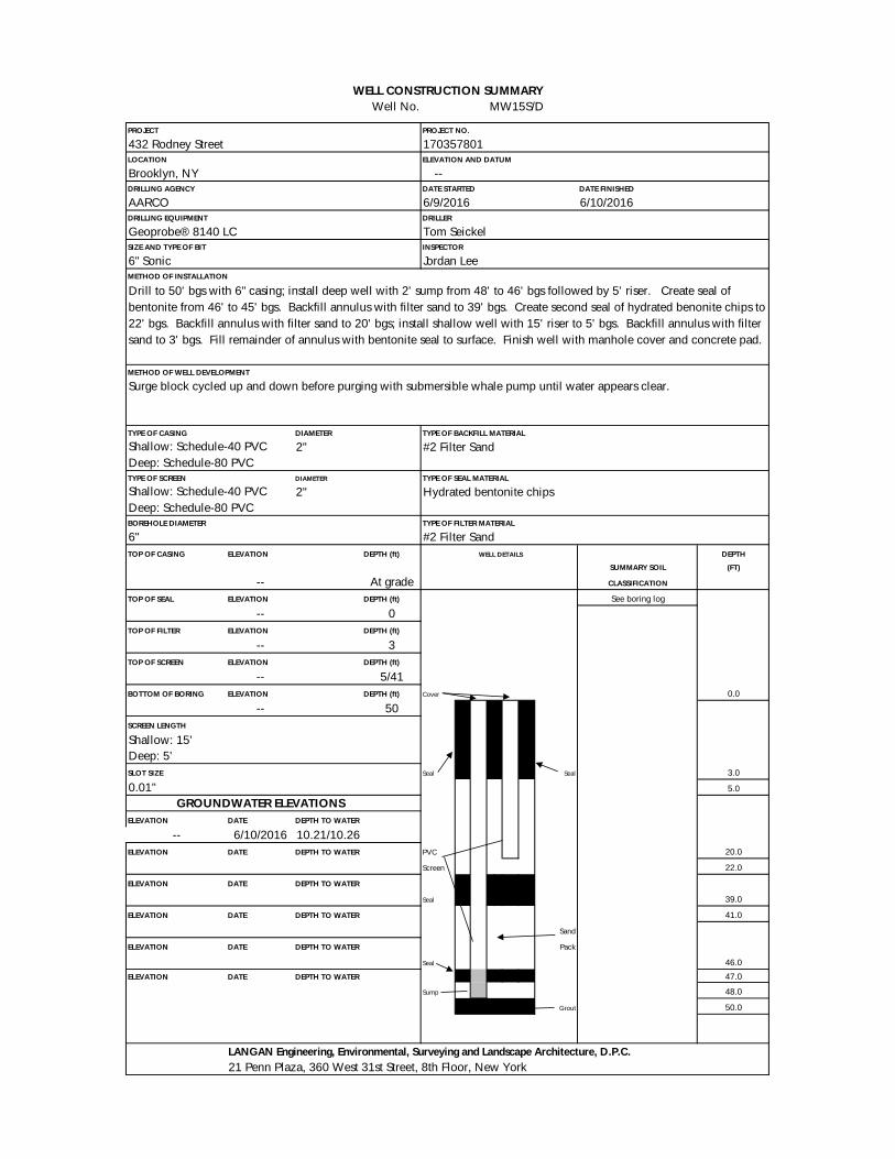
WELL CONSTRUCTION SUMMARY
Well No. MW15S/D
PROJECT PROJECT NO.
432 Rodney Street
LOCATION ELEVATION AND DATUM
Brooklyn, NY --
DRILLING AGENCY DATE STARTED DATE FINISHED
AARCO 6/10/2016
DRILLING EQUIPMENT DRILLER
Geoprobe® 8140 LC
SIZE AND TYPE OF BIT INSPECTOR
6" Sonic
METHOD OF INSTALLATION
METHOD OF WELL DEVELOPMENT
Surge block cycled up and down before purging with submersible whale pump until water appears clear.
TYPE OF CASING DIAMETER TYPE OF BACKFILL MATERIAL
2" #2 Filter Sand
TYPE OF SCREEN DIAMETER TYPE OF SEAL MATERIAL
2" Hydrated bentonite chips
BOREHOLE DIAMETER TYPE OF FILTER MATERIAL
6" #2 Filter Sand
TOP OF CASING ELEVATION DEPTH (ft) WELL DETAILS DEPTH
SUMMARY SOIL (FT)
-- At grade CLASSIFICATION
TOP OF SEAL ELEVATION DEPTH (ft) See boring log
-- 0
TOP OF FILTER ELEVATION DEPTH (ft)
-- 3
TOP OF SCREEN ELEVATION DEPTH (ft)
-- 5/41
BOTTOM OF BORING ELEVATION DEPTH (ft) Cover 0.0
-- 50
SCREEN LENGTH
Shallow: 15'
Deep: 5'
SLOT SIZE Seal Seal 3.0
0.01" 5.0
GROUNDWATER ELEVATIONS
ELEVATION DATE DEPTH TO WATER
-- 6/10/2016 10.21/10.26
ELEVATION DATE DEPTH TO WATER PVC 20.0
Screen 22.0
ELEVATION DATE DEPTH TO WATER
Seal 39.0
ELEVATION DATE DEPTH TO WATER 41.0
Sand
ELEVATION DATE DEPTH TO WATER Pack
Seal 46.0
ELEVATION DATE DEPTH TO WATER 47.0
Sump 48.0
Grout 50.0
LANGAN Engineering, Environmental, Surveying and Landscape Architecture, D.P.C.
21 Penn Plaza, 360 West 31st Street, 8th Floor, New York
Shallow: Schedule-40 PVC
Deep: Schedule-80 PVC
170357801
6/9/2016
Tom Seickel
Jordan Lee
Drill to 50' bgs with 6" casing; install deep well with 2' sump from 48' to 46' bgs followed by 5' riser. Create seal of
bentonite from 46' to 45' bgs. Backfill annulus with filter sand to 39' bgs. Create second seal of hydrated benonite chips to
22' bgs. Backfill annulus with filter sand to 20' bgs; install shallow well with 15' riser to 5' bgs. Backfill annulus with filter
sand to 3' bgs. Fill remainder of annulus with bentonite seal to surface. Finish well with manhole cover and concrete pad.
Shallow: Schedule-40 PVC
Deep: Schedule-80 PVC

WELL CONSTRUCTION SUMMARY
Well No. MW16S/D
PROJECT PROJECT NO.
432 Rodney Street
LOCATION ELEVATION AND DATUM
Brooklyn, NY --
DRILLING AGENCY DATE STARTED DATE FINISHED
AARCO 6/10/2016
DRILLING EQUIPMENT DRILLER
Geoprobe® 8140 LC
SIZE AND TYPE OF BIT INSPECTOR
6" Sonic
METHOD OF INSTALLATION
METHOD OF WELL DEVELOPMENT
Surge block cycled up and down before purging with submersible whale pump until water appears clear.
TYPE OF CASING DIAMETER TYPE OF BACKFILL MATERIAL
2" #2 Filter Sand
TYPE OF SCREEN DIAMETER TYPE OF SEAL MATERIAL
2" Hydrated bentonite chips
BOREHOLE DIAMETER TYPE OF FILTER MATERIAL
6" #2 Filter Sand
TOP OF CASING ELEVATION DEPTH (ft) WELL DETAILS DEPTH
SUMMARY SOIL (FT)
-- At grade CLASSIFICATION
TOP OF SEAL ELEVATION DEPTH (ft) See boring log
-- 2
TOP OF FILTER ELEVATION DEPTH (ft)
-- 3
TOP OF SCREEN ELEVATION DEPTH (ft)
-- 5/42
BOTTOM OF BORING ELEVATION DEPTH (ft) Cover 0.0
-- 50
SCREEN LENGTH
Shallow: 15'
Deep: 5'
SLOT SIZE Seal Seal 3.0
0.01" 5.0
GROUNDWATER ELEVATIONS
ELEVATION DATE DEPTH TO WATER
-- 6/10/2016 11.3/11.25
ELEVATION DATE DEPTH TO WATER PVC 20.0
Screen 22.0
ELEVATION DATE DEPTH TO WATER
Seal 40.0
ELEVATION DATE DEPTH TO WATER 42.0
Sand
ELEVATION DATE DEPTH TO WATER Pack
Seal 47.0
ELEVATION DATE DEPTH TO WATER 48.0
Sump 49.0
Grout 50.0
LANGAN Engineering, Environmental, Surveying and Landscape Architecture, D.P.C.
21 Penn Plaza, 360 West 31st Street, 8th Floor, New York
Shallow: Schedule-40 PVC
Deep: Schedule-80 PVC
170357801
6/10/2016
Tom Seickel
Jordan Lee
Drill to 50' bgs with 6" casing; install deep well with 2' sump from 49' to 47' bgs followed by 5' riser. Create seal of
bentonite from 47' to 45' bgs. Backfill annulus with filter sand to 40' bgs. Create second seal of hydrated benonite chips to
22' bgs. Backfill annulus with filter sand to 20' bgs; install shallow well with 15' riser to 5' bgs. Backfill annulus with filter
sand to 3' bgs. Fill remainder of annulus with bentonite seal to surface. Finish well with manhole cover and concrete pad.
Shallow: Schedule-40 PVC
Deep: Schedule-80 PVC

WELL CONSTRUCTION SUMMARY
Well No. MW17
PROJECT PROJECT NO.
432 Rodney Street
LOCATION ELEVATION AND DATUM
Brooklyn, NY --
DRILLING AGENCY DATE STARTED DATE FINISHED
AARCO 6/28/2016
DRILLING EQUIPMENT DRILLER
Geoprobe® 7822 DT
SIZE AND TYPE OF BIT INSPECTOR
3" Direct Push
METHOD OF INSTALLATION
METHOD OF WELL DEVELOPMENT
Surge block cycled up and down before purging with submersible whale pump until water appears clear.
TYPE OF CASING DIAMETER TYPE OF BACKFILL MATERIAL
Schedule-40 PVC 2" #2 Filter Sand
TYPE OF SCREEN DIAMETER TYPE OF SEAL MATERIAL
Schedule-40 PVC 2" Hydrated bentonite chips
BOREHOLE DIAMETER TYPE OF FILTER MATERIAL
3" #2 Filter Sand
TOP OF CASING ELEVATION DEPTH (ft) WELL DETAILS DEPTH
SUMMARY SOIL (FT)
-- -2.1 CLASSIFICATION
TOP OF SEAL ELEVATION DEPTH (ft) See boring log
-- 0
TOP OF FILTER ELEVATION DEPTH (ft)
-- 3
TOP OF SCREEN ELEVATION DEPTH (ft) +2.1-foot stickup
-- 5
BOTTOM OF BORING ELEVATION DEPTH (ft) Cover
-- 20
SCREEN LENGTH
15' 0.0
SLOT SIZE Seal 3.0
0.01" 5.0
GROUNDWATER ELEVATIONS
ELEVATION DATE DEPTH TO WATER
-- 6/28/2016 12.16'
ELEVATION DATE DEPTH TO WATER PVC
Screen
ELEVATION DATE DEPTH TO WATER
Sand
ELEVATION DATE DEPTH TO WATER Pack
ELEVATION DATE DEPTH TO WATER 20.0
ELEVATION DATE DEPTH TO WATER
LANGAN Engineering, Environmental, Surveying and Landscape Architecture, D.P.C.
21 Penn Plaza, 360 West 31st Street, 8th Floor, New York
170357801
6/28/2016
Tom Seickel
Jordan Lee
Drill to 20' bgs with 3" casing; install 2" diameter well with 15' screen at 20' bgs. Backfill annulus with filter sand to
3' bgs. Create seal of hydrated benonite chips to 0' bgs.

WELL CONSTRUCTION SUMMARY
Well No. MW18
PROJECT PROJECT NO.
432 Rodney Street
LOCATION ELEVATION AND DATUM
Brooklyn, NY --
DRILLING AGENCY DATE STARTED DATE FINISHED
AARCO 6/28/2016
DRILLING EQUIPMENT DRILLER
Geoprobe® 7822 DT
SIZE AND TYPE OF BIT INSPECTOR
3" Direct Push
METHOD OF INSTALLATION
METHOD OF WELL DEVELOPMENT
Surge block cycled up and down before purging with submersible whale pump until water appears clear.
TYPE OF CASING DIAMETER TYPE OF BACKFILL MATERIAL
Schedule-40 PVC 2" #2 Filter Sand
TYPE OF SCREEN DIAMETER TYPE OF SEAL MATERIAL
Schedule-40 PVC 2" Hydrated bentonite chips
BOREHOLE DIAMETER TYPE OF FILTER MATERIAL
3" #2 Filter Sand
TOP OF CASING ELEVATION DEPTH (ft) WELL DETAILS DEPTH
SUMMARY SOIL (FT)
-- -1.7 CLASSIFICATION
TOP OF SEAL ELEVATION DEPTH (ft) See boring log
-- 0
TOP OF FILTER ELEVATION DEPTH (ft)
-- 4
TOP OF SCREEN ELEVATION DEPTH (ft) +1.7-foot stickup
-- 5
BOTTOM OF BORING ELEVATION DEPTH (ft) Cover
-- 20
SCREEN LENGTH
15' 0.0
SLOT SIZE Seal 4.0
0.01" 5.0
GROUNDWATER ELEVATIONS
ELEVATION DATE DEPTH TO WATER
-- 6/28/2016 14.18'
ELEVATION DATE DEPTH TO WATER PVC
Screen
ELEVATION DATE DEPTH TO WATER
Sand
ELEVATION DATE DEPTH TO WATER Pack
ELEVATION DATE DEPTH TO WATER 20.0
ELEVATION DATE DEPTH TO WATER
LANGAN Engineering, Environmental, Surveying and Landscape Architecture, D.P.C.
21 Penn Plaza, 360 West 31st Street, 8th Floor, New York
170357801
6/28/2016
Tom Seickel
Jordan Lee
Drill to 20' bgs with 3" casing; install 2" diameter well with 15' screen at 20' bgs. Backfill annulus with filter sand to
4' bgs. Create seal of hydrated benonite chips to 0' bgs.

WELL CONSTRUCTION SUMMARY
Well No. MW20
PROJECT PROJECT NO.
432 Rodney Street
LOCATION ELEVATION AND DATUM
Brooklyn, NY --
DRILLING AGENCY DATE STARTED DATE FINISHED
AARCO 7/29/2016
DRILLING EQUIPMENT DRILLER
Geoprobe® 7822 DT
SIZE AND TYPE OF BIT INSPECTOR
2" Direct Push
METHOD OF INSTALLATION
METHOD OF WELL DEVELOPMENT
Surge block cycled up and down before purging with submersible whale pump until water appears clear.
TYPE OF CASING DIAMETER TYPE OF BACKFILL MATERIAL
Schedule-40 PVC 2" #2 Filter Sand
TYPE OF SCREEN DIAMETER TYPE OF SEAL MATERIAL
Schedule-40 PVC 2" Hydrated bentonite chips
BOREHOLE DIAMETER TYPE OF FILTER MATERIAL
3" #2 Filter Sand
TOP OF CASING ELEVATION DEPTH (ft) WELL DETAILS DEPTH
SUMMARY SOIL (FT)
-- At grade CLASSIFICATION
TOP OF SEAL ELEVATION DEPTH (ft) See boring log
-- 2
TOP OF FILTER ELEVATION DEPTH (ft)
-- 6
TOP OF SCREEN ELEVATION DEPTH (ft)
-- 8
BOTTOM OF BORING ELEVATION DEPTH (ft) Cover 0.0
-- 18
SCREEN LENGTH
10' 2.0
SLOT SIZE Seal 6.0
0.01" 8.0
GROUNDWATER ELEVATIONS
ELEVATION DATE DEPTH TO WATER
-- 7/29/2016 12'
ELEVATION DATE DEPTH TO WATER PVC
Screen
ELEVATION DATE DEPTH TO WATER
Sand
ELEVATION DATE DEPTH TO WATER Pack
ELEVATION DATE DEPTH TO WATER 18.0
18.5
ELEVATION DATE DEPTH TO WATER
LANGAN Engineering, Environmental, Surveying and Landscape Architecture, D.P.C.
21 Penn Plaza, 360 West 31st Street, 8th Floor, New York
170357801
7/29/2016
Jose Garcia
Woo Kim
Drill to 18' bgs with 3" casing; install 2" diameter well with 10' screen at 18' bgs. Backfill annulus with filter sand to
6' bgs. Create seal of hydrated benonite chips to 2' bgs, followed by sand to 0' bgs. Finish well with manhole cover;
sidewalk concrete restored.

APPENDIX D
GROUNDWATER TREATMENT SYSTEM DESIGN

VITREOUS CHINATOILETCIMARRONK-3828
ACCESSVAULT
Filename: \\langan.com\data\NYC\data8\170357801\Cadd Data - 170357801\SheetFiles\RAWP\Injection System Layout - 6.dwg Date: 3/1/2017 Time: 17:19 User: aschmiedicke Style Table: Langan.stb Layout: ANSID-BL (2)
21 Penn Plaza, 360 West 31st Street, 8th Floor, New York, NY 10001
T: 212.479.5400 F: 212.479.5444 www.langan.com
LEGEND
PROPOSED PERMANENT INJECTION WELL LOCATION
PROPOSED DIRECT-PUSH INJECTION LOCATION
APPROXIMATE INJECTION WELL RADIUS OF INFLUENCE
APPROXIMATE DIRECT-PUSH INJECTION RADIUS OF INFLUENCE
PROPOSED PERFORMANCE MONITORING WELL LOCATION
PROPOSED PIPING NETWORK (EACH LINE REPRESENTS ONE OR MORE LINEAR PIPE RUNS)
NOTES
1. BASEMAP IS REFERENCED FROM ARCHITECTURAL CELLAR PLAN BY AUFGANG ARCHITECTS, DATED JANUARY 16, 2017.
2. RADIUS OF INFLUENCE CALCULATIONS WERE DETERMINED IN CONSULTATION WITH REMEDIAL CHEMICAL MANUFACTURERSBASED ON SUBSURFACE CONDITIONS AND CONTAMINANT CONCENTRATIONS ENCOUNTERED DURING THE REMEDIALINVESTIGATION CONDUCTED BY LANGAN BETWEEN JUNE AND AUGUST, 2016.
3. ALL WELL AND INJECTION LOCATIONS ARE APPROXIMATE.
4. THE ACCESS VAULT IS TO BE INSTALLED AT THE SPECIFIED LOCATION IN THE FLOOR OF THE PROPOSED PARKING GARAGE.
© 2
01
7 L
an
ga
n
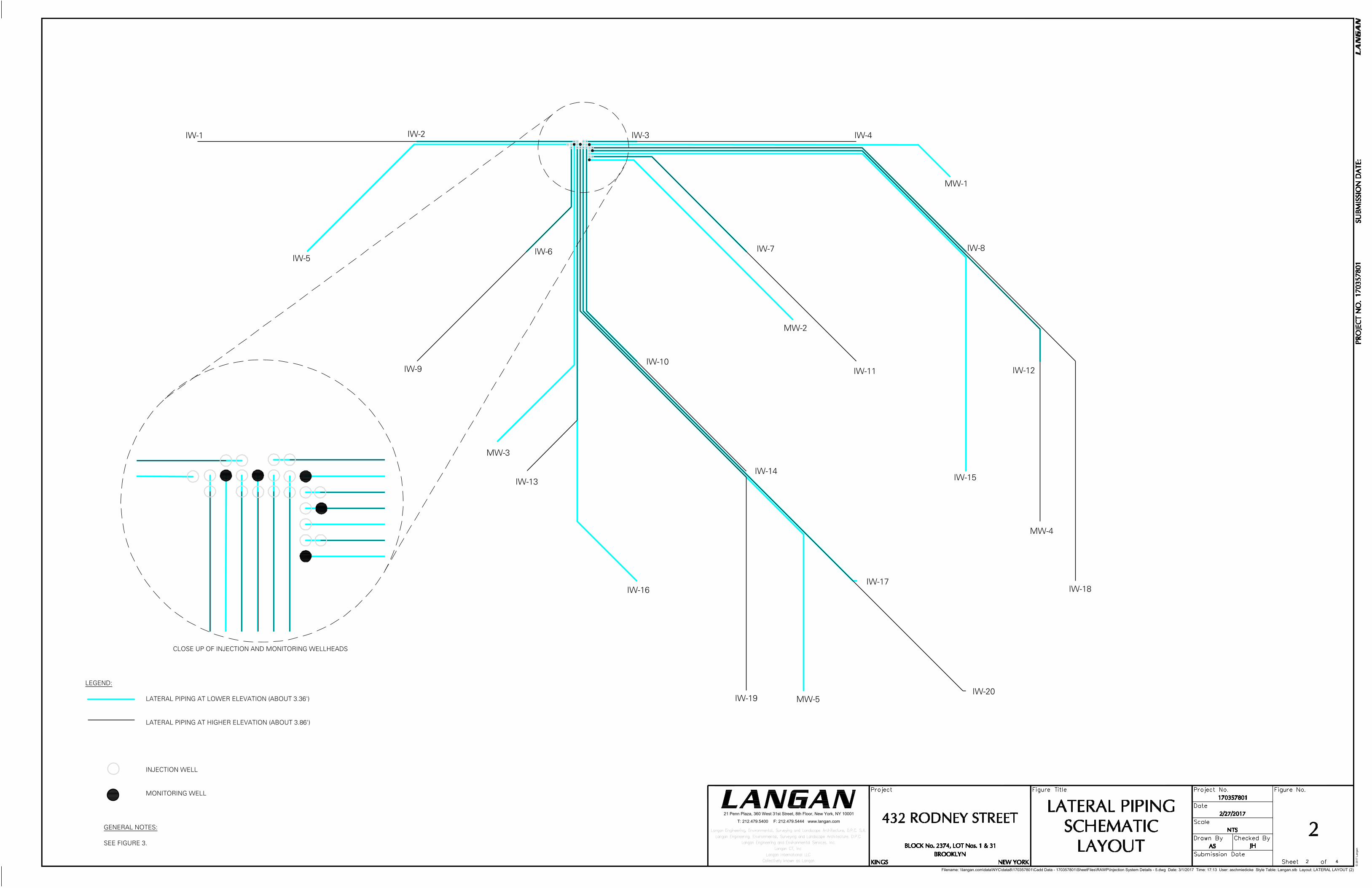
IW-1 IW-2 IW-3 IW-4
MW-1
IW-8
IW-12
IW-18
MW-4
IW-15
IW-11
MW-2
IW-10
IW-14
IW-17
IW-20MW-5IW-19
IW-16
IW-13
IW-9
MW-3
IW-6IW-5
IW-7
Filename: \\langan.com\data\NYC\data8\170357801\Cadd Data - 170357801\SheetFiles\RAWP\Injection System Details - 5.dwg Date: 3/1/2017 Time: 17:13 User: aschmiedicke Style Table: Langan.stb Layout: LATERAL LAYOUT (2)
21 Penn Plaza, 360 West 31st Street, 8th Floor, New York, NY 10001
T: 212.479.5400 F: 212.479.5444 www.langan.com
GENERAL NOTES:
SEE FIGURE 3.
LEGEND:
LATERAL PIPING AT LOWER ELEVATION (ABOUT 3.36')
LATERAL PIPING AT HIGHER ELEVATION (ABOUT 3.86')
INJECTION WELL
MONITORING WELL
© 2
01
7 L
an
ga
n
CLOSE UP OF INJECTION AND MONITORING WELLHEADS

Filename: \\langan.com\data\NYC\data8\170357801\Cadd Data - 170357801\SheetFiles\RAWP\Injection System Details - 5.dwg Date: 3/1/2017 Time: 17:12 User: aschmiedicke Style Table: Langan.stb Layout: DETAILS 1
21 Penn Plaza, 360 West 31st Street, 8th Floor, New York, NY 10001
T: 212.479.5400 F: 212.479.5444 www.langan.com
GENERAL NOTES:
1. ELEVATIONS SUBJECT TO CHANGE BASED ON POST-EXCAVATION CONDITIONS ANDDIRECTION FROM THE REMEDIATION ENGINEER.
2. REFER TO SECTION 33 20 00 - WELLS FOR MONITORING AND INJECTION WELLINSTALLATION SPECIFICATIONS.
3. REFER TO FOUNDATION AND ARCHITECTURAL DRAWINGS FOR WATERPROOFING EXTENTS.FOR SPECIFICATIONS, SEE THE FOLLOWING DETAILS:
SECTION 07 14 16 - COLD FLUID APPLIED WATERPROOFINGSECTION 07 27 13 - SELF ADHERED SHEET AIR BARRIERSECTION 07 27 26 - FLUID APPLIED MEMBRANE AIR BARRIERS
4. REFER TO DRAWINGS SMD-1 THROUGH SMD-4 FOR SYSTEM EXTENTS AND DETAILS. FORVAPOR BARRIER SPECIFICATIONS, SEE THE FOLLOWING DETAIL:
SECTION 07 26 16 - BELOW-GRADE VAPOR BARRIER
5. ALL PIPE ELBOW CONNECTIONS MUST BE LONG SWEEP (SEE DETAILS 8 AND 9).
6. ALL PIPES ARE SCHEDULE 80 PVC.
7. ALL FILTER SAND PACKS ARE WASHED NO. 2 SILICA SAND.
8. PIPE BEDDING (BACKFILL BELOW THE PIPE) AND SHADING (BACKFILL ABOVE THE PIPE)SHALL BE A MINIMUM OF 4 INCHES THICK.
9. VERTICAL AND HORIZONTAL PIPE SPACING SHALL BE A MINIMUM OF 6 INCHES BETWEENPIPE CENTER LINES (SEE DETAIL 7).
© 2
01
7 L
an
ga
n

Dimensions (inches)
Size A
B
(min)
C
(min)
2" 2.375 9.500 2.000
Filename: \\langan.com\data\NYC\data8\170357801\Cadd Data - 170357801\SheetFiles\RAWP\Injection System Details - 5.dwg Date: 3/1/2017 Time: 17:12 User: aschmiedicke Style Table: Langan.stb Layout: DETAILS 2
21 Penn Plaza, 360 West 31st Street, 8th Floor, New York, NY 10001
T: 212.479.5400 F: 212.479.5444 www.langan.com
GENERAL NOTES:
SEE FIGURE 3.
© 2
01
7 L
an
ga
n

APPENDIX E
EXCAVATION WORK PLAN

EXCAVATION WORK PLAN
E-1 NOTIFICATION
At least 15 days prior to the start of any activity that is anticipated to encounter
remaining contamination, the site owner or their representative will notify the New York
State Department of Environmental Conservation (NYSDEC). Currently, this notification
will be made to:
Kerry Maloney
NYSDEC Project Manager
(518) 402-9622
This notification will include:
A detailed description of the proposed work. The description should include the
location and aerial extent of the proposed work, plans for site re-grading,
intrusive elements or utilities to be installed below the cover system, estimated
volumes of contaminated soil to be excavated, and any work that may impact an
engineering control;
A summary of environmental conditions anticipated in the work areas, including
the nature and anticipated concentration of contaminants of concern, potential
presence of grossly contaminated media, and plans for any pre-construction
sampling;
A schedule for the work, detailing the start and completion of all intrusive work;
A summary of the applicable components of this Excavation Work Plan (EWP);
A statement that the work will be performed in compliance with this EWP and
29 CFR 1910.120;
The contractor’s Health and Safety Plan (HASP) and Community Air Monitoring
Plan (CAMP) will be updated and re-submitted, in electronic format, if it differs
from the HASP provided in Appendix F of the SMP;
Identification of disposal facilities for potential waste streams; and
Identification of sources of any anticipated backfill, along with all required
chemical testing results.
E-2 SOIL SCREENING METHODS
Visual, olfactory and instrument-based soil screening will be performed by a field
engineer, scientist or geologist under the direct supervision of a New York State
Professional Engineer (PE) or Qualified Environmental Professional (QEP) during all

Site Management Plan – Appendix E Page 2
432 Rodney Street
BCP Site No. C224216
Langan Project No. 170357801
remedial and development excavations into known or potentially contaminated material
(remaining contamination). Soil screening will be performed regardless of when the
invasive work is done and will include all excavation and invasive work performed during
development, such as excavations for foundations and utility work, after issuance of the
Certificate of Completion.
Soils will be segregated based on previous environmental data and screening results
into the following categories: material that requires off-site disposal, material that
requires testing, material that can be returned to the subsurface, and material that can
be used as cover soil.
E-3 STOCKPILE METHODS
Separate stockpile areas will be constructed, pending loading or characterization testing,
to avoid co-mingling materials of differing types. The excavated soil will be
appropriately lined and securely covered. Stockpiles will be routinely inspected and
broken sheeting covers will be promptly replaced.
Stockpiles will be covered immediately upon reaching a capacity of approximately 1,000
cubic yards until ready for loading. Stockpiles that have not reached their capacity will
be covered at the end of each workday. Active stockpiles will be covered at the end of
each workday. Individual stockpiles will not exceed 1,000 cubic yards.
Each stockpile area will be encircled with silt fences and hay bales as needed to contain
and filter particulates from any rainwater that has drained off the soils, and to mitigate
the potential for surface water run-off. Hay bales will also be used as needed near
catch basins and other discharge points. Stockpile areas will be inspected daily and
after every storm event, and noted deficiencies will be promptly addressed.
E-4 MATERIALS EXCAVATION AND LOAD OUT
A field engineer, scientist, or geologist under the direct supervision of a NYS PE or QEP
will oversee all invasive work and the excavation and load-out of all excavated material.
The owner of the property and its contractors are solely responsible for safe execution
of all invasive and other work performed under this EWP.
The presence of utilities and easements on the site will be investigated by the field
engineer, scientist, or geologist. It will be determined whether a risk or impediment to
the planned work under this SMP is posed by utilities or easements.

Site Management Plan – Appendix E Page 3
432 Rodney Street
BCP Site No. C224216
Langan Project No. 170357801
Loaded vehicles leaving the site will be appropriately lined, securely covered,
manifested, and placarded in accordance with appropriate Federal, State, local, and
NYSDOT requirements (and all other applicable transportation requirements). A truck
wash will be operated on-site. The field engineer, scientist, or geologist will be
responsible for documenting that all outbound truck tires and exterior carriage will be
free from dirt and debris. Trucks will be cleaned or washed as required before leaving
the site until the activities performed under this section are complete. Locations where
vehicles enter or exit the site shall be inspected daily for evidence of off-site soil
tracking.
The field engineer, scientist, or geologist will be responsible for documenting that all
egress points for truck and equipment transport from the site are clean of dirt and other
materials derived from the site during intrusive excavation activities. Cleaning of the
adjacent streets will be performed as needed to maintain a clean condition with respect
to site-derived materials.
E-5 MATERIALS TRANSPORT OFF-SITE
All transport of materials will be performed by licensed haulers in accordance with
appropriate local, State, and Federal regulations, including 6 NYCRR Part 364. Haulers
will be appropriately licensed and trucks properly placarded.
Material transported by trucks exiting the site will be appropriately lined and secured
with tight-fitting covers. Loose-fitting canvas-type truck covers will be prohibited. If
loads contain wet material capable of producing free liquid, truck liners will be used.
All trucks will be washed prior to leaving the site. Truck wash waters will be collected
and disposed of off-site in accordance with appropriate local, State, and Federal
regulations.
Truck traffic would be routed on the most direct course using major thoroughfares
where possible and flaggers would be used to protect pedestrians at site entrances and
exits. Truck routes will take into account:
(a) limiting transport through residential areas and past sensitive sites;
(b) use of city-mapped truck routes;
(c) prohibiting off-site queuing of trucks entering the facility, to the extent possible;
(d) limiting total distance to major highways;
(e) promoting safety in access to highways;
(f) overall safety in transport; and

Site Management Plan – Appendix E Page 4
432 Rodney Street
BCP Site No. C224216
Langan Project No. 170357801
(g) community input [where necessary]
Trucks will be prohibited from stopping and idling in the neighborhood outside the site.
Egress points for truck and equipment transport from the site will be kept clean of dirt
and other materials. Queuing of trucks will be performed on-site in order to minimize
off-site disturbance. Off-site queuing will be prohibited to the extent possible.
E-6 MATERIALS DISPOSAL OFF-SITE
All soil/fill/solid waste excavated and removed from the site will be treated as
contaminated and regulated material and will be transported and disposed of in
accordance with all local, State (including 6NYCRR Part 360), and Federal regulations. If
disposal of soil/fill from this site is proposed for unregulated off-site disposal (i.e. clean
soil removed for development purposes), a formal request with an associated plan will
be made to the NYSDEC for approval.
Off-site disposal locations for excavated soils will be identified in the pre-excavation
notification. This will include estimated quantities and a breakdown by class of disposal
facility if appropriate, i.e. hazardous waste disposal facility, solid waste landfill,
petroleum treatment facility, concrete recycling facility, etc. Actual disposal quantities
and associated documentation will be reported to the NYSDEC in the Periodic Review
Report (PRR). This documentation will include: waste profiles, test results, facility
acceptance letters, manifests, bills of lading and facility receipts.
Non-hazardous historic fill and contaminated soils taken off-site will be handled, at
minimum, as a Municipal Solid Waste per 6NYCRR Part 360-1.2. Material that does not
meet 6 NYCRR 375-6.8(a) Unrestricted Use Soil Cleanup Objectives (SCOs) is prohibited
from being taken to a New York State recycling facility (6NYCRR Part 360-16
Registration Facility).
E-7 MATERIALS REUSE ON-SITE
Materials reuse on-site will not be permitted without NYSDEC approval. Pending
NYSDEC approval, reused soil must be non-hazardous and meet the lower of
Unrestricted or 6 NYCRR 375-6.8(b) Protection of Groundwater SCOs in accordance
with the predetermined beneficial use determination listed in 6 NYCRR § 360-1.15(b).
The Protection of Groundwater SCOs apply only to compounds or analytes detected in
groundwater at concentrations that exceeded the Class GA AWQS. If any of the waste
materials specified are used by the Owner for an end use specified in Section 360-
1.15(b), it will not be considered a solid waste. Material will not be reused within a
cover soil layer, within landscaping berms, or as backfill for subsurface utility lines.

Site Management Plan – Appendix E Page 5
432 Rodney Street
BCP Site No. C224216
Langan Project No. 170357801
Reuse of soil will be coordinated in advance with the NYSDEC case manager. Material
deemed unfit for reuse will be transported for off-site disposal.
E-8 FLUIDS MANAGEMENT
All liquids to be removed from the site, including excavation dewatering and
groundwater monitoring well purge and development waters, will be handled,
transported, and disposed of in accordance with applicable local, State, and Federal
regulations. Dewatering, purge, and development fluids will not be recharged back to
the land surface or subsurface, but will be managed off-site, unless prior approval is
obtained from the NYSDEC.
E-9 COVER SYSTEM RESTORATION
After the completion of any invasive activities, the cover system, including the vapor
barrier membrane underlying the concrete slab, will be restored in a manner that
complies with the RAWP and Decision Document. If the type of cover system changes
from that which exists prior to the excavation (e.g., a soil cover is replaced by asphalt),
this will constitute a modification of the cover element of the remedy and the upper
surface of the remaining contamination. A figure showing the modified surface will be
included in the subsequent PRR and in any updates to the SMP.
E-10 BACKFILL FROM OFF-SITE SOURCES
All materials proposed for import onto the site will be approved by the PE or QEP and
will be in compliance with provisions in this SMP prior to receipt at the site. A Request
to Import/Reuse Fill or Soil form, which can be found at
http://www.dec.ny.gov/regulations/67386.html, will be prepared and submitted to the
NYSDEC project manager, allowing a minimum of 5 business days for review. For soil
sources, an environmental professional under the oversight of a QEP will collect
representative samples at a frequency consistent with CP-51 / Soil Cleanup Guidance
(Table 4). The samples would be analyzed for Part 375 VOCs (EPA Method 8260),
SVOCs (EPA Method 8270), pesticides/PCBs (EPA Method 8082/8081) and metals by
an NYSDOH ELAP-certified laboratory.
Material from industrial sites, spill sites, or other environmental remediation sites or
potentially contaminated sites will not be imported to the site.
All imported soils will meet the backfill and cover soil quality standards established in
6NYCRR 375-6.7(d). Based on an evaluation of the land use, protection of groundwater
and protection of ecological resources criteria, all imported soils will meet the soil

Site Management Plan – Appendix E Page 6
432 Rodney Street
BCP Site No. C224216
Langan Project No. 170357801
quality standards listed in Table 1 of the SMP. Soils that meet ‘exempt’ fill
requirements under 6 NYCRR Part 360, but do not meet backfill or cover soil objectives
for this site, will not be imported onto the site without prior approval by NYSDEC. Solid
waste will not be imported onto the site.
Trucks entering the site with imported soils will be securely covered with tight fitting
covers. Imported soils will be stockpiled separately from excavated materials and
covered to prevent dust releases.
E-11 CONTINGENCY PLAN
If underground tanks or other previously unidentified contaminant sources are found
during post-remedial subsurface excavations or development-related construction,
excavation activities will be suspended until sufficient equipment is mobilized to
address the condition.
Sampling will be performed on product and surrounding soils, as necessary, to
determine the nature of the material and proper disposal method. Chemical analysis
will be performed for full a full list of analytes (TAL metals; Part 375 VOCs and SVOCs,
pesticides, and PCBs), unless the site history and previous sampling results provide a
sufficient justification to limit the list of analytes. In this case, a reduced list of analytes
will be proposed to the NYSDEC for approval prior to sampling.
Identification of unknown or unexpected contaminated media identified by screening
during invasive site work will be promptly communicated by phone to NYSDEC’s Project
Manager. Reportable quantities of petroleum product will also be reported to the
NYSDEC spills hotline. These findings will be also included in the periodic reports
prepared pursuant to Section 6.3 of the SMP.
E-12 DUST, ODOR, AND VAPOR CONTROL/MONITORING PLAN
This dust, odor, and organic vapor control and monitoring plan was developed in
accordance with the NYSDOH Generic CAMP and OSHA standards for construction (29
CFR 1926). Continuous monitoring on the perimeter of the work zones for odor, VOCs,
and dust will be required for all ground intrusive activities such as site remediation
operations and handling activities. Two stationary air-monitoring stations will be set up
at site perimeters (one upwind and one downwind) during intrusive site work for
continuous monitoring. Each station will include a PID and a DustTrak aerosol monitor
or equivalent. A PID will be used to monitor the work zone and for periodic monitoring
for VOCs during activities such as soil sampling. Action levels for the protection of the

Site Management Plan – Appendix E Page 7
432 Rodney Street
BCP Site No. C224216
Langan Project No. 170357801
community and visitors are set forth in the CAMP, which is included in the HASP
(Appendix F of the SMP).
Work practices to minimize odors and vapors will be used during all intrusive activities.
Offending odor and organic vapor controls may include the application of foam
suppressants or tarps over the odor or VOC source areas. Foam suppressants may
include biodegradable foams applied over the source material for short-term control of
the odor and VOCs.
If odors develop and cannot be otherwise controlled, additional means to eliminate odor
nuisances will include the use of chemical odorants in spray or misting systems and the
use of staff to monitor odors in surrounding neighborhoods.
Where odor nuisances have developed during remedial work and cannot be corrected,
or where the release of nuisance odors cannot otherwise be avoided due to on-site
conditions or close proximity to sensitive receptors, odor control will be achieved by
sheltering excavation and handling areas under tented containment structures equipped
with appropriate air venting/filtering systems.

APPENDIX F
SAMPLE HEALTH AND SAFETY PLAN

HEALTH AND SAFETY PLAN
FOR
432 RODNEY STREET
BROOKLYN, NEW YORK
Tax Block 2374, Lots 1, 27, 28 and 31
NYSDEC BCP Site No. C224216
Prepared For
Rodney Street Investors LLC
850 Third Avenue, Suite 16B
New York, New York 10022
Prepared By:
Langan Engineering, Environmental, Surveying
and Landscape Architecture, D.P.C. 21 Penn Plaza
360 West 31st Street, 8th Floor
New York, New York 10001
July 2017
Langan Project No. 170357801

Health & Safety Plan July 2017
432 Rodney Street Page ii
Brooklyn, New York
Langan Project No. 170357801
TABLE OF CONTENTS
Page No.
1.0 INTRODUCTION .............................................................................................................................. 1
1.1 GENERAL ......................................................................................................................................... 1 1.2 SITE LOCATION AND BACKGROUND .................................................................................................... 1 1.3 SUMMARY OF WORK TASKS .............................................................................................................. 2
1.3.1 Excavation Oversight ................................................................................................................ 2 1.3.2 Stockpiling ................................................................................ Error! Bookmark not defined. 1.3.3 Soil Sampling ............................................................................ Error! Bookmark not defined. 1.3.4 Removal of Underground Storage Tank .................................................................................... 2 1.3.5 Drum Sampling .......................................................................................................................... 2 1.3.6 Installation of Injection Wells ................................................... Error! Bookmark not defined. 1.3.7 Installation of Sub-Membrane Depressurization System (SMDS) ............................................ 3 1.3.8 Operation of Injection Remediation System ............................ Error! Bookmark not defined.
2.0 IDENTIFICATION OF KEY PERSONNEL/HEALTH AND SAFETY PERSONNEL .......................... 3
2.1 LANGAN PROJECT MANAGER ............................................................................................................ 3 2.2 LANGAN CORPORATE HEALTH AND SAFETY MANAGER ......................................................................... 3 2.3 LANGAN SITE HEALTH & SAFETY OFFICER .......................................................................................... 4 2.4 LANGAN FIELD TEAM LEADER RESPONSIBILITIES ................................................................................. 4 2.5 CONTRACTOR RESPONSIBILITIES ........................................................................................................ 4
3.0 TASK/OPERATION SAFETY AND HEALTH RISK ANALYSES ..................................................... 5
3.1 SPECIFIC TASK SAFETY ANALYSIS ....................................................................................................... 5 3.1.2 Excavation and Soil Sampling .................................................................................................... 5 3.3.2 Stockpiling ................................................................................................................................. 5 3.1.3 Drum Sampling ......................................................................................................................... 6 3.2.4 Removal of Underground Storage Tank .................................................................................... 6 3.2.5 Installation and Operation of Injection Well Network ............................................................... 6 3.2.6 Installation of SMDS.................................................................................................................. 6
3.2 RADIATION HAZARDS ........................................................................................................................ 7 3.3 PHYSICAL HAZARDS .......................................................................................................................... 7
3.3.1 Explosion ................................................................................................................................... 7 3.3.2 Heat Stress ................................................................................................................................ 7 3.3.3 Cold-Related Illness ................................................................................................................... 9 3.3.4 Noise ......................................................................................................................................... 9 3.3.5 Hand and Power Tools .............................................................................................................. 9 3.3.6 Slips, Trips and Fall Hazards .................................................................................................... 10 3.3.7 Utilities (Electrocution and Fire Hazards) ................................................................................ 10
3.4 BIOLOGICAL HAZARDS .................................................................................................................... 10 3.4.1 Animals .................................................................................................................................... 10 3.4.2 Insects ..................................................................................................................................... 10
3.5 ADDITIONAL SAFETY ANALYSIS ........................................................................................................ 10 3.5.1 Presence of Non-Aqueous Phase Liquids (NAPL) ................................................................... 10
3.6 JOB SAFETY ANALYSIS .................................................................................................................... 11
4.0 PERSONNEL TRAINING ................................................................................................................ 11
4.1 BASIC TRAINING ............................................................................................................................. 11

Health & Safety Plan July 2017
432 Rodney Street Page iii
Brooklyn, New York
Langan Project No. 170357801
4.2 INITIAL SITE-SPECIFIC TRAINING ....................................................................................................... 11 4.3 TAILGATE SAFETY BRIEFINGS ........................................................................................................... 12
5.0 MEDICAL SURVEILLANCE ............................................................................................................ 12
6.0 COMMUNITY AIR MONITORING PROGRAM ............................................................................. 12
6.1 VAPOR EMISSION RESPONSE PLAN .................................................................................................. 13 6.2 MAJOR VAPOR EMISSION ............................................................................................................... 14 6.3 MAJOR VAPOR EMISSION RESPONSE PLAN ...................................................................................... 14 6.4 DUST SUPPRESSION TECHNIQUES .................................................................................................... 14
7.0 PERSONAL PROTECTIVE EQUIPMENT ....................................................................................... 15
7.1 LEVELS OF PROTECTION .................................................................................................................. 15 7.2 RESPIRATOR FIT-TEST ..................................................................................................................... 16
8.0 SITE CONTROL .............................................................................................................................. 16
8.1 SITE COMMUNICATIONS PLAN ......................................................................................................... 16 8.2 WORK ZONES ................................................................................................................................ 17
8.2.1 Exclusion Zone ........................................................................................................................ 17 8.2.2 Contamination Reduction Zone ............................................................................................... 17 8.2.3 Support Zone ........................................................................................................................... 17
8.3 THE BUDDY SYSTEM ....................................................................................................................... 17
9.0 NEAREST MEDICAL ASSISTANCE .............................................................................................. 18
10.0 STANDING ORDERS/SAFE WORK PRACTICES ......................................................................... 18
11.0 SITE SECURITY .............................................................................................................................. 18
12.0 UNDERGROUND UTILITIES ......................................................................................................... 18
13.0 SITE SAFETY INSPECTION ........................................................................................................... 19
14.0 HAND AND POWER TOOLS ......................................................................................................... 19
15.0 DECONTAMINATION PLAN ......................................................................................................... 19
15.1 GENERAL ....................................................................................................................................... 19 15.2 DECONTAMINATION PROCEDURES ................................................................................................... 19 15.3 DISPOSAL OF DECONTAMINATION WASTES ....................................................................................... 19
16.0 EMERGENCY RESPONSE ............................................................................................................. 19
16.1 GENERAL ....................................................................................................................................... 19 16.2 RESPONSIBILITIES ........................................................................................................................... 20 16.3 EVACUATION .................................................................................................................................. 20 16.4 EMERGENCY CONTACTS/NOTIFICATION SYSTEM ................................................................................ 20 16.5 EMERGENCY MEDICAL TREATMENT ................................................................................................. 20 16.6 FIRE OR EXPLOSION ........................................................................................................................ 21 16.7 SPILLS/LEAKS ................................................................................................................................ 21 16.8 ADVERSE WEATHER CONDITIONS .................................................................................................... 21 16.9 UNDERGROUND UTILITIES ............................................................................................................... 22 16.10 DOCUMENTATION ........................................................................................................................... 22
17.0 CONFINED SPACE ENTRY ............................................................................................................ 22
18.0 HASP ACKNOWLEDGEMENT FORM ........................................................................................... 23

Health & Safety Plan July 2017
432 Rodney Street Page iv
Brooklyn, New York
Langan Project No. 170357801
LIST OF TABLES
Table 1 Task Hazard Analysis
Table 2 Contaminant Hazards of Concern
Table 3 Summary of Monitoring Equipment
Table 4 Instrumentation Action Levels
Table 5 Emergency Notification List*
Table 6 Suggested Frequency of Physiological Monitoring For Fit and Acclimated
Workers
Table 7 Heat Index
LIST OF FIGURES
Figure 1 Site Location Map
Figure 2 Route to Hospital (map with directions)*
LIST OF APPENDICES
Attachment A Standing Orders*
Attachment B Decontamination Procedures
Attachment C Employee Exposure/Injury Incident Report
Attachment D Calibration Log
Attachment E Material Data Safety Sheets / Safety Data Sheets*
Attachment F Jobsite Safety Inspection Checklist
Attachment G Job Safety Analysis Forms
Attachment H Tailgate Safety Meeting Log
* Items to be posted prominently on site, or made readily available to personnel.

Health & Safety Plan July 2017
432 Rodney Street Page 1
Brooklyn, New York
Langan Project No. 170357801
1.0 INTRODUCTION
1.1 General
This HEALTH AND SAFETY PLAN (HASP) was developed to address disturbance of known and
reasonably anticipated subsurface contaminants and comply with Occupational Safety and
Health Administration (OSHA) Standard 29 CFR 1910.120(b) (4), Hazardous Waste Operations
and Emergency Response during anticipated remedial activities to be conducted at 432 Rodney
Street in Brooklyn, New York (Tax Block 2374, Lots 1, 27, 28 and 31) (“the Site”). This HASP
provides the minimum requirements for implementing site operations during remedial
activities. All contractors performing work on this Site shall implement their own Health and
Safety Plans that, at a minimum, adhere to this HASP. The contractor is solely responsible for
their own health and safety and that of their subcontractors. Langan personnel will implement
this HASP while on-site.
The management of the day-to-day site activities and implementation of this HASP in the field
is the responsibility of the site Langan Field Team Leader (FTL). Assistance in the
implementation of this HASP can also be obtained from the site Langan Health and Safety
Officer (HSO) and the Langan Health and Safety Manager (HSM). Contractors operating on the
Site shall designate their own FTL, HSO and HSM. The content of this HASP may change or
undergo revision based upon additional information made available to health and safety
personnel, monitoring results, or changes in the work plan.
1.2 Site Location and Background
The site is identified as Tax Block 2374, Lots 1, 27, 28 and 31 and has an estimated footprint of
about 27,160-square-feet. The scope of work proposed in the Remedial Action Work Plan
(RAWP) and covered under this HASP will be performed throughout the entire site. The site is
bound by commercial properties followed by Ainslie Street to the north, Hope Street to the
south, Keap Street to the east, and Rodney Street to the west. The site was historically
operated by various auto-related facilities (garages and auto repair shops) and other commercial
and light industrial uses. A site location map is provided as Figure 1.
The site was entered into the New York State Department of Environmental Conservation
(NYSDEC) Brownfield Cleanup Program (BCP) by Rodney Street Investors LLC as a Volunteer
on June 25, 2015. BCP Site No. C224216 was assigned to the site by NYSDEC. Additional site
information including site maps and data collected previously by Langan and others is provided
in the Remedial Investigation Report, IRM Work Plan and the RAWP.
Previous investigations have indicated that volatile organic compounds (VOCs), semi-volatile
organic compounds (SVOCs) and metals are present in soil and groundwater at concentrations
that exceed applicable standards. Soil sample results obtained through the toxicity

Health & Safety Plan July 2017
432 Rodney Street Page 2
Brooklyn, New York
Langan Project No. 170357801
characteristic leaching procedure (TCLP) indicates a hazardous concentration of lead is present
in Lot 1.
Sanborn Maps identified historical gasoline underground storage tanks (USTs). Four have been
encountered and removed during IRM excavation activities on Lots 1 and 31. Two inactive 275-
gallon aboveground storage tanks (ASTs) were identified in previous investigations and were
removed in April 2016.
1.3 Summary of Work Tasks
The general categories of work tasks being performed during implementation of the work plan
include:
1.3.1 Groundwater Sampling
Langan personnel will collect performance monitoring samples from the seven wells installed
throughout the groundwater treatment area. Prior to sampling, the wells will be purged and
physical and chemical parameters will be monitored. A representative groundwater sample will
be collected from each well with a dedicated submersible (MW-1 through MW-5) or peristaltic
pump (MW-6 and MW-7) and dedicated tubing. The dedicated submersible pumps require
compressed air to expel water. Langan personnel will be properly trained on the unique
methodology for groundwater sampling collection from these pumps. The groundwater
samples will be submitted under standard chain-of-custody protocol to an NYSDOH ELAP-
certified laboratory for analysis of Target compound List (TCL) VOCs and geochemical
parameters (some of which may be collected in the field), under a standard 5-day turnaround
schedule. Following completion of the sampling, drums containing any residual development
water will be transported and disposed at a permitted waste disposal facility.
1.3.2 Removal of Underground Storage Tank
If encountered, the contractor shall furnish all labor and materials, equipment and incidentals
required for the proper decontamination, removal and closure of any underground storage tank
(UST) in accordance with federal, state and local regulations. Langan personnel will monitor
VOCs with a calibrated PID downwind from the UST excavation and record the PID readings.
1.3.3 Drum Sampling
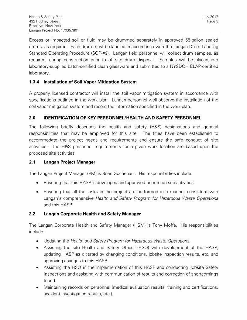
Health & Safety Plan July 2017
432 Rodney Street Page 3
Brooklyn, New York
Langan Project No. 170357801
Excess or impacted soil or fluid may be drummed separately in approved 55-gallon sealed
drums, as required. Each drum must be labeled in accordance with the Langan Drum Labeling
Standard Operating Procedure (SOP-#9). Langan field personnel will collect drum samples, as
required, during construction prior to off-site drum disposal. Samples will be placed into
laboratory-supplied batch-certified clean glassware and submitted to a NYSDOH ELAP-certified
laboratory.
1.3.4 Installation of Soil Vapor Mitigation System
A properly licensed contractor will install the soil vapor mitigation system in accordance with
specifications outlined in the work plan. Langan personnel well observe the installation of the
soil vapor mitigation system and record the information specified in the work plan.
2.0 IDENTIFICATION OF KEY PERSONNEL/HEALTH AND SAFETY PERSONNEL
The following briefly describes the health and safety (H&S) designations and general
responsibilities that may be employed for this site. The titles have been established to
accommodate the project needs and requirements and ensure the safe conduct of site
activities. The H&S personnel requirements for a given work location are based upon the
proposed site activities.
2.1 Langan Project Manager
The Langan Project Manager (PM) is Brian Gochenaur. His responsibilities include:
Ensuring that this HASP is developed and approved prior to on-site activities.
Ensuring that all the tasks in the project are performed in a manner consistent with
Langan's comprehensive Health and Safety Program for Hazardous Waste Operations
and this HASP.
2.2 Langan Corporate Health and Safety Manager
The Langan Corporate Health and Safety Manager (HSM) is Tony Moffa. His responsibilities
include:
Updating the Health and Safety Program for Hazardous Waste Operations.
Assisting the site Health and Safety Officer (HSO) with development of the HASP,
updating HASP as dictated by changing conditions, jobsite inspection results, etc. and
approving changes to this HASP.
Assisting the HSO in the implementation of this HASP and conducting Jobsite Safety
Inspections and assisting with communication of results and correction of shortcomings
found.
Maintaining records on personnel (medical evaluation results, training and certifications,
accident investigation results, etc.).

Health & Safety Plan July 2017
432 Rodney Street Page 4
Brooklyn, New York
Langan Project No. 170357801
2.3 Langan Site Health & Safety Officer
The Langan site HSO is William Bohrer. His responsibilities include:
Participating in the development and implementation of this HASP.
When on-site, assisting the Langan Field Team Leader in conducting Tailgate Safety
Meetings and Jobsite Safety Inspections and correcting any shortcomings in a timely
manner.
Ensuring that proper PPE is available, worn by employees and properly stored and
maintained.
Controlling entry into and exit from the site contaminated areas or zones.
Monitoring employees for signs of stress, such as heat stress, fatigue, and cold
exposure.
Monitoring site hazards and conditions.
Knowing (and ensuring that all site personnel also know) emergency procedures,
evacuation routes, and the telephone numbers of the ambulance, local hospital, poison
control center, fire department, and police department.
Resolving conflicts that may arise concerning safety requirements and working
conditions.
Reporting all incidents, injuries and near misses to the Langan Incident/Injury Hotline
immediately and the client representative.
2.4 Langan Field Team Leader Responsibilities
The Langan Field Team Leader (FTL) is to be determined prior to the start of site activities. The
Field Team Leader’s responsibilities include:
The management of the day-to-day site activities and implementation of this HASP in
the field.
Participating in and/or conducting Tailgate Safety Meetings and Jobsite Safety
Inspections and correcting any shortcomings in a timely manner.
When a Community Air Monitoring Operating Program (CAMP) is part of the scope, the
FTL will set up and maintaining community air monitoring activities and instructing the
responsible contractor to implement organic vapor or dust mitigation when necessary.
Overseeing the implementation of activities specified in the work plan.
2.5 Contractor Responsibilities
The contractor shall develop and implement their own HASP for their employees, lower-tier
subcontractors, and consultants. The contractor is solely responsible for their own health and
safety and that of their subcontractors. Contractors operating on the Site shall designate their
own FTL, HSO and HSM. The contractor's HASP will be at least as stringent as this Langan

Health & Safety Plan July 2017
432 Rodney Street Page 5
Brooklyn, New York
Langan Project No. 170357801
HASP. The contractor must be familiar with and abide by the requirements outlined in their
own HASP. A contractor may elect to adopt Langan's HASP as its own provided that it has
given written notification to Langan, but where Langan's HASP excludes provisions pertinent to
the contractor’s work (i.e., confined space entry); the contractor must provide written
addendums to this HASP. Additionally, the contractor must:
Ensure their employees are trained in the use of all appropriate PPE for the tasks
involved;
Notify Langan of any hazardous material brought onto the job site or site related area,
the hazards associated with the material, and must provide a material safety data sheet
(MSDS) or safety data sheet (SDS) for the material;
Have knowledge of, understand, and abide by all current federal, state, and local health
and safety regulations pertinent to the work;
Ensure their employees handling hazardous materials, if identified at the Site, have
received current training in the appropriate levels of 29 CFR 1910.120, Hazardous Waste
Operations and Emergency Response (HAZWOPER) if hazardous waste is identified at
the Site;
Ensure their employees handling hazardous materials, if identified at the Site, have been
fit-tested within the year on the type respirator they will wear;
Ensure all air monitoring is in place pertaining to the health and safety of their
employees as required by OSHA 1910.120; and
All contractors must adherer to all federal, state, and local regulatory requirements.
3.0 TASK/OPERATION SAFETY AND HEALTH RISK ANALYSES
A Task-Hazard Analysis (Table 1) was completed for general construction hazards that may be
encountered at the Site. Known and suspected chemical contaminant hazards that could be
encountered during site operations are included in Table 2. A complete inventory of
MSDS/SDS for chemical products used on site is included as Attachment E.
3.1 Specific Task Safety Analysis
3.1.2 Excavation and Soil Sampling
Soil handling or sampling activities requires the donning of chemical resistant gloves in addition
to the standard PPE. Langan personnel are not to operate excavation equipment.
3.3.2 Stockpiling
If stockpiling is required, potentially impacted soil shall be segregated and stockpiled on at least
10 millimeters of plastic sheeting; reusable soil and fill shall be segregated and stockpiled
separately from unusable fill, concrete and other debris; the stockpiles shall be kept covered
with 6 millimeters thick plastic sheeting; the plastic sheeting covering the stockpiles shall be

Health & Safety Plan July 2017
432 Rodney Street Page 6
Brooklyn, New York
Langan Project No. 170357801
anchored firmly in place by weights, stakes, or both; the Contractor shall maintain the plastic
sheeting. If stockpile soil sampling is required from above ground level, suitable excavation
equipment (i.e., excavator, front end loader) should be used to collect the sample.
3.1.3 Drum Sampling
Drilling fluid, rinse water, grossly-contaminated soil samples and cuttings will be containerized
in 55-gallon drums for disposed off-site. Each drum must be labeled in accordance with the
Langan Drum Labeling Standard Operating Procedure (SOP-#9). Sampling drums requires the
donning of work gloves when opening the drums and chemical resistant gloves when sampling
in addition to standard PPE.
Langan personnel and contractors are not to move or opened any orphaned (unlabeled) drum
found on the site without approval of the project manager.
3.2.4 Removal of Underground Storage Tank
The contractor will inert or otherwise vent the UST prior to disassembly or transport for
disposal. Excavation and inerting of the UST must be monitored using a fully calibrated
MultiRAE PID (or equivalent) capable surveying for VOCs and the lower explosion limit (LEL).
The excavation is to be monitored by attaching an extension to the PID input such that the
open end of the extension can directly monitor the base of the UST excavation. If the PID
survey detects VOCs above 5 ppm, work must cease and appropriate VOC suppression should
be applied to the excavation. Work can continue when VOC reading in the UST excavation are
below 5 ppm and can be maintained below 5 ppm for 15 minutes. If LEL readings exceed
10%, work must cease and all workers must withdraw from the vicinity of the UST excavation.
Langan field personnel must immediately report the high LEL condition to the PM. Work
cannot continue until appropriate actions are taken to maintain the LEL below 10%. The PM is
to be contacted if PID or LEL readings interrupt the work schedule.
3.2.5 Installation and Operation of Injection Well Network
Specifically trained contractors are to install and operate the injection network. This includes
operating heavy equipment, assembling required parts. This includes operating heavy
equipment, assembling required part and the operation of the system during injection activities.
Langan personnel are there only to observe and record the data required in the work plan.
Assemblage of injection well parts, operation of drilling and injection equipment as well as
system operations are to be done exclusively by the contractor following their own health and
safety specifications outlined in their HASPs.
3.2.6 Installation of SMDS
Specifically trained contractors are to install the SMDS. Langan personnel are there only to

Health & Safety Plan July 2017
432 Rodney Street Page 7
Brooklyn, New York
Langan Project No. 170357801
observe and record the data required in the work plan. Installation and assemblage of the
SMDS is to be done exclusively by the contractor following their own health and safety
specifications outlined in their HASPs.
3.2 Radiation Hazards
No radiation hazards are known or expected at the site.
3.3 Physical Hazards
Physical hazards, which may be encountered during site operations for this project, are detailed
in Table 1.
3.3.1 Explosion
No explosion hazards are expected for the scope of work at this site.
3.3.2 Heat Stress
The use of Level C protective equipment, or greater, may create heat stress. Monitoring of
personnel wearing personal protective clothing should commence when the ambient
temperature is 72oF or above. Table 6 presents the suggested frequency for such monitoring.
Monitoring frequency should increase as ambient temperature increases or as slow recovery
rates are observed. Refer to the Table 7 to assist in assessing when the risk for heat related
illness is likely. To use this table, the ambient temperature and relative humidity must be
obtained (a regional weather report should suffice). Heat stress monitoring should be
performed by the HSO or the FTL, who shall be able to recognize symptoms related to heat
stress.
To monitor the workers, be familiar with the following heat-related disorders and their
symptoms:
Heat Cramps: Painful spasm of arm, leg or abdominal muscles, during or after work
Heat Exhaustion: Headache, nausea, dizziness; cool, clammy, moist skin; heavy
sweating; weak, fast pulse; shallow respiration, normal temperature
Heat Stroke: Headache, nausea, weakness, hot dry skin, fever, rapid strong pulse,
rapid deep respirations, loss of consciousness, convulsions, coma. This is a life
threatening condition.
Do not permit a worker to wear a semi-permeable or impermeable garment when they are
showing signs or symptoms of heat-related illness.
To monitor the worker, measure:
Heart rate: Count the radial pulse during a 30-second period as early as possible in the
rest period. If the heart rate exceeds 100 beats per minute at the beginning of the rest

Health & Safety Plan July 2017
432 Rodney Street Page 8
Brooklyn, New York
Langan Project No. 170357801
period, shorten the next work cycle by one-third and keep the rest period the same. If
the heart rate still exceeds 100 beats per minute at the next rest period, shorten the
following work cycle by one-third. A worker cannot return to work after a rest period
until their heart rate is below 100 beats per minute.
Oral temperature: Use a clinical thermometer (3 minutes under the tongue) or similar
device to measure the oral temperature at the end of the work period (before drinking).
If oral temperature exceeds 99.6oF (37.6oC), shorten the next work cycle by one-third
without changing the rest period. A worker cannot return to work after a rest period
until their oral temperature is below 99.6oF. If oral temperature still exceeds 99.6oF
(37.6oC) at the beginning of the next rest period, shorten the following cycle by one-
third. Do not permit a worker to wear a semi-permeable or impermeable garment when
oral temperature exceeds 100.6oF (38.1oC).
Prevention of Heat Stress - Proper training and preventative measures will aid in averting loss
of worker productivity and serious illness. Heat stress prevention is particularly important
because once a person suffers from heat stroke or heat exhaustion, that person may be
predisposed to additional heat related illness. To avoid heat stress the following steps should
be taken:
Adjust work schedules.
Mandate work slowdowns as needed.
Perform work during cooler hours of the day if possible or at night if adequate lighting
can be provided.
Provide shelter (air-conditioned, if possible) or shaded areas to protect personnel during
rest periods.
Maintain worker's body fluids at normal levels. This is necessary to ensure that the
cardiovascular system functions adequately. Daily fluid intake must approximately equal
the amount of water lost in sweat, id., eight fluid ounces (0.23 liters) of water must be
ingested for approximately every eight ounces (0.23 kg) of weight lost. The normal
thirst mechanism is not sensitive enough to ensure that enough water will be drunk to
replace lost sweat. When heavy sweating occurs, encourage the worker to drink more.
The following strategies may be useful:
o Maintain water temperature 50o to 60oF (10o to 16.6oC).
o Provide small disposal cups that hold about four ounces (0.1 liter).
o Have workers drink 16 ounces (0.5 liters) of fluid (preferably water or dilute
drinks) before beginning work.
o Urge workers to drink a cup or two every 15 to 20 minutes, or at each
monitoring break. A total of 1 to 1.6 gallons (4 to 6 liters) of fluid per day are
recommended, but more may be necessary to maintain body weight.
o Train workers to recognize the symptoms of heat related illness.

Health & Safety Plan July 2017
432 Rodney Street Page 9
Brooklyn, New York
Langan Project No. 170357801
3.3.3 Cold-Related Illness
If work on this project begins in the winter months, thermal injury due to cold exposure can
become a problem for field personnel. Systemic cold exposure is referred to as hypothermia.
Local cold exposure is generally called frostbite.
Hypothermia - Hypothermia is defined as a decrease in the patient core temperature
below 96oF. The body temperature is normally maintained by a combination of central
(brain and spinal cord) and peripheral (skin and muscle) activity. Interference with any of
these mechanisms can result in hypothermia, even in the absence of what normally is
considered a "cold" ambient temperature. Symptoms of hypothermia include: shivering,
apathy, listlessness, sleepiness, and unconsciousness.
Frostbite - Frostbite is both a general and medical term given to areas of local cold
injury. Unlike systemic hypothermia, frostbite rarely occurs unless the ambient
temperatures are less than freezing and usually less than 20oF. Symptoms of frostbite
are: a sudden blanching or whitening of the skin; the skin has a waxy or white
appearance and is firm to the touch; tissues are cold, pale, and solid.
Prevention of Cold-Related Illness - To prevent cold-related illness:
Educate workers to recognize the symptoms of frostbite and hypothermia
Identify and limit known risk factors:
Assure the availability of enclosed, heated environment on or adjacent to the site.
Assure the availability of dry changes of clothing.
Assure the availability of warm drinks.
Start (oral) temperature recording at the job site:
At the FSO or Field Team Leader's discretion when suspicion is based on changes in a
worker's performance or mental status.
At a worker's request.
As a screening measure, two times per shift, under unusually hazardous conditions
(e.g., wind-chill less than 20oF, or wind-chill less than 30oF with precipitation).
As a screening measure whenever anyone worker on the site develops hypothermia.
Any person developing moderate hypothermia (a core temperature of 92oF) cannot return to
work for 48 hours.
3.3.4 Noise
Work activities during the proposed activities may be conducted at locations with high noise
levels from the operation of equipment. Hearing protection will be used as necessary.
3.3.5 Hand and Power Tools

Health & Safety Plan July 2017
432 Rodney Street Page 10
Brooklyn, New York
Langan Project No. 170357801
The use of hand and power tools can present a variety of hazards, including physical harm from
being struck by flying objects, being cut or struck by the tool, fire, and electrocution. All hand
and power tools should be inspected for health and safety hazards prior to use. If deemed
unserviceable/un-operable, notify supervisor and tag equipment out of service. Ground Fault
Circuit Interrupters (GFCIs) are required for all power tools requiring direct electrical service.
3.3.6 Slips, Trips and Fall Hazards
Care should be exercised when walking at the site, especially when carrying equipment. The
presence of surface debris, uneven surfaces, pits, facility equipment, and soil piles contribute
to tripping hazards and fall hazards. To the extent possible, all hazards should be identified and
marked on the Site, with hazards communicated to all workers in the area.
3.3.7 Utilities (Electrocution and Fire Hazards)
The possibility of encountering underground utilities poses fire, explosion, and electrocution
hazards. All excavation work will be preceded by review of available utility drawings and by
notification of the subsurface work to the N.Y. One –Call--Center. Potential adverse effects of
electrical hazards include burns and electrocution, which could result in death.
3.4 Biological Hazards
3.4.1 Animals
No animals are expected to be encountered during site operations.
3.4.2 Insects
Insects are not expected to be encountered during site operations.
3.5 Additional Safety Analysis
3.5.1 Presence of Non-Aqueous Phase Liquids (NAPL)
There is potential for exposure to NAPL at this site. Special care and PPE should be considered
when NAPL is observed as NAPL is a typically flammable fluid and releases VOCs known to be
toxic and/or carcinogenic. If NAPL is present in a monitoring well, vapors from the well casing
may contaminate the work area breathing zone with concentrations of VOCs potentially
exceeding health and safety action levels. In addition, all equipment used to monitor or sample
NAPL (or groundwater from wells containing NAPL) must be intrinsically safe. Equipment that
directly contacts NAPL must also be resistant to organic solvents.
At a minimum, a PID should be used to monitor for VOCs when NAPL is observed. If NAPL is
expected to be observed in an excavation or enclosed area, air monitoring must be started
using calibrated air monitoring equipment designed to sound an audio alarm when atmospheric

Health & Safety Plan July 2017
432 Rodney Street Page 11
Brooklyn, New York
Langan Project No. 170357801
concentrations of VOC are within 10% of the LEL. In normal atmospheric oxygen
concentrations, the LEL monitoring may be done with a Wheatstone bridge/catalytic bead type
sensor (i.e. MultiRAE). However in oxygen depleted atmospheres (confined space), only an
LEL designed to work in low oxygen environments may be used. Best practices require that
the LEL monitoring unit be equipped with a long sniffer tube to allow the LEL unit to remain
outside the UST excavation.
When NAPL is present, Langan personnel are required to use disposable nitrile gloves at all
times to prevent skin contact with contaminated materials. They should also consider having
available a respirator and protective clothing (Tyvek® overalls), especially if NAPL is in
abundance and there are high concentrations of VOCs.
All contaminated disposables including PPE and sampling equipment must be properly
disposed of in labeled 55-gallon drums.
3.6 Job Safety Analysis
A Job Safety Analysis (JSA) is a process to identify existing and potential hazards associated
with each job or task so these hazards can be eliminated, controlled or minimized. A JSA will
be performed at the beginning of each work day, and additionally whenever an employee
begins a new task or moves to a new location. All JSAs must be developed and reviewed by
all parties involved. A blank JSA form and documentation of completed JSAs are in Attachment
G.
4.0 PERSONNEL TRAINING
4.1 Basic Training
Completion of an initial 40-hour HAZWOPER training program as detailed in OSHA's 29 CFR
1910.120(e) is required for all employees working on a site engaged in hazardous substance
removal or other activities which expose or potentially expose workers to hazardous
substances, health hazards, or safety hazards as defined by 29 CFR 1910.120(a). Annual 8-hour
refresher training is also required to maintain competencies to ensure a safe work environment.
In addition to these training requirements, all employees must complete the OSHA 10 hour
Construction Safety and Health training and supervisory personnel must also receive eight
additional hours of specialized management training. Training records are maintained by the
HSM.
4.2 Initial Site-Specific Training
Training will be provided to specifically address the activities, procedures, monitoring, and
equipment for site operations at the beginning of each field mobilization and the beginning of
each discrete phase of work. The training will include the site and facility layout, hazards, and

Health & Safety Plan July 2017
432 Rodney Street Page 12
Brooklyn, New York
Langan Project No. 170357801
emergency services at the site, and will detail all the provisions contained within this HASP.
For a HAZWOPER operation, training on the site must be for a minimum of 3 days. Specific
issues that will be addressed include the hazards described in Section 3.0.
4.3 Tailgate Safety Briefings
Before starting work each day or as needed, the Langan HSO will conduct a brief tailgate safety
meeting to assist site personnel in conducting their activities safely. Tailgate meetings will be
documented in Attachment H. Briefings will include the following:
Work plan for the day;
Review of safety information relevant to planned tasks and environmental conditions;
New activities/task being conducted;
Results of Jobsite Safety Inspection Checklist;
Changes in work practices;
Safe work practices; and
Discussion and remedies for noted or observed deficiencies.
5.0 MEDICAL SURVEILLANCE
All personnel who will be performing field work involving potential exposure to toxic and
hazardous substances (defined by 29 CFR 1910.120(a)) will be required to have passed an initial
baseline medical examination, with follow-up medical exams thereafter, consistent with 29 CFR
1910.120(f). Medical evaluations will be performed by, or under the direction of, a physician
board-certified in occupational medicine.
Additionally, personnel who may be required to perform work while wearing a respirator must
receive medical clearance as required under CFR 1910.134(e), Respiratory Protection. Medical
evaluations will be performed by, or under the direction of, a physician board-certified in
occupational medicine. Results of medical evaluations are maintained by the HSM.
6.0 COMMUNITY AIR MONITORING PROGRAM
Community air monitoring may be conducted in compliance with the NYSDOH Generic CAMP
outlined below:
Monitoring for dust and odors will be conducted during all ground intrusive activities by the FTL.
Continuous monitoring on the perimeter of the work zones for odor, VOCs, and dust may be
required for all ground intrusive activities such as soil excavation and handling activities. The
work zone is defined as the general area in which machinery is operating in support of
remediation activities. A portable PID will be used to monitor the work zone and for periodic
monitoring for VOCs during activities such as soil and groundwater sampling and .soil
excavation. The site perimeter will be monitored for fugitive dust emissions by visual
observations as well as instrumentation measurements (if required). When required,

Health & Safety Plan July 2017
432 Rodney Street Page 13
Brooklyn, New York
Langan Project No. 170357801
particulate or dust will be monitored continuously with real-time field instrumentation that will
meet, at a minimum, the performance standards from DER-10 Appendix 1B.
If VOC monitoring is required, the following actions will be taken based on VOC levels
measured:
If total VOC levels exceed 5 ppm above background for the 15-minute average at the
perimeter, work activities will be temporarily halted and monitoring continued. If levels
readily decrease (per instantaneous readings) below 5 ppm above background, work
activities will resume with continued monitoring.
If total VOC levels at the downwind perimeter of the hot zone persist at levels in excess
of 5 ppm above background but less than 25 ppm, work activities will be halted, the
source of vapors identified, corrective actions taken to abate emissions, and monitoring
continued. After these steps work activities will resume provided that the total organic
vapor level 200 feet downwind of the hot zone or half the distance to the nearest
potential receptor or residential/commercial structure, whichever is less – but in no case
less than 20 feet, is below 5 ppm above background for the 15-minute average.
If the total VOC level is above 25 ppm at the perimeter of the hot zone, activities will be
shutdown.
If dust monitoring with field instrumentation is required, the following actions will be taken
based on instrumentation measurements:
If the downwind particulate level is 100 micrograms per cubic meter (µg/m³) greater
than background (upwind perimeter) for the 15-minute period or if airborne dust is
observed leaving the work area, then dust suppression must be employed. Work may
continue with dust suppression techniques provided that downwind PM10 levels do not
exceed 150 µg/m³ above the background level and provided that no visible dust is
migrating from the work area.
If, after implementation of dust suppression techniques, downwind PM10 levels are
greater than 150 µg/m³ above the background level, work must be stopped and a re-
evaluation of activities initiated. Work can resume provided that dust suppression
measures and other controls are successful in reducing the downwind PM10
concentration to within 150 µg/m³ of the upwind level and in preventing visible dust
migration.
6.1 Vapor Emission Response Plan
This section applies if VOC monitoring is required. If the ambient air concentration of organic
vapors exceeds 5 ppm above background at the perimeter of the hot zone, boring and well
installation, and excavation activities will be halted or odor controls will be employed, and
monitoring continued. When work shut-down occurs, downwind air monitoring as directed by

Health & Safety Plan July 2017
432 Rodney Street Page 14
Brooklyn, New York
Langan Project No. 170357801
the HSO or FTL will be implemented to ensure that vapor emission does not impact the
nearest residential or commercial structure at levels exceeding those specified in the Major
Vapor Emission section.
If the organic vapor level decreases below 5 ppm above background, sampling and boring and
well installation can resume, provided:
The organic vapor level 200 feet downwind of the hot zone or half the distance to the
nearest residential or commercial structure, whichever is less, is below 1 ppm over
background, and
More frequent intervals of monitoring, as directed by the HSO or FTL, are conducted.
6.2 Major Vapor Emission
This section applies if VOC monitoring is required. If any organic levels greater than 5 ppm over
background are identified 200 feet downwind from the work site, or half the distance to the
nearest residential or commercial property, whichever is less, all work activities must be halted
or odor controls must be implemented.
If, following the cessation of the work activities, or as the result of an emergency, organic
levels persist above 5 ppm above background 200 feet downwind or half the distance to the
nearest residential or commercial property from the hot zone, then the air quality must be
monitored within 20 feet of the perimeter of the nearest residential or commercial structure (20
Foot Zone).
If either of the following criteria is exceeded in the 20 Foot Zone, then the Major Vapor
Emission Response Plan shall automatically be implemented.
Sustained organic vapor levels approaching 5 ppm above background for a period of
more than 30 minutes, or
Organic vapor levels greater than 5 ppm above background for any time period.
6.3 Major Vapor Emission Response Plan
Upon activation, the following activities will be undertaken:
The local police authorities will immediately be contacted by the HSO or FTL and
advised of the situation;
Frequent air monitoring will be conducted at 30-minute intervals within the 20 Foot
Zone. If two successive readings below action levels are measured, air monitoring may
be halted or modified by the HSO or FTL; and
All Emergency contacts will go into effect as appropriate.
6.4 Dust Suppression Techniques
Preventative measures for dust generation may include wetting site fill and soil, construction of

Health & Safety Plan July 2017
432 Rodney Street Page 15
Brooklyn, New York
Langan Project No. 170357801
an engineered construction entrance with gravel pad, a truck wash area, covering soils with
tarps, and limiting vehicle speeds to five miles per hour.
Work practices to minimize odors and vapors include limiting the time that the excavations
remain open, minimizing stockpiling of contaminated-source soil, and minimizing the handling
of contaminated material. Offending odor and organic vapor controls may include the
application of foam suppressants or tarps over the odor or VOC source areas. Foam
suppressants may include biodegradable foams applied over the source material for short-term
control of the odor and VOCs.
If odors develop and cannot be otherwise controlled, additional means to eliminate odor
nuisances will include: direct load-out of soils to trucks for off-Site disposal; use of chemical
odorants in spray or misting systems; and, use of staff to monitor odors in surrounding
neighborhoods.
Where odor nuisances have developed during remedial work and cannot be corrected, or
where the release of nuisance odors cannot otherwise be avoided due to on-site conditions or
close proximity to sensitive receptors, odor control will be achieved by sheltering excavation
and handling areas under tented containment structures equipped with appropriate air
venting/filtering systems.
7.0 PERSONAL PROTECTIVE EQUIPMENT
7.1 Levels of Protection
Langan will provide PPE to Langan employees to protect them from the specific hazards they
are likely to encounter on-site. Direct hired contractors will provide their employees with
equivalent PPE to protect them from the specific hazards likely to be encountered on-site.
Selection of the appropriate PPE must take into consideration: (1) identification of the hazards
or suspected hazards; (2) potential exposure routes; and, (3) the performance of the PPE
construction (materials and seams) in providing a barrier to these hazards.
Based on anticipated site conditions and the proposed work activities to be performed at the
site, Level D protection will be used. The upgrading/downgrading of the level of protection will
be based on continuous air monitoring results as described in Section 6.0 (when applicable).
The decision to modify standard PPE will be made by the site HSO or FTL after conferring with
the PM. The levels of protection are described below.
Level D Protection (as needed)
Safety glasses with side shields or chemical splash goggles
Safety boots/shoes
Coveralls (Tyvek® or equivalent)
Hard hat

Health & Safety Plan July 2017
432 Rodney Street Page 16
Brooklyn, New York
Langan Project No. 170357801
Long sleeve work shirt and work pants
Nitrile gloves
Hearing protection
Reflective safety vest
Level C Protection (as needed)
Full or Half face, air-purifying respirator, with NIOSH approved HEPA filter
Inner (latex) and outer (nitrile) chemical-resistant gloves
Safety glasses with side shields or chemical splash goggles
Chemical-resistant safety boots/shoes
Hard hat
Long sleeve work shirt and work pants
Coveralls (Tyvek® or equivalent)
Hearing protection (as needed)
Reflective safety vest
The action levels used in determining the necessary levels of respiratory protection and
upgrading to Level C are summarized in Table 4. The written Respiratory Protection Program is
maintained by the HSM and is available if needed. The monitoring procedures and equipment
are outlined in Section 6.0 (when applicable).
7.2 Respirator Fit-Test
All Langan employees who may be exposed to hazardous substances at the work site are in
possession of a full or half face-piece, air-purifying respirator and have been successfully
fit-tested within the past year. Fit-test records are maintained by the HSM.
8.0 SITE CONTROL
8.1 Site Communications Plan
Verbal communications will be the primary method of communication used at the site during
the remedial action/remedial investigation and routine groundwater monitoring work. Cell
phones shall be used to the extent practical. In the instances where verbal communication
cannot be used, such as when working in respiratory protective equipment, hand signals will be
used. Hand signals will be covered during site-specific training. Hand signals and their
messages:
Hand Signal Meaning
Hand gripping throat Out of air; cannot breathe
Grip partners wrists or place both hands around
waist
Leave immediately without
debate
Hands on top of head Need assistance

Health & Safety Plan July 2017
432 Rodney Street Page 17
Brooklyn, New York
Langan Project No. 170357801
Hand Signal Meaning
Thumbs up OK; I'm alright; I understand
Thumbs down No; negative
Simulated "stick" break with fists Take a break; stop work
8.2 Work Zones
The need to formally establish specific work zones (Support, Contamination Reduction, and
Exclusion Zones) during site activities will be determined by the HSO or FTL. It is important for
the safety of all concerned that appropriate barriers (cones, wooden horses, plastic fencing etc.)
are in place to keep vehicles and pedestrians away from the Work Zone.
8.2.1 Exclusion Zone
Exclusion zones or hot zones will be established within a 25 foot radius around drilling and
sampling activities involving hazardous materials, where applicable and feasible. All personnel
within the hot zone must don the appropriate levels of personal protection as set forth by the
HSO. It is not anticipated that Level C or higher will be required for this site.
All personnel within the hot zone will be required to use the specified level of protection. No
food, drink, or smoking will be allowed in the hot or warm zones.
8.2.2 Contamination Reduction Zone
If PID VOC concentration action levels are exceeded or obvious indications of contamination (by
sight or odor) are encountered, a contamination reduction zone or warm zone will be
established and utilized during the field activities. This zone will be established between the
hot zone and the cold zone (discussed below), and will include the personnel and equipment
necessary for decontamination of equipment and personnel exiting the hot zone. Personnel
and equipment in the hot zone must pass through this zone before entering the cold zone. This
zone should always be located upwind of the hot zone.
8.2.3 Support Zone
The support zone or cold zone will include the remaining areas of the job site. Break areas and
support facilities (include equipment storage and maintenance areas) will be located in this
zone. No equipment or personnel will be permitted to enter the cold zone from the hot zone
without passing through the decontamination station in the warm zone (if necessitated).
Eating, smoking, and drinking will be allowed only in this area.
8.3 The Buddy System
When working in teams of two or more, workers will use the "buddy system" for all work
activities to ensure that rapid assistance can be provided in the event of an emergency. This
requires work groups to be organized such that workers can remain close together and

Health & Safety Plan July 2017
432 Rodney Street Page 18
Brooklyn, New York
Langan Project No. 170357801
maintain visual contact with one another. Workers using the "buddy system" have the following
responsibilities:
Provide his/her partner with assistance.
Observe his/her partner for signs of chemical or heat exposure.
Periodically check the integrity of his/her partner's PPE.
Notify the HSO or other site personnel if emergency service is needed.
9.0 NEAREST MEDICAL ASSISTANCE
The address and telephone number of the nearest hospital:
Woodhull Medical Center
760 Broadway, Brooklyn, NY
718-963-8000
Map with directions to the hospital are shown in Figure 2. This information will either be
posted prominently at the site or will be available to all personnel all of the time. Further, all
field personnel, including the HSO & FTL, will know the directions to the hospital.
10.0 STANDING ORDERS/SAFE WORK PRACTICES
The standing orders, which consist of a description of safe work practices that must always be
followed while on-site by Langan employees and contractors, are shown in Attachment A. The
site HSO and FTL each have the responsibility for enforcing these practices. The standing
orders will be posted prominently at the site, or are made available to all personnel at all times.
Those who do not abide by these safe work practices will be removed from the site.
11.0 SITE SECURITY
No unauthorized personnel shall be permitted access to the work areas.
12.0 UNDERGROUND UTILITIES
As provided in Langan’s Underground Utility Clearance Guidelines, the following safe work
practices should be followed by Langan personnel and the contractor before and during
subsurface work in accordance with federal, state and local regulations:
Obtain available utility drawings from the property owner/client or operator.
Provide utility drawings to the project team.
In the field, mark the proposed area of subsurface disturbance (when possible).
Ensure that the utility clearance system has been notified.
Ensure that utilities are marked before beginning subsurface work.
Discuss subsurface work locations with the owner/client and contractors.
Obtain approval from the owner/client and operators for proposed subsurface work

Health & Safety Plan July 2017
432 Rodney Street Page 19
Brooklyn, New York
Langan Project No. 170357801
locations.
Use safe digging procedures when applicable.
Stay at least 10 feet from all equipment performing subsurface work.
13.0 SITE SAFETY INSPECTION
The Langan HSO or alternate will check the work area daily, at the beginning and end of each
work shift or more frequently to ensure safe work conditions. The HSO or alternate must
complete the Jobsite Safety Inspection Checklist, found in Attachment F. Any deficiencies
shall be shared with the FTL, HSM and PM and will be discussed at the daily tailgate meeting.
14.0 HAND AND POWER TOOLS
All hand- and electric-power tools and similar equipment shall be maintained in a safe operating
condition. All electric-power tools must be inspected before initial use. Damaged tools shall be
removed immediately from service or repaired. Tools shall be used only for the purpose for
which they were designed. All users must be properly trained in their safe operation.
15.0 DECONTAMINATION PLAN
15.1 General
All personnel, equipment, and samples leaving the contaminated area of the site must be
decontaminated. Decontamination for this operation is achieved through physical removal and
chemical detoxification/disinfection/sterilization. The first step in decontamination, however, is
prevention and standard operating procedures have been established meant to minimize
contact with wastes:
Work habits that minimize contact with wastes are stressed.
Disposable equipment, where appropriate, will be used.
15.2 Decontamination Procedures
Standard decontamination procedures will be used as described in Attachment B.
15.3 Disposal of Decontamination Wastes
Waste solutions generated during decontamination procedures shall be contained, collected,
and stored in drums or other appropriate containers and labeled for proper off-site disposal.
16.0 EMERGENCY RESPONSE
16.1 General
Due to hazards that may be present at the site and the conditions under which operations are
conducted, it is possible that an emergency situation may develop. Emergency situations can

Health & Safety Plan July 2017
432 Rodney Street Page 20
Brooklyn, New York
Langan Project No. 170357801
be characterized as injury or acute chemical exposure to personnel, fire or explosion,
environmental release, or hazardous weather conditions.
16.2 Responsibilities
Site Emergency Coordinator - The HSO, or his/her alternate, will serve as the Site Emergency
Coordinator and shall implement emergency procedures whenever conditions warrant such
action. The Site Emergency Coordinator will be responsible for assuring the evacuation,
emergency treatment, emergency transport of site personnel, and notification of emergency
units and the appropriate management staff. Emergency response instructions will be provided
by the HSO as part of every employee's training prior to the start of work.
Employees - All employees at the site will be familiar with emergency response procedures for
this work location.
16.3 Evacuation
In the event of an emergency situation, an air horn or vehicle horn will be sounded three times
indicating the initiation of evacuation procedures. Loud voice command, if appropriate, can be
used. All personnel will evacuate and assemble at the site entrance. No one, except the
emergency responders, will be allowed to proceed into the area once the emergency signal has
been given. The Site Emergency Coordinator will ensure that access for emergency equipment
is provided and that all sources of combustion (e.g., operating machinery, etc.) have been shut
down once the alarm has been sounded. Wind direction will be taken into consideration for
evacuation plans. Evacuation plans will be discussed at the initial Site-Specific Training and as
needed at the regular safety briefings.
In all situations, when an on-site emergency results in an evacuation, personnel shall not
re-enter until:
The conditions resulting in the emergency have been corrected.
The hazards have been reassessed.
This HASP has been reviewed.
Site personnel have been briefed on any changes to this HASP.
16.4 Emergency Contacts/Notification System
The fire department and other emergency response groups will be notified by telephone of the
emergency as soon as possible. An emergency telephone numbers list is presented as Table 5
in this HASP. This list will either be posted prominently at the site or will be made readily
available to all personnel all of the time.
16.5 Emergency Medical Treatment
Personnel Injury - In case of injury to personnel, the HSO or his/her alternate will immediately

Health & Safety Plan July 2017
432 Rodney Street Page 21
Brooklyn, New York
Langan Project No. 170357801
administer emergency first aid. The ambulance/rescue squad will also be contacted as
necessary. Some situations may require transport of the injured parties by automobile.
Therefore, maps/directions to the nearest hospital are provided as Figure 2. Figure 2 will either
be posted at the site, or will be made readily available to all personnel all of the time.
Personnel Exposure – Emergency first aid procedures to be followed are:
Skin Contact: Use copious amounts of soap and water. Wash/rinse affected areas
thoroughly, and then provide appropriate medical attention. Rinse eyes with water for
at least 15 minutes.
Inhalation: Move to fresh air and/or, if necessary decontaminate and transport to
emergency medical facility.
Ingestion: Decontaminate and transport to emergency medical facility.
Puncture/Laceration: Decontaminate, if possible, and transport to emergency medical
facility.
16.6 Fire or Explosion
Appropriate fire extinguishers will be made available at the site for trained personnel to use on
insipient stage fires without endangering the safety and health of those nearby. If the use of
fire extinguishers will not extinguish the fire, immediately notify the fire department, sound the
evacuation signal, and then evacuate the area, assembling at the site entrance to be accounted
for and to receive further instruction.
16.7 Spills/Leaks
Control or stop the spread of minor chemical spills or contamination by utilizing the appropriate
materials (absorbents, etc.), if possible. If the release is significant, or highly hazardous,
immediately notify the appropriate response groups, sound the evacuation signal, evacuate the
area, and assemble at the site entrance to be accounted for and to receive further instruction.
16.8 Adverse Weather Conditions
In the event of severe weather (rain, snow, sleet, heat, etc.), conditions will be assessed on
site to determine if the work can proceed safely. If it is determined that the weather poses a
significant hazard, site operations will be stopped and rescheduled. Some of the items to be
considered prior to determining if work should continue include:
Potential for heat stress and heat-related injuries.
Potential for cold stress and cold-related injuries.
Treacherous weather-related working conditions including thunder storms. When
thunderstorms do occur, work is to cease immediately while personnel seek shelter.
Work cannot resume until 30 minutes after the last thunder clap.
Limited visibility.

Health & Safety Plan July 2017
432 Rodney Street Page 22
Brooklyn, New York
Langan Project No. 170357801
16.9 Underground Utilities
In the event a utility is encountered or disturbed during subsurface work, follow these
procedures:
Immediately stop work;
Leave the work area and retreat to a safe area;
Call 911, if necessary;
Contact the client representative and owner and operator of the property; and
Immediately notify the Langan PM, HSC and Langan Incident/Injury Hotline.
16.10 Documentation
Immediately following an incident or near miss, unless emergency medical treatment is
required, either the employee or a coworker must contact the Langan Incident/Injury Hotline at
1-(800)-9-LANGAN (ext. #4699) and the client representative to report the incident or near miss.
For emergencies involving personnel injury and/or exposure, the HSO and affected employee
will complete and submit an Employee Exposure/Injury Incident Report (Attachment C) to the
Langan Corporate Health and Safety Manager as soon as possible following the incident.
17.0 CONFINED SPACE ENTRY
Confined spaces are not anticipated at the Site during planned construction activities. If
confined spaces are identified, the contractor must implement their own confined space
program that all applicable federal, state and local regulations. Confined spaces will not be
entered by Langan personnel.

Health & Safety Plan July 2017
432 Rodney Street Page 23
Brooklyn, New York
Langan Project No. 170357801
18.0 HASP ACKNOWLEDGEMENT FORM
All Langan personnel and contractors will sign this HASP Compliance Agreement indicating that
they have become familiar with this HASP and that they understand it and agree to abide by it.
Printed Name Signature Company Date

TABLES

TABLE 1
TASK HAZARD ANALYSES
Task Hazard Description Control Measures First Aid
1.3.1
–
1.3.8
Contaminated Soil or
Groundwater-
Dermal Contact
Contaminated water spills on skin,
splashes in eyes; contact with
contaminated soil/fill during construction
activities or sampling.
Wear proper PPE; follow safe practices, maintain safe distance
from construction activities
See Table 2, seek
medical attention as
required
1.3.1
–
1.3.8
Lacerations,
abrasions, punctures
Cutting bailer twine, pump tubing, acetate
liners, etc. with knife; cuts from sharp site
objects or previously cut piles, tanks, etc.;
Using tools in tight spaces
Wear proper PPE; follow safe practices Clean wound, apply
pressure and/or
bandages; seek medical
attention as required.
1.3.1
–
1.3.8
Contaminated Media
Inhalation
Opening drums, tanks, wells; vapors for
non-aqueous phase liquids or other
contaminated site media; dust inhalation
during excavation; vapor accumulation in
excavation
Follow air monitoring plan; have quick access to respirator, do
not move or open unlabeled drums found at the site, maintain
safe distance from construction activities
See Table 2, seek
medical attention as
required
1.3.1
–
1.3.8
Lifting Improper lifting/carrying of equipment and
materials causing strains
Follow safe lifting techniques;
Langan employees are not to carry contractor equipment or
materials
Rest, ice, compression,
elevation; seek medical
attention as required
1.3.1
–
1.3.8
Slips, trips, and falls Slips, trips and falls due to uneven
surfaces, cords, steep slopes, debris and
equipment in work areas
Good housekeeping at site; constant awareness and focus on
the task; avoid climbing on stockpiles; maintain safe distance
from construction activities and excavations; avoid elevated
areas over six feet unless fully accredited in fall protection and
wearing an approved fall protection safety apparatus
Rest, ice, compression,
elevation; seek medical
attention as required
1.3.1
–
1.3.8
Noise Excavation equipment, hand tools, drilling
equipment.
Wear hearing protection; maintain safe distance from
construction activities
Seek medical attention
as required
1.3.1
–
1.3.8
Falling objects Soil material, tools, etc. dropping from drill
rigs, front-end loaders, etc.
Hard hats to be worn at all times while in work zones; maintain
safe distance from construction activities and excavations
Seek medical attention
as required
1.3.1
–
1.3.6
Underground/
overhead utilities
Excavation equipment, drill rig auger
makes contact with underground object;
boom touches overhead utility
"One Call" before dig; follow safe practices; confirm utility
locations with contractor; wear proper PPE; maintain safe
distance from construction activities and excavations
Seek medical attention
as required
1.3.1
–
1.3.8
Insects (bees,
wasps, hornet,
mosquitoes, and
spider)
Sings, bites Insect Repellent; wear proper protective clothing (work boots,
socks and light colored pants);field personnel who may have
insect allergies (e.g., bee sting) should provide this information
to the HSO or FSO prior to commencing work, and will have
allergy medication on Site.
Seek medical attention
as required
1.3.1
–
1.3.8
Vehicle traffic /
Heavy Equipment
Operation
Vehicles unable to see workers on site,
operation of heavy equipment in tight
spaces, equipment failure, malfunctioning
alarms
Wear proper PPE, especially visibility vest; use a buddy system
to look for traffic; rope off area of work with cones and caution
tape or devices at points of hazard, maintain safe distance from
construction activities and equipment
Seek medical attention
as required

TABLE 2
CONTAMINANT HAZARDS OF CONCERN
Task Contaminant CAS
Number
Monitoring
Device
PEL/
IDLH
Source of
Concentratio
n on Site
Route of Exposure Symptoms First Aid
1.3.1 –
1.3.8
1,2,4,5-Tetramethylbenzene 95-93-2 NA None
None
Groundwater
Soil
inhalation, skin
absorption, ingestion,
skin and/or eye contact
irritation to the eyes,
skin, nose, throat,
respiratory system;
bronchitis; hypochromic
anemia; headache,
drowsiness, lassitude
(weakness,
exhaustion), dizziness,
nausea, incoordination;
vomiting, confusion;
chemical pneumonitis
(aspiration liquid)
Eye: Irrigate
immediately
Skin: Soap flush
immediately
Breathing:
Respiratory
support
Swallow: Medical
attention
immediately
1.3.1 –
1.3.8
1,2,3-Trichlorobenzene
Vic- Trichlorobenzene
1,2,6- Trichlorobenzene
87-61-6 PID 5 ppm
None
Groundwater
Soil
Vapor
inhalation, skin
absorption, ingestion,
skin and/or eye contact
irritation eyes, skin,
mucous membrane; In
Animals: liver, kidney
damage; possible
teratogenic effects
Eye: Irrigate
immediately
Skin: Soap wash
Breathing:
Respiratory
support
Swallow: Medical
attention
immediately
1.3.1 –
1.3.8
1,2,4-Trichlorobenzene
Unsym-Trichlorobenzene
1,2,4-Trichlorobenzol
1,2,4,5-Trichlorbenzene
120-82-1 NA None
None
Groundwater
Soil
Vapor
inhalation, skin
absorption, ingestion,
skin and/or eye contact
irritation eyes, skin,
mucous membrane; In
Animals: liver, kidney
damage; possible
teratogenic effects
Eye: Irrigate
immediately
Skin: Soap wash
Breathing:
Respiratory
support
Swallow: Medical
attention
immediately

Task Contaminant CAS
Number
Monitoring
Device
PEL/
IDLH
Source of
Concentratio
n on Site
Route of Exposure Symptoms First Aid
1.3.1 –
1.3.8
1,2,4-Trimethylbenzene 95-63-6 PID None
None
Groundwater
Soil
Vapor
inhalation, ingestion,
skin and/or eye contact
irritation to the eyes,
skin, nose, throat,
respiratory system;
bronchitis; hypochromic
anemia; headache,
drowsiness, lassitude
(weakness,
exhaustion), dizziness,
nausea, incoordination;
vomiting, confusion;
chemical pneumonitis
(aspiration liquid)
Eye: Irrigate
immediately
Skin: Soap wash
Breathing:
Respiratory
support
Swallow: Medical
attention
immediately
1.3.1 –
1.3.8
1,3,5-Trimethylbenzene
Mesitylene
sym-Trimethylbenzene
108-67-8 PID None
None
Groundwater
Soil
Vapor
inhalation, ingestion,
skin and/or eye contact
irritation to the eyes,
skin, nose, throat,
respiratory system;
bronchitis; hypochromic
anemia; headache,
drowsiness, lassitude
(weakness,
exhaustion), dizziness,
nausea, incoordination;
vomiting, confusion;
chemical pneumonitis
(aspiration liquid)
Eye: Irrigate
immediately
Skin: Soap wash
Breathing:
Respiratory
support
Swallow: Medical
attention
immediately
1.3.1 –
1.3.8
1.2-Dibromoethane
Ethylene Dibromide
Ethylene bromide
Glycol dibromide
106-93-4 PID 20 ppm
100 ppm
Groundwater
Soil
Vapor
inhalation, skin
absorption, ingestion,
skin and/or eye contact
irritation eyes, skin,
respiratory system;
dermatitis with
vesiculation; liver,
heart, spleen, kidney
damage; reproductive
effects; [potential
occupational
carcinogen]
Eye: Irrigate
immediately
Skin: Soap wash
immediately
Breathing:
Respiratory
support
Swallow: Medical
attention
immediately
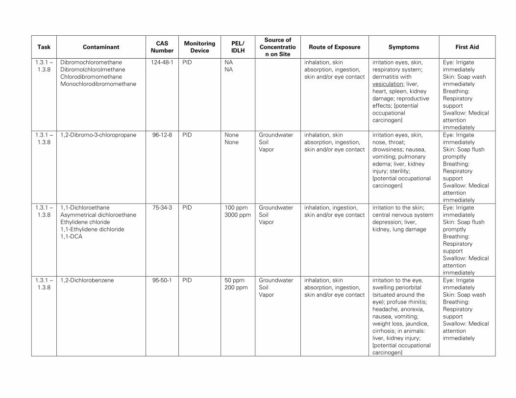
Task Contaminant CAS
Number
Monitoring
Device
PEL/
IDLH
Source of
Concentratio
n on Site
Route of Exposure Symptoms First Aid
1.3.1 –
1.3.8
Dibromochloromethane
Dibromo(chloro)methane
Chlorodibromomethane
Monochlorodibromomethane
124-48-1 PID NA
NA
inhalation, skin
absorption, ingestion,
skin and/or eye contact
irritation eyes, skin,
respiratory system;
dermatitis with
vesiculation; liver,
heart, spleen, kidney
damage; reproductive
effects; [potential
occupational
carcinogen]
Eye: Irrigate
immediately
Skin: Soap wash
immediately
Breathing:
Respiratory
support
Swallow: Medical
attention
immediately
1.3.1 –
1.3.8
1,2-Dibromo-3-chloropropane 96-12-8 PID None
None
Groundwater
Soil
Vapor
inhalation, skin
absorption, ingestion,
skin and/or eye contact
irritation eyes, skin,
nose, throat;
drowsiness; nausea,
vomiting; pulmonary
edema; liver, kidney
injury; sterility;
[potential occupational
carcinogen]
Eye: Irrigate
immediately
Skin: Soap flush
promptly
Breathing:
Respiratory
support
Swallow: Medical
attention
immediately
1.3.1 –
1.3.8
1,1-Dichloroethane
Asymmetrical dichloroethane
Ethylidene chloride
1,1-Ethylidene dichloride
1,1-DCA
75-34-3 PID 100 ppm
3000 ppm
Groundwater
Soil
Vapor
inhalation, ingestion,
skin and/or eye contact
irritation to the skin;
central nervous system
depression; liver,
kidney, lung damage
Eye: Irrigate
immediately
Skin: Soap flush
promptly
Breathing:
Respiratory
support
Swallow: Medical
attention
immediately
1.3.1 –
1.3.8
1,2-Dichlorobenzene 95-50-1 PID 50 ppm
200 ppm
Groundwater
Soil
Vapor
inhalation, skin
absorption, ingestion,
skin and/or eye contact
irritation to the eye,
swelling periorbital
(situated around the
eye); profuse rhinitis;
headache, anorexia,
nausea, vomiting;
weight loss, jaundice,
cirrhosis; in animals:
liver, kidney injury;
[potential occupational
carcinogen]
Eye: Irrigate
immediately
Skin: Soap wash
Breathing:
Respiratory
support
Swallow: Medical
attention
immediately

Task Contaminant CAS
Number
Monitoring
Device
PEL/
IDLH
Source of
Concentratio
n on Site
Route of Exposure Symptoms First Aid
1.3.1 –
1.3.8
p-Diethylbenzene
1,4-Diethyl benzene
105-05-5 PID None
None
Groundwater
Soil
Vapor
inhalation, ingestion,
skin and/or eye contact
irritation to the eyes,
skin, respiratory
system; skin burns; in
animals: central
nervous system
depression
Eye: Irrigate
immediately
Skin: Soap wash
Breathing:
Respiratory
support
Swallow: Medical
attention
immediately
1.3.1 –
1.3.8
p-Dichlorobenzene
p-DCB
1,4-Dichlorobenzene
para-Dichlorobenzene
Dichlorocide
106-46-7 PID 75 ppm
150 ppm
Groundwater
Soil
Vapor
inhalation, skin
absorption, ingestion,
skin and/or eye contact
irritation to the eyes,
swelling periorbital
(situated around the
eye); profuse rhinitis;
headache, anorexia,
nausea, vomiting;
weight loss, jaundice,
cirrhosis; in animals:
liver, kidney injury;
[potential occupational
carcinogen]
Eye: Irrigate
immediately
Skin: Soap wash
Breathing:
Respiratory
support
Swallow: Medical
attention
immediately
1.3.1 –
1.3.8
trans-1,4-Dichloro-2-butene 110-57-6 PID None
None
Groundwater
Soil
Vapor
inhalation, ingestion,
skin and/or eye contact
irritation to the eyes,
skin, respiratory system
Eye: Irrigate
immediately
Skin: Soap flush
immediately
Breathing:
Respiratory
support
Swallow: Medical
attention
immediately
1.3.1 –
1.3.8
1,3-Dichlorobenzene
1,3-Dichlorobenzene; m-
Dichlorobenzol;
m-Phenylene dichloride
541-73-1 PID None
None
Groundwater
Soil
Vapor
inhalation, skin
absorption, ingestion,
skin and/or eye contact
irritation to the eyes,
swelling periorbital
(situated around the
eye); profuse rhinitis;
headache, anorexia,
nausea, vomiting;
weight loss, jaundice,
cirrhosis; in animals:
liver, kidney injury;
[potential occupational
carcinogen]
Eye: Irrigate
immediately
Skin: Soap wash
Breathing:
Respiratory
support
Swallow: Medical
attention
immediately

Task Contaminant CAS
Number
Monitoring
Device
PEL/
IDLH
Source of
Concentratio
n on Site
Route of Exposure Symptoms First Aid
1.3.1 –
1.3.8
2-Butanone,
Ethyl methyl ketone
MEK
Methyl acetone
Methyl ethyl ketone
78-93-3 PID 200 ppm
3000 ppm
Soil
Groundwater
Vapor
inhalation, ingestion,
skin and/or eye contact
irritation to the eyes,
skin, nose; headache;
dizziness; vomiting;
dermatitis
Eye: Irrigate
immediately
Skin: Water wash
immediately
Breathing: Fresh
air
Swallow: Medical
attention
immediately
1.3.1 –
1.3.8
2-Hexanone
Butyl methyl ketone
MBK
Methyl butyl ketone
Methyl n-butyl ketone
591-78-6 PID 100 ppm
1600 ppm
Groundwater
Soil
Vapor
inhalation, skin
absorption, ingestion,
skin and/or eye contact
irritation to the eyes,
nose; peripheral
neuropathy: lassitude
(weakness,
exhaustion),
paresthesia; dermatitis;
headache, drowsiness
Eye: Irrigate
immediately
Skin: Soap wash
immediately
Breathing:
Respiratory
support
Swallow: Medical
attention
immediately
1.3.1 –
1.3.8
2,4-Dinitrophenol
1-hydroxy-2,4-dinitrobenzene
51-28-5 PID None
None
Groundwater
Soil
inhalation, ingestion,
skin and/or eye contact
irritation to the eyes,
nose, throat; headache,
dizziness, central
nervous system
Eye: Irrigate
immediately
Skin: Soap wash
immediately
Breathing:
Respiratory
support
Swallow: Medical
attention
immediately
1.3.1 –
1.3.8
2,4-Dimethylphenol
2,4-Xylenol
m-Xylenol
1-Hydroxy-2,4-
dimethylbenzene
2,4-Dimethylphenol
4-Hydroxy-1,3-
dimethylbenzene
4,6-Dimethylphenol
1,3-Dimethyl-4-hydroxybenze
105-67-9 None NA
NA
Groundwater
Soil
Vapor
inhalation, ingestion,
skin and/or eye contact
irritation to the eyes,
skin, mucous
membrane; headache,
narcosis, coma;
dermatitis; in animals:
liver, kidney damage
Eye: Irrigate
immediately
Skin: Water flush
promptly
Breathing:
Respiratory
support
Swallow: Medical
attention
immediately

Task Contaminant CAS
Number
Monitoring
Device
PEL/
IDLH
Source of
Concentratio
n on Site
Route of Exposure Symptoms First Aid
1.3.1 –
1.3.8
2,4-Dichlorophenol 120-83-2 PID NA
NA
Groundwater
Soil
inhalation, ingestion,
skin and/or eye
contact, in
irritation to the eyes,
skin, mucous
membrane, nose,
throat, respiratory
system; ingestion:
burning sensation,
abdominal pain, tremor,
weakness, convulsion,
labored breathing,
shock or collapse
Eye: Irrigate
immediately
Skin: Water flush
promptly
Breathing:
Respiratory
support
Swallow: Medical
attention
immediately
1.3.1 –
1.3.8
4-Isopropyltoulene
1-Methyl-4-(1-
methylethyl)benzene
4-Isopropyltoluene;
4-Methylcumene;
Paracymene
p-Cymene
p-Isopropyltoluene
99-87-6 PID NA
NA
Soil
Groundwater
Vapor
inhalation, skin
absorption, ingestion,
skin and/or eye contact
irritation to the eyes,
skin, mucous
membrane; dermatitis;
headache, narcosis,
coma
Eye: Irrigate
immediately
Skin: Water flush
promptly
Breathing:
Respiratory
support
Swallow: Medical
attention
immediately
1.3.1 –
1.3.8
2-Methylnaphthalene
β-methylnaphthalene
91-57-6 PID NA
NA
Groundwater
Soil
Vapor
inhalation, ingestion or
skin absorption, eye
contact
irritation to the skin,
eyes, mucous
membranes and upper
respiratory tract. It may
also cause headaches,
nausea, vomiting,
diarrhea, anemia,
jaundice, euphoria,
dermatitis, visual
disturbances,
convulsions and
comatose
Eye: Irrigate
immediately
Skin: Water flush
promptly
Breathing:
Respiratory
support
Swallow: Medical
attention
immediately

Task Contaminant CAS
Number
Monitoring
Device
PEL/
IDLH
Source of
Concentratio
n on Site
Route of Exposure Symptoms First Aid
1.3.1 –
1.3.8
Acenaphthene
1,2-Dihydroacenaphthylene
1,8-Ethylenenaphthalene
peri-Ethylenenaphthalene
Naphthyleneethylene
Tricyclododecapentaene
83-32-9 PID NA
NA
Soil inhalation, ingestion,
skin and/or eye
contact,
irritation to the skin,
eyes, mucous
membranes and upper
respiratory tract; If
ingested, it can cause
vomiting
Eye: Irrigate
immediately
Skin: Soap wash
immediately, if
redness or
irritation develop,
seek medical
attention
immediately
Breathing: Move
to fresh air
Swallow: do not
induce vomiting,
seek medical
attention
immediately
1.3.1 –
1.3.8
Acenaphthylene
Cycopental(de)naphthalene,
Acenaphthalene
208-96-8 PID NA
NA
Soil inhalation, ingestion,
skin and/or eye contact
irritation to the skin,
eyes, mucous
membranes and upper
respiratory tract
Eye: Irrigate
immediately, seek
medical attention
immediately,
Skin: Soap wash
immediately, if
redness or
irritation develop,
seek medical
attention
immediately
Breathing: Move
to fresh air
Swallow: do not
induce vomiting,
seek medical
attention
immediately

Task Contaminant CAS
Number
Monitoring
Device
PEL/
IDLH
Source of
Concentratio
n on Site
Route of Exposure Symptoms First Aid
1.3.1 –
1.3.8
Acetone
Dimethyl ketone
Ketone propane
2-Propanone
67-64-1 PID 1000 ppm
2500 ppm
Groundwater
Soil
inhalation, ingestion,
skin and/or eye contact
irritation to the eyes,
nose, throat; headache,
dizziness, central
nervous system
depression; dermatitis
Eye: Irrigate
immediately
Skin: Soap wash
immediately
Breathing:
Respiratory
support
Swallow: Medical
attention
immediately
1.3.1 –
1.3.8
Acrylonitrile
Acrylonitrile monomer
AN
Cyanoethylene
Propenenitrile
2-Propenenitrile
VCN, Vinyl cyanide
107-13-1 PID 1 ppm
85 ppm
Groundwater
Soil
Vapor
inhalation, skin
absorption, ingestion,
skin and/or eye contact
irritation to the eyes,
skin; asphyxia;
headache; sneezing;
nausea, vomiting;
lassitude (weakness,
exhaustion), dizziness;
skin vesiculation;
scaling dermatitis;
[potential occupational
carcinogen]
Eye: Irrigate
immediately
Skin: Water wash
immediately
Breathing:
Respiratory
support
Swallow: Medical
attention
immediately
1.3.1 –
1.3.8
Aldrin
1,2,3,4,10,10-Hexachloro-
1,4,4a,5,8,8a-hexahydro-endo-
1,4-exo-5,8-
dimethanonaphthalene
HHDN
Octalene
309-00-2 PID 0.25 ppm
5 ppm
Groundwater
Soil
Vapor
inhalation, skin
absorption, ingestion,
skin and/or eye contact
headache, dizziness;
nausea, vomiting,
malaise (vague feeling
of discomfort);
myoclonic jerks of
limbs; clonic, tonic
convulsions; coma;
hematuria (blood in the
urine), azotemia;
[potential occupational
carcinogen]
Eye: Irrigate
immediately
Skin: Soap wash
immediately
Breathing:
Respiratory
support
Swallow: Medical
attention
immediately

Task Contaminant CAS
Number
Monitoring
Device
PEL/
IDLH
Source of
Concentratio
n on Site
Route of Exposure Symptoms First Aid
1.3.1 –
1.3.8
Anthracene 120-12-7 PID 0.2 mg/m3
80 mg/m3
(Coal
Pitch Tar)
Soil inhalation, skin or eye
contact, ingestion
irritation to the skin,
eyes, mucous
membranes and upper
respiratory tract,
abdominal pain if
ingested.
Eye: Irrigate
immediately, seek
medical attention
immediately,
Skin: Soap wash
immediately,
Breathing: Move
to fresh air, refer
to medical
attention;
Swallow: refer to
medical attention
1.3.1 –
1.3.8
Bromobenzene
Monobromobenzene
Phenyl bromide
108-86-1 PID None
None
Groundwater
Soil
Vapor
inhalation, skin
absorption, ingestion,
skin and/or eye contact
irritation to the eyes,
skin, nose, respiratory
system; dizziness;
headache, nausea,
staggered gait;
lassitude (weakness,
exhaustion) [potential
occupational
carcinogen]
Eye: Irrigate
immediately
Skin: Soap wash
immediately
Breathing:
Respiratory
support
Swallow: Medical
attention
immediately
1.3.1 –
1.3.8
Benzene
Benzol
Phenyl hydride
71-43-2 PID 3.19
mg/m3
1,595
mg/mg3
Groundwater
Soil
Vapor
inhalation, skin
absorption, ingestion,
skin and/or eye contact
irritation to the eyes,
skin, nose, respiratory
system; dizziness;
headache, nausea,
staggered gait;
lassitude (weakness,
exhaustion) [potential
occupational
carcinogen]
Eye: Irrigate
immediately
Skin: Soap wash
immediately
Breathing:
Respiratory
support
Swallow: Medical
attention
immediately

Task Contaminant CAS
Number
Monitoring
Device
PEL/
IDLH
Source of
Concentratio
n on Site
Route of Exposure Symptoms First Aid
1.3.1 –
1.3.8
Benzo(a)anthracene
Benzanthracene
Benzanthrene
1,2-Benzanthracene
Benzo[b]phenanthrene
Tetraphene
56-55-3 PID 0.2 mg/m3
80 mg/m3
(Coal
Pitch Tar)
Groundwater
Soil
inhalation, skin or eye
contact, ingestion
dermatitis, bronchitis,
[potential occupational
carcinogen]
Eye: Irrigate
immediately
Skin: Soap wash
immediately
Breathing:
Respiratory
support
Swallow: Medical
attention
immediately
1.3.1 –
1.3.8
Benzo(a)pyrene 50-32-8 PID 0.2 mg/m3
80 mg/m3
(Coal
Pitch Tar)
Soil inhalation, skin or eye
contact, ingestion
dermatitis, bronchitis,
[potential occupational
carcinogen]
Eye: Irrigate
immediately, seek
medical attention
Skin: Soap wash
immediately;
Breathing: move
to fresh air;
Swallow: Induce
vomiting if
conscious, seek
medical attention
immediately
1.3.1 –
1.3.8
Benzo(b)fluoranthene 205-99-2 PID 0.2 mg/m3
80 mg/m3
(Coal
Pitch Tar)
Soil inhalation, skin or eye
contact, ingestion
irritation to eyes and
skin, respiratory
irritation(dizziness,
weakness, fatigue,
nausea, headache)
Eye: Irrigate
immediately, refer
to medical
attention
Skin: Soap wash
immediately
Breathing: move
to fresh air
Swallow: Medical
attention
immediately

Task Contaminant CAS
Number
Monitoring
Device
PEL/
IDLH
Source of
Concentratio
n on Site
Route of Exposure Symptoms First Aid
1.3.1 –
1.3.8
Benzo(g,h,i)perylene 191-24-2 PID 0.2 mg/m3
80 mg/m3
(Coal
Pitch Tar)
Soil inhalation, skin or eye
contact, ingestion
NA Eye: Irrigate
immediately, refer
to medical
attention
Skin: Soap wash
immediately
Breathing: move
to fresh air
Swallow: Medical
attention
immediately
1.3.1 –
1.3.8
Benzo(k)fluoranthene 207-08-9 PID 0.2 mg/m3
80 mg/m3
(Coal
Pitch Tar)
Soil inhalation, skin or eye
contact, ingestion
irritation to eyes and
skin, respiratory
irritation (dizziness,
weakness, fatigue,
nausea, headache)
Eye: Irrigate
immediately, refer
to medical
attention
Skin: Soap wash
immediately
Breathing: move
to fresh air
Swallow: Medical
attention
immediately
1.3.1 –
1.3.8
Bromodichloromethane
dichlorobromomethane
75-27-4 None NA
NA
Groundwater
Soil
Vapor
inhalation, skin or eye
contact, ingestion
irritation of the skin,
eyes, mucous
membranes and
respiratory tract,
narcosis, nausea,
dizziness and headache
Eye: Irrigate
immediately
(liquid)
Skin: Water flush
immediately
(liquid)
Breathing:
Respiratory
support
Swallow: Medical
attention
immediately

Task Contaminant CAS
Number
Monitoring
Device
PEL/
IDLH
Source of
Concentratio
n on Site
Route of Exposure Symptoms First Aid
1.3.1 –
1.3.8
Bromoform
Methyl tribromide
Tribromomethane
75-25-2 PID 0.5 ppm
850 ppm
Groundwater
Soil
Vapor
inhalation, skin
absorption, ingestion,
skin and/or eye contact
irritation eyes, skin,
respiratory system;
central nervous system
depression; liver,
kidney damage
Eye:Irrigate
immediately
Skin:Soap wash
promptly
Breathing:Respirat
ory support
Swallow:Medical
attention
immediately
1.3.1 –
1.3.8
Methyl Bromide
Bromomethane
Monobromomethane
74-83-9 PID 20 ppm
250 ppm
Soil
Groundwater
Vapor
inhalation, skin
absorption (liquid), skin
and/or eye contact
(liquid)
irritation to the eyes,
skin, respiratory
system; muscle weak,
incoordination, visual
disturbance, dizziness;
nausea, vomiting,
headache; malaise
(vague feeling of
discomfort); hand
tremor; convulsions;
dyspnea (breathing
difficulty); skin
vesiculation; liquid:
frostbite; [potential
occupational
carcinogen]
Eye: Irrigate
immediately
(liquid)
Skin: Water flush
immediately
(liquid)
Breathing:
Respiratory
support
1.3.1 –
1.3.8
Carbazole
9-azafluorene
Dibenzopyrrole
Diphenylenimine
diphenyleneimide
86-74-8 None NA
NA
Soil inhalation, skin
absorption (liquid), skin
and/or eye contact
irritation to eyes and
skin, respiratory
irritation
Eye: Irrigate
immediately, refer
to medical
attention
Skin: Soap wash
immediately
Breathing: move
to fresh air
Swallow: Medical
attention
immediately

Task Contaminant CAS
Number
Monitoring
Device
PEL/
IDLH
Source of
Concentratio
n on Site
Route of Exposure Symptoms First Aid
1.3.1 –
1.3.8
Carbon disulfide
Carbon bisulfide
75-15-0 PID 20 ppm
500 ppm
Soil
Groundwater
Vapor
inhalation, skin or eye
contact, ingestion
irritation to the eyes,
skin, respiratory system
Eye: Irrigate
immediately
(liquid)
Skin: Water flush
immediately
(liquid)
Breathing:
Respiratory
support
1.3.1 –
1.3.8
Carbon tetrachloride
Carbon chloride
Carbon tet
Freon® 10
Halon® 104
Tetrachloromethane
56-23-5 PID 10 ppm
200 ppm
Groundwater
Soil
Vapor
inhalation, skin
absorption, ingestion,
skin and/or eye contact
irritation to the eyes,
skin; central nervous
system depression;
nausea, vomiting; liver,
kidney injury;
drowsiness, dizziness,
incoordination;
[potential occupational
carcinogen]
Eye: Irrigate
immediately
Skin: Soap wash
immediately
Breathing:
Respiratory
support
Swallow: Medical
attention
immediately
1.3.1 –
1.3.8
Chlorobenzene
benzene chloride
monochlorobenzene
Phenyl chloride
Chlorobenzol
MCB
108-90-7 PID 75 ppm
1000 ppm
Groundwater
Soil
Vapor
inhalation, skin or eye
contact, ingestion
irritation to the eyes,
skin, nose; drowsiness,
incoordination; central
nervous system
depression; in animals:
liver, lung, kidney injury
Eye: Irrigate
immediately
Skin: Soap wash
promptly
Breathing:
Respiratory
support
Swallow: Medical
attention
immediately
1.3.1 –
1.3.8
Chloroform
Methane trichloride
Trichloromethane
67-66-3 None 50 ppm
500 ppm
Groundwater
Soil
inhalation, skin
absorption, ingestion,
skin and/or eye contact
irritation to the eyes,
skin; dizziness, mental
dullness, nausea,
confusion; headache,
lassitude (weakness,
exhaustion);
anesthesia; enlarged
liver; [potential
occupational
carcinogen]
Eye: Irrigate
immediately
Skin: Soap wash
promptly
Breathing:
Respiratory
support
Swallow: Medical
attention
immediately

Task Contaminant CAS
Number
Monitoring
Device
PEL/
IDLH
Source of
Concentratio
n on Site
Route of Exposure Symptoms First Aid
1.3.1 –
1.3.8
Chlordane
Chlordan
Chlordano
1,2,4,5,6,7,8,8-Octachloro-
3a,4,7,7a-tetrahydro-4,7-
methanoindane
57-74-9 None 0.5 mg/m3
100
mg/m3
Groundwater
Soil
inhalation, skin
absorption, ingestion,
skin and/or eye contact
Blurred vision;
confusion; ataxia,
delirium; cough;
abdominal pain, nausea,
vomiting, diarrhea;
irritability, tremor,
convulsions; anuria
Eye: Irrigate
immediately
Skin: Soap wash
immediately
Breathing:
Respiratory
support
Swallow: Medical
attention
immediately
1.3.1 –
1.3.8
Cis-Chlordane
a-Chlordane
cis-Chlordan
CIS-CHLORDANE
Chlordane
cis-;Chlordane
cis;ALPHA-CHLORDAN
Chlordan,
cis-;ALPHA-CHLORDANE
;alpha(cis)-chlordane
α-chlordane solution
5102-71-
9
None 0.5 mg/m3
100
mg/m3
Groundwater
Soil
inhalation, skin
absorption, ingestion,
skin and/or eye contact
Blurred vision;
confusion; ataxia,
delirium; cough;
abdominal pain, nausea,
vomiting, diarrhea;
irritability, tremor,
convulsions; anuria
Eye: Irrigate
immediately
Skin: Soap wash
immediately
Breathing:
Respiratory
support
Swallow: Medical
attention
immediately
1.3.1 –
1.3.8
Trans-Chlordane
gamma-Chlordane
5103-74-
2
None 0.5 mg/m3
100
mg/m3
Groundwater
Soil
inhalation, skin
absorption, ingestion,
skin and/or eye contact
Blurred vision;
confusion; ataxia,
delirium; cough;
abdominal pain, nausea,
vomiting, diarrhea;
irritability, tremor,
convulsions; anuria
Eye: Irrigate
immediately
Skin: Soap wash
immediately
Breathing:
Respiratory
support
Swallow: Medical
attention
immediately

Task Contaminant CAS
Number
Monitoring
Device
PEL/
IDLH
Source of
Concentratio
n on Site
Route of Exposure Symptoms First Aid
1.3.1 –
1.3.8
Methyl Chloride
Chloromethane
Monochloromethane
74-87-3 NA 100 ppm
2000 ppm
Groundwater
Soil
inhalation, skin and/or
eye contact
dizziness, nausea,
vomiting; visual
disturbance, stagger,
slurred speech,
convulsions, coma;
liver, kidney damage;
liquid: frostbite;
reproductive,
teratogenic effects;
[potential occupational
carcinogen]
Eye: Frostbite
Skin: Frostbite
Breathing:
Respiratory
support
1.3.1 –
1.3.8
Chrysene
Benzo[a]phenanthrene
1,2-Benzphenanthrene
218-01-9 PID 0.2 mg/m3
80 mg/m3
(Coal
Pitch Tar)
Groundwater
Soil
inhalation, absorption,
ingestion,
consumption
irritation to eye, skin,
and respiratory,
gastrointestinal irritation
nausea, vomit, diarrhea
[potential occupational
carcinogen]
Eyes: Irrigate
immediately
Skin: Soap wash
promptly.
Breath:
Respiratory
support
Swallow: Medical
attention
immediately
1.3.1 –
1.3.8
1,2-Dichloroethylene
1,2-DCE
cis-1,2-Dichloroethylene
mixture of cis and trans
Acetylene dichloride
cis-Acetylene dichloride
trans-Acetylene dichloride
sym-Dichloroethylene
cis- 1,2-Dichloroethene
Trans-1,2-Dichloroethylene,
tDCE
cDCE
cis-1,2-Dichloroethene
540-59-0 PID 200 ppm
4000 ppm
Groundwater
Soil
Vapor
inhalation, ingestion,
skin and/or eye contact
irritation to the eyes,
respiratory system;
central nervous system
depression
Eye: Irrigate
immediately
Skin: Soap wash
promptly
Breathing:
Respiratory
support
Swallow: Medical
attention
immediately

Task Contaminant CAS
Number
Monitoring
Device
PEL/
IDLH
Source of
Concentratio
n on Site
Route of Exposure Symptoms First Aid
1.3.1 –
1.3.8
Trans-1,2-Dichlorethylene 156-60-5 PDI None
None
Groundwater
Soil
Vapor
inhalation, ingestion,
skin and/or eye contact
irritation to the eyes,
respiratory system;
central nervous system
depression
Eye: Irrigate
immediately
Skin: Soap wash
promptly
Breathing:
Respiratory
support
Swallow: Medical
attention
immediately
1.3.1 –
1.3.8
1,2,3-Trichloropropane
Allyl trichloride
Glycerol trichlorohydrin
Glyceryl trichlorohydrin
Trichlorohydrin
96-18-4 PID 50 ppm
100 ppm
Groundwater
Soil
Vapor
inhalation, skin
absorption, ingestion,
skin and/or eye contact
irritation eyes, nose,
throat; central nervous
system depression; In
Animals: liver, kidney
injury; [potential
occupational
carcinogen]
Eye: Irrigate
immediately
Skin: Soap wash
Breathing:
Respiratory
support
Swallow: Medical
attention
immediately
1.3.1 –
1.3.8
1,1-Dichloropropane
Propylidene chloride
78-99-9 PID None
None
Groundwater
Soil
Vapor
inhalation, ingestion,
skin and/or eye contact
irritation to the eyes,
respiratory system;
central nervous system
depression
Eye: Irrigate
immediately
Skin: Soap wash
promptly
Breathing:
Respiratory
support
Swallow: Medical
attention
immediately
1.3.1 –
1.3.8
2,2-Dichloropropane 594-20-7 PID None
None
Groundwater
Soil
Vapor
inhalation, ingestion,
skin and/or eye contact
irritation to the eyes,
respiratory system;
central nervous system
depression
Eye: Irrigate
immediately
Skin: Soap wash
promptly
Breathing:
Respiratory
support
Swallow: Medical
attention
immediately
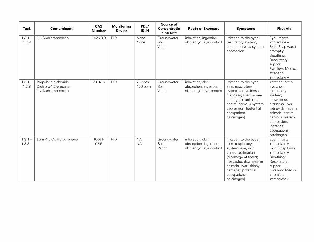
Task Contaminant CAS
Number
Monitoring
Device
PEL/
IDLH
Source of
Concentratio
n on Site
Route of Exposure Symptoms First Aid
1.3.1 –
1.3.8
1,3-Dichloropropane 142-28-9 PID None
None
Groundwater
Soil
Vapor
inhalation, ingestion,
skin and/or eye contact
irritation to the eyes,
respiratory system;
central nervous system
depression
Eye: Irrigate
immediately
Skin: Soap wash
promptly
Breathing:
Respiratory
support
Swallow: Medical
attention
immediately
1.3.1 –
1.3.8
Propylene dichloride
Dichloro-1,2-propane
1,2-Dichloropropane
78-87-5 PID 75 ppm
400 ppm
Groundwater
Soil
Vapor
inhalation, skin
absorption, ingestion,
skin and/or eye contact
irritation to the eyes,
skin, respiratory
system; drowsiness,
dizziness; liver, kidney
damage; in animals:
central nervous system
depression; [potential
occupational
carcinogen]
irritation to the
eyes, skin,
respiratory
system;
drowsiness,
dizziness; liver,
kidney damage; in
animals: central
nervous system
depression;
[potential
occupational
carcinogen]
1.3.1 –
1.3.8
trans-1,3-Dichloropropene 10061-
02-6
PID NA
NA
Groundwater
Soil
Vapor
inhalation, skin
absorption, ingestion,
skin and/or eye contact
irritation to the eyes,
skin, respiratory
system; eye, skin
burns; lacrimation
(discharge of tears);
headache, dizziness; in
animals; liver, kidney
damage; [potential
occupational
carcinogen]
Eye: Irrigate
immediately
Skin: Soap flush
immediately
Breathing:
Respiratory
support
Swallow: Medical
attention
immediately

Task Contaminant CAS
Number
Monitoring
Device
PEL/
IDLH
Source of
Concentratio
n on Site
Route of Exposure Symptoms First Aid
1.3.1 –
1.3.8
1,3-Dichloropropene
AQL Agrocelhone
Cis-1,3-Dichlorpropene
DD92
1,3-D
Dorlone, Nematox, Telone,
Nemex, cis-Dichloropropene
Di-Trapex CP, Vorlex 20
dichloro-1,3-propene
1,3-dichloro-1-propene
1,3-dichloro-2-propene, alpha-
chloroallylchloride
Chloroallylchloride
gamma-chloroallylchloride,
chloroallyl chloride
chloroorpropenyl chloride
1,3-dichloropropylene
3-D, DCP
3-Chloroallyl chloride
542-75-6 PID NA
NA
Groundwater
Soil
Vapor
inhalation, skin
absorption, ingestion,
skin and/or eye contact
irritation to the eyes,
skin, respiratory
system; eye, skin
burns; lacrimation
(discharge of tears);
headache, dizziness; in
animals; liver, kidney
damage; [potential
occupational
carcinogen]
Eye: Irrigate
immediately
Skin: Soap flush
immediately
Breathing:
Respiratory
support
Swallow: Medical
attention
immediately
1.3.1 –
1.3.8
Dieldrin
HEOD
1,2,3,4,10,10-Hexachloro-6,7-
epoxy-1,4,4a,5,6,7,8,8a-
octahydro-1,4-endo
exo-5,8-dimethanonaphthalene
60-57-1 PID 0.25
mg/m3
50 mg/m3
Groundwater
Soil
Water
inhalation, skin
absorption, ingestion,
skin and/or eye contact
headache, dizziness;
nausea, vomiting,
malaise (vague feeling
of discomfort),
sweating; myoclonic
limb jerks; clonic, tonic
convulsions; coma;
[potential occupational
carcinogen]; in animals:
liver, kidney damage
Eye: Irrigate
immediately
Skin: Soap wash
immediately
Breathing:
Respiratory
support
Swallow: Medical
attention
immediately
1.3.1 –
1.3.8
Dioxane
Diethylene dioxide
Diethylene ether
Dioxan
p-Dioxane
1,4-Dioxane
123-91-1 PID 100 ppm
500 ppm
Groundwater
Soil
Vapor
inhalation, skin
absorption, ingestion,
skin and/or eye contact
irritation to the eyes,
skin, nose, throat;
drowsiness, headache;
nausea, vomiting; liver
damage; kidney failure;
[potential occupational
carcinogen]
Eye: Irrigate
immediately
Skin: Water wash
promptly
Breathing:
Respiratory
support
Swallow: Medical
attention
immediately

Task Contaminant CAS
Number
Monitoring
Device
PEL/
IDLH
Source of
Concentratio
n on Site
Route of Exposure Symptoms First Aid
1.3.1 –
1.3.8
m-Cresol
3-methylphenol
meta-Cresol
3-Cresol
m-Cresylic acid
1-Hydroxy-3-methylbenzene
3-Hydroxytoluene
3-Methylphenol
108-39-4 PID 5 ppm
250 ppm
Groundwater
Soil
Vapor
inhalation, skin
absorption, ingestion,
skin and/or eye contact
irritation to the eyes,
skin, mucous
membrane; central
nervous system
effects: confusion,
depression, resp failure;
dyspnea (breathing
difficulty), irreg rapid
resp, weak pulse; eye,
skin burns; dermatitis;
lung, liver, kidney,
pancreas damage
Eye: Irrigate
immediately
Skin: Soap wash
immediately
Breathing:
Respiratory
support
Swallow: Medical
attention
immediately
1.3.1 –
1.3.8
o-Cresol
ortho-Cresol
2-Cresol
o-Cresylic acid
1-Hydroxy-2-methylbenzene
2-Hydroxytoluene
2-Methyl phenol
2-Methylphenol
95-48-7 PID 5 ppm
250 pppm
Groundwater
Soil
Vapor
inhalation, skin
absorption, ingestion,
skin and/or eye contact
irritation to the eyes,
skin, mucous
membrane; central
nervous system
effects: confusion,
depression, resp failure;
dyspnea (breathing
difficulty), irreg rapid
resp, weak pulse; eye,
skin burns; dermatitis;
lung, liver, kidney,
pancreas damage
Eye: Irrigate
immediately
Skin: Soap wash
immediately
Breathing:
Respiratory
support
Swallow: Medical
attention
immediately
1.3.1 –
1.3.8
p-Cresol
para-Cresol
4-Cresol
p-Cresylic acid
1-Hydroxy-4-methylbenzene
4-Hydroxytoluene
4-Methylphenol
106-44-5 PID 5 ppm
250 ppm
Groundwater
Soil
Vapor
inhalation, skin
absorption, ingestion,
skin and/or eye contact
irritation to the eyes,
skin, mucous
membrane; central
nervous system
effects: confusion,
depression, resp failure;
dyspnea (breathing
difficulty), irreg rapid
resp, weak pulse; eye,
skin burns; dermatitis;
lung, liver, kidney,
pancreas damage
Eye: Irrigate
immediately
Skin: Soap wash
immediately
Breathing:
Respiratory
support
Swallow: Medical
attention
immediately

Task Contaminant CAS
Number
Monitoring
Device
PEL/
IDLH
Source of
Concentratio
n on Site
Route of Exposure Symptoms First Aid
1.3.1 –
1.3.8
Cumene
Cumol
Isopropylbenzene
2-Phenyl propane
98-82-8 PID 50 ppm
900 ppm
Groundwater
Soil
inhalation, skin
absorption, ingestion,
skin and/or eye contact
irritation to the eyes,
skin, mucous
membrane; dermatitis;
headache, narcosis,
coma
Eye: Irrigate
immediately
Skin: Water flush
promptly
Breathing:
Respiratory
support
Swallow: Medical
attention
immediately
1.3.1 –
1.3.8
Dibenzo(a,h)anthracene 53-70-3 PID 0.2 mg/m3
80 mg/m3
(Coal
Pitch Tar)
Groundwater
Soil
inhalation, absorption,
ingestion,
consumption
irritation to eyes, skin,
respiratory, and
digestion [potential
occupational
carcinogen]
Eyes: Irrigate
immediately
Skin: Soap wash
promptly.
Breath:
Respiratory
support
PID Swallow:
Medical attention
immediately
1.3.1 –
1.3.8
Dibenzofuran 132-64-9 None NA
NA
Soil inhalation, absorption irritation to eyes, and
skin
Eyes: Irrigate
immediately
Skin: Soap wash
promptly.
1.3.1 –
1.3.8
Dimethyl phthalate
dimethyl benzene-1,2-
dicarboxylate
131-11-3 None 5 mg/m3
2000
mg/m3
Groundwater
Soil
inhalation, ingestion,
skin and/or eye contact
irritation to the eyes,
upper respiratory
system; stomach pain
Eye: Irrigate
promptly
Skin: Wash
regularly
Breathing:
Respiratory
support
Swallow: Medical
attention
immediately

Task Contaminant CAS
Number
Monitoring
Device
PEL/
IDLH
Source of
Concentratio
n on Site
Route of Exposure Symptoms First Aid
1.3.1 –
1.3.8
Bis(2-chloroethyl)ether
2,2-Dichlorethyl ether
1,1-Oxybis(2-chloro)ethane
Sym-Dichloroethyl ether
Diethylene glycol dichloride
111-44-4 PID 15 ppm
100 ppm
Groundwater
Soil
Vapor
inhalation, ingestion,
skin and/or eye contact
Inhalation: Cough, sore
throat, nausea,
vomiting, burning
sensation, labor
breathing
Irritation: Redness, pain
Ingestion: Abdominal
pain, nausea, vomiting,
burning sensation
Eye: Irrigate
immediately
Breathing:
Respiratory
support
Swallow: Medical
attention
immediately
1.3.1 –
1.3.8
Bis(2-ethylhexyl)phthalate
Di-sec octyl phthalate
DEHP
Di(2-ethylhexyl)phthalate
Octyl phthalate
117-81-7 None 5 mg/m3
5000
mg/m3
Groundwater
Soil
Vapor
inhalation, ingestion,
skin and/or eye contact
irritation to the eyes,
mucous membrane; in
animals: liver damage;
teratogenic effects;
[potential occupational
carcinogen
Eye: Irrigate
immediately
Breathing:
Respiratory
support
Swallow: Medical
attention
immediately
1.3.1 –
1.3.8
Dibutyl phthalate
Di-n-butyl phthalate
Butyl phthalate
n-Butyl phthalate
1,2-Benzenedicarboxylic acid
dibutyl ester
o-Benzenedicarboxylic acid
dibutyl ester
DBP
Palatinol C, Elaol
Dibutyl-1,2-benzene-
dicarboxylate
84-74-2 None 5 mg/m3
4000
mg/m3
Groundwater
Soil
Vapor
inhalation, ingestion,
skin and/or eye contact
irritation to the eyes,
upper respiratory
system, stomach
Eye: Irrigate
immediately
Skin: Wash
regularly
Breathing:
Respiratory
support
Swallow: Medical
attention
immediately
1.3.1 –
1.3.8
Dichlorodifluoromethane
Difluorodichloromethane,
Fluorocarbon 12, Freon® 12,
Genetron® 12, Halon® 122,
Propellant 12, Refrigerant 12
75-71-8 None 1000 pp,
15,000
ppm
Groundwater
Soil
Vapor
inhalation, skin and/or
eye contact (liquid)
dizziness, tremor,
asphyxia,
unconsciousness,
cardiac arrhythmias,
cardiac arrest; liquid:
frostbite
Eye: Frostbite
Skin: Frostbite
Breathing:
Respiratory
support

Task Contaminant CAS
Number
Monitoring
Device
PEL/
IDLH
Source of
Concentratio
n on Site
Route of Exposure Symptoms First Aid
1.3.1 –
1.3.8
4,4’-DDD
Dichlorodiphenyldichloroethan
e
1,1'-(2,2-Dichloroethylidene)bis
(4-chlorobenzene)
72-54-8 None NA
NA
Groundwater
Soil
inhalation, skin
absorption, ingestion,
skin and/or eye contact
irritation to the eyes,
skin; paresthesia
tongue, lips, face;
tremor; anxiety,
dizziness, confusion,
malaise (vague feeling
of discomfort),
headache, lassitude
(weakness,
exhaustion);
convulsions; paresis
hands; vomiting;
[potential occupational
carcinogen]
Eye: Irrigate
immediately
Skin: Soap wash
promptly
Breathing:
Respiratory
support
Swallow: Medical
attention
immediately
1.3.1 –
1.3.8
Ethyl chloride
Chloroethane
Hydrochloric ether
Monochloroethane
Muriatic ether
75-00-3 PID 1000 ppm
3800 ppm
Groundwater
Soil
Vapor
inhalation, skin
absorption (liquid),
ingestion (liquid), skin
and/or eye contact
incoordination,
inebriation; abdominal
cramps; cardiac
arrhythmias, cardiac
arrest; liver, kidney
damage
Eye: Irrigate
immediately
Skin: Water flush
promptly
Breathing:
Respiratory
support
Swallow: Medical
attention
immediately
1.3.1 –
1.3.8
Endosulfan sulfate
1,4,5,6,7,7-Hexachloro-5-
norbornene-2,3-dimethanol,
cyclic sulfate
6,7,8,9,10,10-
hexachloro01,5,5a,9,9a-
hexahydro-6,9-methano-2,4,3-
benzodioxathiepin-3,3-dioxide
1031-07-
8
None NA
NA
Groundwater
Soil
Vapor
inhalation, ingestion,
skin and/or eye contact
Hypersensitive to
stimulation, sensation
of prickling, tingling or
creeping on skin.
Headache, dizziness,
nausea, vomiting,
incoordination, tremor,
mental confusion,
hyperexcitable state.
In severe cases:
convulsions, seizures,
coma and respiratory
depression.
Eye: Irrigate
immediately
Breathing:
Respiratory
support
Swallow: Medical
attention
immediately

Task Contaminant CAS
Number
Monitoring
Device
PEL/
IDLH
Source of
Concentratio
n on Site
Route of Exposure Symptoms First Aid
1.3.1 –
1.3.8
DDT
4,4-DDT
p,p’-DDT
Dichlorodiphenyltrichloroethan
e
1,1,1-Trichloro-2,2-bis(p-
chlorophenyl)ethane
50-29-3 None 1 mg/m3
500
mg/m3
Groundwater
Soil
inhalation, skin
absorption, ingestion,
skin and/or eye contact
irritation to the eyes,
skin; paresthesia
tongue, lips, face;
tremor; anxiety,
dizziness, confusion,
malaise (vague feeling
of discomfort),
headache, lassitude
(weakness,
exhaustion);
convulsions; paresis
hands; vomiting;
[potential occupational
carcinogen]
Eye: Irrigate
immediately
Skin: Soap wash
promptly
Breathing:
Respiratory
support
Swallow: Medical
attention
immediately
1.3.1 –
1.3.8
DDE
4,4-DDE
1,1-bis-(4-chlorophenyl)-2,2-
dichloroethene
Dichlorodiphenyldichloroethyle
ne
72-55-9 None NA
NA
Soil inhalation, skin
absorption, ingestion,
skin and/or eye contact
Oral ingestion of food is
the primary source of
exposure for the
general population.
Acute and chronic
ingestion may cause
nausea, vomiting,
diarrhea, stomach pain,
headache, dizziness,
disorientation, tingling
sensation, kidney
damage, liver damage,
convulsions, coma, and
death. 4,4' DDE may
cross the placenta and
can be excreted in
breast milk
Eye: Irrigate
immediately
Skin: Soap wash
promptly
Breathing:
Respiratory
support
Swallow: Medical
attention
immediately
1.3.1 –
1.3.8
Endosulfan
Benzoepin;
Endosulphan;
6,7,8,9,10-Hexachloro-
1,5,5a,6,9,9a-hexachloro-6,9-
methano-2,4,3-benzo-
dioxathiepin-3-oxide
Thiodan
115-29-7 None NA
NA
Groundwater
Soil
Vapor
inhalation, skin
absorption, ingestion,
skin and/or eye contact
irritation skin; nausea,
confusion, agitation,
flushing, dry mouth,
tremor, convulsions,
headache; in animals:
kidney, liver injury;
decreased testis weight
Eye: Irrigate
immediately
Skin: Soap flush
immediately
Breathing:
Respiratory
support
Swallow: Medical
attention
immediately

Task Contaminant CAS
Number
Monitoring
Device
PEL/
IDLH
Source of
Concentratio
n on Site
Route of Exposure Symptoms First Aid
1.3.1 –
1.3.8
Endrin,
1,2,3,4,10,10-Hexachloro-6,7-
epoxy-1,4,4a,5,6,7,8,8a-
octahydro-1,4-endo,endo-5,8-
dimethanonaphthalene;
Hexadrin
72-20-8 None 0.1 mg/m3
2 mg/m3
Soil
inhalation, skin
absorption, ingestion,
skin and/or eye contact
epileptiform
convulsions; stupor,
headache, dizziness;
abdominal discomfort,
nausea, vomiting;
insomnia;
aggressiveness,
confusion; drowsiness,
lassitude (weakness,
exhaustion); anorexia;
in animals: liver damage
Eye: Irrigate
immediately
Skin: Soap wash
immediately
Breathing:
Respiratory
support
Swallow: Medical
attention
immediately
1.3.1 –
1.3.8
Endrin ketone 53494-
70-5
None 0.1
mg/m3
2 mg/m3
Groundwater
Soil
inhalation, skin
absorption, ingestion,
skin and/or eye contact
epileptiform
convulsions; stupor,
headache, dizziness;
abdominal discomfort,
nausea, vomiting;
insomnia;
aggressiveness,
confusion; drowsiness,
lassitude (weakness,
exhaustion); anorexia;
in animals: liver damage
Eye: Irrigate
immediately
Skin: Soap wash
immediately
Breathing:
Respiratory
support
Swallow: Medical
attention
immediately
1.3.1 –
1.3.8
Ethyl benzene
Ethylbenzene
Ethylbenzol
Phenylethane
100-40-4 PID 435
mg/m3
3,472
mg/m3
Groundwater
Soil
Vapor
inhalation, ingestion,
skin and/or eye contact
irritation to the eyes,
skin, mucous
membrane; headache;
dermatitis; narcosis,
coma
Eye: Irrigate
immediately
Skin: Water flush
promptly
Breathing:
Respiratory
support
Swallow: Medical
attention
immediately

Task Contaminant CAS
Number
Monitoring
Device
PEL/
IDLH
Source of
Concentratio
n on Site
Route of Exposure Symptoms First Aid
1.3.1 –
1.3.8
Ethylene dichloride
1,2-Dichloroethane
Ethylene chloride
Glycol dichloride
1,2-DCA
107-06-2 PID 1 ppm
50 ppm
Groundwater
Soil
Vapor
inhalation, ingestion,
skin absorption, skin
and/or eye contact
irritation to the eyes,
corneal opacity; central
nervous system
depression; nausea,
vomiting; dermatitis;
liver, kidney,
cardiovascular system
damage; [potential
occupational
carcinogen]
Eye: Irrigate
immediately
Skin: Soap wash
promptly
Breathing:
Respiratory
support
Swallow: Medical
attention
immediately
1.3.1 –
1.3.8
p-Ethyltoluene
4-Ethyltoluene
1-ethyl-4-methyl-benzene
622-96-8 NA NA
NA
Soil ingestion, skin and/or
eye contact
irritation to the eyes,
skin, mucous
membrane; headache;
dermatitis; narcosis,
coma
Eye: Irrigate
immediately
Skin: Water flush
promptly
Breathing:
Respiratory
support
Swallow: Medical
attention
immediately
1.3.1 –
1.3.8
Fluoranthene
Benzo(j, k)fluorene
206-44-0 PID 0.2 mg/m3
80 mg/m3
(Coal
Pitch Tar)
Groundwater
Soil
inhalation, skin or eye
contact, ingestion
irritation to eyes and
skin, respiratory
irritation(dizziness,
weakness, fatigue,
nausea, headache)
Eye: Irrigate
immediately, refer
to medical
attention
Skin: Soap wash
immediately
Breathing: move
to fresh air
Swallow: Medical
attention
immediately

Task Contaminant CAS
Number
Monitoring
Device
PEL/
IDLH
Source of
Concentratio
n on Site
Route of Exposure Symptoms First Aid
1.3.1 –
1.3.8
Fluorene 86-73-7 PID 0.2 mg/m3
80 mg/m3
(Coal
Pitch Tar)
Soil inhalation, skin or eye
contact, ingestion
irritation to eyes and
skin, respiratory
irritation(dizziness,
weakness, fatigue,
nausea, headache)
Eye: Irrigate
immediately, refer
to medical
attention
Skin: Soap wash
immediately
Breathing: move
to fresh air
Swallow: Medical
attention
immediately
1.3.1 –
1.3.8
Heptachlor epoxide
1,4,5,6,7,8,8-Heptachloro-
3a,4,7,7a-tetrahydro-4,7-
methano-1H-indene
1024-57-
3
None 0.5 mg/m3
35 mg/m3
Groundwater
Soil
Vapor
inhalation, skin
absorption, ingestion,
skin and/or eye contact
In animals: tremor,
convulsions; liver
damage; [potential
occupational
carcinogen]
Eye: Irrigate
immediately
Skin: Soap wash
immediately
Breathing:
Respiratory
support
Swallow: Medical
attention
immediately
1.3.1 –
1.3.8
Hexachlorobenzene
Perchlorobenzene
Pentachlorophenylchloride
Benzene hexachloride
Phenyl perchloryl
HCB
BHC
118-74-1 NA NA
NA
Groundwater
Soil
inhalation, ingestion,
skin and/or eye contact
Irritating to eyes, skin
and mucous
membranes. Prolonged
periods of ingestion
may cause cutaneous
porphyria
Eye: Irrigate
immediately
Skin: Soap wash
promptly
Breathing:
Respiratory
support
Swallow: Medical
attention
immediately

Task Contaminant CAS
Number
Monitoring
Device
PEL/
IDLH
Source of
Concentratio
n on Site
Route of Exposure Symptoms First Aid
1.3.1 –
1.3.8
Hexachlorocyclopentadiene 77-47-4 PID NA
NA
Groundwater
Soil
inhalation, skin
absorption, ingestion,
skin and/or eye contact
Irritation eyes, skin,
respiratory system;
eye, skin burns;
lacrimation (discharge
of tears); sneezing,
cough, dyspnea
(breathing difficulty),
salivation, pulmonary
edema; nausea,
vomiting, diarrhea; In
Animals: liver, kidney
injury
Eye: Irrigate
immediately
Skin: Soap wash
promptly
Breathing:
Respiratory
support
Swallow: Medical
attention
immediately
1.3.1 –
1.3.8
Hexachlorobutadiene
HCBD
Hexachloro-1,3-butadiene
1,3-Hexachlorobutadiene
Perchlorobutadiene
87-68-3 PID NA
NA
Groundwater
Soil
Vapor
inhalation, skin
absorption, ingestion,
skin and/or eye contact
In animals: irritation to
the eyes, skin,
respiratory system;
kidney damage;
[potential occupational
carcinogen]
Eye: Irrigate
immediately
Skin: Soap wash
immediately
Breathing:
Respiratory
support
Swallow: Medical
attention
immediately
1.3.1 –
1.3.8
Indeno(1,2,3-cd)pyrene 193-39-5 None 0.2 mg/m3
80 mg/m3
(Coal
Pitch Tar)
Groundwater
Soil
inhalation, absorption,
ingestion,
consumption
irritation to eyes, skin,
respiratory, and
digestion [potential
occupational
carcinogen]
Eyes: Irrigate
immediately
Skin: Soap wash
promptly.
Breath:
Respiratory
support
Swallow: Medical
attention
immediately,
wash mouth with
water

Task Contaminant CAS
Number
Monitoring
Device
PEL/
IDLH
Source of
Concentratio
n on Site
Route of Exposure Symptoms First Aid
1.3.1 –
1.3.8
Methoxychlor
p,p'-
Dimethoxydiphenyltrichloroeth
ane
DMDT
Methoxy-DDT
2,2-bis(p-Methoxyphenyl)-
1,1,1-trichloroethane
1,1,1-Trichloro-2,2-bis-(p-
methoxyphenyl)ethane
72-43-5 None 15 mg/m3
5000
mg/m3
Groundwater
Soil
Vapor
inhalation, ingestion fasciculation, trembling,
convulsions; kidney,
liver damage; [potential
occupational
carcinogen]
Skin: Soap wash
Breathing: Fresh
air
Swallow: Medical
attention
immediately
1.3.1 –
1.3.8
Methyl tert-butyl ether
MTBE
Methyl tertiary-butyl ether
Methyl t-butyl ether
tert-Butyl methyl ether
tBME
tert-BuOMe
1634-04-
4
PID NA
NA
Groundwater
Soil
Vapor
inhalation, ingestion,
skin and/or eye contact
irritation to the eyes,
skin, nose, throat;
burning sensation in
chest; headache,
nausea, lassitude
(weakness,
exhaustion),
restlessness,
incoordination,
confusion, drowsiness;
vomiting, diarrhea;
dermatitis; chemical
pneumonitis (aspiration
liquid)
Eye: Irrigate
immediately
Skin: Soap flush
immediately
Breathing:
Respiratory
support
Swallow: Medical
attention
immediately
1.3.1 –
1.3.8
Dibromomethane
Methylene bromide
Methylene dibromide
74-95-3 None None
None
Groundwater
Soil
Vapor
inhalation, skin
absorption, ingestion,
skin and/or eye contact
irritation to the eyes,
skin; lassitude
(weakness,
exhaustion),
drowsiness, dizziness;
numb, tingle limbs;
nausea; [potential
occupational
carcinogen]
Eye: Irrigate
immediately
Skin: Soap wash
promptly
Breathing:
Respiratory
support
Swallow: Medical
attention
immediately

Task Contaminant CAS
Number
Monitoring
Device
PEL/
IDLH
Source of
Concentratio
n on Site
Route of Exposure Symptoms First Aid
1.3.1 –
1.3.8
Methylene Chloride
Dichloromethane
Methylene dichloride
75-09-2 PID 25 ppm
2300 ppm
Groundwater
Soil
Vapor
inhalation, skin
absorption, ingestion,
skin and/or eye contact
irritation to the eyes,
skin; lassitude
(weakness,
exhaustion),
drowsiness, dizziness;
numb, tingle limbs;
nausea; [potential
occupational
carcinogen]
Eye: Irrigate
immediately
Skin: Soap wash
promptly
Breathing:
Respiratory
support
Swallow: Medical
attention
immediately
1.3.1 –
1.3.8
Methyl chloroform
Chlorothene
1,1,1-Trichloroethane
1,1,1-Trichloroethane
(stabilized)
1,1,1-TCA
71-55-6 PID 350 ppm
700 ppm
Groundwater
Soil
Vapor
inhalation, ingestion,
skin and/or eye contact
irritation to the eyes,
skin; headache,
lassitude (weakness,
exhaustion), central
nervous system
depression, poor
equilibrium; dermatitis;
cardiac arrhythmias;
liver damage
Eye: Irrigate
immediately
Skin: Soap wash
promptly
Breathing:
Respiratory
support
Swallow: Medical
attention
1.3.1 –
1.3.8
1,1,2-Trichloroethane
1,1,2-TCA Ethane trichloride
β-Trichloroethane
Vinyl trichloride
79-00-5 PID 10 ppm
100 ppm
Groundwater
Soil
Vapor
inhalation, skin
absorption, ingestion,
skin and/or eye contact
irritation eyes, nose;
central nervous system
depression; liver,
kidney damage;
dermatitis
Eye: Irrigate
immediately
Skin: Soap wash
promptly
Breathing:
Respiratory
support
Swallow: Medical
attention
1.3.1 –
1.3.8
Naphthalene
Naphthalin
Tar camphor
White tar
91-20-3 PID 50 mg/m3
250 ppm
Groundwater
Soil
Vapor
inhalation, skin
absorption, ingestion,
skin and/or eye contact
irritation to the eyes;
headache, confusion,
excitement, malaise
(vague feeling of
discomfort); nausea,
vomiting, abdominal
pain; irritation bladder;
profuse sweating;
hematuria (blood in the
urine); dermatitis,
optical neuritis
Eye: Irrigate
immediately
Skin: Molten flush
immediately/solid-
liquid soap wash
promptly
Breathing:
Respiratory
support
Swallow: Medical
attention
immediately

Task Contaminant CAS
Number
Monitoring
Device
PEL/
IDLH
Source of
Concentratio
n on Site
Route of Exposure Symptoms First Aid
1.3.1 –
1.3.8
n-Butylbenzene 104-51-8 PID NA
NA
Groundwater
Soil
Vapor
inhalation, ingestion,
skin and/or eye contact
irritation to the eyes,
skin; dry nose, throat;
headache; low blood
pressure, tachycardia,
abnormal cardiovascular
system stress; central
nervous system,
hematopoietic
depression; metallic
taste; liver, kidney
injury
Eye: Irrigate
immediately
Skin: Water flush
promptly
Breathing:
Respiratory
support
Swallow: Medical
attention
immediately
1.3.1 –
1.3.8
tert-Butylbenzene
t-Butylbenzene
2-Methyl-2-phenylpropane
Pseudobutylbenzene
Phenyltrimethylmethane
Dimethylethylbenzene
2-Phenyl-2-methylpropane
(1,1-Dimethylethyl)benzene
Trimethylphenylmethane
98-06-6 PID 10 ppm
NA
Groundwater
Soil
Vapor
inhalation, ingestion,
skin and/or eye contact
eye, skin irritation; dry
nose, throat;
headaches; low blood
pressure, tachycardia;
abnormal cardiovascular
system; central nervous
system depression;
hematopoietic
depression
Eye: Irrigate
immediately
Skin: Soap wash
immediately
Breathing:
Respiratory
support
Swallow: Medical
attention
immediately
1.3.1 –
1.3.8
n-Propylbenzene
Isocumene
Propylbenzene
1-Phenylpropane
1-Propylbenzene
Phenylpropane
103-65-1 PID NA
NA
Groundwater
Soil
Vapor
inhalation, ingestion,
skin and/or eye contact
irritation to the eyes,
skin; dry nose, throat;
headache; low blood
pressure, tachycardia,
abnormal cardiovascular
system stress; central
nervous system,
hematopoietic
depression; metallic
taste; liver, kidney
injury
Eye: Irrigate
immediately
Skin: Water flush
promptly
Breathing:
Respiratory
support
Swallow: Medical
attention
immediately

Task Contaminant CAS
Number
Monitoring
Device
PEL/
IDLH
Source of
Concentratio
n on Site
Route of Exposure Symptoms First Aid
1.3.1 –
1.3.8
Nitrobenzene
Essence of mirbane
Nitrobenzol
Oil of mirbane
98-95-3 None 1 ppm
200 ppm
Groundwater
Soil
Vapor
inhalation, skin
absorption, ingestion,
skin and/or eye contact
irritation eyes, skin;
anoxia; dermatitis;
anemia;
methemoglobinemia; In
Animals: liver, kidney
damage; testicular
effects
Eye: Irrigate
immediately
Skin: Water flush
promptly
Breathing:
Respiratory
support
Swallow: Medical
attention
immediately
1.3.1 –
1.3.8
Phenanthrene 85-01-8 PID 0.2 mg/m3
80 mg/m3
(Coal
Pitch Tar)
Groundwater
Soil
inhalation, skin or eye
contact, ingestion
irritation to eyes and
skin, respiratory
irritation(dizziness,
weakness, fatigue,
nausea, headache)
Eye: Irrigate
immediately, refer
to medical
attention
Skin: Soap wash
immediately
Breathing: move
to fresh air
Swallow: Medical
attention
immediately
1.3.1 –
1.3.8
Pyrene
benzo[def]phenanthrene
129-00-0 PID 0.2 mg/m3
80 mg/m3
(Coal
Pitch Tar)
Groundwater
Soil
inhalation, skin or eye
contact, ingestion
irritation to eyes and
skin, respiratory
irritation(dizziness,
weakness, fatigue,
nausea, headache)
Eye: Irrigate
immediately, refer
to medical
attention
Skin: Soap wash
immediately
Breathing: move
to fresh air
Swallow: Medical
attention
immediately

Task Contaminant CAS
Number
Monitoring
Device
PEL/
IDLH
Source of
Concentratio
n on Site
Route of Exposure Symptoms First Aid
1.3.1 –
1.3.8
Phenol
Carbolic acid
Hydroxybenzene,
Monohydroxybenzene
Phenyl alcohol
Phenyl hydroxide
108-95-2 PID 5 ppm
250 ppm
Groundwater
Soil
inhalation, skin
absorption, ingestion,
skin and/or eye contact
irritation to the eyes,
nose, throat; anorexia,
weight loss; lassitude
(weakness,
exhaustion), muscle
ache, pain; dark urine,
skin burns; dermatitis;
tremor, convulsions,
twitching
Eye: Irrigate
immediately
Skin: Soap wash
immediately
Breathing:
Respiratory
support
Swallow: Medical
attention
immediately
1.3.1 –
1.3.8
Pentachlorophenol
PCP;
Penta;
2,3,4,5,6-Pentachlorophenol
87-86-5 PID 0.5 mg/m3
2.5 mg/m3
Groundwater
Soil
Vapor
inhalation, skin
absorption, ingestion,
skin and/or eye contact
irritation to the eyes,
nose, throat; sneezing,
cough; lassitude
(weakness,
exhaustion), anorexia,
weight loss; sweating;
headache, dizziness;
nausea, vomiting;
dyspnea (breathing
difficulty), chest pain;
high fever; dermatitis
Eye: Irrigate
immediately
Skin: Soap wash
immediately
Breathing:
Respiratory
support
Swallow: Medical
attention
immediately
1.3.1 –
1.3.8
1,1’-Biphenyl,
Biphenyl,
Phenyl benzene
Diphenyl
92-52-4 None 1 mg/m3
100
mg/m3
Soil
Vapor
inhalation, skin
absorption, ingestion,
skin and/or eye contact
irritation to the eyes,
throat; headache,
nausea, lassitude
(weakness,
exhaustion), numb
limbs; liver damage
Eye: Irrigate
immediately
Skin: Water flush
immediately
Breathing:
Respiratory
support
Swallow: Medical
attention
immediately
1.3.1 –
1.3.8
sec-Butylbenzene 135-98-8 PID 10 ppm
100 ppm
Groundwater
Soil
inhalation, skin
absorption, ingestion,
skin and/or eye contact
irritation to the eyes,
nose, throat;
inhalation: nausea or
vomiting
Eye: Irrigate
immediately
Skin: Soap wash
immediately
Breathing:
Respiratory
support
Swallow: Medical
attention
immediately

Task Contaminant CAS
Number
Monitoring
Device
PEL/
IDLH
Source of
Concentratio
n on Site
Route of Exposure Symptoms First Aid
1.3.1 –
1.3.8
Styrene
Ethenyl benzene
Phenylethylene
Styrene monomer
Styrol
Vinyl benzene
100-42-5 PID 100 ppm
700 ppm
Groundwater
Soil
Vapor
inhalation, skin
absorption, ingestion,
skin and/or eye contact
irritation to the eyes,
nose, respiratory
system; headache,
lassitude (weakness,
exhaustion), dizziness,
confusion, malaise
(vague feeling of
discomfort),
drowsiness, unsteady
gait; narcosis; defatting
dermatitis; possible
liver injury; reproductive
effects
Eye: Irrigate
immediately
Skin: Water flush
Breathing:
Respiratory
support
Swallow: Medical
attention
immediately
1.3.1 –
1.3.8
1,1,1,2-Tetrachloroethane 630-20-6 PID None
None
Groundwater
Soil
Vapor
inhalation, ingestion,
skin and/or eye contact
irritation eyes, skin;
lassitude (weakness,
exhaustion),
restlessness, irregular
respiration, muscle
incoordination; In
Animals: liver changes
Eye: Irrigate
immediately
Skin: Water flush
promptly
Breathing:
Respiratory
support
Swallow: Medical
attention
immediately
1.3.1 –
1.3.8
Tetrachloroethane
1,1,2,2-Tetrachloroethane
Acetylene tetrachloride
Symmetrical tetrachloroethane
79-34-5 PID 5 ppm
100 ppm
Groundwater
Soil
Vapor
inhalation, skin
absorption, ingestion,
skin and/or eye contact
nausea, vomiting,
abdominal pain; tremor
fingers; jaundice,
hepatitis, liver
tenderness; dermatitis;
leukocytosis (increased
blood leukocytes);
kidney damage;
[potential occupational
carcinogen]
Eye: Irrigate
immediately
Skin: Soap wash
promptly
Breathing:
Respiratory
support
Swallow: Medical
attention
immediately

Task Contaminant CAS
Number
Monitoring
Device
PEL/
IDLH
Source of
Concentratio
n on Site
Route of Exposure Symptoms First Aid
1.3.1 –
1.3.8
Tetrachloroethylene
Perchlorethylene
Perchloroethylene
PCE
Perk
Tetrachlorethylene
Tetrachloroethene
127-18-4 PID 100 ppm
150 ppm
Groundwater
Soil
Vapor
inhalation, skin
absorption, ingestion,
skin and/or eye contact
irritation to the eyes,
skin, nose, throat,
respiratory system;
nausea; flush face,
neck; dizziness,
incoordination;
headache, drowsiness;
skin erythema (skin
redness); liver damage;
[potential occupational
carcinogen]
Eye: Irrigate
immediately
Skin: Soap wash
promptly
Breathing:
Respiratory
support
Swallow: Medical
attention
immediately
1.3.1 –
1.3.8
4-Chlorotoluene
p-Chlorotoluene
1-Chloro-4-methylbenzene
p-Tolyl chloride
106-43-4 PID None
None
Groundwater
Soil
Vapor
inhalation, skin
absorption, ingestion,
skin and/or eye contact
irritation eyes, skin,
mucous membrane;
dermatitis; drowsiness,
incoordination,
anesthesia; cough;
liver, kidney injury
ye: Irrigate
immediately
Skin: Soap wash
promptly
Breathing:
Respiratory
support
Swallow: Medical
attention
immediately
1.3.1 –
1.3.8
o-Chlorotoluene
1-Chloro-2-methylbenzene
2-Chloro-1-methylbenzene
2-Chlorotoluene
o-Tolyl chloride
95-49-8 PID None
None
Groundwater
Soil
Vapor
inhalation, skin
absorption, ingestion,
skin and/or eye contact
irritation eyes, skin,
mucous membrane;
dermatitis; drowsiness,
incoordination,
anesthesia; cough;
liver, kidney injury
ye: Irrigate
immediately
Skin: Soap wash
promptly
Breathing:
Respiratory
support
Swallow: Medical
attention
immediately
1.3.1 –
1.3.8
Toluene
Methyl benzene
Methyl benzol
Phenyl methane
Toluol
108-88-3 PID 200 ppm
500 ppm
Groundwater
Soil
Vapor
inhalation, skin
absorption, ingestion,
skin and/or eye contact
irritation to the eyes,
nose; lassitude
(weakness,
exhaustion), confusion,
euphoria, dizziness,
headache; dilated
pupils, lacrimation
(discharge of tears);
anxiety, muscle fatigue,
paresthesia; dermatitis
Eye: Irrigate
immediately
Skin: Soap wash
promptly
Breathing:
Respiratory
support
Swallow: Medical
attention
immediately

Task Contaminant CAS
Number
Monitoring
Device
PEL/
IDLH
Source of
Concentratio
n on Site
Route of Exposure Symptoms First Aid
1.3.1 –
1.3.8
Trichloroethylene
Ethylene trichloride
TCE
Trichloroethene
Trilene
79-01-6 PID 100 ppm
1000 ppm
Groundwater
Soil
Vapor
inhalation, skin
absorption, ingestion,
skin and/or eye contact
irritation to the eyes,
skin; headache, visual
disturbance, lassitude
(weakness,
exhaustion), dizziness,
tremor, drowsiness,
nausea, vomiting;
dermatitis; cardiac
arrhythmias,
paresthesia; liver injury;
[potential occupational
carcinogen]
Eye: Irrigate
immediately
Skin: Soap wash
promptly
Breathing:
Respiratory
support
Swallow: Medical
attention
immediately
1.3.1 –
1.3.8
Trichlorofluoromethane
Fluorotrichloromethane
Freon® 11
Monofluorotrichloromethane
Refrigerant 11
Trichloromonofluoromethane
75-69-4 PID 1000 ppm
2000 ppm
Groundwater
Soil
Vapor
inhalation, ingestion,
skin and/or eye contact
incoordination, tremor;
dermatitis; cardiac
arrhythmias, cardiac
arrest; asphyxia; liquid:
frostbite
Eye: Irrigate
immediately
Skin: Water flush
immediately
Breathing:
Respiratory
support
Swallow: Medical
attention
immediately
1.3.1 –
1.3.8
Vinyl Chloride
Chloroethene
Chloroethylen
Ethylene monochloride
Monochloroethene
Monochloroethylene
VC
Vinyl chloride monomer (VCM)
75-01-4 PID 1 ppm
NA
Groundwater
Soil
Vapor
inhalation, skin and/or
eye contact (liquid)
lassitude (weakness,
exhaustion); abdominal
pain, gastrointestinal
bleeding; enlarged liver;
pallor or cyanosis of
extremities; liquid:
frostbite; [potential
occupational
carcinogen]
Eye: Frostbite
Skin: Frostbite
Breathing:
Respiratory
support
1.3.1 –
1.3.8
Vinylidene chloride
1,1-DCE
1,1-Dichloroethene
1,1-Dichloroethylene
VDC
Vinylidene chloride monomer
Vinylidene dichloride
75-35-4 PID NA
NA
Groundwater
Soil
Vapor
inhalation, skin
absorption, ingestion,
skin and/or eye contact
irritation to the eyes,
skin, throat; dizziness,
headache, nausea,
dyspnea (breathing
difficulty); liver, kidney
disturbance;
pneumonitis; [potential
occupational
carcinogen]
Eye: Irrigate
immediately
Skin: Soap flush
immediately
Breathing:
Respiratory
support
Swallow: Medical
attention
immediately

Task Contaminant CAS
Number
Monitoring
Device
PEL/
IDLH
Source of
Concentratio
n on Site
Route of Exposure Symptoms First Aid
1.3.1 –
1.3.8
Total PCBs Chlorodiphenyl
(42% chlorine)
Aroclor® 1242
PCB
Polychlorinated biphenyl
53469-
21-9
None 0.5 mg/m3
5 mg/m3
Groundwater
Soil
inhalation, skin
absorption, ingestion,
skin and/or eye contact
irritation to the eyes,
chloracne
Eye: Irrigate
immediately
Skin: Soap wash
immediately
Breathing:
Respiratory
support
Swallow: Medical
attention
immediately
1.3.1 –
1.3.8
o-Xylenes
1,2-Dimethylbenzene
ortho-Xylene
o-Xylol
95-47-6 PID 100 ppm
900 ppm
Groundwater
Soil
Vapor
inhalation, skin
absorption, ingestion,
skin and/or eye contact
irritation to the eyes,
skin, nose, throat;
dizziness, excitement,
drowsiness,
incoordination,
staggering gait; corneal
vacuolization; nausea,
vomiting, abdominal
pain; dermatitis
Eye: Irrigate
immediately
Skin: Soap flush
immediately
Breathing:
Respiratory
support
Swallow: Medical
attention
immediately
1.3.1 –
1.3.8
m-Xylenes
1,3-Dimethylbenzene
m-Xylol
Metaxylene
108-38-3 PID 100 ppm
900 ppm
Groundwater
Soil
Vapor
inhalation, skin
absorption, ingestion,
skin and/or eye contact
irritation to the eyes,
skin, nose, throat;
dizziness, excitement,
drowsiness,
incoordination,
staggering gait; corneal
vacuolization; nausea,
vomiting, abdominal
pain; dermatitis
Eye: Irrigate
immediately
Skin: Soap flush
immediately
Breathing:
Respiratory
support
Swallow: Medical
attention
immediately
1.3.1 –
1.3.8
p-Xylenes
1,4-Dimethylbenzene
para-Xylene
p-Xylol
106-42-3 PID 100 ppm
900 ppm
Groundwater
Soil
Vapor
inhalation, skin
absorption, ingestion,
skin and/or eye contact
irritation to the eyes,
skin, nose, throat;
dizziness, excitement,
drowsiness,
incoordination,
staggering gait; corneal
vacuolization; nausea,
vomiting, abdominal
pain; dermatitis
Eye: Irrigate
immediately
Skin: Soap flush
immediately
Breathing:
Respiratory
support
Swallow: Medical
attention
immediately
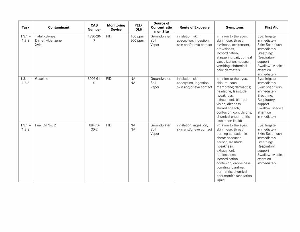
Task Contaminant CAS
Number
Monitoring
Device
PEL/
IDLH
Source of
Concentratio
n on Site
Route of Exposure Symptoms First Aid
1.3.1 –
1.3.8
Total Xylenes
Dimethylbenzene
Xylol
1330-20-
7
PID 100 ppm
900 ppm
Groundwater
Soil
Vapor
inhalation, skin
absorption, ingestion,
skin and/or eye contact
irritation to the eyes,
skin, nose, throat;
dizziness, excitement,
drowsiness,
incoordination,
staggering gait; corneal
vacuolization; nausea,
vomiting, abdominal
pain; dermatitis
Eye: Irrigate
immediately
Skin: Soap flush
immediately
Breathing:
Respiratory
support
Swallow: Medical
attention
immediately
1.3.1 –
1.3.8
Gasoline 8006-61-
9
PID NA
NA
Groundwater
Soil
Vapor
inhalation, skin
absorption, ingestion,
skin and/or eye contact
irritation to the eyes,
skin, mucous
membrane; dermatitis;
headache, lassitude
(weakness,
exhaustion), blurred
vision, dizziness,
slurred speech,
confusion, convulsions;
chemical pneumonitis
(aspiration liquid)
Eye: Irrigate
immediately
Skin: Soap flush
immediately
Breathing:
Respiratory
support
Swallow: Medical
attention
immediately
1.3.1 –
1.3.8
Fuel Oil No. 2 68476-
30-2
PID NA
NA
Groundwater
Soil
Vapor
inhalation, ingestion,
skin and/or eye contact
irritation to the eyes,
skin, nose, throat;
burning sensation in
chest; headache,
nausea, lassitude
(weakness,
exhaustion),
restlessness,
incoordination,
confusion, drowsiness;
vomiting, diarrhea;
dermatitis; chemical
pneumonitis (aspiration
liquid)
Eye: Irrigate
immediately
Skin: Soap flush
immediately
Breathing:
Respiratory
support
Swallow: Medical
attention
immediately

Task Contaminant CAS
Number
Monitoring
Device
PEL/
IDLH
Source of
Concentratio
n on Site
Route of Exposure Symptoms First Aid
1.3.1 –
1.3.8
Diesel
Fuel automotive diesel fuel oil
No. 2 distillate diesoline
diesel oil
diesel oil light
diesel oil No. 1-D
summer diesel
68334-
30-5
PID NA
NA
Groundwater
Soil
Vapor
inhalation, ingestion,
skin and/or eye contact
irritation to the eyes,
skin, nose, throat;
burning sensation in
chest; headache,
nausea, lassitude
(weakness,
exhaustion),
restlessness,
incoordination,
confusion, drowsiness;
vomiting, diarrhea;
dermatitis; chemical
pneumonitis (aspiration
liquid)
Eye: Irrigate
immediately
Skin: Soap flush
immediately
Breathing:
Respiratory
support
Swallow: Medical
attention
immediately
1.3.1 –
1.3.8
Aluminum 7429-90-
5
None 0.5
mg/m3
50 mg/m3
Soil inhalation, skin and/or
eye contact
irritation to the eyes,
skin, respiratory system
Eye: Irrigate
immediately
Breathing: Fresh
air
1.3.1 –
1.3.8
Antimony 7440-36-
0
None 0.5 mg/m3
50 mg/m3
Groundwater
Soil
inhalation, ingestion,
skin and/or eye contact
irritation skin, possible
dermatitis; resp
distress; diarrhea;
muscle tremor,
convulsions; possible
gastrointestinal tract
Eye: Irrigate
immediately
Skin: Soap wash
immediately
Breathing:
Respiratory
support
Swallow: Medical
attention
immediately
1.3.1 –
1.3.8
Arsenic NA None 0.5 mg/m3
NA
Groundwater
Soil
inhalation, ingestion,
skin and/or eye contact
irritation skin, possible
dermatitis; resp
distress; diarrhea;
muscle tremor,
convulsions; possible
gastrointestinal tract
Eye: Irrigate
immediately
Skin: Soap wash
immediately
Breathing:
Respiratory
support
Swallow: Medical
attention
immediately

Task Contaminant CAS
Number
Monitoring
Device
PEL/
IDLH
Source of
Concentratio
n on Site
Route of Exposure Symptoms First Aid
1.3.1 –
1.3.8
Barium 10022-
31-8
None 0.5 mg/m3
50 mg/m3
Groundwater
Soil
inhalation, ingestion,
skin and/or eye contact
irritation to the eyes,
skin, upper respiratory
system; skin burns;
gastroenteritis; muscle
spasm; slow pulse
Eye: Irrigate
immediately
Skin: Water flush
immediately
Breathing:
Respiratory
support
Swallow: Medical
attention
immediately
1.3.1 –
1.3.8
Beryllium 7440-41-
7
None 0.002
mg/m3
4 mg/m3
Soil inhalation, skin and/or
eye contact
berylliosis (chronic
exposure): anorexia,
weight loss, lassitude
(weakness,
exhaustion), chest pain,
cough, clubbing of
fingers, cyanosis,
pulmonary
insufficiency; irritation
to the eyes; dermatitis;
[potential occupational
carcinogen]
Eye: Irrigate
immediately
Breathing: Fresh
air
1.3.1 –
1.3.8
Cadmium 7440-43-
9
None 0.005
mg/m3
9 mg/m3
Soil inhalation, ingestion pulmonary edema,
dyspnea (breathing
difficulty), cough, chest
tightness, substernal
(occurring beneath the
sternum) pain;
headache; chills,
muscle aches; nausea,
vomiting, diarrhea;
anosmia (loss of the
sense of smell),
emphysema,
proteinuria, mild
anemia; [potential
occupational
carcinogen]
Eye: Irrigate
immediately
Skin: Soap wash
Breathing:
Respiratory
support
Swallow: Medical
attention
immediately

Task Contaminant CAS
Number
Monitoring
Device
PEL/
IDLH
Source of
Concentratio
n on Site
Route of Exposure Symptoms First Aid
1.3.1 –
1.3.8
Calcium 7440-70-
2
None NA Groundwater
Soil
inhalation, ingestion,
skin and/or eye contact
irritation to the eyes,
skin, upper resp tract;
ulcer, perforation nasal
septum; pneumonitis;
dermatitis
Eye: Irrigate
immediately
Skin: Water flush
immediately
Breathing:
Respiratory
support
Swallow: Medical
attention
immediately
1.3.1 –
1.3.8
Chromium
Hexavalent-
Trivalent-
7440-47-
3
None 1.0 mg/m3
250
mg/m3
Groundwater
Soil
inhalation
absorption
ingestion
irritation to eye, skin,
and respiratory
Eye: Irrigate
immediately
Skin: Soap wash
Breathing:
Respiratory
support
Swallow: Medical
attention
immediately
1.3.1 –
1.3.8
Cobalt 7440-48-
4
None 0.1mg/m3
20 mg/m3
Soil inhalation, ingestion,
skin and/or eye contact
Cough, dyspnea
(breathing difficulty),
wheezing, decreased
pulmonary function;
weight loss; dermatitis;
diffuse nodular fibrosis;
resp hypersensitivity,
asthma
Eye: Irrigate
immediately
Skin: Soap wash
Breathing:
Respiratory
support
Swallow: Medical
attention
immediately
1.3.1 –
1.3.8
Copper 7440-50-
8
None 1.0 mg/m3
100
mg/m3
Groundwater
Soil
inhalation, ingestion,
skin and/or eye contact
irritation to the eyes,
nose, metallic taste;
dermatitis; anemia
Eye: Irrigate
immediately
Skin: Soap wash
promptly
Breathing:
Respiratory
support
Swallow: Medical
attention
immediately

Task Contaminant CAS
Number
Monitoring
Device
PEL/
IDLH
Source of
Concentratio
n on Site
Route of Exposure Symptoms First Aid
1.3.1 –
1.3.8
Cyanide 57-12-5 None 5 mg/m3
25 mg/m3
Groundwater
Soil
inhalation, ingestion,
skin and/or eye contact
Exposure to cyanide
can cause weakness,
headaches, confusion,
dizziness, fatigue,
anxiety, sleepiness,
nausea and vomiting.
Breathing can speed up
then become slow and
gasping. Coma and
convulsions also occur.
If large amounts of
cyanide have been
absorbed by the body,
the person usually
collapses and death can
occur very quickly.
Long-term exposure to
lower levels of cyanide
can cause skin and
nose irritation, itching,
rashes and thyroid
changes.
Eye: Irrigate
immediately
Skin: Soap wash
Breathing:
Respiratory
support
Swallow: Medical
attention
immediately
1.3.1 –
1.3.8
Iron 7439-89-
6
None 10 mg/m3
NA
Groundwater
Soil
inhalation, ingestion,
skin and/or eye contact
irritation to the eyes,
skin, mucous
membrane; abdominal
pain, diarrhea, vomiting
Eye: Irrigate
immediately
Skin: Soap wash
Breathing:
Respiratory
support
Swallow: Medical
attention
immediately

Task Contaminant CAS
Number
Monitoring
Device
PEL/
IDLH
Source of
Concentratio
n on Site
Route of Exposure Symptoms First Aid
1.3.1 –
1.3.8
Lead 7439-92-
1
None 0.050
mg/m3
100
mg/m3
Groundwater
Soil
inhalation, ingestion,
skin and/or eye contact
lassitude (weakness,
exhaustion), insomnia;
facial pallor; anorexia,
weight loss,
malnutrition;
constipation, abdominal
pain, colic; anemia;
gingival lead line;
tremor; paralysis wrist,
ankles; encephalopathy;
kidney disease;
irritation to the eyes;
hypertension
Eye: Irrigate
immediately
Skin: Soap flush
promptly
Breathing:
Respiratory
support
Swallow: Medical
attention
immediately
1.3.1 –
1.3.8
Manganese 7439-96-
5
None 5 mg/m3
500
mg/m3
Groundwater
Soil
inhalation, ingestion aerosol is irritating to
the respiratory tract
Eye: Irrigate
immediately
Skin: Soap flush
promptly
Breathing:
Respiratory
support
Swallow: Medical
attention
immediately
1.3.1 –
1.3.8
Magnesium 7439-95-
4
None 15 mg/m3
NA
Soil inhalation, skin and/or
eye contact
irritation to the eyes,
skin, respiratory
system; cough
Eye: Irrigate
immediately
Breathing: Fresh
air
1.3.1 –
1.3.8
Mercury 7439-97-
6
None 0.1 mg/m3
10 mg/m3
Groundwater
Soil
inhalation, skin
absorption, ingestion,
skin and/or eye contact
irritation to the eyes,
skin; cough, chest pain,
dyspnea (breathing
difficulty), bronchitis,
pneumonitis; tremor,
insomnia, irritability,
headache, lassitude
(weakness,
exhaustion); stomatitis,
salivation;
gastrointestinal
disturbance, anorexia,
weight loss; proteinuria
Eye: Irrigate
immediately
Skin: Soap wash
promptly
Breathing:
Respiratory
support
Swallow: Medical
attention
immediately

Task Contaminant CAS
Number
Monitoring
Device
PEL/
IDLH
Source of
Concentratio
n on Site
Route of Exposure Symptoms First Aid
1.3.1 –
1.3.8
Nickel 7440-02-
0
None NA
10 mg/m3
Groundwater
Soil
ion, ingestion, skin
and/or eye contact
sensitization dermatitis,
allergic asthma,
pneumonitis; [potential
occupational
carcinogen]
Skin: Water flush
immediately
Breathing:
Respiratory
support
Swallow: Medical
attention
immediately
1.3.1 –
1.3.8
Potassium 7440-09-
7
None NA
NA
Soil inhalation, skin
absorption, ingestion,
skin and/or eye contact
inhalation, ingestion,
skin and/or eye contact
eye: Causes eye burns.
Skin: Causes skin
burns. Reacts with
moisture in the skin to
form potassium
hydroxide and hydrogen
with much heat.
ingestion: Causes
gastrointestinal tract
burns.
inhalation: May cause
irritation of the
respiratory tract with
burning pain in the nose
and throat, coughing,
wheezing, shortness of
breath and pulmonary
edema. Causes
chemical burns to the
respiratory tract.
inhalation may be fatal
as a result of spasm,
inflammation, edema of
the larynx and bronchi,
chemical pneumonitis
and pulmonary edema.
Eyes: Get medical
aid immediately
Skin: Get medical
aid immediately.
Immediately flush
skin with plenty of
water for at least
15 minutes while
removing
contaminated
clothing and
shoes.
ingestion: If victim
is conscious and
alert, give 2-4 full
cups of milk or
water. Get
medical aid
immediately.
inhalation: Get
medical aid
immediately.
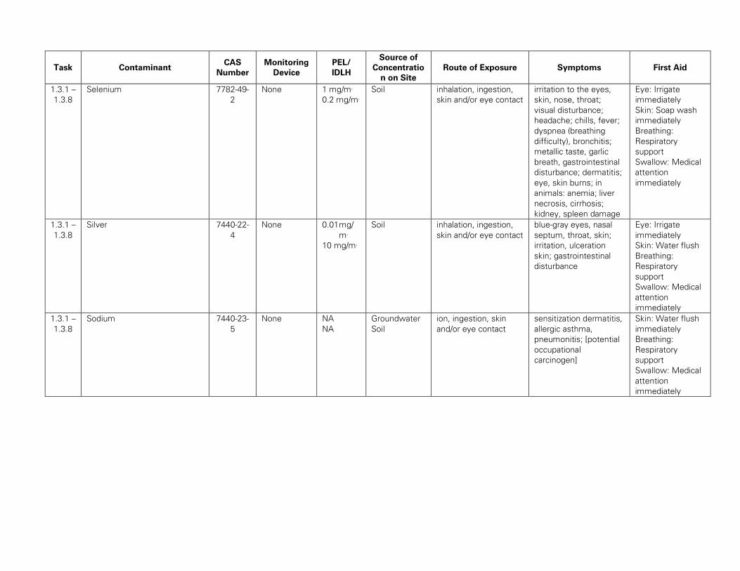
Task Contaminant CAS
Number
Monitoring
Device
PEL/
IDLH
Source of
Concentratio
n on Site
Route of Exposure Symptoms First Aid
1.3.1 –
1.3.8
Selenium 7782-49-
2
None 1 mg/m3
0.2 mg/m3
Soil inhalation, ingestion,
skin and/or eye contact
irritation to the eyes,
skin, nose, throat;
visual disturbance;
headache; chills, fever;
dyspnea (breathing
difficulty), bronchitis;
metallic taste, garlic
breath, gastrointestinal
disturbance; dermatitis;
eye, skin burns; in
animals: anemia; liver
necrosis, cirrhosis;
kidney, spleen damage
Eye: Irrigate
immediately
Skin: Soap wash
immediately
Breathing:
Respiratory
support
Swallow: Medical
attention
immediately
1.3.1 –
1.3.8
Silver 7440-22-
4
None 0.01 mg/
m3
10 mg/m3
Soil inhalation, ingestion,
skin and/or eye contact
blue-gray eyes, nasal
septum, throat, skin;
irritation, ulceration
skin; gastrointestinal
disturbance
Eye: Irrigate
immediately
Skin: Water flush
Breathing:
Respiratory
support
Swallow: Medical
attention
immediately
1.3.1 –
1.3.8
Sodium 7440-23-
5
None NA
NA
Groundwater
Soil
ion, ingestion, skin
and/or eye contact
sensitization dermatitis,
allergic asthma,
pneumonitis; [potential
occupational
carcinogen]
Skin: Water flush
immediately
Breathing:
Respiratory
support
Swallow: Medical
attention
immediately

Task Contaminant CAS
Number
Monitoring
Device
PEL/
IDLH
Source of
Concentratio
n on Site
Route of Exposure Symptoms First Aid
1.3.1 –
1.3.8
Thallium 7440-28-
0
None 0.1 mg/m3
15 mg/m3
Groundwater
Soil
inhalation, skin
absorption, ingestion,
skin and/or eye contact
nausea, diarrhea,
abdominal pain,
vomiting; ptosis,
strabismus; peri
neuritis, tremor;
retrosternal (occurring
behind the sternum)
tightness, chest pain,
pulmonary edema;
convulsions, chorea,
psychosis; liver, kidney
damage; alopecia;
paresthesia legs
Eye: Irrigate
immediately
Skin: Water flush
promptly
Breathing:
Respiratory
support
Swallow: Medical
attention
immediately
1.3.1 –
1.3.8
Vanadium 7440-62-
2
None 0.1
mg/m3
15 mg/m3
Groundwater
Soil
inhalation, skin
absorption, ingestion,
skin and/or eye contact
nausea, diarrhea,
abdominal pain,
vomiting; ptosis,
strabismus; peri
neuritis, tremor;
retrosternal (occurring
behind the sternum)
tightness, chest pain,
pulmonary edema;
convulsions, chorea,
psychosis; liver, kidney
damage; alopecia;
paresthesia legs
Eye: Irrigate
immediately
Skin: Water flush
promptly
Breathing:
Respiratory
support
Swallow: Medical
attention
immediately
1.3.1 –
1.3.8
Zinc 7440-62-
2
None 15 mg/m3
500
mg/m3
Groundwater
Soil
inhalation chills, muscle ache,
nausea, fever, dry
throat, cough; lassitude
(weakness,
exhaustion); metallic
taste; headache;
blurred vision; low back
pain; vomiting; malaise
(vague feeling of
discomfort); chest
tightness; dyspnea
(breathing difficulty),
rales, decreased
pulmonary function
Breathing:
Respiratory
support

Task Contaminant CAS
Number
Monitoring
Device
PEL/
IDLH
Source of
Concentratio
n on Site
Route of Exposure Symptoms First Aid
1.3.1 –
1.3.8
Non-Flammable Gas Mixture
CALGAS (Equipment
Calibration Gas :
Oxygen
Methane
Hydrogen Sulfide
Carbon Monoxide
Nitrogen
7782-44-
7
74-82-8
7783-08-
4
830-08-0
7727-37-
9
Multi-Gas
PID
NA/NA
NA/NA
10/100
ppm
50/1200
ppm
NA/NA
NA inhalation dizziness, headache,
and nausea
Breathing:
Respiratory
support
1.3.1 –
1.3.8
Potassium hydrogen phthalate 877-24-7 NA NA
NA
NA skin absorption,
ingestion, skin and/or
eye contact
nausea, diarrhea,
abdominal pain,
vomiting;
Skin: Water flush
promptly
Swallow: Medical
attention
immediately
1.3.1 –
1.3.8
Non-Flammable Gas Mixture
CALGAS (Equipment
Calibration Gas :
Oxygen
Isobutylene
Nitrogen
7782-44-
7
115-11-7
7727-37-
9
PID
NA/NA
NA/NA
NA/NA
NA inhalation dizziness, headache,
and nausea
Breathing:
Respiratory
support
EXPLANATION OF ABBREVIATIONS
PID = Photoionization Detector
PEL = Permissible Exposure Limit (8-hour Time Weighted Average
IDLH = Immediately Dangerous to Life and Health
ppm = part per million
mg/m3 = milligrams per cubic meter
500 mg/m3

TABLE 3
Summary of Monitoring Equipment
Instrument Operation Parameters
Photoionization
Detector (PID)
Hazard Monitored: Many organic and some inorganic gases and vapors.
Application: Detects total concentration of many organic and some inorganic gases and
vapors. Some identification of compounds is possible if more than one probe is
measured.
Detection Method: Ionizes molecules using UV radiation; produces a current that is
proportional to the number of ions.
General Care/Maintenance: Recharge or replace battery. Regularly clean lamp
window. Regularly clean and maintain the instrument and accessories.
Typical Operating Time: 10 hours. 5 hours with strip chart recorder.
Oxygen Meter Hazard Monitored: Oxygen (O2).
Application: Measures the percentage of O2 in the air.
Detection Method: Uses an electrochemical sensor to measure the partial pressure of
O2 in the air, and converts the reading to O2 concentration.
General Care/Maintenance: Replace detector cell according to manufacturer’s
recommendations. Recharge or replace batteries prior to explanation of the specified
interval. If the ambient air is less than 0.5% C O2 , replace the detector cell frequently.
Typical Operating Time: 8 – 12 hours.
Additional equipment (if needed, based on site conditions)
Combustible Gas
Indicator (CGI)
Hazard Monitored: Combustible gases and vapors.
Application: Measures the concentration of combustible gas or vapor.
Detection Method: A filament, usually made of platinum, is heated by burning the
combustible gas or vapor. The increase in heat is measured. Gases and vapors are
ionized in a flame. A current is produced in proportion to the number of carbon atoms
present.
General Care/Maintenance: Recharge or replace battery. Calibrate immediately before
use.
Typical Operating Time: Can be used for as long as the battery lasts, or for the
recommended interval between calibrations, whichever is less.
Flame Ionization
Detector (FID) with
Gas Chromatography
Option
(i.e., Foxboro Organic
Vapor Analyzer (OVA))
Hazard Monitored: Many organic gases and vapors (approved areas only).
Application: In survey mode, detects the concentration of many organic gases and
vapors. In gas chromatography (GC) mode, identifies and measures specific compounds.
In survey mode, all the organic compounds are ionized and detected at the same time.
In GC mode, volatile species are separated.
General Care/Maintenance: Recharge or replace battery. Monitor fuel and/or
combustion air supply gauges. Perform routine maintenance as described in the manual.
Check for leaks.
Typical Operating Time: 8 hours; 3 hours with strip chart recorder.
Potable Infrared (IR)
Spectrophotometer
Hazard Monitored: Many gases and vapors.
Application: Measures concentration of many gases and vapors in air. Designed to
quantify one or two component mixtures.
Detection Method: Passes different frequencies of IR through the sample. The
frequencies absorbed are specific for each compound.
General Care/Maintenance: As specified by the manufacturer.

Instrument Operation Parameters
Direct Reading
Colorimetric Indicator
Tube
Hazard Monitored: Specific gas and vapors.
Application: Measures concentration of specific gases and vapors.
Detection Method: The compound reacts with the indicator chemical in the tube,
producing a stain whose length or color change is proportional to the compound’s
concentration.
General Care/Maintenance: Do not use a previously opened tube even if the indicator
chemical is not stained. Check pump for leaks before and after use. Refrigerate before
use to maintain a shelf life of about 2 years. Check expiration dates of tubes. Calibrate
pump volume at least quarterly. Avoid rough handling which may cause channeling.
Aerosol Monitor Hazard Monitored: Airborne particulate (dust, mist, fume) concentrations
Application: Measures total concentration of semi-volatile organic compounds, PCBs,
and metals.
Detection Method: Based on light-scattering properties of particulate matter. Using an
internal pump, air sample is drawn into the sensing volume where near infrared light
scattering is used to detect particles.
General Care/Maintenance: As specified by the mfr. Also, the instrument must be
calibrated with particulates of a size and refractive index similar to those to be measured
in the ambient air.
Monitox Hazard Monitored: Gases and vapors.
Application: Measures specific gases and vapors.
Detection Method: Electrochemical sensor relatively specific for the chemical species
in question.
General Care/Maintenance: Moisten sponge before use; check the function switch;
change the battery when needed.
Gamma Radiation
Survey Instrument
Hazard Monitored: Gamma Radiation.
Application: Environmental radiation monitor.
Detection Method: Scintillation detector.
General Care/Maintenance: Must be calibrated annually at a specialized facility.
Typical Operating Time: Can be used for as long as the battery lasts, or for the
recommended interval between calibrations, whichever is less.

TABLE 4
INSTRUMENTATION ACTION LEVELS
Photoionization Detector Action Levels Action Required
Background to 5 ppm No respirator; no further action required
> 1 ppm but < 5 ppm for > 5 minutes 1. Temporarily discontinue all activities and
evaluate potential causes of the excessive
readings. If these levels persist and cannot be
mitigated (i.e., by slowing drilling or excavation
activities), contact HSO to review conditions and
determine source and appropriate response
action.
2. If PID readings remain above 1 ppm,
temporarily discontinue work and upgrade to
Level C protection.
3. If sustained PID readings fall below 1 ppm,
downgrading to Level D protection may be
permitted.
> 5 ppm but < 150 ppm for > 5 minutes 1. Discontinue all work; all workers shall move to
an area upwind of the jobsite.
2. Evaluate potential causes of the excessive
readings and allow work area to vent until VOC
concentrations fall below 5 ppm.
3. Level C protection will continue to be used until
PID readings fall below 1 ppm.
> 150 ppm Evacuate the work area
Notes: 1. 1 ppm level based on OSHA Permissible Exposure Limit (PEL) for benzene.
2. 5 ppm level based on OSHA Short Term Exposure Limit (STEL) maximum exposure
for benzene for any 15 minute period.
3. 150 ppm level based on NIOSH Immediately Dangerous to Life and Health (IDLH) for
tetrachloroethylene.

TABLE 5
EMERGENCY NOTIFICATION LIST
ORGANIZATION CONTACT TELEPHONE
Local Police Department NYPD 911
Local Fire Department NYFD 911
Ambulance/Rescue Squad NYFD 911
Hospital Woodhull Medical Center 911 or 718-963-8000
Langan Incident / Injury
Hotline
800-952-6426 ex 4699
Langan Project Manager Brian Gochenaur 347-320-2756 (cell)
Langan Health and Safety
Manager (HSM)
Tony Moffa 215-756-2523 (cell)
Langan Health & Safety
Officer (HSO)
William Bohrer 410-984-3068 (cell)
Langan Field Team Leader
(FTL)
To Be Determined
Client’s Representative Andrew Cantor 212-500-0774
National Response Center
(NRC)
800-424-8802
Chemical Transportation
Emergency Center
(Chemtrec)
800-424-9300
Center for Disease Control
(CDC)
404-639-3534
EPA (RCRA Superfund
Hotline)
800-424-9346
TSCA Hotline 202-554-1404
Poison Control Center 800-222-1222
Immediately following an incident or near miss, unless emergency
medical treatment is required, either the employee or a coworker must
contact the Langan Incident/Injury Hotline at 1-(800)-9-LANGAN (ext.
#4699).

TABLE 6
SUGGESTED FREQUENCY OF PHYSIOLOGICAL MONITORING
FOR FIT AND ACCLIMATED WORKERSA
Adjusted
Temperatureb
Normal Work
Ensemblec
Impermeable
Ensemble
90°F or above
(32.2°C) or above
After each 45 min.
of work
After each 15 min.
of work
87.5°F
(30.8°-32.2°C)
After each 60 min.
of work
After each 30 min.
of work
82.5°-87.5°F
(28.1°-30.8°C)
After each 90 min.
of work
After each 60 min.
of work
77.5°-82.5°F
(25.3°-28.1°C)
After each 120 min.
of work
After each 90 min.
of work
72.5°-77.5°F
(22.5°-25.3°C)
After each 150 min.
of work
After each 120 min.
of work
a For work levels of 250 kilocalories/hour.
b Calculate the adjusted air temperature (ta adj) by using this equation: ta adj oF = ta oF + (13 x % sunshine).
Measure air temperature (ta) with a standard mercury-in-glass thermometer, with the bulb shielded from
radiant heat. Estimate percent sunshine by judging what percent time the sun is not covered by clouds that
are thick enough to produce a shadow. (100 percent sunshine = no cloud cover and a sharp, distinct
shadow; 0 percent sunshine = no shadows.)
c A normal work ensemble consists of cotton coveralls or other cotton clothing with long sleeves and pants.

TABLE 7
HEAT INDEX
ENVIRONMENTAL TEMPERATURE (Fahrenheit)
70 75 80 85 90 95 100 105 110 115 120
RELATIVE
HUMIDITY APPARENT TEMPERATURE*
0% 64 69 73 78 83 87 91 95 99 103 107
10% 65 70 75 80 85 90 95 100 105 111 116
20% 66 72 77 82 87 93 99 105 112 120 130
30% 67 73 78 84 90 96 104 113 123 135 148
40% 68 74 79 86 93 101 110 123 137 151
50% 69 75 81 88 96 107 120 135 150
60% 70 76 82 90 100 114 132 149
70% 70 77 85 93 106 124 144
80% 71 78 86 97 113 136
90% 71 79 88 102 122
100% 72 80 91 108
*Combined Index of Heat and Humidity...what it "feels like" to the body
Source: National Oceanic and Atmospheric Administration
How to use Heat Index: Apparent Heat Stress Risk with Physical
1. Across top locate Environmental Temperature Temperature Activity and/or Prolonged
2. Down left side locate Relative Humidity Exposure
3. Follow across and down to find Apparent Temperature 90-105 Heat Cramps or Heat
4. Determine Heat Stress Risk on chart at right Exhaustion Possible
105-130 Heat Cramps or Heat Exhaustion
Note: Exposure to full sunshine can increase Heat Index values Likely, Heat Stroke Possible
by up to 15 degrees F. >130 Heatstroke Highly Likely

FIGURES

FIGURE 1
Site Location Map

FIGURE 2
HOSPITAL ROUTE PLAN
Hospital Location: Woodhull Medical & Mental Health Center
760 Broadway Street
Brooklyn, NY
START: 432 Rodney Street, Brooklyn, NY
1. Head northwest on Rodney Street toward Ainslie Street
2. Turn right onto Ainslie Street
3. Turn right at the 3rd cross street onto Lorimer Street
4. Turn left onto Broadway Street, destination will be on the right
END: Woodhull Medical & Mental Health Center, 760 Broadway Street, Brooklyn, NY

ATTACHMENT A
STANDING ORDERS

STANDING ORDERS
GENERAL
No smoking, eating, or drinking in this work zone.
Upon leaving the work zone, personnel will thoroughly wash their hands and face.
Minimize contact with contaminated materials through proper planning of work areas and
decontamination areas, and by following proper procedures. Do not place equipment on the
ground. Do not sit on contaminated materials.
No open flames in the work zone.
Only properly trained and equipped personnel are permitted to work in potentially
contaminated areas.
Always use the appropriate level of personal protective equipment (PPE).
Maintain close contact with your buddy in the work zone
Contaminated material will be contained in the Exclusion Zone (EZ).
Report any unusual conditions.
Work areas will be kept clear and uncluttered. Debris and other slip, trip, and fall hazards
will be removed as frequently as possible.
The number of personnel and equipment in the work zone will be kept to an essential
minimum.
Be alert to the symptoms of fatigue and heat/cold stress, and their effects on the normal
caution and judgment of personnel.
Conflicting situations which may arise concerning safety requirements and working
conditions must be addressed and resolved quickly by the site HSO.
TOOLS AND HEAVY EQUIPMENT
Do not, under any circumstances, enter or ride in or on any backhoe bucket, materials hoist,
or any other device not specifically designed to carrying passengers.
Loose-fitting clothing or loose long hair is prohibited around moving machinery.
Ensure that heavy equipment operators and all other personnel in the work zone are using
the same hand signals to communicate.
Drilling/excavating within 10 feet in any direction of overhead power lines is prohibited.
The locations of all underground utilities must be identified and marked out prior to initiating
any subsurface activities.
Check to insure that the equipment operator has lowered all blades and buckets to the
ground before shutting off the vehicle.
If the equipment has an emergency stop device, have the operator show all personnel its
location and how to activate it.
Help the operator ensure adequate clearances when the equipment must negotiate in tight
quarters; serve as a signalman to direct backing as necessary.
Ensure that all heavy equipment that is used in the Exclusion Zone is kept in that zone until
the job is done, and that such equipment is completely decontaminated before moving it
into the clean area of the work zone.
Samplers must not reach into or get near rotating equipment such as the drill rig. If
personnel must work near any tools that could rotate, the equipment operator must
completely shut down the rig prior to initiating such work. It may be necessary to use a
remote sampling device.

ATTACHMENT B
DECONTAMINATION PROCEDURES

PERSONNEL DECONTAMINATION
_______________________________________________________________________________
LEVEL C DECONTAMINATION
_______________________________________________________________________________
Station 1: Equipment Drop 1. Deposit equipment used on-site (tools, sampling
devices and containers, monitoring instruments,
radios, clipboards, etc.) on plastic drop cloths.
Segregation at the drop reduces the probability of
cross contamination. During hot weather operations,
cool down stations may be set up within this area.
Station 2: Outer Garment, 2. Scrub outer boots, outer gloves and chemical-re-
Boots, and Gloves sistant splash suit with decon solution or detergent and
Wash and Rinse water. Rinse off using copious amounts of water.
Station 3: Outer Boot and 3. Remove outer boots and gloves. Deposit in
Glove Removal container with plastic liner.
Station 4: Canister or 4. If worker leaves Exclusion Zone to change canister
Mask Change (or mask), this is the last step in the decontamination
procedure. Worker’s canister is exchanged, new outer
gloves and boot covers donned, joints taped, and
worker returns to duty.
Station 5: Boot, Gloves 5. Boots, chemical-resistant splash suit, inner gloves
and Outer Garment removed and deposited in separate containers lined
Removal with plastic.
Station 6: Face piece 6. Face piece is removed (avoid touching face with
Removal fingers). Face piece deposited on plastic sheets.
Station 7: Field Wash 7. Hands and face are thoroughly washed. Shower as
soon as possible.
______________________________________________________________________________
LEVEL D DECONTAMINATION
_______________________________________________________________________________
Station 1: Equipment Drop 1. Deposit equipment used on-site (tools, sampling
devices and containers, monitoring instruments,
radios, clipboards, etc.) on plastic drop cloths.
Segregation at the drop reduces the probability of
cross contamination. During hot weather operations,
cool down stations may be set up within this area.
Station 2: Outer Garment, 2. Scrub outer boots, outer gloves and chemical-re-
Boots, and Gloves sistant splash suit with decon solution or detergent and
Wash and Rinse water. Rinse off using copious amounts of water.
Station 3: Outer Boot and 3. Remove outer boots and gloves. Deposit in
Glove Removal container with plastic liner.
Station 4: Boot, Gloves 4. Boots, chemical-resistant splash suit, inner gloves
and Outer Garment removed and deposited in separate containers lined
Removal with plastic.
Station 5: Field Wash 5. Hands and face are thoroughly washed. Shower as
soon as possible.

EQUIPMENT DECONTAMINATION
GENERAL:
Equipment to be decontaminated during the project may include tools, monitoring equipment,
respirators, sampling containers, laboratory equipment and drilling equipment.
All decontamination will be done by personnel in protective gear, appropriate for the level of
decontamination, as determined by the site HSO. The decontamination work tasks will be split or
rotated among support and work crews.
Depending on site conditions, backhoe and pumps may be decontaminated over a portable
decontamination pad to contain wash water; or, wash water may be allowed to run off into a storm
sewer system. Equipment needed may include a steam generator with high-pressure water, empty
drums, screens, screen support structures, and shovels. Drums will be used to hold contaminated
wash water pumped from the lined pit. These drums will be labeled as such.
Miscellaneous tools and equipment will be dropped into a plastic pail, tub, or other container. They
will be brushed off and rinsed with a detergent solution, and finally rinsed with clean water.
MONITORING EQUIPMENT:
Monitoring equipment will be protected as much as possible from contamination by draping,
masking, or otherwise covering as much of the instruments as possible with plastic without
hindering the operation of the unit. The PID, HNu or OVA meter, for example, can be placed in a
clear plastic bag, which allows reading of the scale and operation of knobs. The probes can be
partially wrapped keeping the sensor tip and discharge port clear.
The contaminated equipment will be taken from the drop area and the protective coverings
removed and disposed in the appropriate containers. Any dirt or obvious contamination will be
brushed or wiped with a disposable paper wipe.
RESPIRATORS:
Respirators will be cleaned and disinfected after every use. Taken from the drop area, the masks
(with the cartridges removed and disposed of with other used disposable gear) will be immersed in
a cleaning solution and scrubbed gently with a soft brush, followed by a rinse in plain warm water,
and then allowed to air dry. In the morning, new cartridges will be installed. Personnel will inspect
their own masks for serviceability prior to donning them. And, once the mask is on, the wearer will
check the respirator for leakage using the negative and positive pressure fit check techniques.

ATTACHMENT C
EMPLOYEE EXPOSURE/
INJURY INCIDENT REPORT

EMPLOYEE INCIDENT/INJURY REPORT
LANGAN ENGINEERING & ENVIRONMENTAL SERVICES
(Complete and return to Tony Moffa in the Doylestown Office)
Affected Employee Name: Date:
Incident type: Injury Report Only/No Injury
Near Miss Other:
EMPLOYEE INFORMATION (Person completing Form)
Employee Name: Employee No:
Title: Office Location:
Length of time employed or date of hire:
Mailing address:
Sex: M F Birth date:
Business phone & extension: Residence/cell phone:
ACCIDENT INFORMATION
Project: Project #:
Date & time of incident: Time work started & ended:
Site location:
Incident Type: Possible Exposure Exposure Physical Injury
Names of person(s) who witnessed the incident:
Exact location incident occurred:
Describe work being done:

Describe what affected employee was doing prior to the incident occurring:
Describe in detail how the incident occurred:
Nature of the incident (List the parts of the body affected):
Person(s) to whom incident was reported (Time and Date):
List the names of other persons affected during this incident:
Possible causes of the incident (equipment, unsafe work practices, lack of PPE, etc.):
Weather conditions during incident:
MEDICAL CARE INFORMATION
Did affected employee receive medical care? Yes No
If Yes, when and where was medical care received:
Provide name of facility (hospital, clinic, etc.):
Length of stay at the facility?
Did the employee miss any work time? Yes No Undetermined

Date employee last worked: Date employee returned to work:
Has the employee returned to work? Yes No
Does the employee have any work limitations or restrictions from the injury? : Yes No
If Yes, please describe:
Did the exposure/injury result in permanent disability? Yes No Unknown
If Yes, please describe:
HEALTH & SAFETY INFORMATION
Was the operation being conducted under an established site specific CONSTRUCTION HEALTH AND
SAFETY PLAN?
Yes No Not Applicable:
Describe protective equipment and clothing used by the employee:
Did any limitations in safety equipment or protective clothing contribute to or affect exposure / injury? If so,
explain:
Employee Signature Date
Langan Representative Date

ATTACHMENT D
CALIBRATION LOG

DATE:________________ PROJECT:____________________
CALIBRATION LOG
Date &
Time
Inst
Type
Inst #
Media
Initial
Reading
Span #
Calibrat.
Reading
Performed By:

ATTACHMENT E
MATERIAL SAFETY DATA SHEETS
SAFETY DATA SHEETS
All Langan Field Personnel Completing This Work Plan Are To Have Real Time Accessibility
To Material Safety Data Sheet (MSDs) or Safety Data Sheet (SDSs) Through Their Smart
Phone.
The link is http://www.msds.com/
The login name is “drapehead”
The password is “2angan987”
If You Are Unable To Use the Smart Phone App, You Are To Bring Printed Copies of the
MSDs/SDSs to The Site

ATTACHMENT F
JOBSITE SAFETY INSPECTION CHECKLIST
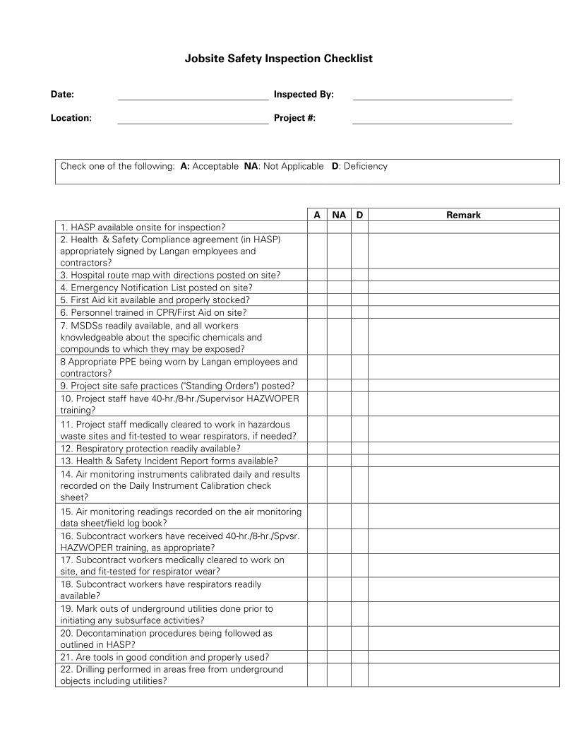
Jobsite Safety Inspection Checklist
Date: Inspected By:
Location: Project #:
Check one of the following: A: Acceptable NA: Not Applicable D: Deficiency
A NA D Remark
1. HASP available onsite for inspection?
2. Health & Safety Compliance agreement (in HASP)
appropriately signed by Langan employees and
contractors?
3. Hospital route map with directions posted on site?
4. Emergency Notification List posted on site?
5. First Aid kit available and properly stocked?
6. Personnel trained in CPR/First Aid on site?
7. MSDSs readily available, and all workers
knowledgeable about the specific chemicals and
compounds to which they may be exposed?
8 Appropriate PPE being worn by Langan employees and
contractors?
9. Project site safe practices ("Standing Orders") posted?
10. Project staff have 40-hr./8-hr./Supervisor HAZWOPER
training?
11. Project staff medically cleared to work in hazardous
waste sites and fit-tested to wear respirators, if needed?
12. Respiratory protection readily available?
13. Health & Safety Incident Report forms available?
14. Air monitoring instruments calibrated daily and results
recorded on the Daily Instrument Calibration check
sheet?
15. Air monitoring readings recorded on the air monitoring
data sheet/field log book?
16. Subcontract workers have received 40-hr./8-hr./Spvsr.
HAZWOPER training, as appropriate?
17. Subcontract workers medically cleared to work on
site, and fit-tested for respirator wear?
18. Subcontract workers have respirators readily
available?
19. Mark outs of underground utilities done prior to
initiating any subsurface activities?
20. Decontamination procedures being followed as
outlined in HASP?
21. Are tools in good condition and properly used?
22. Drilling performed in areas free from underground
objects including utilities?

23. Adequate size/type fire extinguisher supplied?
24. Equipment at least 20 feet from overhead
powerlines?
25. Evidence that drilling operator is responsible for the
safety of his rig.
26. Trench sides shored, layer back, or boxed?
27. Underground utilities located and authorities
contacted before digging?
28. Ladders in trench (25-foot spacing)?
29. Excavated material placed more than 2 feet away
from excavation edge?
30. Public protected from exposure to open excavation?
31. People entering the excavation regarding it as a
permit-required confined space and following appropriate
procedures?
32. Confined space entry permit is completed and
posted?
33. All persons knowledgeable about the conditions and
characteristics of the confined space?
34. All persons engaged in confined space operations
have been trained in safe entry and rescue (non-entry)?
35. Full body harnesses, lifelines, and hoisting apparatus
available for rescue needs?
36. Attendant and/or supervisor certified in basic first aid
and CPR?
37. Confined space atmosphere checked before entry
and continuously while the work is going on?
38. Results of confined space atmosphere testing
recorded?
39. Evidence of coordination with off-site rescue services
to perform entry rescue, if needed?
40. Are extension cords rated for this work being used
and are they properly maintained?
41. Are GFCIs provided and being used?
Unsafe Acts:
Notes:

ATTACHMENT G
JOB SAFETY ANALYSIS FORM

Job Safety Analysis (JSA)
Health and Safety
JSA TITLE:
JSA NUMBER:
DATE CREATED:
CREATED BY:
REVISION DATE:
REVISED BY:
Langan employees must review and revise the Job Safety Analysis (JSA) as needed to address the any site specific hazards not identified.
Employees must provide their signatures on the last page of the JSA indicating they have review the JSA and are aware the potential
hazards associated with this work and will follow the provided preventive or corrective measures.
PERSONAL PROTECTIVE EQUIPMENT REQUIRED: (PPE): ■ Required ☒ As Needed
☐ Steel-toed boots ☐ Nitrile gloves ☐ Dermal Protection (Specify)
☐ Long-sleeved shirt ☐ Leather/ Cut-resistant gloves ☐ High visibility vest/clothing
☐ Safety glasses ☐ Face Shield ☐ Hard hat
ADDITIONAL PERSONAL PROTECTIVE EQUIPMENT NEEDED (Provide specific type(s) or descriptions)
☐ Air Monitoring: ☐ Respirators: ☐ Other:
☐ Dermal Protection: ☐ Cartridges: ☐ Other:
JOB STEPS POTENTIAL HAZARDS PREVENTATIVE OR
CORRECTIVE ACTION
1. 1.
2.
1a.
1b.
2a.
2b.
2. 1. 1
Additional items identified in the field.
Additional Items.
If additional items are identified during daily work activities, please notify all relevant personnel
about the change and document on this JSA.

ATTACHMENT H
TAILGATE SAFETY BRIEFING FORM

LANGAN TAILGATE SAFETY BRIEFING
Date: Time:
Leader: Location:
Work Task:
SAFETY TOPICS (provide some detail of discussion points)
Chemical Exposure Hazards and Control:
Physical Hazards and Control:
Air Monitoring:
PPE:
Communications:
Safe Work Practices:
Emergency Response:
Hospital/Medical Center Location:
Phone Nos.:
Other:
FOR FOLLOW-UP (the issues, responsibilities, due dates, etc.)
ATTENDEES
PRINT NAME COMPANY SIGNATURE

APPENDIX G
VAPOR BARRIER MANUFACTURER DETAILS

FLORPRUFE® 120Integrally bonded vapor protection for slabs on grade
P R O D U C T D ATA S H E E T
Description
Florprufe® 120 is a high perfor-mance vapor barrier with GCP’s Advanced Bond TechnologyTM that forms a unique seal to the underside of concrete floor slabs.
Comprising a highly durable polyolefin sheet and a specially developed, non-tacky adhesive coating, Florprufe 120 seals to liquid concrete to provide integrally bonded vapor protection.
Florprufe exceeds ASTM E1745 Class A rating.
Advantages
• Forms a powerful integral seal to the underside of concrete slabs
• Protects valuable floor finishes such as wood, tiles, carpet and resilient flooring from damage by vapor transmission
• Direct contact with the slab complies with the latest industry recommendations
• Remains sealed to the slab even in cases of ground settlement
• Ultra low vapor permeability
• Durable, chemical resistant polyolefin sheet
• Lightweight, easy to apply, kick out rolls
• Simple lap forming with mechanical fixings or tape
Use
Florprufe 120 is engineered for use below slabs on grade with moisture-impermeable or moisture-sensitive floor finishes that require the highest level of vapor protection.
1 ACI 302.1R-96
Advantages• Forms a powerful integral seal
• Protects valuable floor finishes
• Ultra low vapor permeability
• Durable, chemical resistant
• Lightweight and easy to apply
Florprufe complies with the latest recommenda-tions of ACI Committees 302 and 360, i.e. for slabs with vapor sensitive coverings, the location of the vapor barrier should always be in direct contact with the slab1.
The membrane is loose laid onto the prepared sub-base, forming overlaps that can be either mechanically secured or taped. The unique bond of Florprufe to concrete provides continuity of vapor protection at laps. Alternatively, if a taped system is preferred, self-adhered Preprufe® Tape can be used to overband the laps.
Slab reinforcement and concrete can be placed immediately. Once the concrete is poured, an inte-gral bond develops between the concrete and membrane.
Installation
Health & Safety
Refer to relevant Safety Data Sheet. Complete rolls should be handled by 2 persons.
Building wall
Preprufe Tape
Expansion board (optional)
Moisture sensitive flooring
Concrete slab
Florprufe
Footing
Compacted subgrade
Drawings are for illustration purpose only.Please refer to www.gcpat.com for specific application details.
5 in. x 8 in.open drain rock
Bituthene LiquidMembrane
Exterior gradeat or below levelof subgrade—slope away from structure
Typical Assembly
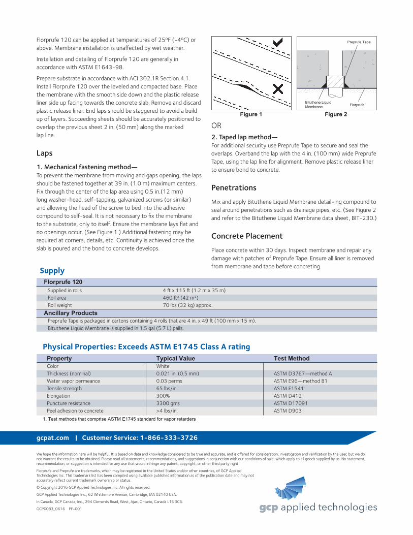
Florprufe 120 can be applied at temperatures of 25ºF (-4ºC) or above. Membrane installation is unaffected by wet weather.
Installation and detailing of Florprufe 120 are generally in accordance with ASTM E1643-98.
Prepare substrate in accordance with ACI 302.1R Section 4.1. Install Florprufe 120 over the leveled and compacted base. Place the membrane with the smooth side down and the plastic release liner side up facing towards the concrete slab. Remove and discard plastic release liner. End laps should be staggered to avoid a build up of layers. Succeeding sheets should be accurately positioned to overlap the previous sheet 2 in. (50 mm) along the marked lap line.
Laps
1. Mechanical fastening method— To prevent the membrane from moving and gaps opening, the laps should be fastened together at 39 in. (1.0 m) maximum centers. Fix through the center of the lap area using 0.5 in.(12 mm) long washer-head, self-tapping, galvanized screws (or similar) and allowing the head of the screw to bed into the adhesive compound to self-seal. It is not necessary to fix the membrane to the substrate, only to itself. Ensure the membrane lays flat and no openings occur. (See Figure 1.) Additional fastening may be required at corners, details, etc. Continuity is achieved once the slab is poured and the bond to concrete develops.
We hope the information here will be helpful. It is based on data and knowledge considered to be true and accurate, and is offered for consideration, investigation and verification by the user, but we do not warrant the results to be obtained. Please read all statements, recommendations, and suggestions in conjunction with our conditions of sale, which apply to all goods supplied by us. No statement, recommendation, or suggestion is intended for any use that would infringe any patent, copyright, or other third party right.
Florprufe and Preprufe are trademarks, which may be registered in the United States and/or other countries, of GCP Applied Technologies Inc. This trademark list has been compiled using available published information as of the publication date and may not accurately reflect current trademark ownership or status.
© Copyright 2016 GCP Applied Technologies Inc. All rights reserved.
GCP Applied Technologies Inc., 62 Whittemore Avenue, Cambridge, MA 02140 USA.
In Canada, GCP Canada, Inc., 294 Clements Road, West, Ajax, Ontario, Canada L1S 3C6.
GCP0083_0616 PF-001
gcpat.com | Customer Service: 1-866-333-3726
OR2. Taped lap method— For additional security use Preprufe Tape to secure and seal the overlaps. Overband the lap with the 4 in. (100 mm) wide Preprufe Tape, using the lap line for alignment. Remove plastic release liner to ensure bond to concrete.
Penetrations
Mix and apply Bituthene Liquid Membrane detail-ing compound to seal around penetrations such as drainage pipes, etc. (See Figure 2 and refer to the Bituthene Liquid Membrane data sheet, BIT-230.)
Concrete Placement
Place concrete within 30 days. Inspect membrane and repair any damage with patches of Preprufe Tape. Ensure all liner is removed from membrane and tape before concreting.
Bituthene LiquidMembrane Florprufe
Preprufe Tape
Figure 1 Figure 2
Physical Properties: Exceeds ASTM E1745 Class A rating Property Typical Value Test Method Color White Thickness (nominal) 0.021 in. (0.5 mm) ASTM D3767—method A Water vapor permeance 0.03 perms ASTM E96—method B1 Tensile strength 65 lbs/in. ASTM E1541 Elongation 300% ASTM D412 Puncture resistance 3300 gms ASTM D17091 Peel adhesion to concrete >4 lbs/in. ASTM D903
1. Test methods that comprise ASTM E1745 standard for vapor retarders
Supply Florprufe 120 Supplied in rolls 4 ft x 115 ft (1.2 m x 35 m) Roll area 460 ft2 (42 m2) Roll weight 70 lbs (32 kg) approx.
Ancillary Products Preprufe Tape is packaged in cartons containing 4 rolls that are 4 in. x 49 ft (100 mm x 15 m). Bituthene Liquid Membrane is supplied in 1.5 gal (5.7 L) pails.

PREPRUFE® 300R Plus & 160R PlusPre-applied waterproofing membranes that bondintegrally to poured concrete for use below slabs orbehind basement walls on confined sites
Grace Below Grade Waterproofing
Advantages• Forms a unique continuous adhesive bond to
concrete poured against it—prevents water migra-tion and makes it unaffected by ground settlementbeneath slabs
• Fully-adhered adhesive to adhesive watertight lapsand detailing
• Provides a barrier to water, moisture and gas—physically isolates the structure from the surroundingground
• Easy roll/kick out installation—reduces installationtime and cost
• Release Liner free—expedites installation andreduces construction site waste
• Solar reflective—reduced temperature gain• Simple and quick to install—requiring no primingor fillets
• Can be applied to permanent formwork—allowsmaximum use of confined sites
• Self protecting—can be trafficked immediately afterapplication and ready for immediate placing of rein-forcement
• Unaffected by wet conditions—cannot activateprematurely
• Inherently waterproof, non-reactive system:• not reliant on confining pressures or hydration• unaffected by freeze/thaw, wet/dry cycling
• Chemical resistant—effective in most types of soilsand waters, protects structure from salt or sulphateattack
DescriptionPreprufe® 300R Plus & 160R Plus membranes areunique composite sheets comprising, a thick HDPEfilm, an aggressive pressure sensitive adhesive aweather resistant protective coating and an adhesive toadhesive seam overlap.
Unlike conventional non-adhering membranes, whichare vulnerable to water ingress tracking between theunbonded membrane and structure, the unique Preprufebond to concrete prevents ingress or migration of wateraround the structure.
The Preprufe R Plus System includes:
• Preprufe 300R Plus—heavy-duty grade for usebelow slabs and on rafts (i.e. mud slabs). Designed toaccept the placing of heavy reinforcement usingconventional concrete spacers.
• Preprufe 160R Plus—thinner grade for blindside,zero property line applications against soil retentionsystems.
• Preprufe Tape LT—for covering cut edges, rollends, penetrations and detailing (temperaturesbetween 25°F (-4°C) and 86°F (+30°C)).
• Preprufe Tape HC—as above for use in HotClimates (minimum 50°F (10°C)).
• Bituthene® Liquid Membrane—for sealing aroundpenetrations, etc.
• Adcor™ ES—waterstop for joints in concrete wallsand floors
• Preprufe Tieback Covers—preformed cover for soilretention wall tieback heads
• Preprufe Preformed Corners—preformed insideand outside corners
Preprufe 300R Plus & 160R Plus membranes areapplied either horizontally to smooth prepared concrete,carton forms or well rolled and compacted earth orcrushed stone substrate; or vertically to permanent form-work or adjoining structures. Concrete is then castdirectly against the adhesive side of the membranes.The specially developed Preprufe adhesive layers worktogether to form a continuous and integral seal to thestructure.
Preprufe can be turned up the inside face of slab form-work but is not recommended for conventionaltwin-sided formwork on walls, etc. Use Bituthene®self-adhesive membrane or Procor® fluid appliedmembrane to walls after removal of formwork for afully bonded system to all structural surfaces.
Drawings are for illustration purposes only. Please refer to graceconstruction.com for specific application details.
Watertight and grout tight sealed laps
Slab formwork
Selvedge
Selvedge Adhesive surface of Preprufe300R Plus/160R Plus Membrane
Watertight details

InstallationThe most current application instructions, detail drawings and technical letters can be viewed at graceconstruction.com. For other technical informationcontact your local Grace representative.Preprufe Plus has colored zip strips at the top andbottom of the seam area on the edge of the roll. Bothzip strips cover an aggressive adhesive. Once theyellow zip strip on the top of the membrane and theblue zip strip on the bottom of the membrane areremoved, a strong adhesive to adhesive bond isachieved in the overlap area.Substrate PreparationAll surfaces—It is essential to create a sound and solidsubstrate to eliminate movement during the concretepour. Substrates must be regular and smooth with nogaps or voids greater than 0.5 in. (12 mm). Groutaround all penetrations such as utility conduits, etc. forstability (see Figure 1).Horizontal—The substrate must be free of looseaggregate and sharp protrusions. Avoid curved orrounded substrates. When installing over earth orcrushed stone, ensure substrate is well compacted toavoid displacement of substrate due to traffic orconcrete pour. The surface does not need to be dry, butstanding water must be removed.Vertical—Use concrete, plywood, insulation or otherapproved facing to sheet piling to provide support tothe membrane. Board systems such as timber laggingmust be close butted to provide support and not morethan 0.5 in. (12 mm) out of alignment.Membrane InstallationPreprufe can be applied at temperatures of 25°F (-4°C)or above. When installing Preprufe in cold or marginalweather conditions <40°F (<4°C) the use of PreprufeTape LT is recommended at all laps and detailing.Preprufe Tape LT should be applied to clean, drysurfaces and the release liner must be removed imme-diately after application. Alternatively, Preprufe PlusLow Temperature (LT) is available for low temperaturecondition applications. Refer to Preprufe Plus LT datasheet for more information.Horizontal substrates—Kick out or roll out themembrane HDPE film side to the substrate with theyellow zip strip facing towards the concrete pour. Endlaps should be staggered to avoid a build up of layers.Leave yellow and blue zip strips on the membrane untiloverlap procedure is completed. Accurately position succeeding sheets to overlap theprevious sheet 3 in. (75 mm) along the markedselvedge with the blue zip strip on top of the yellow zipstrip. Ensure the underside of the succeeding sheet isclean, dry and free from contamination before attempt-ing to overlap. Peel back and remove both the yellowand blue zip strips in the overlap area to achieve anadhesive to adhesive bond at the overlap. Ensure acontinuous bond is achieved without creases and rollfirmly with a heavy roller. Refer to Grace Tech Letter 15 for information on suitable rebar chairs for Preprufe.Vertical substrates—Mechanically fasten the membranevertically using fasteners appropriate to the substrate withthe yellow zip strip facing towards the concrete pour. The membrane may be installed in any convenientlength. Fastening can be made through the selvedgeusing a small and low profile head fastener so that themembrane lays flat and allows firmly rolled overlaps.Accurately position succeeding sheets to overlap theprevious sheet 3 in. (75 mm) along the marked selvedgewith the blue zip strip on top of the yellow zip strip.Ensure the underside of the succeeding sheet is clean,dry and free from contamination before attempting tooverlap. Peel back and remove both the yellow and
blue zip strips in the overlap area to achieve an adhesiveto adhesive bond at the overlap. Roll firmly to ensure awatertight seal. Roll ends and cut edges—Overlap all roll ends and cutedges by a minimum 3 in. (75 mm) and ensure the areais clean and free from contamination, wiping with adamp cloth if necessary. Allow to dry and applyPreprufe Tape LT (or HC in hot climates) centered overthe lap edges and roll firmly (see Figure 2). Immediatelyremove tinted plastic release liner from the tape.DetailsRefer to Preprufe Field Application Manual, Section VApplication Instructions or visit graceconstruction.com.This manual gives comprehensive guidance and standard details.Membrane RepairInspect the membrane before installation of reinforce-ment steel, formwork and final placement of concrete.The membrane can be easily cleaned by power washingif required. Repair damage by wiping the area with adamp cloth to ensure the area is clean and free fromdust, and allow to dry. Repair small punctures (0.5 in.(12 mm) or less) and slices by applying Preprufe Tapecentered over the damaged area and roll firmly. Removethe release liner from the tape. Repair holes and largepunctures by applying a patch of Preprufe membrane,which extends 6 in. (150 mm) beyond the damagedarea. Seal all edges of the patch with Preprufe Tape,remove the release liner from the tape and roll firmly.Any areas of damaged adhesive should be covered withPreprufe Tape. Remove tinted plastic release liner fromtape. Where exposed selvedge has lost adhesion or lapshave not been sealed, ensure the area is clean and dryand cover with fresh Preprufe Tape, rolling firmly.Alternatively, use a hot air gun or similar to activateadhesive and firmly roll lap to achieve continuity.Pouring of ConcreteEnsure the plastic release liner is removed from all areas of Preprufe Tape.It is recommended that concrete be poured within 56 days (42 days in hot climates) of application of themembrane. Following proper ACI guidelines, concretemust be placed carefully and consolidated properly toavoid damage to the membrane. Never use a sharpobject to consolidate the concrete. Provide temporaryprotection from concrete over splash for areas of thePreprufe membrane that are adjacent to a concrete pour.Removal of FormworkPreprufe membranes can be applied to removable form-work, such as slab perimeters, elevator and lift pits, etc.Once the concrete is poured the formwork must remainin place until the concrete has gained sufficientcompressive strength to develop the surface bond.Preprufe membranes are not recommended for conven-tional twin-sided wall forming systems.A minimum concrete compressive strength of 1500 psi(10 N/mm2) is recommended prior to stripping form-work supporting Preprufe membranes. Prematurestripping may result in displacement of the membraneand/or spalling of the concrete. Refer to Grace Tech Letter 17 for information onremoval of formwork for Preprufe.
Figure 1
Figure 2

1 Preprufe 300R Plus 5 Procor 8 Hydroduct®2 Preprufe 160R Plus 6 Bituthene Liquid Membrane 9 Adcor ES3 Preprufe Tape 7 Protection 10 Preprufe CJ Tape4 Bituthene®
1
1
3 4
13
4
Wall base detail against permanent shutter
Bituthene wall base detail (Option 1) Procor wall base detail (Option 1)
Bituthene wall base detail (Option 2) Procor wall base detail (Option 2)
line ofpermanentformwork
4 in. (100 mm)minimum
6 in. (150 mm) 6 in. (150 mm)
3 in. (75 mm)
8
8
6
4
8
8
5
8or7
6
4
1
3
2
1
Detail DrawingsDetails shown are typical illustrations and notworking details. For a list of the most currentdetails, visit us at graceconstruction.com. For technical assistance with detailing andproblem solving please call toll free at 866-333-3SBM (3726).
3
13
1
8or7
5
5
1
3
3
4 in. (100 mm)minimum 4 in. (100 mm)
minimum
9
10
9
5
9
6
9
6
9

www.graceconstruction.comFor technical assistance call toll free at 866-333-3SBM (3726)Adcor is a trademark and Preprufe, Bituthene and Hydroduct are registered trademarks of W. R. Grace & Co.–Conn.Procor is a U.S. registered trademark of W. R. Grace & Co.–Conn., and is used in Canada under license fromPROCOR LIMITED.We hope the information here will be helpful. It is based on data and knowledge considered to be true and accurateand is offered for the users’ consideration, investigation and verification, but we do not warrant the results to beobtained. Please read all statements, recommendations or suggestions in conjunction with our conditions of sale, whichapply to all goods supplied by us. No statement, recommendation or suggestion is intended for any use which wouldinfringe any patent or copyright. W. R. Grace & Co.–Conn., 62 Whittemore Avenue, Cambridge, MA 02140. In Canada, Grace Canada, Inc., 294 Clements Road, West, Ajax, Ontario, Canada L1S 3C6.This product may be covered by patents or patents pending. Copyright 2013. W. R. Grace & Co.–Conn.PF-189 Printed in U.S.A. 02/13 FA/PDF
Physical PropertiesProperty Typical Value 300R Plus Typical Value 160R Plus Test MethodColor white whiteThickness 0.046 in. (1.2 mm) 0.032 in. (0.8 mm) ASTM D3767Lateral Water Migration Pass at 231 ft (71 m) of Pass at 231 ft (71 m) of ASTM D5385, modified1
Resistance hydrostatic head pressure hydrostatic head pressureLow temperature flexibility Unaffected at -20°F (-29°C) Unaffected at -20°F (-29°C) ASTM D1970Resistance to hydrostatic 231 ft (71 m) 231 ft (71 m) ASTM D5385, head modified2
Elongation 500% 500% ASTM D412, modified3
Tensile strength, film 4000 psi (27.6 MPa) 4000 psi (27.6 MPa) ASTM D412Crack cycling at -9.4°F Unaffected, Pass Unaffected, Pass ASTM C8364
(-23°C), 100 cyclesPuncture resistance 221 lbs (990 N) 100 lbs (445 N) ASTM E154Peel adhesion to concrete 5 lbs/in. (880 N/m) 5 lbs/in. (880 N/m) ASTM D903, modified5
Lap peel adhesion at 72°F (22°C) 8 lbs/in. (1408 N/m) 8 lbs/in. (1408 N/m) ASTM D1876, modified6
Lap peel adhesion at 40°F (4°C) 8 lbs/in. (1408 N/m) 8 lbs/in. (1408 N/m) ASTM D1876, modified6
Permeance to water 0.01 perms 0.01 perms ASTM E96, method Bvapor transmission (0.6 ng/(Pa x s x m2)) (0.6 ng/(Pa x s x m2))
Footnotes:1. Lateral water migration resistance is tested by casting concrete against membrane with a hole and subjecting the membrane to hydrostatic head pressure withwater. The test measures the resistance of lateral water migration between the concrete and the membrane.
2. Hydrostatic head tests of Preprufe Membranes are performed by casting concrete against the membrane with a lap. Before the concrete cures, a 0.125 in. (3 mm) spacer is inserted perpendicular to the membrane to create a gap. The cured block is placed in a chamber where water is introduced to themembrane surface up to the head indicated.
3. Elongation of membrane is run at a rate of 2 in. (50 mm) per minute.4. Concrete is cast against the Preprufe membrane and allowed to cure (7 days minimum)5. Concrete is cast against the protective coating surface of the membrane and allowed to properly dry (7 days minimum). Peel adhesion of membrane toconcrete is measured at a rate of 2 in. (50 mm) per minute at room temperature.
6. The test is conducted 15 minutes after the lap is formed (per Grace published recommendations) and run at a rate of 2 in. (50 mm) per minute at 72°F (22°C).
SupplyDimensions (Nominal) Preprufe 300R Plus Membrane Preprufe 160R Plus Membrane Preprufe Tape (LT or HC*)Thickness 0.046 in. (1.2 mm) 0.032 in. (0.8 mm)Roll size 3 ft. 10 in. x 102 ft. (1.17m x 31.15m) 3 ft. 10 in. x 120 ft. (1.17m x 36.6m) 4 in. x 49 ft (100 mm x 15 m)Roll area 392 ft2 (36 m2) 460 ft2 (42 m2)Roll weight 108 lbs (50 kg) 92 lbs (42 kg) 4.3 lbs (2 kg)Minimum side/end laps 3 in. (75 mm) 3 in. (75 mm) 3 in. (75 mm)* LT denotes Low Temperature (between 25°F (-4°C) and 86°F (+30°C))HC denotes Hot Climate (50°F (>+10°C))Ancillary Products
Bituthene Liquid Membrane—1.5 US gal (5.7 liter) or 4 US gal (15.1 liter)
Specification ClausesPreprufe 300R Plus or 160R Plus shall be applied withits adhesive face presented to receive fresh concrete towhich it will integrally bond. Only Grace ConstructionProducts approved membranes shall be bonded toPreprufe. All Preprufe system materials shall besupplied by Grace Construction Products, and appliedstrictly in accordance with their instructions. Specimenperformance and formatted clauses are also available.NOTE: Use Preprufe Tape to tie-in Procor with Preprufe.
Health and SafetyRefer to relevant Material Safety data sheet. Completerolls should be lifted and carried by a minimum of twopersons.

APPENDIX H
SMDS ASBUILT AND DESIGN DETAILS


VITREOUS CHINATOILETCIMARRONK-3828
Filename: \\langan.com\data\NYC\data8\170357801\Cadd Data - 170357801\SheetFiles\RAWP\FigureX-SMD Layout - 2.dwg Date: 2/3/2017 Time: 16:15 User: aschmiedicke Style Table: Langan.stb Layout: ANSID-BL
·
·
··
·
21 Penn Plaza, 360 West 31st Street, 8th Floor, New York, NY 10001
T: 212.479.5400 F: 212.479.5444 www.langan.com
© 2
01
7 L
an
ga
n

Filename: \\langan.com\data\NYC\data8\170357801\Cadd Data - 170357801\SheetFiles\RAWP\FigureX-SMD Details.dwg Date: 1/18/2017 Time: 11:07 User: aschmiedicke Style Table: Langan.stb Layout: SMD-2
21 Penn Plaza, 360 West 31st Street, 8th Floor, New York, NY 10001
T: 212.479.5400 F: 212.479.5444 www.langan.com
© 2
01
7 L
an
ga
n
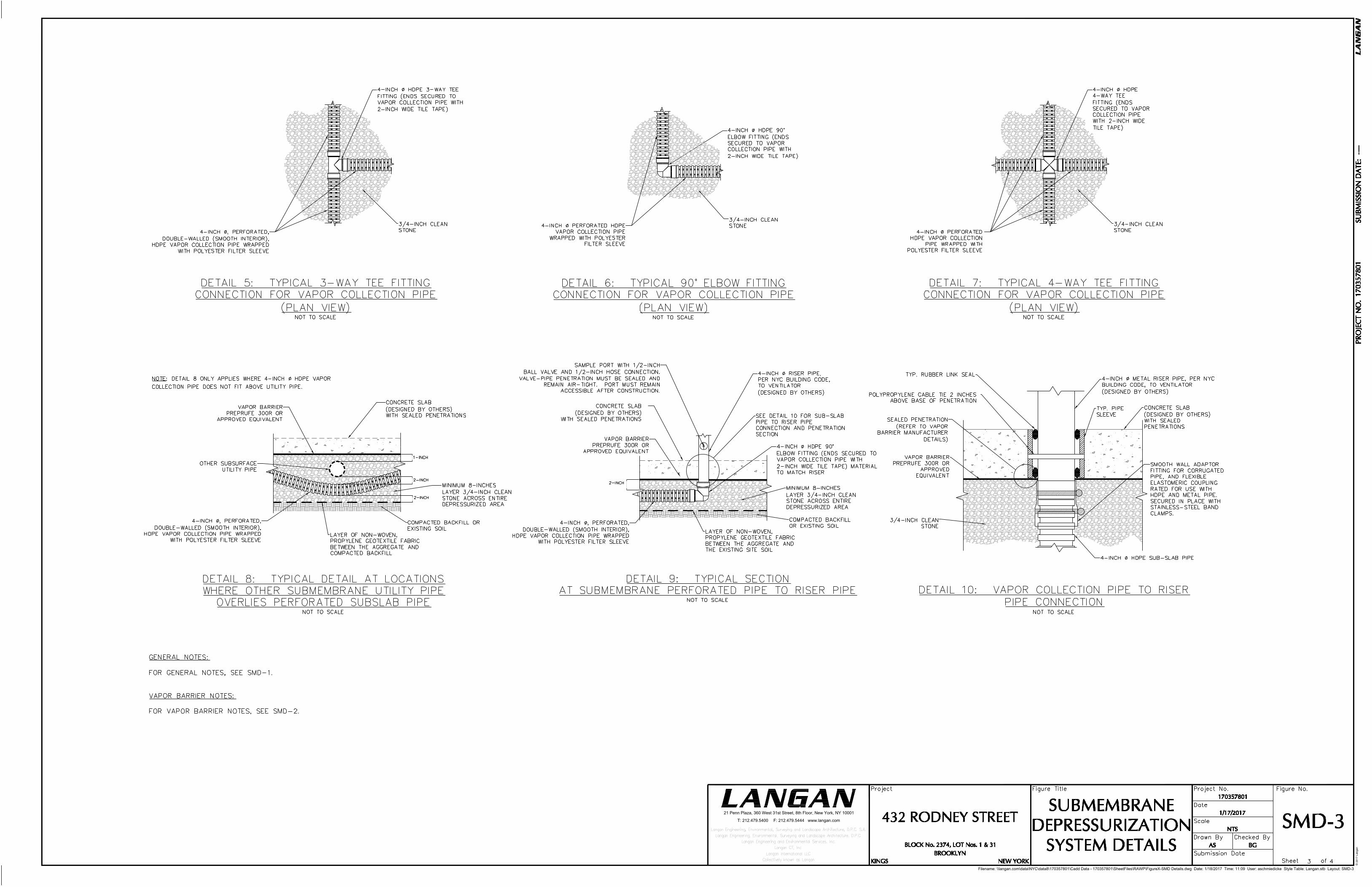
Filename: \\langan.com\data\NYC\data8\170357801\Cadd Data - 170357801\SheetFiles\RAWP\FigureX-SMD Details.dwg Date: 1/18/2017 Time: 11:09 User: aschmiedicke Style Table: Langan.stb Layout: SMD-3
21 Penn Plaza, 360 West 31st Street, 8th Floor, New York, NY 10001
T: 212.479.5400 F: 212.479.5444 www.langan.com
© 2
01
7 L
an
ga
n

AIRINLET
Filename: \\langan.com\data\NYC\data8\170357801\Cadd Data - 170357801\SheetFiles\RAWP\FigureX-SMD Details.dwg Date: 1/18/2017 Time: 11:11 User: aschmiedicke Style Table: Langan.stb Layout: SMD-4
21 Penn Plaza, 360 West 31st Street, 8th Floor, New York, NY 10001
T: 212.479.5400 F: 212.479.5444 www.langan.com
···
© 2
01
7 L
an
ga
n

APPENDIX I
QUALITY ASSURANCE PROTECTION PLAN

QUALITY ASSURANCE PROJECT PLAN
for
432 RODNEY STREET
BROOKLYN, NEW YORK NYSDEC BCP Site No. C224216
Prepared For:
Rodney Street Investors LLC
123 Hope Street Owner LLC &
Keap Retail Owner LLC
850 Third Avenue, Suite 13D
New York, New York 10022
Prepared By:
Langan Engineering, Environmental, Surveying
and Landscape Architecture, D.P.C.
21 Penn Plaza
360 West 31st Street, 8th Floor
New York, New York 10001
August 1, 2017
Langan Project No. 170357801

TABLE OF CONTENTS
PAGE
1.0 PROJECT DESCRIPTION ................................................................................. 1
1.1 Introduction ........................................................................................... 1
1.2 Project Objectives ................................................................................. 1
1.3 Scope of Work ....................................................................................... 2
2.0 DATA QUALITY OBJECTIVES AND PROCESS .............................................. 5
3.0 PROJECT ORGANIZATION ............................................................................. 7
4.0 QUALITY ASSURANCE OBJECTIVES FOR COLLECTION OF DATA ............. 8
4.1 Precision ................................................................................................ 8
4.2 Accuracy ................................................................................................ 8
4.3 Completeness ....................................................................................... 9
4.4 Representativeness ............................................................................... 9
4.5 Comparability ....................................................................................... 10
4.6 Sensitivity ............................................................................................ 10
5.0 SAMPLE COLLECTION AND FIELD DATA ACQUISITION PROCEDURES ... 12
5.1 Field Documentation Procedures ......................................................... 12
5.1.1 Field Data and Notes ............................................................. 12
5.1.2 Sample Labeling .................................................................... 13
5.2 Equipment Calibration and Preventative Maintenance ......................... 13
5.3 Sample Collection ................................................................................ 14
5.4 Sample Containers and Handling ......................................................... 15
5.5 Sample Preservation ............................................................................ 16
5.6 Sample Shipment ................................................................................ 16
5.6.1 Packaging .............................................................................. 16
5.6.2 Shipping ................................................................................. 16
5.7 Decontamination Procedures ............................................................... 17
5.8 Residuals Management ....................................................................... 17
5.9 Chain of Custody Procedures .............................................................. 17
5.10 Laboratory Sample Storage Procedures ............................................... 22
6.0 DATA REDUCTION, VALIDATION, AND REPORTING ................................. 23
6.1 Introduction ......................................................................................... 23
6.2 Data Reduction .................................................................................... 23
6.3 Data Validation ..................................................................................... 24
7.0 QUALITY ASSURANCE PERFORMANCE AUDITS AND SYSTEM AUDITS 26
7.1 Introduction ......................................................................................... 26
7.2 System Audits ..................................................................................... 26
7.3 Performance Audits ............................................................................. 26
7.4 Formal Audits ...................................................................................... 26

8.0 CORRECTIVE ACTION ................................................................................... 28
8.1 Introduction ......................................................................................... 28
8.2 Procedure Description ......................................................................... 28
9.0 REEFERENCES ............................................................................................... 31
FIGURES
Figure 1.3 Proposed Documentation Soil Sampling Plan .......................................................... 18
Figure 5.1 Sample Custody ...................................................................................................... 18
Figure 5.2 Chain-of-Custody Record - Air Samples ................................................................... 19
Figure 5.3 Chain-of-Custody Record - Soil and Groundwater Samples ..................................... 20
Figure 8.1 Corrective Action Request ....................................................................................... 29
ATTACHMENTS
Attachment A Résumés
Attachment B Laboratory Reporting Limits and Method Detection Limits
Attachment C Analytical Methods/Quality Assurance Summary Table
Attachment D Sample Nomenclature

1.0 PROJECT DESCRIPTION
1.1 INTRODUCTION
This Quality Assurance Project Plan (QAPP) was prepared on behalf of Rodney Street
Investors LLC, 123 Hope Street Owner LLC, and Keap Retail Owner LLC (the Volunteer)
for the property located at 432 Rodney Street in the Williamsburg neighborhood of
Brooklyn, New York (the “site”). The Volunteer will remediate the site in conjunction
with new development under the New York State Brownfield Cleanup Program (BCP),
pursuant to a Brownfield Cleanup Agreement (BCA) with the New York State
Department of Environmental Conservation (NYSDEC), dated September 30, 2015, and
amended April 8, 2016, for Site No. C224216. The site, subject to the Greenpoint-
Williamsburg rezoning, was assigned an environmental restrictive ‘E’ zoning designation
(E-138) for hazardous materials. Satisfaction of the ‘E’-Designation requirements is
subject to review and approval by the New York City Mayor’s Office of Environmental
Remediation (NYCOER).
This QAPP specifies analytical methods to be used to ensure that data collected during
Site management are precise, accurate, representative, comparable, complete, and
meet the sensitivity requirements of the project.
1.2 PROJECT OBJECTIVES
The environmental objectives of the Interim Remedial Measures Work Plan (IRMWP)
include the following:
Decommissioning two aboveground storage tank (ASTs) identified in the former
partial basements of Lots 1 and 31;
Decommissioning of suspected USTs at Lots 1 and 31;
Excavation of petroleum-impacted and chlorinated solvent-impacted soil at Lots
1 and 31 to the proposed development depth (about elevation [el.] 3 North
American Vertical Datum 1988 [NAVD88]);
Screening of excavated soil/fill during intrusive work for indications of
contamination by visual means, odor, and monitoring with a photoionization
detector (PID);
Appropriate off-site disposal of material removed from the site in accordance
with federal, state and local rules and regulations for handling, transport, and
disposal;

Collection and analysis of documentation soil samples to confirm NYSDEC Title
6 New York City Rules and Regulations (NYCRR) Part 375 Restricted-Use
Restricted Residential (RRU) Soil Cleanup Objectives (SCOs) have been
achieved;
Installation of engineering controls consisting of a vapor barrier/waterproofing
membrane, a sub-membrane depressurization system (SMDS), and a composite
cover (concrete building slab and two feet of clean fill in remaining landscaped
areas) as part of the construction of the proposed building at Lots 1 and 31;
Direct-injection of base-activated persulfate in the southeast corner of Lot 31 to
pretreat petroleum-related volatile organic compounds (VOCs) in groundwater;
Installation of a network of pressurized injection wells and groundwater
monitoring wells; and
Development and execution of a Health and Safety Plan (HASP) and Community
Air Monitoring Plan (CAMP) for the protection of on-site workers, the
community, and the environment during remediation and construction activities.
The environmental objectives of the Remedial Action Work Plan (RAWP) include the
following:
Implementation of a groundwater treatment program to treat petroleum-related
VOCs and chlorinated VOCs (CVOCs), consisting of direct injections of
PlumeStop on Lots 27 and 28 and an application of PlumeStop through the
network of pre-installed pressurized injection wells on Lots 1 and 31
Installation of a soil vapor mitigation system and rehabilitation of the concrete
slab on Lots 27 and 28
Accordingly, this QAPP addresses sampling and analytical methods that are necessary
as part of redevelopment. These objectives have been established in order to meet
standards that will protect public health and the environment for the site.
1.3 SCOPE OF WORK
Implementation of the IRMWP will include handling of contaminated soil and
groundwater and post excavation documentation soil sampling. Disturbed soil will be
sampled for laboratory analysis per disposal facility requirements, and visually examined,
screened, and characterized to determine whether it is suitable for re-use or will be

properly disposed at an approved disposal facility. A dust, odor, and organic vapor
control and monitoring plan will be implemented during ground intrusive activities.
The following activities were performed as part of the IRM:
Documentation Soil Sampling – Soil samples from the base of completed
excavations will be collected to document the quality of soil remaining
following source removal. These soil samples will be collected at the required
frequency as set forth in the NYSDEC Division of Environmental Remediation
(DER)-10, Technical Guidance for site Investigation and Remediation. The
samples will be analyzed for combined NYSDEC Title 6 New York City Rules
and Regulations (6 NYCRR) Part 375 list VOCs and SVOCs. Figure 1.3 shows a
proposed sampling plan for the documentation soil sampling.

2.0 DATA QUALITY OBJECTIVES AND PROCESS
Data Quality Objectives (DQOs) are qualitative and quantitative statements to help
ensure that data of known and appropriate quality are obtained during the project. The
overall objective is to evaluate the performance of the SMD through the collection of
canister air samples. The sampling program will also provide for collection of soil, soil
vapor, indoor air, or groundwater samples as part of a future need for sampling. DQOs
for sampling activities are determined by evaluating five factors:
Data needs and uses: The types of data required and how the data will be used
after it is obtained.
Parameters of Interest: The types of chemical or physical parameters required
for the intended use.
Level of Concern: Levels of constituents, which may require remedial actions or
further investigations.
Required Analytical Level: The level of data quality, data precision, and QA/QC
documentation required for chemical analysis.
Required Detection Limits: The detection limits necessary based on the above
information.
The quality assurance and quality control objectives for all measurement data include:
Precision – an expression of the reproducibility of measurements of the same
parameter under a given set of conditions. Field sampling precision will be
determined by analyzing coded duplicate samples and analytical precision will be
determined by analyzing internal QC duplicates and/or matrix spike duplicates.
Accuracy – a measure of the degree of agreement of a measured value with the
true or expected value of the quantity of concern. For soil and groundwater
samples, accuracy will be determined through the assessment of the analytical
results of field blanks and trip blanks for each sample set. Analytical accuracy
will be assessed by examining the percent recoveries of surrogate compounds
that are added to each sample (organic analyses only), internal standards,
laboratory method blanks, instrument calibration, and the percent recoveries of
matrix spike compounds added to selected samples and laboratory blanks.
For soil vapor or air samples, analytical accuracy will be assessed by examining
the percent recoveries that are added to each sample, internal standards,
laboratory method blanks, and instrument calibration.
Representativeness – expresses the degree to which sample data accurately
and precisely represent a characteristic of a population, parameter variations at a
sampling point, or an environmental condition. Representativeness is dependent
upon the adequate design of the sampling program and will be satisfied by
ensuring that the scope of work is followed and that specified sampling and
analysis techniques are used. Representativeness in the laboratory is ensured
by compliance to nationally-recognized analytical methods, meeting sample
holding times, and maintaining sample integrity while the samples are in the
laboratory’s possession. This is accomplished by following all applicable
methods, laboratory-issued standard operating procedures (SOPs), the
laboratory’s Quality Assurance Manual, and this QAPP. The laboratory is
required to be properly certified and accredited.
Completeness – the percentage of measurements made which are judged to be
valid. Completeness will be assessed through data validation. The QC objective
for completeness is generation of valid data for at least 90 percent of the
analyses requested.
Comparability – expresses the degree of confidence with which one data set
can be compared to another. The comparability of all data collected for this
project will be ensured using several procedures, including standard methods for
sampling and analysis as documented in the QAPP, using standard reporting
units and reporting formats, and data validation.
Sensitivity – the ability of the instrument or method to detect target analytes at
the levels of interest. The project manager will select, with input from the
laboratory and QA personnel, sampling and analytical procedures that achieve
the required levels of detection.

3.0 PROJECT ORGANIZATION
Any future remedial activities and investigations will be overseen by Langan or another
environmental consultant for the Volunteer or a future owner. The environmental
consultant will also arrange data analysis and reporting tasks. The analytical services
will be performed by an Environmental Laboratory Approval Program (ELAP)-certified
laboratory. Data validation services will be performed by approved data validation
contractor(s).
For the required sampling as stated in the IRMWP, sampling will be conducted by
Langan, the analytical services will be performed by Alpha Analytical Laboratories, Inc.
of Westborough, Massachusetts (NYSDOH ELAP certification number 11148). Data
validation services will be performed by Emily Strake of Langan. All Langan résumés
are attached (Attachment A).
Key contacts for this project are as follows:
123 Hope Street Owner LLC: Mr. Jesse Dorfman
Telephone: (646) 439-6000
Langan Project Manager: Mr. Brian Gochenaur
Telephone: (212) 479-5479
Langan Quality Assurance Officer (QAO):
Mr. Michael Burke, CHMM
Telephone: (212) 479-5582
Program Quality Assurance Monitor: Mr. Jason Hayes
Telephone: (212) 479-5427
Data Validator: Ms. Emily Strake
Telephone: (215) 491-6526
Laboratory Representative: Alpha Analytical Laboratories, Inc.
Mr. Ben Rao
Telephone: (201) 847-9100
Field Personnel:
Ms. Anna Schmiedicke
Telephone : (212) 479-5531

Quality Assurance Project Plan
432 Rodney Street
Brooklyn, New York
Project No. 170357801
4.0 QUALITY ASSURANCE OBJECTIVES FOR COLLECTION OF DATA
The overall quality assurance objective is to develop and implement procedures for
sampling, laboratory analysis, field measurements, and reporting that will provide data
of sufficient quality to evaluate the engineering controls on the site. The sample set,
chemical analysis results, and interpretations must be based on data that meet or
exceed quality assurance objectives established for the site. Quality assurance
objectives are usually expressed in terms of accuracy or bias, sensitivity, completeness,
representativeness, comparability, and sensitivity of analysis. Variances from the quality
assurance objectives at any stage of the investigation will result in the implementation
of appropriate corrective measures and an assessment of the impact of corrective
measures on the usability of the data.
4.1 PRECISION
Precision is a measure of the degree to which two or more measurements are in
agreement. Field precision is assessed through the collection and measurement of field
duplicates. Laboratory precision and sample heterogeneity also contribute to the
uncertainty of field duplicate measurements. This uncertainty is taken into account
during the data assessment process. For field duplicates, results less than 2x the
reporting limit (RL) meet the precision criteria if the absolute difference is less than ±2x
the RL and acceptable based on professional judgment. For results greater than 2x the
RL, the acceptance criteria is a relative percent difference (RPD) of ≤50% (soil and air),
<30% (water). RLs and method detection limits (MDL) are provided in Attachment B.
4.2 ACCURACY
Accuracy is the measurement of the reproducibility of the sampling and analytical
methodology. It should be noted that precise data may not be accurate data. For the
purpose of this QAPP, bias is defined as the constant or systematic distortion of a
measurement process, which manifests itself as a persistent positive or negative
deviation from the known or true value. This may be due to (but not limited to)
improper sample collection, sample matrix, poorly calibrated analytical or sampling
equipment, or limitations or errors in analytical methods and techniques.
Accuracy in the field is assessed through the use of field blanks and through compliance
to all sample handling, preservation, and holding time requirements. All field blanks
should be non-detect when analyzed by the laboratory. Any contaminant detected in an
associated field blank will be evaluated against laboratory blanks (preparation or method)
Quality Assurance Project Plan
432 Rodney Street
Brooklyn, New York
Project No. 170357801
and evaluated against field samples collected on the same day to determine potential
for bias. Trip blanks are not required for non-aqueous matrices but are planned for non-
aqueous matrices where high concentrations of VOCs are anticipated.
Laboratory accuracy is assessed by evaluating the percent recoveries of matrix
spike/matrix spike duplicate (MS/MSD) samples, laboratory control samples (LCS),
surrogate compound recoveries, and the results of method preparation blanks.
MS/MSD, LCS, and surrogate percent recoveries will be compared to either method-
specific control limits or laboratory-derived control limits. Sample volume permitting,
samples displaying outliers should be reanalyzed. All associated method blanks should
be non-detect when analyzed by the laboratory.
4.3 COMPLETENESS
Laboratory completeness is the ratio of total number of samples analyzed and verified
as acceptable compared to the number of samples submitted to the fixed-base
laboratory for analysis, expressed as a percent. Three measures of completeness are
defined:
Sampling completeness, defined as the number of valid samples collected
relative to the number of samples planned for collection;
Analytical completeness, defined as the number of valid sample measurements
relative to the number of valid samples collected; and
Overall completeness, defined as the number of valid sample measurements
relative to the number of samples planned for collection.
Air, soil vapor, soil, and groundwater data will meet a 90% completeness criterion. If
the criterion is not met, sample results will be evaluated for trends in rejected and
unusable data. The effect of unusable data required for a determination of compliance
will also be evaluated.
4.4 REPRESENTATIVENESS
Representativeness expresses the degree to which data accurately and precisely
represents a characteristic of a population, parameter variations at a sampling point, a
process condition, or an environmental condition within a defined spatial and/or
temporal boundary. Representativeness is dependent upon the adequate design of the
sampling program and will be satisfied by ensuring that the scope of work is followed

Quality Assurance Project Plan
432 Rodney Street
Brooklyn, New York
Project No. 170357801
and that specified sampling and analysis techniques are used. This is performed by
following applicable standard operating procedures (SOPs) and this QAPP. All field
technicians will be given copies of appropriate documents prior to sampling events and
are required to read, understand, and follow each document as it pertains to the tasks at
hand.
Representativeness in the laboratory is ensured by compliance to nationally-recognized
analytical methods, meeting sample holding times, and maintaining sample integrity
while the samples are in the laboratory's possession. This is performed by following all
applicable EPA methods, laboratory-issued SOPs, the laboratory’s Quality Assurance
Manual, and this QAPP. The laboratory is required to be properly certified and
accredited.
4.5 COMPARABILITY
Comparability is an expression of the confidence with which one data set can be
compared to another. Comparability is dependent upon the proper design of the
sampling program and will be satisfied by ensuring that the sampling plan is followed
and that sampling is performed according to the SOPs or other project-specific
procedures. Analytical data will be comparable when similar sampling and analytical
methods are used as documented in the QAPP. Comparability will be controlled by
requiring the use of specific nationally-recognized analytical methods and requiring
consistent method performance criteria. Comparability is also dependent on similar
quality assurance objectives. Previously collected data will be evaluated to determine
whether they may be combined with contemporary data sets.
4.6 SENSITIVITY
Sensitivity is the ability of the instrument or method to detect target analytes at the
levels of interest. The project director will select, with input from the laboratory and QA
personnel, sampling and analytical procedures that achieve the required levels of
detection and QC acceptance limits that meet established performance criteria.
Concurrently, the project director will select the level of data assessment to ensure that
only data meeting the project DQOs are used in decision-making.
Field equipment will be used that can achieve the required levels of detection for
analytical measurements in the field. In addition, the field sampling staff will collect and
submit full volumes of samples as required by the laboratory for analysis, whenever
possible. Full volume aliquots will help ensure achievement of the required limits of

Quality Assurance Project Plan
432 Rodney Street
Brooklyn, New York
Project No. 170357801
detection and allow for reanalysis if necessary. The concentration of the lowest level
check standard in a multi-point calibration curve will represent the reporting limit.
Analytical methods and quality assurance parameters associated with the sampling
program are presented in Attachment C. The frequency of associated field blanks and
duplicate samples will be based on the recommendations listed in DER-10, and as
described in Section 5.3.
Site-specific MS and MSD samples will be prepared and analyzed by the analytical
laboratory by spiking an aliquot of submitted sample volume with analytes of interest.
Additional sample volume is not required by the laboratory for this purpose. An
MS/MSD analysis will be analyzed at a rate of 1 out of every 20 samples, or one per
analytical batch. MS/MSD samples are only required for soil and groundwater samples.

Quality Assurance Project Plan
432 Rodney Street
Brooklyn, New York
Project No. 170357801
5.0 SAMPLE COLLECTION AND FIELD DATA ACQUISITION PROCEDURES
Soil sampling will be conducted in accordance with the established NYSDEC protocols
contained in DER-10/Technical Guidance for Site Investigation and Remediation (May
2010). The following sections describe procedures to be followed for specific tasks.
5.1 FIELD DOCUMENTATION PROCEDURES
Field documentation procedures will include summarizing field data in field books and
proper sample labeling. These procedures are described in the following sections.
5.1.1 Field Data and Notes
Field notebooks contain the documentary evidence regarding procedures conducted by
field personnel. Hard cover, bound field notebooks will be used because of their
compact size, durability, and secure page binding. The pages of the notebook will not
be removed.
Entries will be made in waterproof, permanent blue or black ink. No erasures will be
allowed. If an incorrect entry is made, the information will be crossed out with a single
strike mark and the change initialed and dated by the team member making the change.
Each entry will be dated. Entries will be legible and contain accurate and complete
documentation of the individual or sampling team’s activities or observations made. The
level of detail will be sufficient to explain and reconstruct the activity conducted. Each
entry will be signed by the person(s) making the entry.
The following types of information will be provided for each sampling task, as
appropriate:
Project name and number
Reasons for being on-site or taking the sample
Date and time of activity
Sample identification numbers
Geographical location of sampling points with references to the site, other
facilities or a map coordinate system. Sketches will be made in the field logbook
when appropriate

Quality Assurance Project Plan
432 Rodney Street
Brooklyn, New York
Project No. 170357801
Physical location of sampling locations such as depth below ground surface
Description of the method of sampling including procedures followed,
equipment used and any departure from the specified procedures
Description of the sample including physical characteristics, odor, etc.
Readings obtained from health and safety equipment
Weather conditions at the time of sampling and previous meteorological events
that may affect the representative nature of a sample
Photographic information including a brief description of what was
photographed, the date and time, the compass direction of the picture and the
number of the picture on the camera
Other pertinent observations such as the presence of other persons on the site,
actions by others that may affect performance of site tasks, etc.
Names of sampling personnel and signature of persons making entries
Field records will also be collected on field data sheets including boring logs, which will
be used for geologic and drilling data during soil boring activities. Field data sheets will
include the project-specific number and stored in the field project files when not in use.
At the completion of the field activities, the field data sheets will be maintained in the
central project file.
5.1.2 Sample Labeling
Each sample collected will be assigned a unique identification number in accordance
with the sample nomenclature guidance included in Attachment D, and placed in an
appropriate sample container. Each sample container will have a sample label affixed to
the outside with the date and time of sample collection and project name. In addition,
the label will contain the sample identification number, analysis required and chemical
preservatives added, if any. All documentation will be completed in waterproof ink.
5.2 EQUIPMENT CALIBRATION AND PREVENTATIVE MAINTENANCE
A PID will be used during the sampling activities to evaluate work zone action levels and
screen soil samples. Field calibration and/or field checking of the PID will be the

Quality Assurance Project Plan
432 Rodney Street
Brooklyn, New York
Project No. 170357801
responsibility of the field team leader and the site HSO, and will be accomplished by
following the procedures outlined in the operating manual for the instrument. At a
minimum, field calibration and/or field equipment checking will be performed once daily,
prior to use. Field calibration will be documented in the field notebook. Entries made
into the logbook regarding the status of field equipment will include the following
information:
Date and time of calibration
Type of equipment serviced and identification number (such as serial number)
Reference standard used for calibration
Calibration and/or maintenance procedure used
Other pertinent information
Equipment that fails calibration or becomes inoperable during use will be removed from
service and segregated to prevent inadvertent utilization. The equipment will be
properly tagged to indicate that it is out of calibration. Such equipment will be repaired
and recalibrated to the manufacturer’s specifications by qualified personnel. Equipment
that cannot be repaired will be replaced.
Off-site calibration and maintenance of field instruments will be conducted as
appropriate throughout the duration of project activities. All field instrumentation,
sampling equipment and accessories will be maintained in accordance with the
manufacturer’s recommendations and specifications and established field equipment
practice. Off-site calibration and maintenance will be performed by qualified personnel.
A logbook will be kept to document that established calibration and maintenance
procedures have been followed. Documentation will include both scheduled and
unscheduled maintenance.
5.3 SAMPLE COLLECTION
Soil Samples
Soil samples will be visually classified and field screened using a PID to assess potential
impacts from VOCs and for health and safety monitoring. Soil samples collected for
analysis of VOCs will be collected using either EnCore® or Terra Core® sampling
equipment. For analysis of non-volatile parameters, samples will be homogenized and

Quality Assurance Project Plan
432 Rodney Street
Brooklyn, New York
Project No. 170357801
placed into glass jars. After collection, all sample jars will be capped and securely
tightened, and placed in iced coolers and maintained at 4°C ±2°C until they are
transferred to the laboratory for analysis, in accordance with the procedures outlined in
Section 5.4. Analysis and/or extraction and digestion of collected soil samples will meet
the holding times required for each analyte as specified in Attachment C. In addition,
analysis of collected soil sample will meet all quality assurance criteria set forth by this
QAPP and DER-10.
Sample Field Blanks and Duplicates
Field blanks will be collected for quality assurance purposes at a rate of one per 20 soil
investigations samples per analysis. Field blanks will be obtained by pouring laboratory-
demonstrated analyte-free water on or through a decontaminated sampling device
following use and implementation of decontamination protocols. The water will be
collected off of the sampling device into a laboratory-provided sample container for
analysis. Field blank samples will be analyzed for the complete list of analytes on the
day of sampling. Trip blanks will be collected at a rate of one per day if soil samples are
analyzed for VOCs during that day.
Duplicate soil samples will be collected and analyzed for quality assurance purposes.
Duplicate samples will be collected at a frequency of 1 per 20 investigative soil samples
per analysis and will be submitted to the laboratory as “blind” samples. If less than 20
samples are collected during a particular sampling event, one duplicate sample will be
collected.
5.4 SAMPLE CONTAINERS AND HANDLING
Certified, commercially clean sample containers will be obtained from the analytical
laboratory. If soil or groundwater samples are being collected, the laboratory will also
prepare and supply the required trip blanks and field blank sample containers and
reagent preservatives. Sample bottle containers, including the field blank containers,
will be placed into plastic coolers by the laboratory. These coolers will be received by
the field sampling team within 24 hours of their preparation in the laboratory. Prior to
the commencement of field work, Langan field personnel will fill the plastic coolers with
ice in Ziploc® bags (or equivalent) to maintain a temperature of 4° ±2° C.
Soil samples collected in the field for laboratory analysis will be placed directly into the
laboratory-supplied sample containers. Samples will then be placed and stored on-ice in
laboratory provided coolers until shipment to the laboratory. The temperature in the

Quality Assurance Project Plan
432 Rodney Street
Brooklyn, New York
Project No. 170357801
coolers containing samples and associated field blanks will be maintained at a
temperature of 4°±2°C while on-site and during sample shipment to the analytical
laboratory.
Possession of samples collected in the field will be traceable from the time of collection
until they are analyzed by the analytical laboratory or are properly disposed. Chain-of-
custody procedures, described in Section 5.9, will be followed to maintain and
document sample possession. Samples will be packaged and shipped as described in
Section 5.6.
5.5 SAMPLE PRESERVATION
Sample preservation measures will be used in an attempt to prevent sample
decomposition by contamination, degradation, biological transformation, chemical
interactions and other factors during the time between sample collection and analysis.
Preservation will commence at the time of sample collection and will continue until
analyses are performed. Should chemical preservation be required, the analytical
laboratory will add the preservatives to the appropriate sample containers before
shipment to the office or field. Samples will be preserved according to the
requirements of the specific analytical method selected, as shown in Attachment C.
5.6 SAMPLE SHIPMENT
5.6.1 Packaging
Soil sample containers will be placed in plastic coolers. Ice in Ziploc® bags (or
equivalent) will be placed around sample containers. Cushioning material will be added
around the sample containers if necessary. Chains-of-custody and other paperwork will
be placed in a Ziploc® bag (or equivalent) and placed inside the cooler. The cooler will be
taped closed and custody seals will be affixed to one side of the cooler at a minimum.
If the samples are being shipped by an express delivery company (e.g. FedEx) then
laboratory address labels will be placed on top of the cooler.
5.6.2 Shipping
Standard procedures to be followed for shipping environmental samples to the analytical
laboratory are outlined below.
All environmental samples will be transported to the laboratory by a laboratory-
provided courier under the chain-of-custody protocols described in Section 5.9.
Quality Assurance Project Plan
432 Rodney Street
Brooklyn, New York
Project No. 170357801
Prior notice will be provided to the laboratory regarding when to expect shipped
samples. If the number, type or date of shipment changes due to site
constraints or program changes, the laboratory will be informed.
5.7 DECONTAMINATION PROCEDURES
Decontamination procedures will be used for non-dedicated sampling equipment.
Decontamination of field personnel is discussed in the site-specific HASP included in
Appendix B of the IRMWP. Field sampling equipment that is to be reused will be
decontaminated in the field in accordance with the following procedures:
1. Laboratory-grade glassware detergent and tap water scrub to remove visual
contamination
2. Generous tap water rinse
3. Distilled/de-ionized water rinse
5.8 RESIDUALS MANAGEMENT
Debris (e.g., paper, plastic and disposable PPE) will be collected in plastic garbage bags
and disposed of as non-hazardous industrial waste. Debris is expected to be
transported to a local municipal landfill for disposal. If applicable, residual solids (e.g.,
leftover soil cuttings) will be placed back in the borehole from which it was sampled. If
gross contamination is observed, soil will be collected and stored in Department of
Transportation (DOT)-approved 55-gallon drums in a designated storage area at the Site.
The residual materials stored in a designated storage area at the site for further
characterization, treatment or disposal.
Residual fluids (such as purge water) will be collected and stored in DOT-approved (or
equivalent) 55-gallon drums in a designated storage area at the site. The residual fluids
will be transported to the on-site wastewater treatment plant or analyzed, characterized
and disposed off-site in accordance with applicable federal and state regulations.
Residual fluids such as decontamination water may be discharged to the ground
surface, however, if gross contamination is observed, the residual fluids will be
collected, stored, and transported similar purge water or other residual fluids.
5.9 CHAIN OF CUSTODY PROCEDURES
A chain-of-custody protocol has been established for collected samples that will be
followed during sample handling activities in both field and laboratory operations. The

Quality Assurance Project Plan
432 Rodney Street
Brooklyn, New York
Project No. 170357801
primary purpose of the chain-of-custody procedures is to document the possession of
the samples from collection through shipping, storage and analysis to data reporting and
disposal. Chain-of-custody refers to actual possession of the samples. Samples are
considered to be in custody if they are within sight of the individual responsible for their
security or locked in a secure location. Each person who takes possession of the
samples, except the shipping courier, is responsible for sample integrity and safe
keeping. Chain-of-custody procedures are provided below:
Chain-of-custody will be initiated by the laboratory supplying the pre-cleaned and
prepared sample containers. Chain-of-custody forms will accompany the sample
containers.
Following sample collection, the chain-of-custody form will be completed for the
sample collected. The sample identification number, date and time of sample
collection, analysis requested and other pertinent information (e.g.,
preservatives) will be recorded on the form. All entries will be made in
waterproof, permanent blue or black ink.
Langan field personnel will be responsible for the care and custody of the
samples collected until the samples are transferred to another party, dispatched
to the laboratory, or disposed. The sampling team leader will be responsible for
enforcing chain-of-custody procedures during field work.
When the form is full or when all samples have been collected that will fit in a
single cooler, the sampling team leader will check the form for possible errors
and sign the chain-of-custody form. Any necessary corrections will be made to
the record with a single strike mark, dated, and initialed.
Sample coolers will be accompanied by the chain-of-custody form, sealed in a Ziploc®
bag (or equivalent) and placed on top of the samples or taped to the inside of the cooler
lid. If applicable, a shipping bill will be completed for each cooler and the shipping bill
number recorded on the chain-of-custody form.
Samples will be packaged for shipment to the laboratory with the appropriate chain-of-
custody form. A copy of the form will be retained by the sampling team for the project
file and the original will be sent to the laboratory with the samples. Bills of lading will
also be retained as part of the documentation for the chain-of-custody records, if
applicable. When transferring custody of the samples, the individuals relinquishing and
receiving custody of the samples will verify sample numbers and condition and will
document the sample acquisition and transfer by signing and dating the chain-of-

Quality Assurance Project Plan
432 Rodney Street
Brooklyn, New York
Project No. 170357801
custody form. This process documents sample custody transfer from the sampler to
the analytical laboratory. A flow chart showing a sample custody process is included as
Figure 5.1, and chain-of-custody forms from York are included as Figures 5.2 and 5.3.
Figure 5.1 Sample Custody
* REQUIRES SIGN-OFF ON CHAIN-OF-CUSTODY FORM
PREPARATION OF
SAMPLE CONTAINERS
SAMPLES COLLECTED
BY SAMPLING TEAM
SAMPLES
LABELED
SEALED IN INSULATED
COOLER WITH ICE*
SHIPMENT TO
LABORATORY
SAMPLE RECEIPT
AT LAB *
CHECK SAMPLE
INTEGRITY *
STORAGE IN
SECURE AREA
CORRECTIVE ACTION
IF REQUIRED
CHECK OUT
FOR ANALYSIS *
RETURN TO
STORAGE OR
DISPOSAL

Quality Assurance Project Plan
432 Rodney Street
Brooklyn, New York
Project No. 170357801
Figure 5.2 Sample Chain-of-Custody Form – Air Sample

Quality Assurance Project Plan
432 Rodney Street
Brooklyn, New York
Project No. 170357801
Figure 5.3 Sample Chain-of-Custody Form – Soil and Groundwater

Quality Assurance Project Plan
432 Rodney Street
Brooklyn, New York
Project No. 170357801
Laboratory chain-of-custody will be maintained throughout the analytical processes as
described in the laboratory’s Quality Assurance Manual. The analytical laboratory will
provide a copy of the chain-of-custody in the analytical data deliverable package. The
chain-of-custody becomes the permanent record of sample handling and shipment.
5.10 LABORATORY SAMPLE STORAGE PROCEDURES
The subcontracted laboratory will use a laboratory information management system
(LIMS) to track and schedule samples upon receipt by the analytical laboratories. Any
sample anomalies identified during sample log-in must be evaluated on individual merit
for the impact upon the results and the data quality objectives of the project. When
irregularities do exist, the environmental consultant must be notified to discuss
recommended courses of action and documentation of the issue must be included in
the project file.
For samples requiring thermal preservation, the temperature of each cooler will be
immediately recorded. Each sample and container will be will be assigned a unique
laboratory identification number and secured within the custody room walk-in coolers
designated for new samples. Samples will be, as soon as practical, disbursed in a
manner that is functional for the operational team. The temperature of all coolers and
freezers will be monitored and recorded using a certified temperature sensor. Any
temperature excursions outside of acceptance criteria (i.e., below 2°C or above 6°C) will
initiate an investigation to determine whether any samples may have been affected.
Samples for VOCs will be maintained in satellite storage areas within the VOC
laboratory. Following analysis, the laboratory’s specific procedures for retention and
disposal will be followed as specified in the laboratory’s SOPs and/or QA manual.

Quality Assurance Project Plan
432 Rodney Street
Brooklyn, New York
Project No. 170357801
6.0 DATA REDUCTION, VALIDATION, AND REPORTING
6.1 INTRODUCTION
Data collected during the field investigation will be reduced and reviewed by the
laboratory QA personnel, and a report on the findings will be tabulated in a standard
format. The criteria used to identify and quantify the analytes will be those specified for
the applicable methods in the USEPA SW-846 and subsequent updates. The data
package provided by the laboratory will contain all items specified in the USEPA SW-846
appropriate for the analyses to be performed, and be reported in standard format.
The completed copies of the chain-of-custody records (both external and internal)
accompanying each sample from time of initial bottle preparation to completion of
analysis shall be attached to the analytical reports.
6.2 DATA REDUCTION
The Analytical Services Protocol (ASP) Category B data packages and an electronic data
deliverable (EDD) will be provided by the laboratory after receipt of a complete sample
delivery group. The Project Manager will immediately arrange for archiving the results
and preparation of result tables. These tables will form the database for assessment of
the site contamination condition.
Each EDD deliverable must be formatted using a Microsoft Windows operating system
and the NYSDEC data deliverable format for EQuIS. To avoid transcription errors, data
will be loaded directly into the ASCII format from the laboratory information
management system (LIMS). If this cannot be accomplished, the consultant should be
notified via letter of transmittal indicating that manual entry of data is required for a
particular method of analysis. All EDDs must also undergo a QC check by the laboratory
before delivery. The original data, tabulations, and electronic media are stored in a
secure and retrievable fashion.
The Project Manager or Task Manager will maintain close contact with the QA reviewer
to ensure all non-conformance issues are acted upon prior to data manipulation and
assessment routines. Once the QA review has been completed, the Project Manager
may direct the Team Leaders or others to initiate and finalize the analytical data
assessment.

Quality Assurance Project Plan
432 Rodney Street
Brooklyn, New York
Project No. 170357801
6.3 DATA VALIDATION
Data validation will be performed in accordance with the USEPA validation guidelines for
organic and inorganic data review. Validation will include the following:
Verification of the QC sample results,
Verification of the identification of sample results (both positive hits and non-
detects),
Recalculation of 10% of all investigative sample results, and
Preparation of Data Usability Summary Reports (DUSR).
A DUSR will be prepared and reviewed by the QAO before issuance. The DUSR will
present the results of data validation, including a summary assessment of laboratory
data packages, sample preservation and COC procedures, and a summary assessment
of precision, accuracy, representativeness, comparability, and completeness for each
analytical method. A detailed assessment of each SDG will follow. For each of the
organic analytical methods, the following will be assessed:
Holding times;
Instrument tuning;
Instrument calibrations;
Blank results;
System monitoring compounds or surrogate recovery compounds (as
applicable);
Internal standard recovery results;
MS and MSD results;
Target compound identification;
Chromatogram quality;
Pesticide cleanup (if applicable);
Compound quantitation and reported detection limits;
System performance; and
Results verification.
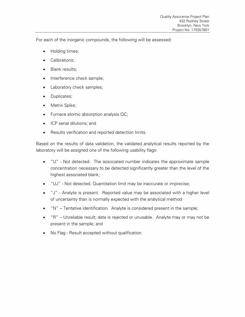
Quality Assurance Project Plan
432 Rodney Street
Brooklyn, New York
Project No. 170357801
For each of the inorganic compounds, the following will be assessed:
Holding times;
Calibrations;
Blank results;
Interference check sample;
Laboratory check samples;
Duplicates;
Matrix Spike;
Furnace atomic absorption analysis QC;
ICP serial dilutions; and
Results verification and reported detection limits.
Based on the results of data validation, the validated analytical results reported by the
laboratory will be assigned one of the following usability flags:
“U” - Not detected. The associated number indicates the approximate sample
concentration necessary to be detected significantly greater than the level of the
highest associated blank;
“UJ” - Not detected. Quantitation limit may be inaccurate or imprecise;
“J” - Analyte is present. Reported value may be associated with a higher level
of uncertainty than is normally expected with the analytical method
“N” – Tentative identification. Analyte is considered present in the sample;
“R” – Unreliable result; data is rejected or unusable. Analyte may or may not be
present in the sample; and
No Flag - Result accepted without qualification.

Quality Assurance Project Plan
432 Rodney Street
Brooklyn, New York
Project No. 170357801
7.0 QUALITY ASSURANCE PERFORMANCE AUDITS AND SYSTEM AUDITS
7.1 INTRODUCTION
Quality assurance audits may be performed by the project quality assurance group
under the direction and approval of the QAO. These audits will be implemented to
evaluate the capability and performance of project and subcontractor personnel, items,
activities, and documentation of the measurement system(s). Functioning as an
independent body and reporting directly to corporate quality assurance management,
the QAO may plan, schedule, and approve system and performance audits based upon
procedures customized to the project requirements. At times, the QAO may request
additional personnel with specific expertise from company and/or project groups to
assist in conducting performance audits. However, these personnel will not have
responsibility for the project work associated with the performance audit.
7.2 SYSTEM AUDITS
System audits may be performed by the QAO or designated auditors, and encompass a
qualitative evaluation of measurement system components to ascertain their
appropriate selection and application. In addition, field and laboratory quality control
procedures and associated documentation may be system audited. These audits may
be performed once during the performance of the project. However, if conditions
adverse to quality are detected or if the Project Manager requests, additional audits may
occur.
7.3 PERFORMANCE AUDITS
The laboratory may be required to conduct an analysis of Performance Evaluation
samples or provide proof that Performance Evaluation samples submitted by USEPA or
a state agency have been analyzed within the past twelve months.
7.4 FORMAL AUDITS
Formal audits refer to any system or performance audit that is documented and
implemented by the QA group. These audits encompass documented activities
performed by qualified lead auditors to a written procedure or checklists to objectively
verify that quality assurance requirements have been developed, documented, and
instituted in accordance with contractual and project criteria. Formal audits may be
performed on project and subcontractor work at various locations.

Quality Assurance Project Plan
432 Rodney Street
Brooklyn, New York
Project No. 170357801
Audit reports will be written by auditors who have performed the site audit after
gathering and evaluating all data. Items, activities, and documents determined by lead
auditors to be in noncompliance shall be identified at exit interviews conducted with the
involved management. Non-compliances will be logged, and documented through audit
findings, which are attached to and are a part of the integral audit report. These audit-
finding forms are directed to management to satisfactorily resolve the noncompliance in
a specified and timely manner.
The Project Manager has overall responsibility to ensure that all corrective actions
necessary to resolve audit findings are acted upon promptly and satisfactorily. Audit
reports must be submitted to the Project Manager within fifteen days of completion of
the audit. Serious deficiencies will be reported to the Project Manager within 24 hours.
All audit checklists, audit reports, audit findings, and acceptable resolutions are
approved by the QAO prior to issue. Verification of acceptable resolutions may be
determined by re-audit or documented surveillance of the item or activity. Upon
verification acceptance, the QAO will close out the audit report and findings.

Quality Assurance Project Plan
432 Rodney Street
Brooklyn, New York
Project No. 170357801
8.0 CORRECTIVE ACTION
8.1 INTRODUCTION
The following procedures have been established to ensure that conditions adverse to
quality, such as malfunctions, deficiencies, deviations, and errors, are promptly
investigated, documented, evaluated, and corrected.
8.2 PROCEDURE DESCRIPTION
When a significant condition adverse to quality is noted at site, laboratory, or
subcontractor location, the cause of the condition will be determined and corrective
action will be taken to preclude repetition. Condition identification, cause, reference
documents, and corrective action planned to be taken will be documented and reported
to the QAO, Project Manager, Field Team Leader and involved contractor management,
at a minimum. Implementation of corrective action is verified by documented follow-up
action.
All project personnel have the responsibility, as part of the normal work duties, to
promptly identify, solicit approved correction, and report conditions adverse to quality.
Corrective actions will be initiated as follows:
When predetermined acceptance standards are not attained;
When procedure or data compiled are determined to be deficient;
When equipment or instrumentation is found to be faulty;
When samples and analytical test results are not clearly traceable;
When quality assurance requirements have been violated;
When designated approvals have been circumvented;
As a result of system and performance audits;
As a result of a management assessment;
As a result of laboratory/field comparison studies; and
As required by USEPA SW-846, and subsequent updates, or by the NYSDEC
ASP.
Project management and staff, such as field investigation teams, remedial response
planning personnel, and laboratory groups, monitor on-going work performance in the

Quality Assurance Project Plan
432 Rodney Street
Brooklyn, New York
Project No. 170357801
normal course of daily responsibilities. Work may be audited at the sites, laboratories,
or contractor locations. Activities, or documents ascertained to be noncompliant with
quality assurance requirements will be documented. Corrective actions will be
mandated through audit finding sheets attached to the audit report. Audit findings are
logged, maintained, and controlled by the Task Manager.
Personnel assigned to quality assurance functions will have the responsibility to issue
and control Corrective Action Request (CAR) Forms (Figure 12.1 or similar). The CAR
identifies the out-of-compliance condition, reference document(s), and recommended
corrective action(s) to be administered. The CAR is issued to the personnel responsible
for the affected item or activity. A copy is also submitted to the Project Manager. The
individual to whom the CAR is addressed returns the requested response promptly to
the QA personnel, affixing his/her signature and date to the corrective action block, after
stating the cause of the conditions and corrective action to be taken. The QA personnel
maintain the log for status of CARs, confirms the adequacy of the intended corrective
action, and verifies its implementation. CARs will be retained in the project file for the
records.
Any project personnel may identify noncompliance issues; however, the designated QA
personnel are responsible for documenting, numbering, logging, and verifying the close
out action. The Project Manager will be responsible for ensuring that all recommended
corrective actions are implemented, documented, and approved.

Quality Assurance Project Plan
432 Rodney Street
Brooklyn, New York
Project No. 170357801
CORRECTIVE ACTION REQUEST
Number: __________________________ Date: ____________
TO: _________________________________________
You are hereby requested to take corrective actions indicated below and as otherwise determined by you to (a) resolve the noted condition and (b) to prevent it from recurring. Your written response is to be returned to the project quality assurance manager by _______________
CONDITION:
REFERENCE DOCUMENTS:
RECOMMENDED CORRECTIVE ACTIONS:
__________ ______ __________ ________ ___________ ________
Originator Date Approval Date Approval Date
RESPONSE
CAUSE OF CONDITION
CORRECTIVE ACTION
(A) RESOLUTION
(B) PREVENTION
(C) AFFECTED DOCUMENTS
C.A. FOLLOWUP:
CORRECTIVE ACTION VERIFIED BY: ____________________________ DATE:_____________
FIGURE 8.1

9.0 REFERENCES
NYSDEC. Division of Environmental Remediation. DER-10/Technical Guidance for Site
Investigation and Remediation, dated May 3, 2010.
Taylor, J. K., 1987. Quality Assurance of Chemical Measurements. Lewis Publishers, Inc.,
Chelsea, Michigan
USEPA, 1986. SW-846 "Test Method for Evaluating Solid Waste," dated November 1986.
U.S. Environmental Protection Agency, Washington, D.C.
USEPA, 1987. Data Quality Objectives for Remedial Response Actions Activities:
Development Process, EPA/540/G-87/003, OSWER Directive 9355.0-7- U.S.
Environmental Protection Agency, Washington, D.C.
USEPA, 1992a. CLP Organics Data Review and Preliminary Review. SOP No.
HW-6, Revision #8, dated January 1992. USEPA Region II.
USEPA, 1992b. Evaluation of Metals Data for the Contract Laboratory Program (CLP)
based on SOW 3/90. SOP No. HW-2, Revision XI, dated January 1992. USEPA
Region II.
USEPA. Hazardous Waste Support Section. Analysis of Volatile Organic Compounds in Air
Contained in Canisters by Method TO-15. SOP No. HW-31, Revision #6, dated June
2014.

APPENDIX J
INSPECTION FORMS AND CHECKLISTS

���������������� ����������������� �������������������� ����!"#���$����� �%���������$�����&'(�)�*���+���(��$�����, ����(�-"�$(� ."�(� �"���+#(��"���+���(�)�*���)����"� /����0#*�(�,��1�/����0#*�(�2���������� �%��������&*��������+���(�/����0#*�(� -#���*$(�34�������2�������� 5�"� "*6�/$��(���7�&*��6�"�$( 8##� ,!���6� 9## :;�����*����7�8�*�����"#*�( ���� <�##�� ��"* 8��"������ ��"* )�0��'����"7�()7���!� �=����( '�$ '��� �����#*�$ ���* "*6'����"7�(����� ����������&*�������"#*�/$��(���7�/0"�>����?"*�0��@(��7���7�A����"��(+��7���#B�����"#*�8#"*��( '����&*������ (��7���7�A#"�����(+��7���#B�<�*��&*������ (<�*�A# ���+#?�@(<�*����"���+#?�@(<"*���CD/�7��E�!���( <�*�FG�)�����"*6 <�*�FH�)�����"*6 <�*�FI�)�����"*6, "�"#*���A"�"6��"#*�:����*���?�0��>������0�������$@('��"*J�� A��7��*� ����� �����>� +���B�##� K�"*���� )�0��-#���*��( A"�"6��"#*��$�����&*�������"#*

2���4���������L�����/����A��0# ( A�����/$��MA�*�B�������(�E#���"#* K�� "*6MK����� '"��1�<�#������"#*�8#"*��?B�@ 8���� N
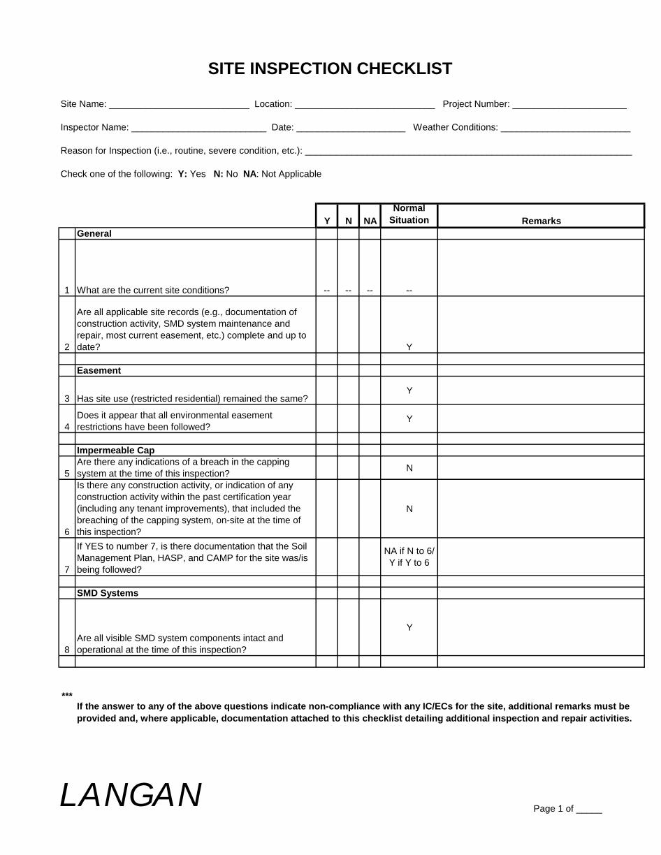
SITE INSPECTION CHECKLIST
Site Name: ___________________________ Location: ___________________________ Project Number: ______________________
Inspector Name: __________________________ Date: _____________________ Weather Conditions: _________________________
Reason for Inspection (i.e., routine, severe condition, etc.): _______________________________________________________________
Check one of the following: Y: Yes N: No NA: Not Applicable
Y N NA
Normal
Situation Remarks
General
1 What are the current site conditions? -- -- -- --
2
Are all applicable site records (e.g., documentation of
construction activity, SMD system maintenance and
repair, most current easement, etc.) complete and up to
date? Y
Easement
3 Has site use (restricted residential) remained the same?Y
4
Does it appear that all environmental easement
restrictions have been followed?Y
Impermeable Cap
5
Are there any indications of a breach in the capping
system at the time of this inspection?N
6
Is there any construction activity, or indication of any
construction activity within the past certification year
(including any tenant improvements), that included the
breaching of the capping system, on-site at the time of
this inspection?
N
7
If YES to number 7, is there documentation that the Soil
Management Plan, HASP, and CAMP for the site was/is
being followed?
NA if N to 6/
Y if Y to 6
SMD Systems
8
Are all visible SMD system components intact and
operational at the time of this inspection?
Y
***If the answer to any of the above questions indicate non-compliance with any IC/ECs for the site, additional remarks must be
provided and, where applicable, documentation attached to this checklist detailing additional inspection and repair activities.
LANGANPage 1 of _____

SITE INSPECTION CHECKLIST
Additional remarks ________________________________________________________________________________________
__________________________________________________________________________________________________________
__________________________________________________________________________________________________________
__________________________________________________________________________________________________________
__________________________________________________________________________________________________________
__________________________________________________________________________________________________________
__________________________________________________________________________________________________________
__________________________________________________________________________________________________________
Minimum Inspection Schedule: Site-wide inspections will be conducted annually, per certification year, at a minimum.
LANGANPage 2 of _____

APPENDIX K
SAMPLE GROUNDWATER SAMPLING LOG

Site: Well#/Location: Job No.
Date: Weather: Sampling Personnel:
Purging Information
Sample ID Purging Method
Well Depth (ft) Purging Rate (l/m; gpm)
Screened Interval (ft) Start Purge Time
Casing Elevation (msl) End Purge Time
Casing Diameter (in) Volume Purged (gal)
Depth to Water (ft)
Water Elevation (msl) Sampling Information
Casing Volume (gal) Sampling Method
PID/FID Reading (ppm) Start Sampling Time
End Sampling Time
Depth Before Sampling (ft)
Number Bottles Collected
Sample TimeTemp
(◦C)
pH ORP
(mV)
Conductivity
(mS/cm)
Turbidity
(NTU)
Dissolved
Oxygen
(mg/L)
Depth to
Water (ft)
Purged Volume
(gallons)
Stablility
PH - ± 0.1 unit
Specific Conductance - ± 3%
Temperature - ± 3%
Dissolved Oxygen - ±10% above 0.5 mg/L
Turbidity - ± 10% above 5 NTU
ORP/Eh - ±10 millivolts
Maximum flow rate - <0.5 L/m or 0.13 gpm
Maximum drawdown - <0.33 feet
Remember: Battery Connections - RED is POSITIVE and BLACK is NEGATIVE
Langan Engineering, Environmental, Surveying and Landscape Architecture, D.P.C.
GROUND WATER SAMPLE FIELD INFORMATION FORM
Well Information
Parameters
Notes/Remarks
C:\Users\wkim\Desktop\Langan - Projects\General\Example Documents\Groundwater\GW Sampling Log

APPENDIX L
SMDS OPERATION AND MAINTENANCE MANUALS

3BA1200-1014
RUTHERFORD, NJ 07070 WWW.AIRTECHUSA.COM TEL: (888) 222-9940 FAX: (201) 569-1696
3BA1200 Vacuum/PressureRegenerative
Blower
Features: Cooler running,
outboard bearing provides
maintenance-free operation
Environmentally friendly
oil-free technology
Extremely quiet operationRugged die cast aluminum
construction
All motors are standard TEFC with
Class F insulation, UL recognized,
CE Compliant Explosion-Proof motors available
Custom construction blowers
are available
�� �� � �� � �� � � � � � � � � � � � �� � � � � � � � � � � � � � � � � � � � � � � � � � � � �� !" #$� %# #& ' ()& *+,
-*�. $& #. $*/0 /12 13 1 13 2 113 14 15 16 12 17 1 8 9 : ; < = > ? @ A @ B C ? D E F F G D E H I J J E D E K L E M N B L G G O PQ RSTRUVQ WURUX YRZ[X \]
_\Q RVX U` V\ab Rac d cc d ec d fc d gc d hc d i
ce cf cg ch ci cj c k l m n o p q r s t s u v r w x y y z w x { | } } x w x ~ � x � � u � z z � ����������� ������� ���� ������� �� �� ���� � �� � �� � �� � �� � �� � �
� � � � � � � � � � � � �� � ¡ ¢ £ ¤ ¥ ¦ ¦ § ¤ ¥ ¨ © ª ª ¥ ¤ ¥ « ¬ ¥ ® ¡ § ® ¥ ¯ £ ° ± ² ³ ´ µ ¶·¹º»»º¼½¾ »º¿ºÀÁ ÀÁà º·½¿·Äà ÅÆÁÇÈÂÉÊ Ë Ë Ì ÍÊ Ë Ë ÌÊ Ë Ë Ë ÍÊ Ë Ë ËÊ Ë Ë Ì ÍÊ Ë Ë ÌÊ Ë Ë Ë ÍÊ Ë Ë Ë
Ê Ë Ë Ë ÍÊ Ë Ë ËÊ Ë Ë Ì ÍÊ Ë Ë ÌÊ Ë Ë Ì ÍÊ Ë Ë Ì Ê Ë Ë Ë ÍÊ Ë Ë Ë
Î Ï Ð Ñ Ò Ð Ó Ô Õ Ö Ï Ö × Ð Ø Ï Ñ Ò Ð Ù Ô Ö × × Ó Ú × Ó Ú Û Ü Ý Þ ß Ý à á â ã Ü ã ä Ý å Ü Þ ß Ý æ ß à ç Ý Ü è è ß Ý
éê éë éì éí éî é
é ê é ë é ì é í é î é ï é
ð ñ ò óô ñ ò ó
õ ö õ ÷ ø ù ú û ü ü ý ú û þ ÿ � � û ú û � � û � � ÷ ý � û � ù � � � � � ���� ��������� ��� �� ��
Ê Ë Ë Ë ÍÊ Ë Ë Ë�� �� �� � �! �
�� �� �� � �! �" �
# $ % &' $ % &
� � � � � ù õ ö õ ÷ ø ù ú û ü ü ý ú û þ ÿ � � û ú û � � û � ( ÷ � ý ý ) � ���� ��������� ��� �� ��
Ê Ë Ë Ì ÍÊ Ë Ë Ì Ê Ë Ë Ë ÍÊ Ë Ë ËÊ Ë Ë Ì ÍÊ Ë Ë Ì
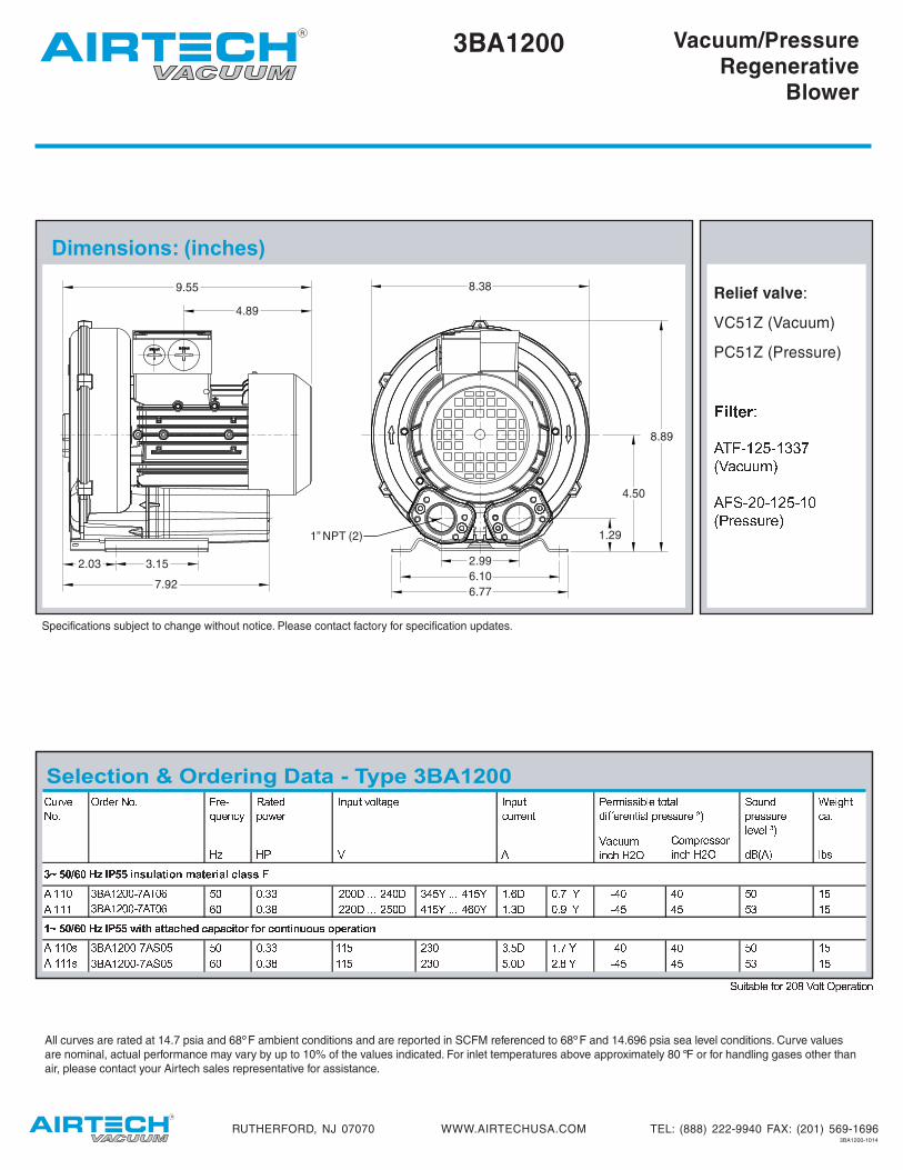
3BA1200-1014
RUTHERFORD, NJ 07070 WWW.AIRTECHUSA.COM TEL: (888) 222-9940 FAX: (201) 569-1696
� � � � �3BA1200 Vacuum/Pressure
RegenerativeBlower
� � � � � � � � � � � � �� � � � � � � � � � � � � �� � � ! " # $ % & � � ' ( ) * + , - ' . ( / , - 0 1 ' , + 2 + , ) ) 3 4 4 5 6 7 8 9 : ; ; < = 8 > ; ? @ 5 5 A B B � 5 5 C A A A � D 5 C B D @ E A A A D 4 @ E 4 A F C 5 A G E H D 5 D 5 @ 5 4 @ 4 4 4 F 5 5 A B I � � 5 C A A A � @ 5 C D 4 @ E A A A D F 5 E 4 AB A @ C@ A 5 CB C 5 A J E H D @ D @ @ B 4 @K � � ! " # $ % & � � L ' - M , - - , 2 M 0 N 2 , O , 2 ' - . 1 P . 1 2 . ( - ' ( * . * ) . O 0 1 , - ' . ( 4 4 5 � 6 7 8 9 : ; ; < = 8 Q ; R @ 5 5 A B B � B 5 4 A G E H D 5 @ 5 4 @ 4 4 4 � F 5 5 A B I 4 4 @4 4 @ � B 5 � A I E H D @ @ B 4 @S � � T � U� V AW � X � � � � � � X � �� � Y � � Z �� � � � � � � � � � � U � U V �� � [ [ � � � � U � V � � � � � X � � \ �] � X U� X � � � � U X � Y �^ � A � � � � � ^ � A _ � � H` X � � � a b V U � � � c � � ] � X U Y � � U V T � � V � X X �� � � � � � �6 7 8 9 : ; ; < = 8 > ; ?6 7 8 9 : ; ; < = 8 Q ; R
Specifications subject to change without notice. Please contact factory for specification updates.
Relief valve:
VC51Z (Vacuum)
PC51Z (Pressure)d e f g h i jk l m n o p q n o r r st u v w x x y zk m { n p | n o p q n o |t } ~ � � � x ~ � z
� � � � � � � � � � � � � � � � � � � � � � � � � � �D 5D @All curves are rated at 14.7 psia and 68 F ambient conditions and are reported in SCFM referenced to 68 F and 14.696 psia sea level conditions. Curve values
are nominal, actual performance may vary by up to 10% of the values indicated. For inlet temperatures above approximately 80 F or for handling gases other than
air, please contact your Airtech sales representative for assistance.
8.38
8.89
4.50
1.29
2.99
6.10
6.77
1” NPT (2)
9.55
4.89
2.03 3.15
7.92
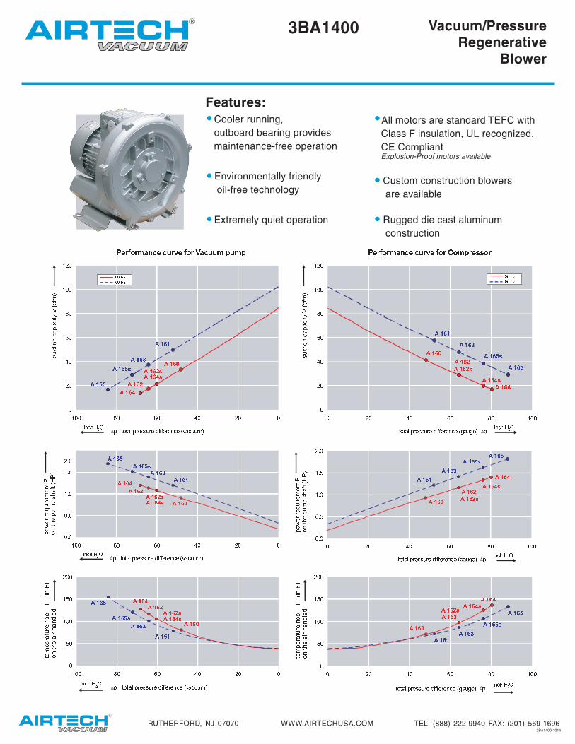
3BA1400-1014
RUTHERFORD, NJ 07070 WWW.AIRTECHUSA.COM TEL: (888) 222-9940 FAX: (201) 569-1696
� � � � � � � � � � � � � � � � � � � � � � � � � � � � � � � � � � � � � � � � � � � � � � � � � � � �
3BA1400 Vacuum/PressureRegenerative
Blower
Features: Cooler running,
outboard bearing provides
maintenance-free operation
Environmentally friendly
oil-free technology
Extremely quiet operation
All motors are standard TEFC with
Class F insulation, UL recognized,
CE Compliant Explosion-Proof motors available
Custom construction blowers
are available
Rugged die cast aluminum
construction
� � � � �� � � �� � � ! � � � � "� � � �� � � �� � � #� � � � � � !$% $& $ $& % $' $ $
$' $( $) $* $& $ $
+ , - . / + , - 0 /+ , - 1 /+ , - 2+ , - , + , - .+ , - 3 + , - 0+ , - 14 5 44 5 67 5 47 5 68 5 4
4 8 4 9 4 : 4 ; 4 7 4 4
< = > ? @< = > A @< = > B @ < = > C< = > =< = > ?< = > D< = > A< = > BEF EG EH EI EJ E EJ F E
EF EG EH EI EJ E EK L M NO L M N
P QRSQTUP VTQTW XQYZW [\][P_ QUW T_ U[a Q`
b c d e f g h i j k j l m i n o p p q n o r s t t o n o u v o w x l v q q y z
{ | } ~ � � � � � � � � � � � � � � � � � � � � � � � � � � � � � � � � � � �� � � � � � � � � � � � � � � � � � � � ¡ � ¢ £ � � £ � ¤ � ¥ ¦ § ¨ © ª «
¬®° ±²®³³®° µ¶· ®¸ ¹º
» ¼ ½ ¾ » ¼ ½ ¿ À» ¼ ½ Á À» ¼ ½ ¾ À » ¼ ½ » ¼ ½ ¼» ¼ ½ ¿ » ¼ ½ û ¼ ½ Á» ¼ ½ ¾Ä Å ÄÄ Å ÆÇ Å ÄÇ Å ÆÈ Å Ä
ÄÈ ÄÉ ÄÊ ÄË ÄÇ Ä Ä Ì Í Î Ï Ð Ñ Ò Ó Ô Õ Ô Ö × Ó Ø Ù Ú Ú Û Ø Ù Ü Ý Þ Þ Ù Ø Ù ß à Ù á â Ö à Û Û ã äåæçèééèêëì éèíèîïð æîïñ èåëíåòñ óôïõöð÷ø ù ú ûø ù ú ü ý ø ù ú þ ýø ù ú û ýø ù ú û ýø ù ú ÿø ù ú ù ø ù ú üø ù ú � ø ù ú þ ø ù ú û�� �� �� �� �� � �� � �
� � � � � � � � � � � �� � � �
� � � � � � � � � � � � � � � � � � � � � � � � � � � � � � � � � ! " #$%&'( )*&+,+&(' -./ &0 12
345677689: 76;6<=> 4<=? 639;3@? AB =CD>EF G H I F G H JF G H J KF G H I K F G H J KF G H L F G H GF G H M F G H N F G H I F G H JOP OQ O OQ P OR O O
O R O S O T O U O Q O OF G H M KV WXYWZ[V \ZWZ] W_] abc
daVe W[] Ze [afg Wfh i h j k l m n o o p m n q r s s n m n t u n v w j p w n x l y z { | } ~ �

Specifications subject to change without notice. Please contact factory for specification updates.
3BA1400 Vacuum/PressureRegenerative
Blower
Relief valve:
VC51Z (Vacuum)
PC51Z (Pressure)� � � � � � �� � � � � � � �� � � � � � � �� � � � � � � � � � � � � � � �
� � � ! ! � " # � #$ � � � % % & ' � % (
) * + , -. / 0 1 + 2 - + . / 0 3 + - 45 * - 6 7 8 9 : ; - 2< / = - + > / * 6 2< + - ? ? * + -@ - , - @ A - B C D ;E F E G H I ) / J < + - ? ? / +B 6 7 D E K 1 2 L M I N @ O ?I P Q R S L I P T R R 4 U I V R Q W R R 0 X T K R R Y 0 0 0 K T R Y S T W Z 0 0 0 T P W Z S 0 [ Y K 0 K Z 4 T [ T [ Q S K XI P Q P Q R P 0 P P S 0 U W Y K 0 P W Z 4 W K W K Q T K XI P Q K S L I P T R R 4 U I V P Q W R P 0 P T K R R Y 0 0 0 K T R Y S T W Z 0 0 0 T P W Z T 0 K Y K 0 T Z 4 Q T Q T Q S S SI P Q S S L I P T R R 4 U I V P Q Q R P 0 K U T 0 R Y K 0 S Z 4 Q T Q T Q T S SI P Q T S L I P T R R 4 U I V K Q W R P 0 U T K R R Y 0 0 0 K T R Y S T W Z 0 0 0 T P W Z W 0 U Y S 0 S Z 4 Q [ [ R Q S S WI P Q W S L I P T R R 4 U I V K Q Q R K 0 R P W 0 W Y S 0 K Z 4 [ T [ [ Q T S W\ ] ^ _ ` a _ b c d e ^ ^ f g h i j k l k j g h m n o m n j m p h g p q m q r m l s n k h g m pt 6 < * ; , / @ ; : C - H : 7 * * JB 6 7 D E K 1G - + J B ? ? B O @ - ; / ; : @2 B u u - + - 6 ; B : @ < + - ? ? * + -t 6 < * ;7 * + + - 6 ;
I P Q T ? S L I P T R R 4 U I > K W W R P 0 T U P P W K S R P S Q 0 W 4 Q R U Q Q S S WI P Q W ? S L I P T R R 4 U I > K W Q R P 0 U T P P W K S R P T U 0 R 4 U K U Q Q T S WS L I P T R R 4 U I V R Qv w x y z { y | } ~ � x x � � � � � � � � � � � � � � � � � � � � � � � � � � � � � � � � � � � � � � � � � � � � � �
� � � � � � � � � � � � ¡ ¢ � � � £ ¤ � � � � � ¥� � � � � � � � � � � � � � � � � � � � � �¦ ¦ § ¨ © © © ¦ ª § ¨ « ¬ ª © © © « ® §
3BA1400-1014
RUTHERFORD, NJ 07070 WWW.AIRTECHUSA.COM TEL: (888) 222-9940 FAX: (201) 569-1696
¯ ¯ ° ± ²¯ ¯ ° ³ ´
µ ° ¶ · ¸ ¶ ¹¶ ° ¶ ´³ ° ³ µ¯ ¯ º ± » ¼ ½ ¾ ¸ ± ¹± ° ´ ¿ À ° · ¶´ ° ¶ À ¯ ° · ³ ² ° µ ¿
All curves are rated at 14.7 psia and 68 F ambient conditions and are reported in SCFM referenced to 68 F and 14.696 psia sea level conditions. Curve values
are nominal, actual performance may vary by up to 10% of the values indicated. For inlet temperatures above approximately 80 F or for handling gases other than
air, please contact your Airtech sales representative for assistance.

3BA1530-0315
RUTHERFORD, NJ 07070 WWW.AIRTECHUSA.COM TEL: (888) 222-9940 FAX: (201) 569-1696
3BA1530 Vacuum/PressureRegenerative
Blower
Features:
Cooler running,
outboard bearing provides
maintenance-free operation
Environmentally friendly
oil-free technology
Extremely quiet operation
All motors are standard TEFC with
Class F insulation, UL recognized,
CE Compliant Explosion-Proof motors available
Custom construction blowers
are available
Rugged die cast aluminum
construction � � � � � � � � � � � � � � � � � � � � � � � � � � � � � � � � � � � � � � � � � � � � � � � � � � � �
� � � � � ! " "# $ # % & " ' ( ) ) * ' ( + , - - ( ' ( . / ( 0 1 % / * * 2 3 # $ # % & " ' ( ) ) * ' ( + , - - ( ' ( . / ( 0 4 % * 4 ( 3 , . / 5 6 7
� � � � � ! " "# $ # % & " ' ( ) ) * ' ( + , - - ( ' ( . / ( 0 1 % / * * 2 3 # $ # % & " ' ( ) ) * ' ( + , - - ( ' ( . / ( 0 4 % * 4 ( 3 , . / 5 6 7
� � � � � ! " "# $ # % & " ' ( ) ) * ' ( + , - - ( ' ( . / ( 0 1 % / * * 2 3 # $ # % & " ' ( ) ) * ' ( + , - - ( ' ( . / ( 0 4 % * 4 ( 3 , . / 5 6 7
0 20 40 60 80 100 120
0 20 40 60 80 100 120
0 20 40 60 80 100 120
0
0
0
Su
ctio
n c
ap
acity V
[cfm
]
0
50
100
150
200
250
020406080100120
……
Po
we
r co
nsu
mp
tio
n P
at
pu
mp
sh
aft
[H
P]
0.0
1.0
2.0
3.0
4.0
5.0
020406080100120
Te
mp
era
ture
ris
e ∆
T
of
co
nve
ye
d a
ir [
F]
0
50
100
150
200
250
020406080100120
Su
ctio
n c
ap
acity V
[cfm
]
Po
we
r co
nsu
mp
tio
n P
at
pu
mp
sh
aft
[H
P]
Te
mp
era
ture
ris
e ∆
T
of
co
nve
ye
d a
ir [
F]
0
50
100
150
200
250
0.0
1.0
2.0
3.0
4.0
5.0
0
50
100
150
200
250
……
8 9 : ;< 9 : ; 8 9 : ;< 9 : ;
= > ? @= > ? A
= > ? > = > ? B= > ? @ = > ? > = > ? B
= > ? @ = > ? > = > ? B
= > ? C = > ? ?= > ? A = > ? C = > ? ?= > ? A
= > ? C = > ? ?
= > ? @ = > ? A= > ? >= > ? B= > ? @= > ? >= > ? B= > ? @= > ? >= > ? B
= > ? C= > ? ?= > ? A= > ? C= > ? ?
= > ? A= > ? C= > ? ?

3BA1530-0315
RUTHERFORD, NJ 07070 WWW.AIRTECHUSA.COM TEL: (888) 222-9940 FAX: (201) 569-1696
Specifications subject to change without notice. Please contact factory for specification updates.
3BA1530 Vacuum/PressureRegenerative
Blower
� � � � � � � � � � �� � � � � � � � � �Relief valve:
VC61Z (Vacuum)
PC61Z (Pressure)� � � � � �� � � � � � � � � � � � � � �� � � ! ! " #� � $ � % � � � � � � � �� & ' ( ) ) ! ' ( #
* + , - ./ 0 1 2 , 3 . , / 0 1 4 , . 56 + . 7 8 9 : ; < . 3= 0 > . , ? 0 + 7 3= , . @ @ + , .A . - . A B . C D E <F G F H I J * 0 K = , . @ @ 0 ,C 7 8 E F L 2 3 M N J O A P @J L Q R S M J Q T S R 5 U J V Q W T R Q 1 U X L R R Y 1 1 1 L X R Y S X T Z 1 1 1 X Q T Z T 1 U Y S 1 S Z 5 X [ X X W T X WJ L Q Q W R L 1 R Q L L R Y 1 1 1 L T R Y X Q T Z 1 1 1 X W R Z T 1 U Y S 1 S Z 5 S W S L U Q X WJ L Q L S M J Q T S R 5 U J V L W T R L 1 Q T L R R Y 1 1 1 L X R Y S X T Z 1 1 1 X Q T Z U 1 T Y X 1 S Z 5 W X W R W T X \J L Q S W R L 1 U T L L R Y 1 1 1 L T R Y X Q T Z 1 1 1 X W R Z U 1 W Y X 1 X Z 5 W X5 Q R X W R U Q X \J L Q X T R L 1 \ T L R R Y 1 1 1 L X R Y S X T Z 1 1 1 X Q T Z \ 1 U Y T 1 W Z 5 [ [ \ L W T T UJ L Q T W R S 1 X L L L R Y 1 1 1 L T R Y X Q T Z 1 1 1 X W R Z Q R 1 S Y W 1 R Z Q R R U Q T UH . , K C @ @ C P A . < 0 < ; A3 C ] ] . , . 7 < C ; A = , . @ @ + , .^ 7 = + <8 + , , . 7 <^ 7 = + < - 0 A < ; D . I ; 8 + + KC 7 8 E F L 2S M J Q T S R 5 U J V Q WS M J Q T S R 5 U J V L WS M J Q T S R 5 U J V S WS M J Q T S R 5 U J V S W
_ ` a b c d b e f g h a a i j k l m n o i p j q n o r s i n m t m n k k uv w x y z { | } ~ � � � � � � � | y � � } � z y x � �
All curves are rated at 14.7 psia and 68 F ambient conditions and are reported in SCFM referenced to 68 F and 14.696 psia sea level conditions. Curve values
are nominal, actual performance may vary by up to 10% of the values indicated. For inlet temperatures above approximately 80 F or for handling gases other
than air, please contact your Airtech sales representative for assistance.
4.09 4.53
12.46
14.37
14.7213.28
1.89
2" NPTINLET
2" NPTOUTLET
2.36
5.12
4.72
10.24
13.14

Operating and Maintenance Instructions
3BA Regenerative Blowers

2

INSTALLATION & OPERATING MANUAL 3BA REGENERATIVE BLOWERS
Table of Contents
Section: Page Number: 1. Safety 1.1 General Safety Precautions 1.2 Clothing and Protective Gear 1.3 Electrical Safety 1.4 Vacuum and Gauge Pressure Safety 1.5 Installation/Start-up 1.6 Maintenance Procedures 1.7 Hot Surfaces 1.8 Hearing Protection 1.9 Safety Guidelines for Transport of the unit
4 4 4 4 5 5 6 6 6 7
2. Technical Data 8
Table 1: 3 Phase, Single Stage, 50 Hertz 10 Table 2: 3 Phase, Single Stage, 60 Hertz 11 Table 3: 3 Phase, Two/Three Stage, 50 Hertz 12 Table 4: 3 Phase, Two/Three Stage, 60 Hertz 13 Table 5: Single-phase, 50 Hz Table 6: Single-phase, 60 Hz Table 7: Single Stage – Approx. Temperature Rise
14 14 16
Table 8: Two/Three Stage – Approx. Temperature Rise 17 Table 9: Tightening Torque Specifications 18
3. Installation 20
3.1 Installation Procedure 21
4. Start-up 4.1 Start-up Procedure 4.2 Potential Risks For Operators
23 23 23
5. Maintenance and Servicing 24
5.1 Troubleshooting Chart 25 5.2 Lifting 27 5.3 Storage 28 5.4 Disposal 28
6. Exploded-View Drawings 29
3BA1 Single-Stage 29 3BA1 Two-Stage 30 3BA1943 Two-Stage 31 3BA7 Single-Stage 32 3BA7 Two-Stage 33 Warranty Statement 34
3

1. Safety 1.1 General Safety Precautions
All personnel should familiarize themselves with the units’ specifications and be careful not to exceed the unit’s capacity. Transport, installation, operation, shut-down, maintenance and disposal of 3BA units should be carried out by qualified professionals. Do not attempt to start or run the unit unless it has been completely assembled. Particular attention should be paid to: the vacuum pump/compressor cover, the muffler on the inlet and discharge connections, and the fan guard. The standard 3BA unit must never come into contact with flammable substances. 1.2 Clothing and Protective Gear It is recommended that all personnel wear proper protective gear while operating the unit. This may include eye protection, gloves and helmets. Please be aware that it is possible for hair and clothing to be pulled into the unit. Avoid wearing loose-fitting clothing near the unit while it is operating and wear a hairnet if necessary. 1.3 Electrical Safety Electrical installation should only be done by qualified electricians. Before doing any electrical work on a 3BA unit, please ensure that power to the unit has been disconnected. Do not attempt to open the unit’s terminal box until you have made certain that the unit is not connected to a power source. The terminal box must be kept free of dirt and moisture at all times. Make sure the terminal box cover and cable entries are tightly sealed so they remain dustproof and waterproof. Check the terminal box regularly to make sure it is sealed and free of debris and moisture.
WARNING: Improper operation of 3BA units can result in serious or even fatal injuries. Please make sure all personnel have read and understood this manual before operating the unit.
4

1.4 Vacuum and Gauge Pressure Safety In order to avoid dangerous situations associated with vacuum and gauge pressure, please utilize secure mounting elements, connections, lines, fittings, and containers. Pipes/hoses must be securely connected to the inlet and discharge connections. The inlet and discharge connections and the pipes/hoses connected to them must not be closed, clogged, or soiled. Check regularly to ensure that these connections and mountings are not becoming unseated. If necessary, support pipes and hoses to ensure that there is no tension on the connections. Failure to observe these precautions can lead to sudden evacuation of hazardous fluids or dangerous suction that can pull hair or clothing into the unit. 1.5 Installation/Start-up The unit and any lines connected to it must be securely installed. In particular, the feed pipes must be securely routed, e.g. in cable ducts, in the floor, etc. If a separate control panel or other such interface will be used to start and stop the unit, it should be installed in an area with an unobstructed view of the unit to ensure that it is not switched on while being serviced. Excess vibration can cause damage to the unit and/or unsafe conditions. Install the unit on a solid foundation or a solid mounting surface. Check screw glands/unions for strength and firm seating. Cables and pipes should be installed in a recess in the floor or duct so they do not present a tripping hazard. To ensure sufficient cooling of the unit, ventilation screens and openings must remain clear. Ensure that discharge air from other units cannot be pulled into the unit. Make sure that the inlet and pressure lines are clearly marked to avoid confusion. Interchanged inlet and pressure lines can lead to damage to the unit and/or serious injury. Install a filter in the inlet pipe and replace it regularly. If particulates or debris enter the unit, the blades of the impellers can be damaged and blades could potentially break off, potentially creating a hazardous situation. If re-starting the unit after it has been idle for a long period of time, measure the insulation resistance of the motor. If values are less than 1 k � per volt of nominal voltage, the winding may be too dry.
5

If the unit is installed or stored in an environment with a temperature of over 104°F (40°C) be aware that the winding may be damaged and the grease might need to be changed more often. 1.6 Maintenance Procedures Before beginning work on the pump-motor unit, please take the following precautions: • Make sure power has been completely disconnected • Wait for the unit to come to a complete stop. • Allow the unit time to cool. • Shut off lines and release pressure • Make certain that no vacuum or gauge pressure is present in the lines/tanks to be opened. • Make sure that no fluids can escape Please note that the rotating impeller is accessible when the inlet and discharge connections are open. Do not reach into the unit through open connections or insert objects into the unit through any openings. Serious injury could occur. If the unit is running without piping or tubing, provide the inlet and discharge of the unit with either additional mufflers or piping of a sufficient length to prevent access to the impeller. Check regularly to ensure the terminal box is free of any dirt or foreign substances and there is no moisture or humidity present. Make certain the terminal box cover and cable entries are tightly closed. 1.7 Hot Surfaces During operation, the surface of the unit can reach temperatures of 320° F (160° C). It is advisable to cover the unit with suitable touch protection (e.g. a perforated plate or wire cover). Do not touch the unit during operation, and allow time to cool after shut-down. Temperature-sensitive parts such as lines or electronic components should not come into contact with the surface of the unit. 1.8 Hearing Protection Make certain any missing or defective silencers are replaced. Noise emitted by the unit can cause serious hearing damage. Conduct a noise measurement test while the unit is running. If the unit operates over 90 dB(A), please place a warning sign in the area where the unit has been installed and make certain that
6

any personnel working in the vicinity wear ear protection at all times while the unit is running. 1.9 Safety Guidelines for Transport of the unit: Prior to transport and handling, please make sure that all components are properly assembled and secure. Any machinery used to transport these units must have the proper lifting capacity. Please consult the table on page 27 to find the weight of the unit being handled. Do not stand or walk under suspended loads. If a 3BA unit has come in contact with any dangerous substances, it must be decontaminated before being sent to Airtech for repair evaluation.
7

2 Technical Data These operating instructions cover the Airtech 3BA side channel vacuum pumps and compressors supplied with standard TEFC motors. Other configurations are available including V-belt driven units, units with explosion proof motors, mechanical seals, magnetic drives, coatings and modifications for high pressure service. Airtech can provide any combination of modifications to meet your application requirements. Such blowers, however, are outside the scope of this manual. Description All regenerative blowers are dynamic compression devices and utilize a non-contacting impeller to accelerate the gas and a specially designed housing to compress the gas. Cooling is accomplished by using the motor fan to blow air over the housing. In larger models, the housing is specially designed with cooling fins to allow a wider range of operation. Both the inlet and outlet ports have built-in silencers and mesh screens. Both the inlet and outlet have an inside connection thread corresponding to DIN ISO 228. On larger units, multiple suction and discharge connection configurations may be available. The wetted parts are constructed of Aluminum on all models. The blower shares a bearing with the motor. The seal between the bearing and the motor is not gas tight in most models, therefore these blowers are not recommended for handling of toxic or explosive gases. (Contact Airtech Vacuum, Inc. for additional options if explosive or toxic gases will be handled.) A full range of accessory items are available, including vacuum or pressure relief valves, check valves, suction filters, motor starters, vacuum/pressure cross-over valves, and in-line filters. Application/Installation Environment CAUTION! These blowers are designed for use in general industry. Suitable personnel protection according to OSHA requirements is provided, but the equipment should not be operated in residential settings. Airtech blowers can be operated as either vacuum pumps or compressors. They are suitable for use with air having a relative humidity up to 90 percent, but not generally suitable for handling corrosive or erosive gases. Special versions for toxic or aggressive gases may be available. Use of the standard blower in aggressive environments may cause damage to the blower or exposure to gases being handled in the local environment.
8

CAUTION! Dangerous (flammable or explosive) or aggressive (corrosive) gases should not be handled by the standard blower. Handling of flammable or aggressive gases and vapors may be possible by using a specially configured or modified blower. Contact factory for additional information. The standard blower is not suitable for operation in explosive environments as defined by NFPA 70. Contact factory for assistance. CAUTION! The ambient and suction temperatures should be between 40 and 105 F. For temperatures outside this region, please contact the factory. The maximum permissible pressure difference for vacuum or pressure is dependant on the motor rating (See Tables 1 to 4 for detailed information by model number.) and power supply frequency. The figures in Tables 1 to 4 are computed assuming an ambient temperature of 77 F (25 C) and a local barometric pressure of 1013 mbar (sea level). Operation at an ambient temperature of 104 F (40C) is the maximum permissible, and will result in a reduction of 10 percent on maximum vacuum or pressure attainable by the unit. For temperatures between 77 F and 104 F, reduce the maximum pressure reduction is a linear function of temperature.
9

Table 1. Three-phase, Single Stage, 50 Hertz
3BA1300-7AT06 .33/.25 200-240/345-415 2.1/1.2 48/82 -100/100 53
2BA1300-7AT16 .54/.4 200-240/345-415 2.6/1.5 48/82 -120/130 53
3BA1400-7AT06 .94/.7 200-240/345-415 3.8/2.2 84/142 -120/120 63
2BA1400-7AT16 1.15/.85 200-240/345-415 4.2/2.4 84/142 -160/160 63
3BA1400-7AT26 1.75/1.3 200-240/345-415 5.7/3.3 84/142 -170/200 63
3BA1500-7AT06 1.15/.85 200-240/345-415 4.2/2.4 120/204 -100/100 64
3BA1500-7AT16 1.75/1.3 200-240/345-415 5.7/3.3 120/204 -170/170 64
3BA1500-7AT26 2.15/1.6 200-240/345-415 7.5/4.3 120/204 -200/190 64
3BA1500-7AT36 2.96/2.2 200-240/345-415 9.7/5.6 120/204 -220/270 64
3BA1600-7AT06 2.15/1.6 200-240/345-415 8.5/4.9 188/320 -160/150 69
3BA1600-7AT16 2.96/2.2 200-240/345-415 9.7/5.6 188/320 -190/190 69
3BA1600-7AT26 4.04/3.0 200-240/345-415 12.5/7.2 188/320 -260/270 69
3BA1600-7AT36 5.4/4.0 200-240/345-415 13.0/7.5 188/320 -290/360 69
3BA1630-7AT06 2.15/1.6 200-240/345-415 8.5/4.9 240/408 -160/150 69
3BA1630-7AT16 2.96/2.2 200-240/345-415 9.7/5.6 240/408 -190/190 69
3BA1630-7AT26 4.04/3.0 200-240/345-415 12.5/7.2 240/408 -260/270 69
3BA1630-7AT36 5.4/4.0 200-240/345-415 15.6/9.0 240/408 -260/290 69
3BA1800-7AT06 5.4/4.0 200-240/345-415 15.6/9.0 280/476 -200/200 70
3BA1800-7AT16 7.4/5.5 200-240/345-415 23/13.3 280/476 -300/300 70
3BA1800-7AT26 10/7.5 200-240/345-415 29/16.7 280/476 -320/430 70
3BA1830-7AT06 5.4/4 200-240/345-415 15.6/9 400/680 -150/140 76
3BA1830-7AT16 7.4/5.5 200-240/345-415 23/13.3 400/680 -200/190 76
3BA1830-7AT26 10/7.5 200-240/345-415 29/16.7 400/680 -270/260 76
3BA1900-7AT06 10.8/8 200-240/345-415 31.5/18.2 568/965 -190/190 74
3BA1900-7AT16 16.8/12.5 200-240/345-415 48.5/28 568/965 -290/280 74
3BA1900-7AT36 25/18.5 200-240/345-415 64.5/37 568/965 -362/462 74
3BA1930-7AT16 16.8/12.5 200-240/345-415 48.5/28 744/1264 -290/280 71
3BA1930-7AT36 25/18.5 200-240/345-415 64.5/37 744/1264 -310/310 71
3BA1930-7AT36 25/18.5 200-240/345-415 64.5/37 744/1264 -310/310 71
3BA7310-0AT167 .75/.55 200-240/345-415 2.8/1.6 40/68 -250/250 57
3BA7410-0AT167 1.5/1.1 200-240/345-415 5.4/3.1 50/84 -300/380 58
3BA7510-0AT168 2/1.5 200-240/345-415 7.5/4.3 70/120 -370/650 64
3BA7510-0AT268 3/2.2 200-240/345-415 9.7/5.6 70/120 -310/430 64
3BA7610-0AT168 3/2.2 200-240/345-415 9.7/5.6 96/163 -310/430 65
3BA7610-0AT368 4.4/3.3 200-240/345-415 13/7.5 96/163 -500/750 65
Model
Voltage Motor
Current
(Amps)
Maximum
Pressure
(mbar)
Sound
Pressure
Level (dBA)
Rated
Power
HP/kW
Open Flow
Capacity
CFM/m3/hr
10

Table 2. Three-phase, Single-stage, 60 Hz
When operating at altitudes above 3280 feet (1000 m) above mean sea level, contact Airtech Inc.
CAUTION! Operation of the unit outside the recommended range of pressures and ambient conditions will result in shorted operating life.
3BA1300-7AT06 .39/.29 220-250/415-460 1.74/1.0 60/102 -100/100 56
2BA1300-7AT16 .67/.5 220-250/415-460 2.6/1.5 60/102 -150/160 56
3BA1400-7AT06 1.12/.83 220-250/415-460 3.75/2.15 105/179 -130/130 64
3BA1400-7AT16 1.28/.95 220-250/415-460 4.35/2.5 105/179 -160/160 64
3BA1400-7AT26 2/1.5 220-250/415-460 5.5/3.2 105/179 -210/200 64
3BA1500-7AT06 1.28/.95 220-250/415-460 4.35/2.5 150/255 -80/70 70
3BA1500-7AT16 2/1.5 220-250/415-460 5.5/3.2 150/255 -150/140 70
3BA1500-7AT26 2.7/2.05 220-250/415-460 7.5/4.4 150/255 -220/210 70
3BA1500-7AT36 3.4/2.55 220-250/415-460 9.0/5.3 150/255 -260/290 70
3BA1600-7AT06 2.7/2.05 220-250/415-460 7.5/4.4 235/400 -160/150 72
3BA1600-7AT16 3.4/2.55 220-250/415-460 9.0/5.3 235/400 -190/190 72
3BA1600-7AT26 4.6/3.45 220-250/415-460 12.0/6.5 235/400 -240/230 72
3BA1600-7AT36 6.1/4.6 220-250/415-460 15.2/8.5 235/400 -320/310 72
3BA1630-7AT06 2.7/2.05 220-250/415-460 7.5/4.4 300/510 -160/150 72
3BA1630-7AT16 3.4/2.55 220-250/415-460 9.0/5.3 300/510 -190/190 72
3BA1630-7AT26 4.6/3.45 220-250/415-460 12.0/6.5 300/510 -240/230 72
3BA1630-7AT36 6.1/4.6 220-250/415-460 15.2/8.5 300/510 -260/260 72
3BA1800-7AT06 6.1/4.6 220-250/415-460 15.2/8.5 350/595 -160/160 74
3BA1800-7AT16 8.4/6.3 220-250/415-460 20/11.2 350/595 -300/280 74
3BA1800-7AT26 11.5/8.6 220-250/415-460 27.5/15 350/595 -350/400 74
3BA1830-7AT06 6.2/4.6 220-250/415-460 15.2/8.5 500/850 -90/90 79
3BA1830-7AT16 8.4/6.3 220-250/415-460 20/11.2 500/850 -180/180 79
3BA1830-7AT26 11.5/8.6 220-250/415-460 27.5/15 500/850 -270/260 79
3BA1900-7AT06 12.1/9 220-250/415-460 31.5/18.2 710/1207 -150/140 79
3BA1900-7AT16 19.5/14.5 220-250/415-460 50/29 710/1207 -270/260 79
3BA1900-7AT36 28.7/21.3 220-250/415-460 68/39 710/1207 -382/422 79
3BA1930-7AT16 19.5/14.5 220-250/415-460 50/29 930/1581 -270/260 75
3BA1930-7AT36 28.7/21.3 220-250/415-460 68/39 930/1581 -300/280 75
3BA7210-0AT167 1.1/.83 220-250/415-460 3.75/2.15 35/60 -270/320 62
3BA7310-0AT167 1.1/.83 220-250/415-460 3.75/2.15 48/82 -260/250 62
3BA7410-0AT167 2/1.5 220-250/415-460 5.5/3.2 60/102 -340/370 62
Model Voltage
Motor
Current
(Amps)
Maximum
Pressure
(mbar)
Sound
Pressure
Level (dBA)
Rated
Power
HP/kW
Open Flow
Capacity
CFM/m3/hr
11

Table 3. 3 Phase, Two/Three Stage, 50 Hertz
3BA1310-7AT26 .94/.7 200-240/345-415 3.8/2.2 48/81.6 -120/120 55
3BA1410-7AT36 2.15/1.6 200-240/345-415 7.5/4.3 84/142.8 -200/190 66
3BA1410-7AT46 2.96/2.2 200-240/345-415 9.7/5.6 84/142.8 -320/420 66
3BA1510-7AT46 4.04/3.0 200-240/345-415 12.5/7.2 121.6/206.7 -340/410 72
3BA1510-7AT56 5.39/4.0 200-240/345-415 17.4/10 121.6/206.7 -390/440 72
3BA1610-7AT36 2.9/2.2 200-240/345-415 9.7/5.6 188/319.6 -190/190 73
3BA1610-7AT26 4.04/3.0 200-240/345-415 12.5/7.2 188/319.6 -260/270 73
3BA1610-7AT36 5.39/4.0 200-240/345-415 13.0/7.5 188/319.6 -290/360 73
3BA1610-7AT46 7.41/5.5 200-240/345-415 23/13.3 188/319.6 -420/500 73
3BA1610-7AT56 10.1/7.5 200-240/345-415 29/16.7 188/319.6 -420/610 73
3BA1640-7AT36 5.39/4.0 200-240/345-415 13.0/7.5 280/476 -290/360 74
3BA1640-7AT46 7.41/5.5 200-240/345-415 23/13.3 280/476 -420/500 74
3BA1640-7AT56 10.1/7.5 200-240/345-415 29/16.7 280/476 -420/610 74
3BA1810-7AT16 7.4/5.5 200-240/345-415 23/13.3 280/476 -420/500 74
3BA1810-7AT26 10.1/7.5 200-240/345-415 29/16.7 280/476 -320/430 74
3BA1810-7AT36 14.8/11 200-240/345-415 29/16.7 280/476 -430/600 74
3BA1810-7AT46 20.2/15 200-240/345-415 56.5/32.5 280/476 -460/670 74
3BA1840-7AT26 10.1/7.5 200-240/345-415 29.0/16.7 280/476 -320/430 74
3BA1840-7AT36 14.8/11.0 200-240/345-415 48.5/28.0 280/476 -430/600 74
3BA1910-7AT16 16.8/12.5 200-240/345-415 48.5/28 624/1061 -290/280 74
3BA1910-7AT36 26.95/20.0 200-240/345-415 69/40 624/1061 -443/502 74
3BA19437AT26 20.1/15 200-240/345-415 59/34 1200/2040 -160/170 75
3BA19437AT36 26.8/20 200-240/345-415 69/40 1200/2040 -250/230 75
3BA19437AT46 33.5/25 200-240/345-415 90/52 1200/2040 -310/280 75
3BA7220-0AT567 2/1.5 200-240/345-415 7.5/4.3 28/48 -370/650 58
3BA7320-0AT467 1.5/1.1 200-240/345-415 5.4/3.1 40/68 -300/380 58
3BA7320-0AT567 2/1.5 200-240/345-415 7.5/4.3 40/68 -480/450 59
3BA7420-0AT267 2/1.5 200-240/345-415 7.5/4.3 50/84 -480/450 61
3BA7420-0AT567 4.4/3.3 200-240/345-415 13/7.5 50/84 -500/750 61
3BA7520-0AT268 3/2.2 200-240/345-415 9.7/5.6 70/120 -470/460 64
3BA7620-0AT368 4.4/3.3 200-240/345-415 13/7.5 96/163 -500/750 68
3BA7620-0AT468 5.4/4 200-240/345-415 14/8.1 96/163 -370/650 67
3BA7620-0AT568 7.5/5.5 200-240/345-415 19.9/11.5 96/163 -520/750 68
3BA7630-0AT668 10.1/7.5 200-240/345-415 29/16.7 96/163 -420/610 77
Model Voltage
Motor
Current
(Amps)
Maximum
Pressure
(mbar)
Sound
Pressure
Level (dBA)
Rated Power
HP/kW
Open Flow
Capacity
CFM/m3/hr
12

Table 4. 3 Phase, Two/Three Stage, 60 Hertz
3BA1310-7AT26 1.11/.83 220-250/415-460 3.75/2.15 60/102 -130/130 61
3BA1410-7AT36 2.7/2.05 220-250/415-460 7.5/4.4 105/179 -220/210 69
3BA1410-7AT46 3.4/2.55 220-250/415-460 9.0/5.3 105/179 -350/440 69
3BA1510-7AT46 4.6/3.45 220-250/415-460 12.0/6.5 152/258 -380/360 74
3BA1510-7AT56 6.1/4.6 220-250/415-460 15.2/8.5 152/258 -410/480 74
3BA1610-7AT36 3.4/2.55 220-250/415-460 9.0/5.3 235/400 -190/190 76
3BA1610-7AT26 4.6/3.45 220-250/415-460 12.0/6.5 235/400 -240/230 76
3BA1610-7AT36 6.4/4.8 220-250/415-460 16.5/9.8 235/400 -320/310 76
3BA1610-7AT46 8.4/6.3 220-250/415-460 20/11.2 235/400 -440/440 76
3BA1610-7AT56 11.5/8.6 220-250/415-460 27.5/15.0 235/400 -440/670 76
3BA1640-7AT36 6.1/4.6 220-250/415-460 15.2/8.5 350/595 -320/310 78
3BA1640-7AT46 8.4/6.3 220-250/415-460 20.0/11.2 350/595 -440/440 78
3BA1640-7AT56 11.5/8.6 220-250/415-460 27.5/15.0 350/595 -440/670 78
3BA1810-7AT16 8.4/6.3 220-250/415-460 20.0/11.2 350/595 -440/440 78
3BA1810-7AT26 11.5/8.6 220-250/415-460 27.5/15.0 350/595 -350/400 78
3BA1810-7AT36 17/12.6 220-250/415-460 50.2/29.0 350/595 -460/600 78
3BA1810-7AT46 23.3/17.3 220-250/415-460 60.0/34.5 350/595 -490/750 78
3BA1840-7AT26 11.5/8.6 220-250/415-460 27.5/15.0 350/595 -350/400 78
3BA1840-7AT36 17/12.6 220-250/415-460 50.2/29.0 350/595 -460/600 78
3BA1910-7AT16 19.5/14.5 220-250/415-460 50.0/29.0 780/1326 -270/260 84
3BA1910-7AT36 31/23 220-250/415-460 72 /42 780/1326 -443/433 84
3BA19437AT26 23.4/17.5 220-250/415-460 63/36.5 1440/2447 -120/110 84
3BA19437AT36 30.8/23 220-250/415-460 72/42 1440/2447 -190/180 84
3BA19437AT46 38.8/28.9 220-250/415-460 90/52 1440/2447 -265/230 84
3BA7220-0AT567 2.7/2.05 220-250/415-460 7.5/4.4 35/60 -500/740 62
3BA7320-0AT467 2/1.5 220-250/415-460 5.5/3.2 48/82 -340/370 63
3BA7320-0AT567 2.7/2.05 220-250/415-460 7.5/4.4 48/82 -430/410 63
3BA7420-0AT267 2.7/2.05 220-250/415-460 7.5/4.4 60/102 -430/410 66
3BA7420-0AT567 5.1/3.8 220-250/415-460 13.5/7.8 60/102 -510/850 66
3BA7520-0AT268 3.4/2.55 220-250/415-460 9/5.3 84/143 -500/450 70
3BA7620-0AT368 5.1/3.8 220-250/415-460 13.5/7.8 115/196 -510/850 71
3BA7620-0AT468 6.1/4.6 220-250/415-460 15.2/8.5 115/196 -480/500 71
3BA7620-0AT568 8.4/6.6 220-250/415-460 22.5/12.6 115/196 -520/820 72
3BA7630-0AT668 11.5/8.6 220-250/415-460 27.5/15 115/196 -440/670 80
Model Voltage
Motor
Current
(Amps)
Maximum
Pressure
(mbar)
Sound
Pressure
Level (dBA)
Open Flow
Capacity
CFM/m3/hr
Rated
Power
HP/kW
13

Table 5. Single Phase, 50 Hertz
Table 6. Single Phase, 60 Hertz
3BA1100-7AS05 0.27/0.2 230 1.45 24/40 -60/70 50
3BA1200-7AS05 0.33/0.25 115/230 3.5/1.7 35/60 -100/100 50
3BA1300-7AS15 0.5/0.37 115/230 5.4/2.7 48/82 -110/110 53
3BA1330-7AS15 0.5/0.37 115/230 5.4/2.7 60/102 -110/110 54
3BA1400-7AS25 1.47/1.09 115/230 13/6.5 84/142 -149/189 64
3BA1410-7AS25 2/1.49 115/230 22/11 84/142.8 -279/259 66
3BA1500-7AS35 2/1.49 115/230 22/11 120/204 -189/199 64
3BA7210-0AS75 0.74/0.55 115/230 13/6.5 35/60 -229/289 57
3BA7220-0AS75 2/1.49 115/230 19.4/9.7 29/49 -371/600 57
3BA7310-0AS75 1.26/0.93 115/230 15.2/7.6 40/68 -249/351 58
3BA7320-0AS75 2/1.49 115/230 19.4/9.7 40/68 -401/550 59
3BA7410-OAS45 1.47/1.09 115/230 13/6.5 50/84 -299/381 59
Sound
Pressure
Level (dBA)
Model
Rated
Power
HP/kW
Voltage Motor
Current
(Amps)
Open Flow
Capacity
CFM/m3/hr
Maximum
Pressure
(mbar)
3BA1100-7AS05 0.31/0.23 230 1.3 24/40 -75/80 53
3BA1200-7AS05 0.38/0.28 115/230 5/2.8 35/60 -112/112 53
3BA1300-7AS15 0.6/0.44 115/230 6.0/3.0 48/82 -130/139 56
3BA1330-7AS15 0.6/0.44 115/230 6.0/3.0 60/102 -130/139 57
3BA1400-7AS25 1.74/1.29 115/230 14.0/7.0 84/142 -179/189 64
3BA1410-7AS25 2.35/1.75 115/230 24.0/12.0 84/142.8 -249/229 69
3BA1500-7AS35 2.35/1.75 115/230 24.0/12.0 120/204 -179/179 70
3BA7210-0AS75 0.84/0.63 115/230 14.2/7.1 35/60 -259/309 62
3BA7220-0AS75 2.35/1.75 115/230 20.6/10.3 29/49 -421/660 62
3BA7310-0AS75 1.47/1.09 115/230 18.0/9.0 40/68 -279/391 62
3BA7320-0AS75 2.35/1.75 115/230 20.6/10.3 40/68 -391/541 63
3BA7410-OAS45 1.74/1.29 115/230 14.0/7.0 50/84 -338/391 62
Sound
Pressure
Level (dBA)
Model
Rated
Power
HP/kW
Voltage Motor
Current
(Amps)
Open Flow
Capacity
CFM/m3/hr
Maximum
Pressure
(mbar)
14

Operation of any blower is possible at 87 Hertz without modification in most cases. When using a VFD to operate the blower at this frequency, refer to the nameplate for limits on vacuum and pressure, current draw and motor performance. If your specific model number is not listed above, please consult the nameplate on the unit for electrical data. If the model you are installing is listed above, please confirm the data on the nameplate. Data in Tables 1 through 4 is subject to change and is approximate. Be sure to confirm necessary operating data what that on the nameplate before commissioning the unit. CAUTION! Do not operate any 3BA blower above 87 Hz without consultation with the factory. Failure of the blower motor is possible when operating out of range. Consult with the factory for assistance.
15

Expected temperature rise of the handled gas at maximum allowable pressure differential and when operating at sea level is indicated below: Table 7: Single Stage – Approximate Temperature Rise
Blower Model Maximum Rise at 50 Hz speed Maximum Rise at 60 Hz speed
Degrees F Degrees C Degrees F Degrees C
3BA1100-7..0. 115 64 136 76
3BA1200-7..0. 65 36 101 56
3BA1300-7..0. 90 50 77 43
3BA1300-7..1. 90 50 140 78
3BA1300-7..2. 90 50 158 88
3BA1400-7..0. 99 55 86 48
3BA1400-7..1. 129 72 122 68
3BA1400-7..2. 149 83 167 93
3BA1500-7..0. 86 48 72 40
3BA1500-7..1. 115 64 97 54
3BA1500-7..2. 138 77 122 68
3BA1500-7..3. 203 113 180 100
3BA1500-7..6. 248 138 248 138
3BA1600-7..0. 81 45 68 38
3BA1600-7..1. 145 81 104 58
3BA1600-7..2. 171 95 176 98
3BA1600-7..3. 225 125 185 103
3BA1600-7..6. 248 138 194 108
3BA1600-7..7. 248 138 248 138
3BA1800-7..0. 104 58 104 58
3BA1800-7..1. 153 85 185 103
3BA1800-7..2. 248 138 221 123
3BA1900-7..0. 97 54 95 53
3BA1900-7..1. 182 101 155 86
3BA1900-7..3. 230 128 212 118
3BA1943-7..2. 85 47 75 42
3BA1943-7..3. 130 72 100 56
3BA1943-7..4. 180 100 140 78
3BA7210-0..1.. 126 70 142 79
3BA7310-0..1.. 142 79 142 79
3BA7310-0..2.. 178 99 187 104
3BA7410-0..1.. 194 108 214 119
3BA7510-0..1.. 199 111 232 129
3BA7510-0..2.. 248 138 234 130
3BA7610-0..1.. 244 136 255 142
3BA7610-0..3.. 244 136 255 142
16

Table 8: Two/Three Stage – Approximate Temperature Rise
Blower Model
Maximum Rise at 50 Hz speed
Maximum Rise at 60 Hz speed
Degrees F Degrees C Degrees F Degrees C
3BA1310-7..2. 127 71 165 92
3BA1410-7..3. 154 86 149 83
3BA1410-7..4. 181 101 180 100
3BA1510-7..4. 190 106 176 98
3BA1510-7..5. 194 108 201 112
3BA1610-7..1. 92 51 86 48
3BA1610-7..2. 129 72 118 66
3BA1610-7..3. 176 98 167 93
3BA1610-7..4. 221 123 190 106
3BA1610-7..5. 246 137 266 148
3BA1610-7..7. 176 98 167 93
3BA1610-7..8. 176 98 248 138
3BA1810-7..1. 113 63 80 45
3BA1810-7..2. 185 103 140 78
3BA1810-7..3. 248 138 248 138
3BA1910-7..1. 119 66 115 64
3BA1910-7..2. 203 113 169 94
3BA1910-7..3. 248 138 274 152
3BA7220-0..2.. 131 73 171 95
3BA7220-0..5.. 165 92 230 128
3BA7320-0..5.. 178 99 255 142
3BA7420-0..2.. 192 107 176 98
3BA7420-0..5.. 250 139 243 135
3BA7520-0..2.. 192 107 216 120
3BA7520-0..7.. 257 143 230 128
3BA7620-0..3.. 255 142 259 144
3BA7620-0..5.. 255 142 262 146
3BA7630-0..6.. 248 138 248 138
17

Table 9: Tightening Torque Specifications For non-electrical connections Thread Ft-lbs maximum torque Nm maximum torque M4 2.43 3.3 M5 3.25 4.4
M6 6.49 8.8 M8 19.47 26.4 M10 34.10 46.2 M12 56.76 77 For electrical connections Thread Ft-lbs torque Nm torque
M4 0.6 to 0.9 0.8 to 1.2 M5 1.3 to 1.8 1.3 to 1.8 For metal threaded glands/unions Thread Ft-lbs maximum torque Nm maximum torque M12x1.5 3 to 4.5 4 to 6 M16x1.5 3.7 to 5.5 5 to 7.5 M20x1.5 4.4 to 6.6 6 to 9
M32x1.5 5.9 to 8.9 8 to 12 M40x1.5 5.9 to 8.9 8 to 12 For plastic threaded glands/unions Thread Ft-lbs maximum torque Nm maximum torque M12x1.5 1.5 to 2.6 2 to 3.5 M16x1.5 2.2 to 3 3 to 4
M20x1.5 3 to 3.7 4 to 5 M32x1.5 3.7 to 5.2 5 to 7 M40x1.5 3.7 to 5.2 5 to 7
18
Operating above the indicated maximum pressure or vacuum would overload the motor and/or overheat the unit. In addition to the maximum allowable pressure difference, careful consideration should be given to matching the motor protection devices (provided by others) to the expected current draw. In no case should the blower be operated with inadequate motor overload protection. Since regenerative blowers are dynamic compression devices, the performance limits shown in Tables 1 to 4 are applicable only for a gas with the same specific gravity, dynamic viscosity and chemical characteristics as air. For gases with different physical properties than air, the limits will be different from those shown in the tables. Please contact Airtech for assistance in determining the proper blower size and configuration if handling gases other than air. A vacuum relief valve or pressure relief valve should always be installed at the suction or discharge of the regenerative blower. This will prevent operation outside the applicable ranges shown in Tables 1 to 4. If the relief valves were not specified in the ordering process, please contact Airtech for details, price and availability of the needed valves before commissioning the unit. Failure to use the proper relief valve may result in failure of the blower due to operation outside the applicable limits; any such failure is outside the scope of Airtech’s standard warranty. WARNING! Be sure to install the necessary personnel protection devices if unexpected shut-down of the unit presents danger of death or injury.
19

3. Installation As illustrated in Figure 1, the Airtech 3BA blower can be installed in any physical configuration. CAUTION! Regenerative blowers can have surface temperatures in excess of 320° F. To avoid burns or other physical injury, take care to avoid contact with the surfaces of the blower during and immediately after operation. To ensure adequate cooling of the blower during operation, install the blower with the minimum clearance as indicated in the table below. Minimum installation clearances, 3BA blowers Range Distance from fan guard
to closest obstruction. (inches/mm)
Distance from cover (opposite of fan) to closest obstruction.
(inches/mm) 3BA11 through 3BA14 1.4/34 0.79/20 3BA15 through 3BA19 2.1/53 1.57/40 3BA72 and 3BA73 1.3/34 1.18/30
3BA74 through 3BA76 2.1/54 1.18/30 Please note that it may be desirable, where possible, to allow for larger clearances to allow access for maintenance or repair personnel. The noted clearances are to ensure adequate air flow for cooling only and are a minimum requirement. Failure to allow for the noted clearances may result in premature failure of the blower due to lack of cooling, even if all other precautions are taken as recommended. For specific advice about installations requiring closer clearances, please contact Airtech, Inc. for recommendations. Airtech regenerative blowers can be mounted in any configuration, either horizontally or vertically mounted. It is not usually necessary to bolt the smaller blowers to a rigid surface during operation, though this may be desirable to reduce pipe vibration, movement and noise. Larger models should be bolted in place, especially when installed vertically, to prevent possible rotation, damage or injury due to start-up torque. CAUTION! For installations at altitudes greater than 3250 Feet above sea level there will be a loss in capacity. Please contact your factory representative for assistance in determining the extent of the loss of capacity likely at your specific location.
20
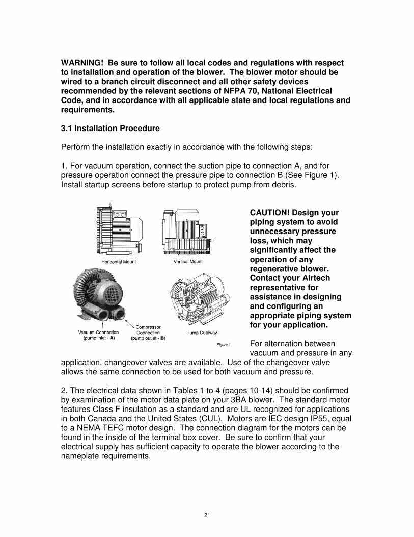
WARNING! Be sure to follow all local codes and regulations with respect to installation and operation of the blower. The blower motor should be wired to a branch circuit disconnect and all other safety devices recommended by the relevant sections of NFPA 70, National Electrical Code, and in accordance with all applicable state and local regulations and requirements. 3.1 Installation Procedure Perform the installation exactly in accordance with the following steps: 1. For vacuum operation, connect the suction pipe to connection A, and for pressure operation connect the pressure pipe to connection B (See Figure 1). Install startup screens before startup to protect pump from debris.
CAUTION! Design your piping system to avoid unnecessary pressure loss, which may significantly affect the operation of any regenerative blower. Contact your Airtech representative for assistance in designing and configuring an appropriate piping system for your application. For alternation between vacuum and pressure in any
application, changeover valves are available. Use of the changeover valve allows the same connection to be used for both vacuum and pressure. 2. The electrical data shown in Tables 1 to 4 (pages 10-14) should be confirmed by examination of the motor data plate on your 3BA blower. The standard motor features Class F insulation as a standard and are UL recognized for applications in both Canada and the United States (CUL). Motors are IEC design IP55, equal to a NEMA TEFC motor design. The connection diagram for the motors can be found in the inside of the terminal box cover. Be sure to confirm that your electrical supply has sufficient capacity to operate the blower according to the nameplate requirements.
21

3. A magnetic motor starter should always be used to connect the motor to the power supply. It is advisable to use thermal overload motor starters to provide maximum protection for the motor and wiring. All cabling used on starters should be secured with good quality cable clamps. We recommend that the motor starters used feature a time delay trip on high amperage to avoid nuisance trips on start-up. When the unit is started cold, over amperage may be experienced for a short time due to the higher resistance of the windings at lower temperatures. If using a change over or solenoid valve, ensure that the voltage connected to the valve matches that shown on the valve instructions or nameplate. Most valves are rated for 110 Volts 60Hz or 220 Volts 50 Hz. Connection of these valves to higher voltages may result in immediate valve failure. WARNING! The electrical installation should be made by a qualified electrician and in complete compliance with all NFPA 70 (National Electrical Code) requirements along with all state and local code requirements. The main disconnect and motors starters are assumed to be provided by others. 4. Install the necessary relief valves and confirm their proper operation.
22

4. Start-up CAUTION! Do not start the blower motor more than 10 times in one hour. If multiple and frequent start-ups are required by your application, install a minimum run timer in the motor control circuit to avoid decreased motor life and possible fire due to over-starting of the motor. 1.1 Start-up Procedure 1. Before operation, confirm the correct direction of rotation by jogging (switching rapidly on and off) the motor and observing the motor fan rotation in the same direction as the arrow. If the direction of rotation is incorrect, lock out the power and switch two leads (three phase) or rewire (single phase) to effect the opposite rotation direction. Recheck the direction of rotation before proceeding. 2. Do not operate the blower at pressure or vacuum ranges that exceed those shown in Tables one through four for the model being installed. This can be achieved by use of the recommended relief valve shown in Table 5. Note: Relief valves that have been factory pre-set have a label indicating the set pressure and an arrow indicating the direction of flow. The arrow will point into the pipe when installed in vacuum applications and out of the pipe when installed in pressure applications. Do not re-set the relief valve if it has been pre-set from the factory. In the event the relief valve setting needs to be reset, adjust the set screw to increase or decrease the tension on the spring. Place the blower in operation and note the current draw of the motor. When the current draw of the motor is near the maximum noted on the motor nameplate, tighten the locking nut on the valve and proceed. 3. When checking the current draw of the motor with an ammeter, be sure to confirm the voltage at the motor junction box. Low voltage conditions may result in difficulty starting or in unexpected motor failure or motor starter trips. 1.2 Potential Risks For Operators Noise emission: Free field noise limits are indicated in Tables 1-4 (pages 10-14). Hearing protection is not normally required at the expected noise generation levels in the table; however, local conditions may result in higher ambient noise. If this is the case and local noise exceeds OSHA recommended levels for expected exposure time (typically 85 dBA for eight hours), hearing protection should be used.
23

5. Maintenance and Servicing WARNING! Be sure the power supply is disconnected and locked out before attempting to do any maintenance on the unit. It is critical that the unit be locked out from starting during maintenance as severe injury or death could result from exposure to high voltage or rotating parts. CAUTION! Allow the blower to cool to a surface temperature of less than 100 F before attempting maintenance. Prolonged exposure to temperatures above 120F can cause severe burns. Clean the blower surfaces periodically to avoid build up of dust or other debris. Build up of debris can cause overheating and premature failure of the blower. If an inlet filter is being use, ensure that it remains clean during operation by examining the filter cartridge for debris build up. Replace dirty or clogged filter cartridges. On pressure units, periodically clean the inlet mesh screen to avoid loss of
capacity. If an external inlet filter is used, the filter element should be cleaned monthly or as frequently as required by local conditions. Excessive pressure drop will develop from use of clogged or dirty filters. This pressure drop will degrade blower performance and increase operating temperatures, leading possibly to premature pump failure. To replace the filter, remove the wing nut and cover. Remove the element and either
clean with compressed air or replace. Reassemble in reverse order. For vacuum applications, the optional in-line vacuum filter must be cleaned regularly, depending on local conditions. Cleaning can be achieved by blowing out with compressed air. If cleaning is not possible, replace the cartridge. Access the cartridge by unhooking the relevant clips and removing the cover. CAUTION! Do not attempt to check the filter cartridge during operation of the blower. Only check the cartridge after disconnecting the power from the blower and locking out the power to prevent an unexpected start.
24
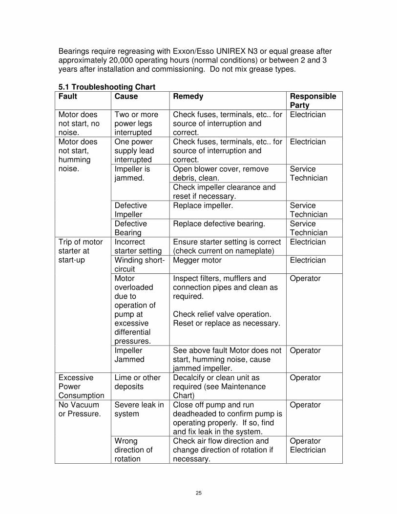
Bearings require regreasing with Exxon/Esso UNIREX N3 or equal grease after approximately 20,000 operating hours (normal conditions) or between 2 and 3 years after installation and commissioning. Do not mix grease types. 5.1 Troubleshooting Chart Fault Cause Remedy Responsible
Party Motor does not start, no noise.
Two or more power legs interrupted
Check fuses, terminals, etc.. for source of interruption and correct.
Electrician
Motor does not start, humming noise.
One power supply lead interrupted
Check fuses, terminals, etc.. for source of interruption and correct.
Electrician
Impeller is jammed.
Open blower cover, remove debris, clean.
Service Technician
Check impeller clearance and reset if necessary.
Defective Impeller
Replace impeller. Service Technician
Defective Bearing
Replace defective bearing. Service Technician
Trip of motor starter at start-up
Incorrect starter setting
Ensure starter setting is correct (check current on nameplate)
Electrician
Winding short-circuit
Megger motor Electrician
Motor overloaded due to operation of pump at excessive differential pressures.
Inspect filters, mufflers and connection pipes and clean as required. Check relief valve operation. Reset or replace as necessary.
Operator
Impeller Jammed
See above fault Motor does not start, humming noise, cause jammed impeller.
Operator
Excessive Power Consumption
Lime or other deposits
Decalcify or clean unit as required (see Maintenance Chart)
Operator
No Vacuum or Pressure.
Severe leak in system
Close off pump and run deadheaded to confirm pump is operating properly. If so, find and fix leak in the system.
Operator
Wrong direction of rotation
Check air flow direction and change direction of rotation if necessary.
Operator Electrician
25

Fault Cause Remedy Responsible Party
Insufficient Vacuum
System too small
Use larger system Operator
Inlet piping too long or too small.
Increase pipe diameter to reduce pressure loss in inlet piping. Contact Airtech for assistance in determining correct pipe size.
Operator
Leak at connection to vacuum system.
Check for leaks and repair if necessary.
Operator
Density of gas handles different from air.
Consider increased limits on operation due to density differences. Consult Airtech, Inc. for assistance.
Airtech Engineering
Change in impeller geometry due to erosion
Clean impeller and examine for wear. Replace if necessary.
Service Technician
Inlet filter clogged.
Change filter element; remove clog.
Operator
Vacuum relief valve incorrectly set.
Reset or replace vacuum relief valve. Contact Airtech for assistance.
Operator
Seal defective. Replace seal. Service Technician
Abnormal flow noises.
Flow speed too high.
Clean pipes or use larger pipes to connect unit to process.
Operator
Muffler soiled. Clean muffler inserts, replace if necessary.
Operator
Abnormal running noise
Ball bearing defective or insufficient lubrication on bearing.
Re-grease or replace bearing as required.
Service Technician
Compressor leaky
Seals on muffler defective.
Tighten muffler connection. Replace gasket if necessary.
Operator
Seals in motor area defective
Replace as necessary. Service Technician
26

WARNING! Before attempting an on-site repair, ensure that a qualified electrician has disconnected the motor from the power supply so that accidental starting of the motor is impossible. After repairing the unit, be sure to follow the instructions noted in this manual in the Installation section (page 20). 5.2 Lifting For smaller units (less than 65 lbs/ 30 kgs), it may be possible to lift the units manually. When doing so, be sure to understand the weight of the unit being lifted and to follow good lifting safety procedures.
Model Weight Lbs/kgs
Model Weight Lbs/kgs
3BA1300-7AT06 20/9 3BA1310-7AT26 33/15 2BA1300-7AT16 22/10 3BA1410-7AT36 55/25 3BA1400-7AT06 29/13 3BA1410-7AT46 59.5/29 3BA1400-7AT26 37.5/17 3BA1510-7AT46 86/39 3BA1500-7AT06 40/18 3BA1510-7AT56 97/44 3BA1500-7AT16 46.5/21 3BA1610-7AT26 104/47 3BA1500-7AT26 51/23 3BA1610-7AT36 119/54 3BA1500-7AT36 55/25 3BA1610-7AT46 163/74 3BA1600-7AT06 57.5/26 3BA1610-7AT56 172/78 3BA1600-7AT16 64/29 3BA1640-7AT36 128/58 3BA1600-7AT26 75/34 3BA1640-7AT46 172/78 3BA1600-7AT36 90.5/41 3BA1640-7AT56 181/82 3BA1800-7AT06 128/58 3BA1810-7AT16 250/113 3BA1800-7AT16 143/65 3BA1810-7AT26 260/118 3BA1800-7AT26 150/68 3BA1810-7AT36 316/143 3BA1900-7AT06 265/120 3BA1810-7AT46 341/155 3BA1900-7AT16 314/142 3BA1840-7AT26 260/118 3BA19437AT26 417/190 3BA1840-7AT36 316/143 3BA19437AT36 463/210 3BA1910-7AT16 409/186 3BA19437AT46 509/231 3BA1910-7AT36 455/206
3BA7210-0AT167 35.3/16 3BA7220-0AT567 61.7/28 3BA7310-0AT167 35.3/16 3BA7320-0AT567 66.1/30 3BA7410-0AT167 50.7/23 3BA7420-0AT267 72.7/33 3BA7510-0AT168 57.3/26 3BA7420-0AT567 86/39 3BA7510-0AT268 63.9/29 3BA7520-0AT268 88.2/40 3BA7610-0AT168 70.5/32 3BA7620-0AT368 106/48 3BA7610-0AT368 77.2/35 3BA7620-0AT568 143/65
3BA7630-0AT668 207/94
27

When lifting 3BA15 through 3BA19 (but not 3BA1943 units) or the 3BA75 through the 3BA76, use the eye bolt provided (eye bolts are not included on smaller units). One attachment point should be sufficient. Ensure that the crane is rated for the weight being lifted. For the 3BA1943, use the eye bolt and the holes in the feet of the blower to lift and maintain a balanced load. 5.3 Storage The 3BA units should be stored in a clean, dry environment. If stored in an area with a humidity of greater than 80 percent, store in a closed container with desiccant drying agents to avoid damage. 5.4 Disposal Dispose in accordance with all local health and safety regulations. Spare parts list are available from your local Airtech service center. Please contact your local Airtech representative for assistance. For additional assistance, please contact: Airtech, Inc., 150 South Van Brunt Street Englewood, NJ, 07631 Phone: 1-201-569-1173 Fax: 201-569-1696.
28

29

30
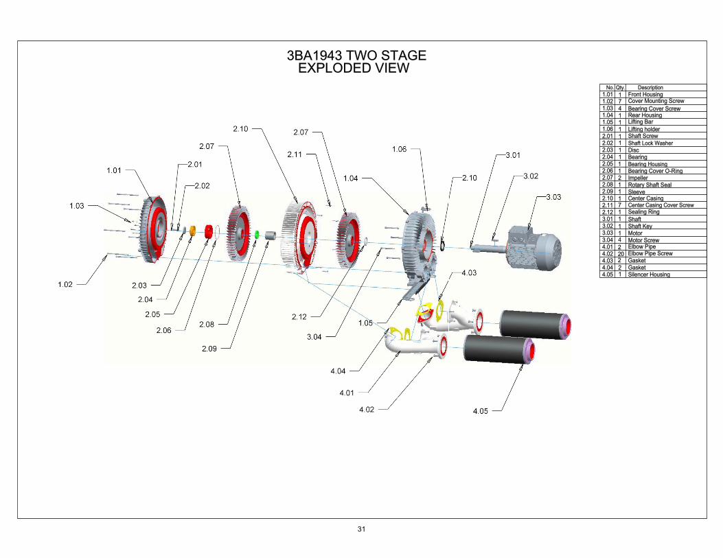
31

32

33

Airtech, Inc. (“Company”) Warranty Statement
Company warrants that on the date of shipment to Purchaser the goods will be of the kind and quality described herein, merchantable, and free of all defects in workmanship and materials. If within one year from the date of initial operation, but not more than eighteen months from date of shipment by the Company, of any item of the goods, Purchaser discovers that such item was not as warranted above and promptly notifies Company in writing thereof, Company shall remedy such defect by, at the Company’s option, adjustment, repair or replacement of the item and any affected part of the good. Purchaser shall assume all responsibility and expense for removal, reinstallation and freight in connection with the foregoing remedy. The same obligations and conditions shall extend to replacement items furnished by the Company hereunder. Company shall have the right of disposal of items replaced by it. Purchaser shall grant Company access to the goods at all reasonable times in order for Company to determine any defect in the goods. In the event that adjustment, repair or replacement does not remedy the defect, the Company and Purchaser shall negotiate in good faith an equitable adjustment in the contract price. The Company’s responsibility does not extend to any item of the goods which has not been manufactured and sold by the Company. Such item shall be covered only by the express warranty, if any, by the manufacturer thereof. The Company and its suppliers shall also have no responsibility if the goods have been improperly stored, handled or installed, or if the goods have not been operated or maintained according to their ratings or according to the instructions in Company or supplier furnished manuals, or if unauthorized repairs or modifications have been made to the goods. THIS WARRANTY IS EXPRESSLY IN LIEU OF ALL OTHER WARRANTIES (EXCEPT TITLE) INCLUDING BUT NOT LIMITED TO IMPLIED WARRANTIES OF MERCHANTABILITY AND FITNESS, AND CONSTITUTES THE ONLY WARRANTY OF COMPANY WITH RESPECT TO THE GOODS. The forgoing states Purchaser’s exclusive remedy against Company and its suppliers for any defect in the good or for failure of the goods to be as warranted, whether Purchaser’s remedy is based on contract, warranty, failure of such remedy to achieve its essential purpose, tort (including negligence), strict liability, indemnity, or any other legal theory, and whether arising out of warranties, representations, instructions, installations, or defects from any cause. Neither Company nor its suppliers shall be liable, whether in contract, warranty, failure of a remedy to meet its essential purpose, tort (including negligence), strict liability, indemnity or any other legal theory, for loss of use, revenue or profit or for cost of capital or of substitute use or performance or for indirect, liquidated, incidental or consequential damages or for any other loss or cost of a similar type, or for claims by Purchaser for damages of Purchaser’s customers.
34

35

150 South Van Brunt St.Englewood, NJ 07631Tel: 1-888-222-9940Fax: [email protected]
SOUTH2121 Newmarket Pkwy. Suite 110Marietta, GA 30067Tel: 770 690 0700Fax: 770 690 [email protected]
WEST42 Digital Drive #9Novato, CA 94949Tel: 415 382 9000Fax: 415 382 [email protected]
CHINA
2nd Building,Jiangbian Second Industrial ParkSonggang Town, Bao'an DistrictShenzhen, ChinaTel: +86 755 81730991(Ext.8018)Fax: +86 755 81730986www.airtechchina.com
10 / 9 Sainsbury RoadO'Connor 6163 WAAustraliaTel: +61 8 9304 6121Fax: +61 8 9331 4813www.vacuvane.com.au
EUROPE EUROPE
VacuvaneVacuum Technology GMBHPfaffenpfad 5D-97440 WerneckGermanyTel: +49 9722 943 96 0Fax: +49 9722 943 96 29www.vacuvane.com
HPEPressure & Vacuum TechnologyC. dels Amics d'Argentona, 4008310 Argentona (Barcelona)SpainTel: +34 93 797 17 66Fax: +34 93 797 17 54www.hpe-technology.com
www.airtechusa.com 3BA_Manual 06-2013