thermoelectric transport in
142
T HERMOELECTRIC TRANSPORT IN SEMICONDUCTING HETEROSTRUCTURES Dissertation zur Erlangung des akademischen Grades doctor rerum naturalium (Dr. rer. nat.) vorgelegt von NICKI F RANK HINSCHE geboren am 07.08.1982 in Halle/Saale Martin-Luther-Universität Halle-Wittenberg Institut für Physik der Naturwissenschaftlichen Fakultät II Fachgruppe Quantentheorie des Festkörpers Von-Seckendorff-Platz 1, 06120 Halle/Saale Halle (Saale), den 13.11.2012
-
Upload
khangminh22 -
Category
Documents
-
view
1 -
download
0
Transcript of thermoelectric transport in

THERMOELECTRIC TRANSPORT IN
SEMICONDUCTING HETEROSTRUCTURES
Dissertationzur Erlangung des akademischen Grades
doctor rerum naturalium (Dr. rer. nat.)
vorgelegt von
NICKI FRANK HINSCHE
geboren am 07.08.1982 in Halle/Saale
Martin-Luther-Universität Halle-Wittenberg
Institut für Physikder Naturwissenschaftlichen Fakultät II
Fachgruppe Quantentheorie des FestkörpersVon-Seckendorff-Platz 1, 06120 Halle/Saale
Halle (Saale), den 13.11.2012

Erstgutachterin: Prof. Dr. Ingrid MertigZweitgutachter: PD Dr. Arthur ErnstDrittgutachter: Prof. Dr. Kornelius Nielsch
Tag der Abgabe: 13.11.2012Tag der öffentlichen Verteidigung: 28.05.2013Vorsitzender der Promotionskommission: Prof. Dr. Jochen Balbach

“An expert is someone who knows some of the worst mistakes that can be madein his subject and who manages to avoid them.”
WERNER HEISENBERG in “Der Teil und das Ganze”, 1969


Contents
1 Introduction 1
2 Thermoelectric concepts 52.1 IOFFE’s theory of thermoelectrics . . . . . . . . . . . . . . . . . . . . . . . . . . . . . . . . . 52.2 Low-dimensional thermoelectrics . . . . . . . . . . . . . . . . . . . . . . . . . . . . . . . . . 62.3 Phonon glass - electron crystal . . . . . . . . . . . . . . . . . . . . . . . . . . . . . . . . . . . 72.4 Phonon-blocking and electron-transmitting superlattices . . . . . . . . . . . . . . . . . . . 9
3 Electronic structure 113.1 Density functional theory . . . . . . . . . . . . . . . . . . . . . . . . . . . . . . . . . . . . . . 11
3.1.1 Theorem of HOHENBERG & KOHN . . . . . . . . . . . . . . . . . . . . . . . . . . . . 113.1.2 Exchange-correlation functional . . . . . . . . . . . . . . . . . . . . . . . . . . . . . 13
3.2 Band structure methods . . . . . . . . . . . . . . . . . . . . . . . . . . . . . . . . . . . . . . 153.2.1 KORRINGA-KOHN-ROSTOKER method . . . . . . . . . . . . . . . . . . . . . . . . . . 153.2.2 The plane-wave pseudopotential method . . . . . . . . . . . . . . . . . . . . . . . . 18
3.3 The DIRAC equation . . . . . . . . . . . . . . . . . . . . . . . . . . . . . . . . . . . . . . . . . 223.4 Evaluation of surface integrals . . . . . . . . . . . . . . . . . . . . . . . . . . . . . . . . . . 24
4 BOLTZMANN transport theory 274.1 Distribution function . . . . . . . . . . . . . . . . . . . . . . . . . . . . . . . . . . . . . . . . 274.2 Linearisation and relaxation time approximation . . . . . . . . . . . . . . . . . . . . . . . 284.3 Transport coefficients . . . . . . . . . . . . . . . . . . . . . . . . . . . . . . . . . . . . . . . . 31
4.3.1 Decoupled processes . . . . . . . . . . . . . . . . . . . . . . . . . . . . . . . . . . . . . 334.3.2 Coupled processes . . . . . . . . . . . . . . . . . . . . . . . . . . . . . . . . . . . . . . 34
4.4 Lattice thermal conductivity . . . . . . . . . . . . . . . . . . . . . . . . . . . . . . . . . . . . 374.5 Beyond relaxation time approximation . . . . . . . . . . . . . . . . . . . . . . . . . . . . . . 40
4.5.1 Electron-impurity scattering . . . . . . . . . . . . . . . . . . . . . . . . . . . . . . . . 404.5.2 Electron-phonon scattering . . . . . . . . . . . . . . . . . . . . . . . . . . . . . . . . 42
5 Selected results 455.1 Bi2Te3/Sb2Te3 heterostructures . . . . . . . . . . . . . . . . . . . . . . . . . . . . . . . . . . 455.2 Silicon/Germanium heterostructures . . . . . . . . . . . . . . . . . . . . . . . . . . . . . . . 71
6 Summary & outlook 99
List of publications i
Bibliography iii
i


List of Figures
1.1 Schematics of a thermoelectric cooler, a thermoelectric generator and a thermoelectricdevice. . . . . . . . . . . . . . . . . . . . . . . . . . . . . . . . . . . . . . . . . . . . . . . . . . 1
1.2 Thermoelectric conversion efficiency for different values of ZT. . . . . . . . . . . . . . . . 2
2.1 Evolution of the thermoelectric figure of merit ZT for semiconductors in the years1950 to 2010. . . . . . . . . . . . . . . . . . . . . . . . . . . . . . . . . . . . . . . . . . . . . . 5
2.2 Dependence of thermoelectric transport properties on the charge concentration. . . . . . 62.3 Complex thermoelectric materials within the phonon glass - electron crystal approach. 82.4 Transmission electron microscopy graphs of Bi2Te3/Sb2Te3 and Si/Ge superlattices. . . 9
3.1 Schematic presentation of different potential shapes. . . . . . . . . . . . . . . . . . . . . . 163.2 Nonlocal part of the relativistic pseudopotential and wavefunctions for atomic bismuth. 193.3 Phonon dispersion relation ω(q) for bulk silicon . . . . . . . . . . . . . . . . . . . . . . . . 223.4 Band structure of Bi2Te3 with and without spin-orbit coupling. Visualization of the
band inversion. . . . . . . . . . . . . . . . . . . . . . . . . . . . . . . . . . . . . . . . . . . . . 233.5 Schematic of a tetrahedron for the approximation of the FERMI surface and the related
properties. . . . . . . . . . . . . . . . . . . . . . . . . . . . . . . . . . . . . . . . . . . . . . . . 253.6 FERMI surface of electron-doped bulk silicon determined with different k-meshes. . . . 26
4.1 Schematic view of the distribution functions under applied electrical and thermal gra-dient . . . . . . . . . . . . . . . . . . . . . . . . . . . . . . . . . . . . . . . . . . . . . . . . . . 30
4.2 Sketch of OHM’s law, the SEEBECK effect and the THOMSON effect. . . . . . . . . . . . . 314.3 FERMI surfaces and transport distribution function for Bi2Te3. . . . . . . . . . . . . . . . 334.4 Electronic thermal conductivity and LORENZ function for a spherical two band model
and for bulk Bi2Te3. . . . . . . . . . . . . . . . . . . . . . . . . . . . . . . . . . . . . . . . . . 344.5 Anisotropic thermopower and THOMSON coefficient for Bi2Te3 . . . . . . . . . . . . . . . 374.6 Phonon thermal conductivity, specific heat, and group velocities for bulk silicon. . . . . 384.7 Experimental temperature-dependent thermal conductivity of bulk silicon. . . . . . . . . 394.8 Anisotropy of the electron-impurity relaxation time in BORN approximation for electron-
doped bulk Bi2Te3 . . . . . . . . . . . . . . . . . . . . . . . . . . . . . . . . . . . . . . . . . . 414.9 Electron-phonon coupling properties of bulk aluminium. . . . . . . . . . . . . . . . . . . . 43
5.1 Electrical conductivity anisotropy of bulk Bi2Te3 and Sb2Te3. Topology of the conduc-tion band of bulk Bi2Te3 . . . . . . . . . . . . . . . . . . . . . . . . . . . . . . . . . . . . . . . 45
5.2 Unit cells and directional anisotropies of lattice thermal conductivity and electricalconductivity for different Bi2Te3/Sb2Te3-SL. . . . . . . . . . . . . . . . . . . . . . . . . . . 46
5.3 Calculated anisotropic thermoelectric transport properties of Bi2Te3/Sb2Te3-SL. . . . . 475.4 FERMI surfaces of electron-doped silicon and anisotropic thermopower under biaxial
001-strain. . . . . . . . . . . . . . . . . . . . . . . . . . . . . . . . . . . . . . . . . . . . . . . . 715.5 Effective masses of 111-strained bulk Si and cross-plane thermoelectric transport prop-
erties of an Si/Ge-SL grown on 111-Si. . . . . . . . . . . . . . . . . . . . . . . . . . . . . . . 72
iii


List of abbreviations
AE all-electron . . . . . . . . . . . . . . . . . . . . . . . . . . . . . . . . . . . . . . . . . . . . . . . . . . . . . . . . . . . . . . . . . . . . . . . . . . . . . . 19
ASA atomic-sphere approximation . . . . . . . . . . . . . . . . . . . . . . . . . . . . . . . . . . . . . . . . . . . . . . . . . . . . . . . . . . . 16
BZ BRILLOUIN zone . . . . . . . . . . . . . . . . . . . . . . . . . . . . . . . . . . . . . . . . . . . . . . . . . . . . . . . . . . . . . . . . . . . . . . . . 10
CBM conduction band minimum . . . . . . . . . . . . . . . . . . . . . . . . . . . . . . . . . . . . . . . . . . . . . . . . . . . . . . . . . . . . . . 41
DFPT density functional perturbation theory . . . . . . . . . . . . . . . . . . . . . . . . . . . . . . . . . . . . . . . . . . . . . . . . . . 21
DFT density functional theory . . . . . . . . . . . . . . . . . . . . . . . . . . . . . . . . . . . . . . . . . . . . . . . . . . . . . . . . . . . . . . . . . 3
DOS density of states . . . . . . . . . . . . . . . . . . . . . . . . . . . . . . . . . . . . . . . . . . . . . . . . . . . . . . . . . . . . . . . . . . . . . . . . . . 7
E-PH electron-phonon . . . . . . . . . . . . . . . . . . . . . . . . . . . . . . . . . . . . . . . . . . . . . . . . . . . . . . . . . . . . . . . . . . . . . . . . . 42
GF GREEN’s function . . . . . . . . . . . . . . . . . . . . . . . . . . . . . . . . . . . . . . . . . . . . . . . . . . . . . . . . . . . . . . . . . . . . . . . . . 3
GGA generalized gradient approximation . . . . . . . . . . . . . . . . . . . . . . . . . . . . . . . . . . . . . . . . . . . . . . . . . . . . 13
IBZ irreducible part of the BRILLOUIN zone . . . . . . . . . . . . . . . . . . . . . . . . . . . . . . . . . . . . . . . . . . . . . . . . . 25
IFC interatomic force constants. . . . . . . . . . . . . . . . . . . . . . . . . . . . . . . . . . . . . . . . . . . . . . . . . . . . . . . . . . . . . .21
KKR KORRINGA-KOHN-ROSTOKER . . . . . . . . . . . . . . . . . . . . . . . . . . . . . . . . . . . . . . . . . . . . . . . . . . . . . . . . . . . .3
L(S)DA local (spin) density approximation . . . . . . . . . . . . . . . . . . . . . . . . . . . . . . . . . . . . . . . . . . . . . . . . . . . . . . 13
LDOS local density of states. . . . . . . . . . . . . . . . . . . . . . . . . . . . . . . . . . . . . . . . . . . . . . . . . . . . . . . . . . . . . . . . . . . .41
PBET phonon-blocking and electron-transmitting . . . . . . . . . . . . . . . . . . . . . . . . . . . . . . . . . . . . . . . . . . . . . . 9
PGEC phonon glass-electron crystal . . . . . . . . . . . . . . . . . . . . . . . . . . . . . . . . . . . . . . . . . . . . . . . . . . . . . . . . . . . . . 7
PGV phonon group velocity . . . . . . . . . . . . . . . . . . . . . . . . . . . . . . . . . . . . . . . . . . . . . . . . . . . . . . . . . . . . . . . . . . . . 7
PHDOS phonon density of states. . . . . . . . . . . . . . . . . . . . . . . . . . . . . . . . . . . . . . . . . . . . . . . . . . . . . . . . . . . . . . . . .24
PP pseudopotential . . . . . . . . . . . . . . . . . . . . . . . . . . . . . . . . . . . . . . . . . . . . . . . . . . . . . . . . . . . . . . . . . . . . . . . . . . .3
QDSL quantum-dot superlattice . . . . . . . . . . . . . . . . . . . . . . . . . . . . . . . . . . . . . . . . . . . . . . . . . . . . . . . . . . . . . . . 10
RTA relaxation time approximation . . . . . . . . . . . . . . . . . . . . . . . . . . . . . . . . . . . . . . . . . . . . . . . . . . . . . . . . . . . 3
SKKR screened KORRINGA-KOHN-ROSTOKER . . . . . . . . . . . . . . . . . . . . . . . . . . . . . . . . . . . . . . . . . . . . . . . . 18
SL superlattice . . . . . . . . . . . . . . . . . . . . . . . . . . . . . . . . . . . . . . . . . . . . . . . . . . . . . . . . . . . . . . . . . . . . . . . . . . . . . . . 3
SOC spin-orbit coupling . . . . . . . . . . . . . . . . . . . . . . . . . . . . . . . . . . . . . . . . . . . . . . . . . . . . . . . . . . . . . . . . . . . . . . 23
TDF transport distribution function . . . . . . . . . . . . . . . . . . . . . . . . . . . . . . . . . . . . . . . . . . . . . . . . . . . . . . . . . . 24
TE thermoelectric . . . . . . . . . . . . . . . . . . . . . . . . . . . . . . . . . . . . . . . . . . . . . . . . . . . . . . . . . . . . . . . . . . . . . . . . . . . . 1
TEC thermoelectric cooler . . . . . . . . . . . . . . . . . . . . . . . . . . . . . . . . . . . . . . . . . . . . . . . . . . . . . . . . . . . . . . . . . . . . . 1
TEG thermoelectric generator . . . . . . . . . . . . . . . . . . . . . . . . . . . . . . . . . . . . . . . . . . . . . . . . . . . . . . . . . . . . . . . . . 1
USPP ultra-soft pseudopotential . . . . . . . . . . . . . . . . . . . . . . . . . . . . . . . . . . . . . . . . . . . . . . . . . . . . . . . . . . . . . . . 24
v


CHAPTER 1
INTRODUCTION
Thermoelectrics are solid-state materials that convert heat into electricity or electrical power di-rectly into cooling or heating [Row06]. The physical effects on which thermoelectricity foot, areknown since the early 19th century. In the 1820s SEEBECK [See26] found that the electrochemi-cal potential and the temperature couple with each other. Applying a temperature gradient ∇T ona materials produces a chemical potential gradient or an electrical field E = S∇T. Here, S is theSEEBECK coefficient or thermopower. In a closed circuit an electrical current j will flow. Few yearslater, PELTIER [Pel34] became aware of the reversion of this phenomenon, when he demonstratedthe emergence of a heat flux Q via coupling to an electrical current, as Q =Π j. The proportionalityof both currents is the PELTIER coefficient. The classical theory of thermoelectrics was then gener-alized by THOMSON [God11], the later LORD KELVIN, who showed that the SEEBECK and PELTIER
effects are not independent and can be related by the THOMSON coefficient K.
With this considerations it is obvious that thermoelectric (TE) effects are able to convert thermalenergy into electrical energy (thermoelectric generator (TEG)) and vice versa (thermoelectric cooler(TEC)). These two concepts of TE energy conversion are sketched in figure 1.1.
(c)
(a) (b)
V
P
(d)
active cooling
heat rejection
n-type p
-type n
-type p
-type
heat source
heat sink
Figure 1.1: Schematics of a thermoelectric cooler, a thermoelectric generator and a thermoelectric device based on n- andp-type semiconductors. (a) Scheme of a thermoelectric cooler (TEC). (b) Scheme of a thermoelectric generator (TEG). Thearrows in the segments illustrate the electric current flow (blue: low temperature, red: high temperature). (c) Sketch of athermoelectric device built of several thermocouples connected in series. (d) The thin-film TEC MPC-D305 from MICROPELTcompany on a one euro cent coin [BNSV07].
Nowadays, modern thermocouples are not made of two metals, but are rather formed by heavilydoped n- and p-type semiconducting materials. The segments of n- and p-type semiconductors arethen connected by a good conductor, i.e. a metal. An applied voltage will now drive an electrical cur-rent through the circuit. Depending on the direction of the electrical current one side will be cooled(heated) and the other heated (cooled) [Bel08]. The method of a TEC shown in figure 1.1(a). Withina TEG, the TE processes are reversed. Active cooling or heating of one side of the thermocouple willresult in an electrical field, forcing an electrical current to flow (cf. figure 1.1(b)). Conventional TE
1

Chapter 1. Introduction
Figure 1.2: Thermoelectric conversion efficiency calculated byequation (1.1) for different values of ZT. For ZT = ∞ theCARNOT limit is reached. The cold side of the thermocouple isfixed to 300K, while the temperature for the hot side is varied.Colored shaded regions show the efficiency range of commonconventional heat-electricity conversion methods.
0
10
20
30
40
50
60
70
300 400 500 600 700 800 900
ZT= 0.5ZT= 1ZT= 2ZT= 3
ZT=!
!(%
)
Thot (K)
ZT= 10
geothermal
solar
nuclear
fossil fuel
Tcold = 300K
devices, as shown in figure 1.1(c), are built of hundreds of n- and p-type thermocouples connectedin series. To state some numbers, MICROPELTs TEG MPG-D751 [Mic12] consists of 540 segmentsproducing an electrical power output of Pel ≈ 12mW and a voltage U ≈ 3V at a heat load of Pth ≈ 2Wand a temperature difference of ∆T ≈ 30K.
The energy conversion efficiency η of a TEG is given by [Iof57]
η= Thot −Tcold
Thot·
√1+ZT −1√
1+ZT + TcoldThot
with ZT = σS2
κel +κphT (1.1)
T is the average temperature of the TE device, and ZT is the average thermoelectric figure ofmerit that expresses the possible conversion efficiency of the material. Obviously, Z depends onlyon the material’s electronic and vibronic transport properties: σ is the electrical conductivity, Sis the thermopower, κel is the electronic part of the thermal conductivity, while κph is the latticepart of the thermal conductivity. The numerator σS2 is referred to as the power factor. The TEconversion efficiency for different values of ZT is shown in figure 1.2. From equation (1.1) andfigure 1.2 one obtains that for infinite values of ZT the CARNOT efficiency will be reached. Forconventional bulk thermoelectrics, e.g. Bi2Te3 , ZT ≈ 0.5− 1, and thus the conversion efficiencywill be well below 20% even at large temperature differences. However, due to its desirable natureof being highly reliable, stable, compact, and integrable TE devices are extensively used in outer-space missions, energy-autarkic sensor systems, and waste-heat recovery within the last 50 years[Nie07,Bel08,ST08,Vin09]. Increasing ZT would extend these niche areas and lead to new potentialTE applications which could compete with conventional geothermal, solar, fossil and nuclear energyconversion methods (cf. figure 1.2) and serve as a new alternative energy source.
In the last years, state-of-the-art concepts and experiments enabled nanostructured TES whichgave a considerable leap forward in reaching higher values of ZT. Most remarkable results were pre-sented by HARMAN [HWLT05] for a PbSeTe/PbTe quantum-dot superlattice (QDSL) with ZT = 3.5and VENKATASUBRAMANIAN [VSC01] for a Bi2Te3/Sb2Te3-SL with ZT = 2.4. Both systems are builtof alternating epitaxially grown material layers. This introduces new artificial interfaces which areexpected to block phonons and to transmit electrons. From this separation it is expected that thelattice part of the thermal conductivity κph will be suppressed, while the electronic transport prop-erties, mainly the power factor σS2, might be enhanced compared to those of the bulk constituents.Consequently, the figure of merit would be enhanced.
The scope of this thesis is to understand the microscopic origin of TE transport in semiconduct-
2

ing heterostructures and to identify and elucidate mechanisms which could lead to enhanced TEconversion efficiency. Based on first-principles calculations the electronic structure and the re-lated TE transport properties of bulk Bi2Te3, Sb2Te3, Si, and Ge, as well as their heterostructuresBi2Te3/Sb2Te3 and Si/Ge are determined and discussed. The focus is on the influence of bulk andinterfacial strain, varying charge carrier concentration, temperature and superlattice (SL) periodson the TE transport properties.
This thesis is organized in four parts. First, the reader is introduced to conventional and novelconcepts of TE material design. In the second part the basis for the electronic structure calculationsis given. The concept of density functional theory (DFT) is introduced (section 3.1) and the bandstructure methods of choice, a KORRINGA-KOHN-ROSTOKER (KKR) GREEN’s function (GF) method(section 3.2.1) and a method based on plane waves and pseudopotentials (PPS) (section 3.2.2) aredescribed. The third part consists of a detailed derivation of the TE transport coefficients for theBOLTZMANN transport theory within the relaxation time approximation (RTA) (section 4). This isdone for electrons (section 4.3) and for phonons (section 4.4). The impact of microscopic scattering,beyond a RTA, is accounted for in section 4.5. In the last part, four publications are chosen to presentthe obtained results. After a brief summary two publications each, for heterostructures based on thechalcogenides Bi2Te3 and Sb2Te3 (section 5.1) and for heterostructures based on Si and Ge (section5.2), are attached. A summary and outlook will conclude this thesis.
3


CHAPTER 2
THERMOELECTRIC CONCEPTS
In the last sixty years, strong efforts were made to improve the TE figure of merit ZT. In figure2.1 this development is summarized by showing the optimal ZT values for different materials to-gether with their original reference. While a huge amount of concepts were developed, only a fewof them had reasonable impact on the TE research and will be reviewed in the following sections.Three of the presented concepts already showed their reliability and contributed significantly to theenhancement of ZT. Those are, marked by red arrows in figure 2.1, IOFFE’s work on TE semicon-ductors [Iof57] (section 2.1), HICKS’ & DRESSELHAUS’ introduction of low-dimensional TES [HD93](section 2.2), and SLACK’s proposal of materials that are glass- and crystal-like at the same time forphonons and electrons, respectively. [Sla95] (section 2.3).
Bi2Te3 [Wri58]
n-type
p-type
Bi2Te3/Bi2Te2.83Se0.17 !SL [VSC01]
Bi2Te3/Sb2Te3 !SL [VSC01]
Si85Ge15 [DES+64]
bulk
alloy
nano
PbTe[Kud71]Bi2Te3 [Gol58]
(Bi,Sb)2Te3 [TBD62]
PbSe0.98Te0.02/PbTe!QDSL[HWL+05]
(BixSb1!x)2Te3 [CCP+92]
PbTe/Pb1!xEuxTe!SL[HHS+96]AgPb18SbTe20 [HLG+04]
PbSeTe!QDSL[HTW+02]PbTe1!xSex [PSL+11]
Si!NW[BBTK+08]
La3Te4 [MSS09]
Tl0.02Pb0.98Te[HJT+08]
BiSbTe[PHM+08]
0
0.5
1
1.5
2
2.5
3
3.5
1950 1970 1990 2010
ZT
Year
Ioffe Hicks Slack
ZnSb[Tel47]
(GeTe)0.85(AgSbTe2)0.15 [Woo88]
Figure 2.1: Evolution of the thermoelectric figure of merit ZT for semiconductors in the years 1950 to 2010. Circles indicatesingle crystalline bulk materials, squares alloyed bulk materials, and triangles nanostructured materials, e.g. nanowires,heterostructures or quantum-dots. Blue and red colors indicate n- and p-type materials, respectively. Given to each symbolis the original reference, which can be found at page iii et seqq.
2.1 IOFFE’s theory of thermoelectrics
In the 1950s, Abram Fedorovich IOFFE set the basis for the modern theory of thermoelectricity. Hefocused on studies of electrical and thermal transport properties of a new class of solids that he latercalled semiconductors [VI98]. IOFFE recognized semiconductors as potential materials with highthermoelectric conversion efficiency. Materials of interest were particulary bulk PbS, PbTe, PbSe,ZnSb, Bi2Te3, and Sb2Te3. By introducing and analyzing the figure of merit ZT, he rapidly realizedthat ZT cannot be optimized by optimizing its constituents [Iof58]. The interdependence of the keytransport properties σ,S, and κ is a challenge for thermoelectrics till today. In figure 2.2 this inter-dependence is highlighted for bulk p-type Bi2Te3 at room temperature. The heavy dependence of
5

Chapter 2. Thermoelectric concepts
0
50
100
150
200
250
300
S (!
V/K
)
0
5
10
15
20
25
30
35
40
PF
(!
W/c
m K
2)
0.1
1
10
100
! (
W/m
K)
0
5
10
15
20
25
30
35
40
ZT
1.0
0.75
0.5
0.25
0
ZT
!
!S2
S
!S2
"ph"el
ZT
N (3!1019 cm"3) N (3!1019 cm"3)1010.10.010.0010.0001 1010.10.010.0010.0001
Figure 2.2: Dependence of thermoelectric transport properties on the charge concentration on the example of bulk p-typeBi2Te3 at room temperature. Shown are the electrical conductivity σ (black dash-dotted line), the thermopower S (red line),the power factor σS2 (blue line), the electronic part of thermal conductivity κel (orange line), the lattice part of the thermalconductivity κph (black dashed line) and the related figure of merit ZT (green line). Results are taken from [E5].
the TE transport on the charge-carrier concentration as well as the interdependence of the singletransport properties is obvious. Assuming pure spherical band conduction, i.e. in a highly degen-erate semiconductor, it is σ∝ N and S ∝ N−2/3 [Mot67, CM69], thus the electrical conductivity andthe thermopower are directly related by S ∝ σ−2/3[E8]. The electronic part of the thermal conduc-tivity κel scales directly with the electrical conductivity σ, as proposed by the WIEDEMANN-FRANZ
law [Zim60]. Thus, the conversion efficiency of a semiconducting TE is highly dependent on thecharge carrier concentration N and should be optimized by doping [VI98]. IOFFE was one of the firstwho claimed that N should be in the order of 1×1019 cm−3 for an optimal semiconducting TE. WhileIOFFE and his co-workers also developed the concept of reducing the lattice thermal conductivity κph
by alloying and by the introduction of point defects, it was IOFFE’s generalized theory on optimizingZT by varying the amount of doping, which boosted TEs from 1950 on (cf. figure 2.1). His work onsemiconducting TES culminated in his classic book [Iof57] which sets a standard for understandingbulk TES up to now.
Despite the remarkable impact of IOFFE’s theory, it is worth noting that, expectedly, other sci-entists contributed to the then young field of semiconducting TEs, too. The works of TELKES,GOLDSMID and PRICE on ZnSb, Bi2Te3 and Sb2Te3 and their alloys should be quoted representa-tively [Tel47,Pri56a,Gol56,Pri56b,GSW58,Wri58,SKS62]
2.2 Low-dimensional thermoelectrics
In 1993, the pioneering work of HICKS & DRESSELHAUS [HD93, HHD93] renewed interest in TES,becoming the inspiration for most of the recent developments in the field of low-dimensional TES
[Sha11]. The basic idea was that quantum confinement of electrons and holes would dramaticallyincrease ZT by independently increasing the power factor. Quantum confinement is available inlow-dimensional geometries as quantum dots (0D), nanowires (1D), as well as quantum wells andSLS (2D).
While infinite enhancements on the in-plane figure of merit were predicted at vanishing geometrysize [HD93, HHD93, DDS+99], HICKS & DRESSELHAUS neglected electron tunnelling and thermalcurrents between the layers by introducing infinite potential barriers at zero width. Later on it wasshown that for realistic barrier heights and widths the enhancement is rather moderate, predictingZT values that at their best are a few percent larger than corresponding bulk materials [BR95a,BR95b,CR11]. Indeed, a few groups found evidently large enhancements of the thermopower in SLS
based on PbTe [HHSD96, KHCD99, HTSW00, HTWL02, HWLT05] and on SrTiO3 [Oht07, OKM+07,
6

2.3. Phonon glass - electron crystal
OMK+08,JS10]. However, the determination of the 2D charge carrier concentration is sophisticatedand leads in at least two of the previous experiments [HTSW00,HWLT05] to a way to large estimatesfor the thermopower [VHC+08]. In some of other cases, the carriers had to be confined in delta-doped like layers with a maximum width of a unit cell to show an enhancement upto ZT ≈ 2 [Oht07,OKM+07,OMK+08], while otherwise ZT would have been only marginally enhanced [KDL09].
Several experiments have been performed on processing and characterizing TE 1D nanowires[LWK+03, ZJS+05, BBTK+08, CHM+08, HCDL08, TZG08, YBP+09]. Confinement effects on the elec-tronic TE transport properties, say σS2, were negligible [LD03, CR11]. While at very low wirediameters, d ¿ 15nm, enhancements of the power factor could be reached [CR11], the main gainin ZT for nanowires came from a dramatical reduction of the lattice thermal conductivity. Here,phonon boundary scattering is the reason [ZJS+05]. Unfortunately, at small diameters the lattereffect causes a reduction of the phonon-drag effect and by that also of the thermopower [WLG92]. Ifboth, phonon boundary scattering and phonon drag, could be retained, promising values of ZT werefound for TE nanowires, too [BBTK+08].
Adding up the previous ideas, MAHAN & SOFO [MS96] argued that sharp features in the densityof states (DOS) alone could lead to enhancements of the thermopower and the power factor. Recentexperimental proofs of principle, showed this assumption to be achievable already in bulk materi-als by the introduction of a resonant defect level near the FERMI level [HJT+08, JKH09, LWG10,KNG+11].
2.3 Phonon glass - electron crystal
Obviously, the TE efficiency (1.1) is dictated by the figure of merit ZT. The latter can be optimizedby enhancing either the power factor σS2 or by decreasing the thermal conductivity κel +κph. Forlong time, the concept of alloying allowed for the lowest thermal conductivities [Iof57]. The reductionof κph was due to scattering of phonons by atomic substitutions and limited by the so-called alloylimit. Unfortunately, the introduction of impurities leads also to electron-impurity scattering whichmost often lowers the power factor.
At the best, TE electronic and vibronic properties are decoupled, allowing for both, maximizingthe power factor and minimizing the lattice contribution to the thermal conductivity. Having this inmind, SLACK proposed 1995 the concept of a phonon glass-electron crystal (PGEC) [Sla95, Sla79].The best TE material should possess thermal properties similar to that of a glass (κ300K . 1W/mK[CP87]) and electrical properties similar to that of a perfect single-crystal material [NMT99]. Upto now, several experimental and theoretical studies support the PGEC concept but differ in theirapproach.
Archetypical examples of bulk PGEC materials are the skutterudites ((Co,Ni,Fe)(As,Sb)3 and re-lated compounds) [NSM+96,NCS98,NMT99,SKL+08] and the clathrates (e.g. Ba8Ga16Si30) [Vin08b,NCSS98,DSM01,BCB+04,SYB+10]. The latter carry the TE approach within their name, as clath-rates is Latin for within a cage. As shown in figure 2.3(a), the typical crystal of skutteruditesand clathrates is cagelike (blue atoms), holding guest atoms inside the cages (purple and orangeatoms). The idea is that the cage atoms form a regular periodic crystal lattice along which electrons(or holes) can move fairly freely, ideally approaching the so-called electron crystal [NPK06]. The en-closed guest atom (often rattler) is commonly bigger, heavier and more loosely bound compared withthe cage atoms. The rattlers are believed to have independent oscillations that scatter the acousticphonons of the cage. This causes an avoided crossing of the acoustic phonon branches, leading to a di-minished phonon group velocity (PGV) and a drastically reduced κph. One then speaks of a phononglass, even though strictly speaking the long-range ordering is maintained in all cases [CAC+08].
7

Chapter 2. Thermoelectric concepts
George S. Nolas, Joe Poon,and Mercouri Kanatzidis DOI: 10.1126/science.1092963
, 818 (2004); 303Science
et al.Kuei Fang Hsu,g g
(b)
10.1021/cm901956r
!(W
/mK
)
Vuc (Å3)
Figure 2.3: Complex thermoelectric materials within the phonon glass - electron crystal approach. (a) Crystal structure ofthe type I clathrate. Cage atoms are shown in blue, guest atoms inside the tetrakaidecahedra are orange, and guest atomsinside the pentagonal dodecahedra are purple. Figure adapted from [NPK06]. (b) TEM image of a AgPb18SbTe20 sampleshowing a nanodot enclosed in the periodic crystal structure. Figure adapted from [HLG+04]. (c) Lattice thermal conductivityin dependence on the unit cell volume for different ZINTL-antimonides. For increasing unit cell volume and number of atomsin the unit cell, the lattice thermal conductivity rapidly decreases. Figure after [TMS09].
Similar findings, although not in cage-like crystal structures, were recently reported for heavilydoped Zn4Sb3 [CFB97,ZTIY03,SCNC04]. While showing a stable single-crystal structure with suffi-ciently high power factor, significant disorder is introduced, with zinc atoms diffusing over multiplevoid positions. These glass-like interstitial sites uncovered a highly effective mechanism for reduc-ing thermal conductivity, which is comparable to the rattling modes mentioned before. Total thermalconductivities of κ≈ 0.5W/mK and a figure of merit of ZT ≈ 1.3 were found at 400K [SCNC04].
An other concept of guest domains in a host matrix was recently provided by HSU [HLG+04]and others [KZG+06, BBG+09]. Here, the samples reveal compositional nano-modulations causedby precipitation and strain relaxation [SW01]. Exemplary, in figure 2.3(b) the transmission electronmicroscopy TEM image of an endotaxially dispersed nano-array within a AgPb18SbTe20 host crystalis shown. The very high number of guest domain-host matrix interfaces provides a formidablebarrier to phonons in the bulk sample [NPK06], enabling thermal conductivity values as low asκph = 0.45W/mK [HLG+04]. Moreover, the nano-inclusions occur to be highly conducive for theelectronic transport, thus backing-up the idea of a PGEC.
Introducing porous or holey materials to TEs did not gave a considerable leap forward [Gol09,TWL+10, LG09,E4]. Here, high-density nanoscopic holes are created in the material and can evenbe filled with various gases to control the lattice thermal conductivity [Gol09]. At first sight, onewould not expect porosity to affect the TE performance, as the holes will not contribute significantlyto neither the electronic nor the vibronic transport; thus, their ratio is constant. However, it wasfound that the increased surface to volume ratio most probably leads to an enhanced phonon-surfacescattering reducing κ by almost two orders of magnitude compared to the bulk value [TWL+10,E4].Unfortunately, these surfaces cause non-homogeneous charge carrier concentrations in the sampleand, moreover, act as electron scattering centers, thereby decreasing the charge carrier mobility.Summing up, this leads to disappointing electronic transport properties and, hence, only to moderatenumbers for ZT.
Different approaches to the PGEC concept were recently contributed by the group of SNYDER.TOBERER et al. suggested that the lattice thermal conductivity scales inversely with the number ofatoms in the unit cell [TCB+08, TMS09, ZZP+]. A support of this proposal is given in figure 2.3(c),where the lattice thermal conductivity in dependence on the unit cell volume is shown for differentantimonides. With increasing unit cell volume, the number of atoms N increases, too. It is wellknown that in a three-dimensional crystal only three acoustic phonon branches, but 3(N−1) opticalbranches exist and hence for complex crystals with high number of atoms per unit cell, optical
8

2.4. Phonon-blocking and electron-transmitting superlattices
500
5
10
15
20
100
Si/Si0.7Ge0.3 SLs (AIM = 1.15)
Si/Si0.4Ge0.6 SL (AIM = 1.26)
300 Å150 Å
150 Å
75 Å
Si0.9Ge0.145 Å
150 200Temperature (K)
Ther
mal
cond
uctiv
ity (W
m–1
K–1
)
250 300 350
12nm
(b)
Figure 2.4: Transmission electron microscopy graphs (TEM) of Bi2Te3/Sb2Te3 and Si/Ge superlattices. (a) TEM of a 10Å/50ÅBi2Te3/Sb2Te3-SL. Red and green areas highlight the layered structure. For cross-plane transport (⊥) phonons (p) are ex-pected to be scattered at the artificial interfaces, while electrons (e−) transmit without losses. In the in-plane direction (‖)quantum confinement effects for electrons are expected. Figure modified from [VCO+99]. (b) Cross-plane thermal conductiv-ity (left frame) of several Si/Ge based superlattices with different superlattice periods. TEM images for different interfaceroughness of the superlattices are shown on the right. Decreasing the superlattice period leads to smaller thermal conductiv-ity and less pronounced temperature dependence. Figure adapted from [Sha11].
phonons dominate. In the argumentation of TOBERER et al. the bandwidth of the acoustic phononsthus reduces to ∆ωacoustic = N1/3ωmax. They note that the 3(N −1) optical modes have very smallPGVS and thus are summed to account only for a constant, small, glass-like contribution to κph
within a DEBYE model [TMS09,RK73]. The latter assumption is rather crude. As will be shown later(cf. figure 4.6(b) and section 4.4), optical phonon modes can have PGVS in the same order as theacoustic modes and consequently contribute to κ [Tiw78, ZB01]. However, the experimental resultsof SNYDER et al. [TMS09,TCB+08,ZZP+] for complex ZINTL-phases showed a tremendous reductionof κph ≈ 0.2W/mK along with ZT ≈ 1.3 at high temperatures. Nevertheless, the intrinsically low κph
might be more connected with the complex crystal structures than with the proposed reduction ofthe optical mode’s PGVS.
The newest, maybe most appropriate, member in the zoo of PGEC materials is bulk p-typeCu2−xSe [LSX+12]. Most interestingly, the Se atoms form a rigid face-centred cubic lattice providinga crystalline pathway for semiconducting holes, while the copper ions are highly disordered aroundthe Se sublattice and show liquid-like mobility [LSX+12]. As a result, Cu2−xSe can be seen as anarchetypical PGEC material. The Se sublattice forms the electron crystal and dictates the electronictransport properties, while the highly disordered, liquid-like copper ions represent the phonon glassand reduce the thermal conductivity. Both transport regimes appear to be decoupled. This combina-tion leads to a remarkable figure of merit ZT = 1.5 together with κ= 0.8W/mK at 1000K.
2.4 Phonon-blocking and electron-transmitting superlattices
The very sophisticated TE concept of phonon-blocking and electron-transmitting (PBET) superlatticescombines the PGEC approach (section 2.3) and the idea of quantum confinement in low-dimensionalsystems (section 2.2). Made available by state-of-the art heteroepitaxy [BCV06, VCW+97, TZVG01,KWB+11, WLK+11, WLK+12], SLS consist of alternating thin layers of different materials stackedperiodically. Most prominent applications of TE SLS are Bi2Te3/Sb2Te3 [VCWH96, Ven97, VSC01,KWB+11, WLK+11], Si/Ge [LCV97, BT00, YLWC01] and SLS based on PbTe and PbSe [HTSW00,HTWL02, HWLT05, BNB+02a, BNB+02b, JNC+11]. Other SLS based on Bi/Sb [CKY+01] or skut-terudites [CSS+01] showed no or only small enhancements of the TE efficiency.
Even though being inspired by the approaches of a PGEC and the idea of quantum confinementin low-dimensional systems, the ansatz of a phonon-blocking and electron-transmitting SL is very
9

Chapter 2. Thermoelectric concepts
different. First, they differ in their quantum confinement. In low-dimensional 1D, 2D structuresproposed by HICKS & DRESSELHAUS, the transport is mostly perpendicular to the confinement, i.e.in the in-plane direction of the SLS, and can be assumed almost free-electron-like. In a phonon-blocking and electron-transmitting SL the thermal gradient is preferably applied parallel to theconfinement, i.e. electron and phonon transport occur in cross-plane direction of the superlattice.The latter is emphasized in figure 2.4(a).
With no obvious enhancement of the cross-plane electronic transport to be expected due to quan-tum confinement effects, the desired increase in ZT has to stem entirely from a distinct reduc-tion of the cross-plane lattice thermal conductivity κph,⊥. Indeed, exceptionally low thermal con-ductivities were found for phonon-blocking and electron-transmitting SLS [LCV97,Ven00,CKH+03,HAT02,HTWL02,EGR+07]. VENKATASUBRAMANIAN reported κph,⊥ = 0.22W/mK for Bi2Te3/Sb2Te3-SL with a period of 50Å, which is about five times smaller than the bulk values and significantlybelow the alloy limit [Ven00]. Those values add up to the lowest room-temperature thermal conduc-tivities in crystalline materials reported so far 1.
The physical reason for the low cross-plane thermal conductivity is still under intense debate us-ing two model pictures [BCV06]. In the first, the phonons are expected to be quasiparticles that arescattered specularly or diffusively at the interfaces [Che98]. Experimental results from TOUZEL-BAEV seem to support this picture, as decreasing lattice thermal conductivity was found for anincreased interface roughness [TZVG01]. In the second, the phonons are expected to behave as co-herent waves across the interfaces. Reduction of the thermal conductivity then comes purely fromband structure effects, like BRILLOUIN zone (BZ) downfolding, leading to decreased PGVS and ther-mal conductivities [HM97, TTM99]. This picture alone is not sufficient to explain the magnitude ofthe thermal conductivity reduction perpendicular to the film plane, and it fails completely to explainthe observed in-plane thermal conductivity reduction [BCV06]. VENKATASUBRAMANIAN proposedthat coherent backscattering of phonons at mirror-like interfaces could lead to standing phononwaves which do not contribute to the thermal transport [Ven00]. Depending on the SL period l, thisleads to a localization of certain phonon modes with wavelength λ ≤ l/2 [Ven00]. The goal of SLengineering is to choose the SL period in such a way that low-frequency acoustic modes are localizedand κph most probably becomes diminished.
To the best, a phonon-blocking and electron-transmitting (PBET) SL shows power factors sim-ilar to that of the bulk, albeit at different optimal carrier concentrations. As will be shown in theresults of this thesis (section 5) these assumptions are per se rather optimistic but achievable undercertain conditions. Summing up, TE transport in the cross-plane direction of SLS shows the high-est numbers for the figure of merit so far. ZT = 2.4 and 1.5 were predicted for p-type and n-typeBi2Te3/Sb2Te3-SLs at room temperature [VCO+99], while ZT = 1.6− 3.5 was reported for n-typePbSeTe-based quantum-dot superlattices (QDSLS) at T = 300−600K [HTSW00,HTWL02,HWLT05]2.
This chapter presents without any claim of completeness some important concepts of modernthermoelectricity and should give the unbiased reader some insight into the developments in thelast 60 years. Unintentionally, some alternative approaches to thermoelectricity like thermionicemission [Sha11,VS07,SB97,MW98] and solar thermal energy conversion [TBC08] are not discussedand the reader is referred to the cited publications.
1Note, that κph,⊥ ≈ 0.05W/mK was reported for intrinsically layered WSe2 [CCN+07, CCHL08, Goo07]. The very poorelectronic transport properties render WSe2 as an insufficient TE material.
2Some of the measurements for the PbSeTe-based QDSLS have been corrected after publication by the authors [VHC+08].The maximum value of ZT = 3.5 is highly unlikely, ZT À 1 is expected for all the samples.
10

CHAPTER 3
ELECTRONIC STRUCTURE
Describing the TE transport properties of an electronic ensemble requires full knowledge of theelectronic structure. According to quantum mechanics, the interaction of electrons at site r andnuclei at site R is determined by the HAMILTONIAN
H =Tn(R)+Unn(R)+Te(r)+Uee(r)+Ven(r,R), (3.1)
describing the physics of about 1026 particles. To find a ground state of this HAMILTONIAN by solvingthe corresponding SCHRÖDINGER or DIRAC equation is numerically impossible. An expedient to thisproblem was given in 1965 by KOHN, HOHENBERG, and SHAM by describing the many-body problemby means of a real-space charge density related to independent one-particle problems [HK64,KS65].This was the origin to the most popular and successful quantum mechanical approaches to matter:density functional theory (DFT) [Koh99].
In the first part of this chapter, the theoretical background of DFT will be elucidated, startingwith the theorems of HOHENBERG & KOHN (section 3.1.1). In the second part, the numerical im-plementation of DFT in order to obtain the electronic structure of the system of interest will beintroduced. The band structure methods of choice are the KORRINGA-KOHN-ROSTOKER (KKR)GREEN’s function (GF) approach (section 3.2.1), as well as a method based on plane waves and pseu-dopotentials (section 3.2.2). The importance of relativistic effects is discussed in section 3.3. Thechapter closes by some introductory remarks on the determination of forces within DFT and thenumerical determination of FERMI surface integrals (section 3.4).
3.1 Density functional theory
The fundamental problem in modern solid state physics is the determination of the ground stateenergy E and the local spin-densities n↑(r), n↓(r) for a huge number of electrons interacting amongthemselves and with an external potential Vext. The HAMILTONIAN H of such a many-body sys-tem consists of several contributions. Here, the total kinetic energy is represented by T , Uee isthe electron-electron COLOUMB repulsion and Vext represents the interaction with an external, inprinciple spin-dependent potential. The latter can be regarded as the COULOMB interaction of elec-trons with the localized nuclei, assuming an adiabatic decoupling of the motion of the electrons andnuclei. This assumption introduced by BORN & OPPENHEIMER is valid as the characteristic kineticenergies of electrons and nuclei differ by several orders of magnitude. The low nuclei mobility leadsto the fact, that the electrons respond to an almost stationary potential. Hence, a product ansatzof the total wavefunction enables a separation of the system into two independent parts, where theelectronic HAMILTONIAN in atomic units reads
Hel =Tee +Uee +Vext =−12
N∑
i∇2
i +12
N∑
i 6= j
1|r i − r′
j|+
N∑
ivσext(r). (3.2)
3.1.1 Theorem of HOHENBERG & KOHN
Unfortunately, a precise determination of the ground state energy of the many-electron problem bysolving the SCHRÖDINGER equation HelΨ = EΨ is still impossible. This is due to the mere fact
11

Chapter 3. Electronic structure
that the presence of the two-electron operator Uee of the electron-electron interaction prevents adecoupling of the many-electron system. An expedient for this problem was provided by the ideaof replacing the many-electron wavefunction with the free-electron charge density, as proposed in1927 by THOMAS [Tho27] and FERMI [Fer27, Fer28]. The latter lead to the so-called THOMAS-FERMI approach to electronic structure. DIRAC improved the theory by adding a term describingthe exchange energy [Dir30]. However, it took nearly forty years until the complementing theoremsof HOHENBERG & KOHN [HK64], VON BARTH & HEDIN [vBH72] as well as LEVY [Lev82] introduceda convenient and effective way to describe the many-electron problem in terms of the one-electroncharge density. Today, modern DFT is based on the following theorems. They propose the groundstate energy of a spin-polarised many-electron system to be a proper and unique functional of theground state spin-dependent electron densities nσ(r)1:
E0 = E[nσ(r)]. (3.3)
The total electron density n(r) and magnetization density m(r) read
n ≡ n(r)= n↑(r)+n↓(r), (3.4)
m ≡ m(r)= n↑(r)−n↓(r). (3.5)
From equation (3.3) it is obvious that a unique energy can be assigned to each electron density, forwhich the variational principle
E0 = E[n0σ]≤ E[nσ] (3.6)
holds. Therefore, the energy of the many-electron system takes its global minimum at the groundstate density. Consequently, the variation of the energy with respect to the electron density has tovanish:
δE[nσ]n=n0 = 0. (3.7)
With that the HOHENBERG-KOHN theory arrives at an equation which only involves a functionalor derivatives of functionals of the charge density alone. However, there is still the obstacle of theunknown interdependence of the ground state energy and the electron density. Without furtherknowledge only the functional dependence for the potential of the nuclei Vext is given.
Kohn-Sham equations
Therefore, a subsequent approach was suggested partially going back to a wavefunction-like de-scription. KOHN & SHAM remedied the HOHENBERG-KOHN problem by mapping the interactingelectronic system onto a fictitious system of noninteracting quasiparticles moving in an effectivepotential [KS65]. In the representation of non-interacting one-electron wavefunctions ψασ, the elec-tron density becomes
nσ =∑α
Θ(µ−εασ)∣∣ψασ(r)
∣∣2 . (3.8)
The HEAVISIDE-function Θ(µ− εασ) in (3.8) ensures all KOHN-SHAM-orbitals with εασ < µ to becompletely occupied and those with εασ > µ being unoccupied. The chemical potential µ coincideswith the FERMI energy at vanishing temperature.
The functional of the kinetic energy can now be decomposed into a part of non-interacting elec-
1Hereinafter the abbreviation A [nα↑ (r),nα↓ (r)] ≡A [nασ] will be used. Here σ=↑,↓ are the z-components of the spin and α
is the basis of the remaining quantum numbers.
12

3.1.2. Exchange-correlation functional
trons and an unknown exchange-correlation part Txc
T[nσ]=−12
∑α
Θ(µ−εασ)⟨ψασ
∣∣∇2∣∣ψασ
⟩+Txc[nσ]. (3.9)
The interaction potential Uee consists of contributions due to the classical electrostatic interactionand an unknown exchange-correlation correction Exc. The total energy functional referring to theHAMILTONIAN (3.2) can now be rewritten as
E[nσ]= T[nσ]+∫
d3r v(r)nσ(r)+U[nσ]+Exc[nσ]. (3.10)
Here, U[nσ] constitutes the HARTREE interaction among the electrons, as well as their self-interaction:
U[nσ]= 12
∫d3r
∫d3r′ n(r)n(r
′)∣∣r−−− r′ ∣∣ . (3.11)
Under the constraints of particle conservation,
µ∫
−∞d3rn(r)= N, (3.12)
and the normalization of the wavefunctions ψασ(r), the variation of equation (3.10) with respect tothe electron density nσ leads directly to the KOHN-SHAM-equations:
(−1
2∇2 +v(r)+u[nσ]+vxc[nσ]
)ψασ(r)= εασψασ(r). (3.13)
The potential u[nσ] in equation (3.13) states a HARTREE-like repulsion
u[nσ]=∫
d3r′ nσ(r′)∣∣r−−− r′ ∣∣ . (3.14)
The exchange-correlation potential vxc[nσ] reads as
vxc[nσ]= δExc[nσ]δnσ
. (3.15)
The term Exc[nσ] represents corrections to the kinetic energy Txc[nσ], as well as those to the inter-action potential Uee. Hereinafter, the potentials v(r), u(r) and vxc(r) are summarized as Veff.
3.1.2 Exchange-correlation functional
In principle, the KOHN-SHAM equations are exact within the framework of the BORN-OPPENHEI-MER approximation. Nevertheless, the exchange-correlation potential is unknown and preventsto solve equation (3.13) exactly. Nowadays the main challenge within DFT is to find reliable ap-proximations for the exchange-correlation potential vxc[nσ] [HCTH98, SS05]. The two most com-mon parametrizations, also applied within this thesis, are the local (spin) density approximation(L(S)DA) and the generalized gradient approximation (GGA) and present the first two rungs of“Jacob’s ladder” towards the divine functional as introduced by PERDEW [Mat02,TPSS03].
Historically, the most important and till today the most widely used density functional approx-imation for the exchange-correlation energy is the L(S)DA, first suggested by KOHN and SHAM
13

Chapter 3. Electronic structure
[KS65]:
ELSDAxc [nσ]=
∫d3r nσ εuniform
xc = 34
(3π
)1/3 ∫d3r (nσ)4/3 . (3.16)
Within, εuniformxc is the exchange-correlation energy per electron in a uniform electron gas of local
density nσ [vL94]. This quantity is known exactly in the limit of high density and is often computedusing Monte Carlo techniques for varying densities [Cep80, CA86, AM98]. In practice, the latterresults are then parametrized within a certain accuracy to present the exchange-correlation energyanalytically. In this thesis, the parametrization of VOSKO, WILK and NUSAIR [VWN80,VW80] wasused for the description of the chalcogenide material systems (section 5.1). Besides basing on simpleformulas derived in the theory of a uniform electron gas, the L(S)DA delivers very good results onthe electronic structure for typical crystals.
A fundamental requirement of the L(S)DA is an almost homogeneous density, that is, nσ onlyslowly varies in space. If this cannot be guaranteed, the spatial change of the density has to betaken into account, too. A first straight-forward attempt at doing this were the so-called gradient-expansion approximations (GEA). Here, one tried to add a first-order gradient of the density to theTHOMAS-FERMI-DIRAC approximation [Tho27] [Fer27,Fer28] [Dir30], resulting in the WEIZSÄCKER
correction to L(S)DA [Wei35]. In practice, the inclusion of low-order gradient corrections almostnever improves on the L(S)DA and often even worsens it [Cap06]. The calculation of higher-ordercorrections is exceedingly sophisticated. Therefore, climbing a step further on “Jacob’s ladder”, theGGA [PJP+92] includes the functional f of the first derivative of the density and the density itself:
EGGAxc [nσ]=
∫d3r f [nσ,∇nσ] . (3.17)
In comparison with the L(S)DA, the GGA tends to improve total energies, ionization energies, andgeometrical energy differences. Additionally, the GGA expands and softens bonds, an effect thatsometimes corrects and sometimes over-corrects the predictions of the L(S)DA ( [PBE96] and ref-erences within). Obviously, the GGA favours density inhomogeneity more than the L(S)DA can.Contrary to L(S)DA, for which all parametrizations have to lead to the only possible correct ex-pression for εuniform
xc , different flavours of the GGA can give very different expressions for the func-tional f (nσ,∇nσ). For the silicon-based materials presented in this thesis, the PERDEW-BURKE-ERNZERHOF flavour of the exchange-correlation functional was chosen [PBE96].
A general drawback of the L(S)DA and GGA is the underestimation of the electronic band gapin semiconductors and insulators [Per85]. Applying advanced approaches, as LDA+U [AAL97] andself-interaction corrections (SIC) [Per81, LED+05] to L(S)DA, as well as the usage of special semi-local exchange-correlation potentials [TB09] and self-energy corrections (GW) [AG98] give zero tem-perature band gap widths comparable to experiment. However, within parts of this thesis (section5.2), the temperature dependence of the band gap is important. Hence, a temperature-dependentscissors-operator based on the representation of GODBY [GSS88] and VARSHNI [Var67] was includedto correct the temperature dependence of the band gaps [E3,E4,E8].
Despite the success of the L(S)DA and GGA, the quest for more precise and powerful functionalgoes ever on. With orbital functionals, like the SIC, the step on the third rung of “Jacob’s ladder” isalready made. Further state-of-the art exchange-correlation functionals include e.g. hybrid function-als [Bec93], which attempt to include the exact exchange of HARTREE-FOCK theory to the L(S)DA,and meta-GGAs [TPSS03], which additionally introduce the KOHN-SHAM kinetic energy density.
14

3.2. Band structure methods
3.2 Band structure methods
In the preceding, it has been shown that the complex many-particle problem (3.2) can be mappedonto an effective one-particle problem for the electronic ground-state. In fact, the KOHN-SHAM
equations (3.13) are understood as effective one-particle SCHRÖDINGER equations. Due to the factof equations (3.13) and (3.8) being coupled, the KOHN-SHAM equations can only be solved by it-eration to self-consistency. The goal of various band structure methods is now to determine thecharge density for a given effective potential by iteratively solving the KOHN-SHAM equations. Inthis section, the band structure methods used within this thesis, namely the KORRINGA-KOHN-ROSTOKER (KKR) approach and a method based on plane waves and pseudopotentials (PPS), willbe introduced.
3.2.1 KORRINGA-KOHN-ROSTOKER method
An elegant way to solve the KOHN-SHAM equations by principles of a multiple-scattering approachwas first described in 1947 by KORRINGA [Kor47] and in 1954 by KOHN & ROSTOKER [KR54]. Thegreat advantage of the method is to separate the scattering properties of the single potentials fromthe geometry of the system. Although KOHN & ROSTOKER already used GREEN’s functions (GFS) tocalculate the electronic structure of materials, DUPREE [Dup61], BEEBY [Bee67], and HOLZWARTH
[Hol75] proposed more efficient ways to solve differential equations, like (3.13), by applying themethod of GFS. Meanwhile, the KKR method is perpetually improved and for deeper reading Irefer to [MMZ87], [PZD02,MP06,DLZ06] and [EBB+10,EKM11].
By using GFS, one avoids to determine the eigenvalues εασ and corresponding eigenstates ψασ
directly from the HAMILTONIAN, but rather inverts the differential equation to obtain the GFG
(r,r′;E
)of the system. The latter is linked to the solution of an inhomogeneous SCHRÖDINGER or
DIRAC like equation(H +Veff −E)G
(r,r′;E
)=−δ(r,r′) . (3.18)
The LEHMANN spectral representation [Leh54] for the spin-dependent GF for complex energiesZ± = E± iΓ reads
G±σ
(r,r′; Z±)=
∑α
ψασ(r)ψ∗ασ(r′)
Z±−εασ, (3.19)
where the poles are the eigenvalues εασ of the KOHN-SHAM operator. Comparing with Equation(3.8) and using the DIRAC identity [MMZ87], the spin-dependent electron density nσ and DOS Nσ
on the real axis (Γ→ 0) can be calculated as
nσ(r)=∓1π
µ∫
∞dE ImG±
σ (r,r;E) (3.20)
Nσ(E)=∓1π
∫d3r ImG±
σ (r,r;E) . (3.21)
DYSON and LIPPMANN-SCHWINGER equation
The hierarchy of GFS allows for an effective way to determine the GF G(E) of the physical systemof interest by relating H to a known reference HAMILTONIAN H , represented by G(E). Assuming,that H can be obtained from H by adding a perturbation ∆V , it is H = H +∆V and the GFS arerelated by a DYSON equation
G(E)= G(E)+ G(E)∆V G(E)= G(E)+ G(E)T(E)G(E), (3.22)
15

Chapter 3. Electronic structure
Figure 3.1: Schematic potential presen-tation for (a) a muffin-tin approximation,(b) an atomic-sphere-approximation and(c) a full potential description. Adaptedfrom [Dän08].
!"# !$# !%#
which in principal has to be solved iteratively for G(E). The definition of the transition operator (of-ten t-matrix) T =∆V
(1+ GT
), which sums the infinite perturbation series (3.22), enables to solve the
DYSON equation exactly. Using T, a wavefunction ψ referring to the electronic system H can be re-lated to the corresponding wavefunction ψ of the reference system H by a LIPPMANN-SCHWINGER
equation [LS50]|ψ⟩ = |ψ⟩+ G(E)T(E) |ψ⟩ = |ψ⟩+ G(E)∆V |ψ⟩ . (3.23)
According to GYÖRFFY & STOTT [GS73], T can be expressed as
T(E)=∑
nn′τnn′
(E), (3.24)
where the scattering path operator τnn′transfers a wave at site n to a wave at site n′ taking into
account all possible scattering paths [Gon92,EKM11].
Single-site and multiple scattering
With the previous introduction, it is obvious that all information of the physical system of interestcan be obtained by knowledge of the reference GF G(E) and the transition operator T. With that,the KOHN-SHAM equations or equivalent differential equations can be solved. Obviously, solving(3.18) for an arbitrary potential is numerically very demanding.
In principle, the effective potential Veff can be represented by discrete non-overlapping scatteringcenters. Within this full-potential approach (sketched in figure 3.1(c)), the potential is treated ex-actly in each WIGNER-SEITZ cell of the system [DWZD91,HZE+98,ASH+99]. It is more practicableto neglect non-spherical potential contributions and to assume a spherically symmetric potentialaround each atom. The potential within each sphere around the atomic position Rn then reads
Veff(r)=∑n
V n0 (r−Rn) with V n
0 (r)=
V n0 (r) r ≤ sn
0 r > sn(3.25)
sn is either the muffin-tin radius and the spheres are non-overlapping (muffin-tin approximation(MTA, cf. figure 3.1(a)), or sn is the WIGNER-SEITZ radius for overlapping spheres accounting forthe full cell volume (atomic-sphere approximation (ASA), cf. figure 3.1(b)). The latter approximationwas used for all KKR calculations within this thesis. Assuming H =−1/2∇2 and applying the ASA,the solution to equation (3.18) reads2
Gnn′ (r,r′;E
)=− ip
Eδnn′∑
LRn
L(r<;E)HnL(r>;E)
+∑
LL′Rn
L(r;E)Gnn′LL′ (E)Rn′
L′ (r′;E). (3.26)
Here, the GF is expressed in terms of the regular and irregular solution to the radial SCHRÖDIN-
2The abbreviation Gnn′ (r,r′;E
)=G(r+Rn,r′+Rn′
;E)
is used here et seq.
16

3.2.1. KORRINGA-KOHN-ROSTOKER method
GER equation
RnL(r<;E)= Rn
l (r;E)YL (er) and HnL(r>;E)= Hn
l (r;E)YL (er) , (3.27)
where YL (er) are real spherical harmonics with shorthand index L = (l,m) and er = r/r, while r< andr> are the smaller and larger of r and r′ [BZLD84]. Equation (3.26) elucidates the character of theKKR method. The first term is the contribution of a scattering event on an isolated potential infree space. The second term, accenting Gnn′
LL′ (E), accounts for multiple scattering between the atomicspheres. The latter structural GF can be related analytically to the free space structural GF gnn′
LL′ (E)via an algebraic DYSON equation [Dup61]
Gnn′LL′ (E)= gnn′
LL′ (E)+∑
n′′L′′gnn′′
LL′′ (E)tn′′l′′ (E)Gn′′n′
L′′L′ (E). (3.28)
The single-site t-matrix tn′′l′′ can be interpreted as the operator connecting an incoming free wave
with the waves being scattered at the single-site crystal potential V n′′0 (r) [MP06]. It is worthwhile
to remember that the structural GF depends only on the geometry of the lattice and not on thescattering properties.
For the scattering path operator, the equation of motion referring to equation (3.28) reads [Gon92,EKM11]:
τnn′LL′ (E)= tn
l (E)δnn′δLL′ + tnl (E)
∑
n′′,L′′gnn′′
LL′′ (E)τn′′n′L′′L′ (E). (3.29)
According to FAULKNER [Fau77], the latter can be solved straightforwardly for finite systems, yield-ing
τ(E)= [t(E)−1 − g(E)
]−1 = [M (E)]−1 , (3.30)
where M (E) is the real-space KKR matrix [PBT+98]. For a periodic system, it is convenient to usethe lattice FOURIER transforms of g and τ and to rewrite equation (3.28) as
GLL′ (k,E)= gLL′ (k,E)+∑
L′′gLL′′ (k,E)tl′′ (E)GL′′L′ (k,E) (3.31)
and with that equation (3.30) becomes
τ(k,E)= [t(E)−1 − g(k,E)
]−1 = [M (k,E)]−1 . (3.32)
The KKR matrix in equation (3.32) is related to the secular equation occurring in the original KKRmethod [Kor47]. That is, varying the energy E for a fixed wave vector k, M (k,E) will indicate aneigenvalue Ek by a jump of its determinants phase [Gon92,EKM11]. Alternatively, one can also fixthe energy and search for the allowed k(E). If the energy is the FERMI energy, k(E) defines theFERMI surface.
By knowledge of the GREEN’s function (GF) GLL′ (k,E) the electron density can be calculatedvia equation (3.20), thus establishing a self-consistency loop for Veff. Using the analytically knownfree-space GF as a starting point in equation (3.22) is not efficient. First, the free space structuralconstants decay weakly in space - a huge number of atoms would be necessary for a correct descrip-tion of the physical system. Second, the free-space solutions Ek = (k+Gn)2 determined by g, whichare in the same energy range as the solutions of the physical system, lead to numerical instabilitiesin equation (3.30). A DYSON equation with a system of repulsive potentials as reference, instead offree space, avoids these problems.
17

Chapter 3. Electronic structure
Screened reference system
As introduced by SZUNYOGH, ZELLER, WILDBERGER and ZAHN [SUWK94,ZDU+95,WZD97,Zah98]in the KKR method and originating in an idea of ANDERSEN [AJ84], constant repulsive potentialsinside the atomic spheres are chosen as a reference system. Within this thesis, a constant positiveheight of 8Ry was used, pushing the reference states out of the physical scope. Accordingly, theDYSON equation (3.22) has to be solved in two steps. First, starting with the free electron gas g, thereference system g is determined. Second, from the reference system g the physical system G canbe found. With ∆t = t− t defined as the difference of the single-site t-matrices of real and referencesystem, one can rearrange equation (3.32) as
[M (k,E)]−1 = [∆t(E)−1 − g(k,E)
]−1. (3.33)
Bydet[M (k,E)−λ(k,E)1]= 0 (3.34)
the single-particle eigenvalue spectrum, which is interpreted as band structure Ek of the physicalsystem, is well defined by the zeros of the eigenvalues λ(k,E).
Due to the fact that the reference GF gnn′LL′ decays rapidly in real space this extension to KKR
is called screened KORRINGA-KOHN-ROSTOKER (SKKR) or tight-binding KKR (TB-KKR) method.The fully relativistic extension to the SKKR [Cze09, GCF+09, Gra10] was used within this thesisand allows for a numerically efficient treatment by sparse matrix techniques.
3.2.2 The plane-wave pseudopotential method
Plane waves are eigenfunctions of the kinetic operator T =−1/2∇2. Thus, presuming that localizedstates are not dominating, it is plausible to expand the KOHN-SHAM eigenfunctions ψ in terms ofplane waves. Demanding periodicity of the system and applying BLOCH’s theorem [Blo25], one canwrite the FOURIER series
ψk(r)=∑
Gck+++G ·ei(k+++G)r and Veff(r)=
∑
GVeff(G) ·eiGr , (3.35)
for the wavefunctions and the effective potential, respectively. Here, G are reciprocal lattice vectors;ck+++G and Veff(G) are the FOURIER expansion coefficients for the effective potential and the wavefunc-tions, respectively. The application of equations (3.35) allows to solve the KOHN-SHAM equations(3.13) in reciprocal space exactly,
∞∑
G′
(|k+G|2δGG′ + Veff(G−−−G′))ck+++G = ε(k)ck+++G . (3.36)
However, a numerical evaluation of equation (3.36) is impossible due to the infinite sum. Practi-cally, it is reliable to account only for a finite number of G, which are related to plane waves withenergy less than a given cut-off Ecut ≥ |k+G|2 [FKBK00]. However, core wavefunctions as well asvalence wavefunctions nearby the core region, show detailed features and thus need high FOURIER
components in equations (3.35), i.e. a large value for Ecut.
Ultrasoft norm conserving pseudopotentials
The idea of pseudopotentials (PPS) was originally introduced to simplify electronic structure cal-culations by eliminating the chemically inert core electrons within a frozen-core approximation
18

3.2.2. The plane-wave pseudopotential method
-8
-6
-4
-2
0
2
0 1 2 3 4 5
6p3/2
6s
Z/r
6p3/2
6s
!PS
!AE
r (a.u.)
V(r
)(R
y)!
(r)(
a.u.
)Figure 3.2: Nonlocal part of the relativistic pseudopo-tential as introduced by equation (3.41) (black dashedline for the 6s state with l = 0, j = 1/2,κ = −1 and blackdash-dotted line for the 6p3/2 state with l = 1, j = 3/2,κ=−2) and accompanied nodeless pseudo-wavefunctionsψPS for atomic bismuth. The effective ionic potentialZ/r (black solid line) and the referring all-electron (AE)wavefunctions ψAE are shown, too. At the cut-off ra-dius rC = 2.7 and beyond, the pseudo-wavefunctions andthe AE solutions have to match according to the con-dition given by equation (3.43). The valence configura-tion 6s26p3 for the pseudopotential was chosen. Theexchange-correlation part was accounted for by the GGA[PBE96]. The pseudopotential was generated with theLD1 atomic code [CC05,Gmo09].
[HSC79, vG80] and to account only for the chemically active valence electrons. Often, the structureand properties of a material are then sufficiently determined by the valence electrons.
The essence of the PP approach is to replace the strong core potential, including valence-coreinteractions, by a PP whose node-less ground state wavefunction ψPS is identical to the all-electron(AE) wavefunction ψAE at and beyond a certain core radius rC [SN06].3
Following the orthogonalized plane wave method (OPW) [Her40], the valence AE wavefunctionψAE
v is augmented with core AE wavefunctions ψAEc to obtain the pseudo-wavefunction in DIRAC
notation⟨ψPS
v | = ⟨ψAEv |+
∑cαcv ⟨ψAE
c | . (3.37)
Here i = E, l,m is a composite index representing the dependence on energy E and angular momen-tum (l,m). Demanding orthonormality, equation (3.37) becomes [Pic89,Hen09]
⟨ψPSv | = ⟨ψAE
v |+∑c|ψAE
c ⟩⟨ψAEc |ψPS
v ⟩ . (3.38)
Substituting the latter into the SCHRÖDINGER equation H ⟨ψAE| = εAE ⟨ψAE| yields the pseudo-wavefunction to be an eigenstate of the HAMILTONIAN
(T +V PS
c
)⟨ψPS
i | = εPS ⟨ψPSi | , (3.39)
where the pseudopotential V PSv can be obtained by inversion of equation (3.39):
V PSv = V (r)+
∑c
(εv −εc) |ψAEc ⟩⟨ψAE
c | , (3.40)
where V (r) is the bare COULOMB potential.
The PP was first introduced by PHILLIPS & KLEINMAN [PK59] and causes some consequences.In fact, V PS is a non-local, energy-dependent operator. As already apparent from the index i, the pro-jector term acts differently on states depending on their angular momentum. According to KLEIN-
3The all-electron (AE) description is obtained by solving the SCHRÖDINGER equation for an isolated atom, yielding thewavefunctions ψAE
c and eigenenergies εAEc of the core electrons. The above introduced KKR method is an AE method and
thus appropriate for this purpose.
19

Chapter 3. Electronic structure
MAN and BYLANDER [KB82,GSS91], one can rewrite equation (3.40) in a semi-local form,
V PS = V (r)+lmax∑
l=0V PS
l P l , (3.41)
in which P l is an angular momentum projection operator. The sum, originally over all l, convergesfast at increasing l. Thus, lmax ≤ 3 is most often sufficient to ensure convergence of equation (3.41).Commonly, lmax is increased by 1, and the local potential V (r) accounts for the l = 0 component. Ad-ditionally, and shown in figure 3.2, the projector term in equations (3.40)-(3.41) is short-ranged andrepulsive. Thus, it weakens the dominating COULOMB potential close to the nucleus and cancelsthe nodal structure of ψAE, leading to smoother pseudo-wavefunctions ψPS close to the core. Con-sequently, a significantly smaller number of plane waves is needed for the FOURIER expansions inequations (3.35) and (3.36) and the main requisite is fulfilled.
Over the last decades, several approaches were introduced to optimize V PS for application andphysical plausibility (see [Pic89,FS99b,SN06] and references therein). For that purpose, the pseudo-wavefunction should fulfill some additional requirements. First, although ψAE 6= ψPS, the chargedensity inside rC has to be conserved [HSC79,BHS82], i.e.
rC∫
0
dr r2|ψPS(r)|2 =rC∫
0
dr r2|ψAE(r)|2. (3.42)
Second, the scattering properties of ψAE should be accurately reproduced by ψPS over a broad energyrange. Therefore, the logarithmic derivatives are matched at rC to account for
1ψPS
v (rC)
dψPSv (rC)dr
= 1ψAE
v (rC)
dψAEv (rC)dr
. (3.43)
A very good transferability of the PP is then usually obtained by fulfilling equation (3.43) at apalmful of energy points per angular momentum channel, spanning the range of occupied states[Van90,FS99b].
Further progress was done in a seminal work by VANDERBILT [Van90], who introduced so-calledultra-soft pseudopotentials USPP. Here, the normalization condition (3.42) is relaxed, allowing formuch smoother ψPS inside the core radius and, therefore, a tremendous reduction in the number ofplane waves in the expansion (3.35). This is done at the price of having to augment the square mod-ulus of the pseudo-wavefunctions with additional contributions Q i j to recover the actual physicalcharge densities. Thus, the generalized norm-conserving condition reads
⟨ψAEi |ψAE
j ⟩ = ⟨ψPSi |ψPS
j ⟩+Q i j. (3.44)
The only other remaining constraint is then given by the matching condition equation (3.43). Inprinciple, ultra-soft PPS tend to be less transferable than conventional PPS and a higher numberof reference energies in equation (3.43) should be taken into account [Van90]. In return, the heavilyreduced basis set allows for large-scale calculations. Within this thesis, the fully relativistic expan-sion ( [CC05], cf. section 3.3) to the VANDERBILT scheme [Van90] is applied for the silicon-basedmaterials.
20

3.2.2. The plane-wave pseudopotential method
Hellmann-Feynman theorem
For the description of the thermoelectric materials addressed in this thesis, knowledge of the equi-librium lattice configuration, e.g. the atomic positions, is essential. Besides the importance ofstructural relaxation of the atomic positions for systems involving external or interfacial strain (cf.[E3,E5,E7,E8]), the knowledge also enables access to the vibrational spectra of the systems. Thelatter are directly connected to the lattice thermal conductivity (see section 4.4) and, with that, tothe TE figure of merit.
Within DFT, lattice dynamics is simulated by treating the nuclei as semi-classical particles onthe BORN-OPPENHEIMER energy surface. The latter is defined by the nuclei part of equation (3.1).At the equilibrium geometry the force on any individual nucleus α has to vanish4,
Fα ≡−∂E(R)∂Rα
= 0. (3.45)
The vibrational modes ω of the lattice are given as eigenvalues of the HESSIAN of the BORN-OPPENHEIMER energy [BGC01,BGI10]
det
∣∣∣∣∣1√
MαMβ
∂2E(R)∂Rα∂Rβ
−ω2
∣∣∣∣∣= 0, (3.46)
where M are the nuclei masses at place α,β. From equations (3.45) and (3.46) it is obvious thatthe determination of the equilibrium lattice configuration of a system demands the computationof the first and second derivatives of the BORN-OPPENHEIMER energy surface. The heart of thisdescription is given by the HELLMANN-FEYNMAN theorem [Hel37,Fey39],
Fα =−∂E(R)∂Rα
=−⟨Ψ|∂H (R)∂Rα
|Ψ⟩ =−∫
nR(r)∂Ven(r)∂Rα
d3r− ∂Unn(R)∂Rα
, (3.47)
where in general Rα could be any parameter on which H depends. Here the HAMILTONIAN isrelated to the nuclei by the electron-nucleus interaction Ven, which couples to the electrons via theelectron charge density nR(r) at the lattice configuration R.
The HESSIAN in equation (3.46) is obtained straightforward by differentiating the HELLMANN-FEYNMAN forces (3.47) as [BGC01,BGI10,SN06]
∂2E(R)∂Rα∂Rβ
=− ∂Fα
∂Rβ=
∫nR(r)
∂2Ven(r)∂Rα∂Rβ
d3r+∫∂nR(r)∂Rβ
∂Ven(r)∂Rα
d3r+ ∂Unn(R)∂Rα∂Rβ
. (3.48)
It is usually defined as the matrix of the real-space interatomic force constants (IFC) C i jαβ
, with i jbeing Cartesian components [GGPB91]. Fourier transforming the IFC equation (3.48) and solvingthe secular equation (3.46) in reciprocal space will give access to the phonon band structure, asshown for bulk silicon in figure 3.3, as well as to integral quantities like the phonon density of statesF (ω), the lattice specific heat or the lattice thermal conductivity (cf. section 4.4).
Obviously, equations (3.47) and (3.48) depend directly on the ground-state electronic chargedensity nR(r) and its linear response to a distortion of the lattice ∂nR (r)
∂Rβ. This result was first
stated by JOHNSON & DE CICCO [DJ69]; it is the basis of modern density functional perturbationtheory (DFPT) [BGT87,BGC01,BGI10,Gon95a,Gon95b].
4Practically, the forces are minimized to be below some threshold. Within, Fα ≤ 0.1 meV/Å was used.
21

Chapter 3. Electronic structure
0
4
8
12
16
Fre
quen
cy (
TH
z)
! X L" # $!
0 1 0 0.5
K
TALA
LO
TOTO
TO
LO
LA
TA
TA
LO
TO
LA
TA
!(T
Hz)
F (!) (THz)!1
[q00] [00q] [qqq]
q!
2"a
"q
!2"a
"q
!2"a
"
Figure 3.3: Phonon dispersion relation ω(q) for bulk silicon. The chosen high-symmetry lines are depicted in the inset of thefcc BRILLOUIN zone shown on the right. The phonon density of states F (ω) as well as the character of the modes are given.LA=longitudinal acoustic, TA=transversal acoustic, LO=longitudinal optical and TO=transversal optical. Red circles showexperimental results from inelastic neutron scattering [TPZ72]. The calculations were done within DFPT, as implementedin the QUANTUMESPRESSO package [Gmo09]. The red arrow on the leftmost axis indicates the energy for which theiso-energy phonon surface is shown in figure 4.6(c).
3.3 The DIRAC equation
As pointed out in section 2, effective thermoelectric materials consist usually of heavy atoms. To ac-count for all relativistic corrections solving the relativistic KOHN-SHAM-DIRAC equation HKSDψk =Wkψk is required. The respective HAMILTONIAN then reads [Dir28,Str98]
HKSD =−icα4∇r +14Veff(r)+mc2β4, (3.49)
where the effective potential Veff should include the vector field A(r), i.e. Veff(r) = −α · A(r)+ V (r).Omitting diamagnetic effects on the electron’s orbital motion, the effective potential simplifies toVeff(r) = βσBeff + V (r) [WZB+92]. The effective magnetic field Beff vanishes in non-magnetic mate-rials, otherwise it depends on the spin magnetization density [HZE+98]. Introducing the PAULI
matrices σ, the 4×4 DIRAC matrices are defined as
α4 =(
0 σ
σ 0
), β4 =
(12 00 −12
), 14 =
(12 00 12
). (3.50)
Within the KKR method the KOHN-SHAM-DIRAC equation replaces the non-relativistic KOHN-SHAM equations (3.13). With some slight extension, the theorems of HOHENBERG and KOHN also ap-ply to the fully relativistic case [MV79,RR79]. Assuming a non-magnetic material, the 4-componentsolutions to the KOHN-SHAM-DIRAC equation can be expanded into spin-angular functions usingthe PAULI bi-spinor formalism,
ψk(r)=∑
Q′aQ′ (k)
(gQQ′ (r)χQ(er)i fQQ′ (r)χQ(er)
)with
Q = +κ,µQ = −κ,µ
(3.51)
Here, fQQ′ (r) and gQQ′ (r) are the large and the small component of the solution, respectively. Thestarting point for the DYSON equation (3.28) are now the fully relativistic structure constants
22

3.3. The DIRAC equation
-2
-1.5
-1
-0.5
0
0.5
1
1.5
2E
ner
gy E
-EV
(eV
)
0
0.2
0.4
0.6
0.8
1Bi p
Te p
wo SOC w SOC
! !U Z F L ! !U Z F L
(a) (b)
Figure 3.4: Band structure of bulkBi2Te3 in the rhombohedral unitcell (a) without (wo) and (b) with(w) spin-orbit coupling (SOC) in-cluded. Superimposed on the high-est valence band and lowest conduc-tion band is the site-dependent or-bital character (l = 1). Accountingfor SOC leads to band inversions insome parts of the BZ. Further de-tails are explained in the text.
gnn′QQ′ (E), which can be obtained from its non-relativistic counterpart, as well as the bi-spinors χQ ,
by a CLEBSCH-GORDON transformation [WZB+92]. With that, the fully relativistic band struc-ture Ek = Wk −mc2 is obtained by solving the secular KKR equation (3.33) analogous to the non-relativistic case. For deeper insight into the fully relativistic KKR method I recommend refer-ences [FRA83, SESG89, WZB+92, HZE+98, Kor12]. The implementation used within this thesis isintroduced in [Cze09,GCF+09,Gra10].
FOLDY-WOUTHOUYSEN representation and spin-orbit coupling
To get more into the physical consequences of DIRAC’s equation, it is instructive to rewrite equation(3.49) via the FOLDY-WOUTHUYSEN transformation [FW50, CM95, SESG89, Ste10] and to separatethe solutions of the particle (electron) and antiparticle (positron). For the special case of a non-magnetic spherical potential, the ansatz (3.51) is applied. One obtains a set of four linear first-orderdifferential equations, coupling the small and large components. Describing the eigenvalues Wk upto O
(1c2
), equation (3.49) becomes
HKSD =−∇2 +V (r)−(∇2)2
2m2c2︸ ︷︷ ︸
(i)
− e8m2c2∆V (r)︸ ︷︷ ︸
(ii)
− e4m2c2r
∂V (r)∂r
λL ·S︸ ︷︷ ︸
(iii)
; (3.52)
it is refereed to as PAULI operator [Pau27], which acts on the large components of ψ only. While thefirst part of equation (3.52) is the SCHRÖDINGER equation for a spherical potential, the accompanied(
1c2
)corrections can be interpreted as follows: (i) This term includes corrections due to the relativis-
tic mass increase. The so-called DARWIN term (ii) accounts for the uncertainty principle. Due toelectron-positron annihilation processes in the electric field of the potential, the position r of the elec-tron is uncertain within an order of δr = ~
mc , which is the COMPTON length [Ste10]. The last term(iii) is related to the coupling of orbital angular moment L = r×p and spin S = ~σ/2, with the total an-gular momentum given by J = L+S. The spin-orbit coupling (SOC) is particularly important for theband formation and related transport processes of the thermoelectric materials within this thesis.The SOC shifts the electron’s atomic energy levels due to electromagnetic interaction between theelectron’s spin and the magnetic field generated by the electron’s orbit around the nucleus. Hence, forl > 0, the energy levels split according to j = l±1/2, known as spin-orbit splitting [SESG89]. For heavyatoms, the spin-orbit coupling strength λ is large [WM74] and the spin-orbit splitting of the valence-states can be in the order of several eV (e.g. for Bi: E(l = 1, j = 3/2)−E(l = 1, j = 1/2)= 1.97eV [CW04]).
Assuming a semiconductor bulk material and the spin-orbit splitting acting on the occupied andunoccupied states near the fundamental band gap, SOC could lead to a shift of the formerly un-
23

Chapter 3. Electronic structure
occupied states to energies below the FERMI level EF and pushing the formerly occupied states toenergies above EF . Thus, the bands are inverted. Hybridization between the inverted bands mostlikely opens the fundamental gap and leaves the electronic structure with reversed orbital characterat the band edges [ZLQ+09,QZ10,HK10]. Such a situation is illustrated in figure 3.4 for bulk Bi2Te3.Here, the band structures without SOC (figure 3.4(a), scalar-relativistic calculation, omitting term(iii) in equation (3.52)) and with SOC (figure 3.4(b), full solution of equation (3.49)) are shown. Ne-glecting SOC, the unoccupied states near the band gap are formed solely by Bi p states, while the oc-cupied states nearby are formed by Te p states. Switching on the SOC yields a change of the orbitalcharacter of the bands at the band gap in certain areas of the BZ, obviously connected with a SOC-induced band inversion, which is most apparent near the Γ high symmetry point [YKML12]. Thek-dependence of the band inversion nicely reflects the k-dependence of the spin-orbit operator L ·S.If the inverted bands furthermore show up opposite parity eigenvalues, a non-trivial topology of oc-cupied bands arises and the related surface states show intriguing robust metallic properties, whilethe bulk states remain insulating [ZLQ+09, QZ10, HK10]. These topologically non-trivial systemsare called topological insulators and include bulk Bi2Te3 and Sb2Te3 [ZLQ+09, HXQ+09, KKKI12].With topological insulators being available by strain engineering [CQK+10, SBPP11] and currentlyunder debate [ZCS12], intrinsic SOC seems to be the main origin for the occurrence of topologicallyprojected surface states.
Upon closing this section, some few words on the generation of fully relativistic PP should besaid. The basis for a fully relativistic PP is the AE solution of equation (3.49) for a free atom. For adeduction of the non-local part of the PP it is common to solve equation (3.52) and to account onlyfor the large component [Kle80, FS99b]. The derived PP is a scalar function of radius r dependingparametrically only on the angular momentum l. However, within this thesis, a more sophisticatedapproach suggested by DAL CORSO & CONTE [CC05] was used for the silicon-based materials, whichapplies for the solution of the small and large components and requires the validity of condition(3.43) for the complete set of relativistic quantum numbers ( j, s). Consequently, the nonlocal ultra-soft pseudopotential (USPP) has to be a 2× 2 matrix of operators acting on the valence electronwavefunctions represented in the two-component spinor form. The local potential can be chosen asa j-averaged USPP [Van90].
This paragraph only gave a rough overview on relativistic electron dynamics. For a more detailedintroduction to relativistic quantum mechanics I recommend the books of STRANGE [Str98], ROSE
[Ros61], and PYYKKÖ [Pyy88].
3.4 Evaluation of surface integrals
All important ingredients of the thermoelectric transport are based on integrals of constant energyε, written as
A (E)=∮
Eξ=E
dξ2
|α(ξ)|β(ξ). (3.53)
As will be shown in detail in section 4.3, the surface integral (3.53) e.g. coincides with the electrondensity of states if the wave vector k and the electronic group velocity v(k) are involved (ξ= k,α=v,β = 1). The phonon density of states (PHDOS) F (ω) is given for ξ = q and the phonon groupvelocity (PGV) v(q). If furthermore beta = τkv(k)2 an expression for the transport distributionfunction (TDF) Σ(E) (cf. equation (4.23)) is given.
As already pointed out, the KKR method allows for an easy access to the FERMI surface k(EF )by solving equation (3.32). However, the numerical evaluation of related surface integrals (3.53) is
24

3.4. Evaluation of surface integrals
k1
k2
k3
k3
k1
k2
A
B
C
D
Figure 3.5: Tetrahedron spanned by 4 k-points (ABCD)within the IBZ. The intersections of the iso-energeticsurfaces are slightly above EF+δE (red) and below EF−δE (blue) the Fermi energy. From linear and quadraticinterpolations, one numerically determines the group ve-locity and the effective mass tensor, respectively. Fur-ther details are given in the text.
rather complicated, especially concerning the convergence of the integral with respect to FOURIER-space (ξ-space) sampling and the determination of the respective derivatives. In recent calculationsof the spin-HALL conductivity (comparable to the expression for the conventional electrical conduc-tivity and originating in strong SOC) it was shown that a large number of k-points in the BZ,usually in the order of a few to many billion k for simple to complex systems, were needed to achieveconvergence of the surface integral within a few percent [YKM+04,YF05,GYN05,WYSV06].
Within this thesis, an extended tetrahedron method [LT72, MMZ87, Zah98] was applied to de-termine the FERMI surface and related integral properties (3.53). Here, the irreducible part ofthe BRILLOUIN zone (IBZ) is divided into disjoint tetrahedra, as illustrated in figure 3.5. Eachtetrahedron is defined by 4 unique k-points (ABCD), at which the eigenvalues Ek are determined.Those tetrahedra which contain the FERMI energy Ek = EF will contribute to the FERMI surface.Performing the iso-energetic surface search for two energies (cf. figure 3.5) slightly around theFERMI energy, i.e. k(EF −δE) (blue) and k(EF +δE) (red) allows to determine the FERMI velocityby linear interpolation: (ki −ki)vF = δE. Obviously, the accuracy of the velocity strongly dependson the size of the tetrahedra, i.e. the number of k-points. The determination of the velocity forcomplicated FERMI surfaces involving bands with large curvatures is very demanding. It was found[E6], that for a highly anisotropic BZ for which the group velocity could be highly anisotropic, too,it does matter in which direction the tetrahedron is spanned. If the derivatives are taken along thedirections of the reciprocal lattice vectors, the error in the anisotropy ratio of the velocities and withthat the conductivities can be substantial. In [E6] we present a detailed analysis how to understandand avoid such problems at the example of bulk Bi2Te3.
Significant efforts have been undertaken to reduce the number of k-points and to retain the qual-ity of the FERMI velocity. One possibility was recently suggested by GRADHAND [Gra10,GFP+11]; itrelies on the analytical derivation of the KKR matrix, taking advantage of the energy dependenceof the latter. It turns out that this method is not feasible if the analytical derivative is needed fora considerable number of energies. Another approach is to use only a sparse k-mesh and to de-termine the corresponding eigenvalues Ek. Afterwards, FOURIER [MS06] or WANNIER [WYSV06]expansions are used to interpolate the bands onto a finer k-mesh. Such interpolation schemes tendto miscalculate bands with very sophisticated curvatures [E6]; they are very crucial if bands arenearly degenerate, e.g. at points of SOC-induced avoided band crossing. Here, adaptive k-meshrefinements are advantageous to eliminate these errors [WYSV06].
To do so, an adaptive k-mesh refinement scheme was also used within this thesis [E6,E7]. Nat-urally, only tetrahedra which contribute to the isoenergetic surface are refined. Here additional sixk-points are added to the edges of the considered tetrahedra (mid of AB,AC,AD,BC,BD,CD in figure3.5). This method also allows to determine the effective mass tensor mi j near the band edges via a
25

Chapter 3. Electronic structure
2.4 4.0 5.6
0.0
9
0.1
5
0.2
1
vk (a.u.)
(a) (b) (c)
Figure 3.6: FERMI surface of electron-doped bulk silicon determined with different k-meshes at constant number of about34000 k-points. (a) The k-mesh was not refined and thus, is spread over the whole IBZ. The eigenvalues are determined atthe four corners of each tetrahedron. (b) The k-mesh was not refined, but additional k-points were added to the tetrahedrons’edges. The eigenvalues are then determined at all ten k-points of each tetrahedron. (c) After using a sparse mesh of k-pointsin the first iteration, all tetrahedra contributing to the FERMI surface were refined according to method (b), thus all 34000k-points were used to construct the FERMI surface in a small part of the IBZ. On the left side, the whole BZ of the electron-doped bulk silicon is shown. The FERMI velocity obtained by linear interpolation of the eigenvalues is plotted by a color codeonto each FERMI surface.
quadratic interpolation [MMZ87]
Ek = E0 +ak+ 12
kMk with12∂2Ek
∂kik j= M = m−1
i j . (3.54)
The knowledge of the effective inverse mass tensor mi j can serve as a benchmark to ensure conver-gence of equation (3.53), as discussed on page 32 and in [E6,E7]. Summarizing, in figure 3.6 thethree presented methods are visualized for the example of weakly electron-doped bulk silicon. In allthree cases, the exact eigenvalues Ek are determined at approximately 34000 k-points in the IBZ.The state’s FERMI velocity vF (k) is plotted onto each surface.
26

CHAPTER 4
BOLTZMANN TRANSPORT THEORY
Owing knowledge to the microscopic electronic structure of a material, the macroscopic thermoelectrictransport properties can be obtained within the BOLTZMANN transport formalism [Zim60,Mer99].
In this chapter, the generalized electronic transport coefficients will be deduced in detail bysolving a linearized BOLTZMANN equation (section 4.2). With this, the thermoelectric transportprocesses will be expressed and discussed by means of generalized forces and fluxes (section 4.3).Solving the BOLTZMANN equation for the BOSE-EINSTEIN distribution function yields insight intothe lattice thermal conductivity (section 4.4). To conclude this chapter, a step beyond the relaxationtime approximation (RTA) is made, by discussing the microscopic effect of electron-impurity (section4.5.1) and electron-phonon scattering (section 4.5.2).
4.1 Distribution function
The BOLTZMANN theory is based on a classical distribution function f (r,k, t) which gives the numberof carriers in a quantum-mechanical state k. It depends on the position in real space r, too.
The semiclassical equations of motion of an electron in a solid read [Zim60]
drdt
= r = vν(k)= 1~∂Eν(k)∂k
, (4.1)
dkdt
= k =−|e|~
(E(r, t)+ 1
cvν(k)×B(r, t)
). (4.2)
Here, Eν(k) is the energy eigenvalue for a given band ν and wave vector k. The electron groupvelocity of this band is hence noted as vν(k). The applied external electric and magnetic fields,E(r, t) and B(r, t), are assumed to be sufficiently weak to ensure the validity of the semiclassicalequations (4.1) and (4.2).
One is now interested in more than just a single electron. Without loss of generality, an ensembleof particles can be represented by the distribution function fνσ(r,k, t), where
fνσ(r,k, t)d3k
(2π)3d3r (4.3)
defines the number of electrons with spin σ and band index ν confined to the infinitesimal phasespace volume 1
(2π)3d3kd3r
at time t. To simplify matters, hereinafter the electron spin and the depen-dence on the band index will be suppressed, giving
fk ≡ f (r,k, t)= fνσ(r,k, t). (4.4)
The total number N of particles is given by an integral over the first BRILLOUIN zone (BZ) Ω
N =∫
Ω
d3k(2π)3
d3r f (r,k, t). (4.5)
Due to diffusion of charge carriers and the influence of external fields as well as scattering effects,the distribution function changes, giving rise to a net rate of change ∂ fk/∂t. Requiring conservationof the number of particles, it is obvious that the distribution function obeys an extended continuity
27

Chapter 4. BOLTZMANN transport theory
equation (∂ fk
∂t
)+∇∇∇· (u fk)−
(∂ fk
∂t
)
scattering= 0, (4.6)
where ∇∇∇= (∂∂r , ∂
∂k)
and u = (r, k
)are six-dimensional phase space vectors. Because E(k) does depend
on k but not on r, it is ∇∇∇·u = 0. Thus we can write [Zim60]
Ck f ≡(∂ fk
∂t
)
scattering=
(∂ fk
∂t
)+ r ·
(∂ fk
∂r
)+ k ·
(∂ fk
∂k
)
=(∂ fk
∂t
)+
(∂ fk
∂t
)
diffusion+
(∂ fk
∂t
)
fields, (4.7)
where the terms at the right-hand side account for changes of the distribution function due to an ex-plicit time dependence, due to diffusion, and due to the influence of external fields. All these changeshave to be in equilibrium with the changes of the distribution function through scattering [Mer99].The latter is often referred to as the collision integral Ck f and is in general a function of r, k, andt, as well as a functional of the distribution function fk. Equation (4.7) is BOLTZMANN’s equationin its general form. Solving for the the distribution function fk would give complete access to theresponse of the electronic system in the presence of external force fields and diffusion. However,the generalized BOLTZMANN equation turns out to be a non-linear integro-differential equation ofa complicated kind, whereas the non-linearity comes, without further restrictions, from the colli-sion integral Ck f [Zim60, Cer88]. In the upcoming section, we will motivate a linearisation ofthe BOLTZMANN equation and introduce the relaxation time approximation (RTA), which gives ananalytical access to the physics described by the BOLTZMANN equation.
4.2 Linearisation and relaxation time approximation
We restrict the following considerations to time-independent external electric and magnetic fieldsE and B, as well as to a temperature gradient ∇∇∇T. Applying weak external fields, one can expectthat a system in a steady state will only slightly differ from its equilibrium distribution. Reinforcingthis, in a conventional free-electron system, an external electrical field of E ≈ 1kV/m leads to analteration of the FERMI surface in the order of δk ≈ 10−6kF . Here, kF is the FERMI wave vector.Hence, it is appropriate that the distribution function fk in the steady state can be separated intothe equilibrium distribution function f 0
k given by the FERMI-DIRAC distribution at temperature Tand a modest perturbation gk:
fk = f 0k + gk with f 0
k = 1
e(Ek−µ(T))/kBT +1. (4.8)
Applying the perturbation ansatz by inserting equation (4.8) in equation (4.7) and by consideringequations (4.1) and (4.2), we get after some algebra
Ck f = ∂gk
∂t+v(k) ·∇∇∇gk −
|e|~
[E + 1
cv(k)×B
]· ∂gk
∂k−v(k)
[|e|E +∇∇∇µ+ Ek −µ
T∇∇∇T
]∂ f 0
k∂E
. (4.9)
If we further assume both, a weakly chemical potential µ and a homogeneous system ∇gk = 0, than,to lowest order in gk, equation (4.9) becomes
Ck f = ∂gk
∂t− |e|~c
[v(k)×B] · ∂gk
∂k−v(k)
[|e|E + Ek −µ
T∇∇∇T
]∂ f 0
k∂E
. (4.10)
28

4.2. Linearisation and relaxation time approximation
This time-dependent linearised BOLTZMANN equation describes the steady-state of an electronic en-semble under weak external fields. Without any further restrictions on the collision operator Ck,equation (4.10) is a linear inhomogeneous integral equation for the function gk [Zim60]. Interest-ingly, the magnetic field B is coupled with ∂gk
∂k , therefore acting as sort of a scattering term [Zim60].Indeed, the presence of a magnetic field deflects electrons into complicated real-space trajectories,while preserving their energy [Zim62]. However, for sake of simplicity, we will concentrate to caseswithout an external magnetic field B subsequently.
To understand the essence of a steady state fk in non-equilibrium and the difference from anequilibrium state f 0
k , it is useful to consider a simplified ansatz to solve for the collision integral Ck
in equation (4.10), before addressing the general theory. We assume that the steady-state distribu-tion function fk will relax towards the equilibrium distribution f 0
k on a certain time scale τ afterswitching off the external fields. This relaxation is solely driven by scattering processes. The heartof this approach for the collision integral is the relaxation time approximation (RTA) [Fog63]
Ck f =−fk − f 0
kτk
=− gk
τkand fk(t)= f 0
k + gk · e−tτk . (4.11)
τk is the relaxation time, which is in principle state-dependent and a tensor of second rank foranisotropic systems. Firstly, τk is considered to be a constant scalar. If one now applies the RTAto the linearised BOLTZMANN equation (4.10), the original integral-differential equation is reducedinto an ordinary differential equation with the solution
gk = τkv(k)[|e|E + Ek −µ
T∇∇∇T
]∂ f 0
k∂E
. (4.12)
Equation (4.12) yields the perturbation of the equilibrium distribution function f 0k in the presence
of weak external fields and gives, considering equation (4.8), the steady-state distribution functionfk, which allows to calculate the transport properties.
Two important facts are apparent from equation (4.12). Firstly, the alteration of the electronicdistribution is, as requested, a linear response to the applied electric field E and the thermal gradient
∇∇∇T. Secondly, the factorization with the derivative∂ f 0
k∂E of the FERMI-DIRAC distribution indicates
that only electrons within an energy shell in the order of kBT near the FERMI surface can respondto the external forces. Those states have unoccupied states in their vicinity an are redistributed ink-space.
Beside these similarities, an electric field and a temperature gradient change the equilibriumdistribution in very different ways [Zim62, Ask94]. To get insight into the processes, we combineequations (4.8) and (4.12) and apply a TAYLOR expansion in k, explicitly involving the definition ofthe group velocity (4.1). In the presence of solely an electric field (equation (4.13)) or a temperaturegradient (equation (4.14)), we arrive at
fk(∇∇∇T = 0)= f 0k +τk
( |e|~E
)∂E∂k
∂ f 0k
∂E≈ f 0
(k+ τk|e|
~E
), (4.13)
fk(E = 0)= f 0k +τk
(Ek −µ~T
)∇∇∇T
∂E∂k
∂ f 0k
∂E≈ f 0
(k+τk
(Ek −µ~T
)∇∇∇T
). (4.14)
For small electric fields, the stationary distribution function fk is identical to the equilibrium dis-tribution function f 0
k , except for an uniform shift of the FERMI surface in reciprocal space, fk ≈f 0 (k+δk). In figure 4.1(a), the perturbation gk according to equations (4.8) and (4.13) is shownfor a spherical FERMI surface. The shift δk = τk e
~ E is not explicitly dependent on the wave vector
29

Chapter 4. BOLTZMANN transport theory
(a) (b)
kx
ky
(!/a)!(!/a)
ky
kx(!/a)!(!/a)
"T
" "
Ex
Figure 4.1: Schematic view of the distribution functions gk on a slice cut through the k-space (kz = 0) for a spherical Fermisurface. Two situations of electronic transport are considered. In the left panel (a), for an applied electric field along thenegative x-direction, in the right panel (b) for a temperature gradient in positive x-direction. The newly populated anddepleted BZ areas are marked by red and blue color, respectively. Note the distinction between the large-angle scattering(the so-called horizontal processes) and small-angle scattering connected with a change in the electron’s energy (the verticalprocesses) [Uhe04]. The scattering angle between an initial and a final state is θ =^
(k,k′).
k; it scales with the applied electrical field. Hence, the effect of a constant electric field in nega-tive x-direction appears to be like a static shift of the entire distribution function by δk in positivex-direction [Uhe04]. However, one should not speak in terms of a "shifted FERMI surface", but ofa redistribution of states enforced by an external electric field. Formerly occupied k-states nearbythe FERMI edge (dashed line) are depleted (blue color), while empty states on the opposite side ofthe FERMI surface become occupied (red color). After switching off the external electric field, fk willrelax towards f 0
k . A priori, it is of minor interest whether fk relaxes by a single scattering eventor by several ones to f 0
k . According to ZIMAN’s ansatz [Zim60, Zim61, Zah05], large-angle elasticscattering, so called horizontal processes, should be the preferred scattering events, since
1τu
1τC
(1−⟨cosθ⟩) , (4.15)
where τC is the time between a single scattering event k → k′ and ⟨cosθ⟩ is the average over thescattering angle θ =^
(k,k′) [Uhe04].
In presence of an external thermal gradient ∇∇∇T, the response of the carrier’s distribution isdifferent with regard to case of an applied electric field. The perturbation gk of the equilibriumdistribution f 0
k for a degenerate electron gas in the presence of a temperature gradient is schemati-cally drawn in figure 4.1(b). Already from equation (4.14) it is obvious that gk is a function of wavevector k. More precisely, for a parabolic dispersion Ek = ~2k2
F , we find the change of the equilibriumdistribution function f 0
k toδk = ~τk
(k2 −k2
F)∇∇∇T. (4.16)
For electrons with k > kF (k < kF ) the distribution shift is δk < 0 (δk > 0) if they move along thetemperature gradient ∇∇∇T and δk > 0 (δk < 0) if they move against ∇∇∇T [Zim60,Ask94]. For electronsresting at the FERMI surface, i.e. k = kF , the temperature gradient will not alter their distributionfunction f (kF ) = f 0(kF ). Furthermore, electrons with k > kF moving “down” the thermal gradient,i.e. in the direction of −∇∇∇T, are “hotter” and tend to spread the distribution fk. On the other handelectrons moving “up” the thermal gradient, i.e. in the direction of ∇∇∇T, are “colder” and “sharpen”
30

4.3. Transport coefficients
(a) (b) (c)
!T
j
E
E
E ,!T!
Q,jFigure 4.2: Sketch of OHM’s law (a), the SEEBECK effect (b), and the THOMSON effect (c). Top and bottom labels showthe generalized force and the resulting flux, respectively. In the boxes, the associated direct coupling parameter is shown.Additional arrows symbolize current flows, while colored boxes represent a temperature gradient from hot (red) to cold (blue).
fk. For electron wave vectors k < kF the opposite holds [Uhe04]. Hence, the asymmetry of gk withrespect to k, as shown in figure 4.1(b), becomes reasonable.
Comparing figures 4.1(a) and (b), one identifies an alternative electron relaxation mechanismwhich becomes available for the thermal distribution. While electrons may achieve equilibrium byscattering processes at large angles θ through the FERMI surface in the same way as the electrondistribution influenced by an electric field, the thermal gradient allows for small angle scattering,too. As indicated in figure 4.1(b), electrons may relax by collisions from populated states (red color)to depleted states, leaving the wave vector k almost unchanged, but slightly changing their energy.Following the large angle, horizontal process, this is the so called vertical process, which provides avery effective means to relax a thermally driven electron distribution incorporating thermal conduc-tivity at low temperatures [Zim60, Uhe04]. By definition, vertical scattering processes are inelasticand become less probable at higher temperatures. One reason for this is that at elevated tempera-tures the maximal energy an electron can absorb or emit is also restricted by the phonon bandwidthof the system, which is usually well below kBT at room temperature for good thermoelectrics. As-sociated with the phonon spectrum is the electron-phonon coupling of the thermal driven system,discussed in section 4.5.2. Despite the different probabilities of relaxation mechanisms at differenttemperatures, one should note that relaxation times in thermally driven systems will be consider-ably shorter compared to cold systems, since electrons have in the vertical process an additionalscattering mechanisms by which they can relax.
Summarizing, even though showing differences in the relaxation mechanisms, in both cases agradient of a generalized force E or ∇∇∇T causes a violation of the symmetric electron distribution f 0
kin k-space and thereby induces a finite current in linear response to the gradients.
4.3 Transport coefficients
While it has been discussed in the last section how a weak electric field and a thermal gradient alterthe population of electronic states, one may conclude what currents drive the system to a steadystate [Pri56b, Uhe04]. To do so, it is customary to introduce current densities [Zim60]. Consideringa flow of particles, a volume element d3k around point k in reciprocal space will contribute a fluxof particles of magnitude 1/8π3v(k)dk, where v(k) is the carrier group velocity [Uhe04]. Since weconsider electrons, there are two spin states for each k-state. Summing over all available states andassigning a charge −|e| to each electron, we obtain the current densities:
j =− |e|2π3
∫v(k) fk d3k, (4.17)
Q = 12π3
∫v(k)
(Ek −µ
)fk d3k. (4.18)
31

Chapter 4. BOLTZMANN transport theory
Considering that fk = f 0k + gk and that there is no spontaneous net current flow in equilibrium, only
gk of the perturbed distribution function fk causes a current flow. Substituting equation (4.12) intoequations (4.17) and (4.18) yields
j =− |e|2π3
∫τkv(k)v(k) ·
(|e|E + Ek −µ
T∇∇∇T
)∂ f 0
k∂E
d3k, (4.19)
Q = 12π3
∫τkv(k)v(k) ·
(|e|E + Ek −µ
T∇∇∇T
)∂ f 0
k∂E
d3k. (4.20)
Without loss of generality, the integral expression
L (n)⊥,‖(µ,T)= 1
(2π)3
∫τk
(v(k)(‖,⊥)
)2 (Ek −µ)n
(−∂ f 0
k (µ,T)
∂E
)
E=Ek
d3k (4.21)
introduces the generalized conductance moments L (n)⊥,‖(µ,T), where n is the moments order. Here,
v(k)(‖,⊥) denote the group velocities within and perpendicular to the basal plane. For convenience,the integrals over a volume in k-space can be transformed into integrals over surfaces of constantenergy by letting d3k = d2kdk⊥ = dSdk⊥ = dSdE/ (~ |v(k)|). Hence, equation (4.21) becomes
L (n)(‖,⊥)(µ,T)=
∫Σ(‖,⊥)(E) · (E−µ)n
(−∂ f 0
k (µ,T)
∂E
)dE, (4.22)
involving integrations over surfaces of constant electron energy E in reciprocal space:
Σ(‖,⊥)(E)= 1~(2π)3
∮
Ek=E
dS|v(k)|τk
(v(k)(‖,⊥)
)2 , (4.23)
which is the zeroth moment at vanishing temperature Σ(‖,⊥)(E)≡L (0)(‖,⊥)(E,0) and coincides with the
TDF as introduced to thermoelectrics by MAHAN & SOFO [MS96].
The determination of the isoenergetic surface integrals (4.23) requires a thorough integration ink-space. Especially the anisotropy ratio Σ‖/Σ⊥ shows up to be very sensitive if the considered systemand the accompanied FERMI surfaces are strongly anisotropic. Different methods to determine thegroup velocities (cf. section 3.4) can improve the convergence of the surface integral (4.23) [E6].Additionally, for energies very close to band edges (cf. red crosses in figure 4.3(b)), the conceptof effective masses can serve as a benchmark to ensure convergence of the numerical integrationschemes [E6,E7].
In figure 4.3(a) the electronic band structure Eνk for bulk Bi2Te3 in the rhombohedral unit cell is
shown. Alongside, the anisotropic FERMI surfaces and the related FERMI velocities of each occupiedstate at two distinct electron- and hole charge carrier concentrations are given. The distribution ofoccupied states and the related absolute value of the state’s velocity v(k) show quite a spread anddo not agree well to those of commonly used free-electron models. As deduced from equation (4.23),surface integrals over all occupied states and their related velocities lead directly to the anisotropicTDF shown in figure 4.3(b). The complex functional behaviour of the TDF ratio Σ‖/Σ⊥ can be directlylinked to specific topological features of the electronic structure. As an example, the local maximaof Σ‖/Σ⊥ at about E−EVBM = 0.05eV and 0.17eV originate from saddle points of the dispersion Eν
k(details discussed in [E7]).
Generally the current densities need not to be parallel to the electric field or the thermal gradient.Thus the generalized conductance moments L (n) and the subsequently related transport coefficientsare tensors and we drop the indices (‖,⊥). Using the above definitions and equations (4.19)-(4.22),
32

4.3.1. Decoupled processes
p!~1.5E20 and n!~2E19
0.06 0.46 0.85
n-doped
U ! Z F ! L
-1.0
-0.5
0.0
0.5
1.0Energy(eV)
0.06 0.46 0.85p-doped vk (a.u.)
Bi2Te3 a=aBiTe
!xx
!zz
-0.50 -0.25 0.00 0.25 0.50E-EVBM (eV)
0.00
0.05
0.10
0.15
0.20
0.25
!(a
.u.)
!xx / !zz
eff. mass
-0.50 -0.25 0.00 0.25 0.50E-EVBM (eV)
0
4
8
12
16
20
!xx
/!zz
(b)(a) !!!"
!!
,"(a
.u.)
E-E
VB
M(e
V)
E-E
VB
M(e
V)
!"/!!
!
!"/!!
Figure 4.3: (a) Band structure of bulk Bi2Te3 on the rhombohedral high-symmetry lines and related FERMI surfaces forelectron- (n) and hole-doping (p), respectively. The charge carrier concentrations correspond to N = 2×1019 cm−3 and N =1.5×1020 cm−3 under n- and p-doping at room temperature, respectively. The color code on the FERMI surfaces shows thestate-dependent FERMI velocity in atomic units. In (b) the anisotropic transport distribution function (TDF) for Bi2Te3 isshown [E7].
the electric current density (4.19) and heat current density (4.20) can be rewritten in terms of thegeneralized conductance moments,
j = e2L (0)E − eT
L (1)∇∇∇T, (4.24)
Q = eL (1)E − 1T
L (2)∇∇∇T. (4.25)
Assuming linear response of the considered ensemble to the influence of any external fields, one findsthat the densities of the electrical current j and the thermal current Q are always linear functionsof the electric field and the temperature gradient along the sample. Per se, the generalized transportcoefficients L are symmetric tensors of second rank, which reduce to scalars in case of cubic systems[Ons31a,Ons31b]. The generalized transport coefficients are, however, no observables. Instead theyare combinations of measurable transport properties, as will be discussed in the following [Zim60,Mer99,GSZ+11].
4.3.1 Decoupled processes
At a constant temperature, an electrical current j flows through the material in response to an ap-plied external electrical field E , as sketched in figure 4.2(a). Assuming this, equation (4.24) becomes
j = e2L (0)E . (4.26)
From comparison with OHM’s, law one reads
j =σE with σ= e2L (0), (4.27)
where σ is the electrical conductivity tensor. Here, σxx,zz =σ‖,⊥ are the in-plane (CIP) or cross-plane(CPP) component, respectively. The associated electrical resistivity ρ is given by inversion σ= (
ρ)−1.
Consider an insulating material in an open circuit. Electrical current flow is not allowed. Fo-cussing on the thermal current flow, equation (4.24) then reads
Q = 1T
((L (1))2
L (0) −L (2)
)∇∇∇T. (4.28)
33

Chapter 4. BOLTZMANN transport theory
1
10
-0.4 -0.3 -0.2 -0.1 0 0.1 0.2 0.3 0.4 0.5 0.01
0.1
1
10
Energy E-EVBM (eV)
6 5 4 3 2 1
!el
(W/m
K)
L/L0
x
!
L!
L"
2
4
N (1/cm3)
3.1019 3.1020 3.10213.10183.10173.1016
1
-0.4 -0.3 -0.2 -0.1 0 0.1 0.2 0.3 0.4 0.510
-2
10-1
100
Energy E-EVBM (eV)
j=0j=0, E=0
L/L0
2
4
7
!
(b)(a)
!el
(a.u
.)Figure 4.4: Electronic thermal conductivity and LORENZ function for (a) a two band model and (b) for bulk Bi2Te3. (a)LORENZ function L (thick black lines, ref. to left scale) and electronic contribution κel to the total thermal conductivity(thin green lines, ref. to the right scale) in dependence on position of the chemical potential µ within a spherical two bandmodel. The effective masses of the conduction and the valence band are identical. Dashed lines show results for L in thecase of zero electric field in the material (S = 0 in equation (4.33)), while solid lines account for the full solution of equation(4.33) and thus include corrections due to bipolar conduction. (b) LORENZ function L presented as in (a) for bulk Bi2Te3 forthe in-plane (thick lines) and cross-plane (thin lines) transport direction. Superimposed onto the LORENZ function in thein-plane direction is a color code referring to the charge carrier concentration. The red cross emphasizes the change from n top doping. Thin vertical dash-dotted lines emphasize the position of the chemical potential for a charge carrier concentrationof N = 3×1019 cm−3 under n and p doping (blue and red line, respectively). The CBM is located at 0.105eV. Green opencircles show experimental values from Ref. [Gol65] for κel,‖ for an n-type Bi2Te3 single crystal. In (a) and (b) the temperatureis fixed to 300K and the LORENZ function is related to the metallic limit L0 = 2.44×10⁻⁸ WΩ/K2.
Checking against FOURIER’s law, we state
Q =−κel∇∇∇T with κel =1T
(L (2) −
(L (1))2
L (0)
). (4.29)
Here, κel is the electronic part of the thermal conductivity. The second term in expression (4.29)accounts for a reduction of the thermal conductivity due to an electric field which counteracts theheat flow (cf. figure 4.4). This effect is of high importance in semiconductors with a small bandgap [FK54,Gol56,Pri56a,Gol65,UG74] and is discussed in [E1,E2,E5]. Under restriction to a closedcircuit at vanishing electric field, it is
Q =−κ(0)el ∇∇∇T with κ(0)
el = 1T
L (2). (4.30)
Note, assuming a FERMI-DIRAC distribution for the deduction of the transport coefficients, that thelattice part of the thermal conductivity κph is neglected up to now. While being of minor importancein metals, its influence in semiconductors is substantial. Hence, the lattice part of the thermalconductivity will be derived and discussed in section 4.4.
4.3.2 Coupled processes
We focus now on processes of thermoelectric coupling, i.e. where electrical and thermal currentscoexist under certain external conditions. Assuming an electrical open circuit j = 0 and applyinga steady thermal gradient along the sample, as in equation (4.29), but measuring the electric fieldcaused by the thermal gradient, we get
E = 1eT
L (1)
L (0) ∇∇∇T and S = 1eT
L (1)
L (0) . (4.31)
34

4.3.2. Coupled processes
The proportionality S of an electric field induced by a thermal gradient was first introduced bySEEBECK in 1821 [See26] and is termed thermopower. Combining the thermopower (4.31) with theelectrical conductivity (4.27), for the thermoelectric power factor reads
PF=σS2 = 1T2
(L (1))2
L (0) , (4.32)
which states the electrical power throughput of a material at a given temperature difference. Asshown in the second chapter (cf. page 6), the power factor strongly depends on the charge carrierconcentration of the thermoelectric material and should be optimized to maximize the figure of meritZT.
By taking the ratio of electrical conductivity (4.27) and electronic thermal conductivity (4.29), theLorenz function L is given by
L = κel
σT=κ(0)
elσT
−S2, (4.33)
which becomes the LORENZ number L0 = (πkb)2
3e2 in the highly degenerate, metallic limit S → 0. Nev-ertheless, slight deviations L 6= L0 are already apparent in this regime for simple metals and semi-metals [KPP93]. In semiconductors, the deviations of L from the metallic limit L0 can be largerthan one order of magnitude. Goldsmid [Gol56] and Price [Pri56a] pointed out that the LORENZ
function in small gap semiconductors increases to large values L & 10L0 in the intrinsic dopingregime, when bipolar conduction is dominant and can be reduced to L . 0.5L0 at almost unipolarconduction and reliable small doping (cf figure 4.4). Indeed, equation (4.33) clearly shows that in thelow temperature regime L consists of a constant term and a negative term of order T2. To illustratethis behaviour the LORENZ function is shown in figure 4.4 for (a) a parabolic two-band model and(b) for bulk Bi2Te3 [E1,E2].
Detailed knowledge of the LORENZ function is particularly important for thermoelectric measure-ments. Nowadays, the total thermal conductivity κ is determined by the 3ω method [CP87,BTKC01].Applying the WIEDEMANN-FRANZ law (4.33) provides then a measure to separate the electronicand lattice contributions to the thermal conductivity by κ = κph + LσT [UG74]. Assuming incor-rect values for the LORENZ number leads to incorrect values for κel and κph and can even sum upto non-physically negative values for κph [SVG01]. In superlattices, additional complex effects, aspronounced oscillations of the Lorenz function in dependence on charge carrier concentration andsuperlattice period [BZS+07,E1] can be present.
If one, as done in equation (4.26), imposes isothermal conditions ∇∇∇T = 0 and relates the heatcurrent to a electric current, one gets from equations (4.25) and (4.27)
Q =Π j with Π= 1e
L (1)
L (0) = ST, (4.34)
whereΠ is the PELTIER coefficient that relates the heat transport in a material to the electric currentpassing through the material. The second identity in equation (4.34) takes advantage of the secondKELVIN relation, equation (4.39). Obviously, the PELTIER effect is linear in the currents and allowsfor thermoelectric cooling and heating [Uhe04,Bel08].
Finally, I am going to summarize the sources of a general heat flux in presence of an electric field,a thermal gradient, and an electric current j. Combining equations (4.24) and (4.25), suppressingthe directional indices, and eliminating the electric field, the heat flux is rewritten as
Q =Π j−κel∇∇∇T. (4.35)
35

Chapter 4. BOLTZMANN transport theory
Applying equations (4.27) and (4.34), the divergence of the heat flux becomes [GSZ+11]
∇∇∇·Q =∇∇∇· (ST j−κel∇∇∇T)
= T∇∇∇S · j+ j ·S∇∇∇T︸ ︷︷ ︸j·E−ρ j2
+∇∇∇· (−κel∇∇∇T) . (4.36)
In equation (4.36) ∇∇∇· j = 0 due to conservation of particles. The second term is due to electrical energyproduction and dissipation, the latter referred to as JOULE heating. The third term is linked to achange in thermal conduction due to heat production or absorption. The first term is the PELTIER-THOMSON contribution and is of particular interest. Presuming the identity Π= ST (see equations(4.34) and (4.39)), one can write [GSZ+11]
T∇∇∇S · j = T j ·∇∇∇(Π
T
)= T j ·
(1T∇∇∇Π− Π
T2 ∇∇∇T)= j · (∇∇∇(ST)−S∇∇∇T) . (4.37)
Thereby, the classical separation of the PELTIER and THOMSON contribution is artificial, as botheffects ground on the gradient of the thermopower [GSZ+11]. This can be either the temperaturedriven gradient S∇∇∇T, or the spatially driven gradient (∇∇∇S)T. At isothermal conditions, equation(4.37) yields the pure PELTIER effect as j ·∇∇∇ (ST). For a homogenous material under a temperaturegradient, as sketched in figure 4.2(c),
j · (∇∇∇Π−S∇∇∇T)= j ·(
dΠdT
−S)∇∇∇T =K j∇∇∇T (4.38)
holds. Here, K is introduced as THOMSON coefficient of a material, connected with a THOMSON
heat per volume K j∇∇∇T [STKS12]. The THOMSON coefficient is a measure for the heat absorbed oremitted when the current j flows in the one or other direction of a temperature gradient.
The THOMSON coefficient K is unique among the three main thermoelectric coefficients becauseit is the only one directly observable for an individual material. The PELTIER coefficient Π and thethermopower S can only be measured for pairs of materials. In 1854, WILLIAM THOMSON (laterLORD KELVIN) found important relationships between the three coefficients S,Π and K. They arenow known as KELVIN or THOMSON relations and imply that only one of them could be consideredunique:
K= dΠdT
−S = TdSdT
= dSdlnT
and Π= ST. (4.39)
While THOMSON himself missed a mathematical proof of these relations, it was LARS ONSAGER
who first succeeded in giving a convincing theoretical justification of the THOMSON relations byhis famous reciprocal relations [Ons31a, Ons31b]. Simultaneously, the experimental support of theinterconnectivity of S,Π and K was fairly advanced [Mil60].
In metals, the THOMSON coefficient compares to the magnitude of the thermopower and is rathersmall with values below a few µV/K. Hence, the related heat is only of minor relevance. In non-degenerate semiconductors, the thermopower S can take rather large values of above several hun-dreds µV/K. Additionally, the dependence of S on the temperature is strongly non-monotonic, whichfavours enhanced values of the derivative dS
dT . To give some insight on this feature, in figure 4.5 thetemperature-dependent anisotropic thermopower and the related THOMSON coefficient are shownfor bulk Bi2Te3 for an electron and hole doping of N = 1× 1019 cm−3, respectively. Here, at oper-ating temperatures between T = 350− 400K an average THOMSON coefficient of about 490µV/K,can be stated under electron doping in the cross-plane transport direction. This number is far be-low the optimal value of K= 1500µV/K, which was suggested for optimally graded materials basedon Bix(SbTe)(1−x) [SST+12]. This magnitude of the THOMSON coefficient could be even more en-
36

4.4. Lattice thermal conductivity
-300
-200
-100
0
100
200
300
100 200 300 400 500 600
S (!
V/K
)
Temperature [K]
100 200 300 400 500 600
-500
-400
-300
-200
-100
0
100
200
300
400
500
K (!
V/K
)
Temperature [K]
S!S"
n = 1 ! 1019 cm#3
n-type
p-type
n = 1 ! 1019 cm#3
K
K= TdSdT
K" K!
Figure 4.5: (a) Anisotropic thermopower forbulk Bi2Te3. Electron doping refers to theblue (thick) lines, while red (thin) lines referto hole doping. Solid lines show the in-planepart S‖ of the thermopower, while dashed linesshow the cross-plane part S⊥ . The extrin-sic charge carrier concentration was fixed toN = 1×1019 cm−3. Experimental data (squares,diamonds) from Ref. [SK75, Kai89] are givenfor comparison. (b) THOMSON coefficient forBi2Te3 in the same presentation as done for (a).
hanced for wide band gap semiconductors (Eg > 1eV) at very low charge carrier concentrations ofN ≤ 1×1014 cm−3 (compare e.g. figure 2 in [E8] for bulk silicon). At the same time, bipolar conduc-tion is suppressed and electrical conductivity is small. Consequently, the absorbed or generated heatK j∇∇∇T is tiny and the THOMSON effect is ineligible for cooling applications [STKS12].
Nevertheless, beside the need of sophisticated techniques to measure K, a large THOMSON co-efficient in a broad temperature range could lead to a new kind of thermoelectric coolers based onthe THOMSON effect. These would enable solid-state cooling to cryogenic temperatures [STKS12,SST+12].
To close this section on the electronic thermoelectric BOLTZMANN transport, I summarize theresponses of a system on the generalized forces E and ∇∇∇T by expressing the generalized fluxes (4.24)and (4.25) entirely in terms of physical observables. Therefore, I introduce the general conductivitymatrix Ξ [CG52,GC52,GSZ+11] as
(j
Q
)=
(σ Sσ
SσT κ0
)
︸ ︷︷ ︸Ξ
·(
E−−−∇∇∇T
). (4.40)
Obviously, the thermopower S acts as thermoelectric coupling between the electronic and thermalfields and currents. Hence, for metals and heavily doped semiconductors (N > 1×1021 cm−3), theinteraction of charge and heat transport is less pronounced. For vanishing thermopower S → 0,electronic and thermal transport decouple and the generalized conductivity matrix Ξ reflects OHM’s(4.27) and FOURIER’s law (4.30), respectively.
4.4 Lattice thermal conductivity
As mentioned in section 4.1, BOLTZMANN’s transport theory can also be applied to phonons by simplytaking into account the boson equilibrium distribution function
n0q = 1
e~ωq /kBT −1, (4.41)
where ωq is the phonon energy dispersion. Comparable to the path described in section 4.1 and4.2, one can derive the linearized phonon BOLTZMANN equation in RTA [Cal59,Zim60,GK66,SJ89].Equivalent to equations (4.6) and (4.7), but with u = (r, q), one has
(∂nq
∂t
)+∇∇∇· (unq)−
(∂nq
∂t
)
scattering= 0. (4.42)
37

Chapter 4. BOLTZMANN transport theory
0 200 400 600 800 1000 1200
2052 5089 8126
(c)
(b)
(a)
! T3
3
2
1
0
0
2
4
6
8
10
0
0.2
0.4
0.6
0.8
1
7
5
3
1
! (meV)
T (K)
CV
(3N
Ak B
)
0 20 40 60
T= !T=100K
T=300K
T=700K
10-6
10-5
10-4
10-3
10-2
10-1
1 10 100
10-5
10-4
10-3
10-2
10-1
100
!ph"
Tn0 q
(a.u
.)#
ph/$
(W/K
cm/p
s)
" vq(!
)#(k
m/s
)
vq (m/s)
Figure 4.6: Phonon thermal conductivity, specific heat, and group velocities for bulk silicon. (a) Thermal lattice conductivityin RTA calculated by equation (4.48) (blue dashed line, ref. to right scale) and specific heat capacity calculated by equation(4.50) (black solid line, ref. to left scale) in dependence on temperature. As an inset, the T3 temperature dependence (redthin line) is emphasized. (b) Energy dependence of the average group-velocity (black solid line, ref. to left scale) and thekernel of equation (4.48) at different temperatures (blue lines, ref. to right scale). The latter demonstrates the increasingand saturating contribution of different phonon modes at rising temperatures. (c) Iso-energy phonon surface for an energy ofabout 21meV (energy position marked by a red arrow in (b) and figure 3.3). The state’s group velocity is depicted onto thephonon iso-energy surface.
Neglecting piezoelectric effects, there is no influence of electric or magnetic fields on the latticedynamics. As a result, the steady state distribution function nq and the equilibrium function n0
q willonly differ by a term gq which is small in response to the applied thermal gradient ∇∇∇T. Revisitingthe RTA (4.11) yields
Cq n≡(∂nq
∂t
)
scattering=−
nq −n0q
τq=− gq
τq, (4.43)
where τq is the condensed relaxation time for all processes, regardless of momentum conservation[Cal59]. From equations (4.42) and (4.43) one then finds
gq =−τqv(q)∇∇∇T
(∂n0
q
∂T
), (4.44)
which is very similar to the perturbation gk of an electronic ensemble by a thermal gradient, asderived in equations (4.12) and (4.14). In equation (4.44), v(q) ≡ vq = gradqωq is the phonon groupvelocity (PGV). The latter is depicted in figures 4.6(b) and (c). In figure 4.6(b) the state-averaged,frequency dependent PGV ⟨vq(ω)⟩ is shown. As expected acoustic phonon modes dominate for lowfrequencies and the PGV is constant (cf. figure 3.3). However, the distribution of the PGV remainscomplicated with respect to energy and the distribution of the states’ PGV in the BZ. As can be seenin figure 4.6(c), the acoustic modes show large absolute values for the PGV near the BZ center, evenin energy regions where multiple phonon branches are present.
The heat flux due to a phonon mode q is the product of the average phonon energy and the PGV.Therefore, the total heat flux carried by all occupied phonon modes at temperature T can be written
38

4.4. Lattice thermal conductivity
! T3
! 1T
10
100
1000
1 10 100 1000
!ph (
W/m
K)
T (K)
! Tn · e"bT
Figure 4.7: Experimental temperature-dependent thermal conductivity of bulk silicon.The black lines represent the temperature depen-dence of different scattering mechanisms. At lowtemperature (dotted line), boundary scatteringdominates, thus, giving the intrinsic temperaturedependence κ∝ T3. At intermediate temperature(dashed line), phonons can contribute to theU-scattering, while N-scattering is still dominant,giving κ∝ Tn · e−bT . At high temperatures (dash-dotted line), U-scattering dominates, yieldinga κ ∝ T−1 dependency. Blue open circles areexperimental results taken from [GS64]. See textfor further explanations.
asQ =
∑q
nq~ωqvq. (4.45)
For brevity, the notations for the transport directions (⊥,‖) are omitted, but can be included as donefor the electronic transport following equation (4.21). Plugging equation (4.44) into equation (4.45)and transforming the sum into an integral, it is
Q =− 18π3
∫τq~ωqv2
q
(∂n0
q
∂T
)d3q∇∇∇T. (4.46)
From comparison with FOURIER’s law (4.29), the lattice part of the thermal conductivity reads
κph(T)= 18π3
∫τq~ωqv2
q
(∂n0
q
∂T
)d3q. (4.47)
Using(∂n0
q∂T
)=−
(ωT∂n0
q∂ω
)and the explicit expression for the PGV, one can express equation (4.47) as
κph(T)=∫Σph(ω)CV (ω,T) dω, (4.48)
involving integrations over surfaces of constant phonon frequency ω,
Σph(ω)= 18π3
∮
ωq=ω
dS∣∣vq∣∣τqv2
q. (4.49)
These are analogous to the electronic case in equation (4.23) and include the PHDOS F (ω) (cf. equa-tion (3.53)). Furthermore, I define the specific thermal heat at constant volume and temperature Tas
CV (ω,T)=(~ωq
)2
kBT2 n0q
(n0
q +1). (4.50)
The latter is shown together with the normalized lattice thermal conductivity κph, ref. to equation(4.47) and τq = 1, in figure 4.6(a). As highlighted in the inset, for both the analytical low-temperatureT3 dependency is reproduced. The specific thermal heat applies furthermore for the expected high-temperature classical limit of CV = 3NAkB. However, even by taking into account the full phonon
39

Chapter 4. BOLTZMANN transport theory
bandstructure, the experimental temperature dependency of κph, as shown for bulk silicon in figure4.7, cannot be reproduced within the RTA. Obviously, phonon scattering processes are important;they determine the lattice thermal conductivity by temperature- and state dependent expressions forthe phonon relaxation time τq [WB10, WBSD09, SLT+10, STMA10]. Proposed by PEIERLS [Pei29],two kinds of phonon scattering events are important in pure crystals: the momentum-conservingnormal (often N-) processes and the momentum-dissipating umklapp (often U-) processes. Only thelatter will contribute to a decrease of the lattice thermal conductivity κph ∝ 1
T at high temperatures.In small samples or impure materials, phonon scattering at impurities, grain boundaries or inter-faces/surfaces can be of importance, too [Cal59]. Excellent reviews on the origins and variations ofthe lattice thermal conductivity are given in the books of ZIMAN [Zim60] and TRITT [NG04].
4.5 Beyond relaxation time approximation
As was pointed out at the end of the last paragraph, microscopic scattering effects can affect themacroscopic transport properties considerably. This holds for phonons, as well as for electrons. In-troduced by MATTHIESSEN & VOGT [MV64] contributions to the relaxation time τ are manifold andoriginate from scattering processes with different physical sources. The total relaxation time is thenrepresented by a sum 1
τ= ∑
i1τi
of the single scattering processes τi. Two of these, i.e. electron-impurity scattering and electron-phonon scattering, will be introduced hereinafter to emphasizepossible influences on the thermoelectric transport.
4.5.1 Electron-impurity scattering
As shown in section 3.2.1 the KKR method provides a very effective way to treat perturbations ofcrystals. Assuming that full information on the physical system by knowing the GREEN’s function(GF) of the unperturbed crystal (cf. equation (3.32)) has been obtained, I introduce a local potentialchange at position n,
∆V (r)=∑n
Vn(r)−V0(r), (4.51)
which may represent an impurity. It acts as perturbation to the perfect crystal. By solving theDYSON equation starting from the GF of the perfect crystal, the electronic structure of the perturbedsystem is properly defined by its GF. According to MERTIG [Mer99, MMZ87] and using equations(3.22)-(3.24), the scattering of an unperturbed state k into a state k′ by interaction with the localpotential is then represented by a t-matrix
Tkk′ =∫
d3r ψk(r)∆V (r)ψk′ (r). (4.52)
By applying FERMI’s “golden rule”, the microscopic transition probability Pkk′ for an electron instate k being scattered into a state k′ on the FERMI surface is given by [MMZ87,ZMRE95]
Pkk′ = 2π~
cN|Tkk′ |2δ(Ek −Ek′ ) and τ−1k =
∑
k′Pkk′ , (4.53)
where c is the concentration of non-interacting impurities in the dilute limit and cN is the numberof perturbed atoms in the system. The electron-impurity scattering time τk,imp is then given by theinverse of the microscopic transition probability summed over all final states. In the presence ofSOC the microscopic reversibility is not valid for the scattering probability Pkk′ 6= Pk′k, although thesystems might be space-inversion invariant [Str98,GFZM10a].
40

4.5.1. Electron-impurity scattering
0.305 0.346 0.386 0.60 0.66 0.72 0.63 0.68 0.74
(a) (b) (c)
! on Te1 ! on Bi ! on Te2
0.31 0.35 0.39 0.60 0.66 0.72 0.63 0.68 0.74
"0 "0 "0
Figure 4.8: Anisotropy of the electron-impurity relaxation time in BORN approximation for electron-doped bulk Bi2Te3 cal-culated via equation (4.55). The chemical potential was set to be about 37meV above the CBM, corresponding to an electroncharge carrier concentration of about N = 1×1019 cm−3 at room temperature. The δ-scatterer was placed on the three (a)-(c)inequivalent sites of the unit-cell. The color code on the FERMI surfaces shows the state-dependent relaxation time in unitsof τ0.
The electron-impurity relaxation time, whose properties depend strongly on the different host-impurity combinations, proved to be important for a proper theoretical description of the giant mag-netoresistance (GMR)effect [ZMRE95, ZBM+98] and the extrinsic spin HALL effect (SHE) [Gra10,GFZM10a, GFZM10b]. It is worth noting that the relaxation time is in principal energy-dependentand anisotropic with respect to k, which in turn could lead to anisotropic transport properties inreal space (cf. equation (4.23)). In [E5], I proposed the introduction of an anisotropic relaxation timeτxx/τzz 6= 1 for bulk Bi2Te3. So far, detailed ab initio calculations of the anisotropic relaxation timewithin the previously presented scheme are unavailable for the complex thermoelectric materialswithin the scope of this thesis. However, first estimations on a possible directional anisotropy ofτk,imp can be made by neglecting details of the scattering potential (4.51), assuming δ-scattererswith weak scattering strength ϑ at site n,
∆V (rn)=ϑδ(r− rn). (4.54)
According to ZAHN [Zah05,ZBM+98], the energy- and state-dependent relaxation time τimp in BORN
approximation becomesτ−1
imp(k,µ)= 2πc|ψk(r)|2n(r,µ)ϑ2 +τ−10 , (4.55)
in which n(r,µ) is the local density of states (LDOS) at the chemical potential µ. τ0 is constant andin the order of the first term in equation (4.55). It is introduced to avoid short-circuit effects due tostates with vanishing probability amplitude at the defect site. In terms of multiple scattering theory,the expression for τimp corresponds to a single-site approximation, neglecting all backscatteringeffects. The scattering strength ϑ approximates the difference of the t-matrices of the host and theimpurity site.
In figure 4.8, the anisotropic relaxation time τ−1imp(k,µ) is shown for bulk Bi2Te3, with the δ-
scatterer placed on the three inequivalent sites of the unit cell (cf. figure (1) in [E7]). The chemicalpotential was set to be 37meV above the conduction band minimum (CBM), i.e. an electron chargecarrier concentration of about N = 1×1019 cm−3 at room temperature. In figures 4.55(a)-(c) distinctdifferences in the absolute value and k-dependence of τimp can be seen. While the scattering seemsto be strongest for a δ-impurity on the Te1 site leading to a small τimp, the occurrence of maximaland minimal values of τimp in dependence on k is very different for all three impurity positions.A directional anisotropy τxx/τzz can be concluded from comparison to the results of equation (4.23)in RTA, where τxx/τzz = 1 by definition. Hence, we find τxx/τzz = 0.95, τxx/τzz = 1.04 and τxx/τzz = 0.97for the δ-impurity placed on the Te1, Bi, and Te2 sites, respectively. Besides these anisotropiesbeing considerably smaller than the suggested value of τxx/τzz = 0.47 [E5], the model shows a possibleimpact of electron-impurity scattering on the electronic transport. Neither directional anisotropies
41

Chapter 4. BOLTZMANN transport theory
nor orbital anisotropies of ∆V (r) were taken into account. Influences of the latter could significantlyenhance the effects.
4.5.2 Electron-phonon scattering
Following FRÖHLICH [FT64,Mah90], the HAMILTONIAN for the electron-phonon (E-PH) interactionin second quantization can be written as
He-ph =∑
kqgq,mn
k+q,k c†mk+qcn
k (n†−q +nq), (4.56)
where c†mk+q and cn
k are the creation and annihilation operators for the electronic states ψmk+q and
ψnk with energies εk+q,m and εk,n in bands m and n, respectively. The phonon’s creation and anni-
hilation operators for frequency ωqν and wavevector q are n†−q and nq. The scheme in figure 4.9(a)
emphasizes possible E-PH interactions. The matrix element gq,mnk+q,k describes the E-PH coupling
and can be obtained, e.g. within density functional perturbation theory (DFPT) [BGC01, WGG05,HEC02,HSRC09] (cf. page 21), by
gq,mnk+q,k =
√~
2ωq
⟨ψm
k+q
∣∣∣∆Vq
∣∣∣ψnk
⟩with ∆Vq =
∑
R,i
∂Vq
∂uR,i·uq,i ·eiqR . (4.57)
∆Vq is the first-order variation of the KOHN-SHAM potential with respect to the atomic displacementuR,i for the i-th atom and requires knowledge of the interatomic force constants (IFC) (3.48).
According to ALLEN [All72], the E-PH coupling matrix element (4.57) defines the spectral func-tion
α2F (ω) = 1N(εF )
∑mn
∑qδ(ω−ωq)
∑
k|gqmn
k+q,k|2 ×δ(εk+q,m −εF )δ(εk,n −εF ), (4.58)
which is the ÈLIASHBERG function [Mig58, Éli60]. It measures the efficiency of an electronic statetransition ψn
k → ψmk+q by emission or absorption of a phonon with wavevector q and energy ~ωq.
Typical phonon energies are in the order of meV (cf. figure 3.3), while the energies of electrons areof the order of eV. Assuming that E-PH scattering changes mainly the direction of the momentum,but not the energy, corroborates the quasi-elastic assumption δ(εk,n−εF )≈ δ(εk,n−εF ±~ωq) [HEC02,HSRC09]. With F (ω) defined as the phonon density of states (PHDOS), the dimensionless electron-phonon coupling constant follows from
λ= 2∫α2F (ω)
ωdω. (4.59)
The latter is often referred to as effective mass enhancement factor m/m0 = 1+λ and relies on asimplified picture of the averaged electron bands being renormalized by the E-PH interaction.
Knowing the ÈLIASHBERG function allows to calculate the E-PH scattering rate by [Mah90]
(τe-ph)−1 = 2π∞∫
0
dωα2F (ω)× f0(εF +~ω)− f0(εF −~ω)+2n0(ω)+1εF=0= 4π
∞∫
0
dωα2F (ω)
sinh(~ωkBT
) . (4.60)
Analysing equation (4.60) gives insight into some physical properties of the E-PH relaxation timeτe-ph, which are moreover shown exemplary in figure 4.9(c) for bulk aluminium. Obviously, at T = 0no phonon modes are occupied, i.e. n0(ω) = 0 and, hence, τe-ph(εF ) =∞. At elevated temperatures,more phonon modes become available for scattering processes and the E-PH relaxation time de-
42

4.5.2. Electron-phonon scattering
h!–e
–e
h!
ph
ph
h!'
h!'
fi
(a)
!k+q!k"k
"k+q
"k+q
mn
!k+q
n†!q
nq
0
0.2
0.4
0.6
0.8
1
0 5 10 15 20 25 30 35 40 45
F(!)"
2 F(!)"
2 (!)
exp. "2 F(!)
10-16
10-14
10-12
10-10
10-8
10-6
10-4
10-2
100
102
1 10 100 1000
T (K)
(b) (c)
#e-
ph(s
)
T (K)Energy"$ (meV)
#e-ph =! "
2%1
kB&
"· 1
T
'2 F
($)(
a.u.
)
Figure 4.9: Electron-phonon coupling properties of bulk aluminium. (a) Sketch for possible E-PH interactions in a two-bandpicture. Electronic initial states ψk+q in band m (blue full circles) can relax via emission or absorption of a phonon to a finalstate ψk in band n (red open circle) (figure adapted from [HSRC09]. (b) ÈLIASHBERG function (red dashed line) for bulkaluminium calculated by equation (4.58) as implemented within the QUANTUMESPRESSO package [Gmo09]. Furthermorethe PHDOS (black solid line) and the energy dependence of the coupling constants α(ω)2 (green dotted line) is shown. Blueopen circles show results for the ÈLIASHBERG function obtained from tunneling experiments [Sav96]. (c) The thermal E-PHrelaxation time obtained via equation (4.60) (solid black line). The red dashed line shows the relation for the high-temperaturelimit, as explained in the text.
creases strongly. For α(ω)2 = constant, it is τe-ph ∝ T−3, while for the exemplary case of bulk alu-minium α(ω)2 ∝ ω at small ω leading to τe-ph ∝ T−4 in the low temperature regime (cf. figures4.9(b) and (c)). However, due to the finite size of the tetrahedra the determination of the asymptoticlow-frequency behaviour is very difficult [CD68, McK76, FS99a]. For frequencies above 5meV thecalculated E-PH coupling α(ω)2 (cf. green dotted line in figure 4.9(b)) is in excellent agreement toprevious published results [Sav96].1 Once all phonon modes can contribute to the E-PH scattering,i.e kBT ≥ ~ωmax, one readily obtains the relation τe-ph =
(~2π
1kBλ
)· 1
T from equation (4.60) [FS99a].It is worthwhile to note that in the high-temperature limit the scattering rate becomes linear intemperature, with a slope determined only by the integral value of the electron-phonon couplingconstant (4.59). For bulk aluminium λ = 0.39, leading to τe-ph ≈ (
3.1×10⁻¹² s) ·T−1. With this, it
is obvious that E-PH processes will not contribute noticeably to thermoelectric electron transportat room-temperature and above, as the E-PH scattering rates are at least one order of magnitudehigher, than contributions from electron-impurity scattering. However, low temperature E-PH con-tributions (T ≤ 100K) can be significant. Here, the phonon-drag effect [Bai67, Zim60, KRR+04] canheavily influence the absolute magnitude of the thermopower. As noted before, in a simplified phys-ical picture E-PH coupling directly affects the band formation in the electronic band structure. Alarge E-PH coupling λ leads to large effective band masses (cf. equation (4.59)) which, at fixedcharge carrier concentration, enhances the thermopower as S/S0 = 1+λ [E3]. A further consequence ofE-PH coupling is the failure of the WIEDEMANN-FRANZ law at intermediate temperatures [Uhe04]due to different temperature dependencies of electron-phonon and electron-impurity scattering pro-cesses [TPPT07].
1The ÈLIASHBERG function (4.58) defines the thermal lifetime τe-ph, neglecting any backscattering effects. Incorporating
the latter, a term∞∫
−∞dθ2π
(1− vk+q
vkcos(θkq)
)enters equation (4.58) and the transport lifetime is defined [Sav96, GKE12].
Hence, for dominating small-angle scattering at low T (see page 31) and α(ω)2 = constant, one expects τe-ph ∝ T−5 [Uhe04].
43


CHAPTER 5
SELECTED RESULTS
As the present work is a cumulative thesis, some important results are selected to be presentedhereinafter by means of peer-reviewed publications. The publications focused on the effect of bulkand interfacial strain on the electronic structure and the anisotropic TE transport properties (see[E5] in section 5.1 and [E8] in section 5.2). They will include detailed discussions on the influenceof quantum confinement and the choice of superlattice periods on the TE transport (see [E2] insection 5.1 and [E3] in section 5.2). All results are presented in dependence on temperature andcharge carrier concentration. Intentionally, the discussions are tempted to built a strong context toexperimental findings.
After a brief introduction and summary for each specific topic, two publications each, for Bi2Te3 /-Sb2Te3 based superlattices (section 5.1) and for Si/Ge based superlattices (section 5.2), are attached.
5.1 Bi2Te3/Sb2Te3 heterostructures
The chalcogenides Bi2Te3 and Sb2Te3 and their solid solutions dominated efficient bulk TES withZT ≈ 0.5− 1 in the last fifty years [GSW58, Wri58, PHM+08]. The intrinsic layered Bi2Te3 andSb2Te3 show large anisotropies in their crystal structure and their TE transport properties. At firstglance, the anisotropic electronic structure of both materials was studied in detail [E7]. The bandstructure’s topology is very complex, and strong SOC effects dictate the formation of the band edges.To give an example, the conduction band minimum (CBM) of Bi2Te3 was found to consist of twovalleys, in contrast to the six-valley model proposed by DRABBLE & WOLFE [DGW58]. However, asindicated in figures 5.1(c) and (d), at slightly increased band occupation of about N = 3×1019 cm−3,additional local CBM off the high symmetry lines are occupied, forming the expected six valleys inreciprocal space. Specific details of the band structures topology, like saddle points, were further-more found to be direct sources of extrema of the electrical conductivity anisotropy [E7]. In [E5]it is shown that the anisotropy of the electrical conductivity surpasses the experimental findingsfor Bi2Te3, but not for Sb2Te3, implying anisotropic scattering effects in the first (cf. section 4.5.1).By detailed convergence and model studies it was shown, that different numerical methods for the
!
Z
CBM
LCBM
s1
s2
Bi2Te3 a=aBiTe
(a)
(d)
(c)
Figure 5.1: Calculated electrical conductivityanisotropy at 300K of bulk (a) Bi2Te3 and (b)Sb2Te3. Electron doping refers to blue lines,while red lines refer to hole doping. The dashedlines in panel (a) present the ratio obtainedwith an anisotropic relaxation time τ‖/τ⊥ = 0.47,while all other results are obtained with anisotropic relaxation time. Experimental data(circles and triangles) are given for comparison(further details in [E5]). (c) Energy contourplots for the conduction band in the plane ΓZUfor bulk Bi2Te3. 10 isolines for E − ECBM at0 to 0.19eV with a constant increment (dotted);additionally, two isolines at E − ECBM=0.05eVand E − ECBM=0.17eV with the saddle pointss1 and s2, respectively (bold). The positions ofthe CBM and the local CBM are marked withcrosses. Below in (d) the corresponding bandstructure near the band gap along the linesshown in the inset are given.
45

Chapter 5. Selected results
0.8
0.9
1
1.1
1.2
1.3
1.4
10 20 30 40 50
xx/
zz
dSb2Te3 ( )
(d)
(e)(d)
dSb2Te3 (Å)
σ‖/σ⊥
dBi2Te3 ∼ 10ÅdBi2Te3 ∼ 20Å
Figure 5.2: Hexagonal unit cells and directional anisotropies for (a) bulk Bi2Te3, (b) 20ÅBi2Te3/10ÅSb2Te3, and (c)5ÅBi2Te3/25ÅSb2Te3-SLS. (d) Experimental lattice thermal conductivity for epitaxial Bi2Te3/Sb2Te3-SL in dependenceon their SL period. A distinct minimum can be seen around a SL period of 40-60Å. Figure adapted from [Ven00]. (e) Exper-imental electrical conductivity anisotropy for different Bi2Te3/Sb2Te3-SL. Cross-plane transport was found most preferablefor a 10ÅBi2Te3/50ÅSb2Te3-SL. Figure modified from [VSC01].
determination of the electrical conductivity anisotropy can give results closer to experiment, hid-ing the evidence for possible anisotropic scattering effects [E6]. Contrary to earlier experimentalassumptions [SH76, Sto80], the anisotropy of the thermopower of both tellurides stems to a largeamount, probably entirely, from band structure effects, more precisely from a distinct anisotropy ofthe transport distribution function (TDF) (see [E5]).
The application of interfacial strain in epitaxially grown Bi2Te3 and Sb2Te3 in order to optimizethe TE transport properties was found to be unsatisfying [E5]. Due to compensation effects of thestrain-dependent thermopower and electrical conductivity, the related power factor decreases underapplied compressive in-plane strain for Bi2Te3, while being stable for tensile strained Sb2Te3. Thus,growing Bi2Te3/Sb2Te3-SLs, a substrate favouring Bi2Te3 should be chosen for TE applications, be-cause the transport properties of Sb2Te3 are much more robust under applied strain.
In 2001, VENKATASUBRAMANIAN et al. made considerable contributions to the field of chalco-genide TE’s. These authors introduced the concept of phonon-blocking and electron-transmittingSLS (see section section 2.4), at the pioneering example of Bi2Te3/Sb2Te3-SL [VCW+97, VSC01].As shown in figure 5.2(c), they found the cross-plane lattice thermal conductivity to be drasticallyreduced below the alloy limit [VCWH96, Ven00]. Furthermore, it was found that the electrical con-ductivity anisotropy σ‖/σ⊥ is a function of the SL period and reduces to values smaller than foundfor bulk, clearly preferring the cross-plane transport σ‖/σ⊥ ≤ 1. Both experimental findings addedup to the highest values for the figure of merit so far: ZT = 2.4 for a p-type Bi2Te3/Sb2Te3-SL andZT = 1.5 for a n-type Bi2Te3/Bi2Te2.83Se0.17 at room temperature.
The findings of σ‖/σ⊥ ≤ 1 are contrary to expectations, as σ‖/σ⊥ ∼ 2.5− 5.5 for bulk Sb2Te3 andBi2Te3 (cf. figure 5.1(a),(b) and [E5]). Further carrier confinement in the cross-plane direction dueto the heterostructure should be expected. VENKATASUBRAMANIAN et al. argued that in the SLS,due to weak confinement and near zero band offset, there is minimal anisotropy between in-planeand cross-plane electrical conductivities. The argumentation of VENKATASUBRAMANIAN concludesthat in bulk Bi2Te3 and Sb2Te3 σ‖/σ⊥ = 1 since the band offsets in bulk materials are zero by defini-tion. The latter conclusion is obviously wrong. While in [E2] I can confirm that the valence bandoffset is almost vanishing in all discussed SLS, leading to a bulk-like behaviour (cf. figure 5.3(b)),strong quantum-well effects were found upon electron doping. Here, the electrons tend to localizein Bi2Te3 layers, leading to an diminished cross-plane transport (cf. figures 5.3(a,c,d)). The in-planetransport properties, especially under hole doping, only showed a weak dependence on the SL period.However, no enhancement of the in-plane TE transport was found under quantum confinement, as
46

5.1. Bi2Te3/Sb2Te3 heterostructures
0
5
10
15
20
3 1019
6 1019
9 1019
!/!
!(a)
2
4
6
!/ !
!
(d)
0 0.2 0.4 0.6 0.8 1(Bi2Te3)x/(Sb2Te3)1-x
(a)
(b)
p-dop
Bi
Te
Te
Bi
Te
Sb
Te
Te
Sb
Te
Sb
Te
Te
Sb
Te
!!
(r)
Bi
Te
Te
Bi
Te
Sb
Te
Te
Sb
Te
Sb
Te
Te
Sb
Te
0
5
10
1515
10
5
0
0.1
0.05
0
|!(r
)|2n-dop
ZT!
(e)
100 200 300 400 500 600 0
0.2
0.4
0.6
0.8
1
1.2
1.4
Temperature [K]
x = 0
= 1/6
= 2/6
= 0.5
= 4/6
= 5/6
= 1
Figure 5.3: (a) and (b) Directionalanisotropies of the electrical conductivityfor (Bi2Te3)x/(Sb2Te3)1−x SLs in dependenceon the superlattice period at 300 K. Resultsfor three different charge carrier concentra-tions (in units of cm−3) are compared, for(a) electron doping and (b) hole doping. (c)Site-resolved probability amplitude for a(Bi2Te3)x/(Sb2Te3)1−x SLs with x = 2/6. In thesame manner, the site-resolved cross-plane elec-trical conductivity [in units of (cm)−1] is shown.The temperature is fixed at 300 K, the chargecarrier concentration is N = 3 × 1019 cm−3.(e) Cross-plane figure of merit for different(Bi2Te3)x/(Sb2Te3)1−x SLs at varying temper-ature and fixed charge carrier concentrationof N = 3×1019 cm−3. Here, red and blue linesconstitute p- and n-doping, respectively.
suggested within the concept of HICKS & DRESSELHAUS (section 2.2). As an additional result, theLORENZ function of the Bi2Te3/Sb2Te3-SL and their directional anisotropy were found to be an in-tricate function of the SL period ([E1] and [E2]). Large deviations from the metallic limit L0 areevident even in the case of large extrinsic charge carrier concentrations, e.g. L⊥/L0 ∼ 2. The latterfinding could be important for the community, as usually the lattice thermal conductivity is derivedby κph = κ−LσT. With κ being directly measured by 3ω methods [BTKC01], assuming too smallor large LORENZ numbers leads to wrong estimations for the lattice part of the thermal conductiv-ity [SVG01].
Concluding, for all Bi2Te3/Sb2Te3-SLs enhancements of the electronic TE transport propertiescould not be found. At its best, they behave as being bulk-like, and the enhancement for the figureof merit stems solely from a reduction of the cross-plane thermal conductivity. As shown in figure5.3 and discussed in [E2], ZT ≈ 1 for the p-type SLS at 300K; it reaches maximal values of ZT ≈ 1.3at 450K for the 5Å Bi2Te3/10Å Sb2Te3-SL. The latter is the same SL composition for which thelargest values of ZT were achieved in experiment, too [Ven00]. While our absolute values for ZTare in contrast to the experimental findings of VENKATASUBRAMANIAN et al., due to the fact thatthe measured σ‖/σ⊥ ≈ 1 could not be confirmed, we find very good accordance to recent experimentalfindings in the group of BÖTTNER [KWB+11,WLK+11,WLK+12].
47


PHYSICAL REVIEW B 84, 165214 (2011)
Influence of strain on anisotropic thermoelectric transport in Bi2Te3 and Sb2Te3
N. F. Hinsche,1,* B. Yu. Yavorsky,1 I. Mertig,1,2 and P. Zahn1
1Institut fur Physik, Martin-Luther-Universitat Halle-Wittenberg, DE-06099 Halle, Germany2Max-Planck-Institut fur Mikrostrukturphysik, Weinberg 2, DE-06120 Halle, Germany
(Received 25 July 2011; revised manuscript received 14 October 2011; published 28 October 2011;publisher error corrected 13 February 2012)
On the basis of detailed first-principles calculations and semiclassical Boltzmann transport, the anisotropicthermoelectric transport properties of Bi2Te3 and Sb2Te3 under strain were investigated. It was found that due tocompensation effects of the strain-dependent thermopower and electrical conductivity, the related power factorwill decrease under applied in-plane strain for Bi2Te3, while being stable for Sb2Te3. A clear preference forthermoelectric transport under hole doping, as well as for the in-plane transport direction was found for bothtellurides. In contrast to the electrical conductivity anisotropy, the anisotropy of the thermopower was almostrobust under applied strain. The assumption of an anisotropic relaxation time for Bi2Te3 suggests that already inthe single crystalline system strong anisotropic scattering effects should play a role.
DOI: 10.1103/PhysRevB.84.165214 PACS number(s): 31.15.A−, 71.15.Mb, 72.20.Pa
I. INTRODUCTION
Thermoelectric (TE) materials are used as solid-state en-ergy devices that convert waste heat into electricity or electricalpower directly into cooling or heating.1–3 Telluride-basedthermoelectrics, e.g., the bulk materials bismuth (Bi2Te3),antimony telluride (Sb2Te3), and their related alloys, dominateefficient TE energy conversion at room temperature for the last60 years.4,5 The materials TE efficiency is quantified by thefigure of merit
ZT = σS2
κel + κphT , (1)
where σ is the electrical conductivity, S the thermopower,κel and κph are the electronic and phononic contributionsto the thermal conductivity, respectively. From Eq. (1) itis obvious that a higher ZT is obtained by decreasing thedenominator or by increasing the numerator, the latter beingcalled the power factor PF = σS2. While bulk Bi2Te3andSb2Te3 show ZT values smaller than one and applicationshave been limited to niche areas, a breaktrough experimentof Venkatasubramanian et al. showed a remarkable ZT =2.4/1.5 for p-type/n-type superlattices (SLs) composed ofthe two bulk tellurides.5–7 With the availability of high-ZT
materials, many new applications will emerge.2 The ideaof thermoelectric SL follows the idea of phonon blockingand electron transmitting at the same time. It suggests thatcross-plane transport along the direction perpendicular to theartificial interfaces of the SL reduces phonon heat conductionwhile maintaining or even enhancing the electron transport.3
While some effort in experimental research was done,8–13 onlya few theoretical works discuss the possible transport acrosssuch SL structures.14,15 While Park et al.14 discussed the effectof volume change on the in-plane thermoelectric transportproperties of Bi2Te3, Sb2Te3, and their related compounds, Liet al.15 focussed on the calculation of the electronic structurefor a Bi2Te3/Sb2Te3 SL, stating changes of the mobilityanisotropy estimated from effective masses.
Superlattices are anisotropic by definition and even thetelluride bulk materials show intrinsic anisotropic struc-tural and electronic properties. However, investigations of
Venkatasubramanian et al. found a strong decrease for themobility anisotropy and the thermoelectric properties for theBi2Te3/Sb2Te3 SLs at certain periods. The reason for thisbehavior is still under debate and could be related to straineffects, which are induced by the epitaxial growth of theBi2Te3/Sb2Te3 SLs. To extend previous works16–18 and toclarify the open question on the reduced anisotropy, weare going to discuss in this paper the anisotropic electronictransport in bulk Bi2Te3 and Sb2Te3 and the possible influenceof strain in epitaxially grown SL on the TE properties.
For this purpose, the paper will be organized as follows. InSect. II, we introduce our first-principles electronic structurecalculations based on density functional theory and thesemiclassical transport calculations based on the solution ofthe linearized Boltzmann equation. With this, we discussthe thermoelectric transport properties, that is, electricalconductivity, thermopower, and the related power factor ofunstrained Bi2Te3 and Sb2Te3with a focus on their directionalanisotropies. While in epitaxially grown the atoms near theinterfaces may be shifted from their bulk positions due tothe lattice mismatch and the changed local environment, wemodeled Bi2Te3 with the experimental lattice parameters andinteratomic distances of Sb2Te3 and vice versa. We assume thatfrom these two limiting cases, one could estimate the effect ofthe interface relaxation on the electronic and transport proper-ties in Bi2Te3/Sb2Te3 SLs. With these structural data we firstanalyze in Sec. III, the anisotropic thermoelectric properties ofthe unstrained bulk systems, while in Sec. IV, a detailed viewon the influence of strain, which may occur in Bi2Te3/Sb2Te3
SLs, on the electronic transport of these tellurides is given.Throughout the paper we quote Bi2Te3(Sb2Te3) as strained, ifit is considered in the lattice structure of Sb2Te3(Bi2Te3). Asin the SL, p type as well as n type transport was reported, wediscuss the concentration dependence for both types of carrierson the transport properties.
II. METHODOLOGY
For both bismuth and antimony telluride, we used theexperimental lattice parameters and relaxed atomic positions19
as provided for the rhombohedral crystal structure with five
165214-11098-0121/2011/84(16)/165214(8) ©2011 American Physical Society
E5-1

N. F. HINSCHE, B. YU. YAVORSKY, I. MERTIG, AND P. ZAHN PHYSICAL REVIEW B 84, 165214 (2011)
atoms, i.e., one formula unit, per unit cell belonging tothe space group D5
3d (R3m). The related layered hexagonalstructure is composed out of three formula units and has thelattice parameters ahex
BiTe = 4.384 A, chexBiTe = 30.487 A, and
ahexSbTe = 4.264 A, chex
SbTe = 30.458 A, for Bi2Te3 and Sb2Te3,respectively. In fact, the main difference between the lattices ofBi2Te3 and Sb2Te3 is a decrease of the in-plane lattice constantwith an accompanied decrease in the cell volume. So, a changebetween the two lattice constants can be related to eithercompressive or tensile in-plane strain. This is very similarto the approach by Park et al.14 while omitting computationalrelaxation of internal atomic positions.
Our electronic structure calculations are performed in twosteps. In a first step, the detailed band structures of thestrained and unstrained Bi2Te3and Sb2Te3 were obtained(see Fig. 1) by first-principles density functional theorycalculations (DFT), as implemented in the fully relativisticscreened Korringa-Kohn-Rostoker Greens-function method(KKR).20 Within this approach, the Dirac equation is solvedself-consistently and with the spin-orbit coupling included.Exchange and correlation effects were accounted for by thelocal density approximation (LDA) parametrized by Vosco,Wilk, and Nusair.21 A detailed discussion on the influence ofstrain on the band structure topology of Bi2Te3 and Sb2Te3 isrecently published.22
With the well-converged results from the first step, weobtain the thermoelectric transport properties by solvingthe linearized Boltzmann equation in relaxation time ap-proximation (RTA) within an in-house developed Boltzmanntransport code.23–25 Boltzmann transport calculations forthermoelectrics have been carried out for quite a long time andshow reliable results for metals26–28 as well as for wide- andnarrow-gap semiconductors.25,29–32 TE transport calculationsfor bulk Bi2Te3
14,18,33,34 and Sb2Te314,17,35 were presented
before. Here, the relaxation time τ is assumed to be constantwith respect to wave vector k and energy on the scale of kBT .This assumption is widely accepted for metals and highlydoped semiconductors. Most of the presented results are in thishigh-doping regime. Within the RTA, the transport distributionfunction L(0)
⊥,‖(μ,0) (TDF)36 and with this the generalized
conductance moments L(n)⊥,‖(μ,T ) are defined as
L(n)⊥,‖(μ,T ) = τ‖,⊥
(2π )3
∑ν
∫d3k
(vν
k,(⊥,‖)
)2
× (Eν
k − μ)n
(−∂f(μ,T )
∂E
)E=Eν
k
. (2)
vνk,(‖) and vν
k,(⊥) denote the group velocities in the directions inthe hexagonal basal plane and perpendicular to it, respectively.Within, the group velocities were obtained as derivatives alongthe lines of the Blochl mesh in the whole Brillouin zone.22
A detailed discussion on implications and difficulties of thenumerical determination of the group velocities in highlyanisotropic materials is currently published elsewhere.37 Ascan be seen straightforwardly, the in- and cross-plane electricalconductivity σ is then given by
σ⊥,‖ = 2e2L(0)⊥,‖(μ,T ) (3)
FIG. 1. (Color online) Band structures of (a) Bi2Te3 and(b) Sb2Te3 along symmetry lines for both unstrained (black solidlines) and strained (red dashed lines) lattices. Energies are givenrelative to the valence band maximum.
and the temperature- and doping-dependent thermopowerstates as
S⊥,‖ = 1
eT
L(1)⊥,‖(μ,T )
L(0)⊥,‖(μ,T )
(4)
for given chemical potential μ at temperature T and extrinsiccarrier concentration N determined by an integration over thedensity of states n(E):
N =∫ VBmax
μ−E
dE n(E)[f(μ,T ) − 1] +∫ μ+E
CBmindE n(E)f(μ,T ),
(5)
165214-2
E5-2

INFLUENCE OF STRAIN ON ANISOTROPIC . . . PHYSICAL REVIEW B 84, 165214 (2011)
where CBmin is the conduction band minimum and VBmax is thevalence band maximum (VBM). The energy range E has tobe taken sufficiently large to cover the tails of the Fermi-Diracdistribution function f(μ,T ) and to ensure convergence of theintegrals in Eqs. (2) and (5).25 The k-space integration ofEq. (2) for a system with an intrinsic anisotropic textureis quite demanding. In previous publications,22,37 we statedon the relevance of adaptive integration methods needed toreach convergence of the energy-dependent TDF. Especiallyin regions close to the band edges, the anisotropy of the TDFrequires a high density of the k mesh. Here, convergence testsfor the transport properties showed that at least 150 000 kpoints in the entire BZ had to be included for sufficient highdoping rates (N 1 × 1019 cm−3), while for energies nearthe band edges, even more than 56 million k points wererequired to reach the analytical values for the conductivityanisotropies at the band edges. (The analytical value of theratio σ‖/σ⊥ at the band edges was obtained by scanningthe energy landscape near the conduction band minimumand valence band maximum fitting the dispersion relation interms of an effective mass tensor. A detailed description isgiven in a recent publication by Ref. 22.) Within the RTA,from comparison of the calculated electrical conductivities[Eq. (3)] with experiment it is possible to conclude on thedirectional anisotropy of τ . For the thermopower S [Eq. (4)],the dependence of the TDF on the energy is essential. Thatis, not only the slope of the TDF, moreover, the overallfunctional behavior of the TDF on the considered energyscale has to change to observe an impact on the thermopower.The calculations in this paper aim to cover band structureeffects and not scattering-specific impacts by an energy- andstate-dependent relaxation time.
III. ANISOTROPIC THERMOELECTRIC PROPERTIES OFUNSTRAINED Bi2Te3 AND Sb2Te3
In order to understand the experimental findings on thein-plane and cross-plane transport of the Bi2Te3/Sb2Te3 SLs,in the following section, the anisotropies of the electricalconductivity, the thermopower, and the related power factorof bulk Bi2Te3 and Sb2Te3 are discussed. Even though thebehavior of Sb2Te3 is strongly p type with an extrinsic carrierconcentration of N = 1–10 × 1020 cm−3,38 we also discuss therelated n-doped case, as in Bi2Te3/Sb2Te3 SLs, n as well as pdopings were reported. Bulk Bi2Te3 is known to be inherentelectron conducting, while hole doping is experimentallyachievable for bulk systems.4,39–41
Figure 2 shows the variation of the anisotropic thermopowerfor unstrained Bi2Te3 and Sb2Te3 in a wide temperaturerange. The extrinsic charge carrier concentration of Bi2Te3
and Sb2Te3 was fixed to N = 1 × 1019 cm−3 and N =1 × 1020 cm−3, respectively. As a reference, experimentalvalues for both single crystalline materials at the same dopingconditions are given and an excellent agreement can bestated. It is worth noting that within Eq. (4), the calculationof the thermopower is completely free of parameters. ForBi2Te3, the in-plane thermopower reaches a maximum ofS‖ ∼ −200 μV/K at 300 K, while the maximum for thehole-doped case is shifted to slightly higher temperatures of350 K with a maximum value of S‖ ∼ 225 μV/K. We note,
FIG. 2. (Color online) Anisotropic thermopower for bulk(a) Bi2Te3 and (b) Sb2Te3 in their unstrained bulk lattice constants.Electron doping refers to the blue (thick) lines in the lower part ofthe figure, while red (thin) lines refer to hole doping and positivevalues of the thermopower. Solid lines show the in-plane partS‖ of the thermopower, while dashed lines show the cross-planepart S⊥ . The extrinsic charge carrier concentration of Bi2Te3 andSb2Te3 was fixed to N = 1 × 1019 cm−3 and N = 1 × 1020 cm−3,respectively. Experimental data (squares, diamonds, circles, triangles)from Refs. 41–43 are given for comparison.
that the temperature of the maximum is slightly overestimated.This might be caused by the missing temperature dependenceof the energy gap, which was determined as Eg = 105 meVfor unstrained Bi2Te3. The anisotropy of the thermopower ismore pronounced for the p-doped case. Here, the cross-planethermopower S⊥ is, for the given doping, always larger than
the in-plane part S‖ . The anisotropyS‖S⊥
is about 0.64 at
100 K, evolving to S‖/S⊥ ∼ 0.79 and S‖/S⊥ ∼ 0.55 at 300and 500 K, respectively. The sole available experimentaldata show no noticeable anisotropy for the thermopowerin the hole-doped case.42 For the electron-doped case, thesituation is more sophisticated. While up to 340 K theoverall anisotropy is rather small, with values S‖/S⊥ ∼ 0.9,a considerable decrease of S⊥at higher temperatures leads tohigh values of S‖/S⊥ for temperatures above 400 K. Thistendency could also be revealed by experiments.44,45 Thecrossing point of S‖and S⊥near room temperature could explainthe fact of varying measured anisotropies for the thermopowerat 300 K. Here, anisotropy ratios of S‖/S⊥ = 0.97–1.10 werereported.41,45 The maximum peak of the thermopower nearroom temperature can be explained by the position of thechemical potential μ as a function of temperature at a fixedcarrier concentration. For T much smaller than 300 K, thechemical potential is located in either the conduction orvalence band with the tails of the Fermi-Dirac distribution inEq. (2) only playing a subsidiary role. For rising temperatures,the chemical potential shifts toward the band edges, and S
maximizes. At these conditions, the conduction is mainlyunipolar. For higher temperatures, the chemical potentialshifts into the band gap and conduction becomes bipolarleading to a reduced thermopower. For the case of Sb2Te3,shown in Fig. 2(b), the situation is different. Due to theten-times-higher inherent doping and the smaller energy gap of
165214-3
E5-3

N. F. HINSCHE, B. YU. YAVORSKY, I. MERTIG, AND P. ZAHN PHYSICAL REVIEW B 84, 165214 (2011)
Eg = 90 meV, the chemical potential is located deeply in thebands for the whole relevant temperature range. Therefore thefunctional behavior can be understood in terms of the well-known Mott relation, where Eq. (4) qualitatively coincideswith S ∝ T d ln σ (E)
dE|E=μ for the thermopower in RTA.46 With
increasing temperature, the thermopower increases almost lin-early, showing values of S‖ ∼ 87 μV/K and S‖ ∼ −72 μV/Kat 300 K for p and n doping, respectively. The anisotropyof the thermopower for the hole-doped case is aroundS‖/S⊥ = 0.91, almost temperature independent and slightlyunderestimates the available experimental values.47,48 Whilefor the electron-doped case the absolute values of the in-planethermopower are comparable to those of the hole-doped case,the anisotropies are rather large. The anisotropy varies onlyweakly on temperature, showing S‖/S⊥ = 0.48–0.52 over thehole temperature range. While bulk Sb2Te3 states have a strongp character due to inherent defects, we note here again, that ndoping is available in heterostructures combining Bi2Te3 andSb2Te3.5
A strongly enhanced cross-plane thermopower S⊥couldlead to a strongly enhanced power factor PF⊥ , if the cross-plane electrical conductivity σ⊥ is maintained at the bulkvalue.
For this purpose, the anisotropy of the electrical conductiv-ity in dependence on the in-plane conductivity σ‖for unstrainedBi2Te3 and Sb2Te3 is shown in Fig. 3. The temperature is fixedat 300 K, blue and red lines refer to electron and hole doping,respectively. From comparison with experimental data, thein-plane relaxation time is determined to be τ‖ = 1.1 × 10⁻¹⁴
and 1.2 × 10⁻¹⁴ s for Bi2Te3 and Sb2Te3, respectively. (Thecalculated dependencies of the electrical conductivity on thethermopower and on the applied doping were matched to fitexperiments from Refs. 4, 39, and 48.) With that, we findstrong anisotropies for the electrical conductivity σ‖/σ⊥ 1,clearly preferring the in-plane transport in both bulk tellurides.For the strongly suppressed cross-plane conduction, p-typeconduction is more favored than n type. For Bi2Te3, the pureband structure effects [solid lines in Fig. 3(a)] overestimatethe measured anisotropy ratio39 of the electrical conductivity.With an assumed anisotropy of the relaxation time of τ‖/τ⊥ =0.47, the experimental values are reproduced very well. Thismeans that scattering effects strongly affect the transport,and electrons traveling along the basal plane direction arescattered stronger than electrons traveling perpendicular tothe basal plane. The origin of this assumed anisotropy hasto be examined by defect calculations, resulting microscopictransition probabilities, and state-dependent mean free pathvectors. It is well known that in Bi2Te3, mainly antisitedefects lead to the inherent conduction behavior.38,45,50 Wehave shown elsewhere37 that the integration of the transportintegrals (2) in anisotropic k space requires large numericaleffort. Tiny regions in k space close to the band gap haveto be scanned very carefully, and the texture in k space has adrastic influence on the obtained anisotropy values, if integralsare not converged with respect to the k-point density. Asshown, some integration methods tend for the given k-spacesymmetry to underestimate the ratio σ‖/σ⊥ in a systematicmanner, and therefore would shift anisotropy closer to theexperimental observed values, without representing the real
FIG. 3. (Color online) Ratio σ‖/σ⊥ of the electrical conductivitesat 300 K for unstrained bulk (a) Bi2Te3 and (b) Sb2Te3. Electrondoping refers to blue lines, while red lines refer to hole doping.The dashed lines in panel (a) present the ratio obtained with ananisotropic relaxation time τxx/τzz = 0.47, while all other resultsare obtained with an isotropic relaxation time. Experimental data(circles and triangles) from Refs. 39, 49, and 48 are given forcomparison.
band structure effects. For unstrained Bi2Te3, the electricalconductivity anisotropy is the highest for low values of σ‖ , i.e.,small amounts of doping and bipolar conduction. For largercharge carrier concentrations, i.e., the chemical potential shiftsdeeper into either conduction or valence band, the in-planeconductivity σ‖ increases and the ratio σ‖/σ⊥ decreases. Valuesfor σ‖/σ⊥ will lower from seven to two for p-type conductionand nine to three for n-type conduction. However, cross-planeelectrical transport is always more suppressed for n-typecarrier conduction, which also holds for unstrained Sb2Te3.As shown in Fig. 3(b), σ‖/σ⊥ is almost doping independentfor hole doping, showing an anisotropy of around 2.7 in verygood agreement with experiment (circle and triangles in Fig. 3from Refs. 47–49). In this case, no anisotropic relaxation timeshad to be assumed. For electron doping, the ratio σ‖/σ⊥ isclearly higher, evolving values of 3.5 to 6 for rising in-planeconductivity. The dependence of the anisotropy ratio on theapplied doping, i.e., changing σ‖ , can be directly linked to thefunctional behaviour of the TDF near band edges, which iscrucially influenced by the topology of the band structure.22
165214-4
E5-4

INFLUENCE OF STRAIN ON ANISOTROPIC . . . PHYSICAL REVIEW B 84, 165214 (2011)
IV. ANISOTROPIC THERMOELECTRIC PROPERTIES OFSTRAINED Bi2Te3 AND Sb2Te3
Before the influence of in-plane strain on the resultingpower factor will be discussed, we will first note on the strain-induced changes of the components electrical conductivityand thermopower. In Fig. 4, the anisotropy of the electricalconductivity σ‖/σ⊥ is shown for both Bi2Te3 in the latticeconstant of Sb2Te3, i.e., under biaxial compressive in-planestrain [Fig. 4(a)], and Sb2Te3 in the lattice constant of Bi2Te3,i.e., under biaxial tensile in-plane strain [Fig. 4(b)].
For Bi2Te3, the compressive in-plane strain causes anincrease of the the band gap by around 23% yieldingEg = 129 meV. While the anisotropy σ‖/σ⊥ for hole dop-ing [red lines in Fig. 4(a)] decreases to around four andis almost constant under varying doping level, the ratiorises considerably under electron doping to values up to13 for σ‖ ∼ 100–1000 ( cm)−1, corresponding to electroncharge carrier concentrations of N = 3–30 × 1019 cm−3. Thisconcludes, that the cross-plane electrical conductivity ofBi2Te3 under compressive in-plane strain will be noticeablyenhanced for p doping, but drastically suppressed for n doping.Such a compressive in-plane strain could be introduced byeither a substrate with smaller in-plane lattice constant, e.g.,
FIG. 4. (Color online) Conductivity ratio σ‖/σ⊥ of the electricalconductivites at 300 K for bulk (a) Bi2Te3 in the Sb2Te3 structureand (b) Sb2Te3 in the Bi2Te3 structure. Electron doping refers to bluelines, while red lines refer to hole doping. Isotropic relaxation timesof τ = 1.1 × 10⁻¹⁴ and 1.2 × 10⁻¹⁴ s for σ‖ and σ⊥ are assumed forBi2Te3 and Sb2Te3, respectively.
GaAs-[111] with a = 3.997 A, or by a considerable amount ofSb2Te3 in the Bi2Te3/Sb2Te3 SLs. For tensile in-plane strainedSb2Te3, the impact on the electrical conductivity ratio σ‖/σ⊥ isless prominent. As shown in Fig. 4(b), at hole doping, σ‖/σ⊥ ∼2.5 is only marginally altered compared to the unstrained case[compare Fig. 3(b)]. Meanwhile σ‖/σ⊥decreases noticeablyfor n-type doping yielding about three at low σ‖and lowelectron charge carrier concentrations, and slightly highervalues of σ‖/σ⊥ ∼ 4 for higher doping. Overall, the tensilestrain reduces the electrical conductivity anisotropy by afactor of about 1.5, directly leading to an enhanced electricalconductivity along the z axis of single-crystal Sb2Te3. Wenote that tensile in-plane strain opens the gap remarkablyby around 56% compared to the unstrained case to a valueof Eg = 140 meV. Furthermore, such tensile strain could beincorporated by using either a substrate with larger in-planelattice constant, e.g., PbTe-[111] with a = 4.567 A, or a higherfractional amount of Bi2Te3 in Bi2Te3/Sb2Te3 SLs.
In Fig. 5(a) and 5(d) [5(b) and 5(c)], the doping-dependentanisotropic thermopower of unstrained (strained) Bi2Te3 andSb2Te3 at room temperature are shown, respectively. Bluethick (red thin) solid lines represent the in-plane thermopowerS‖under electron doping (hole doping). The correspondingcross-plane thermopower S⊥ is shown as a dashed line. Theblack dashed-dotted lines in Fig. 5(d) emphasize the expecteddoping-dependent behavior of the thermopower for parabolicbands, following the Pisarenko relation.52 For both tellurides,we found that the anisotropy of the thermopower shows aweak dependence on the strain state. However, for strainedBi2Te3 [see Fig. 5(b)], the thermopower anisotropy under holedoping almost vanishes, leading to S‖ ∼ S⊥ . It is worth notingthat the anisotropy of the thermopower is less pronounced forhole doping, than for electron doping for Bi2Te3 and Sb2Te3
in both strain states. As shown by the black dashed-dottedlines in Fig. 5(d), the dependence of the thermopower onthe charge carrier concentration differs from the Pisarenkorelation52 under sufficient high electron doping. This indicatesthat the nonparabolicity of the energy bands has a noticeableimpact in the investigated doping regime and should not beomitted by applying parabolic band models.
Actually, changes for the absolute values of the ther-mopower can be found for both telluride systems under appliedstrain. In Fig. 6, the relative change for the in-plane componentS‖ for both tellurides under in-plane strain is given. To comparethe changes with the lattice constant, we relate the in-planethermopower S‖ at the smaller lattice constant aSbTe to the valueat the larger lattice constant aBiTe for both compounds. Thedoping was fixed to N = 1 × 1019 cm−3 for Bi2Te3 and N =1 × 1020 cm−3 for Sb2Te3 as done for Fig. 2. Figure 6(a) showsthat in the relevant temperature range between 350 and 450 K,the thermopower increases for Bi2Te3 under compressive strainfor both p and n doping by about 15–20%. For Sb2Te3, adecrease is expected under tensile strain at electron dopingand nearly no change under hole doping [see Fig. 6(b)].With nearly all values above one for Bi2Te3 as well as forSb2Te3 it is obvious that higher values of the thermopowerrequire a smaller unit cell volume. One can expect that thevolume decrease causes a larger density of states and thusa shift of the chemical potential toward the correspondingband edge, connected with an increase of the thermopower S.
165214-5
E5-5

N. F. HINSCHE, B. YU. YAVORSKY, I. MERTIG, AND P. ZAHN PHYSICAL REVIEW B 84, 165214 (2011)
FIG. 5. (Color online) In-plane (solid lines) and cross-plane(dashed lines) doping-dependent thermopower at 300 K for (a) Bi2Te3
in the Bi2Te3, (b) Bi2Te3 in the Sb2Te3, (c) Sb2Te3 in the Bi2Te3,and (d) Sb2Te3 in the Sb2Te3 structures. Electron (hole) doping ispresented as blue thick (red thin) line. The black (dashed-dotted)line in panel (d) shows the Pisarenko dependence of the thermopowerexpected for parabolic bands. Experimental data (circles) from Ref. 51are given for comparison. The charge carrier concentration is statedin units of electron per unit cell (e/uc) (1/cm3) at the bottom (top) xaxis.
However, Park et al.14 reported an unexpected increase of 16%for the in-plane thermopower S‖ of Sb2Te3 under p doping(T = 300 K and N = 1.32 × 1019 cm−3) if the material isstrained into the Bi2Te3 structure. In the same doping andtemperature regime, we find a slight decrease of 4% for S‖ .
Comprising the statements on the electrical conductivityand the thermopower, the related power factor for bothtellurides in their bulk lattice and in the strained state arecompared in Fig. 7. It is well known that optimizing the powerfactor σS2 of a thermoelectric always involves a compromiseon the electrical conductivity σ and the thermopower S.53
Due to the interdependence of σ and S, it is not advisable tooptimize the power factor by optimizing its parts.
In Figs. 7(a) and 7(d), the doping-dependent anisotropicpower factor of unstrained Bi2Te3 and Sb2Te3 at roomtemperature is shown, respectively. Blue thick (red thin)solid lines represent the in-plane power factor PF‖ underelectron doping (hole doping). The corresponding cross-planepower factor PF⊥ is shown as a dashed line. Under p
FIG. 6. (Color online) Change of the in-plane thermopower S‖under applied strain for (a) Bi2Te3 and (b) Sb2Te3. Given is the ratioof S‖ in the “smaller” lattice of Sb2Te3 divided by S‖ in the “larger”lattice of Bi2Te3. The doping was fixed to N = 1 × 1019 cm−3 forBi2Te3 and N = 1 × 1020 cm−3 for Sb2Te3. Solid blue (dashed red)lines refer to electron (hole) doping, respectively.
doping, both unstrained materials show a maximum powerfactor near carrier concentrations of N ∼ 4 × 1019 cm−3.Absolute values of 35 and 33 μW/cm K2 were found forunstrained Bi2Te3 and Sb2Te3, respectively, which is in goodagreement with experimental and theoretical findings.9,14,51
Under electron doping, the absolute values of PF‖(thick bluelines in Fig. 7) were found to be distinctly smaller. Thisis due to smaller absolute values of the thermopower forelectron doping compared to hole doping (see Fig. 2) andapparently smaller in-plane electrical conductivities σ‖at fixedcarrier concentrations. As a result, a power factor of 18 and8 μW/cm K2 can be stated for unstrained Bi2Te3 and Sb2Te3,respectively, under optimal electron doping. We notice that thepower factor for unstrained Sb2Te3 is monotonically increasingfor electron carrier concentrations of N ∼ 6–30 × 1019 cm−3.This behavior can be linked to a deviation of S‖ fromthe Pisarenko relation under electron doping. While it isexpected that the thermopower will decrease for increasingcarrier concentration, S‖ was found to be almost constantin an electron doping range of N ∼ 6–30 × 1019 cm−3 [seeFig. 5(d)]. For the investigated electron doping range ofN ∼ 6–30 × 1019 cm−3, the chemical potential μ at 300 Kis located around 300–450 meV above the VBM. As canbe seen from the band structure for unstrained Sb2Te3 inFig. 1(b) (black, solid lines), flat nonparabolic bands near thehigh-symmetry point Z dominate in this energy region andmost likely lead to an increased thermopower. This featureis more pronounced for unstrained Sb2Te3 than for strainedSb2Te3 [red, dashed lines in Fig. 1(b)]. Similar statements canbe done for strained and unstrained Bi2Te3 [see Fig. 1(a)].We note, even though this picture is convincing, that it is
165214-6
E5-6

INFLUENCE OF STRAIN ON ANISOTROPIC . . . PHYSICAL REVIEW B 84, 165214 (2011)
FIG. 7. (Color online) In-plane (solid lines) and cross-plane(dashed lines) doping-dependent power factor at 300 K for(a) Bi2Te3 in the Bi2Te3, (b) Bi2Te3 in the Sb2Te3, (c) Sb2Te3 inthe Bi2Te3, and (d) Sb2Te3 in the Sb2Te3 structures. Electron (hole)doping is presented as blue thick (red thin) line. The charge carrierconcentration is stated in units of electron per unit cell (e/uc) (1/cm3)at the bottom (top) x axis.
difficult to link such specific anomalies to the band structureon high-symmetry lines, as the underlying TDF is an integralquantity over all occupied states in the BZ.
Under applied in-plane compressive strain for Bi2Te3 [seeFig. 7(b)] and tensile strain for Sb2Te3 [see Fig. 7(c)] theobtained changes in the power factor are noticeably differentfor both tellurides. While for Bi2Te3 a decrease of the maximalpower factor PF‖ of about 27% and 23% for n and p doping,respectively, was found, the strain shows nearly no influenceon the power factor for Sb2Te3. At a carrier concentration ofabout N ∼ 3 × 1019 cm−3, the decrease in PF‖ for Bi2Te3 isabout 17% and 28% for n and p doping, respectively, while inthe work of Park et al.,14 a slight increase of PF‖ under strainand hole doping is reported. Obviously, this tendency has tobe understood by analyzing the constituent parts σ‖and S‖ . Forcompressively strained Bi2Te3, at a hole carrier concentrationof about N ∼ 3 × 1019 cm−3, the electrical conductivitydecreases by about 39% to 330 ( cm s)−1. At the same time,S‖ increases by about 9%, as shown in Fig. 6(a). This resultsin the overall decrease of about 28% for PF‖ . Under electrondoping of N ∼ 3 × 1019 cm−3, no influence of strain couldbe found for S‖ at room temperature [see solid blue lines inFig. 6(a)]. Thus the decrease of PF‖ under electron doping canbe largely related to a decrease of the electrical conductivityunder applied compressive strain. By detailed evaluation of
the effective mass eigenvalues and eigenvectors, we found adecrease of about 15% for the in-plane electrical conductivityof Bi2Te3 under applied strain in the low-temperature andlow-doping limit.22,37 The discussion can be made in the samemanner for Sb2Te3.22,37 The fact that strain-induced effects inσ and S tend to compensate each other was already reportedfor the case of silicon.25
As mentioned before (summarized in Figs. 3 and 4), wefound a strong anisotropy in the electrical conductivity withσ‖/σ⊥ 1. The clearly preferred in-plane transport in bothbulk tellurides is also reflected in the cross-plane power factorPF⊥(dashed lines in Fig. 7), which is clearly suppressed forall strain states. It is obvious that PF⊥ is more suppressed forelectron than for hole doping.
Nonetheless, we want to include experimental findingsfor the thermal conductivity to our calculations, to give anestimation for the figure of merit ZT in plane and crossplane. In Ref. 49, κ‖ = 2.2 W/m K, κ⊥ = 1.0 W/m K andκ‖ = 7.5 W/m K, κ⊥ = 1.6 W/m K for unstrained Bi2Te3 andSb2Te3 are given, respectively. With this, we find maximalvalues for the figure of merit at room temperature and optimalhole doping of ZT‖ ∼ 0.48 and ZT⊥ ∼ 0.41 for unstrainedBi2Te3 and ZT‖ ∼ 0.13 and ZT⊥ ∼ 0.23 for unstrainedSb2Te3. We note that the figure of merit ZT maximizes atslightly lower carrier concentration than the power factor σS2
shown in Fig. 7. This can be linked directly to an increasingelectronic part of the thermal conductivity κel with increasingcarrier concentration.25,53
V. CONCLUSION
In the present paper, the influence of in-plane strain onthe thermoelectric transport properties of Bi2Te3 and Sb2Te3
is investigated. A focused view on the influence of strain onthe anisotropy of the electrical conductivity σ , thermopowerS, and the related power factor σS2 could help to understandin-plane and cross-plane thermoelectric transport in nanos-tructured Bi2Te3/Sb2Te3 superlattices. Based on detailed abinitio calculations, we focused mainly on band structure effectsand their influence on the thermoelectric transport. For bothtellurides, no reasonable decrease of the anisotropy for σ
and S could be found under strain, while, in principle, theanisotropy for σ and S is more pronounced under electrondoping than at hole doping. Thus a favored thermoelectrictransport along the z direction of Bi2Te3/Sb2Te3 heterostruc-tures due to superlattice-induced in-plane strain effects canbe ruled out and a clear preference of p-type thermoelectrictransport can be stated for Bi2Te3, Sb2Te3, and their relatedepitaxial heterostructures. The absolute value of the in-planethermopower S‖ was increased under reduced cell volume,which is in contrast to recent findings by Park et al.14
We found that even if thermopower or electrical conductiv-ity are enhanced or decreased via applied strain, they tend tocompensate each other suppressing more distinct changes ofthe power factor under strain. We found the thermoelectricallyoptimal doping to be in the range of N ∼ 3–6 × 1019 cm−3
for all considered systems. Our assumption of an anisotropicrelaxation time for Bi2Te3, states that already in the singlecrystalline system, strong anisotropic scattering effects shouldplay a role.
165214-7
E5-7

N. F. HINSCHE, B. YU. YAVORSKY, I. MERTIG, AND P. ZAHN PHYSICAL REVIEW B 84, 165214 (2011)
ACKNOWLEDGMENTS
This work was supported by the Deutsche Forschungsge-meinschaft, SPP 1386 “Nanostrukturierte Thermoelektrika:
Theorie, Modellsysteme und kontrollierte Synthese.” N. F.Hinsche is member of the International Max Planck ResearchSchool for Science and Technology of Nanostructures.
*[email protected]. Sales, Science 295, 1248 (2002).2A. Majumdar, Science 303, 777 (2004).3H. Bottner, G. Chen, and R. Venkatasubramanian, MRS Bull. 31,211 (2006).
4H. Goldsmid, A. Sheard, and D. Wright, Br. J. Appl. Phys. 9, 365(1958).
5R. Venkatasubramanian, E. Siivola, and T. Colpitts, Nature(London) 413, 597 (2001).
6R. Venkatasubramanian, T. Colpitts, B. O’Quinn, S. Liu,N. El-Masry, and M. Lamvik, Appl. Phys. Lett. 75, 1104(1999).
7R. Venkatasubramanian, Phys. Rev. B 61, 3091 (2000).8H. Beyer, J. Nurnus, H. Bottner, A. Lambrecht, E. Wagner, andG. Bauer, Physica E: Low-dimensional Systems and Nanostructures13, 965 (2002).
9H. Bottner, J. Nurnus, A. Gavrikov, and G. Kuhner, J. Microelec-tromech. Syst. 13, 414 (2004).
10J. Konig, M. Winkler, S. Buller, W. Bensch, U. Schurmann,L. Kienle, and H. Bottner, J. Electron. Mater. 40, 1266 (2011).
11C.-N. Liao, C.-Y. Chang, and H.-S. Chu, J. Appl. Phys. 107, 066103(2010).
12N. Peranio, O. Eibl, and J. Nurnus, J. Appl. Phys. 100, 114306(2006).
13M. N. Touzelbaev, P. Zhou, R. Venkatasubramanian, and K. E.Goodson, J. Appl. Phys. 90, 763 (2001).
14M. S. Park, J.-H. Song, J. E. Medvedeva, M. Kim, I. G. Kim, andA. J. Freeman, Phys. Rev. B 81, 155211 (2010).
15H. Li, D. Bilc, and S. D. Mahanti, Mat. Res. Soc. Symp. Proc. 793,837 (2004).
16T. Scheidemantel, C. Ambrosch-Draxl, T. Thonhauser, J. V.Badding, and J. Sofo, Phys. Rev. B 68, 125210 (2003).
17T. Thonhauser, T. Scheidemantel, J. O. Sofo, J. Badding, andG. Mahan, Phys. Rev. B 68, 085201 (2003).
18B.-L. Huang and M. Kaviany, Phys. Rev. B 77, 125209 (2008).19Landolt-Bornstein New Series, group III/41C (Springer Verlag,
Berlin, 1998).20M. Gradhand, M. Czerner, D. V. Fedorov, P. Zahn, B. Y. Yavorsky,
L. Szunyogh, and I. Mertig, Phys. Rev. B 80, 224413 (2009).21S. H. Vosko and L. Wilk, Phys. Rev. B 22, 3812 (1980).22P. Zahn, N. F. Hinsche, B. Y. Yavorsky, and I. Mertig, e-print
arXiv:1108.0023 (unpublished).23I. Mertig, Rep. Prog. Phys. 62, 237 (1999).24P. Zahn, I. Mertig, M. Richter, and H. Eschrig, Phys. Rev. Lett. 75,
2996 (1995).25N. F. Hinsche, I. Mertig, and P. Zahn, J. Phys. Condens. Matter 23,
295502 (2011).
26T. Vojta, I. Mertig, and R. Zeller, Phys. Rev. B 46, 15761(1992).
27J. Yang, H. Li, T. Wu, and W. Zhang, Adv. Funct. Mater. 18, 2880(2008).
28J. Barth, G. H. Fecher, B. Balke, S. Ouardi, T. Graf, C. Felser,A. Shkabko, A. Weidenkaff, P. Klaer, and H. Elmers, Phys. Rev. B81, 064404 (2010).
29D. J. Singh, Phys. Rev. B 81, 195217 (2010).30D. Parker and D. J. Singh, Phys. Rev. B 82, 035204 (2010).31A. F. May, D. J. Singh, and G. J. Snyder, Phys. Rev. B 79, 153101
(2009).32M.-S. Lee, F. Poudeu, and S. D. Mahanti, Phys. Rev. B 83, 085204
(2011).33S. Lee and P. von Allmen, Appl. Phys. Lett. 88, 022107 (2006).34M. Situmorang and H. Goldsmid, Phys. Status Solidi B 134, K83
(1986).35T. Thonhauser, Solid State Commun. 129, 249 (2004).36G. Mahan and J. Sofo, Proc. Natl. Acad. Sci. USA 93, 7436
(1996).37B. Y. Yavorsky, N. F. Hinsche, I. Mertig, and P. Zahn, e-print
arXiv:1109.0186 (unpublished).38D. M. Rowe, CRC Handbook of Thermoelectrics (CRC, London,
1995).39R. Delves, A. Bowley, and D. Hazelden, Proceedings of the Phys.
Society 78, 838 (1961).40H. Jeon, H. Ha, D. Hyun, and J. Shim, J. Phys. Chem. Solids 52,
579 (1991).41H. Kaibe, J. Phys. Chem. Solids 50, 945 (1989).42M. Stordeur and W. Kuhnberger, Phys. Status Solidi B 69, 377
(1975).43M. Stordeur and W. Heiliger, Phys. Status Solidi B 78, K103 (1976).44M. Zhitinskaya, V. Kaidanov, and V. Kondratev, Sov. Phys.
Semicond. 10, 1300 (1976).45E. Muller, Bandstruktur und Ladungstragerstreuung in p-leitenden
(Bi1−xSbx)2T e3-Mischkristallen (VDI Verlag, Dusseldorf, 1998).46M. Cutler and N. Mott, Phys. Rev. 181, 1336 (1969).47G. Simon and W. Eichler, Phys. Status Solidi B 103, 289 (1981).48H. Langhammer, M. Stordeur, H. Sobotta, and V. Riede, Phys.
Status Solidi B 109, 673 (1982).49A. Jacquot, N. Farag, M. Jaegle, M. Bobeth, J. Schmidt, D. Ebling,
and H. Bottner, J. Electron. Mater. 39, 1861 (2010).50S. Cho, Y. Kim, A. Divenere, G. K. Wong, J. B. Ketterson, and
J. R. Meyer, Appl. Phys. Lett. 75, 1401 (1999).51J. Nurnus, Ph.D. thesis, Albert-Ludwigs-Universitat Freiburg, 2001.52A. F. Ioffe, Physics of Semiconductors (Academic, New York,
1960).53G. J. Snyder and E. Toberer, Nat. Mater. 7, 105 (2008).
165214-8
E5-8

PHYSICAL REVIEW B 86, 085323 (2012)
Thermoelectric transport in Bi2Te3/Sb2Te3 superlattices
N. F. Hinsche,1,* B. Yu. Yavorsky,2 M. Gradhand,3 M. Czerner,4 M. Winkler,5 J. Konig,5 H. Bottner,5 I. Mertig,1,6 and P. Zahn1,7
1Institut fur Physik, Martin-Luther-Universitat Halle-Wittenberg, DE-06099 Halle, Germany2Forschungszentrum Karlsruhe, Herrmann-von-Helmholtz-Platz 1, 76344 Eggenstein-Leopoldshafen, Germany
3H. H. Wills Physics Laboratory, University of Bristol, Bristol BS8 1TH, United Kingdom4I. Physikalisches Institut, Justus-Liebig-Universitat Gießen, DE-35392 Gießen, Germany
5Fraunhofer Institut fur Physikalische Messtechnik, Heidenhofstrasse 8, DE-79110 Freiburg, Germany6Max-Planck-Institut fur Mikrostrukturphysik, Weinberg 2, DE-06120 Halle, Germany
7Helmholtz-Zentrum Dresden-Rossendorf, P.O. Box 51 01 19, DE-01314 Dresden, Germany(Received 28 June 2012; published 27 August 2012)
The thermoelectric transport properties of Bi2Te3/Sb2Te3 superlattices are analyzed by means of first-principlescalculations and semiclassical Boltzmann theory. The anisotropy of the thermoelectric transport under electronand hole doping was studied in detail for different superlattice periods at changing temperature and charge carrierconcentrations. A clear preference for thermoelectric transport under hole doping, as well as for the in-planetransport direction was found for all superlattice periods. At hole doping the electrical transport anisotropiesremain bulklike for all investigated systems, while under electron doping quantum confinement leads to strongsuppression of the cross-plane thermoelectric transport at several superlattice periods. In addition, insights onthe Lorenz function, the electronic contribution to the thermal conductivity, and the resulting figure of meritare given.
DOI: 10.1103/PhysRevB.86.085323 PACS number(s): 31.15.A!, 71.15.Mb, 72.20.Pa
I. INTRODUCTION
Solid-state thermoelectric (TE) power generation devicespossess the desirable nature of being highly reliable, stable,compact, and integrable and have potential applications inwaste-heat recovery and outer space explorations. However,while intensively studied in the last decades, poor energyconversion efficiencies below a few percent at room tem-perature prohibited the success of TE devices as promis-ing alternative energy sources. The conversion performanceof a thermoelectric material is quantified by the figureof merit
ZT = !S2
"el + "phT , (1)
where ! is the electrical conductivity, S is the thermopower,and "el and "ph are the electronic and lattice contribution to thethermal conductivity, respectively. From Eq. (1) it is obviousthat a higher ZT is obtained by decreasing the denominatoror by increasing the numerator, the latter being called powerfactor PF = !S2. While ! , S, "el, and "ph can individually betuned by several orders of magnitude, the interdependencebetween these properties impedes high values for ZT .1,2
Bi2Te3, Sb2Te3, and their related alloys dominate the fieldof thermoelectrics with ZT around unity from the 1950s untilnow.3–5
The idea of thermoelectric superlattices (SL) allows forconcepts, which could enable both the suppression of the cross-plane thermal conductivity6–8 and the increase of the electronicpower factor.9 It suggests that cross-plane transport along thedirection perpendicular to the artificial interfaces of the SLreduces phonon heat conduction while maintaining or evenenhancing the electron transport.10 In 2001 a break-throughexperiment by Venkatasubramanian et al. reported a recordapparent ZT = 2.4 for p-type Bi2Te3/Sb2Te3 and ZT = 1.4for n-type Bi2Te3/Bi2Te2.83Se0.17 superlattices,8,11,12 although
these values have not yet been reproduced to the best of ourknowledge.
With the availability of materials with ZT ! 3 thermo-electric materials could compete with conventional energyconversion methods and new applications could emerge.13
Besides thermal conductivities below the alloy limit, theinvestigations of Venkatasubramanian et al.12 found a strongdecrease of the mobility anisotropy and the related electronicthermoelectric properties for the SLs at certain periods.This is counterintuitive since superlattices are anisotropicby definition and even the telluride bulk materials showintrinsic anisotropic structural and electronic properties.14–18
While considerable effort was undertaken in experimentalresearch,19–26 theoretical investigations on Bi2Te3/Sb2Te3 SLsare rare. Available theoretical works concentrate on theelectronic structure and transport properties of the bulkmaterials,17,27–29 with some of them discussing the influenceof strain, which could occur at the SL interfaces.18,30,31 Toour knowledge, only a single theoretical paper discussedthe possible transport across such telluride SL structures.Based on density functional theory, Li et al.32,33 focused onthe calculation of the electronic structure for two distinctBi2Te3/Sb2Te3 SLs, stating changes of the mobility anisotropyestimated from effective masses. To extend this work and toclarify the open questions on the reduced mobility anisotropyand the enhanced thermoelectric efficiency, we are going todiscuss in this paper the anisotropic thermoelectric electronictransport of seven different Bi2Te3/Sb2Te3 SLs, including thebulk materials, on the basis of density functional theory andsemiclassical transport calculations.
For this purpose the paper is organized as follows. InSec. II we introduce our first-principle electronic structurecalculations based on density functional theory and thesemiclassical transport calculations based on the solution ofthe linearized Boltzmann equation. A brief discussion of theobtained band structures, including the dependence of the band
085323-11098-0121/2012/86(8)/085323(13) ©2012 American Physical Society
E2-1

N. F. HINSCHE et al. PHYSICAL REVIEW B 86, 085323 (2012)
gap on different SL periods, is shown in Sec. III. With this,we present in Sec. IV the electronic thermoelectric transportproperties, that is, electrical conductivity, thermopower, andthe related power factor of the Bi2Te3/Sb2Te3 SLs at differentSL periods with a focus on their directional anisotropies. Thediscussions cover a broad temperature and doping range andwill include the bulk materials. Even though only p-typeconduction was found in SLs stacked out of pure Bi2Te3and Sb2Te3, n-type conduction will be studied too, as beingpossible at appropriate extrinsic doping. For the latter casestrong quantum confinement effects were found, which willbe discussed in detail in Sec. IV B. To estimate possible valuesfor the figure of merit, in Sec. IV C results for the electroniccontribution to the thermal conductivity, the Lorenz function,as well as existing experimental results for the lattice partof the thermal conductivity will be presented. Most of thediscussions are presented in a comparative manner consideringthe experimental findings of Ref. 12.
II. METHODOLOGY
For both bismuth and antimony telluride, as well as for thecomposed heterostructures, we used the experimental latticeparameters and relaxed atomic positions34 as provided forthe hexagonal Bi2Te3 crystal structure with 15 atomic layers.The layered structure itself is composed out of three formulaunits, Te1-Bi-Te2-Bi-Te1, often called quintuples. The hexag-onal lattice parameters are chosen to be ahex
BiTe = 4.384 A andchex
BiTe = 30.487 A for Bi2Te3, Sb2Te3, and the Bi2Te3/Sb2Te3SLs, respectively. In fact, the main difference between thelattices of Bi2Te3 and Sb2Te3 is a decrease of the in-planelattice constant with an accompanied decrease in cell volume.So, a change between the two lattice constants can be relatedto either compressive or tensile in-plane strain. Previousstudies revealed that a larger in-plane lattice constant, forexample, ahex
BiTe > ahexSbTe, is favorable for an enhanced cross-
plane TE transport.18,29,35 For this purpose, the experimentallattice parameters of Bi2Te3 were chosen for the studiedheterostructures. Structural relaxations revealed only minorinfluences on the bulk electronic structure29–32 and are beyondthe scope of this work. To study SLs with different layerperiods comparable to the experiments of Venkatasubramanianet al.12 we subsequently substituted the Bi site by Sb, startingwith six Bi sites in hexagonal bulk Bi2Te3 [see Fig. 1(a)].For instance, substituting two atomic layers of Bi withSb leads to a (Bi2Te3)x /(Sb2Te3)1!x SL with x = 2/3, thatis, two quintuples Bi2Te3 and one quintuple Sb2Te3 [seeFig. 1(b)]. The latter case coincides with a (20 A/10 A)-(Bi2Te3/Sb2Te3) superlattice in the experimental notation ofRef. 12.
Our thermoelectric transport calculations are performedin two steps. In a first step, the detailed electronic structureof the Bi2Te3/Sb2Te3 SLs were obtained by first-principlesdensity functional theory calculations (DFT), as implementedin the fully relativistic screened Korringa-Kohn-RostokerGreens-function method (KKR).36 Within this approach theDirac equation is solved self-consistently and with that spin-orbit-coupling (SOC) is included. Exchange and correlationeffects were described within the local density approximation(LDA) parametrized by Vosco et al.37 Detailed studies on
FIG. 1. (Color online) Shown are three possible hexagonal unitcells of the (Bi2Te3)x/(Sb2Te3)1!x superlattices. (a) x = 1 which isbulk Bi2Te3, (b) x = 2/3, and (c) x = 1/6. A concentration of x = 0would coincide with bulk Sb2Te3 in the lattice of Bi2Te3.
the electronic structure and transport anisotropy of the bulktellurides Bi2Te3 and Sb2Te3 were published before18,35 andshow very good agreement with experimental results and othertheoretical findings.
With the well-converged results from the first step weobtain the thermoelectric transport properties by solving thelinearized Boltzmann equation in relaxation time approxima-tion (RTA) within an in-house developed Boltzmann transportcode.38,39 Boltzmann transport calculations for thermoelectricshave been carried out for quite a long time and showreliable results for wide- and narrow-gap semiconductors.39–43
Calculations on the electronic structure and TE transport forbulk Bi2Te3
17,31,44,45 and Sb2Te328,31,46 were presented before.
Here the relaxation time # is assumed to be isotropic andconstant with respect to wave vector k and energy on the scaleof kBT . This assumption is widely accepted for degeneratelydoped semiconductors. Within the RTA, from comparison ofthe calculated electrical and electronic thermal conductivities[Eqs. (3) and (4)] with experiment, it is possible to concludeon the absolute relaxation time and a possible directionalanisotropy of # . We emphasized that electron-impurity scat-tering effects could lead to such anisotropic relaxation times atleast for bulk Bi2Te3.18 Previously, anisotropic relaxation timeswere experimentally stated for both n- and p-doped Bi2Te3at small carrier concentrations and low temperatures fromgalvanomagnetic and de Haas–van Alphen measurements.47
However, to focus on band structure effects and excludescattering anisotropies # is set to 10 fs for all bulk andheterostructure systems. The optimized # is only slightlyapart, stating 11 and 12 fs for bulk Bi2Te3 and Sb2Te3,respectively.18 An energy dependence of the relaxation timewas found to be neglectable for charge carrier concentrationsof N " 5–500 # 1018 cm!3.
085323-2
E2-2

THERMOELECTRIC TRANSPORT IN Bi2Te3/Sb . . . PHYSICAL REVIEW B 86, 085323 (2012)
Within the RTA the TDF L(0)$,%(µ,0)48 and with this the
generalized conductance moments L(n)$,%(µ,T ) are defined as
L(n)$,%(µ,T ) = #
(2$ )3
!
%
"d3k
#v%
k,($,%)
$2
##E%
k ! µ$n
%!&f (µ,T )
&E
&
E=E%k
. (2)
E%k denotes the band structure of band %, v%
k is the groupvelocity, and f (µ,T ) is the Fermi-Dirac distribution. v%
k,(%),v%
k,($) denote the group velocities in the directions in thehexagonal basal plane and perpendicular to it, respectively.Within here the group velocities were obtained as derivativesalong the lines of the Blochl mesh in the whole Brillouinzone (BZ).35 The directions of these lines are parallel to thereciprocal space vectors and so the anisotropy of the real latticeis reflected in these vectors. A detailed analysis of the nu-merical accuracy of the group velocities in highly anisotropicmaterials was published elsewhere.49 The temperature- anddoping-dependent electrical conductivity ! and thermopowerS in the in- and cross-plane directions are defined as
!$,% = e2L(0)$,%(µ,T ), S$,% = 1
eT
L(1)$,%(µ,T )
L(0)$,%(µ,T )
(3)
and the electronic part to the total thermal conductivity can bewritten as
"el$,% = 1T
'
L(2)$,%(µ,T ) !
[L(1)$,%(µ,T )]2
L(0)$,%(µ,T )
(
. (4)
The second term in Eq. (4) introduces corrections due to thePeltier heat flow that can occur when bipolar conduction takesplace.50
The chemical potential µ at temperature T and extrinsiccarrier concentration N is determined by an integration overthe density of states (DOS) n(E),
N =" VBM
!&dE n(E)[f (µ,T ) ! 1] +
" &
CBMdE n(E)f (µ,T ),
(5)
where CBM is the conduction band minimum and VBM is thevalence band maximum. The k-space integration of Eq. (2) fora system with an intrinsic anisotropic texture, for example, inrhombohedral and hexagonal structures, is quite challenging.In previous publications we have highlighted the importanceof using adaptive integration methods to converge the energydependent TDF.35,49 Especially in regions close to the bandedges, which are important for transport, the anisotropy of theTDF requires a high density of the k mesh. Here, convergencetests for the transport properties showed that at least 150 000k points in the entire BZ had to be included for sufficientlyhigh doping rates (N ! 1 # 1019 cm!3), while for energiesnear the band edges even more than 56 million k points wererequired to reach the analytical effective mass values and thecorresponding conductivity anisotropies at the band edges.
III. ELECTRONIC STRUCTURE
In Figs. 2(a)–2(g) the electronic band structures on thehexagonal high symmetry lines for all (Bi2Te3)x /(Sb2Te3)1!x
SLs are shown, starting with (a) x = 0 which is tensile strainedbulk Sb2Te3 and ending at (g) x = 1, which is bulk Bi2Te3.For the case of (b) x = 1/6, (d) x = 1/2, and (f) x = 5/6 afurther band splitting is found. The band degeneracy is liftedbecause of missing space inversion symmetry. This situationoccurs if the Bi(Sb) sites in each quintuple are not uniformlyoccupied.
For increasing number of Bi layers in the SLs no drasticchange in the band structure topology was obtained. Onlyslight variations were found for the in-plane band directions.Stronger impact can be expected from the change of banddispersion which occurs for the lowest-lying conduction bandin the cross-plane direction 'A. Here a continuous change ofthe bands slope is found for increasing amount of Bi layersin the SL. An almost vanishing dispersion and very flat bandsin cross-plane direction are found for the SL with x = 0.5,which is three Bi-like layers and three Sb-like layers. Furtheramount of Bi layers in the system leads to an increase in thebands slope, while showing different signs compared to bulkSb2Te3.
In Fig. 2(h) the calculated band gap in dependence on thesuperlattice period is shown. Applying an extended tetrahedronmethod52,53 and very dense k meshs in the BZ, the bandgap values were determined within an uncertainty below 1%.While for Sb2Te3 at the experimental lattice parameters, wepreviously found a direct band gap located at the center ofthe BZ,35 an indirect gap of Eg = 140 meV can be stated forthe in-plane tensile strained Sb2Te3. For Bi2Te3 as well asfor all Bi2Te3/Sb2Te3 SLs indirect band gaps are obtained,too. A known difficulty within standard DFT is the generalunderestimation of the semiconductors band gaps at zerotemperature,54 as well as the missing temperature dependenceof Eg(T ).55 For small band gap thermoelectrics, such asBi2Te3 and Sb2Te3, this could affect the TE transport. Thethermopower might be reduced at high temperature and lowdoping due to bipolar conduction.17,40 This effect wouldbe overestimated if the band gap is underestimated. WithEg(T ) being considered for TE bulk materials17,39 lack ofknowledge on the absolute size of the gap, as well as itstemperature dependence, permits such gap corrections for thestrained bulk materials as well as for the SLs. However, thecalculated bulk band gap of Eg = 105 meV for unstrainedbulk Bi2Te3is in better agreement with the experimental valueof Eg = 130 meV,51 than for unstrained Sb2Te3 where acalculated value of Eg = 90 meV faces experimental valuesbetween Eg = 150–230 meV.51,56
As is well known, Bi2Te3 and Sb2Te3 exhibit band inversionat certain areas in the BZ.57 Within LDA the strength ofband inversion is most likely underestimated.58 At a givenband inversion the strength of the spin-orbit interaction thencontrols the size of the band gap. Fortuitously, overestimatedSOC effects and underestimated band inversion tend tocancel each other leading to good results for the bandgap size and wave function character. The band gaps usedfor the following thermoelectric transport calculations aresummarized in Fig. 2(h). The band gap difference between
085323-3
E2-3

N. F. HINSCHE et al. PHYSICAL REVIEW B 86, 085323 (2012)
FIG. 2. (Color online) Electronic band structures for (Bi2Te3)x /(Sb2Te3)1!x superlattices in the hexagonal unit cell with different superlatticeperiods. (a) x = 0, (b) x = 1/6, (c) x = 1/3, (d) x = 1/2, (e) x = 2/3, (f) x = 5/6, and (g) x = 1. In (h) black circles show the calculatedfundamental energy gap in dependence on the superlattice period. Red squares show experimental findings51 for (Bi2Te3)x /(Sb2Te3)1!x alloys,which were adapted to the bulk values to allow for comparison with our LDA results.
unstrained Bi2Te3 and strained Sb2Te3 accounts for about35 meV in very good agreement to the proposed experimentalvalue.12 This is of particular importance for the discussion ofquantum well effects as done in Sec. IV B. An inclusion oftemperature-dependent experimental band gaps will only havea minor influence, shifting the maxima of the thermopower,power factor, and resulting ZT (cf. Figs. 6 and 9) to slightlylarger values of the temperature.
While our calculated bulk band gaps are in very goodagreement with other calculations,59–61 data on the SL are rare.We can only compare the Bi2Te3/Sb2Te3 SL with x = 1/3 [seeFig. 2(c)] with previous results of Li et al.32 While they applieda full-potential linearized augmented plane wave (FLAPW)method and treated spin-orbit coupling as a second-orderperturbation, the results on the bands topology are in goodagreement. However, our band gap is substantially larger with
Eg = 95 meV neglecting any structural relaxations, comparedto their value of Eg = 27 meV.
IV. THERMOELECTRIC TRANSPORT
A. Effects of superlattice period composition
The knowledge of the electronic structure enables usto calculate the thermoelectric transport properties of theBi2Te3/Sb2Te3 SLs. As a starting point the in-plane trans-port properties at room temperature for the electron-doped[cf. Figs. 3(a)–3(c)] and hole-doped [cf. Figs. 3(d)–3(f)]heterostructures are chosen, while afterwards the anisotropyreferring to the transport in cross-plane direction is discussedin detail. Preliminary studies revealed the optimal chargecarrier concentration for the SLs to be in the range of
085323-4
E2-4

THERMOELECTRIC TRANSPORT IN Bi2Te3/Sb . . . PHYSICAL REVIEW B 86, 085323 (2012)
50
100
150
5
10
15
20
0 0.2 0.4 0.6 0.8 1(Bi2Te3)x/(Sb2Te3)1-x
PF
(µW
/cm
K2)
S(µ
V/K
)(a)
(b)
(c)
50
100
150
20
25
30
35
0 0.2 0.4 0.6 0.8 1(Bi2Te3)x/(Sb2Te3)1-x
PF
(µW
/cm
K2)
S(µ
V/K
)
(e)
(f)
0
1000
2000
3000
!(1
/!
cm)
0
1000
2000
3000
(d)
3 1019
6 1019
9 1019
!(1
/!
cm)
(
FIG. 3. (Color online) Absolute values of in-plane thermoelectric transport properties for (Bi2Te3)x /(Sb2Te3)1!x superlattices in dependenceon the superlattice period. Shown are (a) and (d) electrical conductivity !%, (b) and (e) thermopower S%, and (c) and (f) power factor PF%. Thetemperature is fixed to 300 K and results for three different charge carrier concentrations (in units of cm!3) are presented. (a), (b), and (c) referto electron doping, while (d), (e), and (f) refer to hole doping.
3–6 # 1019 cm!3.18 For the sake of clarity results are presentedfor three relevant charge carrier concentrations of 3, 6, and9 # 1019 cm!3 (cf. solid, dashed, and dotted lines in Fig. 3,respectively).
Under electron doping [cf. Fig. 3(a)] a decrease of thein-plane electrical conductivity for the superlattices comparedto the bulk materials is found. This decrease is more pro-nounced at higher charge carrier concentrations, while onlyslightly depending on the SL period. Assuming a constantrelaxation time # = 10 fs, we find very good agreement withexperiment62,63 for bulk Bi2Te3 with !% = 1030 (( cm)!1 atN = 3 # 1019 cm!3.
The absolute value of the n-type in-plane thermopoweris shown in Fig. 3(b). At a carrier concentration of N =3 # 1019 cm!3 a higher amount of Bi2Te3 in the superlatticesleads to a monotone increase of the thermopower from S% =103 µV/K (bulk Sb2Te3) to S% = 141 µV/K (bulk Bi2Te3),while showing a dip at a composition of x = 2/6 with S% below100 µV/K. The latter anomaly is linked to confinement effectsand is discussed in detail in Sec. IV B. This overall behaviorof S% is retained for higher charge carrier concentrations atreasonable smaller absolute values. Summarizing the previousresults, the power factor PF% under relevant electron doping isshown in Fig. 3(c). Clearly the reduction of in-plane electricalconductivity !%, as well as the dip of S% at a SL period of x =2/6, lead to a minimal power factor of about 4 µW/cm K2 atthe named SL period. We find PF% for the SLs always below thelinear interpolation of the bulk absolute values. Furthermore,due to compensation effects of !% and S% the dependence
on the amount of doping is less pronounced for PF% thanfor its constituents. The best power factor was found forbulk Bi2Te3 being PF% = 21 µW/cm K2, while experimentallythin films and single crystals show PF% = 8–27 µW/cm K2
and PF% = 45 µW/cm K2, respectively.25,64 We note herethat in experiment n-type conduction was only apparent forBi2Te3/Bi2Te2.83Se0.17-SL. Nevertheless, to get more insightinto the physical mechanisms in thermoelectric SL transport,n-type transport in Bi2Te3/Sb2Te3 SLs is of interest as well.
Highest power factors and ZT were experimentally foundfor p-type Bi2Te3/Sb2Te3 SLs. The preference of holeconduction is dedicated to the large number of inherentdefects introduced by the Sb2Te3 layers. In Figs. 3(d)–3(f)the in-plane thermoelectric transport properties under holedoping are displayed in the same manner as done before.Compared to the electron-doped case [cf. Fig. 3(a)] the holeelectrical conductivity !% is higher at the same charge carrierconcentration. Furthermore, almost no decrease of !% couldbe found for the SLs, which is more pronounced at lowercharge carrier concentrations. For the in-plane thermopowerthe values at different superlattice compositions are againonly slightly suppressed compared to the bulk systems.For a (Bi2Te3)x /(Sb2Te3)1!x SL at x = 3/6 we state S% =149 µV/K, while S% = 154 µV/K and S% = 150 µV/K werefound for bulk Sb2Te3and Bi2Te3at the lowest charge carrierconcentration, respectively. This reduction of the thermopowerat different superlattice periods is reflected and enhanced forPF%. From Fig. 3(f) it can be seen that the in-plane power factorPF% for the various superlattices is decreased compared to the
085323-5
E2-5

N. F. HINSCHE et al. PHYSICAL REVIEW B 86, 085323 (2012)
TABLE I. Theoretical and experimental in-plane thermoelectricproperties of p-type (Bi2Te3)x /(Sb2Te3)1!x SLs at room temperature.The materials composition amounts in all considered systems toabout x = 1/6. See text for additional details.
N !% S% PF%(1019 cm!3) (( cm)!1 ( µV/K) ( µW/cm K2) Ref.
3.0 1300 151 30 this work3.1 1818 "200 "72 12,66–683.2 761–1160 172–189 27–34 26a
5.8 3050 115 40 69b
aSputtered (Bi0.2Sb0.8)2Te3/Sb2Te3 SL.b(BixSb1!x)2Te3 mixed crystal.
bulk materials. The largest reduction (x = 2/6 and x = 3/6) isfound to be about 20% below to the bulk values, but still offersthermoelectrically feasible values of PF% = 30 µW/cm K2.
To give a reference, in Table I the calculated in-planethermoelectric properties are compared to experimental re-sults. In the original paper of Venkatasubramanian et al.12
very large values of !% and S% result in a huge powerfactor PF% about 72 µW/cm K2 at room temperature.65 Thesereported values are way larger than found for bulk or thin filmBi2Te3, Sb2Te3, or their related alloys.25 However, in a morerecent study Winkler et al.26 reported values for the in-planeelectrical conductivity and thermopower of a comparable(Bi0.2Sb0.8)2Te3/Sb2Te3 sputtered SL (cf. Table I), which are invery good agreement to our theoretical calculations and
combine to an in-plane power factor PF% above 30 µW/cm K2.This is similar to values for bulk single crystals with compara-ble compositions. In contrast to the original experiments,12,66
which used low-temperature metal-organic chemical vapordeposition (MOCVD), Winkler et al. applied the concept of“nanoalloying.”21 Here the elemental layers Bi, Sb, and Te aredeposited by sputtering and subsequently annealed to induceinterdiffusion and a solid-state reaction to form the SLs. Thepronounced periodicity and c orientation of the SLs have beendemonstrated by secondary ion mass spectrometry (SIMS) andx-ray diffraction (XRD), respectively.
While up to now we considered only in-plane transport,in the following the cross-plane transport of the superlatticeswill be discussed. The transport direction is therefore alongthe SL direction, perpendicular to the hexagonal basal planeof the bulk materials. In detail the directional anisotropy ofthe transport properties at room temperature are depicted inFigs. 4(a)–4(c) and 4(d)–4(f), for electron and hole doping,respectively. To get the absolute values for cross-plane trans-port, the in-plane values previously shown in Fig. 3 should bedivided by the anisotropies presented hereinafter. Anisotropieslarger than unity represent suppressed thermoelectric transportin cross-plane direction and are therefore less desirable. Aspreviously proven by experiment14–16,45,62 and theory,17,18,27,28
already the bulk thermoelectrics Bi2Te3 and Sb2Te3 show largeanisotropies for the electrical conductivity, thermopower, andthe related power factor.
The thermoelectric transport anisotropies under influence ofhole doping will be considered first. In Fig. 4(d) the anisotropy
0
5
10
15
20
0.5
1
1.5
0
5
10
15
20
25
3 1019
6 1019
9 1019
S/S
"PF
/PF "
!/!
"
(a)
(b)
(c)
2
4
6
0.5
1
1.5
0
1
2
3
4
5
S/S
"PF
/PF
"!
/ !"
(d)
(e)
(f)
0 0.2 0.4 0.6 0.8 1(Bi2Te3)x/(Sb2Te3)1-x
0 0.2 0.4 0.6 0.8 1(Bi2Te3)x/(Sb2Te3)1-x
FIG. 4. (Color online) Directional anisotropies of thermoelectric transport properties for (Bi2Te3)x /(Sb2Te3)1!x superlattices in dependenceon the superlattice period. Shown are (a) and (d) electrical conductivity ratio !%/!$, (b) and (e) thermopower ratio S%/S$, and (c) and (f)power factor ratio PF%/PF$. The temperature is fixed to 300 K and results for three different charge carrier concentrations (in units of cm!3)are compared. (a), (b), and (c) refer to electron doping, while (d), (e), and (f) refer to hole doping.
085323-6
E2-6

THERMOELECTRIC TRANSPORT IN Bi2Te3/Sb . . . PHYSICAL REVIEW B 86, 085323 (2012)
ratio of the electrical conductivity for various SL periods isillustrated at a temperature of 300 K. The anisotropy !%/!$develops smoothly and monotonously between the bulk limitsof !%/!$ = 2.7 and about !%/!$ = 5–6 for bulk Sb2Te3 andBi2Te3, respectively. With increasing amount of Bi2Te3 in thesuperlattices the dependence of !%/!$ on the charge carrierconcentration is more pronounced. This is in accordance toprevious findings for the bulk materials.18 For the thermopoweranisotropy S%/S$ this picture holds, too. While for Sb2Te3only a slight anisotropy of about S%/S$ = 0.9 is found, theasymmetry increases for increasing amount of Bi in the SLs,saturating at S%/S$ = 0.75 for bulk Bi2Te3, in agreement toearlier investigations on the bulk materials.15,16,18,45 The factof the cross-plane thermopower being enhanced compared tothe in-plane part is well known for the two bulk tellurides andcompensates the high electrical conductivity anisotropy !%/!$to result in a slightly reduced cross-plane power factor.18,45
The anisotropy for the latter is shown in Fig. 4(f). Obviously,PF%/PF$ is well above unity for all systems indicating a lesspreferred cross-plane electronic transport. Compared to thebulk values of PF%/PF$ = 2.2 and PF%/PF$ = 2–3.5 for bulkSb2Te3 and Bi2Te3, respectively, the power factor anisotropy isonly slightly enhanced for the SLs with different periods. Forexample, x = 1/6, which refers to a 5 A/25 A Bi2Te3/Sb2Te3SL, the cross-plane power flow PF%/PF$ is only suppressedby 13% with respect to bulk Sb2Te3, while being enhancedby 26% compared to bulk Bi2Te3 at the optimal chargecarrier concentration of N = 3 # 1019 cm!3. For the thermalconductivity in the SLs a reduction compared to bulk and therelated alloys by about a factor of 5 is expected.8,12 This wouldclearly lead to a benefit for the resulting ZT in comparisonto bulk, which is discussed in more detail in Sec. IV C.However, we want to mention that in the experiments ofVenkatasubramanian et al. a further decrease of the electricalconductivity anisotropy was found for thin SLs at various SLperiods.12 It was stated that !%/!$ under hole doping is about0.8–1.4 for the Bi2Te3/Sb2Te3 SLs at different SL periods andtherefore electrical cross-plane transport is strongly improvedcompared to bulk. Our calculations do not confirm this trend.
In Fig. 4(a) the electrical conductivity anisotropy !%/!$under electron doping is shown. Bulk Bi2Te3 and bulk Sb2Te3show anisotropies around !%/!$ = 8 and !%/!$ = 5, respec-tively, in good agreement with earlier studies.18 One easilyrecognizes the anisotropy ratios being larger than expectedfrom the two bulk limits, while obtaining substantially largevalues of about !%/!$ = 20 at N = 3 # 1019 cm!3 for a SLperiod of x = 2/6, that is a 10 A/20 A Bi2Te3/Sb2Te3 SL,or one quintuple of Bi2Te3 and two quintuples of Sb2Te3.For the considered case the anisotropy strongly depends onthe amount of doping, decreasing rapidly with increasingcharge carrier concentration and reaching !%/!$ ! 10 atN = 9 # 1019 cm!3. At the same time the thermopoweranisotropy shows a clear cross-plane preference at S%/S$ '0.5. Nevertheless, the resulting power factor anisotropy showsdisappointing high values of about PF%/PF$ ( 5 for thedistinct SLs, while even showing PF%/PF$ about 20 for theSL at a composition of x = 2/6. The reduced cross-planethermoelectric transport is clearly related to the large electricalconductivity anisotropies found for the n-type Bi2Te3/Sb2Te3SLs caused by quantum well effects in the conduction band,
which are evoked by a conduction band offset between Bi2Te3and Sb2Te3 in the SLs.
B. Quantum well effects
In the early 1990s concepts were presented to enhancein-plane thermoelectric properties by quantum-confinementeffects in SLs.70,71 While huge enhancements on the in-plane figure of merit were predicted, the authors neglectedelectron tunneling and thermal currents between the layersby introducing infinite potential barriers weights at zerowidths. Later on it was shown that for realistic barrier heightsand widths the enhancement is rather moderate, predictingZT values that at their best are a few percent larger thancorresponding bulk materials.72,73
It is known for the considered tellurides that due to spin-orbit driven band inversion near the ' point the CBM is relatedto states localized at the Te atoms, whereas the VBM is formedby Bi or Sb states.57,74 Nevertheless, contributions from otherareas in the BZ lead to the fact that the valence band conductioncontribution is mainly determined by Te states at appropriatecharge concentrations. Consequently, a substitution of Biand Sb in Bi2Te3 or Sb2Te3 affects the character of thevalence band states only marginally and almost bulklikeelectronic structure and transport properties can be expected inthe SLs.
Venkatasubramanian et al.12 argued that in the SLs due toweak confinement and near zero band offset there is minimalanisotropy between in-plane and cross-plane electrical con-ductivities. While we can confirm that the valence band offsetis almost vanishing in all SLs, the argumentation of Ref. 12would conclude that in bulk Bi2Te3 and Sb2Te3 !%/!$ = 1since the band offsets in bulk materials are zero by definition.75
The latter conclusion is obviously wrong.Bi2Te3 and Sb2Te3 show a theoretical band gap difference
of about 35 meV, thus a band offset in the SL is expected.Our calculations reveal that this difference is mostly locatedin the conduction bands. The offset in the conduction bandedges of Bi2Te3 and Sb2Te3 sets up potential barriers inthe superlattice, which leads to confinement of the electronsin the well regions. Therefore, the site resolved probabilityamplitude for the two bulk tellurides, as well as for thesuperlattice which showed the highest conductivity anisotropy,that is, 10 A/20 A Bi2Te3/Sb2Te3 SL (x = 2/6), is shownin Figs. 5(a)–5(c).
For Bi2Te3 the conduction band edge is dominated bycontributions of the Te1 followed by the Bi sites. A localizationof states nearby the van der Waals gap is already visible in thebulk system. The fact that the band inversion does not heavilyaffect the orbital character at the CBM is caused by the indirectband gap character of Bi2Te3. Areas of the BZ where no bandinversion occurs dominate the CBM.
For Sb2Te3 this is quite different. Even though Sb2Te3changes from direct to an indirect semiconductor under appliedin-plane tensile strain,35 the CBM remains nearby the 'point in the BZ. Therefore, most of the contributions to theconductivity arise from an area around the ' point, where theband inversion favors the Sb character. As can be seen fromFig. 5(b) the contributions to the DOS are equally distributedover all positions in the unit cell, while slightly being enlarged
085323-7
E2-7

N. F. HINSCHE et al. PHYSICAL REVIEW B 86, 085323 (2012)
!"
(r)
!"
(r)
!"
(r)
|#(r
)|2|#
(r)|2
|#(r
)|2(a)
(b)
(c)
(d)
(e)
(f)
FIG. 5. (Color online) Site resolved probability amplitude for (a) bulk Bi2Te3, (b) bulk Sb2Te3, and (c) a (Bi2Te3)x /(Sb2Te3)1!x superlatticewith x = 2/6. In the same manner the site resolved cross-plane electrical conductivity !$ [in units of (( cm)!1] is shown for (d) bulk Bi2Te3,(e) bulk Sb2Te3, and (f) a (Bi2Te3)x /(Sb2Te3)1!x superlattice with x = 2/6. The temperature is fixed at 300 K and the charge carrier concentrationis set to N = 3 # 1019 cm!3.
on the Sb sites. For the (Bi2Te3)x /(Sb2Te3)1!x SL at x = 2/6[cf. Fig. 5(c)] we found quantum well states, which localizeabout half of the density in the Bi2Te3 quintuple, while thedensity in the two Sb2Te3 quintuples is strongly depleted. Weobtain similar results if two quintuples (x = 4/6) are occupiedby Bi2Te3.
As shown in Fig. 5(f) the quantum confinement is reflectedin the contribution to the cross-plane electrical conductivity.Here the local contribution to the cross-plane conductivity!$(r) is calculated as introduced in Ref. 76 by weighting thecontributions to L(0)
$,%(µ,T ) with the normalized probabilityamplitude |)(r)|2 of the electronic states at chemical potentialµ. Summing up !$(r) over all sites gives the total electricalconductivity !$ [cf. Figs. 3(a) and 4(a)]. Weighting the DOSn(µ) with the normalized probability amplitude |)(r)|2 refersto the local DOS n(µ,r) (LDOS).
Nevertheless, sites in the Bi2Te3 quintuple with more accu-mulated density carry a larger contribution to the conductivity!$, the total contribution compared to the bulk tellurides isstrongly suppressed [cf. Figs. 5(d) and 5(e)]. This can beaffirmed by a picture that electrons traveling in the cross-planedirection are governed by a suppression of the probabilityamplitude in the Sb2Te3 quintuples. This clearly leads to adiminished cross-plane group velocity of the electronic states.Comparing Figs. 5(d) and 5(e) we see, furthermore, thateven the localization inside the quintuple in bulk Bi2Te3 canlead to reduced cross-plane electronic transport, reflected inlarger total anisotropies about !%/!$ = 8 for bulk Bi2Te3compared to !%/!$ = 5 for bulk Sb2Te3.
In Fig. 6 the temperature dependence of the in-planeand cross-plane thermopower and power factor are presentedat an electron/hole charge carrier concentration of N =3 # 1019 cm!3. The p-type thermopower shows only moderatevariations with the SL period at all temperatures with theanisotropy slightly favoring the cross-plane thermopower S$.
-300
-250
-200
-150
-100
-50
0
50
100
150
200
250
300
100 200 300 400 500 600Temperature [K]
100 200 300 400 500 600Temperature [K]
0
10
20
30
40
50
100 200 300 400 500 600Temperature [K]
(a) (b)
100 200 300 400 500 600Temperature [K]
(c)
S(µ
V/K
)P
F( µ
W/c
mK
2)
PF"PF
S"S
x = 0
= 1/6
= 2/6
= 0.5
= 4/6
= 5/6
= 1
(d)
FIG. 6. (Color online) Temperature dependence of thermoelectrictransport properties for (Bi2Te3)x /(Sb2Te3)1!x superlattices. Shownare (a) in-plane thermopower S% and (b) cross-plane thermopower S$,as well as the corresponding power factors (c) PF% in the in-plane and(d) PF$ in the cross-plane direction. The charge carrier concentrationis fixed to N = 3 # 1019 cm!3 and different line types correspondto different superlattice periods. Blue lines refer to electron doping,while red lines refer to hole doping.
085323-8
E2-8

THERMOELECTRIC TRANSPORT IN Bi2Te3/Sb . . . PHYSICAL REVIEW B 86, 085323 (2012)
Under electron doping the dependence of the thermopower onthe SL period is more pronounced, which can to some amountbe assigned to the quantum well effects which occur in theconduction band. At higher temperatures the thermopoweranisotropy increases. The latter was shown before for bulkmaterials.18 Due to the fact of the thermopower, as well as theelectrical conductivity being clearly smaller under electrondoping than hole doping (cf. Fig. 3), we find the largest valuesof PF for the p-type SLs. Here the largest was found to bePF% = 42 µW/cm K2 at 500 K for (Bi2Te3)x /(Sb2Te3)1!x SLwith x = 1/6. For bulk Bi2Te3 and Sb2Te3 we state maximumPF% = 44 and 49 µW/cm K2 at 400 and 550 K, respectively.Due to previously discussed conductivity anisotropy !%/!$,the cross-plane PF is strongly suppressed and the maxima areshifted to higher temperatures.
C. Towards figure of merit
With the electronic transport properties discussed in theprevious sections, we are now going to focus on the electronicand lattice part contribution to the thermal conductivity"el + "ph to give some estimations for ZT . As has beenstated before, the main benefit from a superlattice structure forZT is expected from a reduction of the cross-plane thermalconductivity at retained electronic transport properties. Today,the reduction of the cross-plane lattice thermal conductivity inthermoelectric superlattices has been widely and successfullyproven.77–80
In the past thermal conductivity reduction in crystalline orpolycrystalline bulk thermoelectric materials was traditionallyachieved by alloying. However, one reaches the so-calledalloy limit of thermal conductivity, which has been difficultto surpass by nanostructuring.2
Nevertheless, for Bi2Te3/Sb2Te3 SLs cross-plane latticethermal conductivities of "ph = 0.22 W/mK were reported forcertain SL periods, which is a factor of 2 below the alloylimit.8 It is obvious that at thermoelectric relevant chargecarrier concentrations and temperature ranges the electroniccontribution "el can be in the same order of magnitude.
Therefore Fig. 7 shows the room temperature doping-dependent electronic part of the thermal conductivity in thein-plane (thick dashed lines, right scale) and cross-planedirection (thin dashed lines, right scale) for bulk Bi2Te3, tooffer insight into the principle dependencies. Furthermore,the Lorenz function defined via Eqs. (3) and (4) as L$,% ="el$,% · (!$,% · T )!1 is shown for the in-plane (thick solid line,left scale and color code) and cross-plane part (thin solid line,left scale), respectively. As can be seen, "el minimizes forenergies near the band edges. Here, at N ' 3 # 1018 cm!3,the thermopower S maximizes at appropriate values forthe electrical conductivity ! , hence the second term inEq. (4) increases leading to small values for "el. At smallintrinsic charge carrier concentrations, the chemical potentialshifts into the gap and the total thermopower is stronglyreduced due to bipolar diffusion. This leads to an enhancedcontribution to the electrical thermal conductivity at intrinsiccharge carrier concentrations and is known as the bipolarthermodiffusion effect.81–83 At charge carrier concentrationsof N = 3 # 1019 cm!3 we find "el% to be about 0.6–0.8 W/mKfor n/p-type bulk Bi2Te3 in very good agreement with
1
10
-0.4 -0.3 -0.2 -0.1 0 0.1 0.2 0.3 0.4 0.5 0.01
0.1
1
10
Energy E-EVBM (eV)
-6 -5 -4 -3 -2 -1
L/L 0
(W/m
K)
"
N (1/cm 3)
T=300K x
3.1019 3.1020 3.10213.10183.10173.1016
FIG. 7. (Color online) Lorenz function L (solid lines, ref. to leftscale) and electronic contribution "el to the total thermal conductivity(dashed lines, ref. to the right scale) in dependence on position ofthe chemical potential µ for bulk Bi2Te3 for the in-plane (thicklines) and cross-plane (thin lines) transport direction. The Lorenzfunction is related to the metallic limit L0 = 2.44 # 10!8 W(/K2.Superimposed onto the Lorenz function in the in-plane direction isa color code referring to the charge carrier concentration given byEq. (5). The red cross emphasizes the change from n to p doping,respectively. The temperature was fixed at 300 K. Thin verticaldash-dotted lines emphasize the position of the chemical potentialfor a charge carrier concentration of N = 3 # 1019 cm!3 under n andp doping (blue and red line, respectively). The CBM is located at0.105 eV. Green open circles show experimental values from Ref. 81for "el,% for an n-type Bi2Te3 single crystal.
experimental (cf. green, open circles in Fig. 7) and theoreticalresults.17,23,84 The cross-plane component of "el is substantiallysmaller, especially for n-type conduction, reflecting herethe electrical conductivity anisotropy discussed earlier. Thebipolar thermodiffusion effect is furthermore responsible forthe suppression of the Lorenz function to values below themetallic limit L0 (L0 = 2.44 # 10!8 W(/K2) for values ofthe chemical potential near the band edges (cf. Fig. 7 solidlines, right scale). At optimal charge carrier concentrationsof N = 3 # 1019 cm!3L% ' 0.7L0 under hole doping (reddashed-dotted lines) and L% ' 0.8L0 under electron doping(blue dashed-dotted lines) can be found. For the cross-planeLorenz function L$ ' L0 is stated at the same amount ofn/p-type doping. Reaching the intrinsic doping regime theLorenz function reaches substantially large values of L% '6.5L0 and L$ ' 8L0. Such a behavior has been described inliterature17,85 and can have consequences for the determinationof the thermal conductivity. The Lorenz factor is generallyused to separate "el and "ph. At thermoelectric advisablecharge carrier concentrations applying the metallic value L0to determine the lattice thermal conductivity could lead toan overestimation of the electronic thermal conductivity, andconsequently to underestimation of the lattice contribution.The Lorenz function of thermoelectric heterostructures canshow further anomalies, which are discussed in detail in aforthcoming publication.86
085323-9
E2-9

N. F. HINSCHE et al. PHYSICAL REVIEW B 86, 085323 (2012)
"(W
/mK
)
"(W
/mK
)
ZT
"
ZT
"
(a)
(b)
(c)
(d)
FIG. 8. (Color online) Absolute values of cross-plane thermoelectric transport properties for (Bi2Te3)x /(Sb2Te3)1!x superlattices independence on the superlattice period. Shown are (a) and (c) the total thermal conductivity "el + "ph and (b) and (d) the cross-plane figureof merit ZT$. The temperature is fixed to 300 K and results for three different charge carrier concentrations are compared. (a) and (b) referto electron doping, while (c) and (d) refer to hole doping. The electronic part "el was calculated, while the lattice part "ph was taken fromliterature.8,12 As a reference point experimental results for the mixed single crystal series (BixSb1!x)2Te3 at comparable material compositionare shown as green downward triangles.69
Experimental findings for the lattice part "ph of the thermalconductivity are added to the calculated electronic contribution"el to present some estimations on the cross-plane ZT$.In particular "ph,$ = 1.05 W/mK, "ph,$ = 0.96 W/mK, and"ph,$ = 0.22 W/mK at room temperature were used for bulkBi2Te3, Sb2Te3, and the Bi2Te3/Sb2Te3 SLs,8 respectively.87
Recently Winkler et al.26 measured for a p-type(Bi0.2Sb0.8)2Te3/Sb2Te3 SL the total cross-plane thermalconductivity "$ to be about 0.45–0.65 W/mK for differentannealing temperatures. The values were obtained within atime-domain thermal reflectance (TDTR) measurement andare in very good agreement with our calculations, which aredisplayed in Fig. 8(c). Compared to the original experiments byVenkatasubramanian et al.,12 the values of the total cross-planethermal conductivity are smaller. This stems to a large extentfrom the fact that a strong electrical conductivity anisotropy!%/!$ is apparent and not vanishing to !%/!$ " 1 as proposedin Ref. 12. Hence not only !$but also "el,$ is noticeablysuppressed. Furthermore, in Refs. 8 and 12 it was suggestedthat mirrorlike SL interfaces lead to potential reflection effectsand reduce "ph,$ very efficiently. Touzelbaev et al.24 showedthat an existing interface roughness will additionally decrease"ph,$. Besides the nanocrystallinity of the samples, such anadditional interface roughness is most likely provided byinterdiffusion effects at the interfaces introduced by the growthof Bi2Te3/Sb2Te3 SLs within the concept of nanoalloying.21,26
In Fig. 8 the room-temperature cross-plane properties ofthe total thermal conductivity and the related cross-plane partof ZT are shown for electron (a) and (b) and hole doping(c) and (d), respectively. As could be expected the strongquantum well effects in the conduction band lead to quite smallvalues for ZT$ " 0.2 under electron doping. Here a reductionof the SL total thermal conductivity of about a factor 5–6compared to bulk is impeded by an accompanied reduction ofPF$ by a factor of 10–20 [cf. Fig. 4(c)]. Thus no benefit for
ZT in the cross-plane direction can be revealed under electrondoping. At hole doping the situation is more advantageous.Besides the total thermal conductivity [cf. Figs. 8(c) and7] being somewhat larger than under electron doping, theelectronic transport properties remain bulklike for all SLperiods [cf. Fig. 4(f)] and hence an enhancement for ZT$by a factor of 2–3 can be achieved under hole doping ofN = 3 # 1019 cm!3. We calculated values ZT$ ' 0.7–0.9 fordifferent SL periods, while an higher amount of Sb2Te3 in theSL leads to larger values for ZT , despite no distinct influenceof the SL period on ZT could be found. As a supplementexperimental data69 for "$ and ZT$ of the mixed single crystalseries (BixSb1!x)2Te3 is shown as green downward trianglesin Figs. 8(c) and 8(d). The hole doping varied steadily betweenN = 1 # 1019 cm!3 for Bi2Te3 to N = 9 # 1019 cm!3 forSb2Te3. One easily concludes that ZT$ values of the optimaldoped SLs and the mixed single crystal series show clearsimilarities considering the dependence on the materialscomposition, as well as the the absolute values of ZT$.
To extend our findings at room temperature, in Figs. 9(a)and 9(b) temperature-dependent results for the total cross-plane thermal conductivity and cross-plane ZT are shownfor the (Bi2Te3)x /(Sb2Te3)1!x SLs at an electron/hole con-centration of N = 3 # 1019 cm!3. Within a conventional 1/Tdependence the lattice thermal conductivity was assumed,88
while the calculated electronic part "el is temperature anddoping dependent, per se. We note that for thermoelectricSLs no clear tendency on the temperature dependence of"ph can be revealed. However, conventional 1/T depen-dence, as well as temperature independent "ph were foundexperimentally.77,78,89 Models show that "ph should diminishat low periods,90 while experiments reveal a saturation towardsthe alloy limit for SL periods below 50 A.8
As can be seen from Fig. 9(a) "$ takes a minimum atabout 300–400 K for the Bi2Te3/Sb2Te3 SLs. This behavior is
085323-10
E2-10

THERMOELECTRIC TRANSPORT IN Bi2Te3/Sb . . . PHYSICAL REVIEW B 86, 085323 (2012)
"(W
/mK
)
ZT
"
x = 0
= 1/6
= 2/6
= 0.5
= 4/6
= 5/6
= 1"
(a) (b)
FIG. 9. (Color online) Temperature dependence of the thermal conductivity and figure of merit for the (Bi2Te3)x /(Sb2Te3)1!x SLs. Shownare (a) total cross-plane thermal conductivity "$ = "el,$ + "ph,$ and (b) cross-plane figure of merit. The charge carrier concentration is fixedto N = 3 # 1019 cm!3 and different line types correspond to different SL periods. Blue lines refer to electron doping, while red lines refer tohole doping. The electronic part "el was calculated, while the lattice part "ph was taken from literature.8,12
dictated by the electronic contribution to "$ and supported bythe 1/T dependence of the lattice part of " . At low temperaturethe chemical potential is located in the bands and thus amoderate contribution to "el,$ is obtained. With increasingtemperature "el,$ slightly decreases as the chemical potentialshifts towards the band edges, then reaching minimal "el,$ forchemical potential positions at the band edges (cf. Fig. 7).At elevated temperatures the bipolar contribution leads to anenhanced electronic contribution to "$, which then clearlydominates the 1/T dependence of the lattice part of " leadingto large values of the total thermal conductivity. The influenceof the electronic contribution is more pronounced in theSLs compared to bulk, as here "el,$ ! "ph,$. Combiningthese results with the temperature-dependent power factorPF$discussed in Fig. 5(d) we find the temperature dependenceon the cross-plane ZT as presented in Fig. 9(b). Concentratingon the more promising p-type SLs we state found enhancedvalues for ZT$ clearly above unity for temperatures of400–500 K. The largest cross-plane figure of merit is found tobe ZT$ = 1.27 at about 470 K for a (Bi2Te3)x /(Sb2Te3)1!x SLat x = 1/6 and a hole concentration of N = 3 # 1019 cm!3.We want to mention that in the experiments of Ref. 12 themaximal ZT$ under hole doping was stated at a SL period ofx = 1/6 too. The best value for an n-type SL is ZT$ = 0.25at about 360 K at a SL period of x = 5/6.
V. CONCLUSION
The anisotropic thermoelectric transport properties ofBi2Te3/Sb2Te3 superlattices at different superlattice periodsare presented to get insight into the physical mechanismswhich are responsible for the path-breaking experimental
results with ZT$ = 2.4 at room temperature obtained byRef. 12. Several aspects added up to obtain those very highZT values in experiment. (i) In-plane values of the electricalconductivity and thermopower were found to be larger than inthe bulk systems at comparable charge carrier concentrations.(ii) An elimination of the electrical conductivity anisotropy!%/!$, which is apparent in both bulk systems, was foundin superlattices at certain periods. (iii) The lattice part of thethermal conductivity was reduced below the alloy limit due tophonon blocking at the superlattice interfaces.8,24
Even though taking into account the most optimisticvalue "ph,$ = 0.22 W/mK for the lattice part of the thermalconductivity, we found the cross-plane figure of merit forthe best p-type superlattice to be ZT$ = 0.9 at room tem-perature and slightly enhanced to ZT$ = 1.27 at elevatedtemperature. However, this differs more than a factor of2 from values experimentally revealed and is caused bythe fact that within the presented ab initio calculations thefindings (i) and (ii) could not be confirmed. We want to addthat in first-consistent experiments by Venkatasubramanianet al.67 a room-temperature ZT$ = 1.2 was proposed for anonsymmetrical Bi2Te3/Sb2Te3 superlattice with a period of30 A.
For the in-plane transport properties of S, ! , and PFwe can present values comparable to bulk for the p-typeand n-type superlattices, which is in agreement with recentexperiments.21,26 Furthermore, for the p-type superlattices aconservation of the bulk transport anisotropies is found, butin no case a reduction, while under electron doping strongquantum well effects due to conduction band offsets leadto large transport anisotropies !%/!$ ! 10 and suppress thecross-plane thermoelectric transport notably.
085323-11
E2-11

N. F. HINSCHE et al. PHYSICAL REVIEW B 86, 085323 (2012)
Concluding, the remarkable experimentally found thermo-electric transport properties in Bi2Te3/Sb2Te3 superlatticescould not be explained by detailed band structure effects. Anongoing issue will be to clarify whether scattering effectscaused by defects and lattice imperfections could give aconsiderable leap forward to understanding the enhancedthermoelectric efficiency in Bi2Te3/Sb2Te3 superlattices.
ACKNOWLEDGMENTS
This work was supported by the Deutsche Forschungsge-meinschaft, SPP 1386 ‘Nanostrukturierte Thermoelektrika:Theorie, Modellsysteme und kontrollierte Synthese’. N. F.Hinsche is member of the International Max Planck ResearchSchool for Science and Technology of Nanostructures.
*[email protected]. J. Snyder and E. Toberer, Nat. Mater. 7, 105 (2008).2C. J. Vineis, A. Shakouri, A. Majumdar, and M. G. Kanatzidis, Adv.Mater. 22, 3970 (2010).
3D. A. Wright, Nature (London) 181, 834 (1958).4T. Caillat, M. Carle, P. Pierrat, H. Scherrer, and S. Scherrer, J. Phys.Chem. Solids 53, 1121 (1992).
5B. Poudel, Q. Hao, Y. Ma, Y. Lan, A. Minnich, B. Yu, X. Yan,D. Wang, A. Muto, and D. Vashaee, Science 320, 634 (2008).
6G. Slack, in CRC Handbook of Thermoelectrics, edited by D. M.Rowe, Chap. 34 (CRC, Boca Raton, FL, 1995).
7G. Chen, Phys. Rev. B 57, 14958 (1998).8R. Venkatasubramanian, Phys. Rev. B 61, 3091 (2000).9T. Koga, X. Sun, S. Cronin, and M. S. Dresselhaus, in The18th International Conference on Thermoelectrics: ICT SymposiumProceedings, Baltimore (Institute of Electrical and ElectronicsEngineers, Inc., Piscataway, NJ, 1999), pp. 378–381; Appl. Phys.Lett. 75, 2438 (1999); T. Koga, T. C. Harman, S. B. Cronin,and M. S. Dresselhaus, Phys. Rev. B 60, 14286 (1999); T. Koga,S. Cronin, M. Dresselhaus, and J. Liu, Appl. Phys. Lett. 77, 1490(2000).
10H. Bottner, G. Chen, and R. Venkatasubramanian, MRS Bull. 31,211 (2006).
11R. Venkatasubramanian, T. Colpitts, B. O’Quinn, S. Liu,N. El-Masry, and M. Lamvik, Appl. Phys. Lett. 75, 1104 (1999).
12R. Venkatasubramanian, E. Siivola, and T. Colpitts, Nature(London) 413, 597 (2001).
13A. Majumdar, Science 303, 777 (2004).14R. Delves, A. Bowley, and D. Hazelden, Proc. Phys. Soc. 78, 838
(1961).15M. Stordeur and W. Heiliger, Phys. Status Solidi B 78, K103
(1976).16M. Stordeur and W. Kuhnberger, Phys. Status Solidi B 69, 377
(1975).17B. L. Huang and M. Kaviany, Phys. Rev. B 77, 125209 (2008).18N. F. Hinsche, B. Y. Yavorsky, I. Mertig, and P. Zahn, Phys. Rev. B
84, 165214 (2011).19H. Beyer, J. Nurnus, H. Bottner, A. Lambrecht, E. Wagner, and
G. Bauer, Physica E 13, 965 (2002).20H. Bottner, J. Nurnus, A. Gavrikov, and G. Kuhner, J.
Micro-electromech. Syst. 13, 414 (2004).21J. Konig, M. Winkler, S. Buller, W. Bensch, U. Schurmann,
L. Kienle, and H. Bottner, J. Electron. Mater. 40, 1266 (2011).22C.-N. Liao, C.-Y. Chang, and H.-S. Chu, J. Appl. Phys. 107, 066103
(2010).23N. Peranio, O. Eibl, and J. Nurnus, J. Appl. Phys. 100, 114306
(2006).24M. N. Touzelbaev, P. Zhou, R. Venkatasubramanian, and K. E.
Goodson, J. Appl. Phys. 90, 763 (2010).
25N. Peranio, M. Winkler, Z. Aabdin, J. Konig, H. Bottner, andO. Eibl, Phys. Status Solidi A 209, 289 (2011).
26M. Winkler, X. Liu, J. Konig, L. Kirste, H. Bottner, W. Bensch, andL. Kienle, J. Electron. Mater. 41, 1322 (2012).
27T. J. Scheidemantel, C. Ambrosch-Draxl, T. Thonhauser, J. V.Badding, and J. O. Sofo, Phys. Rev. B 68, 125210 (2003).
28T. Thonhauser, T. J. Scheidemantel, J. O. Sofo, J. V. Badding, andG. D. Mahan, Phys. Rev. B 68, 085201 (2003).
29G. Wang and T. Cagin, Phys. Rev. B 76, 075201 (2007).30G. Wang and T. Cagin, Appl. Phys. Lett. 89, 152101 (2006).31M. S. Park, J.-H. Song, J. E. Medvedeva, M. Kim, I. G. Kim, and
A. J. Freeman, Phys. Rev. B 81, 155211 (2010).32H. Li, D. Bilc, and S. D. Mahanti, MRS Proceedings 793, S8.37
(2003).33S. D. Mahanti, P. M. Larson, and H. Li, in Chemistry, Physics, and
Materials Science of Thermoelectric Materials: Beyond BismuthTelluride, edited by M. G. Kanatzidis and T. Hogan (KluwerAcademic/Plenum, New York, 2003), p. 227.
34O. Madelung, M. Schulz, and H. Weiss, eds., Numerical Dataand Functional Relationship in Science and Technology (Springer,Berlin, 1998).
35B. Y. Yavorsky, N. F. Hinsche, I. Mertig, and P. Zahn, Phys. Rev. B84, 165208 (2011).
36M. Gradhand, M. Czerner, D. V. Fedorov, P. Zahn, B. Y. Yavorsky,L. Szunyogh, and I. Mertig, Phys. Rev. B 80, 224413 (2009).
37S. H. Vosko and L. Wilk, Phys. Rev. B 22, 3812 (1980).38I. Mertig, Rep. Prog. Phys. 62, 237 (1999).39N. Hinsche, I. Mertig, and P. Zahn, J. Phys.: Condens. Matter 23,
295502 (2011).40D. J. Singh, Phys. Rev. B 81, 195217 (2010).41D. Parker and D. J. Singh, Phys. Rev. B 82, 035204 (2010).42A. F. May, D. J. Singh, and G. J. Snyder, Phys. Rev. B 79, 153101
(2009).43M.-S. Lee, F. P. Poudeu, and S. D. Mahanti, Phys. Rev. B 83, 085204
(2011).44S. Lee and P. von Allmen, Appl. Phys. Lett. 88, 022107 (2006).45M. Situmorang and H. Goldsmid, Phys. Status Solidi B 134, K83
(1986).46T. Thonhauser, Solid State Commun. 129, 249 (2004).47H. Ashworth, J. Rayne, and R. Ure, Phys. Rev. B 3, 2646
(1971).48G. Mahan and J. Sofo, Proc. Natl. Acad. Sci. 93, 7436 (1996).49P. Zahn, N. Hinsche, B. Yavorsky, and I. Mertig, J. Phys.: Condens.
Matter 23, 505504 (2011).50G. Nolas and H. Goldsmid, in Thermal Conductivity: Theory,
Properties, and Applications, edited by T. Tritt, Chap. 1.4 (KluwerAcademic, New York, 2004).
51R. Sehr, J. Phys. Chem. Solids 23, 1219 (1962).52G. Lehmann and M. Taut, Phys. Status Solidi B 54, 469 (1972).
085323-12
E2-12

THERMOELECTRIC TRANSPORT IN Bi2Te3/Sb . . . PHYSICAL REVIEW B 86, 085323 (2012)
53I. Mertig, E. Mrosan, and P. Ziesche, Multiple Scattering Theoryof Point Defects in Metals: Electronic Properties (B. G. Teubner,Leipzig, 1987).
54P. Mori-Sanchez, A. J. Cohen, and W. Yang, Phys. Rev. Lett. 100,146401 (2008).
55Y. Varshni, Physica 34, 149 (1967).56A. von Middendorff, K. Dietrich, and G. Landwehr, Solid State
Commun. 13, 443 (1973).57H. Zhang, C. Liu, X. Qi, X. Dai, Z. Fang, and S. Zhang, Nat. Phys.
5, 438 (2009).58O. V. Yazyev, E. Kioupakis, J. E. Moore, and S. G. Louie, Phys.
Rev. B 85, 161101 (2012).59S. Mishra, S. Satpathy, and O. Jepsen, J. Phys.: Condens. Matter 9,
461 (1997).60S. J. Youn and A. J. Freeman, Phys. Rev. B 63, 85112 (2001).61P. Larson, Phys. Rev. B 74, 205113 (2006).62H. Jeon, H. Ha, D. Hyun, and J. Shim, J. Phys. Chem. Solids 52,
579 (1991).63D. M. Rowe, ed., CRC Handbook of Thermoelectrics (CRC,
Boca Raton, FL, 1995).64H. Scherrer and S. Scherrer, in CRC Handbook of Thermoelectrics,
edited by D. M. Rowe, Chap. 19 (CRC, Boca Raton, FL, 1995).65We note that no coherent data of N,!%,S%, and PF% for the SL is
available. N and !% were concluded from Ref. 12, while S% wasestimated from Refs. 66–68 for comparable SLs, but most probablynot from the same sample.
66R. Venkatasubramanian, T. Colpitts, E. Watko, M. Lamvik, andN. El-Masry, J. Cryst. Growth 170, 817 (1997).
67R. Venkatasubramanian, T. Colpitts, E. Watko, and J. Hutchby, inProceedings of 15th International Conference on Thermoelectrics(IEEE, Piscataway, NJ, 1996), pp. 454–458.
68R. Venkatasubramanian, Bi2Te3/Sb2Te3 Superlattice Structures forHigh-ZT Thermoelectric Cooling Devices, Tech. Rep. (Office ofNaval Research, USA, 1997).
69M. Stordeur, in CRC Handbook of Thermoelectrics, edited byD. M. Rowe, Chap. 20 (CRC, Boca Raton, FL, 1995).
70L. Hicks, T. Harman, and M. Dresselhaus, Appl. Phys. Lett. 63,3230 (1993); L. D. Hicks and M. S. Dresselhaus, Phys. Rev. B 47,12727 (1993).
71M. Dresselhaus, G. Dresselhaus, X. Sun, Z. Zhang, S. Cronin, andT. Koga, Phys. Solid State 41, 679 (1999).
72J. Sofo and G. Mahan, AIP Conf. Proc. 316, 239 (1994).73D. A. Broido and T. L. Reinecke, Phys. Rev. B 51, 13797 (1995).74S. Eremeev, G. Landolt, T. Menshchikova, B. Slomski, Y. Koroteev,
Z. Aliev, M. Babanly, J. Henk, A. Ernst, and L. Patthey, Nat.Commun. 3, 635 (2012).
75J. Sootsman, D. Chung, and M. Kanatzidis, Angew. Chem. 121,8768 (2009).
76P. Zahn, J. Binder, I. Mertig, R. Zeller, and P. H. Dederichs, Phys.Rev. Lett. 80, 4309 (1998).
77S. Lee, D. Cahill, and R. Venkatasubramanian, Appl. Phys. Lett.70, 2957 (1997).
78T. Borca-Tasciuc, W. Liu, J. Liu, T. Zeng, D. W. Song, C. D. Moore,G. Chen, K. L. Wang, M. S. Goorsky, T. Radetic, R. Gronsky,T. Koga, and M. S. Dresselhaus, Superlattices Microstruct. 28, 199(2000).
79S. Huxtable, A. Abramson, and C. Tien, Appl. Phys. Lett. 80, 1737(2002).
80S. Chakraborty, C. Kleint, A. Heinrich, C. Schneider, J. Schumann,M. Falke, and S. Teichert, Appl. Phys. Lett. 83, 4184 (2003).
81H. Goldsmid, Adv. Phys. 14, 273 (1965).82H. Frohlich and C. Kittel, Physica 3, 1086 (1954).83C. Uher and H. Goldsmid, Phys Status Solidi B 65, 765
(1974).84H. Goldsmid, Proc. Phys. Soc. London, Sect. B 69, 203 (1956).85L. Chaput, P. Pecheur, J. Tobola, and H. Scherrer, Phys. Rev. B 72,
085126 (2005).86N. F. Hinsche, I. Mertig, and P. Zahn, arXiv:1206.6124
[cond-mat.mtrl-sci] (2012).87We want to mention that the lattice thermal conductivity was found
to be a function of the SL period.8 As a lack of further data weassumed the smallest "ph,$ for all of our SL periods.
88N. Peranio, Ph.D. thesis, Eberhard-Karls-Universitat zu Tubingen,2008.
89M. Hase and J. Tominaga, Appl. Phys. Lett. 99, 031902(2011).
90A. Pattamatta and C. K. Madnia, Int. J. Heat Mass Transfer 52, 860(2009).
085323-13
E2-13


5.2. Silicon/Germanium heterostructures
5.2 Silicon/Germanium heterostructures
Silicon based materials are particularly interesting for TE transport, as conventional TES are oftenbased on environmentally unfriendly lead, tellurium or selenium compounds and are therefore hardto integrate in semiconductor electronics. Silicon, the cradle of modern semiconductor electronics,on the other hand is non-polluting, readily available, cheap, and perfectly integrated in the presentelectronics infrastructure. While silicon has been stated as an inefficient thermoelectric in the pastdue to its enormous thermal conductivity, recent experiments and theory revealed that nanostructur-ing could lead to thermoelectric efficiencies comparable to state-of-the art commercial thermoelectricmaterials [Vin08a,CHM+08,HCDL08,BBTK+08,BBG+09].
For successful applications, an optimization of TE electronic properties of silicon, i.e. the powerfactor, is of utmost interest. Interfacial strain plays an important role in today’s silicon-based semi-conductor materials. The strain-induced enhancement of the mobility, for either electrons or holes,by strain-engineering is widely applied [FL96, DZMM07, BTN10]. The question whether a signif-icant enhancement of the anisotropic TE transport is achievable by biaxial strain was answeredwithin the two following publications [E8] and [E3]. Two directions of strain were discussed, i.e.[001]-biaxial strain ([E8]) and [111]-biaxial strain ([E3]). Both alter the n-type TE transport dueto different physical mechanisms. As shown in figures 5.4(a)-(c), in the case of [001] strain the six-fold electron pocket degeneracy is lifted and a redistribution of states into other areas of the BZ isobtained. These areas are related to other effective masses and FERMI velocities. The gain in theelectrical conductivity, which can be obtained by the strain-induced redistribution of states is notice-able. However, the lifting of degeneracy was found to lead to a reduction of the thermopower (cf.figure 5.4(d)). As I showed in an analytical model [E8], which only assumes a lifting of degeneratedbands, the absolute value of the thermopower depends directly on the number of carrier pockets
!"#
!$#
Figure 5.4: FERMI surfaces of electron-doped silicon under (a) compressive strain, (b) no strain, and (c) tensile strain in[001]-direction. The absolute value of the group velocities in units of 0.06×10⁶ ms−1 are plotted on the FERMI surfaces. As areference the band structure on two high-symmetry lines is given below. The doping corresponds to additional 0.01 electronsper unit cell which causes carrier densities of N = 6.25×1019 cm−3. (d) Strain-dependent anisotropic thermopower in relativeunits (left scale) and absolute units (in (µV/K), right scale). The temperature was fixed to 100K and the doping amounts to1.6×10−7 electrons per unit cell. (e) Analytical dependence of the thermopower on [001]-biaxial strain for different electroncharge carrier concentrations, small charge carrier concentration (dashed lines) and increased charge carrier concentrationby a factor of five (solid lines).
71

Chapter 5. Selected results
(a)
(b)
(c)
Figure 5.5: (a) Directional effective conduction band masses for silicon under [111]-strain. The insets show in detail theresponse of the averaged effective mass M on the applied strain, as well as the rhombohedral unit cell (red lines). (b) Thedoping-dependent cross-plane figures of merit ZT (of the Si/Ge-SL (blue lines) and bulk Si (black lines) under electron dopingat different temperatures. (c) The electrical conductivity in dependence on the position of the chemical potential µ at zerotemperature, shown for bulk silicon (green dashed-dotted line) and the Si/Ge-SL in the in-plane (red solid line) and cross-plane (blue solid line) directions. The conductivity anisotropy (black dashed line referring to the right axis) is stated for theSi/Ge-SL. The cross at the CBM is the value obtained from an analytical effective mass approach.
being occupied. As discussed in [E8], the enhancement obtained in the electrical conductivity istherefore compensated by a reduction in the thermopower, leading to no noticeable optimization ofthe power factor. This picture holds over a broad temperature and doping range.
In the case of biaxial strain applied in the [111]-direction the situation is different. Here the six-fold degeneracy of the electron carrier pockets is maintained by symmetry. Contrary to the case of[001]-strain, the directional electron effective masses change with applied strain [E3]. This is shownin figure 5.5(a). Due to the retained degeneracy of bands, the thermopower is less sensitive uponapplied [111]-strain. In [E3] I found that the thermopower changes proportional to the change in thedirection averaged effective mass (cf. inset in figure 5.5(a)), but drops not immediately upon applyingstrain. Summarizing, at low temperature and low doping an enhancement of the power factor wasobtained for compressive and tensile strain in the electron-doped case and for compressive strainin the hole-doped case. For the thermoelectrically more relevant high-temperature and high-dopingregime a slight enhancement of the power factor was only found under small compressive strainwith the power factor overall being robust against applied strain (see [E3]).
Based upon the previous findings, the TE transport of an archetypical non-symmetrized Si/GeSL grown on Si-[111] was studied in [E3]. Similar to the case of Bi2Te3/Sb2Te3-SLs an evidentreduction of the lattice thermal conductivity was found in Si/Ge based SLS and lead to focussedexperimental research [LCV97,BT00,YLWC01]. At a first glance it was shown that no degradationof the electronic transport by the heterostructure is expected for electron doping, while even showingan enhancement of about 10% for the cross-plane power factor compared to bulk Si. As shown infigure 5.5(b), assuming a decrease in lattice thermal conductivity, large enhancements in ZT to 0.2and 1.4 are achieved at 300 K and 900 K, respectively. However, the predictions of an in-planeZT ∼ 1 at room temperature stated by KOGA [KSCD99] could not be confirmed. Here, they usedparabolic band models neglecting any coupling of adjacent layers, a rather crude assumption. Theresults of their experimental proof-of-principle for [001] oriented Si/Ge SLS [KCDL00], showing up
72

5.2. Silicon/Germanium heterostructures
ZT ∼ 0.1 at 300K, are in closer agreement to our first-principles calculations presented in [E3].Under hole doping the electronic transport in the Si/Ge-SL is heavily suppressed due to quantum-
well effects. As shown in figure 5.5(c) the electrical conductivity anisotropy is considerably increasedto values of σ‖/σ⊥ ≈ 8 at thermoelectric relevant hole doping rates. The valence states in a broad rangearound the band gap are formed by germanium states. Consequently, the p-type Si/Ge heterostruc-ture consists of electrical high conducting (Ge) and nearly insulating (Si) material layers. As a result,the cross-plane power factor shows only around 50% of the bulk maximal value, leading to very smallZT values under hole doping.
73


IOP PUBLISHING JOURNAL OF PHYSICS: CONDENSED MATTER
J. Phys.: Condens. Matter 23 (2011) 295502 (10pp) doi:10.1088/0953-8984/23/29/295502
Effect of strain on the thermoelectricproperties of silicon: an ab initio studyN F Hinsche1,3, I Mertig1,2 and P Zahn1
1 Institut fur Physik, Martin-Luther-Universitat Halle-Wittenberg, D-06099 Halle, Germany2 Max-Planck-Institut fur Mikrostrukturphysik, Weinberg 2, D-06120 Halle, Germany
E-mail: [email protected]
Received 10 March 2011, in final form 9 June 2011Published 8 July 2011Online at stacks.iop.org/JPhysCM/23/295502
AbstractOn the basis of detailed first-principles calculations the anisotropic thermoelectric transportproperties of biaxially strained silicon were studied with the focus on a possible enhancement ofthe power factor. Electron as well as hole doping was examined in a broad doping andtemperature range. In the low temperature and low doping regime an enhancement of the powerfactor was obtained for compressive and tensile strain in the electron-doped case, and forcompressive strain in the hole-doped case. In the thermoelectrically more important hightemperature and high doping regime a slight enhancement of the power factor was only foundfor the hole-doped case under small biaxial tensile strain. The results are discussed in terms ofband structure effects. An analytical model is presented to understand the fact that thethermopower decreases if degenerate bands are energetically lifted due to a strain-inducedredistribution of states.
(Some figures in this article are in colour only in the electronic version)
1. Introduction
Thermoelectrics convert heat into electric current, and viceversa. Known for more than 60 years, thermoelectrics currentlyattracts a great deal of attention [1–4]. With nearly 90% of theworld’s power being generated by low efficiency heat engines,thermoelectric modules could potentially convert parts of thiswasted heat into electricity. Their conversion efficiency can bestated by the figure of merit:
Z T = ! S2
"el + "phT, (1)
where ! is the electrical conductivity, S is the thermopower,and "el and "ph are the electronic and phononic contributionsto the thermal conductivity, respectively. The numerator ofequation (1) is called the power factor PF = ! S2.
While Z T > 1 was challenging to be reached in thelast decades, nowadays nanostructured thermoelectrics enableeven larger values of Z T [5–7]. Unfortunately, those materialsare often based on environmentally unfriendly lead, telluriumor selenium compounds and are therefore hard to integrate insemiconductor electronics.3 Author to whom any correspondence should be addressed.
Silicon, the cradle of modern semiconductor electronics, isnonpolluting, readily available, cheap and perfectly integratedin the present electronics infrastructure. While siliconhas been stated as an inefficient thermoelectric in thepast due to its enormous thermal conductivity [8], recentexperiments and theory revealed that nanostructuring couldlead to thermoelectric efficiencies comparable to state-of-the-art commercial thermoelectric materials [9–13].
As in nanostructured materials mechanical strain plays animportant role; this paper will focus on the influence of biaxialstrain on the electronic thermoelectric transport properties ofbulk silicon, which might occur in rolled-up and layered Siheterostructures [14–17]. It is well known, that similar strainphysics, e.g. band splitting and band deformation, are expectedfor strained three-dimensional systems, as well as for one andtwo-dimensional silicon devices in complex strain states. Acomprehensive overview on this can be found in [14]. Indetail these common strain physics affect the electronic carriertransport depending on the dimensionality, temperature anddoping density. The question to be answered in this paperwill be whether tensile or compressive strain will lead to anenhancement or reduction of the power factor in silicon undera certain doping and temperature environment. Besides ourinterest in the high temperature thermoelectric application of
0953-8984/11/295502+10$33.00 © 2011 IOP Publishing Ltd Printed in the UK & the USA1
E8-1

J. Phys.: Condens. Matter 23 (2011) 295502 N F Hinsche et al
strained silicon we want to emphasize the possible importanceof our results in the low temperature regime for the metal-oxide–semiconductor device community, where the knowledgeof the thermoelectric properties of silicon under strain couldhelp to understand parasitic effects in these devices. In the lowdoping regime at low temperature, an enhancement of one partof the power factor, namely the electrical conductivity, underexternally applied strain, was found and heavily investigatedin the last few decades [18, 19, 14]. For this purpose thispaper will be organized as follows. In section 2 we introduceour first-principles electronic structure calculations based ondensity functional theory and the transport calculations basedon the solution of the linearized Boltzmann equation. Withthis knowledge we start the discussion of the thermoelectrictransport properties of unstrained bulk silicon (section 3.1)and present afterwards the influence of biaxial strain on theelectron-or hole-doped case of silicon in section 3.2. In thelast paragraphs 3.3 and 4 the optimal power factor under straindue to variation of doping is determined and analyzed, whileestimations of the possible figure of merit are given.
2. Methodology
Our approach is based on two ingredients: first-principlesdensity functional theory calculations (DFT), as implementedin the QUANTUM ESPRESSO package [20], and an in-housedeveloped Boltzmann transport code [21] to calculate thethermoelectric transport properties.
2.1. Electronic structure
In a first step the band structure of the strained and unstrainedSi was calculated using the generalized gradient approximation(GGA) and the PBE (Perdew–Burke–Emzerhof) exchangecorrelation functional [22]. Fully relativistic and norm-conserving pseudopotentials [23] were used to treat the spin–orbit splitting of the Si valence bands in a correct way.The calculations were performed with the experimental latticeconstant a = 5.434 A for a face-centered tetragonal eight-atomunit cell. The in-plane biaxial strain is simulated by changingthe c/a ratio but keeping the cell volume constant. Throughoutthe paper the biaxial strain will be given in units of the relativechange of the in-plane lattice constant as #a/a0 = a/a0 ! 1.That means tensile strain considers changes #a/a0 > 0, whilecompressive strain means #a/a0 < 0.
As expected, our DFT calculations underestimate the sizeof the bandgap at zero temperature and do not reproduce thetemperature dependence of the gap. For this purpose weincluded a temperature-dependent scissor operator [24], sothat the strain- and temperature-dependent energy gap Eg inelectronvolts becomes
Eg
!T,
#aa0
"= Eg
!T = 0,
#aa0
"+UGGA ! 4.73 " 10!4T 2
T + 636,
(2)where Eg(T = 0, #a
a0) is the zero-temperature gap obtained by
our self-consistent DFT calculations and UGGA = 0.57 eV isa static correction to fulfil the experimental low temperaturegap. The third part of equation (2) is the correction of
the temperature dependence of the bandgap [25] in a widetemperature range with T given in K.
2.2. Boltzmann transport
With the converged results from the first step we are now ableto obtain the thermoelectric transport properties by solvingthe linearized Boltzmann equation in the relaxation timeapproximation (RTA) [21]. Boltzmann transport calculationsfor thermoelectrics have been carried out for quite a longtime and show reliable results for metals [26–29] as well asfor wide- and narrow-gap semiconductors [30–33]. In herethe relaxation time is assumed to be constant with respect towavevector k and energy on the scale of kBT . This assumptionis widely used for metals and doped semiconductors. Theconstant relaxation time is a big advantage for the calculationof the thermopower S without any adjustable parameter, whilelacking any doping or temperature dependence of $ . Forunstrained silicon, doping-dependent relaxation times of theorder of 15–150 fs for electron doping and 6–65 fs forhole doping could be estimated from experiments in [34].To concentrate on the band structure effects we assume therelaxation time does not depend on strain, while it was shownthat under strain the dominant scattering process varies: forunstrained Si, the room temperature scattering is dominatedby optical phonons, i.e. intervalley scattering, whereas forstrained Si, this scattering process is less efficient [35, 36].
The temperature- and doping-dependent thermopower in-and cross-plane is defined as
S#,$ = 1eT
L(1)#,$(µ, T )
L(0)#,$(µ, T )
, (3)
where
L(n)#,$(µ, T ) = $
(2%)3
"#
&
$d3k(v&
k,(#,$))2(E&
k ! µ)n!
!' f(µ,T )
' E
"
E=E&k
(4)
is the transport distribution function as termed by Mahan andSofo [37], for a given chemical potential µ at temperature Tand carrier concentration N determined by an integration overthe density of states n(E):
N =$ VBmax
µ!#EdEn(E)[ f(µ,T ) ! 1] +
$ µ+#E
CBmindEn(E) f(µ,T ),
(5)where CBmin is the conduction band minimum and VBmax isthe valence band maximum. As can be seen straightforwardlyfrom equations (3) and (4) the electrical conductivity ! is thengiven by
!#,$ = 2e2L(0)#,$(µ, T ). (6)
The Fermi surface integration, which is requested inequation (4), is performed within an extended tetrahedronmethod [38–40] interpolating the calculated eigenvalues E&
k ona mesh of at least 13 950 k points in the irreducible part ofthe Brillouin zone. L(0)
#,$(E, T = 0) was determined on a fineenergy mesh with a step width of 1 meV. Convergence tests
2
E8-2

J. Phys.: Condens. Matter 23 (2011) 295502 N F Hinsche et al
Figure 1. In-plane thermopower (red dashed lines, refer to left scale,red units) and power factor (blue solid lines, refer to right scale, blueunits) for unstrained, electron-doped silicon in dependence on thedoping level. Furthermore the doping dependence of the electricalconductivity is given as a dashed–dotted line in arbitrary units. Themaxima of the power factor are marked by black open circles.
confirmed that the calculation of the electrical conductivityand the thermopower at a given temperature via equations (6)and (3) requires L(0)
#,$(E, T = 0) for quite a large range.Convergence of the integrals (4) and (5) was achieved with anadaptive integration method for 2#E ! 20kBT in the limit oflow carrier concentrations N " 1 " 1014 cm!3.
3. Thermoelectric transport
3.1. Unstrained case
Since the thermoelectric transport properties of the strainedsilicon will always be discussed in comparison with theunstrained case, we will provide an insight into the transportproperties of the unstrained silicon. In figure 1, thethermopower and the power factor are shown for two differenttemperatures (500 and 900 K) in a wide doping range. Thequalitative behavior of the electrical conductivity is indicatedby the dashed–dotted line to emphasize the trend of theresulting power factor. The picture is well known for theinterrelation of electronic transport and the thermoelectricproperties of semiconductors [41, 1]. At constant temperaturethe thermopower (cf the red dashed lines in figure 1) decreasesat very low and higher doping levels and reaches a maximumin between [41].
As can be seen from figure 1 the thermopower reachesa maximum around an electron carrier concentration of 1 "1015 cm!3 at 500 K, while the maximum at 900 K is shiftedto a larger doping level of 1 " 1018 cm!3. Besides that, themaximum of the more relevant power factor (cf blue solidlines in figure 1, optimal values indicated by black opencircles) is shifted to huge electron carrier concentrations ofabout 1 " 1021 cm!3. This is determined by the linearincrease of the electrical conductivity with increasing chargecarrier concentration. Obviously, there is not much spaceto optimize the power factor with respect to temperature andcharge carrier concentration for unstrained silicon. We will
Figure 2. Thermopower for unstrained silicon in dependence ondoping and temperature. Electron doping refers to the blue lines inthe lower part of the figure, while red lines refer to hole doping andpositive values of the thermopower. Experimental data (squares,circles and triangles) from [42–44] are given for comparison.
focus on this optimization in more detail in section 3.3. Thecomplex dependence of the thermopower on temperature anddoping is shown in figure 2 for electron- and hole-dopedunstrained silicon at different doping concentrations. Forlow temperatures and doping levels the thermopower reachesvalues of 1000 µV K!1 and above, which is caused by thelocation of the chemical potential near the band edges. Thedenominator of equation (3), proportional to the electricalconductivity, is small, while the nominator is large and thethermopower becomes maximal. At fixed charge carrierconcentration the position of the chemical potential is shiftedtowards the middle of the gap with increasing temperature. Thedenominator in equation (3) decreases, because it is mainlydetermined by the opposite contributions of the tails of thederivative of the Fermi–Dirac distribution function with respectto the valence and conduction bands (equation (4), n = 1).At a distinct temperature of about 500 K the thermopowerrapidly vanishes. At this temperature the electronic transportenters into the bipolar intrinsic regime. To emphasize therelevance of our calculations experimental results for merelypure silicon in the intrinsic transport regime are added infigure 2. We want to point out that the thermopower doesnot vanish at all, but converges to small negative values forelectron, as well as for hole doping. At large charge carrierconcentrations of about 0.16 e/uc (dotted lines in figure 2),where the power factor becomes large, the thermopower growslinearly with temperature up to values of 150 µV K!1 at1000 K. In the heavy doped regime the chemical potentialis located deep in the bands and equation (3) qualitatively
3
E8-3

J. Phys.: Condens. Matter 23 (2011) 295502 N F Hinsche et al
Figure 3. Fermi surfaces of electron-doped silicon under compressive strain (left), no strain (middle) and tensile strain (right). On the Fermisurfaces the absolute value of the group velocities are plotted in units of 0.08 " 106 m s!1. As reference the band structure on two highsymmetry lines is given below. The doping corresponds to additionally 0.01 electrons per unit cell which causes carrier densities of6.25 " 1019 cm!3.
coincides with the well-known MOTT relation S % d ln ! (E)dE |E=µ
for the thermopower in RTA [45].
3.2. Optimization of the power factor by strain
3.2.1. Electron doping. Having provided a general view onthe thermoelectric transport properties of unstrained siliconabove, we will now focus on the effect of biaxial strain onthose properties. The results are presented in comparisonto the unstrained case, starting with the electron-doped case,followed by the hole-doped case in section 3.2.2.
In strain-free bulk silicon, as introduced in section 3.1, theconduction band minimum (CBM) consists of six equivalentvalleys on the (–X high symmetry line as shown in the middlepanel of figure 3(b). The Fermi surface pockets correspondingto these valleys are shown on top, with the absolute value ofthe carrier’s group velocity, vk entering equation (4), plottedin color on the surface. The color code gives vk in units of0.08 " 106 m s!1. By applying biaxial in-plane strain, thesix CBM valleys are energetically split into two groups: fourdegenerate in-plane #4 valleys and two degenerate cross-plane#2 valleys (see figures 3(a) and (c)). While the number ofelectrons is fixed, the different sizes of the ellipsoidal pocketsare caused by a change of occupation numbers under strain.The color code indicates the overall smaller Fermi velocitieson the small pockets and in particular on the principal axisof the pockets, whereas larger velocities are found for statespropagating perpendicular to the principal pocket axis. Infigure 4 the thermoelectric transport properties of biaxialstrained silicon for two fixed electron doping regimes areshown. First, we consider the left column (figures 4 (a)–(c)),
which shows the electrical conductivity ! , the thermopower Sand the resulting power factor PF = ! S2 for a low electrondoping of 1.6 " 10!7 e/uc and a low temperature of 100 K.For this doping and temperature value a large enhancementof up to 35% of the electrical conductivity is obtained forthe in-plane component !$ at low tensile strain and for thecross-plane component !# at small compressive strain. !#drops noticeable under small tensile strain up to 30% of theunstrained case, while !$ experiences a slight drop down to83% under small compressive strain, respectively.
With the conduction bands of silicon behaving paraboli-cally near the band edges, the calculated transport propertiescan be understood for small charge carrier concentrations andlow temperatures in terms of effective masses and occupationnumber redistributions (see [35]). With increasing tensilestrain the #4 bands lift up and the occupied states fromthe higher bands are transferred to the lowered #2 bands(compare figure 3(c)). At a certain tensile strain the #4
pockets are completely depleted and the maximally occupied#2 states solely contribute to the transport. In a simplifiedconsideration one can estimate the relative change in theelectronic conductivity from the relative change in the effectiveelectron mass. As reported earlier [35] it is m#,#2 = m#,#4 =0.205 and m$,#2 = m$,#4 = 0.926, whereas the masses are inunits of the free-electron rest mass. For the in-plane component!$ of the electrical conductivity at sufficient tensile strain onlythe lowered #2 bands contribute with their perpendicular massm#,#2 . With the notation
1m0
= 16
!2
m$,#4
+ 2m#,#4
+ 2m#,#2
"= 1
0.277, (7)
4
E8-4

J. Phys.: Condens. Matter 23 (2011) 295502 N F Hinsche et al
Figure 4. Anisotropic thermoelectric transport properties for fixed temperature and electron doping concentrations in dependence oncompressive and tensile strain. Left panels ((a)–(c)) correspond to an electron doping of 1.6 " 10!7 e/uc at a temperature of 100 K, while theright panels refer to an electron doping of 0.48 e/uc at a temperature of 900 K. On the left axis of each figure the relative value compared tothe unstrained case is shown, while on the right axis the absolute values are given. Electrical conductivity ((a), (d)) and power factor ((c), (f))are presented in units of the relaxation time $ .
the normalized asymptotic value becomes
12
!2
m#,#2
"m0 = 1.35 (8)
For the in-plane component !$ of the electrical conductivityat compressive strain only the four pockets of the lowered #4
bands contribute equally with their parallel and perpendicularmass:
14
!2
m$,#4
+ 2m#,#4
"m0 = 0.83. (9)
For the cross-plane conductivity !# at tensile strain it is
12
!2
m$,#2
"m0 = 0.30, (10)
whereas at compressive strain !# becomes
12
!2
m#,#2
"m0 = 1.35. (11)
Since the power factor is composed of ! and S we analyzethe influence of strain on the thermopower as well. In thelow temperature and doping regime (figure 4 left panel) noenhancement of thermopower at either compressive or tensilestrain could be found. It can be seen, that for tensile strain thethermopower decreases by about 10%, while for compressive
strain a drop of about 5% is found. The difference between thein-plane and cross-plane thermopower is marginal. In termsof MOTTS formula [45] it means that the energy dependence ofL(0)
#,$(E, T ) and L(1)#,$(E, T ) is almost the same. Nevertheless
it is interesting to understand why the thermopower of siliconis reduced under strain and why the decay changes for tensileand compressive strains.
For qualitative understanding of our ab initio resultswe apply a free-electron model to discuss the thermopowersbehavior on biaxial strain. The strain-dependent electricalconductivity at zero temperature was modeled as proposedby [35] and then the thermopower was calculated bythe MOTTS relation in RTA [45]. Figure 5 shows theresulting thermopower under tensile and compressive strainfor a small (dashed line) and a five times larger chargecarrier concentration (solid line). For small charge carrierconcentration the thermopower rapidly drops to constantvalues of 48% for tensile and 76% for compressive strain,respectively. We note that the maximum of S which isincreased by 4% compared to the unstrained case is notlocated at zero strain and is shifted to very small values ofcompressive strain. This behavior is more pronounced forthe large charge carrier concentration, where the maximumof the thermopower becomes wider and is shifted to valuesof !0.25 % compressive strain. Again the enhancementreached for S is about 4% and the asymptotic values remain
5
E8-5

J. Phys.: Condens. Matter 23 (2011) 295502 N F Hinsche et al
Figure 5. Analytical dependence of the thermopower on biaxialstrain for different electron charge carrier concentrations, smallcharge carrier concentration (dashes lines) and increased chargecarrier concentration by a factor of five (solid lines).
unchanged with doping. We note that for the calculation of thethermopower the influence of the effective masses completelycancels. For this reason neither for the ab initio nor theanalytic calculation was a noticeable difference of the in-planeand cross-plane thermopower found. The different saturationvalues of the thermopower under tensile and compressive strainagain, however, can be explained in terms of a redistributionof electrons. For free electrons at T = 0 the electricalconductivity ! % E3/2 and the resulting thermopower S %E!1. The amount of charge carriers in one spin band is givenby N % E3/2. With the MOTTS relation S % N!2/3. Asstated before in this paper under sufficient tensile strain onlythe twofold-degenerated #2 pockets are occupied compared tothe sixfold-degenerated CBM pockets in the unstrained case,so the occupation of every pocket increases by a factor of3. One directly yields Stens./S0 = ( 6
2 )!2/3 = 0.48. For
compressive strain only the fourfold-degenerated #4 pocketscontribute, so it is Scomp./S0 = ( 6
4 )!2/3 = 0.76. The factthat, for larger charge carrier concentration, larger strain hasto be applied to reach these limits, is linked to the fact thathigher strain is required to reach a complete redistribution ofstates into either the #2 or #4 pockets. As a consequence ofthe discussed results we see in figure 4(c) an enhancement ofthe power factor in cross-plane direction up to 27% at smallcompressive strain, while the in-plane power factor is onlymarginally enhanced by about 5% under low tensile strain.In-plane transport under tensile strain at low doping and lowtemperature plays an important role in silicon-based devices.Within figure 4(c) it is obvious that the strain-induced influenceof the power factor on this transport will play a minor role. Wewant to point out that the results on the thermopower discussedabove are generally valid for all systems with degenerateoccupied bands. Lifting of the degeneracy causes redistributionof electrons and reduction of the thermopower. While the lowtemperature and low doping case was convenient to providesome general findings on an analytical level, we will now focuson the high temperature and high doping regime (see figure 4left panels) where the power factor might be suitable forthermoelectric application (see also figure 1). At a temperatureof 900 K the electronic band structure on a width of at least
±#E = ±770 meV around the position of the chemicalpotential has to be included, which makes a description ofthe electronic transport properties within a spherical bandpicture impossible. Rather than providing analytical quantitiesa more qualitative description of our ab initio calculations willbe given instead. The electrical conductivity in figure 4(d)states the same qualitative tendencies for !$ and !# as derivedfor the low temperature case. As a consequence of thehigh temperature and the related broadening of the Fermi–Dirac distribution in equations (4) and (5) as well as thehigh charge carrier concentration the redistribution of statesas described before is not completed for the strain valuesconsidered here. The analytical limits for the enhancement of!$ and !# for the given high doping and temperature shouldbe achieved for biaxial strains of at least #a/a0 = ±3%,respectively. It is worth mentioning that the absolute value (cfright scales in figures 4(a) and (d)) of the electrical conductivityis raised enormously compared to the low doping case asexpected. As a consequence, the power factor rises absolutelybut unfortunately no enhancement via strain was obtained.The strain-dependent behavior of the thermopower as shownin figure 4(e) compensates the behavior of the electricalconductivity. In the high-doping–high-temperature regime thethermopower shows a noticeable anisotropy between in-planeand cross-plane components. While the in-plane componentS$ confirms our analytical predictions for high doping (seethe black solid line in figure 5) and even shows the shiftedmaximum to compressive strain, the cross-plane componentS# does not follow the analytical model. This might beexplained by multiband effects and nonparabolic bands, withthe latter being more relevant in the cross-plane direction.The overall resulting power factor summarized in figure 4(f)shows, however, no significant anisotropy. Furthermore noenhancement by biaxial strain could be obtained; in contrasta decrease of about 20% occurs.
3.2.2. Hole doping. We will now focus in more detail onthe thermoelectric properties of hole-doped biaxially strainedsilicon as presented in figure 6. Under full relativistic treatmentthe three valence bands next to the VBM at the (-point arethe heavy hole (HH), light hole (LH), and spin–orbit split-off (SO) hole. While the HH and LH are degenerate, theSO lies 44 meV apart (see figure 3 middle panel). Underbiaxial tensile or compressive strain, the valence bands becomehighly anisotropic and a crossover between bands occurs sothat they even lose their original meaning [46]. It was shownthat mechanical deformation-induced changes in the bandstructure offers potential for significant enhancement of thehole mobility [47]. Nevertheless, a straightforward explanationof the ab initio calculations as done for the electron-doped caseis not any longer possible. Actually tensile and compressivebiaxial strain does not only cancel the degeneracy of the heavyand light hole bands, which will cause reduced intervalleyphonon scattering, but it also leads to a smaller effectiveconductivity mass and a further depletion of the uppermosthole band [14, 48]. Similarly to the electron-doped case infigure 6 the thermoelectric transport properties for hole-dopedsilicon under the influence of biaxial strain are shown for
6
E8-6

J. Phys.: Condens. Matter 23 (2011) 295502 N F Hinsche et al
Figure 6. Anisotropic thermoelectric transport properties for fixed temperature and hole doping concentrations in dependence on compressiveand tensile strain. Left panels ((a)–(c)) correspond to a hole doping of 1.6 " 10!7 h/uc at a temperature of 100 K, while right panels refer to ahole doping of 0.16 h/uc at a temperature of 900 K. On the left axis of each figure the relative value compared to the unstrained case is shown,while on the right axis absolute values are given. Electrical conductivity ((a),(d)) and power factor ((c),(f)) are presented in units of therelaxation time $ .
a fixed low doping, low temperature in figures 6(a)–(c) andfixed high doping, high temperature regime in figures 6(d)–(f). At low temperature and slight doping an increase ofthe electrical conductivity was found for tensile as well asfor compressive strain for the in-plane component !$ and thecross-plane component !#, while biaxial compressive straintends to favor the enhancement of ! . As shown in figure 6(b)the thermopower for hole-doped silicon again experiencesa drop of nearly 7% under compressive and tensile strain.A possible explanation for the almost symmetric drop ofthe thermopower under compressive and tensile strain mightagain be related to the number of bands being occupied. Atsmall doping for compressive and for tensile biaxial strain theprimarily occupied HH and LH split and only the upper holeband is depleted and dominates the character of the transportproperties [14, 48]. Extending our analytical findings for theelectron-doped case one would expect that Stens./compress./S0 =( 2
1 )!2/3 = 0.63. Through the counteracting behavior of
electrical conductivity and thermopower under strain, againno enhancement of the power factor could be found (cffigure 6(c)). Only under strong compressive biaxial strain asignificant enhancement is visible in the low temperature/lowdoping case. In the high doping and temperature regime notonly does the upper hole band plays an important role in
transport, but furthermore the former HH, LH and SO haveto be mentioned. As shown in figure 6(d) an enhancementof around 10% compared to the unstrained case can be foundfor the cross-plane component !# under small tensile strain.For the in-plane electrical conductivity !$ under compressivestrain only a marginal influence on the strain can be reported.The thermopower shows a small anisotropy of the in-plane andcross-plane components. While the thermopower is mainlydecreased for compressive or tensile strain, we again see abroadening of the thermopower drop in dependence on theapplied strain with respect to the low doping regime. Besidesthe absolute values of the power factor being around 30%smaller than in the electron-doped case (compare figures 4(f)and 6 (f)), a slight enhancement under thermoelectricallyrelevant doping and temperature conditions could be found forthe cross-plane power factor PF# under small tensile strain (seefigure 6(f)).
3.3. Optimization of the power factor by doping
While up to this point the power factor and the incorporatedthermoelectric transport properties were studied for fixedtemperature and charge carrier concentration in dependenceon the applied biaxial strain, we want to gain further insight
7
E8-7

J. Phys.: Condens. Matter 23 (2011) 295502 N F Hinsche et al
Figure 7. Anisotropic power factor optimized by the carrierconcentration at given strain state for electron-doped silicon. Thein-plane (cross-plane) power factors are drawn as red circles (bluediamonds). Lines are shown to guide the eyes. The temperature isfixed at 900 K.
into the doping dependence. Therefore the amount of chargecarrier concentration to optimize the power factor PF$ and PF#at given strain and fixed temperature of 900 K was determined.This temperature seems to be a common temperature forthermoelectric application of silicon-based devices. Figures 7and 8 represent the results for the electron- and hole-dopedcase, respectively.
From figure 7 it becomes clear that an enhancement ofthe power factor by sufficiently high electron doping cannot bestated. With increasing biaxial strain the in-plane and cross-plane thermopower decreases compared to the unstrained case.It is worth mentioning that the charge carrier concentration hasto be increased for increasing tensile and compressive biaxialstrain to achieve the optimal power factor under the certainstrain condition. Nevertheless, even for a raised optimal chargecarrier concentration the power factor drops to about 80% ofthe value of the unstrained case for the largest strain valuesconsidered here. As an interesting fact one can see that undertensile strain the cross-plane power factor PF# is always largerthan the in-plane component PF$, while under compressivestrain it is the other way around and PF# is smaller than PF$.In contrast to heavily electron-doped silicon an enhancementof the power factor could be found for hole-doped silicon, asshown in figure 8. Nevertheless, the enhancement is limited tothe cross-plane contribution PF#. Here we find an enhancedPF# under small tensile strain of #a/a0 = 0.2% . . . 0.4%,while for tensile strain of 0.6% a value of the cross-planepower factor similar to the unstrained case is reached. Wenote that the charge carrier concentrations, which are necessaryto optimize the power factor in the hole doping case, areabout three times smaller than in the related electron dopingcase. Even though an enhancement of the cross-plane powerfactor under optimized hole doping and tensile strain can befound, unfortunately the absolute values of the power factor aresufficiently smaller than the absolute value of the PF$ and PF#of electron-doped silicon under all strain conditions examinedhere.
Figure 8. Same as figure 7 but optimized for hole doping.
4. Tendencies on figure of merit
To evaluate tendencies of the figure of merit we are going toinclude and discuss experimental results for the lattice thermalconductivity "ph, which adds up to our calculated electronicthermal conductivity "el for the total thermal conductivity " .Involving the transport distribution function in equation (4)the electronic contribution to the thermal conductivity iscalculated as
"el = 1T
!L(2) ! (L(1))2
L(0)
". (12)
For bulk silicon, porous silicon and thin films, varioustemperature- and doping-dependent measurements are avail-able [49–51, 12, 52]. It is well known that the lattice thermalconductivity of silicon is strongly dependent on temperature.While at room temperature a value of 87 W m!1 K!1 wasreported, this value decreases to 36 W m!1 K!1 at 900 K and23 W m!1 K!1 at 1200 K [12, 50], making silicon a hightemperature thermoelectric. Even at high temperatures andapplicable doping the electronic contribution to the thermalconductivity is only a few per cent of the total thermalconductivity. For bulk silicon it is reported that the heatconduction is impeded by higher dopant concentrations [51].Here the lattice thermal conductivity reduction due to thescattering by dopant ions overbalances the increase of theelectronic thermal conductivity. Due to this behavior the totalthermal conductivity " is weakly dependent on doping fortemperatures clearly above 300 K [49, 52]. Nevertheless,for nanostructured silicon, e.g. in silicon-based superlat-tices [11, 53] or nanoparticle bulk silicon [12], with a lowlattice thermal conductivity of "ph < 3 W m!1 K!1, itmay occur that the electronic thermal conductivity contributesremarkably to the total thermal conductivity. At high dopinglevels above 1 " 1020 cm!3 and temperature of 900 K theelectronic contribution "el can be around 1–3 W m!1 K!1 andtherefore approx. 25–50% of the total thermal conductivity.While it was recently shown [54, 11], that tensile strain couldlead to a reduction of the thermal conductivity by up to 15%in bulk silicon as well as in silicon thin films, we did not
8
E8-8

J. Phys.: Condens. Matter 23 (2011) 295502 N F Hinsche et al
Figure 9. Calculated doping-dependent figure of merit for n-dopedbulk silicon at 900 K (solid line), nanobulk silicon at 900 K (dashedline) and strained Si/Ge superlattice at 300 K (dotted line). The insetshows the doping-dependent electronic contribution to the totalthermal conductivity for 300, 500 and 900 K. Experimental data(open square and circle) from [12] are given for comparison. Notethe logarithmic axes.
include this in our estimation. In figure 9(a) the doping-dependent figure of merit for three silicon-based systemsis shown. We assumed doping-independent experimentallattice thermal conductivities, stated for high doping rates,to include the reduction of "ph by ion scattering. Values of"ph = 36 W m!1 K!1 [12], "ph = 3.8 W m!1 K!1 [12]and "ph = 1.9 W m!1 K!1 [11] were used for single-crystalline bulk silicon, nanostructured bulk silicon and anSi/Ge superlattice, respectively. Here we consider onlyelectron doping, which appeared to be most promising. Thecalculated doping-dependent electronic part "el is shown in theinset of figure 9 for three different temperatures. For bulksilicon (solid line in figure 9) we find a broad maximum forthe figure of merit Z T & 0.1 at 900 K and high dopinglevels of N & 6.5–18 " 1020 cm!3, which is in goodagreement to experiments by Bux et al [12]. Compared tothe related power factor (see figure 1) the maximum shiftsto lower doping concentrations due to the linear increase of"el at higher doping rates, and therefore a stronger decreaseof Z T at high doping rates. If a reduction of the latticethermal conductivity can be achieved by nano-inclusions asreported in [12] a remarkable Z T of about 0.5 at N =3 " 1020 cm!3 at 900 K could be obtained, making siliconan interesting high temperature thermoelectric (dashed line infigure 9). Nevertheless, at room temperature the lowest thermalconductivities have been stated for silicon- and germanium-based superlattices [11, 53]. Therefore the dotted line infigure 9 estimates the figure of merit for an Si/Ge superlatticewith a period of 15 nm assuming no degradation of theelectronic transport by the heterostructure. Here, at 300 K,the maximum figure of merit is found around doping levels of7 " 1019 cm!3 with values of about 0.1, which are comparableto single-crystalline silicon at 900 K at ten times larger dopinglevels.
5. Conclusion
In conclusion, the thermoelectric transport properties ofbiaxially strained silicon were studied in detail with respectto a possible enhancement of the power factor. Two differentdoping and temperature regimes were analyzed in detail: a lowdoping (N & 1 " 1014 cm!3) and low temperature regime(T = 100 K) suitable for metal-oxide–semiconductor deviceapplications, and a heavy doping (N & 1 " 1020 cm!3) andhigh temperature regime (T = 900 K) suitable for silicon-based thermoelectric modules.
It was shown that the electronic transport properties,namely the electrical conductivity ! and the thermopower S,are highly sensitive against strain. Nevertheless it was foundthat strain-induced effects in ! and S compensate each other,and no remarkable enhancement of the power factor by eithercompressive or tensile biaxial strain can be reached. On theother hand, a reduction of the power factor of up to 20% (30%)under electron (hole) doping due to the influence of strainwas found. The latter was assigned to a large extent to band-structure-related redistribution of electrons. Estimations for thefigure of merit under electron doping are given.
As a general result we showed that, when degenerateVBM or CBM exist, the thermopower decreases withdeformation due to a redistribution of electrons in energeticallylifted valleys. This could be the general explanation of thereduction of the electronic thermoelectric properties in strain-influenced heterostructures.
Acknowledgments
This work was supported by the Deutsche Forschungsge-meinschaft, SPP 1386 ‘Nanostrukturierte Thermoelektrika:Theorie, Modellsysteme und kontrollierte Synthese’. NFH is amember of the International Max Planck Research School forScience and Technology of Nanostructures. We want to thankFlorian Rittweger for computational assistance.
References
[1] Snyder G J and Toberer E S 2008 Complex thermoelectricmaterials Nature Mater. 7 105–14
[2] Sales B C 2002 Thermoelectric materials: smaller is coolerScience 295 1248
[3] Majumdar A 2004 Thermoelectricity in semiconductornanostructures Science 303 777
[4] Bottner H, Chen G and Venkatasubramanian R 2006 Aspects ofthin-film superlattice thermoelectric materials MRS Bull.31 211
[5] Venkatasubramanian R, Siivola E and Colpitts T 2001Thin-film thermoelectric devices with highroom-temperature figures of merit Nature 413 597
[6] Harman T, Taylor P, Walsh M and LaForge B 2002 Quantumdot superlattice thermoelectric materials and devices Science297 2229
[7] Dresselhaus M, Chen G, Tang M and Yang R 2007 Newdirections for low-dimensional thermoelectric materials Adv.Mater. 19 1
[8] Vining C B 2008 Materials science: desperately seeking siliconNature 451 132–3
9
E8-9

J. Phys.: Condens. Matter 23 (2011) 295502 N F Hinsche et al
[9] Hochbaum A, Chen R, Delgado R and Liang W 2008 Enhancedthermoelectric performance of rough silicon nanowiresNature 451 163
[10] Boukai A I, Bunimovich Y, Tahir-Kheli J, Yu J K,Goddard W A III and Heath J R 2008 Silicon nanowires asefficient thermoelectric materials Nature 451 168–71
[11] Lee S, Cahill D and Venkatasubramanian R 1997 Thermalconductivity of Si–Ge superlattices Appl. Phys. Lett.70 2957
[12] Bux S K, Blair R G, Gogna P K, Lee H, Chen G,Dresselhaus M S, Kaner R B and Fleurial J-P 2009Nanostructured bulk silicon as an effective thermoelectricmaterial Adv. Funct. Mater. 19 2445–52
[13] Hao Q, Zhu G, Joshi G, Wang X, Minnich A, Ren Z andChen G 2010 Theoretical studies on the thermoelectricfigure of merit of nanograined bulk silicon Appl. Phys. Lett.97 063109
[14] Baykan M O, Thompson S E and Nishida T 2010 Strain effectson three-dimensional, two-dimensional, andone-dimensional silicon logic devices: predicting the futureof strained silicon J. Appl. Phys. 108 093716
[15] Prinz V and Golod S 2006 Elastic silicon-film-basednanoshells: formation, properties, and applications J. Appl.Mech. Tech. Phys. 47 867
[16] Schmidt O and Eberl K 2001 Nanotechnology: thin solid filmsroll up into nanotubes Nature 410 168
[17] Cho A 2006 Pretty as you please, curling films turn themselvesinto nanodevices Science 313 164–5
[18] Ieong M, Doris B, Kedzierski J and Rim K 2004 Silicon devicescaling to the sub-10 nm regime Science 306 2057
[19] Fischetti M and Gamiz F 2002 On the enhanced electronmobility in strained-silicon inversion layers J. Appl. Phys.92 7320
[20] Giannozzi P et al 2009 QUANTUM ESPRESSO: a modularand open-source software project for quantum simulations ofmaterials J. Phys.: Condens. Matter 21 395502
[21] Mertig I 1999 Transport properties of dilute alloys Rep. Prog.Phys. 62 237–76
[22] Perdew J P 1981 Self-interaction correction todensity-functional approximations for many-electronsystems Phys. Rev. B 23 5048–79
[23] Corso A and Conte A 2005 Spin–orbit coupling with ultrasoftpseudopotentials: application to Au and Pt Phys. Rev. B71 115106
[24] Godby R W, Schluter M and Sham L J 1988 Self-energyoperators and exchange–correlation potentials insemiconductors Phys. Rev. B 37 10159–75
[25] Varshni Y P 1967 Temperature dependence of the energy gap insemiconductors Physica 34 149–54
[26] Vojta T, Mertig I and Zeller R 1992 Calculation of the residualresistivity and the thermoelectric power of sp impurities insilver Phys. Rev. B 46 15761
[27] Thonhauser T, Scheidemantel T J and Sofo J O 2004 Improvedthermoelectric devices using bismuth alloys Appl. Phys. Lett.85 588
[28] Yang J, Li H, Wu T and Zhang W 2008 Evaluation ofhalf-heusler compounds as thermoelectric materials based onthe calculated electrical transport properties Adv. Funct.Mater. 18 2880
[29] Barth J, Fecher G H, Balke B, Ouardi S, Graf T, Felser C,Shkabko A, Weidenkaff A, Klaer P and Elmers H J 2010Phys. Rev. B 81 064404
[30] Singh D J 2010 Doping-dependent thermopower of PbTefrom Boltzmann transport calculations Phys. Rev. B81 195217
[31] Parker D and Singh D 2010 High-temperature thermoelectricperformance of heavily doped PbSe Phys. Rev. B 82 035204
[32] May A F, Singh D J and Snyder G J 2009 Influence of bandstructure on the large thermoelectric performance oflanthanum telluride Phys. Rev. B 79 153101
[33] Lee M-S, Poudeu F and Mahanti S 2011 Electronic structureand thermoelectric properties of Sb-based semiconductinghalf-Heusler compounds Phys. Rev. B 83 085204
[34] Jacoboni C, Canali C, Ottaviani G and Quaranta A A 1977A review of some charge transport properties of siliconSolid-State Electron. 20 77–89
[35] Dziekan T, Zahn P, Meded V and Mirbt S 2007 Theoreticalcalculations of mobility enhancement in strained siliconPhys. Rev. B 75 195213
[36] Roldan J B, Gamiz F, LopezVillanueva J A and Carceller J E1996 A Monte Carlo study on the electron-transportproperties of high-performance strained-Si on relaxed Si–Gechannel MOSFETs J. Appl. Phys. 80 5121
[37] Mahan G and Sofo J 1996 The best thermoelectric Proc. NatlAcad. Sci. 93 7436
[38] Lehmann G and Taut M 1972 On the numerical calculation ofthe density of states and related properties Phys. StatusSolidi b 54 469–77
[39] Zahn P, Mertig I, Richter M and Eschrig H 1995 Ab initiocalculations of the giant magnetoresistance Phys. Rev. Lett.75 2996–9
[40] Mertig I, Mrosan E and Ziesche P 1987 Multiple ScatteringTheory of Point Defects in Metals: Electronic Properties(Leipzig: B G Teubner)
[41] Ioffe A F 1960 Physics of Semiconductors (New York:Academic)
[42] Geballe T and Hull G 1955 Seebeck effect in silicon Phys. Rev.98 940
[43] Fulkerson W, Moore J, Williams R and Graves R 1968 Thermalconductivity, electrical resistivity, and seebeck coefficient ofsilicon from Phys. Rev. 167 765
[44] Dugdale J S 1977 The Electrical Properties of Metals andAlloys (London: Edward Arnold)
[45] Cutler M and Mott N 1969 Observation of Andersonlocalization in an electron gas Phys. Rev. 181 1336
[46] Yu D, Zhang Y and Liu F 2008 First-principles study ofelectronic properties of biaxially strained silicon: effects oncharge carrier mobility Phys. Rev. B 78 245204
[47] Nayak D K and Chun S K 1995 Low field hole mobility ofstrained Si on (100) Si1!x Gex substrate Appl. Phys. Lett.64 2514
[48] Sun G, Sun Y, Nishida T and Thompson S E 2007 Holemobility in silicon inversion layers: stress and surfaceorientation J. Appl. Phys. 102 084501
[49] Brinson M and Dunstant W 1970 Thermal conductivity andthermoelectric power of heavily doped n-type siliconJ. Phys. C: Solid State Phys. 3 483
[50] Shanks H, Maycock P, Sidles P and Danielson G 1963 Thermalconductivity of silicon from 300 to 1400 K Phys. Rev.130 1743–8
[51] Slack G A 2004 Thermal conductivity of pure and impuresilicon, silicon carbide, and diamond J. Appl. Phys. 35 3460
[52] Asheghi M, Kurabayashi K, Kasnavi R and Goodson K E 2002Thermal conduction in doped single-crystal silicon filmsJ. Appl. Phys. 91 5079
[53] Borca-Tasciuc T 2000 Thermal conductivity of symmetricallystrained Si/Ge superlattices Superlatt. Microstruct.28 199–206
[54] Li X, Maute K, Dunn M and Yang R 2010 Strain effects on thethermal conductivity of nanostructures Phys. Rev. B81 245318
10
E8-10

IOP PUBLISHING JOURNAL OF PHYSICS: CONDENSED MATTER
J. Phys.: Condens. Matter 24 (2012) 275501 (14pp) doi:10.1088/0953-8984/24/27/275501
Thermoelectric transport in strained Siand Si/Ge heterostructuresN F Hinsche1, I Mertig1,2 and P Zahn1,3
1 Institut fur Physik, Martin-Luther-Universitat Halle-Wittenberg, D-06099 Halle, Germany2 Max-Planck-Institut fur Mikrostrukturphysik, Weinberg 2, D-06120 Halle, Germany3 Helmholtz-Zentrum Dresden-Rossendorf, PO Box 51 01 19, D-01314 Dresden, Germany
E-mail: [email protected]
Received 23 April 2012, in final form 23 May 2012Published 19 June 2012Online at stacks.iop.org/JPhysCM/24/275501
AbstractThe anisotropic thermoelectric transport properties of bulk silicon strained in the [111]-directionwere studied by detailed first-principles calculations focusing on a possible enhancement of thepower factor. Electron and hole doping were examined in a broad doping and temperaturerange. At low temperature and low doping an enhancement of the power factor was obtained forcompressive and tensile strain in the electron-doped case and for compressive strain in thehole-doped case. For the thermoelectrically more important high-temperature and high-dopingregime a slight enhancement of the power factor was only found under small compressive strainwith the power factor overall being robust against applied strain. To extend our findings theanisotropic thermoelectric transport of a [111]-oriented Si/Ge superlattice was investigated.Here, the cross-plane power factor under hole doping was drastically suppressed due toquantum-well effects, while under electron doping an enhanced power factor was found. Forthis, we state figures of merit of ZT = 0.2 and 1.4 at T = 300 and 900 K for the electron-doped[111]-oriented Si/Ge superlattice. All results are discussed in terms of band structure features.
(Some figures may appear in colour only in the online journal)
1. Introduction
Thermoelectric phenomena were first described for metalsby Seebeck at the beginning of the 19th century andrevived by Ioffe in the late 1950s by the introduction ofsemiconductors to thermoelectric devices [1, 2]. However,since then thermoelectrics have been restricted to a scientificand economic niche mainly due to their poor conversionefficiency [3, 4]. Nowadays the emerging global need forenergy production and conservation has intensified interestand research in more effective alternative energy technologiesto reduce our dependence on fossil fuels. Contributing to this,thermoelectric devices could partially convert wasted heatinto electricity by their ability to transform heat directly intoelectric current, and vice versa [5].
The thermoelectric conversion efficiency can be stated bythe figure of merit (FOM)
ZT = !S2
"el + "phT, (1)
where ! is the electrical conductivity, S is the thermopower,"el and "ph are the electronic and phononic contributionsto the thermal conductivity, respectively. The numeratorof equation (1) is called the power factor PF = !S2 andcharacterizes the electric power output.
While thermoelectric devices are extremely facile,have no moving parts, and do not produce greenhousegases [6], two obstacles limit their applicability. The first,a low efficiency, could be challenged by the nanostructuredthermoelectrics of today enabling large values of ZT !1 [7–9]. As a second drawback, the materials are basedon environmentally hazardous or rare lead, tellurium orselenium compounds and are therefore hard to integrate insemiconductor electronics.
However, current research has achieved tremendousprogress in enabling silicon for thermoelectrics. Silicon isnon-toxic, readily available, cheap and well integrated inthe present electronics infrastructure, so this might be aconsiderable leap forward. While silicon has been stated asan inefficient thermoelectric in the past due to its enormous
10953-8984/12/275501+14$33.00 c" 2012 IOP Publishing Ltd Printed in the UK & the USA
E3-1

J. Phys.: Condens. Matter 24 (2012) 275501 N F Hinsche et al
thermal conductivity [10], recent experimental and theoreticalattempts have revealed that nanostructuring could leadto thermoelectric efficiencies comparable to state-of-the-artcommercial thermoelectric materials [11–14].
Besides the reduction of thermal conductivity, that isthe denominator in equation (1), Koga et al showed in aseminal work [15, 16] that it should be possible to enhancethe power factor, that is the numerator in equation (1). Thisconcept of carrier pocket engineering uses the influence ofstrain to optimize the band structure of silicon and germaniumbased superlattices (SLs) regarding their electronic transport.As a main result it was found that the effect of thelattice strain at the Si/Ge interfaces is more relevant forstrain in the [111]-direction than in the [001]-direction withrespect to a possible enhancement of the power factor. Infact, ZT = 1.25 and ZT = 0.98 at room temperature werepredicted for strain-non-symmetrized and strain-symmetrized[111]-oriented Si/Ge-SLs, respectively, and the ZT values areshown to increase significantly at elevated temperatures [17].
While in a previous study we have already concentratedon the influence of biaxial in-plane strain in the [001]-direction on the thermoelectric properties of silicon [18],we will focus here on the influence of strain along the[111]-direction. For this purpose the paper is organizedas follows. In section 2 we introduce our approach basedon first principle electronic structure calculations withindensity functional theory and transport calculations based onthe solution of the linearized Boltzmann equation. By thismeans we start the discussion of the thermoelectric transportproperties of bulk silicon strained along the [111]-directionin dependence on the strain and doping to gain insightinto the physical mechanisms, which clearly differ from the[001]-strain case. A discussion is given for electron as well asfor hole doping in sections 3.1 and 3.2, respectively.
To extend the findings for strained bulk silicon, insection 3.3 results for an exemplary Si/Ge-SL grown on Siin the [111]-direction are presented. Here the influence oftensile strain in the [111]-direction, induced by the latticemismatch at the Si/Ge interface, is investigated with respectto the thermoelectric transport in-plane and cross-plane in theSL. Again, the temperature and doping dependences of thethermoelectric properties are discussed for electron and holedoping regarding a possible enhancement of the power factor.A further aspect will be the influence of structural relaxationand chemical composition on the transport properties. Atthe end of the paper, in section 3.4 insights into the FOMwill be presented along with the electronic part of thethermal conductivity, to give a clue on optimal charge carrierconcentrations to obtain the best FOM.
While focusing our interest on the high-temperaturethermoelectric application of strained silicon, our results inthe room-temperature regime could be of importance for themetal–oxide–semiconductor device community. Knowledgeof the thermoelectric properties of silicon under strain couldhelp in understanding parasitic effects on the electronictransport in those structures. In this low-temperature andlow-doping regime we confirm a remarkable influence ofexternally applied strain on the electrical transport underelectron and hole doping.
2. Methodology
Our approach is based on two constituents: first-principlesdensity functional theory calculations (DFT), as implementedin the QuantumEspresso package [19] and an in-housedeveloped Boltzmann transport code [18, 20–22] to calculatethe thermoelectric properties.
First, the band structure of the strained and unstrainedSi was calculated using the general gradient approximation(GGA) with the Perdew–Burke–Ernzerhof (PBE) flavour ofexchange correlation functional [23]. Fully relativistic andnorm-conserving pseudopotentials [24] were used to treat thespin–orbit splitting of the Si valence bands appropriately.The calculations for the bulk Si were performed with therhombohedral experimental lattice constant a0 = 5.434 A/
#2
for a rhombohedral two atom unit cell, which is sketchedin the inset of figure 1(c). The strain in the [111]-directionunder constant volume is simulated by changing the latticeconstant a and the angle #r. Throughout the paper the biaxialstrain will be given in units of the relative change of thein-plane lattice constant, that is the nearest neighbour distancein the [111]-plane as $a = a[111] or a$/a0 following thenotation of previous works [18, 21, 25, 26]. The angle #r isgiven by cos #r = 1 % 3(1+$a/a0)
6
4+2(1+$a/a0)6 . That means that tensilein-plane strain considers changes $a/a0 > 0 and #r > 60&,while compressive in-plane strain means $a/a0 < 0 and #r <60&. As used previously in the literature, tensile strain alongthe [111]-direction coincides with compressive in-plane strainas denoted here.
By this trigonal deformation an atomic relaxation ofthe atomic positions inside the unit cell is possible, as thedisplacement of the two sublattices along the [111]-directionis no longer given by symmetry. To obtain the atomic positionsof the strained silicon we performed structural relaxationsusing VASP [27]. The atomic positions were optimized suchthat the Hellmann–Feynman forces on them were below0.1 meV A%1. At the same time the given deformed latticeparameters were not allowed to relax and conservation of theunit cell volume was assumed. A volume relaxation at themaximum strain $a/a0 ± 1% resulted in a volume reductionby 0.2% which corresponds to a lattice constant change byless than 0.1%.
As expected, our DFT calculations underestimate the sizeof the bandgap at zero temperature and do not reproducethe temperature dependence of the gap. For this purpose weimplemented a temperature-dependent scissor operator [28],so that the strain- and temperature-dependent energy gap Egbecomes
Eg
!T,
$aa0
"= Eg
!T = 0,
$aa0
"+ UGGA % #T2
T + %, (2)
where Eg(T = 0, $aa0
) is the zero temperature gap obtainedby our self-consistent DFT calculations, UGGA = 0.57 eVis a static correction to reproduce the experimental low-temperature gap and the third part of equation (2) is thecorrection of the temperature dependence of the bandgap in awide temperature range [29], with # = 4.73'10%4 eV K%1, Tthe absolute temperature and % = 636 K for bulk silicon.
2
E3-2

J. Phys.: Condens. Matter 24 (2012) 275501 N F Hinsche et al
Figure 1. The band structure of bulk silicon in the rhombohedral unit cell. In the unstrained case, the F point coincides with the X point ofthe fcc Brillouin zone. (a) The bands for the unstrained case (black solid line), under 1% compressive strain (blue dotted line) and under 1%tensile strain (red dashed line) are shown. In (b) a zoom near the conduction band minimum elucidates the nonparabolicity of the bandsunder applied strain. (c) Directional effective conduction band masses for silicon under [111]-strain. The insets show in detail the responseof the averaged effective mass M on the applied strain, as well as the rhombohedral unit cell [41] (red lines). More details are given in thetext.
Converged results from the first step are the basis toobtain the thermoelectric transport properties by solvingthe linearized Boltzmann equation in the relaxation timeapproximation (RTA) [20]. Boltzmann transport calculationsfor thermoelectrics have been carried out for quite a longtime and show reliable results for metals [30, 31] as well asfor wide- and narrow-gap semiconductors [18, 21, 32, 33]in the diffusive limit of transport. Here the relaxation timeis assumed to be constant with respect to the wavevectork and energy on the scale of kBT . The constant relaxationtime allows for the calculation of the thermopower S withoutany free parameters. To reproduce experimental findings weparametrized the doping-dependent relaxation times from mo-bility measurements on unstrained silicon according to [34] by
& (N) = ((%c/' arctan[a lg(N/N0)] + c/2)
+ 2 lg(N/N1)2)d, (3)
with a = 1.8, N0 = 1017 cm%3, N1 = 1017.5 cm%3, c =1500, d = 0.15 fs (a = 1.3, N0 = 1016.8 cm%3, N1 =1017.5 cm%3, c = 550, d = 0.13 fs) for electron (hole) dopingand charge carrier concentrations of N between 1014 and1022 cm%3. Nevertheless, we state that our relaxation timeis not strain-dependent, while it is known that under strainthe dominant scattering process alters: for unstrained Si,the room-temperature scattering is dominated by opticalphonons, i.e., intervalley scattering, whereas for strained Si,the scattering by optical phonons is reduced [35, 36].
With the transport distribution function (TDF) as termedby Mahan and Sofo [37]
L(n)(,$(µ, T) = &
(2')3
#
(
$d3k (v(
k,((,$))2
' (E(k % µ)n
!%)f(µ,T)
)E
"
E=E(k
(4)
3
E3-3

J. Phys.: Condens. Matter 24 (2012) 275501 N F Hinsche et al
the temperature- and doping-dependent electrical conductivity! and thermopower S are defined as
!(,$ = e2L(0)(,$(µ, T), S(,$ = 1
eT
L(1)(,$(µ, T)
L(0)(,$(µ, T)
. (5)
Here $ denotes the in-plane direction parallel to the a-axis and( the cross-plane direction. The electronic part of the totalthermal conductivity amounts to
"el(,$ = 1T
%
L(2)(,$(µ, T) %
(L(1)(,$(µ, T))2
L(0)(,$(µ, T)
&
. (6)
E(k denotes the band structure of band (, v(
k the groupvelocity and f(µ,T) the Fermi–Dirac-distribution with chemicalpotential µ. The chemical potential µ at temperature Tand extrinsic carrier concentration N is determined by anintegration over the density of states n(E),
N =$ VBM
µ%$EdE n(E)[f(µ,T) % 1] +
$ µ+$E
CBMdE n(E)f(µ,T), (7)
where CBM is the conduction band minimum and VBM isthe valence band maximum. The necessary size of $E will bediscussed below.
In a recent work we showed that the determination ofsurface integrals in anisotropic Brillouin zones is demandingwith respect to convergence of the transport propertyanisotropy [22]. Therefore the constant energy-surfaceintegrations, which are required in equation (4), are performedwithin an extended tetrahedron method [38–40] interpolatingthe calculated eigenvalues E(
k on an adaptive k-meshcorresponding to a density of at least 44 000 k points in theirreducible part of the Brillouin zone. L(0)
(,$(E, T = 0) wasdetermined on a dense energy mesh with a step width of1 meV. At vanishing strain $a/a0 = 0 the numerical errors of!$/!( and S$/S( were constantly below 0.1%. In the limit oflow carrier concentrations N ) 1 ' 1014 cm%3 and for largercarrier concentrations in the bipolar conduction regimes athigh temperatures, convergence of the integrals (4) and (7)was achieved with an adaptive integration method for $E ofat least 10kBT .
3. Thermoelectric transport
3.1. [111]-strained silicon: electron doping
In figure 1(a) the uncorrected band structure of bulk siliconin the rhombohedral unit cell is shown for the unstrainedcase (black solid line), under 1% tensile strain (red dashedline) and for %1% compressive strain (blue-dotted line)on relevant high symmetry lines. Unstrained silicon has anindirect bandgap with conduction band minimum (CBM) nearthe F high symmetry point. The CBM consists of sixfolddegenerate ($6) prolate spheroidal isoenergetic surfacesalong six equivalent *–F directions. Due to symmetry of thelattice distortion in the [111]-direction this degeneracy holdsunder applied strain in contrast to strain applied along the[001]-direction [18].
In the unstrained case, for each $6-valley the effectivemasses along the major and the minor axis are M1 =0.91m0 and M2 = 0.19m0, respectively. As can be seen fromfigure 1(b) the idea of an effective mass determined by asecond order polynomial fit (dashed lines in figure 1(b))is valid for the unstrained case, but band warping leads todeviations for silicon under strain already for small bandoccupations. Here, a fifth order polynomial fit (solid lines infigure 1(b)) is necessary to reproduce the band dispersion,which occurs under applied biaxial [111]-strain. It is thereforeadvisable to go beyond a simplified effective mass model.In contrast to the conduction bands, the [111]-strain leads toa splitting of the degenerate valence bands, the heavy-hole(HH) and light-hole (LH) bands, similarly to the case of[001]-strain [18, 42]. While the spin–orbit-split-off bandis 40 meV away from the band edge, the HH band liftsup energetically under tensile strain, while the LH bandlowers in energy. This picture reverses under opposite strainconditions [43]. While the indirect gap closes linearly undertensile in-plane strain from 0.58 eV in equilibrium to about0.45 eV at $a/a0 = 1%, the gap size is almost constantwithin 0.01 eV under compressive strain within the consideredrange [26, 44, 45] (cf figure 1(b)). The direct gap at *
decreases slightly under applied strain, in a more pronouncedway under compressive in-plane strain.
The influence of biaxial in-plane strain on the fittedeffective masses is summarized in figure 1(c). The changeof the effective mass M1 along the major axis is almostsymmetric to the applied strain and increases up to 130%of the unstrained value. In contrast, the transverse effectivemasses behave drastically differently. While the transverseeffective mass M2 increases under tensile strain, the effectivemass M3 perpendicular to M2 decreases. This behaviour isreversed under applied compressive strain. These results arein good agreement with other findings [44, 45], but add upto GW calculations where only one transverse mass with analmost constant value was found [26]. The strain-dependentaveraged effective mass M = '3
i=1(Mi)1/3, often referred to
as the density-of-states effective mass, is shown additionallyas an inset in figure 1(c).
In the following the influence of trigonal distortion onthe thermoelectric transport of Si under electron doping willbe discussed. For this purpose two doping and temperatureregimes are considered. The first, at a low temperature ofT = 100 K and low charge carrier concentration of N =1 ' 1015 cm%3, is suitable for metal–oxide–semiconductordevice applications. The results for the electrical conductivity,thermopower and power factor in dependence on thein-plane strain are shown in figures 2(a)–(c), respectively.Under tensile strain the in-plane electrical conductivity !$increases almost linearly, while the cross-plane component!( decreases almost comparably. For compressive strainthe behaviour reverses, with the cross-plane conductivitybeing enhanced up to 23% at 1% compressive strain, whilethe in-plane conductivity decreases to nearly 23% of theunstrained value under 1% tensile strain. In the limit ofa degenerate semiconductor at low temperatures and smallcharge carrier concentrations these results can be completely
4
E3-4

J. Phys.: Condens. Matter 24 (2012) 275501 N F Hinsche et al
Figure 2. The anisotropic thermoelectric transport properties of Si for fixed temperature and electron doping concentrations in dependenceon the compressive and tensile strain in the [111]-direction. The left panels ((a)–(c)) correspond to an electron doping of 2 ' 10%8 e/atom(N = 1 ' 1015 cm%3) at a temperature of 100 K, while the right panels ((d)–(f)) refer to an electron doping of 0.04 e/atom(N = 2 ' 1021 cm%3) at a temperature of 900 K. On the left axis of each figure the relative value compared to the unstrained case is shown,while on the right axis the absolute values are given.
understood within an effective mass calculation [22]. Withnoticeable variation of the electrical conductivity underapplied strain, the thermopower is almost unaffected. Atlow temperatures only a small energy window near theband edges plays an important role for the determinationof the thermopower. As the functional change of thecoefficients L(0,1)
(,$ (µ, T) is determined by parabolic bandsand a strain-dependent shift of the chemical potential, astrong change in the thermopower cannot be expected.However, a slight upward tendency for the thermopowerunder compressive and tensile strain can be stated. As S *(ECBM/VBM % µ)%1 * M, this can be directly linked to thestrain dependence of M (cf figure 1(c)). For tensile strain ananisotropy of the thermopower is apparent, which seems tobe suppressed for compressive strain. This could be linkedto stronger deviations from the isotropic effective mass fortensile strain as shown in figure 1(b).
The strain dependence of the resulting power factorPF is shown in figure 2(c). Due to the weak impact ofthe thermopower, the behaviour of the power factor isdominated by the electrical conductivity dependence onthe applied strain. At low temperatures and small chargecarrier concentrations, such a behaviour has already beenobserved for biaxially strained silicon [18]. However, the
additional power output described by the power factor isenhanced by 30% under 1% applied compressive strain forPF( and by 25% under 1% applied tensile strain for PF$ .We note that this low temperature and small doping case isnot feasible for thermoelectric power generation, but couldgive insight into the parasitic effects which play a role inmetal–oxide–semiconductor devices.
The usual conditions for silicon-based thermoelectricapplications, such as a high temperature of 900 K andlarge charge carrier concentrations N = 2 ' 1021 cm%3
are assumed in figures 2(d)–(f). At a temperature of900 K the electronic band structure on a width ±$E =±800 meV around the position of the chemical potential hasto be considered, which makes a simplified description ofthe electronic transport properties within a spherical bandpicture inaccurate. However, the dependence of the electricalconductivity (cf figure 2(d)) on the applied [111]-strain isalmost preserved, even if accidentally. This is in contrastto biaxial strain in the [001]-direction, where the straindependence induced by reoccupation of bands is suppressedunder higher temperatures and dopings [18, 35].
In figure 2(e) the anisotropic thermopower under trigonaldistortion is shown. The cross-plane thermopower shows amonotonic increase from 85% to 110% of the unstrained
5
E3-5

J. Phys.: Condens. Matter 24 (2012) 275501 N F Hinsche et al
Figure 3. The anisotropic thermoelectric transport properties of Si for fixed temperature and hole doping concentrations in dependence onthe compressive and tensile strain in the [111]-direction. The left panels ((a)–(c)) correspond to a hole doping of2 ' 10%8 e/atom (N = 1 ' 1015 cm%3) at a temperature of 100 K, while the right panels ((d)–(f)) refer to a hole doping of0.04 e/atom (N = 2 ' 1021 cm%3) at a temperature of 900 K. On the left axis of each figure the relative value compared to the unstrainedcase is shown, while on the right axis the absolute values are given.
thermopower value of S( = 115 µV K%1 varying fromcompressive to tensile strain. The in-plane component S$decreases to 85% of the unstrained thermopower value under1% tensile strain. A very similar behaviour was found forthe thermopower of biaxially strained silicon in the [001]-direction [18]. The compensation effects of the enhancedthermopower and decreased electrical conductivity, and viceversa, are well known for thermoelectrics under strain [18,21, 46]. This scenario holds for [111]-strained silicon, too. Infigure 2(f) the anisotropic power factor shown in the in-planeand cross-plane directions is always smaller than the powerfactor of the undistorted system, with PF( being at least stableunder small values of compressive strain. We mention thatthe absolute values (cf the right scales in figures 2(a) and(d)) of the electrical conductivity are increased remarkablycompared to the low-doping case as expected. Due tothis, the absolute value of the power factor increasesits absolute value, but unfortunately does not show anenhancement due to mechanical strain in the [111]-direction.Furthermore, compared to the low-doping/low-temperatureregime (figure 2(c)) the power factor does not show noticeableanisotropy between the in-plane and cross-plane components.
3.2. [111]-strained silicon: hole doping
As is well known, thermoelectric devices use two typesof semiconductor, namely n-type and p-type, which areconnected in series [6]. Therefore, the influence of biaxial[111]-strain on hole-doped silicon is presented in figure 3in the same way as was done for the electron-dopedcase. In the low-doping/low-temperature regime an enormousenhancement for the cross-plane electrical conductivity !(under sufficient tensile strain can be found (cf figure 3(a)),while the in-plane component !$ decreases more slightlyunder the same strain conditions. This behaviour can be linkedto a changed subband structure. As mentioned before, strainlifts the degeneracy of the LH and HH bands around the *point and alters the curvature, that is the effective mass, ofboth bands. Under applied strain, the valence bands becomehighly anisotropic and a crossover between bands occurs sothat they even lose their original LH and HH meanings [18,25]. Extended discussions on this can be found in [43, 47].
The thermopower of p-type silicon is shown infigure 3(b). The thermopower in-plane and cross-planedecreases slightly under tensile as well as under compressivestrain. The anisotropy of the thermopower is moderate.As previously reported [18, 48], the thermopower depends
6
E3-6

J. Phys.: Condens. Matter 24 (2012) 275501 N F Hinsche et al
Figure 4. In-plane and cross-plane power factor of Si at a fixed temperature of 900 K under electron ((a), (b)) and hole doping ((c), (d)) forvarying charge carrier concentration and applied [111]-strain. The black circles emphasize the position of optimal doping at a certain strainstate to maximize the power factor. Note the different scales for electron and hole doping.
strongly on the number of occupied carrier pockets. A highervalley degeneracy at a fixed charge carrier concentrationleads to an increased thermopower. As already mentioned,the formerly degenerate HH and LH bands split under tensileand compressive strain. At low hole concentrations and lowtemperatures only the former HH (LH) band is occupied. Thisleads directly to a reduction of S$ and S( . Consequently, theaccompanied power factor (cf figure 3(c)) is also reduced inits maximal possible enhancement, but follows in principle thebehaviour given by the electrical conductivity.
For high temperatures and high hole concentrationsthe results are shown in figures 3(d)–(f). As the carrierconcentration is raised by nearly six orders of magnitudewith respect to the low-doping case, the absolute valueof the electrical conductivity increases in the same order(note the right scale of figure 3(d)). Unfortunately, due tothe higher band occupation and the broader smearing ofthe Fermi–Dirac-distribution, the effects of redistribution instrain-split bands do not play a role any more. Moreover, theeffects of reduced and increased effective masses cancel eachother leading to negligible change, in absolute values as wellas in anisotropy, of the hole electrical conductivity.
For the hole thermopower shown in figure 3(e) thisbehaviour is still valid. For the in-plane thermopower S$ no
significant influence of either compressive or tensile straincould be found. A minor dependence on applied [111]-strainis observed for S( . Here, the cross-plane thermopowerdecreases from 100 to 91 µV K%1 for strain values varyingfrom 1% compressive to 1% tensile strain.
Comprising the results for the electrical conductivity andthermopower, the resulting power factor under hole dopingis shown in figure 3(f). No evident influence of [111]-strainon the power factor could be found in the thermoelectricallyrelevant temperature and hole doping regime. Furthermore,the absolute value of the power factor is about 3–4 timessmaller than in the comparable electron-doped case, which ismainly caused by the higher hole scattering rate as assumedin equation (3). At varying strain not only do the absolutevalues of the thermoelectric properties change, but alsothe optimal charge carrier concentrations to obtain thesemaximized values. For biaxially [001]-strained silicon it wasfound that the optimal doping range can change by a factorof two, while reducing the power factor by up to 20% if notadapting the charge carrier concentration [18]. Therefore, thein-plane and cross-plane power factor under varying electronand hole doping, as well as varying [111]-strain is shownin figure 4. The maximized power factor at optimal chargecarrier concentration at a given strain state is emphasized by a
7
E3-7

J. Phys.: Condens. Matter 24 (2012) 275501 N F Hinsche et al
Figure 5. Maximized in-plane and cross-plane power factors of[111]-strained Si at a fixed temperature of 900 K under optimalelectron doping. The figure highlights the path of the black circles infigures 4(a) and (b). N = 0.01 e/atom corresponds toN = 5 ' 1020 cm%3.
black-dotted line in figures 4(a)–(d). Comparing silicon underelectron doping (cf figures 4(a) and (b)) and hole doping(cf figures 4(c) and (d)), it is obvious that electron-dopedsilicon shows a much stronger variation of the optimal dopingrange. For the in-plane component PF$ and electron dopingthe optimal carrier concentration decreases by about a factorof 5, from N = 5 ' 1021 to 1 ' 1021 cm%3, with the strainchanging from 1% compressive to 1% tensile strain. Forthe corresponding cross-plane power factor PF( the optimalcarrier concentration is about N = 1 ' 1021 cm%3 at 1%compressive strain and increases by about a factor of 5 underthe same strain conditions. For hole doping no evident changeof the optimal doping could be found for varying strain, whilethe absolute value depends only weakly on the applied strain(cf figure 3(f)).
To summarize our findings, sections along the path ofoptimal electron doping are shown in figure 5. With this, itis obvious that even with optimized doping no enhancementby tensile or compressive [111]-strain can be obtained forthe in-plane power factor PF$ . For the cross-plane componentPF( , which is more relevant for possible SLs, an increase ofthe power factor of about 4% at 1% compressive strain wasfound. To obtain this rather small enhancement the electroncharge carrier concentration has to be reduced by about afactor of 2.5 compared to the unstrained case.
3.3. Strained Si/Ge-SL on Si[111]
By introducing the concepts of carrier pocket engineer-ing [15–17] and phonon–glass/electron–crystal [49, 50] tosemiconducting SLs an enormous leap forward to maximizethe thermoelectric FOM was proposed. Indeed, severalproofs-of-principle showed a remarkable enhancement of theFOM for thermoelectric semiconducting heterostructures [7,8, 17, 51]. With the thermal conductivity of SLs far belowtheir alloy limit [52–55] and their constituents’ bulk values,a main task in optimizing the FOM is to enhance or atleast to retain advantageous electronic properties of the bulkmaterials, that is the power factor. For silicon-based SLs,
carrier pocket engineering can be triggered by lattice strain.Using Si1%x/Gex substrates in [111] and [100] orientationsZT values of 0.96 and 0.24, respectively, were predictedfor strain-symmetrized4 Si(20 A)Ge(20 A) SLs at roomtemperature. The latter case was experimentally confirmedwith ZT = 0.1 at N + 1 ' 1019 cm%3 [17], which isnevertheless about a sevenfold enhancement relative to bulkSi [13, 18]. These experimental findings encourage furtherresearch for strain-non-symmetrized Si(20 A)/Ge(20 A)
SLs in [001]-orientation and Si(15 A)/Ge(40 A) SLs in[111]-orientation, with ZT = 0.78 and 1.25, respectively,predicted at T = 300 K [15].
While being in principle possible for very thin films [58,59], to the best of our knowledge state-of-the-art thinfilm technology has not enabled strain-non-symmetrizedSLs with satisfactory structural qualities and thicknessesfor thermoelectric applications so far [56, 57, 60, 61].Nevertheless, in the following the thermoelectric transportproperties of a strain-non-symmetrized Si(5 A)/Ge(5 A)
SL in [111]-orientation will be discussed, as the largestenhancement of the FOM is expected here [15].
The Si(5 A)/Ge(5 A) SL used is represented by ahexagonal six-atom unit cell (see the inset in figure 7(a))with point group symmetry C3v and a fixed in-planelattice constant of a = 5.434 A was used to simulate thebulk silicon substrate. Structural optimization of the atomicpositions and the c-axis elongation of the unit cell wasobtained using VASP [27]. The distinct interlayer distances+ in the [111]-direction were determined as +Si1%Si2 =2.359 A, +Si2%Si3 = 0.784 A, +Si3%Ge4 = 2.409 A, +Ge4%Ge5 =0.929 A, +Ge5%Ge6 = 2.470 A, +Ge6%Si1 = 0.851 A and arein good agreement with previous calculations [62]. The ratioc/a = 2.551 shows an increase of the lattice constant in thec-direction by about 4% compared to bulk Si. This is clearlydictated by the fixed in-plane Si lattice constant and the largervolume of Ge. Due to this, the Ge layer can be seen ascompressively strained in the [111]-direction.
As has already been mentioned in the literature [62, 63],the face centred cubic (fcc) L high symmetry point in the [111]direction folds onto the hexagonal A high symmetry point ata c/a -ratio of 2.449. In addition, the fcc X point is equivalentto the hexagonal M point, while the symmetry directions fcc*X and hexagonal *M are inequivalent. This is due the fccX point lying in an adjoining Brillouin zone. Under biaxial[111]-strain two inequivalent sets of the eight L points occur.There are two points along the c-axis in the [111] directionof growth which fold onto the A point and those in the sixdirections equivalent to [111] hereafter denoted as L.
In figure 6 the band structure for the fully relaxedSi/Ge-SL in the hexagonal unit cell is shown. While infigure 6(a) the site-resolved bands for the Si/Ge-SL aredepicted, in figure 6(b) the bands for pure Si on the fullyrelaxed Si/Ge positions are shown (blue dashed lines), aswell as all sites occupied by Ge (red dotted lines) and thebands referring to the original Si/Ge-SL bands as shown in
4 For an introduction to strain-symmetrized and strain-non-symmetrizedSi/Ge superlattices we refer to the publications of Kasper et al [56, 57].
8
E3-8

J. Phys.: Condens. Matter 24 (2012) 275501 N F Hinsche et al
Figure 6. (a) The band structure of the Si/Ge-SL. The colour codeof the bands refers to the atomic character of the bands. The red dotsrefer to the wavefunction character of pure germanium, while theblue dots refer to pure silicon like character. (b) The band structuresof silicon (blue dashed lines), germanium (red dotted lines) andSi/Ge (black solid line). All three configurations are calculated inthe lattice of Si/Ge. To allow comparison with (a), the bands areenergetically matched at the CBM. The figure has not beencorrected for the bandgap error.
figure 6(a) (black solid lines). Two main insights can bedrawn. First, the VBM is located around the * point andhas an almost pure Ge character, given by the red dots infigure 6(a). This is mainly due to the smaller bandgap ofGe and the accompanied band offset between Ge and Si.Furthermore, the compressive biaxial strain in the Ge layersdecreases the gap size and favours a direct bandgap at *
instead of an indirect one between * and L [64, 45, 65].Valence bands of mixed Si/Ge character come into playaround 0.65 eV below the CBM and suggest the local indirectSi bandgap between * and M to be almost retained bulk like.Second, the CBM is located at the M point and shows a strongmixing of Si and Ge character. Furthermore a strain-inducedlifting of degeneracy occurs at the M point lowering a bandof mixed character to the band edge and lifting a Si likeband upwards in energy. As only the Ge layers in the SLare compressively strained while the Si layers are nearlyunstrained, the Ge L-point CBM valleys split into A valleyslocated higher in energy and L valleys lower in energy [15,
Figure 7. (a) The densities of states for bulk silicon (greendashed–dotted line) and the Si/Ge-SL (black solid line). As an insetthe hexagonal unit cell of the Si/Ge-SL is shown [41]. Furthermorethe interlayer distances are labelled, as referred to in the text.(b) The electrical conductivity in dependence on the position of thechemical potential µ at zero temperature, shown for bulk silicon(green dashed–dotted line) and the Si/Ge-SL in the in-plane (redsolid line) and cross-plane (blue solid line) directions. Theconductivity anisotropy (black dashed line referring to the rightaxis) is stated for the Si/Ge-SL. The cross at the CBM is the valueobtained from an analytical effective mass approach.
65, 66]. These findings on the CBM and VBM characteristicsare in agreement with experimental studies [59]. With this theuncorrected bandgap decreases to around 178 meV, which isabout 30% of the uncorrected GGA gap for unstrained bulkSi. Furthermore, the effective masses at the CBM decrease toM1 = 0.125m0, M2 = 0.026m0 and M3 = 0.010m0.5Applyingan effective mass approach [22] we find the conductivityanisotropy for energies near the CBM to be !$/!( = 0.6,
which clearly prefers cross-plane transport under electrondoping.
The energy-dependent transport distribution functionsin the in-plane and cross-plane directions and their ratioare displayed in figure 7(b) for the Si/Ge-SL and isotropicunstrained bulk Si. For the same systems the densities of statesare shown in figure 7(a). As can be seen from figure 7(b)unfortunately the conductivity anisotropy near the valenceband edge strongly increases to a value of 8 around 0.58 eVbelow the CBM, clearly suppressing cross-plane electronictransport under p-type doping. This behaviour is largely dueto the localization of the Ge like VBM states, in space as wellas energy. As can be deduced from figure 6(a) bands in thecross-plane direction (here *A) show pure Ge band characterin an energy range of 0.18–0.74 eV below the CBM. Clearly,in this energy range cross-plane conduction is suppressed bystates localized in the Ge layers and almost vanishing in the Silayers leading to a strongly increased conductivity anisotropy.At an energy of 0.38 eV below the CBM at * a light band with
5 The corresponding eigenvectors were determined as e1 =(0.8, 0, 0.6), e2 = (0, 1, 0) and e3 = (0.6, 0, %0.8).
9
E3-9

J. Phys.: Condens. Matter 24 (2012) 275501 N F Hinsche et al
strong Si/Ge mixed character appears (cf the black solid linein figure 6(b)) leading to cross-plane transport through the Siand Ge layer forcing !$/!( to decrease, while saturating forvalues above 1, still indicating a preferred in-plane transportunder hole doping.
In figures 8(a), (b) the doping-dependent thermopowerand power factor for the Si/Ge-SL are shown, respectively. Asa comparison the reference values for bulk silicon are statedas black dashed–dotted lines. We note that a temperaturedependence of the energy gap was introduced by applyingequation (2). For the Si/Ge-SL the6 parameters are chosen asUGGA = 0.78 eV, # = 4.76 ' 10%4 eV K%1 and % = 395 K.However, in the highly degenerate limit (N > 1 ' 1020 cm%3)the temperature dependence of the gap plays a negligible roleeven for temperatures above 900 K.
From figure 8(a) it can be seen that the thermopower inthe Si/Ge-SL under electron doping (blue lines in the lowerpanel) is comparable to that of bulk silicon and follows aPisarenko relation [68]. Under hole doping (red lines in theupper panel) the thermopower is suppressed compared tobulk silicon by about 80 µV K%1 for S$ and S( in therelevant doping regime, which might be linked to a changedfunctional behaviour of the TDF L(0,1)
(,$ (µ, T). The latter canbe deduced from figure 7(b) where apparent differences inthe functional behaviour of !(,$ , which is proportional to
L(0)(,$(µ, T), are visible especially in the valence bands of
bulk Si and the Si/Ge-SL. The clear deviation of S( fromthe Pisarenko relation in the vicinity of N + 3 ' 1021 cm%3
is related to the strongly increased conductivity anisotropy0.58 eV below the VBM as shown in figure 7(b). Here, thestrong suppression of !( causes a larger S( . Nevertheless, thisslight enhancement of S( is not reflected in the power factorof the p-type Si/Ge-SL. As shown in figure 8(b) S$ and S( arealways smaller than the values for bulk Si under hole doping(red lines). Obviously, the suppressed electrical conductivity,especially in the cross-plane direction, is responsible for thisresult. A power factor of about 9 µW cm%1 K%2 is foundfor PF$ at N + 3 ' 1020 cm%3, while in the cross-planedirection the same value can be stated at huge values ofN + 3 ' 1021 cm%3, clearly evoked by the anomaly in thethermopower. More interesting is the case of electron doping(blue lines in figure 8(a)). With the thermopower’s behaviouralmost bulk like and conductivity anisotropies !$/!( below 1an enhanced power factor in the required cross-plane directionis found. Compared to bulk silicon the PF( is enhanced by10% and reaches a value of 60 µW cm%1 K%2 at an electronconcentration of N + 7 ' 1020 cm%3. With that the optimalcharge carrier concentration is four times smaller compared tobulk Si. For the in-plane component PF$ almost no reductioncan be seen, while the maximal value of 53 µW cm%1 K%2 isshifted to slightly larger charge carrier concentrations.
3.4. Towards the figure of merit
In figure 9(a) the FOM in the cross-plane direction forthe Si/Ge-SL (blue lines) and the more promising electron-doped case is shown. Different temperatures are chosen to
6 Here we adapted experimental data for Si0.5Ge0.5 alloys from [67].
Figure 8. (a) The in-plane (solid lines) and cross-plane (dashedlines) doping-dependent thermopowers at 900 K for the Si/Ge-SLunder electron (thick blue lines) and hole doping (thin red lines).For comparison the values for bulk silicon are given (blackdashed–dotted lines). (b) The in-plane (solid lines) and cross-plane(dashed lines) doping-dependent power factors at 900 K for theSi/Ge-SL under electron (thick blue lines) and hole doping (thin redlines). Again, for comparison the values for bulk silicon are given(black dashed–dotted lines).
demonstrate the evaluation of maximal ZT and the rangeof optimal charge carrier concentration. As a comparisonthe FOM for bulk Si is shown as a black dashed–dotted
10
E3-10

J. Phys.: Condens. Matter 24 (2012) 275501 N F Hinsche et al
Figure 9. (a) The doping-dependent cross-plane figures of meritZT( of the Si/Ge-SL (blue lines) and bulk Si (black lines) underelectron doping at different temperatures. (b) The total thermalconductivities "( in the cross-plane direction for the Si/Ge-SL (bluelines) and bulk Si (black lines) under electron doping at differenttemperatures. While the electronic part "el( was calculated, thelattice part "ph( was estimated from experiments [13, 55] and isconstant for varying charge carrier concentration. (c) The calculatedcross-plane Lorenz function L( = "el((!(T)%1 is related to themetallic limit L0 = 2.44 ' 10%8 W , K%2.
line too. To present results for the FOM, knowledge ofthe thermal conductivity is relevant. For this purpose, theelectronic part of the thermal conductivity "el( was calculatedapplying equation (6), while the lattice part "ph( was takenfrom experiment. Here, "ph( = 36 W m%1 K%1 [13] wasused for bulk Si at 900 K, while "ph( = 1.9 W m%1 K%1
was used for the Si/Ge-SL [55], with the latter being ratheroptimistic, since it is smaller than the expected nano-alloylimit of 2.5 W m%1 K%1 [69], but achievable in Si/Ge-SL [53,55, 70]. However, from figure 9(b) one can deduce that forthermoelectric reliable charge carrier concentrations above4 ' 1020 cm%3 the electronic contribution to the totalthermal conductivity dominates over its lattice part. At 900 Kfor N + 1.5 ' 1020 cm%3 the electronic part amounts to0.73 W m%1 K%1, clearly smaller than the lattice part. Thiscontribution increases significantly at higher temperatures andcharge carrier concentrations omitting higher absolute values
of the FOM. However, ZT( above unity can be reached foroperating temperatures higher than 750 K and electron-dopingN + 1.5–3 ' 1020 cm%3.
At room temperature a ZT( + 0.2 is achieved in abroad doping range of N + 5–25 ' 1019 cm%3. Althoughthis value is an order of magnitude higher than the bulkSi value of ZT + 0.01 [13, 15, 18], it is still less than thepostulated values of ZT( = 0.96 and ZT( = 1.25 by Kogaet al [15] for strain-symmetrized and strain-non-symmetrizedSi/Ge-SL, respectively. With these values, and using a ratherconservative value of "ph( = 7.3 W m%1 K%1 for theirestimations, they expect enormous power factors of PF( +250 µW cm%1 K%2 and PF( + 340 µW cm%1 K%2 for thestrain-optimized Si/Ge-SL in the [111]-direction. We foundPF( + 15 µW cm%1 K%2 at 300 K and N + 1'1020 cm%3 forthe Si/Ge-SL. Even though a convergence of carrier pocketsis not fully achieved in our superlattice, power factors beyond200 µW cm%1 K%2 seem to be very high, as state-of-the-artpower factors near or above room temperature are well below100 µW cm%1 K%2 [7, 71, 72]. A benefit from thermionicemission even at moderate temperatures cannot be expectedin Si/Ge-SL [73–75]. We note that at very low temperaturesbelow 10 K huge PFs of about 100–1000 µW cm%1 K%2 werereported for bulk Fe2Sb2 and ZnO1%xSex [76, 77].
As an addition, in figure 9(c) the doping-dependentLorenz function L( = "el((!(T)%1 as defined via equa-tions (5) and (6) is presented. From figure 9(c) it is obviousthat the Lorenz number L( can be substantially differentfrom the metallic limit L0. Nevertheless, for very large chargecarrier concentrations and the chemical potential located deepinside the conduction band, L( almost coincides with L0.At intermediate and thermoelectrically relevant charge carrierconcentrations of N + 5–50 ' 1019 cm%3 L( can be muchsmaller than L0. For 900 K and N + 1.25 ' 1020 cm%3
we find a minimal value of L( + 0.7L0. At smaller chargecarrier concentrations L( rapidly increases and reaches L( +7L0 for electron charge carrier concentrations of N < 1 '1018 cm%3 in the intrinsic doping regime. At decreasingtemperatures minimal values of the Lorenz function areobtained at much smaller charge carrier concentrations.Furthermore, the maximal values of L shift to smaller chargecarrier concentrations too, and can reach huge values of Lat very low temperatures and charge carrier concentrations.The effect, which is responsible for the suppression ofthe Lorenz function to values below the metallic limit L0,is termed the bipolar thermodiffusion effect [78–80] andis maximized for positions of the chemical potential nearthe band edges. However, a Lorenz function L ,= L0 canhave consequences for the determination of the thermalconductivity. The Lorenz factor is generally used to separate"el and "ph. At thermoelectrically advisable charge carrierconcentrations applying the metallic value L0 to determine thelattice thermal conductivity could lead to an overestimation ofthe electronic thermal conductivity, and consequently to anunderestimation of the lattice contribution.
11
E3-11
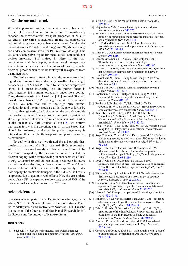
J. Phys.: Condens. Matter 24 (2012) 275501 N F Hinsche et al
4. Conclusions and outlook
With the presented results we have shown, that strainin the [111]-direction is not sufficient to significantlyenhance the thermoelectric transport properties in bulk Sifor energy harvesting applications. In the low-temperatureand low-doping case large enhancements were found undertensile strain for PF$ (electron doping) and PF( (hole doping)and under compressive strain for PF( (electron doping). Thiscould have a negative impact for metal–oxide–semiconductordevices involving [111]-strained Si. Here, in the low-temperature and low-doping regime, small temperaturegradients in the devices could lead to an additional parasiticelectrical power, which could be far larger than expected fromunstrained bulk.
The enhancements found in the high-temperature andhigh-doping regime were distinctly smaller. Here slightenhancements of 5% for PF( were found under compressivestrain. It is more interesting that the power factor isrobust against [111]-strain, especially under hole doping.Thus, thermoelectric SLs based on [111]-strained Si couldprovide an enhanced FOM, as "ph is most likely reducedin SLs. We note that due to the high bulk thermalconductivity and the only modest gain in the power factor by[111]-strain engineering, bulk silicon remains an unfavourablethermoelectric, even if the electronic transport properties arestrain optimized. However, from comparison with earlierstudies on biaxially [001]-strained silicon [18], we confirmthat strain in the [111]-direction, e.g. in silicon-based SLs,should be preferred, as the carrier pocket degeneracy isretained and therefore the thermopower and power factor canbe maximized.
To deal with this, we investigated the anisotropic ther-moelectric transport of a [111]-oriented Si/Ge superlattice.At a first glance we have shown that no degradation of theelectronic transport by the heterostructure is expected forelectron doping, while even showing an enhancement of 10%in PF( compared to bulk Si. Assuming a decrease in latticethermal conductivity large enhancements in ZT to 0.2 and1.4 are achieved at 300 K and 900 K, respectively. Underhole doping the electronic transport in the Si/Ge-SL is heavilysuppressed due to quantum-well effects. Here the cross-planepower factor PF( is expected to show only around 50% of thebulk maximal value, leading to small ZT values.
Acknowledgments
This work was supported by the Deutsche Forschungsgemein-schaft, SPP 1386 ‘Nanostrukturierte Thermoelektrika: Theo-rie, Modellsysteme und kontrollierte Synthese’. N F Hinscheis a member of the International Max Planck Research Schoolfor Science and Technology of Nanostructures.
References
[1] Seebeck T J 1826 Uber die magnetische Polarisation derMetalle und Erze durch Temperatur-Differenz Ann. Phys.,Lpz. 82 253–86
[2] Ioffe A F 1958 The revival of thermoelectricity Sci. Am.199 31–7
[3] Majumdar A 2004 Thermoelectricity in semiconductornanostructures Science 303 777
[4] Bottner H, Chen G and Venkatasubramanian R 2006 Aspectsof thin-film superlattice thermoelectric materials, devices,and applications MRS Bull. 31 211
[5] Tritt T M and Subramanian M A 2006 Thermoelectricmaterials, phenomena, and applications: a bird’s eye viewMRS Bull. 31 188–98
[6] Sales B C 2002 Thermoelectric materials: smaller is coolerScience 295 1248
[7] Venkatasubramanian R, Siivola E and Colpitts T 2001Thin-film thermoelectric devices with highroom-temperature figures of merit Nature 413 597
[8] Harman T, Taylor P, Walsh M and LaForge B 2002 Quantumdot superlattice thermoelectric materials and devicesScience 297 2229
[9] Dresselhaus M, Chen G, Tang M and Yang R 2007 Newdirections for low-dimensional thermoelectric materialsAdv. Mater. 19 1
[10] Vining C B 2008 Materials science: desperately seekingsilicon Nature 451 132–3
[11] Hochbaum A, Chen R, Delgado R and Liang W 2008Enhanced thermoelectric performance of rough siliconnanowires Nature 451 163
[12] Boukai A I, Bunimovich Y, Tahir-Kheli J, Yu J K,Goddard Iii W A and Heath J R 2008 Silicon nanowires asefficient thermoelectric materials Nature 451 168–71
[13] Bux S K, Blair R G, Gogna P K, Lee H, Chen G,Dresselhaus M S, Kaner R B and Fleurial J-P 2009Nanostructured bulk silicon as an effective thermoelectricmaterial Adv. Funct. Mater. 19 2445–52
[14] Tang J, Wang H T, Lee D H, Fardy M, Huo Z, Russell T P andYang P 2010 Holey silicon as an efficient thermoelectricmaterial Nano Lett. 10 4279
[15] Koga T, Sun X, Cronin S B and Dresselhaus M S 1999 Carrierpocket engineering applied to strained Si/Ge superlattices todesign useful thermoelectric materials Appl. Phys. Lett.75 2438
[16] Koga T, Harman T, Cronin S and Dresselhaus M 1999Mechanism of the enhanced thermoelectric power in(111)-oriented n-type PbTe/Pb1%xEuxTe multiple quantumwells Phys. Rev. B 60 14286
[17] Koga T, Cronin S, Dresselhaus M and Liu J 2000Experimental proof-of-principle investigation of enhancedZT in (001) oriented Si/Ge superlattices Appl. Phys. Lett.77 1490
[18] Hinsche N, Mertig I and Zahn P 2011 Effect of strain on thethermoelectric properties of silicon: an ab initio studyJ. Phys.: Condens. Matter 23 295502
[19] Giannozzi P et al 2009 Quantum espresso: a modular andopen-source software project for quantum simulations ofmaterials J. Phys.: Condens. Matter 21 395502
[20] Mertig I 1999 Transport properties of dilute alloys Rep. Prog.Phys. 62 237–76
[21] Hinsche N, Yavorsky B, Mertig I and Zahn P 2011 Influenceof strain on anisotropic thermoelectric transport in Bi2Te3and Sb2Te3 Phys. Rev. B 84 165214
[22] Zahn P, Hinsche N, Yavorsky B and Mertig I 2011 Bi2Te3:implications of the rhombohedral k-space texture on theevaluation of the in-plane/out-of-plane conductivityanisotropy J. Phys.: Condens. Matter 23 505504
[23] Perdew J P, Burke K and Ernzerhof M 1996 Generalizedgradient approximation made simple Phys. Rev. Lett.77 3865–8
[24] Corso A and Conte A 2005 Spin–orbit coupling with ultrasoftpseudopotentials: application to Au and Pt Phys. Rev. B71 115106
12
E3-12

J. Phys.: Condens. Matter 24 (2012) 275501 N F Hinsche et al
[25] Yu D, Zhang Y and Liu F 2008 First-principles study ofelectronic properties of biaxially strained silicon: effects oncharge carrier mobility Phys. Rev. B 78 245204
[26] Bouhassoune M and Schindlmayr A 2009 Electronic structureand effective masses in strained silicon Phys. Status Solidi c7 460–3
[27] Kresse G and Furthmuller J 1996 Efficient iterative schemesfor ab initio total-energy calculations using a plane-wavebasis set Phys. Rev. B 54 11169
[28] Godby R W, Schluter M and Sham L J 1988 Self-energyoperators and exchange–correlation potentials insemiconductors Phys. Rev. B 37 10159–75
[29] Varshni Y P 1967 Temperature dependence of the energy gapin semiconductors Physica 34 149–54
[30] Vojta T, Mertig I and Zeller R 1992 Calculation of the residualresistivity and the thermoelectric power of sp impurities insilver Phys. Rev. B 46 16761
[31] Thonhauser T, Scheidemantel T J and Sofo J O 2004Improved thermoelectric devices using bismuth alloys Appl.Phys. Lett. 85 588
[32] Singh D J 2010 Doping-dependent thermopower of PbTe fromBoltzmann transport calculations Phys. Rev. B 81 195217
[33] Scheidemantel T J, Ambrosch-Draxl C, Thonhauser T,Badding J V and Sofo J O 2003 Transport coefficients fromfirst-principles calculations Phys. Rev. B 68 125210
[34] Jacoboni C, Canali C, Ottaviani G and Quaranta A A 1977 Areview of some charge transport properties of siliconSolid-State Electron. 20 77–89
[35] Dziekan T, Zahn P, Meded V and Mirbt S 2007 Theoreticalcalculations of mobility enhancement in strained siliconPhys. Rev. B 75 195213
[36] Roldan J B, Gamiz F, LopezVillanueva J A andCarceller J E 1996 A Monte Carlo study on the electrontransport properties of high performance strained Si onrelaxed Si1%xGex channel MOSFETs J. Appl. Phys. 80 5121
[37] Mahan G and Sofo J O 1996 The best thermoelectric Proc.Natl Acad. Sci. 93 7436
[38] Lehmann G and Taut M 1972 On the numerical calculation ofthe density of states and related properties Phys. StatusSolidi b 54 469–77
[39] Zahn P, Mertig I, Richter M and Eschrig H 1995 Ab initiocalculations of the giant magnetoresistance Phys. Rev. Lett.75 2996–9
[40] Mertig I, Mrosan E and Ziesche P 1987 Multiple ScatteringTheory of Point Defects in Metals: Electronic Properties(Leipzig: B G Teubner)
[41] Momma K and Izumi F 2011 VESTA3 for three-dimensionalvisualization of crystal, volumetric and morphology dataJ. Appl. Crystallogr. 44 1272–6
[42] Baykan M O, Thompson S E and Nishida T 2010 Straineffects on three-dimensional, two-dimensional, andone-dimensional silicon logic devices: predicting the futureof strained silicon J. Appl. Phys. 108 093716
[43] Sun G, Sun Y, Nishida T and Thompson S E 2007 Holemobility in silicon inversion layers: stress and surfaceorientation J. Appl. Phys. 102 084501
[44] Boykin T, Kharche N and Klimeck G 2007 Brillouin-zoneunfolding of perfect supercells having nonequivalentprimitive cells illustrated with a SiGe tight-bindingparameterization Phys. Rev. B 76 035310
[45] Niquet Y, Rideau D, Tavernier C, Jaouen H and Blase X 2009Onsite matrix elements of the tight-binding Hamiltonian ofa strained crystal: application to silicon, germanium, andtheir alloys Phys. Rev. B 79 245201
[46] Park M S, Song J-H, Medvedeva J E, Kim M, Kim I G andFreeman A J 2010 Electronic structure and volume effecton thermoelectric transport in p-type Bi and Sb telluridesPhys. Rev. B 81 155211
[47] Thompson S E, Sun G, Choi Y S and Nishida T 2006Uniaxial-process-induced strained-Si: extending the CMOSroadmap IEEE Trans. Electron Devices 53 1010–20
[48] Pei Y, Shi X, LaLonde A, Wang H, Chen L andJeffrey Snyder G 2011 Convergence of electronic bands forhigh performance bulk thermoelectrics Nature 473 66–9
[49] Slack G A 1995 CRC Handbook of Thermoelectrics(Boca Raton, FL: CRC Press) chapter 34, p 407
[50] Poudel B, Hao Q, Ma Y, Lan Y, Minnich A, Yu B, Yan X,Wang D, Muto A and Vashaee D 2008 High-thermoelectricperformance of nanostructured bismuth antimony telluridebulk alloys Science 320 634
[51] Hicks L, Harman T, Sun X and Dresselhaus M 1996Experimental study of the effect of quantum-well structureson the thermoelectric figure of merit Phys. Rev. B53 R10493
[52] Venkatasubramanian R 2000 Lattice thermal conductivityreduction and phonon localizationlike behavior insuperlattice structures Phys. Rev. B 61 3091–7
[53] Borca-Tasciuc T 2000 Thermal conductivity of symmetricallystrained Si/Ge superlattices Superlattices Microstruct.28 199–206
[54] Chakraborty S, Kleint C A, Heinrich A, Schneider C M,Schumann J, Falke M and Teichert S 2003 Thermalconductivity in strain symmetrized Si/Ge superlattices onSi(111) Appl. Phys. Lett. 83 4184
[55] Lee S, Cahill D and Venkatasubramanian R 1997 Thermalconductivity of Si–Ge superlattices Appl. Phys. Lett.70 2957
[56] Kasper E, Kibbel H, Jorke H, Brugger H, Friess E andAbstreiter G 1988 Symmetrically strained Si/Gesuperlattices on Si substrates Phys. Rev. B 38 3599–601
[57] Kasper E 1986 Growth and properties of Si/SiGe superlatticesSurf. Sci. 174 630–9
[58] Pearsall T, Bevk J, Feldman L, Bonar J, Mannaerts J andOurmazd A 1987 Structurally induced optical transitions inGe–Si superlattices Phys. Rev. Lett. 58 729–32
[59] Pearsall T, Bevk J, Bean J, Bonar J, Mannaerts J andOurmazd A 1989 Electronic structure of Ge/Si monolayerstrained-layer superlattices Phys. Rev. B 39 3741–57
[60] Brunner K 2002 Si/Ge nanostructures Rep. Prog. Phys. 65 27[61] Kuan T S and Iyer S S 1991 Strain relaxation and ordering in
SiGe layers grown on (100), (111), and (110) Si surfaces bymolecular-beam epitaxy Appl. Phys. Lett. 59 2242
[62] Bass J M and Matthai C C 1990 Electronic structure of (111)Si/Ge superlattices J. Phys.: Condens. Matter 2 7841
[63] Salehpour M R and Satpathy S 1990 Comparison of electronbands of hexagonal and cubic diamond Phys. Rev. B41 3048
[64] Tahini H, Chroneos A, Grimes R W, Schwingenschlogl U andDimoulas A 2012 Strain-induced changes to the electronicstructure of germanium J. Phys.: Condens. Matter24 195802
[65] Zhang F, Crespi V and Zhang P 2009 Prediction that uniaxialtension along 111 produces a direct band gap in germaniumPhys. Rev. Lett. 102 156401
[66] Rideau D, Feraille M, Ciampolini L, Minondo M, Tavernier C,Jaouen H and Ghetti A 2006 Strained Si, Ge, and Si1%xGexalloys modeled with a first-principles-optimized full-zonekp method Phys. Rev. B 74 195208
[67] Braunstein R, Moore A R and Herman F 1958 Intrinsic opticalabsorption in germanium–silicon alloys Phys. Rev.109 695–710
[68] Ioffe A F 1960 Physics of Semiconductors (New York:Academic)
[69] Wang X W, Lee H, Lan Y C, Zhu G H, Joshi G, Wang D Z,Yang J, Muto A J, Tang M Y and Klatsky J 2008 Enhancedthermoelectric figure of merit in nanostructured n-typesilicon germanium bulk alloy Appl. Phys. Lett. 93 193121
13
E3-13

J. Phys.: Condens. Matter 24 (2012) 275501 N F Hinsche et al
[70] Pernot G, Stoffel M, Savic I, Pezzoli F, Chen P, Savelli G,Jacquot A, Schumann J, Denker U and Monch I 2010Precise control of thermal conductivity at the nanoscalethrough individual phonon-scattering barriers Nature Mater.9 491
[71] Jalan B and Stemmer S 2010 Large seebeck coefficients andthermoelectric power factor of La-doped SrTiO3 thin filmsAppl. Phys. Lett. 97 3
[72] Okinaka N and Akiyama T 2006 Latent property ofdefect-controlled metal oxide: nonstoichiometric titaniumoxides as prospective material for high-temperaturethermoelectric conversion Japan. J. Appl. Phys. 45 7009–10
[73] Vashaee D and Shakouri A 2007 Thermionic power generationat high temperatures using SiGe/Si superlattices J. Appl.Phys. 101 053719
[74] Shakouri A and Bowers J E 1997 Heterostructure integratedthermionic coolers Appl. Phys. Lett. 71 1234
[75] Vashaee D and Shakouri A 2004 Improved thermoelectricpower factor in metal-based superlattices Phys. Rev. Lett.92 106103
[76] Sun P, Oeschler N, Johnsen S, Iversen B B andSteglich F 2009 Huge thermoelectric power factor: FeSb2versus FeAs2 and RuSb2 Appl. Phys. Express 2 091102
[77] Lee J-H, Wu J and Grossman J C 2010 Enhancing thethermoelectric power factor with highly mismatchedisoelectronic doping Phys. Rev. Lett. 104 016602
[78] Nolas G S and Goldsmid H J 2004 Thermal Conductivity:Theory, Properties, and Applications (New York: KluwerAcademic) chapter 1.4, p 110
[79] Chaput L, Pecheur P, Tobola J and Scherrer H 2005 Transportin doped skutterudites: ab initio electronic structurecalculations Phys. Rev. B 72 085126
[80] Flage-Larsen E and Prytz O 2011 The Lorenz function: itsproperties at optimum thermoelectric figure-of-merit Appl.Phys. Lett. 99 202108
14
E3-14

CHAPTER 6
SUMMARY & OUTLOOK
The major goal of this thesis was to strengthen the theoretical understanding of anisotropic ther-moelectric transport in semiconducting heterostructures and to elucidate details of the electronicstructure, which could be the origin for high thermoelectric conversion efficiency in the cross-planetransport direction of these systems. Motivated by state-of-the-art experiments, superlattices basedon Bi2Te3/Sb2Te3 or Si/Ge were of major interest.
For this purpose, ab initio calculations footing on a KORRINGA-KOHN-ROSTOKER and a pseu-dopotential method were carried out. Here, it was accounted for all important relativistic effects,by solving the DIRAC equation. The macroscopic thermoelectric transport properties were then de-scribed by a linearized BOLTZMANN equation.
The interdependence of the thermoelectric transport properties remains a big obstacle in thermo-electric superlattices and bulk materials. Optimizing the electronic transport properties by tuningthe charge carrier concentration seems to remain the only efficient and promising approach.
As an alternative ansatz it was suggested to enhance the thermoelectric transport by strain, or inother words, to understand whether strain could be the reason for enhanced cross-plane thermoelec-tric transport, even at the expense of a possibly less efficient in-plane transport. In both materialsystems, no pronounced enhancement could be found, while the transport properties were robustagainst strain, especially in the thermoelectric desirable high-doping and high-temperature regime.While for Bi2Te3 a decrease of the maximal power factor of about 27% and 23% for n and p-doping,respectively, was found, the strain shows nearly no influence on the power factor for Sb2Te3.
For Si/Ge-based superlattices, strain along the [111]-direction was found to be preferable. Underbiaxial strain in [001]-direction lifting of the band’s degeneracy causes reoccupation of states in theBRILLOUIN zone, which can enhance the electrical conductivity in some cases, but is always relatedto a decrease of the thermopower. Both effects tend to compensate each other. The degeneracy of theconduction bands is preserved by symmetry in the case of strain along the [111]-direction. Therefore,a reduction of the thermopower is not expected a priori.
The studies on the thermoelectric transport of the superlattices revealed distinct similarities, too.For both superlattice systems, the band gap differences between the bulk materials caused bandoffsets in the heterostructures. These band offsets tend to localize entirely at either the valenceband edge or the conduction band edge, causing strong quantum confinement effects of the carriersin the cross-plane transport direction. For Bi2Te3/Sb2Te3-SLs , quantum confinement leads to astrong reduction of the cross-plane transport under n-doping, while for the Si/Ge superlattice the p-type transport was diminished. The remaining other n or p-type transport properties were found tobe bulk-like, or could only be slightly enhanced, as shown for the Si/Ge superlattice. The remarkableexperimental findings of a strongly enhanced cross-plane transport in the Bi2Te3/Sb2Te3-SLs couldnot be confirmed.
Nevertheless, for at least one carrier-type (electron or hole transport) bulk-like electronic trans-port can be expected in thermoelectric superlattices, enabling to benefit from the reduction of thelattice thermal conductivity for an enhanced figure of merit.
Further studies could account additionally for interfacial disorder or the detailed influence ofscattering effects, like electron-impurity or electron-phonon scattering, as already proposed in thisthesis, to get more insight into the complexity of thermoelectric heterostructures.
99


List of publications
[E1] N. F. Hinsche, I. Mertig, and P. Zahn, Lorenz function of Bi2Te3/Sb2Te3 superlattices, Jour-nal of Electronic Materials 42 (7), 1406 (2013), [DOI: 10.1007/s11664-012-2279-z]. (Cited onpages 34, 35, and 47.)
[E2] N. F. Hinsche, B. Y. Yavorsky, M. Gradhand, M. Czerner, M. Winkler, J. König, H. Böt-tner, I. Mertig, and P. Zahn, Thermoelectric transport in Bi2Te3/Sb2Te3 superlattices, Phys-ical Review B 86 (8), 085323 (2012), [DOI: 10.1103/PhysRevB.86.085323]. (Cited on pages 34,35, 45, 46, and 47.)
[E3] N. F. Hinsche, I. Mertig, and P. Zahn, Thermoelectric transport in strained Si and Si/Geheterostructures, J. Phys.: Condens. Matter 24 (27), 275501 (2012), [DOI: 10.1088/0953-8984/24/27/275501]. (Cited on pages 14, 21, 43, 45, 71, 72, and 73.)
[E4] J Boor, D. S. Kim, X. Ao, M. Becker, N. F. Hinsche, I. Mertig, P. Zahn, andV. Schmidt, Thermoelectric properties of porous silicon, Appl. Phys. A 107 (4), 789–794 (2012),[DOI: 10.1007/s00339-012-6879-5]. (Cited on pages 8 and 14.)
[E5] N. F. Hinsche, B. Yavorsky, I. Mertig, and P. Zahn, Influence of strain on anisotropicthermoelectric transport in Bi2Te3 and Sb2Te3, Physical Review B 84 (16), 165214 (2011),[DOI: 10.1103/PhysRevB.84.165214] and Publisher’s note: Influence of strain on anisotropicthermoelectric transport in Bi2Te3 and Sb2Te3, Physical Review B 85 (8), 089902 (2012),[DOI: 10.1103/PhysRevB.85.089902]. (Cited on pages 6, 21, 34, 41, 45, and 46.)
[E6] Peter Zahn, N. F. Hinsche, B. Yavorsky, and I. Mertig, Bi2Te3: implications of the rhom-bohedral k-space texture on the evaluation of the in-plane/out-of-plane conductivity anisotropy,J. Phys.: Condens. Matter 23 (50), 505504 (2011), [DOI: 10.1088/0953-8984/23/50/505504].(Cited on pages 25, 26, 32, and 46.)
[E7] B. Yu Yavorsky, N. F. Hinsche, I. Mertig, and P. Zahn, Electronic structure andtransport anisotropy of Bi2Te3 and Sb2Te3, Physical Review B 84 (16), 165208 (2011),[DOI: 10.1103/PhysRevB.84.165208]. (Cited on pages 21, 25, 26, 32, 33, 41, and 45.)
[E8] N. F. Hinsche, I. Mertig, and P. Zahn, Effect of strain on the thermoelectric properties of sil-icon: an ab initio study, J. Phys.: Condens. Matter 23 (29), 295502 (2011), [DOI: 10.1088/0953-8984/23/29/295502]. (Cited on pages 6, 14, 21, 37, 45, 71, and 72.)
[E9] N. F. Hinsche, M. Fechner, P. Bose, S. Ostanin, J. Henk, I. Mertig, and P. Zahn, Stronginfluence of complex band structure on tunneling electroresistance: A combined model and abinitio study, Phys. Rev. B 82 (21), 214110 (2010), [DOI: 10.1103/PhysRevB.82.214110]. (Notcited.)
[E10] N. F. Hinsche, A. Moskalenko, and J. Berakdar, High-order harmonic generation by adriven mesoscopic ring with a localized impurity, Phys. Rev. A 79 (2), 023822 (2009). (Notcited.)
i


Bibliography
[AAL97] V. I. Anisimov, F. Aryasetiawan, and A. I. Lichtenstein, First-principles calcula-tions of the electronic structure and spectra of strongly correlated systems: the LDA+Umethod, J. Phys.: Condens. Matter 9 (4), 767 (1997), [DOI: 10.1088/0953-8984/9/4/002].(Cited on page 14.)
[AG98] F. Aryasetiawan and O. Gunnarsson, The GW method, Reports on Progress inPhysics 61 (3), 237 (1998), [DOI: 10.1088/0034-4885/61/3/002]. (Cited on page 14.)
[AJ84] O. K. Andersen and O. Jepsen, Explicit, First-Principles Tight-Binding Theory, Phys-ical Review Letters 53 (27), 2571–2574 (1984), [DOI: 10.1103/PhysRevLett.53.2571].(Cited on page 18.)
[All72] P. Allen, Neutron Spectroscopy of Superconductors, Phys. Rev B 6 (7), 2577–2579 (1972),[DOI: 10.1103/PhysRevB.6.2577]. (Cited on page 42.)
[AM98] N. Argaman and G. Makov, Density Functional Theory: an introduction, AmericanJournal of Physics 68 (1), 69–79 (1998), [DOI: 10.1119/1.19375]. (Cited on page 14.)
[ASH+99] M. Asato, A. Settels, T. Hoshino, T. Asada, S. Blügel, R. Zeller, and P. Dederichs,Full-potential KKR calculations for metals and semiconductors, Physical Review B 60(8), 5202–5210 (1999), [DOI: 10.1103/PhysRevB.60.5202]. (Cited on page 16.)
[Ask94] B. Askerov, Electron transport phenomena in semiconductors, World Scientific Pub.,Singapore, 1994, [ISBN: 9810212836]. (Cited on pages 29 and 30.)
[Bai67] M. Bailyn, Phonon-Drag Part of the Thermoelectric Power in Metals, Physical Review157 (3), 480–485 (1967), [DOI: 10.1103/PhysRev.157.480]. (Cited on page 43.)
[BBG+09] S. K. Bux, R. G. Blair, P. K. Gogna, H. Lee, G. Chen, M. S. Dressel-haus, R. B. Kaner, and J.-P. Fleurial, Nanostructured Bulk Silicon as anEffective Thermoelectric Material, Adv. Funct. Mater. 19 (15), 2445–2452 (2009),[DOI: 10.1002/adfm.200900250]. (Cited on pages 8 and 71.)
[BBTK+08] A. Boukai, Y. Bunimovich, J. Tahir-Kheli, J. Yu, W. G. Iii, and J. Heath, Sili-con nanowires as efficient thermoelectric materials, Nature 451 (7175), 168–171 (2008),[DOI: 10.1038/nature06458]. (Cited on pages 5, 7, and 71.)
[BCB+04] A. Bentien, M. Christensen, J. Bryan, A. Sanchez, S. Paschen, F. Steglich,G. Stucky, and B. Iversen, Thermal conductivity of thermoelectric clathrates, Phys-ical Review B 69 (4), 045107 (2004), [DOI: 10.1103/PhysRevB.69.045107]. (Cited onpage 7.)
[BCV06] H. Böttner, G. Chen, and R. Venkatasubramanian, Aspects of Thin-Film Super-lattice Thermoelectric Materials, Devices, and Applications, MRS bulletin 31 (3), 211(2006), [DOI: 10.1557/mrs2006.47]. (Cited on pages 9 and 10.)
[Bec93] A. D. Becke, A new mixing of Hartree–Fock and local density-functional theories, J.Chem. Phys. 98 (2), 1372–1377 (1993), [DOI: 10.1063/1.464304]. (Cited on page 14.)
iii

Bibliography
[Bee67] J. L. Beeby, The Density of Electrons in a Perfect or Imperfect Lattice, Proceedingsof the Royal Society A: Mathematical, Physical and Engineering Sciences 302 (1468),113–136 (1967), [DOI: 10.1098/rspa.1967.0230]. (Cited on page 15.)
[Bel08] L. Bell, Science 321 (5895), 1457 (2008), [DOI: 10.1126/science.1158899]. (Cited onpages 1, 2, and 35.)
[BGC01] S. Baroni, S. D. Gironcoli, and A. D. Corso, Phonons and related crystal propertiesfrom density-functional perturbation theory, Reviews of Modern Physics 73 (2), 515–562(2001), [DOI: 10.1103/RevModPhys.73.515]. (Cited on pages 21 and 42.)
[BGI10] S. Baroni, P. Giannozzi, and E. Isaev, Density-Functional Perturbation Theory forQuasi-Harmonic Calculations, Reviews in Mineralogy and Geochemistry 71 (1), 39–57(2010), [DOI: 10.2138/rmg.2010.71.3]. (Cited on page 21.)
[BGT87] S. Baroni, P. Giannozzi, and A. Testa, Green’s-function approach to linear responsein solids, Physical Review Letters 58 (18), 1861–1864 (1987), [DOI: 10.1103/Phys-RevLett.58.1861]. (Cited on page 21.)
[BHS82] G. Bachelet, D. Hamann, and M. Schlüter, Pseudopotentials that work: From Hto Pu, Physical Review B 26 (8), 4199–4228 (1982), [DOI: 10.1103/PhysRevB.26.4199].(Cited on page 20.)
[Blo25] A. Bloch, Les théorèmes de M. Valiron sur les fonctions entières et la théorie del’uniformisation, Annales de la faculté des sciences de Toulouse 17 (3), 22 (1925),[DOI: 10.5802/afst.335]. (Cited on page 18.)
[BNB+02a] H. Beyer, J. Nurnus, H. Böttner, A. Lambrecht, T. Roch, and G. Bauer, PbTebased superlattice structures with high thermoelectric efficiency, Applied Physics Letters80 (7), 1216 (2002), [DOI: 10.1063/1.1448388]. (Cited on page 9.)
[BNB+02b] H. Beyer, J. Nurnus, H. Böttner, A. Lambrecht, E. Wagner, and G. Bauer, Highthermoelectric figure of merit ZT in PbTe and Bi2Te3-based superlattices by a reductionof the thermal conductivity, Physica E: Low-dimensional Systems and Nanostructures13 (2-4), 965–968 (2002), [DOI: 10.1016/S1386-9477(02)00246-1]. (Cited on page 9.)
[BNSV07] H. Böttner, J. Nurnus, A. Schubert, and F. Volkert, New high den-sity micro structured thermogenerators for stand alone sensor systems, Proceed-ings of the XXVI International Conference on Thermoelectrics, 306–309 (2007),[DOI: 10.1109/ICT.2007.4569484]. (Cited on page 1.)
[BR95a] D. Broido and T. Reinecke, Effect of superlattice structure on the thermoelectricfigure of merit, Physical Review B 51 (19), 13797–13800 (1995), [DOI: 10.1103/Phys-RevB.51.13797]. (Cited on page 6.)
[BR95b] D. Broido and T. Reinecke, Thermoelectric figure of merit of quantum wire superlat-tices, Applied Physics Letters 67 (1), 100–102 (1995), [DOI: 10.1063/1.115495]. (Citedon page 6.)
[BT00] T. Borca-Tasciuc, Thermal conductivity of symmetrically strained Si/Gesuperlattices, Superlattices and Microstructures 28 (3), 199–206 (2000),[DOI: 10.1006/spmi.2000.0900]. (Cited on pages 9 and 72.)
iv

Bibliography
[BTKC01] T. Borca-Tasciuc, A. Kumar, and G. Chen, Data reduction in 3ω method forthin-film thermal conductivity determination, Rev. Sci. Instrum. 72 (4), 2139 (2001),[DOI: 10.1063/1.1353189]. (Cited on pages 35 and 47.)
[BTN10] M. O. Baykan, S. E. Thompson, and T. Nishida, Strain effects on 3D, 2D, and 1Dsilicon logic devices: Predicting the future of strained silicon, Journal of Applied Physics108 (9), 093716 (2010), [DOI: 10.1063/1.3488635]. (Cited on page 71.)
[BZLD84] P. Braspenning, R. Zeller, A. Lodder, and P. Dederichs, Self-consistent cluster cal-culations with correct embedding for 3d, 4d, and some sp impurities in copper, PhysicalReview B 29 (2), 703–718 (1984), [DOI: 10.1103/PhysRevB.29.703]. (Cited on page 17.)
[BZS+07] Z. Bian, M. Zebarjadi, R. Singh, Y. Ezzahri, A. Shakouri, G. Zeng, J.-H. Bahk,J. Bowers, J. Zide, and A. Gossard, Cross-plane Seebeck coefficient and Lorenz num-ber in superlattices, Physical Review B 76 (20), 205311 (2007), [DOI: 10.1103/Phys-RevB.76.205311]. (Cited on page 35.)
[CA86] D. Ceperley and B. Alder, Quantum Monte Carlo, Science 231 (4738), 555–560 (1986),[DOI: 10.1126/science.231.4738.555]. (Cited on page 14.)
[CAC+08] M. Christensen, A. B. Abrahamsen, N. B. Christensen, F. Juranyi, N. H. Ander-sen, K. Lefmann, J. Andreasson, C. R. H. Bahl, and B. B. Iversen, Avoided cross-ing of rattler modes in thermoelectric materials, Nature Materials 7 (10), 811 (2008),[DOI: doi:10.1038/nmat2273]. (Cited on page 7.)
[Cal59] J. Callaway, Model for Lattice Thermal Conductivity at Low Temperatures, Physi-cal Review 113 (4), 1046–1051 (1959), [DOI: 10.1103/PhysRev.113.1046]. (Cited onpages 37, 38, and 40.)
[Cap06] K. Capelle, A bird’s-eye view of density-functional theory, Brazilian Journal of Physics36 (4A), 1318–1343 (2006), [DOI: 10.1590/S0103-97332006000700035]. (Cited onpage 14.)
[CC05] A. D. Corso and A. Conte, Spin-orbit coupling with ultrasoft pseudopotentials: Ap-plication to Au and Pt, Physical Review B 71, 115106 (2005), [DOI: 10.1103/Phys-RevB.71.115106]. (Cited on pages 19, 20, and 24.)
[CCHL08] C. Chiritescu, D. Cahill, C. Heideman, and Q. Lin, Low thermal conductivity innanoscale layered materials synthesized by the method of modulated elemental reactants,J. Appl. Phys 104 (3), 033533 (2008), [DOI: 10.1063/1.2967722]. (Cited on page 10.)
[CCN+07] C. Chiritescu, D. G. Cahill, N. Nguyen, D. Johnson, A. Bodapati, P. Keblinski,and P. Zschack, Ultralow Thermal Conductivity in Disordered, Layered WSe2 Crystals,Science 315 (5810), 351–353 (2007), [DOI: 10.1126/science.1136494]. (Cited on page 10.)
[CCP+92] T. Caillat, M. Carle, P. Pierrat, H. Scherrer, and S. Scherrer, Thermoelectric prop-erties of (BixSb1−x)2Te3 single crystal solid solutions grown by the THM method, Jour-nal of Physics and Chemistry of Solids 53 (8), 1121–1129 (1992), [DOI: 10.1016/0022-3697(92)90087-T]. (Cited on page 5.)
[CD68] J. Carbotte and R. Dynes, Superconductivity in Simple Metals, Physical Review 172(2), 476–484 (1968), [DOI: 10.1103/PhysRev.172.476]. (Cited on page 43.)
v

Bibliography
[Cep80] D. M. Ceperley, Ground State of the Electron Gas by a Stochastic Method, PhysicalReview Letters 45 (7), 566–569 (1980), [DOI: 10.1103/PhysRevLett.45.566]. (Cited onpage 14.)
[Cer88] C. Cercignani, The Boltzmann equation and its applications, Springer, New York,1988, [ISBN: 0387966374]. (Cited on page 28.)
[CFB97] T. Caillat, J. Fleurial, and A. Borshchevsky, Preparation and thermoelectric prop-erties of semiconducting Zn4Sb3, Journal of Physics and Chemistry of Solids 58 (7),1119–1125 (1997), [DOI: 10.1016/S0022-3697(96)00228-4]. (Cited on page 8.)
[CG52] H. Callen and R. Greene, On a Theorem of Irreversible Thermodynamics, PhysicalReview 86 (5), 702–710 (1952), [DOI: 10.1103/PhysRev.86.702]. (Cited on page 37.)
[Che98] G. Chen, Thermal conductivity and ballistic-phonon transport in the cross-plane di-rection of superlattices, Physical Review B 57 (23), 14958 (1998), [DOI: 10.1103/Phys-RevB.57.14958]. (Cited on page 10.)
[CHM+08] R. Chen, A. I. Hochbaum, P. Murphy, J. Moore, P. Yang, and A. Majumdar, Ther-mal Conductance of Thin Silicon Nanowires, Physical Review Letters 101 (10), 105501(2008), [DOI: 10.1103/PhysRevLett.101.105501]. (Cited on pages 7 and 71.)
[CKH+03] S. Chakraborty, C. Kleint, A. Heinrich, C. Schneider, J. Schumann, M. Falke,and S. Teichert, Thermal conductivity in strain symmetrized Si/Ge superlattices onSi (111), Applied Physics Letters 83, 4184 (2003), [DOI: 10.1063/1.1628819]. (Cited onpage 10.)
[CKY+01] S. Cho, Y. Kim, S. Youn, A. DiVenere, and G. Wong, Artificially ordered Bi/Sbsuperlattice alloys: Fabrication and transport properties, Physical Review B 64 (23),235330 (2001), [DOI: 10.1103/PhysRevB.64.235330]. (Cited on page 9.)
[CM69] M. Cutler and N. Mott, Observation of Anderson localization in an electron gas, Phys.Rev. 181 (3), 1336 (1969), [DOI: 10.1103/PhysRev.181.1336]. (Cited on page 6.)
[CM95] J. Costella and B. McKellar, The Foldy-Wouthuysen transformation, American Jour-nal of Physics 63 (12), 1119 (1995), [DOI: 10.1119/1.18017]. (Cited on page 23.)
[CP87] D. Cahill and R. Pohl, Thermal conductivity of amorphous solids above the plateau,Physical Review B 35 (8), 4067–4073 (1987), [DOI: 10.1103/PhysRevB.35.4067]. (Citedon pages 7 and 35.)
[CQK+10] S. Chadov, X. Qi, J. Kübler, G. H. Fecher, C. Felser, and S. C. Zhang, Tunablemultifunctional topological insulators in ternary Heusler compounds, Nature Materials9 (7), 541 (2010), [DOI: doi:10.1038/nmat2770]. (Cited on page 24.)
[CR11] J. Cornett and O. Rabin, Thermoelectric figure of merit calculations forsemiconducting nanowires, Applied Physics Letters 98 (18), 182104 (2011),[DOI: 10.1063/1.3585659]. (Cited on pages 6 and 7.)
[CSS+01] J. Caylor, M. Sander, A. Stacy, J. Harper, R. Gronsky, and T. Sands, Epitaxialgrowth of skutterudite CoSb3 thin films on (001) InSb by pulsed laser deposition, Journalof Materials Research 16 (9), 2467 (2001), [DOI: 10.1557/JMR.2001.0337]. (Cited onpage 9.)
vi

Bibliography
[CW04] P. Carrier and S.-H. Wei, Calculated spin-orbit splitting of all diamondlike and zinc-blende semiconductors: Effects of p1/2 local orbitals and chemical trends, Physical ReviewB 70 (3), 035212 (2004), [DOI: 10.1103/PhysRevB.70.035212]. (Cited on page 23.)
[Cze09] M. Czerner, Beiträge zur Theorie des Elektronentransports in Systemen mitnichtkollinearer magnetischer Ordnung, PhD Thesis, (2009), URL: http://digital.bibliothek.uni-halle.de/hs/urn/urn:nbn:de:gbv:3:4-1796. (Cited on pages 18and 23.)
[Dän08] M. Däne, Beschreibung der elektronischen Struktur korrelierter Systeme mittelslokaler Selbstwechselwirkungskorrekturen im Rahmen der Vielfachstreutheorie, Ph.D.thesis, Martin-Luther-Universität Halle-Wittenberg, 2008, URL: http://sundoc.bibliothek.uni-halle.de/diss-online/08/08H021/of_index.htm. (Cited onpage 16.)
[DDS+99] M. Dresselhaus, G. Dresselhaus, X. Sun, Z. Zhang, S. Cronin, and T. Koga,Low-dimensional thermoelectric materials, Phys. Solid State 41 (5), 679–682 (1999),[DOI: 10.1134/1.1130849]. (Cited on page 6.)
[DES+64] J. Dismukes, L. Ekstrom, E. Steigmeier, I. Kudman, and D. Beers, Thermal andElectrical Properties of Heavily Doped Ge-Si Alloys up to 1300K, Journal of AppliedPhysics 35 (10), 2899–2907 (1964), [DOI: 10.1063/1.1713126]. (Cited on page 5.)
[DGW58] J. R. Drabble, R. D. Groves, and R. Wolfe, Galvanomagnetic Effects in n-type Bismuth Telluride, Proceedings of the Physical Society 71 (3), 430 (1958),[DOI: 10.1088/0370-1328/71/3/317]. (Cited on page 45.)
[Dir28] P. A. M. Dirac, The quantum theory of the electron, Proceedings of the Royal Societyof London. Series A, Containing Papers of a Mathematical and Physical Character 117(778), 610–624 (1928), [DOI: 10.1098/rspa.1928.0023]. (Cited on page 22.)
[Dir30] , Note on Exchange Phenomena in the Thomas Atom, MathematicalProceedings of the Cambridge Philosophical Society 26 (03), 376–385 (1930),[DOI: 10.1017/S0305004100016108]. (Cited on pages 12 and 14.)
[DJ69] P. D. DeCicco and F. A. Johnson, The Quantum Theory of Lattice Dynamics. IV, Pro-ceedings of the Royal Society of London. A. Mathematical and Physical Sciences 310(1500), 111–119 (1969), [DOI: 10.1098/rspa.1969.0066]. (Cited on page 21.)
[DLZ06] P. H. Dederichs, S. Lounis, and R. Zeller, The Korringa-Kohn-Rostoker (KKR) GreenFunction Method II. Impurities and Clusters in the Bulk and on Surfaces, in Computa-tional Nanoscience: Do It Yourself, Jülich 31, (2006), [ISBN: 3-00-017350-1]. (Cited onpage 15.)
[DSM01] J. Dong, O. Sankey, and C. Myles, Theoretical study of the lattice thermal conduc-tivity in Ge framework semiconductors, Physical Review Letters 86 (11), 2361 (2001),[DOI: 10.1103/PhysRevLett.86.2361]. (Cited on page 7.)
[Dup61] T. Dupree, Electron scattering in a crystal lattice, Annals of Physics 15 (1), 63–78(1961), [DOI: 10.1016/0003-4916(61)90166-X]. (Cited on pages 15 and 17.)
vii

Bibliography
[DWZD91] B. Drittler, M. Weinert, R. Zeller, and P. H. Dederichs, Vacancy formation energiesof fcc transition metals calculated by a full potential Green’s function method, Solid StateCommunications 79 (1), 31–35 (1991), [DOI: 10.1016/0038-1098(91)90474-A]. (Cited onpage 16.)
[DZMM07] T. Dziekan, P. Zahn, V. Meded, and S. Mirbt, Theoretical calculations of mo-bility enhancement in strained silicon, Physical Review B 75 (19), 195213 (2007),[DOI: 10.1103/PhysRevB.75.195213]. (Cited on page 71.)
[EBB+10] H. Ebert, S. Bornemann, J. Braun, D. Ködderitzsch, S. Lowitzer,S. Mankovskyy, J. Minár, M. Offenberger, S. Polesya, and V. Popescu, Re-cent Developments in KKR Theory, Ψk - Scientific highlight of the month (97), (2010),"URL: http://www.psi-k.org/newsletters/News_97/Highlight_97.pdf". (Citedon page 15.)
[EGR+07] Y. Ezzahri, S. Grauby, J. Rampnoux, H. Michel, G. Pernot, W. Claeys, S. Dilhaire,C. Rossignol, G. Zeng, and A. Shakouri, Coherent phonons in Si/SiGe superlattices,Physical Review B 75 (19), 195309 (2007), [DOI: 10.1103/PhysRevB.75.195309]. (Citedon page 10.)
[EKM11] H. Ebert, D. Ködderitzsch, and J. Minár, Calculating condensed matter propertiesusing the KKR-Green’s function method—recent developments and applications, Reportson Progress in Physics 74, 096501 (2011), [DOI: 10.1088/0034-4885/74/9/096501]. (Citedon pages 15, 16, and 17.)
[Éli60] G. M. Éliashberg, Interactions between electrons and lattice vibrations in a super-conductor, Soviet Physics JETP 11 (3), 696 (1960), URL: http://www.w2agz.com/Library/. (Cited on page 42.)
[Fau77] J. S. Faulkner, Scattering theory and cluster calculations, Journal of Physics C: SolidState Physics 10 (23), 4661 (1977), [DOI: 10.1088/0022-3719/10/23/003]. (Cited onpage 17.)
[Fer27] E. Fermi, Statistical method to determine some properties of atoms, Rend. R. Acc. Naz.dei Lincei 6 (1), 602–607 (1927), URL: http://ricerca.mat.uniroma3.it/ipparco/pagine/deposito/2011/TF.pdf. (Cited on pages 12 and 14.)
[Fer28] , Eine statistische Methode zur Bestimmung einiger Eigenschaften des Atoms undihre Anwendung auf die Theorie des periodischen Systems der Elemente, Z. Physik 48(1-2), 73–79 (1928), [DOI: 10.1007/BF01351576]. (Cited on pages 12 and 14.)
[Fey39] R. Feynman, Forces in Molecules, Physical Review 56 (4), 340–343 (1939),[DOI: 10.1103/PhysRev.56.340]. (Cited on page 21.)
[FK54] H. Fröhlich and C. Kittel, Remark on the paper by Prof. G. Busch, Physica 3, 1086–1086 (1954), [DOI: 10.1016/S0031-8914(54)80240-0]. (Cited on page 34.)
[FKBK00] J. Furthmüller, P. Käckell, F. Bechstedt, and G. Kresse, Extreme softening of Van-derbilt pseudopotentials: General rules and case studies of first-row and d-electron ele-ments, Physical Review B 61 (7), 4576–4587 (2000), [DOI: 10.1103/PhysRevB.61.4576].(Cited on page 18.)
viii

Bibliography
[FL96] M. Fischetti and S. Laux, Band structure, deformation potentals, and carrier mobilityin strained Si, Ge, and SiGe alloys, Journal of Applied Physics 80 (4), 2234–2252 (1996),[DOI: 10.1063/1.363052]. (Cited on page 71.)
[Fog63] B. Fogarassy, On the Solution of the Boltzmann Transport Equation with Re-laxation Time Approximation, Physica status solidi (b) 3 (12), 2347–2355 (1963),[DOI: 10.1002/pssb.19630031217]. (Cited on page 29.)
[FRA83] R. Feder, F. Rosicky, and B. Ackermann, Relativistic multiple scattering theory ofelectrons by ferromagnets, Zeitschrift fÃijr Physik B: Condensed Matter 52 (1), 31–36(1983), [DOI: 10.1007/BF01305895]. (Cited on page 23.)
[FS99a] J. Fabian and S. D. Sarma, Phonon-Induced Spin Relaxation of Conduction Electronsin Aluminum, Physical Review Letters 83 (6), 1211–1214 (1999), [DOI: 10.1103/Phys-RevLett.83.1211]. (Cited on page 43.)
[FS99b] M. Fuchs and M. Scheffler, Ab initio pseudopotentials for electronic structure calcu-lations of poly-atomic systems using density-functional theory, Computer Physics Com-munications 119 (1), 67–98 (1999), [DOI: 10.1016/S0010-4655(98)00201-X]. (Cited onpages 20 and 24.)
[FT64] H. Fröhlich and A. Taylor, The Boltzmann equations in electron-phonon systems,Proceedings of the Physical Society 83, 739 (1964), [DOI: 10.1088/0370-1328/83/5/305].(Cited on page 42.)
[FW50] L. Foldy and S. Wouthuysen, On the Dirac theory of spin 1/2 particles and itsnon-relativistic limit, Physical Review 78 (1), 29 (1950), [DOI: 10.1103/PhysRev.78.29].(Cited on page 23.)
[GC52] R. Greene and H. Callen, On a Theorem of Irreversible Thermodynamics. II, PhysicalReview 88 (6), 1387–1391 (1952), [DOI: 10.1103/PhysRev.88.1387]. (Cited on page 37.)
[GCF+09] M. Gradhand, M. Czerner, D. V. Fedorov, P. Zahn, B. Y. Yavorsky, L. Szunyogh,and I. Mertig, Spin polarization on Fermi surfaces of metals by the KKR method, Phys-ical Review B 80 (22), 224413 (2009), [DOI: 10.1103/PhysRevB.80.224413]. (Cited onpages 18 and 23.)
[GFP+11] M. Gradhand, D. V. Fedorov, F. Pientka, P. Zahn, I. Mertig, and B. L. Györffy,Calculating the Berry curvature of Bloch electrons using the KKR method, Physical Re-view B 84 (7), 075113 (2011), [DOI: 10.1103/PhysRevB.84.075113]. (Cited on page 25.)
[GFZM10a] M. Gradhand, D. V. Fedorov, P. Zahn, and I. Mertig, Extrinsic Spin Hall Effect fromFirst Principles, Physical Review Letters 104 (18), 186403 (2010), [DOI: 10.1103/Phys-RevLett.104.186403]. (Cited on pages 40 and 41.)
[GFZM10b] , Fully relativistic ab initio treatment of spin-flip scattering caused by impurities,Physical Review B 81 (2), 020403 (2010), [DOI: 10.1103/PhysRevB.81.020403]. (Citedon page 41.)
[GGPB91] P. Giannozzi, S. D. Gironcoli, P. Pavone, and S. Baroni, Ab initio calculationof phonon dispersions in semiconductors, Physical Review B 43 (9), 7231 (1991),[DOI: 10.1103/PhysRevB.43.7231]. (Cited on page 21.)
ix

Bibliography
[GK66] R. Guyer and J. Krumhansl, Solution of the Linearized Phonon Boltzmann Equation,Physical Review 148 (2), 766–778 (1966), [DOI: 10.1103/PhysRev.148.766]. (Cited onpage 37.)
[GKE12] S. Giraud, A. Kundu, and R. Egger, Electron-phonon scattering in topological in-sulator thin films, Physical Review B 85 (3), 035441 (2012), [DOI: 10.1103/Phys-RevB.85.035441]. (Cited on page 43.)
[Gmo09] P. Giannozzi and many others, QUANTUM ESPRESSO: a modular and open-sourcesoftware project for quantum simulations of materials, J. Phys.: Condens. Matter 21,395502 (2009), [DOI: 10.1088/0953-8984/21/39/395502]. (Cited on pages 19, 22, and 43.)
[God11] J. Goddard, On the Thermoelectricity of W. Thomson: Towards a Theory of Thermoe-lastic Conductors, Journ. of Elasticity 104 (1-2), 267–280 (2011), [DOI: 10.1007/s10659-011-9309-6]. (Cited on page 1.)
[Gol56] H. Goldsmid, The Thermal Conductivity of Bismuth Telluride, Proceedings of the Phys-ical Society. Section B 69, 203 (1956), [DOI: 10.1088/0370-1301/69/2/310]. (Cited onpages 6, 34, and 35.)
[Gol65] H. Goldsmid, Transport effects in semi-metals and narrow-gap semiconductors, Ad-vances in Physics 14 (55), 273 (1965), [DOI: 10.1080/00018736500101061]. (Cited onpage 34.)
[Gol09] H. Goldsmid, Porous Thermoelectric Materials, Materials 2009, Vol. 2, Pages 903-9102 (3), 903–910 (2009), [DOI: 10.3390/ma2030903]. (Cited on page 8.)
[Gon92] A. Gonis, Green functions for ordered and disordered systems, Nort Holland, Amster-dam, 1992, [ISBN: 0444889868]. (Cited on pages 16 and 17.)
[Gon95a] X. Gonze, Adiabatic density-functional perturbation theory, Physical Review A 52 (2),1096–1114 (1995), [DOI: 10.1103/PhysRevA.52.1096]. (Cited on page 21.)
[Gon95b] , Perturbation expansion of variational principles at arbitrary order, Physical Re-view A 52 (2), 1086–1095 (1995), [DOI: 10.1103/PhysRevA.52.1086]. (Cited on page 21.)
[Goo07] K. E. Goodson, Marerials Science: Ordering up the minimum thermal conductivity ofsolids, Science 315 (5810), 342–343 (2007), [DOI: 10.1126/science.1138067]. (Cited onpage 10.)
[Gra10] M. Gradhand, The extrinsic spin Hall effect, Ph.D. thesis, Martin-Luther-Universität Halle, 2010, URL: http://digital.bibliothek.uni-halle.de/hs/content/titleinfo/777648. (Cited on pages 18, 23, 25, and 41.)
[GS64] C. Glassbrenner and G. Slack, Thermal Conductivity of Silicon and Germaniumfrom 3K to the Melting Point, Physical Review 134 (4A), A1058–A1069 (1964),[DOI: 10.1103/PhysRev.134.A1058]. (Cited on page 39.)
[GS73] B. L. Györffy and M. J. Stott, in Band structure spectroscopy of metals and al-loys, p. 753, Academic Press, London-New York, 1973, [ISBN: 0122474406]. (Cited onpage 16.)
x
Bibliography
[GSS88] R. Godby, M. Schlüter, and L. Sham, Self-energy operators and exchange-correlation potentials in semiconductors, Physical Review B 37 (17), 10159–10175(1988), [DOI: 10.1103/PhysRevB.37.10159]. (Cited on page 14.)
[GSS91] X. Gonze, R. Stumpf, and M. Scheffler, Analysis of separable potentials, PhysicalReview B 44 (16), 8503–8513 (1991), [DOI: 10.1103/PhysRevB.44.8503]. (Cited onpage 20.)
[GSW58] H. Goldsmid, A. Sheard, and D. Wright, The performance of bismuth telluride ther-mojunctions, British Journal of Applied Physics 9 (9), 365 (1958), [DOI: 10.1088/0508-3443/9/9/306]. (Cited on pages 5, 6, and 45.)
[GSZ+11] C. Goupil, W. Seifert, K. Zabrocki, E. Müller, and G. Snyder, Thermodynam-ics of Thermoelectric Phenomena and Applications, Entropy 13 (8), 1481–1517 (2011),[DOI: 10.3390/e13081481]. (Cited on pages 33, 36, and 37.)
[GYN05] G. Guo, Y. Yao, and Q. Niu, Ab initio Calculation of the Intrinsic Spin Hall Effect inSemiconductors, Physical Review Letters 94 (22), 226601 (2005), [DOI: 10.1103/Phys-RevLett.94.226601]. (Cited on page 25.)
[HAT02] S. Huxtable, A. Abramson, and C. Tien, Thermal conductivity of Si/SiGeand SiGe/SiGe superlattices, Applied Physics Letters 80 (10), 1737 (2002),[DOI: 10.1063/1.1455693]. (Cited on page 10.)
[HCDL08] A. Hochbaum, R. Chen, R. Delgado, and W. Liang, Enhanced thermoelectric per-formance of rough silicon nanowires, Nature 451 (7175), 163 (2008), [DOI: 10.1038/na-ture06381]. (Cited on pages 7 and 71.)
[HCTH98] F. A. Hamprecht, A. J. Cohen, D. J. Tozer, and N. C. Handy, Development andassessment of new exchange-correlation functionals, J. Chem. Phys. 109 (15), 6264–6271(1998), [DOI: 10.1063/1.477267]. (Cited on page 13.)
[HD93] L. Hicks and M. Dresselhaus, Effect of quantum-well structures on the thermoelectricfigure of merit, Physical Review B 47 (19), 12727–12731 (1993), [DOI: 10.1103/Phys-RevB.47.12727]. (Cited on pages 5 and 6.)
[HEC02] B. Hellsing, A. Eiguren, and E. V. Chulkov, Electron-phonon coupling at metalsurfaces, J. Phys.: Condens. Matter 14 (24), 5959 (2002), [DOI: 10.1088/0953-8984/14/24/306]. (Cited on page 42.)
[Hel37] H. Hellmann, Einführung in die Quantenchemie, Franz Deuticke, Leipzig, 1937,[DOI: 10.1002/ange.19410541109]. (Cited on page 21.)
[Hen09] J. Henk, Lecture notes on "Concepts and Methods in Electronic Structure Calculations",Max-Planck Institute of Microstructure Physics, 2009. (Cited on page 19.)
[Her40] C. Herring, A New Method for Calculating Wave Functions in Crystals, Physical Re-view 57 (12), 1169–1177 (1940), [DOI: 10.1103/PhysRev.57.1169]. (Cited on page 19.)
[HHD93] L. Hicks, T. Harman, and M. Dresselhaus, Use of quantum-well superlattices toobtain a high figure of merit from nonconventional thermoelectric materials, AppliedPhysics Letters 63 (23), 3230–3232 (1993), [DOI: 10.1063/1.110207]. (Cited on page 6.)
xi

Bibliography
[HHSD96] L. Hicks, T. Harman, X. Sun, and M. Dresselhaus, Experimental study of the effectof quantum-well structures on the thermoelectric figure of merit, Physical Review B 53(16), R10493–R10496 (1996), [DOI: 10.1103/PhysRevB.53.R10493]. (Cited on pages 5and 6.)
[HJT+08] J. P. Heremans, V. Jovovic, E. S. Toberer, A. Saramat, K. Kurosaki, A. Charoen-phakdee, S. Yamanaka, and G. J. Snyder, Enhancement of thermoelectric efficiencyin PbTe by distortion of the electronic density of states, Science 321 (5888), 554 (2008),[DOI: 10.1126/science.1159725]. (Cited on pages 5 and 7.)
[HK64] P. Hohenberg and W. Kohn, Inhomogeneous Electron Gas, Phys. Rev. 136 (3B), B864–B871 (1964), [DOI: 10.1103/PhysRev.136.B864]. (Cited on pages 11 and 12.)
[HK10] M. Z. Hasan and C. L. Kane, Colloquium: Topological insulators, Reviews of ModernPhysics 82 (4), 3045 (2010), [DOI: 10.1103/RevModPhys.82.3045]. (Cited on page 24.)
[HLG+04] K. Hsu, S. Loo, F. Guo, W. Chen, and J. Dyck, Cubic AgPbmSbTe2+m: Bulk ther-moelectric materials with high figure of merit, Science 303 (5659), 818–821 (2004),[DOI: 10.1126/science.1092963]. (Cited on pages 5 and 8.)
[HM97] P. Hyldgaard and G. Mahan, Phonon superlattice transport, Physical Review-SectionB-Condensed Matter 56 (17), 10754–10757 (1997), [DOI: 10.1103/PhysRevB.56.10754].(Cited on page 10.)
[Hol75] N. A. W. Holzwarth, Theory of impurity scattering in dilute metal alloys based onthe muffin-tin model, Physical Review B 11 (10), 3718 (1975), [DOI: 10.1103/Phys-RevB.11.3718]. (Cited on page 15.)
[HSC79] D. Hamann, M. Schlüter, and C. Chiang, Norm-Conserving Pseudopotentials, Phys-ical Review Letters 43 (20), 1494–1497 (1979), [DOI: 10.1103/PhysRevLett.43.1494].(Cited on pages 19 and 20.)
[HSRC09] P. Hofmann, I. Y. Sklyadneva, E. D. L. Rienks, and E. V. Chulkov, Electron–phonon coupling at surfaces and interfaces, New Journal of Physics 11 (12), 125005(2009), [DOI: 10.1088/1367-2630/11/12/125005]. (Cited on pages 42 and 43.)
[HTSW00] T. C. Harman, P. J. Taylor, D. L. Spears, and M. P. Walsh, Thermoelectric quantum-dot superlattices with high ZT, Journal of Electronic Materials 29 (1), L1–L2 (2000),[DOI: 10.1007/s11664-000-0117-1]. (Cited on pages 6, 7, 9, and 10.)
[HTWL02] T. Harman, P. Taylor, M. Walsh, and B. LaForge, Quantum dot superlattice ther-moelectric materials and devices, Science 297 (5590), 2229 (2002), [DOI: 10.1126/sci-ence.1072886]. (Cited on pages 5, 6, 9, and 10.)
[HWLT05] T. C. Harman, M. P. Walsh, B. E. Laforge, and G. W. Turner, Nanostructuredthermoelectric materials, Journal of Electronic Materials 34 (5), L19–L22 (2005),[DOI: 10.1007/s11664-005-0083-8]. (Cited on pages 2, 5, 6, 7, 9, and 10.)
[HXQ+09] D. Hsieh, Y. Xia, D. Qian, L. Wray, F. Meier, J. Dil, J. Osterwalder,L. Patthey, A. Fedorov, H. Lin, A. Bansil, D. Grauer, Y. Hor, R. Cava, andM. Hasan, Observation of Time-Reversal-Protected Single-Dirac-Cone Topological-Insulator States in Bi2Te3 and Sb2Te3, Physical Review Letters 103 (14), 146401 (2009),[DOI: 10.1103/PhysRevLett.103.146401]. (Cited on page 24.)
xii

Bibliography
[HZE+98] T. Huhne, C. Zecha, H. Ebert, P. Dederichs, and R. Zeller, Full-potential spin-polarized relativistic Korringa-Kohn-Rostoker method implemented and applied to bccFe, fcc Co, and fcc Ni, Physical Review B 58 (16), 10236 (1998), [DOI: 10.1103/Phys-RevB.58.10236]. (Cited on pages 16, 22, and 23.)
[Iof57] A. F. Ioffe, Semiconductor thermoelements, and Thermoelectric cooling, Infosearch, Lon-don, 1957, [ISBN: 0850860393]. (Cited on pages 2, 5, 6, and 7.)
[Iof58] , The Revival of Thermoelectricity, Scientific American 199 (5), 31 (1958),[DOI: 10.1038/scientificamerican1158-31]. (Cited on page 5.)
[JKH09] C. Jaworski, V. Kulbachinskii, and J. Heremans, Resonant level formed by tin inBi2Te3 and the enhancement of room-temperature thermoelectric power, Physical ReviewB 80 (23), 233201 (2009), [DOI: 10.1103/PhysRevB.80.233201]. (Cited on page 7.)
[JNC+11] J. Jeffers, K. Namjou, Z. Cai, P. McCann, and L. Olona, Cross-plane thermalconductivity of a PbSnSe/PbSe superlattice material, Applied Physics Letters 99 (4),041903 (2011), [DOI: 10.1063/1.3615797]. (Cited on page 9.)
[JS10] B. Jalan and S. Stemmer, Large Seebeck coefficients and thermoelectric powerfactor of La-doped SrTiO3 thin films, Applied Physics Letters 97 (4), 3 (2010),[DOI: 10.1063/1.3471398]. (Cited on page 6.)
[Kai89] H. Kaibe, Anisotropic galvanomagnetic and thermoelectric properties of n-type Bi2Te3
single crystal with the composition of a useful thermoelectric cooling material, Jour-nal of Physics and Chemistry of Solids 50 (9), 945–950 (1989), [DOI: 10.1016/0022-3697(89)90045-0]. (Cited on page 37.)
[KB82] L. Kleinman and D. Bylander, Efficacious Form for Model Pseudopotentials, PhysicalReview Letters 48 (20), 1425–1428 (1982), [DOI: 10.1103/PhysRevLett.48.1425]. (Citedon page 20.)
[KCDL00] T. Koga, S. Cronin, M. Dresselhaus, and J. Liu, Experimental proof-of-principleinvestigation of enhanced ZT in (001) oriented Si/Ge superlattices, Applied Physics Let-ters 77 (10), 1490 (2000), [DOI: 10.1063/1.1308271]. (Cited on page 72.)
[KDL09] R. Kim, S. Datta, and M. S. Lundstrom, Influence of dimensionality on ther-moelectric device performance, Journal of Applied Physics 105 (3), 034506 (2009),[DOI: 10.1063/1.3074347]. (Cited on page 7.)
[KHCD99] T. Koga, T. Harman, S. Cronin, and M. S. Dresselhaus, Mechanism of the enhancedthermoelectric power in (111)-oriented n-type PbTe/Pb1−xEuxTe, Physical Review B 60(20), 14286 (1999), [DOI: 10.1103/PhysRevB.60.14286]. (Cited on page 6.)
[KKKI12] M. Kim, C. H. Kim, H. S. Kim, and J. Ihm, Topological quantum phase transi-tions driven by external electric fields in Sb2Te3 thin films, Proceedings of the NationalAcademy of Sciences 109 (3), 671–674 (2012), [DOI: 10.1073/pnas.1119010109]. (Citedon page 24.)
[Kle80] L. Kleinman, Relativistic norm-conserving pseudopotential, Physical Review B 21 (6),2630–2631 (1980), [DOI: 10.1103/PhysRevB.21.2630]. (Cited on page 24.)
xiii

Bibliography
[KNG+11] J. König, M. Nielsen, Y.-B. Gao, M. Winkler, A. Jacquot, H. Böttner, and J. Here-mans, Titanium forms a resonant level in the conduction band of PbTe, Physical ReviewB 84 (20), 205126 (2011), [DOI: 10.1103/PhysRevB.84.205126]. (Cited on page 7.)
[Koh99] W. Kohn, Nobel Lecture: Electronic structure of matter–wave functions and density func-tionals, Reviews of Modern Physics 71 (5), 1253–1266 (1999), [DOI: 10.1103/RevMod-Phys.71.1253]. (Cited on page 11.)
[Kor47] J. Korringa, On the calculation of the energy of a Bloch wave in a metal, Physica 13 (6),392–400 (1947), [DOI: 10.1016/0031-8914(47)90013-X]. (Cited on pages 15 and 17.)
[Kor12] P. Kordt, Single-Site Green Function of the Dirac Equation for Full-PotentialElectron Scattering, Schriften des Forschungszentrums Jülich, Jülich, 2012,[ISBN: 9783893367603]. (Cited on page 23.)
[KPP93] G. S. Kumar, G. Prasad, and R. O. Pohl, Experimental determinations ofthe Lorenz number, Journal of Materials Science 28 (16), 4261–4272 (1993),[DOI: 10.1007/BF01154931]. (Cited on page 35.)
[KR54] W. Kohn and N. Rostoker, Solution of the Schrödinger Equation in Periodic Latticeswith an Application to Metallic Lithium, Physical Review 94 (5), 1111–1120 (1954),[DOI: 10.1103/PhysRev.94.1111]. (Cited on page 15.)
[KRR+04] V. D. Kagan, N. A. Red’ko, N. A. Rodionov, V. I. Pol’shin, and O. V. Zotova,Phonon drag thermopower in doped bismuth, Phys. Solid State 46 (8), 1410–1419 (2004),[DOI: 10.1134/1.1788771]. (Cited on page 43.)
[KS65] W. Kohn and L. J. Sham, Self-Consistent Equations Including Exchange and Correla-tion Effects, Physical Review 140 (4), A1133 (1965), [DOI: 10.1103/PhysRev.140.A1133].(Cited on pages 11, 12, and 14.)
[KSCD99] T. Koga, X. Sun, S. Cronin, and M. Dresselhaus, Carrier pocket engineering ap-plied to strained Si/Ge superlattices to design useful thermoelectric materials, AppliedPhysics Letters 75, 2438 (1999), [DOI: 10.1063/1.125040]. (Cited on page 72.)
[Kud72] I. Kudman, Thermoelectric properties of p-type PbTe-PbSe alloys, Journal of MaterialsScience 7 (9), 1027–1029 (1972), [DOI: 10.1007/BF00550066]. (Cited on page 5.)
[KWB+11] J. König, M. Winkler, S. Buller, W. Bensch, U. Schürmann, L. Kienle, and H. Böt-tner, Bi2Te3-Sb2Te3 Superlattices Grown by Nanoalloying, Journal of Electronic Mate-rials 40 (5), 1266 (2011), [DOI: 10.1007/s11664-011-1578-0]. (Cited on pages 9 and 47.)
[KZG+06] W. Kim, J. Zide, A. Gossard, D. Klenov, S. Stemmer, A. Shakouri, and A. Ma-jumdar, Thermal conductivity reduction and thermoelectric figure of merit increase byembedding nanoparticles in crystalline semiconductors, Physical Review Letters 96 (4),45901 (2006), [DOI: 10.1103/PhysRevLett.96.045901]. (Cited on page 8.)
[LCV97] S. Lee, D. Cahill, and R. Venkatasubramanian, Thermal conductivity of Si–Ge su-perlattices, Appl. Phys. Lett. 70 (22), 2957 (1997), [DOI: 10.1063/1.118755]. (Cited onpages 9, 10, and 72.)
[LD03] Y.-M. Lin and M. Dresselhaus, Thermoelectric properties of superlattice nanowires,Physical Review B 68 (7), 075304 (2003), [DOI: 10.1103/PhysRevB.68.075304]. (Citedon page 7.)
xiv

Bibliography
[LED+05] M. Lüders, A. Ernst, M. Däne, Z. Szotek, A. Svane, D. Ködderitzsch, W. Hergert,B. Györffy, and W. Temmerman, Self-interaction correction in multiple scatteringtheory, Physical Review B 71 (20), 205109 (2005), [DOI: 10.1103/PhysRevB.71.205109].(Cited on page 14.)
[Leh54] H. Lehmann, Über Eigenschaften von Ausbreitungsfunktionen und Renormierungskon-stanten quantisierter Felder, Il Nuovo Cimento 11 (4), 342–357 (1954),[DOI: 10.1007/BF02783624]. (Cited on page 15.)
[Lev82] M. Levy, Electron densities in search of Hamiltonians, Physical Review A 26 (3), 1200–1208 (1982), [DOI: 10.1103/PhysRevA.26.1200]. (Cited on page 12.)
[LG09] J. Lee and J. Grossman, Thermoelectric properties of nanoporous Ge, Applied PhysicsLetters 95 (1), 013106 (2009), [DOI: 10.1063/1.3159813]. (Cited on page 8.)
[LS50] B. Lippmann and J. Schwinger, Variational Principles for Scattering Processes. I,Physical Review 79 (3), 469–480 (1950), [DOI: 10.1103/PhysRev.79.469]. (Cited onpage 16.)
[LSX+12] H. Liu, X. Shi, F. Xu, L. Zhang, W. Zhang, L. Chen, Q. Li, C. Uher, T. Day, and G. J.Snyder, Copper ion liquid-like thermoelectrics, Nature Materials 11 (5), 422 (2012),[DOI: doi:10.1038/nmat3273]. (Cited on page 9.)
[LT72] G. Lehmann and M. Taut, On the Numerical Calculation of the Density ofStates and Related Properties, Physica status solidi (b) 54 (2), 469–477 (1972),[DOI: 10.1002/pssb.2220540211]. (Cited on page 25.)
[LWG10] J.-H. Lee, J. Wu, and J. C. Grossman, Enhancing the Thermoelectric Power Factorwith Highly Mismatched Isoelectronic Doping, Physical Review Letters 104 (1), 016602(2010), [DOI: 10.1103/PhysRevLett.104.016602]. (Cited on page 7.)
[LWK+03] D. Li, Y. Wu, P. Kim, L. Shi, P. Yang, and A. Majumdar, Thermal conductivityof individual silicon nanowires, Applied Physics Letters 83 (14), 2934–2936 (2003),[DOI: 10.1063/1.1616981]. (Cited on page 7.)
[Mah90] G. D. Mahan, Many particle physics, Plenum Press, New York, 1990, [ISBN: 0-306-43423-7]. (Cited on page 42.)
[Mat02] A. E. Mattsson, In Pursuit of the "Divine" Functional, Science 298 (5594), 759–760(2002), [DOI: 10.1126/science.1077710]. (Cited on page 13.)
[McK76] N. L. McKay, A Theoretical Calculation of Quasiparticle Properties in Aluminum,Ph.D. thesis, McMaster University, 1976, URL: http://digitalcommons.mcmaster.ca/opendissertations/412/. (Cited on page 43.)
[Mer99] I. Mertig, Transport properties of dilute alloys, Reports on Progress in Physics 62, 237–276 (1999), [DOI: 10.1088/0034-4885/62/2/004]. (Cited on pages 27, 28, 33, and 40.)
[Mic12] Micropelt GmbH, Thin Film Thermogenerators and Sensing Devices: MPG-D651, ac-cessed in September 2012, URL: http://www.micropelt.com/down/datasheet_mpg_d651_d751.pdf. (Cited on page 2.)
xv

Bibliography
[Mig58] A. B. Migdal, Interactions between electrons and lattice vibrations in a normal metal,Soviet Physics JETP 34(7) (6), 996 (1958), URL: http://www.w2agz.com/Library/.(Cited on page 42.)
[Mil60] D. G. Miller, Thermodynamics of Irreversible Processes. The Experimental Ver-ification of the Onsager Reciprocal Relations., Chem. Rev. 60 (1), 15 (1960),[DOI: 10.1021/cr60203a003]. (Cited on page 36.)
[MMZ87] I. Mertig, E. Mrosan, and P. Ziesche, Multiple scattering theory of point defects inmetals: electronic properties, Teubner-Texte zur Physik, Band 11, B. G. Teubner Verlags-gesellschaft, Leipzig, 1987, [ISBN: 3322004406]. (Cited on pages 15, 25, 26, and 40.)
[Mot67] N. Mott, Electrons in disordered structures, Advances in Physics 16 (61), 49–144 (1967),[DOI: 10.1080/00018736700101265]. (Cited on page 6.)
[MP06] P. Mavropoulos and N. Papanikolaou, The Korringa-Kohn-Rostoker (KKR) GreenFunction Method I. Electronic Structure of Periodic Systems, in ComputationalNanoscience: Do It Yourself, Jülich 31, 131–158 (2006), [ISBN: 3-00-017350-1]. (Citedon pages 15 and 17.)
[MS96] G. Mahan and J. O. Sofo, The best thermoelectric, Proceedings of the NationalAcademy of Sciences 93 (15), 7436 (1996), URL: http://www.pnas.org/content/93/15/7436.abstract. (Cited on pages 7 and 32.)
[MS06] G. Madsen and D. J. Singh, BOLTZTRAP. A code for calculating band-structuredependent quantities, Computer Physics Communications 175 (1), 67–71 (2006),[DOI: 10.1016/j.cpc.2006.03.007]. (Cited on page 25.)
[MSS09] A. May, D. J. Singh, and G. J. Snyder, Influence of band structure on the large thermo-electric performance of lanthanum telluride, Physical Review B 79 (15), 153101 (2009),[DOI: 10.1103/PhysRevB.79.153101]. (Cited on page 5.)
[MV64] A. Matthiessen and C. Vogt, On the Influence of Temperature on the ElectricConducting-power of Alloys, Philosophical Transactions of the Royal Society of Lon-don 154, 167–200 (1864), URL: http://www.jstor.org/stable/108867. (Cited onpage 40.)
[MV79] A. H. MacDonald and S. H. Vosko, A relativistic density functional formalism,Journal of Physics C: Solid State Physics 12 (15), 2977 (1979), [DOI: 10.1088/0022-3719/12/15/007]. (Cited on page 22.)
[MW98] G. Mahan and L. Woods, Multilayer Thermionic Refrigeration, Physical ReviewLetters 80 (18), 4016–4019 (1998), [DOI: 10.1103/PhysRevLett.80.4016]. (Cited onpage 10.)
[NCS98] G. S. Nolas, J. L. Cohn, and G. A. Slack, Effect of partial void filling on thelattice thermal conductivity of skutterudites, Physical Review B 58 (1), 164 (1998),[DOI: 10.1103/PhysRevB.58.164]. (Cited on page 7.)
[NCSS98] G. Nolas, J. Cohn, G. Slack, and S. Schujman, Semiconducting Ge clathrates:Promising candidates for thermoelectric applications, Applied Physics Letters 73 (2),178–180 (1998), [DOI: 10.1063/1.121747]. (Cited on page 7.)
xvi

Bibliography
[NG04] G. S. Nolas and H. J. Goldsmid, in Thermal conductivity: Theory, Properties andApplications, ch. 1.4, p. 306, Kluwer Academic, New York, 2004, [ISBN: 0306483270].(Cited on page 40.)
[Nie07] K. Nielsch, Thermoelektrische Multitalente, Physik Journal 6 (5), 35 (2007),URL: http://www.pro-physik.de/details/articlePdf/1105003/issue.html.(Cited on page 2.)
[NMT99] G. Nolas, D. Morelli, and T. Tritt, Skutterudites: A phonon-glass-electron crystalapproach to advanced thermoelectric energy conversion applications, Annual Review ofMaterials Science 29, 89–116 (1999), [DOI: 10.1146/annurev.matsci.29.1.89]. (Cited onpage 7.)
[NPK06] G. Nolas, J. Poon, and M. Kanatzidis, Recent developments in bulk thermoelectricmaterials, MRS bulletin 31 (3), 199–205 (2006), [DOI: 10.1557/mrs2006.45]. (Cited onpages 7 and 8.)
[NSM+96] G. S. Nolas, G. A. Slack, D. T. Morelli, T. M. Tritt, and A. C. Ehrlich, The effect ofrare-earth filling on the lattice thermal conductivity of skutterudites, Journal of AppliedPhysics 79 (8), 4002–4008 (1996), [DOI: 10.1063/1.361828]. (Cited on page 7.)
[Oht07] H. Ohta, Thermoelectrics based on strontium titanate, Materials today 10 (10), 44–49(2007), [DOI: 10.1016/S1369-7021(07)70244-4]. (Cited on pages 6 and 7.)
[OKM+07] H. Ohta, S. Kim, Y. Mune, T. Mizoguchi, K. Nomura, S. Ohta, T. Nomura,Y. Nakanishi, Y. Ikuhara, M. Hirano, H. Hosono, and K. Koumoto, Giant ther-moelectric Seebeck coefficient of a two-dimensional electron gas in SrTiO3, Nature Mate-rials 6 (2), 129 (2007), [DOI: doi:10.1038/nmat1821]. (Cited on pages 6 and 7.)
[OMK+08] H. Ohta, Y. Mune, K. Koumoto, T. Mizoguchi, and Y. Ikuhara, Criti-cal thickness for giant thermoelectric Seebeck coefficient of 2DEG confined inSrTiO3/SrTi0.8Nb0.2O3 superlattices, Thin Solid Films 516 (17), 5916–5920 (2008),[DOI: 10.1016/j.tsf.2007.10.034]. (Cited on pages 6 and 7.)
[Ons31a] L. Onsager, Reciprocal Relations in Irreversible Processes. I., Physical Review 37 (4),405 (1931), [DOI: 10.1103/PhysRev.37.405]. (Cited on pages 33 and 36.)
[Ons31b] , Reciprocal Relations in Irreversible Processes. II., Physical Review 37 (12), 2265(1931), [DOI: 10.1103/PhysRev.38.2265]. (Cited on pages 33 and 36.)
[Pau27] W. Pauli, Zur Quantenmechanik des magnetischen Elektrons, Z. Physik 43 (9-10), 601–623 (1927), [DOI: 10.1007/BF01397326]. (Cited on page 23.)
[PBE96] J. Perdew, K. Burke, and M. Ernzerhof, Generalized gradient approximationmade simple, Physical Review Letters 77 (18), 3865–3868 (1996), [DOI: 10.1103/Phys-RevLett.78.1396]. (Cited on pages 14 and 19.)
[PBT+98] L. Petit, S. V. Beiden, W. M. Temmerman, Z. Szotek, G. M. Stocks, and G. A.Gehring, Screened real-space study of the magnetic properties of Ni, Philosophical Mag-azine B 78 (5/6), 449–456 (1998), [DOI: 10.1080/014186398257691]. (Cited on page 17.)
[Pei29] R. Peierls, Zur kinetischen Theorie der Wärmeleitung in Kristallen, Annalen der Physik395 (8), 1055–1101 (1929), [DOI: 10.1002/andp.19293950803]. (Cited on page 40.)
xvii

Bibliography
[Pel34] J. C. A. Peltier, Nouvelles expériences sur la caloricité des courants électrique, Ann.Chim. Phys. 56, 371 (1834), [ISBN: 9781179117317]. (Cited on page 1.)
[Per81] J. P. Perdew, Self-interaction correction to density-functional approximations for many-electron systems, Physical Review B 23 (10), 5048–5079 (1981), [DOI: 10.1103/Phys-RevB.23.5048]. (Cited on page 14.)
[Per85] , Density functional theory and the band gap problem, International Journal ofQuantum Chemistry 28 (S19), 497–523 (1985), [DOI: 10.1002/qua.560280846]. (Citedon page 14.)
[PHM+08] B. Poudel, Q. Hao, Y. Ma, Y. Lan, A. Minnich, B. Yu, X. Yan, D. Wang,A. Muto, and D. Vashaee, High-thermoelectric performance of nanostructured bis-muth antimony telluride bulk alloys, Science 320 (5876), 634 (2008), [DOI: 10.1126/sci-ence.1156446]. (Cited on pages 5 and 45.)
[Pic89] W. Pickett, Pseudopotential methods in condensed matter applications, ComputerPhysics Reports 9 (3), 115–197 (1989), [DOI: 10.1016/0167-7977(89)90002-6]. (Citedon pages 19 and 20.)
[PJP+92] J. P. Perdew, K. A. Jackson, M. R. Pederson, D. J. Singh, and C. Fiolhais,Atoms, molecules, solids, and surfaces: Applications of the generalized gradient approx-imation for exchange and correlation, Physical Review B 46 (11), 6671–6687 (1992),[DOI: 10.1103/PhysRevB.46.6671]. (Cited on page 14.)
[PK59] J. Phillips and L. Kleinman, New Method for Calculating Wave Functions in Crys-tals and Molecules, Physical Review 116 (2), 287–294 (1959), [DOI: 10.1103/Phys-Rev.116.287]. (Cited on page 19.)
[PLIS11] Y. Pei, A. LaLonde, S. Iwanaga, and G. Snyder, High thermoelectric figure ofmerit in heavy hole dominated PbTe, Energy Environ. Sci. 4 (6), 2085–2089 (2011),[DOI: 10.1039/C0EE00456A]. (Cited on page 5.)
[Pri56a] P. J. Price, Anomalous Lorenz Numbers in Mixed Semiconductors, Proceedings of thePhysical Society. Section B 69 (8), 851 (1956), [DOI: 10.1088/0370-1301/69/8/117]. (Citedon pages 6, 34, and 35.)
[Pri56b] , Theory of Transport Effects in Semiconductors: Thermoelectricity, Physical Re-view 104 (5), 1223–1239 (1956), [DOI: 10.1103/PhysRev.104.1223]. (Cited on pages 6and 31.)
[Pyy88] P. Pyykko, Relativistic effects in structural chemistry, Chemical Reviews 88 (3), 563–594 (1988), [DOI: 10.1021/cr00085a006]. (Cited on page 24.)
[PZD02] N. Papanikolaou, R. Zeller, and P. Dederichs, Conceptual improvements of theKKR method, J. Phys.: Condens. Matter 14 (11), 2799 (2002), [DOI: 10.1088/0953-8984/14/11/304]. (Cited on page 15.)
[QZ10] X. Qi and S. Zhang, The quantum spin Hall effect and topological insulators, PhysicsToday 63 (1), 33–38 (2010), [DOI: 10.1063/1.3293411]. (Cited on page 24.)
[RK73] M. Roufosse and P. Klemens, Thermal Conductivity of Complex Dielectric Crystals,Physical Review B 7 (12), 5379–5386 (1973), [DOI: 10.1103/PhysRevB.7.5379]. (Citedon page 9.)
xviii

Bibliography
[Ros61] M. E. Rose, Relativistic electron theory, 1 ed., John Wiley & Sons, New York, 1961,[ISBN: 10.1119/1.1937653]. (Cited on page 24.)
[Row06] D. M. Rowe, Thermoelectrics Handbook: Macro to Nano, CRC Press, Boca Raton, 2006,[ISBN: 0-8493-2264-2]. (Cited on page 1.)
[RR79] M. V. Ramana and A. K. Rajagopal, Relativistic spin-polarised electron gas, Jour-nal of Physics C: Solid State Physics 12 (22), L845 (1979), [DOI: 10.1088/0022-3719/12/22/005]. (Cited on page 22.)
[Sav96] S. Y. Savrasov, Electron-phonon interactions and related physical properties of met-als from linear-response theory, Physical Review B 54 (23), 16487–16501 (1996),[DOI: 10.1103/PhysRevB.54.16487]. (Cited on page 43.)
[SB97] A. Shakouri and J. Bowers, Heterostructure integrated thermionic coolers, AppliedPhysics Letters 71 (9), 1234 (1997), [DOI: 10.1063/1.119861]. (Cited on page 10.)
[SBPP11] J. Smith, S. Banerjee, V. Pardo, and W. Pickett, Dirac Point Degenerate with Mas-sive Bands at a Topological Quantum Critical Point, Physical Review Letters 106 (5),056401 (2011), [DOI: 10.1103/PhysRevLett.106.056401]. (Cited on page 24.)
[SCNC04] G. J. Snyder, M. Christensen, E. Nishibori, and T. Caillat, Disordered zinc inZn4Sb3 with phonon-glass and electron-crystal thermoelectric properties, Nature Ma-terials 3 (7), (2004), [DOI: 10.1038/nmat1154]. (Cited on page 8.)
[See26] T. J. Seebeck, Über die magnetische Polarisation der Metalle und Erzedurch Temperaturdifferenz, Annalen der Physik 82 (3), 253–286 (1826),[DOI: 10.1002/andp.18260820302]. (Cited on pages 1 and 35.)
[SESG89] P. Strange, H. Ebert, J. B. Staunton, and B. L. Györffy, A relativistic spin-polarisedmultiple-scattering theory, with applications to the calculation of the electronic structureof condensed matter, J. Phys.: Condens. Matter 1 (18), 2959 (1989), [DOI: 10.1088/0953-8984/1/18/002]. (Cited on page 23.)
[SH76] M. Stordeur and W. Heiliger, Anisotropy of the thermopower of p-Sb2Te3, Physicastatus solidi (b) 78 (2), K103–K106 (1976), [DOI: 10.1002/pssb.2220780255]. (Cited onpage 46.)
[Sha11] A. Shakouri, Recent Developments in Semiconductor Thermoelectric Physics and Mate-rials, Annual Review of Materials Research 41, 399–431 (2011), [DOI: 10.1146/annurev-matsci-062910-100445]. (Cited on pages 6, 9, and 10.)
[SJ89] H. Smith and H. H. Jensen, Transport phenomena, Clarendon Press, Oxford, 1989,[ISBN: 0198519850]. (Cited on page 37.)
[SK75] M. Stordeur and W. Kühnberger, Nichtparabolizität des Valenzbandes von Bi2Te3
gefolgert aus Transporteigenschaften, Physica status solidi (b) 69 (2), 377–387 (1975),[DOI: 10.1002/pssb.2220690208]. (Cited on page 37.)
[SKL+08] X. Shi, H. Kong, C. Li, C. Uher, J. Yang, J. Salvador, H. Wang, L. Chen, andW. Zhang, Low thermal conductivity and high thermoelectric figure of merit in n-type BaYbCoSb double-filled skutterudites, Applied Physics Letters 92, 182101 (2008),[DOI: 10.1063/1.2920210]. (Cited on page 7.)
xix

Bibliography
[SKS62] M. Smith, R. Knight, and C. Spencer, Properties of Bi2Te3-Sb2Te3 Alloys, Journal ofApplied Physics 33 (7), 2186–2190 (1962), [DOI: 10.1063/1.1728925]. (Cited on page 6.)
[Sla79] G. Slack, The thermal conductivity of nonmetallic crystals, Solid state physics, vol. 34,Academic Press, New York, 1979, [DOI: 10.1016/S0081-1947(08)60359-8], pp. 1–71.(Cited on page 7.)
[Sla95] G. A. Slack, in CRC Handbook of thermoelectrics, ch. 34, p. 701, CRC Press, Boca Raton,1995, [ISBN: 0849301467]. (Cited on pages 5 and 7.)
[SLT+10] D. Sellan, E. Landry, J. Turney, A. McGaughey, and C. Amon, Size effects in molec-ular dynamics thermal conductivity predictions, Physical Review B 81 (21), 214305(2010), [DOI: 10.1103/PhysRevB.81.214305]. (Cited on page 40.)
[SN06] D. Singh and L. Nordström, Planewaves, Pseudopotentials, and the LAPW method, 2ed., Springer, New York, 2006, [ISBN: 0387287809]. (Cited on pages 19, 20, and 21.)
[SS05] G. Scuseria and V. Staroverov, Progress in the development of exchange-correlationfunctionals, Theory and Applications of Computational Chemistry: The First FortyYears 24, 669–724 (2005), [DOI: 10.1016/B978-044451719-7/50067-6]. (Cited onpage 13.)
[SST+12] W. Seifert, G. Snyder, E. Toberer, C. Goupil, K. Zabrocki, and E. Müller, The self-compatibility effect in graded thermoelectric cooler elements, unpublished, 1–16 (2012).(Cited on pages 36 and 37.)
[ST08] G. J. Snyder and E. Toberer, Complex thermoelectric materials, Nature Materials 7(2), 105–114 (2008), [DOI: 10.1038/nmat2090]. (Cited on page 2.)
[Ste10] S. Stepanow, Relativistische Quantentheorie, 1 ed., Springer-Verlag, Berlin-Heidelberg, 2010, [ISBN: 9783642120497]. (Cited on page 23.)
[STKS12] G. Snyder, E. Toberer, R. Khanna, and W. Seifert, Improved thermoelectriccooling based on the Thomson effect, Physical Review B 86 (4), 045202 (2012),[DOI: 10.1103/PhysRevB.86.045202]. (Cited on pages 36 and 37.)
[STMA10] D. P. Sellan, J. E. Turney, A. J. H. Mcgaughey, and C. H. Amon, Cross-planephonon transport in thin films, Journal of Applied Physics 108 (11), 113524 (2010),[DOI: 10.1063/1.3517158]. (Cited on page 40.)
[Sto80] M. Stordeur, Anisotropie des Seebeck-Koeffizienten, der Lorenz-Zahl und des Hall-Koeffizienten von Halbleitern, verursacht durch anisotrop gemischte Streuung, Physicastatus solidi (b) 98 (1), 199–206 (1980), [DOI: 10.1002/pssb.2220980119]. (Cited onpage 46.)
[Str98] P. Strange, Relativistic quantum mechanics, University Press, Cambridge, 1998,[ISBN: 9787506292580]. (Cited on pages 22, 24, and 40.)
[SUWK94] L. Szunyogh, B. Ujfalussy, P. Weinberger, and J. Kollár, Self-consistent localizedKKR scheme for surfaces and interfaces, Physical Review B 49 (4), 2721–2729 (1994),[DOI: 10.1103/PhysRevB.49.2721]. (Cited on page 18.)
xx

Bibliography
[SVG01] J. Sharp, E. Volckmann, and H. Goldsmid, The Thermal Conductivity of Polycrys-talline Bi88Sb12, Physica status solidi (a) 185 (2), 257–265 (2001), [DOI: 10.1002/1521-396X(200106)185:2<257::AID-PSSA257>3.0.CO;2-D]. (Cited on pages 35 and 47.)
[SW01] G. Springholz and K. Wiesauer, Nanoscale Dislocation Patterning inPbTe/PbSe(001) Lattice-Mismatched Heteroepitaxy, Physical Review Letters 88(1), 015507 (2001), [DOI: 10.1103/PhysRevLett.88.015507]. (Cited on page 8.)
[SYB+10] X. Shi, J. Yang, S. Bai, J. Yang, H. Wang, M. Chi, J. Salvador, W. Zhang, L. Chen,and W. Wong-Ng, On the Design of High-Efficiency Thermoelectric Clathrates througha Systematic Cross-Substitution of Framework Elements, Adv. Funct. Mater. 20 (5), 755–763 (2010), [DOI: 10.1002/adfm.200901817]. (Cited on page 7.)
[TB09] F. Tran and P. Blaha, Accurate band gaps of semiconductors and insulators witha semilocal exchange-correlation potential, Physical Review Letters 102 (22), 226401(2009), [DOI: 10.1103/PhysRevLett.102.226401]. (Cited on page 14.)
[TBC08] T. Tritt, H. Böttner, and L. Chen, Thermoelectrics: Direct solar thermal energy con-version, MRS bulletin 33 (4), 366–368 (2008), URL: http://publica.fraunhofer.de/documents/N-117914.html. (Cited on page 10.)
[TBD62] L. Testardi, J. Bierly, and F. Donahoe, Transport properties of p-type Bi2Te3-Sb2Te3
alloys in the temperature range 80-370K, Journal of Physics and Chemistry of Solids 23(9), 1209 (1962), [DOI: 10.1016/0022-3697(62)90168-3]. (Cited on page 5.)
[TCB+08] E. S. Toberer, C. A. Cox, S. R. Brown, T. Ikeda, A. F. May, S. M. Kauzlarich, andG. J. Snyder, Traversing the Metal-Insulator Transition in a Zintl Phase: RationalEnhancement of Thermoelectric Efficiency in Yb14Mn1−xAlxSb11, Adv. Funct. Mater. 18(18), 2795–2800 (2008), [DOI: 10.1002/adfm.200800298]. (Cited on pages 8 and 9.)
[Tel47] M. Telkes, The Efficiency of Thermoelectric Generators. I., Journal of Applied Physics18 (12), 1116–1127 (1947), [DOI: 10.1063/1.1697593]. (Cited on pages 5 and 6.)
[Tho27] L. Thomas, The calculation of atomic fields, Mathematical Proceed-ings of the Cambridge Philosophical Society 23 (05), 542–548 (1927),[DOI: 10.1017/S0305004100011683]. (Cited on pages 12 and 14.)
[Tiw78] M. Tiwari, Contribution of optical phonons in lattice thermal conductivity of NaCl,Il Nuovo Cimento B 48 (1), 102–108 (1978), [DOI: 10.1007/BF02748652]. (Cited onpage 9.)
[TMS09] E. S. Toberer, A. F. May, and G. J. Snyder, Zintl Chemistry for Designing HighEfficiency Thermoelectric Materials, Chemistry of Materials 22 (3), 624–634 (2009),[DOI: 10.1021/cm901956r]. (Cited on pages 8 and 9.)
[TPPT07] M. Tanatar, J. Paglione, C. Petrovic, and L. Taillefer, Anisotropic violation ofthe Wiedemann-Franz law at a quantum critical point, Science 316 (5829), 1320–1322(2007), [DOI: 10.1126/science.1140762]. (Cited on page 43.)
[TPSS03] J. Tao, J. Perdew, V. Staroverov, and G. Scuseria, Climbing the DensityFunctional Ladder: Nonempirical Meta–Generalized Gradient Approximation De-signed for Molecules and Solids, Physical Review Letters 91 (14), 146401 (2003),[DOI: 10.1103/PhysRevLett.91.146401]. (Cited on pages 13 and 14.)
xxi

Bibliography
[TPZ72] R. Tubino, L. Piseri, and G. Zerbi, Lattice Dynamics and Spectroscopic Properties bya Valence Force Potential of Diamondlike Crystals: C, Si, Ge, and Sn, J. Chem. Phys. 56(3), 1022–1039 (1972), [DOI: 10.1063/1.1677264]. (Cited on page 22.)
[TTM99] S. Tamura, Y. Tanaka, and H. Maris, Phonon group velocity and thermal con-duction in superlattices, Physical Review B 60 (4), 2627 (1999), [DOI: 10.1103/Phys-RevB.60.2627]. (Cited on page 10.)
[TWL+10] J. Tang, H. Wang, D. Lee, M. Fardy, Z. Huo, T. Russell, and P. Yang, Ho-ley Silicon as an Efficient Thermoelectric Material, Nano Lett 10, 4279 (2010),[DOI: 10.1021/nl102931z]. (Cited on page 8.)
[TZG08] G. Tai, B. Zhou, and W. Guo, Structural characterization and thermoelectric transportproperties of uniform single-crystalline lead telluride nanowires, The Journal of Physi-cal Chemistry C 112 (30), 11314–11318 (2008), [DOI: 10.1021/jp8041318]. (Cited onpage 7.)
[TZVG01] M. N. Touzelbaev, P. Zhou, R. Venkatasubramanian, and K. E. Goodson, Thermalcharacterization of Bi2Te3/Sb2Te3 superlattices, Journal of Applied Physics 90 (2), 763(2001), [DOI: doi:10.1063/1.1374458]. (Cited on pages 9 and 10.)
[UG74] C. Uher and H. Goldsmid, Separation of electronic and lattice thermal-condcutivities in bismuth crystals, Phys. Status Solidi B 65 (2), 765–772 (1974),[DOI: 10.1002/pssb.2220650237]. (Cited on pages 34 and 35.)
[Uhe04] C. Uher, in Thermal conductivity: Theory, Properties and Applications, ch. 1.2, p. 306,Kluwer Academic, New York, 2004, [ISBN: 0306483270]. (Cited on pages 30, 31, 35,and 43.)
[Van90] D. Vanderbilt, Soft self-consistent pseudopotentials in a generalized eigenvalue formal-ism, Physical Review B 41 (11), 7892–7895 (1990), [DOI: 10.1103/PhysRevB.41.7892].(Cited on pages 20 and 24.)
[Var67] Y. Varshni, Temperature dependence of the energy gap in semiconductors, Physica 34(1), 149–154 (1967), [DOI: 10.1016/0031-8914(67)90062-6]. (Cited on page 14.)
[vBH72] U. von Barth and L. Hedin, A local exchange-correlation potential for the spin po-larized case. i, Journal of Physics C: Solid State Physics 5 (13), 1629–1642 (1972),[DOI: 10.1088/0022-3719/5/13/012]. (Cited on page 12.)
[VCO+99] R. Venkatasubramanian, T. Colpitts, B. O’Quinn, S. Liu, N. El-Masry, andM. Lamvik, Low-temperature organometallic epitaxy and its application to superlat-tice structures in thermoelectrics, Applied Physics Letters 75 (8), 1104–1106 (1999),[DOI: 10.1063/1.124610]. (Cited on pages 9 and 10.)
[VCW+97] R. Venkatasubramanian, T. Colpitts, E. Watko, M. Lamvik, and N. El-Masry,MOCVD of Bi2Te3, Sb2Te3 and their superlattice structures for thin-film thermoelectricapplications, Journal of crystal growth 170 (1-4), 817–821 (1997), [DOI: 10.1016/S0022-0248(96)00656-2]. (Cited on pages 9 and 46.)
[VCWH96] R. Venkatasubramanian, T. Colpitts, E. Watko, and J. Hutchby, Experimentalevidence of high power factors and low thermal conductivity in Bi2Te3/Sb2Te3 super-lattice thin-films, Proceedings of the XV International Conference on Thermoelectrics,454–458 (1996), [DOI: 10.1109/ICT.1996.553526]. (Cited on pages 9 and 46.)
xxii

Bibliography
[Ven97] R. Venkatasubramanian, Bi2Te3/Sb2Te3 Superlattice Structures for High-ZT Ther-moelectric Cooling Devices, Naval Research Reviews, Special Issue on Thermoelectric,(1997), URL: http://handle.dtic.mil/100.2/ADA327170. (Cited on page 9.)
[Ven00] , Lattice thermal conductivity reduction and phonon localizationlike behavior insuperlattice structures, Physical Review B 61 (4), 3091–3097 (2000), [DOI: 10.1103/Phys-RevB.61.3091]. (Cited on pages 10, 46, and 47.)
[vG80] U. von Barth and C. Gelatt, Validity of the frozen-core approximation and pseudopo-tential theory for cohesive energy calculations, Physical Review B 21 (6), 2222–2228(1980), [DOI: 10.1103/PhysRevB.21.2222]. (Cited on page 19.)
[VHC+08] C. Vineis, T. Harman, S. Calawa, M. Walsh, R. Reeder, R. Singh, and A. Shak-ouri, Carrier concentration and temperature dependence of the electronic transport prop-erties of epitaxial PbTe and PbTe/PbSe nanodot superlattices, Physical Review B 77 (23),235202 (2008), [DOI: 10.1103/PhysRevB.77.235202]. (Cited on pages 7 and 10.)
[VI98] M. Vedernikov and E. Iordanishvili, AF Ioffe and origin of modern semiconduc-tor thermoelectric energy conversion, Proceedings of the XVII International Conferenceon Thermoelectrics, 37–42 (1998), [DOI: 10.1109/ICT.1998.740313]. (Cited on pages 5and 6.)
[Vin08a] C. B. Vining, Materials science: Desperately seeking silicon, Nature 451 (7175), 132–133 (2008), [DOI: 10.1038/451132a]. (Cited on page 71.)
[Vin08b] , Thermoelectrics: Half-full glasses, Nature Materials 7 (10), 765 (2008),[DOI: doi:10.1038/nmat2271]. (Cited on page 7.)
[Vin09] , An inconvenient truth about thermoelectrics, Nature Materials 8, 83 (2009),[DOI: 10.1038/nmat2361]. (Cited on page 2.)
[vL94] R. van Leeuwen, Kohn-Sham potentials in density functional theory, Ph.D. the-sis, Vrije Universiteit Amsterdam, 1994, URL: http://www.scm.com/Doc/thesis.leeuwen.pdf. (Cited on page 14.)
[VS07] D. Vashaee and A. Shakouri, Thermionic power generation at high temperaturesusing SiGe/Si superlattices, Journal of Applied Physics 101 (5), 053719 (2007),[DOI: 10.1063/1.2645607]. (Cited on page 10.)
[VSC01] R. Venkatasubramanian, E. Siivola, and T. Colpitts, Thin-film thermoelec-tric devices with high room-temperature figures of merit, Nature 413, 597 (2001),[DOI: 10.1038/35098012]. (Cited on pages 2, 5, 9, and 46.)
[VW80] S. H. Vosko and L. Wilk, Influence of an improved local-spin-density correlation-energyfunctional on the cohesive energy of alkali metals, Physical Review B 22 (8), 3812–3815(1980), [DOI: 10.1103/PhysRevB.22.3812]. (Cited on page 14.)
[VWN80] S. H. Vosko, L. Wilk, and M. Nusair, Accurate spin-dependent electron liquid correla-tion energies for local spin density calculations: a critical analysis, Canadian Journal ofPhysics 58 (8), 1200 (1980), [DOI: 10.1139/p80-159]. (Cited on page 14.)
[WB10] A. Ward and D. A. Broido, Intrinsic phonon relaxation times from first-principles stud-ies of the thermal conductivities of Si and Ge, Physical Review B 81 (8), 085205 (2010),[DOI: 10.1103/PhysRevB.81.085205]. (Cited on page 40.)
xxiii

Bibliography
[WBSD09] A. Ward, D. Broido, D. Stewart, and G. Deinzer, Ab initio theory of the lat-tice thermal conductivity in diamond, Physical Review B 80 (12), 125203 (2009),[DOI: 10.1103/PhysRevB.80.125203]. (Cited on page 40.)
[Wei35] C. Weizsäcker, Zur Theorie der Kernmassen, Z. Physik 96 (7-8), 431–458 (1935),[DOI: 10.1007/BF01337700]. (Cited on page 14.)
[WGG05] M. Wierzbowska, S. D. Gironcoli, and P. Giannozzi, Origins of low-and high-pressure discontinuities of Tc in niobium, 2005, preprint ArXiv:cond-mat/0504077v2.(Cited on page 42.)
[WLG92] L. Weber, M. Lehr, and E. Gmelin, Reduction of the thermopower in semiconduct-ing point contacts, Physical Review B 46 (15), 9511–9514 (1992), [DOI: 10.1103/Phys-RevB.46.9511]. (Cited on page 7.)
[WLK+11] M. Winkler, X. Liu, J. D. König, L. Kirste, H. Böttner, W. Bensch, and L. Kienle,Sputtered p-Type Sb2Te3/(Bi,Sb)2Te3 Soft Superlattices Created by Nanoalloying, Jour-nal of Electronic Materials 41 (6), 1322 (2011), [DOI: 10.1007/s11664-011-1854-z].(Cited on pages 9 and 47.)
[WLK+12] M. Winkler, X. Liu, J. D. König, S. Buller, U. Schürmann, L. Kienle, W. Bensch,and H. Böttner, Electrical and structural properties of Bi2Te3 and Sb2Te3 thin filmsgrown by the nanoalloying method with different deposition patterns and compositions,J. Mater. Chem. 22 (22), 11323–11334 (2012), [DOI: 10.1039/c2jm30363a]. (Cited onpages 9 and 47.)
[WM74] K. Wittel and R. Manne, Atomic spin-orbit interaction parameters fromspectral data for 19 elements, Theoret. Chim. Acta 33 (4), 347–349 (1974),[DOI: 10.1007/BF00551162]. (Cited on page 23.)
[Woo88] C. Wood, Materials for thermoelectric energy conversion, Reports on Progress in Physics51 (4), 459 (1988), [DOI: 10.1088/0034-4885/51/4/001]. (Cited on page 5.)
[Wri58] D. A. Wright, Thermoelectric Properties of Bismuth Telluride and its Alloys, 834 (1958),[DOI: 10.1038/181834a0]. (Cited on pages 5, 6, and 45.)
[WYSV06] X. Wang, J. Yates, I. Souza, and D. Vanderbilt, Ab initio calculation of the anoma-lous Hall conductivity by Wannier interpolation, Physical Review B 74 (19), 195118(2006), [DOI: 10.1103/PhysRevB.74.195118]. (Cited on page 25.)
[WZB+92] X. Wang, X.-G. Zhang, W. Butler, G. Stocks, and B. Harmon, Relativistic-multiple-scattering theory for space-filling potentials, Physical Review B 46 (15), 9352–9358(1992), [DOI: 10.1103/PhysRevB.46.9352]. (Cited on pages 22 and 23.)
[WZD97] K. Wildberger, R. Zeller, and P. H. Dederichs, Screened KKR-Green’s-functionmethod for layered systems, Physical Review B 55 (15), 10074–10080 (1997),[DOI: 10.1103/PhysRevB.55.10074]. (Cited on page 18.)
[YBP+09] R. B. Yang, J. Bachmann, E. Pippel, A. Berger, J. Woltersdorf, U. Gösele,and K. Nielsch, Pulsed Vapor-Liquid-Solid Growth of Antimony Selenide andAntimony Sulfide Nanowires, Advanced Materials 21 (31), 3170–3174 (2009),[DOI: 10.1002/adma.200803436]. (Cited on page 7.)
xxiv

Bibliography
[YF05] Y. Yao and Z. Fang, Sign Changes of Intrinsic Spin Hall Effect in Semiconductors andSimple Metals: First-Principles Calculations, Physical Review Letters 95 (15), 156601(2005), [DOI: 10.1103/PhysRevLett.95.156601]. (Cited on page 25.)
[YKM+04] Y. Yao, L. Kleinman, A. MacDonald, J. Sinova, T. Jungwirth, D.-S. Wang,E. Wang, and Q. Niu, First Principles Calculation of Anomalous Hall Conduc-tivity in Ferromagnetic bcc Fe, Physical Review Letters 92 (3), 037204 (2004),[DOI: 10.1103/PhysRevLett.92.037204]. (Cited on page 25.)
[YKML12] O. Yazyev, E. Kioupakis, J. Moore, and S. Louie, Quasiparticle effects in the bulkand surface-state bands of Bi2Se3 and Bi2Te3 topological insulators, Physical Review B85 (16), 161101 (2012), [DOI: 10.1103/PhysRevB.85.161101]. (Cited on page 24.)
[YLWC01] B. Yang, J. Liu, K. Wang, and G. Chen, Characterization of cross-plane thermoelectricproperties of Si/Ge superlattices, Proceedings of the XX International Conference onThermoelectrics, 344–347 (2001), [DOI: 10.1109/ICT.2001.979902]. (Cited on pages 9and 72.)
[Zah98] P. Zahn, Screened Korringa-Kohn-Rostoker-Methode für Vielfachschichten, Ph.D. thesis,Technische Universität Dresden, 1998, URL: http://nbn-resolving.de/urn:nbn:de:swb:14-1119864864984-42479. (Cited on pages 18 and 25.)
[Zah05] , Transport phenomena in metallic nanostructures: an ab initio approach, Habil-itation thesis, Technische Universität Dresden, 2005, URL: http://nbn-resolving.de/urn:nbn:de:swb:14-1117186073142-40775. (Cited on pages 30 and 41.)
[ZB01] J. Zou and A. Balandin, Phonon heat conduction in a semiconductor nanowire, Jour-nal of Applied Physics 89 (5), 2932–2938 (2001), [DOI: 10.1063/1.1345515]. (Cited onpage 9.)
[ZBM+98] P. Zahn, J. Binder, I. Mertig, R. Zeller, and P. Dederichs, Origin of Giant Magne-toresistance: Bulk or Interface Scattering, Physical Review Letters 80 (19), 4309–4312(1998), [DOI: 10.1103/PhysRevLett.80.4309]. (Cited on page 41.)
[ZCS12] Z. Zhu, Y. Cheng, and U. Schwingenschlögl, Band inversion mechanism in topolog-ical insulators: A guideline for materials design, Physical Review B 85 (23), 235401(2012), [DOI: 10.1103/PhysRevB.85.235401]. (Cited on page 24.)
[ZDU+95] R. Zeller, P. H. Dederichs, B. Ujfalussy, L. Szunyogh, and P. Weinberger, The-ory and convergence properties of the screened Korringa-Kohn-Rostoker method, Physi-cal Review B 52 (12), 8807–8812 (1995), [DOI: 10.1103/PhysRevB.52.8807]. (Cited onpage 18.)
[Zim60] J. M. Ziman, Electrons and phonons: the theory of transport phenomena in solids,Clarendon Press, Oxford, 1960, [ISBN: 0198507798]. (Cited on pages 6, 27, 28, 29,30, 31, 33, 37, 40, and 43.)
[Zim61] J. M. Ziman, Approximate Calculation of the Anisotropy of the Relaxation Time of theConduction Electrons in the Noble Metals, Physical Review 121 (5), 1320–1324 (1961),[DOI: 10.1103/PhysRev.121.1320]. (Cited on page 30.)
[Zim62] J. M. Ziman, Electrons in metals: A short guide to the Fermi surface, ContemporaryPhysics 4 (2), 81–99 (1962), [DOI: 10.1080/00107516208201722]. (Cited on page 29.)
xxv

Bibliography
[ZJS+05] J. Zhou, C. Jin, J. Seol, X. Li, and L. Shi, Thermoelectric properties of individualelectrodeposited bismuth telluride nanowires, Applied Physics Letters 87 (13), 133109(2005), [DOI: 10.1063/1.2058217]. (Cited on page 7.)
[ZLQ+09] H. Zhang, C. Liu, X. Qi, X. Dai, Z. Fang, and S. Zhang, Topological insulators inBi2Se3, Bi2Te3 and Sb2Te3 with a single Dirac cone on the surface, Nature Physics 5 (6),438–442 (2009), [DOI: 10.1038/NPHYS1270]. (Cited on page 24.)
[ZMRE95] P. Zahn, I. Mertig, M. Richter, and H. Eschrig, Ab Initio Calculations ofthe Giant Magnetoresistance, Physical Review Letters 75 (16), 2996–2999 (1995),[DOI: 10.1103/PhysRevLett.75.2996]. (Cited on pages 40 and 41.)
[ZTIY03] L. Zhang, M. Tsutsui, K. Ito, and M. Yamaguchi, Effects of ZnSb and Zn inclusionson the thermoelectric properties of β-Zn4Sb3, Journal of Alloys and Compounds 358 (1),252–256 (2003), [DOI: 10.1016/S0925-8388(03)00074-4]. (Cited on page 8.)
[ZZP+] A. Zevalkink, W. G. Zeier, G. Pomrehn, E. Schechtel, W. Tremel, and G. J. Sny-der, Thermoelectric properties of Sr3GaSb3 – a chain-forming Zintl compound, EnergyEnviron. Sci. 5 (10), 9121–9128, [DOI: 10.1039/C2EE22378C]. (Cited on pages 8 and 9.)
xxvi

Acknowledgement
At this stage I would like to express my appreciation to some people who shared time, knowledgeand friendliness in the last years with me.
Foremost, I thank my supervisor Prof. Ingrid Mertig for giving me the possibility to do a doctorate inher group and in this very interesting and diverse field. Her commitment to form good scientists wasnoticeable all the time. Besides, she was always an attentive and caring listener and I am gratefulshe shared some of her knowledge. The opportunity to attend a lot of conferences, to give many talksand to collaborate with brilliant scientists enriched my scientific understanding immense.
I am furthermore greatly indebted to Dr. habil. Peter Zahn who guided me through the mainpart of my thesis. His patience in discussions, his accuracy, as well as his knowledge in condensedmatter physics were exhaustless. I hope that I adopted some of his capability of developing plausiblephysical models to get insight the physics and beyond the numerical clutter of our computationalmethods.
I am thankful to Dr. habil. Jürgen Henk, who gave me valuable assistance in scientific writing andtime management. He always was willing to answer questions immediately. The same accounts toDr. habil. Arthur Ernst who generously offered his time to discuss physics at a cup of tea.
I am obliged to Dr. “Dima” Fedorov and Dr. Martin Gradhand, who helped me a lot to understandthe physics and numerics of the fully relativistic version of the KKR code.
Right now I could just thank all my office neighbours. Truly, I was some kind of office-nomad and Iloved to change my working place every few months. To name my office mates and some other niceguys from the floor and the MPI: Dr. Rüdiger S. Achilles, Stephan “LI” Borek, Dr. Michael Fechner,Dr. Guntram Fischer, Markus Flieger, Lord Martin Hölzer, Dr. Christian “KaLeu” Matyssek, Dr. IgorMaznichenko, Florian Rittweger, Dr. Wolfgang Seifert, Michael Strauch and Dr. Bogdan Yavorsky.I am very fortunate that I was able to benefit on the know-how, experience and help of all of you.Thanks a lot.
One should never forget the secretariat. Many thanks to Helgard Meyn and Jurate Claus for storingand delivering my postal packages, feeding me with pens and post-it’s, and correcting my businessbills.
Last but not least, this thesis would not have been possible without the support and interest of myfamily and friends. I am grateful to my parents, who enabled such a worthy path of education forme. Furthermore, I am very glad to have such valuable and warm friends around me. At the topCarsta Langner, who always took care of me and supported me in all my decisions, as stupid as theymight have been.
I am deeply impressed by all of you and want to thank you with the words of Sir Isaac NEWTON (orOASIS):
“If I have seen further it is by standing on the shoulders of giants.”
xxvii


Curriculum vitae
Personal informationName Nicki Frank Hinsche
Address Richard-Wagner-Str. 54 in 06114 Halle (Saale), Germany
Date and place of birth 7th of August, 1982 in Halle (Saale)
Educationsince 08/2009 PhD studies at the “Martin-Luther University Halle-Wittenberg”
and the “Max Planck Institute of Microstructure Physics”, Halle(Saale)
10/2003–07/2009 Study of Physics at the “Martin-Luther University Halle-Wittenberg”, Halle(Saale)Diploma thesis “Electronic transport of ferroelectric tunnel junc-tions”, supervisor Priv.-Doz. Dr. habil. Peter Zahn
10/2002–08/2003 Civilian service at “Martin-Luther-University Hospital”, Halle(Saale)
09/1993–07/2002 High school, “Frieden Gymnasium”, Halle (Saale)
08/1989–07/1993 Elementary school, “Walentina-Tereschkowa-Grundschule”, Halle(Saale)
Academic careersince 01/2010 Scientific member at the “International Max Planck Research
School for Science and Technology of Nanostructures”, chairmanE.K.U. Gross
since 08/2009 Research Assistant at the “Martin-Luther University Halle-Wittenberg”, Halle (Saale) in the group of Prof. Dr. Ingrid Mertig
10/2007–08/2009 Research Assistant at the “Martin-Luther University Halle-Wittenberg”, Halle (Saale) and “Research Centre Dresden-Rossendorf”, Dresden in the groups of Prof. Dr. Reinhard Krause-Rehberg and Prof. Dr. Thomas Cowan
10/2005–02/2009 Student Assistant at the “Martin-Luther University Halle-Wittenberg”, Halle (Saale) in the groups of Prof. Dr. Jamal Be-rakdar and Prof. Dr. Horst Beige
xxix


Eidesstattliche Erklärung
Hiermit erkläre ich, gemäß §5 Abs. 2b der Promotionsordnung der NaturwissenschaftlichenFakultät II-Chemie und Physik der Martin-Luther-Universität Halle-Wittenberg vom 13.06.2012,dass die vorliegende Arbeit
THERMOELECTRIC TRANSPORT IN
SEMICONDUCTING HETEROSTRUCTURES
selbständig und ohne fremde Hilfe verfasst, andere als die von mir angegebenen Quellen undHilfsmittel nicht benutzt und die den benutzten Werken wörtlich oder inhaltlich entnommenenStellen als solche kenntlich gemacht habe. Ich erkläre, die Angaben wahrheitsgemäß gemacht undkeine Dissertation an einer anderen wissenschaftlichen Einrichtung zur Erlangung einesakademischen Grades eingereicht zu haben.
Halle (Saale), den 27. Juni 2013
Nicki F. Hinsche