Optimized Thermoelectric Module-Heat Sink ... - Tufts Digital Library
Upload
independentCategory
view
2download
0
Thermoelectric generators Principle
Thermoelectric generators (also called thermo generators) are devices which convert heat (temperature differences) directly into electrical energy, using a phenomenon called the "Seebeck effect" (or "thermoelectric effect"). Their typical efficiencies are around 5-10%. Older Seebeck-based devices used bimetallic junctions and were bulky while more recent devices use bismuth telluride (Bi2Te3) or lead telluride (PbTe)[1] semiconductor p-n junctions and can have thicknesses in the millimeter range. These are solid state devices and unlike dynamos have no moving parts, with the occasional exception of a fan.Radioisotope thermoelectric generators can provide electric power for spacecraft. Automotive thermoelectric generators are proposed to recover usable energy from automobile waste heat.

A thermoelectric generator converts heat directly into electricity. As heat moves from a gas burner through a thermoelectric module, it causes an electrical current to low.
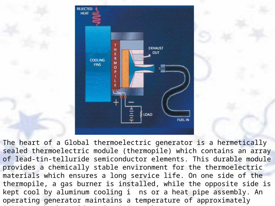
The heart of a Global thermoelectric generator is a hermetically sealed thermoelectric module (thermopile) which contains an array of lead-tin-telluride semiconductor elements. This durable module provides a chemically stable environment for the thermoelectric materials which ensures a long service life. On one side of the thermopile, a gas burner is installed, while the opposite side is kept cool by aluminum cooling i ns or a heat pipe assembly. An operating generator maintains a temperature of approximately 540ºC on the hot side and 140ºC on the cold side. The heat l ow through the thermopile creates steady DC electricity with no moving parts.


Personal Protecting Equipment
12
3
4
5
1. Hard hat2. Safety glass3. Normex suit4. Gloves5. Safety shoes

Tools & Equipment

Thermal Electric generatorIntroductionEach remote wellhead platform is provide with a TEG for the purpose of DC power supply and chargers. The TEG is powered by converting heat energy to electrical energy and charging to a battery backup supply. Knowledge of electrical maintenance is essential to ensure the proper, safe operation of the TEG.
Objectives1. Explain to the satisfaction of the instructor the purpose and operation of the TEG. 2. Identify to the satisfaction of the instructor all components shown on the schematic drawing and explain the functions of each component. 3. Function test the equipment as per the manufacturer's procedures. 4. Perform PM on equipment as per the work order instructions. 5. Troubleshoot equipment/system malfunctions.

Materials and Tools 1. Field electrical drawings 2. Manufacturer's manuals 3. Slide presentations 4. Electrical hand tools 5. Electrical test equipment 6. TEG and components
Venue Classroom & Electrical Workshop
Group 6 Trainee
Duration 1 Day-training
Work Tasks
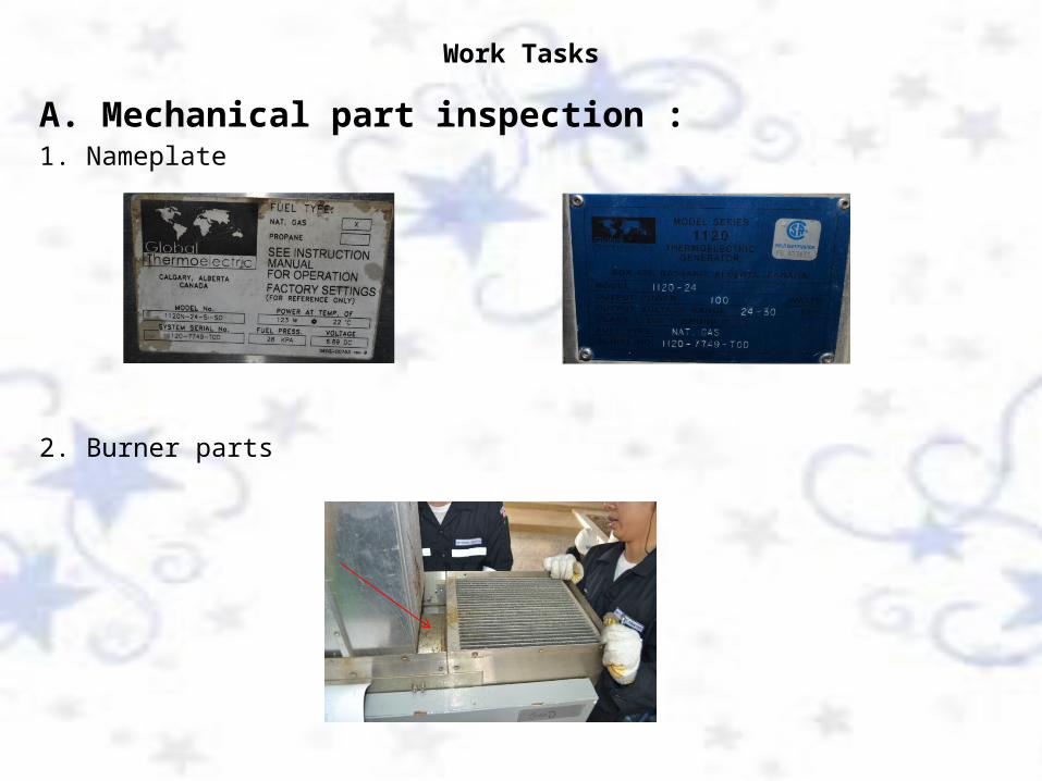
A. Mechanical part inspection :1. Nameplate
2. Burner parts


3. Flame arrestor housing parts

4. Igniter housing part
5. Shut off valve part

B. Check and locate part in electronics assembly:1. Precision load2. Protective limiter3. DC/DC converter4. Voltage sensing relay circuit ( VSR )5. PCB assy , limiter converter6. Battery charge control module and battery7. Digital panel meter and PCB , voltmeter control8. Shunt9. Battery10. Potentiometer adjust

9
8
10

5
4
3
2
6

7

B. Start up TEG follow procedure : TEG.START UP PROCEDURE 1. SET THE " MAIN SW. ON LOAD" TO OFF POSITION. ( not have ) 2. SET THE " POWER SWITCH " TO SET UP POSITION 3. SET THE " OUTPUT VOLTAGE ADJUST " TO MIDDLE POSITION.

4. PLACE THE " STARTING CLIP " ON THE FUEL SHUT OFF VALVE TO BYPASS FUEL SUPPLY .
5. ADJUST THE " AIR SHUTTERS " SLIGHTLY FROM CLOSE POSITION TO OPEN AT 10% (APPROXIMATE) (THE AIR SHUTTERS SHOULD ALWAYS BE ADJUST EQUALLY IN SMALL INCREMENT)

6. CONECT DC VOLTMETER AT TEG (-) AND TEG (+) TERMINAL TO MONITOR TEG OUTPUT VOLTAGE
7. TURN ON FUEL BY LOOSEN THE LOCK NUT ON THE FUEL REGULATOR.

8. INCREASE FUEL PRESSURE FROM MINIMUM TO 0.5 PSI. (THE TEG SHOULD IMMEDIATELY START FIRING, AS NOTE BY POPPING INSIDE THE COMBUSION CHAMBER, IT WILL POP UNTIL SUSTAINED IGNITION OCCURS (PURRING SOUND) NOTE - IF POPPING AND SUSTAINED IGNITION CANNOT BE OBTAINED QUICKLY - ADJUST THE AIR SHUTTETS SLIGHTLY TO INCREASING AIR RICH POSITION UNTIL SUSTAINED. IGNITION OCCURS. - WHEN THE TEG IS FIRING THE SPARKING SYSTEM WILL OFF AUTOMATIC.

9. OBSERVE DC VOLTMETER IF TEG IS FIRING, THE VOLTAGE WILL INCREASING RAPIDLY.
10. OBSERVE DC VOLTMETER AGAIN IF THE VOLTAGE SLOWLY INCREASE. THEN INCREASE FUEL SLIGHTLY FROM 0.5 PSI. TO 3.0 PSI. AND 4.0 PSI.
11. DC VOLTAGE WILL INCREASE RAPIDLY AGAIN.

12. WAIT AND OBSERVE THE VOLTAGE REACHES AT 2.5 - 3.0 VDC THEN DIGITAL DISPLAY IS LOCATE ON THE FRONT DOOR WILL DISPLAY
13. AFTER 30 MINUTES OF OPERATION OBSERVE. THE TEG OUTPUT VOLTAGE SHOULD BE APPROXIMATE 5.0 -5.5 VDC (Vset = 5.38 VDC)
NOTES -IF THE OUTPUT VOLTAGE LESS THAN 5.38 VDC. THEN DECREASE A LITTLE AIR SHUTTERS AND OBSERVE THE OUTPUT VOLTAGE WILL INCREASE. -IF THE OUTPUT VOLTAGE MORE THAN 5.38 VDC. THEN INCRESE A LITTLE AIR SHUTTERS AND OBSERVE THE OUTPUT VOLTAGE WILL DECREASE.WARNING : TO BE AVOIDED A FUEL RICH OPERATION

14. WHEN THE VOLTAGE OUTPUT IS 5.38 VDC (APPROXIMATE) CONSTANT. THAT MEAN THE Vset = 70 % OF FULL LOAD OUTPUT 100 WATTS (100 % OF FULL LOAD OUTPUT 6.20 VDC.)
WARNING : TO PREVENT DAMAGE TO THE TEG. DO NOT ALLOW THE Vset TO EXCEED 7.10 VDC AT AMBIENT TEMPERATURE ABOVE 24 DEGREE C. (P =V(set)²/0.387)

15. NOW THE TEG IS OPERATING AT THE REQUIRED POWER OUTPUT TO CHARGED BATTERIES NOTE: - IF BATTERY BANK VOLTAGE IS BELOW THAN 22 VOLTS THE TEG WILL NOT CHARGE
16. SET POWER SWITCH TO " RUN POSITION " THEN " TEG NORMAL LIGHT" SHOULD COME ON

17. ADJUST THE OUTPUT VOLTAGE CONTROL TO THE OPERATING VOLTAGE (24.00-28.00 VDC). READ ON DIGITAL PANEL METER ,IF PUSH THE RED BUTTON ON "METER SELECT" BUTTON TO READ THE CHARGING CURRENT. NOTE : - THE MULTIPLE TEG SYSTEM IS IN USE ENSURE THAT ALL OUTPUT S ARE EQUAL - THE TEG LIGHT SHOULD REMAIN AS A STEADY GLOW. - IF THE LAMP IS DIMS OR THE OUTPUT VOLTAGE DROPS SIGNIFICANTY THAT MEAN THE TEG IS BEING OVERLOAD. - ENSURE THAT THE LOAD IS NO MORE THAN 100 WATTS. AT 24.00-30.00 VDC

18. REMOVE "THE STARTING CLIP" ON THE SHUT OFF VALVE FOR NORMAL OPERATION. IF THE TEG BURNER GO OUT THE FUEL SHUT OUT VALVE WILL CLOSE AUTOMATIC.
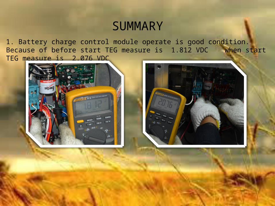
SUMMARY1. Battery charge control module operate is good condition. Because of before start TEG measure is 1.812 VDC when start TEG measure is 2.076 VDC

SUMMARY2. TEG. hasn’t a lock shut off valve therefore we used a lock strap instead.
In a normal condition it has a starting clip.

SUMMARY3. The upper of arrestor hasn’t a exhaust stack.

SUMMARY4. The ground cable at a ignitor housing has broken.5. The ignitor board assy be tattered because of miss the lock nut for fix.
Copyright © 2022 FDOKUMEN