All-Oxide Thermoelectric Module with in Situ Formed Non
8
All-Oxide Thermoelectric Module with in Situ Formed Non- Rectifying Complex p−p−n Junction and Transverse Thermoelectric Effect Nikola Kanas, †,‡ Michael Bittner, ‡ Temesgen Debelo Desissa, § Sathya Prakash Singh, † Truls Norby, § Armin Feldhoff, ‡ Tor Grande, † Kjell Wiik, † and Mari-Ann Einarsrud* ,† † Department of Material Science and Engineering, NTNU Norwegian University of Science and Technology, 7491 Trondheim, Norway ‡ Institute of Physical Chemistry and Electrochemistry, Leibniz University, 30167 Hannover, Germany § Department of Chemistry, Centre for Materials Science and Nanotechnology, University of Oslo, 0315 Oslo, Norway * S Supporting Information ABSTRACT: All-oxide thermoelectric modules for energy harvesting are attractive because of high-temperature stability, low cost, and the potential to use nonscarce and nontoxic elements. Thermoelectric modules are mostly fabricated in the conventional π- design, associated with the challenge of unstable metallic interconnects at high temperature. Here, we report on a novel approach for fabrication of a thermoelectric module with an in situ formed p−p−n junction made of state-of-the-art oxides Ca 3 Co 4−x O 9+δ (p-type) and CaMnO 3 −CaMn 2 O 4 composite (n-type). The module was fabricated by spark plasma co-sintering of p- and n-type powders partly separated by insulating LaAlO 3 . Where the n- and p-type materials originally were in contact, a layer of p-type Ca 3 CoMnO 6 was formed in situ. The hence formed p−p−n junction exhibited Ohmic behavior and a transverse thermoelectric effect, boosting the open-circuit voltage of the module. The performance of the module was characterized at 700−900 °C, with the highest power output of 5.7 mW (around 23 mW/cm 2 ) at 900 °C and a temperature difference of 160 K. The thermoelectric properties of the p- and n-type materials were measured in the temperature range 100−900 °C, where the highest zT of 0.39 and 0.05 were obtained at 700 and 800 °C, respectively, for Ca 3 Co 4−x O 9+δ and the CaMnO 3 −CaMn 2 O 4 composite. 1. INTRODUCTION Energy harvesting from waste heat from, for example, combustion engines or metallurgical processes or other industry has great potential for energy savings and emission reductions. Thermoelectric generators (TEGs) present a promising technology for such energy recovery. 1 A TEG is based on two dissimilar materials (p- and n-types) connected together and when exposed to a temperature gradient, converts thermal energy into electrical energy. 1,2 Power density (P density ) and the figure of merit (zT) are used to evaluate TE modules and their consisting p- and n-type materials, respectively. Figure of merit for any p- or n-type material can be calculate using σ κ = zT S T 2 (1) where S, σ, and κ represent Seebeck coefficient, electrical conductivity, and thermal conductivity, respectively. 3 In a conventional module (π-design), p- and n-type materials are connected electrically in series and thermally in parallel, with conductive metallic interconnects between legs (mostly Ag or Au). 4,5 Conventional modules normally suffer from limited temperature, which obstructs the high-temperature advantage of oxides. Furthermore, conventional modules demonstrate short lifetimes because of the instability of the metallic interconnects and even at low temperature resulting in a decrease in power output as a function of time. 6 All-oxide TE modules with direct oxide−oxide p−n junction would therefore be beneficial. However, such direct p−n junction will normally have high resistance because of charge carrier depletion in the space charge regions. 7 Shin et al. demonstrated for the first time the prototype of a direct p−n oxide module using Li-doped NiO and (Ba, Sr)PbO 3 , and 14 mW at ΔT = 552 K was achieved. 8 Later, Hayashi et al. reported a stacked module with direct p−n oxide junctions based on p-type (La 1.97 Sr 0.03 )CuO 4 and n-type (Nd 1.97 Ce 0.03 )CuO 4 , where the maximum power density obtained from 25 pairs was 40 mW/cm 2 at 400 °C and ΔT = 360 K. 9 Moreover, Funahashi et al. demonstrated a module using a nonoxide p-type Ni 0.9 Mo 0.1 and n-type La 0.035 Sr 0.965 TiO 3 , 10 where the maximum obtained power density from 50 pairs was 450 mW/cm 2 at ΔT = 360 K. Received: June 19, 2018 Accepted: August 14, 2018 Published: August 24, 2018 Article http://pubs.acs.org/journal/acsodf Cite This: ACS Omega 2018, 3, 9899-9906 © 2018 American Chemical Society 9899 DOI: 10.1021/acsomega.8b01357 ACS Omega 2018, 3, 9899−9906 This is an open access article published under an ACS AuthorChoice License, which permits copying and redistribution of the article or any adaptations for non-commercial purposes. Downloaded via LEIBNIZ UNIVERSITAET HANNOVER on December 6, 2018 at 14:38:27 (UTC). See https://pubs.acs.org/sharingguidelines for options on how to legitimately share published articles.
-
Upload
khangminh22 -
Category
Documents
-
view
0 -
download
0
Transcript of All-Oxide Thermoelectric Module with in Situ Formed Non

All-Oxide Thermoelectric Module with in Situ Formed Non-Rectifying Complex p−p−n Junction and Transverse ThermoelectricEffectNikola Kanas,†,‡ Michael Bittner,‡ Temesgen Debelo Desissa,§ Sathya Prakash Singh,† Truls Norby,§
Armin Feldhoff,‡ Tor Grande,† Kjell Wiik,† and Mari-Ann Einarsrud*,†
†Department of Material Science and Engineering, NTNU Norwegian University of Science and Technology, 7491 Trondheim,Norway‡Institute of Physical Chemistry and Electrochemistry, Leibniz University, 30167 Hannover, Germany§Department of Chemistry, Centre for Materials Science and Nanotechnology, University of Oslo, 0315 Oslo, Norway
*S Supporting Information
ABSTRACT: All-oxide thermoelectric modules for energy harvesting are attractivebecause of high-temperature stability, low cost, and the potential to use nonscarce andnontoxic elements. Thermoelectric modules are mostly fabricated in the conventional π-design, associated with the challenge of unstable metallic interconnects at hightemperature. Here, we report on a novel approach for fabrication of a thermoelectricmodule with an in situ formed p−p−n junction made of state-of-the-art oxidesCa3Co4−xO9+δ (p-type) and CaMnO3−CaMn2O4 composite (n-type). The module wasfabricated by spark plasma co-sintering of p- and n-type powders partly separated byinsulating LaAlO3. Where the n- and p-type materials originally were in contact, a layer ofp-type Ca3CoMnO6 was formed in situ. The hence formed p−p−n junction exhibitedOhmic behavior and a transverse thermoelectric effect, boosting the open-circuit voltageof the module. The performance of the module was characterized at 700−900 °C, withthe highest power output of 5.7 mW (around 23 mW/cm2) at 900 °C and a temperaturedifference of 160 K. The thermoelectric properties of the p- and n-type materials weremeasured in the temperature range 100−900 °C, where the highest zT of 0.39 and 0.05 were obtained at 700 and 800 °C,respectively, for Ca3Co4−xO9+δ and the CaMnO3−CaMn2O4 composite.
1. INTRODUCTIONEnergy harvesting from waste heat from, for example,combustion engines or metallurgical processes or otherindustry has great potential for energy savings and emissionreductions. Thermoelectric generators (TEGs) present apromising technology for such energy recovery.1 A TEG isbased on two dissimilar materials (p- and n-types) connectedtogether and when exposed to a temperature gradient, convertsthermal energy into electrical energy.1,2 Power density (Pdensity)and the figure of merit (zT) are used to evaluate TE modulesand their consisting p- and n-type materials, respectively.Figure of merit for any p- or n-type material can be calculateusing
σκ
=zTS T2
(1)
where S, σ, and κ represent Seebeck coefficient, electricalconductivity, and thermal conductivity, respectively.3 In aconventional module (π-design), p- and n-type materials areconnected electrically in series and thermally in parallel, withconductive metallic interconnects between legs (mostly Ag orAu).4,5 Conventional modules normally suffer from limitedtemperature, which obstructs the high-temperature advantage
of oxides. Furthermore, conventional modules demonstrateshort lifetimes because of the instability of the metallicinterconnects and even at low temperature resulting in adecrease in power output as a function of time.6 All-oxide TEmodules with direct oxide−oxide p−n junction wouldtherefore be beneficial. However, such direct p−n junctionwill normally have high resistance because of charge carrierdepletion in the space charge regions.7
Shin et al. demonstrated for the first time the prototype of adirect p−n oxide module using Li-doped NiO and (Ba,Sr)PbO3, and 14 mW at ΔT = 552 K was achieved.8 Later,Hayashi et al. reported a stacked module with direct p−n oxidejunctions based on p-type (La1.97Sr0.03)CuO4 and n-type(Nd1.97Ce0.03)CuO4, where the maximum power densityobtained from 25 pairs was 40 mW/cm2 at 400 °C and ΔT= 360 K.9 Moreover, Funahashi et al. demonstrated a moduleusing a nonoxide p-type Ni0 . 9Mo0 .1 and n-typeLa0.035Sr0.965TiO3,
10 where the maximum obtained powerdensity from 50 pairs was 450 mW/cm2 at ΔT = 360 K.
Received: June 19, 2018Accepted: August 14, 2018Published: August 24, 2018
Article
http://pubs.acs.org/journal/acsodfCite This: ACS Omega 2018, 3, 9899−9906
© 2018 American Chemical Society 9899 DOI: 10.1021/acsomega.8b01357ACS Omega 2018, 3, 9899−9906
This is an open access article published under an ACS AuthorChoice License, which permitscopying and redistribution of the article or any adaptations for non-commercial purposes.
Dow
nloa
ded
via
LE
IBN
IZ U
NIV
ER
SIT
AE
T H
AN
NO
VE
R o
n D
ecem
ber
6, 2
018
at 1
4:38
:27
(UT
C).
Se
e ht
tps:
//pub
s.ac
s.or
g/sh
arin
ggui
delin
es f
or o
ptio
ns o
n ho
w to
legi
timat
ely
shar
e pu
blis
hed
artic
les.

Furthermore, Chavez et al. showed another concept of usinglarge-area p−n junctions (containing no insulator) as a TEmodule where 1.3 mW was generated from one pair at ΔT =300 K.11 The chemical compatibility, long-term stability, andelectrical performance of the p−n junctions/modules were notconsidered in these studies.Ca3Co4−xO9+δ (CCO) has a misfit-layered complex crystal
structure containing triangular CoO2 and rock-salt Ca2CoO3layers.12 CCO shows p-type conductivity and exhibits excellentthermoelectric (TE) power at elevated temperatures inambient air.13 CaMnO3−δ (CMO) has a perovskite structureand exhibits n-type conductivity resulting from an intrinsicoxygen deficiency. By introducing a secondary CaMn2O4spinel phase, the TE properties of the CaMnO3−δ−CaMn2O4composite are improved compared with single phaseCaMnO3−δ, as observed in our research group. TE propertiesof these oxides can further be improved by doping or co-doping.14 So far, only a few reports on conventional modulesbased on the CCO−CMO-based system are available.15−22
Besides high-temperature TE modules, there are recentlyreported promising low-temperature organic-based TE mod-ules, containing flexible layered design.23,24
Here, we report on high-temperature TE performance for anall-oxide TE module based on the system p-type Ca3Co4−xO9+δ(CCO) and n-type CaMnO3−CaMn2O4 (CMO-composite).LaAlO3 (LAO) was selected as the electrical insulatingcomponent because of its ferroelastic properties25 and highthermal expansion coefficient (TEC) compared with otherpotential insulating oxide candidates. Undoped CCO and aCMO-composite were selected as model materials in this workfocusing on developing processing methods of the layeredmodule and thereby analyzing the effect of a direct oxide−oxide p−n junction at high-temperature on TE performance ofthe module. The performance of the module critically dependson the properties of an in situ formed complex p−p−njunction, which was studied with respect to stability,interdiffusion, compatibility, and electrical conductivity.Finally, we report on an environment friendly processingmethod for all-oxide TE devices based on aqueous tape castingand co-sintering of the three materials using spark plasmasintering (SPS).
2. RESULTS2.1. Powder Characteristics. X-ray diffraction (XRD)
patterns of CCO, CMO-composite, and LAO powders arepresented in Figure 1a, confirming the phase purity of CCOand LAO as well as the composite nature of the CMO-composite (CaMnO3 with minor amount of CaMn2O4secondary phase). XRD patterns of polycrystalline CCOprepared by SPS are also included in Figure 1a, both paralleland perpendicular to the pressing direction. A high degree oftexture is observed (c oriented parallel to the pressingdirection) as well as small amounts of Ca3Co2O6 and Co3O4secondary phases. Fine-grained powders of the three startingoxides are confirmed from the scanning electron microscopy(SEM) images in Figure 1b. Sintering curves for the CCO,CMO-composite, and LAO powders shown in Figure 1cdemonstrate the onset of sintering at around 650, 900, and1000 °C for CCO, CMO-composite, and LAO, respectively.TECs of CCO (perpendicular and parallel to pressingdirection during SPS), CMO-composite, and LAO aresummarized in Table 1. CCO and CMO-composite showsimilar TECs while LAO has a significantly lower value.
2.2. TE Performance of the Materials. Electricalconductivity, thermal conductivity, Seebeck coefficient, powerfactor, and zT as a function of temperature for the p- and n-type oxides are presented in Figure 2. CCO shows a maximumelectrical conductivity in the range of 500−600 °C, reachingapproximately 100 S cm−1 (Figure 2a). On the other hand, theelectrical conductivity of the CMO-composite has a constantvalue of 7 S cm−1 up to 600 °C from where it increases to 28 Scm−1 at 900 °C. The thermal conductivity of both materialsdecreases with temperature, reaching minima of 0.85 W m−1
K−1 at 700 °C for CCO and 1.42 W m−1 K−1 at 800 °C for theCMO-composite (Figure 2b). The sudden drop in thermalconductivity for CCO above 600 °C is most probably due tophonon−phonon interactions between the a−b plane and cdirection due to the anisotropic crystal structure and texturingof the sample. A maximum Seebeck coefficient of 186 μV K−1
at 500 °C for CCO and −325 μV K−1 at 400 °C for the CMO-composite (Figure 2c) was achieved. A maximum power factorfor CCO (3.6 μW cm−1 K−2) was obtained at ∼500 °C. Thefigure-of-merit, zT, presented in Figure 2d increased withtemperature, reaching 0.39 at 700 °C for CCO and 0.05 at 800
Figure 1. (a) XRD patterns of CCO, CMO-composite, and LAOpowders as well as a sample of CCO made by SPS in the directionsparallel and perpendicular to the pressing direction, (b) SEMmicrographs, and (c) sintering curves of CCO, CMO-composite,and LAO powders produced by spray pyrolysis. Diffraction lines fromarticles, LAO,25 CCO,26 and CMO-composite powder (CaMnO3
27
and CaMn2O428) are indicated in (a).
ACS Omega Article
DOI: 10.1021/acsomega.8b01357ACS Omega 2018, 3, 9899−9906
9900

°C for the CMO-composite. The electrical conductivity andSeebeck coefficients were measured in the directionperpendicular to the pressing direction, whereas the thermalconductivity was recorded parallel to the pressing direction ofthe sample. The measurements in the two differentorientations resulted in a higher zT than the real one becausethe reported thermal conductivity of CCO is stronglyanisotropic.29
2.3. TE Module. Schematic of the cross section of the TEmodule design is shown in Figure 3a. The thickness of theCMO-composite after co-sintering is approximately four timeslarger than the thickness of the CCO layer. Resistance, R, ofboth conductors was calculated by the formula R = ρ·l/Awhere ρ is electrical resistivity (cm·S−1), l is height/length
(cm), and A is area (cm2). The electrical resistance of CMO-composite at, for example, 800 °C is about 1.6 more than oneof CCO, and therefore, the CMO-composite represents moreelectrically resistive part in spite of larger thickness comparedwith CCO and limits the charge carrier flow. Because of thesignificant increase in electrical conductivity of CMO-composite above 800 °C, and slight decrease of CCO, theelectrical resistance of the CMO-composite at 900 °C is about0.7 times less than one of CCO; hence, the CCO representsmore electrically resistive part.Voltage (polynomial fitting) and power output of the TE
module as a function of measured current output are shown inFigure 3b. Dashed lines represent current and voltage atmaximum power at 700, 800, and 900 °C at the hot side of the
Table 1. TEC of CCO (Perpendicular and Parallel to the Pressing Direction During SPS), CMO, and LAO
CCO parallel to the pressing direction(K−1·10−6)
CCO perpendicular to the pressing direction(K−1·10−6)
LAO(K−1·10−6)
CMO-composite(K−1·10−6)
400−800 °C(heating)
17.0 14.4 9.7 18.0
700−400 °C(cooling)
17.8 14.5 9.7 18.2
Figure 2. (a) Electrical conductivity, (b) thermal conductivity, (c) Seebeck coefficient, and (d) zT (full symbols) and power factor (open symbols)as a function of temperature for CCO and CMO-composite ceramics. Error bars represent standard deviation based on five (Seebeck coefficient)and three (thermal conductivity) measured values. The uncertainty in electrical conductivity is smaller than the symbols and less than ±1%.
ACS Omega Article
DOI: 10.1021/acsomega.8b01357ACS Omega 2018, 3, 9899−9906
9901

module. Power output increases with temperature, reaching amaximum of about 5.7 mW at 900 °C. The effective powerdensity of about 23 mW/cm2 at this temperature wascalculated from the effective area of TE module (approximately0.25 cm2).Open-circuit voltage UOC and short-circuit current Jq,SC were
determined by extrapolation from the measured Jq−U line andreached 213 mV and 108 mA at 900 °C, respectively. Datafrom the characterization of the TE module performance aresummarized in Table 2.Because the power output is dependent on load resistance,
the maximum power output could be measured when the set-up-load from an external circuit of 5.7 Ω became equal to theTE module’s resistance of about 2.1 Ω (at 800 °C).30 Thecalculated figure of merit of the module (ZT) is 0.01, using
= −ZTU
J R1OC
q,SC module (2)
where UOC, Jq,SC, and Rmodule represents open-circuit voltage,short-circuit current, and resistance of the module, respec-tively.31
2.4. p−p−n Junction. The microstructure of the CCO−CCMO−CMO p−p−n junction before and after annealing at900 °C for 100 h is shown in Figure 4a. Elongated grain
growth parallel to the interface is evident in CCO. A thinCa3CoMnO6 (CCMO) layer, confirmed by energy-dispersivespectrometry (EDS), is formed in situ between CCO andCMO during the co-sintering. The CCMO layer has grown toapproximately 5 μm after annealing at 900 °C for 100 h. Inaddition, a layer of approximately 35 μm thickness close to theinterface displayed a higher density than the rest of the CCO.From the EDS profiles of the CCO−CMO interface presentedin Figure 4b, the Ca content in this dense layer is lower thanthat in CCO showing a Co-rich and a Ca-deficient region atthe interface. The Ca/Co ratio equals the initial Ca/Co ratiocorresponding to pure CCO approximately 40 μm from theinterface. A Co-oxide phase seen as grains with higher Co-content in Figure 4a is present both in the dense interface layeras well as in the CCO far from the interface.Current−voltage curves across the CCO−CCMO−CMO
complex junction before and after annealing at 900 °C for 100
Figure 3. (a) Schematic of the cross section of the TE module withillustrated top part and bottom part (p- and n-type materials separatedby an insulator, i) as well as flow direction of heat at top part (b)polynomial fitting of electrical power output (Pel) and linear fitting ofvoltage (U) as a function of the electrical current (Jq) at different Thottemperatures (700, 800, and 900 °C) and constant ΔT = 160 K.Voltage and current at maximum power U(Pmax) and Jq(Pmax) atdifferent temperatures are also indicated by dotted lines.
Table 2. Open-Circuit Voltage UOC, Short-Circuit CurrentJq,sc, Electrical Resistance of the Module R, Electrical PowerOutput Pmax, and Power Density of CCO−CMO TE Moduleat 700, 800, and 900 °C at 160 K Temperature Differencebetween the Hot and Cold Side
Th(°C)
Uoc(mV)
Jq,sc(mA)
Rmodule(Ω)
Pmax(mW)
Pmax(mW/cm2)
700 181 82 2.2 4.0 16800 208 101 2.1 5.2 21900 213 108 2.0 5.7 23
Figure 4. (a) SEM micrographs of CCO−CCMO−CMO junctionbefore and after annealing at 900 °C for 100 h and EDS maps of themagnified section of the annealed junction given by the dashed linesand (b) EDS line profiles across the CCO−CCMO−CMO junctionafter annealing.
ACS Omega Article
DOI: 10.1021/acsomega.8b01357ACS Omega 2018, 3, 9899−9906
9902
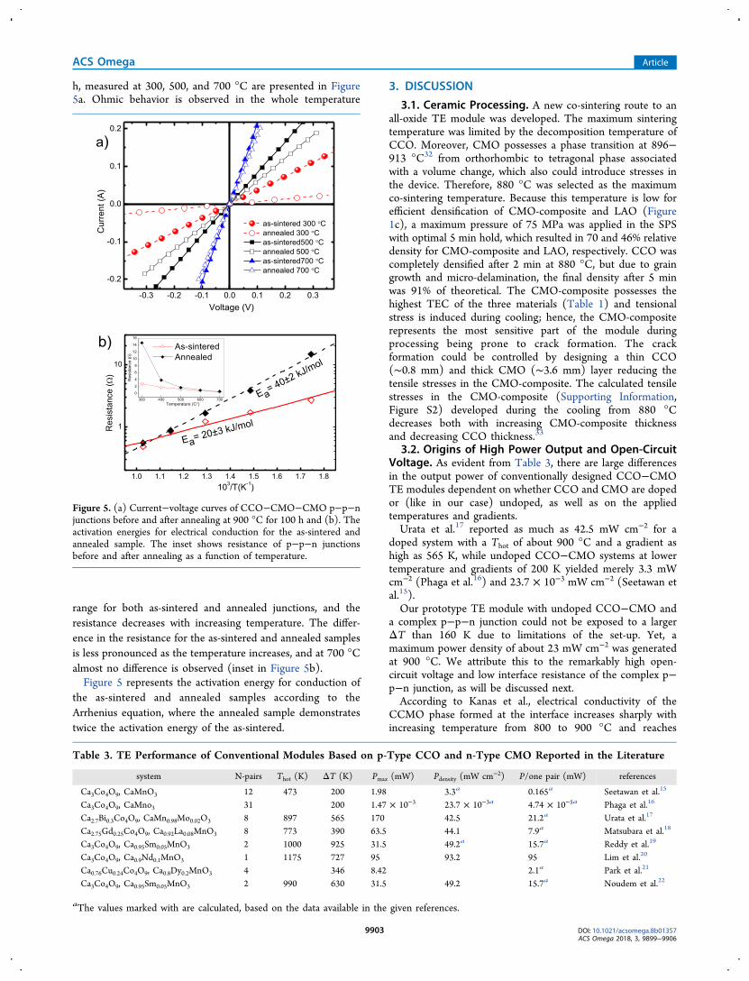
h, measured at 300, 500, and 700 °C are presented in Figure5a. Ohmic behavior is observed in the whole temperature
range for both as-sintered and annealed junctions, and theresistance decreases with increasing temperature. The differ-ence in the resistance for the as-sintered and annealed samplesis less pronounced as the temperature increases, and at 700 °Calmost no difference is observed (inset in Figure 5b).Figure 5 represents the activation energy for conduction of
the as-sintered and annealed samples according to theArrhenius equation, where the annealed sample demonstratestwice the activation energy of the as-sintered.
3. DISCUSSION
3.1. Ceramic Processing. A new co-sintering route to anall-oxide TE module was developed. The maximum sinteringtemperature was limited by the decomposition temperature ofCCO. Moreover, CMO possesses a phase transition at 896−913 °C32 from orthorhombic to tetragonal phase associatedwith a volume change, which also could introduce stresses inthe device. Therefore, 880 °C was selected as the maximumco-sintering temperature. Because this temperature is low forefficient densification of CMO-composite and LAO (Figure1c), a maximum pressure of 75 MPa was applied in the SPSwith optimal 5 min hold, which resulted in 70 and 46% relativedensity for CMO-composite and LAO, respectively. CCO wascompletely densified after 2 min at 880 °C, but due to graingrowth and micro-delamination, the final density after 5 minwas 91% of theoretical. The CMO-composite possesses thehighest TEC of the three materials (Table 1) and tensionalstress is induced during cooling; hence, the CMO-compositerepresents the most sensitive part of the module duringprocessing being prone to crack formation. The crackformation could be controlled by designing a thin CCO(∼0.8 mm) and thick CMO (∼3.6 mm) layer reducing thetensile stresses in the CMO-composite. The calculated tensilestresses in the CMO-composite (Supporting Information,Figure S2) developed during the cooling from 880 °Cdecreases both with increasing CMO-composite thicknessand decreasing CCO thickness.33
3.2. Origins of High Power Output and Open-CircuitVoltage. As evident from Table 3, there are large differencesin the output power of conventionally designed CCO−CMOTE modules dependent on whether CCO and CMO are dopedor (like in our case) undoped, as well as on the appliedtemperatures and gradients.Urata et al.17 reported as much as 42.5 mW cm−2 for a
doped system with a Thot of about 900 °C and a gradient ashigh as 565 K, while undoped CCO−CMO systems at lowertemperature and gradients of 200 K yielded merely 3.3 mWcm−2 (Phaga et al.16) and 23.7 × 10⁻³ mW cm−2 (Seetawan etal.15).Our prototype TE module with undoped CCO−CMO and
a complex p−p−n junction could not be exposed to a largerΔT than 160 K due to limitations of the set-up. Yet, amaximum power density of about 23 mW cm−2 was generatedat 900 °C. We attribute this to the remarkably high open-circuit voltage and low interface resistance of the complex p−p−n junction, as will be discussed next.According to Kanas et al., electrical conductivity of the
CCMO phase formed at the interface increases sharply withincreasing temperature from 800 to 900 °C and reaches
Figure 5. (a) Current−voltage curves of CCO−CMO−CMO p−p−njunctions before and after annealing at 900 °C for 100 h and (b). Theactivation energies for electrical conduction for the as-sintered andannealed sample. The inset shows resistance of p−p−n junctionsbefore and after annealing as a function of temperature.
Table 3. TE Performance of Conventional Modules Based on p-Type CCO and n-Type CMO Reported in the Literature
system N-pairs Thot (K) ΔT (K) Pmax (mW) Pdensity (mW cm−2) P/one pair (mW) references
Ca3Co4O9, CaMnO3 12 473 200 1.98 3.3a 0.165a Seetawan et al.15
Ca3Co4O9, CaMno3 31 200 1.47 × 10⁻³ 23.7 × 10⁻³a 4.74 × 10⁻⁵a Phaga et al.16
Ca2.7Bi0.3Co4O9, CaMn0.98Mo0.02O3 8 897 565 170 42.5 21.2a Urata et al.17
Ca2.75Gd0.25Co4O9, Ca0.92La0.08MnO3 8 773 390 63.5 44.1 7.9a Matsubara et al.18
Ca3Co4O9, Ca0.95Sm0.05MnO3 2 1000 925 31.5 49.2a 15.7a Reddy et al.19
Ca3Co4O9, Ca0.9Nd0.1MnO3 1 1175 727 95 93.2 95 Lim et al.20
Ca0.76Cu0.24Co4O9, Ca0.8Dy0.2MnO3 4 346 8.42 2.1a Park et al.21
Ca3Co4O9, Ca0.95Sm0.05MnO3 2 990 630 31.5 49.2 15.7a Noudem et al.22
aThe values marked with are calculated, based on the data available in the given references.
ACS Omega Article
DOI: 10.1021/acsomega.8b01357ACS Omega 2018, 3, 9899−9906
9903

around 0.1 S cm−1 at 900 °C, where the positive Seebeckcoefficient furthermore reaches as high as 668 μV K−1.34 Thethree-layered CCO−CCMO−CMO junction exhibits Ohmicbehavior with relatively modest interfacial resistance above 700°C as evidenced in Figure 5a. We tentatively interpret this asan effect of the electron energy levels of CCMO as layingintermediate of those of CCO and CMO, hence decreasing thedepletion of charge carriers at the CCO−CCMO andCCMO−CMO interfaces as compared to a hypotheticalpristine CCO−CMO p−n interface. This facilitates anelectrical current flow through the p−p−n interface asillustrated in Figure 3a.The CCMO reaction layer is thicker in the annealed sample
compared with the as-sintered one (Figure 4a), and in thetemperature range 300−500 °C, resistivity is higher for theannealed sample (Figure 5). At 700 °C, the resistivity of bothsamples are almost equal (Figure 5), showing that the sameconcentration of charges will be excited to conduction levelbecause of thermal activation, demonstrating no effect ofCCMO thickness on the current density above 700 °C. TheCCMO layer is therefore contributing equally to the electricalconduction process at this high temperature.When two materials A and B dissimilar in thermal
conductivity and Seebeck coefficient are contacted over anarea exposed to a parallel thermal gradient, a voltage isgenerated in the transversal direction, and an effectivetransversal Seebeck coefficient of the couple can be expressedaccording to Goldsmid35
= + +S S K S K K K( / / )/(1/ 1/ )yo A A B B A B (3)
where SA, SB, KA, and KB represent the Seebeck coefficients andthermal resistances of the two materials. In our case, thethermal conductivity of CCO at 900 °C is 0.94 W m−1 K−1
while that for CCMO is 1.3 W m−1 K−134 and the CMO-composite is 2.0 W m−1 K−1. This will give rise to differentheat flows down the n- and p-type materials, resulting in anincreasing transversal temperature gradient down the CCMOinterface layer corresponding to the transversal heat flowillustrated in Figure 3a.For the following discussion, the module may be divided
into a top hot part above the LAO insulator and a bottomconventional part. The top part contains three material layersand two subjunctions which contribute to a transversal TEvoltage according to eq 3, whereas the bottom part contributesto standard longitudinal TE voltages. On the basis of thedimensions of the module, we may estimate a temperaturedifference of 40 K over the top part and the remaining 120 Kcover the bottom part. Because the Seebeck coefficient ofCMO is strongly influenced by temperature (Figure 2c),average values are used for summing up all possiblecontributions from materials and interfaces in the transversaland longitudinal parts. We arrive at an estimated open-circuitpotential of 125 mV, as compared to the estimate of 64 mVfrom a regular CCO and CMO couple with a total gradient of160 K, based on their Seebeck coefficients of +177 and −171μV K−1 (at 900 °C) and about +179 and −270 μV K−1 (atapproximately 740 °C), respectively. Average absolute valuesof the Seebeck coefficient and thermal conductivity of CCOand CMO for the top and bottom parts of the module used forthe calculations are 178 μV K−1 (CCObottom), 177 μV K−1
(CCOtop), 0.89 W m−1 K−1 (CCOtop), 229 μV K−1
(CMObottom), 189 μV K−1 (CMOtop), and 1.88 W m−1 K−1
(CMOtop). A transversal TE effect occurs when anisotropy in
the electrical and thermal transport occurs,35 as in our top partof the module. This phenomenon is beneficially used forenhancing the voltage in transversal TE modules and relatedapplications.36−40 For instance, the transversal TE voltage inCaxCoO2 textured thin films can be significantly higher thanthe ones generated by regular TE effect.36−38 The transversalvoltage significantly affected the open-circuit voltage UOC andthe maximum electrical power output Pel. The presence of atransverse TE effect can also be observed by comparison ofUOC of the TE module (Figure 3b) and Seebeck coefficienttogether with the power factor of individual materials from 700to 900 °C. The Seebeck coefficients (Figure 2c) of the twoindividual materials decrease as temperature increases, as wellas power factor of CCO (Figure 2d), whereas UOC of TEmodule increases with temperature (Figure 3b). Theexperimentally measured UOC of 213 mV is hence remarkablylarger than both theoretical estimates. Further experimentaland theoretical studies (e.g., field emission microscopysimulations) will be necessary to fully understand the effectof thin layers of materials with high Seebeck coefficients in theinterface of p−n TE junctions. However, the in situ formedcomplex p−p−n junctions evidently improved the perform-ance of the all-oxide TE module, hence representing asignificant step forward toward the possible application ofoxide TE modules in high-temperature energy recovery.
4. CONCLUSIONS
A novel all-oxide TE module was successfully developed andfabricated by careful processing of materials in the CCO−CMO system using LAO as an electrical insulator. Fabricationof this all-oxide TE module is simpler and faster thanassembling conventional modules. The CCO−CMO moduledemonstrated a power of about 5.7 mW corresponding to apower density of 23 mW cm−2 at Thot = 900 °C and ΔT = 160K, a TE performance comparable and better than someconventional CCO−CMO modules. The all-oxide layered TEmodule produces a large open-circuit voltage, which wasattributed to the presence of a thin CCMO reaction layer andtransversal TE effect across the top p−p−n part of the TEmodule. The effect of the CCMO reaction layer is due to thelarge Seebeck coefficient, working transversally and reducingthe charge carrier depletion and resistance at the high-temperature p−n junction. The present investigation demon-strates an example of novel engineering of oxide TE moduleswithout metallic interconnects.
5. EXPERIMENTAL SECTION
5.1. Materials and Ceramic Processing. The ceramicpowders used in this work were prepared by spray pyrolysis(CerPoTech AS, Norway). Slurry for aqueous tape casting ofthe LAO insulator was prepared according to the schematicsshown in Figure S1 (Supporting Information). The slurry wascasted on a polyester (Mylar) film using a height of the doctorblade of 30 μm. After drying at ambient temperature,lamination of 8 layers was conducted by hot-pressing at 150MPa and 80 °C for 3 min. The laminated tape was cut into 12mm discs with one segment cut off (around 3 mm) to makethe direct p−n junction. Binder burnout was done at 440 °Cfor 4 h in air, placing the tape between two alumina plates toavoid bending. The TE module was fabricated by SPS (Dr.Sinter 825) in a 12 mm graphite die at 880 °C and 75 MPa for5 min using heating and cooling rates of 120 °C/min. Initially,
ACS Omega Article
DOI: 10.1021/acsomega.8b01357ACS Omega 2018, 3, 9899−9906
9904

the graphite die was filled with the CMO-composite powder(1.5 g), and then the cut LAO tape was placed on CMO-composite powder, followed by filling of CCO powder (0.5 g)onto the LAO tape.In addition, CMO-composite and CCO materials were
separately sintered by SPS using the same conditions as usedfor the TE module. These pellets were cut into a bar-shape (20× 5 × 2.5 mm) for electrical conductivity and Seebeckcoefficient measurements and discs (12.7 mm diameter) forthermal conductivity measurements. Densities of pellets andbars were determined by Archimedes measurement inisopropanol. To do a separate analysis of the direct CCO−CMO-composite junction, two samples were prepared by SPSco-sintering at 820 °C and 50 MPa for 10 min. One of thesesamples was further annealed at 900 °C for 100 h in air.5.2. Characterization. Phase composition and particle
size/morphology were characterized by powder X-raydiffraction (Bruker D8 DAVINCI) and SEM (Hitachi S-3400N), respectively. Sinterability and TEC were determinedby dilatometer (Netzsch DIL 402) in ambient air. TEC wasmeasured both parallel and perpendicular to the pressingdirection for CCO made by SPS. TE performance of CCO andCMO materials were analyzed by measuring Seebeckcoefficient (ProboStat, NorECs AS), electrical conductivity(home-made setup) and thermal conductivity (Netzsch LFA457 MicroFlash) at 100−900 °C in ambient air as describedelsewhere.41,42
For the power−current−voltage characterization, the layereddisc-shaped TE module was placed horizontally on an aluminaplate with the direct p−n junction at the top (hot temperatureside).To ensure better physical stability of the free-standing
module, a small area of about 0.25 cm2 was removed on thecold side. Both semiconductors were contacted by Pt-wires atthe lower, colder end, using gold paste (Heraeus). The aluminaplate with the TE module connected to Pt-wires was heated at700 °C for 4 h in ambient air, to establish good electricalcontact between the metal electrodes and semiconductingoxides.The power output test in ambient air was performed via load
resistance-dependent measurement, in a vertical furnace at 700,800, and 900 °C, and ΔT = 160 K. The temperature gradientwas established by heating the hot side of the module in thefurnace, whereas the cold side was cooled by an active cooler.The temperature difference ΔT was measured by two Pt−Pt10Rh (type S) thermocouples. During the power outputmeasurement, the voltmeter was connected parallel to theamperemeter, variable resistor (in series to each other), and tothe TE module. When thermal equilibria were established ateach temperature, electrical current and voltage were measuredwith increasing load resistance. More details could be found inref 4.Finally, annealed and as-sintered p−n junctions were
characterized by current−voltage measurements at 300, 500,and 700 °C in a vertical furnace, using a ProboStat cell(NORECS, Norway). A two-electrode set-up was used, wherea dc voltage was applied to the junction followed by measuringcurrent output using Multimeter-Agilent E3642A. After themeasurements, the samples were embedded in “EpoFix” resin,polished by diamond paste (DiaPro NapB1) to 1 μm andcoated with carbon (Cressington Carbon Coater 208) formicrostructural characterization. Interface reaction and inter-
diffusion at the p−n junction were investigated using SEM andEDS (Hitachi S-3400N).
■ ASSOCIATED CONTENT*S Supporting InformationThe Supporting Information is available free of charge on theACS Publications website at DOI: 10.1021/acsome-ga.8b01357.
Material supplied as Supporting Information containsfurther experimental details and estimated tensilestresses developed in CMO in the co-sintered module(PDF)
■ AUTHOR INFORMATIONCorresponding Author*E-mail: [email protected] (M.-A.E.).ORCIDTemesgen Debelo Desissa: 0000-0003-3612-7153Mari-Ann Einarsrud: 0000-0002-3017-1156NotesThe authors declare no competing financial interest.
■ ACKNOWLEDGMENTSThe financial support from The Research Council of Norwayunder the program Nano2021 to the project (number 228854)“TE materials: Nanostructuring for improving the energyefficiency of TEG and heat-pumps” (THELMA) conducted byNTNU, UiO, SINTEF, FFI, UiS, and UiA is gratefullyacknowledged. We also thank for the financial support fromthe Deutsche Forschungsgesellschaft (DFG, German ResearchFoundation)FE928/17-1. Dr Mohsin Saleemi and Dr JulianTolchard are acknowledged for fruitful discussions.
■ REFERENCES(1) Walia, S.; Balendhran, S.; Nili, H.; Zhuiykov, S.; Rosengarten, G.;Wang, Q. H.; Bhaskaran, M.; Sriram, S.; Strano, M. S.; Kalantar-zadeh, K. Transition metal oxidesThermoelectric properties. Prog.Mater. Sci. 2013, 58, 1443−1489.(2) Sootsman, J. R.; Chung, D. Y.; Kanatzidis, M. G. New and OldConcepts in Thermoelectric Materials. Angew. Chem. Int. Ed. 2009,48, 8616−8639.(3) Ioffe, A. F. Semiconductor Thermoelements and Thermoelectriccooling, 1st ed.; Info-search Ltd.: London, 1957.(4) Bittner, M.; Geppert, B.; Kanas, N.; Singh, S. P.; Wiik, K.;Feldhoff, A. Oxide-based thermoelectric generator for high-temper-ature application using p-type Ca3Co4O9 and n-type In1.95Sn0.05O3legs. Energy Harvest. Syst. 2016, 3, 213−222.(5) Tomes, P.; Robert, R.; Trottmann, M.; Bocher, L.; Aguirre, M.N.; Bitschi, A.; Hejtmanek, J.; Weidenkaff, A. Synthesis andcharacterization of new ceramic thermoelectrics implemented in athermoelectric oxide module. J. Electron. Mater. 2010, 39, 1696−1703.(6) Barako, M. T.; Park, W.; Marconnet, A. M.; Asheghi, M.;Goodson, K. E. Thermal cycling, mechanical degradation, and theeffective figure of merit of a thermoelectric module. J. Electron. Mater.2013, 42, 372−381.(7) Streetman, B. G.; Banerjee, S. K. Solid State Electronic Devices, 6thed.; PHI Learning Private Limited: New Delhi, 2009.(8) Shin, W.; Murayama, N.; Ikeda, K.; Sago, S. Thermoelectricpower generation using Li-doped NiO and (Ba, Sr)PbO3 module. J.Power Sources 2001, 103, 80−85.(9) Hayashi, S. F.; Nakamura, T.; Kageyama, K.; Takagi, H.Monolithic thermoelectric devices prepared with multilayer cofiredceramics technology. Jpn. J. Appl. Phys. 2010, 49, 096505.
ACS Omega Article
DOI: 10.1021/acsomega.8b01357ACS Omega 2018, 3, 9899−9906
9905

(10) Funahashi, S.; Nakamura, T.; Kageyama, K.; Ieki, H.Monolithic oxide-metal composite thermoelectric generators forenergy harvesting. J. Appl. Phys. 2011, 109, 124509.(11) Chavez, R.; Angst, S.; Hall, J.; Stoetzel, J.; Kessler, V.; Bitzer, L.;Maculewicz, F.; Benson, N.; Wiggers, H.; Wolf, D.; Schierning, G.;Schmechel, R. High Temperature Thermoelectric Device ConceptUsing Large Area PN Junctions. J. Electron. Mater. 2014, 43, 2376−2383.(12) Masset, A. C.; Michel, C.; Maignan, A.; Hervieu, M.;Toulemonde, O.; Studer, F.; Raveau, B.; Hejtmanek, J. Misfit-layeredcobaltite with an anisotropic giant magnetoresistance:Ca3Co4O9.Phys. Rev. B: Condens. Matter Mater. Phys. 2000, 62, 166−175.(13) Takeuchi, T.; Kondo, T.; Soda, K.; Mizutani, U.; Funahashi, R.;Shikano, M.; Tsuda, S.; Yokoya, T.; Shin, S.; Muro, T. Electronicstructure and large thermoelectric power in Ca3Co4O9. J. ElectronSpectrosc. 2004, 137-140, 595−599.(14) Fergus, J. W. Oxide materials for high temperature thermo-electric energy conversion. J. Eur. Ceram. Soc. 2012, 32, 525−540.(15) Seetawan, T.; Singsoog, K.; Srichai, S.; Thanachayanont, C.;Amornkitbamrung, V.; Chindaprasirt, P. Thermoelectric EnergyConversion of p-Ca3Co4O9/n-CaMnO3 Module. Energy Proc.2014, 61, 1067−1070.(16) Phaga, P.; Vora-Ud, A.; Seetawan, T. Invention of low costthermoelectric generators. Procedia Eng. 2012, 32, 1050−1053.(17) Urata, S.; Funahashi, R.; Mihara, T. Proceedings of theInternational Conference on Thermoelectrics 2006, Vienna, Austria, (6-10 Aug 2006), p 501.(18) Matsubara, I.; Funahashi, R.; Takeuchi, T.; Sodeoka, S.;Shimizu, T.; Ueno, K. Fabrication of an all-oxide thermoelectricpower generator. Appl. Phys. Lett. 2001, 78, 3627−3629.(19) Reddy, E. S.; Noudem, J. G.; Hebert, S.; Goupil, C. Fabricationand properties of four-leg oxide thermoelectric modules. J. Phys. D:Appl. Phys. 2005, 38, 3751−3755.(20) Lim, C.-H.; Choi, S.-M.; Seo, W.-S.; Park, H.-H. A Power-Generation Test for Oxide-Based Thermoelectric Modules Using p-Type Ca3Co4O9 and n-Type Ca0.9Nd0.1MnO3 Legs. J. Electron.Mater. 2012, 41, 1247−1255.(21) Park, K.; Lee, G. W. Fabrication and thermoelectric power of π-shaped Ca3Co4O9/CaMnO3 modules for renewable energyconversion. Energy 2013, 60, 87−93.(22) Noudem, J. G.; Lemonnier, S.; Prevel, M.; Reddy, E. S.;Guilmeau, E.; Goupil, C. Thermoelectric ceramic for generators. J.Eur. Ceram. Soc. 2008, 28, 41−48.(23) Wu, G.; Gao, C.; Chen, G.; Wang, X.; Wang, H. High-performance organic thermoelectric modules based on flexible films ofa novel n-type single-walled carbon nanotube. J. Mater. Chem. A 2016,4, 14187−14193.(24) Wu, G.; Zhang, Z.-G.; Li, Y.; Gao, C.; Wang, X.; Chen, G.Exploring high-performance n-type thermoelectric composites usingamino-substituted rylene dimides and carbon nanotubes. ACS Nano2017, 11, 5746−5752.(25) Islam, M. N.; Araki, W.; Arai, Y. Mechanical behavior offerroelastic LaAlO 3. J. Eur. Ceram. Soc. 2017, 37, 1665−1671.(26) Kang, M.-G.; Cho, K.-H.; Kim, J.-S.; Nahm, S.; Yoon, S.-J.;Kang, C.-Y. Post-calcination, a novel method to synthesize cobaltoxide-based thermoelectric materials. Acta Mater. 2014, 73, 251−258.(27) Wang, Y. X.; Du, Y.; Qin, R. W.; Han, B.; Du, J.; Lin, J. H.Phase equilibrium of the La-Ca-Mn-O system. J. Solid State Chem.2001, 156, 237−241.(28) Zouari, S.; Ranno, L.; Cheikh-Rouhou, A.; Isnard, O.; Pernet,M.; Wolfers, P.; Strobel, P. New model for the magnetic structure ofthe marokite-type oxide CaMn2O4. J. Alloys Compd. 2003, 353, 5−11.(29) Bittner, M.; Helmich, L.; Nietschke, F.; Geppert, B.; Oeckler,O.; Feldhoff, A. Porous Ca 3 Co 4 O 9 with enhanced thermoelectricproperties derived from Sol-Gel synthesis. J. Eur. Ceram. Soc. 2017,37, 3909−3915.(30) Priya, S.; Inman, D. J. Energy Harvesting Technologies; Springer:New York, 2009.
(31) Rowe, D. M.; Snyder, J. G. Thermoelectrics Handbook: Macro toNano, 1st ed.; CRC Taylor and Francis: Boca Raton, 2006; p. 9.(32) Taguchi, H.; Nagao, M.; Sato, T.; Shimada, M. High-temperature phase transition of CaMnO3−δ. J. Solid State Chem.1989, 78, 312−315.(33) Faaland, S. Heterogeneous ceramic interfaces in solid oxide fuelcells and dense oxygen permeable membranes. PhD Thesis,Norwegian University of Science and Technology NTNU:Trondheim, Norway, 2000.(34) Kanas, N.; Singh, S. P.; Desissa, T. D.; Norby, T.; Wiik, K.;Grande, T.; Einarsrud, M.-A. Thermoelectric properties ofCa3Co2‑xMnxO6, x = 0.05, 0.2, 0.5, 0.75 and 1. To be submitted.(35) Goldsmid, H. J. Application of the transverse thermoelectriceffects. J. Electron. Mater. 2011, 40, 1254−1259.(36) Teichert, S.; Bochmann, A.; Reimann, T.; Schulz, T.; Dreßler,C.; Topfer, J. An oxide-based thermoelectric generator: Transversalthermoelectric strip-device. AIP Adv. 2015, 5, 077105-1-6.DOI: 10.1063/1.4926384(37) Kanno, T.; Takahashi, K.; Sakai, A.; Tamaki, H.; Kusada, H.;Yamada, Y. Detection of Thermal Radiation, Sensing of Heat Flux,and Recovery of Waste Heat by the Transverse Thermoelectric Effect.J. Electron. Mater. 2014, 43, 2072−2080.(38) Takahashi, K.; Kanno, T.; Sakai, A.; Tamaki, H.; Kusada, H.;Yamada, Y. Bifunctional thermoelectric tube made of tilted multilayermaterial as an alternative to standard heat exchangers. Sci. Rep. 2013,3, 1501.(39) Takahashi, K.; Kanno, T.; Sakai, A.; Adachi, H.; Yamada, Y.Light-induced off-diagonal thermoelectric effect via indirect opticalheating of incline-oriented CaxCoO2 thin film. Appl. Phys. Lett. 2012,100, 181907.(40) Yan, G.; Wang, S.; Chen, S.; Liu, F.; Bai, Z.; Wang, J.; Yu, W.;Fu, G. The effect of microstructure on the laser-induced transversevoltage in Pb-doped Bi2Sr2Co2O y thin films on tilted substrates.Appl. Phys. A 2013, 111, 1203−1206.(41) Øygarden, V.; Grande, T. Crystal structure, electricalconductivity and thermal expansion of Ni and Nb co-dopedLaCoO3. Dalton Trans. 2013, 42, 2704−2715.(42) Wærnhus, I.; Vullum, P. E.; Holmestad, R.; Grande, T.; Wiik,K. Electronic properties of polycrystalline LaFeO3. Part 1:Experimental results and the quantitative role of Schottky defects.Solid State Ionics 2005, 176, 2783−2790.
ACS Omega Article
DOI: 10.1021/acsomega.8b01357ACS Omega 2018, 3, 9899−9906
9906