Nuclear Regulatory Commission (NRC) Materials on the ...
1029
Description of document: Nuclear Regulatory Commission (NRC) Materials on the following Communities of Practice Site on the NRC Knowledge Center (on Sharepoint/Intranet): Mitigation Strategies for Beyond-Design-Basis External Events and New Reactor Technical Reviews, 2007- 2013 Requested date: 24-February-2017 Release 1 date: 01-May-2017 Release 2 date: 01-May-2017 Release 3 date: 01-May-2017 Posted date: 26-November-2018 Source of document: FOIA Request U.S. Nuclear Regulatory Commission FOIA Officer Mailstop: T-2 F43 Washington, DC 20555-0001 Fax: 301-415-5130 Email: [email protected] The governmentattic.org web site (“the site”) is noncommercial and free to the public. The site and materials made available on the site, such as this file, are for reference only. The governmentattic.org web site and its principals have made every effort to make this information as complete and as accurate as possible, however, there may be mistakes and omissions, both typographical and in content. The governmentattic.org web site and its principals shall have neither liability nor responsibility to any person or entity with respect to any loss or damage caused, or alleged to have been caused, directly or indirectly, by the information provided on the governmentattic.org web site or in this file. The public records published on the site were obtained from government agencies using proper legal channels. Each document is identified as to the source. Any concerns about the contents of the site should be directed to the agency originating the document in question. GovernmentAttic.org is not responsible for the contents of documents published on the website.
-
Upload
khangminh22 -
Category
Documents
-
view
1 -
download
0
Transcript of Nuclear Regulatory Commission (NRC) Materials on the ...

Description of document: Nuclear Regulatory Commission (NRC) Materials on the following Communities of Practice Site on the NRC Knowledge Center (on Sharepoint/Intranet): Mitigation Strategies for Beyond-Design-Basis External Events and New Reactor Technical Reviews, 2007- 2013
Requested date: 24-February-2017 Release 1 date: 01-May-2017 Release 2 date: 01-May-2017 Release 3 date: 01-May-2017 Posted date: 26-November-2018 Source of document: FOIA Request
U.S. Nuclear Regulatory Commission FOIA Officer Mailstop: T-2 F43 Washington, DC 20555-0001 Fax: 301-415-5130 Email: [email protected]
The governmentattic.org web site (“the site”) is noncommercial and free to the public. The site and materials made available on the site, such as this file, are for reference only. The governmentattic.org web site and its principals have made every effort to make this information as complete and as accurate as possible, however, there may be mistakes and omissions, both typographical and in content. The governmentattic.org web site and its principals shall have neither liability nor responsibility to any person or entity with respect to any loss or damage caused, or alleged to have been caused, directly or indirectly, by the information provided on the governmentattic.org web site or in this file. The public records published on the site were obtained from government agencies using proper legal channels. Each document is identified as to the source. Any concerns about the contents of the site should be directed to the agency originating the document in question. GovernmentAttic.org is not responsible for the contents of documents published on the website.

From: Chidichimo, Gabriele <[email protected]> Sent: Thu, Aug 17, 2017 1:36 pm Subject: your FOIA request - 2017-0617 list of NRO records Attached please find the list of NRO records you requested in order to narrow your scope. Thank you again for all your help with this! Gaby
Turbine Missiles - Explained
Lessons Learned from Flow-Induced Vibration to New Reactors
Digital I&C Operating Experience
Corrosion in Nuclear Power Plants
Graphite - Advanced Training
BWR Plant Startup and Shutdown
High Temperature Reactor Materials - Licensing and Regulatory Issue
Seismic Design of Small Modular Reactors
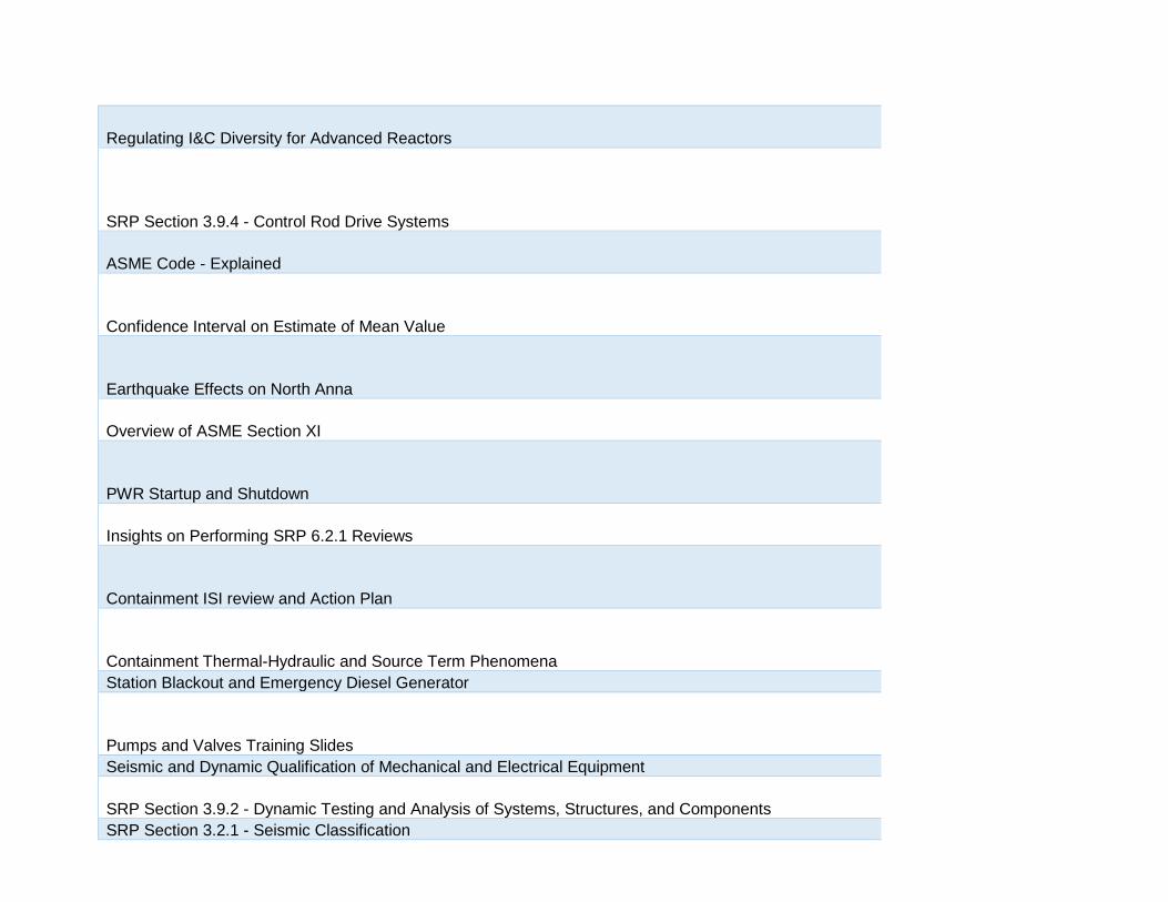
Regulating I&C Diversity for Advanced Reactors
SRP Section 3.9.4 - Control Rod Drive Systems
ASME Code - Explained
Confidence Interval on Estimate of Mean Value
Earthquake Effects on North Anna
Overview of ASME Section XI
PWR Startup and Shutdown
Insights on Performing SRP 6.2.1 Reviews
Containment ISI review and Action Plan
Containment Thermal-Hydraulic and Source Term Phenomena Station Blackout and Emergency Diesel Generator
Pumps and Valves Training Slides Seismic and Dynamic Qualification of Mechanical and Electrical Equipment
SRP Section 3.9.2 - Dynamic Testing and Analysis of Systems, Structures, and Components SRP Section 3.2.1 - Seismic Classification

High Temperature Metallic Materials in HTGR & VHTR Systems
High Temp Reactors - Construction Code Issues
Alternatives to ASME Code Section III and IEEE 603 Requirements
Leak before Break – History, Updates, and Future Plans
Surry EMD Diesel Failure, Notice of Enforcement Discretion, and Generic Implications Fundamentals of Pressurized Thermal Shock (PTS)
Reactor Vessel and Internals: History, Issues & Resolution
Commercial Grade Dedication of I&C Equipment Sodium-Cooled Fast Reactors and LWRs
Environmentally Assisted Fatigue
ABCs of Welding
Key principles of I&C System Architecture

NRC FORM 464 Part I U.S. NUCLEAR REGULA TORY COMMISSION FOIA RESPONSE NUMBER (03-2017)
RESPONSE TO FREEDOM OF INFORMATION ACT (FOIA) REQUEST
1 2017-0617
RESPONSE TYPE
11
INTERIM • FINAL
REQUESTER: DATE:
I AUG 2 8 2017 DESCRIPTION OF REQUESTED RECORDS:
A copy of the materials on the following Communities of Practice Site on the NRC Knowledge Center (on Sharepoint/ Intranet): Mitigation Strategies for Beyond-Design-Basis External Events and New Reactor Technical Reviews
PART I. -- INFORMATION RELEASED You have the right to seek assistance from the NRC's FOIA Public Liaison. Contact information for the NRC's FOIA Public Liaison is available at https://www.nrc.gov/reading-rm/foia/contact-foia.html
r:71 Agency records subject to the request are already available on the Public NRC Website, in Public ADAMS or on microfiche in the ~ NRC Public Document Room.
• • ~ ~
II
Agency records subject to the request are enclosed.
Records subject to the request that contain information originated by or of interest to another Federal agency have been referred to that agency (see comments section) for a disclosure determination and direct response to you.
We are continuing to process your request.
See Comments.
PART I.A -- FEES NO FEES AMOUNT" • You will be billed by NRC for the amount listed.
~ II
Minimum fee threshold not met. $0.00 • You will receive a refund for the amount listed. Due to our delayed response, you will
"See Comments for details • Fees waived. • not be charged fees.
• • • •
PART I.B -- INFORMATION NOT LOCATED OR WITHHELD FROM DISCLOSURE
We did not locate any agency records responsive to your request. Note: Agencies may treat three discrete categories of law enforcement and national security records as not subject to the FOIA ("exclusions"). 5 U.S.C. 552(c). This is a standard notification given to all requesters; it should not be taken to mean that any excluded records do, or do not, exist.
We have withheld certain information pursuant to the FOIA exemptions described, and for the reasons stated, in Part II.
Because this is an interim response to your request, you may not appeal at this time. We will notify you of your right to appeal any of the responses we have issued in response to your request when we issue our final determination.
You may appeal this final determination within 90 calendar days of the date of this response by sending a letter or e-mail to the FOIA Officer, at U.S. Nuclear Regulatory Commission, Washington, D.C. 20555-0001, or [email protected]. Please be sure to include on your letter or email that it is a "FOIA Appeal." You have the right to seek dispute resolution services from the NRC's Public Liaison, or the Office of Government Information Services (OGIS). Contact information for OGIS is available at https://ogis.archives.gov/about-ogis/contact-information.htm
PART I.C COMMENTS Use attached Comments continuation
Please note: As discu~sed, you narrowed the scope of your request as follows: KM materials ONLY, Indian Point records ONLY (NRR) and a list of28 presentations as specified (NRO) ( continued on next page)
Page 2 of 3
I
U.S. NUCLEAR REGULA TORY COMMISSION FOIA NRC FORM 464 Part I (03-2017)
RESPONSE TO FREEDOM OF INFORMATION ACT (FOIA) REQUEST Continued
I 2017-0617
RESPONSE TYPE
REQUESTER:
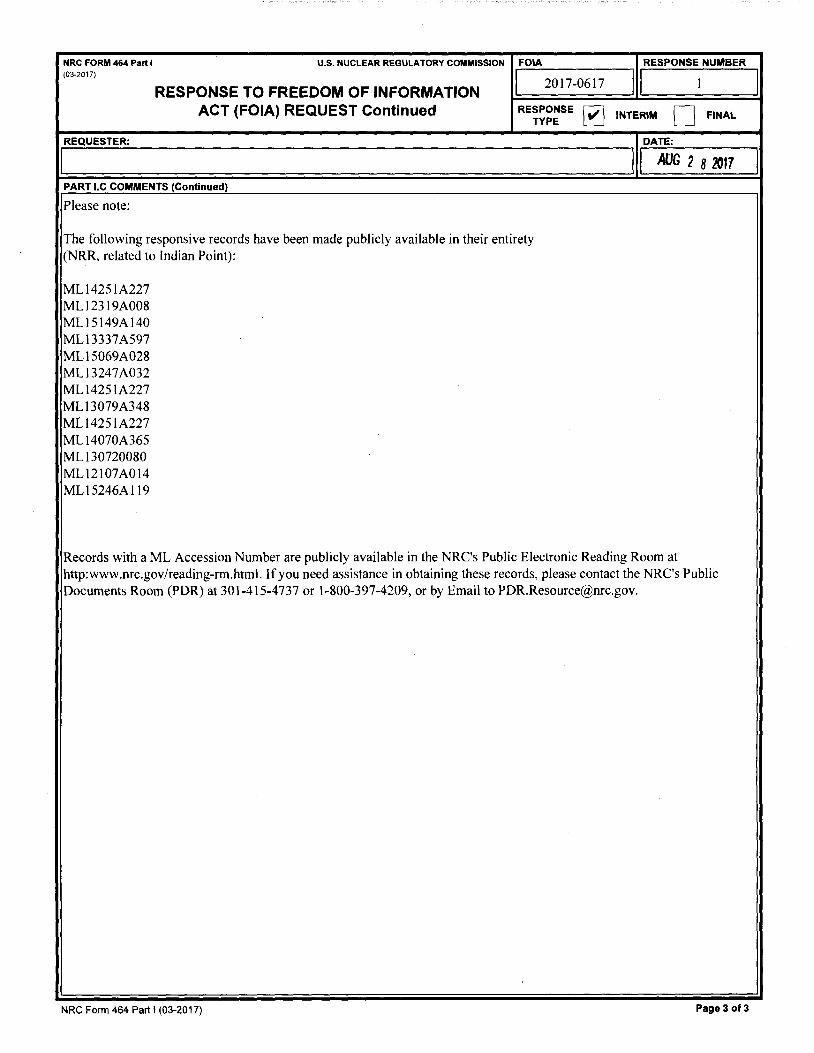
PART I.C COMMENTS (Continued)
Please note:
The following responsive records have been made publicly available in their entirety (NRR, related to Indian Point):
ML 14251A227 ML12319A008 ML15149A140 ML13337A597 MLl 5069A028 MLl3247A032 ML14251A227 ML13079A348 ML14251A227 ML I 4070A365 ML 130720080 ML12107A014 ML15246Al 19
~
RESPONSE NUMBER
II 1
INTERIM • FINAL
DATE:
I I AUG 2 8 2017
Records with a ML Accession Number are publicly available in the NRC's Public Electronic Reading Room at http:www.nrc.gov/reading-rm.html. If you need assistance in obtaining these records, please contact the NRC's Public Documents Room (PDR) at 301-415-4737 or 1-800-397-4209, or by Email to [email protected].
NRC Form 464 Part I (03-2017) Page 3 of 3
I
I

NRC FORM 464 Part I U.S. NUCLEAR REGULATORY COMMISSION FOIA RESPONSE NUMBER (03-2017)
RESPONSE TO FREEDOM OF INFORMATION ACT (FOIA) REQUEST
1 2017-061 7
RESPONSE TYPE •
1 1 2
INTERIM 0 FINAL
REQUESTER: DATE:
:I II OCT25~17 DESCRIPTION OF REQUESTED RECORDS:
A copy of the material s on the fo llowing Communities of Practice Site on the NRC Knowledge Center (on Sharepoint/ Intranet): Mitigation Strategies fo r Beyond-Design-Basis External Events and New Reactor Technical Reviews
PART I. -- INFORMATION RELEASED You have the right to seek assistance from the NRC's FOIA Public Liaison . Contact information for the NRC's FOIA Publ ic Liaison is available at https://www.nrc.gov/readinq-rm/foia/contact-foia .html
• 0 • • 0
II
Agency records subject to the request are already available on the Public NRC Website, in Public ADAMS or on microfiche in the NRC Public Document Room.
Agency records subject to the request are enclosed.
Records subject to the request that contain information originated by or of interest to another Federal agency have been referred to that agency (see comments section) for a disclosure determination and direct response to you.
We are continuing to process your request.
See Comments.
NO FEES AMOU NT"
$0.00 ii Minimum fee threshold not met.
·s ee Comments for details
• • •
PART I.A -- FEES
You will be billed by NRC for the amount listed .
You will receive a refund for the amount listed.
Fees wa ived .
0
• Due to our delayed response, you will not be charged fees.
• 0
• 0
PART 1.8 -- INFORMATION NOT LOCATED OR WITHHELD FROM DISCLOSURE
We did not locate any agency records responsive to your req uest. Note: Agencies may treat three discrete categories of law enforcement and national security records as not subject to the FOIA ("exclusions"). 5 U.S.C. 552(c). This Is a standard notification given to all requesters; it should not be taken to mean that any excluded records do, or do not. exist.
We have withheld certain information pursuant to the FOIA exemptions described , and for the reasons stated, in Part II.
Because this is an interim response to your request, you may not appeal at this time. We will notify you of your right to appeal any of the responses we have issued in response to your request when we issue our final determination.
You may appeal th is final determination within 90 calendar days of the date of this response by sending a letter or e-mail to the FOIA Officer, at U.S. Nuclear Regulatory Commission, Washington, D.C. 20555-0001 , or [email protected]. Please be sure to include on your letter or email that it is a "FOIA Appeal." You have the right to seek dispute resolution services from the NRC's Public Liaison , or the Office of Government Information Services (OGIS). Contact information for OGIS is ava ilable at https://ogis.archives.gov/about-ogis/contact-information.htm
PART I.C COMMENTS ( Use attached Comments continuation page if required) Please note : As discussed, you narrowed the scope of your request as follows: KM materia ls ONLY. Indian Point records ONLY (NRR) and a list of presentations as specified (NRO) (continued on next page)
Sianature - l>nledom of Information Aa..c.tticer or Desianee
NRC Form 464 paft I (03-201 7) I Adc:t'contlf iatlon Page l I Delete Continuation Page I Page 2 of 3

I
NRC FORM 464 Part I (03-2017)
REQUESTER:
U.S. NUCLEAR REGULATORY COMMISSION
RESPONSE TO FREEDOM OF INFORMATION ACT (FOIA) REQUEST Continued
PART I.C COMMENTS (Continued)
Please note:
FOIA
I 2017-0617
RESPONSE • TYPE
The NRC regrets to inform you that we are unable to locate the following records:
BWR Plant Startup and Shutdown Unable to find presentation NRO has no record
Insights on Performing SRP 6.2. l Reviews Unable to find presentation No record found
Containment ISi review and Action Plan Unable to find presentation No record found
NRC Form 464 Part I (03-2017)
RESPONSE NUMBER
11 2 I
INTERIM 0 FINAL
DATE:
11 OCT -2 5 2017 I
Page 3 of 3

NRC FORM 464 Part II U.S. NUCLEAR REGULATORY COMMISSION FOIA/PA (08-2013) ..... -... /¥\. 2017-0617
- \l ~ : \ '/ .........
RESPONSE TO FREEDOM OF INFORMATION ACT (FOIA) / PRIVACY ACT (PA) REQUEST
PART II.A -- APPLICABLE EXEMPTIONS
DATE OCT 2 5 2011
IGXROUP I Records subject to the request that are contained in the specified group are being withheld in their entirety or in part under the . . Exemption No.(s) of the PA and/or the FOIA as indicated below (5 U.S.C. 552a and/or 5 U.S.C. 552(b)).
• •
Exemption 1: The withheld information is properly classified pursuant to Executive Order 12958.
Exemption 2: The withheld information relates solely to the internal personnel rules and practices of NRG.
D Exemption 3: The withheld information is specifically exempted from public disclosure by statute indicated.
D Sections 141-145 of the Atomic Energy Act, which prohibits the disclosure of Restricted Data or Formerly Restricted Data (42 U.S.C. 2161-2165).
• • Section 147 of the Atomic Energy Act, which prohibits the disclosure of Unclassified Safeguards Information (42 U.S.C. 2167).
41 U .S.C., Section 4 702(b), prohibits the disclosure of contractor proposals in the possession and control of an executive agency to any person under section 552 of Title 5, U.S.C. (the FOIA), except when incorporated into the contract between the agency and the submitter of the proposal.
[Z] Exemption 4: The withheld information is a trade secret or commercial or financial information that is being withheld for the reason(s) indicated.
•
• •
0 • • •
The information is considered to be confidential business (proprietary) information.
The information is considered to be proprietary because it concerns a licensee's or applicant's physical protection or material control and accounting program for special nuclear material pursuant to 10 CFR 2.390(d)(1 ).
The information was submitted by a foreign source and received in confidence pursuant to 10 CFR 2.390(d)(2).
Disclosure will harm an identifiable private or governmental interest.
Exemption 5: The withheld information consists of interagency or intraagency records that are not available through discovery during litigation.
• • •
Applicable privileges:
Deliberative process: Disclosure of predecisional information would tend to inhibit the open and frank exchange of ideas essential to the deliberative process. Where records are withheld in their entirety, the facts are inextricably intertwined with the predecisional information. There also are no reasonably segregable factual portions because the release of the facts would permit an indirect inquiry into the predecisional process of the agency.
Attorney work-product privilege. (Documents prepared by an attorney in contemplation of litigation)
Attorney-client privilege. (Confidential communications between an attorney and his/her client)
Exemption 6: The withheld information is exempted from public disclosure because its disclosure would result in a clearly unwarranted invasion of personal privacy.
Exemption 7: The withheld information consists of records compiled for law enforcement purposes and is being withheld for the reason(s) indicated.
• • • •
(A) Disclosure could reasonably be expected to interfere with an enforcement proceeding (e.g., it would reveal the scope, direction, and focus of enforcement efforts, and thus could possibly allow recipients to take action to shield potential wrong doing or a violation of NRC requirements from investigators).
(C) Disclosure could constitute an unwarranted invasion of personal privacy.
(0) The information consists of names of individuals and other information the disclosure of which could reasonably be expected to reveal identities of confidential sources.
(E) Disclosure would reveal techniques and procedures for law enforcement investigations or prosecutions, or guidelines that could reasonably be expected to risk circumvention of the law.
D (F) Disclosure could reasonably be expected to endanger the life or physical safety of an individual. • OTHER CSoecify)
I PART 11.B -· DENYING OFFICIALS
Pursuant to 10 CFR 9.25(g), 9.25(h), and/or 9.65(b) of the U.S. Nuclear Regulatory Commission regulations, it has been determined that the information withheld is exempt from production or disclosure, and that its production or disclosure is contrary to the public interest The person responsible for the denial are those officials identified below as denying officials and the FOIA/PA Officer for any denials that may be appealed to the Executive Director for Operations (EDO).
DENYING OFFICIAL TITLE/OFFICE RECORDS DENIED APPELLATE OFFICIAL
EDO SECY IG
Stephanie Blaney FOIA/PA Officer X [Z] • • LJ • • •••
Appeal must be made in writing within 30 days of receipt of this response. Appeals should be mailed to the FOIA/Privacy Act Officer, U.S. Nuclear Regulatory Commission, Washington, DC 20555-0001, for action by the appropriate appellate official(s). You should clearly state on the envelope and letter that it is a "FOIA/PA Appeal."
NRC FORM 464 Part II (08-2013)

High Temperature Metallic Materials in
HTGR & VHTR Systems
Presented at the NRC Tutorial on High Temperature Metallic Materials for HTGR and SFR Reactor Systems
William Corwin, Oak Ridge National Laboratory
Rockville, Maryland February 17, 2011
8ENERGY ~OAK RIDGE NATIONAL LABORATORY MANAGED BY UT-BATTELLE FOR THE DEPARTMENT OF ENERGY

{V)HTRs Can Provide High Efficiency Electricity and High Quality Process Heat
Characteristics •He coolant •up to 1000°c outlet temperature (long term, <8S0°C near term)
•<600 MWth •Solid graphite block or pebble bed core
Benefits • High thermal efficiency
•Process heat applications
• High degree of passive safety

High Ten,perature, Gas-Cooled Reactor Experience Is Widespread
HTGR PROTOTYPE PLANTS DEMONSTRATION PLANTS
DRAGON
(U.K.) 1963 - 76
LARGE HTGR PLANTS
AVR
(FRG) 1967 - 1988
PEACH BOTTOM 1 (U.S.A.)
1967 - 1974
HTGR TECHNOLOGY
PROGRAM
MATERIALS COMPONENTS FUEL
CORE
PLANT TECHNOLOGY
"':_II_ , - -~
•• I_I · .. • . . .._ .rv- . -
FORT ST. VRAIN
(U.S.A.)
1976 - 1989
THTR
(FRG)
1986 • 1989
MODULAR
HTGR
CONCEPTS
"'
....... -------------~.,., Idaho Nalicral labora·ory
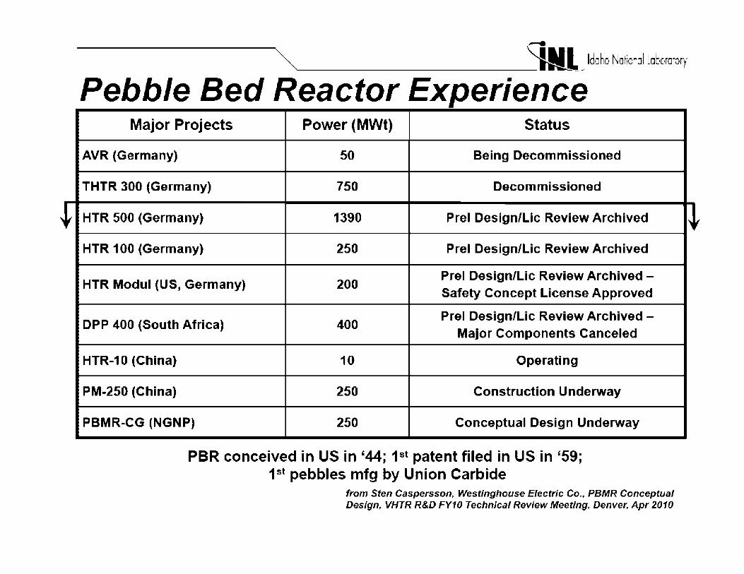
Pebble Bed Reactor Experience Major Projects Power (MWt) Status
AVR (Germany) 50 Being Decommissioned
THTR 300 (Germany) 750 Decommissioned
HTR 500 (Germany) 1390 Prel Design/Lie Review Archived
HTR 100 (Germany) 250 Prel Design/Lie Review Archived
HTR Modul (US, Germany) 200 Prel Design/Lie Review Archived -Safety Concept License Approved
DPP 400 (South Africa) 400 Prel Design/Lie Review Archived -
Major Components Canceled
HTR-10 (China) 10 Operating
PM-250 (China) 250 Construction Underway
PBMR-CG (NGNP) 250 Conceptual Design Underway
PBR conceived in US in '44; 1st patent filed in US in '59; 1st pebbles mfg by Union Carbide
from Sten Caspersson, Westinghouse Electric Co., PBMR Conceptual Design, VHTR R&D FY10 Technical Review Meeting, Denver, Apr 2010
" (

Tvvo HTRs Are Currently Operating
• HTTR (prismatic core)
JAEA, Oarai, Japan
- Up to 950°C ROT
- 50MWth
Targeted IS hydrogen production
- GTHTR300C (600MWth) to follow
• HTR-10 (pebble bed core)
Tsinghua University (INET), China
- 750°C ROT
10MWth
- Steam generation
- PM250 (2x250MWth) to follow

VHTRs & HTGRs Can Provide Energy for Many Applications beyond Electricity
HTSE and Thermo-Chemical Hydrogen Production
Coal Gasification
Steam Reforming of Natural Gas Biomass Hydrothermal Gasification
Cogeneration of Electricity and Steam
Oil Shale and Oil Sand Processing
800-1000°C
500-900°C
350-800°C
300-600°C
Petroleum Refining "'" 250-550°C 9 ~
Ethanol Concentration '° Seawater Desalination l:1,J4,1,g ~
District Heating ------------------------------~ 0 100 200 300 400 500 600 700 800 900 1000
LWRs Process Temperature °C
HTGRs

(V)HTR Process Heat Generation Is Simple in Concept
Generic He-He VHTR . ~ ~~l~.a.r. ~ ~~~ ~.U.P.P.~. ~y~~~ .................... .
Reactor Island
. • Core Support • • Structure I , • Oudet Plenum •
= Helium Flow
Reactor & IHX Pressure Vessels
I
1 t I 111o I lot• I I It 1 1- t I • I• t t- I I t, t, lo. I • I It- t t- t I lllo ii It I ii I tot I- i It ••
• Core includes fuel, graphite, core structural and other ceramic components and the metallic core barrel
To/ From the Process Heat Applications
He-Steam HTR-10
0
0
0
0
0
,_._..,.,
0····-""·''"'"'""'•' 0 ··l1· . .i1: .••·11 .. 1·11" (D,·, d I 1:-111111: ;,:.•11·11:1
01 "''· ,~ 1: :i:.111 , ln1111o• IO 1:. .,, l:i1 .q Q 11 ,: II• .i:.111 , 11:•11:,•·I
Oil,,1 :1,-11111., pl•·:1•-111 0 !I, I ,,., .• ;ti•! Q ~-111=•·,- . q1 1.•,il•
@I 1:I~-- 1•111·11··,,,1;, 1.;f-
from Qin Zhenya, Tsinghua Univ. (/NET), HTGR Reactor Devi. in Mainland China, Intl. Symp. for Gen IV Nucl. Reactors, Taipei, Apr. 2009
Possible NGNP Configurations Described by INL
•Courtesy of Lee Nelson, INL, Leader NGNP Design Activities for pebble bed variants of NGNP
• 208-526-3093
• Presented at INL, October 28, 2009, to NRC-RES staff and updated January 18, 2011
• Based primarily on completed preconceptual design studies by INL and multiple vendors through 2007, as modified by subsequent design studies

Preconceptual Designs (May, 2007) Targeted High Outlet Temperatures
Recommended Operating Conditions and Plant Configuration
Item Westinghouse AREVA General Atomics
Power Level, MWth 500 MWth 565 MWth 550-600 MWth
Reactor Outlet 9so0 c 900°C Up to 950°C
Temperature, °C
Reactor Inlet 350°C S00°C 490°C
Temperature, °C
Cycle Configuration Indirect- Series Indirect - Parallel Direct PCS (Brayton)
hydrogen process and hydrogen process (He) Parallel indirect hydrogen
power conversion and power conversion process (IHX with He)
(Helical Shell and Tube
IHX)
Secondary Fluid He He - Nitrogen mixture to He
PCS
He to H-, Process
Power Conversion 100% of reactor power 100% of reactor power 100% of reactor power
Power
Hydrogen Plant Power 10% of reactor power 10% of reactor power 5 MWth-THE
60 MWth-5-1
Reactor Core Design Pebble Bed Prismatic Prismatic
from Lee Nelson, /NL

Preconceptual Designs (May, 2007) Targeted High Outlet Temps (cont)
Item
Fuel
Graphite
RPV Design
RPV Material
IHX
Hydrogen Plant
Power Conversion
Recommended Operating Conditions and Plant Configuration
Westin house
TRISO UO2 pt and
subsequent cores
PCEA & NBG-18
Exposed to the gas inlet
temperature
SAS08/533
2-Stage Printed Circuit
Heat Exchanger (PCHE), In
617 material
Hybrid thermo-chemical
plus electrolysis
Rankine; standard fossil
power turbine generatior
set
AREVA
TRISO UCO- pt and
subsequent cores
NGG-17 and NBG-18
Exposed to the gas inlet
temperature; insulation and
vessel cooling options may
be ursued
9Cr-1 Mo
PCS-3-Helical Coil Shell &
Tube, In 617
Process - PCHE or Fin-Plate,
In 617
Initial-High Temperature
Electrolysis
Lon er Term - Sulfur-Iodine
Rankine; standard fossil
power turbine generator
set
General Atomics
TRISO UO2 pt core
Variable subsequent cores
IG-110 & NBG-18
Exposed to the gas inlet
temperature
2-1/4 Cr - 1 Mo
9 Cr-1 Mo
Process - single stage PCHE,
In 617
Initial-High Temperature
Electrolysis
Lon er Term - Sulfur-Iodine
Direct gas turbine
Option - Direct Combined
C cle from Lee Nelson, /NL

Prismatic Reactors Based on MHTGR (GA) with Cross Vessel and Steam Generator
• • . ,1 i • ! .. MHTGR Typical Plant Parameters
Thennal Power, MVV(t) 600
Fuel Columns 102
Fuel Cycle LEU/Natural U
Average Power Density, W /cr:f. 6 .6
Primary Side Pressun, MPa (psia) 7.07 (1025)
huluced Heliwn Flowrate 281 kg:/s
Core htlet Temperature, .,C (t) 288(550)
Core Outlet Temperature, •c tF) 704(1300)
from Lee Nelson, /NL

Effect of Po,Ner Level on Reactor Vessel - GA (based on existing design information)
Reactor Parameter 350 MWth 450 MWth 550 MWth
Reactor Vessel 1D1 6.55 7.22 7.22
m*
RPV Thickness, m 0.133 --- ---
RPV Height, m* 22.0 --- ---
RPV Weight, t 728 --- ---
Reactor Vessel SA 508/533 SA508/533 2 ¼ Cr-lMo or
Material 9 Cr-1 Mo
(with active vessel
cooling would be
SAS0S/533)
* Pebble Bed RPV for 500 MWth plant is 6.8m OD and height of 30m
600 MWth
7.22
0.216
24.0
1328
2 ¼ Cr-lMo or
9 Cr-1 Mo
(with active vessel
cooling would be
SA508/533)
from Lee Nelson, /NL

Metallic Materials (GA) Function of ROT
Component Temperature 750C Mat'I Conditions Selection
Inner Control Rod Normal Ops 808 C-CorSiC-PCCD max 1164
SiC DCCD Max 1418
Outer Control Rod Normal Ops 440 C-C orSiC-PCCD max 929 SiC DCCD Max 980
CR and RSM Guide Tubes Normal Ops 346 PCCD max 933 Hastelloy X DCCD Max 418
UCR Normal Ops 346 C-CorSiC-PCCD max 1028 SiC DCCD Max 604
UPS T/B Normal Ops 318 PCCD max 877 Hastelloy X DCCD Max 455
MCS Load pads Normal Ops 653 Macor PCCD max 653 Glass DCCD Max 653 Ceramic
PCCD = Pressurized Conduction Cool Down DCCD = Depressurized Conduction Cool Down RSM= Reserve Shutdown Material UCR = Upper Control Rod UPS T/B= Upper Plenum Shroud Thermal Barrier MCS = Metallic Core Supports
850C Mat'I 950C Mat'I Selection Selection
850 C-C orSiC- 871 C-C orSiC-1174 SiC
1179 SiC 1428 1433
482 C-C orSiC- 526 C-C orSiC-939 SiC
1129 SiC 990 1000
C-C orSiC- C-C orSiC-SiC SiC
346 C-C orSiC- 346 C-C orSiC-1038 SiC 1048 SiC 614 624 318 318 887 Hastelloy X 897 Hastelloy X 465 475 730 Macor 807 Macor 730 Glass 807 Glass 730 Ceramic 807 Ceramic
from Lee Nelson, /NL

Metallic Materials (GA) Function of ROT (cont)
Component Temperature 750C Conditions
Hot Duct T/ Normal Ops 749 B PCCD Max 786
DCCD Max 820 749 749
LPS T/B Normal 670 Operation 707 PCCD Max 742 DCCD Max 670
670 scs Normal 653 Entrance Operation 690 Tubes PCCD Max 724
DCCD Max 653 653
SGS T/B Normal 350 Operation 350 PCCD max 350 DCCD Max
LPS = Lower Plenum Shroud SCS;;; Shutdown Cooling System
Mat'I 850C Selection
848 837
Hastelloy X 923 848 848 752 791
800H 826 752 752 729 768
800H 804 729 729 350
800H 350 350
Mat'I 950C Mat'I Selection Selection
948 986 C-CorSiC-
Hastelloy X 1022 SiC 948
948 833 871
Hastelloy X 907 Hastelloy X 833 833 806 844
Hastelloy X 880 Hastelloy X 806 806 350
800H 350
800H 350
from Lee Nelson, /NL

Layout of the Pebble Bed Reactor Unit Included SG and IHX(s) for Electricity and H2 Generation
R-ima.ry arcua:or& ~Valw
.- ---
\ ~ -- Rec:uperatcr
'--~iiifii\
Core Coocltiooing
. Systan
------
from Lee Nelson, /NL

Helium Temperatures in Pebble Bed NGNP Piping Sections (950°C)
Piping Location Temperature (°C)•
Primary Heat Transport System
RPV to IHX A 950
IHX A to IHX B 760
IHX B to Circulator 337
Circulator to RPV 350
Secondary Heat Transport System
IHX A to PCHX 900
IHX A to Mixing Chamber 900
Mixing Chamber to SG 840
PCHX to Mixing Chamber 659
SG to Circulator 273
Circulator to IHX B 287
IHX B to IHXA 700
•initial studies indicate that transient temperatures are only very slightly higher than these.
from Lee Nelson, /NL

Helium Flo"" Path Configuration through the Pebble Bed Reactor
.-·-
:II
l a ~ ]
:;, ll.. i!! ] ;;i
~ i!! li j .l.
~ !'.i a ~ 'i;
-! , :z: ~ ~ :r ] .i
I
'--I
...
\,
' --... _ "T•·••
Cl ti" Cl)
c= Cl)
er. .... Cl)
"'E Cl)
u
.'
/ ,,.,,/ -
1-.tw ~lr~•t~· Cu1,trul S~,;t,_,r11 (CU11lrul 1\XJ:;_1
Inlet lrum 1-'l llllidl ~ I lt.1idl
lrar,:;i,orl S!l'.;tum
l)uwn flu"" I, d WUCT l
1-.tt.'uctw 1-'ru,;suru Vu~ul .,,,d Curu U.i111..,~
Uµnuw Ill 11:;vr ~ha1111ul,; 111 ::;100 l-.t1..•lk, dur
OUUL•I tu 1-'Tl!lliJT ~· • lo«t ___ ........ _, IT .i 11:;µurt S~·:.1urn
,•'
from Lee Nelson, /NL

Comparison of PBMR DPP and NGNP Key Operational Parameters
Normal OLOFC PLOFCb.c Parameter
Operation
NGNP OPP NGNPd 0ppb NGNP OPP
RIT (°C) 350 500 - - - -
ROT (°C) 950 900 - - - -
Tmax. CB ("C) 350j 414b 466-634 579(48h) 565 482
Tmax. RPV ("C) 308j 324b 328-452 419(56h) 401 (56h) 373 (48h)
-1
He Mass Flow (kg.s ) 160 192 - - - -
Thermal Power (MW) 500 400 - - - -
a 25% increase in power level. hence 25% higher flux level assumed for NGNP compared to DPP
b Based on Case 5. NGNP Special Study 20 2: Prototype Power Level Study. NGNP-20-RPT-002. 26-01-07 (1)
c Indirect cycle NGNP design. hence operating pressure in system assumed to remain constant at 9 MPa
d Reactor Parametric NGNP Special Study. NGNP-NHS 90 PAR. August 2008
from Lee Nelson, /NL
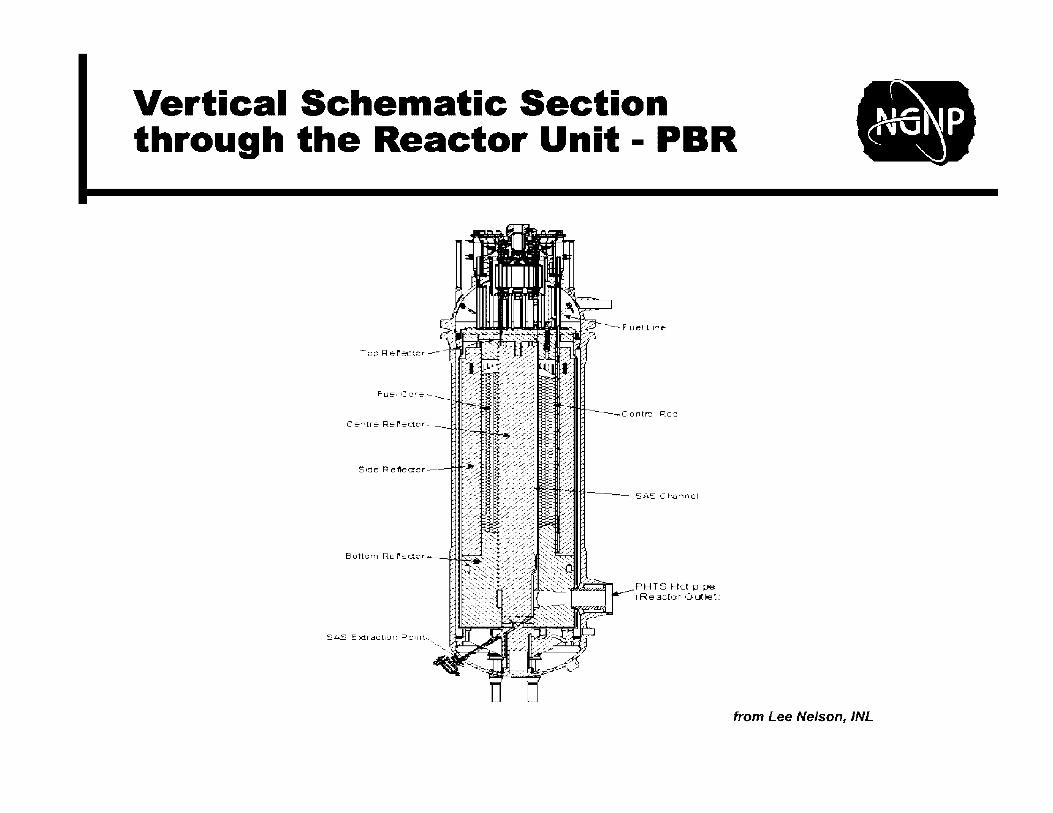
Vertical Schematic Section through the Reactor Unit - PBR
!: ><tr~ct,on P:: ,nt,
'··-"'-._:t,""-=-•.;:;11'"'.:."'..;a";.~u~
PHTS Hct pipe 1 Re actor Out let":
from Lee Nelson, /NL

Horizontal Section through the RU without the Core Inlet and Outlet Pipes
R:eac!Dr :::,fiP.!i s u • e \lt-!s se
.· .. ,,,---e·.-·~--~
.I i,. . . 'I)·,.
i .. · ,(>. . \.
from Lee Nelson, /NL

Control Rods for the PBMR NGNP
• Reactivity Control System (RCS) used to control reactivity in the core, to quickly shut the reactor down and to keep it in a shutdown mode
• RCS consists of 24 identical control rods. • Control rods are one group of 12 • Shutdown rods are one group of 12
• Each rod has six segments containing absorber material (sintered B4C rings between two coaxial cladding tubes separated by joints)
• OPP design uses Alloy 800H for cladding and joints
• Chain lowers and raises the control rods through segmented graphite liners in the Inner Side Reflector (ISR)
• During SCRAM event, control rods drop by gravity but are limited by the characteristics of the drive and the shock is absorbed by secondary shock absorber
_p_ 1,1 I ICU: nt :-nr1r1v-• -1.JJ:lti~
<:::rtrol r-oa ... , J .:t· -, ti-·
~~:ond:3--)·~rcc ,: "1:1,:"~er . ', i ·. i
I
--... __
,-,
,Jr·
3 __ r~VJIOr
... -_,,--8 --........... - - __ .- -·~D"Yi
__ .. --
,-
(' •111, 1~11,J :i:t I~ (' ,::ilU
from Lee Nelson, /NL
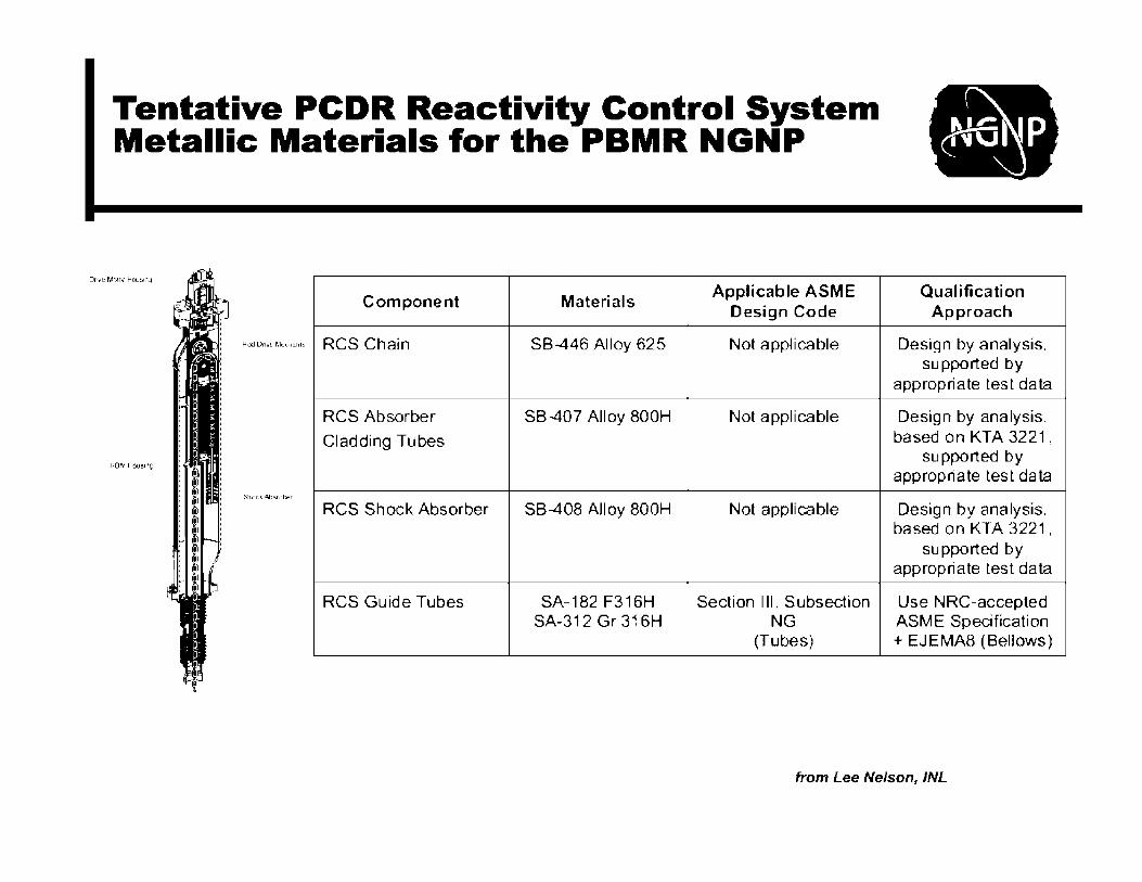
Tentative PCDR Reactivity Control System Metallic Materials for the PBMR NGNP
D1we M~or t-lous1n'll
Component Materials Applicable ASME
Design Code
Ro::I Dri~'{l MIL'chanii RCS Chain SB-446 Alloy 625 Not applicable
RCS Absorber SB-407 Alloy 800H Not applicable
Cladding Tubes
Stiock. .Absorber
RCS Shock Absorber SB-408 Alloy 800H Not applicable
RCS Guide Tubes SA-182 F316H Section 111, Subsection SA-312 Gr 316H NG
(Tubes)
Qua I ifi ca ti on Approach
Design by analysis, supported by
appropriate test data
Design by analysis, based on KTA 3221,
supported by appropriate test data
Design by analysis, based on KTA 3221,
supported by appropriate test data
Use NRG-accepted ASME Specification + EJEMA8 (Bellows)
from Lee Nelson, /NL
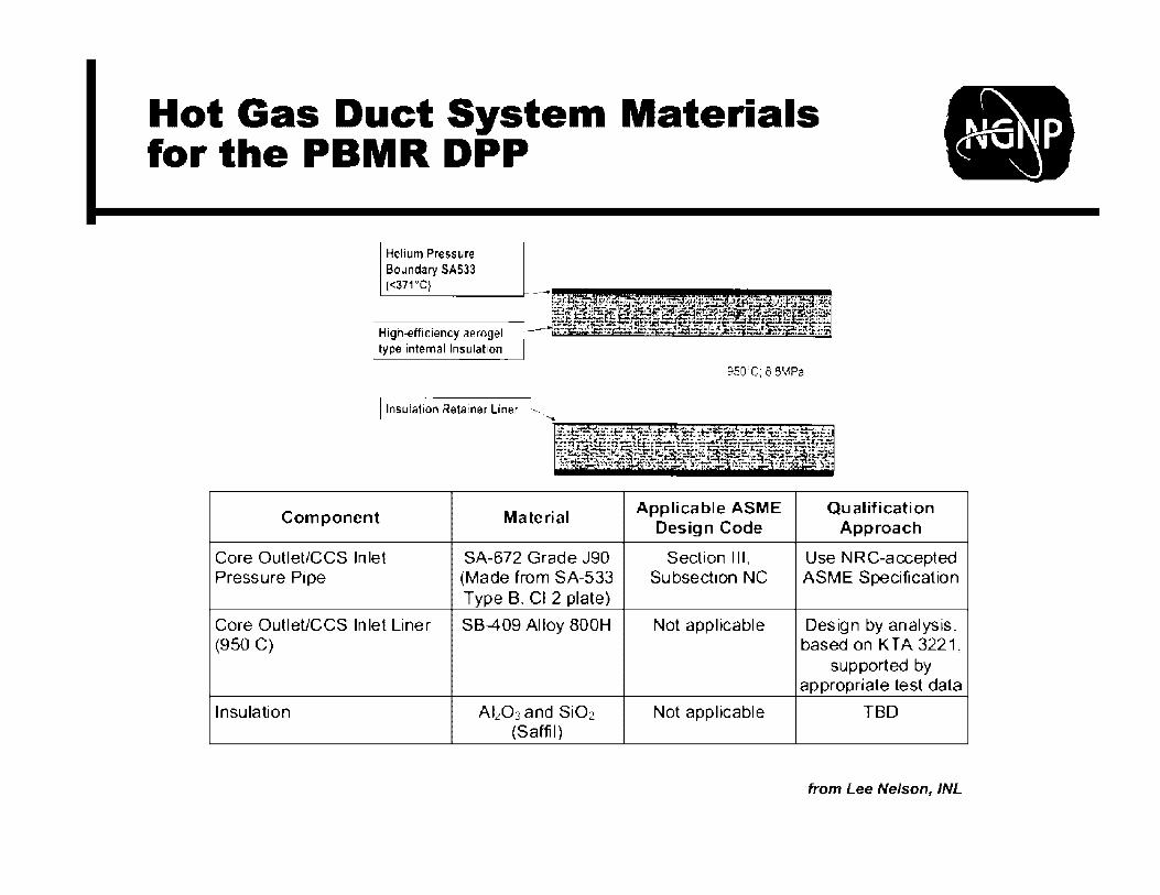
Hot Gas Duct System Materials for the PBMR DPP
Helium Pressure Boundary SAS33 (<371°C) ------~~---
High-efficiency aerogel lype internal Insulation
I lnsulalion Retainer Liner
Component Material
Core Outlet/CCS Inlet SA-672 Grade J90 Pressure Pipe (Made from SA-533
Type B, Cl 2 plate)
Core OutleUCCS Inlet Liner SB--409 Alloy 800H (950 C)
Insulation AbO3 and SiO2 (Saffil)
950'C; 8 5MPe
Applicable ASME Qualification Design Code Approach
Section Ill, Use NRG-accepted Subsection NC ASME Specification
Not applicable Design by analysis, based on KT A 3221,
supported by appropriate test data
Not apphcable TBD
from Lee Nelson, /NL

Steam Generator
STEAM TUSEBHEET
INLET DUCT
BIMETALLIC WELD
TUBE 8UPl"ORT l"LATES-----1"
EC0N0 MIZER/EVAPORATOR/ INITIAL SUPERHEAT
( EEB J BUNDLE
TUBE BUNDLE SUPPORT
' . ./
FEEDWATER TUBESHEET'-
Candidate Materials Include: 800H and 2 ¼ Cr/1 Mo (most likely) Grade 91, 617, Hastelloy 617
FEEDWATER TUBESHEET ACCESSIBILITY EXTENSION
from Lee Nelson, /NL

Compact Heat Exchanger
Unit Cell - Plate-Fin Compact IHX
Candidate Materials: 230 800H 617 Hastelloy X
Concept of Compact IHX
1: -. ,
from Lee Nelson, /NL

By Sept. 2009, Reference Configurations Featured Much Lower ROTs and Included SGs, not Primary-Secondary IHXs
Tentative Operating Conditions and Plant Configuration
Item [to be finalized during Conceptual Design]
Westinghouse AREVA General Atomics
Power Level, MWth 200 625 350-600
Reactor Outlet ?so 0 c 1so0 c ?so 0 c Temperature, °C
Reactor Inlet 280°( 325°C 322°C
Temperature, °C
Cycle Configuration Steam Generator in Steam Generator in primary Steam Generator in primary
primary loop loop loop
Secondary Fluid He NA NA
Reactor Core Design Pebble Bed Prismatic Prismatic
(cylindrical)
from Lee Nelson, /NL

--',,,,,, _____________ ~ Idaho Ncforcl labora·~·y
NHSS Layout - Builds on German HTR Modul Experience
l fll'"l11Ifll,.ti;;.i •.111:11111 ,
l .
Control Rods
Small Absorber Spheres (Shutdown system)
~-, ~· ..,_ ______ Reactor Pressure Vessel
' ' t
I
~a:;Vi I
Pebble Bed Reactor Core
Graphite Reflector
Circulator
Steam Supply Line
Hot Gas Pipe within the Cross Vessel
--- Steam Generator Pressure vessel
Fuel Discharge
--- SAS Transport
-------- Steam Generator Tube Bundle
....___ Feedwater Line from Sten Caspersson, Westinghouse Electric Co., PBMR Conceptual Design, VHTR R&D FY10 Technical Review Meeting, Denver, Apr 2010
.-e
-------------~ ldano Natioral labora·ory
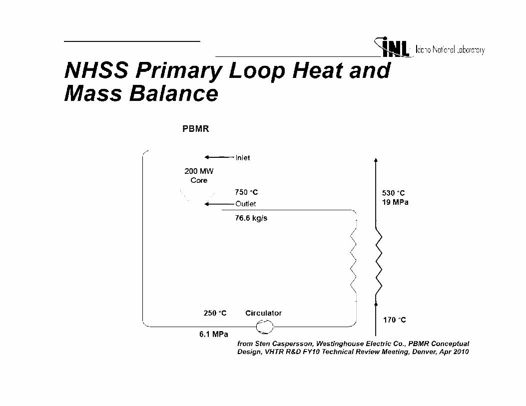
NHSS Primary Loop Heat and Mass Balance
PBMR
.... --Inlet
200MW Core
750 "C
---Outlet
76.6 kg/s
250 °C Circulator ~---o--~ 6.1 MPa
530°c 19MPa
170 °C
from Sten Caspersson, Westinghouse Electric Co., PBMR Conceptual Design, VHTR R&D FY10 Technical Review Meeting, Denver, Apr 2010
Co"t rol Rod Dri-.,E- ...
Fu~II ing I in., -
Top R"flf'rtor
Contr<;>I llod •
Hed<l<>r ~llllll<J<t - .
~otto,,., ~c-flc-c1or -
107500/D --~
--------------~j Idaho ~cfcrcl labora·:·y
- TopPlat~
- . - ~,ue fi«O«Ll<ll
Reactor 0,11I,;,t Nonie
S/\S Tr.1nspor1 V3ls<• Block
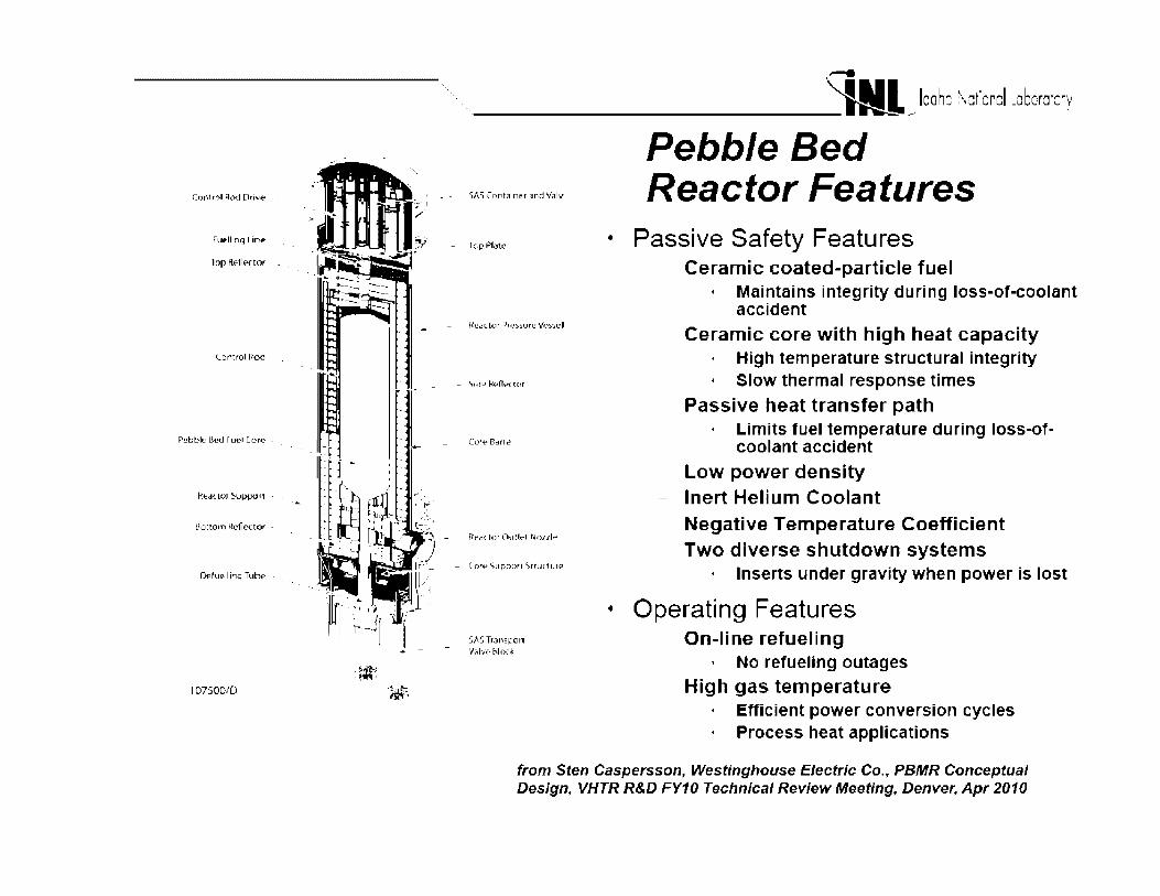
Pebble Bed Reactor Features
• Passive Safety Features Ceramic coated-particle fuel
Maintains integrity during loss-of-coolant accident
Ceramic core with high heat capacity High temperature structural integrity
• Slow thermal response times
Passive heat transfer path • Limits fuel temperature during loss-of-
coolant accident Low power density Inert Helium Coolant Negative Temperature Coefficient Two diverse shutdown systems
Inserts under gravity when power is lost
• Operating Features On-line refueling
• No refueling outages High gas temperature
• Efficient power conversion cycles • Process heat applications
from Sten Caspersson, Westinghouse Electric Co., PBMR Conceptual Design, VHTR R&D FY10 Technical Review Meeting, Denver, Apr 2010
...... -----------~ ldano Natioral labora·ory
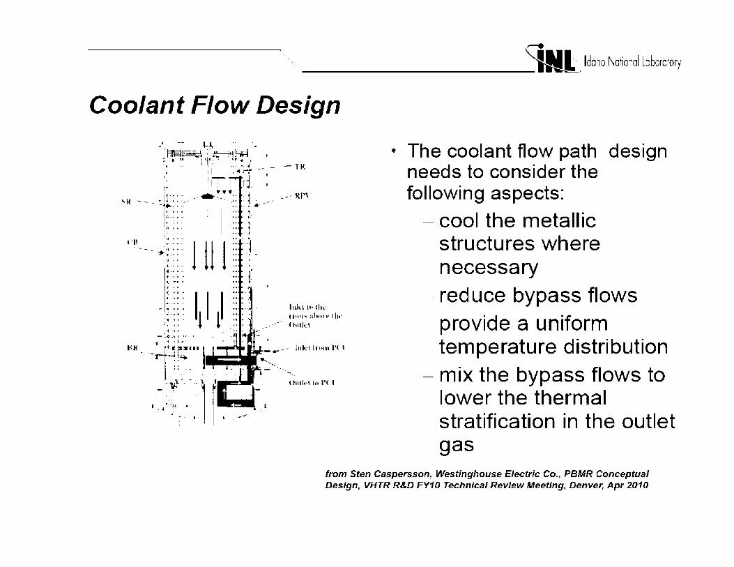
Coolant Flow Design
• The coolant flow path design needs to consider the following aspects:
- cool the metallic structures where necessary
- reduce bypass flows - provide a uniform
temperature distribution - mix the bypass flows to
lower the thermal stratification in the outlet gas
from Sten Caspersson, Westinghouse Electric Co., PBMR Conceptual Design, VHTR R&D FY10 Technical Review Meeting, Denver, Apr 2010

........ '
-------------~ Idaho National laboratory
Prismatic NGNP Primary System
• Modular Nuclear Heat Supply System (NHS)
350 MWt annular core
Triso coated particle fuel
Helium cooled
Graphite moderated
750°C core outlet temp
540° C/17 .3 MP a steam heat
• NHS Contained in 2 steel vessels, RV and SGV, interconnected by a cross vessel
~TE"EL l.:FA(T.~,f::
VESSEL - ~------
.c.JiPiU_A.R REk: T C>H •: C:-RE ---_
!.H'JTDC,'MI Hf AT EX,: H,tJi :.EP. ·-
SI-IIJT::"~:,1NU : 1P,:1JLA T•:fl
' , .. ' J
,:i::c-ss V'E.5$EJ..
__.. ~AJrl ...,...-·-- ::1F(UL.AT,:-R .
"'-- '
~~~ . . -
.. --- :-;.run;;•Ar·;p '1,'ESSEL
. -'·•-··· !lo TE:AM .' •.•U TLf. T
_,- STEAM .,.tJ lt;Roe. T _:P.
IULET
from Arkal Shenoy, General Atomics, Prismatic Conceptual Design, VHTR R&D FY10 Technical Review Meeting, Denver, Apr 2010

,..... ',,,_'-,, _____________ ~.Idaho National laboratory
Main NHS Systems, Subsystems & Components • Reactor System (RS) - Fuel,
graphite, CRs, CRD mechanisms, metallic internals, insulation
• Vessel System (VS)- RV, SGV, xv, supports, pressure relief
• Heat Transport System (HTS) -SG, main circulator, hot duct
• Shutdown Cooing System (SCS) - SCS circulator, SCS heat exchanger
• Helium Service System (HSS) -He Purification, transport & storage
• Fuel Handling and Storage System (FHSS) - Refueling machine, transport cask, cask transporter
• Reactor Cavity Cooling System (RCCS)
snAM aUTlll\
- STl!ll MAC'lall YHSU
from Arkal Shenoy, General Atomics, Prismatic Conceptual Des;gn, VHTR R&D FY10 Technical Review Meeting, Denver, Apr 2010

.-. '-------------~_Idaho National labora·ory
Prismatic NHS Contained in Below Grade Silo
• Cylindrical silo with 2 main cavities:
Reactor cavity Steam generator cavity
• Silo depth based on placing SG thermal center well below core
• Main advantages of below grade silo:
Sabotage/damage resistant
Increased safety approach • Decay heat can be dissipated to
earth in the event of RCCS failure
• More resistant to damage from seismic events
Improved economics relative to above-grade installations
f.... .... -1.1:, ·· ......... ,
~~I: -ltry :-;:, q~fl ,
c_ r1i1, ·
..
··r, ·~ .,l,J-,
,/ ,, - /~
,.
.: t;•,I n
~- ',' \,,' I_J "l'
from Arkal Shenoy, General Atomics, Prismatic Conceptual Des;gn, VHTR R&D FY10 Technical Review Meeting, Denver, Apr 2010
.-. ------------~>Idaho Ncfcrcl labcra·c·y
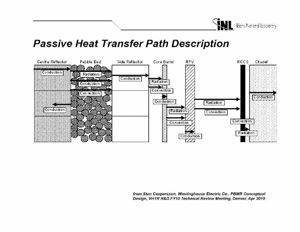
Passive Heat Transfer Path Description
Centre Reflector Pebble Bed
•:::::•:::::::::::::•:::::::::::::::•:::::::
Side Reflector Core Barrel RPV
I Radiation I I Conved:ion I
RCC S Citadel ...... . . . - . .. . . . - .. - - ...
I .. • • I .. • • ......... I • • + • • • • ......... . .. . .. . .. . . . . . . . . . . . . . . . . ' .. . . . . . . . . . . .. . .. . .. . . . . . . . . . . . . . . .. . .. . . . . . . . . . . . ' • ' + ' + ' • . . . . . . . . . . . . - ... -......... . . . . . . . .
I • 0 4 I I O O I ........ . . . . . . . . . . .. . .. . .. . . . . . . . . . . . . .. . . . . . .. . . . . . . . . . ' + •• ' + ' • . . . . - .... . .. . .. . .. . .. . . . . . . . . .
. - . - . - . . . . . . . . . . . . . .. . .. . .. . . . . . . . . . I + I + I + I + ......... . .. . .. . .. . .. . . . . - - .. -.......... . . . . . . . . . . . . .. . ' .. ......... . .. . .. . .. . .. . . . . . . . . . • • • + • + ... . . . . . . . . . 0 + • + I + • +
......... . . . . . . . . . . . .. . . . . . . . . . 0 • + I + • .. . . . . . . . .. . . . . . .. . . . - .. -.........
-~-: :-:i I~;~ I iii I~;~ ........
from Sten Caspersson, Westinghouse Electric Co., PBMR Conceptual Design, VHTR R&D FY10 Technical Review Meeting, Denver, Apr 2010

-'--,,,,,, _____________ ~Idaho National laboratory
Prismatic NGNP Key Design Selections for CD
NGNP mission
Reactor type
Exclusion Area Boundary
Off-site accident dose limits
Occupational exposure limits
Reactor power
Reactor pressure vessel material
Core
Fuel particles
Fuel compact matrix
Fuel block
Graphite grade - fuel elements
Graphite grade - replaceable reflectors
Co-generation of process steam and electricity
Modular Helium Reactor (1 module prototype)
425 m (commercial site requirement)
PAGs (1 rem whole body; 5 rem thyroid)
10% of 10CFR20
350 MW(t)
SA 508/SA533 steel (LWR vessel material)
Prismatic core
LEU UCO (Single or Multiple enrichment)
Thermosetting Resin matrix
10-row block (same as used in FSV)
Near-isotropic, nuclear grade (having properties similar to H-451
TBD
from Arkal Shenoy, General Atomics, Prismatic Conceptual Des;gn, VHTR R&D FY10 Technical Review Meeting, Denver, Apr 2010

_...
-------------~_) Idaho National laboratory
Key Design Selections for Tech Dev Identification (cont)
Graphite grade - permanent core structures
Number of primary coolant loops
Primary coolant
Hot duct material
Core inlet helium temperature
Core outlet helium temperature
Energy transfer system
Secondary working fluid
Steam generator inlet/outlet conditions
Electricity generation
Process steam generation
Reactor Cavity Cooling System
Containment
TBD
Single primary loop, single secondary
Helium
Alloy 800H
322° C
750 ° C
Primary to secondary transfer via steam generator in primary
Water/steam
200° C, 19 MPa / 540° C, 17.3 MPa
In secondary system via Rankine Cycle
In tertiary system via steam-to-steam heat exchanger
Air-cooled RCCS
Vented Low-Pressure Containment
from Arkal Shenoy, General Atomics, Prismatic Conceptual Des;gn, VHTR R&D FY10 Technical Review Meeting, Denver, Apr 2010

(V)HTRs Require Additional Qualification and/or Development of High-Temperature Materials
• Designs for near-term deployment include He-cooled reactors with outlet temperature of 750 to 800°C in service for 60 years
• Outlet temps for advanced VHTRs may exceed 950°C • Primary challenges for VHTR structural materials are irradiation
induced and/or time-dependent failure and microstructural instability in the operating environments
• Additional materials issues related to fabrication, codes and standards, modeling, and design methods must be addressed
• Useful to consider structural materials in four categories - Graphite (e.g., core support structures, fuel matrix, etc.) - Very high temperature metals (e.g., IHX, SG, turbomachinery, etc.) - Medium high temperature metals (e.g., RPV, piping, IHX shell, etc.)
- Ceramic & composites (e.g., core restraints, control rods, duct liners, etc.)
Metals in Very High Temperature Service Have Major Challenges
• High-temperature mechanical properties (e.g., tensile, creep, creep fatigue, stress rupture, high and low-cycle fatigue, creepfatigue crack growth, fracture toughness) in air and impure helium environments
• Environmental degradation processes from exposure to hightemperature helium with contaminants such as CO, CO2, H2, H2O, and CH4
• High-temperature metallurgical stability (thermal aging effects)
• Long-term irradiation-induced effects on core internals
• Extension of ASME and similar design Code approval for metallic materials for higher VHTR operating temperatures, longer service times, and complex loading conditions
• Validated methodologies for inelastic design analysis
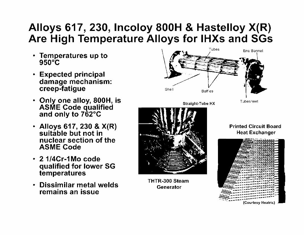
Alloys 617, 230, lncoloy 800H & Hastelloy X(R) Are High Temperature Alloys for IHXs and SGs
• Temperatures up to 9so0 c
• Expected principal damage mechanism: creep-fatigue
• Only one alloy, 800H, is ASME Code qualified and only to 762°C
• Alloys 617, 230 & X(R) suitable but not in nuclear section of the ASME Code
• 2 1/4Cr-1 Mo code qualified for lower SG temperatures
• Dissimilar metal welds remains an issue
Shell Baffles
Straight-Tube HX
THTR-300 Steam Generator
End Bonnet I
Tubesheet
Printed Circuit Board Heat Exchanger

Candidate Materials for IHX & SG Applications Must Have High-Temperature
Strength & Corrosion Resistance
Wrought high-Ni creep resistant alloys (20-22 wt0/o Cr) are creep resistant and offer protection against oxidation
up to about 900°C by formation of chromia scale
Ni lnconel 617 base Haynes 230 base Alloy 800H 32.0 Hastelloy X base
Cr Mn Co C Fe Ti Al w Si 22.0 0.40 12.0 0.10 2.0 0.40 1.2 - 0.40 22.0 0.65 5.0 0.10 3.0 - 0.30 14.0 0.50 21.0 1.00 - 0.06 bal 0.40 0.40 - 0.60 22.0 1.00 1.50 0.10 18.5 0.15 0.50 0.60 1.00
None are fully qualified in ASME or similar codes for VHTR nuclear applications
Mo 9.0 2.0 -
9.0

0
Primary creep
Need to Model and Codify High-Nickel Alloy Creep Behavior
Secondary creep Tertiary
:,, IE creep :,,I I 1
I * I I I
Load = co stant r I I
T1<<0.5T., I
t,
0.05 Alloy := 1-617 Creep Temperature = 1000°C
0.04 Creep Stress= 19.4 MPa
C 0.03
l! ... rn 0.02
0.01
0 50 100
Time, hours
150
/
Typical Metal Alloy 617 Thomas Lillo, INL
• Alloy 617 creep behavior
-Majority of life spent in tertiary creep regime, not in primary and secondary creep.
-Need to determine amount of creep that can be tolerated before load carrying capability is significantly compromised
200

Need to Improve and Validate Creep-Fatigue Interaction Models for High-Nickel Alloys
• Better understanding of operative mechanisms
• Fatigue-dominated regime • Creep-dominated regime
¥ • Effect of hold time: saturation Q)
or continuous degradation • Development of improved
constitutive models • Verification of creep-fatigue
interaction diagram • Incorporation into ASME Code
,..._ .2 'ffi LL 0 -Cf) a:,
800°C Creep-Fatigue 105 (,t---------.--------,-------.----......--r---------~
o Alloy 617 - 0.3% total strain • Alloy 617 - 1.0% total strain
0 f:::1, -' '
• f.:il 7
4----NO Hold
Q
a Allov 6 I 7CCA- OJ'~'~, total :,train • Allov If] 7CC.A. - ·"] O'J, total ':,train
a i::;17
D
D
102 ~~~~~~-~~~~~ 10 100 1000
Thomas Lillo, INL Hold Ti me (sec)
*indicates premature failure
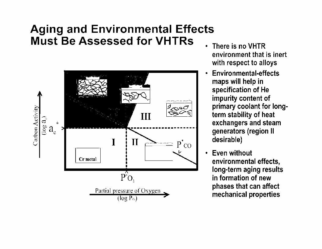
Aging and Environmental Effects Must Be Assessed for VHTRs . There is no VHTR
environment that is inert
·-> ·;::; -u ,., ~ ro *
... CJ)
c: o a 0 __, C ..0-._; I-,
ro u
III
I
Partial pr~ssure of Oxygen > (log Po,)
with respect to alloys • Environmental-effects
maps will help in specification of He impurity content of primary coolant for longterm stability of heat exchangers and steam generators (region II desirable)
• Even without environmental effects, long-term aging results in formation of new phases that can affect mechanical properties

Typical Surface of Alloy 617 Exposed in Air Develops Protective Oxide Layer Containing Islands of Co & Ni
Ni from Watts bath plating
Cr Oxide surface layer
Al Oxide intergrowth
Alloy 617 1,000°C 1,000 hrs
• I
II
.... ..,_ . ;)·r": ..: .._ ~· ... ~--~-
. .
.. ,.
A.re\/ :=::pot 1:1,gn Del \''.'[1 21] µm ~•o 00 ~·.: 4 D llJDDx B'::E 1D 1 lr·Jt,17 (l.'~ 1.date:11DOIJht 1DOIX
Richard Wright, INL
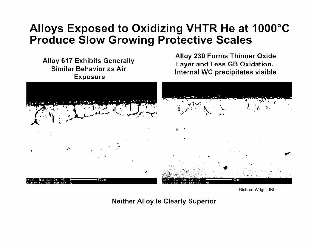
Alloys Exposed to Oxidizing VHTR He at 1000°C Produce Slow Growing Protective Scales
•
Alloy 617 Exhibits Generally Similar Behavior as Air
Exposure
.. .. -,, ... . !
'
,i,..'.,,1 1~ '_ r1ut r 131~11 [l~t ', Tl '.:U ~tr I
'[l[lllf 71] "dl[I E,=E 1[1~ 1:
Alloy 230 Forms Thinner Oxide Layer and Less GB Oxidation. Internal WC precipitates visible
•• .... 4 • ... • .. 111111 •· • i • l • ,( • · ~ ._ t. . ~11 • 'I- - - ,. • ,f/1',
•
• 'C _;
.... -- r·.. . ..
• ••• i~itf ii~{);~~;_,:j~)/;::': i:·? .. .: ·:: :: - .
.,-. . . . .. .... • - , ~ ' <to • :.. • • ~ •
. .·- . •. ~ ..... ' .· ·.·.• · ... :~/~: •.. ··-·' , :.:,i,.".:,
.L11 r \ ~p1it r 1~1p1 Det • [1 'JD µrn "111117 f ' fl c-lJI I B=E 11111 H:'
Richard Wright, INL
Neither Alloy Is Clearly Superior

Stability of Chromia in VHTR Coolants Is Primarily a Function of P(CO} at Low H2O
'-' 0
C ·-
1000
950
900
850
I
,
0
Chromia reduction . . . -....... +£ - ,- .. . . .
...
•• Chromia stability ..
10 20 30
P(C'O) in µbar
• Ha~nes 230
• lnconcl 617 IQuadakkt.·rsJ
40 50
from Rouillard F., Cabet C. et al. Oxid Met 68 (2007) 133
. . .
60
data on lnconel 617 after W. J. Quadakkers, Werkstoffe und Korrosion 36 (1985) 335

Aging of 617 Results in Microstructural Instability and Loss of Ductility
\ . r · • 4 'V ,,- ·•'
. :>. < . \ . .. ;:-< 1.' ~~. :~ . : f: ... · .. :~ ' t,,-;, ....... ,. . ' f,
--. I.! -f~P. 1.: -.,, ---..•.. , A . "-, . .. ., ;, _,. • • ,.v- •••...,__-:;-.,,,\ • - I ; ~ ;r ... ,. ,t I' ~·
7 ~.J. • · ·.. · ~1 ( :,rv ~ ~ It-~ ••
' , •• •• <t,. I f •."!'./,.
' ~- • • • ~ .... :f=~ ,,I ...... •, /'. ' • ~ • ~ .,:,I_ ,, . - . . -· .. . ~ ' -,.., .•·J . ..,_,.,, ~
r:,..._. ... - . • ~b ... ,, I :
~--~"" -o/x:J _,,. . ~---'-- / --:,•.
.. -·~ . ~ .., ) --::........."""~ I " .., it <) , • ., ·,i - , .
4-. ,:,, . o/ :-,. --,:;,,- ( -· ". , .;.
Q - o, (, . i.
o. -;. !1 ·; •. , ~"'""--- · . .,;..J ..... \:" : ,,- .1 • ... ~- ..
Stress(/= · :,~<~/:: ·•·· ·-~ .. . 0 ; -..a~-~--8 -. . ) . ·-.. .. . ,. ', • .,.; ' """'!~- ' . ,., {I
Axis -.. -: 1~ ~ - ,-!... : _ -~: 17;,. f :>'-- . '. · - ·· : .... ·-:-. ... • -·~.... .. • , . t:',,.- Ii'" • . ~ t • • .
... \.. ,··. ··------'ti'·"·'P·. ' . ~ " .,..--, ~ . . ' . ' . ~ ' ·•,-. . - •' ..
,_j--: . 'u • f,,.- J.JU, • .~ ..,,/'" ~ 1-1m
. . . .-
i,
•-
Richard Wright, INL
• Aging under load results in carbide redistribution and cavitation
• Thermal aging can result in precipitation of additional phases that differ from those under load
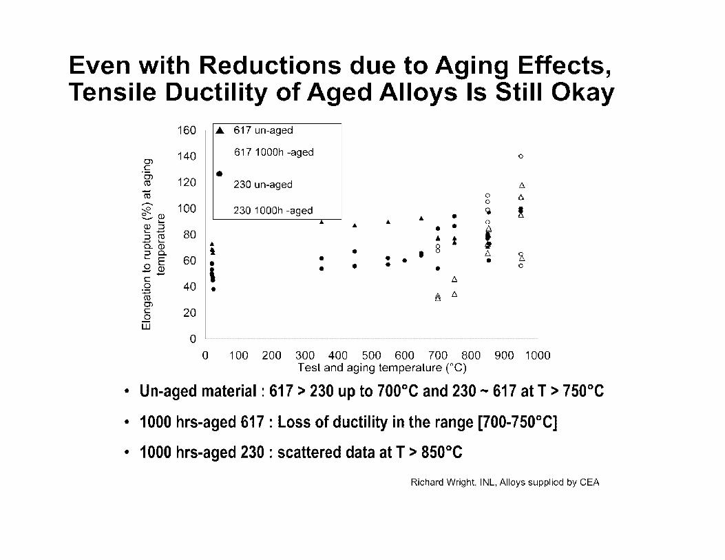
Even with Reductions due to Aging Effects, Tensile Ductility of Aged Alloys Is Still Okay
160 ... 617 un-aged
140 617 1000h -aged 0)
0
C 0) • rn 120 230 un-aged -rn 0
........ 100 0
0 230 1000h -aged ~ ~ Q) .. • -L... .. 0 Q) ::::, .. • • i .__
80 :::, rn ... i - L... .. ~ a.. Q) t 8 :::, a. • I I::. ._ E 60 • • • • 0 Q) • • •
' • • - -C I::.
0 40 • :.= rn 11 I::. 0) C 20 0 w
0 0 100 200 300 400 500 600 700 800 900 1000
Test and aging temperature (°C)
• Un-aged material : 617 > 230 up to 700°C and 230 - 617 at T > 750°C
• 1000 hrs-aged 617 : Loss of ductility in the range [700-750°C]
• 1000 hrs-aged 230 : scattered data at T > 850°C
Richard Wright, INL, Alloys supplied by CEA

Control Rods Must Also Deal with Irradiation Effects
-cu
80
70
0 20 1-
10
0
•
0
Irradiation Temperature 400-500°C
* i
non-irradiated
Irradiated 0.5-1 dpa
200 400 600 800 1000
Test Temperature (°C)
Lance Snead, ORNL
- Irradiation-induced embrittlement is a common feature for high-alloyed heatresistant materials
- Ni-based alloys are highly susceptible to embrittlement due to helium generation and phase instability during irradiation
- Alloy 800 exhibited the best irradiated ductility in material screening experiments for Japanese HTTR
- However, even Alloy 800 undergoes a major loss of ductility after= 0.5 dpa irradiation at 400-600°C and an order of magnitude loss in creep life

VHTR Pressure Vessels Are the Components of Greatest Concern for Medium-Temperature Metallic Service
• Normal/off-normal service temperatures and vessel size dominate materials requirements
• With engineered cooling of the vessel, the use of LWR AS0S/533 steels may be acceptable
• Limited to <<371 °C operation and small, short excursions
• Assessment still needed for short-time exposures at temperatures approaching or beyond 371°C
• Higher temperature operation of VHTR RPVs requires higher temperature alloys, e.g., 2.25Cr-1 Mo(V) or 9Cr-1 MoV • Very large vessel sizes (up to 30m high
x 8-9m diameter) will require scale-up of ring forging & on-site joining technologies, plus Code modifications
Expected Irradiation Dose Low Enough to Avoid Embrittlement but
Very Long Term Service May Produce Excessive Creep at Low
Temperatures

Methods to Ensure High Emissivity of RPV Surfaces Must Be Qualified
• Accident conditions (PLOFC & DLOFC) require high RPV emissivity for passive rejection of decay heat
• Limited studies have shown emissivities from 0.3 for cleaned to 0.9 for oxidized surfaces
• Composition and long-term stability of corrosion products must be evaluated
• Evaluation of core barrel emissivity is also needed
• Additional surface treatments or coating may be needed
Passive cooling by radiation to water or air panels or ground

Improved Multi-Scale Modeling Is Needed to Support Inelastic Finite Element Design Analyses
Develop Guidelines Similar to Nuclear
Standard NE F9-5T
Inelastic Finite Element Design Analyses
Unified Viscoplastic Constitutive Equations
Material Testing
Genetic Algorithm
(GA) to Automatically
Determine -....i and Optimize
Material Parameters
Qualification Against
Instrumented Key Feature Tests
Asymptotic Exponential Integrator
Accurate, Robust, Efficient
• Jacobian: !!a= ( <:8a) tir:
rill£
Updating: <'n+, =an+ f (8E,a,state variables)
I
FORTRAN Subroutines UMAT (ABAQUS) & USERPL (ANSYS)

GIF Activities Are Underway to Address VHTR Materials Issues
• The Generation IV International Forum is coordinating materials research on graphite, metals, and ceramics & composites performed in seven countries and the EU in direct support of VHTR system developments
• Active programs in China, Japan, Korea, France, Russia, and the U.S. are developing designs and materials requirements for gas cooled reactor systems
• DOE-NE is U.S. participant in VHTR Materials Project Arrangement that has been established to develop and share data among GIF signatories

PIRT Techniques Were Used to Identify Safety-Relevant Phenomena for NGNP* • Materials degradation phenomena for major components
and the materials comprising them were identified
• Phenomena were evaluated for their potential contribution to and pathway for off-site release
• Importance and state of knowledge used to prioritize phenomena
• 58 phenomena identified
- 17 deemed to have high importance & low/medium state of knowledge on RPV, piping, control rods, internals and valves
*Reference: Next Generation Nuclear Plant Phenomena Identification and Ranking Tables (PIRTs}, Volume 4: High-Temperature Materials PIRTs, NUREG/CR-6944, Vol. 4, ORNL/TM-2007/147, Vol. 4, March 2008

Recommended Update on NGNP High Temp Matis PIRT Completed in 2010*
• Considered new, lower temperature versions of NGNP
• Several high-priority phenomena on RPV, piping & HX lowered due to lower ROTs or elimination of HX
• 6 phenomena on SG added and 1 on control rods elevated to high priority; total of 10 high-priority items
• Document produced during IPA & presented to RES staff, but not peer reviewed externally
• PIRT update available for internal NRC use only and contains recommended R&D for phenomena *Reference: "Recommendation for a High Temp Metals PIRT Update 02-27-10," sent to Shah Malik, NRC-RES, from Bill Corwin, ORNL, via email on March 29, 2010.

High Priority Phenomena in Update on NGNP High Temp Matis PIRT Include:
• Compromised RPV integrity and excessive fuel temperatures caused by inadequate heat transfer from RPV surface due to potential loss of desired surface layer properties and associated reduction of emissivity (#11)
• Breach to secondary system via SG tube failure from initiation & propagation of flaws due to creep crack growth, creep, creep-fatigue, aging (with or without load) & subcritical crack growth (#40a)
• Breach to secondary system via SG tube failure arising from primary boundary design methodology limitations for high-temperature structures (#40b)

High Priority Phenomena in Update on NGNP High Temp Matis PIRT Include: (cont)
• Breach to secondary system via SG tube failure from materials degradation from long-term aging (#40c)
• Breach to secondary system via tube failure from undetected initiation & propagation of flaws due to inadequacy of ISi for high-temperature SGs (#40d)
• Breach of primary to secondary system boundary resulting in water ingress & attack on graphite core structures due to higher secondary system pressures in SG (#40e)
High Priority Phenomena in Update on NGNP High Temp Matis PIRT Include: (cont)
• Inadequate heat transfer from through core barrel due to potential compromise of emissivity from loss of desired surface layer properties (#46)
• Inability to maintain core structure geometry due to potential excessive deformation from radiation-creep in metallic core barrel (#47)
• Two high-priority phenomena on insulation & core restraint failure for non-metallic materials (#s 52,53)

Contributions to this presentation are gratefully acknowledged
• Lee Nelson <[email protected]>, Richard Wright <[email protected]> and Thomas Lillo <[email protected]> from the Idaho National Laboratory
• Lance Snead <[email protected]>, Sam Sham <[email protected]>, Dane Wilson <[email protected]> and Randy Nanstad <[email protected] from the Oak Ridge National Laboratory
• Bob Jetter <[email protected]>, Chair, ASME Subcommittee on Elevated Temperature Design
• Celine Cabet <[email protected]> from CEA, Saclay
• Qin Zhenya <[email protected]> from Tsinghua Univ.
• Kobus Smit <[email protected]> from PBMR
• Sten Caspersson <[email protected]> from Westinghouse Electric Co.
• Arkal Shenoy <[email protected]> from General Atomics

I
High Temperature Reactors - Construction Code Issues
Sam Sham Oak Ridge National Laboratory
For Presentation at the Nuclear Regulatory Commission Meeting
February 17, 2011
-OAK RIDGE NATIONAL LABORATORY MAN.-'\GED BY UT-BI\TTELLE FOR THE DEPARTMENT OF ENERGY
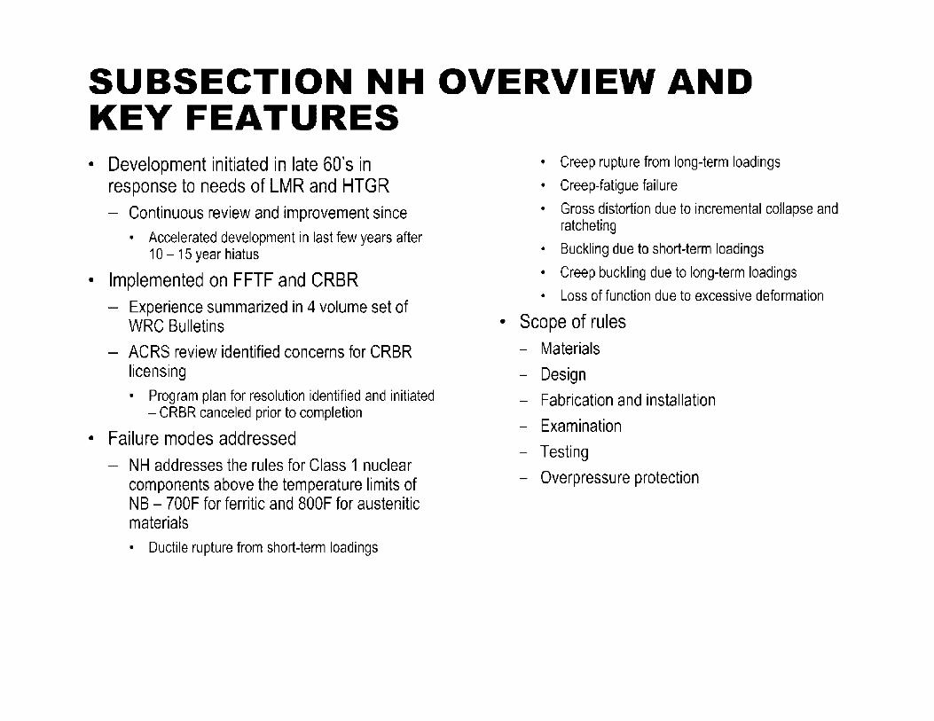
SUBSECTION NH OVERVIEW AND KEY FEATURES • Development initiated in late 60's in
response to needs of LMR and HTGR Continuous review and improvement since • Accelerated development in last few years after
10- 15 year hiatus
• Implemented on FFTF and CRBR - Experience summarized in 4 volume set of
WRC Bulletins
ACRS review identified concerns for CRBR licensing • Program plan for resolution identified and initiated
- CRBR canceled prior to completion
• Failure modes addressed - NH addresses the rules for Class 1 nuclear
components above the temperature limits of NB - 700F for ferritic and 800F for austenitic materials • Ductile rupture from short-term loadings
• Creep rupture from long-term loadings
• Creep-fatigue failure
• Gross distortion due to incremental collapse and ratcheting
• Buckling due to short-term loadings
• Creep buckling due to long-term loadings
• Loss of function due to excessive deformation
• Scope of rules - Materials
- Design
- Fabrication and installation
- Examination
- Testing
- Overpressure protection

ELEVATED TEMPERATURE CODE CASES
Section Ill, Div 1
N-201-5
N-290-1
N-253-14
N-254
N-257
N-467
N-499-2
Coverage
Class CS (Core Support) Components in Elevated Temperature Service.
Expansion Joints in Class 1, Liquid Metal Piping.
Construction of Class 2 or Class 3 Components for Elevated Temperature Service.
Fabrication and Installation of Elevated Temperature Components, Class 2 and 3.
Protection Against Overpressure of Elevated Temperature Components, Classes 2 and 3.
Testing of Elevated Temperature Components, Classes 2 and 3.
Use of SA-533 Grade B, Class 1 Plate and SA-508 Class 3 Forgings and their Weldments for Limited Elevated Temperature Service.
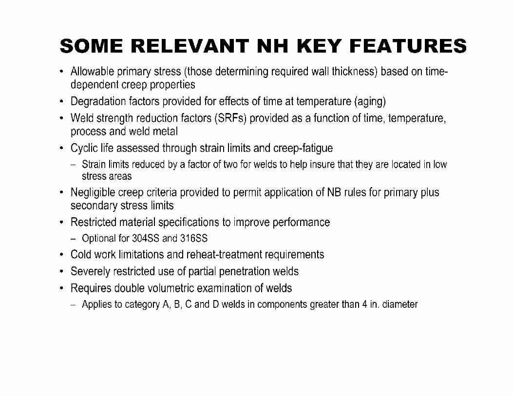
SOME RELEVANT NH KEY FEATURES • Allowable primary stress (those determining required wall thickness) based on time
dependent creep properties • Degradation factors provided for effects of time at temperature (aging) • Weld strength reduction factors (SRFs) provided as a function of time, temperature,
process and weld metal • Cyclic life assessed through strain limits and creep-fatigue
- Strain limits reduced by a factor of two for welds to help insure that they are located in low stress areas
• Negligible creep criteria provided to permit application of NB rules for primary plus secondary stress limits
• Restricted material specifications to improve performance - Optional for 304SS and 316SS
• Cold work limitations and reheat-treatment requirements • Severely restricted use of partial penetration welds • Requires double volumetric examination of welds
- Applies to category A, B, C and D welds in components greater than 4 in. diameter
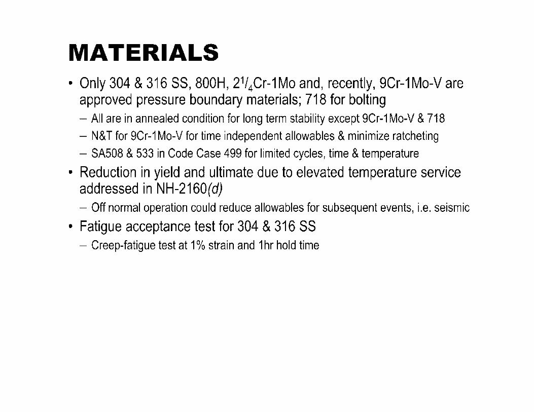
MATERIALS • Only 304 & 316 SS, 800H, 21/ 4Cr-1 Mo and, recently, 9Cr-1 Mo-V are
approved pressure boundary materials; 718 for bolting - All are in annealed condition for long term stability except 9Cr-1 Mo-V & 718 - N& T for 9Cr-1 Mo-V for time independent allowables & minimize ratcheting - SA508 & 533 in Code Case 499 for limited cycles, time & temperature
• Reduction in yield and ultimate due to elevated temperature service addressed in NH-2160(d) - Off normal operation could reduce allowables for subsequent events, i.e. seismic
• Fatigue acceptance test for 304 & 316 SS - Creep-fatigue test at 1 % strain and 1 hr hold time

MATERIALS TIME & TEMPERATURE
NH code materials (other than bolting)
304 stainless steels (UNS S30400, S30409)
316 stainless steel (UNS S31600, S31609)
Alloy 800H (UNS N08810)
2¼Cr 1 Mo steel, annealed condition (UNS K21590)
Grade 91 steel (UNS K90901)C
Maximum temperature
For stress allowables S0, Smt, For fatigue curves S S up to 300,000 hoursa t, r
816°C
816°C
760°C
649°c
760°C
538°C
a. The primary stress limits are very low at 300,000 hours and the maximum temperature limit
b. Temperatures up to 649°C (1200°F) are allowed up to 1,000 hours c. The specifications for Grade 91 steel covered by Subsection NH are SA-182 (forgings), SA-213 (small
tube), SA-335 (small pipe), and SA-387 (plate). The forging size for SA-182 is not to exceed 4540 kg.

DESIGN - Load Controlled (Prin1ary) Stresses
• NH applies above temperature limit for NB allowable stresses
- 700F for ferritic materials and B00F for austenitic materials
• NB applies above temperature limits if creep effects demonstrated not significant
- Documented in Stress Report and included in Design Spec. (NH-3211 (c))
• See also T-1324
- Source for allowable stresses not defined • Presumably Sm from NH
- Disconnect between temperature definition in NB and NH • Section average in NH vs. local maximum
in NB for some cases
• NH Design Condition evaluation same as Section VIII, Div 1 with same allowables
- Don't include short term loads in Design Conditions
• NH Service Condition allowable stress criteria same as NB for time independent Sm but different and more conservative than VIII, Div 1 for time dependent allowable St
VIII, Div 1 80% of min. or 67% of avg. creep rupture stress
Avg. strain rate= 0.01% per 1000 hr
None
67% of min. creep rupture stress
100% avg. stress to 1 % strain
80% of min. stress to tertiary creep
- Wall thickness probably governed by Service Conditions

• Evaluation of Design Conditions and all Service Conditions except Level Dare based on a linear elastic material model.
- Requires stress classification
- Reference stress methodology under consideration
• Time fraction summations used to evaluated different stress, time and temperature conditions
- Time fractions summed over all Service Conditions
• Time fraction is time in a specific condition divided by allowable time at that condition
• Weld strength reduction factors are provided for permitted weld metal and properties
- Analysis based on parent metal properties
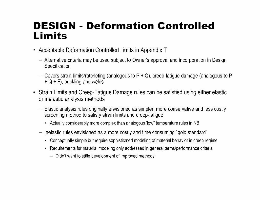
DESIGN - Deformation Controlled Limits • Acceptable Deformation Controlled Limits in Appendix T
- Alternative criteria may be used subject to Owner's approval and incorporation in Design Specification
- Covers strain limits/ratcheting (analogous to P + Q), creep-fatigue damage (analogous to P + Q + F), buckling and welds
• Strain Limits and Creep-Fatigue Damage rules can be satisfied using either elastic or inelastic analysis methods
- Elastic analysis rules originally envisioned as simpler, more conservative and less costly screening method to satisfy strain limits and creep-fatigue
• Actually considerably more complex than analogous 'low" temperature rules in NB
- Inelastic rules envisioned as a more costly and time consuming "gold standard"
• Conceptually simple but require sophisticated modeling of material behavior in creep regime
• Requirements for material modeling only addressed in general terms/performance criteria
- Didn't want to stifle development of improved methods
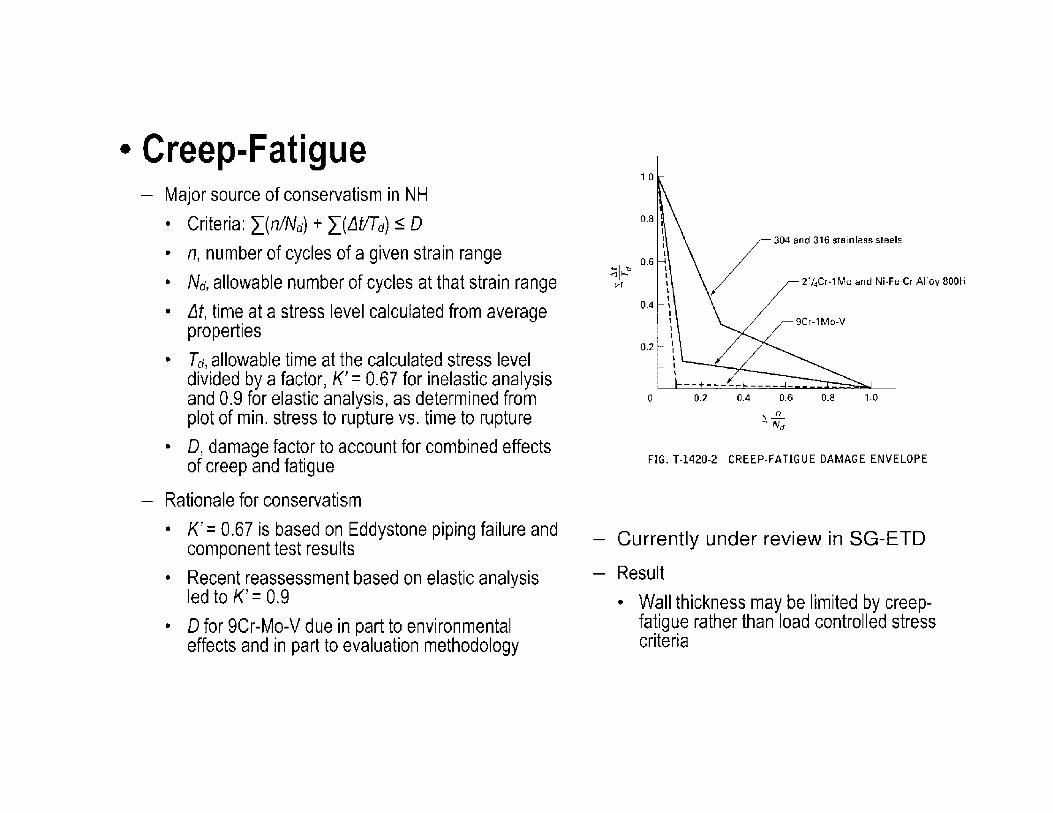
• Creep-Fatigue Major source of conservatism in NH
• Criteria: "i_(n/Nd) + "i_(Llt!Td) s D
• n, number of cycles of a given strain range
• Nd, allowable number of cycles at that strain range
• Llt, time at a stress level calculated from average properties
• Td, allowable time at the calculated stress level divided by a factor, K' = 0.67 for inelastic analysis and 0.9 for elastic analysis, as determined from plot of min. stress to rupture vs. time to rupture
• D, damage factor to account for combined effects of creep and fatigue
Rationale for conservatism
• K' = 0.67 is based on Eddystone piping failure and component test results
• Recent reassessment based on elastic analysis led to K' = 0.9
• D for 9Cr-Mo-V due in part to environmental effects and in part to evaluation methodology
1.0
/
304 and 316 stainless steels
2%Cr-1Mo and Ni-Fe-Cr Alloy 800H
0.4
0.2
0 0.2 0.4 0.6 0.8 1 .o
FIG. T-1420-2 CREEP-FATIGUE DAMAGE ENVELOPE
Currently under review in SG-ETD
Result
• Wall thickness may be limited by creepfatigue rather than load controlled stress criteria

• Buckling - Buckling charts for Section VIII, Div. 1 & Section 1 do not consider creep
• Figures provided in NH to define time & temperature limits for applicability of charts
- A matrix of load factors is supplied in NH to address buckling and instability
• Factors are a function of:
- Source, load controlled or deformation controlled
- Duration, time independent or time dependent
- Service Level

• Welds - Weld strength reduction factors
- Strain limits half that of parent material
- Creep-fatigue limits:
• Nd, allowable number of cycles reduced by factor of two
• Minimum parent metal creep rupture strength reduced by weld strength reduction factor
- Weld geometry
• Worst case geometry used in analysis » No upper limit on stress concentration factor implies ground welds
• Confirmed by inspection

EXAMINATION
• Dual weld exam required - Radiography plus ultrasonic
- Radiography plus eddy current
- Radiography at two different angles
• NH-5000 refers to NB-5000 - NB-5000 invokes Section V "Nondestructive Examination"
- Article 14 "Examination System Qualification"

Recommended Reading
• Chapter 12 of "Companion Guide to the ASME Boiler & Pressure Vessel Code" K. R. Rao, Editor, ASME Press
- Background and discussion of Subsection NH rules and their implementation including relevant Code Cases

DOE/ASME GEN IV MATERIALS PROJECT • Collaboration between DOE and ASME established in 2007 to
address technical topics that were identified by DOE, ORNL, INL, and ASME to have particular value with respect to the ASME Code
• In support of an industrial stakeholder's application for licensing of a Gen IV nuclear reactor
• Phase I
- Tasks 1- 5 completed
• 2007/2008
• Phase II
- Tasks 6-11 completed
• 2009/2010
• Phase Ill
- Proposed Tasks 13-14
• Started in 2010, ongoing
• Task 12 on NOE was funded by NRC

Task 1: Verification of Allowable Stresses in Section Ill, NH with Emphasis on Alloy 800H and Grade 91
• Rationale - Longer design lives at higher temperatures to support HTGR - Discrepancies in 800H allowable stresses and differences in allowables for Grade 91
between RCC-MR and NH/II-Part Din thick sections
• Results - Alloy 800H base metal values for Sy & SU established to 900 C, SRmin values to 600,000
hr and 900 C • 1 % strain controlled long time allowable stress at 850 and above, testing required
- Alloy 800H weldments require testing above 750 C for long times - Grade 91 base metal data support allowable stresses to 600,000 hr and 650 C - Grade 91 weldments should adopt Section II report on SRFs
• Next step - Use data in Task 13 for Code approved allowable stress values

Task 2: Regulatory Safety Issues in Subsection NH and for Very High Temperatures for VHTR & GENIV
• Rationale - Avoid licensing delays due to unresolved concerns
• NRG has not endorsed NH
• Results - Creep crack growth in weldments and notches, inelastic analysis, and environmental
effects are primary issues identified in prior reviews • Time and temperature extension and additional concerns identified
- How NH and Codes Cases address NRG issues was summarized • Materials behavior, creep-fatigue and environmental effects • Structural integrity of welds • Development and verification of simplified design analysis methods • Verification testing
• Next step - Used to identify follow-on tasks

Task 3: Improvement of Subsection NH Rules for Grade 91 Steel - (Negligible Creep and Creep Fatigue) • Rationale
- Current NH criteria for negligible creep and creep-fatigue damage in Grade 91 overly conservative and too restrictive for realistic design application
• Results - Negligible creep
• Criteria for cyclically hardening materials, e.g. austenitic stainless steel, inappropriate for cyclically softening material, e.g. Grade 91
• Detail modifications proposed & further testing - Creep-Fatigue
• ASME design procedure is very conservative • Proposed modifications
- Reduce safety factor for creep damage calculation with elastic analysis (k' = 0.9) Incorporated in 2008 Addenda
- Additional modifications and testing
• Next step - Proposed modifications evaluated in Task Force on Creep-Fatigue &Task Force on
Negligible Creep - Data & recommendations used in Task 10

Task 4: Updating of ASME Nuclear Code Case N-201 to Accommodate the Needs of the HTGR
• Rationale - CC N-201 (Elevated temperature core support structures) last updated prior to NH - Limited materials selection - HTGR core support structures expected to see very high temperatures
• Results - Questionnaire on metallic core support structure design and requirements
• Normal and transient temperatures benign and current design methods applicable • Additional material needs
- 316FR/316LN, 321 & 347, Grade 91 and lnconel 718 - life extension to 60yr
- Comprehensive line by line review performed against NG and NH • CC N-201 revised to correct errors and omissions
• Next step - CC revisions approved in SG-ETD -final edit in WG-CSS

Task 5: Collect and study Available CreepFatigue Data and Procedures for Grade 91 Steel and Hastelloy XR
• Rationale - Significant data on Grade 91 exists in Japan - Hastelloy XR used successfully in the Japanese HTGR
• Results - Grade 91
• Numerous data collected • NH procedure significantly conservative compared to test data and RCC-MR and
Japanese FBR procedures • Potential improvements to NH identified and evaluated • R&D needs identified
- Hastelloy XR • Available data collected • Elevated temperature response characteristics similar to austenitic SS • Material models for inelastic analysis were developed for HGTR IHX
• Next step - Data and assessments used in Tasks 3 and 11

Task 6: Operating Condition Allowable Stress Levels
• Rationale - Minimum Stress to rupture values in NH not consistent with Section 11, Part D
• Results - Inconsistencies confirmed for current NH materials except Alloy 800H - Comprehensive data collection and evaluation for NH materials
• Current data support 304H and 316H allowable stress values to 1200°F • Concern for low creep ductility
• 800H data support extended stress values to 800 - 850°C
• Grade 91 data support 500,000 hr below 600°C and 650°C up to 100,000 hr
• Data for annealed 2 .25Cr-1 Mo support values to 1200° F - Prioritized table of suggested action to revise allowable stress to accommodate HTGR needs
• Next step - Implement recommended actions in follow-on task to develop allowable stresses for code committee
action

Task 7: ASME Code Considerations for the Intermediate Heat Exchanger (IHX)
• Rationale - IHX exposed to full gas outlet temperature at primary to secondary interface - Potential use of compact micro channel heat exchangers with unique design
features raises concerns • Results
- Conventional and compact experience reviewed • Tubular Helical Coil Heat Exchanger most mature • Compact HX less mature but potential cost and volume savings • 617 most promising material followed by 230, XR and B00H
- Recommended Code approaches defined • I HX should be considered non-safety related component • Current C & S basically OK for shell and tube • Difficult ISi suggests periodic replacement of compact IHX
- Extensive review of ASTM Standards development • Next step
- Implement recommendations in a draft code case

Task 8: Creep and Creep-Fatigue Crack Growth at Structural Discontinuities and Welds
• Rationale - Top NRC concern - NH has design factors and procedures for weldments and structural discontinuities but not
a quantitative assessment of crack growth
• Results - Current crack growth methodologies assessed for applicability to design and IS - UK R5 approach selected based on development status and current use - Theoretical limitations identified - Design procedure described
• Next step - Extensive discussion in SG-ETD - Recommended for use with ISi for inspection intervals and flaw evaluation - Applicability for HTGR materials and conditions needs to be established - Potential joint BPV SC-Ill & XI Task Force

Task 9: Update and Improve NH - Simplified Elastic and Inelastic Design Analysis Methods
• Rationale - Current NH rules based on ?O's - 80's technology - Advances in computing technology - Advances in understanding of creep behavior and failure mechanisms
• Results - Comprehensive review and comparison of elevated temp. design codes and fitness for
service manuals - Recommended improvements to NH - Elastic analysis - Reference stress methods - Limit load, shakedown, and ratcheting analysis - Recommended available benchmark problems and key feature tests
• Next Step - Recommended approaches currently under review in SG-ETD

Task 10: Update and Improve NH - Alternative Simplified Creep-Fatigue Design Methods
• Rationale - Phase I Tasks 3 & 5 identified a number of deficiencies in current methodologies
- New methods have been developed
- Identified as an NRC concern
• Results - Creep-fatigue methodologies including damage based, strain based, modified strain range partitioning
and methods not separating creep and fatigue damage evaluated with Grade 91 data from Tasks 3 & 5
- All methods correlate reasonably with short term data, differences in long term extrapolation
- Near term: incorporate key features in current time fraction approach
- Generally currently deployable
- Long term: incorporate SMT methodology which requires signification test & validation
• Next step - Review and implementation in Task Force on Creep-Fatigue Criteria
- Apply methodology to assess other materials of interest

Task 11: New Materials for NH
• Rationale - Additional material options in NH & CC N-201 needed to address unique VHTR
requirements, e.g. very high temperatures and environmental effects
• Results - Comprehensive review of prior design studies and operating conditions - Requirements for codification reviewed in detail
- Candidate alloy characteristics discussed - I00,000 hr creep rupture strength for 7 candidate alloys plotted vs. temperature
- In descending order at 800°C: 230, 617, 625, 556, NF 709, 120, X, 811, 810
- Hastelloy XR covered in separate report - Though 617 is stronger in air than XR they are comparable in HTGR He which doesn't
affect XR - Testing requirements and cost estimates based on review of NGNP IHX Materials R&D
Plan for Alloy 800H and Alloy 617
• Next step - Primarily intended for project use
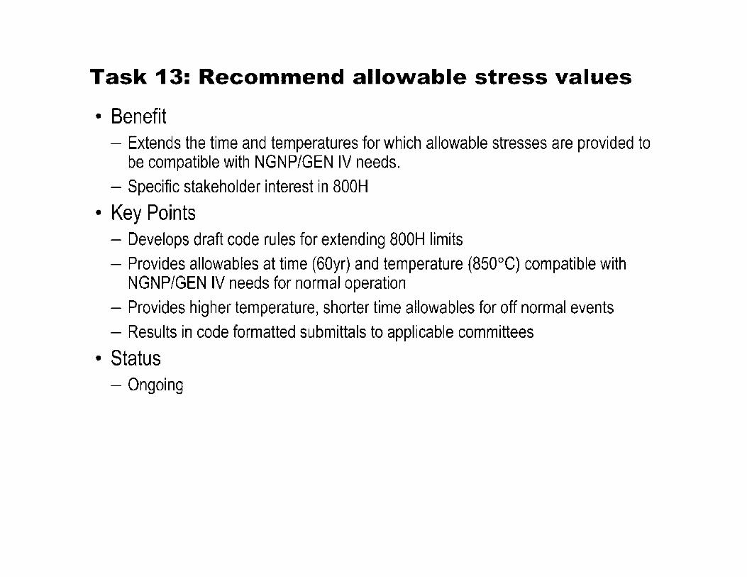
Task 13: Recommend allowable stress values
• Benefit - Extends the time and temperatures for which allowable stresses are provided to
be compatible with NGNP/GEN IV needs. - Specific stakeholder interest in 800H
• Key Points - Develops draft code rules for extending 800H limits - Provides allowables at time (60yr) and temperature (850°C) compatible with
NGNP/GEN IV needs for normal operation - Provides higher temperature, shorter time allowables for off normal events - Results in code formatted submittals to applicable committees
• Status - Ongoing

Task 14: Corrections to stainless steel allowable stresses
• Benefit - Corrects recently identified problems with allowable stress values that impact on
going design studies.
• Key Points - Task 6 identified errors and potential limitations on current SS stress values in NH - Some heats of 304 & 316SS had creep rupture lives below current NH values,
particularly above 1200F (650°C) • NIMS (post NH) data
- Identify restrictions to preclude bad heats or - Delete impacted allowables - Results in code formatted submittals to applicable committees
• Status - Ongoing

DIVISION 5, CONSTRUCTION RULES FOR HIGH TEMPERATURE REACTORS
• Need - Renewed interest and acceptance of nuclear fission as a source of energy on a
global level - High temperature reactors are being considered by various countries and
companies for future reactor applications - Many efforts to collect and develop data for use in high temperature reactor
applications and in the development of appropriate Codes and Standards - Some current rules have not been properly maintained and are out of date - Need a new Division to cover construction rules for components in high
temperature reactors

DIVISION 5 SCOPE The rules of Division 5 constitute the construction requirements associated with components and structures used in high temperature gas-cooled reactors and liquid metal reactors
DIVISION 5
Subsection HA- General Requirements • Subpart A - Metallic Materials (NCA)* • Subpart B - Graphite Materials (New) • Subpart C - Composite Materials (New)
Subsection HB- Class A Metallic Pressure Boundary Components • Subpart A- Low Temperature Service (NB) • Subpart B - Elevated Temperature Service (NH)
o Mandatory Appendix HBB-I (CC N-499)
Subsection HC- Class B Metallic Pressure Boundary Components • Subpart A- Low Temperature Service (NC) • Subpart B- Elevated Temperature Service (CC N-253)
Two Safety Classes-Class A and Class B ( )* Code Basis
Subsection HF- Class A and B Metallic Supports • Subpart A- Low Temperature Service (NF)
Subsection HG - Class A Metallic Core Support Structures • Subpart A- Low Temperature Service (NG) • Subpart B - Elevated Temperature Service (CC N-
201)
Subsection HH - Class A Non-Metallic Core Support Structures • Subpart A- Graphite Materials (New) • Subpart B- Composite Materials (New)

SAFETY CLASSIFICATIONS
Class A- "safety-related" Class B - "non-safety related with special treatment"
• Reflect the risk-based approach derived from safety criteria established for high temperature reactor plants
• Remaining items not in these two classifications shall satisfy requirements of other appropriate non-nuclear codes and standards

FUTURE IMPROVEMENT OF DIVISION 5
• An Ad-Hoc project team within ASME BPV Ill, Working Group on Liquid Metal Reactors (LMRs) was formed to establish strategic goals, structure and scope, and execution plan for LMRs in Div 5
• Two white papers were drafted • The purpose was to develop a consensus on the path forward to
provide ASME Code rules for the construction of the next generation LMRs which also includes LMR-based advanced small modular reactors (SMRs)
• Near Term LMR White Paper focused on the 2011, 2013 and 2015 Code editions
• Long Term LMR White Paper focused on the 2017, 2019 and beyond editions

NEAR TERM LMR WHITE PAPER OVERVIEW
• '11, '13 & '15 Code Editions • Based on current, '11, Div 5 format - Start approval cycle in 1 - 3 years - References other sections
• Conventional scope - Includes Code Cases • Two classes of construction, A & B
Highest priority items Next priority
Correct and extend allowable stresses Update and revise CC N-253 etc.
Resolve 2 vs 3 component classification issue Add 316LN/FR
Inelastic analysis procedures and models Incorporate creep-fatigue crack growth in Section XI, Div 3
Improvements to creep-fatigue and negligible Add exemption rules for creep-fatigue creep evaluation • Emphasis on Mod9Cr
Add reference stress for wall sizing Add exemption rules for creep-fatigue evaluation
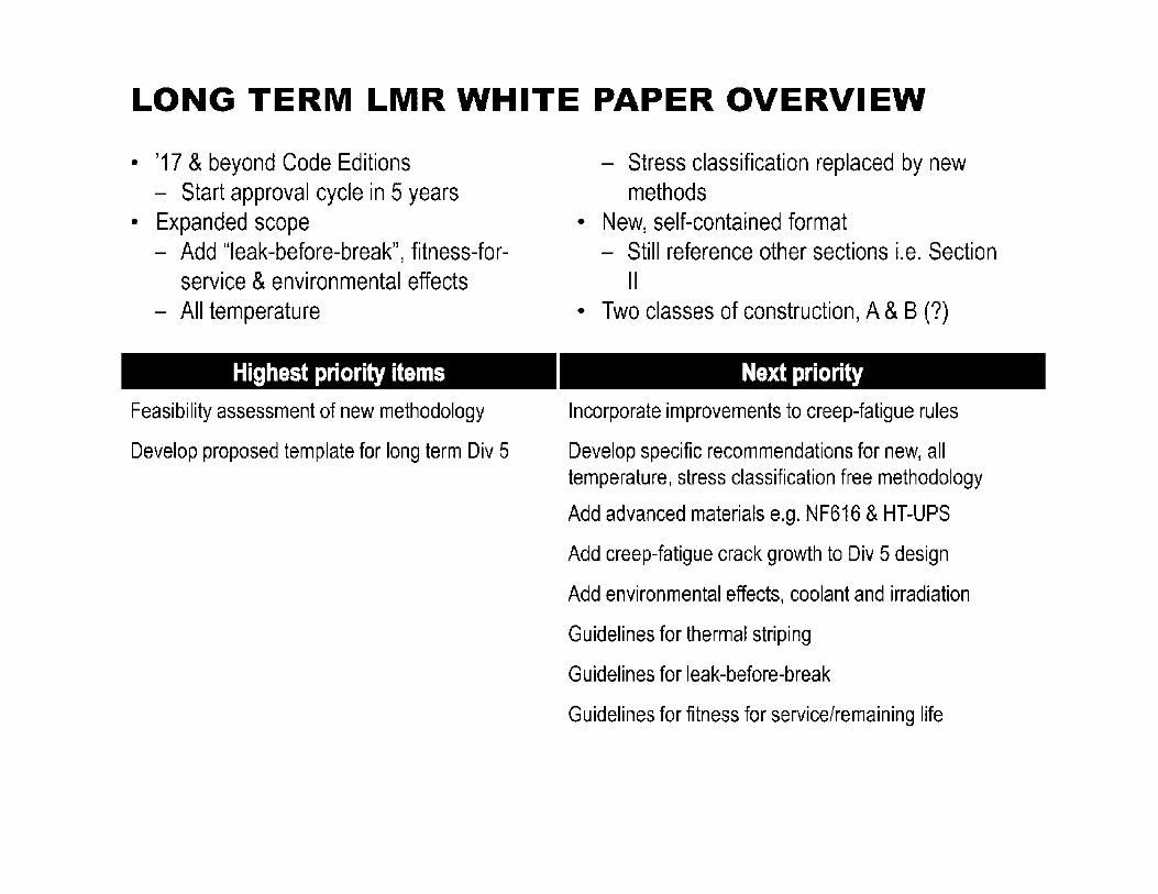
LONG TERM LMR WHITE PAPER OVERVIEW
• '17 & beyond Code Editions - Start approval cycle in 5 years
• Expanded scope - Add "leak-before-break", fitness-for
service & environmental effects - All temperature
Highest priority items
Feasibility assessment of new methodology
Develop proposed template for long term Div 5
- Stress classification replaced by new methods
• New, self-contained format - Still reference other sections i.e. Section
II • Two classes of construction, A & B (?)
Next priority
Incorporate improvements to creep-fatigue rules
Develop specific recommendations for new, all temperature, stress classification free methodology
Add advanced materials e.g. NF616 & HT-UPS
Add creep-fatigue crack growth to Div 5 design
Add environmental effects, coolant and irradiation
Guidelines for thermal striping
Guidelines for leak-before-break
Guidelines for fitness for service/remaining life

TASK GROUP ON INELASTIC ANALYSIS METHODS
• Develop non-mandatory NH appendix on inelastic analysis methods for current NH materials
• Envision having draft code rules in place by end of 2013

Approach
• Use NE F9-5T, "Nuclear Standard, Guidelines and Procedures for Design of Class 1 Elevated Temperature Nuclear System Components" (developed by DOE for CRBR vendors) as guideline
• Use currently available state-of-the-art models - Models might not be perfect - New development will be kept to a minimum
• Use currently available specimen test data, to the extent possible - Experiments and testing by Task Group are out-of-scope
• Data source for material models - Literature - Contributions from vendors, international agencies, US national
labs - all on the basis of supporting ASME code committee work • Perform verification analyses, to the extent practical

Contents of non-mandatory appendix
• Part A - 3D unified viscoplastic constitutive equations for current NH materials
• 304,316 stainless steels, 9Cr-1Mo-V, 2¼ Cr-1Mo, Alloy 800H, Alloy 718 (bolting)
• Material parameters for each material, covering NH temperature range, at every 50C
• Will consider the inclusion of 1 D equations, if a need is identified - Potential Issues
• Could lead to a need for updating isochronous stress-strain curves for consistency
• Part B - Provide guidance on inelastic finite element analyses - Example problems on how to use results from inelastic finite element analyses to
satisfy NH deformation limits

UChicago • ArgonnelLC
High Temperature Reactor Materials
Licensing and Regulatory Issues
February 17, 2011
Saurin Majumdar, Ken Natesan
Argonne National Laboratory

Summary of Licensing Issues for Clinch River Breeder Reactor
• NRC/ACRS conducted a licensing review (NUREG-0968) of a construction permit for CRBR in the 1980's
• Construction permit was supported with the stipulation that numerous technical issues be resolved prior to requesting an operating license
• The R&D program that was agreed to was not completed
- Materials
- Design analysis
- Weldment integrity
- Creep ratcheting
- Creep cracking
- Creep/creep-fatigue damage evaluation procedure

Major Concerns for CRBR Licensing: Background
• Up until now, the maximum temperature experienced by the LWR industry is -350°C
- Primary components designed by ASME Code Section Ill, Subsection NB
- Section 111, Subsection NB and Section XI have been approved by NRG
- Time/temperature-dependent deformation and damage not major concerns
- Significant industry experience in material/design/fabrication of L WR components
- Significant industry experience in in-service inspection techniques
• Reactor outlet temperature for CRBR was 995°F (535°C)
- Austenitic stainless steels and low-alloy ferritic steels
- Time/temperature-dependent deformation cannot be ignored
- Time/temperature-dependent damage cannot be ignored
• Based on the review of the material submitted by the applicant, NRC listed nine areas of concern

Major NRC Concerns for CRBR Licensing
• Weldment Cracking
• Notch weakening
• Material property representation for inelastic analysis
• Steam generator tubesheet evaluation
• Elevated temperature seismic effects
• Elastic follow-up in piping
• Creep-fatigue evaluation
• Plastic strain concentration factors
• Intermediate piping transition welds

NRC Concern - Weldment Cracking
• Identified as the most significant concern
• Early crack initiation in HAZ
• Variation of material properties within the weld - creep damage
• Effect of cycle rate, hold time on propagation of long shallow cracks in HAZ
• Effect of enhanced creep in uncracked ligaments of cracks due to residual stress and thermal cycling on crack stability and creep crack growth
• These effects must be evaluated to determine the safety margins of weldments in elevated temperature service.
• Effect of long-term aging on creep-fatigue damage
• Effect of loading sequence on creep-fatigue behavior

NRC Concern - Notch Weakening
• Cracking at notches and other discontinuities due to stress-strain concentration effect and exhaustion of local ductility
- Subsection NH (Code Case N4 7) ignores notches for load controlled stresses
- They are considered for strain-controlled loading and creep-fatigue
• Main concern was that the creep-fatigue limits are set on the basis of tests on smooth specimens and, therefore, do not consider stress gradient near notches
• Also, concerned about loss of ductility due to long-term cyclic and monotonic loading.

NRC Concern - Material Property Representation for Inelastic Analysis
• NRC was concerned about lack of verification of computer programs used for conducting inelastic analyses
• Concerned about impact of new technology developments on safety
- Safety margins that worked well with conservative simplified analyses may be eroded by the use of more accurate analysis techniques
- Concerned with using average properties rather than minimum properties for inelastic analysis
- Does the safety factors adequately cover departure from average behavior
- Is creep rupture damage calculated conservatively in the presence of hardening due to cyclic loading or fabrication processes?
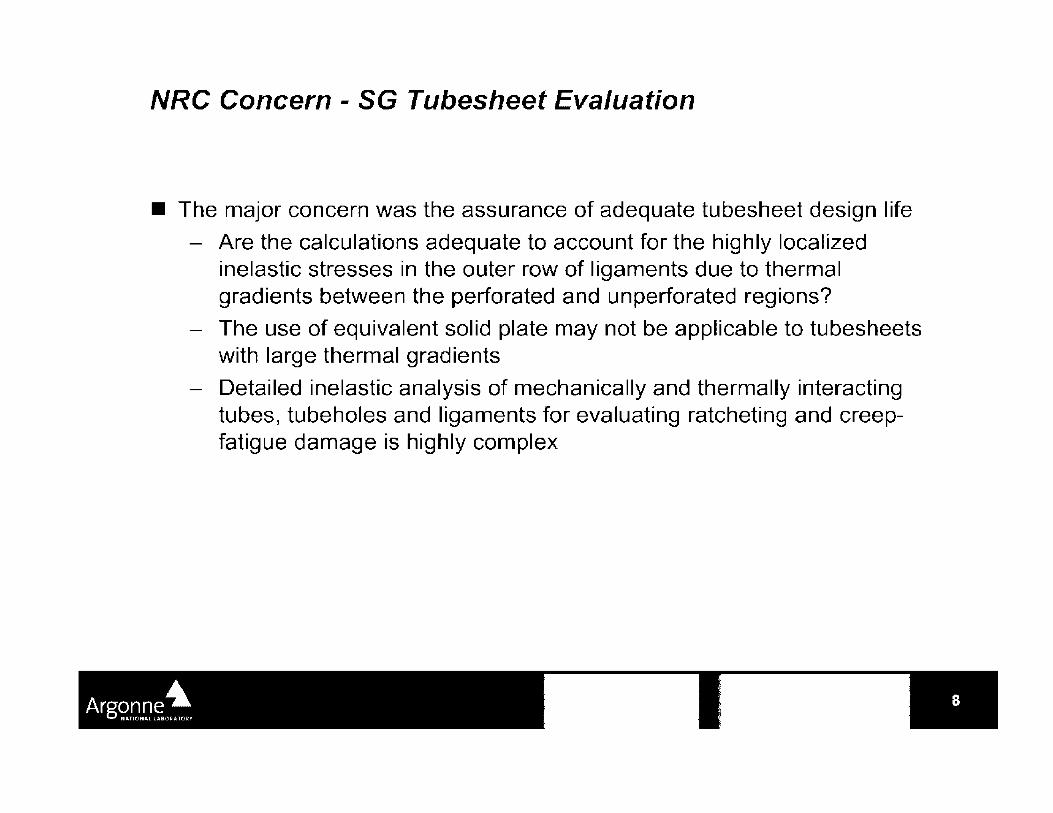
NRC Concern - SG Tubesheet Evaluation
• The major concern was the assurance of adequate tubesheet design life
- Are the calculations adequate to account for the highly localized inelastic stresses in the outer row of ligaments due to thermal gradients between the perforated and unperforated regions?
- The use of equivalent solid plate may not be applicable to tubesheets with large thermal gradients
- Detailed inelastic analysis of mechanically and thermally interacting tubes, tubeholes and ligaments for evaluating ratcheting and creepfatigue damage is highly complex

NRC Concern - Elevated Temperature Seismic Effects
• Can creep strain accumulation or creep-fatigue damage be enhanced by seismic events?
- Seismic events may change the residual stress field by short-term primary loading
- Relaxation of high residual stresses following a seismic event may enhance accumulated creep strain (ratcheting) and creep-fatigue damage
- Sequence effects may be important at elevated temperatures

NRC Concern - Elastic Follow-up in Piping
• The concern was related to categorizing thermal expansion stresses as secondary for evaluating hot leg piping
• Under creeping condition, relaxation of stresses in highly stressed areas may cause additional cyclic strain and strain accumulation due to elastic follow up.
- Subsection NH recommends that thermal stresses with large elastic follow up be considered as primary, but does not define when elastic follow up is large
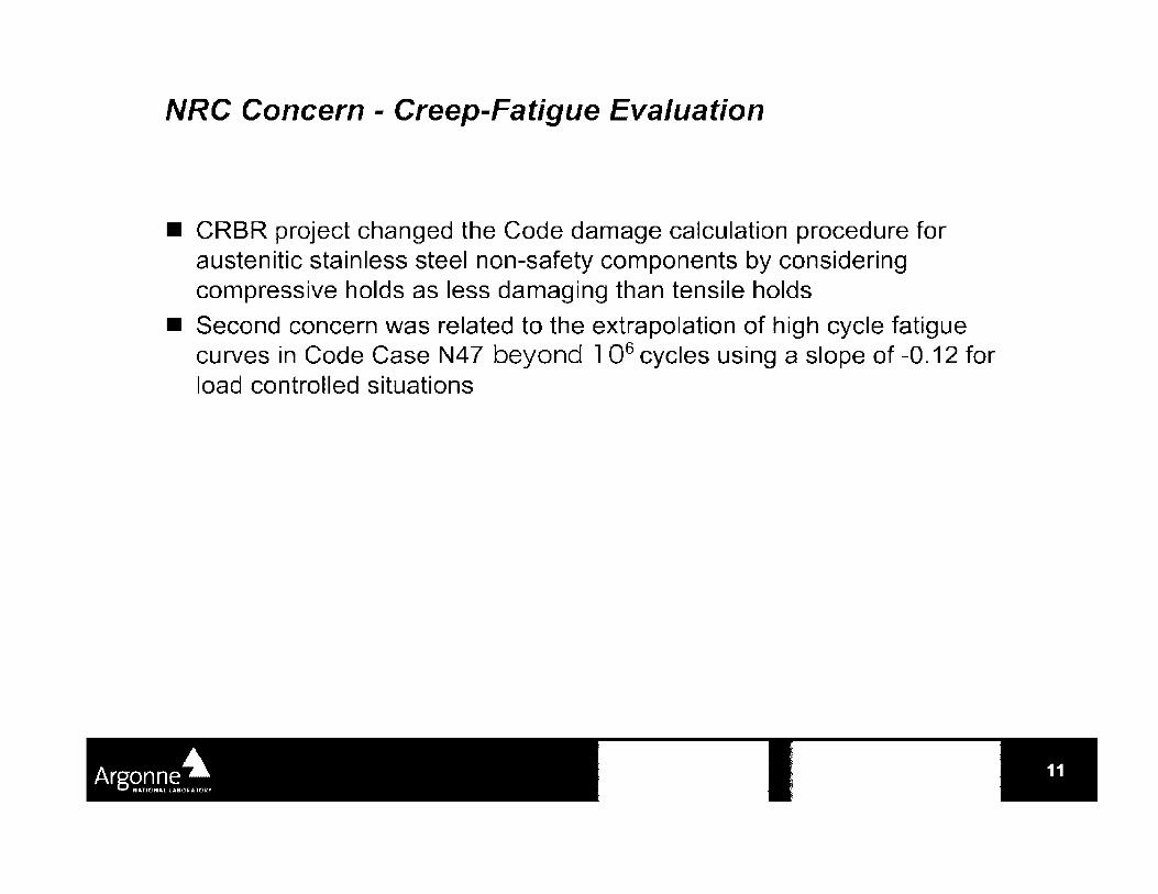
NRC Concern - Creep-Fatigue Evaluation
• CRBR project changed the Code damage calculation procedure for austenitic stainless steel non-safety components by considering compressive holds as less damaging than tensile holds
• Second concern was related to the extrapolation of high cycle fatigue curves in Code Case N47 beyond l 06 cycles using a slope of -0.12 for load controlled situations
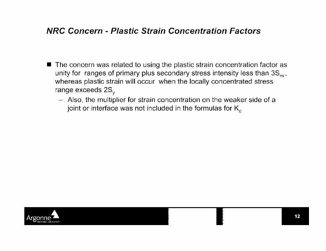
NRC Concern - Plastic Strain Concentration Factors
• The concern was related to using the plastic strain concentration factor as unity for ranges of primary plus secondary stress intensity less than 3Sm, whereas plastic strain will occur when the locally concentrated stress range exceeds 2SY - Also, the multiplier for strain concentration on the weaker side of a
joint or interface was not included in the formulas for Ke
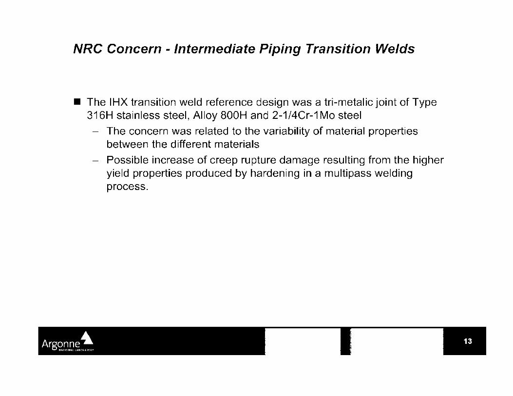
NRC Concern - Intermediate Piping Transition Welds
• The IHX transition weld reference design was a tri-metalic joint of Type 316H stainless steel, Alloy 800H and 2-1/4Cr-1 Mo steel
- The concern was related to the variability of material properties between the different materials
- Possible increase of creep rupture damage resulting from the higher yield properties produced by hardening in a multipass welding process.
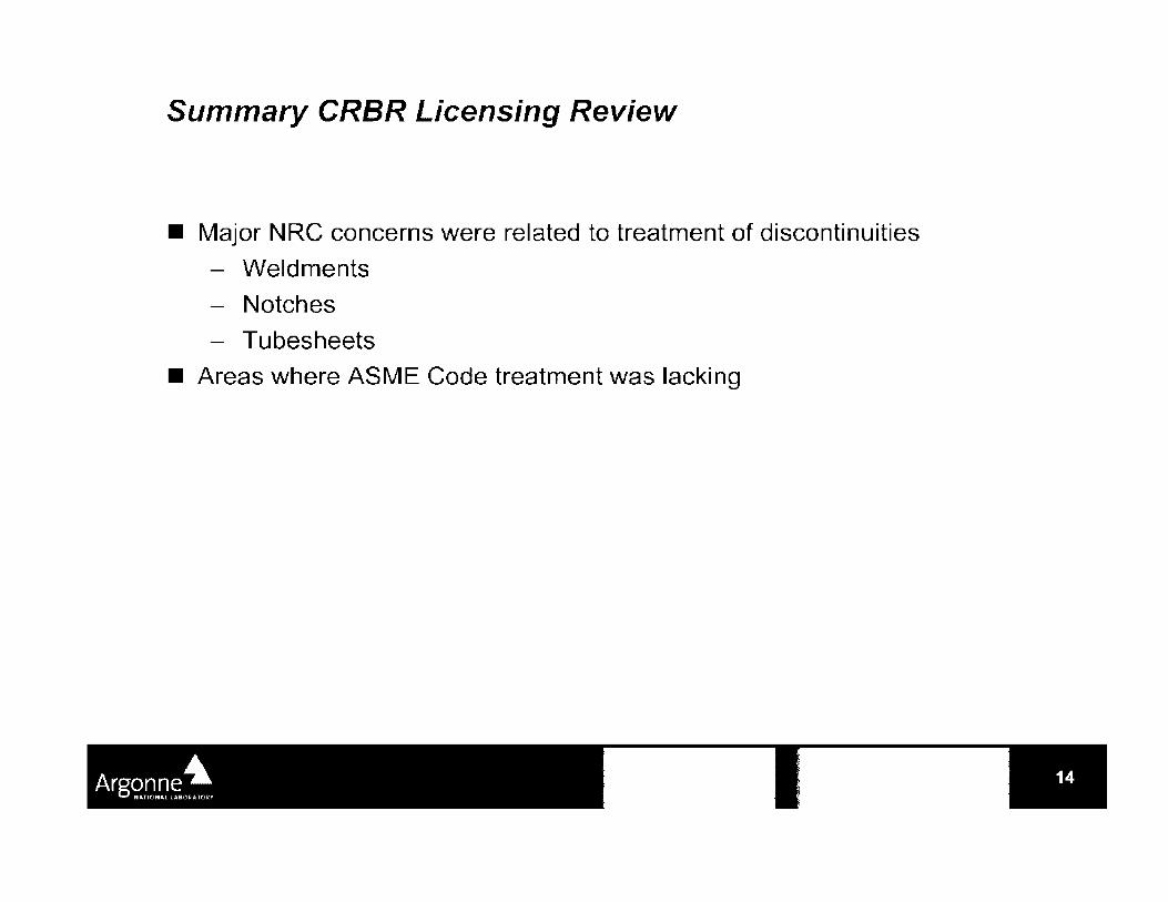
Summary CRBR Licensing Review
• Major NRC concerns were related to treatment of discontinuities
- Weldments
- Notches
- Tubesheets
• Areas where ASME Code treatment was lacking

Current Safety Issues for Structural Design of VHTR and Gen-IV Reactors
• Evaluate Materials and design bases in ASME Code Case N-47 (NUREG/CR-5955, 1993)
- Identify issues that must be resolved in order to avoid creep rupture, creep-fatigue, creep ratcheting and creep buckling
- Advanced LMRs, gas-cooled reactors and CANDU reactors
- 23 issues were identified. Most important issues are
• Lack of materials design allowable data for 60yr life
• Degradation of properties - long-term radiation, corrosion at high temperatures
• Lack of validated thermal striping design methodology
• Reliable creep-fatigue and ratcheting design rules
• Lack of validated weldment design methodology
• Lack of flaw assessment procedure
• Lack of inelastic deign procedure for piping
• Lack of validation of notch weakening effect

Current Safety Issues for Structural Design of VHTR and Gen-IV Reactors (Cont'd)
• Pre-application safety evaluation of power reactor innovative small module (PRISM) LMR (NUREG-1368,1994)
• NRC concerned primarily with
- inelastic and limit analyses
- Extrapolation of Code Case N4 7 design allowables from 34 to 60 yrs.
- Environmental issues related to stress corrosion, flowing sodium effects and irradiation embrittlement
- Weld between core support structure and the RV
- Neutron Embrittlement for RV with 60 yr design life

Review and Assessment of Existing Design Codes for HTGRs (NUREG-CR/6816, 2003)
• Most of the materials needed for HTGR (Alloy 617, 9Cr-1 Mo-V*, Hastelloy X) are not included Subsection NH
• The Code materials that are acceptable for HTGR need to have their upper temperature limit extended to 850°C
• Subsection NH rules are written for materials with classical creep curve (primary, secondary and tertiary). HTGR materials do not show such a behavior
• Advanced unified constitutive equations (no distinction between creep and plastic strain) are needed for the HTGR materials
• The effects of impure helium on fatigue and creep-fatigue properties are needed
• Draft Code Case for Alloy 617 needs to be completed
• Need a more suitable damage theory for creep-fatigue than linear damage rule

Materials Behavior in HTGR Environment (NUREGICR-6824, 2003)
• Among the three materials for high temperature application in HTGR -Alloys 800H and 617 and Hastelloy X - only Alloy 800H is code certified up to 760°C and 34 yrs.
- Substantial database exists for Alloys 800H and 617
- Limited database for Hastelloy X
• Need data on effects of contaminated helium (at pressure) on properties
• Structural alloys can be corroded by gaseous impurities in helium
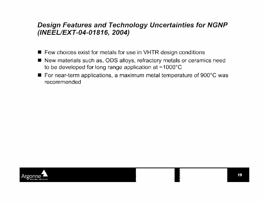
Design Features and Technology Uncertainties for NGNP (INEEL/EXT-04-01816, 2004)
• Few choices exist for metals for use in VHTR design conditions
• New materials such as, ODS alloys, refractory metals or ceramics need to be developed for long range application at --1000°C
• For near-term applications, a maximum metal temperature of 900°C was recommended

Framework for Development of Risk-Informed Alternative to 10 CFR Part 50 (NUREG-1860, 2006)
• Report documents a technical basis to support the development of a risk-informed and performance-based process for licensing of future reactors
- Provides broad guidance for safety review
- Does not provide guidance for codes and standards
- The evaluation approach relies heavily on PRA
- Does not imply that structural design codes be based on PRA
• Code assessment results should be in a form that allows PRA of individual components.

How Regulatory Issues are Addressed in ASME Code
• A new Division 5 of the ASME code has been established to handle HTGRs and LMRs (GEN IV Systems)
- Materials creep behavior, creep-fatigue, environment effect
• Improve structural analysis methods for cyclic loading at high temperatures
• Negligible creep curves
- Structural Integrity of Welds
• Allowable life and ductility limits are reduced at welds
• Need to account for material variability within the weld and HAZ
- Development and verification of simplified design analysis methods
• Need new validated methods for HTGR applications
- Verification testing
• Will need component testing to validate VHTR designs

ASME Code - In-Service Inspection Issues
• A special Working Group has been set up to look at ISi issues (T. Lupold is a member)
- Developing requirements for HTGRs
- Reliability Integrity Management program (RIM)
• risk based program combined with some deterministic inspection requirements
• the designer/owner of the plant has to establish reliability requirements for the systems/components
• ISi established to meet those requirements
• The idea is to change the design during the design phase if the reliability requirements cannot be met by the available inspection techniques
- RIM is still in a developmental stage
- Preliminary version is available in ADAMS
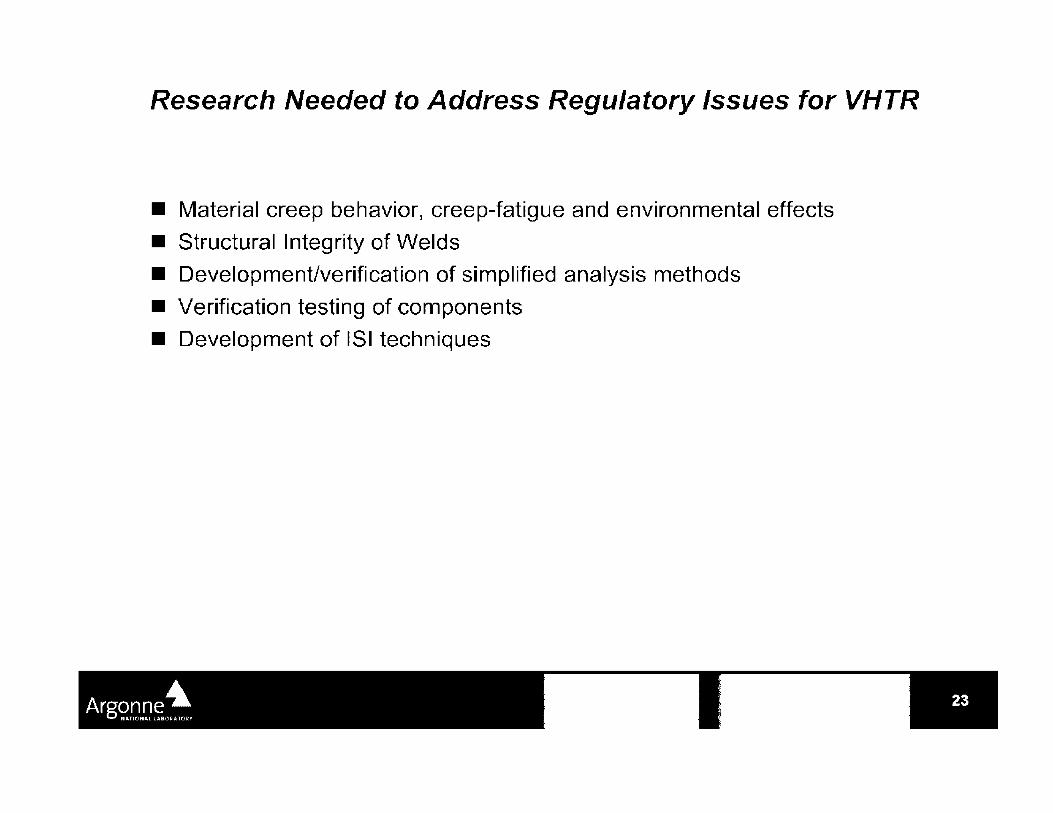
Research Needed to Address Regulatory Issues for VHTR
• Material creep behavior, creep-fatigue and environmental effects
• Structural Integrity of Welds
• Development/verification of simplified analysis methods
• Verification testing of components
• Development of ISi techniques

-t·u.S.NRC l 0 ~l:l. 0 l! .,,.ar.\ ~,,l ~.i1· . .H :1.L~:-.:;.:l • Hl" ;·,,.,.L~TI ••I 11

Outline -t·U.S.NRC
History of LBB
Early application of LBB in regulatory environment
Updates in technology since original SRP 3.6.3
Effects of active degradation (PWSCC) on LBB -Technical and regulatory
xLPR( extremely low probability of rupture) summary and Regulatory plan for LBB

What is LBB? -t·U.S.NRC
Generally, LBB is the demonstration that a postulated flaw will leak and be detected, before catastrophic failure
or ....
Specifically, LBB is the application of fracture mechanics technology to demonstrate that high energy fluid piping is very unlikely to experience doubleended ruptures or their equivalent as longitudinal or diagonal splits
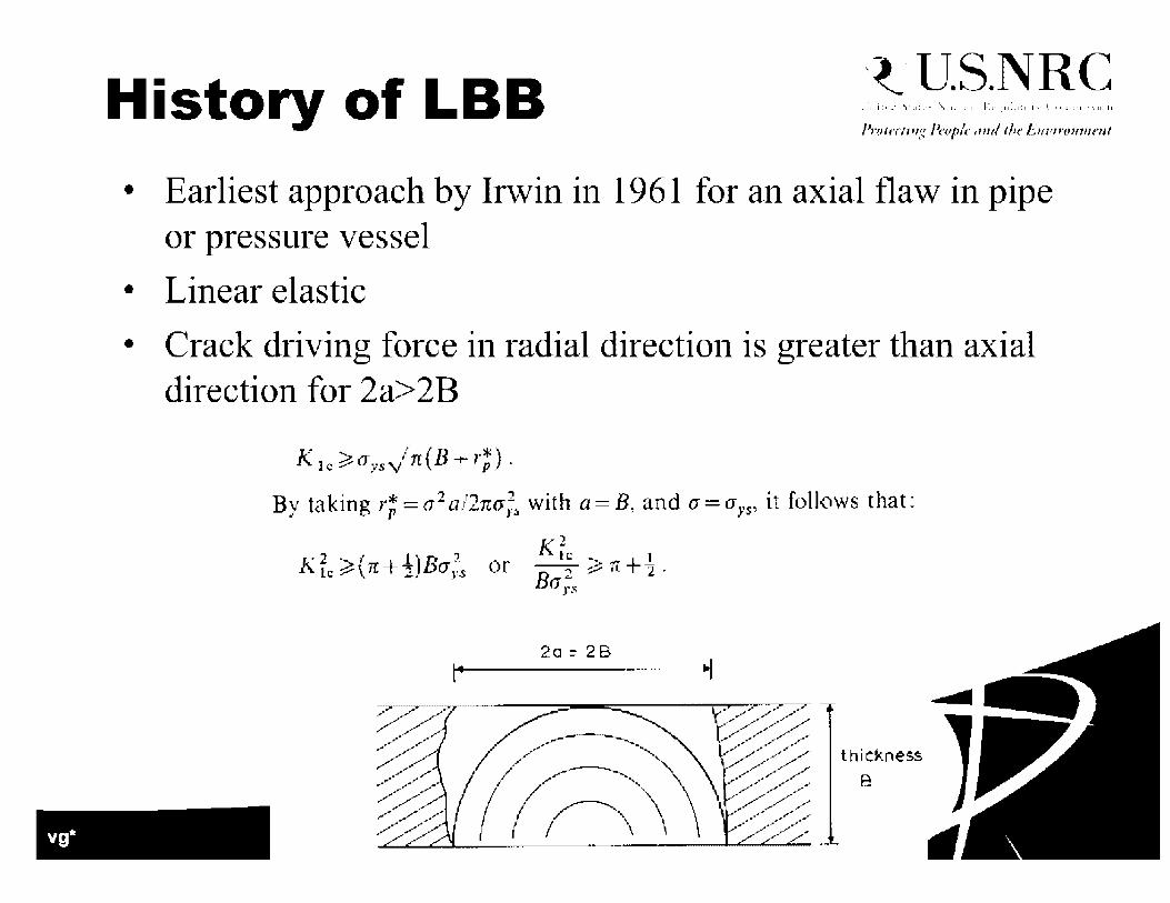
History of LBB -t·U.S.NRC
• Earliest approach by Irwin in 1961 for an axial flaw in pipe or pressure vessel
• Linear elastic
• Crack driving force in radial direction is greater than axial direction for 2a>2B
K le ?<I;,s,/n(B + r;).
By taking r;=a 2 a/1nu;:. with a=B~ and a=a>·s, it follows that:
Kf1:~(n+½)Bo-_;5 or Kie L -B 2 ~n+~.
<1ys
2a = 2B .. I

History of LBB -t·U.S.NRC
Battelle work by Duffy, Eiber, Kiefner and Maxey assumed ductile fracture behavior of axial thin-wall gas pipelines (1960's), then nuclear pipe for USAEC (late 1960's and early 1970's)
Failure stress Flow stress
. ;, ,---- . ---- - ---- ·-- ----
I '~~--•-~ •- - ·-- ~ -· ~ ----- -·~-, ....... , •-------- -- ----.- ----+--·-+ -• • ----+----+· ·• -!....,. :, r
•, \' ':':.-:-.. --•- - -- - ----- '
\ \ .... iif:t:----- -- ---•-- ---- ·--•-- •-•- . . ,- cc \ \'I; ---..;.:~_-A--,._ .. ___ ,I '.
,; i; r- \ ··.. · '-~~----.... _ · Break I ', '•, ----- --...... __ _..,___ •
\ ·-. ~--- -,t, -- ~ -·• \ •.. .....__ ~---•--....,,·- -\ ....... __ .' • - _,.__ __ ,l ;1.' ,:: C
\ ---- ......_____ .· ,' ;-, r •~ --.__ • .......__.._ . ... ' . ,.· . : --..._ _____ ....:.
' ·--------... .:' ------... · --- - - TWC curve ·,,). ,.,,.· -------------------------
,,__ ----•- ---- - a'I r. ,=, "'-A;; ----------., Leak
---'.i.: -- ----
---... ----~-------- -1'- - ~------ - -• "'. -~ '1
: ---- . ------ . •-- ..
., r, "
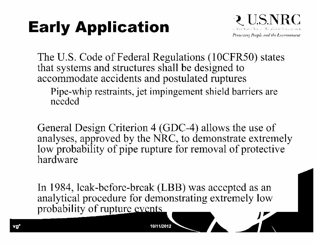
Early Application -t·U.S.NRC
The U.S. Code of Federal Regulations (10CFR50) states that systems and structures shall be designed to accommodate accidents and postulated ruptures
Pipe-whip restraints, jet impingement shield barriers are needed
General Design Criterion 4 (GDC-4) allows the use of analyses, approved by the NRC, to demonstrate extremely low probability of pipe rupture for removal of protective hardware
In 1984, leak-before-break (LBB) was accepted as an analytical procedure for demonstrating extremely low probability of rupture J ,,.
~~

NUREG-1061 -t·U.S.NRC
In 1984, a five volume report was published on a review of the NRC requirements in the area of nuclear
• • p1p1ng
Volume 3 of this document reviews the evaluation of potential to pipe breaks
Gives recommendation for application of LBB in the NRC licensing process
The conclusions and recommendations from this volume were implemented into Standard Review Plan on LBB (3.6.3) in 1987

m ·c: G) ....., ·c (.) C) C •-c G)
~ 0
CIJ
SRP 3.6.3 -t·U.S.NRC
The SRP is applicable to Class 1 piping with the following caveats:
Must be applied to entire system Cannot be used for piping susceptible to SCC, erosion-corrosion, creep, etc. (i.e., no degradation mechanisms that can cause long surface cracks) Pipes with weld overlays cannot be considered (removed in later version) Systems with a history of fatigue cracking cannot be considered Pipe with likely water hammer are not considered Piping systems with possible brittle fracture are not considered Indirect failure must be shown not to cause rupture
SRP 3.6.3 was revised in 2007 to include Alloy 690/52/152 and overlays
"Alloy 690/52/152 material is not currently considered . ~BB .
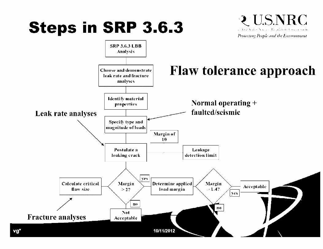
Steps -1n
Leak rate analyses
Cnlculutc cl'itical Daw size
/ Fracture analyses
SRP 3.6.3 -t·U.S.NRC
SRP 3.6.J LBB Anal~'sis
Choose am.I demono,trute leak ralt' and fracture
analyses
Iden ti~'" material properties
Flaw tolerance approach
Sped(,· •~·pe and ----magnitude ofloads
Normal operating + faulted/seismic
Postulate a leakin~ t·rack
\fargin of 10
Leakage dt'lection limit
Deh'rmi11e applied load margin

Defense in Depth -t·U.S.NRC
ECCS is designed to handle break in the largest piping in RCS
ASME Section III and screening criteria in SRP3.6.3 provide assurance of extremely low probability events
LBB analyses provide defense in depth against rupture or large break opening to ensure confidence that the probability of pipe rupture is extremely low

US Accepted LBB -t·U.S.NRC
Accepted LBB applications in U.S. (All PWRs)
SYSTEM NUMBER OF APPROVALS
Primary Coolant Loop (Hot & Cold Legs)
76
Pressurizer Surge Lines
14
Safety Injection Accumulator Lines
11
ResiJlwrR~IIMfflal N<!IJvE Susceptibility to IGSCC Not Adequately Addressed
9 Few requests for LBB
Safety Injection Charging Lines ~
Recent Research Since 'tU.S.NRC Original SRP 3.6.3 Factors that affect leakage size cracks
Crack morphology Restraint of pressure-induced bending Welding residual stress
Material Issues Cyclic Effects Dynamic Strain aging PWSCC testing-Alloy 82/182 and Alloy 52/152
Fracture/Stability Issues J-estimation Scheme

Recent Research Since 'tU.S.NRC Original SRP 3.6.3 Factors that affect leakage size cracks
Crack morphology
Restraint of pressure-induced bending
Welding residual stress
Material Issues Cyclic Effects
Dynamic Strain aging
PWSCC testing - Alloy 82/182 and Alloy 52/152
Fracture/Stability Issues J-estimation Scheme

Crack Morphology Parameters
Using ISCCC or PWSCC morphology, leaking crack length at same leak rate can by 89% longer than when air fatigue is assumed
a a _L9. •
. ""';. . . ..,_ -
;,,,,--. - -- .... --.:.. _---./ ___ ,.. ........ ....,__
.•-.·
E 450 E :ii 400 u ~ 350 u C .!:! 300 II)
0 t: 250 0 u c,, 200 .5 .K Ill 150 .!! o 100 J::. .. g' 50 Q)
...J 0
PWSCC -weld
(growth parallel to
dendnt1c grain)
IGSCC
y = 1 89x
y "' 1 69x
-t·U.S.NRC
0 25 50 75 100 125 150 175 200 225 250
Air fatigue crack sec Alloy 82/182 crack Length of leaking air-fatigue crack, mm
Current leak rate analyses have limited ~~ation with S~~ and thus have large uncertainties

Welding Residual Stress
-t·U.S.NRC
Through thickness welding residual stresses can affect the 1 , o ~_,=l"""""-T~-~:~
crack opening area t , f~ :r--c-c--<:> · ~ 0.9- f ~-~ e 4
Crack-face closure due to the through i 1 1 _ i 0.8 . i
-wall bending residual stresses (thin- ~ f _/ wall pipes), ~ 0·1 : f'
Non-elliptical opening (assumed in many leak-rate calculations), and
~ I ~ 06 -.....
"' ,•, C: 0,;;; i _..., 'Ji
j 0.4 -
1 ~ 0.3 1-{g I a: • 0 2 -ra . i::.i ~ -
0.1 i
I I
('
r
I
l I
I I
, --C- Thin Pipe 1 -A-· Thick Pipe Through-wall residual stress
distribution being a function of weld preparation geometry, total number of passes, start-stop locations, and the bulk heat input.
0.0 -· ----'--Jo-----~----"--........_ _ _. 0 20 40 60 80 100 120
Ap;;ilied Mor1er-it, % at SeNice Level A

Dissimilar Metal Welds -t·U.S.NRC
Most stability calculation for cracks in weld were developed for base metal
DM weld connects stainless and carbon steel with nickel-based welds
Modification of analyses needed
Used FE analyses for development
Used experiments for validation
1,:ou ----------. - - -,, .... .... . • l-HJ
1200 ................................. .,. ................................................................................ ~ ........ .,_ ............................................................................................. . . ....
I
1000 ·
~ ,,. : '. I l. L :; D ::: :,
~ .;(J11 • I •.. c: ;] • I .. 5 ~ c ' '"'I' ·. - LI J , ... ~i ~ ;-·" - - - - - - .. .. - - - - -E (100 .. f; ...... ..-c.- ... D"',lflll,.. .!7-' T"t''C . ... -.... -: .. ·: ... ·····- -· •~:· 0 . .,.. ........ u .J' I. .. ~
Ill , .. :'!: ,
-; , .. :'.IQ(I. ~ !
p' 2(1(.1
D\-Wlll .. Jr .. TViiC
- - - L8:UN1,2 <;<,
- · - LBtl.LNG2 {.':,
• 120
• lOUE
z ... •RO~
C ~
E bO ~
• 20
• (I
2 .; (, 8 10 12 1.: Rotation, deg
~ ____.,,.
LBB Regulation Guide -t·U.S.NRC
Technical basis for LBB Regulatory Guide (NUREG/CR-6765) was published in May 2002
Suggested tiered approach to LBB
Draft Regulation guide followed
With the occurrence of PWSCC in previously approved LBB lines, LBB Regulation Guide was put on hold

PWSCC and LBB
SRP 3.6.3 stipulates that no active degradation is allowed
LBB analyses assumes idealized through-wall crack for leakage and stability calculations -Flaws could grow non-idealized
Current LBB analyses may be non-conservative for this type of behavior
-t·U.S.NRC

PWSCC Experiments -t·U.S.NRC
..... ll". ·-,=
• - ... .c •. .t.-1, ... \.. •:•:ill'-.r:::-10::•1•~
·11:.:-.1111 .. ::. ( (-1,e-. xnl uic
~ ~-E-C9 +----+-------+--- -+---=--+--=--+----+-----1
.;;;; ·--~ :., ... :!I:! • E 1· ;:i::; - • - 1_1 -t::-:=-==-=:-:::f,==-::=-il:t'-:-=:!:-=-~=-==-;.;;.-=-::..;1~:1::::-:~'=-:::-:::l-:=-==-=::'c-l::==-:::-=::I
..i:::: "; .,.. -t:. .. ..... ~ ~-E-L ::c ... -
1 E-07
Ill 1 E-08 E E
Cl'. L?
1E-OH (.)
1 E-10
---~---·--- __ i ___ .. -: •• --~-------·.. I I
I ,_-•-- I
• ...-t•_.. I I I I I ~ _
-r.,. __ .,,,.,. _: _________ : ... ________ : ________ ~-- __ -""'; ..... - ----:----___ _ I I I ___ ,,....- I ~
I _1- - - I , ~ I - _ _..,.,. I _...,-
-~- I .> ...- I C,..
I ,, I
i'.:. '' I
.,,,,, / I J. I I ~ . ~ • - -
-~ .... - - --·- -- - -- - - ,.. -- -;r;-- - --·- -- - -- ___ • ________ ....... -~----·~---~
~ : :~-"' : ___ -~ · ·· --P,WllSAlloy 1B I f ",-- I
I J •• - I I ----A 132/10 I 4· I I
I. I I - - -Al82/100 .·•1 I I I
, /I 18" '1000 ___ .-,;:; __ •-:-•--•-t•-:-•--•--•-:••-••--•••t:::::.-=-- -• • -+ ,• .L.,I
.- , , 1 •• - - • - • ·' ,, Ffll'.l 2 5hr : • L. ---~··i ~ · 1 -·•1 1 AIN..24hr
• • ~-•- : : I - ~ I I I I
--~-----~--------~-------~--------~--------•' I I I I I I I I
•
A'N. constant
Alli. coostant
GE25hr
GE24hr ~-...111.; .i.: .i..11, 111• 11-.:1-.11,;• 111
: ~11 i,~ 111:I: .:-i · L:.:. 1~- i:: 1
~ .E-1.: +--------t-----+-----1---+----+---1-----1 1.E-·11 +----+---+----+---+---....,---+----•--
0 1n ~8 ~o ~G ~n 60 ~c :-,tre-:-:- I11iten'iit;',· f ;1,rt-o1·~ K C.IP:t\;ml
Alloy 82/182
s
On average Alloy 52/152 crack growth is ,..,_ Testing of Alloy 52/152 still underway!
10 20 30 40 50 60 70 80

Regulatory Impact -t·U.S.NRC
Due to PWSCC in susceptible butt welds, the industry developed and released MRP-139, which described the mitigation and inspection efforts to mitigate PWSCC
NRR released R!S2008-25, which stated that MRP-139 provided adequate protection of public health and safety for addressing PWSCC in butt welds for the near term
NRR released RIS2010-07, which reminded licensees that a weld overlay in a piping system approved for LBB may affect the design basis of the plant and may
· · re~

Long Term -t·U.S.NRC
For the near term, PWSCC in LBB lines with mitigation and augmented inspection are acceptable
For the long term, quantitatively assess compliance with 1 0CFR50App-A GDC-4. Include the effects of active degradation, mitigation, inspection, leak detection, uncertainty, etc.
RES is developing the xLPR modular probabilistic fracture mechanics code in cooperation with EPRI through an addendum to the Memorandum of Understanding

\
xLPR Timeline
xLPR T• cw&.e
Short term Mitigation/inspection ____ !'--------,, {
MRP-139
Wolf Cledi:
RIS2010--07
50_55a _ 50_5~ -CC729. OCTI0-1 CC7l2
Jell
-t·U.S.NRC
Long term xLPR generic code ___ ! __ -----., (
Jell Jell
I.BB fllfP)Jai..,_>
xlP.R. Vl rJlll!ll.de
I.BB~ Goidelkaft
RIS200B-25 ::xIPR. pilol aJll!lldr::
y I J
PWSCC emergent issue Medium term xLPR piping

xLPR Technical Flow -t·U.S.NRC • ·1 i:~·J \•a:.··. \.J. :·.1· h:i·,:11:.1~1 1·.· { •il:1::1 ,-.,11 II
Loads
• Ii~•-Material Properties
--.... _ .. / I . ·:-:: :."-·'.-;_ • ' ·,,; ', .... ~. I'
jJ;;'ii Crack Mechanism :~·-· ~ __ _
--. ' ..
(
\
/'rnin-iing l'n.1pk 111ul tin· Lnz,inmmmt
(
i I Nozzle
. I ·•-.. ,-. __ --·:_--' - - . '
_Leakage -------LILi+

Benefits of xLPR Quantified solution to LBB issue
Regulation guide
Update to SRP3.6.3
-t·U.S.NRC
Fully QA'ed modular probabilistic fracture mechanics code for reactor pressure boundary integrity
LBB including evaluation of mitigation for DM welds
Research tool for prioritization
TBS- 50.46a
Risk inf armed ISi
GSI 191
Easily adaptable to other applications CRDM ejection probabilities
RPV

Path Forward -t·U.S.NRC
Version 2.0 Development underway
Ongoing meetings ACRS meeting - March 2012 (yearly updates to subcommittee) NRC and EPRI Management ( as needed) External reviews (annually) Internal reviews (bi-annually)
Version 2.0 release - End 2013
Technical basis and Re

Questions?
~ .. -~
__ Q ~ rt ----- "> .. -~ r-
.
/ ~ I
( ~
-t·U.S.NRC • ·, i :,·.l \·a: .... \ , ... 1 • h: .. · • ( . . . i .• 11 .. 1.1 I·.· I 11:1 ::1 '-..11 II
/'rnin-iing l'n.1pk 111ul tin· Lnz,inmmmt

-t·u.S.NRC l 0 ~l:l. 0 l! .,,.ar.\ ~,,l ~.i1· . .H :1.L~:-.:;.:l • Hl" ;·,,.,.L~TI ••I 11

Objectives -t·U.S.NRC
• In this presentation, you will learn: - What is fatigue?
- How is fatigue measured?
- What is environmentally assisted fatigue (EAF)?
- Why is the NRC interested in EAF? • Background - where did EAF requirements come from and why?
- Methodology for EAF assessment
- Current NRC requirements • License Renewal
• New Reactors
- Future NRC Requirements
- What is the ASME Code doing on EAF?
- Other questions
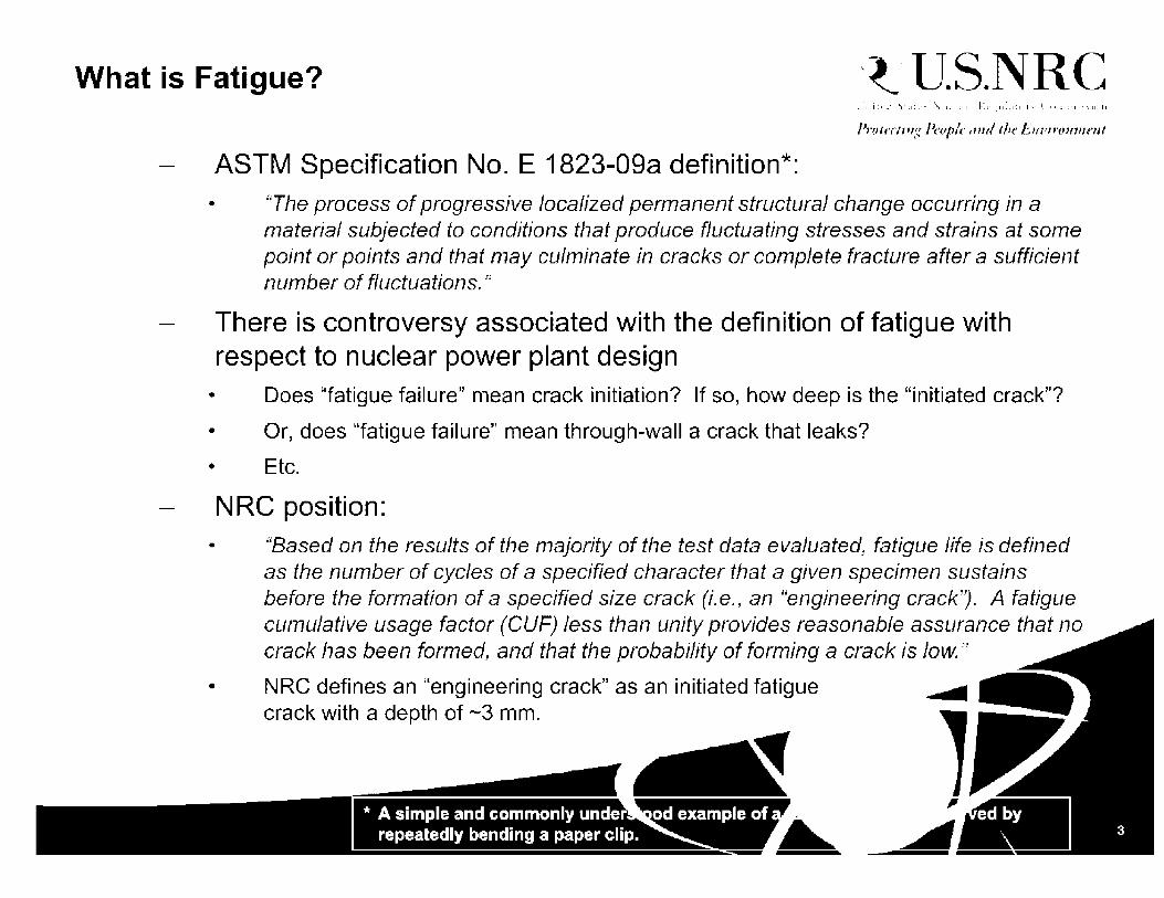
What is Fatigue? -t·U.S.NRC
ASTM Specification No. E 1823-09a definition*: • "The process of progressive localized permanent structural change occurring in a
material subjected to conditions that produce fluctuating stresses and strains at some point or points and that may culminate in cracks or complete fracture after a sufficient number of fluctuations."
There is controversy associated with the definition of fatigue with respect to nuclear power plant design
• Does "fatigue failure" mean crack initiation? If so, how deep is the "initiated crack"?
• Or, does "fatigue failure" mean through-wall a crack that leaks?
• Etc.
NRC position: • "Based on the results of the majority of the test data evaluated, fatigue life is defined
as the number of cycles of a specified character that a given specimen sustains before the formation of a specified size crack (i.e., an "engineering crack'J. A fatigue cumulative usage factor (CUF) less than unity provides reasonable assurance that no
•
crack has been formed, and that the probability of forming a crack is low. "
NRC defines an "engineering crack" as an initiated fatigue crack with a depth of ~3 mm.
* A simple and commonly under repeatedly bending a paper clip.
......
l /fl
ed by _.JIii __ _

How is Fatigue Measured? -t·U.S.NRC
For nuclear plant design, fatigue is "measured" (calculated) using a variable called "cumulative usage factor," or CUF:
Cl/I-"= Li ~ n·here: ,, is the applied ,wmher of cycles f vr load i
N is thP allowahlP 1111uil1Pr of cydPs for thl:' stress assodltlPd \.i:ith load i
N is a function of the alternating stress, Sa, applied to a component, and is material dependent (i.e., it is a material property)
S-N curves ("fatigue curves") are given in Mandatory Appendix I to Section 111 of the ASME Code for different materials:
· ~ : ! : : ; ~ I ~ ~I ' I .. , ., . . ·1
. ·i : .. J ............................................ . ... --- .. : .. ~, .. ·::·:-1 . ·1 ....
I - • - ••-••· • - • - - .,_ - ' •• ··-· • • - • ·- .. - • ...... • - • -·+·
' ' I' 'I ' ' '
L ... l .... '. .. ~ ..... :.. . : .. ·--- . . . . .. : . : ... : .... :: .. I I
.. : .:i
.... ..: .:I .::.: I
,,_
·. .... .. ' ' . ' '
• t •. : . ~ .•
S-N curves are always defined in log -log form
.,,, .,.-• m ••""'"'' •••" •,-, ... •,-••, ,.,,,, •••"•- ""'°"""""'•'" H .. ,• N • .,~.,--.••••,-, .... • <~M• '•"•• o, .. , .. ,..,, ,., .... ,.,. .. ~.c,.,,.,m~

What is Environmentally Assisted Fatigue (EAF)? -t·U.S.NRC
The fatigue curves in Section Ill of the ASME Code were developed from laboratory test data from specimens tested in AIR
The AIR test data were used to develop design fatigue curves suitable for design:
• Develop best fit log-log curves for the AIR data for each material type
• Adjust the best fit curves to account for worst-case mean stress effects using the Modified Goodman relationship
• Apply factors* of 2 on stress (Sa) or 20 on cycles (N), whichever is more conservative, to develop AIR design curves for each material ~---------------~
More recent laboratory testing of specimens tested in WATER indicated that the AIR design curves may not adequately define fatigue life for materials exposed to WATER environments:
Note how some of the points for tests in WATER fall below
A • -errp. (C) : <.1:,0 200-250 ,250 JO ,:ppm) : w.05 0.05-1 o •O 2 ~ate 1 %1s;, : ... -0.4 0.001 • 0 01 S 1•,0,1 %:, : ..:0.005 2:0.00:, .a:O 00:,
10.:.
Fatigue Life (Cycles)
A.SME Code Mean Cur,;e
R- A.r
105
/fl cimens vs.

Why is the NRC interested in EAF? -t·U.S.NRC
• Around 1990, the NRC initiated a Fatigue Action Plan: Focus on operating plant fatigue to address several outstanding technical concerns
Arose from early license renewal activities in the 1980s that uncovered potential technical issues for all operating plants
Four basic issues identified: • Older vintage plants
• Environmental effects on fatigue curves
• Generic Issue 78, "Monitoring of Design Basis Transient Fatigue Limits for Reactor Coolant Systems"
- To determine whether transient cycle monitoring is necessary at operating plants
• Actions when CUF exceeds 1.0 - No current regulatory position
- Flaw tolerance analysis
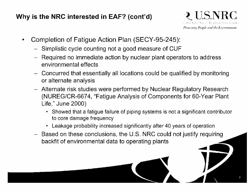
Why is the NRC interested in EAF? (cont'd) -t·U.S.NRC
• Completion of Fatigue Action Plan (SECY-95-245): - Simplistic cycle counting not a good measure of CUF
- Required no immediate action by nuclear plant operators to address environmental effects
- Concurred that essentially all locations could be qualified by monitoring or alternate analysis
- Alternate risk studies were performed by Nuclear Regulatory Research (NUREG/CR-6674, "Fatigue Analysis of Components for 60-Year Plant Life," June 2000)
• Showed that a fatigue failure of piping systems is not a significant contributor to core damage frequency
• Leakage probability increased significantly after 40 years of operation
- Based on these conclusions, the U.S. NRC could not justify requiring backfit of environmental data to operating plants
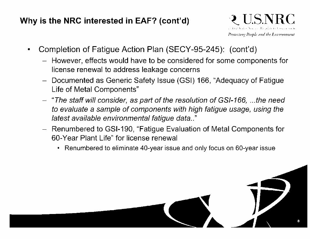
Why is the NRC interested in EAF? (cont'd) -t·U.S.NRC
• Completion of Fatigue Action Plan (SECY-95-245): (cont'd) - However, effects would have to be considered for some components for
license renewal to address leakage concerns
- Documented as Generic Safety Issue (GSI) 166, "Adequacy of Fatigue Life of Metal Components"
- "The staff will consider, as part of the resolution of GSl-166, ... the need to evaluate a sample of components with high fatigue usage, using the latest available environmental fatigue data .. "
- Renumbered to GSl-190, "Fatigue Evaluation of Metal Components for 60-Year Plant Life" for license renewal
• Renumbered to eliminate 40-year issue and only focus on 60-year issue

Methodology for EAF Assessment -t·U.S.NRC
• Initially, the NRC reviewed two methods for incorporating LWR effects; the second method was adopted:
1. Develop new environmental fatigue curves
2. Use of an environmental correction factor, Fen
• Fen is defined as the ratio of fatigue life in air at room temperature to the fatigue life in water at the service temperature:
Fen= Nai/Nwater
• Fen is multiplicative to the calculated fatigue usage in air:
U en = U 1 Fen 1 + U 2 Fen 2 · · · · · Un Fen n > > I
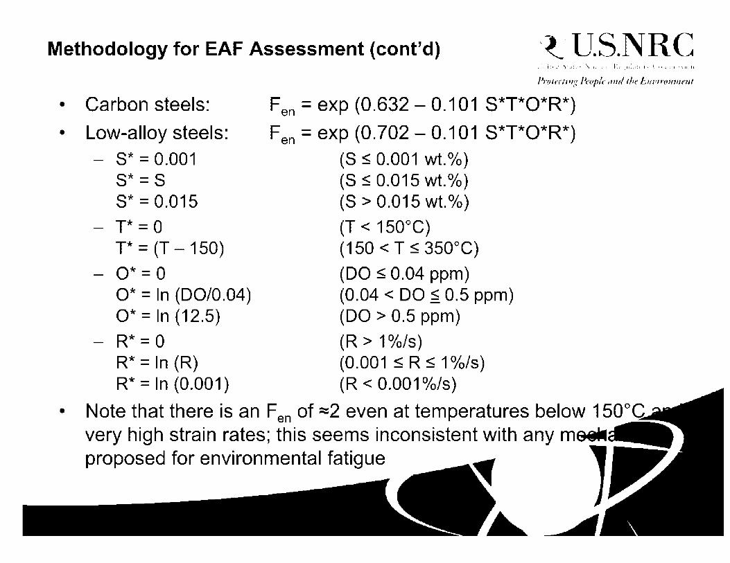
Methodology for EAF Assessment (cont'd) -t·U.S.NRC
• Carbon steels:
• Low-alloy steels: - S* = 0.001
S* = S S* = 0.015
- T* = 0 T* = (T - 150)
- O*= 0 O* = In (DO/0.04) O* = In (12.5)
- R* = 0 R* = In (R) R* = In (0.001)
Fen = exp (0.632 - 0.101 S*T*O*R*)
Fen= exp (0.702- 0.101 S*T*O*R*) (S < 0.001 wt.%) (S < 0.015 wt.%) (S > 0.015 wt.%)
(T < 150°C) (150 < T < 350°C)
(DO < 0.04 ppm) (0.04 < DO < 0.5 ppm) (DO > 0.5 ppm)
(R > 1%/s) (0.001 < R < 1 %/s) (R < 0.001 %/s)
• Note that there is an Fen of =2 even at temperatures below 150°G very high strain rates; this seems inconsistent with any molN proposed for environmental fatigue

Methodology for EAF Assessment (cont'd)
• Stainless steels: - T' = 0
T' = (T - 150 )/ 17 5 T' = 1
- O' = 0.281
- R' = 0 R' = In (R/0.4) R' = In (0.001)
Fen = exp (0. 734 - T' O' R') (T < 150°C) (150 < T < 325°C) (T > 325°C)
{all DO levels)
(R > 0.4%/s) (0.001 < R < 0.4%/s) (R < 0.001 %/s)
-t·U.S.NRC
• Again, an Fen of~ 2 even at temperatures below 150°C and very high strain rates seems inconsistent with any mechanism proposed for environmental fatigue

Methodology for EAF Assessment (cont'd) -t·U.S.NRC
• Ni-Cr-Fe steels: - T' = T/325
T' = 1
- O' = 0.09 0'=0.16
- R' = 0 R' = In (R/5.0) R' = In (0.0004/5.0)
Fen= exp (-T' O' R') (T < 325°C) (T > 325°C)
(NWC BWR water) (PWR or HWC BWR water)
(R > 5.0%/s) (0.0004 < R < 5.0°/o/s) (R < 0.0004°/o/s)
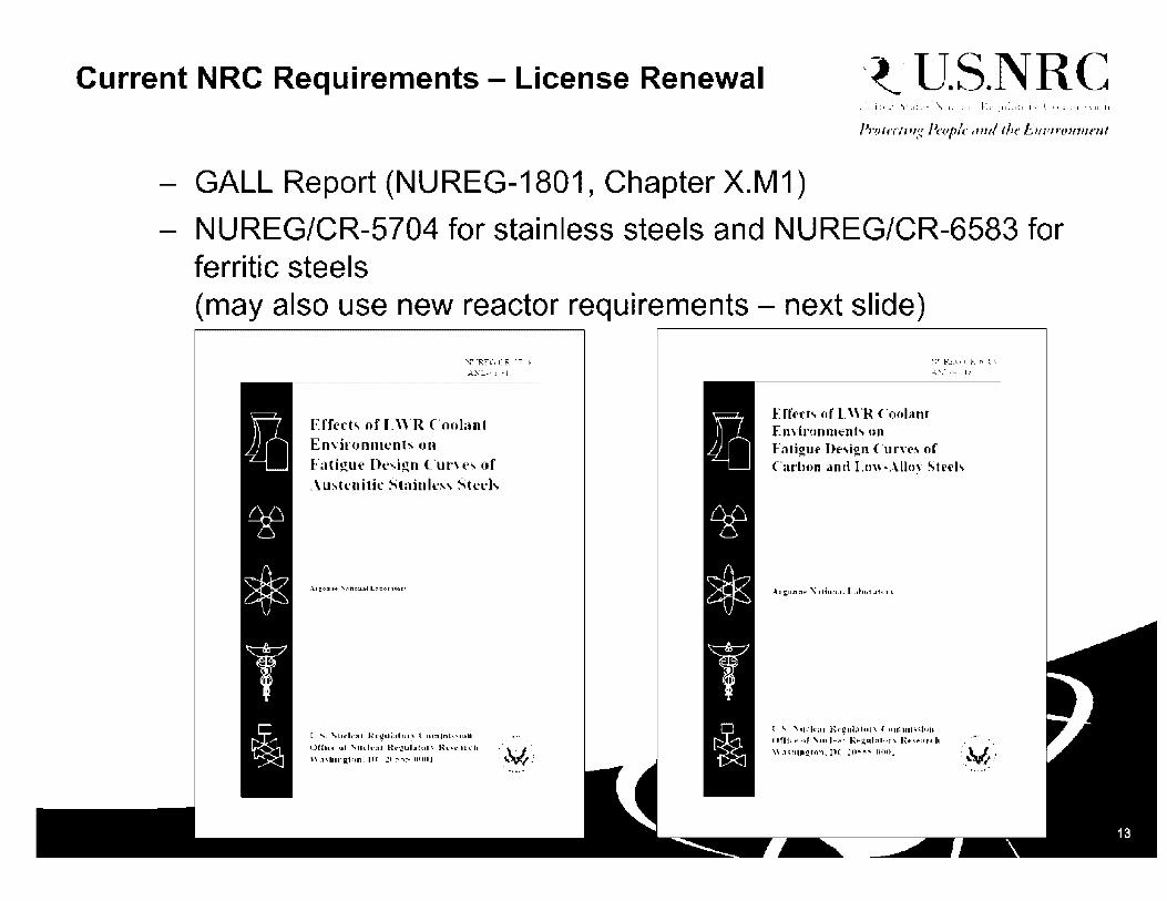
Current NRC Requirements - License Renewal -t·U.S.NRC
GALL Report (NUREG-1801, Chapter X.M 1)
NUREG/CR-5704 for stainless steels and NUREG/CR-6583 for ferritic steels (may also use new reactor requirements - next slide)
i * ,.___
~ . > 'v
~
l ~~
:'--."RH,{R -·:· • A:'.\·:.. ,J ~- .• J
Effect.., nf I.WR Coolant EnYironmcnts m1
Fali~ue Desi~n l"urn!!. of .\m.h'nitk Stainles, Steeh
l ·"""· '.\Ut:lt•~• Rt•\2Ut1hu ~ ( 1Unlnh"lirnU
ornu• ul· '\11i1.h-~u Ri1.•1:!UbJu1, Ki1.•1,,i1.•;Ufh
"~,11in li[ton. ll( :•1~~:' u110 J :M! ' ..
JcJ ~
$ ,)
r i
EUcct!i. or L\\'R Coolant
\."'""RI(, ( R (i"[ l .J.:...::..-.· ].:!
Fatigut> Ue,ign C-urn'"' or C,u•lmn and I.uw-...\lln~· Stl't-b
-~• tun.01 ~ .Ui1J11.,l L.~blti .:if,u1 ~
1·,.;. "'\11.1rlt-;1~ R.-~ul;.llhH\ <o,nun,;,hu, ()frj, f' ... r 'm h•.a~ R.P~1d:lltn\ Rt-",f":Ut h Wa<Jliu~ron. PC :n•;~ ~flf\J

Current NRC Requirements - New Reactors -t·U.S.NRC
Regulatory Guide 1.207
Supporting technical basis documented in NUREG/CR-6909
U.S. NUCLEAR REGULATOR'f COMM1SSION ll.11t.h 2D::"
REGULATORY GUIDE OHICF OF NUCLEAR RFGULATORY RFSEARCH
REGULATORY GUIDE 1.207
GUIDELINES FOR EVA.LUATING FATIGUE ANALYSES INCORPORATING THE LIFE REDUCTION
OF METAL COMPONENTS DUE TO TtlE EFFECTS OF THE LIGHT-WATER REACTOR
ENVIRONMENT FOR NEW REACTORS
, l',lf(OIII I Ill"
• • ~ •. ' I •
. , II:,. ,,I·
!,_ • LI • • , : I !I.- ••• : I •I 1:.. I.. I •
•:I:,• : . 1•• .1. • II
t,_ ·., :, ·1 .• • • : I • I .. •• .~, • ' .·, .. !
.I
.. :- ... ••.• '••I. I ,.1 I• •'•'• i • 1,1:••
.. , '! I,.,.
;I. I I l,:11. I... I .-1' t- 1.-. 11 ', I:,,.
',. , l
'\. I I~ i ~ J L_ 1;. ..... ,. .IJ
\ \.] -11~, I;\.
Effrd of LWR Coolant Enviromm•nt, on tlu.• hlli~m· Lifr of Ml'.ll'tor .'1ah'l'iah,
1 .,. ,u~lr,11 H.t·:.:ol:ilot\ ( 11111111i.,i11n
( •llin ul ,u.-1,,,u· l~•·:.:11b111r~ lh·,•· :,rd1 ",1,hiu:,:11111, 11( ~ll.,._:--011111 (~)
· ... : ... ·
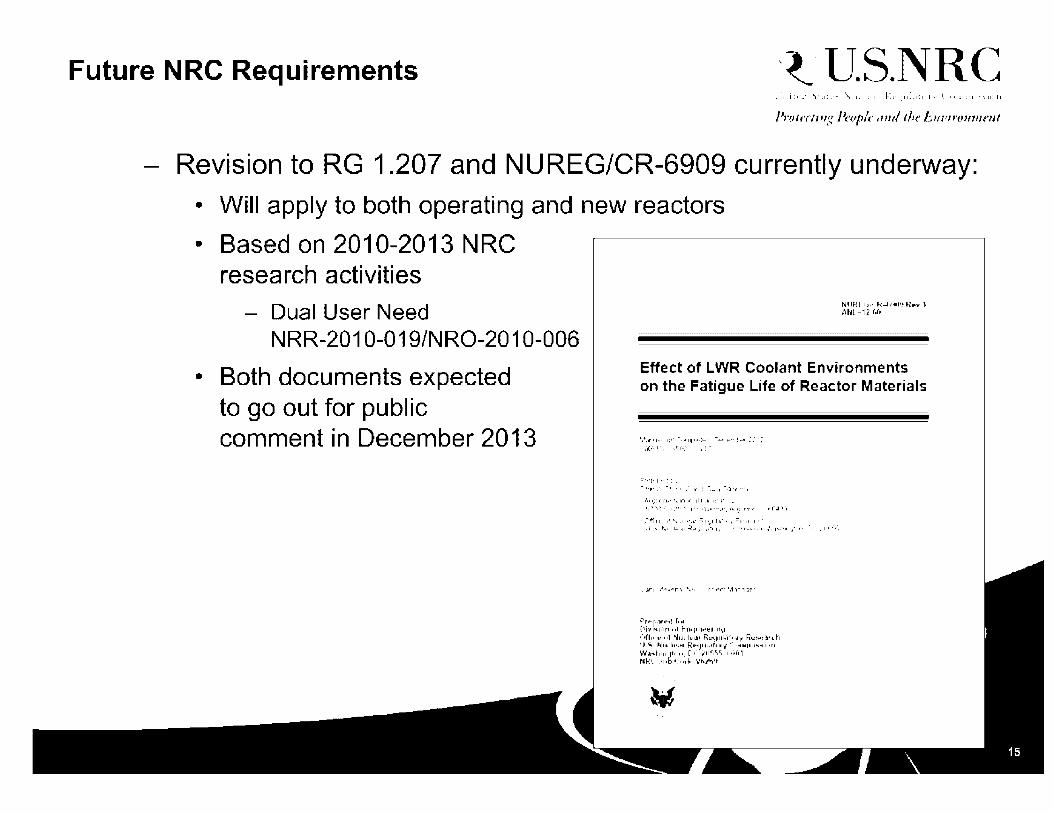
Future NRC Requirements -t·U.S.NRC
Revision to RG 1.207 and NUREG/CR-6909 currently underway:
• Will apply to both operating and new reactors
• Based on 2010-2013 NRC research activities
- Dual User Need NRR-2010-019/NRO-2010-006
• Both documents expected to go out for public comment in December 2013
NUfH 1j1t·R-17·411~~ R•v 1 At.l-1~f,r,
Effect of LWR Coolant Environments on the Fatigue Life of Reactor Materials
·:t.•·-•·.·1,.t-r ... ::-, .•:·
=··••t•I••;:,. '"II' I I I' : ·• : -, : • --~~•••• • ,•
,\1 :_:-: ,1 r•~· t .. ••1 ~- 11 I -•· , ,. 1• • •
!, .... ,-:: .-. ,,"· .. 1·· .• , ........... ,:_ ,_: r•r .. , rnJ1'1
,P~ f' p,Y 'r'd f 1·1,r
{}1·., 1-1,·1-r, ,·,f f-OH•l,o:! .. • 11~~~ ,·,n11·~ 111 Nu-(lt'tli, Rt"~·lll-illT~"-.l'JI R~'!t-i~1lrdl H."- N•.11 .,., . .,. fim•••l.1rt1•v,. ,o111•1u11..,,.,..j.,t, w.1"'t11r1qt,,, •. n(· ,;,11"'1~'i. 11tlt)1 Hl•H .. h,ht_,.,I,,, Vt.Jt-i•t

What is the ASME Code doing on EAF? -t·U.S.NRC
ASME has been struggling with this issue for more than 10 years
From Section Ill, NB-3121, "Corrosion": • Material subject to thinning by corrosion, erosion, mechanical abrasion, or
other environmental effects shall have provision made for these effects during the design or specified life of the component by a suitable increase in or addition to the thickness of the base metal over that determined by the design formulas. Material added or included for these purposes need not be of the same thickness for all areas of the component if different rates of attack are expected for the various areas. It should be noted that the tests on which the design fatigue curves (Figs. 1-9. OJ are based did not include tests in the presence of corrosive environments which might accelerate fatigue failure.

What is the ASME Code doing on EAF? (cont'd) -t·U.S.NRC
ASME Section Ill has published recommended methods for addressing environmental effects in two Code Cases:
• Code Case N-761:
- New fatigue design curves for LWR environments
• Code Case N-792
- Environmental fatigue correction factor Fen method
NRC has not formally endorsed either Code Case
Two other Section Ill Code Cases are under development:
• Flaw Damage Code Case
- Similar to ASME Code, Section XI, Nonmandatory Appendix L
• Strain Rate Code Case
- Provides methods for determining strain rate for the Fen Code Case

Other questions -t·U.S.NRC
- 30+ years of industry experience and no thermal fatigue issues*. What1s the big deal? Why are we imposing this stringent criteria on the industry?
- Is it true that the NRC is not imposing this environmental impact on fatigue uniformly to new reactors?
- Does EAF apply to the RCPB only?
- Is there a difference between BWR and PWR environments? Is it a bounding calculation?

Questions? -t·U.S.NRC
•
Containment Review
Thermal-Hydraulic and Source Term Issues
November 10, 2011

•.r:'' •.: . .-:-·.·, .. _,)_:: ....
-<~}\i;f' . /,., ·,: - -~
•~ • 1 • I • J ,
.~ •• r I ': •'•
r'l-•1_.,. ·1,•
·-~-~~: > ~--:' '-~·-=~ ~ ·.'-. - .·•

Main issue: containment integrity
- Leakage (normal operation) - Breach (abnormal / accident
1• •••t•.11•••••·1
t'ttit-t1••••• ,., .i\u1,i ,,, .1
,._ •'•PJ h•r:I . .-1 ~~ iJllfl••P
A.• ~•.J
;·/ "\ ', \ "\ \ \ ·.
\ \ \
; ....... , ••••• ,111 1
I •• •1ll•II I 1111,"•1 11
........ j.•111-• 1, I 111""''-,. •• I 1• 1 I (( ' r ,-11, ..
. --- I
l .
,i,, .. ~ ...... ,,
I • ..,.,._ ·•w
( ". I ,l<'J"' •. •
I \
I I
I
' • I I
I I
J •
I I i
I
I
' ... a1 . "' I ,., A 'I' "
. ,, ,..-, ._ ...... .,. - -:... ::.; ..
•• ,,I I ·,'•I ''"I~ I
It• ' I I .. 'I"! .. I - ' . . . · .... ,. ... -·
' .,., ...... , , .. 1111 ... ..,. '., '
' u.a. 11 r1.,1t .. 11I I
45
...... 3-5 ~ =9 -:,.-., -..-... ,a)
l; 25
~ 2:• (b)(4)
.S! 15 u.. ....., 1 .... , ....., ... ~ s I: ...
I ... ~ ....
I I
-5 -------------~---time [sec]

NRC regulations for containment - examples:
1. General Design Criterion (GDC) 16 - preserving containment integrity under conditions imposed by postulated LOCAs.
2. GDC 50 - accommodate the calculated P/T without exceeding the design leakage rate
3. GDC 38 - rapid reduction of containment P/T following any LOCA.
4. 10 CFR 50.34(f)(3)(v)(A)(1) - maintain containment integrity assuming H2 burning, as generated from a 100-percent fuel clad metal-water reaction.
5. 10 CFR 52.47(b)(1) - requires a DC application contain the proposed inspections, tests, analyses, and acceptance rritori~ IITA A~,

Fuel Building UFA :'
Large dry: -single or double shell -subatmopheric
Shield Wall (5.9 ft)
Safeguard Building 2+3 WHIUJK/2+3
Typical PWR designs
~,. .arc IQ • .:r-•"'
Ice condenser

Drywell
Drywell to Torus Vent
\ \
\ \
\ ·~
'·--·' 1·
\\ ~ii \
\ ·, \ .. ---:---.~~:-:.-- '-·_:·~:-.:-.
,' j ; ___ .--~-- '-)'., \ '·-. ·-.. _ - ---
... --- - - -
Reactor ,/ __ ,,.. Vessel
Suppression Chamber
\
\ ~- I {._~-.. -- .. :::~ -·i---
·.... ·,-•-;-,'
- Downcomers trD
( 1 )
Drywell
•., / ....
Blowdown
,: 2 i
.------·-·----·-'
]l\".'..-P.I !=:11p:-rP.:::~inn Con:;,nm,nl
' ' I I I ' ' - ia:erle,~1- -·-- i ' ! ' ' ! ! ' I I I
-------• ---·-----------·-1 ------------·---·---------; I I I I I I
i ' I ' ' ·-----------------------------------------1
I ~-~.. I r=B,=ilding~~~~
Downcomer

COntl"Ol I ods
__,.) Hadialion shield and f con1aI11mem s1n1cture
~ Stcain ____ / J separntor
32.70
Typical RBMK ( Chernobyl type)
* 21.50
25 25
FIG. 11-2. Vertical stction through the mnin building of an RBMK unit. including the localization ;:ont. [Numbers refer to itemization of equipment and components in Table 11-Il. Dimensions are gi\'cn in metres.)

SG COMP.ARTMENI
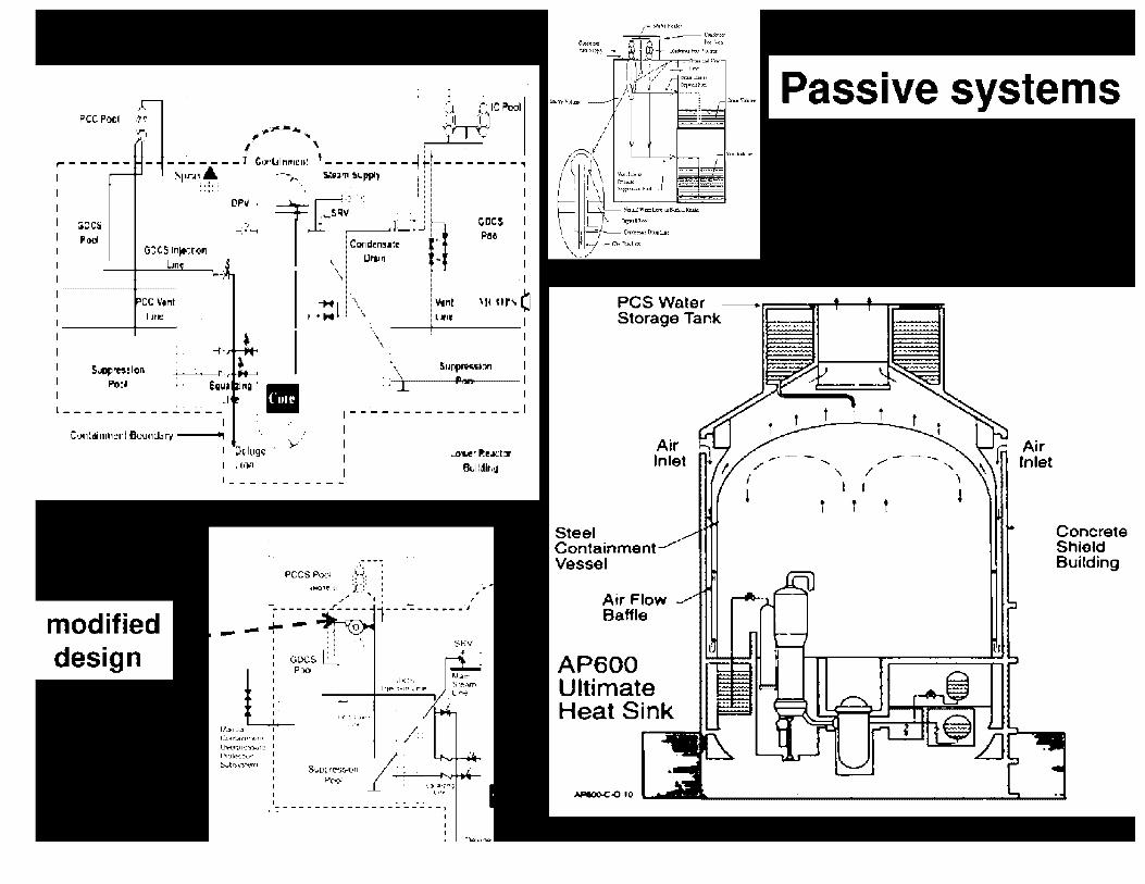
, .... PCC Pool
.1 1 ·J '·1Cl'ool ·: i1 '(~ Y"'r'"T':" :~n ............. .
. f ' ,------- 1 C ~ - - - - - - - - 11·Lll111t1e0' t - _______ 1
!'-i•r..i•_~ ----,.., SlU'II S.1-pPI, --------~
aces Pod
::::: . .,_ .. ·.____,I OP~· 1~~~ic-·,· __
G:::C~ ln)f-:ton Lin
ccv,111 Line
-; /"""' J:_-- . r--_ _.r ~ Car1d,n5al~- •
CiDCS Pll-'1
na · ••
~ Ulllfl • \
\
rH1\ I lwl \
\
I
Vint 'H u,•, Cl L1,1,
--+-----1 \ .
\ .. \ ··I
Silfflor.H:111
hnl I
,--~-------------' Cu11ldi11111e11I Buu,,wr-~ ---
1 Dtlugc ·• ·,.".
I I I I I 1q.,
! __________ ~
.~:--~ PCCS POOl },:: :
4N01E 11 J.~~• :
LaerRe.Kl:ir l'lulldir,11
- ' . - ., t I I ~- -.=..- --_. ---- ,- ---;;. ------"J
u:~· -~--,,,-_._,,-,.-., 1-'::..::'·1•:..;~ ;::::';';,:..:.;~:::::····:.....
~ofJl'II..JII
C.:..r1'!Jr1 1•·it-r11
Uw1;.i1e":1i~rt' 1' /
l',:ilt..-_t•.f'l I ::i..t1')~')."ot"rr1 I
' I ~., ...... ;
l•'.,
I· • ~ - - - - - - - - - - - - - - :. :. _-.:. - -: 11
' I '
SRV
Air Inlet
Steel Containment Vessel
Air Flow Baffle
AP600 Ultimate Heat Sink
H'IOO-C-010
-.. '\ /
I I
t t '
Air Inlet
Concrete Shield Building

~ ...
~ :J II>
"' e o.. (b)(4)
I C
ESBWR Long Term Containment Cooling PCCSr2~
tm1, ,r-, mil:· ·<,I l!aH! ·.!· : ' I mil, ,:· I !:!!ll!I·· 1-l I L'llil_' \' I .... . I
I .,_
MELCOR Drywtll
> 8" ~
:. GOCS, l llPV
MODEL . '
1111111:1 I
1ml lt'i!!i.'lD ~ ~
. m!ll ·-': iii
PCCS(,IM)
,.. ; ---1 'It. '
B l GOC$ I V :zr.l . I. __ .·
'Al LM : ••••• :
•~:··: tf I IIIIII f Wetwell

SWR 1000 Passive Safety Concept J --------
Containment cooling condensers for containment heat removal (4}
SRV for reactor overpressure protection and reactor depressurization (8)
Emergency condensers for heat removal from the RPV {4)
Flooding lines for passive core flooding in the event of LOCA (4)
Passive Outflow Reducer (4)
Drywell flooding line ( event of a core melt accident)
_ _. -·· " r , -, .. _ -, ...
[):·:,.L·; ~c:p~ll.11~11 '1-hll:i~t.~
I'~•• •l
! ' '
Press.ure suppress.ion pooJ
16\.!emp-ip••
I ,--..-. -.r.::r/ ·-·c-·- .,, --]
~,] f--L---___J=::>.L...---'--______ I, t I
Rosiduol b••• rcn1ovul $f$1~1>l
A
n
Re.ai::,or water clean-up •rstcm
FRAMATOME ANP
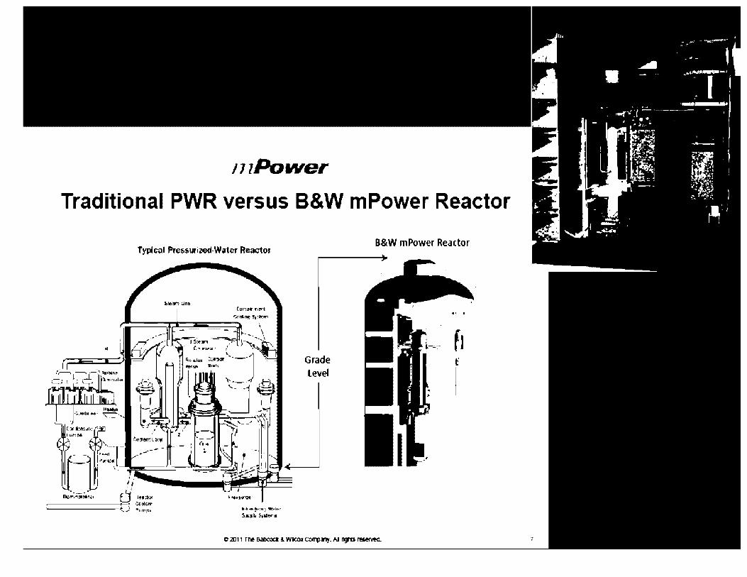
111Power
Traditional PWR versus B&W mPower Reactor
Typlc.il PreHurized-Wator Reactor
li•ll-f,~=1111:, Wl'lhH
!,qi, 5,11«"11
B&W mPower Reactor
·• I
f1 t'
I
7

Power Module • Integrated Reactor
Vessel enclosed in an air evacuated Containment Vessel immersed in a pool of water located below grade.
FECR:a.AllON VN.\U -+-t------t--1HI
CORE ---t+-+-11-t
r-,_ ----------- 1\IRIE --
SlEAM GEMEWJOR
FWPUII' ...,.--..
l,Wt,j~ ll!HTVALV1:
11CFA)"'
'·
Innovative feature:
•
•
N'nWAL~ Z::•--•~••••••• 11 Of ll
RJ:\IENT ,..._ ..... -l-••·-· '1/,tl,LVf
I T 01' .:.1
vacuum between Rx and containment

I NTRO 1----1----14
1 52 (~ANDlJ Re~1cto, ..
Reactor BuUdlnt;
Steam Gener:J,or
P-~, Reoc!or ' \ li!?:!o,
.· -- - ' J .:.~ .... , '
· - I I Clrcu1at1ng , 'Naror , ' I_. ....,. ..... . l , .. __
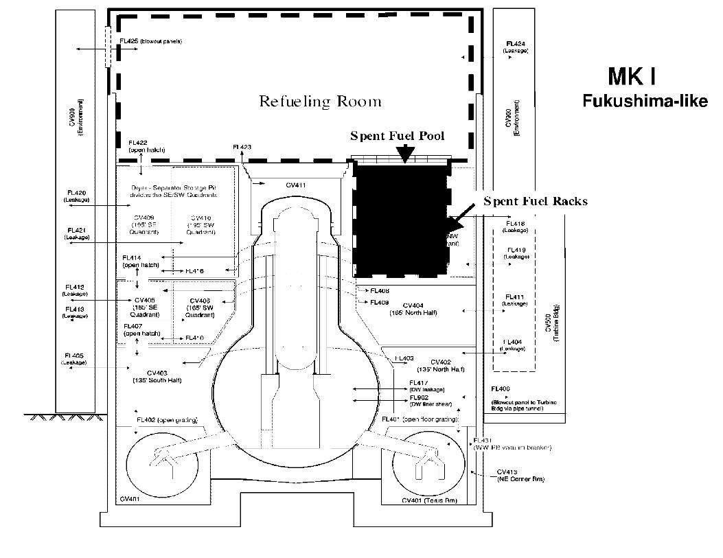
FL420 (Leak&ga)
FL421 (Leakage)
l.r - - -I I I I FL425 (blowout panels) 1,lt-1 I I I I
I
Dryer - Separator Storage Pit dividos tho SEiSW Quadrants
CV409 (195' SE
Quadrant)
FL414
CV410 (195'SW Quadranl)
II I .,.-(open hatch) :; : , , _____ f _______ +--f,--+ FL416 ______ -r
i--- --- .i. ---- ----11-------------------7 ~~-·· FL412
(Leakage) j II ! ,··· __ _.__........,..__ CV405 ii CV406 +-':
(165' SE ii (165' SW ) FL413 (Leakage)
FL405 (Leakage)
Quadrant) : : Quadrant) /
i FL407 ii / ,,l ( open hatch) ii // 1___ t ____ ~ FL410 ___ /.,
CV403 (135' Soulh Half)
.. ______ _,
FL402 (open grating}
+ ---- \ ,·· --------- .. -·
- - - - - - -I FL424
(LeoakageJ
MK I Refueling Rooln Fukushima-like
CV411
__ ..,..,. - - - ... _
_ ........ -
'------·-·
Spent Fuel Pool
,._. FL409 CV404
(165' North Half)
-~3 CV402
Spent Fuel Racks
FL418 (Leakage)
FL419 (Leakage)
FL411 (Leakage)
FL404 _-+-+-+-('-"Leakage)
( 135' North Half)
FL417 __ __.'---I-~ (DW leakage)
----If----+-- FL902 (DW liner shear)
CV401 (Torus Rm)
FL406
(Blowout panel IO Tulblne Bldg via pipe tunnel)
CV413 (NE Corner Rm)

Various vents concepts
Bol:l Rcu·;,;5;,;nts H,11 J!;!·-~~ V!!11l L 11~
PCV Hard Vent
J.,_-----r----- IJ,W V<en!SlllilQbc<e Wall'!!
SIC Verrl !a'jle lle<I! wtlw. ear.i1l!tilr'!-qiP.n-----------·1
I I
' '-
Instrument a,r
(before accide11I)
Special Design for Venting from
\
iE=:::3
~r • .-.+-I
. / . ✓ ~t-A1, ..
t = .. ,· '·"·'" : .~ r- ,..nirj··.-_·:~·...:.,. - - .. r .. ,•jj•1
·. /ll1..r;,., ~ ,· • .. •• 111--1
,. ___ .,. ,\ .,,, 1,.,
Mark I Mark II
I I._Hdened C:unt<1inrnenl Vrnting Sy-;tr.m
I " . - _// .. ~~~:,~~·: :y--~ . . '·t! .. .
··· : .... r..-.,i::;i:o.-i:: •
-, ......... ,, ....
Mark Ill
·,
I I

Containment behavior:
Containment integrity challenged by excessive P / T
Mass and Energy released during an accident THE leading factor
Flow distribution affected by multi-compartmentalization
Long(-er) term effects: ESF heat removal and heat structures
Steam condensation major means for decrease of P / T: - Suppression pools [hydrodynamic loads] and sprays
Passive feature ...... l<b_)<4_) ______ __,l(need active "help" after "peak" pressure at 72 hours)
Containment thermodynamics (and -hydraulics) involve complex phenomena; requires experimental data to support (semi-)empirical models
Traditional conservative approach: 1-node, Tagami/ Uchida correlations - acceptable for active system, may not for passive and/or other advanced designs

Air ---+-I Coolers
Floor
Core Flood Tank
'----
Heat Exchanger

• FL 68 • Ul)IM't
P1Hlum CV22
• • ~ :;, it ~ • • c::v ,.
le• Cond.
• FL27
• CV 14
·• ~ ~ ..
. ' Cl/011 •
•
C\103
SlumC..n. R0cn1
FAN . FL 0~
• A. 71172 C\109
• fL !i3 •
.FL20• . L.....,,
AnmAus
FL 79 . .
Sequoyah
Lo"M""r Cont,11nn1tnl
Ice Condenser Plant
•
C\102,t
U~•Oo""'
FL05
CII01
Pr•s•uri.mr Room
FLU •
"' "' Fl 12 • 111•.aic:tct Uppe1
FL TS • C••lly
. • FL02 .
fL Oi
CVOI
•
• FL 68 • Upper
Plenum CV 22 • • ;,; ~ if. it. • •
• C\/Ol CV 1e
• Fl.$1
Fl.O7
ko S.•• m Gen. Cllftd.
111:00hl
. FLO&
• 4
Fl. 27
• CV I<!,
• FL 11 ~ • • " • FL<!,9 •
CVOB FL 73 · •
LO I C\/011 FL 47 a ,,,.
Cot'l'l,0Ur1mirr1t • FL 48 .,
e FL 17 •
· Fl98
Fl II a L..-1 Annulu:1-
Environment ..
• Using control volume elements, dynamic response models of complex systems can be developed
•
Containment Reactor vessel Core internals Steam gen era tors ...
Specialized physics modules account for special features
Core heatup Zr oxidation and H2
Fission product release H2 Burn models Many more

l .....
.... .... r.: '.
. ~ I
t ... .. I
(! I ... -·· !: " -.
-~~ I
- •• •"' J • I ,,.L.
-" .-:, -· ~ .I'
I
. 1.,,,,. ~ '7-::
•
:-. ,,
0Ba1lelle· ~J:L'l~l,IJ" rr..!~~l~•,.i,.-r-,~ L.Jb1 tt., lnnr-i.
l:..1 ilt.J 1.J. ~\ il•fil.JIJ!ll'ft ~n~·
AEC Research· atid • • • I
D~opment Repon
· BiNWL-1~ OC-41
~-} ·- ~~ ·]"--------........ -------• • I I
I •
• ....:. I • -
0 - " ~. . . -CCXf A~ ~YSIFMS-_Ef Pmt.MINL-i · .. :-
- • • • •
FINM, ~SIJltWMY • I
.. I ..
•• I . . . .. •••• •
• I ', •
. I •• ,'I-."
I "T •
• I
I
t, ~
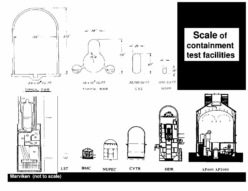
r --- - --r
(
I
1
I ----- -----..,__ ___ ~
2-6 x 10" CU rT
TYP,cAL PWR
rrc.:11.lll ... .: ... v .. o:;:1111,.1
•.
I I r --~-..
i ;
I I I
1
i! ,s' I I
!
- J
LST
Marviken (not to scale)
TYPIC-A[ AWR
• BMC NUPEC
__: 25 ;..,
110'
;
- t J. ·-i
i 67'
J.
J0.700 C1.,1f T.
CSE
i._
CVTR
.. - -0, I. _J
18;
-- r t.150 CU FT.
NSPP
HOR
Scale of containment test facilities
AP600 APl000


I .. , •
,-'I'• J -~···
! .... ; · ·-J ·;; .. ·,
•, ·\;. : i,'1 ;:•• r-::.!::.:\I • •.
":',;,:. ......... ·l
.. , •
. j .......... _ ... _ -.... _ -...... -, ..... _-_ ... -~
I ··, ~ : ·1 ,:,. i .. " ,•-· 1--j
L •• • • '·('
• I • II, ...!....- Ii•:.:.• •;..., •• • - "1, • r • I
lr,:iy,t•.,I llaf'-l" +U•~.,..Dt~-M"'-•'""1'.-1t •'r-'IP' "fYl'f IVAl'Ylr'l-1 .. .,,,.i. ._ ...Wiry,
,..:!'".:.. I
t r=-- .. -~]- : . ;---=i~t !u1· t i -< -~ ~ 7:T ~t
1-~:;f~:-..:~== ·':=:::-! -'!~ fyj" ! · .. ; ..
·-···-'·--J -· ~f- -- ~. .. ··- ·1_• ____ .
._l"'Y'll. •a. •••••••••.•---~" •'T'Y••- • 11•"•._. ____ _..
1-----;...-,..;.,/,:",,-; .... _.v.c=-.-:-... ·;-·•.- :.-·, .,:,.,,-·. ' " - O"i d •":to-~--;;:;:~--- ,~.,,,.--pj ;,.- dltr«n:5: • ................. o---
1
-------------------· -
12 2 3
Multi-compartment
ll.120.01"
El. 74.92"
El. 45.92
IOlTOM OF AUX llDG-2"
ll. 24.01'
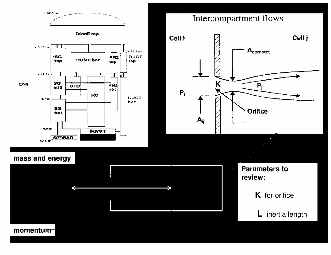
ENV
+ 51.5 n, ----.,,---_
.,,, . ..a: /
(
+ 34.5 n,
·SG' ·to.p
+ 19.5 n1
SG m'ic:I
+ 8.1m
SG bo'I;
+ o.o n,
DOME top
DOME bot
TO
RC
SPREAD. - ii.15 m
+ 28.5 n, DUCT top
DUCT bot
P1
Intercompartment flows
l_
T A1i
A contract
Parameters to review:
Cell j
•
K for orifice
L inertia length

Typical sub-compartment analysis
- figure of merit: pressure difference across a structure
=------· --..':'::i-,-· - .... .. _ .... :I
~~.;.; "1
.... -.. =
.... .. .:, - .... .. .... - _ .... :I
r1-a __ ,. •• -. = .... .. ._._ . - _ .... :I
~~.;; "1 - ... .-r.;
.... r.:, .. .. -- ...... _.. .. :I
~~=:i"l .... -.. =
....... .:. - .... .. .. .. - _.. ... :I
- , r, - .. .. :I
~~=:inl
(b)(4)

Condensation basics
Ps(T) : Ps,PURE,FUT(T) • KR(R) • KSLN p~~ l-l~O
PS,PURE,FLAT: PURE WATER, FlAT SURFACE
KsLN ~ KHYGRO:
(Csl, CsOH) Solution reduces water vapor
pressure, thus effectively reducing value of critical
radius

p
MIi T
!;,,ullc
---•...1r----·-~ "I '<UICI"
riv lw:
------+------ y FlQFE:,
.. t. ic;iu ~d Gllia-"41;10!" V
!!~Hn l,.,!l;Yltl"
u t ~
MECHANlSMS OF COND~srnc h'U'!' TRANS~R
NOTE: in reality there is some condensation in the atmosphere
Reallstlc approach: multl-node, BE condensation HTC
Historical conservative approach: single node, Tagami/Uchida, X% revaporization, minimum heat conductors
T / U condensation models based on Sagawa data (1980's)
- steady-state ( 140x300 mm, vertlcal plate) - L0CA (300, 800, 900 mm cyllnder), - problem with interpretation - became known as Uchida and Tagami (Slaughterback paper, 1970's)
Tagami - "inconvenient", requires iteration (time of Pmax)
Uchida - depends ONLY on air/steam ratio, produces highest peak P, BUT does not apply to superheated conditions

SE ssio~. J .9 P <1J<> 1--'. UCHIDA.,..'. ,,1
(b)(4)

-- ·1-.:, Tota I Heat Trarisfer Coefficient (WI m2:K) -C" -'i: -


Spray [and suppression pool] most effective ESFs
Results in a rapid pressure decrease
Volume coverage depends on headers/ nozzles arrangements
Spray drop size distribution depends on nozzle type [needs test data]
Residence time must be greater than "relaxation time" [i.e. time to reach thermal equilibrium]
Large spray droplet size [e.g. 1000 microns] is a conservative assumption
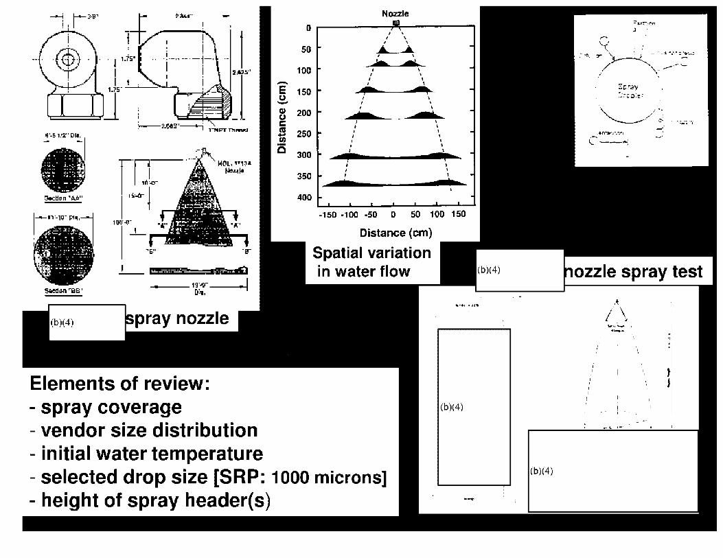
--! r-)11" ~;\,u·· Nozzle ! I 0
I 50 I • •• ·-•-1'1 --·-1-·
I i
J 100
- 150 I \ I I
' I
200 • I I
13'-S. 1.'2'' [Ill. I 250 I
' - -- ' I
• 300 I
ffl I I
350 I
31clll:in ",V." I .. _.. l 400
-150 -100 -50 0 50 100--i:i· _,
Distance (cm) .. 511 "Er Spatial variation
• 1• !iii ell in water flow 11·.,o- .. 1 '!;kled an '"Iii B ' 0,:,.,
Elements of review: - spray coverage - vendor size distribution - initial water temperature - selected drop size [SRP: 1000 microns] - height of spray header(s)
...... ,1'~'111
(b)(4)
(b)(4)
! ·-
::::-,.r:-:.0n .I .
,-. .
• ... ...... >- ...... -... - . . -- _ .. •· - ···-· ··" ~- ~ -. '\- _.....- .,_ . '
Sp.,ay ~;~ ~ ;i,;\!!;
'·"'---,,.·,._ ,, ' ~::- . .. . .::...'"': -~, _,·
.• rc;,,~r..:r~ ·-· .--l --~
ozzle spray test
I I
.~ i \
I ~
----
I F
I --t. .. --
I ·' ~1
.. L

Exercise: condensation rate on water droplet
answer e.g. "Elements of Cloud Physics" H. R. Byers, p. 122
Univ. of Chicago Press
Regulatory flow rate based spray condensation model: e.g. NUREG-0772

Page 0198 of 1020
Withheld pursuant to exemption
(b)(4)
of the Freedom of Information and Privacy Act
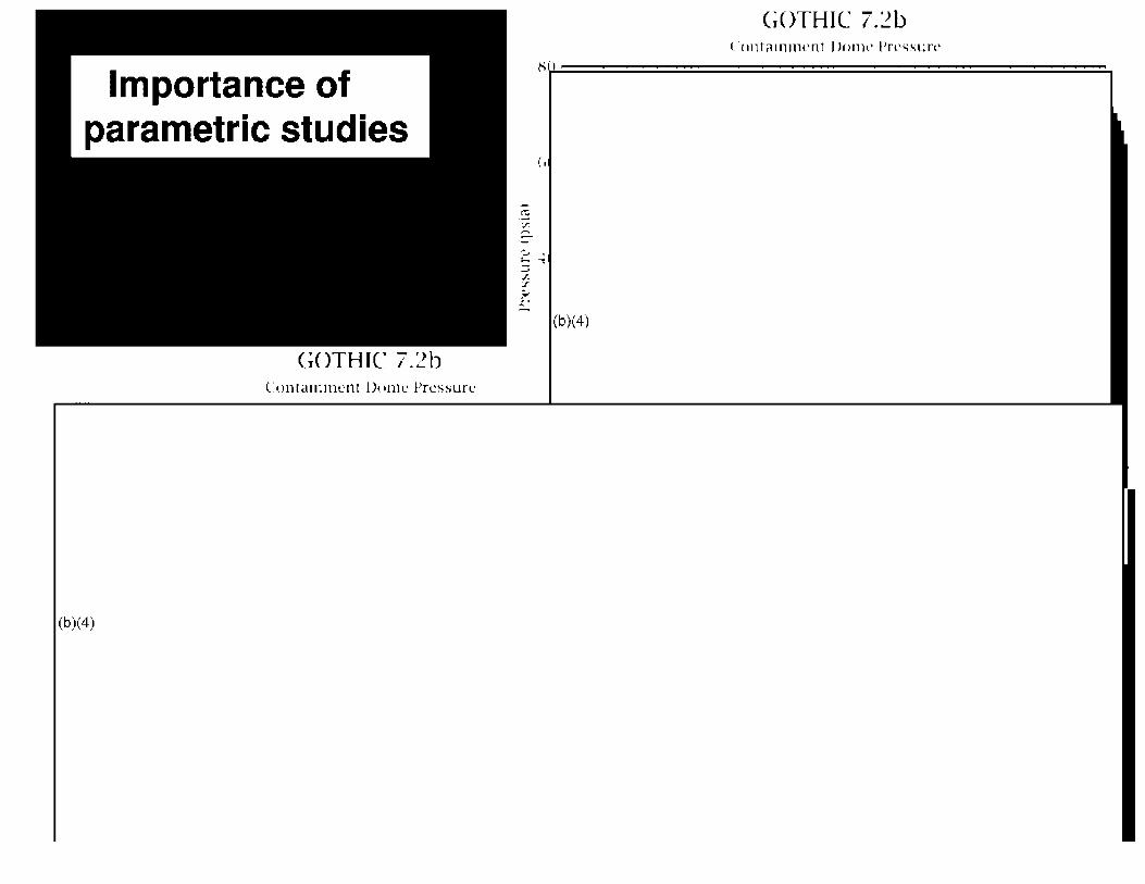
Importance of parametric studies
GC)THIC 7.~b t:on1a111ment Dome Pressure
(b)(4)
G()THIC 7.~b Contamnwnt l)oml' Pressure
81,L..l.=====================::::..
(b)(4)

BWR: DW similar to PWR
WW very different. Important phenomena: - Vent clearing - Pool swell - Condensation oscillation, chugging - Associated hydrodynamic loads
- NO established analytical model
-Approval based on various experiments

Hydrodynamic loads

Notes on BWR-related thermal-hydraulic DBA analysis
GE methodology - GESSAR (NUREG-0979): - basic BWR (MKI, II and Ill) test data (like PSTF) - MKIII specific test data (HVT) - basic models: NUREG-0808 (MKII), and NEDO-20533 (MKIII) - specific application requires combination of test data and scaling analysis
-- direct application of MKll/111 models inadequate -- PSAM (NEDO-21061) for H/D loads (approved based on GE/JAERI test data) -- PICSM code with additional correlation for uneven pool slug rise -- subscale (2.5) and partial full scale (full scale vents with 2 horizontal) tests
- Containment P/T: -- GESSAR methodology (M3CPT code for MKIII) -- being replaced by TRACG (ESBWR) with vent clearing correction -- for sub-compartment: SCAM code
2. NRC independent evaluation based on -ABWR approved using CONTEMPT-LT28 - currently use of MELCOR, based on CONTAIN models - CONTAIN qualification report on BWR DBA analysis - COMPARE / CONTAIN for sub-compartment => MELCOR
3. Industry approach (STP) - use of GOTHIC, benchmarked on other model and/or available test data

11,.0 • ..
@
@.4 @ {§omt10 (b)(4)
8€, (fiq 0 102.,0 ~- ';"-,
-fo·o.otljo,,,,., .... ~.
(§i - o, •. n I>''""
H.JO
:100
· 1700
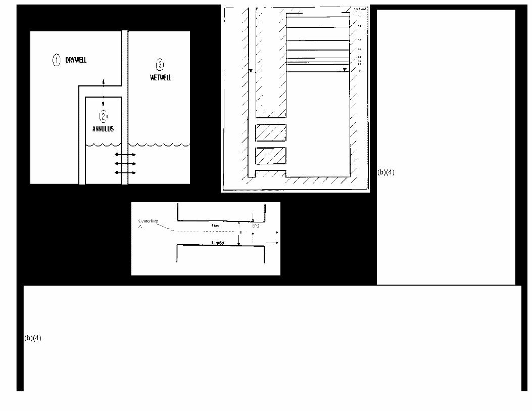
(,J ORY\ln:ll \~
,-';:,'·, lj
\IET\IELL
(2:1 '-'
ANNULUS
( i~h:: t l·J.-1 _____ 11 . f
Liquid 1
Schematic of the Pool Swell Phenomenon (b)(4)
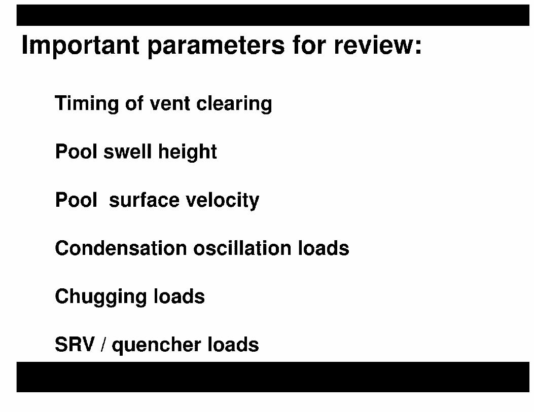
Important parameters for review:
Timing of vent clearing
Pool swell height
Pool surface velocity
Condensation oscillation loads
Chugging loads
SRV / quencher loads

Page 0207 of 1020
Withheld pursuant to exemption
(b)(4)
of the Freedom of Information and Privacy Act
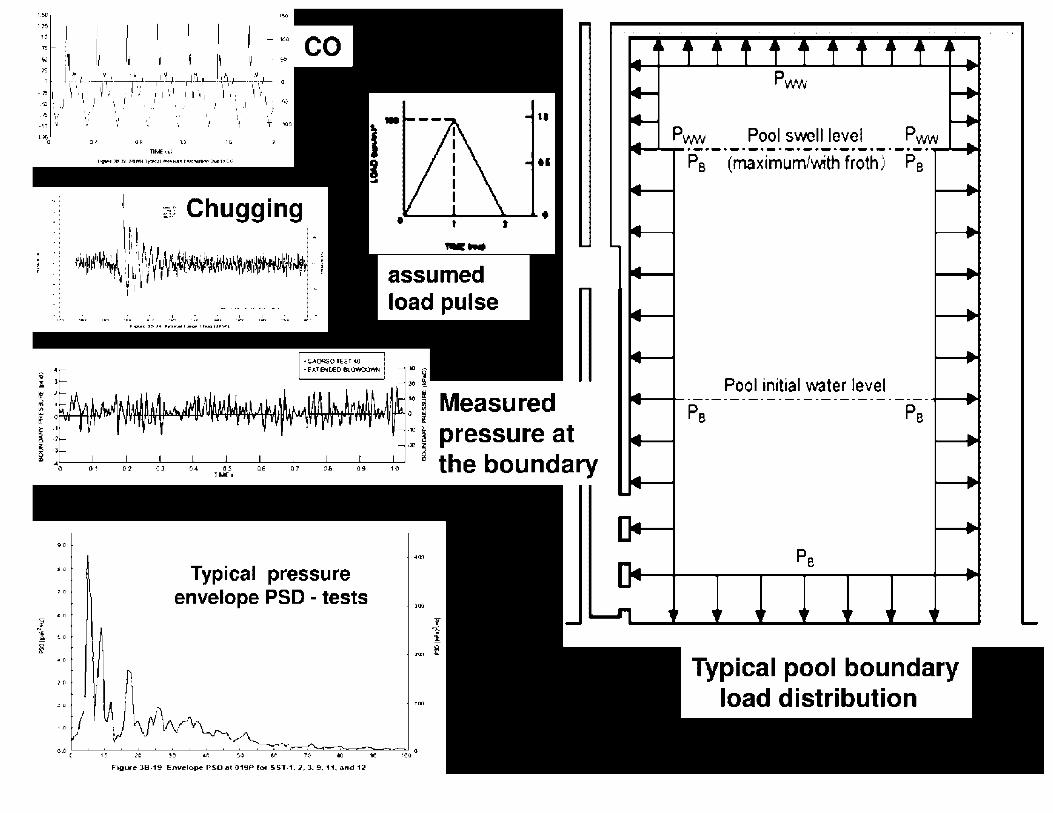
1.SD
•• •• ,.
.. ,. lO
" '•i ·/
•• •• ,., ,. 11111:•.t.~
1 §,: Chugging
' ,.u A' IP1,l1 '• t,Wi' ~ .. f~i•,'Pf.i:., , l,1\/lrlJI~~ .,. 11,,iih1Llf..1a1\l1. · ,_, .. ; ~·1r1 r1 111 , , . ~ 1 f _ n111lffflr,o'!lll~ , , ' l ; II I' ' ' .
~ I l •
' ,:.. .;.. .:. -~ .: ..
-... assumed load pulse
30 g 1G i
II
H
:0
; Measured UMHHIIHjlMI~ •t¥""11'Y'W''tl"'tlltHIAI\WlffflrN~lfftlf-'t'll~lltF1 if
01 O:;t OJ O.& C:$ O.lii 07 .,. ,Q!J 10 1~£•
Typical pressure envelope PSD - tests
:: i pressure at g the boundary
, ..
•• • 0 1(1 JC ,o at:: '5-0 U. 7() 10 90 100
Fig,.e 38-19 l;nvelope PSO at 019P f0< SST-1.1, 3. 9, 11, an<l 11
PvM, Pool swell level Pww ·~·---~-----·~·-·-·-·-·-~-· Pe (maximum/'Nith froth) Pa
Pool initial \Nater level
Typical pool boundary load distribution

(b)(4)
Review of testing data base
AND
it's applicability to a given design
is CRUCIAL
for licensing approval
of hydrodynamic loads

Beyond DBA Challenges

Phases of Beyond Design Basis Accident
-More that one failure: single failure criteria
-Loss of coolant => core uncovery
-Core heat-up => rapid clad oxidation
-Loss of core coolability => core relocation
-Challenge to plant integrity: RX, containment, and beyond ...
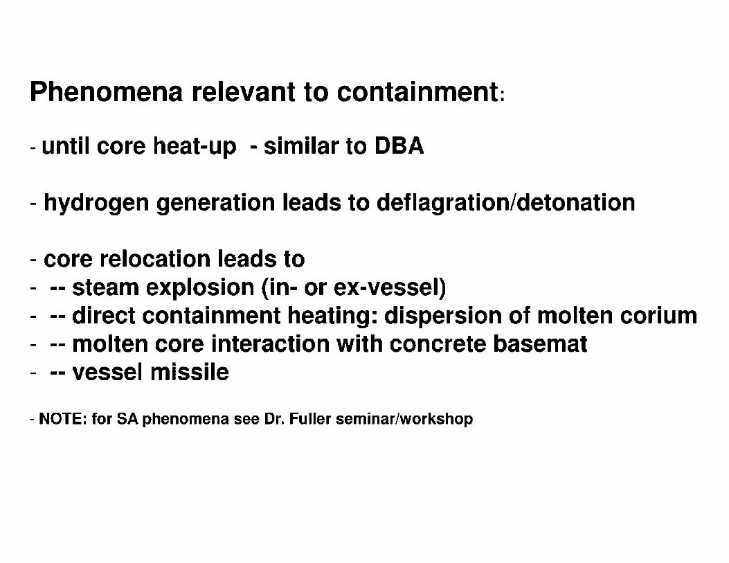
Phenomena relevant to containment:
- until core heat-up - similar to DBA
- hydrogen generation leads to deflagration/detonation
- core relocation leads to - -- steam explosion {in- or ex-vessel) - -- direct containment heating: dispersion of molten corium - -- molten core interaction with concrete basemat - -- vessel missile
- NOTE: for SA phenomena see Dr. Fuller seminar/workshop

Steam Oxidation of Cladding in Fuel Assemblies
Zr ZrO2 fuel
i burn front
motion
temperature
oxidation zone
Zr+ 2H2O - ZrO2 + 2H2 5.8x10⁶ joule/kg
dT 1 [ ] dt = mCP Qox(T) - a,oss(T) heatup rate
• Steam oxidation actually more studied
• Overall behavior quite similar top air oxidation, except ...
• Hydrogen is produced in steam oxidation
• Reaction heat reduced compared to air

Core Debris Penetration of the Reactor Vessel Leads to Ex-vessel Releases of Radionuclides
• High Pressure Melt Ejection from Vessel
• Ex-vessel Steam Explosions
• Melt interactions with concrete
-.. _,_. . --- . - ..
- - ... ~:ii _.,..,,. ...... _._ .... - • -..
• • • ..... • ~. • ' ••• ' • ' ...... J'.. • - • .. ' ...... ~ . . . ~ . . . . ·-· . . . '-· .-., .. . . ... .. . . ·.-
.....-:r ·::: .•.
arr C --~~-. . '
...•• - 'l.ol.·,• ....... ·"""' ..... ,. .• - • - - '.·., •,
.. - .. - "'· '· ~ •,
. . ' .. ,. . : ·. . - - - - . . ~ ' . - . - . . - .
...
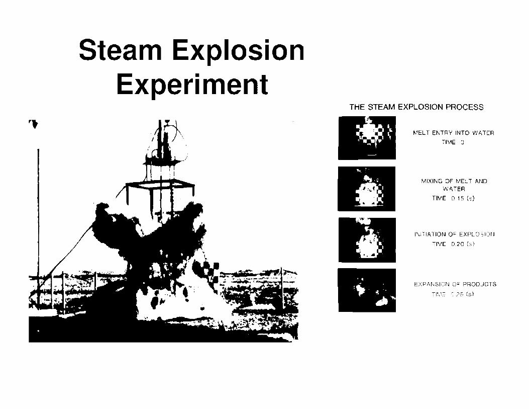
Steam Explosion Experiment
THE STEAM EXPLOSION PROCESS
MELT ENTRY INTO WATER
TIME· 0
MIXING OF MELT AND WATER
TIME 0. 15 (s)
INITIATION OF EXPLO~IOl'J
TIViE 0.20 Cs)
EXPA.NSIOi'J o= PRODUCTS
Tl\1E ,: 25 (s}

Direct Containment Heating (DCH) Issues
\ \ \ \
1
Inertial d-eposi:ion
- Fr agn· e-ntation and
// mixi rig into ine particles
1:trom s:eam e:i:plosion / or high pr-essur~ ejec:ion:1
J I .. I I
I
I I
Lin-2r
Larg-2. deep d-2bris bed
Con cr-2:e a:·.a~~
Trap pi n~ by stru ctu re
• Is sufficient melt entrained as vessel depressurizes?
• Does sufficient heat transfer, oxidation, and/or hydrogen combustion occur to threaten containment integrity?

Large-scale High Temperature Melt Interactions with
Calcareous Concrete
VANESA MCCI model UU I PlH TO CONT I\IN OR N/llJ/1
I I }' "''°"""'""••-" I Y11 A WATER POOl
INPUT FROM ~ .. ) ·. -·. ··· ... :····-~--~:::, -~-.:· ·) ~ CONOENSATiON
MAHCH. COHSOR ' :- ·. WAJ~ll POOL ::,~. OF VAPORS I .- '
II CONTAIN , _ __,.". ,.,_ -- ,-., ,-·: . '-. ~: .. q:·: MECHANICAL AEROSOL
• ;-- -··' ,,...,_ ... •· -~-~ .....,,.....L--•"" :""' ,:. FORMATION
- __j.,. c; ,., ··) ,::. ~ ::, ,::: . ; VAPOFIIZATION FROM
. ~ II ~) .J °.;~IDF;tA~~ ::~ ': : . THE OKIDE PHASE
_ l PARTITION f- ,-, -' . .'- ,-. _, : - ~-- .-··. ( .' JI CONSTITUENTS 1: : .. .:.. ... . .. : II AMONG THE .. · - - ~ MELT PHASES ' '. -· ·: -, ... C '·· ,,
: ,:: . ME.TALLIC PH-~SE .. :: 11
.__1', ·.·•·'·'···~
:I ;: . ' :_ :_: ? .· .. Ji ·-' VAPORIZATION FROM
I . -0 .n r'. ···: __ _ r::_ ~ _) TI--IE METALLIC !>HA.SE
: 7 . Dt TE!iMl"lt 8U8RLF . SHAPFS. SIZ[S &
rREQlJENCY
0 0 water ~ 0
0 0 ~ 0 0 0
0 0 C, 0 0
conum
concrete
MCCI modeling
• Corium assumed to be well mixed {default)
• Enhanced effective corium thermal conductivity (1 Ox)
produces 1 to 5 MW/m2 heat flux Accounts for cracks and fissures Consistent with MACE tests
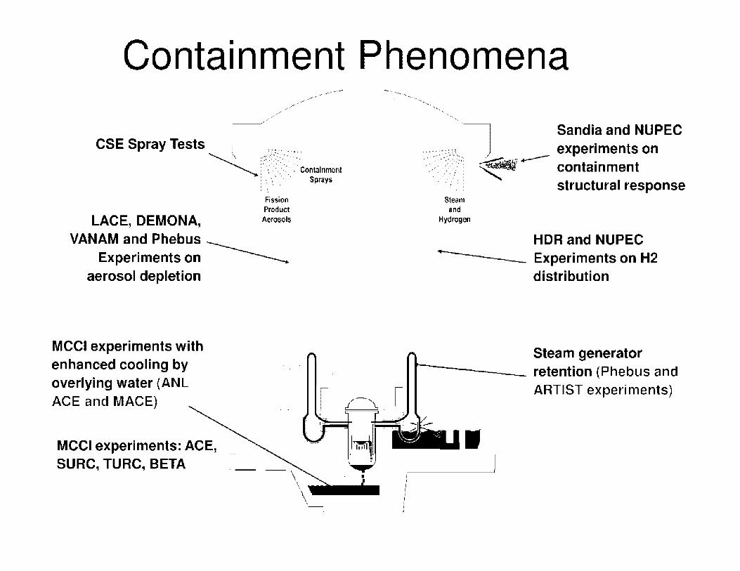
Containment Phenomena ,., ... -·
--~ , .... -
CSE Spray Tests 1 ;,:--------
........ ----- -----_., ..
~ :·,::'.>-----~---. ~ :···<-:.- ::-::- Containment
: ·. ·-, ' .\ ·- Sprays : ·. ·.' ' '.
Fission Product
LACE, DEMQNA, Aerosols
VANAM and Phebus --------Experiments on
aerosol depletion
-----... --.......
MCCI experiments with enhanced cooling by overlying water (ANL ACE and MACE) I- /-), -t MCCI experiments: ACE, SURC,TURC,BETA
-\ \_
I~
)
I I I I I I I I .
--- ·--'·
···,.7 Sandia and NUPEC ----·::::_,_;, , experiments on ·_·.-~·:·::>}:?! ~..,--- containment ---:--:./ .. ·, .. ! structural response
Steam and
Hydrogen
HDR and NUPEC Experiments on H2 distribution
Steam generator r~---- retention (Phebus and
ARTIST experiments)
I

Fission Products Release and Transport
[Source Term Analysis]

J PLUME
/
SHINE FROM GROUND CONTAMINATION
SKIN CONTAMINATION
FOOD WATEIJ
MIL~
INGESTION

Upper grid damnge -
Coahng ol pre111ouslic
molten matenal on bvpass region mte-rior surfaces --· -
Holem ballle plalE'
Abla!E'd ,ncore 1ostrumen1 guide
I C
Cii.·11)'
Loos'-' core deb
C:<u, I
· P,e~ious.iv moll material
lOWE'I
.• ,-,,:-1; ,•··
.,, , .... , _..,, '•• f,•,·::
'
,; '
I,··
Po~~,I deple :;.1,:• ---..
,',:
Temperature i (F)
5162
4874 4712
4352
3722 3587
3200
2642
2372
2192 2066
1724 1472
T (~j
f
(K)
3123 ~ --t--- Melting of UO 2 !
2963 ~ ....-- Melting of ZrO 2
2873 --+---- Formation of ceramic (U.Zr,O) melt
2673 - ..--Formation of [I -Zr(O)/UO, and U/UO2 fl!0nolecl_ics - +-Melting ·of 64 C (acceleratea l1quelachon)
2323 • -Melting of Al 2O !burnable poison rod: A1 2O + 84C) 2248 ~ Melting of oxygen-stabilized a -Zr(O) • <
1 •- Melting of as- received I Star! of UO 2 Dissolu-
2033 lion by mollen Zry ...... l Zircaloy-4 (Zry) formation of metallic
I I (U. Zr, 0) melt
1723 1 .,....__. Melting of stainless s!cel or lnconel t _) •- Eutcc1ic interactions of Zry wi1h 1573 Start of rapid Zry 1 Stainless steel, lnconel and Al 2O3 1473 oxidation by H 20 ......
1403 .::: ~ B4 C/Fe eutectics uncontrolled tom-Formation of liquid U as a result peralure escalation o! U°-2 /Zry interac!ions
1213 _; ..-Formation of first Fe/Zr and Ni/Zr eu!ectics I .
1073 -j .,,._ Melting of (Ag, In, Cd) arloy _ also ballooning and rupture
; _.- I,:'!,,,,,
j . • : ,,, . .,
..,...
L
•
¥"<11
_._ __ __

Elements of Source Analysis
• Release from the Fuel - Gap release - Fuel degradation release - Ex-vessel release
• Transport to the containment - Aerosols - Vapors
• Behavior within the containment - Aerosol physics - Iodine chemistry
• Revaporization • Engineered Safety Features

Fission product specie/volatility
modified (Cs2Mo04 )
Phebus Tests -affects RCS deposition
RN Package expanded to allow analysis of FP release from mixed
MOX/LEU core
(French VERCORS and RT tests)
Fuel failure criteria expanded via control
function - Phebus tests - affects
hydrogen generation and melt progression
BWR failure criteria expanded
Core Heatup and Fission Product Release
c:: iii II 111!'
ii II 11lli
c::
I: .. ··- ... •···.. L c::r::·:· I ::· : : :; I:::::::::::::: I ::·· : :·::· ::::·. f:
Ag release model added - Phebus Tests - important for iodine chemistry
- Important to agglomeration
B4C oxidation model added (PWR) -QUENCH Tests, Phebus FPT-3
Quench-reflood modeling - QUENCH tests - quench front not necessarily water level

Release from the Fuel
• In-vessel Release - Coolant release - Gap release - Fuel degradation release - Air ingression following vessel
failure
• Ex-vessel Release - High pressure melt ejection - Melt interactions with concrete - Steam Explosions
underlying unmelled metal Zr
\
COOLANT EXIT
COOLANT ENT.RV ..:uo, grain
~ ·. . grain boundary
.. ,JI
oxidlxed cladding (ZrOt)
fractured fuel pellets
,,,,1 metallic cladding (a ZrO)
/ / relocated / molten ~ metal
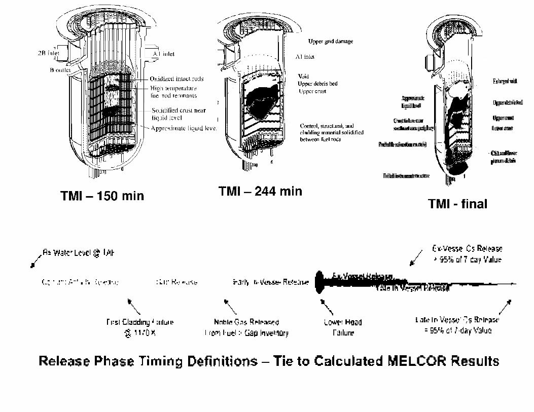
Oxidized intucl rods High temperature li.iel rod remnants
Solidified crust n1;ar liquid level
Appro!<:irnate liquid level
fl
Upper grid damage
i\l inkl
Vui<l Uppt:r debris 1xd LI ppc r crust
Control, slrnclural, and cl!ldding m:11erial solidified betv,een ruel rods
TMI -150 min TMl-244 min
\ r l~!:-1 Cladd1ny ~ :1111.JI 1.!
i , , ,'I) >'\
'\ Nnl'llL'! c;,,$ q,-.1r-:11!!:i":"d
I i"Orr1 I· uil:!1 :, Gap l11'Je1:,i::ir1
\ i,_~i HO-i!d
r~1lurl"
I
TMI - final
lllpltllldhir!i lball
l.lilllwtlllllli1
ll1•1D111lltt
(-.:.v~~ (:5 i:::.~1i~c1iil:'
,. i~% CJr 1 !=:i.!I~ 1.i".1lu~
.JW 4- = 7 I"
/''If l ,Jtt~ Ir, V~~,w· -~,s ~rlr-il~'
= g~c~ ,::;~ l ·dirp· V3l1JC
Release Phase Timing Definitions - Tie to Ca~culated MELCOR Results

' . : ;
< I Canoln1a10n Ev ap(lf'dan
mpo'dOn ~ . ~ TlltW.ll9nO!on &•··••
CltawltallaNI ~,r..., .. __ _,
✓ :,
~ SOiltCI
' : ' ' ' . ' . . . . ' ..
Spray Dropl.t
A '
=
W/4t:21M~
$wrf&;,1,J
4••·····--·· ModCl'I ci G&HOUJ FP
Figure 1 MOdels ol ART for Transport Behavior of Gaseous Fission Products and Aerosol
DEBRIS SOl'RCE
( STt~,1 \ I .-\GCI.O\lfJl-\ TIO;\' .-.°""" CO\DE~S.-\ T!Cl\)
;--\ FIDl FOR\IA TIO\:
; IHSHDO\\':', ) ,
~' / • DlHl'SIO~ ) \" DIFFTSIOPIIORESIS ,
hermoph sis
~ ,l GRAVIT:\ TIO~AL j I SETTLI~G /
DRYWF! LYOOL

In-containment Source Term (ST)
In-containment FP.~----~ Consequence analysi
ST given by:
distribution: FP release DF or lambda (A) L.-----r-. -- -____,, "-------
I
Dose
I I I I I I I I I r I I I I I I I I I I
• Definition (DBA)
lambda (A) depends on removal mechanisms: • spray/ ESF
I I
I I
• Calculated (case based) • gravitational settling I
I I I
' • phoretic phenomena , I
I I
• other I I \ \
' I
I I L--------- , .,,. - - - - ___ ._.,,,
' \ \ I
I .,-/ , ....
I , I I
I l ,
Dose: _ _ _ _ _ _ :> FP release <= [C(t) x L] 1 x dispersion (X/Q) <= meteo : analysis
C0 =ST/ Vol I I I - -I I
C(t) x Leak rate (L) 1 x breathing rate <= empirical
- - - - - -1 data
I I \
I I I
C(t) = tt'0 x exp(-At) Leak rate (L) given as: • design value • calculated
x dose conversion <= health physics
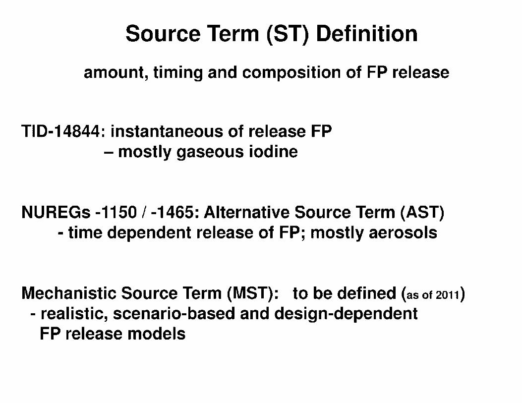
Source Term (ST) Definition
amount, timing and composition of FP release
TID-14844: instantaneous of release FP - mostly gaseous iodine
NUREGs -1150 / -1465: Alternative Source Term (AST) - time dependent release of FP; mostly aerosols
Mechanistic Source Term (MST): to be defined {as ot 2011)
- realistic, scenario-based and design-dependent FP release models

The Iodine Problem
• Iodine removed from containment by sprays or water pools can partition back into the containment atmosphere
12(water) ~ 12(gas)
• Complicated chemistry involving radiation dose to water
• Can be suppressed by making sumps basic (pH > 7)
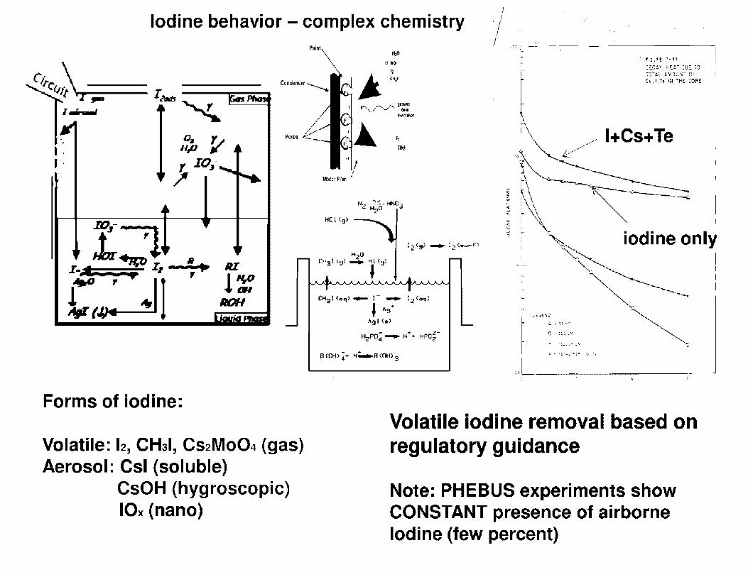
'
Iodine behavior - complex chemistry ,'/
Po'" . I .. t·'
!3 P -..& ~ z- II Pl ! •
.I.' - - ...., II! r
c: •II RI
l~ ROH
Forms of iodine:
Volatile: 12, CH31, Cs2MoQ4 (gas) Aerosol: Csl (soluble)
CsOH (hygroscopic) IOx (nano)
Painl /
11P Ml MOI
HCl ,g>
.. -:,:: ---·
!
:-
-- - ---------,
7::;".":.; .. A'.!::l~.\;T CiC,, 1,ie. iN ~ri~ COR.E
1 / l+Cs+Te ·•~ ~ ~~ i ·~ I
,_ iodine only ~ I
"'-,__ I
CH:31 (,,.1>- I- - 12<"'"1'
I A•:/
~ I
Agl <•> ~ .E'°-~:;
r' 1:.-:CSC
(! . :1:~ _ ...
.It - ''!.-.,• _.,
;i - :.;·J.. =.;= _:;, -.
Volatile iodine removal based on regulatory guidance
Note: PHEBUS experiments show CONSTANT presence of airborne Iodine (few percent)

Aerosols removal mechanisms

IAIAT I:S .AEIIO:i-C-L~
[(HEl'i'IICAL fNGI~EE~I~~. ~A1 20, ],~8, P.1~~]
-.:-i::i~..c.~ .... •l,I ~'!rrHl"'lll'!:l .. 11:
.. • •• I I {' I •
j :i
L
. .... P'liftTICl.r: ~IHNKIII R.11.ft •lfd !:'J:a- 0.: bGr.ding-r'i'i-, 1
Mitigation Systems Remove Aerosol Particles
0.8
06 C: w 1-1,;J
~ 0 -... u :'E z 0.4 0 1-u < C: i.
0.2
{Count mode I0.6i9 µm) d 0
Count median [1.0 µml d 11 ~
/Coun1 mean (1.272 µm) d
Oi1rneter of ave-1191 area 1\.614 µml d,
Oiamtttr of 1verage mas., (2.056 IJITI) dl"'I
..
Area median 12.614 µml d~
Aru mean 13.324 µml d 1
Mus median ,..., __
(4.226 µmJ d:.n
Mus mean .. _-"--15.374 1,1ml dffi
[-0.3-i->0.8] oL-L_.l..,__...L_--1::::::::::::=11i..J-....l _ ___J
0 2 4 6 PARTICLE DIAMETER, ,.un
An example of tht: log-normal disrriburion func• rion in generalized linear form for dg = J .0 and og = 2.0.
(FROM TID•26608)

BASIC EQUATION: SMOLUCHOWSKI [1916]
[EQUATION FROM NUREG/CR-6189]
Aerosol Dynamic Equation
When the homogeneous aeroso: assLlrr..prior. h:!:-. :iee:: made. the aerosol dyr.amil:- eqt;ation is:
\'
mi(v,t) = ~ J K[U,v-C] n(U.t} n(v-U,t)dU - n(v,t) f~ K[L;.,•] n(l;,l) dU ~ 1 0 UL ._ O
• S(\' ,t)
V
where:
R(v.t) n(v.t)
\/
al(v,t; n(v,t).'\.'
iJv
n(v.t) = number conce:itration of panicles having ,·olumes of\' to V + d\',
V f l(!U.v•U] n(C,t) n(,-l:,t) dV = 0
the rate of formation of panicle!., of volume ,. 10 ,. + d\' by coagulation of smaller panic.es.
\'
n(\:.I) I K[l',\! niv,li cl· -- the rat~ of coag1,;!at1on of par11~;es of·, o::.:mr v to\ -,. l!·.
to forrr: !arge~ parti:.-:es. (1
K[L.\'] = coagdation "kernel· for pa.:-:ic:es ,Jf ,olurr.t \ "i::: par.icles of \:Olume lJ,
S(v.t} = ;ate at which panides oi ,obmc " to\ ... dv are ):JP?licd,
V = contair.ment volumt:,
R{v,t) II{\ ,I) = me oi re:nova'. of partides from the :on1.ai11men1 by ar.:, of a variety of mechani~ms.
el(\·,11 n(v,u = d\'
rate of growth by co:1de.1sati()n of particles from t~c \'O'.ur.ie ir.,er-al of,. to \ - d\.
AlA STll[AMl,IN(!
AIR STREAMLINES
AIR S~AEAMLINES
IMPACTION
INTff!ICEPTION
(GI
CROSS SECTIQN OF F1SEII
lbJ
Modes of Particle Collection : (a) Impaction and Interception (b) Diffusion

TRANSPORT PHENOMENA IN PIPE Hf:AT l,.QfJS TO Eft\t~J!Cll'tMEtfJ
0 • • 0
0 •
-------dZ---t--.....a.t
w•LL C()NOE:tl $,A.T'I ON. '1/A~IIIATION I t llt[ACTION
1 l !wa • c - _I PAlTIC;LE. C£PCISll",o,.i; r.
co~ DEl''4'!l4TIOH • RiSU:5P E NS10H .e:v-.POitAT•O"'I. t M.Acf1(J ..
THOT
Processes affecting aerosol behavior in complex geometry
·.,,- ,: :. ,· t,.-/lt I.//.. . ./,,
r
15
TCOLD
1. Gravity ; 2. Turbulence 3. Brownian Motion 4. Tharmophoretlc
. 5. Vapor Deposition ~ 6. lnertla(Bends) ~ 7. Irregularities
8. Re-entrainment

NATURAL PROCESSES Aerosol depletion mechanisms * GRAVITATIONAL SETTLING: STOKES VELOCITY
ctf:. ~ "'111'tJ,1tA-h rtip Parameters to review: UP('t.P,.£ t77t1N::t>/(14y
ll"':: K."'°lf o,e IV ,,,,,.,4t Aerosol size distribution ~lf11f£ ~rlJF,ow -(t.
FA.,ro~ - ----. 'tLtt '~-1 Me,,.~ J Assumed aerosol density
* DIFFUSIOPHORESIS
PROCESS ASSOCIATED WITH MOLAR STEAM FLUX TOWARDS CONDENSING SURFACE.
* THERMOPHORESIS
PROCESS ASSOCIATED WITH TEMPERATURE GRADIENT. PARTICLES TEND TO MIGRATE FROM HOTTER TO COLDER REGION.
ENGINEERED SAFETY FEATURES
* SPRAY
* SUPPRESSION POOL
* FILTERS
Condensation rate AND steam density for (DhP) (based on total - NOT partial -pressure)
Convective heat flux ONLY (ThP)
Spray drop size
Suppression pool DF
Filter DF

..;;
-
-
- - - -- -- -- ---------- - - - -- - - ---- -
- - -: : - - ..:: .. • ..:!" - -;-- = -=- ..: -... -.•--- -
------- ---- -------------- - - -- - - :·....; ~~~~~ -~-=:.
..:....; -• - --~-==-::::-..;;
Perry's handbook ----•--- --~----~ ----------~ ~ - -::... - --- ? _-::.::::::: -- - -- • .. - __.. --- ---------- ---
-- :
- ;
----- _,.- -_ •: -1// - .- .. _ --~-~~~E---=-----=~-~ ---_ ---::=-: -- • • ..,,, - -----='---- - - - ----==
~ - - - ---_--:.......,_ -------=- -- -• -- ----=
- ----- • - -----=--- - -- - / ------ ---- --
-----------=-=-=--=-....:..=.:_=-=~~~:_-~ = - .- - : : ;-~ ~~; -~~ .... -- ----- ---- - -- -
- • - - -
---= -: -- - --- ==- - ..ii - -
- ----- - .. • -.. =- - -- ::-- :- -
--- :- -- --- -- --=- --- -- - -=- - -
---- - - - •
--
___ ;; - - -- - --- - - -- ---•- - - --- - - -I - - -- - -- -- --:----_• -:· 1 ;
- - ------ - -- _-=,--: :• =--- .- '"!!!!:=?!:1· -r - • --: - ii - - :. = ~ ;;.- : =.
~.::. • - =- -;·:-- =- =-- - : •·-- •-• -•• -- ...-::""L"" :..- .;;;•-: --- - - -- - ----= =-- = - -- -- - ---=- -:-- ---- ------- --- -- = - ---- - -; - : ~~- -
• I -• ::
. - - -•-: - --- - -
• - -- - ----- - - - - - • - - -- - - -- - -= L- .. -.. .. .... - -..:- •- ==- ..: --- - - ----- ---------• ----
- ------ --------•---
=--- : ! ~ :- : : - - - • I
- - - .. : • -.. • - I
Particle SettlinL! in Still _.\ir .___
0.5µm lµm 3 µm IOµm
• • • 41 hour, 12 hou~ . 5 hour,-X 2 minutes
AL,o<lvnamu.: d.mrnc tcr Jc fuu lJOfl_ Jiam<."lcr of J. unu detl-,1ty -.-phcrr that
scttk~ at the \JDlC vclonty a, the partu.:lc
m qucsltnn
Parameter to review: particle density
100 µrn

Gravitational settling enhanced by condensation on aerosol
PsCT) = Ps,,uRE,FLAT(T) • KRCR) • KsLN
PS,PURE,FLAT: PURE WATER, FLAT SURFACE SlFA~
I
K1CR) : KELVIN CORRECTION FOR CURVATURE
M = 0 FOR R '-RCRIT 1=tl-th S - ILCL ,. 'l-s1.N = O
KsLN = ICHYGRO: HYGROSCOPIC CORRECTION FOR SOLUTION
CCsl, CsOH)
SOLU "tf 10,,,,
SOLUTION REDUCES WATER VAPOR PRESSURE, THUS EFFECTIVELY REDUCING VALUE OF CRITICAL RADIUS.
MASON EQUATION:
2.nd, Q., a dm 0,q - - -----L_:------:-~~~-.... dt 1 M"'h 11 h,1 --+-~-----
0,qB Rk,.sT2 klU T
d'ls 31 fsn~ .• ,-,
G.c.a = P s.o..- l r)
Q, =l> S"fPR.'1- J._t,.,,_,f.7"/t,,., /t"-'1'"10
QEe. ( J.&t.1'-t"I VI: f.t Loth I Ill/,-.>)
~ i ""' l't ,.,.,.. Jt (c,., ..,.,.,,.,3 hr L 1,
~ I ttri ', co ~.ui.u,r r,tontr T = ra0
@ IA 1£ t lJ r£t P-ft,I f O r,.~ (-ti) A-w1'-l£J.: e. 3· II t1r£ttE~U ,~ Cto,,,, Pu,s.,cs t
H, J., IYEll~ , p, l2Z, u,,,.,. ,, eu,u&1 ru1i
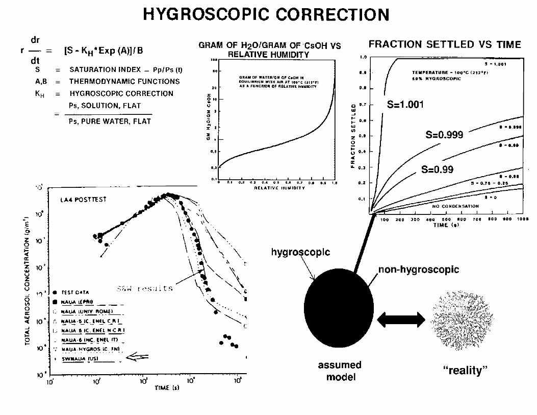
HYGROSCOPIC CORRECTION dr
r - [$ - K H * Exp (A)]/ B dt
S SATURATION INDEX = Pp/Ps (t)
A,B THERMODYNAMIC FUNCTIONS
KH HYGROSCOPIC CORRECTION
Ps, SOLUTION, FLAT
Ps, PURE WATER, FLAT
,c; ----------LA4 POSHEST
z 10' 0
!-i a.: tz 1M
~ 0 u
GRAM OF H20/GRAM OF ·CsOH VS RELATIVE HUMIDITY 1DDr---------------.
,o
to
;i: 0 ,. .. 0 :I J C,
0 .. :E I
::Ii
1:1 '
•••
, ..
QIIAM OF WAHRIGII Of C10N 111 IOUILl• RIUII WllH AUi ,u IH"Cl cau•,i 'IS A fU,tCJIOII Of RELATIVE 1111 .. IOITY
o.t o 0.1 0,2 •• , 11,4 0.1 o., •. , 0,1 RELATIVE HUMIDITY
.. . ..
••• 1.0
FRACTION SETTLED VS TIME ,.o r------:.===========----....
!I - ,.oo, o., TEIIPERATURE • 1oo•c IZU"ft
H1' NYOROSCOPIC
o.•
o o.r 5:1.001 Ill ..J
:: 0.1 Ill
: o., S:0.999 0
::; 0,4 ,c IC IA. o.~
400 100 IOO 700 IDO •oo 101D TIME (8)
non-hygroscopic
10 • .__ __ .,.._....., ____ ,..... __ """"" __ .,......,__,_,--.....,.. __ ...,....,.,...._
10' 1ri 1d ,o· u/
assumed model
"reality" TIME {5)

DIF fUSIOPHOPE SIS S 6!' ,,,,,-1,,,.._ ~ ~ :-:.!G e 0 a, o 0 o C i:i O Q
-1-~ co i·, Q • -ft. 0 O G O C C
.:Mo • ::::,,n:s:cN c. A1tt-~~ e ... Clf'Fi.'SiCN CF Wl"":-£l; VA;::J~ -·· ~ 0 • ~ e • . o r: ., o r-~ k,° • s---·~ ~ ,t,r- .. _, --~ ~].<, C~~ • C C
:} 0 n.::w • o
·-~-· 0 • ~ ~: . . ii: Q ~ GI O e ._ O C' ,., . "---·
Ct Ill
e C
•
C
C
~-
C C • C
0 •
v.,
:::' T!-!E P:.Ri:CU: £:t::>£t;i£NCES A :,; • 8 F"O~CE IN Ti-:E CIQ£C71C'N OF TH[ ;;• o O:f'F..:5:C~ C, THE Hi:AVlE;J S:>EC:ES ... .,,1 •.,•.•I I ;,. , e • ft • It • I"> C. \: C ••• .-. '
: '. . . -: -'->
~
Cl C • \ll'AHw v:. --~- ,----
--.. ---. .__ - A:_,2_ _ -
oJ ~-------::-:-::-=-:-:-:-=-;---;;-;;:;;;;-;--;--;-;;;-;-;.--- •"-:-:-• I ; • • • ;-:--,
Cl STANCE F'RO-~ W:.~L .:: ••• .-.• , .1r .. ~ , .-
= II /' I I
-= ~
.. .. .. I -._._.
____._. II
I • • I •
:I!.:.: ~.:::~ ·;~--~:.:!.~'i :.: : :.:;_~
'I.J'UI "1-,1'1 1•• • T-,la,j• 1-,• 1•e••• ~--••_.,.,.:,~ •• 1,...-.....1 •--"-I •••
I~~ .,~;.,.;t'I 1i il .:.;: ::i:.,: :..:.~.;I 'fr•L.l&r- I ...... l.&...l.l
----------- ,. ,.,., ,,.~,,,.,
-1
\.j, _I
1•' !\ \ ;• \ ' i ..... , ....... .: ....... --1 ~ _._ (: I I I •••=- I
' I ' ' II • I
•• '.• • • I - I I 1- -,
''1. ··: •I
I I
' 1'
f V I ~ I -·L I ?,~ .. ! I 1-.--) .,,.,,,_ .. i,tf~•.· ).i
I A~ I ··1 .It.& I'.... I I t' ,.., \ ! ' .: ~ ,____ ':.,..---;
arameter to review. steam density
Conservative assumption: steam density based on
total and NOT partial pressure
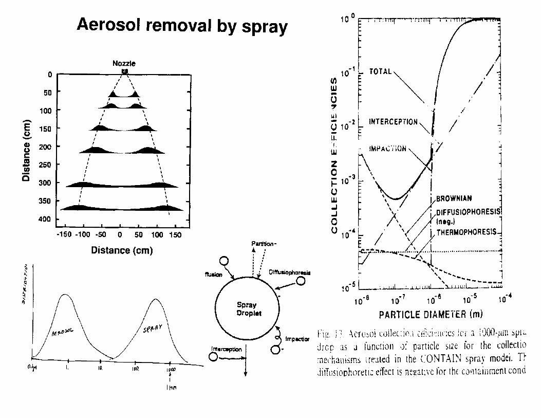
0
50
100 -E 150 () -G) 200 () ~ ta - 250 rn ·-a 300
350
400
~ ... J I;! ' ~ ' ij
Aerosol removal by spray
Nozzle
I \ I \
I \ ..... __., '
I \ I I
I I
I \ I I
' ' , I , ' I I
I \
, J I
-150 -100 -50 0 50 100
Distance (cm)
I
' I
150
Spray Orople1
_, TOTAL"-._ 10
(/) UJ ~ - 1 0 7
INTERCEP710N "''
I
J t!l ~ § ,f2 I l.L t:
~ IMPK110N~_/ j
0 -3 'J· .:: 10 , I u w \, 7d' BROWNIAN j /\. j OIFFUSIOPHORESIS 0 \ / )!(neg.) J U 1 o ·~ /. ' \ / ~/ THERMOPHORESIS ~ r~-~~-~-,~ -- -··· --- ----- ......... ------1
' ._.. I
-s i --~ .. ~ .......... __ ----;id 1 Q L--..;._~ l 1111 ' .J...U..li.U--1.. iJ..Ul.!.:· . ',
10· 8 10·1 10·6 if5 10·4
PARTICLE DIAMETER (m)
Fir. J :_ Aero.sol collec:i,\l C!fr:i,_:1c:cs for J. WOO-,am sµr.: Jrcp :is J function 1Jf particle s11e for the co!lr.ctio me1'ha11isms ;re~ted in the CONT Al~~ ~pray model. Tr difTusioohoretic effect is ne2ati\'C for the containment cond
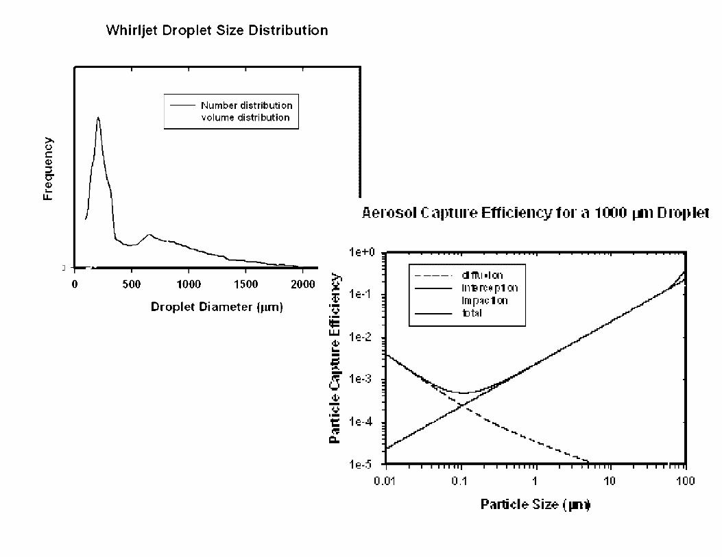
Whirljet Droplet Size Distribution
-- Number distribution volume distribution
~-0 ....... - ... --...... -----,----:: ..... ---...----iiliiiiiiii~-0 500 1000 1500 2000
Droplet Diameter (Jun)
Aerosol C apture Efficiency tor e.l 1000 1-tn D ro1) let
1e+O -------------------
~ t: 1e-1 ·-ii.Ji ·-= w 1e-2 ~ -i: -d 1e-3 4' -ii.Ji ·-t: 1e-4 (II!
CL.
1e-5 0.01
il ffl.l •I a, 111-» ro1;1 [)1 ~1 lmp:rii::1al "D~I
..
0.1
.... ........ ......... ....... ....... .... ..,_
1
Partiele- Size- ( ll"ll 10 100
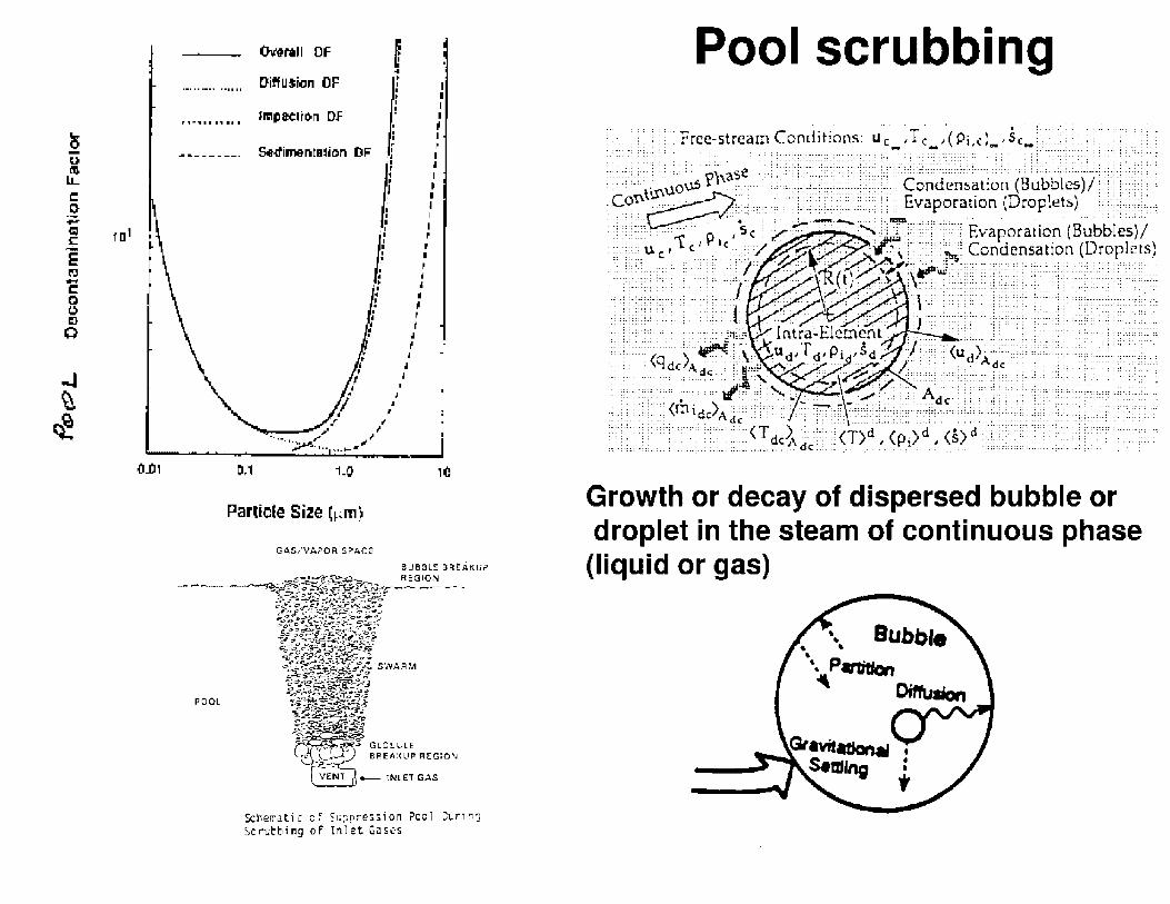
~ u,
~ C 0-P' oil:! ml s;:::
E 111:i -C
8 m 0
..J ~ ~
,0_0,
OvtNII OF
DitfU:Sion OF • I I • I I r I . I • I r 1 • I I I
' I I I I I I I
r I • • I • I
; •
I I I I I I f I i I
• I ~ I I I
I p p I
' j
• j
' f t • f
I
• • j
,I ,,
·• .. ,, 1/ ,,/ ~- ........... . 0,i
Partiele Size (~~m)
GAS/VAPOR SPACE
I l
r
,c
Schematic of S1,;;:~res,ion ilcol Dur,,.,J Scrubbing of Inlet Gases
Pool scrubbing
;:~:::;/:·~\·;:;::: '''
: ~ .. ; . ; ~=: ·; ~; .: : ..
Growth or decay of dispersed bubble or droplet in the steam of continuous phase
(liquid or gas)

Uncertainty analysis ESSENTIAL 1
6
::: 4 .. e .. I J ;;
2
DL_-~~~~~~ 0.0 1.0 2.0 J,0 4,0 f.O 1,0 I.O ,.o 10,0
limo [hr]
_-\irhorn~ Cs] lt)r all 200 sampks of th~ distrihutilm.
1.0CEG
( 1 .OCl&..oi
I I 1.0IIE..cxl
1.00E-01
0
I I I
DF results - 150 realizations
.. e -M
l t
• 10 12
~ :::. = ..
B-
2.0 •
e u. g i C e 1.0 · !!I 5 :l! D o.s '
o.o ' 0
1 6
1 4
1 2
:§: 10
a, :;;; a: 08 ,;; ,. 0
06 E (I>
rr 04
02
00 0 1
Duonum,n111on Cotff,e,,nt
. • • • • .. ., • .. :! 41 • ...
2
2
J 4
submitted
3 4 5 6
!'I
ttml' [hr)
T~m@ ,hr)
6 7
! .. . . ..
7 s 9 10
. -
I 9 10
Fi2urt 2 l>eronhm1ination c11-(>ffiri1·nt: :-'%,i(J~'%. nu•an ,:llt1t• mul EH:1-pn·dictl'll ,·:,Im•,.

''Engineering is the art of modeling materials we do not wholly understand, into shapes we cannot precisely analyze so as to withstand forces we cannot properly assess, in such a way that the public has no reason to suspect the extend of our ignorance."
Dr A.R. D!:Jkes, British Institution ef Structura( Engineers, 1976

It MW _'A}/~) co11-1es e,f,Jvvrl, to J-uiit7l1te-r1,t ...
experiments
reality / facts
model
reality / predictions testing
a11e,{ J row lVe £Jet tlie·re is (.,1, 'nl~/Ste-ry ...

. - ---- ----------------
Somewhere, something went terribly ,vrong
.... _ . . ·1•,
•a'._!~?·i~I~:;I;(i.f /LE'.
l}~JELC-O'R :i~CCID.E=NT. ~IMULAT.ION ~ -~ -~
··-·
=" Office of Nuclear ,;>~ ·. Reguliltury Rese.u"-"
USlN'G ~NAP (MA-SS)
• • • ~ , .

--~~-=-===========~
Corrosion in Nuclear Power Plants
Joel Jenkins
NRO/DE/CIB
June 20, 2012

-------------------------------------
Faces of Corrosion
Rusty Chain

---------------------
------
Faces of Corrosion
Chemical tank with SCC
Source: National Transportation Safety Board Accident Brief NTSB/I IZB-0401
----------

---------------
------------
What is Corrosion?
Degradation of a metal due to electrochemical interaction with its environment
----------

-------------------------------------
Corrosion Mechanisms • General Corrosion
• Pitting
• Crevice Corrosion
• Intergranular Attack

---------------
------------
Corrosion Mechanisms Galvanic Corrosion
Flow Accelerated Corrosion
Stress Corrosion Cracl<ing (SCC) includes but not limited to • PWSCC (Primary Water SCC)
• IGSCC (Inter-Granular SCC)
• IASCC (Irradiation-Assisted SCC)
----------

----------------------------
SCC Factors
Stress
Material Environment
___ ..,.,..,.,.. ----

---------------------------
SCC Factors
Problem Material-Environment Combinations
Steel and caustic solutions
Stainless steel and halogen salt solutions
Alloy 600 and reactor primary water
----------

---------------
------------
Design Considerations Is corrosion of the component lil<ely considering material and operating conditions?
----------
If corrosion is lil<ely, at what point is it detrimental to operation?
What methods can be used to detect presence and extent of corrosion?

----------------------------
------------
Corrosion in the Nuclear Power Plant
Boric Acid Corrosion (BAC) • Responsible for corrosion of bolts and/ or vessel head
(e.g. Davis Besse 2002)
Flow Accelerated Corrosion (F AC) • A synergistic wear/corrosion mechanism responsible
for failure of pipe ( e.g Surry 1986)
Stress Corrosion Cracl<ing (SCC) • A common corrosion problem for nicl<el alloys and
stainless steel. Can happen in primary and nonprimary systems. Sometimes aggravated by neutron radiation.

-------------------------------------
Case Study: sec at Pallisades (IGSCC of Service Water Pumps)

---------------
------------
SWPs at Pallisades Service Water Pumps (SWPs)
Major components: motor, hollow casing, rotating shaft, impeller
Originally designed with carbon steel shaft couplings
Redesigned in 2007 to use corrosion resistant stainless steel couplings (Type 416)
----------

-------------------------
------------
Pallisades-2009 Redesigned stainless steel coupling failed in 2009
Cursory evaluation found hardness to be out-of-spec
Failed coupling replaced with lil<e material, and bacl< to operation
Susceptibility of design to further IGSCC not considered

---------------
------------
Pallisades-2011 Stainless steel coupling fails during operation, disabling one of the three SWPs
----------
Per tech specs, failure of a single pump activates an LCO action (fix in 72h or shut down)
Utility performs root cause analysis and linl<s failure to IGSCC
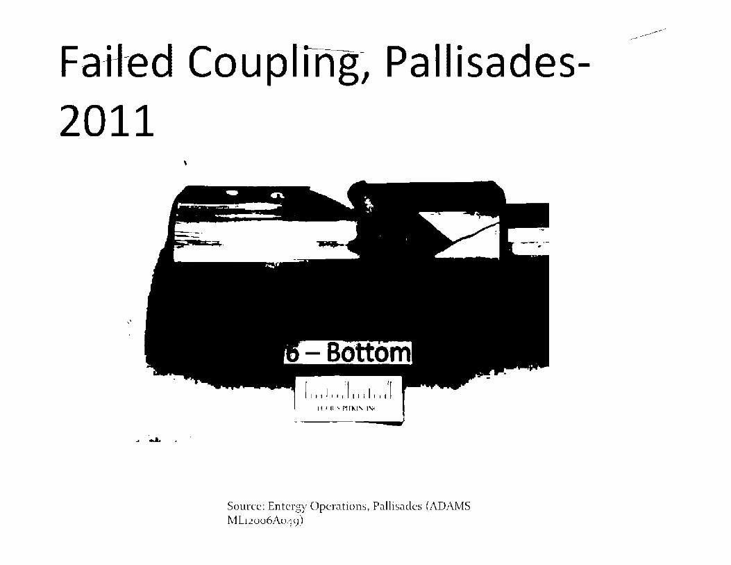
Fatted Coupling~ Pallisades-2011
\
,.
.. ..... .
II ' II ' rut;t, I',;•
Source: Entergy Operations, Pallisades (ADAMS ML12006Ao49)
----------

-------------------------
------------
Failure Analysis, Pallisades-2011 Material was found to be improperly heat treated and thus susceptible to IGSCC
Sufficient tensile stress in shaft assembly to initiate SCC in couplings
Chlorination of lal<e water and concentration of ions due to wet/ dry cycles increased corrosiveness of environment
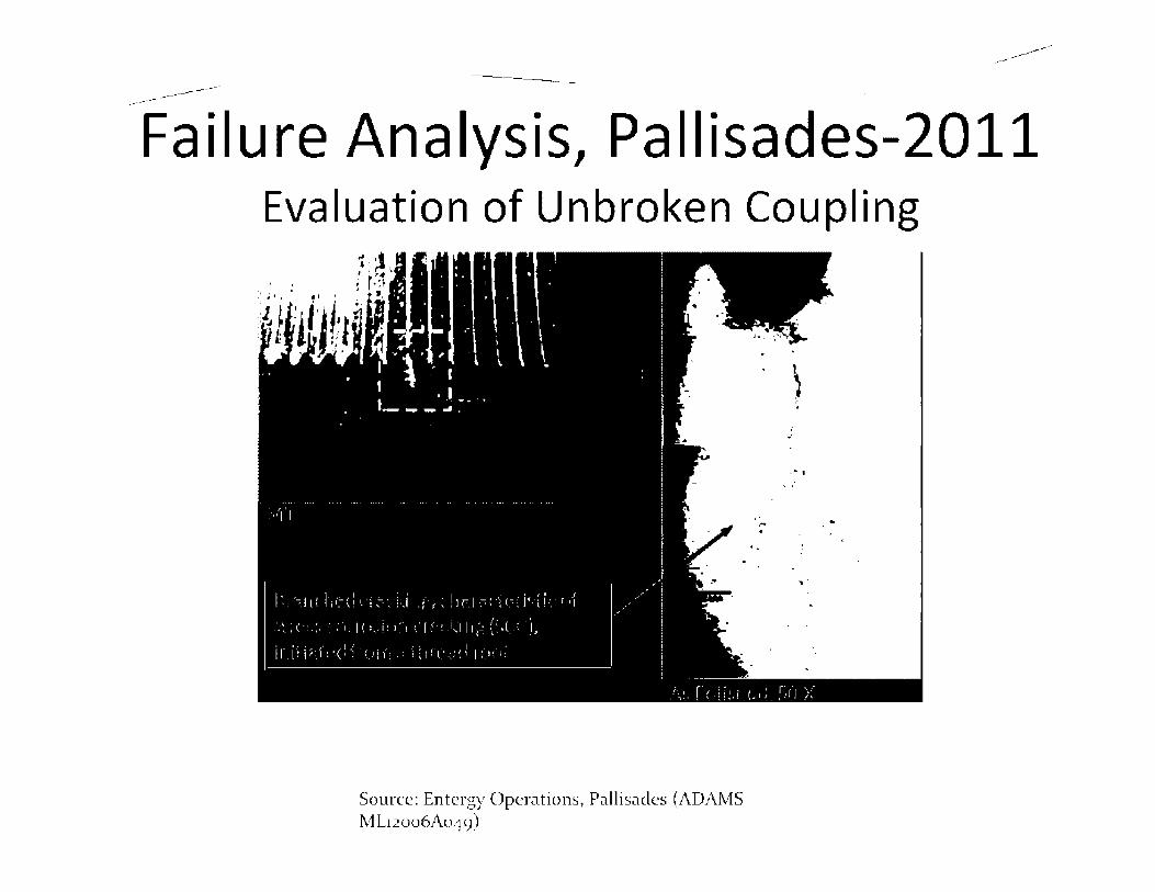
-------------------------
------------
Failure Analysis, Pallisades-2011 Evaluation of Unbroken Coupling
Source: Entergy Operations, Pallisades (ADAMS ML12006Ao49)
. '
. )
-· -~ .
.. ,,
.
-· .
....
..

---------------
------------
Solving the Corrosion Problem at Pallisades
How did Pallisades solve the problem?
Was the Pallisades solution the only option?
----------
Are type 410 and 416 stainless steel "bad" materials?

---------------
------------
Solving the Corrosion Problem in General
----------
Preventing Problems through Good Design (the best solution!)
Effective Inspection at Proper Intervals
Learning Lessons from Operating Experience
---------------
------------
Where to Get More Info Subject Matter Experts
Training • NACE General Corrosion Course
----------
• NRC Course E116 ( Corrosion and Corrosion Control in LWRs)
• NRC Effects of Corrosion Web-Based (basically a short discussion of Davis Besse)
For Official Use Only
UNITED STATES NUCLEAR REGt:LATORY COMMISSIOK
Protecting People and the Environment
Digital l&C Operating Experience Insights
NRC Office of Research: How Things Fail Seminar Series
Daniel Santos
David Garmon
"The only source of knowledge is experience" - Albert Einstein

For Official Use Only
\ -~ ___ )U.S.NRC .J .,/ "" 0 0 .0>s o·, U S " U D" "''< '°. 0. HO"' <,Om"SSO<"
~ Pn,teding Peoplt• ""'' the E,wir(mmnit
• Challenges
Purpose and Agenda
• Operating Experience (OpE)
- Selected Industry Reports
- Specific Events
• Agency Efforts
- Domestic
- International
Digital System OpE Knowledge Management
For Official Use Only 2

For Official Use Only
\ -~ ___ )U.S.NRC .J .,/ "" 0 0 .0>s ,., U S " U D" "''< '°. 0. HO"' <,Om"SSO<"
~ Pn,teding Peoplt• ""'' the E,wir(mmnit
Why is Digital System OpE Important?
• Effect on Plant Safety
• Increasing Integration of Plant Systems - Operating Plants
- New Reactors
For Official Use Only 3

For Official Use Only
\ -~ ___ )U.S.NRC .J .,/ "" ' O .O>s ,., n S " U D" "''' '°.'. "'"." ':""'"""" ~ Pn,teding Peoplt• "'"' the E,w,rcmtnnit
Non-Nuclear Events
l~
.- ',,~;.'i'\·
For Official Use Only 4

For Official Use Only
\ -~ ___ )U.S.NRC .J .,/ "" 0 0 .0>s ,., U S " U D" "''< '°. 0. HO"' <,Om"SSO<"
~ Pn,teding Peoplt• ""'' the E,wir(mmnit
Challenges to OpE Collection
• Small event population - Novelty of digital safety systems
• Reporting and analysis quality - Improve quality - Consider standardization
For Official Use Only 5

For Official Use Only
\ -~ ___ )U.S.NRC .J .,/ "" 0 0 .0>s ,., U S " U D" "''< '°. 0. HO"' <,Om"SSO<"
~ Pn,teding Peoplt• ""'' the E,wir(mmnit
Industry Reports
• Electric Power Research Institute (EPRI) - Operating Experience Insights on Common
Cause Failures in Digital Instrumentation and Control Systems (2008)
• Institute of Nuclear Power Operations (INPO) - Topical Report (TR) 8-63 Software Events
(2008) - TR 8-64 Microprocessor-Based Digital
Hardware-Related Events (2008)
For Official Use Only 6

For Official Use Only
\ -~ ___ )U.S.NRC .J .,/ "" 0 0 .0>s ,., U S " U D" "''< '°. 0. HO"' <,Om"SSO<"
~ Pn,teding Peoplt• ""'' the E,wir(mmnit
• Study Objective
EPRI Study: Intro
- Identify potential digital l&C related common cause failures
• Approach - Primary distinction between safety and non
safety events
For Official Use Only 7

For Official Use Only
\ -~ ___ )U.S.NRC .J .,/ "" ' O .O>s ,., n S " U D" "''' '°.'. "'"." ':""'"""" ~ Pn,teding Peoplt• "'"' the E,w,rcmtnnit
EPRI Study: Data
cl ' ~I lo;
l Ji.h! t
r l
(
'
I . '
~-~ ••u u • r ~ r i,., .,, .. ,
r,,, fil,· 1"11•'1•1 I
( •• ·1,1··11 •I '.ll !1•1 [
Cl) .. C ., > w
EPRI/NEI/INPO Unique: 162
1987
For Official Use Only
Common 160
Study Data Sources
Event Distribution
NRC List Unique: 182
2007
8

For Official Use Only
\ -~ ___ )U.S.NRC .J .,/ "" 0 0 .0>s ,., U S " U D" "''< '°. 0. HO"' <,Om"SSO<"
~ Pn,teding Peoplt• ""'' the E,wir(mmnit
EPRI Study: Selected conclusions
• Number of events increases with installations
• Systemic Failures
- Inadequate ____ _ • Requirements definition
• Testing programs
• Vendor oversight
• Design compatibility, etc
• Software based changes to address nonsoftware problems
For Official Use Only 9

For Official Use Only
\ -~ ___ )U.S.NRC .J .,/ "" 0 0 .0>s ,., U S " U D" "''< '°. 0. HO"' <,Om"SSO<"
~ Pn,teding Peoplt• ""'' the E,wir(mmnit
• Objective
INPO: TR 8-63 and TR 8-64
- Analyze digital hardware/software related events and their impact on power production.
• Approach - Significant Events Evaluation and Information
Network (SEE-IN) - Equipment Performance and Information Exchange
System (EPIX) - Plant Events Database (PED) - Licensee Event Reports, 10 CFR 50. 73 (LER) - International events (World Association of Nuclear
Events, WANO)
For Official Use Only 10

For Official Use Only
\ -~ ___ )U.S.NRC .J .,/ "" 0 0 .0>s ,., U S " U D" "''< '°. 0. HO"' <,Om"SSO<"
~ Pn,teding Peoplt• ""'' the E,wir(mmnit
TR 8-64: Hardware Data
• 55 Domestic events (2003-2007) - SCRAMS (24 ), power reductions (20), misc
impact on production (11)
- Most Prevalent System • Balance of Plant systems (37)
- Most Prevalent Causes • Circuit cards, power supplies failures and
component "design deficiencies" (39)
For Official Use Only 1 1
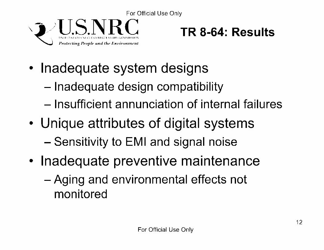
For Official Use Only
\ -~ ___ )U.S.NRC .J .,/ "" 0 0 .0>s ,., U S " U D" "''< '°. 0. HO"' <,Om"SSO<"
~ Pn,teding Peoplt• ""'' the E,wir(mmnit
TR 8-64: Results
• Inadequate system designs - Inadequate design compatibility - Insufficient annunciation of internal failures
• Unique attributes of digital systems - Sensitivity to EMI and signal noise
• Inadequate preventive maintenance - Aging and environmental effects not
monitored
For Official Use Only 12

For Official Use Only
\ -~ ___ )U.S.NRC .J .,/ "" ' O .O>s ,., n S " U D" "''' '°.'. "'"." ':""'"""" ~ Pn,teding Peoplt• "'"' the E,w,rcmtnnit
TR 8-63: Software Events
80
70
60
so
-JO
30
20
10
0
Software Events Reported
200~, 2004 2005 1006 1007
-v . .:o.-ld•,:.;ide E·--·ents -lnternc1tioncll -United Stc1tes
13 For Official Use Only

For Official Use Only
\ l:> !J~,~.~~R,~ TR 8-63: Key Observations Pn,teding Peoplt• "'"' the E,wir(mtnnit
• Complexity of software requirements definition
• Organic skill set
• V&V issues are common
• Consideration of effects of software upgrades
• Vendor control issues
For Official Use Only 14

For Official Use Only
\ -~ ___ )U.S.NRC .J .,/ "" 0 0 .0>s ,., U S " U D" "''< '°. 0. HO"' <,Om"SSO<"
~ Pn,teding Peoplt• ""'' the E,wir(mmnit
TR 8-63: Software Event Contributors
Software Event Causes
Inadequate Verification and Vendor Involvement Validation
Design Deficiency Inadequate Configuration Control
Programming Errors Incompatible Design Modification
For Official Use Only 15

For Official Use Only
\ -~ ___ )U.S.NRC .J .,/ "" 0 0 .0>s ,., U S " U D" "''< '°. 0. HO"' <,Om"SSO<"
~ Pn,teding Peoplt• ""'' the E,wir(mmnit
TR 8-63: Results
• Verification and Validation (V&V)
• Software Design
• Software Modifications/Upgrades/ Configuration Control
For Official Use Only 16

For Official Use Only
\ -~ ___ )U.S.NRC .J .,/ "" 0 0 .0>s ,., U S " U D" "''< '°. 0. HO"' <,Om"SSO<"
~ Pn,teding Peoplt• ""'' the E,wir(mmnit
Recap of Studies
• Number of events follow increases in installations
• Design issues (software and hardware)
• Verification and Validation
• Configuration control programs
• Software used as workaround for hardware failures
For Official Use Only 17
For Official Use Only
\ -~ ___ )U.S.NRC .J .,/ "" 0 0 .0>s ,., U S " U D" "''< '°. 0. HO"' <,Om"SSO<"
~ Pn,teding Peoplt• ""'' the E,wir(mmnit
NRR Reactor OpE Program ,,_ HQ - (ltrtk XrnApp ~ I"" -NI._
r5...,( 11.,oc,,.. c,p,,,MIRQf_...,,., ,..r........000 ua~ •-......--~~loy....::
Prirr1,1rv Opf Proqr,nri f1m1;tiori-.: • '.-i-. - 1-. :.•I•. =t::'
/ldmil 1i.,,r .. 1 ive I nlorm.ttiou:
·; :- --- • r, ·-: .• ·.1, 1
I ('(lllllC.JI ,~('View ,;roup ( 11~1;) PrOC<''io'>: • · • · 1 ~ •• .·1 - id .-.,1 r, -··•t. · • ·1-. I· ... JI'·
opL srnart sample Proqra111 ( op1.._ss ): • •• ,.- • I •1r .•
ReldlccJ OµC: Topic"": • 7· ,_:1_ .•• -• .:. .. • i a ""''•' ,...• :: _r '"•.·•11.•1•
• ::: •• 1 • • ••• -t,- 11· r . -~ , 1 ,11 ... '.l
• r I .•,
n1tier npF Wch-.nc-.:
• i,,.
- ··= • 1-: , -·1,•r ·11_:·=·· I' • ;., .t- _ 11.;",i • It·.
<Jukk I ink<,: [
Recent Notable OpE Information
l'IMr~" ,.,..wf#M <1'1lp..,-,1at,Q1 xp..,,,..,,c.et.ar,r,,.,.,.,1y 1Gn1m lp1·ead;Jbo,11,·..,,entu,,I J,;;..,,..,., T6 subs a- I'll....,."' flhe 011E C..-.81Uliiy dl'sa,,e,,...,, ii,;,:,;, pje;tn ws,I ll'Nt ClfJ,F 1: ,.-r111111111fy ~,,11~0:,"111<111 s,1,-
IN 70 m-m> -lmpOllill'lf:fl rll '""lftf111•lllil•J Clfr.1111 Bffl.illUII on,,11111 ~ lndlC.ilOflml -@d Aprlll 1 t, .1010 (ML 101IUIJ1H.l)---tmou,I
0111 : IIPC,lle IIIUI 7 - hll'blllP. OIM!l'I A1111111¥YteP.tl.,.i91er 1-'1.imp i IU,NW) Mo11le Check y.,...., Oi,;,;:; S.elll1PQ ,,..,,.,,.,,..(o•un•I
11,f 70 tn.na . \M!ldlnv - H,:,.,d., .. -t, .. :IM• f x-11r,,oll11'1 j,.,.,u,,. d,111.,,1 Apl ii !I. XUO •RU911i/D1 /lj ___ [mUII o,I
IN 7Dto-07 . 'Nl•ldlr•J l)o,f.,,1,. in Rl'lol"':o"'•"" SI,.,.., Gom"'"'"'"· 1l.t11"I A111il ~. 711!0 •Ml IOOU/ll11ltij ___ lmrxo,I
Communit•••
• ,:.-Oc•~rohnqf :.cpiPriPn,uJ, ( onnt,unity • •l."lf1•.1Ui~(tt)r{ l)ft1t(l1U1U~
• Ki~I<. JnlDrmed Kequlatior, lomrnu11itv DI l'ratlill!
Ewn! NCJllifiC,sliOO • • .•rf••·1tr,. r 1 ·-~:, •.·.: • ., 1.r.,~. ~irt·1,,1r1·1 • ._ - . •:'11 .. . . (",; • - 1 _. 1 r I II' 1.
Pll'lllll't~I Flllt ... :lnl Sl,tll~"
• F• C' -,. I I ... I • •·[, 1 - ' 11 11'·
• I •• • •·· II Ii •. . ; ..... ··, ·11 1,· - ·,, .. ..;..
Ml•rnn\j R>,p,•l • .--~·-·11: ....... -. 4J'
c;n,t Sto1•01s lti11at • . - . ·- '11
OpE Information Sour-:.e$
• o,.r (1 .. •~oltl'f ~:-.... t :h f 1JhJU,,d
• ··I',;. • - -,11·
• .: I •. - ·•· " . ,.• J~ I "
• ·. I . _I - _ _._. : · -·. •··1-:1111'
I" ·' ~~l 'IL_._ .. ~
_!..] "Q_; l!!!!!l l.:Oe</11/•
http://nrr1O.nrc.gov/ope-info-gateway/index.html
18 For Official Use Only

For Official Use Only
\ -~ ___ )U.S.NRC .J .,/ "" 0 0 .0>s ,., U S " U D" "''< '°. 0. HO"' <,Om"SSO<"
~ Pn,teding Peoplt• ""'' the E,wir(mmnit
Plant Events
• 2005 Palo Verde 1 - Reactor Trip due to Incorrect Operation of DFWCS
• 2007 Perry - Reactor Scram due to Failure of DFWCS Power Supplies
• 2009 Columbia - Reactor Scram with Complications
For Official Use Only 19

For Official Use Only
\ -~ ___ )U.S.NRC .J .,/ "" 0 0 .0>s ,., U S " U D" "''< '°. 0. HO"' <,Om"SSO<"
~ Pn,teding Peoplt• ""'' the E,wir(mmnit
Human Performance (2005, Palo Verde 1}
• Operator "not comfortable" with DFWCS shifted from manual to automatic feed control and overfed the SIG resulting in reactor trip
• Operator consideration as part of implementation program (V& V, training, qualifications program etc.)
• Refs: - IFR 2008-06; SIT Report ML080280499
For Official Use Only 20

For Official Use Only
\ -~ ___ )U.S.NRC .J .,/ "" 0 0 .0>s ,., U S " U D" "''< '°. 0. HO"' <,Om"SSO<"
~ Pn,teding Peoplt• ""'' the E,wir(mmnit
Hardware (2007, Perry)
• Reactor trip due to loss of feedwater - Complications associated with level control
• Insufficient reliability of power supplies compounded by insufficient error annunciation
• Refs - IFR 2008-06; SIT Report ML080280499
For Official Use Only 21

. ForOfficia~lfla0dequate Software V&V \::i,-)!J~,~,~~R,~ (2009, Columbia) ~ Pn,teding Peoplt• ""'' the E,wir(mmnit
• Fault on electrical bus results in reactor trip • During generator load reject a digital electro
hydraulic control system failure results in generator bypass valves being held open
• Following the trip a feedwater control system failure results in low suction pressure trips of each feedpump
• Insufficient design review and testing • Refs
- IFR 2010-04 (and attachments); SIT Report ML093280158
For Official Use Only 22
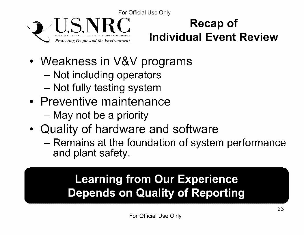
For Official Use Only
\ -~ ___ )U.S.NRC .J .,/ "" 0 0 .0>s ,., U S " U D" "''< '°. 0. HO"' <,Om"SSO<"
~ Pn,teding Peoplt• ""'' the E,wir(mmnit
Recap of Individual Event Review
• Weakness in V&V programs - Not including operators - Not fully testing system
• Preventive maintenance - May not be a priority
• Qua I ity of hardware and software - Remains at the foundation of system performance
and plant safety.
Learning from Our Experience Depends on Quality of Reporting
For Official Use Only 23

For Official Use Only
\ -~ ___ )U.S.NRC .J .,/ "" 0 0 .0>s ,., U S " U D" "''< '°. 0. HO"' <,Om"SSO<"
~ Pn,teding Peoplt• ""'' the E,wir(mmnit
• Office of Research
Agency Efforts
- NRC Dl&C System Research Plan FY 2010-2014 - COMPSIS Cooperation
• NRR - Update NEI 01-01 - ISG-6 - IN 2010-10
• NRO - Design Acceptance Criteria/Inspection, Tests,
Analysis and Acceptance Criteria Procedures
For Official Use Only 24

For Official Use Only
\ -~ ___ )U.S.NRC .J .,/ "" 0 0 .0>s ,., U S " U D" "''< '°. 0. HO"' <,Om"SSO<"
~ Pn,teding Peoplt• ""'' the E,wir(mmnit
• Systemic failures
• Latent Defects
Takeaways
- No event too small to be considered
• Improve event documentation
• Need a well established KM effort
Operating Experience Supports Technical Basis for Regulations
For Official Use Only 25

For Official Use Only
\ -~ ___ )U.S.NRC .J .,/ "" ' O .O>s ,., n S " U D" "''' '°.'. "'"." ':""'"""" ~ Pn,teding Peoplt• "'"' the E,w,rcmtnnit
For Official Use Only
Questions?
26

For Official Use Only
\ -~ ___ )U.S.NRC .J .,/ "" 0 0 .0>s ,., U S " U D" "''< '°. 0. HO"' <,Om"SSO<"
~ Pn,teding Peoplt• ""'' the E,wir(mmnit
Digital System Research Plan
Dete·~~.i~i;ii~··············---• ------<I Assessment of Dl&C systems ~ ' '
3.1.5 T'"---------
1
I
Probabilistic
3.1.6 (Analytical) 3.4.5 Operational Experience I
I
. Analysis of 3 Dl&C platforms --~ Methods •Fault modes & mechanisms
Characterization/Generalization: •Platforms
· •Applications •Environments •Fault modes & mechanisms
l
Data---·
·I Causality framework ......-- Credible causes I
I Expert clinic .,I Research plan refinement I
For Official Use Only
Tools
27

For Official Use Only
\ -~ ___ )U.S.NRC .J .,/ "" 0 0 .0>s ,., U S " U D" "''< '°. 0. HO"' <,Om"SSO<"
~ Pn,teding Peoplt• ""'' the E,wir(mmnit
Preventive Maintenance (2007, North Anna 2)
• Spurious safety injection due to protection system circuit card failure - Signal could not be immediately reset - PORVs lifted - Rupture of relief tank rupture discs
• Running circuit cards to failure vice program to replace based on age.
• Refs - IFR 2007-030; SIT Report ML072410359; INPO
SEN268 28
For Official Use Only

For Official Use Only
Notes Page: Do Not Delete
29 For Official Use Only

For Official Use Only
Notes Page: Do Not Delete
30 For Official Use Only
Manas Chakravorty Sunwoo Park
Structural Engineering Branch 2
<%U.S.NRC United Scates Nuclear Regulatory Commission
Protecting People and the Environment
Outline
• Basics of the earthquake • Recorded ground motions • Seismic impact to the plant • N RC inspection findings • Licensee short-term and long-term
actions
,_·\~U.S.NRC Protecting People and the F.nvironment 2
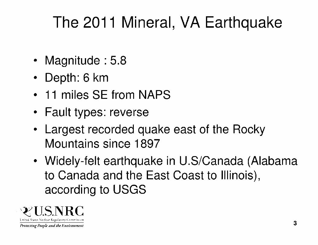
The 2011 Mineral, VA Earthquake
• Magnitude : 5.8
• Depth: 6 km
• 11 miles SE from NAPS
• Fault types: reverse
• Largest recorded quake east of the Rocky Mountains since 1897
• Widely-felt earthquake in U.S/Canada (Alabama to Canada and the East Coast to Illinois), according to USGS
,_·\~U.S.NRC Protecting People and the F.nvironment 3
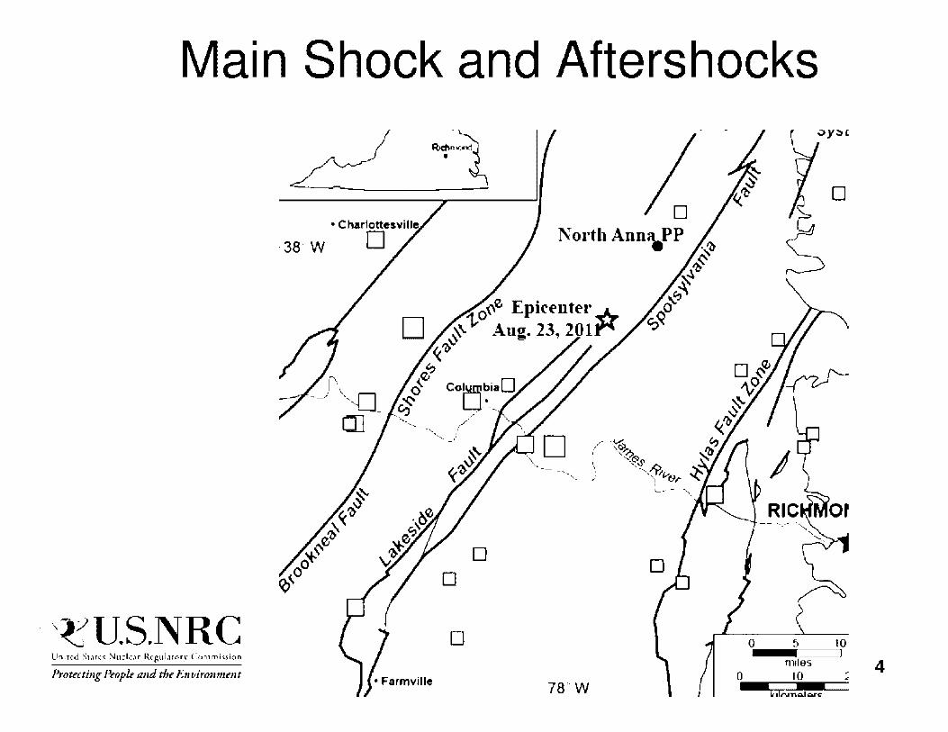
Main Shock and Aftershocks
•
·38· w
0~e Epke-nter ~ 0 ~'-1, Aug. 23, 2011"
~'lj
e" c§ Col,Y!J;'biaO
~ W-"-._c., .,,.-· ~ ""--- /
' ' ,: .... _.,
' ·--...,__ )
• •
_\~U.S.NRC D 5 10
Protecting People and the Environment m,les 4
10 .,. ..
78'.W C:,j....,,.,,.._,...,.c

Impact on Local Community
• More than 900 homes damaged
• Pre-Civil War house in the county was damaged (foundations, chimneys)
• 2 of 6 public schools in the county suffered structural damage
• Estimated costs for repairs in Louisa County exceed $18 million, including damage to public buildings and roadways
_\~U.S.NRC Protecting People and the Environment 5
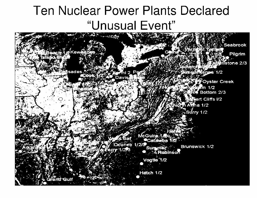
Ten Nuclear Power Plants Declared "Unusual Event"
North Anna Nuclear Power Station

Impact to North Anna Nuclear Power Plant
• Epicenter was "'18km (11 mi) from the plant • PGA estimated at the site is ~0.26g
• 13:51 :00 - Earthquake occurs with both units at 100% power
• 13:51 :11 - Reactor Trip Breakers open for both reactors on negative flux rate trip. All control rods inserted
• 13:51 :12 - Loss of offsite power due to sudden pressure trips on offsite power transformers
• 13:51 :20 - All four diesel generators and the S80 DG start
_\~U.S.NRC Protecting People and the Environment 8

Impact to North Anna Nuclear Power Plant (cont'd)
• 14:03:00 - An Alert was declared based on judgment because LOOP prevented the seismic panel from reporting the earthquake
• 14:40:00 - 2H EOG was tripped due to coolant leak. Subsequently, SBO DG was aligned to 2H bus
• 22:58:00 Offsite power was restored
• On August 30, NRC Implemented AIT to assess the total LOOP and dual unit trip, failure of 2H EDG, and other equipment issues following the seismic event
9

Seismic Design at North Anna Nuclear Power Plant
The North Anna Plant has two Safe Shutdown Earthquake ground motions (SSE),
• for structures, systems, and components (SSCs) located on top of rock, it anchored at a peak horizontal ground acceleration (PGA) of 0.12 g
• for SSCs located on top of soil, it anchored at a PGA of 0.18 g
,_·\~U.S.NRC Protecting People and the F.nvironment 10

QBE and DBE (SSE) - Peak Ground Accelerations
C>BE 0.06 0.0-+ 0.09 0.06
I)BE 0.1~ 0.08 O. lS 0.12
(From a Dominion Presentation) 11
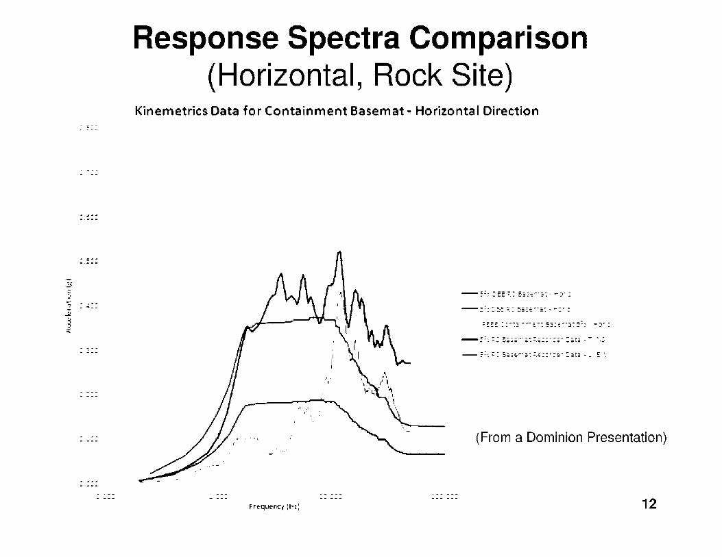
Response Spectra Comparison (Horizontal, Rock Site)
Kinemetrics Data for Containment Basemat - Horizontal Direction
(From a Dominion Presentation)
12

-.;l C
.iii!
:•.5
:•.45
- . ... :.-
:·.35
- ' .,j_ J
-- ... , , ~ :! ........... ..., JI
C , ,.:._
:·. ~ 5
::•.:5
Response Spectra Comparison (Vertical, Rock Site)
Kinemetrics Data for Containment Basemat - Vertical Direction
(From a Dominion Presentation)
13 Frequency (Hzi

Recorded Motion at North Anna Plant from the Mineral, Virginia Earthquake (M5.8)
North-South acceleration
-0.
0 2 4 6 8 10 12 14 16 East-West acceleration
0.2
O·
-0.
0 2 4 6 8 10 12 14 16 Vertical acceleration
0.2 ' ' 0 -.t1,'l',ri"J,t._•ir ll{~.✓\-\v,f+.IL~"l,tJ,1.\.tj,',V./....-,.•.,,.,_,,.~,..,.w--..... .,.., ...... ,..,,... • ..,. .... ......,._.__L ....... _.._.,,. _____ __,_....,_. __ ........ - •. -
-0.
0 2 4 6 8 10 12 14 16
·'~U.S.NRC Protecting People and the Environment
---- PGA = 0.26 g
Kinemetrics SMA-3 Records at Plant Basemat Level
14

Main Control Room
-------'===-
I I
Kinemetrics Triaxial Accelerometers
_.... 16
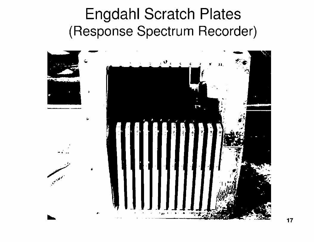
Engdahl Scratch Plates ( Response Spectrum Recorder)
t ; 2 A,, 4 S 6 1 ,· Jl.
•• 1· . '
"""" I • •
.... '
I ..... ~ _,.._ .t"~
17

Powdex Demineralizer Tanks Base
Pedestal (nonsafety related)
_\~U.S.NRC Protecting People and the Environment
U2 Turbine Building
1.., ·,: ••.
18

Turbine Building Hallway
Crack In Unreinforced r-.. -·· Non-Safety ·
Related Block Wall
_\~U.S.NRC Protecting People and the Environment
19

_\~U.S.NRC UniH·d Siar,;:< :,./uclc;1r R.<·gul,Hor~· Commi<si<>n
Protecting People and the Environment
Unit 1 Containment •~r.
. ~····' r.:
• ..
Surface Hairline Crack In Interior Containment Wall 20

ISFSI - Dry Cask Storage Pad #1 (TN-32 Units)
25 of 27 TN-32 vertical casks moved between 1 and 4 ½ inches
All radiology and temperatures normal

ISFSI - Dry Cask Storage Pad #2 (NUHOMS HD System)
NuHoms horizontal modules had small gaps and corners cracked

Augmented Inspection Findings
• Operators responded properly • Ground motion exceeded licensing design
basis • No significant plant damage • Safety systems functioned properly • Some equipment issues were revealed
(seismic monitoring equipment performance, failure of 2H EOG, etc)
• The event did not adversely impact the health and safety
_\~U.S.NRC Protecting People and the Environment 23

\~U.S.NRC Short-Term Actions Protecting Peopk and the F.,wironment
✓ Installed Temporary Free Field Seismic Monitor
✓ Installed Qualified UPS to Seismic Monitoring Panel in Main Control Room
✓ Revised Abnormal Operating Procedure
✓ Complete Start-Up Surveillances
(From a Dominion Presentation )
• NRC performed readiness restart inspections from 10/5/11 - 11 /7 /11 .
• NRC determined licensee performed adequate inspections, walkdowns and testing to ensure that SSCs were not adversely affected by the earthquake.
• NRC approved restart on 11 /11 /11 .
24

'~U.S.NRC Long-Term Actions Protecting Peopk and the F.nvironment
• Install permanent free-field seismic monitoring instrumentation
• Permanently re-power seismic monitoring panel in the main control room
• Re-evaluate safe shutdown equipment (components with identified lower margins)
• Perform seismic analysis of recorded event consistent with EPRI guidance
• Maintain seismic margins in future modifications
• Revise the North Anna Safety Analysis Report
• Coordinate update of seismic design and licensing basis with Gl-199 resolution effort
25

Summary
• Significant beyond DBE occurred
• RG 1.167 and EPRI NP-6695 were used by licensee and staff
• No significant damage to SSCs necessary for operation
• N RC staff are reviewing lessons learned
(More information at: http://www.nrc.gov/aboutnrc/emerg-preparedness/virginia-quake-info. html)
26

Thank you!
27

,~'U.S.NRC Prot,·ctiug lh,pl,· mu/ th,· F111•frrm11u·m
NUREG-0800 U.S. NUCLEAR REGULATORY COMMISSION
Standard Review Section 3.10
SEISMIC AND DYNAMIC QUALIFICATION OF MECHANICAL
AND ELECTRICAL EQUIPMENT

,~'U.S.NRC Prot,·ctiug lh,pl,· mu/ th,· F111•frrm11u·m
Regulation
1. 10 CFR Part 50, Appendix A, General Design Criterion 1, "Quality Standards and Records."
2. 10 CFR Part 50, Appendix A, General Design Criterion 2, "Design Bases for Protection Against Natural Phenomena."
3. 10 CFR Part 50, Appendix A, General Design Criterion 4, "Environmental and Dynamic Effects Design Bases."
4. 10 CFR Part 50, Appendix S, "Earthquake Engineering Criteria for Nuclear Power Plants."
5. 10 CFR Part 52, "Licenses, Certification, and Approval for Nuclear Power Plants."
6. 10 CFR Part 100, Appendix A, "Seismic and Geologic Siting Criteria for Nuclear Power Plants."

,~'U.S.NRC Prot,·ctiug lh,pl,· mu/ th,· F111•frrm11u·m
Guidance Documents
1. SECY-93-087, "Policy, Technical, and Licensing Issues Pertaining to Evolutionary and Advanced Light-Water Reactor (ALWR) Designs," April 2, 1993; Staff Requirements Memorandum 93-087 issued on July 21, 1993.
2. NRC Regulatory Guide 1. 100, Revision 3, "Seismic Qualification of Electric and Active Mechanical Equipment and Functional Qualification of Active Mechanical Equipment for Nuclear Power Plants."
3. NUREG-0800, "Standard Review Plan for the Review of Safety Analysis Reports for Nuclear Power Plants," Section 3.10.
4. Interim Staff Guidance COL/DC-ISG-1, "Interim Staff Guidance on Seismic Issues Associated with High Frequency Ground Motion in Design Certification and Combined License Applications.
5. NRC Regulatory Guide 1.60, Revision 1, "Design Response Spectra for Seismic Design of Nuclear Power Plants."
6. NRC Regulatory Guide 1.206, " Combined License Applications for Nuclear Power Plants (LWR Edition)."

,~'U.S.NRC Prot,·ctiug lh,pl,· mu/ th,· F111•frrm11u·m
Industry Standards 1. IEEE Std 344-1987, "IEEE Recommended Practice for
Seismic Qualification of Class IE Equipment for Nuclear Power Generating Stations," Institute of Electrical and Electronics Engineers.
• IEEE Std. 344-2004, "IEEE Recommended Practice for Seismic Qualification of Class 1 E Equipment for Nuclear Power Generating Stations."
• IEEE Std. 323-2003, "IEEE Standard for Qualifying Class 1 E Equipment for Nuclear Power Generating Stations."
3. ASME QME-1-2007, "Qualification of Active Mechanical Equipment Used in Nuclear Power Plants."

,~'U.S.NRC Prot,·ctiug lh,pl,· mu/ th,· F111•frrm11u·m
ISG (Internal Staff Guideline)
• DC/COL-ISG-1, Internal Staff Guidance on Seismic Issues of High Frequency Ground Motion.

,~'U.S.NRC Prot,·ctiug lh,pl,· mu/ th,· F111•frrm11u·m
AREAS OF REVIEW
• Seismic and dynamic qualification criteria • Methods and procedures for qualifying
electrical equipment, instrumentation, and mechanical components
• Methods and procedures for qualifying supports of electrical equipment, instrumentation, and mechanical components
• Documentation • COL Action Items

,~'U.S.NRC Prot,·ctiug lh,pl,· mu/ th,· F111•frrm11u·m
Information Reviewed
• Deciding factors for choosing between tests or analyses. • Considerations in defining the seismic and other
relevant dynamic load input motions. • Demonstration of adequacy of the qualification program • Methods and Procedures used to ensure structural
integrity and the functionality of Equipment in the event of a SSE after a number of OBEs.
• Methods and Procedures of analysis or testing of supports for equipment.
• Seismic qualification report or similar equipment data documentation.

,~'U.S.NRC Prot,·ctiug lh,pl,· mu/ th,· F111•frrm11u·m
Required Spectrum
Frequency
compare
C: 0
~ Q)
Input Time History I
•·
8 ••-------<(
Frequency
Input to shake table
Output
Response Spectrum Response Time History
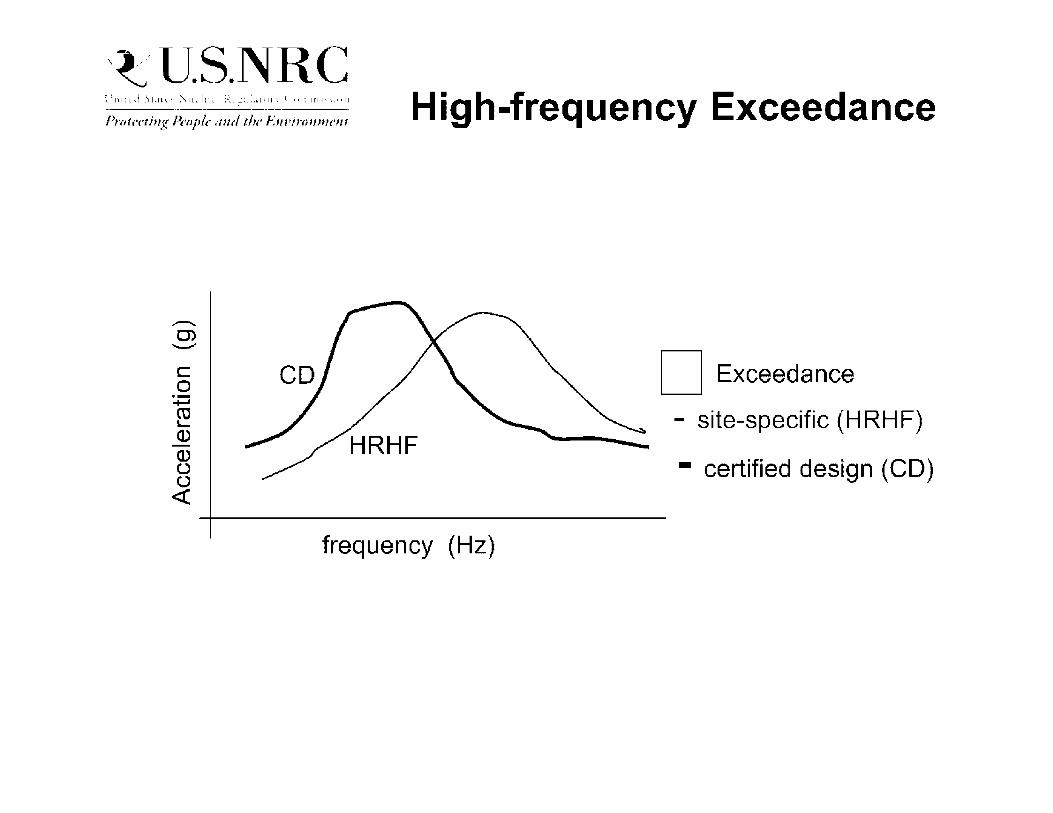
,~'U.S.NRC Prot,·ctiug lh,pl,· mu/ th,· F111•frrm11u·m
C 0
:;::::; ro L.. a., Q) (.,') (.,') <(
High-frequency Exceedance
D Exceedance
- site-specific (HRHF)
- certified design (CD)
frequency (Hz)
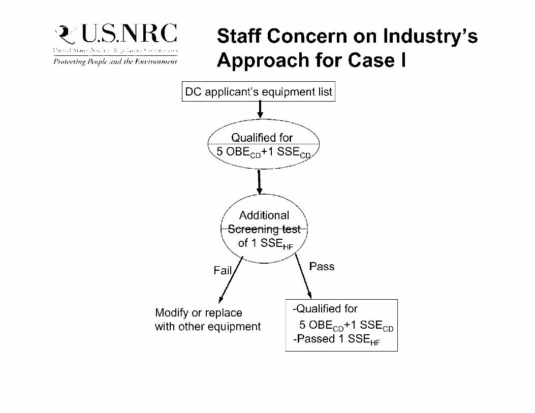
,~'U.S.NRC Prot,·ctiug lh,pl,· mu/ th,· F111•frrm11u·m
Staff Concern on Industry's Approach for Case I
DC applicant's equipment list
Additional
Modify or replace with other equipment
-Qualified for
5 OBEc0 +1 SSEco -Passed 1 SSEHF
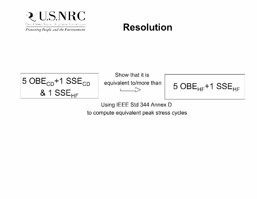
,~'U.S.NRC Prot,·ctiug lh,pl,· mu/ th,· F111•frrm11u·m
5 OBEc0 +1 SSEco
& 1 SSEHF
Resolution
Show that it is
equivalent to/more than r---~>
Using IEEE Std 344 Annex D
to compute equivalent peak stress cycles

,~'U.S.NRC Prot,·ctiug lh,pl,· mu/ th,· F111•frrm11u·m
..-.. 0) -- D Exceedance
- site-specific
- certified design
frequency (Hz)
- enveloped spectrum
frequency (Hz)

,~'U.S.NRC Prot,·ctiug lh,pl,· mu/ th,· F111•frrm11u·m
Interim Staff Guidance on HF issues for DC/COL (ISG-1)
applicant's equipment list I
Screenin Evaluation
Screened-out Screened-in

,~'U.S.NRC Staff Guidance
Prot,·ctiug lh,pl,· mu/ th,· F111•frrm11u·m
Staff Requirements Memorandum of SECY-93-087:
For nuclear power plants that were designed and/or licensed with the elimination of the QBE (plants with QBE defined as equal or less than 1 /3 of SSE), electric and mechanical equipment qualified by testing should be qualified with
5 x QBE + 1 x SSE
5 X 1/2SSE + 1 X SSE
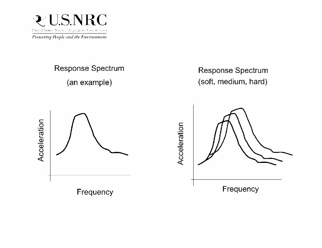
,~'U.S.NRC Prot,·ctiug lh,pl,· mu/ th,· F111•frrm11u·m
C 0
:;:::; ro '-a.> (].) (.) (.) <(
Response Spectrum
(an example)
Frequency
C 0 +-' m ~
Q) -Q) u (.) <(
Response Spectrum
(soft, medium, hard)
Frequency

ABC's Of Welding
John Honcharik Office of New Reactors
June 12, 2013

Agenda • What is a weld and where is it used.
• Welding processes.
• Weld joint design.
• Weld Procedures.
• Welder Qualification.
• Issues with welds. - Steels
- Stainless steels
- Weld defects
- Dissimilar metal weld degradation
- Weld residual stresses

Welding
• A weld: - A localized coalescence of metals or
nonmetals produced by heating the materials to the welding temperature, with or without the application of pressure, or by the application of pressure alone and with or without the use of filler metal.
• Is it an art, or is it science? • A bit of both (automation tries to take out
some of the art/skill)
Welding
• Welding versus brazing/soldering -An atomic bond between the atoms at that
interface is predominant, and the process that produces that joint is called welding.
- Brazing or Soldering • A mechanical bond is predominant at the interface
created by the process (brazing, soldering and thermal spraying)
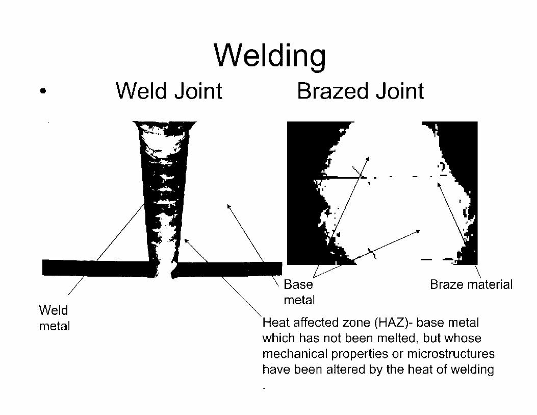
•
Weld metal
Welding Weld Joint Brazed Joint
Braze material
Heat affected zone {HAZ)- base metal which has not been melted, but whose mechanical properties or microstructures have been altered by the heat of welding

Where do you use welding? • Pressure vessels • Piping • Components
-CRD - Pumps - Valves - Internals - Core supports
• Just about everywhere you do not use mechanical joints (bolting)

Weld- Integral Part of Components

Weld - Reactor to Structural
~-- .... ...._ . ---....:: . .;-
- ..
~• 1 j' 1 1 lr ,1' i -tr 1 r ._. •• ·.~•I , r r 1 1 ,, • •ro I I r- r i 1 1.J • t I ril .! 1 rn• • ~ 1•·•' 1 ~ ,i 1'1, r1 I ~•, )
~., I',' , [ ~ ~ I j • I '"I • 1 • I > r • Ir I 1 '

Modular Construction Steel composite structures increases the amount of welding which was once predominately reinforced concrete.
. if • I
• I I . I i
1 I I , ' I
I
~
-- I I
I • •
'• .
':..
201213/20 12:49 •' ..

Welding Processes
• Processes most commonly used in the nuclear industry is Arc welding.
Annex D
American Welding Society Master Chart of Welding and Allied Processes
I llaJ ... ~Uhk b It•.•• .J p.ut · . .-1 .-\ ,s.1 ./.a~, ] . I •J\JI( \" • .;..'c'! . ."r.:. ,:~ ~ ... ·=.~·. ( ·1,!!.t~_:· . .... •t:,. A iJ .• ·~ .. ;-~-.A. I _,_,c.::i. t .... b U.1111.. hJ,lt."\I f .. ,r Hll•)nJuu•:,[L 11~.upi:-... c--. -:-ul~. 1
•.' ~ .
•. 1 : ., ·,
I • :
.: 1·
. ' ... •
-. !
- ·, - - ., - .
-· . _,.
-. ,, t ..
. <'

Welding Processes
• Shielded Metal Arc Welding (SMAW)
• Gas Metal Arc Welding/Flux Cored Arc Welding (GMAW/FCAW)
• Gas Tungsten Arc Welding (GTAW)
• Plasma Arc Welding (PAW)
• Submerged Arc Welding (SAW)
• Electroslag Welding (ES)
• Stud welding (SW)
• Friction Welding (FRW)
• Laser Beam Welding (LBW)

Welding Process - SMAW • Shielded Metal Arc Welding
- Welding arc produced by completing electrical circuit
- Uses flux to shield arc and weld metal from contaminants and oxidization
UAG
WELDING PROCESS
,-om11wi GUI~,
· IIIC 110D1 01

Welding Process - SMAW • Flux can also add alloying elements to weld
• Filler metal designation example : E7018 (E-electrode, 70 minimum tensile strength, 1-position (all), 8 - usability (DCEP, low hydrogen -iron powder flux)
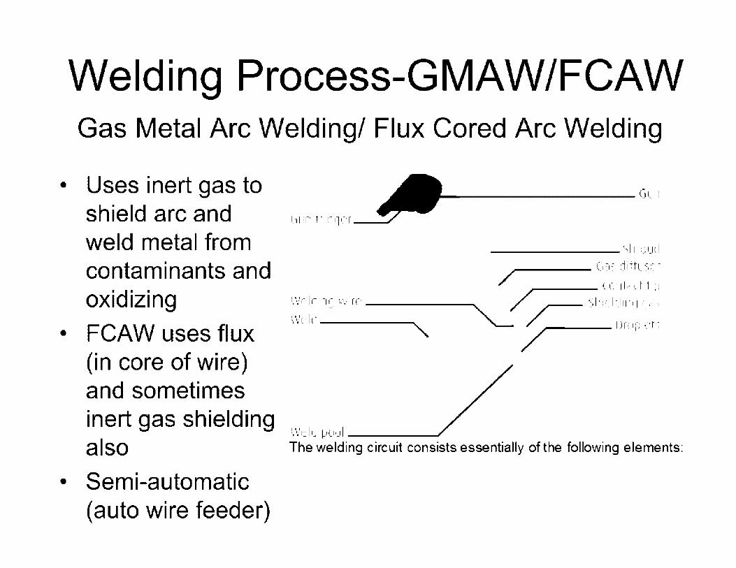
Welding Process-GMAW/FCAW Gas Metal Arc Welding/ Flux Cored Arc Welding
• Uses inert gas to shield arc and weld metal from contaminants and oxidizing
• FCAW uses flux (in core of wire) and sometimes inert gas shielding also
• Semi-automatic (auto wire feeder)
11 .-. .. r· I,- -1 i.- •.,r. '1 • r .... , '"······"·----
'/•.'t·l1·----,
The welding circuit consists essentially of the following elements:
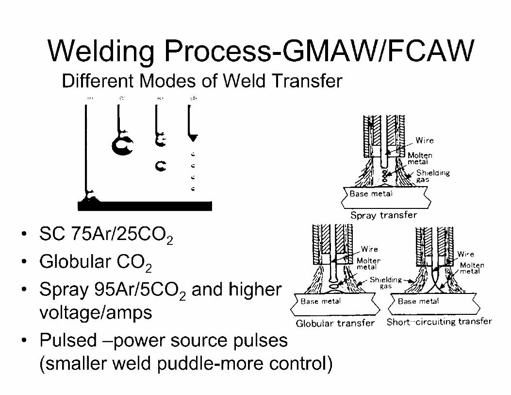
Welding Process-GMAW/FCAW Different Modes of Weld Transfer
l,i.l (~·-
Spray transfer
• SC 75Ar/25C02
• Globular CO2 Wire
11 Molten 1 metal
• Spray 95Ar/5C02 and higher voltage/amps
Globular transfer Short-circuiting transfer
• Pulsed -power source pulses (smaller weld puddle-more control)

Welding Process - GTAW (Gas Tungsten Arc Welding)
GTAW produces high quality weld, but low deposition rate
TIG torch
Gas nozzle
Tungsten electrode
Arc
Doped TIG wire -Welded metal
------!-' '
•
Cooling liquid (cool)
,~;~:: . Cable with current . . .. ~
Protective gas feeding
Cooling liquid (warm)
Protective gas from nozzle
Protective atmosphere
Hard metal

-VE • ··-
+VE
.. -
Power source
Welding Process - PAW (Plasma Arc Welding)
Turagstera electrodE-
Nozzle
Cooling watE-r
Plasma gas
, ShiE-lding gas \
• Similar to GTAW but uses additional gas to concentrate the arc.
• Can be used for hardfacing.
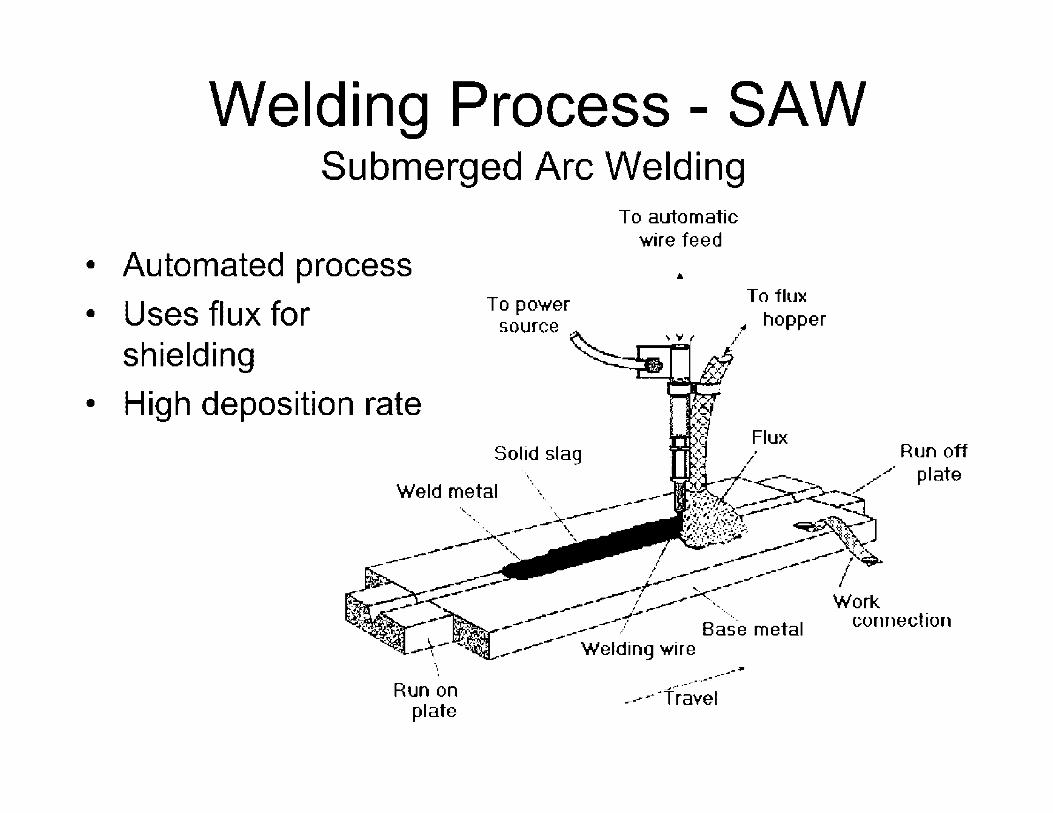
Welding Process - SAW Submerged Arc Welding
• Automated process
• Uses flux for shielding
• High deposition rate
,, '
Run on plate
To automatic wire feed
-· ~-_.,,,... .•• r"' ,..,,,-
-,.J' ," ·Travel
To flux hopper
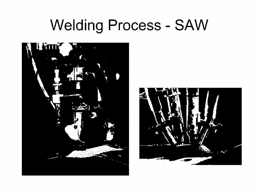
Welding Process - SAW
'·, -~ ·..- '\ i -~c•,~ \ • -t-~-! j ~ ~ ' . .. \ ~ . -- ~·-"9>, , • ...-•. , ', --~~ -.--.
'{ .,. .r_._
•J'• rr:·
,• •

Welding Process - SAW
Strip cladding - form of SAW with different shape filler metal (primarily for cladding).

Welding Process • Such high
deposition rates that it is similar to casting material
• Can affect material properties based on orientation of solidified weld metal
- Electroslag ELECTRODE WIRES
CONSUMABLE GUIDE
RUN OPP TAB
VERTICAL PLATES
SLAG
COPPER COOLING SHOES SHIELDING GAS SUPPLY WATER IN
WATER OUT
RUN ON TAB
• STARTING PL.A.TB
• Meta I crysta I solidification with dendritic growth from weld sides to center of weld having an acute angle results in stronger centerline bond (RG 1 .34 ).
ELECTROGAS WELDING

Welding Process - Stud Welding
Stud Welding with Drawn-A re oa,.amili:i. Fen'i..re ------1., Grouncl - ----,=,,--......_
Slud ie poellfoned i:i911in'511 wo~lcc:cto,.th•~ wi~IJ Ql!ln!lfflk r-e:m.i~.
ni9~b1X9S-Md. ca.u:sing &fuel ID be ~lfled 1rom WOrl(plOQO t11;1 ~11:1~w- ,:in arc: anCII -a-H ~I~ l::ra-M oh-tud :tlfliell m • tlng area on wor11plsce.
"Tlft'K!o' II IOp l!!i tn·g. a:T-1 d =&tuCJ IS i;ilunged Into 1111Jlbm pool can:tailned ib~ e,e,ramlc- 'l'lnrule.
Morter. po,¢1 SOridiritle;, ,::n:t,;Jlin(II a ho.muge,naou1:1 alruc,ure,
• Stud welding used in structural applications (temporary or permanent). • Mostly mechanized (Stud welding gun).

Friction Welding
• Uses nonconsumable tool to melt material due to pressure.
• No addition of filler metal.
Shoulder
llownw~1nl forct> to 11rni11t:.1in cnnt.u·t

Laser Beam Welding • Uses laser to melt
material in lieu electrical arc.
• Higher cost.
• Better quality.
• Piping inlays . • - • -. I . . . ·- . -· .-. . .
2 l 4 5 6 7 II 9 iO ~ 2 3 .... ,
t as t 1 Hl!'i:td
Pawdn
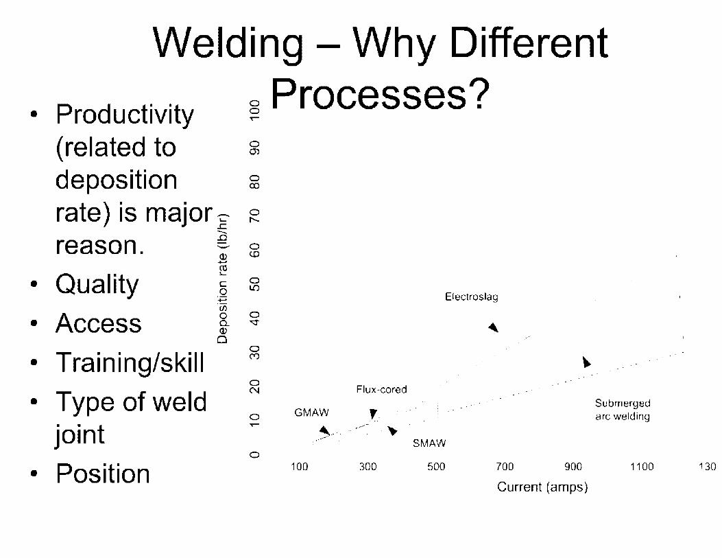
Welding - Why Different
• Productivity (related to deposition
8 Processes? T"""
0 a,
0 co
rate) is major~ ~ reason.
• Quality
• Access
• Training/skill
• Type of weld joint
• Position
-.c - 0 (]) c.o ...... ro 3..-
c: 0 0 I.!)
...... (/)
0 0 c.. v (])
0 0 C"')
0 N
0 -O·
Electroslag
Flux-cored ..
GMAW ,_. _ .. -· :. -- -. .. -, __ .. _.---~ . ~ .
:.··<· · SMAW
100 300 500 700 900
Current (amps)
Submerged arc welding
1100 130

Weld Joint Design
•Different Joint types depends on:
•Access •Efficiency/Strength •Ease of welding •Ease of machining •Welding process •Thickness •Distortion
i'IElhFORCEMEl>tT 0~ WELD\
[] ___ l~
f 7' t A
SQUARE GROO~ Wl!LO
R IIINCILE V GROOVE WELD
c- -,-DOUBLE -y• GROOVE WELD
0 SINGLE IIEYn OROO\IE WELD
F .CLE •u• CAoOYII!. WEL.0
G DOUBLE •u• QAOOVE WELD
H SINGLE •J• CIROOVE WELD

3-:-,,.- .. . ~. :,:-~' r~,, ',· ,!<-•L
, I • .'
I I . I
I '. '.. . '- _1··1,, 1·,
_; . , , , c ' I • '\:· l'l
r I
II, !l
• ~,'1t'I .t· '"' _....,...,...,........... ...... \ • / o:t1ora
' , . i . .. ·.·:·) _J ~ ..
·•.iF .. r .l. 1,•::~ Ln ~ I
A B
1c,1 GTA root- walls:, ·1i ::i 11~ ·~
Weld Joint Design .-
--~. • -1~1· ~-·
'
1 ' ·_.,1/' . I . .
.. !
i . -· ..... ;J,"'l,~ .·,··r·~. .. . . ' ~ • • • • I '
ii. ,.' r .. -<-·. I .,. , •~ I • / ,
.:. ·. : 1 .. Jo··mJ.\... . . ·•1+. ... /·' _. · • .L -.~ J. __ J :1 ;_ r, . . ,.i-l. ! .I
· !• 1n . 1------ .i
A B
1111 Walls~ 1 ·''
-•· .. r 10 ~,-
f -., .,....,...... , ,: ......... /·--/. ,, . ,
:;:,6 :~_ ~,,, ,,,,
1:1 1 GIA root- wall;;> ;•,1 "
•
•
•
Simple to Complex
Balance quality and productivity
Narrow groove weld uses less weld metal therefore faster welding (however, must be used with automated process)
Socket weld end

Weld Procedures
• Common/essential parameters (variables)
Depends on weld process and applicable code used
Typical parameters: • Amps/polarity
• Volts
• Travel speed
• Wire speed
• Base metal/filler metal
• Base metal thickness
• Joint (backing ring, EB ring)
• Shielding
• Preheat/interpass
UW-410 •.El•'.k)
r:, .... ~.~--n,\. 1;t~ . M!t""wtLt HCAT'flflllU'PUlN11-0will':I' I ,., •.. I!"• •• ti ......... -- -- _ . , ............... n...,., ~-~l ltt.all.L.611u.tt _ _ ,
.. ~.,. !111 _ ~-- --.
1 1111 • .i: ... ,-._. .... .._ ~ .:-•-- _. r-111 ... .,.VAKt!..IO Tor.en.___ _ __ I ........ , ....... , .. ,,1, •. KIA -· .,......._ •--- -·--- .1~_.,,.,,.....,, II/A ' '"'P••-1!&" ·Ql"l -11 ... 1 "•••r• • ' ....... , ,.,., I "'"'"HI ......... -. .. •--200:-- t.11.:,11~ "W..11,.,-4; •- ·•~r
1111·•-"'ll•'II• ..... L ""inq ~--, ....... r"'--""I'-• c:K!''.CI: 'fA{Ji l..lY.i:R. --- i !!.Jo-•1""'"" --ff[._A. - --- ---ir, ... ,...,. .., _ .1 .. .., ... ,..,..,.,., • ...,,~._,... •{IL,•11• '""'""'""-"" I ,...,.,.,..
l ....... HJ.A. --
t~t:-11·=.1LC.NJ1--. ... :..,1:•1i,1-:.:11a1111,-,111.)II ~ "- ...... ;..,.r;- :rx: , ........ _,_, --............... ,~ -1,n ,., .. ~ ... ,.ai.,..,. 1922 ·•-,-, ·-• ~ ........ ~-··· ~ ·~--, , ...•. ··••·- ... _.., __ .......... 'II: .... _ ••• Tl!,,~ ... ,,,.._,_..,-·.,~.-.. ,#"',.... N .. .11, 1,"'1'1111••111•1u,1•1111r•~t:11•~I
, ..... ,. •. ,- ....... -,~-N/A . -- -- . ·-·· . . A-· --''••·-~-~ -·· .. ::::::~:;::1~==-~· _:·····_~·_· __ -_-_-_-_
.:,,,~LP'V',•-t•" lln.,
' ··••·••Trl.,Hl"•lllll"'H N.JA. t - ~--
•'l,•'.lo......, .... H,•1!1- i::o••"'t .11,,.,.,.. .. 1 ::;, .'W! ..... ,a,u I~~ F..A n,I, liUiLE 11,ROSn OR Btrrr~J\
~:-.-.~·~.:..:-.1:.:: ~~ 1~1• ~.:•~ .a:::,;p=i11..__-~---. ........ tl/J. ~.:..:,__ ____ ..__ ____
.... ...........
J l ,. ~
NI~
.. t
' ---- I
+t,• -·-

Weld Procedures • Preheat - the minimum temperature in the section of the previously
deposited weld metal, immediately prior to welding
• lnterpass temperature - the highest temperature in the weld joint immediately prior to welding, or in the case of multiple pass welds, the highest temperature in the section of the previously deposited weld metal, immediately before the next pass is started
• Preheat and interpass - Prevent unwanted material phase/properties microstructure
• Untempered martensite • Carbide precipitation • Cracking, stresses
- Good toughness • Typically, increase in strength will decrease toughness {brittle vs.
ductile) • Need balance for each application

Weld Procedures
• Changes to essential parameters (variables) require requalification of procedure
• Changes to supplemental variables may require partial req ual ification
• Changes to non-essential variables do not require req ual ification
• Weld procedures are qualified in accordance with the applicable code and documented in a procedure qualification record (PQR).
• Note - specific codes only provide requirements on qualifying weld procedures and welders (does not state how to weld).

Procedure Qualification Record
• Base material are assigned to groupings (Pnumbers) to group similar metals (properties) to reduce amount of procedure qualifications.
• Filler metals are also assigned to groupings (Fnumbers) based on compatibility with base material characteristics.
• Joint designs, such as full penetration (groove welds- backing rings, double sided, EB ring), partial penetration (fillet welds).
• Base material thickness • Preheat and interpass temperature
Procedure Qualification Record • Positions. • Shielding (flux and/or shielding gas) • Electrical Characteristics (volts, amps, current,
etc. ) • Technique and other requirements
- Stringer vs. weave bead - Travel speed - Multipass to single pass, etc. - Cleaning
• Typically, NOE and tensile and bend tests performed on test assemblies to determine acceptability.

/4 .. I I.·_. ,•1• I Ii .. . .. . •. , _. I•
• I 0.,.-," .. ./ . ·-.-•/_/-•
~---• • I
I •• I • • • • •• -
·,: ··✓,1-· .... . . ...... • :· _✓/ /_."'
-..:.--- "'1/ # . .. ,\'-C--. ........ ..... :----( ·-• •• .. 11: I : : • 1•
•I •.• • ~
•,
,I'.·
#/ // ........ '"' I'. 'i,1:..•
I • .~ • ~ ••.1
/ ... I • .1.• . .... ... . /_.'
/ ·. .·) .-:-. • • I •J -- - - ·- ..
- .. I • .. II: . .. . . . : ....
: 1• •
A ~ j I I .
) .J ' ...... . ... ... ~ .. ... . : :-
\. I: .... . . . .,,1.,, ..
• I .. 1•._ ••
·1 : : : • .. ·.\ ·-..·.:, . • •, I \ ... · ... · .. .. . ·. . . .. . .
...
r, ROOVf.: 1••IE:LDS 11.:1 .. ·1· 1 • •• •• : .. •••
I •
... : , •• 1• 1• I t.••,:.•·~--··· ~- .. -.
,/·· -· .
-11 • : I • I : : ..
II : • 11 -:. • I • ... 1 • :.
... ..,.. I • : • ... : ~ ... II .. • -. . . ., ..... ... •• 1 .,,~ 1.:-.:- J -J ! ~
;~ . .J .---• .... .--·
•\.l',L •.-..: ••
•• 11 ~1••• I :•1 I -
-. · . ~--. ,.--... -. ·-.:. .::.- \ ·.
.... .. .... ... "i I .... :-.. --
1.1•r:-1• ••.
i 1 1 :•~ I : •
! ' -~ '. ! f J. ~ - ., ' I = . .. ·1 I ~=-- ;_-.--;I . { · :. ·1 . /~ /
... ..
~ . _.. 11 . l I • d I r. . I I" ••-.-., r1 •••• • • • / j -~•:+:::1.•:. :1:~f 1• -----:- I'•./~ : •
1 •• I ., 1: •., •• • - • I 1 1 1:. _,.: •: • • _:1
..... - ... , ••• - • A I • •I I • I I 0 ,/',,l'l":J r,- • "ii'J!"••.•., •• il.•.l,lil. ._
: • • .... I I 1:. ••• ._.11,11 J-1 • • I .:+ 11: I I =·· I •" ... ·1 •• :• -.:·1 --- - --- _____ :. -·-
•
•
Positions Groove qualifies fillet Plate qualifies pipe
For Plate QUAL[FIC:\TION POSITION RANGE FOR 11-IE SINGLE \'EE' GROO\'E WEL
W.-L:lu~ Posilio1L<: Qn;tlifitd Fo1
Groove Position I Groove Positions Fillet Positions
FLAT IG I F F.H HORIZONTAL 2G i F.H F.H
VERTICAL3G F.H.V F.H.V OVERHEAD4G F,H.OH F.H.OH
JG AND4G ALL ALL
NOTE Al.,;o Qu:lhfl("!ll fol pq1(" on•1 ~.1·· 1hasn11>lf:>l If b:H hug l<: R<;ed q u .. 1lifiqtiou i,; with b;lC l: iJ~

Welder Qualification
• Typically, a base material and filler metal combination using a given process is used to qualify a weld procedure for that specific material combination and process.
• Base material and filler metal combinations for welder qualifications are broader.
• Generally, welders qualify based on: - Filler material - Thickness - Process - Position

Welder Qualification
• Bend tests or volumetric examines are performed on welder qualification test assemblies
• Generally, a groove weld qualifies also qualifies fillet welds.
• However, this does not mean welders are not trained for different joint types, material combinations (welder qual. tests may use only one type of material), access, etc.
Issues With Welding
• Changes in microstructure
• Changes in material properties
• Introduce defects
• Introduce stresses
Issues With Welding-Steels
• Steels are affected by welding causing - Hydrogen cracking
- Brittle/hard heat affected zones (i.e., Martensite)
- Increase stresses (residual) during cooling
• Methods to minimize these effects (i.e., tempered martensite ): - Preheating base metal before welding minimizes
these effects
- Post weld heat treatment also minimizes these effects (i.e., tempered martensite).
- Temper bead welding

Issues With WeldingSteels
•Depending on composition and heat treatment can change material m icrostructu re/phase.
•Change material properties
.1--:)1:0
::"El~);' .'.!1:100
F.: B
y = Austeri•te a~ Fer", te 6 = Delio 1r'ori
CM= Cernen,.,-e I. r20 .~ :r--,i.~.....:1111....__ ___
1,;,:;,::: ~~52
• Al)s1enltc- solld solutlon of c.arbcm in gamma iron
: 'VQ-e:;rl!'1,c :1~1"4"' F"t :::-:;,n· fl.,:
Pe.irlile and Ce-mer-.lite
L
CM l;legins i ./' •4:).0
Primary au:srenite
/ticglns.to soUdify
lo SOI i t.1111'.I,' ~
I
AE.Jstentit-eled-cbur1•,c .and cementit,e
r + Fe:i,(.
Cemcntl te, pearl ltc an~ fransf• rm-ed lede-1:Jiurite
,
o!.~ i' n:~-...
;,·..:.1Q I Pearlite -i:lflcl fe-rrite
Ao . .. l•'lnq,ie1 ,r. c'" 1;mge- ;Jf :!:e 3 C , .
.::. ::: - -=- - ~ - ..... - - - ...... - - - - - - - - - - .- - .t... - - - - - ... - - - r - - - - - ..... 710 ·- ,.) 0:-B"I'. .II.~ ., I 6.Ei 7 •.
'
LHvpo-~~;:loid 'f '~·ypor-outeetoi<I___:_•• "· '"_j~ 6..,._
65¾
]. Steel -------..-..----- Cas• l1otl

Issues With Welding-Steels
• Different m icrostructu re affects toughness
• Verify toughness of welds/adjacent base metal by Charpy impact tests
t.WO ,--::::_:::---LO~~~~:R CRITIC'I.\I. TE\IPER.\Tt'RE - -"':,,_,,- --;;;.------.::::,.:_ - :;;;--;;;;.-----~---: - - - - - - - - - - - - - - - - -
UOO .\l"STt~Tn:. -----,.,, ',
1200 -':- 1100 -~ llM)O a: 960 I!,-.-___ ...,.
;;:)
~ HOO Q!: 700 ~ Q. (,00
~ 54)0
"" E- 400 ------JOO -
\
.\l"Sl\f~II. + BAI·~ IT~:
'. \,
',
\ ', ... \ ', ', ',
\
200 \I.\RTE'\SITE
TIME
\ ',
R.-\1"-ITE

Issues With Welding-Steels
Underbead cracking/hydrogen cracking
-;_ . · .. . ......
Stress induced/improper post weld heat treatment

Issues with Welding-SS • Sensitization (800° F to
1500°F.
• Cr carbides precipitate out depleting the grain boundary areas of Cr making SS susceptible to sec.
• Methods to minimize sensitization (RG 1 .44 ): - Material composition(low carbon)
- Heat treatment
- Weld heat input
- lnterpass temperature
=~~-:!~~ '.:: -~ '";; .. .:~ _-.;. '. ' ...... ~
~.....,;=:,,._---~-- • .. ~ .. -- .. -- •·
• - ,Ip .. •• - • -
-. ; : ·_ r .
·'
.,:
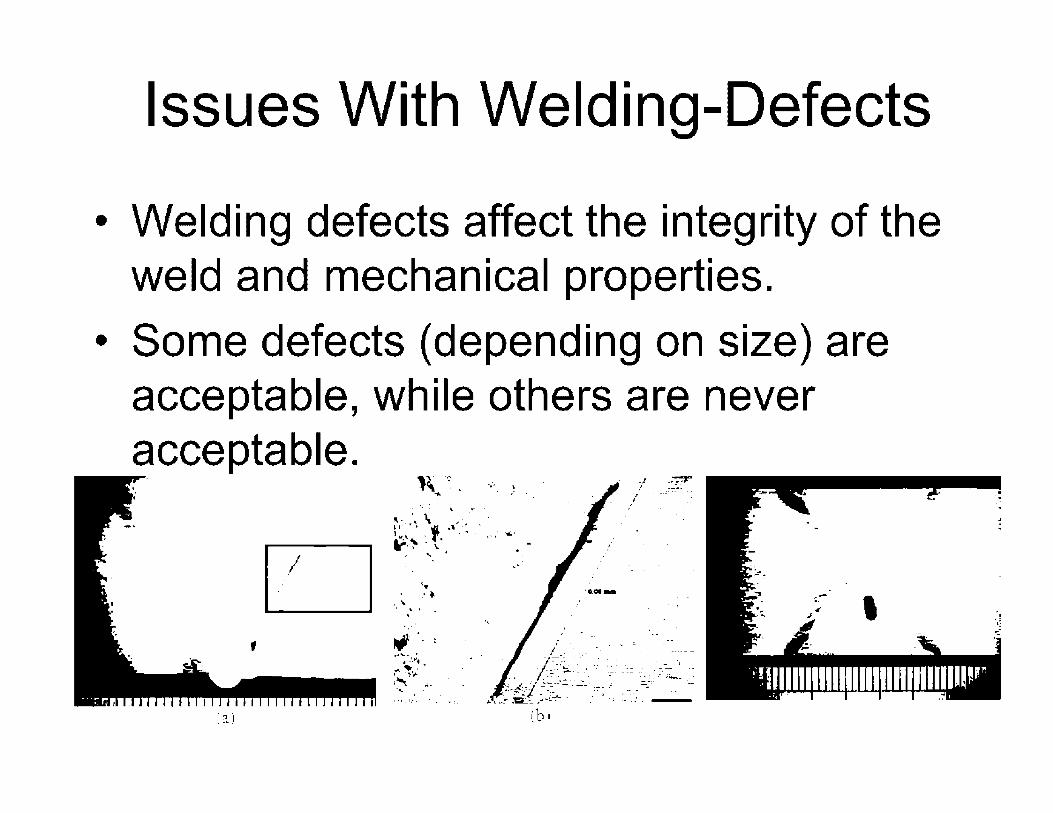
Issues With Welding-Defects
• Welding defects affect the integrity of the weld and mechanical properties.
• Some defects ( depending on size) are acceptable, while others are never acceptable. '
' (a)
,1· -.~ n~.. .;._ ) ..
"'-: 'I, • • ..,,. •
~- ·, \ ~· . . i,·.. ,a; .~ ,, .. ~.," . ,f . ... . .. , "'-"' __ ..... ~- ... ·
, ' .. .. ./ . .
'• ·, .'" . \. --• ...... ,.
...
. ·/ _:0-T . " . --- .
• I •. :' - . ,
i
.l .· .. ·
. ._._. -.~ ' ,r ,,
;~!lllllllllllllllllllllllllllll~~r ;,

Issues With Welding-Dissimilar Metal Welds
• Design use different materials for various components ( due to conditions/environment), and eventually these components need to be connected.
• Welding different material can create totally new alloys/microstructure (dilution) and affect material properties or resistance to aging degradation.
--------- .\/loy 82 '' rid ss Safe l•y~r.·1 , , . ~. ,; J t.: . , . .. . . , ~ F.nd/Pip< ~. It ,ts-! ) Allo~ Stet'.! .. , •:::.··:, __ . . . . . - . . . ~ -. i ~.. ·, -
. ' ' ' . ~,· ~ -. \ ~ 11.-.,r
. \ . - . . .
I ... - •
SS Clmlding -.. , ::(

Issues With Welding-Dissimilar Metal Welds
• Develop materials with similar properties (strength, thermal expansion, etc.) and still be weldable.
• Some alloys can be welded only in a particular way - Weld Ni based alloy to stainless steel, but can not weld
stainless steel onto Ni based alloy.
• New degradation mechanism may occur
- Primary stress corrosion cracking (PWSCC) • Ni based alloy (600) in PWR water previously was
thought immune to SCC
• Need to develop new alloys and how to weld them.

Issues with Welding - Crack Growth
• New alloys or welding processes
• Learn f ram past experiences
• Tests to simulate aging degradation in evaluating long term integrity

Issues with Welding - Residual Stresses
•Stresses can lead to long term issues/aging degradation (i.e., SCC}
Hoop stresses before and after repair weld
Before Repair l\,tain ,Yeld
After Repair l\'lain ,veld
46

Summary
• Welding improves productivity but can change material properties or microstructure of material being welded.
• Need balance of productivity, cost and level of quality.
• Weld procedures are qualified by the fabricator to specific codes (each code may have different requirements).
• Welders are trained and qualified to the specific codes.
• Codes used to qualify weld procedures and welder; does not provide instructions on how to weld.
• Issues with welding including long term degradation have to be taken into account.

Application of Lessons Learned from Flow-Induced Vibration to
New Reactors
Thomas G. Scarbrough
Component Integrity, Performance, and Testing Branch 2
Division of Engineering
Office of New Reactors
U.S. Nuclear Regulatory Commission
May 18, 2010

Introduction
• Some operating nuclear power plants have experienced failure of safety-related and non-safety related components from flow-induced vibration (FIV).
• FIV significance caused by acoustic resonance was not recognized during previous Design Certifications.
• Lessons learned from FIV operating experience is currently being considered during design, qualification, and surveillance planning for new reactors.
• NRC staff reviewing potential FIV in Design Certification and Combined Operating License (COL) applications.
FIV Safety Significance • Severe hydrodynamic and acoustic resonance loads can
cause failure of safety-related and non-safety related components in reactor, steam, and feedwater systems.
• Failure of safety-related or non-safety related components might cause sudden reactor transient.
• lnoperability of safety-related components (such as safety relief valves) might not be revealed until component is signaled to perform its safety function.
• Failure of non-safety related components can cause small pieces to interfere with plant operation, or safe shutdown.
• High steam moisture content from steam dryer failure could damage reactor turbine if shutdown not initiated.

FIV Operating Experience
• Quad Cities Unit 2: Steam Dryer (June 2002/June 2003)
• Quad Cities Unit 1: Steam Dryer (November 2003)
• Quad Cities Unit 2: Steam Dryer (March 2004)
• Quad Cities Units 1 and 2: Relief Valves (January 2006)
• Palo Verde Unit 1: Shutdown Cooling Piping (Dec. 2005)
• Waterford Unit 3: Steam Generator Internals (April 2005)

Boiling Water Reactor Pressure Vessel
rv1SL Inlet
., ....,.++-1~ Skirt
I llJ I -- .

Quad Cities Unit 2 Power Uprate
• Quad Cities Unit 2 - June 2002
- After 90 days of Extended Power Uprate (EPU) operation, steam dryer cover plate fails with pieces found on steam separators and in main steam line (MSL).
• Quad Cities Unit 2 - June 2003
- After additional 300 days of EPU operation, steam dryer experiences failure of hood, internal braces, and tie bars.

QC2 Steam Dryer Failures 2002 and 2003
,•n;i
_ .,,.- -"f¼,_-~~-1,rr 1--: 11(,i'! - ~• •
.,..----·- I I~ k ---. ..___...., 11.1:,-r ~ r-~,-~·.-.. r.·. '-r-~,,.. __, __..._ K_ ..., -..:.,. , I--•• ~ _... ..• '· .... ...._.... ,
,l-~(,1 ❖.··~•l-'r'r· , "..::'--~ ':---, -....'::._...,~ H:-::d ------------ ... ✓ ..... ·-• ••- .. _ -.._ • I ,. _,. -..,_..) -..,;;_..,_
Top of Cuter Hood ~.; ... ;,-'"":-..__ .......... --... ~-~ .... i:a-::i:2.::::3F~iure ~-.... 1"' ~ • .-.- ··-........_, '~~....._:·
~ -·..... ,. .. 1-. Location) 'Z_,.., .. · ........ ".. ~ ... )-:,__.... ,,
-... ~ . .-;';-" .....
-(~~~ .... ::~.->-"·,..... 1·:1:-,i "., ~~~--~ '-.~~~~•'· ....
'• ... cj-":1_ S • I ~ I I ...... •~ _~ .. _ r,-?-. · ..... ..._ ........ . l·S . j' ~ i I ! .... .._-.... k J . .,,:r.. .:-,-. .., ....-: .~ .. ~ • ~ . • ...._..._
:, .. J --. Ji ·v1~~- · .. :_ ,_ J· ... __ ;-~ ; J ~-.... __
:=1 . ""' .... -.....: . ...._ 'll-_ ............. l·,<'1,; _,{:~-.:: .. ),..,.....-') 7~ ., " . ""'';I '•,:;:...·:i.. _.-" : 11 .... i,:1,1:11 _,- ---.
·"",·'"""-;>., ................... r - ... r 1 .. 1!··:.. :" ~l Ii· ... ,.............. ~
~, . ) ___...-............ i ~ __ ....._ _ _._ ___ ......._·=----=.: ._ ). ..._ ~ _,. -• .,,.· . ~ ..._ . I ,, , -- - ~ ~,U.-,...- - _,.,..• I \111:1~-- rl 1-.1
co .. ·e!'" p Gite - --- - ' ., --- - '. ~~I ,j (GC1 2002 1,;_. ... [I.,,.,, •
.,'H'~I L $. h"A:. f I
F~ilLHc Lo cGitio n :1
__, "-.t-:111"11 -i1-1-:
~ ....... -..~=· "=• r-~ ~-- .1)1 [:,I;.
.,_. r: t
I.,,.,._, ~l .. ~.,.I: ::; I•·_/
_.,,.
.',-' .I(
}/ ,,.·/
·/
I
J
I f
/' ~·

Quad Cities Unit 1 Power Uprate
• Quad Cities Unit 1 - November 2003:
- After about 1 year of EPU operation, steam dryer hood experiences significant cracking with 6x9 inch piece of outer bank vertical plate missing.
- Damage also found to • Main steam electromatic relief valve (ERV)
• Steam line supports, and
• High Pressure Coolant Injection (HPCI) steam supply motoroperated valve.

QC1 Steam Dryer Failure November 2003
270-0 Side

QC1 Steam Dryer Failure November 2003
Outer bank vertical plate 6x9 inch hole

Quad Cities Unit 2 Power Uprate
• Quad Cities Unit 2 - March 2004
- After about 8 months of EPU operation, numerous steam dryer indications identified during refueling outage inspection including
• Cracking near gussets installed in 2003,
• Broken tie bar welds, and
• Damaged stiffener plate weld.

• •: -.. ,.. . . ,
I ;
1
Plate attachment stitch weld
QC2 Steam Dryer Failure March 2004
Tie bar welds
Tip of gusset plate

Quad Cities and Dresden Steam Dryer Replacement
• Replacement steam dryers for Quad Cities and Dresden are stronger and more streamlined than their previous dryers.
• Exelon replaced Quad Cities steam dryers in Spring 2005.
• Exelon installed pressure, strain, and acceleration instrumentation directly on Unit 2 steam dryer to determine steam dryer loading and to calibrate acoustic circuit analysis.
• Exelon installed strain gages on main steam lines to measure pressure fluctuations as input to acoustic circuit analysis to calculate steam dryer loading for QC1 and other plants.
• Exelon replaced steam dryer in Dresden Unit 3 in 2006, and Unit 2 in 2007.

Outer Bank Hood
' Cover Pl,arte
M rd support~--- ----Ring
Skirt
~ llfling Lug QC/Dresden Replacement Dryer


ERV Damage at Quad Cities
• In late 2005, Exelon identified intermittent short circuiting of safety-related Electromatic Relief Valve (ERV) at Quad Cities Unit 2.
• Exelon reduced power in QC2 to inspect ERV actuator and found broken internal parts.
• Exelon shut down QC2 and found damage to other ERVs, and performed repairs.
• Exelon shut down QC1 in early January 2006 and found damage to its ERVs, and performed repairs.
• If ERV short circuiting had not occurred, both Quad Cities units might have operated with multiple ERVs inoperable or experienced spurious ERV opening.
Electromatic Relief Valve

Palo Verde Unit 1 FIV
• Long history of vibration and leakage of shutdown cooling (SOC) valve and piping at Palo Verde Unit 1.
• Vibration cause hypothesized as pressure pulsations in suction line from coupling between fundamental frequency of SOC suction line and vortex shedding due to RCS flow over SOC suction line.
• Licensee initially attempted an SOC nozzle modification but obtained unacceptable results.
• Licensee subsequently relocated SOC valve to increase acoustic frequency away from vortex shedding modes.
• Acceptable vibration results obtained.

Waterford Unit 3 FIV
• Failure of batwing supports in Steam Generator (SG) #2 internals found during inspection in April 2005.
• Most probable cause determined to be fatigue due to FIV.
• Nov. 2006 inspection found additional batwing damage in SG #2, but no damage in SG #1.
• Batwing weld repairs performed and selected SG tubes plugged to mitigate potential impact of SG tube vibration.

Acoustic Resonance FIV Cause
• MSL flow creates vortices when passing over branch lines.
• At specific flow velocities, vortices couple with acoustic mode of branch lines.
• Pressure fluctuations in MSLs can cause significant pressure loading on steam dryer.
• Severe vibration can occur in MSL piping and components, including relief valves.
• Acoustic resonance is difficult to predict and quantify prior to its occurrence.

Singing Safety-Relief Valve
s,- FETT lllf=LI E:F Villi LlatE

QC2 ERV 3D inlet flange acceleration with power level . ..
•
1.5
WI
i 1 •
C 0 = .. .. u -., 0.5 u
<
. ..
"" . .
. .
• . •'
~ . . ! • . • ... . .. . . . .. . . .. .. . • •
. . . . ..
. . .
'. .. . • . • ..
• • . . r . . ... :
..
. • . . . . .
• . '• . . : ' •
. ' . . ' . • .. : '
• • • • • • •
•
;, . . • . . :
! • . t .
.
. . .. i .... •'···. : .. . . .. ---~~ ....
• .
,. • • .. · ...
. . ~
" ;
.t ....... .
Io' ............. ... ......
'
. ..
. .
• •
. .
' .
•
. •
' •
. •
.. . ... .. ' .. - .. lo,i,. +
t I 1
I I I ... I I
. ,.
.. ,.., .
• I t .......
. . ~ • • ... ~···· .. . . ... . • . • • • •
111 • 1 ...... .. ...•
--~ ....... . . ' . -4,.., I.• .... ··- ...... • • • . ! I l • •
• . •
..... ' .. .. . ..... ......
. , J
I •
·'
-' ...... )· ... I . . •• I• • • . ...... .
. .
·-:·•··· ..... I•.., It• I ... •
II, • ' • •
• • • • • • . .. . .
.
. ..... ... .... .. ... .... t,..,,.
'· ....
.,l, __ _ . •
• ••••• i .. " ...
. .........
• • r • ; ! . . ,..... .
~~ . . • ............ ...
-. .... ".. . ....h••• • --..... ..: ...
~-- ....... . . .... .. .. "••111-. •
··•••Ill 41
--.... -.. ...
-...... ' ..... . •
. . •
• • :
t
•
-II ............. ' t
' ..... ................
.. . I • •• . ... -~ ..
" ........ . . ..... •
·--... ........... .............
.. "• '• I Ill,"•
... ....... .
' 850 •· I•.,.+••
• .. ..... It • .• . -... ,. •••• .... ... ·• 1
I •• • • .. '.... . .- .... ................. ......... 800
750 0
.. . . ... ,., 1111 ""'~-.
.. 'I ••••• . ,. .. ···•~.~- . . .. ,. ,· .. .. ... ..... ..... •
:'I' ...... . • -II··· ., ..... ·Ila •
• ... ,,,,,,.t •• . ·-. ...... ... ... ............ ~ .. • ,, ....... ......... "4 .... , • ••• •11111
.. •.... .. .. ..,. ......... ~ ...... .. " ...
.. 700
650pawer level fV1ll
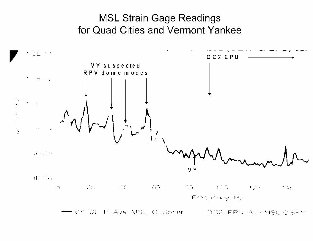
,
-. -
.... ,-' ,-,.,_J _ ..
- .
-- ....
' : ~ - t ' ......
, .JE:ir")
MSL Strain Gage Readings for Quad Cities and Vermont Yankee
• - - - - ' - - - - -- - - - , - - -
-·· .. .,,,··.....,,,
V Y s u s p e c te d RPV dome modes
l
1' ----+ '·.
QC2 EPU
VY
~r..=.·-••Jµ"l"'" L.j • 1 1 ___ ..._ .. .,_ ... .,. • t_ ... ~'f' . r . ,. ..
1)~ ~ \ ' ., --
\ "' 1 S · .,..._ -·- .. ~ · ~ . . C · ' L ' r~.-, ' .,, w ..__, ... ~ ._ -

Quad Cities Modifications
• In spring 2006, Exelon modified branch lines to 8 main steam safety valves and 4 ERVs in each QC unit by installing Acoustic Side Branch (ASB) consisting of 6-inch diameter pipe filled with screen mesh.
• ASB increases effective length of branch line that decreases frequency of acoustic standing wave, and lowers steam velocity at which vortex shedding will excite acoustic standing wave.
• ASB screen mesh dampens pressure fluctuation.
• MSL strain gate data collected after modification reveal pressure fluctuations and vibrations reduced to pre-EPU levels.

ASB Modification r-~\ • • ' ..
( ! ) ~ I I •
/ I ~ . I
l, rriJ I • • I
__ .i_ __ ..l.. __ _j_ __
F -----T" •• !I ---------- I ___ ., •.._ / + / \ • I
-- L_ -- - - ..i _ ___.__
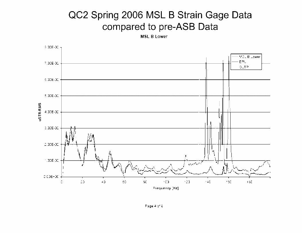
.::,_JCE-J:
QC2 Spring 2006 MSL B Strain Gage Data compared to pre-ASB Data
MSL B Lower
'. JCE-J: -+-----------------------• -------+------+-1 -- E~L
e,.JCE-J: ----------------------------------
~,.)CE-J: ..,...__ ________________________ ...,._ _____ _
~ 4.JCE-J: ------------------------1-f---ll-++--+-,1,------
==
.=-.JCE-J: -+--_..,....t ___________________ __,-+ ____ ·-- ,_+-+-+-------
t :.JCE-J: __ y __ ~ ~~ r/. - _....,..._ .............. _____ _
\.~~I , 111,1 11
-.JCE-J: ..,........ __ , ___ ~~_,, __ ~_-s, ,,.. r.. ,... ""F'-' ~1---\d- 1 1 ,.,T" ,' \~-~ I ti _.,1,, .... , r·\ ,; i ,.,~-.,·, ,.r- L t,~~ ', ,•' ··, C_, \l \::."'i • I ~ .. .,.. ,... ...... •'-.f' ' • .., .... '- , .,/ ... V --.•, '\\,_/'•. / 1..__ ,.. .I 1, I f J 11 ri r... ' • ,-, ~1,-.-;.......--.-.··~-·'_ ...... _..-, ,_, "'-.. ~ ,,i I , ,\ -"--"-.. ,---.-v
~ "'-,/. •..:::......-- '-....,..._,.....,. -...--............. ' U U ,.__ _ ·, I ~ \ - -.. ,,,.______,,,.,,
::: CJE-JC ---------------------------------------. C SC 1CJ
Frequency [Hz]
. ·-1_1 • 9C BC

J 3
J2
J 1
C.C•~
:J
QC2 Spring 2006 3E ERV Accelerometer Data compared to pre-ASB Data
Q2R18 Accelerometer Trends 3E ERV Inlet Flange - X
--.- :, E ER·/ nl~: F 3~9i!!- • :•. -_e\•.;,I , A :: ::-ii= 1,,:!.n,:-:i Cr 14:'ri~
_e· ... ~I 2 A :; :;-:r: 1Jtr'lC ':' Cr 1~ri,:i
-~-E i:R',' Ir e~ Fl;, "'IQ'i • "· :
--rl;-.:,E ER'o"--+ 51ori:..3I • ::,. I I
J ~/
- ~~-~----- :-- ---~~ -..,. ,o,-----0-
- - .i:i - -- - . - --. . . .. -c,, - ·-0,.
C eo: 1CJC .2JCJ
Core Them1al Power. MWt

Industry Response
• Scale model testing and acoustic analysis methodology developed to evaluate acoustic resonance in MSLs.
• GE updated its steam dryer inspection guidance (SIL 644 ).
• BWR Vessel Internals Project prepared generic guidance: - BWRVIP-139 on steam dryer inspections
- BWRVIP-182 on demonstrating steam dryer integrity
- BWRVIP-194 on methodologies for demonstrating dryer integrity
• BWR Owners Group prepared lessons learned report on power uprates.
• GEH developing Plant Based Load Evaluation (PBLE) Methodology for evaluation of acoustic load on ESBWR steam dryers.

Operating Plant FIV Status • Vermont Yankee Power Uprate (March 2006): MSL data
collected during power uprate ascension without significant FIV. Inspected dryer following power uprate and found lntergranular Stress Corrosion Cracking (IGSCC).
• Susquehanna 1 and 2 Power Uprate (Jan. 2008): Steam dryers replaced with upgraded design. Dryer data collected without significant FIV. Unit 1 dryer inspection found IGSCC after 2-year power uprate operation.
• Hope Creek Power Uprate (May 2008): Steam dryer upgraded prior to initial startup. MSL data collected without significant FIV.
• Browns Ferry, Monticello, and NMP2 Power Uprates: under review
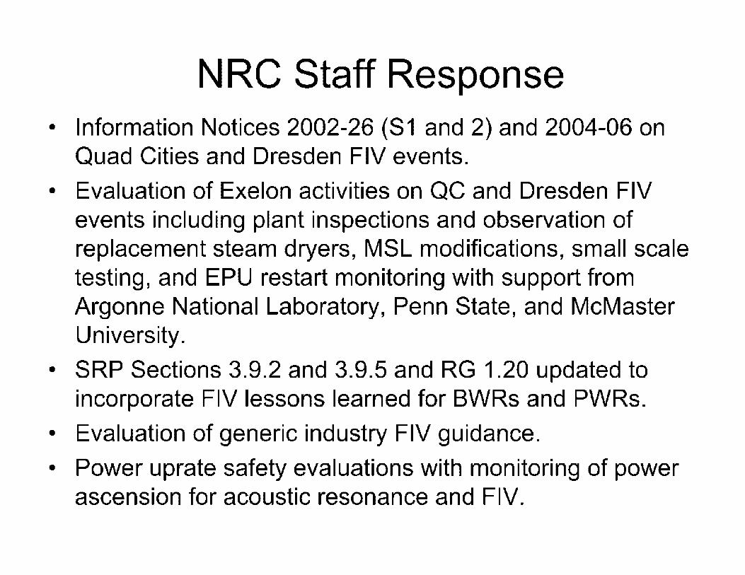
NRC Staff Response • Information Notices 2002-26 (S1 and 2) and 2004-06 on
Quad Cities and Dresden FIV events.
• Evaluation of Exelon activities on QC and Dresden FIV events including plant inspections and observation of replacement steam dryers, MSL modifications, small scale testing, and EPU restart monitoring with support from Argonne National Laboratory, Penn State, and McMaster University.
• SRP Sections 3.9.2 and 3.9.5 and RG 1.20 updated to incorporate FIV lessons learned for BWRs and PWRs.
• Evaluation of generic industry FIV guidance.
• Power uprate safety evaluations with monitoring of power ascension for acoustic resonance and FIV.

Power Ascension Program • License condition provides slow and deliberate power
ascension with lengthy hold points and data evaluation.
• Monitor and trend data (e.g., pressure transducers, strain gages and accelerometers) hourly with 96-hour hold point for data evaluation and walkdown every 5% power when approaching full power.
• If data exceed limit curve, return to acceptable power level, re-evaluate dryer loads, re-establish limit curve, and perform assessment before continuing power ascension.
• Power ascension report to be submitted within 60 days.
• Conduct visual dryer inspection of all accessible, susceptible locations at first 3 RFOs, then long-term BWRVIP-139 plan.

N RO Activities
• Monitoring FIV operating experience for lessons learned applicable to new reactor review.
• Reviewing Design Certification applications for evaluation of potential adverse flow effects.
• Reviewing COL applications (e.g., STP Units 3 and 4) for consideration of potential FIV in design, testing, and monitoring programs.
• Assisting in planning IT AAC inspections for design, quality assurance, fabrication, and testing of plant components that can be adversely affected by FIV.

Summary • Acoustic resonance in reactor and steam systems has
led to failure of safety-related and non-safety related components at BWR and PWR nuclear power plants.
• Potential for severe hydrodynamic and acoustic resonance loads was not recognized during previous Design Certification reviews.
• Nuclear industry addressing FIV for new reactor designs, new reactor license applications, and operating reactors requesting power uprate.
• NRO staff evaluating FIV in Design Certification and COL applications to ensure lessons learned addressed in reactor design, testing, and monitoring.

Surry EMD Diesel Failure, Notice of Enforcement Discretion, and
Generic Implications

Contents
• Surry diesel wrist pin bearing failure
• Notice of Enforcement Discretion
• Industry OE
• Generic Implications
• Lessons Learned

Surry EMD 645 Emergency Diesel Generators
.. I
"-':·_~ -~ ~- J ~- --~ .l II LI ........... . .,. -
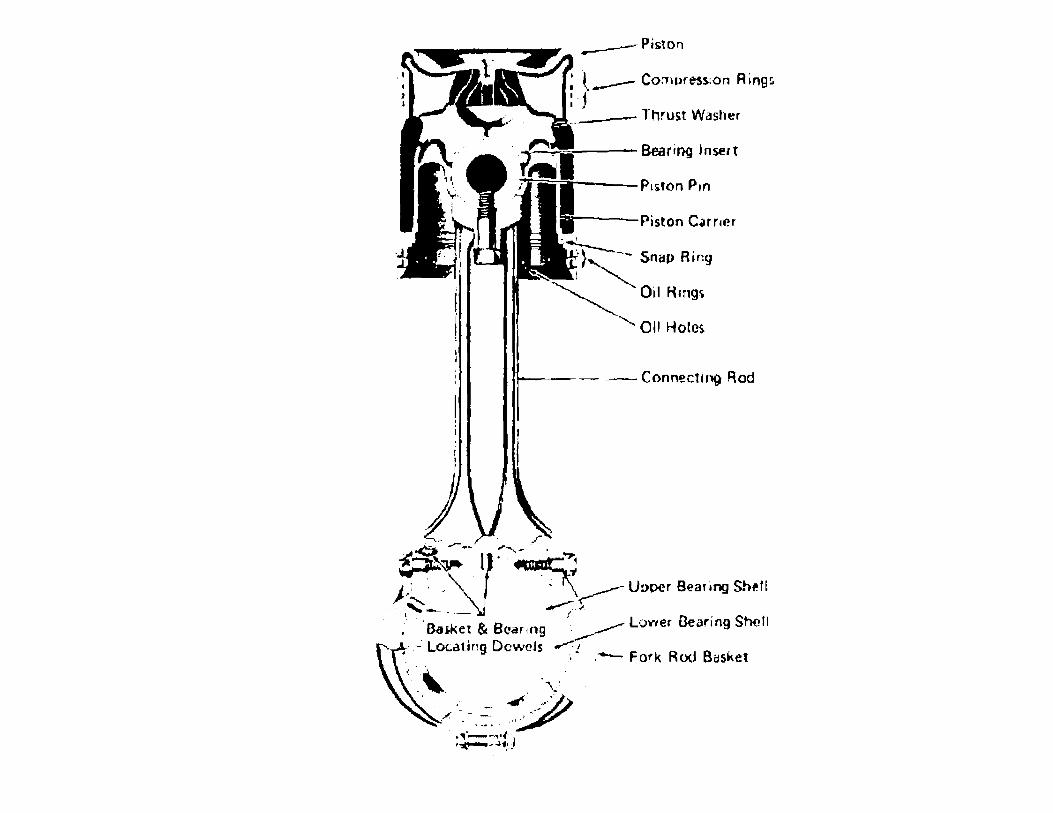
;..._..---Bearing Insert
Piston C.imer
·~ ;>~ Sn~p Ring
~ Oi!Hmgc;
'- OH Holes
- ~- Conn-ecting Rod
1
) ~ ' f <;, --- ,' .
,(~ ... ~---l :---.~~' ~--r: ' . ~ f\ J:~~,- __ ~y- Upper Beafing Shi-H ' ,
, 'Bas.ke~ & Bearing '-_______-Lower Gearing Shell -~ Lot.at mg Dow~h .-. ,
. ~ .- Fork Rod Bc1sket
' ,.,i ' ..r-~~·· --- -- ,.,-1 _/: - '·,
• • ..... ~ ' ',I • '.,--,.,,(-·, ,.,,,_,.Jot:;
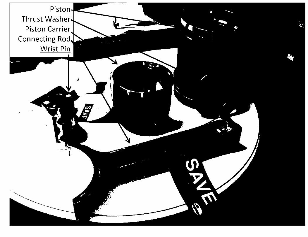
Piston Thrust Washer
Piston Carrier Connecting Rod
Wrist Pin

Gravity oil drain hole to wrist pin & bearing

Piston Carrier
(from the bottom~
I . I I
\/lrist pin Bearing
I ~ I
~- .IL . ' .

P-pipe
.~.
-:1-'9 ~~. ~./.·.·
~ ~- ,! - .. !.ii":· . 1;1 .... -. ~t.,..:. ~ ~- ·.
' .. · . . . .... .
.. \

Wrist Pin Bearing Failure Timeline Date Time
8/9/2012 14 :26
8/9/2012 19 :08
8/9/2012 23 :43
8/10/2012 00:05
8/10/2012 01 :46
8/10/2012 11 :46
8/11/2012 09:45
Event
EDG slow started for beginning of PMTs.
After -2hr loaded run, EDG load reject test performed. An oil sample taken during loaded run showed silver level as less than the detectable threshold (0.1 ppm)
EDG fast start test (minimum starting air pressure and fuel rack held closed during first crank cycle). EOG was shutdown 15 min later with out being loaded.
A second fast start was performed and the EDG was loaded.
The oil sample tube fell into sump during sample attempt. When lube oil samples obtained, 0.23 ppm silver. EDG continues to run loaded for - 2 hrs. Silver flakes found on bottom of oil sump after it was drained to retrieve sample tube.
Cylinder #5 wrist pin bearing found damaged with silver material blocking the oil hole.

di . . ~
Iii • ·r ... t. .... f'.• , • ..,,.
....
' . • _,,,. ~ -·,r
i,I
~ " ,..
,;,~·- ,,,,, . . ' .
' •
' . \
' I
f
.. "
t \
\

Exposed shiny silver
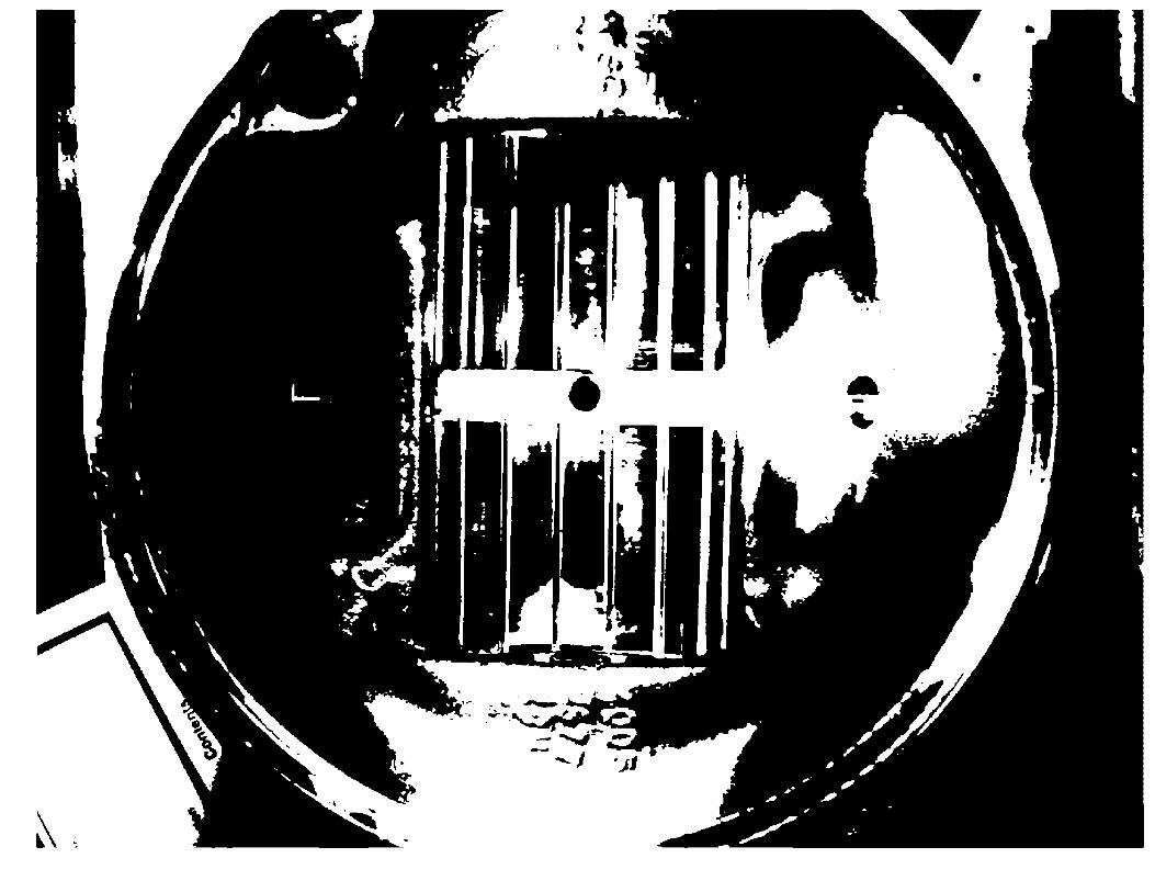
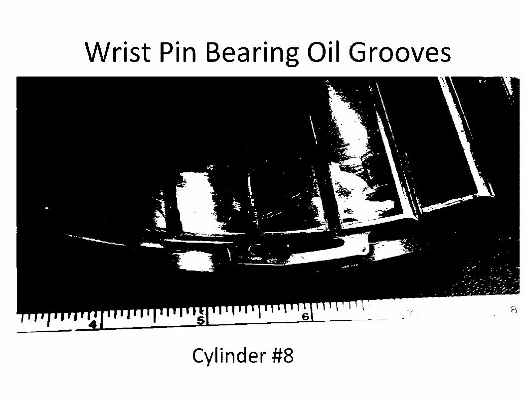
Wrist Pin Bearing Oil Grooves
Cylinder #8

I"
w
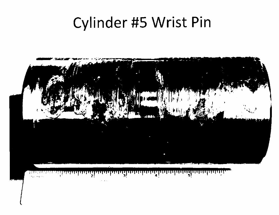
Cylinder #5 Wrist Pin
' 1 I • 1,
--..:....~··•
, I' I
••/ ·-

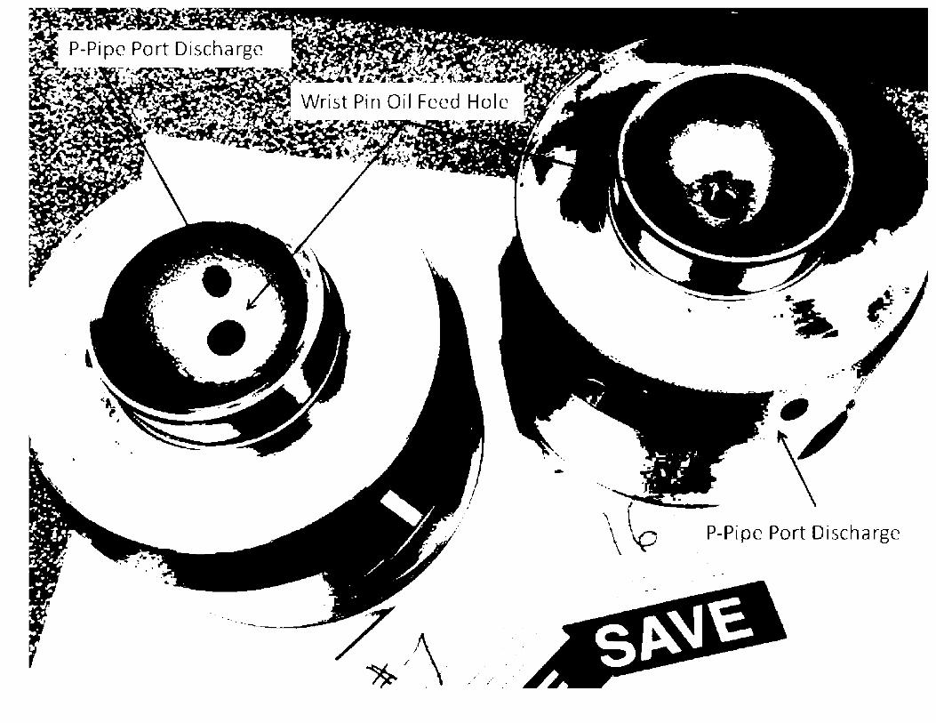
..
P-Pipc Port Discharge


NOED
• EDG #2 maintenance package started on 08/06, damage identified on 08/11
• Surry EDG Tech Spec allowed outage time is 7 days
• Al I power packs must be replaced
• NOED discussions begin
• Several internal calls were held
• NOED granted verbally on 08/12 for additional 7 days AOT with comp measures in place
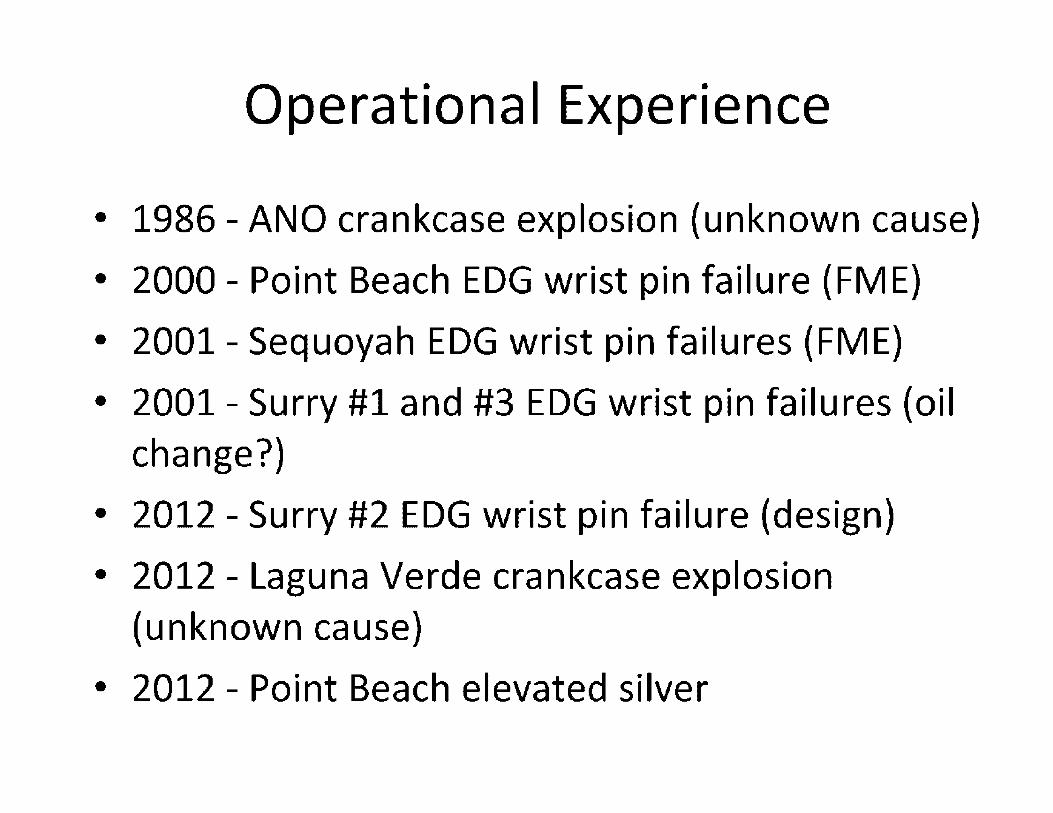
Operational Experience
• 1986 - ANO crankcase explosion (unknown cause)
• 2000 - Point Beach EDG wrist pin failure (FME)
• 2001 - Sequoyah EDG wrist pin failures (FME)
• 2001 - Surry #1 and #3 EDG wrist pin failures (oil change?)
• 2012 - Surry #2 EDG wrist pin failure (design)
• 2012 - Laguna Verde crankcase explosion (unknown cause)
• 2012 - Point Beach elevated silver
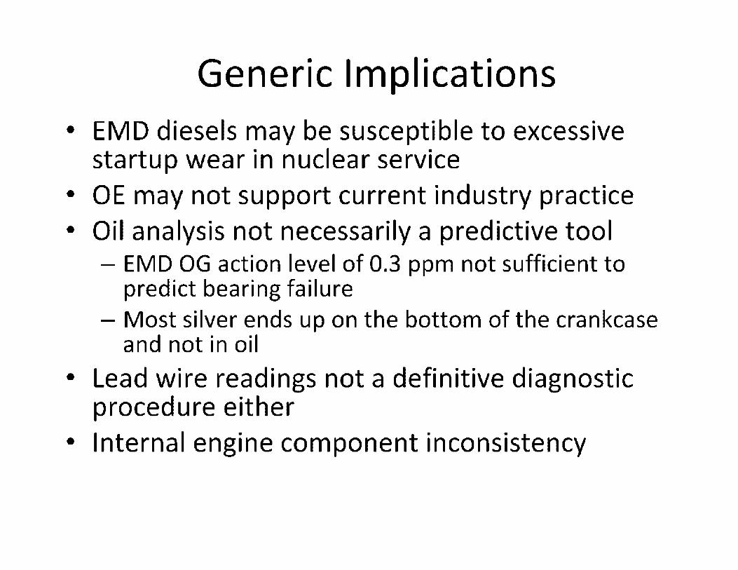
Generic Implications • EMD diesels may be susceptible to excessive
startup wear in nuclear service • OE may not support current industry practice • Oil analysis not necessarily a predictive tool
- EMD OG action level of 0.3 ppm not sufficient to predict bearing failure
- Most silver ends up on the bottom of the crankcase and not in oil
• Lead wire readings not a definitive diagnostic procedure either
• Internal engine component inconsistency

Lessons Learned
• Even supposedly well proven equipment can have unexpected failures
• Closely following licensee activities will pay dividends
• NRC engagement with licensee and collaboration across offices enhances industry safety - Contact HQ and other regions/residents with any
information that may have generic implications
• Use of Confirmatory Action Letter for one licensee allows NRC to push other licensee to take early measures - R2 CAL gave R3 leverage with Point Beach

"New,, Bronze Style Bearing
• -
._ L .. ....... --
- -- . ...-
,. · ..
- - ---
.-
.. , , ,

"New" Rocking Style Pin

\~U.S.NRC United States Nuclear Rcgu1atory Commission
Protecting People and the Environment
Key Principles of l&C Systems Architecture
,~'U.S.NRC Objective Prott•cting Pn,pl,• mu/ th,• f:m•irnnmi'm
• To inform staff on the key principles of l&C systems architecture to ensure that plant safety is maintained and to provide lessons learned from recent l&C systems
• reviews.

,~'U.S.NRC . """'·'''·""''"""",,,; ... ,.., '"'"""" l&C Systems and Their Purpose Prott•cting Pn,pl,• mu/ th,• f:m•irnnmi'm
• Monitoring of plant parameters
• Control of plant processes
• Protection of the plant during and following any anticipated operational occurrences or postulated accidents
• Auxiliary functions (e.g. control of HVAC systems)

,~'U.S.NRC Prott•cting Pn,pl,• mu/ th,• f:m•irnnmi'm
• Redundancy
• Independence
• Diversity
• Determinism • Simplicity
Key Principles of l&C Systems Design

,~'U.S.NRC Redundancy Prott•cting Pn,pl,• mu/ th,• f:m•irnnmi'm
• Redundancy in l&C safety systems can be used to achieve system reliability goals.
• l&C safety systems should have sufficient redundancy to meet the single failure criterion and provide for maintenance and testability.
• Redundancy should not be compromised through a dependency or interference.

,~'U.S.NRC Prott•cting Pn,pl,• mu/ th,• f:m•irnnmi'm
Independence
• Independence between redundant portions of safety l&C system and between safety system and non-safety l&C systems - Physical Separation
- Electrical Isolation
- Functional Independence
- Communications Independence

,~'U.S.NRC Diversity Prott•cting Pn,pl,• mu/ th,• f:m•irnnmi'm
• Diversity is the use of different means including function, design, principles of operation, and organizational and development strategies to compensate for failures within a safety system.
• Diversity is used to address common cause failures (CCFs) of the safety system.
• To mitigate against CCFs, diversity can be provided within the safety system or it can be provided through a diverse back up system.

,~'U.S.NRC Determinism Prott•cting Pn,pl,• mu/ th,• f:m•irnnmi'm
• Safety systems should be designed to operate deterministically. - Predictable: having a known system output at any
time in which a given set of input signals will always produce the same output signals.
- Repeatable: having the output of a system being consistently achieved given the same input and system properties.

,~'U.S.NRC Simplicity Prott•cting Pn,pl,• mu/ th,• f:m•irnnmi'm
• Simplicity is considered to be a cross-cutting principle that affects the fundamental design principles.
• Simplicity of l&C systems design supports demonstration of conformance to other key principles such as independence and defense-indepth.
• Given several design options on how to implement a function, the more simple design options are those that accomplish the function and address potential hazards with the most confidence and clarity.

,~··u.S.NRC Challenges of Implementing Digital ;~;;;,:'..~;:;~;:;;,~;:,:::;~;;::·;::,:.;;:;;;;~;::;;; Tech no I ogy i n I & C S yste ms
• New failure modes in digital l&C systems may challenge defense in depth measures.
• Some digital l&C systems designs are highly integrated and unnecessarily complex, making demonstration of compliance to key principles difficult.

,~'U.S.NRC Prott•cting Pn,pl,• mu/ th,• f:m•irnnmi'm
Lessons Learned From Recent Digital l&C Systems Reviews
• Several applications had highly integrated systems without an understanding of the potential adverse effects on safety due to this integration.
• Applicants did not provide adequate justification for including additional functionality in l&C systems that are not necessary to perform the safety function but may challenge plant safety.
• Not all digital l&C failure modes were addressed by the applicant. - Control systems failures that can adversely impact safety. - Communications failures and functional dependencies
were often not adequately addressed. • Applicants often times provided claims of safety but
did not provide sufficient evidence to support these claims.

,~'U.S.NRC Summary Prott•cting Pn,pl,• mu/ th,• f:m•irnnmi'm
• Safety l&C systems should be as simple as possible to ensure that failures within safety systems and of connected systems do not adversely impact the safety system's ability to perform the safety function. - Unnecessary functions should be avoided so that failure of
such functions do not adversely impact the safety system.
• Sufficient diversity should exist either within the safety l&C system or between the safety l&C system and the diverse backup system to address the potential for common cause failures.
• Designers of digital l&C systems should be cognizant of the new failure modes introduced by such systems.

High Level Presentation to DE and DSRA
Sodium-cooled Fast Reactors (SFRs) and LWRs
, -·. U.S.NR(: J . . , ............. , ....... , .... . ~ , •• ,,,,,,.N['l'.r•,J•f,,.:,.11J1~ ... ,. .................. ,
September 24, 2013
lmtiaz K. Madni
Sr. Reactor Systems Engineer
NRO/DSRA/SCVB
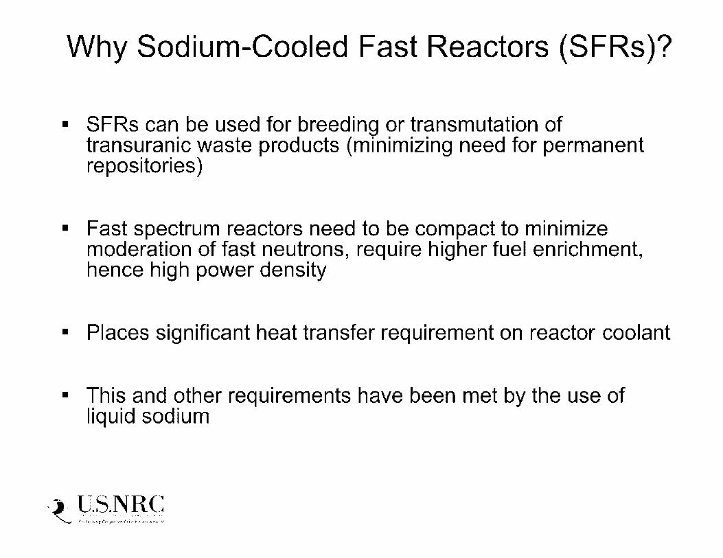
Why Sodium-Cooled Fast Reactors (SFRs)?
• SFRs can be used for breeding or transmutation of transuranic waste products (minimizing need for permanent repositories)
• Fast spectrum reactors need to be compact to minimize moderation of fast neutrons, require higher fuel enrichment, hence high power density
• Places significant heat transfer requirement on reactor coolant
• This and other requirements have been met by the use of liquid sodium
, -·. U.S.NR(: J . . , ............. , ....... , .... . ~ , •• ,,,,,,.N['l'.r•,J•f,,.:,.11J1~ ... ,. .................. ,

EBR-1
Fermi 1
EBR-11
SEFOR
SFR Experience in the US
Idaho R&D
Michigan Power
Idaho Test
Arkansas Test
1951-1963
1963-1972
1963-1994
1.4 / 0.2
200 / 61
62.5 / 20
1969-1972 20 / 0
Pool
Loop
Pool
NaK Na
Na Na
FFTF Washington Test 1980-1992 400 / 0 Loop Na
(CRBR, SAFR, PRISM, 4S designed, not constructed)
• Five facilities have operated from 1951 to 1994. Combined over 30 years operating experience
• The first electrical power production was generated by EBR-1, which fed into the power system for Arco, Idaho
• Most of the initial designs were intended to support development of breeder reactors
, -·. U.S.NR(: J .. , ............. , ....... , .... . ~ , •• ,,,,,,.N['l'.r•,J•f,,.:,.11J1~ ... ,. .................. ,

Neutronics: Thermal and Fast Spectrum Impacts
10-2
THERMAL REACTOR MEAN FISSION ENfRGY ---- FISSION REACTION
\ - - - CAPTURE REACTlON
10 1
' ', ' '\ ' ' ' ' ' '
HIGH FISSION CROSS SECTION AND HIGH PARASIHC CAPTURE CROSS SECTION
' ' ' ' '
FAST REACTOR MEAN FISSION EN[RGY
' ' '
LOW FISSION Cl'lOSS SECTION. BUT VERY LOW PARASITIC CAPTURE CROSS SECTION IR!;LATIVE TO THFAMAL VALUES)
...... ............. t ..... _ - ---.,. __ __
101 102 1()3 105
NEUTRON ENERGY h1VI
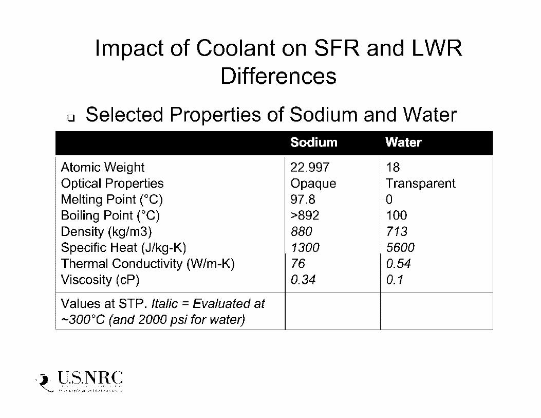
Impact of Coolant on SFR and LWR Differences
• Selected Properties of Sodium and Water Sodium Water
Atomic Weight 22.997 18 Optical Properties Opaque Transparent Melting Point (°C) 97.8 0 Boiling Point (°C) >892 100 Density (kg/m3) 880 713 Specific Heat ( J/kg-K) 1300 5600 Thermal Conductivity (W/m-K) 76 0.54 Viscosity ( cP) 0.34 0.1
Values at STP. Italic= Evaluated at -300°C (and 2000 psi for water)
, -·. U.S.NR(: J . . , ............. , ....... , .... . ~ , •• ,,,,,,.N['l'.r•,J•f,,.:,.11J1~ ... ,. .................. ,
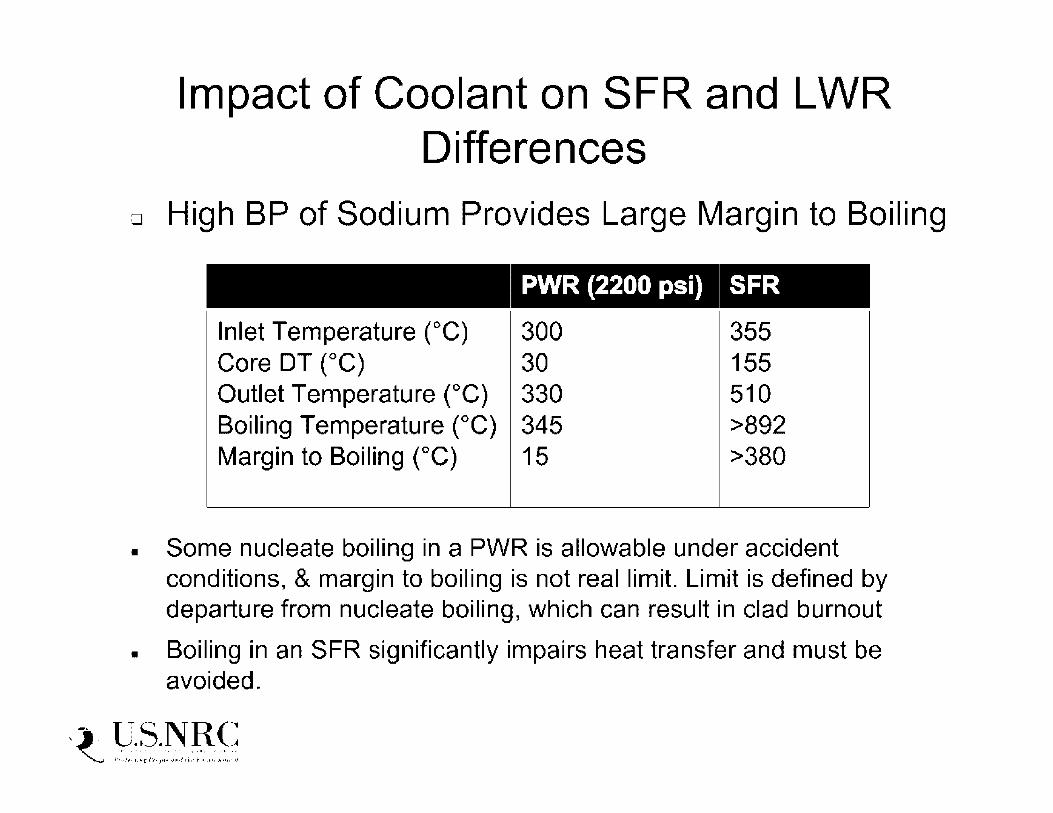
Impact of Coolant on SFR and LWR Differences
• High BP of Sodium Provides Large Margin to Boiling
PWR (2200 psi) SFR
Inlet Temperature (°C) 300 355 Core DT (°C) 30 155 Outlet Temperature (°C) 330 510 Boiling Temperature (°C) 345 >892 Margin to Boiling (°C) 15 >380
• Some nucleate boiling in a PWR is allowable under accident conditions, & margin to boiling is not real limit. Limit is defined by departure from nucleate boiling, which can result in clad burnout
• Boiling in an SFR significantly impairs heat transfer and must be avoided.
, -·. U.S.NR(: J . . , ............. , ....... , .... . ~ , •• ,,,,,,.N['l'.r•,J•f,,.:,.11J1~ ... ,. .................. ,

Impact of Coolant on SFR and LWR Differences
• High BP of Sodium allows Operation at Low System Pressure (near atmospheric)
• Impact on Design Features • Vessel thickness: PWR - 10-12 inches, SFR - 1-2 inches
• No need for pressurization of SFR fuel pins
• Safety Advantages of low system pressure • Minimal pressure loading on coolant boundary
• Coolant leaks are unlikely to propagate to a large-scale failure
• In comparison, in a high-pressure system, coolant pipe breaks are a concern
• No need for high pressure injection or ECCS.
, -·. U.S.NR(: J .. , ............. , ....... , .... . ~ , •• ,,,,,,.N['l'.r•,J•f,,.:,.11J1~ ... ,. .................. ,

• In an LWR, water acts as both a coolant and a moderator. An optimal P/D ratio is adjusted so that
1. Adequate moderation is obtained
2. Generated nuclear heat is affectively removed by the coolant
• In an LMR, no moderation is needed. Sodium acts only as a coolant. Because of excellent cooling properties of sodium, fuel pins can be placed much closer on a triangular pitch
, -·. U.S.NR(: J . . , ............. , ....... , .... . ~ , •• ,,,,,,.N['l'.r•,J•f,,.:,.11J1~ ... ,. .................. ,
I D I

Impact of Coolant on SFR and LWR Differences
00000000000000000 00000000000000000 00000000000000000 00000000000000000 00000000000000000 00000000000000000 ()() 0 0 ()() ()() 0 0 ()() () () () () () 2'.5 ~m
. . ' . . . ~k • ~• • • •· • 1: •' ~• 0i i: • •
·,_ - - - - - _. ·-' ·,_ -. -· ·-. ' . . '
·• _:i::. ,::::11._ :: -=~ :: _.==.. _::i: : :: • . r.. .= .
.......... -.• 'a, ,. Ot ; ·.; ;., ,I • ~- ·• • 0L J. ,I
· .. ;_=·---=-.··\::·-·-=-:I·.-.:._-: .. \ .. -_.,;(·_ •;1:·: .. ·. 0t - ·::i. _·._=> ---~,•--';/··;
I I , '. . t•. -~ .. - ~ •; ! • ' I , I ' I . I~ :- I : J I
- . - -· '· ... ' ,• ·-· -- ' --· ·- .. ·- .. ·.-. .• ..... J•-••.•••-•E ••\; • {- .•-,~.-••I . ...,.• .• •-• ~•-••• -\.,. .1 .• , •.. -.1 ••,~
-. ·· ... - .. - . -· - - ... - . - . ··- ... -· - -
. '_,;:''· .. :''.;_/:; .:'\/\._·, .. ':,_.·\.:"" ,::":·.·,_-,(·. ,.'\ _:'.":_;/'·./'·-.,.;•., .·'·,}' 1
00000000000000000 00000000000000000 00000000000000000 () CJ () CJ CJ CJ C> CJ CJ (J CJ CJ C> CJ CJ (J ()
, .. ··s. .1. :•· ~• .'·· :•,· . :• ~.:.: ·r,. ·.1 . ~·.· • ~,. :•_. .:••· :. < ·s. \t 16.1 cm
00000000000000000 00000000000000000 00000000000000000 00000000000000000 00000000000000000 00000000000000000 ~-
Typical PWR Assembly (289 pin locations) Pin Diameter = 9_4 mm Pin Pitch = 12.5 mm
, -·. U.S.NR(: J . . ,.,. .......... , .. ,, ... , .. ,,. ~ l•r,., ... ,.N['''.i"••J•f,•.:,.,i,i/~1,•"•••• .. ••N•••••11.f
. . . . . . . . . . . )a, :::l: :=a: • .: P . . ::i: .::= r-. :r:.: . .,=-: = ,-_ :c ... ::i •• c::i 1:-·. :r.:: .. z
. . . ·· .. - ... ' .. - .· .··. -..
. ·- - . . .. ·- .... ... - . - -·. . .. . .. I .4 ,' • • -1, • ' • .~ i • • • • •• • \• • • I•• • ; J : - • • II.• ' I• • • '.• ' •
-, '. -:~ '.' :.-.. " --.:·_, -.~·•-:;,..'.'::;/: .. ~. ' __ .;_ .. ~ . .'-\,. '\--' . . . . . •.. .
>• . - • .I• I, I .. • .... ' ll
··Typicar· SFR Assembly (271 pins) Pin Diameter= 7 .4 mm Pin Pitch = 8.9 mm
'

Impact of Coolant: Sodium Interactions .Sodium is inherently compatible with stainless steel
• Does not corrode structural materials • Experience with EBR-I1 after 30 years of operation
.Fuel-coolant interactions are benign for metallic fuel • Many fission products are soluble in sodium, hence
• can be filtered out in the cold trap, this contributes to scrubbing
• Sodium Reaction with Air • Characterized by small flames at interface, formation of Na20
on surface, and vigorous emission of oxide fumes
• Hence sodium systems need sealed guard vessels and inert cover gas (Argon)
.Sodium Reaction with Water • Vigorous, exothermic, and releases hydrogen
-23Na Activation • Results in radioactive isotope 24Na circulating in primary
system , -·. U.S.NR(: ~ ,::.:,,:;.~~ ,.; .. ,,;,:.:~,:.:. ;-,: ... ::.~·:::.·.:;

"Pool'" Design
Impact of Coolant: SFR needs an Intermediate Coolant Loop
'"Loop·· Design
,_cn·o1 rr.-c ~- r - ~•1;11·1 - ~
-----"---,,, -1.----------, ,,,.- -, rJL, II ·' \ ( '. f ,._,.
1.Je1·(.,
1:.=u1.,lt.11·l. h ~t·I
r ~.::;,I:
ll<.1:J:-1u:.I ----o, ~l•1dJ "" L <.:1..1,j
rt Cll
.~~---111-• •-111--------"-.i..,
. l ~
I l ; .. \:::---=- .· -
-....:...... .....-., ,,.,
- \, 4-.-- ...
I h:.i;:,t
---·-====----- d-.,r -· -... .:::.---_ _ .... ::-u:::--·--· ---____ ---_--=-_-=-_____ ---- - · :- : : .
• Na activation and reaction with water
..... In.- -:~1 ·· -t
-~-1 .. , ·1,-~
• Requires separation of high-pressure steam cycle from radioactive primary system; hence intermediate heat transfer system {IHTS) used
• Two design choices: Pool and Loop
, -· -U.S.NR(: ~ ,::.:,,:;.~~ ,.; .. ,,;,:.:~,:.:. ;-,: ... ::.~·:::.·.:;
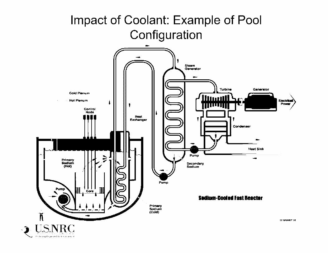
Impact of Coolant: Example of Pool Configuration
Cold Plenum
· Hot Plenum
·x·
Primary Bodllllll
(Hot)
, -·. U.S.NR(: J . . , ............. , ....... , .... . ~ , •• ,,,,,,.N['l'.r•,J•f,,.:,.11J1~ ... ,. .................. ,
control Rods
-
'
--
' Heat
Ex.chang• r '
Pump
Prlnwy Sodium (Cold)
Steam a ..... to,
-
Sec:ondery Sodlu.m
Condenaer
-Hu1Slnll:
-
l .. lllnl-Clellll flll 1181Cllr

SFR Safety Issues: Neutronics • Power variation across core due to neutron leakage at
core boundaries plus high power density • Need to use ducted assemblies to control location of fuel and core
temperatures (lesson learned from EBR-1)
• Flow rate in each ducted assembly is adjusted via adjusted nozzle openings in order to have uniform outlet temp from the core
• Core reactivity is very sensitive to core geometry
• Core sodium void worth is typically positive in center of larger reactor cores (e.g. +ve for PRISM, -ve for 4S)
• With proper design, overall core void could be made negative. How?
• High leakage cores • Large L/D
• Fuel is not in most neutronically reactive configuration in reactor core
• Relocation of fuel has the potential to significantly increase reactivity, including exceeding prompt critical conditions
, -·. U.S.NR(: ~ ,::.:,,:;.~~ ,.; .. ,,;,:.:~,:.:. ;-,: ... ::.~·:::.·.:;

1, ::- · ·1 ·,-.,. i • ·· ~1 J ·r1 p · n 1- p P. i- , t i -1 ··1
1.:i 1:.11 I~ I_, r ir ,; ~I .rr Ip r···1:1l I unct.· on
---• ,. __ _ ... ---- - -
•- -
• Na allowed to enter at bottom & fill tube when pumps are operating • GEM's designed to lower core power level if main coolant pumps malfunction • Helium pressure causes Na level in pins to drop & allow more neutrons to leak out of core
• Lower number of neutrons causes fewer fissions to occur and power level drops

SFR Safety Issues: Sodium Reactivity with Air
• In event of a leak from Na-containing systems/components • Na may emerge as a jet (and impinge on other structures) or may spill
• If air is available • Leaking sodium will react with air. This can lead to:
• Spray fire (starts at 120 °CI high burning ratel high aerosol production) or
• Pool fire (starts at 250 °C 1 low burning rate, low aerosol production)
• Na fires produce aerosols (Nao and Na~O) which react with air to produce NaOH (in a few sec) and Na2CU3 (in several min)
• Aerosol generation may increase thermal loading and raise gas pressure
• Aerosols deposit on floor, walls, and ceiling, can cause equipment damage (electrical 1 instrumentation)
, -·. U.S.NR(: J . . , ............. , ....... , .... . ~ , •• ,,,,,,.N['l'.r•,J•f,,.:,.11J1~ ... ,. .................. ,

SFR Safety Issues: Sodium Reactivity with Air
• Significant Na Leaks • BN-600, October 7, 1993, Na leak on pipeline for cold trap. 800
kg escaped. May 1994, leak from secondary, 30 kg burned.
• Monju (spill and burn of several hundred kg of secondary Na, December 8, 1995)
• Super Phenix (Na leak from used fuel storage tank. lnerted GV, hence no fire, no casualties.) Led to shutdown in July 1996, too . expensive.
• No reported adverse effects to plant personnel or surrounding environment
, -·. U.S.NR(: J .. , ............. , ....... , .... . ~ , •• ,,,,,,.N['l'.r•,J•f,,.:,.11J1~ ... ,. .................. ,
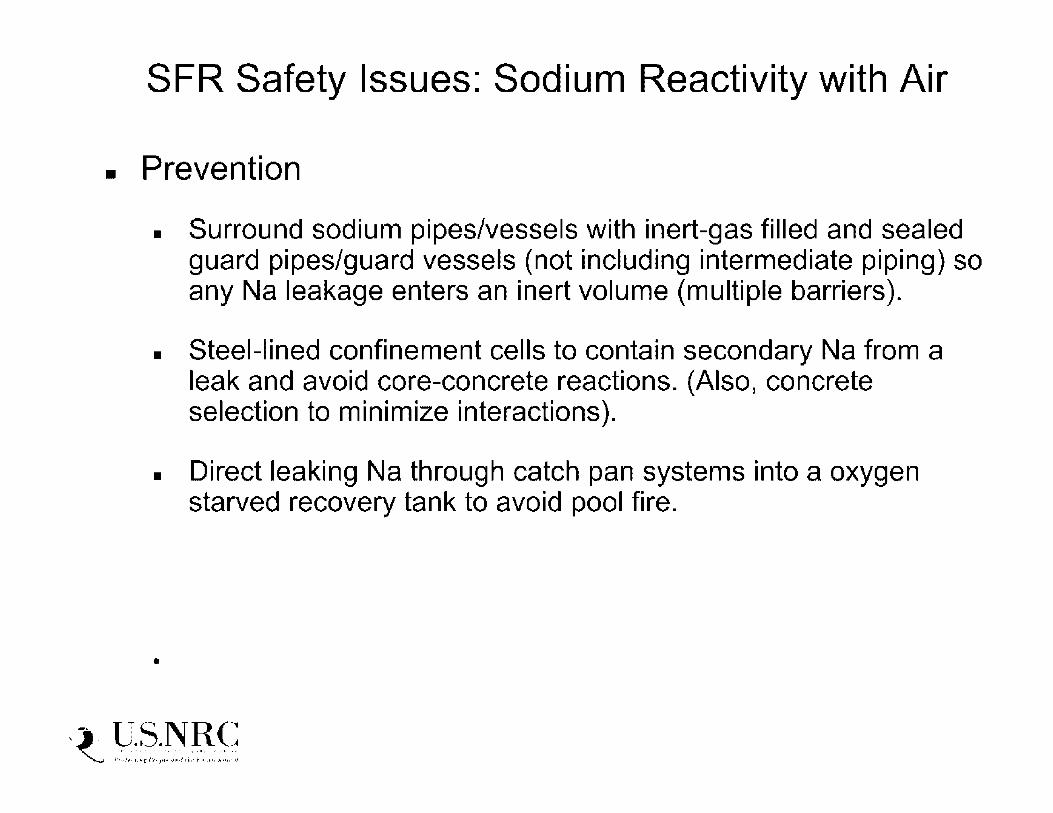
SFR Safety Issues: Sodium Reactivity with Air
• Prevention
• Surround sodium pipes/vessels with inert-gas filled and sealed guard pipes/guard vessels (not including intermediate piping) so any Na leakage enters an inert volume (multiple barriers).
• Steel-lined confinement cells to contain secondary Na from a leak and avoid core-concrete reactions. (Also, concrete selection to minimize interactions).
• Direct leaking Na through catch pan systems into a oxygen starved recovery tank to avoid pool fire .
•
, -·. U.S.NR(: J .. , ............. , ....... , .... . ~ , •• ,,,,,,.N['l'.r•,J•f,,.:,.11J1~ ... ,. .................. ,

SFR Safety Issues: Sodium Reactivity with Air
• Detection • Objective is to prevent large leaks, corrosion, and fires by early
detection
• Mitigation • Fire extinguishing powders for quick and effective extinction of
Na fire
• Limit duration of fires (-15 min) to avoid serious damage to structures
• Preclude pressurization of cells by relief valve openings or rupture disks
• Limit drop height of spray fire by arranging catch pans every few meters vertically - makes spray fire into pool fire.
• Special filters in ventilation to remove Na aerosols from containment atmosphere
, -·. U.S.NR(: J . . , ............. , ....... , .... . ~ , •• ,,,,,,.N['l'.r•,J•f,,.:,.11J1~ ... ,. .................. ,

SFR Safety Issues: Na Reactivity with Water
• SG tubes are boundary between sodium in IHTS & HP steam
• SG tube leaks have occurred in many SFRs (e.g. PFR, Phenix, BN-600) and are an important safety issue with new designs
• IHX is designed to withstand full steam pressure if a tube leak occurs
• However, contact of water with sodium leads to exothermic reaction that could rapidly pressurize IHTS piping or IHX (2nd
safety barrier)
• Need to develop and qualify early leak detection systems to prevent propagation of tube leaks and ruptures
• In PRISM, both large Na leak into air and steam generator tube rupture are included by GE as bounding events to be considered in the design for licensing
, -·. U.S.NR(: J .. , ............. , ....... , .... . ~ , •• ,,,,,,.N['l'.r•,J•f,,.:,.11J1~ ... ,. .................. ,

SFR Safety Issues: Na Reactivity with Water
• Design options • Use successful approach used in EBR-11, Toshiba 4S designs
i.e. use double-walled SG tubes • EBR-11 experience: No tube leaks occurred during 30 years
of operation, Na and water never came in contact during operating lifetime of plant
• Use better SG tube materials, or new tertiary fluid, or a new fluid in IHTS
• Should SG tube leaks be considered as DBAs? • Not settled yet, because no final application has been submitted
, -·. U.S.NR(: J .. , ............. , ....... , .... . ~ , •• ,,,,,,.N['l'.r•,J•f,,.:,.11J1~ ... ,. .................. ,
Commercial Grade Item Dedication and 1 OCFR21:
Application to Digital l&C Systems and
Software
Milton Concepcion, MSc (Eng) Sr. Digital l&C Engineer
NRO/DE/ICE2

DISCLAIMER This presentation is intended for information purposes only and does not replace independent professional judgment. Statements of fact and opinions expressed are those of the presenter individually and, unless expressly stated to the contrary, are not the opinion or position of the NRC, EPRI, or ASME NQA-1 Committee. The presenter assumes no responsibility for the content, accuracy or completeness of the information presented.

Agenda
• Commercial-grade item (CGI) dedication process requirements & guidance
• CGI dedication of digital l&C equipment
• Latest developments affecting CGI dedication of software
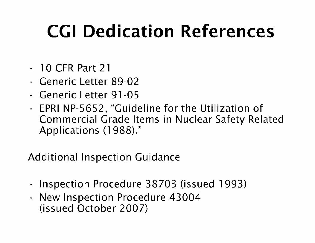
CGI Dedication References
· 1 0 CFR Part 21 • Generic Letter 89-02 • Generic Letter 91-05 • EPRI NP-5652, "Guideline for the Utilization of
Commercial Grade Items in Nuclear Safety Related Applications (1988)."
Additional Inspection Guidance
• Inspection Procedure 38703 (issued 1993) • New Inspection Procedure 43004
(issued October 2007)

CG I Dedication Process(cont'd)
• Commercial-grade dedication is an acceptance process by which a CGI is designated for use as a basic component.
• This acceptance process is undertaken to provide reasonable assurance that a CGI to be used as a basic component will perform its intended safety function and, in this respect, is deemed equivalent to an item designed and manufactured under a 10 CFR Part 50, Appendix B, quality assurance program.

CGI Dedication Process
• An acceptable dedication program involves: - Review for suitability of application per
Criterion Ill, "Design Control," of Appendix B
• (i.e., Technical Evaluation)
- Acceptance controls per Criterion VII, "Control of Purchased Material, Equipment, and Services," of Appendix B
• (i.e., Four Acceptance Methods)

CG I Dedication Process(cont'd)
• Technical Evaluations - Determine item's safety
function and service conditions
- Functional classification of items and components
- Review of vendor's technical/development data
- Identification and selection of item's critical characteristics
- Determine appropriate acceptance criteria
• Acceptance Process - Method 1 : Special tests and
inspections
- Method 2: Commercialgrade survey of supplier
- Method 3: Source verifications
- Method 4: Acceptable supplier/item performance record

Software Used in Nuclear Industry
• Process Control (Dig ital l&C Equipment)
• Design & Analysis
• Operations (Management/Administration) - Not addressed in this presentation

CGI Dedication of Digital l&C Equipment
• NRC conditionally accepted of the following EPRI Guidance Documents for Dedication of Digital l&C including Programmable Logic Control le rs (PLC):
- EPRI TR-106439, "Guideline on Evaluation and Acceptance of Commercial Grade Digital Equipment for Nuclear Safety Applications," October 1 996
- EPRI TR-107330, "Generic Requirements Specification for Qualifying a Commercially Available PLC for Safety-Related Applications in Nuclear Power Plants," December 1996

CGI Dedication of Digital l&C Eq u i pment(cont'd)
• Digital l&C equipment introduces additional challenges - Complexity of the device - including its internal architecture, external
interfaces, communication links, etc.
- Access to detailed information/documentation (design, development, testing, verification/validation, configuration control)
- Proper identification and verification of critical characteristics
• Hardware+software (operating/application)
• Extent/thoroughness of Critical Design Review (CDR)*
- Use of software tools
- Cybersecurity
- Crediting relevant operating history
- Engineering judgment
• Not all commercial digital l&C equipment can be successfully dedicated'''°
"'EPRI TR-106439, "Guideline on Evaluation and Acceptance of Commercial Grade Digital Equipment for Nuclear Safety Applications."

Implementation and Examples (with the invaluable collaboration from Rossnyev Alvarado -- NRR)
• HFC-6000 platform
· SPINLINE 3 platform
• Review of the OS software QA program was limited to assessment of the process, plans, and procedures as they relate to maintaining the commercially dedicated system
• Verification of the critical characteristics - Methods 1, 2 and 4
Note Method 3 would require the licensee to observe FAT for a purchased system
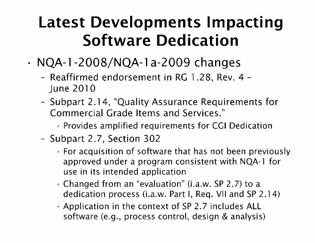
Latest Developments Impacting Software Dedication
• NQA-1-2008/NQA- l a-2009 changes - Reaffirmed endorsement in RG 1 .28, Rev. 4 -
June 2010
- Subpart 2.14, "Quality Assurance Requirements for Commercial Grade Items and Services."
• Provides amplified requirements for CGI Dedication
- Subpart 2.7, Section 302 • For acquisition of software that has not been previously
approved under a program consistent with NQA-1 for use in its intended application
• Changed from an "evaluation" (i.a.w. SP 2.7) to a dedication process (i.a.w. Part I, Req. VII and SP 2.14)
• Application in the context of SP 2.7 includes ALL software (e.g., process control, design & analysis)

Latest Developments Impacting Software Ded ication(cont'd)
• EPRI 1025243, "Plant Engineering: Guideline for the Acceptance of Commercial-Grade Design and Analysis Computer Programs Used in Nuclear Safety-Related Applications." - Generic technical evaluation process overview
- Functional safety classification of computer programs
- Acceptance of commercial-grade computer programs using the dedication process
- Currently under review by NRC QA staff - potential RG endorsement
- Impact of EPRI report on IEEE 7-4.3.2 guidance related to software tools?

Latest Developments Impacting Software Ded ication(cont'd)
• IEEE 7-4.3.2 and software tools - At this time, there is no direct relationship between
EPRl-1025243 and IEEE Std. 7-4.3.2.
- It is worth noting that IEEE 7-4.3.2-2010 added CGI dedication (Clause 5. 1 7) as an alternative to e stab Ii sh suitability of software tools for use in safety related systems.
- Although the scope of EPRl-1025243 does not directly address software tools used to support the development of operating and/or application software in digital l&C systems, the dedication guidance provided in EPRl-1025243 may be considered by an applicant/licensee.

Latest Developments Impacting Software Ded ication(cont'd)
• Em bedded dig ital devices - Register Notice on Embedded Digital Device RIS
(requesting public comment) issued May 20, 2013. - Commercial-grade replacement products containing
embedded digital devices that include software, softwaredeveloped firmware, or software-developed logic that may not have been developed in accordance with guidance and acceptable industry standards.
- Requirements to identify the use of embedded digital devices and sufficiently document the quality of the embedded digital devices to support commercial-grade item dedication.
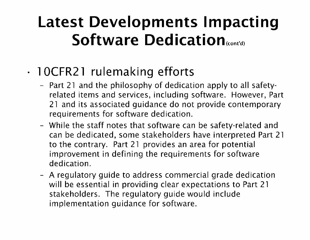
Latest Developments Impacting Software Ded ication(cont'd)
• l OCFR2 l ru lemaki ng efforts - Part 21 and the philosophy of dedication apply to all safety
related items and services, including software. However, Part 21 and its associated guidance do not provide contemporary requirements for software dedication.
- While the staff notes that software can be safety-related and can be dedicated, some stakeholders have interpreted Part 21 to the contrary. Part 21 provides an area for potential improvement in defining the requirements for software dedication.
- A regulatory guide to address commercial grade dedication will be essential in providing clear expectations to Part 21 stakeholders. The regulatory guide would include implementation guidance for software.

Summary
• Licensees/vendors must know, define, and control CGI dedication process - Establish and maintain product/design suitability
(hardware+software) - Determine safety function(s)
- Identify and select critical characteri sties
- Utilize defined acceptance methods
• Licensees/vendors must establish and maintain complete documentation/records - Evaluations - Acceptance tests & inspections
- Supplier controls

Questions/Comments

Graphite: Properties and Behavior
Tim Burchell
Materials Science & Technology Division Presented to
US Nuclear Regulatory Commission
January 12th 2011
8EN"ERGY 4 0.-\k R1nca: N.\TIO:'\,\L I ,:\BOR\TORY '·:,·-.·· •• \. • .. ' c •· .. · ~.-._--; __ , • .. :-. IH: 1:: ··,•.-.1•-,1;•.,· .. •:'·,I<,·

Overview of Presentation
• Manufacture
• Structure
- Single crystal and polycrystalline synthetic graphite
• Porosity and texture
• Physical Properties
- Thermal
- Electrical
• Mechanical Properties
- Elastic constants
- Strength and fracture
• Applications
• Summary

Graphite Single Crystal Structure
A
B C 0.670
nm
A
0.246 nm BOND ANISOTROPY
•Strong, stiff covalent bond in-plane
•Weak bonds of attraction between graphene planes
•ABA repeat stacking (can get ABC ... )
•Crystal unit cell size:
•<a> = 0.246 nm
•<c> = 0.670 nm
•Coherence lengths, 13
and le are measures of crystal size

Synthetic Graphite Manufacture R\.W PETROLEl'l.l
OR PITCH COKE
C...\.LC ~ED AT l 300"C
C'.-\1.CIN'ED COKE
CP.CSHED. GF'.Ol-:-."D_ A:,"D BLE:-;-DED
BLE1'"1lED COAL TAR PARTICLES BD,,"'DER PITCH
~.-!:.XED
COOLED
EXTRl-DED. ~,[OLDED. OR :sos T . .l. T:C-..l.L:. Y ?RE$ SE:>
GREE~ ARTIFACT
r - - - - - - 3AKED AT S~D-l(l~l) 0 (
B...\ilD ARTIFACT I
: _ _ _ _ _ _ _ ::::,...[PREv::'-A TED :o DE:-;-<;IFY iPETROLEt"~·-1 PITC-E_:
--.&.----REBAKED&
RElllPREG~ATED ARTIFACT
GRAPHITE
?l"F'.lFIED
Pl"RIFIED GRAPHITE
•Petroleum coke from calcination of heavy oil distillates
•Pitch coke from calcination of coal -tar pitch
•Coke filler particle morphology and green artifact forming method affect texture and properties
•First bake is a critical stage, -controlled binder pyrolysis
•Acheson or longitudinal graphitization
•Long cycle times ~ 9 months

Manufacture - Baking and Graphitizing
3000
2500
0 OG> 2000 I;. :::, -I! Q)
~ 1500 ~ IQ)
u ra
~ 1000 LL
500
0 0
-Graph1tization - - Baking
/~ol
' /1'1!,~t-:•1_111
V,c1,J h.iT _1_,_;
.._ ~C-."-~ -~· -- -
- - ___ - ----------- -"'"'--k - - __ - - - - / cc-ac.k -<,cao•
.-· - ~ .... ~,c~•.J~ .... .... / .~ ...- ~ 1{·.-li: .11.l '
,..- ,,.. ~ ..., _ -~ l{,.-l,_:_:1.l
5 10 15 20 25 30 35 40 Time, days
Slow heating and cooling during baking allows escape of pyrolysis gasses and minimizes thermal gradients
45

Manufacture - Baking
- - . ;;:-.-.----•-·~ -- -= r-1 f ~,.. --"'
-L ·- _":. --- • "il..t)!I,; . :t ~---!Ill
.. : •• • . • . .ifl'!I' ~. ~ I . I 1·1 •,;. J' ~;_-
. -· ,- ~- . ' . ' ~-. ..,- • ·J.,i· .u.< -.
. 'I; .. •- - I'-..-- f •--. ' ~ ] ' L . t I J-~
,I,' ' ~r t .. . , '-
-- -
Modern car bottom carbon/graphite baking furnace
Green bodies packed in coke and placed in steel saggers

Manufacture - Acheson Graphitization
Baked artifacts surrounded by a coke pack and covered with sand to exclude air. Electric current flow through the
coke-pack & art if acts

Manufacture - Longitudinal Graphitization
Furnace covered with sand to exclude air, current flows though the baked artifact
Carbon atoms migrate to thermodynamically more stable graphitic lattice structure and 3D ordering achieved (degree of ordering depends on feedstock type)

Manufacture - Purification
•
-~
~
Post graphitization halogen gas process
Can be performed with solid fluoride additives to Acheson graphitization furnace or solid fluoride additives to formulation

Manufacture - Purification
Unpurified graphite
Thermally purified graphite
Chlorine purified graphite
Fluorine Purification
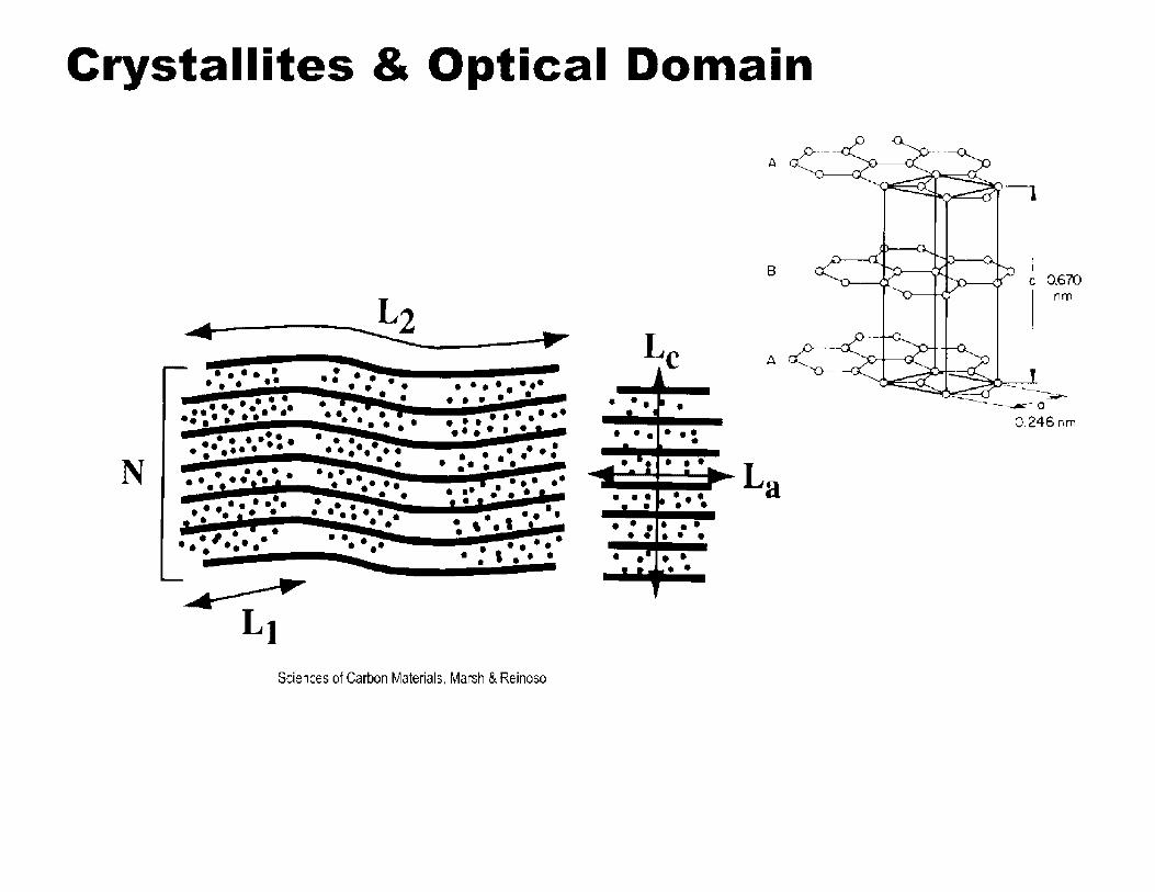
Crystallites & Optical Domain
N
.. •••••• • • • ••
a • • • • • • •• • ••••• •• •• • • • & • • ••• • • •• • •••••• • • • • •••
. . , ... • • • • a
. . .., .. • I .. • • • • • • ••• • •I• • ,a.• • I •
• ••••• • • • • I• i •• • •• • • • • • • • ••• • ••••••• • • ••• .. • ....
• • ••• ••••••• • • • • • • ••
• • • • • •• ...... -• • • •• •• ••• . ..... ·-. . . ... : . .. . . . -
I • • • •• • •• •• • • I• I• I ••• ... :,., ..
• •••• . : ' ...
Sciences of Carbon Materials, Marsh & Reinoso
A
B
Le • •• • • • 1
• • • ••• - • ...... ·-·, • • •
La . --••• •••• • • • • ••• • • • • • • • • • • • • • • • • •
0.670 nm
0.246nm

Synthetic Graphite Structure
Nuclear graphite XRD crystal parameters
Graphite grade Coke type <c> (A) le (A) <a> (A) la (A)
HOPG n/a 3.345 424 1.229 138
H-451 Petroleum 3.353 269 1.230 300
IG-430 Pitch 3.361 218 1.231 298
BAN Petroleum 3.365 250 1.231 322
NBG-17 Pitch 3.364 186 1.231 286
IG-110 Petroleum 3.366 190 1.231 256
PCEA Petroleum 3.367 238 1.231 250
NBG-18 Pitch 3.370 191 1.232 294

Crystallites & Optical Domain
Coherent domain
Carbon layer or
structural unit
Sciences of Carbon Materials, Marsh & Reinoso
I nm
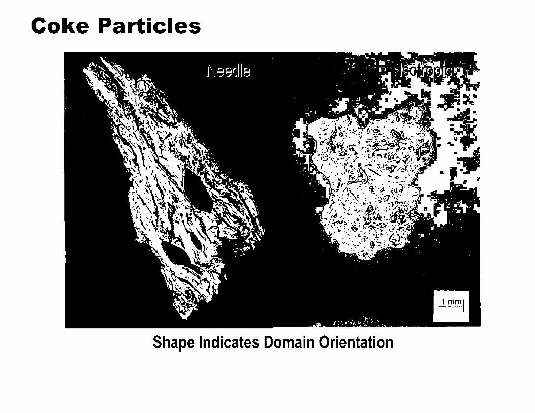
Coke Particles
Shape Indicates Domain Orientation

Optical Domain- Coke Particle
50µ.m I I
Needle 500x Isotropic

Optical Domain
50µ.m ~ I
Individual Particle 500X
wi. . • ""'~ 'r I ,. • • t~ ., ... ,..,. ... -.. ""'r. . . 1·· 11 .• ,.. •• · ·,' • ' ,·. ..,.,-.,:· ,I" ,,· '
• ., -,; . 1!. i• -'l','(t-, .• -, , .?tit-".:" ... t I .,I•• ...... , •-~•,.·;> • • .. W• . • • <'
-'t ·. : lJ ..._ -iJ >· -: -:,-.-; .-ai«"'·~ ·j. \ : -~ \w-;--.a. ....... t, _i-·- ,. .. :·~· ,,. ... ,. i' ·.,,,;, ... 'S·. ". . ..... ' . . . ..... . . - ' .. , . . ..... . .. ...-- . ,,,,._.,.__,..;:\:~ -t,·· .. _._.., ... .,. •\. ..., _, ... '
~- ·-- - ~ - ,., ' ... " • ·\ • ( .. ,- '' \•" ·-·~ • I • • •· • • ~ ,1; ·, ' . • . .... . . .. " ,·. \ .. ·~.}~.I,,:,_~\ -;,i., ~ ' ..,,,,.,_~ .. l1 i-,.,.J !",;, , .... er "' ' •· ,,.·, 7 ,, #. "I'"-. .
• • •• -. . •, .. "': . . l. ". ,/,_'t . • . . '" , . . . ' . ' ... . .· . I • , •. , ... .; .:_-'4•~
. ~ . . . ·~-~ • • ._ , •;• ·. ;· ,, l . , i. . : .
' ... ·. .. . .. ~ ,,. , . r. ., ,. -.• .,. . . • ' •• ..,, • ,• •• •• ••• '."lo •• '"' 4.,
~· "4"' .·.,; ·.·' :;. ,.~ ---~~ ,_1·' • .;;,.:· ' ~··,· .., -c.' '' ·• < ' .. ~, ' ' I .. _, • • ·, - • I , • •, . • ~ • (' II. - ' • - . rr, -. • I. . •. • -.. . ,. ,, ...:,. . . . . . . ,, . , \ .,- \ · i ·· I.,._·,,,\,• ·· i",-,:.. 't : .. 41!.-: < • ' :•,·.' .... ~' •• ·-;'"' '.· ,, ,, ~' . '~:• ,"J'1
·,t· ;.-. ,, .,_I.:"'"'' • . ..... ~' ' : . .,.. ·~· . \.' .. 1'' .:.. ' • ~ . ' ' •• • ' ,.II ~ -~ •• •t --,, rtlt;;' .. ~ ,
........ _), •• ~:.. •¥: "'. -•·· -~ \ -~· .. '~' ..... M ,._ L . •' ~ .Ii} •- t ,. ~- ..... . .. ' -•. ~, •• -~ ..... .c:, ..... . -·- -~ i' . ' '· . - ' ..,.,,. - .. . ' .
- jl 1' J '' .. -:t • ' '~ ' . t\ - ..... --~· .• •.• ' ·, . ;- ,. ,· . : ' ..,, "' . S.' .. •• ... ,, > ,_ , • T
. . ·' ·' . . . r-~ ~ . . ,, ....... . . . • -.: . •. .,. . -• . '°' .· ·. . ' r • "" • .• : : r • .-·. . , . . . -~ ' • • . • • 7 \ A - •• '!- -· l ,,.. -. ' ·--~-' - .... t· ., .._ I r ,., • ~ .~·. ·•. --· ,.
_. • ~\ ... ~~ , .. .: I ••• ,.•_.• ••' • . . . - . ... . . . . . : ' .. ~ ·' .. .., . ~ .... ~ t:""'
Manufactured Graphite 400X
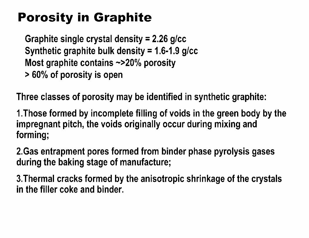
Porosity in Graphite
Graphite single crystal density = 2.26 glee Synthetic graphite bulk density = 1.6-1.9 glee Most graphite contains --->20o/o porosity > 60o/o of porosity is open
Three classes of porosity may be identified in synthetic graphite:
1.Those formed by incomplete filling of voids in the green body by the impregnant pitch, the voids originally occur during mixing and forming;
2.Gas entrapment pores formed from binder phase pyrolysis gases during the baking stage of manufacture;
3.Thermal cracks formed by the anisotropic shrinkage of the crystals in the filler coke and binder.
Graphite Structural Features 0
Lattice {a= 2.45 A, c= 6.7 A)
Crystallite "Coherent Domain"
Micro-crack (between planes, about the size of crystallite)
Optical Domain (extended orientation of crystallites)
Grain Size
Pore Size

Synthetic Graphite Microstructure
Grade AGOT graphite microstructure (viewed under polarized light)
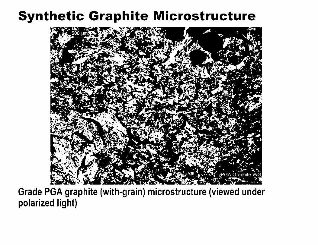
Synthetic Graphite Microstructure
Grade PGA graphite (with-grain) microstructure (viewed under polarized light)

Synthetic Graphite Microstructure

Synthetic Graphite Microstructure
Grade IG-110 graphite microstructure (viewed under polarized light)

Synthetic Graphite Microstructure
Grade IG-110 graphite microstructure (viewed under polarized light)
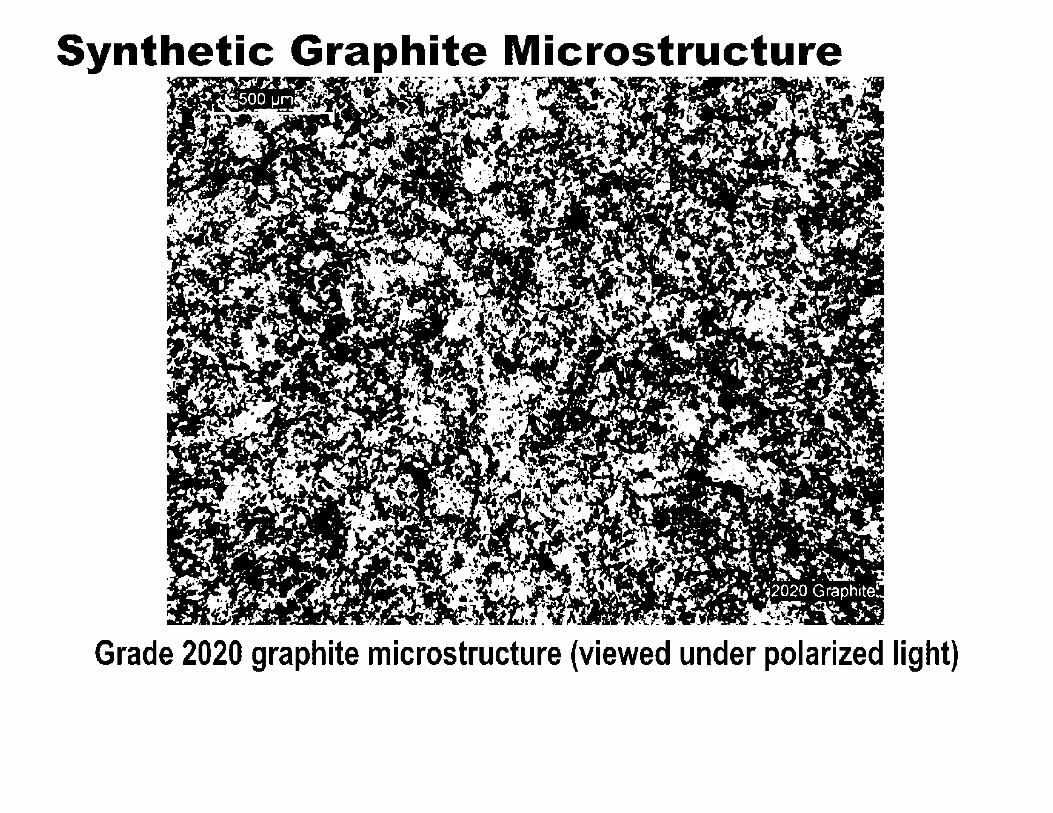
Grade 2020 graphite microstructure (viewed under polarized light)

Synthetic Graphite Microstructure

Grade IM1-24 graphite microstructure (viewed under polarized light)

Synthetic Graphite Texture
Texture in synthetic graphite arises because of: •Crystal anisotropy, coke and binder domain size
•Filler cokes and binder cracks
•Size and shape distribution of filler particle
•Filler coke type
•Recycle fraction and morphology
•Porosity
•Forming method (preferential orientation of filler coke and binder porosity)
Texture imparts anisotropy!

Graphite Production -Extrusion
1 2 3 p Filler Materials: Calcined Coke, (Raw Coke) Recycle Graphite Sizing: Designed Combination of Discrete Fractions 10-1,000 microns
Binder: Pitch (20-45 parts/hundred)
"Remix" "Additives"

Graphite Production -Extrusion
1 2 3 P
Batch Charge Filler

Graphite Production -Extrusion
1 2 3 P
Batch Charge Filler

Graphite Production -Extrusion
1 2 3 P
Batch Charge Filler

Graphite Production -Extrusion
1 2 3 P
Batch Charge Binder

Graphite Production -Extrusion
1 2 3 P
Batch Charge Mixer
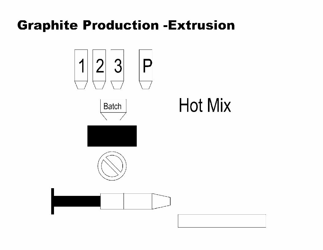
Graphite Production -Extrusion
1 2 3 P
~atch) Hot Mix

Graphite Production -Extrusion

Graphite Production -Extrusion
1 2 3 P
~atch) Charge Press
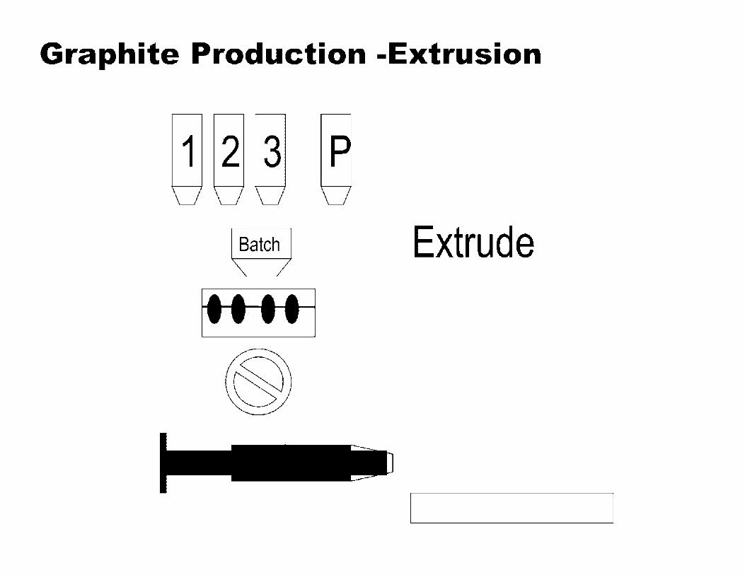
Graphite Production -Extrusion
1 2 3 P
~atch) Extrude

Graphite Production -Extrusion
1 2 3 P
~atch) Extrude
Grain Direction ..

Graphite Production -Extrusion
Grain Direction ..

Graphite Production -Die Molding
Charge Mold

Graphite Production -Die Molding
Charge Mold
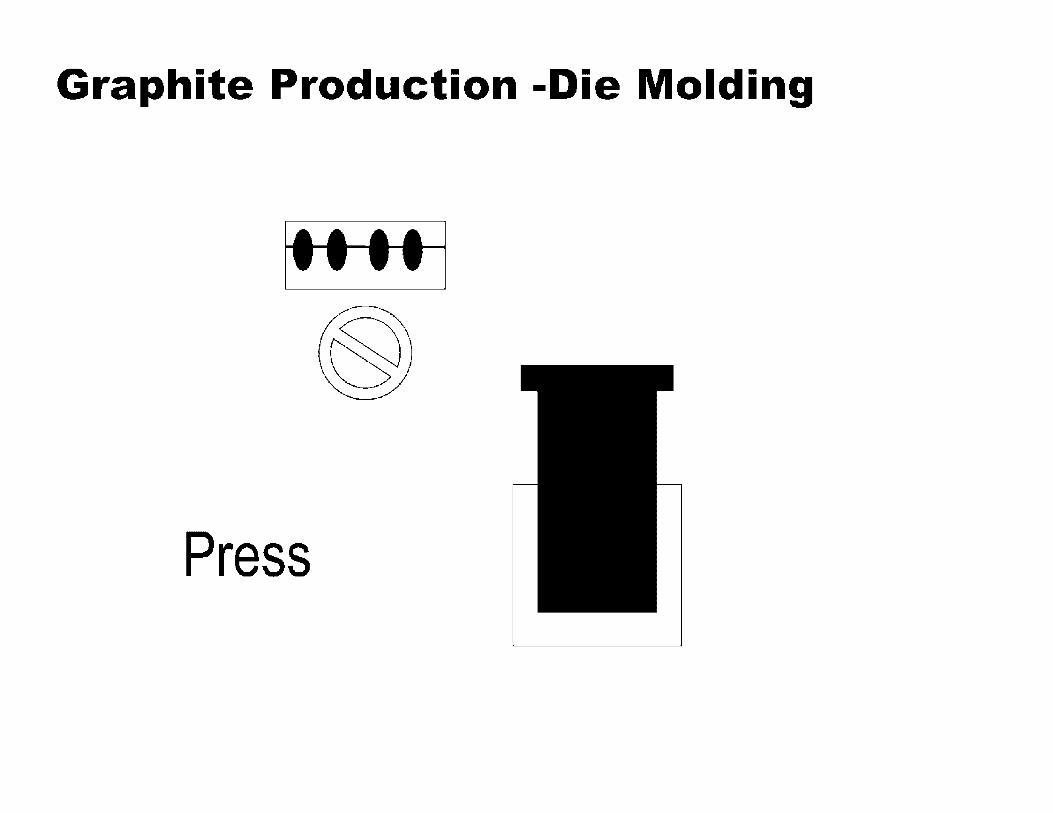
Graphite Production -Die Molding
Press
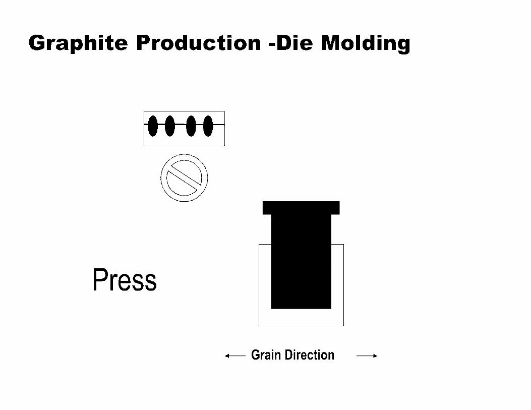
Graphite Production -Die Molding
Press
• Grain Direction •
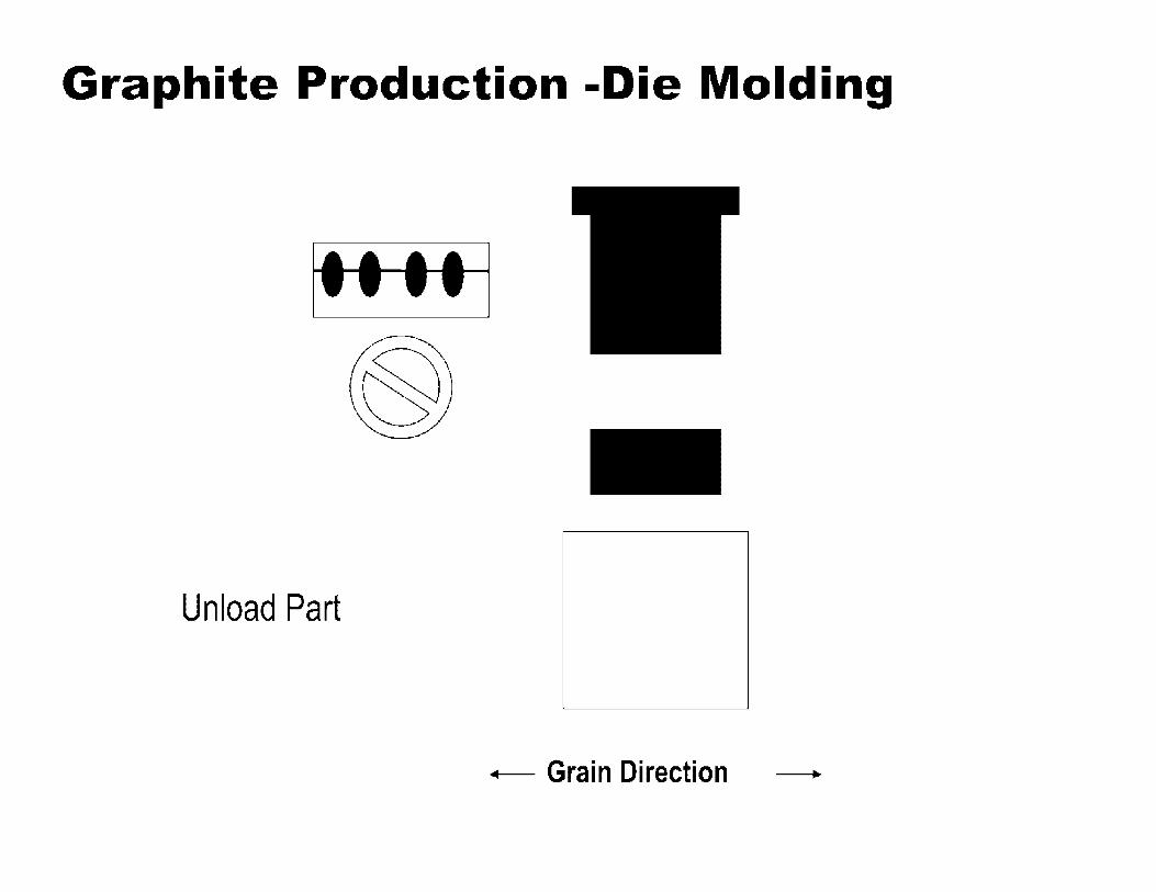
Graphite Production -Die Molding
Unload Part
• Grain Direction •

Graphite Production - Vibration Molding
f Vertical Motion
• Grain Direction •

Graphite Production - Isostatic Molding
Molding Powder Storage

Graphite Production - Isostatic Molding
Mix Agglomerates are Milled to Produce Molding Powder
~ Mill
~
Molding Powder
Storage

Graphite Production - Isostatic Molding
Tooling Supports Rubber Bag - • • - • • • • • ••••••• • •
• I I • I I I I I
• • • • • • • • • - • • - • • • • • •••••••• •
• I I • I I I I I
• • • • • • • • • ......... • •• • • • •• •
• I I • I I I I I
• • • • • • • • • ......... • •• • • • • • •
• I I • I I I I I
• • • • • • • • • - .. -..... • • • • • • • • •
• I I • I I I I I ••• • ••• ••
- • • - • • • • • • • • • • • • • •
• I I • I I I I I ......... - • • - • • • • •
• • • • • • • • • • I I • I I I I I ••• • ••• ••
- • • - • • • • • • • • • • • • • • • I I • I I I I I • •• • • • •• •
• • • • • • • • • • I I • I I I I I • •• • • • • • •
• • • • • • • • • • I I • I I I I I
• • • • • • • • • - • • - • • • • • •• • • ••• •• • I I • I I I I I
• • • • • • • • • - • • - • • • • • •• •• • • •••
Bag Lid
Rubber Bag

Graphite Production - Isostatic Molding
I I I I • I I I •• • • • •• •
• • •• - • • • • • • • • • • •
I I I I • I I I ........ • • • • - • • •
• • • • • • • • I I I I • I I I
•• • • • •• • • • • • - • • •
• • • • • • • • I I I I • I I I
• •• •• • ••
• • • • • • • • I I I I • I I I
• • • •• • • •
• • • • • • • • I I I I • I I I
• • • • • • • • • • • •• • • •
• • • • • • • • I I I I • I I I
• • • • • • • • • • • •• • • •
• •• •• • •• I I I I • I I I
• • • • • • • • • •••• • •• . . . . . . . . I I I I • I I I
• • • • • • • • ••• • ••• •
• • • •• • • • I I I I • I I I
• • • • • • • • .... -... • • • • • • • •
I I I I • I I I •• • • • •• • .... -... • • • • • • • •
I I I I • I I I
• • • • • • • •
Place Bag in Tooling

Graphite Production - Isostatic Molding
l I I I I • I I I •• • • • •• •
• • •• - • • • • • • • • • • •
I I I I • I I I ........ • • • • - • • •
• • • • • • • • I I I I • I I I
•• • • • •• • • • • • - • • •
• • • • • • • • I I I I • I I I
• •• •• • ••
• • • • • • • • I I I I • I I I
• • • •• • • •
• • • • • • • • I I I I • I I I
• • • • • • • • • • • •• • • •
• • • • • • • • I I I I • I I I
• • • • • • • • • • • •• • • •
• •• •• • •• I I I I • I I I
• • • • • • • • • •••• • •• . . . . . . . . I I I I • I I I
• • • • • • • • ••• • ••• •
• • • •• • • • I I I I • I I I
• • • • • • • • .... -... • • • • • • • •
I I I I • I I I •• • • • •• • .... -... • • • • • • • •
I I I I • I I I
• • • • • • • •
Molding Powder
Storage
Fill Rubber Bag

Graphite Production - Isostatic Molding
I I I I • I I I •• • • • •• •
• • •• - • • • • • • • • • • •
I I I I • I I I ........ • • • • - • • •
• • • • • • • • I I I I • I I I
•• • • • •• • • • • • - • • •
• • • • • • • • I I I I • I I I
• •• •• • ••
• • • • • • • • I I I I • I I I
• • • •• • • •
• • • • • • • • I I I I • I I I
Seal Rubber Bag • • • • • • • •
• • • •• • • • • • • • • • • •
I I I I • I I I
• • • • • • • • • • • •• • • •
• •• •• • •• I I I I • I I I
• • • • • • • • • •••• • •• . . . . . . . . I I I I • I I I
• • • • • • • • ••• • ••• •
• • • •• • • • I I I I • I I I
• • • • • • • • .... -... • • • • • • • •
I I I I • I I I •• • • • •• • .... -... • • • • • • • •
I I I I • I I I
• • • • • • • •

Graphite Production - Isostatic Molding
I• I • I • I I I I • • • • • • • • • • • •
• - • - • - •• • • -•• • •• • •••• • I • I • I • I I I I •
• •• • • • • • • • • . - . - . -.... -• • • •• • • • •• • I • I • I • I I I I •
• • • • • • • • • • • • - ••• - •• • • -
• • • •• • • • •• • I • I • I • I I I I •
• •• • • • • • • • • . - ... -.... -• • •• • • • • • • •
I • I • I • I I I I • ........... • - ••• - • • •• -
• • • • • • • • • • • I • I • I • I I I I • ........... • - • - • - • • • • -
• • • • • • • • • • • I • I • I • I I I I •
• • • •• • •••• •
• •• • • • • • • • • I • I • I • I I I I •
• • • •• • • • •••
• •• • • • • • • • • I • I • I • I I I I •
• • •• • • • • • • •
• •• • • • • • • • • I • I • I • I I I I •
• • •• • • • • • • • • - • - • - •• • • -........... I • I • I • I I I I •
• • • • • • • • • • • • - • - • - •• • • -• • • •••••••• I • I • I • I I I I •
• •• • • • • • • • •
Place Tooling in Autoclave
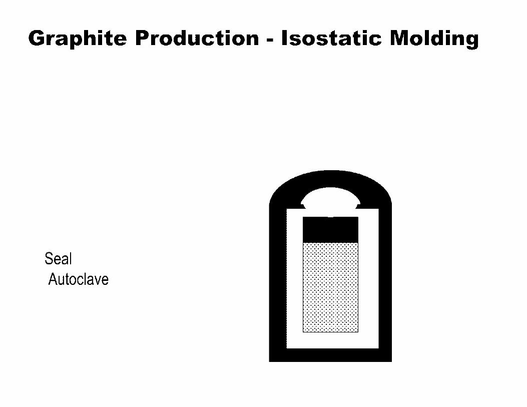
Graphite Production - Isostatic Molding
Seal Autoclave
• • •• • • • • I I I • I I I I
• • •• • • • • • • •• • • • •
• • •• • • • • I I I • I I I I
• • ••• • • •
• • •• • • • • I I I • I I I I
• • •• • • • •
• • •• • • • • I I I • I I I I
• • • • • • • • • • • - • • • •
• • •• • • • • I I I • I I I I
• • •• • • • • • • • - • • • •
• • •• • • • • I I I • I I I I
• • • • • • • • ••• - • ••• . . . . . . . . I I I • I I I I
• • •• • • • • • • • - •• • •
• • •• • • • • I I I • I I I I
• • •• • • • • ••••••• •
• • •• • • • • I I I • I I I I •••• • •••
• • • • • • • • • • • • • • • •
I I I • I I I I
• • •• • • • • • • •••• • •
• • •• • • • • I I I • I I I I ........ • • •• • • • •
• • • • • • • • I I I • I I I I

Graphite Production - Isostatic Molding
Pressurize
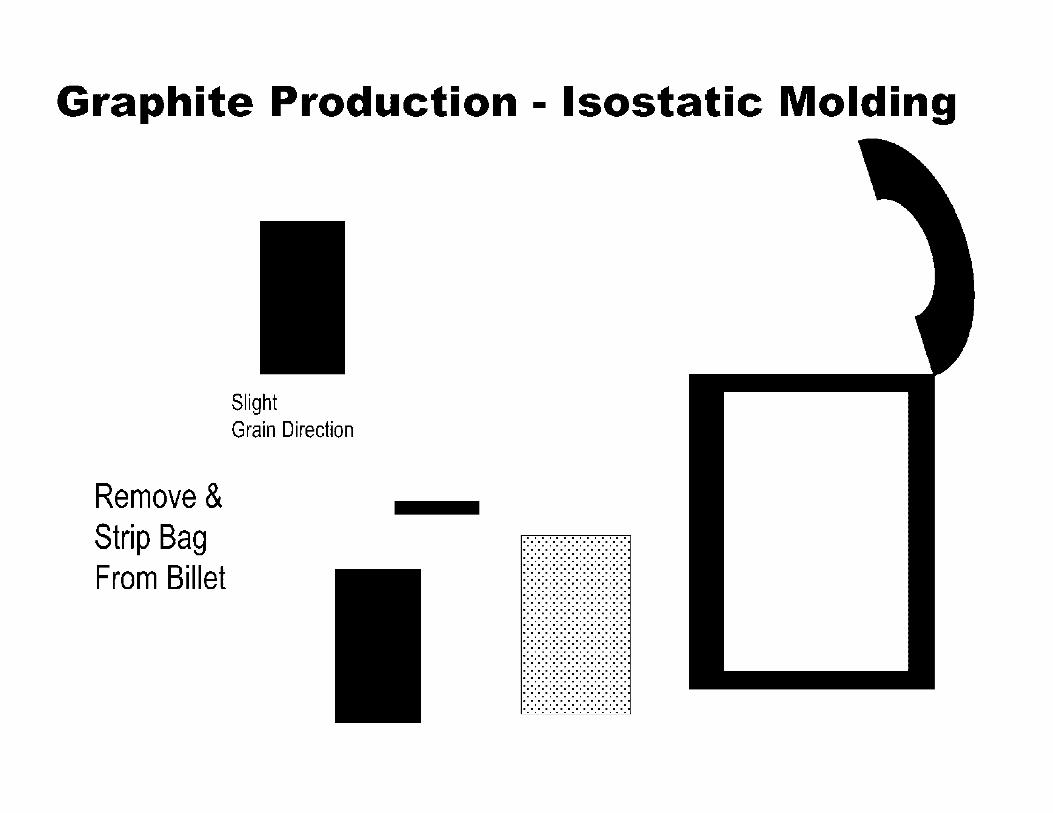
Graphite Production - Isostatic Molding
Remove & Strip Bag From Billet
Slight Grain Direction
I I I • I I I I
• • • • • • • •• • • •• • • • •
• • • • •• • • • I I I • I I I I
• • • • • • • • • • • •• • • • • •••• • •• ••
I I I • I I I I
• • • • • • • • • •••• • ••• . . . . . . . . . I I I • I I I I
• • • • • • • • • • • • •••• •
• • •• • • • •• I I I • I I I I
• • • • • • • • • ... -.... • • • • • • • ••
I I I • I I I I • • • • •• • •• . . . -.... • • • • • • • • •
I I I • I I I I
• • • • • • • • • •• • - ••• •
• • • • • • • • • I I I • I I I I ......... • • • - • • • •
• • • • • • • • • I I I • I I I I
• • ••• • • • •
• • • • • • • • • I I I • I I I I
• • • • • • • • •
• • • • • • • • • I I I • I I I I
• • • • • • • • • • • •• • • • • •••• • •• ••
I I I • I I I I
• • • • • • • • •

Graphite Properties and Behavior
Physical Properties

Synthetic graphite properties Gra hite Grade and Manufacturer
Forming Method
Maximum Particle Size1 1,1m
Bulk Density, g/cm3
Thermal Conductivity, W/m.K (Measured at ambient temperature}
Coefficient of Thennal Expansion, 1 o-e/K (over given temperature range}
Electrical Resistivity, 1,10.m
Young's Modulus! GPa
Tensile Strength, MPa
Compressive Strength, MPa
Flexural Strength, MPa
AXF-5Q
POCO
lsomolded
5 1.8
85
7.4 (20-500°C)
14
11
65
145
90
IG-43
Toyo-Tanso
lsomolded
10 (mean) 1.82
140
4.8 (350-450°C)
9.2
10.8
37
90
54
WG-with grain, AG-against grain
2020 ATJ NBG-18
Mercen GTI SGL Carbon
lsomolded lsomolded vi bro-molded
15 25 (mean) 1600 1.77 1.76 1.88
85 125(WG) 156 {WG) 112 (AG) 150 (AG)
4.3 (20 3.0 (WG) 4.5 (WG) 3.6 (AG) 4.7 (AG)
-500°C) (@500°C) (20-200°C)
15.5 10.1 (WG) 8.9 (WG) 11.7 (AG) 9.0 (AG)
9.3 9.7 (WG) 11.2 (WG) 9.7 (AG) 11.0 (AG)
30 27.2 (WG) 21.5 (WG) 23.1 (AG) 20.5 (AG)
80 66.4 (WG) 72 (WG) 67.4 (AG) 72.5 (AG)
45 30.8 (WG) 28 (WG) 27.9 (AG) 26(AG)
AGR
GTI
Extruded
3000 1.6
152 (WG) 107 (AG) 2.1 (WG) 3.2 (AG)
(@500°C) 8.5 (WG) 12.1 (AG) 6.9 (WG) 4.1 (AG) 4.9 (WG) 4.3 (AG) 19.B(WG) 19.3 (AG) 8.9 (WG) 6.9 (AG)

~ C)
~ --, +J' ftl Q)
:c u !E u Q) C. rJ)
Temperature Dependence of Specific Heat
2400 .--------------------------
2000
1600
1200
800 -Calculated value
Experimental data
400 -+----------~------~---~~
300 800 1300 1800 2300 2800
Temperature. K
Calculated from ASTM C781

Single crystal thermal expansion behavior
Hexagonal graphite lattice has two principal thermal expansion coefficients; ac, the thermal expansion coefficient parallel to the hexagonal <c>-axis and aa, the thermal expansion coefficient of the crystal parallel to the basal plane (<a>-axis). The thermal expansion coefficient in any direction at an angle <p to the <c> axis of the crystal given by:
• ac varies linearly with temperature from ---25 x 10·6K·1 at 300K to --35 x 1 Q-6 K·1 at 2500K.
• a3 is much smaller and increases rapidly from -1.5 x 10·6 K·1 at ---300K to approximately 1 x 10·6 K·1 at 1 000K, and remains relatively constant at temperatures up to 2500K.
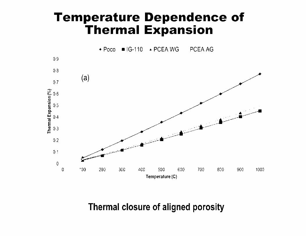
Temperature Dependence of Thermal Expansion
-
0.9
0.8
0.7
t 0.6 C 0
-~ 0.5 RI C. )C
~ 0.4 RI
E ~ 0.3 ~
0.2
0.1
0
• Poca • IG-110 .. PCEA WG PCEA AG
(a)
0 100 200 300 400 500 600 700 800 900 1 ODO
Temperature (C)
Thermal closure of aligned porosity

Temperature Dependence of Coefficient of Thermal Expansion
9 • Poco • IG-110 .._ PCEA WG PCEAAG
8 • • {b) •-- -- -+- --- -.--
- -----+--. --- --...... -- --7 -•-- -
---- -
-- --- +------•-- --
-6 0 -co ' C)
Es . . -.. - -I.LI . • • • - • • .... - • u J.. - I • • G) 4 • • D)
I! G)
~3
2
1
0 0 100 200 300 400 500 600 700 800 900 1000
Temperature (C)
Thermal closure of aligned porosity

Temperature Dependence of the Thermal Conductivity
1200 ----------------------..---
t 100 -~ 1000 ...... 3 900 -~ 800 > -I- 700 u ::)
0 600 z 0 u 500 ...J
; 400 a:: UJ :::c t-
300
200
-•- COMPRESSION ANNEALED ·-&-- AS DEPOSITED --tr- ANNEALED 3000°C
• 100 --------------
0 200 400 600 800 1000 1200 1400 1600 1800
TEMPERATURE (°C)
Phonon scattering, effect of intrinsic defects
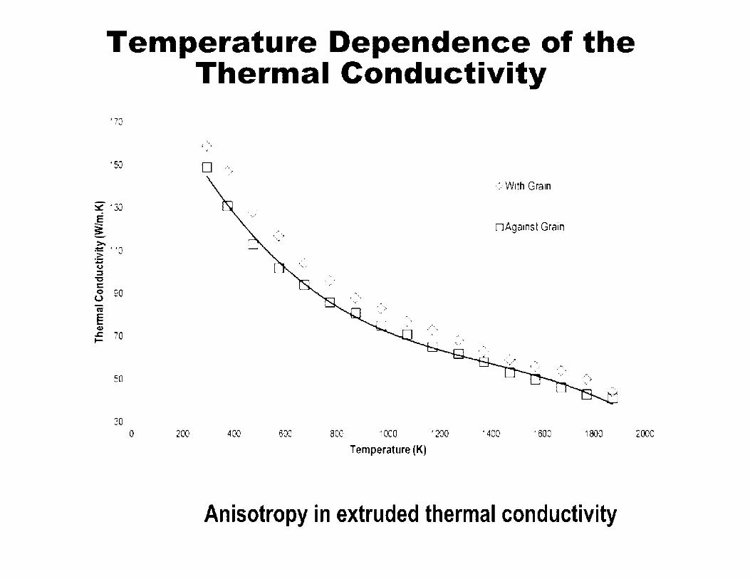
Temperature Dependence of the Thermal Conductivity
'70
'50 • ,•,_ - ,,•
~ ·30 E j ->,
~ "O .::;:
C,) ::::,
"'D C 0 90 0
so
30 0 200 400
<·With Gram
• Against Grain '. ·.• -.
·~ . .,-. ' .. .,.·•
600 800 1000 1200 • 400 1600 1800 2000
Temperature (K)
Anisotropy in extruded thermal conductivity

Temperature Dependence of the Electrical Resistivity
16.0
14.0
-E .\. ci 12.0 ::1. --~ 10.0 ~ > ti 8.0 U) GJ
a: 6.0 CV u "i: -~ 4.0 -w
2.0
00 0
. ·-. .... '
500
....-...--- , -~- _::_..... _____.:.,--::-__ ,.,..:._~-- .
.
1000 1500 2000
Temperature, K
.
.
2500
Electron transport mechanism
3000 3500

Graphite Properties and Behavior
Elastic Behavior
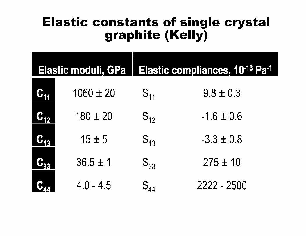
Elastic constants of single crystal graphite (Kelly)
Elastic moduli, GPa Elastic com liances, 10-13 Pa·1
1060 ± 20 S11 9.8 ± 0.3
180 ± 20 S12 -1.6 ± 0.6
15 ± 5 S13 -3.3 ± 0.8
36.5 ± 1 S33 275 ± 10
4.0 - 4.5 S44 2222 - 2500
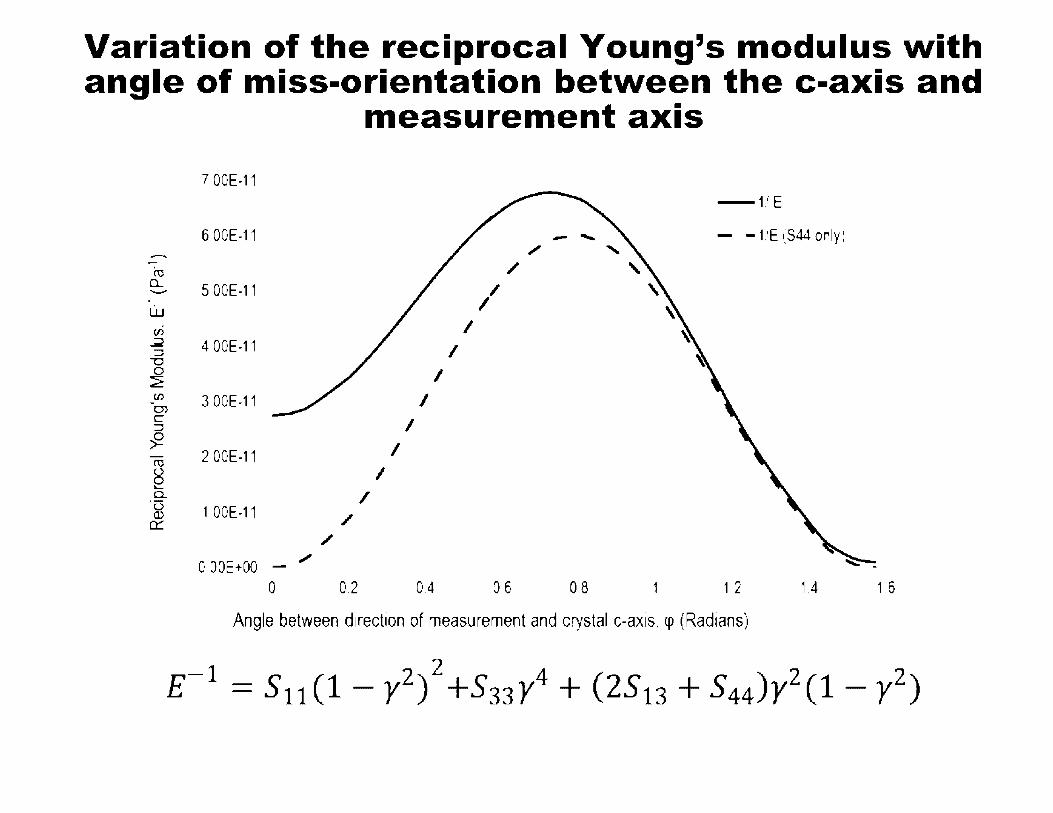
Variation of the reciprocal Young's modulus lNith angle of miss-orientation betlNeen the c-axis and
measurement axis
7.00E-11 -1.iE
6.00E-11 - ...... - - VE (S44 only)
- ,,, cu /
a.. 5.00E-11 / ---w I c.ri I ~ 4.00E-11 I ::::, -0 0 I ~ VJ 3.00E-11 I 0) C I ::::,
-fl. I cu 2.00E-11
~ I c.. I ·u 1.00E-11 (l) / c::::
/
0 OOE+OO ,,, -
0 0.2 0.4 06 0.8 1 1 2 1.4 1 6
Angle between direction of measurement and crystal c-axis. cp (Radians)
-1 2 2 4 ( ) 2 2 E = S11 (1 - y ) +S33y + 2S13 + S44 y (1 - y )

Variation of the reciprocal Shear modulus ,Nith angle of miss-orientation bet,Neen the c-axis and
measurement axis 2.SE-10
ro 2E-10 a.....
en :::, :::, 1.5E-10
'"O
~ I.... cu Q)
t5 1E-10 ro ()
e c.. -~ SE-11 a:
0 0
Sht->.il" Moduh1•, p,H ,1llt ... l to h,i-.. 11 pl.uH-.. , (.i-di, t-'C" tion} r • 1
-1/G
0.2 0.4 06 08 1 1 2 1 4 1 6
Angle between direction of measurement and crystal c-axis, cp (Radians)
-1 ( S44) ( 2) ( ) 2 2 G =S44+ S11-S12-z 1-y +2S11+S33-2S13-S44y(l-y)

Typical Young's Modulus increase with temperature for pitch-coke and
petroleum coke synthetic graphite 0.60
-Pitch-coke ~050
I
- -Petroleum-coke ,t, ,_; ._. __
w uJ 0.40 = 00 ~ ::::,
"'O
~ 030 00 Cl C: :::, 0 ~ 0 20 C
(J) 00 co Q) .._ g 0.10
0.00 0 500 1000 1500 2000 2500
Measurement Temperature, K

Stress-strain behavior of synthetic graphite
There are two major factors that control the stressstrain behavior of synthetic graphite:
•The magnitude of the constant C44, which dictates how the crystals respond to an applied stress,
•The defect/crack morphology and distribution, which controls the distribution of stresses within the body and thus the stress that each crystallite
• experiences.

Graphite Properties and Behavior
Strength and
Fracture

Typical compressive stress-strain curve for medium-grain extruded graphite (WG)
50
45
40 ['IJ a.. ~ 35 • en ,· en ~ 30 -if) • ~ • 25 • ·oo • en ~ a. E
20
8 15
• 10
• 5 ~· o o oo 0 20 0.40 0.60 0.80 1 00 1 20 1.40 1 60 1 80 2.00
Strain,%
Non-linear stress strain curve

Typical tensile stress-strain curves for medium-grain extruded graphite (WG)
16 ~----------------
ro 0.... 2
14
12
10
CJ) 8 V,
~ -en J» 6
J---~!; -
~ •• :a;. __
-t:==
4 -.!S=-1--_,
2 • ,:JrF ;;:p·
. . .. . .: -~ ... .,,,,..-
-=51' a ------~------~---a a.as 0.1 0.15 0.2 0 25
Strain,%

The correlation between mean 3-pt flexure strength and fractional porosity for a wide range of synthetic graphite representing the variation of textures
50 ro a.. 45 ~
..s:::::. -0) 40 C .•.
~ ... ...... (/') 35 ~ ::::, X 30 JU
LL ...... 25 a.
I (Y)
C ro 20 ~
15
10
5
0 0 12 0 16
,·· \. ')("
•: :" V
0.2 0.24
F ract1onal Porosity
y = 179 18c ·' ,;_:_·,x
R: = 0.8042
0.28
'·. '.,,,."
0 32
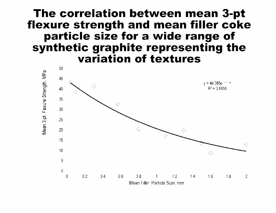
The correlation between mean 3-pt flexure strength and mean filler coke
particle size for a wide range of synthetic graphite representing the
variation of textures 50
ro a.. 2 45 ..c -C')
40 C: ~ -CJ')
Q) 35 .._ :::J ><
JU 30 LL -a. 25 I
("")
C: ro
20 Q)
2
15
10
5
0 0
...... l-
'.,.· y = 44.385c · .·, ··~
R.:: = 0 8655
<.,.>
0.2 0.4 0 6 0 8 1 1.2 1.4 1.6 1.8 2
Mean Filler Particle Size, mm

Crack Propagation in Synthetic Graphite
•• ;~ ,,-·'.' .
•
..
• l..
" '
' .. . . . •
' . ' ' : ' . ' ' . . ' , ..
p ., .. ,.~- ~.
41!1 ·l·1 &·, · I ' .... - ,, - I • ' . ' ... . . . '
, ' ' ' I
' '1
''; -~ \ " .,, '" \ LJ~
' \ , . , : \ I, ' \ :" .· .• ,·, '\ . ,' -~
,' ,'le I I ( • ~ ..-,...___ ~ ,, \ t 50Dµm
. \ I· '\~ • • I ,a , .. ~ .. \• ' $ I ' ., • a I ,
An optical photomicrograph of the microstructure of grade H-451 graphite revealing the presence of pores [P], coke filler particles [F] and cracks [C] which have propagated through the pores presumably under the influence of their stress fields

Burchell fracture model probability predictions for different graphite
Model Inputs:
•Mean filler particle size
•Particle K1c
•Specimen breadth
•Stressed volume
•Pore size distribution mean and st. dev.
•Density
•Number of pores per unit volume
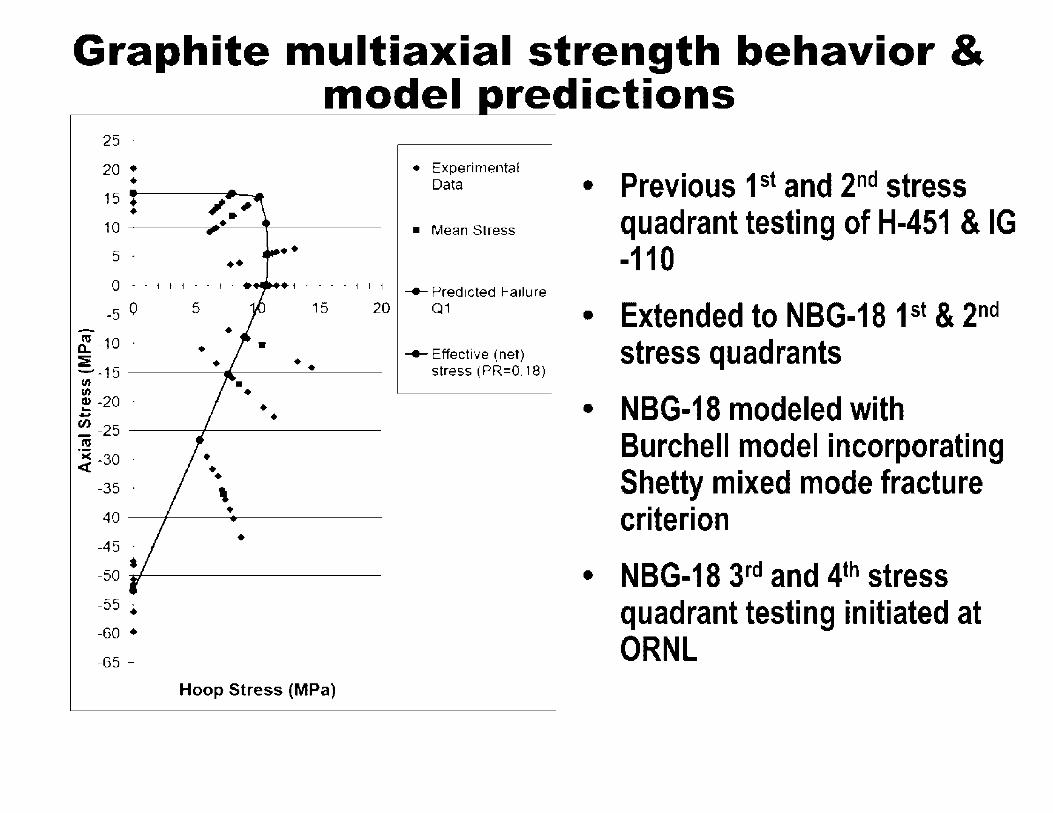
Graphite multiaxial strength behavior & model redictions
25 ·
20 • • 15 •
• 5 . •• ••
., • • • • 1 f i
• Experimental Data
• Mean Stress
-e-- Predicted Failure
-5 0 5 15 20 Q1
-~ -10 · • !._15 -------&---·~· -u, u, ! -20 · • - . ~ -25 _ ___,,____ ___ _ m
-ct -30 ·
-35 · \
• -40 ___,,____ ____ _
•
-55 · • -60 •
-65 -
Hoop Stress (MPa)
-e-- Effective (net) stress (PR=0.18)
• Previous 1st and 2nd stress quadrant testing of H-451 & IG -110
• Extended to NBG-18 1st & 2nd
stress quadrants
• NBG-18 modeled with Burchell model incorporating Shetty mixed mode fracture criterion
• NBG-18 3rd and 4th stress quadrant testing initiated at ORNL

Graphite thermal shock resistance
Thermal Shock FOM, Ka
!l---th- aE(l - v)
K is the thermal conductivity, cry the yield strength, a the thermal expansion coefficient, E the Young's modulus, and u is Poisson's ratio
Material Graphite, AXF-SQ 124,904
Graphite, IG-110 84,844
Wrought beryllium -1x10⁴
Pure tungsten -0.5x10⁵
Carbon-carbon composite -1x10⁶
Graphite does not melt but rather sublimes at T>3300K

Applications • Metal processing
• • •
• Semiconductor manufacture •
• Electrical and electronic • •
• Mechanical •
• Aerospace •
• Nuclear •

Graphite flaw detection & NDE
• Ultrasonic inspection used in graphite manufacture for inspection after bake stage and after graphitization for dry core and gross flaw detection
• But, ultrasonic has limited usefulness/applicability
• Flaw resolution cannot exceed wavelength of signal, i.e., to resolve critical flaws need to use high frequency
• Attenuation increases (range decreases) as frequency increases
• Thus for engineering components may not have sufficient range or resolution, depending on structure/texture and critical defect size
• X-ray tomography promising technique for small artifacts
• Resolution down to micron level or better

Summary • Synthetic graphite is a unique high temperature material
• Crystals have strong in-plane covalent bonds, weak van der Waal bond between planes
• Complicated processing route with many variables
• Properties are controlled by bond anisotropy, structure and texture
• Domain size (extended order) in filler coke and binder directly affects isotropy
• Manufacturing process imparts texture which influences isotropy
• Porosity controls fracture behavior & strength
• Phonon conductor of heat, electron conduction mechanism

Nuclear Graphite
Tim Burchell
Materials Science & Technology Division Presented to
US Nuclear Regulatory Commission
January 12th 2011
4 0.-\k R1nca: N.\TIO:'\,\L I ,:\BOR\TORY '·:,·-.·· •• \. • .. ' c •· .. · ~.-._--; __ , • .. :-. IH: 1:: ··,•.-.1•-,1;•.,· .. •:'·,I<,·

Outline
Graphite

Role in HTGRs

Role of Graphite in a Nuclear Reactor
Neutron moderator (carbon & graphite)
Neutron reflector - returns neutrons to the active core
Graphite (nuclear grade) has a low neutron capture cross section
High temperature material

Role of Graphite in a Nuclear Reactor
Graphite is the reactor core structural material
HTGR cores are constructed from graphite blocks and do not form a pressure boundary
In prismatic cores the graphite fuel elements retain the nuclear fuel
In a pebble bed the graphite structure retains the fuel pebbles
The graphite reflector structure contains vertical penetrations for reactivity control
Reactivity control in also graphite fuel elements

Gas Turbine-Modular Helium Reactor (GT -MHR)
> 50% conversion efficiency (Brayton Cycle) or 1000°C outlet temperature Helium for process heat applications (H2 production)
Graphite core
~;if----- Helium Gas TurbineGenerator or lntermediat e Heat Exchanger
•·
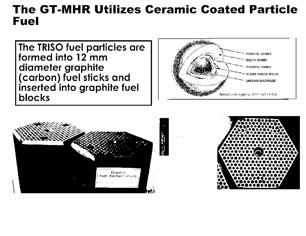
The GT-MHR Utilizes Ceramic Coated Particle Fuel
The TRISO fuel particles are formed into 12 mm diameter graphite (carbon) fuel sticks and inserted into graphite fuel blocks
-,-.;~ .... ~:--:-:.: •=· ·-· ·-.._ ......... _ -· -""'--..;:~---.---~---... ~~~ ~- -.. - ----... -_..,_, .. -- --'-.._,..::a :a.;",_-..... - ---------:-:-=-=--. -.;---..~~,- ----~ ___ ,._...,-_ ... _____ ~--
~~~~, ... , .......... -.,:--~--,,;;-_-,..---.. -.... _.,,._..,. ............. ~-------- ----~--- ---' ~ .. 1L'I~,-~_,_ ~- - - _ .... _ .. _ .. . '.-.:_"~...:.. .. ~---~--:-'"I. .. --. .... ,~-...........
\ I Grnpl11h• i I Fuel Elcmen! 1.11,x;.. , I I
I 1 11 I ,. • I ,1
I __J
.• / ' . .-.. .,. ----~- /"' • ._ L ----
• / .. ~: -·· . -.. ' ---- l'YIIDl"t m: 1,;,J,_;1u11 .. ., ,-~,,,;-:~- . i--•t , ·u-. ··: ",":. ~ : . I ----. SlllCO'll-!'J.IIIIIDr ~/ ~ ~ ,,,_ '! __,__..,___
.. }' • ··., •-,~ . \--------. P'tnOl'l"TIC. Ci\RBC..~ II ··•~ . !" •. J.. ----
•.. '!' J'J 1---. . A...;_ -~~- J -- "·"'"' ""'"' ""'"" . '~-. .,,.J. . ---------. . -- UFli\lilU-.i Ol'iCnl'i::illlE
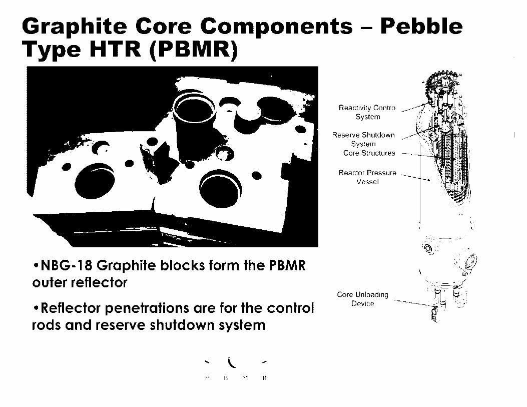
Graphite Core Components - Pebble Type HTR (PBMR)
• NBG-18 Graphite blocks form the PBMR outer reflector
• Reflector penetrations are for the control rods and reserve shutdown system
f' Ii 'I H
Reactivity Control System
Reserve Shutdown System
Core Structures
Reactor Pressure Vessel
\• ,·. _., __ I
;~ ... \\-lJ .. , ....... ·-=-.I ;::--:.- ./t)°J '-.~ ~ ~~1/
\ ·---:-a,7
~-: ~.;: ~~ -:ii✓ Core Unloading ' .. _.tl • ~_: __ . ·1
Device 7f;J .:]_;I
·l ...
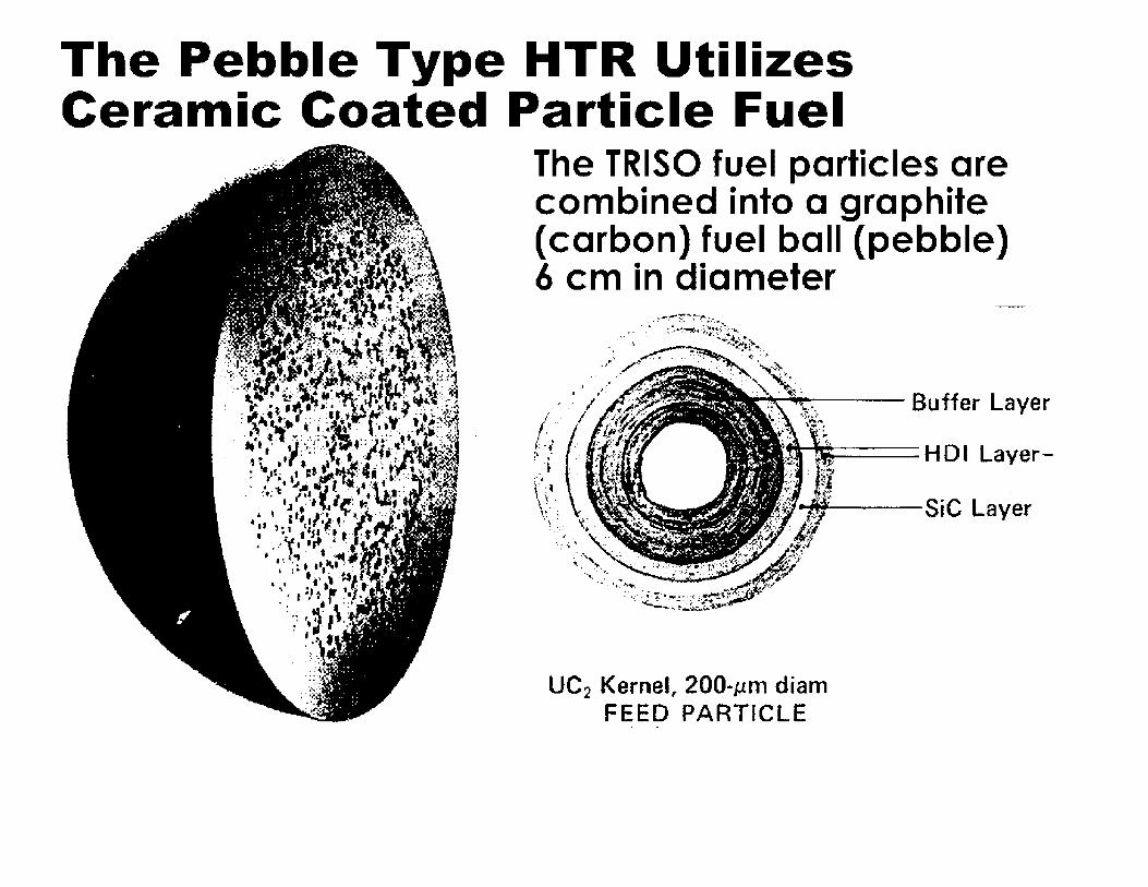
The Pebble Type HTR Utilizes Ceramic Coated Particle Fuel
The TRISO fuel particles are combined into a graphite (carbon) fuel ball (pebble) 6 cm in diameter
UC2 Kernel" 200-µm diam FEED PARTICLE
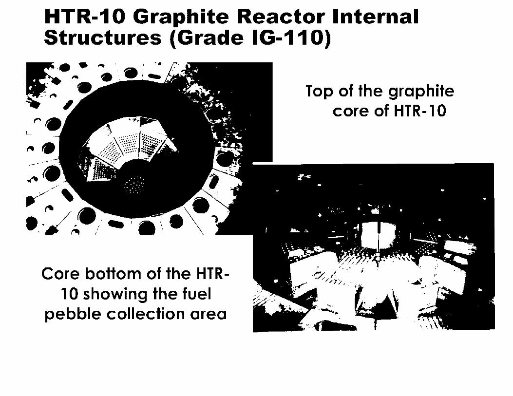
HTR-10 Graphite Reactor Internal Structures (Grade IG-110)
Core bottom of the HTR-10 showing the fuel
pebble collection area
Top of the graphite core of HTR-10

Design of nuclear graphite for HTGRs

In The USA - AGOT Graphite
Very anisotropic irradiation induced dimensional changes
• Coarse texture
• Anisotropic needle coke
• Extruded (faster, lower cost)
• High Purity (low Boron and Sulfur content)
• Low Strength •Nuclear Graphite -The First Years, W. P. Eatherly, J. Nucl. Mater. 100 (1981) 55 -63
Factors Controlling The Neutron Irradiation Damage Response Of Graphite
• Crystallinity (degree of graphitization): More graphitic crystals retain less displacement damage. Crystallinity is a function of precursor (pitch/coke) and graphitization temperature.
• Small crystallite sizes promotes higher strength and retardation of pore generation.
• Structural isotropy (both coke isotropy and final product isotropy). Isotropic irradiation behavior is much preferred. CTE ratio is used as an indication of isotropy. Higher coke CTE and graphite CTE preferred.
• Forming technique - structural and property anisotropy is introduced by extrusion and molding. Isostatic molding produces an isotropic graphite.

Developments in Nuclear Graphite -Process Improvements • Purity
- Advent of in-graphitization furnace purification
• Crystallinity
- High crystallinity retains less radiation damage
• Filler coke size
- Sm~II size _preferable (stronger} but larger block sizes requires coarser particles size
• Forming method
- lsosta,ic pressing_ & vibrational molding yields less anisotropy than extrusion or mola1ng
• Higher strength
- Resists pore generation
• Near-isotropic (isotropic filler coke and graphite artifact)
- Minimizes crystal strains
What Was Learned Over The Years Flowed Down To Improved Graphites:-
• Halogen purification (allowed alternate feedstock sources)
• Understanding of damage mechanism and role of graphite crystallite size
• Need for isotropic cokes - high CTE which yield isotropic properties in the final artifact
• Thus second generation graphites were born
- USA, H-451 - extruded, isotropic pet coke
- UK, IM1-24 - molded, Gilsonite coke

Near-isotropic Graphites - H-451
_ . _ -. ~ • Extruded, isotropic ·:f<,; .. ~,~- petroleum coke
;~ · _._,,-.,,! (NO LONGER . AVAILABLE)
Fuel elements & replaceable reflectors in the FSV HTGR (GA)

Near-isotropic Graphites - IM1-24 (UK) ~- :~-- -·-•·~-~f ~!-lj" -:1• ,. ~ _ ~- ,..[, # .. ··;:·~~-,":...-I_ -~-- •· 7: . - .. . I -' . - ~ . "I . .f'-., . -.i ,_ . , - . .... .... . . • . .. ,./ "' , ,t;"'. . .. . C "I
;· - , - , -~· ~ ' . , . j ... ' • t ~ :-.:·, -~ ,_-' -· · . . , t .. <.-... /7.,,.fJ;.~ ... ' \' ·/. ~· ·1 : fi· ·~·,•.-.,:·.-·· _jj '
. , ~ . ., . \ ' . .. . ., , ' .. " • f. ,. ' • • . ~.. . . .
. ... .,-.- • • ' f -. • . -- .• . t •. ~ .- .. ' .. . . ., . • . . ,, ; ; . . a.l ... ' . ,c ,.... . -- •
_· - - -· .... ,,, 1 ~ . • "I\ --. .. -·--• . ., tf'" ,. - - ...__ 1 J • .. - , •. • r. - ., , \ - ---~ • • • ~ ., • . . 1
'
?f; __ y..::_, '·, ./: • .. ~--. ,,.".' •. ... : ,, ! I ;t,~• \ '~- -. . .• • --- , --. ~-' .-. ., ' ' --; ' -- . -. : ~ I I ' , · · '. '-'~II "\: . , ••., ·._ , _•·~•-•· • -~ ,,· . ._._ ..••. '- 4. • - . ·-- -. \ ' .,;. - . .. -. .,. ,.... .,,. -- - .A. • .. . .... ~
.. • • > --- I • ,I . ._,ti- - ~ , _.:,· ----1 '!,) . . - . ,ti!' ..... ~ .. t!' ', ,-:" • . . .. - . ' . f < \ . ~-' ~ ' \, •. tt- iii:. : .. t'c .. ; . .,r,I, .'. , > ·_._ ~ •-..-:-'-..;__.' 'r• -~~ . \ _,. -,, •17 - . . ........ . , M ' . ..,.._ .. ~-. ~ 'J -·~.... _.· . .. • ,_ , . I . ' f. ... . , - . . ,,, . -- . .
·. ' .. .,. -'- J ."'- . • ' " • . ~- . . ' " ... ·t ' - ·• . . \ • ..1.. • .,,,, ' • ,- ·-•. . l
•. ~ -4 - - • - .. _, - .- ' 1 -· . i .. ~ ~, . I :J :-. . ' -· • • "f \ . '• , ' • "" . · . . · : 11/'! . ' ' • . t ~•-· ~ . •· .
', I, .. I . '· i -- ,/ . " ,..... . , . . ' ~j} ·, . ''•,(--,. .-,..~ ,· 4- ., ,. -- ... , • V ~-- '~- ·- ~- - I~·-... • .,, . Jj ; I .•. • - . , ;. I. • •• ·-:.... ~ .•;-.:~- i, t .
I , . . • • • . · " } , fl' :. , . · f 1 - ' - · . i,(, .. : - . ~ ·. --: ... ' . -. ·, :•.1 ' . , ·, ·, .. :_,,;,.,..~ •• ; I .. , · • •. • "' · "' i .. ..., •· ,. ,· ... . .,:,·-,., ·'•" ' ...... ~·· .. ~
..,,, ')'"' .,,. , J • . .,. • •-;;.' r- ., 0 . I... ·r "'" • . . \ •. • , ' ... • • • • ., I • • • •. .. ( . , ' . -"\ . . . .~ . . .. . . .. ..,· ,• .. - .. ,, ... · .,-~ .. ·· .. -. ' : • . . • .. , ..0 . ' • • ... - ~ T I •
• Molded, isotropic Gilsonite coke (NO LONGER AVAILABLE)
•---SOOµm filler particle size
• Isotropic physical properties
• High CTE and reasonable strength
• Replaced Pile Grade A (Magnox)
Advanced Gas-Cooled Reactor (CO2 cooled) permanent core structure (lifetime component)

Developments In Nuclear GraphiteNear Isotropic Graphites
• Crystallinity
• Smaller particle size
• forming method (Isostatic molding)
• green coke technology
• high strength
• Isotropic - Properties - Irradiation induced dimensional change
• Third generation graphites are born

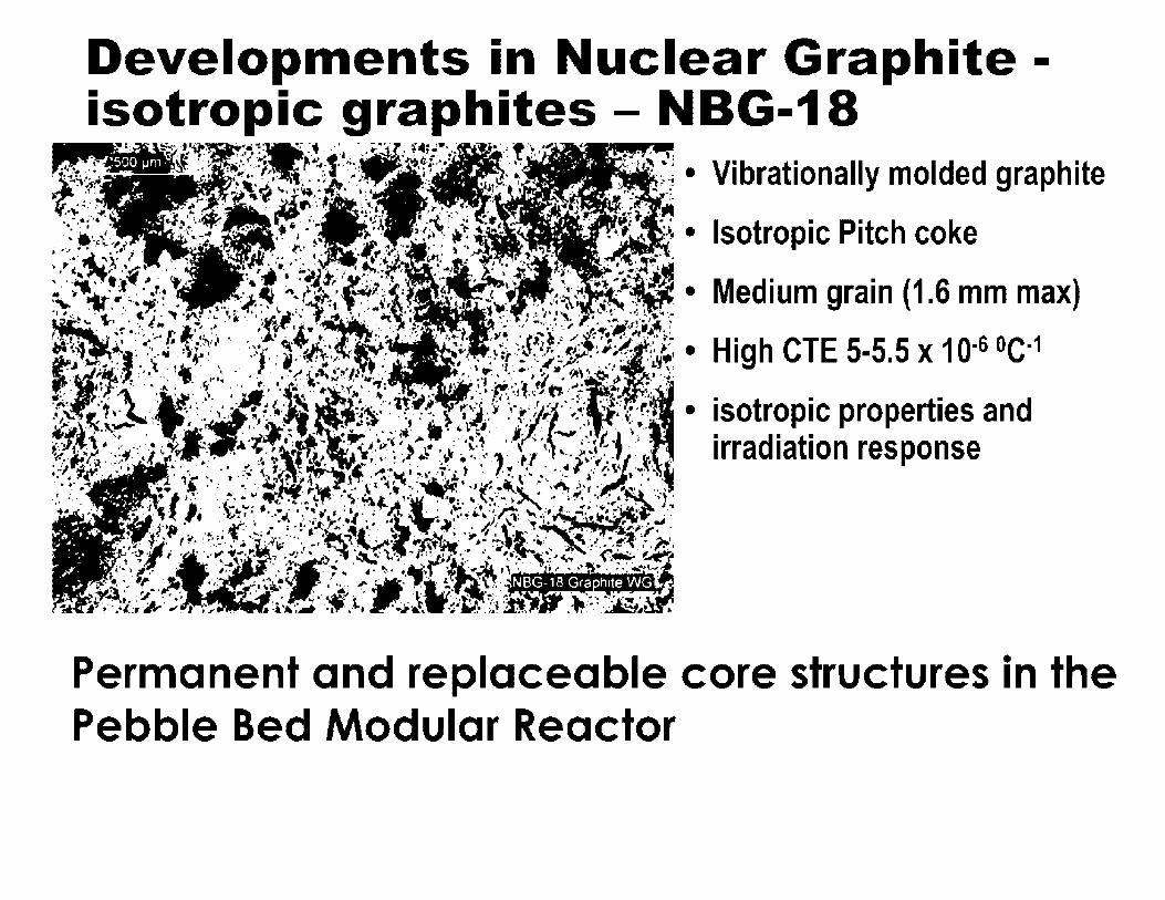
Developments in Nuclear Graphite -isotropic graphites - NBG-18
Vibrationally molded graphite
Isotropic Pitch coke
Medium grain (1.6 mm max)
High CTE 5-5.5 x 1 Q-6 0c-1
isotropic properties and irradiation response
Permanent and replaceable core structures in the Pebble Bed Modular Reactor

Graphite and graphite testing standards

ASTM Standard Specifications
• D7219-08 Standard Specification for Isotropic and Near-isotropic Nuclear graphites
• D7301-08 Standard Specification for Nuclear Graphite Suitable for Components Subjected to Low Neutron Irradiation Dose

What is Specified by The ASTM?
• Coke type and isotropy (CTE)
• Method of determining coke CTE
• Maximum filler particle size
• Green mix recycle
• Graphitization temperature (2700°C)
• Method of determining graphitization temperature
• Isotropy ratio and chemical purity
• Properties: density, strength (tensile, compressive, flexural), CTE,E
• Marking and traceability
• Quality assurance {NQA-1)

ASTM Standard Practices
• C625 Reporting Irradiation Results on Graphite
• C781 Testing Graphite and Boronated Graphite Materials for High-Temperature Gas-Cooled Nuclear Reactor Components
• C783 Core Sampling of Graphite Electrodes
• C709 Standard Terminology Relating to Manufactured Carbon and Graphite
ASTM Standard Test Methods
• C559 Bulk Density by Physical Measurement of Manufactures Carbon and Graphite Articles
• C560 Chemical Analysis of Graphite
• C561 Ash in a Graphite Sample
• C562 Moisture in a Graphite Sample
• C565 Tension testing of Carbon and Graphite Mechanical Materials
• C611 Electrical Resistivity of Manufactured Carbon and Graphite Articles at Room Temperature

ASTM Standard Test Methods (continued)
• C651 Flexural Strength of Manufactured Carbon and Graphite Articles Using Four-Point Loading at Room Temperature
• C695 Compressive Strength of Carbon and Graphite
• C714 Thermal Diffusivity of Carbon and Graphite by Thermal Pulse Method
• C747 Moduli of Elasticity and Fundamental Frequencies of Carbon and Graphite by Sonic Resonance
• C748 Rockwell Hardness of Graphite Materials

ASTM Standard Test Methods (continued)
• C749 Tensile Stress Strain of Carbon and Graphite
• C769 Sonic Velocity in Manufactured Carbon and Graphite for Use in Obtaining Young's Modulus
• C816 Sulfur in Graphite by Combustion-lodometric Titration Method
• C838 Bulk Density of As-Manufactured Carbon and Graphite Shapes
• C886 Scleroscope Hardness Testing of Carbon and Graphite Materials

ASTM Standard Test Methods (continued)
• C1025 Modulus of Rupture in Bending of Electrode Graphite
• C1039 Apparent Porosity, Apparent Specific Gravity, and Bulk Density of Graphite Electrodes
• C1179 Oxidation Mass Loss of Manufactured Carbon and Graphite Materials in Air
• Dxxxx Oxidation Rate and Threshold Oxidation Temperature for Manufactured Carbon and Graphite in Air

New ASTM Test Methods Currently in Development
• ASTM D02.F on manufactured carbons and graphites has several test methods in development - Critical stress intensity factor
- Shear modulus and Poisson's ratio from sonic velocity
- Flexural strength by three point bend
- Chemical purity by ICP- OES and GDMS
- Small (irradiation) specimen best practice
- Non-destructive test and evaluation
- X-Ray diffraction analysis

Physical properties and irradiation effects

Neutron Irradiation Damage
• Neutron irradiation causes •carbon atom displacement
• Dimensional and physical property changes result
• Damage mechanism well understood
A
• Key ~hysical properties are: irradiation dimensional s stability, strength, thermal expansion coefficient, thermal conductivity, radiation cree~ behavior, A
fracture behavior, oxidation behavior.
GRAPHITE CRYSTAL STRUCTURE
C 0.670 nm
0.246 nm

The Radiation Damage Mechanism In Graphite
{c)
INTERSTITIAL! e I
----c:~==~>-----C ----
COLLAPSING VACANCY LI N E ~ ~
~ CONTRACTION
-
~ NEW PLANE
EXPANSION
CARBON ATOM BINDING ENERGY IN GRAPHITE LATTICE IS 7 eV
DISPLACEMENT ENERGY FOR CARBON ATOM IS APPROX. 30 eV

Low Temperature Stored Energy Release
0.7
0.6 EXPOSURES IN Mwd/At a dpa(approx) •T. - 30°C 1rr
0.5 I°" •Hanford K - I , .. ~ SPECIFIC •reactor test ~ 0.4 HEAT]_ __ - t 7 \ • 0 •Data u
I \ -- --- I \ ~--~ 0.3 I )....--- • "'O . , ---- \ ' •Traditionally ' r./) ;-- \ .
1075/0.10 "'O ---- I \ .............. _ associated with 0.2 I \ -·--........_
I ', .. ,
Frenkel pair I ' •
0. -t I ' recombination 'I ' ..... ____ 100/0.01 ----- .... -----0
......... 100 200 300 400 500
ANNEALING TEMPERATURE (°C)
Burchell T, Carbon Materials for Advanced Technologies, Chpt. 13 (1999) p. 429

Displacement Damage in Layered Graphitic Structures
•• - ,.
Sequential HRTEM images illustrating the formation rates of interlayer defects at different temperatures with the same time scale (0 to 220 seconds). (a) 93K, (b) 300K, (c) 573K, in
- ... 1401 --- ·___ · . · · :~~T-i:~!.:.~•-?.:~:;.-·-- .. double wall carbon nanotubes " - , -., . .,.. • . . •,•. ~;~•-~~ ....... ,,.•,• .. •-.~~t:~~ . • I
~ .,. , ¥•'1:i •~ ;=.,; .:;:=c::-,:a:; I ;;: r :;...:::; ,;. . _, •, -.. '•, - • • • • . . -
_,.,, ~ -- . .. ·, - ~· ,' • •"t'· .•.
s:.. • -=f ~ ·• --~ ~ _ .. ,.. ___ ~~~~;;::. ~:=-.·,=~::.~=;~=-·.:=·:~~-~;:.:": • The arrows indicate possible 220, . : ·_ -_- · -- -- - t:",J~--:---~•i=-:,t-.·~~-~ -~-: -~ · ·interlayer de'ects
I' · ' : ' . '-'t,~~,. i~•.-=i.::'.•~ ·:.: .- •. ~; .• ; I I I __ ....,~ 0 t ....... ,, . ... :. -••.•. ; ~· ·.;.·: -:-_·.·. ••.
~~... ~- ~ ~-27 ~~· -...:::, '4 • ~===:=;;:::;::;:: ;:, ·=·:e-:"..:'• •• -.• ·- ee:•:J: r: :·-~.:.·~"II: .. ,,. -... ~-•- .. ··.•· -.'."·~ ... .. .. ... ....
·_·. r _·.. ~-':,~·,, __ ,_''.':,-:. :~
2nm
Urita, K.; Suenaga, K.; Sugai, T.; Shinohara, H.; lijima, S. Physical Review Letters 2005, 94, 155502.

-(J) C:
Displacement Damage in Layered Granhitic Structures 200-----~.---------,
" •·· . I ••
I J_
-ca 150 - ~
• Normalized formation rate of the clusters of 1-V pair defects per unit area of bilayer estimated in HRTEM images recorded at different temperatures
.c -Q) -a:, -c:: j 100 -co E "-0 --(.)
~ 50 -Q)
Q
0 0
: · .. : · •. • ••
·. . . T
·,_. ·-~
t i .. r.. t
I I r· ;Hiw. 200 400 600 800 1000
Temperature (K)
• The dotted line shows the known temperature for Wignerenergy release (-473 K)
Urita, K.; Suenaga, K.; Sugai, T.; Shinohara, H.; lijima, S. Physical Review Letters 2005, 94, 155502.
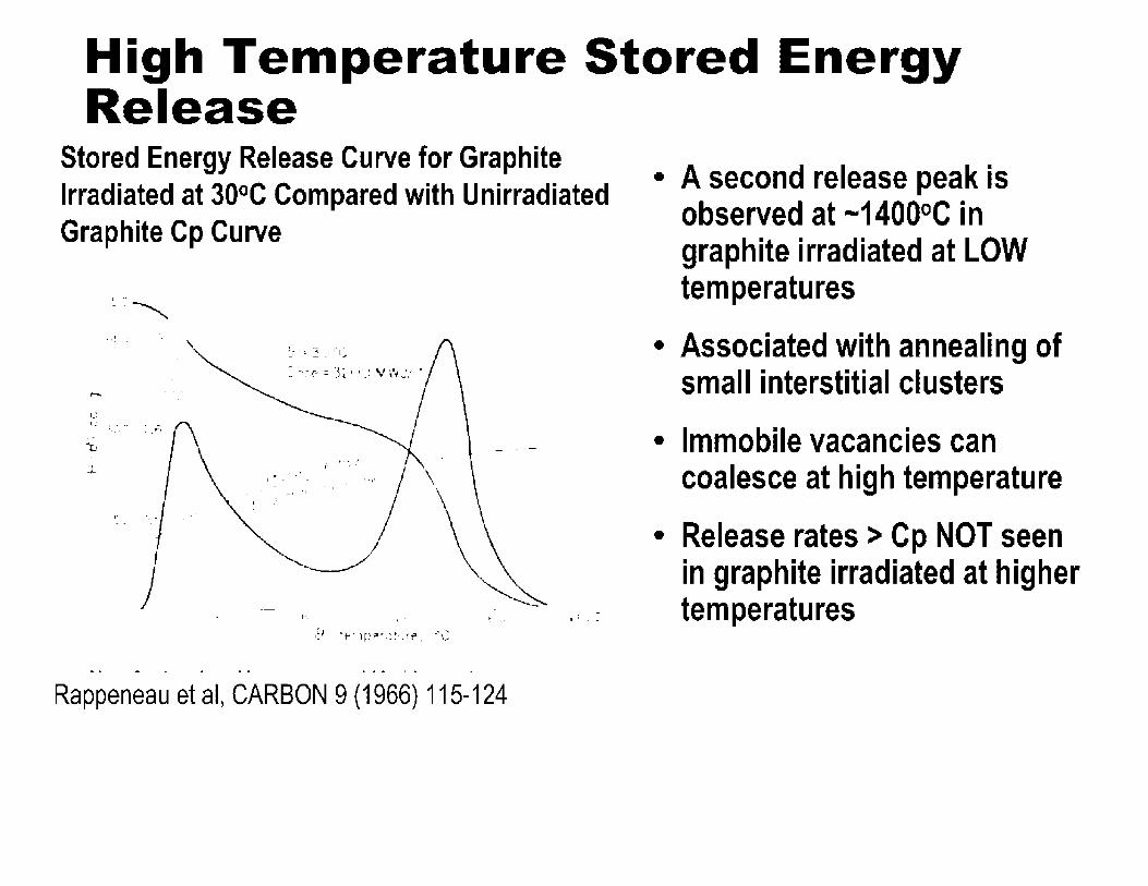
High Temperature Stored Energy Release
Stored Energy Release Curve for Graphite Irradiated at 30°C Compared with Unirradiated Graphite Cp Curve
-. ' ~ . :
' ,-.,
'-~ l: I •••
•, .. . -'U
...... >·
l ·t"· '
~ 1.-- '. ~ .....
.9. ·t~ 1~·~ .. ~~-.... ~e, '-" 1:
Rappeneau et al, CARBON 9 (1966) 115-124
. ' . ' . _,
• A second release peak is observed at -1400°C in graphite irradiated at LOW temperatures
• Associated with annealing of small interstitial clusters
• Immobile vacancies can coalesce at high temperature
• Release rates > Cp NOT seen in graphite irradiated at higher temperatures

High Temperature Stored Energy Release
•. ' ' ·.-.: I
Rappeneau et al, CARBON 9 (1966) 115-124
.. . . _ ....
l ''t• . -, T" , .•. ~--
~
I ·_ .~ i -
8 Dose
I ......_ 70 °C 130C MWJ/T I: ....._ 72 °C l::::40V\\'J/T [Ii ,-19( 1 '''.~ ,;,=,.~Q~/Vw',J/--;--tV·......_ 1-;-o 0 ·~ 3C40MW.J/T
.:t
.. .-\ __
.i.: ..... __ .' ·'
. -.. ~.__ ·-_ ',\ . \ ./ ·,. \
·. '·,
' ·, 1 . ' ' \ . 'i ., ... , ·. \
........... '.
• High temperature release is due to a separate mechanism
• Release rate does NOT exceed Cp
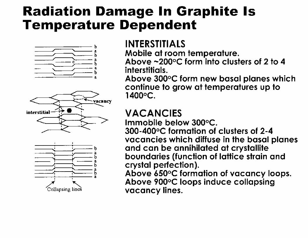
Radiation Damage In Graphite Is Temperature Dependent
--~..=---=:-- b --a
------ b --a __ --c b
---a ---- b -----a
<------%. ;½~ncy interstitial- , ~ • •
~ ~ ~==-> •--b
------ a --b
--- a --b ----_ _J.--~---_ --& _ __._~-- a
I I
/_C 11 . l·, o apsmg mes
INTERSTITIALS Mobile at room temperature. Above ,..,200°C form into clusters of 2 to 4 interstitials. Above 300°C form new basal planes which continue to grow at temperatures up to 1400°C.
VACANCIES Immobile below 300°C. 300-400°C formation of clusters of 2-4 vacancies which diffuse in the basal planes and can be annihilated at crystallite boundaries (function of lattice strain and crystal perfection). Above 650°C formation of vacancy loops. Above 900°C loops induce collapsing vacancy lines.

The Creation of New Basal Planes in Layered Graphitic Structures
Banhart, F.Rep.Prog.Phys. 1999,62, 1181-1221.
A high-resolution electron micrograph showing the basal planes of a graphitic nano-particle with an interstitial loop between two basal planes, the ends of the inserted plane are indicated with arrows.
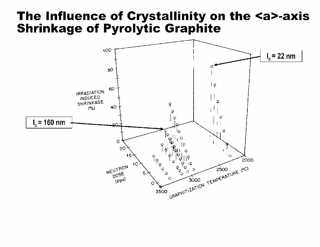
The Influence of Crystallinity on the <a>-axis Shrinkage of Pyrolytic Graphite
~oo
80 -
60 IRRADIATION
INDUCED SHRINKAGE
(°lo) 40
0
0
I
I qi
I I r.,
I I I
I I I~
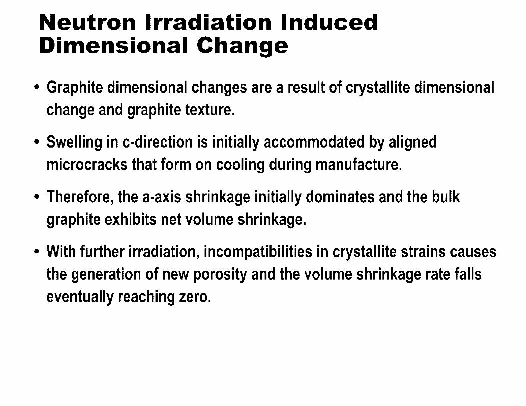
Neutron Irradiation Induced Dimensional Change
• Graphite dimensional changes are a result of crystallite dimensional change and graphite texture.
• Swelling in c-direction is initially accommodated by aligned microcracks that form on cooling during manufacture.
• Therefore, the a-axis shrinkage initially dominates and the bulk graphite exhibits net volume shrinkage.
• With further irradiation, incompatibilities in crystallite strains causes the generation of new porosity and the volume shrinkage rate falls eventually reaching zero.

Neutron Irradiation Induced Dimensional Change (Continued)
• The graphite begins to swell at an increasing rate with increasing
damage dose due to c-axis growth and new pore generation.
• The graphite thus exhibits volume "turnaround" behavior from initial
shrinkage to growth.
• Eventually disintegration occurs due to excessive pore/crack
generation.
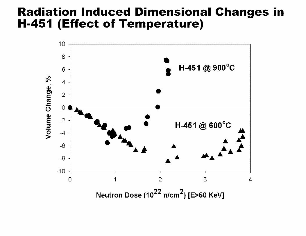
Radiation Induced Dimensional Changes in H-451 (Effect of Temperature)
10
8 - -6 - I H-451 @ 900°C ~
4 -0 -Cl) • C) 2 -C:
m .c
0 ~ ...
0 ~, -cu - • E -2 - ~.- • H-451 @ 600°C ::::, - • 0 -4 -> . , •• • -6 - • .. ~ ·~
-8 - •• .... -10 I I I
0 1 2 3 4
Neutron Dose (1022 n/cm2) [E>50 KeV]
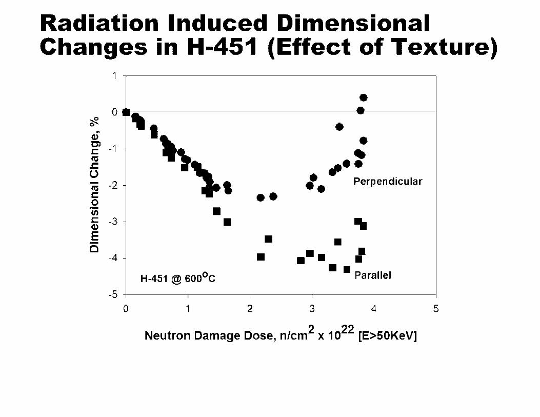
Radiation Induced Dimensional Changes in H-451 (Effect of Texture)
1~--------------~
• 0 ; - ,a.
·9t ~
~ • 0 .. I Q) • C) C: -1 - • cu .c: ,,, •• u ,. - -2 - Perpendicular cu C: •• 0 ·- • U) C: -3 - • ... Cl)
E • • -C ... : -4 - • H-451 @ 60o0 c • • Parallel
-5 I I I I
0 1 2 3 4 5
Neutron Damage Dose, n/cm2 x 1022 [E>50KeV]
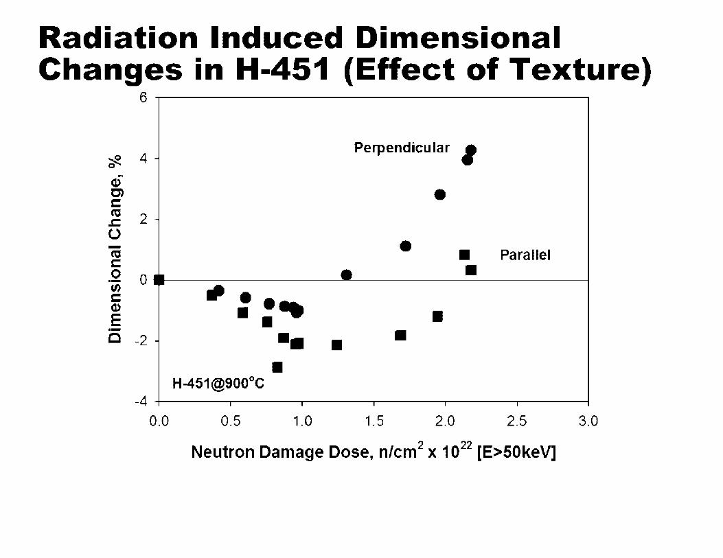
Radiation Induced Dimensional Changes in H-451 (Effect of Texture)
6-----------------
~ 0 4 -
Perpendicular I r,
C1) C) • C: ca 2 -.c: 0 - • ca • Parallel C: • 0 0 • ·-(I) - ••• C: C1)
E • • • ·- • C -2 - •• • •
H-451@900°C -4 I I I I I
0.0 0.5 1.0 1.5 2.0 2.5 3.0
Neutron Damage Dose, n/cm2 x 1022 [E>50keV]
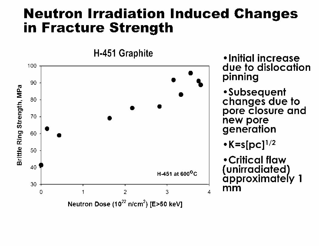
Neutron Irradiation Induced Changes in Fracture Strength
H-451 Graphite 100 ...------------------,
"' CL
90
:E .. 80
r:. .... C)
~ 70 ~ ..... en • C> 60 C ·-0:: !! 50 · = ·-~ cc
40 ~ ~
• •
• • ' • • •
H-451 at soo0 c 30 ----. ----, ----, ---
0 1 2 3 4
Neutron Dose (1022 n/cm2) [E>50 keV]
• Initial increase due to dislocation
• • pInnIng
• Subsequent changes due to pore closure and new pore generation
• K=s[pc] 112
• Critical flaw (unirradiated) approximately 1 mm

Neutron Irradiation Induced Changes in Young's Modulus
H-451 Graphite
30 ......------------------.
ci° 25 a.. C) -w ,,; 20 ::::, -::::, "C
~ 15 (.) -1n cu ijj 10 O
.... "-•
• •
H-451 at 600°C
5 +------. ---. --~,-----0 1 2 3 4
Neutron Dose (1022 n/cm2) [E>50KeV]
• Initial rise due to dislocation pinning
•Subsequent increase due to volume shrinkage ( densification)
• Eventual turnover and reduction due to pore/crack generation and volume expansion
• a a (E}112
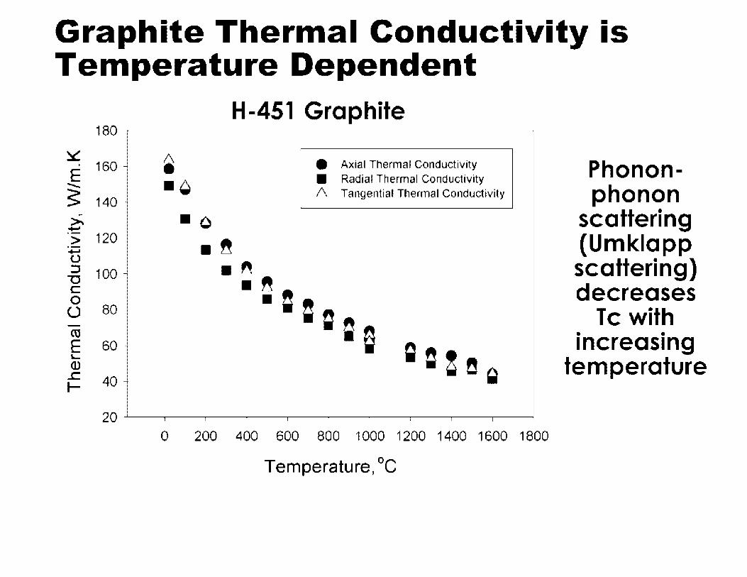
Graphite Thermal Conductivity is Temperature Dependent
180
~ . 160 E -.. $ 140 ·
>i ...... > 120 ·-~ u ::s 100 "'O C 0
(_) 80 -ca E 60 L. (1)
..c: 40 I-
20
H-451 Graphite
~ • Axial Thermal Conductivity
• Radial Thermal Conductivity -~ I\ Tangential Thermal Conductivity
• o -~ • " -~=
• ===e g C ! !! Q
0 200 400 600 800 1 000 1200 1400 1600 1800
Temperature, °C
Phonon-phonon
scattering (Umklapp scattering) decreases
Tc with • • 1ncreas1ng
temperature

IG-110 Thermal Conductivity Chan es
160 -
140
:::.:: 120 --E ~ ~ 100 :::,,
ts 80 =
""Cl :;:: Q u
60 -«:!
E -Qai ..c 40 I-
20
0 0
IG-11 D siamples from HTK-7 (Tirr=8DD°C)
.. ~ ii ii
I I
200 400
iii • • I
GOO
Temperatu.-e, DC
12. 1 dpa
• 24. 8 dpa
• 25. 8 dpa
Unirradiated
=a
I I
800 1000
-
-
I
1200

Irradiation Induced Dimensional Changes Result in Differential Strains • Weaker graphites crack (pore generation)
• Stronger graphites resist pore generation and strains creep out (irradiation creep)
• Radiation creep is a two stage phenomena
• Primary (reversible) creep strain a (1/E0)
• Secondary (irreversible) creep strain f(a,y,E0)
• Mechanism of creep subject of disagreement
• Two effects must contribute
- In-crystal deformation
- Pore generation/pore re-orientation
• At high doses we must allow for structural changes
• Irradiation induced creep in graphite is the subject of a new IAEA Coordinated Research Project

International graphite irradiation programs

International Graphite Irradiation Programs
• European Framework (6th , 7th , 8th •••• )
- Comprehensive irradiation program of available candidate graphites
• South Africa
- MTR program (conducted at ORNL) for NBG-18 covers relevant dose and temperature range to PBMR (ON HOLD)
• China
- Plans an MTR Program relevant to HTR-DM (IG-110)
• USA (DOE)
- NGNP Graphite irradiation program for candidate graphites (See Technology Development Plan)
• International data will become available through the Gen IV International Forum

Graphite oxidation and other chemical reactions
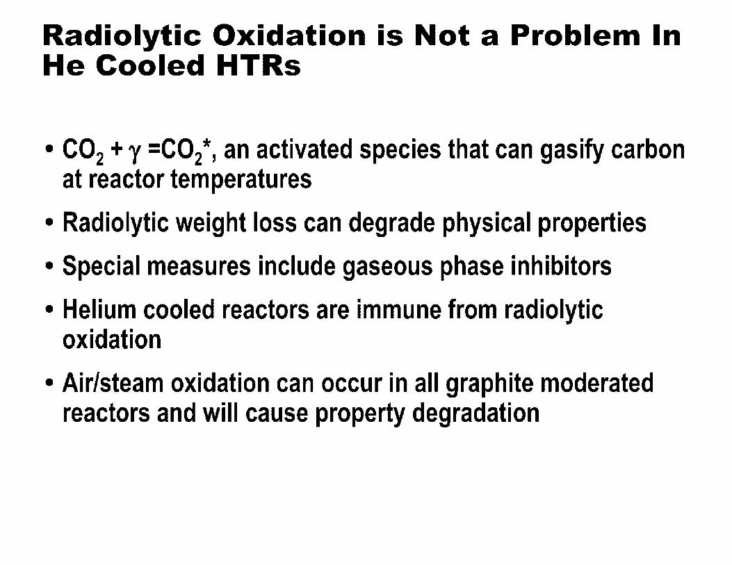
Radiolytic Oxidation is Not a Problem In He Cooled HTRs
• CO2 + y =CO2*, an activated species that can gasify carbon at reactor temperatures
• Radiolytic weight loss can degrade physical properties
• Special measures include gaseous phase inhibitors
• Helium cooled reactors are immune from radiolytic oxidation
• Air/steam oxidation can occur in all graphite moderated reactors and will cause property degradation

Thermal oxidation (Air and Moisture) • Air/steam oxidation can occur in all graphite
moderated reactors and will cause property degradation
• Air ingress accident
- C+O2---+CO2
- CO2+C---+ 2CO
• Moisture in Helium Coolant
- C + H20 ---+ CO + H2
- C + 2H2 ---+ CH4
• Oxidation= Loss of solid Carbon (Graphite)

Thermal oxidation (Air and Moisture)
• Properties degrade as a function of oxidative weight loss (burn-off)
• To predict burn-off we need to know: - Kinetics of oxidation reactions over the appropriate range
of temperature and partial pressure (or concentration) of oxidizing species
- Local partial pressure (or concentration) of oxidizing species within core/graphite block (Effective Diffusivity)
• Graphite purity also has an effect since some impurities act as oxidation catalysts

Erosion of graphite - tribology
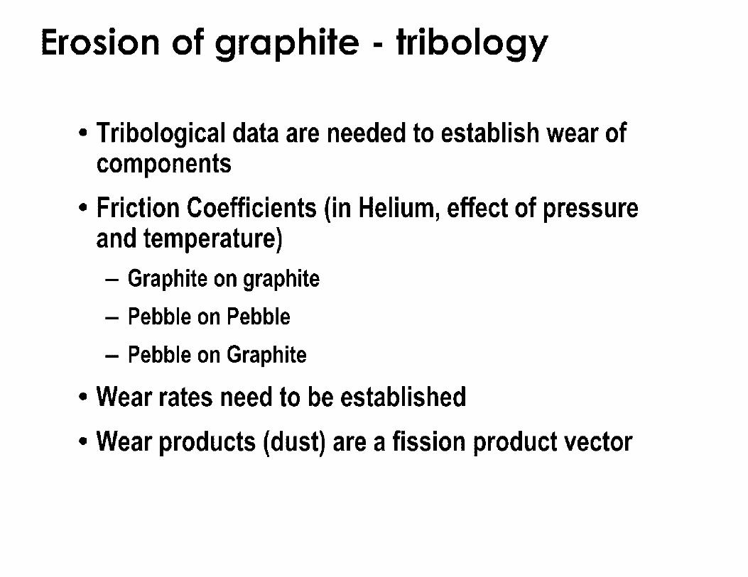
Erosion of graphite - tribology
• Tribological data are needed to establish wear of components
• Friction Coefficients (in Helium, effect of pressure and temperature) - Graphite on graphite
- Pebble on Pebble
- Pebble on Graphite
• Wear rates need to be established
• Wear products (dust) are a fission product vector

Graphite performance modeling

Graphite Performance Modeling
Graphite Performance Modeling Requires:
- Whole core graphite behavioral model
• How large are the stress?
- Fracture Model or Failure Theory
• Do the stresses cause fracture?
- Assessment Criteria
• What are the consequence of brick/block failure for core integrity?

Graphite Performance Modeling
• Whole core graphite behavioral model requires:
- Stress analysis, constitutive equation
- Erotal = Se + St +sd +sc
- Core temperature (T) and dose distribution (y)
- Dimensional change data and model
- Creep data and model, f (T, y, a)
- Property change data and models, Tc, CTE, E, a as a f (T, y)

Graphite Performance Modeling
• Fracture Model or Failure Theory - Weibull model
- Burchell model
- CARES model
- Fracture Mechanics
- Maximum Deformation Energy Theory (ASME)
- Maximum Strain Energy Theory
- Maximum Principal Stress
- Etc.

Graphite Performance Modeling
• Assessment Criteria
- Consequence of brick/block failure for core integrity
- Core structural redundancy
- Fitness for purpose
- In core monitoring to confirm predictions and increase confidence in core integrity
- Replaceable components

Graphite Performance Modeling
• Need to determine the effect of weight loss on property
• Need to predict extent of property degradation
• Work in hand at INL and ORNL to determine oxidation kinetics and effect of oxidation on properties for candidate graphites
• Oxidation is a potential FP transport mechanism

Regulatory challenges
Regulatory Challenges
• For detailed analysis see:
- NRC Graphite PIRT
- NRC Graphite Experts Panel Report & Recommendations
• Acceptance/Endorsement of ASME GCC Code
• Assimilating unirradiated baseline characterization data from DOE programs
• Assimilating irradiated properties data from DOE and international (GIF) programs
• HT Stored Energy Release (being addressed)
• Graphite oxidation (effective diffusivity of species)
• Irradiation induced creep, a full understanding (IAEA Coordinated Research Project)
Summary
• > 60 years experience with graphite as a solid moderator
• Mechanism of radiation damage well understood
• A few grey areas remain - High temp stored energy release
- Whole core models (and material models)
- Irradiation creep
- Tribology & wear
- Effective diffusivity (oxidative weight loss)

Bibliography
• Nuclear Graphite -The First Years, W. P. Eatherly, J. Nucl. Mater. 100 (1981) 55-63
• Irradiation Behavior of Graphite at High Temperatures, G. B. Engle and W. P. Eatherly, High Temperatures-High Pressures, Vol. 4, pp.119-158 (1972)
• Radiation Damage in Graphite, J.H.W. Simmons, Pergamon Press (1965)
• Nuclear Graphite, R.E. Nightingale (Ed.), Academic Press (1962)
• Radiation Effects in Graphite and Carbon-Based Materials, T. D. Burchell. MRS Bulletin, Vol. XXII, No. 2, pp. 29-35 (1997)
• CARBON MATERIALS FOR ADVANCED TECHNOLOGIES, Edited by Timothy D. Burchell. Pub, Pergamon (Elsevier Science), 1999.
- CHAPTER 13: FISSION REACTOR APPLICATIONS OF CARBON by Timothy D. Burchell
• Banh art, F. Irradiation effects in carbon nanostructures. Rep. Prog. Phys. 1999, 62, 1181-1221.
• Graphite for High Temperature Gas-Cooled Reactors, David Ball, ASME STP-NU-009 (2008)

~U.S.NRC UNITED STATES NUCLEAR REGULATORY COMMISSION
Protecting People and the Environment
NRO Intellectual Curiosity Series
Basis for NRC Requirements on Pressurized Thermal Shock
6th November 2013 Mark Kirk, RESIDE/GIB

• Properties of metals
• Nuclear reactors: designed against embrittlement
• Pressurized thermal shock (PTS) - What is it? - How is safety ensured? - Specifics of Regulations
• Status at Palisades

• Provide a perspective on vessel embrittlement and PTS, as regulated by the N RC for all PWRs
• Discuss embrittlement and PTS at the Palisades plant
• Answer questions from the public

Ductile metals bend (absorb energy) when
pulled upon
Ductility & Embrittlement Definitions
Embrittlement
Embrittlement (a loss of ductility) reduces how much a metal can bend before it breaks
NRC Regulations limit embrittlement
to ensure safety

. ,/<tl,~'.~,R-~ Re~ctor Pr~ssure ~essels (RPV) '-J p,.,1n,;ugP,,,.pb,uttdihE,wi,ur,m;,"1 Designed Against Embr1ttlement
• The reactor coolant system produces forces on the RPV - Pressure - Thermal
• RPV designed to resist these forces, even after embrittlement - RPV steel has
adequate toughness - Toughness measures
ductility
• NRC screening criteria for embrittlement keeps the probability of fracture extremely low
RPV: Pressurized Cylinder

Toughness vs. Force Toughness Always Greater
Before reactor operation force < toughness
Exceeds NRC Regulatory
Limits
Safe Operating Region
After operation (& embrittlement) force (still)< toughness
Exceeds NRC Regulatory
Limits Embrittlement
Cl)
.§ -

Photo courtesy of J. May, AREVA NP GmbH
Embrittlement monitored by surveillance programs & limited
by regulations
Measured: Transition Temperature Shift
Toughness after Operation
Temperature

. ,/,J!J,~'.~,R-~ CPalisad1 es Surveillance ""-..J p, . .,1,,,,1;ug p,,,.ple ,wd 11,,, E,wiw""'""' a p s u es
• Purpose of surveillance - Monitor embrittlement of specific
steels in specific plants - Provides advance information
on pressure vessel condition - Provides data for predictive
models
• Data sources for Palisades - Initial program
• 8 irradiation • 2 thermal
- Supplemental program • 2 irradiation
- Other Plants • Indian Point 2&3 • H.B. Robinson 2
L___
Pressure Vessel \
Surveillance Capsules
-·-·-·-·-•-•---'
Surveillance Samples
55mm ------ --- -- -~-~
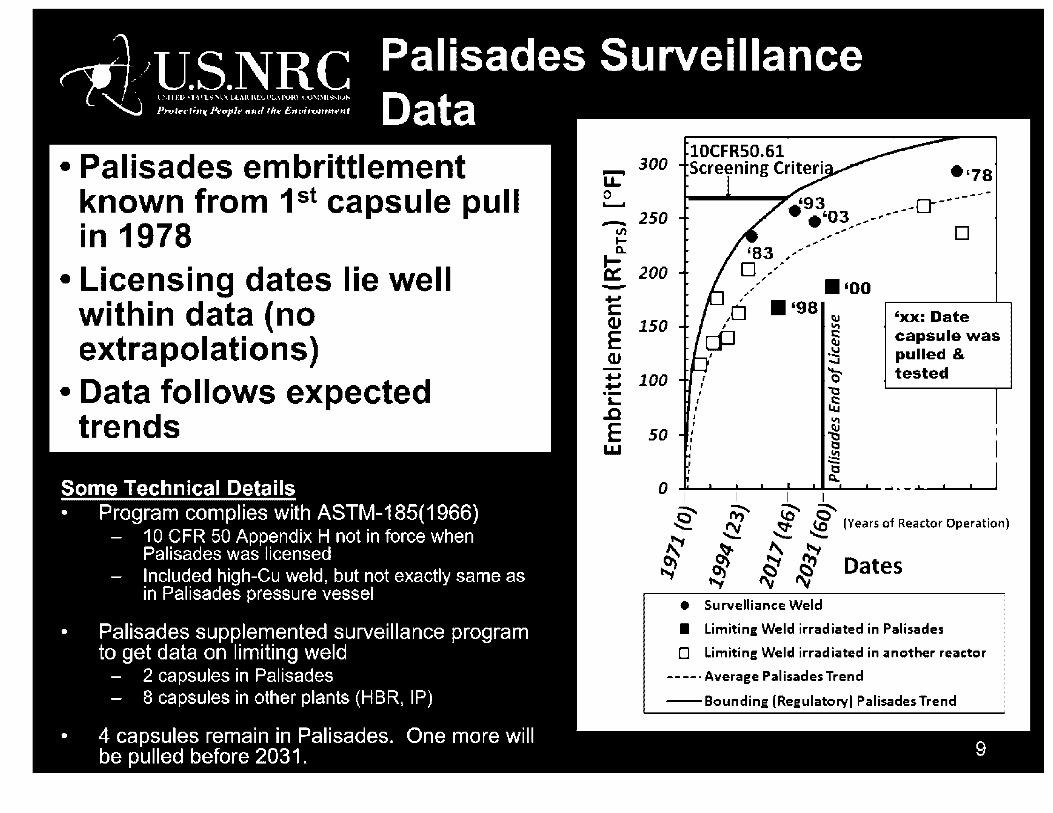
. "6/1L§:N11:S Palisades Surveillance
• Palisades embrittlement known from 1st capsule pull in 1978
• Licensing dates lie well within data (no extrapolations)
• Data follows expected trends
Some Technical Details • Program complies with ASTM-185(1966)
- 10 CFR 50 Appendix H not in force when Palisades was licensed
- Included high-Cu weld, but not exactly same as in Palisades pressure vessel
• Palisades supplemented surveillance program to get data on limiting weld
- 2 capsules in Palisades - 8 capsules in other plants (HBR, IP)
4 capsules remain in Palisades. One more will be pulled before 2031.
lOCFRS0.61 300 Screening Criteri
~ •'78 0 ----_ 250
V,
'93 o-----• '03 ----. _ ..
~,~~ • , .. l-o.. ., .. ..,...-.
b:: 200 D ,,' , ;'
• '00 -... C
, I
, ,
• '98 QJ 150 E
,• I
cP I 'xx: Date capsule was pulled & tested
QJ -!=:! ..... :t 100 r
I , ~ ,:, ·-L
.c E I.LI
, I
J I
so : I
~ ~
~ ti -~ I
0 -1--1--1--1--_.~- 1 I •
=" ;;:.. (D' 0" .,e .. , ~ (Ci {Years of Reactor Operation) ~ ',;_....;;.
~ ~ " !--., ~ ~ ~ ~ Dates ·---, "-1 rv ""
• Survelliance Weld
• Limiting Weld irradiated in Palisades
D limiting Weld irradiated in another reactor
-----Average Palisades Trend
-Bounding (Regulatory) Palisades Trend

. ,/,J!J,~'.~,R-~ uBritdtl5e f(o1 r Embrittled) Materials ""-..J p, . .,1,,,,1;,,gp,,,.pleuttd/h,,£,win"'"'""' se a e y
Nuclear RPVs Non-Nuclear Exam le
• Steel embrittles over time
• Embrittlement is - Understood - Measured - Limited
• NRG limits transition temperature shift so that toughness always exceeds force - Ensures safety
• Aircraft landing gear
• Very high strength steels needecf to resisf landing forces
• High strength steels have lower toughness - Less ductile - More brittle
• Nuclear RPV toughness exceeds landing gear toughness (even after em5rittlement)

• A rare event - Designed against
safety
• More force applied to RPV during PTS - Injection of cold
water - Rapid cooling
Even during PTS (& after embrittlement)
force (still) < toughness
Exceeds NRC Regulatory
Limits
Temperature

10 CFR 50.61 1984 • Significant conservatisms
restrict operations with no safety benefit
• Conservatisms include - Over-estimated force - Under-estimated
toughness
• Conservatisms evidenced by - Additional toughness data - More realistic & thorough
analyses - Scale model experiments
that validate predictions
10 CFR 50.61 a 2010 • Considerations
- Conservatisms in 50.61 limits will cause many plant -specific submittals
- All submittals would address the same fundamental issues
• Alternative approaches - Many plant-specific
assessments reviewed individually
- Comprehensive reassessment of PTS risk performed proactively & with thorough review by technical experts

. ~/1L:§:N11:S AR_ ltern0ativ1 e PTt SP Rule · 1gorous eve opmen rocess
• Joint effort of NRC, national labs, universities, and industry (providing data & operating experience)
• Approximately 10 year project duration
• Many opportunities for public involvement
• Extensive expert technical reviews - Advisory Committee for Reactor Safeguards - Independent expert panel
• Full documentation available on NRC website

. ,/,J1I,~'.~,R-~ Alternative PTS Rule '--J P,ofr<J;ugP,,,.pb,uttdihEm,i,ur,m;, .. t Technical Approach & Insights
• Three analyses performed Analysis
PRA Probabilistic Risk Assessment
TH Thermal Hydraulics
PFM Probabilistic Fracture Mechanics
Purpose
Establish events that cause rapid cooling. Assess human factors.
Quantify force produced by rapid cooling
Quantify resistance to rapid cooling, accounting for embrittlement.
• Detailed assessments of three plants (Palisades, Beaver Valley, Oconee)
• Results generalized to all plants in USA - Only the most severe forces produce any risk
• Similar across the fleet
- Rapid cooldown to 200 °F below operating temperature needed to produce any risk
• Operational controls limit the likelihood of such cooldowns occurring

. ,/<tl,~'.~,R-~ Comparison of PTS Rules '--J P,ofr<J;ugP,,,.plottdihEm,i,ur,m;, .. t 1 o CFR 50.61 & 1 0 CFR 50.61 a
Aspect of Rule 10 CFR 50.61 10 CFR 50.61a REQUIRED VOLUNTARY
Embrittlement Screening Criteria More restrictive Less restrictive
Plant-specific surveillance data check Required: 1 test Required: 3 tests
Plant specific inspection for flaws Not required -.. . .. . • 10 CFR 50.61 a embrittlement limits are less restrictive than 10
CFR 50.61 - Justification: More thorough, consistent, & realistic assessment
• 50.61 a screening criteria can only be used when surveillance and inspection requirements are met
• Surveillance and inspection requirements ensure that key features of the 50.61 a model apply to the plant being assessed a. The embrittlement of specific RPV materials b. The flaws in a specific RPV

10 CFR 50.61 10 CFR 50.61 a • One of the most embrittled
plants in USA
• Palisades operates in compliance
• Embrittlement screening_ criteria will be exceeded in 2017
• Palisades must - Make safety case in 2014 (2017
minus .3 years) for continued operation, or
- Shut down in 2017
• Options for operation beyond 2017 - Annealing to reverse
em brittlement, - Analysis and/or experiments to
proy1_de ? plant specific safety 1ust1f1cat1on, or
- Use10CFR50.61a
• One option Palisades has to continue operation after 2017
• Would need to - Analyze data - Check embrittlement - Check flaws
• Generic analysis of US fleet in NUREG-1874 suggests this is a viable option for Palisades
• Palisades continues to operate safely
• The vessel at Palisades is one of the most embrittled in the USA
• Palisades continues to operate as long as it demonstrates compliance with NRC regulations
• There are several options by which continued safe operation of the Palisades vessel after 2017 could be demonstrated - The licensee decides what option to take
\~U.S.NRC United States Nuclear Rcgu1atory Commission
Protecting People and the Environment
What's New in Valves and Pumps in New Reactors?
Thomas G. Scarbrough
James M. Strnisha
Division of Engineering
Office of New Reactors
August 2013

,~'U.S.NRC Prot,·ctiug lh,pl,· mu/ th,· F111•frrm11u·m
Introduction
• Overview of pumps and valves for new reactors
• Lessons learned from operating experience
• ASME and industry activities
• New reactor pump and valve requirements
• Pump and valve qualification process
• Vendor inspection support
• NRG staff approach for evaluation of pumps and valves
• Regulatory Treatment of Non-Safety Systems (RTNSS)
• Small Modular Reactor (SMR) issues
• Close-out process for pump and valve functional qualification ITAAC
• Pump and valve inspections at Vogtle and Summer
• Future activities
2
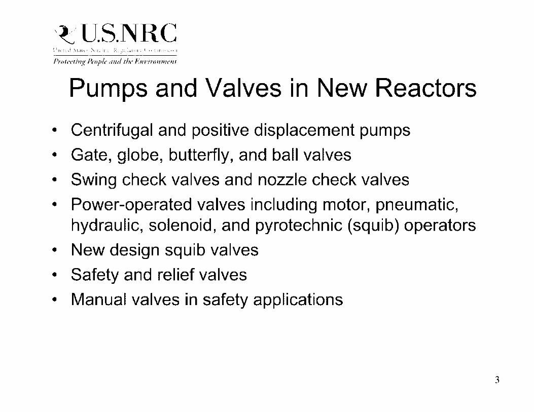
,~'U.S.NRC Prot,·ctiug lh,pl,· mu/ th,· F111•frrm11u·m
Pumps and Valves in New Reactors
• Centrifugal and positive displacement pumps
• Gate, globe, butterfly, and ball valves
• Swing check valves and nozzle check valves
• Power-operated valves including motor, pneumatic, hydraulic, solenoid, and pyrotechnic (squib) operators
• New design squib valves
• Safety and relief valves
• Manual valves in safety applications
3

,~'U.S.NRC Prot,·ctiug lh,pl,· mu/ th,· F111•frrm11u·m
Centrifugal Pump (Wikipedia website) 4

,~'U.S.NRC Prot,·ctiug lh,pl,· mu/ th,· F111•frrm11u·m
Suction pip~
Suction chec~ , al, e
,. .... --j
l)i sc h .. trge ,;.'.hc~i.;
\'i.11,e
Dis(:h.trge pipe
Li4uid t·ylinder
Positive Displacement Pump (http://www. bing .com/images/search)
5

,~'U.S.NRC Prot,·ctiug lh,pl,· mu/ th,· F111•frrm11u·m
. ~ . :
·---...... __ _
------
... _ .. _
---:-_,_._.
·,_
=- ••• -------
___ .. --
Gate Valve
, ___ ,-·
' ;-·-...--...
-.., -•• .r--=-• ·-~
' .. _,,
.:---
.,.---
-~-
----,·
·•-· .. _
_ ... _ ... _ .. -·
___ ..... --.
.... ·--- -
_-.. , ---~--~ •---' ::-.-
.:::i:•:: .. ::.'
.---·
..... .:. ~,
r-.
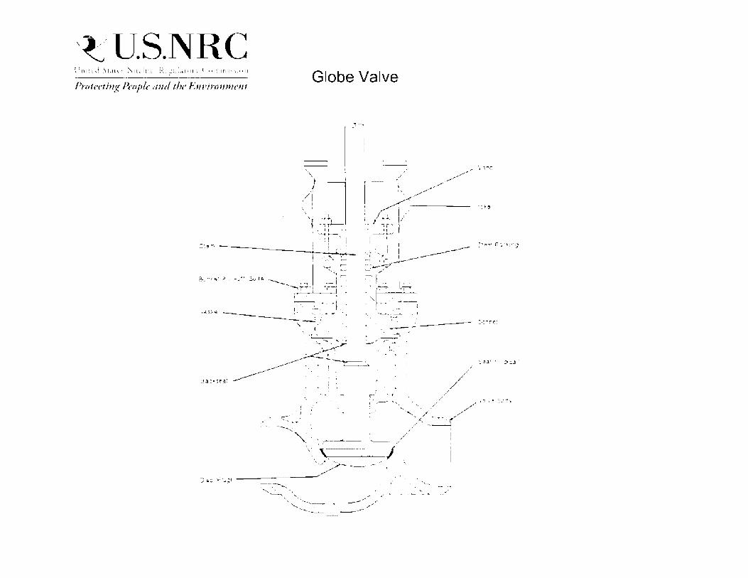
,~'U.S.NRC ~.!l~l~{,j .'ll.lt1,," ~ I•··•~, .... ' ______ · - Ill••~• .\.::,-_,;,i,IUI"• ( "l~lltll'";"II
Prot,·ctiug lh,pl,· mu/ th,· F111•frrm11u·m
:¼ tR
Globe Valve
' '
::l "J; '-' ·•-, I •, t,__
! ~ I L --. :I .. i I •.
.·.-'.'·::..: --- I ~::~ ~ ..
t . " • l
I_ '. •-•- f .
-- . , ~ ~,./
I((-·::·~ f __ .....,
., I I
··t -.._ I I ------..... t •"'r· _ _!_--_____ ~- :----_,-- . - /
~ ! .. :~!~-~-- 1,r
. , '
~--· -~
,,.-~'-
! . --~ . ;
·-' I ,.,.--•
·--....
,._ _..__ ... -k.
~ .,,..,. p ::;.·: li;f" =)

,~'U.S.NRC Prot,·ctiug lh,pl,· mu/ th,· F111•frrm11u·m
Symmetric Disc Butterfly Valve
S"'.'"E\1 ~URNl~JG SLR f _.}.CE
'.' ..:. L \; E ~ ! 'J I \, G
PL . .\S71C 3.:.5E .:i1.,.G
\ I I I I
,~'U.S.NRC Prot,·ctiug lh,pl,· mu/ th,· F111•frrm11u·m
Limitorque SMB-0
•'
I
.,,.•
.,,.. I
_ .... . - -. -~
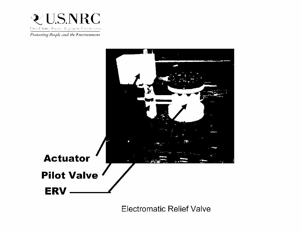
,~'U.S.NRC Prot,·ctiug lh,pl,· mu/ th,· F111•frrm11u·m
Actuator
Pilot Valve
ERV-----
Electromatic Relief Valve

,~'U.S.NRC Prot,·ctiug lh,pl,· mu/ th,· F111•frrm11u·m
AP1000 Passive Design
• AP1000 passive pressurized water reactor designed to provide reactor core cooling in response to LOCA without operator action or pump operation for 72 hours
• Passive Core Cooling System (PCCS) uses high pressure Core Makeup Tanks (CMTs) and Accumulators for initial core cooling, and de-powered motor-operated valves and squib valves to reduce RCS pressure and allow gravity-driven cooling water flow
• After 72 hours, containment makeup water might be needed from external sources
11

,~'U.S.NRC Prot,·ctiug lh,pl,· mu/ th,· F111•frrm11u·m
AP1000 PCCS • PCCS has four passive injection sources:
- 2 CMTs with borated water at RCS pressure
- 2 Accumulators with borated water pressurized at 700 psig
- In-Containment Refueling Water Storage Tank (IRWST) with borated water vented to atmosphere
- Containment Sump allowing long-term recirculation
• PCCS uses 12 squib valves: - Four 14-inch Automatic Depressurization System (ADS)
4th stage squib valves
- Four 8-inch IRWST injection squib valves
- Four 8-inch Containment Recirculation squib valves
12

,~'U.S.NRC Prot,·ctiug lh,pl,· mu/ th,· F111•frrm11u·m
AP1000 Squib Valves
• SPX Copes-Vulcan is valve manufacturer
• AP1000 squib valves are larger and more complex than current BWR squib valves in standby liquid control system
• SPX Copes-Vulcan squib valve designs are proprietary
13

,~'U.S.NRC Prot,·ctiug lh,pl,· mu/ th,· F111•frrm11u·m
Squib Valve Design and Qualification Issues
• Vendor inspections at Westinghouse, Copes Vulcan, and Wyle Laboratories for squib valve functional design and qualification process
• Several significant issues with squib valve explosive system
• Feb. 20, 2013, public meeting with Westinghouse to discuss need to implement systematic engineering design process sufficient to identify critical parameters of explosive system design and to establish acceptable tolerance ranges for each parameter
14

,~'U.S.NRC Prot,·ctiug lh,pl,· mu/ th,· F111•frrm11u·m
AP1000 Squib Valve Surveillance
• Vogtle/Summer FSARs specify that squib valve 1ST program will incorporate lessons learned from design and qualification process
• Vogtle/Summer COLs include license conditions for AP1000 squib valve surveillance
• License conditions specify preservice and inservice inspection and testing to verify external and internal component integrity, absence of degradation and foreign material, availability of electronic actuation circuitry, and explosive powder output capability
15

,~'U.S.NRC Prot,·ctiug lh,pl,· mu/ th,· F111•frrm11u·m
AP1000 Nozzle Check Valves
• AP1000 uses four 8-inch nozzle check valves in PCCS with open-close-open function in event of LOCA.
• AP1000 includes other nozzle check valves with standard open-close functions.
• Enertech is the valve manufacturer.
• Operating plants began using nozzle check valves in 1990s, but limited experience with open-close-open function.
• QME-1 qualification being performed at Enertech in CA and at Utah State University
16

~ ,. -·- ·-··· ',· . ; I.• - .- - ,- - - ' .. I 'I, "i ~, · ••·
i!J v~•~·,· ~,:~""· l:111., Rt·.-, f,
VALVE DISC
C-c,e
: - I'"" - 1-·'
VALVE HOIJY
--1 ,·.
RU<;HING \ \ \
\ \
- ..... · ,; '. -·
....... ---· __ ,,, .... -
HELICAL SPRING
..... •t .,,,.,
' ........
-· FLOW DIFFlJSEH
~ ... 11(J"il'J''•r Z.:r-i-.: P--,:teoec ~l,:;::e 01
Enertech website drawing
.-=-!
,,... .
17

,~'U.S.NRC Prot,·ctiug lh,pl,· mu/ th,· F111•frrm11u·m
Pump Issues
• Mini-flow lines insufficient for pump testing
• Required Net Positive Suction Head (NPSHR) uncertainties
• GSl-191 LOCA Debris Issues
• AP1000 Reactor Coolant Pump impeller blade
• Pump Teflon Seal EQ
18

,~'U.S.NRC Prot,·ctiug lh,pl,· mu/ th,· F111•frrm11u·m
Valve Issues • ASME MOV 1ST stroke-time test inadequate
• Underprediction of thrust and torque requirements for original gate, globe and butterfly valves
• Unpredictable behavior of original gate valves under high flow conditions
• Overprediction of motor actuator output with loading, degraded voltage, temperature, and stem friction
• Valve stem and actuator lubrication issues
• Pressure locking and thermal binding of gate valves
• Valve stem/disc separation
• MOV dead band zone
• Flow induced vibration 19

,~'U.S.NRC Prot,·ctiug lh,pl,· mu/ th,· F111•frrm11u·m
Regulatory Activities
• Extensive research program at Idaho National Laboratory on valve performance
• 10 CFR 50.55a revised to supplement ASME Code for MOV periodic design-basis capability
• Bulletin 85-03 and Generic Letters 89-10, 95-07, and 96-05
• Regulatory Issue Summaries 2000-03 and 2001-15 • Numerous Information Notices • Reviews and inspections of MOV programs at current
nuclear power plants • SRP and inspection procedures updated
20

,~'U.S.NRC Prot,·ctiug lh,pl,· mu/ th,· F111•frrm11u·m
ASME Activities
• ASME Standard QME-1-2007 incorporates valve lessons learned with pump improvements being considered
• Subsection ISTF in ASME OM Code (2011 Addenda) for new reactors specifies comprehensive pump testing
• Preservice and inservice testing provisions for squib valves in new reactors specified in Subsection ISTC of ASME OM Code (2012 Edition)
• ASME task group preparing guidance for treatment of RTNSS pumps and valves
• ASME OM Code evaluating SMR pump and valve surveillance issues
21

,~'U.S.NRC Prot,·ctiug lh,pl,· mu/ th,· F111•frrm11u·m
Industry Activities
• Electric Power Research Institute developed test-based valve performance methodology
• Joint Owners Group (JOG) developed MOV dynamic testing program in response to GL 96-05 (Guidance in RIS 2011-13 for JOG Class D valves)
• ComEd White Paper 125 (Rev. 3, 2/8/99) provides methodology for sizing motor actuators
• BWROG developed updated methodology for DC MOV output and stroke time
22

,~'U.S.NRC Prot,·ctiug lh,pl,· mu/ th,· F111•frrm11u·m
Design Certification Application Requirements
• 10 CFR 52.4 7(a)(9) requires design certification applications to evaluate design against NRC Standard Review Plan in effect 6 months before docket date
• 10 CFR 52.4 7(a)(22) requires design certification applications to address operating experience
23

,~'U.S.NRC Prot,·ctiug lh,pl,· mu/ th,· F111•frrm11u·m
COL Application Requirements
• 10 CFR 52.79(a)(11) requires COL applicant to provide description of programs and their implementation necessary to ensure that systems and components meet ASME BPV Code and OM Code per 10 CFR 50.55a
• 10 CFR 52.79(a)(37) requires COL applications to include information necessary to demonstrate how operating experience has been incorporated into plant design
• 10 CFR 50.55a(f)(4)(i) requires initial 1ST program to meet ASME Code incorporated in 10 CFR 50.55a 12 months before fuel loading
• Guidance in RIS 2012-08, Rev. 1, "Developing lnservice Testing And lnservice Inspection Programs Under 10 CFR Part 52"
24

,~'U.S.NRC Prot,·ctiug lh,pl,· mu/ th,· F111•frrm11u·m
Pump and Valve Qualification Process
• ASM E Standard QM E-1-2007 provides specific criteria for qualification process for valve assemblies, extrapolation of qualification to other valve assemblies, testing of production valve assemblies, and post-installation testing
• QME-1 specifies requirements for Qualification Plan, Functional Qualification Report, and Application Report
• NRG accepted QME-1-2007 in Revision 3 to RG 1.100 with staff positions
• New reactor vendors requiring use of QME-1-2007 in design specifications
25

,~'U.S.NRC Prot,·ctiug lh,pl,· mu/ th,· F111•frrm11u·m
Vendor Inspection Support
• CIB is providing support for vendor inspections of pumps and valves for new reactors
• Squib valve inspections at Westinghouse, Copes-Vulcan, and Wyle Laboratories
• Check valve inspections at Enertech and Utah State
• Relief valve inspections at Pentair Valves
• Motor-operated valve review during Wyle inspection
• Limitorque MOV actuator inspection
• AP1000 RHR Pumps at Flowserve (post-inspection)
26

,~'U.S.NRC Prot,·ctiug lh,pl,· mu/ th,· F111•frrm11u·m
NRC Staff Evaluation of Pump and Valve Design and Qualification
• CIB verifies Design Certification application specifies ASME QME-1-2007 as accepted in RG 1.100 (Rev. 3)
• CIB audits design/procurement specifications in support of design certification and COL application review to confirm use of QME-1-2007
• CIB supports vendor inspections to verify that QME-1-2007 design/procurement specification requirements applied to qualification and testing procedures
• CIB will support operational program and ITAAC inspections to address pump and valve qualification
27

,~'U.S.NRC Prot,·ctiug lh,pl,· mu/ th,· F111•frrm11u·m
Regulatory Treatment of Non-Safety Systems (RTNSS)
• SECY-95-132 specifies policy and technical issues associated with RTNSS in passive plant designs
• Passive plants rely on active systems to avoid use of passive systems and to provide backup for passive features
• SECY-95-132 states that RTNSS systems do not need to meet safety -related criteria, but staff will expect a high level of confidence that active systems are available
• SECY-95-132 states that specific positions on 1ST requirements for RTNSS components will be determined as part of staff's review of plant-specific implementation
• No safety-related pumps in AP1000, but specific pumps are within the scope of RTNSS program
28

,~'U.S.NRC Prot,·ctiug lh,pl,· mu/ th,· F111•frrm11u·m
AP1000 RTNSS Systems • Instrumentation Systems
- DAS ATWS (Diverse Actuation System)
- DAS ESF
• Plant Systems - RNS (Normal Residual Heat Removal System)
- CCS (Component Cooling Water System)
- SWS (Service Water System)
- PCS Water Makeup (Passive Containment Cooling System)
- MCR Cooling
- l&C Room Cooling
- Hydrogen lgniters
• Electrical Power Systems - AC Power Supplies
- Non Class 1 E DC and UPS (Un interruptible Power Supply) System (EDS)
29

,~'U.S.NRC Prot,·ctiug lh,pl,· mu/ th,· F111•frrm11u·m
AP1000 DCD RTNSS Provisions
• DCD Tier 2, Section 3.2 provides general technical provisions for Class D SSCs (RTNSS), such as use of example industry standards
• Augmented QA provisions for RTNSS equipment described in DCD Tier 2, Section 17 .3
• Each RTNSS component needs to be evaluated on a case-by-case basis for the technical standards and methods used to demonstrate its capability to perform the intended functions
• Specific IT AAC need to be satisfied for RTNSS equipment (such as RNS pumps)
30

,~'U.S.NRC Prot,·ctiug lh,pl,· mu/ th,· F111•frrm11u·m
Small Modular Reactor (SMR) Pump and Valve Issues
• Some passive SMR designs may include active systems as part of RTNSS program
• Some SMR designs have operating cycles longer than 2 years which affects relief valve testing frequency provisions and motor-operated valve lubrication basis
• Some SMR designs might use new valve combinations to minimize LOCA conditions
• Environmental qualification of valves and pumps might involve high temperature and radiation
31

,~'U.S.NRC Prot,·ctiug lh,pl,· mu/ th,· F111•frrm11u·m
Close-out Process for Pump and Valve IT AAC
• AP1000 DCD includes IT AAC for seismic, environmental, hydrostatic, and functional qualification of specific valves
• Licensee must complete ASME Boiler & Pressure Vessel Code and ASME Standard QME-1-2007 to support qualification testing and analysis
• Licensee will notify NRC staff of IT AAC completion
• NRC staff has identified targeted ITAAC for detailed verification of completion
• NRO projects and technical staff will need to work together to ensure that IT AAC are adequately closed
32

,~'U.S.NRC Prot,·ctiug lh,pl,· mu/ th,· F111•frrm11u·m
Pump and Valve Inspections at Vogtle and Summer
• Inspection Procedure IP 73758 describes evaluation of the functional design and qualification, preservice testing, and inservice testing of pumps, valves, and dynamic restraints in new reactors
• CIB will assist Region in evaluating implementation of DCD and FSAR provisions for functional design and qualification, PST, and 1ST at Vogtle and Summer
• NRC staff will discuss plans for pump and valve inspections with Vogtle and Summer COL licensees when 1ST program developed
33

,~'U.S.NRC Prot,·ctiug lh,pl,· mu/ th,· F111•frrm11u·m
Future Activities
• Support vendor inspections of pumps and valves
• Interact with Westinghouse to address squib valve issues
• Participate in ASME OM Code activities (including RTNSS treatment guidance)
• Interact with Vogtle and Summer COL licensees on 1ST operational program development
• Assist Region II on operational program and ITAAC inspections
• Work with NRO Projects to evaluate ITAAC closure notifications for pumps and valves
34

PWR STARTUP AND POWER OPERATION

Background and Disclaimers
• Background and area of focus is predominately primary side operation
• My operational experience includes reactor startup and operation in support of licensed RO and SRO's. Plant Certified at Palo Verde NPGS
• Will not provide detailed Technical Specifications LCOs as these can be plant specific
• Know little about secondary side chemistry and generator

Objective
Explain the basic steps of starting up a PWR reactor
from refueling to full power

Typical 4-Loop PWR Primary Side
I . ~----::: -"'-....:---
Reactor -Coolant Pipi n
Stl!am Generator

Typical PWR Modes of Operation
Mode
1- Power Operation
2 - Startup
3 - Hot Standby
4 - Hot Shutdown
5 - Cold Shutdown
6 - Refueling
Greater than or equal to 0.99
Greater than or equal to 0.99
Less than 0.99
Less than 0.99
Less than 0.99
N/A
Power Tcold
Greater than 5% N/A RTP
Less than or equal N/A to 5% RTP
N/A Greater or equal to 350 °F
N/A 200 °F to less than 350 °F
N/A Less than or equal to 200 °F
N/A N/A

Mode 6 - Refueling
• Fuel is in the reactor vessel
• If all fuel is off loaded to the spent fuel pool Operational Mode is defined as N/A
• Reactor head either removed or not fully tensioned
• Residual Heat Removal (RHR) or Shutdown Cooling (SDC) are in service removing decay heat
• Reactor coolant is highly borated to provide TS minimum shutdown margin
• Source range detectors monitor neutron count rates

Mode 6 - Refueling (cont)
• Fuel is typically loaded nearest the source range detectors first and then work outward
• Refueling pattern is tightly controlled to ensure
- Assemblies are placed in the correct locations as determined by the core designer
- Two or more separate "cores" are not formed which may lead to a local criticality

Mode 6 - Refueling (cont)
Source range
detector
Power range
detector
S...No ""'- • Na1 ,. Pfl:I l.o1-illu • lfH • HU ,.,_ ....... ""'- ""'·
I«~. NH
9'ARi Power range
detector
a• .... ~-t-----+-----...... .._~
N31 and N35
Source range
detector
Power range
detector
A
l'OWEft R~GI: DITEC'T'OAS !Roia.t in19 ,._I
I
I
I I
I I
l I
r
' I ELIEVATlON VIIW
Power range
detector
D IN'ftRMEDIA TE RANGE DETECTOR
D !IOUIIICI RANGE DETECTOR (Rota11d M'l10 "'-"'J

Mode 6 - Refueling (cont)
• After fuel load core upper internals are reinstalled
• Control Rod drives attached but de-energized
• Reactor head is installed and Mode 5 is entered upon last head bolt being fully tensioned
• '1Typical'' refueling time 2-3 days
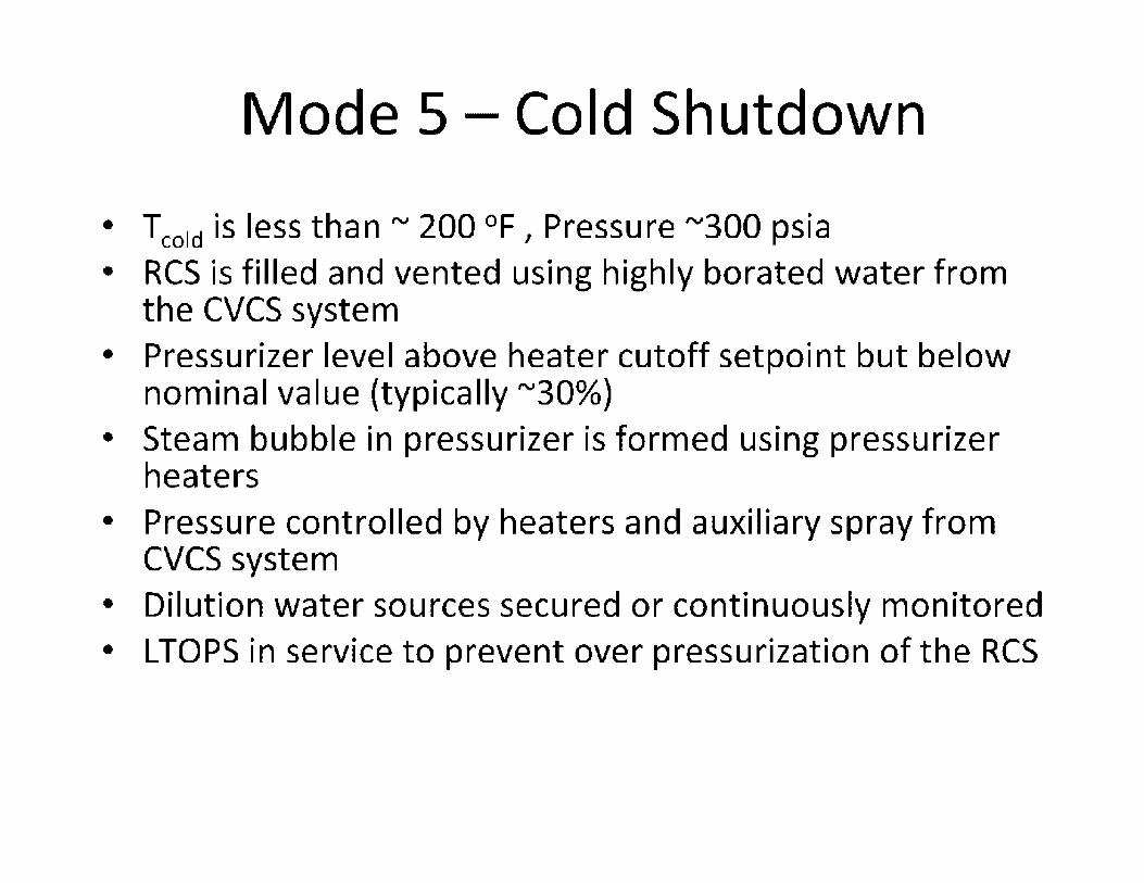
Mode 5 - Cold Shutdown
• Tcold is less than "' 200 °F, Pressure "'300 psia • RCS is filled and vented using highly borated water from
the CVCS system
• Pressurizer level above heater cutoff setpoint but below nominal value (typically "'30%)
• Steam bubble in pressurizer is formed using pressurizer heaters
• Pressure controlled by heaters and auxiliary spray from eves system
• Dilution water sources secured or continuously monitored
• LTOPS in service to prevent over pressurization of the RCS
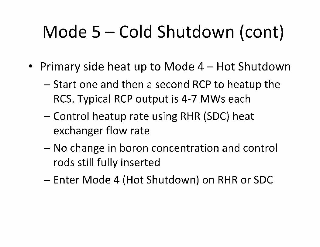
Mode 5 - Cold Shutdown (cont)
• Primary side heat up to Mode 4 - Hot Shutdown
- Start one and then a second RCP to heatup the RCS. Typical RCP output is 4-7 MWs each
- Control heatup rate using RHR (SDC) heat exchanger flow rate
- No change in boron concentration and control rods still fully inserted
- Enter Mode 4 (Hot Shutdown) on RHR or SDC
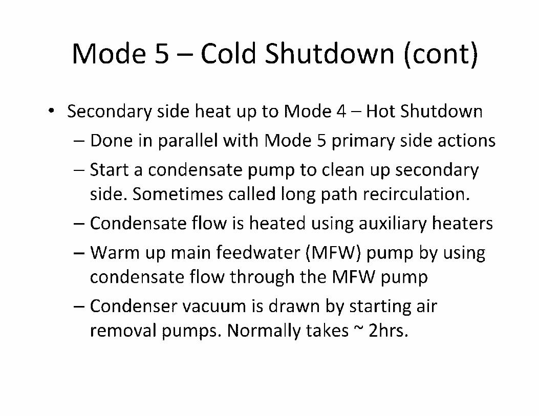
Mode 5 - Cold Shutdown (cont)
• Secondary side heat up to Mode 4 - Hot Shutdown
- Done in parallel with Mode 5 primary side actions
- Start a condensate pump to clean up secondary side. Sometimes called long path recirculation.
- Condensate flow is heated using auxiliary heaters
- Warm up main feedwater (MFW) pump by using condensate flow through the MFW pump
- Condenser vacuum is drawn by starting air removal pumps. Normally takes,..., 2hrs.

Mode 4 - Hot Shutdown
• Primary purpose is to transition from RHR (SDC) to
steam generator (S/G) heat removal
• Auxiliary feedwater pump and steam generator
blowdown lines used to maintain S/G level ("'30-50%
normal level)
• Turbine or Steam bypass put in service to control
RCS temperature and heat up rate
• RHR or SOC heat exchanger bypass reduced; RCS
heats up and turbine bypass system controls RCS
temperature

Mode 4 - Hot Shutdown (cont)
• Start third RCP to establish a heatup rate
• LTOPS valve are isolated at a given RCS
temperature ("'300 °F); pressurizer safeties
provide RCS over pressure protection
• Depending on SDM requirements some plants
may dilute RCS with eves system to reduce
startup time

Mode 3 - Hot Standby
• Purpose to heat RCS up to normal operating pressure and temperature ("'550 °F and 2250 psia)
• Fourth RCP is started to provide additional heat input
• Turbine (steam) bypass controls RCS temperature
• Pressurizer level controlled by eves letdown and charging rates. Now at nominal value typically rv50%
• Pressure controlled by RCS temperature and normal • pressurizer spray
• Control rod drives energized and rod drop testing occurs
• Dilute to estimated critical boron concentration if starting up using control rods
• Usually most of the startup time is spent in Mode 3

Mode 2 - Startup
• Purpose to achieve a self sustaining chain reaction, kett =1, and startup physics tests
• Keff = Number of neutrons in generation N/Number of neutrons in generation N-1, including delayed neutrons
• Two methods of going critical - Withdrawal almost all control rods and dilute RCS using eves system
- Withdrawal control rods holding boron concentration constant
• All Shutdown rod banks withdrawn then regulating or control rod banks
• Core kett monitored using source range detectors by a 1/M plot and startup rate meter {SUR)
• Mode 2 is inferred based on data provided by core design

Mode 2 (cont)
M = Count Rate present/Count rate initial
;:I:
' -
0.8
0.6
Mode 2
0.4
0.2
' 0 ________________ , _________ _
0 2 4 8 a 10 12 14 HJ 18 :zo ROD WITHDRAWAL (in.)
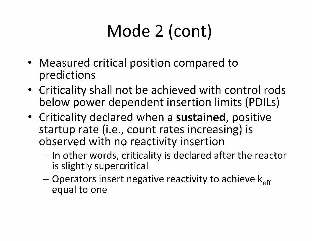
Mode 2 (cont)
• Measured critical position compared to predictions
• Criticality shall not be achieved with control rods below power dependent insertion limits (PDILs)
• Criticality declared when a sustained, positive startup rate (i.e., count rates increasing) is observed with no reactivity insertion - In other words, criticality is declared after the reactor
is slightly supercritical - Operators insert negative reactivity to achieve keff
equal to one

Mode 2 (cont)
• HZP is ketf = 1 and plant at standard operating
temperature and pressure
- HZP rv lXl0-5% power, neutron flux rv(10)4 n/cm2-sec
• keff has noting to do with core power under steady state conditions; core power is
proportional to neutron flux level
• Control rods are withdrawn to create a positive
SUR
• SUR of less than one decade per minute
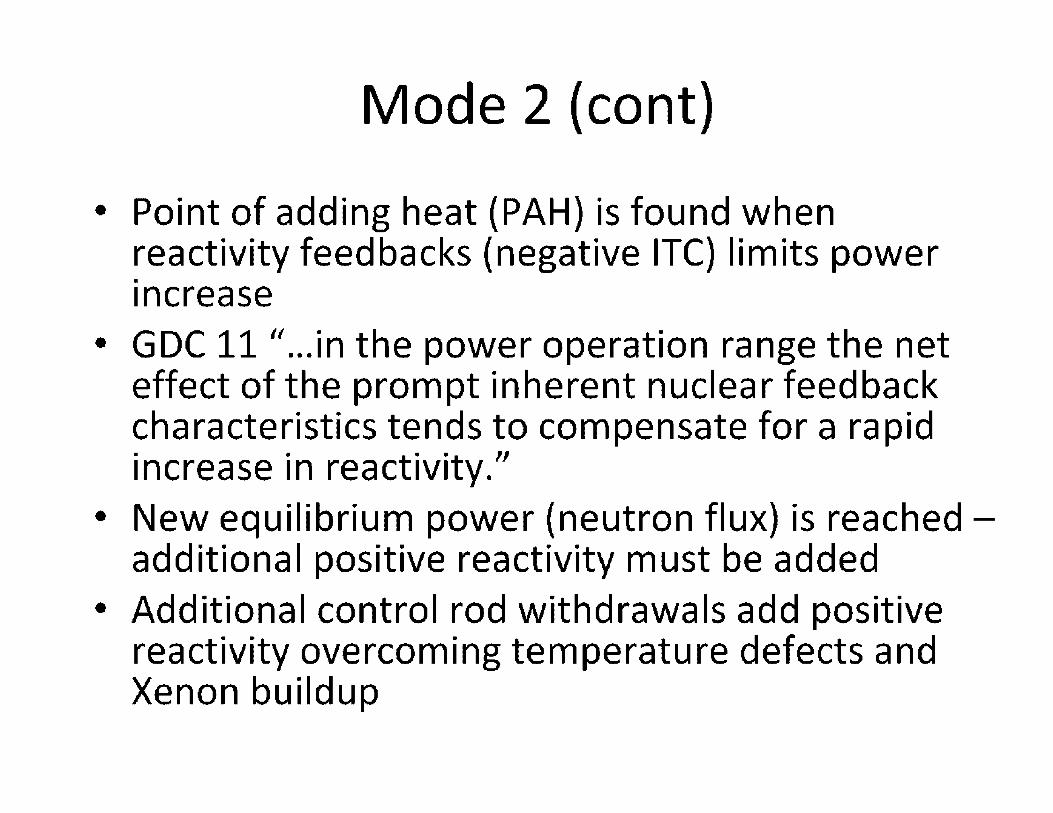
Mode 2 (cont)
• Point of adding heat (PAH) is found when reactivity feedbacks (negative ITC) limits power .. increase
• GDC 11 " ... in the power operation range the net effect of the prompt inherent nuclear feedback characteristics tends to compensate for a rapid increase in reactivity."
• New equilibrium power (neutron flux) is reached -additional positive reactivity must be added
• Additional control rod withdrawals add positive reactivity overcoming temperature defects and Xenon buildup

Mode 2 (cont)
• Main feedwater pump brought online around 2% RTP (System 80 number)
• Mode 2 takes "'2-3 days including physics testing
• Mode 1 declared when core power is greater than 5% RTP
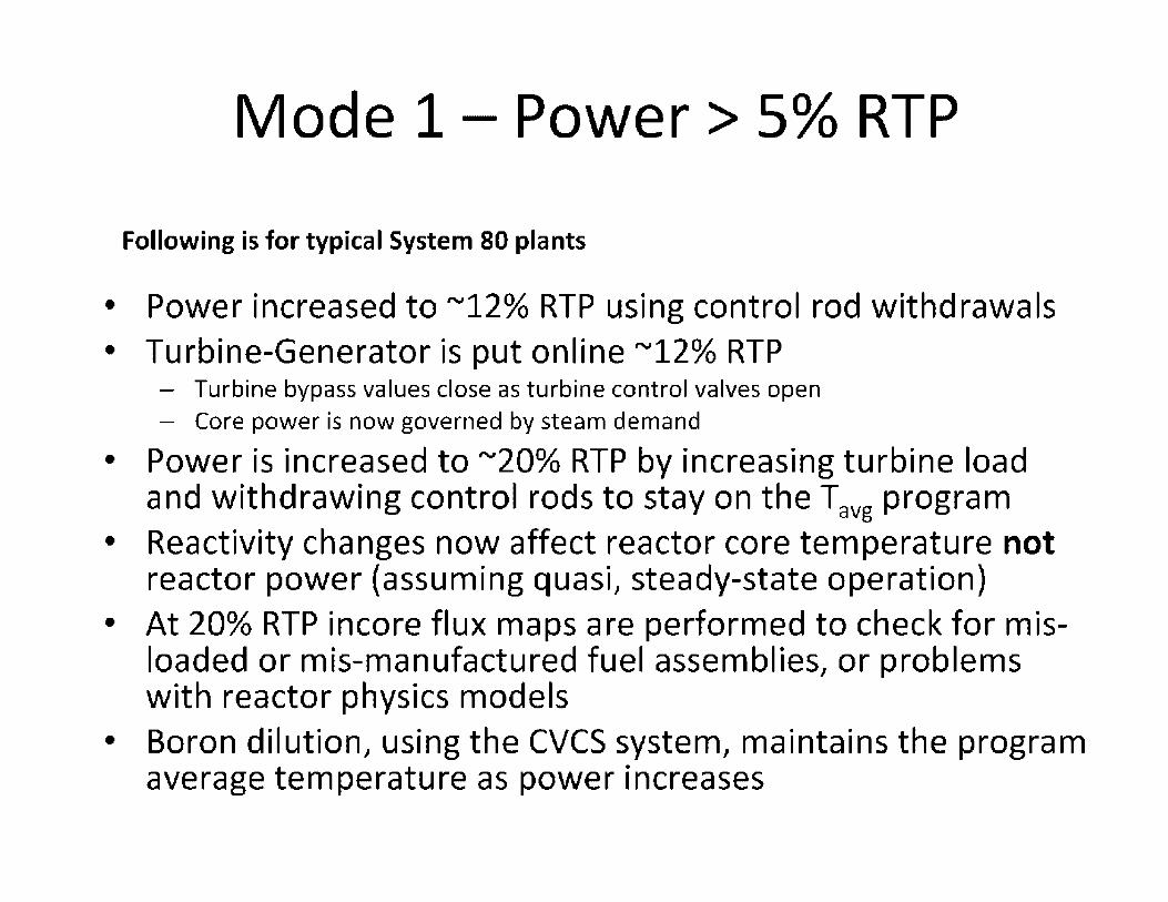
Mode 1- Power > 5% RTP
Following is for typical System 80 plants
• Power increased to "'12% RTP using control rod withdrawals • Turbine-Generator is put online "'12% RTP
- Turbine bypass values close as turbine control valves open - Core power is now governed by steam demand
• Power is increased to "'20% RTP by increasing turbine load and withdrawing control rods to stay on the Tavg program
• Reactivity changes now affect reactor core temperature not reactor power (assuming quasi, steady-state operation)
• At 20% RTP incore flux maps are performed to check for misloaded or mis-manufactured fuel assemblies, or problems with reactor physics models
• Boron dilution, using the eves system, maintains the program average temperature as power increases

610
600
590
U:- 580 0 - 570
560
Mode 1 (cont)
Example Linear T avg Program
550 ,·~---------------------
540
V'l U 530 0:::
520
510 0 20 40 60 80 100
% RTP Power
-+-Tavg
---Tcold
That

Mode 1 (cont)
• Normally measured Tavg is kept within 1 °F of programmed Tavg (Treff)
• Power is increased to 50-65% RTP and second feedwater pump is brought on line (System 80 has two feed water pumps)
• Plant is stabilized at 70% RTP for additional incore flux maps and excore detector checks
• Power is increased to 90% RTP and held for final excore calibration to the secondary side calometric
• Power is increased to 100% RTP and final power ascension flux map is performed

Mode 1 (cont)
• At 70 and 100% RTP measured peaking factors checked against predicted values for TS surveillance - Ensures DNBR margin is available for possible
AOOs
• At 100% RTP neutron flux is "'(10) 14 n/cm2-sec or 10 decades above HZP
• Boron is added or removed for minor power changes, fuel and burnable poison depletion

Thanks for your attention

u 1C
11 10
U I 1010 ,o~ '-21 1 ID ,a •,-s
I 10 ...,. ! ID
,I ltlll
I lot
• .. C ,a' " 8 &l .;
,., C
C -• IM'
C C "' • 101 lllr,jj,, .. .., i.o-u11-,ni• ! u 211 = ,0 .. -· ,.,, _l !
io' .. 101
1.7 I 10-41 AMI'S • • C
~ a
DITICTOII: llNIITIY ITV ,o• I l.f I ir11 .ua,~=',··
·1 ..
t0' ,o' i CPI s
I ,o• I
U I toJ .,o )C ,. :, ,., .. .. ~ ZJ I IDI .11
"' -'-I'S
~ '°" w l)(TICTOII SUISITI\IITY
"' I 1.12 I IO'H /JQJll/an2,,ttt • j 11
! 'tO' •
-1 1 COUNn IIEII IICOIC> ,a
,,, tlfTICTOlt HUITl',f!TY
U CP!il11cm21.-
rn,a!OiltlwtllaflbS..,.na Dll«ICIIIQdlw~
Fi, 1.

---~--=--=========~-;;:;=---
Reactor Vessel and Internals: History, Issues & Resolution
Neil Ray
May 2, 2013
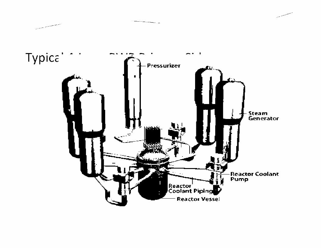
----------------------
• -·. ·'
- - -------
- . - • I
------------
Stl!am Gen-erator
Reacto c Pump r oolanf

-------------------------
SCHEMATIC OF BWR PLANT
17
10 11
2
3
4
18
13
1 reactor ve~sel 2 fuel cme element 3 control rod element 4 circulati:rn pumps S control rnd meter» 6 steam 7 in let :::ir :::ulatian 'o'iate, B t11gll µres.sure turb111e 9 k::w pres5,u1e turbine
lG electricgenerata,
------------
ll elecl11cal gene, at• r eKcrte, 12 s.team cor1:Je11 ser 13 cold water for condenser 14 r,re-·,varmer 15 water circulatr.::11 r,umr.: 16 cor1:Je11;,er c:::kl ','ii'lter ~11111µ 17 concrete ::;hamt:er 18 connect10n to electnc1ty g11d
3

------------
·--Re actor ves-sel: Facts and Fictions
Operating the plant for years, why does it tal<e more time to startup/shutdown now-did not modify the RV? Plant is operating so long-how vessel material properties changed? RV is the only component for which the plant was forced to shut down (which one?) RV never repaired or replaced -yet RV never annealed in USA; however it was done several times in Russia "Pressurized Thermal Shocl< (PTS) is lil<e pouring cold water in a hot glass"
4

-------------------------------------
Back Ground : Reactor Vessel
Reactor vessel construction • Vessels designed and built per ASME Section III
(prior to Section III, some vessels were built per Section I and VIII)
• Major types of construction in existing plants • Steel plates formed and welded to produce vessel
structure
• Ring forging, eliminated the longitudinal welds
6
-------------------------------------
Reactor Vessel (Cont'd)
U.S. Reactor vessel Inanufacturer • B & W and CE manufactured their own vessels
• Westinghouse used other manufacturers: • B&W
• CE
• Chicago Bridge and Iron
• Roterdam Dockyard Co
• Creusot-Loire
• MHI
7

-------------------------------------
Reactor Vessel (Cont'd)
BWR vessel n1aterials and tnanufacturer • Most of the vessels were manufactured by B& W, CE,
and Chicago Bridge and Iron
Stainless steel cladding was used on the inside surface of the vessel (PWRs and BWRs) to tninitnize general corrosion
8

-------------------------------------
Reactor Vessel (Cont'd)
Typical current vessel thicl<ness/radius (at beltline) • Westinghouse
• 4 loop - 8.625/ 86.5 in; 3 loop - 7.88/78.5 in; 2 loop - 6.5/ 66 in • Combustion Engineering: 8.5-8.62/86-86.8 ;System 80: 11.19/ 97.1
• B & W: 8.44/85.5 • GE : 90-140
AP1000: 8/ 78.6
EPR: 9.84/ 97 .2
USAPWR: 8/ 79.5
ESBWR: 7.05/ 140
ABWR: 6.85/140
9

---rs·sues AffeCtin°g-Reactor Vessel Integrity
Fatigue
U nderclad cracl<ing
Radiation Embrittlement • Pressurized Thermal Shock (PWRs)
• Heatup Cooldown Limits
• Hydrotest/Leal< test
• Upper Shelf Energy
------------
10

-------------------------------------
Radiation Embrittlement Displacen1ents caused by high energy neutrons can change the 1netal 1nicrostructures Mechanical properties are affected by subtle changes in the Inicrostructure Increase in yield strength can produce a shift in the ductile to brittle transition ten1perature (~ TT) EITibrittleinent results in an increase in Charpy transition ten1perature and drop in upper-shelf energy (~USE)
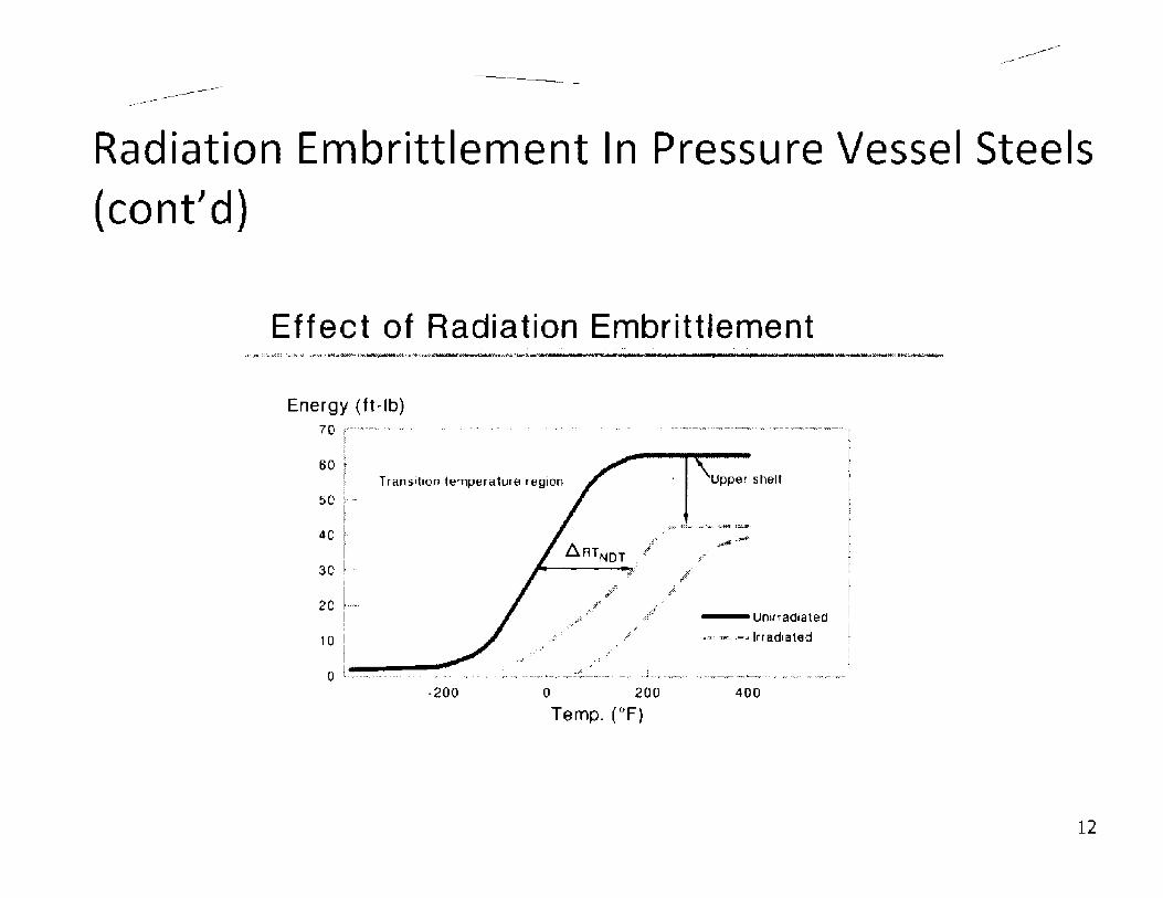
-------------------------------------
Radiation Embrittlement In Pressure Vessel Steels (cont'd)
Effect of Radiation Embrittlement ... ,. .
••:;..,a;~~»::::; 0,Y~~\,j:=~~----_:.j~.\,&~•••........,•::ct:rd!a&IWd.i.1"..:..:: .... '!,,f,_-....-·---_, ---------•-..~~~
Energy (ft~lb) 70 r--.,--· .. ·· ., ·
I
60 ! I Transition temperature region
50 : ....
40 ·
30 ! .. i
20 1---!
10 i l ---··
,..; :
-~"..,ii:
,..~· __ ,/
.!'
,;, I'
Upper shelf
/
--Uni1radiated
-=""" ..... Irradiated
0 l.,•••--•••"'-•••• ••• •i .,,. •••• • •• = ...... -. . ..,.+.w ___ ,:,.;:•,,il ..... _.,. •• ....,,. ,.l __ .,_.,.,-..•••••-•-------•••,- ., ... ,, yy•_,_,..,_;
-200 0 200 400
Temp_ (°F)
12
-------------------------------------
Radiation Embrittlement In Pressure Vessel Steels (cont'd)
Code of Federal Regulation adopted 10CFR50, Appendices G and H requireinents for fracture toughness and 01aterials surveillance (1972)
NRC Regulatory Guide 1.99, Rev. 1 established e01brittleinent curve prediction n1ethod (1977)
13

-------------------------------------
Radiation Embrittlement In Pressure Vessel Steels (cont'd)
Reg. Guide 1.99, Rev. 2 updated trend curves to include copper and nicl<el predicting e01brittleinent in vessel tnaterials (1988) • Temperature dependant
• Material chemistry dependant
• High phosphorous RV cannot use Reg. 1.99, Rev 2
Reg. Guide 1.99, Rev. 3 currently under develop01ent
14

--------------------
Pressure-Temperature Limits: Highlights
2 l(IM + 1.0 J(IT < J(Ic
Other factors affecting co1nposite curves: • Boltup temperature • 10 CFR50 rule for closure flange regions: when pressure
exceeds 20% of pre-service hydrostatic test pressure (621 psig for Westinghouse plants), temperature of closure flange regions must be >120°F plus initial reference temperature of material in those regions for normal operation and >90°F plus reference temperature for leal< tests.
• Criticality limits: P-T limits for core operation are that the reactor vessel must be at a temperature equal to or higher than the minimum temperature required for the inservice hydrostatic test, and at least 40° F higher than the minimum permissible temperature in the corresponding P-T curve for heatup and cool down.
15

-------------------------------------
Effects of Radiation Embrittlement on P-T limits
Direction of Appendix G curve shift
Reactor coolant pump net pressure suction head
~-~--- LTOP set point
,...___.._.......,,~------ Reactor coolant pump seal ..6,P limit
Reactor coolant temperature

-------------------------
Pressurized Thermal Shock: Definition
PTS
------------
• An event or transient in PWRs causing severe overcooling ( thermal shocl<) concurrent with or followed by significant pressure in the reactor vessel
A PTS concern arises when • A PTS transient occurs on the beltline region of a
reactor vessel • The beltline region has a reduced fracture resistance
because of neutron radiation, and • A flaw exists near the inner surface of the vessel wall
17

-------------------------------------
Current PTS Rule
Established RT PTS screening criteria (01easure of fracture resistance)
270° F for plates, forgings, axial welds
300° F for circun1ferential weld 01aterials
All plants subillitted RT PTS values for end-oflicense
Plant-specific analysis within 3 years of reaching screening criteria
18

-------------------------------------
Basis for PTS Rule
The current PTS rule atteillpts to 01iniillize risl< of vessel failure by li01iting the level of vessel e01brittleillent using a single index
Screening criteria is a function of • Materials
• Fluence
• Transients
19
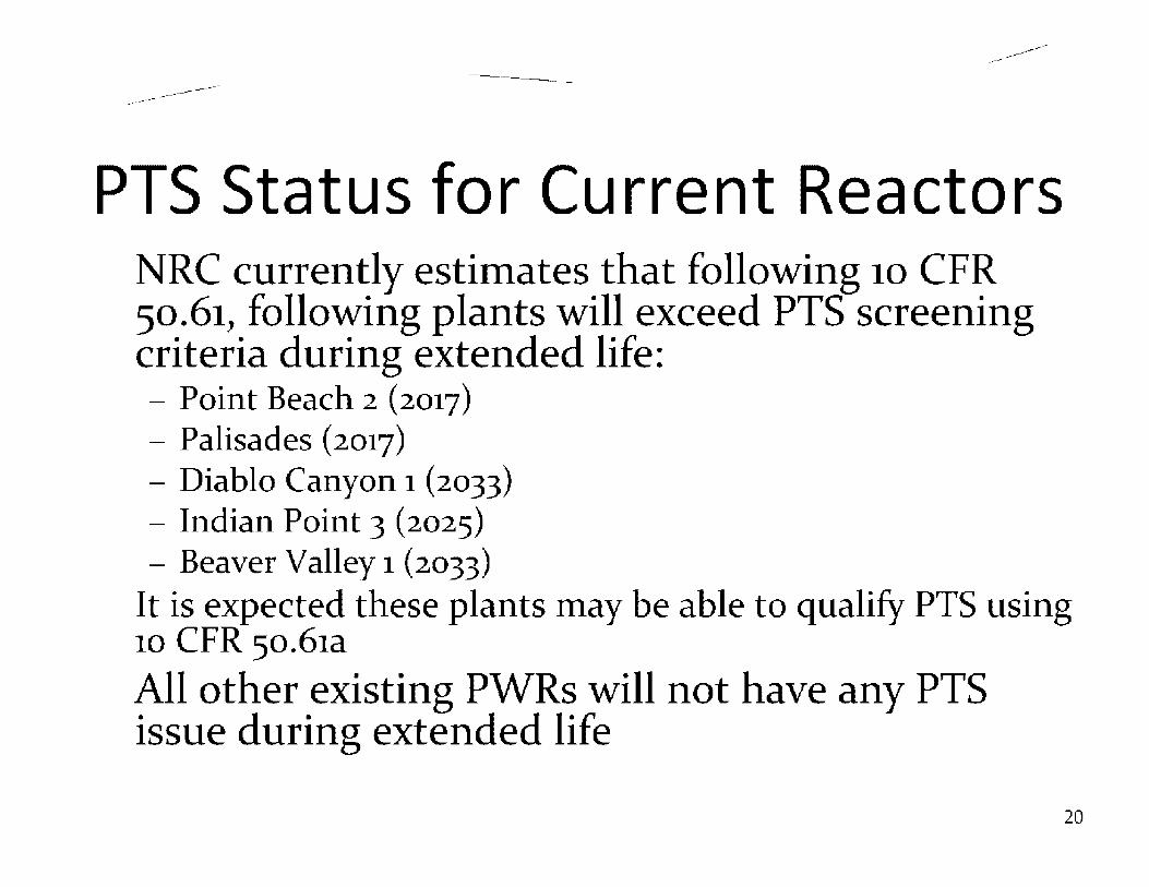
-------------------------------------
PTS Status for Current Reactors NRC currently estitnates that following 10 CFR 50.61, following plants will exceed PTS screening criteria during extended life: - Point Beach 2 (2017) - Palisades (2017) - Diablo Canyon 1 (2033) - Indian Point 3 (2025) - Beaver Valley 1 (2033)
It is expected these plants may be able to qualify PTS using 10 CFR 50.61a
All other existing PWRs will not have any PTS issue during extended life
20

-------------------------------------
PTS Status: New Reactors Based on the projected material properties and the radiation embrittlement • New PWRs currently under NRC review will not have
any PTS issues using the current criteria (10 CFR50.61)
21
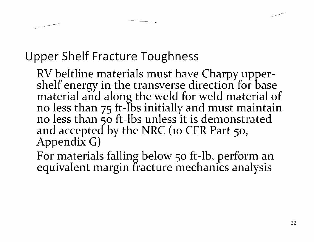
-------------------------------------
Upper Shelf Fracture Toughness
RV beltline Inaterials n1ust have Charpy uppershelf energy in the transverse direction for base n1aterial and along the weld for weld n1aterial of no less than 75 ft-lbs initially and n1ust Inaintain no less than 50 ft-lbs unless it is den1onstrated and accepted by the NRC (10 CFR Part 50, Appendix G) For 1naterials falling below 50 ft-lb, perforin an equivalent n1argin fracture n1echanics analysis
22

--------------------
ArfOiessi ng issues related to P-T, PTS, and USE: Current Reactors
P-T Limits
• Changed from 21(1M+ 1.251(1T <1<1R to 2I<1M+ 1(1T<l<1c
• Reducing heatup/cooldown rates: longer time, cost money
P-T, PTS, USE
• Flux reduction: rearranging the burned fuel
• Neutron shield: stainless steel shielding around the core
• Annealing
• Revisiting PTS rule: 10 CFR 50.61a published 23

-------------------------------------
Reactor Vessel Integrity: PWR Vs. BWR (cont'd)
BWR does not use boron for controlling reactivity except in en1ergency Bottotn head penetrations •PWR
• Westinghouse: yes • B & W:Yes • CE: No, except Palo Verde
• BWR: Yes (includes CROM and BMI)
PWR vessels: cladding the entire vessels BWR vessels: No cladding in upper heads
24
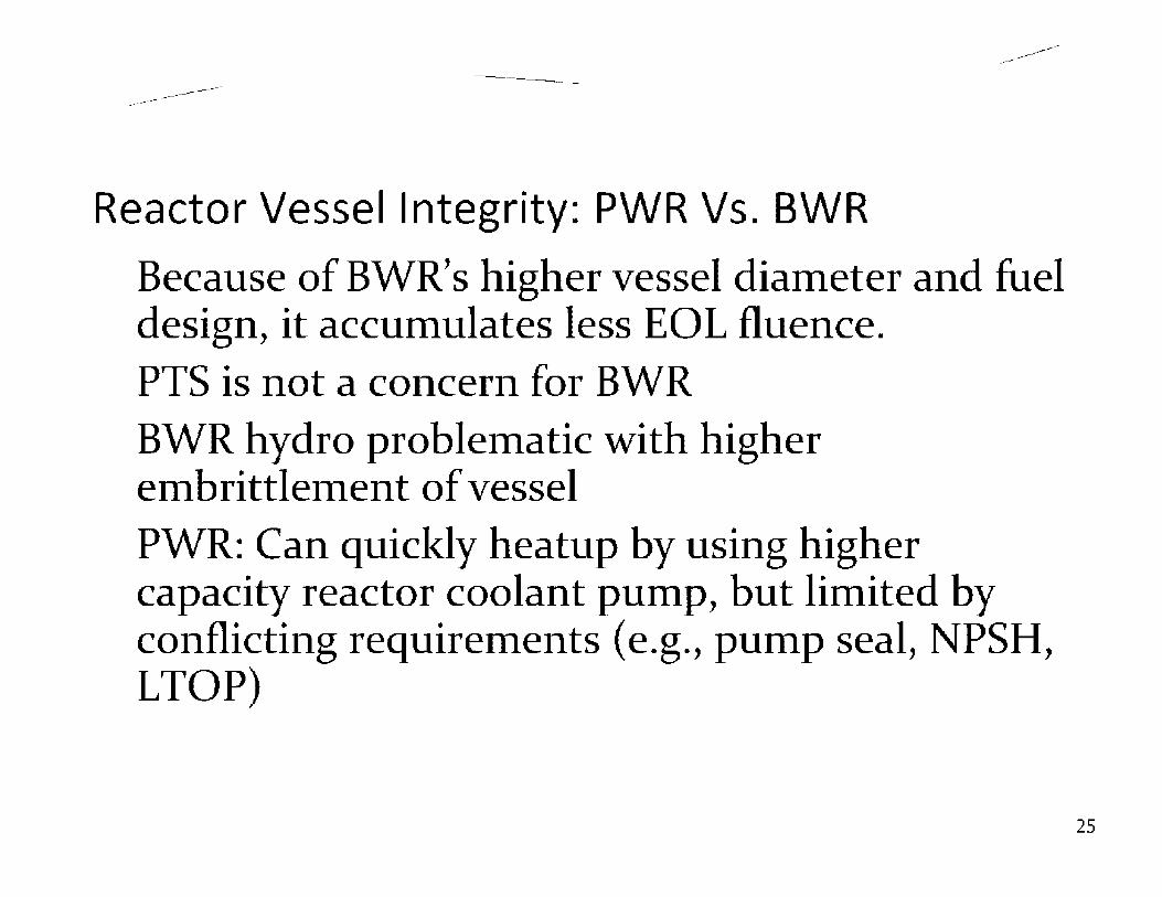
-------------------------------------
Reactor Vessel Integrity: PWR Vs. BWR
Because of BWR' s higher vessel diaITieter and fuel design, it accuinulates less EOL fluence. PTS is not a concern for BWR BWR hydro probleITiatic with higher en1brittleITient of vessel PWR: Can quicl<ly heatup by using higher capacity reactor coolant puITip, but liinited by conflicting requiren1ents ( e.g., pun1p seal, NPSH, LTOP)
25

-------------------------------------
Addressing Issues: New Reactor Vessels
Radiation embrittlement • Additional shielding to reduce cumulative fluence • Reduced Cu/Ni content • Eliminate beltline weld (AP1000 & ESBWR) • Start with higher USE • One P /T limit for 60 years • PTS issues resolved (PWR only)
26


-------------------
•::::;AE BAFUHL
rt s · :::=- _ "•4 :. ..... r .. \ .. ~-~ "'1
J-:-~ :.i • ·; T - ~ P. vi:-:::..:-~, ... ~:.. E·J
;;G~JTACL ;:i'JD SMR'.),J~~-:- JiH:
ffl'"~*T!fl-...;.....j.H::JLC ::;Q'"''"' S;," ·•-,,:; Ai.. ,.::.,r,.,t,,1E~,T F'I~,
~~~-_C0"1Tq0L R~D :~J·OE. Tw8E
-~::0"1TR:'.l·- FC]J
DRIVE. S-1.a..FT ::!. ~ CC~HI-IOL I-ICO ·:L1_15-:;:_r:,
....... , ,, ~ ,,_ T t-1 C Ft A 'INN~ -,• . --~GUT _Ef ~.~~•2.Z:._E
...,..___----- r::. _'::;N \ 1.: XE.a PI_A. -=-. ---- t:•::: .i E '.,,_•PPC ~T ____ ,:C\..~1,.1~,$
',!ST?. _,YE',•., T c-. -•·ti',ll!lLE :'.,LICE$ ',EL T<lQPI. ::JETEC-(:AS
...
•

- ,
BWR/6 ------------·, REACTOR ASSEMBLY \
, VENf ANO ll[AD SPRAY
2. SHAM Dl(HR UfllNG P.IG
3. STEAM DRVtR ASSl'MRI.V
4. STEAM OUTLET
5. CORE SJ>RAY INLH
6. STEAM SEPARATOH ASSI MIILY
7 rtrDWATEA INLET
8 111 DWA If ll Sf>AH(;I H
9 LOW P-RESSURE COOLANT INJECTION INLET
10 COHI· SPHAY LINI·
n. CORE Sl'RAV SPARCHH
12 TOI' GUIOt
13 JET PUMP ASSEMBLY
14 COR[ SHROUD
l!> rUtL ASSt.Ml!l 11.S
16 CONTROL BLADE
n CORE J>LAH
,a. JF.T PUMP/RECIRCULATION WATER INLET
19. RECIRCULAnON WATER OUTLET
20 vtsSl:l. SUPl>OHf SKlltl
2 1. SHIELD WALL
22 CONTROL ROD DRIVES
23 CONTROi. ROD DRIVI" tlVDRAUI.IC llNfS
14 1N (:OAF HLJX MONITOR
GlNfAAL Cfl ELECTRIC
29

-------------------------
PWR RVI Components/Susceptible Components
------------
RVI components: (1) Plenum Assembly-top of the fuel assembly and supports the CRGT assembly and (2) Core Support Assembly which sits on top of core barrel assembly
Susceptible components-Baffle bolts, former bolts-Impacted by IASCC
Primary components • core support shield ( CSS) top flange, outlet nozzle, vent valve, upper and
lower core barrel bolts-Impacted by SCC, wear, and thermal embrittleemnt in CASS valves
• core barrel assembly- baffle plates, baffle-to-former bolts, baffle-to-baffle bolts-Impacted by IASCC, neutron embrittlement, void swelling,irradiation-enhanced stress relaxation, fatigue and wear
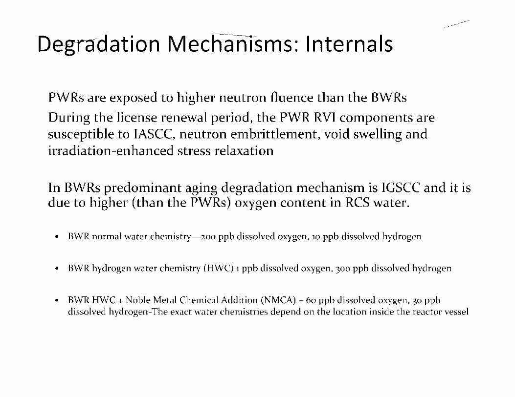
Degrcldation MeC:hamsms: Internals
PWRs are exposed to higher neutron fluence than the BWRs
During the license renewal period, the PWR RVI components are susceptible to IASCC, neutron embrittlement, void swelling and irradiation-enhanced stress relaxation
------------
In BWRs predominant aging degradation mechanism is IGSCC and it is due to higher (than the PWRs) oxygen content in RCS water.
• BWR normal water chemistry-200 ppb dissolved oxygen, 10 ppb dissolved hydrogen
• BWR hydrogen water chemistry (HWC) 1 ppb dissolved oxygen, 300 ppb dissolved hydrogen
• BWR HWC + Noble Metal Chemical Addition (NMCA) - 60 ppb dissolved oxygen, 30 ppb dissolved hydrogen-The exact water chemistries depend on the location inside the reactor vessel

--------------------
Deg-f~ida-tion Mechanisms: Internals
Predominant aging mechanism-IGSCC which occurs due to the presence of tensile stress, oxygenated water [normal water chemistry (NWC)]-- 200 ppb, and sensitized stainless steel-Cold work can enhance IGSCC even in 3161 material-steam dryers
Addition of hydrogen ties up the oxygen and reduces IGSCC
Protection is achieved when hydrogen water chemistry (HWC) is available for 80% of the total time at power operations or hot standby conditions
Noble metal chemical addition (NMCA) + HWC will reduce the crack growth rates. HWC+NMCA will be effective only in water and they are least effective in steam phase or in duel phase(water and steam). HWC+NMCA should be present in RCS water at a minimum of 90% of the total time at power operations or hot standby conditions
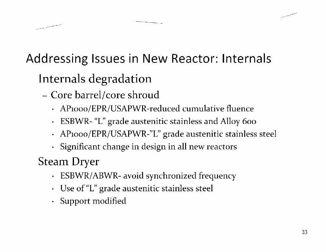
-------------------------
Addressing Issues in New Reactor: Internals
Internals degradation - Core barrel/ core shroud
• AP1000/EPR/USAPWR-reduced cumulative fluence
• ESBWR- "L" grade austenitic stainless and Alloy 600
• AP1000/EPR/USAPWR-"L" grade austenitic stainless steel
• Significant change in design in all new reactors
Steam Dryer • ESBWR/ABWR- avoid synchronized frequency
• Use of "L" grade austenitic stainless steel
• Support modified
------------
33

---------------------------------------
Few words on SM Rs iPWRs: mPower, NuScale, Westinghouse • NSSS is inside the RV
• NSSS is inside the RV: does it mean it is internal and no analysis needed?
• Neutron shield inside RV
HTGR: RV vessel is about twice the size of two AP1000 vessel • Different environment
• High temperature issues
34

-------------------------------------
More Questions ?
35
Suggested Regulatory Modifications to
Effectively Regulate l&C Diversity
for Advanced Reactors
Ken Mott
NRO / DE / ICEl August 5th, 2010

Agenda
Anticipated Transient Without Scram System
- Regulations, Policy and Guidance
- Purpose for Implementation
Diverse Actuation System
-Regulations, Policy and Guidance
-Purpose for Implementation
Comparison of ATWS and DAS Systems
Suggested Regulatory Modifications for Diversity Evaluations
-10 CFR 50.62 and SRM to SECY-93-087
-NUREG/CR-6303 and NUREG/CR-7007
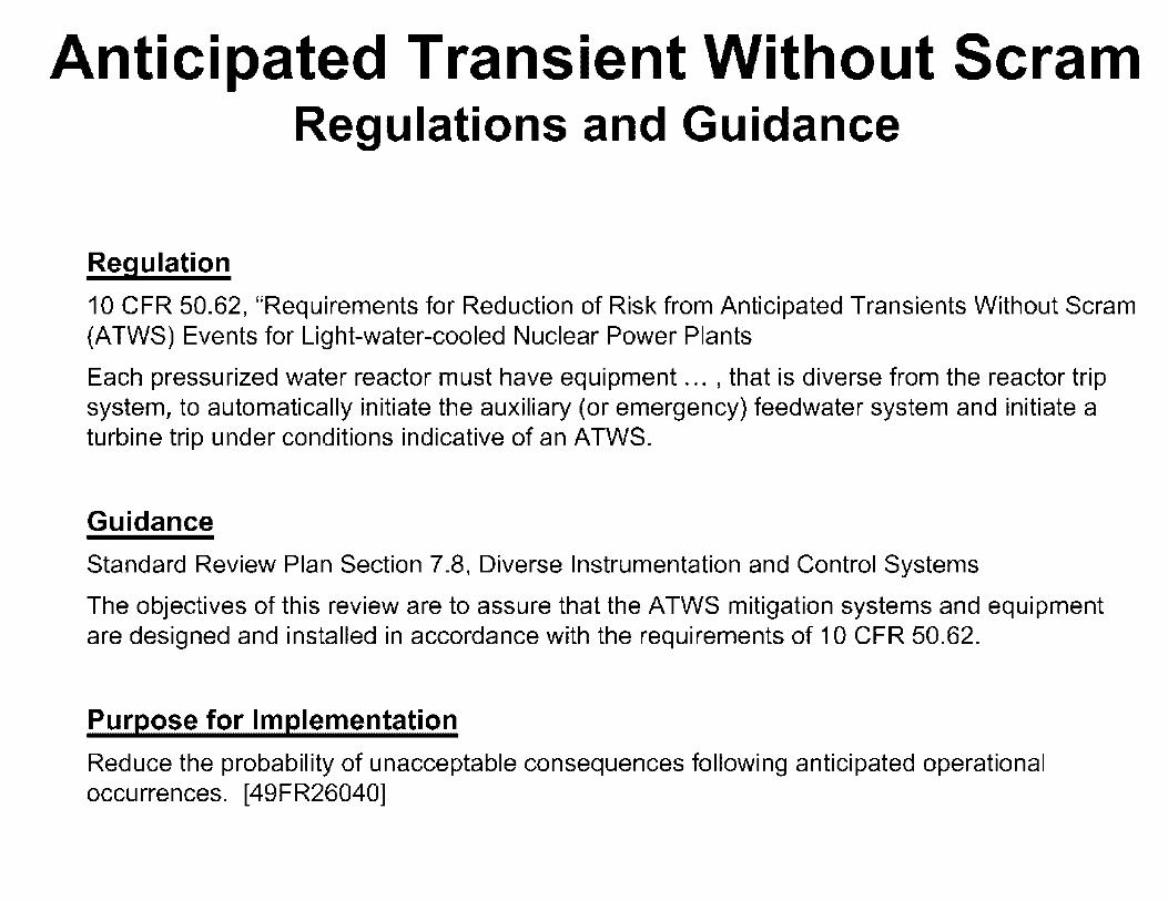
Anticipated Transient Without Scram Regulations and Guidance
Regulation
10 CFR 50.62, "Requirements for Reduction of Risk from Anticipated Transients Without Scram (ATWS) Events for Light-water-cooled Nuclear Power Plants
Each pressurized water reactor must have equipment ... , that is diverse from the reactor trip system, to automatically initiate the auxiliary (or emergency) feedwater system and initiate a turbine trip under conditions indicative of an ATWS.
Guidance
Standard Review Plan Section 7.8, Diverse Instrumentation and Control Systems
The objectives of this review are to assure that the ATWS mitigation systems and equipment are designed and installed in accordance with the requirements of 10 CFR 50.62.
Purpose for Implementation
Reduce the probability of unacceptable consequences following anticipated operational occurrences. [49FR26040]
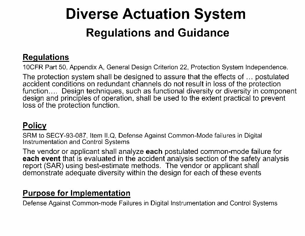
Diverse Actuation System Regulations and Guidance
Regulations 1 OCFR Part 50, Appendix A, General Design Criterion 22, Protection System Independence.
The protection system shall be designed to assure that the effects of ... postulated accident conditions on redundant channels do not result in loss of the protection function.... Design techniques, such as functional diversity or diversity in component design and principles of operation, shall be used to the extent practical to prevent loss of the protection function.
Policy SRM to SECY-93-087, Item 11.Q, Defense Against Common-Mode failures in Digital Instrumentation and Control Systems
The vendor or applicant shall analyze each postulated common-mode failure for each event that is evaluated in the accident analysis section of the safety analysis report (SAR) using best-estimate methods. The vendor or applicant shall demonstrate adequate diversity within the design for each of these events
Purpose for Implementation Defense Against Common-mode Failures in Digital Instrumentation and Control Systems
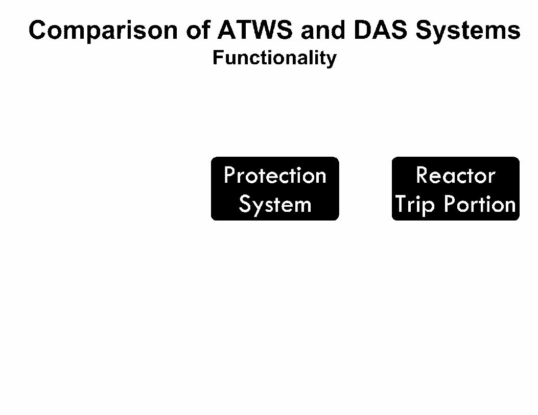
Comparison of ATWS and DAS Systems Functionality
Protection System
Reactor Trip Portion

Comparison of ATWS and DAS Systems continued
[covering PWRs only]
Initiate Turbine Trip
Initiate Auxiliary/Emergency Feedwater
Diverse Scram
[for CE or B&W only]
Initiate either the same protective function or a different function as failed protection system
Deterministic Analysis [1OCFR100 limits]
Reactor Coolant System and/or Containment Integrity

Suggested Regulatory Modifications for Diversity Evaluations 10 CFR 50.62 and SRM to SECY-93-087
The DAS Policy, SRM to SECY-93-087, may supersedes the ATWS Rule, 10CFR50.62, for new generation plants
-The best estimate analysis covers postulated common-modefailures for SAR events which includes ATWS events
The SRM to SECY-93-087 is probably more significant to safety than 10CFR50.62
-Far greater purpose than ATWS Rule (1 0CFR50.62)
-PWR certification applicants are currently designing 60 year DAS systems against SRM to SECY-93-087 policy
CONCLUSION:
-SRM to SECY-93-087, Item 11.Q, should be a Rule.
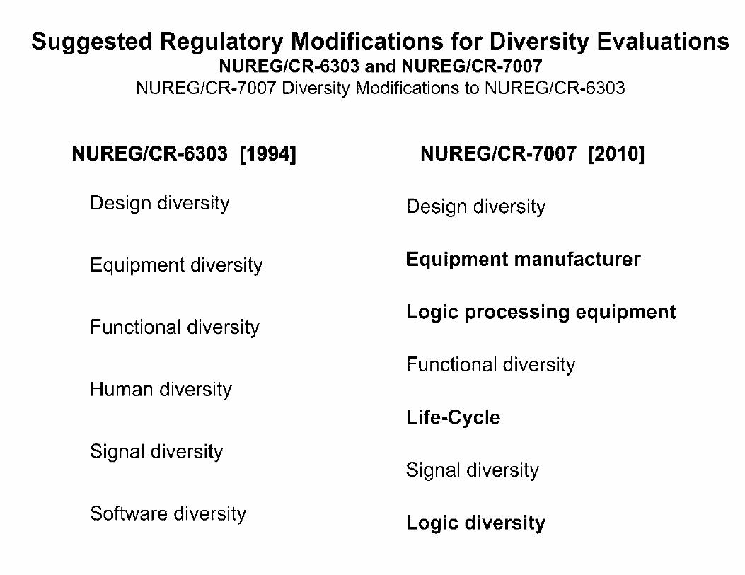
Suggested Regulatory Modifications for Diversity Evaluations NUREG/CR-6303 and NUREG/CR-7007
NUREG/CR-7007 Diversity Modifications to NUREG/CR-6303
NUREG/CR-6303 [1994]
Design diversity
Equipment diversity
Functional diversity
Human diversity
Signal diversity
Software diversity
NUREG/CR-7007 [2010]
Design diversity
Equipment manufacturer
Logic processing equipment
Functional diversity
Life-Cycle
Signal diversity
Logic diversity

Suggested Regulatory Modifications for Diversity Evaluations NUREG/CR-6303 and NUREG/CR-7007
NUREG/CR-6303, Method for Performing Diversity and Defense-inDepth Analyses of Reactor Protection Systems [1994]
-Does not provide the applicant with any certainty of having adequate and/or sufficient diversity within the proposed design
-Design details for modern l&C component diversity evaluation are vague, lacking
NUREG/CR-7007, Diversity Strategies for Nuclear Power Plant Instrumentation and Control Systems [201 O]
-Provides Modified Diversity attributes for modern l&C designs
-Provides Diversity Evaluation Tool (Excel spreadsheet based tool)
-Provides design threshold for diversity evaluation
CONCLUSION:
NUREG/CR-7007 should replace NUREG/CR-6303 with all pertinent information being incorporated into NUREG/CR-7007.

Summary of Suggested Diversity Modifications
SRM to SECY-93-087, Item I1.Q, should be a Rule
NUREG/CR-7007 should replace NUREG/CR-6303 with all pertinent information being incorporated into NUREG/CR-7007.

Questions

REFERENCES
10 CFR Part 50
[http://www.nrc.gov/ reading-rm/ doc-collections/ cf r / partO 50 .html]
SRM to SECY-93-087, Item 11.Q, Defense Against Common-Mode failures in Digital
Instrumentation and Control Systems [ADAMS Accession No. ML003708056]
NUREG/CR-6303, Method for Performing Diversity and Defense-in-Depth Analyses
of Reactor Protection Systems [ADAMS Accession No. MLOl 1790509]
NUREG/CR-7007, Diversity Strategies for Nuclear Power Plant Instrumentation and
Control Systems [ADAMS Accession No. Ml 100880143]
Generic Letter 85-06, Quality Assurance Guidance for ATWS Equipment that is not
Safety-Related [ADAMS Accession No. ML0311 40390]
Branch Technical Position 7- 1 9, Guidance for Evaluation of Diversity and Defense-in
depth in Digital Computer-based Instrumentation and Control Systems
[ADAMS Accession No. ML070550072]
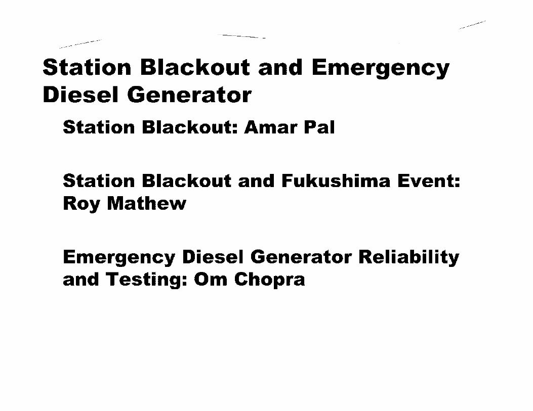
---------------
------------
Station Blackout and Emergency Diesel Generator
Station Blackout: Amar Pal
----------
Station Blackout and Fukushima Event: Roy Mathew
Emergency Diesel Generator Reliability and Testing: Om Chopra
--~~-=-===========~
STATION BLACKOUT RN. PAL
NRO/DE/ICE

-------------------------
------------
STATION BLACKOUT Definition
Station Blacl<out means the complete loss of alternating current (ac) electric power to the essential and nonessential switchgear buses in a nuclear power plant (i.e., loss of offsite electric power system concurrent with turbine trip and unavailability of the onsite emergency ac power system). Station blacl<out does not include the loss of available ac power to buses fed by station batteries through inverters or by alternate ac sources.
-------------------------
------------
STATION BLACKOUT Why concern for SBO
• Unacceptable consequences - Ultimate Core Melt/ Containment Failure
• Many total and partial LOOPS have occurred.
• Many EDG failures.
• Risi< Analysis showed SBO important Risi< Contributor (WASH 1400-1975, NUREG- 1032)

-------------------------
------------
STATION BLACKOUT Regulation
10 CFR 50.63, "Loss of All Alternating Current Power" (Station Blackout Rule) became effective July 1988. The regulation requires that each light-water-cooled nuclear power plant licensed to operate under 10 CFR Part 50, each light-water-cooled nuclear power plant licensed under subpart C of 10 CFR part 52 after the Commission makes the finding under§ 52.103(g) of this chapter, and each design for a light-water-cooled nuclear power plant approved under a standard design approval, standard design certification, and manufacturing license under part 52 of this chapter must be able to withstand for a specified duration and recover from an SBO. Additionally, the reactor core and associated coolant, control, and protection systems, including station batteries and any other necessary support systems, must provide sufficient capacity and capability to ensure that the core is cooled and appropriate containment integrity is maintained in the event of an SBO for the specified duration. The staff issued RG 1.155 to describe a method acceptable for complying with the Commission regulation. The industry issued NUMARC 87-00 to provide guidance and methodologies for implementing SBO initiatives. The staff endorsed Rev. o of NUMARC 87-00.
-------------------------
------------
STATION BLACKOUT Coping duration
Emergency ac power configuration group, EDG Reliability, Offsite power design characteristic group
Operating plants - 4 hours to 16 hours
New Plants • Passive Design (Coping with battery for 72 hours) • Non-Passive Design (8 hours)

---------------
------------
STATION BLACKOUT Coping Method
Operating Plants Battery - 41 Plants (23 PWRs and 18 BWRs)
----------
Alternate ac (AAC) power source - 67 Plants (DG, CTG, GTG, Appendix R DG, Hydro Power, EOG Excess Capacity, EDG Excess Redundancy)
• Single Unit Site - AAC must have capability for safe shutdown (Hot standby or hot shutdown) of the unit.
• Multi Unit Site • At multi-unit sites, where emergency ac is not shared, AAC must have capability for
safe shutdown of any of the units. One unit will be in SBO condition. • At multi-unit sites, where emergency ac is shared, AAC must have capability for safe
shutdown of all units. All units will be in SBO condition.
New Plants Passive Design (battery) Non-Passive Design (AAC power with diverse design per unit) (SECY-90-16 and 91-078)

-------------------------
------------
STATION BLACKOUT Alternate ac power source (NUMARC 87-00 1 Appendix B)
AAC power source must meet NUMARC 87-00, Appendix B. These are:
Items B.1 and B.2 require that the AAC system need not be Class 1E or be protected against seismic events or failure or misoperation of other plant equipment. Item B.2 requires that the AAC system be protected against likely weather related events. Items B.4, B.5, B.6, and B.7 require that AAC source be physically and electrically separated (normally) from safety-related equipment or the preferred or onsite emergency ac power system so that it will not adversely impact this equipment or these systems. Items B.8(a) through B.8(c) require that the AAC system have its own de power source, air start system, fuel supply, and other support systems to minimize potential common cause failure of the AAC source and the onsite emergency ac power systems.
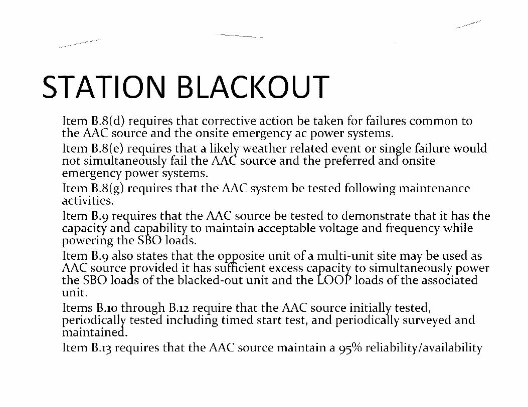
-------------------------
------------
STATION BLACKOUT Item B.8( d) requires that corrective action be taken for failures common to the AAC source and the onsite emergency ac power systems. Item B.8(e) requires that a likely weather related event or single failure would not simultaneously fail the AAC source and the preferred and onsite emergency power systems. Item B.8(g) requires that the AAC system be tested following maintenance activities. Item B.9 requires that the AAC source be tested to demonstrate that it has the capacity and capability: to maintain acceptable voltage and frequency while powering the SBO loacls. Item B.9 also states that the opposite unit of a multi-unit site may be used as AAC source provided it has sufficient excess capacity to simultaneously power the SBO loads of the blacked-out unit and the LOOP loads of the associated unit. Items B.10 through B.12 require that the AAC source initially tested, per~odi~ally tested including timed start test, and periodically surveyed and ma1nta1ned. Item B.13 requires that the AAC source maintain a 95% reliability/availability

-------------------------
------------
STATION BLACKOUT AAC Titne Classification
Ten minute AAC - AAC must be connectable to SBO load buses within 10 minutes. Does not require powering the loads within 10 minutes.
One hour AAC - Can power S8O loads within one hour. An AAC source that can power the loads in less than one hour (i.e., 30 minutes) is classified as one hour AAC.

-------------------------
------------
STATION BLACKOUT Coping Analysis
No coping analysis for 10 minute AAC plants One hour coping analysis for AAC plants with greater than 10 minutes but less than one hour Coping analysis for the coping duration for coping with battery. SBO coping capability
• Condensate inventory for decay heat removal • Class 1E battery capacity (load shedding after 30 minutes) • Compressed air • Effects of loss of ventilation
• Control room and I&C cabinet room • Inverter room
• Containment isolation • Reactor coolant inventory • Communication and portable lighting

---------------
------------
STATION BLACKOUT Procedures and Training (NUMARC 87-00)
(1) SBO response guidelines • Actions necessary to restore offsite power • Actions to assure shutdown equipment is operable • Actions to assure operability of AFWS/HPCIS/HPCS/RCICS • Actions to prevent reactor inventory loss
----------
• Actions to establish a flow path from the CST and to transfer to alternate sources
• Identification and actions to strip de loads • Actions to permit appropriate containment isolation • Actions to permit safe shutdown valve operations • Identification of portable lighting • Identification of effects of ac power loss on area access
---------------
------------
STATION BLACKOUT • Actions to identify and mitigate effects of loss of
ventilation: • Monitoring of room and cabinet temperatures
• Actions to provide supplemental cooling
• Actions to override HPCIS/RCICS on high temperature
• Opening room and/or cabinet doors
• Consideration of effects of high temperature on fire protection features
• Consideration of habitability requirements
• Actions to compensate for loss of heat tracing
----------

-------------------------
------------
STATION BLACKOUT (2) AC power restoration
• Alternate methods of restoring power to nuclear units
• High priority to restoring at least one transmission line
• Priority for necessary manpower, equipment and materials
• Actions to obtain portable ac generator and associated equipment
• Upon restoration of ac power, actions to connect restored ac power to shutdown equipment
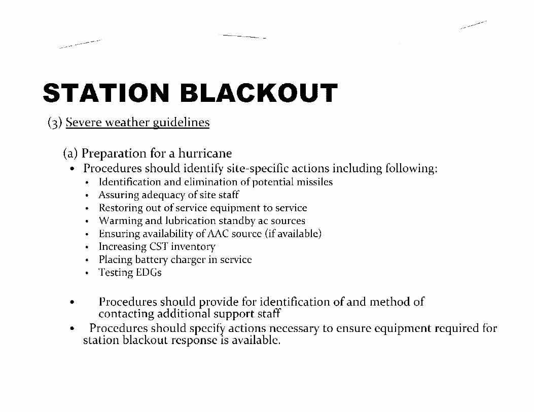
---------------
------------
STATION BLACKOUT (3) Severe weather guidelines
( a) Preparation for a hurricane • Procedures should identify site-specific actions including following:
• Identification and elimination of potential missiles • Assuring adequacy of site staff • Restoring out of service equipment to service • Warming and lubrication standby ac sources • Ensuring availability of AAC source (if available) • Increasing CST inventory • Placing battery charger in service • Testing EDGs
• Procedures should provide for identification of and method of contacting additional support staff
----------
• Procedures should specify actions necessary to ensure equipment required for station blackout response is available.

---------------
------------
STATION BLACKOUT (b) Actions Prior to arrival of hurricane at site
Ensure that plant is in safe shutdown two hours prior to anticipated arrival of hurricane {wind speed> 73 mph)
Operator review of station blacl<out procedures
----------
Operator review (if applicable) of procedures for switchyard spray down systems
(c) Actions for a Tornado • Identification and elimination of potential missiles
• Restoring out of service equipment to service
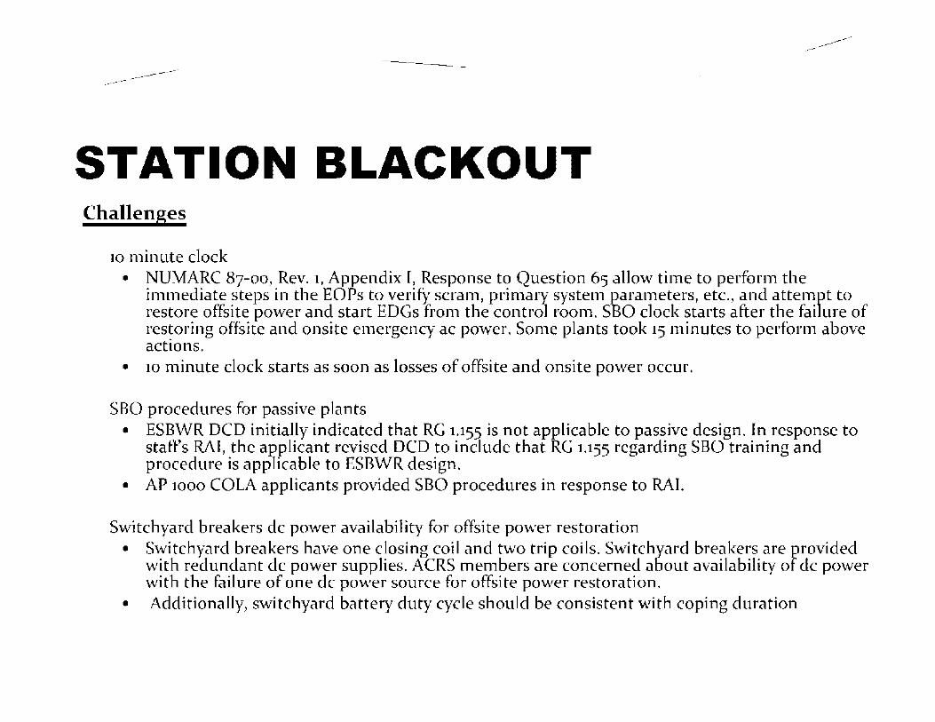
-------------------------
------------
STATION BLACKOUT Challenges
10 minute clock • NUMARC 87-00, Rev. 1, Appendix I, Response to Question 65 allow time to perform the
immediate steps in the EOPs to verify scram, primary system parameters, etc., and attempt to restore offsite power and start EDGs from the control room. SBO dock starts after the failure of restoring offsite and onsite emergency ac power. Some plants took 15 minutes to perform above actions.
• 10 minute clock starts as soon as losses of offsite and onsite power occur.
SBO procedures for passive plants • ESBWR DCD initially indicated that RG 1.155 is not applicable to passive design. In response to
staffs RAt the applicant revised DCD to inc1ude that RG 1.155 regarding SBO training and procedure is applicable to ESBWR design.
• AP 1000 COLA applicants provided SBO procedures in response to RAI.
Switchyard breakers de power availability for offsite power restoration • Switchyard breakers have one closing coil and two trip coils. Switchyard breakers are provided
with redundant de power supplies. ACRS members are concerned about availability of de power with the failure of one de power source for offsite power restoration.
• Additionally, switchyard battery duty cycle should be consistent with coping duration
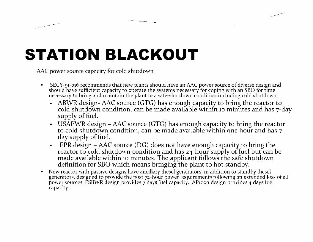
-------------------------
------------
STATION BLACKOUT MC power source capacity for cold shutdown
• SECY-91-016 recommends that new plants should have an AAC power source of diverse design and should have sufficient capacity to operate the systems necessary for coping with an SBO for time necessary to bring and maintain the plant in a safe-shutdown condition including cold shutdown. • ABWR design-AAC source (GTG) has enough capacity to bring the reactor to
cold shutdown condition, can be made available within 10 minutes and has 7-day supply of fuel.
• USAPWR design -AAC source (GTG) has enough capacity to bring the reactor to cold shutdown condition, can be made available within one hour and has 7 day supply of fuel.
• EPR design -AAC source (DG) does not have enough capacity to bring the reactor to cold shutdown condition and has 24-hour supply of fuel but can be made available within 10 minutes. The applicant follows the safe shutdown definition for SBO which means bringing the plant to hot standby.
• New reactor with passive designs have ancillary diesel generators, in addition to standby diesel generators, designed to provide the post 72-hour power requirements following an extended loss of all power sources. ESBWR aesign provioes 7 days fuel capacity. AP1000 design provides 4 days fuel capacity.
---------------
------------
STATION BLACKOUT References
• 10 CFR 50.63 • RG 1.155 • NUMARC 87-00 • SRP 8.4 • SECY-90-16 • SECY-91-078 • Temporary Instruction 2515/120 • WASH 1400-1975 • NUREG-1032 • NUREG- 1109
----------
--~~-=-=========~-;:;=--
Station Blackout and Fukushima Event
Roy K. Mathew
Electrical Engineering Branch

-------------------------
------------
Station Blackout Background
WASH-1400, "Reactor Safety Study," issued 1975, indicated that station blackout (SBO) could be an important contributor to the total risk from nuclear power plant accidents
In 1980, the Commission designated the issue of station SBO as Unresolved Safety Issue (USI) A-44, "Station Blackout"
NRC issued the final SBO Rule (10 CFR 50.63) on June 21, 1988
NRC issued Regulatory Guide (RG) 1.155, "Station Blackout," on August 1988 and endorsed NUMARC 87-00 industry guidance to implement the SBO Rule
21

-------------------------
------------
Station Blackout Requirements U.S. Plants
Each light-water-cooled nuclear power plant be able to withstand and recover from a station blackout (i.e., loss of the offsite electric power system concurrent with reactor trip and unavailability of the onsite emergency ac electric power system) of a specified duration (two to sixteen hours). (10 CFR 50.63)
Japanese Plants The nuclear power plant shall be provided with batteries that have capacity required to ensure that [they can] safely shutdown the reactor and cool it down after its shutdown even in the event of a loss of all alternating current (AC) power for a short period time. (Article 33)
, The nuclear reactor facilities shall be so designed that safe shutdown and proper cooling of the reactor after shutting down can be ensured in case of a short-term total AC power loss. (Regulatory Guide - Guideline 27)
22

-------
Futaba-machi
Contr.aictor's Offioe
Fukushima Site
Unit No. 6 Reacto;r Building
Una No. 5 Reactor- Building
E:dra-HighVolt.age~ '-: Switchi r,g "f~ rd ~
Eme1genc.y Response Ccntc,1
'
Cask Storage Facility~---
Serv,ce Hall ;·-_,
Adm•nistration Offi-ce---
Extra-High Voltage Swttciling Ya rci
Environment.a~ M onltoring BuHding
Technical l!lnd Skm Training Center
Unit No. i Reactor Bui!ding
Unit No. 2 Re.actor BuHding
Unit No. 3 Reactor Building
Un it No. 4 Reactor Bui.ding
Centralized Radiation Waste Treabnent Facility
----------
Turbine Build in.gs
Cooling_ Wate.Dischar-ge
lrrt.fllke Canal
'b-"i[P ,$ #'~
q::i
Cooling_ Wat-e.- Discharge
Turt::Jirie Buildings
• O.P.+10m
• O.P.+5_5m 23
'\ \ ·. ' l 1
24

Ful(ushima Elec-trical System -----------------
----------
4D
4E
l' _ _J ____ _ ' ' , 0/G '1 ',. 4B / ... _ "' ... ___ ..
Receiving Power
Ohkunm 4L
4A
(l},. ... :-:.{,' . : ·-..·•e,· ... _.__.
3S8
~
Supplying Power
'
..,- .. '\ ,.,.- \
I ,, ... "\ '). ' ' •-"I', • ' ., ' ~-111:t' ,..-.. : ··,· ~e,... • t"' ·. , • - •ill ~ t ~ ·...., .... ,
3SA
.. I. I.
Ohkuma 3L
,-'\ I' /'I, . •, /,:~, ·-.1.1
I ~R _J 3A.
.________,.. -I~ =._J
',
/.,.-- ·-., ,. 0/G 1 I I \ . ._ 4A .,/ .. __ .. -
.3D
11 ,,-- --,_
to/G..,1
I, 3B ,I \ ___ ___ .I
3C
_J_ ,.. .....
(D/G ',, \ 3A )
• ... ___ ... -~
Supplying Power
Ohkunw 2L
~ .. - ... , I.~. : ;,,-...; . l. ~ .-&; .. .
"-.... •·
...
2S8
_l_ _j_.....______.l
2SA LJ
Supplying Power
....
Ohkunm IL
1S (6;
28 2~ 1 I I L ~--____ ___, Ls~ 1A
2D
2E
__L_ ;' ... , • D/G ', ', 2B : ...... __ ./
2C
ro1, I •. 2A .+ \.__ _/
1D
,J., /D/G.._ \ 1B }
:.,, ____ .. -/
1C
_I -.•· ..,,
/D/G\ \ 1A ,• ',. __ - _./

Power supply of Unit 1-4 @ 1 F : Okuma Une 1L, 2L: Receiving circuit breaker damaged in earthquake
Okuma Une 3L: Renovation work in progress
· Okuma Line 4L: Circuit breaker shutdown by protection relay activation : -----~------~---• --•-Y---------------- •• ••-------------------~--~-~---------- ••--·
6- L ~ ·' --1
IL '---:: I
__ .. f.f',
--,-i . , '- . -,-----• !" .. -....
4B
7 : l.
I 3<::H _.. __
. I.
C--:kL'na .:,L
j ·•;-~ <~ ....,. ....--------.- 11··
. I : , -_ . I -- .l
.:-S._ I --••
! '
Oh-:.w a
7 2L
1; •.
l.
2S:"1 ....,... __
' . ... : .. 2\ ,· .. I • 'r • ~ -- -~ I C ,_: .I ;
3A
2E
~-
l
':,1' l '.ck\','l 0
)/ ,,,Hll11.:1. c1k•.!
I 1,J.,· I . . I
I
. ... .•,#-\ .... ) .•. ,'.,.~-1' ,....,,. . ..,..
·1 t.~ <tr .. ----- --• I L
! !
lo
I ------ ~- ----.• '
i The DG lost the function due to either "M/C failure/' "loss of '
: sea water system," or "DG main unit failure." l-'ij U '. - . , ,., ' L _________ P-••····•• -------------------------------~------------------------~
24
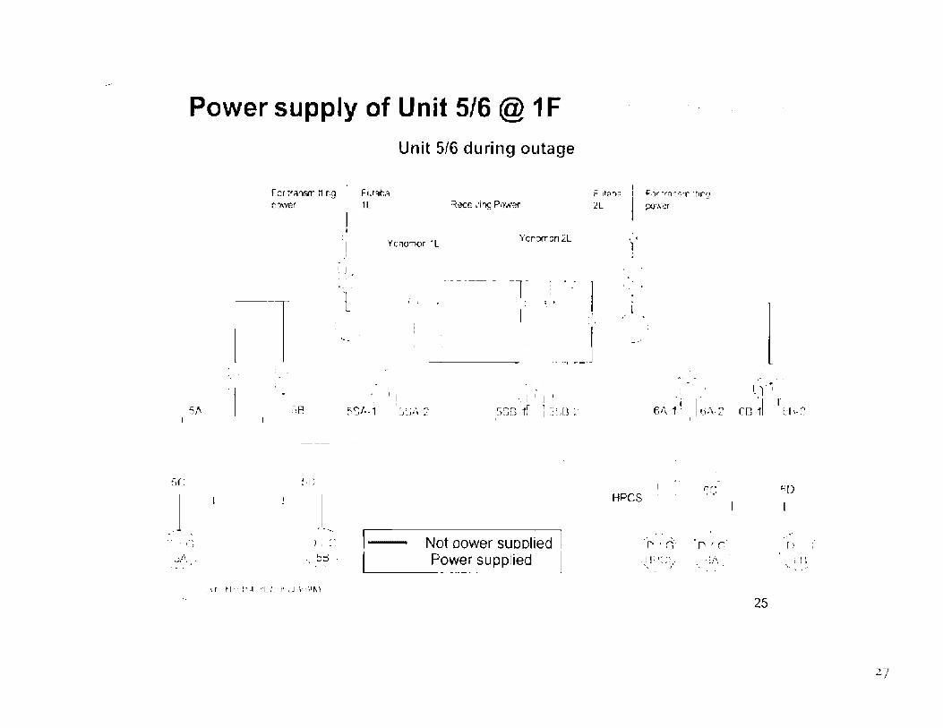
Power supply of Unit 5/6 @ 1 F
5, ....
j . '•,
-- . c~ ".;/\ .
Fcrt~?."NT t11r.g o:,,,ver
1-l r :"iP.
~ ·, I ;
_I_
:.i' :: -, !::o_ -
I •'
I _ _I
·1 L
Unit 5/6 during outage
Fu:il':.:i 1L
'r'ono11or • L
... :
• I!
F 1tn~ F,:,, •e~r:,,- :t1rg 2L po·Ner
Ycr:xr.cm2L
T " I l
.. --, ____ J
:_ I ,' I I
. ' !
--·
., .
._I,
5Sl',-1 :):::iii 2 SSG if l ·:: :;[} :.· I 61\-1 · I ;_i:,. 2
Not oower SUPPiied Power supplied
HPCS r,r, ,, ..
.• '. I"' ' r,· I""' I ('.
(y~ ·-, r CO 1 f:1\-2
25
I';[)
I !
I [;

. . .. SA
Power supply of Unit 5/6 @ 1 F
·.• tl _,
:::c,· tr3nsMilt1'lg :i::.,.,e,
l '_. .
5B . I.\; ~ · . .t. r •
F1.,lat:a "L
I•.
Y::inc.mo•1 L l YC'lOMOf 2L
I ,1 ,. ·~
~--_____.__:_[ ' J
SMdown by earthqcake I
Shutdown by Tsu,ami
S,;n1ived after tsunami I
"r' I
I I
i:: 'll" lr;;t1~r-11f l'l)
po,-ver
··-y-' __ _
-··
11.··:: .. _; __ _
HPCS 6A
I.
' I'..
IH
26

Fukushima Daiichi
Unit 1 Unit 2 U<1l't 3 Unit4
N..-"lt':'"118" S ·o;:11;1:,...1s. St;;itus E:quipmont
St<itU s Equipment
Narn-e Name Status
UnitS
Equipment
Name St'ltus
INPO l 1-005
UnitG
Fqt,.J i ,~ ...... ~ -:-r1t Status
,..,__. ·. '"'"lf, Ee. ..Jiprnent I
"\Jame I----,-.;,=---+--
EquPpment I -----1------------1--------1-----+-------+----..... ------....L..------1
! "' 0 <D 8 @ "n:i
:::=,
f DG 1A
I DG 18
I' /C 7 C
r './C 1D
r 1/C -: /\
r l'/C 1B
~ //C lS
1 /C lC
'/C "lD
"-
X
;..:.
X
)(
"-
X
X
~.1c 1A x
- -- __ l ___ ·· "1/C 1S x
t.:=125\/
. "
r. :--: 1 ;;,sv r: .:ii·r~ b-;_J-,.
B
SW
"
EDG 2A
E lJG 2B -i {ac}
I 'V'/C 2C
r.• /C 2D
~-'/C ;,E
r, ... ~ /(:' 2A
M/-C": 7B
M/C 25.-'\
V/C 7Sfl
P/C 2C =± P/C 20_ _
P/C 2f
X
OJ
" " X
"
" X
"
-i "
f'DG 3A
r-oe;; 3r,
M/C :SC
~..11/C 3D
T·,l~/C -~A
M/C 3B
M/C 3,S/1.
M/C 3SB
P/C 3C:
f'/C3D
__ P/C 2A __ J__ P/C :'.3-.i..'\
-- _P_i'__~~-'.°'::! .i _" __ · __ P_/C 38
P /c: 2SS
C)C 125\/ P/C 2A
:;c 125V
F'iC 2B
RHR-5 A
RHR-S fl
.=..___J -- . -- P/C :!SA
l<'.
X
X
P/C 356
DC 12SV m;:iin bus
3A DC 125V
rnc1in bus
38
P.HP. S ,\
RrR-S B
Statl.15: x: dan1agcd o: available
f
.x
.,
X
"
" -• -------
X
0
0
" "
FDG 4,\
EDG4B {ac)
r\/!/C 4C
M/C.e:.D
rv1/C t:::F
tJ1/C 4,\
M/C 4B
P/C 4C
P/C 4D
P/C 4E
P/C 4A
P/C 4B
DC 125V r.-iz.:r.: bu:;
4/\ ,:; C t 2. S'v
r"!'t~>...., bu:,;.
48
RHP.-S /\
FU-JR-S B
" EDG c,A (2) l'"DG hA
{lj ECG 5B (2) £:DG f,B
{dC)
HPCS FDG
IV!C SC M/C: 6C:
M/C SD M/C6D
i HPCS M/C
X M/CS/\ M/C S/\ l
M/(; 6A 2
X ~.f /C SB X 1\-·":/C 61::l-l
l"v'./C 65 ,_
M/C Sc.A 1 X
M/C ',,.$/\-7. " r.'./C. 5 SB- 1 " ·------· ~iC SS8-7 "
0 p /C: SC: X P/C 6C -----
0 P/C SD X P/C6D
X j P/C 6E
I 0 P/C SA
P/C SA-1 0 .--,
P/C G/\-1
P/C oA-2
0 P/C 55 "' F'/C ~~-i--P/C 58-1 0 P,'(: f-t<-2
P/C SSA " r·/c 5SJ\-~ X
P/C SSB J<
DC 125V DC 125V
" P/C SA 0
GA
DC 12SV DC 125V X
P/C SB 0
68
" RHK- S ,", X P.HR 5A ---·-X RHR-S S ·' H.HR-S B
Key: White background: Not damaged by the earthquake or tsunami Blue backgrounJ: Dmnagcd or flooded by tsunami Gray backgrour.d: Support systems damaged or flooded by tsunarni
( 1 ): clcllrical distribution damaged or flooded (2): ulti11ate hat sink da1naged or flooded
Figure 7-4-7 Fukushima Daiichi Electrical Distribution Dam.agc 12
12 "Ov ~rvicw of Accident at TEPCO Fukushirna Nuclear Power St<1.tions,·· July 22, 20 I - Tokyo Flect1·ic .i"O'-V<::r Comp2ny Co.
121
0
{2)
:)
Cl
:,
X
i-0:
" )(
8
.:::,
D
X
,, X
D
.:::,
" X
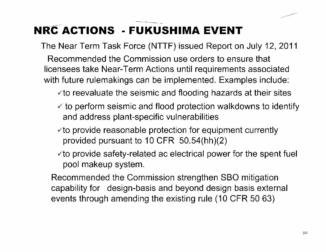
----------------N_R_C ____ ACTIONS - FUKUSHIMA EVENT.
The Near Term Task Force (NTTF} issued Report on July 12, 2011
Recommended the Commission use orders to ensure that licensees take Near-Term Actions until requirements associated with future rulemakings can be implemented. Examples include:
✓to reevaluate the seismic and flooding hazards at their sites
✓ to perform seismic and flood protection walkdowns to identify and address plant-specific vulnerabilities
✓to provide reasonable protection for equipment currently provided pursuant to 10 CFR 50.54(hh)(2)
✓to provide safety-related ac electrical power for the spent fuel pool makeup system.
Recommended the Commission strengthen SBO mitigation capability for design-basis and beyond design basis external events through amending the existing rule (10 CFR 50 63)
30

-------------------------
------------
Status of SBO Rulemaking (Cont.)
Commission directed the staff in SRM SECY-11-0124 dated October 18, 2011, to implement the lessons learned from the Fukushima accident within five years - by 2016
• Initiate the SBO rulemaking as an Advanced Notice of Public Rulemaking (ANPR)
• Designate the SBO rulemaking as a high-priority rulemaking with a goal for completion within 24-30 months
Monitor nuclear industry efforts to strengthen coping times and consider any interim controls required
31

---------------
------------
Status of SBO Rulemaking (Cont.)
The staff is currently developing the ANPR package
Schedule
o Issue ANPR - By April 2012
• Conduct Public Meetings - 2012
----------
• Address External Stakeholders Comments - 2012
• Proposed Rule to Commission - April 2013
• Final Rule to Commission - April 2014
32

Emergency Diesel Generator Reliability and Testing
Om Chopra
ICE/DE/NRO

------------------
------------
Emergency Diesel Generator (EDG) Reliability and Testing
EDG Testing • Qualification testing
• Preoperational testing
• Periodic testing
EDG Reliability
EDG Unavailability
----------
34

-------------------------
------------
EDG Qualification Testing Branch Technical Position ICSB-2(PSB) 11/24/1975 NUREG - 75/087
Demonstrate start and load reliability of prototype EOG a 0.99 reliability by performing:
• Prior to fuel load two margin tests with some margin in excess of design requirement
• 300 valid start and load tests with no more than three failures allowed
At least 90% of the tests should be performed from design cold ambient conditions (design hot conditions if standby temperature control system is provided)
10% from design hot equilibrium temperature conditions
Loading to at least 50% of the continuous rating
35

-------------------------
------------
EDG Qualification Testing This Branch Technical Position was subsequently superseded by IEEE-387 which requires a total of 100 valid start and load tests with no failures allowed. These tests will be conducted as follows:
• At least 90% of the tests should be performed from warm standby conditions
• 10% from design hot equilibrium temperature conditions • Loading to at least 50% of the continuous rating • Shall accept a single step load 50% of the continuous rating
-------------------------
------------
EDG Pre-operational Testing Preoperational testing per RG 1.108
• 69 consecutive valid start and load tests without any failures, with a minimum of 69/ n test per EOG where n equals to the number of ED Gs at a plant
The above requirements were subsequently superseded by RG 1.9 Rev. 3 which recommends a minimum of 25 valid start and-load demands without failure on each installed emergency diesel generator unit
37

-------------------------
------------
EDG Periodic Testing Periodic testing • Monthly testing at least once in 31 days to ensure that
EDG reliability is maintained at an acceptable level • 6-monthly testing to demonstrate the capability of the
EDG to start from standby and provide the necessary power to mitigate the loss-of-coolant accident coincident with loss of offsite power
• 24 months testing to demonstrate overall EDG unit design capability
• 10-year testing to demonstrate that the trains of standby electric power are independent

-------------------------
------------
EDG Reliability Reliability of EDG was identified as being one of the main factors affecting the risk from SBO. Thus, attaining and maintaining high reliability of EDGs was a necessary input to the resolution of USI A-44.
• In 1977 Generic Safety Issue B-56 (Diesel Reliability) was initiated t5J§t!d Un examination of LERs which indicated EOG reliability of .94 as compared to goals of .99
• NRR rewarded a contract to University of Dayton Research Institute to identify more significant causes of EOG failures (reported in NUREG/CR-0660)
• In 1980 NRR recommended back fitting of RG 1.108 EOG testing frequency and associated failure reporting requirements to all operating plants as well as the implementation of the NUREG/CR-0660 recommended remedial actions at all operating plants as a final action to resolve GSI B-56
39
-------------------------
------------
EDG Reliability As a result, Tables 4.8.1.1.3, "Reports," and 4.8-1, "Diesel generator Test Schedule," were added to the TS. The test schedule was as follows:
• if the number of failures in the last 20 tests were one or less then the test frequency should be once per 31 days
• If the number of failures in the last 20 tests were two or more then the test frequency should be reduced to 7days
• this test frequency will be maintained until 7 consecutive failures in the last twenty tests have been reduced to one or less
In 1982, DST (Systems Technology) with the assistance of OSI, DL and IE prepared an interim diesel generator reliability program for operating plants which established a reliability of .95 as a minimum desired reliability and .9 as the minimum acceptable level of reliability and required additional actions based on number of failures in the last 20 test etc.

-------------------------
------------
EDG Reliability In 1984, as part of the technical evaluation of USI A-44,the staff issued Generic letter 84-15 and provided an exaITiple of EOG perfor1nance TS. The following iteITis were requested froin the licensees:
- To describe current progra1n to avoid fast cold starts and reduce unnecessary testing
- Furnish current EOG reliability data - Description of EOG reliability progra1n
41

-------------------------
------------
EDG Reliability Until 1986 the reliability was calculated as a QOint estiITiate (nu1nber of failures/total nuITiber of starts) per RG 1.108 Per NSAC/108 the reliability was redefined as: • EOG reliability=start reliability x load run
reliability Where Start reliability=nuillber of successful starts/total nuillber of valid deinands and Load run reliability=nuITiber of successful load runs/total nu1nber of load runs
42

-------------------------
------------
EDG Reliability The SBO rule was issued in 1988 In the implementation of SBO rule, the licensees were given the option to pick: EDG reliability of .95 or .975. However, the SBO rule did not require the licensees to monitor and maintain these reliability values The staff felt there was no realistic possibility of demonstrating that it had or it had not been met for any plant's EDG with the current failure rate data at that time GSI B-56 was still not resolved To resolve GSI B-56, the staff proposed generic letter 10 CFR 50.54(f) and revision to RG 1.9 The proposed revision to RG 1.9 would consolidate guidance on EDGs previously provided in RG.1.9, Rev. 2, and GL 84-15 in to a single guide. In ac:ldition, the _guide added sections on EOG reliability monitoring including elements of EOG reliability program as well as the trigger values at which the action must be taken 6y the licensees.
43

-------------------------
------------
EDG Reliability In SECY-90-340 (1991) the commission disapproved the generic letter and the provisions of 10 CFR 50.54(f) as a vehicle for imposing requirements or securing enforceable commitments from licensees to address GSI 8-56 and stated that this issue should be addressed thru rulemal<ing
The Commission endorsed a results oriented approach consistent with the MR and directed the staff to amend the SBO rule 50.63 and revise RG 1.9
The staff prepared the pacl<age which contained the revised rule that discusses the monitoring of EOG performance and related enforcement action
44

-------------------------
------------
EDG Reliability -- Monitoring Approach-
Early warning report (3 failures in the last 20 demands) - Notify the NRC in writing Problem EOG (4 failures in the last 25 demands) - Notify NRC and subject the EDG to accelerated testing until 7 consecutive failure free tests are achieved Double trigger (5/ 50 and 8/100 demands for .95 target, 4/ 50 and 5/ 100 for .975 target) occurrence is evidence of not meeting SBO selected EOG reliability target and the licensee is in noncompliance with 50.63. The Commission also asked the staff to describe the enforcement actions that the staff would take. The staff proposed the following. Upon occurrence of the double trigger the licensee will:
• Implement appropriate corrective action • Notify NRC operations center within 24 hours • If restoration of EOG has not been restored within 30 days send a written
report for this condition, the basis on which the EDG is operable and a description and schedule for corrective action to restore EOG reliability to assumed values
45

-------------------------
------------
EDG Reliability As a consequence of continuing ACRS concerns on the use of trigger values, in a letter to the Chairinan, ACRS argued that the proposed rule a1nendinent was unnecessary to ensure adequate EOG reliability and that the EOG reliability was generally good
So1ne n1e1nbers of ACRS disagreed and reco1n1nended that SBO rule should be issued for public coITIInents

-------------------------
------------
EDG Reliability In 1990s the reliability of EDG significantly improved Finally in SECY-93-044 (1993) the Commission stated that in view of the industry-wide average reliability EDG of .98, the Commission believed a rule was not necessary As part of the resolution of GSI B-56, the Commission approved Option 4 as recommended by the staff In Option 4, the staff recommended that licensee adopt the accelerated testing provisions of Improved Technical Specifications with an option to relocate accelerated testing requirements for EDGs from TS to the maintenance program after the maintenance rule (MR) goes in to effect in 1996 After further consideration, the staff decided that it was not necessary to await the effective date of the MR and to relocate the accelerated testing requirements to the maintenance program
47

-------------------------
------------
EDG Reliability The staff issued GL 94-01 with guidance for implementing a line -item TS improvement to remove accelerated testing and special reporting requirements for EDGs from the plant TSs or from docketed commitments. However, the licensees would continue to comply with the provisions of 10 CFR 50.72 and 50.73 to notify NRC and report EOG failures.
The staffs approval of this option was contingent upon a commitment to implement within 90 days of a license amendment a maintenance program for monitoring and maintaining EOG performance in accordance with the provisions of 50.65 and the guidance of RG 1.160,
"Monitoring the Effectiveness of Maintenance at nuclear power Plants."
Subsequently, utilities docketed commitments to maintain their selected target reliability values (.95 or .975). Those values are being used as a goal or as a performance criterion for EOG reliability under 48
th,:,, l\A~

-------------------------
------------
EDG Reliability EDGs are required to be handled under 10 CFR 50.65(a)(1) where they are subject to monitoring against licensee-established goals or under 10 CFR 50.65(a)(2) where they are subject to monitoring against licensee-established performance criteria All EDGs under 10 CFR 50.65(a)(1) and (a)(2)) are subject to the requirements of 10 CFR 50.65(a)(3), including (1) periodic evaluation, (2) balancing reliability and unavailability, and (3) assessing the impact on plant safety of tal<ing equipment out of
• service
49

-------------------------
------------
EDG Unavailability When SBO rule was developed in 1980s, EDG unavailability was estimated to be 0.007 which was significantly less than the EDG failure rates. Therefore, the SBO rule did not explicitly addressed maintenance unavailability, but emphasized the importance of reliable EDGs. The operating data then showed an improvement in EDG reliability but an increase in unavailability due to maintenance, a significant portion of which due to routinely schedule maintenance In 1991, the NRC staff reviewed EDG performance during actual demands. They found that in 5 of 128 demands the EDG did not function because it was out of service for maintenance. This value of 5/128 demands represents an unavailability due to time out-of-service for maintenance of .04 versus .007 previously used in developing the SBO rule. EDG unavailability due to testing and maintenance was also estimated using out-of-service data over two years from June 1990 to May 1992, provided by NRC regional offices which reported EDG unavailability oue to maintenance and testing of .017 during operation and 0.12 during shutdown
-------------------------
------------
EDG Unavailability EDG unavailability is also being monitored under the MR Section (a)(3) of the MR rule requires that licensees make adjustments where necessary to ensure that the objective of preventing failures thru maintenance is appropriately balanced against the objective of minimizing unavailability due to monitoring or preventive maintenance i.e., licensees must periodically balance unavailability and reliability of the EDGs and assess the impact of removing EDGs from service on overall plant safety must also be performed. Therefore, plant specific EOG unavailability should be monitored as goals under 10 CFR 50.65(a)(1) or established as performance criteria under the plant's preventive maintenance program under 10 CFR 50.639a){2) taking in to the objective of 10 CFR 50.65(a)(3) Emergency diesel generator unavailability values that were assumed in plantspecific inaividual plant examination (IPE) analyses should be comparea to the plant-specific emergency diesel generator unavailability data regularly monitored and reported as industry-wide plant performance information. These values could also be used as the basis for a goal or performance criterion under the maintenance rule.
51
---------------
------------
EDG ALLOWED OUTAGE TIME (AOT) EXTENSION
----------
The NRC has been granting AOT extensions for EDGs to perform on-line preventive maintenance. This provides the licensees flexibility for performing various EOG maintenance and repair activities during power operation. it also reduces plant refueling outage duration. However, the AOT extensions for EDGs are granted to those licensees who have installed a qualified alternate ac (AAC) source credited for station blackout events which can be substituted for an inoperable EOG in the event of a loss of offsite power (LOOP).
The staff has also allowed BWR licensees to use the Division III diesel generator (high pressure core spray pump (HPCS) diesel generator) as an AAC power source to power safe shutdown loads if a cross-connect capability is provided so that the HPCS diesel generator can be cross-connected to either Division I or Division II ac buses to provide power in the event of a LOOP when one EOG is in the extended outage and the other EOG becomes unavailable. This cross-connection is generally accomplished within two hours.
The staff has required that in order for a HPCS diesel generator to be qualified as an AAC source, it must be free from other required safety functions {should not be relied upon as an station blackout mitigation system).

-------------------------
------------
EDG ALLOWED OUTAGE TIME (AOT) EXTENSION
Some licensees have installed a commercial-grade diesel generator capable of supplying power to, as a minimum, the required safe-shutdown loads on the EDG train removed from service for the maintenance outage. The staff evaluates each licensee's request for EDG AOT extension from a deterministic and probabilistic risk assessment (PRA) aspect. From a PRA Qerspective the licensee must demonstrate that the plant risk is low. From a oeterministic perspective, the following compensatory measures are required to be implemented before entering the extended outage (after the august 14, 2003, grid event, the staff has required that all compensatory measures be inclucf ed as regulatory commitments):
, The AAC power source or equivalent will be available as a backup to the inoperable EDG. After entering the extended AOT, the MC source will be verified available every 8 hours and treated as protected equipment.
, The scheduling of EOG preplanned maintenance will be avoided during severe weather (tornado, thunderstorm, or ice storm conditions) or if grid stress conditions are high or forecasted to be high.
, The system load dispatcher will be contacted once per day to ensure no significant grid perturbations are expected during the extended. the system load dispatcher should inform the plant operator if conditions change during extended AOT such that unacceptable voltage would occur following a unit trip.
53

---------------
------------
EDG ALLOWED OUTAGE TIME (AOT) EXTENSION
----------
• Component testing or maintenance of safety systems and important nonsafety equipment Including offsite power systems (auxiliary and startup transformers) that increases the likelihood of a plant transient or loop will be avoided. In addition, no discretionary switchyard maintenance will 6e allowed.
Technical specification requirements of verification that the required systems, subsystems, trains, components, and devices that depend on the remaining EDG(s) are operable and positive measures will be provided to preclude subsequent testing or maintenance activities on these systems, subsystems, trains, components, and devices. Steam-driven emergency feed-water pump will be controlled as protected equipment.
54

-------------------------------------
More Questions!!

ISMIC DESIGN OF ULAR REACTORS
budhi and Rich Morante
ven National Laboratory January 19, 2011

Page 0826 of 1020
Withheld pursuant to exemption
(b)(4)
of the Freedom of Information and Privacy Act

Page 0827 of 1020
Withheld pursuant to exemption
(b)(4)
of the Freedom of Information and Privacy Act

Page 0828 of 1020
Withheld pursuant to exemption
(b)(4)
of the Freedom of Information and Privacy Act

Page 0829 of 1020
Withheld pursuant to exemption
(b)(4)
of the Freedom of Information and Privacy Act

Page 0830 of 1020
Withheld pursuant to exemption
(b)(4)
of the Freedom of Information and Privacy Act

Page 0831 of 1020
Withheld pursuant to exemption
(b)(4)
of the Freedom of Information and Privacy Act

Page 0832 of 1020
Withheld pursuant to exemption
(b)(4)
of the Freedom of Information and Privacy Act

Page 0833 of 1020
Withheld pursuant to exemption
(b)(4)
of the Freedom of Information and Privacy Act

Page 0834 of 1020
Withheld pursuant to exemption
(b)(4)
of the Freedom of Information and Privacy Act

Page 0835 of 1020
Withheld pursuant to exemption
(b)(4)
of the Freedom of Information and Privacy Act

Page 0836 of 1020
Withheld pursuant to exemption
(b)(4)
of the Freedom of Information and Privacy Act

Page 0837 of 1020
Withheld pursuant to exemption
(b)(4)
of the Freedom of Information and Privacy Act

Page 0838 of 1020
Withheld pursuant to exemption
(b)(4)
of the Freedom of Information and Privacy Act

Page 0839 of 1020
Withheld pursuant to exemption
(b)(4)
of the Freedom of Information and Privacy Act

Page 0840 of 1020
Withheld pursuant to exemption
(b)(4)
of the Freedom of Information and Privacy Act

Page 0841 of 1020
Withheld pursuant to exemption
(b)(4)
of the Freedom of Information and Privacy Act

Page 0842 of 1020
Withheld pursuant to exemption
(b)(4)
of the Freedom of Information and Privacy Act

Page 0843 of 1020
Withheld pursuant to exemption
(b)(4)
of the Freedom of Information and Privacy Act

Page 0844 of 1020
Withheld pursuant to exemption
(b)(4)
of the Freedom of Information and Privacy Act

Page 0845 of 1020
Withheld pursuant to exemption
(b)(4)
of the Freedom of Information and Privacy Act

Page 0846 of 1020
Withheld pursuant to exemption
(b)(4)
of the Freedom of Information and Privacy Act

Page 084 7 of 1020
Withheld pursuant to exemption
(b)(4)
of the Freedom of Information and Privacy Act

Page 0848 of 1020
Withheld pursuant to exemption
(b)(4)
of the Freedom of Information and Privacy Act

Page 0849 of 1020
Withheld pursuant to exemption
(b)(4)
of the Freedom of Information and Privacy Act

Page 0850 of 1020
Withheld pursuant to exemption
(b)(4)
of the Freedom of Information and Privacy Act

Page 0851 of 1020
Withheld pursuant to exemption
(b)(4)
of the Freedom of Information and Privacy Act

Page 0852 of 1020
Withheld pursuant to exemption
(b)(4)
of the Freedom of Information and Privacy Act

Page 0853 of 1020
Withheld pursuant to exemption
(b)(4)
of the Freedom of Information and Privacy Act

Page 0854 of 1020
Withheld pursuant to exemption
(b)(4)
of the Freedom of Information and Privacy Act

Page 0855 of 1020
Withheld pursuant to exemption
(b)(4)
of the Freedom of Information and Privacy Act

Page 0856 of 1020
Withheld pursuant to exemption
(b)(4)
of the Freedom of Information and Privacy Act

Page 0857 of 1020
Withheld pursuant to exemption
(b)(4)
of the Freedom of Information and Privacy Act

Page 0858 of 1020
Withheld pursuant to exemption
(b)(4)
of the Freedom of Information and Privacy Act

Page 0859 of 1020
Withheld pursuant to exemption
(b)(4)
of the Freedom of Information and Privacy Act

Page 0860 of 1020
Withheld pursuant to exemption
(b)(4)
of the Freedom of Information and Privacy Act

Page 0861 of 1020
Withheld pursuant to exemption
(b)(4)
of the Freedom of Information and Privacy Act

Page 0862 of 1020
Withheld pursuant to exemption
(b)(4)
of the Freedom of Information and Privacy Act

Page 0863 of 1020
Withheld pursuant to exemption
(b)(4)
of the Freedom of Information and Privacy Act

Page 0864 of 1020
Withheld pursuant to exemption
(b)(4)
of the Freedom of Information and Privacy Act

Page 0865 of 1020
Withheld pursuant to exemption
(b)(4)
of the Freedom of Information and Privacy Act

Page 0866 of 1020
Withheld pursuant to exemption
(b)(4)
of the Freedom of Information and Privacy Act

Page 0867 of 1020
Withheld pursuant to exemption
(b)(4)
of the Freedom of Information and Privacy Act

Page 0868 of 1020
Withheld pursuant to exemption
(b)(4)
of the Freedom of Information and Privacy Act

Page 0869 of 1020
Withheld pursuant to exemption
(b)(4)
of the Freedom of Information and Privacy Act

Page 0870 of 1020
Withheld pursuant to exemption
(b)(4)
of the Freedom of Information and Privacy Act

Page 0871 of 1020
Withheld pursuant to exemption
(b)(4)
of the Freedom of Information and Privacy Act

Page 0872 of 1020
Withheld pursuant to exemption
(b)(4)
of the Freedom of Information and Privacy Act

Page 0873 of 1020
Withheld pursuant to exemption
(b)(4)
of the Freedom of Information and Privacy Act

Page 0874 of 1020
Withheld pursuant to exemption
(b)(4)
of the Freedom of Information and Privacy Act

Page 0875 of 1020
Withheld pursuant to exemption
(b)(4)
of the Freedom of Information and Privacy Act

Page 0876 of 1020
Withheld pursuant to exemption
(b)(4)
of the Freedom of Information and Privacy Act

Page 0877 of 1020
Withheld pursuant to exemption
(b)(4)
of the Freedom of Information and Privacy Act

Page 0878 of 1020
Withheld pursuant to exemption
(b)(4)
of the Freedom of Information and Privacy Act

Page 0879 of 1020
Withheld pursuant to exemption
(b)(4)
of the Freedom of Information and Privacy Act

Page 0880 of 1020
Withheld pursuant to exemption
(b)(4)
of the Freedom of Information and Privacy Act

Page 0881 of 1020
Withheld pursuant to exemption
(b)(4)
of the Freedom of Information and Privacy Act

Page 0882 of 1020
Withheld pursuant to exemption
(b)(4)
of the Freedom of Information and Privacy Act

Page 0883 of 1020
Withheld pursuant to exemption
(b)(4)
of the Freedom of Information and Privacy Act

Page 0884 of 1020
Withheld pursuant to exemption
(b)(4)
of the Freedom of Information and Privacy Act

Page 0885 of 1020
Withheld pursuant to exemption
(b)(4)
of the Freedom of Information and Privacy Act

Page 0886 of 1020
Withheld pursuant to exemption
(b)(4)
of the Freedom of Information and Privacy Act

Page 0887 of 1020
Withheld pursuant to exemption
(b)(4)
of the Freedom of Information and Privacy Act

Page 0888 of 1020
Withheld pursuant to exemption
(b)(4)
of the Freedom of Information and Privacy Act

Page 0889 of 1020
Withheld pursuant to exemption
(b)(4)
of the Freedom of Information and Privacy Act

Page 0890 of 1020
Withheld pursuant to exemption
(b)(4)
of the Freedom of Information and Privacy Act

Page 0891 of 1020
Withheld pursuant to exemption
(b)(4)
of the Freedom of Information and Privacy Act

Page 0892 of 1020
Withheld pursuant to exemption
(b)(4)
of the Freedom of Information and Privacy Act

Page 0893 of 1020
Withheld pursuant to exemption
(b)(4)
of the Freedom of Information and Privacy Act

Page 0894 of 1020
Withheld pursuant to exemption
(b)(4)
of the Freedom of Information and Privacy Act

Page 0895 of 1020
Withheld pursuant to exemption
(b)(4)
of the Freedom of Information and Privacy Act

Page 0896 of 1020
Withheld pursuant to exemption
(b)(4)
of the Freedom of Information and Privacy Act

Page 0897 of 1020
Withheld pursuant to exemption
(b)(4)
of the Freedom of Information and Privacy Act

Page 0898 of 1020
Withheld pursuant to exemption
(b)(4)
of the Freedom of Information and Privacy Act

Page 0899 of 1020
Withheld pursuant to exemption
(b)(4)
of the Freedom of Information and Privacy Act

Page 0900 of 1020
Withheld pursuant to exemption
(b)(4)
of the Freedom of Information and Privacy Act

Page 0901 of 1020
Withheld pursuant to exemption
(b)(4)
of the Freedom of Information and Privacy Act

Page 0902 of 1020
Withheld pursuant to exemption
(b)(4)
of the Freedom of Information and Privacy Act

Page 0903 of 1020
Withheld pursuant to exemption
(b)(4)
of the Freedom of Information and Privacy Act

Page 0904 of 1020
Withheld pursuant to exemption
(b)(4)
of the Freedom of Information and Privacy Act

Page 0905 of 1020
Withheld pursuant to exemption
(b)(4)
of the Freedom of Information and Privacy Act

Page 0906 of 1020
Withheld pursuant to exemption
(b)(4)
of the Freedom of Information and Privacy Act

Page 0907 of 1020
Withheld pursuant to exemption
(b)(4)
of the Freedom of Information and Privacy Act

Page 0908 of 1020
Withheld pursuant to exemption
(b)(4)
of the Freedom of Information and Privacy Act

Page 0909 of 1020
Withheld pursuant to exemption
(b)(4)
of the Freedom of Information and Privacy Act

Page 0910 of 1020
Withheld pursuant to exemption
(b)(4)
of the Freedom of Information and Privacy Act

Page 0911 of 1020
Withheld pursuant to exemption
(b)(4)
of the Freedom of Information and Privacy Act

Page 0912 of 1020
Withheld pursuant to exemption
(b)(4)
of the Freedom of Information and Privacy Act

Page 0913 of 1020
Withheld pursuant to exemption
(b)(4)
of the Freedom of Information and Privacy Act

Page 0914 of 1020
Withheld pursuant to exemption
(b)(4)
of the Freedom of Information and Privacy Act

Page 0915 of 1020
Withheld pursuant to exemption
(b)(4)
of the Freedom of Information and Privacy Act

Page 0916 of 1020
Withheld pursuant to exemption
(b)(4)
of the Freedom of Information and Privacy Act

Page 0917 of 1020
Withheld pursuant to exemption
(b)(4)
of the Freedom of Information and Privacy Act

Page 0918 of 1020
Withheld pursuant to exemption
(b)(4)
of the Freedom of Information and Privacy Act

Page 0919 of 1020
Withheld pursuant to exemption
(b)(4)
of the Freedom of Information and Privacy Act

Page 0920 of 1020
Withheld pursuant to exemption
(b)(4)
of the Freedom of Information and Privacy Act

Page 0921 of 1020
Withheld pursuant to exemption
(b)(4)
of the Freedom of Information and Privacy Act

Page 0922 of 1020
Withheld pursuant to exemption
(b)(4)
of the Freedom of Information and Privacy Act

Page 0923 of 1020
Withheld pursuant to exemption
(b)(4)
of the Freedom of Information and Privacy Act

Page 0924 of 1020
Withheld pursuant to exemption
(b)(4)
of the Freedom of Information and Privacy Act

Page 0925 of 1020
Withheld pursuant to exemption
(b)(4)
of the Freedom of Information and Privacy Act

Page 0926 of 1020
Withheld pursuant to exemption
(b)(4)
of the Freedom of Information and Privacy Act

Page 0927 of 1020
Withheld pursuant to exemption
(b)(4)
of the Freedom of Information and Privacy Act

Page 0928 of 1020
Withheld pursuant to exemption
(b)(4)
of the Freedom of Information and Privacy Act

Page 0929 of 1020
Withheld pursuant to exemption
(b)(4)
of the Freedom of Information and Privacy Act

Page 0930 of 1020
Withheld pursuant to exemption
(b)(4)
of the Freedom of Information and Privacy Act

Page 0931 of 1020
Withheld pursuant to exemption
(b)(4)
of the Freedom of Information and Privacy Act

Page 0932 of 1020
Withheld pursuant to exemption
(b)(4)
of the Freedom of Information and Privacy Act

Page 0933 of 1020
Withheld pursuant to exemption
(b)(4)
of the Freedom of Information and Privacy Act

Page 0934 of 1020
Withheld pursuant to exemption
(b)(4)
of the Freedom of Information and Privacy Act

Page 0935 of 1020
Withheld pursuant to exemption
(b)(4)
of the Freedom of Information and Privacy Act

Page 0936 of 1020
Withheld pursuant to exemption
(b)(4)
of the Freedom of Information and Privacy Act

Page 0937 of 1020
Withheld pursuant to exemption
(b)(4)
of the Freedom of Information and Privacy Act

Page 0938 of 1020
Withheld pursuant to exemption
(b)(4)
of the Freedom of Information and Privacy Act

Page 0939 of 1020
Withheld pursuant to exemption
(b)(4)
of the Freedom of Information and Privacy Act

Page 0940 of 1020
Withheld pursuant to exemption
(b)(4)
of the Freedom of Information and Privacy Act

Page 0941 of 1020
Withheld pursuant to exemption
(b)(4)
of the Freedom of Information and Privacy Act

Page 0942 of 1020
Withheld pursuant to exemption
(b)(4)
of the Freedom of Information and Privacy Act

Page 0943 of 1020
Withheld pursuant to exemption
(b)(4)
of the Freedom of Information and Privacy Act

Page 0944 of 1020
Withheld pursuant to exemption
(b)(4)
of the Freedom of Information and Privacy Act

Page 0945 of 1020
Withheld pursuant to exemption
(b)(4)
of the Freedom of Information and Privacy Act

Page 0946 of 1020
Withheld pursuant to exemption
(b)(4)
of the Freedom of Information and Privacy Act

Page 094 7 of 1020
Withheld pursuant to exemption
(b)(4)
of the Freedom of Information and Privacy Act

Page 0948 of 1020
Withheld pursuant to exemption
(b)(4)
of the Freedom of Information and Privacy Act

Page 0949 of 1020
Withheld pursuant to exemption
(b)(4)
of the Freedom of Information and Privacy Act

Page 0950 of 1020
Withheld pursuant to exemption
(b)(4)
of the Freedom of Information and Privacy Act

Page 0951 of 1020
Withheld pursuant to exemption
(b)(4)
of the Freedom of Information and Privacy Act

Page 0952 of 1020
Withheld pursuant to exemption
(b)(4)
of the Freedom of Information and Privacy Act

Page 0953 of 1020
Withheld pursuant to exemption
(b)(4)
of the Freedom of Information and Privacy Act

Page 0954 of 1020
Withheld pursuant to exemption
(b)(4)
of the Freedom of Information and Privacy Act

Page 0955 of 1020
Withheld pursuant to exemption
(b)(4)
of the Freedom of Information and Privacy Act

Page 0956 of 1020
Withheld pursuant to exemption
(b)(4)
of the Freedom of Information and Privacy Act

Page 0957 of 1020
Withheld pursuant to exemption
(b)(4)
of the Freedom of Information and Privacy Act

Page 0958 of 1020
Withheld pursuant to exemption
(b)(4)
of the Freedom of Information and Privacy Act

Page 0959 of 1020
Withheld pursuant to exemption
(b)(4)
of the Freedom of Information and Privacy Act

Page 0960 of 1020
Withheld pursuant to exemption
(b)(4)
of the Freedom of Information and Privacy Act

Page 0961 of 1020
Withheld pursuant to exemption
(b)(4)
of the Freedom of Information and Privacy Act

Page 0962 of 1020
Withheld pursuant to exemption
(b)(4)
of the Freedom of Information and Privacy Act

Page 0963 of 1020
Withheld pursuant to exemption
(b)(4)
of the Freedom of Information and Privacy Act

Page 0964 of 1020
Withheld pursuant to exemption
(b)(4)
of the Freedom of Information and Privacy Act

Page 0965 of 1020
Withheld pursuant to exemption
(b)(4)
of the Freedom of Information and Privacy Act

Page 0966 of 1020
Withheld pursuant to exemption
(b)(4)
of the Freedom of Information and Privacy Act

Page 0967 of 1020
Withheld pursuant to exemption
(b)(4)
of the Freedom of Information and Privacy Act

Page 0968 of 1020
Withheld pursuant to exemption
(b)(4)
of the Freedom of Information and Privacy Act

Page 0969 of 1020
Withheld pursuant to exemption
(b)(4)
of the Freedom of Information and Privacy Act

Page 0970 of 1020
Withheld pursuant to exemption
(b)(4)
of the Freedom of Information and Privacy Act

Page 0971 of 1020
Withheld pursuant to exemption
(b)(4)
of the Freedom of Information and Privacy Act

Page 0972 of 1020
Withheld pursuant to exemption
(b)(4)
of the Freedom of Information and Privacy Act

Page 0973 of 1020
Withheld pursuant to exemption
(b)(4)
of the Freedom of Information and Privacy Act

Page 0974 of 1020
Withheld pursuant to exemption
(b)(4)
of the Freedom of Information and Privacy Act

Page 0975 of 1020
Withheld pursuant to exemption
(b)(4)
of the Freedom of Information and Privacy Act

Page 0976 of 1020
Withheld pursuant to exemption
(b)(4)
of the Freedom of Information and Privacy Act

Page 0977 of 1020
Withheld pursuant to exemption
(b)(4)
of the Freedom of Information and Privacy Act

Page 0978 of 1020
Withheld pursuant to exemption
(b)(4)
of the Freedom of Information and Privacy Act

Page 0979 of 1020
Withheld pursuant to exemption
(b)(4)
of the Freedom of Information and Privacy Act

Page 0980 of 1020
Withheld pursuant to exemption
(b)(4)
of the Freedom of Information and Privacy Act

Page 0981 of 1020
Withheld pursuant to exemption
(b)(4)
of the Freedom of Information and Privacy Act

Page 0982 of 1020
Withheld pursuant to exemption
(b)(4)
of the Freedom of Information and Privacy Act

Page 0983 of 1020
Withheld pursuant to exemption
(b)(4)
of the Freedom of Information and Privacy Act

Page 0984 of 1020
Withheld pursuant to exemption
(b)(4)
of the Freedom of Information and Privacy Act

Page 0985 of 1020
Withheld pursuant to exemption
(b)(4)
of the Freedom of Information and Privacy Act

'~U.S.NRC Protecting People and the Environment
Turbine Missiles - Explained George Georgiev, Sr. Materials Engineer Component Integrity, Performance and
Testing Branch 2 Division of Engineering Office of New Reactors
. ----·-·-···················-·-·------------•- •-·-••1•111111111•1• 1• 1111-•- •--·------·-········

Turbine Generator (TG) System Description
The TG does not perform or support any safety-related function, and thus, has no safety design basis. The TG is, however, a potential source of high energy missiles that could damage safety-related equipment or structures. Therefore, the turbine needs to be designed to minimize the possibility of failure of a turbine blade or rotor.
'~U.S.NRC Protecting People and the Eu11fronment
2

Regulatory Basis General Design Criterion (GDC) 4 states that structures, systems and components (SSCs) important to safety shall be appropriately protected against environmental and dynamic effects, including the effects of missiles, that may result from equipment failure. Turbine rotors have large masses, rotate at relatively high speeds during operation and, therefore, failure of a rotor may result in the generation of high-energy missiles which may inflict damage on SSCs. To satisfy GDC 4, turbine rotor integrity must be maintained to minimize the probability of turbine rotor failure.
'~U.S.NRC Protectiug People and the Environment
3

NRC Guidance and Review Documents
Regulatory Guide (RC) 1. 115, "Protection Against Low-Trajectory Turbine Missiles," and Standard Review Plan (SRP) Section 3.5. l .3, "Turbine Missiles," guide the evaluation of the effect of turbine missiles on public health and safety. SRP Section 10.2.3, Revision 2, "Turbine Rotor Integrity," provides guidance to achieve integrity of the turbine rotor and ensure that the turbine rotor materials have acceptable fracture toughness and elevated temperature properties to minimize the potential for failure.
'~U.S.NRC Protecting People mid the E11viro11me11t
4

Probability of Damage from Turbine Missiles
The probability of unacceptable damage from turbine missiles is expressed as the product of: The probability of turbine missile generation resulting in the ejection of turbine blades (or internal structure) fragments through the turbine casing, (P1)
The probability of ejected missiles perforating intervening barriers and striking safety-related SSCs, (P2)
The probability of impacted SSCs failing to perform their safety functions, (P3).
'~U.S.NRC Protecting People and the Environment
5

Probability of Damage from Turbine Missiles (cont.)
Upon review of the operating experience of turbines and the NRC safety objectives in 1986, the NRC staff shifted its emphasis in the review of turbine missile issues from missile generation, strike, and damage probability, P1 x P2 x P3, to the missile generation probability, P1•
The minimum recommended reliability values of P1
are less than 1 0-4 per reactor-year for favorably oriented turbines, and less than 1 0-5 per reactoryear for unfavorably oriented turbines.
'~U.S.NRC L·nitnl St.11c~ ~ud1..·H Rq.:,uLtllH\. Commi~~inn ' .
Protecting People mid the E11viro11me11t 6

j - I _J _J
I
_I
__ J
r:::,
";j
~ :..:
ll~•..,,j~n t ·nrUrul Um:un:u:.n[ · I u:-r .2
F',\'S: F.::t~ •ws ' . • 1
c,s
'8
Hi;ur·~ 3.:1-2. t.,H\\ lt Slarub.nl l'l,1111 l.1>¥>-'l'rnJ~\:lor_, Turbint :1-lissil~ Strike Zone
... - I -~
7
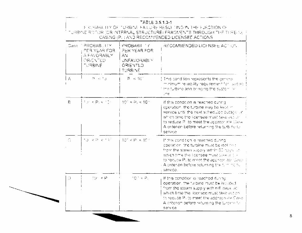
Tt-.B~E 3.5.1.3-1 f-· ,· 1i--:.~.8i: 11 Y Cf '~H.61~•;~ !-.O.lt:0·~~ R~SUi : 1r-.;:; If\ lH~ :-Jr.Cl ION O·
~ ~IR~i'•;C: =:.::_'"'.",:::R OR :~H:=W·.A~ STRJ(:TlJ;;.E: F~AGr.1::'..;~S THROJ.SH ~r;= T:.:~T ·' C/ ... S;:K; ,?. : /\ \ D RECCr•:1\~= i·mEJ LICENSE[ AC""."lOr\S
Cas,~ =ir~C)r3AF3 l I 7V ! f--)~OBABll '. {
B
~r:R Y[A~ FOR .:::i~R YEAR FOF : .• \ F •\'·/O~i\BL Y AN J -JR::\ Tf::Q JNFAVORABL v
I ~,_}~81~✓~ __GO~lt:'\J.TEJ H.JRBI!\,~
___I__ - --- ' - ---~
I :J < .. '. __ ! P < 1 r: · i
' ·~ p' -~ 11;<:.J.<10-
1,~ ' l._.
T"1s :ord tic11 m;m:-scr't:S tre ~;e"C"a ·~j:-imurr ·e 1ab.iily -ec;u rer~·e··,· ':::- J,,:j 11::
t..-.L: • ._.rbir-ie af'lr. ~)r·nG:'~g tre s~ s:c ..... - -1; ·
,: ''!E-
I'. 1h:s condi:1011 Is ·eachec cu~Ir'::J O~J['r3.t1or. n·c tJrtJIne n-,c1y he h,p,;,! I .
service u",ti tre i~ex1 s::r,ed .. :(-C •,::10::i,~,~- -i·
•,,,1hich :ime t1e l,cwist.'G rrus: :d ... v ,·,_>~:· to re::Lce P to ~eet !re 3p~:rcp· .:ii"" '.>,~·-re A criter1or' before ret...n"i~g :h8 turb n•.: L: serv1v: --------- ----------------
1' th,s ccir:j t·c'l 1s -e;;:ichecl d .. '1",;::; ' coera;·or :re :1.,rbine rn_.s: ~e 1s;,1.. .
frc•n tr·e :-le,--HTl :C,,j;jpy ·1,:1t·r G: ·;_·,_.·, ~~~-n ch r:---e tr 1e I c~~'.see r,--·~r:,~ :~-~hi:-.,~ to --oc~1.~Ct.~ P. tc rr·n~~o1t_ the app'"•-~;:·1 ~ .:1,:· 1 __ : •. ~~>
A cr1!e'.on be'cre ,eturn:n~; !"E--! '.. -· ··,:
serv,se. --- - ---------~-------------~-- - ~--·-·
:J 1 C' < P. !f tris concJition Is rcac,...cd rLr1'),~ ope·at;on. ~he tJrt:1m· 1~1us: be is::: .,' ... <1
' 'rorn :he s:earn s.Jpp )' w:th n f •li-.!Vci c-1: ·...-h U-1 ti-ne ,he icensec rn~st tc1ke ,v~ ,.::·-. '_c ~._::cL1•:e ~- :c r1ee'. tt1e d::':'P'O_::.r:.:,·,:, C,1:,,:A ;::•i~er10~ ::iefore 0 e:um ng Irie L,::-n:, ·,_, s.:;~v1ce
8
Turbine Manufacturers in USA
There are relatively few manufacturers that have supplied turbines to the nuclear power plant owners Westinghouse has the most turbines installed followed by General Electric Siemens and Alstom had refurbished lowpressure rotors in several nuclear power plants in USA
\~U.S.NRC Protectiug People and the Environment
9

Turbine Designs employed
In most of US operating plants the shrunk-on disk rotor were initially installed For new plants all DCD applicants except ARIVA have proposed to use an integral forging rotor design ARIVA has proposed to use an unique welded rotor design that Alstom employs in the fabrication of its turbines
Protecting People ,111d the E111-1iro11me11t 10

Shell
l lll Oi1 Supply & Droin I r l
f TC
Generator: Slot RTD's Slot TC'S(?)
l
Gas Temperatures Cooler Temperatures
Steam Turbine Supervisory Instruments System
11

Front Standard
--· ...... •
COMPONENTES
Turning Gear Housing
12

ROTORS • A typical rotor assembly consists of a shaft, wheels,
buckets and couplings which transform the energy of the steam into rotating, mechanical energy.
13
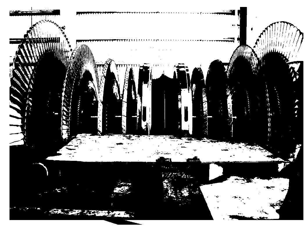
'¢ ..-:,.; .... -- - _ ..
-:.. !

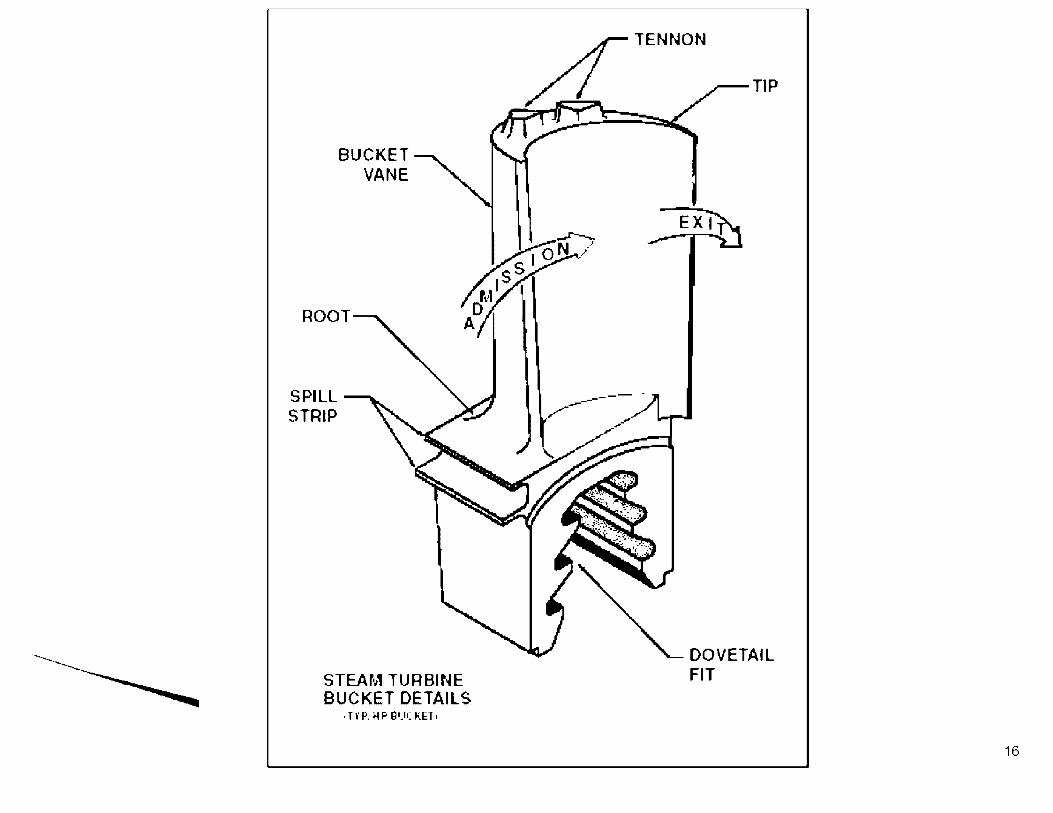
SPILL STRIP
BUCKET VANE
STEAM TURBINE BUCKET DETAILS
,HP. MP Bl.l(KH,
,.,---
TENNON
TIP
-- .
16
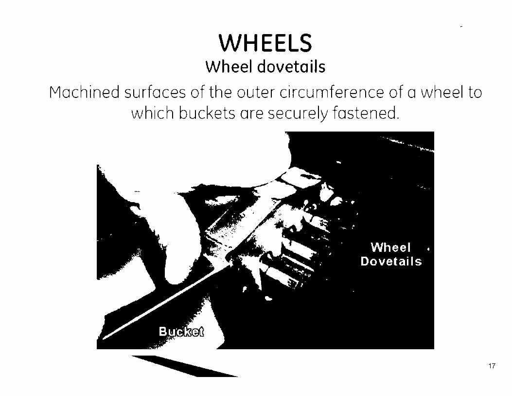
WHEELS Wheel dovetails
Machined surfaces of the outer circumference of a wheel to which buckets are securely fastened.
17

100 mm ( 4 in l
A4t I
Ill STEAM FLOW
SPACER --...+-....;:•~•
KEY WAY
I
' A...,J
~---S HArT
DIAMETER : 19 mm (0. 75 in) CLEARANCE BElWEEN D JSC AND KEY: 0.050 mm (0.002 in)
SECTION A-A
figure 3-1. Schematic drawings of keyway design used by Westinghouse in shrunk-on disks of low-pressure rotors. (Source: EPRI HP-2429-LO, Vol. 6)
18

i_..~ ..
L 5. L6 -~. L? L·8 -.
" I t,
.--- L-3, 1.-~ ---!.·1 .-~,I
·~911 ~-BA
---7R ·---~R. 6R
Flgure 3-2. Schematic draw1ng of Westinghouse Model X-1 lowpressure rotor. All disks are shrunk on and the number of blade rows per disk is as indicated. last-stage blades are 112 cm (44 in.) long. (Source: EPRI NP-2429-LD, Vol. 6)
GO-.'E Rl<O~ El;O
,, .
L•5, A--,. L 7, LS - \
L-~~, ' ·,
-~. 2R J~ -d:_;R--
,--L.,3, L" ~--L-2 -L-~
IOR ~-9~
~~--B" ----6~. JR
Figure 3-3. Schematic drawing of Westinghouse Model X-3 1owpressure rotor. All disks are shrunk on and the "umber of blade rows per disk is as indicated. Last-stage blades are 112 cm (44 in.) long. (Source: EJ>RI NP-2429~LO, Vol. 6} 19

DISC
A ..., I I
I
• A..J
64mm ( 2. 5 in )
SHAFT
STEAM FLOW
LOCKING RING
CLEARANCE AT B : 0.32 mm ( 0.13 in ) CLEARANCE AT C : 0. 79 mm ( 0.03 in )
.38mm(l.5in)
SECTjQN A - A
Figure 3-8. Schematic drawing of keyway design reportedly used by General Electric in shrunk on disks of low-pressure rotors.
20

r. '
11 ! "
I I 7 ~
~OVElitN~'-(\ J
FigurE J-g, Schematic Drawing pressure rotor. All disks are 97 cm (38 in.) long. (Source:
L.•
l ['
,,, L 2 =:
, l ,. " . ~ --~ ,,, I -·~ I.
of General Electric Model Y-3 lowshrunk on. Last-stage blades are
EPR[ NP-2429-LD, Vol. 6) ' ., L,
• 2 • L J ,,.
< 1 \ 6 d L-4 - ~
',. '• ,·
·..J
SR
Figure 3-10. Schematic draw1ng of General Electr1c Model Y-1. Y-2, Y-4 and Y-5 low-pressure rotors. All disks are shrunk on. Model Y-1 last-stage blades are 97 cm (38 in.) long. Last-stage blades of Models Y-2, Y-4 and Y~5 are to9 cm (43 in.) long. (Source: EPRI NP-2429-LC, Vol. 6) 21

Figure3-1 T . yptcal Fully Int . egral Rot C or onstr-u n· con
22
How Ejection of Turbine Missiles Prevented
The ejection of turbine is prevented by following the turbine manufacturer's recommendations specified in the Turbine Maintenance Program The NRC staff requires that the Turbine Maintenance program is submitted to the staff's review within three years after the plant is placed in operation
'~U.S.NRC Protecting People nud the Environment
23

How Ejection of Turbine Missiles Prevented (Cont.)
The turbine maintenance program specifies periodic in-service inspection of turbine subcomponents including rotors The in-service inspection recommendations are based on actual as-build rotor material properties and actual preservice inspection results performed on the rotor prior to shipment to the site
Protecting People and the Euvfronment
24

Information included in the Turbine Maintenance Program
Probabilistic approach to evaluating P1 that includes information on critical crack size, crack growth rate, rotor operating temperature and applied stress used in the evaluation model Numerical approach such as Monte-Carlo simulations and number of iterations required for reliable probability estimate
\~U.S.NRC Protecting People and the Environment
25
Information included in the Turbine Maintenance Program (Cont.)
Results of the preservice non-destructive examinations Rotor material mechanical test results including FATT and Charpy tests results Recommended turbine valve testing intervals Recommended in-service inspection intervals In general every 10 to 1 3 years in-service inspection is recommended for the rotor
\~U.S.NRC Protecting People and the Environment
26
Status of Turbine Missile Generation Issue for New Reactors
The NRC staff had specified that a bounding analysis report exist assessing the probabi I ity of turbine missiles prior to approving COL application, if not the DCD applicant needs to provide an ITAAC requiring that the COL submit to the staff its Turbine Maintenance Program for review and approval prior to fuel load. This process was communicated in two public meetings with the industry and other stake holders \~U.S.NRC
Protecting People and the Environment 27
Status of Turbine Missile Generation Issue for New Reactors
All DCD applicants have provided the NRC staff with bounding analysis reports showing that they can meet the NRC recommended values for P1
The bounding analysis reports also include assessment of various modes of failures such as ductile burst from destructive overspeed, high and low cycle fatigue and failure due to stress corrosion cracking
\~U.S.NRC Protecting People and the Environment
28
Conclusion
Because all DCD applicants have provided bounding analysis reports showing that their turbines will meet the NRC requirements for P1, it can be concluded that the turbine probability issue will not result in open items or otherwise impact the project licensing schedules
\~U.S.NRC Protecting People and the Environment
29

Backup SI ides
Illustrations for Cracks and Examples of evaluation methods
Monte Carlo Variables
30

t:PH.I l.ic('n!>cu \l:Ucri:11
Figure 5-15 Schematic of Yankee Rowe LP rotor; arrows point out failed No.1 disks {8]
~ Balance hole No.
Flame cu1
I
8~in r-· I I 3 7 in
L __ _ lnlel Face
Figure 5-16 Diagram of Yankee Rowe failed generator-end no.1 disk (largest bore crack, 1.94" deep x 1.62" long. is at segments 5/6) [8]


The b.isic cJg,:-crack modd is modifo.:J li..ff us-'. in th1.· \\°c•s,trnghousc an~-11:, -.;is to im:orpuratt .1
nav,: gi:om-:try l;1ctor. Cr. wluch aL'tuums for both tht.: ~ross shape of the tlJ\\ as\\ L'll ;1s th1.· bt.:ncfo.:ial eiT.:cls pf crad, hranl·h111g and 1rr.:,gulantic-. i11 !lit: shape local to the crack tip lhc n.:su lt ing. crack model 1"' g.1 \ ..:n 111 1'.quat llm :::- I b,: low
whcr(;':
a ... ~- l.2lrc Equation 2-1
a.,· 1s the nunimJl (fll11:al crJck -;iz.: ~!Cl'uunting for sh,ipc parartll'k"r or htanching fae10r a.," G-a, 1 ° is a lurgt:r. cfti.:-ct1\c cnt1cal cr~ck si:..-:c that :ndudcs shape paramct1.·r and branching lactur Kit is thL.: mah:riul tm1ghnL·ss a:1d, o is the applil..'d stress

Disks sand !I Th·~,,: ;,.;~ l\"1-Cr-Mt>-\' J1,b, ,11th F.-\TI"
v.ii;rc, ii\ th,: 1:is·:r lo fr7F range IT:1hl1:: :). Thcrc:"l>re for nonna; opcrahon tht·;c Ji,i.~ :ir~ 111 lht· ,1pp~r ~hdf rq,:on Th<.: lo'.lr,wing R,)!f~-.\'1•1·,1k up;:,::r-~i,o:lf rcbtion,h1r was mL·d ! '.i]'
_ ;.: ,'; : . C 1 '\' _ _ f - / =--·"I-·- - 0.(),1j ( 7 l
rr' .•\ :1_1w,·r h(•L:11J K1_ \ ,,b~ c,I I!, I b1 i:nd1 w;b ,·,t;m.u~d L)r the
m:11:mum r:-;iur1c-J C\'N \':Jlue L\f -:'f) :t-lb, :me ~n ,1n:,;1,:!'-' v:,;J ,lrt:n,:th of I IJ: ks: I ,L·~ l;1bk ~ I
34

Inputs for Monte Carlo variables
1. Scale factor for load/stresses (normal distribution) 2. Overspeed level (normal distribution) 3. Rotor startup temperature (normal distribution) 4. Rotor operating temperature (normal distribution) 5. Crack depth (normal distribution) 6. Crack ratio depth/length (normal distribution) 7. Yield strength (normal distribution) 8. Lower bound Fracture (normal distribution) 9. FATT {normal distribution) 10. Fracture Toughness (normal distribution) 11. Crack Initiation time (user-defined) 12. SCC Growth Rate Constant 13. SCC Growth Threshold (normal distribution)
35