App J. - Nuclear Regulatory Commission
208
_ _ . - . - - _ - - - - - . . - - - - - - - - - - - - - - - - - - th; j $' * 1 1 e h. g *< . . ; ,,, , .. * , . . , M anesessissem A A anseer,7.'- [/ / L/ g , ,. Seekst Be. S&WD ?- , Aiugust 5,1NSi ' - [: N' : < | am steestes must lar. . Ilmenger Aneeresse feet - Genestes. -80001 ' See eseper Basleer stasias , ' eastlemens i , ! 13 Cpt feet. St. Appendia J. " Primary Beester *==*=4====* 1ashees : Testies for Basesmesolad Deser se e-o,a ses published Fahrsary 14 | 1973. Sinos emurameneer plante had either seeslood as operating 11eemse er thods aestatemente had seashed advenued stages of desige : ; er essetseatiam et that time, esos plaats ser est meer he de init complisses with the requiqemente of this regulaties. N Yes are regenoted te ,deth if 9ee are condesties eestatement | 1eekage testies is fe&! compliesee eith Appeedia J. This detessinaties N shoold imelade the id@ikesties eF any decise festeves that de not , : py posait asefoemenes with.i regel er esisties teehoiset spesi- ' fiestico seguisement's are is !!st with Mie J. (i.e. 3 Men sagtstative them). - sheeW that shite a sentaissesst lashage' des program he is temee eith & techniset apost= fleet Ser year facil , the any not be la esafeemenen with 2. * . . ' 3 If yee see in Ostl Id identify year plammed . settaus and' to to the mapa ed= Bessible ~3 e est testade modi imme, asememente to she esahoiset spee and for parement es le CBS poet St. = .seties . ., : * e.eneous t o ,es,studens . . esso , ,seeine .es .~ e y a g o ietter. es _ ' - ms. an=s. assess ase. .e ows. sed b, e= =$= a > ' emater >tesses (seges): thee enessenes empisee Jety ' . a ~ ' *4. . d'. ,,, '.i. r . . . . A ets uA A ' e B. Gutler, & h r W esettes Sensesse % ' . .. 3, t***= = = ===== g f - ,, p . , , . d,,,m , , . .- i ' 9512130209 951206 * ANU[ , TE -262_,PDR A u *. ~ 4 . _. -- . _ _ _ . -
-
Upload
khangminh22 -
Category
Documents
-
view
3 -
download
0
Transcript of App J. - Nuclear Regulatory Commission

_ _ . - . - - _ - - - - - . . - - - - - - - - - - - - - - - - - -
th;j $'*
11
e h. g *<.. ; ,,,, ..
*, . .
,
M anesessissem A A anseer,7.'- [/ / L/ g , ,.Seekst Be. S&WD ?- ,
Aiugust 5,1NSi '-
[: N' : < |am steestesmust lar. . Ilmenger
Aneeressefeet -
Genestes. -80001 '
See eseper Basleer stasias,
'
eastlemensi ,
!13 Cpt feet. St. Appendia J. " Primary Beester *==*=4====* 1ashees: Testies for Basesmesolad Deser se e-o,a ses published Fahrsary 14| 1973. Sinos emurameneer plante had either seeslood as operating
11eemse er thods aestatemente had seashed advenued stages of desige:
; er essetseatiam et that time, esos plaats ser est meer he de initcomplisses with the requiqemente of this regulaties.
N Yes are regenoted te ,deth if 9ee are condesties eestatement| 1eekage testies is fe&! compliesee eith Appeedia J. This detessinatiesN shoold imelade the id@ikesties eF any decise festeves that de not,
: py posait asefoemenes with.i regel er esisties teehoiset spesi-'
fiestico seguisement's are is !!st with Mie J. (i.e.3 Men sagtstative them). - sheeW that shite a sentaissesst
lashage' des program he is temee eith & techniset apost=fleet Ser year facil , the any not be la esafeemenenwith 2. *
. .
'
3 If yee see in Ostl Id identify year plammed.
settaus and' to to the mapa ed= Bessible~3 e est testade modi imme, asememente to she esahoiset
spee and for parement es le CBS poet St.= .seties . .,
: *e.eneous t o ,es,studens . . esso , ,seeine .es .~e y a g o ietter.es
_'-ms. an=s. assess ase. .e ows. sed b, e= =$= a>
'
emater >tesses (seges): thee enessenes empiseeJety '
.
a ~ ' *4. . d'. ,,,'.i. r. . . .
A ets
uA A '
e
B. Gutler, &h r W esettes Sensesse %
'.
..
3, t***= = = ===== g f-
,,
p., ,.
d,,,m , , .
.-
i '
9512130209 951206 *
ANU[,
TE -262_,PDR A u *. ~4
. _. -- . _ _ _ . -
., __
4' ,
e
M"* e **L,,.. '
, , ,,_ . ,,..
.
IIshpasha M elas M ust M 88r488 3- August 5,SMS. '
.
cc w/csslesuresGame Notase AttesesFserlaw, Estase.4 JetmeenF. O. Best 816Liasets, IIsbesehm 4W08
Ifr. Arthur C. Gehr Attesoursmell 4 M inor400 SecurityPhoemds Arisses
~
Anthsay1 metamas, 5sgstretertie, Notaman and Esoster1712 N Street, N. W.o
.g m eteress, D. C. 20N6
N Auburn Pinblic Librarylits - 15th Street
29 Auburn, Nebraska 68308O
.
*3
1J9
%-
.-e
.
O
.
*
.
eo
p e' g e, *
,. * -. 4. * - *
| /
_
..
. h. f| ,. . . . A*
.. , .
. .
,
;g amesessesent om a..sesser_. [L/_L/ g ,.
'-,
asehet so. SPSSSF . Angset 5,1978'<
..
$ |menseh r- g: < wateses>
4 -
.-
ATER Mr. J4 3r . Messeramourense
feet Mdelense, SN81
as Geoper testeer statiesGestimmons i10 CPR Pest St. Appeedia J " Primary Beester ==*=d====e taskage Ir
testing for Beeso=4 soled Power Beesters," wee published Febroery 14,1973. Sinos emey nestear plaats had either seesived an operatingliessee er their sentaiseemse had reached advanced stages of deoiseer seestrustias at that ties, some plaats eey set ese he le feltcomplisses with the requi emoets of this regulaties.t
M You are regneated to .dethine if p are condussing caetatementteskaps testies in full compliases with Appeedia J. This determinatiesN obeeld isolede the idekiRestion et any desige features that de not
py permit confessenes with .i requiregets er esisties teaksles! spesi-fisatias seguirenset's are is ameflict with W im J. (i.e.
::3 Idee restriative them). obeeld ret M that chile a testaieneet1sahege' ing progras be is isse< Lth sne seeksiset epost-fiest for your facili , the u.c et be le eenforesseede J.
, g
o If yes are is full 14 identify peer plassed,
settees and' te - to the engesmed==. Seasible-- '
".7 e set imelade sedi ione, assedmonts to the seeksiestspesif amt far perseems to le CPR part Se,M Seetles . .,,
the seestas b stem es as sees gs possible betF== es M days ist of g letter.
h geestie $ssateesias see spressed by em seder amember > 14es S (seers): ein stoessman empires
July '.
. *%y, -L , g'<'
neeenety,~~..
'% r,."*
.s
n.
B. Galler. AsetIsot Stree.
sur speesting acessere N .
.,: -
* atuenses se eneseer usemeias J'
7)7a..
. , -.. P s
4 , 4,,
Appendia J '
9512130209 951206 *
PDR FOIAPATTERS 95-262 PDR af/p/1f .*-
_
_ .
metensks Mih&&S Dimer S$8Sflat 3* August 5, 1975-
.
cc w/ enclosure:Gene Instsee, Attessorgeriew, m 4 JehusesP. O. Sus 816Lissola, IIntueeks 4W88
Ber. Arttuur C. Gehr, Atteenersnell 4 W11merdet SecurityPhoemas, Arisons
~
Anthoey 1. noisman, 5sgdreaselis, Asisema and Rossier1712 N Street, N. W.
3 M iagten. D. C. M
N Asturn Public Library1118 - 15th StreetM Auburn, Nebraska 68305
O
.
'J
tn
N
= *
.,
e
e
.
e
5.
.
e
-
. _ _ . .
_.. _ _ ._ _ _ _ . . __ . _ _ _ _ _ _ _ _ _ _ .__..~.._. _ . _ _ . _ _ _ _ _ . . _ _ _ _ _ _ _ -
p^ .
;. .
ie
-:
.i!
t4
i 6-8
!-
j ' We conclude that design of the primary centsin=nt system vill'
1
permit the conduct of a contain=nt Isakage testing program in11
compliance with the requirements set forth in proposed Appandiv J;
;
to 10 CPR Part 50, "Reacter Containment laakage Testing for Water
Cooled Power Reactors" (36 Ted. Reg.17053, Aug. 27,1971).
6.2.4 Atmosohere Control.
As an operational technique to preclude flammable gas concentra-
tions, the primary containment will be operated with an inert nitroge.
acaosphere. The system will maintain the oxygen content of the
containment atmosphere below 4 volume percent and we find it acceptah ;g
Following a loss-of-coolant accident (IDCA), (a) hyerogen gas-
,
- "could be generated inside the primary contain==nt from a cheatcal
1
reaction between the fuel rod cladding and steam (metal-water!
reaction), and (b) both hydrogen and oxygen would be generated as a;-t
. result of radiolytic decomposition of recirculating water. If a,
g sufficient amount of the hydrogen is generated and oxygen is avail-
N able in stoichiometric quantities, the subsequent reaction ofQ hydrogen with oxygen can occur at rates rapid enough to lead to a
significant pressure increase in the containment. This could cause
damage to the contain= ant and could lead to failure of the contascaec
to maintain low laakage integrity.
General Design Criterion 41 of Appendix A to 10 CFR Part 10
requires that systems to control hydrogen, oxygen and other sues:ance
W . . - - ..- - - - - - - - - - - - - - ~^~~ ^ ~ ~ ~~~ ' ^~ ~ ~^^~
] 4- Q (N:- ,..
-
.
COOPER NUCLEAR STATIONBACKUP DATAENFORCEMENT SUMMARY
SALP CYCLE 012
APRIL 25,1993THROUGH
OCTOBER 22,1994
Updated
September 12,1994
information in this record was deletedin acccidance with the Freedom of Informah,e,,'-naa_s_v_, m, - _.____ _ _ _ _ _ k d}
_____
a marweasaunAct, exemptions # " 5 I'E' EUE ~'
F01A. f/-24 2- h >
. .
. - - . .. . . . - _ -- - .-
4
. . .
,
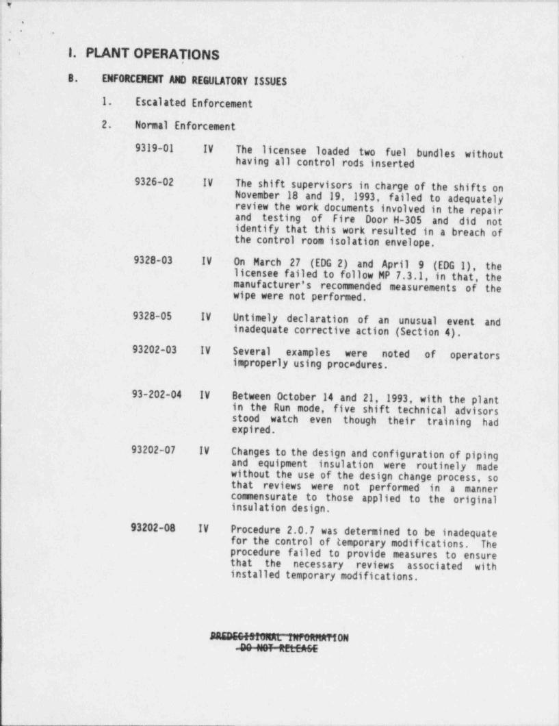
1. PLANT OPERATIONS.
.
8. ENFORCEMENT Alm REGULATORY ISSUES '.
1. Escalated Enforcement
32. Normal Enforcement
9319-01 IV The licensee loaded two fuel bundles without '
having all control rods inserted,
9326-02 IV The shift supervisors in charge of the shifts onNovember 18 and 19, 1993, failed to adequatelyreview the work documents involved in the repair
.'
and testing of Fire Door H-305 and did not. identify that this work resulted in a breach of1
the control room isolation envelope.
9328-03 IV On March 27 (EDG 2) and April 9 (EDG 1), thelicensee failed to follow MP 7.3.1, in that, the
imanufacturer's recommended measurements of the !
.
'
wipe were not performed. |
9328-05 IV Untimely declaration of an unusual event andinadequate corrective action (Section 4)..
93202-03 IV Several examples were noted of operatorsimproperly using procedures. '
4
93-202-04 IV Between October 14 and 21, 1993, with the plantin the Run mode, five shift technical advisorsstood watch even though their training had !expired. '
93202-07 IV Changes to the design and configuration of pipingand equipment insulation were routinely madewithout the use of the design change process, sothat reviews were not performed in a mannercommensurate to those applied to the original |
,
insulation design.
93202-08 IV Procedure 2.0.7 was determined to be inadequatefor the control of temporary modifications. Theprocedure failed to provide measures to ensurethat the necessary reviews associated withinstalled temporary modifications.
MON-4NH10HtttfAGE
- ,. .-. . . . - _ - . - -_ .. . . . . _ . . . - .
.
.' '
.
3. ,
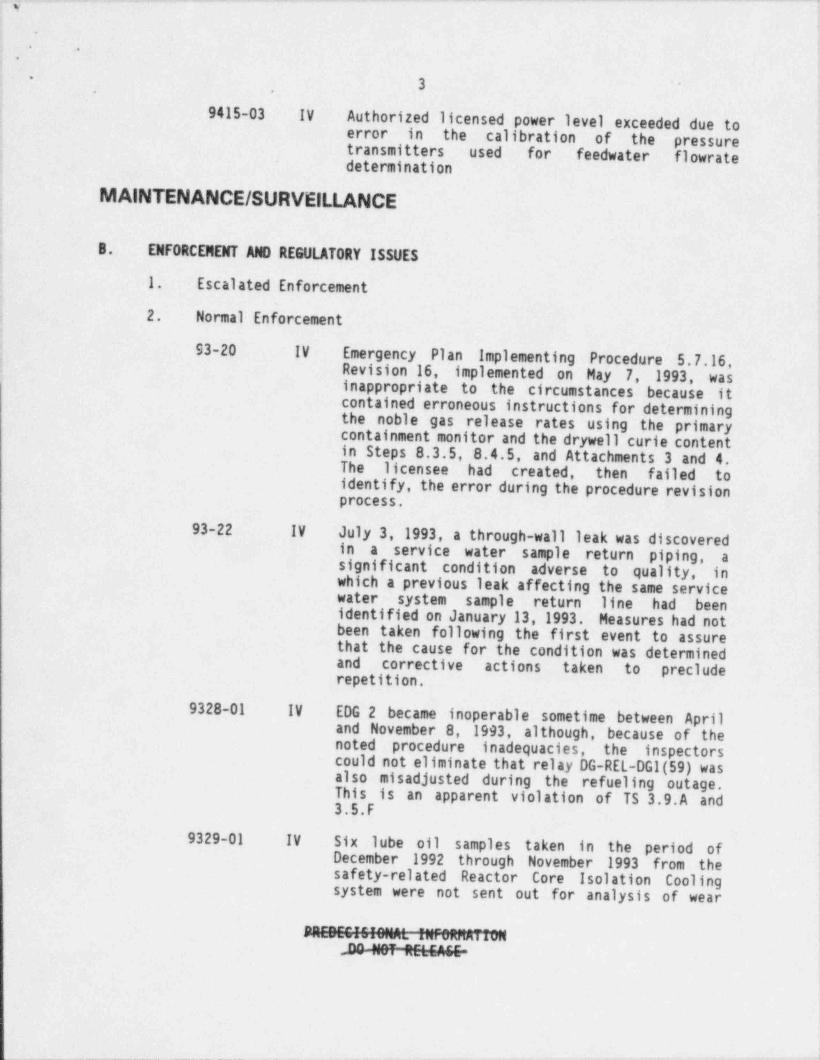
: 9415-03 IV Authorized licensed power level exceeded due toerror in the calibration of the pressure'
transmitters used for feedwater flowrate, determination,
MAINTENANCE / SURVEILLANCE<
8. ENFORCEMENT AND REGULATORY ISSUES,
1. Escalated Enforcement
2. Normal Enforcement
93-20 IV Emergency Plan Implementing Procedure 5.7.16, IRevision 16, implemented on May 7, 1993, wasinappropriate to the circumstances because itcontained erroneous instructions for determiningthe noble gas release rates using the primarycontainment monitor and the drywell curie contentin Steps 8.3.5, 8.4.5, and Attachments 3 and 4.The licensee had created, then failed toidentify, the error during the procedure revisionprocess.
93-22 IV July 3, 1993, a through-wall leak was discoveredin a service water sample return piping, asignificant condition adverse to quality, inwhich a previous leak affecting the same servicewater system sample return line had beenidentified on January 13, 1993. Measures had notbeen taken following the first event to assurethat the cause for the condition was determined
,
and corrective actions taken to preclude !repetition.;
9328-01 IV EDG 2 became inoperable sometime between April,
and November 8, 1993, although, because of thenoted procedure inadequacies, the inspectorscould not eliminate that relay DG-REL-DGl(59) wasalso misadjusted during the refueling outage.This is an apparent violation of TS 3.9.A and3.5.F
9329-01 IV Six lube oil samples taken in the period ofDecember 1992 through November 1993 from thesafety-related Reactor Core Isolation Coolingsystem were not sent out for analysis of wear
""i"00:0:00L I%TeTemiiimDa "07 Z LC."IE-
_ _ _ _ - - _ _ _ - _ _ _ _ - - - _ _ _ _ _ _ _ _
- - . - . . . . . - . . _ . . . . .. .,
: .,
4..
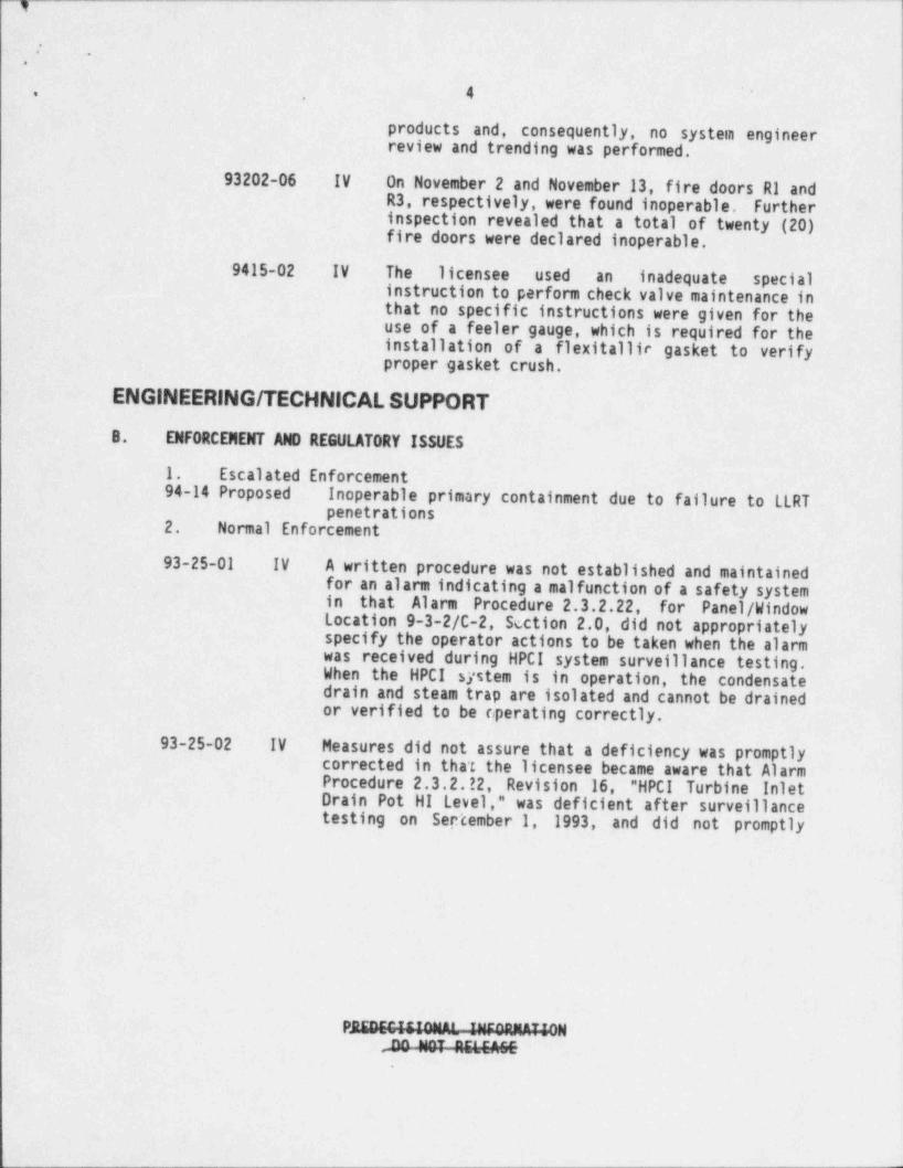
products and, consequently, no system engineerreview and trending was performed.
93202-06 IV On November 2 and November 13, fire doors R1 andR3, respectively, were found inoperable, Furtherinspection revealed that a total of twenty (20)fire doors were declared inoperable,
9415-02 IV The licensee used an inadequate specialinstruction to perform check valve maintenance inthat no specific instructions were given for theuse of a feeler gauge, which is required for theinstallation of a flexitallic gasket to verifyproper gasket crush.
ENGINEERING / TECHNICAL SUPPORT
B. ENFORCENENT A W REGULATORY ISSUES
1. Escalated Enforcement94-14 Proposed Inoperable primary containment due to failure to LLRT
penetrations2. Normal Enforcement
93-25-01 IV A written procedure was not established and maintainedfor an alarm indicating a malfunction of a safety systemin that Alarm Procedure 2.3.2.22, for Panel / WindowLocation 9-3-2/C-2, Section 2.0, did not appropriatelyspecify the operator actions to be taken when the alarmwas received during HPCI system surveillance testing.When the HPCI system is in operation, the condensatedrain and steam trap are isolated and cannot be drainedor verified to be operating correctly.
93-25-02 IV Measures did not assure that a deficiency was promptlycorrected in that the licensee became aware that AlarmProcedure 2.3.2. !2, Revision 16, "HPCI Turbine InletDrain Pot HI Level," was deficient after surveillancetesting on Sep'cember 1, 1993, and did not promptly
PAEDEEMONAL-4NEGANAMONE *2T ?.5LE"."
]
_ . . _ . . . . _ ~ _ _ _ _ . -_ . - . _ _ _ . _ _ _ _ __ _. _ .
1.
. .
,
5.
'
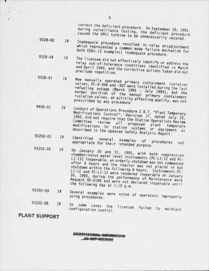
correct the deficient procedure. On Septemberduring surveillance testing, the deficient procedure29, 1993,
caused the HPCI turbine to be unnecessarily secured.'
I
9328-02 IVInadequate procedure resulted in relay misadjustmentwhich represented a common mode failure mechanism forboth EDGs.(2 examples) inadequate procedure.
' 9328-04 IV
relay out-of-tolerance conditions identified in MarchThe licensee did not effectively identify or address theand April 1993, and the corrective actions taken did not
,
preclude repetition.9328-01 IV
New manually operated primary containment
refueling outage - (March 1993 - July 1993), valves, PC-V-506 and -507 were installed during the lastisolation
normal position of the manual primary containmentbut theisolation valves, an activity affecting quality, was notprescribed by.any procedure
9406-01 IVConduct of Operations Procedure 2.0.7, " Plant TemporaryModifications Control", * Revision 17, dated July 22,|
1993, did not require that the Station Operations Review!
Committee review all proposed plant temporarymodifications to station systems or equipment asdescribed in the Updated Safety Analysis Report.
;
93202-01 IV Identified several examples ofappropriate for their intended purpose. procedures
1
not
93202-02 IV On January 30 and 31, 1993,chamber / torus water level instrumentswith both suppressionLI-13) inoperable, an orderly shutdown w(PC-LI-12 and PC-
shutdown within the following 6 hours.after 6 hours and the reactor was not placed in hotas not commenced
Instruments PC-LI-12 and PC-LI-13 were rendered inoperable on January30, 1993,during the performance of Maintenance WorkRequest 92-0185
the following day at 1:19 p.m.and were not declared inoperable until93202-03 IV
Several examples were noted of operators improperlyusing procedures.
93202-05 IV In some cases the licensee failed to maintainconfiguration control.
PLANT SUPPORT l
'
| .
E IE - ._"_ . [[.[.NN- - - . . _
:__. __-
J
--- - . -. . . . .-. -. . .- - - _ . -
,
.
.. .
, ,
6'
,.
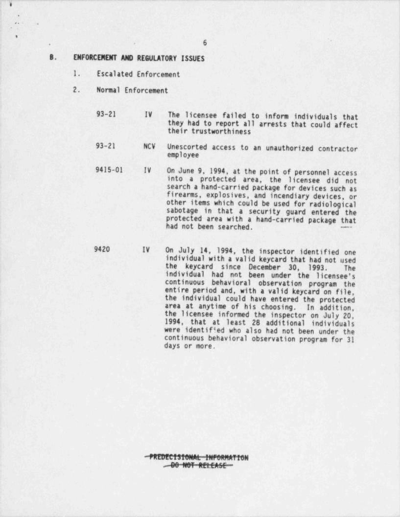
8. ENFORCENENT AND REGULATORY ISSUES
1. Escalated Enforcement ,
2. Normal Enforcement
93-21 IV The licensee failed to inform individuals thatthey had to report all arrests that could affecttheir trustworthiness
,
93-21 NCV Unescorted access to an unauthorized contractor'
employee
9415-01 IV On June 9,1994, at the point of personnel accessinto a protected area, the licensee did notsearch a hand-carried package for devices such as
1
firearms, explosives, and incendiary devices, or !other items which could be used for radiological
isabotage in that a security guard entered the !protected area with a hand-carried package that
|had not been searched.;
9420 IV On July 14, 1994, the inspector identified oneindividual with a valid keycard that had not usedthe keycard since December 30, 1993. Theindividual had not been under the licensee'scontinuous behavioral observation program the {entire period and, with a valid keycard on file, i
the individual could have entered the protected Iarea at anytime of his choosing. In addition,. !the licensee informed the inspector on July 20,!1994, that at least 28 additional individuals '
were identified who also had not been under thecontinuous behavioral observation program for 31days or more.
l
-N% ;;;T Z;.;ZC
_- -
_ _ _ _ _ _ - _ _ _ _ _ _ _ - .
.
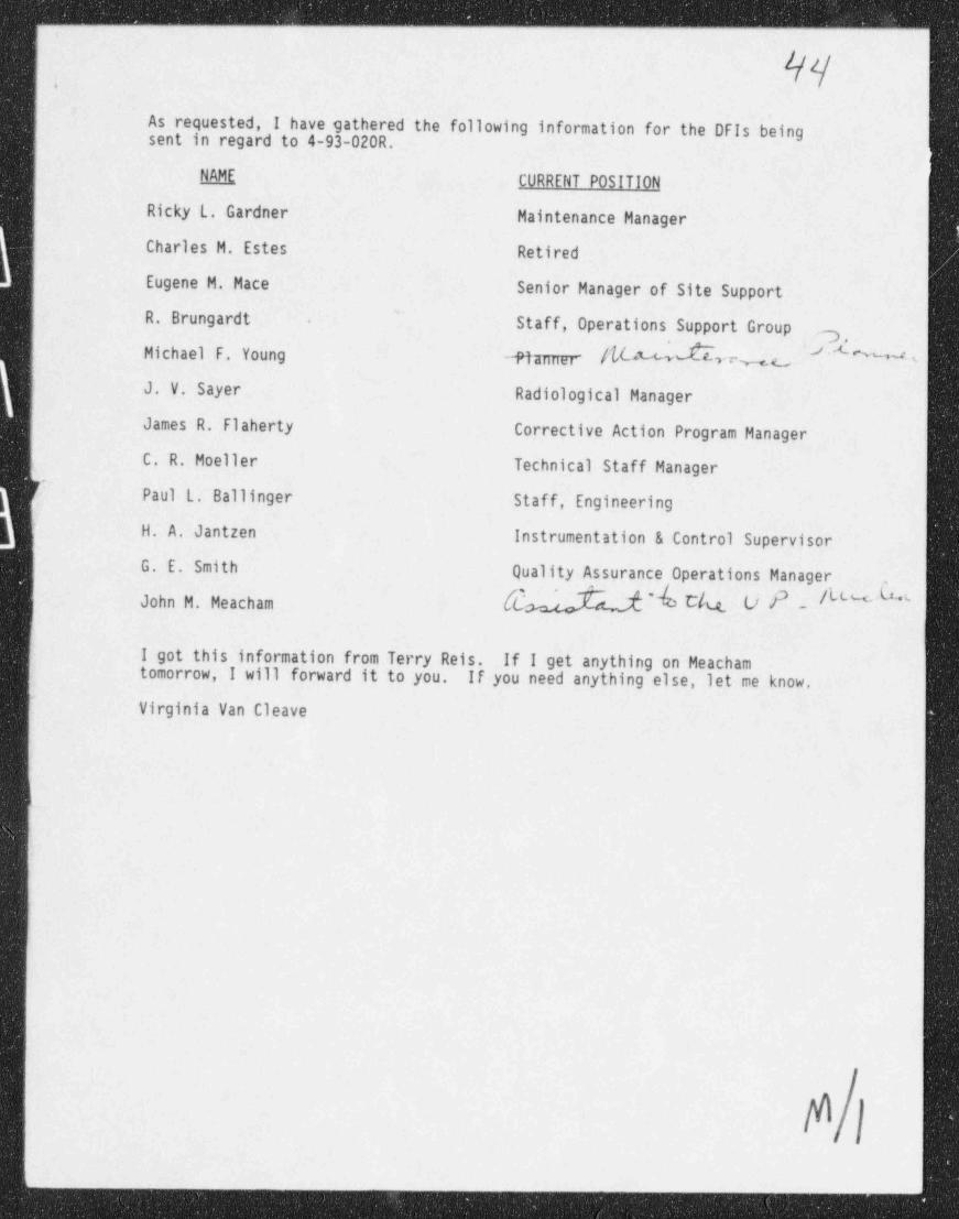
As requested, I have gathered the following information for the DFIs beingsent in regard to 4-93-020R.
RAME CURRENT POSITION,
Ricky L. Gardner Maintenance Manager
Charles M. Estes Retired
Eugene M. Hace Senior Manager of Site Support
R. Brungardt Staff, Operations Support Group-
.7Michael F. Young -Plamer /b v % c.- '
J. V. Sayer Radiological Manager
James R. Flaherty Corrective Action Program Manager
C. R. Moeller Technical Staff Managerf Paul L. Ballinger Staff, Engineering
H. A. Jantzen Instrumentation & Control Supervisor
G. E. Smith Quality Assurance Operations Manager,
John M. Meacham [d 'b C/q. OPO " ' '
I got this information from Terry Reis. If I get anything on Meachamtomorrow, I will forward it to you. If you need anything else, let me know.
Virginia Van Cleave
i
_ ___ ,
.- _ _ _ _ _ _ _ - _ _ _
-..
|4'Ks'
LMITING CONDITIONS FOR OPERATIONSl'RVETI T ANcr RFOUTRPMFMT(
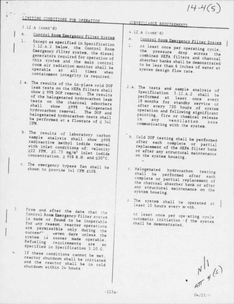
3.12.A (cont'd)*
4.12.A (cont'd)|iA. Control Room F=rrency Filter System |A.
Except as specified in Specification Control Room Emerzenev Filter System |1.1. At least3.12.A 3 below,' the Control Room once per operating cycle,
iEmergency filter system, the diesel the pressure drop across the i
generators required for operation of combined HEPA filters and charcoalthis system and the main control absorber banks shall be demonstratedroom air radiation monitor shall be to be less than 6 inches of water atoperable at all times when system design flow race,containment integrity is required.
2.a. The results of the in-place cold DOPleak tests on the HEPA filters shall 2.a. The tests and sample analysis ofi
show 2 99% DOP removal. The resultsSpecification 3.12.A.2 shall be
of the halogenated hydrocarbon leak performed at least once every18 months for standby service ortests on the charcoal adsorbersj shall show 299% halogenated after every 720 hours of system! hydrocarbon removal. The DOP and operation and following significant
halogenated hydrocarbon tests shall painting, fire or chemical releasebe performed at a flowrate of s 341 in any ventilation zoneCFM. communicating with the system.
b. The results of laboratory carbon 'b. Cold DOP testing shall be performedsample analysis shall show 299%!after each complete or partialradioactive methyl iodide removal
with inlet conditions of: velocity replacement of the HEPA filter bank222 FPM, 21. 75 mg/m inlet iodide or after any structural maintenance3
concentration, 2 95% R.H. and $30'C. on the system housing.~
c. The emergency bypass fan shall be !
shown to provide 341 CFM 110%. c. Halogenated hydrocarbon testingshall be performed after eachcomplete or partial replacement ofthe charcoal absorber bank or afterany structural maintenance on thesystem housing.
J. The system shall be operated atleast 10 hours every w nth.
3.From and after the date that theControl Room Emergency Filter system At least once per ope rating cycleis made or found to be inoperable automatic initiation ef the systemfor any reason. reactor operations shall be demonstrated,are permissible only during thesucceeF e, seven days unless thesystem is sooner made operable.Refueling requirements are asspecified in Specification 3.10.G.
4 If these conditions cannot be met,reactor shutdown shall be initiatedand the reactor shall be in coldshutdown within 24 hours.
|d
p215a.
04/23/9!
. _ - - - - -~ . .. -- . - . - . .
,
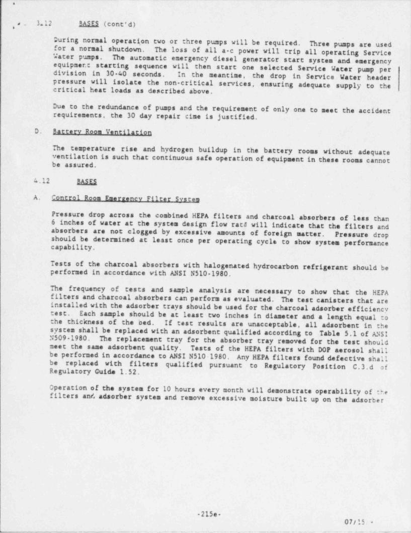
3.12 BASES (cont'd),.,
During normal operati,on two or three pumps will be required. Three pumps are usedfor a normal shutdown. The loss of all a-c power will trip all operating Service
{'Jater pumps. The automatic emergency diesel generator start system and emergency{equipmer.t starting sequence will then start one selected Service Water pump per
division in 30-40 seconds. In the meantime, the drop in Service Water header )pressure will isolate the non-critical services, . ensuring adequate supply to thecritical heat loads as described above.
)
Due to the redundance of pumps and the requirement of only one to meet the accidentrequirements, the 30 day repair cime is justified.
D. Battery Room Ventilation
IThe temperature rise and hydrogen buildup in the battery rooms without adequateventilation is such that continuous safe operation of equipment in these rooms cannotbe assured.
4.12 BASES
A. Control Room Emerrency Filter System
Pressure drop across the combined HEPA filters and charcoal absorbers of less than6 inches of water at the system design flow rate will indicate that the filters andabsorbers are not clogged by excessive amounts of foreign matter. Pressure dropshould be determined at least once per operating cycle to show system performancecapability.
Tests of the charcoal absorbers with halogenated hydrocarbon refrigerant should beperformed in accordance with ANSI N510-1980.
The frequency of. tests and sample analysis are necessary to show that the HEPA jfilters and charcoal absorbers can perform as evaluated. The test canisters that areinstalled with the adsorber trays should be used for the charcoal adsorber efficiency
Each sample should be at least two inches in diameter and a length equal totest.
the thickness of the bed. If test results are unacceptable, all adsorbent in thei
system shall be replaced with an adsorbent qualified according to Table 5.1 of ANSI !N509-1980. The replacement tray for the absorber tray removed for the test shouldmeet the same adsorbent quality. Tests of the HEPA filters with DOP aerosol shallbe performed in accordance to ANSI N510-1980. Any HEPA filters found defective shallbe replaced with filters qualified pursuant to Regulatory Position C.3.d ofRegulatory Guida 1.52.
Operation of the system for 10 hours every month will demonstrate operability of :hefilters and adsorber system and remove excessive moisture built up on the adsorber
-215e-07/15.-
, . . - - - -. - - . . . - -
.
4
,,
,. .
.12 BASES (cont'd), *
If significant painting, fire or chemical release occurs such that the HEPA filteror charcoal adsorber could become contaminated from the fumes, chemicals or foreignmaterial, the same tests and sample analysis shall be performed as required foroperational use. The determination of significance shall be made by the operator onduty at the time of the incident. Knowledgeable staff members should be consultedprior to making this determination.
Demonstration of the automatic initiation capability is necessary to assure systemperformance capability.
B. Reactor Eauinment Coolina Svstem
Normal plant operation requires one heat exchanger and three pumps. Therefore,normal equipment rotation will demonstrate pump operability.
Pump rates will be demonstrated every three months as an indication of the pumpcondition.
C. Service Water System
The Service W4:er pumps shall be proven operable by their use during normal stationoperations. Since three pumps are continuously operating during normal operation andonly one pump is required during accidents, phe normal equipment rotation shall provethe pump operability.
Pump discharge head tests will be run every three months to verify the pumpingability.
Any silting problems caused by the Service Water system will be analyzed during and ffollowing the Preoperational Test Program. Any required changes in operatingprocedures, technical specifications or surveillance requirements will be made priorto CNC commercial operation.
D. Batterv Room Ventilation
The ventilation fans will be rotated on a weekly basis to demonstrate operability.
.
-215f. 04/23/ 6-
..4
i* -
.
III.D.3.4 CONTROL-ROOM HABITABILITY REQUIREMENTS |
|; Position;
}In accordance with Task Action Plan item III.D.3.4 and control room habitability,!licensees shall assure that control room operators will be adequately protected '
,
against the. effects of accidental release of toxic and radioactive gases and;
that the nuclear power plant can be safely operated or shut down under design;
! basis accident conditions (Criterion 19, " Control Room," of Appendix A " General{ Design Criteria for Nuclear Power Plants," to 10 CFR Part 50).! Chances to Previous Requirements and Guidance4
There are no changes to the previous requirements.
Clarification!
(1) All licensees must make a submittal to the NRC regardless of whether ornot they met the criteria of the referenced Standard Review Plans (SRP)
isections. The new clarification specifies that licensees that meet the l
criteria of the SRPs should provide the basis for their conclusion thatSRP 6.4 requirements are met. Licensees may establish this basis byreferencing past submittals to the NRC and/or providing new or additionalinformation to supplement past submittals.
(2) All licensees with control rooms that meet the criteria of the following,
!sections of the Standard Review Plan: !
2.2.1-2.2.2 Identification of Potential Hazards in Site Vicinity,2.2.3 Evaluation of Potential Accidents,
6.4 Habitability Systems!
shall report their findings regarding the specific SRP sections as explainedbelow. The following documents should be used for guidance:
(a) Regulatory Guide 1.78, " Assumptions for Evaluating the Habitabilityof Regulatory Power Plant Control Room During a Postulated HazardousChemical Release";
(b) Regulatory Guide 1.95, " Protection of Nuclear Power Plant ControlRoom Operators Against an Accident Chlorine Release"; and,
(c) K. G. Murphy and K. M. Campe, " Nuclear Power Plant Control RoomVentilation System Design for Meeting General Design Criterion 19,"13th AEC Air Cleaning Conference, August 1974.
Licensees shall submit the results of their findings as well as the basisfor those findings by January 1, 1981. In providing the basis for thehabitability finding, licensees may reference their past submittals.Licensees should, however, ensure that these submittals ref. lect thecurrent facility design and that the information requested in Attachment 1is provided.
.
III.O.3.4-1 3-197
_ _ _ _ _ _ . _ ._ _ _ _ _ - _ _ _ _
_ _ __ _. _ _ ___ _ _ _ _ _ ____ _ _ ______ _____ _ _ _
,
i
. .,
(3)All licensees with control rooms that do not meet the criteria of theabove-11sted refe'rences, Standard Review Plans, Regulatory Guides, and
-
other references.
These licensees shall perform the necessary evaluations and identify appropriatemodifications.
i
Each licensee submittal shall include the results of the analyses of control i
room concentrations from postulated accidental release of toxic gases andcontrol room operator radiation exposures from airborne radioactive material
'
;
and direct radiation resulting from design-basis accidents.accident anngsis should be performed for all potential hazardous chemicalThe toxic gasreleases occurring either on the site or within 5 miles of the plant-siteboundary.
in the evaluation of control room habitability but is not all inclusiveRegulatory Guide 1.78 lists the chemicals most commonly encountered.
coolant accident LOCA containment leakage and engineered safety feature (ESF)The design-basis-accident (DBA) radiation source term should be for the loss of-
leakage contribution outside containment as described in' Appendix A and 8 ofStandard Review Plan Chapter 15.6.5.
facility evaluations should add any leakage from the main steam isolationIn addition, boiling-water reactor (BWR)valves (MSIV) (f. e.,valve stem leakage, valve seat leakage, main steam !
isolation valve leakage control system release) to the containment leakage andESF leakage following a LOCA.This should not be construed as altering the
'
staff recommendations in Section D of Regulatory Guide 1.96 (Rev. 2) regardingMSIV leakage-control systems.Other DBAs should be reviewed to determinewhether they might constitute a more severe control-room hazard than th
e LOCA.
possible need for control room modifications or provide assurance that theIn addition to the accident-analysis results, which should either identify thehabitability systems will operate under all postulated conditions to pe
i
actions required by General Design Criterion 19, the licensee should submitthe control-room operators to remain in the control room to take approp i t'
rmitrae
sufficient information needed for an independent evaluation of the adequacy ofthe habitability systems. )provided along with the licensee's evaluation. Attachment 1 lists the information that should be;
Applicability 1
This requirement applies to all operating reactors and operating Ifeenseapplicants.1
Implementationi
,
Licensees shall submit their responses to this request on or before Janu1981.issuance of a full power license. Applicants for operating licenses shall submit their responses prior toary 1,
Modifications needed for compliance withthe control-room habitability requirements specified in this letter sho ld bidentified, and a schedule for completion of the modifications should beu e !provided.
Implementation of such modifications should be started withoutawaiting the results of the staff review.any, identified by the staff during its review will be specified to IfeenseesAdditional needed modifications, if
3-198III.D.3.4-2 1
.
Oh eet-
- -. . . - . - - . . . - . .. . . - _ . - . . . .- .
T.
,i . .
.
Type of Review.
1,
|A postimplementation review will be performed.-
;
Documentation Required 1
1
jBy January 1,1981 licensees shall provide the information described in I
Attachment 1.prior to full power licensing. Applicants for an operating license shall submit their responses
;'
Technical Specification Chances Required
Changes to technical specifications will be required..
; References
NUREG-0660, Item III.D.3.4.i
|-Letter from D. G. Eisenhut, NRC, to All Operating Reactor Licensees, datedMay 7, 1980.
i
?
Il
i
| 111.0.3.4-3 3-199|
- _ _ _ _ _ _ _ _ _ _ _ _ _
,
w pay i
.- -
.
Stancard Review Plan - 6.4 - CONT 30L ROOM HABITABILITY SYSTEM
U.S. NUCLEAR REGULATORY COMMISSIONSTANDARD REVIEW PLAN
OFFICE OF NUCLEAR REACTOR REGULATION
NUREG-0800(rormerly NUREG-75/087)
,
6.4 CONTROL ROOM HABITABILITY SYSTEM
KcVIEW RESPONSIBILITIES.
Primcry - Accident Evaluation Braach ( AEB).
Secondary - Effluent Treatment Systems Branch (ETSB)Siting Analysis Branch (SAB)
I. AREAS OF REVIEW
The control room ventilation system and control building layout andstructures, as described in the applicant's safety analysis report (SAR) arereviewed with the objective of assuring that plant operators are adequatelyprotected against the effects of accidental releases of toxic and radioactivegases. A further objective is to assure that the control room can bemaintained as the backup center from which technical support center personnelcan safely operate in the case of an accident. To assure that these objectivesare accomplished the followirg items are reviewed:
1. The zone serviced by the contr: room emergency ventilation system isexamined to ascertain that all cr4 tical areas requiring access in the event ofan accident are included witnin t e zone (control room, kitchen, sanitaryfacilities, etc.) and to assure t at those areas not requiring' access aregenerally excluded from the zone.
s
2. The capacity of the control re:m in terms of the number of people it canaccommodate for an extended :eriec of time is reviewed to confirm the adequacyof seif-contained breathing apparetus aad to determine the length of time thecontrol room can be iscicted befc e C0(2) levels become excessive.
3. The control room ventilation s stem layout and functional design isreviewed to determine flow rates !ad filter efficiencies for input into theanalyses of the buildup of aaaf oac-ive or toxic gases inside the control room,assuming a design basis release. Basic deficiencies that might impair the
RECALL Database
Stancard Review Dlan - 6.4 - CODTROL ROOM HABITABILITY SYSTEM
U.S. NUCLEAR REGULATOR) COMMISSIONSTANDARD REVIEW PLAN
OFFICE OF NUCLEAR REACTOR REGULATION
_ _ - _ _ - _ _ - _ _ _ _
.___________-__- - - - '~
.
. .,
* DREG-0800(Former'j NUREG-75/087)-
6.4 CONTROL ROOM HABITABILITY SYSTEM
REVIEW RESPONSIBILITIES
Primary - Accident Evaluation Bran:'
9 (AEB)
Secondary - Effluent Treatment Systems Branch (ETSB)Siting Analysis Branch (SAB)
1. AREAS OF REVIEW
The control room ventilation system and control building layout andstructures, as described in the ap:iicant's safety analysis report (SAR), arereviewed with the objective of assseing that plant operators are adequatelyprotected against the effects of ac:idental releases of toxic and radioactivegases. A
further objective is to atture that the control room can be,
maintained as the backup center fr:m'which technical support center personnelcan safely operate in the case of teare accomplished the following ite*s are reviewed: accident. To assure that these objectives
1. The zone serviced by the contro; acom emergency ventilation system isexamined to ascertain that all cri ' al areas requiring access in the event offacilities, etc.)an accident are included within the zone (control room, kitchen, sanitarygenerally excluded from the zone.and to assure the; those areas not requiring access are
2. The capacity of the control roc- in terms of the number of people it can
of self-contained breathing appara ,s and to determine the length of time theaccommodate for an extended perioo f time is reviewed to confirm the adequacycontrolroom can be isolated before 20(2) levels become excessive.
3. The control room ventilation sy!!em layout and functional design isreviewed to determine flow rates ar: filter efficiencies for input into theanalyses of the butidup of racioac 've or toxic gases inside the control roomassuming a design basis release. Basic deficiencies that might impair the ,
SECALL Database
4
Rev. 26.4-2 July 1981
effectiveness of the system are examined.and procedures are reviewed. In addition. the system operation
4. The chysicallocation of the cea:*ol room with respect to potential release
points of hazardous airborne mater'51s is reviewed. The layout of the controlbuilding is reviewed to assure thaSirborne materials will not enter the
- - _ _ - _ -
_ _ - _ _ _ _ . _ _ - . _ _ _ _. .
_
. .,
contro". room from corridors or ventilation ducts, etc.
5. Radiation shielding provided by structural concrete is analyzed todetermine the effectiveness of shielding and structure surrounding the controlroom. he control building layouts are checked to see if radiation streamingthrougn doors or other apertures or from equipment might be a problem. ]
6. Independent analyses are performed to determine the radiation doses andtoxic gas concentrations. Estimates of dispersion of airborne contaminationare mace in conjunction with the assigned meteorologist.
A secondary review is performed by the Effluent Treatment Systems Branch(ETSB) and tne Siting Ana. lysis Branen (SAB) and t5e results are used by AEB in
|1
its overall evaluation of the control room habitability. ETSB reviews the '
iodine aemoval efficiencies of the conttol room atmosphere filtration system. ,
The ef''ciencies are transmitted to AEB for use in the analysis and arereferenced in the SER. The evaluation of the potential hazardous gas sourcesis per'ormed by the SAB under SRP Section 2.2. The SAB will provide AEB with a
i
descri: tion of the sources. In those cases where the identified sources are |
found to have the potential for incapacitating people in the vicinity of thecontroi room building, the SAB will provide AEB with source location.estimated hazardous gas concentrations near the control racm building, and ;
probability for the releases with respect to transportation accidents.)i
1
In add' tion. AEB will coordinate the evaluation with other branches thatinterface with the review of the control room habitable system as follows: the I
Auxiliary System Branch (ASB) reviews the design of the control roomventilation system as part of its primary review responsibility for SRPSectier 9.4.1. The Radiological Assessment Branch _,(RAB) reviews radiationshield'ag and exposures as part of the primary review responsibility for SRPSections 12.1 through 12.5. The review for technical specifications arecoordianted and performed by the Licensing Guidance Branch (LGB) as part ofthe prd ary review responsibi' ty 'or SRP Section 16.0. The acceptancecriter*a necessary for the review and their applicaticn are contained in theabove eferenced SRP section of the corresponding primary branch.
II. AC:EPTANCE CRITERIA
The cc trol room habitability system design is acceptable if the requirementsof the 'ollowing regulations are met: '
a, General Design Criterion 4 * Environmental and Missile Design Bases * (Ref.1), as t relates to accommodating ne effects of and being compatible withpostulated accidents, including the effects of the release of toxic gases.
b. Gene-al Design Criterion 5. * Sharing of Structures. Systems and Components *(Ref. "'. as it relates to facilities which have a single control room formore t an one nuclear power unit and with
,
RECALL !ataBase

.. _ _. . .. .. _ . . _ _ _ ~ . _ _ _ _ . _ _ . _ _ _ _ _ - - . _. _
,
e:i
. ,
-
Rev. 26.4-3 July 1981',. .
respect to ensuring that such sharing will not significantly'impaiability to perform safety functions including, in the event of an accident inr the I
one unit, an orderly' shutdown and cooldown of the remaining unit (s). ;
c. General Design Criterion 19, ' Control Room" (Ref. 3), as it relates tomaintaining the control room in a safe, habitable condition under accidentconditions by providing adequate protection against radiation and toxic gases!
!
The specific criteria necessary to meet the rtlevant requirements of General.
1
Design Criteria 4, 5 and 19 and to assure that the control room habitabilityi
positions of item III.D.3.4 of NUREG 0737 (Ref. 4)are met are as follows:
1. Control Room Emergency Zone.
The control room emergency zone should include the following:;
!
ia. instrumentation and controls necessary for a safe shutdown of the planti.e.,
the control room, including the critical document reference file ,
,
b. computer room, if it is used as an integral part of the emergency responsplan,e
c. shift supervisor's office, and
d. operator wash room and the kitchen.
2. Ventilation System Criteria
The ventilation system is reviewea by ASB under SRP Section 9 4 1Room Area Ventilation System.' The AEB reviewer ascertains from the ASB if the" Control. . ,
following system performance and avai1 ability criteria are met:
a. Isolation dampers - dampers used ** isol 9 hezones or the outside should be leakt'gnt Th s
ntrol zone from adjacentlow leakage dampers or valves. The. y be accomplished by usingdocumented in the SAR. egree of leaktightness should be
A'*b. Single failure - a single fail;re :fin loss of the systems functional per3 an active component should not result
0rmance. All the components of thecontrol room emergency filter train snould be c~onsidered active componentsdee Appeno1x A
to this SRP for criter's regarding valve or camper repat r?.
3. Pressurization Systems
Ventilation systems that will pressur'Ze the control room during a radiati !
emergency should meet the following *equirements: oni
changes per hour should be subject to periodic verification (every 18 months)a. Systems having pressurization rates of greater than or equal to 0.5 volume|.
|
|
_ _
-- , - -- --
. - .. - . - _ . . . .- . - ._. .. . . -- .-
,
'
. .
,
that the makeup is + 10% of design value. Duringa
;,
RECALL Database
d
Rev. 2 6.4-4 July 1981,
plant construction or af ter any modification to the control room that mightsignificantly affect its capability to maintain a positive pressure. 1
measurements should be taken to verify that the control room is pressurized to ).
ptt -least 1/8-inch water gauge relative to all surrounding air spaces while _|
4
applying makeup air at the design rate.'~ --' ~'
'
. . - . . _ _ _ . , _ . . _. .
b. Systems having pressurization rates o'f less tnan 0.5 and equal to ori
. greater than 0.25 volume changes per hour should have identical testing '
'
requirements as indicated in (1), above. In addition, at the CP stage ananalysis Should be provided (based on the planned leaktight design features) !
that ensures the feasibility of maintaining 1/,8-inch water gauge differential:I with the design makeup aFilow Tatil ^~_
f c. Systems having pressurization rates of less than 0.25 volume changes perhour should meet all the requirements for (2). above except that periodicverification of control room pressurization (every 18 months) should bespecified.
'
a. Emergency Standby Atmosphere Filtration System
The atmosphere filtration system is reviewed by ETSB under SRP Section 6.5.1.,
The ETSB will determine the credit for iodine removal for this system in;
i accordance with the guidelines of Regulatory Guide 1.52 (Ref. 5) and willi advise the AEB accordingly. Effic*encies for systems not covered by Regulatoryi-
Guide 1.52 will be determined on a case-by case casis by ETSB.t
5. Relative Location of Source and Centrol Room
The control room inlets should be located considering the potential releasepoints of radioactive material and toxic gases. Specific criteria as toradiation and toxic gas sources are as follows:
a. Radiation so,urces - as a general rule the control room ventilation inletsshould be separated from the major potential release points by at ' east 100feet laterally and by 50 feet vertically. However, the actual minimumdistances must be based on the dose analyses (Ref. 6).
b. Toxic. gases - the minimum distance Detween the toxic gas source and thecontrol room is depencent upon the amount and type of the gas in cuestion, thecontainer size and the available control room protection provisions. Theacceptance criteria for the control room habitability system are provided inthe regulatory positions of Regulatory Guide 1.78 (Ref. 7) with respect topostulated hazardous chemical releases in general and :n Regulatory Guide 1.95
, __ _ __ . . ._ . ~ . . _ ._. ._
,
. .
.
(Ref. 3) with respect to accidental chlorine releases in particular.
6. Radiation Hazards
The dose guidelines for evaluating the emergency zone radiation protectionprovisions are as follows:
RECALL Database
Rev. 2 6.4-5 July 1981
whole Oody gamma: 5 rem
thyroid: 30 rem
beta .<in dose: 30 rem /*/ '
In acc rdance with GDC 19 (Ref. 3?. these doses to an individual in thecontrol room should not be exceecea for any post-lated design basis accident.The whole body gamma dose consists Of contributions from airborne j
i
radioactivity inside and outside t~e control rgog. as well as direct shine '
from all radiation sources.
7. Toxic Gas Hazards
Three exposure categories are defi'ed: protective action exposure (? minutesor less), short-term exposure (be:neen 2 minutes and 1 hour), and long-termexposure (1 hour or greater). Because the physiological effects can vary
{
,
widely #com one toxic gas to anot ee, the fo11 ewing general restrictions!should be used as guidance: there s'ould be no caronic effects from expa:are; j
acute effects, if any, should be reversiDie witn4 n a short period of time '
(several minutes) without benefit :f any measures other than the use of self-contaiaed besathing apparatus.
The al'owable limits should be estaolished on the basis that the operatorsshould te capable of carrying out :9eir duties eith a minimum of interferencecauseo cy the gas and subsequent :*0tective meassres. The limits for the threecategoetes normally are set as fe1~ows:
a. Protective action limit (2 minu;es or less): use a limit that will assurei
.that the operators will quickly re:over af ter breathing apparatus is in place. I
In determining this limit, it shovio be assumed that the concentrationincreases linearly with time from :ero to two miautes and that the limit isattained at two minutes.
b. Short-term limit (2 minutes to . hour): use a limit that will assure thatthe operators will not suffer inca:acitating effects after a 1-hour exposure,
c. Long-term limit (1 hour or gres:er): use a l' ,it cssigned for occupational
. . - -- . ~ - . . . . .
,
. .
_
exposure (40-hour week),. '
/*/Crecit for the beta radiation snielding afforded by 'special protectiveclothing and eye protection is allowed if the applicant commits to their useduring severe radiation releases. However., even though protective clothing isused, the calculated unprotected s<in dose is not to exceed 75 rem. The skinand thyroid dose levels are to be used only for judging the acceptability of
{the design provisions for protecting control room operators under postulateddesign basis accident conditions. They are not to be interpreted as acceptable emergency doses. The dose levels quoted here are derived for use in thecontrolled plant environment and should not be confused with the conservative
<
dose computation assumptions used in evaluating exposures to the general,public for the purposes of comparison with the guideline values of 10 CFR Part
100. {
.
RECALL Database 1
Rev. 2 6.4-6 July 1981I
the protective action limit is usec to de'. ermine the acceptability ofemergency zone protection provisions during the time personnel are in the
{process of fitting themselves with self-contained _ breathing apparatus. Theother timits are used to determine whether the concentrations with breathingapparatus in place are applicable. They are also used in those cases where thetoxic 'evels are such that emergeecy zone isolation with out use of protective jgear 'I sufficient. Self-containec Dreathing apparatus for the control roompersonrel (at least 5 individuals. snould be on Mand. A six-hour orsite ;
bottlec air supply should be availaDie with unlimited offsite replenishment'
capability from nearby location (s ?. As an example of appropriate limits, thefollowing are the three levels fc chlorine gas:
protective action: 15 ppm by volume
short-term: 4 ppm by volume
long-term: 1 ppm by volume
Regulatory Guide 1.18 (Ref. 7) provides a partial list for protective actionlevels for other toxic gases.
141. REVIEW PROCEDURES
The reviewer selects and emphasizes aspects of the areas covered by thisreview plan as appropriate for a ; articular case. The judgment on areas to begiven attention and emphasis in tae review is cased on an inspection of the
_ ._ _. _ -- - -- -
. .
.
material presented to see whether it is similar to that recently reviewed forother plants and whether it is of special safety significance are Involved.1. Control Room Emergency Zone
The reviewer veriff es that the control room emergency zone includes the areasidentified in Subsection II.1 of this SRP section. The emergency zone shouldbe limited to those spaces requiring operator occupancy. Spaces such asbattery rooms, cable spreading rooms, or other spaces not requiring continuousor frequent occupancy after a design basis accident (DBA) generally should beexcluded from the emergency zone. Inclusion of these spaces may increase theprobability of smoke or hazardous gases entering the emergency zone. They may ,
'
o i n c re a s e t h eJ o s s i b i l i ty, o f._.imf. iltra t i o n i n t o .t h e ele _ r g e.tn ey._Jo,n e , _ t h u si.
nde~g~sir.g the effectiveness of the ventilation _ system in excludingit'is advant'ageous to have the emergency zone located on one ;contamination.
floor, with the areas included in the zone being contiguous. ;
2. Control Room Personnel Capacity :
A control room designed with complete isolation capability from the outside air to provide radiation and toxic gas protection is reviewed to
{determine if the buildup of carbon cioxide could present a problem. The airt
inside a 100.000 cubic foot control room would suoport five persons for at!least six days. Thus. C0(2) buildup in an isolated emergency zone is not
normally considered a limiting problem.
RECALL Database
.
Rev. 2 6.4-7 July 1981
.I3. Ventilation System Layout and Functional Design
The reviewer evaluates the control room ventilation system in order toestablish appropriate parameters to ce used In the control room dosecalculations. The review is coordinated with the ASB which evaluates thecontrol room ventilation system design and performance in accordance with SRPSection 9.4.1. the procedures are as #ellows:
a. The type of system proposed is ceterminea. The following types ofprotection provisions are currently ceing employed for boiling water reactor(BWR) or pressurized water reactor i.DWR) plants: !
'
(1) Zone isolation, with_the incoming a,ir_ filtered and a Dositive pressuremain _tained by th,e venti.lation system fans. This arrangenent is often provided,.
,_
for BWRs having, high _ttEis. Air flew rates are'detween 400 and 4000 cfm.
(2) Zone isolation, with filtered recirculated air. This arrangement is oftenprovided for BWRs anc PWRs with roof vents. Sec1rculation rates range from2.000 to 30,000 cfm. |
.h
.. - ..- - _. .- - .. . .
M &q!<
. .
,
' . ..< (3) Zone isolation, wi,th filtered recirculated air, and with a positive''
; _ ' pressure maintained in the zone. This. arrangement is essentially the same as'C~~
that in (2), with the addition of the positive pressure provision.,
(4) Oual air inlets for the emergency zone. In this' arrangement two widelyspaced inlets are located outboard, on opposite sides of potential toxic andradioactive gas sources. The arrangement guarantees at least one inlet beingfree of contamination, except under extreme no-wind conditions. It can be usedin all types of plants. Makeup air supplied from the contamination-free inletprovides a positive pressure in the emergency zone and thus minimizesinfiltration.
(5) Bottled air supply for a limited time. In this arrangement a flow rate of400 to 600 cfm is provided from compressed air containers for about one hourto prevent inleakage. It is used in systems having containments whose internal '
atmospheric pressure becomes negative within an hour after a DBA(subatmospheric containments).
b. the input parameters to the radiological dose model are determined (seeItem 5 below). The parameters are emergency zone volume filter efficiency,filtered makeup air flow rate, unfiltered inleakage (infiltration), andfiltered recirculated air flow rate.
ic. The ventilation system compontnts and the system layout diagrams areexamined. The review will be coordinated with the ASB in particular if thereare questions pertaining to the system design. ASB will determine if thesystem meets the single failure criterion as well as other safety requirementsunder SRP Section 9.4.1. Damper failure and fan failure are especiallyimportant. The review should confirm that the f ailure of isolation dampers onthe upstream side of fans will not result in too much unfiltered air enteringthe control room The radiation dose and toxic gas analysis results are used todetermine how much unfiltered air can be tolerated.
RECALL Database
'Rev. 2 6.4-8 July 1981
d. The following information may be used in evaluating the specific systemtypes (see Reference 6 for further discussion):
(1) Zone i sol ation with fil tered i ncoming . si r__anc.,p_gli_t.ty_e pressure. Thesesystems may not be_S.Uf ficiently of f set tve_.in_protecti ng agai nst iodine. TAestaf f, allows an iodine _Motection.,f a_ctor, (lP_EL which_ is defined as the time-
._
int _e_ grated concent ratj on of iodi ne outsi.de..over..the.. time-in. tegratedcencentratt.o twithin ttle em.erge.ncy zone, of.2D_to_100 for filters built _,
_
ma i n t a i n ed , a n dj,_o.p_e r a t ed a C cMA109 t o Re Q1LlJLloI Y Guide 1.52 (Ref. 5). An IPFof 100 requires deep bed filters. Such systems are likely to provide asufficient reduction in iodine concentration only if the source is at somedistance from the inlets. Thus, in most cases only plants with high stacks
.. . - .--
.
. .
. ,
(about 100 meters) w.d meet GDC 19 (Ref. 3) with this system.;
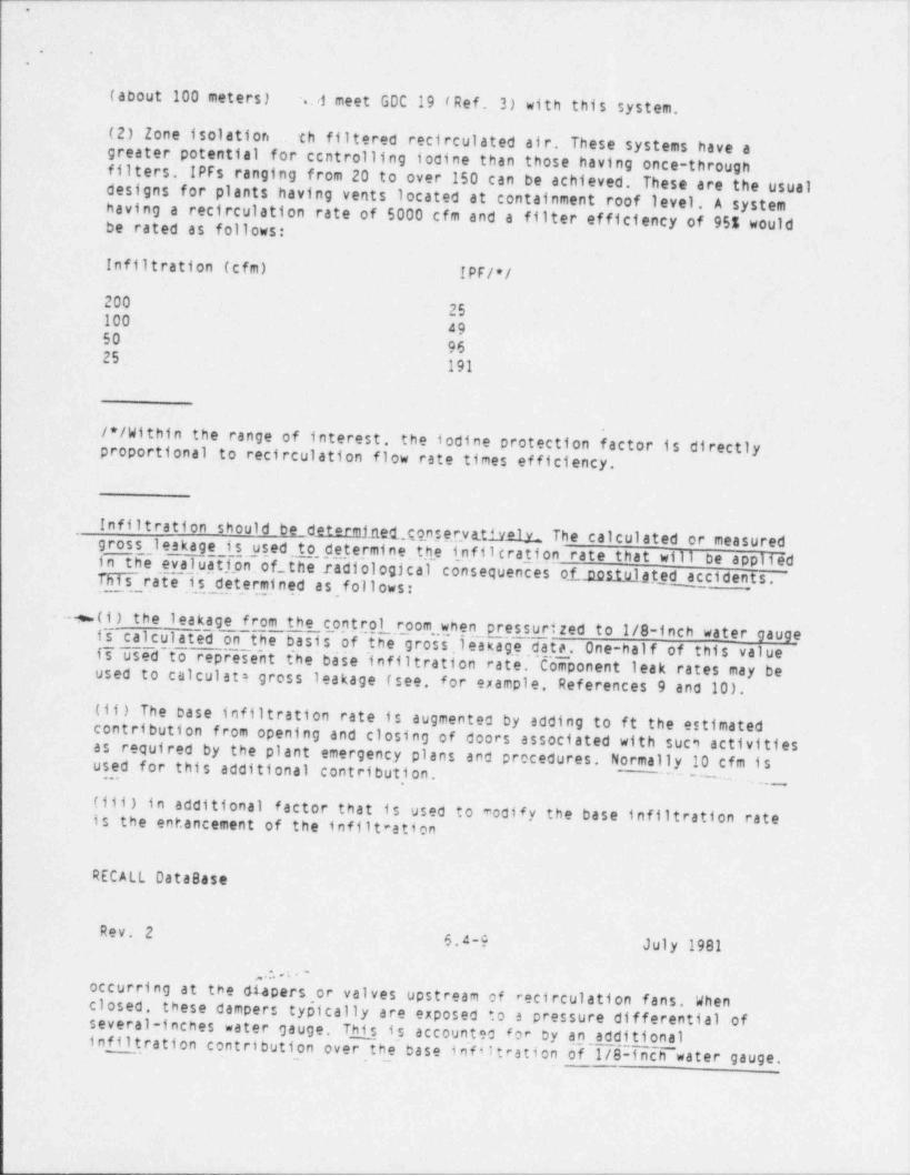
(2) Zone isolation th filtered recirculated air. These systems have agreater potential for centrolling iodine than those having once-throughfilters. IPFs ranging from 20 to over 150 can' be achieved. These are the usualdesigns for plants having vents located at containment roof level. A systemhaving a recirculation rate of 5000 cfm and a filter efficiency of 951 would
.be rated as follows:'
Infiltration (cfm) IPF/*/
20025
100 4950
96 ,
25 :191
/*/Within the range of interest. the iodine protection factor is directlyproportional to recirculation flow rate times efficiency.
Infiltration should be determf_ net,qqnservttivolv The calculated or measuredgross leakage is used to determine the infiltrati,on rate that will be appliedin the evaluation.of_the radiological consequences of gcit.ulated accidents. ~ j
N . rate is_ deter, mined as follows:
- --m- ( i ) the leakage from the controlroom when_ pressurized to 1/8-inch water gauge
is calculated on the basis of the gr.oss, leak.ag,e data. One-half of this value_
is~used to represen't t'he base ' infiltration rate. Component leak rates may be I
~~
used to calculate gross leakage (see, for example, References 9 and 10).(ii) The base infiltration rate is augmented by adding to ft the estimated ,
!contribution from opening and closing of doors associated with suc9 activities I
as required by the plant emergency plans and procedures. Normally 10 cfm isused for this additional contribut, ion., ~~~~~~~
---
(iii) in additional factor that is used to modify the base infiltration rateis the ent.ancement of the infilt ation
RECALL Database
Rev. 2 6.4-9 July 1981
, ,:. a . -
occurring at the diapers or valves upstream of recirculation fans. Whenclosed, these dampers typically are exposed *.o a pressure differential ofseveral-inches water gauge. This,is accounted for by an additional
infiltration contribution over the base infiltration of 1/8-inch water gauge.
'
.4
. .
The use of an infiltration rate that is based on calculation is acceptableexcept in the case where the applicant has assumed exceptionally low rates ofinfiltration. in these cases more substantial verification or proof may berequired. For instance, if an applicant submits an analysis that shows a-grossleakage rate of less than 0.06 volume changes per hour, the reviewer wouldrequire that the gross leakage be verified by periodic tests as described inRegulatory Position C.5 of Regulatory Guide 1.95 (Ref. 8).
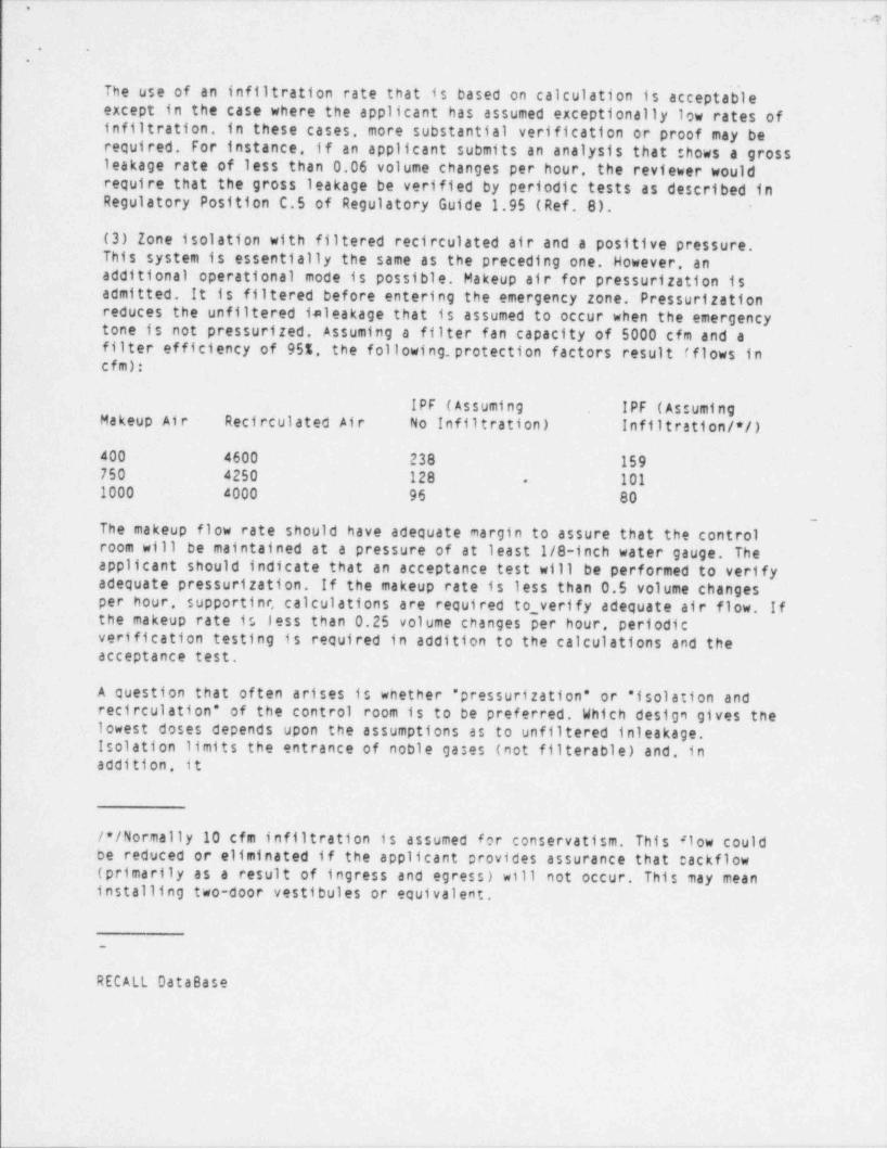
(3) Zone isolation with filtered recirculated air and a positive pressure.This system is essentially the same,as the preceding one. However, anadditional operational mode is possible. Makeup air for pressurization isadmitted. It is filtered before entering the emergency zone. Pressurizationreduces the unfiltered ialeakage that is assumed to occur when the emergencytone is not pressurized. Assuming a filter fan capacity of 5000 cfm and afilter efficiency of 955, the following. protection factors result (flows in ,
cfm):
IPF (Assuming IPF (AssumingMakeup Air Recirculated Air No Infiltration) Infiltration /*/)400 4600 238 159750 4250 128 101.
1000 4000 96- 80
The makeup flow rate should have adequate margin to assure that the control-
room will be maintained at a. pressure of at least 1/8-inch water gauge. Theapplicant should indicate that an acceptance test will be performed to verifyadequate pressurization. If the makeup rate is less than 0.5 volume changesper hour, supportinr, calculations are required to_ verify adequate air flow. Ifthe makeup rate is less than 0.25 volume changes per hour, periodicverification testing is required in addition to the calculations and theacceptance test, j
,
A question that often arises is whether " pressurization" or * isolation andrecirculation * of the control room is to be preferred. Which design gives .thelowest doses depends upon the assumptions as to unfiltered inleakage. !
Isolation limits the entrance of noble gases (not filterable) and, inaddition it
|:i
/*/Normally.10 cfm infiltration is assumed for conservatism. This #1ow could!
be reduced or eliminated if the applicant provides assurance that cackflow I
-(primarily as a result of ingress and egress) will not occur. This may meaninstalling two-door vestibules or equivalent.
1
-
RECALL Database
,
i
- , . -- ---r m
.- _ __ . . . . _ - ._ - - - . .. - - --
'
II
. .
Rev. 26.4-10 July 1981',
infiltration is 25 cfm or less. " isolation * would be best in any eventis a better approach when the accident involves a short-term * puff release. If.
A second Question related to the first involves the method of operati !
following possibilities have been considered: on. The
(i)automatic isolation with subsequent manual control of pressurization. )
(ii)automatic isolation with immediate automatic pressurization.
,
The first is advantageous in the case of external puff releases
also protect the filters from excessive concentrations in the case of aisolation would maintain the buildup of the unfilterable noble gases. It would. Simple
chlorine release. However, the second. method does guarantee that infiltration !(unfiltered)would be beneficial in the case where the contamination transport path tis reduced to near zero immediately upon accident detection. thisemergency zone is mainly inside the building. Method (i) o the
should be used in thecase of a toxic gas release and either method (1)or (ii) should be used in
A substantial time delay should be assumed where manual isolation is athe case of a radiological release. provided GOC 19 (Ref. 3) can be satisfied.;
e.g., ~ 20 minutes for the purposes of dose calculations. ssumed,,
1 (4)Dual air inlets for the emergency zone. Several plants have utilized thisL
the placement of the inlets assures that one inlet will always be free fromconcept. The viability of the dual inlet concept depends upon whether or not|
I
contamination. The assurance of a contamination *ree inlet depends in part j;
j
upon building wake effects, terrain, and the :ossibility of wind stagnation or'
!
reversal. For example, in a situation where tne inlets are located at thextreme edges of the plant structures (e.g., :ne 01 e
the north side and one onthe south sice). it is possible under certain 'cw probability conditions forI bothinlets to be contaminated from the same oint source. Reference 6
disoersion fY/0 values) presents the position for dealing with the evaluation of the atmospheric.
( for dual inlet systems.
With dual inlets placed on plant structures onradiation release points (e.g. containment bu' icing)00posite sides of potential
t
and capable offunctioning with an assumed single active fai'ure in the inl t ie solationsystem, the fo!' awing considerations may be a oldcontrol room X/O's: ed to the evaluation of the
'
(i)Qual inlet designs without manual or automat 4c selection control - :
equation (6)of Reference 6 may be used with *es ect to the least favorable
f actor of 2 to account for dilution effects associated with a dual inletInlet locatien to estimate X/0 is. The estimated values can be reduced by aconf!guration. This is based upon the dilutiC"amounts of clean and contaminated air oe"ived from drawing in equal,
througn *no open inlets.
RECALL Database
_ _ __ _ - _ _ _ ._ _ _ _ __
. .
.
.
'
Rev. 2 6.4-11 July 1981
(11) Oual inlet designs limited to manual selection control equation (6) ofReference 5 may e used with respect to the more favorable inlet location toestimate the X/O's. The estimated values can be reduced by a factor of 4 toaccount for dilution effects associated with a dual irelet configuration andthe relative prooability that the operator will make the proper Inletselection. the reduction factor is contingent upon having redundant radiationdetectors within each air inlet. the reduction factor is based on the judgmentthat trained control room operators, in conjunction with radiation alarm ,
indication, will select and close the contaminated air Inlet.
(iii) Dual inlet aesigns with automatic. selection control features - equation(6) of Reference 6 may be used with respect to the more favorable inletlocation to estimate the X/Q's. The estimated values can be reduced by about afactor of 10 to account for the :Dility to select a " clean" air inlet. Theactual factor may be somewhat higner if the inlet configuration begins toapproach the remote air inlet concept such that the probability of having oneclean air inlet is relatively high. Plant configuration and meteorologicalconditions should be used as the principal basis for reduction factors greaterthan 10. the reduction factor of 10 or more is contingent upon havingredundant detectors in eacn inlet and the provisions of acceptable controllogic which would be used in the automatic selection of a clean air Inlet.
Because damage to the ducting might seriously affect the system capability toprotect the operators, the ducting should be seismic Category I and should beprotected against tornado missiles. In addition, the number and placement ofdampers must be sJCh as to assure both flow and isolation in each inletassuming one single active component-f ailure (see Appendix A for informationon the damper repair alternative). The location of the Intakes with respect tothe plant security fence should also be reviewed.
(5) Bottled air supply for a limited time. In some plant designs thecontainment pressure 4s reduced below atmospneric within one hour after a DBA.this. generally assures that after one hour significant radioactive materialwill not be released from the containment. Such a design makes it feasible tomaintain the control room above atmospheric cressure by use of bottled air.Periodic pressur4zation tests are required to determine thet the rated flow(normally about 300 to 600 cfm) is sufficient to cressurize the control room
to at least 1/8 'ach water gauge. The system is also required to be composedof several separate circuits, one of which is assumed to be inoperative toaccount for a possible single failure. At least one non-redundant, oncethrough filter system for pressurization as a standby for accidents of longduration should ce orovided.
Compressed air b:ttles should be protected f rom t:rnado missiles orinternally-generated missiles and should be placed so as not to cause damageto vital equipment or 4nterference with operation if they fail.
__. . _ _ _ -. .__ .. . _ __
,
- 3e|I
. .
RECALL DatabaseI, ,
Rev. 2 6.4-12 July 1981
4. Atmosphere filtration Systems
ETSB evaluates the iodine removal efficiency of the atmosphere filtration|systems under SRP Section 6.5.1 determines the appropriate credit to be given
and advises the AEB reviewer.
5. Relative location of Source and Control Room I
.The SAB will identify all potential sources of toxic or otherwise potentiallyhazardous gases as described in SRP Section 2.2. The SAB will provide to theAEB th- 'Indings of its toxic gas estimates for use in the control roomhabi+ lity analysis. There are three basic categories; Radioactive sources,tox Jses such as chlorine, and gases with the potential for being releasedinside confined areas adjacent to the control room.
a. Radiation Sources
The LOCA source terms determined from the AEB review in accordance withAppendix A to SRP Section 15.6.5 are routinely used to evaluate radiationlevels external to the control room. The dispersal from the containment or thestandby gas treatment vent is determined with a building wake diffusion model.This model is discussed in Reference 6. Contemination pathways internal to theplant are examined to determine their impact on control room habitability.Other DBAs are reviewed to determine whether they might constitute a moresevere hazard than the LOCA. If appropriate, an additional analysis isperformed for the suspect DBAs.
b. Toxic Gases
The SAB will review and identify those toxic sucstances stored or tvansportedin the vicinity of the site which way pose a threat to the plant operatorsupon a postulated accidental release. The methoc used to determine whether thequantity or location of the toxic material is sach as to require closer studyis described in Regulatory Guide 1.78 (Ref. 7). :his guide also discusses themethods for analyzing the degree of risk and states, in general terms, thevarious protective measures that could be instituted if the hazard is found to i
"
be too great. In the case of chlorine, specific acceptable protectiveprovisions have been determined (Ref. 8).
In summary, the following provisions or their e uivalent are required for theemergency zone ventilation system:
(1) quick-acting toxic gas detectors.'
(2) automatic emergency zone isolation,
- . . - -.. -. .. . -- - . - -
Ie
.' '
)
!
(.3) emergency zone leaktightness. '
(4) limited fresh air makeup rates, and'1
I
RECALL Database Ii
Rev. 2 6.4-13 July 1981|
(5) breathing apparatus and associated bottled air supply.~
The best solution for a particular case will depend on the toxic gas inquestion and on the specific ventilation system design.
c. Confined Area Releases 1
i
The reviewer studies the control building layout in relation to potentialsources of radiation and toxic gases inside the control building or adjacentconnected buildings. The following is considered:
(1) Storage location of C0(2) or other fire fighting materials should be suchias to eliminate the possibility of significant Quantities of the gases
entering the emergency zone. The review will be coordinated with the ChemicalEngineering Branch (CMEB). i
l
(2) The ventilation zones adjacent to the emergency zone should be configuredj
and balanced to preclude air flow toward the emercLency zone. '
(3) All pressurized equipment and piping (e.g., main steam lines and turbines)ithat could cause significant pressure gradients when failed inside buildings '
should be isolatea from the emergency zone by multiple barriers such as:multiple door vestibules or their equivalent. i
6. Radiation Shielding,
Control room operators as well as other plant personnel are protected fromradiation sources astociated with normal plant operation by a combination ofshielding and distarce. The adequacy of this type of protection for normaloperating conditions is coordinated with the RAB. To a large extent the sameradiation shielding (and missile barriers) also provides protection from DBAradiation sources. This is especially true with respect to the control roomwalls which usually consist of at least 18 inches of concrete. In most cases,
<
tne radiation from external DBA radiation sources is attenuated to negligiblelevels. However, the following items should be considered qualitatively inassessing the adecuacy of control room radiation shielding and should becoordinated with the RAB who will be requested to provide assistance asnecessary,
a. Control room structure boundary. Wall, ceiling, and floor materials andthickness snould be reviewed. Eighteen inches to two feet of concrete or its
. . . - . _ _ _ _ _ _ . _ _ _ _ .- . _.. _ . _ . _ __. . _ _ _ _ ... _ . _ ._ __. _ _ .
,
!'
;. .
, ..
| equivalent will be adaquate in most cases.*
'
i. Radiation streaming. The control room structure boundary should be. reviewed
b.!
with respect to penetrations (e.g., doors, ducts, stairways). the potentialfor radiation streaming from accident sources shculd be identified, and if
'
.
Ideemed necessary, quantitatively evaluated.|!
c. Radiation. shielding from internal sources. If :ources internal to thecontrol room complex-are. identified, protective ressures against them should jbe reviewed. typical sources in this category inciuce contaminated filter J
trains.' or airborne radioactivity in enclosures acjacent to the control' room.
RECALL Database
Rev. 2 6.4-la July 1981 j'
4!
Evaluations of radiation shielding effectiveness .ith respect to the above li
items should be performed using simplified analytical models for point, line,or volume sources _such as those presented in Repecences 11 and 12. If moreextended analysis is required, analytical support from the RAB should berequested. The applicant's coverage of the above 'tems should also be reviewedin terms of completeness, method of analysis, anc assumptions.
7. Independent Analyses
The applicant is required to calculate doses to t~e control room operators.Independent analyses are made by the AEB because :f the diversity of controlroom habitability system designs and the engineer'ng judgment Involved'intheir evaluation. Using the approach indicated 4- Reference 6. the sourceterms and doses due to a DBALare calculated.-The source terms determined bythe AEB's. independent analysis of 1ew population one (LPZ) doses for a LOCAare used. The methods and assumptions for this ca*:ulation are presented inAppendix A to SRP Section 15.6.5. The control roc.' doses are determined by |
|estimating the X/O from the source points to the emergency zone using i
meteorological input supplied by the assigned meteorologist, by determiningthe. credit for the emergency zone's protection features, and by calculatingthe dose. the attached Table 6.4-1 is a form whic- may be used to summarizethe information that is .needed for the control recm dose calculation. the
i
Ieffective X/O's are used for calculating the doses. The dose is then compared!with the guidelines of GOC 19. If the guideline va;ues are exceeded, the i
applicant will be requested to ime ove the system. In the event'that otherDBAs are expected to result in doses comparable :: or higher than the LOCA,additional analyses are performed. the limiting c:nsequences of the accidentsare compared with Criterion 19.
1
IV.. EVALUATION FINDINGS
The reviewer verifies that sufficient informatic" as been'provided and that I
the review and calculations support conclusiens :# the following type, to be
. .- _ . - . - -. - -- .- - - . - . ..
__. _. . __ . . . . _ _ . .. ._ _ _._._ _ _ . _ _ _
,
-@, . .
.
Included in the staff',s safety evaluation report (note: items 2 and 3 s'h'ouldbe included only if appropriate):
We conclude that the control room habitability system of the (insertPLANT NAME) facility Is acceptable and meets the requirements of thefollowing General Design Criteria:
1. GDC 19, ' Control Room," with respect to maintaining the control room in asafe and habitable condition under accident conditions by providing adequateprotection against radiation and toxic gases such that the radiologicalexposures are within the limits of this criterion, and
2. GDC'4, " Environmental _and Missile Design Bases," with respect to theenvironmental effects of the release of toxic gases and
|.
3. GDC 5 " Sharing of Structures Systems and Components," with respect toensuring that the control room, shared by Units and of the (insert PLANT NAME)facility will not significantly impair the ability of the control room
. personnel to perform safety functions, including, in the event of an accident;
in one unit, an orderly shutdown and cooldown of the other unit (s).*
RECALL Database
Rev. 2 6.4-15 July 1981
These conclusions are based on the staff review and evaluation that the.control room habitability systems meet the regulatory positions of RegulatoryGuide 1.52, * Design Testing and Maintenance Criteria for Engineered-Safety-Feature Atmospheric Cleanup System Air Filtration and Adsorption Units of!
'
Light-Water-Cooled Nuclear Power Plants " Regulatory Guide 1.78, " Assumptionsfor Evaluating the Habitability of a Nuclear Power Plant Control Room Ouring aPostulated Hazardous Chemical Release," and Regulatory Guide 1.95. " Protectionof Nuclear Power Diant Control Room Operators Against an Accidental Release."
In meeting the positions of these regulatory gui:es, the applicant has'
demonstrated that the control room will adecuately protect the control roomoperators and will remain habitable in accordance with Task Action Plan ItemIII.D.3.4 of NUREG-0737.
If the design is not adequate, the fact is statec. Alternatives such as an! increase in the enarcoal filter flow rate may be *ndicated as is given in the| example below:
The staff has calculated the potential radiation Ooses to control roompersonnel following a LOCA. The resultant whole 00dy doses are within the
iguidelines of General Design Criterion 19. The thyroid dose resulting from '
exposure to radioactive iodine exceeds the dose guidelines. A method of.
meeting GDC 19 would be to increase the filtration system size from 2000 cfmto 4000 cfm. This increased filtration will De sufficient to keep the'
.
. .
.
estimated thyroid doses within the guidelines.
If special protection provisions for toxic gases are not required, thefollowing statement or its equivalent is made:
The habitability of the control room was evaluatea ; sing the proceduresdescribed in Regulatory Guide 1.78. As indicated ir Section 2.2, no offsitestorage or transport.of chemicals is close enough to the plant to beconsidered a hazard. There are no onsite chemicals that can be consideredhazardous under Regulatory Guide 1.78. A sodium hycochlorite biocide systemwill be used, thus eliminating an onsite chlorine cazard Therefore, specialprovisions for protection against toxic gases will not be required. Inaccordance with plant emergency plans and procedures, self-contained breathingapparatus is provided for assurance of control room habitability in the event
!
of occurrences such as smoke hazards.
If special protection previsions are required for toxic gases, compliance ornoncompliance with the guidelines of Regulatory Guices 1.78 and 1.95 should be
't
stated.:
V. IMPLEMENTATIONI
The following provides guidance to applicants ano **censees regarding thestaff's plans for using this SRP section.I
Except in those cases in which the applicant prepcses an acceptable alter||
native method for complying with specified portions of the Commission's{regulations, the method described herein will be used by the staff in its '
!
evaluation of conformance with Commission regulati:ns. |j!
RECALL Database i
|
Rev. 2 1
6.4-16 July 1981
Implementation schedules for conformance to parts :# |the method discussedPerein are contained in the referenced regulatory ;; ides.
VI. REFERENCES i
1. 10 CFR Part 51 Appendix A, General Design Cri e-don 4* Environmental andMissiles Design _ Bases."
2. 10 CfR Part 50. Appendix A.Structures Systems and Components." General Design Cr':erion 5, * Sharing of
3. 10 CFR Part 50. Appendix A. General Design Cr';erion 19, " Control Room. "4
NUREG-0737. " Clarification of TMI Action Plan ecuirements.* Item !III.O.3.4, " Control Room Habitability.' November "?BO.
.
I
. - . - . - -.. . - .- . . -- . . - - - . . . . . .
.q..
. .
,
5. Regulatory Guide 1.52, " Design. Testing, and Maintenance Criteria for '
. Engineered-Safety-Feat'ure Atmosphere Cleanup System Air Filtration and'
Adsorption Units of Light-Water-Ccoled Nuclear Power Plants."
6. K.G. Murphy and K. M. Campe, " Nuclear Power Plant Control Room Ventilation .System Design for Meeting General Design Criterion 19," 13th AEC Air CleaningConference, August 1974 ' ' '
1
7. Regulatory Guide 1.78, " Assumptions for Evaluating the Habitability of aNuclear Power Plant Control Room During a Postulated Hazardous ChemicalRelease.",
8. Regulatory Guide 1.95 *Protet. ... of Nuclear Power Plant Control RoomOperators Against an Accidental Chlorine Release."
9. * Leakage Characteristics of Openings ~for Reactor Housing Components,"NM-SR-MEMO-5137, Atomics International, Div. of North American Aviation. Inc., ,
-June 20, 1960..
,
10. R.L. Koontz, et al., " Leakage Characteristics of Conventional BuildingComponents for Reactor Housing Construction," Trans. Am. Nucl. Soc., November1961.
11. R.G. Jaeger, et al., eds., " Engineering Compendium on Radiation|Shielding," Vol.1. " Shielding Fundamentals and Methods," Springer Verlag
(1968).'
12. N.M. Schaeffer " Reactor Shielding for Nuclear Engineers," TID-75951 U.S.Atomic Energy Commission.-
'
RECALL Database
Rev. 2 6.4-17 July 1981
SECTION 6.4 APPENDIX A
ACCEPTANCE CRITERIA FOR VALVE OR DAMPER REPA!R ALTERNATIVEP
The control room ventilation system must meet the criterion to functionproperly, even with a single failure of an active component. In certain cases,complex valve or damper configurations are required to meet the single failurecriterion. For example, assurance of the isolation and operability of each legof a dual inlet system at various times after a postulated accident couldrequire a four-valve arrangement in which two pairs of series valves arec_onnected in parallel. The mechanical, power, and control components of sucharrangements combine to form'a rather complex system. Credit will be allowedfor an alternative system that allowed the failed valve to be manuallyrepositior.3d so that it will not interfere with the operation of the system.For example, in the case of a dual inlet system, if credit for repair is
_ ._.
O
*
given, then two valves in series in each leg of the dual inlet would beacceptable. Where a valve fails closed but meets the criteria given below,credit would be allowed for the valve to be repositioned and locked in an openposition.
The approval of the repair option is contingent upon the intrinsic reliabilityof the internal components of the valve or damper and also upon the ease andability to overcome the failure of the external actuating components(electrical relays, motors, hydraulic pistons, etc.). The following criteriaor their equivalent will be required.
-1.'The valve or damper components must be listed as to which are consideredinternal (nonrepairable) and which external (repatrable). These must bedesigned to meet the following criteria.
!
a. Internal valve components (i.e., components that are difficult to repairmanually without opening the ductwork) must be judged to have a very low !
probability of f ailure. The component design details will be reviewed and|characteristics such as simplicity, ruggedness, and susceptibility to '
postulated failure mechanisms will be considered in arriving at an engineeredjudgment of the acceptability of the Internal component design with respect toreliability. For example, a butterfly valve welded or keyed onto a pivot shaft
<
would be considered a high reliability internal component. Conversely, I
multiple blade dampers.. actuated by multi-element linkages or pneumaticallyj
operated components internal to the ducts, would be viewed as being subject to ;failure. i
Ib. External valve components (i.e., components including motors and power
!supplies that are to be assumed repairable or removable) must be designed toensure that the failed valve component can be bypassed easily and safely and
'
that the valve can be manipulated into an acceptable position. The electroniccomponents must be isolated from other equipment to assure that the repairoperations do not result 4n further equipment failure.
RECALL Database
Rev. 2 6.4-18 July 1981
2. The location and positioning of the valve or camper must permit easy accessfrom the control room for convenient repair. especially under applicable DBAconditions.
3. Appropriate control room instrumentation should be provided for a clearindication and annunciation of valve or damper malfunction. '
4Periodic manipulation of the valve or damper by control- room operators
should be required for training purposes and to verify proper manualoperability of the valve or' damper.
!
I
_m_ _ _. . . . - ,
- _ ~ . - . .- - - . - . . . . .. -. . . .
,
. . y. -
. .
5. The need for manual manipulati:ns of the failed valve or damper should notbe recurrent during the course of the accident. Manipulation should not occurmore than once during the accident. Adjustment or realignment of other partsof the system should be possible '*om the control room with the failed valvein a fixed position.
6. The time for repair used in the computation of control room exposuresshould be taken as the time necessary to repair the valve plus a one-half hourmargin. No manual correction will se credited during the first two hours ofthe accident.
7. Compliance with the above criteria should be documented in the SAR when;
ever the repair option is used.,
RECALL Database.
Rev. 2 6.4-19 July 1981
TABLE 6.4-1 Summary Sheet for Control Room Dose Analysis,
MEMORANDUM TO: , AEB Lead Reviewer. Meteorologist
cc: Meteorology Section. AEBAEB Habitability Files
CONCERNING CONTROL ROOM DOSE ANAlv5IS FOR (Insert-Plant Name)
The fo11 ewing summarizes the X/O's. used in. determining the control roomoperator dose for the subject plart:
A. VENTILATION SYSTEM DESCRIPTION
B. SKETCH OF SYSTEM (and inlets /s:;rces if applicable)
C. SUMMATION OF X/0 ANALYSIS
Source / Receptor Type and Distance
S/D Ratio K Factor
Humber of 22-1/2x Wind DirectionSectors that Result in Exposure
C,entral Wind Sector (sector wind is blowing from)
5% Wind Speed (m/sec) 40% Wind Speed (m/sec)
Projected Area of Wake (m**2) 5% X/0 (sec/m**3)

4
.
Aind. Wind''
Time 2 peed Factor , Direction Factor Occupancy. FactorEffective X/O's
''
0-8 hr 118-24 hr- I11-4' day.0.64-30 day0.4
RECALL. Database
Rev. 26.4-20 July 1981
0.' ACTION REQUESTED
Assigned Reviewer
- For your information only :
- Please use the effective f/O's in TACT run and provide control room d|'
oses. !
.in addition, please summarize safety system assumptions and indicate theirstatus (interim or final).Meteorologist
,
- These are interim X/0's. 31 ease review to determine'their reasonablenessi
- These are final X/0's. P' ease determine if they are accurate based on yourI
1
analysis.of site data. .
Please Contact
RECALL Database
Rev. 26.4-21 July 1981
,
|
|.
:
--\?,,7 , ,
NUCLEAR REGULATORY COMMISSION / k - L{ [/| - * RE210N IV. " *- * 8i., 8 611 RYAN PLAZA CRIVE. SulTE 400
ARLlNGTON. TEXA5 760118084**,.* *
.
Docket: 50-298License: OPR-46
,
Nebraska Public Power District iATTN: Guy R. Horn. Vice President. Nuclear IP.O. Box 98)Brownville. Nebraska 68321 '
SUBJECT:
FINAL SYSTEMATIC ASSESSMENT OF LICENSEE PERFORMANCE (SALP) REPORTThis forwards the final SALP report (50-298/93-99)Station for the period of January for the Cooper Nuclear
|
final SALP Report includes: 19. 1992, through April 24, 1993 This 'I.
1.
initial SALP report were made).The cover letter for the initial SALP report (no revisions to the2. A summary of our July 12. 1993.
security building auditorium in Brownville Nebrasca.meetin9 at the Coo3er Nuclear Station,
;3. Your August 11. 1993.
'
response to the initial SALP report.We have reviewed your letter dated August j
11. 1993,recommendations in each of the SALP functional areas.in response to the NRCSALP functional areas. response has identified specific actions to imorove performance in each of the
,
It was noted that your '
improvements in inspection efforts during this SALP period.We will review your progress to achieve theseThe next SALP period for Cooper Nuclear Station is scheduled to lastapproximately 18 months, from April 25. 1993. to October 22. 1994. Asidentified in our letter dated August 11. 1993, from Mr. A. B. Beach.Nuclear, the reviseo SALP program will be utilized. Director. Division of Reactor Projects, to Mr. G. R. Horn. Vice President.'
Sincerely.
James L. MilhoanRegionai Administrator
Enclosures:1. Cover letter 'or2. NRC Meeting Summary
.clal SALP report j33.
Nebraska Puol c Power District esconse a the initial SALP reportyi fcc: 'see next Da9e' N
.
fQ%aMd II&-vr ' 7
_ . -__ . _ _ _-.. _._ _ _ _ _ . . _ _ _ ._.
-
;i4
" * -
Nebraska Public Power District 2- .
. ,
cc w/ enclosure:Nebraska Public Power District .ATTN:
G. D. Watson. General Counseli
|
P.O. Box 499
Columbus. Nebraska 68602-0499 '
Cooper Nuclear Station! . ATTN:
P.O. Box 98 John H. Meacham. Site Manageri
Brownville. Nebraska 68321
Nebraska Department of EnvironmentalControl
ATTN: Randolph Wood. Director1
t
P.O. Box 98922Lincoln. Nebraska 68509-8922
1
Nemaha County Board of CommissionersATTN: Richard Moody. ChairmanNemaha County Courthouse1824 N StreetAuburn, Nebraska 68305
! Nebraska Department of HealthjATTN:
! Harold Borchert. Director301 Centennial Mall. SouthDivision of Radiological Health !
P.O. Box 95007- !
Lincoln. Nebraska 68509-5007 i;
!, <
. Kansas Radiation Control Program Director \
|
!
i
'
i i
I !
|
'
s
1
i
a
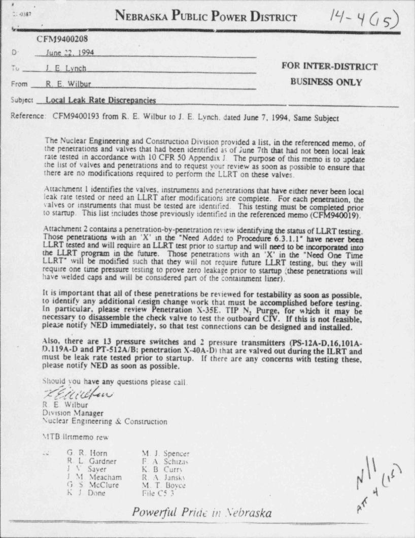
..
NEBRASn PuBuc PowEn DISraicT $ y (f g==
h -
CFM9400208.
D- ' June 22.1994 '
To J E. Lynch FOR INTER-DISTRICT'
From R. E. Wilbur BUSINESS ONLYF
Subject Local Leak Rate Discrenancies
Reference: CFM9400193 from R. E. Wilbur to J. E. Lynch, dated June 7,1994, Same Subject
The Nuclear Engineering and Construction Division provided a list, in the referenced memo, ofthe penetrations and valves that had been identified as of June 7th that had not been local leak !
,
rate tested in accordance with 10 CFR 50 Appendix 1. The purpose of this memo is to update |the list of valves and penetrations and to request your review as soon as possible to ensure that t
there are no modifications required to perform the LLRT on these valves.|
Attachment 1 identifies the valves, instruments and penetrations that have either never been localleak rate tested or need an LLRT after modifications are complete. For each penetration, thevalves or instruments that must be tested are identified. This testing must be completed priorto startup. This list includes those previously identified in the referenced memo (CFM940019).
Attachment 2 contains a penetration-by-penetration review identifying the status of LLRT testing.Those penetrations with an 'X' in the "Need Added to Procedure 6.3.1.1" have never beenLLRT tested and will require an LLRT test prior to startup and will need to be incorporated intothe LLRT program in the future. Those penetrations with an 'X' in the "Need One TimeLLRT" will be modified such that they will not require future LLRT testing, but they willrequire one time pressure testing to prove zero leakage prior to startup (these penetrations willhave welded caps and will be consicered part of the containment liner).
It is important that all of these penetrations be reviewed for testability as soon as possible,- to identify any additional 6esign change work that must be accomplished before test.ing.In particular, please review Penetration X-35E. TIP N Purge, for which it may be2
necessary to disassemble the check valve to test the outboard C;V. If this is not feasible,please notify NED immediately, so that test connections can be designed and lastalled.
'
Also, there are 13 pressure switches and 2 pressure transmitters (PS-12A-D,16,101A-D.119A-D and PT-512A/B; penetration X-40A-D) that are valved out during the ILRT and
-
must be leak rate tested prior to startup. If there are any concerns with testing these,please notify NED as soon as possible.
Should you have any questions please call.
k/G VR. E. WilburDivision ManagerNuclear Engineering & Construction
N!TB:llrtmemo rew1
.:e : G. R. Horn N1. J Spencer
\ hR. L. Gardner F. A. SchizasJ V Sayer K. B. Curry ( 71 M. Nieacham R. A. Jansk) N { \G. S. NicClure M. T. BoyceK. J Done File C5 3 N'.
kPowerful Pridt in .Vebraska.
_ ___
r----- ,- c- -- e ,- a,-e - - - p-- k
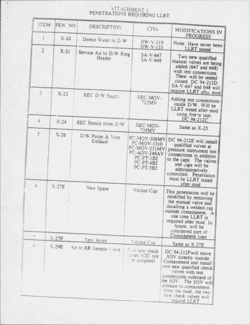
- - . - - - - - ~ ~ ~ ~~~~'
..
ATTACHMENT 1,. -_ PENETRATIONS REQUIRING LLRT-
ITEM PEN.NO. . DESCRIPTION CIVsMODIFICATIONS IN
PROGRESSI X-20 Demin Water to D/W DW-V 219 None. Have never bee _
l
DW-V-133 LLRT testedn
2 X-21 Service Air to D/W Ring SA-V 647 Two new qualifiedHeader SA-V-648manual valves are being
added (647 and 648with test connections),
,
!
These will be sealedt'
closed. DC 94-212D- ^~
SA-V-647 and 648 willi
reouire LLRT aftet mod3 X 23 [ REC D!W Supply REC MOV-l
Adding test connectionsi
! 702MVinside D/W.' Will be
LLRT tested after mod'
|4 using free 7.e seal.'
DC 94-212C4 X-24 REC Return from D/W REC-MOV- Same as X-23709MV5 X-26 D/W Purve & Vent PC-MOV-306MV DC 94-212E will install
.
~
Exhaust ' PC-MOV-1310 qualified valves at{PC MOV-231MV pressure instnament test '
PC-AOV-246AV connections in additionPC PT-1B2 to the caps. The valvesPC-PT-4B2PC-PT-5B2
and caps will be ;
iadmimstratively; controlled. Penetration
must be LLRT testedafter mod i*
6 X-27E New Spare ' Welded Cap This penetration will bei
y;
modified by removing ;I i
the manual valve andi installing a welded cap-
outside containment. A2 ,
t
one time LLRT is.
!
required after mod. In:
future, will beI considered part of
Containment lineri X-27F New Spare ! Telded CapSame as X.27E
~
i.. .
j- 8 X 29EAir to RR Sample Valve i Two new check
,
! utses (CIC not DC 94 212Fwill moveSOV directly outsidei
i
-j'.et assiuned) Containment and install'
j two new qualified check( valves with test
,
ii : connections outboard of!
the SOV. The SOV will;
exhaust to containment.After the mod, the two.
!__
ew check valves willn
require LLRT.
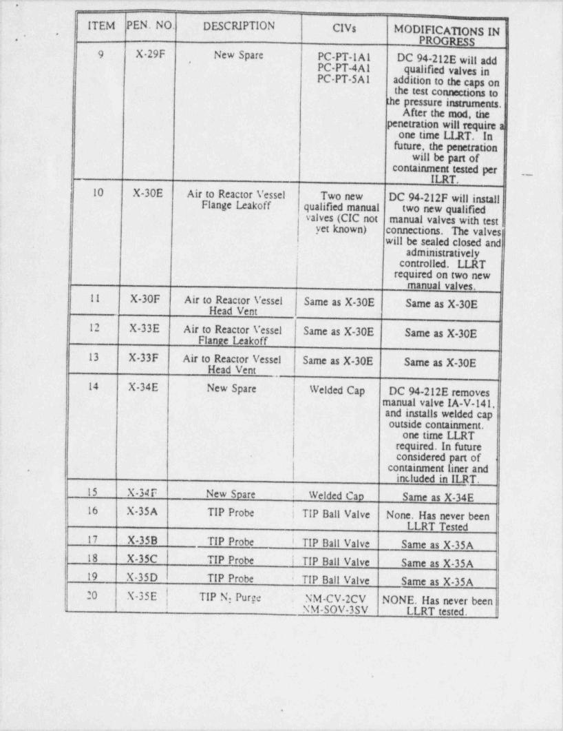
. . . . _ . . _ _ _ . _ - . _ _ -___ _ __ _ ._ _. ___ _ _.._ _ _ ___~ _,
. .i
ITEM PEN.NO. DESCRIPTION CIVs . MODIFICATIONS IN |j.PROGRESS
-
1
9 X 29F New Spare PC-PT-1 A1 DC 94-212E will add - |i- *
PC-PT-4A1 qualified valves in '
PC PT-SA1 addition to the caps onthe test connections to
the pressure instruments.After the mod, the
,
penetration will require a '4
one time LLRT. Infuture, the penetration
|will be part of .
containment tested per {__. ,
-_ ILRT. i
10 X-30E Air to Reactor Vessel Two new DC 94-212F will install |Flange leakoff qualified manual two new qualified '
valves (CIC not manual valves with testyet known) connections. The valves
will be sealed closed and ;*
administratively-controlled. LLRT
required on two new{
manual valves.11 X-30F Air to Reactor Vessel Same as X-30E Same as X-30E <
Head Vent !
!12 -X-33E Air to Reactor Vessel Same as X-30E Same as X-30E
Flanne 12akoff
13 X-33F Air to Reactor Vessel Same as X-30E Same as X-30EHead Vent
'
l14 X-34E New Spare Welded Cap DC 94-212E removes '
manual valve IA-V-141,and installs welded capoutside containment. i
one time LLRT |required. In futureconsidered part of.
containment liner and-
inc,luded in ILRT.. 15 X-34 F New Soare ! Welded Cap Same as X-34E
:16 X-35A TIP Probe ! TIP Ball Valve None. Has never been
LLRT Tested- 17 X-35B TIP Probe i TIP Ball Valve Same as X-35A18 X-35C TIP Probe i TIP Ball Valve Same as X-35A19 X-35D TIP Probe TIP Ball Valve Same as X-35A20 - X-35E . I TIP N: Purge | NM-CV-2CV NONE. Has never beenI NM-SOV-3SV LLRT tested.
.
9
_ , . . , - . - .-- , , - . - - , . . r-
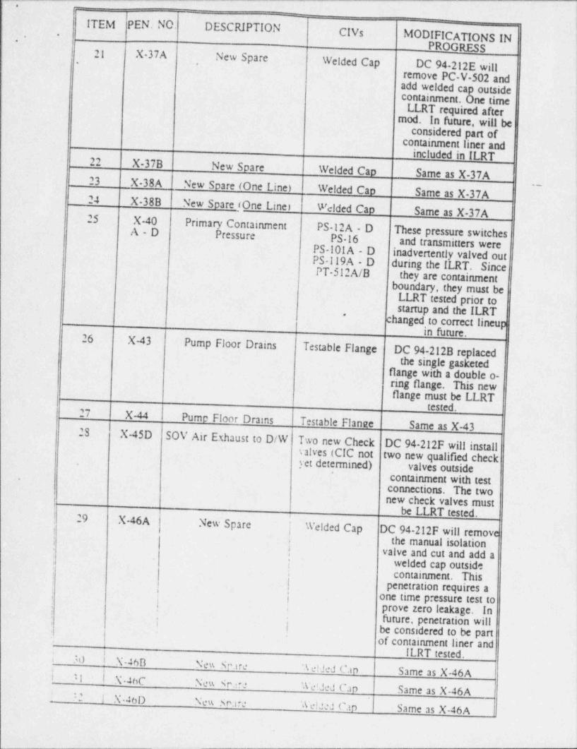
.c. _
ITEM PEN.NO. DESCRIPTION CIVs MODIFICATIONS IN.,
.3
PROGRESS| 21 X-37A New Spare Welded Cap DC 94-212E will
,
remove PC-V-502 andadd welded cap outsidecontainment. One timeLLRT required after
mod. In future, will beconsidered part of
containment liner andincluded in ILRT22 X-37B New Spare
Welded Cao Same as X-37A23 X-38A New Spare (One Line) Welded Cao Same as X-37A
. _ .
24 X-38B New Spare (One Line Welded Cao Same as X-37A25 X-40 Primary Containment PS 12A - D These pressure switchesA-D Pressure PS 16 and transmitters werePS-101 A - D inadvertently valved outPS-119A - D during the ILRT. SincePT-512A/B they are containment
boundary, they must beLLRT tested prior tostartup and the ILRT*
changed to correct lineupin future.
26 X-43 Pump Floor Drains Testable Flange DC 94-212B replacedthe single gasketed
flange with a double o-ring flange. This new.flange must be LLRT
tested.27 X-44 Pume Floor Drains Testable Flange Same as X-4328 X-45D
SOV Air Exhaust to D/W Two new Check DC 94 212F will installvalves (CIC not two new qualified checkyet determined) valves outside
'
'
. containment with testconnections. The twonew check valves musti
! be LLRT tested.! 29 X-46A New Spare
| Welded Cap DC 94-212F will remove
,
t
: ;the manual isolationi
| valve and cut and add a'
welded cap outside'
containment. This; .
| penetration requires a>
: - oi !
ne time pressure test toprove zero leakage. In; !
i future, penetration willi be considered to, be part
,
*
of containment liner and.
ILRT tested.l 30 | X-46B New Scare Welded Can Same as X-46A| 'l | N-4hC New Scare We!Jed Can Same as X-46A! '2 1 X-46D New Snare Welded can Same as X-46A
'
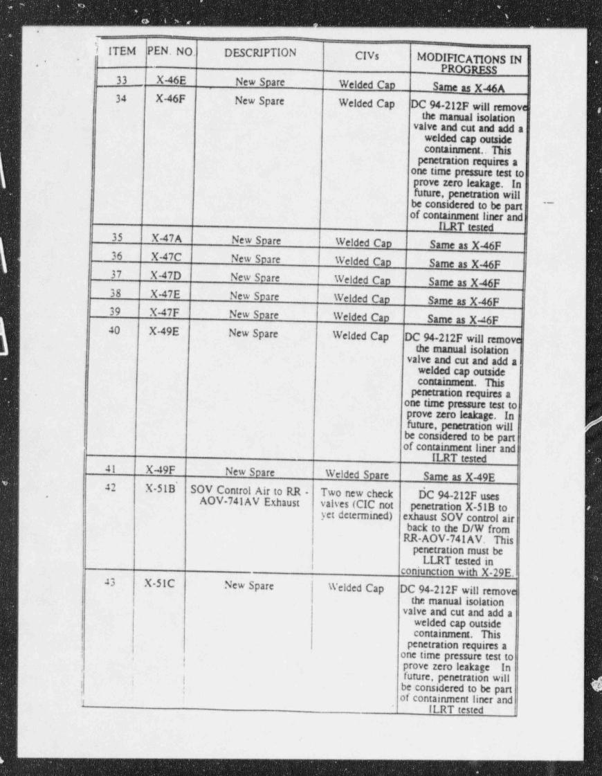
________ _ _____ _ _--__-
-
i ITEM PEN.NO. DESCRIPTION CIVs MODIFICATIONS IN-,.
PROGP m33 X-46E New Spare Welded Cao Ss = as X4A34 X-46F New Spare Welded Cap DC 94-212F will remove
the manual isolationvalve and cut and add a
welded cap outsidecoraminment.. His
Penetration requires aone tune pressure test toprove zem leakage. 'Infuture, penetration willbe considered to be part
-
of containment liner andILRT =W
35 X-47A New Spare Welded Cao Same as X-46F36 X-47C New Spare Welded Cao Same as X-46F
,
37 X-47D New Spare Welded Cap Same as X-46F38 X-47E New Spare Welded Cap Same as X-46F39 X-47F New Spare Welded Cao Same as X4F40 X-49E New Spare Welded Cap DC 94-212F will remove
the manual isolationvalve and cut and add a
welded cap outsulecaarnian mar This
penetranon requires a.
one time pressure test toprove zero leakage. Infuture, penetration will
4
be considered to be partof containment liner and
ILRT tested41 X-49F New Spare Welded Soare Same as X-49E42 X-51B' SOV Control Air to RR - Two new check dC 94-212F uses-
AOV-741AV Exhaust valves (CIC not penetration X-51B toyet determined) exhaust SOV control air
back to the D/W fromRR-AOV-741 AV. This
penetration must beLLRT tested in
coniunction with X-29E.43 X 51C New Spare Welded Cap DC 94-212F will remove
the manual isolationvalve and cut and add a
welded cap outside
{ containment. Thisi penetration requires a
one time pressure test to'j prove zero leakage. In
'
,
i | future, penetration willbe considered to be part
!i.
of containment liner and1ILRT tested
*
_ _ _ _ _ _ _ _ _ _ _
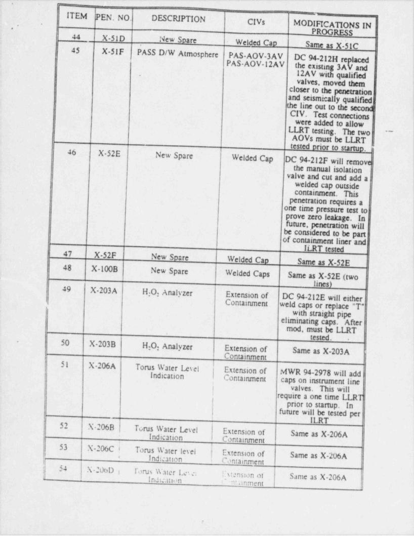
7-_. - - . . . -- -. . ..-.- ---..-.. - .- - .-.. _.-.--... - .
ITEM PEN.NO. DESCIUPTION._ i
CIVs MODIFICATIONS IN.
..,
PROGRESS !44 X-SID New Soare Welded cad Same as X-51C.
'
45 X-SIF PASS D/W Atmosphere PAS-AOV-3AV DC 94-212H rep _ lacedPAS AOV-12AV the existing 3AV and
12AV with qualified!
-
valves, moved them!
closer to the Ation .!and seismically qualifiedi
the line out to the second t
CIV. Test connections '
were added to allow !LLRT testing. The two )
- - - ~
AOVs must be ILRT itested prior to startuo.!46 X 52E New Spare Welded Cap DC 94-212F will remov!
e !the manual isolation ~ '
valve and cut and add awelded cap outside
icontainment. This i
penetration requires a{one time pressure test to!prove zero leakage. In!future, penetration will !
be considered to be part '
of containment liner andILRT t===447 X-52F New Soare Welded Can Same as X-52E
)48 X-100B New Spare Welded Caps Same as X-52E (two,
lines)49 X-203A H,0, Analyzer Extension of DC 94-212E will either
,
~~ ~
Containment weld caps or replace "T" -
with straighteliminating caps. pipeAfter
mod, must be LLRTtested. .
50 X-203B H:0, Analyzer Extension of Same as X-203A
-
Containment51 X 2%A Torus Water level I Extension of MWR 94-2978 will addIndication I Containment caps on instrument line'
! valves. This willrequire a one time LLRT
prior to startup. Infuture will be tested per
ILRT52 X-2%B Torus Water 12 vel Extension of Same as X-2%AIndication Containment
-
53 X-206C i Torus Water level Extension of Same as X-206AIndication Cantainment*
t 54 X-200D i forus Water Le.e: lhtension of Same as X-206Ai Indication c m:anment
.
.,.-.m ,.y s-.. __ n .- , . - . e -. , ,
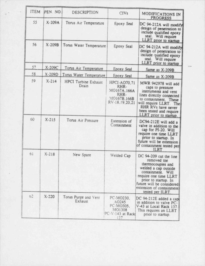
7_ _ . .. _ __._._.____ __._.__ _ . _ _ _ _ _ _ _ . _ . _ . . _ _ _ _ _ . . _ _ _
i
ITEM PEN. NO. DESCRIPTION CIVs MODIFICA'IlONS IN !
.,
"*
_ PROGRESS '
55 X-209A Torus Air Temperature Epoxy Seal DC 94-212A will modify!
design of penetration to !
include qualified epoxy ,
seal. Will requireLLRT orior to startuo j
56 X 209B Torus Water Temperature Epoxy Seal DC 94-212A will modify .
design of penetration toinclude qualified epoxy {
.
seal. Will requireI I RT orior to startuo
57 X-209C Torus Air Temperature Epoxy Seal Same as X-209B i
58 X-209D Torus Water Temperature Epoxy Seal Same as X-209B59 X-214 HPCI Turbine Exhaust HPCI-AO70,71 MWR 942978 will addDrain RHR- caps to pressure
htOl67A,166A instruments and ventRHR- lines directly connected
htOl67B,166B to containment. TheseRV-18,19,20,21 will require LLRT. The
- RHR RVs have neverbeen tested and requireLLRT orior to stattuo.
60 X-215 Torus Air Pressure Extension of DC94-212E will add aContainment valve in addition to the
cap for PI-20. Willrequire one time LLRT
prior to startup. Infuture will be extension
of containment tested perILRT
61 X-218 New Spare Welded Cap DC 94-209 cut the lineremoved the !
thermocouples and !welded a cap outside,
,
containment. Will'
require one time LLRT |prior to startup. In '
future will be consideredextension of containment
tested per ILRT.62 X-220 Torus Purge and Vent PC htO230 DC 94-212E added a cap
Exhaust A0245 in addition to valve PC-PC-h10305, V-43 at Local Rack 137.
h101308 This requires an LLRT !
,
PC-V-143 at Rack prior to startup.I 137
I
,
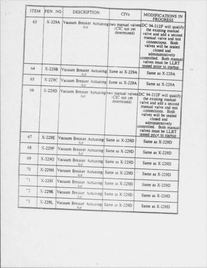
'
.
.-
ITEM PEN.NO. DESCRIPTIO"
CIVs MODIFICATIONS IN |.-
PROGRESS63X-229A Vacuum Breaker Actuating two manual valves DC 94-212F will qualify
jAir )(CIC not yet the existing manual
determined) valve and add a secondmanual valve and test
connections. Both'
valves will be scaledclosed and !admimstratively j
controlled. Both manuali
valves must be LLRT !tested prior to startuo.64 X-229B Vacuum Breaker Actuating Same as X-229ASame as X-229A
__
Air65 X-229C Vacuum Breaker Actuating Same as X-229A
Same as X-229AAir66 X-229D Vacuum Breaker Actuating
two manual valves DC 94-212F will qualifyAir ICIC not yet the existing manualdetermined) valve and add a second
imanual valve and test
connections. Bothvalves will be sealed .
closed and {
administrativelycontrolled. Both manual
valves must be LLRTtested oriqr to startuo67
X-229E Vacuum Breaker Actuating Same as X-229D Same as X-229D1
Air68
X-229F Vacuum Breaker Actuating Same as X-229DSame as X-229D
!Air
69 X-229G Vacuum Breaker Actuating Same as X-229D- Same as X-229DAir
70 X-229H Vacuum Breaker Actuating Same as X-229D ' Same as X-229D I. Air i
71 X-229J Vacuum Breaker Actuating Same as X 229DSame as X-229DAir
~2 X-229K Vacuum Breaker Actuating Same as X-229DSame as X-229DAir
~3 X-229L V !acuum Breaker Actuating Same as X 229DSame as X-229D !
. Air
i
|
,
|
|
.
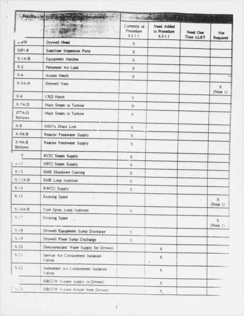
. .__ .- _. . - . _ - _ __ _ . - _ _ _ . - _ - .- _ _ _ _ _ _ _ _ _ _ _ _
' emme=====me====
.*g g *Q 4] f:. ,g|Q'~!,. .,
vm; m. , . 69 +l Ne,$ .
, .
[g%n@@hys& i Currently in Need Added,
#0*di, U g2pg Procedure to Procedure Need One Not*
~
4 my $:n u ~ 6.3.1.1 6.3.1.1 Time f I RT RequiredvWH Drywell Head X | | |
| | |SIPI 8 Stabilizer inspection Ports X
X IA/B Equipment Hatches X | | |X-2 Personnel Air Lock X | | |X-4 Access Hatch X | |
'
X SA-H Drywell Vent| || (Note 1) f
X| |
X-6 CRD Hatch X | | |X 7A/D Main Steam to Turbine X- | | |XUA/D Main Steam to Turbine X |Bellows
|X-8 MSIVs Drain Line X | | ||X 9A/B Reactor Feedwater Supply X | | |X 9A/B Reactor feedwater Supply X | |Bellows
| |
| | ||0 RCIC Steam Supply X
4 11 HPCI Steam Supply X | | )X 12 RHR Shutdown Cooling X | | | |
X 13A/B RHR Loop Injection X | | ||X 14 RWCU Supply X | | ||X 15 Existing Spare
| | X !.
-
| | (Note 2) |I
X 16A/B Core Spray Loop injection X | | ){
X-17 Existmg Spare| X
|,
j
| (Note 2) JX-18 Drywell Equipment Sump Discharge X | |X 19 Drywell Floor Sump Discharge X | |
'
X-20 Demmeralized Water Supply for Drvwell X | |X 21 Service Air Contamment Isolation X
Valves.
X 22 Instrument Air Contamment isolation XValves
| RBCCW System Supply to Drvwell | ! X:
| |.|\.:4 | RBCCW kstem Return t' rom Drvwell ! X, | |
.
I
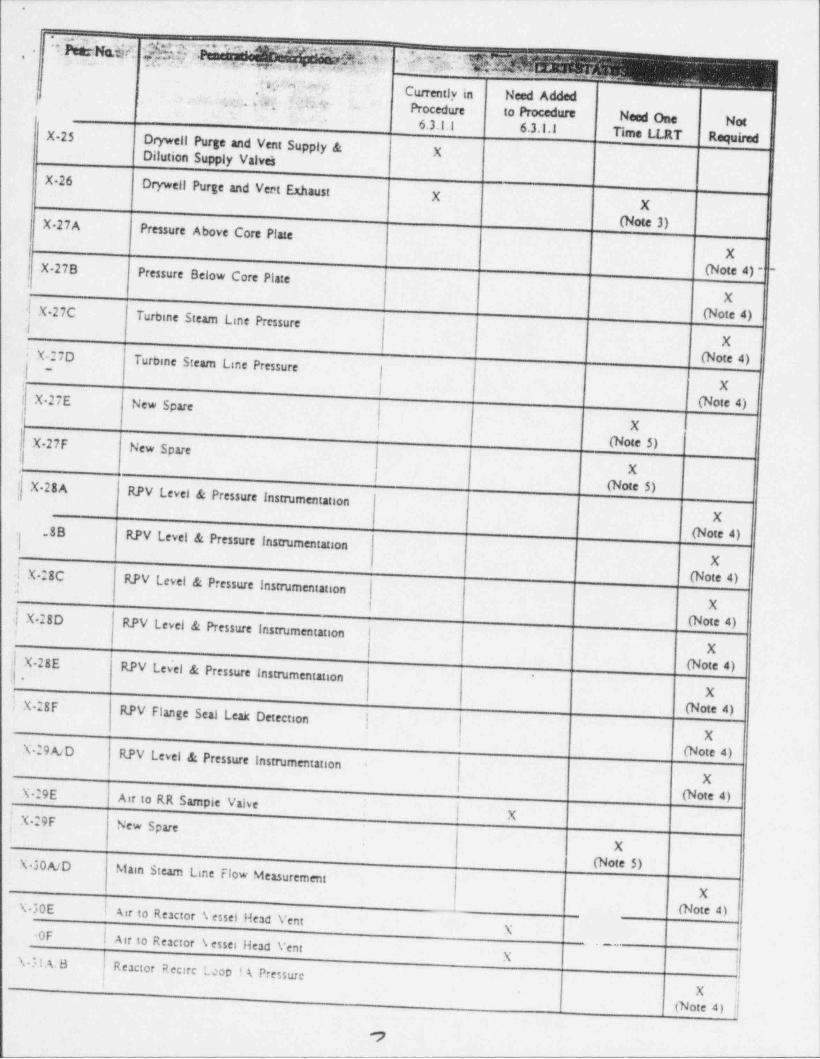
a.= , . . . --
.
*( Q g z $ff.MF'"#[email protected] 30946 j.
,-
-, gey w.m,% o -me- . ; :.:- ,--
; pg.h::::#y Currently in Need Added[ .[q U;ngsProcedure to Procedure Need One Not
.
6.3.1.1 6.3.1.1 Time LLRT RequiredX-25Drywell Purge and Vent Supply & XDilution Supply Valvei |Drywell Purge and Vent Exhaust | |X.26
X
|X(Note 3)| X 27A
Pressure Above Core Plate |l
| XX 37B
Pressure Below Core Plate (Note 4) -
X',I X 27C
Turbine Steam Line Pressure (Note 4)I
| |X
Turbme Steam Line Pressure | (Note 4)' L27Dj | I
-
| X! X 27E New Spare (Note 4)i |
' X !
h}X 37F New Spare (Note 5) ||i
|Xr
I(Note 5) |
i X-28ARPV Level & Pressure Instrumentation'
X. 8Bl RPV Level & Pressure Instrumentation
. (Note 4)
X! X 28C | (Note 4)i RPV Level & Pressure Instrumentation|
| X1
I X 28D' RPV Level & Pressure Instrumentation | (Note 4)
i !
| | X| X-28El- RPV Lev'el & Pressure instmmentation | (Note 4)
'
| X! X 28F | (Note 4)RPV Flange Seal Leak Detection
| | | X:
X 29A/DRPV Level & Pressure Instrumentation
| (Note 4)'
Xi
.
Air to RR Sample Valve | (Note 4)L29E| X |I L29F
!New Spare
X
(Note 5)L30A/DMam Steam Line Flow Measurement
X
I Air to Reactor Vessel Head Vent (Note 4)L30EX
| Air to Reactor VesseOFHead Vent
\-} l A.B |R X
! eactor Rectre Lcop ! A PressureX U
| (Note 4) |
,

__ _ __ ._ _ _ _ _ . . _ _ _ _ . ~ _ _ _ . . . _ . .-._ _ _ _ _ _ ..
,, uv- ~ .
- . . .,
_
.-
_m._ & e,p :
-
-
s[-*4 dkk,Uf.O'
f jgg9 app 4 Currently in Need Added !g' /"c 6) ( Procedure to Procedure Need One Not
*gT ^*'k:g g- gg6 s 'p|yshg hN+; - - .n 6.3.1.1 6.3.1.1 Time LLRT Required
X JIC/D Reactor Recire. Loop 6P| | (Note 4)
X || |
X 31E/F Reactor Recire. Pump Seal PressureX
(Note 4)X 32A/D Reactor Recire. Loop IA Flow
| X
| (Note 4) - -X 32E/F Reactor Recire. Pump Seal Leakage
| | X| | (Note 4)
X-33A/D Reactor Recire. Loop l A/B 6P| | X| | (Note 4)
X 33E/F Air to Vessel Flange Leakoff| |X
X 34A/D Main Steam Line Flow Measurement| | X| | (Note 4)
X 34E New Spare|f |X| (Note 5) |
X 34F New Spare| |X| (Note 5) |
{E Traveling in-Core Probes| |X
X-35A/E Traveling in-Core Probes X|Flanges
|X 36 Drywell H,/O. Monitors (3 lines) X
(Procedure3 6. 3.1.1.1 )
IX 37A (31 Control Rod Dnve Water insert | |linis) X
'
| | (Note 6). X 37A (I New Spare
|Xlinen(Note 5) |'
X 378 (37 Control Rod Dnve Water Insertlines) X!
(Note 6)i
I X 378 (1 New Spare! X
line)(Note 5)
X 37C (38 Control Rod Drive Water Insert | | Xlines)| | (Note 6)
X 37C (I CRD Mini-Purge to RR Fump A X | |lines| | |
X 37D (31 Control Rod Drive Water Insert| X |
1
| (Note os't ..J7D (1 Existing Spare
| Xl linesi | (Note
.
.
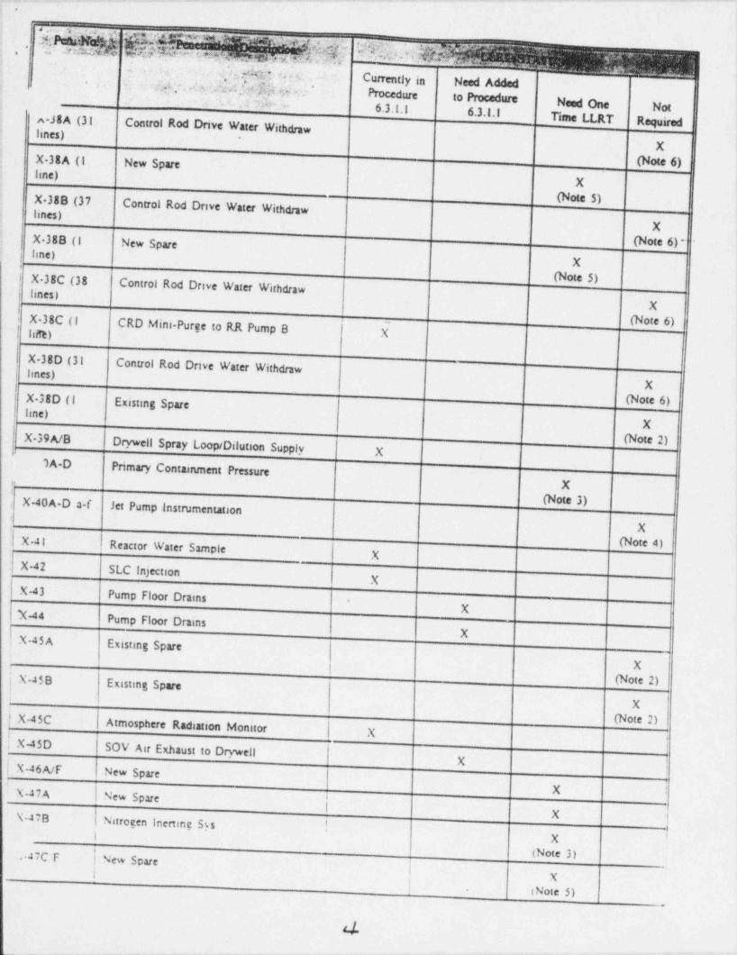
. .-.- - . . . . - . - - .
.
,.; .
-
l, ..).q% o g Currently in Need Added
,
, _,g -6Ad.,:wd69.@$yce *
Procedure to Procedure Need One Not
.
rSA ,.a6.3.1.1 63.1.1
i
Time LLRT Requireda J8A (31Control Rod Dnve Water Withdraw
linss) ~
X
'
X 38A (1 New Spare (Note 6)line) X
(Note 5)X 38B (37Control Rod Drive Water Withdrawlines)i
XX 38B (I New Spare (Note 6)-
| line) Xt
(Note 5)i X 38C (38Control Rod Drive Water Withdraw
i lines)l X
X 38C (I CRD Mini-Purge to RR Pump 8 l k (Note 6)i
| liitt)l
X 38D (31Control Rod Drive Water Withdraw I
; ImGs)| X
| X 38D (1 Existmg Spare (Note 6); line)
Xi
X-39A/B (Note 2)Drywell Spray Loop / Dilution Supply Xl
SA D Primary Containment Pressure
| X(Note 3)X-40A D a-f Jet Pump instnamentation
X) X 41 (Note 4)Reactor Water Sample
XX 42 SLC Injection
XX-43 Pump Floor Drams
XN-44 Pump Floor DrainsX
X-45 A Existmg Spare
X
Eustmg Spare (Note 2)X-4 5 B
' X
| X-45C | Atmosphere Radiation Monitor| X
(Note 2)i
_
|! X-45D SOV Air Exhaust to DrywellX i
[ X-46A/F New Spare'
4 i X !~ X 47A | New Spare a
}
| Nitrogen Inenmg Sys !XL478
l X(Note 3).
47C F ! New Sparei X
i iNote 5).
_
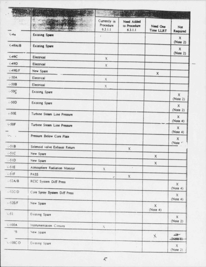
. _ . - _ _ . - . . - - . _ . _ . - ._.- -
k$W,
3':
~
g .- - >-
Currently in Need Added"' g~' ,,y y Procedure to Pincedure Need One Notc,
gS 47: - 6.3.1.1 6.3.1.1 Time LLRT Reqmrod. m, ,,__
\' 4s Existing Spare|
<
X
| (Note 2)'<49A/B Existing Spare
| X
| (Note 2)X-49C Electrical
| |X
*
s-49D Electncal| fX
<-49E/F New Spare| |X
s50A Electncal| |
X
4 50B Electrical| |
X
<50C Existmg Spare
(Note 2) ||X
s 50D Existmg Spare|X
(Note 2) |s50E Turbme Steam Line Pressure
| |X
| (Note 4) |X-50F Turbme Steam Line Pressure
-
| |X
| (Note 4) |X. Pressure Below Core Plate
|.
X(Note C }
{ 51B Solenoid valve Exhaust Return|X
i-51C New Spare|X
X-S I D New Spare|X
X 51E Atmosphere Radiation Monitor X |'
N-5'l F PASS|X,
s-52A/B RCIC System Diff Press| X
| (Note 4)'
v52C/D Core Spray System Diff Press| X
| (Note 4)v52E/F New Spare
X(Note 4)
X 53 Esisting Spare| X
| (Note 2)X 100A Instrumentauon Circuits ! |N
'O New Spare i |i K M
- @"'"-* F-,
N 100C/D Esisting Spare f'
X|
'
(Note 2) 1
(
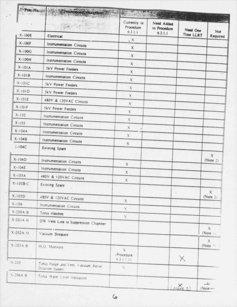
,,mi..e -** -' _ _ _ _ _ . - . --- -- -~ ~
'
' '$' k.-
*
h , yAgs -
Currently in Need Added.
.2Fg+ ' gA, 'Tpi -. .g
Procedure to Procedure Need One Not* *
6.3.1.1 6.3.1.1u X 100E Electrical Time LLRT Required
~,X
| | |X 100FInstrumentation Circuits
| | |X
X 100G Instrumentation Circuits
| | |X
X 100H Instrumentation Circuits
| | |X
X 10l A SkV Power Feeders
| | ~ ||X
X 10lBinstrumentation Circuits
| | fX
X- 101C SkV Power Feeders
| | ]XX 10lO SkV Power Feeders
| | ]X
X-101 E480V & 120VAC Circuits
| | )X
X-10lF 5kV Power feeders
| | }|X
X 102Instrumentation Circuits
| | ]X
X-103Instrumentation Circurts
| | ]X
_-X 104 AInstrumentation Circuits
| | ]X
u X-104Binstrumentation Circuits
| | )X
-104C Existing Spare
| | X
Instrumentation Circuits| | (Note 2) jX 104D
| |X
X 104EInstrumentation Circuits
| |X
X 105A480V & 120VAC Circuits
| | ]X
X 105B/C Existing Spare
|,
X {,
X-105D180V & 120VAC Circuits | (Note 2) j
| | )X
X-106Instrumentation Circuits
| | )X
X 200A B Torus Hatches
| |X
X-201 A H DW Vent Line to Suppression Chamber
XX-202 A. M Vacuum Breakers . (Note Ii
1
X '
X-203 A. B H.O. Monitors (Note 9 6X
(Procedure6.3.11.1) K
X-205Torus Purge .uid Vent. Vacuum Reliet'.
XDilution SupphI N :06A B[ Torus Water Lesel Indication
| 4| [ y[, O (Note-l
G
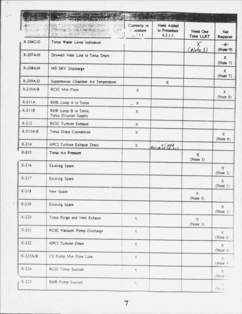
4
*
+. m . .
t;;4rmthi,
&W Currently in Need Added
$9p"Q1t$$jjjf)$$N544:T*$ dab %@D Ms%vr!)pf ;M;py s ' :.A
| Jsi x u d Y Mfdft ??N!4 (cxedure to Proceduct Need One Nme
(3 ? .xi- e* ', v. ?, I I 6.3.1.1 Time LLRT Required
X 206C/D Torus Water Level Indication|
/44[3)--3t -
sarnIX 207A/H Drywell Vent Line to Torus Drain
| || (Note 7) | !X
| |X 208A/H MS SRV Discharge
| |X| (Note' 7) || ,
| | ||X-209A/D Suppression Chamber Air Temperature X
| |X 210A/B RCIC Min Flow X
|X| | (Note 8) |
| | ||X-211 A RHR Loop A to Torus X
-X 211B RHR Loop B to Torus, X |Torus Dilution Supply|
| | |X 212 RCIC Turbine Exhaust X
| |X 213A/B Torus Drain Connection X X
| | (Note 8)
gg,g[fd4 | | ||X-214 HPCI Turbine Exhaus Drain X
X 215 Torus Air Pressure| ||X
(Note 3) | ||X 216 Existing Spare
| | (Note 2) |X '
| | |'
X 217 Existmg Spare| | |X
'
| (Note 2) |X 218 New Spare X
*
(Note 5) !-
X-219 Existing Spare|
~
X
| (Note 2) ||
| | ftX-220 Torus Purge and Vent Exhaust X X
| (Note 3) | | 1
fX-221 RCIC Vacuum Pump Discharge X |X
| | (Note 8) |
| fXX 222 HPCI Turbine Drain X
| | (Note 8) |X-223A/B CS Pump Min Flow Line X X l
(Note s,
X-224 RCIC Torus Suction I X X,
(Note -X-225 RHR Pump Suction ! N i
'
(Nm.
7

- . . .- .. .- . . . . . - . ~ -- - _ . _ _ - . . . - --_
. ,
| HPCI Torus SuctionX-us,
|| |
X|| (Note 8) ||
X
| X-227A/B |CS Torus Suction
XX
| Existing Spare (Note 8)X 228
| |(Note 2) ||-
X|
| Vacuum Breaker Actuatmg AirX 229A/L
| | |X
X 229M Existing Spare
| || (Note 2) |h
X
| Electrical| |X-230
| | |X._
!'
1 NOTES
The Drywell to Torus Vent Lines are considered an extension of the containment boundary and are included in theType A test.
Existing spare penetrations are considered as part of the containment liner and are included in the Type A test.
with the Type A test. Modifications to the instrumentation or isolation of the instrumentation during the Type A tInstrumentation associated with these penetrations is considered an extension of the contamment boundary and is includ de
equire a one time local leak rate test (LLRT). est will;|
These penetrations are designed in accordance with Safety Guide 11 (Regulatory Guide I.ll) and are included in the TypeA test.
Modifications are being made to make these penetrations spares.
Subsequently, these penetrations will be considered part of the containment liner and included in the Type A testa one time local leak rate test (LLRT) is required..
Th2 Cooper Nuclear Station Safety Evaluation, dated February14. 1973,
the implementation of Appendix J, such as the control rod dnve penetrations and standby liquid contSection 6.2.3, states " Systems designed pnor to*
have design provisions for individual leak tests; however, the nonnat functional testing of these systems ensure theirrol system, do not
op;rability and thence the necessary containment integnty.*
These penetrations are entirely contamed in the torus and to not represent a potential post-accident atmosphenc releasepath.
Thtse penetrations are currently in the local leak rate test (LLRT) program. However, these penetrations are water scaledby the torus and can be removed from the LLRT program.reviewed pnor to removal from the LLRT program. IST program requirements for these penetrations should be
9
! .
| + q(m*.-
1- .
_ _ _ _ -
. . - .-
...
. ,.. . ..
nameseaansee$ ElitThlt--
SENERAL e.e. eam== ame. tene n ,a,,,,_e sees ==mr,
p p.c. %-
4 sener spectriemes9 Nka_talam_ _
TITLE coess das zuussaur, staantas
i3 1.o .aga
-~
t.1me deemme.t e,ectf tee the Codee e.d 2.d.etesel st
rde .,,1s.
*
cable te (a) he3, - ci . e beti e, yetene end itema of equipment uhteh enha up thees e.d =R g" better eyotes of a bellies water type melear power plane.-. pen te -1.te. so .e moeie.,
, ,
2-I 1.2
h Codes and Industrial stenderde tieted are these which apply.*
Ny may be supplemented to sattefy h requirements of the appli.This empplementies infeemstion will be speetfied by deelan,! cattom.
perehastas or testa 11etten specificattene toewed by b esmeesttiectrie Campeay,
y 1.1
the Genere1 electric Campsey as betog appliemble to the speetfieReference eheutd be made to any drawinge se spectitestgese Leseed by._ -
jeet for the itene toeleded berata.'
pre.thte standard design speetficaties and the regetressete of the ehehee differeneee esset between"
oestioned deemmente, the project deenemente shall be used. erO
*
1.4This destga er,Hrcificettee was prepared based open ne spee&fte
;
Electric Campeep and its cuateusta er eestractere.dietetes of work assigement or respemethitity between the Comorenwork assigneemt shall be spectited eteeubers. h dieteges of
T2.0 M3
The objective to to conform with the requiremente of the vertene regelo.'
tory bedies having jettedicties at the site of the euclear power planti
,
i
It is a further ehjeetive to estehtteh the Codee ese xadestrial stenderde''
.
ubteh boet meet the level of quality and eseuranee eenetetent with themesure of the applicaties of the ayates er it.m of equipment taetodedhereta.
3.0 m3.1
Deless othetwise specified, the deetta of itsee, eyetene end equiposetand their esbeequent fabricetten and testallettee, shall be im neeood.ease with the Standards and Industrial Cedes speetfied sa the Appendia.
3.2Itene of piping and equipment which are met within the oespe of h !
fabricated med tastalled ta sceerdasee with the etendard eedes thishnuetear better systene and met iteted ta the Appeedia shall be des 1M,
iapp 1F.
~ .* ewjjgs- ; M rr/A .
| |
..
-suitss, n. 1, san L m, t
2.. 1oesTatsution . .. e . . (,
sursassess any, o anssa 11/1stes, j |
i
_ .- '~ _ , _ __ --
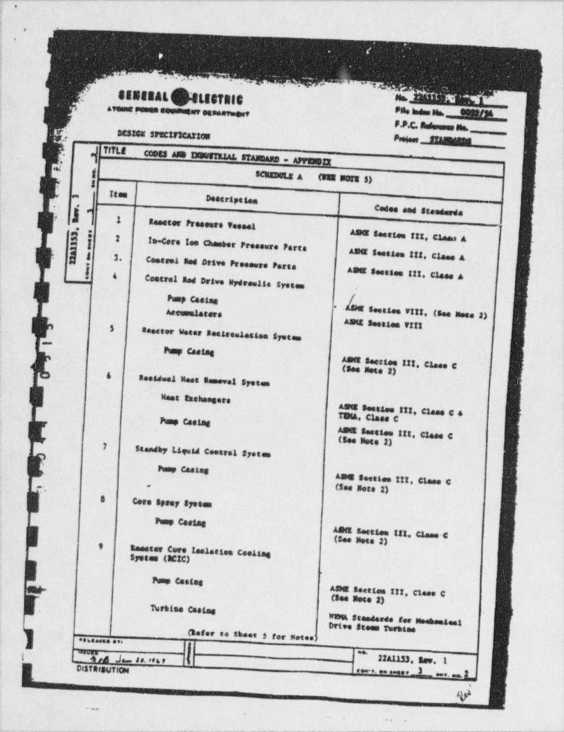
,>
<
!y. '>
1 -
i __
i
f'.
, ''' .,, , . . .
- '' 'O, ,
F
SIBIBALhtISTROC.-
'No,-
,
}*a,,
,
,
steanssomesseuseusarees N ene hessue, ERINM. ..t
P.P.C. Suissesse Ms._sesags spectrscartes.
i TITLECOSes Am INNgTERAL STAMARB = APMII
-' .
; ,&}g SCMBOLE A (W W Nots $)
-
g
igen,
, Doetription ,
t
j Cedes and Steedeeds-
, .'
i.
seester Pressors Tu set - - - -
' -
ICl *. Amer Sm eten itt, Claea A2I te. Core tee Chamber Freasure Porta-
AsNE Soestem 111, Claes AJ 3.Centeel med Drive Pressere Parte
| 4 ASE Soestes !!!, Claes ACenteel Red Drive Wydram11e system
i PunP Cecing-
Aecumeleters Seetles r!!!, (See Nees 2)ASit Soestes ?!!!$
teeeter Water Reesseuletten Syeces,
-
Pump Caesag
Asnt Seerga !!!, C1.ee C(See Note 2)&
Residual Meet Removal Syst e,
Heat taebeegersAs s Soestes !!!, Clase C &T984, Class C
Pump CassagAB E Su ti m !!!, Claes C(See note 2)7
Steadby Lip id Centeel Systems,
heap CastesAm t Seetles !!!, Clase C(See Note 2)
. .'
,
8 Cere Spesy Spetas
Pump CasingASit seetten 111, Caese C(See Note 2)9
taester Core toelation CoettagSystem (EIC)
Pump CassegAD E Seettee !!!, Close C(See Deze 2)
Turbine Caetas-
Wem Steederee for MeehestestI
Drive $ team psettee(Refer to shoes 5 for Notes?..6s . . ..
j=*.
| ! ~ '7(a J 4 e. <* 6 , T h 22A1153. Rev. 1'
- DISTRIBUTION . . . . . 3 .. 2*
Y.,
_
e e e
,w-,. - - - , , , . , _ . . _ . _ . _ _ . _ _ _ _ _ _ _ _ _ _ , __ _ _ _ _ _ , , , _ ___,_,_m_ _ _ _ , . _ , , _ , , , _ , _ _ _ _ _ . _ _ _ . _ _ _ _ _ _ _ _ _ _ _ _ _ _ _ _ , _ , , _ , _-
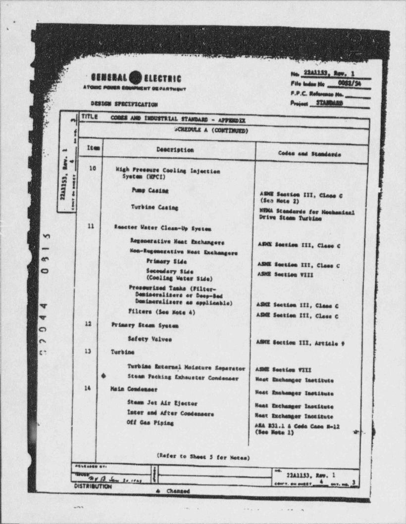
_.-- . - ..- - . - - -. - - - - _..-- - - - _ _ ___ _ - - _-__ - ___ ___ _ -
,,!l
! *.-
!-.
!
I-!
y ,. .. ~-. ..
j .
. , , ,.
,..
.
!ne, saamass ner, s
SENERAL$ ELECTalt'
-:
en. i.e.e u. esss/sn,
i. Afees sesem assummer eneeerese"?t . . .
I- F.F.C. Nedessess nn. _
,, f sasass spectr Carses @ S18345-
*'
:
!--
_ TITLE CCMS Als IWUSTRIAL STAMR&B - AFFWIE-
, c e|- 'I -l I SCitEDULE A (CouTINUEB) -
jI I| Item Descripties,
{_ Codes med Steeseede*-
.:- -!: 10 Wish Pressure Cae11e6 !ajeettee ;
i
, g; System (llFCI)i.n -
!' "Pump Caetat
I ASE Seettee III, Claes C [. k (Sca Note 2) {
Tvebtee Castes! FWitta Stenderde for u==h==a==t*
! Drive Steen Tw bies,
! 11! Reseter Water Close-Up systee >
,
|D
Rosenerative Mest toehongere ,1
{AndE Seesame III. Clase C
!-Mee-Regemesettve Nest Esehengere '> |
( 'e Prisery Side| AS E Seestaa III, Claes C
g $eseedery side*
AS S seetten VIII '(Caeling Water Side)
j'
Pressorised Tanke (Filter - ;
ii Denisere11 sere er Deep-Sed
'
Desteeralisere es appliesble) ASet Seetsee III, Clane CT<
Filtere (See Note 4) ASE Seattae !!!, Claes C'v $
i 12 Primary Stese Systes! C
Safety Velves ;
ASIE Setties 111. Article 9g 13 Turbtee
!
Tweblee Enternal Meisture Separator AS E Seettee VIII4) 6 Steen Peckies tahouster Candenser Meet 8==h==ger testatete !
14 Mais CondescerBest amehmoser lootitate
Steaun Jet Air tjeeter Nest Enehenger lessitateInter med After Ceedessere Ileet taehanger Issattute iOff Geo Piping' A34 331.1 4 Code Ceee 5-11
(gee geen 1) *' h-
(Refer to Sheet 3 for Metes)* * " " * * * '
_ l ^22A1133, Aar. 1
~ 3 F /$ b f p ff6f f
dese.9. ess essGe f Gus'* 8ushDISTRitt# TION , w{
.
. . . . -.. + * * a
. . _ _ - - - - - - . _ _ _ _ _ _ _ _ _ _ _ _ _ _ _ _ _ _ _ _ _ _ . _ _ _ _ _ _ _ _ _ _ _ _ _ _ _ _ _ . _ _ _ _ _ ._-

-
. .!
j - . -
! . -
t _-
i,
-.
.
, _ ., . ... .~.'
. . .
,
neeer.pensa eeu$ tLEsfRIS n., 22s tss. new. t4EN8BAl|
wesetos mesmewr raeu essais ~Desses :PECIFICAftcK.
y,p,4 % ]i
Tlft.Ecosts Ane tiesstatA1, stagnaan - Appsustr
-
.
ISCIEBCLE A (CokTINUts) ]S .g
Ites,
Deeeripetee,
en
C n. Codes and Stendeede--
1. Pee -e e. re e-4 I ^
2 ! lleeters (including drain coolere)e**
j
ASME Seatten Vit! 4 FeedesterI
| Destees Menefecentes AseeeAetStendesde ionPipiel from the Reester PressureE * , 16 Vessel thru first Elmat-off VelveASA 331.1 and ASME Seettaa !
Condeneste Filter-Gesinere11serPersaraph PC-54 (3) (See Mete1)
pPresevrised Tanke'
Filters (See Note 4) Aatt Settles VI!!ASit Sostica V!!!; -
17Closed ime, Coelina Sysses - Reacterse1141st'
heat Eachengerr
A5ME Seetten V!!!". 18Fuel Peel Coelies & Filterten \'Systeen.
Cb Pop Casing'
itset Escheager ASME Seatten VIII (see Note t)#
ASME Seeties V!!!-19Rediseettve Veete stepenen systes'
weste s,. se pree-re veeesteAStE Sau ten VI!!20 Peteery Caesatenese
{,
Costatsment Veeeel (ineludina dry-E'
well, wetwell, and interseceaseingp1 pine)1
Costelaneet Veeuus Areakers AS:1E Seetime 111, Claes Ri
ASME Section 111, Class 5 andCenteiseent Aemiliary Frecese ASA 331.1
'k F1ptag.4
i
E Costeinseet Penetrations ASA 231.1 (See Note 3) }
AS:1E Sectica !!!, Class 5 g|i
] (Refer to Shoes 3 for Notes).... . . . . . y"'W pp) Jm ps,adap
, e. ,,,13,3, ,,,, ,i0857H9UTl0N
,i
:
. ,,, og o e . _ $ ,,,, 1
- - . _ . - -- . . - --
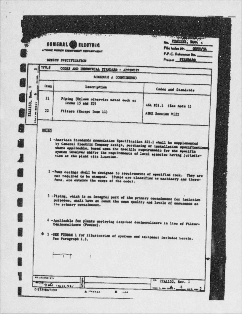
,-.-..-.- _.__.-__._ - ..--- - ----_- _ -__-_ - - -
.-
|
:- .. ..
.
. . . . - . . .. , . - , ,. . . . . ,. ,.,,
..ne, ; aum.,a
, SENERAL$8L88T818,!
Areegesses seessemeressee m m e pee nia smi.h5, F.P.C. Redweses 80s. '
asstes spectrscarsom W SM. .'
Tf?LE Ceems Aug INESTRIAL 87A15435 - AppseDEI.
-
g SCIEBOLE A (CONTINUED)
E Is teen Descripties
~
'_ Codes and steeds.sde
Eje
I 21 ' F1 ping (Ontees otherwise neced eveh as4 ; Itase 15 and 20)
ASA 331.1 (See Note 1)
8 *l Asut seetles VI!!22 Filters (Riseeps Ites 11)
i1
g,
:
1 -Ameriese Standesde Asessistsee spesificattee 3311 ehe11 he neppienented8 by General Electric Campeer deelse, pereheeses or inetouetten spesaftestseesenere applieeble, based spee she specific regetrements for the eyesifAs ,
oyeten sece e .c e,oleel end/or the regattements of letal egenstes hertog justedle- ;y epl .it. - e... '
.
;
2 -Pump coolese shall be deelseed to requiremente of specified code.i They aremot required to be et a ped. (Ptente are claestfied as machlaery and there-fere, are seteide the esepe of the eede).
,-,,p . h . e.r.1,.rt.,t prme,-.._ ,or m.m.
E perpeces, shall have et leses the eene queuty and legale et asessasse sethe pramery eessaiement.,
g . . . .. .. ,or P,- . ,,e. ..ep.h . nor.m r. e o e , t _e s o.or. < ee.e.).
4 5 35 F30tas 1.for.111estrestee of eyesees and equipeest testeded herese..
p.r rep 1. .
IL a > .
-
y .. . . . . . .; _ muu m...
, . ., e , s . _ . . . . . . 4 .. _ toistanutrowa ti..n.. A ade
.
, , , , , , . - - - . - ,
*I
.a
1 .
.
^ ';
~*4, . , ,
.g, , y,.stestai
*J ** *,
.- esssen. 'A .,j' .
1-=** ** =Emanu_._
,
.
,,,,,-
.ma . _*
F.P.C Asdis m -M'
Um.a Y
cens me amer *'ai emmenas . - .
e. -
> '
j.
.;- ag .
5 \ g d -
j- :iii|J3..
+,
.
i e: )i==
If i [ J|s 18 hlgs
b$ ),__i =:
\
' Yhl _k-
thly,1D h'.e 4 g4__
!* ,_i 8
l. 7 |.,
I ! |, % 4 "a,
< 1,-
h' f/ ki [ n*
'-
M ,
[ T M s4g.
- i < , tr4 .
4"
g -| (\; y &., o a,,
"
. g)~
\ risede".
,i ~.**O ++ated( n \-
44 LE -- a,
-
/|5 (N" !
1,.
*i
1
-a [, w'i~I.., % , j-il s ~rjiEe ., . .. .
'.
._ , w ,j L .. ... m--
3- .e. . . .1
m,..>..,,., 1 - ,.
. . >***.**enea,FWA'
.. 1
_.
*,,..e a
- - . , , _ , . - -. ,, . - . _ . - - . - - - . - - - - |
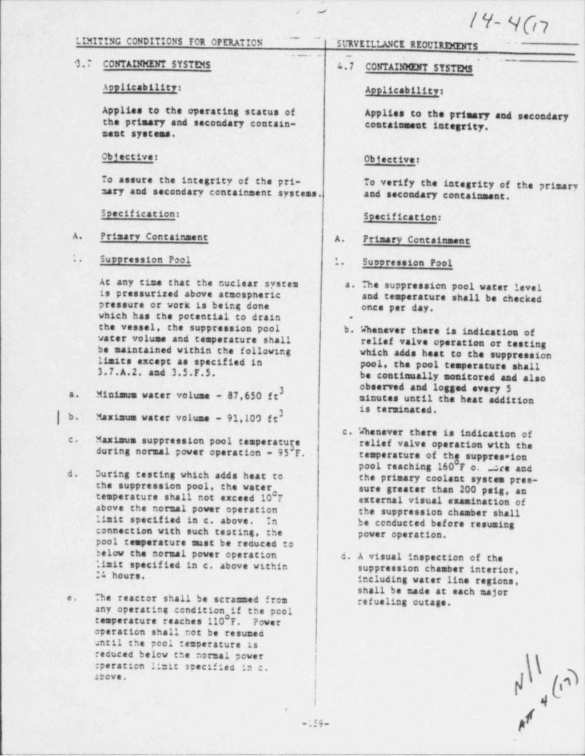
--
' '
/ Y- 4071
~~~ ''
LIMXTING CONDITKONS FOR OPERATION "SURVEKLLANCE REOUIREMENTS'~
3.T CONTAINMENT SYSTES 4.7 CONTAINMENT SYST25
Applicability: Applicability
Applies to the operating status of Applies to the primary and secondarythe primary and secondary contain- containment integrity.ment systems.
I-Objective: Objective: )
To assure the integrity of the pri- To verify the integrity of the primarysary and secondary containment systems. and secondary containment.
Specification: Specification:
A. Primary Containment A. Primary Containment
1. -Suppression Pool .1. Suopression Pool
At any time that the nuclear system a. The suppression pool water levelis pressurized above atmospheric and temperature shall be checkedpressure or work is being done once per day.which has'the potential to drain ,
-
jthe vessel, the suppression pool b. 'Jhenever there is indication ofwater volume and temperature shall relief valve operation or testingbe maintained within the following which adds heat to the suppressionlimits except as specified in pool, the pool temperature shall3.7.A.2. and 3.5.F.5. be continually monitored and also
3 observed and logged every 5a. Minimum water volume - 87,650 ft minutes until the heat addition3|b. Maximum water volume - 91,100 ft
c. '4henever there is indication ofMaximum suppression pool temperatu5' '*li'' **1'* Operation with thec.during normal power operation - 95 T.
temperature of thg suppresaionpool reaching 160 F ot ace and , |d. During testing which adds heat to the primary coolant system pres-the suppression pool, the water sure greater than 200 psig, ancesperature shall not exceed 10*? external visual examination ofabove the normal power operation the suppression chamber shall
limit specified in c. above. In be conducted before resumingconnection with such testing, the power operation.pool temperature must be reduced to 1
jbelow the normal power operation d. A visual inspection of the '
limit specified in c. above within suppression chamber interior, i24 hours. including water line regions,shall be made at each majore. The reactor shall be scrammed from refueling outage. Iany operating condition if the pool
!temperature reaches'110 F. Poweroperation shall not be resumeduntil the pool temperature is
!reduced below the normal power:peration limit specified in c.above.
4*
f-;39-$
_
J
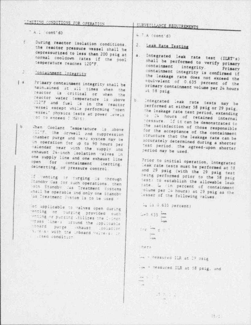
_ _ _ _ _ -
t
LIMITING CONDITIONS FOR OPERATIONSURVEILLANCE REOUIREMENTS
.A.1 ' cont'd)4. 7. A (cont'd)
f. During reactor isolation conditions. 2. Leak Rate Testinethe reactor pressure vessel shall bedepressurized to less than 200 psig at a. Integrated leak rate test (ILRT's)normal cooldown rates if the pool shall be:emperature reaches 120*F. performed to verify primarycontainment integrity. Primary
containment integrity is confirmed if2. ontainment Interrity-
the leakage rate does not exceed theequivalent of 0.635 percent of the| a. Primary containment integrity shall beprimary containment volume per 24 hoursmaincained at all times when the at 58 psig.reactor is critical or when the
reactor water :emperature is above b. :ntegrated leak rate tests may be212'F and fuel is in the reactorperformed at either $8 psig or 29 psig,vessel except while performing "open
vessel" physics :ests at power ;evels the leakage rate test period, extending Ito 24 hours of retained internalno: to exceec ! .TJ(t) .
If it can be demonstrated torressure.:he satisfaction of thoseb. 'a~h e n Coolant Temee ra ture is above responsiblefor the acceptance of the containmentl .' " * F . :he drywell and suppressionstructure thatchamber purge and ve.sc system may be the leakage rate can be
iaccurately determined during a shorterin operation for up to 90 hours per test period, the agreed.upon shorter ;calendar year with the supply anc period may be used.exhaust 24. inch isolation valves in :one supply line and one exhause line
?rior to initial operation, integrated iopen for containment inerting,deinerting, or pressure control. '.eak race tests must be performed at 58
and 29 psig (with the 29 psig testbeing performed prior ,
:f venting er : urging is throughtest) to establish the allowable leak
to the 58 psig !1:ancby Cas for such operations. then rate. L lin percent of containment
'
otn Standbv .ia s Treatment Systemsenall be operable and only one Stancbv volume per 24 hours) at 29 psig as theias Trea: men: Svs:am is to be used. ". esser of the following values. )
L, is 0.635 percent)No: applicable :o valves open during :''enting or : urging provided such -0.635 _*+n:ing nr purtir.g 2:ill:es :he : inchL,.v; ass '. ine e s sround the applicaole
.coard purge exhaus: .sola:icn f a r "* r 0 ' ;.
1.veisi 91:5 :..e .nboard valveis; |'----
.:seo conoi:::r ''*
:ner+
-, ereasured ILR at 29 asig-
.,, - measured ILR at 58 psig, and,- 2__ -
..@
4 . O
_
5
05/l'
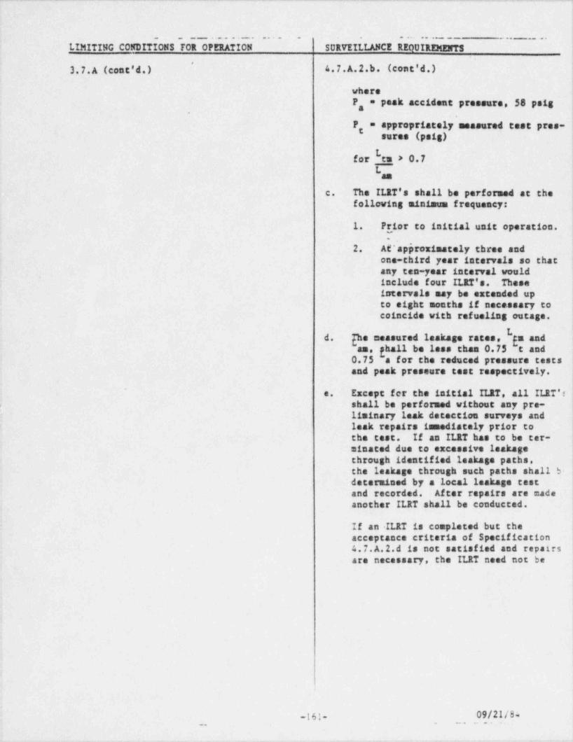
-. . . - . . . - - . - . . . . - . . . _ - - - ..-_- ..--..-._ _ . - . - _ . - . - . - . . - . -
.
. _ _ _ . . . . . . . . . . . . . . . . . . . . . .. _ .. ..
LIMITING CONDITIONS FOR OPERATION SURVEILLANCE REQUIREMENTS }' '
3.7.A (cont'd.) 4.7.A.2.b. (cont'd.),
where
-
P, = peak accident preneure, 58 psig j;.
F* = appropriately measured test pres- ;sures (psig) +
bfor en > 0.7 ,
'Las
c. The ILRT's shall be performed at thefollowing minimum frequency:
1. Fr,ior to initial unit operation. I
2. A *approximately three andone-third year intervals so that
'
any ten-year interval wouldinclude four ILIT's. Theseintervals may be extended upto eight months if necessary tocoincide with refueling outage.
{hemeasuredleakagerates,Lgaandd.an, ghall be less than 0.75 e and0.75 a for the reduced pressure testsand peak pressure test respectively. j
l
ExceptfertheinitialILRT,allILRT's]e.shall be performed without any pre- '
r.
11minary leak detection surveys andleak repairs immediately prior tothe test. If an ILRT has to be ter-minated due to excessive leakagethrough identified leakage paths.the leakage through such paths shall b-determined by a local leakage castand recorded. After repairs are made
'another ILRT shall be conducted.
If an ILRT is completed but theacceptance criteria of Specification4.7.A.2.d is not satisfied and repairs |are necessary, the ILRT need not be
I1
6
161- 09/21/84-
.. . -. . . .
w---- em , -
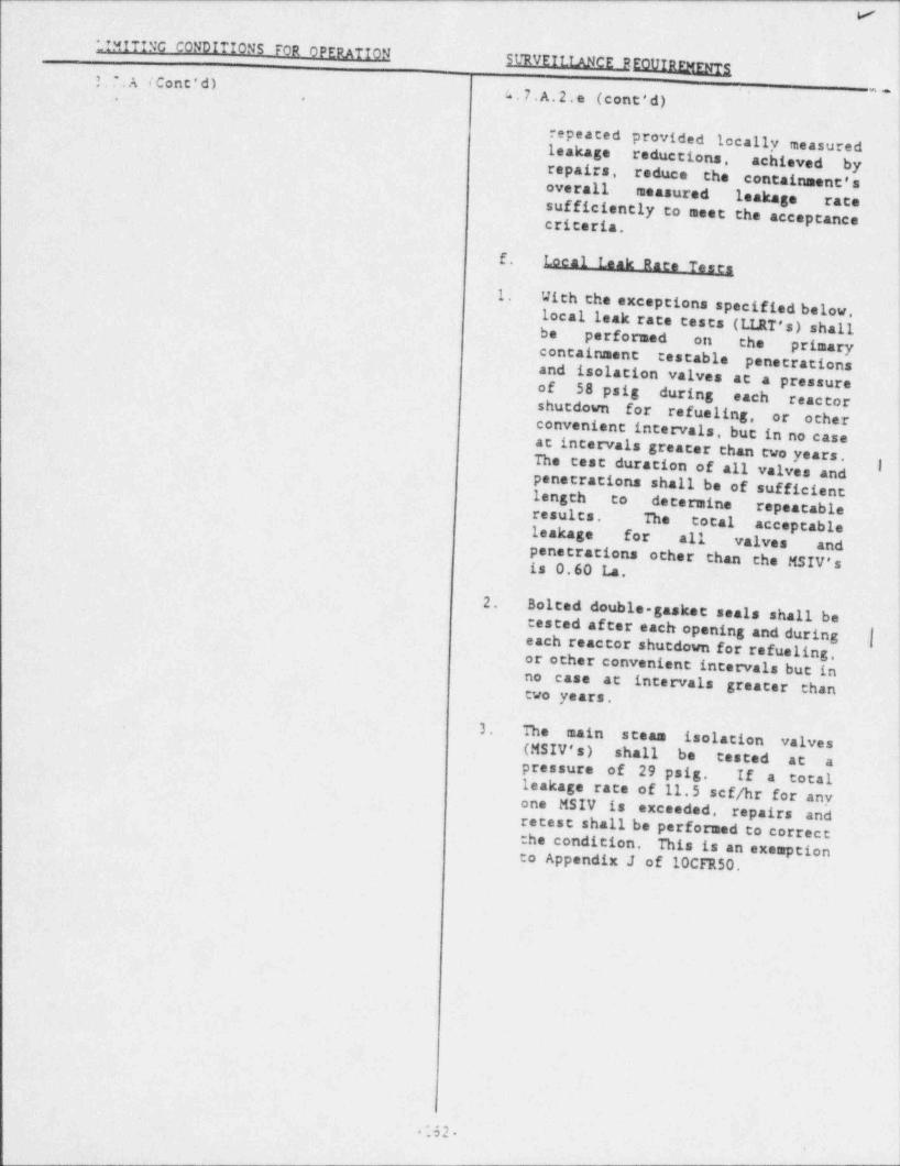
l7
*
._IMITING CONDITIONS FOR OPERATTON :SURVEff_TANCE REOUInrwgs3. ,A iCont'd)
'
_n4.7,A.2.e (cont'd),
i
repeated provided locally measuredleakage reductions, achieved by,
repairs, reduce the contaitunent's!overall measured leakage rate.
sufficiently to meet the acceptancecriteria. 1
,
|
f. Local bak Rate Testa |
1.With the exceptions specified below, 1
local leak rate ceses (I.IJtT's) shallbe performed on the primarycontainment testable penetrationsand isolation valves at a pressureof 58 psig during each reactor
!shutdown for refueling, or otherconvenient intervals, but in no caseat intervals greater than two years.The cost duration of all valves and ;
penetrations shall be of sufficientlength to determine repeatable|
i
results. The total acceptableleakage for all- valves andpenetrations other than the MSIV'sis 0.60 La. |
|
2. Bolted double-gasket seals shall betested af ter each opening and during |each reactor shutdown for refueling,
_
or other convenient intervals but inno case at intervals greater thantwo years,
i
3.The main steam isolation valves(MSIV's) shall be tested at apressure of 29 psig. If a totalleakage race of 11.5 scf/hr for anyone MSIV is exceeded, repairs andretest shall be performed to correctthe condition. This is an exemptionto Appendix J of 10CFR50.
1
|
!i
*52.
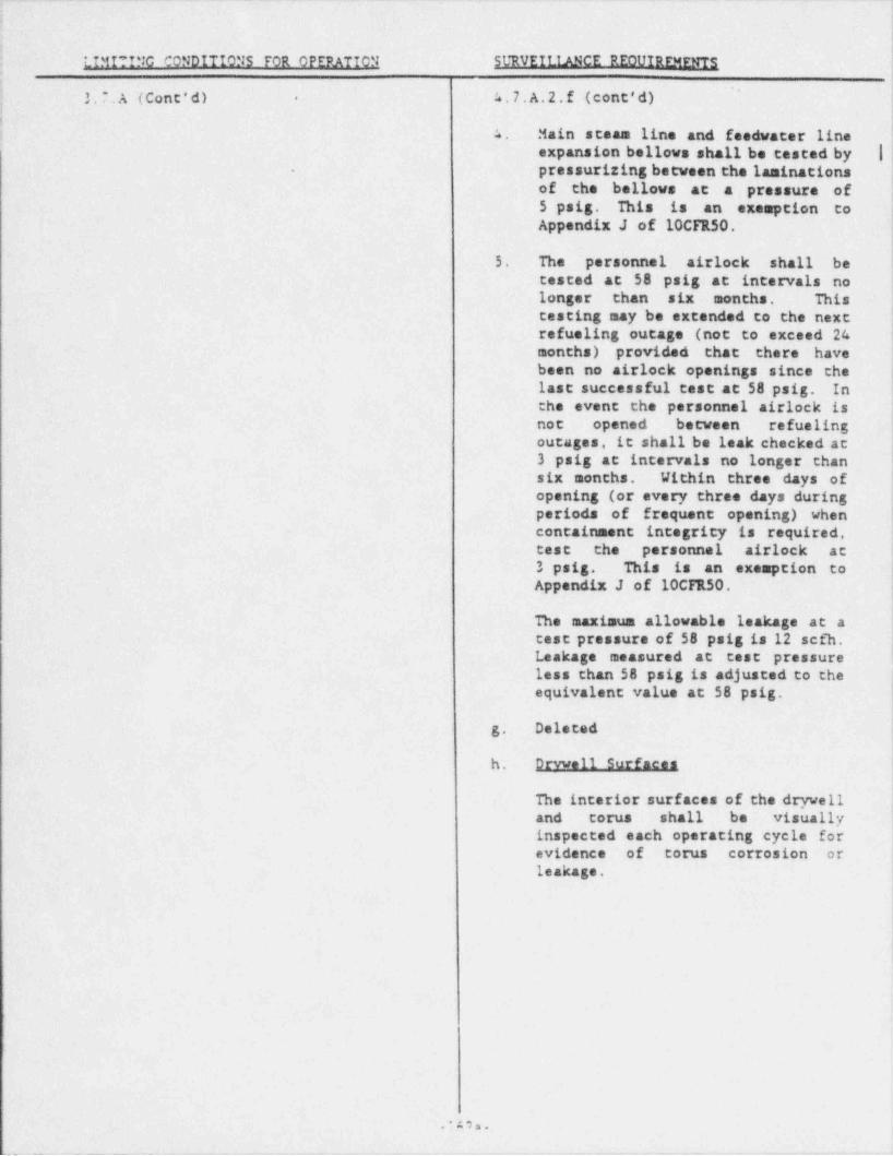
. _ _. . __ _ . - ~ _ . _ _ . _ . _ . _ . . _ _ _ . . . _ _ . _ _ . _ - . _ _ _ . . _ . . . _ _ _ _ _ . _
d
t
J
] LIMf??NC CONDIT?ONS FOR OPERATION SURVEILflNCE REOtfIRFMENTS,
k.7 A.2.f (cont'd)3.7.A (Cont'd) .
{'
4 Main steam line and feedwater lineexpansion bellows shall be tested by |
. pressurizing between the laminationsof the bellows at a pressure of5 psig. This is an exemption to
|Appendix J of 10CFR50. <
5. The personnel airlock shall betested at 58 psig at intervals no |longer than six months. This '
testing may be extended to the nextrefueling outage (not to exceed 24months) provided that there havebeen no airlock openings since thelast successful test at 58 psig. Inthe event the personnel airlock isnot opened between refuelingoutages, it shall be leak checked at3 psig at intervals no longer thansix months. Within three days ofopening (or every three days duringperiods of frequent opening) whencontainment integrity is required,test the ' personnel airlock at3 psig. This is an exemption toAppendix J of 10Cf1L50.
The maximum allowable leakage at atest pressure of 58 psig is 12 sefh.Leakage measured at test pressure
. less chan 58 psig is adjusted to theequivalent value at 58 psig.
g. Deleted
h. Drvwell Surfaces
The interior surfaces of the dryvell j
and torus shall be visually 'iinspected each operating cycle for
,
evidence of torus corrosion or |
1eakage. I
i
.*A7a.
. __ .__ ._ - _ _ _ _ _ _ -. --
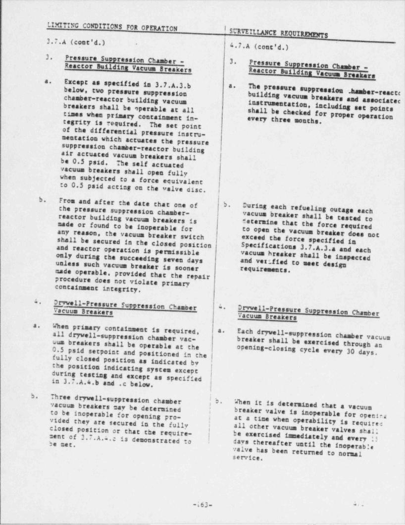
- . - . - - .. - ...- - - - - _ . . - - . - - . - . . - . - - - - - . . _ . - - -
),
LIMITING CONDITIONS FOR OPERATION! StltUEII.IJufCE REQUIREMENTS !
3.7.A (cont'd.) 4.7.A (cont'd.) \,
\3. Pressure Suppression Chamber - 3.Reactor Buildinz Vacuum Breakers Pressure Suppression Chasber -
Reactor Buildins Vacuum Breakers !Except as specified in 3.7.A.3.ba.below, two pressure suppression The pressure suppression .hamber-reaccc |I
a.
chamber-reactor building vacuum buildingvacuumbreakersandassociatec|instrumentation, including set pointsbreakers shall be operable at allshall be checked for proper operationtimes when primary containment in. every three months.tegrity is required. The set point
of the differential pressure instru-mentation which actuates the pressuresuppression chamber-reactor buildingair actuated vacuum breakers shall '
,
be 0.5 psid. The self actuatedvacuum breakers shall open fullywhen subjected to a force equivalent |to 0.5 paid acting on the valve disc. t
b.Tros and af ter the date that one of b.the pressure suppression chamber- During each refueling outage eachreactor building vacuum breakers is vacuum breaker shall be tested tomade or found to be inoperable for determine that the force requiredany reason, the vacuum breaker switch to open the vacuum breaker does notshall be secured in the closed position exceed the force specified inand reactor operation is permissible Specifications 3.7.A.3.a and eachonly during the succeeding seven days vacuum breaker shall be inspected
unless such vacuum breaker is soonerand vestfied to meet design-requirements,
made operable, provided that the repairprocedure does not violate primarycontainment integrity.
4Drvwell-Pressure Suppression Chamber 4
Drvvell-Pressure Suppression ChamberI,~icuus BreakersVacuum Breakers
When primacy containment is required,a.
all dryvell-suppression chamber vac- Each drywell-suppression chamber vacuuma.
i
uum breakers shall be operable at the breaker shall be exercised through an0.5 psid seepoint and positioned in the opening-closing cycle every 30 days.fully closed position as indicated bythe position indicating system exceptduring testing and except as specifiedin 3.7.A.4.b and .c below.
b. Three drywell-suppression chamber b.When it is determined that a vacuumvacuum breakers may be determined j breaker valve is inoperable for opeut .a ;
to be inoperable fo' r opening ' pro-vided they are secured in the fully | at a time when operability is requirec i
all other vacuum breaker valves shalli
closed position or that the require.ment of 3.7.A.I..e is demonstrated to he exercised inmediately and every !!
days thereaf ter until the inoperable3, e.g,
valve has been returned to normalservice.
IJ
-163- '
_-- _ =____-
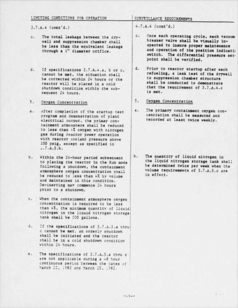
. .. -- -. . ., -. .-.. - .. _- .- -
|
l
|
1.IMITING CONDITIONS FOR OPERATION I SURVEILLANCE REQUIRDENTS
3.7.A.4 (cont'd.) 4.7.A.4 (cont'd.) j'
1
c. Once each operating cycle, each vacuumc. The total leakage between the dry-well and suppression chamber shall breaker valve shall be visually in-be less than the squivalent leakage spected to insure proper maintenancethrough a 1" diameter orifice. and cperation of the position indicatic i
switch. The differential pressure set-point shall be verified.
d. Prior to reactor startup af ter eachd. If specifications 3.7.A.4.a. b or c.cannot be met, the situation shall refueling, a leak test of the drywellbe corrected within 24 hours or the to suppression chamber structure
reactor will be placed in a cold shall be conducted to demonstrate |shutdown condition within the sub- that the requirement of 3.7.A.4.c jsequent 24 hours. 18 ****
I
5. Oxvaan Concentration 5. Oxygen Concentration
The primary containment oxygen con-a.a. After completion of the startup testprogram and demonstration of plant centration shall be measured and ;
electrical output, the primay con- recorded at least twice weekly.tainment atmosphere shall be reducedto less chan 4% oxygen with nitrogen )gas during reactor power operation ;
|with reactor coolant pressure above '
100 psig, except as specified inJ.7.A.5.b.
b. The quantity of liquid nitrogen inb. Within the 24-hour period subsequent,
to placing the reactor in the Run mode the liquid nitrogen storage tank shall 1
.following a shutdown, the containment be determined twice per week when the;
atmosphere oxygen concentration shall volume requirements of 3.7.A.5.c are|in eMeet.be reduced to less chan 4% by volume
and maintained in this condition.De-inerting may commence 24 hours ,
prior to a shutdown.
c. When the containment atmosphere oxygen Iconcentration is required to be lessthan 4%. the minimum quantity of liquidnitrogen in the liquid nitrogen storagetank shall be 500 gallons.
d. If the specifications of 3.7.A.5.4 thruc cannot be met, an orderly shutdownshall be initiated and the resctorshall be in a cold shutdown conditionwithin 24 hours.
e. The specifications of 3.7.A.S.a thru dare not applicable during a a8 hourcontinuous period between the dates of |March 22, 1982 and March 25, ;?82.
,
i,
se eg e
|
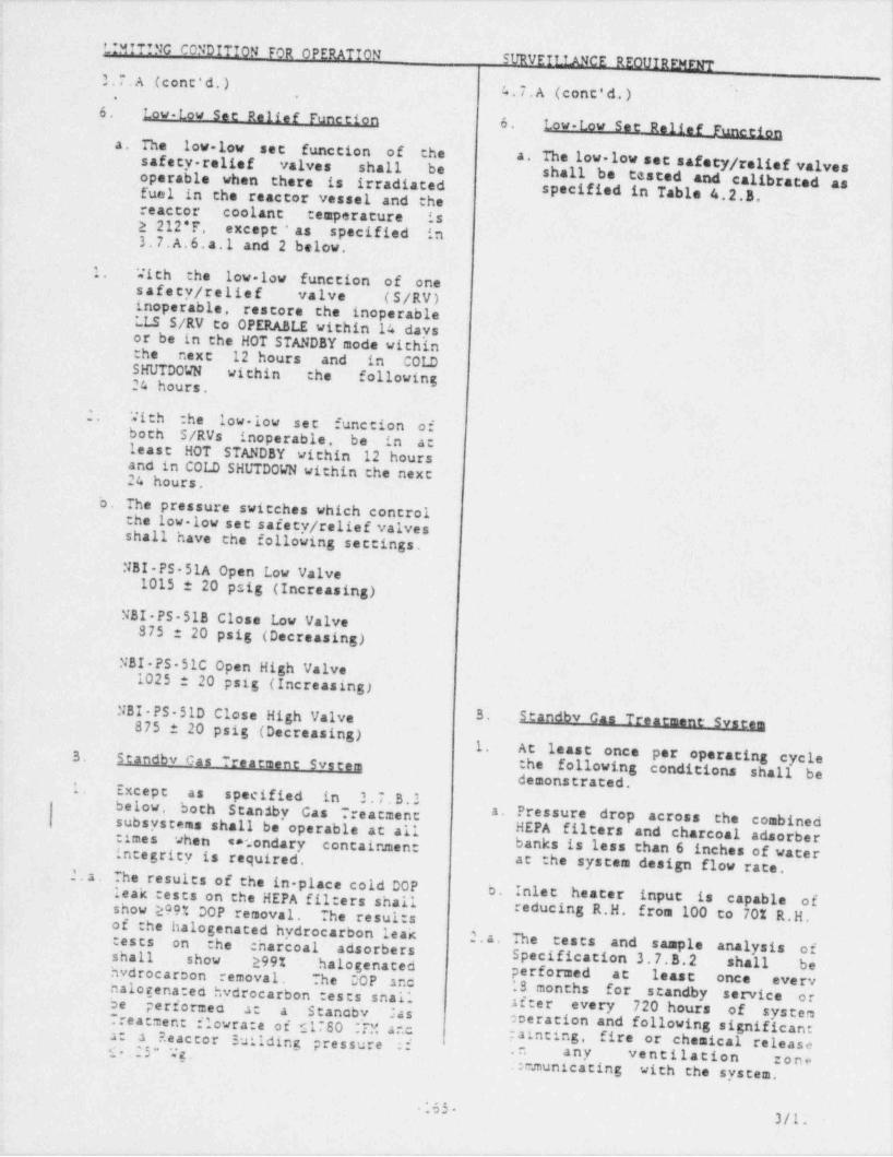
. . . - - . _ _ _ - - . .- . -. .- -. . . . . - - .. . . --
.
L*MfT?NC CO?DITION FOR OPERATIONSURVET2_2AICE REOUIRFMENT
3.7.A (cone'd.) 4.7.A (cont'd.) '
6$ Low-Low See Relief Function 6. Low-Low See Relief Function.
a. The low-low set function of the a. The low-low set safety / relief valvessafety-relief valves shall. be shall beoperable when there is irradiated tasted and calibrated asfuel in the reactor vessel and the specified in Table 4.2.B.reactor coolant temperature is2 212*f'. except*as specified in3.7.A.6.a.1 and 2 below. '
1. With the low low function of onesafecy/ relief valve (5/RV)inoperable, restore the inoperableLLS S/RV to OPERABLE within 14 daysor be in the HOT STANDBY mode withinthe next 12 hours and in COLDSHUTDOWN within the following24 hours.
2. With :he low-lov sec function ofboth S/RVs inoperable, be in atleast HOT STANDBY within 12 hoursand in COLD SHUTDOWN within che nexc24 hours.
b. The pressure switches which controlthe low-low see safecy/ relief valvesshall have the following sectings.NBI-PS-51A Open Low Valve
1015 t 20 psig (Increasing)
NBI PS-518 Close Low Valve-875 t 20 psig (Decreasing)
NBI-PS-51C Open High Valve1025 t 20 psig (Increasing)
NBI PS-51D Close High Valve ' "" #' ***
875 t 20 psig (Decreasing)1. At least once per operating cycle3. Standbv Cas Treatment Svstem the following condicions shall be
demonstrated.1. Except as specified in 3.7.3.2below, both Standby Gas ,reacmenc a. Pressure drop across the combined.
subsystems shall be operable at a" HEPA filters and charcoal adsorber~
:imes when ea'.ondary containmen: banks is less chan 6 inches of waternce6rity is required. at the system design flow race.2.2. The results of the in place cold DOP b. Inlet heater input is capable ofleak :ests on the HEPA fil:ers shall
show 299% DOP removal. The resul:s reducing R.H. from 100 to 70% R.H.of the halogenated hydrocarbon leak
2.a. The tests and sample analysis oftests on the :harcoal adsorbers Specificacion 3.7.3.2 shall beshall show 299% halogenated performed at least once evervhydrocaroon removal. The DOP anc iS months for scandby service ornalogena:ed hydrocarbon tests shallafter every 720 hours of systembe performeo a: a' Stanoby .ia s
Treatment flowra:e of c1780 :PY. anc operation and following significantpaincing, fire or chemical releasea ?.eactor 3uilding pressure :fa:
s .25" Wg. .n any vencilacion :one.:mmunicating with the syscem.
'
.65)jl.
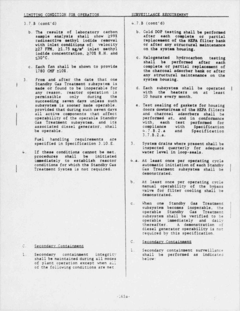
_ . _ _ _ _ . _ _ _ ~ _ ~ _ _ . _ - . _ . _ . _ _ _ _ _ _ _ _ _ _ _ _ _ _ _ ~ . _ _ . _ .
!
L7MITINC CONDITION FOR OPrnATTON SURVrfTtANcr nFot?TRFMFNT
3.7.8 (cont'd) 4.7.8 (cont'd) |
|b. The results of laboratory carbon b. Cold DOP testing shall be performed
sample analysis shall show 2991 after each complete or partialradioactive methyl iodide removal replacement of the HEPA filter bankwith inlet conditions of: velocity or after any structural maintenance
a inlet methyl on the system housing.227 FPN, 21.75 mg/miodide concentration, 2701 R.H. and
$30*C. c. Halogenated hydrocarbon testing.
shall be performed after each*
c. Each fan shall be shown to provide complete or partial replacement of1780 CNF 101. the charcoal adsorber bank or after
any structural maintenance on the3. From and after the date that one system housing.
| Standby Cas Treatment subsystem ismade or found to be inoperable for d. Each subsystem shall be operated |any reason, reactor operation is with the heaters on at leastpermissible only during the 10 hours every month,succeeding seven days unless such |
| subsystem is sooner made operable, e. Test sealing of gaskets for housing i
provided that during such seven days doors downstream of the HEPA filtersall active components that affect and charcoal adsorbers shall beoperability of the operable Standby. performed at, and in conformance
.
jGas Treatment subsystem, and its with. -each test performed for <
associated diesel generator, shall compliance with Specificationbe operable. 4.7.8.2.a and Specification
3.7.8.2.a.Fuel handling requirements arespecified in Specification 3.10.E. 3. System drains where present shall be
inspected quarterly for adequate4 If these conditions cannot be met, water level in loop-seals.
procedures shall be initiatedimmediately to establish reactor 4.a. At least once per operating cycleconditions for which the Standby Cas automatic initiation of each StandbyTreatment System is not required. Cas Treatment subsystem shall be
demonstrated.
b. At least once per operating cyclemanual operability of the bypassvalve for filter cooling shall bedemonstrated.
c. When one Standby Gas Treatmentsubsystem becomes inoperable, theoperable Standby Gas Treatmentsubsystem shall be verified to beoperable immediately and dailythereafter. A demonstration ofdiesel generator operability is notrequired by this specification.
C. Secondary Containment
C. Secondary Containment
1. Secondary containment surveillance~
1. Secondary containment integrity shall be performed as indicatedshall be' maintained during all modes below:of plant operation except when allof the following conditions are met.
.65a-'
y
1. . _ . , . _ _ -- _ _. _ _ _ _ _ _
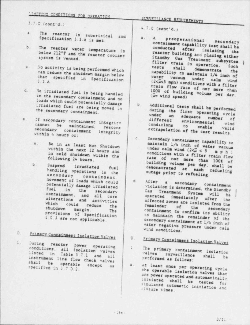
, _ ._.. _ _ _ . _ .. _ _ _ _ _ _ .__ _ . -_.._~.-.___ ..._ _ _ _._ _.--
*?MYT?"c comb 7TTOMR FOR OPFRATTON_
CURVE 7?_?ANcF RroUTarwrwTg3.7.C (cont'd.) .
4.7.C (cont'd.),
a. The' reactor is subcritical and a. ASpecification 3.3.A is set. preoperational secondary. containment capability test shall beb. The reactor water temperature is conducted after isolating the
below 212*F and the reactor coolant reactor building and placing eithersystem is vented,
Standby Gas Treatment subsysten |filter train in operation. SuchNo activity is being performed whichc. tests shall demonstrace the. can reduce the shutdown margin below capability to maintain 1/4 inch ofthat specified in Specification water vacuum under calm wind
(24<5 mph) conditions with a' filter3,3.A.
train flow rate of not more than-d. 1001 of building volumeNo irradiated fuel is being handledin the secondary containment and no (g_= wind speed) per day,
loads which could potentially damage b.irradiated fuel are being moved in Additional tests shall be performedduring the firstthe secondary containment, operating cycleunder an adequate number ofIf secondary containment integrity conditions to enable valid
differente.environmental windcannot be maintained, restore
within 4 hours or:integrity extrapolation of the test results.secondary containment
Secondary containment capability toc.
maintaina.Be in at least Hot Shutdown 1/4 inch of water vacuumwithin the next 12 hours and under calm wind (24 < 5 eph)
conditions with a filter train flowin cold shutdown within thefollowing 24 hours. cate of not more chan 1001 ofbuilding volume per day, shall beb. Suspend irradiated fuel demonstrated at . each refuelinghandling operations in the uta8e prior to refueling.secondary containment.movement of loads which could d. After a secondary containmentpotentially damage irradiated
violation is determined, the Standbyfuel in the Gas Treatment System will besecondarycontainment, and all core operated immediately after the
i
alterations and activities affected zones are isolated from thewhich could reduce the Mr of hshutdown margin. The containment smWto confirm its abilityprovisions of Specification to maintain the remainder of the1.0.J are not applicable. secondary containment at 1water negative pressure u/4 inch of
nder calmwind conditions.D. Primary Conemin= ant Isolation Valves
D. Primary Containment Isolation Valves1. During reactor power operating 1. Theconditions, all isolation valves primary containment isolationlisted in Table 3.7.1 and all surveillance shall bevalves
instrument line flow check valves performed as follows:shall be operable except as a. At least once per operating cyclespecified in 3.,.D.2.
the operable isolation valves thatare power operated and automaticallyinitiated shall be tested forsimulated automatic:losure times. initiation and
*
ii
'.5e-
3/11.-
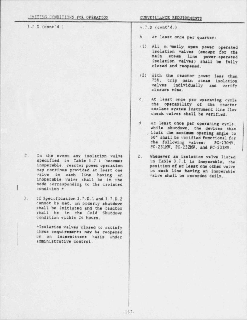
i
LTMiTTNG CONDITTONS FOR OPERATION SURVEILIANCE REOUTRFMENTS
I3.7.D (cont'd.) 4. 7.D (cont' d. ) t-
i
b. At least once per quarter: )
. (1) All nC 7aally open power operatedisolation valves (excape for themain steam line power-operatedisolation valves) shall be fullyclosed and reopened.
(2) With the reactor power less than75%. trip main steam isolationvalves individually and verifyclosure time.
c. At least once per operating cyclethe operability of the reactorcoolant system instrument line flowcheck valves shall be verified.
d. At least once per operating cycle,while shutdown, the devices that
.. limit the maximum opening angle to60* shall be verified functional forche following valves: PC-230MV, '
PC-231MV PC-232MV, and PC-233MV.
2. In the event any isolation valve 2. Whenever an isolation valve listedspecified in Table 3.7.1 becomes in Table 3.7.1 is inoperable, theinoperable, reactor power operation position of at least one other valvemay continue provided at least one in each line having an inoperablevalve in each line having an valve shall be recorded daily.inoperable valve shall be in . the
!mode corresponding to the isolated|| condition.* '
3. If Specification 3. 7.D.1 and 3. 7.D.2cannot bs met, an orderly shutdownshall be initiated and the reactorshall be in the Cold Shutdowncondition within 24 hours.
I
* Isolation valves closed to satisfythese requirements may be reopenedon an intermittent basis underadministrative control.
167---
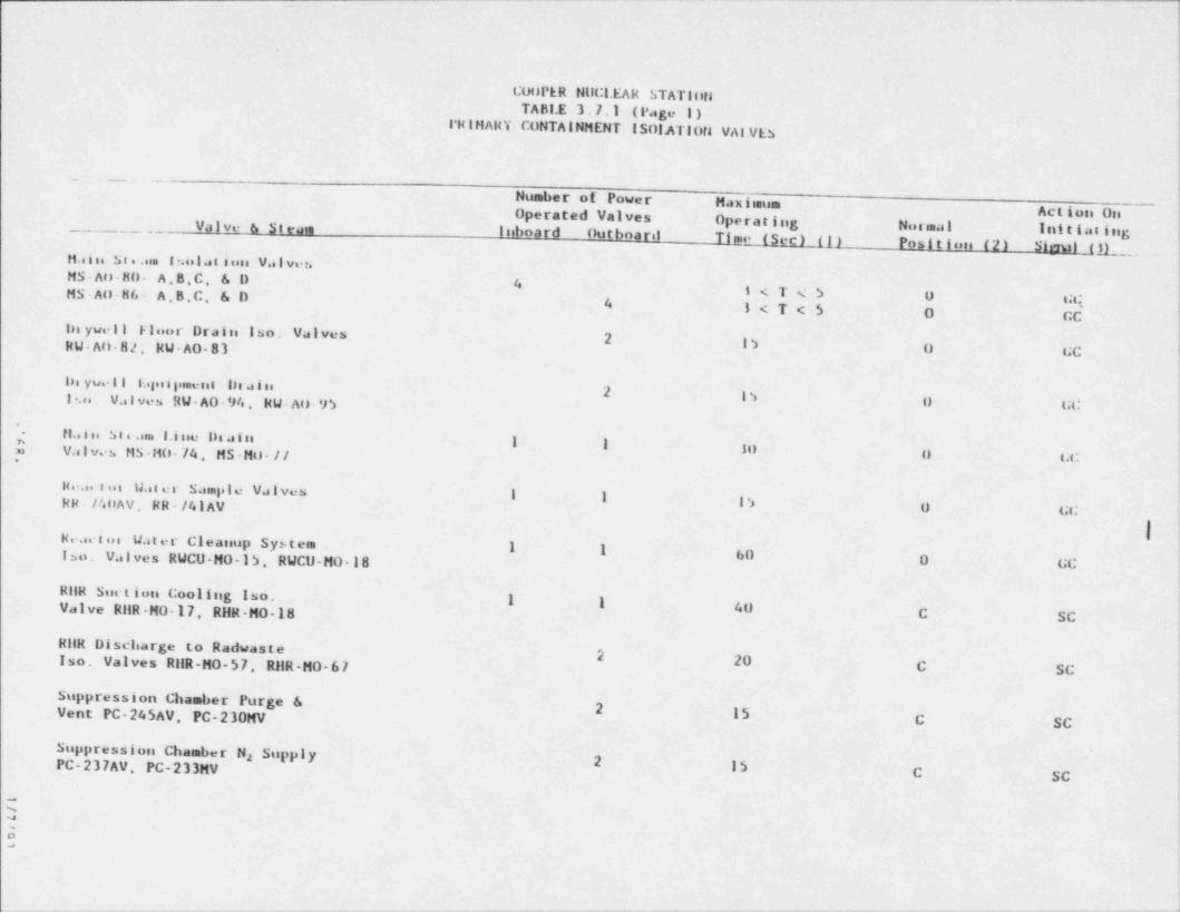
CouPER HilCl. EAR STATlutlTABLE 3.7.1 (Page 1)
I'HINARY CONTAINMENT ISOIATlofJ VAI.VES
_. . _ _ . ._
Number of Power Maxiinum Action onOperated Valves Operating Normal Initiasinig_ . _ _ Valve & Steam Inboard Outboaril Ti me- (Sec) (I) Position (2) Sisul ML_,Ha i ne Se e .uu i r.olat ioni Val veuMS-AO-HO- A B.C, 6 D 4MS-AO-H6- A,B,C, 6 D 1<T<5 0 GQ4 1<T<5 0 GCin ywel l teloor Draini Iso. Valves
2RW-An-82, NW-AO-83 l ') 0 GC
lin yue l l E.gu i pimeis t 1) rain i2 l ')I ?.o . V..lves RW-AO-94, RW-Au 95 U GC
i
- fl.. i n S t e.ina I.i nie I)ra i n 1 I 10 Lf Valves NS-HU-74. MS-MO-// 0 GG
Hva. i on W. iter Sasuple Valves I I l '>l
RR - /4tlAV. RR - /41 AV 0 GC
I'
Heactus Water Cleasiup System 1 1 60iso. Valves RWCU-MO-15. RWCU-MO-18 0 GC>
RilR Suct ion Coolitig Iso. I 1 40Valve RHR-MO-17. RHR-MO-18 C SCs
RllR Discharge to Radwaste2 20 \
Iso. Valves RilR-MO-57 RHR-MO-67 C SC
Suppression Chamber Purge 62 15Vant PC-245AV, PC-230MV C SC
Siippression Chainber Na Supply -
2 15PC-237AV, PC-233MV C SC
'~~
~
>
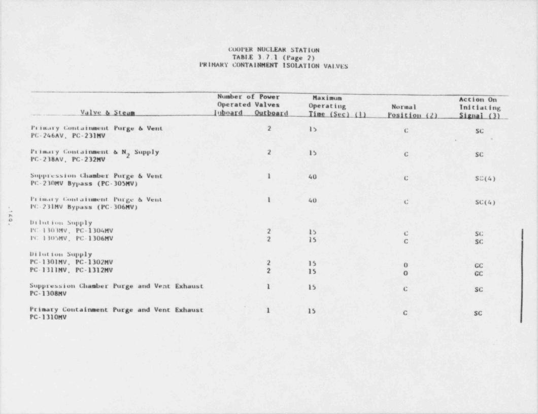
.
COOPER NUC1. EAR STATIONTABI.E 3.7.1 (Page 2)
PRIMARY CONTAINMENT ISOL.ATION val.VESa
Nussber of Power Maximum Actios Onk
Operated Valves Operating Normal Initiating !
_ Valve & Steam Inboard' Outboard Time (Sec) (1) Position (2) Simnal (3)
Ps in.ory Cont aisument Purge & Vent 2 15 C SCPC-246AV, PC-231MV
-,
Pi i sm.e r y Cunt a i nsment &N Supply 2 15 C SC2PC-238AV, PC-232MV
Suppression Chamber Purge & Vent 1 40 C Sc(4)PC-230MV Bypass (PC-305MV)
Pi im.as y Cunt ai nement Purge & Vent 1 40 C SC(4) '
PC-231MV Bypass (PC-306MV).
i,
Delutinu Supply.
PC 110IMV, PC-1304MV 2 15 C SCIC 1luSMV, PC-1306MV 2 15 C SC
,
Dilution SupplyPC-1301MV, PC-1302MV 2 15 0- GCPC-1311MV, PC-1312MV 2 15 0 CC
Suppression Chamber Purge and Vent Exhaust 1 15 C SCPC-1308MV
,
Primary Containment Purge and Vent Exhaust 1 15 C SC !PC-1310MV
.
>
!!
.
. . . . _ _ . _ m _-. _.__.___.m m_____ . - . _ . _ _ . _ ______..______.___.____-_____.m.__- _._.__.___ ___m.____ _ _ _ _ _ _ _ _ . , _ _ _ _ _ . . . . . . . ~ .
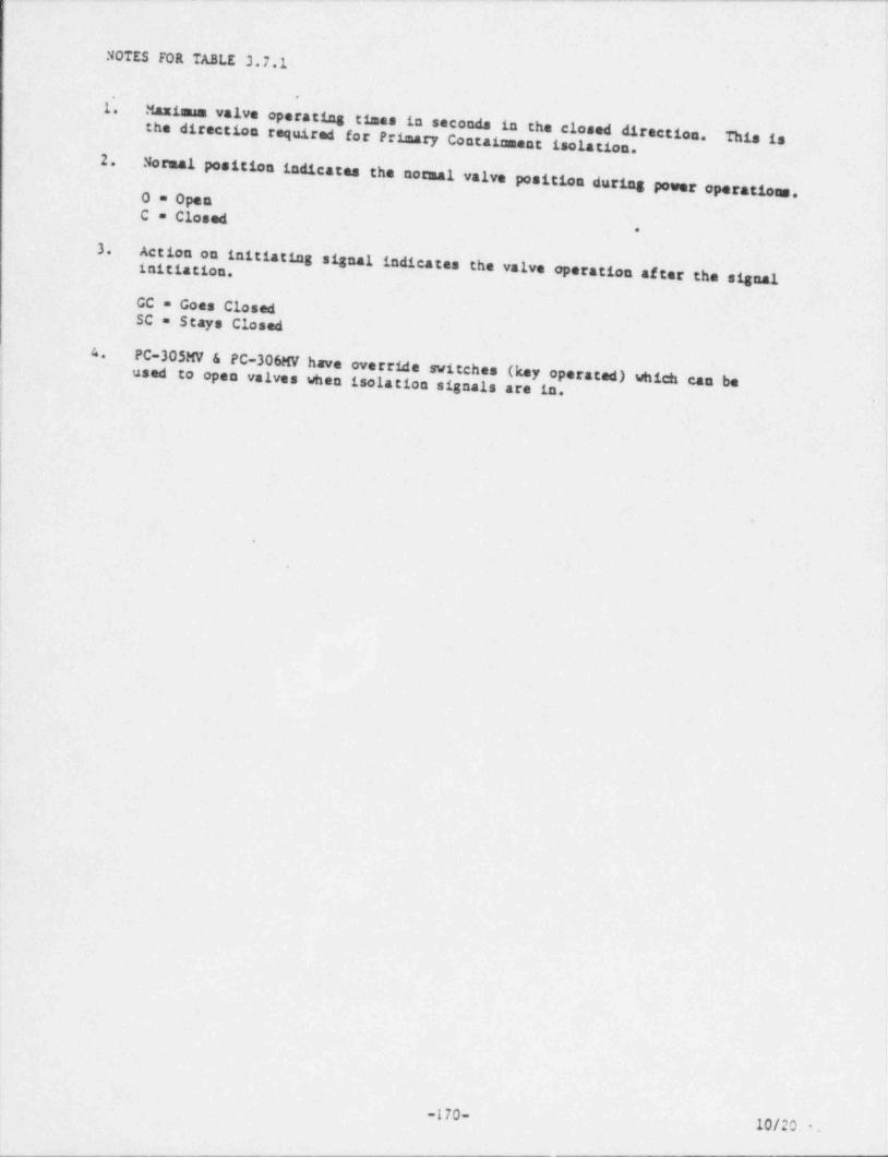
NOTES FOR TABLE 3.7.1
l'.Maximum valve operating times in seconds in the closed directionthe direction required for Primary Containment isolation This is.
.
2.Normal position indicates the normal valve position during power
operations.0 = OpenC = Closed
*
3.Action on initiating signal indicates the valve operation af tinitiation. er the signal
GC = Goes ClosedSC = Stays Closed
4
PC-305MV & PC-306MV have override switches (key operated) whichused to open valves when isolation signals are in.
,
can bel.
{
.
0
4
1
1
l
1
-170-10/20 - '
i

. _ .
!
!1
e
j
.
i
l
I:
Ifi
I '
'
!
l1i
1
|
||
|:14
1
,
I
1
|
<
I!
||
I
|4
I.
1.,..$ 4re MOC usedasase .
)i
l
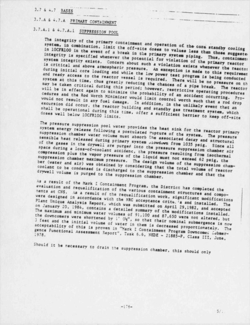
_ ._ _ ___. _ _ _ _ _ _ _ __ _ __ _ _ _._ .. _ _ __ _ _ --_ _ _ _ _ _ _ _ _ ___
3.7 & 4.7 BASES_ . -
;...... - . _ -.- . .
....
3.7.A & 4.7.A PRIMARY CONTAINMENT--
_ . . .. . . - . . _ .
3.7.A.1 & 4.7.A.1 ShPPRESSIONPOOL
The integrity of the primary containment and operation of the cor L
in 10CF1100 in the event of a break in the primary system pipingsystem, in combination, limit the off-site dosee to values less thsa ch~
, -
e standby coolingose suggestai
integrity is specified whenever the potential for violation of thThus, containmeni.
system integrity exists.is critical and above atmospheric pressure. Concern about such a violation exists whenever the react
e primary reactorl
and ready access to the reactor vessel is required.during initial core loading and while the low power test progrAn exception is made to this requiremecor
!am is being conducted,
may be taken critical during this period; however, restrictivesystem at chts time. thus greatly reducing the chances of a pipe brThere vill be no pressure on th'
|
eak. The reactorvill be in effect again to minimize the probability of an accid
i
! operating procedures
cedures and the Rod Worth Minialzer would limit control worth such thent occurring. Pro-would not result in any fuel damage.excursion did occur, the reactor building and standby gas treatmIn addition, in the unlikely event that anat a rod dropshs11 be operational during this time, offer a sufficient barrier tent system, whichdoses well below 10CTR100 limits. o keep off-site
The pressure suppr'ession pool vater provides the heat sink fsystem energy release following a postulated rupture of the systor the reactor primary
sensible heat released during primary system alovduva from 1035 poissuppression chamber water volume must absorb the associated decay andem. The pressure
structuralof the gases in the dryvell are purged into the pressure suppression chSince all.
space during a loss-of-coolant accident, amber aircompression plus the vapor pressure of the liquid must not ezeeed 62the pressure resulting from isothermalsuppression chamber maximum pressure. psig, the
ber (water and air) was obtained by considering that the total voluThe design volume of the suppression chan-coolant to be condensed is discharged to the suppressio'n chamber and thme of reactordryvell volume is purged to the suppression chamber. at the
As a result of the Mark I Containment Program, the District hasevaluation and requalification of the various containment structurcompleted thenents at CNS.
were designed in accordance with the NRC acceptance critsifa and iAs a result of the requalification work, significant modific ties and compo- j
a ons i
Plant Unique Analysis Report. which was submitted on Aprilnstalled. The !on January- 20, 1984, 29 1982
The maximum and minimum water volumes of 91,100 sad 87,650 were notcontains a detailed summary of the modification, and accepted,
s installed.the downconers were shortened by l' 0\", so that their nomi altered, but !
3 feet and the initial volume of water in them is decreased proportinal submergence is nowi' J
acceptability of this is proven in " Mark I Containment Program Downcom i C bonately. Thegence Functional Assessment Report". m a ner-
Task 6.6 NEDE - 21885-P, Class III, June,1978.
!Should it be necessary to drain the suppression chamber
this should only,
|
|
.
-176-5/;
- . . _ . _. - ___ . _ _ -,
-. - _ _ _ - - - - . _ _ _ _ - . .-. - -.- - .- - - .- -. _ . - . - - -
3.7.A & 4.P.A 3ASES (cont'd) - - " - - - - - - - " - -
bo denn when there is no requirement for core standby cooling syst, ems operability anexplained in bases 3.5.F.
Experimental data indicates that excessive steam condensing loads can be avoided ifthe peak temperature of the suppression pool la maintained below 160*F during anyperiod of relief valve operation with sonic conditions ac tha discharge exit. Spec-ifications have been placed on the envelope of r6 actor operating conditions so thatthe reactor can be depressurized in a timely manner to avoid the regime of poten-,
|
tially high suppression chamber loadings.
In addition to the limits on temperature of the suppression chamber pool water. op-erating procedures define the action to be taken in the event a relief valve inad-vertently opens or sticks open. This action would include: (1) use of all avail-
| able means to close the valve, (2) initiate suppression pool water cooling heat ex-! changers. (3) initiate reactor shutdown, and (4) if other relief valves are used to
depressurize the reactor, their discharge shall be separated from that of the stuck-open relief valve to assure mixing and uniformity of energy insertion to the pool.Because of the large volume and thermal capacity of the suppression pool, the volume'
and temperature normally change very slowly and monitoring these parameters daily issufficient to establish any temperature trends. By requiring the suppression poolcesperature to be continually monitored and frequently logged during periods of sig-nificant heat addition, the temperature trends will be closely followed so that ap-propriate action can be taken. The requirement for an external visual examinationfollowing any event where potentially high loadings could occur provides assurancethat no significant damage was encountered. Particular attention should be focusedon structural discontinuities in the vicinity of the relief valve discharge since ,
t
these are expected to be the points of highest stress.
The maximum suppression pool corporature of 95'F is based on not exceeding the 200*FMark I temperature limit as contained in NUREG-0661. This 95'T limit also preventsexceeding LOCA considerations, or ECCS pump NPSH requirements. The basis for theselimits are contained in NEDC-24360-P.
3.7.A.2 & 4.7.A.2 CONTAINMENT INTEGRITY
The maximum allevable test leak rate is 0.635%/ day at a pressure of 58 psig, thepeak calculated accident pressure. Experience has shown that there is negligibledifference between the leakage races of air at normal temperature and a steam-hotair mixture.
| Establishing the test limit of 0.635%/ day provides an adequate margin of safety to'
assure the health and safety of the general public. It is further considered thatthe allowable leak race should not deviate significantly from the containment designvalue to take advantage of the design leak-tightness capability of the structureover its service lifetime. Additional margin to maintain the containment in the "asbuilt" condition is achieved by establishing the allowable operational leak race.The allowable operational leak race is derived by multiplying the maximum allowableleak rate, La. or the allowable test leak rate. Lt. by 0.75 thereby providing a 255margin to allow for leakage deterioration which may occur during the period betweenleak rate tests.
The primary containment leak rate test frequency is based on maintaining adequateassurance that the leak rate remains within the specification. The leak rate test
| frequency is based on the NRC guide fer developing leak rate testing and surveillanceof reactor containment vessels. Allowing the test intervals to be extended up to 3months permits some flexibility needed to have the ceses coincide with scheduled :runscheduled shutdevn periods.
The penetration and air purge piping leakage rest frequency, along with thecontainment leak race casts, is adequate :o allow detection of leakage,
|
-177- ||
-9n- -W ~
._ __ ._. . _ _ _ _ . _ _ _ . - _ _ _ _ _ _ . _ _ . _ . _ _. _ ._. . _ _ _ _
,
|
:.~ A & . 7,A Ei.L1 (cont ' d. )
Whenever a bolted double gaskeced penetration is broken and remade,: rends.the
space between the gaskets is pressurized to determine that the seals are performingproperly. It is expected that the majority of the leakage from valves, penetrations! and seals would be into the reactor building.into other parts of the facility could ' occur. However, it is possible that leakage!
significantly the consequences of accidents are to be minimized.Such leakage paths that may affectCertain' isolation valves are
tested by pressurizing the volume between the inboard |and outboard isolation valves. This results in conservative test results since theinboard valve. if a globe valve, will be tested such that the test pressure is:ending to life the globe off its seat. Addicionally, che measured leak rate for sucha test is conservatively assigned to both of the valves equally and not dividedbetween the two.
The main steam and feedwater testable penetrations consist of a double layered metalbellows. The ; inboard high pressure side of the bellows is subjected. co drywellpressure.The re fo re , the bellows is :ested in its entirety when the drywell is:ested. The bellows layers are tested for the integrity of both layers by -
pressuri:ing the void between the layers to 5 psig. Any higher pressure could causepermanent deformation, damage and possible ruptures of the bellows.
Surveillance requirements for integrity of the personnel air lock are specified inEnclosure 1 (Exemption) to the letter. D. G. Eisenhut to J. M. Pilant, September 3,1982. When the Personnel Air Lock Leakage Test is performed at a test pressure lessthan 58 psig,the measured leakage musc be adjusted to reflect the expected leakageat 58 psig. Equation A-3 of Enclosure 3 (Franklin Research Center Technical
Evaluacion Reporc) to the letter. D. G. Eisenhut to J. M. Pilant, September 3, 1982,defines the method of adjustment.
The primary containment pre-operational test pressures are based upon the calculatedprimary containment pressure response in the event of a loss-of coolant accident.The peak drywell pressure would be about 58 psig which would rapidly reduce29 psig following the pipe break. Following the pipe break, the suppression chamber
to
pressure rises to 27 psig. equalizes with drywell pressure and therefore rapidlydecays with the drywell pressure decay. The design pressure of the drywell andsuppression chamber is 56 psig. 3ased on the calculated containment pressureresponse discussed above. the primary containment preoperational test pressure waschosen. Also, based on the primary containment pressure response and the fact thatthe drywell and suppression chamber function as a unit, the primary containment willbe tested as a unit rather than the individual componenes separately.The design basis loss-of coolant accident was evaluaced ac the primary containmentmaximum allowable accident leak rate of 0.635%/ day at 58 psig. Calculations made bythe NRC staff with leak rate and a standby gas creatment system filter efficiency of20% for halogens and assuming the fission product release fractions stated in NRCRegulatory Guide 1.3 show that the maximum total whole body passing cloud dose isabout 1.0 REM and the maximum total thyroid dose is about 12 REN at 1100 meters fromthe stack over an exposure duration of two hours. The resultant doses reported are:he maximum that would be expected in the unlikely event of a design basisloss of coolanc accident. These doses are also based on the assumption of no holduoin the secondary containment resulting in a direct release of fission products fromthe primary containment through the filters and stack to the environs. Therefore.:he specified primary containment leak race and filter efficiency are conservatna:nc provide margin between expected off site doses and 10 CFR 100 guidelines.
The water in the suppression chamber is used for cooling in the event of an acciden-..e. it is not used for normal operation: the re fo re , a daily
**21/7/G'
. , _ _ . . . - . - _ -
. _ - - - . - - . . - . - - - - - - - - - - .. - - - - - . - -..... _
4 |
| 3.7.A & 4.7.A BASES (ccat'd.) '' '' ~ ""
trends. Whenevar a bolted double-gasketed penetration is broken and remede, the, ,
| space between the gaskets is pressurized to detetuina that the seals are perform-'
ing properly. It is expected that the majority of the leakage from valves, pene-trations and seals would be into the reactor building. However, it is possiblethat leakage inte other parts of the facility could occur. Such leakass pathsthat may affect significantly the consequences of accidents are to be adat=fsed.Table 3.7.4 identifies certain isolation valves that are tested by pressurisingthe volume between the inboard and outboard isolation valves. This results inconservative test results since the inboard valve, if a globe valve, will betested such that the test pressure is tending to lift the globe off its seat.Additionally, the measured leak rate for such a test is conservatively assignedto both of the valves equally and not divided between the two.
The. main steam and feedwater testable penetrations consist of a double layeredmetal bellows. The inboard high pressure side of the bellows is subjected to2' drywell ,oressure. Therefore, the bellows is tested in its entirety when thedrywell is tested. The bellows layers are tested for the 1 2egrity of bothlayers by pressurizing the void between the layers to 5 psig. Any higherpressure could cause permanent deformation, damage and possible ruptures ofthe bellows.
.
Surveillance requirements for integrity of the personnel air lock are specifiedin Enclosure 1 (Exemption) to the letter, D. G. Eisenhut to J. M. Pilant,
iSeptember 3, 1982. When the Personnel Air Lock Leakage Test is performed at a I
test pressure less than 58 psig, the measured leakage must be adjusted to reflectthe expected leakage at 58 psig. Equation A-3 of Enclosure 3 (FranM in ReseachCenter Technical Evaluation Report) to the letter, D. G. Eisenhut to J. M. Pilant,September 3,1982, defines the method of adjustment.
The primary containment pre-operational test pressures are based upon thecalculated primary containment pressure response in the event of a loss-of-coolant accident. The peak drywell pressure would be about 58 psig whichwould rapidly reduce to 29 psig following the pipe break. Following thepipe break, the suppression chamber-pressure rises to 27 peig, equalises with
~dryvell pressure and therefore rapidly decays with the drywell pressure decay.The design pressure of the drywell and suppression chamber is 56 psig. Basedon the calculated containment pressure response discussed above, the primarycontainment preoperational test pressure was chosen. Also, based on theprimary containment pressure response and the fact that the drywell and'
suppression chamber function as a unit, the primary containment will betested as a unit rather than the individual components separately.The design basis loss-of-coolant accident was evaluated at the primary con-tainment maximum allowable accident leak rate of 0.6351/ day at 58 pais.Calculations made by the NRC staff with leak rate and a standby gas treat-ment system filter efficiency of 90% for halogens and assuming the fissionproduct release fractions stated in NRC Regulatory Guide 1.3, show that themaximum total whole body passing cloud dose is about 1.0 REM and the mezismantotal thyroid dose is about 12 RDi at 1100 meters from the stack over anexposure duration of two hours. ~he resultant doses reported are the maximumthat would be expected in the unlikely event of a design basis loss-of-coolantaccident. These doses are also based on the assumption of no holdup in thesecondary containment resulting in a direct release of fission products fromthe primary containment through the filters and stack to the environs.Therefore, the specified primary containment leak race and filter efficiencyare conservative and provide margin between expected off-site doses and10 CFR 100 guidelines.
The water in the suppression chamber is used for cooling in the eventof an accident; i.e., it is not used for normal operation; therefore, a daily
-178- 00 *
, _ _ . -- . . ._ _ __
_
3.7|K T C 7.A BMfd (cont'd) '' ~ ' " ~ ~ ' ~ ' ~~~. . . _ _ _
checkofthetemperatureandvolumeisadequatetoassurethatadequateheatremovalcapability is present.
The interiors of the drywell-and suppression chamber are painted to prevent rustingThe inspection of the paint during each major refueling outage, approziantely once per
.
year, assures the paint is intact.Experience with this type of paint at fossil fueled
generating stations indicates that the inspection interval is adequate..
ne intent of Specification 3.7. A.2.b is to reduce the probability of a IDCA occurrence3
j when the 24-inch purge and vent valves are open in series.closed during power operation to minimize reliance on the valve operators to ensureThese valves are normally
*
j containment integrity. The
filters would experience from excessive difference pressere caused by a 1DCA with therequirements for Standby Gas is due to the damage the!
24-inch exhaust valves open in series from the drywell or suppression chamber.-
:specification does allow venting with the inboard exhaust bypass valve and the outboardThis
|exhaust valve both open in series and the time does not count against the yearly limit:
he NRC has accepted the determination that due to the small size of the bypass valve.
i there is no chance of damage to the filtersj containment through the bypass with a SBGT system on line.if a 14CA occurs while venting the,
i The term " calendar year"is a period of time beginning on January 1 and ending on December 31 for each numbered; year.
[ 3.7.A.3 & 4 and 4,7.A.3 & 4 VACUUM _ BREAKERS
The purpose of the vacuum relief valves is to equalize the pressure between the drywell*
and suppression chamber and reactor building so that the structural integrity of thecontainment is maintained.chamber to reactor building consists of two 1001 vacuum relief breakers (2 parallelThe vacuum relief system from the pressure suppression'
sets of 2 valves in series).differential of less than 2 psi, the external design pressure. Operation of either system will maintain a pressure
j One valve may be outof service for repairs for a period of 7 days. If repairs cannot be completed withini7 days the reactor coolant system is brought to a condition where vacuum relief is no: longer required.
1
The capacity of the 12 dryvell vacuum relief valves are sized to limit the pressure,
differential between the suppression chamber and drywell during post-accident dry-wellcooling operations to well under the design limit of 2 psi. They are sized on thebasis of the Bodega Bay pressure suppression system tests. The ASME Boiler andPressure Vessel Code, Section III, Subsection B. for this vessel allows a 2 psidifferential; therefore, with three vacuum relief valves secured in the closed positionand 9 operable valves, containment integrity is not impaired.
3.7.A.5 and 4.7.A.5 OXYCEN CONCENTRATION
Safety Guide 7 assumptions for Metal-Water reaction result in hydrogen concentrationin excess of the Safety Guide 7 flammability limit. By keeping the oxygenconcentration less than 4% by volume the requirements of Safety Guide 7 are satisfied.
*he occurrence of primary system leakage following a major refueling outage or otherscheduled shutdown is much more probable than the occurrence of the loss-of-coolantaccident upon which the specified oxygen concentration limit is based. Permittingaccess to the drvvell for leak inspections during a startup is judged prudent in termsof the added plant safety offered without significantly reducing the margin of safetyThus,
:o preclude the possibility of starting the reactor and operating for extendedperiod of time wtth significant leaks in :heoperating temperature and pressure. primary system is at or near rated
The T.-hour period to provide inerting is judgeeo be sufficient to perform the leakinspect;on and establish the required oxyger.:o nc e n t ra t io n .
.; 905/15/80
_!
_ _ . _ _ . _ _ _ _ _ _ . _ _ _ _ _ _ _ _ _ . _ . _ _ _ _ _ _ _ _ . _ _ _ _ _______ __
3.7,.A & 4.7.A MEU,(cont' d)
!The primary containment is normally slightly pressurized during periods of reactoroperation. Nitrogen used for inerting could leak out of the containment but aircould not leak in to increase oxygen concentration. Once the containment is filledwith nitrogen to the required concentration, no monitoring of oxygen c.oncentrationis necessary. However, at least twice a week the oxygen concentration will bedetermined as added assurance.
i
The 500 gallon conservative limit on the nitrogen storage tank assures that adequatetime is available to get the tank refilled assuming normal plant operation. Theestimated maximum makeup rate is 1500 SCFD which would require about 160 gallons fora 10 day makeup requirement. The normal leak race should be about 200 SCFD. !
3.7.A.6 & 4.7.A.6 LOW-LOW SET RELIEF FUNCTION
The low-low set relief logic is an automatic safety relief valve (SRV) control systemdesigned to mitigate the postulated thrust load concern of subsequent actuations ofSRV's during certain transients (such as inadvertent MSIV closure) and small andintermediate break loss-of-coolant accident (IDCA) events. The setpoints used inSection 3.7.A.6.b are based upon a minimum blowdown range to provide adequate time '
i
between valve actuations to allow the SRV discharge line high water leg to clear. !coupled with consideration of instrument inaccuracy and the main steam isolation!valve isolation serpoint.!
The as-found setpoint for NBI-PS 51A, the pressure switch controlling the opening ofRV-71D, must be s 1060 psig. The as-found clos'ing setpoint for.NBI-PS-515 must beleast 90 psig less than 51A, and must be 2 850 psig. 'Ihe as-found setpoint forat
NBI-PS-51C, pressure switch controlling the opening of RV-71F aust be $ 1050 psig.The as-found closing setpoint for NBI-PS-51D aust be at least 90 psig below SIC, andmust be 2 850 psig. This ensures that the analytical upper limit for the openingsetpoint (1050 psig), the analytical lower limit on the closing setpoint (850 psig)and the analytical limit on the blowdown range (2 90 psig) for the Low-Iow See ReliefFunction are not exceeded. Although the specified instrument setpoint tolerance ist 20 psig, an instrument drift of ! 25 psig was used in the analysis to ensure
!
adequate margin in deterisining the valve opening and closing setpoints. The opening |setpoint is set such that, if both the lowest set non-LLS S/RV and the highest setof the two LLS S/RVs drif t 25 psig in the worst case directions, the LLS S/RVs willstill control subsequent S/RV actuations. Likewise, the closing setpoint is set toensure the LLS S/RV closing secpoint remains above the MSIV low pressure trip. ,
The !
90 psig blowdown provides adequate energy release from the vessel to ensure time forthe water leg to clear between subsequent S/RV actuations.
3.7.B & 3.7.C STANDRY CAS TREATMENT SYSTEM AND SECONDARY CONTAffmHNT'
The secondary containment is designed to minimize any ground level release ofradioactive asterials which might result from a sorious accident. The reactorbuilding provides secondary containment during reactor operation when the drywell is isealed and in service. The reactor building provides primary containment when thereactor is shut down and the drywell is open, as during refueling. Because thesecondary containment is an integral part of the complete containment syste.asecondary containment is required at all times that primary containment is requireoas well as during refueling, and during movement of loads which could potential; .damage irradiated fuel in the secondary containment. Secondary containment may tebroken for short periods of time to allow access to the reactor building roof 2perform necessary inspections and maintenance.
*he Standby Cas Treatment System consists of two, distince subsystems, eacecontaining one exhaust fan and associated filter train, which is designed to fil:,-and exhaust the reactor building atmosphere to the stack during secondary containser-isolation conditions. Both Standby Gas Treatment System fans are designedautomatically start upon containment isolation and to maintain the reactor build.-
<
pressure to the design negative pressure so that all leakage should be in-leakas.Should one subsystem fail to start. the redundant subsystem is designed to s4automatically. Each of the two fans has 100 percent capacity.
180- 3/.
. .. ._ A

. . - - - .-
- - -.-. . -.
_ _ _ _ _ _ _
-
-. . _ _ .
.
~..
.. .
.
" INTENTIONALLY LEFT BLANK"
;
1
ii
-181-5/13 'I
_ _ _ __ _ _ _ _ . _ _ __ _ _ _ _ _ _ _ _. _ _ _ _ _ _ _ . _ _ _- -.
3.7.8 & 3.7.C M (cont'd)
High efficiency particulate absolute (HEPA) filters are installed before and afterthe charcoal adsorbers to minimize potential release of particulates to theenvironment and to prevent clogging of the iodine adsorbers. The charcoal adsorbersare installed to reduce the potential release of radioiodine to the environment. The |in place test results should indicate a system leak tightness of less than 1 percent '
bypass leakage for the charcoal adsorbers and HEPA filters. The laboratory carbonsample test results should indicate a radioactive methyl iodide removal efficiencyof at least 99 percent for expected accident conditions. If the performance of theHEPA filters and charcoal adsorbers are as specified, the resulting doses will beless than the 10 CFR 100 guidelines for the accidents analyzed.
Only one of the two Standby Cas Treatment subsystems is needed to cleanup the reactorbuilding atmosphere upon containment isolation. If one subsystem is found to be
jinoperable, there is no immediate threat to the containment system performance and 1
reactor operation or refueling operation may continue while repairs are being made.If both subsystems are inoperable, the plant is brought to a condition where the>
Standby Cas Treatment System is not required.
4.7.5 & 4.7.C MSeman y Cam Treae- ne System and Secondary Contafn= ne
Initiati ? actor building isolation and operation of the Standby Cas TreatmentSystem r. saintain . at least a 1/4 inch of water vacuum within the secondarycontainment provides an adequate cast of the operation of the reactor buildingisolation valves, leak tightness of the reactor building and performance of theStandby Cas Treatment System. Functionally casting the initiating sensors and Iassociated trip channels demonstraces the capability for automatic actuation.Periodic testing gives sufficient confidence of reactor building integrity andStandby Cas Treatment System performance capability |
Pressure drop across the combined HEPA filters and charcoal adsorbers of less than6 inches of water at the system design flow rate will indicate that the filters andadsorbers are not clogged by excessive amounts of foreign matter. A 7.8 kw heateris capable of maintaining relative humidity below 701. Heater capacity and pressuredrop should be determined at least once per operating cycle to show systemperformance capability.
The frequency of tests and sample analysis are necessary to 'show that the HEPAfilters and charcoal adsorbers can perform as evaluated. Tests of the charcoaladsorbers with halogenated hydrocarbon refrigerant shall be performed in accordancewith ANSI N510-1980. The test canisters that are installed with the adsorber traysshould be used for the charcoal adsorber efficiency test. Each sample should be atleast two inches in diameter and a length equal to the thickness of the bed. If testresults are unacceptable, all adsorbent in the system shall be replaced
,
-182- ) |
. . - - - - - - _ - . . . .- -. --
_ . _ . _ , __ _ _ _ _ _ _ _ . _ . _ _ _ _ _ _ _ . _ _ _ _ _ _ _ . - - ._ _
.
. .:.3 & 7.c gasIIvich an adsorbent qualified
according to Table 5.1 of ANSI N509 1980The
< . replacementadsorbent quality. tray for the adsorber tray removed for the
.
accordance to ANSI N510-1980. Tests of the HEPA filters with DOP aerosol shall betest should meet the same !Any filters found defective shall be replfilters qualified pursuant performed in
to Regulatory Position C.3.d. of Regulatory G iRevision 2. March, 1978. aced withu de 1.52,
All elements of the heater 'should be demonstrated toduring the test of heater capacity.Operation of the heaters will prevent moisturebe functional and operablebuildup in the filters and.adsorber system.
the full linear peripherv of each respective dJith doors closed and fan in operation. DOP aerosol sh ll ba
oor to check the gasket seal.e sprayed externally alongand the gaskets repaired and test repeated. detection of DOP in the fan exhaust shall be consider dAnye an unacceptable test resultIf system drains are presentwith adequate water level to prevent by pass leakage fin the filter /adsorber banks,loop-seals aunt be usedIf significant painting, ron'the banks.
or charcoal adsorber could become contaminated from thfire or chemical release occurs such that the HEPA filmaterial, the same tests terand sample analysis shall bee fuses, chemicals or foreignoperational use.
The determination of significance shall be made by thperformed as required for-duty at the time of the incident. .
e operator onprior to making this-decernination. Knowledgeable staff members should be consultedDemonstration of the automatic
.
Treatment subsystem is inoperable, the operable ~ subsycooling is necessary to assure system performance capabiliinitiation capability andoperability of filterty. If one Standby Casdaily.
This substantiates the availability of thestem's operability is verifiedreactor operation or refueling operation can continue for a li ioperable subsystem and thus3.7.D & 4.7..D A6311 m t.ed period of time.Primary Containment Isolation Valves
Double isolatica valves are provided on lines penetratiopen to the free space of the containment. ng the primary containment andvould be sufficient
Closure of one of the valves in'each lineto maintain theAutomatic initiation is required to minimize thintegrity of the pressure suppression system.containment in the event of a loss-of coolant accidente potential leakage paths from the
The maximum closure times for the automatic isolation valves of the primary.
concalnment and reactor vessel isolation control system have been selected inconsideration of the design intent to prevent core uncoverinoutsidethe primary containment and the need to cont g following pipe breaks
following pipe breaks inside the primary containment,
ain released fission products.
The USAR identifies those testable primary containment valves that perform anisolation function, and testable penetrations with Do blpenetrations with cascable Bellows e 0 Ring Seals, and testable |-u.'0CFR50. 59 review. ensuring that
valves, and testable penetrations with Double 0 RinIn addition, plant procedures also identify containment iany changes thereto receive ai;
vich testable solationBellows changes to these g Seals, and testable penetrations-
Technical Specification 6.2.1.A.4 (Administrative Coprocedures and the USAR an controlled by.
ntrols). .
These valves !
highly reliable. have a low service requirement, and most areare
.ormally closed.The initiating sensors and associated trin channels,: necked to demonstrate the capabilit:. for automatic isolation
sn=e per operatin5 cycle for automatic initiation are als-The test interval -
.
...
, - - , , . - , - - - - . , . , - _ . _ , , m- - , _ 4 -- ,-- ---r , , , - .e

-.- - - . - - - - . - - - .. - _ _ - - - - - --.. . . _. - . - . - . - - - . - _ . _ .... - -
i !. _ . .
|'
3. 7.44 4. 7.D A&&EE (cont'd) l,
; {.
: 1results in a failure probability of 1.1 x 10~ that a line will not isolate. '
More freguest testing for valve operability results in a greater assurance that thevalve will be operable when needed.
In order to assure that the doses that may result from a steam line break do not exceedthe 10CFR100 guidelines, it is necessary that no fuel rod perforation resulting from,
;
the accident occur prior to closure of the main steam line isolation valves. Analysesindicate that fuel rod cladding perforations would be avoided for main steam valveclosure times, including instrument delay, as long as 10.5 seconds. The primarycontainment is penetrated by several small diameter instrument lines connected to thereactor coolant system. Each instrument line contains a 0.25 inch restricting orificeinside the primary containment and an excess flow check valve outside the primarycontainment. A program for periodic testing and examination of the excess flow checkvalves is performed as follows:
:\1. Vessel at pressure sufficient to actuate valves. This could be at time of vessel |hydro following a refueling outage. '
2. Isolate sensing line from its instrument at the instrument manifold.3. Provide means for observing and collecting the instrument drain or vent valve
flow.
4 Open vent or drain valve.ii
Observe flow cessation and any leakage race. Ia.
b. Reset valve after test completion.
5. The head seal leak detection line cannot be tested in this manner. This valvewill not be exposed to primary system pressure except under unlikely conditionsof seal failure where it could be parcially pressurized to reactor pressure.Any leakage path is restricted at the source and therefore this valve need not
;be tested. This valve is in a sensing line that is not safety related. !
6. Valves will be accepted if a marked decrease in flow rate is observed and theleakage rate is acceptable.
The operators for containment vent / purge valves PC-230MV, PC-231MV, PC.232MV, andPC-233MV have devices in place to limit the maximum opening angle to 60 degrees. Thishas been done to ensure these valves are able to close against the maximum differentialpressure expected to occur during a design basis LOCA.
|'
. '
-184 05/15,
- - - ---
. - - - - _ -.-..- _.- - _ _-.- . _.. ...-._ .. _ ~_ - . - - . -
USAR
APPENDIK A '
' ,
.m PRESSURE INTECRITY OF PIPING AND EQUIPMENT PRESSURE PARTS. ) .
1.0 SCOPEe.
This- appendix provides additional information pertinent to thepreceding sections concerning the pressure integrity of piping and equipmentparts.
Piping and equipment pressure parts are classified according to serviceand location. The design, fabrication, inspection, and testing requirementswhich are defined for- the equipment of each classification assure the properpressure integrity. This Appendix describes the requirements in effect at thetime of the original installation of the piping and equipment pressure parts.The evolution. of industry codes and _ standards, regulatory requirements,fabrication, testing, and erection procedures; and supplementary requirements hasresulted in parts of these requirements being superseded. The new requirementsgenerally ' result in an improvement in quality and overall margins over tigeoriginal requirement. Upgrades or replacement of piping and equipment pressureparts.are performed to these new requirements provided the safety design basesdescribed in the USAR are maintained. *
Por the purpose of this appendix, the pressure boundary of the processfluid includes but is not necessarily limited to: branch outlet nossles ornipples, instrument wells, reservoirs, pump casing closures, blind flanges andsimilar pressure closures, studs, nuts and fasteners in flanged joints betweenpressure parts and bodies and pressure parts of in-line components such as trapsand strainers.,
Specifically excluded from the scope of this appendix are pressureparts such as vessels and heat exchangers or any components which are within thescope of the ASME Pressure Vessel Code, Section III and VIII; and nonpressureparts such as pump motors, shafts, seals, impe11ers, wear rings, valve stems,gland followers, seat rings, guides, yokes, and operators; any nonnotallicmaterial such as packing and gaskets; fasteners not in pressure part joints such~
as yoke studs and gland follwer studs; and washers of any kind.
1.1 Codes and Specifications
The piping and equipment pressure parts in this station are desi ned,fabricated, inspected, and tested in accordance with recognized industrial codes.and specifications. In some cases supplementary requirements are applied toincrease safety and operational reliability. The application of the industrialcodes and specifications is defined in this appendix as well as the applicationof the supplementary requirements. Where conflicts occur between the industrialcodes and specifications and the supplementary requirements, the supplementaryrequirements take precedence.
United States of America Standards (USAS) referenced herein have beensuperceded by ANSI standards. The edition of the USA standards in effect whenbids were made for supplying and installing piping was:
USAS-B31.1.0 - Power Piping (1967)USAS-B31.7 - Nuclear Power Piping (Feb.1968) w/Draft and Errata (June 1968)
A-1-1 07/?'
, , , _- . - _ - _ . - _ - . .- . - _ _ -.
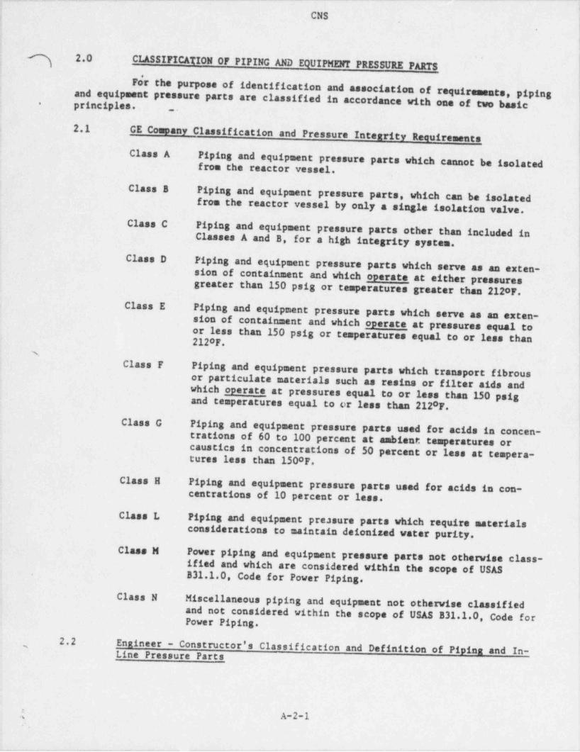
_ _ _ _. _ _ _ _ _._. _ _ _ _ - . _ __ _ _ _ _ . _ . . _ _ _ . _ _ _ _ _ _ _ _ . _ . _ _ _ . _ _ . _ . _ _
4 CNS'
|.
; I
g 2.0CLASSIFICATION OF PIPING AND EQUIPMENT PRESSURE PARTS
For the purpose of identification and association of requirements, piping.
and equipment pressure parts are classified in accordance with one of two basicprinciples.-_.
; 2.1 GE Company Classification and Pressure Integrity Requirementsi
Class A Piping and equipment pressure parts which cannot be isolatedfrom the reactor vessel.
Class B Piping and equipment pressure parts, which can be isolatedfrom the reactor vessel by only a single isolation valve.
Class C Piping and equipment pressure parts other than included inClasses A and B, for a high integrity system.
Class D Piping and equipment pressure parts which serve as an exten-sion of containment and which operate at either pressuresgreater than 150 psig or temperatures greater than 212oF.
Class E Piping and equipment pressure parts which serve as an exten-sion of containment and which operate at pressures equal toor less than 150 psig or temperatures equal to or less than2120F.
1Class F Piping and equipment pressure parts which transport fibrous I
or particulate materials such as resins or filter aids andwhich operate at pressures equal to or less than 150 psigand temperatures equal to or less than 2120F.
Class G Piping and equipment pressure parts used for acids in concen-trations of 60 to 100 percent at ambient temperatures orcaustics in concentrations of 50 percent or less at tempera-tures less than 150oF.
Class H Piping and equipment pressure parts used for acids in con-centrations of 10 percent or less.
Class L Piping and equipment pressure parts which require materialsconsiderations to maintain deionized water purity.
Class M Power piping and equipment pressure parts not otherwise class-ified and which are considered within the scope of USASB31.1.0, Code for Power Piping..
Class N Miscellaneous piping and equipment not otherwise classifiedand not considered within the scope of USAS B31.1.0, Code forPower Piping.
2.2 Engineer - Constructor's Classification and Definition of Piping and In-,
Line Pressure Parts
f A-2-1
. ..
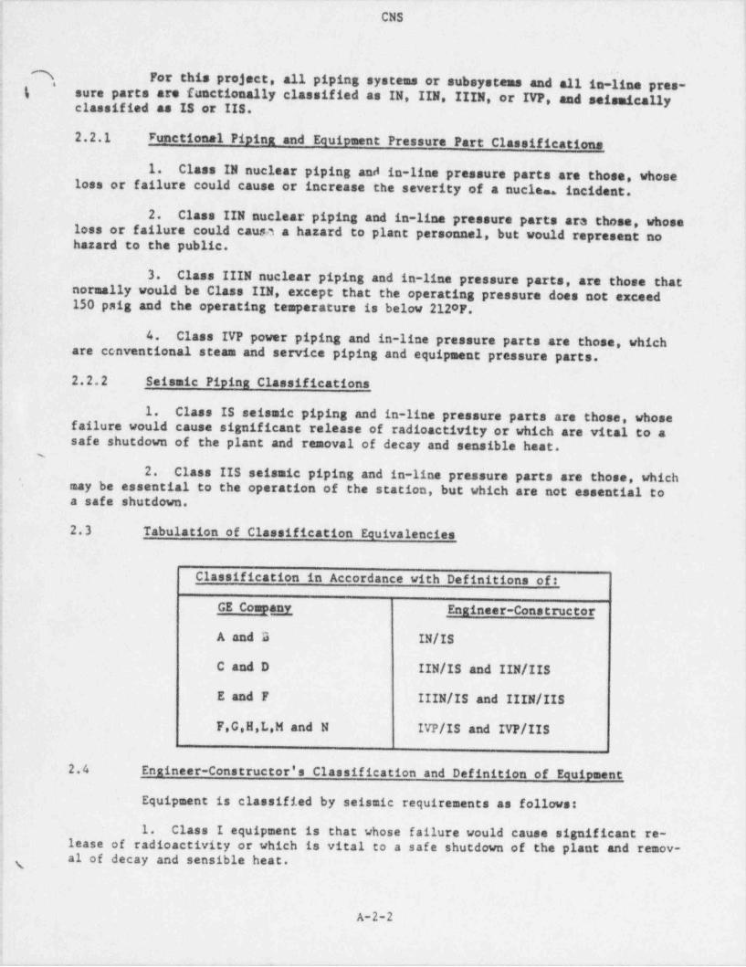
- _ _ . . _ _ . . _ _ _ _ _ _ _ . _ _ . _ . _ . _ . _ . _ _ . . _ . . _ _ _ __ _ _ __ _ _ _ . _ _ . .
CNS i
|e
| !
i: A For this project, all piping systems or subsystems and all in-line pres-*
i % sure parts are functionally classified as IN, IIN, IIIN, or IVP, and seismically,
5 classified as IS or IIS.s
. 2.2.1 Functional Piping and Equipment Pressure Part Classifications i
1'
i1. Class IN nuclear piping and in-line pressure parts are those, whoseloss or failure could cause or increase the severity of a nucles. incident. ,
',
!j 2. Class IIN nuclear piping and in-line pressure parts ara those, whose
loss or failure could causa a hazard to plant personnel, but would represent no;
j hazard to the public..
3. Class IIIN nuclear piping and in-line pressure parts, are those thatj normally would be Class IIN, except that the operating pressure does not exceed
150 psig and the operating temperature is below 2120F.,
; 4. Class IVP power piping and in-line pressure parts are those, which|.
are conventional stesa and service piping and equipment pressure parts.
| 2.2.2 Seismic Piping Classifications!
j 1. Class IS seismic piping and in-line pressure parts are those, whose} failure would cause significant release of radioactivity or which are. vital to a
safe shutdown of the plant and removal of decay and sensible heat.i s
b 2. Class IIS seismic piping and in-line pressure parts are those, which'
: may be essential to the operation of the station, but which are not essential toI
{ a safe shutdown. I
2.3 Tabulation of Classification Equivalencies.
i Classification in Accordance with Definitions of:,
j GE Compagn Engineer-Constructors': A and B IN/IS1
C and D IIN/IS and IIN/IISt
{ E and F IIIN/IS and IIIN/IIS:; F,G,H,L M and N IVP/IS and IVP/IIS1,
i
| 2.4 Engineer-Constructor's Classification and Definition of Equipment;
q Equipment is classified by seismic requirements as follows:i
i 1. Class I equipment is that whose failure would cause significant re-lease of radioactivity or which is vital to a safe shutdown of the plant and remov-al of decay and sensible heat.; y
.
A-2-2
1
- -- - . _ > ,, - - - . , . . . , - - ,- - ,- -.

- . - . - . - . . . . . . . . . - - - . . . - - - . . - - .-. -. . - - - -
CNS
^- 2. Class II equipment is that which may be essential to the operation.
g of the' station,but which is not essential to a safe shutdown.
-
!
l
s-
,
;
iJ
l
'
i
A
IA-2-3
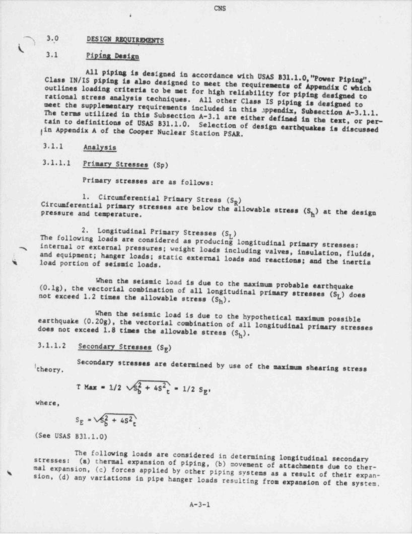
_ . _ _ . . . _ . _ . _ _ . _ _ _ . _ _ . _ _ _ _ _ _ _ _ _ _ . _ _ _ _ _ . _ _ _ . - _ . _ . - _
CNS& .
3.,0 DESIGN REQUIREMENTSk] !
3.1 Pipina Desian
All piping is designed in accordance with USAS B31.1.0," Power Piping".Class IN/IS piping is also' designed to meet the requirements of Appendia C whichoutlines loading criteria to be met for high reliability for piping designed torational stress analysis techniques. All other Class IS piping is designed to ;
aset the supplementary requirements included in this appendiz, Subsection A-3.1.1.The terms utilized in this Subsection A-3.1 are either defined in the text, or per-tain to definitions of USAS 831.1.0.
gin Appendix A of the Cooper Nuclear Station PSAR. Selection of design earthquakes is discussed
3.1.1 Analysis
3.1.1.1 Primary Stresses (Sp)
Primary stresses are as follows:
1. Circumferential Primary Stress (S )R
Circumferential primary stresses are below the allowable stress (S ) at the designpressure and temperature. h
2. Longitudinal Primary Stresses (S )g
The following loads are considered as producing, longitudinal primary stresses:internal or external pressures; weight loads including valves, insulation, fluids,3
and equipment; hanger loads; static external loads and reactions; and the inertia,
% load portion of seismic loads.
When the seismic load is due to the maximum probable earthquake(0.1g), the vectorial combination of all longitudinal primary stresses (S,) doesnot exceed 1.2 times the allowable stress (S )* t
h
When the seismic load is due to the hypothetical maximum possibleearthquake (0.20s), the vectorial combination of all longitudinal primary stressesdoes not exceed 1.8 times the allowable stress (S )*h3.1.1.2 Secondary Stresses (S )E
:Secondary stresses are determined by use of the maximum shearing stress
;
2T Mas = 1/2 + 4S g = 1/2 S 'E|
where,
SE. + 432\g l.
(See USAS B31.1.0)
The following loads are considered in determining longitudinal secondary(a) thermal expansion of piping, (b) movement of attachments due to ther-stresses:
mal expansion, (c) forces applied by other piping systems as a result of their expan-\ sion,(d) any variations in pipe hanger loads resulting from expansion of the system.
A-3-1i
_ _ - _- _. . _ _ , _ _ ,__ - , .

.. .. - . . ~ - - . - . . . . . . . . . . . . . .- _ - - . . . . - _ - - . _ . . - . - .
CNS
\] FABRICATION AND INSTALLATION REQUIREMENTS5.0,
Fabrication and erection of piping and equipment pressure parts are inaccordance with USAS B31.1.0, " Power Piping", and the supplementary requirements inschedules FIN, FIT,N, FIIIN, and FIVP included herein. These schedules are appliedas follows:
Piping and Equipment Fabrication andPressure Parts Classification Erection Schedules
IN FINIIN FIINIIIN FIIINIVP FIVF
I
\*
T
I-
A-5-1

CNS
i6.0 TESTING AND INSPECTION REQUIREMENTS I
s
.i.
Testing and inspection of piping and equipment pressure parts are in ac-|cordance with USAS 531.1.0, " Power Piping".and the supplementary requirements in
schedules TIN, TIIN, TI,IIN, and TIVP included herein. These schedules are appliedas follows:
Piping and Equipment Inspection and jPressure Parts Classification Test Schedule i
IN TINIIN TIINIIIN TIIINIVP TIVP
;
j 6.1 Methods Techniques and Acceptance Standards
6.1.1 Radiography-
i
(
6.1.1.1 Welds
The radiography of welds, including acceptability standards, are in ac-cordance with the following:
Classification Criteria & Acceptance Standards.
IN & IIN!
ASME Boiler and Pressure Vessel Code,' *
Section III, Paragraph N-624
IIIN & IVP ASME B&PV Code, Section I, para. PW-51and Section VIII, para. VW-51 (a throughk).
6.1.1.2 Castings
Methods and Techniques
The radiography of castings employ methods and techniques in accordance |
with ASTM E94, " Tentative Recommended Practices for Radiographic Testing", to the. quality level in accordance with ASTM E142, " Standard Method for Controlling Qual-icy of Radiographic Testing". i
i
Acceptance Standards
Discontinuities are judged by comparison with ASTM E71, E186, and E280as appropriate for section thickness. Discontinuity types A through C of severitylevel 2 are acceptable; discontinuity types beyond C are not acceptable.6.1.2 Ultrasonic Testing
Ultrasonic examination of forgings in Class IN and IIN systems is done !in accordance with the following:s
A-6-1
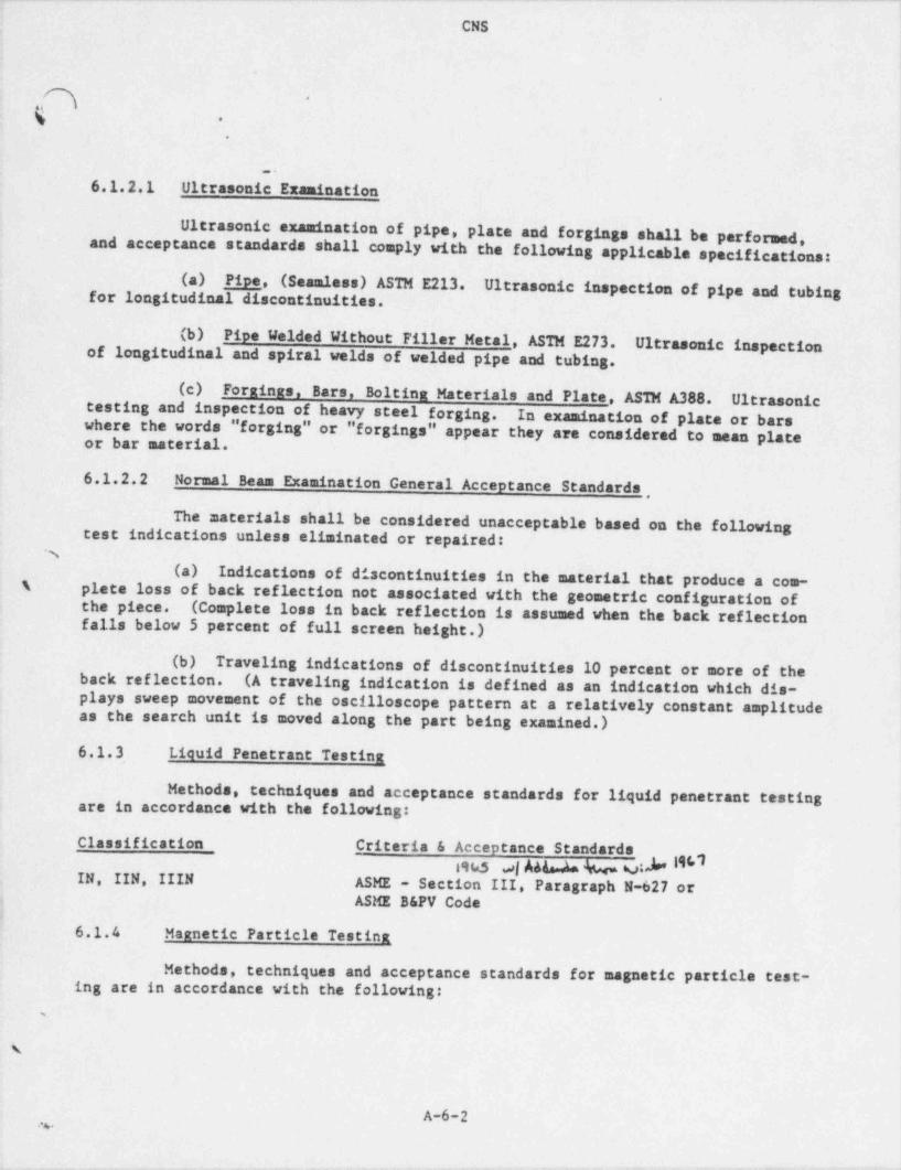
-- .. . - . _ . - . _ . - . . .. . - - .- - . - - . - - . . . - . - . _ - _ _ _
CNS
a * *
g,.
.
_.
6.1.2.1 Ultrasonic Examination -
Ultrasonic examination of pipe, plate and forgings shall be performed. 1
and acceptance standards shall comply with the following applicable specifications:
(a) Pipe, (Seamless) ASTM E213. Ultrasonic inspection of pipe and tubing |
for longitudinal discontinuities.
(b) Pipe Welded Without Filler Metal, ASTM E273. Ultrasonic inspectionof longitudinal and spiral welds of welded pipe and tubing.
(c) Forminas, Bars. Boltina Materials and Plate ASTM A388. Ultrasonictesting and inspection of heavy steel forging. In ewamination of plate or barswhere the words " forging" or " forgings" appear they are considered to mean plateor bar material.
6.1.2.2 Normal Beam Examination General Acceptance Standards,
The materials shall be considered unacceptable based on the followingtest indications unless eliminated or repaired:
%(a) Indications of discontinuities in the material that produce a com-
'\ plate-loss of back reflection not associated with the geometric configuration ofthe piece. (Complete loss in back reflection is assumed when the back reflectionfalls below 5 percent of full screen height.)
(b) Traveling indications of discontinuities 10 percent or more of theback reflection. (A traveling indication is defined as an indication which dis-
- plays sweep movement of the oscilloscope pattern at a relatively constant amplitudeas the search unit is moved along the part being examined.)
6.1.3 Liquid Penetrant Testina
Methods, techniques and acceptance standards for liquid penetrant testingare in accordance with the following:
Classifiestion Criteria & Acceptance Standards1%5 s|A44a.4a b MIN, IIN, IIIN ASME - Section III, Paragraph N-627 or
ASME B&PV Code:
6.1.4 Maanetic Particle Testina
Methods, techniques and acceptance standards for magnetic particle test-ing are in accordance with the following:
,
A-6-2.s.
....m. . __ . - . . . _ , . ..- , , ._ --.. .- -, ,
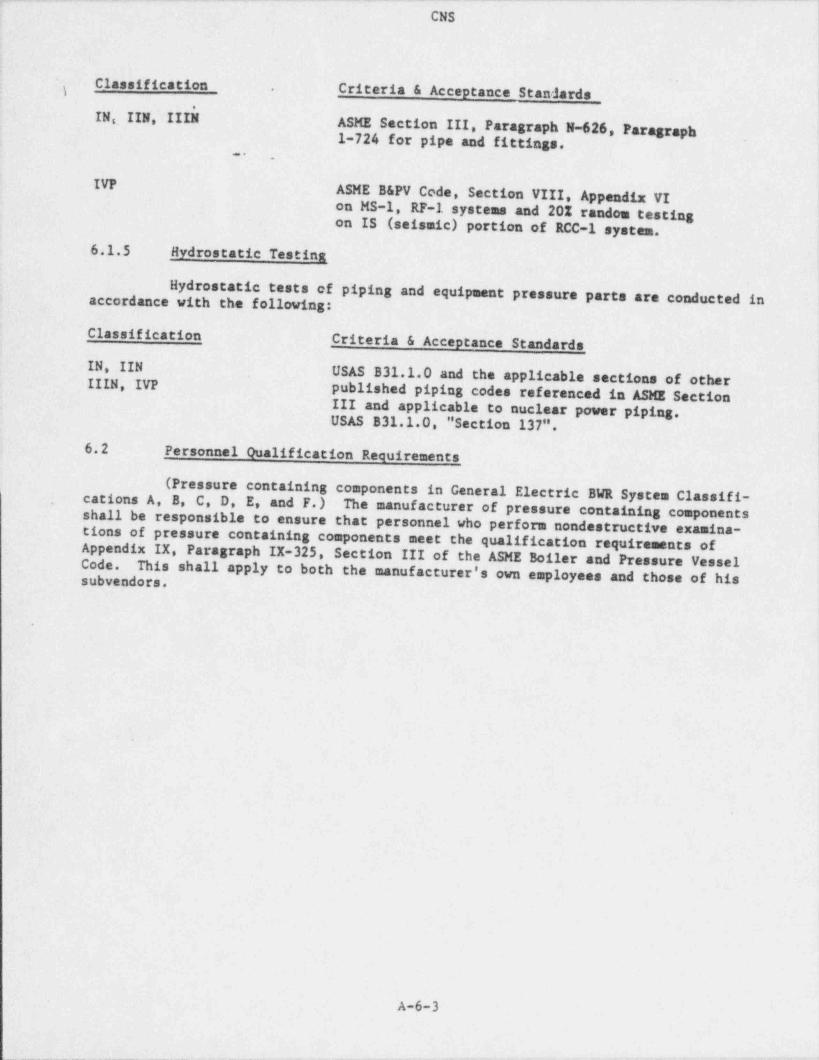
~ - . - . . . . - _ - . - - - . - . . . . - . - - - . . . - . - - - _ . . - - - _ . - - - - . - . - -
CNS
t
Classification Criteria & Acceptance Standards,
IN~ IIN III$l ASME Section III, Paragraph N-626 Paragraph1-724 for pipe and fittings.
...
IVPASME B&PV Code, Section VIII Appendix VIon MS-1, RF-1 systems and 20% randon testingon IS (seismic) portion of RCC-1 system.
6.1.5 Hydrostatic Testina
Hydrostatic tests of piping and equipment pressure parts are conducted inaccordance with the following:
Classification _ Criteria & Acceptance StandardsIN, IIN
USAS B31.1.0 and the applicable sections of otherIIIH, IVP published piping codes referenced in ASME Section
III and applicable to nuclear power piping. '
USAS B31.1.0, "Section 137".
6.2 Personnel Qualification Requirements
(Pressure containing components in General Electric BWR System Classifi-cations A, B, C, D, E, and F.) The manufacturer of pressure containing componentsshall be responsible to ensure that personnel who perform nondestructive examina-tions of pressure containing components meet the qualification requirements ofAppendix IX, Paragraph IX-325, Section III of the ASME Boiler and Pressure VesselCode. This shall apply to both the manufacturer's own employees and those of hissubvendors.
.
A-6-3
_ ___ _ - - _ _ _ _ _ . ._ _ - - . . - - . - -
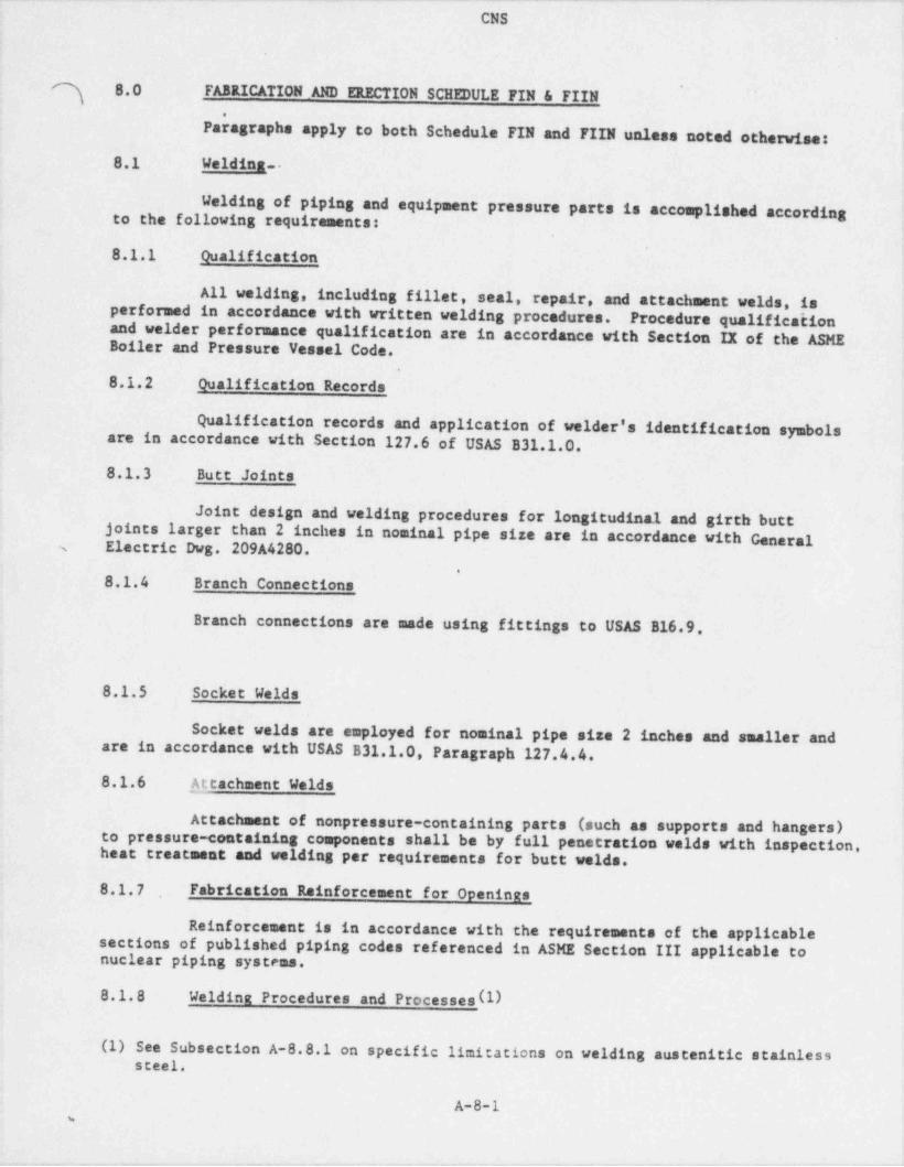
- . . - . . - . .. -.. _.- - . - - - _ - ~. ~ .. . _ - - - - . - . - - - - . -
CNS
] 8.0 FABRICATION _AND ERECTION SCHEDULE FIN & FIIN. r
Paragraphs apply to both Schedule FIN and FIIN unless noted otherwise:
8.1 Weldina--
Welding of' piping and equipment pressure parts is accomplished accordingto the following requirements:,
.
8.1.1 Qualification
All welding, including fillet, seal, repair, and attachment welds, isperformed in accordance with written welding procedures. Procedure qualifica^ tionand welder performance qualification are in accordance with Section IX of the ASMEBoiler and Pressure Vessel Code.
.
8.1.2 Qualification Records
Qualification records and application of welder's identification symbolsare in accordance with Section 127.6 of USAS B31.1.0.8.1.3 Butt Joints
Joint design and welding procedures for longitudinal and girth butt. joints larger than 2 inches in nominal pipe size are in accordance with GeneralElectric Dwg. 209A4280.s
.
8.1.4 Branch Connections
Branch connections are made using fittings to USAS B16.9
8.1.5 Socket Welds
Socket welds are employed for nominal pipe size 2 inches and smaller andare in accordance with USAS B31.1.0, Paragraph 127.4.4.
8.1.6 A_ttachment Welds
Attachment of nonpressure-containing parts (such as supports and hangers)to pressure-containing components shall be by full penetration welds with inspection,heat treatment and welding per requirements for butt welds.
8.1.7 Fabrication Rainforcement for Openings
Reinforcement is in accordance with the requirements of the applicablesections of published piping codes referenced in ASME Section III applicable tonuclear piping systems.
8.1.8 Welding Procedures and Processes (l)
(1) See Subsection A-8.8.1 on specific limitations on welding austenitic stainlesssteel.
A-8-1%
. - . . , ,, , . , - ., , - - - ,. -
. - . . . . . - . _ . . - . - - . . . - . - - . . . - . . - - - - . . - . . - . - - - . - . - . . . . _ . -
CNS.
I
i.n.
\ '
*
1. Welding procedures2. Repair procedures0 # HeatL. treatment procedures4 Cleaning procedures5.
Quality Assurance Control Plan (as specified in Appendix D)8.9 Inspection and Testina
Inspection and testing of piping and equipment pressure parts, includingcompleted welds, assemblies, and subassemblies, is performed as shown in the appli-cable schedule for the specific classification of piping and equipment pressureparts (see Subsection A-6.0).
I
~i
%
i
|
!
A-8-6
_ , _ _ _ ,
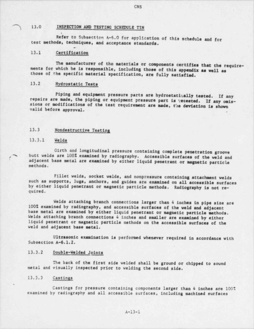
. . - - . - . - - . - . -.
- _ - -
CNS
] 13.0 INSPECTION AND TESTING SCHEDULE TIN*
'
Refer to Subsection A-6.0 for application of this schedule and fortest methods, techniques..and acceptance standards.
..
13.1 Certification
The manufacturer of the materials or components certifies that the require-ments for which he is responsible, including those of this appendix as well asthose of the specific material specification, are fully satisfied.
13.2 Hydrostatic Tests
Piping and equipment pressure parts are hydrostatically tested. If anyrepairs are made, the piping or equipment pressure part is 'tecosted. If.any omis-sions or modifications of the test requirement are made, c'.te deviation is shownvalid before approval.
-
13.3 Nondestructive Testing
13.3.1 Welds
Girth and longitudinal pressure containing complete penetration grooveg butt welds are 100% examined by radiography. Accessible surfaces of the weld ands
adjacent base metal are examined by either liquid penetrant or magnetic particle-
methods.
Fillet welds, socket welds, and nonpressure containing attachment weldssuch as supports, lugs, anchors, and guides are examined on all accessible surfacesby either liquid penetrant or magnetic particle methods. Radiography is not re-quired.
Welds attaching branch connections larger than 4 inches in pipe size are !100% examined by radiography, and accessible surfaces of the weld and adjacent i
base metal are examined by either liquid penetrant or magnetic particle methods. I
Welds attaching branch connections 4 inches and smaller are examined by ~eitherliquid penetrant or magnetic particle methods on the accessible surfaces of theweld and adjacent base metal.
Ultrasonic examination is performed whenever required in accordance with !Subsection A-6.1.2. i
13.3.2 Double-Welded Joints
The back of the first side welded shall be ground or chipped to soundmetal and visually inspected prior to welding the second side.
13.3.3 castinas.
Castings for pressure containing components larger than 4 inches are 100%examined by radiography and all accessible surfaces, including machined surfaces j
A-13-1
.. __ _ _ _ .
_ _ _ _ _ . - _ - _ _ _ _ . _ . _ _ _ _ . . _ _ _ _ . _ _ _ _ . _ . _ . . _ . . _ _ _ . _ _ . _ _ _ _ . _ . _ . _ . __ _
) CNSi
|ii
! q and castings 4 inches and smaller are examined by either the magnetic particle or5 the liquid penetrant method.I \j 13.3.4 Forginasij
Forgings for pressure containing components over 4 inches nominal dia-}
meter are examined in the finished condition by ultrasonic inspection; componentsi 4 inches and smaller on all accessible surfaces including machined surfaces, byeither the liquid penetrant or the magnetic particle method.3
1
j 13.4 Submittalss
j
) Approval is required for the following inspection and test procedures:; 1. Radiographyj 2. Ultrasonic testingI 3. Liquid penetrant testingj 4. Magnetic particle testingi
:)
$
-
!1
%
A-13-2
- _ _ - _ _ __ _ _ _ - - - . _ _ __--
. . . . . - . - . - - . - .. _. -. _ - - _
CNS
14 0 INSPECTION AND. TESTING SCHEDULE TIIN3
'
Refer to Subsection A-6.0 for application of this schedule and for testi methods, techniques and acceptance standards.:
.
| 14.1 Certification!
|'
The manufacturer of the materials or components certifies that the require-ments for which he is responsible including those included in this appendix as wellas those of the specific material specification, are fully satisfied.14.2 Hydrostatic Tests
iPiping and equipment pressure parts are hydrostatically tested. If any irepairs are made, the piping or equipment pressure part is retested. If any omis- '
sions or modifications of the test requirement are made, the deviation is shownvalid before approval.
14.3 Nondestructive Testing
1,4. 3.1 Welds
Girth and longitudinal pressure containing complete penetration groove i
butt welds are 100% examined by radiography.!!
Fillet welds, socket welds, and nonpressure-containing attachment welds jsuch as supports, lugs, anchors, and guides are examined on all accessible surfaces
;by either the liquid penetrant or the magnetic particle method. Radiography is not Is
required.
Welds attaching branch connections larger than 4 inches in pipe size are100% examined by radiography, except where configuration does not permit effectiveradiography; then the root tad final pass is examined by liquid penetrant or mag-netic particle methods.
Accessible surfaces of the weld and adjacent base metal of brEnch connec-tions 4 inches and less in pipe size are examined by either the liquid penetrant orthe magnetic particle method.
Ultrasonic examination is not required.
14.3.1.1 Double-Welded Joints
The back of the first side welded is ground or chipped to sound metaland visually inspected prior to welding the second side.
14.3.2 Castings
Castings for pressure containing components larger than 4 inches are 100%examined by radiography and in the finished condition on all accessible machinedsurfaces by either the liquid penetrant or the magnetic particle method.
s
A-14 -1
- ,_ _ . - - - - - - - - - -~
'.
CNS
i
] Castings for' pressure containing components 4 inches nominal size andsmaller do not require special non-destructive testing beyond non-destructive test-
,
ing per materials specification.i
14.3.3 Forminas-- .
Forgings for pressure containing components larger than 4 inch s in nomi-nal pipe size are examir4ed in the finished condition on all accessible surfacesincluding machined s*>rfaces by either the liquid penetrant or the magnetic particle
t
method.
14.4 Submittalg
fApproval is required for the following inspection and test procedures:
'
l. Radiography'
2. Ultrasonic testingi 3. Liquid penetrant testing'
4. Magnetic particle testing
.
\
|
|
N
\
| A-14-2|.
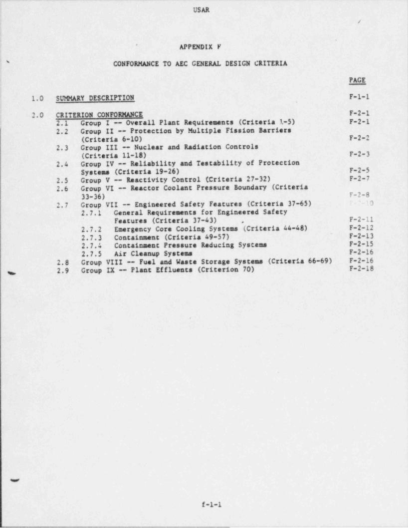
. . - . - - -- . . . . . - - . - . - - - - . - . . - . - - . - . - - - . - _
USAR
? /4
)
. .
j APPENDIX F*
' CONFORMANCE TO AEC GENERAL DESIGN CRITERIA
I PAGE; .
\I
l.0 SUMHARY DESCRIPTION F-1-1'
,.
2.0 CRITERION CONFORMANCE F-2-12.1 Group I -- Overall Plant Requirements (Criteria 1-5) F-2-1'
2.2 Group II -- Protection by Multiple Fission Barriers I
(Criteria 6-10) F-2-2 |
2.3 Group III -- Nuclear and Radiation Controls |'
(Criteria 11-18) F-2-32.4 Group IV -- Reliability and Testability of Protection
Systema (Criteria 19-26) F-2-52.5 Group V -- Reactivity Control (Criteria 27-32) F-2-7 j
!
2.6 Group VI - _ Reactor Coolant Pressure Boundary (Criteria33-36) F-2-8
'1. 0 |2.7 Group VII -- Engineered Safety Features (Criteria 37-65)
'-
2.7.1 General Requirements for Engineered Safety I
Features (Criteria 37-43) F-2-11'
,
2.7.2 Emergency Core Cooling Systems (Criteria 44-48)- F-2-13
F-2-122.7.3 Containment (Criteria 49-57)2.7.4 Containment Pressure Reducing Systems F-2-152.7.5 Air Cleanup Systema F-2-16
2.8 Group VIII -- Fuel and Wasta Storage Systems (Criteria 66-69) F-2-162.9 Group IX -- Plant Effluents (Criterion 70) F-2-18
,,
.
f-1-1

_ . . _ _ __ _ . _ _ __ _ _ . _ _ . . _ _. _ . _ . _ . _ _ . _ - . . _ _ _ _ _ .
i
i
|APPENDIX F
i.
CONFORMANCE TO AEC GENERAL DESIGN CRITERIA
~ 1. 0 SUMMARY DESCRIPTION1-
The proposed 70 General Desian Criteria for Nuclear Power Plant Construc-tion Permits were issued in July of 1967 to serve as a guide in the establishmentof design criteria and bases for the design and construction of a nuclear powerstation. It is the purpose of this appendix to show that the design and construc-~
tion of the Cooper Nuclear Station has been performed in accordance with these gen-cral design criteria.
It should be recognized that these criteria, which appeared in the July11, 1967 issue _of the Federal Register, were issued in order to secure commentsfrom the nuclear industry, and at that time had not yet been adopted as regulatoryrequirements. It was anticipated that revisions and clarifications would takeplace prior to such adoption. The comparison which follows is presented to showthat the concerns expressed by those criteria, as interpreted by the applicant,have been fully considered in the design of the station.
The method of presentation is to consider the criteria in nine groups.The grouping of the criteria is that given in the above referenced draft. For eachgroup. a statement of the applicant's then current understanding of the intent of.
the criteria in the group is given along with discussion of conformance which. isapplicable to all of the criteria within the group. Each criterion in the groupis then discussed as necessary to enlarge upon the general statements and,a listof references where the subject material of the individual criterion is found inthe original CNS-SAR is presented. The statements of the criteria are not presentedbut are referenced by number to the criteria statements presented in the July 11,1967 Federal Register.
The.following discussion was extracted directly from the original FSARand left in its original form for historical purposes.
F-1-1._
-- - - . . . -. . .- -- - - _. -
! CNS
2.0 CRITERION CONFORMANCE
i 2.1 Croup I -- Overall Plant Reauirements (Criteria 1-5),
The purpose of these criteria is to insure that those systems and compon- jents of the station which have a vital role in the prevention or mitigation of con-sequences of accidents affecting public health and safety are designed and construc- !
,
ted to high quality standards which include consideration of natural phenomena and !fire. Also, there must be sufficient surveillance and record keeping during fab- |rication and construction to ensure that these high quality standards have been met. !
As the station consists of a single nuclear plant, Criterion 4, Sharing of Systems,is not applicable. It will be seen that the concerns of these criteria have beenproperly considered throughout the design of the station.
Criterion 1 -- Quality Standards.
A thorough quality assurance program has been undertaken during designand construction of the station to ensure that highest quality standards were used.Applicable codes were used where they were sufficient and more stringent require- i
ments were placed on the design, where available codes were not sufficient. Thequality assurance program is presented in Appendix D. The description of thevarious systems and components includes the codes and standards that are met in thedesign and their adequacy. '
References: Subsections I-5, I-10, III-2 through III-8, IV-1 throughIV-8, VII-2 through VII-5, Sections V. VI, VIII, and Appendix D.
Criterion 2 -- Performance Standards,,,
Conformance to the structural loading criteria presented in Appendix Cinsures that those systems and components affected by this criterion are designedand built to withstand the forces that might be imposed by the occurrence of thevarious natural phenomena mentioned in the criterion, and this presents no risk tothe health and safety of the public. The phenomena considered and margins of safetyare also given.
References: Subsections I-5, XII-2 and Appendix C,
Criterion 3 -- Fire Protection
As described in Subsection X-9, the materials and layout used in thestation design have been chosen to minimize the possibility and to mitigate theeffects of fire. Sufficient fire protection equipment is provided in the unlikelyevent of a fire, and in no case will the ability of the station to be shutdown becompromised by fire.
References: Subsection X-9, Section XII.
Criterion 5 -- Records Requirement
Complete records of the as-built design of the station, changes duringoperation and quality assurance records will be maintained throughout the life ofthe station.
w
F-2-1
CNS '
;
. ,,
References: Subsection XIII-8, XIII-9, and Appendix D.*
2.2 Group It -- Protection by Multiple Fission Barriers (Criteria 6-10)
Conformance to these criteria assures, through proper design, that the!\
station has been provided with multiple barriers against the release of, or means !
for, the mitigation of the consequences of the release of fission products to theenvirons and that these barriers remain intact during abnormal operational tran-sients. These criteria also provide for proper containment and barrier against therelease of fission products in the event of design basis accidents.
To provide the required protection, the reactor design provides six meansof containing, preventing, or mitigating the release of fission products. Thesethe fuel barrier consisting of highly compacted UOare: 2 fuel sealed in high in-tegrity Zircaloy cladding, the nuclear process system, the primary containment,the reactor building (secondary containment), the reactor building standby gastreatment system, and the plant stack (ERP).
Criterion 6 -- Reactor Core Design;
The basis of the reactor core design, in combination with the station )i
equipment characteristics and nuclear safety systems, is to provide sufficient mar-gins to ensure that fuel damage does not occur during normal operation or as aresult of abnormal operational transients. The core design is described in SectionIII and analysis of abnormal operational transients is given in Section XIV. Theresidual heat removal system and the reactor core isolation cooling system which ,
J
remove decay heat during normal shutdowns and when the cora is isolated from thecondenser, are discussed in Section IV.%=<
References: Subsections I-5, III-2. III-6, III-7, IV-3, IV-7, IV-8,VII-2, XIV-2, XIV-4..and XIV-5.
Criterion 7 -- Suppression of Power Oscillations
The core design alone and the design of the nuclear system including thecore have been analyzed to determine if power oscillations could occur. This an-alysis, which is presented in Section VII-17 " Nuclear System Stability Analysis",shows that all power oscillations are suppressed and no fuel damage would occur.
References: Subsections I-5, III-4, III-6, III-7, IV-4, VII-2, VII-5,VII-7, VII-17, and XIV-5.
Criterion 8 -- Overall Power Coefficient
As indicated in Sections III and VII-17, the core is designed to be self-limiting; i.e., an arbitrary increase in core power over the power operating rangeresults in a negative feedback. Thus, the overall power coefficient is negative.
References: Subsections I-5, III-6, III-7, and VII-17.
F-2-2
- - -
CNS
, Criterion 9 -- Reactor Coolant Pressure Boundary (Nuclear System' Process" Barrier)w
The nuclear system process barrier consists of the vessels, pipes, pumps, '
tubes and similar process components that contain steam, water, gases, and radio-ective materials coming from, going to, or in communication with the reactor core.These are described primarily in Section IV " Reactor Coolant System". The reactorcoolant system is designed to carry its dead weight and specified live loads sep-arately or concurrently; these include pressure and temperature stresses, vibrations,and seismic loads prescribed for the station. Provisions are made to control orshutdown the reactor coolant system in the event of malfunction of operating equip-ment or leakage of coolant from the system. The reactor vessel and support struc-tures are designed, within the limits of applicable criteria for low probabilityaccident conditions, to withstand the forces that would be created by a full areaflow of any vessel nozzle to the containment atmosphere with the reactor vessel atdesign pressure concurrent with the station maximum earthquake loads.
References: Subsections I-5, IV-2, IV-3, IV-4, IV-10. VII-8, XII-2,XIV-5, XIV-6, Appendix A and Appendix C.
.
Criterion 10 -- Containment
Two containment systems are provided; the drywell suppression chamberprimary containment and the reactor building (secondary containment). These are
|,
described in Section V. "
The primary containment system is designed, fabricated, and erected toaccommodate without failure the pressures and temperatures resulting from or sub-,,
sequent to the double-ended rupture or equivalent failure of any coolant pipe with-in the primary containment. The reactor building, encompassing the primary contain-ment system, provides secondary containment when the primary containment is closedand in service, and provides for primary containment when the primary containmentis open. The two containment systems and such other associated engineered safe-guards as may be necessary are designed and maintained so that off-site doses re-sulting from postulated design basis accidents are below the values stated in10CFR100.
1
References: Subsections V-2, V-3, XIV-4, and XIV-6.
2.3 Group III -- Nuclear and Radiation Controls (Criteria 11-18)
These criteria identify and define the station instrumentation and control3systems necessary for maintaining the station in a safe operational status. This !
also includes determining the adequacy of radiation shielding, effluent monitoring,and fission process controls, and providing for the effective sensing of abnormalconditions and initiation of nuclear safety systems and engineered safeguards.
i
To satisfy the intant of these criteria the station is provided with a !comprehensive control and instrumentation system, most of which is described inSection VII. Control of the station is from a central control room. Shielding and 1
.
radiation protection are discussed in Subsection XII-3.
ma
F-2-3
- . - . - _. ._--
CNS
Criterion 11'-- Control Room'"#
The station is provided with a centralized control room having adequateshielding to permit access and continuous occupancy under 10CF120 dose limits duringany of the design basis accident situations.
This allows the station to be shutdown when necessary and allows safe control of the station to be maintained fol-lowing shutdown.The station design does not contemplate the necessity for evacu-ation of the control room. However, if it is necessary to evacuate the control
room, the station can be brought to a safe, cold shutdown from outside the controlroom.
References:VII-12, X-10, XII-2, XII-3, and Section XIV. Subsections I-5, VII-2 through VII-5, VII-7 through VII-10,
_ Criterion 12 -- Instrumentation and Control Systems
The necessary station controls, instrumentation, and alarms for safe andorderly operation are located in the control room. These instruments and systemsallow complete monitoring control of the facility throughout the normal operatingrange and through startup and shutdown. Sufficient instrumentation is provided toallow monitoring of all variables necessary for ef,fective station control.
_ References: Subsections I-5, III-4, III-8, IV-10, VII-2 through VII-5,VII-7 through VII-10, VII-12 through VII-14, VII-17, and IX-2 through IX-4.
Criterion 13 -- Fission Process Monitors and Control
Continuous monitoring of the performance of the reactor and the reactors.,
power level are provided by the nuclear instrumentation system as described inSubsection VII-5.the positions of which are continuously available on the control board. Control of core reactivity is through the use of control rods,
References:VII-9, and VII-17. Subsections I-5 III-4, III-8, VII-2, VII-5, VII-7 through
Criterion 14 -- Core Protection Systems
The reaccor protection system, described in Subsection VII-2 in associa-tion with other safety systems, automatically senses and limits conditions whichcould lead to unacceptable fuel damage. This system acts independently of, andoverrides, all other controls to initiate the necessary protective action. Evalu-ation of the protective action is given in the safety analysis.
References: Subsections I-5, III-4, III-5, IV-4 through IV-8, VI-1through VI-7, VII-2 through VII-5, VII-7, VII-12, and XIV-1 through XIV-7.
Criterion 15 -- Enmineered Safety Features Protection Systems
The reactor core standby cooling system control and instrumentationsystem description in Subsection VII-4 details the instrumentation provided to non-itor the necessary variables and to automatically initiate the proper safety actionin the event of an accident. This system also acts independently of the station
s.
F-2-4
_ _ _ .- _._._ . _ _ . _ _ . . _ _ _ _ _ _ _ _ - _ _ _ _ _ _ _ _ _ _ _ _ _ _ _ _
CNS||
ocess control systems and overrides all other controls to initiate the nec'essaryafety actions. 1,
References: Subsections I-5, VI. VII-2 through VII-5, and VII-12.!
| Criterion 16 -- Monitoring Reactor Coolant Pressure Boundary
| The methods of detecting leakage through the reactor coolant pressureboundary, and the limits imposed on this leakage, are discussed in Subsection IV-10.
References: Subsections I-4, IV-10,-V-2, VII-8, and X-14.
Criterion 17 -- Monitorina Radioactive Releases
The station process and area radiation monitoring systems and station |~
'
| sempling procedures are provided for monitoring significant parameters from specificstation process systems and specific areas including the station effluents to thesite environs and to provide alarms and signals for appropriate corrective actions. ,
!
.These are described in Subsections VII-12 and VII-13.
References: Subsections I-4, VII-12, VII-13 IX-2 and IX-4.
Criterion 18 -- Monitorina Fuel and Waste Storate
The new and spent fuel storage areas have been analyzed to determineControltheir safety, and instrumentation is provided for monitoring where needed. ,
and monitoring of waste storage is provided as described in Section IX, S ubsection |- VII-12 and X-5. ,
,
References: Subsections I-5, VII-12, VII-13, IX-2, IX-4, and X-5.
2.4 Group IV -- Reliability and Testability of Protection Systems(Criteria 19-26)
The purpose of these criteria is to ensure that the systems used to pre-vent breach of the clad barrier will: (1) function when needed in spite of thefailure of a component within the system, (2) be designed such that a condition
|requiring a protection system will not prevent the proper functioning of that sys-tem, and (3) be designed so that each channel of a protection system is independ- |
of other channels within that system and the control systems. Protectionentsystem testability and detection of failures within the protection systems are nec-As seen in the design bases andessary to ensure the reliability of these systems.descriptions of these systems, sufficient attention has been paid to componentreliability, system testability and alarms, independence and power supply, to ensureThe des-the protection systems are adequate with respect to these criteria.thatcription of these systems appears largely in Section VII of the CNS-SAR.
Criterion 19 -- Protection Systems Reliability
The components of the protection systems are designed to a high standard i
!Each system is designed with provisions for testing which approx-of reliability.imate very closely the functioning of the system under design conditions of thatsystem.,,
F-2-5
., _ -_- . . - _ _ . _- . .. - - _ .
__ __ _ . . . _ . _ _ _ _ . _ _ _ _ ___ . _ _ _ . _ _ . _ _ _ _ ______ _ __
CNS
References: Subsections I-5. III-4, VI. VII-2 through VII-5, Vif-12, and_
Section XIV.
Criterion 20 -- Protection Systems Redundancy and Indeoendence
Protection system design includes the capability of providing the requiredprotection, even with a component or channel inoperative due to failure or removal.Each of the protection function actions are initiated by a variety of sensed stationconditions and by at least two instrument channels. This protection action is notdependent on a single channel.
References: Subsections I-5, III-4, VI. VII-2 through VII-5, VII-12, andSection XIV.
Criterion 21 -- Single Failure Definition
This definition is used in the design throughout the CNS-SAR for safetysystems.
References: Subsections 1-2, and XIV-4.
Criterion 22 -- Separation of Protection and Control InstrumentationSys tems
The systems which initiate the scram, isolation, and core standby coolingactions are designed to automatically override normal operational controls wheneverstation conditions monitored by these systems exceed pre-established limits. Re-moval from service of a control instrumentation system cannot compromise any reactor,,,
protection function. Thus, protection action is independent of the state in normaloperational process control actions.
References: Subsections I-4, III-4, VI-5, VII-2 through VII-5, and VII-12.
Criterion 23 -- Protection Against Multiple Disability for ProtectionSystems
These systems are designed to provide the required protection as long asnecessary and in the presence of the most severe conditions which would be en-countered. This includes'all conditions resulting from transients and accidentsfor which the protective action is required.
References: Subsections I-5, III-4, VII-2 through VII-5, VII-12, and Sec-tion XIV.
Criterion 24 -- Emergency Power for Protection Systems
In the event of a loss of offsite power, the station auxiliary power sys-tem, the standby diesel generators, and the 125 volt battery system provide adequatepower and redundancy to permit the required functioning of the protection systems.In addition, the 100% capacity redundant halves of each system are adeqvstely sep-erated to prevent the loss of power to the protection systea-resulting from anysingle active or passive failure.
"#References: Sections VI VII. Subsections I-5, and VIII-4 ehrough VIII-e
F-2-6
. . _ ._ _ _. _ _ . _ . _ _ _ _ _ _ _ _ . _ _ _ _ _ _ _ _ - _ _ _ _ . . _ _ _ . . _ _ _ _ _ . _ _ _ _ _ _ _
r
USAR
criterion is not interpreted to require a fLst scram capability of both systems buti -
only the stated shutdown capability.
References: Subsection I-5, III-4, III-6, III-9, VII-7, and Section XIV.|
Critarion 29 - Rametivity Shutd a cm==hility
Reactor shutdown by the control rod drive system is sufficiently rapidto prevent violation of fuel damage limits for normal operation and all abnormaloperational transients, even with the most reactive control rod fully withdrawn.The nuclear dssign assures that sufficient reactivity compensation is alwaysavailable to make the reactor suberitical from its most reactive condition includingcompensation for positive and negative reactivity changes resulting from nuclearcoefficients, fuel depletion and fission product transients and buildup.
References: Subsections I-5, III-4, III-6, VII-2, and Section XIV.
Critarion 30 -- Rametivity Holddawn Canability
As indicated in the previous criterion response, the operational controlsystem is designed to make and hold the reactor suberitical from its most reactivecondition under all normal credible operating conditions.
References: Subsections I-5, III-4, III-6 and III-9.|.
Criterion 31 -- Rametivity Control Syne === Mal func tion
Reactivity control systems designs (in conjunction with the reactotprotection systems) ensure that acceptable fuel damage limits will not be exceededfor any credible reactivity transient resulting from a single equipment malfunctionor a single operator error.
Rafarancam- Subsections I-5, III-4, III-6, III-7, VII-2, VII-7, andSection XIV.
Critarion 32 -- Mawi== Rametivity Worth of Control Rods
The system design is such that control rod worths and the rate at whichreactivity can be added are sufficiently limited to assure that the design basisreactivity accident is not capable of damaging the reactor coolant system ordisrupting the reactor core, its suppo:t structures, or other vessel internalssufficiently to impair the core, standby cooling systems' effectiveness, if thesesystems are needed.
References: Subsections I-5, III-4, III-6, III-7, VI, VII-7 andSection XIV.
2.6 croun VI - n==etor Coolant Pressure Boundary (Criteria 33-36)
The intent of this group of proposed criteria is to establish the. reactor coolant pressure boundary design requirements and to identify the means usecto satisfy these design requirements. The " reactor coolant pressure boundary" .*referred to in the safety analysis report as the " nuclear system primary barrie:(see " Definitions" in " Introduction and Summary", Subsection I-2). The reac -
F-2-8 07/22/9.
_ _ - _ . . -. _ ._. -
USAR
Critarion 25 -- D-- =tration of Functional Onarahility of ProtectionSXAasat
All of the protection systems contain sufficient test shnals,bypasses and indicators to allow testing ,of the system under simulated con, ; ionsclosely approximating the actual condition for which the protective action is> required. .
being carried on, should the channel under test be needed for a protective actionProvisions are also included to automatically override any testing4
.
; References: Subsections I-5, VI-7, VII-2 through VII-5, and VII 12.Critarion 26 -- Protaction Sys*=== Fail-Safe Desien
Systems essential to the protection functions are designed tofail-safe in their most probable failure modes. Thus, a systematic orenvironmentally caused failure will be indicated and will not compromise theprotective function of the system.
Rafarances!VIII-4 and VIII-5. Subsections I-5, VI-l through VI-6, VII-2 through VII 5,
2.5 Croun V -- R==ctivityceneral (Criteria 27-32)
Conformance to these six criteria provides assurance that the reactorcore can be madeand held suberitical from normal operation or from normal
anticipated operational transients, by at least two reactivity control systems andthat malfunction of a reactivity control system will not result in unacceptabledamage to the fuel, rupture of the reactor coolant pressure boundary, or disruptthe core to the point of preventing core standby cooling if needed
,
Two systems,an operational control system, consisting of moveable control rods, and control
.
by recirculation flow control; and a standby liquid control system are providedto meet the intent of these criteria. The moveable control rod system design isgiven in Subsection III 4 and control of the moveable rod system is described inSubsection VII-7; the nuclear design, including the control rod reactivity worthsis given in Subsection III-6; reactor coolant recirculation system flow control,is described in Subsection VII-9; and thedescribed in Subsection III-8. standby liquid control system is
Critarion 27 -- Radundanev of Rametivity Control
and of different principal.The two reactivity control systems provided are completely independentburnup, load changes and long term reactivity changes.The operational control system accosmodates fuelThe standby liquid controlsystem provides independent shutdown capability if it is needed.
References: Subsection I-5, III-4, III-9, and VII-7.|
Critarion 28 -- R=merivity Hot Shutdown c===hility
Both the control rod system and the standby liquid control system arecapable of making and holding the core subcritical from any hot standby or hotoperating condition up through full power. Consistent with current practice, this
F 2-7 07/22/91
. . . - . _- - - - . - _ ~ . - . - . - - _ - - . - . . . - - - . - . . - - - . . . -
| CNS!
! coolant system design, described in _ Section IV and Subsection III-3, together with|:he quality assurance program (Appendix D), show that these criteria have been prop-* ;
erly considered. In-service inspection of components and parts inside this bound- ;,
i ary is discussed in Appendix J.! ;
Criterion 33 -- Reactor Coolant Pressure Boundary Capability.
i
| As shown in Section XIV, the consequences of the design basis rod drop! accident cannot result in damage (either by motion or rupture) to the nuclear systenj process barrier. This is due to the inherent safety features of the reactor corej design combined with the control rod velocity limiter.;
References: Subsections I-5, III-3 through III-6, IV-2, IV-5, IV-6, and'
XIV-4 through XIV-6.
! Criterion 34 -- Reactor Coolant Pressure Boundary Rapid Propaastionj' Failure Preventiont
The ASME and USASI Codes are used as the established and acceptable cri-teria for design, fabrication, and operation of components of the nuclear systemprimary barrier. The nuclear system primary barrier is designed and fabricated tomeet the following, as a minimum:
,
1. Reactor Vessel--ASME Boiler and Pressure Vessel Code, Section IIINuclear Vessels, Subsection A.
2. Pumps--ASKE Boiler and Pressure Vessel Code, Section III, Nuclear==r Vessels, Subsection C.
3. Piping and Valves--USAS B.31.1, Code for Pressure Power Piping.
The brittle fracture failure mode of the nuclear system primary barriercomponents is prevented by control of the notch toughness properties of ferriticsteel. This control is exercised in the selection of materials and fabrication of ;
equipment and components. In the design, appropriate consideration is given to the Idifferent notch toughness requirements of each of the various ferritic steel productforms, including veld and heat-affected zones. In this way, assurance is providedthat brittle fracture is prevented under all potential service loading temperatures.
References: Subsections III-3, IV-2, IV-3, VII-8, Appendix A and Appendix D.
Criterion 35 -- Reactor Coolant Pressure Boundary Brittle FracturePrevention
i
The applicant's selected approach to brittle fractura prevention is to use ia temperature based rule with modifications drawn from fracture mechanics techno-logy. The approach, which is generally accepted by materials specialists, esta-blishes the requirements for brittle fracture prevention. These requirements areless stringent, when measured in terms of NDTT requirement, for thin section mat-erials than the thick section materials assumed in the first draft of this criter-ion.
.e
F-2-9
. -
- - . . - - - . - . - -- - - - - - - . . . . - - - . - - - - - - -
CNS
The toughness properties of ferritic material and the service temperatureof the reactor coolant pressure boundary shall assure:g,,
1. Fully ductile behavior (e.g. , in the energy absorption region of 100percent shear fracture) whenever the boundary can be pressurized beyond the systemssafety valve setting by operational transients in postulated accidents; and
2. A ductile to brittle fracture transition temperature at least 600Fbelow the service temperature whenever the boundary can be pressurized beyond 20percent of its design pressure by operational transients, hydro tests, and postu- '
;laced accidents.
The response of the reactor system pressure to postulated accidents is I
discussed in the General Electric Company reply to Comment 3.8.1 of Amendment 1 toi
. Bell Station Unit 1, Docket No. 50-319. There are no operational transients whichcan pressurize the system boundary beyond the system's safety valve setting (1250psig), so requirements for fully ductile behavior in pressure boundary materialsare not anticipated.
It is believed that criterion 35 should be applicable only to those com-ponents or systsas whose failure would result in a loss of coolant in excess of thenormal make-up capability of the reactor coolant system. On this ground small linessuch as instrument lines have been excluded; certain other lines, such as the mainsteam lines, have been exempted from temperature control during hydrostatic testconditions in which failure would not affect core cooling.
Reference: Subsection IV-2.V I
Criterion 36 -- Reactor Coolant Pressure Boundary Surveillance
The reactor coolant system is given a final hydrostatic test at 1560 psigin accordance with code requirements prior to initial reactor startup. A hydro-
|static test, not to exceed system operating pressure, is made on the reactor cool- !
system following each removal and replacement of the reactor vessel head.antThe !
system is checked for leaks, and abnormal conditions are corrected before reactorstartup. The minimum vessel temperature during hydrostatic tests is at least 60 Fabove the calculated NDTT prior to pressurizing the vessel. Extensive quality con-trol assurance programs are also followed during the entire fabrication of the
|reactor coolant system. Vessel material surveillance samples are used to enable|periodic monitoring of material properties with exposure. The program includes '
specimens of the base metal, heat affected zone metal and standards specimens.Also, leakage from the reactor coolant system is monitored during reactor operation.The material surveillance program will conform to ASTM E 18566.
References: Subsections IV-2, IV-3, and IV-10.
2.7 Group VII -- Enmineered Safety Features (Criteria 37-65)
The intent of this group of proposed criteria is (1) to identify the '
nuclear safety systems and engineered safeguards, (2) to examine each one for inde-pendency, functional redundancy, capability, testability, inspectability, andreliability, (3) to determine the suitability of each for its intended duty, and(4) justify that each safety feature's capability-scope encompasses all the anti-,,
F-2-10
__ ..__ _ _ _ _. _ _ _ _ ._ ____ _ . _ _ _ _ _ _ _ . _ _ _ _ __ _ ___.
|
CNS |
cipated and credible phenomena associated with the station operational transients% or design basis accidents being considered. While the first seven criteria are
applicable to all of the engineered safety features, the remaining criteria fallinto four groups: emergency core cooling systems (Criteria 44-48); containment s(Criteria 49-57); containment pressure reducing systems (Criteria 58-61); and aircleanup systems (Criteria 62-65). Examination of each of these safety featureswill show that their design conforms to the Group VII Criteria.
2.7.1 General Requirements for Enmineered Safety Features (Criteria 37-43)
Criterion 37 -- Engineered Safety Features Basis for Desian
The normal station control systems maintain station variables withinoperating limits. These systems are thoroughly engineered and backed up by a sig-nificant amount of experience in system design and operation. Even if an improbablemaloperation or equipment failure occurs (including a nuclear system process barrierbreak up to and including the circumferential rupture of any pipe in that barrier),the nuclear safety systems and engineered safeguards 1 Lait the effects to levelswell below those which are of public safety concern. These engineered safety feat-
.
ures include those systems which are essential to the containment, isolation, and !core standby cooling functions.
References: Subsections I-5, III-3 III-4, IV-2, IV-4, IV-6, V-2, V-3,VI-1 through VI-7, VII-2 through VII-4, VIII-4 through VIII-6, and VIV-1 through XIV-7. ;
1
Criterion 38 -- Reliability and Testability of Engineered Safety Features
The design of each of the systems essential to the engineered safety feat-*='
ures includes the use of highly reliable components and provides for ready testa-bility of these systems. Extensive analytical and experimental programs have shownthat these systems are capable of performing their designated tasks.
References: Subsections I-5, III-4, III-5, IV-6, V-2, V-3, VI-6, VII-2,VII-4, VII-5, VII-12, and VIII-4 through VIII-6.
Criterion 39 -- Emersency Power for Engineered Safety Features
With the redundant, full capacity diesel generators and batteries and re-dundant sources of offsite power, adequate power sources to accomplish all requiredsafety functions under postulated design basis accident conditions is assured.Furthermore, each power source can be periodically tested for availability.
References: Subsections VII-2, VII-3, VII-4, and VIII-2 through VIII-6.
Criterion 40 -- Missile Protection
The systems and equipment which are required to function after designbasis accidents or abnormal operational transients are designed to withstand themost severe forces and environmental effects, including missiles from station equip-ment f ailures anticipated from the accidents and missiles generated by tornadoes,without impairment of their performance capability.
References: Subsections V-2, XII-2, and Appendix C.g,,
F-2-11
. . - --_ __. .-
. . . . . - - _ . - _ . - - - . - - . - - - . - - _ - . - - - _ _ . - . - . . . - - . . _ -
4
) CNSi
! ,
; .. <
jCriterion 41 -- Enaineered Safety Features Performance Capability
%.,
Those systems that comprise the engineered safety features are designedwith sufficient redundancy and independence to fulfill their integrated requiredsafety functions even with failure or a single component. However, as with Criter-ion 39, the applicant considers high availability and reliability of the engineeredsafety features to be the intent of this criterion. Designs based on meeting over-all reliability and availability goals will lead to improved safety as it givesproper weighting not only to single failures, but also to combined failures with ahigh probability of occurrence.
References: Subsections VI-l through VI-5, VII-4, and XIV-6.
Criterion 42 -- Enmineered Safety Features Ceeronents capability
The components which are required to function following a design basisloss-of-coolant accident are designed to withstand the most severe forces and en-vironmental effects resulting from the accident.
References: Subsections III-4 V-2, V-3, VI-l through VI-5, VII-2,VII-3, VII-4, VIII-2 through VIII-6, and XIV-6.
Criterion 43 -- Accident Amaravation Prevention
The systems comprising the engineered safety features are all designed toact in a positive manner in reducing the consequences of a loss-of-coolant accident.
%=/ References: Subsections III-4, V-2, V-3, VI-1 through VI-5, VII-3, VII-4,and VIII-2 through VIII-6.
2.7.2 Emersency Core Cooling Systems (Criteria 44-48)
Criterion 44 - Emeraency Core Coolina Systems Capability
The core standby cooling systems (CSCS) are designed to limit clad temp-erature to below 27000F over the entire credible spectrum of postulated designbasis reactor coolant system breaks. Such capability is available concurrentlywith the loss of all offsite a-c power. The CSCS themselves are designed to variouslevels of component redundancy such that no single active component failure inaddition to the accident can prevent adequate core cooling.
)1References: Subsections VI-l through VI-5, VII-4, and XIV-6. '
Criterion 45 -- Inspection of Emeraency Core Coolina Systems
The CSCS design includes provisions to enable physical and visual inspec-tion of the CSCS components. All components are inspected prior to installation.In-service inspection is discussed in Appendix J.
<
References: Subsectfore III-3, IV-2, and VI-6. '
w
F-2-12
_ _ _ _ _ _ _ _-
_ _ . _ . _ _ _ _ - _ _ . . - _ _ . _ _ _ . _ _ . _ _ _ _ . _ _ _ . . _ . _ _ _ _ _ _ _ _ . _ _ _ _ . _ _ . _ _ _ . . _ _ _
CNS
Criterion 46 -- Testina of Emeraency Core Coolina System Cer::-nents3s
To assure that the CSCS functions properly, if needed, specific provisionshave been made for testing the operability and functional performance of each act-ive component of each system.
References: Subsections I-5, VI-6, and VII-4.
Criterion 47 -- Testina of Emergency Core Coolina Systems
Specific provisions such as recirculation loops have been provided in theCSCS design to allow periodic testing of the delivery capability of these systemswith conditions as close to accident conditions as possible.
References: Subsections VI-6, and VII-4.
Criterion 48 -- Testina of Operational Sequence of Emeraency CoreCoolina Systems
To assure that the CSCS functions properly, if needed, specific provisionshave been made for testing the sequential operability and functional performanceof each individual system. Testing of the systems is done in parts rather thantesting of the entire operational sequence. This is due to the unavailability ofthese systems during a complete operational test as described, particularly since .it may be extremely difficult to perform such a test during reactor operation. Thedesign complications which will be required in order to permit such a test compli-cates an already complex system, which may be detrimental to safety.
-w
References: Subsections I-5, VI-4, VI-6, VII-4, VIII-5, VIII-6, and X-8.2.7.3 Containment (Criteria 49-57)
Criterion 49 - Containment Desian Basis
The primary containment structure, including access openings and penetra-tions, is designed to withstand the peak accident pressure and temperatures whichcould occur due to the postulated design basis loss-of-coolant accident. The con-tainment design includes considerable allowance for energy addition from metal-water or other chemical reactions beyone conditions that could exist during theaccident.
References Subsections I-5, IV-6, V-2, V-3, VI-1, VI-2, VI-5, VII-3,VII-4, XIV-2 through XIV-7, and Appendix C.
Criterion 50 - NDTT Requirement for Containment Material
The design of the containment and its material are described in SubsectionV-2. The criterion as stated is considered to be overly specific, considering thegeneral nature of the other criteria. In keeping with the intent of these criteria
!to serve as a general guide, this criterion is interpreted to mean that the contain-ment will be designed in accordance with applicable engineering codes.
References: Subsections V-2 and V-3., , , ,,
l!F-2-13
I
|.
_ _ _ _ . _ . _ , _ . _ _ . - _ _ _ . _ _ _ _ . _ . _ . _ _ _ _ _ . _ _ _ _ _ . _ . . . _ _ _ _ - .
r<
CNS
,
Criterion 51 -- Reactor Coolant Pressure Boundary Outside Containment"#
Analyses have been made to ensure that a rupture of a pipe which is partof the reactor coolant pressure boundary will not jeopardize the health and safetyof the public according to the requirements established by 10CFR100. When needed,isolation valves are provided. The largest of these pipes are the steam lines.The analysis of a circumferential rupture of the steam line is discussed in Section
!XIV. The definition of the coolant primary pressure boundary is given in Subsection !I-2.
References: Subsections I-5, II-2, II-3, IV-6, V-2, VII-3, Lad XIV-6.
Criterion 52 -- Containment Heat Removal Systems,1
Provisions are made for the removal of heat from within the primary con- !i
tainment as necessary to maintain the integrity of the containment for as long as !necessary following the various postulated design basis accidents. Pressure sup- i
ression phenomena and the containment spray cooling system provide two differentmeans to rapidly condense the steam portion of the flow from the postulated designbasis loss-of-coolant accident.
References: Subsections I-5, IV-8, V-2', VI-l through VI-5, VII-4, X-8,XIV-6 and XIV-7.,
criterion 53 -- Containment Isolation Vsivesi'
All lines which penetrate the primary containment and which communicate(,, with the reactor vessel or the primary containment free space are provided with at
least two isolation valves (or equivalent) in series.
References: Subsections I-5, IV-6, V-2, and VII-3.
Criterion 54 -- Containment Leakase Rate Testina
After completion and installation of all penetrations, an integrated leak-age race test is performed at design pressure to verify that the containment designdoes meet the required maximum leakage rate. The test is performed over a 24 hourinterval or longer as required, to show conformance to the required performance.
Reference: Subsection V-2.
Criterion 55 -- Containment Periodic Leakane Rate-Testina-
Leakage rate testing of the containment at design pressure is not now anAEC requirement for stations af ter they have been placed in service. The severeburden which this would impose has been recognized and a modified procedure adopted.This procedure uses the relationship between leakage rates measured initially at
| design pressure, and at some reduced pressure. Such a relationship is then employedto extrapolate subsequent test values for leakage at reduced pressure to the full
'
design pressure of interest.
This ceiterion is therefore interpreted as follows: "The containmentshall be designed so that integrated leakage rate testing can be done periodicallv,,,
F-2-14
-. - - - _ - - .- . ._- -- . a
-_.
CNS,
;
!.
during station lifetime., Such tests will be made at a pressure which permits extra- '
polation of results to the design pressure condition, using relationships establish-\" ed initially for comparative leakage at these low conditions."
,
Provisions have been included in the station design for periodic leakage |rate testing as described above.
.
Reference: Subsection V-2. !,
s
Criterion 56 -- Provisions for Testina of Penetrations:
Provisions are made to demonstrate leak tightness at design pressure of,
all resilient seals and expansion bellows on containment penetrations on an indivi- '
dual basis.
Reference: Subsections V-2 and V-3.
Criterion 57 -- Provisions for Testina of Isolation Valves ,
. Provisions are also made for demonstrating the functional performance ofcontainment system isolation valves and monitoring valve leakage.
,
References: Subsections IV-6, IV-10. V-2, VII-3, and VII-12,
2.7.4 Containment Pressure Reducing Systems
Criterion 58 -- Inspection of Containment Pressure Reducina Systems
VThe containment spray cooling system, an integral part of the residual
heat removal system, is designed to allow periodic inspection of the pumps, pumpmotors, valves, heat exchangers, and piping of this system. The torus and toruswater and the spray nozzles may also be periodically inspected.
;
References: Subsections IV-8, V-2, V-3, VI-4, VI-6, X-6, X-8, and XII-2.
Criterion 59 -- Testina of Containment Pressure Reducina SystemsComponents
.
All of the valves and pumps of these systems can be tested periodicallyfor operability and capability to perform as required.
References: Subsections IV-8, V-2, VI-4, VI-6, VII-3, VII-4, X-6, and X-8.
Criterion 60 -- Testina of Containment Spray Systems
The capability to test the functional performance of the containment spraycooling system is provided by inclusion in the design of appropriate test connec -tions.
References: Subsections IV-8, VI-4, VI-6, and VII-7.
v
F-2-15
_ _ _ __.
- _ _ _ _ - _ . . _ . _ _ _ _ _ . . _ _ . _ _ _ _ _ _ _ . _ _.__ _ ._ .. _ . . _ _
CNS
t
Criterion 61 -- Testina of Operational Sequence of Containment Pressure-_Reducinz Systems
!
systems (Criterion 48) ara reiterated here.Those concerns expressed -in the similar criterion for core standby cooling;
These concerns are the detrimental,
effects on safety of-the unavailability of the systems during test and the system'
complications required to carryout the test. ',Because of these concerns, this crit-erion is also interpreted to mean testing of such systems in parts rather than
)
testing of the entire operational sequence. t
of the containment pressure-reducing systems, including the transfer to alternateSuch testing is provided in the designpower sources..
References:Subsections V-2, V-3, VI-4, VI-6, VII-4, VIII-4, VIII-5, andVIII-7.
!2. 7. 5 ' Air Cleanup Systems i
i
Criterion 62 -- Inspection of Air Cleanup Svstems )
'iThe standby gas treatment system (see Subsection V-3) which is located in
i
the reactor building, may be physically inspected. This includes all ducting, fans,filters, valves and heaters.
References: Subsections V-2, V-3, and X-10.
Criterion 63 -- Testina of Air,$lesnup Systems Components
Fans and dampers for the standby gas treatment system can be tested per-,,j
iodically for operability and required functional performance.References: Subsections V-2, V-3, and X-10.
Criterion 64 -- Testing of Air Cleanup Systems
The standby gas treatment system includes provisions for periodic testingand surveillance to verify that degradation of the system has not occurred.
References: Subsections V-2, V-3, and X-10.
Criterion 65 -- Testina of Operational Sequence of Air Cleanup Systems
The standby gas treatment system can be periodically tested for systemperformance by tracer injection and sampling under full flow conditions.
References: Subsections V-3, VII-12, and XIII-4.2.8
Croup VIII -- Fuel and Waste Storane Systems (Criteria 66-69) |
IThe intent of this group of criteria is to ensure that fuel and wastestorage systems are designed to minimize the probability of radioactivity releaseco station operating areas or public environs. !A review of the new and spent fuel
istorage systems (Subsections X-2 and X-3) and the radwaste systems (Section IX)shows that the intent of these criteria has been met. {.e
!
F-2-16 \
i
_ ,_ _ _ _ _ _ _ _ _ _ _ - - - - - - - - - -
_ . . _ , _ . _ _ _ _ _ . _ _ . _ . _ _ . . _ _ _ _ _ _ _ . . _ _ _ _ . _ _ _ . _ _ _ _ _ .
Criterion 66 -- Prevention of Fuel Storage Criticality*
Appropriate station fuel handling and storage facilities are provided topreclude accidental criticality for spent fuel. The new fuel storage vault racks(located inside the reactor building) are top entry, and are geometrically designedto prevent an accidental critical array, even in the event the vault becomes flooded.Vault drainage is provided to prevent possible water collection.
References: Subsections VII-6, X-2 and X,3.
Criterion 67 -- Fuel and Waste Storane Decay Heat
The spent fuel pool cooling system is designed to remove decay heat tomaintain the pool water temperature. The fuel storage pool contains sufficient jwater so that in the event of the failure of an active system component, sufficienttime is available to either repair the component or provide alternate means ofcooling the storage pool.
References: Subsection X-5.
Criterion 68 -- Fuel and Waste Storage Radiation Shieldinaj
The handling and storage of spent fuel is done in the spent fuel storagepool. Water depth in the pool is maintained at a level to provide sufficientshielding for normal reactor building occupancy (10CFR20) by operating personnel.The spent fuel pool cooling and domineralizar system is designed to control waterclarity.(to allow safe fuel movement) and to reduce water radioactivity. Access-ible portions of the reactor and radwaste buildings have sufficient shielding tosmaintain dose rates within the limits of 10CFR20.
References: Subsections IX-1 through IX-4, X-3, X-5, XII-2 and XII-3.
Criterion 69 -- Protection Aasinst Radioactivity Release From Spent Fueland Waste Storane
The consequences of a fuel handling accident are presented in SubsectionXIV-6 of the CNS-SAR. In this analysis, it is demonstrated that undue amounts ofredioactivity are not released to the public.
|
All spent fuel and waste storage systems are conservatively designed withample margin, to prevent the possibility of gross mechanical failure which couldrelease significant amounts of radioactivity. Backup systems such as floor and
!trench drains are provided to collect potential leakages. The fuel handling andwaste disposal systema are described in Sections X and IX, respectively. Operatorsare rigorously trained and administrative procedures are strictly followed to re-duce the potential for human error.
The radiation monitoring systes as described in Subsections VII-12 andVII-13 of the CNS-SAR is designed to provide station personnel with early indicationof possible station malfunctions.
References: Subsections V-1, V-2, V-3, IX-2 through II-4, X-2, X-3, X-5,X-14, XII-1, XII-2, and XIV-6.
F-2-17
. - . --
. . _ _ . _ . _ _ . _ __ . . _ _ _ . . _ . . . _ . _ _ _ . . _ _ _ _ _
CNS
2.9 Group IX -- Plant Effluents (Criterion 70)'**
The intent of this criterion is to establish the station affluent releaselimits as defined by applicable regulations and to ensure that the station designprovides means of controlling the releases within these limits. The various systemsprovided for radioactive affluent control are all designed to meet the intent ofthis criterion. i
Criterior. 70 -- Control of Releases of Radioactivity to the Environment
The ststion radioactive waste control systems (which include the liquid,gaseous and solid radweste systems) are designed to limit the off-site radiationexposure to levehs below limits set forth in 10CFR20. The station engineered safe-guards (including; the containment barriers) are designed to limit the off-site doseunder various postulated design basis accidents to levels significantly below thelimits of 10CFR100. The air ejector off gas system is designed with sufficient j
holdup retention capacity so that during planned station operation the controlledrelease of radioactive materials does not exceed the established release limits atthe ERP.
References: Subsections I-5, V-2, V-3, VII-12, VII-13, IX-2 throughIX-4, XIV-2 through XIV-7, and Appendix E.
I
M
1
1
1
!
|
!
I
v
I
F-2-18|
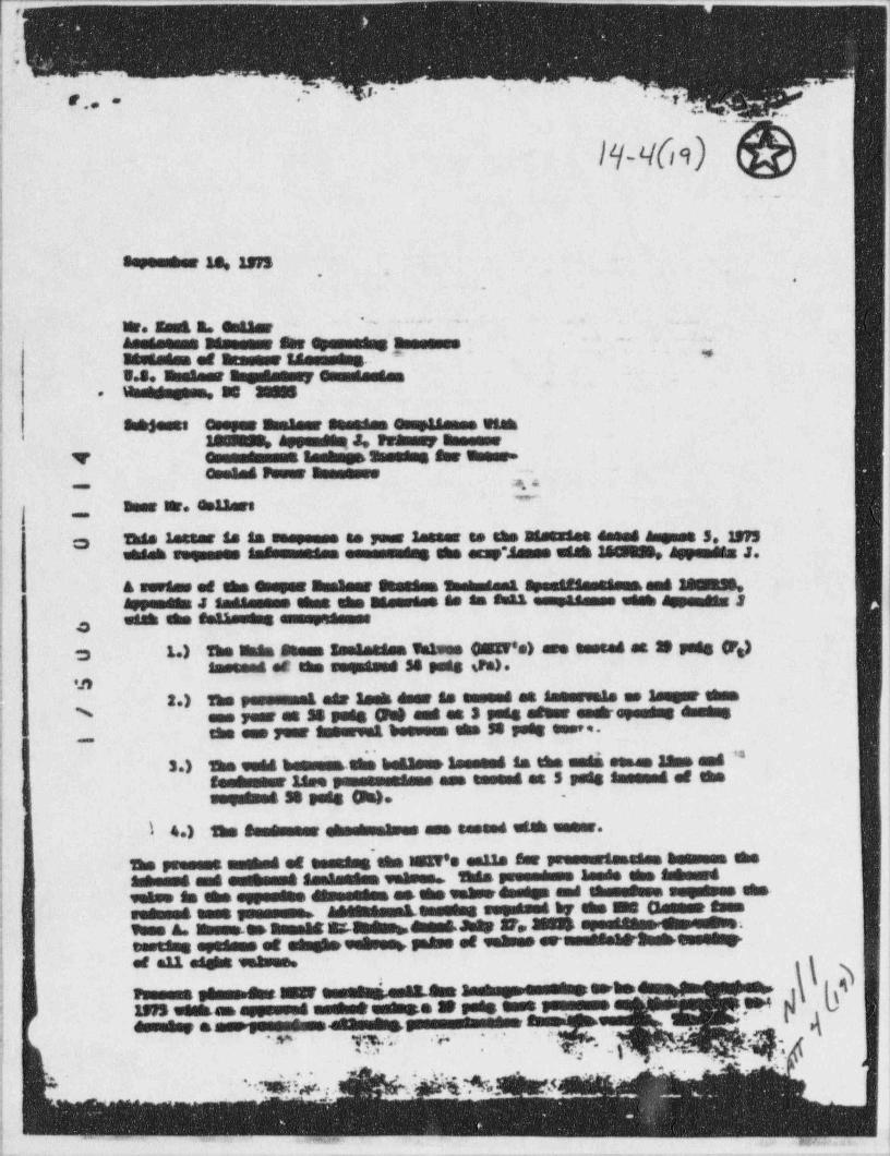
e
i;i'
tt .
-_
' *' ' ' J- . 4,
*
g,, .
-a . , . . .F
| |pt(m) &.-
i!.
j sayemmer 13, ins..
(.
|- '' '' '*
} W. East R. mi aseteesem Messeur She M assessee ~
*| aessmenn of atasese taasamens; s.s. ammaaer asemessmer esmusasses
HamWagens. as agm-;
-
| Suh$ests esager h seassen esug48ames wtaanN Appendeut ,Petussy Banesse2
|.
v - samensa ====ame sur unese.! Omele8 Peuer asemesse.
*. e~
j amar ser. estaars,,,,
I This lasser is la sospesos se your lasses to the 38stsies dame 8 Augass 3.1975::3utdath sogneses ' " emmasuudes she assy".$ames use 34WN, Appendes J.
.
& series of the esapag thnalant Steedse Sambadant e ==e#em=88a== ame Mri
|Appenets J *=an===== that eks name=a== se am smax ==.r88==== eeek Appendes 2with she *=SW amanymesmos
| o,
The IInta Seems a.ae gaises OEN's) age easted at 3D pets Fg)v; 3 1.)Sassoas et the sagessed' 34 gang da).
..
| m| 2.) The r=======8 eer Seek deer $s esseet at sammevels as 3augst them
{ ens year at 38 pees Ot$ amt at 3 pode afear anst opemens emmensN
j -
the amo year tenervan boeuses tem 58 poet seen.
; 3.) The vede bensues.she beElemer la== mad la the enda sesan 33mm ame **i
.
';
! *aae==m- 18ee y=======*a== esa sessed at 5 pels *====ad af theseguesee 38 sees On)= -
;-
;
<|
! l 4.) tem essesmeer ehestmeamos aus tasees etah unter.
The present aushed of essadas ska MEN's eaus aar seesserieneaan tanssoa she! setemas amo sustamme <==a==a== vatses 'them suomeemus lande she setenedj gateo $a the oppsette dAmessess as.the gehueensega and lessnessa sagsgems eks-
Aasenesman.ansales seedsma 67 the sus Canose esen |
seemsee sans &s si:.amembemens.Juey 3r, Seget egeasseangtensene.;
vues A.in em amena!testems syssens se sensem vem sname se senses erammesawasss>essessei
h{i et all asent inases.|f psmesma ,ae gue.r -ama'tir. ann a= ass.enesessmensem a1. .e..a a - I4 .4 n.,m
e & e. s=mem=.anammes==m====ne=t
-
-
; .
. . . . .. . 2 ~,
|~ . n. ,
_ _ _ _ _ _ _ _ _ _ _ . _ _ _ _ _ _ _ _ _ _ _ _ _ _ _ ___
r1
.
, , , , ,d4; s'
~.
ner. tari B. estaar -
semester 18, 1935Peam 2
poussemme eut ens a Se pads amas pommmmme. After ends genomessa men gem,ymmensmed ene poemen spammenemm&. a asemana fee a ha m ge481 he senseemt. as atanummes Sur =sampde amamens as a peas er uma et estet een shuse, & apesame es31 he sammemme.
me emaamans y=- a es , Samh dear apues emmmoday ame ammes e mmi ammaesmarommamme. as pumanas ensemeent & magnese emmaans es pummmmmes,air lash at SS pate as amemammas as nameur ens een yees. Mas esas segueman i
I. thus a menempumas he emamm13a6 en edes emmenemmmus seen et she tamsde eses. Maair lamk deses ama enemme ser air Samhmen as 5 puts efems omuk epsadas emmens !the emme-imamment heemmen eks amment N pode essa.
J Es ehemens ama ensameplasme fusa eks emismens temates seguemummasse Temmens ,
as as h pumammes of SS pues @W emeM seguesa dayam&& emmay car - |4
9 h 1Ms esa enty be dans dimens a emeemum emmedagen. ;asemadme'4
me penseessammaan of she done as the ammme dames aams anos ases43s emme adeh |i-
sf ymmmmmmma -- eldsk ummM he esensty saammesed if an emmes emme suaas 38 pads. Et ta eks epdenas of the samertas thus a ymmely emme as SS pegg se ,-
edidasame es ehme phystemL Amanaster and the 3 pang amms atens emme apesanoma |
; o shaus sha eenL emeddasan. Am $memanas no a 4 sammen amas emmemammy alas glamesen =^8898===* W-8 sessnessa en etun plama etati sham 84 aden13y epsumes
,
; for passess aanger ehms mMa miehung maydama esmedams assi daymeR1 asser.m
to enes osaan and *W emmesMa sammamassens emmedes of a demMe 3mpamme4
: o masat hm13ams. en sammans hasti ymmmmmes side d she bataams amas the smaamensdryman ymmmmmen. nummemme eks betaams se emmend ha ses amassemy seen es .dayenni se emansa. me betaams tapsme ese emmens ser smengassy of tenai asymme3my pmemensamens een emad hemmann eks 3apass as 5 pets. Amy tiehas sumuseus; ,, emend asume pommmmmes ensammentum. dammes an4 somethaa sepsmens et eks batasos.: maan ehda emmedes humanas she batamus damemas amas eks SS pues esquemmenes of; sAppenden J. As is Sett egent the emmedes of ths ymmmemmatan as a emusesse autaf
was ohn depeats.r-----a===a- esas est eks.a.aa m og eks asemesser af bush-
wi==a 3apaus suomeens summonetas ammmmmmes atos ehm pummemmates e881 et' emes =4;
the ammiemet emeShlame. .
L
The fenemment atmak waamme, esah aus et a encess dias emmesa, sus emensmedy ,
lack emment um unams Amammes et air ans ==gn==d by appemets J. hear as a.
.mmmmmma Se goesy=====.= sa muggases en ehmarmama enemmmmmes adde of abe estem.atens the ammt, maga has semb818mme en gamemme s enamanes seen of Sus em ths.
-
& etesof ets gutme, ehm 23ms is sumammet euer a gemma aden egen. 988sademmendam.assumahas estambaam aesti name Amr thaus gatmos eldsk out pommetsen einemans andesseems of thm unhumPs amamesam;
me oneses muutems gemeens ametmengemeLeese'est.ar==***==ad=== umma enemmeessai sen samenemy apammenne aammmamenJummamer as,, asm up emess, seus same.memmenos ummehmetusse6 ean Ass m.=.a., esser en ammann ches een ens **=8==*: u - - as smug &Samam uc h ths 3 6 Appena s J. a s dans ammes ;
et mem emapaammes sammmmmes an enen amenes umme eammmmmes,as 3mmesa$ essen ens-
:s
e
*g a. .
"
';L .... . ( { ,_ ,
' ' * v: ..,,_
.,
a-_~ - . _ . _ _ _ . _ , _ _ _ _ _ _ _ _. __ _ _ _ _ _ _ _ _ _ _ _ _ _ _ _ _ _ ___
y__
_ _ , _ _ _ _ _ _ _ . - . . . - _ - - - - - - - - _ - - - - - - - - - - - - - - - - - - - - ---- +-
- %.
fi(
q -
!-- .
. . , . . !
R43IR8Ei'
/% 4(af) |'
i
i= = = = = = = = = = - o
i m ime me e - m e mas nI W GeSE N af M h .( M M N toUS M h hI see sees of guer N L. !l 8 ease D same meessum !i N WWarm. ThE 6* It
!saare esausee pseesset eSummmes et I
fuumer a.s.o.eur.e sm.e.se skumme tsaat-to m
. em som ma me es! ete Sh est testap sW setteea'
f 8 6 9 m met e m WWEteseussest es m e Ctennemess.*f h m
i
$- flsmetse et ame esammasses uG essetom 8 A E W S a se h M W W as! *
I sesemur er ass .tsmancesense send home base a tameestet osums a eenese sans emeesnt**se to escue en mesmme, ese tussets.
I, NGhAst 4 mester InsW mm & fer.
The 19 emsede EneW essesF ene heads et adm toeng !}., gangy ames to e moonsmee e asse me aun !
mums eenspecte isshase umAs and n|
|tasa.s tar asesor eseme.smenes e aus.se tre.
ji samt er-
e.g e- ammem m m mm m .ee ,
J Asle F er ensapsens er evenecimer e.ausear~a '
| annuaar emalutusumus ItsEng ter 18th vuseze to seses sat ensum tr e; m pumus utte sus esse estos apesees eussasen e,.1 Wesell es Sumsee maar der esseamg. M M SE. ISUL em Aasme kmWm smaams h h h andow.same num tem en,penseum enees M e sun.Ememe es 7R STEED & Wsugeset sessment eues Typo ,sI *% emagemens e em seeminIIsms an at WB emmeetummes guammes esses. The gesammes
pus se utse sees W te m ytestagageneseensasasummeseemess.
'*g amm amates mentasebmese m e m suasasumass esoner semenesmenen.-
es lmeaMM 88sW8m8mEmM gesum use W to ee" smuus aw one ese tems ar. i
eas e er S e essenesmem W e emrt |(3 Elm th MImament ena E6 shame to eusse se semangsang agrers< '
| | earemaeusmAm aesensmen e es emmehemse sem amas rute seems tems tv.|- | EuSEm$ Ge m M W M S 4E55 gens ggngsmy egyesAB eMEWhehesseAer smessAm h em Saman, Ban *;.
- m We emed hem' esueens seus sessese sur me enemme et1 esaus meagem m megu m|
semesse.,len has megame theensseessessus ammesse, me er meesmas mensame samummmma -
- .
OlemWI 3sanage team to these mump ansmor=i i
WE seWE Wede to se itse in me suam Th!sa '
4f h h e e t t h e us. peneusse a esmunaues to to emusue.
|* h te the aes t e m ~j
!'
"|||I WM See ensaamessa esos TheImammenet as enestpweste see.tu asumaneum es suusemum spuusm* tems an en asuses enesessess emmenes. <
g W66 m8 M h m as Im W teus een to ese 6WM tsS # GED* utAsessumeura fWestandaeesseeREW Em86 et petu m egen W W. ty su h,
F% She the maugumasameuraf Pi
i he Se W guemme e at assume stem MS anim AE S esp guins uptesemL Amst r 6 ato} ,,,,
M see austhe se m esen.; . . . . =s .
}- m. ggs A em gab k esse spo.. . . . ... m . t s u a. . ...- MMS Wh tus S em est I
.
; . . . . .v ... . .- . Wh Suk teen.- ende estemmemas 14 f .."~. .y. . . momeus mammes tus es sammananus er samemaeum me 1
- -
j,- . , , , , asente ames me emmemmes tea.
===es- ans as umasan, een man ese esa soumem esmous amasummone4
{ ;
, . ei saa.,. - d. . ..mW esamtems tAs som ter ImImWpd me..a eia a .euhte em Bush er tems egne sensmuss me sumisemmensa. . . ..gesarone e of suesNeuen. temmeurhmeamasseSun.. . . . . 4 -.
em h a e dessmannesesausR6heeED* The seuemme see sugeses me me et. .. -- M um sessus sesik ese tus aseses enemmes a.-
)* M W G N 6 Am m R$sehmW Alm* *I TASsysuamusesa ___ a -see.
en h use of e esM een= pemme asumh6 On 8HS SS WE sheGun.m asamosa ens amma amasame ammess
.|
, .L
ehmeuse eggessue a m TAG ensM h h tpshaus,h ammemam
|' - * *s M ec h m aamm8mmena. W M .to
l ~ ^ ^ensammamas ans er enamanus summumussur ans.gap. amme aussamm* The sammanstes base. u .
et a susesmasanyaumsmemmechessoo. j;M& tenAmmannene to game eenens a ses summteens an. -
-4 . . ,-
...
agan m m eses h essgegensedes sum Aam |
-9 5 ? M e, , sat.
; ., . p//e . es - - ,e. ee..
- -
. . . . . . . . . .
m,, ___ , .- - , , - - - - - - - - - - - ~ - ~ - ---~--~=~~#' * - #

l,||!!||L,i
j j :,
!jI y~^
'
y _ .- y!? o - _SL....>-*os., __
.
_
__
.
'
' '
I,
!. ||
II; | !;'
:. a
. a,. .
'. ,,
-, .
. M.
.- ..-- .. _. >-.
.
.r . . .,-, -
,. . .... . ,
. - _ ...
.. - ..= = .-. :.n,~.m.o . .~..e,.**- *'
.--.-
. . . . . .
:::r. s
..
.
w3-.
= g y . z_ a n ,E = . _ _ . -- -
40 M ^
_
m m ' ._ _= . . . . ' .. . , .
. . .
. . -
.. . ... .. . .
.r- .
.._ . .
a m .m.- .x .
9_ m.-a.... . er-
:g s m.rar _..e _s m m -
__. .a c _. .... -.
. _
. . . .M>. a.arsm. - --- - * . * -. ._ _
..
.
. .m . - m .= . . .
.
_ar.., ..
.. .= .. . . ... -
'.E W "- . - .. n .. .-.. -
E*s.**.*, g im. ex e sg.E'' ' ' ' ''
. - - >-
.%OE $. ~ 5s"'g .;,,, . .._~. . =r .
- - -
. .
.
- ._ ..-- - ., s.2"*'".1.
3.""I... .. -.
. . - = =. ...
,.:~- a == g= .
. .. .. . . . -' ;...- . ,. ,
. .== W- ***** . . .n,
.r:.::',,~|" ,~:::',,''.',7"4.e u e ,
.- m. >'5""""* .e - -
. ., a , .,
.
.
l'r.5" W.' * * * * ' * * * ". ,
. . .
. ~ , ,;',:;, ~ =,J.,;.. -
E.R'
. .F''''_**"*'A2 -_ - _ r. . e . .. .. . .".: ."."."""." - * 4 ,= " .'.,
- -
.W. . ....n.,.
.gm assaapus us . _b
O g g as**e 44 .erer
sg. sees e ainsa... .
M._
so mm
au.s u a se ta at Esis.wse.a ea . me m 4 - .- . . -i =. a .me e in e .g
. ng,gg. & = #=EEF'.35.'t~bsp
- - -> .*-*=.g._. _ ;;, ;;.. . 7 , . . n.. .. . . ..,,,,,, , .
. ..pN - MO EOO . e t..sc
,
6 '_ _ - _ 4.r - anas.r m .e.4 e ,..-=,s . e en
se *= mat. sense g-* . *PE8" D e"E89 N_ gs m - .=amerus as -9 se. *.' ' . * . * . , ' , * , * . * . " , , , , " ' . , ' * * . *
Q-Q' 6 sa.a wo.mpa<
< :. ,,~..em. M ggg a. amass a. sun see 1.au. .r-,. ..*wme.s.sen
- ...ssae8 y.s tekee
e et .e.. M ek -- ; _ .w.ess s* t. .,
a,, , ,,,gy,*summaammw. mas,em v i .,g
'
- 4. - . .:'s .. ~ g., y,.; g... :. . . , .,
. -
O'"
s * * * * ' '.. _ . _ _ _ _ _ _ _ _ _ _
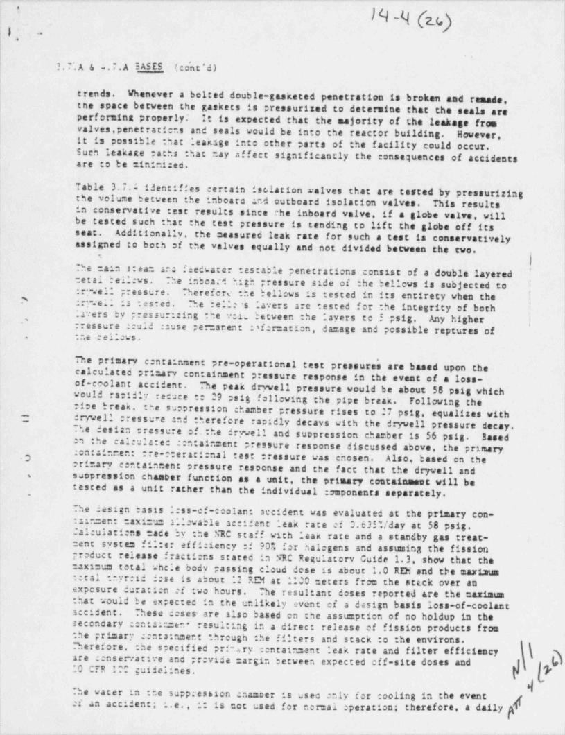
- - . - - - -. ... - . . - . - - - . - .
h(e,)1 -, .
3.7'.A & e.7.A 5ASES ( co'n t ' d )! i
itrends. Whenever a bolted double-gasketed penetration is broken and remade.
| the space between the gaskets is pressurized to determine that the seals areperforming properly It is expected that the majority of the leakage fromvalves.penetrati:ns and seals would be into the reactor building. However,it is possible : hat ;eaksge into other parts of the facility could occur. 3
l
Such leakage paths that may affect significantly the consequences of accidentsare to be =ini=1:ed.
Table 3.7.1 identifies certain ise,lation ralves that are tested by pressurizingthe volume between the inboaro end outboard isolation valves. This results |
,
in conservative :est results since the inboard valve. if a globe valve, will '
be tested such : hat the test pressure is tending to lift the globe off itsseat. Additionally, the measured leak rate for such a cast is conservativelyassigned to both of the valves equally and not divided between the two.
.
The cain s:ea: at: feedwater testable penetrations consist of a double layeredtetal bell:vs. The inboard high pressure side of the bellows is subjected to Idr: sell pressure. Therefore the bellows is tested in its entirety when the3 fry.el; is :es:ed. The belle s ;ayers are tested for :he integrity of both;ayers by ;ressur::ing the vele between the "ayers to 5 psig. Any higher
[
,
'pressure ::uld :suse per anent :sfor:ati:n, damage and possible reptures ofr.e Dd11:ws..
De primary c:ntainment pre-operational test pressure's are based upon thecalculated pri arv containment pressure response in the event of a loss-of-coolant accident. "*he peak drvvell pressure would be about 58 psig whichwould racidly recuee :: 29 psig following the pipe break. Following the j
!
;1pe break. the suopression chamber pressure rises to 27 psig, equalizes withdrywell :ressure and therefore rapidly decays with the dryvell pressure decay.
--
The des 12n tressure of. :he drywell and suopression cha ber is 56 psig. Basedn the cal:ula:ec ::ntain=ent pressure response discussed above, the primary:entaineen: rre-::erati:nal :est :ressure was chosen. Also, based on the'Oprimary centainment pressure response and the fact that the dryvell andsuopression chamber function as a unit, the primary containment will bes
tested as a unit rather than the individual :omponents separately..
The design basis 1:ss-of-coolan accident was evaluated at the primary con-aln=en: =axi=u 2.levable accident leak rate et 3.635Uday at 58 psig.
*
Calculattens made by the NRC staff with leak rate and a standby gas treat-system fil:er ef fi:1ency :f 90% f:r halogens and asstasing the fissioncent
product release fracti:ns stated in NRC Regulatory Guide 1.3, show that theaxi=um total whele body passing cloud dese is about 1.0 RDi and the mariaum
::tal :.'yr:id 3:se is about 12 RDi at 1100 =eters from the stcck over anexposure durati:n of two hours. ~he resultant doses reported are the maximum: hat would be ex;ected in the unlikely event of a design basis loss-of-coolantaccident. These deses are also based on the assumption of no holdup in thesecondary c:ntain=en resulting in a direct release of fission products fromthe primary : ntain=ent threugh :he filters and stack to the environs.
jherefore. :he specified pria ry ::ntain=ent leak rate and filter efficiency j(k gare ::nservative and pr vide cargin between expected eff-site doses and h8|I10 CyR 100 guidelines. F j
dThe water in the suppression chamber is usec nly for cooling in the event;
; ci an accident; :.e., i: is not used for nor=al Operation; therefore, a daily
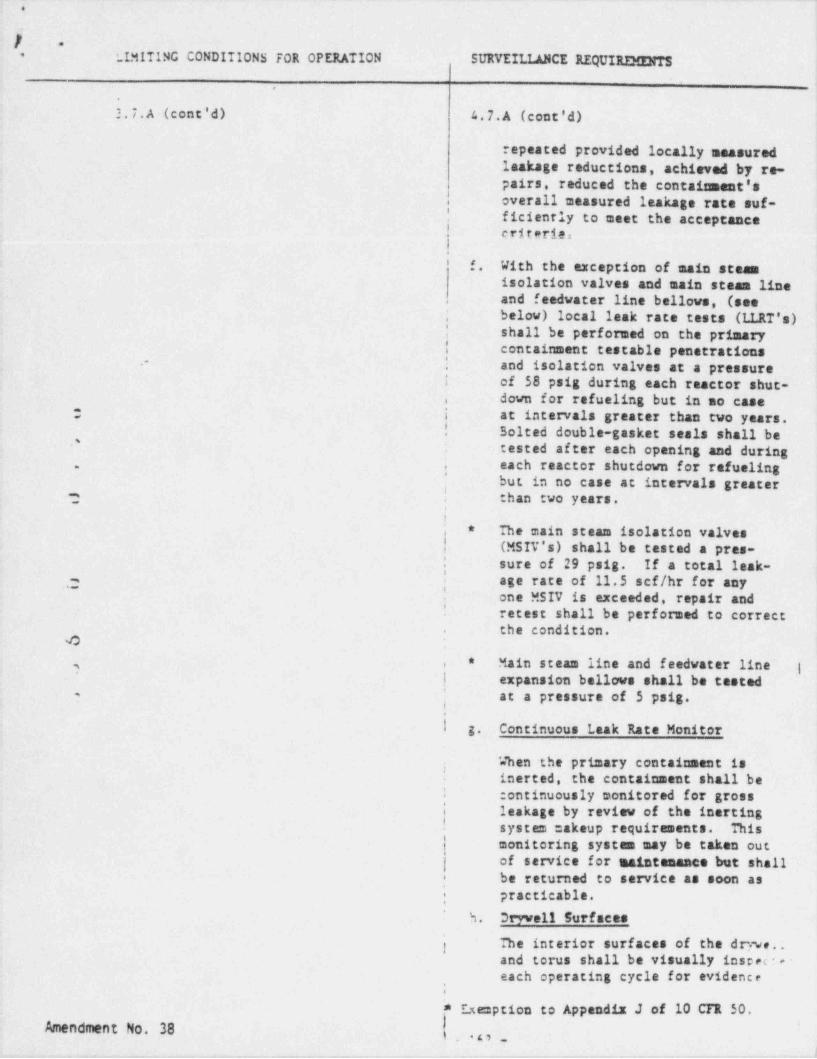
e
.
/ =
LLMITING CONDITIONS FOR OPERATION SURVEILLANCE REQUIRIMENTS'
',
h.7.A(cont'd) 4.7.A (cont'd)
repeated provided locally measuredlaakage reductions, achieved by re- <
pairs, reduced the containment's
overall measured leakage rate suf-,
! ficiently to meet the acceptance! criteria.I.
'f. With the exception of main steam
isolation valves and main steam lineand feedwater line bellows (see,
below) local leak rate. tests (LLRT's),
| shall be performed on the primaryI containment testable penetrations| and isolation valves at a pressure.-
i of 58 psig'during each reactor shut-down for refueling but in no case.
i at intervals greater than two years.-
! Solted double-gasket seals shall be'
tested after each opening and during,
each reactor shutdown for refueling, ,'
but in no case at intervals greater', than two years.-,
-
I
; The main steam isolation valves*
! (MSIV's) shall be tested a pres-| sure of 29 psig. If a total leak-| age rate of 11.5 scf/hr for any.,
~ 'one MSIV is exceeded, repair and
''retest shall be-performed to correctthe condition..
4
Main steam line and f eedwater line' |*, ,
| expansion bellows shall be tested
| at a pressure of 5 psig.-
.
I g. Continuous Leak Rate Monitor'
; When the primary containment isinerted, the containment shall be
:entinuously monitored for grossi leakage by review of the inerting' system makeup requirements. This
monitoring systes may be taken outof service for maintenance but shall
i be returned to service as soon as| practicable.
5. Dryve11 Surfaces
j The interior surfaces of the drvve..and torus shall be visually inspec : -
each operating cycle for evidence,
,
* E.xemption to Appendix J of 10 CTR 50.Amendment No. 38
'
,.o.1
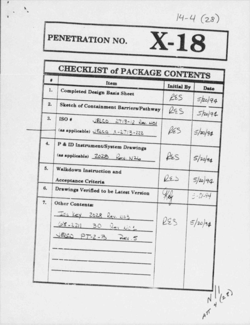
. __ _- ._ . - _ - _ _ _ - - - _ _ . - - - - _ _ _ . - - - . . -_
,
%, .
14 I-/ (2I),
-
.
PENETRATION NO. ==
CHECKLIST of PACKAGE CONTENTS.-
_
9;
, _~# Item !
Completed Design Basis Sheet _Initial By Date
'
i 1.
g3 g)u)q2.
Sketch of Containment Barriers /Pathwahg3y gg3. ISO # JEtc.c 23 13-12 2=. uc{
-
(as applicable) JEtc.o A -2.713 - 227. *!N1
_
\4.P & ID Instrument / System Drawings< . ,u i.> 22a o. uu. Bis s/u/u.
5.Walkdown Instmetion and
Acceptance Criteria6.
Drawings Veri 8ed to be Latest Version3 -f/-9]
7. Other Contents: "
~~Z~ s e.ke9 262.St b. es5$$ e 2o 94
-
96-2.20 30 Qm, Oc L
GElco PT-2 a A .5.__
_
"
--
-
_3 -
p l'a
P.. .
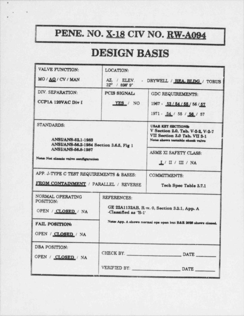
, - - - - . . - - - . - _ -
. .
.
I
PENE. NO. X-18 CIV NO. RW-A094
DESIGN BASISVALVE FUNCTION: LOCATION:
MO/g/CV/ MAN AZ. / ELEV. DRYWELL /M/ TORUS-
32 / 898' 9"
DIV. SEPARATION: PCIS SIGNAL: GDC REQUIREMENTS:
CCP1A 120VAC Div I & / NO 1967 ,[[f,,gg[/ 56 /,,[1
1971 ,g ,/ 55 / R / 57
STANDARDS: UaAa surseenONEV Section 2.0, Tab. V-S-2, V 2-7VII Section 3.0 Tab. VU 3-1
ANSI /ANS 52.1 1988 Neses shows sesemble shed newANSI /ANS 64.2-1984 Section 3.8.5. Fig 1ANSI /ANS 56.81987
ASME XI SAFETY CLASS:" * "** " *
1/ II / IH / NA
APP. J-TYPE C TEST REQUIREMENTS & BASES: COMMITMENTS:
FROM CONTAINMENT / PARAI.T.FT. / REVERSE Tech Spee TaWe 3.7.1
NORMAL OPERATING REFERENCES:POSITION:
GE 22A1132AB, R w. O Section 3.2.1. App. AOPEN / M/ NA Classi8ed as "B-l'
Notes App. A shows normaal ope open but R&a 3038 shows elemed.
OPEN /M/ NA
DBA POSITION:CHECK BY; DATE
OPEN / ,g,Q3ED,,/ NA
VERIFIED BY: DATE_
. _ .
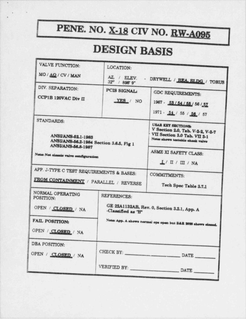
. - . - . _ . . - . . . . . . - . - . . _ . . - . . - . . - - . - - . . - - _ . . . . - . - - . .. _ .. --
. .
..
PENE. NO. X-18 CIV NO. RW-A095
DESIGN BASISVALVE FUNCTION: LOCATION:
MO / g/ CV/ MAN AZ. / ELEV.32* / 89B* 9" DRYWELL / BEA.ELDG / TORUS
-
DIV. SEPARATION: PCIS SIGNAL:GDC REQUIRPM*NTS:
CCPIB 190VAC Div II & / NO 1987 - M 56 /21971 E / 55 / & / 57
STANDARDS:Usha Err sacTrommV Section 2.0, Tab. V.3-3, V.3 7
ANSFANS-52.1 1988 * VII W_3.0 Tab. VII 31Neees shows essenhas eheek veheANSI /ANS 54.51984 Section 3A.5, Fig 1
ANSI /AN8 5sA-1987
ASME XISAFETY CLASS:Neem N s eseesse veh.sama urmes n |s
,L/ II / III / NA I
APP. J TYPE C TEST REQUIREMENTS & BASES:COMMITMENTS:
FROM CONTAINMPVP / PARAT.T.Ffi / REVERSETech Spee TaWe 3.7.1
NORMAL OPERATINGPOSITION: RErr.aENCES
OPEN /M/ NA GE 22A1132AB, Rev. O. Section 3.2.1. App. A
'
Classased as "B"i
FAIL POSITION: * * * * " "
OPEN /M/ NADBA POSITION:
CHECK BY:OPEN / M/ NA DATE.
VERIFIED BY:DATE.
_
, -
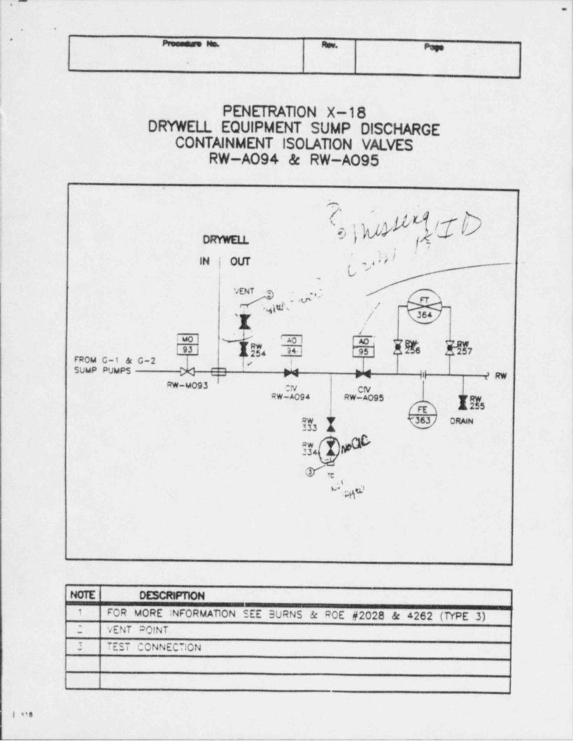
. , . - _ - . _ _ _ _ - - _ - - - - - . _ - _ - - - _ . - - . - - - . . . - - . - -
!, . .
-
: -m n.,
*ii
!
|
| PENETRATION X-18! DRYWELL EQUIPMENT SUMP DISCHARGEi CONTAINMENT ISOLATION VALVES| RW-A094 & RW-AO95.
Iy .
4
", *
m .
g . .
i ,! 7,
||N | OUT ,) -
I .t[' FTj4'
/ 364-
'
. j
h7I jf4 .| 6 t
FROM G-1 & G-2 |<' iSUMP PUMPS >< "~' ''' ' ' ''
' RWRW-MO93 ON CfV
RW-A094 RW-A095 RW[g] 2$5
;y3 I W oa"
? Y*
.s
v...;gd
1
NOTE N
FOR MORE INFORMATION SEE SURNS & ROE #2028 & 4262 (T(PE 3) !1
: VENT POINT l
3 TEST CONNECTIONi!
||
| 08|
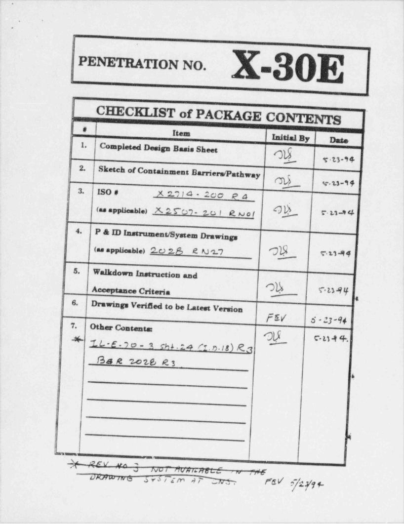
- _ - - _ _ _ _ - _ - - _ . _ _ _ - . - . - - - - - . - - - -
_
..
.
PENETRATION NO. am
CHECKLIST of PACKAGE CONTENTS i
# Item |
Initial By Date1. Completed Design Basis Sheet gf- 3,9,
2.Sketch of Containment Barriers /Pathway
_ _g3. ISO # X 2.7 I 4 - 20 0 P4 i
,
(as appliemble) % 2 CD7- 2,o i R Mo! U"
4. P & ID i=drument/ System Drawings !
Ch(as appliemble) 2 c.) 2.6 R M 2.'? WM
5. Walkdown In=ruction and.
Acceptance Criteria Oh . T LMIf-t t
6. Drawings Verified to be Latest VersionfEV 6 - 13-%
7. Other Contents: g e,g g 4,
~1L-E-9o- A Ch 5 . 2.4 /*! . r). I&) R.:1f34 e 2-oz6 R 3
4
'4
--_ _ ,
"
NU| flV/9 f ee /7 Q se ' IV 44vk
t)Kirw iw a b y5 t c,in 4 M~
Y6V f2f'f1-'
2
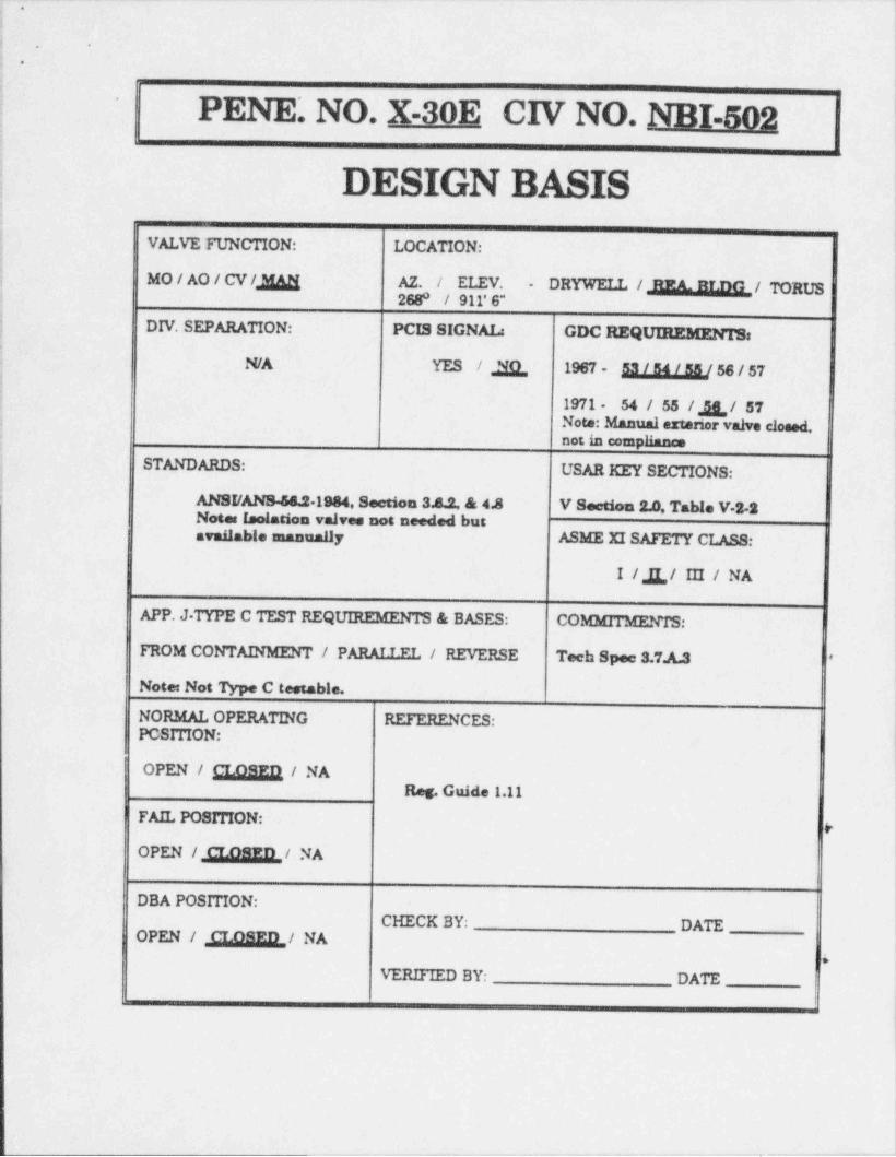
. . _ _ _ . _ _ _ _ _ _ _ _ ___ ._ _ _ _ _ _- .__ .
.
4
,.. .
I *
:
i PENE. NO. X-30E CIV NO. NBI-502:
Is
i DESIGX BASIS !If
VALVE FUNCTION: LOCATION:1
MO/AO/CV/,3&g AZ. / ELEV. - DRYWELL / REA. BLDG / TORUS !.
| 268* / 911'6"-
DIV. SEPARATION: PCIS SIGNAL: GDC REQUIREMENTS:.
N/A YES / gg, 1967 - Mj,,B,ggj 56 / 57.
I.
; 1971 54 / 55 / & / 57i Note: Manual extenor valve closed,;
not,in compliance
STANDARDS: USAR KEY SECTIONS:
ANSI /ANS 58.21984, Section 3.8.2. & 4.8 V Section 2.0, Table V 2 2Note: Isolation valves not needed butavailable unanually ASME XI SAFETY CLASS: i
I /,g,,/ III / NA
APP. J TYPE C TEST REQUIREMENTS & BASES: COMMIT 3GLNTS:
FROM CONTAINMENT / PARALLEL / REVERSE Tech Spee 3.7.A.3 '~
Note: Not Type C testable.!NORMAL OPERATING REFEIULNCES: '
PCSITION:
OPEN / M / NAReg. Guide 1.11
FAIL POSITION: y
OPEN /M/ NA!
DBA POSITION:CHECK BY: DATE
OPEN / M/ NA&
VERIFIED BY: DATE
_ . . . . - .

.
'
Pressere Ms. Rev,,
pop
,
PENETRATION X-30E ,
AIR TO VESSEL FLANGE LEAK-OFF DETECTION AOVCONTAINMENT ISOI.ATION VALVE
AVSPV-737,
)I
.
. -
'
N
^
>
ORYWELL '
IN|OUT _
l
CIVvq N81-502 AVSPV-737'
TO 737AV '
?C || y J-v :
g .a.
pjel!!/s *
NOTE DESCRP110N)
FOR MORE~ INFORMATION SEE BURNS & ROE #2028 & 4262 (TYPE 9),1
I
& IL-E-70-3 SHT 242 VENT POINT
--2 TEST CONNECTION
,-
_
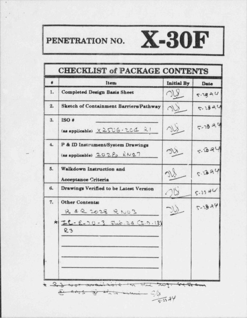
;._.___._.____...______ _ _ _ _ _ - - - - _ _ _ _ _ _ _ _ _ _ _
i
$; .
!>
PENETRATION NO. mm
ii
!
!- C :s: CKLIST of PACKAGE CONTENTS|
# Item Initial By Date;
| 1. Completed Design Basis Sheet Q9 y,y g u:!
2. Sketch of Containment Barriers / Pathway 4 y, tg A.4
! 3. ISO #
(as applicable) X lW Co - ? C6 A]:
4. P & ID Instrument / System Drawings .
-
(.s . ppis bi.> 2.0 2.P > E M o.'7 @p s. G St 4.
5. Walkdown Instruction and gyAcceptance Criteria
6. Drawings VeriBed to be Latest Version 4c/-
7. Other Contents:v-@ AY
R & GL W2Ss 9. Na o "1
. A I.L- E _ 3 0 - 3 %.1. u CT .B t2)9. 'b
,
!
g _Q_ _ - - - 't ' ' -
,;Q_ __"*q j
{ ^ As ; Q Q A -4 . - g6'-
& AY
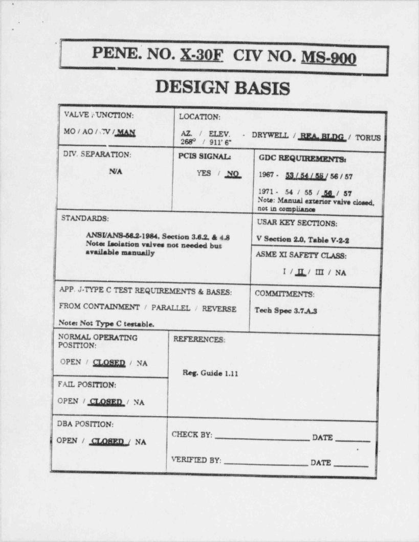
.- - ---. _._ _ . . . . _ _ _ _ - _ - _ _ _ . _ _ - _ _ - .
..
.
.,
;
PENE. NO. X-30F CIV NO. MS-900I
DESIGN BASIS !
VALVE I47NCTION: LOCATION:
MO / AO / M /,ggi AZ. / ELEV. DRYWELL / REL BLDG / TORUS-
268* / 911' 6"
DIV. SEPARATION: PCIS SIGNAL: GDC REQUIREBEENTS:!
i N/A YES /, Jig,, 1967 - Ag],jg,jg/ 56 / 57,
1971 - 54 / 55 /,jg,,/ 57Note: Manual extenor valve closed,DOC in CompII*"
STANDARDS:USAR KEY SECTIONS:
ANSI /ANS48.21984 Section 3.8.2, & 4A V Section 2.0, Table V-2 2Note: Isolation valves not needed butavailable manually ASME XI SAFETY CLASS:
II / E,/ III / NA
APP. J. TYPE C TEST REQUIREMENTS & BASES: COMMITMENTS:
FROM CONTAINMENT / PARALLEL / REVERSE Tech Spee 3.7.A.3,
;
Note: Not Type C testable.,
NORMAL OPERATING REFERENCES:POSITION:
OPEN / M / NAi
Reg. Guide 1.11
FAIL POSITION:
OPEN / M/ NA
i DBA POSITION:CHECK BY: DATEOPEN / m NA
.
i VERIFIED BY: DATEi
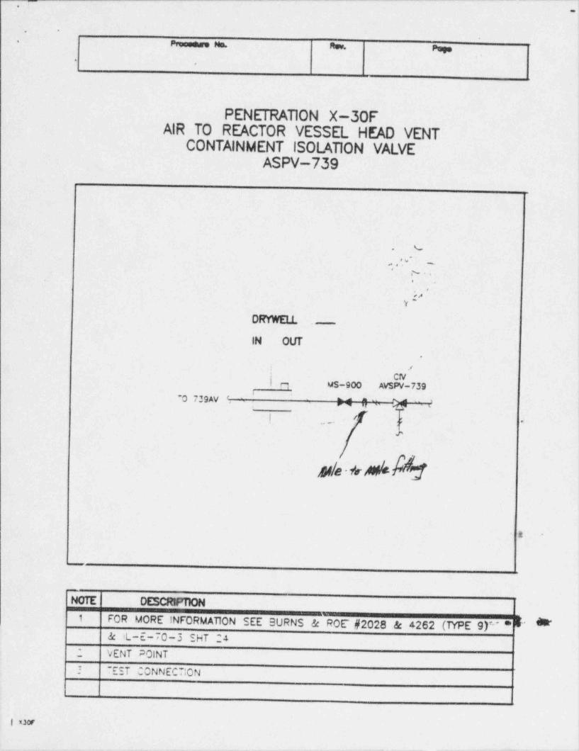
,- -
.
-.
- Pmesese Mm. Rey, page-
. ,
i1
l1
PENETRATION X-30FAIR TO REACTOR VESSEL HEAD VENT
CONTAINMENT ISOLATION VALVEASPV-739
%-
,,,',v' ,
' , ~ . .,
P'y
DRYWELL .
IN OLR.
'.,
|' r1CfV
|WS-900 AVSPV-739' '
O 739AV #4 *' y. J
! ' ; e|
-
e
h e fir k
1
1 -
NOTE DESCRNmON1
FOR MORE INFORMATION SEE SURNS & ROE #2028 & 4262 (TYPE 9)'' *E' *& iL-E-70-3 SHT 24VENT POINT
1 TEST CONNECTION
I cor
-.
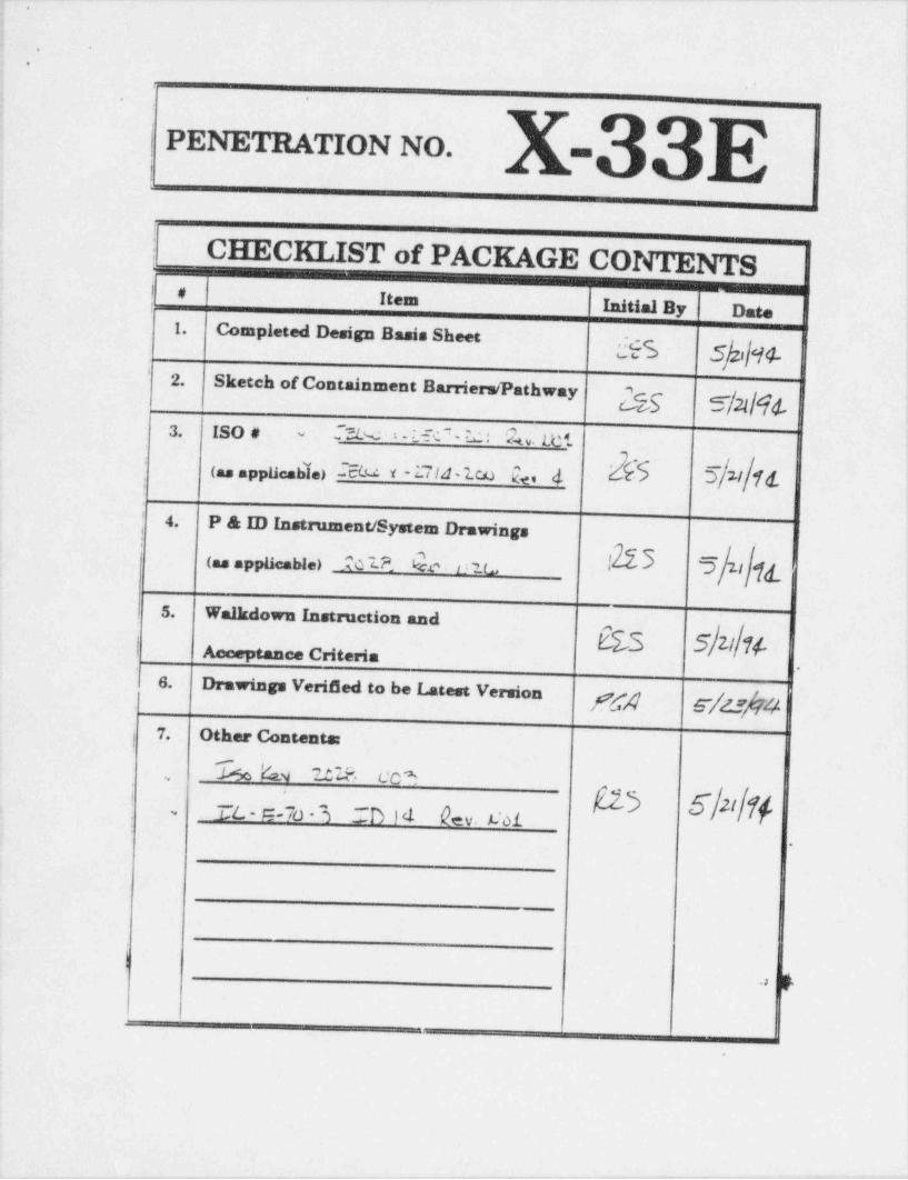
_ _ _ _ . _ ___ _ _ _ _ __ __ . _ _ _ _ _ _ . _ _ _ _ _ _ _ . _ _ _ _ _
,
!.
.
|,
| PENETRATION NO. lmmi
| CHECKLIST of PACKAGE CONTENTS{ #- Item Initial By Date
1. Completed Design Basis Sheet g'
2. Sketch of Containment Barriers / Pathway {c gg'
3. ISO # -.~cL w i-L C - M : L. Let-
(as applicable) IEM Y -17/4 lco bd 2b 5/W/N-
| 4. P & ID InstrumenuSystem Drawings
(as applicable) 101P. he - D ? L, I 5Ik'5. Walkdown Instruction and
F15 5/z//1/-m
| Acceptance Criteria.
6. Drawings Verifled to be Latest Version gg g 47. Other Contents:
i
!
% k e.y 2 S ?. co*,
(a3 s/n/r1.
TL - c -70 - 3 IB ) d 12ev.C01~
.
p..,
.
+ + - , -
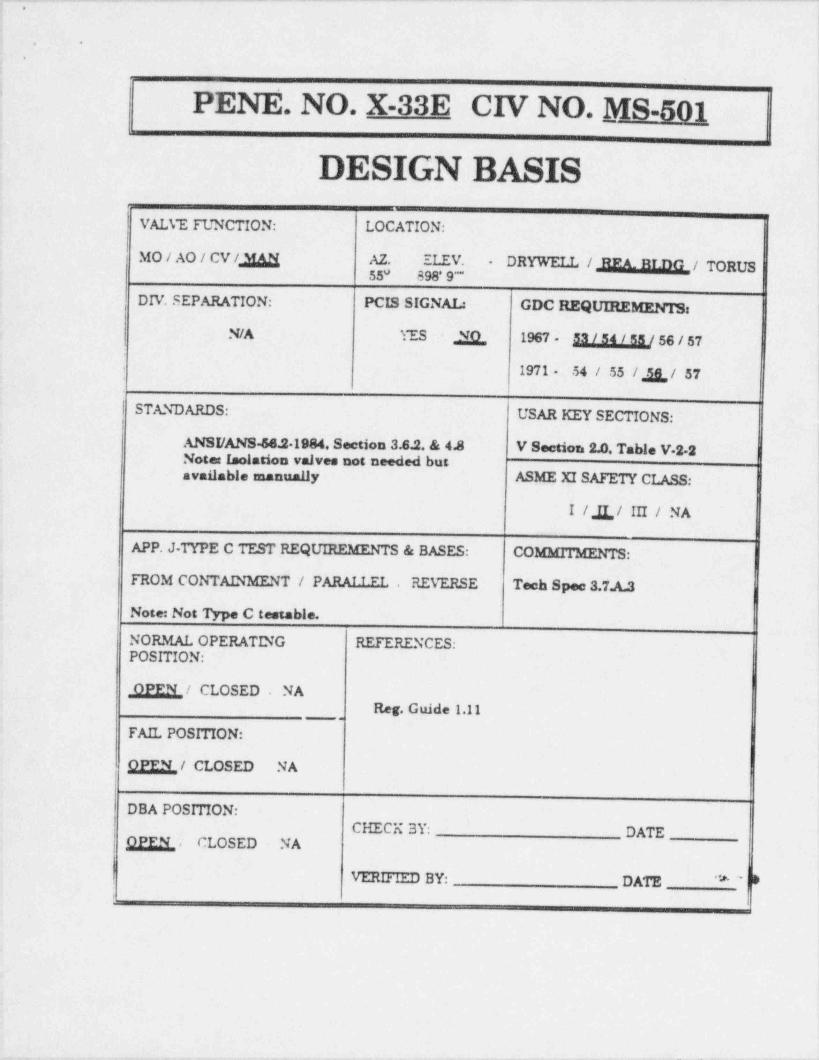
. . _ .__ _ _ _ . . _ _ _ _ _ _ . . . _ _ . _ _ _ _ _ . _ _ _ . _ _ . _ . _ _ . . _ . . _ _ _ _ _ _ . . _ _ _ . _ _ _ _
,
i
. .
.
'
PENE. NO. X-33E CIV NO. _MS-501
DESIGX BASISVALVE FUNCTION: LOCATION:
MO/AO/CV/ g AZ. ELEV. DRYWELL /M/ TORUS55* 898* 9-"
DIV. SEPARATION: PCIS SIGNAL: GDC REQUIREMENTS:
N/A YES X 1967 - 53 / 54 / 58 / 56 / 57
1971 - 54 / 55 / & / 57
| STANDARDS: USAR KEY SECTIONS:
ANSI /ANS46.21984. Section 3.6.2, & 4.8 V Section 2.0, Table V 2-2Note: Isolation valves not needed butavailable manually ASME XI SAFETY CLASS:
I / A / III / NA
APP. J-TYPE C TEST REQUIREMENTS & BASES: COMMITMENTS:!FROM CONTAINMENT / PARAT T.ET. , REVERSE Tech Spee 3.7.A.3 '
Note: Not Type C testable.
NORMAL OPERATING REFERENCES:POSITION:
llEEN_ / CLOSED . NAReg. Guide 1.11
.
FAIL POSITION:
M/ CLOSED NA,
DBA POSITION:CHECK 3Y: DATE
j M , CLOSED NA
VERIFIED BY: DATE "# ~~ Di
- - _ ,
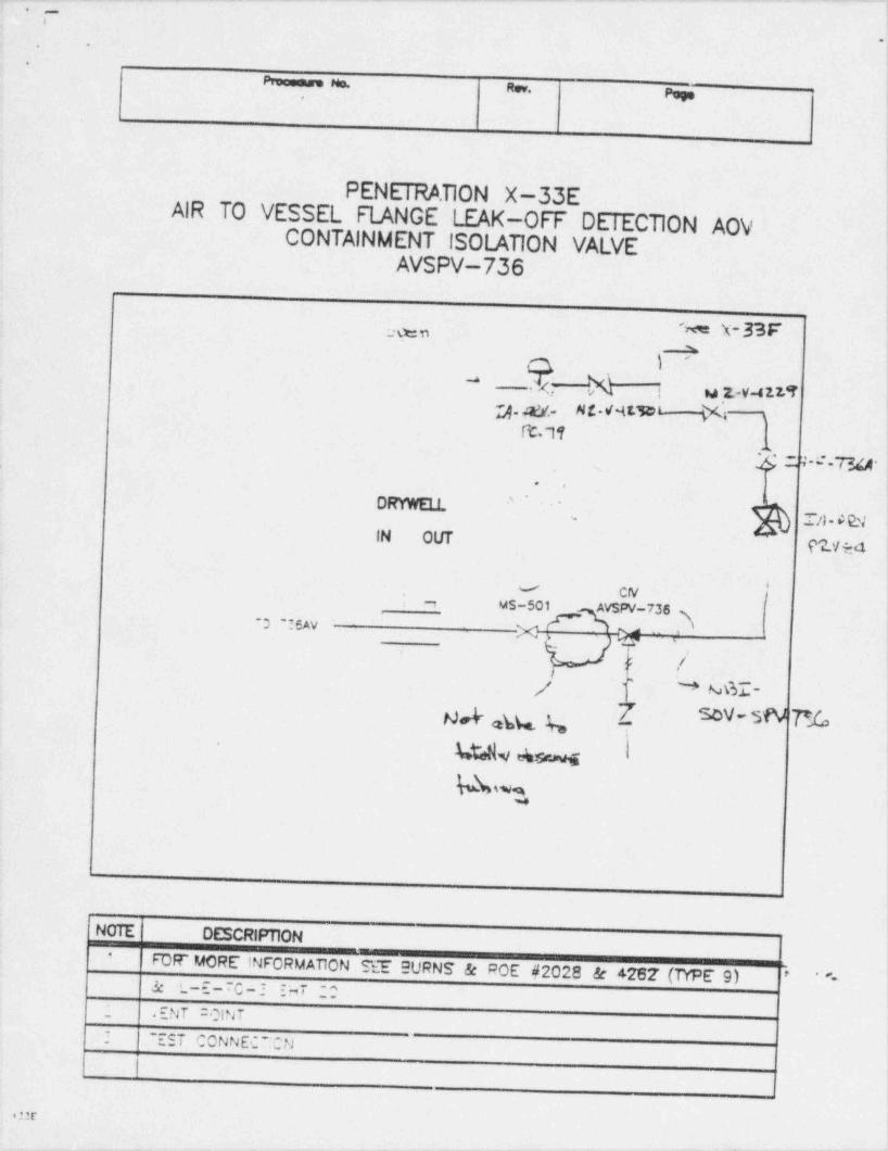
_ _ _ . . . - . _ .
. . _ . - . . _ . . . . . . _ _ . _ _ _ . _ _ _ _ . _ . . . _ . _ _ _ . _ _ . _ . _ _ _ _ _ . _ . - . _ _ _ . . _ . . _ - . . _!* ~
i
-. .
;
e i
h* w. g
|
PENETRATION X-33EAIR TO VESSEL FLANGE LEAK-OFF DETECTION AOV
CONTAINMENT ISOLATION VALVEAVSPV-736
;.y X-33F'
ya - ut
i4 v% t u 2.-v-41.13Q. Mf.- Mi-NL3DQi ,
ft.11S2 7-e-724-,
,
..
DRYWEli - ''~!
.T/)- E EV j"-
IN OLIT'
gzyy
f" CIV,
m MS-501 AVSPV-736 l~3 !6AV
_
7 ,\ |y* e ,
./ !.'
:
/ ]' N ME- )
Nd ,W ( [ D- SW P_fo--
44.Nv % I !'
Ow, |
w
Nuit. DESCRIPTION'
FDF MORE INFORMAllON SEE 9 URNS & ROE #2028 & 4262' (TYPE 9)*-& 'L-E ~C-I EHT ;;
- .ENT COINT'- 'EST CONNECT:CN
|
.m
- _ _ _ _, _ . . _ . . _ _ . _ _ ._. ._ .

_. _ _ _ _ . _ _ . _ _ _ . . . . . _ _ _ _ . _ _ _ _ _ _ . . - _ _ _ _ _ _ . _ _ _ _ _ _ _ _ _ _ _ _ _ _
1
; ..
..
4
I.
4 PENETRATION NO. -
|Y
CHECKLIST of PACKAGE CONTENTS1'
# Item Initial By Date1. Completed Design Basis Sheet g3 //y2. Sketch of Containment Barriers / Pathway
,
3. ISO # "I55c Y ~6Cfc- Icd Eed Lti
SES 5/"/44( . ,,u 6i.>
4. P & ID Instrument / System Drawings
(.s .ppucabi.) 267A b AJ 74
5. Walkdown Instruction and
$fPfl4-Acceptance Criteriai
6. Drawings Veri 6ed to be Latest Version5 @h
7. Other Contentsi
$ %2% e DJ 5
-fL-70 3 ~.T'.b I4- 2.9 ce t
!
|<- e ..
|\
. - - - - . . -
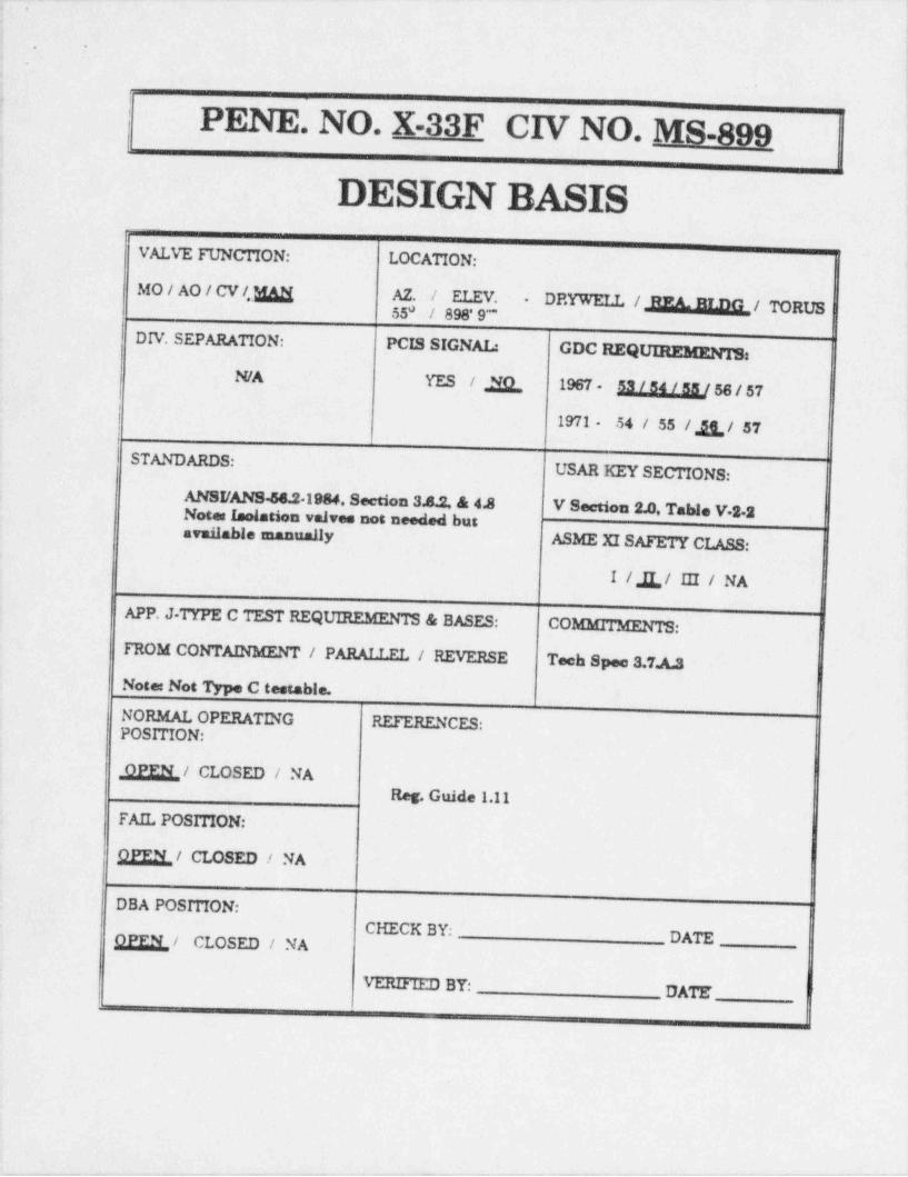
-- _ - _- - _ _ _ _ _ _ - . . . _ _ _ - _ _ _ _ _ _ _ _ - _ _ _
.
. .
-
.
'
PENE. NO. X-33F CIV NO. MS-899;
|
DESIGN BASIS 1
VALVE FUNCTION: LOCATION:|
MO/AO/CV/, M AZ. / ELEV.DRYWELL / REA. BLDG / TORUS
-
55* / 898' 9 "DIV. SEPARATION: PCIS SIGNAL: GDC REQUUREMEN'IB:
N/A YES / R 1967 - 53 / 54 / 58 / 56 / 57Ii
) 1971 - 54 / 55 / & / 57STANDARDS:
USAR KEY SECTIONS:
ANSI /ANS 56.21984. Section 3.8.2. & 4J V Section 2.0, Table V-2-2i
Note: Isolation valves not needed butarmilable manually
ASME XISAFETY CLASS:
I / A/ III / NA
APP. J-TYPE C TEST REQUIREMENTS & BASES: COMMITMENTS:
FROM CONTAINMENT / PARALLEL / REVERSE Tech Spee 3.7.A.3
Note: Not Type C testable.
NORMAL OPERATING RUtRENCES:POSITION:
,QEEL,/ CLOSED / NAReg. Guide 1.11
FAIL POSITION:
QEEM_ / CLOSED / NA
DBA POSITION:CHECK BY:
QEEL/ CLOSED / NA DATE
Vt.nuu.u BY: DATE'
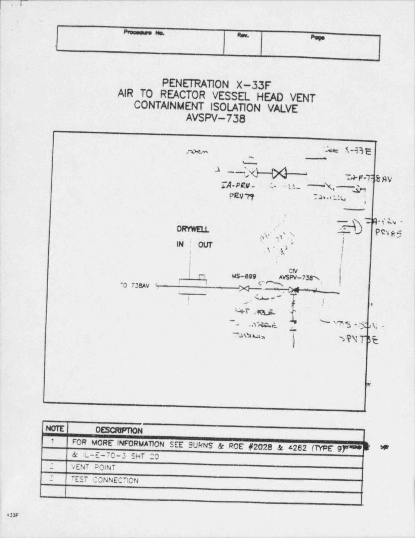
- . - - . . . - . - . - . - . . - . - - . - . - . _ - _ . . - - - - -
_
. .
-
Pmessee Ms. ;Rev. Page
PENETRATION X-33FAIR TO REACTOR VESSEL HEAD VENT
CONTAINMENT ISOLATION VALVEAVSPV-738 t
__ c- s-% s%
N~'
T+F-T %$VQ-PRV- : L ~ L L. " '% -b
PEV'77 74' ' ' N ;-
-'
T Q t' h --',
DRYWELL 2- d PSve5'
U, . ss
} .'.'s, \ ij |,
IN ' OUT a |i ,aj
t i
CN !n MS-899- AVSPV-7 m !i i cm -
70 738AV ''
X Gy -
j, '
.
_
; ;!{ '
? !- ^|
WT ofGuiL '~
.wm_ ~ ''? S .$ >\; -'*~-
uh= WN T'R
e'.
i
NOTE DESCRPTION1
FOR MORE INFORMATION SEE SURNS & ROE #2028 & 4262 (TYPE 9f CF *& IL-E-70-3 SHT 20
2 VENT POINT
3 TEST CONNECDON,
; ,
usy
- . _ . , , . - , . ~ - -
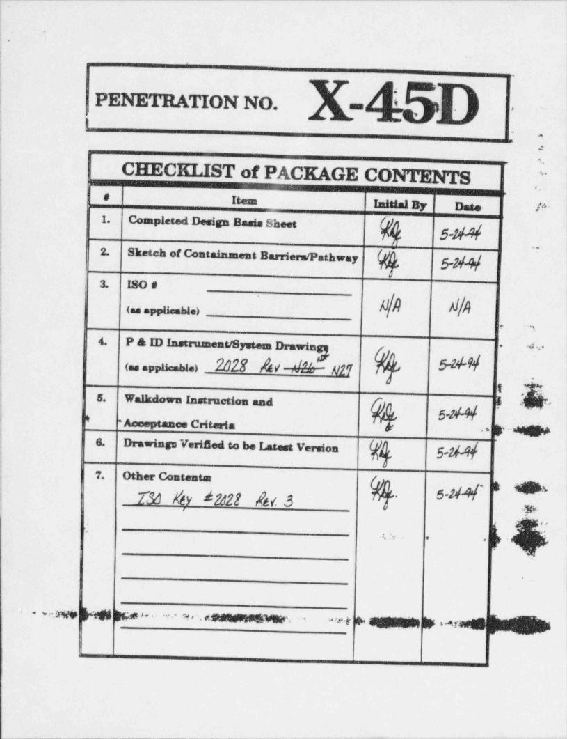
,;.
|.
-.
:. ,
i
ii
PENETRATION NO. - -
! I
|-
; :,
.
jCHECKLIST of PACKAGE CONTENTS "
i ,.'
! # Itent InitialBy Date /f''1. Completed Design Basis Sheet
t 5-Ni
| 2. Sketch of Contains=ent Barriers / Pathway..
5-24',
; . ,,D .
1 (.s applia.We)i
-
.n:
i 4. P & ID Instrument / Systema Drawin * ~'
\ 5'M< a.,u u.> 2au /u 21 er.
:h'5. Walkdown Instruction and !,g! * - Amosptance Criteria '# >'6*
6. Drawings Veri 5ed to be rmed VersionYM. 5-lM/,
1 z
j 7. Other Contents . g. gs| 230 hhv d222E $6/. 3
'
iw. <
. $ ['t - f- e h$
.
~.sw M pm s. . .. . . .:.1, .. . , m, . . ,_ ,,,,, ,.
.
,
i
i
_ _ _ _ _ _ ______.____._____m_ _ _ _ _ _ _ _ _ _-- - _- --ww_- w- - - e-
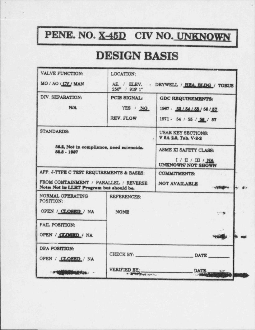
,.! -;
1
; . .
: _.
!:
j PENE. NO. X-45D CIV NO. UNKNOWN;
i
i DESIGN BASIS !i
ie
| VALVE FUNCTION: LOCATION:;
i MO/AO/ g MAN AZ. / ELEV. DRYWELL /.JREAJELIML/ 70 BUS-
] 250 / 919' 1"0
DIV. SEPARATION: PCIS SIGNAL: GDC REQUnntanngrS
N/A YES / R 1987 M 56/ g .,
;REV. FLOW 1971- 54 / 55 / g / 57
;
i STANDARDS: USAR KEY SECTIONS:'j V 5A S.0, Tab. V.S.S.
i; sa.S. Not k comh nM MMA ASME XI SAFETY CLASS:; 58.8 - 1997
) I / II / III /gUNENOWN/ NOT SHOWN
APP. J-TTPE C TEST REQUIREMENTS & RASES: COMMITMENTS:*
-
FROM CONTADGENT / PARALLEL / REVERSE NOT AVAILABLENote Net turIIRT Program but should be. -M 5' * '
NORMAL OPERATING REFERENCES:POSITION:
|
OPEN L12dMEIl / NA NONE 2.'s -
FAIL POSITION:
OPEN /M/ NA k as+
DBA POSITION:CHECK BY: DATEOPEN / ,gagg,/ NA
-6 - MEy . . .P@ w,
i
. . . _ . . __
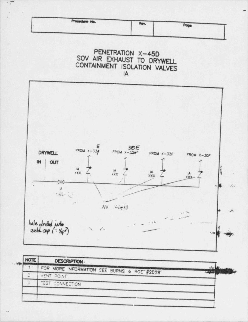
.-1
. -
.
Pmonese Mm. msv. Pug..
.
!
PENETRATION X-45DSOV AIR EXHAUST TO DRYWELLCONTAINMENT ISOLATION VALVES
IA !
E 3e6DRYWELL rRou x-33p FRou x uw" FROM X-33F FROM X-30F,, , ,, ,,
IN OUTif-g 4 -
XXX - (XX b 'j-.
XXXi X-
/'
X /..
4 .s..- yf
i t ,H . ' .' ,
if' ''
No .'Abi/S-
* e,, s
,- /
Nlt.desN hnko -
b
' ~
,,L-
N A. fOQfhI,h .. g .g,;$-
<.
NOTE DESCRFTION.,a summmma'
1* wFOR MORE INFORMATTOR SEE BURNS & ROE ~f2028'
,
2 VENT DOINT2 7EST CONNECTION |
|1
..
-- - - --
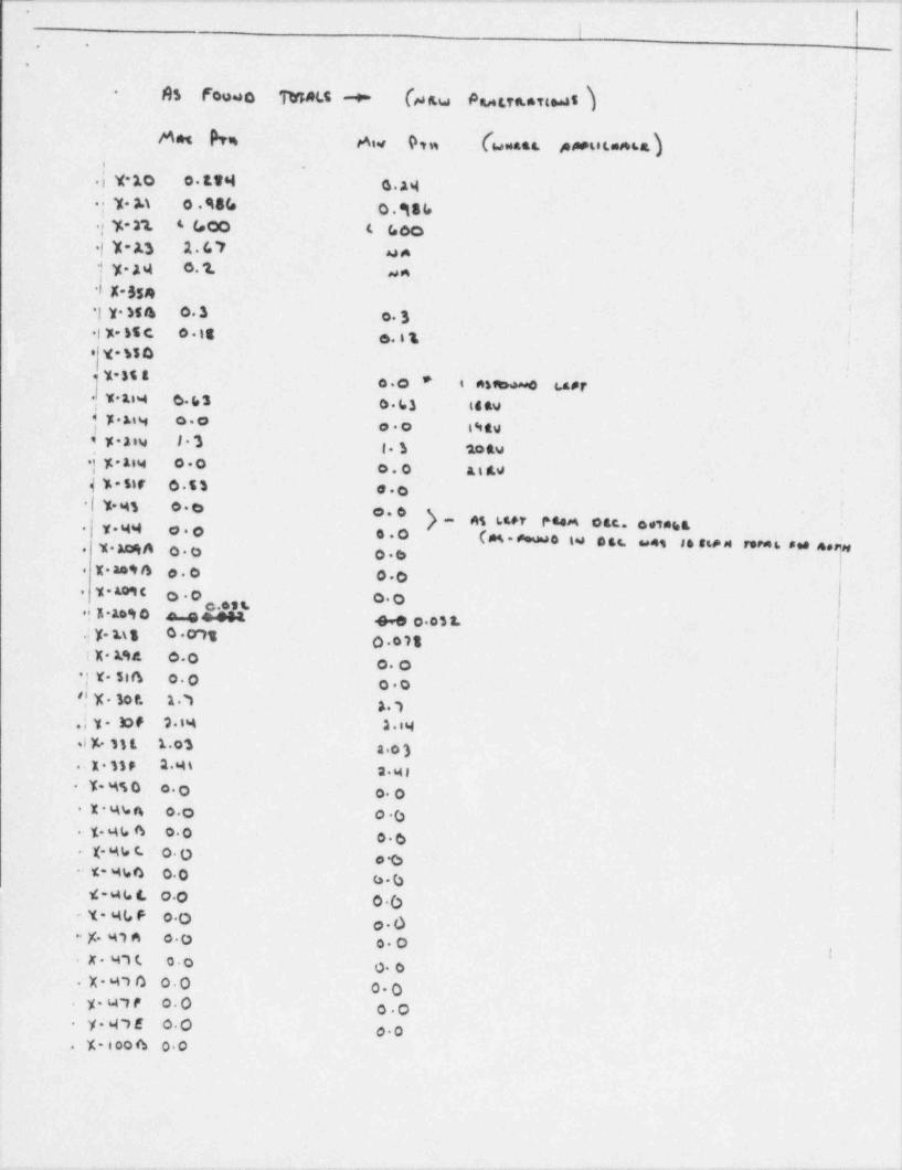
. . . - . . . . . . ._ .- . . .. - ~ . . . . - . . - . . . _ .
.
I. .
' ,
!As Fouwo TMAtt + (ssw Pa,r.ra.* Tied 5)
- '
MM bg Aiv 9tw (wwatt A ArtitmA68. )y-10 o.1364 a.a4 |
.
.; 7. M 0 . 98(e O . egg y
.{y-21 4 (,00 t Goo
.|Y-A) 1.67 aJ A;
ty-34 0.1 un,'I
l X-554*[y.M4 0.3 o. 3.l y- nt e o.it e. i t
;'
* y-%5 0-
1-35 L o.o * i nsawa4 t.4* riY*184 6. b 3 0.b3 i4 49.
4 y.uy o.o| o.o i%ev}yAiy l3 1. S totu.|K.Asw oO o.O At&Wf%=5)F 6 53 00
-| Y MS o.e o.6i
) ,, 4g gen p e.g e gg, ,,3,ggx.ww o.. ..O cm ~. io u. .. , . n, ,. ~~ . .. s,,.
T. M A O.0 06.
X. ao4 4 p.0 00.
% MPI C o.o 00.
C 09%.} A 109 0 4 e e.084. 4-90032. :
i
.; y. u S 0.M1 J- 0 018i X aae 00 |o. o 1
-| Y 516 00 00 j9 y 30 f. 17 1 !17,;y-lof 31% 1.84.Iy 1)L 1.oS 2 03.:x.sse 24s n.w
|Y-M50 0. o oO |'
X %sn o.o o6;
..y-44 6 o.oo.6
(- 44 t. O. 0 ;.
o.Ot-4%b 00 66iC - 4 b t o.0 0 -()Y- %(, F o.O o.0 ;
.- )(. w7 A o.O o. OIx 47t o.o o. o
.X470 00 00y- 4W o.O. o.oy cE 00-
00Y,- l oo 6 00.
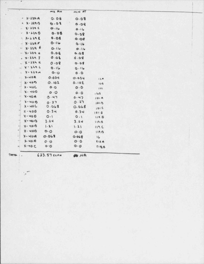
g.. ~ . - - . . . . . - . . - . - - . . . . . . . . . . . - - . . . . _ . . - . . . . - . . . . . - - . - . ~ - .-
.
. -
ms ein m.a #f.
X- 1 t'e A 'O.04 0 01 I-
|% 2&io b.0% o.oq*<
. t.11% (. o.14 o.i g
y >tw o 0 08 o.gg-
2 n. A ts 4. .o.ot o.ot.i y . itt F 0 lb 4 th
%.11.ai G- c.tb o.th.i
.%-ngg 0.04 6 01 '
15 tsg 7 0 04- 6 01,s
y. - 11% it. o.ot- o.01,,
.; Y sti L o.tL o.th
.; Y-1194 00 00 '
%.404 0 036( o.oh ita,
x.406 0 .10 1 6.107. it.4>
X . 54 0 C. 0o 00 i s t..'
.f LY. 400 o.O o.o , s.n'' Y- 40 4 0 47 0 54 ) see AJ
Y - 540 0 'o.27 O 17 toie*
K - 40 C. O.bbt 0.048 gee* x-i4oo 0 364 c.34 sei o
,
,
*V - Mo D 0. \ O.t us 0
8 Y- W 4 3 14 3.14 t t; Gv. so o 1 11 n.1) i n c..
: i- v.4oo o. o o.o its a '
ji 1
y-won o.041 o.06t tL.
.| x. Mo e o.e oo sea 4j;
.j - x wo e, o.o o.o ri u;
Toen. i . (, n. 57 < <. a u ape NRIi i
'.-
O
'!
!
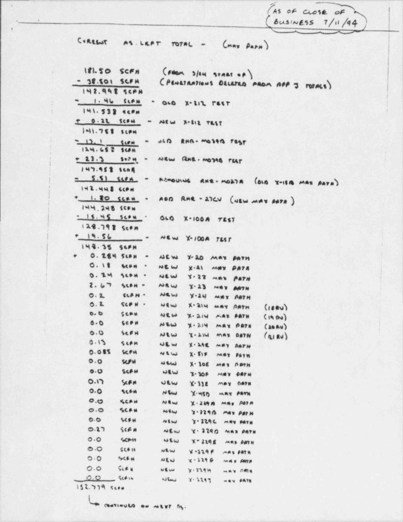
_ _ _ _ _ . . . _ _ _ _ _ . _ _ _ _ . _ .. _ _ _ _ _ _ . _ . 7____.____ _ . _ . _ _ _ _ _ . _
As of C w St. of
0"5 'N ESS 7[d [4k. .
, t ~ - w-
C * A tt.at M , t. s.P r Torat. (,m , p.,.3 )-
.
\ fi- T O SCFM (Femm, slag seast o c h,
Ces uAare. s eacaran eA a ne s rweh3e.soi sua-.
IMI.%%I TCPni %- t(* u- - oso x-ten, rssr.
i l%\.$31 4t#MS o it Sc84 MtW F* 1l t TE% T
-.
} N)."i T % SCPMi
; % g 3, g g g, . 4LO AMA **%94 ft%f-
.' 11.% . O 3 Stan'
g 13.g Soo n, M4w (tm& N194 rs4r-
i; 14*1.95) senq
| T .4 ) na* M%ows Apt-mo&1A late 1-il4 d*** # arm)- -
' I41 448 ScpH| t i. to usa Aeo A mt * 11(V (utw 44v Adra )
-
| i<s. 24 3 st.t.| 15. % T st** -- oto %-1004 TEsf
- *
,! t 19.'111 See n| * 1%.54 dew Y-100m T&st-
| I M4. M StPM ;
f+ o.1.$% ften 4tw Y-10 Mas pawn-
O.tI seen at w x.at usy #AFAi
-
| 0 . 1. 9 st*n - 4tW T t's uns par #!'
2 . (, v sten - 44w y 23 unv aavn l'i
O . 2. St# H * d '' W Y*14 "#* ##fM )'
o .1. See W - utw % 'atw any norn ( seu)*
jo. o st * usw 32w .au earw cm) ;60 Sced pa so y. t:9 sans para Caekw).
;'O.O St F n 9tw 1- A)4 m44 047N [ft| Agl)0.t3 StFM utw %. Mt met AarN0 08% SC'* Ntw %. TIF M*v Patn00 stPW stw x. gog me, tiern
00 5tFW utW y.1op sev ##rM
O.C) 978 utw Y. 118 *** A**"
O.0 stS* Ntw Y.%5s) anat ##tMOQ St>H N4w y . 249 4 M4s #4? Mo.O SCF# Mtw 1r. 319 th mes permO.o SCS M stw it * 11.i t ^#4 MTNC.1"1 ScF M Mtw Ya 1190 ^4 41 747WO.0 Scet* utw Y- 3191 ** * Aa1 He .O stS in usw y-nqf eas petito.0 M5a atu x - ni rr =ep mom
C.O SC5 a utw y . t'ti n %ni oma_ o.O 4te n utw Y nil -ev put
l$'d.71% ttom
esatt uto ens u t vr og.
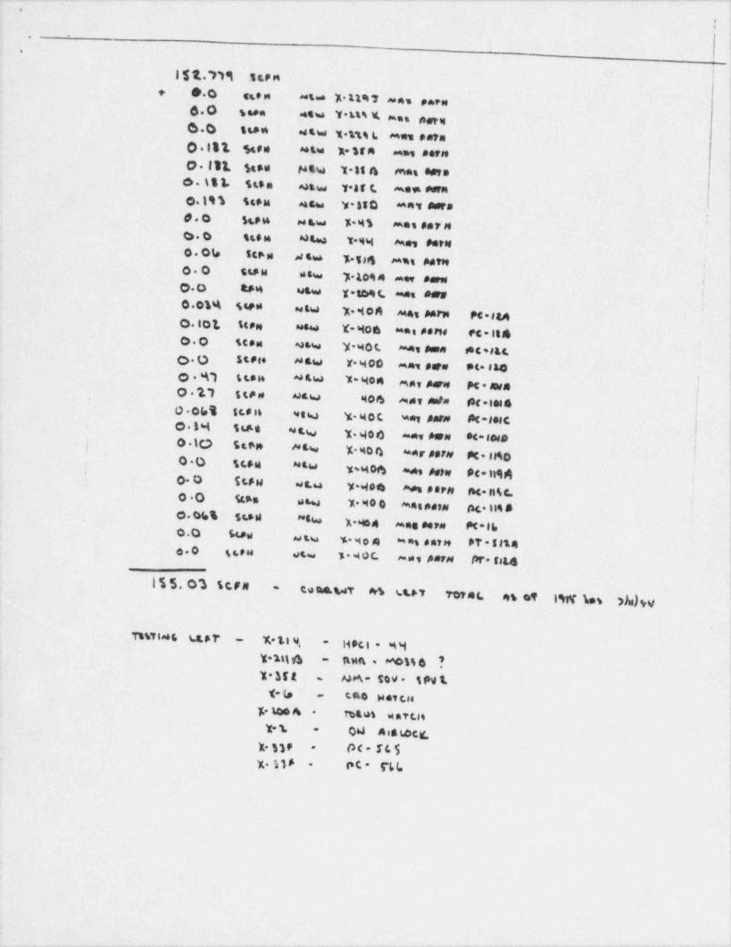
. . . . . ~ . . - . . - . . . _ . . . .. - . - , . - - - . . . - - ... . - . . . - . . -- .
.
I'.
%
i~
l $1."Pli StPn+ 0.0 aen ~s x.st u ~ns enen
6.0 g een 4tw Y.tu % mas pegg6.0 1 ** * 4%w 1.u% t. M eu pete
0 141 Stee ** tu 1-STA mas **fM
O.111 Stoe totw 1884 mas apto ,6. \ % k StSa 4tw Y.a t t m e n eseno. m seen 4tw v.sso mas aars I
d.O Sten 4 w a,w %. 4 % mas ear MO.O ste n 4W t.W mes perseO. One Sto p atw y.Taft eams patM .
'O.O stP W asw 7 1094 m., earw|O.0 4F4 utw Y-t09 C. a*es dersi0 01% sted usw y.40A Mas Aarp Pc sa4
0. lot StPN **w X- 6 ton a* * #8PN ec-It400 Stem 4tw Y-40L **v Amon f* C #EC.o.O stes* daw Y. Hoc = =5 pare pt. saso . %") t ts s, 4&w Yaq04 mmy pare M. Awa0 1't t te a dew 404 ** v mata fec.ies a j'
o .otet sc.a i6 wtw y.got was Aarn;
18 -folcC
|o. b4 5ee as s,w v.4oo ==, earn oc-se#aj O.50 Sten Wtw % Morn aaer porn M. 9a
i'
O.0 sceu ** tw ji ysgo6 % Aetw #C-Il94
O. O StpH w s.u y.goe Aesper# ftc. H 4 C. !*
o.O Scan usu %.M00 mespann o c. 169 8i
0.O(s% 5t82 "N % . 64 o 4 aane 8 erd M*lbQ.0 Sopw usu 5 904 ans antM PT * Siteo.O gsra st=. 1 4 0 C. may perm /8r- rate
155.o*3 term co ma.m ars sut tofet es oe t w w A),y-
i\
Tt%Tlass ss,pr Y,.1 t 9, Haci . gy- -
V.1% 4 ftun . MOM 4 ?-
1 354 MA- 509 t fN 1.-
T-le 440 N et tse-
%.464 rotos w a t t. $.
Y-1 04 A is i.ocit,-
t. nr OC- SL S-
x. M S et- 5 L t.,
-
i
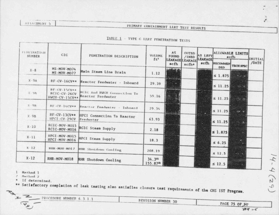
. .- - -. . - _ - - . _ _ _-.-
.!?
*
\
T#
| Ai 1 ACitMI.N r S ]-r
!
l'ItlMARY CONTAINMENT 1.IJtT TEST REstJI.TS}!
'
{
i,
Tant.E 1_ - TYPE C I.lRT PENETilATION TESTS !
i
ALIANAEbIbINIIIIl l flE'I RATi bri AS 011T80 !NUMBER CIC PENETRATION DESCRIPTION v0I1'ME FOUND /INBD ^ s c D'
INITIA1ft3 LEAKAGE LEAKAGEg-
** " /DATE-- scfh scfh* :sEDED g jNS'"X8
MS-MOV-M077 Main Steam Line Drain 1.12. i
s 1.875 !X-9A R F- CV - 16CV4 * Reactor Feedwater - Inboard 29.39
1s 11.25j
[e '[' ''X-9A CIC C ''"'" ""c F ate $9.16RUCll-CV 15CV** s 11.25
;x . 9 It nr-cy-14cva* anac s ur ranslun t ar - Inhaaril 29.34 )s 11.25;
X RF-CV-13CV** ILPCI Connection To Reactor_ ' 90 __.llPCI-CV-29CV Fondwnter 63.93 ,
s 11.25 j- - - . - - -
X-10 RCIC-MOV-M015.
)
,
RCIC-MOV-M016 RCIC Steam Supply 2.18 s 1.875X-Il HPCI-MW-M015 )
IIPCI-MOV-M016 HPCI Steam Supply 18.3 s 6.25 !X 12
Hilu HOV-Moll HilH Sliist.ilowei Cua l l ulL 208.19s 12,5
%)X-12 RHR-MOV-H018 RllR Shutdown Cooling
155$87m s 12.5 ' |
34 381 dl
k|1 Herhod 1not 1.uil :r N*
.
o If determined. p I
o* Satisfactory completion of leak testing also satisfien clonura test requiromants of the CNS IST Pro rJg am.'$. - - .1'p _ PROCEDURE NilMBER 6.3.1.1 | REVISION NilMBER 30 | PACE 75 0FJ1- |
-gD w ,,c ,
. _ _ _ _ _ _ _ _ - _ _ _ _ _ _ _ _ _ _ _ _ _ _ _ _ - _ _ - _ _ _ - _ - _ - - _ - _ - - - _ _ _ _ _ _ - _ _ - _ _ _ _ _ _ _ _ _ _ _ _ _ _ _ _ - _ _ _ _ _ _ _ - _ - - _ _ _
>__
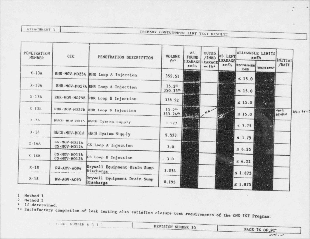
_ _ _ ._ _ . - _ _ _ _ _ - _ . _ _ _ _ _ _ .
.;.
|-
!
|i*r
| A l At:llMI:ta t > | i
l'It IHAltY Cot 4TAIIJill'. fir I.IJtT TI::;T ItE ;lil.T!i||i
I
e
PENETRATION AS OUTBD AliDUABLE LIMITS |NilHBER CIC PENETRATION DESCRIPTION V0lllHE FOUND /INBD ^
ft' I.EAKAGE I.EAKAGE C INITIAL !g ,my /DATE jsc fla me: flea 1DCit artic
X-13A RilR-MOV-M025A_ _ .
RilR Loop A Injection 355.51 j s 15.0 Ii
-
!X-13A RHR-MOV-M027A RHR Loop A Injection 15.2m
f'350.33m s 15.0
X-13B RllR-MOV-M0258 RilR Loop B Injection 338.92s 15.0
X-13B ItllR -MOV-MO2 7B HIIR I.oop B Injec tion i s . 2i'i *""'I353,74m s 15.0 ( I"h''('
x - l e, n ucil - Hov . Hol ". :Wcts *:yme=m ::eyel l y 1, ". 7 7 !1
5 1.75}
X 14 IlWCU H0V H0lll itWCil !)yst.ala thilitily 9.522;
A .1.75 !7,"7,"yg^ cs Loop A Injection 3.0 s'6.25
x-16A !
|X-16B "
, g CS Loop B Injection - 3.0s 6.25
X-18 RU-A0V-A094 Drywell Equipment Drain Sump t3.054Dischargs,
_s 1,873
X-18 RW-A0V-A095 Drywell Equipment Drain Sump j_
Discharge 0.195 s 1.875 i
j'
1 Method 1 . i
'. 2 Method 2 '1
If determined.o
]**
Satisfactory completion of leak testing also satisfies closure test requirements of the CNS IST P [rogram.
6 f tikI tit:MnER 6 3 1.1 | REVISION NUMBER 30 |
, ,+.
PACE 76 OFJt'. |.u, . . -
. - _ _ - . . - _ _ _ _ _ _ _ - _ _ - _ _ _ _ . _ _ _ _ _ _ _ _ _ _ _ _ _ _ _ _ _ _ _ _ _ - _3
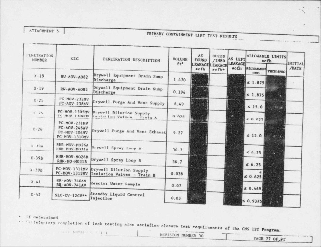
. -
. --
,
| ATTACllMENT 5 | .
PRIMARY CONTAINMENT l.11tT TEST RESill.TS. ---.- -
\- --
- . - . . . ..- - - - .
__
' -_.
PENETRATION AS OllTBD ALIDWABLE LIMITSNUMBER CIC PENETRATION DESCRIPTION VOLUME FOUND /INBD _ schS 1E
ft' LEAKAC LEAKAC INITIALacfh a c fh* ,,g , /DATE
"I"nnnX-19 RU-AOV,AOS2 rywell Equipment: Drain Sump ~1
a 1.470 s 1.875 '
X-19 RW-AOV-A083 Drywell Equipment Drain Sump _
0 0.196. s 1.875
X-250 3 Dryw 11 Purge And Vent Supply 8.49
_
s 15.0PC- MOV- 110'iMV nrywell Dilution Supplyy' 7 ,, -re: niiv itor.nv i .. t .. e t ..si VIw. '8 a t s. A n n?n < o ' r. y.PC-MOV-231MV
fC- Drywoll Purgo And Vent Exhaust 9.27X-26
OV- 06PC-MOV-1310MV s 15.0
y ina RilR-MOV-H026Ag ,.y,,, j g g ,.,, y g ,,,,,p 3 g,7ptellit HOV Mulla
. (. 7 5
X-39B RHR-MGV M026np_g9_g93 g Drywell Spray Loop B 36.7 5 6.25
X-39B PC-MOV-1311MV Drywell Dilution SupplyPC-MOV-1312MV Isolation Valves - Train B 0.038 s 0 62
X-41 ~^ Y' 4^Reactor Water Sample 0.07
s 0.469
S'8"d Y 9" " #X-42 SLC-CV-12CV**Inj ection 0.03
0,937
If determined.*
- e
a r t sfactory completion of lonk testing also antisfion clonuro enst requiromanta of the CNS IST Program.
_[ imvihibNNilMBER30 ] PECE 77 0F,&i-
,.iii r.o:uu e e. t i ~
- . _ _ _ _ _ _ _ _ _ _ _ _ _ _ _ _ _ _ _ _ _ _ _ _ _ _ _ _ _ _ _ _ _
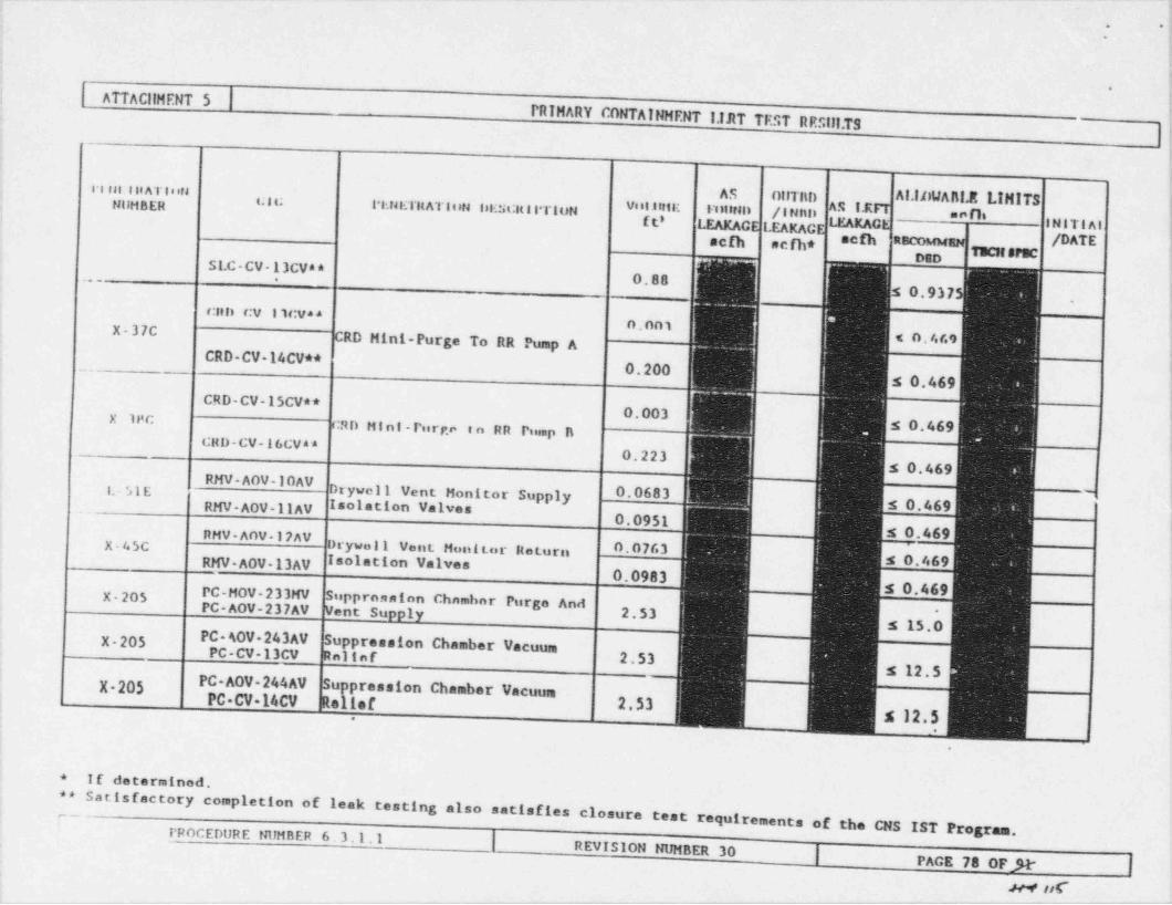
. _ . . _ _ , . . _ _ _ ._ __
-|.
-t
~
^
ATTACllMENT 5 $
PRIMARY CONTAINHENT I.IJIT TEST RRSill.TS!
!
i i nst titATinn AS OtITED Al.ItitIARI.It LIMITSNilHBER C H-I'l.Ni ~l'HA~l'luN his:iCit t i'T!UN VHlHME MlHND /INius
- Of t' LEAKAC LEAKAC g INITIA1. {
scfh acfh* acfh R8COMM MANfTacusrec,
SLc-CV-13CVa*0.88.. *
-
s o,937, j
r:lin cv 11r:vas- !
X-37C n.nniCRD Hint-Purge To RR Pump A < 0. 4r.9
CRD-CV-14CV**;
_ _ _ 0.200 |s 0.469 !
CRD-CV-15CV** {0.003X llic !
CRD Hint-Purr,c en RR Purnp B s 0.469!Citp-cV-16CVa*
0.223 !- s 0.469A A
1' *; l E Drywel1 Vent Honitor Supply 0.0683 , !
RMV-AOV-IIAV Isolation Valves s0.0951 {
RMV AOV-17AV s 0.46X-45c Drywoll Vent Honitor Return 0. 07f.3
RHV A0V-13AV Isolation Valves $ O.46g,ggg3
$X-205 PC-MOV-233MV Supprosalon Chnmhnr Purgo AndPC-AOV-237AV 2.53s 15.0
X-205 PC-40V 243AV Suppression Chamber VacuumPC-CV-13CV Rnlinf 2 53
s 12.5$ MUefsu{,ressionchambervacuu"
'. X 205 q, g 2.53: s 12.5
.
o if determined.**
Satisfactory completion of leak testing also satisfies closure test req iu rements of the CNS IST Program.
PROCEDURE NUMBER 6.3.1.1 | REVISION NUMBER 30 | PAGE 78 OFSt- |M is(
_ _ _ _ - _ _ _ _ - - _ _ _ _ - _ _ - _ _ - _ _ _ _ _ - _ _ _ _ - _ _ _ - _ _ _ _ _ _ _ _ _ _ _ _ _ _ _ _ - - _ _ _ _ _ _ _ _ _ _ _ _ _ - - - - _ _ _ _ _ _ _ _ _ _ _ _ - - - _ _ _ _ _ _ _ _ - _ _ _ - _ _
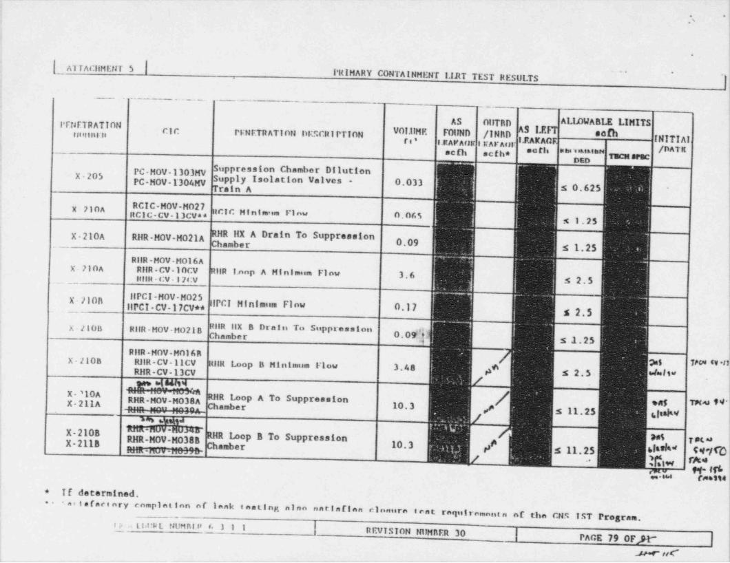
._. . .- . _- -_ ._ _ _ _ _ . ._ _ . _
. ;
,,
h
!.
| NITAcilMENr 5 |PRIMARY CONTAINMENT I.lRT TEST RESULTS l,
. . _ _ _ _ . _ . . _ . . _ . . _ - - _.
-
!
PFNF.TRATION AS OllTRD ALIAWABLE LIMITSCIC PlNETRATION DEScit1PTION fl, E MIND /INRD - dIMi riorf ul~lt
1.ftAFArm RArAul ,3 g -INITIAL,, gg, /DATKselh aefh* ,,,3 g,g,g,, Tucu arac
j,
PC-MOV-1303MV Suppression Gambor DHuttonX-205 lSUPP y Isolation Valves - 0.033PC-MOV-1304MV
Train A s 0.625 -
jj
x 710A " " :itCIC H intmaim l'i nw 0.065ncI -cv-13 vans 1.25
X-210A RHR-MOV-M021A RHR IIX A Drain To SuppressionChamber 0.09 '
s 1.25RIIR -MOV-MOl 6A
X 710A RilR-CV-10CV RiiR I.nop A Minimum Finw 3.6 ;;
. _ _ . _ little-cv 1: rov s 2.5 ;
j" I' "X-ll0BIIPCI CV-17CV** llPCI Hinlinum Finw 0,17
g 2*$
X-2IOB RilR-MOV-HO21B #" " " "PP'*** "
0.09h s .1.25R11R -HOV-MOl 6 R !X-210B RllR-CV-llCV lulR Loop B Min 1:nuin Flow 3.48 A* s 2.5- *la' l l''
>$ 7#0* 'V *19RHR-CV-13CV
:
M |
X '10A " " " ' " ' " ' " ' ',
RHR Loop A To Suppression !X-211A "P , ", " " Chamber 10.3 *M,,e 5 11.25 shakv_~
h.g CP B To Suppression10.3 / 5 11.25 6 @J m m -nu v uv.,ir
[gw,.
sw rassu i!'* If determined. i
* ai t ef acinry comrint ion or Innk t esting ninn u n r. i n fi n n c.lonurn tent requiromant n of the CNS TST Program.{
.-.
!
~
| REVISION NUMRER 30 | PAGE 79 0FX {
2 .,u a t nunnir (. ) i ii
1
_ _ _ _ _ _ _ _ . _ _ _ _ _ ._ . _ _ _ . _ _ . . . _ _ _ _ _ _ _ _ _ _ _ _ _ _ _ _ . _ _ _ _ _ _____

__
i
.' 'I1
| ATTACI(MENT 5.
PRIMARY CONTAINMENT I.iRT TEST RESIII.TS\
PEllETRATIotl .
AS OUTBD A1.1DWABLE LIMITStalHBER CICPENETRATION DESCRIPTION VOLU,ME FOUND /INBD sc&ft C LEAKAC C INITIAL
scfh acfh* **O /DATEn tisces sencx-211n Suppression Chamber Dilution !
Supply Isolation Valves - 0.028Train B ,
s 0.625\X 210A & 211A
x.710n & 2118 RilR-HOV-H067 RilR Dischargn to Ra:1wastaSurge Tank 0.033
210A 6 211A s 1.25X-?lan 6 2118 RIIR-MOV M057 RllR Discharge to Radwasta
SurAs Tank 0.075,,, acic-cv-l'icva* s 1.257 ,
itcic-v- n** n c i c .,.,, , ,, , ,,, ,;, ,, ,,, i s1.26 e*
X-214 IIPCI-CV-15CV** s no ''
IIPC I - V - 44 * * IIPc1 Turbine Exhaust 17.7 e/ "'M*'p 5 25.0 $he tv 881X-214 N 'N ~N ^
RNR MOV-M0167A RilR llX A Vent 0.044K-214 ' I s 0.625~
01 RilR llX B Vent0.039
X-214 ffPCI-AOV- A070 s 0.625HPCI-A0V-A071 lPCI Turbine Exhaust Drain
i0.02
PC- MOV- ? '80MV s 0.625X-220 PC-AOV-245AV Suppression Chamber Purge And
| PC-MOV-305MV Vent Exhaust 13.94 {PO H0V 1308MV 5 15.0 i
|
X-221 RclC-CV-12CVAA ((RCIC-V-42** C[C VSCuum I' ump DISCItarge To
0.0456i s 2.5 |
* If determined. ,
**
Sarlafactory complotton of leak tancing alan antlaf ten closure t''
ant requirementa of the CNS IST Program. !raiy rooit i*. titiHit rie t. y .1 ( jsenvi:: on r388Hnkit 30| rAnit no orpP
| k
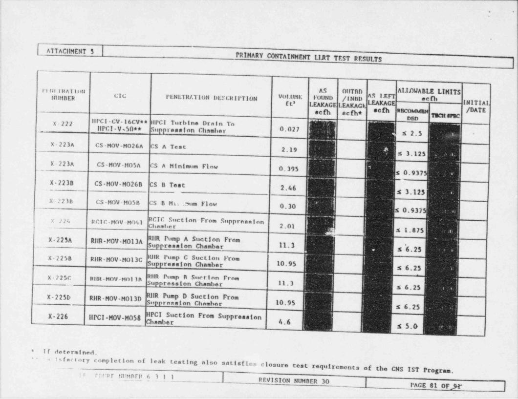
_ ._ _ __ ~ ~ -
|'
.
ATTACllHENT 5PRIMARY CONTAINMENT LIJ1T TEST RESULTS
l 1 fil. Ilt AT l ori AS OllTAD ALIAUABLE LIMITSNUMBER
ggg g,ENETRt. TION DESCRll' TION VOIUME IVUND /INBD II''
f t' I.EAKAGE LEAKAC C INITIAL.scfh ecfh* scfh a /DATE
TecusrecX-222 llPC I -CV- 16CVa * IIPCI Turbine Drnin To
.___ DE
IIPCI-V,50** Suppression Chamhar 0.027 s 2.5 i'
jX-223A CS-MOV-M026A CS A Test !2.19
s 3.125
X 223A CS-HOV-MOSA CS A Minimum Flow 0.395 i0.937{!
X 223B CS HOV-H026B CS B Test 2.46 s 3.125X-223b CS-MOV-M05h CS B Mn t.mism Flow 0.30 0.937 |
X ??4 PCIC-MOV-HO41 RCIC Suction From SupprnnnionChamber 2.01 s 1.875
X-225A RilR-MOV H013A RilR Pump A Suction From3 11.3 s '6.25
X-2258 RilR-MOV-Mol3C 10.95 s 6.25" "*E " " "X 725C Hillt -MOV-Mol 3 n 11.3~_
s 6'25
X-225D RilR-MOV-M013D 10.95 s 6.25
g,,"r3 ction From SuppressionX 226 IIPCI-MOV-H058l.6i
s 5.0
If determined.*
1 s f actory completion of leak testing also satisfies closure tcat requirements of the CNS IST Program.
:: ri epr tntMarit 631 1 | REVISION NUMBER 30 | PACE 81 0F Jt-_ _ _ _ _ - _ _ . _ _ - - _ _ _ _ _ _ _ _ - _ _ _ _ _ - _ -

__
. -
-
i
!!
- i
[ATTACllMEt1T5 |PRIMARY CONTAINMENT LIRT TEST RESULTS
|
t
!
IPErlETRATIOil AS OUTBD AMABM MITS '
cyctHIMillit PrNETRATinN DESr.RirTTON VOI.IIMF* F0lIND /INBD achg,. LEAKAGE I.EAKAGE * AI INITIALI
sca sc @ 8CEh R /DATE i1ECH SPEC
X-227A CS - HuV - Hu /A cs pump A Suction FromSuppression Chamber 3,gg
g 4,373;,
X 2278 CS-MOV-MO78 CS Pump R Suction From ~
Supprennion Chambar 3*11 is 4.375 !
if determined.*!
_.. . - . . .
ii
It
!-
i
,
f f =! S
e
...
__-_._______.___________ _ ___ _____._ __ _ _ __ _ _-__
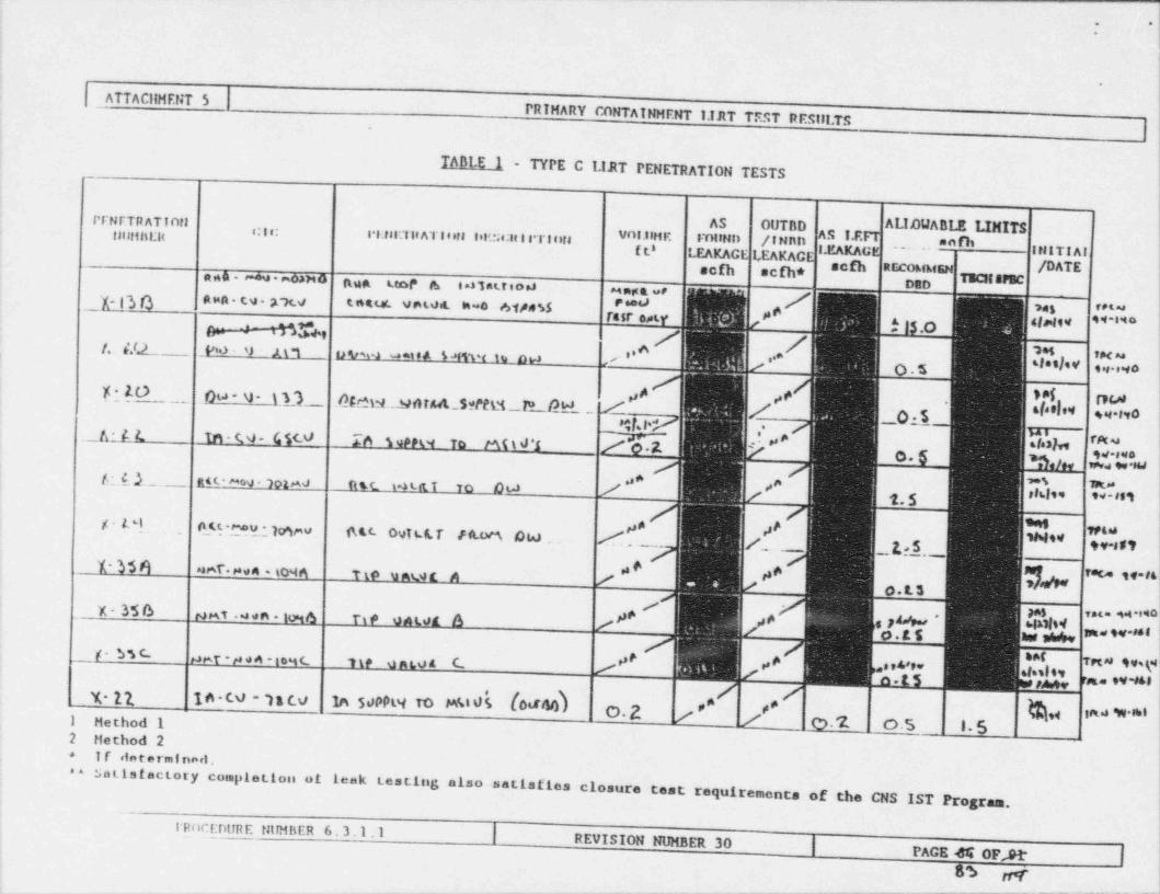
__ _- ____- - - - - - - -- - -
!. ,
* *
i,
!t
;ATTACllHENT 5
PRIMARY CONTAINHENT I.IJIT TEST RESIII.TS;
|
- TABLE 1 - TYPE C LIRT PENETRATION TESTS |
,
I,
i
iPFNETR ATinti AS OUTBD ALIOU^ OLE LIMITSI110:1151 l<
, , , , ,,s.tss: Tit ATinta leic;e:It t s Tints WI.UH K IWIND /INnD ?"bf t' LEAKAC 1,EAKAC g IH1TIAI. . . .
acfh scfh* scfh RECOhibfENtscuerne /DATE |a n A - r-*u - moaM O nun uor A i d l at.f i o *J 3,3
** mst a ve /,gg a.in - tv - rx.y snaur. vewit m-o mensra # m ret a
'##" ' "'"-e .n% , / / ;
,"
/. 4.0 W - 9 ' M *1 8) * 2 " " A M f W i 19 DH '. , . h ,.* w i !sles]se ,n =5 .a. , n o -
!R an _ 00-n-t.D oma.sasut sema n- thL / / ._0:10 A rn,a i9
*let*
s q.t,0 ,
*$l' .' ;_ _6 - f. ( in - C 4- G 5< V To i9PPW To tM i d 'i -e, 7g,',9r reta '
0- v.s.noser.a9. Si
/ d-h._ RR * ^*0V * lol,AJ ft tt t4 Lit T To OW m m,. \
T.$
8 ti . ou mu.novev_ tw. ovis.or i m o w Z . _. /. _. L:1. gy.as t
s # 4e* ,8 fete iW''
1-356 er. .. - ioq . #. t. s
mst .u.n . mo pe '4 _ y-356+ e&' $4'I $|,.$s.c 5 *
**tge e . .ve- recu tvsy,sie,w w w-m
y. n le-to n c.o la 5oppW To miis (o 3 44) #. #. 4O.2 ina **i1 Method 1 e.2 o.s i.5
|2 Hethod 2I f <laterminarl .+
*a
satisfactory coinpletion at leak testing also satisfies closure test requirements of the CNS IST Progr!'am.
I RocEntIRE NIIMEiER 6. 3.1.1 | REVISION NUMBER 30 |~~
PAGE M OF,91* |ss nr i_ . . - . _ _ _ _ _ _ _ . . _ _ __
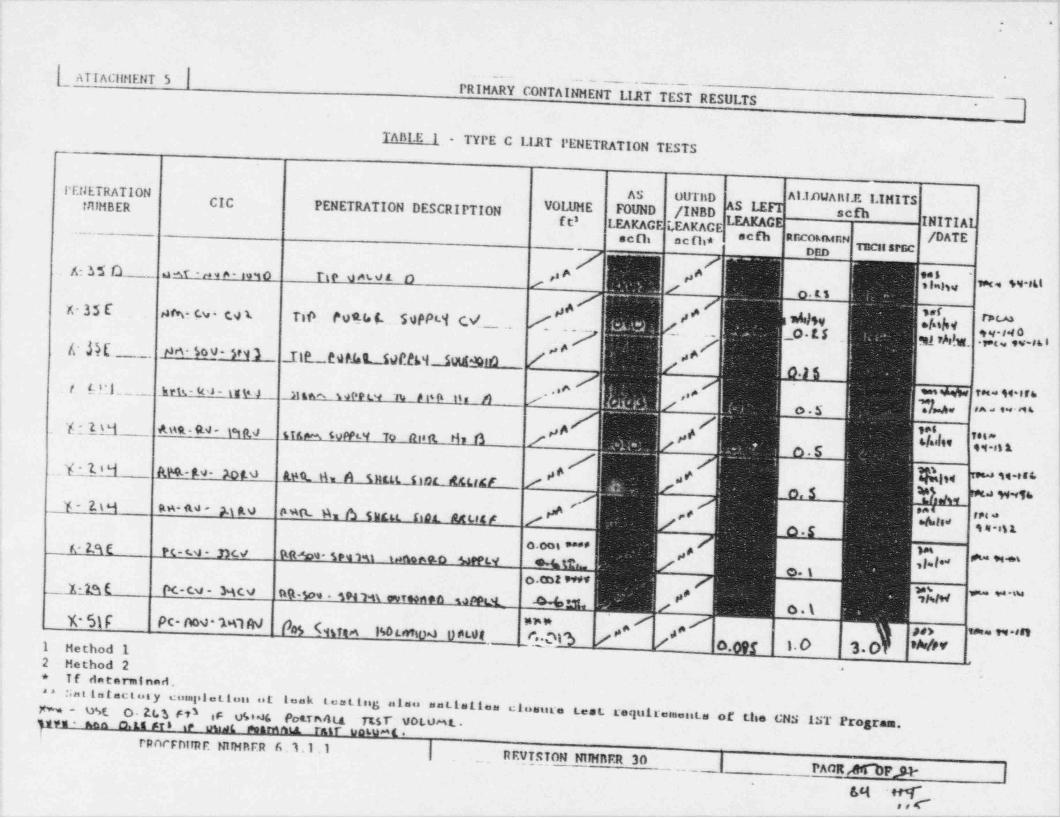
. . . _ . _ _ . _ _ . . . . . _ _ - . _.._mm.. ._
. .i*.
,
[ ATIAClitlENT 5 | --
.. _ _ . . _ _____, !(
PRIMARY CONTAINHENT LIJtT TEST RESULTS _ |*
!
TAnl.E 1 -,
__ TYPE C LIJ1T PENETRATION TESTS !'
'(
!.N ATION AS OUThD A1.IDWAnl.F. LIMITS !TIllHBER CICPENETRATION DESCRIPTION VOLUME FOUND /INBD *
^f t' LEAKAC LEAKACE C INITIAL
seth ocfh* scfh sincokstenN /DATE |, nicst srse
i
A: n O . a +r ,. , a - i. i o ri - e rai,., ' ~ w ,a is
!
x- 35 E 9tv cv co Tie Po% $ . 59PP8'l c.V se ,s * dlSv .'[dhv ""d/_. _ . . - _o F. 5 _ w,W, .',7|'d[v ,6 s ;
!
/c M rM-500-SN'3 _Ite._.est.ht_.59RM__SuutS9to _ .,, e
,, A
t trL__ .hrts- u - iv u . _m '' = ra . u ers- '
I o.s D' ' ^ " ' * " ''
em m-u- w ~* ?* {I,'" fataam u 'a
._Y-1.t4 RM.- #.9 - X)f.o A9tL A A tuttk Doc it&tidr.._..g j h|td " " ' ' ' '
* W"%y_ ggq gg. no , p g,9 M '' # M '# 't 's ane t.y pt.w. nce _ # #'
o. cot M___1 ja f Pc-cu - Mcv #, g - * -su
o.\% 5)F Pc-oov MW pg<mm not wioa oncos _ gog 3
,is m*, d, on se e n ret
0.09f 1. 0 3. 0 'W1 Hethod 12 Method 2 ~
o if determined.* * :;n t is t aci nn y coingila tion ut teak teattug alau untimL1== cluettro testN- uSE
O. Et.t FO if usi4 PotTesota TtsT' voLOML- requiremonta of Llie CNS IST Program.pm un o.ts sr s ir m et near e i.t ratr unLuat .
renernime mrwarn 6. i.1. i | . _ . REVTSTON NIINRER 30,, PAOR MFSI- |
'
sct n 4 ,~ . ;
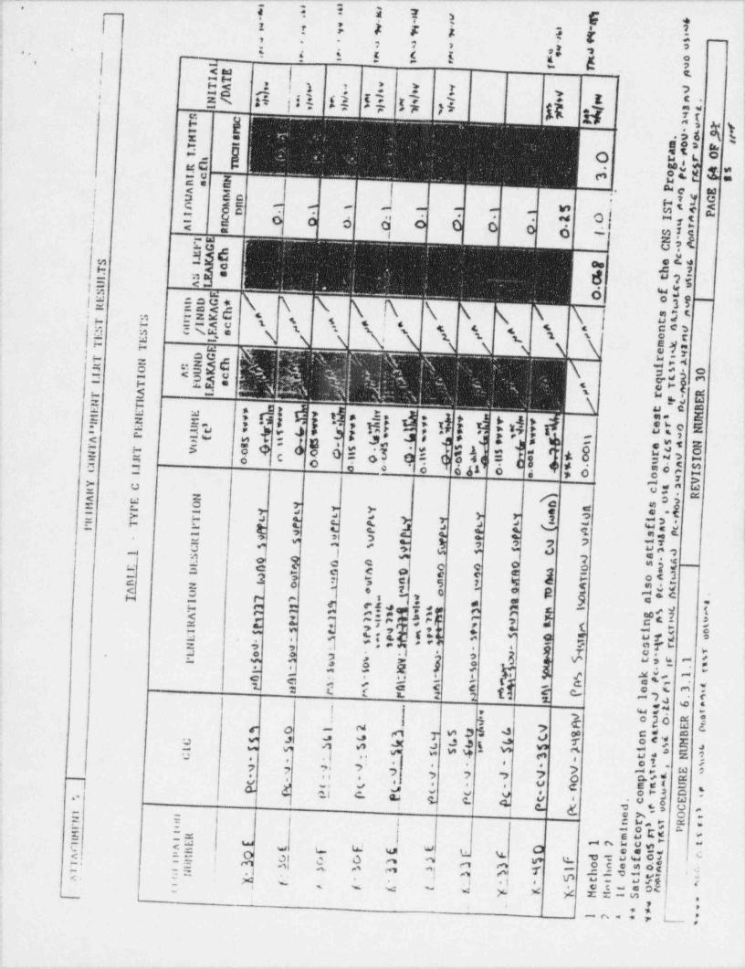
_ . - - - - - - ~ _-w. - - ' " - - " " " " ' _ _ _ _ - - _ - - - - - - -
7 i-
? ? 1 F i'
- -
I : : a s i f r
.; -
: 2 1 >, ;- -.
*3". i s i 5 5 ( . ,
Eo
!t h ,| t 1~~
i! | kk A |ik 15 !$ d >5 N 17 I {
, * * * 2*r <-
i
: ..
t Wg% >u6 s= =
st|"
=M. o u '--
tie . *M C2 5 es t 1. we
w.
; < s | _. m e wis' y e: 8 gj , .
1w . m' < 2' - -
. ~ of 1 5.
: 8 o 6 d. .
'
a | 6 3 E' {<
I 1re U?' 3 6 **m
8 5 yo<g = *
ty.7.- 1
'5 6,
g- |=ce. N .N \ U; 33I- ==<-- -=xc - '
't; h, itq: \,'.
.
s . .. ,< - ce,!. . .' N'- ' s ,t ' '-= o
51;ew -
- ~, mese =: S egsd 4
= 0- a !<os: r-ls .w .-.
$
<f t..
. \ ,n 5s u-
1 5 5 e =
F 5 E. o :g ial> t "2m
3 .i ' t ,; e st? Ng,: ti b: ;
'
- s - a - :5 5 39 o O E d} *q ( o4 -
8 4 sn 3 9 8- .
si - cg .. 'A8.=E~)
,.
3 o i- O f o o 6 41 0 d > 0
-
C, d E".;
_
o.g ge aa 4
. .
"l.a s
1 :s p : ?e- >
,'-oe 3 3= a '
-r L t c E 4: e, 4
t ,t i-. -t J., 7 2
0.%'a -o- i J 3 2 3
a
1l1 2 e c o -" = e e < g 3 -
.o c. -o , 3E 2 - - $ -e s=
,q, 3 8 5 -ra' o; *#A E S Eli%j$ $$$ III i
9 a -o
! E 3 ,z; q 'q : - a s 42e ".; 1' -
g iJ 3;s :-z -.. .
. 2 s y 1 5,s.ic.-
.
9-
. -r r t tc e 4..
c : 4:s 5 e e1 : L f n g e c an,*.c. 2t p i
!} *20 5 2
5 +3 d3 ,9 33N $ e.ihE $!s $u n s
4- _ wr.i n -- ; ; w >- , ,. e 1. w ;. .4 . .
-, o233 2 ,. .i . o es, s-- ,
E E El I yE y %, i i j g> |.. . . e ,o rg a
-- >
= =t
I r a cs "1IE 2D
-
i
.'= .: o a~ ~ tN:* ;v u W W % cu ' s, O<; = . = s 81%%.a,) .c,.. O n v: e-. = , m n As n ,t P -r_= .i c-
2. 5- m*n, +
= =c - . .v .ot. u a r c
.
. .i ..- o'
- - < - .< w x s -=, ;_,
' '
I. L_ ,'! -n.
- . . . . ..
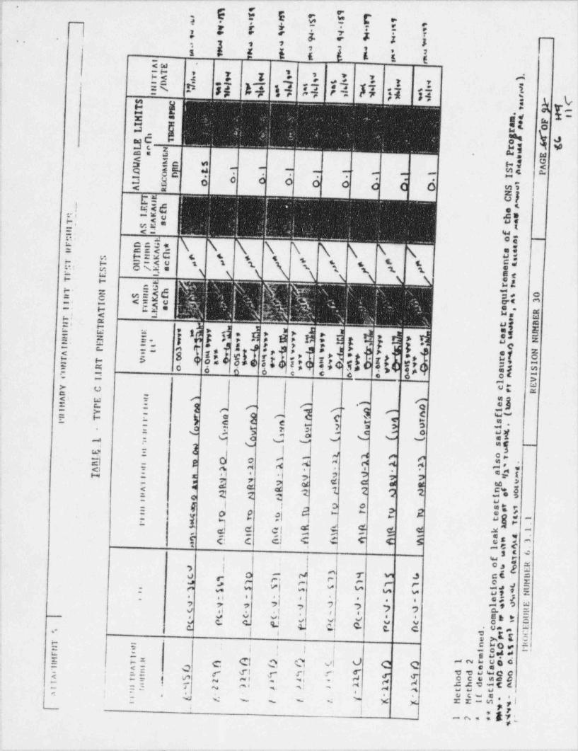
I*
3 h h ! E hE O ;i R i * = ? i : 5 i i- -..' - 3 2 2'
2 1 is * ! E E E & E E
, s
i ? I h 1 al 1 * v k: ER 15 IJ h'i H E? E 4 fi R H ik l{b !
.t: W * c.
|3 5si= -
u-
gC e a 1"
=15 S ,I 'u v 1
w,
s 2 * s: ?q * a =< =. . .s y f ..
.0 y'< m
t of ,
i
= ,1 -=d .* iwa51 !
E- $$"uh<E! ced. \ \ 35 .
-
= isis 6 4. + + < 5 . ..b. , d,. 8q5: t c Ed !' ' ' ' i s * '.
!Y.w
u .!. !-
H
w ij.A.
t- - = d he C;, 3 o ''<s. P.en-.
u, g ;s: s -
;$ E-
E! E E II ; d; d! d =*
3 *| -}$4 g ) *d O *s. m :-$$a t,a; 9 ;! $$,t h, g"}id
c[ 5~
' a ef 58 <$ 0itd i!4 I |} Es
3 ,4 .
I O o o o e c 4= g- g
a. u u. a :g' g ! j : l
% c-)eq -e -,,
-E C : $ a f 7 3 $ b B!" '"
I e I i E 81 a d :T.
- .= M a " " i
i 12_-
'
j* - s az\ eeo - g
.s 4
<> - n. , a. A., ,. ,- < a ,s=
. .
o5 3 a 5 a,"
$ $ 5 I4 !": z 2 2 2.
a g ,| 2 ? 2 .; ' 4 l
Bjf2t m e
- -- -- . e+ g, d cl b a s
.
-~ -
( di 5 k % %e
# I g 3g-
~j T e-
> i $-,o - r ., se :o -
<- <. c,_ -, '[ [ ,- ,-w w M ., s =#
M u -,hZ?.,-
. ,, , .. . . 5-
~
7.
7 7 7 7 2 w
Y a' ) ) 7 $*g , bo e, ; a a o-
e oSv c c. s,.' s e., c. c. cC 5ua| 1 t
** cMEy vH = C 4 0 w. 9'| ! | f
= - .
* E YdI hE - m w og o'
= C %<= QI fl- | 55 j C, C y rs r' f gg Qo c e me $a
% ',- 7. d N d. 5. f ' M. . '.~
= ,Y |
.
~0 ~* .
g w w w d Y Y y*
k 7, '-n=
_ _. . _ _. . . ..

;i kI ,i ! !>! I 'l;i | |i 4 \ iI ; , I i,i IjI} l
.
" " 1 "1 tS " "] r ' Ts) "e
* C '- v 'Vw i " ' |f
"e * '
" '
"- '
~. - * * " ' _"m F * _' ' ' f " " _
.
I
S C_
-AE
4 * ' a *
" 7t.
IT 'TA " *+ ,
I'$ $ID
s# M wg'4 ,l- ,ll ,
N/ ,
,Iss g'i O s,s 'I 1s $
MiT B g
I P .
M Sr re
I H a oL1 gC r
g n1
E 1 oL r ,
B D P nA
MDnD TW AE ) SA r_. . i. II
Eo O _
.L* o sA
ttiCs _
C& e '.-
S c hseT a tDLU faeS oc |
E DDC* / _
aaR BBAhS TNKi p tt
* n-aeT T UI Ac # g # - n.S S O / E, a / mtAE E I
T T E noDG r
T N A hSNKc iw
f u nR O A q 3I. I A aE eTI
A L ra nT eR
t* nN T t _e o h+ o* m .E E
W,'t.
-e v w v y s o*f
m, hwMm# N w m, * ts
v $ s v ^*- .v yW v *t E
y4v.
o. m O o. , 9_ o.n
-t W {s ei P sv . *s *4I f nA + e ei
- s 4 '#c srt oo
LsT T .so o s
c. o.J . e. *6 u*N i'
O R * s* so 0-
o o o . o o os. -
C I. iI v-
l aY C c' ER R) )i 5A E } a*r
O 0 p nH P I 4 G o o i*T Y T d O f*R T T
iw"P I' I I
( V u sI
- r oR ( t(C a a1 S l
L s"' I |E AE. D D A o*- el s_' n
V. J" ib_
n 3. _
VtA 0 $ _
E'
Me-
.
R n*_
T _A1
N g** .4T sA t_ ._n*a
i ** w.
R bT 9 6 t* o .t
TE 1 -1 s>o
.f _l
e' _rE t R
1=i i _t
P t i sA A i
. h_s _
h k* i1 _
n*1 -n= e
. wt _I _
n c.._
.
_ f a .
_o m r n.
0 .
-1 l L oa rM 8 L 3 s nu ni l
c I' o*oi & 1 1 u
C .5 5 x m1
I - *. : - S T 5 s1_
i n _
_t* c.- i-- -C u W a 4 4 i u ,9 4 e- - l* r-
t L cm .- rap o-t - - - . _
P. P c C>
JP 2_
(oe,ri1 cf P P o .c*
n,
5 d ..e y s n -T f in r s, r + _
O _ _
M n ihdion
3 f-t _- i oe s _
rE L_ nI 1 2 i t o t.cM T R l f. f f% M r c t. _
_E i I ea o .G A _n \
A _ Rl l' L' s 1 S lid tfo _1L
n moes o _p n RT. il {l
_T _ 31 gT. l i .i f _
i tomt tt - -_ A L
u_i 2 *
't - . efI 1 g i g ( ax .HMI SI
' __ _.w-
*ws~* s.< m
-___
_
! i
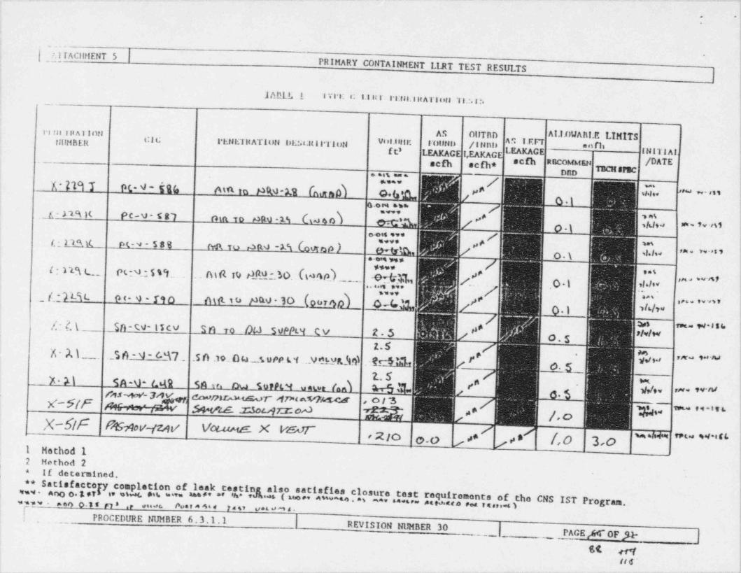
. .. .
. -}'
:
!
. _ ._
| ] TAClll!ENT 5 |,
i
PRIMARY CONTAINMENT LIRT TEST RESULTS]
';
1ABLL.1 I VI E a: 1.l H I-. _ . I :rn.litATiesta T1.:.1:.
i
AI.II)WAh!.E LIMITSIr1in alaA1Inti AS OUTBD
tufMBElt ggg g.ggg.IltATION lali:st:It i 1*Ti t JN d '"H E I'U"iU3 / I I"d' "f t' LEAKAGE I,EAKAG LEA C INITIAI I| /DATE-- sefh aefh* #N OTBCHSPEC. .., . ;
' ' ' ' 'N* M O(*N'kN M.. ID . NM *M.. . (AtKfb ,hg >PaJ w- ass'
* * "* 'f ' ;,.J - l'lA K PC- V - C R~l . thft10 m:@V ? A't _ _ baJ 4 O M
, ,4i
'
oots eve /'(12ML pg4-58% fvi\ to raft 4uv *
T .''t bW DP ) h / ,# w3O.\ ''' , . . v. . s ,
e m us ,
$$wwi * 1D L._ . Pt!M ", 5 I'I.. Al N I4 N_.b.' DO. %98 kh_N1 /,. ,Q % *!*I"
**%_
i
"" air I,7-_ ( - Teit- o c- 9 - rso n ut i t> Nao-30 (oormd___ c 4 '% '# , , . . . . . , , , jg ' ''h ''
;
/:2.\ _Sn - CV- I T cv S n to . /)4.. SoPPs.9 .Rv 25S rys Set 131. Iu*s rielw io.s |z.s
'X - A \ ._ . .._.S 6 - 4 - 6%7 _ .5 A .10. O ks. s u ve L'i.. N '_9i ustg $ .gr4 LL f o. g_ j!f, g ,,,. ,_., .
?. 5'A M S A -\)- 6619 5 * !
M * '~ros~,w- s wo ~ rnmansa ,9n&Sif x .= ,=p:. Swzs z.sourr2:oA g /. o y,., - - . -ts ;' ' ,c------
X-Sif Rthw+v Vow >ut x vsar ;
,2 ic, w , , , * ,s f,o 3,o "' " ' ' ' * ' "1 Hathod 1
,
2 Method 2 ,
!c If determined.!00
Satisfaccopi, ompletion of leak testing **also satisfies closure test requirements of the CNS IST Pc
!inw . ano o. g ,y os < mit ='v= u**' "' 'h* * 5 ( tw e' ^ $'*** a . a s aa* **** * 4teo.nea e.4 vs,,.. o rogram.!. acon - ,sn o.s s n * .e .*****c- Po * * * * * * 1*s' '' * ' '* m s - 'f,_ PROCEDURE NUMBER 6.3.1.1 | REVISION NUMBER 30
|_ PACE /r4~ 0F JI- |
st w !
st e - I,
_ _ _ - _ _ _ _ _ _ _ _ _
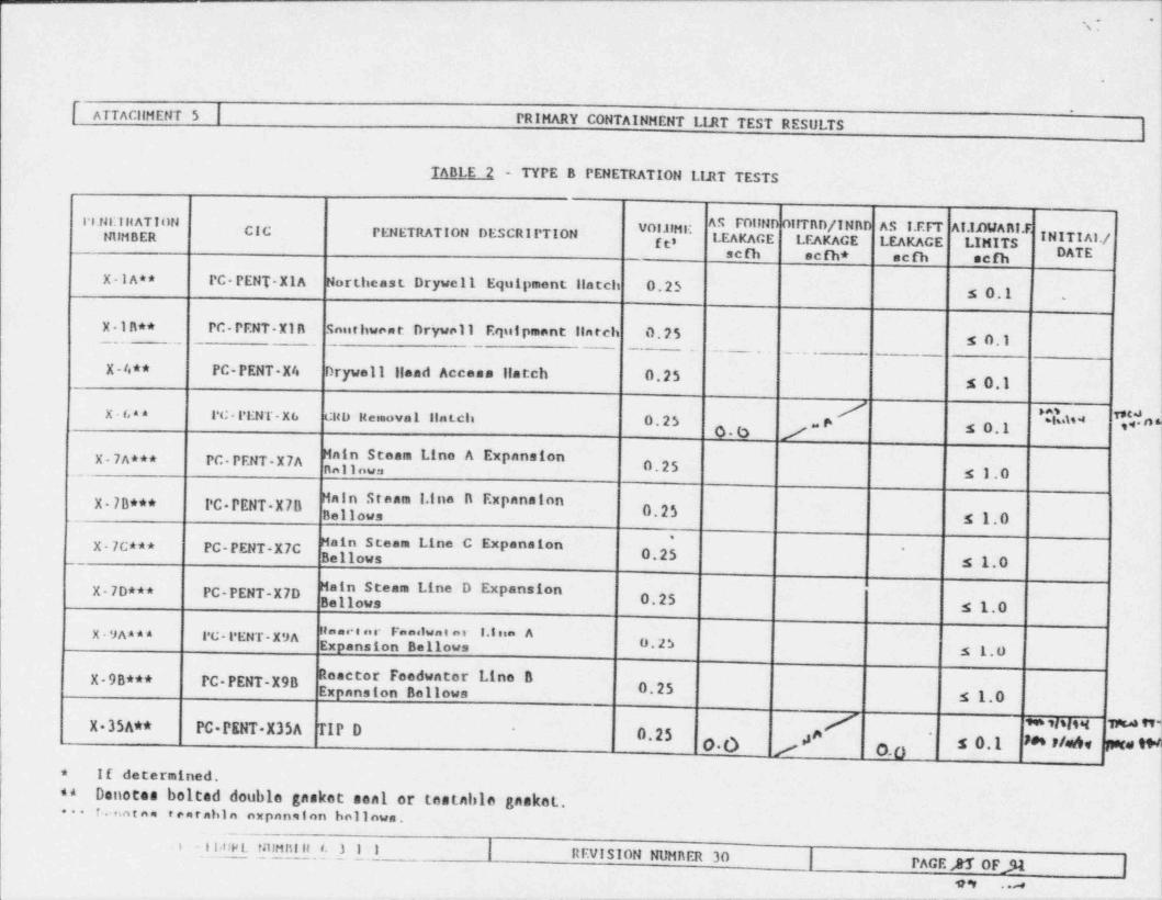
*
%!
.
IATTAcilHENT5 | PRIMARY CONTAINNENT LIJtT TEST RESULTS ||.
TABLE 2 - TYPE B PENETRATION LIJIT TESTS
18.fR.'l H AT I ON AS FOIIND OIITRD/INRD AS I. EFT AI.Il1WARI.FCIC PENETRATION DESCRIPTION " I'.ft3 LEAKAGE LEAKAGE LEAKAGE LIMITS INITI Al./
'
- tAlHBERsc sc * acm ach DATE
X-IA** PC-PENT-X1A Northeast Drywell Equipment llatch 0.25 5 0.1 .
X-1R** PC-PENT-X1R Southwnnt Drywell Equipment llarch 0.25 s o,)
X-4** PC-PENT-X4 Drywell llead Accesa llatch 0.25 5 0.1/ tas vnaX 68* 1*C - l'ENT - X 6 CHD Reinovel lint.ch 0.25
O% /e 5 0.1 ***t
X-7A*** PC-PENT-X7A Main Steam Line A Expanaton_ nn11nwn 0.25 s10
" **" I*I"' " "P""'I "X 7B*** PC PENT X7B ,' 0.253 g g,o
X-7c*** PC-PENT-X7C Main Steam Line C Expansion *
Bellows 0.25 '
s 1.0 ,
tX-7D*** PC-PENT-X7D Main Steam Line D Expansion
Bellows 0 25 $ 1.0 ;
IRence ar Fanelwat er 1.I na AX-9AA** PC-PENT-X9AExpansion Bellows o 25 ;
5 1.0 t
X-9B*** PC-PENT-X98 Reactor Feedwater U ne 8Expansion Bellows 0.25 s1o
ja/ ** sisitet wtd M-X 35A** PC PENT-X35A TIP D -
0.25 '
s 0.1 m r/e4, pare wg* If determined,
Denotes bolted double gasket seal or testable gasket.** i'
*- r.notaa rearnhin expanginn hollows..._ ,
_I I t!Pl. talHiti st t. ) 1 1 | PsEVISION m m M | gg yl
99 . .a !
. _ _ . . . . . -
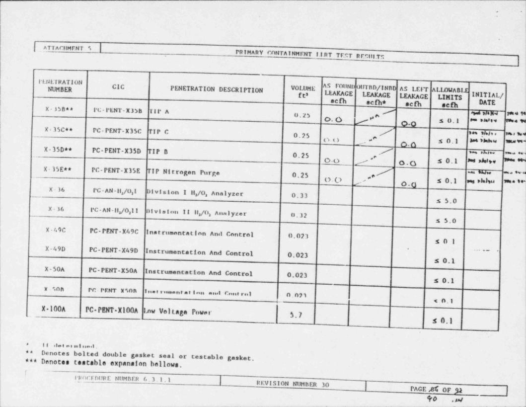
~
.
.
| _ ATTACIIMENT |'.PRIMARY CONTAINMENT 1.1.nT TEST RESill.TS
ru1ETHATIONER PENETRATION DESCRIPTION VOLUME AS FollNI)OtrrnD/INAD AS LEl r ALIBJABI-ECic
fts LEAKAGE LEAKAGE LEAKAGE LIMITS IN AL/sefh sefh* sefh sefhX-3SBa* l'C- PENT- X 3)B Til' A / *ias sten.4 f*4 NjU.2S O- O j # *' s 0.1 * *'" NgX-35C** PC- PENT'-X3 5C TIP C / tes */.1, e me sui0.25 gg ,, e s o,I ks thhie me *- O.oX-350** PC-PENT-X35D TIP n 7 , ,s.s,. m ,~0.25 ,eOO / o.O s o,1 m Aesw 3*** *
\X-35E** PC-PENT-X35E_
TIP Nitrogen Purge 0.25 . w .3w ,,
g ,.* s 0,1 m ,Mou mos- 00X-36 PC - AN -II,/0,1 Division I 11/0 Analyzer O.333 3
5 5.0X-36 PC- AN-Ilgo,I I Ol vi es t on II 11/0 Analyzer U.323
s 5,0
X - /. 9C PC-PENT-X49C Instrumontation Anil control 0.023so1
X-49DPC-PENT-X49D Instrumentation And Control 0.023
. .._ .
s 0,1 i
X-50A PC-PENT-X50A Instrumentation And Control 0.023 i
s 0,1 I
x . ".n nPC-PRHT X" inn Ins t rus==nt a t I nn anel Canern) 0.07'l
< o,1
X 100A PC PENT X100A I,nw Voltage Power $.7s 0.1
,
* 11 .i e . . . I no.l .**
Denotes bolted double gasket seal or testable gasket.*** Denotes testable expansion bellows.I
rnocenunE NUMBER 6.3.1 1 | HEVISION NUMBER 30 | PACE,81|I OF 31 |9o .w
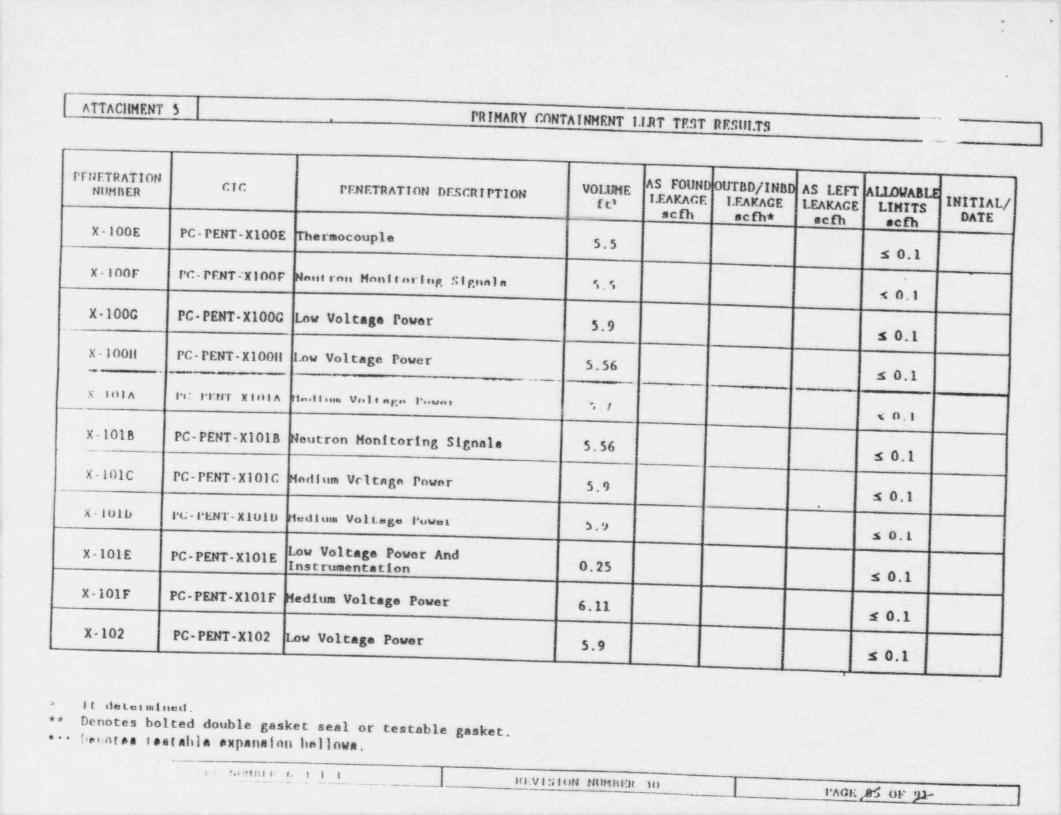
__ _ _ _ _ _ _ _ - _ _ _ - - - -- --- -- *
.i,
-;
i(
',.
ATTACllMENT 5PRINARY CONTAINNENT 1.IRT TEST RESill.TS
~ ,
!
Prt1ETRAT10N ,
AS FOUND OUTBD/INBD AS LEFT ALIAllABLE INilHilERcyc
PENETRATION DESCRIPTIONg 1.EAKACE 1.EAKACE LEAKAGE LINITS A!
scfh scfh* scfh scfh E i'
X-100E PC-PENT-X100E Thermocouple,
5.5 ;
s 0.1 I
X-100F PC- PF.NT *X100F Maint rnes Nnnt e nrIng, S tr.nala 's ">i.
t
s 0.1 !
X 1000 PC PENT-X1000.
Low Voltage Power 5.9 s 0.1 *'
x-100ll PC-PENT-X100ll I.ow Voltage Power t
5.56s 0.1
x inin .: rr.trr x io in r i-.e s .. v.. I e a r... I* .=. ' ".-I i~.
< n.I
!X-101B PC-PENT-X1018 Neutron Monitoring Signale 5.562 s 0.1 !-
X-101C PC-PENT-X101C Nadium Vritaga Power 5.9 .
s 0.1 >
* P
X-10lb 1*G- l'ENT- X 101 D Hediusa Vollege l'uwe r 11S . '>!
s 0.L
X-101E PC-PENT-X101Ee t 0.25
s 0.1,
X-101F PC-PENT-X101F Nedium Voltage Power 6.11s 0.1 !
!X-102 PC-PENT-X102 Low Voltage Power 5.9 |s 0.1
. '
i'a it nie ta s sol uest . ,
**Denotes bolted double gasket seal or testable gasket.
1
i* ! ,oten sentabla expanalen hollows. {.
.
i s> t fell!!!110: t. t I L !'
lt F.V I S I ON Nt_lHiti!H 'l O | 3.Aag;,36 op p |. .
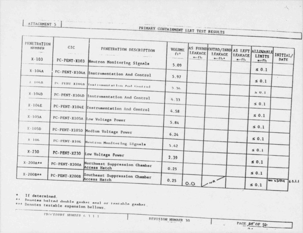
m,
i.- -:
\ATTACIIMENT5 ... __ __- ~ ~ ~
- - - - . . . ~ . . . .. '
- - - - -,- . . . - -
PRINARY CONTAINNENT I. ULT TEST RESULTS'
L
_
PENETRATIONnunnFR CIC
,
PENETRATION DESCRIPTION VOIJIME AS FOIINil OtITBD/INRD AS i. EFT AUJMIARI.l! e
pp 1.EAKAGE 1.EAKACE 1.EAKACE I.TNTTS I Al./ ji
... ri. ... rl.a ... rs. .. rt.X 103_-
PC-PENT-X103 Neutron Monitoring Signala |5.09 ts o,1
|X-104A cPC-PENT;X104AInstrumentation And Control )5.97 -
is 0,1!,X i ti/s h l't; l'l*Ml" K l u/s h
liiant a stessaut a t l'ont /b e n.1 4!8.sil. 3 so l I*b . 3 f.L
s u.1X-104D PC-PENT-X104D Instrumentation And Control -
4.13X-104E s 0.1 k
- - .PC-PENT-X104E Instrumentation And Control 4.58
s 0.1 IX-105A PC-PENT-X105A 1.ow Voltage Power !5.84 ;,
s 0.1 .
X-105DPC-PENT-X105D Medium Voltage Power !
6.24 t
s 0.1x - 10t. l'C- l'ENT - X l Df,Neist_rusi Mont t<tring Zilguania
?3.42s 0.1 iX-230
PC-PENT-X230 Low Voltage Power 1
2.39 1
orthwest Suppression Chamber- s 0.1X-200A** PC-PENT-X200A N
Access Hatch 0.25 )
5 0.1 ;X 200B** PC-PENT-X2008 Southeast Suppression Chamber |
Access Hatch 0.25 6.
0.0 / .4 se1,
i,
O If determined.08
Dannten leoi ted <louliin ganket anni or s ent al In ganket.!Oo* Denotes testable expansion bellows
,
irpnerDUFF talHRFR (> 1.I 1 |, REVTSTON,MlHRER 30
|_ PACE OF'p- | (
\
,
, _ _ _ . . , , 3 - _ . . _ _ . _ _ __ ..or-. -. . ~ , . . , _ _ .
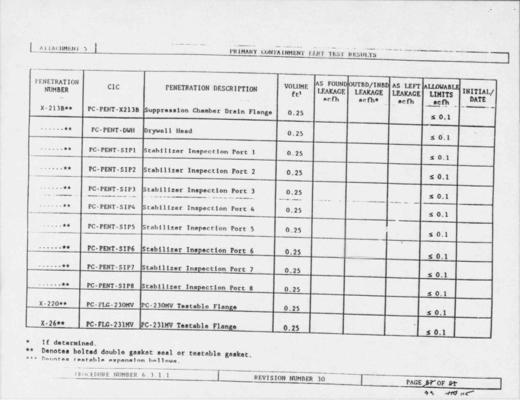
_____________ ____ _ __ _ _ _ _ _ _ _ - __ _ _ _ _ _ .____ ___-__ _ _ - - . .. . . _ -
.,.
| Al I At:llMEtel |3l'itiMAltY t;uNTAINMENT I.lJtT 'IEST ltEStil.TS
|
l'ENETRATIONAS FOUND OUTBD/INBD AS 1.EF'P Al.IIWABI.ECIC PENETRATION DESCRIPTION W ENUMBER l.EAKACE LEAKAGE 1.EAKACE LIMITS I f_,_ acfh acfh* acfh sefh _.
.
,
,.X-213B** PC-PENT-X213B Suppression Chamber Drain Flange 0.25_
s 0.1-.-- -** PC- PENT-DWil Drywell llead 0.25 '
s O'.1 !
------** PC-PENT-SIP 1 Stabilizar Inspection Port 1 0.25 ;
s 0.1
----- ** PC-PENT-SIP 2.
Stabilizer Inspection Port 2 0.25 s 0.1,
----- ** PC-PENT-SIP 3 Stabilizer Inspection Port 3 0.25,
s 0.1. - . .. -.. . . . . - '. - . - - - -
--
- - - . . . . . ..-.
----- ** PC-PENT-SIP 4 Stabilizer Inspection Port 4 0.25s 0.1
. --- ** PC-PENT-SIP 5.-
Stabilizer Inapaction Port 5 0.25 '
s 0.1
------** PC-PENT-SIP 6 Stabilizer Inspection Port 6 0.25_.. s 0.1
------** PC-PENT-SIP 7 Stabilizer Inspection Port 7 0.25s 0.1
.---- ** PC-PENT-SIP 8 Stabilizer Inspection Port 8 0.25I
s 0.1
X-220** PC-FLC-230MV PC-230MV Testablo Flange 0.25s 0.1
X-26** PC-F14-231MV PC-231MV Testable Flanne 0.25'
s 0.1* If determined.** Denotes bolted double gasket seal or testable gasket.*** Danntaa eantabla expan= Inn ha11nwa. ,
,_llu)CEDURE t3 UMBER 6. 3.1.1 | REVISION NUMBER 30 | PAGEJ T OF Dt*
,s a ,,c-

-,.t
L
!
| ATTACllMENT 5 | _PRIMARY CONTAINMENT I.IJtT TEST RESUI.TS
.
];
PENETRATION ,
NUMBER CIC g.__ PENETRATION DESCRIPTION VOLUME AS FOUND OUTBD/INBD AS I. EFT ALIDWABLE.
gti LEAKAGE LEAKAGE LEAKACE LIMITS INITIAI'/,DATEX-25** PC-FLE-232NV PC-232HV Testable Flange ,
y0.25,
-s 0.1X-20$** PC-FIB-233MV PC-233MV Testable Flange 0.25t
s 0.1X-205** PC- Fin- 241AVPC-241AV Teat ahla Flan 5* 0.25 !
\
s 0.1X 20$** PC- FIS- 244AV PC 244AV Testahla Flange'
0.25s 0.1 Ig //SAa* RilR - Fl o- l unV res t alsl e Flange
0.25 !s 0.1 iX-225C** RilR- FIR- 11RV Testable Flange !
;
0.25 I
5 0.1 tX-225B**RHR-FLC-12RV Testable Flango 1
0.25 .
s 0.1X-225D**RHR- FIE- 13RV Testable Flange !
'
-
-0.25 .
t
s 0.1X-210A** RHR-FIE-14RV Testable Flange0.25 \
s 0.1_ _X-210B**RilR- FIA - 15RV Test:ahla Flange
_
0.25 i
X 210A** RHR-F14-17RV Testable Flange__ s 0.1
'
_ _ 0.25 ;
x-214** Ritu-rir-lany 'rn a s. i. l . ri ni,x.-.
5 0,1!
- -
-. -- - - --
.
_
o.2;* 00 #f, o.o s e.g "#{
,,
;* If datarminnd. l**
Denotes bolted double gasket seal or testable gaskett
i***Denotes testable expanaton bellows. .
(_. _
. i i. me r.imni r__ |_ .. L a i
!ni.vinson mninEn 30|
.
rAcr. aHr or,s+ |.
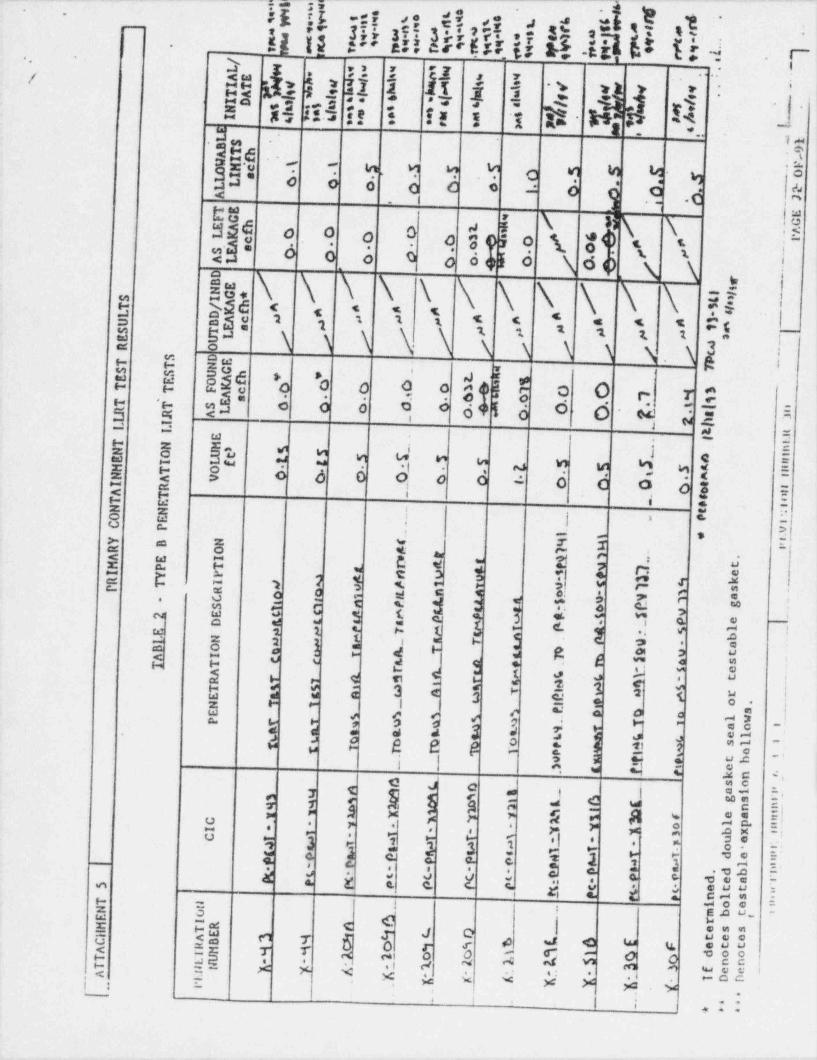
-- -w -t t_ . . _ _ . . _ . _ _
i:13 -::?. n
$[ kf fN !!e fe!!kNh5N k- hN $$ j - [' !
.
g.; .: e at t - gi .s~ >
.
.
'~
i!=h. _3 !.:ii H.2a 5
i 1 = a i,
i ':< =s .I~iiia -
d., gr-3 a .;.e i. .t .z y ]~! $o d.v.- .. -
5 9. ..
-
E-i~ t
.!T ia. 5 9 4 o 9 9 T M 2
-
a.c :'i' o o d o e o : o e c d j
-~
tu. I . .
_,:a
i \ * \ \ !$ }M$ s9 9 0 3 05 9 1. o9 i i j
0 0
43 o o o o' '
is. \, o d el o \ do,g \\ \ '\ \ \\ ?!
,
12 ydd ><i 1 5c. * < < . < s cc I__s as 2 *
s e: i s \ \\ s s s s s u, i
1 s : 2 2 t ti
-
a mE $ 236
.
5 u'* *
d d. 5 o. O. r.. 7 0*o o o. o.:e e o
,,$"o. e o o o oo. .
64 5 6 O w- 4 .Ee .
- - = i5 * * ' ^'4 U ' " *w
, j 5h h bb h U D U $ M U M D DE g g o 6 o o o o 4 o o o o g iq =
U . ,
9 i : -2 iq ,O ts. l 3 *|i -U % >
'
: 9 i''ay y 3 ~
W- L7 4$ $ Ig e. e. Dt W f"* " '
'
0 $ M j 4 $ $ {,e
N ; E E ' '*
{ J j E b [[ k ! i h j $
W c
e = a a : 4 * 38 e a :e% $ U ' - :d k Mg J ag s - e e
t'< 1 3 i
-g i : E 3 e a s e og<" 1 u
2 e r i e s' a o ow e # # # p ? H " -2w y > 3 0 cc ~,4 g .s e a 3 y7s Y j G-
-.
*
d O k b h h u.$q 4 m-y '
~'
| |I e
M N 5 $. C*
. dsN d O .M C
r T C e r m i k bY E'e y M g S. s C we
=Ia c :-
O pK Y 5 gf g oeY Mw *' * P . 0 5
P|* *, er . >o r p <
e 8 :s e . . 'q a 13 3 3 3
. 5rr *- o. -tr e me ro* e, -* 2e
a.. c. . 2 2 3e. 5
c E', ,p a * *a J * ** 4. U % C f :-sec 4, 2": 5 g % C <-4 # :
. . euu :g
7, t a oe -z o i $4 U- ~
E pg C (| eeny J O5 5= " 7 6 o e 5
"$$g s e w g< ;E T T c- 5o o gge4 c' O -s a A 4 *a re * *.I d en n su eeQ 5' # <
'
. .. .: .
M N * * % Y >G $.4 -oc
i : '' .a f .
+
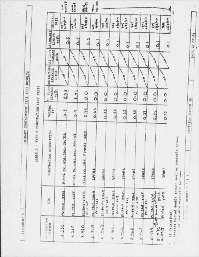
. . _ . . . _ _ _ . ..-- _
5 % el4= eu a tv;- -A
. a- - -
2 5_._ .'
-% -
.. ~.
. -.-
h: .1 :*
s*5 13.:: 5 1 I I
;,Q,1._D. T Pi
'. :. v-v r-. <= r-5" t.1, h. [ T. $7 83 ve h
.
- .
s . _
j.
e i ss,e
,
- W v1 in i m, -: 6 6 0 6 6 ; ; g3 6 6 Oc
<. ~
5e \ \. \ \ \ \ \ \\\ \. ! i
. m
as . < < s sat t t . . . . s s -s ' 2og,
\ \ \ \ \ \ \ \ \ \x 1 s s s i< \
is. \ \ \ \ \ \ \ \ \ i.n sse . < < . < s = <p 2 2
B 5"3g N \ \ \ \ '\ \ N \ \ \
. . .t 2 2 2 2 2- .
x 2 2 ---
n s sw i ,
$ w" $2 5 $| 7 O O O o Ol :
9{ 9 9 0,
m$* G s O O 6 6 O O, O O O Es n4 a;
.._
'< ''
**M .- . e eg | g C
$m a S e.- M,
2 E cV1 Vi m M u u y u w E9 r- o a a o o - . . !E! 3 S
.
0|0 o d d 6 6 6 6 d O 8 i$ $ .= z i E '
8 N I t g! i g
'> a 2 4oc o J p$ N Y & Q 5
u
E D $ 3 I g E j<
. O D *m el ,
| n w aa s c' ,
o -ia > A ;-
W 4 IW - e *2 O d Y 5
,
E.# 6 y i. *o, -
ku O M d & Ep p *
U c a e e d * g m'= - - =, , - 2[ $ $ $u 4 b E3o
} t d 3& C ~'
< v v - * *a == :. : a% { "E. ul e -
c.M C 4 ,v :C Ctad & C C C b NN3-
E!i E O w
> es[J a T z* re .j 7 T M r v FA
s
7 b *T TC *o M "
i, C7 A ". $ #"F -* " EE ;- . y , * *. 4 =i n . e * c- e
_ . c .S
7 .e s. o . g. ;t s., m e. n m; A : 3 xb la s s s :o E a s a s at s -uus - c. c. Q c. s c s ,. c. .5 7 :s m
5 3 r g .c _ |,
"g 4 . . .b r u ocd O W 4 T )- h'$ = , - 0 -, 4 J E
f Eh ?. 1 1 Y' T T 7 Y Y N51> > > J C'~ sr- c:
< : 9 '<~ M e C- *A A >c -6
'
c__ iI i
.
, . ' ' . ~
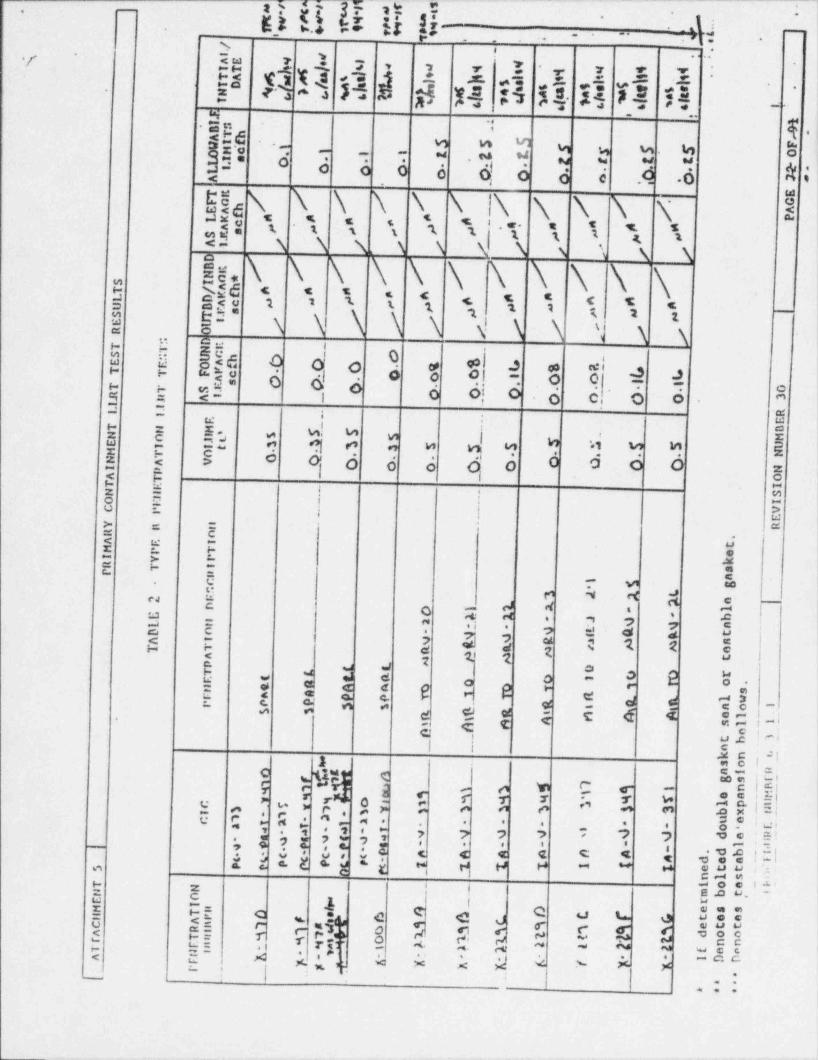
K} x s[,f,.y~ ., s ,
_ _ _ .__ . _ _ _ _--
,-
7 $- '
2.
w.o * 25 g?- .. ..
- -- m, .,.
, -
. .k. 1 t .1 . , -^ .
,. , ,i x :.,q a s .c _=.: -
. s - 2ga e A M t 8 y4 :s 54 4 m4 is.
7 --
, .
4..._ .
b6,
...
M M Mx*o 7. .
.4 w w w . L1 oWe4,
-.
a .: . u .,, w w.
o o 0 o Q o d e .O O ',. . . .. . ,
< .s
e N. \ \ \ \ \ l\ -t
\.,, \. \ N, 3:ss << . . . .8 i. t s s 1 1.\j . ..44 tt < s
N N N N N \ s i \ \.
is \ \ \ \E R.g 2.;6 < < s < < . s = c c< 2 2 '- t 1. 2 1 .
2 !!g 2 s 2 2
-
x \ \ \ N \ \ \ \ \n c ... i
b6 9 O 0 6 $ IS E S div. 4 " O O o eq a e- 1 6 di 0 6 d, 6 6
s s .
''.
e, -
u- .-
$j $e w
5 5 $2g.
d9 9*
'i% " " Ew -z s cz < > c o' o o' o o O O o O- **
=. z-< s i ou e -= = : mQ :: . -u : ,
! >i
: u% E
c:=
a.< w -z A h
E C : M
ac. =E
- vi =-
e 4 4 y'4 <a ,<
c. e -
tO . --o. ,4 d . , o 1 ;s = t - ,
. o 6.i 4 e u
$ $ 3 hh I C * * 3j
2 2 S 1s4 e oi on a wa 2! ! E 2 I 6 h0 ? E
- o .
d T!i %.' a * -
e s e ; e d < ::e e, i, mi
. e-
c .
u .c -
I i C.
.ec -i1 Ie .o. =-
S )*3$ia .
< U!!!- o w C e-f ,' S ;a
r -
% <-, r 5 1 - 5 *c ? w w - c. i. = ':: o o e *' "*,, i:~
C i ?, i '>' 77' ; i f 4 4 4 4 5 EI-
.r .: o. :-' ,. * - - - ' ,
e' '.o . e. 9c c c e e ,e <
%.Es i 1 M H H ''' ~i i E t < -
* Es Str,
g i O e 1 -b '
2 | E4 W. *
C$ E i: 3 i ea mC d ' d U00o
S ED=4 C J5 si 5 p g5 C 6 6 "88
r os t r r rtv e 4 ~ ~ ? :- eaa. .-e2 g- A ;<. ;,*h, . 4 A 1,: iJ e s x xj- ...
.....
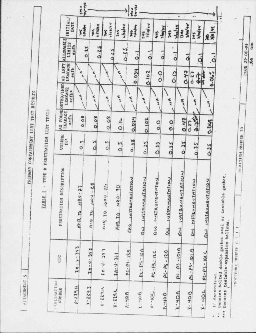
_ - . - . _ .-_.
b.
L.tu s-
i,k -
L 4 .;,
.- ...
,. ,- .
- -<w3 v ,
t t N1 *,
P dil d nd G si GA E1 6>-
:
.n. ,
.ee. s. :. . w,-
' -=
9 0.
.
. . .. . . .
.a
,b2 3' o o d~
o O C C 0. .
.O .C< |i.
e sx x x!.$sw
..o 0 2 ,w r . 76 ,..< s = s ; e: - 1 1 osi e. o 6 66a , *.-< N N \ \ 0 41
is. \ \ \\ \ \ \' \ \ . i,..H g\ h 4 C t E 4~
$ I . I 1 1 1 1 1 1 % 1
4 * C T E k C !m
si !! \1 N N NN s \ s A 1\ . sg
M Q
E E !"w6 3 3 5
i
I '
i
3 I t o o $ cL 5[ [ $a f 4 6 d$ 6 6 d d* 0.$
e 6- - -a-
w!
5 s 83 $ 9 M| $ E N D $ N M 5s"
E t 8 o o o o o.
H< s i 6 6 o 6 e E!.
- aiw
1Z Z* * -
fS. E ,I :
:-> l:= 8 E=
i 7& 2 C JE U 2 2 2 9e %
2 2 1e 0 0 0 %* - q O M
-| o A " C *-. O I"" SJ s E
~, C E C E **Wa 4
i T"9
., - ' 7 5e? 2 9ci- 24, 3 3
-
}w *e 1 3 aZ e e ei! E o s z 1< Lq 7 q q 9 3
- ,un E 3 D I z
$, $ $ $ $ a3 yg .a og * "
" o < e ~b
.-* < c -
2 f 3 2 7 7 au-
e, e, eZw is e E E.
- -a- -=C a 3 3 'l 3 '3 : 1
eo _.
! c a c e o. e uy e!1
4 i =.M C 4|.
t 23 -e u , ee < c d c e 0 w.% s ;; Q t' d-
eE E-
4 t #. E s 2R E
o - o. .-
.U 7 i 4- 6 E E d. i E.
2
. m .j.bk. k Sc , .-
e itg c < u .c|
.e - * c- a a a a o* a. a.- c. c. .a .b
zen b. . guu 8'|H =
E 3 g j ', E'3 M d I
*E +6 c r r 4 q e d EeEe c d oG Sm $ 9iN *
o o o .O O o cuu4< ;~. " N N6- u -f, y . 7 'I T 7 -ggMa . '.
y f~, " . ,, .. . s ee% . *Y <M Y $ Y Y Y -oa"[ ! '_ < i ,
*** <
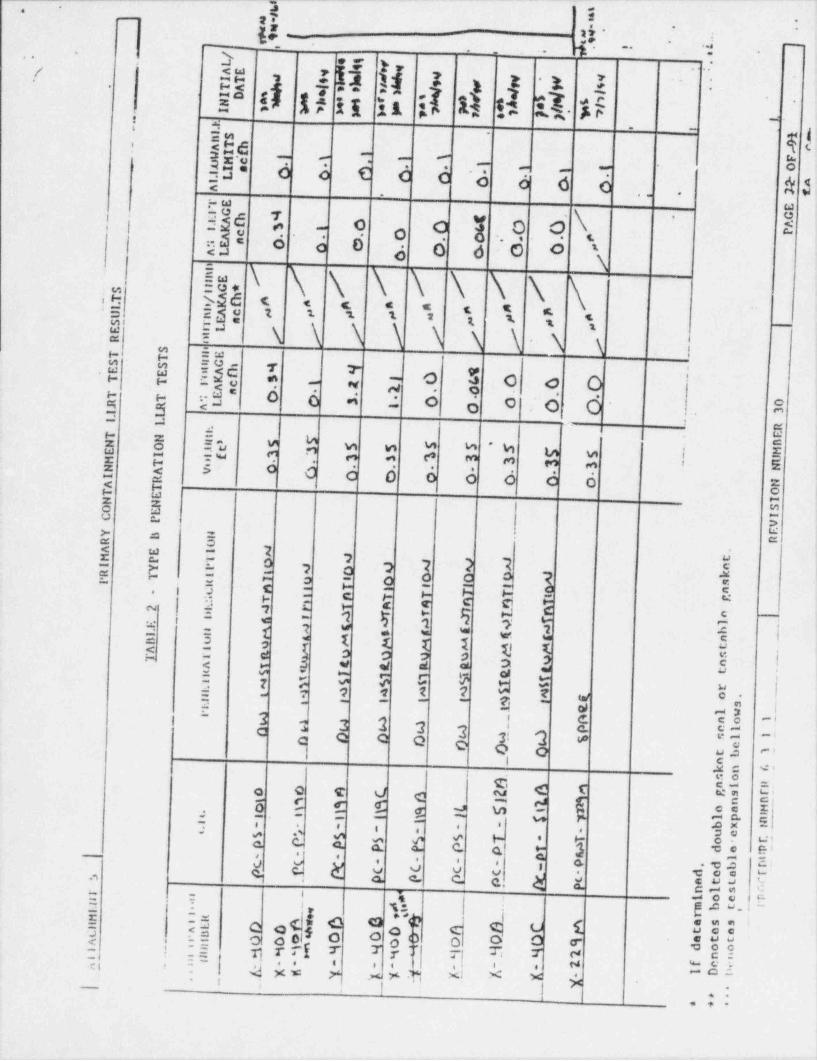
'_
_ _ -- . - .
.a _
{q g- ;. ;
2-- -
,
4,
-. --., .y-
.. .
Ia a>N , 1,
< ss1,I
,. ~-
: 11 11 ; 1 12 Al- . :F. -- - -
5" i. . - -
>t -.a .L d . I:h U.d
' L. -
7 - -- -
h b C b b ' hf f- ,
._ O\
h b<. '
uo
i | '"
Q *.'
1 nd= o o 0 t
o 6 0 o '-<a o\2- \ \ \% o*
iH bdd C < t * * t t a\
ig g3o t i 1. t 2 g 2. g
!! iM \ \ \ \ \ N \ N \ i
g g -
m Emg
U' a !36 1 * .
o 5 o o O.
-
<h b b'
h O bn$ $ o1a .a- -
e 4..
= 5- u E i*
v w w w w w u w i *5 S 2d e M o e F M M e m i 5E h b b b b< P E9 wz G-,-
o 3 -u : *e
E 5* e7< w -
7 uz o -
7 O g 7 2 IO- cp ae n o O o. .e o e.e -a . = - eH .c! d 9 s e _
e- -. p C g- eg c c gy e 7 A *
R H c _w1; - pe 1 7 ;< -M g 7 * * 1 4.
|* = w wE 3 I E T T
* 53h (l ( U.
i< -3 0 ? 8 3 *
'
|d8 -
yr a w w d * w "; ; y c 5 ;= <
5 .,
9 s t 7 d e7 C u~
|? w 4| |
-
$,- - - -a g ~3' 3 e eo l3 2 3 3
-- ii c 50e a3: QC Q Q G Q Q o um " '
-,w a :I
| ;
u= e ' i
eod g ( E7 dio C T d C % s { o5 $h 6 .$ % d MO G e 2 0" 5:.. 7' T 7, - '.; .
m f e F ' * g=# ' e eic. C- c. a. o C. a * 3 .c e ei- , . . o -.
, , ,V g { O V V v '' a me m
C c. 4 C. C. . k 730 U-' 1 ,
o. c-a ';w _ l i, g 4 v.. -
s oo 9= ?E ~
>h Q V ie G NY; f= c c <. o c' U R
. ..,af C O O O O #
u oco euu! 25 h T{5 Th 5 oo'IT ' 7
T| N -c!E. :: e .. . s e
w<I : 4 x, w,'y .x y .Tj x: A,. x $-
1 ;} |- .
+. .-. ,
4

_ _ _ _ _ - _ - . .
_ ..
.
[]i A<.stris.rs |*.
rit lHARY 1:UNTAINMENT l.lJtT TEST HESill.TS}
-.
I,f.11ETR AT10t1E AS FOUNDOUTBD/INBD AS LEFT ALIDWABLENilMBER CIC PENETRATION DESCRIPTION Volytf LEAKAGE LEAKACE LEAKAGE LIMITS MITIAI./,c m ,c m, ,c g ,, 3 DATE
/X-?l4** RilR-FLG-19RV Testable Flango . . . .# T) Iia0.25 o. O / o.o s 0.1"-' O
/X-214** RilR-F14-20RV Testable Flange AI$hu " ' "0.25 o.o / ** o.o s 0.1 %h **
/ qX-214** lllik - FIE- 21 RV restable Flange 7et est= wco / "#0.25'I"'I"OO s 0.1
X-227A** CS-FLC-10RV Testable Flange 0.25s 0.1
_,;j/1A** CS-Fir-llRV Testable Flange 0.25s 0.1
///B** CS-FIE-12RV Testable Flange<
_ .0.25
g 0,1y 7/in** CS-Fin-11RV Tontnhin Finnrn
_.
0.25s 0.1
X-213A** PC-FLC-DL1 Testable Flanne .
0.25s 0.1
X-213A** PC-FLC-DL2 Testable Flange 10.25s 0.1* If determined.
**Denotes bolted double gasket. seals or testable flangen.*** Denotes testable expansion bellows.
IST Engineer Review (Table 1 only):Date:LLRT Engineer Review: _
___ Date:
PROCEDURE tRIMBER 6. 3.1.1 | REVISION NUMRER 30 | PACE Ef*0 eatce .., .

_ _ . _ . _ ___ _ _ . _ . . _ _ _ _ ._. _
e ~- _
.-i -
14 s 4 goc. - =-. .-.
. .
9
:. C'/IR AL" ?LANT ?ICL*IREM.ENTS
:RITIRION 1. O'.*J12 ? STA' CARDS (Taceserv A)
Those sys: ems anc ::mponents :f reac:or faci' :tes which are essential :: *
:ne prevention of ace: den:s unica : uid aff ec: the public health and safety or
:o mitigation cf : heir : nsecuences shall be identified and then designed,
f abr:cated, anc erec:ec :s cuality standards : hat reflect the impor ance of :he '
i1
safety fune::en :s be perfo r=ec. '4here generally recognized codes or standards '
sn design, ester als, f abricatien, and inspection are used, they shall be
iden::fiac. Where acherence :s suca ecdes or stancards does not suffice :n
assure a cualt:y pr:cuc: :n keep ng vita :ne safety function, they shall be
suspieren ac :: :cifisc as necessary. ;uali:y assurance programs. :est
procacures, anc inspec:::n accastance levels :s be usec snail be identifisc.
A snow ng of suffic:ency and appli:soilley of :: des, standares, quality !
assurance pr:graes. :est procedures, and inspec: ion acceptance levels used is
recutree.
R:TIR!CN : . FIUC?.MANCI STA:CARCS (04:eeerv A)
These sys:ees anc :: ponen:s :f reac::: facti!::es vn:ca are essent:a1i!
:: :r.e preven:::: Of ac:::ents vn::n ::uid aff ec: :na tuolic heal:n ano saf a y
:::: gat::n :f :netr ::nsecuences snal; be esignes, f abr::a:ac, ano:: ::
perf:reance stancar:s ::at vt !1 enaoie :ne f ac:'i:y :: vt:nstanc.erec:ec ::.
*2::::ut .:ss :f :ne :s:ast;;:v :: ::::ec: :ne puoli:, :r.e addi:::nal f:::es
:na: :gn: :s . ::sec v a:urs. :nenc=ena sucn as ear:ncuakes, ::rnacces,
f*.:ccing ::n:::::ns. .:n s, ::e. anc ::ner '.: cal s:ce effec:s. The design
kAccencix- - -
plI (}04
4e
_
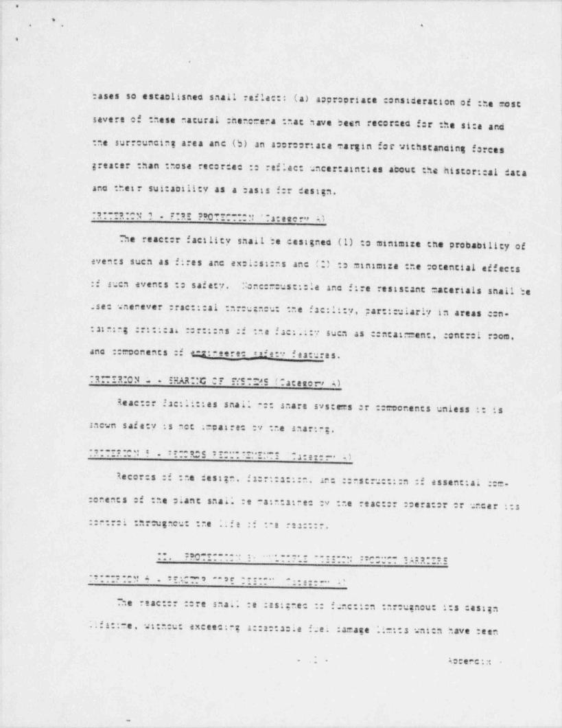
. . _ . _ . _ . . _ . _ . . . _ _ _ _ . . - _ _ _ _ . - _ . . . . . _ _ _ .
2 0
4 o.. aa
.
. e
T
lj
bases so estantisneo snail refle::: (a) aapropriate constderation of :he most|
i
severe of these natural :hene=ar.a : .at have been recor:ea f:r the si:e ana
:ne surrouncine area anc (b) an acercortata =argin for vichstanaing forces
greater than : .ose recorde :: reflac: uncertainties about the histor::a1 dataano :hetr sui: ability as a basis f:r design.
. ,. . . . 3. . . n. .: , r. e. s.. e.s.o..o,.....-.. ,.a. nee ., :). . . . . . . . .
?.te react:r f actlity snail be cest gned (1) :o ministre the probabilicy of
even:s such as' fires anc ex=1:st:ns anc (2) :s msntatze :ne :ocencial effects:f suen events : safety. :: enc:==ust::la anc fire rests: ant =aterials shall be
ase: snenever ::ac:::21 :ar:uzncu: :.e ise:11:y, particularly in areas c:n- !!
i
:st e:ng ::::::ai ::::::ns :i : e .Jac: .::y suen as :entat:=ent, :cntrei room, '
anc ::=conents :f e.:2: eere _'ife:v festures.__
R! IR O N :. - 52.AR-'C O T ?:"S 25 ' 04t eser i A) '-
,
1
React:r fac lt::es snal.' :: anare systems er ::nocnents unless i: is 'i
Jacun saft:y :s net :=patre: :v :.e snar: z.,!
i..S. . . ;. ; .a. .; s ; - -a g e ; ;a. - _u. .;.. = ; .a...._.) )I. . .
. . . . . . ..... .
Recor:s :i : .e destzn. f s::::2 ::n. an: ::r.stru::::n :f essent:ai ::=.:or.ents :J :ne siant saal; :e air.:str.e: :v :ne reac::: Operator er uncer 1:s.
!
::r. ::L :hr uge.cu: ..e ;;fa :i :.e ess::::.
.. ; ,O . . . . . . . . . ., .............. .;, .. . , 3...;;... . . . . . . . . . . . . . . . . . . . . . . . . . . . . . . . . . . . . . . .
?. . *. *.;. *. a s. e 4 ; ; ;* .w g. - ; g=..?..==.=... a..... .s. ,.... .......
he reac::: : Ore snai. :e :estzne: : fu.c icn -.reuanou its castgn. . f 1: -'e , u t t .:ut exceec: 2 2:::::2:le fuei :amage *i=::s unten have :een.
. .; Accere:: -.
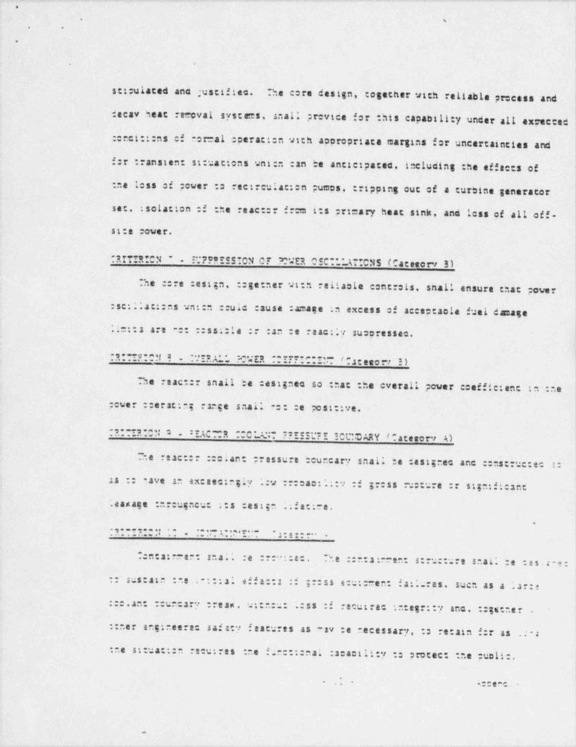
. _- - -. . - - .- - - - . . . - . - -. .- - - ~ .
O 1
1
s 1'
. .
6
. *
st ;uisted ano ;ustif ten. he core design, together with reliable peccess and
decay heat reuvat. systems, saal' pr=vice for :his capabill:y under all ex=ected ,t
: r.ct-!:ns of no: al :perati:n with aopropriate margins for uncertainties and
f:r .ransten: situattens unt:n can be anticipates, including :he effec:s of
ne less of ;cwer o rec:::ulat::n pumps, : ripping out of a turbine generator
set. : solation :f -he react: f rom 1:s prt=ary heat sink, and less of all off.1
st:e :over. 1i
RITIR!CN * . it.*???!SSION CT C'4ER OSC-*.* AT'CNS (Cateserv 3)
he ::re :esign, :ge:ner vt n reliaole controls, shall ensure cnat power
:se:.'.at::ns unt:n ::uid cause :amase :n excess of acceptacle fusi damage'
*L : s are .:: :ss :le :: :an :e reac:.'y suopressec..
I. ., , c. . m. ! a. ***?....%. m. . '. .2 . . ?. .? ?. *. e. *. _ s. ==..ra. a t ese :-r 3. )* * *
s. . . . . . . . . .. c.
1
he react: snall be :esignac so ::ac the everall power :cefficient :n :ne !
power :; erat:n; range snail :: :e ;ost::ve.
j, . . . . , . . . ..:AC R .C . . ... ........ . .C t CJ. Y ( a t e eo rv A) J.....:..... - .. .. ._s.. . . 2 :: c .- - : . .
i
7.e reac :: ::c ian pressure :cun= arf saal.' be dest;nec anc :: s: rue:ec s:
as :: Save in exceecingly .:v :::cae: .'::e :f gr:ss ::ure :: si;nti:: ant
*.easage :nr uencu: ::s :est;n .'; fat: e..
..,..........,..,...p.e..._ . ,. . . . .... . . . . . . . . . . . .. .. ..... .. . ..... .
~
:::2:- en: snai. :e :: t :a . T.e ::.:a:- en: s:ru::ure s .al' te :e s . -:.
:: sus:ste : .e ; :::41 ef f a::s :i gr:ss e: ::ren: fa:.*ures, sucn as a .'ar:e
:::.an ::uncary tream, ut:n:u- .':ss :f re utre in:eer::y anc, ::gs: .e r .
:: .er ang:reerec saisey f escures as sy :e necessary. : re:ain f:r as .: :
: .e st:ua:::n recu res :ne fun::::nai :acacility : p rotect ne puoli:.*
k* t TC . ~* *.
.
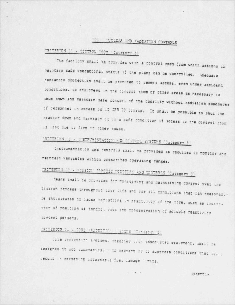
- . _ _ _ . __ _ _ . _ . _ . . .. _. _ . . ~ _ ~ . _ _ . _ . _ _ . _ . .. _ _ _ . _ _. . . ~ , ___ _qJ
. . .
.
, ..
:::.!.t*C* IAR ' ND S ADI AT:0 N CONTRO L5.
_R...3...cu.. ..
. .u.. .s. .n. t :. .c. Cu. . ' * a . =. e . r 2. ).. .
.
he f acill:y saal; be ;;:vides ut .h a ::ntroi cca f rem vnten_
accions ::
tatntain safe coeractenal sca::s :f -he plant can be contro lled. Adecuate!1
i
raciac::n retec:::n snall be ;;:videc :s per=t: i
iaccess, even uncer acciden: ;
:enci:: ens. :s ecut: ment ii
:n :ne ::nt:01 ::om or ccher areas as necessary :o1
shuc :cun ano maintain safe c:n:::1 :f :he f acili:y vichouc radiation exposures!,
:f personnel :n excess of 13 TR .0 l!=t:s. *: snail be possible :s shuc :nei,1reae::: d:vn anc main:atn ::
in a saf e ::noi:icn if access :s :ne cent s1 :::m:s ;:st :ue o fire :: ::ner :suse.
|
.R.. . 3y. .. .........ye....s.-.-.. . 3 . . . , -. . r . ). 2 . . . . . . s .. . . .5 -_
,. . . . . . . .. . . , ... . . . u. .e f.4.eeorr 2. ) i
.
.nstrumencac::n anc c:n:::is snat .:e p : video as recuires :: i.
|ont:c: anc
Saintain vartaoles ut nin pres:::beo :perac:ng ranges.
_ q . . e. . .,. . y . , . - ..:.:...; : n. e. .. .-.. . .. . . . .r. .:~. . . g e. s.,.3 . - . . . .s.o e_ : < r.a e ec.r ) i
... . .--
. .
,
Means saal.' be :::v:dec f:: :nt :::ng ano eate:ainine conc::1 Over : e1
1
. ',
fissten Or: cess : . :uencu: :::.ife anc f:: all ::nc::icns : hat :an reasonas..
:e an:::::a:aa :: :ause is::a::: s in reac:ti.:7 :f :.e :::e, suen as : et:.
2.
::en ei post::en :i ::n:::i :::s anc ::nce .::a: ten of soluble reac:ivi:y:ence:1 possens.
.3. . ,. . . .,. r. y ..-....s_- .:....-........ . ..:. .. . .,:. . :s. . . .... .. .. .. ..
:::e ::::ac::: svs:ers, ::ge:ner .:::assoc:a:a eeu:: rent. snal'.:s
:esignec :: a:: :::::a:::si v :: ::even: :: :: suporess c nci:i:ns ::at ::...resui: :n exceec e a: :: 2: 14 fuei :amaet .iSt:s.
. .. . Ao:en:: x
_
, , _ - -- _ ~ -,
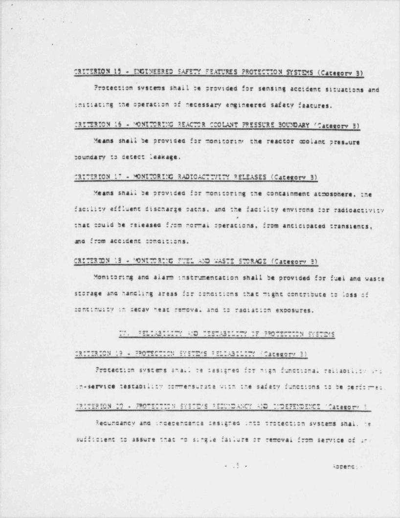
- . . ___ __ _ __ ___ _ _ __ . _ _ _ _ . _ _ . . _ . . _ . . . _ _ . _ _ _ _ _ _ _ ___
.Q
. . ., .
\*
i . .
CRI*IRION 15 - ISCINEERED SAFIN ??ATURES PROTEC*!ON SYSTD8.5 (Caceserv 3)
?rotec: ten systems shall be provided for sensing accident situaticas and
in:::ac:nl : e operac:en of .ecessary engineered saf ety f eatures.J
CRI"!RION 16 'ONI OR!!!C REAC OR CCOI. ANT ?'. ESSURE 3OUSCARY /Caceserv 3)
Means snall be providen f:r moni:or:nt, the reactor melant pres ure
boundary :s detec: leakage.
CRITIRION 17 - MONI"0RI:C RADICAC-**II?! 5.EI.IASES (Caceserv 3)
Means snail be providea f:r on::cring :he containment atmosonere. :ne i4
fac:li y affluent disenarge :acas, ano -he fac:lity envt cas ter radioac:tyt:y.
:nac ::uld be releaseo f t:m ner al :perac: ens, f:cm anticipated ::anstants,.
ano f::m ace: dent :enci:::ns.
CRI IR DN '.3 'tNI-'''R :C 77I* A:C *'ASTI 5"'OR.3CE (Catesorr 3)
Mons:or:ng ano alarm :nstr.:=entacion shall be provided for fuel and was:e
s:: rage anc .ancling areas f:: ::ne::::ns : hat :ght c:nc; bute := icss Of
:ent:nu::y in :acay tac reecva; anc : racia:i:n excesures.
. . . : t. . 2. . . - . ., :.D ..e...3r...., .r. 2 3. D . _ r. . . . .t .. e . c e... . . . _ . . . .. _ . . .. .
R . . .,. C.4 3 :s. 0 . e. r. . . ..... :.v.e.... e_ : t_ :3 5 . . .i c.ateverr :.). -.. . . . . _ . .
?:ccac:::n sys:= s s .ai. :s :ss:;nec f:: n:ta fune:::nai reitaotii:. 2;
:n-service :escastli:y ::-- eesur::e v::n :ne saf a:y funett:ns :: he pe rf:- e:.
. 3. . . . v..o. r.e s. .9 . .:s. .o . e_... . . u. :v. e. . _ e : r .,. . .s .C'.' a. ' " . '.C e r.'.'.., r''C'- ' ". a : e s o rr -. . . ._ ... .. . . .. ..
Recuncancy ano : ce:encence :es:;nes :n:: ::::ee:::n sysca=s shal. e
suf f t::en: := assure na: : s:-21e fa: lure :r remevai f m sertice of 2 .
.i A:: enc.- -

.
O
. .
. .
.
::mponene or channel f a system vi11 resui: in loss of the protection function.
he recuncancy provideo snail ir.cluce, as a tatmum, tuo channels f protectionf:r eacn protect en fune::en o :s served. Differe- principles shall be used i
aners .ecessary :s acnteve r.:e :ncependence of recundant inscr.usentacion
::moonents.I
;
"RITI? ION 21 - 5*!C*.I MI*_'.*RE 3EFINITION (Catemorv 3)
..ultiple f ailures resulting f rom a singis event shall be treated as aw i
single failure.
2!TI?*C N 22 - SI?AS AT*0N CF :*0T!CT*0N 4.ND C*NT201. NSTRUMENTAT'ON svS;ce.SC a c e se r-i - 3 )
?recac::en systees snail be separatto f r:m centrol inser.: mentation systems -
:s :.e ex: enc :r.ac fatiure :: : moval from service of any c=ncrol instrumenta-::en syste: ::::enent ::
:Mannel. :r of those common to control instrumentacion
ana precec::en ::::uitry, leaves incact a system satisfying all requirements,
f:r :.e pr::ac:::n ::annels.
.......v....2,-.,...., .,C. ...-.! .....!S .,,....-, 3 an.3...~..,;,R. 0.er.. ..
- . . . ... .. un.. i . . _ . . _ _ 5.. . . . .. .:. . e . .y S.
1 escr. i) . . . ..
\l
~..e effnets :f acvarse ::nct:::ns :: vnten : c ncant ::annels :: p ro t ec.i : ::n systees =t;n: :e ex=osec in :: =cn. et:ner unser orma A ::ndt:: ens or1
nese :f an acts:en . snai.' n:: :ssu.: ; .:ss :f tr.e ::::ee:::n func::en, i
'
. e. . . . . ;. *..a..g . e ru.rs.e .?.er. v. .#. *. ?. :. ;a t : n. . ?. . . . . y e.v. e . .=s. e ( r. a c e t o . 3. 3. . , -..a .. . . . . . . .
. :..e even: :f i:ss :f a;*. :f f st:a :cuer, sufft: tent al:ernace sources
:i ::uer saal' :e :::vt:aa :: :e:- : : :ne recuires fune::ening f ::e p stec..
:::n syscoes.
1
'
Accenc x A.:- -
.
, - , . .
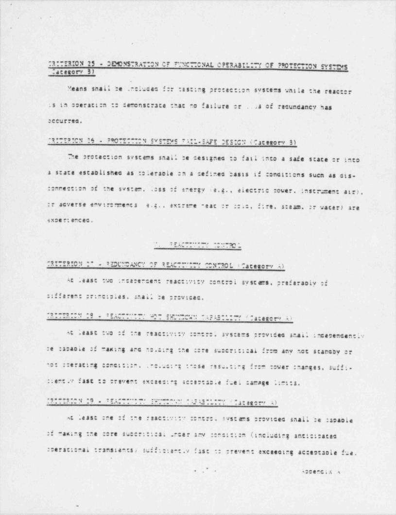
. . .- . . . - . . -. .. -. -
.
||
|t
.
.
|t
~2:TIRION 25 - 3EMONSTRATION CF TTNC- CNAL 0*ERASIL T' 0F **0TECTION SYST*5-acetot-i 3) ,
|-
i
Means snail te .nciucas f:: :es::ng pr::ee::en syste=s untle the reac::
:s in ::erac::n :: econscrste :.at no fatture er . 22 of recundancy has
:ccurrec.
. a. ,. . '. '. . '.C N. '. 6 2 8. 0 *. ?_ * .~.~. N. .V c.. W.C. ? *u *_ . : e'.c~ 2 ' r.* ?.C".. t' r. .a c eso rv 3 ). . ..
-"ne r: cec: ton systems saal' be cesignec := fati into a safe state r into.
a s:a:s escaolishec as ::lersole :n a :efinec ':asts if ::nci:: ens such as cis-. . .
.::nne::::n c :ne svs:em. .:ss :: energy te.g., etec:::e :ever, ins t ru=en: a t r s' .
1
:: acverse env::::: ents e. .. ex:re e . eat :: ::10 fire, s:aam. :: vacer) are !
<
-
i,
ex:e::encec.ii
. .,.............'O._ ,. . . .... .. . . . . .,
. g. e. . e_ u..r.o : . . s. zgt ~ . xc r. e. r. g e_v. . . . .~. .i n.a. s . .to .r. i , 4 e , e e r .s. ). . . . a. . . .
Ac ; east :ve :nce:encen: reac::et:y ::ncroi syscams pref eraoly :f
:if f eren: pr:ne::les. saal* ':e :::vtcec.!I.
..,.....;..,.w.._..... . , ...._,... ........ , ,.a:ee,rr . . , 1........... .. .. ..... . . ..... .... ..... ..... . ..
at ' east :vo :f : .e reac:: ::7 :: :::i sys:e=s pr: video s .at. ; ce:encen:r..
.. . 1..
:e :a:acie :f maning anc :.::ng :..e ::re su:cr::::a1 fr:t: any .c: scanoby ::
no: ::eracing ::ne::::n. . :.u:: ; : .:se re su.:: g f::= ::ver : .anse s, suf f: .
::en:.y fas: :: :reven: ex:ee:: ; se:e::s:ie fuei :acase '.: ::s.
9. . . . . . . y. .g =r..=...... ...t=-a.,.. . . : : =. . . =. f / =. 3 . , g , ,. .).;.. ,. . . . . . . . . .. . . . . . . . _ _ . . . ,
.s t .eas: :ee :f : .e reac:: ::7 ::ntr:i syst ems :::vtcec snall ':e :a:aole
:f an:ng : .e ::re su:::::::si ; . a r at:v ::n:::::n (including ant:::: aces
::ers:::nal ::ansten:s> suff:::en:.v fast :: :reven: exceecine ac:::: sole fue..
..
. . . s:eeec:4 4
-
_. . ___ . - _ _ _ _ _ . . . . . _ _ _ _ . _ . . . _ . _ _ _ _ . ._ _ . . _ _ . . _ _ . - ..
.
. !.. .
A 'i
.
d
, . -
4
1
!
: - damage. limits. Shuecoun margins rreater than :he maximum worth of the cost4
aa
.
eff settve centroi roc *Jnen fully withdrawn shall be provided. l
11
1
, RITI2!CN 10 . :IAC~*?t Y MO'.ZCWN CAP.43ILI?! (Ca- : ~r 3 ) !1
1
(At least :ne of ne reae:tvity :entrol systens provided shall 'ce capablei
:f making and holding ne c re sueert:tcal under any conditions utch approcriateargins f:r cont:ngencies.
RITIRION 31"IACT!*/I*v CONT?OL SYSTD45 MALFUNCT*.ON f Caceserv 3)
he reactivt:y :entrei systems snail be capaole ci sustaintog any single
aifunc:::n. suen as. .nciannec ::n::.usus vtchdrawal (not ejec:::n) f a
:en:::. rec. vt:neu: :austng a reac::vt:y ::anstant unten ::uld resul: inexcescing ac: ::acia fuei :a= age .i=::s.
1
i
"RITIRION 32">Y *MW * EACT-**-~f ~4RTM O F O NTRO L A005 (Cateeorv A)
.
.
* imsts, unt en incluce ::nstcaracia margin, shall be placed on the eaxt=ue.
!
reac:t et .v vor- . :f ::ntrei :::s :r elements anc :n rates at uni reactivt:y
:an :e increasec :: ensure :nac : e :otential effects :f a succe.. sr large<:nant e :f reac .tyt ty :ar. net 21 :.:::ure :ne reac::: ::oian pressure ' ouncarv I$
c
:: it) ::sru:: :.r. ::re. ::s su::c; stru::ures :: ::..er ressel :n=ernaissuff:::ently :: ::nat :.e effs:::veness :: emergency ::re : o ting,
|
f.. : e.:.. . . e. . .- . . . . :. s. e .t . . .g e :.
. . s . . . C L". *. n* iF. -
l1
-.:. . e. s..r. y. n. . ..e.. .. .. s. . . r. .. . ::e..e.:..e .r.L.- v. . .s.2.:..s. . . . . <. acne, , ,.):
. *:. . . . .u na. . I
. . .
|1..e rese :: :::is : :ress.:n : uncary shal* be :acaole :f ace:meccat; :.
vs:. cut ructure. 2nc v:::. :ni .;:::ac allowance f:r energy absorption - ::.;-
: '. a s ti : :si:r at.: .. :.e sta::: anc :veamte 'cacs i::esec :n any ':ouncarr.
: a.::en:: a. .
.
_-_ - . - . . - . . . . - . - -- - _ . - - . - - - - - . _ . . . . - - - _ _
.
.
. .
f- -
,
|
.
:omeonent as a resui: of any inaevertent and sudden release of energy to che
:*.olant. As a design reference. :nis sudden release snail be taken as that
vnica vould resuit f:cm a suaden reactivity insertion such as rod ejection
(unless prevences by post:tve teenanical means), red dropout. or :cid vacer
addition.
. RI !!!ON '% . REAC CR 000!_VIT ?RE55URE 3CUNDARY RAPID PROP. scat *03 F A!'TRE;
?REVENTION t Cateserv A)!
| he reaccor coolant pressure boundary shall be designed to minimize che
procaotiity of raptdly ;;ccagac:ng :ype failures. Consideration snail be
5tven (a) :o :ne not:n.c:ugnness :::;er:tas ci materials extencing :s :he
upper snelf :f :he " harpy ranst:::n curve. (b) :o the scace of scress of
cacer:als uncer s:act: ana ::anstant .:acings. (c) o : .e cuali:y c:ntrol
specifies f:r racert als sna :=penene f abricacion to limit flav stres, ano
(d) :s :he pr:vtstons for centrei over service cesserature and irradiatica
ef f ects unich ay recut re perati:nal restrictions.
"R O ? "0 !: * ! :.EACTOR 7:0 *_A :T 2:IE3TRE ICU!CARY 3RITT*.I TR AC*TRE ? REY!MT :::~. 4 : e ec t - ,,
'.*ncer ::nc :::ns uners reac::: :: iant ;; essure bouncarv sys:e= ::mponen:s
:: s::ue te :f ferr::t: acert a.s av :s suojec:ec :: :cc encial '.:act .a s, suen,
,
1 .
| as a reac::v::y-tecuceo ':aate;. serr::e :ee: era:ures snai' be a: ' ease '.Z~~. . .
!
| acove :ne .tl ductt'ity ::anst:::n :0!: temperature Of :ne ==:enent racer: 3..o|
| ;f :ne resui::ng energy release .s ex:e::ac :: be aoscr:ec :y :iast:: :ef:- 2i
:::n :: s0*? ace re : e :0! ter: era:: e :f : .e c:=penen: a:er:si :f :ne
resui:::e energy sicase is ex:ec:sc :: :s aosorben ut hin :ne elastic s: 2. -
energy range.11
'4:: enc; >- . .
- -- ._- _- . . . _ - _ - ..
-- . . . - .- _ . - - - . - - - - . ..
.
.
-,
!
l1
. g. 6 . .s. t.o y 1. 6 - t r.AC . "R ". .O ' . .'.4*. * *'' *UR. '. '.CUN. D A RY. : 'U. I'm *.'. *._s' .NC'.O. a c e e o rv s) -
--_ . . . . _ _ _ .. -
Reactor :colant pressure :cuncary ::=conents shal; have pr:vtst:ns f:r t
1
nseec::en, testing, ene sur:et t.ance by sopropeta- eans to assess :he..
1s: rue: ural ed leantizn: :n=egr::y :i ne :ouncary Octeconents dur:ng -heir,
;
iservtce lifet:=e. Ter :he reac::: vessel, a =acer141 survet11ance progrste
::nicr t .g with ASTM-E-1SS-66 snail be provideo.
I .. :s.C .s.ers..e.D c_ A :.w.v. e. r_ ATUR ES_ . _. r
l
|,
. 3. . r, IC y. , . ;. g u.. e.2. ._ D :.srT_.'. ? ? u' *". I. .' .c. '. .A S t _: 7. '. t D e c *tC".. ( "_ a t e e c ev A ) I
!,. . . . . . _. . .. --
.
:.netteeren safety f eatures snai. te :rovides :n :ne :.ac:li:y s :ack ue ne |.
saf ety :roviceo :v :ne ::re :esign. ne reac:or ::olant pressure boundary, ancnet :r :ee::en sys:e=s. As a :n: u=. suen engineeres safety features shall !de cesignec :s :::e vt:. 4any s a:e reac: r :colant pressure bouncarv break ue ::
ana :nclucing :he :::cu=ferent:ai -upture of any pipe tn that boancary assuesne !
JnoOst C e2 CisCnargt ft: Oc n enCs.
..g...3..c3 .. , :._; ..:......~. . .3 . _ .: . .:. . . . . - ; : s. c . . ,;_;_;.. r). :....r..:a t ete r . . .. .. .. .. _ , ;;.~. ,;c ..r ...
.i ' ene:neere safe.y fea:ures snal; be :esignec :: :revice n:gn func::: a.reit aet ': y anc reacy :ss:2:: . :: .-.
.. :e:er=:nteg :ne sut:acili:y :i a fac:...
i:: 2 crtsosee st e. : .e :a;ree :f re.:2.:e 2:en anc 2 :: cance -f : .e :- ere--
anc e stneerec saia:v sif::: : :v - e systers. ; clucing engineeres safe:viascures, 211* be :nf..e.:a: : e A.:vn an: : .e :e ens::ates :erf:: anc e. -"
:2:a::.'ity an rei:a:...:. :: : e sys:ers. 2n: by :ne extent :: unten :ne::eract;;;y :f suen sys:a s :an :e :ss:e anc inscec:ac vnere sopre:r: ace
:ur:ng :ne .:fe :f :..e :ian:.
..- - ;::en::x--
-
,.- - .- - . . . . - . - - - . - - . - - - . . - - - - - - - - . . _ . . . . - - . _
t .
). .
.,.
i
1 *
I
. 3. . ,. . e. g go y 3 9 . m_ .e. s.., ". :C ' ' W. . e..2 2. '. t. r.'. C I.NE.?.'. .'D .:.v' *_~.". . . .A'w*R'..' (Cac esorv s).
. . .
.. *
Alterna:e cover systees snal.' be prevtdea ano destinen u::n acecuate
:.ce:encency, recuncancy. :acact:y. anc :es:aot il: - : per t: :na functient.erecutres :f :ne enerneere: safety features.
As a = tat =ue. :ne onst:e powersystem and : .e of f site :cuer svs:em snal' each. independently. ;rovide this
:acac::y asstaning a f atlurs :f a s nzie ac:: f e ::=ponenc :n esca :cuer svstem 1
!.
. .
:RITIR:CN ' O '. v!S5**.E ?ROTICT*0N r ac egory ' A).
r ::ac::en :.:: enetneers: sa:e:y :.e a:ures snail .:e previced against.
.
.
.a:,e::s ancsst.as :.at : n:
:v act: |.
resui: fr:m pianc ecut: ent failures. I
.3.. .....- ; -. . n.c.... ...r.,-
: ;;.. ... . . .s . . . .r r. e. .:.. m. . . :. . :. : .:.:,. .s. ..a.NC ?. v ***. ..s. .AB *. *.*. ~. .' P.t e to r i ,' )
Ing:neere sa:e:y :..
aacures suen as e erzency core ::otine ana ::ncaineen:.
neac remeval systems snai. ;;:v::e suff:::ene perior=ance cacaotit:y :s acc e.
ocate par:1ai
.
.':ss of ins:allao :anac::y and sc:11 fulfil; :ne recuired saie:yfune:::n.
.ss a =tn:=um, esca enetneerec sa:.a y :.aature snal:revice :nis
. .
recut zsc saie:y func:::n assu=:rg a ..:a:..ure :: a s:ngle ac::ve ::rt.conent..
1
i
<
..,...R.... ........:.,..,._ .. .. ..._..... ... .. ,...e. .... . A3 . . . . ..a eto rv,
. . . . . . . . . ..~...r :.v i. .s.. --l. . . . . . . . .. . ... . .,
Ingineerec saf ety f estures snai'. :e :estznes so : a:: .e :a:ae:'::y :f
;
eac . ::: enent ano systa= :::erf::- : s recut res func:::n :s n:: :::atree bv
. . .n..e e..e .s .a. s . ss.o.'... .a.. .<--'. e.... .. .
i. . . .. .
...__....I =.. . . . . . ...:.... 2 * = . . . . . . _ ............ ..,....I.. .n.e .~. . . . . : e ,., . .. . '--......... . . . . .a ..-
Inst .eerec sait: r f escures snad :e :es:znee so :.ac snv 10::: .:i : .e
a 2:neeric safe:y iaacures .n : . tznt ,
.accentuate : .e acverse at:ar.ef f ec:s
:: : .e :ss ::. or a6 :: .:nz :s ave::ec.. .
. .. -
40:e*:.X -
_
. - . - , _ _ , ,
_- - - ~ - - - - - .. ... -
l*
.
. .
.
:.
:RITIRIGN :.1. - OtERCIMCY ~~RE :C'"C itSTD!S C)JABII.: ? (Cacatorv_
A) ||
At least :90 e ergencv ::re ::ci: s sys tems, preferaoly of diff erent cesign .
pr:.e .,ies, esca ut:n a cacaot.'i:; f:: ac ==plishing aouncanc emergency core: olins, snall be pr:vided. Isc . ere gencv core cooling system and the core
i
snail be cesigneo :s prevent fuel anc : lad damage that would interf ere with :ne
emergency : ore c:eling fune:::n anc :: l!=t: :he clad recal-vacer reac: ten :
.egligible amounts f r all st:ss :f breaks in the reactor coolant pressure i1
bouncary, :ncluct ng :ne deuole-enceo ruocure of :he largest pipe. he perfern:-
,
ance f eaca e=ergency ::re :::.:nz syscam snal' be evaluated conservatively : ..
esca area :: .;nce r:st n:y. ..ne sys:e=s snail not snare ace:ve c:eponents anci
.
|
|
snal.' noe snare ::ner f eatures :: ::::enen:s unless i: :an be cemenscraced :na: l
1
i
'a) : .e :soaotli:y :f :ne snare: fsa:ure :: =ceconent :o :erform i:s reautrec
func::en can te reactly ascar:2: rec :ur:ng reaccoe cperacton, (b) fatture of4
!:he shared f eature or ::=conen: ::es ce :niciate a less-of-coolanc accident. |:
anc (:) :acact'i:y :f :.e snare: feature :: ::::enen: :: perf:: ::s reoutrec.
fu.c:::n :s .:: : atrec :y : e =ffe::: :f a .':ss-of-c::ian: ace: dent anc :s:- ;:s: :urteg :.e ent: e :er::: :n; s : n::::n :s re ut rec f:ll:ving :nese:::en:
..,......a......t, . . e ;; r. . . . .g . r -.;>=....".- . . a
. . o. r. _ .. q =-. g -. t. . e_.s.c_ .a e ese .. )a * *
..<a. ... - . . . .
..
Oesign ;;:v:s :ns sna.. :e s:a :: fa::.; .t:e :nvst:a: : s :ee:::n :f2. .
::::::si par:s :i : .e e er;c: :::n :::.; ; sy s:e: s. . cluct g reae::: resse.. .:erna.s anc va:er ~.e:::-- :::.as.
.
.4
.- A:perc:x.
6
, - - . . -. .- - - - . - - . . . - . _ - - .-_. . . - . - . . - - - . _ . , . - . . - . . . . _ _ _
.
.
. .,
.
| . .
|
|,
. ,. . '.*. * *. '.C 4 6 . "_ . . . ". C O r. ".. .'.'. 0 '"..C.' P.O R .r C*.O ' *.N. C e.v. 5 $'"_ .5 ww. .P0 N. ET. .'S (..ac ese rv M' aw. .
Design :cvistons saal. be ace so : hat ac:tva c:coonents f :he emergency
:::e c:oiing systaes. suen as pu==s anc valves can be :asted certedically f:r.
::erantli:y anc recu :sc func::enal perfor=ance.
. 4 . . e. ,. .. o .: . . . n. . . . . . - e. ;. m_.e w. ...C'' *. t . .*,.O!."..C. e.v. *. ".'. ( ". a c eso r'.+ ' ). . . . . .. .. . . .
i
A cacaot li:y snal" be ::: vices :s : esc periodically the celivery caos' ili:yo.
:f -r.e emergency :: e c:oitsg systers at a locacion as close to the core as is
::ac:::al.i11
I
......._.o...._:; . ; , ., , , , m_ . e. 40 .'". .C.' ". *. R ' ' . . ". '. *. *. *.. j.. . __ . , e y . ,.n...... .;..,_,...s.....~.,..... . . . . . . . . . . .. . .. . .
sY STD'S * 2:eee rar -. , !
:
A cacao:~.i:f sna;'. :e Or:v::aa :: est uncer ::nct:: ns as el:se s casten |
as ;;ac:::st :r.e :::. :: erat :na. secuence :nac -cuid b :ng - .e eetzgency :::a. . ..
::oling systars in:o a :::n. ; :Lu::ng :.e :ransfer : ai:ernate power sour:ss.
?.I' ??.IC'l M . -*N'"AI!3'ENT ':E!*';!! 3 ASI S ("ac esor r O I1
".e ::ntaineen s: ue:uze. . .ciu::n; a :ess :;enings anc pene::att ens, at:
snv -etessary ::nta:neen: .e a: tr eval sys:ars saal. :s dest;;.ec so ::at : .e
::ntat : en: 3:: ::ure :an 20::--::a:e :::::u: excesc:n; : .e cast;n 'sanage sta.
: .e ::sssures anc :er=: era:. s s issu.::ng f r:- :ne '.ar;es: :recibla energy
release f:U.:et g a ;:ss..si..:::.an: 20:::an:. .nciuct.; a ::nsiderasie art:-
|.. . 4.as. a n. . a .2 . . ..e aL.,<aca. .. ..... ..e ..a.:: ..ac....s ...a. .... ..... 33 3.. . . . . . . ..... ...... . .. . . . . . . . . . . . . . . .
'
::nsecuence :i f at..:re :f arer;e : :::a ::: .ine sys:e s,
......... ,, , .... ....... .e...._.................:.-..3 , . , g , . 7, ns. . . . ... . . . . . . . . . . . . _ .u . .,
. . .. . . . .
? : n:::ai '.:ac car : g :::::.en:s :i farr::i: acertais execsec :: ,
ex ernal env:::neene sna.. :e seie::ac != ::ac ::e:: areeratures uncer :--
1i ::'
.::ent :::.. .
. - - - . .
. . . - - . - - . - .-. . -.-- - . . .. . _ - . .
.
.. . .
.
.
:perating and testing c nctetens are notless than 30*? above at t ductility
:ransition (:CT) :emperature.
1
TRITER!ON 51. REACTOR C30LANT sgregt c e noLNDARY OLTSIDE co37Ag)3gy7|
i(Cacatorv ,)- -- -
i!! par: Of the reac: r ::clantpressure boundary is outside the ce+.ainreen:
appropriate features as necessary shall be provided to protect the health and
safety of the public in case of an accidental rupture in that part. Deceivina-
: ton of the appropriatenass Of features such as isolation valves and addi it onal
::ntainmentsnall incluce c nstderati:n of the environnental and population
i
::nci:icns surr:unding :ne st:e. i,
73.!TER!ON 5 2 - 20NTA00dE!T" MEAT ?.CC7AL SYT!Dd.5 (Cateeorv A)~.'here active heat
re= oval sys: ems are needed under accident ::nditions ::|
preventexceecing ::ntainment desi6n pressure, at least two systems, preferaelv
f different principles, each utch full capacity, shall be provided.
R!!!2!ON $3 - TONTA*:NE!.i *E0'.AT!ON 7ALVES (Cateverv A)?enetts:::ss :nat
recut re :1:sure f:r :he c:ntatncent function snail be::::ectac by recuncant vaivt.g anc assoc:ates apparatus.
27.'Is! N U. . !CA:'ME!!T *I.GACI ATI TI57!:*0 (Categorv A)
Osneat- en: shall be testinec so :nat an integrated 'eakage rate :es:: ;.
:an be ::ncuctan at destin pressura af:ar ::=platten anc installation of al.:ene:rst :ns anc :ne ' eanate rs:a essurec :ver a suffi: tent
.
per::a of :: e ::eer: f ::s :: .f:r se:2 v::n :scu:re: ;eri:r anca.
,,. .. . Appencix
e
- _ - . . . ._.. _ __- ._. . _ . . _ . _ . _ _ _ . . . _ - _ _ _ _ . _ _ . _ _. _ _ .
.
2. .,
i
1.
i
-i
|. *
j
* \
i'
RITER!CN 55 - 00!TTA!'NENT ?!R! ODIC *_I.UC.;GZ RATE TESTUC (Ca:eeori A)-
he concatrient snall be designes so :ha: :::egraced leakage rate :sseing
| =an :e cone pertec:cally at design pressure curing plant lifactre.;
i
ORIT!RION 15 . ?'O'/*3: CMS FOR TESTI!C 0F PENETRATIONS (Cateserv A),
I
j ?rovt stons snall be maae f:r :escing penetrations which have restlienc
semis or exoanston tell:ws : pe r=:: *eaktightness c: be demonstracac ac'.
d
destgn pressure at any ::=e.,
;
d'
~2:TIR:CN ! " *'0'! *. 5 CN S FO R T 5-*!C O F ~ 501.;T *D N */ AL7E S (Ca c ese rv A),
i, ..
..soso'.t:v snal. :e :::vtsec ,: :sst:ng func:icnal :ersaility of valves-
.
~
I' :nc .. soc:a:e: 2:caratus essent:ai :: :he c:ncatament func: ton f:r establishing- |
,
!.
e :atiure as :::urrec anc f:r cecerminine nat valve leakage does not |' a:
4
.
exceec accc:: Joie *.icits.
RITI? t0N 59 NS?!C~~jN O F -':NTAINMENT '3tESSI.QREDUCQC 5?STD8.5 (Cataserv A)f
1estgn :::v:st:ns sna;l te sce :: f acti! sce che pert cic ;nysicalj ; s:ec:::n :f 2.' :Or:sn: ::::: rents :f - .e :: .:stneen: pressure-recuctnz. .
sys:ees. acen as. :ue:s. taives, s:rsv : :ias. ::rus, anc su :s.
. R. ~.. '. '.'. c. N. 53 .'.'~.~.*.*v* ~.~.'.'~..~.~."'.'.*.*-*'..:._:t.*R.'.-?.''L.~*.*~ .*. '-.* N.. * * \. ' o. n. N. E '..~i .c~~
. - . s. . . .
-Cateserv. s.
~~ e ::n=atr en: :ressure rs:'.:; : sys :n s 4 .2. . :e as;:re: .o :;4: 2:: ,.
:: ce nents , suc= as : :--s a .: es.ves. :sn :e :ss:e: :er::::::i. i:- - ecs.
2nc recutres fu .c:::nai :erf:r seca.
. .. . . 0 '.' 3. -) ~. 7. - ~. ~. '. C .* : ".'.'..'.'**..''.'N. .~ ~. . . .A't' .v. : ~'''- ' 'a c e t e . .* <)".
'
. . . . . . . . . . . .
|
|
A :ssact 3:y s..ai'. :e :::v::ac :: :sst per::cical'.y ::e calivery :::a.
::1. y :f : .e ::::s t : e-: - s:rsv sys:em at a ; cst::en as 01:se :: :..e s:rav
. :5 .::en::s
-
%______ -
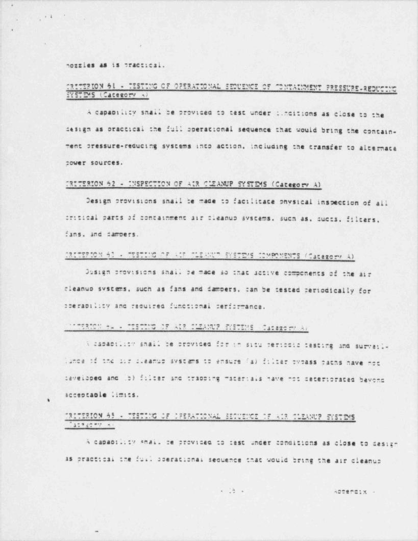
_ . , . _ . . . _ . _ _ _ _ . __. _ . ___._. _ . _ - __ _-. __ _ . . _ . _ _ _ . . _ _ _ _
.
s-
.. ..
.
.
. ,
I
s.ozzles as is rac:: cal.
l
6 1 . -~. ~. ". . G C T 0 :'R.s' s .C "' As'..
,R . * 10 N. - - U '. !C' " '. "'".'.4'''.*.-.''.***"P.'' R EDr* *. ."~-"'' - - .3 . . .. . . . . .. - .
SY ST Dd.S ( Cace eorv *) ,
I
lA capaatli:y snal; be prevtceo :o :sst uncer .r.ci:: ens as close :s :he l
I1esign as oracescal :ne ful'. :oerat:enal sequence :hac : ould bring the contain-
-ent stessure-reaucteg systems into ac: ton, incluaing :ne transfer to alternacel11
;over sources. li.
R!TERION 62 *NSPECT!ON OF A*R C'.IANUP SYSTD45 (Cateserv- A)
Design provtstens snail be mace :s f act!!cate onysical insseccion of all
::::ical par:s Of ::n atement str :leanus syscaes. suen as. :ue:s. filters,
fans and cameers.
. , . . . - .c. u. . , . ,, ,. . . . .. .e......-. ..: . . : .;. . - : : . c_.,c . y e. n. u.. _y. . . r . a t a r e i ,. ). ..e . -- .s ... . .... .
hstan :revistens snal'. be mace so : .at ac:tve c:msenents of :he air i
eleanuo systems, sucn as f ans and darcoers. :an be :ssced periodically for
::e ract 1::y anc recutrea func:::nal :eri:r ance.
. ..:...- . ;. ..., - . ; 3t.2 . : . e.. . e.. c..3.=s.. ,*o'. . - . ,...e ... . . ... . . .u u.. -- . ... .. .. . '
; :acact;;;v snai* be :revicec f:: : st:u :er::::: :sse:ne sna surte ;.
.2nce :f :..c :;r :.ea.u: sys:e-s :: ensure fa) f:*.:er :yeass ;acas nave n::
:evei ceo anc 'b) f:1:er sec :rso:: s:ar: ais -ave :: : start: races bey n:.
acceccaole l!=t:s..
.3 . . : . ,.O N o. . . ::- . . .C v. -. . . . . . . . , . .....u. : :. . . :. . .C :. . s. . .. - . . .. . . . . . .t. 3 : : s . ,:. 5.__. ..s : .e.
. -: s... . ..
-1 - . a c -.: ...
A cacaot.;;y anal. :e pr:vicec c :sst uncer ::nci: tens as close to dest--
as prac:::si :ne fui'. ::erac::nal secuence ::ac .sould bring the att cleanu:
3 4 :ene:x. - .
-
__- . . - _-
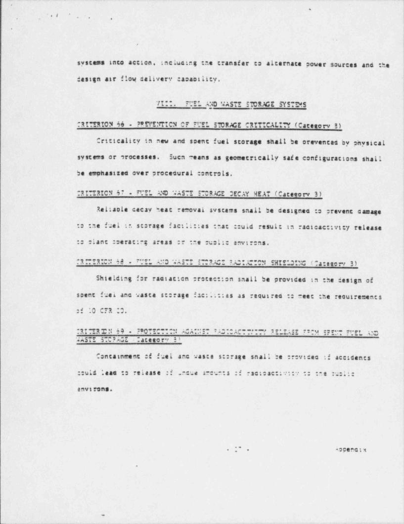
.
O
* . I'
. ., , .
.
,
systems into accien. :nclue:ng :ne transfer to alternace power sources and :he
design air flow delivery casaoility.
*/I:I. ?"EL A140 '4ASTE STORME SYSTD8.5
ORI'!RION 46 . ??9/ENTICN OF T'!!L STORME CRITICALI?? (Caceserv !)
Criticality in new and scent fuel storage shall be orevenced by physical
systems or orocesses. Suca eans as geometrically saie configuracions shall
be emohastzee over procedural controls.
RI*IRICN 67 7'.*IL A.ND 'JASTI STORACE DECAY HEAT (Caceterv 3 )-
Relisole cecay heat removal syscams snail be designac :o prevene camage1:o ne fuel : . scoraee f ac:li::as ::ac ::uld result in racicac::vity release l
:: :lanc :cerat:n; areas : ne ucli envtr:ns.
. R R .. .. t,.
. . _ . . _ . . . .- . : . a. 3 . . . ._ _ . . . .,~. . . . . ...m. .g e..dI e . 3,.,..,,. g. 4 n e e r i 3 ). . - w .. . .ns.: - .. _ ..w ..s . __
Shielding for radtacien protec::en snall be providea in :he design oflscent fusi anc waste sc: rage f ac:': :as as required : eaec :he reautrements i.
:f '.0 C7R ;3.
l1
RI IRIN 64 ??OTEC-~~N ACA-**ST C*^ ACT7.' - f EELEASE ::CM 5?ENT 7t;EL A:C ;WASTI 5;C? AGE . :acesor r s' |
Containtrent :f fuel anc was:e s:::ase snail be :::vicac if accidents1
::uld *.eae :s release :i .neue neun:s :f ract:ac::v: y :: ne :::11:!
|
envi rons.
;. .ocenetx.
.
e.
% ___
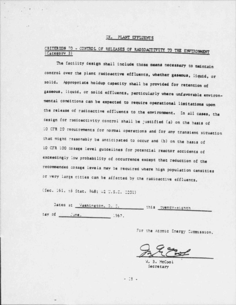
__ ___._ _ _ _ _ _ _ . . _ . _ _ _ _ . . _ _ _ _ . . . . _ _ . _ . _ . . _ . . _ _ _ . _ . _ . _ _ _ _ _ _ _ _ _ _ _ _ _ _ _ _ . _
-;
*- . , .,
. .;:
!'
f .. -
'
IX. PLANT DTLUENTS
1
CRITERION 70 - CONTROL OF RELEASES OF RADICACfITITY TO THE E1WIR010ENT;
j (Categorv 3)1
|
i The facility design shall include those means necessary to maintain
) control over the plant radioactive effluents, whether gaseous, liquid, or
| solid. Appropriate holdup capacity shall be provided for retention of,
gaseous, liquid, or solid effluents, particularly where unfavorable environ-
mental conditions can be expected to require operational limitations upon;
{ the release of radioactive effluents to the environment. In all cases, the'
;
; design for racicactivity control shall be justified (a) on the baats ofi*
'O C7120 reouirements for normai operations and for any transient situationi
j that might reasonably be anticipated to occur and (b) on the bassa ofi
10 CTR 100 dosage level guidelines for potential reactor accidents of:1
iexceedingly low probability of occurrence except that reduction of the
!
econnended osage levels may be reouired where high population censities1 .
; sr very large cities can be affected by the radioactive affluents.ii
j (Sec. '61. :s Stat. %8: : 2 '.* . S . C . ;201).
14
i Daten at 'Ja sh i ns te n. 3. 2. :his tventv-eizhth3
cay of June. *967.4
:,
Ter the At mic Energy C =ntssion.e
'4. 3. McCoo lSecretary
- :S -
_
_ . - - . - - . . _
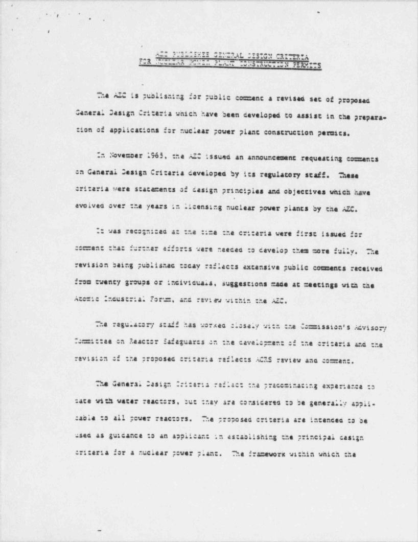
. . . - . . . - . - . . = ...., .. . . ~ . . .-~.----.~..---->.~,-~..~.-~.-.--...~-n ~.-.,~.~_-.~-w.--.--,
e
|~
,. ..
. . .
*.
i
i
i
... . . ., . . . .: ; - - - s.. ,ge . . . .. C1 *6 . .'.'. ". A
,
A. -. . . . . . . . . w .. . 3 .ks .o..R ....... . . . . . ., a .. 3 ..:. . - ...sa . . . . .. .s.aw..A.,c,R.y._$. .s
. ...ji'
1.
Sa AIC is publishing for public co=anc a ravised set of proposed
Canaral Oasign Critaria which have been developed to assist in the prepara-
: ion of applicacions f r nuciaar ;over plant construction pernics.,
n .''ove=cer 1965, ::a AIO issued an announcement requesting cos: an:s
en General Oasign Cri: aria coveloped by its sgulatory staff. 3ese
critaria nera s:acan:ents of design principles and objectivaa which have.
avolves over :ha years in licensing nuclear power plancs by the AZC.
: was reco;nt:ad a : .a :i=a :he cri: aria were first issued f::
, ::c=an: :ha: fur:nar aff:::s were .aecao :o develop : hem more fully. ha
revision being publishac :: cay :sflac:s excansiva public comunants received !
from vency groups or incivicuaia, suggestions =ase at =estings with the,
1*A::=t ncus::tal Tor =, and ravi av within :he AIC.
l3a ragula:s:/ s:sff has vorxac :issaly wi:n : a C:=1ssion's Adviso:/ ~
:=1::aa en Raac::: Safaguar:s en -ha cavals;=an: Of ::a cri: aria and -ha,
i
ravist:n of :ha ;; posac ::1: aria raflac:s ACIS raviav ana co=an:.
2.a Ganarai Casi;n ::i:arta ref'.as: : .a ;;acc=ina:Ing expartanca :s
: ace with varar reac:::s, bu: : .ay are co .sicares :s be general.*y appit.
:able :s all ;cuer : ac:srs. -".a pr: posed crt: aria are in:ences :s be-
used as guicanca :s an applican: in as:asiishing tha ;;incipal cast;n
::1: aria for a ..ucisar ;:ver plan:. Sa fra=avoric vichin which .ha
4
.o
, . , , c .- - - , . - __. ._- . _ _ - m_ _ I
t
- - . ... . . ,
,
\-,
.
.
::1:ari;n are presented ;;ovices sufficient flaxibili:y to par =1: applicanes
s astablish dasign acuira=en:s using al:arnaca and/or additional critaria.
= particular, acditional ::1:arta vill be naaded for unusual sitas and
anvire==antal conditions and i:: new or advanced :ypes of reactors. In each!
casa an applicant will ha recuiran to identify its principal design critaria
anc ;;ov:ca assurance chac hay ance= pass all : hose facility design features
requ::ad in the interest si puolic health and safety.
The cri: aria are designa:ac as "Canaral Casign Critaria for Nucisar
?: war Plan: :sstrue:::n ?ar:i:s" :: a=phasize che key cia chay assu=a
a: :nis scag; si ::a ;icans: g pr:cass. The crt: aria have baan catagorized
as C4 agory A or Ca:ag::y 3. Ixperienca has shown cha: = ora cafini-tva
infor=acion nas baan nascac a: :ha construc: ion par =i: scaga for certain of
:ha crt: aria; :hase have baan cas gna:ad as Cacagory A.
Oavelsp=an: si :hasa ::::ar:a :s ;ar: :f a 'ongar-range C ==1ssion.
progra= :s cavaisp ::::ar:2 4::ncar:s, ::: ::cas i:: nuciaar raac::r||
plants. This inclucas ::cas 2n: 3:ancar:a ::a: indus r; :s cavaloping I
with AIC par:tcipation. Tha 21::=a:2 goal is na evolu:::n of incustry
::cas and stancar s based :n a:::=ula:ad knoviacga anc axperience as has
:ccurred in various italds :i anginaar: g anc cens::::: :n.
;..
.. . ~ .
. _ _ _.- . . . . _ . _ _ . . ._. . . _ _ . . _ _ _ _ _ _ _ _ _ . - - . - . . . _ . _ - . . . . _ _ . _ _ . . . . _ _ _ _ _ _ _ - _ _ . . _ _ _
O
i s. , s. . . .
: *,.
i,
.,
!
ne provisions of the proposed amendment relating to General Design,
i
criteria are eximected to be useful as interim guidance until such time as*
the Commission takes further action on them.,
Ia
!3e proposed criteria, vnich would become Appendix A to Part 50 of'
the AEC's regulations, will be pue' lished in the Federal Resister on;
4
*
nterested persons =ay suismic written comments or sugges..
jtions to the Secretary, U. S. Atomic Energy Commission, Washington
{, D. C.
205t.5, within 60 days.A copy of the proposed " General Design Critaria
i
for Nuclear Power Plant Construction Permits" is attached.1
!
l
1
i
-3-,
G & --- - - -
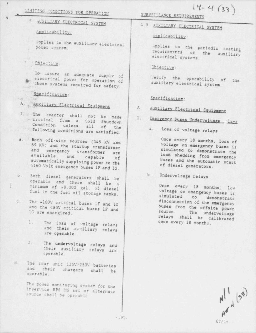
- . . -. _ _ _ . . . - - - .__. -
,
L4- 4 (r3LIMIT!NG CONDITIONS FOR OPERATIONSURVEILLANCE REOUIREMENTS
.*n
. F AUXILIARY ELECTRICAL SYSTEM 4.9AUXILIARY ELECTRICAL S STEM
.
l
{AeolicabilitvAeolicability: ,
;
Applies to the auxiliary electrical i
power system. Applies to the periodic testing;
,
requirements of the auxiliaryelectrical systems. ;
l
* Obi +cti"e:Cbiective:.e
To assure an adequate supply of Yerify theelectrical power for operation of operability of the J
..
.m. ,', .D those systems required for safety. auxiliary electrical system.
'.'Eheecification:. e. :J.N Seecification:A. [cs,uxiliary Electrical EautomentA
!A. Auxiliary Electrical Eauinment{{ s The' reactor shall not be made 1..m critical from a Cold Shutdown Emerrenev Buses Undervoltare . ,Lgy2 '
Condition unless all of the i^ Nfollowing conditions are satisfied: Loss of voltage relaysa.!
s.
Once every 18 months, loss of}
e. # Both off-site sources (345 KV and69 KV) and the startup transformer voltage on emergency buses is
simulated to demonstrate theand emergency _ transformer are load shedding fromavailable- and capable of emergencyautomatically supplying power to the buses and the automatic start4160 Volt emergency buses IF and 1G. of diesel generators.
t
!.b.,
b. Undervoltage relays IBoth diesel generators shall be1 operable and there shall be a Once| minimum of 48.000 gal. of diesei every 18 months, lowfuel in the fuel oil storage tanks. voltage on emergency buses is
simulated to demonstrateThe 160V critical buses IF.and 1G disconnection of the emergencyc.
buses from the offsite powerand the 480V critical buses IF and1G are. energized. source. The undervoltagerelays shall be calibrated1. The loss of toltage relays once every 18 months.
and their au::iliary relays-are operable.
1
.! . The undersoltage relays andtheir auxiliary relays are !
operable.
d. The four unit 125V/250V batteriesand their chargers shall beoperable.
The power monitoring system for theinservice RPS MG set or alternate I{source shall be operable. 9
,
n'191-07/16 -
I

_. - . . . . . - . - . . ~ . . . . - . . . . . . . . . . -
,
*. *!MITING S DITIONS FOR OPERATION SURVEII. LANCE REOUIREMENTS*
_ ,
3 . ? *. 3 A.9.A (cont'd.)-'
3. Oeeration with Inocerable Ecuirment'
Wenever the reactor is in Run Moceor Startup Mode with the reactor not
iin a Cold Condition, the !
availability of electric power shallbe as specified in 3.9.A.1, except
i
as specified in 3.9.3.1.
1. Incomina Poweri
a. From. and after the date incoming-power- is not available from <a
startup or. emergency transformer,continued reactor. operation ispermissible under this condition forseven days. At the ~ end of this '|
;period, provided the second sourceof incoming power has not been madeimmediately available, the NRC :nustbe notified of the event and theplan to restore this second source.During this period. :ne evo dieselgenerators ' and associated critical
buses must be demonstrated to beoperable.
b. From and after the date thatincoming power is not available from -
both start up and emergencytransformers (i.e., both failed),continued operation is permissible,provided the two diesel generators ;
'
and associated critical buses aredemonstrated to be operable, allcore and containment cooling systemsare operable, reactor power level isreduced to 25% of the rated and NRCis notified within 24 hours of the j
situation, the precautions to be:aken during this period and theiplans for prompt restoration of
incoming power.
i
1
-192 n7fn7jos
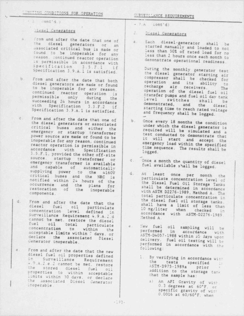
, _ _ - . ~ ~ . . - . . . . . - - . . - - - ~ . ... .-- . . - . . - - . . - - . . _ . - - .-
* *M P NG COND P"f 0NS " FOR OPERATION t
y RRVEIL*MCE REOUIREMENTS I.
-
.? cont'd.) ;..?.A cont'd) '
>
. ';tesel Generators2. Diesel Generators
From'and after the date that one ofa.a. Each diesel-generator shall be !the diesel generators or . an
associated critical bus is made or ' started manually and loaded to not )less than 50% of rated load for nofound to be inoperable for any i
reason. continued reactor operation less than 2 hours once each month to -{demonstrate operational readiness.is. permissible in accordance with '
Specification 3.5.F.1 ifSpecification 3.9. A.1 is satisfied, During the - monthly generator test.
the diesel generator starting aircompressor. shall be- checked forb; From and af ter the date that both operation and its ability' codiesel generators are made or.found recharge air- receivers. Theto. be inoperable for ' any - reason. operation of the . diesel fuel oilcontinued . reactor operation is transfer pumps and fuel oil day tankpermissible. only during the- level switches- shall be.succeeding 24 hours v in - accordance - demonstrated, and the . dieselwith Specification- 3.5.F.2 if
Specification - 3. 9. A.' 1 is satisfied, starting time to reach raced voltageand frequency shall be logged.
From and after the.date that one of b. Once every 18 months the condition ' -
c.the diesel generators or associated
under which the diesel generator iscritical buses. and either the required will be simulated and aemergency or startup transformertest conducted to demonstrate thatpower source are made or found to be it will start and ' accept. theinoperable for any reason, continued
reactor operation is permissible in- emergency load within the specifiedtime sequence. The results shall beaccordance .with Specification
' 3. 5.F.1, provided the other off-site logged..
-source. startup transformer or c.emergency transformer is available Once a month the quantity of diesel
fuel available.shall be logged.and- capable of automaticallysupplying power to the 4160V d. At least once per month thecritical buses and- the NRC: .is particulate. concentration level ofnotified within 24 hours of the the Diesel Fuel Oil Storage Tanksoccurrence and the plans for shall be determined - in accordance
~
restoration of the inoperable with ASTM D2276-1989, Method A. Thecomponents,total particulate concentration in
.. the diesel fuel oil storage tanks.d. From and after the date that the shall have a limit of less thandiesel fuel oil particulate 10 mg/ liter when checked in !concentration- level defined in accordance with ASTM-D2276-1989: 1Surveillance ' Requirement 4.9. A.2.d Method A. 'cannot be met. restore the diesel
fuel oil total particulate e. New fuel oil sampling will be '! i
concentration to within the performed in accordance~ with-acceptable limits within 7 days. orASTM D4057-1988 within M days upon
ideclare .the associated DieselGenerator inoperable. delivery. . Fuel oil testing will be i
performed in accordance with thei
From and af ter the date that the newfollowing: ,
e. '
diesel fuel oil properties defined i1. By verifying in accordance within Surveillance Requirement the tests specified .- ;;
a.9 A.2.e.2 cannot be met. restore ASTM-D975-1989a prior |the stored diesel fuel oil addition to the storage tank-
properties to within acceptable that the sample has: '
;
limits within 30 days, or declarethe associated Diesel Generator a) An API Gravity of with. |inoperable * 0.3 degrees at 60'F. or
specific gravity of witt !0.0016 at 60/60*F; when
- 03-
|. , _ , _ __ _ __ -_ __
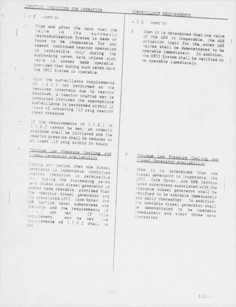
. ._ _._ _._ . . _ - . _ . _ . .._ _________m,
LIMITINC TONDfTIONS FOR OPERATIONSt*RVEILLANCF REOUIREMENTSd
'
3.5.E icont'd)_
-
4.5.E ' cont'd) '
2.- From and after the date that one 2.valve in the Automatic When it is determined that one valve3epressurization System is made or of the ADS is inoperable, the ADS I,found :o be inoperable for .any actuation logic for the other ADSreason, continued reactor operation valves shall be. demonstrated to be| is . permissible only~ during the operable immediately. In addition.!succeeding seven days unless such the HPCI System shall be verified tovalve is sooner made operable. be operable 1:amediately, |:
- provided that during such seven days[ :he HPCI System is operable.,
;i-i
-
'-2.
With the surveillance requiremen:s>
' !,of . 6.3.5 not. performed ac' :herequired intervals due to reae:orshuecown. a reactor. startup may beE ;.
!concucted provided the . appropriate;.surveillance is performed within .'2jhours of achieving- 113 psig reac:or
'
,
| steam pressure.
i- If the requirements..
of 3.5.E.1 orL 3.5.I.2 cannot be met.! an orderly -shutdown shall be initiated and thereae:or pressure shall be reduced :oat least *
.13 psig within 24 hours.? Minimum _ow
*
Pressure - Cooline and F ..
Minimum Low Pressure Cooline andOtesel Generator Availability
~ 21esel Cenerator Availability1. During ary period when one }diesel 1. *~
generstor is inoperable; continled|
.nen itis_ determined that one
k
reac:or operation is pe rmis sib.* e diesel generator is inoperable..
the iniv during the *?CI. Core Spray, and RHR Service-succeeding seven.days unless such diesel generator is Ta:er subsystems associated with thesoor.e: cade operable. provided that operable diesel generator shall be:he Operable diesel generator and verified to be operable immediatelyits associated L?CI Core Spray, and and daily thereafter. In addition,F.HR service . Vater subsystems :he operable diesel generator shallare he demonstrated :o be operableoperable - and the requiremen:s of;.*.A.~ arr met. If this i=ediately and every three days.
recuirement thereafter. inot be met. :herecuirements of 3.5.F.2 shall beme . -
>
i
. ;n .3/1L m
e&T - +7' *r- e n-
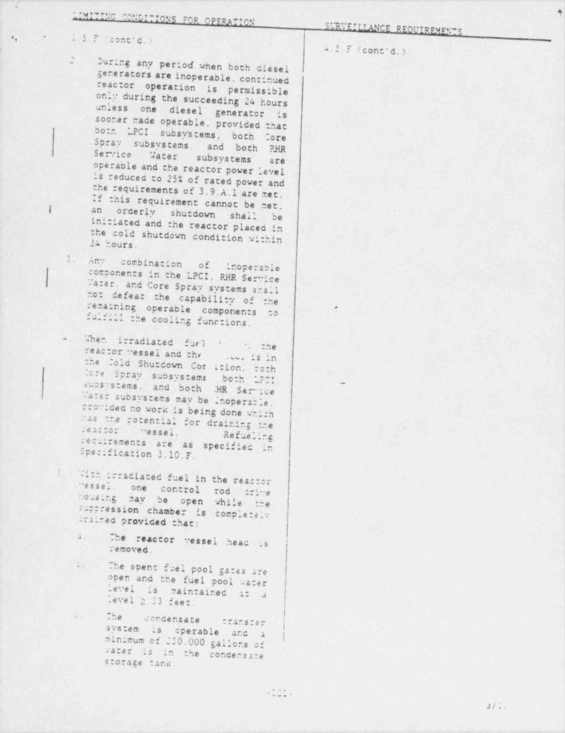
. . . __ ._ . _. _. . . . _ _ _ . _ _ _ _ _ - . .
,
J
W'.:MITING 'ONDITIONS FOR OPERATION
ST.'EILIANCE REOUIREv.ENTS., 3.5.? f ont'd.) _ 7
-
1
A.5.? (cont'd.)>
2. Ouring any period when both dieselgenerators are inoperable, continued |
,
reactor. operation is permissible !
only during the succeeding 24 hoursunless one diesel generator is j
3
sooner cade operable. provided_ : hat ;both LPCI subsy's t ems , both CorejSpray subsystems. and both ?J{R iSe rvice Water subsystems are l
operable and the reactor power levelis reduced to 25% of rated power andthe requirements of 3.9. A.1 are met.If this requirement cannot be met.) an orderly shutdown shall- be ')initiated and :he reactor placed inthe cold shutdown condition wi:hin.24 hours. j
3. Any combination of inoperable. components in.:he LPCI, RHR Service
!Ca:er, and Core Spray systems sha'1 I
no: defeat the capability of the{
.
remaining operable componen:s :o ,
fulfill the cooling functions.'
4 When irradiated fuel '-. :he
reac:or vessel and the w. is in:he :old Shutdown Cor 1: ion, both:cre Spray subsystems bo:h *?C!. -
suosystems, and both ;HR S e r-' . c eTa:er subsystems may be ' nope rah ".e .prorided no work is being done whichhas :he po:encial for draining :heres::or vessel. *
Refue"ingrecuiremen:s are as specified in
.
Specifica: ion 3.10.F. )t
.
Wi:h irradia:ed fuel in the rea::or.
vessel. one con rol rod drive ihousing 'may be open while :hesuppression chamber is c omple :e i:.irained provided : hat:
i
a. The reactor vessel heac isremoved.
;. The spen fuel pool ga:es areopen and the fuel pool va:erlevel is maintained s: alevel 2 33 fee:.
:. The condensate :rans:er !sys:em is operable and a {minimum of 220.000 Sallons ofwater is in :he condensa:estorage :ank. ;
* , , ,. e. e *
3/;
_.
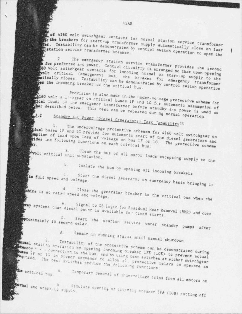
.
.' 6
,
USAR.
,
of 4160 volt switchgear contacts
[the breakers for start up transformer supply automaticallyfor normal station servicetransformerTestability can be demonstrated by control switch o close on fast |
er.station service
transformer breaker. peration to open the2. The emergenc
.
for preferred a c power.y station se rvice transformer provides
Control circuitry is arranged so that upfor incoming ncrmal or starr-up supply tthe second'60 volt switchgear contacts
" ole critical (emergency) on openingbus,the braaker for o thetically closes.
,n the incoming breaker to the critical bus. Testability can be demonstrated by controlemergency transformerswitch operation
Provision is also made in the under-voitage160 volts -iv.'sgear on critical buses IF .nd 1G f( r autprotective scheme forical load 8 -)? 'he
emergency transformer before standby a-c pomatic assumption of,}erdescribedbelow.This test can be repeated dur:,ng normalower is used as
.2 operation.
Standbv A-C Power (Diesel Generators)Test "apabilievm1.
ical buses if and 1G provide for automatic start ofThe undervoltage protective schemes for 4160volt switchgear ontion of load upon loss of voltage on bus IF the diesel generators andides ne following functions on each or 1G. The
' ~ critical bus: protective schemeClear thea.
bus of all motor loads excepting supply tvolt critical unit substation.-
o the"
5.
Isolate the bus by opening all incoming breakers.c. Start
to full speed and voltage. the diesel generator on emergency basis bringing itd.
ine is at Closeratet speed and voltage.the generator breaker to the critic l ba us when the
e.
diesel pot sr is available fo : Signal to GE logic for Residual Heat Remay systems thattimed starts, oval (RHR) and core
f.
Start the station setvice waterroximately 15 second delay.standby pumps afteri
g.Remain in running statu; until manual sh
2. utdown.Testability of the protective scheme carmal st
tanaoy atisn o3 ration by opening incoming breaker 1FE (lCE)- connection to the bus, and by using test switches at eithn be demonstrated during<
es if or 1G in procer sequence to prevent actualotd.re d . The test to allow al. protective er switchgear
' switches provide the follow nB functions:relays to operate asa.
- Temporarv removal of uncervoltage trips from all motors on4
5.
.rmal and start-up supol:. Simulate opening of incc ming breaker IFA (lGB) cutting off
.
-* _ . . - - ~ - ^