Slipped proximal femoral epiphysis in a priest from the medieval period
http://ajs.sagepub.com
MedicineAmerican Journal of Sports
DOI: 10.1177/036354658901700210 1989; 17; 208 Am. J. Sports Med.
Mohamed S. Hefzy, Edward S. Grood and Frank R. Noyes ligament
Factors affecting the region of most isometric femoral attachments: Part II: The anterior cruciate
http://ajs.sagepub.com/cgi/content/abstract/17/2/208 The online version of this article can be found at:
Published by:
http://www.sagepublications.com
On behalf of:
American Orthopaedic Society for Sports Medicine
can be found at:American Journal of Sports MedicineAdditional services and information for
http://ajs.sagepub.com/cgi/alerts Email Alerts:
http://ajs.sagepub.com/subscriptions Subscriptions:
http://www.sagepub.com/journalsReprints.navReprints:
http://www.sagepub.com/journalsPermissions.navPermissions:
http://ajs.sagepub.com/cgi/content/abstract/17/2/208#BIBLSAGE Journals Online and HighWire Press platforms):
(this article cites 37 articles hosted on the Citations
© 1989 American Orthopaedic Society for Sports Medicine. All rights reserved. Not for commercial use or unauthorized distribution. by FRANK NOYES on May 3, 2007 http://ajs.sagepub.comDownloaded from
208
winner of the 1988 O’Donoghue award
Factors affecting the region of mostisometric femoral attachmentsPart II: The anterior cruciate ligament*
MOHAMED S. HEFZY,† PhD, EDWARD S. GROOD,†§ PhD, ANDFRANK R. NOYES,‡ MD
From the †Noyes-Giannestras Biomechanics Laboratories, Department of AerospaceEngineering and Engineering Mechanics, University of Cincinnati, and the ‡Cincinnati
Sportsmedicine Center, The Deaconess Hospital, Cincinnati, Ohio
ABSTRACT
During flexion of the intact knee, we measured thechanges in distance between possible tibial and femoralattachments of an intraarticular ACL substitute. The
change in distance during motion was described by thedifference between the longest and shortest distancesmeasured. Using knees from eight cadaver donors, westudied the effects of varying tibial and femoral attach-ment locations, applying anterior and posterior forces,and altering the range of flexion.We found that altering the femoral attachment had a
much larger effect than had altering the tibial attach-ment. No femoral attachments were completely iso-metric. Femoral attachments that produced the small-est change in tibiofemoral distance, 2 mm and less,formed a band whose greatest width ranged from 3 to5 mm. The axis of the 2 mm region was nearly proximal-distal in orientation and located near the center of theACL’s femoral insertion. Attachments located anteriorto the axis moved away from the tibial attachment withflexion, whereas attachments located posterior to theaxis moved toward the tibia.The AP position of the tibial attachment affected the
orientation of the 2 mm region. Moving the tibial attach-ment posteriorly caused the proximal part of the regionto move anterior, with little change in the location ofthe distal part of the region. Changing the applied jointforce from anterior to posterior was similar to moving
the tibial attachment posteriorly, but the effect was lesspronounced. Increasing the range of flexion from 90°to 120° caused the 2 mm region to become narrowerand changed its orientation.
ACL rupture is recognized as a major injury that oftenresults in a functional impairment requiring surgical recon-struction. A large number of intraarticular5,6. 10, 12-14, 22, 23, 26, 28, 30, 32, 33 and extraarticular2-4. 7.19,25 surgical proce-dures have been described for reconstructing the ACL defi-cient knee. Many surgeons prefer intraarticular reconstruc-tions because they directly address the anatomical and ki-nematic deficit of a ruptured ACL.The success of reconstruction depends on many factors,
including the ability of the substitute to reproduce therestraining action of the ACL and restore the normal limitsto anterior translation of the tibia. It is not currently possibleto replicate the normal ACL exactly because of its complexfibrous architecture. The anatomical arrangement of fiberscauses some to become longer (tense) with flexion and someto become shorter (slack).15.20.35.36 This behavior is also
observed intraoperatively with ACL substitutes. Improperplacement is known to produce a tensing of the substitutewith flexion or extension that can result in fixation failureor a limitation of motion. Recognition of this problem hasled many surgeons to seek femoral and tibial attachmentswhose separation distance remains nearly constant, or iso-metric, when the knee is flexed.The recognition that the attachment location is important
is not new; Palmer32 advocated the need for proper drill holeplacement in 1938. Since then, many intraarticular proce-dures have been described in the literature, with differentrecommendations for tibial and femoral placement. On the
* Presented at the 14th Annual Meeting of the AOSSM, June 1988, PalmDesert, Califorrna.
§ Address correspondence and repnnt requests to: Edward S. Grood, PhD,Noyes-Giannestras Biomechanics Laboratones, 2900 Reading Road, CSB,University of Cincmnati, Cincinnati, OH 45221-0048
© 1989 American Orthopaedic Society for Sports Medicine. All rights reserved. Not for commercial use or unauthorized distribution. by FRANK NOYES on May 3, 2007 http://ajs.sagepub.comDownloaded from
209
tibia, this has included placing the graft either over the tibiallip, 22,23 anteromedial to the insertion of the ACL/3,31 ordirectly on the tibial insertion site.6.l4 On the femur, rec-ommended attachment sites include posterior place-ment,1O.l3 posterosuperior placement,~ anatomical place-ment,31 and anterior to the ACL’s femoral attachment. 21Furthermore, Galway and McIntosh14 and Insall et al.22advocated routing the graft in the over-the-top position.Which, if any, of these recommended placements results inthe goal of obtaining an isometric graft remains uncertain.
Although numerous studies on how flexion angle affectsthe distance between tibial and femoral attachments of theACL have been reported,~-&dquo;-&dquo;-~-~-~ only a few stud-ies have directly addressed the issue of substitute attachmentlocation. 1,21,25,29,30 Recently, we reported 21 on a new methodfor measuring the distance between tibial and femoral at-tachments in the intact knee of cadaver whole lower limbs.We found that whether this distance increased or decreasedwith knee flexion depended strongly on the AP position ofthe femoral attachment. Anterior attachments moved awayfrom the tibia with flexion, increasing the distance, whileposterior attachments moved toward the tibia. Because
many previous studies have not provided sufficiently de-tailed descriptions of the femoral attachments used, inter-pretation of their results is difficult. In the three studieswhere femoral attachment location was clearly de-
scribed,2l.29.3l only a few femoral attachments were investi-gated, and the effects of the weight of the tibia and the rangeof joint motion were not considered. Both factors are poten-tially important in interpreting readings made with thecommercially available isometers.The research presented in this paper had the following
purposes. The first was to determine the region of thefemoral attachments of ACL substitutes that produce alength change of 2 mm or less during knee flexion andextension; these attachments are located in a region we referto as the 2 mm region. The second purpose was to determinehow the size and location of this region were affected bytibial attachment location, joint load, and the range of kneeflexion.
MATERIALS AND METHODS
Length measurements
The distance between selected attachments on the femurand tibia was computed from two sets of measurementsmade using a 6 degrees-of-freedom electrogoniometer. 17,11,31The first set of measurements was the three-dimensional
positions of the tibia with respect to a femoral referenceframe made under the desired experimental conditions.After completing the experiments, we separated the tibiafrom the femur by cutting the ligaments in their midlengthregion. The peripheries of the femoral and tibial insertionsof the ACL were identified by dissection. The second set ofmeasurements was the location, in three dimensions, ofpoints on the surface of each bone where the ACL attaches.The femoral points were located with respect to a femoral
reference frame and the tibial points were located withrespect to a tibial reference frame. The location of anyselected tibial attachment with respect to the femoral framewas computed from its location with respect to the tibialframe and the position of the tibia relative to the femur,measured during the experiments. Finally, the distance be-tween the femoral and tibial attachment points was deter-mined using the Pythagorean theorem in three dimensions.The theory behind this approach and the detailed equationsused have been reported previously.’oWhen choosing the specific attachment points for analy-
sis, it was necessary to approximate the shape of the bonesurfaces in the regions of insertion. A best fit plane wasemployed for both tibial and femoral insertions. These
planes were determined using the coordinates of 5 to 10points lying on the perimeter of the ACL’s attachments.
Experimental design
The position of the tibia with respect to the femur wasmeasured and the knee was flexed from full extension to120° of flexion. During the motion, either an anterior or aposterior force of 100 N (22.5 pounds) was applied to the legjust below the joint line. In addition, there was a distractionforce induced by gravity that was equal to the weight of theleg and foot, typically 45 N. The details of this techniqueand the experimental apparatus have been previously re-ported. 11-11,20 The anterior force was applied in order tosimulate a condition that required the ACL to resist anteriortibial translation. The posterior force was applied to mini-mize the force in the ACL, to provide a contrasting conditionfor the assessment of the effects of joint load, and to simulatethe posterior force of gravity and the manual posterior forcessometimes applied intraoperatively when using an isometer.
Specimens
The experiments were conducted using eight unembalmedcadaver whole lower limbs obtained from six male donors
aged 31, 31, 41, 42, 43, and 57 years old (three right, threeleft), and from two female donors aged 42 and 43 years old(one left, one right). All of the limbs were stored at -15°Cuntil the night before testing, when they were thawed toroom temperature. All of the knees were examined for pre-vious injury, surgery, or degenerative changes that mighthave affected the results; none were found.
Contour maps
To distinguish the influence of tibial attachment locationfrom the influence of femoral attachment location, we firstselected a tibial attachment of interest and determined theeffects of changing the femoral attachment location. Foreach femoral attachment, we determined the maximum andminimum distances to the tibial attachment during flexionand their difference, d = dmax - dmn, the maximum lengthchange. The results were summarized using maps that com-
© 1989 American Orthopaedic Society for Sports Medicine. All rights reserved. Not for commercial use or unauthorized distribution. by FRANK NOYES on May 3, 2007 http://ajs.sagepub.comDownloaded from
210
prised contour lines, each with a single value of maximumlength change.The contour maps were constructed as follows. We first
selected one of the five tibial attachments used for analysis.The tibial attachment was paired with femoral attachmentslocated along an AP oriented line. As shown in Figure 1, theline a-a was located on the medial surface of the lateralfemoral condyle. We computed, for each pair of attachments,the maximum length change that occurred as the knee wasflexed. Linear interpolation between points was used to findthe location along the line of a specific value of maximumlength change. This process was repeated for lines spaced at2 mm intervals in the proximal-distal direction. The contourlines were constructed by connecting points with the samemaximum length change.
Tibial attachments
We studied five different tibial attachment sites. The firstattachment was located at the center of the tibial insertionarea of the ACL. The remaining four attachments werelocated along the perimeter of the insertion area, lateral,medial, posterior, and anterior to the first attachment.
Statistical analysis
In order to perform statistical analysis, we first characterizedeach contour map by the five geometric variables describedin the &dquo;Results&dquo; section. A three-way analysis of variance(ANOVA) was performed to determine if any of the fivevariables depended on tibial attachment location or on theapplied force. The tibial attachment location and the force
were considered as fixed variables and subjects as randomvariables. In those cases where a significant (P < 0.01)interaction between tibial attachment and shear force wasfound, a one-way ANOVA was also performed. The Student-Newman-Keuls (SNK) test was used to perform multiplepair-wise comparisons among means.
RESULTS
Specimen geometry
The geometric variables used to describe the size of theknees studied, with their mean values and standard devia-tions, are shown in Figure 2. The intersection of the troch-lear groove with the roof of the intercondylar notch, point0, was used as a reference for all measurements. The pointwhere the average flexion axis intersects the lateral surfaceof the medial femoral condyle, point CR (center of rotation),did not significantly change when a posterior force wasapplied in place of an anterior force.
Contour maps
Figure 3A shows a contour map for one of the eight speci-mens studied. This map was determined using a centraltibial attachment and flexion of 90° while an anterior forcewas applied. The numbers at the distal end of each lineindicate the maximum length change for all attachmentsalong the line. The shaded region, which includes a portionof the ACL’s femoral insertion, are those attachments thathave a 2 mm or less maximum length change. The proximal
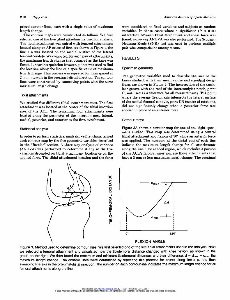
Figure 1. Method used to determine contour lines. We first selected one of the five tibial attachments used in the analysis. Nextwe selected a femoral attachment and calculated how the tibiofemoral distance changed with knee flexion, as shown in thegraph on the right. We then found the maximum and minimum tibiofemoral distances and their difference, d = dmax - dm~~, themaximum length change. The contour lines were determined by repeating this process for points along line a-a, and thensweeping line a-a in the proximal-distal direction. The number on each contour line indicates the maximum length change for allfemoral attachments along the line.
© 1989 American Orthopaedic Society for Sports Medicine. All rights reserved. Not for commercial use or unauthorized distribution. by FRANK NOYES on May 3, 2007 http://ajs.sagepub.comDownloaded from
211
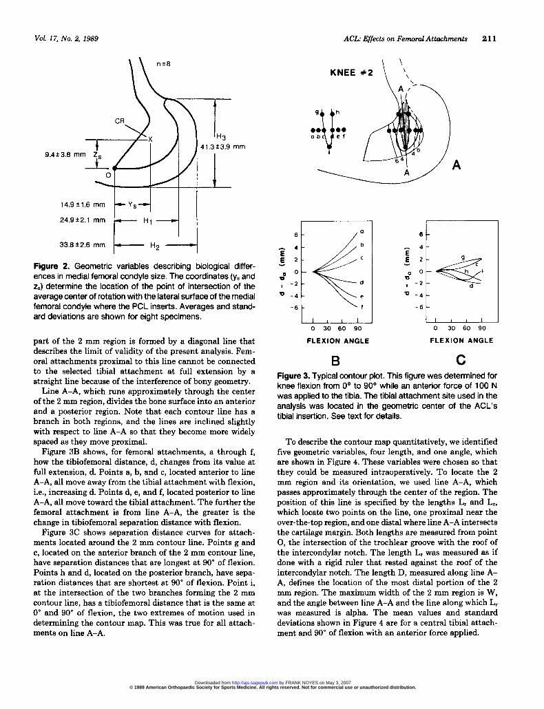
Figure 2. Geometric variables describing biological differ-ences in medial femoral condyle size. The coordinates (ys andzs) determine the location of the point of intersection of theaverage center of rotation with the lateral surface of the medialfemoral condyle where the PCL inserts. Averages and stand-ard deviations are shown for eight specimens.
part of the 2 mm region is formed by a diagonal line thatdescribes the limit of validity of the present analysis. Fem-oral attachments proximal to this line cannot be connectedto the selected tibial attachment at full extension by astraight line because of the interference of bony geometry.
Line A-A, which runs approximately through the centerof the 2 mm region, divides the bone surface into an anteriorand a posterior region. Note that each contour line has abranch in both regions, and the lines are inclined slightlywith respect to line A-A so that they become more widelyspaced as they move proximal.
Figure 3B shows, for femoral attachments, a through f,how the tibiofemoral distance, d, changes from its value atfull extension, d. Points a, b, and c, located anterior to lineA-A, all move away from the tibial attachment with flexion,i.e., increasing d. Points d, e, and f, located posterior to lineA-A, all move toward the tibial attachment. The further thefemoral attachment is from line A-A, the greater is the
change in tibiofemoral separation distance with flexion.Figure 3C shows separation distance curves for attach-
ments located around the 2 mm contour line. Points g and
c, located on the anterior branch of the 2 mm contour line,have separation distances that are longest at 90° of flexion.Points h and d, located on the posterior branch, have sepa-ration distances that are shortest at 90° of flexion. Point i,at the intersection of the two branches forming the 2 mmcontour line, has a tibiofemoral distance that is the same at0° and 90° of flexion, the two extremes of motion used indetermining the contour map. This was true for all attach-ments on line A-A.
Figure 3. Typical contour plot. This figure was determined forknee flexion from 0° to 90° while an anterior force of 100 Nwas applied to the tibia. The tibial attachment site used in theanalysis was located in the geometric center of the ACL’stibial insertion. See text for details.
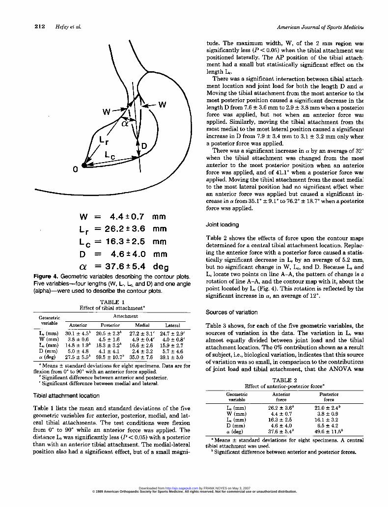
To describe the contour map quantitatively, we identifiedfive geometric variables, four length, and one angle, whichare shown in Figure 4. These variables were chosen so thatthey could be measured intraoperatively. To locate the 2mm region and its orientation, we used line A-A, whichpasses approximately through the center of the region. Theposition of this line is specified by the lengths Lr and Lc,which locate two points on the line, one proximal near theover-the-top region, and one distal where line A-A intersectsthe cartilage margin. Both lengths are measured from point0, the intersection of the trochlear groove with the roof ofthe intercondylar notch. The length Lr was measured as ifdone with a rigid ruler that rested against the roof of theintercondylar notch. The length D, measured along line A-A, defines the location of the most distal portion of the 2mm region. The maximum width of the 2 mm region is W,and the angle between line A-A and the line along which Lrwas measured is alpha. The mean values and standarddeviations shown in Figure 4 are for a central tibial attach-ment and 90° of flexion with an anterior force applied.
© 1989 American Orthopaedic Society for Sports Medicine. All rights reserved. Not for commercial use or unauthorized distribution. by FRANK NOYES on May 3, 2007 http://ajs.sagepub.comDownloaded from
212
Figure 4. Geometric variables describing the contour plots.Five variables-four lengths (W, Lr, L~, and D) and one angle(alpha)-were used to describe the contour plots.
TABLE 1Effect of tibial attachment’
° Means ± standard deviations for eight specimens. Data are forflexion from 0° to 90° with an anterior force applied.
b Significant difference between anterior and posterior.c Significant difference between medial and lateral.
Tibial attachment location
Table 1 lists the mean and standard deviations of the five
geometric variables for anterior, posterior, medial, and lat-eral tibial attachments. The test conditions were flexionfrom 0° to 90° while an anterior force was applied. Thedistance Lr was significantly less (P < 0.05) with a posteriorthan with an anterior tibial attachment. The medial-lateralposition also had a significant effect, but of a small magni-
tude. The maximum width, W, of the 2 mm region wassignificantly less (P < 0.05) when the tibial attachment waspositioned laterally. The AP position of the tibial attach-ment had a small but statistically significant effect on thelength Le.There was a significant interaction between tibial attach-
ment location and joint load for both the length D and a.Moving the tibial attachment from the most anterior to themost posterior position caused a significant decrease in thelength D from 7.6 ± 3.6 mm to 2.9 ± 3.8 mm when a posteriorforce was applied, but not when an anterior force wasapplied. Similarly, moving the tibial attachment from themost medial to the most lateral position caused a significantincrease in D from 7.9 ± 3.4 mm to 3.1 ± 3.2 mm only whena posterior force was applied.There was a significant increase in a by an average of 32°
when the tibial attachment was changed from the mostanterior to the most posterior position when an anteriorforce was applied, and of 41.1 when a posterior force wasapplied. Moving the tibial attachment from the most medialto the most lateral position had no significant effect whenan anterior force was applied but caused a significant in-crease in a from 35.1 ° + 9.1 to 76.2 ° + 18.7 when a posteriorforce was applied.
Joint loading
Table 2 shows the effects of force upon the contour mapsdetermined for a central tibial attachment location. Replac-ing the anterior force with a posterior force caused a statis-tically significant decrease in Lr by an average of 5.2 mm,but no significant change in W, Lc, and D. Because Lr andLe locate two points on line A-A, the pattern of change is arotation of line A-A, and the contour map with it, about thepoint located by Le (Fig. 4). This rotation is reflected by thesignificant increase in a, an average of 12°.
Sources of variation
Table 3 shows, for each of the five geometric variables, thesources of variation in the data. The variation in Lr wasalmost equally divided between joint load and the tibialattachment location. The 0% contribution shown as a resultof subject, i.e., biological variation, indicates that this sourceof variation was so small, in comparison to the contributionsof joint load and tibial attachment, that the ANOVA was
TABLE 2Effect of anterior-posterior force’
ø Means ± standard deviations for eight specimens. A centraltibial attachment was used.
b Significant difference between anterior and posterior forces.
© 1989 American Orthopaedic Society for Sports Medicine. All rights reserved. Not for commercial use or unauthorized distribution. by FRANK NOYES on May 3, 2007 http://ajs.sagepub.comDownloaded from
213
TABLE 3Sources of variation of geometric variables
not able to determine it accurately. The five tibial attach-ments studied were the largest source of variation in thewidth of the 2 mm region, W, and in a. The biologicalvariation among specimens was the largest source of varia-tion in Lc, whereas the variation in length of the 2 mmregion, D, was a result, in nearly equal contributions, of allthree sources.
Range of motion
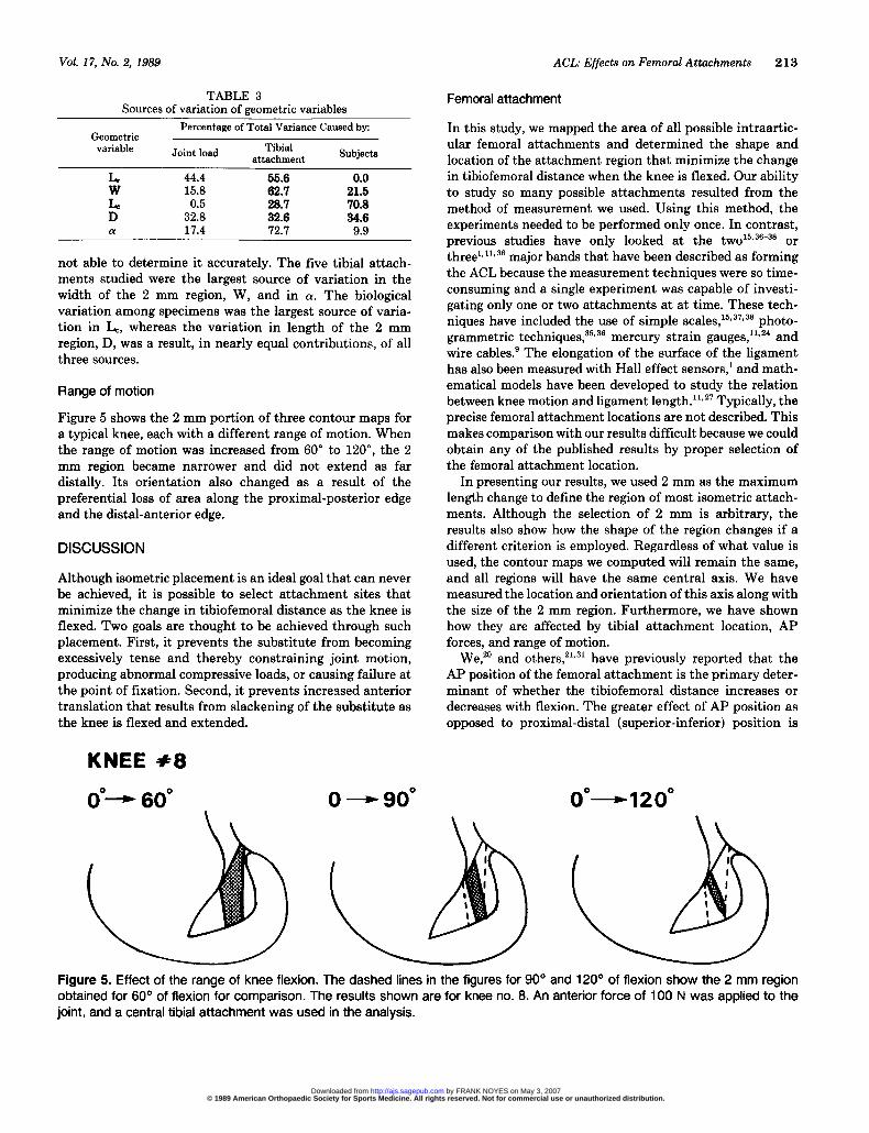
Figure 5 shows the 2 mm portion of three contour maps fora typical knee, each with a different range of motion. Whenthe range of motion was increased from 60° to 120°, the 2mm region became narrower and did not extend as far
distally. Its orientation also changed as a result of thepreferential loss of area along the proximal-posterior edgeand the distal-anterior edge.
DISCUSSION
Although isometric placement is an ideal goal that can neverbe achieved, it is possible to select attachment sites thatminimize the change in tibiofemoral distance as the knee isflexed. Two goals are thought to be achieved through suchplacement. First, it prevents the substitute from becomingexcessively tense and thereby constraining joint motion,producing abnormal compressive loads, or causing failure atthe point of fixation. Second, it prevents increased anteriortranslation that results from slackening of the substitute asthe knee is flexed and extended.
Femoral attachment
In this study, we mapped the area of all possible intraartic-ular femoral attachments and determined the shape andlocation of the attachment region that minimize the changein tibiofemoral distance when the knee is flexed. Our abilityto study so many possible attachments resulted from themethod of measurement we used. Using this method, theexperiments needed to be performed only once. In contrast,previous studies have only looked at the two15.36-38 or
threel.ll.36 major bands that have been described as formingthe ACL because the measurement techniques were so time-consuming and a single experiment was capable of investi-gating only one or two attachments at at time. These tech-niques have included the use of simple scales,15,3’,3a photo-grammetric techniques,35.36 mercury strain gauges,’ 1,24 andwire cables.’ The elongation of the surface of the ligamenthas also been measured with Hall effect sensors,l and math-ematical models have been developed to study the relationbetween knee motion and ligament length. 11. 27 Typically, theprecise femoral attachment locations are not described. Thismakes comparison with our results difficult because we couldobtain any of the published results by proper selection ofthe femoral attachment location.
In presenting our results, we used 2 mm as the maximumlength change to define the region of most isometric attach-ments. Although the selection of 2 mm is arbitrary, theresults also show how the shape of the region changes if adifferent criterion is employed. Regardless of what value isused, the contour maps we computed will remain the same,and all regions will have the same central axis. We havemeasured the location and orientation of this axis along withthe size of the 2 mm region. Furthermore, we have shownhow they are affected by tibial attachment location, APforces, and range of motion.
We, 20 and others,21,31 have previously reported that theAP position of the femoral attachment is the primary deter-minant of whether the tibiofemoral distance increases ordecreases with flexion. The greater effect of AP position asopposed to proximal-distal (superior-inferior) position is
Figure 5. Effect of the range of knee flexion. The dashed lines in the figures for 90° and 120° of flexion show the 2 mm regionobtained for 60° of flexion for comparison. The results shown are for knee no. 8. An anterior force of 100 N was applied to thejoint, and a central tibial attachment was used in the analysis.
© 1989 American Orthopaedic Society for Sports Medicine. All rights reserved. Not for commercial use or unauthorized distribution. by FRANK NOYES on May 3, 2007 http://ajs.sagepub.comDownloaded from
214
reflected in the orientation of the contour lines. The close
spacing of the contour lines in the AP direction suggests theneed to minimize placement errors in this direction if anintraarticular femoral attachment is used.
Although the following suggestion is speculative at thistime, the shape and orientation of the 2 mm region suggestthat when using grafts with a flat shape, like the patellartendon, the width of the graft might be oriented parallel tothe axis of the 2 mm region, i.e., in the proximal-distaldirection. On the tibia, the graft width might then be ori-ented in the AP direction similar to the normal insertion ofthe ACL. In our anatomical dissections of cadaver speci-mens, we have seen several ACLs with just this shape andinsertion orientation.
Tibial attachment
Although the tibial attachment location was shown to havea smaller effect than had the femoral attachment location,it is still important. We found that the AP position of thetibial attachment affected the orientation of the 2 mm regionbut had no statistically significant effect on its width, W, orlength, D. In contrast, previous reports describe only ananterior shift in the most isometric femoral attachmentswhen the tibial attachment is moved posteriorly. This isconsistent with the movement of the proximal portion ofthe 2 mm region as its central axis, line A-A, rotates. Wealso found a small, but significant, effect of the mediolateraltibial position that has not previously been described.
Joint load
The effects of joint loads have often been neglected inprevious studies. In conducting our experiments, we usedtwo loading states, an anterior force to ensure that the ACLwas loadbearing, and a posterior force to serve as a contrast-ing state and simulate the intraoperative posterior forcesthat result from the weight of the tibia. Furthermore, ourmeasurements were made in the intact knee, not followingligament sectioning. This condition was selected because webelieve one goal of surgery is to restore the normal limits ofanterior tibial translation. Thus, decisions on placementshould be based on the response of the intact knee when theACL is known to resist anterior translation, not on the kneeat surgery when the limits to anterior translation are abnor-mal.
Because both activity and intraoperative loads depend onmany factors, we chose two load states that we believedwould induce the extremes of anterior and posterior tibialtranslation. In addition to the anterior and posterior forceswe applied, there was also a gravity-induced distraction forceequal to the weight of the leg and foot. We do not believethat this force had a significant effect upon our results forthe following reasons. First,we were seeking conditions ofmaximum anterior and posterior translation.Second,earlierexperiments have demonstrated that if the limb is alignedso that gravity produces a compressive force, the limits of
anterior and posterior translation are not significantly al-tered.The effect of load is important because most surgery is
done under the influence of a gravity force coming from theweight of the tibia.Our studies using a posterior force weredesigned to provide an estimate of the upper limit of gravityeffects. The posterior force produced an anterior displace-ment of the proximal part of the 2 mm region as a result ofa rotation about the distal part of the region. This wasreflected in the 12° change in a. If the goal of surgery is torestore the normal limits of anterior translation, then theresults with an anterior force applied to the tibia would bemore appropriate than the results with a posterior force.The difference between these two load conditions should beconsidered when an isometer is used during surgery todetermine the desired attachment location.Our results show that joint loads affect the location of the
most isometric femoral attachments. The influence of theAP forces was probably exerted, in part, through the locationof the tibial attachment, which moves in the direction of theapplied force. Both the posterior force and posterior tibialattachment caused a rotation of the contour maps in thesame direction. The amount of rotation caused by the changefrom an anterior to a posterior force was about one-thirdthe rotation caused by change in tibial attachment from theanterior to the posterior limit of the normal tibial insertionof the ACL.
Range of motion
We found that the size of the region of most isometricattachments decreased as the range of knee flexion increasedfrom 60° to 120°. This behavior was anticipated and isconsistent with clinical observations that excessive tensionin a substitute is often seen only when the knee is flexedsignificantly past 90°. Because kneeling activities are im-portant to many patients, intraoperative testing for exces-sive graft tension should probably be done over the fullrange of knee flexion and extension.
AP translation following reconstruction
The analysis of attachment sites in this study was based onnormal motions in the intact knee. After replacement of theACL, knee motions may be abnormal. Although this studywas not designed to measure abnormal motions, it is possibleto infer from our results what abnormalities should be
expected. Consider first a substitute with an anterior femoralattachment. Our results show that the tibiofemoral distancewill increase with flexion. This will stretch the substitute,producing a tension that resists further increases in substi-tute length. Because the length does not increase, the tibiais constrained to a more posterior position. Thus, placementtoo far anterior will result in a constraint to anterior tibialtranslation as the knee is flexed. The opposite will occur fora posterior femoral attachment; the substitute will becomeslack with flexion, resulting in an increased anterior tibialtranslation.
© 1989 American Orthopaedic Society for Sports Medicine. All rights reserved. Not for commercial use or unauthorized distribution. by FRANK NOYES on May 3, 2007 http://ajs.sagepub.comDownloaded from
215
This explains one reason why the amount of AP transla-tion after reconstruction may depend on flexion angle. Thisknowledge can be used by the surgeon to assess the attach-ment locations used. If the Lachman test, performed at 20°of flexion, is negative and the drawer test, conducted at 90°of flexion, is positive, the femoral attachment may be locatedtoo posteriorly. Conversely, if the Lachman test is positiveand the drawer test is negative, the femoral attachment maybe too anterior. This relationship between placement, APtranslation, and knee flexion angle has been demonstratedin patients by Melhorn and Henning.2s
CONCLUSIONS
The AP position of the femoral attachment is the primarydeterminant of whether the distance between femoral andtibial attachments increases, decreases, or remains nearlyconstant with knee flexion. The precise relationship betweenfemoral attachment location and maximum length changecan be clearly illustrated using contour maps. We found thatthere are no absolutely isometric attachments. The regionwithin which tibiofemoral distance changes less than 2 mmis smaller than the substitutes normally used. The locationof this region is affected by the tibial attachment locationand the loads applied. Furthermore, the size of the 2 mmregion shrinks as the range of knee flexion is increased. Theresults of our studies can be used to estimate the location ofthe most isometric attachments during surgery. This regionis located between 20 and 30 mm from the junction of thetrochlear groove and the intercondylar notch, measured ina direction along the intercondylar roof. The shorter dis-tance is for a tibial attachment centered at the posteriorlimit of the ACL insertion, and the longer distance is for anattachment centered at the anterior limit. The widest partof the most isometric region is located proximally, along theroof of the intercondylar notch. The intraoperative use ofisometers may result in a placement that is slightly tooanterior and distal as a result of the effects of gravity.Because the size of the most isometric region decreases asthe range of flexion increases, it is important for intraoper-ative evaluation of substitute tension to be made over thefull range of knee flexion.
ACKNOWLEDGMENT
This work was supported by Grant AR-21172 from theNational Institute of Arthritis & Musculoskeletal & SkinDiseases.
REFERENCES
1 Arms SW, Pope MH, Johnson RJ, et al: The biomechanics of anteriorcruciate ligament rehabilitation and reconstruction. Am J Sports Med 12.8-18,1984
2 Bennett GE: The use of fascia for the reinforcement of relaxed joints. ArchSurg 13: 655-666, 1926
3. Bosworth DM, Bosworth BM Use of fascia lata to stabilize the knee incases of ruptured crucial ligaments. J Bone Joint Surg 18: 178-179, 1936
4. Bumett QM, Fowler PJ: Reconstruction of the anterior cruciate ligament:Historical overview Orthop Clin North Am 16: 143-157, 1985
5. Campbell WC: Reconstruction of the ligaments of the knee. Am J Surg 43:473-480, 1939
6. Clancy WG Jr, Nelson DA, Reider B, et al. Antenor cruciate ligamentreconstruction using one-third of the patellar ligament, augmented by extra-articular tendon transfers. J Bone Joint Surg 64A: 352-359, 1982
7. Cotton FJ, Morrison GM: Artificial ligaments at the knee: Technique. NEngl J Med 210: 1331-1332, 1934
8. Crowninshield R, Pope MH, Johnson RJ: An analytical model of the knee.J Biomech 9: 397-405, 1976
9 Dorlot JM, Chnstel P, Meunier A, et al. The displacement of the bonyinsertion sites of the antenor cruciate ligament during the flexion of theknee. Trans Orthop Res Soc 8: 328, 1983
10. Drez D Jr: Modified Enksson procedure for chronic anterior cruciateinstability. Orthopedics 1: 30-36, 1978
11. Edwards RG, Lafferty JF, Lange KO: Ligament strain in the human knee.J Basic Eng 92. 131-136, 1970
12. Ellison AE: Distal iliotibial-band transfer for anterolateral rotatory instabilityof the knee J Bone Joint Surg 61A: 330-337, 1979
13. Enksson E: Reconstruction of the antenor cruciate ligament. Orthop ClinNorth Am 7: 167-179, 1976
14. Galway HR, Macintosh DL: The lateral pivot shift: A symptom and sign ofantenor cruciate ligament insufficiency. Clin Orthop 14 7., 45-50, 1980
15 Girgis FG, Marshall JL, Al Monajem ARS: The cruciate ligaments of theknee joint. Anatomical, functional and experimental analysis. Clin Orthop106: 216-231, 1975
16 Grood ES, Hefzy MS, Lindenfeld TR. Factors affecting the region of mostisometric femoral attachments. Part I : The posterior cruciate ligament. AmJ Sports Med 17 197-207, 1989
17. Grood ES, Stowers SF, Noyes FR: Laxity limits in the human knee Effectof sectioning the posterior cruciate and posterolateral structures. J BoneJoint Surg 70A 88-97, 1988
18. Grood ES, Suntay WJ A joint coordinate system for the clinical descriptionof three-dimensional motions: Application to the knee. J Biomech Eng 105:136-144,1983
19 Hauser EDW: Extra-articular repair for ruptured collateral and cruciateligaments. Surg Gynecol Obstet 84: 339-345, 1947
20. Hefzy MS, Grood ES: Sensitivity of insertion locations on length patternsof antenor cruciate ligament fibers. J Biomech Eng 108: 73-82, 1986
21. Hoogland T, Hillen B: Intra-articular reconstruction of the anterior cruciateligament: An expenmental study of length changes in different ligamentreconstructions. Clin Orthop 185: 197-202, 1984
22. Insall J, Joseph DM, Agliefti P, et al: Bone-block iliotibial-band transfer forantenor cruciate insufficiency. J Bone Joint Surg 63A: 560-569, 1981
23. Jones KG: Reconstruction of the antenor cruciate ligament. A techniqueusing the central one-third of the patellar ligament. J Bone Joint Surg 45A:925-932, 1963
24. Kennedy JC, Hawkins RJ, Willis RB: Strain gauge analysis of knee liga-ments. Clin Orthop 129: 225-229, 1977
25. Krackow KA, Brooks RL: Optimization of knee ligament position for lateralextraarticular reconstruction. Am J Sports Med 11: 293-302, 1983
26. Lam SJS: Reconstruction of the anterior cruciate ligament using the Jonesprocedure and its Guy’s Hospital modification. J Bone Joint Surg 50A:1213-1224,1968
27. Lew WD, Lewis JL: A technique for calculating in-vivo ligament lengthswith application to the human knee joint. J Biomech 11: 365-377, 1978
28. Lindstrom N: Cruciate ligament plastics with meniscus. Abstract, ActaOrthop Scand 29: 150-152, 1959
29. Melhorn JM, Henning CE: The relationship of the femoral attachment siteto the isometric tracking of the anterior cruciate ligament graft. Am J SportsMed 15: 539-542, 1987
30. Odensten M, Gillquist J: Functional anatomy of the antenor cruciateligament and a rationale for reconstruction. J Bone Joint Surg 67A: 257-262, 1985
31. O’Donoghue DH: A method for replacement of the antenor cruciate liga-ment of the knee. Report of twenty cases J Bone Joint Surg 45A: 905-924, 1963
32 Palmer I : On the injuries to the ligaments of the knee joint. A clinical study.Acta Chir Scand (Suppl) 53: 1-282, 1938
33 Slocum DB, Larson RL: Pes ansennus transplantation. A surgical proce-dure for control of rotatory instability of the knee. J Bone Joint Surg 50A:226-242,1968
34. Suntay WJ, Grood ES, Hefzy MS, et al: Error analysis of a system for
© 1989 American Orthopaedic Society for Sports Medicine. All rights reserved. Not for commercial use or unauthorized distribution. by FRANK NOYES on May 3, 2007 http://ajs.sagepub.comDownloaded from
216
measuring three-dimensional joint motion. J Biomech Eng 105: 127-135,1983
35 Trent PS, Walker PS, Wolf B: Ligament length patterns, strength, androtational axes of the knee joint. Clin Orthop 117: 263-270, 1976
36 Van Dijk R, Huiskes R, Selvik G: Roentgen stereophotogrammetnc meth-ods for the evaluation of the three-dimensional kinematic behaviour and
cruciate ligament length patterns of the human knee joint. J Biomech 12:727-731,1979
37. Wang CJ, Walker PS, Wolf B: The effects of flexion and rotation on thelength patterns of the ligaments of the knee J Biomech 6: 587-596, 1973
38. Warren LF, Marshall JL, Girgis F: The prime static stabilizer of the medialside of the knee. J Bone Joint Surg 56A: 665-674, 1974
© 1989 American Orthopaedic Society for Sports Medicine. All rights reserved. Not for commercial use or unauthorized distribution. by FRANK NOYES on May 3, 2007 http://ajs.sagepub.comDownloaded from
Copyright © 2022 FDOKUMEN