0" SITE PLAN 1"=20'-0" FIRE PUMP ISOMETRIC VIEW Scale
98
NOT IN CONTRACT FUTURE NOT IN CONTRACT FUTURE FUTURE SWIMMING POOL FUTURE POOLHOUSE (NIC) SECTION VIEW Scale: 1/4" = 1'-0" ERITAGE BED & BREAKFAST 1281 BERGEVIN SPRINGS ROAD WALLA WALLA WA SITE PLAN 1"=20'-0" FIRE PUMP ISOMETRIC VIEW Scale: NTS FIRE PUMP SECTION VIEW Scale: 1/4" = 1'-0" FIRE PUMP PLAN VIEW Scale: 1/2" = 1'-0" By Todd Blevins ([email protected]) at 8:43 am, May 05, 2016
-
Upload
khangminh22 -
Category
Documents
-
view
0 -
download
0
Transcript of 0" SITE PLAN 1"=20'-0" FIRE PUMP ISOMETRIC VIEW Scale
NOT IN CONTRACT
FUTURE
NOT IN CONTRACT
FUTURE
FUTURE SWIMMING POOL
FUTUREPOOLHOUSE(NIC)
SECTION VIEWScale: 1/4" = 1'-0"
ERITAGE BED & BREAKFAST1281 BERGEVIN SPRINGS ROADWALLA WALLA WA
SITE PLAN1"=20'-0"
FIRE PUMP ISOMETRIC VIEWScale: NTS
FIRE PUMP SECTION VIEWScale: 1/4" = 1'-0"
FIRE PUMP PLAN VIEWScale: 1/2" = 1'-0"
By Todd Blevins ([email protected]) at 8:43 am, May 05, 2016

MASTERSUITE
MECHPLATFORM
40'-0
"
8'-0" 8'-0" 8'-0" 8'-0" 8'-0" 8'-0" 8'-0" 8'-0" 8'-0" 8'-0" 8'-0" 8'-0" 8'-0" 8'-0" 8'-0" 8'-0" 8'-0" 8'-0"
144'-0"
MATCHLINE MATCHLINE
²
DININGROOM
HOSPITALITY
CLST
CONFERENCEROOM
HOSPITALITY
WORKROOM/
STORAGE
KITCHEN(FUTURE)
MEN'SRESTROOM
WOMEN'SRESTROOM
WALK-INCOOLER(AREA)
JANITORCLOSET
MECHANICAL
RESTROOM
OFFICE
RECEPTION
LOUNGE
DININGROOM
40'-0
"
OFFICE/PANTRY
RISERROOM
OFFICE
SCULLERY(FUTURE)
ENTRY
HA
LLW
AY
ENTRY COURT
144'-0"
STORAGE
UP
FUTUREPOOLHOUSE(NIC)
MATCHLINE MATCHLINE
ERITAGE BED & BREAKFAST1281 BERGEVIN SPRINGS ROADWALLA WALLA WA
ROOF LEVEL WEST WINGScale: 18" = 1'-0"
MAIN FLOOR WEST WINGScale: 18" = 1'-0"
MSTR SUITE/ OFFICE RISERScale: nts
BED & BREAKFAST RISERScale: nts
By Todd Blevins ([email protected]) at 8:43 am, May 05, 2016
JANITOR/STORAGE
15'-11 1/2"
5'-7"
15'-11 1/2"
37'-6"8'-0"
8'-0"
8'-0"
8'-0"
8'-0"
8'-0"
8'-0"
8'-0"
8'-0"
8'-0"
8'-0"
8'-0"
8'-0"
8'-0"
8'-0"
8'-0"
8'-0"
8'-0"
152'-
0"
SITTING ROOM
STAIR 3
4'-0"
4'-0"
MATCHLINE MATCHLINE
STAIR 2
ELEVATOR
BEDROOM
BEDROOM
BATHROOM
BATHROOM
SITTING ROOM
SITTING ROOM
BEDROOM
BEDROOM
BATHROOM
BATHROOM
²
CLST
LOBBY
ELEVATOR
LIVINGROOM
MECH/ELEC
152'-
0"
15'-11 1/2"
5'-7"
15'-11 1/2"
37'-6"
STAIR 3
SITTINGROOM
ENTRY
STORAGE
STAIR 2
BEDROOM
BATHROOM
BATHROOM
BATHROOM
BATHROOM
SITTINGROOM
SITTINGROOM
SITTINGROOM
BEDROOM
BEDROOM
BEDROOM
MATCHLINE MATCHLINE
ERITAGE BED & BREAKFAST1281 BERGEVIN SPRINGS ROADWALLA WALLA WA
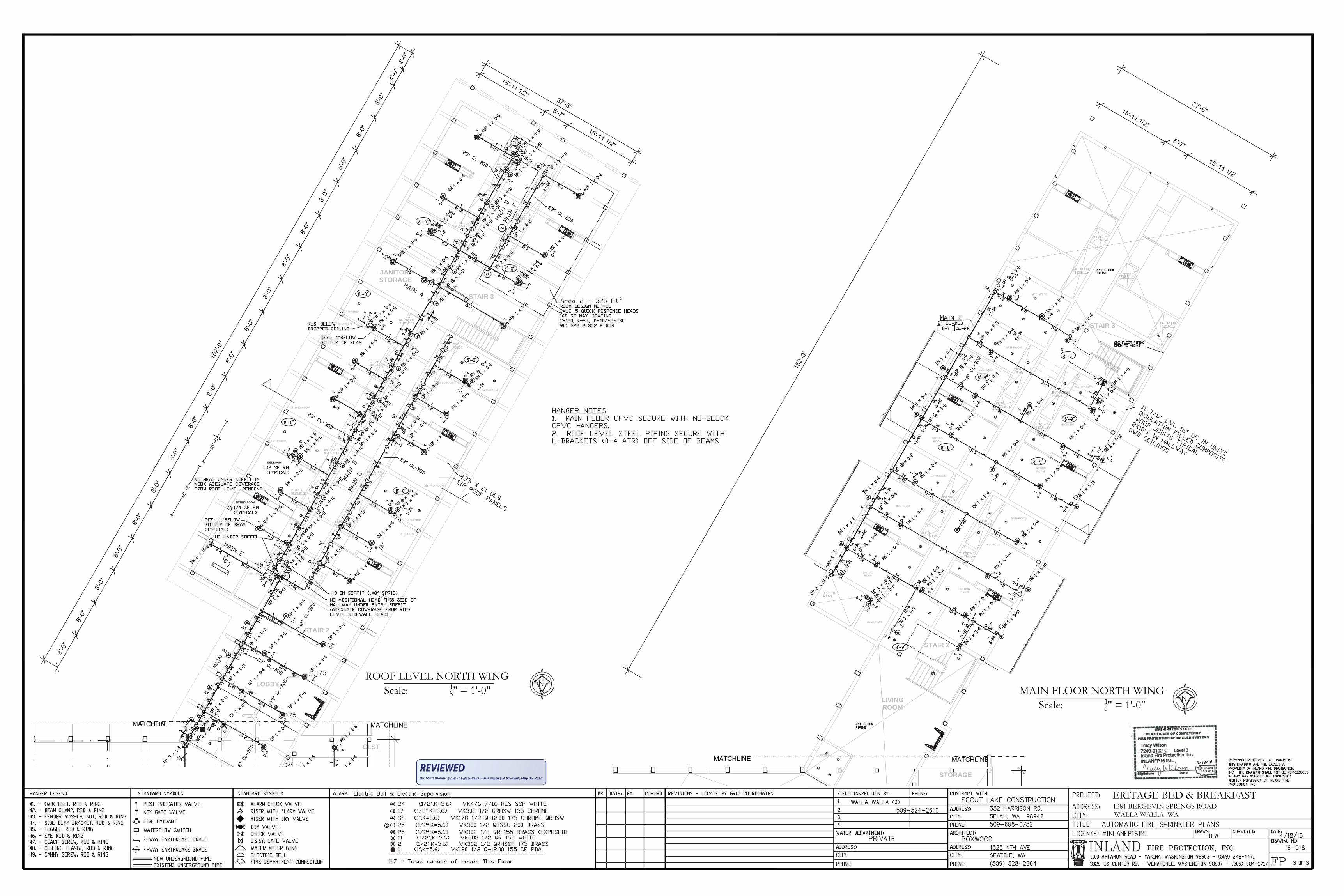
ROOF LEVEL NORTH WINGScale: 18" = 1'-0" MAIN FLOOR NORTH WING
Scale: 18" = 1'-0"
By Todd Blevins ([email protected]) at 8:50 am, May 05, 2016
By Todd Blevins ([email protected]) at 8:51 am, May 05, 2016


By Todd Blevins ([email protected]) at 8:52 am, May 05, 2016


By Todd Blevins ([email protected]) at 8:52 am, May 05, 2016


By Todd Blevins ([email protected]) at 8:54 am, May 05, 2016

By Todd Blevins ([email protected]) at 8:54 am, May 05, 2016


By Todd Blevins ([email protected]) at 8:54 am, May 05, 2016


By Todd Blevins ([email protected]) at 8:54 am, May 05, 2016

By Todd Blevins ([email protected]) at 8:54 am, May 05, 2016


By Todd Blevins ([email protected]) at 8:55 am, May 05, 2016


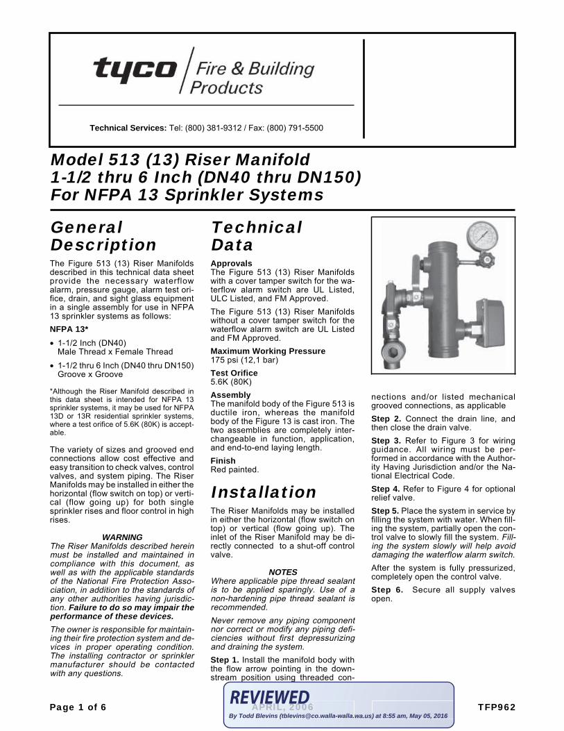
GeneralDescriptionThe Figure 513 (13) Riser Manifoldsdescribed in this technical data sheetprovide the necessary waterflowalarm, pressure gauge, alarm test ori-fice, drain, and sight glass equipmentin a single assembly for use in NFPA13 sprinkler systems as follows:NFPA 13*• 1-1/2 Inch (DN40)
Male Thread x Female Thread
• 1-1/2 thru 6 Inch (DN40 thru DN150)Groove x Groove
*Although the Riser Manifold described inthis data sheet is intended for NFPA 13sprinkler systems, it may be used for NFPA13D or 13R residential sprinkler systems,where a test orifice of 5.6K (80K) is accept-able.
The variety of sizes and grooved endconnections allow cost effective andeasy transition to check valves, controlvalves, and system piping. The RiserManifolds may be installed in either thehorizontal (flow switch on top) or verti-cal (flow going up) for both singlesprinkler rises and floor control in highrises.
WARNINGThe Riser Manifolds described hereinmust be installed and maintained incompliance with this document, aswell as with the applicable standardsof the National Fire Protection Asso-ciation, in addition to the standards ofany other authorities having jurisdic-tion. Failure to do so may impair theperformance of these devices.The owner is responsible for maintain-ing their fire protection system and de-vices in proper operating condition.The installing contractor or sprinklermanufacturer should be contactedwith any questions.
TechnicalDataApprovalsThe Figure 513 (13) Riser Manifoldswith a cover tamper switch for the wa-terflow alarm switch are UL Listed,ULC Listed, and FM Approved.The Figure 513 (13) Riser Manifoldswithout a cover tamper switch for thewaterflow alarm switch are UL Listedand FM Approved.Maximum Working Pressure175 psi (12,1 bar)Test Orifice5.6K (80K)AssemblyThe manifold body of the Figure 513 isductile iron, whereas the manifoldbody of the Figure 13 is cast iron. Thetwo assemblies are completely inter-changeable in function, application,and end-to-end laying length.FinishRed painted.
InstallationThe Riser Manifolds may be installedin either the horizontal (flow switch ontop) or vertical (flow going up). Theinlet of the Riser Manifold may be di-rectly connected to a shut-off controlvalve.
NOTESWhere applicable pipe thread sealantis to be applied sparingly. Use of anon-hardening pipe thread sealant isrecommended.Never remove any piping componentnor correct or modify any piping defi-ciencies without first depressurizingand draining the system.Step 1. Install the manifold body withthe flow arrow pointing in the down-stream position using threaded con-
nections and/or listed mechanicalgrooved connections, as applicableStep 2. Connect the drain line, andthen close the drain valve.Step 3. Refer to Figure 3 for wiringguidance. All wiring must be per-formed in accordance with the Author-ity Having Jurisdiction and/or the Na-tional Electrical Code.Step 4. Refer to Figure 4 for optionalrelief valve.Step 5. Place the system in service byfilling the system with water. When fill-ing the system, partially open the con-trol valve to slowly fill the system. Fill-ing the system slowly will help avoiddamaging the waterflow alarm switch.After the system is fully pressurized,completely open the control valve.Step 6. Secure all supply valvesopen.
Model 513 (13) Riser Manifold1-1/2 thru 6 Inch (DN40 thru DN150)For NFPA 13 Sprinkler Systems
Page 1 of 6 TFP962APRIL, 2006
Technical Services: Tel: (800) 381-9312 / Fax: (800) 791-5500
APRIRIL, 200606By Todd Blevins ([email protected]) at 8:55 am, May 05, 2016

Page 2 of 6 TFP962
FIGURE 11-1/2 INCH (DN40) RISER MANIFOLD ASSEMBLY AND DIMENSIONS
to the Waterflow Alarm Switches.
6-1/8�(155,6�mm)
12-5/8�(320,7�mm)
(131,8�mm)
Male x Male NPT
1. Approximate weight, 11.2 lbs. (5,1 kg).
Cover Tamper Switches installed internalULC Listed Manifolds are equipped with2.
N�TES:
3/4�(19,1 mm)
1�5-3/16�
NPT
1
Male x�Female NPT,
ManifoldsGroove x�Groove
10�(254,0 mm)
Manifolds
14-1/4�
11-1/8�(282,6 mm)
(362,0�mm)
2
Waterflow
3
3. CH: Common Hardware
3-1/2�(88,9 mm)
�T�.
UL/FM
Waterflow Alarm Switch:�SR-SF with Paddle,
�SR-SF with Paddle andCover Tamper Switch,ULC/FM
DESCRIPTI�N
1-1/2�Manifold �ody,
Groove x GrooveMale x Female NPT
2
N�.
1
. . . . . . . . . . . . . . .
. . . . . . . . . . . . . .
1. . . . .. . . . . . .
1
1
1N/A
976-519-02
971-096-00
N/A
P/N
Water Pressure Gauge300 psi/2000 kPa3
. . 1 2341
Closed)(Normally
Drain �alveInspector�s�Test� Drain �alve(Normally set
to �Drain�)
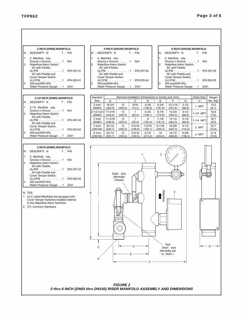
TFP962 Page 3 of 6
FIGURE 22 thru 6 INCH (DN50 thru DN150) RISER MANIFOLD ASSEMBLY AND DIMENSIONS
9/16
1(14,3)
CNominal Installation Dimensions in Inches and (mm)
1
4-5/16(25,4)
4-5/16(109,5)
(109,5)
(25,4)133 Inch 17-3/16
Cover�Tamper Switches installed internalto the Waterflow Alarm Switches.
ULC�Listed Manifolds are equipped withN�TES:
CH:�Common Hardware2.
1.
H
C
E
D
4 Inch(DN80)
6 Inch(DN150)
(DN100)
A
�
Drain �alve(NormallyClosed)
20-1/2(436,6)
20-1/2(520,7)
(520,7)
(330,2)
(330,2)
(330,2)13
13
�T�.2 INCH (DN50) MANIFOLD
DESCRIPTI�N
ULC/FM
UL/FM
Waterflow Alarm Switch:�SC�with Paddle,
�SC�with Paddle andCover�Tamper Switch,
2�Manifold �ody,Groove x Groove
300 psi/2000 kPaWater�Pressure Gauge
3
2
N�.
1
1. . . . . . . . . . . . . . .
. . . . . . . . . . . . . .
. . 1
1
. . . . . . . 1
Manifold
2 Inch
2-1/2 Inch(DN50)
(DN65)
976-357-01
976-520-01
2341
Size
N/A
P/N
16-3/4
17-3/16(425,5)
(436,6)
A
(330,2)
(330,2)
13
13
�
3-1/2 18.77-1/86 14-1/4 1-1/4��NPT
to �Drain�)(Normally set� Drain �alve
F
Test
(422,3)16-5/8
(469,9)18-1/2
(362,0)
Waterflow
1
7-9/16(152,4)
(215,9)
(192,1)8-1/2
3
9-1/16(181,0)
10(254,0)
(230,2)
2
4-1/2(88,9)
6-5/8(168,3)
(114,3)
2�NPT
2�NPT
G
32.7(8,5)
(18,9)41.6
(14,8)
Drain Size
1-1/4��NPT13-3/4(331,8)13-1/16
(349,3)
(136,5)
(146,1)
5-3/8
5-3/4
D6-3/8
6-7/8(161,9)
(174,6)
E3-1/2
3-1/2(88,9)
(88,9)
F G
1�NPT
HWeight
(6,1)13.5
16.8
lbs. (kg)
(7,6)
2 Waterflow Alarm Switch:
976-520-05
2341
976-357-05�SC�with Paddle,
�SC�with Paddle andCover�Tamper Switch,ULC/FM
UL/FM
Water�Pressure Gauge300 psi/2000 kPa3
1. .
. . . . . . . . . . . . . .
. . . . . . . . . . . . . . .
1
1
P/N
N/A
2341
976-520-04
976-357-04
N/A
P/N
1. . . . . . . . . . . . . . .UL/FM
300 psi/2000 kPaWater�Pressure Gauge
Cover�Tamper Switch,�SC�with Paddle and
ULC/FM
Groove x Groove6�Manifold �ody,
DESCRIPTI�NN�.
1
3
. . . . . . .
6 INCH (DN150) MANIFOLD�T�.
1
. . . . . . . . . . . . . .
1. .
1
Groove x Groove4�Manifold �ody,
DESCRIPTI�N
Waterflow Alarm Switch:�SC�with Paddle,
2
N�.
1. . . . . . . 1
�T�.4 INCH (DN100) MANIFOLD
1. . . . . . . . . . . . . .ULC/FM 976-520-02
2341Water�Pressure Gauge300 psi/2000 kPa3
. . 1
976-357-02. . . . . . . . . . . . . . .
Groove x Groove2-1/2�Manifold �ody,
Cover�Tamper Switch,�SC�with Paddle and
�SC�with Paddle,Waterflow Alarm Switch:
DESCRIPTI�N2-1/2 INCH (DN65) MANIFOLD
1
UL/FM
2
N�.
. . . . . . .
1
N/A1
P/N�T�.
1. . . . . . . . . . . . . .ULC/FM 976-520-03300 psi/2000 kPaWater�Pressure Gauge
31. . 2341
. . . . . . . . . . . . . . .
3�Manifold �ody,Groove x GrooveWaterflow Alarm Switch:�SC�with Paddle,
�SC�with Paddle andCover�Tamper Switch,
DESCRIPTI�N3 INCH (DN80) MANIFOLD
1
2
UL/FM
N�.
1
. . . . . . . 1
976-357-03
N/A
�T�. P/N
Page 4 of 6 TFP962
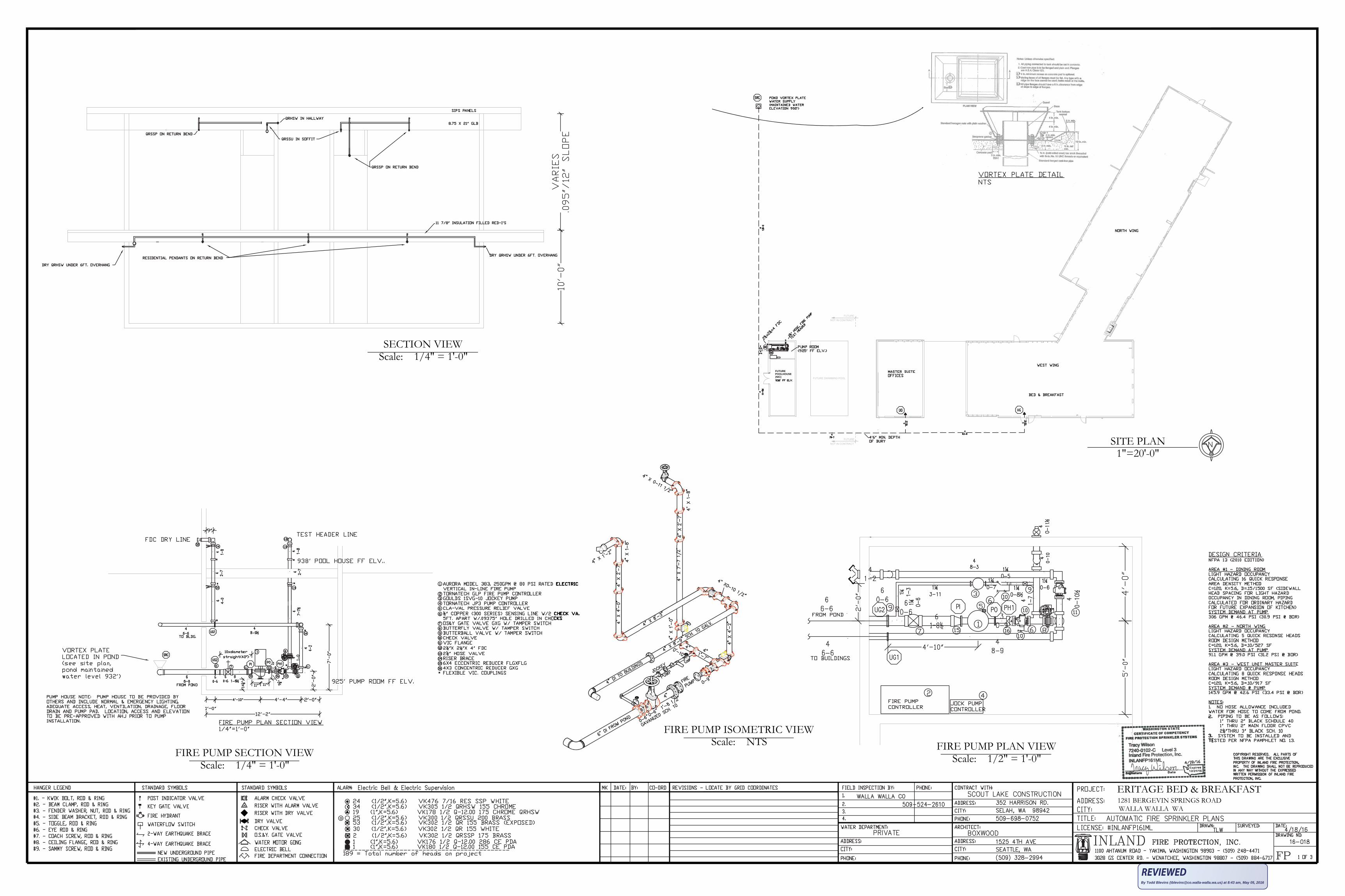
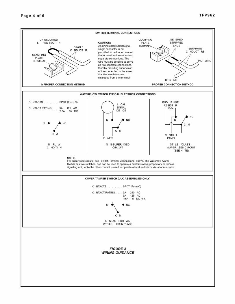
FIGURE 3WIRING GUIDANCE
INC�MING
�UTG�ING
SINGLEC�NDUCT�R
TERMINALPLATE
L��PED SECTI�NUNINSULATED
CLAMPINGC�NDUCT�RS
SEPARATE
STRIPPEDENDS
SWITCH TERMINAL CONNECTIONS
CLAMPING
TERMINALPLATE
IMPROPER CONNECTION METHOD PROPER CONNECTION METHOD
SE�EREDCAUTION:An uninsulated section of�asingle conductor is notpermitted to be looped aroundthe terminal and serve as twoseparate connections.�Thewire must be severed to serveas two separate connections,thereby providing supervisionof the connection in the eventthat the wire becomesdislodged from the terminal.
WATERFLOW SWITCH TYPICAL ELECTRICA CONNECTIONS
C�M
NCN�
N� FL�W
C�NTACTS SPDT (Form C)
5A � 125 �ACC�NTACT RATING2.5A � 30 �DC
. . . . . . . . . .
. . . .
C�M
N� NC
P�WER
SIGNALL�CAL
DE�ICE
N�N-SUPER�ISEDCIRCUITC�NDITI�N
END �F LINERESIST�R
C�M
SUPER�ISED�CIRCUITST�LE �/CLASS �
C�NTR�L
N�NC
PANEL
signaling unit, while the other contact is used to operate a local audible or visual annunciator.Switch has two switches, one can be used to operate a central station, proprietary or removeFor supervised circuits, see �Switch Terminal Connections�above. The Waterflow AlarmNOTE:
(SEE N�TE)
COVER TAMPER SWITCH (ULC ASSEMBLIES ONLY)
C�NTACTS�SH�WNWITH C��ER�IN PLACE
C�M
. . . . . . . . . .
. . . .C�NTACT RATING
N�
C�NTACTS
3A � 250 �AC5A � 125 �AC
NC
SPDT (Form C)
1mA � 5 �DC min.
Care andMaintenanceThe following inspection proceduremust be performed as indicated, in ad-dition to any specific requirements ofthe NFPA, and any impairment mustbe immediately corrected.The owner is responsible for the in-spection, testing, and maintenance oftheir fire protection system and de-vices in compliance with this docu-ment, as well as with the applicablestandards of the National Fire Protec-tion Association (e.g., NFPA 25), inaddition to the standards of anyauthority having jurisdiction. The in-stalling contractor or product manufac-turer should be contacted relative toany questions.It is recommended that automaticsprinkler systems be inspected,tested, and maintained by a qualifiedInspection Service in accordance withlocal requirements and/or nationalcodes.
NOTESNo attempt is to be made to repair any
Riser Manifold component in the field.�nly the pressure gauge, waterflowalarm switch, or relief valve can bereplaced. If any other problems areencountered the entire riser manifoldmust be replaced.The alarm/flow test procedure will re-sult in operation of the associatedalarms. Consequently, notificationmust be given to the owner and the firedepartment, central station, or othersignal station to which the alarms areconnected, and notification must begiven to the building occupants.�efore closing a fire protection systemcontrol valve for inspection or mainte-nance work on the fire protection sys-tem that it controls, permission to shutdown the effected fire protection sys-tem must first be obtained from theproper authorities and all personnelwho may be affected by this actionmust be notified.After placing a fire protection systemin service, notify the proper authoritiesand advise those responsible for moni-toring proprietary and/or central sta-tion alarms.
Alarm/Flow Test Procedure
Step 1. Place the test � drain �alve inthe �test�position.Step 2. Fully open the drain valve.Make certain that drainage water willnot cause any damage or injury.Step 3. �erify operation of associatedalarms.Step 4. Close the drain valve.Step 5. Place the test � drain �alve inthe �drain�position.Step 6. �erify that the residual (flow-ing) pressure indicated by the pres-sure gauge is no less that originallyrecorded for the system when it wasfirst installed.Step 7. Close the drain valve.Step 8. �erify that the static (not flow-ing) pressure indicated by the pres-sure gauge is no less that originallyrecorded for the system when it wasfirst installed.
TFP962 Page 5 of 6
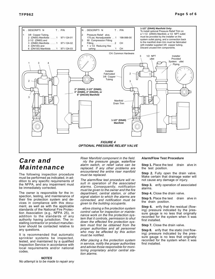
FIGURE 4OPTIONAL PRESSURE RELIEF VALVE
1
system outlet piping, and a connection back
3/8�Copper�Tubing,2�(DN50) Manifolds
6�(DN150) Manifolds4�(DN100) and3�(DN80) Manifolds
To install optional Pressure Relief�Trim�on
must be provided by the installer on thea 1-1/2�(DN40) Manifold, a 1/2�NPT�outlet
2-1/2�(DN65) and1
1
1
. . . .
. . .
. . . .
971-124-02
971-124-01
971-124-03
Pressure Relief��alve,
DESCRIPTI�N
175 psi, Nonadjustable
N�.
2
�T�.
1. . 198-066-00
P/N
CH: Common Hardware
with installer supplied 3/8�copper tubing.to the manifold drain trim must be fabricated
3
2
1 3 4
2
3
1-1/2" (DN40)Manifold
Discard unused trim components.
Fabricated3/8�Copper
Tubing
Installer
1/2��NPT�utlet
90�Compression Fitting
. . . . . . . . . . . . . .1�x 1/2�Reducing Hex4�ushing 1 CH
DESCRIPTI�NN�.
3
�T�. P/N
CH2. . . . . . . . . . . . . . . .Fitting
ManifoldDrain�Trim
3
ProvidedSystem��utlet
Installer
Piping
1-1/2" (DN40) Manifold Only:
2" (DN50), 2-1/2" (DN65),
6" (DN150) Manifold3" (DN80), 4" (DN100), or
LimitedWarrantyProducts manufactured by Tyco Fire ��uilding Products (TF�P) are war-ranted solely to the original �uyer forten (10) years against defects in mate-rial and workmanship when paid forand properly installed and maintainedunder normal use and service. Thiswarranty will expire ten (10) yearsfrom date of shipment by TF�P. Nowarranty is given for products or com-ponents manufactured by companiesnot affiliated by ownership with TF�Por for products and components whichhave been subject to misuse, improperinstallation, corrosion, or which havenot been installed, maintained, modi-fied or repaired in accordance with ap-plicable Standards of the National FireProtection Association, and/or thestandards of any other AuthoritiesHaving Jurisdiction. Materials foundby TF�P to be defective shall be eitherrepaired or replaced, at TF�P�s soleoption. TF�P neither assumes, norauthorizes any person to assume for it,any other obligation in connection withthe sale of products or parts of prod-ucts. TF�P shall not be responsible forsprinkler system design errors or inac-curate or incomplete information sup-plied by �uyer or �uyer�s repre-sentatives.In no event shall TF�P be liable, incontract, tort, strict liability or underany other legal theory, for incidental,indirect, special or consequential dam-ages, including but not limited to laborcharges, regardless of whether TF�Pwas informed about the possibility ofsuch damages, and in no event shallTF�P�s liability exceed an amountequal to the sales price.The foregoing warranty is made in lieuof any and all other warranties, ex-press or implied, including warrantiesof merchantability and fitness for a par-ticular purpose.This limited warranty sets forth the ex-clusive remedy for claims based onfailure of or defect in products, materi-als or components, whether the claimis made in contract, tort, strict liabilityor any other legal theory.This warranty will apply to the full ex-tent permitted by law. The invalidity, inwhole or part, of any portion of thiswarranty will not affect the remainder.
OrderingInformationRiser Manifold:Specify�Size (specify), Figure 513,(specify connection type inlet x outlet)Riser Manifold (specify - without orwith) a cover tamper switch for thewaterflow alarm switch, P/N (specify).
NOTES�rders for Figure 513 may be filledwith a Figure 13. The two assembliesare completely interchangeable infunction, application, and end-to-endlaying length.If a ULC Listing is required, the RiserManifold must be ordered with a covertamper switch for the waterflow alarmswitch.
UL/ULC/FM AssembliesWith Cover Tamper Switch1-1/2 Inch (DN40)
MT x FT . . . . . . . . . . . . . . P/N 40861-1/2 Inch (DN40)
MT x MT . . . . . . . . . . . . . . P/N 40872 Inch (DN50)
G x G . . . . . . . . . . . . . . . . P/N 40902-1/2 Inch (DN65)
G x G . . . . . . . . . . . . . . . . P/N 40913 Inch (DN80)
G x G . . . . . . . . . . . . . . . . P/N 40924 Inch (DN100)
G x G . . . . . . . . . . . . . . . . P/N 40956 Inch (DN150)
G x G . . . . . . . . . . . . . . . . P/N 4096
UL/FM AssembliesWithout Cover Tamper Switch1-1/2 Inch (DN40)
MT x FT . . . . . . . . . . . . . . P/N 40551-1/2 Inch (DN40)
MT x MT . . . . . . . . . . . . . . P/N 40562 Inch (DN50)
G x G . . . . . . . . . . . . . . . . P/N 40602-1/2 Inch (DN65)
G x G . . . . . . . . . . . . . . . . P/N 40613 Inch (DN80)
G x G . . . . . . . . . . . . . . . . P/N 40624 Inch (DN100)
G x G . . . . . . . . . . . . . . . . P/N 40656 Inch (DN150)
G x G . . . . . . . . . . . . . . . . P/N 4066
Optional Pressure Relief Valve:Specify: �perational Pressure Relief�alve and Trim for use with (specifysize) Figure 513 or 13 Series RiserManifold, P/N (specify).
1-1/2�or 2�. . . . . . . . . . . . . . . P/N 40632-1/2�or 3�. . . . . . . . . . . . . . . P/N 40724�or 6�. . . . . . . . . . . . . . . . . . P/N 4073
Replacement Parts:Specify: (description) for use with Fig-ure 513 or 13 Riser Manifold, P/N (Ref.Figure 1 or 2, as applicable).
Page 6 of 6 TFP962
TYCO FIRE & BUILDING PRODUCTS, 451 North Cannon Avenue, Lansdale, Pennsylvania 19446

Trusted above all ™
Features• Sizes Available (Nominal): 3/4” (DN20) through 3” (DN80) pipe diameters, with a Standard Dimension Ratio (SDR) of 13.5 as specified in ASTM F442.
• Environmental Specifications: Indoor use only. Maximum Ambient Temperature: 150°F (65°C)
• Hazen-Williams C Value: 150
• Pressure Data: Working Pressure: 175 PSI (12.1 bar) at 150°F (65°C)
• Specifications: • Meets NFPA 13R and 13D standards for residential occupancies as well as NFPA 13 standards for light hazard occupancies. • Pipe meets or exceeds ASTM F442. • Certified by NSF International for potable water services. • CPVC pipe from Viking Plastics use compound cell class 23547 (demonstrated highest structural properties). • cULus Listed, FM Approved, New York City (MEA) Approved, LPCB Approved.
CPVC PIPE PHYSICAL DATA
Nominal Pipe Size
Actual Outside Diameter
Average Inside Diameter
*Weight per 15’ (4,6 m) length Length
Approvals Part NumberInch DN Inch mm Inch mm Lb. Kg. Feet M3/4” DN20 1.050 26,670 0.874 22,199 2.52 1,14 15 4.6
cULus, FM, NSF
34PIPE1” DN25 1.315 33,401 1.101 27,965 3.93 1,78 15 4.6 1PIPE
1 1/4” DN32 1.660 42,164 1.394 35,408 6.27 2,84 15 4.6 114PIPE1 1/2” DN40 1.900 48,260 1.598 40,589 8.22 3,73 15 4.6 112PIPE
2” DN50 2.375 60,325 2.003 50,876 12.89 5,85 15 4.6 2PIPE2 1/2” DN65 2.875 73,000 2.423 61,500 18.86 8,55 15 4.6 212PIPE
3” DN80 3.500 88,900 2.950 74,900 28.01 12,71 15 4.6 3PIPE
Nominal Pipe Size
Actual Outside Diameter
Average Inside Diameter
*Weight per 10’ (3,05 m) length Length
Approvals Part NumberInch DN Inch mm Inch mm Lb. Kg. Feet M3/4” DN20 1.050 26,670 0.874 22,199 1.68 0,76 10 3,05
cULus, FM, NSF
34PIPE101” DN25 1.315 33,401 1.101 27,965 2.62 1,19 10 3,05 1PIPE10
1 1/4” DN32 1.660 42,164 1.394 35,408 4.18 1,90 10 3,05 114PIPE101 1/2” DN40 1.900 48,260 1.598 40,589 5.48 2,49 10 3,05 112PIPE10
2” DN50 2.375 60,325 2.003 50,876 8.59 3,90 10 3,05 2PIPE102 1/2” DN65 2.875 73,000 2.423 61,500 12.57 5,70 10 3,05 212PIPE10
3” DN80 3.500 88,900 2.950 74,900 18.67 8,47 10 3,05 3PIPE10NOTE: CPVC Pipe is produced in SDR 13.5 Dimensions in accordance with ASTM F442. Standard Dimension Ratio is the ratio of the outside pipe diameter to the wall thickness of the pipe.
Blazemaster® is a registered trademark of Lubrizol.
Specifications subject to change without notice
*Empty pipe weights
IMPORTANT: Installers should receive thorough hands-on training in the proper methods of assembly and installation of CPVC products.
By Todd Blevins ([email protected]) at 8:55 am, May 05, 2016

Trusted above all ™
CPVC Pipe Product Specifications
Corrosion resistant CPVC fire sprinkler pipe, when installed in strict accordance with the manufacturer’s design and instal-lation instructions, is UL and c-UL Listed by Underwriters Laboratories for use in the following:
Meets NFPA 13R and 13D standards for residential occupancies as well as NFPA 13 standards for light hazard occupancies.Residential occupancies up to and including four stories in height as defined by NFPA 13R.Residential occupancies as defined in the Standard for Sprinkler Systems in One and Two Family Dwellings, NFPA 13D.Installation of private fire service mains and their appurtenances, NFPA 24.
CPVC fire sprinkler pipe from Viking Plastics shall be employed in wet pipe systems only and are not listed for outdoor use. CPVC pipe must never be used in a system using compressed air or other gases.
••••
CPVC pipe from Viking Plastics also carries the follow-ing enhanced listings and approvals:
According to UL ListingCan be flush at return air plenumsExposed system risers NFPA 13D, 13RExposed basement NFPA 13D (solid wood joist)Extended coverage (exposed)
20’ spacing on pendent in lieu of 15’18’ spacing on sidewall in lieu of 14’
Use with combustible concealed sprinklersTyco attic sprinkler head (to protect the floor below)Tyco attic sprinkler head with wet system piping (feed main and ridge installation)
•••••
•••
Exposed sidewall sprinkler listing for exposed pipe & fittings24’ extended coverage sidewall sprinkler, 12” drop, 155°F sprinkler head18’ extended coverage sidewall sprinkler, 12” drop, 165°F sprinkler head16’ extended coverage sidewall sprinkler, 12” drop, 175°F sprinkler head14’ standard coverage sidewall sprinkler, 12” drop, 200°F sprinkler head
Factory Mutual Approved*Factory Mutual Approval exposedFactory Mutual Approval above drop-in ceilingsFactory Mutual Approval exposed w/Soffi-Steel soffiting covering system
•
••••
New and enhanced listings and approvals are being pursued. Always check with the appropriate Listing and Approval agency for details on current listing parameters.
CPVC pipe meets all applicable standards for pressure rated applica-tion as required in ANSI-NSF Standard 14 and complies with ANSI-NSF Standard 61 for health effects and are marked with the NSF-pw end use marking.
All CPVC fire sprinkler pipe shall be Listed by Underwriters Laboratories for wet pipe systems, and shall carry a rated working pressure of 175 psi @ 150°F (12 bar @ 65.5°C). *The FM Approval is limited to use in wet pipe fire protection sprinkler systems for light hazard occupancies in both concealed and exposed applications with certain restrictions.
Piping must always be installed in strict accordance to the manufacturer’s DESIGN AND INSTALLATION GUIDE, including product storage and handling, joining methods, supporting and bracing, expansion and con-traction allowance and testing, etc. National Fire Protection Association (NFPA) Standards 13, 13D, and 13R must be referenced for design and installation requirements in conjunction with the installation instructions.
All CPVC fire sprinkler pipe from Viking Plastics is manufactured in the USA. All CPVC pipe shall be packaged immediately after its manufacture to prevent damage and shall be stored indoors after production, at the manufacturing site, until shipped from the factory. The pipe shall bear the logo of the listing agencies, and shall carry the National Sanitation Foun-dation (NSF) seal of approval for potable water applications.
CPVC products are intended for use in areas where the maximum ambi-ent temperature does not exceed 150°F (65.5°C). If the ambient tempera-ture is expected to exceed this limitation, refer to the manufacturer’s DE-SIGN AND INSTALLATION GUIDE for additional information on methods to reduce the pipe exposure temperatures. CPVC pipe is not intended to be installed in outdoor applications. CPVC pipe is intended to be used in wet pipe systems only and have not been investigated for use in dry pipe systems. Special installation and design criteria relative to pipe hanger spacings, piping and sprinkler restraint, sprinkler temperature rating, piping locations, testing procedures and friction loss characteristics are specified in the manufacturer’s installation instructions provided with the pipe. The manufacturer’s installation instructions should be reviewed and the Authority Having Jurisdiction consulted before installation.
QUICK RESPONSEDRY HORIZONTAL
SIDEWALL SPRINKLERSTECHNICAL DATA
The Viking Corporation, 210 N Industrial Park Drive, Hastings MI 49058Telephone: 269-945-9501 Technical Services: 877-384-5464 Fax: 269-818-1680 Email: [email protected]
Form�No.�F�031993��Rev�15.1
Page�1�of�8
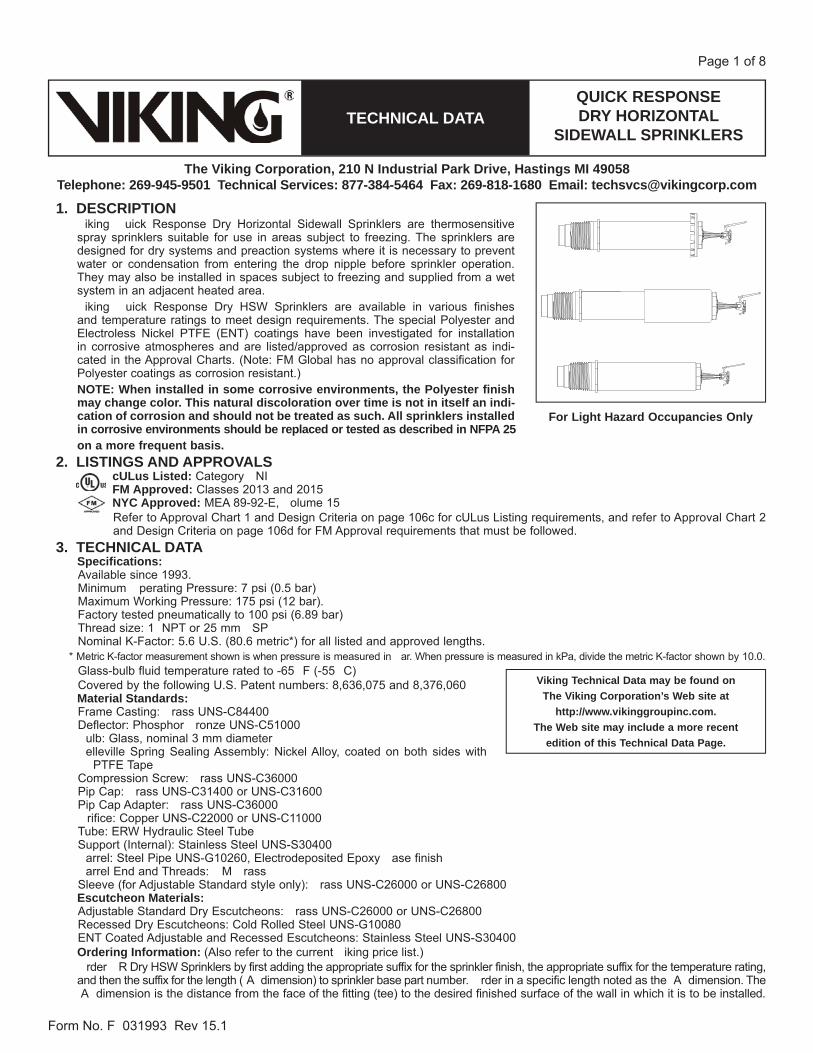
1. DESCRIPTION�iking��uick�Response�Dry�Horizontal�Sidewall�Sprinklers�are�thermosensitive�spray�sprinklers�suitable�for�use�in�areas�subject�to�freezing.�The�sprinklers�are�designed�for�dry�systems�and�preaction�systems�where�it�is�necessary�to�prevent�water�or�condensation�from�entering�the�drop�nipple�before�sprinkler�operation.�They�may�also�be�installed�in�spaces�subject�to�freezing�and�supplied�from�a�wet�system�in�an�adjacent�heated�area.�iking��uick�Response�Dry�HSW�Sprinklers�are�available�in�various�finishes�and�temperature�ratings�to�meet�design�requirements.�The�special�Polyester�and�Electroless�Nickel�PTFE�(ENT)�coatings�have�been�investigated�for�installation�in�corrosive�atmospheres�and�are�listed/approved�as�corrosion�resistant�as�indi-cated�in�the�Approval�Charts.�(Note:�FM�Global�has�no�approval�classification�for�Polyester�coatings�as�corrosion�resistant.)NOTE: When installed in some corrosive environments, the Polyester finish may change color. This natural discoloration over time is not in itself an indi-cation of corrosion and should not be treated as such. All sprinklers installed in corrosive environments should be replaced or tested as described in NFPA 25on a more frequent basis.
2. LISTINGS AND APPROVALScULus Listed: Category��NI�FM Approved:�Classes�2013�and�2015NYC Approved:�MEA�89-92-E,��olume�15Refer�to�Approval�Chart�1�and�Design�Criteria�on�page�106c�for�cULus�Listing�requirements,�and�refer�to�Approval�Chart�2�and�Design�Criteria�on�page�106d�for�FM�Approval�requirements�that�must�be�followed.
3. TECHNICAL DATASpecifi cations:Available�since�1993.Minimum��perating�Pressure:�7�psi�(0.5�bar)�Maximum�Working�Pressure:�175�psi�(12�bar).�Factory�tested�pneumatically�to�100�psi�(6.89�bar)Thread�size:�1��NPT�or�25�mm��SPNominal�K-Factor:�5.6�U.S.�(80.6�metric*)�for�all�listed�and�approved�lengths.
*�Metric�K-factor�measurement�shown�is�when�pressure�is�measured�in��ar.�When�pressure�is�measured�in�kPa,�divide�the�metric�K-factor�shown�by�10.0.Glass-bulb�fluid�temperature�rated�to�-65��F�(-55��C)Covered�by�the�following�U.S.�Patent�numbers:�8,636,075�and�8,376,060Material Standards:Frame�Casting:��rass�UNS-C84400�Deflector:�Phosphor��ronze�UNS-C51000�ulb:�Glass,�nominal�3�mm�diameter�elleville�Spring�Sealing�Assembly:�Nickel�Alloy,�coated�on�both�sides�with�
PTFE�TapeCompression�Screw:��rass�UNS-C36000Pip�Cap:��rass�UNS-C31400�or�UNS-C31600�Pip�Cap�Adapter:��rass�UNS-C36000�rifice:�Copper�UNS-C22000�or�UNS-C11000Tube:�ERW�Hydraulic�Steel�TubeSupport�(Internal):�Stainless�Steel�UNS-S30400�arrel:�Steel�Pipe�UNS-G10260,�Electrodeposited�Epoxy��ase�finish�arrel�End�and�Threads:��M��rassSleeve�(for�Adjustable�Standard�style�only):��rass�UNS-C26000�or�UNS-C26800Escutcheon Materials:Adjustable�Standard�Dry�Escutcheons:��rass�UNS-C26000�or�UNS-C26800Recessed�Dry�Escutcheons:�Cold�Rolled�Steel�UNS-G10080ENT�Coated�Adjustable�and�Recessed�Escutcheons:�Stainless�Steel�UNS-S30400Ordering Information:�(Also�refer�to�the�current��iking�price�list.)�rder��R�Dry�HSW�Sprinklers�by�first�adding�the�appropriate�suffix�for�the�sprinkler�finish,�the�appropriate�suffix�for�the�temperature�rating,�and�then�the�suffix�for�the�length�(�A��dimension)�to�sprinkler�base�part�number.��rder�in�a�specific�length�noted�as�the��A��dimension.�The��A��dimension�is�the�distance�from�the�face�of�the�fitting�(tee)�to�the�desired�finished�surface�of�the�wall�in�which�it�is�to�be�installed.
Viking Technical Data may be found on The Viking Corporation’s Web site at
http://www.vikinggroupinc.com.The Web site may include a more recent
edition of this Technical Data Page.
For Light Hazard Occupancies Only
QUICK RESPONSEDRY HORIZONTAL
SIDEWALL SPRINKLERSTECHNICAL DATA
The Viking Corporation, 210 N Industrial Park Drive, Hastings MI 49058Telephone: 269-945-9501 Technical Services: 877-384-5464 Fax: 269-818-1680 Email: [email protected]
Form�No.�F�031993��Rev�15.1
Page�2�of�8
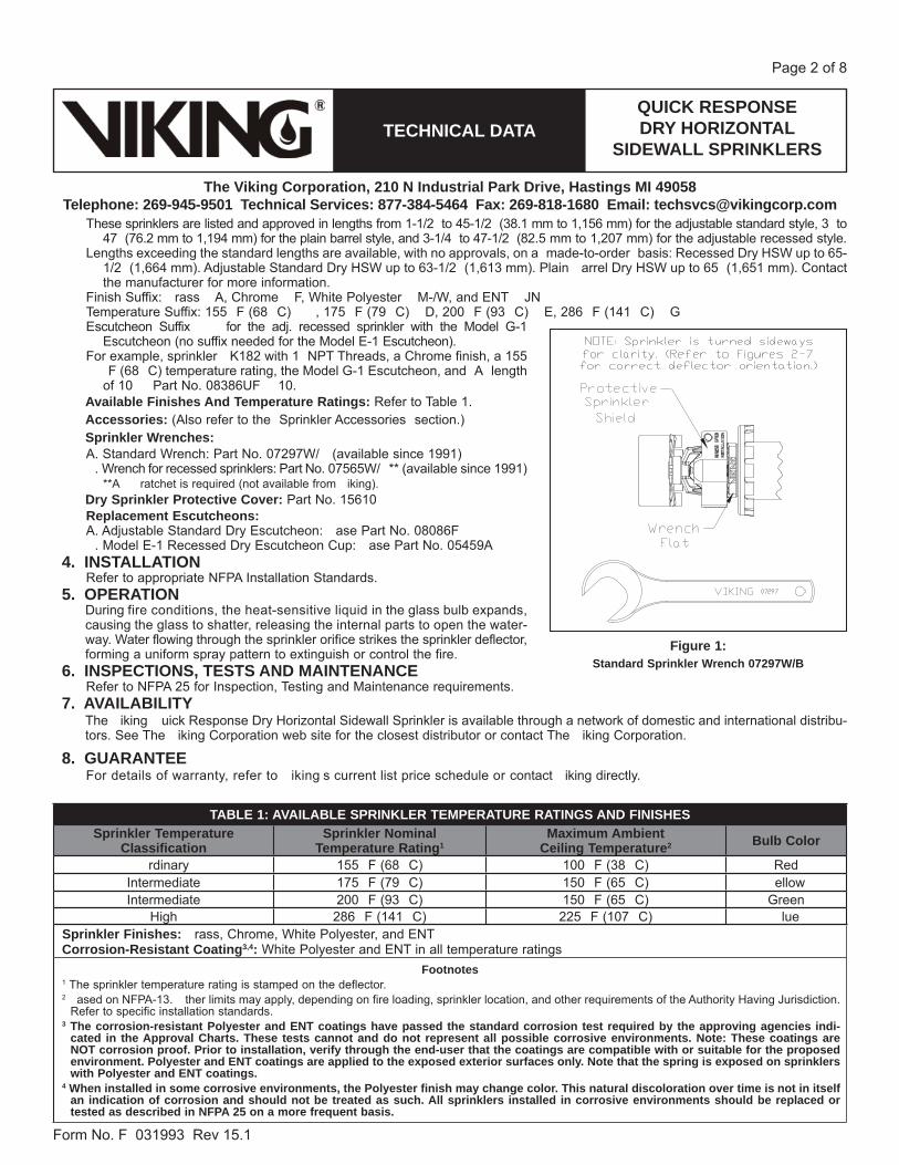
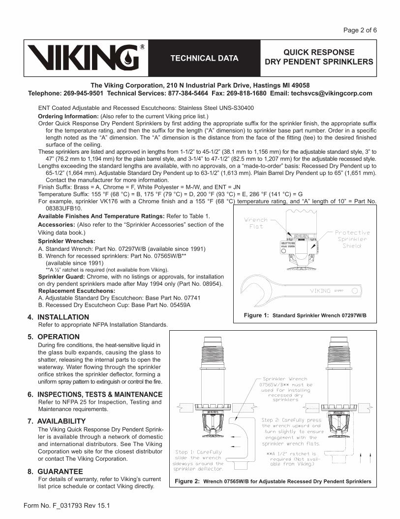
These�sprinklers�are�listed�and�approved�in�lengths�from�1-1/2��to�45-1/2��(38.1�mm�to�1,156�mm)�for�the�adjustable�standard�style,�3��to�47��(76.2�mm�to�1,194�mm)�for�the�plain�barrel�style,�and�3-1/4��to�47-1/2��(82.5�mm�to�1,207�mm)�for�the�adjustable�recessed�style.
Lengths�exceeding�the�standard�lengths�are�available,�with�no�approvals,�on�a��made-to-order��basis:�Recessed�Dry�HSW�up�to�65-1/2��(1,664�mm).�Adjustable�Standard�Dry�HSW�up�to�63-1/2��(1,613�mm).�Plain��arrel�Dry�HSW�up�to�65��(1,651�mm).�Contact�the�manufacturer�for�more�information.
Finish�Suffix:��rass���A,�Chrome���F,�White�Polyester���M-/W,�and�ENT���JNTemperature�Suffix:�155��F�(68��C)����,�175��F�(79��C)���D,�200��F�(93��C)���E,�286��F�(141��C)���GEscutcheon�Suffix�����for�the�adj.�recessed�sprinkler�with�the�Model�G-1�
Escutcheon�(no�suffix�needed�for�the�Model�E-1�Escutcheon).For�example,�sprinkler��K182�with�1��NPT�Threads,�a�Chrome�finish,�a�155�
�F�(68��C)�temperature�rating,�the�Model�G-1�Escutcheon,�and��A��length�of�10����Part�No.�08386UF��10.�
Available Finishes And Temperature Ratings:�Refer�to�Table�1.Accessories:�(Also�refer�to�the��Sprinkler�Accessories��section.)Sprinkler Wrenches:A.�Standard�Wrench:�Part�No.�07297W/��(available�since�1991)��.�Wrench�for�recessed�sprinklers:�Part�No.�07565W/�**�(available�since�1991)� **A����ratchet�is�required�(not�available�from��iking).Dry Sprinkler Protective Cover:�Part�No.�15610Replacement Escutcheons:A.�Adjustable�Standard�Dry�Escutcheon:��ase�Part�No.�08086F�.�Model�E-1�Recessed�Dry�Escutcheon�Cup:��ase�Part�No.�05459A
4. INSTALLATIONRefer�to�appropriate�NFPA�Installation�Standards.
5. OPERATIONDuring fire�conditions,�the�heat-sensitive�liquid�in�the�glass�bulb�expands,causing�the�glass�to�shatter,�releasing�the�internal�parts�to�open�the�water-way.�Water�flowing�through�the�sprinkler�orifice�strikes�the sprinkler�deflector,forming�a�uniform�spray�pattern�to�extinguish�or�control�the�fire.
6. INSPECTIONS, TESTS AND MAINTENANCERefer�to�NFPA�25�for�Inspection,�Testing�and�Maintenance�requirements.
7. AVAILABILITYThe��iking��uick�Response�Dry�Horizontal�Sidewall�Sprinkler�is�available�through�a�network�of�domestic�and�international�distribu-tors.�See�The��iking�Corporation�web�site�for�the�closest�distributor�or�contact�The��iking�Corporation.
8. GUARANTEEFor�details�of�warranty,�refer�to��iking�s�current�list�price�schedule�or�contact��iking�directly.
TABLE 1: AVAILABLE SPRINKLER TEMPERATURE RATINGS AND FINISHESSprinkler Temperature
ClassificationSprinkler Nominal
Temperature Rating1Maximum Ambient
Ceiling Temperature2 Bulb Color
�rdinary 155��F�(68��C) 100��F�(38��C) RedIntermediate 175��F�(79��C) 150��F�(65��C) �ellowIntermediate 200��F�(93��C) 150��F�(65��C) Green
High 286��F�(141��C) 225��F�(107��C) �lueSprinkler Finishes:��rass,�Chrome,�White�Polyester,�and�ENTCorrosion-Resistant Coating3,4:�White�Polyester�and�ENT�in�all�temperature�ratings
Footnotes1�The�sprinkler�temperature�rating�is�stamped�on�the�deflector.�2��ased�on�NFPA-13.��ther�limits�may�apply,�depending�on�fire�loading,�sprinkler�location,�and�other�requirements�of�the�Authority�Having�Jurisdiction.�
Refer�to�specific�installation�standards.3 The corrosion-resistant Polyester and ENT coatings have passed the standard corrosion test required by the approving agencies indi-
cated in the Approval Charts. These tests cannot and do not represent all possible corrosive environments. Note: These coatings are NOT corrosion proof. Prior to installation, verify through the end-user that the coatings are compatible with or suitable for the proposed environment. Polyester and ENT coatings are applied to the exposed exterior surfaces only. Note that the spring is exposed on sprinklerswith Polyester and ENT coatings.
4 When installed in some corrosive environments, the Polyester finish may change color. This natural discoloration over time is not in itself an indication of corrosion and should not be treated as such. All sprinklers installed in corrosive environments should be replaced or tested as described in NFPA 25 on a more frequent basis.
Figure 1:Standard Sprinkler Wrench 07297W/B

QUICK RESPONSEDRY HORIZONTAL
SIDEWALL SPRINKLERSTECHNICAL DATA
The Viking Corporation, 210 N Industrial Park Drive, Hastings MI 49058Telephone: 269-945-9501 Technical Services: 877-384-5464 Fax: 269-818-1680 Email: [email protected]
Form�No.�F�031993��Rev�15.1
Page�3�of�8
Figure 3: Adjustable Standard Dry Horizontal Sidewall Sprinkler
Figure 4: Adjustable Standard Escutcheon Installation
Figure 2: Wrench 07565W/B for Adjustable Recessed Dry Horizontal Sidewall Sprinklers

QUICK RESPONSEDRY HORIZONTAL
SIDEWALL SPRINKLERSTECHNICAL DATA
The Viking Corporation, 210 N Industrial Park Drive, Hastings MI 49058Telephone: 269-945-9501 Technical Services: 877-384-5464 Fax: 269-818-1680 Email: [email protected]
Form�No.�F�031993��Rev�15.1
Page�4�of�8
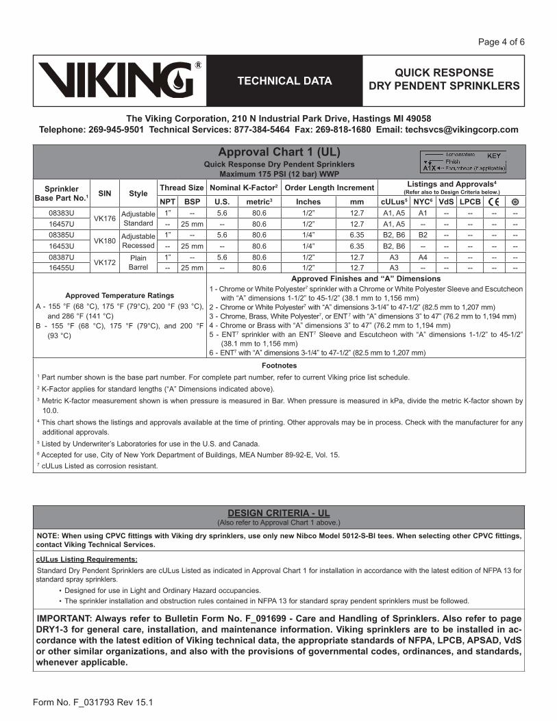
Approval Chart 1 (UL)Quick Response Dry Horizontal Sidewall Sprinklers
For Light Hazard Occupancies OnlyMaximum 175 PSI (12 bar) WWP
Sprinkler Base Part No.1 SIN Style Thread Size Nominal
K-Factor2Order Length
IncrementListings and Approvals4
(Refer also to Design Criteria on page 106e.)
NPT BSP U.S. metric3 Inches mm cULus5 NYC6 VdS LPCB08384U �K178 Adjustable
Standard1� -- 5.6 80.6 1/2� 12.7 A1,�A5 A1 -- -- -- --
16458U -- 25�mm -- 80.6 1/2� 12.7 A1,�A5 -- -- -- -- --08386U
�K182 AdjustableRecessed
1� -- 5.6 80.6 1/4� 6.35 �2,��6 �2 -- -- -- --16454U -- 25�mm -- 80.6 1/4� 6.35 �2,��6 -- -- -- -- --08388U
�K174 Plain��arrel1� -- 5.6 80.6 1/2� 12.7 A3 A4 -- -- -- --
16456U -- 25�mm -- 80.6 1/2� 12.7 A3 -- -- -- -- --
Approved Temperature RatingsA�-�155��F�(68��C),�175��F�(79�C),�200��F�
(93��C),�and�286��F�(141��C)��-�155��F�(68��C),�175��F�(79��C),�and�
200��F�(93��C)
Approved Finishes and “A” Dimensions1*�-�Chrome,�or�White�Polyester7�sprinkler�with�a�Chrome,��rass,�or�White��Polyester�Sleeve�and�
Escutcheon�with��A��dimensions�1-1/2��to�45-1/2��(38.1�mm�to�1,156�mm)2*�-�Chrome,�or�White�Polyester7�with��A��dimensions�3-1/4��to�47-1/2��(82.5�mm�to�1,207
mm)3�-�Chrome,��rass,�White�Polyester7,�or�ENT7�with��A��dimensions�3��to�47��(76.2�mm�to�1,194�mm)4�-�Chrome�or��rass�with��A��dimensions�3��to�47��(76.2�mm�to�1,194�mm)5�-�ENT7�sprinkler�with�an�ENT7�Sleeve�and�Escutcheon�with��A��dimensions�1-1/2��to�45-1/2��(38.1�
mm�to�1,156�mm)6�-�ENT7�with��A��dimensions�3-1/4��to�47-1/2��(82.5�mm�to�1,207�mm)*�rass�Finish�is�listed�and�approved�but�not�standard�offering,�lead�times�of�6-8�weeks�required.�(Matching��rass�escutcheons�are�not�available.)
Footnotes1�Part�number�shown�is�the�base�part�number.�For�complete�part�number,�refer�to�current��iking�price�list�schedule.2�K-Factor�applies�for�standard�lengths�(�A��Dimensions�indicated�above).3�Metric�K-factor�shown�is�for�use�when�pressure�is�measured�in�bar.�When�pressure�is�measured�in�kPa,�divide�the�metric�K-factor�shown�by�10.0.4�This�chart�shows�the�listings�and�approvals�available�at�the�time�of�printing.��ther�approvals�may�be�in�process.�Check�with�the�manufacturer�
for�any�additional�approvals.�5�Listed�by�Underwriter�s�Laboratories�for�use�in�the�U.S.�and�Canada�for�Light�Hazard�occupancies�only.6 Accepted�for�use,�City�of�New��ork�Department�of��uildings,�MEA�Number�89-92-E,��ol.�15.7�cULus�Listed�as�corrosion�resistant.
DESIGN CRITERIA - UL(Also�refer�to�Approval�Chart�1�above.)
NOTE: When using CPVC fittings with Viking dry sprinklers, use only new Nibco Model 5012-S-Bl tees. When selecting other CPVC fittings,contact Viking Technical Services.cULus Listing Requirements:�uick�Response�Dry�Horizontal�Sidewall�Sprinklers�are�cULus�Listed�as�indicated�in�Approval�Chart�1�for�installation�in�accordance�with�the�latest�edi-tion�of�NFPA�13�for�standard�spray�sprinklers.
�Limited�to�Light�Hazard�occupancies�only.��Protection�areas�and�maximum�spacing�shall�be�in�accordance�with�the�tables�provided�in�NFPA�13.�Minimum�spacing�allowed�is�6�ft.�(1.8�m).��Deflector�must�be�positioned�between�4��and�6��(102�mm�and�152�mm)�below�the�ceiling.�Keep�the�top�of�the�deflector�oriented�parallel�with�
the�ceiling.�Locate�no�less�than�4��(102�mm)�from�end�walls.�Maximum�distance�from�end�walls�shall�be�no�more�than�one-half�of�the�allowable�distance�between�sprinklers.�The�distance�shall�be�measured�
perpendicular�to�the�wall.�The�sprinkler�installation�and�obstruction�rules�contained�in�NFPA�13�for�sidewall�standard�spray�sprinklers�must�be�followed.
IMPORTANT: Always refer to Bulletin Form No. F_091699 - Care and Handling of Sprinklers. Also refer to page DRY1-3 for general care, installation, and maintenance information. Viking sprinklers are to be installed in accordance with the latest edition of Viking technical data, the appropriate standards of NFPA, LPCB, APSAD, VdS or other similar organizations, and also with the provisions of governmental codes, ordinances, and standards, whenever applicable.

QUICK RESPONSEDRY HORIZONTAL
SIDEWALL SPRINKLERSTECHNICAL DATA
The Viking Corporation, 210 N Industrial Park Drive, Hastings MI 49058Telephone: 269-945-9501 Technical Services: 877-384-5464 Fax: 269-818-1680 Email: [email protected]
Form�No.�F�031993��Rev�15.1
Page�5�of�8
Approval Chart 2 (FM)Quick Response Dry Horizontal Sidewall Sprinklers
For Light Hazard Occupancies OnlyMaximum 175 PSI (12 bar) WWP
Sprinkler Base Part No.1 SIN Style
Thread Size Nominal K-Factor2 Order Length Increment FM Approvals4
(Refer also to Design Criteria below.)NPT BSP U.S. metric3 Inches mm08384U
�K178 Adjustable�Standard1� -- 5.6 80.6 1/2� 12.7 A1
16458U -- 25�mm -- 80.6 1/2� 12.7 A108386U
�K182 Adjustable�Recessed1� -- 5.6 80.6 1/4� 6.35 �2
16454U -- 25�mm -- 80.6 1/4� 6.35 �208388U
�K174 Plain��arrel1� -- 5.6 80.6 1/2� 12.7 A3
16456U -- 25�mm -- 80.6 1/2� 12.7 A3
Approved Temperature RatingsA�-�155��F�(68��C),�175��F�(79��C),�200��F�(93��C),�and�
286��F�(141��C)��-�155��F�(68��C),�175��F�(79��C),�and�200��F�(93��C)
Approved Finishes and “A” Dimensions1*�-��right��rass,�Chrome,�White�Polyester,�or�ENT5�with��A��dimensions�1-1/2��to�45-1/2��(38.1�
mm�to�1,156�mm)2*�-��right��rass,�Chrome,�White�Polyester,�or�ENT5�with��A��dimensions�3-1/4��to�47-1/2��(82.5�
mm�to�1,207�mm)3�-��rass,��right��rass,�Chrome,�White�Polyester,�or�ENT5��A��dimensions�3��to�47��(76.2�mm�to�
1,194�mm)*�rass�Finish�is�listed�and�approved�but�not�standard�offering,�lead�times�of�6-8�weeks�required.�(Matching��rass�escutcheons�are�not�available.)
Footnotes1�Part�number�shown�is�the�base�part�number.�For�complete�part�number,�refer�to�current��iking�price�list�schedule.2�K-Factor�applies�for�standard�lengths�(�A��Dimensions�indicated�above).3�Metric�K-factor�shown�is�for�use�when�pressure�is�measured�in�bar.�When�pressure�is�measured�in�kPa,�divide�the�metric�K-factor�shown�by�10.0.4�This�chart�shows�the�FM�Approvals�available�at�the�time�of�printing.��ther�approvals�may�be�in�process.�Check�with�the�manufacturer�for�
any�additional�approvals.�5�FM�approved�as�corrosion�resistant.
DESIGN CRITERIA - FM(Also�refer�to�Approval�Chart�2�above.)
NOTE: When using CPVC fittings with Viking dry sprinklers, use only new Nibco Model 5012-S-Bl tees. When selecting other CPVC fittings,contact Viking Technical Services.
FM Approval Requirements:The�Dry�HSW�Sprinklers�in�the�Approval�Chart�above�are�FM�Approved�as�quick�response�Non-storage�standard�spray�sprinklers�as�indicated�in�the�FM�Approval�Guide.�For�specific�application�and�installation�requirements,�reference�the�latest�applicable�FM�Loss�Prevention�Data�Sheets�(including�2-0)�and�Technical�Advisory��ulletins.�FM�Global�Loss�Prevention�Data�Sheets�and�Technical�Advisory��ulletins�contain�guidelines�relating�to,�but�not�limited�to:�minimum�water�supply�requirements,�hydraulic�design,�ceiling�slope�and�obstructions,�minimum�and�maximum�allowable�spacing,�and�deflec-tor�distance�below�the�ceiling.NOTE: The FM installation guidelines may differ from cULus and/or NFPA criteria.
IMPORTANT: Always refer to Bulletin Form No. F_091699 - Care and Handling of Sprinklers. Also refer to page DRY1-3 for general care, installation, and maintenance information. Viking sprinklers are to be installed in accordance with the latest edition of Viking technical data, the appropriate standards of NFPA, FM Global, LPCB, APSAD, VdS or other simi-lar organizations, and also with the provisions of governmental codes, ordinances, and standards, whenever applicable.
QUICK RESPONSEDRY HORIZONTAL
SIDEWALL SPRINKLERSTECHNICAL DATA
The Viking Corporation, 210 N Industrial Park Drive, Hastings MI 49058Telephone: 269-945-9501 Technical Services: 877-384-5464 Fax: 269-818-1680 Email: [email protected]
Form�No.�F�031993��Rev�15.1
Page�6�of�8
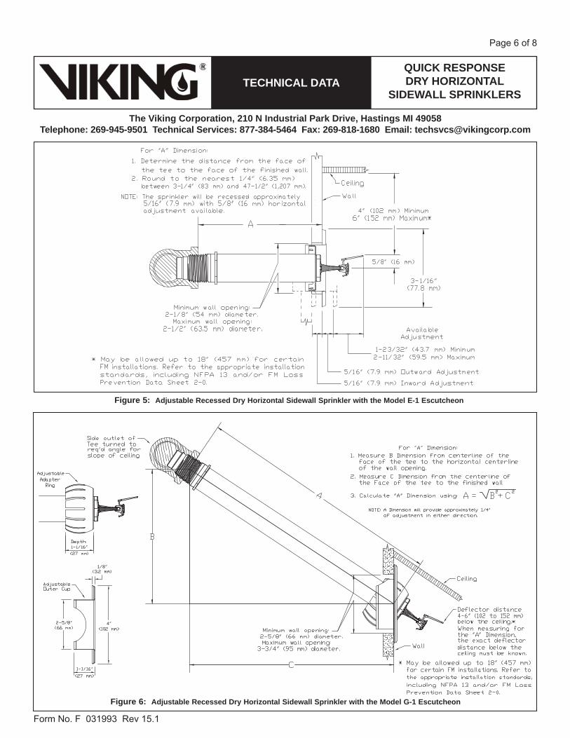
Figure 6: Adjustable Recessed Dry Horizontal Sidewall Sprinkler with the Model G-1 Escutcheon
Figure 5: Adjustable Recessed Dry Horizontal Sidewall Sprinkler with the Model E-1 Escutcheon

QUICK RESPONSEDRY HORIZONTAL
SIDEWALL SPRINKLERSTECHNICAL DATA
The Viking Corporation, 210 N Industrial Park Drive, Hastings MI 49058Telephone: 269-945-9501 Technical Services: 877-384-5464 Fax: 269-818-1680 Email: [email protected]
Form�No.�F�031993��Rev�15.1
Page�7�of�8
Press�the�cover�togetheruntil�it�snaps�closed.
Figure 8: Dry Horizontal Sidewall Sprinkler Cover Part Number 15610 (shown with an Adjustable Standard Dry HSW Sprinkler)(Optional for temporary use with Viking Dry HSW Sprinklers until finish work is completed around the sprinkler.)
After�the�sprinkler�is�installed,�carefully�place�the�cover�over�
the�dry�sprinkler�as�shown. NOTE: Remove the sprinkler clip and coverbefore placing the system in service!
Top��iew�-�Dry�HSW�SprinklerSide��iew�-�Sprinkler�Cover�15610
N�TE:�Shown�with�an�Adjustable�Standard�Dry�HSW�Sprinkler.�The�protective�cover�may�also�be�used�with�the�Adjustable�Recessed
or�Plain��arrel�style�Dry�HSW�Sprinkler.
Figure 7: Quick Response Plain Barrel Dry Horizontal Sidewall Sprinkler
QUICK RESPONSEDRY HORIZONTAL
SIDEWALL SPRINKLERSTECHNICAL DATA
The Viking Corporation, 210 N Industrial Park Drive, Hastings MI 49058Telephone: 269-945-9501 Technical Services: 877-384-5464 Fax: 269-818-1680 Email: [email protected]
Form�No.�F�031993��Rev�15.1
Page�8�of�8
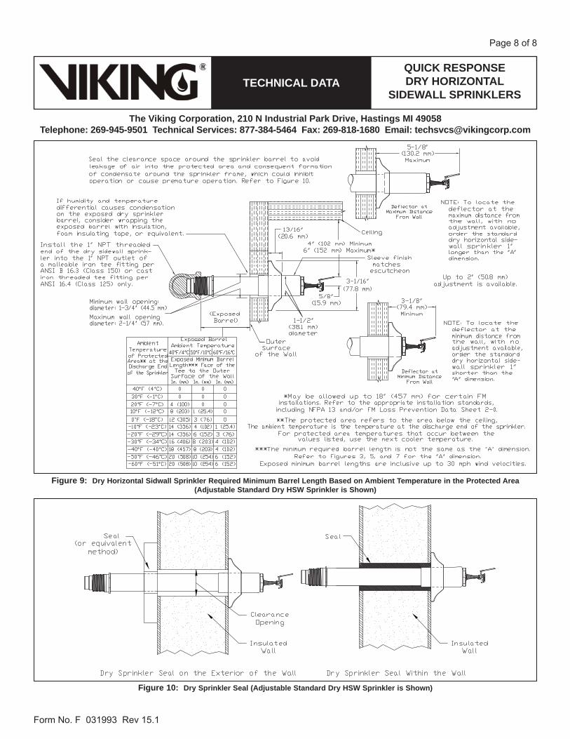
Figure 10: Dry Sprinkler Seal (Adjustable Standard Dry HSW Sprinkler is Shown)
Figure 9: Dry Horizontal Sidwall Sprinkler Required Minimum Barrel Length Based on Ambient Temperature in the Protected Area(Adjustable Standard Dry HSW Sprinkler is Shown)

By Todd Blevins ([email protected]) at 8:56 am, May 05, 2016


By Todd Blevins ([email protected]) at 8:56 am, May 05, 2016


MICROFAST® QUICK RESPONSE PENDENT
SPRINKLER VK302 (K5.6)TECHNICAL DATA
The Viking Corporation, 210 N Industrial Park Drive, Hastings MI 49058Telephone: 269-945-9501 Technical Services: 877-384-5464 Fax: 269-818-1680 Email: [email protected]
Form No. F_033314 16.01.28 Rev 16.1
Page 1 of 6
1. DESCRIPTIONThe Viking Microfast® Quick Response Pendent Sprinkler VK302 is a small thermosensitive glass bulb spray sprinkler available with various finishes and temperature ratings to meet design requirements. The special Polyester, Polytetrafluoroethelyne (PTFE), and Electroless Nickel PTFE (ENT) coatings can be used in decorative applications where colors are desired. In addition, these coatings have been investigated for installation in corrosive atmospheres and are listed/approved as corrosion resistant as indicated in the ApprovalCharts. (Note: FM Global approves ENT finish as corrosion resistant. FM Global has no approval classification for PTFE and Polyester coatings as corro-sion resistant.)
2. LISTINGS AND APPROVALScULus Listed: Category VNIV
FM Approved: Class Series 2000
VdS Approved: Certificates G414009 and G414010
LPCB Approved
CE Certified: Standard EN 12259-1:1999, A3:2006 Certificate of Constancy of Performance 0832-CPR-S0021
CCCF Approved: Approved by the China Certification Center for Fire Products (CCCF)Refer to Approval Chart 1 and Design Criteria cULus Listing requirements, and refer to Approval Chart 2 and Design Criteria for FM Approval requirements that must be followed.
3. TECHNICAL DATASpeci cations:Minimum Operating Pressure: 7 psi (0.5 bar) Rated to 175 psi (12 bar) water working pressureFactory tested hydrostatically to 500 psi (34.5 bar)Thread size: 1/2” NPT, 15 mm BSPNominal K-Factor: 5.6 U.S. (80.6 metric**)
Glass-bulb fluid temperature rated to -65 °F (-55 °C)Overall Length: 2-1/4” (58 mm)
*cULus Listing, FM Approval, and NFPA 13 installs require a minimum of 7 psi (0.5 bar). The minimum operating pressure for LPCB and CE Approvals ONLY is 5 psi (0.35 bar).
Material Standards:Frame Casting: Brass UNS-C84400 or QM Brass Deflector: Phosphor Bronze UNS-C51000 or Copper UNS-C19500Bulb: Glass, nominal 3 mm diameterBelleville Spring Sealing Assembly: Nickel Alloy, coated on both sides with PTFE TapeScrew: Brass UNS-C36000Pip Cap and Insert Assembly: Copper UNS-C11000 and Stainless Steel UNS-S30400 For PTFE Coated Sprinklers: Belleville Spring-Exposed, Screw-Nickel Plated, Pip Cap-PTFE CoatedFor Polyester Coated Sprinklers: Belleville Spring-ExposedFor ENT Coated Sprinklers: Belleville Spring-Exposed, Screw and Pipcap - ENT plated.Ordering Information: (Also refer to the current Viking price list.)Order Quick Response Pendent Sprinklers by first adding the appropriate suffix for the sprinkler finish and then the appropriate
suffix for the temperature rating to the sprinkler base part number. Finish Suffix: Brass = A, Chrome = F, White Polyester = M-/W, Black Polyester = M-/B, Black PTFE = N, and ENT = JNTemperature Suffix: 135 °F (57 °C) = A, 155 °F (68 °C) = B, 175 °F (79 °C) = D, 200 °F (93 °C) = E, 286 °F (141 °C) = GFor example, sprinkler VK302 with a Brass finish and a 155 °F (68 °C) temperature rating = Part No. 12979AB
Viking Technical Data may be found on The Viking Corporation’s Web site at
http://www.vikinggroupinc.com.The Web site may include a more recent
edition of this Technical Data Page.
Replaces Form F_033314 Rev 15.2 (Revised temperature suf x designation)
By Todd Blevins ([email protected]) at 8:56 am, May 05, 2016
MICROFAST® QUICK RESPONSE PENDENT
SPRINKLER VK302 (K5.6)TECHNICAL DATA
The Viking Corporation, 210 N Industrial Park Drive, Hastings MI 49058Telephone: 269-945-9501 Technical Services: 877-384-5464 Fax: 269-818-1680 Email: [email protected]
Form No. F_033314 16.01.28 Rev 16.1
Page 2 of 6
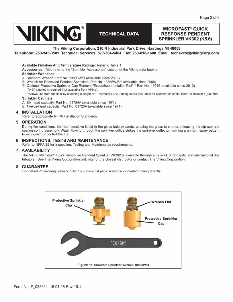
Available Finishes And Temperature Ratings: Refer to Table 1.Accessories: (Also refer to the “Sprinkler Accessories” section of the Viking data book.)Sprinkler Wrenches:A. Standard Wrench: Part No. 10896W/B (available since 2000). B. Wrench for Recessed Pendent Sprinklers: Part No. 13655W/B** (available since 2006)C. Optional Protective Sprinkler Cap Remover/Escutcheon Installer Tool*** Part No. 15915 (available since 2010) **A ½” ratchet is required (not available from Viking).
***Allows use from the floor by attaching a length of 1” diameter CPVC tubing to the tool. Ideal for sprinkler cabinets. Refer to Bulletin F_051808.Sprinkler Cabinets:A. Six-head capacity: Part No. 01724A (available since 1971)B. Twelve-head capacity: Part No. 01725A (available since 1971)
4. INSTALLATIONRefer to appropriate NFPA Installation Standards.
5. OPERATIONDuring fire conditions, the heat-sensitive liquid in the glass bulb expands, causing the glass to shatter, releasing the pip cap and sealing spring assembly. Water flowing through the sprinkler orifice strikes the sprinkler deflector, forming a uniform spray pattern to extinguish or control the fire.
6. INSPECTIONS, TESTS AND MAINTENANCERefer to NFPA 25 for Inspection, Testing and Maintenance requirements.
7. AVAILABILITYThe Viking Microfast® Quick Response Pendent Sprinkler VK302 is available through a network of domestic and international dis-tributors. See The Viking Corporation web site for the closest distributor or contact The Viking Corporation.
8. GUARANTEEFor details of warranty, refer to Viking’s current list price schedule or contact Viking directly.
Figure 1: Standard Sprinkler Wrench 10896W/B
Protective Sprinkler Cap
Wrench FlatProtective Sprinkler Clip
MICROFAST® QUICK RESPONSE PENDENT
SPRINKLER VK302 (K5.6)TECHNICAL DATA
The Viking Corporation, 210 N Industrial Park Drive, Hastings MI 49058Telephone: 269-945-9501 Technical Services: 877-384-5464 Fax: 269-818-1680 Email: [email protected]
Form No. F_033314 16.01.28 Rev 16.1
Page 3 of 6
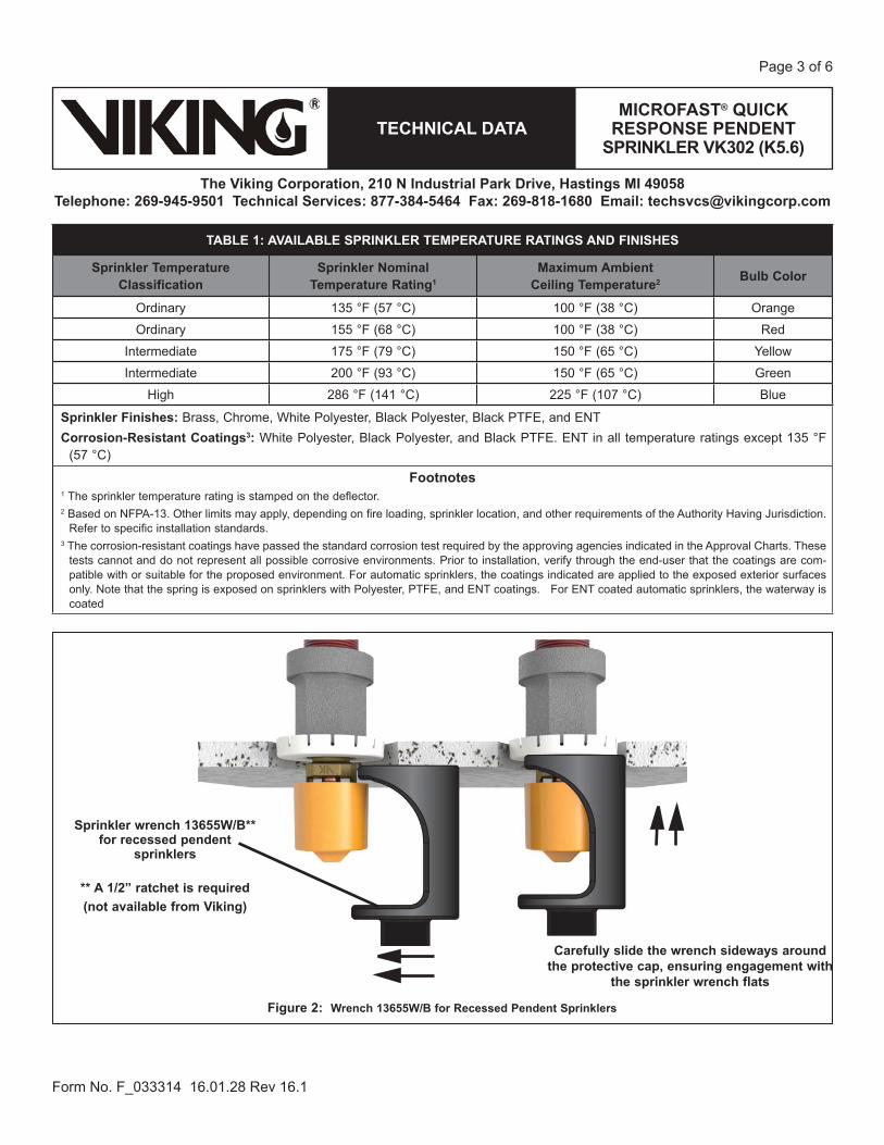
TABLE 1: AVAILABLE SPRINKLER TEMPERATURE RATINGS AND FINISHES
Sprinkler Temperature Classification
Sprinkler Nominal Temperature Rating1
Maximum Ambient Ceiling Temperature2 Bulb Color
Ordinary 135 °F (57 °C) 100 °F (38 °C) Orange
Ordinary 155 °F (68 °C) 100 °F (38 °C) Red
Intermediate 175 °F (79 °C) 150 °F (65 °C) Yellow
Intermediate 200 °F (93 °C) 150 °F (65 °C) Green
High 286 °F (141 °C) 225 °F (107 °C) Blue
Sprinkler Finishes: Brass, Chrome, White Polyester, Black Polyester, Black PTFE, and ENTCorrosion-Resistant Coatings3: White Polyester, Black Polyester, and Black PTFE. ENT in all temperature ratings except 135 °F
(57 °C)
Footnotes1 The sprinkler temperature rating is stamped on the deflector. 2 Based on NFPA-13. Other limits may apply, depending on fire loading, sprinkler location, and other requirements of the Authority Having Jurisdiction.
Refer to specific installation standards.3 The corrosion-resistant coatings have passed the standard corrosion test required by the approving agencies indicated in the Approval Charts. These
tests cannot and do not represent all possible corrosive environments. Prior to installation, verify through the end-user that the coatings are com-patible with or suitable for the proposed environment. For automatic sprinklers, the coatings indicated are applied to the exposed exterior surfaces only. Note that the spring is exposed on sprinklers with Polyester, PTFE, and ENT coatings. For ENT coated automatic sprinklers, the waterway is coated
Figure 2: Wrench 13655W/B for Recessed Pendent Sprinklers
Carefully slide the wrench sideways around the protective cap, ensuring engagement with
the sprinkler wrench flats
Sprinkler wrench 13655W/B** for recessed pendent
sprinklers
** A 1/2” ratchet is required(not available from Viking)
MICROFAST® QUICK RESPONSE PENDENT
SPRINKLER VK302 (K5.6)TECHNICAL DATA
The Viking Corporation, 210 N Industrial Park Drive, Hastings MI 49058Telephone: 269-945-9501 Technical Services: 877-384-5464 Fax: 269-818-1680 Email: [email protected]
Form No. F_033314 16.01.28 Rev 16.1
Page 4 of 6
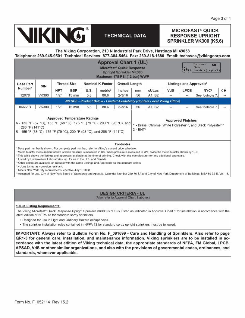
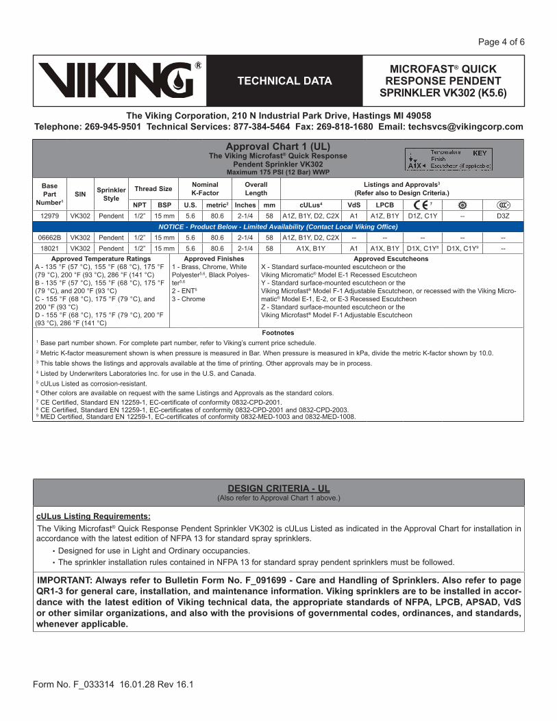
Approval Chart 1 (UL)The Viking Microfast® Quick Response
Pendent Sprinkler VK302 Maximum 175 PSI (12 Bar) WWP
Base Part
Number1SIN Sprinkler
StyleThread Size Nominal
K-FactorOverall Length
Listings and Approvals3
(Refer also to Design Criteria.)
NPT BSP U.S. metric2 Inches mm cULus4 VdS LPCB 7
12979 VK302 Pendent 1/2” 15 mm 5.6 80.6 2-1/4 58 A1Z, B1Y, D2, C2X A1 A1Z, B1Y D1Z, C1Y -- D3ZNOTICE - Product Below - Limited Availability (Contact Local Viking Office)
06662B VK302 Pendent 1/2” 15 mm 5.6 80.6 2-1/4 58 A1Z, B1Y, D2, C2X -- -- -- -- --18021 VK302 Pendent 1/2” 15 mm 5.6 80.6 2-1/4 58 A1X, B1Y A1 A1X, B1Y D1X, C1Y8 D1X, C1Y9 --
Approved Temperature RatingsA - 135 °F (57 °C), 155 °F (68 °C), 175 °F (79 °C), 200 °F (93 °C), 286 °F (141 °C)B - 135 °F (57 °C), 155 °F (68 °C), 175 °F (79 °C), and 200 °F (93 °C)C - 155 °F (68 °C), 175 °F (79 °C), and 200 °F (93 °C)D - 155 °F (68 °C), 175 °F (79 °C), 200 °F (93 °C), 286 °F (141 °C)
Approved Finishes1 - Brass, Chrome, White Polyester5,6, Black Polyes-ter5,6
2 - ENT5
3 - Chrome
Approved EscutcheonsX - Standard surface-mounted escutcheon or the Viking Micromatic® Model E-1 Recessed EscutcheonY - Standard surface-mounted escutcheon or the Viking Microfast® Model F-1 Adjustable Escutcheon, or recessed with the Viking Micro-matic® Model E-1, E-2, or E-3 Recessed EscutcheonZ - Standard surface-mounted escutcheon or the Viking Microfast® Model F-1 Adjustable Escutcheon
Footnotes1 Base part number shown. For complete part number, refer to Viking’s current price schedule.2 Metric K-factor measurement shown is when pressure is measured in Bar. When pressure is measured in kPa, divide the metric K-factor shown by 10.0.3 This table shows the listings and approvals available at the time of printing. Other approvals may be in process.4 Listed by Underwriters Laboratories Inc. for use in the U.S. and Canada.5 cULus Listed as corrosion-resistant.6 Other colors are available on request with the same Listings and Approvals as the standard colors.7 CE Certified, Standard EN 12259-1, EC-certificate of conformity 0832-CPD-2001.8 CE Certified, Standard EN 12259-1, EC-certificates of conformity 0832-CPD-2001 and 0832-CPD-2003.9 MED Certified, Standard EN 12259-1, EC-certificates of conformity 0832-MED-1003 and 0832-MED-1008.
DESIGN CRITERIA - UL (Also refer to Approval Chart 1 above.)
cULus Listing Requirements: The Viking Microfast® Quick Response Pendent Sprinkler VK302 is cULus Listed as indicated in the Approval Chart for installation in accordance with the latest edition of NFPA 13 for standard spray sprinklers.
Designed for use in Light and Ordinary occupancies. The sprinkler installation rules contained in NFPA 13 for standard spray pendent sprinklers must be followed.
IMPORTANT: Always refer to Bulletin Form No. F_091699 - Care and Handling of Sprinklers. Also refer to page QR1-3 for general care, installation, and maintenance information. Viking sprinklers are to be installed in accor-dance with the latest edition of Viking technical data, the appropriate standards of NFPA, LPCB, APSAD, VdS or other similar organizations, and also with the provisions of governmental codes, ordinances, and standards, whenever applicable.
MICROFAST® QUICK RESPONSE PENDENT
SPRINKLER VK302 (K5.6)TECHNICAL DATA
The Viking Corporation, 210 N Industrial Park Drive, Hastings MI 49058Telephone: 269-945-9501 Technical Services: 877-384-5464 Fax: 269-818-1680 Email: [email protected]
Form No. F_033314 16.01.28 Rev 16.1
Page 5 of 6
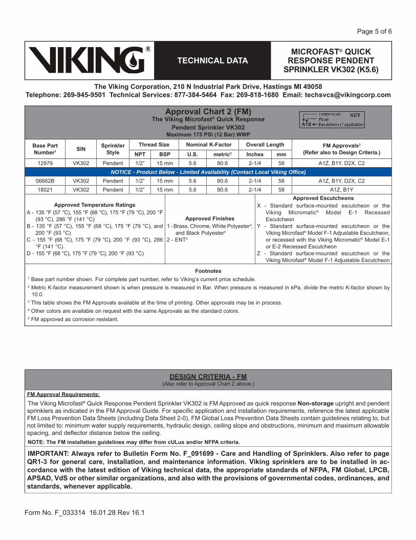
Approval Chart 2 (FM)The Viking Microfast® Quick Response
Pendent Sprinkler VK302 Maximum 175 PSI (12 Bar) WWP
Base Part Number1 SIN Sprinkler
StyleThread Size Nominal K-Factor Overall Length FM Approvals3
(Refer also to Design Criteria.)NPT BSP U.S. metric2 Inches mm12979 VK302 Pendent 1/2” 15 mm 5.6 80.6 2-1/4 58 A1Z, B1Y, D2X, C2
NOTICE - Product Below - Limited Availability (Contact Local Viking Office)06662B VK302 Pendent 1/2” 15 mm 5.6 80.6 2-1/4 58 A1Z, B1Y, D2X, C218021 VK302 Pendent 1/2” 15 mm 5.6 80.6 2-1/4 58 A1Z, B1Y
Approved Temperature RatingsA - 135 °F (57 °C), 155 °F (68 °C), 175 °F (79 °C), 200 °F
(93 °C), 286 °F (141 °C)B - 135 °F (57 °C), 155 °F (68 °C), 175 °F (79 °C), and
200 °F (93 °C)C - 155 °F (68 °C), 175 °F (79 °C), 200 °F (93 °C), 286
°F (141 °C)D - 155 °F (68 °C), 175 °F (79 °C), 200 °F (93 °C)
Approved Finishes1 - Brass, Chrome, White Polyester4,
and Black Polyester4
2 - ENT5
Approved EscutcheonsX - Standard surface-mounted escutcheon or the
Viking Micromatic® Model E-1 Recessed Escutcheon
Y - Standard surface-mounted escutcheon or the Viking Microfast® Model F-1 Adjustable Escutcheon, or recessed with the Viking Micromatic® Model E-1 or E-2 Recessed Escutcheon
Z - Standard surface-mounted escutcheon or the Viking Microfast® Model F-1 Adjustable Escutcheon
Footnotes1 Base part number shown. For complete part number, refer to Viking’s current price schedule.2 Metric K-factor measurement shown is when pressure is measured in Bar. When pressure is measured in kPa, divide the metric K-factor shown by
10.0.3 This table shows the FM Approvals available at the time of printing. Other approvals may be in process.4 Other colors are available on request with the same Approvals as the standard colors.5 FM approved as corrosion resistant.
DESIGN CRITERIA - FM (Also refer to Approval Chart 2 above.)
FM Approval Requirements: The Viking Microfast® Quick Response Pendent Sprinkler VK302 is FM Approved as quick response Non-storage upright and pendent sprinklers as indicated in the FM Approval Guide. For specific application and installation requirements, reference the latest applicable FM Loss Prevention Data Sheets (including Data Sheet 2-0). FM Global Loss Prevention Data Sheets contain guidelines relating to, but not limited to: minimum water supply requirements, hydraulic design, ceiling slope and obstructions, minimum and maximum allowable spacing, and deflector distance below the ceiling.NOTE: The FM installation guidelines may differ from cULus and/or NFPA criteria.
IMPORTANT: Always refer to Bulletin Form No. F_091699 - Care and Handling of Sprinklers. Also refer to page QR1-3 for general care, installation, and maintenance information. Viking sprinklers are to be installed in ac-cordance with the latest edition of Viking technical data, the appropriate standards of NFPA, FM Global, LPCB, APSAD, VdS or other similar organizations, and also with the provisions of governmental codes, ordinances, and standards, whenever applicable.
MICROFAST® QUICK RESPONSE PENDENT
SPRINKLER VK302 (K5.6)TECHNICAL DATA
The Viking Corporation, 210 N Industrial Park Drive, Hastings MI 49058Telephone: 269-945-9501 Technical Services: 877-384-5464 Fax: 269-818-1680 Email: [email protected]
Form No. F_033314 16.01.28 Rev 16.1
Page 6 of 6
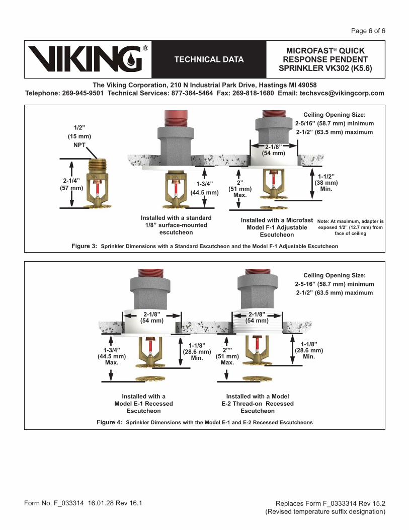
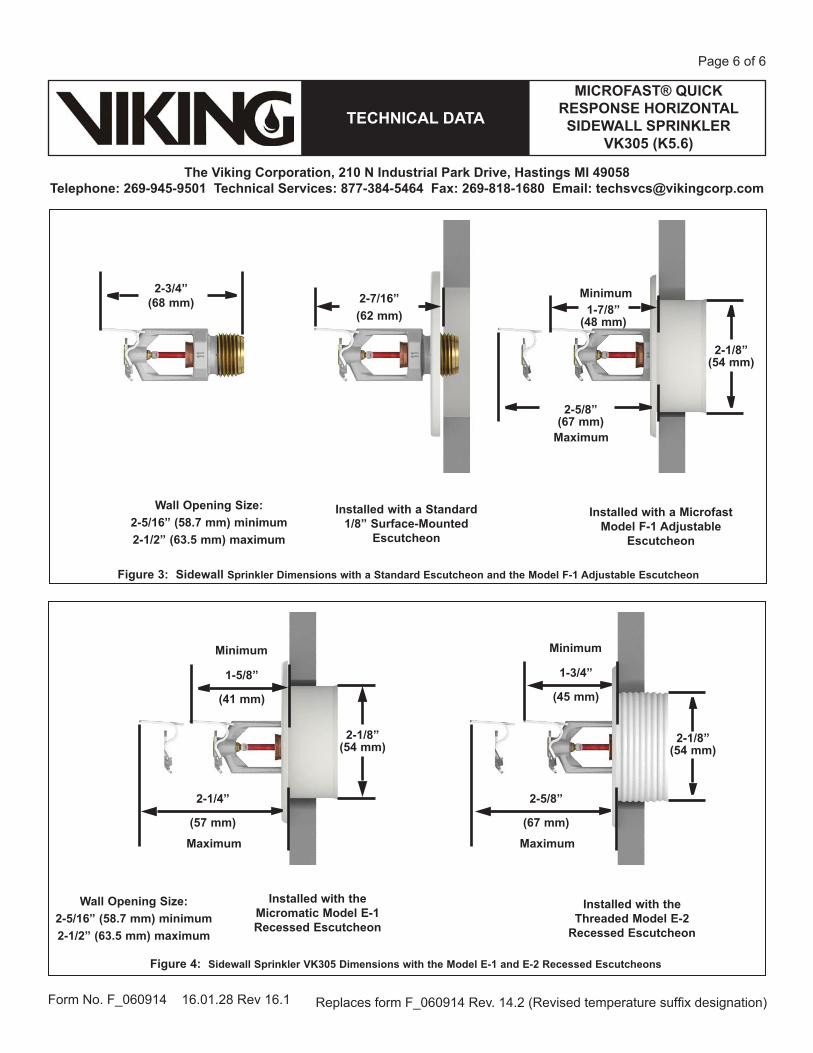
Figure 4: Sprinkler Dimensions with the Model E-1 and E-2 Recessed Escutcheons
Figure 3: Sprinkler Dimensions with a Standard Escutcheon and the Model F-1 Adjustable Escutcheon
1/2”(15 mm)
NPT
2-1/4” (57 mm) 1-3/4”
(44.5 mm)2”
(51 mm)Max.
2-1/8” (54 mm)
1-1/2” (38 mm)
Min.
Installed with a standard 1/8” surface-mounted
escutcheon
Installed with a Microfast Model F-1 Adjustable
Escutcheon
Ceiling Opening Size:2-5/16” (58.7 mm) minimum2-1/2” (63.5 mm) maximum
Note: At maximum, adapter is exposed 1/2” (12.7 mm) from
face of ceiling
1-3/4” (44.5 mm)
Max.
2-1/8” (54 mm)
1-1/8” (28.6 mm)
Min.2””
(51 mm)Max.
1-1/8” (28.6 mm)
Min.
2-1/8” (54 mm)
Ceiling Opening Size:2-5-16” (58.7 mm) minimum2-1/2” (63.5 mm) maximum
Installed with a Model E-1 Recessed
Escutcheon
Installed with a Model E-2 Thread-on Recessed
Escutcheon
Replaces Form F_0333314 Rev 15.2 (Revised temperature suf x designation)

MICROFAST® QUICK RESPONSE HORIZONTAL SIDEWALL SPRINKLER
VK305 (K5.6)TECHNICAL DATA
The Viking Corporation, 210 N Industrial Park Drive, Hastings MI 49058Telephone: 269-945-9501 Technical Services: 877-384-5464 Fax: 269-818-1680 Email: [email protected]
Page 1 of 6
Form No. F_060914 16.01.28 Rev 16.1
1. DESCRIPTIONThe Viking Microfast® Quick Response Horizontal Sidewall Sprinkler VK305 is a small thermosensitive glass bulb spray sprinkler available with various finishes and tempera-ture ratings to meet design requirements. The special Polyester and Electroless Nickel PTFE (ENT) coatings can be used in decorative applications where colors are de-sired. In addition, these coatings have been investigated for installation in corrosive atmospheres and are listed/approved as corrosion resistant as indicated in ApprovalCharts.
2. LISTINGS AND APPROVALScULus Listed: Category VNIVFM Approved: Class 2020Refer to Approval Chart 1 and Design Criteria for cULusListing requirements, and refer to Approval Chart 2 and Design Criteria for FM Approval requirements that must be followed.
3. TECHNICAL DATASpeci cations:Minimum Operating Pressure: 7 psi (0.5 bar) Rated to 175 psi (12 bar) water working pressureFactory tested hydrostatically to 500 psi (34.5 bar)Nominal K-Factor: 5.6 U.S. (80.6 metric*)
* Metric K-factor measurement shown is when pressure is measured in Bar. When pressure is measured in kPa, divide the metric K-factor shown by 10.0.Overall Length: 2-3/4” (68 mm)Material Standards:Frame Casting: Brass UNS-C84400 or QM Brass Deflector: Copper UNS-C19500 Bulb: Glass, nominal 3 mm diameterBelleville Spring Sealing Assembly: Nickel Alloy, coated on both sides with PTFE TapeScrew: Brass UNS-C36000Pip Cap and Insert Assembly: Copper UNS-C11000 and Stainless Steel UNS-S30400For Polyester Coated Sprinklers: Belleville Spring-ExposedFor ENT Coated Sprinklers: Belleville Spring - Exposed, Screw and Pip cap - ENT plated.Ordering Information: (Also refer to the current Viking price list.)Order Viking Microfast® Quick Response Horizontal Sidewall Sprinkler VK305 by first adding the appropriate suffix for the sprin-
kler finish and then the appropriate suffix for the temperature rating to the sprinkler base part number. Finish Suffix: Brass = A, Chrome = F, White Polyester = M-/W, Black Polyester = M-/B, and ENT = JNTemperature Suffix: 135 °F / 57 °C = A, 155 °F / 68 °C = B, 175 °F / 79 °C = D, 200 °F / 93 °C = E, and 286 °F / 141 °C = GFor example, sprinkler 12997 with a Brass finish and a 155 °F / 68 °C temperature rating = Part No. 12997ABAvailable Finishes And Temperature Ratings: Refer to Table 1.Accessories: (Also refer to the “Sprinkler Accessories” section of the Viking data book.)Sprinkler Wrenches:A. Standard Wrench: Part No. 10896W/B (available since 2000). B. Wrench for recessed and/or wax coated sprinklers: Part No. 13655W/B** (available since 2006) **A ½” ratchet is required (not available from Viking).Sprinkler Cabinets:A. Six-head capacity: Part No. 01724A (available since 1971)B. Twelve-head capacity: Part No. 01725A (available since 1971)
Viking Technical Data may be found on The Viking Corporation’s Web site at
http://www.vikinggroupinc.com.The Web site may include a more recent
edition of this Technical Data Page.
Replaces form F_060914 Rev. 14.2 (Revised temperature suf x designation)
By Todd Blevins ([email protected]) at 8:57 am, May 05, 2016

MICROFAST® QUICK RESPONSE HORIZONTAL SIDEWALL SPRINKLER
VK305 (K5.6)TECHNICAL DATA
The Viking Corporation, 210 N Industrial Park Drive, Hastings MI 49058Telephone: 269-945-9501 Technical Services: 877-384-5464 Fax: 269-818-1680 Email: [email protected]
Page 2 of 6
Form No. F_060914 16.01.28 Rev 16.1
4. INSTALLATIONRefer to appropriate NFPA Installation Standards.
5. OPERATIONDuring fire conditions, the heat-sensitive fusible link disengages, the pip cap and spring are released, and the waterway is opened. Water flowing through the sprinkler orifice strikes the sprinkler deflector, forming a uniform spray pattern to extinguish or control the fire.
6. INSPECTIONS, TESTS AND MAINTENANCERefer to NFPA 25 for Inspection, Testing and Maintenance requirements.
7. AVAILABILITYViking Microfast® Quick Response Horizontal Sidewall Sprinkler VK305 is available through a network of domestic and interna- is available through a network of domestic and interna-tional distributors. See The Viking Corporation web site for the closest distributor or contact The Viking Corporation.
8. GUARANTEEFor details of warranty, refer to Viking’s current list price schedule or contact Viking directly.
Figure 1: Standard Sprinkler Wrench 10896W/B
Wrench Flat
MICROFAST® QUICK RESPONSE HORIZONTAL SIDEWALL SPRINKLER
VK305 (K5.6)TECHNICAL DATA
The Viking Corporation, 210 N Industrial Park Drive, Hastings MI 49058Telephone: 269-945-9501 Technical Services: 877-384-5464 Fax: 269-818-1680 Email: [email protected]
Page 3 of 6
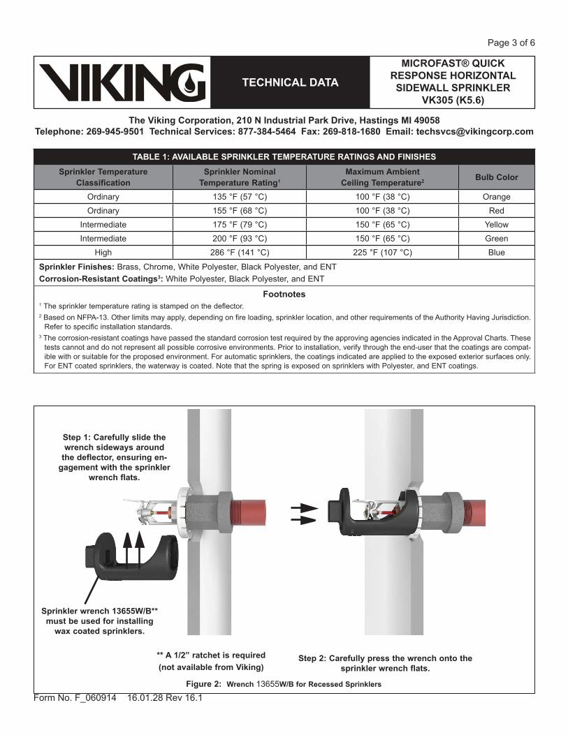
Form No. F_060914 16.01.28 Rev 16.1Figure 2: Wrench 13655W/B for Recessed Sprinklers
Step 1: Carefully slide the wrench sideways around
the deflector, ensuring en-gagement with the sprinkler
wrench flats.
Sprinkler wrench 13655W/B** must be used for installing
wax coated sprinklers.
** A 1/2” ratchet is required(not available from Viking)
Step 2: Carefully press the wrench onto the sprinkler wrench flats.
TABLE 1: AVAILABLE SPRINKLER TEMPERATURE RATINGS AND FINISHES
Sprinkler Temperature Classification
Sprinkler Nominal Temperature Rating1
Maximum Ambient Ceiling Temperature2 Bulb Color
Ordinary 135 °F (57 °C) 100 °F (38 °C) Orange
Ordinary 155 °F (68 °C) 100 °F (38 °C) Red
Intermediate 175 °F (79 °C) 150 °F (65 °C) Yellow
Intermediate 200 °F (93 °C) 150 °F (65 °C) Green
High 286 °F (141 °C) 225 °F (107 °C) Blue
Sprinkler Finishes: Brass, Chrome, White Polyester, Black Polyester, and ENTCorrosion-Resistant Coatings3: White Polyester, Black Polyester, and ENT
Footnotes1 The sprinkler temperature rating is stamped on the deflector. 2 Based on NFPA-13. Other limits may apply, depending on fire loading, sprinkler location, and other requirements of the Authority Having Jurisdiction.
Refer to specific installation standards.3 The corrosion-resistant coatings have passed the standard corrosion test required by the approving agencies indicated in the Approval Charts. These
tests cannot and do not represent all possible corrosive environments. Prior to installation, verify through the end-user that the coatings are compat-ible with or suitable for the proposed environment. For automatic sprinklers, the coatings indicated are applied to the exposed exterior surfaces only. For ENT coated sprinklers, the waterway is coated. Note that the spring is exposed on sprinklers with Polyester, and ENT coatings.

MICROFAST® QUICK RESPONSE HORIZONTAL SIDEWALL SPRINKLER
VK305 (K5.6)TECHNICAL DATA
The Viking Corporation, 210 N Industrial Park Drive, Hastings MI 49058Telephone: 269-945-9501 Technical Services: 877-384-5464 Fax: 269-818-1680 Email: [email protected]
Page 4 of 6
Form No. F_060914 16.01.28 Rev 16.1
Approval Chart 1 (UL)Microfast® Quick Response Horizontal Sidewall Sprinkler VK305
For Light or Ordinary Hazard OccupanciesMaximum 175 PSI (12 Bar) WWP
Deflector must be located 4” to 12” (102 mm to 305 mm) below the ceiling.
Base Part Number1 SIN Sprinkler
StyleThread Size Nominal K-Factor Overall Length Listings and Approvals3
(Refer also to Design Criteria on page 43x.)
NPT BSP U.S. metric2 Inches mm cULus4 LPCB
12997 VK305 HSW 1/2” 15 mm 5.6 80.6 2-11/16 68 A1Y, B1X, C2W, D2Z -- -- --
NOTICE - Product Below - Limited Availability (Contact Local Viking Office)
12121 VK305 HSW 1/2” 15 mm 5.6 80.6 1-11/16 68 A1Y, B1X, C2W, D2Z -- -- --
Approved Temperature Ratings
A - 135 °F (57 °C), 155 °F (68 °C), 175 °F (79 °C), 200 °F (93 °C), and 286 °F (141 °C)
B - 135 °F (57 °C), 155 °F (68 °C), 175 °F (79 °C), and 200 °F (93 °C)
C - 155 °F (68 °C), 175 °F (79 °C), 200 °F (93 °C), and 286 °F (141 °C)
D - 155 °F (68 °C), 175 °F (79 °C), and 200 °F (93 °C)
Approved Finishes1 - Brass, Chrome, White Poly-ester5,6,
and Black Polyester5,6
2 - ENT5
Approved EscutcheonsW - Installed with standard surface-mounted escutcheonsX - Installed with standard surface-mounted escutcheons or
the Viking Microfast® Model F-1 Adjustable Escutcheon, or recessed with the Viking Micromatic® Model E-1, E-2, or G-1 Recessed Escutcheon
Y - Installed with standard surface-mounted escutcheons or the Viking Microfast® Model F-1 Adjustable Escutcheon
Z - Installed with standard surface-mounted escutcheons or recessed with the Viking Micromatic Model E-1
Footnotes1 Base part number shown. For complete part number, refer to Viking’s current price schedule.2 Metric K-factor measurement shown is when pressure is measured in Bar. When pressure is measured in kPa, divide the metric K-factor shown by 10.0.3 This table shows the listings and approvals available at the time of printing. Other approvals may be in process.4 Listed by Underwriters Laboratories Inc. for use in the U.S. and Canada.5 cULus Listed as corrosion-resistant. 6 Other colors are available on request with the same Listings and Approvals as the standard colors.
DESIGN CRITERIA - UL (Also refer to Approval Chart 1.)
cULus Listing Requirements: Quick Response Horizontal Sprinkler VK305 is cULus Listed as indicated in Approval Chart 1 for installation in accordance with the latest edition of NFPA 13 for sidewall standard spray sprinklers.
Designed for use in Light and Ordinary Hazard occupancies. Locate with the deflector 4” to 12“ (102 mm to 305 mm) below the ceiling. Protection areas and maximum spacing shall be in accordance with the tables provided in NFPA 13. Minimum spacing allowed is 6 ft. (1.8 m). Align the top of the deflector parallel with the ceiling. Locate no less than 4” (102 mm) from end walls. Maximum distance from end walls shall be no more than one-half of the allowable distance between sprinklers. The distance shall be measured perpendicular to the wall.
The sprinkler installation and obstruction rules contained in NFPA 13 for sidewall standard spray sprinklers must be followed.
IMPORTANT: Always refer to Bulletin Form No. F_091699 - Care and Handling of Sprinklers. Also refer to page QR1-3 for general care, installation, and maintenance information. Viking sprinklers are to be installed in accor-dance with the latest edition of Viking technical data, the appropriate standards of NFPA, LPCB, APSAD, VdS or other similar organizations, and also with the provisions of governmental codes, ordinances, and standards, whenever applicable.

MICROFAST® QUICK RESPONSE HORIZONTAL SIDEWALL SPRINKLER
VK305 (K5.6)TECHNICAL DATA
The Viking Corporation, 210 N Industrial Park Drive, Hastings MI 49058Telephone: 269-945-9501 Technical Services: 877-384-5464 Fax: 269-818-1680 Email: [email protected]
Page 5 of 6
Form No. F_060914 16.01.28 Rev 16.1
Approval Chart 2 (FM)Quick Response Sidewall Sprinklers
Maximum 175 PSI WWP
Base Part Number1 SIN
Thread Size Nominal K-Factor Overall Length FM Approvals3,4
(Refer also to Design Criteria below.)NPT BSP U.S. metric2 Inches mm12997 VK305 1/2” 15 mm 5.6 80.6 2-11/16 68 A1Y, B1X
NOTICE - Product Below - Limited Availability (Contact Local Viking Office)12121 VK305 1/2” 15 mm 5.6 80.6 2-11/16 68 A1Y, B1X
Approved Temperature Ratings
A - 135 °F (57 °C), 155 °F (68 °C), 175 °F (79 °C), 200 °F (93 °C), and 286 °F (141 °C)
B - 135 °F (57 °C), 155 °F (68 °C), 175 °F (79 °C), and 200 °F (93 °C)
Approved Finishes1 - Brass
Approved EscutcheonsX - Installed with standard surface-mounted escutcheons or the Viking
Microfast® Model F-1 Adjustable Escutcheon, or recessed with the Viking Micromatic® Model E-1, E-2, E-3, or G-1 Recessed Escutcheon
Y - Installed with standard surface-mounted escutcheons or the Viking Microfast® Model F-1 Adjustable Escutcheon
Footnotes1 Base part number shown. For complete part number, refer to Viking’s current price schedule.2 Metric K-factor measurement shown is when pressure is measured in Bar. When pressure is measured in kPa, divide the metric K-factor shown by 10.0.3 This table shows the FM Approvals available at the time of printing. Other approvals may be in process.4 Viking vertical sidewall sprinklers may be installed pendent or upright.
DESIGN CRITERIA - FM (Also refer to Approval Chart 2 above.)
FM Approval Requirements: Horizontal Sidewall Sprinkler VK305 is FM Approved as a quick response Non-Storage sidewall sprinkler as indicated in the FM Approval Guide. For specific application and installation requirements, reference the latest applicable FM Loss Prevention Data Sheets (including Data Sheet 2-0). FM Global Loss Prevention Data Sheets contain guidelines relating to, but not limited to: minimum water supply requirements, hydraulic design, ceiling slope and obstructions, minimum and maximum allowable spacing, and deflector distance below the ceiling.NOTE: The FM installation guidelines may differ from cULus and/or NFPA criteria.
IMPORTANT: Always refer to Bulletin Form No. F_091699 - Care and Handling of Sprinklers. Also refer to page QR1-3 for general care, installation, and maintenance information. Viking sprinklers are to be installed in ac-cordance with the latest edition of Viking technical data, the appropriate standards of NFPA, FM Global, LPCB, APSAD, VdS or other similar organizations, and also with the provisions of governmental codes, ordinances, and standards, whenever applicable.
MICROFAST® QUICK RESPONSE HORIZONTAL SIDEWALL SPRINKLER
VK305 (K5.6)TECHNICAL DATA
The Viking Corporation, 210 N Industrial Park Drive, Hastings MI 49058Telephone: 269-945-9501 Technical Services: 877-384-5464 Fax: 269-818-1680 Email: [email protected]
Page 6 of 6
Form No. F_060914 16.01.28 Rev 16.1
Figure 4: Sidewall Sprinkler VK305 Dimensions with the Model E-1 and E-2 Recessed Escutcheons
Figure 3: Sidewall Sprinkler Dimensions with a Standard Escutcheon and the Model F-1 Adjustable Escutcheon
2-3/4” (68 mm) 2-7/16”
(62 mm) 1-7/8” (48 mm)
Installed with a Standard 1/8” Surface-Mounted
Escutcheon
Installed with a Microfast Model F-1 Adjustable
Escutcheon
Wall Opening Size:2-5/16” (58.7 mm) minimum2-1/2” (63.5 mm) maximum
2-5/8” (67 mm)
2-1/8” (54 mm)
1-5/8”
(41 mm)
Installed with the Threaded Model E-2
Recessed Escutcheon
Wall Opening Size:2-5/16” (58.7 mm) minimum2-1/2” (63.5 mm) maximum
2-1/8” (54 mm)
2-1/4”
(57 mm)
Maximum
Minimum
2-1/8” (54 mm)
2-5/8”
(67 mm)
Maximum
1-3/4”
(45 mm)
Minimum
Installed with the Micromatic Model E-1 Recessed Escutcheon
Minimum
Maximum
Replaces form F_060914 Rev. 14.2 (Revised temperature suf x designation)

Schedule 10 Sprinkler Pipe Youngstown Tube manufactures Schedule 10 pipe in sizes 1 ¼" thru 6" using only high quality domestic steel. This ensures a uniform superior product for roll grooving, welding or plain end uses. Youngstown Tube's schedule 10 pipe is produced under ASTM A795 Type E, Grade A, NH standards. Every piece is Eddy-Current tested and conforms to internal SPC testing and recording.
Youngstown Tube Schedule 10 steel sprinkler pipe is coated with a black enamel coating, continuous color coded white stencil, and stored indoors ready for immediate shipment.
Approvals
o UL Listedo CUL Listedo FM Approved
Youngstown Tube schedule 10 pipe meets the rigorous testing and certification processes of Underwriters Laboratory and Factory Mutual for steel sprinkler pipe with working pressures of 300 psi or less. It also meets the requirements of NFPA 13 and can be used in wet, dry, deluge and preaction systems.
Schedule 10 *PipeSize
PipeOD
Nominal Wall
Weight per Foot
Standard Length
Piecesper
Bundle
Feetper
Bundle
Weight per Bundle
ULThreaded
CRR1 ¼ 1.660 .109 1.81 21 61 1,281 2,319 8.5 1 ½ 1.900 .109 2.08 21 44 924 1,921 6.8 2 2.375 .109 2.64 21 37 777 2,051 5.5
2 ½ 2.875 .120 3.53 21 37 777 2,742 4.1 3 3.500 .120 4.33 21 24 504 2,182 3.0 4 4.500 .120 5.61 21 19 399 2,238 1.8 6 6.625 .134 9.29 21 10 210 1,951 1.16
8** 8.625 .188 18.49 21 7 147 2,424 1.81
* Schedule 10 pipe can not be threaded or cut-grooved. ** 8" schedule 10 is manufactured from a different domestic supplier.
Youngstown Tube Company 401 Andrews Avenue
Youngstown, Ohio 44505 1-866-The-Tube
www.youngstowntube.com
By Todd Blevins ([email protected]) at 8:57 am, May 05, 2016


![(2Z,N 0 0 0 E)-N 0 0 0 -[(2-Hydroxy-1-naphthyl)- methylidene]furan-2-carbohydrazonic acid](https://static.fdokumen.com/doc/165x107/631360d4b033aaa8b2100e91/2zn-0-0-0-e-n-0-0-0-2-hydroxy-1-naphthyl-methylidenefuran-2-carbohydrazonic.jpg)