Three Femoral Fixation Devices for Anterior Cruciate Ligament Reconstruction: Comparison of Fixation...
12
Three Femoral Fixation Devices for Anterior Cruciate Ligament Reconstruction: Comparison of Fixation on the Lateral Cortex Versus the Anterior Cortex Chad S. Conner, M.D., Brandon A. Perez, M.D., Randal P. Morris, B.S., James W. Buckner, B.S., William L. Buford Jr., Ph.D., and Frank M. Ivey, M.D. Purpose: To evaluate the biomechanical properties of 3 anterior cruciate ligament (ACL) recon- struction femoral fixation devices in a porcine model with implantation on both the lateral femoral cortex and the anterior femoral cortex. Methods: ACL reconstructions with an 8-mm porcine tendon graft were performed on 48 porcine femurs with the EndoButton CL (Smith & Nephew, Andover, MA), ToggleLoc with ZipLoop technology (Biomet Sports Medicine, Warsaw, IN), or EZLoc (Biomet Sports Medicine). In 8 specimens for each implant, the femoral tunnel was drilled from the 10:30 surgical position out the lateral cortex. In another 8 specimens for each implant, the tunnel was drilled from the 10:30 position to a standardized anterior femoral surface. Cyclic testing was performed on an MTS testing machine (MTS, Eden Prairie, MN) from 50 N to 450 N for 2,000 cycles, followed by load-to-failure testing in specimens that survived. The cortical thickness and location of the implant exit were recorded. Results: In the lateral femur group, 0 of the EZLoc devices, 2 of the ToggleLoc devices, and 3 of the EndoButtons completed cyclic testing. In the anterior femur group, 1 of the EZLoc devices, 5 of the ToggleLoc devices, and 5 of the EndoButtons completed cyclic testing (P .012). In the anterior femur group, the ToggleLoc exhibited higher 2,000-cycle elongation (5.46 1 mm) than the EndoButton (3.55 0.6 mm) (P .005). The EndoButton showed a higher first failure load (1,190.9 150.0 N) than the ToggleLoc (912.6 82.4 N) (P .007). The anterior cortex (1.4 mm) was thinner than the lateral cortex (1.7 mm) (P .0002). Conclusions: The EndoButton provided the strongest ACL femoral fixation with significantly less graft-implant elongation and significantly higher failure loads. It was also shown in a porcine model that implants on the anterior cortical surface perform better than those on the lateral surface. Increased cortical thickness, in the range tested, was not associated with improved implant perfor- mance in the porcine model. Clinical Relevance: The EndoButton provided the best ACL femoral fixation of the devices tested. A nterior cruciate ligament (ACL) reconstructions are among the most common sports medicine procedures performed each year. Different fixation implants for the femoral side have been developed to provide initial stability to the knee during rehabilita- tion while the graft is healing to the tunnel. A tendon graft heals to the tunnel with Sharpey fibers at around 8 to 12 weeks postoperatively. 1-4 Forces that can occur during the initial rehabilitation have been estimated in many studies. 5-8 With the single-leg squat and sit-to- stand exercises, the forces resisted by the ACL have been estimated from 59 to 100 N. 7,8 With walking down an incline, forces up to 445 N have been repor- From the Department of Orthopaedic Surgery and Rehabilitation, The University of Texas Medical Branch, Galveston, Texas, U.S.A. Supported by Smith & Nephew and Biomet Sports Medicine, which provided the implants for the study and funds for the spec- imens and testing. The authors report no conflict of interest. Received April 23, 2009; accepted October 30, 2009. Address correspondence and reprint requests to Chad S. Conner, M.D., Department of Orthopaedic Surgery and Rehabilitation, The University of Texas Medical Branch, 301 University Blvd., Galveston, TX 77555-0165, U.S.A. E-mail: [email protected] © 2010 by the Arthroscopy Association of North America 0749-8063/9245/$36.00 doi:10.1016/j.arthro.2009.10.015 796 Arthroscopy: The Journal of Arthroscopic and Related Surgery, Vol 26, No 6 (June), 2010: pp 796-807
Transcript of Three Femoral Fixation Devices for Anterior Cruciate Ligament Reconstruction: Comparison of Fixation...

T
wi
MUT
7
Three Femoral Fixation Devices for Anterior Cruciate LigamentReconstruction: Comparison of Fixation on the Lateral Cortex
Versus the Anterior Cortex
Chad S. Conner, M.D., Brandon A. Perez, M.D., Randal P. Morris, B.S.,James W. Buckner, B.S., William L. Buford Jr., Ph.D., and Frank M. Ivey, M.D.
Purpose: To evaluate the biomechanical properties of 3 anterior cruciate ligament (ACL) recon-struction femoral fixation devices in a porcine model with implantation on both the lateral femoralcortex and the anterior femoral cortex. Methods: ACL reconstructions with an 8-mm porcine tendongraft were performed on 48 porcine femurs with the EndoButton CL (Smith & Nephew, Andover,MA), ToggleLoc with ZipLoop technology (Biomet Sports Medicine, Warsaw, IN), or EZLoc(Biomet Sports Medicine). In 8 specimens for each implant, the femoral tunnel was drilled from the10:30 surgical position out the lateral cortex. In another 8 specimens for each implant, the tunnel wasdrilled from the 10:30 position to a standardized anterior femoral surface. Cyclic testing wasperformed on an MTS testing machine (MTS, Eden Prairie, MN) from 50 N to 450 N for 2,000cycles, followed by load-to-failure testing in specimens that survived. The cortical thickness andlocation of the implant exit were recorded. Results: In the lateral femur group, 0 of the EZLocdevices, 2 of the ToggleLoc devices, and 3 of the EndoButtons completed cyclic testing. In theanterior femur group, 1 of the EZLoc devices, 5 of the ToggleLoc devices, and 5 of the EndoButtonscompleted cyclic testing (P � .012). In the anterior femur group, the ToggleLoc exhibited higher2,000-cycle elongation (5.46 � 1 mm) than the EndoButton (3.55 � 0.6 mm) (P � .005). TheEndoButton showed a higher first failure load (1,190.9 � 150.0 N) than the ToggleLoc (912.6 � 82.4N) (P � .007). The anterior cortex (1.4 mm) was thinner than the lateral cortex (1.7 mm) (P � .0002).Conclusions: The EndoButton provided the strongest ACL femoral fixation with significantly lessgraft-implant elongation and significantly higher failure loads. It was also shown in a porcine modelthat implants on the anterior cortical surface perform better than those on the lateral surface.Increased cortical thickness, in the range tested, was not associated with improved implant perfor-mance in the porcine model. Clinical Relevance: The EndoButton provided the best ACL femoralfixation of the devices tested.
Apiptg8dmsb
From the Department of Orthopaedic Surgery and Rehabilitation,he University of Texas Medical Branch, Galveston, Texas, U.S.A.Supported by Smith & Nephew and Biomet Sports Medicine,
hich provided the implants for the study and funds for the spec-mens and testing. The authors report no conflict of interest.
Received April 23, 2009; accepted October 30, 2009.Address correspondence and reprint requests to Chad S. Conner,.D., Department of Orthopaedic Surgery and Rehabilitation, Theniversity of Texas Medical Branch, 301 University Blvd., Galveston,X 77555-0165, U.S.A. E-mail: [email protected]© 2010 by the Arthroscopy Association of North America
d0749-8063/9245/$36.00doi:10.1016/j.arthro.2009.10.015
96 Arthroscopy: The Journal of Arthroscopic and Related
nterior cruciate ligament (ACL) reconstructionsare among the most common sports medicine
rocedures performed each year. Different fixationmplants for the femoral side have been developed torovide initial stability to the knee during rehabilita-ion while the graft is healing to the tunnel. A tendonraft heals to the tunnel with Sharpey fibers at aroundto 12 weeks postoperatively.1-4 Forces that can occururing the initial rehabilitation have been estimated inany studies.5-8 With the single-leg squat and sit-to-
tand exercises, the forces resisted by the ACL haveeen estimated from 59 to 100 N.7,8 With walking
own an incline, forces up to 445 N have been repor-Surgery, Vol 26, No 6 (June), 2010: pp 796-807
tvhca
ooarttbssiAtt
phmsno
mofiftdfiatt
aSutdowobt
at
cdlwt9t(ctimbdcl
pfiTMsrugTsbbl
F
797COMPARISON OF 3 FEMORAL FIXATION DEVICES
ed.5,6 Therefore the ideal ACL femoral fixation de-ice would have the strength to sustain these forces origher, minimize the elongation of the graft-implantonstruct that can ultimately lead to graft laxity, andllow healing to the bone tunnel.
As ACL reconstruction has evolved, the advantagesf a more anatomic femoral origin, centered on therigins of the anteromedial and posterolateral bundles,s well as the potential benefits of double-bundle ACLeconstruction, have led to the placement of femoralunnels that exit the lateral femoral cortex.9 In addi-ion, improved graft healing of soft-tissue grafts in theone tunnels with cortical or suspension fixation ver-us interference fixation has been shown in animaltudies.10,11 Most previous ACL femoral fixation stud-es that included the EndoButton (Smith & Nephew,ndover, MA) tested the fixation devices as drilled
hrough an 11-o’clock position that exited on or nearhe anterior femoral cortex.12-14
The porcine model has been accepted and usedreviously for ACL femoral fixation studies.12-14 Itas been shown to be similar to humans both inorphology and in composition and function.15-17 No
tudy has determined the differences in cortical thick-ess on the anterior and lateral surfaces of the humanr porcine femur to our knowledge.The purpose of this study was to evaluate the bio-echanical properties of 3 ACL reconstruction fem-
ral fixation devices in a porcine model comparingxation on the lateral femoral cortex to the anterioremoral cortex. In addition, the cortical thickness onhe anterior and lateral aspects of the femurs wasetermined. The null hypothesis was that the 3 ACLxation devices tested would perform similarly to onenother and that no difference would be found be-ween fixation on the lateral femoral cortex and fixa-ion on the anterior femoral cortex.
METHODS
Adult porcine rear limbs were obtained frozen fromlocal meat packing plant and stored at �20°C.
everal limbs at a time were thawed and dissected,ntil 48 femur bones, as well as the extensor tendonso the toes, were harvested. The femur bones wereissected free of soft tissue, with sparing of the peri-steum, and 2 to 4 tendons, depending on size, werehip stitched at the ends to make an ACL graft bundlef 8 mm, as measured with a graft cylindrical sizinglock (Linvatec, Largo, FL). The dissected femurs and
endon bundles were refrozen and then thawed andE(
ssembled into an ACL reconstruction on the day ofesting.
We preliminarily performed testing on 10 tendononstructs to show that the whip-stitched tendon bun-le provided ample and consistent strength for theoading protocol, ensuring that the fixation interfaceould be the variable of the construct and less so the
endons. The 8-mm tendon graft was looped over a-mm stainless steel rod securely attached to the ac-uator of the MTS 858 Mini Bionix testing machineMTS, Eden Prairie, MN), and the tendons werelamped at 60 mm (same free tendon distance as withhe EndoButton and ToggleLoc [Biomet Sports Med-cine, Warsaw, IN]) with a custom cryo-clamp. Aark was made on the tendons with a marker just
elow the level of the clamp before clamping to allowetermination of any graft slippage. The tendons wereyclically tested and pulled to failure as describedater for the implant testing.
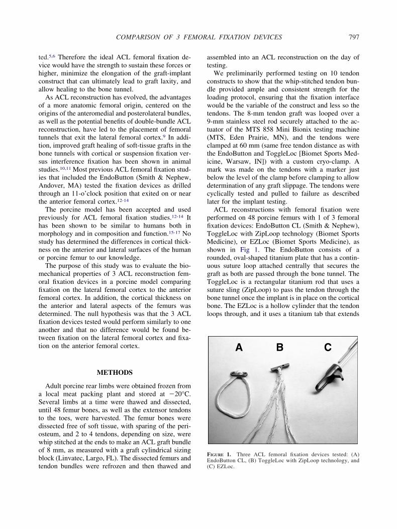
ACL reconstructions with femoral fixation wereerformed on 48 porcine femurs with 1 of 3 femoralxation devices: EndoButton CL (Smith & Nephew),oggleLoc with ZipLoop technology (Biomet Sportsedicine), or EZLoc (Biomet Sports Medicine), as
hown in Fig 1. The EndoButton consists of aounded, oval-shaped titanium plate that has a contin-ous suture loop attached centrally that secures theraft as both are passed through the bone tunnel. TheoggleLoc is a rectangular titanium rod that uses auture sling (ZipLoop) to pass the tendon through theone tunnel once the implant is in place on the corticalone. The EZLoc is a hollow cylinder that the tendonoops through, and it uses a titanium tab that extends
IGURE 1. Three ACL femoral fixation devices tested: (A)
ndoButton CL, (B) ToggleLoc with ZipLoop technology, andC) EZLoc.
uo
ffbwgu
tfAwi&nEaett4dt8tosffmwt
giadaldttot
igwae
omctEmttctawbibfrpwtacwoca
1fic
798 C. S. CONNER ET AL.
pon passing through the bone tunnel, which seatsnto the cortical bone surface.The implants were randomized by drawing for each
emur, and all bone tunnels were drilled in similarashion by a single orthopaedic surgeon, who waslinded to the implant while placing the initial guide-ire. The implants were placed according to the sur-ical guides accompanying each implant and a man-facturer representative unless otherwise indicated.In 24 specimens (lateral femur group), the femoral
unnel was drilled with a Beath pin (Smith & Nephew)rom the 10:30 surgical position on the femur. Ancufex 5-mm femoral aimer guide (Smith & Nephew)as used from a simulated 8-mm tibial tunnel created
n a wooden block with an Acufex ACL guide (SmithNephew) set at 55° and placed at 65° in the coro-
al plane.18 The tunnel was drilled 30 mm for thendoButton group and 20 mm for the ToggleLoc withn 8-mm acorn reamer (Smith & Nephew) to allow anffective length of 20 mm of tendon in the femoralunnel with these implants. After this, the remainingunnel was drilled with the respective manufacturer’s.5-mm drill through the cortex. The EZLoc wasrilled after placement of a Beath pin completelyhrough the tunnel with Biomet Sports Medicine’s-mm reamer. A standard 7-8 EZLoc (designed for aotal femoral tunnel length of 35 to 50 mm) was thenly size of implant available. As a result, 3 of 16pecimens should have used a long 7-8 EZLoc (totalemoral tunnel length �50 mm) because of their totalemoral lengths being 52 mm in 2 specimens and 54m in 1 specimen. The length of tendon in the tunnelith all the EZLoc specimens would be equal to the
otal femoral length minus 12 mm.In the remaining 24 specimens (anterior femur
roup), a hole that was a few millimeters deep (start-ng point) was made through the transtibial simulationt the 10:30 position, and then the guidewire wasrilled directly with the Acufex ACL guide at 55° tostandardized anterior femoral surface 5 mm from the
ateral cortical edge. The guide pin was drilled in airect fashion (not simulated transtibially) to the an-erior cortex to allow comparison of the implants on aypical anterior femoral cortex exit that may haveccurred with a historic 11-o’clock position drilledranstibially.
For both groups, each fixation device was implantednto 8 femur specimens by use of an 8-mm tendonraft composed of 2 to 4 porcine extensor tendonship stitched with No. 0 silk suture (available suture)
t the free ends with 5 to 6 throws while being held at
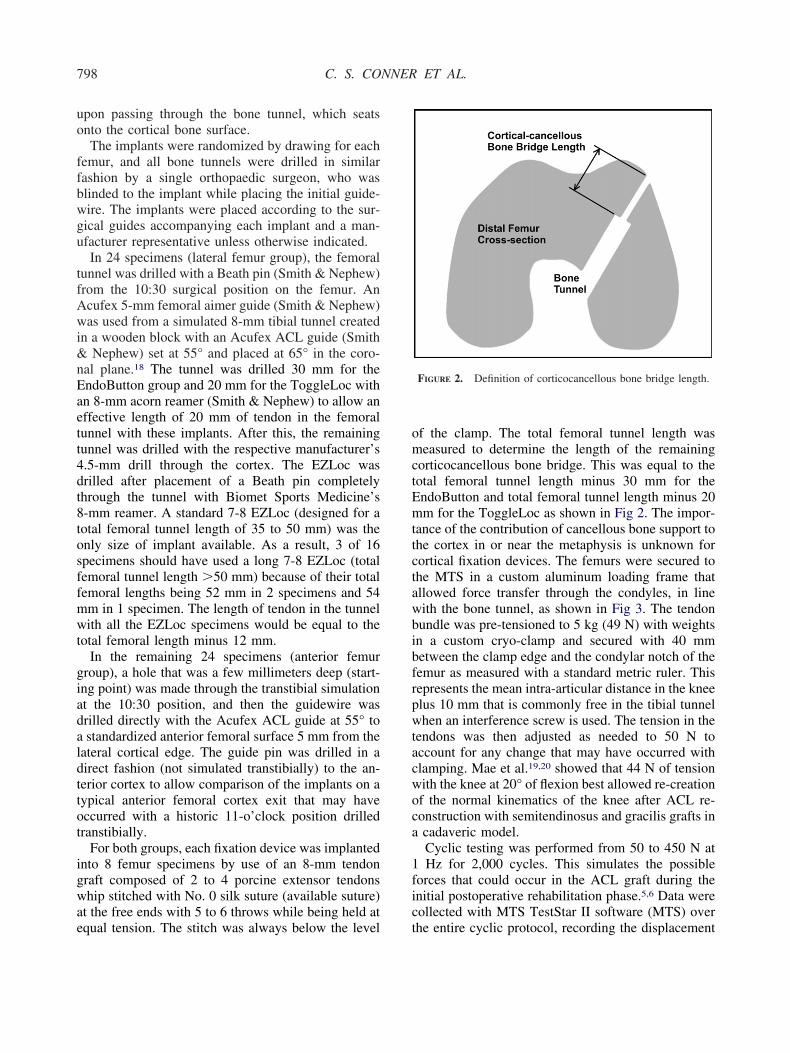
qual tension. The stitch was always below the level tf the clamp. The total femoral tunnel length waseasured to determine the length of the remaining
orticocancellous bone bridge. This was equal to theotal femoral tunnel length minus 30 mm for thendoButton and total femoral tunnel length minus 20m for the ToggleLoc as shown in Fig 2. The impor-
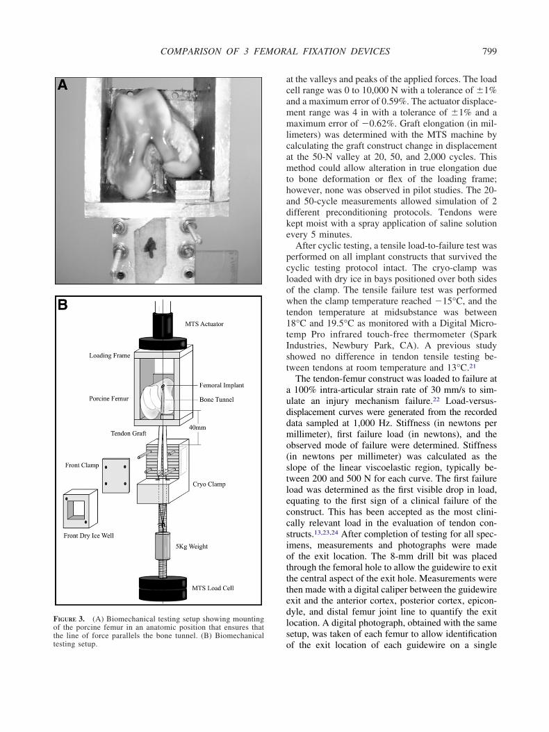
ance of the contribution of cancellous bone support tohe cortex in or near the metaphysis is unknown forortical fixation devices. The femurs were secured tohe MTS in a custom aluminum loading frame thatllowed force transfer through the condyles, in lineith the bone tunnel, as shown in Fig 3. The tendonundle was pre-tensioned to 5 kg (49 N) with weightsn a custom cryo-clamp and secured with 40 mmetween the clamp edge and the condylar notch of theemur as measured with a standard metric ruler. Thisepresents the mean intra-articular distance in the kneelus 10 mm that is commonly free in the tibial tunnelhen an interference screw is used. The tension in the
endons was then adjusted as needed to 50 N toccount for any change that may have occurred withlamping. Mae et al.19,20 showed that 44 N of tensionith the knee at 20° of flexion best allowed re-creationf the normal kinematics of the knee after ACL re-onstruction with semitendinosus and gracilis grafts incadaveric model.Cyclic testing was performed from 50 to 450 N atHz for 2,000 cycles. This simulates the possible
orces that could occur in the ACL graft during thenitial postoperative rehabilitation phase.5,6 Data wereollected with MTS TestStar II software (MTS) over
FIGURE 2. Definition of corticocancellous bone bridge length.
he entire cyclic protocol, recording the displacement
acammlcamthadke
pclowt1tIst
auddmo(stleccsiotttedlso
Fothe line of force parallels the bone tunnel. (B) Biomechanicaltesting setup.
799COMPARISON OF 3 FEMORAL FIXATION DEVICES
t the valleys and peaks of the applied forces. The loadell range was 0 to 10,000 N with a tolerance of �1%nd a maximum error of 0.59%. The actuator displace-ent range was 4 in with a tolerance of �1% and aaximum error of �0.62%. Graft elongation (in mil-
imeters) was determined with the MTS machine byalculating the graft construct change in displacementt the 50-N valley at 20, 50, and 2,000 cycles. Thisethod could allow alteration in true elongation due
o bone deformation or flex of the loading frame;owever, none was observed in pilot studies. The 20-nd 50-cycle measurements allowed simulation of 2ifferent preconditioning protocols. Tendons wereept moist with a spray application of saline solutionvery 5 minutes.
After cyclic testing, a tensile load-to-failure test waserformed on all implant constructs that survived theyclic testing protocol intact. The cryo-clamp wasoaded with dry ice in bays positioned over both sidesf the clamp. The tensile failure test was performedhen the clamp temperature reached �15°C, and the
endon temperature at midsubstance was between8°C and 19.5°C as monitored with a Digital Micro-emp Pro infrared touch-free thermometer (Sparkndustries, Newbury Park, CA). A previous studyhowed no difference in tendon tensile testing be-ween tendons at room temperature and 13°C.21
The tendon-femur construct was loaded to failure at100% intra-articular strain rate of 30 mm/s to sim-
late an injury mechanism failure.22 Load-versus-isplacement curves were generated from the recordedata sampled at 1,000 Hz. Stiffness (in newtons perillimeter), first failure load (in newtons), and the
bserved mode of failure were determined. Stiffnessin newtons per millimeter) was calculated as thelope of the linear viscoelastic region, typically be-ween 200 and 500 N for each curve. The first failureoad was determined as the first visible drop in load,quating to the first sign of a clinical failure of theonstruct. This has been accepted as the most clini-ally relevant load in the evaluation of tendon con-tructs.13,23,24 After completion of testing for all spec-mens, measurements and photographs were madef the exit location. The 8-mm drill bit was placedhrough the femoral hole to allow the guidewire to exithe central aspect of the exit hole. Measurements werehen made with a digital caliper between the guidewirexit and the anterior cortex, posterior cortex, epicon-yle, and distal femur joint line to quantify the exitocation. A digital photograph, obtained with the sameetup, was taken of each femur to allow identification
IGURE 3. (A) Biomechanical testing setup showing mountingf the porcine femur in an anatomic position that ensures that
f the exit location of each guidewire on a single
flOwftoasattcEs
oMttubw9spp6d
T
t
0awtvpsfc
L
2sTs.fpmafioticit
A
EtaT
L
A
800 C. S. CONNER ET AL.
emur photograph, scaled to the anterior to posteriorateral condyle, by use of Corel PhotoPaint (Corel,ttawa, Ontario, Canada). Specimens were then cutith a band saw at the level of the exit hole in the
emur, and the cortical thickness was measured withhe digital caliper at the exit hole. For comparison, thether cortex (anterior cortex for lateral femur groupnd lateral cortex for anterior femur group) was mea-ured as well at the similar exit hole location. Inddition, each device’s available cortical surface con-act area, defined as the total area of the button orab (length � width), was measured with a digitalaliper (and an applied geometric equation for thendoButton’s rounded corners) to determine any pos-ible correlation with device performance.
Statistical analysis of construct failure as a functionf loading cycles was assessed by use of Kaplan-eier survivability analysis and the Mantel-Cox test
o determine differences between implant groups. Sta-istical differences in elongation, failure stiffness, fail-re load, exit hole location, corticocancellous boneridge length, and cortical thickness were performedith analysis of variance with SAS software, version.2 (SAS, Cary, NC), unless otherwise noted. Allignificance levels were set at P � .05. An a prioriower analysis (� � .05, power � 0.80) of 6 testedilot specimens (n � 2 per each device) showed thatspecimens would be required to detect an elongationifference greater than 1.0 mm between devices.
RESULTS
endon Controls
The results of the 8-mm whip-stitched tendon con-rol testing showed mean graft elongation of 0.72 �
TABLE 1. Cy
Implant and LocationTotal No.of Cycles
Mean No.of Cycles
Median No.of Cycles B
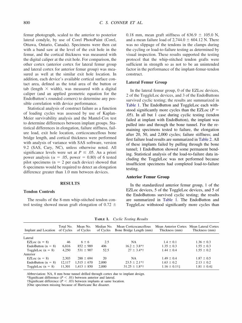
ateralEZLoc (n � 8) 46 6 � 6 2.5EndoButton (n � 8) 6,816 852 � 989 406ToggleLoc (n � 8) 4,250 531 � 907 52.5
nteriorEZLoc (n � 8) 2,303 288 � 694 20EndoButton (n � 8) 12,117 1,515 � 670 2,000ToggleLoc (n � 8) 11,301 1,413 � 850 2,000
Abbreviation: NA, 8 mm bone tunnel drilled through cortex du*Significant difference (P � .01) between anterior and lateral.
†Significant difference (P � .03) between implants at same location.‡One specimen missing because of Hurricane Ike disaster..18 mm, mean graft stiffness of 636.9 � 105.0 N,nd a mean failure load of 2,744.0 � 604.12 N. Thereas no slippage of the tendons in the clamps during
he cycling or load-to-failure testing as determined byisual inspection. These results supported the testingrotocol that the whip-stitched tendon grafts wereufficient in strength so as not to be an unintendedactor in the performance of the implant-femur-tendononstruct.
ateral Femur Group
In the lateral femur group, 0 of the EZLoc devices,of the ToggleLoc devices, and 3 of the EndoButtons
urvived cyclic testing; the results are summarized inable 1. The EndoButton and ToggleLoc each with-tood significantly more cycles than the EZLoc (P �05). In all but 1 case during cyclic testing (tendonailed at implant with EndoButton), the implant wasulled into and through the bone tunnel. For the re-aining specimens tested to failure, the elongation
fter 20, 50, and 2,000 cycles; failure stiffness; andrst failure load results are summarized in Table 2. Allf these implants failed by pulling through the boneunnel; 1 EndoButton showed some permanent bend-ng. Statistical analysis of the load-to-failure data in-luding the ToggleLoc was not performed becausensufficient specimens had completed load-to-failureesting.
nterior Femur Group
In the standardized anterior femur group, 1 of theZLoc devices, 5 of the ToggleLoc devices, and 5 of
he EndoButtons survived cyclic testing; the resultsre summarized in Table 1. The EndoButton andoggleLoc withstood significantly more cycles than
sting Results
orticocancellousidge Length (mm)
Mean Anterior CortexThickness (mm)
Mean Lateral CortexThickness (mm)
NA 1.4 � 0.1 1.36 � 0.36.2 � 3.8*† 1.35 � 0.3 1.55 � 0.327 � 3.4*† 1.44 � 0.4 1.55 � 0.2
NA 1.49 � 0.4 1.87 � 0.53.5 � 2.1*† 1.63 � 0.2 2.13 � 0.2.25 � 1.8*† 1.16 � 0.1†‡ 1.81 � 0.4‡
plant design.
clic Te
Mean Cone Br
1
231
e to im
tdtititchTbtb
CC
sstapttascEaTiis
asa
C
bErtrTbbv
CF
w(swoticrt
L
A
801COMPARISON OF 3 FEMORAL FIXATION DEVICES
he EZLoc (P � .001). The EZLoc and ToggleLocevices all failed by pulling through the bone, whereashe EndoButtons all failed by tendon failure at themplant junction. The remaining constructs were thenested to failure: 5 EndoButton implants, 5 ToggleLocmplants, and 1 EZLoc implant. As shown in Table 2,he ToggleLoc exhibited significantly higher 2,000-ycle elongation. The EndoButton had significantlyigher first failure loads and lower stiffness than theoggleLoc. All implants failed by pulling through theone, except for 1 EndoButton that failed because ofendon rupture at the implant junction and 1 that failedecause of the button’s breaking.
omparison of Lateral Versus Anterior Femurortex
Kaplan-Meier survivorship results for all 3 implantshowed that implants on the anterior surface wereignificantly more resistant to cyclic loading thanhose on the lateral surface (P � .012). In addition, annalysis of variance calculation showed that the im-lants on the anterior cortex resisted elongation betterhan those on the lateral cortex (P � .02). Because ofhe poor performance of the EZLoc on the lateral andnterior cortical surfaces, further data for compari-on of cortical fixation on the lateral versus anteriorortical surface were derived from the respectivendoButton and ToggleLoc results as shown in Tables 1nd 2. Furthermore, statistical analysis of the lateraloggleLoc implants was not done because only 2
mplants completed full testing. On cyclic testing, themplants on the anterior femoral surface withstood
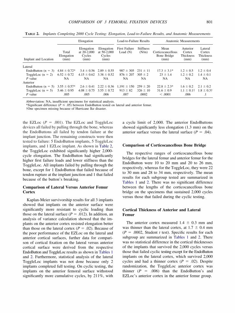
TABLE 2. Implants Completing 2000 Cycle Testing: Elo
Implant and Location
Elongation
TotalElongation
(mm)
Elongationat 20-2,000
Cycles(mm)
Elongationat 50-2,000
Cycles(mm)
ateralEndoButton (n � 3) 4.84 � 0.72* 3.4 � 0.56 2.89 � 0.55ToggleLoc (n � 2) 6.52 � 0.72 4.15 � 0.62 3.38 � 0.52P value NA NA NA
nteriorEndoButton (n � 5) 3.55 � 0.57* 2.6 � 0.41 2.22 � 0.36ToggleLoc (n � 5) 5.46 � 0.95 4.08 � 0.75 3.55 � 0.72P value .005 .005 .006
Abbreviation: NA, insufficient specimens for statistical analysis*Significant difference (P � .05) between EndoButton tested on†One specimen missing because of Hurricane Ike disaster.
ignificantly more cumulative cycles, by 211%, with E
cycle limit of 2,000. The anterior EndoButtonshowed significantly less elongation (1.3 mm) on thenterior surface versus the lateral surface (P � .04).
omparison of Corticocancellous Bone Bridge
The respective ranges of corticocancellous boneridges for the lateral femur and anterior femur for thendoButton were 10 to 20 mm and 20 to 26 mm,
espectively, whereas for the ToggleLoc, they were 22o 30 mm and 28 to 34 mm, respectively. The meanesults for each subgroup tested are summarized inables 1 and 2. There was no significant differenceetween the lengths of the corticocancellous boneridge on the specimens that sustained 2,000 cyclesersus those that failed during the cyclic testing.
ortical Thickness of Anterior and Lateralemur
The anterior cortex measured 1.4 � 0.3 mm andas thinner than the lateral cortex, at 1.7 � 0.4 mm
P � .0002, Student t test). Specific results for eachubgroup are summarized in Tables 1 and 2. Thereas no statistical difference in the cortical thicknessesf the implants that survived the 2,000 cycles versushose that failed cyclic testing except for the EndoButtonmplants on the lateral cortex, which survived 2,000ycles and had a thinner cortex (P � .02). Despiteandomization, the ToggleLoc anterior cortex washinner (P � .006) than the EndoButton’s and
n, Load-to-Failure Results, and Anatomic Measurements
-to-Failure Results Anatomic Measurements
Failuread (N)
Stiffness(N/m)
MeanCorticocancellous
Bone Bridge(mm)
AnteriorCortex
Thickness(mm)
LateralCortex
Thickness(mm)
7 � 305 231 � 11 17.3 � 3.1* 1.2 � 0.5 1.2 � 0.46 � 207 305 � 2 23 � 1.4 1.2 � 0.2 1.4 � 0.1NA NA NA NA NA
1 � 150 259 � 20 22.8 � 2.3* 1.6 � 0.2 2.1 � 0.23 � 82 326 � 10 31.6 � 0.9 1.1 � 0.1† 1.8 � 0.3†007 .0002 � .0001 .006 .1
l and anterior femur.
ngatio
Load
FirstLo
9887
1,1991
.
.latera
ZLoc’s anterior cortex in the anterior femur group.
EF
Faipmw.sofmf
D
mataststtfato
tpvAfiswca
eodfi
L
A
o
.
802 C. S. CONNER ET AL.
xit Hole Locations on Anterior and Lateralemur
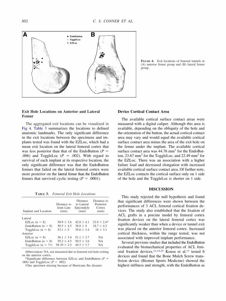
The aggregated exit locations can be visualized inig 4. Table 3 summarizes the locations to definednatomic landmarks. The only significant differencen the exit locations between the specimens and im-lants tested was found with the EZLoc, which had aean exit location on the lateral femoral cortex thatas less posterior than that of the EndoButton (P �
006) and ToggleLoc (P � .002). With regard tourvival of each implant at its respective location, thenly significant difference was that the EndoButtonemurs that failed on the lateral femoral cortex wereore posterior on the lateral femur than the EndoButton
emurs that survived cyclic testing (P � .0001).
TABLE 3. Femoral Exit Hole Locations
Implant and Location
Distance toJoint Line
(mm)
Distanceto Lateral
Epicondyle(mm)
Distance toPosteriorCortex(mm)
ateralEZLoc (n � 8) 50.9 � 3.6 42.8 � 4.1 23.9 � 2.4*EndoButton (n � 8) 50.5 � 4.5 38.8 � 4 18.7 � 4.3ToggleLoc (n � 8) 53.1 � 5 39.6 � 3.4 18 � 3.1
nteriorEZLoc (n � 8) 56.1 � 3.4 51.1 � 3.7 NAEndoButton (n � 8) 59.2 � 4.5 50.5 � 3.6 NAToggleLoc (n � 7†) 58.39 � 2.5 49.3 � 3.7 NA
Abbreviation: NA, not measured due to femoral exit hole exitingn the anterior cortex.*Significant difference between EZLoc and EndoButton (P �
h006) and ToggleLoc (P � .002).
†One specimen missing because of Hurricane Ike disaster.
evice Cortical Contact Area
The available cortical surface contact areas wereeasured with a digital caliper. Although this area is
vailable, depending on the obliquity of the hole andhe orientation of the button, the actual cortical contactrea may vary and would equal the available corticalurface contact area minus the area of the exit hole onhe femur under the implant. The available corticalurface contact area was 44.76 mm2 for the EndoBut-on, 23.67 mm2 for the ToggleLoc, and 22.49 mm2 forhe EZLoc. There was an association with a higherailure load and decreased elongation with increasedvailable cortical surface contact area. Of further note,he EZLoc contacts the cortical surface only on 1 sidef the hole and the ToggleLoc is shorter on 1 side.
DISCUSSION
This study rejected the null hypothesis and foundhat significant differences were shown between theerformances of 3 ACL femoral cortical fixation de-ices. The study also established that the fixation ofCL grafts in a porcine model by femoral cortexxation devices on the lateral femoral cortex wasignificantly weaker than when a device or tunnel exitas placed on the anterior femoral cortex. Increased
ortical thickness, within the range tested, was notssociated with improved implant performance.
Several previous studies that included the EndoButtonvaluated the biomechanical properties of ACL fem-ral fixation devices.12-14,25 Kousa et al.13 tested 6evices and found that the Bone Mulch Screw trans-xion device (Biomet Sports Medicine) showed the
FIGURE 4. Exit locations of femoral tunnels in(A) anterior femur group and (B) lateral femurgroup.
ighest stiffness and strength, with the EndoButton as
tEvss
cNctiAsAlh
ttldabpfiscawaAarts
fmppptj
sampmeE
slf9
aiamsteiwo
spomcplNbpvo
tct(voaswtasHt
fwaaimc
803COMPARISON OF 3 FEMORAL FIXATION DEVICES
he next strongest device. Potential advantages of thendoButton and the other femoral cortex fixation de-ices tested in our study include ease of use and aingle incision. The Bone Mulch Screw requires aeparate incision for placement.
In previous EndoButton studies,12-14,25 the testedyclic peak loading was substantially less (150 to 250) than might be expected in the normal postoperative
ourse and the number of cycles was limited to 1,000o 1,500. Wallace et al.26 showed that after a single-ncision ACL reconstruction, the force produced in theCL could reach 296 N intraoperatively in full exten-
ion. Furthermore, it has been estimated that the nativeCL may reach forces of 303 N during walking on
evel ground27 and 445 N during walking on a down-ill incline at a normal pace.5
Therefore it was believed that the low loads used inhe prior studies did not fully test the possible forceshat the devices may encounter and a cyclic testingoad to 450 N was selected. However, because theevices in this biomechanical study were tested par-llel to the tunnel (as in previous studies)12-14,25 toetter test the biomechanical performance of the im-lants without confounding variables such as tunnelriction and load angle, the loads transferred to themplant were higher than in vivo loads. This is alsoupported by the higher failure rate found duringyclic loading than that which occurs in vivo. This isweakness of the study because a lower cyclic forcehen testing parallel to the tunnel is likely closer to
ctual in vivo forces that the implant must resist.lthough the testing protocol subjected the implants
nd specimens to more strenuous circumstances, theesults can still show differences in the performance ofhe implants, but the clinical differences may be lessubstantial.
In addition, the prior studies loaded the implants toailure at relatively low failure pullout rates (50 to 200m/min).12-14,25 A failure load that could occur in a
atient initially postoperatively might include step-ing off a curb or falling down stairs. To best test theotential failure mode that may occur in vivo, a rela-ively fast failure rate of a 100% strain22 across theoint was selected (1,800 mm/min).
Of further significance, in several of the previoustudies,12-14 the femoral tunnel was universally drilledt the 11-o’clock position, which had been recom-ended in older literature.28,29 This likely resulted in
lacement of the EndoButton on the anterior cortex, aore anterior lateral femoral exit or a more proximal
xit in stronger cortical bone.30 Our results for the
ndoButton compared relatively well with the other ttudies in regard to elongation, stiffness, and failureoads. The mean elongation, stiffness, and failure loador the previous studies were 2.99 mm, 179 N/m, and60 N, respectively.12-14,25
With the knowledge of the ACL footprint evolvingnd the anatomic influences being integrated into clin-cal practice, a further lateralized tunnel is becomingccepted as the tunnel position of choice,31,32 withany investigators favoring double-bundle recon-
truction for certain knees.33,34 Rue et al.35 showedhat the 10:30 position offers approximately 50% cov-rage of both the posterolateral and anteromedial or-gins of the ACL footprint when drilling is transtibialith a No. 10 reamer; that position was selected forur study.This placed the fixation device on the lateral cortical
urface of the distal porcine femur with slightly variedosition depending on the femoral size and the anat-my. Although it appeared a few centimeters proxi-al, the placement of this tunnel in the porcine femur
orrelated well with the description of the variableosition of the posterolateral tunnel exit drilled from aow accessory anteromedial portal in a recent study byeven et al.9 in human cadavers. This difference maye expected given the normal anterior origin of theosterolateral bundle on the lateral femoral condyleersus the posterior placement of the single bundle inur study drilled transtibially (simulated).The findings of our study show that the strength of
he ACL femoral cortical fixation devices is signifi-antly weaker in a porcine model when placed onhe lateral femoral cortex. Only 5 of the devicesEndoButton and ToggleLoc) completed cyclic testingersus 10 of the devices on the anterior cortex, withverall substantially fewer cycles sustained laterally at450-N cyclic load. In addition, the elongation ob-
erved with the EndoButton was significantly lesshen the EndoButton was placed on the anterior cor-
ex. This adds a consideration for the surgeon treatingpatient with a lateralized ACL femoral socket recon-
truction or a double-bundle ACL reconstruction.owever, anatomic tunnel placement is more impor-
ant than higher fixation strength.The cortical thicknesses of the anterior and lateral
emur at the exit locations tested were not associatedith the performance of the implants. Although the
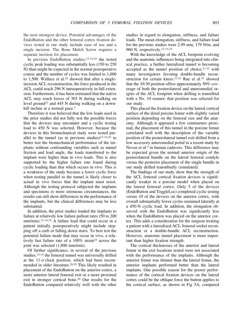
nterior femur was thinner than the lateral femur, thenterior implants performed better than the lateralmplants. One possible reason for the poorer perfor-ance of the cortical fixation devices on the lateral
ortex could be the oblique force the button applies to
he cortical surface, as shown in Fig 5A, compared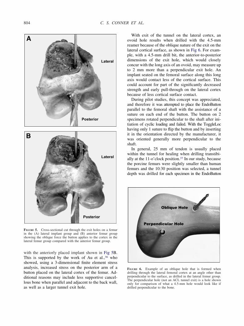
wTsabdla
orlpdctiacsb
apssthiws
watfd
Fisl
FdpT
804 C. S. CONNER ET AL.
ith the anteriorly placed implant shown in Fig 5B.his is supported by the work of Au et al.,36 whohowed, using a 3-dimensional finite element stressnalysis, increased stress on the posterior arm of autton placed on the lateral cortex of the femur. Ad-itional reasons may include less supportive cancel-ous bone when parallel and adjacent to the back wall,
IGURE 5. Cross-sectional cut through the exit holes on a femurn the (A) lateral implant group and (B) anterior femur grouphowing the oblique force the button applies to the cortex in theateral femur group compared with the anterior femur group.
s well as a larger tunnel exit hole.od
With exit of the tunnel on the lateral cortex, anvoid hole results when drilled with the 4.5-mmeamer because of the oblique nature of the exit on theateral cortical surface, as shown in Fig 6. For exam-le, with a 4.5-mm drill bit, the anterior-to-posteriorimensions of the exit hole, which would closelyoncur with the long axis of an ovoid, may measure upo 2 mm more than a perpendicular exit hole. Anmplant seated on the femoral surface along this longxis would contact less of the cortical surface. Thisould account for part of the significantly decreasedtrength and early pull-through on the lateral cortexecause of less cortical surface contact.During pilot studies, this concept was appreciated,
nd therefore it was attempted to place the EndoButtonarallel to the femoral shaft with the assistance of auture on each end of the button. The button on 2pecimens rotated perpendicular to the shaft after ini-iation of cyclic loading and failed. With the ToggleLocaving only 1 suture to flip the button and by insertingt in the orientation directed by the manufacturer, itas oriented generally more perpendicular to the
haft.In general, 25 mm of tendon is usually placedithin the tunnel for healing when drilling transtibi-
lly at the 11-o’clock position.37 In our study, becausehe porcine femurs were slightly smaller than humanemurs and the 10:30 position was selected, a tunnelepth was drilled for each specimen in the EndoButton
IGURE 6. Example of an oblique hole that is formed whenrilling through the lateral femoral cortex at an angle other thanerpendicular to the surface, as drilled in the lateral femur group.he perpendicular hole (not an ACL tunnel exit) is a hole shown
nly for comparison of what a 4.5-mm hole would look like ifrilled perpendicular to the bone.
abpwstTbtrbrl
2itttbctbrstelttcm
fedTcrgtsciaEe
oApd
dngltfismcftcpmnr
dTt5tEecvbteaoettfg
ltcrcoceteTtot
805COMPARISON OF 3 FEMORAL FIXATION DEVICES
nd the ToggleLoc to allow 20 mm of tendon in theone. In double-bundle ACL reconstruction with aosterolateral tunnel, the tunnel length can be less, andith the EndoButton, one is limited to 15 mm as the
mallest loop. Therefore one may have less tendon inhe tunnel or a shorter corticocancellous bone bridge.he ToggleLoc insertion method allows the tendon toe placed within the entire tunnel drilled. Some inves-igators have advocated drilling with the 4.5-mmeamer first and then measuring the tunnel lengthefore drilling the tunnel for the graft to decrease theisk of drilling through the tunnel completely with thearge reamer.38,39
When we compared the specimens that withstood,000 cycles with those that failed during cyclic test-ng, there was no significant difference in the respec-ive corticocancellous bone bridges at the lengthsested (10- to 34-mm range). Furthermore, althoughhe ToggleLoc had a longer corticocancellous boneridge than the EndoButton, it did not withstand moreycles or provide better strength. There was a posi-ive correlation between longer corticocancellousone bridges and improved performance on the ante-ior cortical surface compared with the lateral corticalurface. However, this is likely because of other fac-ors as discussed previously. There may be a differ-nce that could be noted with shorter corticocancel-ous bone bridges, as may occur with a posterolateralunnel, and this will necessitate further testing to de-ermine the shortest corticocancellous bone bridge ac-eptable for a cortical fixation device in or near theetaphysis.When we compared the actual devices, the EZLoc
ailed to complete the cyclic study except for 1 test inither testing group, and therefore further analysis wasone only comparing the EndoButton and ToggleLoc.he EndoButton showed decreased elongation, orreep, compared with the ToggleLoc. This would cor-elate with increased graft laxity in the ToggleLocroup and potentially less knee stability postopera-ively. The EndoButton also showed increased failuretrength. This could be protective of the graft in thease of an injury in the early postoperative period. Thencreased cortical contact area of the implants wasssociated with the favorable characteristics of thendoButton, and this may be an important factor tovaluate with new implants.
The stiffness of the ToggleLoc was higher than thatf the EndoButton during the load-to-failure testing.lthough many investigators have discussed and re-orted the variable stiffness of different graft fixation
evices, the benefit or detriment of a stiff graft fixation tevice has not been determined. In theory, the stiff-ess of the fixation is less important because after theraft heals to the tunnel, the fixation device is noonger contributing to the construct, and before this,he knee does not have to resist full-activity loads. Thexation stiffness, in theory, will be equal in the con-truct once it has healed, and that is when the deter-ination of physiologic laxity is accessed. In addition,
oncerning the ToggleLoc, the increased stiffness onailure testing was associated with increased elonga-ion during the cyclic testing. Stiffness during theyclic test was not measured. Other authors haveroposed that the stiffness of an implant may deter-ine in part the ultimate graft laxity as well as the
eed for initial tension, which is inversely related toestoration of normal ACL kinematics.40,41
The effect of preconditioning was evaluated byetermining the elongation after various cycles.herefore a more clinically based elongation would be
o reference the elongation from 20 to 2,000 cycles or0 to 2,000 cycles, assuming the knee was precondi-ioned in a similar manner. For instance, with thendoButtons in the lateral femur group, the meanlongation was decreased by 30% beginning after 20ycles and by 40% beginning after 50 cycles. Throughisualization of the cycles, it was apparent that theutton settles into the periosteum and cortex, and it ishought that this may account for some of the initiallongation. The tendon constructs elongated on aver-ge 0.72 mm, so most of the elongation was becausef the implant fixation. With regard to graft-implantlongation, our study is consistent with other studieshat have shown the importance of initial precondi-ioning.12-14,25 We recommend extensive cycling be-ore securing the graft to decrease postoperative elon-ation.The remodeling of the tendon graft to an ACL
igament with healing to the tunnels ultimately affectshe final stability of the knee. As a result, this biome-hanical study is limited in that this factor cannot beeplicated. In addition, the study was limited to 2,000ycles, and although this is more cycles than used inther studies, it still under-represents the number ofycles that will occur before full graft healing. How-ver, although healing in a soft-tissue graft is thoughto occur at 8 to 12 weeks,1-4 it is not a dichotomousvent; rather, healing occurs beginning at time 0.herefore the expected contribution to stability from
he graft fixation will decrease as additional healingccurs. A better cyclic testing protocol may factor inhis understanding and apply less cyclic force over
ime, although the exact protocol that relates to the per-
ctmo
eanmckmbipptcalsg
ogaatrp
ta
1
1
1
1
1
1
1
1
1
1
2
806 C. S. CONNER ET AL.
entage of healing would be difficult to determine athis time. Thus static cyclic testing and failure testingay just as effectively compare performance of vari-
us fixation devices.An additional limitation of this study is that it only
valuated the lateral cortex versus anterior cortex fix-tion of the ACL with a simulated transtibial tech-ique in porcine femurs. The choice of porcine fe-urs and tendons was made because of the increased
ost and scarcity associated with young cadavericnees and their similarity to human tissue.15-17 Place-ent of a posterolateral tunnel, drilling the single-
undle ACL from the anteromedial portal, or testingn human cadavers could offer further information. Aosterolateral tunnel or drilling from an anteromedialortal may allow a more perpendicular exit of theunnel out the lateral femoral cortex. This could in-rease the button contact area (less oblique hole) and,s a result, potentially increase the performance of aateral cortical fixation device. Most importantly, onehould remember that the anatomic location of theraft is more important than the exit hole location.
CONCLUSIONS
The EndoButton provided the strongest ACL fem-ral fixation with significantly less graft-implant elon-ation and significantly higher failure loads. It waslso shown in a porcine model that implants on thenterior cortical surface perform better than those onhe lateral surface. Increased cortical thickness, in theange tested, was not associated with improved im-lant performance in the porcine model.
Acknowledgment: The authors thank Newt Scott for hisechnical assistance and Suzanne Simpson for her editorialssistance.
REFERENCES
1. Tomita F, Yasuda K, Mikami S, Sakai T, Yamazaki S, To-hyama H. Comparisons of intraosseous graft healing betweenthe doubled flexor tendon graft and the bone-patellar tendon-bone graft in anterior cruciate ligament reconstruction. Arthros-copy 2001;17:461-476.
2. Weiler A, Peine R, Pashmineh-Azar A, Abel C, Südkamp NP,Hoffmann RF. Tendon healing in a bone tunnel. Part I: Bio-mechanical results after biodegradable interference fit fixationin a model of anterior cruciate ligament reconstruction insheep. Arthroscopy 2002;18:113-123.
3. Kawakami H, Shino K, Hamada M, et al. Graft healing in abone tunnel: Bone-attached graft with screw fixation versus
bone-free graft with extra-articular suture fixation. Knee SurgSports Traumatol Arthrosc 2004;12:384-390.2
4. Goradia VK, Rochat MC, Grana WA, Rohrer MD, Prasad HS.Tendon-to-bone healing of a semitendinosus tendon autograftused for ACL reconstruction in a sheep model. Am J KneeSurg 2000;13:143-151.
5. Morrison JB. Function of the knee joint in various activities.Biomed Eng 1969;4:573-580.
6. Noyes FR, Butler DL, Grood ES, Zernicke RF, Hefzy MS.Biomechanical analysis of human ligament grafts used inknee-ligament repairs and reconstructions. J Bone Joint SurgAm 1984;66:344-352.
7. Heijne A, Fleming BC, Renstrom PA, Peura GD, BeynnonBD, Werner S. Strain on the anterior cruciate ligament duringclosed kinetic chain exercises. Med Sci Sports Exerc 2004;36:935-941.
8. Kvist J, Gillquist J. Sagittal plane knee translation and elec-tromyographic activity during closed and open kinetic chainexercises in anterior cruciate ligament-deficient patients andcontrol subjects. Am J Sports Med 2001;29:72-82.
9. Neven E, D’Hooghe P, Bellemans J. Double-bundle anteriorcruciate ligament reconstruction: A cadaveric study on theposterolateral tunnel position and safety of the lateral struc-tures. Arthroscopy 2008;24:436-440.
0. Singhatat W, Lawhorn KW, Howell SM, Hull ML. How fourweeks of implantation affect the strength and stiffness of atendon graft in a bone tunnel: A study of two fixation devicesin an extraarticular model in ovine. Am J Sports Med 2002;30:506-513.
1. Zantop T, Weimann A, Wolle K, Musahl V, Langer M, Pe-tersen W. Initial and 6 weeks postoperative structural proper-ties of soft tissue anterior cruciate ligament reconstructionswith cross-pin or interference screw fixation: An in vivo studyin sheep. Arthroscopy 2007;23:14-20.
2. Ahmad CS, Gardner TR, Groh M, Arnouk J, Levine WN.Mechanical properties of soft tissue femoral fixation devicesfor anterior cruciate ligament reconstruction. Am J Sports Med2004;32:635-640.
3. Kousa P, Jarvinen TL, Vihavainen M, Kannus P, Jarvinen M.The fixation strength of six hamstring tendon graft fixationdevices in anterior cruciate ligament reconstruction. Part I:Femoral site. Am J Sports Med 2003;31:174-181.
4. Milano G, Mulas PD, Ziranu F, Piras S, Manunta A, Fabbri-ciani C. Comparison between different femoral fixation de-vices for ACL reconstruction with doubled hamstring tendongraft: A biomechanical analysis. Arthroscopy 2006;22:660-668.
5. Xerogeanes JW, Fox RJ, Takeda Y, et al. A functional com-parison of animal anterior cruciate ligament models to thehuman anterior cruciate ligament. Ann Biomed Eng 1998;26:345-352.
6. Aerssens J, Boonen S, Lowet G, Dequeker J. Interspeciesdifferences in bone composition, density, and quality: Poten-tial implications for in vivo bone research. Endocrinology1998;139:663-670.
7. Pearce AI, Richards RG, Milz S, Schneider E, Pearce SG.Animal models for implant biomaterial research in bone: Areview. Eur Cell Mater 2007;13:1-10.
8. Raffo CS, Pizzarello P, Richmond JC, Pathare N. A reproduc-ible landmark for the tibial tunnel origin in anterior cruciateligament reconstruction: Avoiding a vertical graft in the coro-nal plane. Arthroscopy 2008;24:843-845.
9. Mae T, Shino K, Nakata K, Toritsuka Y, Otsubo H, Fujie H.Optimization of graft fixation at the time of anterior cruciateligament reconstruction. Part I: Effect of initial tension. Am JSports Med 2008;36:1087-1093.
0. Mae T, Shino K, Nakata K, Toritsuka Y, Otsubo H, Fujie H.Optimization of graft fixation at the time of anterior cruciateligament reconstruction. Part II: Effect of knee flexion angle.Am J Sports Med 2008;36:1094-1100.
1. Hamner DL, Brown CH Jr, Steiner ME, Hecker AT, HayesWC. Hamstring tendon grafts for reconstruction of the anterior
2
2
2
2
2
2
2
2
3
3
3
3
3
3
3
3
3
3
4
4
807COMPARISON OF 3 FEMORAL FIXATION DEVICES
cruciate ligament: Biomechanical evaluation of the use ofmultiple strands and tensioning techniques. J Bone Joint SurgAm 1999;81:549-557.
2. Noyes FR, Grood ES. The strength of the anterior cruciateligament in humans and Rhesus monkeys. J Bone Joint SurgAm 1976;58:1074-1082.
3. Nurmi JT, Jarvinen TL, Kannus P, Sievanen H, Toukosalo J,Jarvinen M. Compaction versus extraction drilling for fixationof the hamstring tendon graft in anterior cruciate ligamentreconstruction. Am J Sports Med 2002;30:167-173.
4. Conner CS, Morris RP, Vallurupalli S, Buford WL Jr, IveyFM. Tensioning of anterior cruciate ligament hamstring grafts:Comparing equal tension versus equal stress. Arthroscopy2008;24:1323-1329.
5. Brown CH Jr, Wilson DR, Hecker AT, Ferragamo M. Graft-bone motion and tensile properties of hamstring and patellartendon anterior cruciate ligament femoral graft fixation undercyclic loading. Arthroscopy 2004;20:922-935.
6. Wallace MP, Howell SM, Hull ML. In vivo tensile behavior ofa four-bundle hamstring graft as a replacement for the anteriorcruciate ligament. J Orthop Res 1997;15:539-545.
7. Shelburne KB, Pandy MG, Anderson FC, Torry MR. Patternof anterior cruciate ligament force in normal walking. J Bio-mech 2004;37:797-805.
8. Markolf KL, Hame S, Hunter DM, et al. Effects of femoraltunnel placement on knee laxity and forces in an anteriorcruciate ligament graft. J Orthop Res 2002;20:1016-1024.
9. Manifold SG, Cushner FD, Scott WN. Anterior cruciate liga-ment reconstruction with bone-patellar tendon-bone autograft:Indications, technique, complications, and management. In:Scott WN, ed. Insall and Scott surgery of the knee. Ed 4.Philadelphia: Churchill Livingston Elsevier, 2006;632-646.
0. Acar HI, Comert A, Ozer H, et al. Femoral seating position ofthe EndoButton in single incision anterior cruciate ligamentreconstruction: An anatomical study. Surg Radiol Anat 2008;30:639-643.
1. Loh JC, Fukuda Y, Tsuda E, Steadman RJ, Fu FH, Woo SL.Knee stability and graft function following anterior cruciateligament reconstruction: Comparison between 11 o’clock and
10 o’clock femoral tunnel placement. 2002 Richard O’ConnorAward paper. Arthroscopy 2003;19:297-304.2. Jepsen CF, Lundberg-Jensen AK, Faunoe P. Does the positionof the femoral tunnel affect the laxity or clinical outcome ofthe anterior cruciate ligament-reconstructed knee? A clinical,prospective, randomized, double-blind study. Arthroscopy2007;23:1326-1333.
3. Pombo MW, Shen W, Fu FH. Anatomic double-bundle ante-rior cruciate ligament reconstruction: Where are we today?Arthroscopy 2008;24:1168-1177.
4. Siebold R, Zantop T. Anatomic double-bundle ACL recon-struction: A call for indications. Knee Surg Sports TraumatolArthrosc 2009;17:211-212.
5. Rue JP, Ghodadra N, Bach BR Jr. Femoral tunnel placement insingle-bundle anterior cruciate ligament reconstruction: A ca-daveric study relating transtibial lateralized femoral tunnelposition to the anteromedial and posterolateral bundle femoralorigins of the anterior cruciate ligament. Am J Sports Med2008;36:73-79.
6. Au AG, Raso VJ, Liggins AB, Otto DD, Amirfazli A. Athree-dimensional finite element stress analysis for tunnelplacement and buttons in anterior cruciate ligament recon-structions. J Biomech 2005;38:827-832.
7. Rosenberg TD. ACL reconstruction with the ACUFEX Direc-tor Drill Guide and ENDOBUTTON CL Fixation System.Knee series technique guide. Reference 10600026, revision A.Andover, MA: Smith & Nephew, 2005. Available from: www.smith-nephew.com. Accessed March 24, 2009.
8. Gittins M. Toggle Loc femoral fixation device with Zip Looptechnology. Surgical protocol. Reference BSM0023, revision091507. Warsaw, IN: BIOMET Sports Medicine, 2007. Avail-able from: www.biometsportsmedicine.com. Accessed March24, 2009.
9. Miller MD. EndoButton drill bit failure. Arthroscopy 2002;18:322-324.
0. Ishibashi Y, Rudy TW, Livesay GA, Stone JD, Fu FH, WooSL. The effect of anterior cruciate ligament graft fixation siteat the tibia on knee stability: Evaluation using a robotic testingsystem. Arthroscopy 1997;13:177-182.
1. To JT, Howell SM, Hull ML. Contributions of femoral fixation
methods to the stiffness of anterior cruciate ligament replace-ments at implantation. Arthroscopy 1999;15:379-387.