Biomechanics of locking plates in femoral neck fixation - UiO ...
235
Biomechanics of locking plates in femoral neck fixation Jan Egil Brattgjerd Thesis for the degree of philosophiae doctor (PhD) Institute of Clinical medicine, Faculty of Medicine, University of Oslo Division of Orthopaedic Surgery, Oslo University Hospital Norway 2020
-
Upload
khangminh22 -
Category
Documents
-
view
1 -
download
0
Transcript of Biomechanics of locking plates in femoral neck fixation - UiO ...
Biomechanics of locking plates in femoral neck fixation
Jan Egil Brattgjerd
Thesis for the degree of philosophiae doctor (PhD)
Institute of Clinical medicine, Faculty of Medicine, University of Oslo
Division of Orthopaedic Surgery, Oslo University Hospital
Norway
2020
© Jan Egil Brattgjerd, 2020
Series of dissertations submitted to the Faculty of Medicine, University of Oslo
ISBN 978-82-8377-776-5
All rights reserved. No part of this publication may be reproduced or transmitted, in any form or by any means, without permission.
Cover: Hanne Baadsgaard Utigard. Print production: Reprosentralen, University of Oslo.
____________________________________________________________________________
2
____________________________________________________________________________
3
Table of contents
1 Acknowledgements 6
2 Abbreviations 8
3 List of papers 10
4 Summary 11
5 Introduction 16
5.1 Anatomy 16
5.2 Bone healing 19
5.3 Femoral neck fractures 23
5.3.1 Epidemiology 23
5.3.2 Etiology 24
5.3.3 Classification 25
5.3.4 Treatment 27
5.3.5 Complications 39
5.4 Biomechanics 41
5.4.1 Definition 41
5.4.2 History 41
5.4.3 Orthopaedic biomechanics 42
5.4.4 Methodology 61
5.4.5 Clinical relevance 84
5.4.6 Implant introduction 86
____________________________________________________________________________
4
6 Aims of the study 88
7 Summary of results 90
8 Methods 98
8.1 Fixations 98
8.2 Radiological examinations 102
8.3 Bone models 104
8.4 Fracture patterns 106
8.5 Test set-ups 108
8.6 Tests 112
8.7 Outcomes 114
8.8 Statistics 115
9 Discussion 117
9.1 General discussion 117
9.2 Discussion of results 122
9.3 Interpretations 131
10 Conclusions 133
11 Future research 134
12 References 136
13 Appendix 169
14 Papers 182

____________________________________________________________________________
5
"A great responsibility rests on the surgeon who introduces a new method of treatment.
The desire to have a new idea published is so great that the originator is often led astray,
and the method is broadcast before it has been proved worthwhile and before the
technique has been perfected."
Marius Nygaard Smith-Petersen (Smith-Petersen et al., 1931)
____________________________________________________________________________
6
1 Acknowledgements
The present thesis was primarily performed at the Biomechanics lab at Oslo University
Hospital during the years 2013-2019. The lab is located within the Institute for Surgical
Research at the University of Oslo. Appointed as a clinical fellow during these years I am
truly thankful for the opportunity to do research in such enthusiastic environments.
My sincere gratitude goes to the initiator of the thesis; professor emeritus Knut
Strømsøe. His personality needs no further introduction: One of the orthopaedic
pioneers in Norwegian orthopaedic trauma surgery and a true bastion regarding
femoral neck fixation. He introduced me to the sphere of orthopaedic traumatology to
which I am grateful.
My main supervisor, professor emeritus Harald Steen, Head of the Biomechanics Lab,
has convinced me of the importance of orthopaedic biomechanics by his way of
reasoning and problem solving. His critical eye has been both instructional and
motivational in my research.
A great thank to professor Olav Røise, my contact supervisor who deserves credit for
making time for my research in an otherwise buzzy time schedule.
It would have been impossible to carry out the thesis without backing from the
Orthopaedic Department at Ullevål and the Head of Science Department professor Lars
Nordsletten. His expectations for time investment for novices in research are inspiring.
My supervisor in statistics professor Are Hugo Pripp is acknowledged for his long and
prosper navigation into the galaxy of variables, imposing order and regularity in the
statistics section.

____________________________________________________________________________
7
I want to express gratitude to chief engineer Jan Rune Nilsen at the Norwegian Defence
Research Establishment for his collaboration.
Also, a thank to our lab´s engineer Sanyalak Niratisairak. I value the hands-on activity
and skilled data analysis. Following appropriate precautions, our future studies
hopefully will involve not only outliers, but also true alien spices (internal humour).
At the University´s mechanical workshop, Head of the department, Knut Rekdal, is
greatly appreciated for his constructive contributions with production of our jig designs.
At the University, master of photography Øystein Horgmo is highly valued for his photos,
which received bronze at the prestigious 2019 Institute for Medical Illustrators Awards!
Swemac Innovation AB with owner and CEO Henrik Hansson and R&D engineer Lars
Öster were fundamental in supporting the studies. The cooperation has been nothing
but a constructive experience. I hope to reflect their innovative and educative approach.
Sophies Minde Ortopedi AS is also appreciated for the financial support to the thesis.
I am grateful to my supportive parents for in adolescence teaching the importance of
working and completing a job begun, which are necessary qualifications in research.
Everything began in tender loving care from my enchanting wife, Na
and got inspired by Isak and August, our own prodigies entering the world.
Now these 3 remain, to whom the thesis is entirely dedicated in unparalleled gratitude.

____________________________________________________________________________
8
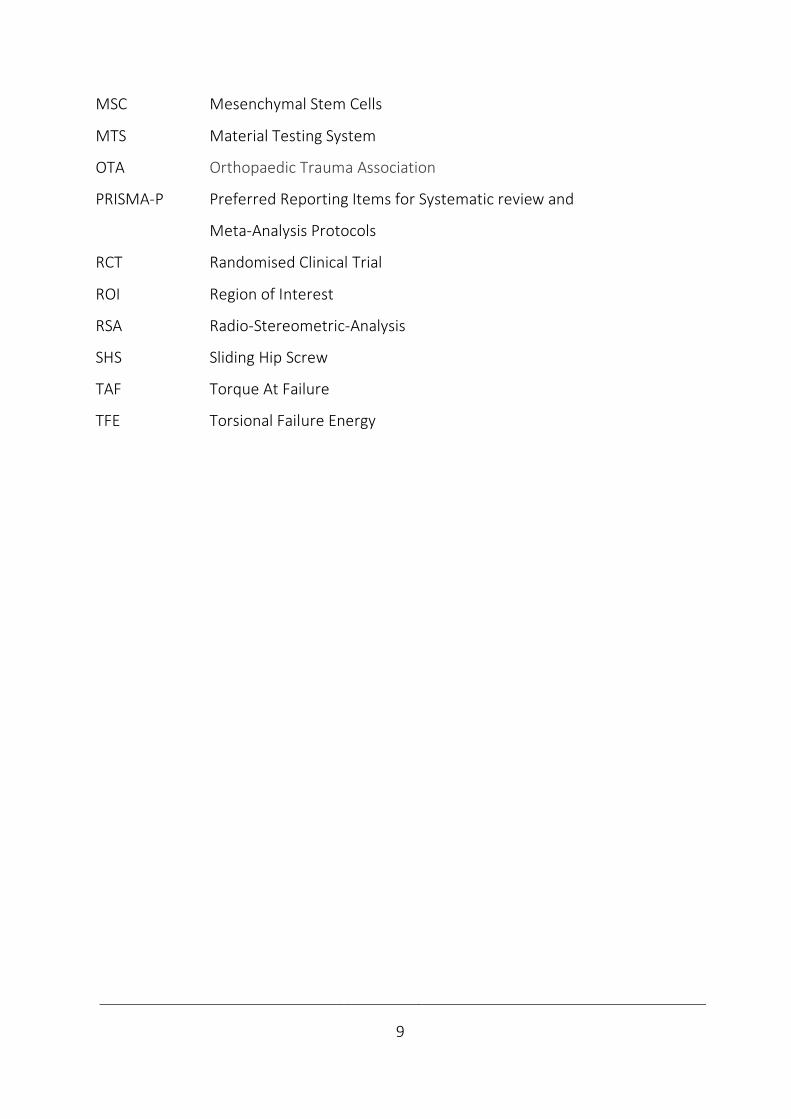
2 Abbreviations
3-GCF
4-GCB
4-GCF
ARS
ANOVA
AO
ASTM
BMD
BW
CCD
CE
CHS
CS
CT
3rd Generation Composite Femur
4th Generation Composite Bone
4th Generation Composite Femur
Anti-Rotational Screw
Analysis of Variance
Arbeitsgemeinschaft für Osteosynthesefragen
(German for "the Association for the Study of Internal Fixation")
American Society for Testing and Materials
Bone Mineral Density
Body-Weight
The angle of Caput-Collum-Diaphysis
Conformité Européene
Cannulated Hip Screws
Cannulated Screws
Computed Tomography
DAF
DCS
DEXA
FDA
FEA
ISO
JRF
LTF
LTD
MDR
Displacement At Failure
Dynamic Compressive Screw plate
Dual Energy X-ray Absorptiometry
U.S. Food and Drug Administration
Finite Element Analysis
The International Organization for Standardization
Joint Reaction Force
Load To Failure
Load To Displacement
Medical Device Regulation (EU)
____________________________________________________________________________
9
MSC
MTS
OTA
PRISMA-P
RCT
ROI
RSA
SHS
TAF
TFE
Mesenchymal Stem Cells
Material Testing System
Orthopaedic Trauma Association
Preferred Reporting Items for Systematic review and
Meta-Analysis Protocols
Randomised Clinical Trial
Region of Interest
Radio-Stereometric-Analysis
Sliding Hip Screw
Torque At Failure
Torsional Failure Energy
____________________________________________________________________________
10
3 List of papers
Study 1 Brattgjerd JE, Loferer M, Niratisairak S, Steen H, Strømsøe K.
Increased torsional stability by a novel femoral neck locking plate. The role
of plate design and pin configuration in a synthetic bone block model.
Clin Biomech. 2018;55;28-35.
Study 2 Brattgjerd JE, Niratisairak S, Steen H, Strømsøe K.
Dynamic compression and posterior tilt counteraction in femoral neck
fixation by a novel pin-plate interlocking system. A biomechanical study in
synthetic bone.
Submitted.
Study 3 Brattgjerd JE, Steen H, Strømsøe K.
Increased stability by a novel femoral neck interlocking plate compared to
conventional fixation methods. A biomechanical study in synthetic bone.
Clin Biomech. 2020; published online May 13th
Study 4 Brattgjerd JE, Niratisairak S, Steen H, Strømsøe K.
Interlocked pins increase strength by a lateral spread of load in femoral
neck fixation. A cadaver study.
Submitted. .
____________________________________________________________________________
11
4 Summary
Background
The age of “the silver tsunami” is already rolling in. An increased number of fragility
fractures of the proximal femur has been predicted by the high incidence in a growing
population of elderly people (Rosengren and Karlsson 2014; Cheung et al., 2018). In this
context, the everyday challenge of a femoral neck fracture associated with premature
mortality and excessive morbidity (Haleem et al., 1998; Hall et al., 2000) justifies an
intensified development of treatment strategies.
While stable fixations promote primary bone healing in intracapsular femoral neck
fractures, the complications, reoperations and low patient functioning remain
challenging with traditional fixations like screws, pins or a Sliding Hip Screw (SHS) device.
So far, internal fixation remains the main treatment in non-displaced fractures of the
femoral neck and in middle-aged patients with a displaced fracture (Gjertsen et al.,
2011; Bartels et al., 2018). The main complication with failure of the fracture to heal
with resulting fixation failure and non-union is determined by an insufficient torsional,
bending and compressive stability (Ragnarsson and Kärrholm, 1991 and 1992; Palm et
al., 2009) and no clear conclusion has been reached on which traditional fixation is
superior when indicated (Parker and Gurusamy, 2001).
Locking plates may increase stability by combining the advantageous medial hold by
multiple screws or pins and the lateral hold of an SHS with a sideplate. Locking plates
differ whether they permit the important fracture dynamization. Preventing fracture
motion may increase the implant´s load-sharing, change stress distribution and increase
the risk of devastating failure patterns as implant fatigue or cut-out from the femoral
head (Berkes et al., 2012). However, locking plate technology permitting intermediate
sintering may improve clinical results (Yin et al., 2018). Principally, intermediate fracture
____________________________________________________________________________
12
motion is achieved by multiple sliding screws in a traditional sideplate fixed to femur or
by interlocked screws sliding en bloc with a plate not fixed to femur laterally.
The first femoral neck plate with 3 interlocked pins in a triangle (Hansson Pinloc®
System) has recently been developed by modification of the original 2 hook-pins, but
lacks documentation of biomechanical characteristics.
Biomechanical studies represent a necessary step to evaluate new fixation principles
(Schemitsch et al., 2010). However, comparisons between different studies and their
clinical relevance are challenging, as no standardised protocols are available.
Biomechanical equivalence to similar implants has previously been sufficient for market
release of a new clinical implant, but recently the recommended increased safety and
performance expectations in new regulations replace these directives (Regulation EU,
2017).
The present study´s main purpose was to analyse the novel implant´s strengths and
weaknesses, both its mechanisms of action and failure. We hypothesised increased
stability by the implant modification and asked if this was achieved at the expense of
restricted fracture motion, altered load distribution and failure types in a more
comprehensive biomechanical study than performed earlier ex vivo in this setting.
Methods
The novel implant was compared to the original pin configuration of its predecessor
(Studies 1, 2, 4) and to multiple screws and a sliding hips screw device (Study 3). The
bone models were either synthetic blocks (Study 1), synthetic femurs (Studies 2, 3) or
fresh frozen human cadaver femurs (Study 4). Non-displaced or anatomically reduced
fixation was performed of a mid-cervical torsional unstable osteotomy (Study 1), semi-
stable wedge osteotomies (Studies 2, 3) or a stable subcapital osteotomy (Study 4).
____________________________________________________________________________
13
The loading directions were torsion around the femoral neck length axis (Studies 1, 3,
4), anteroposterior bending or axial compression (Studies 2-4). The loading modes were
quasi-static, i.e. apparently constant or changing over time (dynamic) with a non-
destructive or destructive load (Studies 1-4), according to respective elastic and plastic
deformation. The loading level ranged from simulating the physiologic partial weight-
bearing or full weight-bearing (Studies 2-4) to pathologic or destructive loading by
imitating stumbling, provoking deformation related with non-unions or clinical failure
types (Studies 1-4).
Test results were initial stiffness from non-destructive quasi-static testing (Studies 1-4)
or displacement locally at the fracture site (Study 3) or globally of the model from
dynamic non-destructive (Study 4) or destructive testing (Studies 2-3), which was
indicative of fracture site motion. Failure strength and energy absorption were revealed
by quasi-static destructive simulation of clinical failure patterns or overloading (Studies
1, 4). Initial signs of fixation failures (Studies 1-3) and complete failure patterns were
inspected (Study 4), along with signs of implant breakage (Studies 1-4).
A sample-size calculation was performed (Studies 2, 4) and parametric testing was
executed (Studies 1-4). Correlations between biomechanical parameters were analysed
to assess test reliability (Studies 1-3). In Study 4 correlation analysis between CT based
bone mineral content and biomechanical parameters was performed to evaluate the
bone-implant constructs´ load distribution.
Results
Increased multidirectional stability was detected by the novel implant in comparison to
the conventional fixation methods (Studies 1-4). The novel implant increased mean
torsional stability up to 20 times (p < 0.001) in non-destructive and destructive testing
of stable, semi-stable and unstable fractures (Studies 1, 3, 4). The mean bending stability
____________________________________________________________________________
14
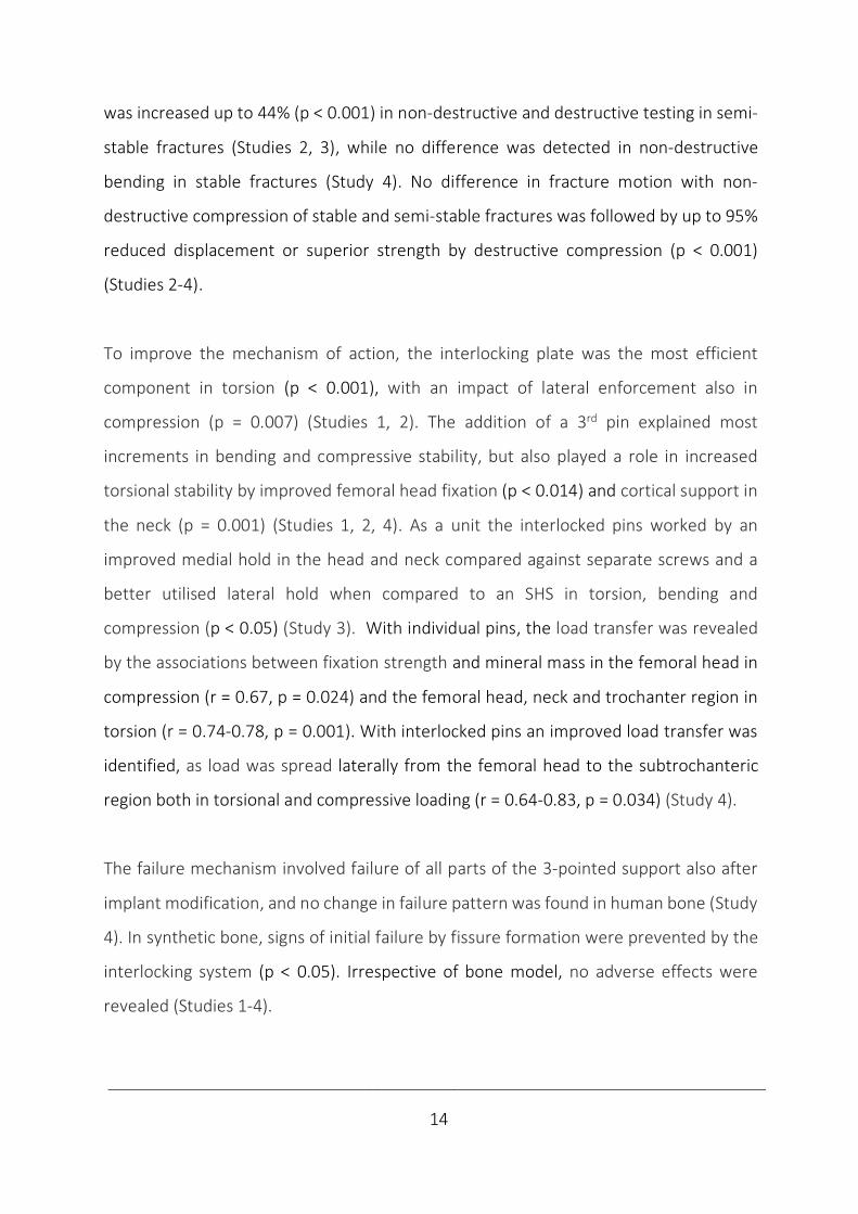
was increased up to 44% (p < 0.001) in non-destructive and destructive testing in semi-
stable fractures (Studies 2, 3), while no difference was detected in non-destructive
bending in stable fractures (Study 4). No difference in fracture motion with non-
destructive compression of stable and semi-stable fractures was followed by up to 95%
reduced displacement or superior strength by destructive compression (p < 0.001)
(Studies 2-4).
To improve the mechanism of action, the interlocking plate was the most efficient
component in torsion (p < 0.001), with an impact of lateral enforcement also in
compression (p = 0.007) (Studies 1, 2). The addition of a 3rd pin explained most
increments in bending and compressive stability, but also played a role in increased
torsional stability by improved femoral head fixation (p < 0.014) and cortical support in
the neck (p = 0.001) (Studies 1, 2, 4). As a unit the interlocked pins worked by an
improved medial hold in the head and neck compared against separate screws and a
better utilised lateral hold when compared to an SHS in torsion, bending and
compression (p < 0.05) (Study 3). With individual pins, the load transfer was revealed
by the associations between fixation strength and mineral mass in the femoral head in
compression (r = 0.67, p = 0.024) and the femoral head, neck and trochanter region in
torsion (r = 0.74-0.78, p = 0.001). With interlocked pins an improved load transfer was
identified, as load was spread laterally from the femoral head to the subtrochanteric
region both in torsional and compressive loading (r = 0.64-0.83, p = 0.034) (Study 4).
The failure mechanism involved failure of all parts of the 3-pointed support also after
implant modification, and no change in failure pattern was found in human bone (Study
4). In synthetic bone, signs of initial failure by fissure formation were prevented by the
interlocking system (p < 0.05). Irrespective of bone model, no adverse effects were
revealed (Studies 1-4).

____________________________________________________________________________
15
The systematic testing nuanced the definite findings of improved stability, both
regarding load level, mode and direction by low to high correlations between
biomechanical parameters, reflecting different properties of fixation stability, also
between local and global displacement (r = 0.29-0.99, p < 0.05) (Studies 1, 2, 4).
Conclusions
The strength of the novel implant was an incrementally increased multidirectional
stability by the modified components in comparison to relevant fixation methods. While
a profound impact was detected in torsion, the effect in compression was limited to still
permit the important intermediate fracture motions. The mechanism of action was
improved 3-pointed support of each interlocked pin, which facilitated load transfer and
spread load laterally to the more solid cortical bone. The mechanism of failure was
unchanged, as no adverse effects were detected by increased stability.
The short-term patient safety requirements involved with implant development were
achieved with the current findings of the novel implant ex vivo and justified the
introduction, which already had taken place in vivo. The presented approach of a more
systematic biomechanical investigation nuanced the findings of the implant
modification. All studies demonstrated superior mechanical characteristics by increased
load-sharing with the interlocking plate device. With a low load level and used with more
stable fractures the new implant can be expected to have a possible impact, which
questions the relevance of the current experimental findings with respect to long-term
safety in making optimal mechano-biological conditions for primary bone healing. This
is noted as a provisional unanswered question of the novel implant, since the clinical
effect of the experimentally documented safe and modest improvement in 3-pointed
support may be insufficient to improve results in patients in the long run. Hence, to
reveal the relevance of the improved biomechanics of interlocked pins, further clinical
studies are needed.

____________________________________________________________________________
16
5 Introduction
5.1 Anatomy
Hip geometry
The femur is the longest bone in humans. Proximally, the spherical head is followed by
a short and narrow neck, which normally faces forward relative to the shaft with an
anteversion angle of 7-15° in adults (Fig. 1). From the caput, the collum forms an angle
with the diaphysis (CCD) of 120-130°. The greater trochanter is located on top laterally,
while the minor is directed backwards medially further distally. In front, the neck´s
lateral border is marked by the intertrochanteric line and the crest on the backside. The
proximal femur ends and the shaft curves backwards towards the distal femur. In
upright position, the shaft is 5-7° adducted (Dahl and Rinvik, 2010). While the femoral
geometry varies greatly both with age and gender (Toogood et al., 2009), the intrapair
correlation is high down to its mineral content (Young et al., 2013; Wright et al., 2018).
Figure 1. The proximal femur (anterior view) (llustration by JEB).
The femur forms a stable ball and socket joint with acetabulum, which is faced anteriorly
(20°) and laterally (45°). The capsule adheres to the intertrochanteric line in front and
medially to the crest in back and allows motion in the cardinal planes by frontal ab-
/adduction, sagittal flex-/extension and transverse rotations (Dahl and Rinvik, 2010).
Greater trochanter
Intertrochanteric line
Femoral neck
Femoral head
Minor trochanter
____________________________________________________________________________
17
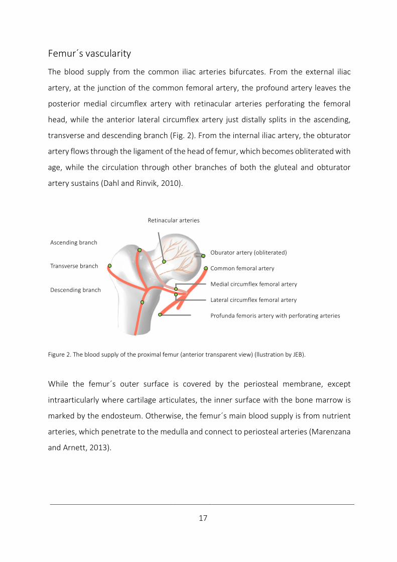
Femur´s vascularity
The blood supply from the common iliac arteries bifurcates. From the external iliac
artery, at the junction of the common femoral artery, the profound artery leaves the
posterior medial circumflex artery with retinacular arteries perforating the femoral
head, while the anterior lateral circumflex artery just distally splits in the ascending,
transverse and descending branch (Fig. 2). From the internal iliac artery, the obturator
artery flows through the ligament of the head of femur, which becomes obliterated with
age, while the circulation through other branches of both the gluteal and obturator
artery sustains (Dahl and Rinvik, 2010).
Figure 2. The blood supply of the proximal femur (anterior transparent view) (llustration by JEB).
While the femur´s outer surface is covered by the periosteal membrane, except
intraarticularly where cartilage articulates, the inner surface with the bone marrow is
marked by the endosteum. Otherwise, the femur´s main blood supply is from nutrient
arteries, which penetrate to the medulla and connect to periosteal arteries (Marenzana
and Arnett, 2013).
⏞⏞
Ascending branch
Transverse branch
Descending branch
Oburator artery (obliterated)
Common femoral artery
Medial circumflex femoral artery
Lateral circumflex femoral artery
Profunda femoris artery with perforating arteries
Retinacular arteries

____________________________________________________________________________
18
Bone structure
The bone structure is mainly compact in shafts and spongy in both ends of long bones
(Fig. 3). To resist physical stress, cancellous bone is organised in trajectories in the
proximal femur. The trabecular structure is a meshwork of struts with bars and plates.
The presence of pores varies from 30-90%, with a corresponding variation in density
between 0.1-1.0 g/cm3. Compact bone resists deformation by the cortex´ cylindrical
lamellae with typical porosity of 5-30% and a corresponding density of 1.8-2.0 g/cm3
(Martin et al., 1998). The basic structural unit of cortical bone is the osteon (Haversian
system). The central blood vessels are surrounded by osteocytes, layers of bone and are
lined by osteoblasts (Lowe and Anderson, 2015).
Figure 3. The femoral bone structures (llustration by JEB).
Bone material
Bone is a composite material composed by organic and inorganic particles. It is a
specialised connective tissue with an organic extra-cellular matrix of collagen fibres
cemented in a ground substance of glycoproteins and proteoglycans. The inorganic
mineral crystals consist of calcium and phosphate forming hydroxyapatite
Ca10(PO4)6(OH)2. The organic component constitutes 30% of bone weight, mineral salt
60% and water 10% (Nordin and Frankel, 2012; Lowe and Anderson, 2015).
Osteocyte Osteoblast
Osteoclast
CanalNerve
Artery Lymph Vein Lamellae
Cancellous Trajectories Trabeculae
Cortical Lamellae Osteon
____________________________________________________________________________
19
5.2 Bone healing
Bone formation
From embryonic life on, bone is formed by 2 pathways. In intramembranous formation,
bone is formed between membranes. Mesenchymal Stem Cells (MSC) may differentiate
into osteoblasts producing bone, as e.g. in the skull. By endochondral ossification,
preformed cartilage is transformed into bone, as in long bones. MSC differentiate into
chondrocytes producing cartilage, which are mineralised and penetrated by
osteoblasts) (Lowe and Anderson, 2015). Bone healing utilizes both these pathways.
Forms of bone healing
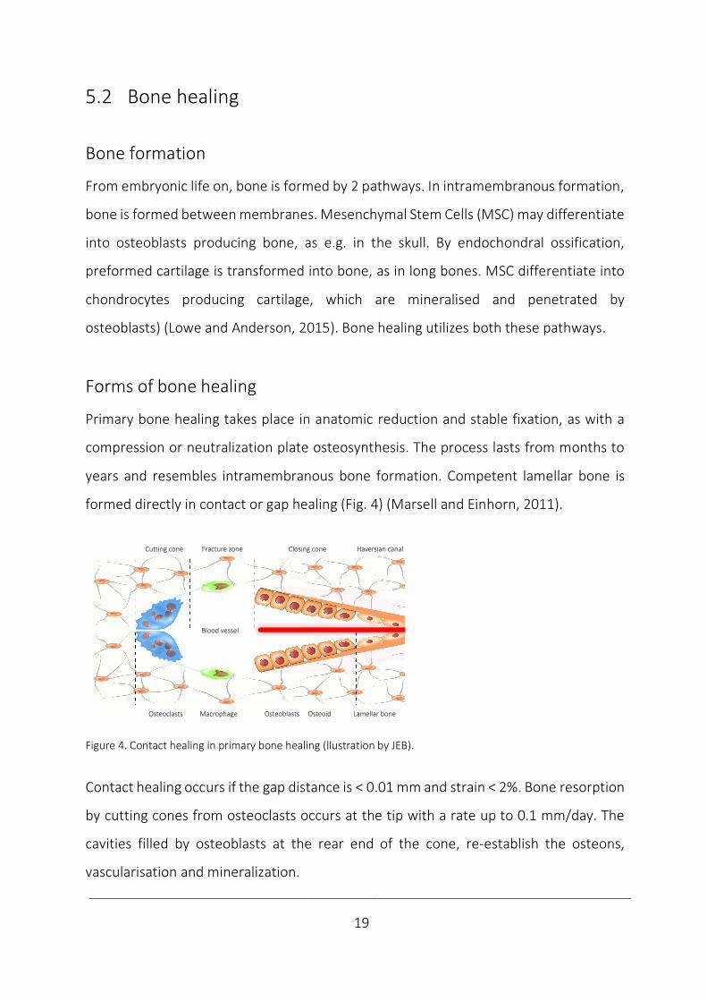
Primary bone healing takes place in anatomic reduction and stable fixation, as with a
compression or neutralization plate osteosynthesis. The process lasts from months to
years and resembles intramembranous bone formation. Competent lamellar bone is
formed directly in contact or gap healing (Fig. 4) (Marsell and Einhorn, 2011).
Figure 4. Contact healing in primary bone healing (llustration by JEB).
Contact healing occurs if the gap distance is < 0.01 mm and strain < 2%. Bone resorption
by cutting cones from osteoclasts occurs at the tip with a rate up to 0.1 mm/day. The
cavities filled by osteoblasts at the rear end of the cone, re-establish the osteons,
vascularisation and mineralization.
Blood vessel
Cutting cone Fracture zone Closing cone Haversian canal
Osteoclasts Macrophage Osteoblasts Osteoid Lamellar bone
____________________________________________________________________________
20
Gap healing occurs if the gap is less than 1 mm. Woven bone fills the gap in 1-2 months,
prior to remodelling as with contact healing (Marsell and Einhorn, 2011).
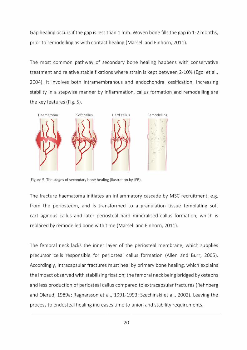
The most common pathway of secondary bone healing happens with conservative
treatment and relative stable fixations where strain is kept between 2-10% (Egol et al.,
2004). It involves both intramembranous and endochondral ossification. Increasing
stability in a stepwise manner by inflammation, callus formation and remodelling are
the key features (Fig. 5).
Figure 5. The stages of secondary bone healing (llustration by JEB).
The fracture haematoma initiates an inflammatory cascade by MSC recruitment, e.g.
from the periosteum, and is transformed to a granulation tissue templating soft
cartilaginous callus and later periosteal hard mineralised callus formation, which is
replaced by remodelled bone with time (Marsell and Einhorn, 2011).
The femoral neck lacks the inner layer of the periosteal membrane, which supplies
precursor cells responsible for periosteal callus formation (Allen and Burr, 2005).
Accordingly, intracapsular fractures must heal by primary bone healing, which explains
the impact observed with stabilising fixation; the femoral neck being bridged by osteons
and less production of periosteal callus compared to extracapsular fractures (Rehnberg
and Olerud, 1989a; Ragnarsson et al., 1991-1993; Szechinski et al., 2002). Leaving the
process to endosteal healing increases time to union and stability requirements.
Haematoma Soft callus Hard callus Remodelling
____________________________________________________________________________
21
Biological and mechanical factors
The fracture hematoma is the biological starting point of healing; growth factor release,
cell migration and differentiation and tissue synthesis of angiogenesis and osteogenesis.
Growth factors influence healing either by an osteogenic effect (Bone Morphogenetic
Proteins), an angiogenic effect (Fibroblast Growth Factors) or by both (Transforming
Growth Factor-Beta, Platelet Derived Growth Factor and Vascular Endothelial Growth
Factor) (Ghiasi et al., 2017). Angiogenesis precedes osteogenesis, as it supplies the
nutrition, oxygen and growth factors required in healing.
The biological factors are regulated by mechanics; strain, fluid velocity and hydrostatic
pressure may cause MSC deformation and activation, a stimulus for bone formation
(Ghiasi et al., 2017). Based on stability diverse forms of repair initiate (Claes et al., 2012).
Delayed or failed bone healing
At the fracture site, a race between union and failure is started. If the basic mechanical
stability requirements of bone healing are met, union is the biological end result. With
primary bone healing, a larger gap may increase instability and delay or even prevent
healing as seen when simulated by computational modelling (Lacroix et al., 2002; Carlier
et al., 2014). This is opposed to secondary healing, where micromotions enhance
healing, while overloading is known to delay the repair process and can cause non-union
(Green et al., 2005).
To explain the faith of a fracture to heal or not, alternative conceptual models interpret
bone healing as bone forming or resorbing responses to mechanical, biological or
pharmacological stimuli. If stress and strain remain under a threshold value, granulation
tissue is formed below 100% strain, subsequently cartilage with 10% strain tolerance
and bone with 2-5% (Perren, 1979). The central role of angiogenesis in bone healing is
____________________________________________________________________________
22
explained by inhibited vascularisation with larger deformations and high strain, only
allowing fibrocartilage to be formed (Carter et al., 1998; Claes and Heigele, 1999).
Bone is in homeostasis when under tolerable stress. Between 2-100% strain, the bone
healing organ starts to work as fracture occurs. Under intolerable strain the organ
activity stops and a non-union develops (Elliott et al., 2016). This sums up the bone
healing response to mechanical stimuli as in Wolff´s law (Wolff, 1892), the theories of
strain (Perren, 1979) and bone homeostasis (Frost, 1987).
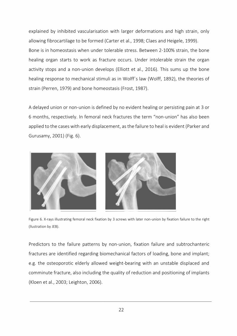
A delayed union or non-union is defined by no evident healing or persisting pain at 3 or
6 months, respectively. In femoral neck fractures the term “non-union” has also been
applied to the cases with early displacement, as the failure to heal is evident (Parker and
Gurusamy, 2001) (Fig. 6).
Figure 6. X-rays illustrating femoral neck fixation by 3 screws with later non-union by fixation failure to the right
(llustration by JEB).
Predictors to the failure patterns by non-union, fixation failure and subtrochanteric
fractures are identified regarding biomechanical factors of loading, bone and implant;
e.g. the osteoporotic elderly allowed weight-bearing with an unstable displaced and
comminute fracture, also including the quality of reduction and positioning of implants
(Kloen et al., 2003; Leighton, 2006).
____________________________________________________________________________
23
5.3 Femoral neck fractures
5.3.1 Epidemiology
Globally, approximately 1.7 million proximal femur fractures occurred annually in 1990
(Woolf and Pfleger, 2003). With an increasing world population and number of elderly
(the silver tsunami), a dramatical wave with range of 7-21 million proximal femur
fractures is estimated in 2050 (Gullberg et al., 1997). With an increased number of such
fractures in most countries worldwide, it seems fair to conclude that these projections
are not far off target (Rosengren and Karlsson, 2014; Cheung et al., 2018). Based on
increased life expectancy, an overall life-time risk of proximal femur fractures of 11-23%
is evident (Oden, 1998) with a corresponding high prevalence of fracture sequelae.
Regarding world-wide incidence rates, North America and Europe report high incidence
of proximal femur fractures, especially high in the Scandinavian countries (Johnell et al.,
1992; Bacon et al., 1996). Despite lower osteoporotic fracture rates in Asian and African
countries, the expected changes will be mostly prevalent in Asia (Gullberg et al., 1997.
The increased incidence of proximal femur fractures, especially high in postmenopausal
women, has been explained by a reduced physical activity level and bone mass (Finsen
and Benum, 1987; Kannus et al., 1999, Leighton, 2006). A reversal of the trend from
increased incidence (Nymark et al., 2006; Chevalley et al., 2007) may be explained by
the increased use of hormone replacement therapy in this group (Meyer et al., 2009).
Nationally, about 8000-9,000 proximal femur fractures (ca. 3500 displaced and ca. 1000
non-displaced femoral neck fractures) are primarily operated annually (Gjertsen et al.,
2019). The city of Oslo still reports the world´s highest incidence of the fracture (Støen
et al., 2012). With exponentially increased incidence in high age (Lofthus et al., 2001),
proximal femur fractures are most frequent in patients about 80 years, with females
constituting about 3/4 of the patients (Cserháti et al., 2002; Lönnroos et al., 2006).
____________________________________________________________________________
24
5.3.2 Etiology
Femoral neck fractures are most commonly preceded by decreasing bone quality (Augat
et al., 1998). One half of women have bone mineral content below a fracture limit at 65
years of age, while all 85-year-old women have (Singh et al., 1970, Arnold, 1984).
The most frequent mechanism of injury with this insufficiency fracture is a low-energy
fall in the elderly. Similar to a sideways fall on the hip, a direct blow to the greater
trochanter or along the shaft in external rotation of the hip is suggested (Backman,
1957; Klenerman and Marcuson 1970).
Reflecting the bimodal incidence curves, these fracturs are sometimes seen in the young
after stress or high impact injuries with compression along the shaft (Leighton, 2006).
The most frequent low-angled subcapital fracture line follow the epiphyseal scar
(Klenerman and Marcuson 1970), while true trans-cervical fractures appear in a 2:1 ratio
in low energy fractures (FAITH investigators, 2017). Femoral neck fractures in young
individuals are commonly high-angled located transcervically or basicervically due to the
high energy mechanism (Ly and Swiontkowski, 2008).
With a fall on the trochanter, the component of compression along the neck
corresponds with the features of an impacted non-displaced fracture. Landing on the
greater trochanter, which is located somewhat posteriorly, tend to externally rotate the
femur. This explains the posterior neck comminution by posterior impingement against
acetabulum (Backman, 1957; Leighton, 2006) and explains the more common
comminution in up to 70% of displaced fractures (Scheck, 1980; Khan et al. 2009). Only
a 2% lamellar bone elongation (tensional strain tolerance) is necessary at the time of
fracture (Perren, 1979).
____________________________________________________________________________
25
5.3.3 Classification
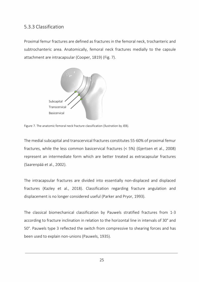
Proximal femur fractures are defined as fractures in the femoral neck, trochanteric and
subtrochanteric area. Anatomically, femoral neck fractures medially to the capsule
attachment are intracapsular (Cooper, 1819) (Fig. 7).
Figure 7. The anatomic femoral neck fracture classification (llustration by JEB).
The medial subcapital and transcervical fractures constitutes 55-60% of proximal femur
fractures, while the less common basicervical fractures (< 5%) (Gjertsen et al., 2008)
represent an intermediate form which are better treated as extracapsular fractures
(Saarenpää et al., 2002).
The intracapsular fractures are divided into essentially non-displaced and displaced
fractures (Kazley et al., 2018). Classification regarding fracture angulation and
displacement is no longer considered useful (Parker and Pryor, 1993).
The classical biomechanical classification by Pauwels stratified fractures from 1-3
according to fracture inclination in relation to the horizontal line in intervals of 30° and
50°. Pauwels type 3 reflected the switch from compressive to shearing forces and has
been used to explain non-unions (Pauwels, 1935).
Subcapital
Transcervical
Basolateral
Subcapital
Transcervical
Basicervical
____________________________________________________________________________
26
Garden classified fracture completeness and displacement in 4 types with decreasing
union rates by increased number (Garden, 1961).
The alphanumerical AO/OTA (AO Foundation/Orthopaedic Trauma Association)
classification considers:
the bone (femur: 3),
segment (proximal: 1),
fracture type (femoral neck: B)
and group (subcapital 1; transcervical: 2 and basicervical: 3).
The subgroups also take the inclination, impaction, displacement and comminution into
consideration (Meinberg et al., 2018).
____________________________________________________________________________
27
5.3.4 Treatment
Conservative treatment
Historic perspective
The report of the earliest proximal femur fractur in humans is a history of conservative
treatment. The discovery of a female skeleton with a proximal femur non-union in Egypt
is dated back to the XIIth Dynasty (1990–1786 B.C.). The long-term survival of a proximal
femur fracture reflects a degree of social care (Dequeker et al., 1997). Until the first
description in the 16th century by Ambroise Paré, these injuries were assumed to be
dislocations and handled accordingly (Kazár and Manninger et al., 2007). In 1819, Sir
Astley Cooper differentiated extracapsular fractures from intracapsular, as the latter
were thought not to consolidate (Bartonicek, 2004). This perception prevailed during
the 19th century (Kazár and Manninger et al., 2007). Attempts to defeat this opinion was
made by the English surgeon Henry Earle, whom in 1823 constructed a fracture bed for
conservative treatment (Bartonicek, 2004). The Norwegian dermatologist Carl Wilhelm
Boeck´s (1808-75) skin traction device ensured treatment by traction as a rule (Emneus,
1979). In addtion, conservative treatment included a closed reduction and
immobilisation with splints and plaster casts (Bissell, 1903; Bartonicek, 2010).
Indications
Regarding preoperative traction, evidence is insufficient to exclude a potential benefit
and to confirm any harm. Traction prior to surgery should discontinue or be evaluated
within a Randomised Controlled Trial (RCT) (Handoll et al., 2011). Otherwise, further
evaluation on conservative treatment is not considered feasible and only considered
acceptable if surgery is not available (Handoll and Parker, 2008). Nowadays, the main
treatment alternatives are internal fixation or arthroplasty, while excision arthroplasty
(a.m. Girdlestone) is reserved the cases of salvage procedures (Frihagen et al., 2007).
____________________________________________________________________________
28
Internal fixation
Development
The introduction of surgery was influenced by advances in medical technology; the
discoveries of anaesthesia by ether inhalation (1846), antiseptics by carbolic acid (1865),
aseptic by steam sterilization (1886) and introducing surgical rubber gloves (1890s) and
visualisation by X-ray (1895) (Bartonicek, 2010). Also, the discovery of penicillin (1928)
later proved to be essential in the success of surgerical procedures (Fleming, 1929).
Regarding the first attempt of femoral neck fixation, the German surgeon Bernhard
Rudolf Konrad von Langenbeck in the 1850s performed internal fixation in a case of
femoral neck non-union. The fellow countryman Franz König was the first to do
successful fixation by percutaneous insertion of a gimlet tool of a femoral neck fracture
under aseptic conditions in 1875 (Bartonicek, 2004).
The Norwegian surgeon Julius Nicolaysen at the National Hospital in Oslo, is credited
the first series of closed nailing in 1894. He inserted a 15 cm triangular pointed steel nail
percutaneously. After postoperative plaster the results were interpreted as “good” in
most patients, although dependency on canes at times (Nicolaysen, 1897 & 1899).
In 1906, the Belgian surgeon Albin Lambotte performed successfully an open reduction
and fixation of a basicervical fracture with 2 screws, but it was not concluded until 1923
that 2 screws held better than 1 (Bartonicek, 2004).
The pioneer era was closed in 1925 when Marius Nygaard Smith-Petersen, a Norwegian-
American surgeon, started to use a 3-flanged nail of steel (Smith-Petersen et al., 1931).

____________________________________________________________________________
29
In 1946, he introduced this as a standard procedure at Ullevål Hospital in Norway, which
became a world leading hip fracture surgery centre in its time (Bomann-Larsen, 2019),
while the procedure fast gained worldwide acceptance (Bartonicek, 2004).
More than a hundred internal fixation devices were developed in this period (Tronzo,
1974). The conventional implants still in use are pins (smooth), screws (partially
threaded) and fixed-angle devices, i.e. an SHS and a sideplate with an optional Anti-
Rotational Screw (ARS) (Hoshino and O´Toole, 2015; Augat et al., 2019) (Fig. 8).
Figure 8. From left; hook-pins, 2 Olmed and 3 ASNIS cannulated screws and an SHS with an ARS (Photo by Horgmo).
The only differences between cannulated screws are core and thread diameter and the
threads´ length and pinch. While only screws may compress fractures axially by design,
screws utilise the same fixation principle of 3-pointed support as pins; cortically in the
trochanteric wall, subcortically in the neck and subchondrally in the head.
The Hansson pin has been the only pin in use in the Scandinavian countries lately
(Gjertsen, 2008). The Swedish surgeon Nils Rydell added a spring to his 4-flanged nail
(Rydell, 1964), which was further developed by Lars Ingvar Hansson in 1975 into a
smooth hook-pin; the Hansson pin. A single pin was first applied in children with
epihysiolysis capitis femoris to eliminate the risk of loosening and further displacement
(Hansson, 1982). Two pins were found suitable to adults with femoral neck fractures
and were introduced in Lund, Sweden in 1980 (Strömqvist et al., 1987) and have since
been implanted in more than 250 000 patients (Hansson Pin Brochure, Swemac).
____________________________________________________________________________
30
The sliding hip screw with a sideplate was patented by the German designer Ernst Pohl
in 1951 (Bartonicek and Rammelt, 2014). As late as in the 1980s it became a standard
implant as AO/ASIF introduced the dynamic hip screw system (Regazzoni et al., 1985).
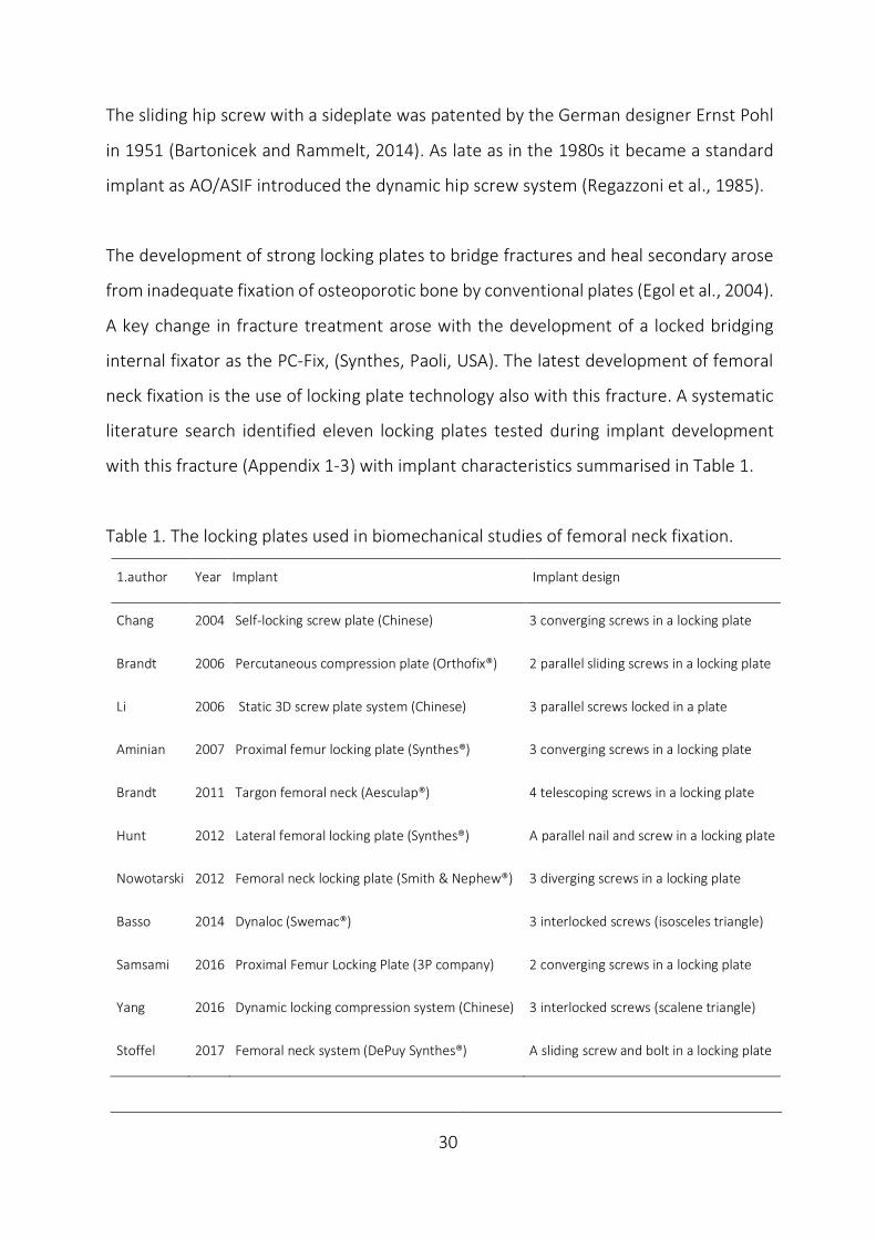
The development of strong locking plates to bridge fractures and heal secondary arose
from inadequate fixation of osteoporotic bone by conventional plates (Egol et al., 2004).
A key change in fracture treatment arose with the development of a locked bridging
internal fixator as the PC-Fix, (Synthes, Paoli, USA). The latest development of femoral
neck fixation is the use of locking plate technology also with this fracture. A systematic
literature search identified eleven locking plates tested during implant development
with this fracture (Appendix 1-3) with implant characteristics summarised in Table 1.
Table 1. The locking plates used in biomechanical studies of femoral neck fixation.
1.author Year Implant Implant design
Chang 2004 Self-locking screw plate (Chinese) 3 converging screws in a locking plate
Brandt 2006 Percutaneous compression plate (Orthofix®) 2 parallel sliding screws in a locking plate
Li 2006 Static 3D screw plate system (Chinese) 3 parallel screws locked in a plate
Aminian 2007 Proximal femur locking plate (Synthes®) 3 converging screws in a locking plate
Brandt 2011 Targon femoral neck (Aesculap®) 4 telescoping screws in a locking plate
Hunt 2012 Lateral femoral locking plate (Synthes®) A parallel nail and screw in a locking plate
Nowotarski 2012 Femoral neck locking plate (Smith & Nephew®) 3 diverging screws in a locking plate
Basso 2014 Dynaloc (Swemac®) 3 interlocked screws (isosceles triangle)
Samsami 2016 Proximal Femur Locking Plate (3P company) 2 converging screws in a locking plate
Yang 2016 Dynamic locking compression system (Chinese) 3 interlocked screws (scalene triangle)
Stoffel 2017 Femoral neck system (DePuy Synthes®) A sliding screw and bolt in a locking plate

____________________________________________________________________________
31
Locking plates differ regarding the number of screws and their orientation, and handling
them as a group is challenging and may not be right. With some exceptions, multiple
screws are used (Brandt et al., 2006; Hunt et al., 2012; Samsami et al., 2016; Stoffel et
al., 2017), in non-parallel (Fig. 9), or parallel non-sliding screw configurations (Fig. 10),
sliding screw configurations (Fig. 11) or interlocked screws sliding en bloc (Fig. 12)
Self-locking screw plate (Chinese). Proximal femur locking plate (Synthes®).
Adapted from Chang et al., 2004. Adapted from Aminian et al., 2007.
Femoral neck locking plate (Smith & Nephew®). Proximal femur locking plate (3P company).
Adapted from Nowotarski et al., 2012. Adapted from Samsami et al., 2016.
Figure 9. The locking plates restricting fracture motion by non-sliding non-parallel screws (Illustration by JEB).
.
Proximal femur locking plate (Synthes) Aminian et al., 2007
Proximal Femur Locking Plate (3P company) Samsani et al., 2016

____________________________________________________________________________
32
Lateral femoral locking plate (Synthes®). Adapted from Hunt et al., 2012.
Figure 10. The locking plate restricting fracture motion by full threading non-sliding despite implant parallelism
(Illustration by JEB).
While fracture site motion principally is hindered postoperatively by non-parallelism or
fully threaded parallel implants, sliding may be achieved by screws sliding individually
within the neck (Fig. 11) or interlocked screws (Fig. 12) sliding en bloc along the neck.
Percutaneous compression plate (Orthofix®). Targon femoral neck (Aesculap®).
From Brandt et al., 2006. Reprinted with permission. From Brandt et al., 2011. Reprinted with permission.
Lateral femoral locking plate (Synthes) Hunt et al., 2012
Percutaneous compression plate (Orthofix) Brandt et al., 2006
Targon femoral neck (Aesculap) Brandt et al., 2011

____________________________________________________________________________
33
Femoral neck system (DePuy Synthes®). Static 3D screw plate system with 3 parallel screws.
From Stoffel et al., 2017. Reprinted with permission. (Chinese). Li et al., 2006. (Image unavailable).
Figure. 11 The locking plates with parallel and non-parallel sliding screws that permit intermediate fracture motion.
Dynaloc® femoral neck fracture system (Swemac). Dynamic locking compression system (Chinese).
From Basso et al., 2014a and b. Reprinted with permission. From Yang et al., 2016. Reprinted with permission.
Figure 12. The interlocked screws, the alternative to principally achieve intermediate fracture compression.
Femoral neck system (DePuy Synthes) Stoffel et al., 2017
Dynamiclockingcompressio
nsystem
(Chinese)
Yang
etal.,2016

____________________________________________________________________________
34
The novel Hansson Pinloc® System has been developed from the standard 2 Hansson
pins (Fig. 13). The major implant modifications were including a 3rd pin with a resulting
triangular pin configuration and a lateral locking plate with reciprocal interlocking. This
represents the only alternative of pins in locking plate technology and the latest
contribution to locking plates in this setting.
Since its introduction in 2013 Pinloc® has reached 20 000 implantations performed and
has been mostly applied in Japan, but also in the Scandinavian countries (Personal
communication, Swemac). The aluminium plate interlocks up to 3 titanium pins with a
reduced shaft diameter in a top-down triangular configuration without further fixation
of the plate to the femur. The plates permit variable angulation of interlocked parallel
pins to the plate and are available in different size; i.e. distance between pins.
Figure 13 The interlocked pins (Swemac). From the brochure of the Hansson Pinloc® System. Reprinted with
permission.
Hansson Pinloc System (Swemac) Introduced, 2013
____________________________________________________________________________
35
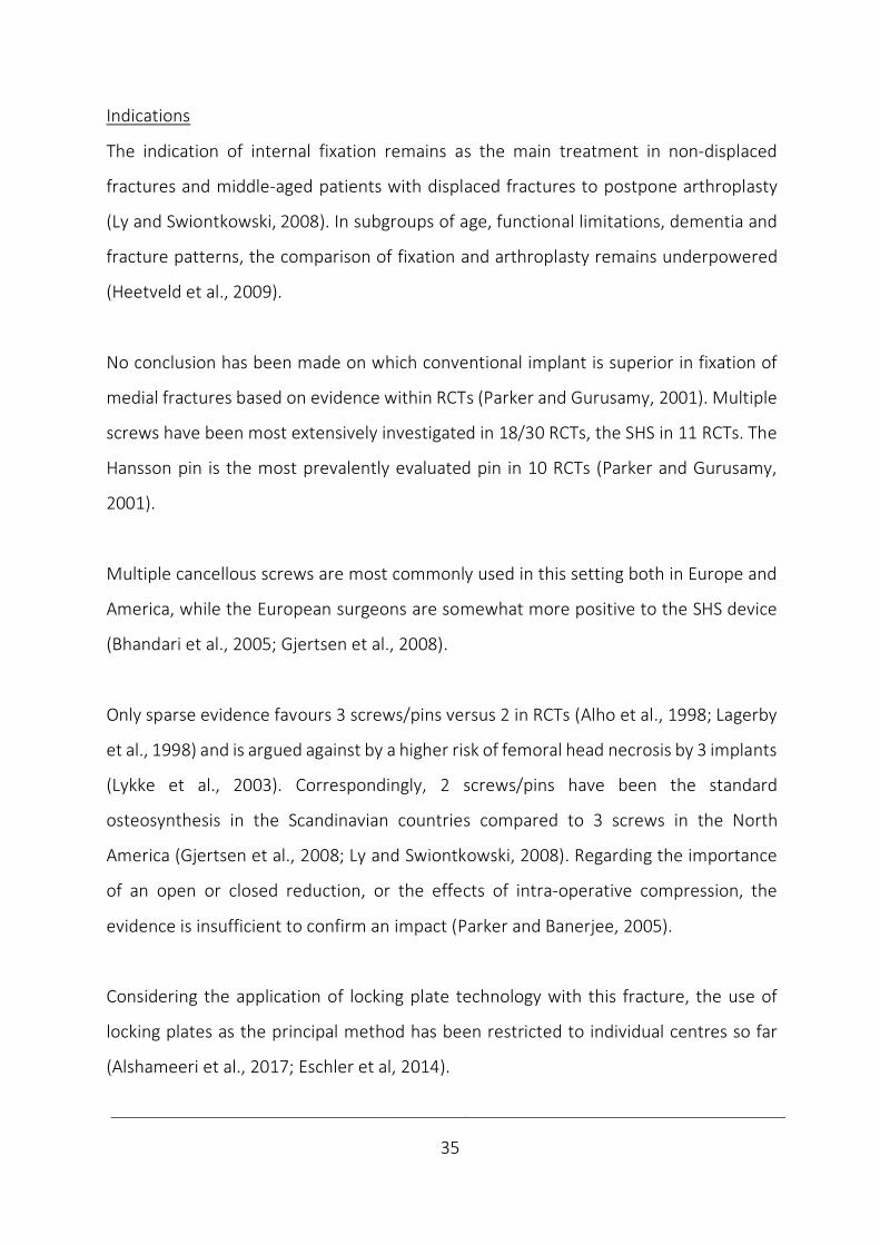
Indications
The indication of internal fixation remains as the main treatment in non-displaced
fractures and middle-aged patients with displaced fractures to postpone arthroplasty
(Ly and Swiontkowski, 2008). In subgroups of age, functional limitations, dementia and
fracture patterns, the comparison of fixation and arthroplasty remains underpowered
(Heetveld et al., 2009).
No conclusion has been made on which conventional implant is superior in fixation of
medial fractures based on evidence within RCTs (Parker and Gurusamy, 2001). Multiple
screws have been most extensively investigated in 18/30 RCTs, the SHS in 11 RCTs. The
Hansson pin is the most prevalently evaluated pin in 10 RCTs (Parker and Gurusamy,
2001).
Multiple cancellous screws are most commonly used in this setting both in Europe and
America, while the European surgeons are somewhat more positive to the SHS device
(Bhandari et al., 2005; Gjertsen et al., 2008).
Only sparse evidence favours 3 screws/pins versus 2 in RCTs (Alho et al., 1998; Lagerby
et al., 1998) and is argued against by a higher risk of femoral head necrosis by 3 implants
(Lykke et al., 2003). Correspondingly, 2 screws/pins have been the standard
osteosynthesis in the Scandinavian countries compared to 3 screws in the North
America (Gjertsen et al., 2008; Ly and Swiontkowski, 2008). Regarding the importance
of an open or closed reduction, or the effects of intra-operative compression, the
evidence is insufficient to confirm an impact (Parker and Banerjee, 2005).
Considering the application of locking plate technology with this fracture, the use of
locking plates as the principal method has been restricted to individual centres so far
(Alshameeri et al., 2017; Eschler et al, 2014).

____________________________________________________________________________
36
Arthroplasties
Development
Creating the first hip arthroplasty in 1890, Glück inserted an ivory ball and preceded the
advance by Smith-Petersen´s arthroplasty of glass in 1923 (Coventry, 1987). Following
the Austin Moore, Judet and Thompson hemiarthroplasties, Charnley developed the
low-friction total hip replacements in the 1950-ies (Judet and Judet, 1950; Moore, 1957;
Thompson, 1954; Charnley, 1979). A diversity of prosthesis and components followed.
When an arthroplasty is indicated in the setting of a fracture of the femoral neck, the
proximal fragment is replaced, either with a modern hemiarthroplasty or a total hip
replacement (Fig. 14). In a hemiarthroplasty, only the femoral head is replaced, either
by a unipolar prosthesis or a bipolar, which also allows movement within the prosthesis,
not only between the acetabulum and the prosthesis. With a total hip replacement, the
acetabulum is also replaced. The acetabular shell component, which includes a high-
density polyethylene liner is usually cemented. The femoral metal stem may be
cemented or press-fit inserted.
Figure 14. The principle of hip prosthesis with standard components (Illustration by JEB).
Unipolar hemiprothesis Bipolar hemiprothesis Total prosthesis
Femoral stem
Taper
Unipolar head Inner head Polyethylene liner
Bipolar head Acetabular shell
____________________________________________________________________________
37
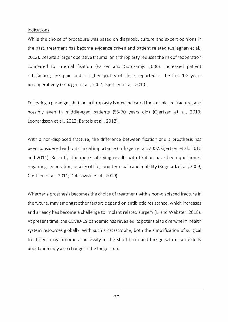
Indications
While the choice of procedure was based on diagnosis, culture and expert opinions in
the past, treatment has become evidence driven and patient related (Callaghan et al.,
2012). Despite a larger operative trauma, an arthroplasty reduces the risk of reoperation
compared to internal fixation (Parker and Gurusamy, 2006). Increased patient
satisfaction, less pain and a higher quality of life is reported in the first 1-2 years
postoperatively (Frihagen et al., 2007; Gjertsen et al., 2010).
Following a paradigm shift, an arthroplasty is now indicated for a displaced fracture, and
possibly even in middle-aged patients (55-70 years old) (Gjertsen et al., 2010;
Leonardsson et al., 2013; Bartels et al., 2018).
With a non-displaced fracture, the difference between fixation and a prosthesis has
been considered without clinical importance (Frihagen et al., 2007; Gjertsen et al., 2010
and 2011). Recently, the more satisfying results with fixation have been questioned
regarding reoperation, quality of life, long-term pain and mobility (Rogmark et al., 2009;
Gjertsen et al., 2011; Dolatowski et al., 2019).
Whether a prosthesis becomes the choice of treatment with a non-displaced fracture in
the future, may amongst other factors depend on antibiotic resistance, which increases
and already has become a challenge to implant related surgery (Li and Webster, 2018).
At present time, the COVID-19 pandemic has revealed its potential to overwhelm health
system resources globally. With such a catastrophe, both the simplification of surgical
treatment may become a necessity in the short-term and the growth of an elderly
population may also change in the longer run.
____________________________________________________________________________
38
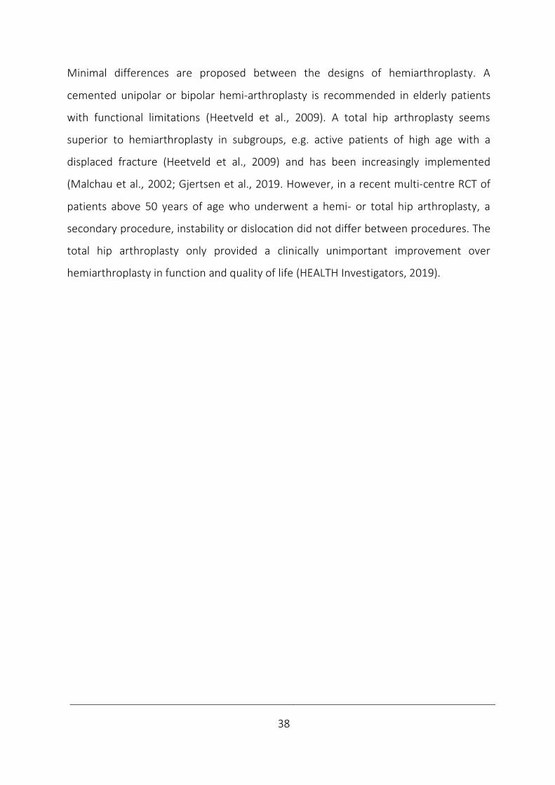
Minimal differences are proposed between the designs of hemiarthroplasty. A
cemented unipolar or bipolar hemi-arthroplasty is recommended in elderly patients
with functional limitations (Heetveld et al., 2009). A total hip arthroplasty seems
superior to hemiarthroplasty in subgroups, e.g. active patients of high age with a
displaced fracture (Heetveld et al., 2009) and has been increasingly implemented
(Malchau et al., 2002; Gjertsen et al., 2019. However, in a recent multi-centre RCT of
patients above 50 years of age who underwent a hemi- or total hip arthroplasty, a
secondary procedure, instability or dislocation did not differ between procedures. The
total hip arthroplasty only provided a clinically unimportant improvement over
hemiarthroplasty in function and quality of life (HEALTH Investigators, 2019).

____________________________________________________________________________
39
5.3.5 Complications
Femoral neck fractures are burdened by high rates of mortality and morbidity (Haleem
et al., 1998; Hall et al., 2000). The highest mortality risk perioperatively is gradually
reduced in time. About 25% of the elderly patients die during the following year.
Afterwards, the mortality rate seems to approach the age-matched controls (Leighton,
2006; Gjertsen et al., 2010). 5 years after the operation half of the patients are alive
(Jensen and Tøndevold, 1979). This supports considering the fracture of the femoral
neck as a warning of imminent life closure.
Amongst medical complications, cardiac and pulmonary complications commonly
occur. Gastrointestinal bleeding, stroke and venous thromboembolism contribute to a
medical complication rate in 1 out of 5 patients (Lawrence et al., 2002). In addition, a
delirium increases the risk of dementia (Lundström et al., 2003) and pressure sores
are another well-known complication (Haleem et al., 2008).
The surgical complications are procedure-related. Conservative treatment resulted in
limb shortening and a high percentage of morbidity and mortality in these patients
(Bissell, 1903). While conservative treatment for a long time remained advocated in
impacted or truly non-displaced fractures (Raaymakers and Marti, 1991), fractures are
now treated surgically as internal fixation reduces the risk of non-union and secondary
surgery (Conn and Parker, 2004). Also, operative treatment most likely reduces hospital
stay and ease rehabilitation as with extracapsular fractures (Handoll and Parker, 2008).
With conventional fixations, the main complication of fixation failure leads to non-union
rates of 5-10% in non-displaced and 20-40% in displaced fractures (Parker and Pryor,
1993; Lu-Yao et al.,1994; Parker and Gurusamy, 2001). The other main complication is
the avascular femoral head necrosis reported in 7% in non-displaced and 16 % of

____________________________________________________________________________
40
displaced fractures (Lu-Yao et al., 1994; FAITH investigators, 2017). Both these
complications may be explained by the femoral head mainly being left avascular with a
displaced intracapsular fracture (Leighton, 2006). In addition, the subsidence of the
fracture may cause implant protrusion and local complaints may necessitate metal
removal. These complications explain reoperation rates with non-displaced
intracapsular fractures of 10-20% and 40% in displaced fractures (Frihagen et al., 2007;
Gjertsen et al., 2011; FAITH investigators, 2017).
The initial case-series of locking plates inhibiting fracture compression by design or
possible jamming within the neck, revealed complication rates of 16-37% with failure
patterns of implant fatigue or cut-out (Berkes et al., 2012; Biber et al., 2014). In a meta-
analysis of 386 patients in 4 controlled clinical trials comparing a locking plate permitting
fracture compression against conventional fixations, the locking plate reduced odds
ratio regarding non-union (0.16, 95% CI 0.05–0.49], revision (0.56, 95%CI 0.32–0.96)
and replacement (0.26, 95%CI 0.10–0.69) (Yin et al., 2018). So far, the clinical results
encourage further investigations of locked plates permitting dynamic compression.
With an arthroplasty, infection, dislocation, periprosthetic fracture or loosening have a
5-10% reoperation rate (Frihagen et al., 2007; Gjertsen et al., 2007). Following a primary
hemi- or a total arthroplasty, a secondary procedure within 24 months occurs in 8%,
while instability or dislocation in 2-5% (HEALTH Investigators, 2019).
Following a femoral neck fracture, functioning is commonly impaired with long term
pain, reduced quality of life and dissatisfaction with result. About half of the patients
(40%) may not regain their walking capacity, making dependency of support common
and independent living challenging (Koval et al., 1995; Gjertsen et al., 2010 and 2011).
____________________________________________________________________________
41
5.4 Biomechanics
5.4.1 Definition
The term “biomechanics” is derived from the Greek words;”βίος” and “μηχανική”,
meaning “life” and “mechanics”. Mechanics is the branch of physics that deals with
behaviour of physical bodies. Biomechanics has been defined as the study of movement
of living things using the science of mechanics. This involves the mechanics of a variety
of activities, injury mechanisms and diseases. Further division into orthopaedic
biomechanics has been made to characterize mechanical properties of the
musculoskeletal system and develop implants and surgical techniques related to its
disorders. It is all about discovering and reducing mechanical stress (Zdero, 2016).
5.4.2 History
The precursor of biomechanics has been attributed to Aristotle (384-322 BC), who
studied physiology and animal motion. His ideas were not superseded until the Middle
age when experiments provoked a shift into the modern era (Mow and Huiskes, 2004).
Considering proximal femur fractures, Riedinger (1874), Messerer (1880), Kocher
(1896), Frangenheim (1906) and Odelberg-Johnson (1930) mimicked the injury
mechanism (Backman, 1957). The natural next step was testing fixations (Compere et
al., 1942; Harmon et al., 1948). In the 1960s, major efforts contributed to the
development of the field of orthopaedic biomechanics (Mow and Huiskes, 2004).
Later, ex vivo studies (Sjöstedt et al., 1994; Hernefalk and Messner, 1995), were
followed by Radio-Stereometric-Analysis (RSA) or “biomechanics in vivo” (Ragnarsson
and Kärrholm, 1991 and 1992) and meta-analysis of RCTs of implants (Parker and
Gurusamy, 2001).

____________________________________________________________________________
42
5.4.3 Orthopaedic biomechanics
Basic biomechanics
Mechanics of rigid bodies is divided into statics involving stationary objects and
dynamics when objects are moving. In static testing load and motion are constant, while
in dynamic both loading and motions are changing over time. If a process is slow enough
to allow internal equilibrium, it is termed quasi-static. Stability is defined as the load
needed to get a body out of equilibrium. The static properties of steadiness and balance
are important, but when a body moves dynamics becomes involved.
A force causing an object to accelerate linearly is termed a vector, while in rotation the
vector is called a moment as the force is working in a distance with a moment arm
relative to the rotational axis. The basic loads of compression, tension, and bending
cause respective shortening, elongation and bowing. The vectoral sum of loads and
moments constitutes the resultant force on a joint or bone. The resultant force causes
the 3 basic stresses in fracture healing; tension, compression and shear (Tencer, 2006).
During loading, elastic, non-destructive deformation occurs as long as the construct
returns to its original shape after loading. Otherwise, a plastic, destructive deformation
takes place. The transition in-between is termed the yield point (Tencer, 2006) (Fig. 15).
Figure 15. The force-displacement and stress-strain curve (Illustration by JEB).
Yield strength
Elastic region Plastic region % Elongation
Force Stress
Displacement Strain
Permanent deformation
Young´s modulus = Stress/Strain
Ultimate failure strength
Energy
Stiffness
____________________________________________________________________________
43
The most important properties of fixation stability are considered the elastic working
range reflecting stiffness (load/elastic deformation), the yield point (max load until
failure) and the ability to resist fatigue during cycling. These measurements define the
upper limit of safe loading. Subsequently plastic, i.e. permanent deformation occurs and
eventually the construct moves into ultimate failure, which may be characterised both
by its load and displacement.
Beside failure by overloading, fatigue at a lower loading level may be caused by
repetitive stress creating a growing crack with shape irregularities (Tencer, 2006) and
the failure development may reveal the failure mechanism (Nordin and Frankel, 2012).
While introductory testing evaluates the complete fixation and reveal the circumstances
for healing, cyclic testing aims at reflecting the clinical interesting values of deformation
until healing, where altered hip biomechanics may impair functioning (Zlowodzki et al.,
2008). Displacement itself may also affect healing (Ragnarsson et al., 1991 and 1992).
Regarding deformation in cyclic testing, plastic deformation may accumulate until a
stable or unstable situation arise. After long term cycling not only fatigue of fixation,
but also implant fatigue comes into account. Beside measurements of displacement,
the product of the force applied and the displacement expressed as the work performed
or energy absorbed is characterised by the area under the load displacement curve.
Stress is expressed by the load per unit of area, i.e. force divided by area (normalised
force). Strain is defined by change in length divided by original length (normalised
length). They can be plotted on a stress-strain curve. By dividing stress by strain in the
non-plastic portion of the curve the modulus of elasticity or Young's modulus is
calculated (Tencer, 2006; Nordin and Frankel, 2012). Attaching strain gauges to an
object or digital image correlation is applied for strain investigation (Grassi and Isaksson,
2015), while stress itself cannot be measured directly.
____________________________________________________________________________
44
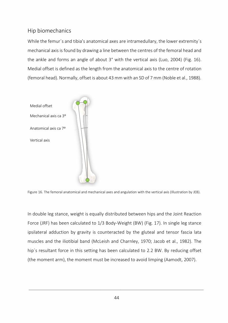
Hip biomechanics
While the femur´s and tibia’s anatomical axes are intramedullary, the lower extremity´s
mechanical axis is found by drawing a line between the centres of the femoral head and
the ankle and forms an angle of about 3° with the vertical axis (Luo, 2004) (Fig. 16).
Medial offset is defined as the length from the anatomical axis to the centre of rotation
(femoral head). Normally, offset is about 43 mm with an SD of 7 mm (Noble et al., 1988).
Figure 16. The femoral anatomical and mechanical axes and angulation with the vertical axis (Illustration by JEB).
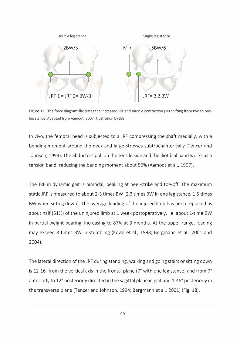
In double leg stance, weight is equally distributed between hips and the Joint Reaction
Force (JRF) has been calculated to 1/3 Body-Weight (BW) (Fig. 17). In single leg stance
ipsilateral adduction by gravity is counteracted by the gluteal and tensor fascia lata
muscles and the iliotibial band (McLeish and Charnley, 1970; Jacob et al., 1982). The
hip´s resultant force in this setting has been calculated to 2.2 BW. By reducing offset
(the moment arm), the moment must be increased to avoid limping (Aamodt, 2007).
Medial offset
Mechanical axis ca 3º
Anatomical axis ca 7º
Vertical axis
____________________________________________________________________________
45
Double leg stance Single leg stance
Figure 17. The force diagram illustrates the increased JRF and muscle contraction (M) shifting from two to one-
leg stance. Adapted from Aamodt, 2007 (Illustration by JEB).
In vivo, the femoral head is subjected to a JRF compressing the shaft medially, with a
bending moment around the neck and large stresses subtrochanterically (Tencer and
Johnson, 1994). The abductors pull on the tensile side and the iliotibial band works as a
tension band, reducing the bending moment about 50% (Aamodt et al., 1997).
The JRF in dynamic gait is bimodal, peaking at heel-strike and toe-off. The maximum
static JRF is measured to about 2-3 times BW (2,3 times BW in one leg stance, 1,5 times
BW when sitting down). The average loading of the injured limb has been reported as
about half (51%) of the uninjured limb at 1 week postoperatively, i.e. about 1-time BW
in partial weight-bearing, increasing to 87% at 3 months. At the upper range, loading
may exceed 8 times BW in stumbling (Koval et al., 1998; Bergmann et al., 2001 and
2004).
The lateral direction of the JRF during standing, walking and going stairs or sitting down
is 12-16° from the vertical axis in the frontal plane (7° with one leg stance) and from 7°
anteriorly to 12° posteriorly directed in the sagittal plane in gait and 1-46° posteriorly in
the transverse plane (Tencer and Johnson, 1994; Bergmann et al., 2001) (Fig. 18).
JRF 1 = JRF 2= BW/3 JRF= 2.2 BW
2 leg stance 1 leg stance
2BW/3 M > 5BW/6
____________________________________________________________________________
46
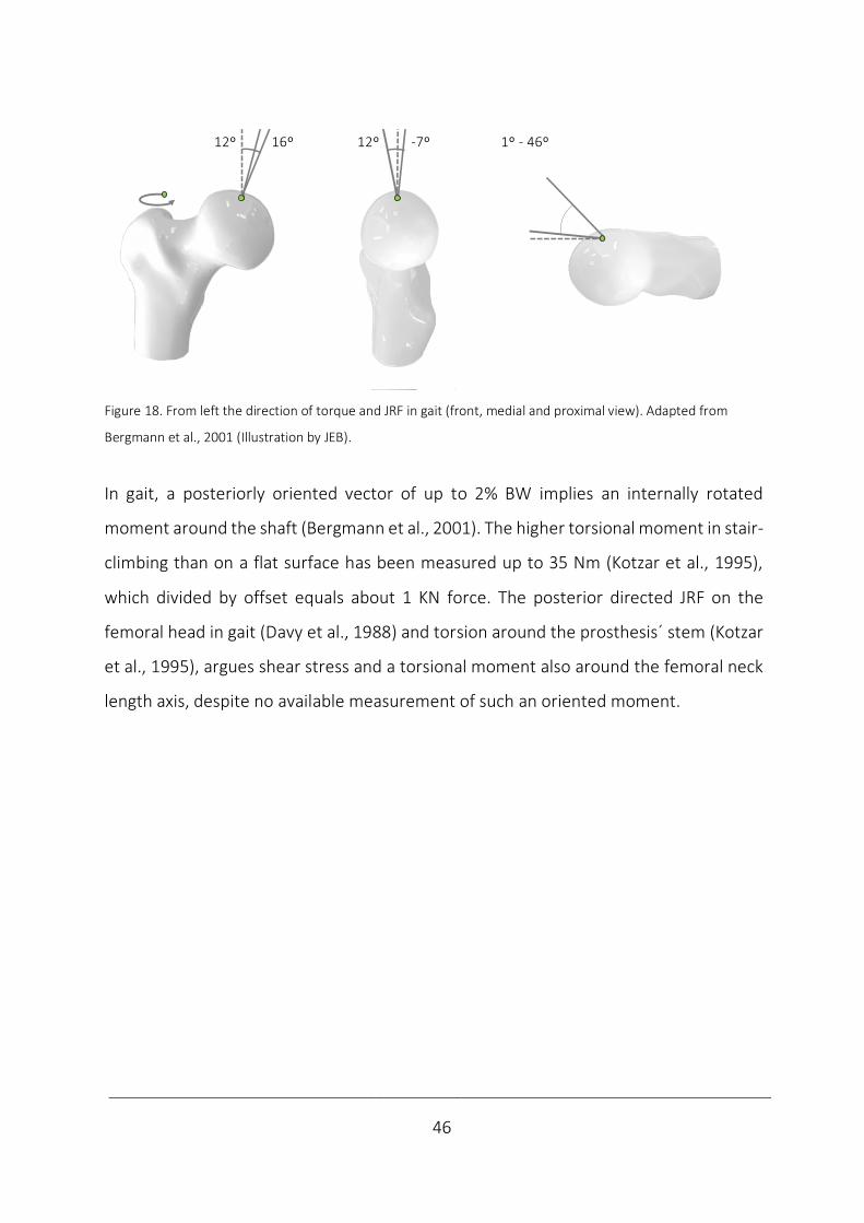
Figure 18. From left the direction of torque and JRF in gait (front, medial and proximal view). Adapted from
Bergmann et al., 2001 (Illustration by JEB).
In gait, a posteriorly oriented vector of up to 2% BW implies an internally rotated
moment around the shaft (Bergmann et al., 2001). The higher torsional moment in stair-
climbing than on a flat surface has been measured up to 35 Nm (Kotzar et al., 1995),
which divided by offset equals about 1 KN force. The posterior directed JRF on the
femoral head in gait (Davy et al., 1988) and torsion around the prosthesis´ stem (Kotzar
et al., 1995), argues shear stress and a torsional moment also around the femoral neck
length axis, despite no available measurement of such an oriented moment.
Sitting down JRF 16ºPeak 1.56 BW
1 leg stand JRF 7º Peak 2.31 BW 12º 16º 12º -7º 1º - 46º
____________________________________________________________________________
47
Biomechanics of conventional femoral neck fixations
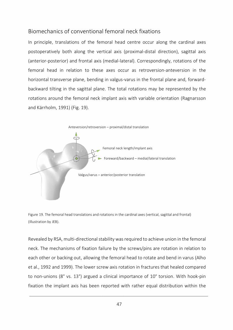
In principle, translations of the femoral head centre occur along the cardinal axes
postoperatively both along the vertical axis (proximal-distal direction), sagittal axis
(anterior-posterior) and frontal axis (medial-lateral). Correspondingly, rotations of the
femoral head in relation to these axes occur as retroversion-anteversion in the
horizontal transverse plane, bending in valgus-varus in the frontal plane and, forward-
backward tilting in the sagittal plane. The total rotations may be represented by the
rotations around the femoral neck implant axis with variable orientation (Ragnarsson
and Kärrholm, 1991) (Fig. 19).
Figure 19. The femoral head translations and rotations in the cardinal axes (vertical, sagittal and frontal)
(Illustration by JEB).
Revealed by RSA, multi-directional stability was required to achieve union in the femoral
neck. The mechanisms of fixation failure by the screws/pins are rotation in relation to
each other or backing out, allowing the femoral head to rotate and bend in varus (Alho
et al., 1992 and 1999). The lower screw axis rotation in fractures that healed compared
to non-unions (8° vs. 13°) argued a clinical importance of 10° torsion. With hook-pin
fixation the implant axis has been reported with rather equal distribution within the
Anteversion/retroversion – proximal/distal translation
Foreward/backward – medial/lateral translation
Valgus/varus – anterior/posterior translation
Femoral neck length/implant axis
____________________________________________________________________________
48
femoral head, neck and trochanterically (Ragnarsson and Kärrholm, 1991 and 1992),
interpreted as the femoral neck length axis.
The neutralization of the torsional moment has been considered essential from the first
implants by Nicolaysen´s triangular pointed nail and Smith-Petersen´s 3-flanged nail,
and in torsional stability examinations ex vivo for decades (Swiontkowski et al., 1987;
Husby et al., 1989; Nowotarski et al., 2012). While the importance of torsional stability
earlier was unknown in this setting (Baril et al., 1975), the findings from RSA argued its
importance. However, the importance of improved torsional stability remains unclear.
The largest mean movements in the distal direction during the first month with 6 mm
in fractures that subsequently healed and 10 mm in fractures that did not heal,
introduced 10 mm compression as an interesting value. The trend of a larger posterior
translation in non-union did not reach significance (Ragnarsson and Kärrholm, 1991),
but the increased posterior femoral head tilt predicting reoperation is indicative of the
importance of antero-posterior bending stability (Palm et al., 2009).
The load, bone and implant factors affect bone healing by affecting these stability
measurements of rotations and translations (Tencer, 2006).
Loading
Partial weight-bearing may reduce load, but high stability requirements remain with a
high JRF, where the bending moment around the neck must be resisted to oppose varus
of the femoral head. Correspondingly, counteracting the axially compressive force may
prevent excessive femoral neck shortening and altered mechanics, which may result in
a poorer functional outcome and fixation failure (Alho et al., 1999; Ragnarsson and
Kärrholm, 1991; Zlowodzki et al., 2008).
____________________________________________________________________________
49
Bone
The mechanical functions of bone are protection, support and locomotion. The strength
and stiffness are the most important mechanical features of bone. These properties are
determined at different levels by bone geometry (shape, dimensions), structure
(trabecular, cortical) and material properties (Huiskes and Rietbergen, 2004).
Regarding geometrical strength, the larger bones are stiffer and stronger, which is
explained by statics. The strength of material theory by moment of inertia calculation
takes shape and dimension relative to load direction into account. The Load To Failure
(LTF) and stiffness are proportional to the bone´s cross-sectional area in compression
and tension (area moment of inertia). In bending and torsion, the bone tissue
distribution also affects mechanical behaviour (polar moment of inertia) (Nordin and
Frankel, 2012). A long femoral neck and a low angle of CCD increase the moment arm
and fixation requirements, potentially provoking varus and healing disturbances.
Also, the fracture´s pattern and displacement determine the inherent stability, which is
reflected by increased risk of healing disturbances and failure with calcar comminution
both in the anteroposterior and lateral view and with displaced fractures (Alho et al.,
1992; Gjertsen et al., 2011), as well as with the plausible posterior comminution in
posterior tilt reported to predict reoperation (Palm et al., 2009). The importance of the
quality of the reduction to regain shape and strength to achieve union has also been
highlighted (Heetveld et al., 2007)
The structural strength of cortical and cancellous bone, can be considered as the
strength of one material of varying structural porosity and density. Cortical bone is
anisotropic, i.e. elastic and plastic properties depend on the load direction, yet strongest
in the most common load directions. Cortical bone is stronger along osteons than
perpendicular to them, compressive strength is greater than tensile and shear strength.
____________________________________________________________________________
50
Trabecular bone has been assumed weaker and isotropic due to its micro-structure
(Huiskes and Rietbergen, 2004). In the proximal femur the contribution to strength by
trabecular bone is less than 10%, which demonstrates the importance of a solid cortex
(Holzer et al., 2009).
In material strength, the water´s shock absorbing function contributes to its
viscoelasticity (Turner and Burr, 1993), the organic part further explains flexibility, while
the inorganic part makes bone solid (Nordin and Frankel, 2012). The local bone mineral
content is an important predictor of mechanical strength (Wright et al., 2018). A
reduced bone mineral quality reduces implant anchorage and femoral head fixation
(Leicher et al., 1982; Goldhahn et al., 2008). Clinically, osteoporosis more often may lead
to reoperation after a femoral neck fixation (Spangler et al., 2001).
Implant
The importance of material, structure and geometry also applies with implants
themselves. Metals are used because of high mechanical strength. The choice of
material also delivers the compatibility, degradability and resorbability characteristics.
Because of high resistance to corrosion and biocompatibility, stainless steel (316L) is one
of the prominent metals in implants along with titanium, tantalum and cobalt-chromium
alloys.
The implant structure of stainless steel with a high elastic modulus (200 GPa) may be
reduced by titanium (100 GPa) porosity to bring stability within the area of bone (16-
20 GPa). With the metal´s drawbacks of pain, hypersensitivity, tissue accumulation,
imaging interference, stress shielding, migration, revision difficulties and growth
restrictions, biogradable polymers may become interesting (Kehinde et al., 2018).

____________________________________________________________________________
51
The impact by the fixation´s geometry on stiffness is explained by the moment of inertia.
In single implants, the stiffness is diameter dependent, while multiple implants may be
interpreted as a single beam construct (Egol et al., 2004). By increasing the implant´s
cross-section, an increased moment of inertia explains the load-direction dependent
increased stability (Björk, 2011).
Geometrically, the mechanism of action with multiple screws/pins over an SHS device is
an increased medial hold by 3-pointed support (Parker and Stedtfeld, 2010). The
resulting preserved vascularity and torsional stability are supposed to be beneficial
(Swiontkowski et al., 1987; FAITH investigators, 2017). The stronger conventional fixed-
angle devices work by an increased lateral hold and load-sharing well suited in vertical
shear (Pauwels type 3) and basicervical fractures. Varus angulation and inferior head
displacement may be better resisted with such devices (Parker and Stedtfeld, 2010;
Hoshino and O´Toole, 2015). The high compressive stability by the alternative of
intramedullary nails (Rupprecht et al., 2011a and b), has not been commonly used
(Gjertsen et al., 2019), except in patients with basicervical fratures (Augat et al., 2019)
and with ipsilateral fractures of the neck and shaft (Ostrum et al., 2014).
Osteosyntheses are either load-bearing or load-sharing. With a load-sharing lag screw
or compression plate, the bone shares the load. With load-bearing fixation the plate
absorbs all load, which is better with a comminuted fracture lacking the bone buttress.
The fixation principle of 3-pointed support of screws and pins is a load-sharing
osteosynthesis. The SHS is also load-sharing, but due to its strength and fixed-angle
fixation it may work by an increased load sharing by the implant (Egol et al., 2004).
____________________________________________________________________________
52
Considering the optimum geometric configuration of multiple implants, the number of
implants has been thoroughly investigated ex vivo (DeAngelis, 2010). While some
authors advocated 2 screws (Walker et al., 2007), a modestly increased stability has
been demonstrated by 3 (Husby et al., 1989). No advantage has been found by more
than 3 implants except in cases of severe posterior comminution (Swiontkowski et al.,
1987; Holmes et al., 1993; Kauffmann et al., 1999).
Regarding the geometric shape and dimension, triangular configurations has been
shown to increase stability compared to linear ex vivo (Selvan et al., 2004) and an
increased size of the triangle has also been reported with increased stability (Zdero et
al., 2010). The importance of invers triangularity has been stressed regarding the
incidence of non-unions (Yang et al., 2013) and subtrochanteric fracture initiation
(Oakey et al., 2006).
The implant positioning is emphasized with the subcortical support in the inferior and
posterior neck which may increase stability and reduce non-union rates (Lindequist et
al., 1993 and 1995; Gurusamy et al., 2005), while higher non-union rates has been
identified with screw positioning superiorly or anteriorly (Parker, 1994). Also, implant
parallelism and positioning subchondrally may both improve femoral head fixation and
promote fracture healing (Rehnberg and Olerud 1989b; Parker et al., 1991). Both
implant diameter, thread pinch and length may predict pull-out strength of cancellous
screws (Chapman et al., 1996).
____________________________________________________________________________
53
Biomechanics of femoral neck locking plates
To improve the results of osteoporotic bone fixation; cortical buttressing by impaction,
spreading load in a larger region and enhanced fixation by augmentation have been
attempted (Tencer, 2006). While e.g. bone cement injection may increase fixation
stability, a poor result is reported in the long-term (Lindner et al., 2009).
New fixations have been tried. A self-locking blade (Yang et al., 2011), a medial buttress
plate (Mir and Collinge, 2015, Giordano et al., 2019), a deployable crucifix (Gosiewski et
al., 2017) and a perforated H-beam (Jafarov et al., 2019) have been tested.
Modified fixations have been tried. An expanding cannulated screw (Zhang et al., 2011),
a dynamic locking blade (Roerdink et al., 2009), an SHS with an anchorage (Knobe et al.,
2018) and a compressive hip screw with an anti-rotator (Sağlam et al., 2014) have been
evaluated.
Different screw configurations; diverging screws (Filipov and Gueorguiev, 2015) and a
trochanteric lag screw (Hawks et al., 2013) have been studied. An intramedullary nail
has also been examined (Rupprecht et al., 2011a and b).
After a reported benefit in osteoporotic and periprosthetic distal femoral fractures
(Schütz et al., 2001), biomechanical studies of locking plates were conducted in proximal
femur fractures (Crist et al., 2009; Floyd et al., 2009) and femoral neck fractures (Chang
et al., 2004). With locking plate technology, biomechanical studies of femoral neck
fixation once again became a hot topic. In general, ex vivo studies supported locking
plates in this location (Table 2) which were introduced clinically. With locking plates, ex
vivo studies again were followed by case series, controlled trials and meta-analysis
(Berkes et al., 2012, Biber et al., 2014, Yin et al., 2018), reflecting introduction of novel
implants by evaluation at an increasing level in the hierarchy of evidence.
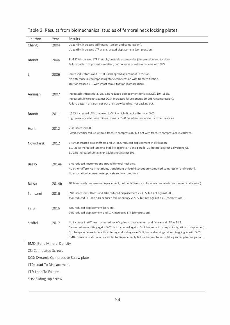
____________________________________________________________________________
54
Table 2. Results from biomechanical studies of femoral neck locking plates.
1.author Year Results
Chang 2004 Up to 43% increased stiffnesses (torsion and compression).
Up to 65% increased LTF at unchanged displacement (compression).
Brandt 2006 81-337% increased LTF in stable/unstable osteotomies (compression and torsion).
Failure pattern of posterior rotation, but no varus or retroversion as with SHS.
Li 2006 Increased stiffness and LTF at unchanged displacement in torsion.
No difference in corresponding static compression with fracture fixation.
105% increased LTF with intact femur fixation (compression).
Aminian 2007 Increased stiffness 93-272%, 52% reduced displacement (only vs DCS). 104-182%.
Increased LTF (except against DCS). Increased failure energy 19-196% (compression).
Failure pattern of varus, cut-out and screw bending, not backing out.
Brandt 2011 110% increased LTF compared to SHS, which did not differ from 3 CS.
High correlation to bone mineral density r2 = 0.54, while moderate for other fixations.
Hunt 2012 71% increased LTF.
Possibly earlier failure without fracture compression, but not with fracture compression in cadaver.
Nowotarski 2012 6-45% increased axial stiffness and 14-26% reduced displacement in all fixation.
317-354% increased torsional stability against SHS and parallel CS, but not against 3 diverging CS.
11-25% increased LTF against CS, but not against SHS.
Basso 2014a 27% reduced micromotions around femoral neck axis.
No other difference in rotations, translations or load distribution (combined compression and torsion).
No association between osteoporosis and micromotions.
Basso 2014b 40 % reduced compressive displacement, but no difference in torsion (combined compression and torsion).
Samsami 2016 89% increased stiffness and 48% reduced displacement vs 3 CS, but not against SHS.
45% reduced LTF and 54% reduced failure energy vs SHS, but not against 3 CS (compression).
Yang 2016 38% reduced displacement (torsion).
24% reduced displacement and 17% increased LTF (compression).
Stoffel 2017 No increase in stiffness. Increased no. of cycles to displacement and failure and LTF vs 3 CS.
Decreased varus tilting agains 3 CS, but increased against SHS. No impact on implant migration (compression).
No change in failure type with sintering and sliding as an SHS, but no backing-out and toggling as with 3 CS.
BMD covariate in stiffness, no. cycles to displacement/ failure, but not to varus tilting and implant migration.
BMD: Bone Mineral Density
CS: Cannulated Screws
DCS: Dynamic Compressive Screw plate
LTD: Load To Displacement
LTF: Load To Failure
SHS: Sliding Hip Screw

____________________________________________________________________________
55
Locking plates work by combining the benefits of medial hold with multiple screws and
lateral hold by fixed-angle fixations (Parker and Stedtfeld, 2010). By design, a locking
plate defines a single-beam construct and works as an internal fixator promoting
secondary healing when strain is less than 10% (Egol et al., 2004). While active screw
compression may increase stability by impaction (Rehnberg and Olerud, 1989a) and the
SHS permits passive compression, the locking plates differ regarding the amount of
interfragmentary compression permitted. The true locking plates do not only restrict
motion between screws and plates, but also at the fracture site. Principally, this may be
achieved e.g. by non-parallel screws (Chang et al., 2004; Aminian et al., 2007;
Nowotarski et al., 2012; Samsami et al., 2016) (Fig. 9).
Chang et al. (2004) made an inquiry on the self-locking screw plate with 3 converging
screws in comparison to 2 pins, 3 CS and an SHS in cadavers with subcapital osteotomies.
Beside increased non-destructive torsional and both non-destructive and destructive
compressive stability, failure at indifferent displacement were also reported.
Aminian et al. (2007) compared the proximal femur locking plate with 3 converging
screws against 3 CS, SHS and a Dynamic Compressive Screw-plate (DCS) in cadavers with
unstable transcervical Pauwels type 3 osteotomies. Increased compressive stability by
stiffness, displacement vs. DCS, LTF except vs. DCS and failure energy were noted beside
an altered failure type of varus, cut-out, screw bending and screws not backing out.
Nowotarski et al. (2012) compared the femoral neck locking plate with 3 diverging
screws in a locking plate to 3 parallel and 3 diverging CS and an SHS in unstable
basicervical Pauwels type 3 osteotomies in 3-GCF. They found increased compressive
stability by stiffness and displacement in all comparisons. LTF was increased against CS,
but not against SHS. Torsional stability was increased against SHS and parallel, but not
diverging screws.
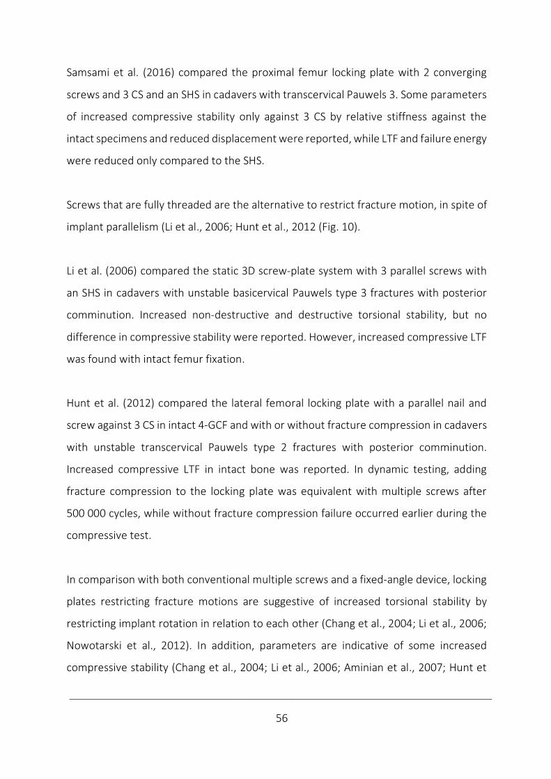
____________________________________________________________________________
56
Samsami et al. (2016) compared the proximal femur locking plate with 2 converging
screws and 3 CS and an SHS in cadavers with transcervical Pauwels 3. Some parameters
of increased compressive stability only against 3 CS by relative stiffness against the
intact specimens and reduced displacement were reported, while LTF and failure energy
were reduced only compared to the SHS.
Screws that are fully threaded are the alternative to restrict fracture motion, in spite of
implant parallelism (Li et al., 2006; Hunt et al., 2012 (Fig. 10).
Li et al. (2006) compared the static 3D screw-plate system with 3 parallel screws with
an SHS in cadavers with unstable basicervical Pauwels type 3 fractures with posterior
comminution. Increased non-destructive and destructive torsional stability, but no
difference in compressive stability were reported. However, increased compressive LTF
was found with intact femur fixation.
Hunt et al. (2012) compared the lateral femoral locking plate with a parallel nail and
screw against 3 CS in intact 4-GCF and with or without fracture compression in cadavers
with unstable transcervical Pauwels type 2 fractures with posterior comminution.
Increased compressive LTF in intact bone was reported. In dynamic testing, adding
fracture compression to the locking plate was equivalent with multiple screws after
500 000 cycles, while without fracture compression failure occurred earlier during the
compressive test.
In comparison with both conventional multiple screws and a fixed-angle device, locking
plates restricting fracture motions are suggestive of increased torsional stability by
restricting implant rotation in relation to each other (Chang et al., 2004; Li et al., 2006;
Nowotarski et al., 2012). In addition, parameters are indicative of some increased
compressive stability (Chang et al., 2004; Li et al., 2006; Aminian et al., 2007; Hunt et
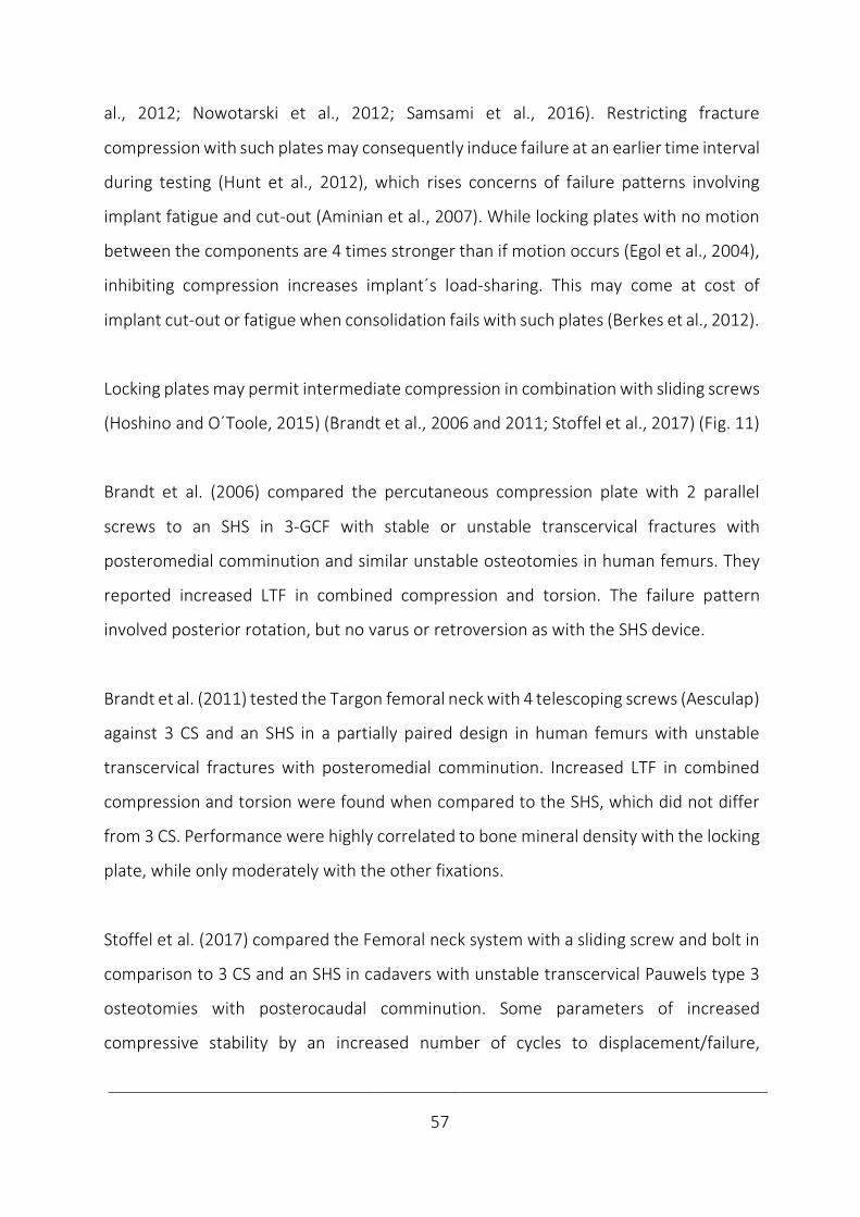
____________________________________________________________________________
57
al., 2012; Nowotarski et al., 2012; Samsami et al., 2016). Restricting fracture
compression with such plates may consequently induce failure at an earlier time interval
during testing (Hunt et al., 2012), which rises concerns of failure patterns involving
implant fatigue and cut-out (Aminian et al., 2007). While locking plates with no motion
between the components are 4 times stronger than if motion occurs (Egol et al., 2004),
inhibiting compression increases implant´s load-sharing. This may come at cost of
implant cut-out or fatigue when consolidation fails with such plates (Berkes et al., 2012).
Locking plates may permit intermediate compression in combination with sliding screws
(Hoshino and O´Toole, 2015) (Brandt et al., 2006 and 2011; Stoffel et al., 2017) (Fig. 11)
Brandt et al. (2006) compared the percutaneous compression plate with 2 parallel
screws to an SHS in 3-GCF with stable or unstable transcervical fractures with
posteromedial comminution and similar unstable osteotomies in human femurs. They
reported increased LTF in combined compression and torsion. The failure pattern
involved posterior rotation, but no varus or retroversion as with the SHS device.
Brandt et al. (2011) tested the Targon femoral neck with 4 telescoping screws (Aesculap)
against 3 CS and an SHS in a partially paired design in human femurs with unstable
transcervical fractures with posteromedial comminution. Increased LTF in combined
compression and torsion were found when compared to the SHS, which did not differ
from 3 CS. Performance were highly correlated to bone mineral density with the locking
plate, while only moderately with the other fixations.
Stoffel et al. (2017) compared the Femoral neck system with a sliding screw and bolt in
comparison to 3 CS and an SHS in cadavers with unstable transcervical Pauwels type 3
osteotomies with posterocaudal comminution. Some parameters of increased
compressive stability by an increased number of cycles to displacement/failure,

____________________________________________________________________________
58
an increased LTF and a reduced displacement only by varus tilting and only in
comparison against 3 CS were reported. No change in failure type with sintering and
sliding as SHS was found. Bone Mineral Density (BMD) was found as a covariate both in
stiffness and number of cycles to displacement/failure in all fixations.
Several sliding screws with a sideplate may both increase torsional and at least some
parameters of compressive stability in comparison both with multiple screws and the
fixed-angle devices (Brandt et al., 2006 and 2011; Stoffel et al., 2017). Regarding failure
type, possible no change in comparison to conventional fixed-angle fixation methods
has been reported in compression (Stoffel et al., 2017), while varus or retroversion as
with an SHS device may be prevented if including torsional testing (Brandt et al., 2006).
Interlocking is a novel fixation principle in this setting and the only alternative to achieve
intermediate compression (Basso et al., 2014a and b; Yang et al., 2016) (Fig. 12).
Basso et al. (2014a) compared Dynaloc, i.e. an interlocking plate with 3 screws in an
isosceles triangle to 3 CS in human femurs with subcapital Pauwels type 3 fractures.
Reduced torsional micromotions, but no difference in other rotations, translations or
load distribution were found in a combined compressive and torsional dynamic test
without a complete failure evaluation. No association between osteoporosis and
micromotions by any fixation were reported. However, reduced compressive
displacement, but no impact on torsional displacement were also identified (Basso et
al., 2014b).
Yang et al. (2016) compared the Dynamic locking compression system with 3 interlocked
screws in a scalene triangle with 3 CS in cadavers with transcervical Pauwels type 3
osteotomies. Reduced displacement by torsion and compressive testing and also
increased compressive LTF were identified by interlocking in this set-up.
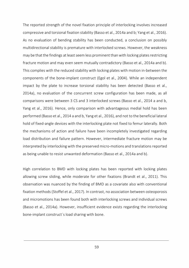
____________________________________________________________________________
59
The reported strength of the novel fixation principle of interlocking involves increased
compressive and torsional fixation stability (Basso et al., 2014a and b; Yang et al., 2016).
As no evaluation of bending stability has been conducted, a conclusion on possibly
multidirectional stability is premature with interlocked screws. However, the weakness
may be that the findings at least seem less prominent than with locking plates restricting
fracture motion and may even seem mutually contradictory (Basso et al., 2014a and b).
This complies with the reduced stability with locking plates with motion in-between the
components of the bone-implant construct (Egol et al., 2004). While an independent
impact by the plate to increase torsional stability has been detected (Basso et al.,
2014a), no evaluation of the concurrent screw configuration has been made, as all
comparisons were between 3 CS and 3 interlocked screws (Basso et al., 2014 a and b,
Yang et al., 2016). Hence, only comparison with advantageous medial hold has been
performed (Basso et al., 2014 a and b, Yang et al., 2016), and not to the beneficial lateral
hold of fixed-angle devices with the interlocking plate not fixed to femur laterally. Both
the mechanisms of action and failure have been incompletely investigated regarding
load distribution and failure pattern. However, intermediate fracture motion may be
interpreted by interlocking with the preserved micro-motions and translations reported
as being unable to resist unwanted deformation (Basso et al., 2014a and b).
High correlation to BMD with locking plates has been reported with locking plates
allowing screw sliding, while moderate for other fixations (Brandt et al., 2011). This
observation was nuanced by the finding of BMD as a covariate also with conventional
fixation methods (Stoffel et al., 2017). In contrast, no association between osteoporosis
and micromotions has been found both with interlocking screws and individual screws
(Basso et al., 2014a). However, insufficient evidence exists regarding the interlocking
bone-implant construct´s load sharing with bone.
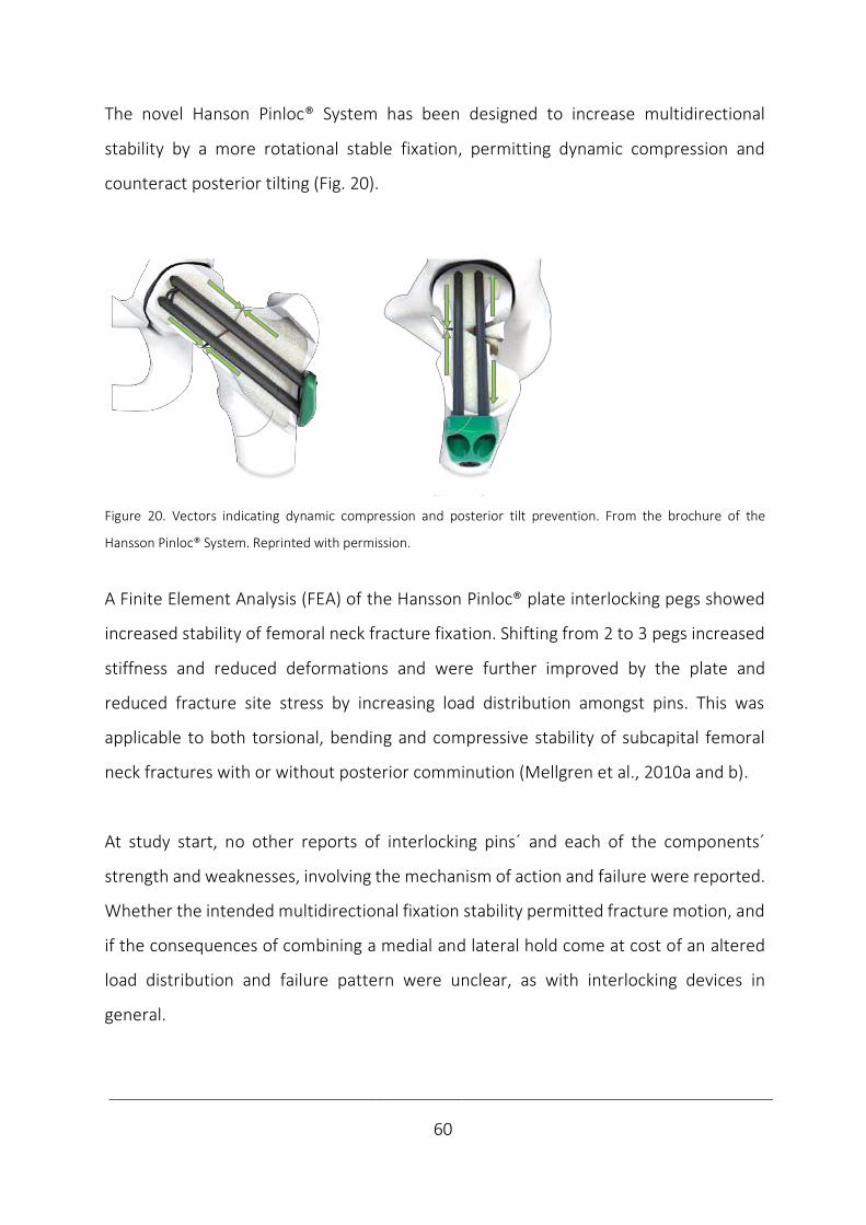
____________________________________________________________________________
60
The novel Hanson Pinloc® System has been designed to increase multidirectional
stability by a more rotational stable fixation, permitting dynamic compression and
counteract posterior tilting (Fig. 20).
Figure 20. Vectors indicating dynamic compression and posterior tilt prevention. From the brochure of the
Hansson Pinloc® System. Reprinted with permission.
A Finite Element Analysis (FEA) of the Hansson Pinloc® plate interlocking pegs showed
increased stability of femoral neck fracture fixation. Shifting from 2 to 3 pegs increased
stiffness and reduced deformations and were further improved by the plate and
reduced fracture site stress by increasing load distribution amongst pins. This was
applicable to both torsional, bending and compressive stability of subcapital femoral
neck fractures with or without posterior comminution (Mellgren et al., 2010a and b).
At study start, no other reports of interlocking pins´ and each of the components´
strength and weaknesses, involving the mechanism of action and failure were reported.
Whether the intended multidirectional fixation stability permitted fracture motion, and
if the consequences of combining a medial and lateral hold come at cost of an altered
load distribution and failure pattern were unclear, as with interlocking devices in
general.
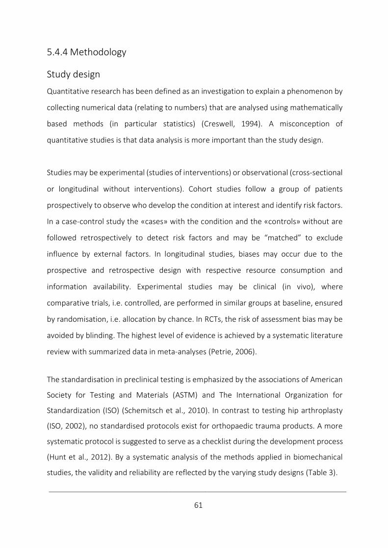
____________________________________________________________________________
61
5.4.4 Methodology
Study design
Quantitative research has been defined as an investigation to explain a phenomenon by
collecting numerical data (relating to numbers) that are analysed using mathematically
based methods (in particular statistics) (Creswell, 1994). A misconception of
quantitative studies is that data analysis is more important than the study design.
Studies may be experimental (studies of interventions) or observational (cross-sectional
or longitudinal without interventions). Cohort studies follow a group of patients
prospectively to observe who develop the condition at interest and identify risk factors.
In a case-control study the «cases» with the condition and the «controls» without are
followed retrospectively to detect risk factors and may be “matched” to exclude
influence by external factors. In longitudinal studies, biases may occur due to the
prospective and retrospective design with respective resource consumption and
information availability. Experimental studies may be clinical (in vivo), where
comparative trials, i.e. controlled, are performed in similar groups at baseline, ensured
by randomisation, i.e. allocation by chance. In RCTs, the risk of assessment bias may be
avoided by blinding. The highest level of evidence is achieved by a systematic literature
review with summarized data in meta-analyses (Petrie, 2006).
The standardisation in preclinical testing is emphasized by the associations of American
Society for Testing and Materials (ASTM) and The International Organization for
Standardization (ISO) (Schemitsch et al., 2010). In contrast to testing hip arthroplasty
(ISO, 2002), no standardised protocols exist for orthopaedic trauma products. A more
systematic protocol is suggested to serve as a checklist during the development process
(Hunt et al., 2012). By a systematic analysis of the methods applied in biomechanical
studies, the validity and reliability are reflected by the varying study designs (Table 3).
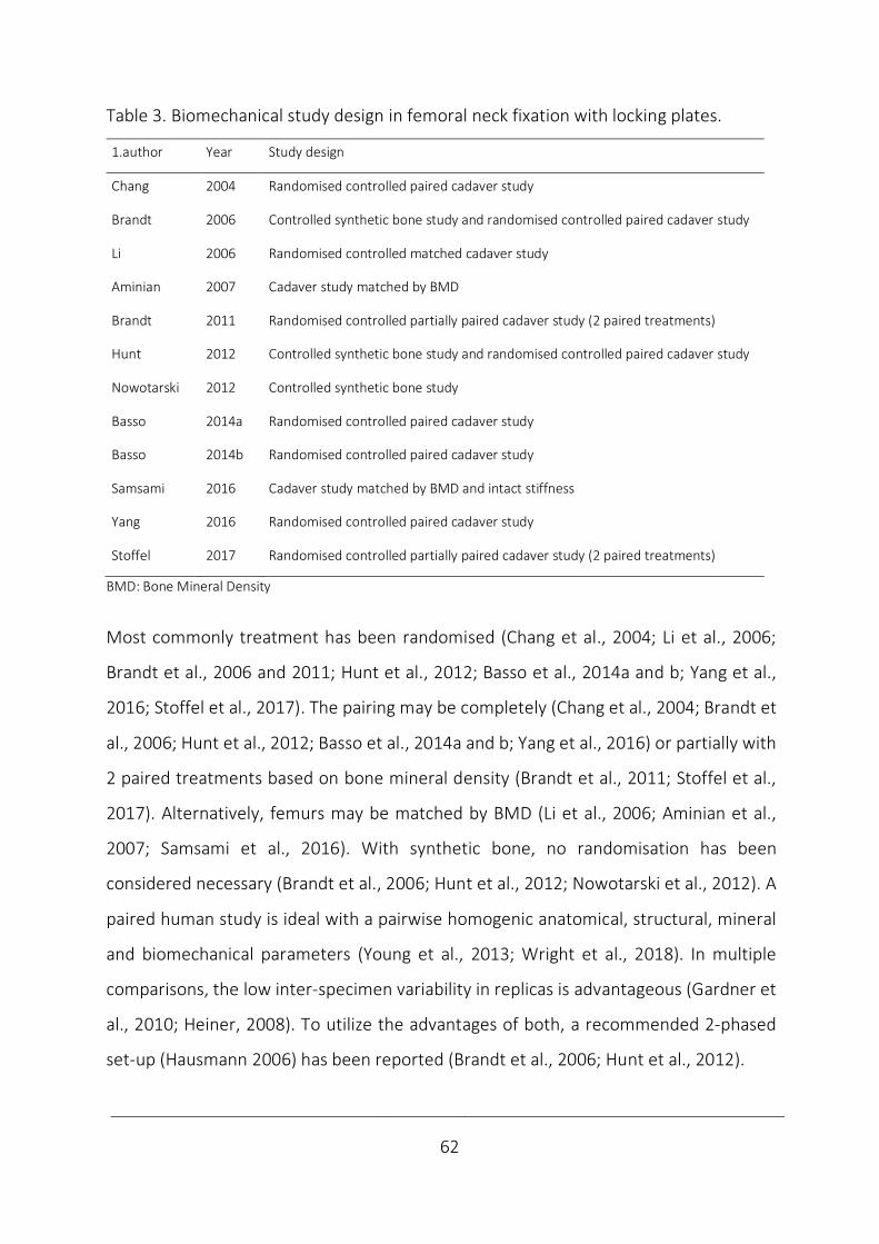
____________________________________________________________________________
62
Table 3. Biomechanical study design in femoral neck fixation with locking plates.
1.author Year Study design
Chang 2004 Randomised controlled paired cadaver study
Brandt 2006 Controlled synthetic bone study and randomised controlled paired cadaver study
Li 2006 Randomised controlled matched cadaver study
Aminian 2007 Cadaver study matched by BMD
Brandt 2011 Randomised controlled partially paired cadaver study (2 paired treatments)
Hunt 2012 Controlled synthetic bone study and randomised controlled paired cadaver study
Nowotarski 2012 Controlled synthetic bone study
Basso 2014a Randomised controlled paired cadaver study
Basso 2014b Randomised controlled paired cadaver study
Samsami 2016 Cadaver study matched by BMD and intact stiffness
Yang 2016 Randomised controlled paired cadaver study
Stoffel 2017 Randomised controlled partially paired cadaver study (2 paired treatments)
BMD: Bone Mineral Density
Most commonly treatment has been randomised (Chang et al., 2004; Li et al., 2006;
Brandt et al., 2006 and 2011; Hunt et al., 2012; Basso et al., 2014a and b; Yang et al.,
2016; Stoffel et al., 2017). The pairing may be completely (Chang et al., 2004; Brandt et
al., 2006; Hunt et al., 2012; Basso et al., 2014a and b; Yang et al., 2016) or partially with
2 paired treatments based on bone mineral density (Brandt et al., 2011; Stoffel et al.,
2017). Alternatively, femurs may be matched by BMD (Li et al., 2006; Aminian et al.,
2007; Samsami et al., 2016). With synthetic bone, no randomisation has been
considered necessary (Brandt et al., 2006; Hunt et al., 2012; Nowotarski et al., 2012). A
paired human study is ideal with a pairwise homogenic anatomical, structural, mineral
and biomechanical parameters (Young et al., 2013; Wright et al., 2018). In multiple
comparisons, the low inter-specimen variability in replicas is advantageous (Gardner et
al., 2010; Heiner, 2008). To utilize the advantages of both, a recommended 2-phased
set-up (Hausmann 2006) has been reported (Brandt et al., 2006; Hunt et al., 2012).
____________________________________________________________________________
63
Implants
The choice of implant test groups and the way they are inserted differ between ex vivo
studies in this setting (Table 4). Implants may be inserted in a standardised manner using
an aiming guide (Basso et al., 2014c) or as done clinically, which include the surgeon´s
experience (Brandt et al., 2011). If reported, predrilling has commonly been utilized to
ensure a non-displaced or anatomically reduced fracture fixation (Aminian et al., 2007;
Nowotarski et al., 2012; Samsami et al., 2016; Stoffel et al., 2017).
The main conventional fixation methods (screws, pins or an SHS) have been the natural
control groups. Most often both a group with pins or screws and a group of an SHS have
been included (Chang et al., 2004; Aminian et al.,2007; Brandt et al., 2011; Nowotarski
et al., 2012; Samsami et al., 2016; Stoffel et al., 2017). Occasionally, either only a medial
(Hunt et al., 2012; Basso et al., 2014a and b; Yang et al., 2016) or a lateral control group
have been tested for comparisons purposes (Brandt et al., 2006; Li et al., 2006).
Table 4. Fixations in control groups in femoral neck fixation with locking plates ex vivo.
1.author Year Control group Predrilling
Chang 2004 3 CS, 2 Pins, SHS -
Brandt 2006 SHS no
Li 2006 SHS -
Aminian 2007 3CS, SHS, Dynamic compressive screw-plate yes
Brandt 2011 3 CS, SHS no
Hunt 2012 3 CS -
Nowotarski 2012 3 parallel/non-parallel CS, SHS with an ARS yes
Basso 2014 3 CS -
Samsami 2016 3 CS, SHS with an ARS yes
Yang 2016 3 CS -
Stoffel 2017 3 CS, SHS-screw with an ARS, SHS-blade yes
- Not reported
ARS: Anti-Rotational Screw
CS: Cannulated Screw
SHS: Sliding Hip Screw
____________________________________________________________________________
64
Radiological examinations
Fluoroscopy, X-rays, Dual-Energy X-ray Absorptiometry (DEXA) and Computer
Tomography (CT) serve different purposes in this context (Table 5). Fluoroscopy may
guide reduction and implant positioning (Aminian et al., 2007; Nowotarski et al., 2012;
Basso et al., 2014b; Samsami et al., 2016; Stoffel et al., 2017), while X-rays may
document the quality of fixation and reduction (Brandt et al., 2006 and 2011). X-rays
may also validate femurs by excluding pathology (Chang et al., 2004; Li et al., 2006; Yang
et al., 2016) and evaluate the type of failures (Stoffel et al., 2017).
DEXA measures bone mineral as the ratio of projected bone mineral per unit area
(g/cm2). The diagnosis of osteoporosis is based on T-scores of measurements at the hip
and lumbar spine and provides a good estimate of fracture risk in Caucasian
postmenopausal women (Marshall et al., 1996). The T-score is reported as the number
of standard deviations from race- and gender-matched young adults at peak bone
mineral density. A T-score of -2.5 or below defines osteoporosis (National Institutes of
Health, 2000). In ex vivo studies, DEXA both may be used to classify osteoporosis (Basso
et al., 2014b), match femurs by BMD (Aminian et al., 2007; Samsami et al., 2016) and
analyse the correlation between BMD and biomechanical performance (Brandt et al.,
2011; Basso et al., 2014a).
As with X-rays, CT may also be used to exclude bone pathology (Basso et al., 2014b). The
similarities with DEXA is the ability to measure BMD and correspondingly to match test
groups and correlate to biomechanical performance (Stoffel et al., 2017). Whole-body
CT or assessment of the peripheral skeleton in research with high-resolution CT is
referred to as quantitative (QCT). As the photon energy passes through the body, CT
scanners measure the bone density, which is quantified in Hounsfield units. QCT has
been used to match groups by BMD and reveal the relationship of BMD and
biomechanical parameters (Stoffel et al., 2017).
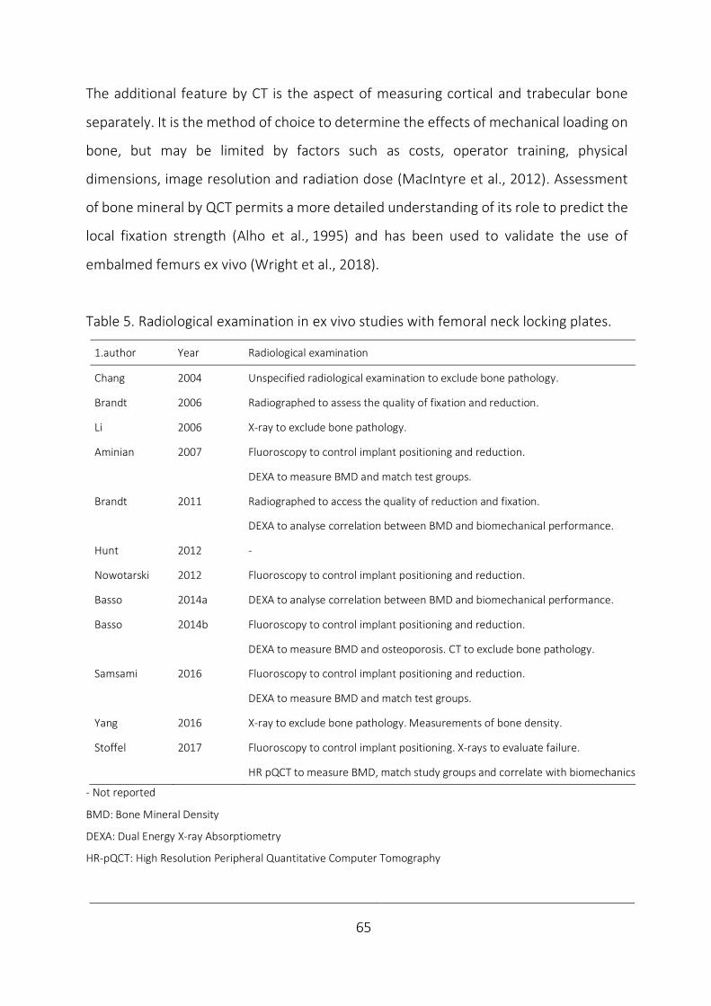
____________________________________________________________________________
65
The additional feature by CT is the aspect of measuring cortical and trabecular bone
separately. It is the method of choice to determine the effects of mechanical loading on
bone, but may be limited by factors such as costs, operator training, physical
dimensions, image resolution and radiation dose (MacIntyre et al., 2012). Assessment
of bone mineral by QCT permits a more detailed understanding of its role to predict the
local fixation strength (Alho et al., 1995) and has been used to validate the use of
embalmed femurs ex vivo (Wright et al., 2018).
Table 5. Radiological examination in ex vivo studies with femoral neck locking plates.
1.author Year Radiological examination
Chang 2004 Unspecified radiological examination to exclude bone pathology.
Brandt 2006 Radiographed to assess the quality of fixation and reduction.
Li 2006 X-ray to exclude bone pathology.
Aminian 2007 Fluoroscopy to control implant positioning and reduction.
DEXA to measure BMD and match test groups.
Brandt 2011 Radiographed to access the quality of reduction and fixation.
DEXA to analyse correlation between BMD and biomechanical performance.
Hunt 2012 -
Nowotarski 2012 Fluoroscopy to control implant positioning and reduction.
Basso 2014a DEXA to analyse correlation between BMD and biomechanical performance.
Basso 2014b Fluoroscopy to control implant positioning and reduction.
DEXA to measure BMD and osteoporosis. CT to exclude bone pathology.
Samsami 2016 Fluoroscopy to control implant positioning and reduction.
DEXA to measure BMD and match test groups.
Yang 2016 X-ray to exclude bone pathology. Measurements of bone density.
Stoffel 2017 Fluoroscopy to control implant positioning. X-rays to evaluate failure.
HR pQCT to measure BMD, match study groups and correlate with biomechanics
- Not reported
BMD: Bone Mineral Density
DEXA: Dual Energy X-ray Absorptiometry
HR-pQCT: High Resolution Peripheral Quantitative Computer Tomography
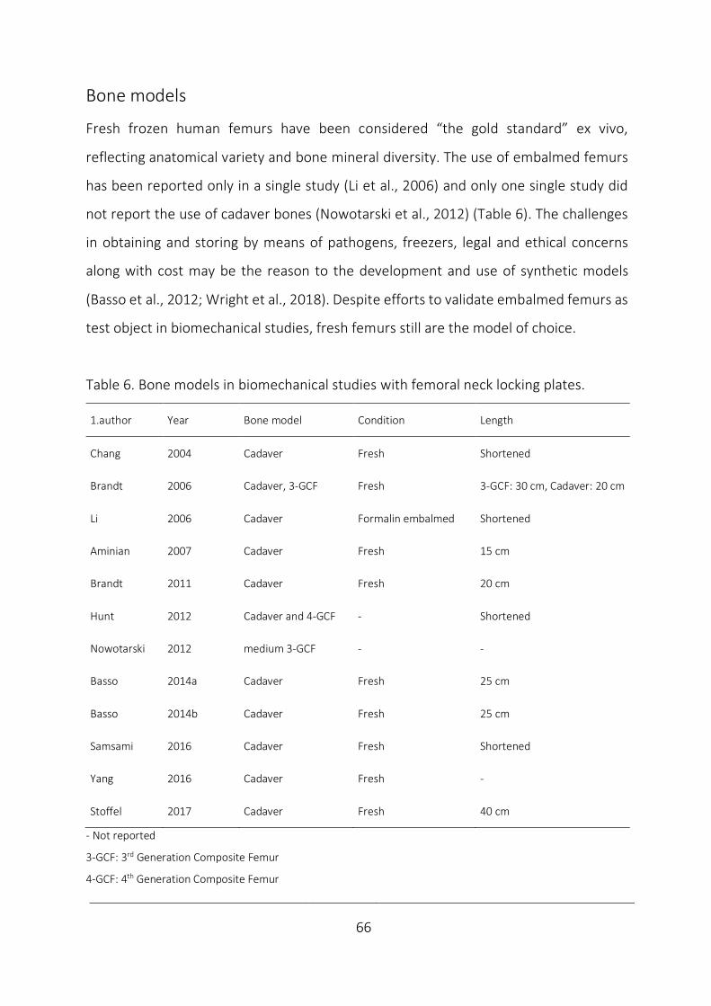
____________________________________________________________________________
66
Bone models
Fresh frozen human femurs have been considered “the gold standard” ex vivo,
reflecting anatomical variety and bone mineral diversity. The use of embalmed femurs
has been reported only in a single study (Li et al., 2006) and only one single study did
not report the use of cadaver bones (Nowotarski et al., 2012) (Table 6). The challenges
in obtaining and storing by means of pathogens, freezers, legal and ethical concerns
along with cost may be the reason to the development and use of synthetic models
(Basso et al., 2012; Wright et al., 2018). Despite efforts to validate embalmed femurs as
test object in biomechanical studies, fresh femurs still are the model of choice.
Table 6. Bone models in biomechanical studies with femoral neck locking plates.
1.author Year Bone model Condition Length
Chang 2004 Cadaver Fresh Shortened
Brandt 2006 Cadaver, 3-GCF Fresh 3-GCF: 30 cm, Cadaver: 20 cm
Li 2006 Cadaver Formalin embalmed Shortened
Aminian 2007 Cadaver Fresh 15 cm
Brandt 2011 Cadaver Fresh 20 cm
Hunt 2012 Cadaver and 4-GCF - Shortened
Nowotarski 2012 medium 3-GCF - -
Basso 2014a Cadaver Fresh 25 cm
Basso 2014b Cadaver Fresh 25 cm
Samsami 2016 Cadaver Fresh Shortened
Yang 2016 Cadaver Fresh -
Stoffel 2017 Cadaver Fresh 40 cm
- Not reported
3-GCF: 3rd Generation Composite Femur
4-GCF: 4th Generation Composite Femur
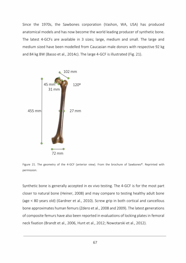
____________________________________________________________________________
67
Since the 1970s, the Sawbones corporation (Vashon, WA, USA) has produced
anatomical models and has now become the world leading producer of synthetic bone.
The latest 4-GCFs are available in 3 sizes; large, medium and small. The large and
medium sized have been modelled from Caucasian male donors with respective 92 kg
and 84 kg BW (Basso et al., 2014c). The large 4-GCF is illustrated (Fig. 21).
Figure 21. The geometry of the 4-GCF (anterior view). From the brochure of Sawbones®. Reprinted with
permission.
Synthetic bone is generally accepted in ex vivo testing. The 4-GCF is for the most part
closer to natural bone (Heiner, 2008) and may compare to testing healthy adult bone
(age < 80 years old) (Gardner et al., 2010). Screw grip in both cortical and cancellous
bone approximates human femurs (Zdero et al., 2008 and 2009). The latest generations
of composite femurs have also been reported in evaluations of locking plates in femoral
neck fixation (Brandt et al., 2006, Hunt et al., 2012; Nowotarski et al., 2012).
455 mm 27 mm
72 mm
102 mm
120º45 mm31 mm
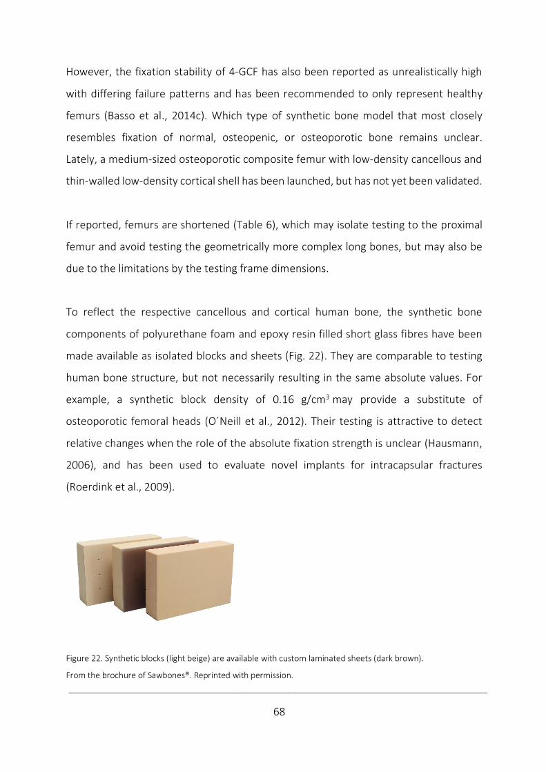
____________________________________________________________________________
68
However, the fixation stability of 4-GCF has also been reported as unrealistically high
with differing failure patterns and has been recommended to only represent healthy
femurs (Basso et al., 2014c). Which type of synthetic bone model that most closely
resembles fixation of normal, osteopenic, or osteoporotic bone remains unclear.
Lately, a medium-sized osteoporotic composite femur with low-density cancellous and
thin-walled low-density cortical shell has been launched, but has not yet been validated.
If reported, femurs are shortened (Table 6), which may isolate testing to the proximal
femur and avoid testing the geometrically more complex long bones, but may also be
due to the limitations by the testing frame dimensions.
To reflect the respective cancellous and cortical human bone, the synthetic bone
components of polyurethane foam and epoxy resin filled short glass fibres have been
made available as isolated blocks and sheets (Fig. 22). They are comparable to testing
human bone structure, but not necessarily resulting in the same absolute values. For
example, a synthetic block density of 0.16 g/cm3 may provide a substitute of
osteoporotic femoral heads (O´Neill et al., 2012). Their testing is attractive to detect
relative changes when the role of the absolute fixation strength is unclear (Hausmann,
2006), and has been used to evaluate novel implants for intracapsular fractures
(Roerdink et al., 2009).
Figure 22. Synthetic blocks (light beige) are available with custom laminated sheets (dark brown).
From the brochure of Sawbones®. Reprinted with permission.
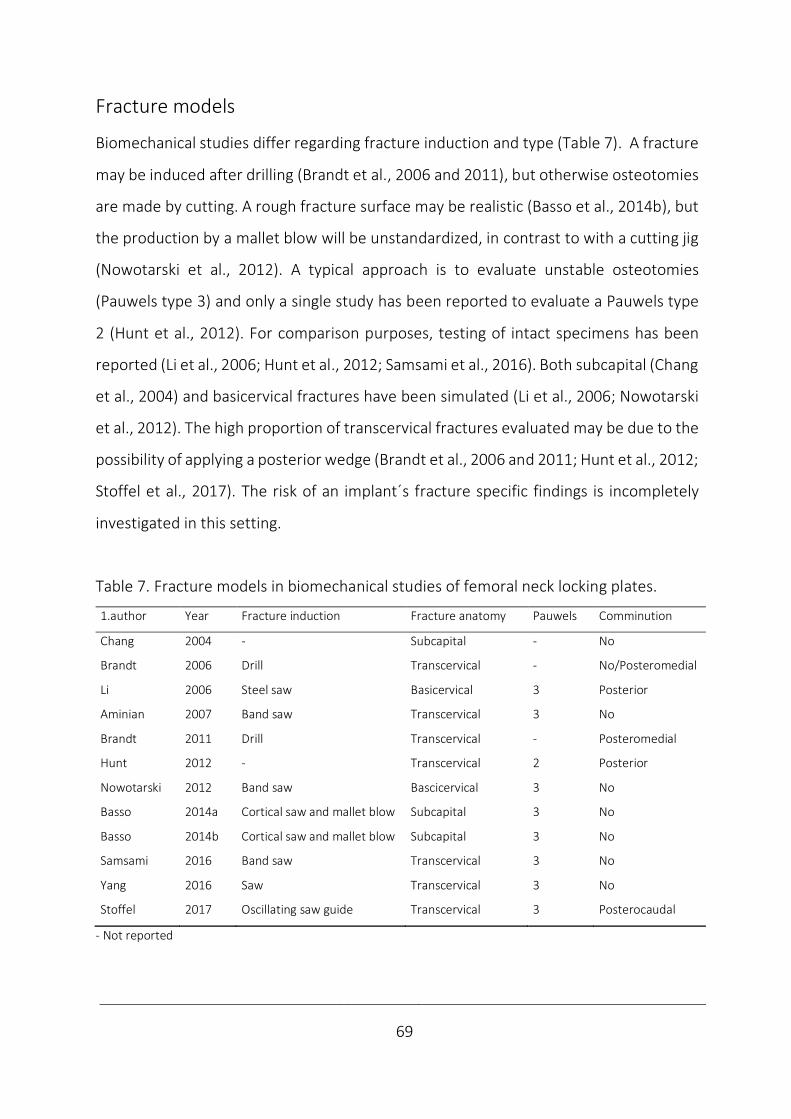
____________________________________________________________________________
69
Fracture models
Biomechanical studies differ regarding fracture induction and type (Table 7). A fracture
may be induced after drilling (Brandt et al., 2006 and 2011), but otherwise osteotomies
are made by cutting. A rough fracture surface may be realistic (Basso et al., 2014b), but
the production by a mallet blow will be unstandardized, in contrast to with a cutting jig
(Nowotarski et al., 2012). A typical approach is to evaluate unstable osteotomies
(Pauwels type 3) and only a single study has been reported to evaluate a Pauwels type
2 (Hunt et al., 2012). For comparison purposes, testing of intact specimens has been
reported (Li et al., 2006; Hunt et al., 2012; Samsami et al., 2016). Both subcapital (Chang
et al., 2004) and basicervical fractures have been simulated (Li et al., 2006; Nowotarski
et al., 2012). The high proportion of transcervical fractures evaluated may be due to the
possibility of applying a posterior wedge (Brandt et al., 2006 and 2011; Hunt et al., 2012;
Stoffel et al., 2017). The risk of an implant´s fracture specific findings is incompletely
investigated in this setting.
Table 7. Fracture models in biomechanical studies of femoral neck locking plates.
1.author Year Fracture induction Fracture anatomy Pauwels Comminution
Chang 2004 - Subcapital - No
Brandt 2006 Drill Transcervical - No/Posteromedial
Li 2006 Steel saw Basicervical 3 Posterior
Aminian 2007 Band saw Transcervical 3 No
Brandt 2011 Drill Transcervical - Posteromedial
Hunt 2012 - Transcervical 2 Posterior
Nowotarski 2012 Band saw Bascicervical 3 No
Basso 2014a Cortical saw and mallet blow Subcapital 3 No
Basso 2014b Cortical saw and mallet blow Subcapital 3 No
Samsami 2016 Band saw Transcervical 3 No
Yang 2016 Saw Transcervical 3 No
Stoffel 2017 Oscillating saw guide Transcervical 3 Posterocaudal
- Not reported
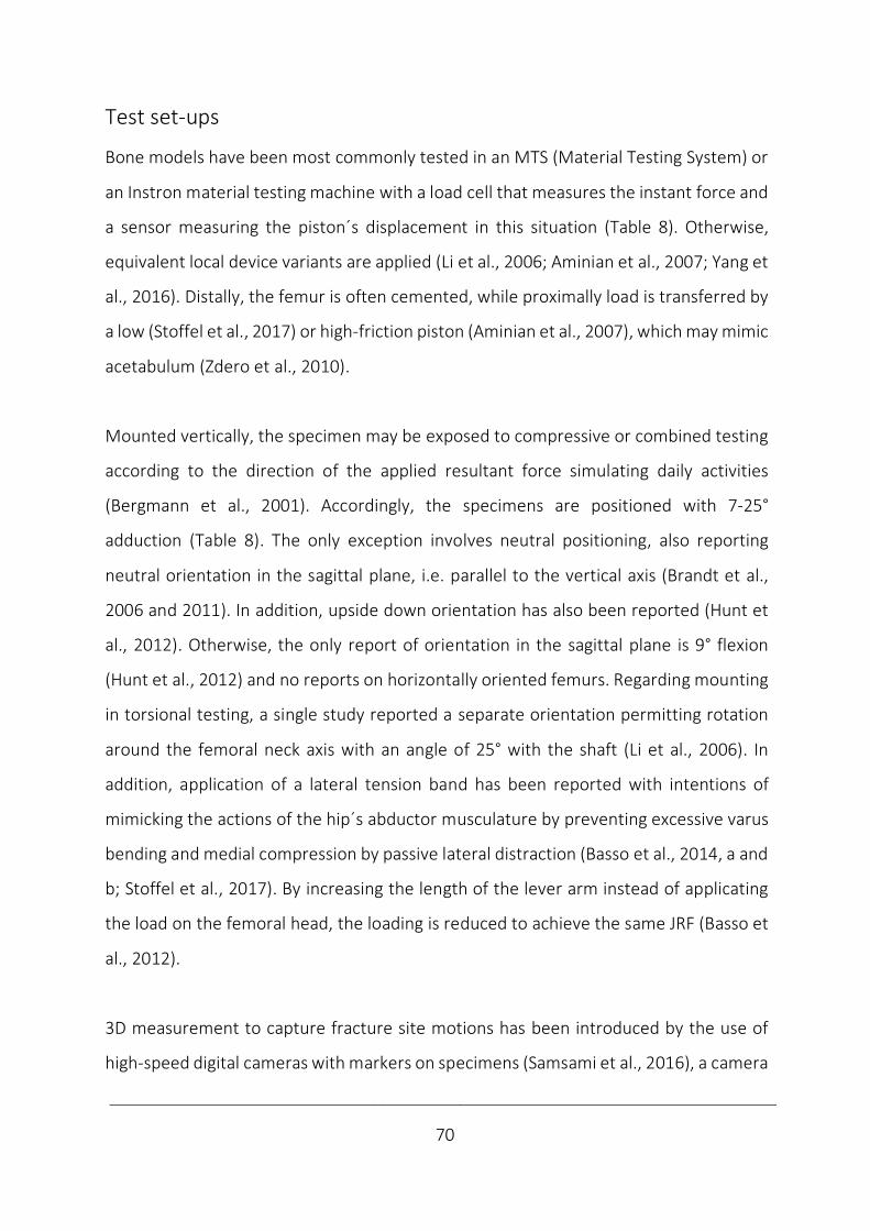
____________________________________________________________________________
70
Test set-ups
Bone models have been most commonly tested in an MTS (Material Testing System) or
an Instron material testing machine with a load cell that measures the instant force and
a sensor measuring the piston´s displacement in this situation (Table 8). Otherwise,
equivalent local device variants are applied (Li et al., 2006; Aminian et al., 2007; Yang et
al., 2016). Distally, the femur is often cemented, while proximally load is transferred by
a low (Stoffel et al., 2017) or high-friction piston (Aminian et al., 2007), which may mimic
acetabulum (Zdero et al., 2010).
Mounted vertically, the specimen may be exposed to compressive or combined testing
according to the direction of the applied resultant force simulating daily activities
(Bergmann et al., 2001). Accordingly, the specimens are positioned with 7-25°
adduction (Table 8). The only exception involves neutral positioning, also reporting
neutral orientation in the sagittal plane, i.e. parallel to the vertical axis (Brandt et al.,
2006 and 2011). In addition, upside down orientation has also been reported (Hunt et
al., 2012). Otherwise, the only report of orientation in the sagittal plane is 9° flexion
(Hunt et al., 2012) and no reports on horizontally oriented femurs. Regarding mounting
in torsional testing, a single study reported a separate orientation permitting rotation
around the femoral neck axis with an angle of 25° with the shaft (Li et al., 2006). In
addition, application of a lateral tension band has been reported with intentions of
mimicking the actions of the hip´s abductor musculature by preventing excessive varus
bending and medial compression by passive lateral distraction (Basso et al., 2014, a and
b; Stoffel et al., 2017). By increasing the length of the lever arm instead of applicating
the load on the femoral head, the loading is reduced to achieve the same JRF (Basso et
al., 2012).
3D measurement to capture fracture site motions has been introduced by the use of
high-speed digital cameras with markers on specimens (Samsami et al., 2016), a camera
____________________________________________________________________________
71
with kinematic sensors on specimen (Aminian et al., 2007), an infrared camera with
passive markers (Basso et al 2014, a and b) or magnetic tracking with sensors
(Nowotarski et al., 2012). Modern technology is increasingly included also by the use of
FEA (Mellgren et al., 2010a and b). While the precision and accuracy added by the
modern technology may be beneficial, the clinical importance is unknown.
Table 8. Test set-ups in biomechanical studies with femoral neck locking plates.
1.author Year Mounting Machine Additional equipment
Chang 2004 15° adduction MTS Analysis system, computer imaging*
Brandt 2006 Neutral MTS -
Li 2006 15° adduction (Chinese) -
Torsion axis 25° to femur axis
Aminian 2007 25° adduction KollMorgen motor Optotrak camera and markers,
IDC actuator Labview software
Brandt 2011 Neutral MTS -
Hunt 2012 10° adduction, 9° flexion/- Instron -
Nowotarski 2012 7 ° adduction Instron Fastrak magnetic tracking,
Hall sensors
Basso 2014a 12° adduction MTS Tokyo Kenkyujo strain-gauge,
Polaris
Basso 2014b 12° adduction MTS Polaris Spectra infrared camera,
rigid body markers
Samsami 2016 25° adduction - Casio Hi-Speed Cameras, markers
SkillSpector software
Yang 2016 - Zwick, RNJ* -
Stoffel 2017 16° adduction MTS Qualisys ProReflex digital cameras
- Not reported
* unspecified,
IDC: Industrial Devices Corporation
MTS: Material Testing System
____________________________________________________________________________
72
Tests
The test specifications differ between ex vivo investigations of locking plates in femoral
neck fixation (Table 9). The common test load has been compressive, bending or
torsional (Basso et al., 2012). In vertical compression, the femur´s orientation is
according to the JRF during stance. In horizontal bending, rising from a chair or
stairclimbing is mimicked (Kauffmann et al., 1999). Principally, there is no difference
between setups combining forces (Basso et al., 2014a and b, Brandt et al, 2006 and
2011) and consecutive tests of isolated forces, as long as the former tests are not
incriminating (Zdero et al., 2010). With locking plates all studies evaluated axial
compression in upright femurs. Regarding torsional testing (Yang et al., 2016), both
torsion around the femoral neck length axis (Li et al., 2006, Brandt et al., 2006 and 2011)
and retroversion of the femoral head have been reported (Nowotarski et al., 2012;
Basso et al., 2014a and b), but no reports of anteroposterior bending have been written.
The loading modes are either static or dynamic. While static (Chang et al., 2004; Li et
al., 2006) and dynamic testing (Brandt et al., 2006 and 2011; Basso et al., 2014a and b)
have both been reported separately, including consecutive static and dynamic tests
have been a common approach (Aminian et al., 2007, Hunt et al., 2012; Nowotarski et
al., 2012; Samsami et al., 2016; Yang et al., 2016; Stoffel et al., 2017).
In static testing, loading is non-destructive to measure stiffness or destructive to
provoke failure patterns with measurements of strength (Chang et al., 2004). The
dynamic loading replicates the fixation´s ability to resist fatigue by multiple repetitions
and aims at reflecting the physiologic loading level during simulated gait (Basso et al.,
2014a and b). In physiologic loading, quasi-static non-destructive and destructive
testing intend to reflect the respective partial weight-bearing postoperatively and
overloading as e.g. in stumbling, while dynamic tests may cause fatigue respective of
____________________________________________________________________________
73
the simulated partial or full weight-bearing. All included studies were characterised by
initial intended non-destructive testing with subsequent destructive testing (Table 9).
To eliminate mechanical slack a small preload has been recommended (Zdero, 2016)
and has commonly been specified in the available reports and not considered to affect
the results, but rather validate testing (Table 9).
Considering the load magnitude, 300-1800 N has been considered simulating partial to
full weight-bearing (Cha et al., 2019). Further overloading provokes failure patterns
(Brandt et al., 2011). Dynamic loading with a sufficient load will eventually cause fatigue
(Basso et al, 2014, a and b), which also may be achieved by an incrementally increased
loading level (Aminian et al., 2007).
The number of cycles intended to reflect the period until fracture consolidation in this
setting has been 10 000-20 000 (Aminian et al., 2007; Nowotarski et al., 2012). A larger
number of cycles has been recommended to simulate walking, a smaller number with
stair-climbing, while only a one-shot attempt is necessary to emulate overloading by
stumbling (Bergmann et al., 2001).
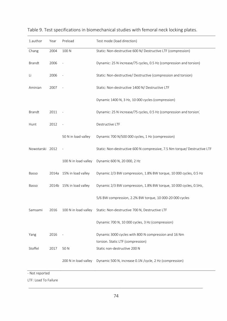
____________________________________________________________________________
74
Table 9. Test specifications in biomechanical studies with femoral neck locking plates.
1.author Year Preload Test mode (load direction)
Chang 2004 100 N Static: Non-destructive 600 N/ Destructive LTF (compression)
Brandt 2006 - Dynamic: 25 N increase/75 cycles, 0.5 Hz (compression and torsion)
Li 2006 - Static: Non-destructive/ Destructive (compression and torsion)
Aminian 2007 - Static: Non-destructive 1400 N/ Destructive LTF
Dynamic 1400 N, 3 Hz, 10 000 cycles (compression)
Brandt 2011 - Dynamic: 25 N increase/75 cycles, 0.5 Hz (compression and torsion)
Hunt 2012 - Destructive LTF
50 N in load valley Dynamic 700 N/500 000 cycles, 1 Hz (compression)
Nowotarski 2012 - Static: Non-destructive 600 N compressive, 7.5 Nm torque/ Destructive LTF
100 N in load valley Dynamic 600 N, 20 000, 2 Hz
Basso 2014a 15% in load valley Dynamic 2/3 BW compression, 1.8% BW torque, 10 000 cycles, 0.5 Hz
Basso 2014b 15% in load valley Dynamic 2/3 BW compression, 1.8% BW torque, 10 000 cycles, 0.5Hz,
5/6 BW compression, 2.2% BW torque, 10 000-20 000 cycles
Samsami 2016 100 N in load valley Static: Non-destructive 700 N, Destructive LTF
Dynamic 700 N, 10 000 cycles, 3 Hz (compression)
Yang 2016 - Dynamic 3000 cycles with 800 N compression and 16 Nm
torsion. Static LTF (compression)
Stoffel 2017 50 N Static non-destructive 200 N
200 N in load valley Dynamic 500 N, increase 0.1N /cycle, 2 Hz (compression)
- Not reported
LTF: Load To Failure
____________________________________________________________________________
75
Outcomes
Stability parameters reported after a single test (Basso et al., 2014a and b) or after
different tests reflect various aspects of stability (Nowotarski et al., 2012) (Fig. 15).
The initial stiffness may be calculated by non-destructive static loading (Aminian et al.,
2007; Nowotarski et al., 2012). The linear incline of the elastic region of the load-
deformation graph describes the stiffness of the construct (Zdero et al., 2010).
Calculations may either be made as a mean of e.g. the first cycles (Zdero et al., 2010) or
in the 3rd cycle (Stoffel et al., 2017) with the same considerations of impaction as with a
preload. Alternatively, stability has been reported as displacement at a tested load by
LTD, (with the corresponding cycles to displacement) (Stoffel et al., 2017), representing
a mean value of stiffness in an intended non-destructive test interval (Chang et al.,
2004). Similarly, relative stiffness calculations are based on fixation stiffness divided by
the intact specimen´s stiffness (Samsami et al., 2016)
With increased static loading, testing becomes destructive and the fixation yields in LTF,
which is reflected by the graph´s non-linearity signalling the limit of elastic testing.
Beyond this yield point, the model exhibits plastic deformation (Nordin and Frankel,
2012). The failure may be defined by construct dissolution (Brandt et al., 2006 and
2011), predefined criterions reflecting Displacement At failure (DAF) (Chang et al., 2004)
or known failure types (Stoffel et al., 2017).
In femoral neck fixation with locking plates ex vivo, all these outcomes have been
reported (Table 10). Reporting a single test may be too simplified, as no isolated test is
known to predict clinical performance. Using several outcomes also involves a risk of
reporting bias and effectuate overestimation by overlapping (von Elm et al., 2004). All
reviewed studies evaluated several outcomes corresponding with the test modes used.
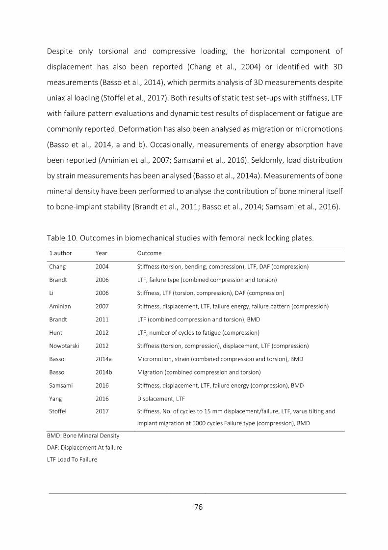
____________________________________________________________________________
76
Despite only torsional and compressive loading, the horizontal component of
displacement has also been reported (Chang et al., 2004) or identified with 3D
measurements (Basso et al., 2014), which permits analysis of 3D measurements despite
uniaxial loading (Stoffel et al., 2017). Both results of static test set-ups with stiffness, LTF
with failure pattern evaluations and dynamic test results of displacement or fatigue are
commonly reported. Deformation has also been analysed as migration or micromotions
(Basso et al., 2014, a and b). Occasionally, measurements of energy absorption have
been reported (Aminian et al., 2007; Samsami et al., 2016). Seldomly, load distribution
by strain measurements has been analysed (Basso et al., 2014a). Measurements of bone
mineral density have been performed to analyse the contribution of bone mineral itself
to bone-implant stability (Brandt et al., 2011; Basso et al., 2014; Samsami et al., 2016).
Table 10. Outcomes in biomechanical studies with femoral neck locking plates.
1.author Year Outcome
Chang 2004 Stiffness (torsion, bending, compression), LTF, DAF (compression)
Brandt 2006 LTF, failure type (combined compression and torsion)
Li 2006 Stiffness, LTF (torsion, compression), DAF (compression)
Aminian 2007 Stiffness, displacement, LTF, failure energy, failure pattern (compression)
Brandt 2011 LTF (combined compression and torsion), BMD
Hunt 2012 LTF, number of cycles to fatigue (compression)
Nowotarski 2012 Stiffness (torsion, compression), displacement, LTF (compression)
Basso 2014a Micromotion, strain (combined compression and torsion), BMD
Basso 2014b Migration (combined compression and torsion)
Samsami 2016 Stiffness, displacement, LTF, failure energy (compression), BMD
Yang 2016 Displacement, LTF
Stoffel 2017 Stiffness, No. of cycles to 15 mm displacement/failure, LTF, varus tilting and
implant migration at 5000 cycles Failure type (compression), BMD
BMD: Bone Mineral Density
DAF: Displacement At failure
LTF Load To Failure
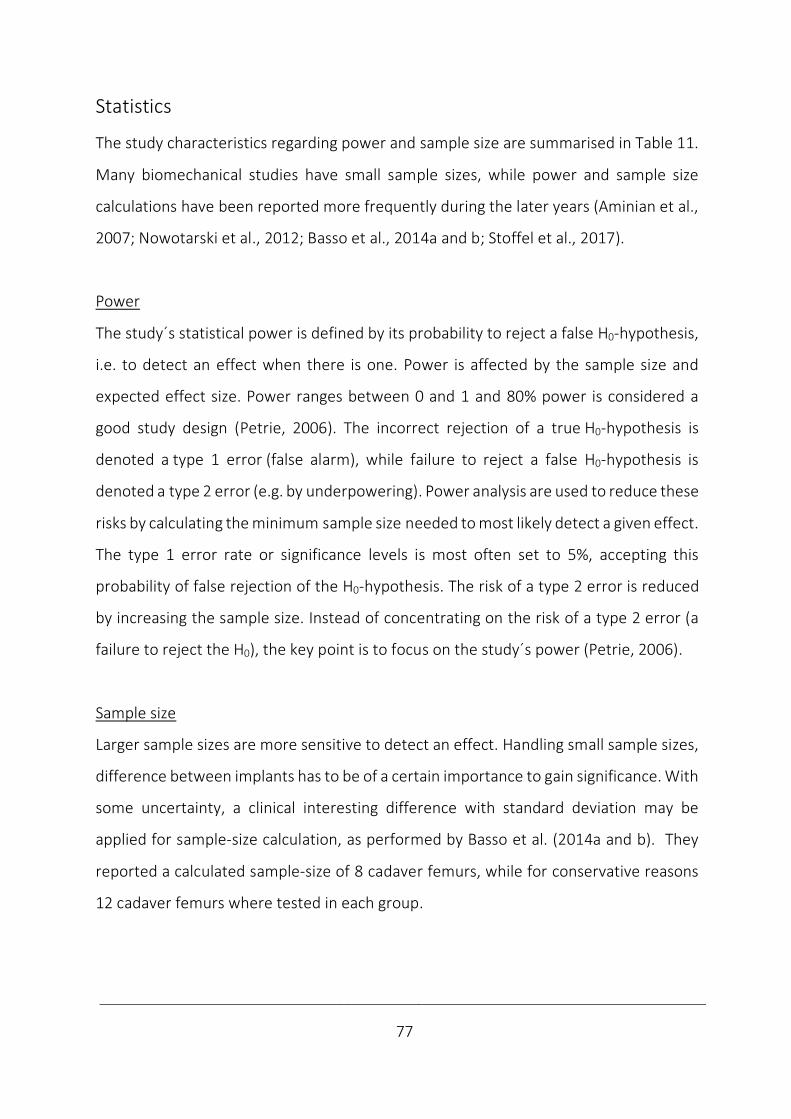
____________________________________________________________________________
77
Statistics
The study characteristics regarding power and sample size are summarised in Table 11.
Many biomechanical studies have small sample sizes, while power and sample size
calculations have been reported more frequently during the later years (Aminian et al.,
2007; Nowotarski et al., 2012; Basso et al., 2014a and b; Stoffel et al., 2017).
Power
The study´s statistical power is defined by its probability to reject a false H0-hypothesis,
i.e. to detect an effect when there is one. Power is affected by the sample size and
expected effect size. Power ranges between 0 and 1 and 80% power is considered a
good study design (Petrie, 2006). The incorrect rejection of a true H0-hypothesis is
denoted a type 1 error (false alarm), while failure to reject a false H0-hypothesis is
denoted a type 2 error (e.g. by underpowering). Power analysis are used to reduce these
risks by calculating the minimum sample size needed to most likely detect a given effect.
The type 1 error rate or significance levels is most often set to 5%, accepting this
probability of false rejection of the H0-hypothesis. The risk of a type 2 error is reduced
by increasing the sample size. Instead of concentrating on the risk of a type 2 error (a
failure to reject the H0), the key point is to focus on the study´s power (Petrie, 2006).
Sample size
Larger sample sizes are more sensitive to detect an effect. Handling small sample sizes,
difference between implants has to be of a certain importance to gain significance. With
some uncertainty, a clinical interesting difference with standard deviation may be
applied for sample-size calculation, as performed by Basso et al. (2014a and b). They
reported a calculated sample-size of 8 cadaver femurs, while for conservative reasons
12 cadaver femurs where tested in each group.
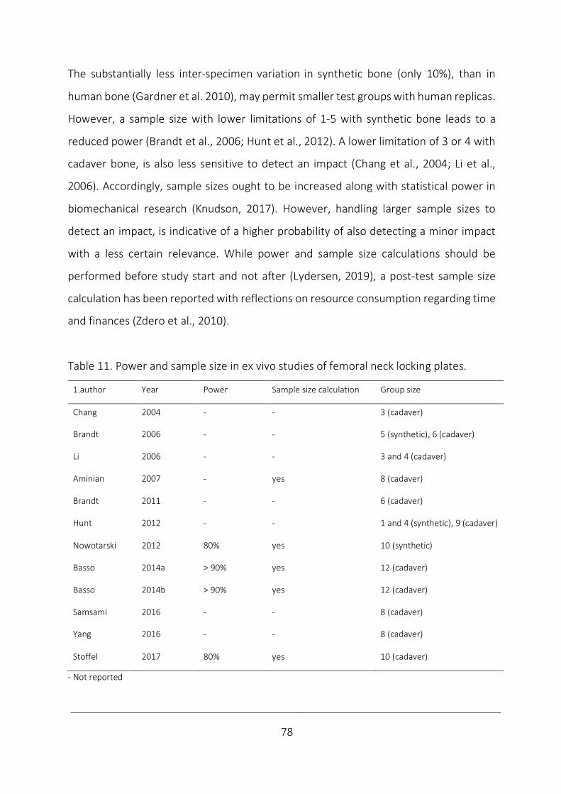
____________________________________________________________________________
78
The substantially less inter-specimen variation in synthetic bone (only 10%), than in
human bone (Gardner et al. 2010), may permit smaller test groups with human replicas.
However, a sample size with lower limitations of 1-5 with synthetic bone leads to a
reduced power (Brandt et al., 2006; Hunt et al., 2012). A lower limitation of 3 or 4 with
cadaver bone, is also less sensitive to detect an impact (Chang et al., 2004; Li et al.,
2006). Accordingly, sample sizes ought to be increased along with statistical power in
biomechanical research (Knudson, 2017). However, handling larger sample sizes to
detect an impact, is indicative of a higher probability of also detecting a minor impact
with a less certain relevance. While power and sample size calculations should be
performed before study start and not after (Lydersen, 2019), a post-test sample size
calculation has been reported with reflections on resource consumption regarding time
and finances (Zdero et al., 2010).
Table 11. Power and sample size in ex vivo studies of femoral neck locking plates.
1.author Year Power Sample size calculation Group size
Chang 2004 - - 3 (cadaver)
Brandt 2006 - - 5 (synthetic), 6 (cadaver)
Li 2006 - - 3 and 4 (cadaver)
Aminian 2007 - yes 8 (cadaver)
Brandt 2011 - - 6 (cadaver)
Hunt 2012 - - 1 and 4 (synthetic), 9 (cadaver)
Nowotarski 2012 80% yes 10 (synthetic)
Basso 2014a > 90% yes 12 (cadaver)
Basso 2014b > 90% yes 12 (cadaver)
Samsami 2016 - - 8 (cadaver)
Yang 2016 - - 8 (cadaver)
Stoffel 2017 80% yes 10 (cadaver)
- Not reported
____________________________________________________________________________
79
Analyses
Regarding choice of statistical method in comparisons between data sets, an important
question is: “Do we need a p-value at all?” The p-value signals the probability that the
H0-hypothesis of no difference between groups is true, given a result equal or more
extreme than observed (Wasserstein and Lazar, 2016). When the minimal difference
interesting to detect is unknown, estimating the effect size (e.g. mean difference) with
confidence intervals may provide more information (Skovlund, 2017). While both trends
and significant findings may be interesting, it is natural to focus on significant differences
in small groups in biomechanical studies, which may have clinical importance.
The included studies´ statistics are summarised in Table 12. Descriptive statistics define
data by the central tendency (e.g. mean, or median if the data are skewed) and
variability (e.g. standard deviation). In spite of small sample sizes most statistical analysis
are based on parametric testing, while exceptionally studies executing non-parametric
tests have been reported (Basso et al., 2014a and b; Samsami et al., 2016). The choice
of statistical method has only seldomly been reported with testing of the prerequisites
of parametric testing (Nowotarski et al., 2012; Basso et al., 2014b; Stoffel et al., 2017).
The requirement of independence is absolute (observations provide no information
about each other), while normality (an observation close to mean are more probable
than one deviating from the mean), homogeneity of variance (the average squared
deviation from the mean) and standard deviations (the boundaries of the estimate) are
not absolute. On the other hand, the alternative of non-parametric testing is
distribution-free and robust against outliers. Different tests are used to analyse if the
assumptions are violated. To test against normality, Shapiro-Wilk’s or Kolmogorov-
Smirnov tests are executed. To analyse homogeneity of variance, Levene’s test may be
used. Graphical methods as Q-Q plot are often used to confirm normality where the
observed value does not vary more from a straight line than the expected value.

____________________________________________________________________________
80
Table 12. Analyses in biomechanical studies of femoral neck fixation with locking plates.
1.author Year Testing assumptions Statistics Test
Chang 2004 - Parametric ANOVA, Student Newman Keuls post hoc
Brandt 2006 - Parametric Paired samples t-test
Li 2006 - Parametric T-tests
Aminian 2007 - Parametric ANOVA, Tukey-Kramer post hoc
Brandt 2011 - Parametric Paired samples t-test
Hunt 2012 - Parametric Paired samples t-test
Nowotarski 2012 Kolmogorov-Smirnov Parametric ANOVA, Fischer´s PLSD post hoc
Bartlett´s chi-square
Basso 2014a Non-parametric Related-samples Wilcoxon signed rank test,
Linear mixed model, Fisher's exact test.
Basso 2014b Shapiro–Wilk Parametric Paired samples t-test
Samsami 2016 - Non-parametric Kruskal-Wallis, Mann-Whitney U
Yang 2016 - Parametric T-tests
Stoffel 2017 Shapiro–Wilk Parametric Paired samples t-test, ANOVA,
Levene´s test Bonferroni post hoc
- Not reported
ANOVA: Analysis of Variance
Standardisation ex vivo may provide homogeneity and normally distributed parameters,
logically with smaller confidence intervals and less outliers. Despite few observations,
even with single outliers, a robust t-test will do fine and is commonly accepted with
continuous variables that can take any value (Skovlund, 2017). With categorical
variables taking a set of values, comparisons by cross tabulation and the Chi-square test
are commonly performed. With ex vivo studies, parametric tests with paired sample t-
tests in cadavers and one-sided ANOVA between multiple groups have been most
commonly reported, with subsequent post hoc testing of subgroups. Ordinarily, tests
are two-sided, according to the underlaying H0-hypotheses addressing the possibilities
of both a positive and negative impact. (To clarify, both a one-way and two-way ANOVA
refers to a two-sided test, but differ regarding the number of variables analysed).
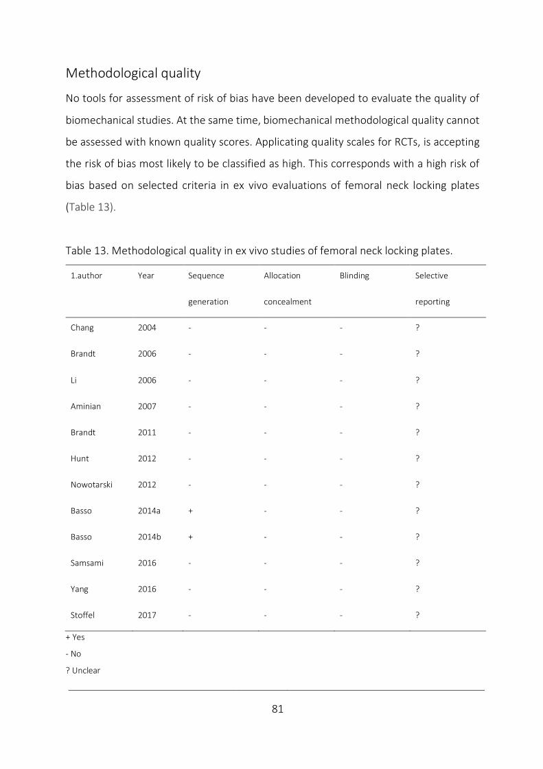
____________________________________________________________________________
81
Methodological quality
No tools for assessment of risk of bias have been developed to evaluate the quality of
biomechanical studies. At the same time, biomechanical methodological quality cannot
be assessed with known quality scores. Applicating quality scales for RCTs, is accepting
the risk of bias most likely to be classified as high. This corresponds with a high risk of
bias based on selected criteria in ex vivo evaluations of femoral neck locking plates
(Table 13).
Table 13. Methodological quality in ex vivo studies of femoral neck locking plates.
1.author Year Sequence Allocation Blinding Selective
generation concealment reporting
Chang 2004 - - - ?
Brandt 2006 - - - ?
Li 2006 - - - ?
Aminian 2007 - - - ?
Brandt 2011 - - - ?
Hunt 2012 - - - ?
Nowotarski 2012 - - - ?
Basso 2014a + - - ?
Basso 2014b + - - ?
Samsami 2016 - - - ?
Yang 2016 - - - ?
Stoffel 2017 - - - ?
+ Yes
- No
? Unclear
____________________________________________________________________________
82
No studies reported the sequence generation (method of allocation) or allocation
concealment (hiding allocation until assignment), except a single report of mechanical
randomisation by coin toss (Basso et al., 2014b). This makes the studies prone to a
selection bias. Likewise, blinding of participants and personnel and outcome assessment
have not been practiced in this setting, which increase the risk of a performance and
detection bias. Without prospective registration of the study protocols, the risk of a
reporting bias by selective outcome reporting cannot be ruled out. Amongst other
biases, incorrect analysis based on small sample sizes in biomechanical studies has
commonly been reported. Improved reporting transparency, may reduce the
researcher´s degrees of freedom in data analysis and guide analyses when testing the
dependent variable´s effect on the measured independent variable (Knudson, 2017).
Although the risk of bias may be high and quality of methodology poor, the methods of
biomechanical studies still may be valid. Ex vivo studies were designed to represent the
clinical setting and may succeed in reflecting it.
Validity refers to whether a study measures what it claims to measure. This requires a
reliable test-set up, which means that it delivers consistent results, e.g. between
different parts of the test and against re-testing. However, with significant findings the
test is obviously reliable, but not necessarily valid. The intern reliability characterises the
results possibility to explain the hypothesis and reflect the control of bias, while external
reliability defines the ability to generalise from a study group to the underlying
population (Dahlum, 2018; Svartdal, 2018).
An adjusted evaluation of the risk of bias in each ex vivo study in this setting may be
based on critical appraisal of selection (implant design, bone and fracture
characteristics), performance (biomechanical testing parameters) and detection
(measurement tools), which corresponds with Table 1-12. The lack of a consensus in the
literature on how to evaluate femoral neck fixations ex vivo contribute to the
____________________________________________________________________________
83
heterogeneity of methods. This applies to details of the study designs where both
randomized and matched studies have been reported. Both implants and the way they
were inserted have been reported to vary. Different bone models have been used with
various fracture types, which differed in the way they were induced. The diversity of
tests set-ups and specifications, both regarding mounting, load direction, loading modes
and corresponding outcomes dominated. Correspondingly, after a systematic review a
meta-analysis of results of femoral neck locking plates as a group ex vivo was not
considered feasible.
____________________________________________________________________________
84
5.4.5 Clinical relevance
While clinical studies report rates of failure, biomechanical studies have the advantage
of describing and explaining the failure mechanism after intentional overloading. This
explains the aim of preclinical testing to deliver safety declarations. Correspondingly,
short-term failures are not frequent when orthopaedic devices are introduced
(Schemitsch et al., 2010). The short-term strength requirements in vivo have been
documented (Bergmann et al., 2001 and 2004).
The obvious inconveniences by ex vivo studies are the lack of standardised testing and
in vivo responses. These limitations increase the risk of bias and make the clinical impact
of ex vivo studies more uncertain in situations demanding long term follow-up as in
fracture healing. The minimal difference important to detect ex vivo regarding micro-
motions associated with bone healing and functional outcome is unclear (Ragnarsson
and Kärrholm, 1991 and 1992; Zlowodzki et al., 2008) and applying clinical interesting
difference for sample size calculation ex vivo, does not guarantee a clinical relevance
(Basso et al., 2014b). Also, post-test sample size calculations may help explaining type 2
errors by underpowering, but powering to detect significant differences does not imply
clinical importance. In such cases, more ex vivo evaluations may have predicted the
inferior test results, but this is often only realised after a clinical failure analysis
(Schemitsch et al., 2010).
A crisis of confidence in biomechanical findings is in general due to a bias from errors in
design and analysis. Incorrect analyses may inflate results and type 1 error rate and
represent a threat to the validity and accuracy in this field (Knudson, 2017).
Correspondingly, the interpretation of statistical significance and the role of
biomechanical studies in implant introduction are debatable. The role of biomechanical
____________________________________________________________________________
85
studies has been claimed of no more value than to suggest candidates for clinical testing
(Viberg et al., 2017), which is argued against by biomechanical studies being suggested
to be ranked between expert opinions and clinical trials regarding evidence level
(Schemitsch et al., 2010). So far, the clinical importance of biomechanical studies
continues to be a source of debate (DeAngelis, 2010).
To be concise of strengths and weaknesses of biomechanical findings ex vivo by their
intended overloading nature; they are only considered preliminary or hypothesis
forming, pending in vivo verification. Only by clinical trials a full understanding of
implant performance can be achieved (Schemitsch et al., 2010). However, the aim to
deliver short-term patient safety declarations remains.

____________________________________________________________________________
86
5.4.6 Implant introduction
When introducing drugs, short-term safety declarations regarding toxicity and adverse
effects may be delivered by healthy individuals (phase 1), case-series may detect any
dose-dependent effect (phase 2), RCTs are used to reveal effectiveness in comparison
with established treatment or placebo (phase 3) and post-marketing studies monitor
the long-term effects (phase 4).
To introduce a novel orthopaedic device similar to an existing one, only equivalence has
been necessary in a preclinical evaluation to get U.S. Food and Drug Administration
(FDA) approval. Fulfilling directives on technical documentation by the process of CE-
marking (Conformité Européene), implants are approved and made commercially
available within the European Union and also in some nations outside.
In strategic planning of implant development, a SWOT analysis of both strengths,
weaknesses, opportunities and threats may come in handy. To strengthen patient
safety and implant effectiveness, a step-wise clinical introduction of implants with
comprehensive biomechanical evaluation and high-quality clinical evidence has been
requested (Schemitsch et al., 2010; Malchau et al., 2011; Hunt et al., 2012). The ex vivo
studies are suggested to deliver short-term patient safety requirements at the basal
level of the 4 phases of the proposed orthopaedic evidence pyramid (Fig. 23).
Figure 23. The orthopaedic evidence pyramids. For definitions, please see text. Adapted from Schemitsch et al.,
2010 (Illustration by JEB).
____________________________________________________________________________
87
To guide implant introduction, study designs of increasing evidence level are
recommended; case-series with the new implant, case control studies analysing the
novel implant´s contribution to the outcome between “cases” and “controls” and the
comparison of cohorts and evaluations within RCTs (Schemitsch et al., 2010).
In consistence with the recommended more systematic preclinical evaluations, the
Regulation on Medical Devices (MDR), applicable from May 2020 (Regulation EU, 2017)
will increase the need of technical documentation prior to implant release. Within the
medical device industry, this is considered a major event, and is notified to alter the way
companies develop and introduce orthopaedic implants considerably.
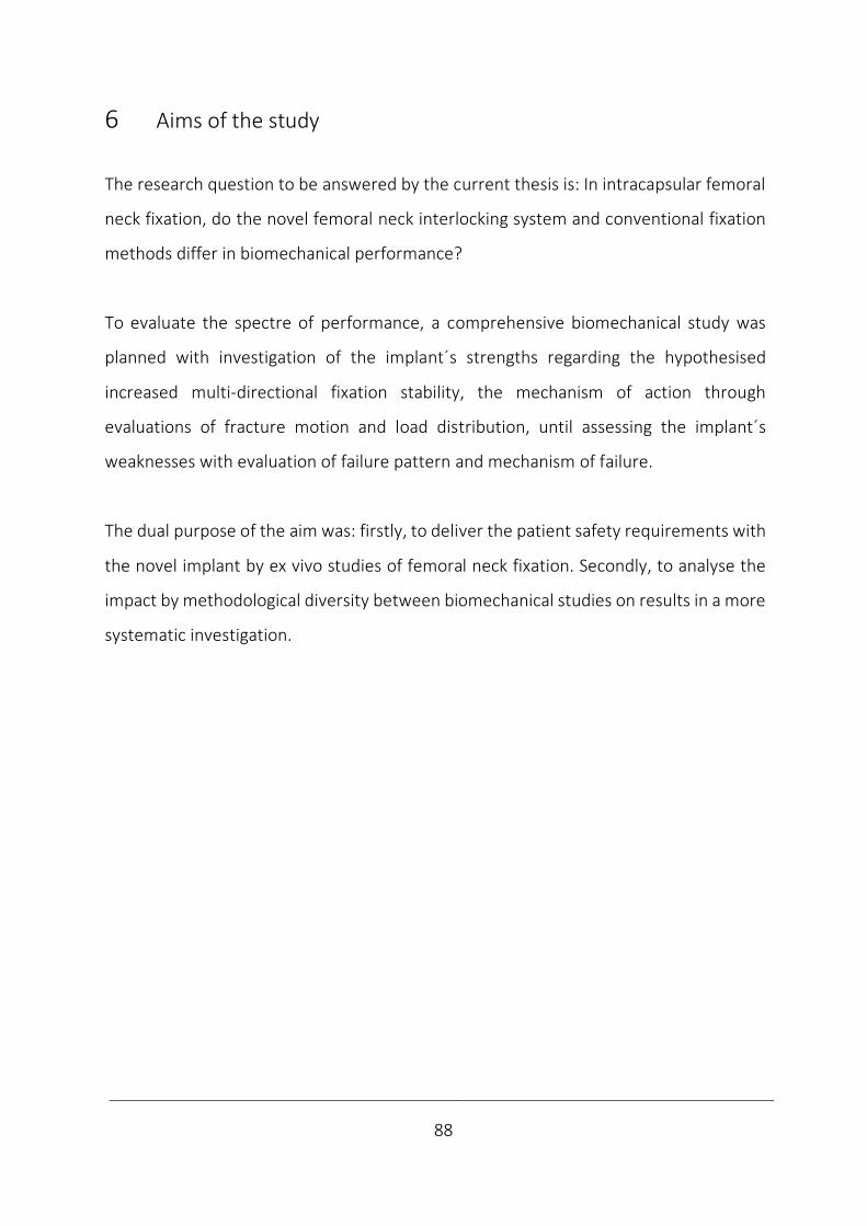
____________________________________________________________________________
88
6 Aims of the study
The research question to be answered by the current thesis is: In intracapsular femoral
neck fixation, do the novel femoral neck interlocking system and conventional fixation
methods differ in biomechanical performance?
To evaluate the spectre of performance, a comprehensive biomechanical study was
planned with investigation of the implant´s strengths regarding the hypothesised
increased multi-directional fixation stability, the mechanism of action through
evaluations of fracture motion and load distribution, until assessing the implant´s
weaknesses with evaluation of failure pattern and mechanism of failure.
The dual purpose of the aim was: firstly, to deliver the patient safety requirements with
the novel implant by ex vivo studies of femoral neck fixation. Secondly, to analyse the
impact by methodological diversity between biomechanical studies on results in a more
systematic investigation.
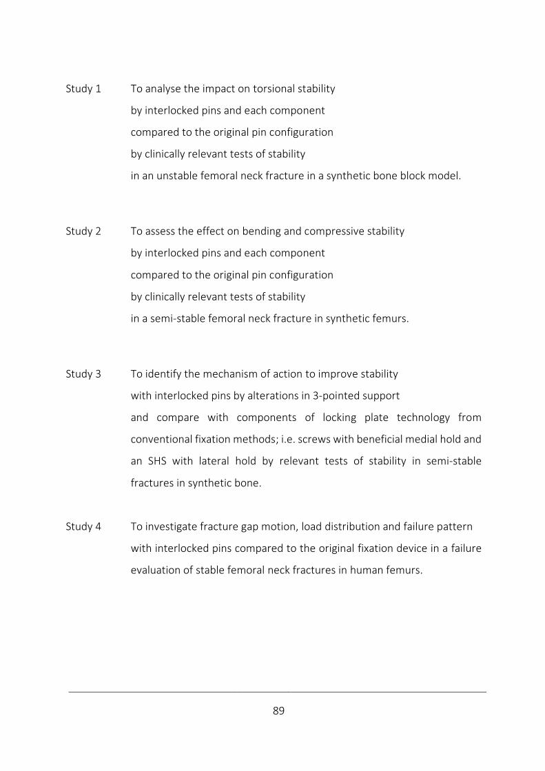
____________________________________________________________________________
89
Study 1 To analyse the impact on torsional stability
by interlocked pins and each component
compared to the original pin configuration
by clinically relevant tests of stability
in an unstable femoral neck fracture in a synthetic bone block model.
Study 2 To assess the effect on bending and compressive stability
by interlocked pins and each component
compared to the original pin configuration
by clinically relevant tests of stability
in a semi-stable femoral neck fracture in synthetic femurs.
Study 3 To identify the mechanism of action to improve stability
with interlocked pins by alterations in 3-pointed support
and compare with components of locking plate technology from
conventional fixation methods; i.e. screws with beneficial medial hold and
an SHS with lateral hold by relevant tests of stability in semi-stable
fractures in synthetic bone.
Study 4 To investigate fracture gap motion, load distribution and failure pattern
with interlocked pins compared to the original fixation device in a failure
evaluation of stable femoral neck fractures in human femurs.

____________________________________________________________________________
90
7 Summary of results
Study 1
Torsional stability
The novel implant enhanced quasi-static non-destructive torsional stability up to an
average of 12.0 (stiffness), 19.3 (torque) and 19.9 (energy) times higher than 2 pins (p
< 0.001). Application of the plate itself was the most efficient implant change from the
conventional pins (p < 0.001). In addition, both the plate size with increased distance
between pins and the plate shape allowing a 3rd pin triangular arrangement enhanced
all parameters (p = 0.03) compared to the classical 2 pin configuration.
The simulated femoral head fixation was improved by the 3rd interlocked pin in a
triangular configuration with an increased torque when replacing a peg with a complete
pin (p = 0.014).
Torsional failure pattern
By quasi-static destructive testing, the independent pins´ failure pattern of permanent
rotations in relation to each other with fissure formation in the lateral cortical area
between pins, was prevented by the plate (p < 0.001).
No negative adverse effects were detected with the renewed implant system.
Correlations
During torsional analysis, nearly perfect associations were found between the quasi-
static non-destructive stability parameters (r = 0.97-0.99, p = 0.001).

____________________________________________________________________________
91
Study 2
Bending and compressive stability
Compared to 2 pins, the 3 interlocked pins improved bending stability by 30% increased
initial stiffness in quasi-static non-destructive loading by simulated partial weight-
bearing and 44% reduced displacement after simulated dynamic weight-bearing (p <
0.001). In the corresponding comparison by compression no difference in stiffness was
detected after simulated partial weight-bearing (p > 0.5), but a 25% reduced
displacement was detected following weight-bearing (p < 0.001). No difference was
found between 3 individual and 3 interlocked pins (p > 0.8).
Bending and compressive failure pattern
Only cortical fissures were identified. The proportions of a medial fissure of the nearby
pin support in the inferior neck in compression and identically in the posterior neck in
bending, were reduced by the 3rd pin (p = 0.001). In compression, the lateral fissures
between pin´s entry holes were prevented by the plate itself (p = 0.007). No negative
adverse effects were found with the implant modification.
Correlations
All introductory and final results from bending showed high mutual correlations (r =
0.84-0.96, p = 0.01) (absolute values). Similarly, the compressive test results showed
moderate to high correlations (r = 0.46-0.77, p = 0.05) with the correlation between
initial stiffness and final lateral failure pattern as the only exception (r = -0.24, p = 0.3).

____________________________________________________________________________
92
Study 3
Stability
Compared to the established implants altogether, the interlocked 3 pins increased initial
stiffness 130% in torsion and 33% in bending by quasi-static non-destructive loading (p
< 0.001). In compression the finding of no increased stiffness during non-destructive
testing with partial weight-bearing (p > 0.8), was followed by a 62% reduced
displacement of the model and a 95% reduction in the femoral head (p < 0.001) by
dynamic compression simulating weight-bearing.
In comparisons with each of the traditional fixation devices of screws and an SHS, both
torsional and bending stiffness were increased and compressive displacement reduced
by the new implant (p = 0.004), with bending stability against 2 Olmed screws as the
only exception (p = 0.4). In compressive stiffness, an increment was also detected
against 2 Cannulated Hip Screws (CHS) (p = 0.001).
Failure pattern
A cortical fissure medially in the inferior neck was found with the conventional implants
and prevented with the new implant (p = 0.045), which revealed no adverse effects.
The zero-failure mode by the novel implant was reduced compared to Olmed and CHS
screws (p = 0.033), while failure was absent also with the SHS device.
Correlations
Low to moderate correlations were detected between stiffnesses from different load
directions (r = 0.29-0.49, p < 0.05). In compression, low to high coefficients of mutual
correlations with absolute values from 0.39 to 0.80 were identified (p < 0.01), which
also reflected the correlation between global and local measurement of displacement.
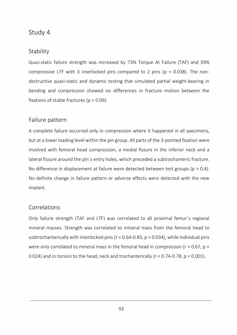
____________________________________________________________________________
93
Study 4
Stability
Quasi-static failure strength was increased by 73% Torque At Failure (TAF) and 39%
compressive LTF with 3 interlocked pins compared to 2 pins (p = 0.038). The non-
destructive quasi-static and dynamic testing that simulated partial weight-bearing in
bending and compression showed no differences in fracture motion between the
fixations of stable fractures (p > 0.09).
Failure pattern
A complete failure occurred only in compression where it happened in all specimens,
but at a lower loading level within the pin group. All parts of the 3-pointed fixation were
involved with femoral head compression, a medial fissure in the inferior neck and a
lateral fissure around the pin´s entry holes, which preceded a subtrochanteric fracture.
No difference in displacement at failure were detected between test groups (p > 0,4).
No definite change in failure pattern or adverse effects were detected with the new
implant.
Correlations
Only failure strength (TAF and LTF) was correlated to all proximal femur´s regional
mineral masses. Strength was correlated to mineral mass from the femoral head to
subtrochanterically with interlocked pins (r = 0.64-0.83, p = 0.034), while individual pins
were only correlated to mineral mass in the femoral head in compression (r = 0.67, p =
0.024) and in torsion to the head, neck and trochanterically (r = 0.74-0.78, p = 0.001).
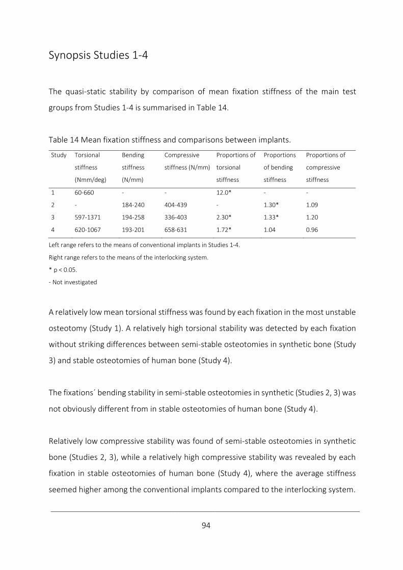
____________________________________________________________________________
94
Synopsis Studies 1-4
The quasi-static stability by comparison of mean fixation stiffness of the main test
groups from Studies 1-4 is summarised in Table 14.
Table 14 Mean fixation stiffness and comparisons between implants.
Study
Torsional
stiffness
(Nmm/deg)
Bending
stiffness
(N/mm)
Compressive
stiffness (N/mm)
Proportions of
torsional
stiffness
Proportions
of bending
stiffness
Proportions of
compressive
stiffness
1 60-660 - - 12.0* - -
2 - 184-240 404-439 - 1.30* 1.09
3 597-1371 194-258 336-403 2.30* 1.33* 1.20
4 620-1067 193-201 658-631 1.72* 1.04 0.96
Left range refers to the means of conventional implants in Studies 1-4.
Right range refers to the means of the interlocking system.
* p < 0.05.
- Not investigated
A relatively low mean torsional stiffness was found by each fixation in the most unstable
osteotomy (Study 1). A relatively high torsional stability was detected by each fixation
without striking differences between semi-stable osteotomies in synthetic bone (Study
3) and stable osteotomies of human bone (Study 4).
The fixations´ bending stability in semi-stable osteotomies in synthetic (Studies 2, 3) was
not obviously different from in stable osteotomies of human bone (Study 4).
Relatively low compressive stability was found of semi-stable osteotomies in synthetic
bone (Studies 2, 3), while a relatively high compressive stability was revealed by each
fixation in stable osteotomies of human bone (Study 4), where the average stiffness
seemed higher among the conventional implants compared to the interlocking system.
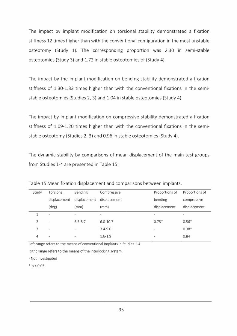
____________________________________________________________________________
95
The impact by implant modification on torsional stability demonstrated a fixation
stiffness 12 times higher than with the conventional configuration in the most unstable
osteotomy (Study 1). The corresponding proportion was 2.30 in semi-stable
osteotomies (Study 3) and 1.72 in stable osteotomies of (Study 4).
The impact by the implant modification on bending stability demonstrated a fixation
stiffness of 1.30-1.33 times higher than with the conventional fixations in the semi-
stable osteotomies (Studies 2, 3) and 1.04 in stable osteotomies (Study 4).
The impact by implant modification on compressive stability demonstrated a fixation
stiffness of 1.09-1.20 times higher than with the conventional fixations in the semi-
stable osteotomy (Studies 2, 3) and 0.96 in stable osteotomies (Study 4).
The dynamic stability by comparisons of mean displacement of the main test groups
from Studies 1-4 are presented in Table 15.
Table 15 Mean fixation displacement and comparisons between implants.
Study
Torsional
displacement
(deg)
Bending
displacement
(mm)
Compressive
displacement
(mm)
Proportions of
bending
displacement
Proportions of
compressive
displacement
1 - - - - -
2 - 6.5-8.7 6.0-10.7 0.75* 0.56*
3 - - 3.4-9.0 - 0.38*
4 - - 1.6-1.9 - 0.84
Left range refers to the means of conventional implants in Studies 1-4.
Right range refers to the means of the interlocking system.
- Not investigated
* p < 0.05.
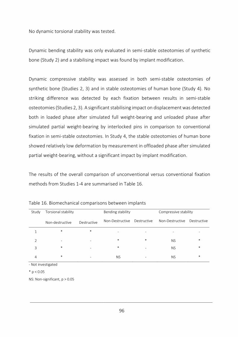
____________________________________________________________________________
96
No dynamic torsional stability was tested.
Dynamic bending stability was only evaluated in semi-stable osteotomies of synthetic
bone (Study 2) and a stabilising impact was found by implant modification.
Dynamic compressive stability was assessed in both semi-stable osteotomies of
synthetic bone (Studies 2, 3) and in stable osteotomies of human bone (Study 4). No
striking difference was detected by each fixation between results in semi-stable
osteotomies (Studies 2, 3). A significant stabilising impact on displacement was detected
both in loaded phase after simulated full weight-bearing and unloaded phase after
simulated partial weight-bearing by interlocked pins in comparison to conventional
fixation in semi-stable osteotomies. In Study 4, the stable osteotomies of human bone
showed relatively low deformation by measurement in offloaded phase after simulated
partial weight-bearing, without a significant impact by implant modification.
The results of the overall comparison of unconventional versus conventional fixation
methods from Studies 1-4 are summarised in Table 16.
Table 16. Biomechanical comparisons between implants
Study
Torsional stability Bending stability Compressive stability
Non-destructive Destructive Non-Destructive Destructive Non-Destructive Destructive
1 * * - - - -
2 - - * * NS *
3 * - * - NS *
4 * - NS - NS *
- Not investigated
* p < 0.05
NS: Non-significant, p > 0.05
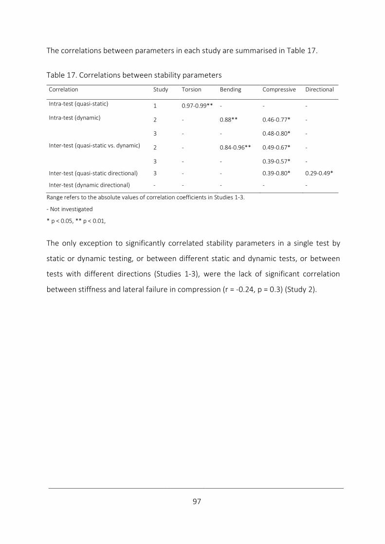
____________________________________________________________________________
97
The correlations between parameters in each study are summarised in Table 17.
Table 17. Correlations between stability parameters
Correlation Study
Torsion Bending Compressive Directional
Intra-test (quasi-static) 1 0.97-0.99** - - -
Intra-test (dynamic) 2 - 0.88** 0.46-0.77* -
3 - - 0.48-0.80* -
Inter-test (quasi-static vs. dynamic) 2 - 0.84-0.96** 0.49-0.67* -
3 - - 0.39-0.57* -
Inter-test (quasi-static directional) 3 - - 0.39-0.80* 0.29-0.49*
Inter-test (dynamic directional) - - - - -
Range refers to the absolute values of correlation coefficients in Studies 1-3.
- Not investigated
* p < 0.05, ** p < 0.01,
The only exception to significantly correlated stability parameters in a single test by
static or dynamic testing, or between different static and dynamic tests, or between
tests with different directions (Studies 1-3), were the lack of significant correlation
between stiffness and lateral failure in compression (r = -0.24, p = 0.3) (Study 2).
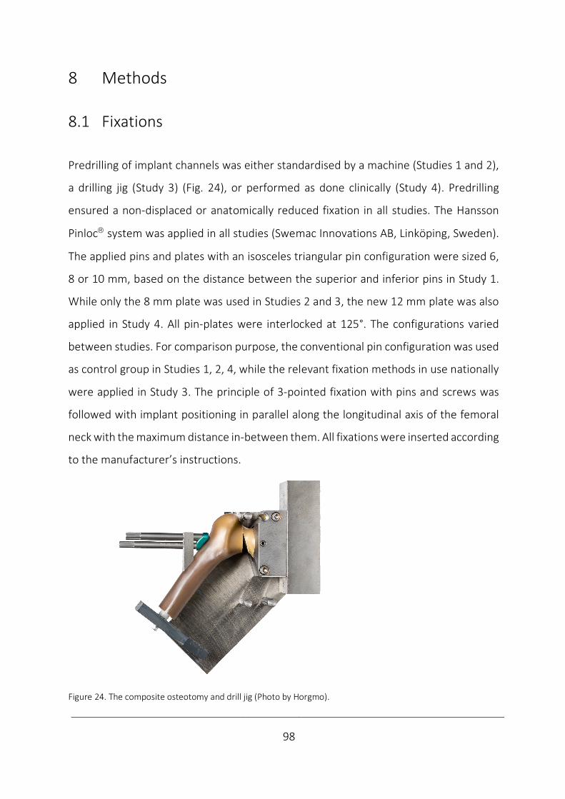
____________________________________________________________________________
98
8 Methods
8.1 Fixations
Predrilling of implant channels was either standardised by a machine (Studies 1 and 2),
a drilling jig (Study 3) (Fig. 24), or performed as done clinically (Study 4). Predrilling
ensured a non-displaced or anatomically reduced fixation in all studies. The Hansson
Pinlocâ system was applied in all studies (Swemac Innovations AB, Linköping, Sweden).
The applied pins and plates with an isosceles triangular pin configuration were sized 6,
8 or 10 mm, based on the distance between the superior and inferior pins in Study 1.
While only the 8 mm plate was used in Studies 2 and 3, the new 12 mm plate was also
applied in Study 4. All pin-plates were interlocked at 125°. The configurations varied
between studies. For comparison purpose, the conventional pin configuration was used
as control group in Studies 1, 2, 4, while the relevant fixation methods in use nationally
were applied in Study 3. The principle of 3-pointed fixation with pins and screws was
followed with implant positioning in parallel along the longitudinal axis of the femoral
neck with the maximum distance in-between them. All fixations were inserted according
to the manufacturer’s instructions.
Figure 24. The composite osteotomy and drill jig (Photo by Horgmo).
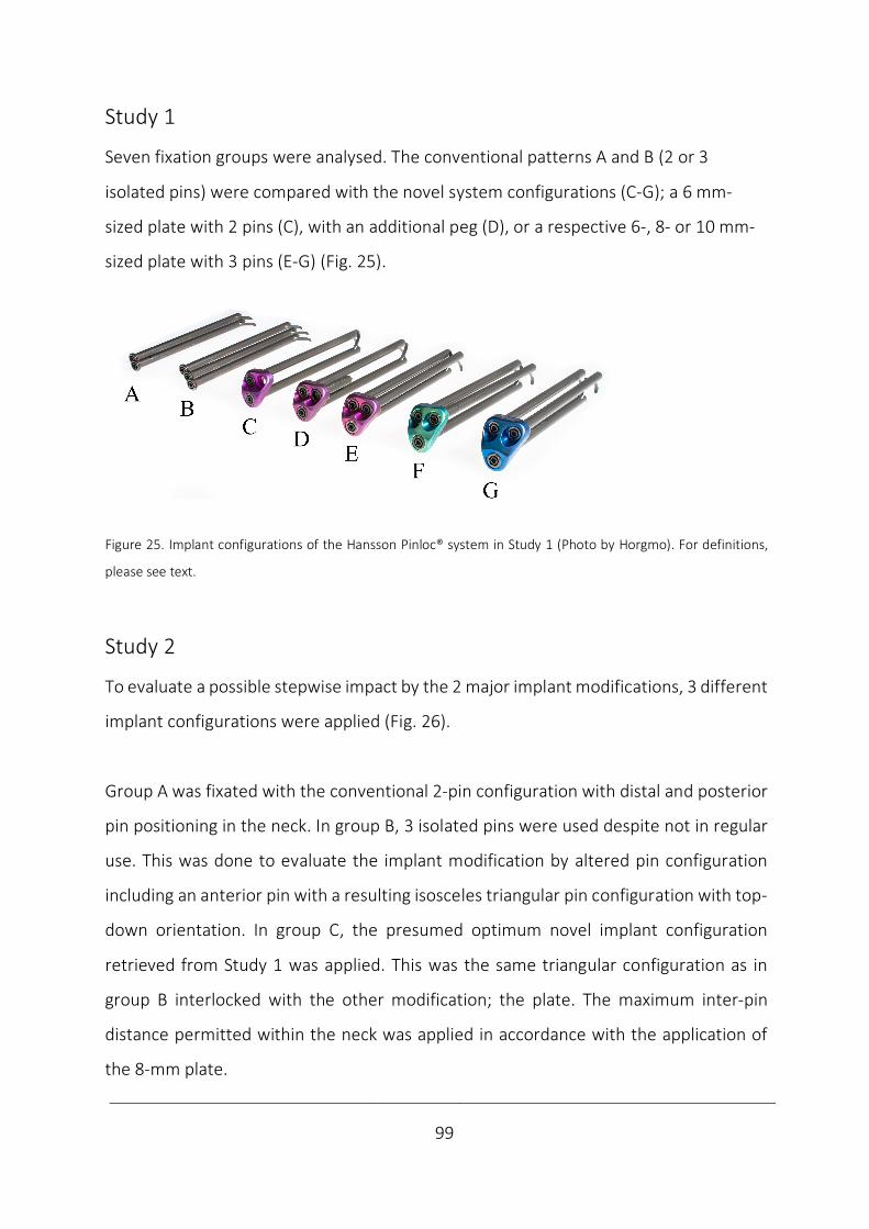
____________________________________________________________________________
99
Study 1
Seven fixation groups were analysed. The conventional patterns A and B (2 or 3
isolated pins) were compared with the novel system configurations (C-G); a 6 mm-
sized plate with 2 pins (C), with an additional peg (D), or a respective 6-, 8- or 10 mm-
sized plate with 3 pins (E-G) (Fig. 25).
Figure 25. Implant configurations of the Hansson Pinloc® system in Study 1 (Photo by Horgmo). For definitions,
please see text.
Study 2
To evaluate a possible stepwise impact by the 2 major implant modifications, 3 different
implant configurations were applied (Fig. 26).
Group A was fixated with the conventional 2-pin configuration with distal and posterior
pin positioning in the neck. In group B, 3 isolated pins were used despite not in regular
use. This was done to evaluate the implant modification by altered pin configuration
including an anterior pin with a resulting isosceles triangular pin configuration with top-
down orientation. In group C, the presumed optimum novel implant configuration
retrieved from Study 1 was applied. This was the same triangular configuration as in
group B interlocked with the other modification; the plate. The maximum inter-pin
distance permitted within the neck was applied in accordance with the application of
the 8-mm plate.
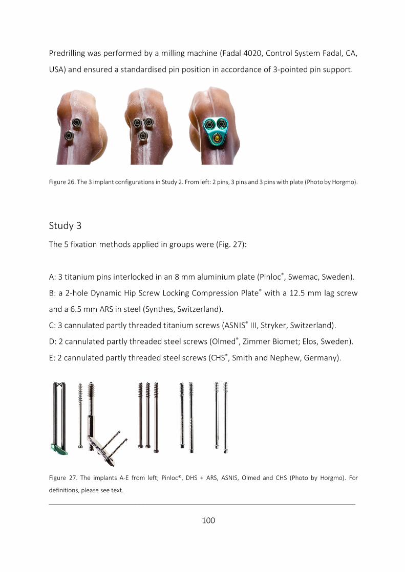
___________________________________________________________________________
100
Predrilling was performed by a milling machine (Fadal 4020, Control System Fadal, CA,
USA) and ensured a standardised pin position in accordance of 3-pointed pin support.
Figure 26. The 3 implant configurations in Study 2. From left: 2 pins, 3 pins and 3 pins with plate (Photo by Horgmo).
Study 3
The 5 fixation methods applied in groups were (Fig. 27):
A: 3 titanium pins interlocked in an 8 mm aluminium plate (Pinloc®, Swemac, Sweden).
B: a 2-hole Dynamic Hip Screw Locking Compression Plate® with a 12.5 mm lag screw
and a 6.5 mm ARS in steel (Synthes, Switzerland).
C: 3 cannulated partly threaded titanium screws (ASNIS® III, Stryker, Switzerland).
D: 2 cannulated partly threaded steel screws (Olmed®, Zimmer Biomet; Elos, Sweden).
E: 2 cannulated partly threaded steel screws (CHS®, Smith and Nephew, Germany).
Figure 27. The implants A-E from left; Pinloc®, DHS + ARS, ASNIS, Olmed and CHS (Photo by Horgmo). For
definitions, please see text.
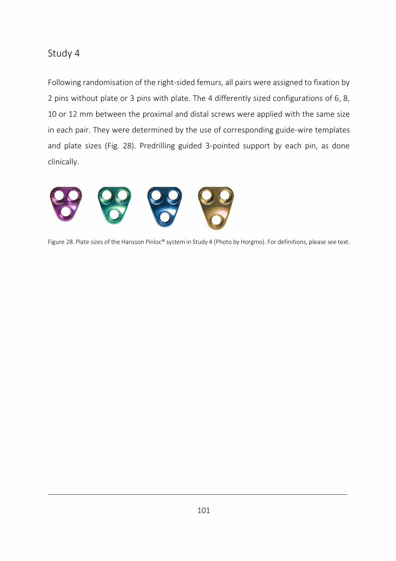
___________________________________________________________________________
101
Study 4
Following randomisation of the right-sided femurs, all pairs were assigned to fixation by
2 pins without plate or 3 pins with plate. The 4 differently sized configurations of 6, 8,
10 or 12 mm between the proximal and distal screws were applied with the same size
in each pair. They were determined by the use of corresponding guide-wire templates
and plate sizes (Fig. 28). Predrilling guided 3-pointed support by each pin, as done
clinically.
Figure 28. Plate sizes of the Hansson Pinloc® system in Study 4 (Photo by Horgmo). For definitions, please see text.
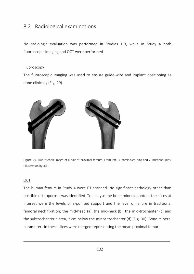
___________________________________________________________________________
102
8.2 Radiological examinations
No radiologic evaluation was performed in Studies 1-3, while in Study 4 both
fluoroscopic imaging and QCT were performed.
Fluoroscopy
The fluoroscopic imaging was used to ensure guide-wire and implant positioning as
done clinically (Fig. 29).
Figure 29. Fluoroscopic image of a pair of proximal femurs. From left, 3 interlocked pins and 2 individual pins.
(Illustration by JEB).
QCT
The human femurs in Study 4 were CT-scanned. No significant pathology other than
possible osteoporosis was identified. To analyse the bone mineral content the slices at
interest were the levels of 3-pointed support and the level of failure in traditional
femoral neck fixation; the mid-head (a), the mid-neck (b), the mid-trochanter (c) and
the subtrochanteric area, 2 cm below the minor trochanter (d) (Fig. 30). Bone mineral
parameters in these slices were merged representing the mean proximal femur.
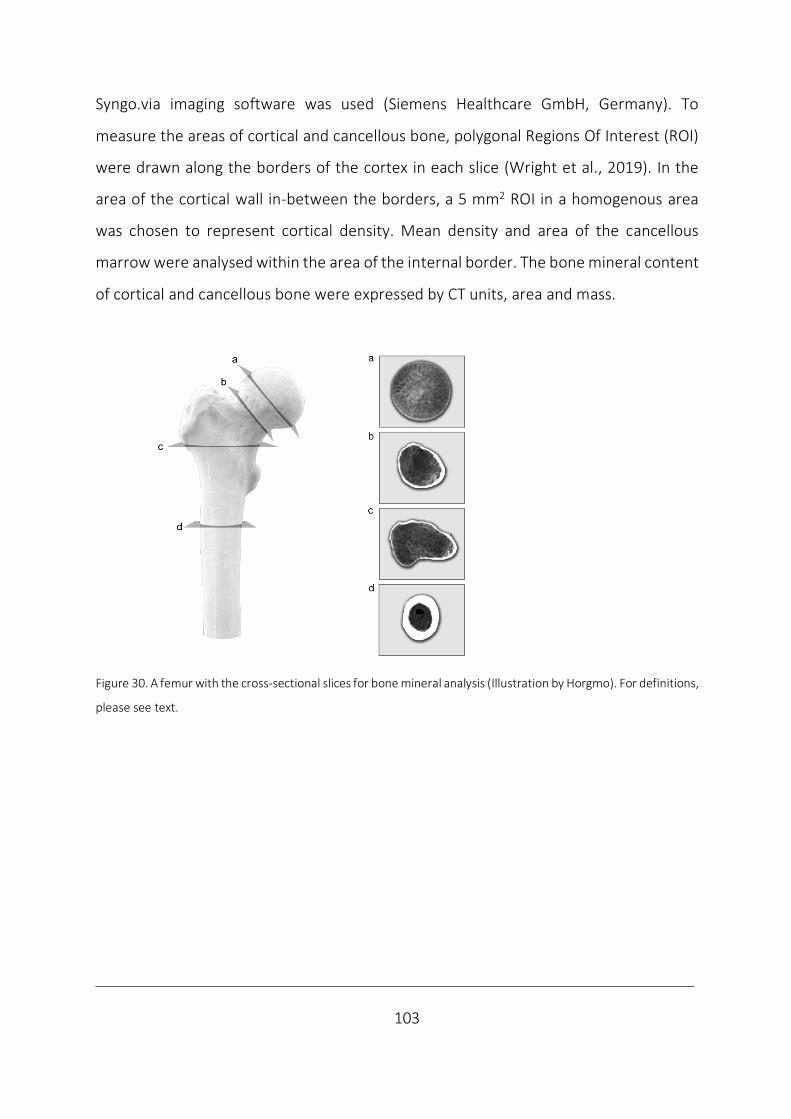
___________________________________________________________________________
103
Syngo.via imaging software was used (Siemens Healthcare GmbH, Germany). To
measure the areas of cortical and cancellous bone, polygonal Regions Of Interest (ROI)
were drawn along the borders of the cortex in each slice (Wright et al., 2019). In the
area of the cortical wall in-between the borders, a 5 mm2 ROI in a homogenous area
was chosen to represent cortical density. Mean density and area of the cancellous
marrow were analysed within the area of the internal border. The bone mineral content
of cortical and cancellous bone were expressed by CT units, area and mass.
Figure 30. A femur with the cross-sectional slices for bone mineral analysis (Illustration by Horgmo). For definitions,
please see text.
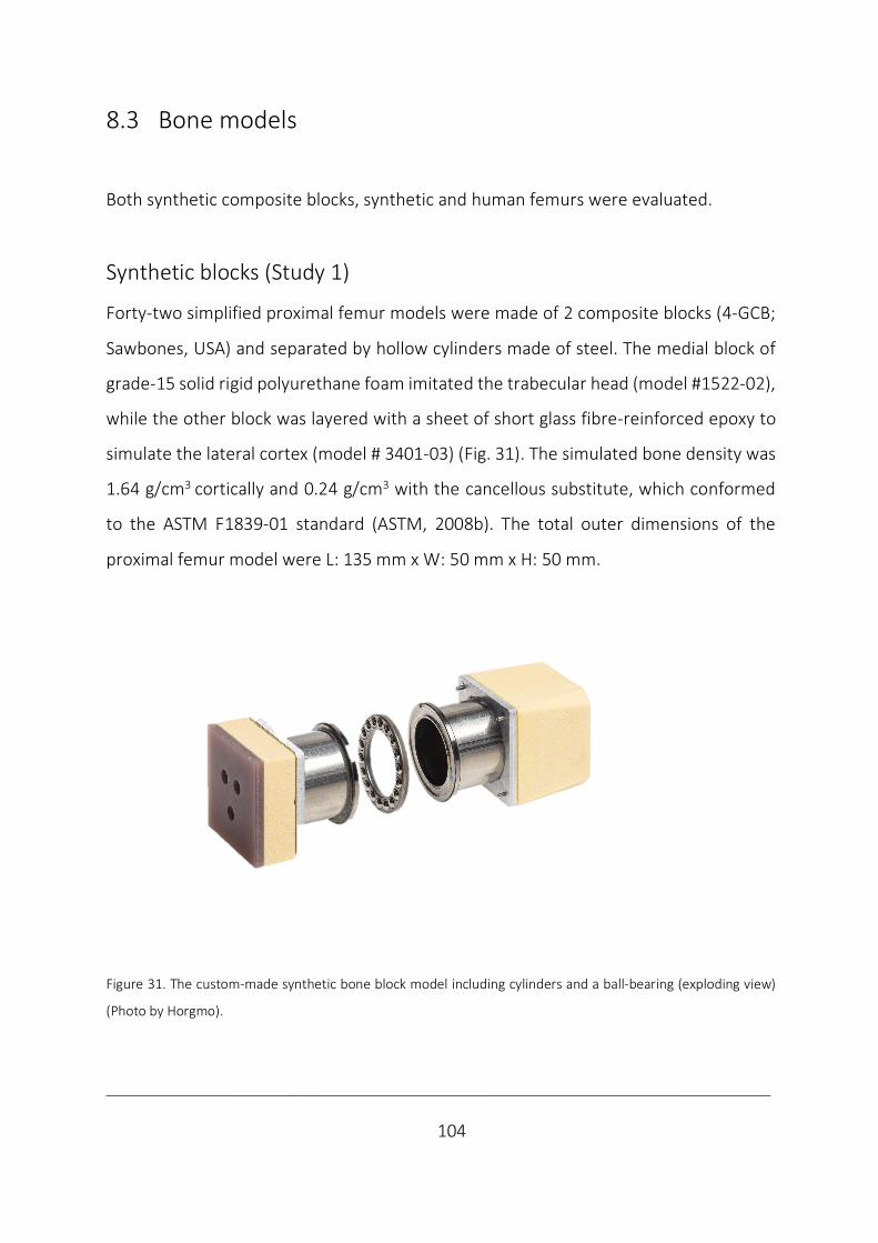
___________________________________________________________________________
104
8.3 Bone models
Both synthetic composite blocks, synthetic and human femurs were evaluated.
Synthetic blocks (Study 1)
Forty-two simplified proximal femur models were made of 2 composite blocks (4-GCB;
Sawbones, USA) and separated by hollow cylinders made of steel. The medial block of
grade-15 solid rigid polyurethane foam imitated the trabecular head (model #1522-02),
while the other block was layered with a sheet of short glass fibre-reinforced epoxy to
simulate the lateral cortex (model # 3401-03) (Fig. 31). The simulated bone density was
1.64 g/cm3 cortically and 0.24 g/cm3 with the cancellous substitute, which conformed
to the ASTM F1839-01 standard (ASTM, 2008b). The total outer dimensions of the
proximal femur model were L: 135 mm x W: 50 mm x H: 50 mm.
Figure 31. The custom-made synthetic bone block model including cylinders and a ball-bearing (exploding view)
(Photo by Horgmo).
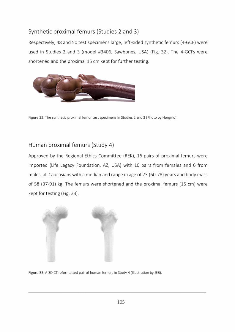
___________________________________________________________________________
105
Synthetic proximal femurs (Studies 2 and 3)
Respectively, 48 and 50 test specimens large, left-sided synthetic femurs (4-GCF) were
used in Studies 2 and 3 (model #3406, Sawbones, USA) (Fig. 32). The 4-GCFs were
shortened and the proximal 15 cm kept for further testing.
Figure 32. The synthetic proximal femur test specimens in Studies 2 and 3 (Photo by Horgmo)
Human proximal femurs (Study 4)
Approved by the Regional Ethics Committee (REK), 16 pairs of proximal femurs were
imported (Life Legacy Foundation, AZ, USA) with 10 pairs from females and 6 from
males, all Caucasians with a median and range in age of 73 (60-78) years and body mass
of 58 (37-91) kg. The femurs were shortened and the proximal femurs (15 cm) were
kept for testing (Fig. 33).
Figure 33. A 3D CT reformatted pair of human femurs in Study 4 (Illustration by JEB).
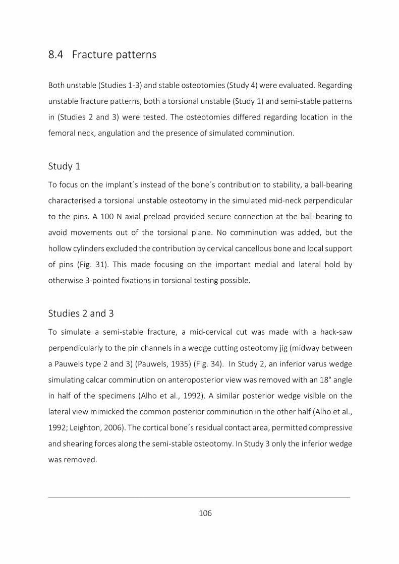
___________________________________________________________________________
106
8.4 Fracture patterns
Both unstable (Studies 1-3) and stable osteotomies (Study 4) were evaluated. Regarding
unstable fracture patterns, both a torsional unstable (Study 1) and semi-stable patterns
in (Studies 2 and 3) were tested. The osteotomies differed regarding location in the
femoral neck, angulation and the presence of simulated comminution.
Study 1
To focus on the implant´s instead of the bone´s contribution to stability, a ball-bearing
characterised a torsional unstable osteotomy in the simulated mid-neck perpendicular
to the pins. A 100 N axial preload provided secure connection at the ball-bearing to
avoid movements out of the torsional plane. No comminution was added, but the
hollow cylinders excluded the contribution by cervical cancellous bone and local support
of pins (Fig. 31). This made focusing on the important medial and lateral hold by
otherwise 3-pointed fixations in torsional testing possible.
Studies 2 and 3
To simulate a semi-stable fracture, a mid-cervical cut was made with a hack-saw
perpendicularly to the pin channels in a wedge cutting osteotomy jig (midway between
a Pauwels type 2 and 3) (Pauwels, 1935) (Fig. 34). In Study 2, an inferior varus wedge
simulating calcar comminution on anteroposterior view was removed with an 18° angle
in half of the specimens (Alho et al., 1992). A similar posterior wedge visible on the
lateral view mimicked the common posterior comminution in the other half (Alho et al.,
1992; Leighton, 2006). The cortical bone´s residual contact area, permitted compressive
and shearing forces along the semi-stable osteotomy. In Study 3 only the inferior wedge
was removed.

___________________________________________________________________________
107
Figure 34. The composite femur´s osteotomy model where wedges were removed (Photo by Horgmo).
Study 4
To simulate a more stable, subcapital non-displaced fracture, the femoral neck was
osteotomised by a hack-saw subcapitally perpendicularly (Fig. 35), according to AO/OTA
31-B1.2 (Meinberg et al., 2018). No additional comminution was simulated.
Figure 35. A 3D CT reformatted femur with the subcapital perpendicular osteotomy being pictured (Illustration by
Horgmo).

___________________________________________________________________________
108
8.5 Test set-ups
The studies differed regarding how the test specimens were fixed distally and whether
they were fixed proximally to the piston or not. The test specimen orientation permitted
both compressive, bending and torsional stability testing, which were performed in
different testing machines during the studies.
Study 1
Specimens were press-fitted horizontally into cylindrical tubes with squared brackets
which avoided interference between implants and the tubes. Torsional screw test
equipment was used, according to ASTM F543-07 standard (ASTM, 2008a); an
electronical motor (Maxon Motor AG, Germany) and a torque sensor (Lorenz
Messtechnik GmbH, Germany) (Fig. 36). No additional equipment was used.
Figure 36. The set-up with press fit insertion, horizontal model orientation and test equipment used in Study 1
(Photo by Loeferer).

___________________________________________________________________________
109
Studies 2-3
The proximal femurs were mounted by distal press-fit insertion (Study 2), press-fitted in
a test jig (Study 3) or cemented in steel spheres (Study 4) (Fig. 37).
Figure 37. The test jig used in Studies 3 and 4 representing mounting from left in torsion, bending and compression
(Illustration by JEB).
A low friction piston transferred proximal load in bending and compression (Studies 2-
4), while point fixation in a cylindrical steel cup mimicking acetabulum was used in
torsional testing (Studies 3, 4) (Fig. 38).
Figure 38. From left the press-fit with low-friction piston in compression and bending and fixed piston in torsion
(Photo by Horgmo)
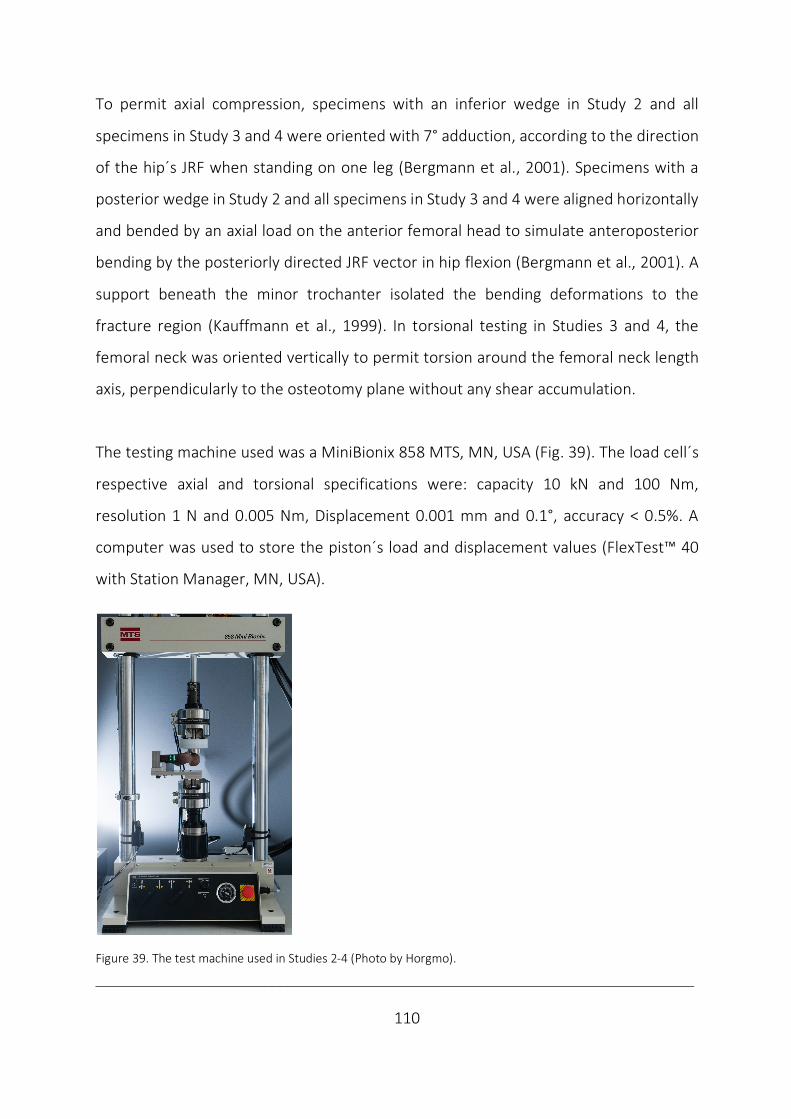
___________________________________________________________________________
110
To permit axial compression, specimens with an inferior wedge in Study 2 and all
specimens in Study 3 and 4 were oriented with 7° adduction, according to the direction
of the hip´s JRF when standing on one leg (Bergmann et al., 2001). Specimens with a
posterior wedge in Study 2 and all specimens in Study 3 and 4 were aligned horizontally
and bended by an axial load on the anterior femoral head to simulate anteroposterior
bending by the posteriorly directed JRF vector in hip flexion (Bergmann et al., 2001). A
support beneath the minor trochanter isolated the bending deformations to the
fracture region (Kauffmann et al., 1999). In torsional testing in Studies 3 and 4, the
femoral neck was oriented vertically to permit torsion around the femoral neck length
axis, perpendicularly to the osteotomy plane without any shear accumulation.
The testing machine used was a MiniBionix 858 MTS, MN, USA (Fig. 39). The load cell´s
respective axial and torsional specifications were: capacity 10 kN and 100 Nm,
resolution 1 N and 0.005 Nm, Displacement 0.001 mm and 0.1°, accuracy < 0.5%. A
computer was used to store the piston´s load and displacement values (FlexTest™ 40
with Station Manager, MN, USA).
Figure 39. The test machine used in Studies 2-4 (Photo by Horgmo).
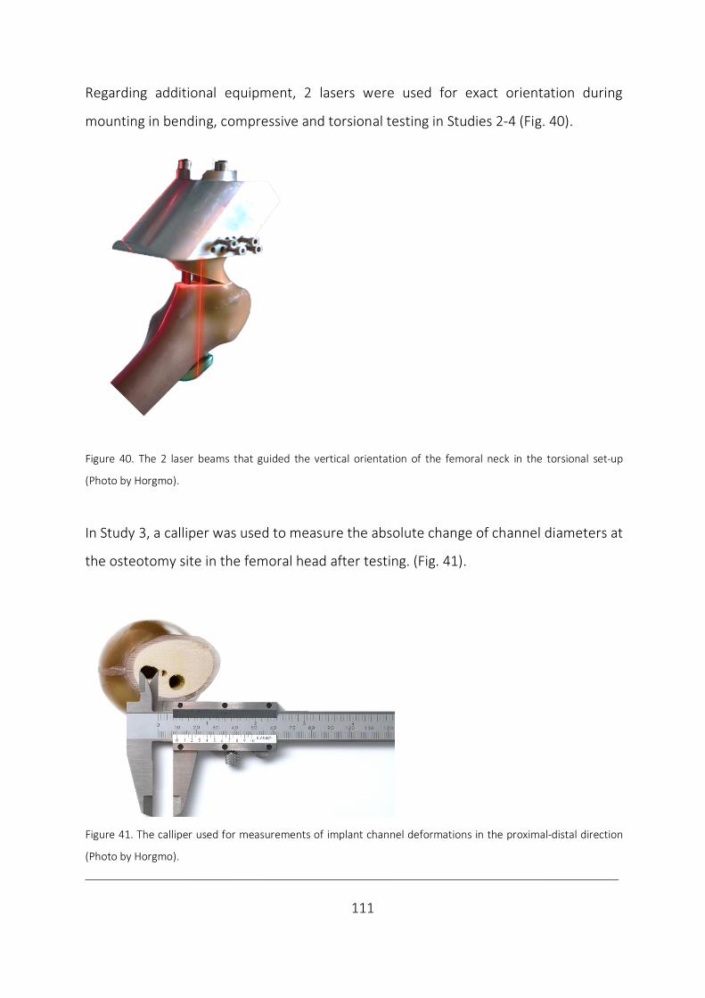
___________________________________________________________________________
111
Regarding additional equipment, 2 lasers were used for exact orientation during
mounting in bending, compressive and torsional testing in Studies 2-4 (Fig. 40).
Figure 40. The 2 laser beams that guided the vertical orientation of the femoral neck in the torsional set-up
(Photo by Horgmo).
In Study 3, a calliper was used to measure the absolute change of channel diameters at
the osteotomy site in the femoral head after testing. (Fig. 41).
Figure 41. The calliper used for measurements of implant channel deformations in the proximal-distal direction
(Photo by Horgmo).

___________________________________________________________________________
112
8.6 Tests
The studies differ regarding the magnitude of an axial compressive preload, the test
modalities of static and dynamic loading, the load magnitude of non-destructive and
destructive testing, along with the load direction inducing mainly proximal-distal
compression, anteroposterior bending and torsion both ways around the longitudinal
axis of the femoral neck.
Study 1
The axial compressive preload ensured a stabile connection and no pre-torque was
considered necessary. Quasi-static non-destructive and destructive loading were
performed. Viewed from medially, clockwise torsion of the medial block around the
longitudinal axis of the model was applied. The feed rate was 90°/min until a maximum
of 20 Nm or 90°.
Study 2
A minor axial compressive preload of 90 N was applied. Dynamic loading was performed
using a sinusoidal load pattern (rate 1 Hz; maximum compression load 1900 N;
maximum bending load 1300 N). To simulate the number of steps considered until bone
healing, 20 000 and 1000 cycles were tested in respective compression and bending
(Bergmann et al., 2001; Nowotarski et al., 2012). The loadings were based on
measurements in vivo and adapted to the estimated JRF in one-leg stance and during
sitting down of the composite bone model based on an individual of 92 kg BW
(Bergmann et al., 2001; Basso et al., 2014c).

___________________________________________________________________________
113
Study 3
A 30 N axial compressive preload was applied during the quasi-static non-destructive
tests, which were conducted 3 times each. No pre-torque was considered necessary. In
torsion, 10° rotation around the longitudinal neck axis where chosen. Rotation was
tested both ways with a linear angulation rate of 1 deg/s. Both the bending and
compressive stiffness tests were conducted with linear load control (rate, 200 N/s;
maximum bending and compression 500 N).
Non-destructive levels were chosen to allow further testing without the latter being
incriminated (Zdero et al., 2010). Dynamic testing by cyclic compression followed as in
Study 2, but the alternative of 10 000 cycles was chosen to shorten the test (Aminian et
al., 2007) (rate 1 Hz, maximum load 1900 N, preload 60 N).
Study 4
Introductory quasi-static testing by torsion (10°), bending (maximum load 200 N) and
compression (maximum load 500 N) was performed as in Study 3.
Secondly, dynamic testing by cyclic axial compression was applied with sinusoidal load
control (rate 1 Hz, cycles 20 000, maximum load 500 N, preload 60 N). This
approximated the one-time BW by partial weight-bearing with the median weight of our
donors (Koval et al., 1998) and with the number of steps considered to consolidation
(Nowotarski et al., 2012).
Thirdly, the quasi-static destructive, compressive LTF was performed using linear load
control (rate 250 N/s, maximum load 10 kN, preload 60 N) to simulate stumbling
(Bergmann et al., 2004). The specimens were loaded until failure with dissociation of
the test model or rapid actuator displacement exceeding 10 mm displacement.
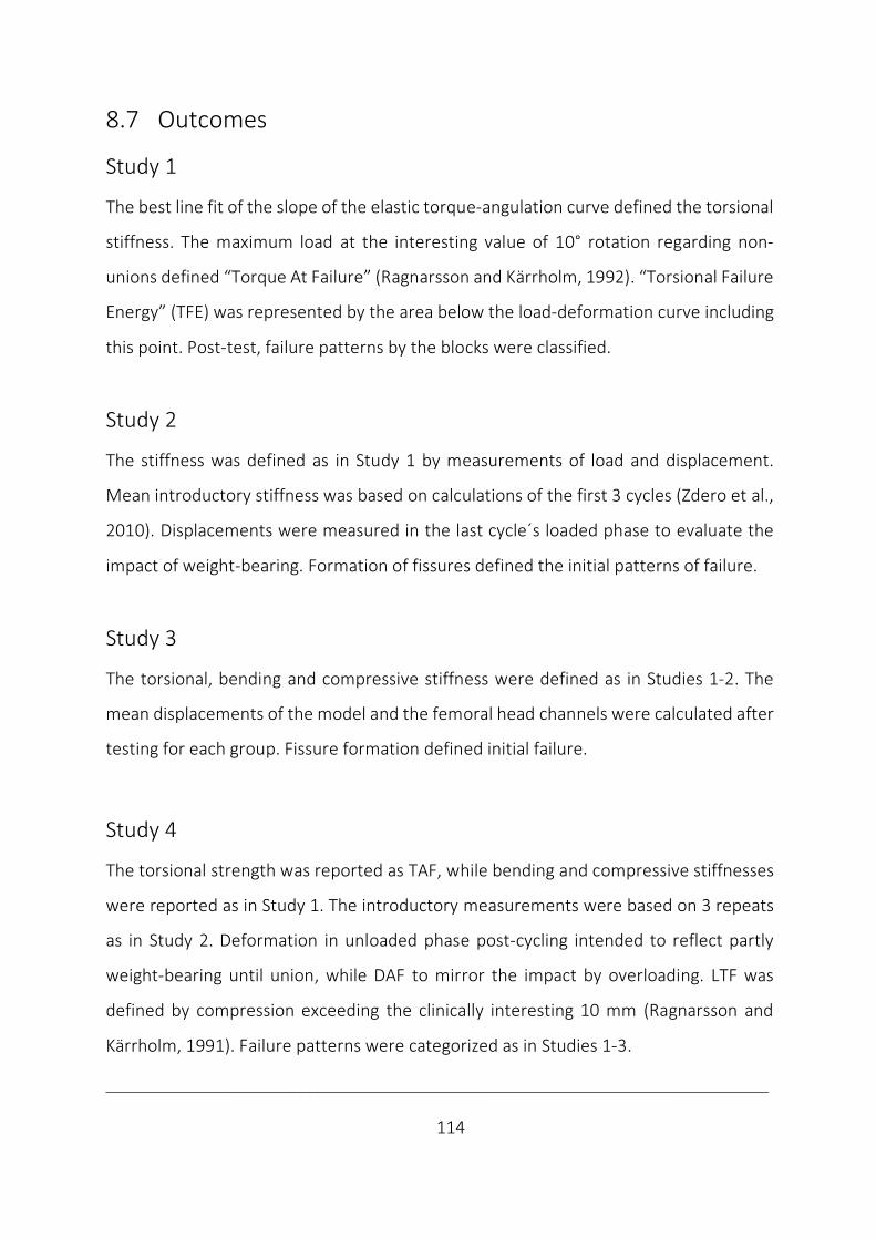
___________________________________________________________________________
114
8.7 Outcomes
Study 1
The best line fit of the slope of the elastic torque-angulation curve defined the torsional
stiffness. The maximum load at the interesting value of 10° rotation regarding non-
unions defined “Torque At Failure” (Ragnarsson and Kärrholm, 1992). “Torsional Failure
Energy” (TFE) was represented by the area below the load-deformation curve including
this point. Post-test, failure patterns by the blocks were classified.
Study 2
The stiffness was defined as in Study 1 by measurements of load and displacement.
Mean introductory stiffness was based on calculations of the first 3 cycles (Zdero et al.,
2010). Displacements were measured in the last cycle´s loaded phase to evaluate the
impact of weight-bearing. Formation of fissures defined the initial patterns of failure.
Study 3
The torsional, bending and compressive stiffness were defined as in Studies 1-2. The
mean displacements of the model and the femoral head channels were calculated after
testing for each group. Fissure formation defined initial failure.
Study 4
The torsional strength was reported as TAF, while bending and compressive stiffnesses
were reported as in Study 1. The introductory measurements were based on 3 repeats
as in Study 2. Deformation in unloaded phase post-cycling intended to reflect partly
weight-bearing until union, while DAF to mirror the impact by overloading. LTF was
defined by compression exceeding the clinically interesting 10 mm (Ragnarsson and
Kärrholm, 1991). Failure patterns were categorized as in Studies 1-3.
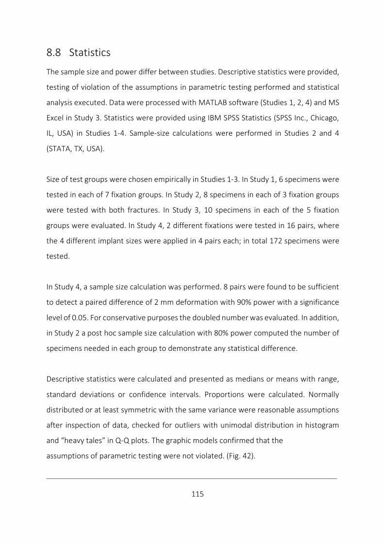
___________________________________________________________________________
115
8.8 Statistics
The sample size and power differ between studies. Descriptive statistics were provided,
testing of violation of the assumptions in parametric testing performed and statistical
analysis executed. Data were processed with MATLAB software (Studies 1, 2, 4) and MS
Excel in Study 3. Statistics were provided using IBM SPSS Statistics (SPSS Inc., Chicago,
IL, USA) in Studies 1-4. Sample-size calculations were performed in Studies 2 and 4
(STATA, TX, USA).
Size of test groups were chosen empirically in Studies 1-3. In Study 1, 6 specimens were
tested in each of 7 fixation groups. In Study 2, 8 specimens in each of 3 fixation groups
were tested with both fractures. In Study 3, 10 specimens in each of the 5 fixation
groups were evaluated. In Study 4, 2 different fixations were tested in 16 pairs, where
the 4 different implant sizes were applied in 4 pairs each; in total 172 specimens were
tested.
In Study 4, a sample size calculation was performed. 8 pairs were found to be sufficient
to detect a paired difference of 2 mm deformation with 90% power with a significance
level of 0.05. For conservative purposes the doubled number was evaluated. In addition,
in Study 2 a post hoc sample size calculation with 80% power computed the number of
specimens needed in each group to demonstrate any statistical difference.
Descriptive statistics were calculated and presented as medians or means with range,
standard deviations or confidence intervals. Proportions were calculated. Normally
distributed or at least symmetric with the same variance were reasonable assumptions
after inspection of data, checked for outliers with unimodal distribution in histogram
and “heavy tales” in Q-Q plots. The graphic models confirmed that the
assumptions of parametric testing were not violated. (Fig. 42).
___________________________________________________________________________
116
Figure 42. Representative examples of a nearly symmetric histogram and a normal Q-Q-plot in Study 4 (Illustration
by JEB).
In addition, both Shapiro-Wilk and Levene´s test of respective normality and
heterogeneity were performed with the more heterogenic human bone in Study 4.
Correspondingly, parametric tests were performed in Studies 1-4.
To analyse continuous variables, a 2-sample t-test/one-sample t-test of the difference
between groups was performed in Studies 1-3. For comparisons between paired data
the paired samples t-test was used in Study 4.
To compare continuous parameters in multiple groups, ANOVA was performed using
IBM SPSS Statistics (SPSS Inc., Chicago, IL, USA). Level of significance was set to p < 0.05.
Post hoc multiple comparisons were made by the conservative Bonferroni correction in
Studies 1-4.
To test categorical variables, computed crosstabs were tested with Fisher’s exact 2-
sided test (Studies 1-3), while McNemar´s test was used in paired data (Study 4).
A Pearson product-moment correlation was performed to determine the relationship
between variables (Studies 1-4). The correlation coefficients were interpreted as low,
moderate or high respective of size in intervals between: 0.00, 0.30, 0.50 and 1.00.
Bending stiffness Observed Values0 100 200 300 400
Freq
uenc
y
Normal___
Expe
cted
Nor
mal
2
1
0
-1
-2
-30 100 200 300 400
Histogram Q-Q plot of bending stiffness8
6
4
2

___________________________________________________________________________
117
9 Discussion
9.1 General discussion
Clinical relevance of ex vivo studies of femoral neck locking plates
In femoral neck fracture fixation, is locking plate fixation sufficiently stiff and strong
enough to permit mobilisation, without disturbing healing, causing deformation or
implant breakage? Poor correlation was found between findings of increased stability
and clinical results of locking plates in this setting. The implant and study design have
been suggested to explain the disparities ex et in vivo in a systematic review (Viberg et
al., 2017).
Locking plates differed regarding the number of screws, their orientation and
configuration (Table 1). While fixation stability by locking plates appeared to be higher
than with conventional fixation methods (Table 2), different pros and cons underlay
each locking plate, and to reach a conclusion on this fixation strategy as a group is
challenging. Locking plates not permitting fracture compression increased the risk of
overloading bone medially with resulting implant cut-out or laterally by implant fatigue
in vivo (Berkes et al., 2012; Biber et al., 2014) and identified the importance of
permitting fracture compression with femoral neck fractures also with locking plates.
This may explain the link between increased stability ex vivo and poor clinical results
(Viberg et al., 2017). Locking plates that allowed sintering may be less strong (Egol et al.,
2004), but permitting compression may increase fixation stability, reduce load-sharing
by implant and possibly promote primary healing.
The biomechanical study design itself may have increased the risk of bias in ex vivo
findings by also including partially paired studies, where 2 paired treatment where
___________________________________________________________________________
118
compared in contrast to the gold standard of paired studies of heterogenic human bone
(Aminian et al., 2007; Stoffel et al., 2017) (Table 3). Matched studies based on only BMD
by DEXA were also evaluated (Aminian et al., 2007; Samsami et al., 2016) (Table 5). By
this approach, only material strength and not structural or geometrical strength was
considered (Huiskes and Rietbergen, 2004), with an increased risk of difference
between femurs at baseline. The choice of test groups differed amongst studies. Only
comparison to the medial hold with multiple screws (Hunt et al., 2012; Basso et al.,
2014a and b; Yang et al., 2016) or the lateral hold of an SHS device (Brandt et al., 2006;
Li et al., 2006), frequently led to an insufficient evaluation of the novel locking plates´
advantages and disadvantages against the main conventional fixation groups (Table 4).
Regarding the choice of models (Table 6), only seldomly the recommended step-wise
testing of both human and synthetic bone (Hausmann, 2006) has been utilised (Brandt
et al., 2006; Hunt et al., 2012). When only one type of bone model has been evaluated,
this may reduce the expressive power of these studies (Table 11). The fracture types
also differed (Table 7) as almost all biomechanical studies on this topic evaluated
unstable fracture patterns with Pauwels type 3 with or without additional transcervical
wedges. This may have led to an underestimate of the contribution to stability by the
fracture and involve a risk of fracture-specific findings (Berkes et al., 2012). Evaluating
more stable osteotomies may also provide evidence relevant to most of the patients.
Considering test set-up, both mounting (Table 8) and testing (Table 9) varied between
studies. While biomechanical testing represents snapshots and no true hip simulator
exists, the relevance of isolated tests is questioned (Brandt et al., 2006 and 2011; Basso
et al., 2014a and b. Regarding different test modes, a prolonged test interval may come
into consideration (500 000 cycles) (Hunt et al., 2012), if fixation failure or implant
fatigue is at interest in dynamic testing. Otherwise, too few cycles may have been

___________________________________________________________________________
119
evaluated. Only the common axial compression was tested in all included studies, while
torsion around the femoral neck length axis (Li et al., 2006; Brandt et al., 2006 and 2011;
Basso et al., 2014a and b) or ante- and retroversion (Nowotarski et al., 2012) were
tested or measured in half of the studies. The recommended testing in hip flexion
(anteroposterior bending/seated position) has not been reported (Bergmann et al.,
2001; Basso et al., 2012). Despite several outcomes have been reported in each of the
studies of locking plates in this setting (Table 10), the lack of systematic testing is
illustrated by a definite biomechanical advantage by locking plates only reported after
testing in one main direction (Aminian et al., 2007) with static (Chang et al., 2004) or
dynamic loading (Brandt et al., 2006 and 2011). Improvements by locking plates ex vivo
are apparently less striking with more systematic testing in this setting. Including
biplanar loading (Nowotarski et al., 2012; Basso et al., 2014a and b) or bimodal (static
and dynamic) loading (Hunt et al., 2012; Nowotarski et al., 2012; Samsami et al., 2016)
findings are more divergent (Table 2). Not even within principally uniaxial loading the
results are categorically supportive of locking plates (Hunt et al., 2012).
Reflecting statistical analyses, a threat to the validity and accuracy of biomechanical
results are present with incorrect analysis (Knudson, 2017). Parametric testing is most
commonly performed (Table 12). While t-tests are less vulnerable to different variation
between groups than non-parametric testing, another reason to why the non-
parametric tests are less often performed (Basso et al., 2014a and b; Knobe et al., 2018),
may be the reduced power with a resulting reporting bias of prominent effects
(Skovlund, 2017). Also, a publication bias may be due to a file-drawer effect, where
journal policies tend against reporting non-significant findings. An increased acceptance
of biomechanical studies has been suggested to increase power by replicating studies
(Knudson, 2017), but whether the findings are new and interesting influence the
process of publication, which in some ways has been experienced also with this thesis.
___________________________________________________________________________
120
In brief, the lack of standardised protocols makes direct comparison between studies
and interpretation of results difficult (Basso et al., 2012) and uncertainty on
methodological quality follows (Table 13). This may have contributed to the poor
relationship between ex vivo et in vivo results of locking plate technology in this setting.
Due to the absence of stringent regulations on the introduction of orthopaedic implants,
locking plates may have been introduced after testing only in scenarios they were
invented to prevent (Brandt et al., 2011). Increased orthopaedic procedure volumes and
devices introduced without data of effectiveness, cause concern. Application of locking
plates without documenting advantages over conventional plating may be overshooting
the need. A higher level of evidence must be demanded when introducing new
technologies, as the value of an intervention or a device resides in its ability to improve
patient outcomes and reduce costs, not by its novelty (Schemitsch et al., 2010).
In the context of more strict requirements to technical documentation (EU-Regulation,
2017), a more systematic evaluation of new implants and their components in relevant
tests and bone models has been recommended (Hausmann, 2006, Schemitsch et al.,
2010; Basso et al., 2012; Hunt et al., 2012; EU regulations, 2017). A more
comprehensive comparison is more likely to reveal both strengths and possible negative
consequences of new devices. Besides preventing premature release of implants, this
approach may improve biomechanical methodology and contribute to a closure of the
knowledge gap of internal fixation of fractures of the femoral neck and improve the
relevance of ex vivo studies, where clinical findings may be explained biomechanically.
If clinical studies confirm findings of systematic ex vivo studies, the relevance of
systematic biomechanical analyses is identified. If so, the evidence level from
biomechanical studies could be argued as the cornerstone of the orthopaedic evidence
___________________________________________________________________________
121
pyramid (Schemitsch et al., 2010). Otherwise, if poor correlation to the in vivo situation
remains with findings from systematic ex vivo evaluation, ex vivo studies only defend
their role as hypothesis forming and to deliver the short-term patient safety
requirements, while the role of clinical outcome will eventually be reserved for clinical
studies.
Applying locking plates is the latest development also with this fracture. A learning curve
with increased risk of failure can be expected during implementation of a technically
more demanding method (Bjørgul et al., 2011). Concluding in a systematic review with
a poor relationship between biomechanical and clinical studies for a locking plate which
could not permit compression in femoral neck fixation by 2 reports (Aminian et al., 2007;
Nowotarski et al., 2012) may have been too simplified (Viberg et al., 2017). The
catastrophic failures with locking plates not permitting compression was actually also
detected in the preceding ex vivo study with such plates (Aminian et al., 2007; Berkes
et al., 2012). The poor correlation between ex vivo et in vivo may not apply to locking
plates which permit compression. A reduced complication and reoperation rate by use
of a modern angular stable fixation allowing dynamic compression has been reported
lately (Alshameeri et al., 2017; Yin et al., 2018). This complies well with findings of
improved biomechanics in an ex vivo study of this implant (Brandt et al., 2011).
Compared to trials of traditional devices during decades, the evidence is still too sparse
to make any definite conclusion on this topic.
In sum, a systematic ex vivo study of an optimal implant allowing sintering, may better
correspond with in vivo performance and defend ex vivo studies´ role in implant
introduction. For now, locking plates permitting sintering remain promising in femoral
neck fixation.
___________________________________________________________________________
122
9.2 Discussion of results
The implant factors
In Study 1, interlocked pins markedly increased torsional stability compared to 2 pins.
The plate itself was the most effective modification and both its shape and size were
identified as independent factors. While the plate mediated lateral enforcement, the 3rd
pin improved medial hold. As a unit, the optimum configuration of 3 interlocked pins in
one of the larger plates was identified.
In Study 2, 3 interlocked pins modestly improved bending and compressive stability
against 2 pins. While bending stability was improved by stiffness and displacement, no
difference in stiffness was followed by decreased displacement in compression. The
major improvements in bending and compressive stability were explained by the 3rd pin
itself by offloading the cervical support. In addition, lateral enforcement by the plate
offloaded the trochanteric area between pins in compression.
In Study 3, 3 interlocked pins increased torsional stability, but also bending stability,
while compressive stability was only improved by displacement following no difference
in stiffness against common fixations as a group. As a unit, interlocked pins
outperformed the medial hold in the head and neck with screws in most comparisons
and showed no benefit by the lateral hold with an SHS regarding multi-directional
stability. The mechanics of action to improve multidirectional stability, most prominent
in torsion, was mainly explained by improved 3-pointed support by the plate´s lateral
enforcement and medial anchorage in the femoral head and neck with the 3rd pin
(Studies 1-3). While no difference in compressive stiffness indicated compression along
the fracture, the subsequently reduced displacement indicated that only intermediate
dynamic compressive fracture motion was allowed with interlocked pins (Studies 2, 3).
___________________________________________________________________________
123
In Study 4, 3 interlocked pins in comparison to 2 pins, revealed increased torsional and
compressive strength, which did not come at expense of different fracture motion or
altered failure pattern, which still involved all portions of 3-pointed support. Regarding
load distribution, the plate offloaded the area between pins´ entry holes, while the 3rd
pin offloaded the cervical buttress (Studies 1-3). The increased strength by the
interlocked pins can also be indicative of improved load transfer by spreading load over
a larger area from the fragile cancellous bone medially to the solid cortical bone laterally
(Studies 1, 4), underlaying the assumed mechanism of action (Studies 1-4). Regarding
the mechanism of failure, a lateral shift of load could also be suggestive of a possible
altered failure pattern, as the trochanteric cortical area may represent a limitation to
further increase fixation strength with possible failure initiation. However, no definite
altered failure pattern or adverse effects were detected with the modified implant and
no failure pattern as with restricted fracture motion were registered (Studies 1-4).
The high impact on torsional stability complied with a more rightful comparison to a
single beam construct by interlocking pins (Egol et al., 2004). The impact by the plate
itself, both by its size and shape agreed with the considerations on the implants´ polar
moment of inertia and its results (Husby et al., 1989; Zdero et al., 2010), also with
multiple locked screws ex vivo (Brandt et al., 2011) and also by the improved medial
hold by triangular implant configurations (Parker and Stedtfeld, 2010).
In bending and compression, the importance of the 3rd pin is in correspondence with
the calculation of similar moments of inertia by triangular prism reflecting 3 pins in both
orientations, while a rectangular prism of a linear 2 pin configuration has a definite
decrease with 90° rotation from the vertical to horizontal position (Study 2).
___________________________________________________________________________
124
In compression, the 3rd pin´s impact adhere with the improved stability by triangular
screw configurations in comparisons to 2 or 3 screws in linear configurations (Selvan et
al., 2004). The additional effect by the plate is illustrated by a reduced deformation
reported as unable to resist unwanted deformation (Basso et al., 2014a and b). This may
be indicative of the role of the interlocking plate to only allow the important
intermediate compression before a stabilising impact (Hoshino and O´Toole, 2015).
The interlocked pins were designed to counteract the migrations and rotations that
occur in femoral neck fixation postoperatively (Ragnarsson and Kärrholm, 1991 and
1992) and the important posterior femoral head tilting (Palm et al., 2009). As intended
during implant design this was safely permitted without adverse effect ex vivo.
In agreement with our findings, an unpublished FEA shows increased torsional, bending
and compressive stability by stiffness and deformations with 3 interlocked pins in
comparison to 2 pins (Mellgren et al., 2010a and b). This was improved by the 3rd pin
itself and further improved by interlocking. In addition, reduced stresses at the fracture
surface and deformations in the femoral head at the expense of elevated stresses at the
boundaries of the entry hole, was interpreted as increased utilisation of lateral fixation
ability. The FEA also suggested an impact on compressive stiffness, but some
deformation was also permitted with interlocked pins (Mellgren et al., 2010b).
Our findings of increased stability, permitted fracture motion and improved load
distribution complied with implant design, basic physics, FEA and added to the
literature. In addition, we delivered the safety requirements by a failure evaluation.
Increased stability by improved 3-pointed support and load distribution were achieved
by a guarantee of pin parallelism with interlocking. This synergism safely outperformed
the common fixations and sum up the roles of pins and plates in femoral neck fixation.
___________________________________________________________________________
125
The bone factors
The simplified model of biomechanical blocks mimicking a torsional unstable mid-
cervical osteotomy with comminution (Study 1), was obviously the least stable model
followed by the replicas with semi-stable mid-cervical wedge osteotomies (Studies 2, 3).
The human pairs with compressive stable subcapital osteotomies were the most stable
(Study 4). The initial failure pattern in synthetic bone revealed cortical cracks laterally
(Study 1), laterally and medially (Study 2) and medially (Study 3), while in complete
failure testing of human bone the failure pattern involved both the lateral area and
medially in the femoral head and neck (Study 4). Only descriptive data were provided
concerning bone factors in the present study, as direct comparison was impossible due
to the set-up diversity (Table 14 and 15).
The role of fracture pattern on stability was retrieved (Pauwels, 1935), but rather by
comminution and not angulation, which were constant in our studies. Correspondingly,
the implant´s load-share and impact may have been more present in unstable fractures
in our study. A more dominant effect by the novel implant was also detected in
subcapital fractures with posterior comminution over stable osteotomies in FEA
(Mellgren et al., 2010a and b), in agreement with fixed angle fixations (Egol et al., 2004).
Our studies support the recommended 2-phased set-up (Hausmann, 2006) as we
utilised the benefits of using both models to detect a step-wise impact of the implant in
synthetic bone and reveal absolute values of possible clinical interest in human bone.
We did not perform true failure tests of synthetic bone and are unable to verify if failure
modes in synthetic bone differ (Basso et al., 2014c), as the initial failure modes evident
with both human and synthetic bone were similar. A higher fixation ability with synthetic
bone has already been reported (Basso et al., 2014c). In our studies, this may have been
neutralised by more unstable fracture patterns in artificial than in human bone.
___________________________________________________________________________
126
We argue that with the benefits of systematic testing the pros and cons of each model
are outweighed and further argumentation seems superfluous.
The test factors
The recommended systematic testing was applied in our study (Schemitsch et al., 2010;
Hunt et al., 2012; EU-Regulation, 2017). Regarding set-up, standardisation was achieved
by identical synthetic models, randomised paired cadavers and jigs for predrilling,
osteotomy and mounting. The relevant load magnitude of non-destructive and
destructive testing and loading moduli of dynamic and static conditions were conducted
within a range from simulated physiologic partial weight-bearing postoperatively to
pathologic overloading (Koval et al., 1998; Bergmann et al., 2001 and 2004; Cha et al.,
2019). Relevant load directions of torsion, bending and compression associated with
non-union were also applied (Ragnarsson and Kärrholm, 1991 and 1992; Palm et al.,
2009). A diversity of outcomes of both the elastic and plastic working range (Tencer,
2006) with evaluation of relevant failure patterns of pin twisting and iatrogenic
subtrochanteric fracture formation were evaluated (Alho et al., 1999; Kloen et al., 2003)
and compared by adequate analyses with mutual analysis of correlation (Studies 1-4).
Only descriptive data were provided concerning the test factors in the present study, as
direct comparison was impossible due to the set-up diversity (Table 14 and 15). Despite
a more systematic study, testing was not complete. No dynamic torsional stability
testing was performed and dynamic bending stability was only evaluated with semi-
stable osteotomies. Based on otherwise significant correlations between static and
dynamic stability in bending and compression (Studies 2, 3), a similar impact as in quasi-
static stability should be expected if these tests had been performed. A more distinct
impact in compressive testing reflects the effect of dynamic over initial static loading in
agreement with the importance of fatigue testing (Tencer, 2006).
___________________________________________________________________________
127
A possible load dependent factor with increased impact in compression at a high load
level is intuitive with a load-sharing implant (Studies 2-4) (Table 16). This argument is
also used to emphasize the importance of including a range of load magnitudes.
The varying values of significant correlation coefficients both within one direction and
between load directions signal that different aspects of stability were measured and
justified the multiple outcomes reported (Table 17).
In addition, the only lack of significant correlation found between initial stiffness and
final lateral failure in compression in Study 2 is suggestive of these parameters being
based on different biomechanical properties of the bone-implant construct. A significant
correlation between these parameters may be expected with an implant conveyed by a
lateral shift of load. However, the rationale of the original implant and its modification
also involved the ability to permit fracture compression. The independency between
initial stiffness and the later lateral failure pattern may be explained by the increased
stability following intermediate compression with implant modification. We have no
other explanation to this lack of correlation.
These findings emphasize the necessity of compressive evaluations to expose the
strengths and weaknesses of novel orthopaedic trauma designs by different load
directions (Bergmann et al., 2001, Basso et al., 2012), but also by different loading
modes and different outcomes. With systematic testing, a reporting bias is less likely
and methodological quality will improve. Increased statistical strength may follow
replication, which is not necessarily a weakness ex vivo (Knudson, 2017). On the
contrary, concerns of overlapping have been raised, as an undue weight may be given
due to duplication (von Elm et al., 2004).
___________________________________________________________________________
128
While several locking plates report a definite advantage in femoral neck fixation (Chang
et al., 2004; Brandt et al., 2006; Aminian et al., 2007), findings are less definite if more
systematic testing has been applied (Brandt et al., 2011; Hunt et al., 2012; Nowotarski
et al., 2012; Basso et al., 2014a and b).
To our knowledge, the current thesis is the first to demonstrate a systematically
enhanced stability of a locking plate and its components by a stepwise modification in
this setting. The systematic testing approach nuanced the definite findings of improved
stability, both regarding load level, mode and direction.
Limitations
In strategic planning of implant development, a SWOT analysis of both strengths,
weaknesses, opportunities and threats may come in handy.
The strength of our studies is the more systematic approach regarding standardisation
and comprehensive relevant testing of different bone models, fractures and fixation
methods.
The major limitations by our experimental ex vivo study are related to the biomechanical
study design. The most obvious weakness is the absence of measurements of
physiologic response as it is experienced in clinical bone healing.
Despite a more comprehensive study than previously performed, the disadvantages of
such an approach were that it was not completely systematic and may differ in reflecting
the clinical situation, both regarding the choice of bone model, fracture model and
fixation technique. The interest in our findings may further be affected by the choice of
control groups. The results of the implant modification by the comparison to its
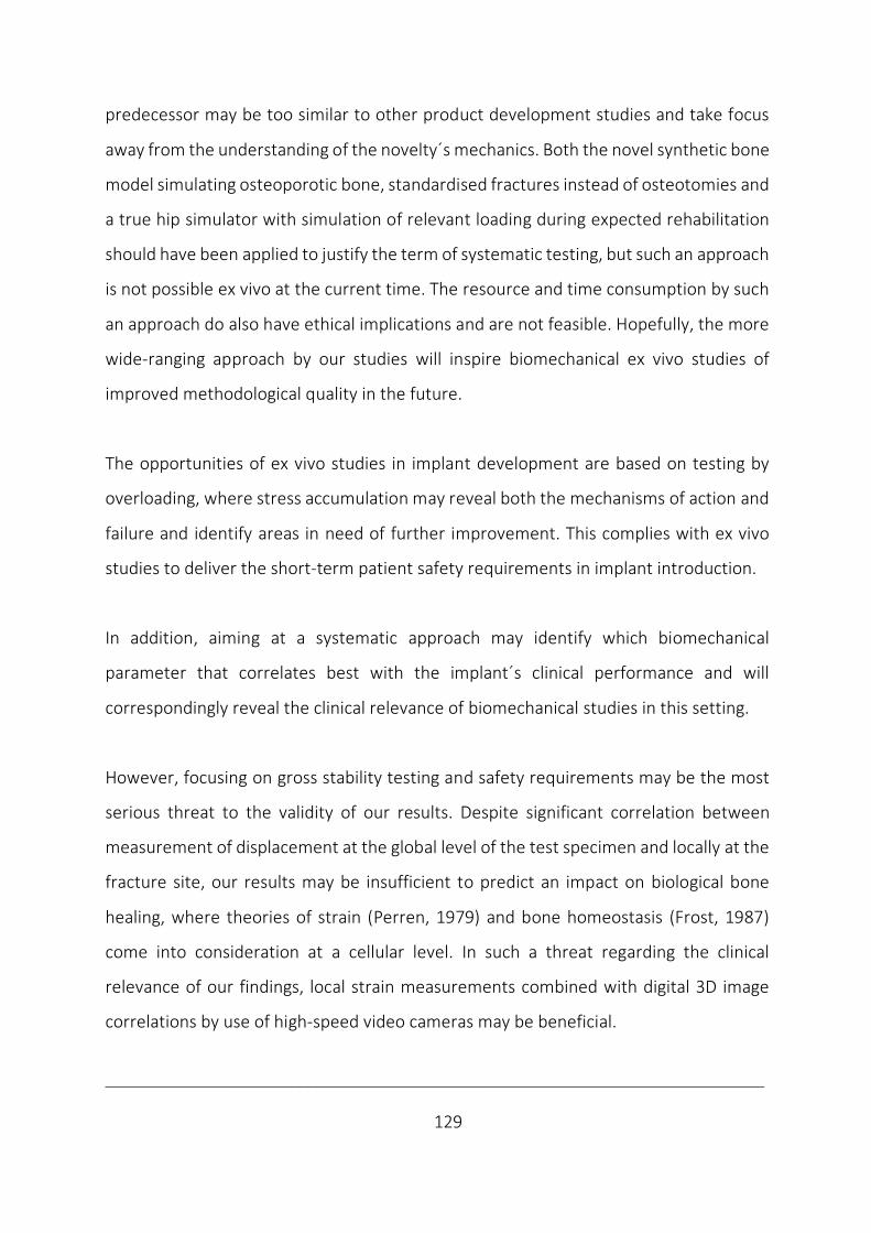
___________________________________________________________________________
129
predecessor may be too similar to other product development studies and take focus
away from the understanding of the novelty´s mechanics. Both the novel synthetic bone
model simulating osteoporotic bone, standardised fractures instead of osteotomies and
a true hip simulator with simulation of relevant loading during expected rehabilitation
should have been applied to justify the term of systematic testing, but such an approach
is not possible ex vivo at the current time. The resource and time consumption by such
an approach do also have ethical implications and are not feasible. Hopefully, the more
wide-ranging approach by our studies will inspire biomechanical ex vivo studies of
improved methodological quality in the future.
The opportunities of ex vivo studies in implant development are based on testing by
overloading, where stress accumulation may reveal both the mechanisms of action and
failure and identify areas in need of further improvement. This complies with ex vivo
studies to deliver the short-term patient safety requirements in implant introduction.
In addition, aiming at a systematic approach may identify which biomechanical
parameter that correlates best with the implant´s clinical performance and will
correspondingly reveal the clinical relevance of biomechanical studies in this setting.
However, focusing on gross stability testing and safety requirements may be the most
serious threat to the validity of our results. Despite significant correlation between
measurement of displacement at the global level of the test specimen and locally at the
fracture site, our results may be insufficient to predict an impact on biological bone
healing, where theories of strain (Perren, 1979) and bone homeostasis (Frost, 1987)
come into consideration at a cellular level. In such a threat regarding the clinical
relevance of our findings, local strain measurements combined with digital 3D image
correlations by use of high-speed video cameras may be beneficial.
___________________________________________________________________________
130
Our interpretations of the biomechanical performance by fracture motion, intermediate
dynamic compression, load distribution and initial failure patterns are affected of our
experience from clinical situations. Hence, one should be careful not to draw too firm
conclusions from the behaviour ex vivo in general, and the relevance of such findings.
A clinical study is the natural next step to further evaluate the implant´s biomechanical
performance. By use of the RSA method, stability measurements and consequences on
bone healing may be delivered after relevant clinical fixation of a genuine intracapsular
fracture of the femoral neck in human bone during rehabilitation.

___________________________________________________________________________
131
9.3 Interpretations
A definite biomechanical impact was detected by the novel Hansson Pinloc® System
with increased stability without adverse effects, but findings were nuanced in a more
comprehensive ex vivo evaluation than performed earlier in this setting.
In correspondence with our findings of short-term patient safety declarations, the safe
introduction of the novel system has been reported (Yamamoto et al., 2019). Similarly,
the safe introduction of interlocking a scalene triangular screw configuration has also
been noticed (Xiao et al., 2018) following favourable reports ex vivo (Yang et al., 2016).
Working mechanically and safely as intended, a single question remains; is it stiff enough
to increase union rates in the long term? The first RCT reported no clear advantages by
Pinloc in comparison to 2 Hansson pins regarding fixation failure and reoperation rates
during the 1st year postoperatively (Kalland et al., 2019). These findings may agree with
no significant impact by the implant modification at a lower loading level in more stable
fractures. However, concerns regarding length of follow-up time and a learning curve in
the clinical trial have been raised. In contrast, a significant positive impact on fracture
healing time, femoral neck shortening and fracture healing rate have been reported
with an interlocking plate with 3 screws in comparison with 3 cannulated screws in a
prospective evaluation (Shu et al., 2020). Before a more final conclusion can be drawn
on the interlocking fixation principle in this setting, a single surgeon RSA study
(ClinicalTrials.gov Id: NCT02699619) at our institution holds potential to reveal the
relevance of improved biomechanics on micro-motions and bone healing.
Pending clinical verification, the improved biomechanics by the novel design must be
considered a progressive development of the established hook-pins. So far, the findings

___________________________________________________________________________
132
of improved biomechanics shed light on the relation from basic physics, through the
FEA to the biomechanical ex vivo studies. The clinical relevance of our findings is not
documented beyond the interlocked pins´ safe introduction into the clinics.
This summarises the strengths and weaknesses on the novel interlocking system so far.

___________________________________________________________________________
133
10 Conclusions
No clear conclusions can be made on locking plates as the choice of implant in fixation
of intracapsular femoral neck fractures from the existing evidence within RCTs. There is
insufficient evidence to determine whether locking plate technology offers relevant
advantages in comparison to the conventional pins or screws or an SHS with a sideplate
fixed to the femur. Further studies are required to determine its role in fixation of
intracapsular fractures. So far, results are promising regarding a reduced complication
and reoperation rate with a locking plate permitting intermediate fracture sintering.
In general, physical calculations and ex vivo studies point towards increased fixation
stability with locking plate technology as the choice of fixation method. The initial clinical
cases, however, identified the necessity of allowing intermediate compression to avoid
the catastrophic complications of cut-out or implant fatigue with modern fixed-angle
devices. This may be caused by an increased load-sharing by implant in more unstable
fractures that eventually did not heal.
Regarding the interlocking fixation principle, intermediate compression is achieved by a
sideplate not fixated to the femur. The novel Hansson Pinloc® System improved relevant
stability outcomes without negative adverse effects in a more systematic biomechanical
comparison than earlier performed. These findings further support mechanical
principles to increase fixation and guide implant development.
Evidence from systematic preclinical studies delivered the required patient safety
requirements in the short-term and justified clinical implant introduction in the setting
of increased requirements to technical documentation in new regulations. Only in vivo
studies can reveal the clinical relevance of the improved biomechanics by interlocking.
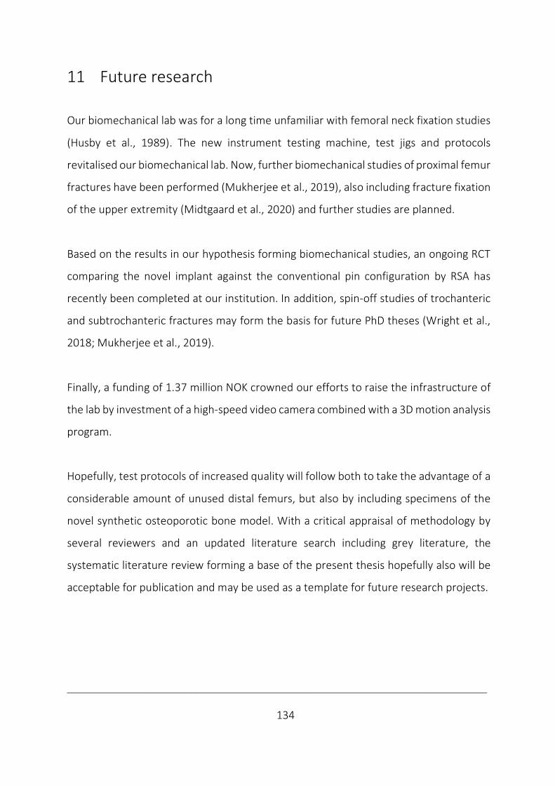
___________________________________________________________________________
134
11 Future research
Our biomechanical lab was for a long time unfamiliar with femoral neck fixation studies
(Husby et al., 1989). The new instrument testing machine, test jigs and protocols
revitalised our biomechanical lab. Now, further biomechanical studies of proximal femur
fractures have been performed (Mukherjee et al., 2019), also including fracture fixation
of the upper extremity (Midtgaard et al., 2020) and further studies are planned.
Based on the results in our hypothesis forming biomechanical studies, an ongoing RCT
comparing the novel implant against the conventional pin configuration by RSA has
recently been completed at our institution. In addition, spin-off studies of trochanteric
and subtrochanteric fractures may form the basis for future PhD theses (Wright et al.,
2018; Mukherjee et al., 2019).
Finally, a funding of 1.37 million NOK crowned our efforts to raise the infrastructure of
the lab by investment of a high-speed video camera combined with a 3D motion analysis
program.
Hopefully, test protocols of increased quality will follow both to take the advantage of a
considerable amount of unused distal femurs, but also by including specimens of the
novel synthetic osteoporotic bone model. With a critical appraisal of methodology by
several reviewers and an updated literature search including grey literature, the
systematic literature review forming a base of the present thesis hopefully also will be
acceptable for publication and may be used as a template for future research projects.

___________________________________________________________________________
135
“To be successful in orthopaedic surgery,
basic mechanical aspects in internal fixation of fractures
can never be eclipsed by new fixation devices.
In treatment of fractures & diseases of bone,
a surgeon should be a gardener, not a carpenter.”
M. Shantharam Shetty, 2017
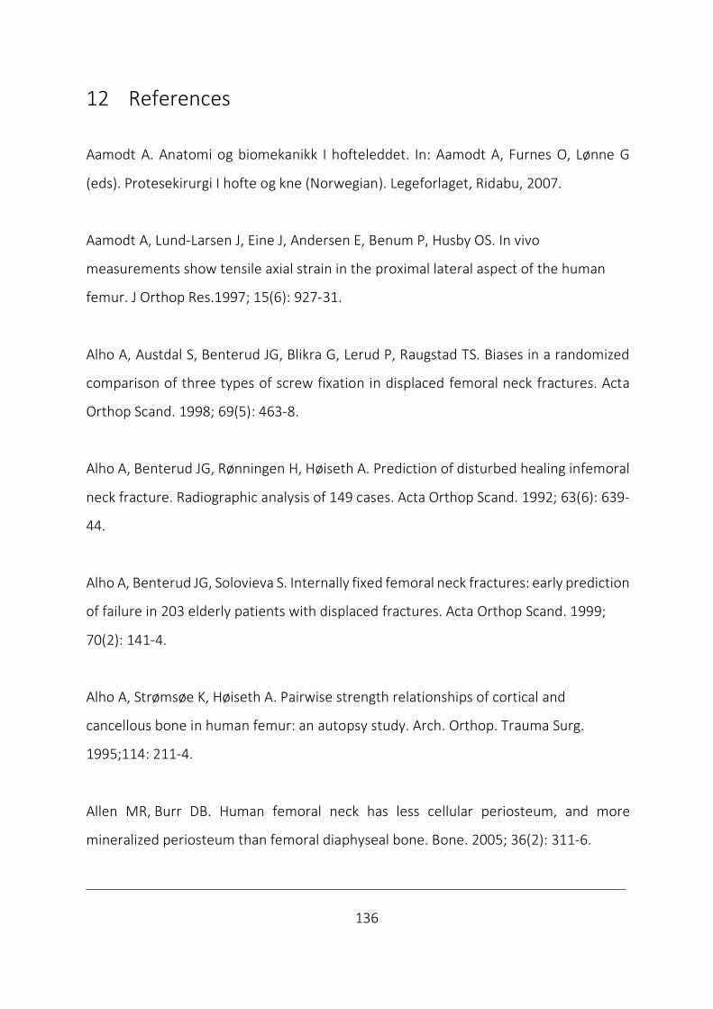
___________________________________________________________________________
136
12 References
Aamodt A. Anatomi og biomekanikk I hofteleddet. In: Aamodt A, Furnes O, Lønne G
(eds). Protesekirurgi I hofte og kne (Norwegian). Legeforlaget, Ridabu, 2007.
Aamodt A, Lund-Larsen J, Eine J, Andersen E, Benum P, Husby OS. In vivo
measurements show tensile axial strain in the proximal lateral aspect of the human
femur. J Orthop Res.1997; 15(6): 927-31.
Alho A, Austdal S, Benterud JG, Blikra G, Lerud P, Raugstad TS. Biases in a randomized
comparison of three types of screw fixation in displaced femoral neck fractures. Acta
Orthop Scand. 1998; 69(5): 463-8.
Alho A, Benterud JG, Rønningen H, Høiseth A. Prediction of disturbed healing infemoral
neck fracture. Radiographic analysis of 149 cases. Acta Orthop Scand. 1992; 63(6): 639-
44.
Alho A, Benterud JG, Solovieva S. Internally fixed femoral neck fractures: early prediction
of failure in 203 elderly patients with displaced fractures. Acta Orthop Scand. 1999;
70(2): 141-4.
Alho A, Strømsøe K, Høiseth A. Pairwise strength relationships of cortical and
cancellous bone in human femur: an autopsy study. Arch. Orthop. Trauma Surg.
1995;114: 211-4.
Allen MR, Burr DB. Human femoral neck has less cellular periosteum, and more
mineralized periosteum than femoral diaphyseal bone. Bone. 2005; 36(2): 311-6.

___________________________________________________________________________
137
Alshameeri Z, Elbashir M, Parker MJ. The outcome of intracapsular hip fracture fixation
using the Targon Femoral Neck (TFN) locking plate system or cannulated cancellous
screws: a comparative study involving 2004 patients. Injury. 2017; 48(11): 2555-62.
Aminian A, Gao F, Fedoriw WW, Zhang LQ, Kalainov DM, Merk BR. Vertically oriented
femoral neck fractures: mechanical analysis of four fixation techniques. J Orthop
Trauma. 2007; 21(8): 544-8.
Arnold WD. The effect of early weight-bearing on the stability of femoral neck fractures
treated with Knowles pins. J Bone Joint Surg Am. 1984; 66(6): 847-52.
ASTM International. Standard specifications and test methods for metallic medical bone
screws. Annual book of ASTM Standards; 2008a: 131-50.
ASTM International. Standard specification for rigid polyurethane foam for use as a
standard material for testing orthopedic devices and instruments. Annual book of ASTM
Standards; 2008b:851-6.
Augat P, Bliven E, Hackl S. Biomechanics of femoral neck fractures and implications for
fixation. J Orthop Trauma. 2019; 33 Suppl 1: S27-S32.
Augat P, Fan B, Lane NE, Lang TF, LeHir P, Lu Y, Uffmann M, Genant HK. Assessment of
bone mineral at appendicular sites in females with fractures of the proximal femur.
Bone. 1998; 22(4): 395-402.

___________________________________________________________________________
138
Backman S. Etiologic considerations. In: Backman S. The proximal end of the femur:
investigations with special reference to the etiology of femoral neck fractures;
anatomical studies, roentgen projections, theoretical stress calculations, experimental
production of fractures. Acta Radiol Suppl. 1957; (146): 43-54.
Bacon WE, Maggi S, Looker A, Harris T, Nair CR, Giaconi J, Honkanen R, Ho SC, Peffers
KA, Torring O, Gass R, Gonzalez N. International comparison of hip fracture rates in
1988-89. Osteoporos Int. 1996; 6(1): 69-75.
Baril JD, Sonstegard DA, Matthews LS. Rotational control of unstable subcapital
fractures. An experimental study. J Bone Joint Surg Am. 1975; 57(5): 613-6.
Bartels S, Gjertsen JE, Frihagen F, Rogmark C, Utvag SE. High failure rate after internal
fixation and beneficial outcome after arthroplasty in treatment of displaced femoral
neck fractures in patients between 55 and 70 years. Acta Orthop. 2018; 89(1): 53-8.
Bartonicek J. Early history of operative treatment of fractures. Arch Orthop Trauma
Surg. 2010; 130(11): 1385-96.
Bartonicek J. Proximal femur fractures: the pioneer era of 1818 to 1925. Clin Orthop
Relat Res. 2004; (419): 306-10.
Bartonicek J, Rammelt S. The history of internal fixation of proximal femur fractures. Ernst
Pohl - the genius behind. Int Orthop. 2014; 38(11): 2421-6.

___________________________________________________________________________
139
Basso T, Klaksvik J, Foss OA. Locking plates and their effects on healing conditions and
stress distribution: a femoral neck fracture study in cadavers. Clin Biomech. 2014a;
29(5): 595-8.
Basso T, Klaksvik J, Foss OA. The effect of interlocking parallel screws in subcapital
femoral-neck fracture fixation: a cadaver study. Clin Biomech. 2014b; 29(2): 213-7.
Basso T, Klaksvik J, Syversen U, Foss OA. A biomechanical comparison of composite
femurs and cadaver femurs used in experiments on operated hip fractures. J Biomech.
2014c; 47(16): 3898-902.
Basso T, Klaksvik J, Syversen U, Foss OA. Biomechanical femoral neck fracture
experiments-a narrative review. Injury. 2012; 43(10): 1633-9.
Bergmann G, Deuretzbacher G, Heller M, Graichen F, Rohlmann A, Strauss J, Duda GN.
Hip contact forces and gait patterns from routine activities. J Biomech. 2001; 34(7): 859-
71.
Bergmann G, Graichen F, Rohlmann A. Hip joint contact forces during stumbling.
Langenbecks Arch Surg. 2004; 389(1): 53-9.
Berkes MB, Little MT, Lazaro LE, Cymerman RM, Helfet DL, Lorich DG. Catastrophic
failure after open reduction internal fixation of femoral neck fractures with a novel
locking plate implant. J Orthop Trauma. 2012; 26(10): e170-6.
Bhandari M, Devereaux PJ, Tornetta P 3rd, Swiontkowski MF, Berry DJ, Haidukewych G,
Schemitsch EH, Hanson BP, Koval K, Dirschl D, Leece P, Keel M, Petrisor B, Heetveld

___________________________________________________________________________
140
M, Guyatt GH. Operative management of displaced femoral neck fractures in elderly
patients. An international survey. J Bone Joint Surg Am. 2005; 87(9): 2122–30.
Biber R, Brem M, Bail HJ. Targon femoral neck for femoral neck fracture fixation: lessons
learnt from a series of one hundred and thirty-five consecutive cases. Int Orthop. 2014;
38(3): 595-9.
Bissell JB. The treatment of fracture of the neck of the femur at Bellevue, St. Vincent's´,
and New York Hospitals. The Philadelphia Medical Journal 1903; 11: 900-3.
Bjørgul K, Novicoff WM, Saleh KJ. Learning curves in hip fracture surgery. Int Orthop
2011; 35(1): 113-9.
Björk K. Formler och tabeller för mekanisk konstruktion (Swedish), 7th ed.. Karl Björks
Förlag HB, Spånga, 2011.
Bomann-Larsen, T. Kongen. Haakon & Maud - VIII (Norwegian). Cappelen Damm AS,
Oslo, 2019.
Brandt E, Verdonschot N, van Vugt A, van Kampen A. Biomechanical analysis of the
percutaneous compression plate and sliding hip screw in intracapsular hip fractures:
experimental assessment using synthetic and cadaver bones. Injury. 2006; 37(10): 979-
83.
Brandt E, Verdonschot N, van Vugt A, van Kampen A. Biomechanical analysis of the
sliding hip screw, cannulated screws and Targonâ FN in intracapsular hip fractures in
cadaver femora. Injury. 2011; 42(2): 183-7.
___________________________________________________________________________
141
Callaghan JJ, Liu SS, Haidukewych GJ. Subcapital fractures: a changing paradigm. J Bone
Joint Surg Br. 2012; 94(11 Suppl A): 19-21.
Carlier A, van Gastel N, Geris L, Carmeliet G, Van Oosterwyck H. Size does matter: an
integrative in vivo-in silico approach for the treatment of critical size bone defects. PLoS
Comput Biol 2014; 10(11): e1003888.
Carter DR, Beaupré GS, Giori NJ, Helms JA. Mechanobiology of skeletal regeneration.
Clin Orthop Relat Res. 1998; 355 Suppl: S41-55.
Cha YH, Yoo JI, Hwang SY, Kim KJ, Kim HY, Choy WS, Hwang SC. Biomechanical evaluation
of internal fixation of Pauwels type 3 femoral neck fractures: a systematic review of
various fixation methods. Clin Orthop Surg. 2019; 11(1): 1-14.
Chang YB, Yin D, Li PY. Design and biomechanical structure evaluation of self-locking
screw plate system for femoral neck fracture. Chinese Journal of Clinical Rehabilitation.
2004;8(35):8126-8.
Chapman JR, Harrington RM, Lee KM, Anderson PA, Tencer AF, Kowalski D. Factors
affecting the pullout strength of cancellous bone screws. J Biomech Eng. 1996; 118(3):
391-8.
Charnley J (ed). Low friction arthroplasty of the hip. Springer Verlag, Berlin, 1979.
Cheung CL, Ang SB, Chadha M, Chow ES, Chung YS, Hew FL, et al. An updated hip
fracture projection in Asia: The Asian Federation of Osteoporosis Societies study.
Osteoporos Sarcopenia. 2018; 4(1): 16-21.
___________________________________________________________________________
142
Chevalley T, Guilley E, Herrmann FR, Hoffmeyer P, Rapin CH, Rizzoli R. Incidence of hip
fracture over a 10-year period (1991-2000): reversal of a secular trend. Bone. 2007;
40(5): 1284-9.
Claes LE, Heigele CA. Magnitudes of local stress and strain along bony surfaces predict
the course and type of fracture healing. J. Biomech. 1999; 32(3): 255-66.
Claes L, Recknagel S, Ignatius A. Fracture healing under healthy and inflammatory
conditions. Nat. Rev. Rheumatol. 2012; 8(3): 133-43.
Cooper AP. Fractures of the neck of the thigh-bone. In: Cooper AP, Travers B (eds).
Surgical Essays. Part II. Longman, Hurst, London. 1819: 20–54.
Compere EL, Wallace G, Lee J. Materials for internal fixation of intracapsular fracture of
the neck of the femur. Arch Surg. 1942; 44: 327-38.
Conn KS, Parker MJ. Non-displaced intracapsular hip fracture: results of internal fixation
in 375 patients. Clin. Orthop. Rel. Res. 2004; (421): 249-54.
Coventry MB. Historical review. Evolution of hip joint replacement. Curr Orthop. 1987;
1(3): 290-6.
Creswell JW. Research Design: Qualitative & quantitative approaches, SAGE
Publications, London, 1994.
Crist BD, Khalafi A, Hazelwood S J, Lee MA. A biomechanical comparison of locked plate
fixation with percutaneous insertion capability versus the angled blade plate in a
subtrochanteric fracture gap model. J Orthop Trauma. 2009; 23(9): 622-7.

___________________________________________________________________________
143
Cserháti P, Fekete K, Berglund-Rödén M, Wingstrand H, Thorngren KG. Hip fractures in
Hungary and Sweden - differences in treatment and rehabilitation. Int Orthop. 2002;
26(4): 222-8.
Dahl HA, Rinvik E. Menneskets funksjonelle anatomi (Norwegian) (3rd ed). Cappelen
Akademisk forlag AS, Oslo, 2010.
Dahlum S. Validitet (Norwegian). Store norske leksikon. 2018; https://snl.no/validitet.
Davy DT KG, Brown RH, Heiple KG, Goldberg VM, Keiple KG jr, Berilla J, Burstein AH.
Telemetric force measurements across the hip after total arthroplasty. J Bone Joint Surg
(Am). 1988; 70(1): 45-50.
DeAngelis JP. Biomechanics of femoral neck fracture fixation - a review. Tech Orthop.
2010; 25(3): 160-3.
Dequeker J, Ortner DJ, Stix AI, Cheng XG, Brys P, Boonen S. Hip fracture and osteoporosis
in a XIIth dynasty female skeleton from Lisht, Upper Egypt. J Bone Miner Res. 1997; 12(6):
881-8.
Dolatowski FC, Frihagen F, Bartels S, Opland V, Šaltytė Benth J, Talsnes O, Hoelsbrekken
SE, Utvåg SE. Screw fixation versus hemiarthroplasty for nondisplaced femoral neck
fractures in elderly patients: a multicenter randomized controlled trial. J Bone Joint Surg
Am. 2019; 101(2): 136-44.
Egol KA, Kubiak EN, Fulkerson E, Kummer FJ, Koval KJ. Biomechanics of locked plates and
screws. J Orthop Trauma. 2004; 18(8): 488-93.
___________________________________________________________________________
144
Elliott DS, Newman KJ, Forward DP, Hahn DM, Ollivere B, Kojima K, Handley R, Rossiter
ND, Wixted JJ, Smith RM, Moran CG. A unified theory of bone healing and non-union:
BHN Theory. Bone Joint J. 2016; 98-B(7): 884-91.
Emneus H (ed). Nordisk ortopedisk forening 1919-1979 (Nordic languages). Ky Printaco
Kb, Helsingfors, 1979.
Eschler A, Brandt S, Gierer P, Mittlmeier T, Gradl G. Angular stable multiple screw
fixation (Targon FN) versus standard SHS for the fixation of femoral neck fractures.
Injury. 2014; 45: S76-S80.
FAITH Investigators. Fracture fixation in the operative management of hip fractures
(FAITH): an international, multicentre, randomised controlled trial. Lancet.
2017; 389: 1519-27.
Filipov O, Gueorguiev B. Unique stability of femoral neck fractures treated with the
novel biplane double-supported screw fixation method: a biomechanical cadaver study.
Injury. 2015; 46(2): 218-26.
Finsen V. Benum P. Changing incidence of hip fractures in rural and urban areas of
central Norway. Clin Orthop Relat Res. 1987; 218: 104-10.
Fleming A. On the antibacterial action of cultures of a penicillium, with special
reference to their use in the isolation of b. influenzæ. Br J Exp Pathol. 1929; 10(3):
226-36.
___________________________________________________________________________
145
Floyd JC, O’Toole RV, Stall A, Forward DP, Nabili M, Shillingburg D, Hsieh A, Nascone JW.
Biomechanical comparison of proximal locking plates and blade plates for the treatment
of comminuted subtrochanteric femoral fractures. J Orthop Trauma. 2009; 23(9): 628-
33.
Frihagen F. Nordsletten L. Madsen JE. Hemiarthroplasty or internal fixation for
intracapsular displaced femoral neck fractures: randomised controlled trial. BMJ. 2007;
335: 1251-4.
Frost HM. Bone “mass” and the “mechanostat”: a proposal. Anat Rec. 1987; 219(1): 1-
9.
Garden RS. Low-angle fixation in fractures of the femoral neck. J Bone Joint Surg
Br. 1961; 43: 647–63.
Gardner MP, Chong AC, Pollock AG, Wooley PH. Mechanical evaluation of large-size
fourth-generation composite femur and tibia models. Ann Biomed Eng. 2010; 38(3):
613-20.
Ghiasi MS, Chen J, Vaziri A, Rodriguez EK, Nazarian A. Bone fracture healing in
mechanobiological modeling: a review of principles and methods. Bone Rep. 2017; 6:
87-100.
Giordano V, Alves DD, Paes RP, Amaral AB, Giordano M, Belangero W, Freitas A, Koch
HA, do Amaral NP. The role of the medial plate for Pauwels type III femoral neck
fracture: a comparative mechanical study using two fixations with cannulated screws. J
Exp Orthop. 2019; 6(1): 18.
___________________________________________________________________________
146
Gjertsen JE, Engesæter LB, Furnes O, Havelin LI, Steindal K, Vinje T, Fevang JM. The
Norwegian Hip Fracture Register: experiences after the first 2 years and 15,576 reported
operations. Acta Orthop. 2008; 79(5): 583-93.
Gjertsen JE, Fevang JM, Matre K, Vinje T, Engesæter LB. Clinical outcome after non-
displaced femoral neck fractures. Acta Orthop. 2011; 82(3): 268-74.
Gjertsen JE, Dybvik E, Kvamsdal L, Kvinnesland I. The Norwegian Hip fracture Register.
Annual report 2019. ISBN: 978-82-91847-24-5. ISSN: 1893-8914. Bergen, 2019.
Gjertsen JE, Lie SA, Fevang JM, Havelin LI, Engesæter LB, Vinje T, Furnes O. Total hip
replacement after femoral neck fractures in elderly patients. Results of 8,577 fractures
reported to the Norwegian Arthroplasty Register. Acta Orthop. 2007; 78(4): 491-7.
Gjertsen JE, Vinje T, Engesæter LB, Lie SA, Havelin LI, Furnes O, Fevang JM. Internal
screw fixation compared with bipolar hemiarthroplasty for treatment of displaced
femoral neck fractures in elderly patients. J Bone Joint Surg Am. 2010; 92(3): 619-28.
Goldhahn J, Suhm N, Goldhahn S, Blauth M, Hanson B. Influence of osteoporosis on
fracture fixation - a systematic literature review. Osteoporos Int. 2008; 19(6): 761-72.
Gosiewski JD, Holsgrove TP, Gill HS. The efficacy of rotational control designs in
promoting torsional stability of hip fracture fixation. Bone Joint Res. 2017; 6: 270-6.
Grassi L, Isaksson H. Extracting accurate strain measurements in bone mechanics: A
critical review of current methods. J Mech Behav Biomed Mater. 2015; 50: 43-54.
___________________________________________________________________________
147
Green E, Lubahn JD, Evans J. Risk factors, treatment and outcomes associated with
nonunion of the midshaft humerus fracture. J Surg Orthop Adv. 2005; 14(2): 64-72.
Gullberg B, Johnell O, Kanis JA. World-wide projections for hip fracture. Osteoporos Int.
1997; 7(5): 407-13.
Gurusamy K, Parker MJ, Rowlands TK. The complications of displaced intracapsular
fractures of the hip: the effect of screw positioning and angulation on fracture healing.
J Bone Joint Surg Br. 2005; 87(5): 632-4.
Haleem S, Heinert G, Parker MJ. Pressure sores and hip fractures. Injury. 2008; 39(2):
219-23.
Haleem S, Lutchman L, Mayahi R, Grice JE, Parker MJ. Mortality following hip fracture:
trends and geographical variations over the last 40 years. Injury. 2008; 39(10):1157-63.
Hall SE, Williams JA, Senior JA, Goldswain PRT, Criddle RA. Hip fracture outcomes: quality
of life and functional status in older adults living in the community. Austr N Z J
Med. 2000; 30(3):327-32.
Handoll HHG, Parker MJ. Conservative versus operative treatment for hip fractures in
adults. Cochrane Database Syst Rev. 2008; 3: CD000337.
Handoll HHG, Queally JM, Parker MJ. Pre-operative traction for hip fractures in adults.
Cochrane Database Syst Rev. 2011;12: CD000168.
___________________________________________________________________________
148
Hansson LI. Osteosynthesis with the hook-pin in slipped capital femoral epiphysis. Acta
Orthop Scand. 1982; 53(1): 87-96.
Harmon PH, Baker DR, Reno JH. Experiments on the holding powers of various types of
metallic internal fixation for transcervical fractures of the femur. Am J Surg. 1948; 76:
515-24.
Hausmann JT. Sawbones in biomechanical settings - a review. Osteo Trauma Care 2006;
14(4): 259-64.
Hawks MA, Kim H, Strauss JE, Oliphant BW, Golden RD, Hsieh AH, Nascone JW, O'Toole
RV. Does a trochanteric lag screw improve fixation of vertically oriented femoral neck
fractures? A biomechanical analysis in cadaveric bone. Clin Biomech. 2013; 28(8): 886-
91.
HEALTH Investigators. Total Hip Arthroplasty or Hemiarthroplasty for Hip Fracture. N Engl J
Med. 2019; 381:2199-2208.
Heetveld MJ, Raaymakers EL, Luitse JS, Gouma DJ. Rating of internal fixation and clinical
outcome in displaced femoral neck fractures: a prospective multicenter study. Clin
Orthop Relat Res. 2007; 454: 207-13.
Heetveld MJ, Rogmark C, Frihagen F, Keating J. Internal fixation versus arthroplasty for
displaced femoral neck fractures: what is the evidence? J Orthop Trauma. 2009; 23(6):
395-402.
Heiner AD. Structural properties of fourth-generation composite femurs and tibias. J
Biomech. 2008; 41(15): 3282-4.
___________________________________________________________________________
149
Hernefalk L, Messner K. Femoral stiffness after osteosynthesis of a subcapital osteotomy
in osteoporotic bone: an in-vitro comparison of nine fixation methods. J Orthop Trauma.
1995; 9: 464-9.
Higgins and Green (eds). The Cochrane Handbook for Systematic Reviews of
Interventions Section 8.5, 2011.
Holmes CA, Edwards WT, Myers ER, Lewallen DG, White AA 3rd, Hayes WC.
Biomechanics of pin and screw fixation of femoral neck fractures. J Orthop Trauma.
1993; 7(3): 242-7.
Holzer G, von Skrbensky G, Holzer LA, Pichl W. Hip fractures and the contribution of
cortical versus trabecular bone to femoral neck strength. J Bone Miner Res.
2009;24(3):468-74.
Hoshino CM, O'Toole RV. Fixed-angle devices versus multiple cancellous screws: what
does the evidence tell us? Injury. 2015; 46(3):474-7.
Hunt S, Martin R, Woolridge B. Fatigue testing of a new locking plate for hip fractures.
J Med Biol Eng. 2012;32(2):117-22.
Huiskes R, Rietbergen B van. Biomechanics of Bone. In: Mow VC, Huiskes R (eds). Basic
Orthopaedic Biomechanics and Mechanobiology, 3rd ed.. Lippingcott Williams &
Wilkins, Philadelphia, 2004.
Husby T, Alho A, Rønningen H. Stability of femoral neck osteosynthesis. Comparison of
fixation methods in cadavers. Acta Orthop Scand. 1989; 60(3): 299-302.

___________________________________________________________________________
150
ISO 7206-4: 2002(E), Implants for surgery–partial and total hip joint prosthesis, part 4:
determination of endurance properties of stemmed femoral components.
International Organization for Standardization, Geneva, 2002.
Jacob HAC, Huggler AH, Rüttimann B. In-vivo investigations on the mechanical function
of the tractus iliotibialis. In: Huiskes R., van Campen D.H., de Wijn J.R. (eds)
Biomechanics: Principles and Applications. Developments in Biomechanics, vol 1.
Springer, Dordrecht, 1982.
Jafarov A, Elibol F, Alizadeh C, Gülşen M, Toğrul E, Demir T. Perforated H-beam implant
can be used in femoral neck fracture. Proc Inst Mech Eng H. 2019; 233; 3: 354-61.
Jensen JS. Tøndevold. Mortality after hip fractures. Acta Orthop Scand. 1979; 50(2): 161-
7.
Johnell O, Gullberg B, Allander E, Kanis JA. The apparent incidence of hip fracture in
Europe: a study of national register sources. Osteoporos Int. 1992; 2(6): 298-302.
Judet J, Judet R. The use of an artificial femoral head for arthroplasty of the hip joint.
J Bone Joint Surg Br. 1950; 32B: 166-73.
Kalland K, Åberg H, Berggren A, Ullman M, Snellman G, Jonsson KB, Johansson T. Similar
outcome of femoral neck fractures treated with Pinloc or Hansson Pins: 1-year data
from a multicenter randomized clinical study on 439 patients, Acta Orthop. 2019; 27: 1-
5.

___________________________________________________________________________
151
Kannus P, Niemi S, Parkkari J, Palvanen M, Vuori I, Jarvinen M. Hip fractures in Finland
between 1970 and 1997 and predictions for the future. Lancet. 1999; 353: 802-5.
Kauffman JI, Simon JA, Kummer FJ, Pearlman CJ, Zuckerman JD, Koval KJ. Internal
fixation of femoral neck fractures with posterior comminution: a biomechanical study. J
Orthop Trauma. 1999; 13: 155-9.
Kazár G, Manninger J. Historical retrospection. in: Manninger J, Bosch U, Cserháti P,
Fekete K, Kazár G (eds). Internal fixation of femoral neck fractures. An Atlas. Wien,
Springer-Verlag, 2007.
Kazley JM, Banerjee S, Abousayed MM, Rosenbaum AJ. Classifications in brief: Garden
classification of femoral neck fractures. Clin Orthop Relat Res. 2018; 476(2): 441-5.
Kehinde A, Oluropo AS, Festus OA, Akinlabi E, Emagbetere E. Mechanical strength and
biocompatibility properties of materials for bone internal fixation: a brief overview.
Proceedings of the International Conference on Industrial Engineering and
Operations Management. 2018; 2115-26.
Khan SK, Khanna A, Parker MJ. Posterior multifragmentation of the femoral neck: does
it portend a poor outcome in internally fixed intracapsular hip fractures? Injury. 2009;
40(3): 280-2.
Klenerman L, Marcuson RW. Intracapsular fractures of the neck of the femur. J Bone
Joint Surg Br. 1970; 52(3): 514-7.
___________________________________________________________________________
152
Kloen P, Rubel IF, Lyden JP, Helfet DL. Subtrochanteric fracture after cannulated screw
fixation of femoral neck fractures: A report of four cases. J Orthop Trauma. 2003; 17(3):
225-9.
Kotzar GM, Davy DT, Berilla J, Goldberg VM. Torsional loads in the early postoperative
period following total hip replacement. J Orthop Res. 1995; 13(6): 945-55.
Knobe M, Altgassen S, Maier KJ, Gradl-Dietsch G, Kaczmarek C, Nebelung S, Klos K, Kim
BS, Gueorguiev B, Horst K, Buecking B. Screw-blade fixation systems in Pauwels three
femoral neck fractures: a biomechanical evaluation. Int Orthop. 2018; 42(2): 409-18.
Knudson D. Confidence crisis of results in biomechanics research. Sports Biomech.
2017;16(4):425-33.
Koval KJ, Sala DA, Kummer FJ, Zuckerman JD. Postoperative weight-bearing after a fracture of
the femoral neck or an intertrochanteric fracture. J Bone Joint Surg Am. 1998; 80(3): 352-6.
Koval KJ, Skovron ML, Aharonoff GB, Meadows SE, Zuckerman JD. Ambulatory ability
after hip fracture. A prospective study in geriatric patients. Clin Orthop Relat Res. 1995;
310: 150-9.
Lacroix D, Prendergast PJ, Li G, Marsh D. Biomechanical model to simulate tissue
differentiation and bone regeneration: application to fracture healing. Med Biol Eng
Comput. 2002; 40(1): 14-21.
___________________________________________________________________________
153
Lagerby M, Asplund S, Ringqvist I. Cannulated screws for fixation of femoral neck
fractures: No difference between Uppsala screws and Richards screws in a randomized
prospective study of 268 cases. Acta Orthop Scand. 1998;69(4):387-91.
Lawrence VA, Hilsenbeck SG, Noveck H, Poses RM, Carson JL. Medical complications and
outcomes after hip fracture repair. Arch Intern Med. 2002; 162(18): 2053-7.
Leicher I, Margulies JY, Weinreb A, Mizrahi J, Robin GC, Conforty B, Makin M, Bloch B.
The relationship between bone density, mineral content, and mechanical strength in
the femoral neck. Clin Orthop Rel Res. 1982; 163: 272-81.
Leighton RK. Fractures of the neck of the femur. In: Buchholz RW, Heckman JD, Court-
Brown C (eds). Rockwood and Green’s fractures in adults, 6th ed.. Lippincott Williams &
Wilkins, Philadelphia, 2006.
Leonardsson O, Rolfson O, Hommel A, Garellick G, Åkesson K, Rogmark C. Patient-
reported outcome after displaced femoral neck fracture: a national survey of 4467
patients. J Bone Joint Surg Am. 2013; 95(18): 1693-9.
Li B, Webster TJ. Bacteria antibiotic resistance: new challenges and opportunities for
implant-associated orthopedic infections. J Orthop Res. 2018; 36(1): 22-32.
Li G-C, Li K-H, Wei B, Liang J-Y. Biomechanical comparison of static three-dimensional
screwplate system and dynamic hip screw in fixing unstable femoral neck fracture.
Chinese Journal of Clinical Rehabilitation. 2006; 10(41): 93-7.

___________________________________________________________________________
154
Liberati A, Altman DG, Tetzlaff J, Mulrow C, Gøtzsche PC, Ioannidis JPA, Clarke M,
Devereaux PJ, Kleijnen J, Moher D. The PRISMA Statement for reporting systematic
reviews and meta-analyses of studies that evaluate health care Interventions:
explanation and elaboration. PLOS Medicine. 2009; 6(7): e1000100.
Lindequist S, Wredmark T, Eriksson SA, Samnegård E. Screw positions in femoral neck
fractures: comparison of two different screw positions in cadavers. Acta Orthop Scand.
1993; 64(1): 67-70.
Lindequist S, Törnkvist H. Quality of reduction and cortical screw support in femoral
neck fractures: an analysis of 72 fractures with a new computerized measuring method.
J Orthop Trauma. 1995; 9(3): 215-21.
Lindner T, Kanakaris NK, Marx B, Cockbain A, Kontakis G, Giannoudis PV. Fractures of
the hip and osteoporosis: the role of bone substitutes. J Bone Joint Surg Br. 2009; 91(3):
294-303.
Lofthus CM, Osnes EK, Falch JA, Kaastad TS, Kristiansen IS, Nordsletten L, Stensvold I,
Meyer HE. Epidemiology of hip fractures in Oslo, Norway. Bone. 2001; 29(5): 413-8.
Lowe J, Anderson PG. Musculoskeletal system. In: Lowe J, Anderson PG (eds). Stevens &
Lowe's Human Histology. 4th ed., Mosby Ltd., Maryland Heights, MO, 2015.
Lundström M, Edlund A, Bucht G, Karlsson S, Gustafson Y. Dementia after delirium in
patients with femoral neck fractures. J Am Geriatr Soc. 2003; 51(7): 1002-6.
Luo CF. Reference axes for reconstruction of the knee. Knee. 2004; 11(4): 251-7.
___________________________________________________________________________
155
Lu-Yao GL, Keller RB, Littenberg B, Wennberg JE. Outcome after displaced fracture of
the femoral neck: a meta-analysis of one hundred and six published reports. J Bone Joint
Surg Am. 1994; 76A: 15-25.
Ly TV, Swiontkowski MF. Treatment of femoral neck fractures in young adults. J Bone
Joint Surg Am 2008; 90(10): 2254-66.
Lydersen S. Statistical power: before, but not after! Tidsskr Nor Legeforen. 2019; 139(2).
Lykke N, Lerud PJ, Strømsøe K, Thorngren KG. Fixation of fracture of the femoral neck.
A prospective, randomised trial of three Ullevaal hip screws versus two Hansson hook-
pins. J Bone Joint Surg Br. 2003; 85(3):426–30.
Lönnroos E, Kautiainen H, Karppi P, Huusko T, Hartikainen S, Kiviranta I, Sulkava
R. Increased incidence of hip fractures. A population based-study in Finland. Bone.
2006; 39(3): 623-7.
Macintyre NJ, Lorbergs AL. Imaging-based methods for non-invasive assessment of
bone properties influenced by mechanical loading. Physiother Can. 2012; 64(2):202-
15.
Malchau H, Herberts P, Eisler T, Garellick G, Söderman P. The Swedish total hip
replacement register. J Bone Joint Surg Am. 2002; 84A Suppl 2: 2-20.
Malchau H, Bragdon CR, Muratoglu OK. The stepwise introduction of innovation into
orthopedic surgery: the next level of dilemmas. J Arthroplasty. 2011; 26(6): 825-31.
___________________________________________________________________________
156
Marenzana M, Arnett TR. The key role of the blood supply to bone. Bone Res. 2013; 1(3):
203-15.
Marsell R, Einhorn TA. The biology of fracture healing. Injury. 2011; 42(6): 551-5.
Marshall D, Johnell O, Wedel H. Meta-analysis of how well measures of bone mineral
density predict occurrence of osteoporotic fractures. BMJ. 1996; 312(7041): 1254-9.
Martin RB, Burr DB, Sharkey NA. Skeletal biology. In: Martin RB. Burr DB, Sharkey NA
(eds). Skeletal tissue mechanics. Springer, New York. 1998: 29–78.
McLeish RD, Charnley J. Abduction forces in the one-legged stance. J Biomech. 1970;
3(2): 191-209.
Meinberg EG, Agel J, Roberts CS, Karam MD, Kellam JF. Fracture and dislocation
classification compendium 2018. J Orthop Trauma. 2018; 32(S1): S33-6.
Mellgren M, Larsson B, Theodorsson J. Technical Report: Torsional rigidity of Hansson's
Pin loc System for femoral neck fracture. XDIN develop and deliver. 2010a (white paper).
Mellgren M, Larsson B, Theodorsson J. Technical Report: Analysis of Hansson's Pin loc
System for femoral neck fracture. XDIN develop and deliver. 2010b (white paper).
Meyer HE, Lofthus CM, Søgaard AJ, Falch JA. Change in the use of hormone replacement
therapy and the incidence of fracture in Oslo. Osteoporos Int. 2009; 20(5): 827-30.
___________________________________________________________________________
157
Midtgaard K, Søreide E, Brattgjerd JE, Moatshe G, Madsen JE, Flugsrud GB.
Biomechanical comparison of tension band wiring and plate fixation with locking screws
in transvers olecranon fractures. J Shoulder Elbow. 2020; Published online March 2.
Mir H, Collinge C. Application of a medial buttress plate may prevent many treatment
failures seen after fixation of vertical femoral neck fractures in young adults. Med
Hypotheses. 2015; 84(5): 429-33.
Moher D, Liberati A, Tetzlaff J, Altman DG; PRISMA Group. Preferred reporting items
for systematic reviews and meta-analyses: the PRISMA statement. PLoS Med. 2009;
6(7): e1000097.
Moore AT. The self-locking metal hip prosthesis. J Bone Joint Surg Am. 1957; 39A(4):
811-27.
Mukherjee P, Brattgjerd JE, Niratisairak S, Nilssen JR, Strømsøe K, Steen H.
The stabilising effect by a novel cable cerclage configuration in long cephalomedullary
nailing of subtrochanteric fractures with a posteromedial wedge. Clin Biomech. 2019;
(68): 1-7.
National Institutes of Health. Consensus Development Program. Osteoporosis
prevention, diagnosis and therapy. NIH Consens Statement. 2000; 17(1): 1-36.
Mow VC, Huiskes. A brief history of science and orthopaedic biomechanics. In: Mow VC,
Huiskes R (eds). Basic Orthopaedic Biomechanics and Mechanobiology, 3rd ed..
Lippingcott Williams & Wilkins, Philadelphia, 2004.
___________________________________________________________________________
158
Nicolaysen J. Lidt om Diagnosen og Behandlingen af Fr. colli femoris (Norwegian). Nord
Med Arch. 1897; 16: 1-23.
Nicolaysen J. Om lårhalsfrakturens behandling med nagling (Norwegian). Nord Med
Arch. 1899; 29: 1-13.
Noble PC, Alexander JW, Lindahl LJ, Yew DT, Granberry WM, Tullos HS. The anatomic
basis of femoral component design. Clin Orthop Relat Res. 1988; 235: 148-65.
Nordin M, Frankel VH. Biomechanics of bone. In: Nordin M, Frankel VH. Basic
Biomechanics of the Musculoskeletal System, 4th ed.. Wolters Kluwer, Lippincott
Williams and Wilkins, Philadelphia, 2012.
Nowotarski PJ, Ervin B, Weatherby B, Pettit J, Goulet R, Norris B. Biomechanical analysis
of a novel femoral neck locking plate for treatment of vertical shear Pauwel's type C
femoral neck fractures. Injury. 2012; 43(6): 802-6.
Nymark T. Lauritsen JM. Ovesen O. Röck ND. Jeune B. Decreasing incidence of hip
fracture in the Funen County, Denmark. Acta Orthop. 2006; 77(1): 109-13.
O´Neill F, Condon F, McGloughlin T, Lenehan B, Coffey C, Walsh M. Validity of synthetic
bone as a substitute for osteoporotic cadaveric femoral heads in mechanical testing. A
biomechanical study. Bone Joint Res. 2012; 1(4): 50–55.
Oakey JW, Stover MD, Summers HD, Sartori M, Havey RM, Patwardhan AG. Does screw
configuration affect subtrochanteric fracture after femoral neck fixation? Clin Orthop
Relat Res. 2006; 443: 302-6.
___________________________________________________________________________
159
Oden A, Dawson A, Dere W, Johnell O, Jonsson B, Kanis JA. Lifetime risk of hip fractures
is underestimated. Osteoporos Int. 1998; 8(6):599-603.
Ostrum RF, Tornetta P 3rd, Watson JT, Christiano A, Vafek E. Ipsilateral proximal
femur and shaft fractures treated with hip screws and a reamed retrograde
intramedullary nail. Clin Orthop Relat Res. 2014; 472(9): 2751-8.
Palm H, Gosvig K, Krasheninnikoff M, Jacobsen S, Gebuhr P. A new measurement for
posterior tilt predicts reoperation in non-displaced femoral neck fractures: 113
consecutive patients treated by internal fixation and followed for 1 year. Acta Orthop.
2009; 80(3): 303-7.
Parker MJ, Banerjee A. Surgical approaches and ancillary techniques for internal fixation of
intracapsular proximal femoral fractures. Cochrane Database Syst Rev 2005; 2: CD001705.
Parker MJ, Gurusamy KS. Internal fixation implants for intracapsular hip fractures in
adults. Cochrane Database Syst Rev. 2001; 4: CD001467.
Parker MJ, Gurusamy KS. Internal fixation versus arthroplasty for intracapsular
proximal femoral fractures in adults. Cochrane Database of Syst Rev. 2006; 4:
CD001708.
Parker MJ. Parallel Garden screws for intracapsular femoral fractures. Injury. 1994;
25(6): 383-5.

___________________________________________________________________________
160
Parker MJ, Porter KM, Eastwood DM, Schembi Wismayer M, Bernard AA. Intracapsular
fractures of the neck of femur. Parallel or crossed garden screws? J Bone Joint Surg
Br. 1991; 73(5): 826-7.
Parker MJ, Pryor GA. Hip fracture management. Blackwell Scientific Publications,
Oxford, 1993.
Parker MJ, Stedtfeld HW. Internal fixation of intracapsular hip fractures with a dynamic
locking plate: initial experience and results for 83 patients treated with a new implant.
Injury 2010; 41(4): 348-51.
Pauwels F. Der Schenkelhalsbruch ein mechanisches Problem (German). Stuttgart,
Germany: Ferdinand Enke, 1935.
Perren SM. Physical and biological aspects of fracture healing with special reference to
internal fixation. Clin Orthop Relat Res. 1979; 138:175-96.
Petrie A. Statistics in orthopaedic papers. J Bone Joint Surg Br. 2006; 88(9): 1121-36.
Raaymakers EL, Marti RK. Non-operative treatment of impacted femoral neck fractures.
A prospective study of 170 cases. J Bone Joint Surg Br. 1991; 73(6): 950-4.
Ragnarsson JI, Boquist L, Ekelund L, Kärrholm J. Instability and femoral head vitality in
fractures of the femoral neck. Clin Orthop Relat Res. 1993; 287: 30-40.
Ragnarsson JI, Kärrholm J. Factors influencing postoperative movement in displaced
femoral neck fractures: evaluation by conventional radiography and stereoradiography.
J Orthop Trauma. 1992; 6(2): 152-8.
___________________________________________________________________________
161
Ragnarsson JI, Kärrholm J. Stability of femoral neck fracture. roentgen
stereophotogrammetry of 29 hook-pinned fractures. Acta Orthop Scand. 1991; 62(3):
201-7.
Regazzoni P, Rüedi T, Winquist R, Allgöwer M. The dynamic hip screw implant system.
Springer, Berlin, 1985.
Regulation (EU) 2017/745 of the European Parliament and of the Council of 5 April 2017
on medical devices. Official Journal of the European Union. 2017; L 117:1-175.
Rehnberg L, Olerud C. The stability of femoral neck fractures and its influence on
healing. J Bone Joint Surg Br. 1989a; 71(2): 173-7.
Rehnberg L, Olerud C. Subchondral screw fixation for femoral neck fractures. J Bone
Joint Surg Br. 1989b; 71(2): 178-80.
Roerdink WH, Aalsma AM, Nijenbanning G, van Walsum AD. The dynamic locking blade
plate, a new implant for intracapsular hip fractures: biomechanical comparison with the
sliding hip screw and Twin Hook. Injury. 2009; 40(3): 283-7.
Rogmark C, Flensburg L, Fredin H. Non-displaced femoral neck fractures - no problems?
A consecutive study of 224 patients treated with internal fixation. Injury. 2009; 40(3):
274-6.
Rosengren BE, Karlsson MK. The annual number of hip fractures in Sweden will double
from year 2002 to 2050: projections based on local and nationwide data. Acta Orthop.
2014; 85(3): 234-7.
___________________________________________________________________________
162
Rupprecht M, Grossterlinden L, Ruecker AH, de Oliveira AN, Sellenschloh K, Nuchtern
J, Püschel K, Morlock M, Rueger JM, Lehmann W. A comparative biomechanical
analysis of fixation devices for unstable femoral neck fractures: the Intertan versus
cannulated screws or a dynamic hip screw. J Trauma. 2011a; 71(3): 625-34.
Rupprecht M, Grossterlinden L, Sellenschloh K, Hoffmann M, Püschel K, Morlock M,
Rueger JM, Lehmann W. Internal fixation of femoral neck fractures with posterior
comminution: a biomechanical comparison of DHS and Intertan nail. Int Orthop.
2011b; 35(11): 1695-701.
Rydell N. Osteosynthesis of medial collum fractures with the “spring loaded nail”. Acta
Orthop Scand. 1964;35(1): 149-57.
Saarenpää I, Partanen J, Jalovaara P. Basicervical fracture - a rare type of hip fracture.
Arch Orthop Trauma Surg. 2002; 122(2): 69-72.
Sağlam N, Küçükdurmaz F, Kivilcim H, Kurtulmuş T, Sen C, Akpinar F. Biomechanical
comparison of antirotator compression hip screw and cannulated screw fixations in the
femoral neck fractures. Acta Orthop Traumatol Turc. 2014; 48(2): 196-201.
Samsami S, Saberi S, Bagheri N, Rouhi G. Interfragmentary motion assessment for three
different fixation techniques of femoral neck fractures in young adults. Biomed Mater
Eng. 2016; 27(4): 389-404.
Schemitsch EH, Bhandari M, Boden SD, Bourne RB, Bozic KJ, Jacobs JJ, Zdero R. The
evidence-based approach in bringing new orthopaedic devices to market. J Bone Joint
Surg Am. 2010; 92(4): 1030-7.
___________________________________________________________________________
163
Scheck M. The significance of posterior comminution in femoral neck fractures. Clin
Orthop Relat Res. 1980; 152: 138-42.
Schütz M, Müller M, Krettek C, Höntzsch D, Regazzoni P, Ganz R, Haas N. Minimally
invasive fracture stabilization of distal femoral fractures with the LISS: a prospective
multicenter study; results of a clinical study with special emphasis on difficult cases.
Injury. 2001; 32 Suppl 3: sc48-54.
Selvan VT, Oakley MJ, Rangan A, Al-Lami MK. Optimum configuration of cannulated hip
screws for the fixation of intracapsular hip fractures: a biomechanical study. Injury.
2004; 35(2): 136-41.
Shamseer L, Moher D, Clarke M, Ghersi D, Liberati A, Petticrew M, Shekelle P, Stewart
L, PRISMA-P Group. Preferred reporting items for systematic review and meta-analysis
protocols (PRISMA-P) 2015: elaboration and explanation. BMJ. 2015: 2; 349(1): g7647.
Shantharam Shetty M. Changing Scenario in Orthopaedic Surgery and Ethics and
Philosophy of Orthopaedic Practice in India. Journal of Clinical Orthopaedics. 2017; 2(1):
4-9.
Shu DP, Xiao YP, Bei MJ, Ji T, Peng YJ, Ma B, Li SG. Dynamic compression locking system
versus multiple cannulated compression screw for the treatment of femoral neck fractures: a
comparative study. BMC Musculoskelet Disord. 2020; 21(1): 230.
Singh M, Nagrath AR, Maini PS. Changes in trabecular pattern of the upper end of the
femur as an index of osteoporosis. J Bone Joint Surg Am. 1970; 52: 457-67.

___________________________________________________________________________
164
Sjöstedt A. Zetterberg C. Hansson T. Hult E. Ekstrom L. Bone mineral content and fixation
strength of femoral neck fractures. A cadaver study. Acta Orthop Scand. 1994; 65(2):
161-5.
Skovlund E. Når bør man velge en ikke-parametrisk metode? (Norwegian). Tidsskr Nor
Lægeforen. 2017; 137 (16).
Smith-Petersen MN, Cave EF, Vangorder GW. Intracapsular fractures of the neck of the
femur. Treatment by internal fixation. Arch Surg 1931; 23 (5): 715-59.
Spangler L, Cummings P, Tencer AF, Mueller BA, Mock C. Biomechanical factors and
failure of transcervical hip fracture repair. Injury. 2001; 32(3): 223-8.
Stoffel K, Zderic I, Gras F, Sommer C, Eberli U, Mueller D, Oswald M, Gueorguiev B.
Biomechanical evaluation of the femoral neck system in unstable Pauwels III femoral
neck fractures: a comparison with the dynamic hip screw and cannulated screws. J
Orthop Trauma. 2017; 31(3): 131-7.
Strömqvist, B, Hansson, LI, Nilsson, LT, Thorngren KG. Hook-pin fixation in femoral neck
fractures. A two-year follow-up study of 300 cases. Clin Orthop Rel Res. 1987; 218: 58-
62.
Støen RØ, Nordsletten L, Meyer HE, Frihagen JF, Falch JA, Lofthus CM. Hip fracture
incidence is decreasing in the high incidence area of Oslo, Norway. Osteoporos Int.
2012; 23(10): 2527-34.
___________________________________________________________________________
165
Svartdal F. Reliabilitet (Norwegian). Store norske leksikon. 2018;
https://snl.no/reliabilitet.
Swiontkowski MF, Harrington RM, Keller, TS, Van Patten PK. Torsion and bending
analysis of internal fixation techniques for femoral neck fractures: the role of implant
design and bone density. J Orthop Res 1987; 5(3): 433-44.
Szechinski JW, Grigorian MA, Grainger AJ, Elliott JM, Wischer TK, Peterfy CG, Genant HK.
Femoral neck and intertrochanteric fractures: radiographic indicators of fracture
healing. Orthopedics. 2002;25(12)1365-8.
Tencer AF, Johnson KD. Lower extremity fixation. In: Tencer AF, Johnson KD (eds).
Biomechanics in Orthopedic Trauma. London, England, Martin Dunitz Ltd., 1994.
Tencer AF. Biomechanics of Fixation and Fractures. In: Buchholz RW, Heckman JD,
Court-Brown C (eds). Rockwood and Green’s fractures in adults, 6th ed.. Lippincott
Williams & Wilkins, Philadelphia, 2006.
Thompson F. Two and a half years' experience with a vitallium intramedullary hip
prosthesis. J Bone Joint Surg Am. 1954; 36A: 489-500.
Thorngren KG, Hommel A, Norrman PO, Thorngren J, Wingstrand H. Epidemiology of
femoral neck fractures. Injury 2002; 33 Suppl 3: C1-7.
Toogood PA, Skalak A, Cooperman DR. Proximal femoral anatomy in the normal human
population. Clin Orthop Relat Res. 2009; 467(4): 876-85.
___________________________________________________________________________
166
Tronzo RG. Hip nails for all occasions. Orthop Clin North Am. 1974; 5: 479–91.
Turner CH, Burr DB. Basic biomechanical measurements of bone: a tutorial. Bone. 1993;
14(4): 595-608.
Viberg B, Rasmussen KMV, Overgaard S, Rogmark C. Poor relation between
biomechanical and clinical studies for the proximal femoral locking compression plate.
Acta Orthop. 2017; 88(4):427-33.
von Elm E, Poglia G, Walder B, Tramèr MR. Different patterns of duplicate publication:
an analysis of articles used in systematic reviews. JAMA. 2004; 291(8): 974-80.
Walker E, Mukherjee DP, Ogden AL, Sadasivan KK, Albright JA. A biomechanical study of
simulated femoral neck fracture fixation by cannulated screws: effects of placement
angle and number of screws. Am J Orthop. 2007; 36(12): 680-4.
Wasserstein RL, Lazar NA. The ASA's statement on p-values: context, process, and
purpose. Am Stat. 2016; 70(2): 129-33.
Wolff J. Das Gestz der Transformation der Knochen (German). Hirschwald, Berlin, 1892.
Woolf AD. Pfleger B. Burden of major musculoskeletal conditions. Bull World Health
Organ. 2003;81(9):646-56.
Wright B, Ragan L, Niratisairak S, Høiseth A, Strømsøe K, Steen H, Brattgjerd JE. High
correlation between mechanical properties and bone mineral parameters in embalmed
femurs after long-term storage. Clin Biomech. 2018; 59: 136-42.
___________________________________________________________________________
167
Xiao YP, Shu DP, Bei MJ, Ji T, Kan WS, Li SG. The clinical application of a novel method
of internal fixation for femoral neck fractures-dynamic locking compression system. J
Orthop Surg Res. 2018; 13(1): 131-8.
Yamamoto T, Kobayashi Y, Nonomiya H. Non-displaced femoral neck fractures
need a closed reduction before internal fixation. Eur J Orthop Surg Traumatol. 2019;
29: 73-8.
Yang M, Chen J, Zhang D, Wang J, Yu K, Fu Z, Zhang, H, Jiang, B. Biomechanical evaluation
of a new device for internal fixation of femoral neck fractures. Artif Cells Blood Substit
Immobil Biotechnol. 2011; 39(4): 252-8.
Yang JJ, Lin LC, Chao KH, Chuang SY, Wu CC, Yeh TT, Lian YT. Risk factors for nonunion in
patients with intracapsular femoral neck fractures treated with three cannulated screws
placed in either a triangle or an inverted triangle configuration. J Bone Joint Surg
Am. 2013; 95(1): 61-9.
Yang RR, Tan JF, Liu Y, Yang Q, Zhang H. Biomechanical research of hollow screws and
static locking plate with hollow lag screws for femoral neck fracture. BME Clin Med.
2016; 3: 225-8.
Yin H, Pan Z, Jiang H. Is dynamic locking plate (Targon FN) a better choice for treating of
intracapsular hip fracture? A meta-analysis. Int J Surg. 2018; 52: 30-4.
Young EY, Gebhart J, Cooperman D, Ahn NU. Are the left and right proximal femurs
symmetric? Clin Orthop Rel Res. 2013; 471(5): 1593-1601.

___________________________________________________________________________
168
Zdero R, Elfallah K, Olsen M, Schemitsch EH. Cortical screw purchase in synthetic and
human femurs. J Biomech Eng. 2009; 131(9): 094503.
Zdero R, Keast-Butler O, Schemitsch EH. A biomechanical comparison of two triple-
screw methods for femoral neck fracture fixation in a synthetic bone model. J Trauma.
2010; 69(6): 1537-44.
Zdero R, Olsen M, Bougherara H, Schemitsch EH. Cancellous bone screw purchase: a
comparison of synthetic femurs, human femurs, and finite element analysis. Proc Inst
Mech Eng H. 2008; 222(8): 1175-83.
Zdero R. What is orthopeadic biomechanics? In: Zdero R (ed). Experimental methods in
orthopaedic biomechanics, 1st ed.. Academic Press. 2016.
Zhang Y, Tian L, Yan Y, Sang H, Ma Z, Jie Q, Lei W, Wu Z. Biomechanical evaluation of the
expansive cannulated screw for fixation of femoral neck fractures. Injury. 2011; 42(11):
1372-6.
Zlowodzki M, Brink O, Switzer J, Wingerter S, Woodall J Jr, Petrisor BA, Kregor
PJ, Bruinsma DR, Bhandari M. The effect of shortening and varus collapse of the femoral
neck on function after fixation of intracapsular fracture of the hip: a multi-centre cohort
study. J Bone Joint Surg Br. 2008; 90(11): 1487-94.

___________________________________________________________________________
169
13 Appendix
Appendix 1
A systematic review protocol
Appendix 2
A systematic literature search strategy
Appendix 3
A flow chart of results from the systematic literature search
___________________________________________________________________________
170
Appendix 1
___________________________________________________________________________
The effect on stability by locking plates compared to conventional fixations in femoral neck fixation ex vivo: A systematic review protocol ____________________________________________________________________________________________________________________________________________
Introduction
The high incidence of proximal femur fractures and cost of treatment justify an
intensified development of treatment strategies (Thorngren et al., 2002). These
fractures are most frequently triggered by a low-energy fall in the elderly with reduced
bone mineral content. Pathological fractures caused by other reasons, such as high-
energy injuries, malignancy or periprosthetic fractures are not considered in this review.
The proximal femur fractures are classified as intra- or extracapsular, as they differ
regarding treatment and complications. Intracapsular hip fractures correspond with the
term femoral neck fractures, which are essentially non-displaced or displaced. Only
femoral neck fractures are considered in this review.
Internal fixation of femoral neck fractures is burdened by a high incidence of healing
complications of fixation failure, non-unions, avascular necrosis and subsidence at the
fracture site, leading to respective implantation of an arthroplasty or only implant
removal (Parker and Gurusamy, 2001). In patients with a non-displaced fracture,
internal fixation remains the main treatment. With a displaced fracture, most patients
get an arthroplasty implanted primarily or secondary due to higher complication rates
(Parker and Gurusamy, 2006). Arthroplasties are beyond the scope of this review.
___________________________________________________________________________
171
The conventional femoral neck fixation methods include multiple screws, pins and fixed-
angle fixation with an SHS device. No clear conclusions can be drawn between these
methods in vivo (Parker and Gurusamy, 2001). Novel implants have been developed to
increase fixation stability and reduce complication rates. The first report of a new
generation of fixed-angle devices combining multiple screws in locking plates signalled
increased stability ex vivo (Chang et al., 2004). Correspondingly, reduced complication
and reoperation rates have been reported in vivo lately (Yin et al., 2018). Still, the clinical
documentation is insufficient to conclude whether the novel generation fixation
methods will improve management of femoral neck fractures. Clinical studies are not
considered in this review, but will be included in the search strategy.
In biomechanical studies fixation stability is evaluated by comparing different implants
in test specimens subjected to physiological loading. Measurements of stability are
continuous variables; e.g. stiffness after non-destructive loading (corresponding with
post-operative mobilization), deformation after cyclic loading (imitating gait) and load
to failure (simulating overloading) with destructive loading and analysis of categories of
failure patterns. Biomechanical studies of femoral neck fracture fixation are mandatory
in implant introduction. Improved biomechanical performance ex vivo may provide
candidates for further clinical testing. A more sufficient documentation is likely with ex
vivo studies, as clinical validation of ex vivo results is time-consuming. The expected
results within biomechanical studies hold a potential of improving management of
femoral neck fractures. Biomechanical studies were chosen to review.
Despite increasing data on femoral neck fractures, the optimal fixation method remains
unclear. No systematic reviews of clinical evidence comparing locking plates and
conventional fixations in this setting are available. The required biomechanical studies
are already available, but have not been reviewed systematically yet.
___________________________________________________________________________
172
Objective
This review aims to address the following research question: “What are the positive and
negative effects of novel angular stable fixation methods compared to conventional
implants to improve the stability of femoral neck fracture fixation ex vivo?”
Methods
Eligibility criteria
The systematic review protocol is authored according to the PRISMA-P (Preferred
Reporting Items for Systematic review and Meta-Analysis Protocols) checklist
addressing the following items (Shamseer et al., 2015):
Study characteristics (PICO)
§ Types of participants: We will include studies on the topic femoral neck fractures
fixation ex vivo; induced either in human cadaveric femurs, synthetic composite
bone or bone blocks.
§ Types of interventions: We will include studies focusing on novel angular stable
fixation methods in femoral neck fracture fixation. We will only include studies
comparing this intervention of novel fixation methods against conventional fixation
methods.
§ Types of comparators: The fixation with conventional implants as screws, pins and
sliding hip screw will serve as control group to the intervention with fixation with
novel angular stable fixation methods.
§ Types of outcomes: We will only include studies if they assess any of the following
primary or secondary outcomes. We will exclude studies that do not assess any of
these outcomes.
- Primary outcomes
Biomechanical measurement of stability in material testing machines:

___________________________________________________________________________
173
Initial fixation stiffness.
Final displacement after cyclic loading.
Load and displacement at failure.
- Secondary outcomes
Identification of mode of failure.
Study design
We will include biomechanical studies of femoral neck fracture fixation ex vivo which
compare one or more units in each arm of the study.
Exclusion criteria
Excluding studies involving computational modelling as FEA and in vivo evaluation,
systematic reviews, clinical controlled studies, randomized controlled trials, prospective
and retrospective studies, studies involving hip fractures except femoral neck fractures,
studies involving pathologic femoral neck fractures and reoperation of such. Studies of
fixation methods involving only conventional implants will also be excluded.
Time frame
As the intervention was introduced in the last decade, the time frame will be from year
2000 to the date of the search.
Report characteristics
Studies published in international papers and grey literature as reports, working papers,
government documents, white papers and evaluations by organizations outside the
traditional distribution channels from the 2000 to 2018 will be included. To achieve high
coverage of publications we will search in databases containing grey literature sources:

___________________________________________________________________________
174
Global Index Medicus, http://www.greylit.org/ OpenGrey, OAlster, Bielefeld Academic
Search Engine (BASE), irrespective of their language of publication.
Information sources
This systematic review will search the following electronic databases; Ovid MEDLINE and
Embase, Cochrane Central Registry of Controlled Trials and Scopus, from January 1,
2000 to the date of search as the planned dates of coverage. In addition, we will hand-
search the reference lists of all included studies for additional eligible primary studies.
Of the same reason we will contact relevant researchers with national and international
expertise relevant to the topic and study authors of included studies to seek
unpublished/missing data. No trial registers are available in biomechanics, but
conference proceedings are intended to search.
Search strategy
The search strategy will combine terms relating to biomechanical and clinical studies,
hip fracture and internal fixation. To avoid omitting any novel locking plates a wide
approach with “internal fixation” is applied, without any further specification. The
search strategy will be reviewed by a Medical Sciences Librarian with expertise in
systematic review searching. The search syntax will be developed for Medline using
medical subject headings (MeSH) and text words, and then adapted for use with the
other bibliographic databases. The search strategy is attached (Appendix 2).
Data management
The results of our literature search will be exported to Endnote to remove duplicates.
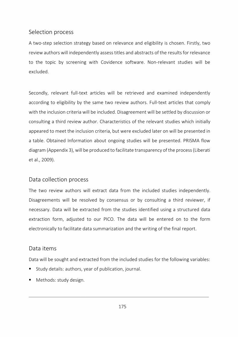
___________________________________________________________________________
175
Selection process
A two-step selection strategy based on relevance and eligibility is chosen. Firstly, two
review authors will independently assess titles and abstracts of the results for relevance
to the topic by screening with Covidence software. Non-relevant studies will be
excluded.
Secondly, relevant full-text articles will be retrieved and examined independently
according to eligibility by the same two review authors. Full-text articles that comply
with the inclusion criteria will be included. Disagreement will be settled by discussion or
consulting a third review author. Characteristics of the relevant studies which initially
appeared to meet the inclusion criteria, but were excluded later on will be presented in
a table. Obtained Information about ongoing studies will be presented. PRISMA flow
diagram (Appendix 3), will be produced to facilitate transparency of the process (Liberati
et al., 2009).
Data collection process
The two review authors will extract data from the included studies independently.
Disagreements will be resolved by consensus or by consulting a third reviewer, if
necessary. Data will be extracted from the studies identified using a structured data
extraction form, adjusted to our PICO. The data will be entered on to the form
electronically to facilitate data summarization and the writing of the final report.
Data items
Data will be sought and extracted from the included studies for the following variables:
§ Study details: authors, year of publication, journal.
§ Methods: study design.
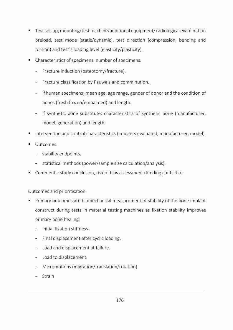
___________________________________________________________________________
176
§ Test set-up; mounting/test machine/additional equipment/ radiological examination
preload, test mode (static/dynamic), test direction (compression, bending and
torsion) and test´s loading level (elasticity/plasticity).
§ Characteristics of specimens: number of specimens.
- Fracture induction (osteotomy/fracture).
- Fracture classification by Pauwels and comminution.
- If human specimens; mean age, age range, gender of donor and the condition of
bones (fresh frozen/embalmed) and length.
- If synthetic bone substitute; characteristics of synthetic bone (manufacturer,
model, generation) and length.
§ Intervention and control characteristics (implants evaluated, manufacturer, model).
§ Outcomes.
- stability endpoints.
- statistical methods (power/sample size calculation/analysis).
§ Comments: study conclusion, risk of bias assessment (funding conflicts).
Outcomes and prioritisation.
§ Primary outcomes are biomechanical measurement of stability of the bone implant
construct during tests in material testing machines as fixation stability improves
primary bone healing:
- Initial fixation stiffness.
- Final displacement after cyclic loading.
- Load and displacement at failure.
- Load to displacement.
- Micromotions (migration/translation/rotation)
- Strain

___________________________________________________________________________
177
§ Secondary outcomes are identification of different categories of failure type, which
are reflecting the fixation stability in overloading of the construct, an advantage of
biomechanical studies, but with uncertain clinical relevance.
Risk of bias in included studies
Critical appraisal of the risk of bias (methodological quality) will be assessed
independently by the two review authors. Any disagreements will be resolved by
discussion or if necessary by involving a third reviewer.
Tools for assessment of risk of bias used will be the criteria outlined in the Cochrane
Handbook for Systematic Reviews of Interventions Section 8.5 and handled in Reference
Manager, version 5.3 software (Higgins and Green, 2011). Being developed for
randomized controlled trials, its application in biomechanical studies is accepting the
risk of bias most likely to be classified as high.
We will assess the risk of bias according to the following domains:
§ Selection bias: Sequence generation, allocation concealment.
§ Performance bias: Blinding of participants and personnel.
§ Detection bias: Blinding of outcome assessment.
§ Reporting bias: Selective outcome reporting, incomplete outcome data.
§ Other: Bias due to contamination, Recruitment, Loss of clusters, Incorrect analysis.
Data synthesis
The study data will be pooled in meta-analysis by using Reference Manager software,
version 5.3. If homogenous controlled trials are available, i.e. specimens, interventions,
controls and outcomes are similar enough and data appropriate for pooling, meta-
analysis is feasible. If data are appropriate for quantitative synthesis continuous data
will be expressed as mean difference (MD) or standardized mean difference (SMD),

___________________________________________________________________________
178
while categorical data will be analysed by calculating relative risk (RR) by using
Reference Manager. I-squared statistic will be used exploring the consistency for each
outcome. If reported data are incomplete for a metanalysis in any of the included
studies, we plan to contact the corresponding author of these studies for
supplementary data. If significant heterogeneity discourages meta-analysis instead
findings will be summarized narratively, using text and tables. If possible, we will divide
the data in groups and analyse them separately based on the fixation method.
Meta-biases
The overall risk of bias for each included study will be reported.
Grading the certainty of evidence
This is not applicable for the included studies.
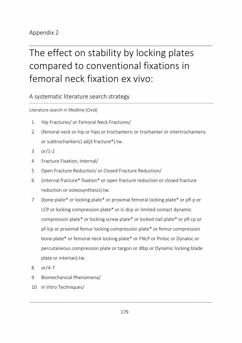
___________________________________________________________________________
179
Appendix 2
___________________________________________________________________________
The effect on stability by locking plates compared to conventional fixations in femoral neck fixation ex vivo: A systematic literature search strategy ____________________________________________________________________________________________________________________________________________
Literature search in Medline (Ovid) 1 Hip Fractures/ or Femoral Neck Fractures/
2 (femoral neck or hip or hips or trochanteric or trochanter or intertrochanteric
or subtrochanteric) adj3 fracture*).tw.
3 or/1-2
4 Fracture Fixation, Internal/
5 Open Fracture Reduction/ or Closed Fracture Reduction/
6 (internal fracture* fixation* or open fracture reduction or closed fracture
reduction or osteosynthesis).tw.
7 (bone plate* or locking plate* or proximal femoral locking plate* or pfl p or
LCP or locking compression plate* or lc-dcp or limited contact dynamic
compression plate* or locking screw plate* or locked nail plate* or pfl cp or
pf-lcp or proximal femur locking compression plate* or femur compression
bone plate* or femoral neck locking plate* or FNLP or Pinloc or Dynaloc or
percutaneous compression plate or targon or dlbp or Dynamic locking blade
plate or intertan).tw.
8 or/4-7
9 Biomechanical Phenomena/
10 In Vitro Techniques/

___________________________________________________________________________
180
11 (biomech* or mech* or cadaver stud* or in vivo or in vitro or ex-vivo or
(controlled adj2 trial*)).tw.
12 Randomized Controlled Trial.pt.
13 controlled clinical trial.pt.
14 (randomized or randomised).tw.
15 clinical trials as topic.sh.
16 trial.ti.
17 or/9-16
18 3 and 8 and 17
19 limit 18 to yr="2000 -Current"
The search was drafted in Medline and adapted to Embase (Ovid) and Cochrane
Library. There are no limitations related to language of included studies, search is
limited by date from year 2000-june 2018.
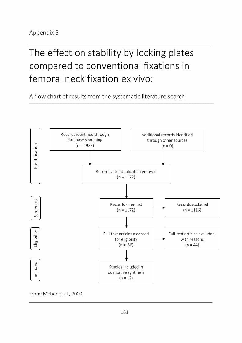
___________________________________________________________________________
181
Appendix 3
___________________________________________________________________________
The effect on stability by locking plates compared to conventional fixations in femoral neck fixation ex vivo: A flow chart of results from the systematic literature search ____________________________________________________________________________________________________________________________________________
From: Moher et al., 2009.
Scre
enin
g El
igib
ility
Records identified through database searching
(n = 1928)
Additional records identified through other sources
(n = 0)
Records after duplicates removed (n = 1172)
Records screened (n = 1172)
Records excluded (n = 1116)
Full-text articles assessed for eligibility
(n = 56)
Full-text articles excluded, with reasons
(n = 44)
Studies included in qualitative synthesis
(n = 12)
Iden
tific
atio
n In
clud
ed

___________________________________________________________________________
182
14 Papers

I

Contents lists available at ScienceDirect
Clinical Biomechanics
journal homepage: www.elsevier.com/locate/clinbiomech
Increased torsional stability by a novel femoral neck locking plate. The roleof plate design and pin configuration in a synthetic bone block model
Jan Egil Brattgjerda,c,⁎, Martin Lofererb, Sanyalak Niratisairaka,c, Harald Steena, Knut Strømsøec
a Division of Orthopaedic Surgery, Biomechanics Lab, Oslo University Hospital, Pb. 4950 Nydalen, 0424 Oslo, Norwayb Endolab Mechanical Engineering GmbH, Seb.-Tiefenthaler Str. 13, D-83101 Thansau, Rosenheim, Germanyc Institute of Clinical Medicine, Faculty of Medicine, University of Oslo, Pb. 1171 Blindern, 0318 Oslo, Norway
A R T I C L E I N F O
Keywords:Femoral neck fractureInternal fixationBiomechanicsTorsional testingLocking plateComposite bone
A B S T R A C T
Background: In undisplaced femoral neck fractures, internal fixation remains the main treatment, with me-chanical failure as a frequent complication. As torsional stable fixation promotes femoral neck fracture healing,the Hansson Pinloc® System with a plate interlocking pins, was developed from the original hook pins. Since itseffect on torsional stability is undocumented, the novel implant was compared with the original configurations.Methods: Forty-two proximal femur models custom made of two blocks of polyurethane foam were tested. Themedial block simulated the cancellous head, while the lateral was laminated with a glass fiber filled epoxy sheetsimulating trochanteric cortical bone. Two hollow metal cylinders with a circumferential ball bearing in betweenmimicked the neck, with a perpendicular fracture in the middle. Fractures were fixated by two or three in-dependent pins or by five configurations involving the interlocking plate (two pins with an optional peg in asmall plate, or three pins in a small, medium or large plate). Six torsional tests were performed on each con-figuration to calculate torsional stiffness, torque at failure and failure energy.Findings: The novel configurations improved parameters up to an average of 12.0 (stiffness), 19.3 (torque) and19.9 (energy) times higher than the original two pins (P < 0.001). The plate, its size and its triangular con-figuration improved all parameters (P=0.03), the plate being most effective, also preventing permanent failure(P < 0.001).Interpretation: The novel plate design with its pin configuration enhanced torsional stability. To reveal clinicalrelevance a clinical study is planned.
1. Introduction
Internal fixation is the main treatment of undisplaced medial fe-moral neck fractures. Most surgeons still use multiple pins or screws asthe preferred device (Gjertsen et al., 2008).
This procedure is burdened by a high incidence of bone healingcomplications; early fixation failure with secondary dislocation, non-unions, as well as avascular necrosis with segmental collapse of thefemoral head during revascularisation (Frihagen et al., 2007). The mostcommon reason for reoperation is fixation failure with the character-istics of twisting and backing out of the implants. The subsidence at thefracture site causing protrusion of pins/screws and secondary localcomplaints may necessitate secondary surgery (e.g. metal removal)(Bjørgul and Reikerås, 2007). A substantial reoperation rate of 11–27%is common in the first year postoperatively (Bjørgul and Reikerås, 2007;Gjertsen et al., 2011; Palm et al., 2009).
Nevertheless, no clear conclusions can be drawn on which implant
is superior in the femoral neck fracture fixation in vivo, not even be-tween screws and hook-pins (Parker and Gurusamy, 2001).
In biomechanical studies, no advantage has been detected by usingmore than three screws, unless in the presence of considerable posteriorcomminution of the neck (Kauffmann et al., 1999; Swiontkowski et al.,1987). Triangular configurations increase stability, compared to linearconfigurations with two or three screws (Selvan et al., 2004). Increaseddistance between screws in upside-down triangular configurations hasalso shown superior parameters (Zdero et al., 2010a).
Today, several fixed-angle devices combining multiple screws in-crease fixation stability in biomechanical trials compared to conven-tional implants, as multiple pins/screws or a sliding hip screw device, inthis setting (Aminian et al., 2007; Basso et al., 2014a; Basso et al.,2014b; Brandt et al., 2006; Brandt and Verdonschot, 2011; Nowotarskiet al., 2012; Roerdink et al., 2009; Rupprecht et al., 2011).
Correspondingly, initial case series with fixed-angle implants havereported encouraging findings (Lin et al., 2012; Parker and Stedtfeld,
https://doi.org/10.1016/j.clinbiomech.2018.03.024Received 27 June 2017; Accepted 26 March 2018
⁎ Corresponding author at: Division of Orthopaedic Surgery, Oslo University Hospital, Ullevål, Pb. 4956 Nydalen, 0424 Oslo, Norway.E-mail address: [email protected] (J.E. Brattgjerd).

2010; Roerdink et al., 2011). Reduced risk of cut-out of the lag screw,less subsidence of the head fragment and a lower conversion rate tohemiarthroplasty have been documented (Eschler et al., 2014). On theother hand, implants increasing stability may prevent fracture sitemicro-motion, placing the mechanical burden on the implant, in-creasing the risk of implant perforation and failure at the bone-screwinterface or the implant itself (Berkes et al., 2012; Biber et al., 2014).
Accordingly, the demonstration of early failure, such as loosening,cut-out or breakage are interesting findings within biomechanical stu-dies, while for documenting on later complications, dependent on invivo bone responses, clinical trials are needed. Hence, the clinical re-levance of biomechanical studies remains a source of debate.
The high incidence of bone healing complications of this unsolvedfracture has anatomical implications. The medial femoral neck, locatedintracapsularly in the hip joint with no surrounding periosteum, con-solidates by endosteal callus formation (Keating, 2011). Adequate sta-bility of the osteosynthesis is critical during the first weeks of con-solidation, as osteons spread across the fracture site andrevascularisation occurs. Ingrowth of capillaries through the Haversiansystems is essentially finished within the first six weeks after surgery(Schenk and Willenegger, 1963). Hence, maximum stability in terms ofboth torsion and bending of the fixated femoral neck is a prerequisitefor undisturbed primary fracture healing (Perren, 2002; Ragnarssonand Kärrholm, 1992; Rehnberg and Olerud, 1989). The magnitude ofthe mean screw axis rotation has been found to be higher in non-unionsthan in femoral neck fractures that healed (13 vs. 8°), indicating 10-degree rotation as a clinical interesting value (Ragnarsson andKärrholm, 1992).
For internal fixation of displaced femoral neck fractures, accuratereduction and positioning of the implants are important, as emphasizedby the use of the Hansson hook-pins (Hoelsbrekken et al., 2012; Lykkeet al., 2003). Accordingly, rotational instability, indicated by thetwisting of the pins during the first months after surgery, seems to be apredictor of fixation failure, as well as delayed and non-union.
As neutralization of the torsional forces has been considered es-sential in preventing fixation failure, isolated torsion along the axis ofthe femoral neck has been evaluated in biomechanical studies fordecades (Husby et al., 1989; Nowotarski et al., 2012; Swiontkowskiet al., 1987). Biomechanical studies of femoral neck fracture fixationincluding evaluation of torsional stability in particular are thereforenecessary and mandatory before introducing novel implants into theclinic.
To increase torsional stability of the fixation per se, the originalfixation method by two or occasionally three Hansson hook-pins, wasmodified. An angular stable implant was designed, allowing a max-imum of three titanium pins to be interlocked in an isosceles triangularconfiguration within an aluminum plate, available in three different
sizes. Without fixation to the lateral cortex, the plate is only supportedagainst the greater trochanter. This feature of the plate allows a con-trolled compression along the neck, leaving the trochanteric wall whilemaintaining intrinsic stability of the bone-implant construct duringmobilisation. Instead, if only pins were tightened with their threadsengaging cortical bone, the risk for penetration of the femoral headwould increase.
Still, the fixation principle of the novel system is the 3-point corticalcontact for each pin laterally, cervically and subchondrally in the fe-moral head. In addition, interlocking pins engage in subchondral boneas a dynamic unit. This firm anchorage in the femoral head prevents itsrotation unless it cuts through all pins simultaneously. The main in-tention of the novel implant design was to increase torsional capacityby improving this fixation principle in cancellous bone, aiming forneutralization of the torsional forces.
Accordingly, the purpose of this study was to compare the bio-mechanical properties in torsion of the original configurations of iso-lated pins with the novel Hansson Pinloc® System in a composite boneblock model simulating fixed medial femoral neck fractures.
2. Methods
2.1. Model preparation
Forty-two models of the proximal femur were custom-made fromtwo synthetic bone blocks (model #1522-02, Fourth GenerationComposite Bone; Sawbones, Pacific Research Laboratories, Vashon,WA, USA). One medial block of 50× 50×40mm with grade-15 solidrigid polyurethane foam simulated the cancellous femoral head, whilethe lateral block of 50×50×20mm was laminated with a corre-sponding squared 4-mm thick short glass fiber-reinforced epoxy to re-semble the lateral cortex in the trochanteric region (model # 3401-03).The foam complied with the ASTM F1839-01 specifications (ASTMF1839-01, 2008). Density of the cortical bone substitute was 1.64 g/cm3, while 0.24 g/cm3 for the corresponding cancellous bone. The fe-moral neck was simulated by two hollow metal cylinders of 35mmlength each, separated by a ball-bearing circumferential interface, re-presenting a low-friction transverse osteotomy, i.e a transcervicalfracture perpendicular to the pins (Fig. 1).
For all configurations, the pins used were Hansson Pinloc® pinsmade of titanium alloy (Ti6Al4V), with a shank diameter of 6.5mm andlength of 130 superiorly and 140mm inferiorly, while the length of theanterior pegs (a component of the Hansson Pinloc® System) was 40mm.The sizes of the plates with 3 holes were 6, 8 or 10mm, according to thedistance between the superior and inferior pins, while the corre-sponding distance between the anterior and posterior pin was 4.5, 5.5and 6.5 mm (Swemac Innovations AB, Linköping, Sweden).
Fig. 1. The composite bone block model of thetranscervical femoral neck fracture fixated by theHansson Pinloc® System.Upper right: a cross sectional view of the test spe-cimen at the site of the osteotomy visualizing theinternal features of the test model with the medialhollow cylinder and the standardised pin holes of thetriangular pin configuration in the medial block.Bottom right: The Hansson Pinloc® System was ap-plied with a small (6 mm), medium (8mm) or, asillustrated, a large-sized (10mm) plate, according tothe length between the superior and inferior pin. Thecorresponding length between the anterior and pos-terior pin was 4.5, 5.5 and 6.5 mm.
J.E. Brattgjerd et al.

Accordingly, pre-drilling of the pin holes was standardised by ma-chine and implants inserted following surgical technique instructions.The anatomical plates were based on the caput-collum-diaphysis anglein femurs, leaving the superior pins and plate in flush with the flatcortical sheet and the inferior pin and plate sticking out, despite notbeing its actual clinical appearance. The configurations were; two orthree isolated pins (Configurations A and B), a 6mm-sized plate withtwo pins (Configuration C) or an additional peg (Configuration D), or a6-, 8- or 10mm-sized plate with three pins (Configurations E, F, and G),with six identical specimens in each group (Fig. 2).
2.2. Test procedure
The tests were carried out on equipment designed for a torsionscrew test in accordance with the ASTM F543-07 standards (ASTMF543-07, 2008). The specimens were oriented horizontally and press-fitinserted into square-channeled steel tubes without interference be-tween the implants and the tubes. To ensure a uniform connection, anaxial preload of 100 N was applied by means of deadweights. Thetesting machine was equipped with a computer-controlled brushless ECmotor (type EL45BLY250WKL2WEA; Maxon Motor AG, Sachseln,Switzerland) and a 20 Nm torque sensor (type DR-2212, resolution:0.02 Nm, accuracy: 0.1%; Lorenz Messtechnik GmbH, Alfdorf, Ger-many) (Fig. 3). The motor applied torque on the medial block, rotatingclockwise with a torsional feed rate of 90°/min until a maximum of20 Nm. The torsional moment (torque) and the angulation, were mea-sured by the sensor and the motor, respectively, and recorded on ahard-disk.
The best line fit of the slope of the load-deformation curve's linearelastic portion defined torsional rigidity (stiffness). The clinically re-levant value of 10-degree rotation was considered as testing end point
or failure (Ragnarsson and Kärrholm, 1992). The maximum load withinthis interval was defined as “torque at failure”. Correspondingly, “tor-sional failure energy” was defined as the signed area below the load-deformation graph, including the failure point at 10° (Fig. 4). After thetest the blocks were categorized according to signs of failure.
2.3. Statistical analysis
Data were processed with MATLAB software (MathWorks Inc.,Natick, MA, USA). Average values were expressed as arithmetic means,and dispersion as standard deviations or 95% confidence intervals. Forcomparisons between configurations, one-way analyses of variance(ANOVA) were conducted using IBM SPSS Statistics (version 23 forWindows; SPSS Inc., Chicago, IL, USA). Level of significance was set toP < 0.05. Post hoc multiple comparisons were made by Bonferronicorrection. A Pearson product-moment correlation was performed todetermine the relationship between continuous variables. For the ca-tegorical variable a crosstab was computed.
3. Results
3.1. Torsional parameters
Torsional rigidity, torque at failure and torsional failure energy forall configurations are presented in Table 1. The mean torsional rigidityof the fixation for all configurations ranged from 0.06 to 0.68 Nm/deg.The mean torque at failure levels ranged from 0.30 to 5.15 Nm, whilemean torsional failure energy from 0.03 to 0.51 J.
The comparisons of these torsional stability parameters are given forall configurations in Table 2. The novel fixation method improvedparameters at most to an average of 12.0 (torsional stiffness), 19.3(torque at failure) and 19.9 (failure energy) times higher than the ori-ginal two pins (F vs A) (P < 0.001).
The interlocking of pins in a plate (C–G vs A–B) (P=0.006), theplate size (F–G vs E) (P=0.005) and application of the third pin within
Fig. 2. The configurations A–G from left to right ofthe Hansson Pinloc® System. Pin length used was130mm superiorly and 140mm inferiorly, the ante-rior pegs being 40mm long, while both had a shankdiameter of 6.5 mm.Configuration A: 2 independent pins with distancebetween pins as in the small-sized plate.Configuration B: 3 independent pins with distancebetween pins as in the small-sized plate.Configuration C: 2 pins in a small-sized plate.Configuration D: 2 pins and a peg in a small-sizedplate.Configuration E: 3 pins in a small-sized plate.Configuration F: 3 pins in a medium-sized plate.Configuration G: 3 pins in a large-sized plate.
Fig. 3. The test set-up for torsional analysis.Annotation above different elements of the set-up.A Computer controlled brushless EC motor.B Square-channeled steel tubes.C Test model.D Hook with line to deadweights.E Torque sensor.
Torsion (Deg)
Torque (Nm)
Rigidity
Failure energy
0
5
10
5 10 15 20
Max torque
10
5
05 10 15 20
Fig. 4. The load-deformation curve with definitions of outcomes of torsionalstability.
J.E. Brattgjerd et al.
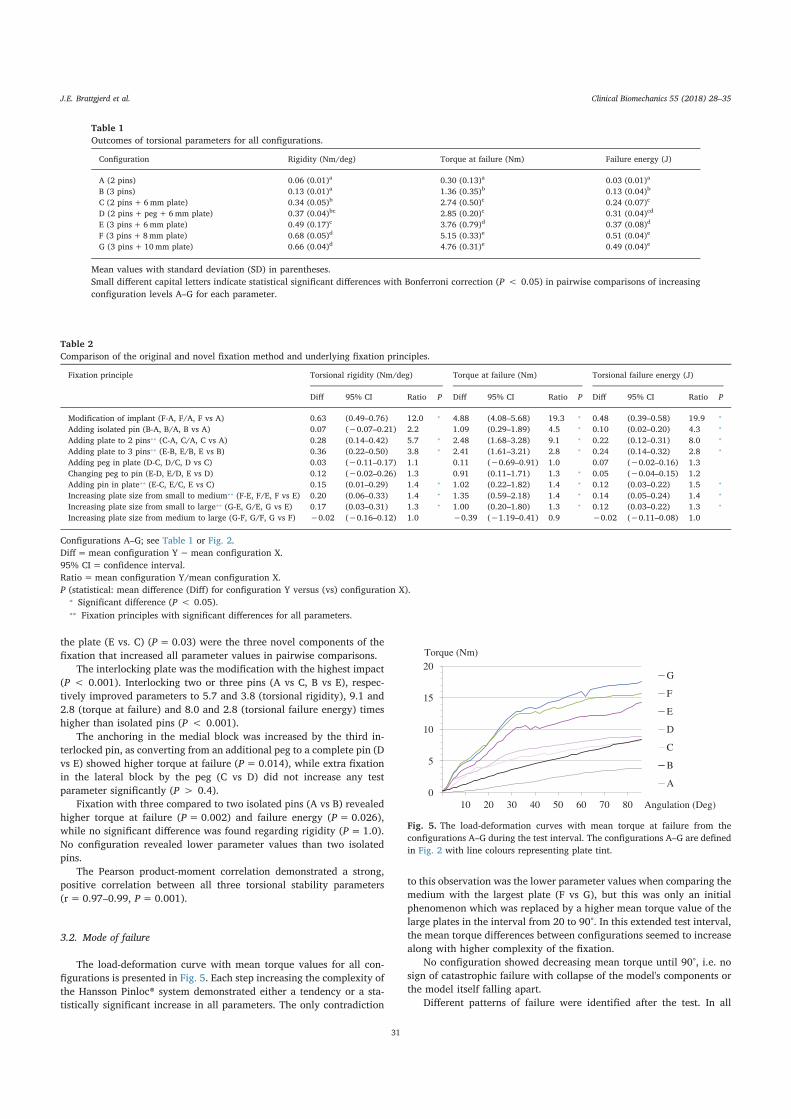
the plate (E vs. C) (P=0.03) were the three novel components of thefixation that increased all parameter values in pairwise comparisons.
The interlocking plate was the modification with the highest impact(P < 0.001). Interlocking two or three pins (A vs C, B vs E), respec-tively improved parameters to 5.7 and 3.8 (torsional rigidity), 9.1 and2.8 (torque at failure) and 8.0 and 2.8 (torsional failure energy) timeshigher than isolated pins (P < 0.001).
The anchoring in the medial block was increased by the third in-terlocked pin, as converting from an additional peg to a complete pin (Dvs E) showed higher torque at failure (P=0.014), while extra fixationin the lateral block by the peg (C vs D) did not increase any testparameter significantly (P > 0.4).
Fixation with three compared to two isolated pins (A vs B) revealedhigher torque at failure (P=0.002) and failure energy (P=0.026),while no significant difference was found regarding rigidity (P=1.0).No configuration revealed lower parameter values than two isolatedpins.
The Pearson product-moment correlation demonstrated a strong,positive correlation between all three torsional stability parameters(r= 0.97–0.99, P=0.001).
3.2. Mode of failure
The load-deformation curve with mean torque values for all con-figurations is presented in Fig. 5. Each step increasing the complexity ofthe Hansson Pinloc® system demonstrated either a tendency or a sta-tistically significant increase in all parameters. The only contradiction
to this observation was the lower parameter values when comparing themedium with the largest plate (F vs G), but this was only an initialphenomenon which was replaced by a higher mean torque value of thelarge plates in the interval from 20 to 90°. In this extended test interval,the mean torque differences between configurations seemed to increasealong with higher complexity of the fixation.
No configuration showed decreasing mean torque until 90°, i.e. nosign of catastrophic failure with collapse of the model's components orthe model itself falling apart.
Different patterns of failure were identified after the test. In all
Table 1Outcomes of torsional parameters for all configurations.
Configuration Rigidity (Nm/deg) Torque at failure (Nm) Failure energy (J)
A (2 pins) 0.06 (0.01)a 0.30 (0.13)a 0.03 (0.01)a
B (3 pins) 0.13 (0.01)a 1.36 (0.35)b 0.13 (0.04)b
C (2 pins+ 6mm plate) 0.34 (0.05)b 2.74 (0.50)c 0.24 (0.07)c
D (2 pins+ peg+ 6mm plate) 0.37 (0.04)bc 2.85 (0.20)c 0.31 (0.04)cd
E (3 pins+ 6mm plate) 0.49 (0.17)c 3.76 (0.79)d 0.37 (0.08)d
F (3 pins+8mm plate) 0.68 (0.05)d 5.15 (0.33)e 0.51 (0.04)e
G (3 pins+ 10mm plate) 0.66 (0.04)d 4.76 (0.31)e 0.49 (0.04)e
Mean values with standard deviation (SD) in parentheses.Small different capital letters indicate statistical significant differences with Bonferroni correction (P < 0.05) in pairwise comparisons of increasingconfiguration levels A–G for each parameter.
Table 2Comparison of the original and novel fixation method and underlying fixation principles.
Fixation principle Torsional rigidity (Nm/deg) Torque at failure (Nm) Torsional failure energy (J)
Diff 95% CI Ratio P Diff 95% CI Ratio P Diff 95% CI Ratio P
Modification of implant (F-A, F/A, F vs A) 0.63 (0.49–0.76) 12.0 ⁎ 4.88 (4.08–5.68) 19.3 ⁎ 0.48 (0.39–0.58) 19.9 ⁎
Adding isolated pin (B-A, B/A, B vs A) 0.07 (−0.07–0.21) 2.2 1.09 (0.29–1.89) 4.5 ⁎ 0.10 (0.02–0.20) 4.3 ⁎
Adding plate to 2 pins⁎⁎ (C-A, C/A, C vs A) 0.28 (0.14–0.42) 5.7 ⁎ 2.48 (1.68–3.28) 9.1 ⁎ 0.22 (0.12–0.31) 8.0 ⁎
Adding plate to 3 pins⁎⁎ (E-B, E/B, E vs B) 0.36 (0.22–0.50) 3.8 ⁎ 2.41 (1.61–3.21) 2.8 ⁎ 0.24 (0.14–0.32) 2.8 ⁎
Adding peg in plate (D-C, D/C, D vs C) 0.03 (−0.11–0.17) 1.1 0.11 (−0.69–0.91) 1.0 0.07 (−0.02–0.16) 1.3Changing peg to pin (E-D, E/D, E vs D) 0.12 (−0.02–0.26) 1.3 0.91 (0.11–1.71) 1.3 ⁎ 0.05 (−0.04–0.15) 1.2Adding pin in plate⁎⁎ (E-C, E/C, E vs C) 0.15 (0.01–0.29) 1.4 ⁎ 1.02 (0.22–1.82) 1.4 ⁎ 0.12 (0.03–0.22) 1.5 ⁎
Increasing plate size from small to medium⁎⁎ (F-E, F/E, F vs E) 0.20 (0.06–0.33) 1.4 ⁎ 1.35 (0.59–2.18) 1.4 ⁎ 0.14 (0.05–0.24) 1.4 ⁎
Increasing plate size from small to large⁎⁎ (G-E, G/E, G vs E) 0.17 (0.03–0.31) 1.3 ⁎ 1.00 (0.20–1.80) 1.3 ⁎ 0.12 (0.03–0.22) 1.3 ⁎
Increasing plate size from medium to large (G-F, G/F, G vs F) −0.02 (−0.16–0.12) 1.0 −0.39 (−1.19–0.41) 0.9 −0.02 (−0.11–0.08) 1.0
Configurations A–G; see Table 1 or Fig. 2.Diff=mean configuration Y−mean configuration X.95% CI= confidence interval.Ratio=mean configuration Y/mean configuration X.P (statistical: mean difference (Diff) for configuration Y versus (vs) configuration X).
⁎ Significant difference (P < 0.05).⁎⁎ Fixation principles with significant differences for all parameters.
0
5
10
15
20
10 20 30 40 50 60 70 80
G
F
E
D
C
B
A
Angulation (Deg)
Torque (Nm)
Fig. 5. The load-deformation curves with mean torque at failure from theconfigurations A–G during the test interval. The configurations A–G are definedin Fig. 2 with line colours representing plate tint.
J.E. Brattgjerd et al.
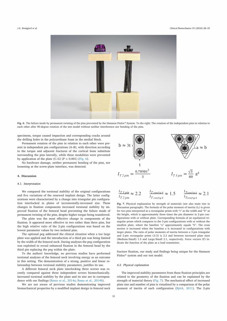
specimens, torque caused impaction and corresponding cracks aroundthe drilling holes in the polyurethane foam in the medial block.
Permanent rotation of the pins in relation to each other were pre-sent in independent pin configurations (A–B), with direction accordingto the torque and adjacent fractures of the cortical bone substitutesurrounding the pins laterally, while these modalities were preventedby application of the plate (C–G) (P≤ 0.001) (Fig. 6).
No hardware damage, neither permanent bending of the pins, norloosening at the screw-plate interface, was detected.
4. Discussion
4.1. Interpretation
We compared the torsional stability of the original configurationsand five variations of the renewed implant design. The latter config-urations were characterised by a change into triangular pin configura-tion interlocked in plates of incrementally-increased size. Thesechanges in fixation components increased torsional stability by im-proved fixation of the femoral head preventing the failure mode ofpermanent twisting of the pins, despite higher torque being transferred.
The plate was the most effective change in components of thefixation. It appeared more effective in two rather than three pins, butthe high relative ratio of the 2-pin configurations was based on thelowest parameter values by two isolated pins.
The optional peg addressed the clinical situation when a too largeplate was applied and the introduction of a third pin was being limitedby the width of the femoral neck. During analyses the peg configurationwas exploited to reveal enhanced fixation in the femoral head by thethird pin replacing the peg within the plate.
To the authors' knowledge, no previous studies have performedtorsional analyses of the femoral neck involving energy as an outcomein this setting. The demonstration of a strong, positive and linear re-lationship between torsional stability parameters, justifies its use.
A different femoral neck plate interlocking three screws was re-cently compared against three independent screws biomechanically.Increased torsional stability by the plate and its size are in correspon-dence with our findings (Basso et al., 2014a; Basso et al., 2014b).
We are not aware of previous studies demonstrating improvedbiomechanical properties by a modified implant design in femoral neck
fracture fixation, our study and findings being unique for the HanssonPinloc® system and our test model.
4.2. Physical explanation
The improved stability parameters from these fixation principles arerelated to the geometry of the fixation and can be explained by thestrength of material theory (Fig. 7). The mechanical effect of increasedplate size and number of pins is visualised by a comparison of the polarmoment of inertia of each configuration (Björk, 2011). The 2-pin
Fig. 6. The failure mode by permanent twisting of the pins prevented by the Hansson Pinloc® System. To the right: The rotation of the independent pins in relation toeach other after 90-degree rotation of the test model without neither interference nor bending of the pins.
T 2 pi =,
3
T 3 pin = a4
T 3 pinT 2 pin
2.2 TT
1.5 TT
2.1
b ≈ 3t
t
a ≈ b
F
Fig. 7. Physical explanation by strength of materials (see also main text inDiscussion paragraph). The formula of the polar moment of inertia (IT) is givenfor two pins interpreted as a rectangular prism with “t” as the width and “b” asthe height, which is approximately three times the pin diameter in 2-pin con-figurations with or without plate. Corresponding formula of an equilateral tri-angular prism which compares to the 3-pin configurations with or without thesmallest plate, where the baseline “a” approximately equals “b”. The crosssection is increased when the baseline a is increased in configurations withlarger plates. The ratio of polar moments of inertia between a 3-pin triangularand 2-pin rectangular prism (3/2) is 2.2 and between increased plate sizes(Medium/Small) 1.5 and Large/Small 2.1, respectively. Force vectors (F) in-dicate the function of the plate as a load transmitter.
J.E. Brattgjerd et al.
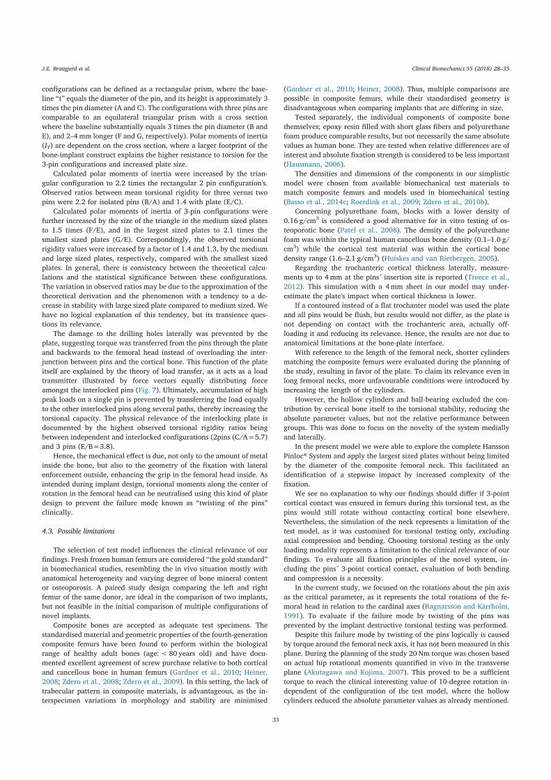
configurations can be defined as a rectangular prism, where the base-line “t” equals the diameter of the pin, and its height is approximately 3times the pin diameter (A and C). The configurations with three pins arecomparable to an equilateral triangular prism with a cross sectionwhere the baseline substantially equals 3 times the pin diameter (B andE), and 2–4mm longer (F and G, respectively). Polar moments of inertia(IT) are dependent on the cross section, where a larger footprint of thebone-implant construct explains the higher resistance to torsion for the3-pin configurations and increased plate size.
Calculated polar moments of inertia were increased by the trian-gular configuration to 2.2 times the rectangular 2 pin configuration's.Observed ratios between mean torsional rigidity for three versus twopins were 2.2 for isolated pins (B/A) and 1.4 with plate (E/C).
Calculated polar moments of inertia of 3-pin configurations werefurther increased by the size of the triangle in the medium sized platesto 1.5 times (F/E), and in the largest sized plates to 2.1 times thesmallest sized plates (G/E). Correspondingly, the observed torsionalrigidity values were increased by a factor of 1.4 and 1.3, by the mediumand large sized plates, respectively, compared with the smallest sizedplates. In general, there is consistency between the theoretical calcu-lations and the statistical significance between these configurations.The variation in observed ratios may be due to the approximation of thetheoretical derivation and the phenomenon with a tendency to a de-crease in stability with large sized plate compared to medium sized. Wehave no logical explanation of this tendency, but its transience ques-tions its relevance.
The damage to the drilling holes laterally was prevented by theplate, suggesting torque was transferred from the pins through the plateand backwards to the femoral head instead of overloading the inter-junction between pins and the cortical bone. This function of the plateitself are explained by the theory of load transfer, as it acts as a loadtransmitter illustrated by force vectors equally distributing forceamongst the interlocked pins (Fig. 7). Ultimately, accumulation of highpeak loads on a single pin is prevented by transferring the load equallyto the other interlocked pins along several paths, thereby increasing thetorsional capacity. The physical relevance of the interlocking plate isdocumented by the highest observed torsional rigidity ratios beingbetween independent and interlocked configurations (2pins (C/A=5.7)and 3 pins (E/B=3.8).
Hence, the mechanical effect is due, not only to the amount of metalinside the bone, but also to the geometry of the fixation with lateralenforcement outside, enhancing the grip in the femoral head inside. Asintended during implant design, torsional moments along the center ofrotation in the femoral head can be neutralised using this kind of platedesign to prevent the failure mode known as “twisting of the pins”clinically.
4.3. Possible limitations
The selection of test model influences the clinical relevance of ourfindings. Fresh frozen human femurs are considered “the gold standard”in biomechanical studies, resembling the in vivo situation mostly withanatomical heterogeneity and varying degree of bone mineral contentor osteoporosis. A paired study design comparing the left and rightfemur of the same donor, are ideal in the comparison of two implants,but not feasible in the initial comparison of multiple configurations ofnovel implants.
Composite bones are accepted as adequate test specimens. Thestandardised material and geometric properties of the fourth-generationcomposite femurs have been found to perform within the biologicalrange of healthy adult bones (age:< 80 years old) and have docu-mented excellent agreement of screw purchase relative to both corticaland cancellous bone in human femurs (Gardner et al., 2010; Heiner,2008; Zdero et al., 2008; Zdero et al., 2009). In this setting, the lack oftrabecular pattern in composite materials, is advantageous, as the in-terspecimen variations in morphology and stability are minimised
(Gardner et al., 2010; Heiner, 2008). Thus, multiple comparisons arepossible in composite femurs, while their standardised geometry isdisadvantageous when comparing implants that are differing in size.
Tested separately, the individual components of composite bonethemselves; epoxy resin filled with short glass fibers and polyurethanefoam produce comparable results, but not necessarily the same absolutevalues as human bone. They are tested when relative differences are ofinterest and absolute fixation strength is considered to be less important(Hausmann, 2006).
The densities and dimensions of the components in our simplisticmodel were chosen from available biomechanical test materials tomatch composite femurs and models used in biomechanical testing(Basso et al., 2014c; Roerdink et al., 2009; Zdero et al., 2010b).
Concerning polyurethane foam, blocks with a lower density of0.16 g/cm3 is considered a good alternative for in vitro testing of os-teoporotic bone (Patel et al., 2008). The density of the polyurethanefoam was within the typical human cancellous bone density (0.1–1.0 g/cm3) while the cortical test material was within the cortical bonedensity range (1.6–2.1 g/cm3) (Huiskes and van Rietbergen, 2005).
Regarding the trochanteric cortical thickness laterally, measure-ments up to 4mm at the pins´ insertion site is reported (Treece et al.,2012). This simulation with a 4mm sheet in our model may under-estimate the plate's impact when cortical thickness is lower.
If a contoured instead of a flat trochanter model was used the plateand all pins would be flush, but results would not differ, as the plate isnot depending on contact with the trochanteric area, actually off-loading it and reducing its relevance. Hence, the results are not due toanatomical limitations at the bone-plate interface.
With reference to the length of the femoral neck, shorter cylindersmatching the composite femurs were evaluated during the planning ofthe study, resulting in favor of the plate. To claim its relevance even inlong femoral necks, more unfavourable conditions were introduced byincreasing the length of the cylinders.
However, the hollow cylinders and ball-bearing excluded the con-tribution by cervical bone itself to the torsional stability, reducing theabsolute parameter values, but not the relative performance betweengroups. This was done to focus on the novelty of the system mediallyand laterally.
In the present model we were able to explore the complete HanssonPinloc® System and apply the largest sized plates without being limitedby the diameter of the composite femoral neck. This facilitated anidentification of a stepwise impact by increased complexity of thefixation.
We see no explanation to why our findings should differ if 3-pointcortical contact was ensured in femurs during this torsional test, as thepins would still rotate without contacting cortical bone elsewhere.Nevertheless, the simulation of the neck represents a limitation of thetest model, as it was customised for torsional testing only, excludingaxial compression and bending. Choosing torsional testing as the onlyloading modality represents a limitation to the clinical relevance of ourfindings. To evaluate all fixation principles of the novel system, in-cluding the pins´ 3-point cortical contact, evaluation of both bendingand compression is a necessity.
In the current study, we focused on the rotations about the pin axisas the critical parameter, as it represents the total rotations of the fe-moral head in relation to the cardinal axes (Ragnarsson and Kärrholm,1991). To evaluate if the failure mode by twisting of the pins wasprevented by the implant destructive torsional testing was performed.
Despite this failure mode by twisting of the pins logically is causedby torque around the femoral neck axis, it has not been measured in thisplane. During the planning of the study 20 Nm torque was chosen basedon actual hip rotational moments quantified in vivo in the transverseplane (Akutagawa and Kojima, 2007). This proved to be a sufficienttorque to reach the clinical interesting value of 10-degree rotation in-dependent of the configuration of the test model, where the hollowcylinders reduced the absolute parameter values as already mentioned.
J.E. Brattgjerd et al.
Regarding outcomes, more advanced set-ups with measurements ofthree-dimensional micro-motions of the femoral head, are advocated(Aminian et al., 2007; Basso et al., 2014b), but neither its biomecha-nical consequence nor clinical relevance are well documented.
Since the femoral neck locking plate, as hypothesized demonstratedincreased torsional stability in this first evaluation, further biomecha-nical studies are justified and prepared involving both composite andcadaveric bones, physiologic compression and bending. Because thecurrent investigation assessed the relative mechanical performance ofthe various configurations, our findings were due neither to theanatomy nor the material properties of the model, but to the geometryof the novel fixation device. This serves as a starting point for furtherexamination formulating a hypothesis where this relativity may betransferable to the clinical situation in normal and osteoporotic femurs.Recently a prospective clinical study has been started. Hopefully, thesestudies together will reveal the clinical consequence of improved bio-mechanics and the clinical relevance of different models and loadings.
5. Conclusions
In the torsional test model emulating the proximal femur, stabilitywas increased and permanent twisting of the pins prevented by thenovel interlocking plate itself, but also by its possibility of triangularpin configuration with increased distance between the pins. Our ex-perience with the Hansson Pinloc® system is supported by basic physicscalculations, suggesting it represents an advancement over the originalhook-pins. Whether this experimentally-assessed biomechanical effectwill improve management of the medial femoral neck fracture by in-ternal fixation has to be further validated in clinical studies.
Acknowledgments
The authors want to express gratitude to Professor M.D. Stephan M.Perren for continued intellectual guidance. We extend our thanks toSwemac Innovation AB for supplying this study with implants andsynthetic bone block models. Swemac played no other part in the in-terpretation and presentation of the results. Statistician Are Hugo Prippand photographer Øystein Horgmo at the University of Oslo are ap-preciated for their contributions.
Funding
This research did not receive any specific grant from fundingagencies in the public, commercial, or not for profit sector.
Conflict of interest statement
All authors declare no conflict of interest.
References
Akutagawa, S., Kojima, T., 2007. Trunk rotation torques through the hip joints during theone- and two-handed backhand tennis strokes. J. Sports Sci. 23 (8), 781–793.
Aminian, A., Gao, F., Fedoriw, W.W., Zhang, L.Q., Kalainov, D.M., Merk, B.R., 2007.Vertically oriented femoral neck fractures: mechanical analysis of four fixationtechniques. J. Orthop. Trauma 21 (8), 544–548.
ASTM F1839-01, 2008. Standard specification for rigid polyurethane foam for use as astandard material for testing orthopedic devices and instruments. In: Annual book ofASTM Standards, pp. 851–856.
ASTM F543-07, 2008. Standard specifications and test methods for metallic medical bonescrews. In: Annual book of ASTM Standards, pp. 131–150.
Basso, T., Klaksvik, J., Foss, O.A., 2014a. The effect of interlocking parallel screws insubcapital femoral-neck fracture fixation: a cadaver study. Clin. Biomech. 29 (2),213–217.
Basso, T., Klaksvik, J., Foss, O.A., 2014b. Locking plates and their effects on healingconditions and stress distribution: a femoral neck fracture study in cadavers. Clin.Biomech. 29 (5), 595–598.
Basso, T., Klaksvik, J., Syversen, U., Foss, O.A., 2014c. A biomechanical comparison ofcomposite femurs and cadaver femurs used in experiments on operated hip fractures.J. Biomech. 47, 3898–3902.
Berkes, M.B., Little, M.T., Lazaro, L.E., Cymerman, R.M., Helfet, D.L., Lorich, D.G., 2012.
Catastrophic failure after open reduction internal fixation of femoral neck fractureswith a novel locking plate implant. J. Orthop. Trauma 26 (10), e170–6.
Biber, R., Brem, M., Bail, H.J., 2014. Targon femoral neck for femoral-neck fracturefixation: lessons learnt from a series of one hundred and thirty five consecutive cases.Int. Orthop. 38 (3), 595–599.
Bjørgul, K., Reikerås, O., 2007. Outcome of undisplaced and moderately displaced fe-moral neck fractures. Acta Orthop. 78 (4), 498–504.
Björk, K., 2011. Formler och tabeller för mekanisk konstruktion (Swedish), 7th ed. KarlBjörks Förlag HB, Spånga.
Brandt, E., Verdonschot, N., 2011. Biomechanical analysis of the sliding hip screw, can-nulated screws and Targon1 FN in intracapsular hip fractures in cadaver femora.Injury 42 (2), 183–187.
Brandt, E., Verdonschot, N., van Vugt, A., van Kampen, A., 2006. Biomechanical analysisof the percutaneous compression plate and sliding hip screw in intracapsular hipfractures: experimental assessment using synthetic and cadaver bones. Injury 37 (10),979–983.
Eschler, A., Brandt, S., Gierer, P., Mittlmeier, T., Gradl, G., 2014. Angular stable multiplescrew fixation (Targon FN) versus standard SHS for the fixation of femoral neckfractures. Injury 45, S76–S80.
Frihagen, F., Nordsletten, L., Madsen, J.E., 2007. Hemiarthroplasty or internal fixation forintracapsular displaced femoral neck fractures: randomised controlled trial. BMJ 335(7632), 1251–1254.
Gardner, M.P., Chong, A.C., Pollock, A.G., Wooley, P.H., 2010. Mechanical evaluation oflarge-size fourth-generation composite femur and tibia models. Ann. Biomed. Eng. 38(3), 613–620.
Gjertsen, J.E., Engesaeter, L.B., Furnes, O., Havelin, L.I., Steindal, K., Vinje, T., et al.,2008. The Norwegian Hip Fracture Register: experiences after the first 2 years and15.576 reported operations. Acta Orthop. 79 (5), 583–593.
Gjertsen, J.E., Fevang, J.M., Matre, K., Vinje, T., Engesaeter, L.B., 2011. Clinical outcomeafter undisplaced femoral neck fractures. Acta Orthop. 82 (3), 268–274.
Hausmann, J.T., 2006. Sawbones in biomechanical settings - a review. Osteo. TraumaCare 14 (4), 259–264.
Heiner, A.D., 2008. Structural properties of fourth-generation composite femurs and ti-bias. J. Biomech. 41 (15), 3282–3284.
Hoelsbrekken, S.E., Opsahl, J.H., Stiris, M., Paulsrud, Ø., Strømsøe, K., 2012. Failed in-ternal fixation of femoral neck fractures. Tidsskr Nor Legeforen 132 (11), 1343–1347.
Huiskes, R., van Rietbergen, B., 2005. Biomechanics of bone. In: Mow, V.C., Huiskes, R.(Eds.), Basic Orthopaedic Biomechanics and Mechano-Biology, Third edition.Lippincott, Williams, and Wilkins, Philadelphia, Pennsylvania, USA, pp. 123–179.
Husby, T.A., Alho, A., Rønningen, H., 1989. Stability of femoral neck osteosynthesiscomparison of fixation methods in cadavers. Acta Orthop. Scand. 60 (3), 299–303.
Kauffmann, J.I., Simon, J.A., Kummer, F.J., Pearlman, C.J., Zuckerman, J.D., Koval, K.J.,1999. Internal fixation of femoral neck fractures with posterior comminution: abiomechanical study. J. Orthop. Trauma 13 (3), 155–159.
Keating, J., 2011. Femoral neck fractures. In: Rockwood and Green's Fractures in Adults,7th ed. Lippincott Williams and Wilkins, Philadelphia, pp. 1561–1596.
Lin, D., Lian, K., Ding, Z., Zhai, W., Hong, J., 2012. Proximal femoral locking plate withcannulated screws for the treatment of femoral neck fractures. Orthopedics 35 (1),e1–5.
Lykke, N.L., Lerud, P.J., Strømsøe, K., Thorngren, K.G., 2003. Fixation of fractures of thefemoral neck. A prospective, randomised trial of three Ullevaal hip screws versus twoHansson hook-pins. J. Bone Joint Surg. (Br.) 85 (3), 426–430.
Nowotarski, P.J., Ervin, B., Weatherby, B., Pettit, J., Goulet, R., Norris, B., 2012.Biomechanical analysis of a novel femoral neck locking plate for treatment of verticalshear Pauwel's type C femoral neck fractures. Injury 43 (6), 802–806.
Palm, H., Gosvig, K., Krasheninnikoff, M., Jacobsen, S., Gebuhr, P., 2009. A new mea-surement for posterior tilt predicts reoperation in undisplaced femoral neck fractures:113 consecutive patients treated by internal fixation and followed for 1 year. ActaOrthop. 80 (3), 303–307.
Parker, M.J., Gurusamy, K., 2001. Internal fixation implants for intracapsular hip frac-tures in adults. Cochrane Database Syst. Rev. 4. http://dx.doi.org/10.1002/14651858 CD001467.
Parker, M.J., Stedtfeld, H.W., 2010. Internal fixation of intracapsular hip fractures with adynamic locking plate: initial experience and results for 83 patients treated with anew implant. Injury 41 (4), 348–351.
Patel, P.S., Shepherd, D.E., Hukins, D.W., 2008. Compressive properties of commerciallyavailable polyurethane foams as mechanical models for osteoporotic human cancel-lous bone. BMC Musculoskelet. Disord. 9, 137 (2008 Oct 09).
Perren, S.M., 2002. Evolution of the internal fixation of long bone fractures. The scientificbasis of biological fixation: choosing a new balance between stability and biology. J.Bone Joint Surg. (Br.) 84 (8), 1093–1110.
Ragnarsson, J.I., Kärrholm, J.J., 1991. Stability of femoral neck fracture. Roentgen ste-reophotogrammetry of 29 hook-pinned fractures. Acta Orthop. Scand. 62 (3),201–207.
Ragnarsson, J.I., Kärrholm, J.J., 1992. Factors influencing postoperative movement indisplaced femoral neck fractures: evaluation by conventional radiography and ste-reoradiography. J. Orthop. Trauma 6 (2), 152–158.
Rehnberg, L., Olerud, C., 1989. The stability of femoral neck fractures and its influence onhealing. J. Bone Joint Surg. (Br.) 71 (2), 173–177.
Roerdink, W.H., Aalsma, A.M., Nijenbanning, G., van Walsum, A.D., 2009. The dynamiclocking blade plate, a new implant for intracapsular hip fractures: biomechanicalcomparison with the sliding hip screw and Twin Hook. Injury 40 (3), 283–287.
Roerdink, W.H., Aalsma, A.M., Nijenbanning, G., van Walsum, A.D., 2011. Initial pro-mising results of the dynamic locking blade plate, a new implant for the fixation ofintracapsular hip fractures: results of a pilot study. Arch. Orthop. Trauma Surg. 131(4), 519–524.
Rupprecht, M., Grossterlinden, L., Ruecker, A.H., de Oliveira, A.N., Sellenschloh, K.,Nüchtern, J., et al., 2011. A comparative biomechanical analysis of fixation devicesfor unstable femoral neck fractures: the Intertan versus cannulated screws or a dy-namic hip screw. J. Trauma 71 (3), 625–634.
J.E. Brattgjerd et al.

Schenk, R., Willenegger, H., 1963. Zum histologischen Bild der SogenanntenPrimärheilung der Knochenkompakta nach experimentellen Osteotomien am Hund(German). Exp. Dermatol. 19 (11), 593–595.
Selvan, V.T., Oakley, M.J., Rangan, A., Al-Lami, M.K., 2004. Optimum configuration ofcannulated hip screws for the fixation of intracapsular hip fractures: a biomechanicalstudy. Injury 35 (2), 136–141.
Swiontkowski, M.F., Harrington, R.M., Keller, T.S., Van Patten, P.K., 1987. Torsion andbending analysis of internal fixation techniques for femoral neck fractures: the role ofimplant design and bone density. J. Orthop. Res. 5 (3), 433–444.
Treece, G.M., Poole, K.E., Gee, A.H., 2012. Imaging the femoral cortex: thickness, densityand mass from clinical CT. Med. Image Anal. 16 (5), 952–965 (2012 Jul).
Zdero, R., Olsen, M., Bougherara, H., Schemitsch, E.H., 2008. Cancellous bone screwpurchase: a comparison of synthetic femurs, human femurs, and finite element ana-lysis. Proc. Inst. Mech. Eng. (H) 222 (8), 1175–1183 (2008 Nov).
Zdero, R., Elfallah, K., Olsen, M., Schemitsch, E.H., 2009. Cortical screw purchase insynthetic and human femurs. J. Biomech. Eng. 131 (9), 094503 (2009 Sep).
Zdero, R., Keast-Butler, O., Schemitsch, E.H., 2010a. A biomechanical comparison of twotriple-screw methods for femoral neck fracture fixation in a synthetic bone model. J.Trauma 69 (6), 1537–1544.
Zdero, R., Shah, S., Mosli, M., Bougherara, H., Schemitsch, E.H., 2010b. The effect of thescrew pull-out rate on cortical screw purchase in unreamed and reamed syntheticlong bones. Proc. Inst. Mech. Eng. (H) 224 (3), 503–513.
J.E. Brattgjerd et al.

III

Contents lists available at ScienceDirect
Clinical Biomechanics
journal homepage: www.elsevier.com/locate/clinbiomech
Increased stability by a novel femoral neck interlocking plate compared toconventional fixation methods. A biomechanical study in synthetic boneJan Egil Brattgjerda,b,⁎, Harald Steena, Knut Strømsøeba Division of Orthopaedic Surgery, Biomechanics Lab, Oslo University Hospital, Pb. 4950 Nydalen, 0424 Oslo, Norwayb Institute of Clinical Medicine, Faculty of Medicine, University of Oslo, Pb. 1171 Blindern, 0318 Oslo, Norway
A R T I C L E I N F O
Keywords:Femoral neck fractureBiomechanicsInternal fixationLocking plateComposite bone
A B S T R A C T
Background: Stable fixation promotes union in the common femoral neck fractures, but high non-union rates dueto fixation failure remain with traditional fixations. To enhance stability, a plate interlocking pins, but withoutfurther fixation to femur has been developed. To our knowledge, no comparison to other conventional fixationmethods has been performed. We tested the hypothesis that the novel implant biomechanically leads to a morestable femoral neck fixation.Methods: Fifty synthetic femurs with a cervical wedge osteotomy were allocated to intervention with three hook-pins interlocked in a plate (Hansson Pinloc® System) or standard fixations with a two-hole Dynamic Hip Screw®plate with an anti-rotational screw, three cannulated screws (ASNIS® III) or two screws (Olmed® or CannulatedHip Screws®). Quasi-static non-destructive torsion around the neck, anteroposterior bending and vertical com-pression were tested to detect stiffness. The specimen's deformation was evaluated after cyclic compressionsimulating weight-bearing. Local deformation of implant channels was measured. Fixation failure was defined byfissure formation.Findings: Compared to the conventional implants all together, the interlocked pins enhanced mean stiffness130% in torsion and 33% in bending (P < 0.001), while compressive stability was increased by a reduceddeformation of 62% in average of the global test specimen and 95% decreased local implant channel de-formation after cycling (P < 0.001). In comparisons with each of the standard fixations the interlocking pinsrevealed no signs of adverse effects.Interpretation: The novel femoral neck interlocking plate allowed dynamic compression and improved multi-directional stability compared to the traditional fixations.
1. Introduction
The ever-present challenge of patients with intracapsular femoralneck fractures justifies an intensified development of treatment strate-gies (Thorngren et al., 2002). The main objection to internal fixationhas been the key complication of failure of the fracture to heal. In-sufficient fixation stability with increased implant rotation, posteriortilting of the femoral head and femoral shortening has been identifiedto predict fractures that subsequently do not heal (Palm et al., 2009;Ragnarsson and Kärrholm, 1991; Ragnarsson and Kärrholm, 1992).Following a paradigm shift arthroplasty is now indicated in elderlypatients with a displaced fracture (Gjertsen et al., 2010; Rogmark andJohnell, 2006). In spite of a reduced reoperation rate and improvedpatient reported outcome with arthroplasty in middle-aged patients(Bartels et al., 2018), closed reduction and internal fixation are
commonly recommended in these patients (Bhandari et al., 2005).While increased mobility and fewer major reoperations have been re-ported with primary arthroplasty in undisplaced fractures (Dolatowskiet al., 2019), internal fixation by traditional multiple cannulatedscrews, pins or a sliding hip screw device remains the preferred methodamongst surgeons in this setting (Gjertsen et al., 2008). However, noclear answer to which conventional fixation is superior with thecommon cervical or transcervical fractures was concluded by a recentinternational, multicentre, randomised controlled study (FAITHInvestigators, 2017). This conclusion confirms the results from a pre-vious meta-analysis (Parker and Gurusamy, 2001) and an internationalsurvey, which showed that surgeons disagree on the optimal implant forinternal fixation in this setting (Bhandari et al., 2005).
Locking plates show a potential in reducing non-union and revisionrates by internal fixation (Alshameeri et al., 2017; Yin et al., 2018).
https://doi.org/10.1016/j.clinbiomech.2020.104995Received 7 November 2019; Accepted 15 March 2020
⁎ Corresponding author at: Division of Orthopaedic Surgery, Biomechanics Lab, Oslo University Hospital, Pb. 4950 Nydalen, 0424 Oslo, Norway.E-mail address: [email protected] (J.E. Brattgjerd).
Clinical Biomechanics 76 (2020) 104995
0268-0033/ © 2020 Elsevier Ltd. All rights reserved.
T
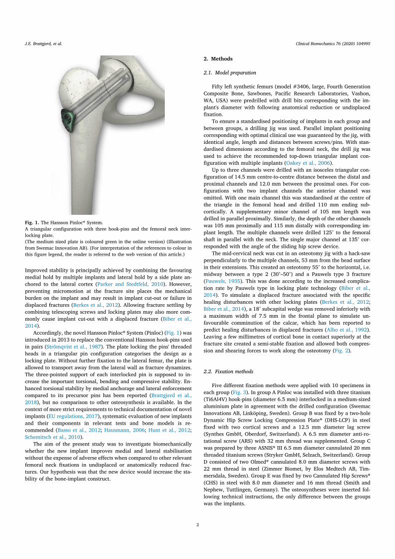
Improved stability is principally achieved by combining the favouringmedial hold by multiple implants and lateral hold by a side plate an-chored to the lateral cortex (Parker and Stedtfeld, 2010). However,preventing micromotion at the fracture site places the mechanicalburden on the implant and may result in implant cut-out or failure indisplaced fractures (Berkes et al., 2012). Allowing fracture settling bycombining telescoping screws and locking plates may also more com-monly cause implant cut-out with a displaced fracture (Biber et al.,2014).
Accordingly, the novel Hansson Pinloc® System (Pinloc) (Fig. 1) wasintroduced in 2013 to replace the conventional Hansson hook-pins usedin pairs (Strömqvist et al., 1987). The plate locking the pins' threadedheads in a triangular pin configuration categorises the design as alocking plate. Without further fixation to the lateral femur, the plate isallowed to transport away from the lateral wall as fracture dynamizes.The three-pointed support of each interlocked pin is supposed to in-crease the important torsional, bending and compressive stability. En-hanced torsional stability by medial anchorage and lateral enforcementcompared to its precursor pins has been reported (Brattgjerd et al.,2018), but no comparison to other osteosynthesis is available. In thecontext of more strict requirements to technical documentation of novelimplants (EU regulations, 2017), systematic evaluation of new implantsand their components in relevant tests and bone models is re-commended (Basso et al., 2012; Hausmann, 2006; Hunt et al., 2012;Schemitsch et al., 2010).
The aim of the present study was to investigate biomechanicallywhether the new implant improves medial and lateral stabilisationwithout the expense of adverse effects when compared to other relevantfemoral neck fixations in undisplaced or anatomically reduced frac-tures. Our hypothesis was that the new device would increase the sta-bility of the bone-implant construct.
2. Methods
2.1. Model preparation
Fifty left synthetic femurs (model #3406, large, Fourth GenerationComposite Bone, Sawbones, Pacific Research Laboratories, Vashon,WA, USA) were predrilled with drill bits corresponding with the im-plant's diameter with following anatomical reduction or undisplacedfixation.
To ensure a standardised positioning of implants in each group andbetween groups, a drilling jig was used. Parallel implant positioningcorresponding with optimal clinical use was guaranteed by the jig, withidentical angle, length and distances between screws/pins. With stan-dardised dimensions according to the femoral neck, the drill jig wasused to achieve the recommended top-down triangular implant con-figuration with multiple implants (Oakey et al., 2006).
Up to three channels were drilled with an isosceles triangular con-figuration of 14.5 mm centre-to-centre distance between the distal andproximal channels and 12.0 mm between the proximal ones. For con-figurations with two implant channels the anterior channel wasomitted. With one main channel this was standardised at the centre ofthe triangle in the femoral head and drilled 110 mm ending sub-cortically. A supplementary minor channel of 105 mm length wasdrilled in parallel proximally. Similarly, the depth of the other channelswas 105 mm proximally and 115 mm distally with corresponding im-plant length. The multiple channels were drilled 125° to the femoralshaft in parallel with the neck. The single major channel at 135° cor-responded with the angle of the sliding hip screw device.
The mid-cervical neck was cut in an osteotomy jig with a hack-sawperpendicularly to the multiple channels, 53 mm from the head surfacein their extensions. This created an osteotomy 55° to the horizontal, i.e.midway between a type 2 (30°–50°) and a Pauwels type 3 fracture(Pauwels, 1935). This was done according to the increased complica-tion rate by Pauwels type in locking plate technology (Biber et al.,2014). To simulate a displaced fracture associated with the specifichealing disturbances with other locking plates (Berkes et al., 2012;Biber et al., 2014), a 18° subcapital wedge was removed inferiorly witha maximum width of 7.5 mm in the frontal plane to simulate un-favourable comminution of the calcar, which has been reported topredict healing disturbances in displaced fractures (Alho et al., 1992).Leaving a few millimetres of cortical bone in contact superiorly at thefracture site created a semi-stable fixation and allowed both compres-sion and shearing forces to work along the osteotomy (Fig. 2).
2.2. Fixation methods
Five different fixation methods were applied with 10 specimens ineach group (Fig. 3). In group A Pinloc was installed with three titanium(Ti6Al4V) hook-pins (diameter 6.5 mm) interlocked in a medium-sizedaluminium plate in agreement with the drilled configuration (SwemacInnovations AB, Linköping, Sweden). Group B was fixed by a two-holeDynamic Hip Screw Locking Compression Plate® (DHS-LCP) in steelfixed with two cortical screws and a 12.5 mm diameter lag screw(Synthes GmbH, Oberdorf, Switzerland). A 6.5 mm diameter anti-ro-tational screw (ARS) with 32 mm thread was supplemented. Group Cwas prepared by three ASNIS® III 6.5 mm diameter cannulated 20 mmthreaded titanium screws (Stryker GmbH, Selzach, Switzerland). GroupD consisted of two Olmed® cannulated 8.0 mm diameter screws with22 mm thread in steel (Zimmer Biomet, by Elos Medtech AB, Tim-mersdala, Sweden). Group E was fixed by two Cannulated Hip Screws®(CHS) in steel with 8.0 mm diameter and 16 mm thread (Smith andNephew, Tuttlingen, Germany). The osteosyntheses were inserted fol-lowing technical instructions, the only difference between the groupswas the implants.
Fig. 1. The Hansson Pinloc® System.A triangular configuration with three hook-pins and the femoral neck inter-locking plate.(The medium sized plate is coloured green in the online version) (Illustrationfrom Swemac Innovation AB). (For interpretation of the references to colour inthis figure legend, the reader is referred to the web version of this article.)
J.E. Brattgjerd, et al. Clinical Biomechanics 76 (2020) 104995
2

2.3. General test procedure
The proximal femurs of 15 cm length were press-fitted into a steeltube mounted in a testing machine (MiniBionix 858 MTS Systems, EdenPrairie, MN, USA). The load cell exhibited respective axial and torsionalcharacteristics (capacity, 10 kN and 100 Nm; resolution, 1 N and0.005 Nm; Displacement, 1 μm and 0.1°; accuracy < 0.5%). The loadand displacement by the piston were recorded by a computer.
2.3.1. Quasi-static testingIntroductory quasi-static testing was performed (Fig. 4). Non-de-
structive load levels were chosen to allow further testing without in-criminating the latter tests (Zdero et al., 2010). In the torsional test, thefemoral head was point-fixed in a cylindrical steel cup simulating theacetabulum (Zdero et al., 2010). The actuator transferred torque at arate of 1°/s until 10° rotation around the longitudinal axis of the neck, aclinical interesting value concerning the risk of non-union (Ragnarssonand Kärrholm, 1992). Rotation was tested clockwise, then antic-lockwise viewed from medially. In anteroposterior bending the modelwas oriented horizontally and the femoral head was loaded anteriorly.This simulated the orientation of the joint reaction force in sitting downor walking stairs (Bergmann et al., 2001). A support was placed beneaththe minor trochanter to isolate displacement to the osteosynthesis(Kauffman et al., 1999) (Fig. 4). In compression, specimens weremounted vertically with 7° adduction to mimic the contact force vectorduring one-leg stand phase (Bergmann et al., 2001). A low frictionpiston avoided accumulation of shear forces in bending and compres-sion and loaded 500 N at a rate of 200 N/s. All quasi-static tests wererepeated three times with a minor axial preload of 30 N.
2.3.2. Dynamic testingCyclic compression followed with a number of cycles often con-
sidered to simulate the steps until fracture consolidation (Aminianet al., 2007). The dynamic load was applied at the femoral head withsinusoidal motion using load control (rate 1 Hz; cycles 10,000; max-imum load 1900 N; preload 60 N). This load approximated the esti-mated joint reaction force in one-leg stance phase of a 92 kg Caucasian
male, the model of the applied synthetic bones (Basso et al., 2014a;Bergmann et al., 2001).
2.3.3. OutcomesThe mean slope of the linear load-deformation curves from the
quasi-static loadings defined the initial torsional, bending and com-pressive fixation stiffness (Zdero et al., 2010). Deformation of the modelin unloaded phase after cycling intended to reflect deformation byweight-bearing in the fracture healing period. To evaluate local de-formation, the femoral head implant channels were measured by acalliper after dismantling. The mean difference between drilled andmeasured channel diameter was calculated in each group. In group B,only the lag screw channel was measured. The formation of fracturelines defined initial fixation failure.
2.4. Statistical analysis
Descriptive statistics were calculated, average values expressed as
Fig. 2. The osteotomy.The novel implant fixating a composite femur with a mid-cervical wedge os-teotomy simulating a femoral neck fracture, 55° to the horizontal with simu-lated subcapital comminution by an 18° varus wedge removed in the frontalplane.
Fig. 3. The implants.From the top the implants A–E are pictured.A: The novel Hansson Pinloc® System.B: A two-hole Dynamic Hip Screw plate® with cortical screws and a 6,5 mmcancellous screw.C: Three ASNIS III® screws.D: Two Olmed® screws.E: Two Cannulated Hip Screws®.
J.E. Brattgjerd, et al. Clinical Biomechanics 76 (2020) 104995
3
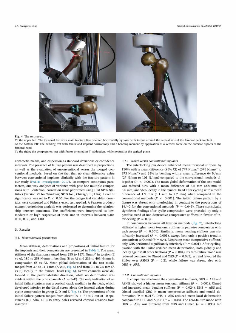
arithmetic means, and dispersion as standard deviations or confidenceintervals. The presence of failure pattern was described as proportions,as well as the evaluation of unconventional versus the merged con-ventional methods, based on the fact that no clear difference existsbetween conventional implants clinically with the fracture pattern inour study (FAITH investigators, 2017). To compare continuous para-meters, one-way analyses of variance with post hoc multiple compar-isons with Bonferroni correction were performed using IBM SPSS Sta-tistics (version 25 for Windows; SPSS Inc., Chicago, IL, USA). Level ofsignificance was set to P < 0.05. For the categorical variables, cross-tabs were computed and Fisher's exact test applied. A Pearson product-moment correlation analysis was performed to determine the relation-ship between outcomes. The coefficients were interpreted as low,moderate or high respective of their size in intervals between 0.00,0.30, 0.50, and 1.00.
3. Results
3.1. Biomechanical parameters
Mean stiffness, deformations and proportions of initial failure forthe implants and their comparisons are presented in Table 1. The meanstiffness of the fixations ranged from 355 to 1371 Nmm/° in torsion (Evs A), 180 to 258 N/mm in bending (B vs A) and 236 to 403 N/mm incompression (E vs A). Mean global deformation of the test modelranged from 3.4 to 11.1 mm (A vs E, Fig. 5) and from 0.1 to 2.5 mm (Avs E) locally in the femoral head (Fig. 6). Screw channels were de-formed in the proximal-distal direction, while no deformation wasevident within the pins' channels (A vs B–E). The only indication of aninitial failure pattern was a cortical crack medially in the neck, whichdeveloped inferior to the distal screw along the femoral calcar duringcyclic compression in group C, D and E (Fig. 6). The proportions of thisinitial failure pattern ranged from absent (A + B) to 7 out of 10 spe-cimens (D). Also, all CHS entry holes revealed cortical erosions frominsertion.
3.1.1. Novel versus conventional implantsThe interlocking pin device enhanced mean torsional stiffness by
130% with a mean difference (95% CI) of 774 Nmm/° (575 Nmm/° to973 Nmm/°) and 33% in bending with a mean difference 64 N/mm(27 N/mm to 101 N/mm) compared to the conventional methods al-together (P < 0.001). The mean global deformation of the test modelwas reduced 62% with a mean difference of 5.6 mm (2.8 mm to8.5 mm) and 95% locally in the femoral head after cycling with a meandifference of 1.9 mm (1.1 mm to 2.7 mm) when compared to theconventional methods (P < 0.001). The initial failure pattern by afissure was absent with interlocking in contrast to the proportions of14/40 for the conventional methods (P = 0.045). These statisticallysignificant findings after cyclic compression were preceded by only apositive trend of non-destructive compressive stiffness in favour of in-terlocking (P = 0.8).
In comparison between all fixation methods (Fig. 7), interlockingaffiliated a higher mean torsional stiffness in pairwise comparison witheach group (P < 0.001). Similarly, mean bending stiffness was sig-nificantly increased (P < 0.001), except from only a positive trend incomparison to Olmed (P= 0.4). Regarding mean compressive stiffness,only CHS performed significantly inferiorly (P = 0.001). After cycling,fixation with the Pinloc reduced mean deformation, both globally andlocally against all other fixations (P= 0.004). Its zero-failure mode wasreduced compared to Olmed and CHS (P= 0.033), a trend favoured thePinloc over ASNIS (P = 0.2), while failure was absent also withDHS + ARS.
3.1.2. Conventional implantsIn comparisons between the conventional implants, DHS + ARS and
ASNIS showed a higher mean torsional stiffness (P < 0.001). Olmedhad increased mean bending stiffness (P = 0.024). DHS + ARS andOlmed excelled CHS in mean compressive stiffness and model de-formation (P = 0.017). DHS + ARS reduced mean local deformationcompared to CHS and ASNIS (P = 0.048). The zero-failure mode withDHS + ARS was different from CHS and Olmed (P = 0.033). No
Fig. 4. The test set-up.To the upper left: The torsional test with main fracture line oriented horizontally by laser with torque around the central axis of the femoral neck implant.At the bottom left: The bending test with femur and implant horizontally and a bending moment by application of a vertical force on the anterior aspects of thefemoral head.To the right; the compression test with femur oriented in 7° adduction, while neutral in the sagittal plane.
J.E. Brattgjerd, et al. Clinical Biomechanics 76 (2020) 104995
4

fixation methods provided statistically significant inferior parametersto CHS.
3.2. Correlations
The Pearson product-moment correlation analysis between theoutcomes is presented in Table 2. The stiffnesses documented statisti-cally significant correlations between the different load directions re-vealing low or moderate correlation coefficients (r = 0.29–0.49,n = 50, P < 0.05). The outcomes within compression exposed sta-tistically significant moderate to high coefficients with absolute valuesfrom 0.39 to 0.80 (P < 0.01).
4. Discussion
4.1. Interpretation
Compared to the established methods altogether (A vs B–E), Pinlocimproved torsional, bending and compressive stability. In compressionthe impact was most evident by enhanced dynamic stability withoutadverse effects in fatigue testing. This indicates the presence of an in-creased multidirectional stability with retained intermediate dynamiccompression.
In pairwise comparisons to each of the other fixations, improve-ments are explained by Pinloc outperforming the advantageous lateralhold by fixed angle fixations and medial hold by multiple screws.
Compared to cannulated screws (A vs C, D, E), multi-directional fixa-tion stability was significantly increased in most parameters. The ex-ceptions were only a trend towards Pinloc compared to Olmed inbending and compressive stiffness and to ASNIS in compressive stiffnessand failure frequency. These findings agree well with increased medialfixation and lateral enforcement by interlocking compared to individualimplants (Brattgjerd et al., 2018). Between the plate osteosyntheses (Avs B), the only exceptions to increased multi-directional stability byPinloc was no difference in compressive stiffness and failure frequency.This is suggestive of no beneficial lateral hold by fixating the plate tothe lateral cortex between these fixed angle devices. The additionalstrengthened medial fixation attributed the multiple femoral headfixation combined with fixed angle devices (Aminian et al., 2007;Brandt et al., 2011) is in correspondence with our findings.
In-between conventional implants, the torsional and compressivestability with the fixed angle device were increased in most compar-isons to no-plate devices (B vs C, D, E). Cannulated screws were alsounable to prevent fatigue failure of calcar which is indicative of a re-duced lateral purchase. A less stable CHS fixation followed damage ofthe lateral entry holes by the screw with a prominent larger thread thanshaft diameter. These findings reflected the insufficient lateral hold bycannulated screws (Parker and Stedtfeld, 2010), which showed some-what similar characteristics in our study. The increased stability mea-surements by DHS + ARS over multiple screws correspond with thepreference in more unstable basicervical fractures (FAITH Investigators,2017). However, a most likely deficient medial fixation was manifested
Table 1Results from biomechanical testing of all fixation methods.
Fixation methods Torsional stiffness(Nmm/°)
Bending stiffness (N/mm)
Compressive stiffness (N/mm)
Model deformation(mm)
Channel deformation(mm)
Initial failure (n/N)
A: PINLOC 1371 (215) a 258 (17) a 403 (73) a 3.4 (0.9) a 0.1 (0.1) a 0/10 aB: DHS + ARS 840 (122) b 180 (46) b 401 (99) a 7.4 (2.3) b 1.3 (0.5) b 0/10 aC: ASNIS 743 (86) b 184 (12) b 342 (66) a,b 10.2 (1.7) b,c 2.2 (0.2) c 2/10 a,bD: OLMED 450 (156) c 229 (47) a 364 (127) a 7.4 (2.3) b 1.9 (0.5) b,c 7/10 cE: CHS 355 (48) c 183 (14) b 236 (36) b 11.1 (3.7) c 2.5 (1.2) c 5/10 b,cB–E 597 (229) 194 (39) 336 (106) 9.0 (3.0) 2.0 (0.8) 14/40A/(B–E) 2.30⁎ 1.33⁎ 1.20 0.38⁎ 0.05⁎ 0.00⁎
Mean values with standard deviation (SD) and proportions of failure mode from tests.Different small letters indicate significant difference in the same column (p < 0.05).Two letters in a cell indicate no significant difference to groups with any of these letters.Proportion Y vs X = Y/X.
⁎ Comparison of corresponding means with statistically significant difference (p < 0.05).
Fig. 5. Model deformation.From left to right global deformation of test models A–E. Depression of the femoral head was reduced by Pinloc® (A) compared to the conventional fixations (B–E)after cyclic testing.
J.E. Brattgjerd, et al. Clinical Biomechanics 76 (2020) 104995
5
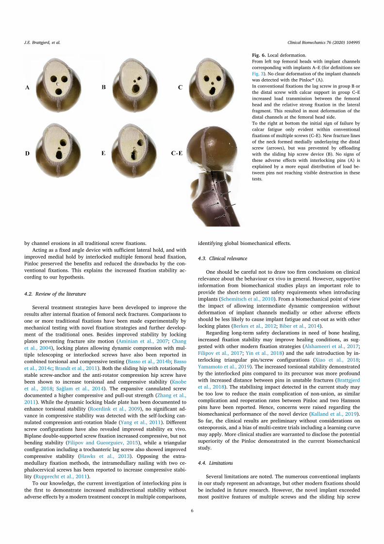
by channel erosions in all traditional screw fixations.Acting as a fixed angle device with sufficient lateral hold, and with
improved medial hold by interlocked multiple femoral head fixation,Pinloc preserved the benefits and reduced the drawbacks by the con-ventional fixations. This explains the increased fixation stability ac-cording to our hypothesis.
4.2. Review of the literature
Several treatment strategies have been developed to improve theresults after internal fixation of femoral neck fractures. Comparisons toone or more traditional fixations have been made experimentally bymechanical testing with novel fixation strategies and further develop-ment of the traditional ones. Besides improved stability by lockingplates preventing fracture site motion (Aminian et al., 2007; Changet al., 2004), locking plates allowing dynamic compression with mul-tiple telescoping or interlocked screws have also been reported incombined torsional and compressive testing (Basso et al., 2014b; Bassoet al., 2014c; Brandt et al., 2011). Both the sliding hip with rotationallystable screw-anchor and the anti-rotator compression hip screw havebeen shown to increase torsional and compressive stability (Knobeet al., 2018; Sağlam et al., 2014). The expansive cannulated screwdocumented a higher compressive and pull-out strength (Zhang et al.,2011). While the dynamic locking blade plate has been documented toenhance torsional stability (Roerdink et al., 2009), no significant ad-vance in compressive stability was detected with the self-locking can-nulated compression anti-rotation blade (Yang et al., 2011). Differentscrew configurations have also revealed improved stability ex vivo.Biplane double-supported screw fixation increased compressive, but notbending stability (Filipov and Gueorguiev, 2015), while a triangularconfiguration including a trochanteric lag screw also showed improvedcompressive stability (Hawks et al., 2013). Opposing the extra-medullary fixation methods, the intramedullary nailing with two ce-phalocervical screws has been reported to increase compressive stabi-lity (Rupprecht et al., 2011).
To our knowledge, the current investigation of interlocking pins isthe first to demonstrate increased multidirectional stability withoutadverse effects by a modern treatment concept in multiple comparisons,
identifying global biomechanical effects.
4.3. Clinical relevance
One should be careful not to draw too firm conclusions on clinicalrelevance about the behaviour ex vivo in general. However, supportiveinformation from biomechanical studies plays an important role toprovide the short-term patient safety requirements when introducingimplants (Schemitsch et al., 2010). From a biomechanical point of viewthe impact of allowing intermediate dynamic compression withoutdeformation of implant channels medially or other adverse effectsshould be less likely to cause implant fatigue and cut-out as with otherlocking plates (Berkes et al., 2012; Biber et al., 2014).
Regarding long-term safety declarations in need of bone healing,increased fixation stability may improve healing conditions, as sug-gested with other modern fixation strategies (Alshameeri et al., 2017;Filipov et al., 2017; Yin et al., 2018) and the safe introduction by in-terlocking triangular pin/screw configurations (Xiao et al., 2018;Yamamoto et al., 2019). The increased torsional stability demonstratedby the interlocked pins compared to its precursor was more profoundwith increased distance between pins in unstable fractures (Brattgjerdet al., 2018). The stabilising impact detected in the current study maybe too low to reduce the main complication of non-union, as similarcomplication and reoperation rates between Pinloc and two Hanssonpins have been reported. Hence, concerns were raised regarding thebiomechanical performance of the novel device (Kalland et al., 2019).So far, the clinical results are preliminary without considerations onosteoporosis, and a bias of multi-centre trials including a learning curvemay apply. More clinical studies are warranted to disclose the potentialsuperiority of the Pinloc demonstrated in the current biomechanicalstudy.
4.4. Limitations
Several limitations are noted. The numerous conventional implantsin our study represent an advantage, but other modern fixations shouldbe included in future research. However, the novel implant exceededmost positive features of multiple screws and the sliding hip screw
Fig. 6. Local deformation.From left top femoral heads with implant channelscorresponding with implants A–E (for definitions seeFig. 3). No clear deformation of the implant channelswas detected with the Pinloc® (A).In conventional fixations the lag screw in group B orthe distal screw with calcar support in group C–Eincreased load transmission between the femoralhead and the relative strong fixation in the lateralfragment. This resulted in most deformation of thedistal channels at the femoral head side.To the right at bottom the initial sign of failure bycalcar fatigue only evident within conventionalfixations of multiple screws (C–E). New fracture linesof the neck formed medially underlaying the distalscrew (arrows), but was prevented by offloadingwith the sliding hip screw device (B). No signs ofthese adverse effects with interlocking pins (A) isexplained by a more equal distribution of load be-tween pins not reaching visible destruction in thesetests.
J.E. Brattgjerd, et al. Clinical Biomechanics 76 (2020) 104995
6
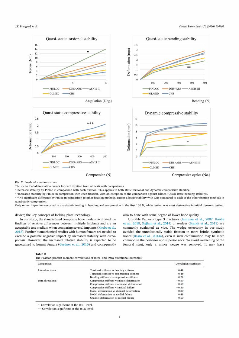
device; the key concepts of locking plate technology.In our study, the standardised composite bone models facilitated the
findings of relative differences between multiple implants and are anacceptable test medium when comparing several implants (Knobe et al.,2018). Further biomechanical studies with human femurs are needed toexclude a possible negative impact by increased stability with osteo-porosis. However, the increased relative stability is expected to begeneralised to human femurs (Gardner et al., 2010) and consequently
also to bone with some degree of lower bone quality.Unstable Pauwels type 3 fractures (Aminian et al., 2007; Knobe
et al., 2018; Sağlam et al., 2014) or wedges (Brandt et al., 2011) arecommonly evaluated ex vivo. The wedge osteotomy in our studyavoided the unrealistically stable fixation in more brittle, syntheticbones (Basso et al., 2014a), even if such comminution may be morecommon in the posterior and superior neck. To avoid weakening of thefemoral strut, only a minor wedge was removed. It may have
Angulation (Deg.) Bending (N)
Def
orm
atio
n (m
m)
Torq
ue(N
m)
Def
orm
atio
n (m
m)
Def
orm
atio
n (m
m)
Compression (N) Compressive cycles (No.)
0
2
4
6
8
10
12
14
16
0 5 10
Quasi-static torsional stability
PINLOC DHS+ARS ASNIS III
OLMED CHS
0
0.5
1
1.5
2
2.5
3
3.5
0 100 200 300 400 500
Quasi-static bending stability
PINLOC DHS+ARS ASNIS III
OLMED CHS
0
0.5
1
1.5
2
2.5
0 100 200 300 400 500
Quasi-static compressive stability
PINLOC DHS+ARS ASNIS III
OLMED CHS
0
2
4
6
8
10
12
Dynamic compressive stability
PINLOC DHS+ARS ASNIS III
OLMED CHS
*
**
***
*
Fig. 7. Load-deformation curves.The mean load-deformation curves for each fixation from all tests with comparisons.*Increased stability by Pinloc in comparison with each fixation. This applies to both static torsional and dynamic compressive stability.**Increased stability by Pinloc in comparison with each fixation, with an exception of the comparison against Olmed (Quasi-static bending stability).***No significant difference by Pinloc in comparison to other fixation methods, except a lower stability with CHS compared to each of the other fixation methods inquasi-static compression.Only minor impaction occurred in quasi-static testing in bending and compression in the first 100 N, while testing was most destructive in initial dynamic testing.
Table 2The Pearson product-moment correlations of inter- and intra-directional outcomes.
Comparison Correlation coefficient
Inter-directional Torsional stiffness vs bending stiffness 0.49⁎
Torsional stiffness vs compression stiffness 0.48⁎
Bending stiffness vs compression stiffness 0.29⁎⁎
Intra-directional Compressive stiffness vs model deformation −0.57⁎
Compressive stiffness vs channel deformation −0.50⁎
Compressive stiffness vs medial failure −0.39⁎
Model deformation vs channel deformation 0.80⁎
Model deformation vs medial failure 0.48⁎
Channel deformation vs medial failure 0.53⁎
⁎ Correlation significant at the 0.01 level.⁎⁎ Correlation significant at the 0.05 level.
J.E. Brattgjerd, et al. Clinical Biomechanics 76 (2020) 104995
7
contributed to stress accumulation and inferior fissuring, which wereprevented by interlocked pins. The wedge may have enabled the findingof intermediate dynamic compression with Pinloc. The osteotomy'sreduced inherent stability allows expecting a biomechanical effect ofthe intervention also in mild dislocation with less successful implantpositioning, but further investigation of more stable fracture patterns isnecessary regarding undisplaced fractures.
Testing of intact specimens validated the use of the 4th generationsynthetic femurs (Heiner, 2008), and an equivalent test may have giveninteresting parameters of relative stability between intact and fixedbone in our study. In correspondence with our aim, this procedure wasnot performed, as it is unclear to what extent this would reflect thestability requirements with fracture healing. Otherwise, the relativedifferences between implants detected in our study, also should applywhen compared with an intact test specimen. When comparing a si-milar isosceles triangular screw configuration interlocked in a similarplate in fractured human bone with the intact specimens, a 22% re-duction in lateral strain and 5% increased medial strain were detected(Basso et al., 2014b). A corresponding reduction in stability would beexpected in our study if the fixed specimens had been compared withthe intact ones.
With the standardised material and dimensions of test models in ourstudy, the load-deformation curves by each implant correspond withglobal stress-strain curves, while local measurements are needed forassessments of local stress distribution. However, the load distributionhas been reported as not being influenced by the corresponding inter-locking of three screws during compression and torque (Basso et al.,2014b).
Our study design was motivated by the recommended more sys-tematic evaluations (Hunt et al., 2012; Schemitsch et al., 2010). Noteven within compression the results are categorically supportive oflocking plates, as improved initial static strength has not been reportedto be followed by improved fatigue performance (Hunt et al., 2012). Wereport significant correlations between stability in different directionsand between static and dynamic stability. These findings add to theargumentation of testing relevant load directions and modes to revealimplant's strength and weaknesses, where the variation in coefficientsexpresses different aspects of stability. However, only failure by fixationfatigue and not load to failure was evaluated in our study. To in-vestigate the implications of implant modification on load distribution,the use of cadaver femurs has been recommended (Basso et al., 2014a;Hunt et al., 2012) with relevant overloading and analysis of three-di-mensional motions and strain (Aminian et al., 2007; Basso et al., 2014b;Basso et al., 2014c), which are warranted in further studies. Our find-ings of high correlation (r = 0.80) between local and global deforma-tion adds to the discussion on the necessity of use of such expensiveequipment, as most deformation obviously takes place at the fracturesite.
5. Conclusions
The plate with interlocking of pins demonstrated improved multi-directional stability in synthetic bone compared to frequently used fe-moral neck fixations. These experimental findings are considered safeand beneficial, but are not coincident with preliminary clinical results,and more clinical results are needed.
Funding
This research did not receive any specific grant from fundingagencies in the public, commercial, or not for profit sector.
Declaration of competing interest
All authors declare no conflict of interest.
Acknowledgments
The authors want to thank Swemac Innovation AB for supplyingimplants and synthetic bones without any further participation in thestudy. We extend our thanks to statistician Are Hugo Pripp and pho-tographer Øystein Horgmo at the University of Oslo, whom are ap-preciated for their contributions.
References
Alho, A., Benterud, J.G., Rønningen, H., Høiseth, A., 1992. Prediction of disturbed healingin femoral neck fracture. Radiographic analysis of 149 cases. Acta Orthop. Scand. 63(6), 639–644.
Alshameeri, Z., Elbashir, M., Parker, M.J., 2017. The outcome of intracapsular hip frac-ture fixation using the Targon Femoral Neck (TFN) locking plate system or cannu-lated cancellous screws: a comparative study involving 2004 patients. Injury 48 (11),2555–2562.
Aminian, A., Gao, F., Fedoriw, W.W., Zhang, L.Q., Kalainov, D.M., Merk, B.R., 2007.Vertically oriented femoral neck fractures: mechanical analysis of four fixationtechniques. J. Orthop. Trauma 21 (8), 544–548.
Bartels, S., Gjertsen, J.E., Frihagen, F., Rogmark, C., Utvag, S.E., 2018. High failure rateafter internal fixation and beneficial outcome after arthroplasty in treatment of dis-placed femoral neck fractures in patients between 55 and 70 years. Acta Orthop. 89(1), 53–58.
Basso, T., Klaksvik, J., Syversen, U., Foss, O.A., 2012. Biomechanical femoral neck frac-ture experiments - a narrative review. Injury 43 (10), 1633–1639.
Basso, T., Klaksvik, J., Syversen, U., Foss, O.A., 2014a. A biomechanical comparison ofcomposite femurs and cadaver femurs used in experiments on operated hip fractures.J. Biomech. 47 (16), 3898–3902.
Basso, T., Klaksvik, J., Foss, O.A., 2014b. Locking plates and their effects on healingconditions and stress distribution: a femoral neck fracture study in cadavers. Clin.Biomech. 29 (5), 595–598.
Basso, T., Klaksvik, J., Foss, O.A., 2014c. The effect of interlocking parallel screws insubcapital femoral-neck fracture fixation: a cadaver study. Clin. Biomech. 29 (2),213–217.
Bergmann, G., Deuretzbacher, G., Heller, M., Graichen, F., Rohlmann, A., Strauss, J.,Duda, G.N., 2001. Hip contact forces and gait patterns from routine activities. J.Biomech. 34 (7), 859–871.
Berkes, M.B., Little, M.T., Lazaro, L.E., Cymerman, R.M., Helfet, D.L., Lorich, D.G., 2012.Catastrophic failure after open reduction internal fixation of femoral neck fractureswith a novel locking plate implant. J. Orthop. Trauma 26 (10), e170–e176.
Bhandari, M., Devereaux, P.J., Tornetta 3rd, P., Swiontkowski, M.F., Berry, D.J.,Haidukewych, G., Schemitsch, E.H., Hanson, B.P., Koval, K., Dirschl, D., Leece, P.,Keel, M., Petrisor, B., Heetveld, M., Guyatt, G.H., 2005. Operative management ofdisplaced femoral neck fractures in elderly patients: an international survey. J. BoneJoint Surg. Am. 87 (9), 2122–2130.
Biber, R., Brem, M., Bail, H.J., 2014. Targon femoral neck for femoral-neck fracturefixation: lessons learnt from a series of one hundred and thirty-five consecutive cases.Int. Orthop. 38 (3), 595–599.
Brandt, E., Verdonschot, N., van Vugt, A.B., van Kampen, A., 2011. Biomechanical ana-lysis of the sliding hip screw, cannulated screws and Targon® FN in intracapsular hipfractures in cadaver femora. Injury 42 (2), 183–187.
Brattgjerd, J.E., Loferer, M., Niratisairak, S., Steen, H., Strømsøe, K., 2018. Increasedtorsional stability by a novel femoral neck locking plate. The role of plate design andpin configuration in a synthetic bone block model. Clin. Biomech. 55, 28–35.
Chang, Y.B., Yin, D., Li, P.Y., 2004. Design and biomechanical structure evaluation of self-locking screw plate system for femoral neck fracture. Chin. J. Clin. Rehab. 8 (35),8126–8128.
Dolatowski, F.C., Frihagen, F., Bartels, S., Opland, V., Šaltytė, Benth, J., Talsnes, O.,Hoelsbrekken, S.E., Utvåg, S.E., 2019. Screw fixation versus hemiarthroplasty fornondisplaced femoral neck fractures in elderly patients: a multicenter randomizedcontrolled trial. J. Bone Joint Surg. Am. 101 (2), 136–144.
Filipov, O., Gueorguiev, B., 2015. Unique stability of femoral neck fractures treated withthe novel biplane double-supported screw fixation method: a biomechanical cadaverstudy. Injury 46 (2), 218–226.
Filipov, O., Stoffel, K., Gueorguiev, B., Sommer, C., 2017. Femoral neck fracture osteo-synthesis by the biplane double-supported screw fixation method (BDSF) reduces therisk of fixation failure: clinical outcomes in 207 patients. Arch. Orthop. Trauma Surg.137 (6), 779–788.
Fixation using Alternative Implants for the Treatment of Hip fractures (FAITH)Investigators, 2017. Fracture fixation in the operative management of hip fractures(FAITH): an international, multicentre, randomised controlled trial. Lancet 389(10078), 1519–1527.
Gardner, M.P., Chong, A.C., Pollock, A.G., Wooley, P.H., 2010. Mechanical evaluation oflarge-size fourth-generation composite femur and tibia models. Ann. Biomed. Eng. 38(3), 613–620.
Gjertsen, J.E., Engesæter, L.B., Furnes, O., Havelin, L.I., Steindal, K., Vinje, T., Fevang,J.M., 2008. The Norwegian Hip Fracture Register: experiences after the first 2 yearsand 15,576 reported operations. Acta Orthop. 79 (5), 583–593.
Gjertsen, J.E., Vinje, T., Engesaeter, L.B., Lie, S.A., Havelin, L.I., Furnes, O., Fevang, J.M.,2010. Internal screw fixation compared with bipolar hemiarthroplasty for treatmentof displaced femoral neck fractures in elderly patients. J. Bone Joint Surg. Am. 92 (3),619–628.
J.E. Brattgjerd, et al. Clinical Biomechanics 76 (2020) 104995
8
Hausmann, J.T., 2006. Sawbones in biomechanical settings - a review. Osteo Trauma Care14 (4), 259–264.
Hawks, M.A., Kim, H., Strauss, J.E., Oliphant, B.W., Golden, R.D., Hsieh, A.H., Nascone,J.W., O'Toole, R.V., 2013. Does a trochanteric lag screw improve fixation of verticallyoriented femoral neck fractures? A biomechanical analysis in cadaveric bone. Clin.Biomech. 28 (8), 886–891.
Heiner, A.D., 2008. Structural properties of fourth-generation composite femurs and ti-bias. J. Biomech. 41 (15), 3282–3284.
Hunt, S., Martin, R., Woolridge, B., 2012. Fatigue testing of a new locking plate for hipfractures. J. Med. Biol. Eng. 32 (2), 117–122.
Kalland, K., Åberg, H., Berggren, A., Ullman, M., Snellman, G., Jonsson, K.B., Johansson,T., 2019. Similar outcome of femoral neck fractures treated with Pinloc or HanssonPins: 1-year data from a multicenter randomized clinical study on 439 patients. ActaOrthop. 27, 1–5.
Kauffman, J.I., Simon, J.A., Kummer, F.J., Pearlman, C.J., Zuckerman, J.D., Koval, K.J.,1999. Internal fixation of femoral neck fractures with posterior comminution: abiomechanical study. J. Orthop. Trauma 13 (3), 155–159.
Knobe, M., Altgassen, S., Maier, K.J., Gradl-Dietsch, G., Kaczmarek, C., Nebelung, S., Klos,K., Kim, B.S., Gueorguiev, B., Horst, K., Buecking, B., 2018. Screw-blade fixationsystems in Pauwels three femoral neck fractures: a biomechanical evaluation. Int.Orthop. 42 (2), 409–418.
Oakey, J.W., Stover, M.D., Summers, H.D., Sartori, M., Havey, R.M., Patwardhan, A.G.,2006. Does screw configuration affect subtrochanteric fracture after femoral neckfixation? Clin. Orthop. Relat. Res. 443, 302–306.
Palm, H., Gosvig, K., Krasheninnikoff, M., Jacobsen, S., Gebuhr, P., 2009. A new mea-surement for posterior tilt predicts reoperation in undisplaced femoral neck fractures:113 consecutive patients treated by internal fixation and followed for 1 year. ActaOrthop. 80 (3), 303–307.
Parker, M.J., Gurusamy, K.S., 2001. Internal fixation implants for intracapsular hipfractures in adults. Cochrane Database Syst. Rev. 4, CD001467.
Parker, M.J., Stedtfeld, H.W., 2010. Internal fixation of intracapsular hip fractures with adynamic locking plate: initial experience and results for 83 patients treated with anew implant. Injury 41 (4), 348–351.
Pauwels, F., 1935. Der schenkelhalsbruch, ein mechanisches problem: grundlagen desheilungsvorganges, prognose und kausale therapie. Ferdinand Enke Verlag, Stuttgart,Germany.
Ragnarsson, J.I., Kärrholm, J., 1991. Stability of femoral neck fracture. Roentgen ste-reophotogrammetry of 29 hook-pinned fractures. Acta Orthop. Scand. 62 (3),201–207.
Ragnarsson, J.I., Kärrholm, J., 1992. Factors influencing postoperative movement indisplaced femoral neck fractures: evaluation by conventional radiography and ste-reoradiography. J. Orthop. Trauma 6 (2), 152–158.
Regulation (EU), 2017. 2017/745 of the European Parliament and of the Council of 5April 2017 on medical devices. Off. J. Eur. Union 117, 1–175 L.
Roerdink, W.H., Aalsma, A.M., Nijenbanning, G., van Walsum, A.D., 2009. The dynamiclocking blade plate, a new implant for intracapsular hip fractures: biomechanicalcomparison with the sliding hip screw and Twin Hook. Injury 40 (3), 283–287.
Rogmark, C., Johnell, O., 2006. Primary arthroplasty is better than intemal fixation ofdisplaced femoral neck fractures: a meta-analysis of 14 randomized studies with2,289 patients. Acta Orthop. 77 (3), 359–367.
Rupprecht, M., Grossterlinden, L., Ruecker, A.H., de Oliveira, A.N., Sellenschloh, K.,Nüchtern, J., Püschel, K., Morlock, M., Rueger, J.M., Lehmann, W., 2011. A com-parative biomechanical analysis of fixation devices for unstable femoral neck frac-tures: the Intertan versus cannulated screws or a dynamic hip screw. J. Trauma 71(3), 625–634.
Sağlam, N., Küçükdurmaz, F., Kivilcim, H., Kurtulmuş, T., Sen, C., Akpinar, F., 2014.Biomechanical comparison of antirotator compression hip screw and cannulatedscrew fixations in the femoral neck fractures. Acta Orthop. Traumatol. Turc. 48 (2),196–201.
Schemitsch, E.H., Bhandari, M., Boden, S.D., Bourne, R.B., Bozic, K.J., Jacobs, J.J., Zdero,R., 2010. The evidence-based approach in bringing new orthopaedic devices tomarket. J. Bone Joint Surg. Am. 92 (4), 1030–1037.
Strömqvist, B., Hansson, L.I., Nilsson, L.T., Thorngren, K.G., 1987. Hook-pin fixation infemoral neck fractures. A two-year follow-up study of 300 cases. Clin. Orthop. Rel.Res. 218, 58–62.
Thorngren, K.G., Hommel, A., Norrman, P.O., Thorngren, J., Wingstrand, H., 2002.Epidemiology of femoral neck fractures. Injury 33 (Suppl. 3), c1–c7.
Xiao, Y.P., Shu, D.P., Bei, M.J., Ji, T., Kan, W.S., Li, S.G., 2018. The clinical application ofa novel method of internal fixation for femoral neck fractures-dynamic lockingcompression system. J. Orthop. Surg. Res. 13 (1), 131–138.
Yamamoto, T., Kobayashi, Y., Nonomiya, H., 2019. Undisplaced femoral neck fracturesneed a closed reduction before internal fixation. Eur. J. Orthop. Surg. Traumatol. 29,73–78.
Yang, M., Chen, J., Zhang, D., Wang, J., Yu, K., Fu, Z., Zhang, H., Jiang, B., 2011.Biomechanical evaluation of a new device for internal fixation of femoral neckfractures. Artif. Cells Blood Substit. Immobil. Biotechnol. 39 (4), 252–258.
Yin, H., Pan, Z., Jiang, H., 2018. Is dynamic locking plate (Targon FN) a better choice fortreating of intracapsular hip fracture? A meta-analysis. Int. J. Surg. 52, 30–34.
Zdero, R., Keast-Butler, O., Schemitsch, E.H., 2010. A biomechanical comparison of twotriple-screw methods for femoral neck fracture fixation in a synthetic bone model. J.Trauma 69 (6), 1537–1544.
Zhang, Y., Tian, L., Yan, Y., Sang, H., Ma, Z., Jie, Q., Lei, W., Wu, Z., 2011. Biomechanicalevaluation of the expansive cannulated screw for fixation of femoral neck fractures.Injury 42 (11), 1372–1376.
J.E. Brattgjerd, et al. Clinical Biomechanics 76 (2020) 104995
9


IV

1
Interlocked Pins Increase Strength by a Lateral Spread of Load in
Femoral Neck Fixation: A Cadaver Study
MD Jan Egil Brattgjerd a, b, SR ENGR Sanyalak Niratisairak a, b, Professor emeritus MD
Harald Steen a, Professor emeritus MD Knut Strømsøe b
a Biomechanics Lab, Division of Orthopaedic Surgery, Oslo University Hospital, Norway
b Institute of Clinical Medicine, Faculty of Medicine, University of Oslo, Norway
ABSTRACT
PURPOSE OF THE STUDY
To improve the important torsional, bending and compressive stability in femoral neck
fixation, locking plates has been the latest contribution. However, increased strength by
restricted fracture motion may come at expense of an altered load distribution and failure
patterns. Within locking plate technology, the important intermediate fracture compression
may principally be achieved by multiple sliding screws in a sideplate fixed to femur or an
interlocking plate not fixed to femur laterally, sliding “en bloc”. While biomechanical studies
may deliver the short-time patient safety requirements in implant development, no adequate
failure evaluation has been performed with interlocking devices ex vivo in this setting. In this
biomechanical study we analysed if a novel femoral neck interlocking plate with pins
improved strength by changing the parameters involved in the failure mechanism in terms of
fixation strength, fracture motion, load distribution and failure pattern.
2
MATERIAL AND METHODS
Sixteen pairs of femurs with stable subcapital osteotomies were fixated by 2 pins or 3 pins
interlocked in a plate using a paired design. Femurs were loaded non-destructively to 10°
torsion around the neck, 200 N anteroposterior bending and 500 N vertical compression in 7°
adduction with 1 Hz in 20 000 cycles and were subsequently subjected to destructive
compression to evaluate failure patterns. Bending and compressive stiffness and displacement
from compressive testing reflected fracture motion. Torque and compression to failure
replicated known failure mechanisms and defined strength. To evaluate load distribution,
associations between biomechanical parameters and local bone mineral measurements by CT
were analysed.
RESULTS
Interlocked pins increased mean strength 73% in torsion and 39% in compression (p =
0.038). Strength was related to all regional mineral masses from the femoral head to
subtrochanterically with interlocking (r = 0.64-0.83, p = 0.034), while only to mineral masses
in the femoral head in compression and to the head, neck and trochanterically in torsion with
individual pins (r = 0.67-0.78, p = 0.024). No difference was detected in fracture motion or
failure pattern.
DISCUSSION
Within the last decade, the interlocking plates has expanded our therapeutic arsenal of femoral
neck fractures. The increased stability at the expense of altered devastating failure patterns
was not retrieved in our study. The broadened understanding of interlocking plates by our
study involved the feature to gain fixation strength by permitting fracture compression and a
lateral spread of load from local bone mineral factors in the fragile medially bone with pins to
3
the more solid lateral bone with interlocked pins. Regarding the long-term patient safety of
interlocking devices regarding healing complications of non-union and segmental collapse of
the femoral head, a definite conclusion may be premature. However, the improved
biomechanics must be considered a favourable development of the pin concept.
CONCLUSIONS
The interlocked pins improved strength by a lateral spread of load, not by restricting
fracture motion and altering failure patterns. This is encouraging of further studies of the
interlocking plate technology with this unsolved fracture.
Key words: femoral neck fracture, biomechanics, cadaver bone, bone mineral, internal
fixation, locking plate, pins
4
INTRODUCTION
Intracapsular femoral neck fractures comprise more than half of the common proximal
femur fractures (10) with subcapital fractures as the most frequent type (9). The key
complication with failure of the fracture to heal is determined by a pattern of torsional,
bending and compressive instability (18, 20-21). High revision rates of 11-27% remain with
internal fixation as the main treatment in non-displaced fractures and in middle-aged patients
with displaced fractures (2, 11). No clear conclusion on which implant is superior can be
drawn between the traditional multiple screws, pins or a sliding hip screw device in this
setting (9, 19).
To improve results, the use of locking plates has been the latest attempt. Improved stability
by locking plates restricting fracture motion with non-parallel screws, may change load
distribution and come at cost of altered failure patterns of implant fatigue or cut-out (1, 6). In
contrast, reduced reoperation rates have been reported with locking plate technology
permitting intermediate fracture compression, i.e. sliding of the fracture (26). Principally, this
may be achieved by parallel sliding screws locked in a sideplate fixed to femur (7) or parallel
screws interlocked in a plate not fixed to femur laterally, sliding en bloc.
Biomechanical studies evaluating the failure mechanism may deliver the short-time patient
safety in implant development (22). Accordingly, almost identical failure patterns were
detected ex vivo et in vivo with locking plates that restricted fracture motion (1, 6). To our
knowledge, no such failure evaluation has been reported with interlocking devices. So far,
only an improved dynamic stability has been demonstrated by interlocking screws ex vivo (3,
4).
Recently, the first interlocked pins developed from the original two Hansson pins (23) have
demonstrated an enhanced torsional stability in synthetic bone blocks (8) (Fig. 1). A sufficient
5
reduction to decrease reoperation rates was emphasized in the first patients (25). Concerns of
increased stability at the expense of early devastating subtrochanteric fractures or later
segmental collapse have been raised in the first randomised controlled trial (14). To our
knowledge, there is a lack of biomechanical data to support these concerns.
The purpose of the current study was to perform an adequate failure evaluation of the
interlocking fixation principle. The objective was to evaluate if interlocked and traditional
pins differ regarding strength, fracture motion, load distribution and failure pattern in
intracapsular femoral neck fixation ex vivo. We hypothesised improved fixation stability
without restricted fracture motion or altered fracture pattern by the novel implant as intended
during implant design.
MATERIAL AND METHODS
Specimen preparation
Following approval by the regional ethics committee, 16 pairs of fresh-frozen femurs from
Caucasian donors without significant bone pathology were imported (Life Legacy
Foundation, Tucson, AZ, USA); ten females and six males with a median age of 73 years
(range, 60–78 years) and weight of 58 kg (37-91kg). Before evaluation, the proximal femurs
were thawed in room temperature overnight.
Guide-wire templates allowed a paired maximum distance between the parallel proximal
and distal pins of 6, 8, 10 or 12 mm, in agreement with plate sizes and the stabilising impact
by increased distance between pins (8). With three-pointed support, the first guide-wire was
advanced in parallel with the neck along the femoral calcar until subchondrally, while the
second was shifted posteriorly. With interlocked pins, a third guide-wire was shifted
6
anteriorly to form a top-down isosceles triangle. Adequate positioning was controlled by
fluoroscopy, guide-wires were over-drilled with a 6.7-mm drill bit and then removed.
Following pre-drilling, the femoral necks were osteotomised perpendicularly subcapitally
with a hack-saw, according to AO/OTA 31-B1.2 (16).
The right femur of each pair was allocated at http://randomization.com. Individual pins
were implanted with the original clinical configuration of two pins or three pins interlocked in
the novel plate, resulting both in locking and an additional pin, with the same pin-lengths as
the corresponding alternative in each pair (Fig. 2). To reduce variability, the same surgeon
(JEB) performed all operations. To detect alterations by the implant modification, the optimal
configuration of three interlocked pins has already been reported (8). The predecessor
represented the natural control group, supported by two Hansson pins being the most
frequently evaluated pin design within randomised clinical trials and the lack of superiority
between traditional implants (19).
The Hansson PinlocÒ System (Swemac Innovations, Linköping, Sweden) was applied with
pins of titanium alloy grade 5 with 6.5 mm shaft diameter. The four plate sizes were applied
in four pairs each. The reinforced, threaded pin-base allowed interlocking into the aluminium
plate at 125° before the inner tongue was introduced in the head.
Mechanical Testing
The 150 mm long proximal femurs were cemented distally (Biomet Orthopaedics GmbH,
Dietkon, Switzerland) and mounted in a testing machine (MiniBionix 858 MTS Systems,
Eden Prairie, MN, USA) with a load cell with respective axial and torsional characteristics;
capacity 10 kN and 100 Nm, resolution 1 N and 5 Nmm, displacement 0.001 mm and 0.1º,
accuracy < 0.5% and sampling 0.01 s. The piston´s load and displacement were recorded by a
computer (MTS FlexTest 40 with Station Manager, Eden Prairie, MN, USA).

7
Firstly, three quasi-static non-destructive tests were performed three times each with a 30 N
vertical preload (Fig. 3). In a steel-cup simulating acetabulum, the head was superficially
screw-fixated and subjected to a torsional testing rate of 1º/s both ways around the neck´s
length axis with 10º as the maximum value. This was done to keep results within the elastic
range by almost perfect correlation to initial stiffness (8) and still reflect displacement
associated with an increased risk of non-union (5). To avoid shear accumulation, a low-
friction piston applied load on the femoral head in the following tests (rate 200 N/s, maximum
bending 200 N, maximum compression 500 N). In anteroposterior bending, horizontally-
oriented specimens were loaded vertically to simulate the load direction when sitting down
(5), while a support beneath the minor trochanter isolated displacement to the fracture, i.e. as
in fracture motion. In compressive tests, vertical specimens with 7º adduction simulated the
load direction during one-leg stance (5).
Subsequent dynamic compression with a sinusoidal loading pattern (rate 1 Hz, cycles 20
000, preload 60 N) was applied to simulate a relevant number of steps until consolidation
with partial weight-bearing of one-time median bodyweight of donors in our study (1, 5, 15).
Finally, to simulate subtrochanteric fracturing (21), a quasi-static compressive load-to-
failure (LTF) was tested (rate 250 N/s, maximum load 10 kN, preload 60 N), as hip joint
reaction force may exceed eight times bodyweight during stumbling (5). After testing, the
failure patterns were inspected.
Regarding the choice of outcomes, the best line fit of the slope of the load-deformation
curve’s linear elastic portion defined stiffness in bending and compression, while
displacement was measured after cycling. These parameters were chosen to reflect fracture
motion at a low loading level, while in overloading this was reflected by displacement at
failure. Torque at risk of failure (10º) (TAF) (8) and LTF exposed respective torsional and
compressive strength. The compressive failure was defined by abrupt increment or 10 mm
8
distal displacement, as in fractures that subsequently did not heal (21). The term “pro-
interlocking” refers to the proportion how often the interlocked specimens outperformed the
paired individual pins.
Bone Mineral Assessment
Before specimen preparation, a quantitative CT (QCT) with bone scan parameters (100
mA, 120 kV, 3 mm slices) was performed in a Siemens Somatom Definition Edge (Siemens
Healthcare GmbH, Erlangen, Germany). QCT allows presenting cortical and cancellous bone
densities as volumetric density per unit of area (CT-density/cm2) without considering slice
thickness, presumed infinitely thin. In densities above -100 HU (threshold value representing
fat), mineral density estimation with excellent reproducibility and accuracy is possible (12).
The bone mineral assessment was modelled after previous work by our laboratory and
intended to reflect load distribution, as local femoral mineral mass may predict fixation
strength by variable cancellous density in mainly spongy bone and cortical area in compact
bone (24).
Syngo.via imaging software (Siemens Healthcare GmbH, Erlangen, Germany) was used to
measure bone mineral by the same instructed operator. The levels of three-pointed pin support
and the subtrochanteric level possibly involved in its failure were analysed in four slices; the
cross-sectional slice in the mid-head, -neck, -trochanter (halfway between the greater
trochanter´s tip and the minor´s lower border) and 20 mm distal to the minor (Fig. 4). A
region of interest (ROI) was drawn around the external cortex to obtain bone area, around the
internal cortex to derive the medullary/cancellous area, with cortical area as the difference
between these regions. To assess mean cancellous density, the medullary area was analysed,
while with cortical density, a 5 mm2 ROI was placed exclusively within the homogenous
cortex. The regional bone mineral mass was calculated as the summarised product of
9
cancellous and cortical area and density in each slice. No difference in regional bone mineral
mass was detected between the groups of individual and interlocked pins, neither in the
femoral head, neck, trochanterically nor subtrochanterically (p = 0.217).
Statistics
As powering for failure rate was not considered feasible, a sample-size calculation with a
minimal important difference of 2 mm fracture displacement and 1.5 mm standard deviation,
revealed that 8 pairs were needed to complete testing and achieve 90% power (STATA,
StataCorp, College Station, TX, US).
Data were processed by MATLAB (MathWorks Inc, Natick, MA, USA), tested for
normality (Shapiro-Wilk) and homoscedasticity (Levene’s test) and further analysed by IBM
SPSS Statistics (SPSS Inc. Chicago, IL, USA). Beside descriptive statistics, paired t-tests,
one-way analyses of variance and post-hoc tests with Bonferroni correction were computed
with continuous parameters and McNemar´s test with categorical variables. Results are
expressed as mean or median with range or standard deviation. A Pearson correlation analysis
was performed between bone mineral and biomechanical parameters. All tests were two-tailed
and assessed at the 5% significance level.
RESULTS
The biomechanical parameters with comparisons are presented (Table 1). A technical error
caused failures of three pairs during bending and further two pairs failed by displacement in
cyclic compression and were excluded from further analysis. The remaining 11 pairs showed
linear elastic load-displacement curves prior to LTF.
10
Considering strength (TAF and LTF), interlocked pins outperformed individual pins in all
pairs. TAF was 6.2 Nm (SD 3.8 Nm) in individual pins and 10.7 Nm (SD 4.9 Nm) in
interlocked pins with a mean increase of 73% (p < 0.001). LTF was 2034 N (SD 793 N) in
individual pins and 2827 N (SD 1405 N) in interlocked pins with a mean increase of 39% (p =
0.038).
No significant difference was found regarding fracture motion. Pro-interlocking ratio in
bending stiffness was 10/13 (p = 0.09), compressive stiffness 4/13 and displacement 7/11. No
difference was detected in displacement at failure (p = 0.477).
In LTF, the failure pattern affected all points of three-pointed fixation in both groups.
Femoral head compression and a transverse subtrochanteric fracture developed in all
specimens and a medial fissure along the calcar in five individual and two interlocked
specimens (p = 0.371). No other failure signs were identified.
The proximal femur´s mineral parameters with statistics are presented (Table 2). The
femoral head exposed the highest cancellous mineral density and mass, while the
trochantanteric and subtrochanteric level revealed the highest cortical mineral area and mass
and the lowest regional bone mineral mass in the femoral neck (p < 0.001).
The correlations between biomechanical and bone mineral parameters (Table 3a) were
confined to significant correlations between the proximal femur´s regional mineral mass and
strength in both groups. Interlocked pin strength was related to all regional mineral masses
from the femoral head to subtrochanterically (r = 0.64-0.83, p = 0.034). In difference,
individual pins were only significantly correlated to the femoral head mineral mass in LTF (r
= 0.67, p = 0.024) and not to the subtrochanteric mineral mass with TAF (r = 0.46, p = 0.085).
In subgroups (Table 3b), the significant correlations were limited to density of spongy bone
and area of compact bone (r = 0.59–0.81, p = 0.017), with the cancellous area in the femoral
head (r = 0.53–0.58, p = 0.036) and its absence subtrochanterically as the only contradictions
11
(r = -0.67– -0.52, p = 0.039). With respective individual and interlocked pins, 6/9 significant
correlations were to medial and lateral parameters, 5 and 1 to cancellous density and 3 and 5
to cortical area.
DISCUSSION
To our knowledge, this study is the first failure evaluation of a femoral neck interlocking
device. Only a moderately reduced femoral head migration and micro-motion around the
femoral neck, with no impact on load distribution or association with osteoporosis has
previously been reported by interlocking three screws during dynamic testing (3, 4).
In agreement, this study showed that interlocked parallel pins improved both torsional and
compressive fixation. In addition, no change in failure pattern or fracture motion indicated
that the important compression along the femoral neck may be safely permitted when the
interlocking plate slides away from the trochanteric wall. As far as we know, our study is the
first to conceptualize and evaluate the fixation´s ability to allow fracture compression during
ex vivo testing.
We also report a lateral shift in bone mineral parameters when predicting failure strength
with interlocked pins, which was indicative of an altered load distribution in comparison to
with individual pins. This suggested that load was spread along the three-pointed support of
each pin from the medial hold in fragile bone with individual pins to the lateral hold in solid
compact bone with interlocked pins. We are not aware of any reports of QCT indirectly
evaluating load transfer by detecting the fixation strength´s important link to local bone
mineral in this setting.
Regarding clinical relevance of our findings, an increased load at the proximal femur´s
lateral aspects, where tensile forces are substantial, may be suggestive of a subtrochanteric

12
failure initiation, but in agreement with our findings no such change in failure pattern has
been reported clinically so far (14, 25). However, with no significant impact by interlocked
pins in simulated post-operative partial weight-bearing, the safe biomechanical impact may be
too low to gain long-term clinical importance. Consistently, similar union rates have been
reported by comparing the new device to the predecessor (14), A possible bias involving a
learning curve and a multi-centre trial may apply and a definite conclusion on the clinical
importance of interlocked pins may be premature. We argue that the improved biomechanics
justifying implant introduction must be considered a favourable development of the pin
concept.
Limitations are noted. To correct for implant´s material properties only titanium pins were
used, but results should also be transferable to the original hook-pins in steel. To simulate a
non-displaced or an anatomically reduced fracture, a representative stable subcapital
osteotomy was chosen. These results nuance the profound torsional impact by interlocked
pins in an unstable mid-cervical osteotomy (8) and may also differ from results with a
genuine fracture. While a paired study in human bone is considered beneficial, this approach
only permitted evaluating the implant as a unit. A stepwise impact by the implant
modification has previously been reported mainly by the plate, but also by the third pin in
torsion (8). The obvious limitation by non-vital specimens without soft tissue was the
responses of bone healing and segmental collapse in the long-term. We tested relevant
strengths and weaknesses of the fixations by provoking failure patterns as the subtrochanteric
fracture by axial load as reported previously (17), but it is unclear which load combination
that causes this clinically. However, in correspondence with our findings, an increased load to
an unaltered transverse or short oblique subtrochanteric fracture pattern preceded the
recommendation of the top down triangular implant orientations in a previous report (17).

13
In spite of the benefit of ex vivo failure evaluations to deliver the short-time patient safety in
implant development (22), the failure mechanism may have been better distinguished by a
high-speed digital camera with strain measurements by digital image correlation, which was
not in the amenities of our lab. We did not measure strain directly, but argue that the
interpretations on local load distribution based on the more comprehensive bone mineral
assessment provide additional info in comparison to isolated measurements of medial and
lateral cortical strain by two strain gauges (3). Finally, no normative femoral mineral data
exists by QCT, but the measured densities with variation was within the normal ranges (24).
The lowest regional bone mineral mass in the femoral neck complies with its susceptibility to
fracture. In addition, well-known associations between strength and local bone mineral
parameters with variable spongy density and cortical area were retrieved (24). As bone
mineral density measured by Dual-energy X-ray Absorptiometry and CT are correlated (13)
our findings also may be extrapolated to the setting of low bone mineral content. Regarding
the choice of statistics, a correlation does not imply causality. Although, the reasonable
system of correlations between bone mineral content and failure biomechanics suggests a
causal relationship (24), a larger sample-size would have been necessary to perform a
multiple regression analysis and reveal the relative importance of the different bone mineral
factors.
CONCLUSIONS
The results of the present failure evaluation by the interlocking device with an indirect
assessment of load transfer by QCT agreed with our hypothesis. Femoral neck fixation by
multiple interlocked pins increases mechanical strength and may not harm patient safety in
the short-term, as it can be achieved by a shift of load from the fragile medial bone to the

14
more solid lateral bone and not by restricted fracture motion. This is encouraging of further
studies of the interlocking plate technology with this unsolved fracture.
15
References
1. Aminian A, Gao F, Fedoriw WW, Zhang LQ, Kalainov DM, Merk BR. Vertically
oriented femoral neck fractures: mechanical analysis of four fixation techniques. J Orthop
Trauma. 2007;21:544-548.
2. Bartels S, Gjertsen JE, Frihagen F, Rogmark C, Utvag SE. High failure rate after internal
fixation and beneficial outcome after arthroplasty in treatment of displaced femoral neck
fractures in patients between 55 and 70 years. Acta Orthop. 2018;89:53-58.
3. Basso T, Klaksvik J, Foss OA. Locking plates and their effects on healing conditions and
stress distribution: A femoral neck fracture study in cadavers. Clin Biomech.
2014;29:595-598.
4. Basso T, Klaksvik J, Foss OA. The effect of interlocking parallel screws in subcapital
femoral-neck fracture fixation: a cadaver study. Clin Biomech. 2014;29:213-217.
5. Bergmann G, Deuretzbacher G, Heller M, Graichen F, Rohlmann A, Strauss J, Duda GN.
Hip contact forces and gait patterns from routine activities. J Biomech. 2001;34:859-871.
6. Berkes MB, Little MT, Lazaro LE, Cymerman RM, Helfet DL, Lorich DG. Catastrophic
Failure After Open Reduction Internal Fixation of Femoral Neck Fractures With a Novel
Locking Plate Implant. J Orthop Trauma. 2012;26:e170-176.
7. Brandt E, Verdonschot N, van Vugt A, van Kampen A. Biomechanical analysis of the
sliding hip screw, cannulated screws and TargonÒ FN in intracapsular hip fractures in
cadaver femora. Injury. 2011;42:183-187.
8. Brattgjerd JE, Loferer M, Niratisairak S, Steen H, Stromsoe K. Increased torsional
stability by a novel femoral neck locking plate. The role of plate design and pin
configuration in a synthetic bone block model. Clin Biomech. 2018;55:28-35.
16
9. FAITH Investigators. Fracture fixation in the operative management of hip fractures
(FAITH): an international, multicentre, randomised controlled trial. Lancet.
2017;389:1519-1527.
10. Gjertsen JE, Engesaeter LB, Furnes O, Havelin LI, Steindal K, Vinje T, Fevang JM. The
Norwegian Hip Fracture Register: experiences after the first 2 years and 15.576 reported
operations. Acta Orthop. 2008;79:583-593.
11. Gjertsen JE, Fevang JM, Matre K, Vinje T, Engesaeter LB. Clinical outcome after
undisplaced femoral neck fractures. A prospective comparison of 14,757 undisplaced and
displaced fractures reported to the Norwegian Hip Fracture Register. Acta Orthop.
2011;82:268-274.
12. Hendrickson NR, Pickhardt PJ, del Rio AM, Rosas HG, Anderson PA. Bone mineral
density T-scores derived from CT attenuation numbers (Hounsfield units): clinical utility
and correlation with dual-energy X-ray absorptiometry. Iowa Orthop J. 2018;38:25-31.
13. Johnson CC, Gausden EB, Weiland AJ, Lane JM, Schreiber JJ. Using Hounsfield units to
assess osteoporotic status on wrist computed tomography scans: comparison with dual
energy x-ray absorptiometry. J Hand Surg Am. 2016;41:767-774.
14. Kalland K, Åberg H, Berggren A, Ullman M, Snellman G, Jonsson KB, Johansson T.
Similar outcome of femoral neck fractures treated with Pinloc or Hansson Pins: 1-year
data from a multicenter randomized clinical study on 439 patients. Acta Orthop.
2019;90:542-546.
15. Koval KJ, Sala DA, Kummer FJ, Zuckerman JD. Postoperative weight-bearing after a
fracture of the femoral neck or an intertrochanteric fracture. J Bone Joint Surg Am.
1998;80:352–356.
16. Meinberg EG, Agel J, Roberts CS, Karam MD, Kellam JF. Fracture and dislocation
classification compendium 2018. J Orthop Trauma. 2018;32:s1-170.
17
17. Oakey JW, Stover MD, Summers HD, Sartori M, Havey RM, Patwardhan AG. Does
screw configuration affect subtrochanteric fracture after femoral neck fixation? Clin
Orthop Relat Res. 2006;443:302-306.
18. Palm H, Gosvig K, Krasheninnikoff M, Jacobsen S, Gebuhr P. A new measurement for
posterior tilt predicts reoperation in undisplaced femoral neck fractures: 113 consecutive
patients treated by internal fixation and followed for 1 year. Acta Orthop. 2009;80:303-
307.
19. Parker MJ, Gurusamy K. Internal fixation implants for intracapsular hip fractures in
adults. Cochrane Database Syst Rev. 2001. http://dx.doi.org/10.1002/ 14651858
CD001467.
20. Ragnarsson JI, Kärrholm J. Factors influencing postoperative movement in displaced
femoral neck fractures: evaluation by conventional radiography and stereoradiography. J
Orthop Trauma. 1992;6:152-158.
21. Ragnarsson JI, Kärrholm J. Stability of femoral neck fracture. Roentgen
stereophotogrammetry of 29 hook-pinned fractures. Acta Orthop Scand. 1991;62:201-207.
22. Schemitsch EH, Bhandari M, Boden SD, Bourne RB, Bozic KJ, Jacobs JJ, Zdero R. The
evidence-based approach in bringing new orthopaedic devices to market. J Bone Joint
Surg Am. 2010;92:1030-1037.
23. Strömqvist B, Hansson LI, Nilsson LT, Thorngren KG. Hook-pin fixation in femoral neck
fractures. A two-year follow-up study of 300 cases. Clin Orthop Rel Res. 1987;218:58-62.
24. Wright B, Ragan L, Niratisairak S, Høiseth A, Strømsøe K, Steen H, Brattgjerd JE. High
correlation between mechanical properties and bone mineral parameters in embalmed
femurs after long-term storage. Clin Biomech 2018;59:136-42.
25. Yamamoto T, Kobayashi Y, Nonomiya H. Undisplaced femoral neck fractures need a
closed reduction before internal fixation. Eur J Orthop Surg Traumatol. 2019;29:73-78.

18
26. Yin H, Pan Z, Jiang H. Is dynamic locking plate (Targon FN) a better choice for treating
of intracapsular hip fracture? A meta-analysis. Int J Surg. 2018;52:30-34.
19
Legends to the figures
Fig. 1 The novel implant
The Hansson PinlocÒ System with three pins in a top down triangular configuration
interlocked in a plate laterally. The feature of a hook at the tip is unchanged from the original
Hansson pin. The 4 commercially available plate sizes; 6, 8, 10 and 12 mm according to the
length of the bridge between the proximal and distal pin hole from top.
Fig. 2 The test models
Fluoroscopic images of one pair of fixated cadaveric proximal femurs with a subcapital
osteotomy perpendicular to the central femoral neck axis. To the left the novel femoral neck
plate interlocking three pins, the original fixation configuration by two individual pins to the
right.
Fig. 3 The test directions
A: Testing in torsion around the femoral neck length axis.
B: Anteroposterior bending test in simulated sitting position.
C: Axial compression test in simulated standing position.
Fig. 4 The bone mineral parameters
To the left a proximal femur with marked levels for CT-slices for quantitative bone mineral
analysis. To the right the corresponding cross-sectional CT images.
A: Perpendicular to the central femoral neck axis in the mid-head.
B: The mid-neck.

20
C: The shaft halfway between the greater trochanter´s top and the lower border of the minor.
D: The subtrochanteric area 2 cm below the trochanter minor.
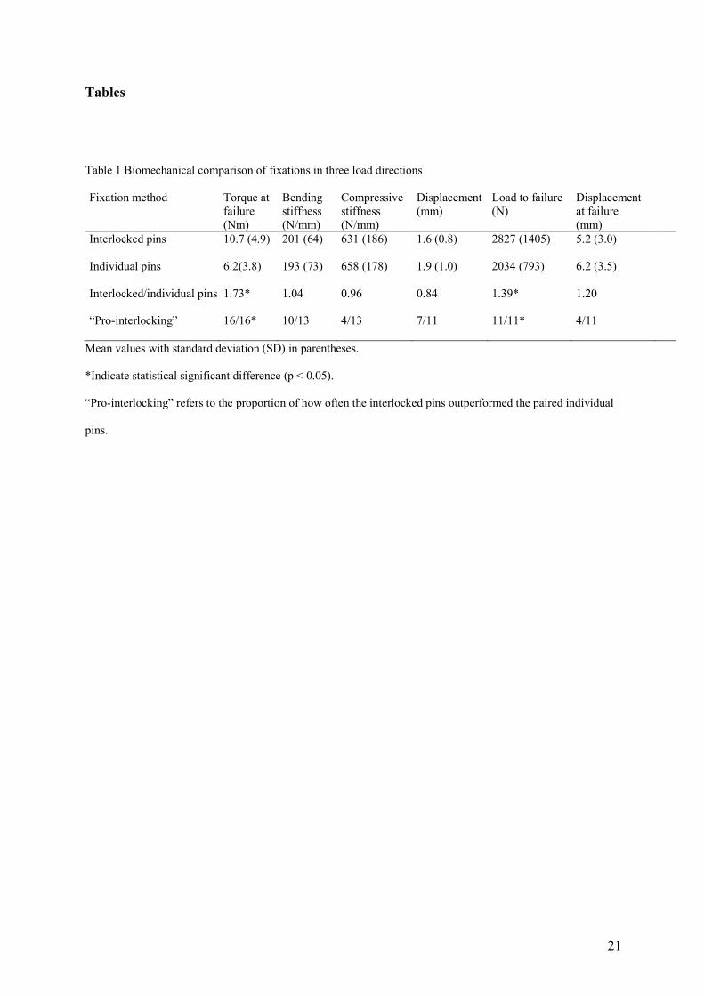
21
Tables
Table 1 Biomechanical comparison of fixations in three load directions
Fixation method Torque at failure (Nm)
Bending stiffness (N/mm)
Compressive stiffness (N/mm)
Displacement (mm)
Load to failure (N)
Displacement at failure (mm)
Interlocked pins 10.7 (4.9) 201 (64) 631 (186) 1.6 (0.8) 2827 (1405) 5.2 (3.0)
Individual pins 6.2(3.8) 193 (73) 658 (178) 1.9 (1.0) 2034 (793) 6.2 (3.5)
Interlocked/individual pins
“Pro-interlocking”
1.73*
16/16*
1.04
10/13
0.96
4/13
0.84
7/11
1.39*
11/11*
1.20
4/11
Mean values with standard deviation (SD) in parentheses.
*Indicate statistical significant difference (p < 0.05).
“Pro-interlocking” refers to the proportion of how often the interlocked pins outperformed the paired individual
pins.

22
Table 2 Bone mineral parameters from 16 pairs of proximal femurs with comparisons
Bone mineral parameter/ CT level
Cancellous area (cm2)
Cancellous density (HU/cm2)
Cortical area (cm2)
Cortical density (HU/cm2)
Cancellous mineral mass (HU)
Cortical mineral mass (HU)
Bone mineral mass (HU)
Femoral mid-head 15.2 (2.7) a 255 (69)a 2.1 (0.4) b 789 (193) b 3897 (1267) a 1650 (501) b 5544 (1442) b
Cervical mid-neck 5.9 (1.2) b 52 (61) b 1.7 (0.3) b 1690 (198) a 298 (366) c 2933 (629) c 3231 (727) c
Mid-trochanter 13.8 (2.9) a 77 (48) b 3.8 (0.6) a 1701 (124) a 1071 (646) b 6396 (1269) a 7466 (1718) a
Sub-trochanter 2.9 (0.7) c -46* (57) c 4.0 (1.0) a 1598 (306) a -123 (121) c 6307 (1900) a 6184 (1909) b
Mean values with standard deviation (SD) in parentheses.
A mean proximal femur value for each pair with SD was calculated based on the analysed CT-slices.
Different small letters within the same column indicate different parameter values in comparisons between the
CT levels for each parameter, (a ≠ b ≠ c, p < 0.05).
*Negative value represents fat without calcium

23
Table 3a. Correlations of biomechanical versus mineral parameters in the proximal femur.
Fixation Bone mineral mass/ Biomechanical parameter
Caput Collum Trochanter Subtrochanter
Interlocked pins
Torque at risk of failure (TAF) 0.69** 0.83** 0.74** 0.70**
Bending stiffness 0.28 0.18 -0.06 0.12 Compressive stiffness 0.33 0.13 -0.06 0.08 Compressive deformation -0.57 -0.58 -0.28 -0.53 Compressive load to failure (LTF) 0.64* 0.80** 0.72* 0.73* Compressive displacement at failure 0.38 0.22 0.33 0.42 Individual pins
Torque at risk of failure (TAF) 0.78** 0.74** 0.78** 0.46
Bending stiffness 0.29 0.17 0.33 -0.12 Compressive stiffness 0.64* 0.63* 0.49 0.01 Compressive deformation -0.63* -0.54 -0.51 -0.17 Compressive load to failure (LTF) 0.67* 0.50 0.46 0.47 Compressive displacement at failure 0.41 0.38 0.39 0.40
* Correlation significant at the 0.05 level.
** Correlation significant at the 0.01 level.
Table 3b Correlations of biomechanical versus mineral parameters in the proximal femur subgroups
Fixation Biomechanical parameter
Bone mineral parameter
Location: Caput Collum Trochanter Subtrochanter
Interlocked pins TAF Cancellous density 0.46 0.47 0.66** -0.04 Cancellous area 0.58* 0.35 0.24 -0.52* Cortical density -0.13 0.32 0.19 -0.12 Cortical area 0.48 0.67** 0.65** 0.67** LTF Cancellous density 0.54 0.43 0.53 -0.29 Cancellous area 0.57 0.49 0.42 -0.67* Cortical density -0.39 0.31 0.28 -0.10 Cortical area 0.15 0.64* 0.59 0.69* Individual pins TAF Cancellous density 0.59* 0.61* 0.70** 0.16 Cancellous area 0.53* 0.34 0.28 -0.44 Cortical density -0.09 0.18 0.33 -0.05 Cortical area 0.64* 0.50 0.61* 0.69* LTF Cancellous density 0.72* 0.81** 0.43 0.38 Cancellous area 0.19 0.23 0.23 -0.26 Cortical density 0.09 0.00 0.40 0.18 Cortical area 0.31 0.22 0.38 0.38
* Correlation significant at the 0.05 level.
** Correlation significant at the 0.01 level.
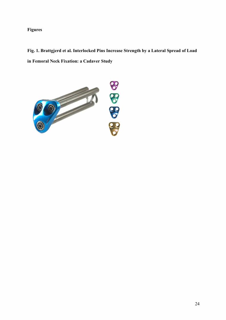
24
Figures
Fig. 1. Brattgjerd et al. Interlocked Pins Increase Strength by a Lateral Spread of Load
in Femoral Neck Fixation: a Cadaver Study
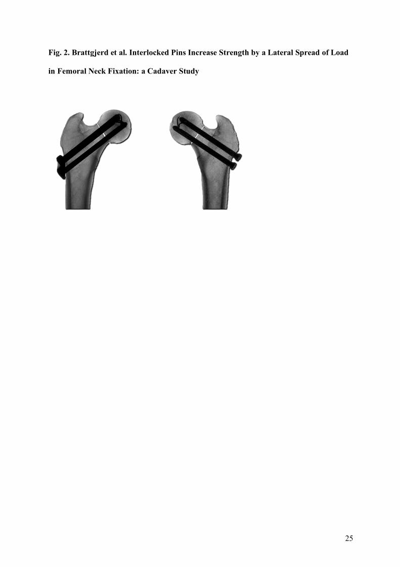
25
Fig. 2. Brattgjerd et al. Interlocked Pins Increase Strength by a Lateral Spread of Load
in Femoral Neck Fixation: a Cadaver Study
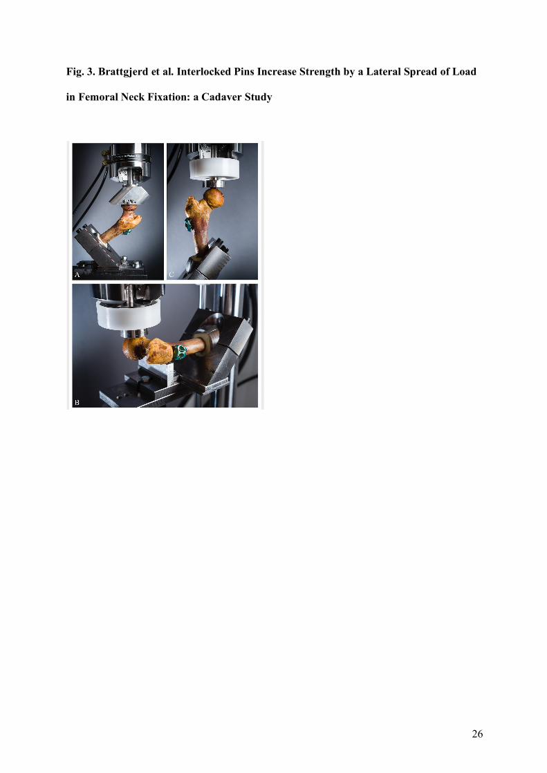
26
Fig. 3. Brattgjerd et al. Interlocked Pins Increase Strength by a Lateral Spread of Load
in Femoral Neck Fixation: a Cadaver Study
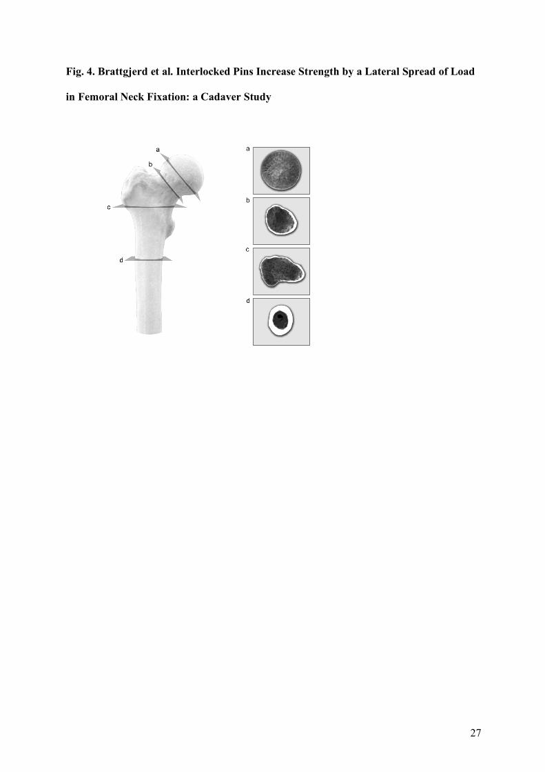
27
Fig. 4. Brattgjerd et al. Interlocked Pins Increase Strength by a Lateral Spread of Load
in Femoral Neck Fixation: a Cadaver Study

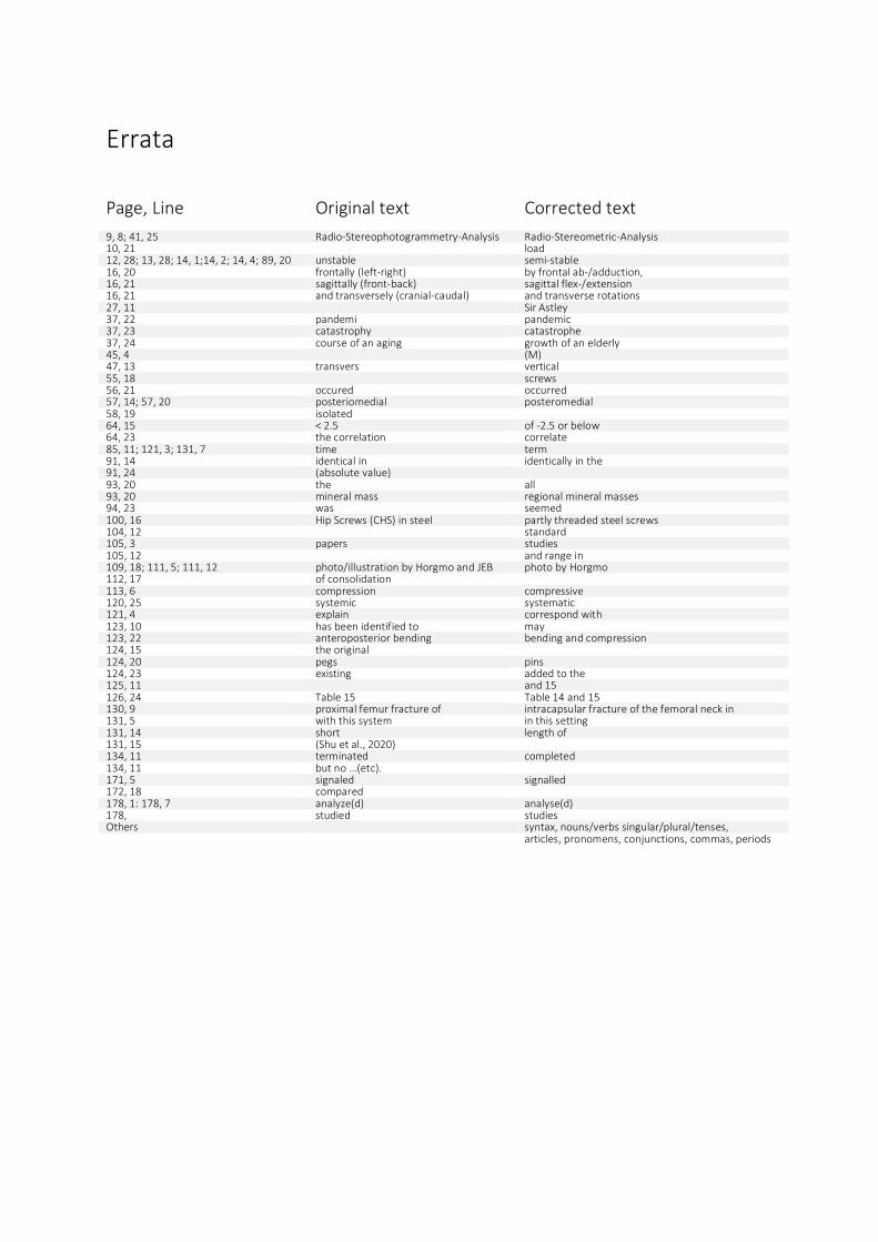
Errata
Page, Line Original text Corrected text 9, 8; 41, 25 Radio-Stereophotogrammetry-Analysis Radio-Stereometric-Analysis 10, 21 load 12, 28; 13, 28; 14, 1;14, 2; 14, 4; 89, 20 unstable semi-stable 16, 20 frontally (left-right) by frontal ab-/adduction, 16, 21 sagittally (front-back) sagittal flex-/extension 16, 21 and transversely (cranial-caudal) and transverse rotations 27, 11 Sir Astley 37, 22 pandemi pandemic 37, 23 catastrophy catastrophe 37, 24 course of an aging growth of an elderly 45, 4 (M) 47, 13 transvers vertical 55, 18 screws 56, 21 occured occurred 57, 14; 57, 20 posteriomedial posteromedial 58, 19 isolated 64, 15 < 2.5 of -2.5 or below 64, 23 the correlation correlate 85, 11; 121, 3; 131, 7 time term 91, 14 identical in identically in the 91, 24 (absolute value) 93, 20 the all 93, 20 mineral mass regional mineral masses 94, 23 was seemed 100, 16 Hip Screws (CHS) in steel partly threaded steel screws 104, 12 standard 105, 3 papers studies 105, 12 and range in 109, 18; 111, 5; 111, 12 photo/illustration by Horgmo and JEB photo by Horgmo 112, 17 of consolidation 113, 6 compression compressive 120, 25 systemic systematic 121, 4 explain correspond with 123, 10 has been identified to may 123, 22 anteroposterior bending bending and compression 124, 15 the original 124, 20 pegs pins 124, 23 existing added to the 125, 11 and 15 126, 24 Table 15 Table 14 and 15 130, 9 proximal femur fracture of intracapsular fracture of the femoral neck in 131, 5 with this system in this setting 131, 14 short length of 131, 15 (Shu et al., 2020) 134, 11 terminated completed 134, 11 but no …(etc). 171, 5 signaled signalled 172, 18 compared 178, 1: 178, 7 analyze(d) analyse(d) 178, studied studies Others syntax, nouns/verbs singular/plural/tenses, articles, pronomens, conjunctions, commas, periods