A PA - WUR eDepot
300
SOFTWARE VERIFICATION, MODEL VALIDATION, AND HYDROGEOLOGIC MODELLING ASPECTS IN NUCLEAR WASTE DISPOSAL SYSTEM SIMULATIONS - A PARADIGM SHIFT Grant Sheng
-
Upload
khangminh22 -
Category
Documents
-
view
1 -
download
0
Transcript of A PA - WUR eDepot
SOFTWARE VERIFICATION, MODEL VALIDATION, AND
HYDROGEOLOGIC MODELLING ASPECTS IN NUCLEAR
WASTE DISPOSAL SYSTEM SIMULATIONS
- A PARADIGM SHIFT
Grant Sheng
/ J WO? ? ® f
f
P R O P O S I T I O N S
Software Verification, Model Validation, and
Hydrogeologie Modelling Aspects in
Nuclear Waste Disposal System Simulations
- A Paradigm Shift
G. Sheng
June 22,1994
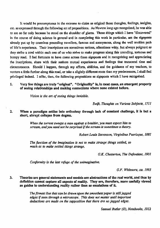
It would be presumptuous in the extreme to claim as original those thoughts, feelings, insights, etc. as expressed through the following set of propositions. As Newton long ago recognized, he was able to see so far only because he stood on the shoulder of giants. Those things which I have "discovered" in the course of doing science in general and in completing this work in particular, are the signposts already put up by countless preceding travellers, famous and anonymous, along the well trodden path of life's experience. Their inscriptions are sometimes serious, oftentimes witty, but always poignant as they strike a cord within each one of us who strive to make progress along this unending, tortuous and bumpy road. I feel fortunate to have come across these signposts and in recognizing and appreciating the inscriptions, share with their authors mutual experiences and feelings that transcend time and circumstances. Should I happen, through my efforts, abilities, and the guidance of my teachers, to venture a little further along this road, or take a slightly different route than my predecessors, I shall feel privileged indeed. I offer, then, the following propositions as signposts which I have recognized.
1. Very few things are truly "original". " Originality" is, in most cases, an emergent property of seeing relationships and making connections where none existed before.
Vision is the art of seeing things invisible.
Swift, Thoughts on Various Subjects, 1711
2. When a paradigm settles into orthodoxy through lack of constant challenge, it is but a short, abrupt collapse from dogma.
When the torrent sweeps a man against a boulder, you must expect him to scream, andyou need not be surprised if the scream is sometimes a theory.
Robert Louis Stevenson, Virginibus Puerisque, 1881
The junction of the imagination is not to make strange things settled, so much as to make settled things strange.
GX. Chesterton, The Defendant, 1901
Conformity is the last refuge of the unimaginative.
G.F. Whitmore, ca. 1993
3. Theories are general statements and models are abstractions of the real world, and thus by definition cannot capture all aspects of reality. They are, therefore, more usefully viewed as guides to understanding reality rather than as emulations of i t
The firmest line that can be drawn upon the smoothest paper is still jagged edges if seen through a microscope. This does not matter until important deductions are made on the supposition that there are no jagged edges.
Samuel Butler (II), Notebooks, 1912
It is desirable at time for ideas to possess a certain roughness, like drawings on heavy-grain paper. Thoughts having this quality are most likely to match the texture of actual experience.
Harold Rosenberg, Discovering the Present, 1973
4. The biggest responsibility of a scientist towards his theory or a modeller towards her model is to serve as its harshest critic To best fulfil this responsibility, it is much wiser to judge them on utilitarian grounds rather than on aesthetics.
A theory has only the alternative of being right or wrong. A model has a third possibility: it may be right, but irrelevant.
Manfred Eigen
5. Although a theory or model is often described using mathematics in order to express our thoughts and ideas more precisely, let us not fall into the trap of thinking that the results are necessarily more accurate. Precision is not accuracy.
God forbid that Truth should be confined to Mathematical Demonstration!
Blake, Notes on Reynolds's Discourses, c. 1808
6. Parsimony or the use of Ockham's razor is a time-tested heuristic as well suited for the practice of science as it is for the conduct of everyday life.
To probe a hole we first use a straight stick to see how far it takes us. To probe the visible world we use the assumption that things are simple until they prove to be otherwise.
EM. Gombrich, Art and Illusion, 1960,
7. Everyone knows that you need the proper tools to do a job properly. That is why it is so astounding to see such a huge market for tools made in, and for, a one-dimensional world.
If the only tool you have is a hammer, then everything around you starts to look like nails.
G.F. Whitmore, ca. 1992
8. Perfection should only be viewed as an asymptotic goal. If viewed as an end unto itself, perfection becomes the enemy of the good.
There is no such thing as absolute certainty, but there is assurance sufficient for the purposes of human life.
John Stuart Mill, On Liberty, 1859
Fortunate is the scientist who asks the right question.
A wise man's question contains half the answer.
Solomon Ibn Gabirol, The Choice of Pearls, c. 1050
The most fortunate is being able to devote one's life to answering (and getting paid for it!).
A moment's insight is sometimes worth a life's experience.
Oliver Wendell Holmes Sen., The Professor at the Breakfast Table, 1859
Hubris is a poor choice of garment to wear during the conduct of science as it is for everyday life. Nature will soon show you naked for the amusement of your peers.
There is an ABC ignorance which precedes knowledge and a doctoral ignorance that comes after it.
Montaigne, 'Of vain subtleties', Essays, 1580-8
A man should never be ashamed to own that he has been in the wrong, which is but saying, in other words, that he is wiser today than he was yesterday.
Swfft, Thoughts on Various Subjects, 1711
I am all for the freedom of thought and expression and all that — but I do feel that the dress code at universities these days should be tightened up a bit
The University brings out all abilities, including stupidity.
Chekhov, Notebooks, 1892-1904
Software Verification, Model Validation, and Hydrogeologie Modelling Aspects in Nuclear Waste Disposal System Simulations
- A Paradigm Shift
jJJlJJ^^ 0000 0574 1992

ir. M.S. Elzas hoogleraar in de informatica leerstoel Kennis-systemen.
G.M. Sheng
Software Verification, Model Validation, and Hydrogeologie Modelling Aspects in Nuclear Waste Disposai System Simulations
- A Paradigm Shift
ter verkrijging van de graad van doctor in de landbouw- en milieuwetenschappen op gezag van de rector magnificus, dr. C M . Karssen, in het openbaar te verdedigen op woensdag 22 juni 1994 des namiddags te vier uur in de Aula van de Landbouwuniversiteit te Wageningen.
Proefschrift 2 Ü J J"
BTBLIOTHEERT e S N D B O U W U N I V E R S
12AGENINGEIS
A theory has only We alternative of being right or wrong.
A model has a third possibility: It may be right, but irrelevant.
Manfred Eigen

CONTENTS
Page
PREFACE AND ACKNOWLEDGEMENTS 1
SAMENVATTTNG 3
SUMMARY 5
CHAPTER 1 GENERAL INTRODUCTION 1-1
1.1 The General Concept of Nuclear Waste Disposal 1-1
1.2 The Challenges Facing the Current Disposal Concept 1-1
1.2.1 Socio-political Issues 1-1 1.2.2 Technical Issues 1-2
1.2.2.1 The Geologic Problem 1-2 1.2.2.2 The Validation Problem 1-2
1.2.2.3 The Verification Problem 1-7
1.3 The Regional Recharge Concept - A Paradigm Shift 1-8
1.4 Organization of Material 1-8
References 1-10
CHAPTER 2 ASPECTS OF THE NUCLEAR WASTE DISPOSAL CONCEPT 2-1
2.1 An Overview of Nuclear Waste Management 2-1
2.2 An Evaluation of the Canadian Nuclear Fuel Waste Management Program 2-1
2.3 Evaluation of the Canadian High-level Waste Disposal Program - Performance Assessment Aspects 2-2
2.4 Are We Focusing on the Right Technical Issues in HLW Research? The Evaluation of the Canadian Program 2-2
2.5 Canada's High-level Nuclear Waste Disposal Concept: The Evaluation Process and a Review of Some Aspects of the Research Work 2-3
Contents (cont'd) Page
CHAPTER 3 MODEL VALIDATION AND SOFTWARE VERIFICATION ISSUES 3-1
3.1 Model Reliability and Software Quality Assurance in Simulation of
Nuclear Fuel Waste Management Systems 3-1
3.2 Semantic Rules and Facts for an Expert Modelling and Simulation System 3-2
3.3 Computer-Aided Software Understanding Systems to Enhance Confidence of Scientific Codes 3-2
3.4 Model Validation: A Systemic and Systematic Approach 3-3
CHAPTER 4 REVIEW OF THE CANADIAN PERFORMANCE ASSESSMENT 4-1 CODE - A CASE STUDY
4.1 A Brief Discourse on Some Basic Concepts and Terminology
used in Simulation and Software Engineering 4-3
4.1.1 The Simulation and Software Development Lifecycle 4-3
4.1.2 The Three Different Levels of Abstraction 4-3
4.1.2.1 Requirements Level 4-6 4.1.2.2 Design Level 4-6
4.1.2.3 Implementation (Coding) Level 4-6
4.1.3 Software Quality Assurance (SQA) 4-6
4.1.4 Definitions and Discussions of Terms and Processes 4-7
4.2 The AECL "SYVAC" Project 4-9
4.2.1 System Variability Analysis 4-9
4.2.2 The SYVAC Simulation 4-9 4.2.3 The SYVAC Computer Code 4-10 4.2.4 SYVAC and Quality Assurance (QA) 4-10
Contents (cont'd) Page
4.3 TAC's Review 4-12
4.3.1 Material Available for TAC's Review 4-12
4.3.2 TAC's Review Procedure 4-12
4.3.2.1 Requirements 4-12 4.3.2.2 Design 4-13 4.3.2.3 Code 4-15
4.3.2.3.1 Code Inspection 4-15 4.3.2.3.2 Time Series Package 4-15 4.3.2.3.3 XREF Tool 4-16 4.3.2.3.4 DATRDC/LECS Tool 4-16 4.3.2.3.4 DATRK/LECS Tool 4-16 4.3.2.3.5 REFINE/FORTRAN Tool 4-17 4.3.2.3.6 SYVAC Simulations 4-17
4.3.2.4 Other Review Activities 4-17 4.3.2.5 Software Tools Developed/Acquired by AECL 4-18
4.3.3 Comments on Software Requirements Specifications 4-18
4.3.3.1 Introduction 4-18 4.3.3.2 Comments on AECL's SRS Standard 4-18 4.3.3.3 Comments on BIOTRAC SRS 4-20 4.3.3.4 Comments on SRS Current/Organization 4-20 4.3.3.5 Summary of SRS Review 4-22
4.3.4 Comments on SVS-CC3 Software Design Specifications 4-23
4.3.4.1 Introduction 4-23 4.3.4.2 Comments on AECL's SDD Standard 4-23
4.3.4.2.1 SYVAC Software Development Project 4-23 4.3.4.3 Brief Description of the ANSI/IEEE SDD Standard 4-24
4.3.4.3.1 Design Entities and Design Entity Attributes 4-24 4.3.4.3.2 Design Views 4-25
4.3.4.4 Comparison of SDD and ANSI/IEEE SDD Standards 4-25 4.3.4.4.1 Comparison of Organization 4-25 4.3.4.4.2 Comparison of Content 4-26
4.3.4.5 General Comments on Content Comparison 4-29 4.3.4.6 Comments on BIOTRAC SDD 4-30 4.3.4.7 Summary 4-30
Contents (cont'd) Page
4.3.5 Comments on SV3-CC3 Verification & Validation 4-31 4.3.5.1 Introduction 4-31 4.3.5.2 Requirements Phase V&V 4-31
4.3.5.2.1 V&V performed by AECL 4-31 4.3.5.2.2 Comments on V&V 4-31
4.3.5.3 Design Phase V&V 4-32 4.3.5.3.1 V&V Performed by AECL 4-32 4.3.5.3.2 Comments on V&V 4-32
4.3.5.4 Implementation Phase V&V 4-33 4.3.5.4.1 Coding 4-33 4.3.5.4.2 Program Testing 4-34 4.3.5.4.3 USDOE Involvement 4-35 4.3.5.4.4 Comparisons 4-36 4.3.5.4.5 Comments on V&V 4-37
4.3.5.5 Problems Encountered During V&V Assessment 4-38 4.3.6 Some Explanatory Remarks on, and Observations of, the Present
State of SYVAC and its Documentation 4-39
4.4 Conclusions and Recommendations 4-41
References 4-43
APPENDTXI - Documentation Associated with SYVAC Code 4-44
APPENDIX H - Software Development Tools 4-46
CHAPTER 5 THE REGIONAL GROUNDWATER RECHARGE CONCEPT - A PARADIGM SHIFT IN THE DISPOSAL OF HIGH-LEVEL NUCLEAR WASTE 5-1
5.1 Demonstration of Safety Performance 5-2
5.2 Assumptions of the RRC 5-3
5.3 Premise for Development of the RRC 5-3
5.4 The General Approach to Repository Siting Based on the RRC 5-4
Contents (cont'd) Page
5.5 Regional Groundwater How and its Characterization 5-5
5.5.1 Groundwater Flow Systems: Areas of Recharge,
Discharge and Throughflow 5-5
5.5.2 Characterization of Groundwater Flow Systems 5-6
5.5.2.1 Hydrodynamic parameters 5-6 i) Potentiometrie surface 5-7 ii) hydraulic cross-sections 5-8 iii) vertical pressure-gradient 5-8
5.5.2.2 Characterization of Basinal Distribution of Groundwater Flow 5-8 i) mathematical modelling 5-8 ii) field observations of fluid dynamic parameters 5-9 iii) field mapping of effects and manifestations
of regional groundwater 5-10 5.6 Comparison of Key Characteristics of Regional Groundwater
Flow in Recharge vs. Discharge Areas 5-11
5.6.1 Model Calculations 5-11 5.6.1.1 Scope and Method of Calculations 5-11 5.6.1.2 Modelling Results for Different Basin Variants 5-12
Flow in Homogeneous Basins 5-13 Effect of Stratification on Basinal Flow 5-14 Effect of Fault Zones on Flow in Stratified Basins 5-15
5.6.2 Summary and Discussion of Modelling Results 5-17
5.7 Suggested Steps in Repository Site Selection Based on the Regional Recharge Concept 5-20
Reference List 5-23
Figures 1 to 9 5-26
CHAPTER 6 SUMMARY AND CONCLUSIONS 6-1
GLOSSARY
CURRICULUM VTTAE
PREFACE AND ACKNOWLEDGEMENTS
Serving from 1980 as the Science Secretary of the Technical Advisory Committee to Atomic Energy of Canada Limited on Canada's Nuclear Fuel Waste Management Program, the author has had extensive, first-hand experience on the subject of nuclear waste disposal technology. Because of this, he has been either the main author or a major contributor to the papers included in this work.
The author is greatly indebted to the Chairman and present and past members of the Technical Advisory Committee for their continual support and encouragement of the work that comprises this collection. More specifically, deep appreciation is expressed: to Prof. dr. L.W. Shemilt (Department of Chemical Engineering, McMaster University) for his continual support, understanding, generosity and guidance over all these years and without whom this work would not be possible; to Prof. dr. G.F. Whitmore (Head, Division of Experimental Therapeutics, Ontario Cancer Institute) for his personal interest in my intellectual development and other aspects of my life, for his ever-ready willingness to help in times of great difficulties, and for his unwavering faith in my ability to face life's challenges; to Prof. dr. T.I. Ôren (Department of Computer Science, University of Ottawa) and to Prof. dr. J. T<5th (Department of Geology, University of Alberta) for their confidence in my abilities to contribute to, and participate in their work, for their warm and generous support and, for their impact on shaping my professional work.
In addition, the following have all contributed to, and have had.a great impact on my intellectual and professional development and given generously of their time: Prof. dr. P.F. Williams (Dept. of Geology, University of New Brunswick), Prof. dr. G.B. SMppen (Department of Earth Sciences, Carleton University), Prof. dr. D.T. Can vin (Department of Biology, Queen's University), Prof. dr. John Heddle (Department of Biology, York University), Prof. dr. D. Parkinson (Department of Biology, University of Saskatchewan), Prof. dr. K.J. McCallum (Department of Chemistry, University of Saskatchewan), Prof. dr. W.E. Harris (Department of Chemistry, University of Alberta), Prof. dr. B. Ladanyi (Département de Génie Civil, Université de Montréal), Prof. dr. G.M. Volkoff and Prof. dr. M.H.L. Pryce (Department of Physics, University of British Columbia), Prof. dr. A. Beck (Department of Geophysics, University of Western Ontario) and Dr. John Convey. From this group of great teachers I learned the difference between being educated and being merely highly-trained.
Not to be forgotten are Prof. dr. J.D. Rising and Prof. dr. G.M. Clark (Department of Zoology, University of Toronto) and Prof. dr. R. Haynes (Department of Biology, York University) who all "took a chance" and inspired a young mind at an early stage of my academic life. A warm expression of thanks is due to Prof. dr. G.M. Volkoff and Prof. dr. M.H.L. Pryce who, to this day, still take keen interest in my personal and professional activities, and by their indefatigable spirit, continue to provide inspiration on how to live life.
1

In a work of this nature, the efforts of many people are crucial for successful completion. Consequently, the assistance of Mr. Peter Brewer on various aspects of this work is acknowledged and much appreciated, as are the efforts of Mrs. R. Donaldson, Ms. J. Arsenault, Ms. L. Honda, Mrs. G. Riddell, Mrs. B. Petro and Mrs. D. Maltese.
A special tribute is paid to the memory of Mr. R. Robinson, my "Second Father", who taught me how to behave with grace under pressure and to think with "disciplined creativity" at an age when I "knew everything".
I express my deep-felt gratitude to Prof. ir. M.S. Elzas for the privilege and pleasure of studying under his tutelage, for his support, patience and faith all through these years, and who with Yetty Elzas, has always treated me as a member of the family. They are the model of peace and harmony with the world and with each other.
Finally, mere words cannot express the gratitude and indebtedness I owe to my parents, Dr. and Mrs. G. Sheng. Through countless years of hard work and sacrifice, they have made possible all the privileges and opportunities I have enjoyed. I can only offer this work as a small measure of thanks and aspire to conduct my life in accordance with their exemplary values.
2
SAMENVATTING
Dit werk behandelt de problematiek van de permanente opslag van nucleair afval, benaderd vanuit een systeemkundig standpunt.
Behandeid worden: 1) de huidige, internationale, stand van zaken ten aanzien van het opslag-concept
voor sterk radioactief nucleair afval; 2) de vcornaamste Problemen en uitdagingen voor deze opslag-technologie; 3) een evaluatie, in de vorm van een case Studie - van de Canadese inspanningen om
te komen tot een prestatie analyse vooraf van zulk een systeem en
4) een geheel nieuwe aanpak voor het kiezen van de plaats voor ondergrondse opslag, die een aantal significante voordelen biedt ten opzichte van het huidige concept.
Hoofdstuk 1 leidt de problematiek in.
Hoofdstuk 2 beschrijft het -internatLonaal aanvaarde- concept van ondergrondse opslag in stabiele, continentale, geologische media met behulp van een systeem van meervoudige afscherming. Deze afscherming bestaat uit meerdere, natuurüjke en geconstrueerde hinderpalen die de beweging van radionuclides vanuit de onderaardse gewelven naar het humane milieu aan het oppervlak dienen tegen te houden of, op zijn minst, te vertragen. Verschiliende facetten van het onderzoeks- en ontwikkelingswerk, dat op vele plaatsen in de wereld wordt uitgevoerd, worden beschreven. De nadruk wordt hierbij met name gelegd op het Canadese Nucleaire Brandstof Afval Beheer Programma (Canadian Nuclear Fuel Waste Management Program: CNFWMP).
Hoofdstuk 3 onderzoekt de technisch-wetenschappelij ke problematiek van het huidige opslag concept nader ten aanzien van onder andere:
a) de huidige concentratie van de inspaiming op de lithologische aspecten voor wat betreft het geologisch/geotechnisch onderzoek,
b) de onbevredigende situatie bij de pogingen tot 'validatie' van de modellen die worden gebruikt in computer simulaties van Systemen die onder invloed staan van toekomstige omstandigheden op zeer lange termijn,
en c) de weinig doeltreffende aanpak van de bewaking van de kwaliteit van de
programmatuur die gebruikt wordt voor het tot stand brengen van deze simulaties.
De in dit hoofdstuk verzamelde publikaties kenschetsen deze problemen en behandelen een aantal 'software engineering' gereedschappen en technieken die gebruikt kunnen worden voor de verifkatie van programmatuur en zijn kwaliteitsbewaking. Het artikel in paragraaf 3.4 presenteert daarenboven een gedetailleerde en systematische benadering waarmee een sluitend proces voor het valideren van modellen kan worden opgezet.
3
Hoofdstuk 4 betreft de case Studie en onderzoekt de Canadese prestatie analyse programmatuur, de daarbij behorende modellen en documentatie, op basis van de principes, gereedschappen en technieken die in hoofdstuk 3 werden bescnreven. Ook verscheidene andere, reeds ingeburgerde, ANSI/IEEE software engineering normen werden hierbij gebruikt. Deze grondige evaluatie is de eerste die extern op deze modellen en program ma's werd uitgevoerd en zal -naar alle waarschij nlij kheid- een van de kernen vormen van het uiteindelijke beoordelingsrapport over het Canadese prestatie analyse werk.
Hoofdstuk 5 introduceert een nieuwe benadering voor de keuze van de locatie van ondergrondse opslagplaatsen voor gevaarlijk afval: het Regional Recharge Concept (RRC). De nadruk bij deze nieuwe aanpak is gelegen in de duidelijke formulering en het gebruik van fundamentele kennis betreffende regionale grondwater stromingspatronen ten behoeve van de keuze van een adequate opslagplek. Het concept leidt ertoe dat de plaatsing zodanig kan zijn dat ontsnappende, contaminerende, Stoffen door het grondwater meegenomen zullen worden naar zones waar het water stagneert of naar een ondergrondse stroming die een zo lange baan aflegt, voordat hij weer aan het oppervlak verschijnt, dat de radionuclides vervallen zijn tot een onschadelijk niveau van radioactiviteit, zo ze ooit weer in de biosfeer verschijnen. Naast het uitwerken van de theoretische grondslagen voor de RRC, toont dit hoofdstuk de belangrijkste voordelen hiervan aan, door middel van relevante modellen. Zowel vanwege de visie van 'passieve veiligheid', die aan dit concept ten grondslag ligt, als vanwege het verdwijnen van de noodzaak van een lithologie-centrische benadering (waarvan de ervaring heeft aangetoond dat deze leidt tot ernstige problemen in verband met de moeilijkheden bij het karakteriseren van breuken en barsten en nun toekomstig gedrag), leidt de RRC tot nieuwe mogelijkheden bij het zoeken naar een haalbare aanpak voor de opslag van nucleair afval.
Hoofdstuk 6, tenslotte, bevat de conclusies van het werk op basis van de resultaten uit de voorgaande hoofdstukken.
4
SUMMARY
This work (1) reviews the current concept adopted internationally on the disposal of high-level nuclear wastes; (2) discusses some of the major challenges facing this disposal technology; (3) presents an evaluation of the Canadian performance assessment work as a case study; and (4) introduces a new paradigm within which to site an underground disposal facility that offers many significant advantages over the existing concept
Chapter 1 explains the setup of the work and forms the "General Introduction" to the subject material.
Chapter 2 describes the current internationally-accepted concept of underground disposal in stable, terrestrial, geologic media using a multi-barrier system of engineered (man-made) and natural barriers to prevent or retard the movement of radionuclides from depth to man's environment at the surface. Various aspects of the research and development work being conducted internationally to demonstrate the efficacy of this technology are described with emphasis paid to the Canadian Nuclear Fuel Waste Management Program (CNFWMP).
Chapter 3 examines some of the technical challenges of the current disposal concept including (a) the present focus on the lithologic aspects of the geologic/geotechnic research; (b) the unsatisfactory situation in attempts at "validating" models used in computer simulations to forecast very long-term future conditions; and (c) the unsatisfactory state of software quality assurance in such computer simulations. The collection of papers in this chapter points out these problems and presents some of the software engineering tools and techniques used for software verification and quality assurance. Paper 3.4 introduces a comprehensive and systematic approach with which a rigorous process of validating models can be applied.
Chapter 4 presents a review of some aspects of the Canadian performance assessment code, its models, as a case study to illustrate the application of principles, and tools and techniques described in Chapter 3. As such, various widely-recognized ANSI/IEEE software engineering standards were used to carry out the evaluation. This review is the first in-depth evaluation done externally and will likely serve, in part, as a basis for the ultimate judgement as to the quality and credibility of the Canadian performance assessment work.
Chapter 5 introduces a completely new approach, called the Regional Recharge Concept (RRC), to the siting of underground waste repositories. The emphasis of this new concept is on achieving understanding of regional groundwater flow patterns so as to exploit such knowledge to locate a repository in an area where escaping contaminants will be carried by the groundwater into "stagnant zones" or on a flow trajectory long enough to render decaying radionuclides harmless if and when they do ever surface. The theoretic basis of the RRC is developed in this chapter and the many advantages of the concept are shown through a modelling exercise. Because of the "passive safety" philosophy inherent in this new concept, as well as the move away from the current international focus on lithologic studies (where experience has shown the great difficulties in characterizing fractures and predicting their future behaviour), the
5
RRC being advocated in this work represents a true paradigm shift from the current concept of nuclear waste disposal.
Chapter 6 summarizes the results from previous chapters in the form of conclusions relevant to future work in this area.
6

CHAPTER 1
GENERAL INTRODUCTION
1.1 The General Concept of Nuclear Waste Disposal
The idea of permanent disposal of high-level nuclear waste (HLW) in terrestrial geologic media was extant from at least 1957 (National Research Council, 1957). Since the first international meeting held almost 35 years ago (IAEA, 1960), there has been a tremendous amount of R&D work done towards solving this problem. The general concept adopted internationally (e.g. Belgium, Canada, Finland, France, Germany, Holland, Japan, Spain, Sweden, Switzerland, UK, USA, etc.) involves the burial of radioactive wastes in underground repositories to be built approximately 500-1000 m deep in some stable, terrestrial geologic media with the addition of various engineered barriers to enhance further the confinement or retardation of possible contaminant escape back up to the surface (2.1, 2.2,2.3). The existing international consensus on the practicability and efficacy of this general approach is typified by the "collective opinion" of the Organization for Economic Cooperation and Development/Nuclear Energy Agency (OECD/NEA), the International Atomic Energy Agency (IAEA) and the Commission for European Communities (NEA/IAEA/CEC, 1991).
1.2 The Challenges Facing the Current Disposal Concept
1.2.1 Socio-Political Issues
Despite this general consensus and the tremendous international effort focused on this problem over the last 40 years, it is interesting to note that not a single waste repository has yet been built anywhere in the world. Although some countries seem further along the process in achieving this end, all countries face, to varying degrees, a common suite of technical, political and social problems in realizing this elusive goal. In the case of the US, for instance, social and political impediments seem especially severe to the point where they appear to overwhelm those technical issues which are yet to be resolved. In the Canadian case, however, the social and political aspects of the disposal problem have been minimized so far because of the unique "phased" approach it has taken: the disposal concept must be judged to be safe through a complex procedure before the second phase of site selection may be allowed to begin (2.5).
Although socio-political issues are legitimate and necessary aspects of the disposal problem to be addressed, the present work focuses only on several particular technical issues the resolution of which are critical for the success of the whole waste disposal enterprise. At the operational level the issues are primarily technical, while at a meta-level, they are also philosophical issues and as such, have a significant impact in the socio-political arena. This situation stems from the peculiarities of the disposal technology which is distinguished by at least
1-1
two unique characteristics: (a) the very long time spans (tens-, or even hundreds-of-thousands of years) over which the disposal system must remain effective and, (b) no precedents exist for such an endeavour.
1.2.2 Technical Issues
Since the overriding concerns are to ensure safety of humans and protection of the environment both now and far into the future, a convincing demonstration of the safety of the disposal system primarily involves technical issues. The first is associated with the capability to make forecasts of far-future events (especially those geologically related), and the second, with the extent that such forecasts can be "confirmed" in some fashion within the obvious limits of our "present time". However, the methodology as presently envisaged to implement the general concept faces some inherent difficulties in addressing these technical issues.
1.2.2.1 The Geologic Problem
With respect to the first technical issue, much effort and resources have been devoted by the international community to geologic and geotechnical R&D work because of the concept's heavy reliance on the geology to act as a natural barrier (2.1, 2.2, 2.3). Furthermore, due to the axiomatic view that: (a) groundwater is always a negative agent for transporting contaminants up to the surface and, (b) fractures are the conduits for such transport, there has been, and continues to be, an undue focus on attempts at characterizing all aspects of fractures (e.g. density, orientation, width, etc.) and associated features (e.g. fracture fillings, matrix diffusion, geochemistry, rock properties, etc.). However, many years of research and common experience have shown that trying to " predict" or forecast future geologic conditions based on the present focus on characterizing geologic attributes is an intractable problem. The sheer complexity of the natural system together with our lack of understanding about many of the geologic processes and associated parameter values make such prediction attempts questionable. This point is elaborated further below in conjunction with discussion of the next issue.
1.2.2.2 The Validation Problem
With respect to the second technical issue, the extent with which the forecasts from models can be confirmed (or to use the popular term in mis field: "validated"), obviously has a great bearing on the degree of confidence one places on the models and their results. However, the demonstration of safety of the disposal system is problematical in this situation where the ultimate performance of the system at some distant point in the future cannot be ascertained. Adequate/satisfactory performance must be inferred based on a combination of: (a) our present understanding of natural processes, (b) knowledge about relevant system parameters, (c) our ability to design, and have confidence in, the engineered systems and (d) our ability to extrapolate this collection of knowledge far into the future.
Computerized simulation is the only means we have to carry out systematically and quantitatively such an extrapolation upon which to base an inference of satisfactory system
1-2
performance so far into the future. Confidence in the results produced by such computerized simulations is dependent upon two crucial considerations: (i) the extent to which the conceptual models used in the simulation have been validated and, (ii) the extent to which the software implementing the simulation has been verified. Unfortunately the two terms, "validation" and "verification", are often confused and used in various ways in different contexts (3.4). For instance, the many international cooperative projects purportedly devoted to "validating" various models associated with geologic, hydrogeologic, biospheric, and contaminant transport aspects of nuclear waste disposal are actually exercises in intercomparison of computerized models. Often, the sole criterion for a model being "validated" is related to some qualitative consensus reached about the modelling results among the groups doing the calculations. On those occasions where the computational results are actually compared with laboratory or field measurements, quantitative criteria for determining whether, and to what extent, the model results agree with real system values are rarely specified beforehand. Instead, qualitative arguments for, or against, agreement are offered afterwards on an of hoc basis.
Perhaps the most serious flaw in the popular claim for having "validated" models is the fact that, in almost all cases, the models pose questions for which measurements obtainable from the real systems cannot answer. In other words, the models used are not appropriate to deal with the system under study. One of the major reasons for this is that often the models used were originally developed for "short-term" purposes. However, they are now being applied in the nuclear waste disposal context where process and events extend very long times into the future. As an illustration of this criticism, of the five studies reviewed by Anderson and Woessner (1992), several of the models were developed and/or calibrated on the basis of short-duration data sets (e.g. short-term pumping tests) and subsequently used for long-term predictions. Not one of the models produced accurate results when compared with field measurements.
Although the crucial importance of ensuring the "appropriateness" of a model's usage with its intended purpose is emphasized in Sheng et al. 1993 (3.4), this issue merits some discussion in this General Introduction as well.
Caswell (1976) calls for a clear distinction to be made between "(i) models that are constructed primarily to provide accurate prediction of the behaviour of a system and, (ii) models that, as scientific theories, are attempts to gain insight into how the system operates" (emphases added). Further elaboration is provided by Mankin et al. (1975) and Loehle (1983) between "theoretical" models whose primary purpose is to facilitate understanding of the system, and "predictive" models which are regarded as "calculation tools" the usefulness of which is judged by "how accurately they can predict aspects of the real world, or on how well they meet design specifications" (Loehle, 1983).
Generally speaking, such distinctions are not made apparent in the simulation work in nuclear waste disposal. Unfortunately, in this field, the consequences of confusing models developed to provide accurate predictions vs. those to provide insights of system behaviour can be quite severe. Because of the particular characteristics of the disposal technology mentioned earlier (very long time spans, and lack of precedent), very few models, especially those
1-3
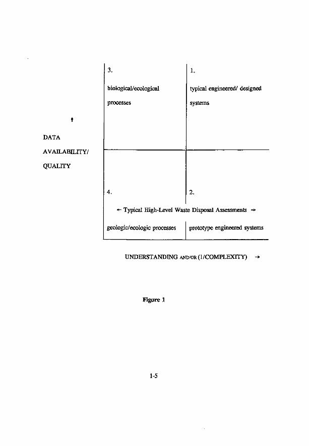
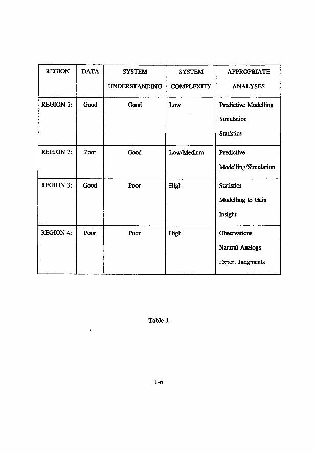
simulating geologic processes, can be justified as models for predictive purposes. Figure 1 (adapted from Holling, 1978) in conjunction with Table 1 illustrate the point. Under this scheme, models can be distinguished according to four regions defined by two parameters which characterize: (a) the availability/quality of data observed/measured from the real system and, (b) the degree of understanding of system behaviour. The latter, (b), is often associated with the degree of "complexity" of the real system. Although there are many instances where a good understanding of the process exists, but where the phenomenon under question may be too complex to model, these two attributes, nevertheless, are generally inversely related. Thus, even though these are two distinct issues, for the purposes of this illustration, they can be treated as congruent as indicated by their common axis on the diagram.
In region 1, where the amount and quality of data is plentiful and good, respectively, and where system understanding is also good (and/or the real system has low complexity), use of predictive models is justified. This situation is typical of well-understood engineered or designed systems. The life span of such systems is such that there is ample opportunity to monitor/check system performance and thus calculated results from simulations can be confirmed with actual experience.
In region 2 where system understanding is good but for which data is lacking or poor in quality, such as in cases of prototype engineered systems, predictive modelling may also be appropriate but the simulation results must be interpreted with caution and must certainly be checked with data as they become available.
In region 3, where the data situation is good but where system understanding is poor (and/or system complexity is high), the most appropriate approach is to use statistical analyses first to explore possible relationships and then to develop models to clarify and test our tentative understanding of such possible relationships. The purpose of simulations done under these conditions clearly should be to gain insight on system operation or behaviour and not to provide predictive results. Many models developed for simulating environmental processes on an ecological time scale lasting tens, or at most, several hundreds of years (e.g. forest successions) fall within this category.
In region 4, where the situation for both data and system understanding is poor (and/or system complexity is high), it is clearly inappropriate to develop models for predictive purposes. The appropriate approach here would be to make observations of the system of interest wherever possible, to observe other systems with similar aspects of interest, (e.g. natural analogs) and to elicit knowledge and judgment from recognized experts in the field. The primary purpose of all of these activities is to impute possible intra-system relationships and make inferences about likely system behaviour. The models that are developed after these activities have been carried out are then similar to those in region 3 with respect to the purpose - to gain insight of the system. This is the situation most typically encountered in high-level waste disposal, especially with respect to geologic processes such as groundwater flow, fracture formation and propagation, geochemical reactions, matrix diffusion, seismic events, etc., and ecologic processes such as climatic changes, long-term ecological successions, biological concentration mechanisms, etc.
1-4
DATA
AVAILABILITY/
QUALITY
3.
biological/ecological
processes
1.
typical engineered/ designed
systems
4.
«- Typical High-Level Was
geologic/ecologic processes
2.
te Disposal Assessments ->
prototype engineered systems
UNDERSTANDING AND/OR (1/COMPLEXITY)
Figure 1
1-5
REGION DATA SYSTEM
UNDERSTANDING
SYSTEM
COMPLEXITY
APPROPRIATE
ANALYSES
REGION 1: Good Good Low Predictive Modelling
Simulation
Statistics
REGION 2: Poor Good Low/Medium Predictive
Modelling/Simulation
REGION 3: Good Poor High Statistics
Modelling to Gain
Insight
REGION 4: Poor Poor High Observations
Natural Analogs
Expert Judgments
Table 1
1-6
The study of natural analogs is especially appropriate in the nuclear waste disposal context. Rich uranium deposits at Cigar Lake in Saskatchewan, Canada, Alligator Rivers in Australia, and Pacos de Caldos in Brazil are several sites presently under study to observe the migration behaviour of various radionuclides under natural geologic conditions. However, interpretation of data and findings must be done with caution as none of these would be exact analogs of disposal facilities. Differences in geologic conditions, geochemistry, and in "man-made" vs. "natural" radionuclides must be recognized and taken into account.
Despite these obvious difficulties, there is a plethora of models developed (or adopted from other, very different applications) with the intention of "predicting" system behaviour in the nuclear waste disposal community. Usage of the term "validation" should, therefore, be seriously questioned under these circumstances where models originally constructed for essentially short-term predictions based on sound understanding of underlying processes and knowledge about parameter values are now being used for very long-term "predictions" with inadequate understanding of complex natural processes and little knowledge about parameter values such as often the case in nuclear waste disposal simulations.
There has been an increasing awareness and recognition of the central role that model validation plays in the performance assessment of disposal systems in the last few years (Niederer, 1990; Papp, 1990; Davis and Goodrich, 1990; McCombie et al., 1990; Eisenberg, 1990; Bogorinski, 1987; Cronjhort and Sheng, 1992; Flavelle, 1992; Konikow and Bredehoeft, 1992; Anderson and Woessner, 1992; Sheng et al., 1993). Paper 3.4 presents a critical review of the many international projects devoted to "validating" various waste disposal sub-systems such as the geosphere, biosphere, groundwater flow, contaminant transport, etc. and due to the problems noted in the above discussion, outlines a systematic and comprehensive approach to carry out a proper process of model validation based on systems theory to improve the situation.
1.2.2.3 The Verification Problem
Similarly, the term "verification" is also almost always misused. Common practice and general literature in the nuclear waste disposal field indicate that usage of this term usually refers to those activities associated with comparison of results of numerical calculations with analytical results or with intercomparison of calculation results derived from different computer codes developed by various groups (e.g. Nies, 1993). It should be further noted that although the term "code intercomparisons" is generally used to describe these types of activities, even this name is a misnomer. The focus of the comparisons in these exercises is always, in the first instance, on the results from the calculations and not on comparing the codes themselves. Actual intercomparison of aspects of the codes takes place infrequently and only when the calculation results differ significantly despite the fact that the groups are working on (ostensibly) the same problem.
Although these comparison activities are valuable in helping the various groups in understanding the problem, in clarifying the model being used, and in detecting and correcting semantic and syntactic errors during model construction as well as after program execution, they are for the large part, ad hoc methods and should not be substitutes for a formal and systematic
1-7
programme of software quality assurance. The complete process of code verification properly has its basis in software engineering and involves a comprehensive suite of procedures designed to ensure that "the products of a given phase of software development cycle fulfil the requirements established during the previous phase" (IEEE, 1986). This and other aspects of code verification are discussed in 3.1, 3.2, 3.3.
1.3 The Regional Recharge Concept — A Paradigm Shift
In response to the challenges posed by the first two issues described in Sections 1.2.2.1 and 1.2.2.2, a new approach towards demonstrating safety performance has been developed by the author together with Prof. Dr. Jozsef Tôth of the University of Alberta. Starting at the most fundamental level, the philosophical basis of this new paradigm, called the "Regional Recharge Concept" (RRC) is markedly different from that of the present waste isolation methodology. Rather than placing the emphasis on engineering "active" barriers (e.g. containers of varying degrees of "exotic" composition, buffers, backfills, etc.) to confine or retard contaminant movement, this new approach relies on a natural fundamental force (gravity) to do the job in a "passive" fashion. By exploiting knowledge about regional groundwater flow patterns, one can strategically locate a repository in a flow system such that escaping contaminants would be carried by water downwards deeper into the earth where they may be trapped in stagnant zones (areas of no-flow) or be transported along a very long flow trajectory during which time radioactive decay would render the radionuclides harmless if and when they do ever surface. The theoretical basis and development of the RRC is presented in Chapter 5. A modelling study is also included to illustrate the concept.
1.4. Organization of Material
This work is organized into six chapters with the first serving as the "General Introduction". In Chapter 2, the collection of five papers describes: 1) the general concept of high-level nuclear waste disposal adopted internationally, 2) the Canadian Nuclear Fuel Waste Management Program (CNFWMP) established to carry out the research and development work in support of the Canadian disposal concept, and 3) traces the evolution of the Canadian program from the early 1980's to the present. Besides serving as chronological documentation, each of the papers also emphasizes some particular aspect of the disposal technology or of the Canadian program such as performance assessment, geologic and geotechnical research, the international context and the evaluation process.
The collection of four papers in the Chapter 3 focuses on two closely related but distinct issues: model validation and software quality assurance. As pointed out earlier in Chapter 1 and elaborated in 3.4, these terms are often used interchangeably, used inconsistently, and/or just plain misunderstood. Papers 3.1 and 3.4 make the distinction explicitly. Papers 3.1, 3.2, 3.3, address various aspects of software verification while papers 3.1 and 3.4 address the issue
1-8
of model validation and outline a systematic and comprehensive approach to the model validation process.
Chapter 4 presents a case study which applies the principles and techniques discussed in Chapter 3 to a specific instance: the Canadian performance assessment computer program.
Chapter 5 consists of a paper which presents the theoretic basis for, and develops the concept of, enhancing passive safety by strategically placing disposal vaults in areas of regional groundwater recharge. Development of this new paradigm was prompted by the need to resolve the challenging problems facing the current nuclear waste disposal methodology as adopted internationally.
Chapter 6 provides the general conclusions from, and a brief summary of this work.
A short abstract of each of the papers are given within the introductions of each of Chapters 2, 3, 4 and 5. The papers are grouped such that they focus on a particular subject area and follow the course of discussion in Chapter 1. Papers within each chapter, where applicable, are presented in chronological publication order.
1-9
REFERENCES
AECB (1987), Regulatory Objectives, Requirements and Guidelines for the Disposal of Radioactive Wastes. Atomic Energy Control Board Regulatory Policy Statement R-104.
Anderson, M.P. and W.W. Woessner (1992), Advances in Water Resources. 15 (167).
Aytac, K.Z. and T.I. Oren, (1986), MAGEST: A Model-Based Advisor and Certifier for GEST Programs. IQ Modelling and Simulation Methodology in the Artificial Intelligence Era, M.S. Elzas, T.I. Oren, B.P. Zeigler (eds), North-Holland, Amsterdam.
Bogorinski, P. (1987), How do the code verification and validation projects Hydrocoin and Intracoin cope with licensing requirements for nuclear waste repositories in the FRG? In Proceedings of SKI Symposium GEOVAL-87. Swedish Nuclear Power Inspectorate, Sweden, Vol. 2, pp. 559-67.
Bredehoeff, J.D. and L.F. Konikow, (1993), Groundwater Models: Validate or Invalidate. Editorial in Groundwater, 31 (2), March-April.
Caswell, H. (1976), The Validation Problem. Systems Analysis and Simulation in Ecology, Vol. TV, B.C. Patten (Ed.), Academic Press, pp. 313-325.
Cronhjort, B.T. and G. Sheng, (1992), Validation of System Models of Deep Geological Disposal ofHigh-Level Nuclear Waste. In Proceedings of the Third International Topical Meeting on High Level Radioactive Waste Management, Las Vegas, April 13-16, pp. 2122-2125.
Davis, P.A. and M.T. Goodrich, (1990), A Proposed Strategy for the Validation of Ground-Water Flow and Solute Transport Models. In Proceedings of GEOVAL-1990 Symposium on Validation of Geosphere Flow and Transport Models, Stockholm May 14-17.
Eisenberg, N., (1990), Some Considerations for Validation of Repository Performance Assessment Models, ibid.
Flavelle, P. (1992), A Quantitative Measure of Model Validation and Its Potential Use for Regulatory Purposes. Advances in Water Resources 15.
Holling, C.S. (Ed.), (1978), Adaptive Environmental Assessment and Management. John Wiley & Sons, Toronto, p. 65.
IAEA, (1960), Disposal of Radioactive Wastes. Proceedings of a Conference held in Monaco, Nov. 1959. International Atomic Energy Agency, Vienna.
1-10
IEEE, (1986), Standard for software verification and validation plans. ANSI/IEEE Std. 1012-1986, IEEE, New York, IEEE Computer Society Press, Los Alamitos, CA, USA.
Konikow, L.F. and J.D. Bredehoeft, (1992), Ground-water models cannot be validated. Advances in Water Resources 15, pp. 75-83.
Loehle, C , (1983), Evaluation of theory and calculation tools in ecology, Ecological Modelling 19, pp. 239-247.
ManMn, J.B., R.V. O'Neil, H.H. Shugart, and R.W. Rust, (1975), The Importance of Validation in Ecosystem Analysis. In New Directions in the Analysis of Ecological Systems, Part 1, Simulation Councils Proceedings Series, 5, No. 1, Simulation Councils Inc., La Jolla, CA, pp. 63-71.
McCombie, C , P. Zuidema and LG. McKinley, (1990), Sufficient Validation: The Value of Robustness in Performance Assessment and System Design. In Proceedings of GEOVAL-1990 Symposium on Validation of Geosphere How and Transport Models, Stockholm May 14-17.
National Research Council, (1957), Publication 91, National Academy Press, Washington, D.C.
NEA/IAEA/CEC, (1991), Disposal of Radioactive Wastes. Can Long-Term Safety Be Evaluated? A Collective Opinion of the Radioactive Waste Management Committee, Advisory Committee, International Atomic Energy Agency. OECD Nuclear Energy Agency, Paris.
Niederer, U., (1990), In Search of Truth: The Regulatory Necessity of Validation. In Proceedings of GEOVAL-1990 Symposium on Validation of Geosphere How and Transport Models, Stockholm May 14-17.
Nies, A., (1993), Towards verification of computer codes for the performance assessment of radioactive waste disposal. Reliability Engineering and System Safety, 42.
Ören, T.I. and G.S. Sheng, (1988), Semantic Rules and Facts for an Expert Modelling and Simulation Systems. In Proceedings of the 12th IMACS World Congress, Paris, M y 18-22, pp. 596-598.
Ören, T.I., M.S. Elzas, G. Sheng, (1985), Model Reliability and Software Quality Assurance in Simulation of Nuclear Fuel Waste Management Systems. Simuletter, 16 (4).
Papp, T., (1990), Validation Strategy and Strategic Validation. As Seen by a Safety Assessor. In Proceedings of GEOVAL-1990 Symposium on Validation of Geosphere How and Transport Models, Stockholm, May 14-17.
1-11
Sheng, G., B. Ladanyi and L.W. Shemilt, (1993), Canada's High-level Nuclear Waste Disposal Concept: The Evaluation Process and a Review of Some Aspects of the Research Work. Energy Studies Review, 5 (3), pp. 165-179.
Sheng, G. and T.I. Oren, (1991), Computer-Aided Software Understanding Systems to Enhance Confidence of Scientific Codes. In Proceedings of BIOMOVS Symposium on the Validity of Environmental Transfer Models, pp. 275-286, Stockholm, October 8-10, 1990. Proceedings published in 1991.
Sheng, G. and T.I. Oren, (1989), Software Tools for the Quality Assurance of Scientific Codes Used in Nuclear Waste Management Programs. In Proceedings of the International Symposium on Safety Assessment of Radioactive Waste Repositories, pp. 761-766, Paris, October 9-13.
Sheng, G., M.S.E. Elzas, T.I. Oren, B.T. Cronhjort, (1993), Model Validation: A Systemic and Systematic Approach. Reliability Engineering and System Safety, 42, pp. 247-259.
Thompson, B.GJ. and B. Sagar, (1993), The development and application of integrated procedures for post-closure assessment based upon Monte Carlo simulation: the probabilistic systems assessment (PSA) approach. Reliability Engineering and System Safety, 42.
1-12
CHAPTER 2 ASPECTS OF THE NUCLEAR WASTE DISPOSAL CONCEPT
INTRODUCTION
This chapter describes the general concepts adopted internationally in the disposal of high-level nuclear wastes, with particular emphasis on aspects of the Canadian concept. The contents of this chapter provide the context in which the discussions of various issues relevant to this technology take place in succeeding chapters.
2.1. An Overview of Nuclear Waste Management
The main emphasis of this paper is an overview of the international effort on high-level waste disposal. The methodology adopted by all countries is based on terrestrial geologic disposal relying on a combination of natural and engineered barriers (the multi-barriers concept) to confine wastes and retard the movement of contaminants that might escape the underground vault and travel to man's accessible surface environment. The various tables indicate the similarities and differences among the countries involved with disposal R&D work. Comparisons are made of their treatment of fuel wastes, waste forms, method of temporary storage, container systems, repository programs, anticipated geologic host media, the scientific assessment methodology, and the review mechanisms established to evaluate the R&D work. A review of the Canadian program with emphasis on the geologic/geotechnic and engineering work is given within this international context. A summary of the conclusions from this review is given.
This paper is the first to provide a fairly comprehensive comparison of various aspects of international disposal programs such as nuclear fuel reprocessing and storage programs, methods of high-level waste immobilization, container systems, repository programs, geologic host media, and program review mechanisms.
2.2 An Evaluation of the Canadian Nuclear Fuel Waste Management Program
The process for formal evaluation of the Canadian disposal program is described including the establishment of a Federal Environmental Assessment Panel to lead the evaluation and the role the public will play in the process. This paper then concentrates on a review of the then-current geologic, hydrogeologic and geomechanic work being conducted on granitic rocks in the central region of Canada. Particular emphasis is given to the construction of a unique research facility, the Underground Research Laboratory (URL), which is dedicated to performing geotechnical experiments of direct relevance to disposal in hard rock. Results from hydrological, mechanical stress, and other geomechanical experiments are described. It is clear
2-1
that the geosciences component comprises the major portion of the program and is indicative of the importance of this type of research in the nuclear disposal effort both in Canada and internationally.
This is the first paper to provide a thorough review of the unique Canadian URL and the many experiments being conducted at this facility. It is also the first paper to explicitly outline the process of concept evaluation as was then current.
2.3 Evaluation of the Canadian High-Level Waste Disposal Program - Performance Assessment Aspects
The performance assessment aspect of the Canadian high-level waste disposal program is highlighted. To take into account the uncertainties associated with the models and parameter values used in the simulation of the disposal system for very long times into the future, a "systems variability analysis" is adopted. The methodology is implemented through a FORTRAN computer program called SYVAC. Its characteristics and some of its preliminary simulation results are described. The importance of software quality assurance is emphasized and the various activities associated with that process and being carried in the Canadian program are described.
This paper is the first to elucidate five issues important for rigorous quality assurance of the assessment models and the SYVAC computer program. It is also the first to make explicit the steps involved in the performance assessment process and the system variability analysis approach.
2.4 Are We Focusing on the Right Technical Issues in HLW Research? The Evaluation of the Canadian Program
A brief description of the Canadian disposal program is given. An independent scientific bodyj the Technical Advisory Committee (JAC), was established 1979 specifically to review, advise on, and publicly report the research and development work being conducted by AECL on Canada's plan to dispose of nuclear waste. The role, responsibilities, membership, operating procedures etc. of TAC are explained. TAC's many recommendations and judgements made during its first ten years are summarized. Comments on salient issues and aspects of the disposal technology both in Canada and internationally are presented.
This paper is the first to point out the importance of characterizing the distribution of groundwater flow on a regional scale as a consideration for siting. The concept of regional groundwater recharge is also introduced in this context. With regard to performance assessment, this paper points out the difficulties faced with validating models developed for the disposal technology and the general lack of rigor within the international disposal community with respect to the process of software verification.
2-2
2.5 Canada's High-level Nuclear Waste Disposal Concept: The Evaluation Process and a Review of Some Aspects of the Research Work
This most recent update of the progress in the Canadian waste disposal program highlights the evaluation process that the concept is undergoing, and presents an assessment of the geologic/geotechnic research in Canada. The evaluation process which includes significant inputs from the public is described in detail and is summarized by a diagram that shows all the major events and participants in the process. The technical review focuses on" two issues of critical importance: hydrogeology and geomechanics. The performance assessment involving the SYVAC simulation program is also described and the importance of software quality assurance is highlighted. The conclusion calls for the engineering and scientific communities in Canada to participate actively in the evaluation.
This paper is the first to: (a) make explicit the importance of separating clearly, social issues from technical considerations during the concept assessment phase; (b) comprehensively describe the entire process of concept evaluation together with all the participants; (c) unequivocally advocate the regional recharge concept; (d) question the idea of dependence on intact rock to ensure safety in the Canadian program and the undue international focus on lithological studies in nuclear waste disposal.
2-3

An Overview of Nuclear Waste Management
L.W. SHEMTLT and G. SHENG
Department of Chemical Engineering McMaster University
Hamilton, Ontario, Canada L8S 4K1
Energy Exploration & Exploitation, Vol. 2, No. 1, 1983, pp. 41-56

An Overview of Nuclear Waste Management
L. W. SHEMILT and G. SHENG McMaster University, Hamilton, Ontario, Canada
The disposal and safe handling of high-level radioactive wastes resulting from the generation of electricity by nuclear fission is a topic of great current concern and future importance. All types of nuclear fuel produce similar quantities of fission products per GW over time, and the most important factor in handling is whether the waste is used fuel or
reprocessing waste. It is believed that deep terrestrial or sub-seabed disposal offer the most risk-free options, the former being the more immediate proposition. Developments in media for encapsulating reprocessed wastes may
increase the ease with which they can be disposed of. All geologic systems of disposal require a multi-barrier approach, but there are no significant technical problems to safe disposal in this way. Site investigations must study geologic formations, hydrogeology, geochemical properties of host rock and groundwater and long-term stability of the site. Risk assessment of the long-term safety of disposal sites is necessarily probabilistic, and is the subject of
much study. The major problem of such assessments is the lack of a commonly-accepted concept of 'safe' levels of radiation over geologic timescales.
The paper examines in detail the Canadian waste management and research programs and discusses various international projects on nuclear waste disposal
1. HIGH-LEVEL N U C L E A R WASTE DISPOSAL
In common with most industrial activities, the generation of electricity by nuclear fission is accompanied by the production of waste materials. We discuss here only those waste materials with high levels of radioactivity requiring a considerable level of safeguarding. Specifically, these are confined to the used or irradiated fuel either as it comes from operating power reactors or after it has been processed to remove pluton-ium or other components. Arising from a primary concern for human safety, both now and into the future, disposal of such wastes has been the subject of increasing study and effort. Interim or temporary storage of high-level wastes has been essentially no problem since adequate protection is easily achieved, e.g. by storage of used fuel in water pools. Advantages gained by this approach are through the initial rapid decrease of radioactivity for the first few years of such storage and the accompanying heat dissipation. Surveillance
and careful isolation from the public is, of course, required. However, the radioactivity of very long-lived radionuclides necessitates permanent disposal. This permanent disposal will be achieved through the material or physical separation of the wastes on a time scale ultimately independent of any institutional arrangement for surveillance.
Many technological strategies have been proposed for the isolation of high-level nuclear wastes. Considerable information exists for some of these strategies while others are still in the conceptual stage. A thorough review of these was made by U . S . Interagency Review Group (1979) followed by a further evaluation by the U .S . D O E (1979). Concepts studied included geologic disposal using conventional mining techniques, chemical resynthesis, the 'very deep hole' concept, the rock melting concept, island disposal, sub-seabed geologic disposal, ice sheet disposal, reverse well disposal, partitioning and transmutation, and space disposal. Some of these con-
L. W. Shemilt is Professor at the Department of Chemical Engineering of McMaster University. G. Sheng is Science Secretary of the Technical Advisory Committee (Canadian Nuclear Fuel Waste Management Program).
Energy Exploration & Exploitation © Graham & Trottnan Ltd. 1983.
41
42 L. W. SHEMILT & G.SHENG EEE VOL. 2 NO. 1, 1983
cepts were adaptable only to reprocessed waste forms and not to used fuel bundles. Al l of the systems rely on a multibarrier approach to achieve the required level of isolation. Comparative assessments concluded that the status of the technology involved was a major factor and that the geologic disposal option was, in the near term, most propitious. T h e earth, having successfully contained natural radioactive ores for eons , is a logical repository for radioactive waste. In at least one location, it has contained, in a narrow area, a succession of naturally occurring nuclear reactions for at least 100 000 years. Although both deep-hole disposal and sub-seabed disposal hold longer term promise, it is the conventional geologic disposal which has a wide base of known technologies and knowledge.
International organizations and governmental and non-governmental organizations have issued reports of studies o n the management of radioactive wastes. The I A E A (1982) has stated '. . . the overwhelming majority of these reports concludes that radioactive waste management, including storage and disposal of the waste, can be accomplished safely with today's technology, with no significant public health or environmental effects*. Direct quotations from 24 such studies support this claim. It is also reflected in the International Nuclear Fuel Cycle Evaluation (INFCE) which was carried out in the period 1977-1980 through the combined efforts of forty countries and four international organizations. The INFCE Working Group on Waste Management and Disposal (1980) noted that a commonly accepted approach was through the emplacement and sealing of radioactive wastes in deep , stable, geological formations. Its technical analysis concentrated on two reference waste repositories, salt and hard crystalline rock, to each of which were applied general geological considerations and the multibarrier concept. A deep repository provides natural barriers which can be supplemented by engineered barriers such as a highly stable waste form, encapsulation material of long-service life, and buffer and backfill material of low permeability and high sorptive capacity for radionuclides.
This multibarrier system for waste disposal must be designed and selected to meet the overall objective of future safety for people. Both the time for safe confinement and the specific safety
criteria continue to be discussed. However, the ultimate safety, whether for 10 5 or 10 s years will be judged from a risk assessment. Parameters for such an analysis must be realistic and, therefore, have a strong basis in scientific and technical knowledge. As a result, there are increasing research efforts in many countries to provide the generic research results, the criteria for site selection for a repository, and the best analytical tools for the safety assessment.
In later sections of this paper, we summarize briefly, some of the international efforts in the above areas beginning with some elaboration of the INFCE (1980) report referred to above. This will be done against a background of a description of the Canadian Nuclear Fuel Waste Management Program. While research on high-level radioactive waste disposal began in Canada at least thirty years ago, it was only in 1978 that a major integrated research development program was initiated.
2. C A N A D I A N P R O G R A M
2.1 BASIS AND CONCEPT
The nuclear power program in Canada is based on the heavy water moderated and cooled, natural uranium-fuelled Canada Deuterium Uranium ( C A N D U ) reactor, which operates on a once-through cycle. C A N D U reactors, operating at an 80% capacity factor, will produce irradiated fuel at the rate of approximately 140 kg U/MW(e)/ annum. About 4 Gg of irradiated fuel have been accumulated to date in the water-filled storage bays at nuclear power stations. From additional stations, planned or under construction in Ontario and in other provinces, there could be as much as 50 Gg uranium in storage in Canada at the turn of the century. Since there are no criti-cality concerns with irradiated C A N D U fuel, use of high-density storage arrangements in existing water-filled bays will provide storage capacity until at least 1993, and with some extension, for at least another decade. Nevertheless, a small research program on methods for air-cooled interim storage has been supported by Atomic Energy of Canada Limited (AECL) (see Morgan, 1974; Ohta, 1978) and the provincial utility, Ontario Hydro (Barnes, 1976). A E C L is now storing fuel from the organic-cooled research reactor (WR-1) at the Whiteshell Nuclear Research Establish-
E E E V O L . 2 N O . 1, 1 9 8 3 N U C L E A R W A S T E M A N A G E M E N T 4 3
ment (WNRE) , Pinawa, Manitoba, in above-ground concrete canisters cooled by natural convection.
Canada has sufficient uranium reserves to fuel its nuclear power program well into the next century. To ensure a long-term future, research into using the thorium cycle in Canada's reactors is being pursued. The thorium cycle offers the possibility for much more efficient use of our nuclear fuel resources and an assured long-term fuel supply. N o decision has yet been made to adopt the thorium fuel cycle or to reprocess used fuel in storage. Pending such a decision on fuel recycling, two options must be considered for the management of nuclear fuel wastes: disposal of intact used fuel bundles, and disposal of the wastes that would result from reprocessing.
It is often forgotten that some of the earliest pioneering work on disposal of high-level reprocessing waste began more than twenty years ago at the Chalk River Nuclear Laboratories (CRNL) of A E C L with the use of nepheline-syenite glass blocks loaded with the waste (Merritt, 1976) and then buried below the water table in sandy soil. Work by the Geological Survey of Canada (Scott and Charlwood, 1979) in the 1970s led to the conclusion that an appropriate geological host medium for deep disposal might be large igneous intrusions of crystalline rock, known as plutons, found in the Canadian Shield — one of the most stable geological formations in the world. A major study was commissioned by Energy, Mines and Resources Canada in 1977. It emphasized the need for a national plan and research program for safe disposal of the used fuel/wastes, and supported the concept of underground disposal in such geological formations as being the most promising for Canada (Aiken et al., 1977). With the perceived need for seeking ultimate permanent disposal, Canada has focused the major fraction of its research efforts in that area.
2.2 ORGANIZATION OF THE CANADIAN NUCLEAR FUEL WASTE MANAGEMENT PROGRAM
The Canadian Nuclear Fuel Waste Management Program (NFWMP) was established in June 1978 as a joint responsibility of the Federal Government and the Government of Ontario. The overall objective in the Canadian program was stated as "the safe management of radioactive wastes, ensuring that there will be no adverse effects on
man or on the environment at any time". (Boul-ton, 1978). The coordination and management of the research and development program on the immobilization of irradiated fuel and fuel wastes and their subsequent permanent disposal was assigned to Atomic Energy of Canada as lead agency. This disposal program was established in three phases. The first phase, was seen as an assessment of the concept that the disposal of waste in deep , stable, geologic formations would achieve the stated objective. The second phase was to be selection of suitable candidate sites if the assessment resulted in a positive conclusion, and the third phase was to be construction and operation of a demonstration vault. This Canadian nuclear waste disposal research program was outlined in some detail in Boulton (1978), and progress on it has been reported annually (Boulton 1979; Boulton and Gibson, 1980; Dixon and Rosinger, 1981). A definitive and comprehensive guide to the program has been recently issued (Lyon et al., 1981).
Since site selection would not take place unless and until concept acceptance is approved, only the first phase is proceeding at present through a 10-year generic research program. In summary, the Canadian program is based on the concept of deep underground disposal in a stable geologic formation in which the integrity of the container with the immobilized used fuel or wastes will be reinforced by several additional barriers.
In recognizing the .trans-disciplinary nature of the disposal problem, the program was structured to involve expertise from both inside and outside the Government Agencies. Some 11 university departments and over 20 companies or firms in the private sector are now participating, along with several government departments or agencies and A E C L . In all, almost 500 professional scientists or engineers are involved in some way with this program.
2.3 CURRENT RESEARCH PROGRAM
Major program elements Underground terrestrial disposal established as a multi-barrier system implies that any ultimate hazard to population would be from t i e movement of groundwater that has breached the containment and other engineered barriers, leaching out the radionuclides and eventually transporting them to surface regions. Here , pathways in the
4 4 L. W . S H E M I L T & G. S H E N G E E E V O L . 2 N O . 1. 1 9 8 3
biosphere (e .g . lakes or rivers to man or to man's food chain) could lead to human exposure due to radionuclide activity. Based on this system, major elements in the research program are:
(a) geotechnical research, in the geosphere volume of interest, including groundwater studies; (b) engineered barriers including waste forms, containers, buffers, backfill and the vault sealing; (c) environmental and safety assessment, based on a total systems analysis including the vault system, the geosphere, and the biosphere.
Geotechnical Research T h e objective of the geotechnical program is to determine, study and quantify those geological factors which are important in the long-term isolation of nuclear wastes within the proposed disposal vault. Some of these geological factors of major significance include:
(a) structure of geologic formations such as degree of outcrop, and faulting; (b) hydrogeological parameters such as fracture density, porosity, permeability and hydraulic gradients; (c) geochemica) parameters such as groundwater and rock compositions, sorptive capacity of the medium surrounding the vault and its effects on radionuclide migration; (d) long-term stability - evaluating seismic activities such as earthquakes, the frequency and effect of glacial erosion and meteorite impact, etc.
Geological exploration of the portion of the Canadian Shield that lies within the province of Ontario (70% of its land mass) has led to identification and a complete geological inventory of 1375 plutons. Some 7 5 % of these bodies are granite, 15% are gabbro, and the remainder syenite (8%) and anorthosite (2%). For detailed studies, six research sites have been established, five in Ontario and one in Manitoba. Work on gneissic rock is being done at Chalk River Nuclear Laboratories (CRNL) in the Ottawa Valley. B e cause the rock beneath this site has been metamorphosed and fractured, geologic signatures and geophysical targets are plentiful, thus
offering many opportunities for the testing of instruments and concepts. This site has been well characterized both on the surface and to depth. Using both core recovery and air-drilling methods, over 20 boreholes of various diameters and depths have been drilled for hydrogeological studies to investigate the flow patterns and the ability of various investigative tools to define and predict the flow. Near-hole hydraulic conductivities were determined by open-hole injection tests and nine boreholes drilled to a depth of 40 m. Measured conductivities varied over five orders of magnitude with the higher conductivities being apparently associated with highly fractured zones. Solute transport experiments are also being conducted. Boreholes have been drilled and instrumented to provide a radial network for tracer tests. Hydraulic conductivity and hydraulic head distribution are measured as a function of depth. The results of tracer tests compare well with those from hydraulic measurements.
Granites are being studied at the Lac du Bonnet batholith in Manitoba and at Atikokan in northwestern Ontario. Since a pluton may be several hundred square kilometers in area, it is impossible and counter-productive to allocate the resources for the large amount of drilling that would be required for a detailed investigation of the entire pluton. A n alternative approach being tested is to investigate relatively small areas in great detail and then to develop evidence that the results so obtained are representative of much larger parts of the pluton. The Eye-Dashwa pluton in Atikokan is approximately 15 km by 10 km and is elliptical in shape. The entire pluton has been surveyed and well characterized by various geophysical and geological methods. A small grid area of 200 m by 200 m has been mapped in great detail. Most of the research, including drilling, sampling and testing, was done in this area. Five boreholes, the longest to 1183 m, have been cored. Correlations exist between fracture data from the core and borehole television logs, various geophysical logs, and hydraulic conductivity measurements. Downhole thermal profiling, seismic tube-wave surveys and other geophysical measurements indicate that open fractures occur mostly in the upper 200 m. Studies are also being done on fracture-filling materials such as epidote, chlorite, gypsum, calcite and clay. Analyses of these filling materials are useful for identifying
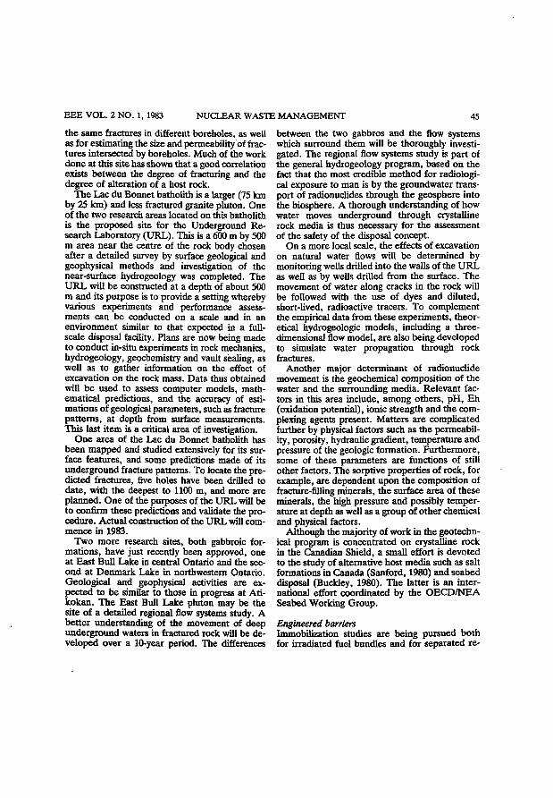
E E E V O L . 2 N O . 1, 1 9 8 3 N U C L E A R W A S T E M A N A G E M E N T 4 5
the same fractures in different boreholes, as well as for estimating the size and permeability of fractures intersected by boreholes. Much of the work done at this site has shown that a good correlation exists between the degree of fracturing and the degree of alteration of a host rock.
T h e Lac du Bonnet batholith is a larger (75 km by 25 km) and less fractured granite pluton. One of the two research areas located on this batholith is the proposed site for the Underground Research Laboratory (URL) . This is a 600 m by 500 m area near the centre of the rock body chosen after a detailed survey by surface geological and geophysical methods and investigation of the near-surface hydrogeology was completed. The U R L will be constructed at a depth of about 500 m and its purpose is to provide a setting whereby various experiments and performance assessments can be conducted on a scale and in an environment similar to that expected in a full-scale disposal facility. Plans are now being made to conduct in-situ experiments in rock mechanics, hydrogeology, geochemistry and vault sealing, as well as to gather information on the effect of excavation on the rock mass. Data thus obtained will be used to assess computer models, mathematical predictions, and the accuracy of estimations of geological parameters, such as fracture patterns, at depth from surface measurements. This last item is a critical area of investigation.
One area of the Lac du Bonnet batholith has been mapped and studied extensively for its surface features, and some predictions made of its underground fracture patterns. To locate the predicted fractures, five holes have been drilled to date, with the deepest to 1100 m, and more are planned. One of the purposes of the U R L will be to confirm these predictions and validate the procedure. Actual construction of the U R L will commence in 1983.
T w o more research sites, both gabbroic formations, have just recently been approved, one at East Bull Lake in central Ontario and the second at Denmark Lake in northwestern Ontario. Geological and geophysical activities are expected to be similar to those in progress at Ati-kokan. T h e East Bull Lake pluton may be the site of a detailed regional flow systems study. A better understanding of the movement of deep underground waters in fractured rock will be developed over a 10-year period. The differences
between the two gabbros and the flow systems which surround them will be thoroughly investigated. The regional flow systems study is part of the general hydrogeology program, based on the fact that the most credible method for radiological exposure to man is by the groundwater transport of radionuclides through the geosphere into the biosphere. A thorough understanding of how water moves underground through crystalline rock media is thus necessary for the assessment of the safety of the disposal concept.
On a more local scale, the effects of excavation on natural water flows will be determined by monitoring wells drilled into the walls of the U R L as well as by wells drilled from the surface. The movement of water along cracks in the rock will be followed with the use of dyes and diluted, short-lived, radioactive tracers. To complement the empirical data from these experiments, theoretical hydrogeologic models , including a three-dimensional flow model , are also being developed to simulate water propagation through rock fractures.
Another major determinant of radionuclide movement is the geochemical composition of the water and the surrounding media. Relevant factors in this area include, among others, p H , Eh (oxidation potential), ionic strength and the com-plexing agents present. Matters are complicated further by physical factors such as the permeability, porosity, hydraulic gradient, temperature and pressure of the geologic formation. Furthermore, some of these parameters are functions of still other factors. The sorptive properties of rock, for example, are dependent upon the composition of fracture-filling minerals, the surface area of these minerals, the high pressure and possibly temperature at depth as well as a group of other chemical and physical factors.
Although the majority of work in the geotechn-ical program is concentrated on crystalline rock in the Canadian Shield, a small effort is devoted to the study of alternative host media such as salt formations in Canada (Sanford, 1980) and seabed disposal (Buckley, 1980). The latter is an international effort coordinated by the O E C D / N E A Seabed Working Group.
Engineered barriers Immobilization studies are being pursued both for irradiated fuel bundles and for separated re-
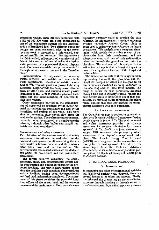
4 6 L . W . S H E M I L T & G . S H E N G E E E V O L . 2 N O . 1 , 1 9 8 3
processing wastes. High integrity containers with a life of 300-500 years are being considered as one of the engineered barriers for the immobilization of irradiated fuel. T w o different container designs are being evaluated. Most of the development work is directed at a thin-walled, supported metallic shell container. The alternative is the thick-walled, self-supported container of sufficient thickness to withstand twice the hydrostatic pressure in a postulated flooded disposal vault. Container materials must prove suitable for the high salinity waters c o m m o n in the Canadian Shield.
Immobilization of separated reprocessing wastes involves both volatile and non-volatile waste constituents. Removal of volatile wastes such as 1 2 9 I , from off-gases has proven to be very successful. Major efforts are being devoted to the study of using boro- and alumino-silicate glasses (Strathdee et al., 1979) as well as crystalline waste forms for the immobilization of non-volatile, high-level wastes.
Other engineered barriers in the immobilization of waste will be provided by the buffer material surrounding the containers and also by the backfilling and sealing of the vault. This work aims at preventing short-circuit flow from the vault to the surface. The reference buffer material currently being investigated is a sand/bentonite mixture, although other buffer and backfill materials are being considered.
Environmental and safety assessment The objective of the environmental and safety assessment is to estimate the total effect that the proposed underground vault containing the nuclear wastes will have o n man and the environment both now and in the future. T h e environmental assessment studies are divided into two parts: the pre-closure and the post-closure assessment.
The former involves evaluating the social, economic, safety and environmental effects during construction and operation phases of the proposed facilities. The post-closure period begins after the vault has been backfilled and sealed, the surface facilities having been decommissioned and final land reclamation completed. The assessment of this phase considers the potential long-term effects of the sealed vault and its contents on man and the environment. Since no such waste
repository currently exists to provide the data necessary for this assessment, a method known as Systems Variability Analysis (Lyon, 1981) is being used to estimate potential impacts on future generations. This analysis uses a computer simulation which models the possible release of radionuclides from their containments and the subsequent route and time of such radionuclide migration through the geosphere and into the biosphere. The endpoint of this analysis is the estimation of the potential radiological impact on man over a significant life-time of the long-lived radionuclides.
The simulation consists of three major models representing the vault, the geosphere and the biosphere. Ranges of values are assigned to all the parameters identified as being important in characterizing each of these three models. The range of values for each parameter, acquired through field and laboratory studies, reflects the best current state of knowledge about that parameter. By sampling values throughout its entire range, one can thus take into account the uncertainties associated with each parameter.
2.4 REVIEW AND REGULATION
The Canadian program is subject to external review by a Technical Advisory Committee (further details appear in Section 3.7). The environmental and safety assessment provides the concept assessment for eventual submission for concept approval. A Canada-Ontario joint statement in August 1981 announced the process by which acceptance of the disposal concept would take place. The Atomic Energy Control Board (AECB) was designated as the responsible authority for the final approval. After. A E C B reviews input from the Technical Advisory Committee, the scientific community and the general public, a full public hearing will be held prior to AECB's decision.
3. INTERNATIONAL P R O G R A M S
3.1 INTRODUCTION
In examining the range of international activities and high-level nuclear waste disposal, there are several factors to be taken into account. Firstly, the principal aim of ensuring no undue radiation exposure through handling or through return to man's environment from a final repository is com-
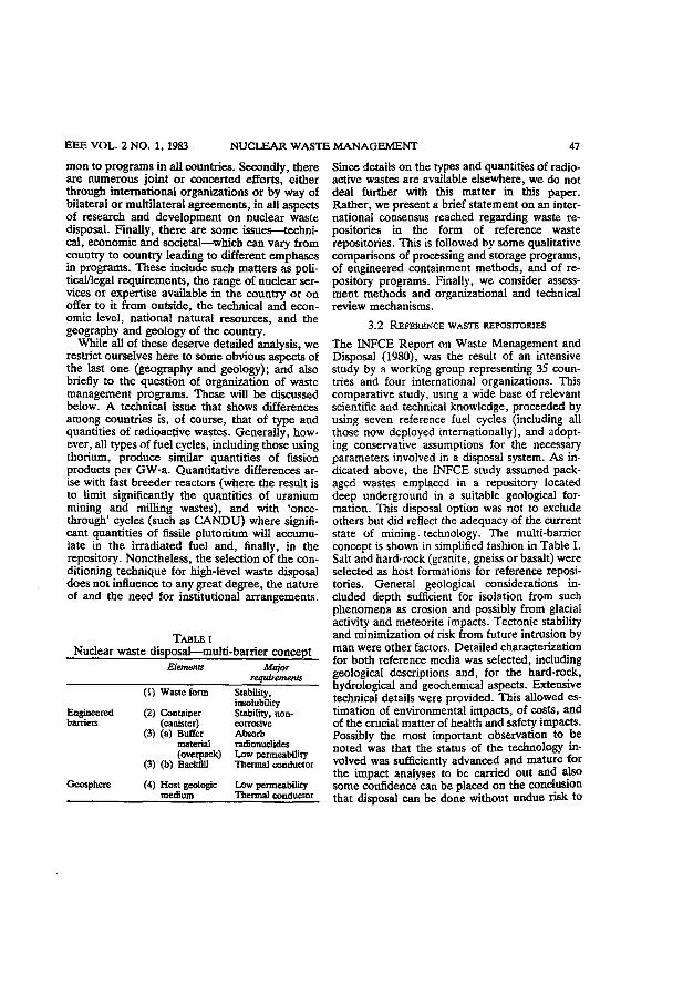
E E E V O L . 2 N O . 1 , 1 9 8 3 N U C L E A R W A S T E M A N A G E M E N T 4 7
mon to programs in all countries. Secondly, there are numerous joint or concerted efforts, either through international organizations or by way of bilateral or multilateral agreements, in all aspects of research and development on nuclear waste disposal. Finally, there are some issues—technical, economic and societal—which can vary from country to country leading to different emphases in programs. These include such matters as political/legal requirements, the range of nuclear services or expertise available in the country or on offer to it from outside, the technical and economic level, national natural resources, and the geography and geology of the country.
While all of these deserve detailed analysis, we restrict ourselves here to some obvious aspects of the last one (geography and geology); and also briefly to the question of organization of waste management programs. These will be discussed below. A technical issue that shows differences among countries is, of course, that of type and quantities of radioactive wastes. Generally, however, all types of fuel cycles, including those using thorium, produce similar quantities of fission products per GW-a. Quantitative differences arise with fast breeder reactors (where the result is to limit significantly the quantities of uranium mining and milling wastes), and with 'once-through' cycles (such as C A N D U ) where significant quantities of fissile plutonium will accumulate in the irradiated fuel and, finally, in the repository. Nonetheless, the selection of the conditioning technique for high-level waste disposal does not influence to any great degree, the nature of and the need for institutional arrangements.
TABLE I Nuclear waste disposal—multi-barrier concept
Elements Major requirements
(1) Waste form Stability, insolubility
Engineered (2) Container Stability, non-barriers (canister) corrosive
(3) (a) Buffer Absorb material radionuclides (overpack) Low permeability
(3) (b) Backfill Thermal conductor
Geosphere (4) Host geologic Low permeability medium Thermal conductor
Since details on the types and quantities of radioactive wastes are available elsewhere, we do not deal further with this matter in this paper. Rather, we present a brief statement on an international consensus reached regarding waste repositories in the form of reference waste repositories. This is followed by some qualitative comparisons of processing and storage programs, of engineered containment methods, and of repository programs. Finally, we consider assessment methods and organizational and technical review mechanisms.
3.2 REFERENCE WASTE REPOSITORIES
The INFCE Report on Waste Management and Disposal (1980), was the result of an intensive study by a working group representing 35 countries and four international organizations. This comparative study, using a wide base of relevant scientific and technical knowledge, proceeded by using seven reference fuel cycles (including all those now deployed internationally), and adopting conservative assumptions for the necessary parameters involved in a disposal system. A s indicated above, the INFCE study assumed packaged wastes emplaced in a repository located deep underground in a suitable geological formation. This disposal option was not to exclude others but did reflect the adequacy of the current state of mining technology. The multi-barrier concept is shown in simplified fashion in Table I. Salt and hard-rock (granite, gneiss or basalt) were selected as host formations for reference repositories. General geological considerations included depth sufficient for isolation from such phenomena as erosion and possibly from glacial activity and meteorite impacts. Tectonic stability and minimization of risk from future intrusion by man were other factors. Detailed characterization for both reference media was selected, including geological descriptions and, for the hard-rock, hydrological and geochemical aspects. Extensive technical details were provided. This allowed estimation of environmental impacts, of costs, and of the crucial matter of health and safety impacts. Possibly the most important observation to be noted was that the status of the technology involved was sufficiently advanced and mature for the impact analyses to be carried out and also some confidence can be placed on the conclusion that disposal can be done without undue risk to
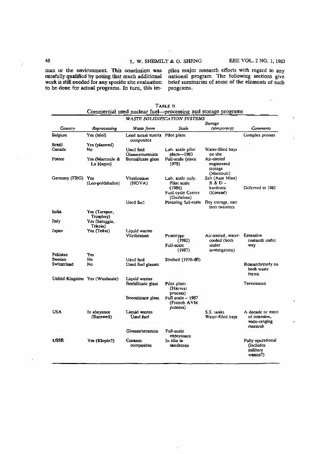
4 8 L . W . S H E M I L T & G . S H E N G E E E V O L . 2 N O . 1, 1983
man or the environment. This conclusion was carefully qualified by noting that much additional work is still needed for any specific site evaluation to be done for actual programs. In turn, this im
plies major research efforts with regard to any national program. The following sections give brief summaries of some of the elements of such programs.
TABLE n Commercial used nuclear fuel—processing and storage programs
WASTE SOLIDIFICATION SYSTEMS
Country Reprocessing Waste form Scale Storage
(temporary) Comments Belgium
Brazil Canada
France
Yes (Mol)
Yes (planned) No
Yes (Marcoule & La Hague)
Germany (FRG) Yes (Leo-poldshafen)
India
Italy
lapan
Pakistan Sweden Switzerland
Yes (Tarepur, Trombay)
Yes (Saluggia, Trisaia)
Yes (Tokai)
Yes No No
United Kingdom Yes (Wlndscale)
USA
USSR
In abeyance (Barnwell)
Yes (Klopin?)
Lead metal matrix Pilot plant composites
Used fuel Glasses/ceramics Borosilicate glass
Vitrification (HOVA)
Used fuel
Liquid wastes Vitrification
Used fuel Used fuel glasses
Liquid wastes Borisilicate gla
Borosilicate glass
Liquid wastes Used fuel
Glasses/ceramics
Ceramic composites
Lab. scale pilot plant—1983
Full-scale (since 1978)
Lab. scale only. Pilot scale (1986)
Fuel cycle Centre (Gorleben)
Planning full-scale
Full-scale experience
In situ in sandstone
Complex process
Prototype (1982)
Full-scale (1987)
Studied (1976-80)
Pilot plant (Harvest process)
Full scale - 1987 (French AVM process)
Water-filled bays on site
Air-cooled engineered storage (Marcoule)
Salt (Asse Mine) R & D -hardrock (Konrad)
Dry storage, cast iron canisters
Air-cooled, water-cooled (both under investigation)
S.S. tanks Water-filled bays
Deferred to 1985
Extensive research under way
Research/study on both waste forms
Terminated
A decade or more of intensive, wide-ranging research
Fully operational (includes military wastes?)
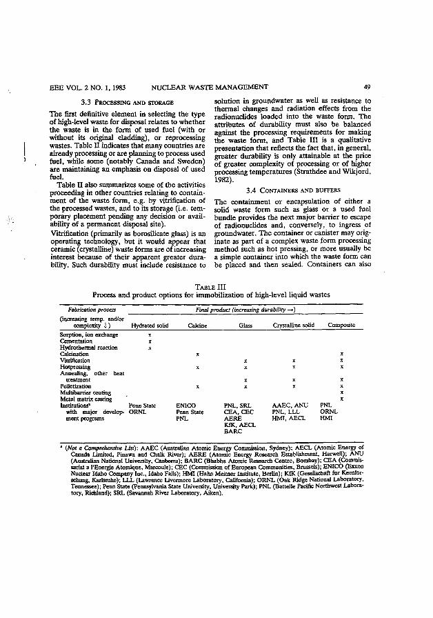
E E E V O L . 2 N O . 1 , 1 9 8 3 N U C L E A R W A S T E M A N A G E M E N T 49
3.3 PROCESSING AND STORAGE
The first definitive element in selecting the type of high-level waste for disposal relates to whether the waste is in the form of used fuel (with or without its original cladding), or reprocessing wastes. Table H indicates that many countries are already processing or are planning to process used fuel, while some (notably Canada and Sweden) are maintaining an emphasis on disposal of used fuel.
Table II also summarizes some of the activities proceeding in other countries relating to containment of the waste form, e.g. by vitrification of the processed wastes, and to its storage (i .e. temporary placement pending any decision or availability of a permanent disposal site). Vitrification (primarily as borosilicate glass) is an operating technology, but it would appear that ceramic (crystalline) waste forms are of increasing interest because of their apparent greater durability. Such durability must include resistance to
solution in groundwater as well as resistance to thermal changes and radiation effects from the radionuclides loaded into the waste fonn. The attributes of durability must also be balanced against the processing requirements for making the waste form, and Table III is a qualitative presentation that reflects the fact that, in general, greater durability is only attainable at the price of greater complexity of processing or of higher processing temperatures (Strathdee and Wikjord, 1982).
3.4 CONTAINERS AND BUFFERS
The containment or encapsulation of either a solid waste form such as glass or a used fuel bundle provides the next major barrier to escape of radionuclides and, conversely, to ingress of groundwater. The container or canister may originate as part of a complex waste form processing method such as hot pressing, or more usually be a simple container into which the waste form can be placed and then sealed. Containers can also
TABLE III Process and product options for immobilization of high-level liquid wastes
Fabrication process (increasing temp, and/or
complexity i )
Final product (increasing durability —»)
Hydrated solid Calcine Glass Crystalline solid Composite Sorption, ion exchange Cementation x Hydrothermal reaction x Calcination Vitrification Hotpressing Annealing, other heat
treatment Pelletization Multibarrier coating Metal matrix casting Institutions* Penn State
with major develop- ORNL ment programs
ENICO Penn State PNL
PNL, SRL CEA, CEC AERE KfK, AECL BARC
AAEC, ANU PNL, LLL HMI, AECL
PNL ORNL HMI
* (Not a Comprehensive List): AAEC (Australian Atomic Energy Commission, Sydney); AECL (Atomic Energy of Canada Limited, Pinawa and Chalk River); AERE (Atomic Energy Research Establishment, Harwell); ANU (Australian National University, Canberra); BARC (Bhabha Atomic Research Centre, Bombay); CEA (Commissariat a I'Energie Atomique, Marcoule); CEC (Commission of European Communities, Brussels); ENICO (Exxon Nuclear Idaho Company Inc., Idaho Falls); HMI (Hahn Meitner Institute, Berlin); KfK (Gesellschaft fur Kemfor-schung, Karlsruhe); LLL (Lawrence Livermore Laboratory, California); ORNL (Oak Ridge National Laboratory, Tennessee); Penn State (Pennsylvania State University, University Park); PNL (Battelle Pacific Northwest Laboratory, Richland); SRL (Savannah River Laboratory, Aiken).
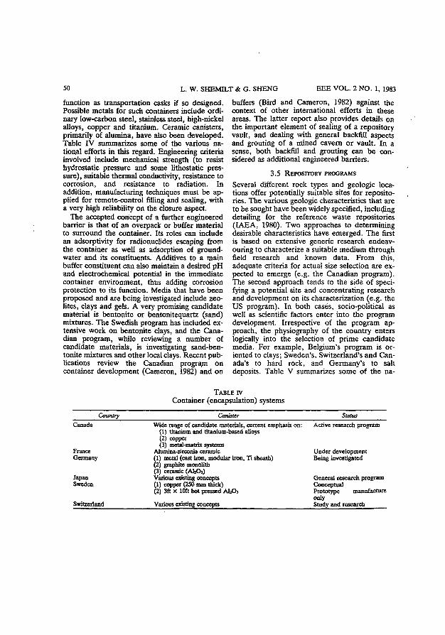
5 0 L . W . S H E M I L T & G. S H E N G E E E V O L . 2 N O . 1 , 1 9 8 3
function as transportation casks if so designed. Possible metals for such containers include ordinary low-carbon steel, stainless steel, high-nickel alloys, copper and titanium. Ceramic canisters, primarily of alumina, have also been developed. Table IV summarizes some of the various national efforts in this regard. Engineering criteria involved include mechanical strength (to resist hydrostatic pressure and some lithostatic pressure), suitable thermal conductivity, resistance to corrosion, and resistance to radiation. In addition, manufacturing techniques must be applied for remote-control filling and sealing, with a very high reliability on the closure aspect.
The accepted concept of a further engineered barrier is that of an overpack or buffer material to surround the container. Its roles can include an adsorptivity for radionuclides escaping from the container as well as adsorption of groundwater and its constituents. Additives to a main buffer constituent can also maintain a desired pH and electrochemical potential in the immediate container environment, thus adding corrosion protection to its function. Media that have been proposed and are being investigated include zeolites, clays and gels. A very promising candidate material is bentonite or bentonitequartz (sand) mixtures. The Swedish program has included extensive work on bentonite clays, and the Canadian program, while reviewing a number of candidate materials, is investigating sand-ben-tonite mixtures and other local clays. Recent publications review the Canadian program on container development (Cameron, 1982) and on
buffers (Bird and Cameron, 1982) against the context of other international efforts in these areas. The latter report also provides details on the important element of sealing of a repository vault, and dealing with general backfill aspects and grouting of a mined cavern or vault. In a sense, both backfill and grouting can be considered as additional engineered barriers.
3 . 5 REPOSITORY PROGRAMS
Several different rock types and geologic locations offer potentially suitable sites for repositories. The various geologic characteristics that are to be sought have been widely specified, including detailing for the reference waste repositories ( IAEA, 1980). Two approaches to determining desirable characteristics have emerged. The first is based on extensive generic research endeavouring to characterize a suitable medium through field research and known data. From this, adequate criteria for actual size selection are expected to emerge (e.g. the Canadian program). The second approach tends to the side of specifying a potential site and concentrating research and development on its characterization (e .g. the U S program). In both cases, socio-political as well as scientific factors enter into the program development. Irrespective of the program approach, the physiography of the country enters logically into the selection of prime candidate media. For example, Belgium's program is oriented to clays; Sweden's, Switzerland's and Canada's to hard rock, and Germany's to salt deposits. Table V summarizes some of the na-
TABLE rv Container (encapsulation) systems
Country Canister Status Canada Wide range of candidate materials, current emphasis on: Active research program
(1) titanium and titanium-based alloys (2) copper (3) metal-matrix systems
France Alumina-zirconia ceramic Under development Germany (1) metal (cast iron, modular iron, Ti sheath) Being investigated
(2) graphite monolith (3) ceramic (AbOa)
Japan Various existing concepts General research program Sweden (1) copper (250 mm thick) Conceptual
(2) 3ft x 10ft hot pressed AbOj Prototype manufacture only
Switzerland Various existing concepts Study and research
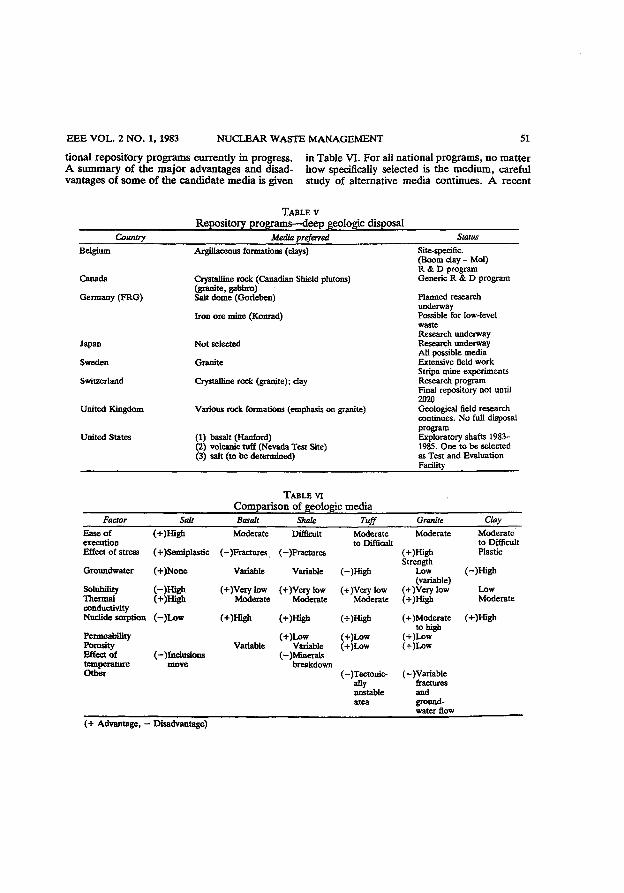
EEE VOL. 2 NO. 1, 1983 NUCLEAR WASTE MANAGEMENT 51
tional repository programs currently in progress, in Table VI. For all national programs, no matter A summary of the major advantages and disad- how specifically selected is the medium, careful vantages of some of the candidate media is given study of alternative media continues. A recent
TABLE V Repository programs—deep geologic disposal
Country Media preferred Status Belgium
Canada
Germany (FRG)
Japan
Sweden
Switzerland
United Kingdom
United States
Argillaceous formations (clays)
Crystalline rock (Canadian Shield plutons) (granite, gabbro) Salt dome (Gorleben)
Iron ore mine (Konrad)
Not selected
Granite
Crystalline rock (granite); day
Various rock formations (emphasis on granite)
(1) basalt (Hanford) (2) volcanic tuff (Nevada Test Site) (3) salt (to be determined)
Site-specific. (Boom clay - Mol) R & D program Generic R & D program
Planned research underway Possible for low-level waste Research underway Research underway All possible media Extensive field work Stripa mine experiments Research program Final repository not until 2020 Geological field research continues. No full disposal program Exploratory shafts 1983-1985. One to be selected as Test and Evaluation Facility
TABLE VI Comparison of geologic media
Factor Salt Basalt Shale Tuff Granite Clay Ease of (+)HJgh Moderate Difficult Moderate Moderate Moderate execution
(+)HJgh to Difficult to Difficult
Effect of stress (+)Senüplastic (-)Fractures (-)Fractures (+)High Strength
Plastic
Groundwater (+)None Variable Variable (-)High Low (-)High (-)High (variable)
Solubility (-)High (+)Very low (+)Very low (+)Very low (+)Very low Low Thermal (+)Mgh Moderate Moderate Moderate (+)High Moderate conductivity
(+)High
Nuclide sorption (-)Low (+)High (+)High (+)High (+)Moderate to high
(+)High
Permeability (+)Low (+)Low (+)Low Porosity Variable Variable (+)Low (+)Low Effect of (-)lnclusions (—)Minerals
(+)Low
temperature move breakdown Other (-)Tectonic-
ally unstable area
(-VVariable fractures and groundwater flow
(+ Advantage, — Disadvantage)
5 2 L . W . S H E M I L T & G . S H E N G E E E V O L . 2 N O . 1 , 1983
report (Bredehoeft and Maini, 1981) indicates, for example, how a crystalline rock mass beneath a blanket of sedimentary rock offers significant advantages.
The overall effort is extensively supported by the free exchange of information that occurs, as well as through multination participation in such international organizations as the International Atomic Energy Agency ( I A E A ) , the Commission of European Communities, and the Nuclear Energy Agency of the Organization for Economic Development ( O E C D / N E A ) . Relevant experimental work in mined vaults is an interesting and valuable feature. The Stripa mine in Sweden has had such research activity for several years, first through a joint Swedish-American program (Witherspoon et al., 1981) and more recently through a multination cooperative arrangement which is planning to extend the activity. In the United States, underground caverns in basalt at the Hanford site near Richland, Washington, and in granite in the Climax Mine at the Nevada Test Site, have been the scene of extensive research operations employing temporary storage of canisters of spent fuel. A s mentioned earlier, Canada is now in the preliminary stages of developing a major Underground Research Laboratory (URL.) in a granitic batholith near Lac du Bonnet, Manitoba (Simmons and Soonawala, 1982). Germany has extensive exploratory work going on in the salt beds near Gorleben as well as in the A s s e Salt Mine.
All geologic repository research programs have a wide range of geoscientific effort involved. This includes geophysical and geological characterization, geotechnical work on rock masses, geo-chemical considerations, and hydrogeological factors. Extensive and complex modelling accompanies such efforts since the fate of a repository containing radioactive waste must be predictable within acceptable limits for up to hundreds of thousands of years. Such a time span is, however, not long in terms of geologic time scales, and studies of natural geologic analogs are of value in this regard.
3.6 ASSESSMENT METHODS
The environmental and safety assessment of repositories for highly radioactive wastes is based on the criterion that all nuclides must be isolated for a sufficiently long time to permit their decay
to acceptable levels. Both the questions of 'how long?' and 'What is acceptable?' are complex and have been the subject of extensive study and debate in recent years. While essentially all radioactivity from fission products has disappeared within 1000 years, that from the actinides such as plutonium continues much longer. For this reason, the range of 10 s - 10' years is often used. Similarly, while radiation standards are estab-
"lished both internationally and nationally, theoretical and experimental evidence suggests that there may be no threshold for radiation effects. The need to reduce any future potential exposure to the lowest practicable level has led to an emphasis in recent years on relating such a level to the amount of natural background radiation.
A n important and comprehensive review of the literature on long-term safety of high-level waste repositories has been published by Koplik et al. (1982). As this review notes, the process of evaluating repository safety proceeds from assembling a comprehensive list of processes and events that could contribute to release of radioactivity, and analysing a list of scenarios in which events and processes which control repository performance are specified and described mathematically. After describing the likelihood of occurrence of each scenario, the consequences to human health are evaluated for the occurrence of each. The two major approaches for judging safety which have been applied are: (1) the use of some type of hazard index for comparison to other toxic substances; and (2) analysis of the future behaviour of the total system that is a waste repository. Hazard indexes have the value of simplicity in making reasonable comparisons. Most employ the so-called maximum permissible concentration (MPC) of radionuclides in air or water and are based, for example, on the amount of air or water (Pigford, 1982) needed to dilute the waste to MPC levels. The more complex system analysis approach is exemplified by that described for the Canadian program in Section 2 above. The selection of scenarios for such analysis can be done through a variety of methods (Koplik et al., 1982) and their probabilities estimated. The elements in the system must be modelled for analysis purposes, e.g. waste package and repository (vault model) , the geologic formation (geosphere model) and the biosphere. Uncertainties arise in selecting scenarios, in the models used to calcu-
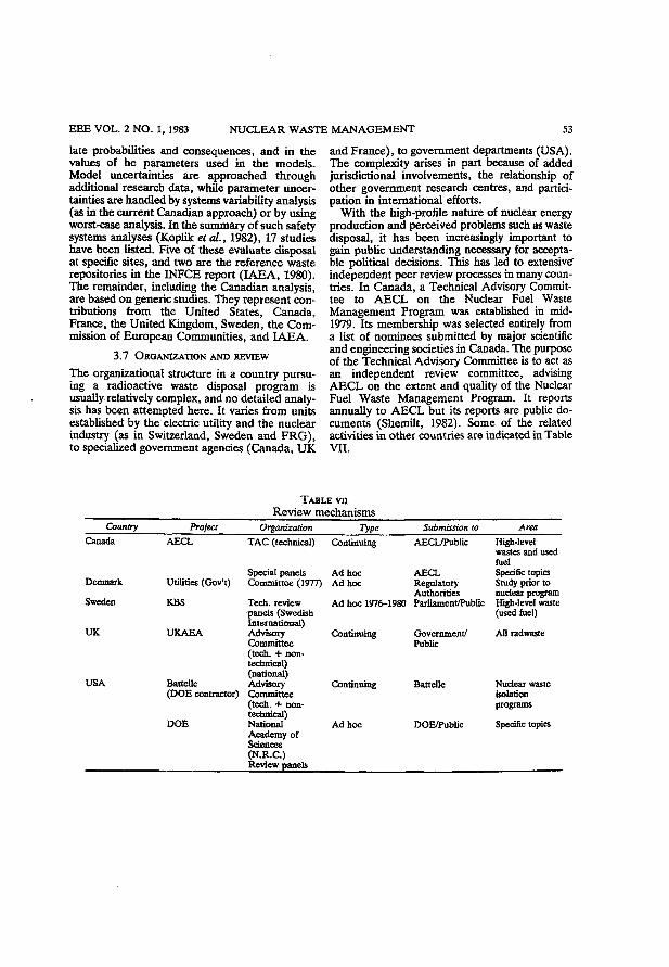
EEE VOL. 2 NO. 1, 1983 NUCLEAR WASTE MANAGEMENT 53
late probabilities and consequences, and in the values of he parameters used in the models . Model uncertainties are approached through additional research data, while parameter uncertainties are handled by systems variability analysis (as in the current Canadian approach) or by using worst-case analysis. In the summary of such safety systems analyses (Koplik et al., 1982), 17 studies have been listed. Five of these evaluate disposal at specific sites, and two are the reference waste repositories in the INFCE report ( I A E A , 1980). The remainder, including the Canadian analysis, are based on generic studies. They represent contributions from the United States, Canada, France, the United Kingdom, Sweden, the Commission of European Communities, and I A E A .
3.7 ORGANIZATION A N D REVIEW
The organizational structure in a country pursuing a radioactive waste disposal program is usually relatively complex, and no detailed analysis has been attempted here. It varies from units established by the electric utility and the nuclear industry (as in Switzerland, Sweden and F R G ) , to specialized government agencies (Canada, U K
and France), to government departments (USA) . The complexity arises in part because of added jurisdictional involvements, the relationship of other government research centres, and participation in international efforts.
With the high-profile nature of nuclear energy production and perceived problems such as waste disposal, it has been increasingly important to gain public understanding necessary for acceptable political decisions. This has led to extensive" independent peer review processes in many countries. In Canada, a Technical Advisory Committee to A E C L on the Nuclear Fuel Waste Management Program was established in mid-1979. Its membership was selected entirely from a list of nominees submitted by major scientific and engineering societies in Canada. The purpose of the Technical Advisory Committee is to act as an independent review committee, advising A E C L on the extent and quality of the Nuclear Fuel Waste Management Program. It reports annually to A E C L but its reports are public documents (Shemilt, 1982). Some of the related activities in other countries are indicated in Table VII.
TABLE vn Review mechanisms
Country Project Organization Type Submission to Area Canada
Denmark
Sweden
AECL
UK
USA
Utilities (Gov't)
KBS
UKAEA
Battelle (DOE contractor)
DOE
TAC (technical) Continuing
Special panels Ad hoc Committee (1977) Ad hoc
Tech. review panels (Swedish International) Advisory Committee (tech. + nontechnical) (national) Advisory Committee (tech. + nontechnical) National Academy of Sciences (N.R.C.) Review panels
Ad hoc 1976-1980
Continuing
Continuing
Ad hoc
AECL/Public
AECL Regulatory Authorities Parliament/Public
Government/ Public
Battelle
DOE/Public
High-level wastes and used fuel Specific topics Study prior to nudear program High-level waste (used fuel)
All radwaste
Nudear waste isolation programs
Specific topics
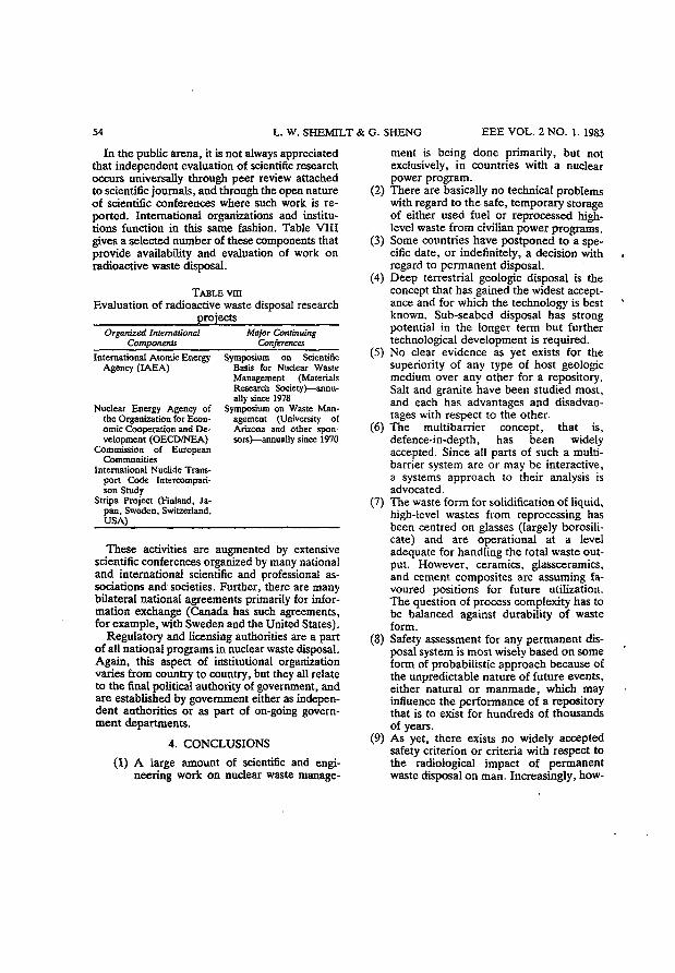
54 L. W. SHEMILT & G. SHENG EEE VOL. 2 NO. 1. 1983
In the public arena, it is not always appreciated that independent evaluation of scientific research occurs universally through peer review attached to scientific journals, and through the open nature of scientific conferences where such work is reported. International organizations and institutions function in this same fashion. Table VIII gives a selected number of these components that provide availability and evaluation of work on radioactive waste disposal.
TABLE vm Evaluation of radioactive waste disposal research
projects Organized International Major Continuing
Components Conferences International Atomic Energy Symposium on Scientific
Agency (IAEA) Basis for Nuclear Waste Management (Materials Research Society)—annually since 1978
Nuclear Energy Agency of Symposium on Waste Man-the Organization for Econ- agement (University of omic Cooperation and De- Arizona and other spon-velopment (OECD/NEA) sors)—annually since 1970
Commission of European Communities
International Nuclide Transport Code Intercompari-son Study
Stripa Project (Finland, Japan, Sweden, Switzerland, USA)
These activities are augmented by extensive scientific conferences organized by many national and international scientific and professional associations and societies. Further, there are many bilateral national agreements primarily for information exchange (Canada has such agreements, for example, with Sweden and the United States).
Regulatory and licensing authorities are a part of all national programs in nuclear waste disposal. Again, this aspect of institutional organization varies from country to country, but they all relate to the final political authority of government, and are established by government either as independent authorities or as part of on-going government departments.
4. CONCLUSIONS
(1) A large amount of scientific and engineering work on nuclear waste manage
ment is being done primarily, but not exclusively, in countries with a nuclear power program.
(2) There are basically no technical problems with regard to the safe, temporary storage of either used fuel or reprocessed high-level waste from civilian power programs.
(3) Some countries have postponed to a specific date, or indefinitely, a decision with regard to permanent disposal.
(4) D e e p terrestrial geologic disposal is the concept that has gained the widest acceptance and for which the technology is best known. Sub-seabed disposal has strong potential in the longer term but further technological development is required.
(5) No clear evidence as yet exists for the superiority of any type of host geologic medium over any other for a repository. Salt and granite have been studied most, and each has advantages and disadvantages with respect to the other.
(6) The multibarrier concept, that is, defence-in-depth, has been widely accepted. Since all parts of such a multi-barrier system are or may be interactive, a systems approach to their analysis is advocated.
( 7 ) The waste form for solidification of liquid, high-level wastes from reprocessing has been centred on glasses (largely borosili-cate) and are operational at a level adequate for handling the total waste output. However, ceramics, glassceramics, and cement composites are assuming favoured positions for future utilization. The question of process complexity has to be balanced against durability of waste form.
(8) Safety assessment for any permanent disposal system is most wisely based on some form of probabilistic approach because of the unpredictable nature of future events, either natural or manmade, which may influence the performance of a repository that is to exist for hundreds of thousands of years.
(9) A s yet, there exists no widely accepted safety criterion or criteria with respect to the radiological impact of permanent waste disposal on man. Increasingly, how-

EEE VOL. 2 NO. 1,1983 NUCLEAR WASTE MANAGEMENT 55
ever, the comparison of radiation dose levels attributable to the disposal with that from existing natural radiation sources is being emphasized.
(10) There is a remarkable amount of inter
national effort and cooperation as evident in the free exchange of information among various countries as well as the general ease of access to such information by interested parties.
R E F E R E N C E S Aiken, A. M., Harrison, J. M. and Hare F. K., 1977. The Management of Canada's Nuclear Wastes.
Energy, Mines and Resources Energy Policy Sector Rep., EP-77-6, Ottawa. Barnes, R. W. 1976. The Management of Irradiated Fuel in Ontario. A Review. Ontario Hydro Report,
GP 76014, Vol. 1. Bird, G. W. and Cameron, D. J. 1982. Vault Sealing Research for the Canadian Nuclear Fuel Waste
Management Program. Atomic Energy of Canada Ltd. Tech. Record, TR-145. Boulton, J. (Editor), 1978. Management of Radioactive Fuel Wastes: The Canadian Disposal Program.
Atomic Energy of Canada. Rep., AECL-6314. Boulton. J. (Editor), 1980. Second Annual Report of the Canadian Nuclear Fuel Waste Management
Program. Atomic Energy of Canada Ltd. Rep., AECL-6804. Boulton, J. and Gibson, A. R. (Editors), 1979. First Annual Report of the Canadian Nuclear Fuel Waste
Management Program. Atomic Energy of Canada Ltd. Rep., AECL-6443. Bredehoeft, J. D. and Tidu Maini, 1981. Strategy for radioactive waste disposal in crystalline rocks.
Science, 2 1 3 (4505) 17 July. Buckley, D. E., 1980. Deep Sea Sediments as an Alternative Medium for Nuclear Waste Disposal. Paper
presented at the Geotech. Info. Meet., Nuclear Fuel Waste Management Program, Ottawa, May 5-6. Cameron, D. J., 1982. Fuel Isolation Research for the Canadian Nuclear Fuel Waste Management Program.
Atomic Energy of Canada Ltd. Rep. AECL-6834. Dixon, R. S. and Rosinger, E. L. J. (Editors), 1981. Third Annual Report of the Canadian Nuclear Fuel
Waste Management Program. Atomic Energy of Canada Ltd. Rep., AECL-6821. US DOE/EIS 1979. Management of Commercially Generated Radioactive Waste. Final Environmental
Impact Statement, DOE/EIS - 0046F, Vol. 1. US Dept. of Energy, Washington, DC. USDOE 1979. Report to the President. Interagency Review Group on Nuclear Waste Management,
TID-29442. US Dept. of Energy, Washington, DC. IAEA 1980. Waste Management and Disposal. Rep. International Nuclear Fuel Cycle Evaluation Working
Group 7, International Atomic Energy Agency, Vienna. IAEA 1982. Radioactive Waste Storage and Disposal. Extracts from Major Tech. Reps, by National and
International Organizations 1975-1981. International Atomic Energy Agency, Vienna. Koplik, C. M., Kaplan, M. F. and Ross, B., 1982. The safety of repositories for highly radioactive wastes.
Rev. Mod. Phys. 5 4 , 269-310. Lyon, R. B . , 1981. Environmental and safety assessment for nuclear waste disposal—the Canadian ap
proach. Waste Management '81 Symp. Tucson, AZ, February Lyon, R. B., Rosinger, E. L. J., Wright, J. H. and Gillespie, P., 1981. Guide to the Canadian Nuclear
Fuel Waste Management Program. Atomic Energy of Canada Ltd., Whiteshell Nuclear Research Establishment, Pinawa, Manitoba, December.
Merritt, W. F., 1976. The leaching of radioactivity from highly radioactive glass blocks buried below the water table: fifteen years of results. Proc. Intl. Symp. on the Management of Radioactive Wastes from the Nuclear Fuel Cycle, Vol. 2, p. 77. IAEA, Vienna.
Morgan, W. W., 1974. The Management of Spent CANDU Fuel. Nuclear Tech. 2 4 , 409. Ohta, M. M., 1978. The Concrete Canister Program. Atomic Energy of Canada Ltd. Rep., AECL-5965. Pigford, T. H., 1982. Geological Disposal of Radioactive Wastes. Chem. Eng. Progr. 7 8 ( 3 ) 18-26. Sanford, B . V. , 1980. Alternative Host Rock Media—Sali, Limestone and Shale. Paper presented at the
Geotech. Info. Meet., Nuclear Fuel Waste Management Program, Ottawa, May 5-6. Scott, J. S., and Charlwood, R. G., 1979. Canadian Geoscience Research and Design Concepts for
Disposal of High-Level Waste in Igneous Rocks. Intl. Symp. on the Underground Disposal of Radioactive Wastes, IAEA/OECD/NEA, Otaniemi, Finland, July, IAEA-SM-243/168.
56 L. W. SHEMILT & G. SHENG EEE VOL. 2 NO. 1, 1983
Shemilt, L. W. (Chairman), 1982. Third Annual Report of the Technical Advisory Committee on the Nuclear Fuel Waste Management Program. Tech. Advisory Committee, Engineering Bldg., McMaster University, Hamilton, Ont, (TAC-3) June.
Simmons, G. R. and Soonawala, N. W., (eds.), 1982. Underground Research Laboratory Experimental Program. Atomic Energy of Canada Ltd., Whiteshell Nuclear Research Establishment, Pinawa, Manitoba, TR-153.
Strathdee, G. G., Mclntyre, N. S; and Taylor, P., 1979. Development of aluminosilicate and borosilicate glasses as matrices for CANDU high-level wastes. Proc. Am. Ceram. Soc. 81st Ann. Meet, Cincinnati, April 30-May 2, CONF-790420.
Strathdee, G. G. and Wikjord, A. G., 1982. Waste Immobilization Research for the Canadian Nuclear Fuel Waste Management Program. Atomic Energy of Canada Limited Tech. Rec., TR-148.
Witherspoon, P. A. , Cook, N. G. W. and Gale, J. E . , 1981. Geologic storage of radioactive waste: field studies in Sweden. Science, 2 1 1 (27 February).
2.2
An Evaluation of the Canadian Nuclear Waste Management Program
G. SHENG
McMaster University, GSB-216 Hamilton, Ontario L8S 4K1
B. LAD ANY!
École Polytechnique Université de Montréal
Montréal, PQ
L.W. SHEMLLT
McMaster University, GSB-216 Hamilton, Ontario L8S 4K1
to Proceedings of the Canadian Engineering Centennial Convention, Montreal, May 18-22,1987, pp. 111-121

An Evaluation of the Canadian Nuclear Fuel Waste Management Program
G. Sheng McMaster University, GSB-216
Hamilton, Ontario, LBS 4K1 B. Ladanyi,
Ecole Polytecfmtque University of Montreal
Montreal, Quebec, H3C 3A7 L.W. Shemlft
McMaster University, GSB-216 Hamilton, Ontario L8S 4K1
SUMMARY The Canadian Program on Nuclear Waste Management conducted by Atomic Energy of Canada Limited is reviewed. The concept involves a multi-barrier system and includes a 1 km deep vault in the Canadian Shield. Results from current research is anticipated to be formally reviewed in 3 years. The complex assessment process includes public hearings, and precedes any site selection. The role and work of the Technical Advisory Committee, established as an independent scientific and engineering review body is described.
Extensive geological, geophysical and hydro-geological work has been carried out in the past eight years. A major regional flow system study has been initiated. Predictive aspects are being tested through the construction of an Underground Research Laboratory (URL) in the Lac du Bonnet botholith-The URL is a key component in gaining the necessary scientific understanding of the type of rock system that could eventually be selected somewhere in the Canadian Shield to host a waste disposal vault. Results so far achieved justify this endeavour, and show the importance of the recent Canada-U.S. agreement for U.S. participation in extending the URL.
The methodology being employed to assess the environmental and safety outcome of a disposal vault is based on a probabilistic approach and is considered sound.
INTRODUCTION
The research and development program to establish appropriate technologies for the safe, permanent disposal of Canada's nuclear fuel wastes was formally initiated in June 1978 by a Federal Government-Ontario Agreement (Canada-Ontario, 1978}. The resulting Canadian Nuclear Fuel Waste Management Program (CNFWMP) is described in a public document (Boulton, 1978> and its course of development can be followed through a series of publicly available annual reports (e.g. Dixon and Rosinger, 1984). External peer review of the program is made annually by a Technical Advisory Committee (e.g. TAC, 1986).
THE CANADIAN WASTE DISPOSAL CONCEPT The Objective
The overall objective of the CNFWMP is "to ensure-that there will be no significant adverse effect on man or the environment from nuclear fuel waste at any time" (Rosinger and Dixon, 1982). Nuclear fuel waste is defined as either used or irradiated fuel, or high-level radioactive material separated from used fuel through reprocessing (should Canada adopt this option in the future).
The Multi-Barrier System
Similar to efforts in several other nations, the Canadian program of research on deep geological disposal of nuclear waste is based on the concept of isolating wastes with a series of barriers situated in a deep (500 m - 1000 m) underground vault, built in a stable, terrestrial geologic formation such as the Canadian Shield. This multi-barrier concept is illustrated in Figure 1.
First, the bundles of used fuel would be encased in canisters with an anticipated minimum lifetime of several hundred years which correspond to the period of high fission-product activity. The containers would be designed to withstand vault pressures and be resistant to corrosion under the temperature, groundwater exposure and radiation fields that could potentially exist.
Research is also being conducted on immobilizing high-level wastes from fuel reprocessing (if adopted) whereby the waste would be incorporated into a water-insoluble, leach-resistant material, such as glass or ceramic.
Following waste immobilization or containment, the canisters would be emplaced in the vault and packed with compacted buffer material such as bentonite clay. This candidate material swells upon contact with water, thus acting as a seal against leaching and corrosive agents. It also has a high capacity to absorb chemical species, including most of the significant radionuclides. The vault and the shaft would then be
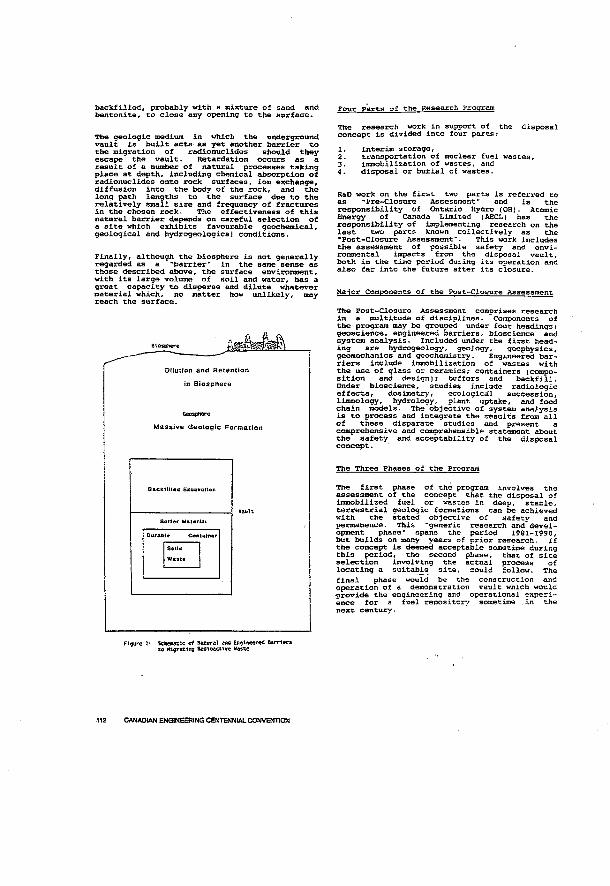
backfilled, probably with a mixture of sand and bentonite, to close any opening to the surface.
The geologic medium in which the underground vault is built acts as yet another barrier to the migration of radionuclides should they escape the vault. Retardation occurs as a result of a number of natural processes taking place at depth, including chemical absorption of radionuclides onto rock surfaces, ion exchange, diffusion into the body of the rock, and the long path lengths to the surface due to the relatively small size and frequency of fractures in the chosen rock. The effectiveness of this natural barrier depends on careful selection of a site which exhibits favourable geochemical, geological and hydrogeological conditions.
Finally, although the biosphere is not generally regarded as a "barrier" in the same sense as those described above, the surface environment, with its large volume of soil and water, has a great capacity to disperse and dilute whatever material which, no matter how unlikely, may reach the surface.
Dilution and Retention in Biosphere
Massive Geologic Formation
Backt 111* tf Excavation
Batter Material
Seil«
Waste
Four Parts of the Research Program
The research work in support of the disposal concept is divided into four parts: 1. interim storage, 2. transportation of nuclear fuel wastes, 3. immobilization of wastes, and 4. disposal or burial of wastes.
R&D work on the first two parts is referred to as -pre-Closure Assessment" and is the responsibility of Ontario Hydro (OH). Atomic Energy of Canada Limited (AECL) has the responsibility of implementing research on the last two parts known collectively as the •Post-Closure Assessment". This work includes the assessment of possible safety and environmental impacts from the disposal vault, both in the time period during its operation and also far into the future after its closure.
Major Components of the Post-Closure Assessment
The Post-Closure Assessment comprises research in a multitude of disciplines. Components of the program may be grouped under four headings: geoscience, engineered barriers, bioscience and system analysis. Included under the first heading are hydrogeology, geology, geophysics, geomechanics and geochemistry. Engineered barriers include immobilization of wastes with the use of glass or ceramics; containers (composition and design); buffers and backfill. Under bioscience, studies include radiologic effects, dosimetry, ecological succession, limnology, hydrology, plant uptake, and food chain models. The objective of system analysis is to process and integrate the results from all of these disparate studies and present a comprehensive and comprehensible statement about the safety and acceptability of the disposal concept.
The Three Phases of the Program
The first phase of the program involves the assessment of the concept that the disposal of immobilized fuel or wastes in deep, stable, terrestrial geologic formations can be achieved with the stated objective of safety and permanence. This "generic research and development phase" spans the period 1981-1990, but builds on many years of prior research. If the concept is deemed acceptable sometime during this period, the second phase, that of site selection involving the actual process of locating a suitable site, could follow. The final phase would be the construction and operation of a demonstration vault which would provide the engineering and operational experience for a fuel repository sometime in the next century.
Figure 1: Schematic at ftatwal and Engineered Barriers to Htgrating RaOtoactiire Vaste
112 CANADIAN ENGINEERING CENTENNIAL CONVENTION
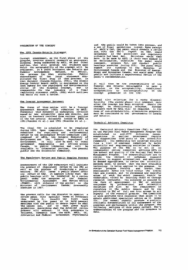
EVALUATION OF THE CONCEPT
The 1981 Canada-Ontario Statement
Concept assessment, as the first phase of the program, involves generic research on geological disposal being conducted by AECL, OH and other parties, that will provide the evidence upon which the acceptability of the concept will be evaluated. In a joint statement the Ontario and Federal' Governments defined, in detail, the process for that evaluation. Public announcement o f the joint statement constituted the first step of that process, in that document (Canada-Ontario, 1981), the Atomic Energy Control Board (AECB) is designated as the lead agency for the regulatory and environmental review of the disposal concept, and is responsible for the issuance of a final regulatory statement (AECB, 1985) which outlines the basis for such a review.
and the public would be taken into account, and a set of final guidelines issued. Upon receipt of AECL's CAD, the panel would conduct a review and, with the IRC's report on CAD, would determine if the guidelines and regulatory criteria had been met. Revisions would then have to be made by AECL if there were deemed to be deficiencies, otherwise the panel would announce, prepare for, and conduct public hearings sometime during 1991- • The panel would report its findings to the Minister of Environment Canada and the Minister of Energy, Mines and Resources Canada, who would make them public and initiate a departmental review of the panel's recommendation.
It will then be the responsibility of the Federal and Ontario Governments to make a decis ion on the acceptabi1ity, conditional acceptability or non-acceptability of the concept presented in the CAD.
The Concept Assessment Document
The focus of this review will be a Concept Assessment Document (CAD) submitted by AECL. Presently this document is undergoing revision based on new scientific data and results, and also on feedback received from various parties on the two interim' documents issued by AECL in 1981(wuschke et al.) and 1985 (Wuschke et al.).
Actual site selection for a waste disposal facility (the second phasei will commence only after the concept has been accepted. Should the concept be conditionally accepted, further research work by AECL will be required. In the case of non-acceptability, alternative proposals must be considered by the governments of Canada and Ontario.
Technical Advisory Committee
The final CAD is scheduled to be completed during 1990. Upon completion, the CAD will be submitted for regulatory and environmental review to the Interagency Review committee (IRC) composed o f AECB, the Ontario Minis try o f Environment and the Federal Department of Environment. It will also be sent to other government departments and offices across Canada, to public libraries and will be available to interested parties, the general public and the scientific community.
The Regulatory Review and Public Hearing Process
Announcement of the CAD submission will initiate the process of regulatory review by the IRC as well as the process of conducting a public hearing. IRC will issue a public report after its review of CAD. It appears likely that the public hearings will be conducted by a review panel under the auspices of the Federal Environmental Assessment and Review Office (FEARO), with referral of the project to the Minister of Environment Canada, presumably sometime in 1987.
The process calls for the Minister to appoint a review panel with specific terms of reference (See Figure 2). Usually the first task undertaken by the panel is to hold general meetings with the public to obtain input on what the issues are, and to then issue draft guidelines describing what the detailed review process will address. If this procedure is followed, comments from the AECB, AECL, OH. Provincial and Federal Government Departments
The Technical Advisory Committee (TAC) to AECL on the Nuclear Fuel Waste Management Program was established in mid-1979 following recommendations in earlier government reports and suggestions from parts of the scientific community. . Its membership was selected entirely from a list of nominees submitted by major scientific and engineering societies in Canada. The purpose of the TAC is to act as an independent review committee advising AECL on the extent and quality of the Nuclear Fuel Waste Management Program. Its responsibilities are to review the content of proposed research projects, to suggest alternatives and additions as deemed appropriate, to review the scientific methods used, to assure that the best available technology is being applied to the program, to review program results and assure that conclusions drawn are valid within the limits that are claimed, and to recommend any specific areas of work for which research should be undertaken, either by existing staff or through research contracts. Its autonomy is assured by the form of appointment to TAC of persons nominated by professional and scientific societies and also by the requirement of reporting in the public domain and by the provision to TAC of full and free access to all aspects of the research program. The Committee is also provided with resources that allow it to obtain additional specialist advice as it deems fit. Its annual reports provide a publicly available documentation of its assessment of the progress and performance within the program. The following sections of. this paper reflect TAC's understanding of the program and its progress to date.
An Evaluation « the Canadian Nuclear Fuel Waste Management Program 113
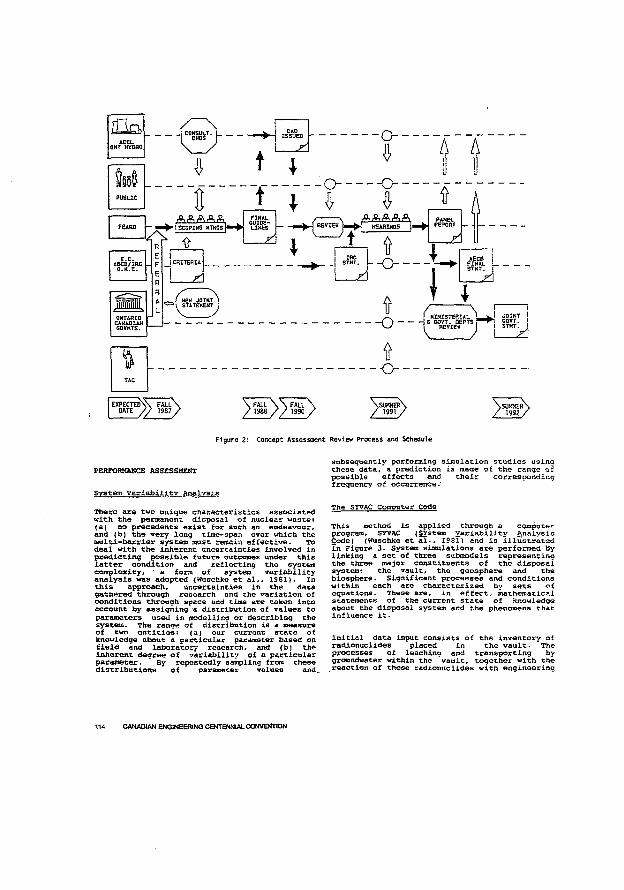
P U B U C
4 fë\ fë\ fl\ ifi
FÊARO j — — • jSCOPIMS HTKSSp
E . C . iËC8/IRC
O.K.E.
O N T A R I O C A N A D I A N C O V N T S .
j — H E A R I N G S {•
-0--
ft • - 0 -
T
A P A N E L H E P O S T
AECB FINAL STXT
M I N I S T E R I A L L S G O V T . O E P T S
review J O I N T ! sovr. S T M T . I
Z J
EXPECTEON DATE FALt\ \ FALL \ \ FÄLL \ \ S U M M £ R \ / / 1987/ / 1988 / / 1930 / /1891 / \ s i W M E R / 1992
Figure 2: Concept Assessment Review Process and Schedule
PERFORMANCE ASSESSMENT
System Variability Analysis
There are two unique characteristics associated with the permanent disposal of nuclear wastei (a) no precedents exist for such an endeavour, and (b) the very long time-span over which the multi-barrier system must remain effective. To deal with the inherent uncertainties involved in predicting possible future outcomes under this latter condition and reflecting the system complexity, * a form o f system variabil i ty analysis was adopted {Wuschke et al., 1961). In this approach, uncertainties in the data gathered through research and the variation of conditions through space and time are taken into account by assigning a distribution of values to parameters used in modelling or describing the system. The range of distribution is a measure of two entities: (a > our current state of knowledge about a particular parameter based on field and laboratory research, and (b) the inherent degree of variability of a particular parameter. By repeatedly sampling from these distributions of parameter values and.
subsequently performing simulation studies using these data, a prediction is made of the range of possible effects and their corresponding frequency of occurrence.1
The SYVAC Computer Code
This method is applied through a computer program, STVAC (SYstero Variability Analysis Code) (Wuschke et al., 1981) and is illustrated Xn Figure 3. System simulations are performed by linking a set of three submodels representing the three major constituents of the disposal systems the vault, the geosphere and the biosphere. Significant processes and conditions within each are characterized by sets of equations- These are, in effect, mathematical statements of the current state of knowledge about the disposal system and the phenomena that influence it.
Initial data input consists of the inventory of. radionuclides placed in the vault. The processes .of leaching and transporting by groundwater within the "vault, together with the reaction of these radionuclides with engineering
m CANADIAN ENGINEERING CENTENNIAL CONVENTION
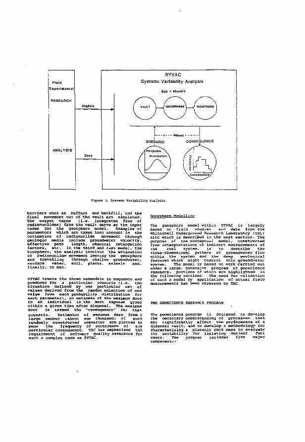
Field
Experimental
SYVAC Systems Variability Analysis
Sub - Models
{ VAULT \ J OeOSPHEBE \ . J BIOSPHERE \
— - « Bopoat - - •<
SCENARIO CONSEQUENCE
Figure 3. Systems V a r i a b i l i t y Analysis.
barriers such as buffers and backfill, and the final movement out of the vault are simulated. The output terms (i.e. integrated flux of radionuclides} front the vault serve as the input terms for the geosphere model. Examples of parameters which are taken into account in the estimation of radionuclide movement through geologic media include groundwater velocity, effective path length, chemical retardation factors, etc. In the third and last model, the biosphere, the analysis involves the estimation of radionuclide movement leaving the geosphere and travelling through shallow groundwater, surface water, soil, plants, animals and, finally, to man-
SYVAC treats the three submodels in sequence and produces for a particular scenario (i.e. the situation defined by one particular set of values derived from the random selection of one value from each probability distribution for each parameter), an estimate of the maximum dose to an individual in the most exposed group within a given time after disposal. The maximum dose is termed the -consequence * for that scenario. Estimates of maximum dose from a large number (about one thousand) of such randomly constructed scenarios are plotted to show the frequency of occurrence of any particular consequence. TAC has emphasized the requirement of software quality assurance for such a complex code as SYVAC.
Geosphere Modelling
The geosphere model within SYVAC is largely based on field studies and data from the Whiteshell Underground Research Laboratory (URL) site which is described in the next section. The purpose of the conceptual model, constructed from interpretations of indirect measurements of the real system, is to describe the three-dimensional pattern o f groundwater flow within the system and the deep geological features which might control this groundwater system. The model is based on work carried out under a large, extensive program of geoscience research, portions of which are highlighted in the following sections. The need for validation of such a model by application of actual field measurements has been stressed by TAC.
THE GEOSCIENCE RESEARCH PROGRAM
The geoscience program is designed to develop the necessary understanding of processes that may significantly affect the performance of a disposal vault, and to develop a methodology for characterizing a plutonic rock mass to evaluate its suitability for isolating nuclear fuel waste. The program includes five major components:
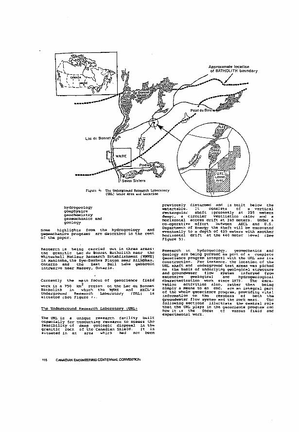
hydrogeology goephysics geochemistry geomechanics and geology
Some highlights from the hydrogeology and geomechanics programs are described in the rest of the paper.
previously disturbed and is built below the watertable. It consists of a vertical rectangular shaft (presently at 255 meters deep), a circular ventilation raise and a horizontal access drift at 240 meters. Under a co-operative effort between AECL and U.S. Department of Energy the shaft will be excavated eventually to a depth of 455 meters with another horizontal drift at the 440 meter ievel (See Figure 5).
Research is being carried out in three areas: the granitic Lac du Bonnet Batholith near the Whiteshell Nuclear Research Establishment (WNRE) in Manitoba, the Eye-Dashwa Pluton near Atikokan, Ontario and the East Bull Lake gabbroic intrusive near Massey, Ontario.
Currently the main focus of geoscience field work is a 750 tan** region on the Lac du Bonnet Batholith in which' the WNRE and AECL's Underground Research Laboratory (URL) is situated (See Figure
The Underground Research Laboratory (.URL)
The URL is a unique research facility built especially for conducting research to assess the feasibility of deep geologic disposal in the granitic rock of the Canadian Shield. It is situated in an area which had not been
Research in hydrogeology, geomechanics and geology are being pursued as part of a complete geoscience program integral with the URL and its construction. For instance, the location of the URL shaft and underground test areas was picked on the basis of underlying geological structure and groundwater flow system inferred from extensive geological and hydrogeological characterization work since 1979. The excavation activities also, rather than being simply a means to an end, are an integral part of the whole geoscience program, providing vital information on the response of both the groundwater flow system and the rock mass. The following sections illustrate the central role that the URL plays in the geoscience program and how it is the focus of varous field and experimental work.
116 CANADIAN ENGINEERING CENTENNIAL CONVENTION
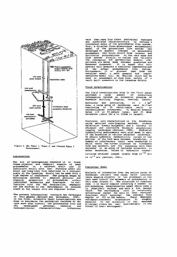
Figure 3. URL Phase 1 , Phase 2. and Planned Phase 3 Development-.
Hvdroaeoloqy
The aim of hydrogeology research is to study those physical and chemical aspects of deep groundwater at a relevant scale and in sufficient detail such that forcasts about its short and long-term flow behaviour on a regional scale in the Canadian Shield can be made with a high degree of confidence. The program began by developing methods to measure physical and chemical properties of groundwater within individual boreholes and fractures. In conjunction with the tTRL contruction, emphasis now has shifted to the development of methods aimed at the larger site and regional scales.
The present hydrogeology reseaxch has developed in four- phases (Davison and Guvanasen, 1985). In the first, extensive field investigations was done to determine the geological features of the rock mass that control the groundwater flow and the associated physical, chemical and hydrogeological characteristics. Inferences
were then made from these geological features and assoc iated characteris tics to develop a conceptual model of the groundwater flow system. Next, a detailed three-dimensional mathematical model of the postualated flow system was developed to predict changes in measurable parameters that would result from natural and artificial perturbations to the rock mass and flow system. Finally, to refine and validate the conceptual and mathroat ica1 mode1s, comparisons are being made between predicted and measured responses. It is hoped that this process will generate a realistic representation of the actual groundwater flow system. Furthermore, it is planned that from the detailed model, a more general and representative model will be derived which may be used in assessment of long term safety of a vault built somewhere in the Canadian Shield.
Field Investigations
The field investigations done in the first phase provided a large amount of subsurface information through an extens i ve program o f borehole drilling, logging, testing, instrumentation and monitoring. In a 4 kni area, a large array of boreholes were drilled consisting of 58 water-table wells in unconsolidated overburden. 41 shallow bedrock holes (10 to 60 meters long), and 25 deep boreholes (about 100 m to 1100m in length).
Fractures were characterized in the boreholes using detailed core-logging methods, in-hole television camera equipment, and a variety of standard and innovative borehole geophysical logging techniques (Davison. 1985). " Hydraulic conductivity measurements were also made in many of the boreholes at various selected intervals. To obtain hydraulic conductivity values of the portion of the rock mass between boreholes, a number of interference tests were conducted in which water was either injected or withdrawn from one borehole, and the responses were then recorded in an array of isolated intervals in other boreholes. values of hydraulic conductivities obtained ranged widely from lO"-1^ m/s to 10" 3 m/s (Davison, 1985).
Conceptual Model
Analysis of information from the entire array of boreholes indicate that three major fracture zones dipping slightly tc the southeast in the rock mass control the movement of groundwater in this area (Figure 6i. The structure of fracture zone 2 is fairly complex involving a number of off-branching, interconnected zones while zone 3 is relatively uniform and only a few meters thick. The surrounding rock is relatively unfractured except for sets of near vertical fractures which intercept the surface from depths of 100 to 300 meters. Their dominant northeast-southwest orientation is roughly parallel to the direction of the maximum principal stress but vary considerably in the extent of their development.
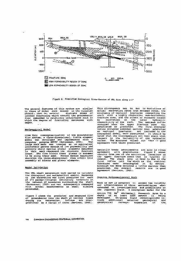
300
200 Ê z o 100
§ 0
tu -100
-200
M5A.58 UHL11 NI4A.4B URL6 M2A, 2B
J FRACTURE 20NE ! HIGH PERMEABILITY REGION OF ZONE
I LOW PERMEABILITY REGION OF ZONE
I00 200 m
Figure 6: Simplified Geological Cross-Section of URL Site Along l-i'
The general features of this system are similar to those of other rock masses in the Canadian Shield, that is, several discrete zones of intense fracturing which control the groundwater flow embedded in relatively unfractured rock in which the degree of fracturing decreases with depth.
Mathematical Model
From this conceptualization of the groundwater flow system, a three-dimensional, finite element model was developed and implemented with a computer program MOTIF (Guvanasen, 1985). The large rock mass was treated as an equivalent anistropic porous medium of low permeability and porosity while special planar elements embedded in this mesh represent the discrete fracture zones. The flow within these planes is assumed to be along their axes. Porous medium equations describe the three-dimensional flow within this assembly of blocks and planar elements.
Model Validation
The URL shaft excavation work served to validate the conceptual and mathematical models. Response to the excavation was first predicted for each of 174 packer-isolated monitoring intervals in the network of boreholes surrounding the shaft (Guvanasen, 1985) and was subsequently compared with actual measurements as shaft sinking proceeded.
Figure 7 shows the predicted and measured flow of groundwater into the shaft at various times during its excavation. Inflows are over-predicted by a factor of three (Davison, 1986).
This discrepancy may be due to deviations of actual excavation rates from assumed rates, the existence of vertical fractures connecting the shaft with a highly conductive sub-horizontal fracture zone, artd the effect of stresses caused by excavation on the local hydraulic conductivity of the rock- The maximum inflow occurred when the upper fracture zone was penetrated as predicted. The first measured inflow occurred somewhat earlier than predicted as vertical fractures, not included in the conceptual model, were penetrated. It should be noted that the discrepencies are very small with respect to the variability of the hydraulic values. The measured values are thus in good agreement with those predicted -
Hydraulic heads measurements are also in close agreement with predictions. Figure 8 shows results from one of the monitoring locations in the upper fracture zones that is typical of others. The sharp drop in head is due to the first inflow into the shaft as the vertical fractures were intercepted at 62 meters. Although the drop occurred a little earlier than predicted, the overall results are in good agreement (Davison, 1986j.
Ongoing Hydrooeological Work
work is now in progress to assess the validity and effectiveness of these methodologies when extended to investigations and predictions on the regional scale. A conceptual model for the entire 750 km 2 Whiteshell Research Area to a depth of at least 1000 meters is being developed. On-going field investigations include additional detailed geological and geophysical surveys: expansion of the^
118 CANADIAN ENGINEERING CENTENNIAL CONVENTION
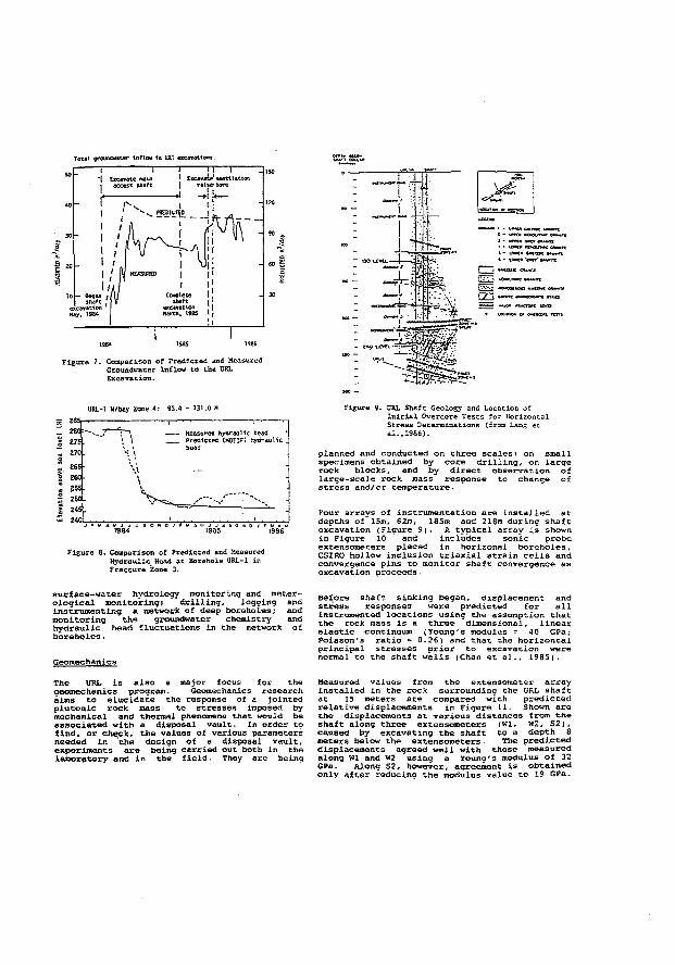
T«ul qevuaOMttr Inflow la CRI «ecflMtlww:
URL-1 U/bey Zone 4 : 93 .4 - 131.0 M
- Measured hydraulic head _ Predicted (MOTIF) hydraul ic
head
Figure 8. Comparison of Predicted and Measured Hydraulic Head ac Borehole URL-1 in Fracture Zone 3.
Figure 9. URL Shaft Geology and Location of Initial Overcore Tests for Horizontal Stress Determinations (from Lang ec si.,1986).
planned and conducted on three scales: on small specimens obtained by core drilling, on large rock blocks, and by direct observation of large-scaJe rock mass response to change of stress and/or temperature.
Four arrays of instrumentation are installed at depths of 15m, 62m, 185m and 218m during shaft excavation (Figure 9). A typical array is shown in Figure 10 and includes sonic probe extensometers placed in horizonal boreholes, CSIRO hollow inclusion triaxial strain cells and convergence pins to monitor shaft convergence as excavation proceeds.
surface-water hydrology monitoring and meter-ological monitoring; drilling, logging and instrumenting a network of deep boreholes; and monitoring the groundwater chemistry and hydraulic head fluctuations in the network of boreholes.
Geomec hanles
Before shaft sinking began, displacement and stress responses were predicted for all instrumented locations using the assumption that the rock mass is a three dimensional, linear elastic continuum (Young's modulus = 4 0 GPa; Poisson's ratio B 0.26) and that the horizontal principal stresses prior to excavation were normal to the shaft walls (Chan et al., 1985).
The URL is also a major focus for the geomechanxcs program. Geomechanics research aims to elucidate the response of a jointed plutonic rock mass to stresses imposed by mechanical and thermal phenomena that would be associated with a disposal vault. In order to find, or check, the values of various parameters needed in the design of a disposal vault, experiments are being carried out both in the laboratory and in the field. They are being
Measured values from the extensometer array installed in the rock surrounding the URL shaft at 15 meters are compared with predicted relative displacements in Figure 11. Shown are the displacements at various distances from the shaft along three extensometers (Ml. W2, S2), caused by excavating the shaft to a depth 8 meters below the extensometers. The predicted displacements agreed well with those measured along Ml and W2 using a Young's modulus of 32 GPa. Along S2, however, agreement is obtained only after reducing the modulus value to 19 GPa-
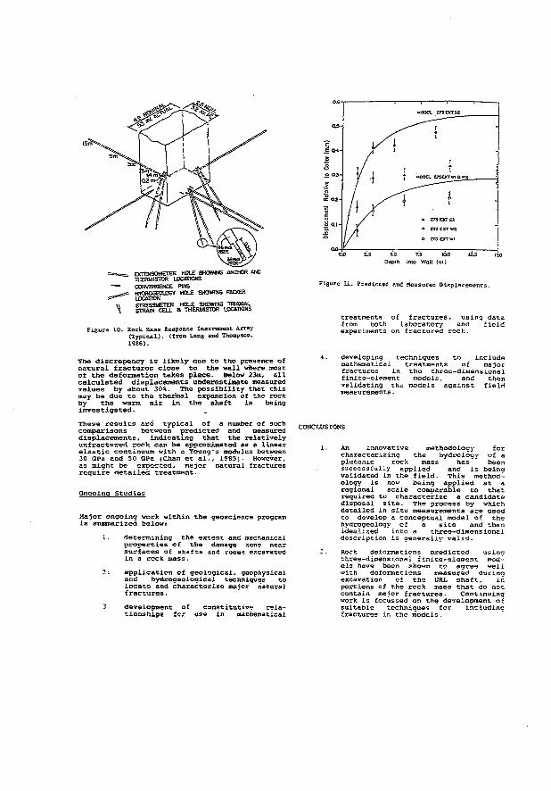
EXTEKSOMETER HOLE SHOWING ANCHOR AND THERMISTOR LOCATIONS CONVERGENCE PINS HYOTOGEOLOGY HOLE SHOWING PACKER LOCATION STRESSMETER HOLE SHOWING TRJASAL STRAW CELL & THERMISTOR LOCATIONS
Figure XO. Rock Mass Response Instrument Array ( T y p i c a l ) , (from Lang and Thompson, 1986) .
Figure 1 1 . Predicted and Measured Displacements.
treatments of fractures, using data from both laboratory and field experiments on fractured rock.
The discrepancy is likely due to the presence of natural fractures close to the wall where most of the deformation takes place. Below 23m, all calculated displacements underestimate measured values by about 30%. The possibility that this may be due to the thermal expansion of the rock by the warm air in the shaft is being investigated. These results are typical of a number of such comparisons between predicted and measured displacements, indicating that the relatively unfractured rock can be approximated as a linear elastic continuum with a Young's modulus between 30 GPa and 50 GPa (Chan et al., 1985). However, as might be expected, major natural fractures require detailed treatment.
Ongoing Studies
Major ongoing work within the geoscience program is summarized below:
I. determining the extent and mechanical properties of the damage zone near surfaces of shafts and rooms excavated in a rock mass.
2-. application of geological, geophysical and hydrogeological techniques to locate and characterize major natural fractures.
developing techniques to include mathematical treatments of major fractures in the three-dimens iona1 finite-element models, and then validating the models against field measurements.
CONCLUSIONS
development tionshiDs 1
of constitutive rela-or use In mathematical
1. An innovative methodology for characterizing the hydrology of a plutonic rock mass has been successfully applied and is being validated in the.field. This methodology is now being applied at a regional scale comparable to that required to characterize a candidate disposal site. The process by which detailed in situ measurements are used to develop a conceptual model of the hydrogeology of a site and then idealized into a three-dimensional description is generally valid.
2 . Rock deformations oredicted using three-dimensional finite-element models have been shown to agree well with deformations measured during excavation of the URL shaft, in portions of the rock mass that do not contain major fractures. Continuing work is focussed on the development oi suitable techniques for includinc fractures in the models.
3. The STVAC performance assessment methodology, which accounts for uncertainty and variability in system parameters, has been established and is widely accepted as the preferred method of assessing the long-term performance of a disposal system.
4. The Technical Advisory Committee carries out regular periodic reviews of all the activities in the research program, and presents its findings and assessments in a public document.
REFERENCES
AECB (1985), "Deep Geological Disposal of Nuclear Fuel Hastes Background Information and Regulatory Requirements Regarding the Concept -Assessment Phase". Regulatory Document R-71.
Boulton, J. (Editor) (1978), ".Management of Radioactive Fuel Hastes: The Canadian Disposal program", Atomic Energy of Canadia Limited Report, AECL-6314. Canada-Ontario (1978), Joint Agreement by the Minister of Energy, Mines and Resources Canada and the Ontario Energy Minister", Printing and Publishing, Supply and Services Canada, Ottawa, Canada.
Canada-Ontario(1981), "Joint Statement by the Minister of Energy, Mines and Resources Canada and the Ontario Energy Minister', Printing and Publishing, Supply and Services Canada, Ottawa, Canada.
Chan, T., P.A. Lang and P.M. Thompson (1985), "Mechanical response of jointed granite during shaft sinking at the Canadian Underground Research Laboratory". Proceedings of the 25th U.S. Symposium on .Rock Mechanics: Research and Engineering Applications in Rock Masses, Rapid City, SD-, 1985 June 26-28.
Davison, C.C- (1985), "Hydrogeological Characterization of the URL Site", Proceedings of the 17th Information Meeting of the Nuclear Fuel Haste Management Program, Atomic Energy of Canada Limited Technical Record*. TR-299, pp 231-252.
Dixon, R-S. and E.L . J . Rosinger (Editors) (1984), "Fifth Annual Report of the Canadian Nuclear Fuel waste Management Program", Atomic Energy of Canada Limited Report, (in preparation).
Guvanasen, v. (1985), "Development of a Finite-Element Code and Its Application to Geoscience Research", Proceedings of the 17th Information Meeting of the Nuclear Fuel waste Management Program. Atomic Energy of Canada Limited Technical Record*, TR-299, pp 554-566-Guvanasen, v., J . A . K . Reid and B.W. Nakka (1985), "Predictions of Hydrogeological Perturbations Due to the Construction of the Underground Research Laboratory", Atomic Energy of Canada Limited Technical Record*, TR-344. Rosinger, E-L . J - , and R.S. Dixon (Editors) (1982), "Fourth Annual Report of the Canadian Nuclear Fuel Waste Management Program", Atomic Energy of Canada Limited Report. AECL-7793-
T e c h n i c a l A d v i s o r y C o m m i t t e e ( 1 9 8 6 ) , " S e v e n t h
A n n u a l R e p o r t o f t h e T e c h n i c a l A d v i s o r y C o m m i -
t e e o n t h e N u c l e a r F u e l W a s t e M a n a g e m e n t P r o
g r a m " , L . H . S h e m i l t ( C h a i r m a n ) , R e p o r t T A C - 7 .
( A v a i l a b l e f r o m P r o f . L . W . S h e m i l t . M c M a s t e r
U n i v e r s i t y , H a m i l t o n , O n t a r i o , L S S 4 K 1 ) .
Wuschke, D.M., K.K- Mehta. K .W. Dormuth. T. Andres, G - R . Sherman, E.L .J . Rosinger, B.w. Goodwin, J.A.K. Reid and R.B. Lyon (1981), "Environmental and Safety Assessment Studies for Nuclear Fuel waste MAnagaement, Volume 3: Post-Closure Assessment". Atomic Energy of Canada Limited Technical Record, TR-127.
Wuschke, D.M., P.A. Gillespie, K.K. Mehta, w.F. Heinrich, D.M. LeNeveu, v.M. Guvanasen, G.R. Sherman, D-C. Donahue, B.w. Goodwin, T.H. Andres and R.B. Lyon (1985), "Second Interim Assessment of the Canadian Concept for Nuclear Fuel Waste Disposal Volume 4: Post-Closure Assessment". Atomic Energy of Canada Limited Report, AECL-8373.
* Technical Records are unrestricted, unpublished reports available from SDDO, Atomic Energy of Canada Limited Research Company, Chalk River, Ontario, Canada KOJ 1J0.
Davison, C.C (1986), "URL Drawdown Experiment and Comparison with Model Predictions", Proceedings of the 20th Information Meeting of the Canadian Nuclear Fuel waste Management Program, Atomic Energy of Canada Limited Technical Record*, TR-375. Davison, C.C and v. Guvanasen (1985), -Hydrogeological characterization, modelling and monitoring o f the s ite o f Canada ' s Underground Research Laboratory". Proceedings o f the 17 th Internationa 1 Congress o f the International Association of Hydrologists on Hydrogeology of Rocks of Low Permeability, Tuscson, A«-, 1985 January -

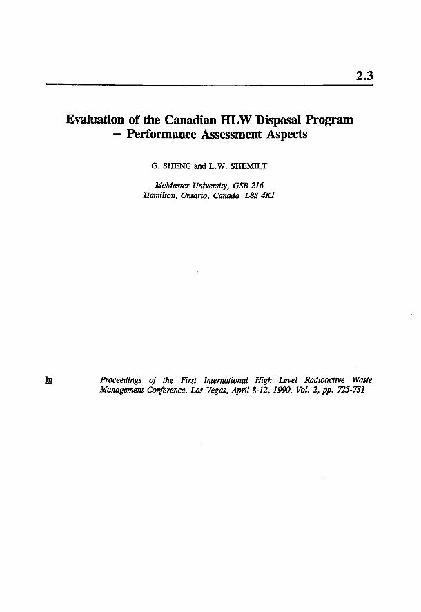
2.3
Evaluation of the Canadian HLW Disposal Program — Performance Assessment Aspects
G. SHENG and L.W. SHEMLT
McMaster University, GSB-216 Hamilton, Ontario, Canada L8S 4K1
In Proceedings of the First International High Level Radioactive Waste Management Conference, Las Vegas, April 8-12,1990, Vol 2, pp. 725-731

EVALUATION OF THE CANADIAN HLW DISPOSAL PROGRAM - PERFORMANCE ASSESSMENT ASPECTS
G. SHENG Technical Advisory Committee to AECL c/o McMaster University, GSB-216 Hamilton. Ontario, Canada L8S 4K1 (416) 522-2802
ABSTRACT
The Inception and development of the Canadian HLW disposal program are described, showing Its basis In the multi-barrier system concept and noting the mechanisms In place for Its evaluation and review. The Canadian approach to performance assessment, which utilizes the concept of "Systems Variability Analysis", and Its computer Implementation are explained. The emphasis that has been placed on quality assurance aspects Is noted. Related judgments and comments by the Technical Advisory Committee on aspects of the program are summarized.
INTRODUCTION
The nuclear power program In Canada Is based on the heavy water moderated and cooled, natural uranium fuelled CANDU (CANadian Qeuterium Uranium) reactor which operates on a once-through cycle. About 4 Gg of Irradiated fuel have been accumulated to date In the water-Bled storage bays at nuclear power stations, largely In the Province of Ontario where over 60% of Its electrical energy is now produced in such stations. Additional development, planned or under construction In Ontario and In other provinces, would result In as much as 50 Gg uranium In storage In Canada at the turn of the century. The use of high-density storage arrangements in existing water-filled bays at reactor sites wB provide storage capacity until at least 1993. and with some extension, for at least another decade. It Is recognized, however, that this type of storage Is only a temporary measure and that a permanent means of waste disposal must be found.
A major study', commissioned by Energy, Mines and Resources Canada in 1977, emphasized the need for a national plan and research program for safe disposal of the used fuel/wastes, and supported the concept of underground disposal in geological formations such as Igneous Intrusions of crystalline rock, known as plutons, found In the Canadian Shield. Following the recommendations from this report, the Canadian Nuclear Fuel Waste Management Program (NFWMP) was formally established In June 1978 by a Federal Govern. men-Ontario Agreement which designated Atomic Energy of Canada Limited (AECL) as the lead agency for carrying out the research with participation from the provincial uuTfcy Ontario Hydro as weD as from various governmental departments. The present program is described in a freely available public document2 "Managing Canada's Nuclear Wastes".
L.W. SHEMILT Technical Advisory Committee to AECL c/o McMaster University, GSB-216 Hamilton. Ontario. Canada LBS 4K1 (416) 522-2802
THE CANADIAN WASTE DISPOSAL CONCEPT
The Multi-Barrier System
The overall objective of the NFWMP is "to ensure that there wB be no significant adverse effect on man or the environment from nuclear fuel waste at any time*2. Nuclear fuel waste Is defined as either used or Irradiated fuel, or high-level radioactive material separated from used fuel through reprocessing (should Canada adopt this option In future). Similar to efforts In several other nations, the Canadian program of research on deep geological disposal of nuclear waste Is based on the concept of Isolating wastes with a series of barriers situated In a deep (500 m -1000 m) underground vault, bust In a stable, terrestrial geological formation such as the Canadian Shield. This muM-barrter system comprises the following:
Waste Form and Containers
The bundles of used fuel would be encased In containers with an anticipated minimum lifetime of several hundred yeans corresponding to the period of high fission-product activity. The containers would be designed to withstand vault pressures and be resistant to corrosion under the temperature, groundwater exposure and radiation fields that could potentially exist A supported shell packed with particulate matter has been selected as the reference container design, with candidate container materials Wentliled as ASTM Grades 2 and 12 titanium4. Research has also been conducted on immobilizing high-level wastes from fuel reprocessing flf adopted) whereby the waste would be incorporated into a water-Insoluble, leach-reststant material, such as glass or ceramic.
The Vault
Following waste Immobilization or containment, the containers would be empjaced In the vault and packed with a compacted buffer material such as bentonfte day. The reference buffer materia!5, a 50-50 mixture of sfUca sand and a Canadian bentontte, swells upon contact with water, thus acting as a seal against leaching and corrosive agents. It also has a high capacity to absorb chemical species. Including most of the significant radionuclides. The vault and the shafts would then be backfUed, probably with a mixture containing bentonfte and crushed granite, and along with borehole sealing thus dose any openings to the surface.
Geological Medium
The geologic medium in which the underground vault Is butt acts as yet another barrier to the migration of radionuclides should they escape the vault Retardation occurs as a result of a number of natural processes taking place at depth. Including chemical absorption of radionuclides onto rock surfaces. Ion exchange, diffusion into the body ol the rock, and the long path lengths to the surface due to the relatively small size and frequency of fractures In the chosen rock. The effectiveness of this natural barrier depends on careful selection of a site which exhibits favourable geochemlcal. geological and hydrogeologlcal conditions.
The Biosphere
Finally, although the biosphere b not generally regarded as a "barrier in the same sense as those described above, the surface environment, with its large volume of soil and water, has a great capacity to disperse and dilute whatever material which, no matter how unlikely, may reach the surface.
IMPLEMENTATION OF THE DISPOSAL CONCEPT
The program for actual disposal Is proceeding In three distinct phases. The first phase Involves the assessment of the above concept as to whether ft can achieve the stated objective of safety and permanence. This generic research and development phase spans the period 1981-1991 at the end of which time a rigorous regulatory and scientific review wm be conducted to determine the acceptability and feasibility of the concept The second phase, that of site selection Involving the actual process of locating a potential site, may only begin if the concept Is deemed acceptable. The final phase would be the construction and operation of an actual vault after successful location of a suitable site.
CONCEPT EVALUATION AND REVIEW
With a national endeavour of this magnitude, importance, and complexity, it was deemed necessary that a thorough evaluation and review procedure be Implemented. Two major mechanisms are in place to address this need.
The Technical Advisory Committee (TAC)
To provide an on-going scientific/technical evaluation and continual review of the Canadian NFWMP, TAC was established in mid 197a Its membership was selected entirely from a list of nominees submitted by major scientific and engineering societies In Canada. The purpose of TAC is to act as an Independent review committee, advising AECL on the extent and quality oi the NFWMP. its responsHtles are to review the content of proposed research projects, to suggest alternatives and additions as deemed appropriate, to review the scientific methods used, to assure that the best available technology Is being applied to the program, to review program results and assure that conclusions drawn are valid within the Emits that are claimed, and to recommend any specific areas of work tor which research should be undertaken, either by existing staff or through research contracts. Its autonomy Is assured by 8» form of appointment to TAC of persons nominated by professional and scientific societies and also by the requirement of reporting In the public domain and by the provision to TAC of full and free access to an aspects of the research program. The Committee is also provided with resources that allow t to obtain additional
specialist advice as It deems fit The annual reports of TAC (e.g. TAC, 1989)6 provide a publicly available documentation of Its assessment of the progress and performance within the program.
Environmental Assessment and Review Panel
To cany out a more general review of the concept Including social and political (actors, an approvals process was recently announced. This Involved the referral to the Minister of the Environment of the NFWMP for environmental review. This referral included the request for the establishment of an Environmental Assessment and Review Panel which would have a broad mandate in Its examination of the concept of deep geological disposal, and would ensure an opportunity for full public discussion of nuclear fuel waste management issues. This panel, now constituted, is to establish an advisory Scientific Review Group (SRG) and hold general meetings with the public as wall as with appropriate government agencies and bodies to obtain views on what Issues are involved. The Panel wSt then Issue guidelines describing what the concept evaluation process wm address. Upon receipt ol AECL's Environmental Impact Statement (EIS), expected In 1991, the Panel will conduct a review and with the help of the SRG, would determine If the guidelines and regulatory criteria had been met If there were deemed to be deficiencies, revisions would then have to be made by AECL. otherwise the Panel would announce, prepare for, and conduct public .hearings; The Panel would receive public input and participation In the review throughout Ontario and In the provinces of Quebec and New Brunswick, where used nuclear fuel Is also produced and stored. The Panel would report Its findings to the Minister of Environment Canada and the Minister of Energy, Mines and Resources Canada, who would then make them public. It wQ then be the responsibility of the Federal and Ontario Governments to make a decision on the overall acceptability, conditional acceptability or non-acceptabmty of the concept presented in EIS.
The review process is designed to ensure that all parties, including regulatory bodies, government departments, the scientific community, the general public, and Interested groups, have the opportunity to provide views on and responses to the results of the very complex undertaking of the research on nuclear fuel waste disposal At the same time, the final decision on its acceptability rests property with the governments as having overall responsibility. Actual site selection for a waste disposal facility (the second phase) will commence only after the concept has been accepted. Should the concept be conditionally accepted, further research work by AECL win be required. In the case of rran-acceptabHity, alternative proposals must be considered by the Governments of Canada and Ontario.
CANADIAN RESEARCH PROGRAM
The Canadian research program can be conveniently considered as encompassing four general areas: geoscience, engineered barriers, bioscience and systems analysis. The geoscience area Includes hydrogeology. geology, geophysics, geomechanlcs and geochemistry. Engineered barriers include studies on immobilization of wastes with the use of glass or ceramics; containers (composition and design); buHers and backfU; and vault seating. In these two areas, the role of groundwater Is a primary feature through its potential for penetration to the source of radtoncufldes and their subsequent transport through the engineered barriers and the
geosphere into the biosphere. The bioscience areas include studies on radiologic effects, dosimetry, ecological succession, limnology, hydrology, plant uptake, and food chain models. The objective of system analysis or performance assessment is to process and integrate the results from all of these disparate studies and present a comprehensive and comprehensible statement about the safety and acceptability of the disposal concept The focus of the rest of this paper wHI be the Canadian approach to performance assessment with comments of the Technical Advisory Committee thereoa
PERFORMANCE ASSESSMENT
The forecasting of system performance far Into the future must be done with sufficient accuracy to ensure acceptable safety and to produce results to satisfy regulatory authorities. The most favoured type of performance assessment involves a probabilistic approach. Canada has adopted it in the form of Systems Variability Analysis (SVA). Generally, the performance assessment process Involves the following steps7 with SVA comprising steps 2, 3, 4.
"t. The system to be assessed Is described and the criteria to |udge Its safety and performance are specified.
"2. All scenarios relevant to the assessment8 are systematically Identified. A scenario Is a combination of factors (events, processes and features) that could affect the performance of the disposal facility. From the range of possible scenanos, a central scenario Is chosen, defined as one In which the constituent phenomena have the highest probability of occurrence. An example would be the transport of radionuclides by water from the vault to the biosphere. Also specified are alternative scenarios which consist of phenomena less likely to occur. An example would be the dispersal of contaminants by accidental human Intrusion. Each scenario Is assessed as to the factors that could affect the performance of the facility and the Importance of its impact
"3. Models that incorporate these scenarios and Important components of the system are formulated mathematically and the associated data are gathered. Complex models are usually developed for detailed research studies while simpler models are usually used In assessment studies for computational efficiency9. The system thus formulated Is then Implemented as a computer program in which processes and events can be simulated.
•4. The health and environmental Impacts of the disposal system are estimated by carrying out the computer simulation studies. The SVA philosophy of probabilistic assessment is manifest In using distributions of values for model parameters rather than specifying single values as In the case for deterministic analysis. Similarly, the calculated results are expressed as a distribution rather than as a single value. There Is a trend Internationally to characterize the estimated Impact as a risk figure. The Canadian SYVAC computer code described below Is a prime example of the SVA approach to performance assessment
"5. The estimated Impacts are compared with regulatory criteria to see whether the disposal facility performance Is acceptably safe.
"6. Sensitivity analysis plays an important role In the assessment process by Identifying those components and parameters in the system that have the most Influence on fhe acceptable and unacceptable impacts. This Increased understandfag of the system has great value in directing the course of further model and data development and focusing on certain areas of subsequent research. The results from sensitivity analysis can also be applied to aid In selecting various disposal options and In establishing facility stung and design constraints.*
The following sections discuss each of the above steps in more detail.
Safety and Performance Criteria
A general description of the Canadian waste disposal concept was given above. The criteria for Judging system safety and performance has been established by the Atomic Energy Control Board (AECB), the regulatory body In Canada which has responsibility for matters dealing with radioactive substances. Three regulatory documents R-71'0, R-72'' and R-104'2 are directly relevant to nuclear waste disposal. R-71 is a statement on the general requirements for a waste disposal concept Including the assessment and documentation requirements. R-72 describes the characteristics of a geologically acceptable site for underground disposal of high-level radioactive waste. R-104 contains specific radiological and risk criteria as weB as other requirements. In brief, the AECB requires that (a) burdens placed on future generations be minimized; (b) the environment must be protected, and (c) human health must be protected, for which a risk criterion of less than 10"6 serious health effects per year is Imposed. This figure corresponds to a dose of 0.50 mSv/yr.
Scenario Formulation
In two previous interim assessments, SYVAC was used to evaluate one large and fairly comprehensive scenario. Experience has shown that this is cumbersome because any factor that may significantly affect the assessment results must be Included regardless of whether it warrants the same degree of treatment It Is more efficient to construct various separate scenarios to concentrate on assessing events that are very common or very fare, processes that occur very quickly or very slowly, and features that are always Important or others that are infrequently Important or conditionally Important. By specifying the assessments more precisely In this fashion, formulation ol the problem becomes easier and efficiencies In terms of program design and coding, and computer executive lime can be gained.
The procedure of formulating scenarios for subsequent computer simulation consists of the following six steps:
1. all factors that could affect the performance of the disposai system are IdemDled.
2. the factors are classified to ensure comprehensiveness, 3. the factors are screened to determine their Importance
and inclusion for further analyses, 4. based on this information, scenarios are constructed, 5. the scenarios are screened for further refinement and 6. the scenarios are precisely defined and their likelihood
of occurrence specified.
The current Canadian approach has been to Identify a central scenario and three alternative scenarios. The central scenario defines the situation with the highest chance of occurring and Is described by Goodwin e t a i 1 3 The alternative scenarios postulate the situations for an "unsealed borehole", a "high well demand" and an "unsealed borehole with a high well demand*. The effects of variations In the parameters specifying each particular scenario are assessed since such hypothesized systems, events and processes all describe possible pathways for radionuclides to leave the vault and eventually enter the biosphere. For Instance, using the above example of the scenario Involving the borehole/well system, the effect of varying the values ol water velocity, amount flowing through the vault, the path length of the flow to the wen, eta are assessed.
Mathematical Description
After the various scenarios are formulated, these conceptualizations and descriptions are expressed precisely in mathematical terms with sets of equations specifying the relationships among aO the parameters that define a particular scenario. Since ft Is Impossible to specify the exact true value for all parameters, either because we do not have complete knowledge about the parameter or because the parameter Is of a multi-value nature, it is inappropriate to assign single values to all parameters. Therefore, uncertainties In the data gathered through research and the variation of conditions through space and time are taken Into account by assigning a distribution of values to parameters used in modelling the system. The range of distribution Is a measure of two entitles: (1) our current state of knowledge about a particular parameter based on field and laboratory research, and (2) the inherent degree of vartabBtty of a particular parameter. By repeatedly sampling from these distributions of parameter values for a particular scenario and subsequently performing simulation studies using these data, a forecast is made of the range of possible effects and their corresponding frequency of occurrence within each scenario.
The SYVAC Computer Simulation
The system variability analysis methodology is applied through a computer program SYVAC (SYstems Variability Analysis Code)1*. It Is a FORTRAN program of about 20,000 fines of code. The present version. SYVAC3. Is the result of two previous Iterations, and will provide the concept assessment results to be used for the Environmental Impact Statement In SYVAC, system simulations are performed by linking a set of three models representing the three major constituents of the disposal system: the vault, the geosphere and the biosphere. Significant processes and conditions within each are characterized by sets of equations specified according to the particular scenarios being simulated. These are. In effect, mathematical expressions of our knowledge about the disposal system and the phenomena Influential in a particular scenario.
The Initial data Input Is to the vault and includes the Inventory of radionuclides placed In the vault The processes of leaching and transporting by groundwater within the vault together with the reaction of those radionuclides with engineering barriers such as buffers and backfO, and the final movement out of the vault are simulated. The output terms tie. integrated flux of radionuclides) from the vault serve as
the Input terms for the geosphere model. Parameters which are taken Into account In the estimation of radionuclide movement through geologic media include groundwater velocity, effective path length, chemical retardation factors, eta In the third and last model, the biosphere, the analysis Involves the estimation of radionuclide movement leaving the geosphere and travelling through shallow groundwater, surface water, soli, plants, animals and, finally, to man.
SYVAC thus treats the three models sequentially and produces from a particular set of randomly selected values (from an appropriate distribution of the values of each parameter) for each scenario, an estimate of annual dose to an Individual In the most exposed group as a function of time. This simulation process Is repeated typlcaHy about one thousand times. The result is presented as a histogram or graph of the consequences versus the frequency of occurrence. ABemativefy, results may be represented by plotting the downward cumulative fraction of simulations against the maximum annual dose equivalent The advantage of this method Is that the fraction of simulations giving doses exceeding any specified level can be readily seen from the plot
The SYVAC2 assessment calculated the "maximum annual effective dose equivalent" which was taken to be the "consequence" for a particular computer simulation run. In the SYVAC3 probabilistic assessment the annual dose calculated wfll be the expected or mean value. An annual risk value Is then derived from the sum over all significant scenarios, of the products of the probability of the scenario, the mean dose figures and the probability of generating a serious health effect per unit dose.
n _ Annual Risk - P s l " Hj • r
1=1
Where Psg Is the probability of scenario I occurring.
Ht Is the mean annual effective dose equivalent calculated for that scenario.
r Is the probability of producing fatal cancer or serious genetic effects from a unit dose. The internationally recognized risk conversion factor Is 2 x 10"' per slevert and Is the figure adopted by the AECB In Its regulations.
Estimated Impacts
Results from the latest assessment, SYVAC3. are to be presented In early 1991 as an Environmental Impact Statement to be formally reviewed by regulatory agencies and special panels constituted for that purpose. Although these results are not yet available, they are not expected to be significantly dSferent from the major Endings of the second Interim assessment From SYVAC2, doses calculated were orders of magnitude below natural background levels for tens of thousands of years. When the simulation was carried out to 10' years, only 7% of the computer runs exceeded 10'2 mSv. The major contributor to dose (92% of simulations) Is 1 2 9 I , followed by "Tc (6%). 2 4 2 P u (1%) with the remainder of an other radionuclides making up 0.7% of simulations15. These results are attributed primarily to the performance of two barriers: (a) the used fuel waste form which limits the release of radionuclides and (b) the geological barrier which retards the transport of radionuclides through physical and chemical processes.
SensMvty Analysis
As mentioned above, sensitivity analysis facilitates the Identification of those parameters which have the greatest Impact on the results of SYVAC simulations. This enables models to be simplified or improved and research priorities to be more efficiently established.
A good sensitivity analysis should (a) measure the sensitivity over the entire range of parameter variability rather than be restricted to |ust a small region around a central point, and (b) weigh the sensitivity to a given parameter over the entire space of the other parameter ranges rather than confining all other parameters constant
Applying sensUMy analysis to SYVAC results Is a difficult task because of the large number (several thousands) of variables Involved, and only limited attempts appear yet to have been made. TAC considers sensitivity analysis of the SYVAC data to be a necessary part of a total performance assessment process, and suggested In its Tenth Annual Report6 that there be a clear exposition by AECL of the overall strategy for addressing this very Important area.
QUALITY ASSURANCE ASPECTS
TAC recognizes the complex nature of the SYVAC computer program and thé critical role that It plays In the performance assessment of the Canadian NFWMP. It has continually emphasized the need for rigorous quality assurance of the entire model/computer program system, and noted Bve matters with respect to the Issue of quality6.
"1. the adequacy of the conceptual models representing the actual disposal system;
•2. the accuracy of the mathematical representation ol each conceptual model, and the choice of the parameters Involved in It;
•3. the adequacy of the probability densftv functions (p.d.f.(s)) chosen to represent the uncertainty In the knowledge of the values of the parameters;
"4. the validity of applying concept of system variability analysis to deal with the inherent uncertainties In the numerical values of the parameters characterizing the model;
"5. the confidence that the above concept has been implemented correctly; that Is, that the SYVAC3 computer code faithfully represents the mathematical equations of step 2, and the p.dX(s) of step 3, and provides the correct algorithms for randomly selecting sets of parameters from the p.dJ.(s) for Inserting Into the appropriate equations, for solving equations, and for recording and displaying the results ol a large number of Individual simulations.-
The flrst three items relate to model development aspects while the fourth point deals with the basic concept of addressing uncertainty.
Items 1 and 2 regarding the adequacy of the conceptual models and the accuracy of their mathematical representation are being examined continually by AECL as well as through the peer review mechanisms inherent In refereed publications. In conference presentations'6, and In TACs evaluation6. In the case of item 3, the probability density
functions specified for SYVAC parameters are likewise being examined and a recent report'7 on "Guidelines for Defining Probability Densfty Functions for SYVAC3-CC3 Parameters" constitutes an Important step towards ensuring data quality. With respect to the fourth matter, TAC has continued to affirm that the concept of system variability analysis is a sound and Justifiable approach to environmental and safety assessment provided the conceptualization of the system, events and processes Including eS of their component parts and parameter distributions has validity.
Software Quality Assurance
The fifth matter relates to the Implementation aspects of safely assessment by means of the SYVAC3 computer program. TAC has considered that ft Is essential to address the various components of software quality as a means of ensuring credlbffity and delensIbBty of the code. Recommendations on this Issue have appeared in successive annual TAC reports emphasizing: (a) the use of techniques Including software tools to ensure both model and software reliability, and (b) the use of advanced computer-aided modelling systems such as simulation environments to enhance the comprehenstbttty, modfflabgity and reliability of computer programs.
Significant progress has been made by AECL in addressing the first ol the recommendations. The aim was to provide a comprehensive and Integrated program of systematically quality assuring the development maintenance and testing of the SYVAC computer program. Such a program consists of several groups of activities: (a) formalized SYVAC3 development and testing procedures, (b) software tool development, (c) SYVAC documentation, (d) model specifications, and (e) model/code intercomparlsons.
A rigorous and formalized set of procedures was specified for software development The steps outlined the development cycle bom Initial analysis and design through the coding stage, followed by various testing activities and final approval AO of these activities were formalized through the use of standardized forms which specify the exact procedures to be followed for each activity. These forms thus document the development, testing, coding and approval processes, and provide an audit trail necessary for subsequent code maintenance and review.
Much erlort has been developed toward software tool development for error detection and consistency checking. The set ol tods developed b extensive and they vary widely in terms of function and complexly, ranging from simple character string Identifiers to sophisticated. Integrated tools for static analysis. Tods have also been developed to facilitate the transport of computer codes among different types ol computers. A significant amount of attention has also been directed to the dear diagrammatic presentation of the computer code and its analysis. The use of an of these tods greatly reduces the possibility of making errors or leaving any undetected within the code.
To explain and document the SYVAC computer program and quality assurance activities, an extensive set of reports are being prepared. These Include (a) user's manual, (b) fle reading package, (c) parameter sampling package, (d) time series management package, (e) execution conlrol and utMles routines. (I) development and structure, (g) software standards manual, and (h) quality assurance manual. These documents
are essential for conducting meaningful external reviews as well as for software maintenance or modification Internally.
As part of the model quality assurance activities, the use of model specifications has been adopted and should ensure that the computer models are consistent with the original conceptualization. These specifications describe. In detail, the models' structure and how the models are implemented as part of the computer program. The specHcatlons comprise three components: data Bow diagrams, data dependency diagrams and a data dictionary. The data flow diagrams are schematic representations of the system, showing all major processes that are being modelled and the data Interfaces between these processes. Data dependency diagrams give specific details of the actions carried out within each of the Sow diagrams. Mathematical equations would be examples of the specific actions Implemented. The data dictionary lists all of the variables used In the specifications and associated information characterizing them. These three components serve to provide a detailed (Ink between the models and the computer code in a fashion that permits reviews and changes to be made easily, thus minimizing the possibility of leaving errors In the code undetected.
Code Comparisons
There has been an Increasing emphasis placed on various code comparisons, especially In the international forum, as a means of enhancing model and software quality. Canada, for Instance, Is an 'active participant in the following:
PSAC - (Probabilistic System Assessment Codes Users Group) - coordinates the development of probabilistic safety assessment (PSA) codes through computer code intercomparison and benchmarking exercises18.
INTRAVAL - (International Transport Model Validation) -stemming from the work of 1NTRACOIN and HYDHOCOIN, this project alms to Increase understanding of how various geophysical, hydrogeotogtcal and geochemlcal processes affect the transport ol radionuclides from a ground repository to the surface biosphere19.
BIOMOVS - (Biosphere Model Validation Study) - its purpose Is to test models of the environmental transfer and bto-accumulatton of radionuclides and other trace substances, to explore the assumptions and deficiencies In the models, and to recommend future research for Improving the accuracy of model predictions20.
Canada has also participated In the following exercises which are now concluded:
INTRACOIN - (International Nuclide Code Intercomparison) -earned out systematic comparison of various computational codes to Improve the understanding of the modelling work done In radionuclide transport. The project was concluded In 1986 with summary reports,21- ^
HYDROCOIN - (Hydrogeologlcal Code Intercomparison) -studies groundwater flow modelling by applying various computer codes to seven hypothetical test cases representing a range of possible physical situations23.
SWG - (Seabed Working Group) The objective of this group b to assess the concept, the available technology and the technical feasibility of seabed disposal The project concluded with an eight-volume report24.
TAC deems these types of code comparison studies to be a form of peer review that is useful In enhancing the understanding of one's own work as well as those of others by facilitating the detection of logical errors, coding errors, omissions, eta The Committee stresses, however, that caution must be exercised to avoid placing undue reliance on the consensus of results with others as the only or even predominant basis for belief In the correctness of the models and codes.
CONCLUDING SUMMARY
The Canadian nuclear waste disposal program is based on the concept of deep geological disposal utilizing a multl-barrier system. The generic research and development phase Is to provide the basis for an environmental assessment of the concept A continuing evaluation of the research program Is made by a Technical Advisory Committee (TAC). The approach to performance assessment of the Canadian disposal concept Is based largely on the probabilistic method of Systems Variability Analysts, and Is implemented with a large and complex computer program called SYVAC. The procedural steps Involved are similar to those used Internationally. The quality assurance of the entire model/software system and the execution of sensitivity analysis on the data are prominent program features augmented by International code comparisons. TAC has noted the progress made in these areas, and supports the general direction shown and the emphasis given to the continuing program in quality assurance.
REFERENCES
1. A.M. AITKIN, J.M. HARRISON, FX. HARE. The Management of Canada's Nuclear Wastes*. Energy, Mines and Resources Energy Policy Sector Report, EP-77-6, Ottawa, 1977.
2. AECL, "Managing Canada's Nuclear Wastes". Atomic Energy of Canada United Report WWM-89-05-01, 1989.
3. E.LJ. ROSINGER and R.S. DIXON (Editors). -Fourth Annual Report of the Canadian Nuclear Fuel Waste Management Program*. Atomic Energy of Canada Limited Report, AECL-7793. 1982.
4. J.L CROSTHWAITE and JA CHADHA, "Nuclear Fuel Waste Container Performance Evaluation and Fabrication Development Studies In the Canadian Program". In Proceedings 1989 Joint International Waste Management Conference, Kyoto, Japan, October 22-28. 1989, Vol 2, pp. 489-497.
5. LH JOHNSON, J.L. CROSTHWAITE. M.N. GRAY. B.M. IKED A and J.C. TAfT, "Engineered Banter Research for the Canadian Nuclear Fuel Waste Management Program". Radioactive Waste Management and the Nuclear Fuel Cycle, & pp. 105-144, (1987).
6. TAC-1989, Tenth Annual Report of the Technical Advisory Committee on the Nuclear Fuel Waste Management Program". LW. SHEMILT (Chairman), Report TAC-10.
7. LW. SHEMILT, G. SHENG, Evaluation of the Canadian Hlgh-Level Waste Research Program In an International Context", in Proceedings of the Second Joint International Waste Management Conference, Kyoto, Japan, October 23-28, 1989.
8. R.M. CRANWELL, RV. GUZOWSKI, J.E. CAMPBELL, MR. ORITZ, "Risk Methodology for Geologic Disposal of Radioactive Waste: Scenario Selection Procedure". NUREG/CR-1667; SAND80-1429, Sandte Laboratories, Albuquerque, NM, 1982.
9. K.W. DORMUTH. R.B. LYON, The Link Between Detailed Process Models and SimpMed Models*, in Proceedings of the Second NEA Workshop on System Performance Assessments for Radioactive Waste Disposal, Paris. October 22-24, 1985: OECD/NEA, Paris, pp. 81-87.
10. AECB, "Deep Geological Disposal of Nuclear Fuel Waste: Background Information and Regulatory Requirements Regarding the Concept Assessment Phase". Regulatory Policy Statement R-71, 1985.
11. AECB, "Geological Considerations In Siting a Repository for Underground Disposal of Hlgh-Level Radioactive Waste". Regulatory Guide R-72, 1987.
12. AECB, "Regulatory Objectives, Requirements and Guidelines for the Disposal of Radioactive Wastes*. Regulatory Policy Statement R-104, 1987.
13. B.W. GOODWIN, M.E. STEPHENS. C.C. DAVISON, LH. JOHNSON, R. ZACH, "Scenario Analysis for the Post-Closure Assessment of the Canadian Concept for Nuclear Fuel Waste Disposal", Atomic Energy of Canada Limited Technical Record (In preparation), 1989.
14. D.M. WUSCHKE, ICK. MEHTA, K.W. DORMUTH, T.H. ANDRES. G.R. SHERMAN. ELJ. ROSINGER. B.W. GOODWIN. JAK. REID, R.B. LYON. "Environmental and Safety Assessment Studies for Nuclear Fuel Waste Management, Volume 3: Post-Closure Assessment". Atomic Energy of Canada Limited Technical Record, TR-127. 1981.
15. E.LJ. ROSINGER, B.W. GOODWIN. D.M. WUSCHKE. "Performance Assessment for Nuclear Fuel Waste Disposal - The Canadian Approach", in Proceedings of Symposium of Waste Management, Tucson, AZ, VoL 1, pp. 47-53, March 24-28, 1985.
16. ELJ. ROSINGER and W.T. HANCOX "Recent Developments In Radioactive Waste Management In Canada". Waste Management 88, Vol. 2, pp. 249-257 (1988).
17. M.E. STEPHENS, B.W. GOODWIN, T.H. ANDRES, "Guidelines for Defining Probability Density Functions for SYVAC3-CC3 Parameters", Atomic Energy of Canada Limited Technical Record. TR-479, 1989.
18. PSAC, Probabilistic System Assessment Code Users Group, 1987.
19. 1NTRAVAL, 1NTRAVAL Progress Report 1". SKI, Box 27106, S-102 52 Stockholm. Sweden, 1988.
20. BIOMOVS. "BIOMOVS Progress Report 7". The Swedish National Institute of Radiation Protection (SSI), Box 602 04, S-104 01 Stockholm. Sweden, 1988.
21. INTRACOIN, "INTRACOIN Final Report Level 1: Code Verification", Swedish Nuclear Power inspectorate (SKI), Box 27106, S-102 52, Stockholm, Sweden. 1986.
22. INTRACOIN, "INTRACOIN Final Report Levels 2 and 3: Model Validation and Uncertainty Analysis", Swedish Nuclear Power Inspectorate (SKI), Box 27106. S-102 52, Stockholm, Sweden, 1986.
23. HYDROCOIN Coordinating Group, "The International Hydroooh Project Level 1: Code Verification". OECD/ NEA Paris, 1988.
24. SWG. "FeasBjlïy of Disposal of Hlgh-Level Radloacttve Waste Into the Seabed". OECD Publications Services. 2 rue Andre Pascal. 75775 Paris Cedex 16. France, 1988. ,

2.4
Are We Focusing on the Right Technical Issues in HLW Research? The Evaluation of the Canadian Program
L.W. SHEMILT and G. SHENG
Department of Chemical Engineering McMaster University, GSB-216
Hamilton, Ontario, Canada L8S 4K1
to Proceedings of the 10th Anniversary SKN Symposium on Nuclear Waste Management Review Work - Part of the Decision Making Process, Stockholm, Sweden, September 25-26, 1991

A R E W E F O C U S I N G O N T H E R I G H T T E C H N I C A L I S S U E S I N H L W R E S E A R C H ?
T H E E V A L U A T I O N O F T H E C A N A D I A N P R O G R A M
L.W. Shemilt , Chairman, and G. Sheng, Science Secretary Technical Advisory Committee to AECL, Canada
1. I N T R O D U C T I O N
The nuclear power program in Canada is based on the heavy water moderated and cooled, natural uranium fuelled C A N D U (CANadian Deuterium Uranium) reactor which operates on a once-through cycle . Since 1972 (to the end of 1990) about 14.4 Gg o f irradiated fuel have been accumulated in the water-filled storage bays at nuclear power stations, largely in the Province o f Ontario where over 5 0 % o f its electrical energy is now produced in such stations. The use of high-density storage arrangements in existing water-filled bays at reactor sites will provide storage capacity until at least 1993 (for the Pickering site) and 1997 (for the Bruce site). Extension is quite feasible to meet requirements for at least two decades more. It is recognized, however, that this type of storage is only a temporary measure and that a permanent means o f waste disposal must be found.
Following recommendations that a national plan and research program for safe disposal o f the used fuel/wastes be instituted, the Canadian Nuclear Fuel Waste Management Program (NFWMP) was formally established in June 1978. Under this Federal Government-Ontario Agreement, Atomic Energy o f Canada l i m i t e d (AECL) was designated as the lead agency for carrying out the research with participation from the provincial utility Ontario Hydro as well as from various governmental departments. The program was for the concept o f deep disposal in geological formations in the Canadian Shield, more specifically in igneous intrusions of crystalline reck. The concept and the ensuing research program have been frequently described and will be very briefly summarized in Section 2 below.
T o provide an on-going stientific/te'hnical evaluation and continual review of the Canadian N F W M P , a Technical Advisory Committee (TAC) to AECL was established in 1979. Its organization and role are described in Section 3 of this paper.
The national mechanisms for the regulatory aspects and the approvals process for the examination of the program results are outlined in Section 4 . Information is also given there on how environmental concerns are being highlighted both through the approvals process and by independent examination by Environment Canada.
The environmental reviews mentioned immediately above are just being instituted. In effect, the evaluation o f the Canadian NFWMP by T A C (since 1979) has been the only one of record. In Section 5 , therefore, is outlined some o f the major elements in TAC's evaluation over the last 11 to 12 years. This retrospective listing provides a basis for a current perspective (Section 6) and a more speculative prospective (Section 7) in which the author endeavors to answer the question, rhetorical or otherwise, presented in the title of this paper.
2 . T H E CANADIAN H I G H L E V E L W A S T E DISPOSAL C O N C E P T A N D P R O G R A M
T h e overall objective of the NFWMP is "to ensure that there will be no significant adverse effect on man or the environment from nuclear fuel waste at any time" (Rosinger and Dixon, 1982). Nuclear
1
fuel waste is defined as either used or irradiated fuel, or high-level radioactive material separated from used fuel through reprocessing (should Canada adopt this option in future). Similar to efforts in several other nations, the Canadian program of research on deep geological disposal o f nuclear waste is based on the concept o f isolating wastes with a series o f barriers situated in a deep (500 m - 1000 m) underground vault, built in a stable, terrestrial geological formation such as the Canadian Shield. The present program has been described in general terms (AECL, 1989), and details on the research components for the multi-barrier system have been presented in a group of papers (Dormuth, 1987). AECL also issues continuing series o f technical reports on specific work, as well as periodic progress reports on the entire program.
The multi-barrier system under investigation follows what is now almost an international standard with a series o f engineered barriers and the natural barriers offered by the geosphere and the biosphere. The bundles o f used fuel would be encased in containers with an anticipated minimum lifetime o f several hundred years corresponding to the period o f high fission-product activity. The containers would be designed to withstand vault pressures and be resistant to corrosion under the temperature, groundwater exposure and radiation fields that could potentially e x i s t A supported shell packed with particulate matter has been selected as the reference container design, with candidate container materials identified as A S T M Grades 2 and 12 titanium (Crosthwaite and Chadha, 1989). Additional work on copper is being pursued. Research has also been conducted o n immobilizing high-level wastes from fuel reprocessing (if adopted) whereby the waste would be incorporated into a water-insoluble, leach-resistant material, such as glass or ceramic.
Following waste immobilization or containment, the containers would be emplaced in the vault and packed with a compacted buffer material such as bentonite clay. The reference buffer material (Johnson et aL, 1987), a SO-SO mixture o f silica sand and a Canadian bentonite, swel ls upon contact with water, thus acting as a seal against leaching and corrosive agents. It also has a high capacity to absorb chemical species, including most o f the significant radionuclides. The vault and the shafts would then be backfilled, probably with a mixture containing bentonite and crushed granite, and along with borehole sealing thus close any openings to the surface.
The geologic medium in which the underground vault is built acts as yet another barrier to the migration o f radionuclides should they escape the vault. Retardation occurs as a result o f a number o f natural processes taking place, at depth, including chemical absorption of radionuclides onto rock surfaces, ion exchange, diffusion into the body o f the rock, and the long path lengths to the surface due to the relatively small size and frequency o f fractures in the chosen rock. T h e effectiveness o f this natural barrier depends on careful selection o f a site which exhibits favorable geochemical, geological and hydrogeological conditions. Major exploratory work has been undertaken at three different research areas, East Bull Lake, Atikokan, and at the Lac du Bonnet batholith in the Whiteshell Research Area. The most extensive work has been the last named which has been the site o f the construction and current operation of the Underground Research Laboratory (URL).
Although the biosphere is not generally regarded as a "barrier" in the same sense as those described above, the surface environment, with its large volume o f soil and water, has a great capacity to disperse and dilute whatever material which, no matter how unlikely, may reach the surface. Bioscience studies include radiologic effects, dosimetry, ecological succession, limnology, hydrology, plant uptake, and food chain analysis.
The objective of the overall system analysis or performance assessment is to process and integrate the results from such disparate studies into a comprehensive and comprehensible statement about the safety and acceptability o f the disposal concept Most performance assessments involve a probabilistic approach. Canada has adopted it in the form o f Systems Variability Analysis ( S V A ) through a computer code, S Y V A C (Wuschke et aL, 1981).
2
T h e program for actual disposal was established to proceed in three distinct phases. The first phase involves the assessment of the above concept as to whether it can achieve the stated objective o f safety and permanence. This generic research and development phase was initiated about 1978 and reformulated for the decade 1981-1991. Currently it continues while an external and formal environmental assessment ^including both regulatory and scientific review aspects) has recently been instituted (Section 4 below) to determine the acceptability and feasibility o f the concept. The second phase, that o f site selection involving the actual process o f locating a potential site, may only begin i f the concept i s deemed acceptable. The final phase would be the construction and operation of an actual vault after successful location o f a suitable site.
3 . T E C H N I C A L A D V I S O R Y C O M M I T T E E
Both the organizational details and operational role o f T A C have been reported recently (Shemilt and Sheng, 1991). The following text draws extensively on that report.
A s noted, the Technical Advisory Committee was formed in 1979. The terms o f reference for such a committee had been agreed to by AECL i n consultation with the presidents o f seven major scientific and engineering associations in Canada. T h e agreed terms, subject to triennial review, have not been changed. The purpose was to advise on the extent and quality of the program (CNFWMP), and to serve as an independent peer-review committee. The members were to have suitable technical or scientific background, to be recommended by appropriate professional bodies, to be appointed by AECL for three years with reappointment through recommendation of the appropriate bodies. The responsibilities o f T A C were to review proposed research programs within the CNFWMP, suggest alternatives and additions as deemed appropriate, review scientific methodology, note if the best available technology was being applied, and to review results and conclusions. In addition, T A C was to identify expertise for contracts, recommend areas for research and advise on research proposals. T A C w a s to be responsible for its o w n internal organization, to meet as deemed appropriate, to appoint a secretary to keep minutes o f all meetings and to recommend other resource personnel as deemed desirable. It reports to the AECL Program Director and submits an annual report published by AECL as a public document
T h e Technical Advisory Committee initially had a membership of ten, now extended to sixteen. It meets regularly as a full committee, and some sixty-five meetings have been held since its inception twelve years ago. T A C also utilizes a subcommittee structure correlated with major elements o f the research program. The four subcommittees (Geosciences. Engineered Barriers, Bioscience and Systems Analysis) have some overlap o f membership to maintain continuity and invoke expertise in required aspects o f the program. The noniinating societies and the number of such nominees currently on T A C are as follows: Canadian Federation o f Biological Societies (4), Canadian Association of Physicists (2), Canadian Geoscience Council (3) , Canadian Information Processing Society (1) , Canadian Institute o f Mining and Metallurgy (2), Chemical Institute o f Canada (2), and the Engineering Institute o f Canada (2) . The distinction of such peer nomination i s further evidenced by the fact that nine o f the current members are Fellows of the Royal Society o f Canada, and two engineers are both Fel lows of the Canadian Academy of Engineering.
T h e review procedures used by T A C "remain in the tradition of peer review and include a critical examination o f information directly available from a large number of research projects within the program. Such information comes in three main formats: published documents, laboratory and field visits , and meetings and discussions. Documentation includes an AECL Technical Record (TR) series o f reports, initiated primarily for this program, and a large number of contributions in the AECL report series. Both series are publicly available, and both were subjected to internal review before publication. In many instances the report contents were also published, in part or in whole, in the open scientific literature. Other AECL reports available to T A C include a series of quarterly progress reports (for the
3
first few years) which were succeeded about 1986 with semi-annual status reports published in the TR series. Inputs for TAC's evaluation have also been provided by scientific papers presented at national and international conferences, and publications, n o w numbering over 300, in scientific periodicals and conference proceedings as authored b y participants in the research program. The vast open literature available in the field o f high-level radioactive waste provides an invaluable context for evaluation o f all components o f the Canadian program, especially those closely related to work in other jurisdictions and countries." (Shemilt and Sheng, 1991) .
T A C arranges for site and laboratory visits, combining these with informal presentations by program staff on an organized basis. Progress report presentations by research staff, have been a paramount source of direct and current information to T A C In the early years o f the program such information meetings were held three to four t imes a year, then o n a bi-annual basis for several years, and now occasionally as needs demand. "These 2-3 day assemblies were-an ongoing part o f program activities assisting in the integration of projects and developing coherence for the overall program. Simultaneously they provided T A C with an opportunity to hear and to enter into discussion with research personnel, as wel l as to fol low current progress in many of the specific research projects. Latterly the proceedings from such meetings were published in the TR series. Occasional special workshops and meetings o n specific program areas or topics have been held, sometimes following suggestions made by T A C These occasions provided for participation by scientists w h o are not otherwise involved in the program. The direct involvement, as reviewers or discussants, o f several outside expert scientists provided valuable and direct evaluation of specific program components. The convening of review panels, again o n specific topics, has occurred. These also allowed for T A C participation. The total flavour o f openness and full freedom of information has been noted in annual T A C reports as a most commendable feature o f the Canadian program. Presentations and contributions to the proceedings of national and international conferences, workshops, and special working groups by program personnel are also noted by T A C " (Shemilt and Sheng, 1991). All such meetings facilitate direct, informal communication between members o f T A C and program research personnel, enabling the exchange o f information, suggestions and advice, and assisting in our endeavors to fulfil our mandated role.
"Utilization o f the above sources o f information, including the monitoring of related work elsewhere, provides the basis for the review and advisory activities o f TAC. These continue to centre on a scientific evaluation of methods, technology and results achieved within the program both as related to objectives, and with regard to such limiting problems as time, manpower and resources. Efforts to determine missing or neglected areas o f research, and to suggest potential sources o f expertise or special facilities that might become involved in the program are part of the evaluation mode. Judgments on scientific methodology, accuracy and significance of results are made. Publications in refereed proceedings and journals are an important aspect o f external recognition that can significantly augment our evaluations. Extensive subcommittee and committee discussion assists in judging degrees of relevancy and levels o f priority. T h e existence and adequacy of research plans, o f experimental design and specificity o f data and experiment needs are all categories entering into the judgment areas employed by T A C as it assesses and advises." (Shemilt and Sheng, 1991).
Some of T A C ' s advice and assessment is communicated informally and directly to research personnel through meetings, site visits, etc. as described above. However, the major focus for presentation of TAC's evaluation and advice remains its annual report. Directed to AECL, and formally communicated to the Director of the AECL program, the annual report presents program managers and personnel with evaluations and judgments in each program area reviewed, and, in terms o f general interest, an overall review o f the program through the cumulative status o f research accomplishments and the national context in which the program is operating. This latter includes regulatory and external environmental assessment plans, program funding and organization, public information and participation, and comments on international involvements. Annual reports, available in both official languages, are widely
4
distributed and have a current circulation o f some 800. Infrequently T A C also sends Technical Communications to the Program Director on topics of immediate concern. These are noted in ensuing annual reports. Annual reports wil l also deal explicitly or implicitly with any responses received to previous reports. AECL's formal response to a T A C report is bound with the succeeding year's T A C report. TAC's operations are supported b y a small staff consisting of an adrrtinistrative-office secretary, a computer analyst and a science secretary, the latter two with professional scientific qualifications.
4 . R E G U L A T O R Y A S P E C T S A N D P R O G R A M A P P R O V A L S P R O C E S S
The first phase of the Canadian program as described above w a s initially termed "Concept Assessment". The original plan for its evaluation or review, reached by Canada-Ontario agreement, was to be through an Interagency Review Committee comprising the Atomic Energy Control Board (AECB), the Ontario Ministry o f Environment, and Environment Canada. AECB, which is Canada's regulatory authority for all matters related to radiation, was to b e the lead agency for the environmental review. The current approvals or review process respecting the N F W M P which i s now in effect, was based on a referral to the Minister of the Environment (Canada) for action under the federal Environmental Assessment and Review Process (EARP) administered by the Federal Environmental Assessment Review Office (FEARO). This involved the appointment of a Review Panel (announced in October 1989) which has a broad mandate for examination o f the concept o f deep geological disposal and which ensures opportunities for full public discussion o f nuclear fuel waste management issues. A Scientific Review Group (SRG) of eminent, independent experts has been established to assist the Panel in its evaluation of scientific and technical matters and to supply its o w n scientific evaluation o f the concept. An Environmental Impact Statement (EIS) for review is to be submitted by AECL. This documentation is being compiled from all o f the program research that has been carried out.
An important factor in providing AECL with guidance on criteria to be used in its development o f the waste disposal concept has been the regulatory requirements set out by AECB in two Regulatory Policy Statements, R-71 and R-104 which deal respectively with the disposal concept and with radiological criteria. AECB has also issued a Regulatory Guide, R-72 which describes the characteristics, in the form o f geological criteria, o f a geologically acceptable site for underground disposal o f high-level radioactive waste. AECB, as the federal regulatory agency, is playing a role as intervenor in the review process, and is available for consultation by the Review Panel.
Based on a series o f public workshops followed by a series o f public hearings in 1990, the Review Panel issued draft guidelines in May 1991 for public response. The Panel is expected to issue final guidelines in the fall of 1991 describing what is expected o f the EIS and the issues to be addressed in concept evaluation 'AECL will be expected to submit its EIS in a reasonable time thereafter, presumably sometime in 1992. Upon receipt o f AECL's EIS, the Panel will distribute it widely for review, and with the help of the SRG, would determine if the guidelines and regulatory criteria had been m e t If there were deemed to be deficiencies, revisions would then have to be made by AECL, otherwise the Panel would announce, prepare for, and conduct public hearings. T h e Panel would receive public input and participation in the review certainly throughout Ontario and in the provinces o f Quebec and N e w Brunswick, where used nuclear fuel is also produced and stored. The Panel would report its findings to the Minister o f Environment Canada and the Minister o f Energy, Mines and Resources Canada, who would then make them public. It will then be the responsibility of the Federal and Ontario Governments to make a decision on the overall acceptability, conditional acceptability or non-acceptability of the concept presented in the EIS.
The review process is designed to ensure that all parties, including regulatory bodies, government departments, the scientific community, the general public, and interested groups, have the opportunity to provide v iews on and responses to the results o f the very complex undertaking o f the research on nuclear fuel waste disposal. At the same time, the final decision on its acceptability rests properly with
5
the governments as having overall responsibility. Actual site selection for a waste disposal facility (the second stage) wilL it i s understood, commence only after the concept has been accepted.
A n additional role in review of the concept o f deep geological disposal in Canada has been assumed by the Conservation and Protection Division o f Environment Canada. It has assembled two teams o f consultants, a Subsurface Advisory Team and an Environmental Advisory Team, to work with their o w n staff in carrying out independent evaluation and calculations relating to certain aspects o f the concept They have made submissions to FEARO respecting the guidelines to be issued, and presumably will play a part, essentially as intervener, in the review process.
S. T E C H N I C A L ISSUES - R E T R O S P E C T I V E
With the broad objectives o f T A C ' s task and reporting thereon, it is not unexpected that our recommendations in each annual report are often wide-ranging as well as very specific. In addition, since each report purports to review the entire program and to reflect its current status, there will be much overlap and repetition among the 645 recommendations or evaluative judgments made in the eleven T A C reports now issued. Additional to those specifically enumerated as recommendations, the accompanying text frequently includes suggestions or comments that are designed to assist the progress o f the various investigations. Affirmations, matters o f commendation, items of criticism, suggestions and the raising of questions are included. In the various listings which follow, a greatly abbreviated format i s used to give the essence o f the issue which is itemized. The full implication can only be accurately understood i f its original context with basis and rationale i s taken into account Wherever a number fol lows a statement it refers to the pertinent annual report(s), e x . TAC-1 is the First Annual Report published in 1980.
Throughout the eleven annual reports there is noticeable a steady pattern for certain recommendations or affirmations which are presented each year, reflecting either a continuing or a consistent v iew by T A C for a number of years or throughout the past decade. Among these are many which are of a general or semi-technical nature. These include:
Support wide participation in the program (government, industry, university). Know international framework — cooperate internationally. Support construction and operation o f an Underground Research Laboratory. Publication in scientific literature strongly encouraged. Construction of hydrostatic test facility commended.
Of the technical issues showing regular and continuing inclusion in T A C reports, the following are examples:
Concentrate o n used fuel as waste form. Support system variability analysis for performance (safety) assessment Range of tools/techniques for software reliability should be used. Thorough evaluation of emulation models required. Awareness o f alternative geologic media included.
The main categories for T A C recommendations correspond logically to the main organizational groupings in the Canadian NFWMP, i.e. engineered barriers, geosciences, biosphere and systems analysis (including performance assessment). The pattern for most comments has been a changing one over the years as they address developing aspects o f the many investigations and research tasks being undertaken. For each of these categories, a short listing is given below, as taken from a recent publication (Shemilt and Sheng, 1991). They illustrate the dynamics of the development of a mission-
6
oriented program, and reflect the more important technical issues as judged by T A C at the time even though the brief statements appear usually as recommendations or as evaluations.
Technical Issues (Recommendations/Evaluations) — Geology and Geophysics
Develop borehole geophysics instrumentation CTAC-1). Maintain concentration on granitic plutons (TAC-1). Program document with current research plans required (TAC-1, 2 , 4 , 5) . Close coordination among geoscience groups needed (TAC-1, 2 , 4 , 5) . Expand research areas with more reconnaissance work (TAC-2). Suggest critical review and selection of geophysical methods (TAC-2, 3, 4 , 6) . Consider studies on gneissic rocks (TAC-4). Commend advances in characterization and correlation of fracture systems (TAC-4). High quality structural lithological mapping commended (TAC-5). A site specific geosphere model is a reasonable approach (TAC-8). Subsurface geophysical methods valuable (TAC-10). High quality of instrumentation development noted (TAC-10). Maintain emphasis on underground geophysical methods (TAC-11).
Technical Issues (Recommendations/Evaluations) — Hvdrogeology
Research plan document needed (TAC-1). Expand hydrogeologic resources/personnel (TAC-1, 2) . Explore groundwater flow patterns on both local/regional scales (TAC-1). Obtain data pre-construction of the URL (TAC-2). Good research plans (TAC-2). Expanded flow system studies needed (TAC-2). Instrumentation development proceeding well (TAC-3). F low system study well conceived (TAC-3). Pursue simulations of URL Field Results (TAC-4). Location change for regional flow study supported (TAC-7). Quality o f hydrogeology program noted (TAC-7, 8, 9) . Excavation response modelling needs development (TAC-9). Emphasis on regional recharge areas needed (TAC-10, 11).
Technical Issues (Recommendations/Evaluations) — Geotechnical
Expand data base (TAC-1). Expand instrumentation capabilities (TAC-1). Large scale rock mass properties needed (TAC-2). Expand rock mass modelling approaches (TAC-3). U R L Pre-construction experiments well conceived (TAC-3). Continued development of methods to model U R L rock mass response (TAC-4). Plan for URL construction phase experiments needed (TAC-5). Suggest extension of studies to large scale and jointed rock (TAC-6). Investigate microcracking potential (TAC-6). Geomechanical instrumentation development evaluated (TAC-7). U R L extension advantageous (TAC-7). Extend research on time effects of rock response (TAC-11).
7
Technical Issues Olecornmendations/Evaluations'l — Geochemical
Expand studies o n groundwater - mineral interactions (TAC-1). Suggest sorption studies more realistic (TAC-1). Maintain studies on effect o f colloids (TAC-2). Sorption studies on alteration products commended (TAC-3). Continue w&rk on modelling complex sorption processes (TAC-4). Rock matrix diffusion studies noted (TAC-4). Support development of international data bases (TAC-4, 5 , 11). Continue large scale migration experiment (TAC-5, 10). Support natural analog studies, interpret cautiously (TAC-5, 9) . Commend geochemical research quality (TAC-10).
Technical Issues (Recommendations/Evaluations) - Waste Immobilization/Engineered Barriers
Suggest more corrosion studies and special workshops (TAC-1, 2 , 4 ) . Seek alternatives to glasses (TAC-1). Re-assess casting technology CTAC-1). Emphasize experiments with realistic vault conditions (TAC-2). Noted good coordination between process and product development (TAC-2). Radiolysis effects require study (TAC-3, 5) . Expanded work on buffers, rock sealing needed (TAC-3, 5 , 6). Support integrated cask development (TAC-4). Suggest overall review of used fuel characterization (TAC-4). Multi-component tests commended (TAC-4, 5) . Suggest full data compilation on container fabrication, testing, closure, inspection (TAC-5). Consider immobilized fuel test facility essential (TAC-6). Localized corrosion effects important (TAC-7). Suggest emphasis on buffer-rock interface studies (TAC-7) . Commend progress in used fuel characterization (TAC-8) . Document basis for parameter values in vault model (TAC-8). Termination of waste form development acceptable (TAC-9) . Maintain copper and titanium corrosion studies (TAC-7, 8, 9, 10, 11). Commend grouting and sealing research progress (TAC-10) . Suggest re-examination aspects o f (fuel) solubility model (TAC-1I).
Technical Issues (Recommendations/Evaluations)— Biosphere
ConsoUdate/coordinate biological research (TAC-2) . Support doing field work at existing sites (TAC-2). Emphasize deep groundwater age determination (TAC-2) . Not all potential pathways included (TAC-3). Vegetation - radionuclide studies needed (TAC-3). Atmospheric pathways analysis commended (TAC-4, 5 ) . Commend development of generic food chain model (TAC-4). Canadian Shield conditions need emphasis (TAC-4, 5) . Biosphere model developing satisfactorily (TAC-6, 9 ) . Radionuclide transport in soil important CTAC-7).
8
Technical Issues (Recommendations/Evaluations) — Safety (Performance') Assessment
Approach setting regulatory criteria cautiously (TAC-1). Iterative studies on assessment methodology commended (TAC-3, 5). Ensure model and software rehability (TAC-2 to TAC-11) . Facilitate process o f exatrtining algorithm—code translation (TAC-4, 5) . Need to apply senativity analysis (TAC-4, 8) . Transitional processes considered (TAC-S). International code comparisons useful (TAC-6). Suggest greater emphasis on software quality assurance (TAC-7, 10, 11). Risk criteria exposition needed (TAC-7, 8) . Suggest carrying out uncertainty analysis (TAC-11).
6 . T E C H N I C A L ISSUES - P E R S P E C T I V E
Despite the appearance of a miscellany of issues in the retrospective listings above, T A C ' s current v iew o f the Canadian program is focusing on a few matters considered to be o f major import. These will be briefly listed, noting only that such a listing is not necessarily complete, and should have more detailed explanation and reasoning than space permits here.
6.1 Geological Considerations
6.1.1 Site Characterization
AECL has recently (Dormuth et aL, 1991) listed the geotechnical factors considered important in characterizing potential disposal sites as follows: tectonic and structural setting; nature of major lithologies and contacts; properties and history of sealed fractures; properties and history of fluid-filled fractures; properties and history of rock alteration, chemistry and mobility o f fluids; fluid pressure field; rock stress and thermal fields; nature o f local topography; nature and distribution o f soils; local meteorology; surface water hydrology, and terrestrial and aquatic biology. Thus there appears to be an interest centred on fractures and fracture properties, including thermomechanical properties.
6.1.2 Current AECL approach i n modelling
The Geosphere Model used in the system assessment program S Y V A C 3 is a mathematical representation of those geological characteristics o f the site and those processes acting at the site which are believed to control transport of contaminants from the disposal vault to the biosphere over 10,000 years. The conceptual model developed represents the understanding o f the distribution o f the important hydrogeological units at the site. Currently it has been applied to the Whiteshell Research Area (WRA), which encompasses the URL, and takes into account convective, dispersive and diffusive transport by groundwater flow using a three-dimensional finite-element approach. T h e resulting f low equation is solved using AECL's MOTIF finite-element code to predict the hydraulic head and groundwater velocity distributions. These velocity distributions are then integrated as a function o f time using a particle-tracking algorithm to obtain the distribution of groundwater f low paths from the vault to the biosphere as well as the associated travel times. This information is then used to produce representative paths as well as the expected diffusion paths when convective f low i s so low that the process o f diffusion dominates. A network o f one-dimensional segments, each corresponding to a path, is thus constructed, but in three-dimensional space. This simplified representation or abstraction is known as GEONET and is the one actually implemented in the SYVAC3 code - it is the S Y V A C Geosphere Model. GEONET calculates the mean groundwater velocity for each o f its segments based on the head distribution predicted by the MOTIF model. It also calculates the flow rate of contaminants by solving the one-dimensional convection-dispersion-retardation equations for a
9
radionuclide decay chain by the analytical response function. Its application through S Y V A C 3 is made in accordance with a central (or modified) scenario which includes parameter distributions for all features, events or processes considered important
6.1.3 Technical issues of concern to T A C
1. It appears to T A C that AECL's underiying assumption made in the above geological considerations and modelling is that rock, relatively uruxactured and free o f major fracture zones, should be the major barrier. Further it is assumed that such suitable rock masses can be found and characterized, and will remain essentially unchanged through the time period o f regulatory interest The methodology i s developed for a specific site. If the performance assessment indicates that it cannot meet safety criteria, there would be a lack o f reasonable assurance that an adequate site with appropriate characteristics actually exists in the Canadian Shield.
2 . There is need to explicitly invoke a vault position in a regional recharge area as a necessary site characteristic. Characterization of the distribution of groundwater f low on a regional scale i s considered by T A C to be of primary importance. This strategy emphasizes application o f basic principles, criteria and techniques to reduce the risks associated with the inevitable uncertainties in geological systems. This moves away from the apparent existing emphasis on making accurate long-term predictions to meet regulatory criteria. This latter is beset by the immense problems of obtaining enough data and knowledge of the geological systems to ensure such accurate predictions.
3 . Model validity is questionable on its assumptions as to topography, f low boundaries, extent o f porous medium characteristics, and permeability. Experimental testing of model validity is extremely limited, although it does include the coupling of geomechanical and hydrological forces as seen through the (relatively) short-term measurements made during shaft sinking.
4 . Long-term rock mass characterization with emphasis on coupled effects from chemical , hydrological and heat forces as well as seismic and tectonic considerations needs emphasis.
5 . Of specific import is the verification needed that the one-dimensional GEONET model and its three-dimensional finite-element MOTIF model are fully consistent Validation o f both models with field data is required.
63. Performance Assessment Considerations
A s noted above, the Canadian program is employing the concept o f system variability analysis to performance (environmental and safety) assessment applied through a computer program which, in its current modification, is designated SYVAC3. Our technical concerns listed retrospectively lead to a current perspective centred on two areas, model validation and software quality assurance.
6.2.1 Model Validation
Despite its widespread use, at issue here is probably the need to come to a full agreement as to what model validation means, at least in terms o f any high-level waste disposal concept Possibly erring on the s implist ic T A C has affirmed and continues to affirm the need for testing models , as mathematically formulated or computer coded, against realistic conditions. The paradox o f attempting this o n the geological time-scale has often been noted, since real system measurements offer relatively short-term data. The importance of natural analogs has arisen in large part because o f this. A s far as mode l s o f components o f a disposal system are concerned, model validation should still be attempted.
10
International code intercomparison activities have some virtue in verification of codes, but is not rigorous verification. However, it does lead to working independently on the same or similar problem or system, and hence has further value in examination of the conceptualization and even mathematical formulation of the problem or system.
6.2.2. Software Quality Assurance
The technical issues here can be summarized as (1) use, where necessary through initial development, o f appropriate tools and procedures for software quality assurance, and (2) utilization of computer-aided simulation environments. In T A C ' s v i ew AECL, in recent years, has made progress in both areas. A software development audit trail has been initiated, and many of the very basic software tools are being examined and/or used. The latter include software management tools, and tools used in code generation and testing. Systematic usage o f such tools needs to b e implemented, and continual examination made of the advances in the field. Code verification through code inspection as well as code testing is being planned in detail and involves cooperative work with the United States Department of Energy. T A C itself is carrying out independently some limited code verification through code inspection o f several sections of the S Y V A C For such complex codes the issue remains of providing the fullest assurance possible o f an error-free code. A perspective on this issue is exemplified by continuing contributions to this area of code reliability (e.g. Oren and Sheng, 1990; Sheng and Oren, 1991).
63 Other Considerations
W e add here four additional technical issues that from a current perspective are important in our consideration o f the Canadian program. There i s no order o f importance intended nor should our listing be deemed complete.
6.3.1 Natural Analogs
The important Cigar Lake uranium deposit in Canada is an example where all possible factors must b e examined and conclusions drawn, but s lowly and with extreme care. We consider that hydrogeological factors need to be better understood before conclusions can be drawn with reasonable certitude.
6.3.2 Engineered Barriers
The importance of such coupled processes as container corrosion and radiolysis effects has generated careful study. Such processes remain an issue in terms of both a container failure model and a transport model for radionuclide migration through buffer and backfill A clear understanding of potential processes generating gases, especially hydrogen, needs to be gained.
6 . 3 3 . Radionuclide Sorption
T h e technical issue relating to sorption processes arising in rock-water interactions appears to hinge on the degree to which existing sorption coefficient data are applicable to realistic vault and geosphere conditions. Of importance here is the effect o f redox potential, and o f possible contaminants arising from vault construction and operation including organic carbon sources in buffer and backfill There is also need for more empirical data on some actinides and a better understanding o f the sorptive behavior of radionuclides o f iodine, carbon and technetium.
11
6.3.4 Colloid Formation
The potential for radiocolloids to enhance radionuclide mobility is an acceptable premise. The technical issue arises from the lack o f knowledge on concentrations and compositions of natural colloids, their transport i n fractured rock and their sorptive properties for radionuclides.
7 . T E C H N I C A L I S S U E S - P R O S P E C T I V E
From the current perspective of technical issues, even estimating the future or prospective issues on a short-term horizon i s somewhat speculative. Nonetheless a limited agenda for tomorrow can be suggested, with most items clearly possessing current issues as antecedent The listing below, with barely more than a title, i s proposed more as suggestions for discussion and examination than as completely definitive. The order in which these technical issues appear reflect the authors' consideration o f prospective importance proceeding from most to least important
7.1 Conceptual Hvdrogeologv
A focus o n regional scale hydrogeology with an emphasis on recharge areas as potential vault sites will reflect an effort to stress basic principles and criteria. The need to advance the modelling and validation o f hydrogeological systems is clear, the objective to reduce the uncertainties o f knowledge o f systems-and processes should remain paramount
7.2 Sof tware Qual i ty Assurance
Advances in the science and practices o f system simulation should be used to refine continually all aspects o f code verification.
7 .3 D a t a B a s e Utilization The degree to which both thermodynamic and sorption data bases are adequate and utilized wil l remain a technical issue. Empirical correlations and simplifications will require expanded justification i f they are to b e employed in a credible way. The importance of knowing more o f the kinetics o f sorption processes should replace the importance attached to steady-state measurements and their defining coefficients.
7 .4 Natural Analogs
Highly critical examination o f the characteristics selected in the study and analysis o f natural analogs should continue. These become the assumptions for the comparison with the behaviour o f a real disposal system and thus set the limits for the application of the analog.
7.5 Coup led Processes Revisited
The multi-disciplinary research requirement for advancing the understanding o f the coupled processes involved in a nuclear waste disposal system remains a challenge to any program. A n e w counterpart to the 1985 international symposium (Tsang, 1987) o n this topic would be most valuable, especially in relation to processes that may be significant o n the longer time frames utilized in waste disposal concepts.
7.6 Uncerta inty Analysis Revisited
Uncertainties related to the understanding of geological systems and processes will continue to b e a central issue. A s in recent years, the prospect for coming years will centre both on spatial variability
12
in geologic parameters and on conceptual model uncertainties relative to configuration, major features and boundary conditions. The focus set for the 1987 conference (Buxton, 1989), that is , on groundwater flow and radionuclide transport modelling should remain.
7 .7 Critical Aspects o f Engineered Barriers
In further development of a vault model , issues wil l continue to range from container corrosion (the convincing translation o f mechanism into a container failure model) , to buffer stability and backfill properties. Sorption process and the propensity for radiocolloid transport should retain some emphasis. A re-examination o f possible microbiological effects wil l have to b e made.
7 .8 Surge, Surprise and Response The emergence of a new factor, feature or process as wel l as the advent o f new concerns arising from better or more thoughtful analysis o f the known will undoubtedly occur. The surge into prominence in the ranks o f technical issues need not surprise if the response is more thoughtful effort
13
R E F E R E N C E S
A E C L , "Managing Canada's Nuclear Wastes". Atomic Energy of Canada Limited Report WWM-89-05-01, 1989.
Buxton , B J L , Editor, "Proceedings of the Conference on Geostatistical, Sensitory, and Uncertainty Methods for Ground-Water Flow and Radionuclide Transport Modeling". Battelle Press (Columbia, Ohio) 1989.
Crosthwaite , J.L. and J A . Chadha, "Nuclear Fuel Waste Container Performance Evaluation and Fabrication Development Studies in the Canadian Program". In Proceedings 1989 Joint International Waste Management Conference, Kyoto, Japan, October 22 -28 , 1989, Vol. 2 , pp. 489-497.
Dormuth , K . W . (1987), Guest Editor, "Radioactive Waste Management and the Nuclear Fuel Cycle." 8, Nos . 2 -3 , pp. 93-272. Special Issue on Canadian Nuclear Fuel Waste Management Program.
D o r m u t h , K.W., W . T . Hancox and SJH. Whitaker , (1991), "Geological Considerations for Disposal o f Nuclear Fuel Waste in Canada". In "Geological Problems in Radioactive Waste Isolation— A World Wide Review", ed. P A . Witherspoon, Lawrence Berkeley Laboratory, LBL-29703 , Ch. 4 , pp. 27-36.
Johnson , L J E L , J X . Crosthwaite, MJM. Gray, B .M. Ikeda and J . C . Tait, . "Engineered Barrier Research for the Canadian Nuclear Fuel Waste Management Program". Radioactive Waste Management and the Nuclear Fuel Cycle, 8, pp. 105-144, (1987) .
O r e n , T X and G. Sheng, (1989), "Software Tools for the Quality Assurance o f Scientific Codes Used in Nuclear Waste Management Programs. In Proceedings o f the International Symposium on the Safety Assessment of Radioactive Waste Repositories. Paris, France, October 9-13, 1989.
Rosinger , E X J . and Ris . Dixon (Editors), "Fourth Annual Report o f the Canadian Nuclear Fuel Waste Management Program". Atomic Energy of Canada Limited Report, AECL-7793 , 1982.
Shemil t , L . W . and G. Sheng, "Assess and Advise: A Decade of Evaluation o f the Canadian Nuclear Fuel Waste Management Program". In Proceedings of the Symposium on Waste Management, Tucson, Arizona, February 24-28, 1991, VoL 1, pp. 311-319.
Sheng , G. and T X Oren, "Computer-Aided Software Understanding Systems to Enhance Confidence o f Scientific Codes." In Proceedings on the Validity of Environmental Transfer Models Symposium, BIOMOVS, Stockholm, Sweden, October 8-10, 1990, pp. 275-286 .
T A C (990), "Eleventh Annual Report of the Technical Advisory Committee on the Nuclear Fuel Waste Management Program". L.W. Shemilt (Chairman), Report TAC-11 . (Available from Professor L.W. Shemilt, McMaster University, Hamilton, Ontario (L8S 4K1) .
Tsang , C.-F., Editor, "Coupled Processes Associated with Nuclear Waste Repositories." Academic Press, Inc. (Orlando, Florida), 1987.
W u s c h k e , DJVL, K.K. Mehta, K.W. Dormuth, T J L Andres, G.R. S h e r m a n , E X J . Rosinger , B .W. Goodwin, J A . K . Reid and R.B. Lyon, "Environmental and Safety Assessment Studies for Nuclear Fuel Waste Management, Volume 3: Post-Closure Assessment" Atomic Energy o f Canada Limited Technical Record, TR-127, 1981.
14
2.5
Canada's High-Level Nuclear Waste Disposal Concept: The Evaluation Process and a Review of
Some Aspects of the Research Work
G. SHENG
McMaster University, GSB-216 Hamilton, Ontario L8S 4K1
B. LADANYI
École Polytechnique Université de Montréal
Montréal, PQ
L.W. SHEMELT
Department of Chemical Engineering, GSB-216 Hamilton, Ontario L8S 4K1
McMaster University
Energy Studies Review, Vol. 5, No. 3, 1993, pp. 165-179

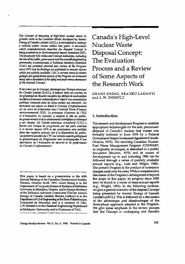
The Concept of disposing of high-level nuclear waste in granitic rocks in the Canadian Shield, developed by Atomic Energy of Canada Limited (AECL), is anticipated to undergo a national public review within two years. A document which comprehensively describes the disposal Concept is being prepared as an Environmental Impact Statement (EIS). The processfor EIS review and Concept evaluation, including men^(^thepuhbc,goœiiwmdandthescient^momeering innuiuuUly, is summarized. A Technical Advisory Committee (TAC) has provided external peer review of the Program since 1979 and its findings are published in annual reports which are publicly available. TAC's current views of certain geologic and geatedtnkal aspects of the Program are presented almg with a description of the safety and perfonnam^ a of the disposal Concept.
B est prévu que le Concept, développé par Énergie atomique du Canada Limitée (EACL), d'enfouir dans les couches de roc granitique du Bouclier canadien des déchets de combustibles nucléaires fortement radioactifs fera l'objet d'une consultation publique nationale dans les deux années qui viennent. Un document qui expose en détail le Concept d'enfouissement est en cours de préparation sous l'intitulé Étude d'impact environnemental (E1E). Le processus d'examen de l'EIE et d'évaluation du Concept, y compris le rôle du public, du gouvernement et de la communauté scientifique et technique y est résumé. Un Comité technique consultatif (CTC) a fourni une critique du programme par des pairs externes à ce dernier depuis 1979 et ses conclusions sont publiées dans des rapports annuels mis à la disposition du public. Les positions actuelles du CTC sur certains aspects géologiques et géotechniques du Programme sont accompagnées d'une description de l'évaluation de sécurité et de performance du Concept d'enfouissement.
This paper is based on a presentation at the 45th Annual Meeting of the Canadian Geotechnkai Society, Toronto, October 26-28, 1992. Grant Sheng is in the Department of Computer Science & Systems at McMaster University in Hamilton, Ontario, and is Science Secretary of the Technical Advisory Committee (TAQto Atomic Energy of Canada Limited. Branko Ladanyi is in the Department cfGvil Engineering at me EccleFc^ Université de Montréal, and is a member of TAC. L.W. Shemilt is in the Chemical Engineering Department at McMaster University and is Chairman of TAC.
Canada's High-Level Nuclear Waste Disposal Concept: The Evaluation Process and a Review of Some Aspects of the Research Work G R A N T S H E N G , B R A N K O L A D A N Y I a n d L .W. S H E M I L T
1. Introduction
The research and development Program to establish appropriate technologies for the safe, permanent disposal of Canada's nuclear fuel wastes w a s formally initiated in June 1978 by a Federal Gwaimiail-OntariQGovemrr^Agreem^(C^itad^ Ontario, 1978). The resulting Canadian Nuclear Fuel Waste Management Program (CNFWMP) as originally envisaged, is described in a public document (Boulton, 1978) and its course of deve lopment up to and including 1985 can be fo l lowed through a series of publicly available annual reports (e.g.. Lisle and Wright, 1986). The present Program is the product of numerous changes made ova: the years. While a a>rnprehensive discussion of the Program's development is beyond the scope of this paper, its progress since 1985 may b e found in a series of semi-annual reports (e.g., Wright, 1991). In the following sections, w e give a general overview of the disposal Concept being presented by Atomic Energy of Canada Limited (AECL). This is followed by a discussion of the advantages a n d disadvantages of the three-phase approach adopted in the Program. We give s o m e emphasis to the review process that the Concept is undergoing and describe
Energy Studies Review Vol. 5, No. 3, 1993 Printed in Canada 165
the roles of various participants but highlighting that of the public. In the second part of the paper, w e focus o n several salient geologic-related issues as raised b y the Technical Advisory Committee (TAQ (TA.C, 1992). This is followed by a description of the safety and performance assessment methodology applied to the total disposal system. This is heavi ly dependent o n simulation with computers, and consequently, the critical importance of software quality assurance is noted. A concluding summary is added.
2. The Canadian Waste Disposal Concept
The overall objective of the CNFWMP is "to ensure that there wil l b e no significant adverse effect o n m a n or the environment from nuclear waste at any time" (Rosinger and Dixon, 1982). Nuclear fuel waste is defined as either irradiated fuel or high-level radioactive material separated from the used fuel through reprocessing, although there are presently no plans to pursue this latter possibility.
2.1 The Multi-Barrier System
Similar to efforts in several other nations, the Canadian Program of research on deep geological disposal of nuclear waste is based on the concept of isolating wastes with a series of barriers situated in a deep (500m-1000m) underground vault, built in a stable, terrestrial geologic formation such as the granitic rocks of the Canadian Shield.
T h e bundles of used fuel w o u l d be encased in containers with an anticipated life of at least 500 years which corresponds to the period of high fission-product activity. The containers would be designed to withstand hydrostatic and lithostatic pressures and be resistant to corrosion under the temperature, groundwater exposure and radiation fields that could potentially exist at depth. The containers w o u l d b e emplaced in the vault and surrounded with compacted buffer material such as a mixture of sand and bentonite clay. This candidate material swells upon contact with water, thus acting as a highly impermeable seal against leaching and corrosive agents. It also has a high capacity to absorb chemical species, including
most of the significant radionuclides. The vault and the shaft w o u l d then be backfilled, probably with a mixture of crushed rock, sand, and bentonite to close any opening to the surface.
The geotogk: medium in which the u n ^ vault is built acts as yet another barrier to the migration of radionuclides should they escape the v a u l t Retardation occurs as a result of a number of natural processes taking place at depth, including chemical absorption of radionuclides onto rock surfaces, ion exchange, diffusion into the b o d y of the rock, and the long path lengths to the surface d u e to the relatively small s ize a n d frequency of fractures in the chosen rock. The effectiveness of this natural barrier depends o n careful selection of a site which exhibits f a v o u r a b l e geochemica l , geo log i ca l a n d hydrogeological conditions.
Finally, although the biosphere is not generally regarded as a "barrier" in the same sense as those described above, the surface environment, wi th its large vo lume of soil and water, has a great capacity to disperse and dilute whatever material which, no matter h o w unlikely, may reach the surface.
2.2 Components of the Research Program
The research work in support of the disposal Concept is divided into several parts: 1. interim storage, 2. transportation of nuclear fuel wastes , 3. disposal or burial of wastes.
Research and development work on the first two parts is referred to as "preclosure" work and is the responsibility of Ontario Hydro (OH). AECL has the responsibility of implementing research on the "postclosure" work. This work includes the assessment of possible safety and environmental impacts from the disposal vault, both in the time period during its operation and also far into the future after its closure.
The postclosure work comprises research in a multitude of disciplines. Components of the Program may be grouped under four headings: geoscience, engineered barriers, bioscience and performance assessment Included under the first heading are hydrogeology, geology, geophysics, geomexiianicsand geochemistry. Work on engineered
166
barriers includes des ign and deve lopment of the underground vault, and the research on containers (composition and design), and buffers and backfill. Under bioscience, studies include radiologic effects, obsimeby,ecological succession. Him plant uptake, and food chain models. The objective ofperibnnance assessment is to process and integrate the results from all of these disparate studies into a comprehensive and comprehensible analysis of the safety of the disposal system.
23 Three Phases of the Program
The Canadian Program, unlike disposal research programs of m a n y other countries, is d iv ided into phases. The first, Concept Assessment involves research which a ims to determine whether and to what extent waste disposal in deep , stable, terrestrial geologic formations can be achieved with the stated objective of ensuring h u m a n safety and environmental protection. This "generic research and development" phase w a s formally initiated in 1981 and the results of the ensuing years of research are n o w being assembled by AECL as the substantive work by which the Concept can b e evaluated and judged as to its acceptability. This evaluation process is discussed in the succeeding section.
The second phase, that of Site Selection, involving the actual process of screening, evaluating and finally selecting a suitable site, can only begin if the Concept is deemed acceptable. However, there are two other possibilities. The Concept may be found to be conditionally acceptable, in which case AECL wil l have to conduct further research or otherwise modify present work to satisfactorily address the d e e m e d inadequacies. Should the Concept be judged unacceptable, then it w o u l d be the responsibility of the Federal and Ontario Governments to consider alternatives.
The final phase , assuming success in both of the previous phases, w o u l d be the construction and operation of the disposal vault. It may b e that a demonstration facility w o u l d first b e built to provide the engineering and operational experience for the full-scale facility. In either case, this third phase i s not envis ioned to start until somet ime in the next century.
The Canadian Program is unusual among
other international programs in its dear distinction between the phases - work in one phase cannot begin until successful completion of the previous phase. This sequential approach has both its advantages as w e l l as its disadvantages. These are manifested in the characteristics of the research program as wel l as in its evaluation.
The scientific and technical research work as originally envisioned and initiated was "generic" in nature, without reference necessarily to any particular location or site. The biospheric conditions and associated data values were obtained from various sources including different locales in the Canadian Shield, field and laboratory experiments a n d from the literature. This composite of environmental and biologic information is representative of the Shield conditions in general but does not necessarily portray any particular location.
Although this approach proved to be satisfactory for characterizing the surface environment, it proved less successful w h e n applied to the underground geologic conditions. The very wide range of values and heterogeneous conditions encountered in this domain made the concept of a "generic geosphere" questionable, at least in the Canadian Shield situation. Recognition of this fact during the mid-80s led to a much more focused effort in and around the Whiteshell Research Area (WRA) located near the Manitoba-Ontario border close to the Whiteshell Nuclear Research Establishment (WNRE) site. Most data gathering, fieldwork, laboratory experiments and modelling work are specific to this location, although considerable geologic exploratory work has been carried out in t w o other research areas, one near Atikokan and the other at East Bull Lake, both in Ontario. The present AECL work, therefore, is based on a hybrid of b o m generic (mostly envirorunental conditions) and site-specific (mostly geologic conditions) information.
To a lesser degree, the problems encountered in the geologic case are also applicable to the assessment of socioeconomic impacts which belong in the preclosure studies. Although a generic approach w a s adopted, the effects of transportation and other activities associated with siting are difficult to assess without reference to a specific site.
167
Despite these difficulties there is an important advantage conferred by this approach. The clear distinction of the phases also defines what type of work is to be done during each phase a n d gives guidance on where emphasis is to be placed. During this first phase, for instance, the goal is to assess the Concept of waste disposal in deep , stable, terrestrial geologic formation — to see if, and h o w , this can be accomplished to meet the regulatory requirements of human safety and environmental protection. A s such, the research work is necessarily concerned with technical issues such as the effectiveness of system components (e.g., containers, the vault, the geologic barriers) for long periods of time, the possible failures that m a y occur at each barrier, the consequences of such failures, e t c In brief, the central and critical question which this phase of the work is to answer is: "Will it b e technically possible to dispose of high-level nuclear waste safely?" Other considerations associated with disposal such as ethical, social, economic, a n d political issues , valid as they are, must be treated as secondary considerations at this stage. If it cannot be established that safe disposal is at least technically possible, then clearly all other considerations are irrelevant
The establishment of technical feasibility, a l though necessary for the ultimate act of waste disposal, is not sufficient. A satisfactory resolution of non-technical issues such as the ones mentioned above are just as necessary for an eventual successful outcome. It is during the second phase w h e n the process focuses o n selecting a specific site, that issues such as equitable treatment, social and economic impacts on a certain region, matters of impact rrtitigation, compensation, etc. wi l l come to the fore, and properly so . The experiences in other disposal programs s h o w the critical importance of non-technical issues to successful siting. The experiences of the Low Level Waste Siring Task Force (Siting Task Force, 1990), the Ontario Waste Management Corporation and even the present controversy over selection of landfill sites in Southern Ontario all provide valuable lessons and insights on the immense difficulty of siting. Intense and vociferous opposition, characterized by the acronyms NIMBY (Not In M y Back Yard) and LULU (Locally Unwanted
Land Use) have accompanied recent attempts at siting any type of disposal facility.
It is in this sense that the CNFWMP enjoys an advantage over all other disposal situations — t h e phased approach clearly separates assessment of the Concept (Le., judgment of technical possibility and feasibility) from the actual process of site selection where experience has s h o w n that nontechnical considerations overwhelm technical issues. This phased approach has a l lowed the Program to concentrate o n doing the necessary technical work without being mired in counter-productive controversies and delays as faced by other disposal programs.
3. Evaluation of the Disposal Concept
3.1 Development of an Evaluation Process
In a joint statement (Canada-Ontario, 1981) the Ontario and Federal Governments defined, in detail, the process for evaluation of the acceptability of the proposed Concept. Public announcement of the joint statement constituted the first step in that process. In that document, the Atomic Energy Control Board (AECB) w a s originally designated as the lead agency for the regulatory and environmental review of the disposal Concept, and w a s responsible for the issuance of a final regulatory statement (AECB, 1985) which outlined the basis for such a review.
Since the publication of our previous paper (Sheng et al., 1987) in which this review process w a s described, a number of significant changes have taken place. First, AECB is no longer the lead agency for the review, and second, the Interagency Rev iew Committee (IRC) originally comprising the AECB, the Ontario Ministry of Environment and the Federal Department of the Environment, n o longer exists as a collective entity to conduct the review. Because of the increasing recognition during the eighties that implementation of technological projects, large or small, involves the n e e d to better address the concerns of a democratic society in terms of g iv ing d u e emphasis to socioeconomic and political issues in addition to the technical ones, it w a s felt that an independent body with such
168
a mandate w o u l d be the most appropriate agent to lead the Concept evaluation. Consequently, in a referral fetter (Masse, 1988), the Federal Minister of Energy, Mines and Resources requested that the Federal Minister of the Environment set u p an Environmental Assessment (EA) Panel to lead the review under the auspices of the Federal Environmental Assessment Review Office (FEARO). Under this n e w scheme, AECB will p lay a consultative role to the EA Panel a l though its regulatory requirements wi th respect to nuclear waste disposal as promulgated in R-71 (AECB, 1985), R-104 (AECB, 1987a) and R-72 (AECB, 1987b) must still be m e t In addition to these regulations, however, the CNFWMP m u s t also satisfy the requirements of the EA Panel operating under the Environmental Assessment Rev iew Process (EARP). One of the requirements under EARP i s that the proponent, AECL in this case, must submit an Environmental Impact Statement (ESS) detailing and explaining its disposal Concept and giving due emphasis to non-technical issues. Another essential requirement is that public hearings must b e held as part of the process o f evaluating the AECL Concept The entire process is diagrammatically shown in Figure 1 wi th dates of past events as wel l as expected dates of future milestones. The end point of this process i s a decision by the governments based on the findings of the EA Panel as to whether the disposal Concept is acceptable, conditionally acceptable, or not acceptable.
3.2 The Environmental Impact Statement
AECL is presently preparing the EIS in accordance with the EA Panel final Guidelines, the development of which is described in section 3 3 below. The EIS wil l be based on the research conducted over file last 15 years as summarized in a nine volume set of documents designated as the Trimary References," each with the primary title The Disposal of Canada's Nuclear Fuel Waste and a subtitle as follows: 1. Public Involvement and Social Aspects; 2. Site Screening and Site Evaluation Technology; 3. Engineered Barriers Alternatives; 4. Engineering for a Disposal Facility; 5. Preclosure Assessment of a Conceptual System;
6. Poslclosure Assessment of a Reference System; 7. The Vault Model for Postdosure Assessment; 8. The Geosphere Model forPostdosure Assessment, 9. The Biosphere Model, BlOTRAC.for postdosure
Assessment. A s evident from the titles, each of these
nine documents addresses, in detail, a specific aspect or significant component of the Program such as the engineering, predosure a n d postdosure work, the derails of the vault , geosphere and biosphere models , a n d social aspects of disposal, etc. Originally this set of documents w a s to be the EIS submission, but n o w serves as the primary supporting documentation for w h a t wil l be a single vo lume E B entitled "Environmental Impact Statement on the Concept for Disposal of Canada's N u d e a r Fuel Waste." In addition, a summary v o l u m e of the EIS wil l be produced for general readership. It is expected that AECL wi l l submit the EIS to the EA Panel somet ime in 1994.
3.3 Public Participation and Participant Funding
A s s h o w n in Figure 1, the EARP provides many different opportunities during the rev iew process for the public to receive information as wel l as to provide i n p u t We describe these below.
33.1 INPORMATION DISSEMINATION - OPEN HOUSES
The Panel, after its appointment o n October 4, 1989, (Minister of the Environment, 1989), scheduled "Open Houses" to be held in major cities in N e w Brunswick, Quebec, Ontario, Manitoba and Saskatchewan throughout the months of May a n d June of 1990. Secretariat members of the Panel were available to discuss the review process, the Panel's terms of reference, anticipated review activities and participant funding. A s wel l , AECL and O H staff had displays and distributed literature to inform about, and explain, the disposal Concept Attendance at the some 20 sess ions , he ld both during the day and in the evening, w a s generally low.
33a PUBLIC INPUT THROUGH SCOPING MEETINGS
The Panel held some 23 "Scoping Meetings" during
169
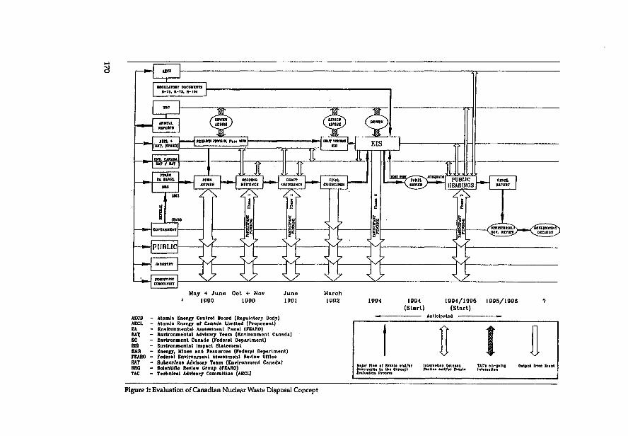
AlCB
ANfftUL RKPOtin
PANEL REPORT
AECB - Atomic Energy Control Board (Retulatory Body) AECL - Atomic Energy of Canada Limited (Proponent) . EA - Environmental Assessment Panel (FËARO) EAX - Environmental Advisory Team (Environment Canada) EC - Environment Canada (Federal Department) BIS - Environmental Impact Statement EMR - Energy, Mines and Resources (Federal Department) FEARO - Federal Environment Assessment Review Office SAT - Subsurface Advisory Team (Environment Canada) SRO - Scientific Review Croup (FEARO) TAC - Technics! Advisory Committee (AECL)
1094 1004/1005 (Slarl) (Start)
Anticipated
1095/1006
Major now of etrenU «twj/or DooumsnU to tb« Concept Evaluation Ptoc«M
Output from Scant 1
Figure 1: Evaluation of Canadian Nuclear Waste Disposal Concept
the months of October and November of 1990 i n the same provinces as for the Open Houses . The intent of these meetings was for members of the general public and any interested parties to present to the Panel their v i ews on w h a t issues shou ld b e included in the Panel's guidel ines for the preparation of AECL's E E . More than 100 written and oral presentations were m a d e to the Panel in accordance with a set of procedures announced o n November 5,1990 (FEARO, 1990d). A wide diversity of groups including government agencies, industry, professional, scientific and engineering societies, environmental groups, labour organizations and. members of the general public participated in this process. A compilation of the submissions is available from FEARO.
The most salient issues arising out of these meetings include: (1) the need to examine the disposal Concept within the context of the entire Canadian energy policy, (2) the public concern about a "walk-away" Concept on-going postdosuce monitoring being a very high priority i n the public mind; (3) the v iew that ethical and socioeconomic issues are at least as important as technical issues and the difficulty of talking separately about them.
3 3 3 PUBLIC COMMENTS ON THE DRAFT GUIDELINES
From the input provided through the Scoping Meetings, the EA Panel drafted a set of Interim Guidelines for AECL's FJS which w a s released for public c o m m e n t Although the level of response to the Draft Guidelines d i d not match that of the Scoping Meetings, comments received from some groups, including AECL, were detailed a n d comprehensive. Modifications were m a d e to the Draft Guidelines as a result of the various responses and the set of Final Guidelines w a s i s sued b y the EA Panel in March 1992 (FEARO, 1992). A complete compilation of all submissions is available from the FEARO office.
33.4 PARTICIPATION THROUGH PUBLIC HEARINGS
The next opportunity for formal input and participation wi l l be during the public hearings which are anticipated to start after AECL submits
its EIS (expected in 1994) and after the EA Panel is satisfied of the EE's compliance wi th the Final Guidelines. At that time the E E will be distributed for public review to any interested party. The dates, locations and detailed procedures for the hearings will be announced by the PaneL Although it is difficult to predict h o w long the hearings wil l take, it is anticipated that complet ion w o u l d be within a twelve-month period. Upon completion, the Panel will submit a report of its f indings and recommendations to the Federal and Ontario governments. It is then the responsibility of those governments to state the acceptability, conditional acceptability or non-acceptability of AECL's proposed Concept Should the first outcome b e realized, the second phase, site-selection, may b e initiated. In the second instance, AECL m a y b e required to d o further work. In the event of the third outcome, the two governments will have to consider other alternatives.
33.5 PARTICIPANT FUNDING
A critical component of the review process is the availability of funding to he lp the public participate more effectively over the entire process. The $750,000 participant funding, prov ided b y AECL, is administered b y a separate Funding Committee set u p b y FEARO which reviews and allocates funds to successful applicants in accordance with its eligibility criteria (FEARO, 1990a). The Committee had awarded $152,500 to 17 of 33 applicants to assist them i n the preparation for, and participation in, the Scoping Meetings and for review and comment o n the Draft Guidelines (FEARO, 1990c). The remaining amount has been allocated for Phase 2 which involves the review of the E E and its related documents, and participation in subsequent public hearings. This amount will be distributed such that full opportunity is provided for participation in both the socioeconomic and technical reviews. However, at least half of the amount wi l l be available to participants wishing to conduct s d o u i n c reviews on the technical aspects of the Program. Information about eligibility criteria, deadl ines , application forms, and the list of successful applicants from Phase 1 are available from FEARO.
171
4. Scientific Reviewing Bodies
A s wel l as the overall Concept evaluation process l e d b y the EA Panel as described above, the Concept is presently also being reviewed b y three groups with the focus o n scientific, technical a n d engineering aspects o f the Program.
4.1 The Technical Advisory Committee (TAC)
T h e Technical Advisory Committee to AECL, w a s established in mid-1979, and has prov ided continuous reviews since then. The purpose of TAC is to act as an independent review b o d y advis ing AECL o n the extent a n d quality of the CNFWMP. Its responsibilities are to rev iew the content of proposed research projects, to sugges t alternatives a n d additions as deemed appropriate, to review the scientific methods used, to rev iew Program results and assure that conclusions drawn are valid within the limits that are claimed, and to recommend any specific areas of work for which research should b e undertaken, either b y existing staff or through research contracts. Its autonomy is assured b y the form of appointment to TAC of persons independently nominated b y professional and scientific societies, b y the requirement of reporting in the public d o m a i n a n d b y the provision to TAC of full and free access to all aspects of the research Program. The Committee is also prov ided wi th resources that al low it to obtain additional specialist advice as i t deems fit TAC's 13 annual reports provide a publicly available documentation of its on-going assessment of the progress and performance within the Program as wel l as external factors influencing i t A concise summary of TACs recommendations over the last d o z e n years is presented in Shemilt and Sheng (1991).
4.2 The Scientific Review Group (SRG)
The SRG w a s established b y the EA Panel in mid-1990 specifically to evaluate and provide advice o n the scientific and engineering aspects of the Concept (FEARO, 1990b). Similar to TAC, most of its members are Canadian scientists chosen most ly from universities, a l though several are from industry and government. The SRG reports
directly to the EA Panel and has provided input to the Scoping Meetings as well as comments on the Draft Guidelines.
4.3 TJie Subsurface Advisory Team (SAT) and Environmental Advisory Team (EAT)
These two teams of consultants were established in 1989-90 by Environment Canada on a contractual basis to provide it with dedicated scientific advice o n AECL's disposal Concept, and to develop Environment Canada's position as an intervenor during the public hearings. The SAT is responsible for i ssues associated with the disposal vault and the geosphere, and the EAT is to review issues associated with the biosphere as well as those involving social, economic and policy aspects of disposal. Both teams have conducted their o w n "scoping calculations" which are summarized in SAT (1992) and EAT (1992). A concise description of the teams' roles, activities and major findings is g iven b y Pascoe et al. (1992).
5. Aspects of T A C S Review
5.1 The Geoscience Program and Salient Issues
The CNFWMP places considerable importance o n the geosphere as a barrier for the long-term containment of nuclear wastes. The objectives of the geoscience program are to develop and refine the technologies for locating and characterizing potential disposal sites, leading to the development of a geosphere model which can be used in performance assessment of a hypothetical vault. The geoscience program is the largest component wi thin the CNFWMP and has undergone many changes since its inception in the late seventies. It is beyond the scope of this paper to trace the history of the program's development and discuss the reasons for the changes. Do imuth et al, (1989) provide a comprehensive overview of the geological considerations for nuclear fuel waste disposal in Canada including the philosophy a n d goals of the Canadian effort, the rationale a n d justification for the choice of plutonic rocks in the Canadian Shield as the potential host medium, the mos t important geotechnical factors to be examined in considering potential sites, the
172
methodology developed and planned to be u s e d in the site characterization process, the methodology deve loped a n d being used in the prediction of disposal system performance, and a brief presentation of the case study (based on the Whiteshell Research Area) developed for demonstration of the Canadian Disposal Concept Our previous, paper (Sheng et at, 1987) reviewed s o m e highlights of the then current geologic, geotechnical and performance assessment work, including the Underground Research Laboratory (URL), the geomechanic characterizations taking place there as wel l as the hydrogeological studies wi th the associated field investigations. In this paper w e focus o n several aspects of the geoscience program w h i c h w e believe to b e critical for successful demonstration of the Concept
The approach being adopted b y AECL for the FJS is to present a case s tudy based most ly o n the work at the WRA, including the URL, to demonstrate the safety of the C o n c e p t The case s tudy places high reliance o n the integrity of the granitic host m e d i u m (the Lac d u Bonnet Batholith) as the main barrier for the long-term containment of any wastes . This is manifested in the geosphere model l ing which simulates the characteristics of the URL and its surroundings within the WRA. The model assumes the existence of a zone of unfractured rock around a hypothetical vault with transport of material across this z o n e only through diffusion. TAC, in its recent annual report (TAC, 1992), raised several issues of concern related to this approach, as wel l as on the results of preliminary modell ing which indicate that a fracture zone penetrating through the mass of intact rock within 50 meters of a failed container w o u l d seriously reduce the effectiveness of the geosphere as a barrier. Furthermore, this reduced effectiveness is most serious for a vault wi th such an intersecting fracture located in a hydrogeolo-g k discharge area as is the case at the URL site. Based on the above, T A C s specific concerns are summarized b y the fol lowing points: 1. the existence of a vo lume of continuously-intact
rock necessary to host a disposal vault w i t h an equivalent area of 2 k m x 2 km,
2. the ability to characterize the rock mass such that any significant fracture ( i e . , any fracture wi th the characteristics that w o u l d violate
the diffusion-only transport assumption) within 50 meters of the vault would be detected,
3. the implicit assumption that no such fractures w o u l d deve lop in the future,
4. the inherent disadvantages of placing a vault in an area of groundwater discharge which is the case s tudy being presented at the URL site.
Environment Canada's Subsurface Advisory Team have also carried out scoping studies which explicitly raised the same concerns as in 2. above, as wel l as the first issue implicitly (SAT, 1992).
In the papers b y Pascoe et at .(1992) and Raven and Timlin (1992) they state the following as o n e of a number of issues which they bel ieve "require substantially greater attention by AECL during the presentation of their environmental impact statement" (Pascoe et at, 1992):
The intact rock surrounding the emplacement room is l ikely to be the critical feature of the multi-barrier concept developed b y AECL. Our scoping calculations indicate that approximately 50m of intact rock of bulk permeability less than 10' 1 8 m 2 would be needed to prevent radionuclide releases over a 10,000 year period. Consequently, demonstrated success of the AECL Concept m a y require reliable characterization of the bulk rock permeability to values of 10"" m 2 or less over scales of 50m surrounding each emplacement room throughout the repository" (Raven and Timlin, 1992).
A s noted above, TAC therefore considers that t w o elements within the geoscience program require particular attention: (1) hydrogeologic characteristics of the site, and (2) long-term geomechanical behaviour of the rock mass.
5.2 Hydrogeology
With regard to the former, TACs advocacy of regional flow system studies and a regional recharge area as a desired site characteristic has been presented in previous TAC reports (e.g., TAC, 1989; 1990), and reiterated in its recent Twelfth and Thirteenth Annual Reports (TAC, 1992; 1993).
In a regional recharge area, groundwater moves away from the land surface and is generally
173
dest ined to migrate along very long f low paths (possibly tens or even hundreds of kilometres) for very long times (possibly hundreds of thousands of years), thereby contributing to higher amounts of adsorption and radioactive decay of the transported nuclides. TAC continues to hold its previous opinion (TAC, 1989; 1990) that from a groundwater hydraulics point of v i e w , such regional recharge areas have posit ive characteristics as potential vault locations and therefore that a recharge setting in regional groundwater flow systems should be fonnatty recognized as a highly ranking favourable hydrogeological attribute. Such a consideration could also expedite the process of initial site screening since it can b e readily deduced from topographic m a p s and does not require the use of destructive methods of investigation. Hence the claim by AECL that current knowledge does not justify a search for regional recharge areas is not a posit ion that accords with the above judgment which TAC is reasserting in recent reports (TAC, 1992; 1993).
TAC has noted that the work o n regional groundwater f low systems is being maintained by field investigations and monitoring of hy drogeological conditions both at the Atikokan Research Area (ARA) and more extensively at the W R A (especially related to the URL). Hydrogeological m a p s for both areas are being prepared using general specifications. TAC reaffirms its earlier judgment that the delineation of f low systems and establishing of flow directions should constitute integral components of such mapping. The H S and its supporting documents, including such fundamental components as hydrogeological maps, should demonstrate both an understanding of all significant conceptual aspects of ground-water flow distribution in the Canadian Shield a n d an ability to evaluate, characterize and m o d e l regional flow paths in several field situations (TAC, 1992).
5.3 Geomechanics
Geomechanical research in the NFWMP is being carried out to gain an adequate understanding of the response of rock mass to stresses imposed b y the range of disturbances associated with the construction, operation and long-term existence
of a deep disposal vaul t One of the most important ultimate goals of the CNFWMP is to demonstrate the ability to predict, from a l imited amount of data, the short- and long-term behaviour of rock masses surrounding the vault w h e n they are subjected to changes of stress, temperature, hurnidity and other time-dependent factors (TAC, 1990). Al though this is clearly a well-defined objective, at this stage in the Program and o n the basis of presently available data o n vault rock a n d rock m a s s constitutive behaviour, TAC considers that the ability to simulate the behaviour of rock mass around the projected vault for any hypothetical site, including one similar to the URL site, and to check its short- and long-term stability has not yet been sufficiently demonstrated. Further, a l though g o o d experimental work has been d o n e in connection wi th ground stress determination, more attention to addressing the problem of understanding the behaviour of the host rock w o u l d s e e m to b e n e e d e d A s noted below, the p lanned Mine-by Experiment, being carried out in the URL, promises to be a valuable source of information concerning this problem.
These aspects have continued to b e stressed b y TAC. H o w e v e r , wi th currently available information, it is still difficult to model adequately for stresses induced by the vault and the possible development of short- and long-term failure zones. Through existing AECL documents , the useful, but fragmentary, information o n the hos t rock mechanical behaviour at small scale, a n d the small amount of data available at a large scale have yet to b e p u t in a form appropriate for use in vault modelling and design. What is needed is a 3 D constitutive mode l of the rock which hosts the v a u l t a n d which includes both existing a n d potential fracture zones. This w o u l d enable s imulation of the rock behaviour around the p lanned vault at both short- and long-term, and at both small- a n d large-scale, taking into account all imposed time, space and environmental constraints (TAC, 1992). It is noted that the first results o f a 3 D near-field, structural analysis of the vault have just become available.
The value in reaching such an overall understanding of the rock behaviour around the planned vault is demonstrated by the propagation of damage zones encountered during experimental
174
water-jet cutting of a typical emplacement borehole in the URL, and during the Mine-by Experiment in the URL. This problem may be expected to occur on a much larger scale in a real situation if in-floor emplacement of containers is adopted. The renewed emphasis on in-room emplacement (Wright, 1991) appears most justified in this respect (TAC, 1992).
Some positive steps towards obtaining additional and much needed information on rock mass behaviour are presently being taken (Wright, 1991). A number of outside rock mass modell ing experts are participating in the prediction and back-analysis of rock response in the URL Mine-by Experiment In that study, various more-or-less complex constitutive models wi l l be used. A t the end, an independent review will be d o n e to assess which of the models may be the most suitable for predicting the behaviour of elastic-brittle rock masses around a vaul t TAC supports this approach (TAC, 1992).
TAC emphasizes the importance of selecting future sites within geological units that are not located in an unusually high lateral stress field, as is the case in a portion of the URL. Engineering technology is capable of overcoming differential stress during the predosure phase of a vault in order to maintain safety. Highly stressed rock is more likely to develop fractures in the future during the postdosure phase. Such fractures could provide n e w pathways to the surface although it is possible to minimize such an eventuality for a vault sited in a hydrogeologic recharge zone.
5.4 Performance Assessment
In order to assess adequately the long-term environmental impact of the disposal Concept, it is necessary to invoke methodologies that wi l l both encompass the large number of variables inherent in the system and predict effects over extensive time periods. The possible consequences, over both time and space, will be measured against criteria that are set by regulatory agencies, as discussed immediately below. A common approach to assessment is to apply probabilistic analysis (Sheng and Shemilt, 1990). This methodology and its application is briefly described below.
5.4.1 DOSE, RISK AND OTHER CRITERIA
175
The criteria for judging nudear waste disposal safety has been established by AECB, the regulatory b o d y in Canada which has responsibility for matters dealing with radioactive substances. The regulatory document R-104 (AECB, 1987a) contains specific radiobiological and risk criteria as wel l as other requirements. In brief, AECB requires that (a) burdens placed o n future generations beminirxiized,(b)theeavironrnentmustbepro a n d (c) h u m a n health must be protected, for which the risk criterion of less than 10"* (or one in a million) serious health effects per year is imposed. This risk figure is associated wi th a dose of 0.05 m S v / y r which is equivalent to approximately 23% of the annual dose received b y the general population in Canada from natural background radiation.
5.4.2 SYSTEM VARIABILITY ANALYSIS
There are t w o unique characteristics associated wi th the permanent disposal of nudear waste: (a) no precedents exist for such an endeavour and (b) the very long time-span over which the multi-barrier sys tem must remain effective. To deal wi th the inherent uncertainties involved in predicting possible future outcomes under this latter condition and reflecting the system complexity, a method known as "system variability analysis" w a s adopted (Wuschke et at, 1981). It takes into account, systematically, the effects of imprecise data (i.e., parameter values that cannot be precisely specified as single point values).
In this approach, uncertainties in the data gathered through research, and the variation of conditions through space and time are taken into account b y assigning a distribution of values (rather than specifying a single value) to the parameters used to model or describe the disposal s y s t e m The distributions (e.g., normal, lognormal, exponential, uniform, etc.) are selected to cover the credible range of values for the parameters and are characterized by the likelihood of occurrence of chosen values in the specified range. The distributions thus represent observed or theoretical variability, subjective uncertainty, or a combination of both. Simulation studies using these data are
performed by sampling values from each parameter distribution to generate a range of possible outcomes and their corresponding frequency of occurrence.
5.4.3 THE SYVAC SIMULATION
This method is implemented wi th a computer program, SYVAC (SYstems Variability Analysis Code) (Wuschke et al., 1981) and is illustrated in Figure 2. System simulations are performed b y linking a set of three submodels representing the three major constituents of the disposal system: the vault, the geosphere, and the biosphere. Significant processes and conditions within each are characterized b y sets of equations. These are, in effect, mathematical statements of the current state of knowledge about the disposal sys tem and the phenomena that influence i t
Initial data input consists of the inventory of radionuclides placed in the vault. This is in the form of the used fuel bundles packed in a structurally supported container of titanium or copper. The processes of container failure and of leaching a n d transporting b y groundwater within the vault, together with the reaction of these radionuclides w i t h engineered barriers such as buffers a n d backfill, and the final movement out of the vault are simulated. The output terms (i.e., integrated flux of radionuclides) from the vault serve as the input terms for the geosphere model . Examples of parameters which are taken into account in the estimation of radionuclide movement through geolog ic media include groundwater velocity, effective path length, chemical retardation factors including sorption, etc. In the third and last model , the biosphere, the analysis involves the estimation of radionuclide movement leaving the geosphere and travelling through shal low groundwater surface water, soil, plants, animals and, finally, to humans.
SYVAC treats the three submodels in sequence and produces for a particular run (ie . , the situation defined by one particular set of values derived from the stochastic selection of one value from each parameter probability distribution), an estimate of the m a x i m u m dose to an individual in the m o s t exposed group within a g iven time after disposal.
The rnaximum dose is termed the "consequence"
for that run. Estimates of maximum dose from a large number (typically 1000) of such stochastically constructed simulation runs are plotted to s h o w the frequency of occurrence of any particular consequence. A theoretical risk figure can then be calculated b y summing the product of each pair of consequence (maximum ctosej-versus-frequency values .
5.4.4 THE SYVAC COMPUTER CODE
The SYVAC computer code is a large and complex FORTRAN computer program consisting of over 370 software modules (or FORTRAN subroutines). It has over 30,000 executable FORTRAN statements and, over 100,000 statements (inducting comment statements) in total More than 7000 parameters characterize the disposal system and describe the behaviour of more than 90 radionuclides a n d chemically toxic elements. W i t h respect to execution time, SYVAC (Version 3.07) requires a lmost three full days of dedicated execution t ime to complete a 1000 run case on a S U N Sparcstation 1+ Workstation (12 - 15 MIPS). A 5000run case requires almost two weeks to complete. Version 3.8 requires considerably more execution time, possibly an increase by a factor of 10.
5.43 SYVAC AND QUALITY ASSURANCE (QA)
The critical nature of the conceptual models as wel l as the s ize and complexity of the SYVAC computer code necessitates a rigorous program of quality assurance. TAC in its annual reviews a n d evaluation of the Canadian Program has continually emphasized the critical importance of code verification (i.e., the process of ensuring that the software is doing what was intended of it) and recommended the use of software tools and adoption of weU-established software engineering practices to minimize program errors. Examples of such tools and techniques are described in Oren et al. (1985), Oren and Sheng (1988), Oren a n d Sheng (1990), and Sheng and Oren (1991).
Another critical, but more difficult, i ssue is that of m o d e l validation which is concerned w i t h h o w closely or relevantly the conceptual mode l s describe real-world processes. There is as yet no agreed-upon methodology for tackling
176
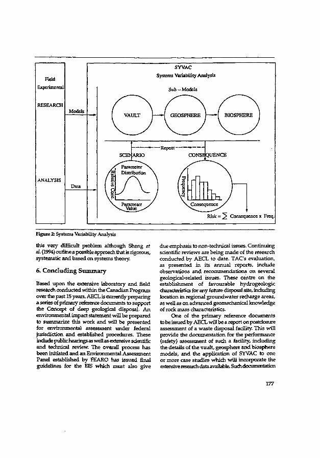
Held Experimental
RESEARCH
ANALYSIS
Models
Data
SYVAC Systems Variability Analysts
Sub - Models
Repeat -*
Risk = 5 Consequence x Freq.
Figure 2i Systems Variability Analysis
this very difficult problem although Sheng et al. (1994) outline a possible approach mat is rigorous, systematic and based on systems theory.
6. Concluding Summary
Based upon the extensive laboratory and field research conducted within the Canadian Program over the past 15 years, AECL is currently preparing a series of primary reference documents to support the Concept of deep geological disposal. A n environmental impact statement wil l be prepared to summarize this work and will be presented for environmental assessment under federal jurisdiction and established procedures. These include public hearings as well as extensive scientific and technical review. The overall process has been initiated and an Environmental Assessment Panel established b y FEARO has i ssued final guidelines for the E E which must also g ive
due emphasis to non-technical issues. Continuing scientific reviews are being made of the research conducted by AECL to date. T A C s evaluation, as presented in its annual reports, include observations and recommendations on several geological-related issues. These centre on the establishment of favourable hydrogeologic characteristics for any future disposal site, including location in regional groundwater recharge areas, as well as on advanced geomechanical knowledge of rock mass characteristics.
One of the primary reference documents to be issued by AECL will be a report on postdosure assessment of a waste disposal facility. This wi l l provide the documentation for the performance (safety) assessment of such a facility, inducting the details of the vault , geosphere and biosphere models , and the application of SYVAC to one or more case studies which wil l incorporate the extensive research data available. Such documentation
177
should be available in 1994for independent external evaluation The scientific and engineering ccarunumues in Canada can perform service to the nation b y direct participation in such evaluation.
Acknowledgements
The authors w i s h to express their appreciation to Mel Kliman a n d two anonymous referees for their helpful comments o n a draft of this paper. Thanks are d u e a lso to Guido Bendrich and Peter Bewer for their assistance in preparing the figures, and to Rita Donaldson for the preparation of the manuscript
References
AECB (1985) "Deep Geological Disposal of Nuclear Fuel Waste: Background Information and Regulatory Requirements Regarding the Concept Assessment Phase,' Regulatory Document R-71.
—(1987a) 'Regulatory Objectives, Requirements and Guidelines for the Disposal of Radioactive Wastes,' Regulatory rJocument R-104.
—(1987b) 'Geological Considerations in Siting a Repository for Underground Disposal of High-Level Radioactive Waste,' Regulatory Document R-72.
BoultonJ. (Ed.) (1978) 'Management of Radioactive Fuel Wastes: The Canadian Disposal Program,' Atomic Energy of Canada Limited Report, AECL-6314.
Canada-Ontario (1978) Joint Agreement b y the Minister of Energy, Mines and Resources Canada and the Ontario Energy Minister," (Ottawa: Supply and Services Canada).
—(1981) Joint Statement by the Minister of Energy, Mines and Resources Canada and the Ontario Energy Minister," (Ottawa: Supply and Services Canada).
Dormuth, K.W., W.T. Hancox and S.H. Whitaker (1989) Geological Considerations for Disposal of Nuclear Fuel Waste in Canada, paper presented at Workshop W3B, Geological Problems in Radioactive Waste Isolation, A World Wide Review. 28th International Geological Congress, Washington, July 15-16.
EAT (1992) Report of the Environmental Advisory Team to Environment Canada on the Canadian
Nuclear Fuel Concept Waste Disposal (Brampton, Ontario: Beak Consultants).
FEARO (1990a) Participant Funding Announced, N e w s Release b y the Federal Environmental Assessment Review Office, Ottawa, July 20.
—(1990b) Environmental Assessment Panel to Nuclear Waste Management and Disposal Concept Appointments to Scientific Review Group, N e w s Release by the Federal Environmental Assessment Review Office, Ottawa, Augus t 15.
—(1990c) Funding Of Public Participation In The Environmental Assessment Review Of The Nuclear Fuel Waste Management and Disposal Concept, N e w s Release by the Federal Environmental Assessment Review Office, Ottawa, September 21.
—(1990d) Nuclear Fuel Waste Management Environmental Assessment Panel Makes Available Operational Procedures, Database, Compilations Of Written Submissions, and Transcripts, N e w s Release by the Federal Environmental Assessment Review Office, Ottawa, November 5.
—(1992) Final Guidelines For The Preparation Of An Environmental Impact Statement On TheNudear Fuel Waste Management And Disposal Concept (Ottawa: Federal Environmental Assessment Review Office).
Lisle, P.D.R. and E.D. Wright (Compilers) (1986) The Canadian Nuclear Fuel Waste Management Program 1985 Annual Report, Atomic Energy of Canada Limited Technical Record, TR-400.
Masse, M. (1988) Nuclear Waste Disposal Concept and Waste Management Issues Referred For Environmental Review, N e w s Release by the Minister, Energy, Mines and Resources Canada, Ottawa, September 28.
Minister of the Environment (1989) Minister of the Environment Appoints Pand to Review Nuclear Fuel Waste Management and Disposal Concept, N e w s Release by the Federal Environmental Assessment Review Office, October 4.
Ören, T.I., M.S. Elzas and G. Sheng (1985) Model Reliability and Software Quality Assurance in Simulation of Nuclear Fuel Waste Management Systems, Simuletter, 16:4.
Ören, TX and G. Sheng (1988) 'Semantic Rules and Facts for an Expert Modelling and Simulation System," Proceedings of the 12th IMACS World Congress, pp. 597-98, Paris, Julyl8-22.
178

—(1990) 'Software Tools for the Quality Assurance of Scientific Codes Used in Nuclear Waste Management Programs,' Proceedings of the International Symposium on Safety Assessment of Radioactive Waste Repositories, pp . 761-66, Paris, October 9-13,1989 (Paris: OECD).
Pascoe, D.J., R E , Jackson and D.L. Lush (1992) TJefending the Environmental Standpoint A Report of the Work of Environment Canada in Assessing the Canadian Nuclear Fuel Waste Disposal Concept' in Proceedings of the 45th Canadian Geotechnical Conference, Toronto, Ontario, October 26-28.
Raven, K.G. and R.T. Timlin (1992) 'Assessing Radionuclide Migration from a Nuclear Fuel Waste Disposal Facility' in Proceedings of the 45th Canadian Geotechnical Conference, Toronto, Ontario, October 26-28.
Rosinger, EL.J. and R S . Dixon (Eds.) (1982) Fourth Annual Report of the Canadian Nuclear Fuel Waste Management Program, Atomic Energy of Canada Limited Report, AECL-7793.
SAT (1992) Summary Report of the Subsurface Advisory Team to Environment Canada on the Canadian Nuclear Fuel Waste Disposal Concept for the Period January 1991 to March 1992, (Austin, Texas: A U S C A N . I n c ) .
Shemilt, L.W. and G. Sheng (1991) 'Assess and Advise: A Decade of Evaluation erf the Canadian Nuclear Fuel Waste Management Program in Proceedings of Waste Management '91, pp . 311-19, Tucson, February 24-28.
Sheng, G., B. Ladanyi and L.W. Shemilt (1987) 'An Evaluation of the Canadian Nuclear Fuel Waste Management Program' in Proceedings of the Canadian Engineering Centennial Convention, p p . 111-21, Montreal, May 18-20.
Sheng, G. and L.W. Shemilt (1990) Evaluation of the Canadian HLW Disposal Program Performance Assessment Aspects' in Proceedings of the First International Topical Meeting on High level Radioactive Waste Management, Vol. 2,
pp . 725-31, Las Vegas, April 8-12. Sheng, G- and T.L Oren (1991) 'Computer-Aided
Software Understanding Systems to Enhance Confidence of Scientific Codes' in Proceedings of BIOMOVS Symposium on (he Validity of Environmental Transfer Models, p p . 275^86, Stockholm, October 8-10,1990.
Sheng, G., M S . Elzas, TX Oren and B.T. Cronhjort (1993) 'Model Validation: A Systemic and Systematic Approach' Reliability Engineering and System Safety Journal (in press).
Siting Task Force (1990) 'Opting for Cooperation: A Process in Action, The First Phases' (Ottawa: Ministry of Energy, Mines and Resources).
TAC (1989) Tenth Annual Report of the Technical Advisory Committee on the Nuclear Fuel Waste Management Program, L.W. Shemilt (Chairman) Report TAC-10.
—(1990) Eleventh Annual Report of the Technical Advisory Committee on the Nuclear Fuel Waste Management Program, L.W. Sherrult (Chairman) Report TAC-11.
—(1992) Twelfth Annual Report of the Technical Advisory Committee on the Nuclear Fuel Waste Management Program, L.W. Shemilt (Chairman) Report TAC-1Z
—(1993) Thirteenth Annual Report of the Technical Advisory Committee on the Nuclear Fuel Waste Management Program, L.W. Shemilt (Chairman) Report TAC-13.
Wright E D . (compiler) (1991) Semi-Annual Status Report of the Canadian Nuclear Fuel Waste Management Program: 1990 October 1-1991 March 31, Atomic Energy of Canada Limited Technical Record, TR-425-10.
Wuschke, D M , K X Mehta, K.W. Dormuth, TXL Andres, G J t Sherman, E.L.J. Rosinger, B.W. Goodwin, J-AJC Reid and R B . Lyon (1981) Environmental and Safety Assessment Studies for Nuclear Fuel Waste Management, Volume 3: Post-Closure Assessment, Atomic Energy of Canada Limited Technical Record, TR-127.
179

CHAPTER 3
MODEL VALIDATION AND SOFTWARE VERIFICATION ISSUES
As discussed in Chapter 1 and further elaborated in 3.4, the terms validation and verification (V & V) are often used interchangeably, used inconsistently, and/or just utterly misunderstood. Although it may seem merely a case of semantics, these two issues are quite distinct and their confused usage, either with one another, or because of misunderstanding of what activities each process actually entails, can, and have had, severe consequences as detailed in 3.4. In the context of simulating the performance of nuclear waste disposal systems over geologic (i.e very long) time scales, confidence in (a) the conceptual models and, (b) in the proper functioning of the implementing computer program, is of paramount concern. Confusion, misunderstanding and misapplication of the terms and activities detract from this confidence and must, therefore, be eliminated.
The collection of four papers in this chapter: (a) make explicit the distinction between the two terms and their associated activities; (b) present various techniques and tools used for software quality assurance; and (c) present an outline of a systematic and comprehensive, step-by-step approach to the process of validating models.
3.1 Model Reliability and Software Quality Assurance in Simulation of Nuclear Fuel Waste Management Systems
Two issues of critical importance to the simulation of waste disposal systems, model validation and software verification, are addressed. The first portion introduces a possible framework for systematically assessing each component of a simulation study with emphasis on the conceptual model aspects. In the second portion, a list of the large number of possible errors that can occur in a FORTRAN program is given as an illustration of the importance of software quality assurance. A review of the then-current tools and techniques applied to verification of software is given and some examples are provided.
This is the first paper to explicitly introduce the concepts of V & V to the nuclear waste disposal community. More specifically, it illustrates a possible approach one can take to assess each component of a simulation study in a systematic rather than in an ad hoc manner. Second, the paper introduces the techniques used in software engineering for verifying software. Due principally to TAC's recommendations in its annual reports on this subject and to this paper which elucidated those recommendations, AECL mounted the first V & V program for its SYVAC simulation code. This Canadian effort was the first within the international waste disposal community and the latest version, SYVAC3, with its CC-3 models, are now recognized as the performance assessment code most thoroughly tested and the standard by which other codes are compared (Nies, 1993; Thompson, 1993).
3-1
3.2 Semantic Rules and Facts for an Expert Modelling and Simulation Systems
3.3 Computer-Aided Software Understanding Systems to Enhance Confidence of Scientific Codes
Another means by which to contribute to software quality assurance is through error detection in code and/or model. The human capability to detect such errors through visual code inspection depends very much upon the "readability" and "comprehensibility" of the code. This paper introduces a software tool, ORFOR, which re-documents input FORTRAN source code such that various code characteristics and attributes (e.g. logical structure) become immediately apparent.
In extending the concept of minimizing error through maximizing comprehensibility, one can develop tools which transform code to a higher abstraction level (e.g. specification level) to enhance understanding of the computerized model. One such reverse-engineering system, E/SLAM,is described. It analyzes SLAM n programs to produce design specification-level information such as network graph, statement templates, and program templates for cross-reference, etc. Such output representations can be compared with the original specifications to verify that they have been Mthfully implemented by the code. The concept that working at a higher abstraction level minimizes errors is emphasized for both "reverse-engineering" and "forward-engineering" activities.
This is the first paper to introduce to the waste disposal community the concept of "reverse-engineering" as another means to assure software quality. The benefits of such a system extends to situations where code intercomparisons among groups are carried out. It is
3-2
One means to better assure software quality is to niinimize the possibility of making logical and/or syntactic errors. Procedural languages such as FORTRAN are prone to both types of errors, but especially the latter. A modellmg/simulanon-environment may be developed so that one works at a higher abstraction level (e.g., the model specification level), and thus minimizing syntactic errors often made during coding. Logical errors can also be minimized if the simulation system can check for internal consistency among the various components and functionalities of a conceptual/mathematical model. This short paper provides the knowledge base, expressed in semantic facts and "if... then" rules, upon which the modelling system, MAGEST (Ayta? and Oren, 1986), verifies logical and semantic consistency of models.
This is the first paper to introduce to the waste disposal community the concept of using "modelling environments" to assure software quality. The paper illustrates the relative ease with which this can be done by explicitly presenting the knowledge base for such a modelling environment (MAGEST). The use of this knowledge base is not restricted to models written in a FORTRAN-like language but may be applied to models implemented in any other programming language.
much easier for groups that otherwise would not be familiar with one another's code, to reverse-engineer the code of other groups so that reviews can be done at a higher level of abstraction.
3.4 Model Validation: A Systemic and Systematic Approach
The systematic framework introduced in paper 3.1 is refined further in this paper and assessment activities of some of the components of a simulation study are elaborated upon to illustrate the concept. This systematic approach, with its basis in systems theory, comprehensively identifies all of the constituents of a simulation study and provides a framework by which the interrelationships among, these constituents are clarified. Most importantly, this framework provides the guide by which each component of the simulation study can be assessed so as to assure the quality of the conceptual model and the software implementing that model. In other words, the framework provides a guide for identifying and carrying out those activities associated with the process of validating a model and verifying its software.
This approach was developed and refined as a result of the current state-of-art in model validation. As described in the first part of the paper, the results of a review of the model validation efforts in the international nuclear disposal endeavour show clearly that this process is characterized by "ad hoc" and "piecemeal" approaches. Experiences from the many international co-operative projects which aim to "validate" various models used in groundwater flow, contaminant transport, biospheric processes, and performance assessment etc. illustrate a disturbing lack of scientific rigour in the approach to validation and thus clearly show the need for development and adoption of a practical, effective and standardized approach to address this critical issue.
3-3

3.1
Model Reliability and Software Quality Assurance in Simulation of Nuclear Fuel Waste Management Systems
T.I. ÖREN
Department of Computer Science, University of Ottawa Ottawa, Ontario, Canada K1N9B4
M.S. ELZAS
Department of Computer Science, Wageningen University Hollandsweg 1, 6706 KN Wageningen
The Netherlands
G. SHENG
McMaster University, GSB-216 Hamilton, Ontario L8S 4K1
Simuletter, Vol. 16, No. 4, October 1985


MODEL RELIABILITY ANÜ SOFTWARE QUALITY ASSURANCE IN SIMULATION OF NUCLEAR FUEL WASTE MANAGEMENT SYSTEMS
Tuncer I. Oren Computer Science Dept., University of Ottawa
Ottawa, Ontario, KIN 9B4, Canada
Maurice S. Elzas Computer Science Dept., Wageningen Agricultural Univ. Hollandseweg I, 6706 KN Wageningen, The Netherlands
Grant Sheng Department of Chemical Engineering
McMaster Univ., Hamilton, Ontario, L8S 4L7 Canada
ABSTRACT As Is the case with all scientific simulation studies, computerized simulation of nuclear fuel waste
management systems can Introduce and hide various types of errors. Frameworks to clarify Issues of model . rellablI!ty and software qualIty assurance are offered. Potential problems with reference to the main areas of concern for reliability and quality are discussed; e.g. experimental Issues, decomposition, scope, fidelity, verification, requirements, testing, correctness, robustness are treated with reference to the experience gained In the past. A list comprising over 80 most common computerization errors Is provided. Software tools and techniques used to detect and to correct computerization errors are discussed.
INTRODUCTION
Nuclear fuel waste management programs of many countries are based on terrestrial disposal of high-level radioactive waste whereby these wastes are placed and sealed In a vault constructed deep In a stable geologic formation. Augmenting this natural barrier Is a series of engineered barriers to prevent the radionuclides from reaching the surface.
Regulatory authorities normally require that an assessment of the long-term safety concept be done before a disposal plan can be approved and Implemented. Since there Is no precedent for en endeavour such as permanent nuclear waste disposal, the assessment usually requires that extensive computer modelling and simulation be done to supplement or replace experience.
The common approach has been, first, to Identify those significant processes and conditions which affect or are likely to affect the movement of radionuclides from the vault to man. Various scenarios are constructed from this Information and formulated In mathematical terms which are then coded as a computer program. Simulations are carried out to calculate the consequences to human health. Impact on the environment, the likelihood of occurrences of the various scenarios, and to evaluate the overall safety
S I M U L ^ T T E R , Vol. 1 6 , No. 4 , October 1 9 8 5
of the system. Although there are other approaches to safety assessment such as comparison of the hazards of nuclear wastes wltn other toxic substances through hazard Indices, the more popular method Involves some sort of computerized simulation for the evaluation. Atomic Energy of Canada Limited (AECt), for example, has developed a computer program SYVAC (System Variability analysts £ode) which generates various scenarios from a system of three sub-models representing the vault, the geosphere and the biosphere'. In view of the complexity and Importance of computer simulations In the context of nuclear waste disposal. It Is Imperative to ensure the reliability of models and computer programs.
There are two aspects of a computerized simulation which must be distinguished. The first Involves the conceptual model(s) which represent the real world system under Investigation. The conceptualIzatlon can be expressed In the form of words, diagrams, schematics or, more usually, by mathematical equations. That group of activities which Involves ensuring that models do Indeed represent reality adequately and usefully Is termed model validation and qualification.
The second aspect deals with "translating" the conceptual models, as expressed In mathematical form. Into a computer program so that simulations may be
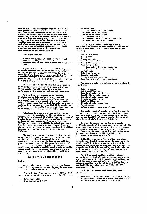
carried out. This translation process Is rarely a straightforward one. Often the computer models can misrepresent the Intentions of the modeller In a plethora of subtle ways with the result that errors become very difficult to detect, especially after the program design and coding stage. This situation can be aggravated further by the choice of computer language used for the simulation. As an example, a poorly-structured language such as FORTRAN, although widely used for scientific applications, Is error-prone and not particularly well suited for specification of simulation studies.
This paper aims to: - explain the concept of model reliability and
software quality assurance, and - describe some of the various tools and techniques
used.
A general framework as well as a list of quality assurance concepts and Issues to assess the accept-abl IIty of simulation studies and hence to point out areas for their Improvements are given by Oren2'-5. A functional decomposition of model reliability is given In Fig. 1 to provide a guideline (rather than an exhaustive enumeration of the possibilities).
Model reliability can be regarded as a function of 1) performance of the computer code, and 2) quality of the model. Two attributes determine the performance of the code: correctness and robustness.
As a mathematical procedure, correctness involves: appropriate choice of algorithms and techniques, satisfying basic assumptions, ensuring true 'randomness* where needed, etc. As a computer program, correctness Implies that the code was properly designed In a top-down way, and that It Is modular so that changes can be easily Incorporated, thus resulting In an easily modifiable and maintainable code.
Robustness Is a measure of how well a program behaves under all possible run-time conditions. Its sensitivity to different (Including Incorrect) types of Inputs, formalisms, algorithms and equipment usage Is an important consideration. Even more Important perhaps is the program's ability to detect and recover from bad inputs and anomalous conditions. Traps or alarms for out-of-scope Indices, numerical Instability, Incorrect utilization, etc should be built-in features.
The qua t Ity of the model depends on Its realism as well as Its scope. The ease with which the model can be verified through decomposition and experimentation Is critical to judging how well the model represents real Ity. Its scope Is a measure of how applicable the model Is under various 'real' conditions. As such, a quality model should be easily understandable with the assumptions clearly stated, and, If at all possible. Its limitations explicitly qualIf led.
RELIABILITY IN A MODELLING CONTEXT Backqroupj
An Introduction to the complexity of the issues Involved In the construction and the# quality assurance of reliable models can be found In Oren ,
Figure 2 Identifies four groups of entitles which need to be evaluated In a simulation study. They are: - Conceptual model - Experimental conditions
- Behavior (data) - Real-system behavior (data) - Model behavior (data)
- Simulation software system - Computerized model - Computerized experimental conditions - Run-time simulation library
Each of the elements listed above can be evaluated with respect to some criteria. The set of criteria considered In this study consists of the following: - Goal of the study - . Real-system - Conceptual model - Experimental conditions - Real-system behavior - Behavior of model
- Same model, different scenarios - Another model, same scenarios
- Another model - Modelling formalism - Computerized model - Software engineering norms - Numerical and statistical techniques
The possible model evaluations which are given In Fig. 2 are*. - Model relevance - Model qualification - Behavioral model validity - Sensitivity of model behavior - Behavioral model comparison - Structural model validity - Model verification - Structural model comparison - Formal checks - Software quality assurance of model
One would expect of a model of which the quality can be measured - and thus assured - that means have been developed by which one can assess both realism and the eppl IcabI I Ity„of such a model. See Nance et a!.5, Turek et el.6, Oren7, and Zelgier8.
In order to assess the real Ism of a model, verifiable aspects of the model must be validated. The more aspects validated, the higher the assured degree of realism* Validation can be done by conducting experiments on the model and on the real-system under the same experimental conditions which can be formalized by exprlmentel frames .
Validation problems arise In situations where adequate experimental frames cannot be constructed to provide sufficient details against which certain facets of the model can be checked. The problems thus encountered, their interconnection and their relation with systems and modelling "style" are treated In a more exhaustive way In Elzas .
Apart from model-real Ism, another relevant matter In the context of waste management pertains to the applicability of certain models In situations for which the models were not originally Intended, The relevant question here Is not so much one of marginal applicability but rather applicability with some assurance of fidelity.
To be able to assess such questions, models should be: - understandable by users other than the "original
manufacturers'*, (this Is critical for peer review of models and experimental conditions),
2
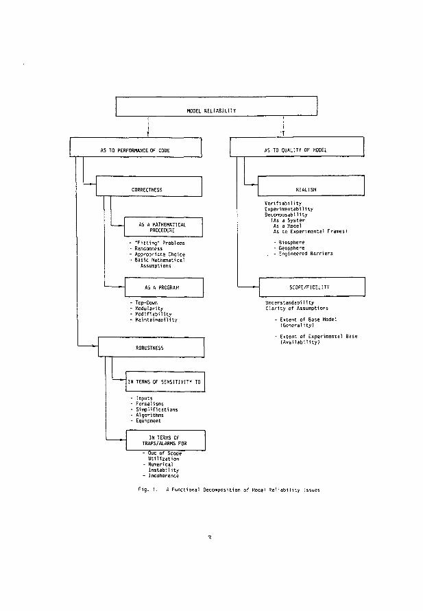
MODEL R E L I A B I L I T Y
A S TO PERFORMANCE OF CODE AS TO QUALITY- OF MODEL
AS A MATHEMATICAL PROCEDURE
"Fitting" Problems Randomness Appropriate Choice Basic Mathematical
Assumptions
Top-Down Modularity Modifiability Maintainability
R E A L I S M
Verifiability E x p e r i m e n t a l 1 ity Decomposability
(As a S y s t e m As a Model As tc Experimental F r a m e s ) - Biosphere - Geosphere
. - Engineered B a r r i e r s
SCOPE/FIDELITY
ROBUSTNESS
Understandabi H t y Clarity of A s s u m p t i o n s
- Extent of B a s e Model [Generality)
- Extent of Experimental Base (Availability)
IN TERMS OF SENSITIVITY TO
Inputs Forma H s m s Simplifications Algorithms Equipment
IN TERMS OF TRAPS/ALARMS FOR - Out of Scope
Utilization - Numerical
Instability - Incoherence
A Functional D e c o m p o s i t i o n of Moael Reliability Issues
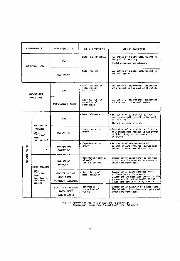
E V A L U A T I O N OF: WITH R E S P E C T T O : TYPE OF E V A L U A T I O N D E F I N I T I O N / C O M M E N T
C O N C E P T U A L MODEL
GOAL -.Model q u a l i f i c a t i o n - Evaluation of a model w i t h respect to
the goal o f the study. (Model r e l e v a n c e and a d e q u a c y )
R E A L - S Y S T E M - Model r e a l i s m - Evaluation o f a model w i t h r e s p e c t to
the real-system
EXPERIMENTAL GOAL
- Q u a l i f i c a t i o n of expe r i m e n t a l c o n d i t i o n s
- Evaluation of experimental c o n d i t i o n s with respect t o the goal of the study
CONDITIONS
COMPUTATIONAL MOOEL - A p p l i c a b i l i t y of
exp e r i m e n t a l c o n d i t i o n s
- Evaluation of exp e r i m e n t a l c o n d i t i o n s with respect t o the r e a l - s y s t e m
REAL-SYSTEM BEHAVIOR
(Data collected f r o m r e a l - s y s t e m )
GOAL - D a t a r e l e v a n c e - Evaluation of data c o l l e c t e d f r o m the
real-system with respect to the goal of the study (Data type, data a c c u r a c y )
REAL-SYSTEM BEHAVIOR
(Data collected f r o m r e a l - s y s t e m )
R E A L - S Y S T E M - I n s t r u m e n t a t i o n
e r r o r - Evaluation of d a t a c o l l e c t e d f r o m the
real-system w i t h r e s p e c t t o the source of data taking into a c c o u n t error tolerance
R (D
ATA)
R E A L - S Y STEM BEHAVIOR
(Data collected f r o m r e a l - s y s t e m )
EXPERIMENTAL C O N D I T I O N S
- E x p e r i m e n t a t i o n e r r o r
- Evaluation of the p r o c e d u r e of collecting data f r o m r e a l - s y s t e m w i t h respect to experimental c o n d i t i o n s
BEHA
VIO
M O D E L BEHAVIOR
R E A L - S Y S T E M BEHAVIOR
- B e h a v i o r a l v a l i d i t y of model (as a black b o x )
- Comparison of model b e h a v i o r and r e a l -system behavior o b s e r v e d or generated under same c o n d i t i o n s
(Data collected f r o m experimentation with m o d e l s )
BEHAVIOR OF SAME MODEL UNDER
DIFFERENT S C E N A R I O S
- S e n s i t i v i t y of model b e h a v i o r
- Comparison of model b e h a v i o r under different s c e n a r i o s w h e r e all conditions are kept s a m e except for t h e parameter and initial c o n d i t i o n for which sensitivity is being assessed
(Data collected f r o m experimentation with m o d e l s )
B E H A V I O R OF A N O T H E R MODEL U N D E R
SAME S C E N A R I O
- Behavioral c o m p a r i s o n of mo d e l s
- Comparison o f beh a v i o r of a model with the behavior of a n o t h e r model generated under same c o n d i t i o n s
F 1 g . 2a Spectrum of Possible Evaluations 1n Simulation (Conceptual Model, Experimental Conditions, Behavior)
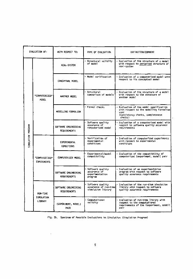
EVALUATION OF: WITH RESPECT TO: TYPE OF EVALUATION DEFINITION/COMMENT
REAL-SYSTEM - Structural validity of model
- Evaluation of the structure of a model with respect to perceived structure of real-system
CONCEPTUAL MODEL - Model verification - Evaluation of a computerized model with
respect to its conceptual model
"COMPUTERIZED-MODEL
ANOTHER MODEL - Structural comparison of models
- Evaluation of the structure of a model with respect to the structure of another model
MODELLING FORMALISM - Formal checks - Evaluation of the model specification
with respect to the modelling formalism used (Consistency checks, completeness checks)
1 PROGRAM
SOFTWARE ENGINEERING REQUIREMENTS
- Software quality assurance of computerized model
- Evaluation of a computerized model with respect to software quality assurance requirements
siMU
LATI
or
EXPERIMENTAL CONDITIONS
- Verification of experimental conditions
- Evaluation of computerized experiments with respect to experimental conditions
"COMPUTERIZED" EXPERIMENTS
COMPUTERIZED MODEL - Experimental/model compatibility
- Evaluation of the compatibility of computerized (experiment, model) pair
SOFTWARE ENGINEERING REQUIREMENTS
- Software quality assurance of experimentation program
- Evaluation of an experimentation program with respect to software quality assurance requirements
RUN-TIME
SOFTWARE ENGINEERING REQUIREMENTS
- Software quality assurance of run-time simulation library
- Evaluation of the run-time simulation library with respect to software quality assurance requirements
SIMULATION LIBRARY
(EXPERIMENT, M O D E L )
PAIR
- Computational validity
- Evaluation of run-time library with respect to the computational requirements of the (experiment, model) pair
Fig. Hb. Spectrum of Possible Evaluations in Simulation (Simulation Program)
5
- clearly documented as to the assumptions governing them,
- explicitly described In terms of the base model (the most extensive concept from which the actual model Is a simplification)9*10, end clearly qualifying Its general applicability,
- explicitly documented as to the availability of experiments to provide supportive evidence for the most general form of the model10.
The following highlight some of the problems associated with ensuring model reliability. Problems with Model Realism
To conduct a meaningful evaluation, one cannot avoid Investigating the effects of nuclear waste disposal on living systems yet nour technological design experience Is so far much too limited to capture the design (I.e. the model) of the principles of life-''.
In order to construct models when experimental evidence Is lacking, one has to rely on expert opinions, but "... for most of the data requirements the variance of expert opinion is considerable against such a background a deterministic analysis can be very misleading ..."1Z.
Problems with Model Validation
Although large portions of the systems that ere modelled In nuclear waste management are non-observable, models, nevertheless, have to be constructed and be utilized to predict and evaluate. "There Is a tremendous need on how to better apply known approaches and for new approaches to validate models of non-observable systems «.. unfortunately, this author believes the progress will be extremely slow"13.
The fact that new computational methods, are presently yielding better results with less resources, has led us to believe that running many computational experiments Is a substitute for the lack of experimental evidence. "However there Is a long way to go from the first Idealistic test example to practical application, and the effort of verification and validation of these advanced methods Is usually underestimated"1'*. Problems with Exnerlmental Verification
One of the foremost uses of experiments In connection with models Is to use the former to calibrate the latter; that Is, adjusting all relevant parameters In the model until It behaves in an "Identical fashion" to reality. As In most complex systems, this Is too complicated a procedure to carry out In one step. The generally accepted procedure is to perform the Identification by stepwise, deterministic, decomposition. It has recently been shown that In the presence of noise or other uncertainties In the system, this procedure does not lead to correct results, and there is need for a new approach.
Bekey et a!.15 presented a critique of the olo procedure and came to the conclusion that " .„ the theory of 1 dent iflabl1Ity needs to be reformulated If It is to be broadly applicable +o rea! world situations".
Another Issue In this context t& tna tack c sufficient experimental evidence to support alternative models. This 1» especially true tor a large set of systems which are tha result of the
Integration of other complex systems, as In the case mentioned In Murarka16: n «. the use of modelling to predict chemical Interactions and their effects on the face of leachates In the groundwater Is not yet well developed. As a result, reliable combined geohydro-chemtcal models are not yet available. Even after theoretical and computational problems are overcome, the availability of such models greatly depends on rigorous and multiple validation with high quality field data".
Problems with Subsystems/Decomposition
As has been mentioned earlier, the global quality of a model depends greatly on the quality of Its submodels. Thus, the strength of the whole system will not be greater than that of Its weakest link.
In the case of waste management, many weak links
- In subsystems which contain living material (see for example, Yates' ),
- in subsystems which describe interactions of a multiplicity of other systems, asfe for example. In the case of leaching (Murarka , Pescatore ), In subsystems Involving extremly long-term effects, as In very .slow decay and tectonic effects (e.g. Foley concludes that: " ... as previously discussed the results of the geological simulation model are not yet defensible . . . " ) .
Problems with Scope/FidelItv
In nuclear waste management one Is confronted with similar problems to those occurring In training simulators for man-made systems: the basic unpredictability of the complete future behavior of some device or system, including the most Improbable situations. A remark by Kerlln " ts relevant to this type of situation: "The fidelity needed In nuclear plant simulators Is not yet known. However regardless of the eventual conclusion on required fidelity. It is necessary to be able to fluent!fy simulator fidelity. It will never be possible to obtain "complete" validation because alt conditions simulated for training wilt not be experienced In any plant".
It Is Important, therefore, to establish clearly (in this "fidelity" measure) those situations In which a model Is applicable and those In which It Is not. International cooperation In exchanging experimental data can help_to assess the scope of models In a decisive way .
SOFTWARE QUALITY ASSURANCE
Computerization can hide and/or introduce various types of errors21 and scientific computation Is not Immune from It* .
Operating systems normally include hundreds of errors. In this article we concentrate on the errors of user programs. A 11st of the most common computerization errors (based on Howden**) Is given In Fig, 3,
fhe disadvantages of using faulty software are O D V I O U S In terms of Its reliability, usefulness end ultimate cost. The Importance o f ensuring the reliability of softwore f o r s c i e n t i f i c e p p l I c s t l e n h i* alto obvious, This p o i n t I s amply I l l u s t r a t e d by the application of computer s i m u l a t i o n s o f n u c l e a r w e s t * disposal s y s t e m s where t h e u l t i m a t a r « u l t c a n n o t be v e r i f i e d b u t depends rather o n computer!led e x t r a p o l a t i o n of p r « * n t hnowlsflaw *** u n d e r s t a m H n e
6
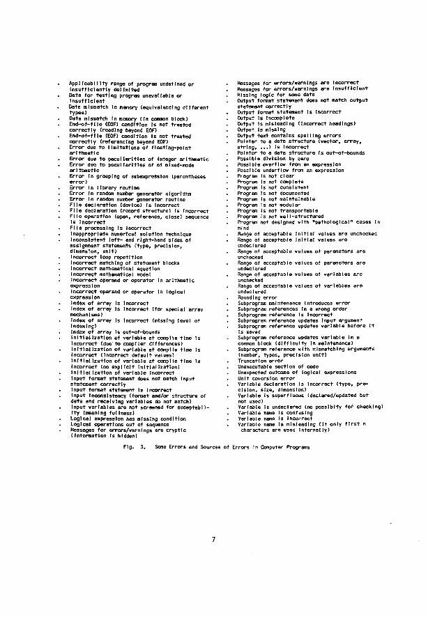
AppItcabllIty range of program undefined or Insufficiently delimited Data for testing program unavailable or Insufficient Data mismatch In memory (equivalenclng different types) Data mismatch In memory (In common block) End-of-flle (EOF) condition Is not treated correctly (reading beyond EOF) End-of-ftle (EOF) condition Is not treated correctly (referencing beyond EOF) Error due to limitations of floattng-polnt arithmetic Error due to peculiarities of Integer arithmetic Error due to peculiarities of of mixed-mode arithmetic Error In grouping of subexpression (parentheses error) Error In library routine Error In random number generator algorithm Error In random number generator routine File declaration (device) Is Incorrect File declaration (record structure) Is Incorrect File operation (open, reference, close) sequence Is Incorrect File processing Is Incorrect Inappropriate numerical solution technique Inconsistent left- and right-hand sides of assignment statements (type, precision, dimension, unit) Incorrect loop repetition Incorrect matching of statement blocks Incorrect mathematical equation Incorrect mathematical model Incorrect operand or operator In arithmetic expression Incorrect operand or operator In logical expression Index of array Is Incorrect Index of array Is Incorrect (for special array mechanisms) Index of array Is Incorrect (missing level of indexing) Index of array Is out-of-bounds Initialization of variable at compile time Is Incorrect tdue'to compiler differences) Initialization of variable at compile time Is Incorrect (Incorrect default values) Initialization of variable at compile time Is Incorrect (no explicit Initialization) Initialization of variable Incorrect Input format statement does not match Input statement correctly Input format statement Is Incorrect Input Inconsistency (format and/or structure of data end receiving variables do not match) Input variables are not screened for acceptability (meaning fullness) Logical expression has missing condition Logical operations out of sequence Messages for errors/warnings are cryptic (Information Is hidden)
Messages for errors/warnings are Incorrect Messages for errors/warnings are Insufficient Missing logic for some data Output format statement does not match output statement correctly Output format statement Is Incorrect Output Is Incomplete Output Is misleading (Incorrect headings) Output Is missing Output text contains spelling errors Pointer to a data structure (vector, array, string, ...) Is Incorrect Pointer to a data structure Is out-of-bounds Possible division by zero Possible overflow from an expression Possible underflow from an expression Program is not clear Program Is not complete Program is not consistent Program Is not documented Program is not maintainable Program i s not modu I ar Program is not transportable Program Is not we Il-structured Program not designed with "pathological" cases In mind Range of acceptable Initial values are unchecked Range of acceptable Initial values are undeclared Range of acceptable values of parameters are unchecked Range of acceptable values of parameters are undeclared Range of acceptable values of variables are unchecked Range of acceptable values of variables are undeclared Rounding error Subprogram maintenance introduces error Subprogram references In a wrong order Subprogram reference Is Incorrect Subprogram reference updates Input argument Subprogram reference updates variable before it Is saved Subprogram reference updates variable In a common block (difficulty In maintenance) Subprogram reference with mismatching arguments (number, types, precision unit) Truncation error Unexecutable section of code Unexpected outcome of logical expressions Unit coversIon error Variable declaration Is Incorrect (type, precision, size, dimension) Variable Is superfluous (declared/updated but not used) Variable is undeclared (no posslblty tor checking) Variable name Is confusing Variable name Is Incorrect Variable name Is misleading (If only first n characters are used internally)
Fig. 3. Some Errors and Sources of Errors In Computer Programs
7
of relevant natural processes and conditions far Into the future. Verification
Just as conceptual models must be checked through the process of validation to ensure they reflect the real-system, so computerized models must also be checked through program verification to ensure that they represent the conceptual models faithfully. Software quality assurance comprises all aspects of ensuring the "correctness'1 of software. It Includes not only "verification" of the finished program but starts from specification of the program requirements, design, continues through code Implementation, and finally ends with program testing. Requirements Verification
In the program requirements verification stage, the problem to be coded Is carefully analysed to see what exactly Is required of It. For Instance, unusual routines may,be needed to solve a mathematical problem, a particularly large block of memory Is required, complex Input/output operations are Involved, or data have to be displayed In some special fashion, etc These requirements are then assessed In terms of their Impact and/or limitations with respect to the proposed software to be used and/or the system environment. A critical assessment at this stage may determine the correct and optimum choice of the programming language, the type of computer, and ancillary software and system support, thus avoiding those tedious problems often associated with system/software limitations and the use of Inadequate and inappropriate tools.
Deslon Verification
In this phase, the framework of the software Is built, and the design Is evaluated with respect to Its ability to meet the requirements set in the previous phase. The design Is also checked for internal consistency, logic structures. Input/output operations, efficient memory allocations and other operational parameters. The designing and the verification process may undergo several Iterations and a few prel Imlnary designs may be produced before a final, detailed one Is completed. It Is important, at the end of this stage, that the design be as definitive as possible and that the documentation be unambiguous and attain a quality such that coding may commence. Code Verification
After the coding has been done In accordance with the design specifications, the code must undergo Inspection and analysis. Typing errors, syntax errors, and other "bugs" should be revealed and corrected to ensure error-free compilation. Variables and algorithms are checked for consistency, mathematical models are examined to ensure correct representation, and data bases are tested for their Integrity. The code, either In whole or In parts, is Inspected and assessed to ensure that requirement and design specifications are met. The tools and techniques available at this stage vary a great deal In their complexity and sophistication. They range from simple visual Inspection of code to fully automated dynamic analysis.
Program Testing/Proving The last stage of verification Involves testing
the program. The emphasis Is on detecting and correcting the subtle errors arising from faulty logic
constructs, incorrect module Interfacing, unsatisfied conditions, Invalid data input, faulty branching and control flow, etc Errors of this type are not always readily obvious because they are revealed only under certain conditions or sets of pathological circumstances. Generally speaking, the larger and more complex a program Is, the greater are the chances for the presence of subtle errors. It Is Imperative, therefore, that the software be systematical ly exercised under carefully controlled circumstances with the aid of various specialized tools. It must be noted that even under the most Ideal situation where program testing was systematically and rigourously . applied, program "correctness" cannot be assured but can only serve to guarantee the absence of obvious "bugs". Correctness can be assured only through "program proofs" which are analogues to proofs used In mathematical theorems. An overview of this subject can be found In Adrton et at.
Regarding the performance of the coded model, a great number of questions can be raised which pertain directly to the problems of quality assessment.
Firstly, while one would expect such a simulation program to be correct, the term correctness has a dual connotation. The mathematical procedures which have been chosen should inherently yield the right results. The program Itself also should have the appropriate structure for assessment of possible errors In functioning (correctness proofs being more or less out of the question for this type of extremely complex program).
Secondly, robustness is to be assessed. There must be some assurance that the code will behave in a predictable manner with any Input data under the appropriate system environment (for example. Rice ). Alarms and traps should be built-in features to Indicate Improper behavior of the simulation code2*.
The performance of the code with respect to correctness and robustness can be seen In Fig. 1.
On correctnessP we point out that some routine approaches to certain mathematical problems often fall to yield elegant solutions to real problems of common systems.
Some examples are offered: - Standard distributions are neat, but seldom found
In real data^ . - Pseudo-random numbers are easily generated but
often are not really random, especjel I* when time and space constraints play a role ' . On robustness, the following are pointed out:
- The effect of the random number generator seed and randomness synthetically applied to variables In general can obscure the real results, unless an enormous amount of simulation runs are sampled2".
- The same applies to other tnltlIIzatlon values, scenarios and model details which can cause anomalous behavior In the model that l&jiot a true representation of the real-system**,
- Adequate simplification con be very useful If It helps to display the most Important features without clouding the model with excessive details. However, It Is still up to the "clever modeller" to formulate such a model as there is no clear-cut procedure to follow .
8
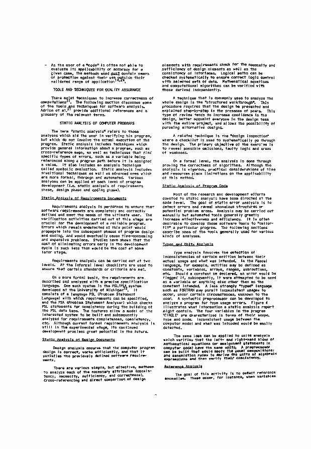
- As the user of a "code" Is often not able to evaluate Its applicability or accuracy for a given case, the methods used must contain means of protection against their use outside their validated range of opplIcatlon1**24,
TOOLS AND TECHNIQUES FOR QUALITY ASSURANCE There exist techniques to Increase correctness of
computations31. The following section discusses some of the tools and techniques for software analysis. Adrlon et al.21 provide additional references and a glossary of the relevant terms.
STATIC ANALYSIS OF COMPUTER PROGRAMS The term "static analysis" refers to those
analyses which aid the user In verifying his program, but which do not Involve the actual execution of the program. Static analysis Includes techniques which provide general Information about a program, such as cross-reference maps, as well as techniques that find specific types of errors, such as a variable being referenced along a program path before It Is assigned a value. It also Includes an analysis technique called symbolic evaluation. Static analysis Includes traditional techniques as well as advanced ones which are more formal, thorough and automated. Various analyses can be applied at each level of program development (I.e. static analysis of requirements phase, design phase and coding phase). Static Analysis of Requirements Documents
Requirements analysis Is performed to ensure that software requirements are completely and correctly defined and meet the needs of the ultimate user. The verification activities carried out at this stage are crucial for the development of a reliable program. Errors which remain undetected at this point would propagate Into the subsequent phases of program design and coding, and would eventually cause time-consuming and expensive problems. Studies have shown that the cost of eliminating errors early In the development cycle is much less than would be the cost at some later stage.
Requirements analysis can be carried out at two levels. At the Informal level checklists are used to ensure that certain standards or criteria are met.
On a more formal basis, the requirements are., described and analyzed with a precise specification language. One such system Is the PSL/PSA system developed at the University of Michigan32, It consists of a language PSL (Problem Statement Language) with which requirements can be specified, and the PSA (Problem Statement Analyser) which checks PSL statements for consistency during the building of the PSL data base. The features allow a model of the Interested system to be built and subsequently analyzed for requirements completeness, consistency, etc Although current formal requirements analysis is sti!! In the experimental stage. Its continued development promises great potential In the future.
Static Analysis of Design Documents
Design analysis ensures that the computer program design Is correct, works efficiently, and that It satisfies the previously defined software require* ments.
There are various simple, but effective, methods to analyze each of the necessary attributes (consistency, necessity, sufficiency, and correctness). Cross-referencing and direct comparison of design
elements with requirements check for the necessity and sufficiency of design elements as well as the consistency of Interfaces. Logical paths can be checked systematically to ensure correct logic control with selected sets of data. Mathematical equations and computational algorithms can be verified with those derived Independently.
A technique that Is commonly used to analyze the whole design is the "structured walkthrough". This procedure requires that the design be presented and explained step-by-step In the presence of peers. This type of review tends to Increase confidence In the design, better acquaint everyone In the design team with the entire project, and allows the possibility of pursuing alternative designs.
A related technique Is the "design Inspection" where a checklist Is used to systematically go through the design. The primary objective of the exercise Is to reveal possible omissions, faulty logic and areas of weakness.
On a formal level, the analysis Is done through proving the correctness of algorithms. Although the analysis Is vigorous, practical considerations of time and resources place limitations on the applicability of this method. Static Analysis of Program Code
Most of the research and development efforts devoted to static analysis have been directed at the code level. The goal of static error analysis Is to detect errors and reveal anomalous structures or potential problem areas. Analysis may be carried out manual ly but automated tools general ly greatly Increase effectiveness and efficiency. Jt Is often desirable to develop those software tools to "tatlor-flt" a particular program. The following sections describe some of the tools generally used for various kinds of analyses. Tvoes and Units Analysis
Type analysis involves the detection of Inconsistencies of certain entitles between their actual usage and what was Intended. In the Pascal language, for example, entitles may be defined as constants, variables, arrays, ranges, subroutines, etc Should a constant be declared, an error would be flagged If, subsequently. It were attempted to be used as a variable or anything else other than as the constant Intended. A less strongly "typed" language such as FORTRAN may permit Inconsistent usages to occur, under certain circumstances, unknown to the user. A syntactic preprocessor can be developed to analyze a program for type usage errors. Figure 4 Illustrates what Information a static analysis report might contain. The four variables In the program 'CIRCLE' are characterized In terms of their scope, type and mode. Inconsistent usage between the computer model and what was Intended would be easily detected.
The same Idea can be applied to units analysis which verifies that the left- and right-hand sides of mathematical equations (or osalgnment statements In computer code) have the same unite, A preprocessor con be built that would epplv the ysuol compositional and emulation rules to derive the units of slgebroic expressions and then verify their consistency.
Reference A n a l y s e
The goal of this activity is to detect reference anomalies. These occur, for Instance, when vorlobleH
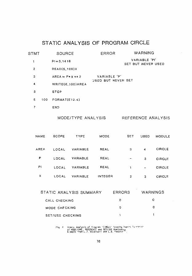
STATIC ANALYSIS OF PROGRAM CIRCLE
STMT SOURCE ERROR WARNING
1 P I - 3 . 1 4 1 6 VARIABLE 'PI-SET BUT NEVER USED
2 R E A D ( 5 , 1 0 0 ) X
3 A R E A = P * X * * 2 VARIABLE 'P ' USED BUT NEVER SET
4 W R I T E ( 6 , 1 0 0 ) A R E A
5 STOP
6 100 FORMATCE12.4)
7 END
MODE/TYPE ANALYSIS REFERENCE ANALYSIS
NAME SCOPE TYPE MODE SET USED MODULE
AREA LOCAL VARIABLE REAL 3 4 CIRCLE
P LOCAL VARIABLE REAL - 3 CIRCLE
PI LOCAL VARIABLE REAL 1 _ CIRCLE
X LOCAL VARIABLE INTEGER 2 3 CIRCLE
STATIC ANALYSIS SUMMARY
CALL CHECKING
MODE CHECKING
S E T / U S E CHECKING
F i g . 4 . S t a t u A n a l y s i s of ?i-ocr«e 'CIRCLE' b l .Ov, i r , s k*Br.-t •;,•!-*•>«•. of M O D E / T Y P E . REFERENCE ana SET/USE Analyses,! Example f^om L.J. Oste<-v,ei 1 and L . D . r o s d i O .
ERRORS WARNINGS
o 0
0 o
1 1
1 0
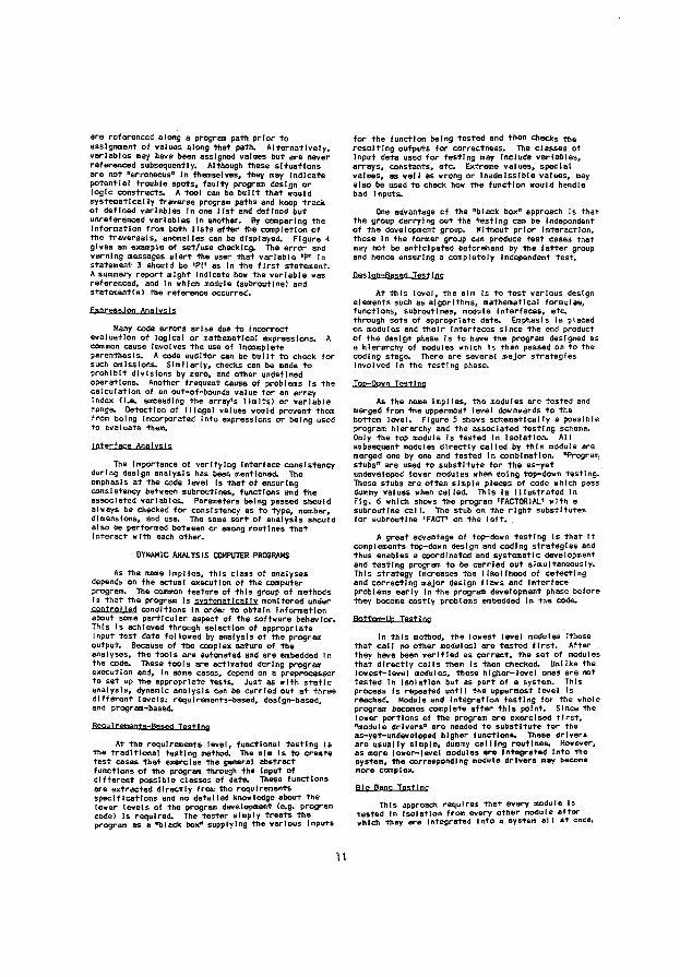
are referenced along a program path prior to assignment of values along that path. Alternatively, variables may have been assigned values but are never referenced subsequently. Although these situations are not "erroneous0 In themselves, they may Indicate potential trouble spots, faulty program design or logic constructs. A tool can be built that would systematically traverse program paths and keep track of defined variables In one list and defined but unreferenced variables In another. By comparing the Information from both lists after the completion of the traversals, anomalies can be displayed. Figure 4 gives an example of set/use checking. The error and warning messages alert the user that variable 'P* In statement 3 should be *PI' as In the first statement. A summary report might Indicate how the variable was referenced, and In which module (subroutine! and statement(s) the reference occurred.
Fxoresslon Analysis
Many code errors arise due to Incorrect evaluation of logical or mathematical expressions. A common cause Involves the use of incomplete parenthesis. A code auditor can be built to check for such omissions. Similarly, checks can be made to prohibit divisions by zero, and other undefined operations. Another frequent cause of problems Is the calculation of an out-of-bounds value for an array index (I.e. exceeding the array's limits) or variable range. Detection of Illegal values would prevent them from being Incorporated Into expressions or being used to evaluate them.
interface Analysis
The Importance of verifying Interface consistency during design analysis has been mentioned. The emphasis at the code level is that of ensuring consistency between subroutines, functions and the associated variables. Parameters being passed should always be checked for consistency as to type, number, dimensions, and use. The same sort of analysis should also be performed between or among routines that Interact with each other.
DYNAMIC ANALYSIS COMPUTER PROGRAMS
As the name implies, this class of analyses depends on the actual execution of the computer program. The common feature of this group of methods Is that the program Is systematical Iv monitored under control led conditions In order to obtain Information about some particular aspect of the software behavior. This Is achieved through selection of appropriate input test data followed by analysis of the program output. Because of the complex nature of the analyses, the tools ere automated and are embedded In the code. These tools are activated during program execution and. In some cases, depend on a preprocessor to set up the appropriate tests. Just as with static analysis, dynamic analysis can be carried out at three different levels: requirements-based, design-based, and program-based.
Requirements-Based Ttt«T|nfl
At the requirements level, functional testing is the traditional testing method. The aim is to create test cases that exercise the general abstract functions of the program through the Input of different possible classes of date. These functions ere extracted directly from the requirements specifications and no detailed knowledge about the lower levels of the program development (e.g. program code) Is required. The tester simply treats the program as a "black box" supplying the various Inputs
for the function being tested and then checks the resulting outputs for correctness. The classes of Input data used for testing may Include variables, arrays, constants, etc Extreme values, special values, as well as wrong or Inadmissible values, may also be used -to check how the function would handle bad Inputs,
One advantage of the "black box" approach Is that the group carrying out the testing can be Independent of the development group. Without prior Interaction, those in the former group can produce test cases that may not be anticipated beforehand by the latter group and hence ensuring a completely Independent test.
Design-Based Testing At this level, the aim is to test various design
elements such as algorithms, mathematical formulae, functions, subroutines, module interfaces, etc through sets of appropriate date. Emphasis Is placed on modules and their Interfaces since the end product of the design phase is to have the program designed as a hierarchy of modules which Is then passed on to the coding stage. There are several major strategies Involved In the testing phase.
TOD-Oown Testing
As the name implies, the modules are tested and merged from the uppermost level downwards to the bottom level. Figure 5 shows schematically a possible program hierarchy and the associated testing scheme. Only the top module Is tested In Isolation. All subsequent modules directly called by this module are merged one by one and tested In combination. "Program stubs" are used to substitute for the as-yet undeveloped lower modules when doing top-down testing. These stubs are often simple pieces of code which pass dummy values when called. This Is Illustrated In Fig. 6 which shows the program 'FACTORIAL* with a subroutine call. The stub on the right substitutes for subroutine 'FACT* on the left. .
A great advantage of top-down testing Is that it complements top-down design and coding strategies and thus enables a coordinated and systematic development and testing program to be carried out simultaneously. This strategy Increases the likelihood of detecting and correcting major design flaws and Interface problems early in the program development phase before they become costly problems embedded In the code.
Bottom-Up Testing
In this method, the lowest level modules (those that call no other modules) are tested first. After they have been verified as correct, the set of modules that directly calls them Is then checked. Unlike the lowest-level modules, these higher-level ones are not tested In Isolation but as part of a system. This process Is repeated until the uppermost level is reached. Module and Integration testing for the whole program becomes complete after this point. Since the lower portions of the program are exercised first, "module drivers" are needed to substitute for the as-yet-undeveloped higher functions. These drivers are usually simple, dummy calling routines. However, as more lower-level modules are Integrated Into the system, the corresponding module drivers may become more complex.
Rip Bang Testing This approach requires that every module is
tested In Isolation from every other module after which they are Integrated Into a system ell at ones.
11
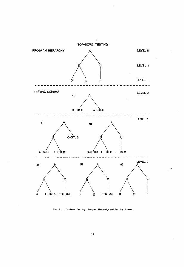
TOP-DOWN TESTING
PROGRAM HIERARCHY A LEVEL 0
LEVEL 1
LEVEL 2
TESTING SCHEME LEVEL 0
B-STUB C-STUB STUB
2) 3)
C-STUB B / \
D-STUB E-STUB \
D-StUB E-STUB F-STUB
LEVEL 1
4) 5) 6)
A
D E-STUB F-StUB D E F-STUB D
LEVEL 2
A
F1g. 5. *Top-0own Testing' Program Hierarchy and Testing Scheme
1 ?
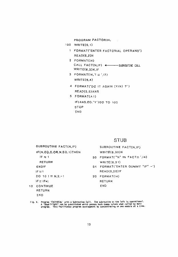
PROGRAM FACTORIAL
100 W R I T E ( 6 , 1 )
1 F O R M A T C E N T E R FACTORIAL O P E R A N D ' )
R E A D ( 5 , 2 ) N
2 F O R M A T 0 4 )
CALL F A C T ( N . I F ) « SUBROUTINE CALL W R I T E ( 6 , 3 ) N , I F
3 F O R M A T ( l 4 , ' ! - ',17)
W R I T E ( 6 . 4 )
4 FORMATC'DO IT AGAIN ( Y / N ) ? ' )
R E A D ( 5 , 5 ) A N S
5 FORMATC A 1)
I F ( A N S . E Q . ' Y ' ) G O TO 100
STOP
END
STUB SUBROUTINE FACT(N. IF ) SUBROUTINE F A C T ( N . I F )
W R l T E ( 6 . 3 0 ) N
3 0 F O R M A T C ' N " IN F A C T = '.14)
WRITEC6.3 1)
3 1 FORMATCENTER OUMMY " I F '
R E A D ( 5 , 2 0 ) I F
I F ( N . E Q . 0 . O R . N . E Q . 1 ) T H E N
IF = 1
RETURN ENDIF
IF = 1
DO 10 I — N .2 , -1 20 FORMAT( l4 )
I F = I F i l RETURN
CONTINUE END
RETURN
END
. 6. Program 'FACTORIAL' with a Subroutine Call. The subroutine on the left is operational. A 'StubMright! can be substituted which passes back dummy values when called by main program. This facilitates program development by concentrating on one module at a time.
13
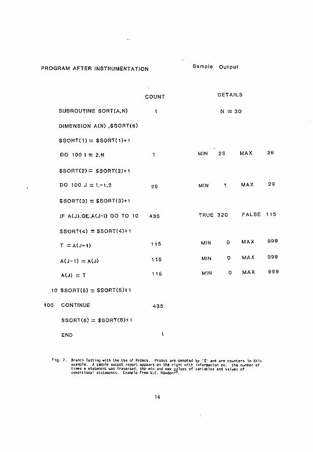
PROGRAM AFTER INSTRUMENTATION S a m p l e O u t p u t
COUNT D E T A I L S
1
29
SUBROUTINE SORT(A.N) 1
DIMENSION A(N) , $ S 0 R T ( 6 )
S S O R T ( 1 ) = $ S O R T ( 1 ) + 1
DO 100 I = 2,N
$ S O R T ( 2 ) = $ S O R T ( 2 ) + 1
DO 100 J = 1,-1,2
S S O R T ( 3 ) = $ S O R T ( 3 ) + 1
IF A(J ) .GE.A(J -0 GO TO 10 4 3 5
S S O R T ( 4 ) = S S O R T ( 4 ) + 1
T = A ( J - 1 )
A ( J - 1 ) = A(J)
A(J) = T
10 $ S O R T ( 5 ) = $ S O R T ( 5 ) + 1
100 CONTINUE
SSORT(6 ) = $ S O R T ( 6 ) + 1
END
N = 3 0
115
115
1 15
4 3 5
1
MIN 29 MAX 29
MIN 1 MAX 29
TRUE 3 2 0 FALSE 115
MIN 0 MAX 9 9 9
MIN 0 MAX 9 9 9
MIN 0 MAX 9 9 9
Fig. 7. Branch Testing with the Use of Probes. Probes are denoted by '$' and are counters in this example. A sample output report .appears on the right with information on: the number of times a statement was traversed, the min and max values of variables and values of conditional statements. Example from W.E. HowdenJO.
14
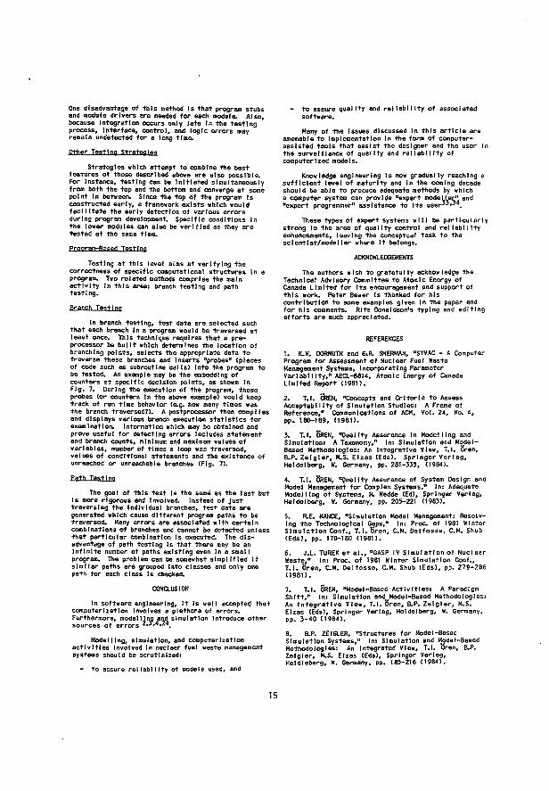
One disadvantage of this method Is that program stubs and module drivers are needed for each module. Also, because Integration occurs only late In the testing process. Interface, control, and logic errors may remain undetected for a long time. Other Testing Strategies
Strategies which attempt to combine the best features of those described above ere also possible. For Instance, testing can be Initiated simultaneously from both the top and the bottom and converge at some point In between. Since the top of the program Is constructed early, a framework exists which would facilitate the early detection of various errors during program development. Specific conditions in the lower modules can also be verified as they are tested at the same time. Frooram-Based Testing
Testing at this level alms at verifying the correctness of specific computational structures In a program. Two related methods comprise the main activity In this area: branch testing and path testing.
Branch Testing
In branch testing, test data are selected such that each branch In a program would be traversed at least once. This technique requires that a preprocessor be built which determines the location of branching points, selects the appropriate data to traverse these branches and Inserts "probes" (pieces of code such as subroutine calls) Into the program to be tested. An example may be the embedding of counters at specific decision points, as shown In Fig. 7. During the execution of the program, these probes (or counters In the above example) would keep track of run time behavior (e.g. how many times was the branch traversed?). A postprocessor then complies and displays various branch execution statistics for examination. Information which may be obtained and prove useful for detecting errors Includes statement and branch counts, minimum and maximum values of variables, number of times a loop was traversed, values of conditional statements and the existence of unreached or unreachable branches (Fig. 7). Path Testing
The goal of this test Is the same as the last but Is more rigorous and Involved. Instead of just traversing the Individual branches, test data are generated which cause different program paths to be traversed. Many errors are associated with certain combinations of branches and cannot be detected unless that particular combination Is executed. The disadvantage of path testing Is that there may be an Infinite number of paths existing even In a small program. The problem can be somewhat simplified If similar paths are grouped Into classes and only one path for each class Is checked.
CONCLUSION
In software engineering. It Is well accepted that computerization Involves a plethora of errors. Furthermore, modelling and simulation Introduce other sources of errors 2,3,4,24
Modelling, simulation, and computerization activities Involved In nuclear fuel waste management systems should be scrutinized: - to assure reliability of models used, and
- to assure quality and reliability of associated software. Many of the Issues discussed In this article are
amenable to Implementation In the form of computer-assisted tools that assist the designer and the user In the surveillance of quality and reliability of computerized models.
Knowledge engineering Is now gradually reaching a sufficient level of maturity and In the coming decade should be able to produce adequate methods by which a computer system can provide "expert nodeLLer" and "expert programmer" assistance to Its user 3 3' 3 4.
These types of expert systems will be particularly strong In the area of quality control and reliability enhancements, leaving the conceptual task to the scientist/modeller where It belongs.
ACKNOWLEDGEMENTS The authors wish to gratefully acknowledge the
Technical Advisory Committee to Atomic Energy of Canada Limited for Its encouragement and support of this work. Peter Bewer Is thanked for his contribution to some examples given In the paper and for his comments. Rita Donaldson's typing and editing efforts are much appreciated.
REFERENCES 1. K.W. DORMUTH and G.R. SHERMAN, "SYVAC - A Computer Program for Assessment of Nuclear Fuel Waste Management Systems, Incorporating Parameter Variability," AECL-6814, Atomic Energy of Canada Limited Report (1981). 2. T.I. ÏJREN, "Concepts and Criteria to Assess Acceptability of Simulation Studies: A Frame of Reference," Communications of ACM, Vol. 24, No. 4, pp. 180-189, (1981). 3. T.I. OREN, •'Quality Assurance In Modelling and Simulation: A Taxonomy," In: Simulation and Model-Based Methodologies: An Integrative View, T.I. Oren, B.P. Zeigler, M.S. Elzes (Eds). Springer Verlag, Heidelberg, W. Germany, pp. 281-335, (1984).
4. T.I. OREN, "Quality Assurance of System Design and Model Management for Complex Systems," In: Adequate Modelling of Systems, H. Wedde (Ed), Springer Verlag, Heidelberg, W. Germany, pp. 205-221 (1983).
5. R.E. NANCE, "Simulation Model Management: Resolving the Technological Gaps," In: Proc of 1981 Winter Simulation Conf., T.l.bVen, CM. Delfosse, CM. 5hub (Eds), pp. 170-180 (1981). 6. J.L. TUREK et al., "GASP IV Simulation of Nuclear Waste," In: Proc of 1981 Winter Simulation Conf., T.I. Oren, CM. Delfosse, CM. Shub (Eds), pp. 279-286 (1981). 7. T.I. OREN, "Model-Based Activities: A Paradigm Shift," In: Simulation andMModel-Based Methodologies: An Integrative View, T.I. Oren, B.P. Zeigler, M.S. Elzes (Eds), Springer Verlag, Heidelberg, W. Germany, pp. 3-40 (1984). B. &P. ZEIGLER, "Structures for Model-Based Simulation Systems," In: Simulation and Model-Based Methodologies: An Integrated View, T.l. Oren, B.P. Zeigler, M.S. Elzas (Eds), Springer Verlag, Heldleberg, W. Germany, pp. 185-216 (1984).
15
9. B.P. ZEIGLER, "Structuring Principles for Multi-faceted System Model I Ing," In: Methodology In Systems Modelling and Simulation, B.P. Zeigler, M.S. Elzas, G.J. Kllr, T.I. 'Oren <Eds), North-Holland, Amsterdam, pp. 93-135 (1979).
10. M.S. ELZAS, "Systems Paradigms as Reality Mappings," In: Simulation and Model-Based Methodologies: An Integrative View, T.I. 5ren, ELP, Zeigler, M.S. Elzas (Eds), Springer Verlag, Heldelberg, W. Germany, pp. 41-67 (1984).
11. F.E. YATES, "A Skeleton of Physical Ideas for the Dynamics of Complex Systems," In: Proc of 10th IMACS World Congress, W.F. Ames (Ed), Montreal, PQ, Canada, Vol. 2, pp. 190-193 (1982).
12. P.E. LOVE, "Stochastic Analysis In Energy Planning, In: Proc of 10th IMACS World Congress, W.F. Ames (Ed), Montreal, PQ, Canada, Vol. 4, pp. 32-34 (1982).
13. R.G. SARGENT, "Simulation Model Validation," In: Simulation and Model-Based Methodologies: An Integrative View, T.I. Sren, B.P. Zeigler, M.S. Elzas (Eds), Springer Verlag, Heldelberg, W. Germany, pp. 537-555 (1984). 14. W. FRISCH, "Simulation of Transients In Light Water Reactors - Oestre and Reality" In: Proc of 10th IMACS World Congress, W.F. Ames (Ed), Montreal, PQ, Canada, Vol. 4, pp. 95-97 (1982). 15. G.A. BEKEY et al., "Is Deterministic Iden-tlflablllty a Fraud?" In: Proc of 10th IMACS World Congress, W.F. Ames (Ed), Montreal, PQ, Canada, Vol. 2, pp. 211-213 (1982). 16. I.P. MURARKA, "Seohydrochemlcal Models: Uses In the Electric Utility Industry," In: Proc of 10th IMACS World Congress, W.F. Ames (Ed), Montreal, PQ, Canada, Vol. 2, pp. 277-279 (1982).
17. C PESCATORE et al., "The Use of Asymptotic Expansions to Determine the Short- and Long-Terra Leaching Behaviors of Nuclear Waste Forms," In: Proc of 10th IMACS World Congress, W.F. Ames (Ed), Montreal, PQ, Canada, Vol. 2, pp. 283-285 (1982). 18. MX. FOLEY et al., "The Development of a Geologic Simulation Model," In: Proc. of 10th IMACS World Congress, W.F. Ames (Ed), Montreal, PQ, Canada, Vol. 2, pp. 288-290 (1982). 19. T.W. KERL IN, "Validation of Models for Nuclear Reactor Simulators," In: Prcc of 10th IMACS World Congress, W.F. Ames (Ed), Montreal, PQ, Canada, Vol. 2, pp. 98-100 (1982). 20. A.K. AGRAWAL, "Simulation of Liquid Metal Fast Breeder Reactors," in: Proc of 10th IMACS World Congress, W.F. Ames (Ed), Montreal, PQ, Canada, Vol. 2, pp. 111-112 (1982). 21. W.R. AORI0N, H.A. BRANSTAO, J.C. CHERNIAVSKY, "Validation, Verification, and Testing of Computer Software," ACM Computing Surveys, Vol. 14, No. 2, pp. 159-192 (1982). 22. W.E. HOWOEN, "Val l'dation of Scientific Programs", ACM Computing Surveys, Vol. 14, No. 2, pp. 193-227 (1982).
23. J.R. RICE, "Machine and Compiler Effects on the Performance of Elliptic PDE Software," In: Proc of 10th IMACS World Congress, W.F. Ames (Ed), Montreal, PQ, Canada, Vol. 1, pp. 446-448 (1982). 24. M.S. aZAS, "What Is Needed for Robust Simulation," In: Methodology In Systems Modelling and Simulation, B.P. Zeigler, M.S. Elzas, G.J. Kllr, T.I. Oren (Eds), North-Holland, Amsterdam, pp. 57-91 (1979).
25. 8.L. FOX, "Fitting 'Standard' Distributions to Data Is Necessarily Good: Dogma or Myth?" In: Proc of 1981 Winter Simulation Conf., T.I. Oren, CM. Delfosse, CM. Shub (Eds), pp. 305-309 (1981).
26. E.J. DUDEWICZ et al., "Modern and Easy Generation of Random Numbers - Testing of Random Numbers Using TESTRAND," In: Proc. of 10th IMACS World Congress, W.F. Ames (Ed), Montreal, PQ, Canada, Vol. 2, pp. 133-135 (1982). 27. L.E. RAMSHAW et al., "A Note on Random Number Generation Under Time and Space Constraints," In: Proc of 10th IMACS World Congress, W.F. Ames (Ed), Montreal, PQ, Canada, Vol. 2, pp. 139-141 (1982). 28. S.D. TULJAPURKAR et al., "Fisheries In an Uncertain World: Age-Structured, Density-Dependent, Stochastic Models," In: Proc 1984 Summer Computer Simulation Conf., Society for Computer Simulation, L B Jolla, CA, Vol. 2, pp. 883-886 (1984). 29. P.B. ABRAMS0N, "Calculatlonal Limitations In PKR System Simulation," In: Proc of 10th IMACS World Congress, W.F. Ames (Ed), Montreal, PQ, Canada, Vol. 4, pp. 151-153 (1982).
30. D.R. WILLIAMS, "Blofluld Speclatlon Models Correlated with Pharmaceutical Activity," In: Proc 1984 Summer Computer Simulation Conf., Society for Computer Simulation, La Jolla, CA, Vol. 2, pp. 792-797 (1984).
31. H. BÖHM, "Evaluation of Arithmetic Expressions with Maximum Accuracy," In: A New Approach to Scientific Computation, U.W. Kullsh, W.L. Mlranker (Eds), Academic Press, New York, pp. 121-137 (1983). 32. D. TEICHR0EW, E.A. HERSHEY III, "PSL/PSA: A Computer-Alded Technique for Structured Documentation and Analysis of Information Processing Systems," IEEE Trans. Software Eng., Vol. SE-3, No. 1, pp. 41-48 (1977).
33. T.I. OREN, "Computer-Alded Modelling Systems," In: Progress In Modelling and Simulation, F.E. Cellier (Ed), Academic Press, London, England, pp. 189-203 (1982). 34. M.S. ELZAS, T.I. OREN, B.P. ZEIGLER (Eds), Knowledge-Based Modelling and Slmutatlon Methodologies, North-Holland, Amsterdam (In Preparation). 35. L.J. OSTERKEIL, L.D. F0S01CK, "OAVE - A Validation Error Detection Bnd Documentation System for Fortran Programs," Software, Practice and Experience, Oct.-Dec 1976. 36. W.E. H0WDEN, "A Survey of Dynamic Analysis Methods," In: Tutorial: Software Testing and Validation Techniques, E. Miller and W.E. Howden (Eds) (1978).
3.2
Semantic Rules and Facts for An Expert Modelling and Simulation System
T.I. ÔREN
Department of Computer Science, University of Ottawa Ottawa, Ontario, Canada KIN 9B4
G. SHENG
McMaster University, GSB-216 Hamilton, Ontario L8S 4K1
Proceedings of the 12th 1MACS World Congress, Paris, July 18-22,1988, pp. 596-598

5DC SEMANTIC RULES AND FACTS FOR AN
EXPERT HOOSXLIHO AMD SIMULATION SXSTEH
Tuncer dren Computer Science Department
university of Ottawa Ottawa, Ontario LIN 9B4
Canada
Grant sheng Department of Chemical Engineering
McKaster University Hamilton, Ontario LBS 4K1
Canada
ABSTRACT
A list of about fifty semantic rules and facts are given relating to the specifications of static and dynamic structures of models, coupling, parameter seta, and experimentation. Th'ese facts and rules
) ore based on the methodology of modelling and simulation, (ii) can be extended to domain-specific applications, (111) are being Implemented in the MAG EST system, and <iv) can be incorporated into other advanced modelling and simulation environments.
IHTRODUCTIOH.
As expressed by Oren and Zeigler (1), conventional simulation techniques have three shortcomings when applied to large-scale modelling!
1) the conceptual framework is poor, 21 the man-machine interface is inadequate, 3) a lack of. necessary tools for effective
data and model management.
To"this list, a fourth may be addedt
4} lack of a quality assurance system to ensure the completeness, correctness and consistency in model formulation and subsequent computer implementation.
With respect to the first issue, dren'e work on the oesr language (2, 3) based on the axiomatic system theory of Wymore <4) and the simulation work of Zeigler (5, 6) have firmly established the conceptual framework under which simulation and modelling should be carried' out.
CEST is the first completely model-baaed simulation language and is a radical departure from other simulation languages in that specifications of the model are totally separate from the experimentation portion of the model.
A further enhancement to CEST which addresses Issues 2, 3 and 4, is the development of a prototype advisor system called MAGEST (Modelling Advisor and Certifier for CEST programs) (7). It la a knowledge-based modelling and simulation system which provides a user-oriented specification and certification environment for CEST. The current version of HAGEST, which is being implemented on the Sun system, has the ability to use two types of knowledge.
1] knowledge about the CEST structure and morphology*
2) incremental knowledge obtained from and about user specifications.
By using thia knowledge, MAtfEST can perform the following activities.
to assist the user in specifying! - models, - parameter sets, - experimentations,
to perform checks on user specifications fort - completeness, - correctness, - compatibility, - consistency, and
to certify CEST programs which pass the above checks.
The overall structure of the GEST system consists of an executive and two modules!
1) the HAGEST certification and adviaor system which can generate templates (6) for model construction and edit them dynamically,
il) the CEST translator.
MAGEST has three modes of operation* guidance, certification and edit. In guidance mode, the system prompts the user for relevant information, step-by-step, ensures that specifications are valid and correctly placed and effects various consistency checks on these specifications. After construction of the model, or a portion of it, the certification mode ensures that the product is syntactically and semancically correct within the entire GEST framework. The edit mode enables the user to be somewhat more flexible in his specifications. Error and consistency checks in this mode are postponed until the certification stage-
With respect to the QEST translator, it is currently being developed to translate non-procedural CEST programs into c programs to which the MAGEST executive will have access.
The interactive advisory and certification capabilities of KAGEST are made possible by the knowledge embedded in the system in the form of certain semantic rules and facts and ie the subject of this paper.
Rules and Tacts
Rulea and facts used in the MAGEST system can be applied in any advanced simulation modelling environment and are presented in the following categorieai
General, - Static Structure of Models,
Dynamic Structure of Models, - Coupling,
Parameters, and Exper imentatIon.
Rules and Facte - General
In guidance modei
RULE IF the beginning (or end) of a major declaration block is assigned a name by a user,
THEN its end (or beginning) is updated by MAOEST to ensure consistency.
S97
In certification modèi
IF a usee entry field ia left empty, THES HAG EST expects the user to either delete
the line or provide additional information.
IF the beginning and the end of any major declaration block do not have identical
THEN HAGEST ensures that they are identical by updating the name at the end of the block.
RULE IF a variable, constant, parameter, or auxiliary parameter is not utilized in the dynamic section or in experimentation,
THEN MAG EST requests that it be used or deleted. ,
Facta and Rules Relating to Static structure of Models
FACT In a list of identifiers, there shod Id be no duplication of names.
FACT Between any two lists of identifiers, there should be no duplication of names except for output variables which may be identical to state variables or auxiliary variables.
FACT A continuous model requires at least one state variable.
FACT A discrete model requires at least one state variable.
FACT A memoryleea model cannot have any state variable.
FACT A memory leas model should have at least one Input variable.
FACT At least one output variable must be declared for any type of model.
FACT A macro model -should have at least one input variable.
FACT Any auxiliary parameter necessitates the existence of at least one parameter.
FACT An auxiliary parameter should be specified in an arithmetic statement.
FACT An auxiliary parameter should be a function of at least one parameter.
FACT Any interpolated variable necessitates the existence of at least one tabular function.
RULE IF there is a tabular function which is not used in the specification of an interpolated variable,
THEN HAGEST requires either its elimination Or the existence of an interpolated variable which refers to it.
In discrete models, an input variable should appear on the right-hand side of at least one state transition function. In the output block or in the update block of a continuous or a discrete model, an input variable may appear only in a condition specification. In the derivative block, the derivative of every state variable should be specified.
a state variable is the derivative given in a high order, the lower order derivatives specified by the user.
cannot be
FACT In the dynamic section of a continuous model, state variables or their derivatives may appear on the right-hand side of assignments or in conditions.
FACT In the dynamic section of a discrete model, " state variables may appear on the right-hand side of assignments or in conditions.
RULE IF
IF THEN
in a continuous model or a discrete model there is at least one output variable distinct from state or auxiliary variables,
there is an output function block,
an output block exists, each output variable distinct from state or auxiliary variables should have one and only one output function specification.
An auxiliary variable must be specified in, at most, one assignment statement in the derivative block or in the output block. An auxiliary variable cannot appear on the r lght-hand e ide of the assignment statement where it is specified. An auxiliary variable specified in the derivative or output function block can appear on the right-hand side of an assignment statement or in a condition of the same and following blocks in the same dynamic section. Constants, parameters, or auxiliary parameters should be used at least once in the dynamic section and/or in the experimentation specification. An Interpolated variable should be used at least once in the dynamic section. A macro which appears in the "macros used" list should be used at least once in the dynamic section.
Rules .od F«=t. Rel.tl.nq to oyn«»t= streets, of Model. Rui.s ««. Facte Relating to courting
RULE IF the static structure is not certified, THEN one cannot work on the dynamic structure.
FACT A continuous model has a derivative block. FACT A discrete model has a state transition block. FACT A memoryless model has an output block. FACT A macro model has an output block. FACT All Identifiers in the dynamic section must have
been declared in the static section of the same model.
FACT In otemoryless models or in macro models, input variables should be used on the right-hand side of output functions.
FACT In memoryleea models or in macro models. Input variables may appear in condition specifications.
FACT Input variables cannot be assigned values in the dynamic section.
FACT In continuous models, an input variable should appear on the right-hand side of at least one derivative specification.
An external input variable can be connected to one or more internal input variabie(e). An external output variable can be connected to only one internal output variable. For each input/output connection in the Internal coupling specification, the component model which is specified as the source of input should be part of the coupled component models. For each input/output connection in the internal coupling specification, the output variable which ia specified as the source of the input should appear in the list of the output variables of the component model which is specified in the coupling as the source of the input.
59C
Rules and Facte Relating to Parameters
ROUS IF a model has at least one parameter or one tabular function,
THEN it requires a parameter set.
FACT Each parameter specified in the static section should be assigned values in a parameter aet.
RULE IF the range of acceptable values of a parameter la given,
THEN acceptability checks are performed during the specification of the-parameter values.
FACT Each tabular function specified in the static section should be numerically defined in a parameter set*
Rules and Facta Relating to Experimentation
FACT Every sta.te variable should be initialized.
RULE IF there is an external input to the model, THEN Its values should be available during
experimentation.
CONCLOSION
The semantic rules and facts are baaed on the methodology of modelling and simulation as typified by the morphology of the GBST language which, in turn, is based on axiomatic general system theory.
A taxonomy of both traditional and advanced quality assurance concepts and techniques applicable to modelling and simulation was given in the literature (S). An important concept identified in this taxonomy is "built-in quality assurance" which ensures the existence of quality during the model formulation and development stage as opposed to testing techniques which attempt to show lack of dysfunctions in a simulation system after its construction.
The inventory of semantic facte and rules given is a first step in the realization of built-in quality assurance In modelling and simulation environments and this concept can be extended to domain-speclf tc applications. Since the concept itself is much more important than its implementation in any particular computer language, the rules and facts are expressed in English rather than in a rule-baaed programming language.
REFERENCES
(1) T.I. Oreo and e.P. Zeig1er, "Concepts for Advanced simulation Methodologies-, Simulation, 20iS, pp. 69-82, Karen 1979. ~
(2) T.I. Or en, CESTi A Combined Digital Simulation Language Large scale Systems. Proceedings of the Tokyo 1971 AICA (Association Internationale pour le Calcul Analogique) Symposium on Simulation of Complex Systeme, Tokyo, Japan, September 3-7, 1971.
(3) T.I. ören, GEST - A Modelling and Simulation Language Baaed on System Theoretic concepts. Ini Simulation and Hodel-Baeed Méthodologies! An Integrative View, T.I. ören, B.P. Zeigler and M.S. Elzas (Eds.). Springer-Verlag, Heidelberg, Germany, 1984, pp. 281-33S.
(4) A.W. Wymore, A Mathematical Theory of Systems Engineering« The Elements. John Wiley, New York, 1967.
(5) B.P. Zeigler, Theory of Modelling and Simulation. John Wiley, New jfork, 1976.
(6) B.P. Zeigler, Multlfacetted Modelling and Discrete Event Simulation.' Academic Press, London, 1984.
(7) K . Z . Aytaç and T.I. Ören, MAGESTt "A Hödel-Based Advisor and Certifier for GEST Programs". Int Modelling and Simulation Methodology In the Artificial Intelligence Era, M.S. Elzas, T.X. Ören, 8.P. Zeigler (Eds.), North-Holland, Amsterdam, 1986, pp. 1986.
(8) T.I. ören, "Model Update) A Model Specification Pormaliam with Generalized View of Discontinuity" in Proceedings of the Summer Computer Simulation Conference, Montreal, Quebec, Canada, July 27-30, 1987, pp. 689-694.

3.3
Computer-Aided Software Understanding Systems to Enhance Confidence of Scientific Codes
G. SHENG
Department of Chemical Engineering McMaster University, GSB-216
Hamilton, Ontario L8S 4K1
T.I. ÖREN
Department of Computer Science, University of Ottawa Ottawa, Ontario, Canada KIN 9B4
to Proceedings ofBIOMOVS Symposium on the Validity of Environmental Transfer Models, Stockholm, Sweden, October 8-10, 1990, pp. 275-286

COMPUTER-AIDED SOFTWARE UNDERSTANDING SYSTEMS TO ENHANCE CONFIDENCE OF SCIENTIFIC CODES
Grant Sheng* Department of Chemical Engineering McMaster University, GS-216 Hamilton, Ontario, Canada L8S 4K1
Tuncer I. Ören** Simulation Research Group Computer Science Department University of Ottawa Ottawa, Ontario, Canada K1N 6N5
INTRODUCTION
A unique characteristic of nuclear waste disposal is the very long time span over which the combined engineered and natural containment system must remain effective: hundreds of thousands of years. Since there is no precedent in human history for such an endeavour, simulation with the use of computers Is the only means w e have of forecasting possible future outcomes quantitatively. The need for reliable models and software to make such forecasts so far into the future is obvious.
One of the critical elements necessary to ensure reliability is the degree of reviewability of the computer program. Among others, there are two very important reasons for this. Firstly, If there is to be any chance at all of validating the conceptual models as implemented by the computer code , peer reviewers (experts in a certain substantive area) must be able to s e e and understand what the program is doing. It is all but impossible to achieve this understanding by just looking at the c o d e due to possible unfamfliarity with the language and often due a s well to the length and complexity of the code. Secondly, a thorough understanding of the code is also necessary to carry out c o d e maintenance activities which include among others, error detection, error correction and code modification for purposes of enhancing its performance, functionality or to adapt it to a changed environment
The emerging concepts of computer-aided software understanding and reverse engineering can answer precisely these needs. This paper will discuss the role they can play in enhancing the confidence one has o n computer codes and several examples will be provided. Finally a brief discussion of combining state-of-art forward engineering systems with reverse engineering systems will show how powerfully they can contribute to the overall quality assurance of a computer program. First, a review of the various stages of the simulation lifecycle wHI be useful.
SIMULATION UFECYCLE
Simulation (or more precisely "computerized" simulation) is the activity of carrying out goal directed experiments with a computer program. A distinctive aspect of the program is that it has been developed to capture relevant aspects of the dynamic behaviour of some system under study. This system (frequently called the simulant) is s o m e particular aspect of reality that has been identified a s being of special interest The portion of reality upon which attention is focused could exist now. or may exist in the future or might have existed in the past.
* Sc ience Secretary and ** Member of the Technical Advisory Committee to Atomic Energy of Canada Limited.
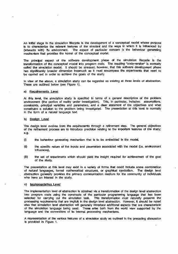
An Initial s tage in the simulation lifecycle is the development of a conceptual model w h o s e purpose is to characterize the relevant features of the simulant and the ways In which it b influenced by (interacts with) its environment. The aspect of particular concern is the behaviour generating mechanism that provides the kernel of the conceptual model.
The principal aspect of the software development phase of the simulation lifecycle is the transformation of the conceptual model into program code. The resulting "code-version'' Is normally called the simulation model. It should be stressed, however, that this software development phase has significantly broader dimension inasmuch a s it must encompass the experiments that need to be carried out in order to achieve the goals of the study.
In view of the above, a simulation study can be regarded as existing at three levels of abstraction. These are outlined below (see Figure 1 ) .
a) Requirements Level
At this level, the simulation study is specified in terms of a general description of the problem environment (the portion of reality under investigation). This, in particular, includes: assumptions, constraints, principal variables and parameters, and a clear statement of the objectives and what constitutes a solution to the problem being investigated. The presentation at this level is normally in the form of a natural language text.
b) Des ign Level
The design level evolves from the requirements through a refinement step. The general objectives of the refinement process are to introduce precision relating to the important features of the study; e.g.
(i) the behaviour generating mechanism that is to be embedded In the model,
(ii) the specific nature of the Inputs and parameters associated with the model (Le. environment influences),
(HO the set of experiments which should yield the insight required for achievement of the goal of the study.
The presentation at this level may exist in a variety of forms that could Include s o m e combination of natural languages, formal mathematical structures, or graphical symbolism. The design level abstraction generally provides the primary communication medium for the community of individuals who have an interest in the study.
c) Implementation Level
The implementation level of abstraction is obtained via a transformation of the design level abstraction into program c o d e using the constructs of the particular programming language that has been se lected for carrying out the simulation task. This transformation must naturally preserve the processing requirements that are implicit in the design level abstraction. However, it should be noted also that simulation level abstraction will generally introduce additional aspects that are characteristic of the simulation language being used. These arise both from the world view supported by the language and the conventions of its internal processing mechanisms.
A representation of the various features of a simulation study as outlined in the preceding discussion is provided in Figure 1.
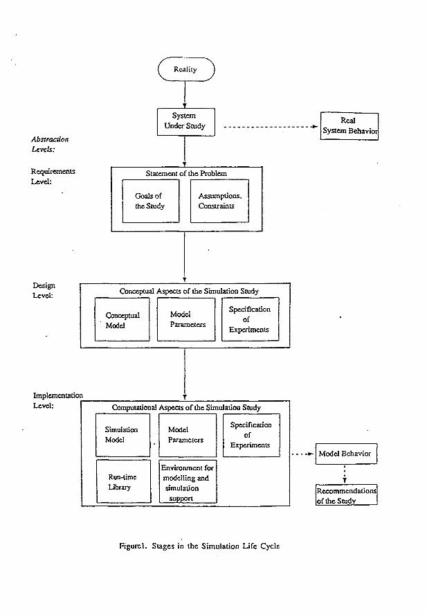
Reality
Abstraction Levels:
Requirements
Level:
System Under Study
Real System Behavior
Statement of the Problem
Goals o f the Study
Assumptions, Constraints
Design Level: Conceptual Aspects of the Simulation Study
Conceptual Model
Model Parameters
Spécification of
Experiments
Implementation Level: Computational Aspects o f the Simulation Study
Simulation Model
Run-time Library
Model Parameters
Environment for modelling and simulation
support
Specification of
Experiments Model Behavior
Recommendations of the Study
F igurc l . S t a g e s in the S imulat ion L i f e Cyc l e
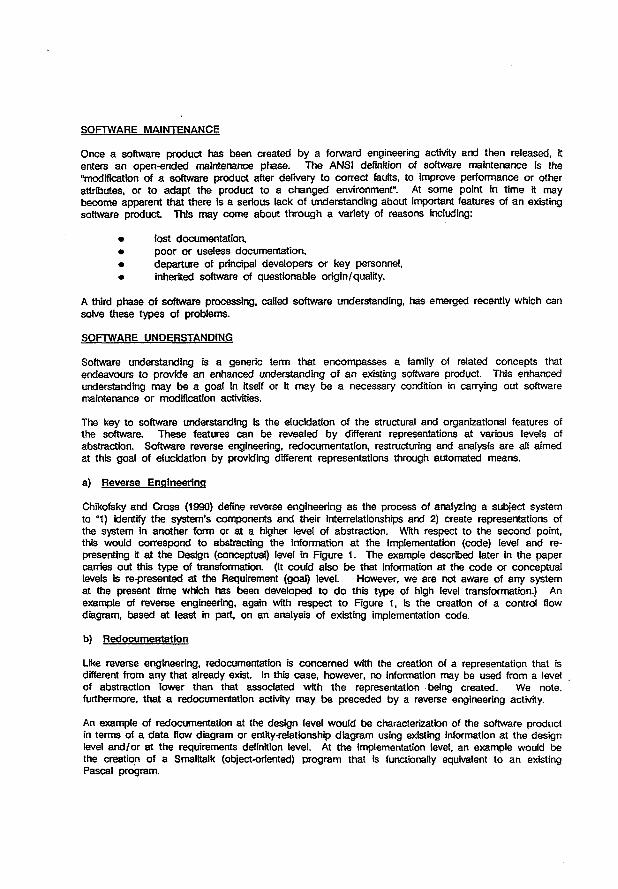
SOFTWARE MAINTENANCE
Once a software product has been created by a forward engineering activity and then released, it enters an open-ended maintenance phase. The ANSI definition of software maintenance is the "modification of a software product after delivery to correct faults, to improve performance or other attributes, or to adapt the product to a changed environment". At some point in time it may become apparent that there is a serious lack of understanding about important features of an existing software product This may c o m e about through a variety of reasons including:
• lost documentation, • poor or useless documentation, • departure of principal developers or key personnel, • inherited software of questionable origin/quality.
A third phase of software processing, called software understanding, has emerged recently which can solve these types of problems.
SOFTWARE UNDERSTANDING
Software understanding is a generic term that encompasses a family of related concepts that endeavours to provide an enhanced understanding of an existing software product. This enhanced understanding may be a goal in itself or it may be a necessary condition in carrying out software maintenance or modification activities.
The key to software understanding is the elucidation of the structural and organizational features of the software. These features can be revealed by different representations at various levels of abstraction. Software reverse engineering, redocumentation, restructuring and analysis are all aimed at this goal of elucidation by providing different representations through automated means.
a) Reverse Engineering
Chikofsky and Cross (1990) define reverse engineering a s the process of analyzing a subject system to "1) identify the system's components and their interrelationships and 2) create representations of the system in another form or at a higher level of abstraction. With respect to the second point, this would correspond to abstracting the Information at the Implementation (code) level and representing it at the Design (conceptual) level In Figure 1. The example described later in the paper carries out this type of transformation. (It could also b e that information at the c o d e or conceptual levels Is re-presented at the Requirement (goal) level. However, we are not aware of any system at the present time which has been developed to d o this type of high level transformation.) An example of reverse engineering, again with respect to Figure 1, is the creation of a control flow diagram, based at least in part, on an analysis of existing implementation code.
b) Redocumentat ion
Like reverse engineering, redocumentation is concerned with the creation of a representation that is different from any that already exist. In this c a s e , however, no information may be used from a level of abstraction lower than that associated with the representation being created. We note, furthermore, that a redocumentation activity may be preceded by a reverse engineering activity.
An example of redocumentation at the design level would be characterization of the software product in terms of a data flow diagram or entity-relationship diagram using existing information at the design level and/or at the requirements definition level. At the implementation level, an example would be the creation of a Smalltalk (object-oriented) program that is functionally equivalent to an existing Pascal program.
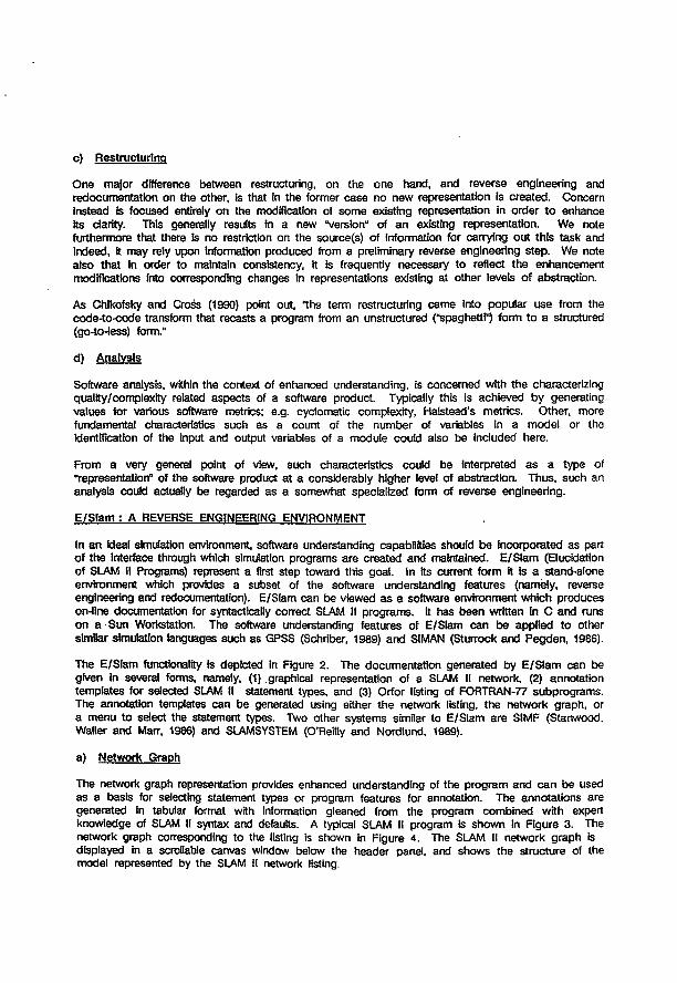
c) Restructuring
One major difference between restructuring, on the one hand, and reverse engineering and redocumentation on the other, is that in the former c a s e no new representation is created. Concern instead is focused entirely on the modification of some existing representation in order to enhance its clarity. This generally results in a new "version" of an existing representation. We note furthermore that there Is no restriction on the source(s) of information for carrying out this task and Indeed, it may rely upon information produced from a preliminary reverse engineering step. We note also that in order to maintain consistency, it is frequently necessary to reflect the enhancement modifications into corresponding changes in representations existing at other levels of abstraction.
As Chikofsky and Cross (1990) point out, "the term restructuring came into popular use from the code-to-code transform that recasts a program from an unstructured ("spaghetti^ form to a structured (go-to-less) form."
d) Analysis
Software analysis, within the context of enhanced understanding, is concerned with the characterizing quality/complexfty related aspects of a software product. Typically this is achieved by generating values for various software metrics; e.g. cyclomatic complexity, Halstead's metrics. Other, more fundamental characteristics such as a count of the number of variables in a model or the Identification of the input and output variables of a module could also be included here.
From a very general point of view, such characteristics could be interpreted a s a type of "representation" of the software product at a considerably higher level of abstraction. Thus, such an analysis could actually be regarded as a somewhat specialized form of reverse engineering.
E /S lam : A REVERSE ENGINEERING ENVIRONMENT
In an ideal simulation environment, software understanding capabilities should b e Incorporated as part of the interface through which simulation programs are created and maintained. E/Stam (Elucidation of SLAM II Programs) represent a first step toward this goal. In its current form it is a stand-alone envfronment which provides a subset of the software understanding features (namely, reverse engineering and redocumentation). E/SIam can be viewed a s a software environment which produces on-line documentation for syntactically correct SLAM II programs. It has been written in C and runs on a Sun Workstation. The software understanding features of E/SIam can be applied to other similar simulation languages such a s GPSS (Schriber, 1989) and SIMAN (Sturrock and Pegden, 1986).
The E/SIam functionality is depicted in Figure 2. The documentation generated by E/SIam can be given In several forms, namely, (1) .graphical representation of a SLAM II network, (2) annotation templates for selected SLAM II statement types, and (3) Orfor listing of FORTRAN-77 subprograms. The annotation templates can be generated using either the network listing, the network graph, or a menu to select the statement types. Two other systems similar to E/SIam are SIMF (Stanwood. Waller and Marr, 1986) and SLAMSYSTEM (O'Reilly and Nordlund, 1989).
a) Network Graph
The network graph representation provides enhanced understanding of the program and c a n be used a s a basis for selecting statement types or program features for annotation. The annotations are generated in tabular format with information gleaned from the program combined with expert knowledge of SLAM II syntax and defaults. A typical SLAM II program is shown in Figure 3 . The network graph corresponding to the listing is shown in Figure 4. The SLAM II network graph is displayed in a scrollable canvas window below the header panel, and shows the structure of the model represented by the SLAM II network listing.
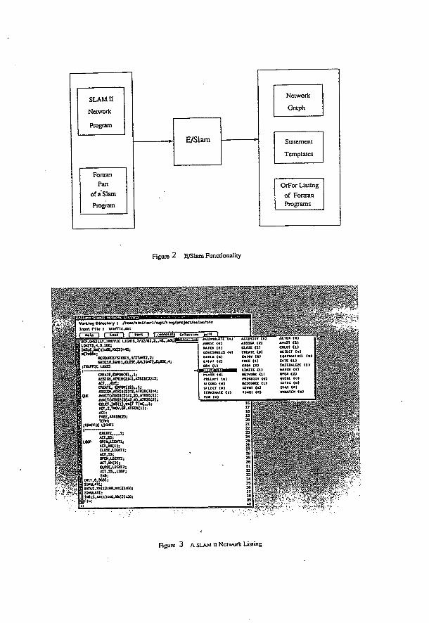
SLAM II
Network
Program
Fortran Part
of a Slam Program
E/Slam
Network
Graph
Statement
Templates
OrFor Listing of Fortran Programs
Figure 2 E/Slam Functionality
Vorking Ol r e c t o r y : / h e - * / « i » l A « « - l / . s « p V » t o g / p r o J e c t / t t l W t . « *
Inpu t f n « : v « f f ( c . ö » t j tot« ) Font J I .Wvr-fr1it| Safa
G£S.u^IU.Y.TftAffIC U C H T S , 7 / 1 2 / e 3 , 3 . . l < û . , W ; ^
JKTU,XX(J)=6e,>0C(2>=<S; tCTVORC;
KSOURCE/STUTl,1/START2.2; UICS/a&HIt,aOSC,VU6K72^L0Se.4;
;TRtff lC U*CS
CR£*T£.CXPCNW.,1; aSSIC«,«818<2)»l,ATöe<3jB3;
CREATE, É*PtWCI2) , . t ; ASSICN,*TRIB<2)=2.ATW6<3)^i
QUE 4VAnCnRIB<2)=l,2),*TrUe(2); JrVAlT(*TRI6<3)c3,4).MRie<2); COLCT,ItfTU>.VAIT T ] < „ 1 ; ICT,2.TK«J3'.âTBI6<l); « a : r-R££,«H10<2î; t O W ;
TSAFFIC U M T S
C K A T E . , , , 1 ;
LOOP CPEK.UGKTI;
«CT.SS; tf*N.UCKT2: ACT,W(2) : aose.ucMTZ; ia, ss.,LOOP; EM);
siNuuit:
S I M U L E E ;
I F l « ;
m i n c i i « ï Kl CORO <«) SlttCI {«> tC«KX*A» < t )
[ f«)
«CUTI IT \*t AS3I6* <2} CUSG <2) atCAie cal t * t « f t « ) «œe <i» LIMITS « ) MEtwtw a i neimtw Ui tCsamcc (l) S t f f ! <•) 1IN31 <€>
M U « 10) *«*n « Ï m e t a i et n e t {« tOOt«Mt« Mie <t) » I I U J . I 2 MAICH 1 « ! Oft« C21 « a c t a <«1 S i r o s « r i SIAt {€) « O A t C * «
Figure 3 A SLAM U Network Listing
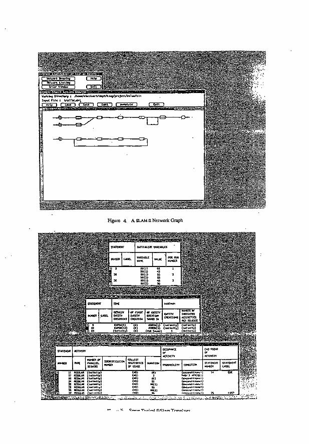
VorkJog D i r e c t o r y s / r o ^ / « U l / u * r l / « J « p t A t < « g / p r o J * c l / « » t W b i n
I<V" l F i l e : t r a f f i c d â \ _ _ _ _ _
S â U ' ) ^ E d » ] I A n f l b U f " " ] ) [ ( M l 1
• • M _ H n É
j
H U P « WsËÊÊlÊmÈÊËBÈÊÈSMËÊm .î-ia**'.,*-"-'!! ~ ^
Figure 4 A SLAM n Network Graph
-• .'S , | STiTOCKT T W E
IJj
- 1 KfCER uaa. UlVCOt wmcv CREATIONS
Of rjHST
iKimr CSEATUM
or cm m C R O T l » SAVED [h
E K T I I Y CHEiTIGtfS ACÏIVTTÎCS
PER m eu*
C r t ™ T . . „ ; ^ , 1 n / C U m T V f r m l w <
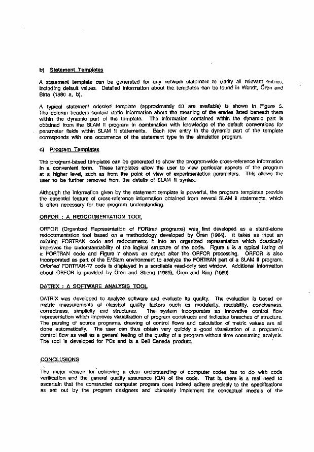
b) Statement Templates
A statement template can be generated for any network statement to clarify all relevant entries, including default values. Detailed information about the templates can be found in Wendt, CVen and B'lrta (1990 a, b).
A typical statement oriented template (approximately 60 are available) is shown in Figure 5. The column headers contain static information about the meaning of the entries listed beneath them within the dynamic part of the template. The information contained within the dynamic part is obtained from the SLAM II program in combination with knowledge of the default conventions for parameter fields within SLAM II statements. Each row entry in the dynamic part of the template corresponds with one occurrence of the statement type in the simulation program.
c) Program Templates
The program-based templates can b e generated to show the program-wide cross-reference information in a convenient form. These templates allow the user to view particular aspects of the program at a higher level, such a s from the point of view of experimentation parameters. This allows the user to be further removed from the details of SLAM II syntax.
Although the information given by the statement template is powerful, the program templates provide the essential feature of cross-reference information obtained from several SLAM ll statements, which is often necessary for true program understanding.
ORFOR : A REDOCUMENTATION TOOL
ORFOR (Organized Representation of FORtran programs) w a s # first developed a s a stand-alone redocumentation tool based on a methodology developed by 6Ven (1984). It takes a s input an existing FORTRAN code and redocuments it into an organized representation which drastically improves the understandability of the logical structure of the code . Figure 6 is a typical listing of a FORTRAN c o d e and Figure 7 shows an output after the ORFOR processing. ORFOR is also incorporated a s part of the E/SIam environment to analyze the FORTRAN part of a SLAM II program. Orfor'ed FORTRAN-77 code is displayed in a scrollable read-only text window. Additional Information about ORFOR is provided by Oren and Sheng (1989), 0>en and King (1989).
DATR1X : A SOFTWARE ANALYSIS TOOL
DATRIX was developed to analyze software and evaluate Its quality. The evaluation is based on metric measurements of classical quality factors such a s modularity, readability, conciseness , correctness, simplicity and structures. The system incorporates an innovative control flow representation which improves visualization of program constructs and indicates breaches of structure. The parsing of source programs, drawing of control flows and calculation of metric values are all d o n e automatically. The user can thus obtain very quickly a -good visualization of a program's control flow a s well a s a general feeling of the quality of a program without time consuming analysis. The tool is developed for PCs and is a Bell Canada product
CONCLUSIONS
The major reason for achieving a clear understanding of computer codes has to do with code verification and the general quality assurance (QA) of the code . That is. there is a real need to ascertain that the constructed computer program d o e s indeed adhere precisely to the specifications a s set out by the program designers and ultimately implement the conceptual models of the
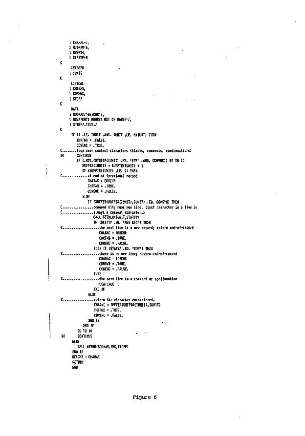
I C H A K A I M , I HOOKAH!6, t KS6»2<, 1 STATTP»B
C IKTE6ER
1 ItlKIT C
USICAL 1 CHRFKO, 1 C0NÎNC, 1 STOPP
C DATA
1 HOOKAnY'SETCKR'/, 1 HSB/'UHIT KUKBER OUT OF RANGE'/, 1 STOPP/.TRUE./
C IF (1 .IE. IUH1I .AM). IUKIT .IE. IKIOKTJ TKEK
CHRFND = .FAISE. COKEKC = .TRUE.
C loop over control claracters (blanks, couen t s , cortinaations) 10 COHTIKUE
IF <.HOT.CSmnltHIKITJ .HE. 'EOF' .AHB. COKEKC)) 60 TO 20 8UFPTR( IUKIT) = BUFPTR(IÖKIT) • 1 IF (BUFPTR(IUHIT) .IE. 0) THEN
C at end of (prêtions) record CHARAC = EOHCHB CHRFHD = .TRUE. COKEKC » .FALSE.
EISE IF (BUFFERfBUFPTRUOHIT), IUKIT) .ES. COKSHO THEH
C conent nit) read nev l ine , ( l as t character in a line i s C alvays a cement character.)
CAU SETKlKdUKII.STATrP) IF (STATT? .EO. 'KEK REO THEH
C the nezt line is a nev record; return end-of-record CHARAC ' EORCHR CHRFHD = .TRUE. COKEKC = .FALSE.
EISE IF (STATYP .EO. 'EOF') THEK C there i s no nev line] return end-of-record
CHARAC = EORCHR CHRFHD = .TRUE. COKEHC « .FAISE.
ELSE C. the neit line i s a coaaent or continuation
COHTIKUE , EKD IF
ELSE C return toe character encoontered.
CHARAC - BUFFERtBUFPTRHUHlT), IUKIT) CHRFHD « .TRUE. COKEKC ' .FALSE.
EKD IF EKO IF
SO TO 10 20 COHTIKUE
ELSE CAU KRERR(IIODHAH,HSS,ST0PP)
EKD IF EETCKR = CHARAC RETURN EKD
Figure 6
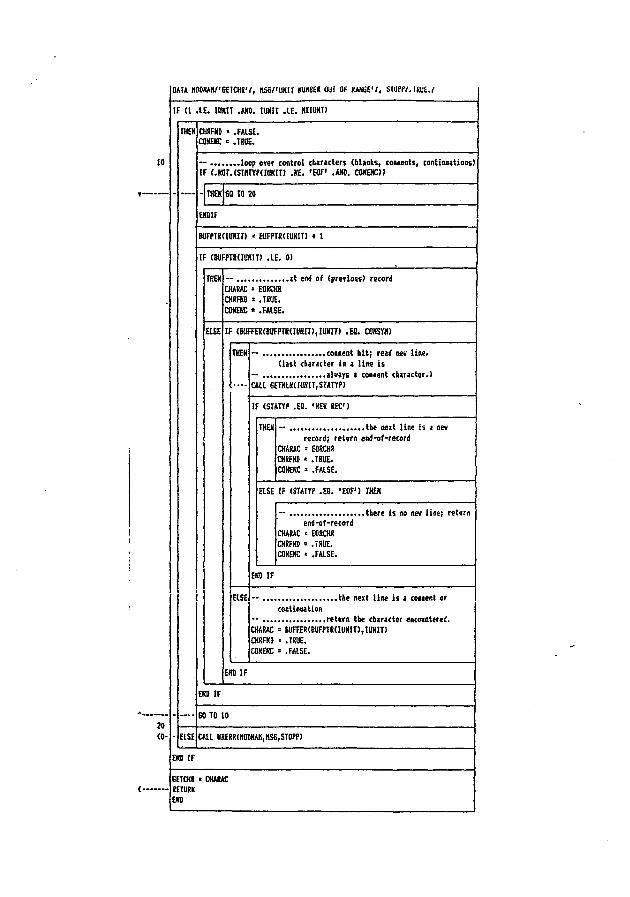
DATA K0OKA!l/'6EICHR'/, t lS6/ 'UNI[ KUB8E8 Out OF UMi'l, surti.mi.i
IF (1 . IE . IUKIT .AHO. IUKIT . IE. ItllOKt)
IHEK (
ELSE
EM) IF
CHSFKD ' .FALSE. CONEKC •= .TRUE.
— loop oyer control characters (blanks, couents , continuations) IF (.KOr.(STHTYf(IUKIT) .K£. 'EOF' .AND, COKEKC))
- IHEK SO TO 20
EKD1F
tUFPTRUUHIT) • 8UFPTRUUKIT) • 1
IF (SUFFTRdUNIT) .IE. 0)
ELSE
THEN CHARAC - EORCKR CHRFHD = .TRUE. COKEKC « .FALSE.
. a t end of (prerioas) recorii
IF (SUFFERtBUFPTRdllKIT), IUKIT) .Efl. CMSWI)
THEH
R S E
— conent h i t ; read nev l ine . ( las t character in a l ine i s
— always a coiaent character.) CALL GEIHLKdUNITjSTAryP)
IF (STATYP .EQ. 'HE* REO)
THEH — the next line is a nev record; return end-of-record
CHARAC - EOSCHR CHRFHD = .TRUE. CONEKC = .FALSE.
aSE IF (STATYP .E8. ' E O F ' ) THEH
end-of-record CHARAC = EORCHR CHRFHD = .TRUE. COKEKC * .FALSE.
. there i s no nev line; return
EKD IF
- the next line i s a coiaent or continuation
— retsrn the character encountered. CHARAC « BUFFER«UFPTR(IUKIT),IUKIT) CHRFKO ' .TRUE. COKEKC = .FALSE.
EKD IF
EKD IF
SO TO 10
CALL NRERR(HDDHAH,HS6,ST0PP>
SETCHR > CHARAC RETURN END
mcxlellers correctly. This situation is precisely applicable to a group such as the BIOMOVS modellers. Unless QA procedures have been followed rigorously throughout each stage of the software development cycle, there are very few of us who would claim to have great confidence in the correctness of the code that has been constructed. In spite of this, QA in general, has not been accepted as an essential element In model and software development There are perhaps two major reasons for this, the first being that of unfamiliarity with the concept and the procedures Involved. This state can, of course, be corrected quite easily through consultation with literature and people with relevant experience. The second reason has to do with the amount -of "pain" involved, l.e. the amount of time, personnel and other resources that must be devoted. This, however, no longer needs to be so. Wtth the advances now being made in software engineering, much of the time, effort and tedium traditionally associated with carrying out QA activities are no longer applicable. The above discussion of the various computer-aided software understanding systems such as E/Slani demonstrates the tremendous advantage, to be gained by relegating low level tasks to be implemented by the computer and thus freeing the human to concentrate on the conceptual aspects.
This principle was first applied In forward engineering systems. There are simulations environments now available which allow a modeller to specify models In a mathematical form and the system will subsequently generate the code automatically to implement the simulation. These systems, naturally, ensure that programs are syntactically correct but can also detect semantic errors to various degrees. Two such systems are MAGEST in prototype (Aytac and Oren, 1986; Oren and Sheng, 1988) and CM-100 by Campus Software which is commercially available. The latter system also produces graphic output .of simulation results in real time.
The combination of computer-aided simulation and software understanding environments can provide a powerful contribution to the quality assurance of computer programs. These systems free the user from the tedious tasks at the implementation level where most mistakes are made and enable one to concentrate on the conceptual level where humans belong.
REFERENCES
Aytac, Z.K., T.I. Oren (1986). Magset: A Model-Based Advisor and Certifier for Gest Programs, in Modelling and Simulation Methodology in the Artificial Intelligence Era, M.S. Elzas, T.I. bren, BP. Zeigler (Eds.). North Holland, pp. 299-307.
Campus Software. CM-100: Desktop Modelling and Simulation System. P.O. Box 431, 6700 AK Wageningen, the Netherlands. Tel. (Int) -33-8370-97627.
Chikofsky, E.J. and J.H. Cross, II (1990). Reverse Engineering and Design Recovery: A Taxonomy. IEEE Software, January 1990, pp. 13-17.
O'Reilly. J.J. and C. Noriund (1989). Introduction to SLAM II and SLAMSYSTEM. jn Proceedings of the 1989 Winter. Simulation Conference, Washington, DC, Dec. 4-6, 1989. E.A. MacNair, K.J. Musselman and P. Heidelberger (Eds.). IEEE, Piscataway, NJ, pp. 178-183.
Gren, T.I. and D.G. King (1989). Orfor: Organized Representation of Fortran Programs on a Sun Workstation. Technical Report TR-89-16 (Prepared for Bell Canada). Simulation Research Group, Computer Science Department University of Ottawa, Ottawa, Ontario, Canada.
oren, T.l. and G. Sheng (1988). Semantic Rules and Facts for an Expert Modelling and Simulation System. In Proceedings of 12th IMACS World Congress on Scientific Computation, Paris, France, July 18-22, 1988.
Ören, T.I. and G. Sheng (1989). Software Tools for the Quality Assurance of Scientific Codes Used in Nuclear Waste Management Programs, in Proceedings of the international Symposium on the Safety Assessment of Radioactive Waste Repositories. Paris, France, Oct. 9-13, 1989.
RobHIard. P.N., F. Coallier, A Beaucage, M. Simoneau (1990). A New Tool for Software Quality Assessment ]n Proceedings of Canadian information Processing Society Congress 90, Ottawa, Ontario, Canada, May 16-18, 1990.
Schriber, T.J. (1989). Perspectives on Using GPSS. In Proceedings of the 1989 Winter Simulation Conference, Washington, DC, Dec. 4-6, 1989. EA MacNair, K.J. Musselman, P. Heidelberger (Eds.). IEEE, Piscataway, NJ, pp. 115-128.
Stanwood, K.L, L.N. Waller, G.C. Mart (1988). System Iconic Modeling Facility. ]n Proceedings of the 1986 Winter Simulation Conference. J. Wilson, J. Henriksen, S. Roberts (Eds.). IEEE, Piscataway, NJ, pp 531-
Sturrock. D.T., CD. Pegden (1989). Introduction to SIMAN. In Proceedings of the 1989 Winter Simulation Conference, Washington, DC, Dec. 4-6, 1989. EA MacNair, K.J. Musselman, P. Heldelberger (Eds.). IEEE, Piscataway, NJ, pp. 129-139.
Wendt, R.N., T.I. 6ren, 1_G. Birta (1990). Knowledge Base for SLAM II Understanding System, Volume 1 - Templates. Technical Report TR-89-54 (Prepared for Bell Canada). Simulation Research Group, Computer Science Department University of Ottawa, Ottawa, Ontario, Canada.
Wendt, R.N., T.I. 8ren, L.G. Birta (1990). Knowledge Base for SLAM II Understanding System, Volume 2 - Rule Base. (Prepared for Bell Canada). Simulation Research Group, Computer Science Department University of Ottawa Ottawa, Ontario, Canada.
3.4
Model Validation: A Systemic and Systematic Approach
G. SHENG
Department of Computer Science and Systems McMaster University, Canada
M.S. ELZAS
Department of Computer Science, Wageningen University The Netherlands
T.I. ÖREN
Department of Computer Science, University of Ottawa Ottawa, Ontario, Canada
B.T. CRONHJORT
Department of Automatic Control, Royal Institute of Technology Sweden
Reliability Engineering and System Safety, 42 (1993), pp. 247-259

Reliability Engineering and System Safety 42 (1993) 247-259 ^ ^ \ |
Model validation: a systemic and systematic approach
G . S h e n g * Dept. of Computer Science and Systems, McMaster University, Hamilton, Ont., Canada, L8S 4K1
M . S . Elzas Dept. of Computer Science, Wageningen University, 6703 HB, Wageningen, The Netherlands
T . I. Oren
Dept. of Computer Science, University of Ottawa, Ottawa, Ont., Canada, KIN 9B4
&
B. T . Cronhjort Dept. of Automatic Control, Royal Institute of Technology, S-100 44 Stockholm, Sweden
The term 'validation' is used ubiquitously in association with the modelling activities of numerous disciplines including social, political, natural, physical sciences, and engineering. Tnere is however, a wide range of definitions which give rise to very different interpretations of what activities the process involves. Analyses of results from the present large international effort in modelling radioactive waste disposal systems illustrate the urgent need to develop a common approach to model validation. Some possible explanations are offered to account for the present state of affairs. We believe that a rigorous approach to validation must necessarily be based on a thorough understanding and application of the theory of simulation and modelling. The methodology developed treats model validation and code verification in a systemic and systematic fashion. In fact, this approach may be regarded as a comprehensive framework to assess the adequacy of any simulation study.
1 INTRODUCTION
Although the word 'validation' is used ubiquitously in numerous disciplines including management sciences, economics, ecology, energy studies, mathematics, engineering, operations research, software engineering and earth sciences such as hydrogeology, its definition is as varied as its usage is wide. Based on a compilation of 308 references,1 the following 16 items are commonly encountered and often used interchangeably among the various disciplines: acceptability, accuracy, analysis, assessment, calibration, certification, confidence, credibility, evaluation,
* To whom correspondence should be addressed.
Reliability Engineering and System Safety0951-8320/93/$06.00 © 1993 Elsevier Science Publishers Ltd, England.
performance, qualification, quality assurance, reliability, testing validation, and verification.
Although usage of the term may be questionable for certain applications, even well-defined and accepted definitions in closely related fields may appear quite different. Compare, for instance, the definition adopted by the simulation community for 'model validation':
'Substantiation that a computerized model within its domain of applicability possesses a satisfactory range of accuracy consistent with the intended application of the model'2
and that used in software engineering (IEEE Std 1012-1986):
'The process of evaluating software at the end of the software development process to ensure compliance with software requirements'.3
247
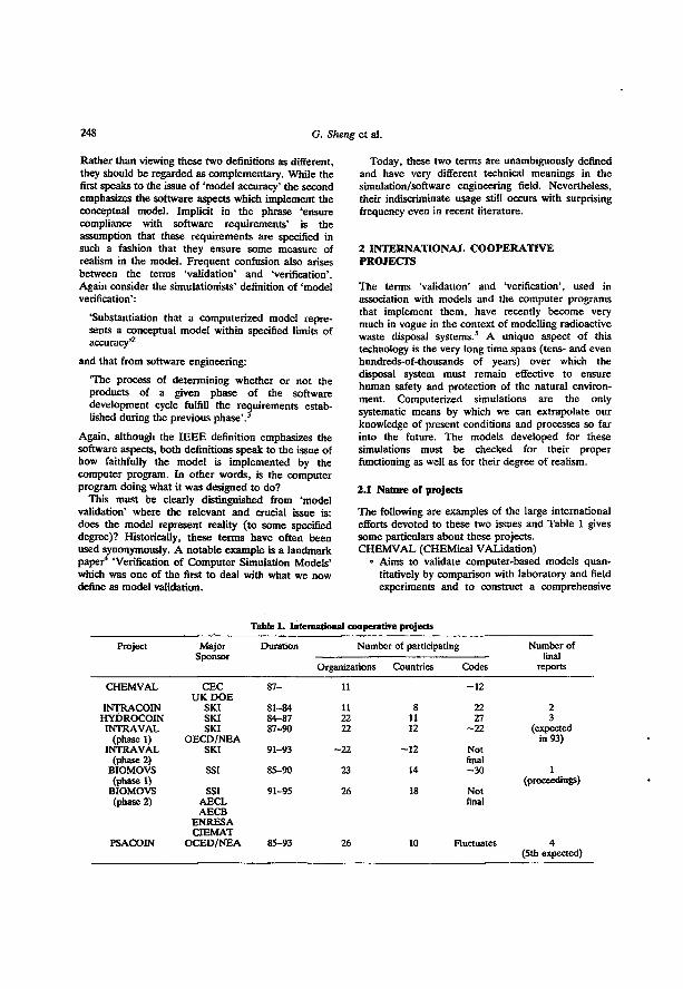
248 G. Sheng et al.
Rather than viewing these two definitions as different, they should be regarded as complementary. While the first speaks to the issue of 'model accuracy' the second emphasizes the software aspects which implement the conceptual model. Implicit in the phrase 'ensure compliance with software requirements' is the assumption that these requirements are specified in such a fashion that they ensure some measure of realism in the model. Frequent confusion also arises between the terms 'validation' and 'verification'. Again consider the simulationists' definition of 'model verification':
'Substantiation that a computerized model represents a conceptual model within specified limits of accuracy'2
and that from software engineering:
'The process of determining whether or not the products of a given phase of the software development cycle fulfill the requirements established during the previous phase'. 3
Again, although the IEEE definition emphasizes the software aspects, both definitions speak to the issue of how faithfully the model is implemented by the computer program. In other words, is the computer program doing what it was designed to do?
This must be clearly distinguished from 'model validation' where the relevant and crucial issue is: does the model represent reality (to some specified degree)? Historically, these terms have often been used synonymously. A notable example is a landmark paper" 'Verification of Computer Simulation Models' which was one of the first to deal with what we now define as model validation.
Today, these two terms are unambiguously defined and have very different technical meanings in the simulation/software engineering field. Nevertheless, their indiscriminate usage still occurs with surprising frequency even in recent literature.
2 INTERNATIONAL COOPERATIVE PROJECTS
The terms 'validation' and 'verification', used in association with models and the computer programs that implement them, have recently become very much in vogue in the context of modelling radioactive waste disposal systems.5 A unique aspect of this technology is the very long time spans (tens- and even hundreds-of-thousands of years) over which the disposal system must remain effective to ensure human safety and protection of the natural environment. Computerized simulations are the only systematic means by which we can extrapolate our knowledge of present conditions and processes so far into the future. The models developed for these simulations must be checked for their proper functioning as well as for their degree of realism.
2.1 Nature of projects
The following are examples of the large international efforts devoted to these two issues and Table 1 gives some particulars about these projects. CHEMVAL (CHEMical VALidation)
• Aims to validate computer-based models quantitatively by comparison with laboratory and field experiments and to construct a comprehensive
Table 1. International cooperative projects
Project Major Sponsor
Duration Number of participating
Organizations Countries Codes
Number of final
reports
CHEMVAL CEC 87- 11 -12 UK DOE
INTRACOIN SKI 81-84 U 8 22 2 HYDROCOIN SKI 84-87 22 11 27 3 INTRAVAL SKI 87-90 22 12 -22 (expected
(phase 1) OECD/NEA in 93) INTRAVAL SKI 91-93 -22 - 1 2 Not
(phase 2) final BIOMOVS SSI 85-90 23 14 -30 1 (phase 1) (proceedings)
BIOMOVS SSI 91-95 26 18 Not (phase 2) AECL final (phase 2)
AECB ENRESA CIEMAT
PSACOIN OCED/NEA 85-93 26 10 Fluctuates 4 (5th expected)
Model validation: a systemic and systematic approach 249
thermodynamic data base for use in radiological assessment.
INTRACOIN (International Nuclide TRAnsport COde INtercomparison)
• Carried out systematic comparison of various computational codes to improve the understanding of the modelling work done in radionuclide transport. The project was concluded in 1986 with summary reports.
HYDROCOIN (HYDROgeological COde INtercomparison)
• Studied groundwater flow modelling by applying various computer codes to seven hypothetical test cases representing a range of possible physical situations.
INTRA VAL (INternational TRAnsport Model VALidation)
• Stemming from the work of INTRACOIN and HYDROCOIN, this project aims to increase understanding of how various geophysical, hydrogeological and geochemical processes affect the transport of radionuclides from an underground repository to the surface biosphere. Presently in Phase 2.
BIOMOVS (BlOspheric MOdei Validation Study) • Its purpose is to test models of the environmental
transfer and bioaccumulation of radionuclides and other trace substances, to explore the assumptions and deficiencies in the models, and to recommend future research for improving model prediction accuracy. Presently in Phase 2.
PSACOIN (Probabilistic Safety Assessment COde INtercomparison)
• Coordinates the development of probabilistic safety assessment (PSA) codes through, computer code intercomparison and benchmarking exercises.
2.2 Results from projects
Despite the numerous efforts aimed at validation and verification of hydrogeologic, geologic and biospheric models as indicated above, analysis of these projects shows that there are many misconceptions about the activities associated with these two terms, and consequently no significant validation or verification, in the strict sense, has thus far taken place. The following are quotes assessing the various projects by some of their participants.
The following are concluding remarks from the assessment" of the HYDROCOIN and INTRACOIN studies:
' • • - both studies failed to perform a full validation exercise.'
' - • • level 2 of both studies lacked of (sic)
appropriate experimental results that could be used for code validation. In nearly all cases, independent measurements with which the simulation results could be compared, were not available, so that level 2 should more or less be called a matching exercise that showed which parameter combination achieved the best results.'
'So level 2 only proved that the results of computer simulations can be fitted to the measured date (sic) by varying the input data.'
The last two quotes suggest that, rather than having performed validation of the models, what was done amounted to model calibration. This was also the assessment by a participant7 in the INTRA VAL project:
'The first phase of INTRA VAL has made some progress toward defining what validation means, but participants have not yet reached a consensus on an exact definition. Many participants, through the analysis of test cases have begun to understand what validation is not (i.e. calibration) though what it is, remains elusive.'
The BIOMOVS experience highlights yet another problem endemic to these projects: the critical need to know precisely what is the problem to be studied and then to specify the problem (model) concisely and precisely enough to ensure that all participants are working on the same problem. This was a valuable lesson8-2* stemming from phase 1 of BIOMOVS:
'BIOMOVS has shown that user judgment has significant impact on model predictions by way of: (a) misinterpreting the assessment problem, (b) improper or incomplete specification of the
problem issue.'8
It is these and many other types of shortcomings that give rise to the following modelling results which are fairly representative of the other intercomparison projects as well:
'BIOMOVS has forcefully demonstrated the shortcomings of our present capabilities for biosphere modelling. With values assigned to basic parameters differing between modelers by three, four and five orders of magnitude (e.g. technetium distribution factors for milk, Scenario B2), with estimates of uncertainties about these parametes by the individual modelers covering a similar range, and with, in the worst cases, little to no overlapping of the uncertainty ranges, the situation clearly demands a remedy."
Based on the analyses of the results from these international cooperative projects which the above brief examples typify, as well as on a survey of the general literature on the subject, the existing
250 G. Sheng et ai.
methodology on model validation can only be characterized as 'ad hoc' and 'piecemeal'.
The following sections will offer some explanations on why this current state of affairs exists in model validation, why there is so much confusion about what it is, and what activities the process actually involves. Below, a brief review of current thinking and theory that would help the situation is followed by the introduction of a systematic approach intended to advance the present state of development.
3 REASONS FOR INADEQUATE MODEL VALIDATION METHODOLOGY
There are three major factors—philosophical, definitional, and theoretical, which underlie this state of affairs.
3.1 The philosophical problem
Even at the most fundamental level, validation is viewed differently from two opposing philosophies. The first, referred to as 'positivism',* is the view advanced by Thomas Kuhn1" that ' • • • theories are confirmed or refuted on the basis of critical experiments designed to verify the consequences of the theories.' Subscribers to this school of thought clearly believe that theories can be confirmed as to their correctness or 'validity' if only the decisive experiments, designed expressly for that purpose, were performed.
In direct contrast, the opposing view, advanced by Karl Popper," is that theories, being tentative statements about truth, are always provisional, and can never be proven true, but can only be shown to be false: ' • • • as scientists we can never validate a hypothesis, only invalidate it.'
Since models are, effectively, precise statements about particular theories or specific hypotheses, it follows from the Popperian view that models can never be validated but only invalidated. However, the strength of this approach is that with each successive and successful passing of tests or experiments designed to refute it, increased confidence is placed on the correctness or validity of the model. This fundamental philosophical difference between the two diametrically opposing views precludes development of the validation concept from common ground.
3 J, The definition problem
This situation is further exacerbated by the general descriptive nature of existing definitions which lack
precise operational guidance. Consider, as examples, the following definitions of model validation adopted for use in modelling in the field of nuclear waste disposal [our emphasis]:
' • • • the process of obtaining assurance that a model, as embodied in a computer code, is a correct representation of the process or system for which it is intended.' Nuclear Regulatory Commission12 (US) ' • • • a process whose objective is to ascertain that the code or model indeed reflects the behavior of the real world.' Dept. of Energy 1 3 (US) 'Validation is a process carried out by comparison of model predictions with independent field observations and experimental measurements. A model cannot be considered validated until sufficient testing has been performed to ensure an acceptable level of predictive accuracy. (Note that the acceptable level of accuracy is judgmental and will vary depending on the specific problem or question to be addressed by the model.)' International Atomic Energy Agency 1 4
Although they ail have the common theme that the constructed model must somehow represent reality, the definitions do not specify how this is to be shown. The IAEA definition is somewhat more specific in stating that comparison of model predictions with real world measurements is necessary but noted that the acceptable degree of agreement is judgmental and problem specific.
The most precise definition of model validation is probably the one provided by the Society of Computer Simulation (SCS) Technical Committee on Model Credibility in a report to its general membership and recognized by the simulation community [our italics]: 'Substantiation that a computerized model within its domain of applicability possesses a satisfactory range of accuracy consistent with the intended application of the model'. 2 Even though the three italicized terms do provide some guidance, they are insufficient from an operational sense when applied to specific cases. For instance 'domain of applicability' is not defined or explained. Likewise the term 'satisfactory range of accuracy' provides little operational guidance. As yet, no metrics have been developed as measures of accuracy nor is there even a generally recognized approach to address this accuracy issue. Finally, 'intended application' which refers to the purpose for which the model was developed, is not clarified nor is its crucial significance generally, with only a few exceptions, recognized in the literature. This last point, the most important of the three, determines what the model is, how it is to be used and how it is to be ultimately assessed as to its quality, accuracy, and usefulness. 1 5
Model validation: a systemic and systematic approach 251
3.3 Lack of a theoretical foundation
The third major factor is associated with the fact that the theoretical basis of simulation itself was not developed until the seventies and eighties by a handful of people including Elzas, Klir, Oren and Zeigler. Their seminal works are published in a series of books and papers. l 5~ 2 ' Prior to this period, computerized simulation was very much an ait. As a 'science', therefore, simulation is a very young discipline, emerging only within the last fifteen years or so. Since we believe that the development of a theoretical foundation for model validation must necessarily be based on an established theory of simulation and modelling, it is not surprising then that we regard carrying out the process of computerized-model validation on a rigorous, systemic basis could not have been possible until very recently.
4. PRESENT STATE OF DEVELOPMENT
In order to advance the state of development of validation, it is clearly necessary to address the above three major problems.
4.1 The philosophical issue
From strictly an operational standpoint, it probably matters little whether one adopts the 'Kuhnsian' (positivistic) view or the opposing 'Popperian' view. In almost all real world situations, the system of interest is too complex to permit its thorough understanding; too complicated and/or expensive to gather the necessary data both qualitatively and quantitatively to compare with simulation results. These conditions are especially true in dealing with modelling ecological and geological processes such as encountered in High Level Waste (HLW) disposal. In fact, the very long time-spans involved in this type of endeavour make the concept of validation, in the strict sense, a moot point. In these types of situations it is much more fruitful to consider what is the intended application of (i.e. purpose for) the model being developed and then to assess the success (e.g. accuracy) of the model accordingly.
43. Defining the purpose of the model
It is of critical importance to know clearly the purpose for which the model is developed. 2 2 A clear distinction must be made between '(i) models that are constructed primarily to provide accurate prediction of the behavior of a system, and (ii) models that, as scientific theories, are attempts to gain insight into how the system operates' 2 2 (our italics). On the basis
of this important difference, the means of model construction and ultimately of model assessment, or validation, are quite different for these two types of models.
Two others 2 3 , 2 4 adopt the same view between 'theoretical' models whose primary purpose is to facilitate understanding of the system, and 'predictive' models which are regarded as 'calculation tools' the usefulness of which is judged by 'how accurately they can predict aspects of the real world, or on how well they meet design specifications.'24 Loehle 2 4 adds one further category: that of 'logical simulation models' which 'do not necessarily need to simulate reality but may be based purely on a conceptual model or algorithm'. They support Caswell's2 2 point that the method to be used for evaluation of the quality, usefulness, or truthfulness of a simulation model differs for each of these model types.
43 The theoretical foundation of simulation and modelling
It is beyond the scope of this paper to describe and discuss the theoretical foundation of simulation and modelling upon which a rigorous approach to validation must necessarily be based. Two landmark pieces of work 1 6 1 7 establish the theory. Various aspects of the theory are further presented in concise form in a series of short articles by Elzas, Oren, and Zeigler in the Systems and Control Encyclopedia.25
The concept of experimental frame However, one key aspect of the theory is of direct relevance to model validation in this paper: the concept of 'experimental frame'. I 6- 1 7
There are three components in an experiment: an object (real-world system under investigation or a model of it) used in the experiment, an experimental frame, and generated/collected/observed data. The experimental frame defines a limited set of circumstances under which the real-world system is to be observed or under which the simulation model is subjected to experimentation. Figure 1 illustrates the concept by showing the relationship of the five elements that define the 'experimental constraints' with respect to experimentation on a real system with the analogous five elements that define the 'experimental specification' in the case of a simulation. The five blocks resulting from this relationship form the experimental frame: observational variables, input schedules, initialization settings, termination conditions, and specifications for data collection and compression.17
The experimental frame, when applied to experimentation on a real system, can be interpreted as the procedures for measurement, system excitation.
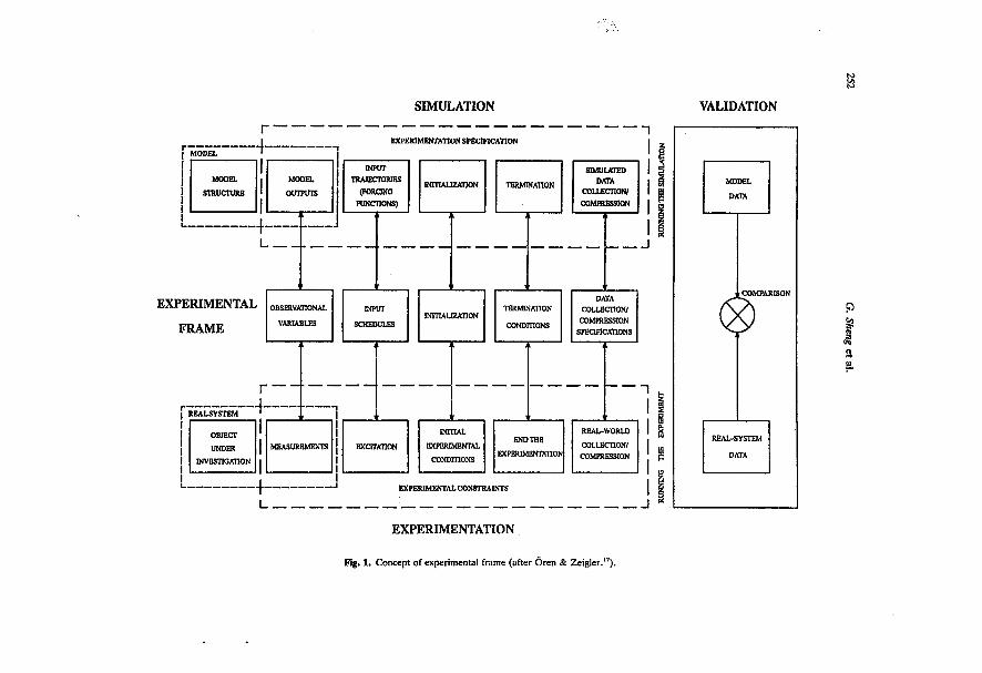
SIMULATION
EXPERIMENTATION SPECIFICATION
MODEL
STRUCTURE
MODEL
OUTPUTS
INPUT TRAJECTORIES
(FORONO FUNCTIONS)
INITIALIZATION
SIMULATED DATA
COLLECTION/ COMPRESSION
EXPERIMENTAL
FRAME
OBSERVATIONAL
VARIABLES
INPUT
SCHEDULES INrnAUZATION
TERMINATION
CONDITIONS
DATA COLLECTION;
COMPRESSION SPECIHCATIONS
OBJECT
UNDER
INVESTIGATION
MEASUREMENTS
INITIAL
EXPERIMENTAL
CONDITIONS
END THE
EXPERIMENTATION
REAL-WORLD
COLLECTION/
COMPRESSION
EXPERIMENTAL CONSTRAINTS
EXPERIMENTATION
g. 1. Concept of experimental frame (after ören & Zeigler.17).
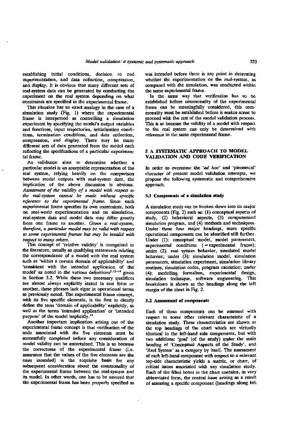
Model validation: a systemic and systematic approach 253
establishing initial conditions, decision to end experimentation, and data collection, compression, and display. It is obvious that many different sets of real-system data can be generated by conducting the experiment on the real system depending on what constraints are specified in the experimental frame.
This situation has an exact analogy in the case of a simulation study (Fig. 1) where the experimental frame is interpreted as controlling a simulation experiment by specifying the model's output variables and functions, input trajectories, initialization conditions, termination conditions, and data collection, compression, and display. There may be many different sets of data generated from the model each reflecting the specifications of a particular experimental frame.
As validation aims to determine whether a particular model is an acceptable representation of the real system, relying heavily on the comparison between model outputs with real-system data, the implication of the above discussion is obvious. Assessment of the validity of a model with respect to the real-system cannot be made without specific reference to the experimental frame. Since each experimental frame specifies its own constraints, both on real-world experimentation and on simulation, real-system data and model data may differ greatly from one frame to another. Given a real-system, therefore, a particular model may be valid with respect to some experimental frames but may be invalid with respect to many others.
This concept of 'relative validity' is recognized in the literature, usually as qualifying statements relating the correspondence of a model with the real system such as 'within a certain domain of applicability' and 'consistent with the intended application of the model' as noted in the various definitions2'12"'4 given in Section 3.2. While these two necessary qualifiers are almost always explicitly stated in one form or another, these phrases lack rigor in operational terms as previously noted. The experimental frame concept, with its five specific elements, is the first to clearly define the term 'domain of applicability* explicitly, as well as the terms 'intended application' or 'intended purpose' of the model implicitly.15
Another important implication arising out of the experimental frame concept is that verification of the code associated with the five elements must be successfully completed before any consideration of model validity can be entertained. This is so because the correctness of the experimental frame (i.e. assurance that the values of the five elements are the ones intended) is the requisite basis for any subsequent consideration about the commonality of the experimental frame between the real-system and its model. In other words, one has to be assured that the experimental frame has been properly specified as
was intended before there is any point in determing whether the experimentation on the real-system, as compared with the simulation, was conducted within the same experimental frame.
In the same way that verification has to be established before commonality of the experimental frame can be meaningfully considered, this commonality must be established before it makes sense to proceed with the rest of the model validation process. This is so because the validity of a model with respect to the real system can only be determined with reference to the same experimental frame.
5 A SYSTEMATIC APPROACH TO MODEL VALIDATION AND CODE VERIFICATION
In order to overcome the 'ad hoc' and 'piecemeal' character of present model validation attempts, we propose the following systematic and comprehensive approach.
5.1 Components of a simulation study
A simulation study can be broken down into its major components (Rg. 2) such as: (1) conceptual aspects of study, (2) behavioral aspects, (3) computerized simulation program, and (4) methods and techniques. Under these four major headings, more specific operational components can be identified still further. Under (1): conceptual model, model parameters, experimental conditions ( = experimental frame); under (2): real system behavior, simulated model behavior; under (3): simulation model, simulation parameters, simulation experiment, simulation library routines, simulation codes, program execution; under (4): modelling formalism, experimental design, simulation technique, software engineering. This breakdown is shown as the headings along the left margin of the chart in Fig. 2.
53. Assessment of components
Each of these components can be assessed with respect to some other relevant characteistic of a simulation study. These characteristics are shown as the top headings of the chart which are virtually identical to the left-hand side components, but with two additions: 'goal' (of the study) under the main heading of 'Conceptual Aspects of the Study', and •Real System' as a category by itself: The assessment of each left-hand component with respect to a relevant top-side characteristic yields a matrix, or chart, of critical issues associated with any simulation study. Each of the filled boxes in the chart contains, in very abbreviated form, the central issue arising as a result of assessing a specific component (headings along left
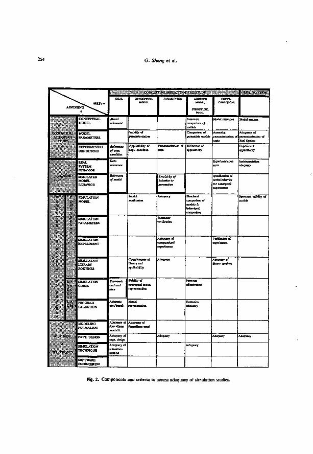
G. Sheng et al.
O O N O J
A S S E S W R T s -
» ^ " » » -
GOAL • CONCEPTUAL - PARAMETERS ANOTHER M O D E L
STRUCTURE, PROG.
EXPT*L. CONDITIONS
C O Y C E P A S r t O
STCT
C O N C E P T U A L M O D E L
Moid
relevance
Structural compansoo of models
M o d d relevance Model realism
C O Y C E P A S r t O
STCT
I L A L S O I ; iV
M O D E L P A R A M E T E R S
V < ! > % a r paratnctcnzatMu
Compsnsou of puametr ic models pa^rrr^^Tttron of
expts
Adequacy of ptrtnMtcrizflion of Real S y n c m
C O Y C E P A S r t O
STCT
E X P E R I M E N T A L
C O N D m O N S
Rdrmnct App&arjiiliry of « p t . condition
Fararoctctintton of Differeoce of applicability
Experiment applicability
R E A L S Y S T E M BEHAVIOR
Data 1 rtUwance
Experimentation error
tnfFpTrtfTTtaTrflo adequacy
1 1 1 1 » IOR S I M U L A T E D M O D E L BEHAVIOR
Relevance
cfmodd SeitstimVifji of Qmlificjtioo of
model behavior wtt cooceptual
c o M 1 1
T E H 1
1
It
. 1 v 1 1.
4
1 1
c o M f O
SIMULATION M O D E L
Model
venficsifOn
Adequacy S tnc tora l compansoD of models & behavioral comparison
Structural validity of models
c o M 1 1
T E H 1
1
It
. 1 v 1 1.
4
1 1
9, fc N r s
SIMULATION P A R A M E T E R S
Pmranjctcf
venficattoo
c o M 1 1
T E H 1
1
It
. 1 v 1 1.
4
1 1
S IMULATION E X P E R I M E N T
Adequacy of
expenracoj^
Verification of
c o M 1 1
T E H 1
1
It
. 1 v 1 1.
4
1 1
S IMULATION LIBRARY
ROUTINES
library and applicability
Adequacy Adequacy of library routines
O %
1
R • • t H a, «
op V F F . t l K C
* H
S I M U L A T I O N C O D E S
Economic
cost and
time
FMelity of conceptual model roprcserittttoo
Program effectiveness
O %
1
R • • t H a, «
L * i L H
P R O G R A M E X E C U T I O N
Adequate
eon/benefit M a i d icpteseolalioa
Execution efficiency
M O D E L I N G
F O R M A L I S M
Adequacy of formalisms available
Adequacy of formalisms writ
M E T W
m M M
iw E X P T . DESION Adequacy of cxpt . design
Adequacy Adequacy Adequacy M E T W
m M M >UES
S IMULATION T E C H N I Q U E
Adequacy of
method
Adequacy
M E T W
m M M
S O F T W A R E E N G I N E E R I N G
Fig. 2 . Components and criteria to access adequacy of simulation studies.
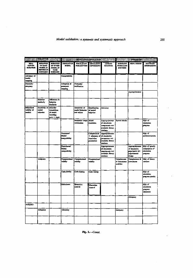
Model validation: a systemic and systematic approach
U M I A M O K \ PKOtiRAMS
REAL SYSTEM BEHAVIOR
BEHAVIOR or SAME MODEL IN DOTERENT SCENARIO
BEHAVIOR OF OTHER MODEL IN SAME
SCENARIO
SIMULATION MODEL
SIMULATION PARAMETERS
SIMULATION EXPERIMENT
LIBRARY ROUTINES
MODEUNC FORMALISM (METHOD)
EOT. DESJCN SOFTWARE ENCtNEERTNC
Adequacy of mode, mapping
Gcmpntabilhy
adequacy^ Adequacy of ^ammeter
Parameter verification
Appropriateness
Behavior similarity
Difference m nebavjor similarity
Behavioral vafidiiy of
Seosdmty of model behavior
Behavior iciin>afuwtt of model
para + expts
Sensitivity of model bebavior wrt values
Qttalificanoa of model behavior
Accuracy
Parameter range verification
Model resolution
Appropriateness of aiinu talion components wrt available I&rary
Fornui check « SQAof ttrcttlatioo program
Parameter/ Model wmpilSiiBty
OfflnpW^TtfTï + adequacy of
parameters
Appropriateness of ammlation parameters wrt available library
SQAof
Modd Appropriateness of simulation experiments wtt available ubrary
Appiopnatrawiw of simulation experiment wrt expernoental design
SQA of specific fnrTtrdfjTKKi of
program
Adequacy vaSaoy
Computational validity
^OfltpHStiftTlfl vafidiiy
Completeness of formalisms available
Completeness & correctness
SQA of library routines
CodefidcCry Code fidelity Code fidelity SQA of simulation program (static)
Robustness Etectrtioq control
Extentùm contrat
SQA of •imulatîou program (dynamic)
Adequacy
Adequacy
Adequacy Adequacy Adequacy
Fig. l.—Corud.
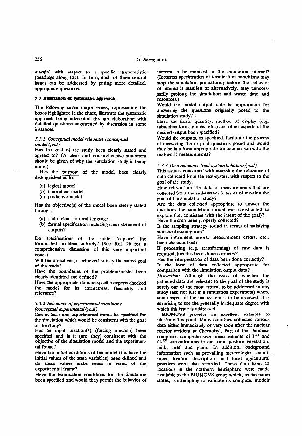
256 G. Sheng et al.
margin) with respect to a specific characteristic (headings along top). In turn, each of these central issues can be addressed by posing more detailed, appropriate questions.
S3 Illustration of systematic approach
The following seven major issues, representing the boxes highlighted in the chart, illustrate the systematic approach being advocated through elaboration with detailed questions augmented by discussion in some instances.
5.3.1 Conceptual model relevance (conceptual model/goal) Has the goal of the study been clearly stated and agreed to? (A clear and comprehensive statement should be given of why the simulation study is being done.)
Has the purpose of the model been clearly distinguished as to:
(a) logical model (b) theoretical model (c) predictive model
Has the objective(s) of the model been clearly stated through:
(a) plain, clear, natural language, (b) formal specification including clear statement of
outputs?
Do specifications of the model "capture' the formulated problem entirely? (See Ref. 26 for a comprehensive discussion of this very important issue.) Will the objectives, if achieved, satisfy the stated goal of the study? Have the boundaries of the problem/model been clearly identified and defined? Have the appropriate domain-specific experts checked the model for its correctness, feasibility and relevance?
5.3.2 Relevance of experimental conditions (conceptual experimental/goal) Can at least one experimental frame be specified for the simulation which would be consistent with the goal of the study? Has an input function(s) (forcing function) been specified and is it (are they) consistent with the objective of the simulation model and the experimental frame? Have the initial conditions of the model (i.e. have the initial values of the state variables) been defined and do these values make sense in terms of the experimental frame? Have the termination conditions for the simulation been specified and would they permit the behavior of
interest to be manifest in the simulation interval? (Incorrect specification of termination conditions may stop the simulation prematurely before the behavior of interest is manifest or alternatively, may unnecessarily prolong the simulation and waste time and resources.) Would the model output data be appropriate for answering the questions originally posed to the simulation study? Have the form, quantity, method of display (e.g. tabulation form, graphs, etc.) and other aspects of the desired output been specified? Would the outputs, as specified, facilitate the process of answering the original questions posed and would they be in a form appropriate for comparison with the real-world measurements?
5.3.3 Data relevance (real-system behavior/goal) This issue is concerned with assessing the relevance of data collected from the real-system with respect to the goal of the study. How relevant are the data or measurements that are collected from the real-system in terms of meeting the goal of the simulation study? Are the data collected appropriate to answer the questions the simulation model was constructed to explore (i.e. consistent with the intent of the goal)? Have the data been properly collected? Is the sampling strategy sound in terms of satisfying statistical assumptions? Have instrument errors, measurement errors, etc., been characterized? If processing (e.g. transforming) of raw data is required, has this been done correctly? Has the interpretation of data been done correctly? Is the form of data collected appropriate for comparison with the simulation output data? Discussion: Although the issue of whether the gathered data are relevant to the goal of the study is surely one of the most critical to be addressed in any study (and not just in a simulation experiment) where some aspect of the real-system is to be assessed, it is surprising to see the generally inadequate degree with which this issue is addressed.
BIOMOVS provides an excellent example to illustrate this point. Many countries collected various data either immediately or very soon after the nuclear reactor accident at Chernobyl. Part of this database comprised comprehensive measurements of I' 3 1 and Cs 1 3 7 concentrations in air, rain, pasture vegetation, milk, beef and grain. In addition, background information such as prevailing meterological conditions, location description, and local agricultural practices were also recorded. These data from 13 locations in the northern hemisphere were made available to the BIOMOVS group which, as the name states, is attempting to validate its computer models
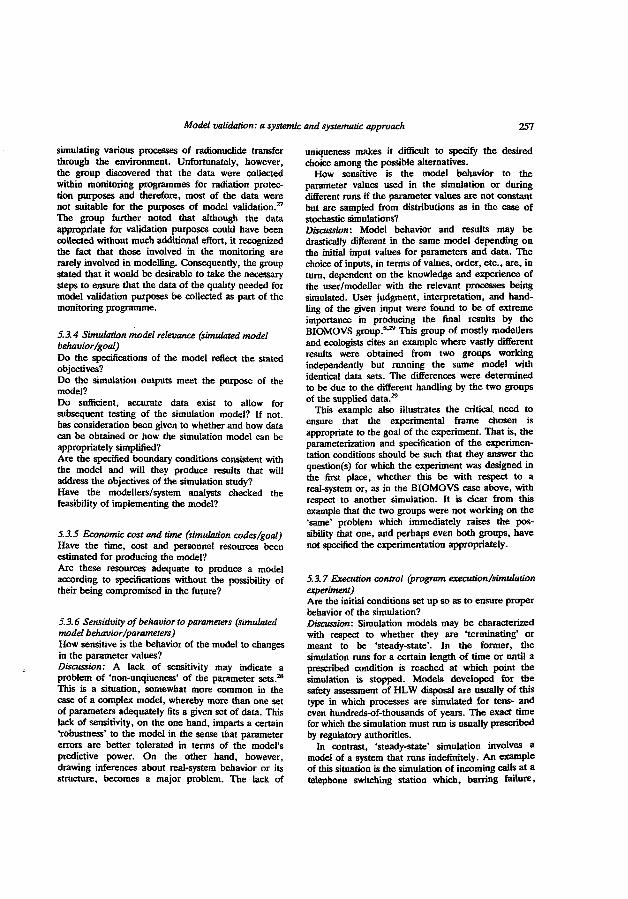
Model validation: a systemic and systematic approach 257
simulating various processes of radionuclide transfer through the environment. Unfortunately, however, the group discovered that the data were collected within monitoring programmes for radiation protection purposes and therefore, most of the data were not suitable for the purposes of model validation.2 7
The group further noted that although the data appropriate for validation purposes could have been collected without much additional effort, it recognized the fact that those involved in the monitoring are rarely involved in modelling. Consequently, the group stated that it would be desirable to take the necessary steps to ensure that the data of the quality needed for model validation purposes be collected as part of the monitoring programme.
5.3.4 Simulation model relevance (simulated model behavior/goal) Do the specifications of the model reflect the stated objectives? Do the simulation outputs meet the purpose of the model? Do sufficient, accurate data exist to allow for subsequent testing of the simulation model? If not, has consideration been given to whether and how data can be obtained or how the simulation model can be appropriately simplified? Are the specified boundary conditions consistent with the model and will they produce results that will address the objectives of the simulation study? Have the modellers/system analysts checked the feasibility of implementing the model?
5.3.5 Economic cost and time (simulation codes/goal) Have the time, cost and personnel resources been estimated for producing the model? Are these resources adequate to produce a model according to specifications without the possibility of their being compromised in the future?
5.3.6 Sensitivity of behavior to parameters (simulated model behavior /parameters) How sensitive is the behavior of the model to changes in the parameter values? Discussion: A lack of sensitivity may indicate a problem of 'non-unqiueness' of the parameter sets.2* This is a situation, somewhat more common in the case of a complex model, whereby more than one set of parameters adequately fits a given set of data. This lack of sensitivity, on the one hand, imparts a certain 'robustness' to the model in the sense that parameter errors are better tolerated in terms of the model's predictive power. On the other hand, however, drawing inferences about real-system behavior or its structure, becomes a major problem. The lack of
uniqueness makes it difficult to specify the desired choice among the possible alternatives.
How sensitive is the model behavior to the parameter values used in the simulation or during different runs rf the parameter values are not constant but are sampled from distributions as in the case of stochastic simulations? Discussion: Model behavior and results may be drastically different in the same model depending on the initial input values for parameters and data. The choice of inputs, in terms of values, order, etc., are, in turn, dependent on the knowledge and experience of the user/modeller with the relevant processes being simulated. User judgment, interpretation, and handling of the given input were found to be of extreme importance in producing the final results by the BIOMOVS group. 8 - 2* This group of mostly modellers and ecologists cites an example where vastly different results were obtained from two groups working independently but running the same model with identical data sets. The differences were determined to be due to the different handling by the two groups of the supplied data. 2 5
This example also illustrates the critical need to ensure that the experimental frame chosen is appropriate to the goal of the experiment. That is, the parameterization and specification of the experimentation conditions should be such that they answer the question(s) for which the experiment was designed in the first place, whether this be with respect to a real-system or, as in the BIOMOVS case above, with respect to another simulation. It is clear from this example that the two groups were not working on the 'same' problem which immediately raises the possibility that one, and perhaps even both groups, have not specified the experimentation appropriately.
5.3.7 Execution control (program execution/simulation experiment) Are the initial conditions set up so as to ensure proper behavior of the simulation? Discussion: Simulation models may be characterized with respect to whether they are "terminating' or meant to be 'steady-state'. In the former, the simulation runs for a certain length of time or until a prescribed condition is reached at which point the simulation is stopped. Models developed for the safety assessment of HLW disposal are usually of this type in which processes are simulated for tens- and even hundreds-of-thousands of years. The exact time for which the simulation must run is usually prescribed by regulatory authorities.
In contrast, 'steady-state' simulation involves a model of a system that runs indefinitely. An example of this situation is the simulation of incoming calls at a telephone switching station which, barring failure,
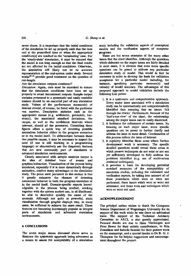
258 G. Skeng et al.
never closes. It is important that the initial conditions of the simulation be set up properly such that the runs end at the prescribed time or when the appropriate conditions) are reached in the 'terminating' case. For the 'steady-state' simulation, it must be ensured that the model is run long enough so that the final results are not affected by the initial conditions. Otherwise, the simulation will likely not be an accurate representation of the real-system under study. Several works 3 0" 3 2 provide good treatment on the question of run-length. Are the simulation outputs consistent? Discussion: Again, care must be exercised to ensure that the simulation conditions have been set up properly to avoid inconsistent outputs. Sample output statistics presented in a systematic and easily readable manner should be an essential part of any simulation study. Values of the performance measure(s) of interest should, of course, be listed with the particular run number. Descriptive statistics such as the appropriate means (e.g. arithmetic, geometric, harmonic), the associated standard deviations, the ranges, as well as the confidence intervals where relevant, should all the presented. Consulting these figures offers a quick way of detecting possible anomalous behavior either in the program execution or in the model itself. To differentiate between these two possible causes, it may be necessary to inspect the code (if one is still working in a programming language) or alternatively use the diagnostic features that are now commonly part of simulators or advanced simulation environments.
Closely associated with sample statistics output is the idea of detailed trace of events and graphics/animation. Visualization of the process being simulated, especially if it is done dynamically through animation, confers many advantages to the simulation study. The point most pertinent to this section is that it greatly enhances the chances of detecting anomalous behavior in both the program execution or in the model itself. Domain-specific experts knowledgeable in the process being studied, working together with the system analyst can, in all likelihood, be able to determine quickly the cause of the anomaly. Although not quite as powerful, static visualization through graphic displays may, in many cases, be sufficient to achieve the same result. These features are becoming increasingly popular as integral parts of simulators and advanced simulation environments.
6 CONCLUSIONS
The seven major issues discussed above serve to illustrate the systematic approach being advocated as a means to assess the acceptability of a simulation
study including the validation aspects of conceptual models and the verification aspects of computer programs.
These are but seven examples of the many other issues that the chart identifies. Although the questions which elaborate on the major issues are fairly detailed in most cases, it is obvious that even more specific questions can be posed to address any particular simulation study or model. This would in fact be necessary in order to develop the basis for validation acceptance for a particular model including, for instance, specifying particular measure(s) and value(s) of model accuracy. The advantages of this proposed approach to model validation include the following four points:
1. It is a systematic and comprehensive approach. Every major issue associated with a simulation study can be systematically and comprehensively identified thus ensuring that no issues 'fall through the cracks'. Furthermore, because of the 'bird's-eye-view' of the chart, the relationship among the major issues can be easily discerned.
2. It facilitates the refinement of certain issues. By focusing on each major issue, more specific questions can be posed to further clarify and address the issue in more detail. Continuation of this process refines the issue of interest.
3. It explicitly identifies those areas where further development work is necessary. The specific detailed questions would reveal those areas in which present techniques do not exist or are not yet sufficiently developed to fully address the problems identified (e.g. use of multivariate statistical techniques).
4. It provides a basis for developing potential standard measures of the acceptability of simulation studies, including the validation and verification aspects, by taking into account all of those procedures which were or were not performed, those issues which were or were not addressed, and those tools and techniques which were or were not used.
ACKNOWLEDGEMENT
The principal author wishes to thank the Computer Science Department of Wageningen University for its support of this work while he was there on sabbatical leave. The support of the Technical Advisory Committee to AECL is also greatly appreciated. Personal thanks are due to Hans Vierbergen and Peter Bewer for their artistic contributions, to Rita Donaldson and Isabelle Iwanski for their patient work on the manuscript, and a special thanks to Dr B. G. J. Thompson for his helpful suggestions and encouragement throughout the project.
Model validation: a systemic and systematic approach 259
REFERENCES
1. Balci, O. & Sargent, R. G-, A bibliography on the credibility, assessment and validation of simulation and mathematical models. Simuletter, 15(3) (1984) 15-27.
2. Society for Computer Simulation—Technical Committee on Model Credibility, Terminology for model credibility. Simulation, 32(3) (l979) 103-4.
3. IEEE Standard for software verification and validation plans. ANSI/IEEE Std 1012-1986, IEEE, New York, IEEE Computer Society Press, Los Alamitos, CA, USA, 1986.
4. Naylor, T. H. & Finger, J. M., Verification of computer simulation models. Management Science, 14(2) (1967) B92-101.
5. Sheng, G. & Cronhjort, B. T., Intercomparison activities of probabilistic safety assessment codes in the context of model and software reliability. Presentation at International Conference on Probabilistic Safety Assessment and Management, Beverly Hills, February 4-7,1991.
6. Bogorinski, P., How do the code verification and validation projects Hydrocoin and Intracoin cope with licensing requirements for nculear waste repositories in the FRG? In Proceedings of SKI Symposium GEOVAL-%1. Swedish Nuclear Power Inspectorate, Sweden, 1987, Vol. 2, pp. 559-67.
7. Lehman, L., State of Nevada Review of Phase I of the INTRAVAL project. Technical Report of the State of Nevada Agency for Nuclear Projects/Nuclear Waste Project Office (in press).
8. Barry, P. J., Davis, P. A., van Dorp, F., Hoffman, F. O., Nielsen, S. P. & Smith, G. M., BIOMOVS Final Report (draft).
9. Konikow, L. F. & Bredehoeft, J. D., Ground-water models cannot be validated. Advances in Water Resources (Special issue on Validation of Hydrogeologi-cal Models), 15 (1992) 75-83.
10. Kuhn, T., The Structure of Scientific Revolutions (2nd edn). The University of Chicago Press, Chicago, 1970.
11. Popper, K.. The Logic of Scientific Discovery. Harper and Row, New York, 1958, 479 pp.
12. Nuclear Regulatory Commission, A revised modelling strategy document for high-level waste performance assessment. U.S. Nuclear Regulatory Commission, Washington, D.C., 1984.
13. Department of Energy, Environmental Assessment— Yucca Mountain Site, Nevada Research and Development Area, Nevada. DOE/RW-0073, 2, U.S. Department of Energy Office of Civilian Radioactive Waste Management, Washington, D.C., 1986.
14. IAEA Radioactive waste management glossary (2nd edn). IAEA-TECH-DOC-447, International Atomic Energy Agency, Vienna, 1988.
15. Elzas, M. S., Systems paradigms as reality mappings, Ch. 2. In Sumdation and Model-Based Methodologies: An Integrative View, (eds). Oren, T. I., Zeigler, B. P. & Elzas. M. S. Springer-Verlag, Berlin, Heidelberg, New York, Tokyo, 1984. 651 pp.
16. Zeigler, B. P.. Theory of Modelling and Simulation. Wiley, New York, 1976.
17. Oren, T. I. & Zeigler, B. P., Concepts for advanced simulation methodologies. Simulation, 32(3) (1979) 69-82.
18. Zeigler, B. P., Elzas, M. S., Klir, G. J. & Oren, T. I. (Eds), Methodology in System Modelling and Simulation. North-Holland, Amsterdam, 1979, 537 pp. (out of print).
19. Oren, T. I., Zeigler, B. P. & Elzas, M. S. (Eds), Simulation and Model-Based Methodologies: An Integrative View. Springer-Verlag, Berlin, Heidelberg, New York, Tokyo, 1984, 651 pp.
20. Elzas, M. S., Oren, T. I. & Zeigler, B. P. (Eds), Modelling and Simulation Methodology in the Artificial Intelligence Era. North-Holland, Amsterdam, 1986, 423 PP-
21. Elzas, M. S., Oren, T. I. & Zeigler, B. P. (Eds), Modelling and Simulation Methodology: Knowledge Systems Paradigms. North-Holland, Amsterdam, 1989, 487 pp.
22. Caswell, H., The validation problem. In Systems Analysis and Simulation in Ecology, Vol. IV, ed. B. C. Patten. Academic Press, New York, 1976, pp. 313-25.
23. Mankin, J. B., O'Neill, R. V., Shugart, H. H. & Rust, B. W., The importance of validation in ecosystem analysis. In New Directions in the Analysis of Ecological Sysems, Part 1. Simulation Councils Proceedings Series, 5, No. 1. Simulation Councils, Inc., LaJolIa, CA, 1975, pp. 63-71.
24. Loehle, C , Evaluation of theory and calculation tools in ecology. Ecological Modelling, 19 (1983), 239-47.
25. Singh, M. G. (Ed.), Systems and Control Encyclopedia. Pergamon Press, Oxford, UK, 1987.
26. Balci, O. & Nance, R. E., Formulation problem verification as an explicit requirement of model credibility. Simulation, 45(2) (1985) 76-86.
27. Köhler, H., Peterson, S. R. & Hoffman, F. O. (Eds), Multiple model testing using Chernobyl fallout data of 1-131 in forage and milk and Cs-137 in forage, milk, beef and grain. BIOMOVS Technical Report 13, Scenario A4, Part 1, Swedish National Institute of Radiation Protection (SKI), Stockholm, Sweden, 1991.
28. Loehle, C , Errors of construction, evaluation, and inference: A classification of sources of error in ecological models. Ecological Modelling, 36 (1987) 297-314.
29. Hoffman, F. O., Conclusions of BIOMOVS Phase 1. In Proceedings of BIOMOVS Symposium on the Validity of Environmental Transfer Models, Stockholm, October 8-10, 1990. Swedish Radiation Protection Institute, Stockholm, Sweden, 1991.
30. Kleijnen, J. P. C , Statistical Techniques in Simulation, Pan 1. Marcel Dekker, Inc., New York, 1974.
31. Law, A. M., Statistical analysis of simulation output data. Operations Research, 31(6) (1983) 983-1029.
32. Law, A. M. & Kelton, W. D., Simulation Modeling & Analysis (2nd edn). McGraw-Hill, Inc.. New York, 1991, 759 pp.

CHAPTER 4
REVIEW OF THE CANADIAN PERFORMANCE ASSESSMENT CODE
- A CASE STUDY
This chapter presents a review of some aspects of the Canadian performance assessment code and its models. The chapter details the review process carried out by the author in evaluating the quality of the code and some of its associated documentation. The review is based on the principles and techniques discussed in Chapter 3 and on the application of relevant ANSI/IEEE standards to each of the phases of the software development as well as to some of its supporting documentation.
This chapter (and the ensuing official report expected to arise therefrom), is the first (and likely to be the only) in-depth review of the computer code implementation of Canada's performance assessment work to be conducted externally. Consequently, it is important to make this software development process and its evaluation visible and understandable. The contents of this chapter may very well contribute to the ultimate judgement as to the quality of the assessment code and its models. Should other external reviews be undertaken by other parties (as described in 2.5) in the disposal concept evaluation process, it is likely that the ensuing official report arising from this chapter will serve as a guide.
The development of the SYVAC (SYstem Variability Analysis Code) code was initiated in the late seventies to implement the methodology of system variability analysis (SVA) (Dormuth and Quick, 1981; Dormuth and Sherman, 1981) as a means of assessing the safety performance of a nuclear waste disposal system. At that time the fundamental concept of SVA was novel to the field of nuclear waste disposal. It did address the need to manage both the large number of variables and the uncertainties in such parameters used in modelling a disposal system.
Because of the centrality of safety performance assessment to the Nuclear Fuel Waste Management Program (NFWMP) the development and application of SYVAC engaged TAC's attention from the beginning of our reviews of the NFWMP. TAC's initial reviews (TAC-2) as well as presentations at AECL information meetings marked our special concerns with regard to the quality assurance of the software (the code itself) and led to TAC's decision to carry out an independent and detailed review of SYVAC. At the same time TAC supported the soundness of using a SVA approach (TAC-5) and re-affirmed this view in succeeding reports.
Resources were provided by AECL through TAC's operating budget to enable some detailed investigation of SYVAC and its supporting documentation. For several years, part of the time of the Science Secretary of TAC as well as a full-time computer scientist has been devoted to this task. Through this period of time there have continued to be major developments in SYVAC, as well as very rapid developments in software engineering which has come to
4-1
characterize the current rapidly evolving situation in computer program design, code development, associated software standards, and even the field of Performance Safety Assessment (PSA) itself. This has meant that TAC has been endeavouring to examine a "moving target" as well as trying to encompass evolving techniques and methodologies for such critical review.
TAC has received successive versions of SYVAC for examination. Such review has been quite interactive with frequent consultations with AECL staff and excellent cooperation in the process. This has allowed informal suggestions to be made regarding software tools, transmittal of errors found in the code and/or its documentation, and questioning on specific matters. At one point, parallel work for Ontario Hydro led to suggesting and helping in developing useful tools for code construction and verification. As a direct result, Ontario Hydro has since completely re-developed its pre-closure assessment code. Occasional interim reports were prepared for TAC members leading to statements, comments and recommendations which then appeared in successive annual TAC reports.
TAC's review of SYVAC has been organized with regard to well-accepted principles in software engineering for the design and development of computer codes. Adherence to this software development life cycle has been coupled with continuing reference to recognized industry standards set by ANSI/IEEE (American National Standards Institute/Institute of Electrical and Electronic Engineers) for requirement, specification, coding and verification and validation phases.
The application of SYVAC to performance assessment of the disposal system as conceived in the NFVVMP is generally documented under the heading of post-closure assessment. "The Post-closure Assessment of a Reference System for Disposal of Canada's Nuclear Fuel Waste" was the title of a draft of a primary reference document supporting the Environmental Impact Statement (EIS) to be submitted by AECL. This draft was reviewed by TAC in late 1992 and comments conveyed in writing and through a discussion meeting with the prime author in January 1993. TAC's views were supplemented by a special report commissioned by TAC from a specialist in systems engineering dealing with some aspects of the modelling and the software quality assurance as contained in the document. This was also supplied to AECL at the time of our appraisal of the draft document. TAC's views of the contents of that draft document which pertain directly to SYVAC are integrated into this report.
This report thus presents an account of the current status of TAC's review of SYVAC, with Section 4.1 introducing the basic concepts and terminology used in simulation and software engineering; Section 4.2 summarizing AECL's SYVAC project; and Section 4.3 presenting TAC's review procedures, and comments on each component of that review with some explanatory observations. Some conclusions and recommendations are offered in Section 4.4. Appendices are provided for additional detail as deemed appropriate.
4-2
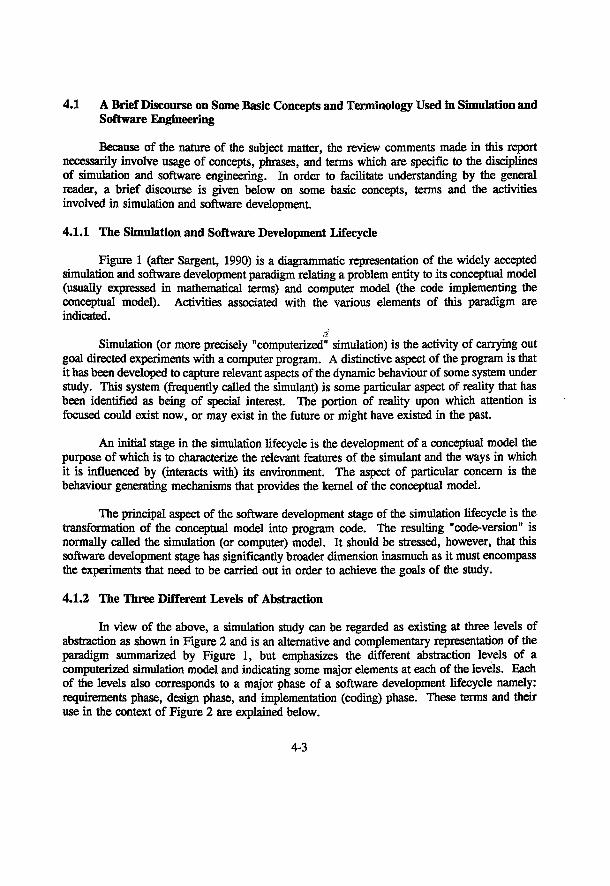
4.1 A Brief Discourse on Some Basic Concepts and Terminology Used in Simulation and Software Engineering
Because of the nature of the subject matter, the review comments made in this report necessarily involve usage of concepts, phrases, and terms which are specific to the disciplines of simulation and software engineering. In order to facilitate understanding by the general reader, a brief discourse is given below on some basic concepts, terms and the activities involved in simulation and software development.
4.1.1 The Simulation and Software Development Lifecycle
Figure 1 (after Sargent, 1990) is a diagrammatic representation of the widely accepted simulation and software development paradigm relating a problem entity to its conceptual model (usually expressed in mathematical terms) and computer model (the code implementing the conceptual model). Activities associated with the various elements of this paradigm are indicated.
Simulation (or more precisely "computerized" simulation) is the activity of carrying out goal directed experiments with a computer program. A distinctive aspect of the program is that it has been developed to capture relevant aspects of the dynamic behaviour of some system under study. This system (frequently called the simulant) is some particular aspect of reality that has been identified as being of special interest. The portion of reality upon which attention is focused could exist now, or may exist in the future or might have existed in the past.
An initial stage in the simulation lifecycle is the development of a conceptual model the purpose of which is to characterize the relevant features of the simulant and the ways in which it is influenced by (interacts with) its environment. The aspect of particular concern is the behaviour generating mechanisms that provides the kernel of the conceptual model.
The principal aspect of the software development stage of the simulation lifecycle is the transformation of the conceptual model into program code. The resulting "code-version" is normally called the simulation (or computer) model. It should be stressed, however, that this software development stage has significantly broader dimension inasmuch as it must encompass the experiments that need to be carried out in order to achieve the goals of the study.
4.1.2 The Three Different Levels of Abstraction
In view of the above, a simulation study can be regarded as existing at three levels of abstraction as shown in Figure 2 and is an alternative and complementary representation of the paradigm summarized by Figure 1, but emphasizes the different abstraction levels of a computerized simulation model and indicating some major elements at each of the levels. Each of the levels also corresponds to a major phase of a software development lifecycle namely: requirements phase, design phase, and implementation (coding) phase. These terms and their use in the context of Figure 2 are explained below.
4-3
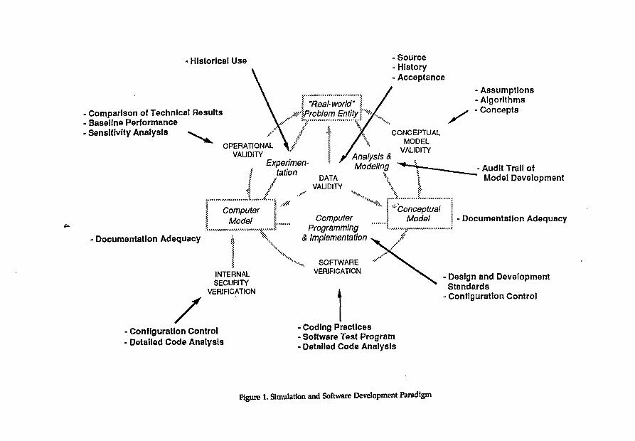
Historical Use • Source • History • Acceptance
• Comparison of Technical Results • Baseline Performance • Sensitivity Analysis > ^
I "Real-world" jzr\Problem EntityJ'**
- Assumptions - Algorithms - Concepts
Documentation Adequacy
OPERATIONAL VALIDITY
Experimen-I talion
Analysis & Modeling
CONCEPTUAL MODEL
VALIDITY
Computer Model
DATA VALIDITY
Computer Programming
& Implementation
"Conceptual Model
- Audit Trail of Model Development
• Documentation Adequacy
INTERNAL SECURITY
VERIFICATION
Configuration Control Detailed Code Analysis
SOFTWARE VERIFICATION
• Coding Practices • Software Test Program • Detailed Code Analysis
- Design and Development Standards
- Configuration Control
Figure 1. Simulation and Software Development Paradigm
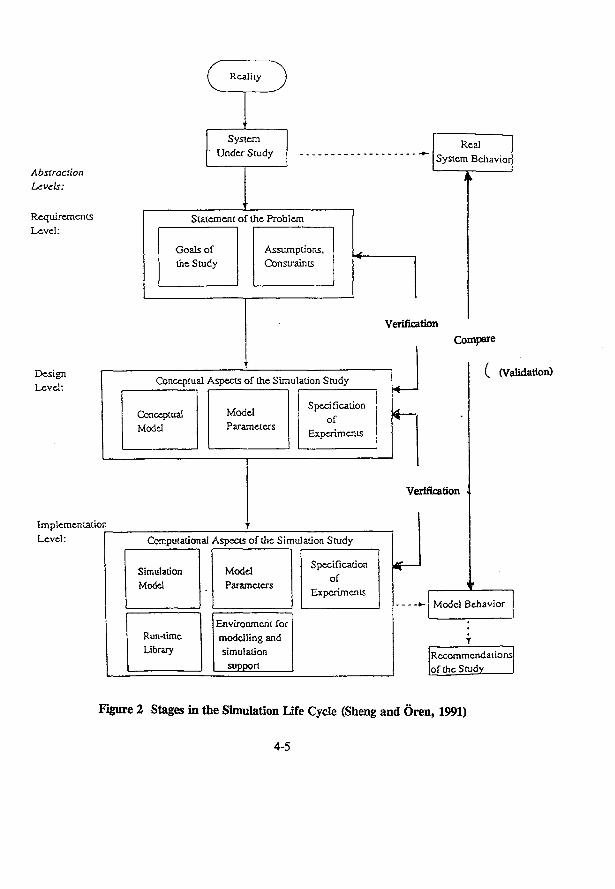
Abstraction Levels:
Requirements Level:
R e a l i t y
System Under Study
Real System Behavior
Statement of the Problem
Goals of the Study
Assumptions. Constrain is
Design Level:
Implementation Level:
Conceptual Aspects of the Simulation Study
Conceptual Model
Model Parameters
Specification of
Experiments
Computational Aspects o f the Simulation Study
Simulation Model
Run-lime Library
Model Parameters
Environment for modelling and simulation
supppn
Specification of
Experiments
Verification
Compare
( (Validation)
Verification
Model Behavior
Recommendations of the Study
Figure 2 Stages in the Simulation Life Cycle (Sheng and Oren, 1991)
4-5
4.1.2.1 Requirements Level
At this level, the simulation study is specified in terms of a general description of the problem environment (the portion of reality under investigation). This, in particular, includes: assumptions, constraints, principal variables and parameters, and a clear statement of the objectives and what constitutes a solution of the problem being investigated. The presentation at this level is normally in the form of a natural language text.
4.1.2.2 Design level
The design level evolves from the requirements through refinement steps. The general objectives of the refinement process are to introduce precision relating to the important features of the study; e.g.
(i) the behaviour generating mechanism that is to be embedded in the model,
(ii) the specMc nature of the. mputs and parameters associated with the model (i.e. environment influences),
(iii) the set of experiments which should yield the insight required for achievement of the goal of the study.
The presentation at this level may exist in a variety of forms that could include some combination of natural languages, formal mathematical structures, or graphical symbolism. The design level abstraction generally provides the primary communication medium for the community of individuals who have an interest in the study.
4.1.2.3 Implementation (Coding) Level
The implementation level of abstraction is obtained via a transformation of the design level abstraction into program code using the constructs of the particular programming language that has been selected for carrying out the simulation task. This transformation must naturally preserve the processing requirements that are implicit in the design level abstraction. However, it should be noted also that simulation level abstraction will generally introduce additional aspects that are characteristic of the simulation language being used. These arise both from the world view supported by the language and the conventions of its internal processing mechanisms.
4 . 1 . 3 Software Quality Assurance (SQA)
SQA is not so much a phase as it is an embodiment of a concept or principle which aims to produce a (software) product of quality. This is manifest by adoption of a set of standards, practices and procedures that pervades the entire development lifecycle. One major suite of activities comprising SQA is "code/software verification". Another set of major activities relate
4-6
to the quality of the conceptual models (model validation) including the quality of the data used (data validation).
Verification and Validation
As indicated in Figure 2, verification is" "The process of deterrnining whether or not the products of a given phase of the software development cycle fulfil the requirements established during the previous phase" (IEEE Std. 1012-1986 definition). Also indicated in Figure 2 is "validation" which is: "Substantiation that a computerized model within its domain of appHcability possesses a satisfactory range of accuracy consistent with the intended application of the model" (Society for Computer Simulation - Technical Committee on Model Credibility). These two terms "Verification" and "Validation" are often confused with each other and used interchangeably. "Verification" is almost always misused, especially in the nuclear waste disposal field, where the term is applied to code intercomparison exercises and/or comparison of numerical calculations to an analytical solution. Verification, as understood in software engineering, has to do with ensuring internal consistency between the different abstraction levels and is independent of computational results produced from other codes or computational methods. Validation always (strictly speaking) involves comparison of model calculation results with measurements from the real-world and not with the results produced by other groups.
4.1.4 Definitions and Discussion of Terms and Procedures
The following is a brief discussion of the other terms and technical processes associated with the paradigm.
• Data validation. Validation of the data used in the development and operation of the model is applied during each activity of the assessment process. It requires delving into the source, history, and past acceptance of the data. The source of the data includes its origin and any justification provided supporting its selection. The history of the data includes investigation of past studies that used the data. A key to the validity for data is community acceptance.
• Conceptual model validation. Validation of the conceptual model is divided into justification of the assumptions, algorithms, and modeling concepts used in development of the model. Assumptions can be explicit or implicit and may be related to application of an algorithm or embedded in the modeling construct used. Clear statement of the assumptions is a key to assuring that they were considered and their consequences weighed in model implementation. These assumptions may influence the domain of applicability of the model and will identify the bounds of model validity. Appropriateness of the algorithms and modeling techniques is also addressed.
• Analysis and modeling. Essential to assessing the development of the conceptual model are the documentation and organization of the analysis and modeling effort. This establishes an audit trail of the development from specification of the real-world problem
4-7
to the testing required in the model's validation. The modeling specifications are also influenced by accuracy requirements. The degree of accuracy required is influenced by the intended use of the model and, to some extent, by the conceptual design.
Conceptual model. The conceptual model should be completely described to clarify the purpose, function and development history of the model. Adequate documentation of this is a critical element in determining the model's functional utility.
Computer programming and implementation. As the developer implements the conceptual model, there are many activities and methods that can be employed to support the model credibility. Examination must include whether good software design, coding, and testing practices, standards, and tools were imposed, as well as the effectiveness of configuration control during development.
Software verification. Verifying that the software model is a faithful implementation of the conceptual model is essential to assuring potential users that the simulation results are credible. All procedures employed by the developer and/or independent evaluators to verify the model's implementation are assessed, and additional testing or analysis is accomplished as necessary. These procedures include verifying the implementation of software design and coding standards and evaluating the thoroughness of the test program. This also involves detailed code analysis. These activities are formalized through a comprehensive set of standards and procedures set by IEEE. The degree of accuracy required can be a factor of the depth of this effort.
Internal security verification. Evaluation of the configuration management program and all detailed software verification efforts help establish whether the computerized model is currently free of any tampering devices that would affect its operation or results.
Computer model. Adequate descriptions of the capabilities, lirnitations, use, maintenance, and so on are critical to the acceptance of the computer model. These must be described at a level that allows the users to understand how and when the model can be reasonably applied.
Operational validation. The computer model must demonstrate consistency with the real-world problem it was intended to represent. Operational validation is the comparison of model performance with the real-world system, if possible. Otherwise, comparison is made either with a standard, with itself after variation of selected input parameters, or with other models. This can include both developer and independent testing efforts.
Experimentation. Many of the models assessed will have been used in previous studies. How the models were used, acceptance of the results, and problems noted with the application are also contributors to the overall assessment of the model credibility. Adequacy of documentation is again essential here.
4-8
4.2 THE AECL "SYVAC PROJECT"
4.2.1 System Variability Analysis
There are two unique characteristics associated with the permanent disposal of nuclear waste: (a) no precedents exist for such an endeavour and (b) the very long time-span over which the multi-barrier system must remain effective. To deal with the inherent uncertainties involved in predicting possible future outcomes under this latter condition and reflecting the system complexity, a method known as "system variability analysis" was adopted (Wuschke et al., 1981). It takes into account, systematically, the effects of imprecise data (i.e. parameter values that cannot be precisely specified as single point values).
In this approach, uncertainties in the data gathered through research, and the variation of conditions through space and time are taken into account by assigning a distribution of values (rather than specifying a single value) to the parameters used to model or describe the disposal system. The distributions (e.g. normal, lognormal, exponential, uniform, etc.) are selected to cover the credible range of values for the parameters and are characterized by the likelihood of occurrence of chosen values in the specified range. The distributions thus represent observed or theoretical variability, subjective uncertainty, or a combination of both. Simulation studies using these data are performed by sampling values from each parameter distribution to generate a range of possible outcomes and their corresponding frequency of occurrence.
4.2.2 The SYVAC Simulation
This method is implemented with a computer program, SYVAC (SYstems Variability Analysis Code) (Wuschke et al., 1981) and is illustrated in Figure 3 . System simulations are performed by linking a set of three submodels representing the three major constituents of the disposal system: the vault, the geosphere, and the biosphere. Significant processes and conditions within each are characterized by sets of equations. These are, in effect, mathematical statements of the current state of knowledge about the disposal system and the phenomena that influence i t
Initial data input consists of the inventory of radionuclides placed in the vault. This is in the form of the used fuel bundles packed in a structurally supported container of titanium or copper. The processes of container failure and of leaching and transporting by groundwater within the vault, together with the reaction of these radionuclides with engineered barriers such as buffers and backfill, and the final movement of the vault are simulated. The output terms (i.e. integrated flux of radionuclides) from the vault serve as the input terms for the geosphere model. Examples of parameters which are taken into account in the estimation of radionuclide movement through geologic media include groundwater velocity, effective path length, chemical retardation factors including sorption, etc. In the third and last model, the biosphere, the analysis involves the estimation of radionuclide movement leaving the geosphere and travelling through shallow groundwater surface water, soil, plants, animals and, finally, to humans.
4-9
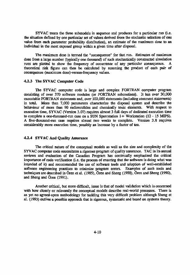
SYVAC treats the three submodels in sequence and produces for a particular run (i.e. the situation defined by one particular set of values derived from the stochastic selection of one value from each parameter probability distribution), an estimate of the maximum dose to an individual in the most exposed group within a given time after disposal.
The maximum dose is termed the "consequence" for that run. Estimates of maximum dose from a large number (typically one thousand) of such stochastically constructed simulation runs are plotted to show the frequency of occurrence of any particular consequence. A theoretical risk figure can then be calculated by summing the product of each pair of consequence (maximum dose)-versus-frequency values.
4.2.3 The SYVAC Computer Code
The SYVAC computer code is large and complex FORTRAN computer program consisting of over 370 software modules (or FORTRAN subroutines). It has over 30,000 executable FORTRAN statements and, over 100,000 statements (including comment statements) in total. More than 7,000 parameters characterize the disposal system and describe the behaviour of more than 90 radionculides and chemically toxic elements. With respect to execution time, SYVAC (Version 3.07) requires almost 3 full days of dedicated execution time to complete a one-thousand-run case on a SUN Sparcstation 1+ Workstation (12 - 15 MIPS). A five-thousand-run case requires almost two weeks to complete. Version 3.8 requires considerably more execution time, possibly an increase by a factor of ten.
4.2.4 SYVAC And Quality Assurance
The critical nature of the conceptual models as well as the size and complexity of the SYVAC computer code necessitates a rigorous program of quality assurance. TAC in its-annual reviews and evaluation of the Canadian Program has continually emphasized the critical importance of code verification (i.e. the process of ensuring that the software is doing what was intended of it) and recommended the use of software tools and adoption of well-established software engineering practices to minimize program errors. Examples of such tools and techniques are described in Oren et al. (1985), Oren and Sheng (1988), Qren and Sheng (1990), and Sheng and Oren (1991).
Another critical, but more difficult, issue is that of model validation which is concerned with how closely or relevantly the conceptual models describe real-world processes. There is as yet no agreed-upon methodology for tackling this very difficult problem although Sheng et al. (1993) outline a possible approach that is rigorous, systematic and based on systems theory.
4-10
Field
Experimental
RESEARCH
A N A L Y S I S
Models
Data
SYVAC
Systems Variability Analysis
Sub - Models
Risk = ^> Consequence x Freq.
Figure 3 . Systems Variability Analysis
4.3 TAC's REVIEW
43.1 Material Available For TAC's Review
A comprehensive list of material available for TAC's review can be found in Appendix I.
4.3.2 TAC's Review Procedure
4.3.2.1 Requirements
In order to assess the requirements phase of SYVAC's software development, the following pertinent AECL documents were reviewed:
(i) Model Bridging Reports (preliminary versions of Model Reports stated in (ii) below)
(ii) Draft Versions of SYVAC Model Reports (Biosphere, Geosphere, and Vault Models - final versions referred to as EIS Primary References)
(iii) Various miscellaneous Biosphere Submodel Documentation (Surface Water, Soil, Food-Chain (CALDOS), and Atmosphere)
(iv) SYVAC Software Development Project Plan (Doc. No.: ES001.001)
(v) Analysis Specifications of the Biosphere (known as BIOTRAC) and Vault Models (containing Data Flow Diagrams (DFDs), Data Dependency Diagrams (DDDs), Data Dictionary (DD) and, model synopses for Biosphere submodels)
The documents specified in points (i), (ii) and (iii) define the abstract mathematical models that are implemented in the SYVAC code.
The SYVAC Software Development (SSD) Project Plan (specified in point (iv)) is one of three software development standards documents produced by AECL's SYVAC Software Development Project which was established to complete the production of software used to assess the environmental and safety consequences of the disposal of nuclear fuel waste. The SSD Project Plan includes an outline on the activity used to develop and maintain Waste Disposal Assessment Software. In particular it describes what is involved in producing the "functional specifications" or requirements for SV3-CC3 software. TAC's review of AECL's standards regarding requirements phase development was conducted by checking for its conformance with the ANSI/IEEE Guide to Software Requirements Specifications (Std 830-1984)
4-12
The analysis specifications documents (specified in point (v) above) define the software requirements needed to implement the mathematical models (defined by the documents stated in points (i), (ii) and (iii)) in the SYVAC code. The software requirements specifications (SRS) produced in these documents were reviewed by checking for their conformance with the ANSI/IEEE Guide to Software Requirements Specifications (Std 830-1984).
The requirements components used in the specifications (DFDs, DDDs, DD, and model synopses) were spot checked for the following properties:
1) Consistency: Each requirement should be consistent with other requirements.
2) Necessity: Each requirement should be necessary in order to achieve the goals of ths system.
3) Sufficiency: The requirements should be examined for missing or incomplete requirements.
4) Ambiguity: The requirements should be clearly specified.
For a detailed discussion on both the assessment of SV3-CC3 Software Requirements Specifications and the components comprising the specifications, see report entitled Comments On SV3-CC3 Software Requirements Specifications.
4.3.2.2 Design
In order to assess the design phase of SYVAC's software development, the following pertinent AECL documents were reviewed:
(i) SYVAC Software Development Project Plan (Doc. No.: ES001.001)
(ii) Bioshpere Design Specifications (containing Module Specifications)
(iii) Computer Files Containing Biosphere Design Documentation (containing Design Data Dictionary, Data Cluster (COMMON Block) Descriptions)
(iv) SYVAC Structure Charts
4-13
The SYVAC Software Development (SSD) Project Plan (document referred to in point (i)) includes a description of what is involved in producing the "design specifications" for SV3-CC3 software. TAC's review of AECL's standards regarding design phase development was conducted by checking for its conformance with the ANSI/IEEE Recommended Practice for Software Design Descriptions (Std 1016-1987). A more detailed explanation of the SSD Project can be found in the previous section 2a (requirements assessment).
The SYVAC design specifications (documents referred to in points (ii), (iii) and (iv) for the Biosphere model were reviewed by checking for compliance with the ANSI/IEEE Recommended Practice for Software Design Descriptions (Std 1016-1987). The Biosphere model was selected for review since it is the only SYVAC model that has design documentation available.
The design components used in the specifications (structure charts, module specifications, design date dictionary, data cluster (COMMON Block) descriptions, and file format descriptions) were spot checked for the following properties:
1) Consisteneyr The design data should be consistent. For example, module interfaces should remain uniform whenever referenced in the specifications.
2) Necessity: It should be possible to trace each design element back to a requirement.
3) Sufficiency: Each requirement should be implemented by one or more design elements.
4) Correctness: The correctness of mathematical equations and computational algorithms should be checked. The correctness of control logic in the design should be analyzed.
In particular, the structure charts were reviewed with the aid of a software tool (developed in-house) known as XREF (Cross Reference Analyzer). See the next section 2.3 for more details.
For a detailed discussion on both the assessment of SV3-CC3 Software Design Specifications and the design components comprising the specifications, see the report entitled Comments On SV3-CC3 Software Design Specifications.
4-14
4.3.2.3 Code
4.3.2.3.1 Code Inspection
The most extensively used review technique used on the SYVAC code was "code inspection". This review technique involved the actual examination of the FORTRAN code on a line by line basis. The sections of the SYVAC code that were considered to be the most crucial (e.g. portions of the Executive, Time Series Package (TSP), and the Vault) would be examined in a top-down fashion dictated by the hierarchical calling structure of the individual modules (or FORTRAN subroutines) that constitute the SYVAC program. The main objectives of this review technique were to determine the existence of logical programming errors (such as inconsistencies in the code), the failure of adherence to the requirements/design specifications or any documentation associated with functioning of the examined code and lastly, to document the workings of the code.
A software tool known as ORFOR aided the inspection process. This software tool has the ability to format FORTRAN code in a manner suitable for easy code review. The tool takes original FORTRAN code as input and then generates as output a new version of the code formatted to accentuate the major language constructs of the language (such as "IF" statments, "DO" loops, etc.). The increased readability of the code allows the process of code inspection (described in the previous paragraph) to be done with greater ease and efficiency.
The major benefit derived from code inspection was that it allowed TAC to become familiar with the inner workings of the SYVAC code (especially the critical sections listed above). Very little documentation of this nature was available from AECL which forced TAC to provide its own. Also, code inspection enabled TAC to detect logical programming errors in past versions of the SYVAC code. These errors were communicated to AECL and were subsequently rectified. Lastly, the in-house documentation not only aided in understanding the SYVAC code but was useful for becoming reacquainted with sections of the code when continuing review was conducted at a later date.
4.3.2.3.2 Time Series Package (TSP)
The TSP (considered as part of the Executive code) was a special case for review. Besides being quite large and complex, it was unique in the fact this package could be segregated from the Executive and used in a generic sense (provided one understood the interface) for other applications besides simulations of nuclear waste disposal. Hence, the TSP was isolated from the Executive and incorporated into simple applications (requiring Time Series management) where the analytical solutions were well understood. The output results were then compared against the analytical solution.
The most complex TSP operation was the convolution of two time series. Hence, test applications were set up to employ the convolution operation. Past versions of the TSP were found to approximate the analytical solutions but descrepancies were found (enough to cause
4-15
some concern). This appears to have been related to the particular numerical methods used to solve the problem. The TSP has undergone changes since our test applications were run and the problems that have existed in the past versions has hopefully been rectified. Lack of time (coupled with possible changes to TSP interface) has hindered re-runing these test applications on the latest version of the SYVAC code.
4.3.2.3.3 XREF Tool
An in-house developed software tool known as XREF (Cross Reference Tool) was applied to the SYVAC code. The XREF tool statically analyzes (i.e. does not require actual execution of SYVAC code) the computer code and determines the complete module calling structure of SYVAC. The output from the XREF tool was entered into a simple but extremely useful database system that allows simple access to module calling information.
This information aided TAC's understanding of how SYVAC works and allowed TAC to verify the structure charts (part of the design specifications) supplied by AECL. There were no major descrepancies between XREF's output and the structure charts supplied by AECL.
4.3.2.3.4 DATRLX/LECS Tool
A software tool known as DATRLX/LECS was acquired from Bell Canada to collect software metrics that characterize the software attributes (that can be quantified) of the SYVAC computer code. This software tool performed a comprehensive static analysis (i.e. does not require execution of code) of the SYVAC computer code and, generated measurements of program characteristics such as documentation (e.g. comments), control structures (e.g. loops), volume (e.g. number of lines), breaches of program structure (e.g. bad programming practices) and metrics associated with call structure. These metrics provide a useful way of characterizing the SYVAC code in quantitative and semi-quantitative terms.
A point that is worth noting concerns the. metric, breaches of program structure. The SYVAC code mimics a "WHILE" loop construct (available in more recent high level languages but is not available in ANSI FORTRAN-77) using a combination of "IF" statements and a "GOTO" statement. DATRLX flags all "GOTO" statements used for this purpose as breaches of program structure. The implementation of the "WHILE" construct in this fashion seems to be correct but in the strict sense, it is not good programming practice.
4.3.2.3.5 RFFINE/FORTRAN Tool
A commercial tool known as REFINE/FORTRAN was purchased to reverse-engineer the SVYAC code (produce the design specifications from the code). For example, the tool was able to generate structure chart diagrams, provide data flow analysis, call/called tables for modules, set/use tables, etc. The information generated by this tool was used to verify the design specifications produced by AECL.
4-16
The output results of the tool showed reasonable agreement with the design specifications produced by AECL. For example, the structure chart information produced by the tool matched both the output produced by the XREF tool and the structure charts provided by AECL.
4.3.2.3.6 SYVAC Simulations
Most of the versions of the 3 r d generation SYVAC program (SYVAC3.xx) were implemented on TAC's workstation(s) and executed for various simulation case runs. The SYVAC versions were slightly modified to produce its output results in a format suitable for input into a software tool known as SVPLOTS. SVPLOTS is an in-house program that produces a "Frequency vs. Dose" histogram from the SYVAC output results. These histograms allowed TAC to compare its results with those produced by AECL.
SYVAC simulations in general required large amounts of computer time to execute. The latest version of the SYVAC code (version 3.09) required approximately 3.5 - 4 months of dedicated computer time on a SUN Sparcstation SLC (4/20) to perform a 500 run simulation case. This heavy time requirement hindered TAC's ability to do a large number of simulation cases on the SYVAC code. However, the simulations that were performed on older versions of SYVAC showed some descrepancies between TAC's and AECL's results. In particular, the histograms produced by TAC's simulations showed significantly higher output doses than those produced by AECL (see Figures 4 and 5 for sample histograms generated from SVYAC version 3.07). This may be due to the result of "sampling error" due to the relatively few runs that the histograms were based on. But, execution of the latest version of SYVAC produced significantly lower output doses compared to those from past SYVAC versions and present output results that are in good agreement with those produced by AECL (see Figure 6 for a sample histogram).
4.3.2.4 Other Review Activities
Verification of the mathematical model that forms the basis of the Vault Submodel was performed because of its extreme complexity and major importance in the SYVAC program. In particular, the mathematical model that depicts the "Response Function of the Convection-Dispersion Equations Describing Radionuclide Migration in a Finite Medium (LeNeveu, 1987), was reviewed. This mathematical model is essentially the blueprint used within the Vault Model.
To assist in the verification of the mathematical model, a Ph.D candidate with a masters in Chemical Engineering was employed to verify the derivation of the final solution to the mathematical model. The student followed the documentation step by step and filling in missing steps not stated in the documentation along with keeping a complete written record of his verification of the model.
No significant errors or inconsistencies were found.
4-17
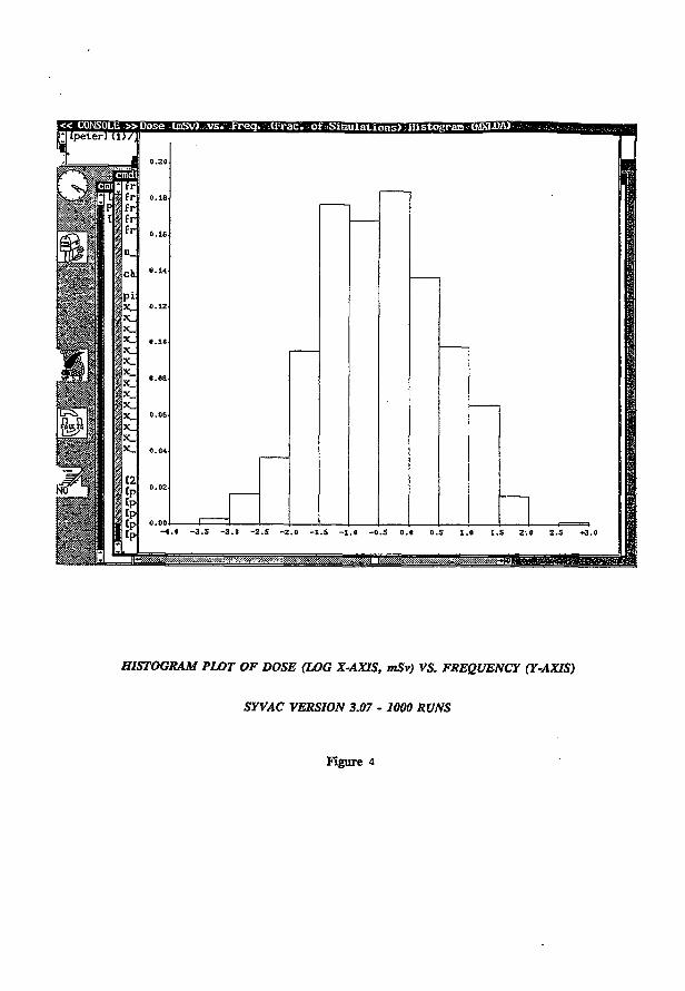
HISTOGRAM PLOT OF DOSE (LOG X-AXIS, mSv) VS. FREQUENCY (Y-AXIS)
SYVAC VERSION 3.07 - 1000 RUNS
Figure 4
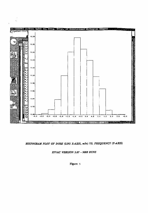
« . CONSOLE » D o s e (mSv) vs..Preq. (prac. of Simulations) Histogram <MXLDA)
HISTOGRAM PLOT OF DOSE (LOG X-AXIS, mSv) VS. FREQUENCY (Y-AXIS)
SYVAC VERSION 3.07 - 5000 RUNS
Figure 5
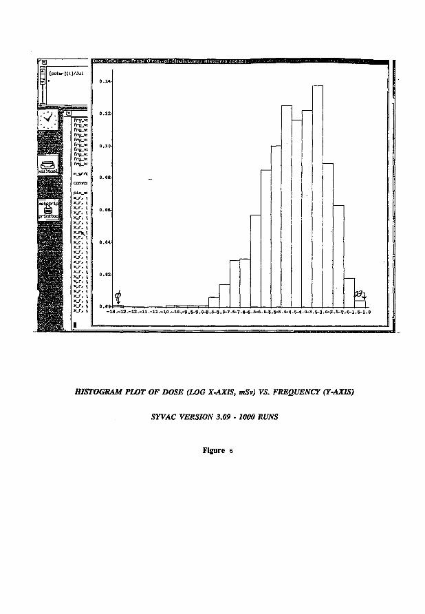
(peterKD/Jul
lui
mm
si
fry_w fry_v: fru.vt fry:.vc fryjw fru_vt fru_vt fry_w fru_vt
O.WH!
pix_xr «_r. x_r# x-r, x_r, x_r, x_r, x_r, "-"V x_r. x_r, x_r, x_r, x_r, x_r, x_r, x_r, x_r, x_r, x_r, x_r, x_r, x_r. * j \ X_f j -13.-12.-ja.-ll.-ll.-10.-10.-9.S-9.0-8.S-8.»-7.S-7.«-6.S-fi.O-S.S-S.(K4.M.(h3.S-3.0-2.S-2.0-l.S-1.0
HISTOGRAM PLOT OF DOSE (LOG X-AXIS, mSv) VS. FREQUENCY (Y-AXIS)
SYVAC VERSION 3.09 • 1000 RUNS
Figure 6
4.3.2.5 Software Tools Developed/Acquired By AECL
4.3.3.2 Comments On AECL's SRS Standard
The SYVAC Software Development (SSD) project was established to complete the production of software used to assess the environmental and safety consequences of disposal of nuclear fuel waste. The SSD project formally establishes the standards and procedures used in producing this software. These formal standards and procedures are presented in three documents. Only one of these three documents is currently available and is entitled SYVAC Software Development Project Plan (Doc. No. ES001.001). The remainder of this discussion focuses on the SRS aspects of this document.
Section 6.0 A) of the SSD Project Plan document outlines the activity used to develop and maintain WDA (Waste Disposal Assessment) software. It specifically states that "this activity involves the production and revision of documentation of functional and design requirements, testing, and coding". Subsection 6.0 A i) describes what is involved in producing the "functional spécifications" for the SV3-CC3 software and, is the part of the document that presents the SRS standard used by AECL, in an overview fashion.
4-18
The collection of software tools developed/acquired by AECL to aid in its software development and to ensure quality assurance of the computer code is extensive and appears to be a direct response to one of TAC's major recommendations on this issue. See Appendix U for specific details.
4.3.3 Comments On SV3-CC3 Software Requirements Specifications
4.3.3.1 Introduction
This report presents an assessment of the SRS (Software Requirements Specifications) standard adopted by the SYVAC Software Development (SSD) project at AECL. The review was conducted by comparing the SSD software development standards documents and SYVAC model SRSs to the ANSI/IEEE Guide to Software Requirements Specifications (Std 830-1984).
This assessement is comprised of two sections. The first section of the report will assess AECL's SRS standard by examining the current software development standards documents. The second section specifically reviews the SYVAC Biosphere model (BIOTRAC) SRS known as the Biosphere Analysis Specifications document. The BIOTRAC SRS document was selected for review since it is the most current, comprehensive, and suitable (i.e. best fits SRS format), documentation for a SYVAC model available (October 3, 1992). In fact the only other SRS documentation available for SYVAC is a dated draft version of the Vault Specifications (September 12, 1990) which is not necessarily representative of current SRS documentation. Consequently review of the BIOTRAC SRS was felt to be more representative of the current SRS documentation developed for SYVAC models.
However, there are problems with this part of the standards document. It states that the "functional specifications define the solution to the problem to be addressed by the software". This is incorrect. Functional specifications in the requirments phase of software development define what is functionally required in order that the problem be solved. In point b), it states that "mini-specs show the solution methods used in each detailed process". Again this is untrue. Mini-specs describe in detail what is functionally required for the lowest-level logical processes in order that the problem be solved. One receives the impression from this material that the task of the requirements phase is to solve the problem when in fact the requirements phase (logically the most abstract) is only the first step in a series of developement phases that together produce a solution to the problem.
However, it is also common in the software engineering field to think of the design phase of development as the solution to the problem being solved. If this section is written with this point of view, then this part of the standards document would probably better fit in the design phase of development. This material seems to be serving a dual function. On the one hand it describes the results of the problem analysis portion of the requirements development phase. Normally, after the problem analysis is completed, the actual requirements specifications are produced. However, it seems the requirements specifications have been skipped going directiy into the design phase. On the other hand one gets the impression that this material describes the rroUminary part of the design phase of software development. The material seems oriented towards solving the problem when it should be concerned about defining what is required to solve the problem.
There is perhaps a historical reason that explains this strange dual role. In the early days of SYVAC software development, the computer code was implemented without documented specifications or detailed design. In fact program specifications were documented over time as the requirements became more clear (i.e. coded versions of the program were produced before there was a clear statement of what the program was required to do). This type of backward software development appears to have led to this type of SRS standard. Of course, it is not unusual that documentation and standards be revised over time but in this case, AECL has developed documentation and standards after the computer code has already been written. Since the code was essentially developed first, it is not surprising that the SRS material has no real requirements specifications as those described in the TFF.F. SRS standard. The problem appears to have risen through confounding of the distinctive activities of solving the problem as opposed to defining the needs of the computer program.
In Section 2.0 (second paragraph), it states that the "SSD project software includes requirements specifications, code, test data and documentation ...". What happened to the design specifications ? Is this a documentation error or is this more evidence pointing to the fact that the requirements and design specifications are really one development phase trying to solve the problem ?
4.3.3.3 Comments On BIOTRAC SRS
4-19
This section of the report presents an assessment of the BIOTRAC Analysis Specifications document. After examination of this document, it is not clear whether this document represents a Software Requirements Specification (SRS) or a document presenting the results of the problem analysis component of the software requirements development phase (which then leads to the SRS). Since TAC is not aware of any additional documents pertaining to software development, it is assumed that this document represents the SRS for BIOTRAC. In the event that this document instead represents the problem analysis results, the comments made by this report should be viewed queries on to what is still required to produce a satisfactory SRS document.
The assessment consisted of comparing the BIOTRAC Analysis Specifications document to the ANSI/LEEE Guide to Software Requirements Specifications (Std 830-1984). The comparison looked for compliance to the required content and necessary qualities of a good SRS. The comparison also examined the organization of the requirements specifications.
4.3.3.4 Comments On SRS Content/Organization
After examination of the BIOTRAC SRS with respect to required content, it is clear that only some of the elements necessary for a good SRS are included, many of the included content elements are not appropriately clear in detail and, the organiztion of the material does not appear to have been well thought out. Some examples of the aforementioned failings are the following:
(a) The intended audience of this SRS is not clear. The SRS should state all persons that will make use of this document.
(b) There is no general (or overview) discussion of what tasks the submodel software will perform, and if necessary, will not perform. The reader is forced to examine the technical research synopses in the SRS or, refer to the unabridged technical documents of the submodels to obtain this information. This would be cumbersome to a reader who is not familiar with the technical details of the project. The same comment applies the need to provide a precise description of the application of this software, with specific attention to its relevant benefits, objectives, and goals.
(c) At the' beginning of the SRS there is a discussion of the format of BIOTRAC specifications. This includes notes on the Data Flow Diagrams (DFDs), Data Dependency Diagrams (DDDs), and Data Dictionary (DD) used in the SRS. Comments pertaining to this topic are stated in Appendix n of this report.
(d) There should be a section at the beginning of the SRS stating what is contained in the document and how it is organized. Some of this information is there, but it is vague and scattered in the beginning sections. It is not a good idea to depend just on the Table of Contents to provide this information.
4-20
(e) If an SRS defines a product that is a component of a larger system, then the functions of each component of the larger system should be described (in an overview) along with identifying the interfaces (internal) between them. Also principal external interfaces of this software product should be identified. However in this SRS, this information is somewhat vague and scattered throughout the document. It would be more effective to have some more detail on how BIOTRAC fits into the SYVAC project and, to have this information centralized (for example, put the description together with the DFDs in the Overview section of the BIOTRAC SRS). There is no mention of external interfaces to BIOTRAC and if there are in fact none, this should be stated also.
(f) There should be a general description of the computer hardware and peripheral equipment to be used to run the software.
(g) There should be a section(s) of the SRS that provides a summary of the functions that the software will perform. This SRS divides up the descriptions of BIOTRAC functions by submodel (Surface water (Lake), Soil, Atmosphere, Food Chain and Dose) and uses the DFDs, DDDs, and research model synopses to describe the submodel functions. But there are no corresponding verbal explanations of the process bubbles shown on the DFDs. Some explanations may be found by digging through the research model synopsis or referencing the corresponding unabridged technical description of the submodel but, this is not a satisfactory way of providing a summary of functions to the reader. The functions should be organized in a way that makes the list of functions understandable and easy to access/follow.
(h) There should be a section of the SRS that should describe those general characteristics of the eventual users of the product that will affect the specific requirements. There are many people who interact with the system during the operation and maintenance phase of the software life cycle. These people (users, operators, maintenance and systems personnel) have different educational levels, experience, technical expertise and, functions which may impose important constraints on the system's operating environment.
(i) There should be a section in the SRS describing the general constraints of the system. These are items that will limit the developer's options for designing the system. Some examples of such items are regulatory policies, hardware limitations, interfaces to other applications, parallel operation, audit functions, control functions, higher-order language requirements, criticality of the application, safety and security considerations, etc. This SRS does not provide any insight into these system constraints.
(j) There should be a section of the SRS describing the assumptions and dependencies made by the requirements. These are the factors that affect the requirements
4-21
stated in the SRS. In the event that these factors are altered, the associated requirements must be modified as well. This should not be confused with design constraints of the system. An example of such a factor might be the assumption that a particular Operating System will be available for the designated hardware. If the Operating System is not available, then the SRS will have to change accordingly.
(k) The largest and most important part of an SRS is the section that contains all the details the software developer needs to create a design (i.e. the specific requirements). Comments pertaining to this section are stated in Appendix HI.
(1) There are a number of characteristics that a good SRS must possess. In the case of BIOTRAC, there are two characteristics in particular that do not hold up well. One of these characteristics is that of completeness. This document does not meet this requirement. This is especially evident in the Appendix II discussion. The second characteristic this SRS lacks is verifiability. The requirements stated in an SRS should be verifiable in the final software product. Since the documentation is incomplete especially in the area of specific requirements (see Appendix HI), it makes it very difficult to verify the requirements. For example, since the documentation does not have specifically related discussions corresponding to the DFDs/DDDs, it makes it difficult to be sure that the requirements specifications of the DFDs/DDDs are correctly implemented in the software. In addition, the research model synopses are model descriptions and not really requirements specifications which means that the synopses are in a form not suitable for verification review.
It should be noted that any missing sections stated above may not be applicable to a particular software product. In this event, the SRS still should state this fact.
4.3.3.5 Summary Of SRS Review
After careful review of the BIOTRAC Analysis Specifications document, it is clear that this document does not meet the requirements of a bonafide SRS. This document for the most part resembles the result of the requirements analysis phase (which is suppose to precede requirements specification) and not a requirements specifications document. Also, there is a distinct feeling (which may not be apparent in the BIOTRAC comments) that the BIOTRAC analysis specifications are more suited to the design phase of software development than the requirements phase. Additional information explaining the reasons for the BIOTRAC SRS resulting in its current form can be found in the discussion on the SRS standards (earlier in this report). Hence, this document cannot pass as an SRS if this is the desired intent (or least one of the intents) of this document. This document will have to undergo numerous changes in both organization and required content in order to make it conform to a proper SRS as defined in the ANSI/IEEE Std 830-1984. In fact, this document is better suited to be an accompanying appendix to the SRS.
4-22
4.3.4 Comments On SV3-CC3 Software Design Specifications
4-23
4.3.4.1 Introduction
This report presents an assessment of the SDD (Software Design Description) standard adopted by the SYVAC Software Development (SSD) project at AECL. The review was conducted by comparing the SSD software development standards documents and SYVAC model SDDs to the ANSI/IEEE Recommended Practice for Software Design Descriptions (Std 1016-1987).
This assessment comprises two sections. The first section of the report assesses AECL's SDD standard by examining the current software development standards documents. The second section specifically reviews the SYVAC Biosphere model (BIOTRAC) SDD known as the Biosphere Design Specifications document (dated October 3, 1992) and the associated SYVAC computer files œntaining design information. The BIOTRAC SDD was selected for review since it is the only SDD documentation for a SYVAC model (or executive) that is available from AECL to date. Since the Biosphere model is the most current and comprehensive SYVAC documentation available, it is assumed that this documentation will be indicative of the type of SDD documentation presumably to be produced for the other SYVAC models and the executive.
4.3.4.2 Comments On AECL'S SDD Standard
4.3.4.2.1 SYVAC Software Development Project
The SYVAC Software Development (SSD) project was established to complete the production of software used to assess the environmental and safety consequences of disposal of nuclear fuel waste. The SSD project formally establishes the standards and procedures used in producing this software. These formal standards and procedures are presented in three documents. Only one of these three documents is currently available and is entitled SYVAC Software Development Project Plan (Doc. No. ES001.001). The remainder of this discussion will focus on the SDD aspects of this document. It should be noted that some of the detailed information that follows is also based on actual samples of AECL design documentation (in particular the Biosphere model) because the one SSD standards document that is available provides only general SDD information.
Section 6.0 A) of the SSD Project Plan document outlines the activity used to develop and maintain WDA (Waste Disposal Assessment) software. It specifically states that "this activity involves the production and revision of documentation of functional and design requirements, testing, and coding". Subsection 6.0 A ii) describes what is involved in producing the "design specifications" for the SV3-CC3 software and, is the part of the document that presents the SDD standard used by AECL, in an overview fashion.
The SDD describes how the software system will be structured to satisfy the requirements identified in the SRS (Software Requirements Specifications). It is a translation of requirements
into a description of the software structure, software components, interfaces, and data necessary for the implementation phase of software development. Hence, the SDD is the blueprint for the implementation activity.
In the case of the SDD standard outlined in the SSD Project Plan document, this blueprint comprises the following design components:
a) Structure Charts b) Module Specifications c) Design Data Dictionary d) Data Cluster (COMMON Block) Descriptions e) File Format Descriptions
Explanations of these design components is provided later on in this report.
4.3.4.3 Brief Description Of the ANSI/IEEE SDD Standard
4.3.4.3.1 Design Entities And Design Entity Attributes
The ANSI/IEEE SDD standard is comprised of components known as design entities. These design entities represent the elements (or components) of a software system that result from the decomposition (or partitioning) of the overall system requirements into separate components that can be considered, implemented, changed and tested with minimal effect on other entities. Design entities are stracturally and functionally distinct from other elements and can exist as a system, subsystems, data structures, modules, programs, and processes. Although different in nature, entities possess common characteristics or properties which are referred to as design entity attributes. A design entity attribute is a named characteristic or property of a design entity. It provides a statement of fact about the entity. The design entity attributes required to be specified are the following :
(a) Identification G>) Type (c) Purpose (A) Function (e) Subordinates (f) Dependencies (g) Interface (h) Resources (0 Processing (i) Data
4-24
4.3.4.3.2 Design Views
4-25
The information provided by the design entity attributes must be organized in a manner suitable for the different types of users of the design documentation. Each user of the design documentation may have a different view of what is considered the essential aspects the software design and therefore may consider the remaining information as extraneous. Hence, the ANSI/LEEE standard recommends that different design views be created to handle the different needs of the users. A design view is a subset of the design entity attribute information that is specifically suited to the needs of a particular software development activity. This will enable the user to focus on design details from their particular viewpoint. Hence, each design view represents a separate concern about the software system. Together, all the design views would constitute the SDD. This organizational approach provides the SDD information in a comprehensive and concise manner and provides flexibility in its presentation, allowing the information to be easily accessed by the different users of the design documentation.
For more comprehensive details, see the ANSI/IEEE SDD standard (Std 1016-1987).
4.3.4.4 Comparison Of SSD And ANSI/LEEE SDD Standards
4.3.4.4.1 Comparison Of Organization
The ANSI/TREE standard uses a collection of design views (decomposition description, depedency description, interface description, and detail description - for more detils, see the ANSI/IEEE SDD standard (Std 1016-1987)) to form an SDD. Each of these design views is aimed at meeting the needs of a different type of user of the design documentation. However, the SDD of the SSD standard is comprised of a collection of design components which are not structured as design views. Each of these design components provides some type of information to the overall design but is not intended to stand independently for assimilation from a particular viewpoint. Information would be required from the other design components to complete the design view. Hence, the SSD standard is considered as a single design view with a global perspective.
It is therefore evident that one of the major drawbacks of the SSD standard is its lack of flexibility (it is limited to only one design view - a global view) to accomodate the different needs of the user. For example, a designer may need to examine the interface documentation of previously developed entities so that newly created design entities will properly interface with the existing entities. It should not be necessary for the designer to examine the entire documentation for this purpose. It is extremely cumbersome and inefficient to try and extricate the required information. In fact, it may even be a more error-prone procedure.
As an overall design view, the SSD standard is adequate but, other documentation should be developed to accomodate the different viewpoints required by the various users of the design documentation.
4.3.4.4.2 Comparison Of Content
3) Function - A brief description of the design entity's function is given inside its corresponding box (or boxes) on the structure chart.
4) Dependencies - The design entity's dependencies are those entities that are called upon to perform supporting tasks. They are indicated on the structure chart as those modules (boxes) immediately below in the hierarchical structure that are connected by lines from the calling module.
4-26
It was decided that the best (and simplest) approach for the comparison of the two SDD standards was to assume that the modules of the SSD standard (i.e. FORTRAN subprograms) correspond with the design entities of the ANSI/IEEE standard. All the components of the SSD standard (structure charts, module specifications, design data dictionary, COMMON block descriptions, file format descriptions) are considered as the organizational blocks used to present the design entity information required by the ANSI/IEEE standard (i.e. the design entity attribute descriptions - identification, type, purpose, function, subordinates, dependencies, interface, resources, processing, data)
The comparison was done by examining each of the SDD components used in the SSD standard with regard to the type of information it provides and how it corresponds to the design entity information required by the ANSI/LEEE SDD standard.
(a) Structure Charts
Structure charts are used to graphcially display the hierarchical call-structure of the modules comprising the system. Each module is represented as a box containing its unique FORTRAN name and a brief description of its function. Also indicated (inside the box) are the COMMON blocks (FORTRAN global data structures) declared in each of the modules and, whether their data values are set and/or used (or possibly neither). In addition, the variables used in the argument lists of invocations of supporting modules are indicated. The variables in the argument lists are marked as being input and/or output.
The design entity information covered according to the ANSI/LEEE SDD standard is as follows:
1) Identification - The name of the design identity (or module) is indicated inside its corresponding box (or boxes) on the structure chart.
2) Type - All design entities indicated on the structure chart are modules (i.e. FORTRAN subprograms).
5) Interface - The structure chart indicates common data areas (FORTRAN COMMON blocks) decalared in each design entity by rectangular boxes nested inside at the bottom of the module box. A right arrow beside the rectangular box indicates that variables belonging to this common data area are used in the module. A left arrow indicates that variables are assigned values. If both arrows are used, then the variables are set and used. If no arrows exist, then the common data area is only declared (i.e. no data is set and/or used).
The structure chart indicates the data passed from the calling module to the supporting modules (mentioned above in 4). The variables used in the argument lists of invocations of these supporting modules are indicated by two variable lists atop the supporting module boxes. The list to left side (marked with a down arrow) indicate the variables that are being passed into the corresponding supporting module. The list on the right side (marked with an up arrow) indicate the variables that have been altered in the supporting module and are returned to the calling module.
(bt Module Specifications
Module specifications define the algorithm used by the module. They define the assumptions and conditions upon entry and exit of the module and, identify the module's input/output.
The design entity information covered according to the ANSI/IEEE SDD standard is as follows:
1) Identification - The design entity (or module) is identified on the top right corner.
2) Type - The design entity is of type module (actually FORTRAN subprogram) since it is a "module" specification.
3) Purpose - The module specification includes reference(s) to the corresponding analysis specifications. This enables one to determine the specific functional requirements on which this module is based. It also provides the rationale for the creation of this entity.
4) Function - The module specification provides a brief description of the module's function.
5) Interface - The argument list (input/output interface) for the module is indicated in the module specification. Each argument's type (FORTRAN declaration type -integer, double precision, etc.) is identified along with stating whether it is an input and/or output type variable. Pre-condition(s) and post-condition(s) (condition(s) that must be satisfied on entry/exit of the module respectively) for
4-27
these variables are indicated. In addition, each of the module's arguments is defined, with any additional comments relevant to the variable also being indicated.
The same information is indicated for those variables "included" (implemented during the coding stage as the FORTRAN INCLUDE statement) in the module specification through global data structures (i.e. variables that belong to FORTRAN COMMON blocks)
6) Processing - The algorithm for the module is specified in a FORTRAN-like pseudo-code. The pseudo-code is formatted (i.e. block structures are indented) to highlight the nested block structures of the language (makes it easier to read). The specification is detailed (almost the FORTRAN code equivalent) and contains comments explaining the steps performed in the algorithm.
7) Data - The local variables used in the module specification are listed. The type of the variable (FORTRAN declaration type - integer, double precision, etc.), its definition, and any relevant comments are included.
(c) Design Data Dictionary
The design data dictionary is an alphabetical listing of all variables (global and local module variables) used in the design along with their corresponding definitions. Included with the each variable definition is its physical units.
The design entity information covered according to the ANSI/IEEE SDD standard is as follows:
1) Interface - The global variables used in the design (via FORTRAN COMMON blocks) are listed in the data dictionary. There is a cross reference table that allows one to locate the particular COMMON block that a global variable belongs to and vice versa. See next section on data cluster descriptions.
2) Data - The modules' local variables used in the design are also listed in the data dictionary. It is not possible to determine which module a local variable belongs.
(d) Data Cluster (COMMON Blockl Descriptions
These descriptions define and document the structure of the common data areas (FORTRAN COMMON blocks) used in the design.
The design entity information covered according to the ANSI/IEEE SDD standard is as follows:
4-28
1) Interface - The data cluster descriptions indicate the following for each variable belonging to a specific COMMON block (identified by a COMMON block name): the variable's type (FORTRAN type - integer, double precision, etc.), the variable's number of dimensions and their sizes if the variable is an array, and the variable's value if the variable is a constant (or in FORTRAN, its PARAMETER value).
As an added note, there is cross reference table that allows one to locate the particular COMMON block that a global variable belongs to and vice versa. The cross reference table is comprised of two lists (side by side) with each entry being a variable and associated COMMON block pair. One is sorted alphabetically by variable name and the other by COMMON block name.
(el File Format Descriptions
These descriptions define and document the format and contents of the input and output files used in the design.
The design entity information covered according to the ANSI/IEEE SDD standard is as follows:
1) Interface - The file format descriptions document common data areas (files which reside on computer disk storage) that are used for input (input files) and output (output files).
4.3.4.5 General Comments On Content Comparison
After comparison of both SDD standards with regard to content, one has the impression that the SSD standard has the basic elements that comprise an SDD but seems to lack detail in the form of verbal explanation. For example, the description of a design entity's function consists of a short phrase inside a module box of a hierarchical structure chart and a short explanation atop a module specification. These terse descriptions provide very little insight into the entity's function. A user of the design documentation is forced to examine the pseudo-code to increase his understanding of the entity's function which can be extremely difficult considering the cryptic nature of the pseudo-code. A concise and comprehensive verbal explanation in conjunction with the module specification's pseudo-code would be very beneficial. Another example is the description of the processing (rules used by the entity to achieve its function) performed by an entity. The description is in the form of FORTRAN-like pseudo-code which can be very difficult to follow at this level of detail. The only aid is the accompanying comments placed throughout the code. These comments are quite specific and may be suitable in the next phase of software development (coding) but are not adequate from a design point of view. There should be a higher level of explanation of the steps being performed to achieve its function. In essence, more explanations (and/or references to other appropriate documentation)
4-29
should be used in the SSD design components to improve the understanding of the design entity attribute information.
4.3.4.6 Comments On BIOTRAC SDD
One of the main concerns about the BIOTRAC SDD involves the module specifications. The module specification's FORTRAN-like pseudo-code strongly resembles its implementation counterpart (FORTRAN subprogram). The resemblence is so strong (in many instances almost identical) that one does not get the impression that the module specifications provide an intermediate step in the software development phases. It seems that the module specifications were written after the computer code was already completed. If so, the design specifications were not done in accordance with the proper sequence of software development phases (i.e. requirements, design, coding, etc.) - that is, the design development phase was done after the implementation phase (coding) was completed. Support for this conclusion stems from the examination of the SRS (Software Requirements Specifications) which revealed the same backwards development problem (See the comments on AECL's SRS standard for more details).
The other main problem with the BIOTRAC SDD concerns the organization of the design components. The Biosphere Design Specifications document only contains the module specifications. The rest of the design components are located in computer files of the SYVAC code except for the structure charts (all of which are grouped together and stored separately). Since the design documentation is not centralized (possibly because it is not complete), it is extremely difficult to try and relate all the design components. How are reviewers, new design people, programmers, and testers of the SSD project to understand the documentation in its present form ?
4.3.4.7 Summary
The SDD standard adopted by the SSD seems to have many of the key elements required in a software design but the documentation seems to lack the comprehensive detail one would expect as necessary to do the programming, testing, maintenance, subsequent development, etc. Also, the SDD standard does not include different design views to accomodate the different needs required by the users of the design documentation. With regard to the BIOTRAC SDD, it appears to be still in a transitional state of disarray because there is no centralization and organization of design component information. In addition, the BIOTRAC SDD gives strong indications that the design phase was not done in accordance with the required sequence of software development phases (i.e. coding was done before design) and is probably the major reason for the current state of the BIOTRAC design documentation.
4-30
4.3.5 Comments On SV3-CC3 Verification & Validation
4-31
4.3.5.1 Introduction
This report discusses the V&V (Verification & Validation) tasks performed by the SYVAC Software Development (SSD) project at AECL. The examination of these V&V tasks is done at each of the requirements, design, and implementation (coding) phases of the software life-cycle. The discussion of V&V at each of the software life-cycle phases is comprised of two parts. The first part discusses the V&V tasks performed by AECL and the second part provides comments on AECL's V&V activities (such as how it compares to the V&V requirements of the ANSI/IEEE Standard for Software Verification and Validation Plans (Std 1012-1986)).
In addition to a discussion on V&V, a list and categorization of software development tools used by AECL is provided.
4.3.5.2 Requirements Phase V&V
4.3.5.2.1 V&V Performed By AECL
Succesive draft versions of the requirements specifications are subjected to a series of "walkthroughs" (a peer review of a product with the intent of finding problems or potential problems but not to devise solutions to these problems on the spot). In order to facilitate the walkthroughs performed at the review sessions, participants are provided with the necessary information comprising the requirements specifications (model synopsis, data dictionary, data flow diagrams, data dependency diagrams). The participants attempt to find flaws during the walkthrough sessions. After completion of the walkthrough, the participants must decide whether the product should be accepted or rejected. If rejected, follow-up reviews are conducted until the product is judged acceptable.
In addition, visual inspections employing specialized checklists (lists of various attributes that must be satisified) for each of the components (not sure about model synopsis) of the requirements specification are performed. Checklists help focus the review effort and to ensure that no major source of errors are overlooked by the reviewers.
4.3.5.2.2 Comments On V&V
A comprehensive comparison of the V&V performed by AECL and the V&V required by the ANSI/LEEE standard is not feasible. The major reason for this situation is the lack of comprehensive documentation of V&V activities at the requirements phase. In fact the only documentation on this subject consists of a brief section in the BIOTRAC Analysis Specification document on "walkthroughs" plus the brief mention of checklists being used for requirements verification. The details of these V&V activities are unclear. The requirements set out in the ANSI/IEEE standard are very specific and requires in-depth, detailed description of the V&V activities.
The use of walkthroughs would give one the impression that some of the elements of the ANSI/JJEEE standard have been covered (in particular, the correctness, consistency, and completeness stated in step 2 entitled "Software Requirements Evaluation" of the "Requirements Phase V&V") but, this is a tentative conclusion. Unfortunately, the lack of comprehensive documentation makes it difficult to know exactly what was covered and what was not covered.
The inadequacy of the documentation raises some questions about the V&V used during the requirements phase. What specific attributes were being sought during the walkthroughs ? Also, none of the checklists used for visual inspections were available to TAC. Hence, the exact content of these inspections is unknown. Also, there is no information describing when these inspections were performed or who was performing them. Are these visual inspections part of the walkthrough process ?
4.3.5.3 Design Phase V&V
4.3.5.3.1 V&V Performed By AECL
Visual inspections using specialized checklists for each of the components of the design specification (structure charts, module specifications, design data dictionary, COMMON block descriptions, file format descriptions) were performed.
4.3.5.3.2 Comments On V&V
There are only two inspection checklists (available to TAC) describing the V&V activities of the design phase. These checklists correspond to the structure chart and module specification components of the software design specification. However, detailed information (each query in the checklist is expanded upon in detail) exists only for the module specification checklist.
Compared to the requirements phase, the information on the V&V activities is more in-depth and detailed for the design phase. However, the amount of information is still inadequate for a comprehensive review. There are still checklists for the other software design components (design data dictionary, COMMON block descriptions, file format descriptions) that are not available. Also, detailed explanations of the checklists (each query is expanded upon) is not available for any of the software design components except the module specification checklist. Lastly, it would seem a logical choice to make use of walkthroughs during the design phase as was done during the requirements phase. However, if walkthroughs were used during the design phase, there is no indication of it.
The AECL documentation seems to have some of the elements required by the ANSI/LEEE standard (in particular, traceability back to the requirements phase stated in step 1 entitled "Design Traceability Analysis" and, correctness, consistency, and completeness stated in step 2 entitled "Design Evaluation" of the "Design Phase V&V" section) but the incomplete documentation makes it difficult to provide a comprehensive assessment.
4-32
4.3.5.4 Implementation Phase V&V
4.3.5.4.1 Coding
AECL applied various coding principles during the implementation of the SYVAC program to provide built-in QA (Quality Assurance) of the computer code. Some of the coding principles applied are the following:
1) The computer code was written using the block structures (such as the "IF" statement) of the programming language (FORTRAN 77). Programming in this fashion produces more understandable and less error-prone (logically) computer code then using unstructured "spaghetti" code with numerous "GO TO" statements providing dangerous change of control flow. The block structure nature of the computer code can be graphically enhanced (via indentation or more advanced software tools such as ORFOR) to accentuate the individual block structures of the code, allowing one to follow the logic of code more easily.
2) The computer code uses inserted comments to explain the purpose of the blocks of code. The comments are written in lower case to contrast with the FORTRAN code written in upper case. This contrast enables quick recognition of the comments in the code.
3) The variables used in the computer code are chosen to be as meaningful as possible with the restriction of six characters per FORTRAN variable (FORTRAN 77 standard).
4) The "IMPLICIT NONE" statement (VAX extension to FORTRAN 77 standard) is used to force the programmer to declare all the variables used in the computer code. FORTRAN is a poorly "typed" language which can cause great havoc if the programmer is not extremely careful. Therefore, this language extension aids in catching misspellings and typing errors which could be detrimental to the code.
5) The "INCLUDE" statement (another VAX extension to FORTRAN 77 standard) is used to insert single copies of COMMON blocks ensuring consistency among the modules that require them. Since there is only one copy of each COMMON blocks inclusion, modification is required in only one spot (instead of every module that has this inclusion).
Any extensions added to the FORTAN 77 language are simple enough to remove in the event the code was ported to another machine that requires standard FORTRAN 77. The added benefit considerably outweighs the minor effort required to port the code to the FORTRAN 77 standard.
4-33
4.3.5.4.2 Program Testing
Testing is the predominant V&V technique used in this phase of the software life-cycle. The different types of testing employed are as follows:
1) System Testing - System testing involves running of the complete computer code (i.e. in the case of SYVAC3, the executive plus all the CC3 submodels -biosphere, geosphere, vault). Test cases are designed using sets of input data that emphasizes the checking of interfaces (interface between the individual models as well as the interface between the models and the Executive), major functions and options in a systematic and comprehensive manner. The particlular functions and options that are tested with each specific set input data are documented. At this testing level, it is not required that each statement of computer code be executed after the completion of all test cases. However, each module that is linked into the computer code must be executed at least once. Lastly, system testing is used to check the accuracy of results produced from the computer models.
2) Function Testing - Function testing involves exercising specific functional sections of the computer program, usually involving a few modules. Function tests can examine individual modules or combinations of modules (i.e. those module(s) responsible for the function being tested). The focus is to observe responses to varied inputs, not on the internal structure and logic. The output of the coded function, run with varied ranges of input parameters, is compared to pre-idenufied or expected results. Each test case (characterized by an input data set, a specific function, actual results, pre-identified/expected results) is documented. Some examples of functions being tested in SYVAC are the Soil submodel in the biosphere, container failure in the vault, time series operations in the executive, etc.
3) Unit Testing - Unit testing involves rigorous checking and exercising of small portions of the computer program, usually individual modules. Test cases are designed using varied sets of input data to test/verify the following conditions:
a) total Statement coverage, b) 0,1, many loop execution, c) typical, extreme, illegal data, d) execute all logical branches, e) verify that variables are passed correctly from one module to another, f) verify that COMMON blocks are correctly specified, g) verify that dimensions of variables are used consistently throughout code.
Unit testing requires the use of a test harness (i.e. a module known as a "driver" that sets up the conditions necessary for the test case run, plus modules known as "stubs" that simulate the external calls to subordinate routines) in order to run the test cases. Each of the test cases
4-34
(characterized by an input data set, module, actual results, expected results) is documented. The unit testing of all the SYVAC3-CC3 modules is being performed by the USDOE (see next section on USDOE involvement).
4) Standalone Testing - Standalone testing refers to testing the SYVAC3 executive linked to only one of the CC3 submodels (biosphere, geosphere, or vault). This type of testing isolates a particular submodel (thus narrowing the scope of the problem to a convenient subdivison for analysis) and hence, avoiding potential interference from the other submodels which can cloud the meaning of test results. In addition, the detection of modellmg/coding errors is much more efficient.
5) Prototype Testing - Prototype testing refers to testing a "frozen" version of the complete SYVAC3 program (i.e. a major version of the executive plus all the submodels that reaches a desired level of required functionality with tolerable errors) plus the modifications made since the freeze. This type of testing provides output results originally intended for the SYVAC simulations and therefore, can be analyzed/interpreted for insight into the workings of the entire program (such as the interaction of the submodels and the overall effect of modifications) and/or insight into the actual results of simulation runs.
4.3.5.4.3 USDOE Involvement
An agreement was signed by AECL and USDOE (United States Department of Energy) where the parties agreed to cooperate in the study of topics relating to the management fo radioactive wastes. Part of this agreement, known as the "Performance Assessment Technology Exchange", stipulates USDOE's involvement with respect to a detailed exarnination and verification of the AECL total system performance assessment software package known as SYVAC3-CC3.
In the Performance Assessment Technology Exchange, verification of the S YVAC3-CC3 code is being performed in accordance with established software engineering practices. Verification is being performed on a per unit (or module) basis. Only the higher level testing (such as system/functional testing) remains the responsibility of AECL. There are over 300 code modules containing over 25,000 lines of code to be examined. The steps involved in the verification process are the following:
1) proof-reading module design specifications and comparing them to functional specifications to ensure compliance,
2) proof-reading the computer programs statement by statement and completing a checklist of module attributes,
3) developing and documenting test cases,
4-35
4) preparing test harnesses to exercise each unit (or module) independently,
5) running the individual modules using a test instrumenter to report test coverage,
6) comparing the actual run outputs to expected outputs,
7) reporting the results.
Step 1 focuses on design verification, step 2 focuses on code inspection, and steps 3-6 focus on unit testing (see previous section on unit testing). In addition, tools have been developed to automate part of the verification process. These tools automatically examine code modules, check units, and prepare driver routines to exercise every line of code, and verify that they were executed correctly.
The project originally started with the test examination of ten modules in the vault model (which calculate container failure rate) that were intentionally seeded with errors by AECL to determine the efficiency of error detection methods used by USDOE. Most of the errors were detected and some unintentional errors were also detected. Some of these errors were traced back to logical errors in the analytical specifications.
At the writing of this report, examination of the CC3 models is still in progress. The biosphere model was the first model examined, followed by the vault model. Progress on the geosphere model and SYVAC executive are to be reported at an upcoming meeting.
4.3.5.4.4 Comparisons
Comparison of SYVAC results (or results from portions of SYVAC) with those produced by alternate calculation methods and from other simulation codes were done as part of the "code verification" process. Some of the comparisons performed are the following:
1) Code intercomparison of SYVAC2 (predecessor to SYVAC3) with SYVAC3 versions were performed.
2) The results of the vault model were compared with results of the related AREST code, developed by Battelle Pacific Northwest Laboratories.
3) The results of the geosphere model were compared with the results of other models in the International Nuclide TRAnsport VALidation Code Intercomparison Study (INTRAVAL).
4) The results produced using components of the biosphere model were compared with tests set up by the BlOsphere MOdel Validation Study (BIOMOVS) involving environmental transport and bioaccumulation of radionuclides and other contaminants.
4-36
5) Code intercomparisons with the OECD/NEA PSAG (Probabilistic Saftey Assessment Group) User Group were performed.
6) The transport rate of nuclides out of the vault has been compared with that predicted by the AECL code BUFFER.
7) The Soil model of the biosphere submodel was compared with the detailed AECL code SCEMR.
8) Intermediate SYVAC results (submodel variables calculated from selected parameter values) were compared with expected values determined by analytical solutions or manual calculations (examples include manual calculation of geosphere variables such as porosity and path length, computer evaluation of an equation giving the steady-state vault-output transport rate, and procedures such as the evaluation of the convolution integral have been performed using a different language, APL, on a different machine, an IBM PC)
9) In order to verify the vault response function solution, an independent solution to the set of convection-diffusion differential equations modelling the mass transport of radionuclides released from the vault was performed by Ontario Hydro. This solution was done using the Laplace transform method with a numerical inversion as opposed to analytically inverting the Laplace transform solution, as AECL had done.
4.3.5.4.5 Comments On V&V
First of all, it should be noted that the ANSI/IEEE standard includes a test phase V&V section. For the sake of practicality, this V&V phase is considered as part of the implementation phase V&V.
The V&V performed during the implementation stage seems to be the most extensive in both the V&V tasks performed and the available documentation (as compared to the requirements and design V&V). The documentation is still not at a professional level, but there is enough content to provide a reasonably accurate assessment of this V&V phase. In general, this V&V phase is adequately done in accordance with the ANSI/IEEE standard.
One impressive feature of this V&V phase is the extensive use of a wide range of software development tools used to aid software development and ensure quality assurance of the computer code (see next section on "Software Development Tools" for an alphabetical list of these tools). However, many of these tools are very "low-level" in nature (for example, tools at the compilmg/lirildng/debugging stage) and are deemed mandatory and routine in competent software development. However, state-of-art tools such as computer-aided modelling environments have not been used as recommended in previous TAC reports. This class of tools
4-37
would be of great value not only to software development but also for providing superior quality assurance of final computer products.
A point of potential concern should be raised here. Why is the implementation phase V&V the only one which seems to be generally in conformance with the ANSI/IEEE standard ? Is it because this software development phase was done before the requirements and design phases ? The answer seems to be yes based partly from the following statements: "The structured development methods advocated by Yourdon have influenced SYVAC development, although strict adherence has been rejected. In particular, detailed analysis of the problem addressed by SYVAC, that is the production of detailed program specifications, was found to take an inordinate amount of time. Specifying the requirements of a simulation that involves many detailed chemical and physical processes, even identifying the most important processes, is difficult until preliminary results are available. Therefore, the code has been implemented without documented specifications or detailed design, and is being refined." The requirements and design phases are far more important in the software life-cycle then the implementation stage. If these phases have not been properly developed according to the generally accepted software standards, then the quality of the implementation phase is in doubt. Even if the implementation phase is perfectly done, it suffers in credibility if it does not perform the required functions originally intended.
4.3.5.5 Problems Encountered During V&V Assessment
Our assessment of the V&V performed on SYVAC3-CC3 was made difficult based on a number of reasons.
The predominant reason for this difficulty was the lack of professional documentation available from AECL. In fact, there is no formal documentation available on the subject of V&V (nor is it covered to any great detail as part of other available documentation). Restricted by this limitation, the AECL documentation used for the assessment consisted of various handouts received from meetings with AECL, published papers, progress reports, current standards documents (only one currently available entitled SYVAC Software Development Project Plan (Doc. No. ES001.001) and the SYVAC program documentation.
Unfortunately, the pertinent documentation did not provide a good account of the V&V performed by AECL. For example, the handouts received from AECL tended to be written in point form and are only appropriate when accompanied by an AECL presentation. Hence, when the material is accessed at a much later time, the point form style makes it extremely difficult to interpret (even with notes added during the presentation to supplement the handout). Many of the points listed in the handouts were unclear and it was often difficult to ascertain whether the interpretation made was in fact the correct one. Therefore, the assessment could lose validity if incorrect interpretations (or conclusions) are made from the available documentation. Also, the AECL papers/reports provide only general information on AECL's V&V activities and often lack the content necessary to make a proper assessment. In addition, the one standards document that is available describes some of the testing procedures (unit, function, and system
4-38
testing) used on SYVAC (Section 6.0 A iv, v, vi) but only at a general level (more detail is needed). Lastly, the SYVAC program documentation contained virtually no information on the topic of V&V (except for a small section on the topic of walkthroughs presented in the BIOTRAC Analysis Specifications).
Another problem with the AECL documentation is that the V&V information is neither organized in a orderly fashion nor is the information centralized. The V&V information is scattered throughout the various handouts, papers, reports, etc. making it extremely difficult to compile and understand the information. Also, these documents cover a large time span (roughly 1985-92) so that the review activities become even more complex. It becomes difficult to know exactly what is current and what has been abondoned.
Lastly, the comparison of AECL's V&V activities with that required by the ANSI/LEEE standard was significantly hindered because the nature of AECL's documentation was not readily comparable to the ANSI/IEEE standard. For example, even though the ANSI/LEEE standard is detailed in its requirements, it is also sometimes general in the use of terms in its standard (such as correctness, consistency, completeness, etc.). AECL's documentation does not convey its information in these general terms but expresses it in the form of checklists with specific queries (for visual inspections) which may indirectly answer these questions. This forces subjective evaluations that are sometimes difficult to make.
4.3.6 Some Explanatory Remarks on, and Observations of, the Present State of SYVAC and its Documentation
The development of the SYVAC code was initiated in the late seventies to implement the "System Variability Analysis" (SVA) methodology promoted originally by Dr. K.W. Dormuth (Dormuth and Sherman, 1979). The fundamental concept of SVA was (then) novel in the field of nuclear waste disposal simulation and addressed the need to "handle" the wide range of data (i.e. parameter) and (to a certain extent) model uncertainty that characterize this waste disposal technology. Early on, TAC had deemed that the SVA methodology was sound (TAC-5) and reaffirmed this view continually in our TAC reports (e.g. TAC-6, TAC-7). That there is merit in this SVA methodology for treating uncertainty is well established and is manifested in the number of performance assessment codes subsequently developed or adopted by many countries based on this concept (e.g. U.K., Belgium, Germany, Finland Spain).
The implementation of SVA takes the form of SYVAC (the executive, i.e. that part of the computer program that "directs" the operation of the program) and associated CC3 modules (i.e. the three models - vault, geosphere and biosphere) which are specific to the Canadian situation. This computer program was coded in FORTRAN — the definitive programming language for scientific applications during the sixties and seventies. Scientists trained and working during that period had limited options of other languages to use because of IBM's dominance and FORTRAN'S well-developed "library routines" that were indispensable for scientific computation. However, because of its particular inherent characteristics, FORTRAN is not very well suited to do simulations and, moreover, was very prone to software design and
4-39
coding errors. Although later versions (or "dialects") of FORTRAN improved in these respects, it was essentially a technology of the sixties. "Software engineering" as practised today was unknown then and only came into being in the seventies. The large strides made in this discipline occurred in the late seventies and early eighties with the work of people such as Yourdon and DeMarco who emphasized a much more "disciplined" and "structured" approach to software development. Greater emphasis was placed at the "front end" of the software development process — during the "requirements" and especially the "design" stages rather than the "coding" stage as was the practice then. More advanced paradigms such as the use of object-oriented based languages/systems came later still, starting about the mid-eighties.
It is in this climate of great change and transition period that the SYVAC code was conceived and developed. The choice of the FORTRAN language was not at all surprising considering the time and thus for historical reasons, SYVAC was coded in FORTRAN. When TAC made its early recommendations in the very early eighties about the need to use more advanced techniques, and even a language more appropriate for simulation purposes, a large amount of effort and resources had already been spent on developing the SYVAC code. Furthermore, it was a "functioning" program in that results were being generated and used to produce results for the Interim Concept Assessment Document (ICAD 1). To scrap the code and use something else entirely would have meant a significant delay in producing the ICAD 1 assessment. In addition, the AECL personnel were not familiar with the "computer-aided software engineering" (CASE) technology, "simulation languages" and "software tools" that Dr. T.I. Oren was espousing. They had very little idea regarding the concept of "software engineering". Perhaps the most unfortunate factor was that the number of commercially-available, tried-and-tested, CASE products were very limited at that time. The availability of such products only became significant starting in the mid-eighties and we now witness an "explosion" of software tools and environments of every description. (See Fuggetta, 1993 for a classification of CASE technology; Roman and Cox, 1993, for a taxonomy of program visualization systems.)
Although AECL have either acquired or developed many of the important and useful software tools, they are mostly tools to do the "checking" after the code was developed. In contrast, more advanced software environments are meant to provide a complete, integrated, and "seamless environment" in which to develop, quality assure, and maintain computer programs throughout the entire software life cycle. In following the FORTRAN paradigm rather than adopting such advanced systems, a very heavy burden is placed on verification techniques that tend to emphasize checking, testing and inspection activities at the late stages of the software development life cycle (i.e. during and after coding). As countless studies and plenty of experience from numerous large-scale software development projects have shown, faults and errors are much harder and much more expensive to detect and correct at these late stages. While the Yourdon and DeMarco methodologies aim to minimize faults and errors at every stage of the development cycle through a more structured and disciplined approach, the price extracted is in labour intensive activities (relative to more advanced techniques now available) associated with implementation (i.e. coding) as well as providing the supporting documentation. These
4-40
methodologies require detailed and comprehensive documentation at every stage of software development.
4.4 CONCLUSIONS
(A) AECL seems to be the first to develop and apply the "Systems Variability Analysis" (SVA) methodology to take into account the data and system (i.e. processes) uncertainties inherent in the simulation of nuclear disposal systems. As a valuable contribution to the performance assessment work associated with this technology, it has been adopted by every country which carries out probabilistic performance assessment of its disposal program. TAC concurs with the soundness of this approach and continues to support it.
(B) The implementation of SVA, through the "SYVAC Code" appears to be well regarded by the international community. Many countries (e.g. U.K., Belgium, Spain, Germany, etc.) and other organizations (e.g. Canada's LLW program) have either developed then-own simulation programs along the same lines, acquired (certain portions of) SYVAC for their work, or retained AECL to help/consult in developing their codes. The establishment of the international Probabilistic Safety Assessment Group (PSAG) principally to do intercomparison of performance assessment codes was prompted by the existence of SYVAC and SYVAC-like codes of other countries.
(C) The software verification process instituted by AECL for SYVAC is recognized as the most comprehensive and rigorous one applied to a safety performance code (Thompson 1993; Nies 1993). Canada appears to be regarded as the world-leader in this area — both in terms of being the first to recognize clearly the critical need to do such software verification as well as in the effort and resources spent in supporting this conviction. This could prove to be a strong "selling point" for SYVAC should serious effort be devoted to marketing this code internationally.
(D) Paradoxically, the detailed and on-going review by TAC of the SYVAC implementation reveals that many aspects of its development process (including its documentation) do not meet established software engineering standards and practices such as promulgated by the ANSI/IEEE. These include the following:
i. weak requirements analysis, ii. lack of appropriate documentation to support and guide required activities at
certain stages of software development lifecycle, iii. coding done before requirements and (especially) design phases were completed, iv. design documentation written after coding was initiated and (almost) completed, v. little or no documentation to support verification and validation (V&V) activities, vi. documents which should have been written dedicated to particular development
and V&V activities are not available, but instead, are doing "double" (or more) duty,
4-41
vii. organization of documents was such that they do not facilitate review. Information required for a comprehensive, detailed and meaningful review is often missing, not yet available, or distributed over many different sources. The audit trail is poor and tortuous.
Some possible explanations for this state of affairs relate to historical reasons, the rapidly evolving state-of-art in software engineering and background and experience of staff developing the SYVAC code.
(E) The collection of software tools developed/acquired by AECL for code development and V&V activities is extensive. These tools seemed to have helped in the software quality assurance (SQA) activities. However, the other major TAC recommendation in this area, of CASE technology adoption have not been acted upon to nearly the same degree. Proper and timely adoption of such "modelling environments" would have dramatically reduced the software development time, the labour intensive activities, and further contributed to SQA.
(F) TAC's "spot-checking" activities such as inspection of code, algorithms, specification with implementation, etc. did not reveal any major inconsistencies or errors. TAC's execution of the SYVAC simulation generated results generally in agreement with those of AECL. However this can, by no means, be taken as evidence that significant errors do not exist in the code.
4-42
REFERENCES
Dormuth, K.W. and Quick, R.D. (1981), "Accounting for Parameter Variability in Risk Assessment for a Canadian Nuclear Fuel Waste Disposal Vault". Int. J. Energy Syst., Vol. 1, pp. 125-127.
Dormuth, K.W. and Sherman, G.R. (1981), "SYVAC - A Computer Program for Assessment of Nuclear Fuel Waste Management Systems, Incorporating Parameter Variability". Atomic Energy of Canada Limited Report, AECL-6814.
Fuggetta, A. (1993), "A Classification of CASE Technology". Computer, Vol. 26, No. 12, pp. 25-38
Nies, A. (1993), "Towards Verification of Computer Codes for the Performance Assessment of Radioactive Waste Disposal". Reliability Engineering and System Safety, 42.
Ôren, T.I., M.S. Elzas and G. Sheng (1985), "Model Reliability and Software Quality Assurance in Simulation of Nuclear Fuel Waste Management Systems". Simuletter, Vol. 16, No. 4.
Ôren, T.O. and G. Sheng (1988), "Semantic Rules and Facts for an Expert Modelling and Simulation System". In Proceedings of the 12th MACS World Congress, pp. 597-598, Paris, July 18-22, 1988.
Ôren, T.I. and G. Sheng (1990), "Software Tools for the Quality Assurance of Scientific Codes Used in Nuclear Waste Management Programs". la Proceedings of the International Symposium on Safety Assessment of Radioactive Waste Repositories, pp. 761-766, Paris, October 9-13, 1989. Proceedings published in 1990 by OECD Nuclear Energy Agency, 2, rue André-Pascal, 75775 Paris Cedex 16, France.
Roman, G.C., K.C. Fox (1993), "A Taxonomy of Program Visualization Systems". Computer, Vol. 26, No. 12, pp. 11-24.
Sargent, R.G. (1990), "Validation of Mathematical Models". In Proceedings of a Symposium on Validation of Geosphere Flow and Transport Models, GEOVAL-1990, Stockholm, May 14-17, OECD/Nuclear Energy Agency, Paris.
Sheng, G. and T.I. Ôren (1991), "Computer-Aided Software Understanding Systems to Enhance Confidence of Scientific Codes. In Proceedings of BIOMOVS Symposium on the Validity of Environmental Transfer Models, pp. 275-286, Stockholm, October 8-10, 1990. Proceedings published in 1991 by the Swedish National Institute of Radiation Protection (SKI), Box 60204, S-10401 Stockholm, Sweden. ISBN 91-630-0437-2.
4-43
Sheng, G., M.S. Elzas, T.I. Ören and B.T. Cronhjort (1993), "Model Validation: A Systemic and Systematic Approach". Reliability Engineering and System Safety Journal 42, pp. 247-259.
TAC-2 (1981), "Second Annual Report of the Technical Advisory Committee on the Nuclear Fuel Waste Management Program". L.W. Shemilt (Chairman), Report TAC-2.
TAC-5 (1984), "Fifth Annual Report of the Technical Advisory Committee on the Nuclear Fuel Waste Management Program". L.W. Shemilt (Chairman), Report TAC-5.
Thompson, B.G.J., B. Sagar (1993), "The Development and Application of Integrated Procedures for Post-Closure Assessment Based Upon Monte Carlo Simulation: The Probabilistic Systems Assessment (PSA) Approach". Reliability Engineering and System Safety, 42.
Wuschke, D.M., K.K. Mehta, K.W. Dormutil, T.H. Andres, G.R. Sherman, EX.J. Rosinger, B.W. Goodwin, J.A.K. Reid and R.B. Lyon (1981), "Environmental and Safety Assessment Studies for Nuclear Fuel Waste Management, Volume 3: Post-Closure Assessment". Atomic Energy of Canada Limited Technical Record, TR-127.
4-44
APPENDIX I - DOCUMENTATION ASSOCIATED WITH SYVAC CODE
4-45
Each document in the following comprehensive list is associated with the SYVAC code and has been reviewed (except for the three presently undergoing review as indicated) are as follows:
1) Biosphere Analysis Specifications (CC305, Sept. 28/92)
2) Biosphere Design Specifications (CC305, Oct. 3/92)
3) Draft Vault Specifications (Feb. 12/90)
4) Extended Abstract: Verification of the AECL Total System Performance Models (Keith Kersch, Science Applications International Corporation and Steve Oliver, AECL Whiteshell Laboratory)
5) SYVAC3-CC3 Unit Testing: AECL/US-DOE Subsidiary Agreement #2, Performance Assessment Technology Exchange
6) Performance Assessment Technology Exchange: Detailed Scope and Activity Description
7) ESAB Software Development Tools (Feb. 28/92)
8) 3.2 Presentation To Technical Advisory Committee, Systems Analysis Subcommittee On Software Development Tools (G. Sherman, Feb. 27/91)
9) TAC Systems Analysis Subcommittee Presentation: 3. Software QA, 3.4 Function Testing (CM. Saunders)
10) 3.5 Software QA - System Testing (L. Wojciechowski, Feb. 27/91)
11) 4.1 Presentation to Technical Advisory Committee, Systems Analysis Subcommittee On SYVAC3-CC3 QA Plan (G. Sherman, Feb. 27/92)
12) 4.1 SYVAC Sofware Development Project Plan (Doc. No.: ES001.001, Version: 01E, Issued: Jan. 24/92)
*** 12) SYVAC Sofware Development Project Plan (Doc. No.: ES001.001, Version: OIK, Issued: Aug. 24/93)
*** 13) SYVAC Software Development Project Procedures (Doc. No.: ES001.002, Version 01A, Issued: Sept. 30/93)
14) SYVAC Software Development Standards (Doc. No.: ES001.003, Version: 01B, Issued: Sept. 16/93)
13) 4.2, 4.3 SYVAC3-CC3-ML3 Sofware Development (Carolee M. Cosgrove, Feb. 27/92)
14) 4.4 DOE Unit Testing
15) 4.6 Software QA - System Testing (L. Wojciechowski, Feb. 27/1992)
16) 5.2 Vault Specifications
17) 5.3 Geosphere Specifications (T.W. Melnyk, Feb. 28/92)
18) 5.4 Model Specifications - CC3 Biosphere Specifications (L. Wojciechowski, Feb. 28/92)
19) Status Of The CC3 Model Software (Feb. 19/90)
20) PSAC Level 1A Code Intercomparison
21) Abstract: Verification Of Vault Response Function Solution (Arthur Chan and Aneel Advani, Statistical Methods and Analysis Unit, Operations Research Department)
22) Mathematical Modelling of a Radioactive Waste Disposal System (K.W. Dormuth, Sept.23/91, Revised Jan. 15/92)
23) The Program SYVAC, For Stochastic Assessment Of Nuclear Waste Disposal (G.R. Sherman, K.J. Hoffman, D.C. Donahue)
24) SYVAC Code Development (G.R. Sherman and K.J. Hoffman)
25) Software Development Procedure (G. Sherman, Feb. 19/90)
26) Semi-Annual Status Report (Oct./88 - March/89)
Note: Documents just recently received (Nov. 1/93) but not included in this review. Report on the review of these documents is forthcoming.
4-46
APPENDIX H - SOFTWARE DEVELOPMENT TOOLS
4-47
The software tools AECL used in aid of its software development and to ensure quality assurance of the computer code include the following:
1) Aide-de-Camp (Software Maintenance and Development Systems Inc., Concord, Mass.) - Code management system (facilitates code maintenance and efficient use of resources for code storage).
2) CCC (Softool Corporation) - CCC (Change and Configuration Control) is an entire software development environment that facilitates code maintenance and efficient code storage (rninimize storage requirements).
3) CHEKER (ESAB) - CHEKER determines whether each module and include file meets eight of AECL's code standards listed below:
a) Lines must not extend beyond column 72. b) Statement labels must start at 10 a go up by 10. c) *!" must be in column 32. d) If "!" is in column 32 then a comment must be on the rest of the line. e) Tabs are not allowed in the code. f) Lower case C or D is not allowed in column 1. g) Executable lines must not contain lower case characters.
4) CMS (VAXset Tool) - CMS (the VAX DEC/Code Management System) keeps track of files at all development stages (files created by text editor, compiler, or linker). It maintains a library history showing who made changes, when, and why.
5) DATRIX (Bell Canada) - Datrix produces source code metrics.
6) DECdesign (DEÇA'AX) - Design tool for VAX environment.
7) DECwindows (DEC/VAX) - DEC graphic window environment (allows VAX and PC users to use the same environment, use software from other platforms, and is required for some of the other DEÇA'AX tools) that facilitates code maintenance and efficient use of resources for code storage.
8) DIFF (VAX Utility "Difference") - DIFF compares files and lists differences.
9) DDMERG (ESAB) - DDMERG (Data Dictionary Merger) merges files containing variable definitions and flags conflicts.
10) DSTRTJC (ESAB) - DSTRUC (Document Program Structure) analyzes FORTRAN source code to produce a listing in the call structure implemented in a program, all arguments, and common variables. All arguments and common variables are identified as input only, output only, input and output, or unused. Some similar information is listed in FORTRAN LENT output.
11) DTM (VAXset Tool) - DTM (VAX DEC/TEST Manager) organizes and automates the way software test runs and test evaluations. DTM allows for regression testing.
12) FORCF (ESAB) - FORCF analyses FORTRAN code, drawing boxes around each block structure with indentation, to emphasize program structure. The block structures are important for checking the FORTRAN-77 standard implementation of "DO WHLLE" and "DO UNTIL" in SYVAC3-CC3 using "GO TO".
13) FLINT (Information Processing Techniques Corporation) - FLINT (FORTRAN Static Analysis) shows the errors in argument lists (number, type, and dimension), whether or not variables, arguments, modules, common blocks, and externals are used, and whether or not variables are referenced. Some of this information is duplicated in the DSTRUC output. This tool is similar to the UNLX Lint for C. It is also similar to the FPE Auditor but it has the capability to check modules on a global scale.
14) FPE Auditor (Softool Corporation) - The FPE Auditor (FORTRAN Programming Environment Auditor) checks whether the code complies with ANSI FORTRAN 77 standard. It does syntax checks which may not be provided by most compilers. The messages are divided into the following 6 groups:
1) Error messages: Definite violations of the standard. 2) Warning messages: Potential violation of the standard. 3) Portability messages: Program transferability problems. 4) Documentation messages: Program documentation. 5) Confirmation messages: Completion of analysis indication. 6) System messages: Internal system information.
15) Historian Plus (OPCODE Inc., Austin, Tx.) - Code management system (facilitates code maintenance and efficient use of resources for code storage).
16) INSDEF (ESAB) - INSDEF (Insert Definition) inserts definitions, including physical units of variables as they are defined in a data dictionary.
17) LSE (VAXset Tool) - LSE (VAX Language Sensitive Editor) allows editing of language specific source code. Allows compiling, review, and correction of
4-48
compile time errors within a single editing session. LSE has integrated access to the cross-referencing features of SCA.
18) MASS-11 (Microsystems Engineering Corporation) - MASS-11 is an office automation product including a dedicated word processing system.
19) MATHEMATICA (Wolfram Corporation) - This tool converts symbolic mathematics to C and/or FORTRAN code (or T e X )
20) MMS (VAXset Tool) - MMS (VAX DEC Module Management System), a "MAKE" facility, automates and simplifies the building of a software system by building only the parts which need building (ek'minating recompiling and linking of modules which have not changed).
21) MODEL (Computer Command and Control Corporation, Philadelphia, Pa.) -C code generation package (converts equation form specifications to C - also
available for ADA and PASCAL).
22) MOTHRA (SERC, West Lafayette, la.) - Mutation analysis code.
23) PCA (VAXset Tool) - PCA (VAX Performance and Coverage Analyzer) measures the execution time of code statements, helping to identify execution time bottlenecks. PCA analyzes and documents line coverage. PCA offers an alternative to FPE Auditor for coverage analysis required for unit testing.
24) PCSA (CADRE Corporation) - PCSA produces data flow diagrams.
25) PC-Metric (Set Laboratories, Portland, Or.) - PC-Metric produces sofware metrics of computer codes.
26) PE (Softool Corporation) - This software product aids in the production, checking, and documentation of the computer code. It detects code errors not normally detected by the compiler, report non-standard code, document module interfacing, display CPU time used by specific sections of the code, report the sections of code exercised (and number of times) in the test runs, etc.
27) RESEQ (ESAB) - RESEQ (Resequencer) resequences FORTRAN statement labels.
28) SCA (VAXset Tool) - SCA (VAX Source Code Analyzer) is an interactive cross-reference and static analysis tool. SCA lists local symbols, their occurences, and attributes (name, class, read or write reference . . . ) .
4-49
29) STRCHT (ESAB) - STRCHT (Structure Chart Drawing Program) produces charts containing the information derived from DSTRUC.
30) Units Auditor (ESAB) - The Units Auditor (combination of two software tools know as UNTTDB + UNTTCK) performs the following tasks:
a) Checks whether units and missing definitions in the modules match those in the dictionary specified,
b) reports missing units and missing definitions in a module, c) reports units which are not in the units database or a model units database, d) reports units the auditor cannot interpret, e) checks whether units balance in assignment statements and expressions, f) reports some FORTRAN syntax errors.
It is similar to the commercial product Dimensional Reasoner. However, the commercial product is considered not sufficiently developed at this time to replace UNITCK.
31) VAXPC (ESAB) - VAXPC converts VAX FORTRAN Code to ANSI-77 format. VAXPC must be run on the source code before the FPE Auditor is used.
32) VCROSS (ESAB) - VCROSS (Variable Cross Reference Table Generator) generates a variable cross reference table, including all variables used in the program, their definition and units, data type, COMMON block name, dimension, a module line and line number reference of each occurrence, and an indicator whether the variable was set or used at that occurence. A source listing of the code containing the line is also produced.
33) WRKOUT (ESAB) - WRKOUT (WoRK with the SYVAC3 OUTput file) is a computer code that reads information from a binary file produced by the program SYVAC3. This menu-driven program rewrites the extracted information to a terminal or to an ASCII file in a more readable form. It also has the capability to perform some statistical functions on the extracted information.
4-50

CHAPTER 5 THE REGIONAL GROUNDWATER RECHARGE CONCEPT - A
PARADIGM SHIFT IN THE DISPOSAL OF HIGH-LEVEL NUCLEAR
WASTE
This chapter advances the view that a clear understanding of regional groundwater flow patterns can be exploited so as to have groundwater delay the movement to the surface of radionuclide contaminants escaping from an underground waste repository and thereby adding another "barrier" to the planned system of engineered/geologic multi-barriers adopted internationally. The Regional Recharge Concept (RRC) is introduced and the inherent advantages of its adoption as the foundation of a general strategy to site disposal vaults in various geologic media are discussed. The concept is illustrated through modelling examples using geologic data and field conditions typical of the Canadian Shield. The modelling results as well as the essence of the RRC are also presented in T6th and Sheng (1994).
The RRC differs in many important ways from the present general disposal concept adopted internationally. As mentioned earlier, it is axiomatic to view groundwater always as the negative agent that transports contaminants to the surface, and fractures as the conduits through which the groundwater does the transport. These assumptions stem from an implicit world-view that we must somehow create a "water-tight box" to confine the contaminants. Although there is an explicit recognition that absolute confinement is not possible, it is, nevertheless, the acknowledged idealized goal, as indicated by use of terms such as "waste isolation", "multi-barriers", etc. The "box" is to be made "water-tight" with a series of man-made (container, buffer, backfill, vault) and natural barriers (host geologic medium, dilution/dispersion in biosphere). Thus, the major research effort internationally is directly or indirectly focused on how to keep groundwater (a) from intruding into the vault, (b) away from the waste, (c) from exiting the vault, (d) away from fractures and (e) studying the influence of fracture and fracture-associated phenomena on the movement of groundwater. Both (d) and (e) have received undue attention under the present vision of waste disposal.
Many years of intense research documented in publications such as GEOVAL (1987, 1990) have shown the great difficulties associated with items (d) and (e). There are at least two underlying factors that give rise to this situation: (1) an inherent characteristic of fractures is that they are essentially "discontinuous" on the scale relevant to site characterization and, (2) although various theories exist to explain the formation and propagation of fractures, the phenomenon is so complex (again at the relevant scale) that accurate predictions or forecasting of their future behaviour even in the short-term (geologically speaking) is not yet within the realm of our present understanding and technology. Furthermore, as pointed out in paper 2.5,
5-1
even if it were possible to do such accurate predictions and characteristics, there is no guarantee that no new fractures may form during the period of time (say, 100,000 years) that the disposal vault may be required to remain effective. These are but several of the most salient and fundamental issues that the current disposal concept have yet to resolve. Table 5-1 lists, in point form, some of the important differences between the RRC and a concept based on lithology focusing on fracture characterization.
As discussed in Chapter 1, the RRC represents a totally new way of thinking about high-level nuclear waste disposal. Safety is accomplished in a passive fashion through strategic placement of the underground vault based on knowledge of regional groundwater flow patterns. Moreover, as shown in the modelling later in this chapter, the adoption of the RRC as a siting strategy adds many other safety features and ultimately confers additional significant margins of safety to the disposal system as compared to existing concepts.
As discussed in paper 3.4, the most important element in the process of validating a model is to have a clear understanding, and to provide a precise statement, in operational terms, of what the goal of the model is. In this present example, the application of the RRC to repository siting, the goal is to demonstrate the safety performance of the disposal system by calculating a "minimum travel time" (MTT) for the contaminated groundwater to reach the surface. This is detailed in the next section. The assumptions underlying the RRC are then made explicit before commencement of the theoretic development of the RRC.
5.1 DEMONSTRATION OF SAFETY PERFORMANCE
To demonstrate safety performance based on the RRC approach a bounding type calculation is carried out whereby a minimum travel time (MTT) for groundwater flowing from a repository to reach the surface is calculated. The MTT is calculated based on an estimation of the shortest path length that the water can take from the repository to the surface in a regional groundwater flow system. The flow distribution and other associated characteristics of groundwater in such a system can be derived from the surface topography by applying the fundamental principle of groundwater flow as first elucidated by Tdth (1963) and detailed in Chapter 5.
The MTT derived from a particular set of topographic and subsurface geologic conditions can, in the first instance, be compared with the half-life of any specific radionuclide of concern. Should the MTT significantly be greater than the half-life of a particular radionuclide (say ten times) then clearly that radionuclide merits no further consideration. Should the half-life be greater than the MTT, then the maximum amount of the radionuclide that can possibly reach the surface can be calculated based on its initial inventory in the repository together with its half-life. The maximum possible dose from such a radionuclide can be calculated by estimating its concentration at the point of discharge at the surface. The surface area needed to estimate the concentration is upperly bounded by the lateral extent of the discharge area which can be estimated from the particular set of topographic and subsurface geologic conditions used in the
5-2
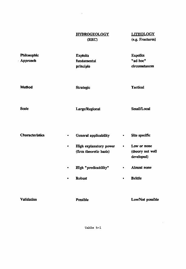
HYPROGEOLOGY (RRC)
LITHOLOGY (e.g. Fractures)
Philosophic Approach
Exploits fundamental principle
Expolits "ad hoc" circumstances
Method Strategic Tactical
Scale Large/Regional Small/Local
Characteristics • General applicability
• High explanatory power (firm theoretic basis)
High "predicability"
Robust
Site specific
Low or none (theory not well developed)
Almost none
Brittle
Validation Possible Low/Not possible
Table 5-1
simulation study or, alternatively, based on actual measurements if a specific site is being investigated. The estimated dose figure can then be compared with the regulatory limit* to decide if a particular hypothetical or actual site is safe.
5.2 ASSUMPTIONS OF THE RRC
The assumptions underlying the RRC are few in number and not onerous:
(1) the system only delays the escape of contaminants to the surface and does not necessarily confine them within the vault or the geosphere;
(2) the only significant medium for the transport of contaminants is the groundwater;
(3) the contaminants cannot travel faster than the water "front" — i.e. the leading edge of the transport medium;
(4) the geologic medium in which the groundwater flows is saturated;
(5) the RRC does not assume constant hydraulic conductivity of the geologic medium, nor constant fluid density with depth. (Although variations in values of these parameters can affect the "shape" of flow patterns, such as the idealized representations shown in Figures 1 and 2, they do not alter the general direction and other manifestations of the flow patterns.)
5.3 PREMISE FOR DEVELOPMENT OF THE RRC
The Regional Recharge Concept is developed from two basic arguments. First, it is recognized that the favourable combination of maximum groundwater flow-path lengths with minimum flow velocities, ensuring maximum travel times and maximum dilution of contaminants, is most likely to occur along flow lines that originate in regional recharge areas. Second, for recharge positions it appears possible to confirm calculated travel times, i.e. to confirm model calculations to the extent needed for the guaranteed safety of a repository. The second point implies the assertion that minimum travel times can be established which cannot
*The authority in Canada responsible for regulations associated with radiation and radioactive substances is the Atomic Energy Control Board (AECB). The regulatory limit for the safety performance of a nuclear disposal facility is given in terms of a radiation dose to an individual of a "critical" group (i.e. members of a general population who are most at risk of receiving a dose by virtue of their location and life-style - living at a contaminated site; earing, dririking and deriving their basic needs from contaminated substances). The dose limit set by the AECB is 0.05 mSv/yr to a member of such a group (AECB, 1987).
5-3
possibly be negated by unknown deviations from assumed geologic conditions such as, for instance, undetected fractures or fault zones. Such an assurance cannot, on the other hand, be given for other basinal areas, including those of groundwater discharge. Furthermore, adoption of the Regional Recharge Concept as a guiding principle facilitates and rationalizes the practical procedural aspects of the selection, screening and evaluation of a repository location. Although economy and logistical ease are not specifically considered in this paper, the great advantages conferred in these respects by a siting strategy based on the RRC should not be ignored.
5.4 THE GENERAL APPROACH TO REPOSITORY SITING BASED ON THE RRC
The practical approach to achieve the ultimate objective of safe waste disposal by employing the Regional Recharge Concept may be summarized in the following seven basic steps:
i. Selection of a repository location from which groundwater travel times to prohibited points are assumed (from general considerations, experience and/or scoping calculations) to be sufficiently large;
ii. Calculation of possible travel times by site-specifically developed models of regional groundwater flow;
iii. Calculation of measurable fluid-dynamic parameters of the groundwater flow regime;
iv. Installation of exploratory instrumentation at key points in the basin;
v. Verification of the appropriateness, i.e. applicability of the model by comparing the calculated fluid-dynamic parameters with their field determined values;
vi. Acceptance/rejection of the model, depending on the degree of agreement between calculated and observed values of the dynamic parameters;
vii(a). If model is rejected, construction of new one and repeating of the process from Step iii.;
vii(b). If model is accepted, acceptance/rejection of site based on a comparison of the calculated minimum travel times with the required minimum travel time.
Basic principles, concepts and procedures needed in the execution of the above seven steps, as well as considerations in support of the Regional Recharge Concept, are briefly presented in the following sections.
5-4
5.5 REGIONAL GROUNDWATER FLOW AND ITS CmRACTERIZATION
The spatial and temporal distributions, the fluid dynamic properties and the wide array of natural manifestations, i.e. the general characteristics of gravity-induced regional groundwater flow have been studied extensively over the last three decades (Tdth, 1962, 1963, 1972, 1984, 1990; Freeze, 1969; Freeze and Witherspoon, 1966, 1967, 1968; Gustafsson, 1968; Shahbazi and Todd, 1967; Domenico and Palciauskas, 1973; Sastre Merlin, 1978; Stokes and Thunvik, 1987; Winter, 1978; Bredehoeft et al., 1982; Tdth and Millar, 1983; Kimmeier et al., 1986| Engelen and Jones, 1986; England and Freeze, 1986; Engelen et. al, 1989; Bethke, 1989T Jacobson and Jankowski, 1989; Kloosterman, 1989; Ortega and Farvolden, 1989). Also, these questions are routinely treated in modern texts on hydrogeology (Custodio and Llamas, 1976; Freeze and Cherry, 1979; Todd, 1980; Fetter, 1988; Domenico and Schwartz, 1990). For the present purposes it is necessary, therefore, to review briefly only those characteristics which are directly relevant to the problem of nuclear waste disposal in the Canadian Shield.
5.5.1 Groundwater Flow Systems: Areas of Recharge. Discharge and Throughflow
Groundwater flow in the Canadian Shield is generally recognized to be driven by gravity, i.e. by elevation differences of the water table. The flow is regionally unconfined, that is, a change anywhere in the water table entails an adjustment of the flow pattern throughout the entire domain. In regionally unconfined gravity-flow fields groundwater can be at rest only in the idealized situation where the upper surface of the water body, namely the water table, is horizontal and infinite in area! extent. In real conditions, however, as in the Canadian Shield, the configuration of the water table is a close replica of the topographic relief. In such cases, groundwater moves downward, or away from the water table, under topographically high regions; it moves upward, or toward the water table, beneath topographically low areas as, for instance, stream valleys or lake basins; and flow is parallel to the water table under medium elevations between mounds and vales. Based on their distinct functions in the subsurface hydrology of drainage basins these three different regions of groundwater hydraulics are termed, respectively, as recharge, discharge and throughflow, or midline areas of groundwater (Figure la).
A family of flow lines originating in a given recharge area and terminating in a given discharge area is referred to as a groundwater flow-system. Flow systems terminating in discharge areas which are immediately adjacent to their recharge areas are called local systems, whereas the systems connecting the principal recharge areas with the principal discharge areas of a topographic basin are termed regional (Figure 2a). Intermediate systems may straddle one or more local systems without, however, extending from the principal watershed to the main valley. In basins with complex groundwater flow patterns (e.g. Figure 2a), different hydraulic regions of local and higher order flow systems may spatially coincide. At Site 2, for example, the discharge area of a local system is superimposed on the descending limb, i.e. recharge portion, of the regional system, whereas at Site 3 local recharge is underlain by the regional discharge area.
5-5
Additional complications may be introduced into the pattern of basinal groundwater flow by permeability variations. The effects on the flow patterns of heterogeneities, such as fault zones and fractures, depend on their degree, area! extent, orientation with respect to flow lines, and elevation of outcrop regions.
5.5.2 Characterization of Groundwater Flow Systems
5.5.2.1 Hydrodynamic Parameters
Regional groundwater flow is governed by the basic physical principle, namely, that movement takes place from regions of relatively high toward regions of relatively low potential energy. This principle is embodied in the Laplace Equation (Eq 1) which describes the steady-state energy distribution in a conservative flow field:
V 2 * = 0. (1)
In Eq. l , # , as defined by Hubbert (1940), is the mechanical energy per unit mass of fluid [L 2 /T 2 ] .
The energy-, thus the flow-, distribution in a subsurface region can, therefore, be characterized by spatial patterns of fluid dynamic parameters that are related to, indeed derived from, the fluid potential $ . Such, practically useful dynamic parameters are the hydraulic head h, and the vertical pressure gradient 7.
According to Hubbert (1940), the fluid potential is
$ = gh = gz + p/p, (2a)
where: * is as defined above, g = acceleration due to gravity [L/T 2]; z = vertical coordinate of the point of measurement, called elevation head in the context of Eq. 2a and positive upward with respect to a datum plane at which z = 0, [L]; h = hydraulic head, defined as elevation to which water rises with respect to the datum plane in an open vertical tube from the point of measurement [L]; p = pore-fluid pressure in point z [M/T 2L]; and p = fluid density [M/L 3].
The hydraulic head h (also called potentiometric elevation) is a convenient measure of the fluid potential. It can be determined from water-level and/or pore-pressure measurements in wells by the relation
h = z + p/pg , (2b)
where pg = 7 [M/L 2T 2] is the rate of vertical change in pore pressure or the vertical pore-pressure gradient.
The intensity and direction of fluid flow is related to the hydraulic head by Darcy's Law:
5-6
q = -K gradh = -K dh/dl , (3)
where: q is the specific volume discharge or flux | l / r j ; K is the hydraulic conductivity of the rock-fluid system [L/Tj; and dh/dl = gradh is the hydraulic gradient which is taken positive in the direction of increasing hydraulic head h. The negative sign in Darcy's Law indicates that the fluid impelling force, thus also the flow, is oriented opposite to the hydraulic gradient, i. e., in the direction of decreasing hydraulic head.
In case of hydrostatic equilibrium, q = 0. Consequently, the condition of no flow in the vertical direction is that the vertical component of the hydraulic head gradient must also be zero, i.e. from Eq. 3:
q z = dq/dz = -K 3h/3z = 0 . (4a)
According to Eq. 4a, the vertical head-gradient dh/dz also must be zero because K is a finite quantity. Substituting h from Eq. 2b into Eq. 4a yields, therefore,
dh/dz = 1 + (1/pg) (3p/3z) =0 , (4b)
as condition for no flow in the vertical direction. The static vertical pressure-gradient, 7^, is then, from Eq.4b:
7st = pg = -Op/a*)* = (ap/adv (5)
Eq. 5 states explicitly that the condition of no flow in the vertical direction is that the vertical pressure gradient be equal to the product of the fluid's density p and the acceleration of gravity g. The negative and positive signs indicate that the pressure decreases with increasing elevation, z, and increases with increasing depth, d, respectively.
If, on the other hand, there is flow in the vertical, an upward direction is reflected by a dynamic vertical pressure-gradient 7 d y n which is greater, while a downward direction by one which is less, than the hydrostatic, or nominal, pressure-gradient pg = 7^ (Figure lb):
7dyn,uP = (3p/9d)uP > PS = 7* = 0p/9d ) s t .
7dyn,<ta = (3p/9d)dn < Pg = 7* = WW* • <6b)
The distribution of groundwater flow can now be characterized by calculated and/or observed values of these parameters in three different ways:
i. The potentiometric surface shows the lateral distribution of fluid potential in a horizontal confined aquifer by means of a map of contours of equal hydraulic heads, h(x,y) = const. Such a map can be used to infer the lateral (i.e. x,y) directions of groundwater flow in
5-7
the aquifer: flow is normal to the contours and takes place toward decreasing head values. The intensity of the flow can also be evaluated by Eq. 3 if the hydraulic conductivity K is known.
ii. Hydraulic cross-sections portray flow patterns by hydraulic head contours, h(l,z) = const., in vertical planes which can be oriented in any arbitrary direction, 1. However, because the hydraulic head values depend on the fluid's density (Eq.2b) the magnitude and even the sense of the vertical component of the driving force, thus of the flow, may not be correctly reflected by the contours if the flow regime contains fluids of significantly different densities (Lusczynski, 1961; Davies, 1987).
iii. The vertical pressure-gradient, dj)/dd = -3p/dz, (Eqs.5, 6) expresses the rate of change of pore-pressure in the vertical direction. Usually, the gradients are presented in two-dimensional co-ordinate systems. Pressures, p, are shown on the horizontal axis, while the vertical positions of the points of measurement on the vertical axis with respect either to elevation, z, or to depth, d. The respective diagrams are commonly referred to as "pressure-versus-elevation, p(z), or pressure-versus-depth, p(d), plots or curves. The above mentioned problem caused by variable fluid densities can be reduced by comparing plots of actual , possibly dynamic, y d y n , vertical pressure-gradients determined from measurements to plots of nominal static gradients, 7^, calculated by Eq. 6 with the fluid densities prevailing at the various depth ranges (Eq.6a and b).
5.5.2.2 Characterization of Basinal Distribution of Groundwater Flow
Topographically controlled basinal patterns of groundwater flow may be characterized by three, independent methods: i) mathematical modelling; ii) field observations of fluid dynamic parameters; and iii) field mapping of the natural effects and manifestations associated with regional groundwater flow.
i. Mathematical modelling. Mathematical modelling by both analytical and numerical techniques is a well established every-day method of studying regional groundwater flow for practical and theoretical purposes (Stokes and Thunvik, 1978; Bachmat et al., 1980; Kimmeier et al., 1985; DVWK, 1987; Anderson and Woessner, 1992). Both steady-state and transient models, in one, two and three dimensions are used, depending on the nature of the problem and input data available. Solutions of steady-state flow problems require the knowledge of the geometry of the flow domain, the permeability distribution and the distribution of the hydraulic head, hydraulic head gradient or the flux along the domain's boundaries. For transient solutions the initial values of one fluid dynamic parameter throughout the region, and the temporal changes of the boundary conditions also must be specified. The most common major obstacle to the accurate and reliable simulation of groundwater flow over extended regions is the incomplete knowledge of the permeability distribution of the rock framework and, in non-steady flow problems, the uncertainty in the past and/or future changes in the boundary conditions with respect to time.
5-8
As principal output, groundwater flow-models may yield information, among others, on the spatial and temporal distribution of fluid dynamic parameters (e.g. pore pressure p , hydraulic head h, pressure/depth gradient dp/dd, flow-path geometry, flux q and travel time between specified points of the flow domain).
Figures la, b and 2a, b are schematic drawings of two-dimensional steady-state patterns of hydraulic head, flow geometry and vertical pressure-depth profiles in vertical cross-sections of drainage basins of simple and complex topography and homogeneous rock framework. These patterns illustrate the main features of parameter distributions in the three different basinal regions of groundwater hydraulics. In recharge areas hydraulic heads decline with increasing depth, flow is downward, and the vertical pressure gradient is less than hydrostatic (Figure la,b: Site 1; Figure 2a,b: Site 1). In discharge areas (Figure la,b: Site 3; Figure 2a,b: Site 3), all three conditions are opposite to those in the earlier example. In the throughflow regions, water levels are invariant with depth and the vertical pressure-gradient equals hydrostatic (Figure la.b: Site 2), although, obviously, flow does occur horizontally. In the case of a complex flow field, the depths of the local systems may be estimated from either the flow pattern (Figure 2a) or the vertical pressure profile (Figure 2b). In the latter case, this depth is indicated by the depth at which the slope of the dp/dd gradient reverses from above- to below-hydrostatic values, or vice versa, on curves 2 and 3 (Figure 2b). This depth corresponds to the "quasi-stagnant" transitional zones between the discharge region of the local system and recharge limb of the regional system at Site 2, and between the similar but oppositely oriented systems at Site 3.
A useful application of calculated flow models is the analysis of the effects of the repository's location relative to the different hydraulic regions of groundwater flow systems, and of the discrepancies between the assumed and real conditions of the flow domain (e.g. permeability distributions, boundary values), on repository performance and its predictability
ii. Field observations of fluid dynamic parameters. Because groundwater flow cannot be measured directly, so called "observed" flow patterns in real basins must be inferred indirectly from field-determined values of hydraulic gradients and permeabilities through the Laplace Equation (Eq. 1) and Darcy's Law (Eq. 3). Hydraulic gradients dh/dl, and the vertical pressure gradient dp/dd, that are used for this purpose, are derived from water-level and/or pore-pressure measurements at points of known elevation or depth in observation wells (Eqs. 2, 3, 5). Permeability values, on the other hand, can be estimated from pumping tests, or on rock samples obtained from cored wells or outcrops.
Important characteristics of basinal flow distribution may be deduced from patterns of field determined values of fluid dynamic parameters such as the potentiometric surface, vertical hydraulic cross sections and pressure-depth profiles. These patterns are derived by interpolation between observed values. Interpolation is justified by the recognition that the fluid dynamic parameters are continuous functions in space because the water body is a continuum through the hydraulically connected network of the rock's voids.
5-9
Hydraulic continuity is a fundamentally important property of the rock framework (Toth, 1990): it allows the adjustment of the entire flow pattern to changes in fluid potential at any point in the domain. Consequently, a knowledge of the actual distribution of dynamic parameters in appropriate portions of the flow field facilitates potentially important conclusions to be drawn of certain characteristics of the entire flow field. If, for example, water-level measurements taken at different depths in strategically positioned observation wells show that the flow of water is uniformly downward at least to a certain depth below surface, it can be demonstrated that a minimum length of time exists within which water cannot possibly return to the surface from that depth regardless of undetected values and distribution of rock permeability in other parts of the basin.
Another important application of field measurements is the evaluation and/or verification of boundary conditions of flow domains assumed for modelling purposes. In an effective and efficient characterization of regional groundwater flow, mathematical modelling and field characterization of fluid dynamic parameters are used iteratively.
Hi. Field mapping of the effects and manifestations of regional groundwater flow. Moving groundwater interacts with its subsurface- and surface- environments in a variety of different chemical, physical and mechanical ways. It: 1) dissolves and precipitates chemical constituents; 2) mobilizes and transports matter and heat; 3) modifies pore pressures; and 4) lubricates grain surfaces of unconsolidated earth material. As a result of this interaction, a wide array of natural phenomena may be generated which pertain to the realm of: a) surface water hydrology; b) aqueous geochemistry and mineralogy; c) botany; d) soil- and rock-mechanics; e) transport and accumulation of mass and heat (Tdth, 1972, 1984; Custodio and Llamas, 1976; Freeze and Cherry, 1979).
In groundwater flow systems recharge areas are environments of high mechanical and chemical energy (high hydraulic heads, high Eh, low Ph), whereas discharge areas are environments of low energies. Consequently, the phenomena developed as a result of interaction between groundwater and its environment in recharge and discharge areas are different or even opposite, as it were polarized, in character. For example, descending groundwaters result in a deficient surface-water balance and the consequent development of xerophytic vegetation in recharge areas, whereas seeps and springs derived from ascending flow may generate and maintain a positive water balance, manifest even by wetlands and phreatophytes, in discharge areas. In recharge areas descending meteoric waters dissolve and leach out mineral constituents, owing to their low Ph and high Eh, lower the geothermal gradient, increase the effective stress on rock grains by lowering the pore pressure and thereby reducing the surface's vulnerability to erosion. In discharge areas, on the other hand, relatively saline and warm waters ascending to the surface may give rise to soil salination and salt deposition, positive geothermal anomalies, soil liquefaction (quick sands and quick clays), land slides and other soil mechanical phenomena, due to an increase in pore pressures and the corollary reduction in effective stress.
Regional patterns of these groundwater flow-related phenomena can be mapped on the ground or by remote sensing methods such as satellite imagery (e.g. LANDSAT). They can be
5-10
used as valuable complements in the characterization of regional groundwater flow in drainage basins.
5.6 COMPARISON OF KEY CHARACTERISTICS OF REGIONAL GROUNDWATER FLOW IN RECHARGE VS DISCHARGE AREAS
The two basic arguments upon which the Regional Recharge Concept has been developed, as stated earlier, are: 1) that a position in a regional recharge area ensures the maximum degree of dilution and maximum possible travel times back to the land surface (as compared with other positions in a basin of similar hydrogeologic property) for contaminants possibly escaping from a repository, and 2) that it is recharge environments where the groundwater flow-characteristics are sufficiently insensitive to discrepancies between actual hydrogeologic conditions and conditions assumed for purposes of calculations, to allow the construction of adequately robust flow models and their validation. Clearly, the above reasoning is relativistic: it compares the effects of different positions in topographically defined drainage basins on those hydrogeologic attributes which play a role in regional groundwater flow, thus in basinal transport of contaminants. The greatest contrasts in the basinal scale hydrogeologic attributes can be expected to exist between regional recharge and discharge areas, which represent opposite end-members of basinal flow- and transport-conditions (Tdth, 1984). It is logical, therefore, that a comparison between the relevant key characteristics of regional groundwater flow in recharge- and discharge-areas should provide an adequate test of the validity of the above arguments and, thus, of the Regional Recharge Concept.
5.6.1 Model Calculations
5.6.1.1 Scope and Method of Calculations
Four key characteristics of basinal groundwater flow have been calculated by numerical modelling. The calculation were performed for hypothetical repositories located at depths of 500 m and 1000 m in both recharge and discharge areas of topographically defined basins which are underlain by a geologic framework of varying permeability distributions. The four flow characteristics are: 1) "return time", i,., or the travel time of water from a repository to the land surface; 2) "repository-age of water", L. or the travel time of water from the land surface to the repository; 3) "return route", lg, i.e. the length of flow line leading from the repository to the land surface in the direction of flow; and 4) "fault route", If, or the total length of that flow line inside of a highly conductive fault which passes also through a repository. These characteristics were determined with reference to a point 500 m below the land surface and 1 km distant from the lateral boundaries of the basin (Figure 3). The point is considered to represent the upper edge of a repository. The repository extends over a surface area of 2 x 2 km (the same dimensions as the reference vault in the Canadian Disposal Concept) and its centre coincides with the basin's lateral boundaries at both the water divide (recharge side) and valley bottom (discharge side). The two repositories modelled at both the recharge and discharge sides are
5-11
treated as identical in their features. Their characteristics are taken to be those of the Canadian reference vault and have been described in earlier papers.
The key flow properties were determined by interpolation from the model's direct outputs, which are: basinal patterns of equipotentials (Tiydraulic heads), flow lines, travel times (indicated by time-step beads on flow lines) and isochrone lines of the travel time. Specifically, travel times were estimated by interpolation between computed isochrone values, and travel distances were expressed as relative lengths along flow lines passing through the reference point. The calculations were performed by the code FLOWNET , developed by van FJburg et al. (Engelen and Jones, eds., 1986). FLOWNET® models two-dimensional steady state, groundwater flow in a rectangular, heterogeneous and isotropic domain of the subsurface with arbitrary water-table configuration, by the technique of finite differences.
5.6.1.2 Modelling Results for Different Basin Variants
The general purpose of the modelling experiments was to establish a conceptual reference framework of the key characteristics of regional groundwater flow for the Canadian shield. To this end, basinal patterns of hydraulic heads, flow lines and travel times were computed for a large variety of basin-permeability configurations. However, a summary of illustrative examples only is presented in this paper (Figures 3-9; Tables 1 and 2).
The geometry of the modelled basin is constant for all variants. It simulates one flank of a centrally symmetrical depression as, for instance, one side of a river valley (Tdth, 1963). The width of the modelled basin's flank is 20 km and its depth at the valley is 4 km. The flow domain is enclosed by impermeable boundaries on the two sides and the bottom, and by a sinusoidal water table, (i.e. a sinusoidal distribution of the fluid potential) along the top (Figure 3) The water table is higher by 400 m at the divide than at the valley bottom.
Two basic, or reference, distributions of basin permeability are used, namely: one homogeneous (Figure 3), and one stratified into three horizontal depth ranges of different permeabilities (Figure 4). The latter case was further modified by the introduction of highly permeable fault zones which lead with a slope from points of fixed depths at the lateral basin boundaries to outcrops at the land surface (Figures 5a, b, c; 6a, b, c; 7a, b, c; 8a, b, c) or horizontally, to the opposite lateral boundary thus abutting against it without outcropping (Figures 5d; 6d; 7d; 8d). The purpose of introducing the faults was to examine the potential effects on travel times and flow-path lengths of highly permeable conduits located at or near a repository that might remain undetected, and thus ignored, while modelling real life situations. In the different model variants the attitude of the faults was changed by discrete step between a vertical position at the boundary and the horizontal, as mentioned above.
The hydraulic conductivities K (m/s), or equivalent permeabilities k (m 2) and their distributions in the different basin variants are consistent with those found in rocks of the Canadian Shield in general (Reference!) and are:
5-12
i. homogeneous (Figure 3) K = 10~1 0 m/s; k = 10" 1 7 m 2 ;
ii. stratified (Figure 4)
for depth range of:
0 to 300 m K ^ e ^ e d ) = 1 0 - 9 m / s ; k„ = 10
300 to 2000 m = lO ' 1 0 m/s; 1^ = 10" 1 7 m 2 ;
2000 to 4000 m K b ( a s e m e n t ) = 10" 1 1 m/s; Is = 10" 1 8 m 2 ;
(ault)
= m - 1 6 m2:
iii. &u]ted. (Figures 5, 6, 7, 8) K f ( m l t ) = 10"8 m/s; kf = 10" 1 5 m 2
Porosities were kept uniformly ( m a t r i x ) = 0.01 for the matrix rocks of three different permeabilities and n f ( a u n ) ) = 0.1 for the faults
The fault zone's thickness is modelled to be 100 m, representing a transmissivity of T = 10"6 m 2/s, which is probably too high for common conditions in the Canadian Shield and thus yields travel times which are too short, i.e. conservative from a safety point of view. Owing to limitations of the model, sloping faults were simulated by stepwise arranged straight horizontal segments (Figures 5, 6, 7, 8)
Flow in homogeneous basins. A flow model computed for a homogeneous basin allows an analysis of the general
properties and regularities of the flow field, a quantitative estimation of a set of basic reference values of the key flow characteristics and a comparison of those characteristics in recharge areas and discharge areas.
Figure 3 shows the calculated distribution of the three basic flow parameters, namely, hydraulic head, flow field and travel time, for a homogeneous drainage basin with a sinusoidal water-table and with a basin-flank width which equals one-half of a wave length.
The general properties of the calculated flow field are consistent with those described earlier (Figure 1). Thus the basin is divided into three principal hydraulic regions: the recharge-, through-flow, and mid-line areas, in which flow is descending, lateral and ascending, respectively. Hydraulic heads (i.e. water levels measured with respect to a horizontal datum plane) decline monotonically from basin divide to valley bottom. They decline with increasing depth in the recharge area, remain constant in the mid-line region and rise in the lower parts of the valley.
Whereas these flow and head distributions are generally recognized and understood, the third family of curves, namely the isochrones, reveals several aspects of the flow field that are less well known, rarely considered and occasionally misconstrued.
An isochrone represents the calculated times a water particle is required to travel along a flow line from its entry point into the flow domain at the water table to the point of
5-13
intersection of that flow line with the isochrone. In essence, at any point of an isochrone, it shows the age of the water arriving along that flow line which intersects it at that point. Consequently, the travel time along a given flow line and between any two arbitrary isochrones can be determined as the difference between the values of the two selected isochrones. The travel time from an arbitrary interior point of the flow field to the land surface can thus be evaluated by subtracting the age of water at the point of interest from the age of water at the exit point of the flow line (possibly requiring interpolation between isochrones); the exit point selected must, of course, lie on the same flow line that crosses the point of interest. Using this method, ages of water, t,, and return times, t s , were determined for all model variants and for both recharge- and discharge areas.
The contrast between the travel times to and from the repositories is striking though easily understood (Figure 3; Tables 1 and 2). The age of water is tyR = 8.0 x 10 4 years at the repository-reference point in the recharge area, whereas the return time (from the repository to the surface) is tj.R = 3.4 X 10 6 a. In the discharge area position, on the other hand, the water's age is found to be as high as = 3.4 x 10 6 a, but it takes only = 9.5 X 10 4 a for this old water to reach the surface in the repository's vicinity. The difference between the ages, on the one hand, and the return travel times, on the other, is easily explained by the difference in flow routes to and from the two corresponding reference points. Travel, both down (recharge area) and up (discharge area) between the surface and the repositories is along a short route and driven by relatively high head gradients. Migration from the recharge area, on the other hand, takes the water, whether possibly contaminated or not, to great depths and through a long trajectory. Furthermore, driving forces are significantly reduced in several regions along this flow path and they even vanish, theoretically, in the two lower corner areas of the flow domain. The extremely low velocities in these "quasi-stagnant" regions contribute largely to the long travel times from the crustal parts of the recharge areas to the surface.
An important feature of the isochrone pattern is its asymmetry. The isochrone lines are largely subhorizontal and widely spaced, with spacing slowly decreasing with increasing depth, in the recharge area. The pattern indicates a relatively small, mainly vertical and downward increasing age gradient. Maximum age of the water is less than 2 x 10⁶ years in the upper 3.8 km. On approaching the discharge area, the isochrones bend vertically upward, become sub-vertical to vertical and increase in number and density (Figure 3): The age gradients are relatively high and increasing laterally toward the divide beneath the valley bottom. The water's age exceeds 4 x 10 6 years at any depth within one kilometre of this divide, including the repository's depth of 500 m. Yet, this 3 to 4 million years old water has only 9.5 X 10 4 yean to reach the surface (Table 1). The isochrone pattern of the basin clearly dispels the axiomatic assumption, commonly made by the nuclear waste disposal community, that a high water age indicates stagnancy, i.e. a safe environment for contaminant confinement.
Effect of stratification on basinalflow Figure 4 shows the calculated distribution of hydraulic head, flow and the age of water
in a horizontally stratified basin. The depth-ranges and the hydraulic conductivities of the three zones represent, as specified earlier, assumed general conditions in the Canadian Shield and are
5-14
as follows. Weathered zone: d w = 0 -300 m; K,, = 10"9 m/s. Main body: d m = 300 - 2000 m; = 10" 1 0 m/s. Basement: d b = 2000-4000 m; K b = 10" 1 1 m/s.
From Figure 4 and Tables 1 and 2 it appears that stratification has a significant modifying effect on the head, flow and age distribution of the groundwater, as compared with those in the homogeneous basin. A large portion of the flow is now deflected through the shallow, high permeability weathered zone. Consequently, flow becomes, more sluggish in deep regions; isochrones rise to shallower depths, and the age of water at greater depths increases. Because water from the vicinity of the divide in the recharge area has to move through the low permeability basement, the return time in a stratified basin exceeds largely that in the homogeneous case; it increases from 3.4 X 10 6 a to 8 x 10 6 a. This increase, however, is not as significant for the discharge area repository, it being from 9.5 x 10 4 a to 1.1 x 10 5 a.
Effects of fault zones on How in stratified basins The purpose of a series of numerical experiments with flow patterns in faulted stratified
basins was to develop a conceptual understanding of the effect of possibly undetected faults on key characteristics of regional groundwater flow in recharge- and discharge areas in the Canadian Shield. To this end, following several sets of experimental runs, a total of 73 model variants were computed to simulate the head-, flow- and travel-time distributions in four basic types of hydrogeologic settings, namely: faults anchored at a depth of 500 m (at repository level) and at 1000 m, both at the crestal and the thalweg boundaries. As variants of these groups, the faults were rotated about the anchor points step-wise from a vertical to a horizontal position by progressively increasing their outcrop distances from the nearby basin-boundary. After their distant end reached the opposite boundary of the basin, their dips continued to be decreased to a horizontal position. This process resulted in a number of "dead-end" variants, in which the faults abut against the basin's opposite boundary without outcropping.
The four groups of model variants corresponding to the four settings are labelled, with the number of simulations run in each group in brackets, as: 1. S Re 5 (18); 2. S Re 10 (17); 3. S Di 5 (23); 4. S Di 10 (15). In these terms the symbols mean: S: stratified; Re: Recharge area; Di: Discharge area; 5: 500 m fault anchor-depth; 10: 1000 m fault anchor-depth. Additional numbers indicate (Table 1) the distance in kilometres to the distant side of the outcrop area from the anchor-side divide. An increase in this outcrop distance is, therefore, equivalent to a decrease in fault dip.
The calculated return times from repository to land surface are plotted for all four settings in Figure 9. The time determination may involve interpolation between calculated flow lines and calculated isochrones and may, thus, include uncertainties. The uncertainties are indicated in Figure 9 by error bars.
Samples of the calculated head- and flow-patterns are reproduced in Figures 5a, b , c, d (S Re 5); 6a, b, c, d (S Re 10); 7a, b , c, d (S Di 5 ); and 8a, b, c, d (S DilO). Because isochrones tend to clutter the patterns they have not been plotted in the figures. Instead, equal steps of travel time At = 2 x 10 s a are shown by beads on the flow lines. (The spacing of the
5-15
time-step beads illustrates the relative flow velocity in different parts of the flow domain and is of significant assistance in drawing conclusions relevant to the problem of waste isolation.)
The effects of faults on a basin's flow field (pattern, flux, velocity) are various and depend on the complex interaction between, among others, the size, geometry and permeability distribution of the basin, on the one hand, and the position, attitude, geometry and surface connectedness of the fault, and the contrasts between matrix and fault permeabilities, on the other. A thorough investigation of this problem would require an extensive sensitivity analysis and is beyond the scope of the present paper. Nevertheless, in proposing the Regional Recharge Concept it is essential to ascertain that possibly undetected faults near repository sites do not negate the otherwise obvious advantages of recharge area positions offered by faultless basins in terms of relatively great return times (Tables 1, 2) and long and deep return routes (Figures 3, 4), as compared with those characteristics in discharge areas. The effect of faults on the flow field is, therefore, analyzed in the present study but emphasis is placed on those ones reflected by the four key characteristics: return time, water age at repository, return route and fault flow-length.
A highly permeable conduit fault located in any part of the basin tends to concentrate the flow inside and parallel to its bounding planes. As a consequence, flow intensity, in general, and the vertical flow components, in particular, increase in those regions above the fault (c.f. Figures 5, 6, 7, 8 and Figure 4).
The effect of a fault on the return times was analyzed with respect to the "repository reference-point", 1 km distant from the nearest basin boundary and 500 m deep. In general, the presence of faults reduces the return times. For example, the 8 X 10⁶ a return time from the recharge area repository in the stratified unfaulted basin (S Re 0) is reduced to 3 X 10 6 a and 2.98 x 10 6 a by the steepest faults anchored at depths of 500 m and 1 km (S Re 5/1.6 and S Re 10/2.6, respectively) and is lowered further as the dip of the faults decreases (Figures 5, 6; Table 1).
A summary of the calculated return times is presented in Figure 9 for all four hydro-geologic settings. In the figure, return time ^ is plotted against the distance of fault outcrop from the basin's boundary nearest to the repository. In essence, an increase in distance represents a decrease in the fault's dip angle. Three properties of the calculated relations are striking and immediately obvious.
First, the return times, tg, decrease from their maximum values at high angle faults (short outcrop distances) and level off at a range of minimum values at low angle faults. The trend is valid for both the recharge and discharge area positions as well as for both anchor depths of 500 m and 1000 m. Minimum return times, including the effects of the horizontal "dead-end" faults, are approximately one-tenth of the maximum times for both the recharge and discharge areas. If the horizontal faults are excluded, minimum return times decrease only to about one-fifth of the maximum values in the recharge area and remain virtually unchanged for the discharge area. The most important conclusion of this analysis is that minimum return times
5-16
exist for non-outcropping and deep faults, which are the faults most likely to remain undetected. At the same time, however, these minimum return times can be determined by modelling for any conceivable fault configuration. (The reason for the low minimum return times for the low angle faults appears to be computational. The progressive decrease in the number of straight line segments — not illustrated in the paper — as the dip angle is reduced for the "dead-end" faults represents a reduction in the faults' hydraulic resistance and results in an increase in flow velocity, i.e. decrease in travel time. This effect is stronger for the recharge area repository than it is for the discharge area position because in the first case the calculated time reflects flow through the entire length of the fault and is, therefore, highly sensitive to its hydraulic properties. In the case of the discharge area, on the other hand, the fault's effect is included in the age of the water (i.e. in the travel time before the water reaches the repository).
Second, minimum return times are 30 to 40 time greater for the recharge area position ( » 9 x 10 s a) than for the discharge area position ( » 2.5 x 10 4 a).
The general decrease in return times with decreasing dip angle is explained by the corollary increase in the "fault-flow length". As the dip is reduced, the flow line that crosses the repository-reference point becomes progressively shallower, and an increasingly larger portion of its total length is moved into the fault's high velocity interior (Figures 5, 6, 7, 8). It is clear, therefore, that the return time for the recharge position cannot be less than that needed for the water to travel the entire width of the basin from the repository, and for the discharge position the thickness of the rock vertically above the repository.
Third, the return times are generally shorter for the deep faults (anchored at 1000 m) than for the shallow ones (anchored at 500 m). However, the difference decreases and even vanishes as the outcrop distance increases (dip angle is reduced). This difference in travel time is due to the difference in the "fault-flow length", i.e. to the difference in the length the water travels relatively fast inside the fault in the different situations. This difference can be well appreciated by comparing the route a water particle crossing the repository-reference point takes across the basin, as indicated by the heavy flow lines in Figures 5 and 6 for the recharge area positions, and in Figures 7 and 8 for the discharge area positions. It is important to note, however, that for all cases there exist a finite minimum return time and that this time is the same, regardless of the fault's depth. Clearly, for recharge area repositories this time is controlled by the width of the basin, whereas for a discharge area position it is controlled by the depth of the repository.
5.6.2 Summary and Discussion of Modelling Results
Thirteen hydrogeologic characteristics that have been calculated by the groundwater flow-modelling and are relevant to the development of a strategy for repository site-selection are summarized in Table 2. In order to emphasize the contrast between conditions in recharge and discharge areas the characteristics for these hydraulic regions are juxtaposed in the Table. The unfaulted stratified basin is considered as the basic, or reference, basin. The hydrogeologic conditions established for this basin variant are accepted as the fundamental rationale for the
5-17
Regional Recharge Concept. The faulted-basin variants have been generated in order to examine if the presence of conduit faults might negate the conclusions drawn from the basic model.
The most fundamental advantage of a repository location in a regional groundwater recharge area as opposed to that in a discharge area is summed up in the first four items in Table 2. Collectively they indicate that in a recharge area groundwater flows downward with respect to the land surface, at decreasing velocities which may approach zero in the direction of flow and beneath the water divide. Conditions are opposite, on the other hand, in discharge areas: water moves from depth toward the land surface with increasing intensity in the directions of flow and the thalweg boundary. In the field, the sense of flow directions can be determined by measurements of fluid pressures and/or water levels in wells.
As a consequence of the opposite nature of conditions in these hydraulic environments, two associated key characteristics, namely the return-route length and the return time, also are more favourable for recharge area locations (Table 2, Items 5, 7). Contaminants, possibly escaping from a recharge-area repository would have to travel virtually the full width of the basin plus twice the depth to which regional flow would take them (Figure 4). If originating from areas within one kilometre of the divide boundary, this flow penetrates into the low permeability basement thereby delaying contaminant return both by adding distance and reducing velocity; the route length is significantly greater than 20 km. From a discharge area position, on the other hand, the contaminants would only have to travel 500 m, mostly through the high permeability weathered zone, to reach the land surface. The different conditions are amply reflected by the difference in return times (Table 2, Item 7): 8 X 10 6 a for the recharge area repository and 1.1 X 10 5 a for the discharge area repository. Both the return-route length and the return time have significant bearings on the safety of a nuclear waste facility. The longer the route, the greater a proportion of the contaminants is adsorbed on the rock matrix's minerals; the longer the travel time the larger proportion of the radioactivity decays.
The age of the water in the recharge and discharge areas (Table 2, Item 12) are noteworthy from two view-points. During the 1.3 x 10 5 years that descending meteoric waters take to reach a repository in a recharge area they will be largely depleted in free or dissolved oxygen and will not be an oxidizing agent. In the discharge area, on the other hand, by virtue of its high age, an 8 X 10 6 year old water could be mistaken to indicate stagnancy, yet it is only 1.1 x 10 5 years away from the surface.
All the above numbers are modified by the presence of faults. Nevertheless, all the parameters have minimum values that can be evaluated for realistic conditions.
Thus, faults can reduce the return-route length to a mimmum of approximately 20 km for a recharge-area repository, but cannot change the 500 m distance from repository to the surface in a discharge area. Similarly, the return travel times can be significantly reduced by faults in recharge areas: from 8 x 10 6 to 0.18 x 10 6 years in the absolute extreme (the minimum value of the error bar - see Fig. 9), but more likely only to approximately 0.8 xlfj 6
years (Table 2, Items 7,8,9). An important point here to note is that, with the exception of
5-18
those recharge area faults which run the full length of the basin and outcrop in the valley bottom (Figure 5c, 6c), none of the faults can convey water directly from the vicinity of the recharge divide to the land surface. But even in these extreme cases, water that descends from the surface within one kilometre of the basin's crest is forced to move across these faults down into the low velocity or stagnant zone of the basin and then travel its full width, largely through the low permeability basement, to emerge in the discharge area some 10 7 years later. All these numbers can be increased purposefully further by selecting a basin configuration with a lower elevation difference between valley and the upland, a longer flank and a broader divide than those in the present model. Faults may reduce the return travel times in discharge areas also. In the calculated cases (Table 2, Items 7, 8, 9) the reduction is from 1.1 X 10 5 to 2.3 X 10 4
years. (Actually, the upper limit obtained for a near vertical fault is « 4 X 10 s years; Figure 9.) However, because return times and return-route lengths are controlled by local conditions in discharge positions, modifying the regional basin characteristics, namely by the choice of the basin, will have little or no effect on these parameters.
Regional groundwater flow can be exploited to enhance the role (utility) of the geosphere as a barrier to radioactive waste migration by judiciously selecting the basin and locating the repository near the basin's crest. Such deliberate exploitation, as it were "engineering", of natural conditions is not possible for discharge-area repository positions.
The conclusions drawn from the model calculations may be summarized as follows:
1. From the view-point of contaminant transport by groundwater, recharge areas are superior to discharge areas for the siting of high level nuclear waste repositories. Recharge area locations assure considerably greater minimum travel-path lengths and return-flow times than do discharge area locations, and their effectiveness can be evaluated and purposefully modified; this type of control is not possible for discharge area locations.
2. The possible presence of, even undetected, faults does not negate or compromise the theoretical superiority or the suitability of recharge areas.
3. The hydrogeologic conditions required for the suitability of a recharge area location can be recognized and verified from field observations and, to the extent needed for safety, evaluated and confirmed by modelling. No such confirmation is possible for discharge-area positions: the sensitivity of regional hydrogeological conditions to changes in their controlling factors is low as compared with that of the local conditions. Consequently, regional model predictions are robust relative to local model predictions.
5-19
5.7 SUGGESTED STEPS IN REPOSITORY-SITE SELECTION BASED ON THE REGIONAL RECHARGE CONCEPT
A formulation of the major stages in the procedure of repository-site selection by relying on the Regional Recharge Concept can be based on the following two premises: 1) regional groundwater recharge areas are preferable to other parts of drainage basins for repository locations in the Canadian Shield, and 2) regionally, groundwater flow in the Shield area is controlled by the topographic relief. These premises justify the direct, goal-oriented strategy of starting the siting procedure by searching for potential regional recharge areas.
A hydrogeologically based siting procedure may be organized into five major stages: 1) Theoretical definition of potentially adequate basin configurations; 2) Reconnaissance field inventory; 3) Initial basin culling; 4) Second-phase basin culling; 5) Final area selection.
Stage 1. Theoretical definition of potentially adequate basin configurations. Approximate topographic configurations of theoretically adequate basins can be
determined by preliminary numerical experiments in terms of total relief, lateral dimensions and expected basin depth. These experiments would be comparable in nature to the model calculations performed for the purposes of the present paper, except that modern models can simulate flow in three dimensional basins of heterogeneous rock framework and complex local topography.
Stage 2. Reconnaissance field inventory. Identification of an arbitrary but large, M, number (e.g. M = + 500) of geographic
areas that, according to the numerical experiments performed in Stage 1, can be presumed to be recharge areas of regional groundwater flow systems in suitable topographic basins. The inventory is based on geomorphologic/topographic characteristics and can be provided by a Geographic Information System (GIS). From these M-number of regions a lower number N (e.g. N = ±50) is selected that could, in principle, qualify as a repository location based on anticipated availability, accessibility and other factors.
Stage 3. Initial basin culling. The selected N (±50) number of areas are subjected to an initial assessment with respect
to (a) geologic and (b) hydrogeologic characteristics.
(al Geologic Characteristics to be considered will include, but not limited to e.g.: i) presence/absence of major fracture zones; ii) expectable integrity of the rock matrix; iii) seismicity.
(b) Hvdrogeologic Characteristics to be observed and analyzed will include, but not necessarily be limited to:
il. coarse-grid geometry of the groundwater flow-field as established by a standardized procedure consisting of the installation of at least five piezometer nests centred on the apex of the divide with the deepest point of measurement at a depth of ± 1000 m; hydraulic heads to be
5-20
determined at approximately 100 m depth-intervals and/or in zones of relatively high permeability.
ii). vertical hydraulic gradients (dh/dz. to be determined for the entire depth range in all wells and to be compared with "nominal values" (e.g. hydrostatic pressures). Gradients should be negative throughout the depth range, except that reversals at shallow depths, indicating local discharge conditions, do not necessarily disqualify the area from further considerations.
iiil. the nature of hydrogeologic discontinuities: no low-angle fault-zones should occur below possible repository depth that could outcrop in adjacent basins at elevations lower than the hydraulic head in them at the anticipated site of the repository. (This requirement might be waived pending modelling results - see 4.b.ii below.)
iv). groundwater chemistry: waters preferred are chemically reducing and high in Total Dissolved Solids (TDS); fresh water-salt water interface to be observed and preferred at shallow depths.
(cl combined assessment and ranking, based on (a)+(b)+(possible other) considerations, and selection of O-number ( ± 5) of regions for further evaluation.
Stage 4. Second-phase basin culling. Assessment of the O-number (+ 5) of areas retained after "Initial Basin Culling". (These
areas already have the initial geological, hydrogeological, etc., information. Further studies require the acquisition only of additional, complementary data.)
(a) Geologic Characteristics: i.1 detailed evaluation of faults and fractures based on surface and subsurface (bore-hole)
data; ii.) rock mechanical investigations to determine rock strength, stress values, directions;
(b) Hydrogeologic Characteristics: LI establishment of basinal and flow-field boundaries, to be based on: —surface mapping
of hydrogeologic indicators; —potentiometric surfaces and hydraulic cross-sections derived from 15 to 20 new piezometer nests plus already available data; —chemical composition patterns of groundwaters, with special attention to the fresh water-salt water interface.
ii.l groundwater flow-field calculations, i.e. modelling: —calculation of basinal groundwater flow-models, with particular attention of known fault zones and other hydraulic discontinuities; —numerical experiments with assumed (unknown but possible) and potentially dangerous faults, i.e. development of possible flow-path and flow-rate scenarios. This is the step by which the stipulation of Stage 3. b. iii) might be waived.
(Note: These scenarios should, and could, take into account the effects of the various possible positions (lateral and vertical) of a repository, and various types, attitudes and positions of known and possible, present and future changes in permeability patterns, as for instance, fault zones. In fact, this is the stage through which the degree of safety (risk, etc.) of a repository could be engineered to a specified level of safety or adjusted to a prescribed level of safety factor (opportunity for engineered robustness).
5-21
Stage 5. Final Area Selection.
5-22
At least 3 areas (P > 3) from the number O = ± 5 should be retained as potentially suitable ones for the siting of a repository. Out of these P ^ 3 areas the final selection can be made based on engineering, socio, economic, political, etc., considerations. From a technical scientific view-point they will be equally suitable and robust, with the possibility to guarantee safe performance.
REFERENCES
5-23
Anderson, M.P. and W.W. Woessner, (1992), Applied groundwater modeling: simulation of flow and advective transport. Academic Press, Inc., San Diego, California, 381 pp.
Bachmat, Y., J. Bredehoeft, B. Andrews, D. Holte and S. Sebastian, (1980), Groundwater management: the use of numerical models. Water Resources Monograph 5, Amer. Geophys. Union, 127 pp.
Bethke, C M . , (1989), Modeling subsurface flow in sedimentary basins. Geologische Rundschau, 78 (1), pp. 129-154.
Bredehoeft, J.D., W. Back and B.B. Hanshaw, (1982), Regional ground-water flow concepts in the United States: historical perspective. Geol. Soc. Amer., Spec. Paper 189, pp 297-316.
Custodio, E. and M.R. Llamas, (1976), Hidrologia subterranea. Ediciones Omega, S.A., Barcelonia, 2 vols.
Davies, P.B., (1987), Modeling ureal, variable-density, ground-water flow using equivalent freshwater head—analysis of potentially significant errors. Proc. Solving Groundwater Prob, with Models Conf., Assoc. Groundwater Sei. Eng. (NWWA) and Intern. Gmdw. Model Center, Holcomb Res. Inst., Denver, Colorado, Vol. 2, pp. 888-903.
Domenico, P.A. and F.W. Schwartz, (1990), Physical and chemical kydrogeology. John Wiley & Sons, Inc., 824 pp.
Domenico, P.A. and V.V. Palciauskas, (1973), Theoretical analysis of forced convective heat transfer in regional groundwater flow. Geol. Soc. Amer. Bull., 84, pp. 3803-3814.
DVWK, (1987), Erkundung tiefer Grundwasserzirkationssysteme: Grundlagen und Beispiele. Schriftenreihe des Deutschen Verbandes ßr Wasserwirtschaft und Kulturbae e.V., Heft 81, Verlag Paul Parey, 223 pp.
Engelen, G.B., J.M.J. Gieske and S.O. Los, (1989), Grondwaterstromingsstelsels in Nederland. Achtergrondreeks Natuurbeleidsplan Nr. 2, Ministerie van Landbouw, Natuurbeheer en Visserij, 's-Gravenhage, The Netherlands, 130 pp.
Engelen, G.B. and G.P. Jones, (eds.) (1986), Developments in the analysis of groundwater flow systems. Intern. Assoc. of Hydrol. Sciences, Publ. No. 163, 356 pp.
England, L.A. and R.A. Freeze, (1988), Finite-element simulation of long-term transient regional ground-water flow. Ground Water, 26(3), pp. 298-308.
Fetter, C.W., (1988), AppliedHydrogeology. 2nd ed., Merrill Publishing Company, Ohio, 592 pp.
Freeze, R.A., (1969), Regional groundwater flow — Old Wives Lake Drainage Basin, Saskatchewan. Can. Inland Waters Branch, Sci. Series No. 5, 245 pp.
Freeze, R.A. and J.A. Cherry, (1979), Groundwater. Prentice-Hall, Englewood Cliffs, New Jersey, 604 pp.
Freeze, R.A. and P.A. Witherspoon, (1966), Theoretical analysis of regional groundwater flow: 1. Analytical and numerical solutions to the mathematical model. Water Resources Res., 2, pp. 641-656.
Freeze, R.A. and P.A. Witherspoon, (1967), Theoretical analysis of regional groundwater flow: 2. Effect of water-table configuration and subsurface permeability variation. Water Resources Res., 3, pp. 623-634.
Freeze, R.A. and P.A. Witherspoon, (1968), Theoretical analysis of regional groundwater flow: 3. Quantitative interpretations. Water Resources Res., 4, pp. 581-590.
GEOVAL, (1987), A symposium on validation of geosphere flow and transport models organized by the Swedish Nuclear Power Inspectorate, SKI, in cooperation with OECD/NEA. Stockholm.
GEOVAL, (1990), A symposium on validation of geosphere flow and transport models organized by the Swedish Nuclear Power Inspectorate, SKI, in cooperation with OECD/NEA. Stockholm, May 14-17.
Gustafsson, Y., (1968), The influence of topography on ground water formation. Ground Water Problems. Proc. Intern. Symp., Stockholm, Oct. 1966, Wenner-Gren Center Intern. Symp. Series, (11), pp. 3-21.
Hubbert, M.K., (1940), The theory of groundwater-motion. J. Geololgy, 48 (8). pp. 785-944.
Jacobson G. and J. Jankowski, (1989), Groundwater-discharge processes at a Central Australian playa. J. Hydrol., 105, pp. 275-295.
Kimmeier, F . , P. Perrochet, R. Andrews and L. Kiraly, (1985), Simulation par modèle mathématique des écoulements souterrains entre les Alpes et la Forêt Noire; Partie A: Modèle régional; Partie B: Modèle local (Nord de la Suisse). Technischer Bericht 84-50, Nagra (Cédra), Switzerland, 169 pp.
5-24
Kloosterman, F.H., (1989), Groundwater flow systems in the northern coastal lowlands of West and Central Java, Indonesia. Ph.D. Thesis, Vrije Universiteit te Amsterdam, The Netherlands.
LusczynsM, N.J., (1961), Head and flow of ground water of variable density. J. Geophys. Res., 66 (12), pp. 4247-4256.
Ortega, A.G. andR.N. Farvolden, (1989), Computer analysis of regional groundwater flow and boundary conditions in the Basin of Mexico. J. Hydrol., 110, pp. 271-294.
Sastre Merlin, A., (1978), Hidrogeologia regional de la Cuenca Terciaria del Rio Alberche. Ph.D. Thesis, Madrid, Spain, 3 vols.
Shahbazi, M. and D.K. Todd, (1967), Analytic techniques for determining ground water flow fields. Water Resources Center Contribution No. 117, Tech. Rept. 6-28, Hydraulic Lab., University of California, Berkeley, 139 pp.
Stokes, J. and R. Thunvik, (1978), Investigations of groundwater flow in rock around repositories for nuclear waste. KBS Teknisk Rapport 47, Karnbranslesakerhet, Stockholm, Sweden, 96 pp.
Todd, D.K., (1980), Groundwater hydrology. 2nd ed., John Wiley & Sons, Inc., 535 pp.
Toth, J., (1962), A theory of groundwater motion in small drainage basins in Central Alberta. J. Geophys. Res., 67 (11), pp. 4375-4387.
Toth, J., (1963), A theoretical analysis of groundwater flow in small drainage basins. J. Geophys. Res., 68 (10), pp. 4795^1812.
Tdth, J., (1972), Properties and manifestations of regional groundwater movement. Proc. 24th Intern. Geol. Congress, Montreal, Canada; Section 11, Hydrogeology, pp. 153-163.
Tdth, J., (1984), The role of regional gravity flow in the chemical and thermal evolution of groundwater. Proc. First Can./Amer. Conf. on Hydrogeol., Banff, Alberta, National Water Well Assoc., Worthington, Ohio, pp. 3-39.
Tdth, J., (1990), Hydraulic continuity in large sedimentary basins. Keynote address. Proc. Intern. Conf. on Groundwater in Large Sedimentary Basins, Perth, Australia, Australian Water Resources Council Conf. Series No. 20, pp. 2-14.
Tdth, J and R.F. Millar, (1983), Possible effects of erosional changes in the topographic relief on pore pressures at depth. Water Resources Res., 19 (6), pp. 1585-1597.
5-25
Toth, J. and G. Sheng, (1994), Enhancing nuclear waste disposal safety by exploiting regional groundwater flow — An exploratory proposition. In Proc. of the Fifth International High-Level Radioactive Waste Management Conference, Las Vegas, May 22-26.
Winter, T.C., (1978), Numerical simulation of steady state three-dimensional groundwater flow near lakes. Water Resources Res., 14 (2), pp. 245-254.
5-26
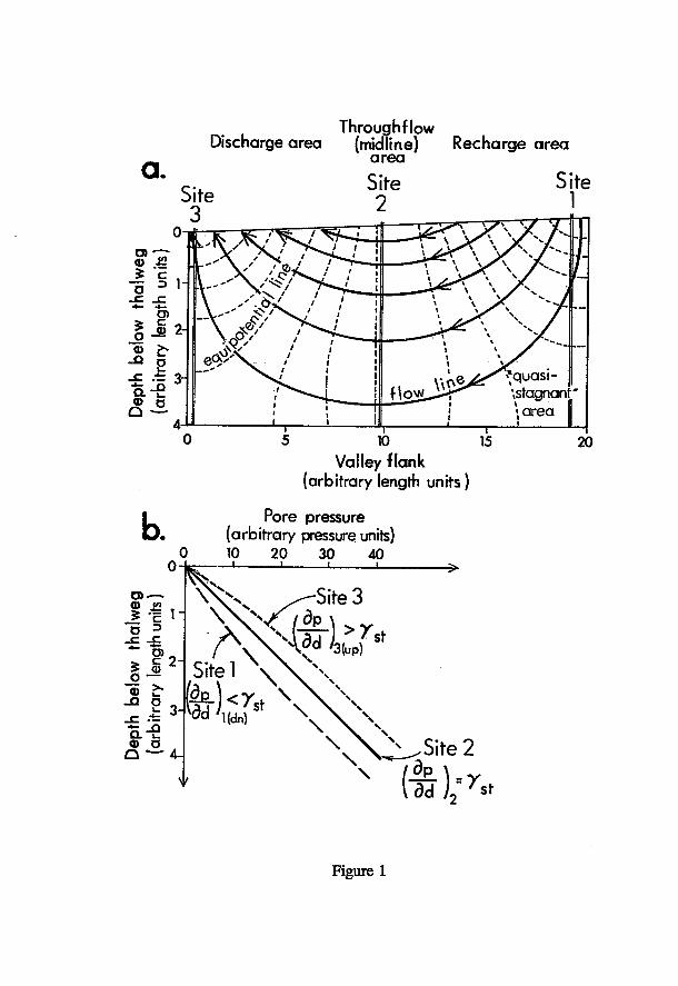
a .
Throughflow Discharge area (midline) Recharge area
area
Site Site 2
Site 1
g 1 ^
*~ a>
J J i £
o
Ö r V \ X > ^ y-
_ _
\<?° ' / » h i * X «.._ > x / --
" r ^ J I \ \ a ^ J ^ r ^ '.stagnan ; ! f • i i •
j » a r e a 1i 1 1 ! 1
10 Valley flank
(arbitrary length units )
15 20
b . Pore pressure
(arbitrary pressure units) 10 2 0 30 40
J -1 H
a-S Q — 4-
/ \ Sitel \
„ Site 2
("ad" ) " r s t
Figure 1
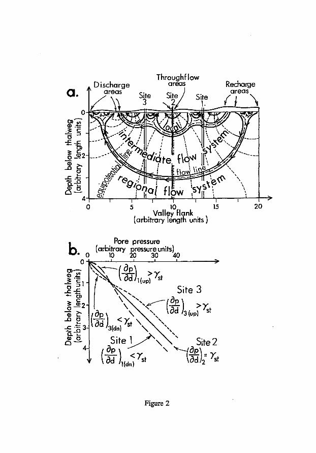
Discharge Throughf low
areas Recharge areas
I 10
Valley flank (arbitrary length units )
• Pore pressure k ^ (arbitrary r^essureunits)
0 30 40
7 ^ Vâd/ , ( u p ) 'st Site 3
\ \ \ - - / d p \
3 M St
Uda)
\ \ Site 2
^ d d ^ 7st
Figure 2
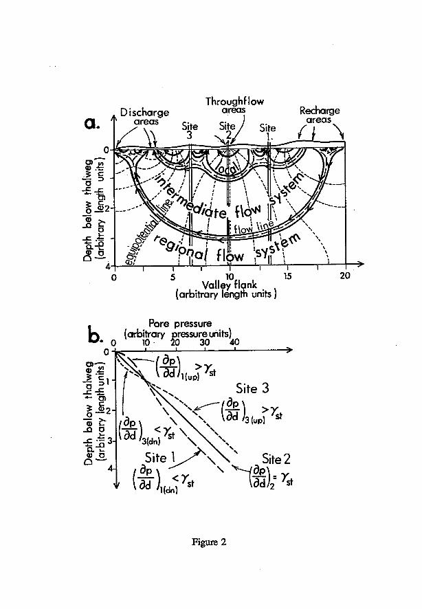
Discharge Throughflow
areas Recharge areas
T 5 10
Valley flank (arbitrary length units)
. Pore pressure J3 (arbitrary ^essureuhits^
S i t e l ^ W Site 2
Figure 2
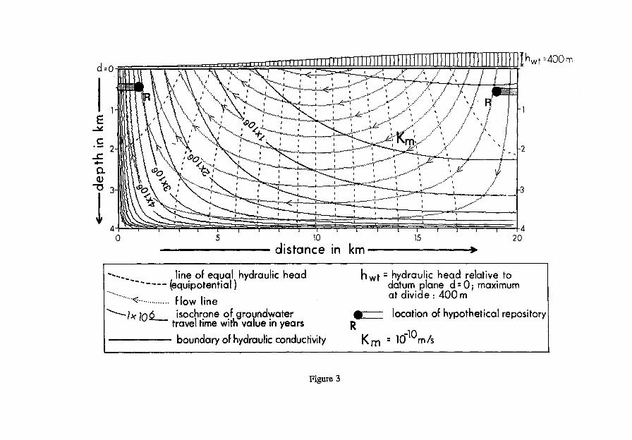
10 15 20 dis tance in km
line of equal hydraulic head (equipotential )
flow line - l x j n ô isochrone of groundwater
travel time with value in years boundary of hydraulic conductivity
h w t = hydraulic head relative to datum plane d = 0; maximum at divide •. 400 m
location of hypothetical repository
K m
8 10"10m/s
Figure 3
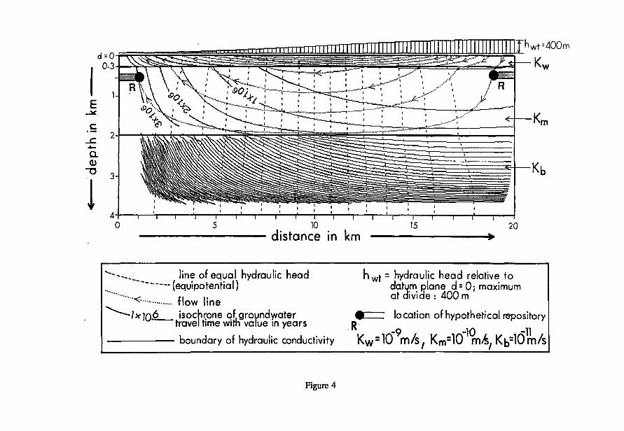
line of equal hydraulic head h W f = hydraulic head relative to (equipotential) datum plane d=0; maximum
<r f I ,. at divide : 400 m ^ tlow line "}x]n6 isochrone of groundwater • location of hypothetical repository
travel time with value in years D -9 -10 -11
boundary of hydraulic conductivity Kw = 10 m/s , K m
= 1 0 n\A/ Kb~}0 m/s
Figure 4
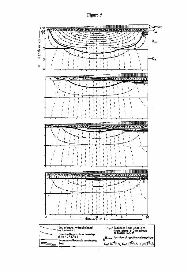
Figure 5
line of equal hydraulic head » hydraulic head relative to (equipotential) datum pbne d=0; maximum
"••<-- flow line(beods show rimesteps" ° * < * v , d f i : 4 0 0 m
o f A t = 2 x t 0 5 a ) # location of hypothetical repository boundary of hydraulic conductivity " „ *«* rVKTm/s, rVlO^mA, Kb=10"m/s
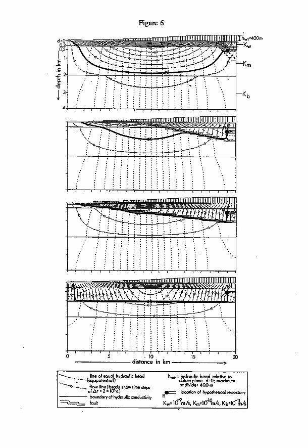
Figure 6
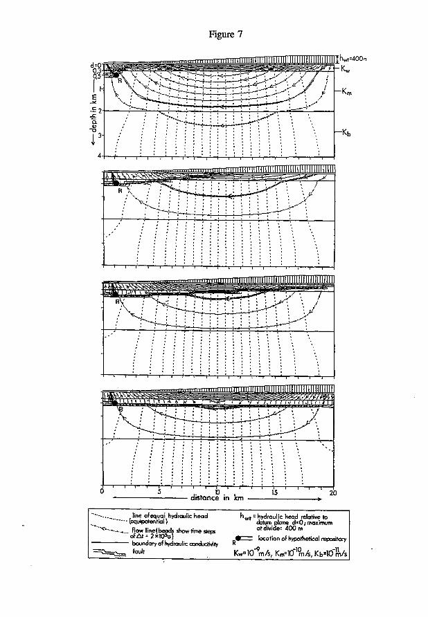
Figure 7
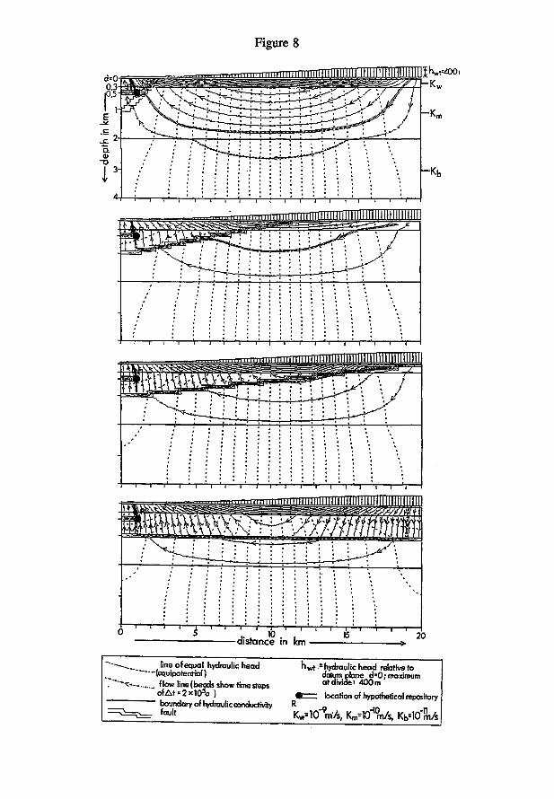
Figure 8
fine ofequal hydraulic head (equipotenrial) flow line (beads show time steps ofAt"2xlO s a ) boundary of hydraulic ccmducttvity R
hvvt =hydraulic head relative to datum plane d-0; maximum at divide: 400m
fc=; location of hypothetical repository
f a u l t ' " K w = 1 0 i n 7 s ( Km lO^m/s, Kb=10"m/s
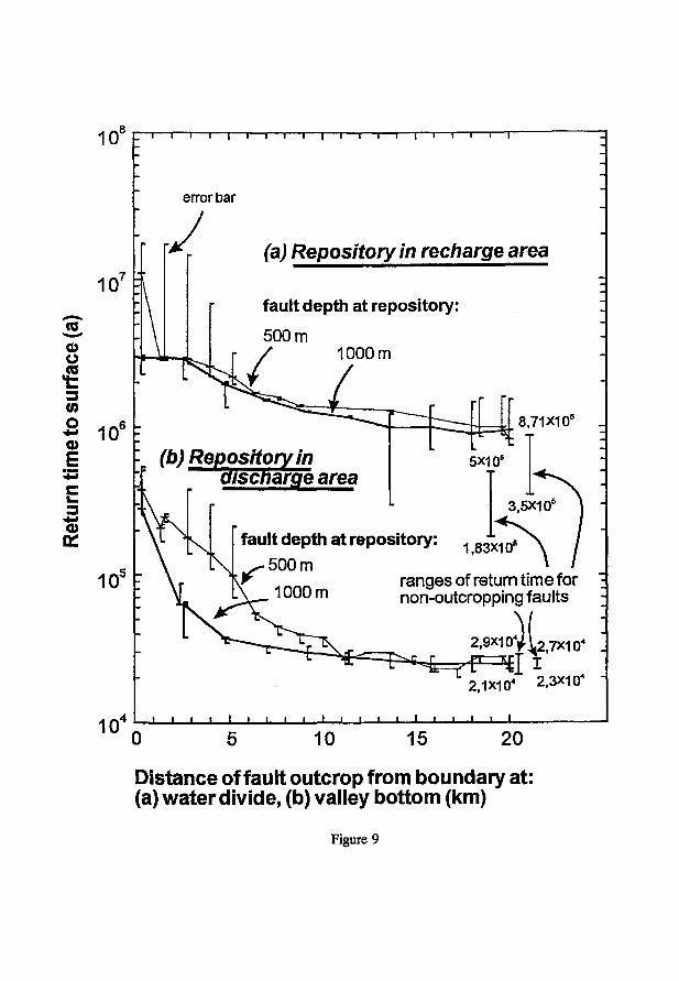
10 8F
o
o
E
0)
10 5
10«
T — i — i — i — i — i — i — i — i — i — i — ( — i — i — i — i — r
error bar
(a) Repository in recharge area
fault depth at repository:
500 m 1000 m
8,71X1 o 5 _
(b) Repository in aiscnarge area
fault depth at repository: 1 g 3 X 1 Q S
500 m ranges of return time for non-outcropping faults
2,9X1 o 4)( 2,7x1 o« ; - 4 - y r " ^ g I
2.1X10 4 2.3X10⁴
I I I I I — I — l — L
0 10 15 20
Distance of fault outcrop from boundary at: (a) water divide, (b) valley bottom (km)
Figure 9
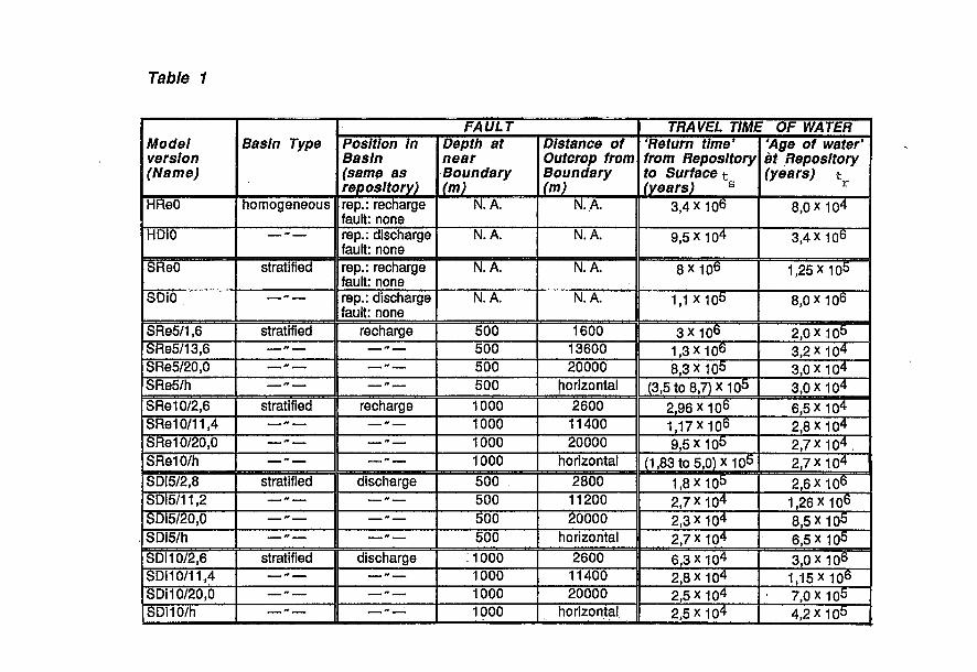
Table 1
Model version (Name)
Basin Type FAULT TRAVEL TIME OF WATER
Model version (Name)
Basin Type Position In Basin (same as repository)
Depth at near Boundary (m)
Distance of Outcrop from Boundary (m)
'Return time' from Repository to Surface t
(years) s
'Age of water' at Repository (years) t r
HReO homogeneous rep.: recharge fault: none
N. A. N.A. 3,4 x 10⁶ 8,0 X 10⁴
HDiO ** — rep.: discharge fault: none
N. A. N.A. 9,5 x 10⁴ 3,4 x 10⁶
SReO stratified rep.: recharge fault: none
N. A. N. A. 8 X 10⁶ 1,25 X 10⁵
SDiO —" — rep.: discharge fault: none
N. A. N. A. 1,1 X 10⁵ 8 , 0 X 1 0 6
SRe5/1,6 stratified recharge 5 0 0 1 6 0 0 3 X 10⁶ 2,0 x 1 0 5 SRe5/13,6 — -— — -— 5 0 0 13600 1,3X10⁶ 3,2X10⁴ SRe5/20,0 —" — —~— 5 0 0 20000 8 , 3 X 1 0 5 3,0 X 10⁴ SRe5/h —» — —"— 5 0 0 horizontal (3,5 to 8,7)X105 3,0X10⁴ SRe10/2,6 stratified recharge 1000 2600 2,96X10⁶ 6,5 X 10⁴ SRe10/11,4 — — —" — 1000 11400 1 , 1 7 X 1 0 6 2 , 8 X 1 0 4 SRe10/20,0 1000 20000 9,5 x 10⁵ 2 , 7 X 1 0 4 . SRe10/h —- — —"— 1000 horizontal (1,83 to 5,0) x 1 0 5 2 , 7 X 1 0 4 SDi5/2,8 stratified discharge 5 0 0 2 8 0 0 1 , 8 X 1 0 5 2,6 X 1 0 6
SDI5/11.2 — -— — -— 5 0 0 11200 2 , 7 X 1 0 4 1 , 2 6 X 1 0 6 SDi5/20,0 — -— 5 0 0 20000 2 , 3 X 1 0 4 8 , 5 X 1 0 5 SDi5/h —-— —~— 5 0 0 horizontal 2 , 7 X 1 0 4 6 , 5 X 1 0 5 SDI10/2,6 stratified discharge 1000 2600 6,3 x 10⁴ 3,0 x 10⁶ SDi 10/11,4 — » — — -— 1000 11400 2,8 X 10⁴ 1.15X 10⁶ SDi10/20,0 — -— 1000 20000 2 , 5 X 1 0 4 • 7 , 0 X 1 0 5 SDi10/h — -— —-— 1000 horizontal 2 , 5 X 1 0 4 4,2 X 1Q5
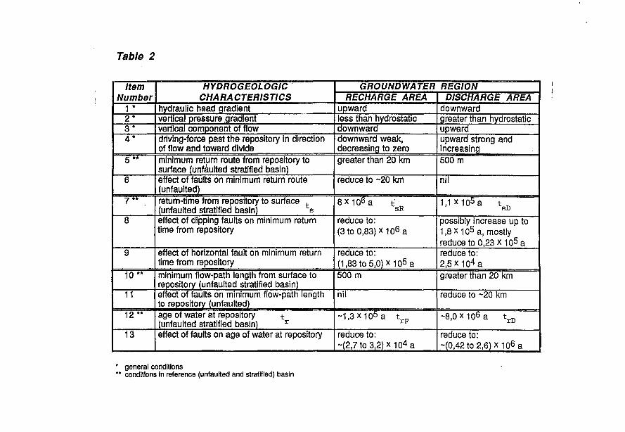
Table 2
Item Number
HYDROGEOLOGIC CHARACTERISTICS
GROUNDWATER REGION Item Number
HYDROGEOLOGIC CHARACTERISTICS RECHARGE AREA DISCHARGE AREA
1 * hydraulic head gradient upward downward 2 * vertical pressure .gradient less than hydrostatic greater than hydrostatic 3 * vertical component of flow downward upward 4 * driving-force past the repository in direction
of flow and toward divide downward weak, decreasing to zero
upward strong and increasing
5 ** minimum return route from repository to surface (unfaulted stratified basin)
greater than 20 km 500 m
6 effect of faults on minimum return route (unfaulted)
reduce to ~20 km nil
return-time from repository to surface . (unfaulted stratified basin) s
8 x 1 0 6 a t SR 1,1 x io5 a t
SD 8 effect of dipping faults on minimum return
time from repository reduce to: (3 t o 0 , 8 3 ) x i o 6 a
possibly increase up to 1.8X io5 a, mostly reduce to 0,23 x io5 a
9 effect of horizontal fault on minimum return time from repository
reduce to: (1,83 to 5,0) x 105 a
reduce to: 2 , 5 X i o 4 a
10 ** minimum flow-path length from surface to repository (unfaulted stratified basin)
500 m greater than 20 km
11 effect of faults on minimum flow-path length to repository (unfaulted)
nil reduce to ~20 km
12 " age of water at repository t
(unfaulted stratified basin) r ~ 1 , 3 x i o 5 a t D ~8 ,0xir j6a t r D
13 effect of faults on age of water at repository reduce to: ~(2,7 to 3,2) x i o 4 a
reduce to: ~(0,42to2,6)xio6a
* general conditions " conditions in reference (unfaulted and stratified) basin

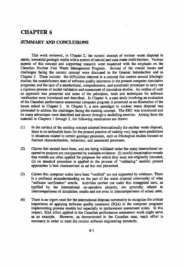
CHAPTER 6
SUMMARY AND CONCLUSIONS
This work reviewed, in Chapter 2, the current concept of nuclear waste disposal in stable, terrestrial geologic media with a system of natural and man-made multi-barriers. Various aspects of this concept and supporting research were examined with the emphasis on the Canadian Nuclear Fuel Waste Management Program. Several of the crucial issues and challenges facing the current concept were discussed in the General Introduction and in Chapter 3. These include: the difficulties inherent in a concept that centres around lithologic studies; the unsatisfactory state of software quality assurance in the present computer simulation programs; and the lack of a standardized, comprehensive, and systematic procedure to carry out a rigorous process of model validation and assessment of simulation studies. An outline of such an approach was presented and some of the principles, tools and techniques for software verification were introduced and described. In Chapter 4, a case study involving an evaluation of the Canadian performance assessment computer program is presented as an illustration of the issues raised in Chapter 3. In Chapter 5, a new paradigm to nuclear waste disposal was advocated to address the challenges facing the existing concept. The RRC was introduced and its many advantages were described and shown through a modelling exercise. Arising from the material in Chapters 1 through 5, the following conclusions are drawn:
(1) In the context of the existing concept adopted internationally for nuclear waste disposal, there is no defensible basis for the present practice of making very long-term predictions in situations related to certain geologic processes, such as lithological studies focused on fracture characterization, behaviour, and associated processes.
(2) Claims that models have been, and are being validated under the many international cooperative projects are unsupported by available evidence: (i) careful examination reveals that models are often applied for purposes for which they were not originally intended; (ii) no standard procedure is applied to the process of "validating'' models; present approaches is best characterized as ad hoc and piecemeal.
(3) Claims that computer codes have been "verified'' are not supported by evidence. There is a profound misunderstanding on the part of the waste disposal community of what "software verification" entails. Activities carried out under this misapplied term, as typified by the international co-operative projects, are generally related to intercomparisons of simulation results and not even to intercomparisons of actual code.
(4) There is an urgent need for the international disposal community to recognize the critical importance of applying software quality assurance (SQA) to the computer programs implementing process models but especially to performance assessment codes. In this respect, SQA effort applied to the Canadian performance assessment work might serve as an example. However, as demonstrated in the Canadian case, much effort is necessary in order to meet the current software engineering standards.
6-1
(5) State-of-the-art software engineering tools and techniques should be applied to facilitate the development, maintenance and quality assurance of computer codes. The emphasis should be on the use of modelling environments which allow the modeller/user/reviewer to work at a high abstraction level in order to maximize understandability and minimize semantic and syntactic errors.
(6) In view of the fact that validation of most models in the nuclear waste disposal context is, strictly speaking, not possible, it is crucial that a standardized procedure be developed and adopted that would systematically and comprehensively assess all the critical components of a simulation study. An outline of a possible approach (paper 3.4) is offered as a starting point for such development.
(7) A new concept, called the Regional Recharge Concept, embodies the view that a clear understanding of regional groundwater flow patterns can be exploited so as to have groundwater delay the transport of escaped contaminants to the surface and thereby add another "barrier" to the planned system of engineered/geologic multi-barriers.
(8) In addition to the enhancement of total system safety, a siting strategy based on the RCC makes it possible to confirm modelling results with field measurements that can be extrapolated far into the future.
(9) From the viewpoint of contamination transport by groundwater, recharge areas are superior to discharge areas for the siting of high level nuclear waste repositories. Recharge area locations assure considerably greater minimum travel-path lengths and return-flow times than do discharge area locations, and their effectiveness can be evaluated and purposefully modified; this type of control is not possible for discharge area locations.
(10) The possible presence of, even undetected, faults does not negate nor compromise the theoretical superiority or the suitability of recharge areas.
(11) The hydrogeologic conditions required for the suitability of a recharge area location can be recognized and confirmed from field observations, and to the extent needed for safety, evaluated and critically assessed by modelling. This is not possible for discharge-area positions: the sensitivity of regional hydrogeological conditions to changes in their controlling factors is low as compared with that of the local conditions. Consequently, regional model estimates are robust relative to those from local models.
(12) Regional groundwater flow can be exploited to enhance the role (utility) of the geosphere as a barrier to radioactive waste transport by judiciously selecting the basin and locating the repository near the basin's crest. Such deliberate exploitation, as it were engineering, of natural conditions is not possible for discharge-area repository-positions.
6-2
(13) Adoption of the RRC as a siting strategy would greatly minimize the economic cost and simplify the logistics of site screening and selection, especially if properly used with GIS technology.
(14) Because of the unique characteristics of the high-level nuclear waste disposal technology (the disposal system must remain effective for very long times and the lack of precedent for such an endeavour), societal acceptance of any such disposal plan will require that there is general confidence in the efficacy of the disposal concept based, at the very least, on technical considerations. A concerted effort must be made to address the technical issues as itemized in 1—13 above in order to increase such confidence.
6-3

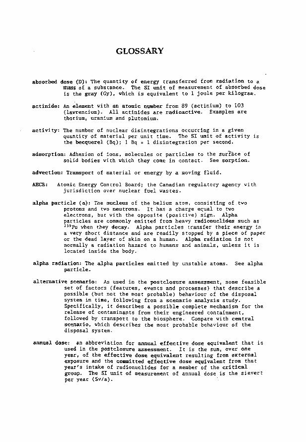
G L O S S A R Y
a b s o r b e d d o s e (D) : T h e q u a n t i t y o f e n e r g y t r a n s f e r r e d from r a d i a t i o n t o a mass o f a s u b s t a n c e . The S I u n i t o f m e a s u r e m e n t o f a b s o r b e d d o s e i s t h e g r a y ( G y ) , w h i c h i s e q u i v a l e n t t o 1 j o u l e p e r k i l o g r a m .
a c t i n i d e : An e l e m e n t w i t h an a t o m i c number f r o m 8 9 ( a c t i n i u m ) t o 1 0 3 ( l a w r e n c i u m ) . A l l a c t i n i d e s a r e r a d i o a c t i v e . E x a m p l e s a r e t h o r i u m , u r a n i u m and p l u t o n i u m .
a c t i v i t y : The number o f n u c l e a r d i s i n t e g r a t i o n s o c c u r r i n g i n a g i v e n q u a n t i t y o f m a t e r i a l p e r u n i t t i m e . The S I u n i t o f a c t i v i t y i s t h e b e c q u e r e l ( B q ) ; 1 Bq = 1 d i s i n t e g r a t i o n p e r s e c o n d .
a d s o r p t i o n : A d h e s i o n o f i o n s , m o l e c u l e s o r p a r t i c l e s t o t h e s u r f a c e o f s o l i d b o d i e s w i t h w h i c h t h e y come i n c o n t a c t . S e e s o r p t i o n .
a d v e c t i o n : T r a n s p o r t o f m a t e r i a l o r e n e r g y by a m o v i n g f l u i d .
AECB: A t o m i c E n e r g y C o n t r o l B o a r d ; t h e C a n a d i a n r e g u l a t o r y a g e n c y w i t h j u r i s d i c t i o n o v e r n u c l e a r f u e l w a s t e s .
a l p h a p a r t i c l e ( a ) : The n u c l e u s o f t h e h e l i u m a t o m , c o n s i s t i n g o f two p r o t o n s and two n e u t r o n s . I t h a s a c h a r g e e q u a l t o two e l e c t r o n s , but w i t h t h e o p p o s i t e ( p o s i t i v e ) s i g n . A l p h a p a r t i c l e s a r e commonly e m i t t e d from h e a v y r a d i o n u c l i d e s s u c h a s 3 3 9 P u when t h e y d e c a y . A l p h a p a r t i c l e s t r a n s f e r t h e i r e n e r g y i n a v e r y s h o r t d i s t a n c e and a r e r e a d i l y s t o p p e d by a p i e c e o f p a p e r o r t h e d e a d l a y e r o f s k i n on a human. A l p h a r a d i a t i o n i s n o t n o r m a l l y a r a d i a t i o n h a z a r d t o humans and a n i m a l s , u n l e s s i t i s l o c a t e d i n s i d e t h e b o d y .
a l p h a r a d i a t i o n : The a l p h a p a r t i c l e s e m i t t e d by u n s t a b l e a t o m s . S e e a l p h a p a r t i c l e .
a l t e r n a t i v e s c e n a r i o : As u s e d i n t h e p o s t c l o s u r e a s s e s s m e n t , some f e a s i b l e s e t o f f a c t o r s ( f e a t u r e s , e v e n t s and p r o c e s s e s ) t h a t d e s c r i b e a p o s s i b l e ( b u t n o t t h e mos t p r o b a b l e ) b e h a v i o u r o f t h e d i s p o s a l s y s t e m i n t i m e , f o l l o w i n g from a s c e n a r i o a n a l y s i s s t u d y . S p e c i f i c a l l y , i t d e s c r i b e s a p o s s i b l e c o m p l e t e m e c h a n i s m f o r t h e r e l e a s e o f c o n t a m i n a n t s from t h e i r e n g i n e e r e d c o n t a i n m e n t , f o l l o w e d by t r a n s p o r t t o t h e b i o s p h e r e . Compare w i t h c e n t r a l s c e n a r i o , w h i c h d e s c r i b e s t h e m o s t p r o b a b l e b e h a v i o u r o f t h e d i s p o s a l s y s t e m .
a n n u a l d o s e : an a b b r e v i a t i o n f o r a n n u a l e f f e c t i v e d o s e e q u i v a l e n t t h a t i s u s e d i n t h e p o s t c l o s u r e a s s e s s m e n t . I t i s t h e sum, o v e r o n e y e a r , o f t h e e f f e c t i v e d o s e e q u i v a l e n t r e s u l t i n g from e x t e r n a l e x p o s u r e and t h e c o m m i t t e d e f f e c t i v e d o s e e q u i v a l e n t from t h a t y e a r ' s i n t a k e o f r a d i o n u c l i d e s f o r a member o f t h e c r i t i c a l g r o u p . The S I u n i t o f m e a s u r e m e n t o f a n n u a l d o s e i s t h e s i e v e r t per y e a r ( S v / a ) .
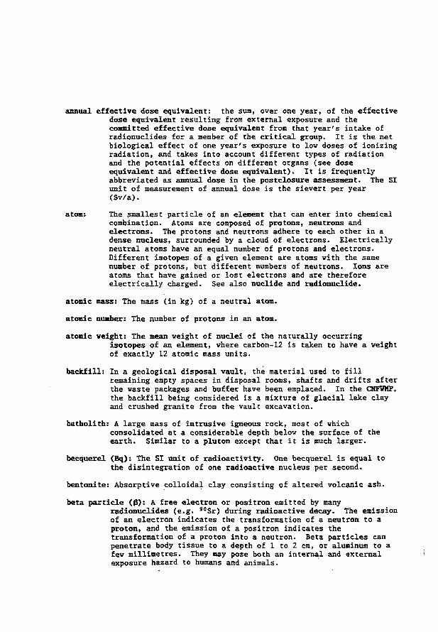
annual effective dose equivalent: the sum, over one year, of the effective dose equivalent resulting from external exposure and the committed effective dose equivalent from that year's intake of radionuclides for a member of the critical group. It is the net biological effect of one year's exposure to low doses of ionizing radiation, and takes into account different types of radiation and the potential effects on different organs (see dose equivalent and effective dose equivalent). It is frequently abbreviated as annual dose in the postclosure assessment. The SI unit of measurement of annual dose is the sievert per year (Sv/a).
atom: The smallest particle of an element that can enter into chemical combination. Atoms are composed of protons, neutrons and electrons. The protons and neutrons adhere to each other in a dense nucleus, surrounded by a cloud of electrons. Electrically neutral atoms have an equal number of protons and electrons. Different isotopes of a given element are atoms with the same number of protons, but different numbers of neutrons. Ions are atoms that have gained or lost electrons and are therefore electrically charged. See also nuclide and radionuclide.
atonic mass: The mass (in kg) of a neutral atom,
atomic number: The number of protons in an atom.
atomic weight: The mean weight of nuclei of the naturally occurring isotopes of an element, where carbon-12 is taken to have a weight of exactly 12 atomic mass units.
backfill: In a geological disposal vault, the material used to fill remaining empty spaces in disposal rooms, shafts and drifts after the waste packages and buffer have been emplaced. In the CNFWMP, the backfill being considered is a mixture of glacial lake clay and crushed granite from the vault excavation.
batholith: A large mass of intrusive igneous rock, most of which consolidated at a considerable depth belov the surface of the earth. Similar to a pluton except that it is much larger.
becquerel (Bq): The SI unit of radioactivity. One becquerel is equal to the disintegration of one radioactive nucleus per second.
bentonite: Absorptive colloidal clay consisting of altered volcanic ash.
beta particle ( 0 ) : A free electron or positron emitted by many radionuclides (e.g. 3 0Sr) during radioactive decay. The emission of an electron indicates the transformation of a neutron to a proton, and the emission of a positron indicates the transformation of a proton into a neutron. Beta particles can penetrate body tissue to a depth of 1 to 2 cm, or aluminum to a few millimetres. They may pose both an internal and external exposure hazard to humans and animals.

beta radiation: The electrons or positrons emitted by an unstable atom. See beta particle.
biosphere model: In STVAC3-CC3, the disposal system is modelled using a system model that contains models for the vault, geosphere and biosphere. These models were introduced to simplify the development of mathematical models of complex processes. The biosphere submodel describes the transport of contaminants within the local surface water, soil, atmosphere and the food chain to man, including the resultant health impact of contaminants on members of the critical group. See BTOTRAC.
BIOTRAC: A computer code written at AECL Vhiteshell to model Biosphere TRansport And Consequences associated with nuclear fuel waste disposal. It was written to serve as the biosphere model in STVAC3-CC3, and is used in the postclosure assessment of the CNFVKP.
buffer: A barrier surrounding the waste containers in a disposal vault, consisting of highly impermeable material primarily intended to retard the movement of water. It would also affect the rates of container corrosion, fuel dissolution, and radionuclide migration. In the CNFVMP, the reference buffer is a compacted sand-bentonite mixture.
case: In the postclosure assessment, a set of STVAC simulations for one waste disposal system, one set of models, one set of nuclides and one set of parameters and parameter probability density functions. Data from a case are usually analyzed together statistically to generate estimates of mean annual dose, risk, etc. A case corresponds to a single scenario, and the simulations include representations of all processes and events defining the scenario.
central scenario (sometimes referred to as the base case or normal evolution scenario): As used in the postclosure assessment, the most probable set of factors (features, events and processes) that describe the expected behaviour of the disposal system in time, and following from a scenario analysis study. It describes the most probable complete mechanism for the release of contaminants from their engineered containment, followed by transport to the biosphere. Compare with alternative scenario, which describes a less probable situation.
CNFWMP: Abbreviation for Canadian Nuclear Fuel Waste Management Program.
collective dose: One of several measures of the net biological effect of lov doses of ionizing radiation on a group of people, assuming that effect is directly proportional to effective dose equivalent. These measures include: collective effective dose equivalent, per caput effective dose equivalent, and collective effective dose equivalent commitment (ICRP Publication 42, 1984). Such quantities are not calculated in the postclosure assessment because the regulatory requirements that must be addressed are stated in terms of dose to an individual (See committed effective dose equivalent). The SI unit of measurement of collective dose is the person-sievert (person-Sv).
colloid: A dispersion of a solid, liquid or gas in another solid, liquid or gas, with characteristic dimension 10 - 9 to 10"6 m.
committed effective dose equivalent (H E): A measure of the total radiological impact to an individual and his/her progeny due to the internal dose from ingested radioactive material, including the risk from the continuing irradiation during the 50 years following the intake:
to+50 H E = Z w^E, = I wT-J Hr
T(t) dt T T tc
where is the committed dose equivalent to organ or tissue T <Sv),
w T is the weighting factor used to define the effective dose equivalent for organ or tissue T (dimensionless)-,
t„ is the year in which the exposure occurred (years), and Hr
T(t) is the rate at which the dose equivalent is received by organ or tissue T at time t (Sv/a). The integral is over 50 years to represent the length of a person's working life. The S I unit of measurement of commLtted effective dose equivalent is the sievert (Sv).
compartment model: A mathematical description of a region (such as an a lake and its watershed, or a soil zone), for which it is assumed that the,properties of interest are homogeneous. This assumption may arise because relevant processes occurring within the region occur uniformly and relatively quickly. Compartment models are used within STVAC3-CC3 to describe the concentration or mass of contaminants in different parts of the vault and biosphere. In the lake sediment zone of the biosphere, for instance, it is assumed that contaminants enter and exit the sediment in groundwater, and that resulting contaminant concentrations in sediment may be estimated using selected values for controlling parameters such as the amount of diluting water present and the degree of sorption of contaminants onto sediment particles.
concentration ratio (CR): The concentration of a radionuclide present in an organism, an organ, or a tissue, divided by the concentration of that radionuclide in the surrounding medium. For example, BIOTRAC uses a plant/soil concentration ratio (which is dimensionless) in its food-chain and dose model.
conditional dose limit: In the CNFVHP, a maximum dose that conforms with the AECB risk, criterion, and that would apply if only one scenario required quantitative evaluation in the assessment of a disposal system. The conditional dose limit is derived from the radiological risk criterion set by the AECB. For a risk limit of 10 - s (probability of serious health effects per year), and assuming that only one scenario contributes to the risk, the conditional dose limit is the risk limit divided by the risk factor (2 x 10~2 serious health effects per sievert). Thus the conditional dose limit is 5xl0-5 sieverts per year or 50 microsieverts per year. It is about 2% of the annual dose that residents of the Canadian Shield receive from natural sources of radiation. Compare with conditional risk.
conditional risk: In the postclosure assessment, the product of the estimated annual dose for a single scenario and the risk factor (2 x 10"2 serious health effects per sievert). This product equals the total radiological risk if the scenario were the only one requiring quantitative evaluation in the assessment. Compare with conditional dose limit.
consequence: In the SYVAC3-CC3 computer code, calculated variables that describe some aspect of the waste disposal system. They include variables such as annual dose, maximum annual doses and container failure rates.
container: A durable receptacle for enclosing and isolating radioactive wastes for disposal. In a disposal vault, the containers would serve as one barrier between the waste form and the human population.
continuous variable: A quantity that can have a value in a continuum of values.
convolution: One of the mathematical operations used in STVAC3-CC3 to estimate the flow of radionuclides through a barrier. Two pieces of information are required: the time-dependent input of radionuclides and a description of how the barrier responds to a standard input (the response function). The result of a convolution is the flow of radionuclides out of the barrier. In more general terms, convolution is a mathematical procedure used to solve differential equations, using a specialized set of functions known as Green's functions.
critical group: For a given radiation source, the hypothetical group of individuals expected to receive the highest annual effective dose equivalent from the source. For the postclosure assessment, the critical group is assumed to be a self-sufficient community that lives its entire life at, and obtains all its food, clothing, home furnishings, heating fuel and building materials from the locality vhere there is the largest radiological impact due to contaminant release from a hypothetical disposal vault.
c u m u l a t i v e d i s t r i b u t i o n f u n c t i o n : For a random v a r i a b l e X, a f u n c t i o n F ( x ) e q u a l t o t h e p r o b a b i l i t y , P , t h a t X h a s a v a l u e l e s s t h a n o r e q u a l t o x ; i . e . F ( x ) = F ( X < x ) ; u s e d i n STVAC t o s e t t h e v a l u e s o f s a m p l e d p a r a m e t e r s . I t i s t h e i n t e g r a l o f t h e a s s o c i a t e d p r o b a b i l i t y d e n s i t y f u n c t i o n from -<° t o x .
c u m u l a t i v e f r e q u e n c y d i s t r i b u t i o n c u r v e (upward and d o w n w a r d ) : I n STVAC c a l c u l a t i o n s , a p l o t o f t h e f r a c t i o n o f s i m u l a t i o n s i n w h i c h t h e v a l u e o f a v a r i a b l e i s a b o v e ( u p w a r d ) o r b e l o w ( d o w n w a r d ) p a r t i c u l a r v a l u e s .
D a r c y ' s l a w : An e m p i r i c a l r e l a t i o n t y p i c a l l y u s e d i n t h e s t u d y o f f l u i d f l o w t h r o u g h p o r o u s m e d i a s u c h a s r o c k s , s o i l s , o r c l a y s . I t r e l a t e s t h e f l o w r a t e o f a f l u i d t h r o u g h a medium t o t h e p r e s s u r e g r a d i e n t and t h e v i s c o s i t y o f t h e f l u i d , i . e .
v = K/n dP dx
w h e r e v i s t h e r a t e o f f l o w o f a f l u i d o r g a s t h r o u g h a m a t e r i a l ( ra / s ) K i s t h e p e r m e a b i l i t y o f t h e m a t e r i a l ( m 2 ) , r| i s t h e v i s c o s i t y o f t h e f l u i d o r g a s ( N - s / r a 2 ) and d P / d x i s t h e r a t e o f c h a n g e o f p r e s s u r e w i t h r e s p e c t t o p o s i t i o n ( N / m 3 ) .
d a u g h t e r p r o d u c t : A n u c l i d e t h a t i s d i r e c t l y p r o d u c e d by t h e r a d i o a c t i v e d e c a y o f a r a d i o n u c l i d e . A l s o known a s d a u g h t e r o r p r o g e n y .
d e c a y : S e e r a d i o a c t i v e d e c a y .
d e c a y c o n s t a n t : For a r a d i o n u c l i d e i n a p a r t i c u l a r e n e r g y s t a t e , t h e r a t e a t w h i c h i t u n d e r g o e s r a d i o a c t i v e d e c a y . T h e S I u n i t s o f m e a s u r e m e n t o f t h e d e c a y c o n s t a n t a r e s " 1 . I t i s r e l a t e d t o t h e r a d i o a c t i v e h a l f - l i f e by t h e e q u a t i o n :
d e c a y c o n s t a n t = I n 2 / h a l f - l i f e w h e r e In 2 i s t h e n a t u r a l l o g a r i t h m o f 2 , a p p r o x i m a t e l y e q u a l t o 0 . 6 9 3 1 5 .
d e c i s i o n v a r i a b l e : I n t h e STVAC c o m p u t e r c o d e , a p a r a m e t e r t h a t s e l e c t s w h i c h a l t e r n a t i v e , o r w h i c h p r o b a b i l i t y d e n s i t y f u n c t i o n (PDF) i n a s e t o f PDFs f o r a p a r a m e t e r , i s t o b e u s e d i n e a c h s i m u l a t i o n . For e x a m p l e , d e c i s i o n v a r i a b l e s a r e u s e d i n STVAC t o s e l e c t among a l t e r n a t i v e s s u c h a s t h e p o s s i b l e s o u r c e s o f d o m e s t i c w a t e r u s e d by members o f t h e c r i t i c a l g r o u p ( i . e . a w e l l o r a l a k e ) .
d e p e n d e n t p a r a m e t e r : A s c a l a r q u a n t i t y i n a m o d e l ( u s u a l l y a c o m p u t e r m o d e l ) w h i c h i s computed u s i n g m a t h e m a t i c a l e q u a t i o n s a n d a s e t o f i n p u t p a r a m e t e r s . I n STVAC3-CC3, d e p e n d e n t p a r a m e t e r s a r e c a l c u l a t e d o n c e p e r s i m u l a t i o n ? e x a m p l e s i n c l u d e t h e r a t e o f f a i l u r e o f c o n t a i n e r s , t h e f r a c t i o n o f c o n t a m i n a n t s c a p t u r e d b y a w e l l and t h e c o n c e n t r a t i o n o f r a d i o n u c l i d e s i n s o i l .
I,
deposition velocity: The radionuclide flux (mol/(m2-s)) of airborne particles or gases to a specified surface (such as vegetation or soil), divided by the radionuclide concentration in the air above the surface (mol/m3). The SI unit of measurement of deposition velocity is m/s.
derived constraint: A feasible restriction on a part of the disposal system determined to be effective in lowering annual doses to the critical group based on results of sensitivity analysis on simulations of the disposal system. Derived constraints can fall into two general classes: design constraints and siting constraints.
design constraint: A feasible restriction on a part of the disposal system, determined to be effective in lowering annual doses to the critical group, that is controlled by engineering design. For example, a design constraint might be the thickness of the walls of the container.
deterministic analysis: A technique for studying system behaviour mathematically using the classic laws of science and engineering, and assuming that all system parameters, events, and features are precisely defined. Compare to probabilistic analysis.
deuterium: An isotope of the element hydrogen with one neutron in its nucleus.
diffusion: The spontaneous migration of atoms or molecules in a gas, liquid, or solid from a region of high to low concentration (more accurately, from a region of high to low chemical potential).
diffusion coefficient: A parameter describing the number of particles crossing an area per unit time and under a unit diffusion gradient. The SI unit of measurement of diffusion coefficient is square metres per second (m2/s).
discharge area: A portion of the earth's surface where the direction of flow of saturated groundwater is upward toward the vater table. Also called discharge zone.
discrete variable: A quantity that can have only values belonging to a finite set of possibilities.
dispersion: The combined effect of transport, diffusion and mixing which tend to distribute materials released from wastes or effluents
• through an increasing volume of water, air or soil, with the ultimate effect of diluting the materials.
disposal: The emplacement of waste materials in a vault, or at a given location in such a way that public safety is assured without continued maintenance and administrative control. A permanent method of waste management in which the waste is safely discarded with no intention of retrieval.
disposai facility: A disposal vault and its supporting buildings and functions. Also called disposal centre.
disposal system: 1. A disposal facility for the safe, permanent isolation of nuclear fuel vaste plus the transportation facilities needed to bring the vaste to it from interim storage sites. 2. In the postclosure assessment, the sealed disposal vault and its surrounding local geosphere and biosphere. See vaste disposal system.
disposal vault: An underground structure excavated in rock including shafts, tunnels, and disposal rooms where containers of nuclear fuel waste would be placed for permanent disposal. Also referred to as nuclear fuel waste disposal vault, nuclear waste disposal vault, used-fuel disposal vault, waste disposal vault and vault.
distributed variable: A characteristic measurable property of a system whose probability of being observed is described by a probability density function (for a continuous variable) or probability function (for a discrete variable).
distribution attribute: A characteristic of a probability density function (e.g. range, mean, standard deviation). One or more attributes may be required to completely define a probability density function; for example an unconstrained "normal" probability density function is often defined using its mean and standard deviation.
distribution coefficient: The amount of a substance sorbed on a unit mass of dry solid (mol/kg) divided by the concentration of that substance in a solution in contact with the solid (mol/m3); the Si units are (mVkg). Equilibrium conditions are assumed. It is also referred to as the partition coefficient and frequently by its mathematical symbol, Kd. The K d description is used to generate simplified models of contaminant retardation resulting from a variety of processes, including sorption, ion exchange, precipitation, diffusion into "dead-ends", ultrafiltration and chemical substitution. For instance, in STVAC calculations, distribution coefficients are used to relate the concentration of a contaminant sorbed on soil (or other solids, such as buffer and minerals in the geosphere) to its concentration in the associated groundwater. If used as a time-independent parameter, it is assumed that a sorption reaction is reversible and that equilibrium conditions prevail.
dose: A general term denoting the quantity of radiation or radiation energy absorbed by a specified mass of a substance. Dose is often qualified to refer to specific quantities, and to an individual versus a group of people; examples are: absorbed dose, dose equivalent, effective dose equivalent,' committed effective dose equivalent, and collective dose. The SI unit of measurement of dose is the sievert (Sv). In the postclosure assessment, dose is frequently encountered in expressions such as annual dose and dose per year. In these cases, it is an abbreviation of annual effective dose equivalent.
dose conversion factor: A multiplicative quantity used to convert intake of radioactivity to a committed effective dose equivalent (internal dose), or external exposure to radioactivity to an effective dose equivalent (external dose). The SI unit for the dose conversion factor is the sievert per becquerel (Sv/Bq) for internal doses, and Sv per unit of radionuclide concentration in the exposing media (Bq/L, Bq/m2 or Bq/m3) for external doses.
dose equivalent (H,): A measure of the biological effect of low doses of ionizing radiation to an organ or tissue of the human body:
H T = DT-Q-N where DTis the absorbed dose for organ or tissue T (Gy),
Q is a quality factor which allows for the different effectiveness of .different types of radiation (dimensionless), and N is the product of all other modifying factors (dimensionless).
Q = 1 for X-rays, gamma rays and electrons; 2.3 for thermal neutrons; 10 for neutrons and protons of unknown energy; and 20 for alpha particles of unknown energy. N is currently to be set to 1 (ICRP Publication 42, 1984). The SI unit of measurement for dose equivalent is the sievert (Sv).
effective dose equivalent (Hj): A measure of the net biological effect on the human body of low doses of ionizing radiation when organs and tissues of the body are irradiated non-uniformly (for example, by ingested radionuclides):
H E = t w,-^
where wTis a tissue weighting factor representing the proportion of the stochastic risk associated with organ or tissue T to the total stochastic risk, when the body is irradiated uniformly (dimensionless), and Eyis the mean (i.e. average) dose equivalent in organ or tissue T from non-uniforra irradiation (Sv).
The ICRP has recommended use of the following values of w T
(ICRP Publication No. 42):
Organ or Tissue Recommended w T
Gonads 0.25 Breast 0.15 Red Bone Harrow 0.12 Lung 0.12 Thyroid 0.03 Bone surfaces 0.03 Remainder 0.30
The SI unit of measurement of effective dose equivalent is the sievert (Sv).
BIS: Abbreviation for Environmental Impact Statement. electron (symbol: e): An atomic particle containing one negative unit of
electric charge and mass equal to 9.11xl0~31 kg. Neutral atoms contain equal numbers of electrons and protons. A free electron is also called a beta particle.
element: Atoms which contain the same number of protons, and which cannot be decomposed into any simpler units by any chemical transformation. Some radioactive atoms may spontaneously change into other elements by radioactive processes.
engineering constraint: A feasible restriction on a part of the disposal system, determined to be effective in lowering annual doses to the critical group, that is controlled by engineering design. For example, an engineering constraint might be the thickness of the vails of the container. See derived constraint and contrast vith siting constraint.
environmental and safety assessment: Evaluation of the behaviour and potential impacts of a disposal system, and comparison of the results with appropriate standards or acceptability criteria. In the CNPWHP, the system under consideration is the entire disposal system, and one acceptability criterion is a limit on radiological risk to an individual of the critical group. Also referred to as the preclosure assessment and the postclosure assessment. The preclosure assessment considers impacts over the period of time covering the construction, operation and decommissioning of a disposal facility, up to and including the final shaft sealing and surface facility decommissioning. The postclosure assessment considers impacts starting after decommissioning, and extending far into the future.
equilibrium distribution coefficient ( K d ) : See distribution coefficient. equilibrium surface distribution coefficient ( K a ) : The mass per unit
surface area of a substance sorbed on a solid (nol/ra2), divided by its Concentration in the associated solution (mol/m3) after equilibrium is achieved. The ST unit of measurement is metre (m).
exclusion zone: As used in the post closure assessment, a region of rock that isolates the rooms in the vault from fracture zone LD1. In the reference disposal system, this region is achieved through the location of the vault, and through the use of shorter lengths for the vault rooms nearest fracture zone LDl. The closest distance in a horizontal direction from LDl to any room is about 155 metresj hovever, the closest distance is only about 50 metres because the plane of the fracture zone is not vertical, but inclined at a shallow angle to the plane of the vault. In the reference disposal system, therefore, the exclusion zone is about 50 metres wide.
executive code: The main computer routines which control the calculations being performed, some of which may be carried out by dependent subroutines or functions invoked by the executive code. Also known as executive routines and executive program. In the series of codes involving STVAC, the executive is the set of routines that oversee and control the computation of system model code. For the computer code STVAC3-CC3, the executive routines are frequently referred as STVAC3.
expectation (symbol: E(X)): In statistics, the mean value of a distributed variable. Specifically, for a random continuous variable X with probability density function f(x), the expectation of X (i.e. the mean value of X), E(X), is
external dose: Irradiation resulting from exposure to radiation sources outside the body. The SI unit of measurement of dose is the sievert
factor: In the post closure assessment, this term has a specific meaning when used in association with scenario analysis. A factor is any feature, event, or process that could influence the performance of any component of the disposal system.
fission: The splitting of an atomic nucleus into two or more parts with a resultant release of energy; may be spontaneous or induced by neutrons hitting the nucleus. Also called nuclear fission.
fission product: An atom produced either by nuclear fission or by the radioactive decay of an unstable atom produced by fission.
flux: The volume or mass of fluid or particles transferred across a given area perpendicular to the direction of flow in a given time. An example of the SI unit of measurement of flux is moles per square metre per second (mol/m2/s).
( S v ) .
fractional factorial analysis: A study of hov the output of a computation changes when the input parameters are varied according to a subset of a factorial experimental design: Each experiment repeats the computation with a different set of parameter values. Each parameter in each experiment takes a value from a set of prespecified levels. The most common fractional factorial experimental designs use two levels of high and low values of the parameters.
gabbro: A coarse-grained, dark, igneous plutonic rock. gamma radiation: The photons (gamma rays), which carry energy but no charge,
emitted by an unstable atom. Gamma radiation is the most highly penetrating radiation. It can pass through the human body, but is stopped by a few centimetres of lead, or a few metres of water or concrete.
gamma ray ( Y ) S High-energy, highly-penetrating photons of short wave length commonly emitted by the nucleus of a radioactive atom during radioactive decay as a result of a transition from one of its excited • energy levels to a lower level.
Gaussian plume model: A mathematical description of the dispersion and dilution of contaminants in the environment (air, water, soil) based on advective transport and classical diffusion theory.
genetic effect: A change induced by radiation which manifests itself in the descendants of the exposed individual.
GEONET: An AECL Vhiteshell computer code that implements a GBOspnere model as a NETvork of segments through which contaminants move. It was written to serve as the geosphere model in STVAC3-CC3, and is used in the postclosure assessment of the CNFVMP.
geosphere model: In STVAC3-CC3, the disposal system is modelled using a system model that contains models for the vault, geosphere and biosphere. These models were introduced to simplify the development of mathematical models of complex processes. The geosphere submodel describes transport of contaminants through fractured and porous rock that are saturated with groundwater.. See also GEONET.
gradient: The magnitude and direction of the greatest rate of change of a scalar property, such as temperature or contaminant concentration in a disposal vault.
granite: A coarse-grained igneous rock consisting mostly of quartz (20 to 40Z), alkali feldspar and mica. A number of accessory minerals may be present.
gray (Gy): The SI unit of absorbed dose for ionizing radiation. One gray is equal to 1 Joule of radiation energy absorbed in 1 kilogram of the material of interest.
groundwater: Water in the saturated zone beneath the earth's surface in soils and geologic formations.
groundshine: Beta and gamma radiation emitted from radionuclides on the surface of the earth.
half-life, biological: The time required for the amount of a radioactive material present in a living organism to be reduced, by a combination of biological processes and radioactive decay, to one-half of its initial value. Biological processes dominate for long-lived radionuclides; radioactive decay dominates for short-lived radionuclides. The SI unit of measurement is second (s) or year (a).
half-life, effective: See half-life, biological. half-life, radioactive: For a single radioactive decay process, the time
required for half of the atoms present to disintegrate through radioactive decay, following the exponential law. Half-lives of different elements range from fractions of a second to billions of years. After a period equal to ten half-lives, the activity will have* decreased to (0.5)10 (about 0.1%) of its original value. The SI unit of measurement is second (s), day (d) or year (a).
health effect: Fatal cancer or transmission of a fatal or debilitating genetic effect to offspring.
hold-up times: Characteristic periods of time describing the length of time that radionuclides would remain in plant and animal products and water. Hold-up times are used to estimate biological half-lifes of radionuclides in materials used by the critical group. The SI unit of measurement is second (s), day (d) or year (a).
hydraulic conductivity: The ratio of flow velocity to the force driving the flow, for a specified viscous fluid flowing through a porous medium. Saturated and unsaturated hydraulic conductivities may be defined for saturated and unsaturated media. The SI unit of measurement is metres per second (m/s).
hydraulic gradient: In hydrogeology, the rate of change in total hydraulic head per unit of distance of flow in a given direction. It is a dimensionless quantity, although frequently effectively dimensionless units such as metre per metre (m/m) are cited.
h y d r a u l i c h e a d : I n h y d r o g e o l o g y , t h e h e i g h t o f t h e s u r f a c e o f a w a t e r mass u n d e r a t m o s p h e r i c p r e s s u r e m e a s u r e d from a r e f e r e n c e d datura p o i n t . I t h a s S I U n i t s o f m e t r e s ( m ) . H y d r a u l i c h e a d i s d e t e r m i n e d by u s i n g t h e e q u a t i o n :
h = z + [ p / ( p . g ) J
w h e r e h i s t h e h y d r a u l i c h e a d ( m ) , p i s t h e g a u g e p r e s s u r e ( k g / ( m - s 2 ) ) , p i s t h e f l u i d d e n s i t y ( k g / r a 3 ) , g i s t h e g r a v i t a t i o n a l a c c e l e r a t i o n c o n s t a n t ( m / s 2 ) , and z i s t h e e l e v a t i o n o f t h e m e a s u r e m e n t p o i n t a b o v e a common datum ( e . g . s e a l e v e l ) ( m ) .
h y d r o d y n a m i c d i s p e r s i o n : The s p r e a d i n g o u t o f a s o l u t e c a u s e d by t h e movement o f a f l u i d t h r o u g h , a n e t w o r k o f p a t h s i n a s o l i d medium ( e . g . f r a c t u r e s i n g r a n i t e ) . T h e h y d r o d y n a m i c d i s p e r s i o n l e n g t h i s a p a r a m e t e r d e s c r i b i n g t h e m a g n i t u d e o f t h e s p r e a d i n g o u t o f a s o l u t e c a r r i e d by a f l u i d ; i t i s s c a l e - d e p e n d e n t and h a s S I u n i t s o f m e t r e s ( m ) . I t i s
. a l s o known a s d i s p e r s i v i t y and h y d r o d y n a m i c d i s p e r s i o n c o e f f i c i e n t .
h y d r o s t a t i c p r e s s u r e : The p r e s s u r e e x e r t e d by o v e r l y i n g w a t e r a t some d e p t h i n a b o d y o f w a t e r s u c h a s a l a k e o r i n a s a t u r a t e d medium s u c h a s a p l u t o n . I t s S I u n i t o f m e a s u r e i s k i l o g r a m s p e r m e t r e p e r s q u a r e s e c o n d ( K g / ( m s 2 ) ) .
ICRP: I n t e r n a t i o n a l C o m m i s s i o n on R a d i o l o g i c a l P r o t e c t i o n .
i g n e o u s : Formed by s o l i d i f i c a t i o n o f magna o r l a v a .
i m p a c t : A s u s e d i n t h e p o s t c l o s u r e a s s e s s m e n t , a n e f f e c t on humans , n o n -human b i o t a o r t h e e n v i r o n m e n t . The p o s t c l o s u r e a s s e s s m e n t e s t i m a t e s , f o r e x a m p l e , p o t e n t i a l e f f e c t s due t o m a t e r i a l t h a t may b e r a d i o a c t o x i c and c h e m i c a l l y t o x i c .
i m p a c t a s s e s s m e n t : E s t i m a t i o n o f t h e f u t u r e e f f e c t s o f a d i s p o s a l s y s t e m on humans and non-human b i o t a , and e v a l u a t i o n o f t h e r e s u l t s on t h e b a s i s o f s t a n d a r d s and c r i t e r i a . I n t h i s d o c u m e n t , t h e p r e f e r r e d t e r m s a r e p o s t c l o s u r e a s s e s s m e n t and p r e c l o s u r e a s s e s s m e n t . S e e a l s o e n v i r o n m e n t a l and s a f e t y a s s e s s m e n t and p e r f o r m a n c e a s s e s s m e n t .
i n p u t p a r a m e t e r : A v a r i a b l e i n a m o d e l ( u s u a l l y a c o m p u t e r m o d e l ) w h i c h must b e d e f i n e d ( i n p u t ) b e f o r e t h e mode l i s u s e d t o g e n e r a t e a s o l u t i o n . In STVAC s i m u l a t i o n s o f a w a s t e d i s p o s a l s y s t e m , o n e v a l u e o f e a c h i n p u t p a r a m e t e r i s s e l e c t e d from t h e r a n g e o f i t s p o s s i b l e v a l u e s f o r e a c h s i m u l a t i o n .
i n t e r n a l d o s e : Q u a n t i t y o f r a d i a t i o n r e c e i v e d f r o m s o u r c e s i n s i d e t h e b o d y . The S I u n i t o f m e a s u r e m e n t o f d o s e i s t h e s i e v e r t ( S v ) .
i n t r u s i v e : A t e r m u s e d t o d e s c r i b e r o c k - f o r m i n g m a t e r i a l s t h a t , w h i l e f l u i d , h a v e p e n e t r a t e d i n t o o r b e t w e e n o t h e r r o c k s , and s o l i d i f i e d b e f o r e r e a c h i n g t h e s u r f a c e .
ion: See atom. ion exchange: Reversible movement of ions between a liquid phase and a solid
phase which is not accompanied by any radical change in the solid structure.
ionizing radiation: Electromagnetic energy (e.g. X-ray or gamma ray photons) or rapidly-moving subatomic particles (e.g. alpha or beta particles) capable of displacing electrons from atoms or molecules, thereby producing ions. Ionizing radiation may produce skin or tissue damage.
isotope: An atom. Different isotopes of an element have the same atomic number (or number of protons) but a different mass number (protons plus neutrons). Some elements have many isotopes.
lithostatic pressure: Pressure on an underground rock formation due to the weight of the overlying rock, soil, and water.
long-lived nuclide: As used within the postclosure assessment, a radionuclide with a half-life greater than about 30 years, such as iodine-129, uranium-238, cesium-135 and nickel-63.
magma: Natural molten rock material generated within the earth. mass number: The number of protons and neutrons in an atom. mass transfer coefficient: The amount of a material crossing a boundary
divided by the concentration of the contaminant at the boundary, and assumed to be independent of concentration.
matrix: A material used to immobilize radioactive waste in a monolithic structure. Examples of matrices are bitumen, cement, various polymers, lead-antimony, glass and ceramic. For used fuel, the fuel pellets (mostly uranium dioxide) from a reactor are referred to as the fuel matrix or the U0 2 matrix.
mean (symbol: p): The expectation or average value of a variable. For a continuous variable X with probability density function f(x), the mean is fZ. x f(x) dx. For a discrete variable X with probability function f(x), it is Z xif(xi), where the sum is over all possible values of
mean, sample: A statistic applying to a sample of values of a variable. It is equal to the arithmetic average of the values, or Z Xj/n, where the sum is over all n sampled values x i of the variable. For very large values of n, the sample mean will approach the true expectation or mean of the variable.
median: For a distributed variable, the value for which there is an equal probability of selecting larger and smaller values. It is equivalent to the 50th percentile.
medium: In waste disposal, the type of rock in which a disposal facility is located, and through which released waste must move to reach the surface environment.
migration: The movement of materials, e.g. radionuclides, through a rock medium or some other solid substance.
mode: For a distributed variable, the most probable value. For example, for a continuous variable X with a probability density function f(x), it is a value of X where f(x) is a global maximum.
model: An analytical or mathematical representation or quantification of a real system and the ways that phenomena occur within the system. Individual or sub-system models can be combined to give system models. In STVAC3-CC3, for example, the system model consists of the vault, geosphere and biosphere models.
modelling: The creation or application of a mathematical representation of a physical, biological, or geological system. The mathematical representation is often converted into computer code so that the system can be examined in more detail.
Monte Carlo analysis: In applied mathematics, a probabilistic simulation method employing statistical sampling techniques to obtain an approximation to the solution of a complex problem for which an analytical solution is not available. The method requires repeated random selection of values of a large number of parameters defining contributing events and processes, and application of the mathematical theory of random variables.
MOTIF: Model Of Transport In Fractured/porous media, an AECL Whiteshell computer program for predicting groundwater movement in fractured/porous rock formations.
natural analog: Situations in nature which parallel features of man-made structures, e.g. radioactive minerals or mineral deposits whose history of movement in groundwater over very long times can be determined and used to forecast the possible behaviour of chemically similar radionuclides in a disposal vault over a similar time frame.
natural background dose equivalent: The amount of radiation received from environmental sources, which include cosmic rays (from outside the solar system and from the sun), and radionuclides in the earth's crust, in the air, and in the human body. The SI unit of measurement of dose is the sievert (Sv).
natural background radiation: The various types of radiation not made by man, including: 1. External sources of extra-terrestrial (cosmic rays) and terrestrial origin (the radioactive isotopes present in the crust of the earth, the water and the air), and 2. Internal sources, i.e. the radioactive isotopes of potassium and carbon, which are normal constituents of the human body, and other isotopes, such as radium-226 and thorium-232 and their decay products, which are ingested from the environment and retained in the human body.

neutron: An atomic particle vith electric charge 0 and mass equal to 1.67x10-" kg.
neutron activation: A nuclear process in which the nucleus of an atom captures a neutron. The resultant atom vill have an increased atomic mass, and it may be either stable or radioactive. For example, hydrogen-1 can capture a neutron to form stable hydrogen-2 (also known as deuterium); hydrogen-2 can capture a neutron to form radioactive hydrogen-3 (also known as tritium).
node: Unique location in the transport network of the GEONKT geosphere model defined by its spatial coordinates. Nodes are used to define the inlet and outlet locations of segments of the network.
normal evolution scenario: See central scenario. nuclear fission: See fission. nuclear fuel vaste: Highly radioactive waste from fuel that has been used in
.a nuclear power reactor. This could be either used fuel or waste from a reprocessing operation.
nucleus (plural: nuclei): The positively-charged core of an atom, with which is associated practically the entire mass of the atom, but only a minute part of its volume.
nuclide: A species of atom characterized by its mass number, atomic number and energy state.
packed particulate container: A used-fuel disposal container featuring a thin, corrosion-resistant metal shell supported by particles (such as glass beads) filling the residual spaces between fuel bundles.
parameter: A characteristic of a system. In SYVAC runs, a variable which has a constant value for a given set of assumed conditions (e.g. for one simulation) but which may be different for other conditions. In most applications of SYVAC to date, parameters remain constant throughout a specific simulation, but can be changed between simulations.
pathway: The route taken by radionuclides from a geosphere discharge area through the biosphere to where they impact the critical group.
percentile: The k'th percentile of a cumulative distribution function for a variable X is the smallest value of x such that the probability of X not exceeding x is k/100. That is, the k'th percentile is the smallest solution to the equation F(x)=0.01k, where F(x) is the cumulative distribution function of X.
performance (of a vaste disposal system): The ability of a vaste disposal system to isolate waste, and retard and disperse eventual releases of waste. One can refer to the performance of different parts of the system. For example, the performance of a container may refer to the period of time that the container remains intact and prevents the release of nuclear waste.
performance analysis: Development, testing and application of quantitative models for calculating or predicting the behaviour of a disposal system or subsystem in terms of a particular measure or measures.
performance assessment: Evaluation of the behaviour of a disposal system or subsystem, and comparison of the results with appropriate standards or criteria. It is equivalent to a environmental and safety assessment when the system under consideration is the entire disposal system, and the performance measure is radiological impact or some other global measure of impact. In the CNFUMP, the system under consideration is the entire disposal system and one measure of performance is radiological risk to members of the critical group. See also preclosure assessment and postclosure assessment.
performance measures: Quantitative criteria for judging 'the behaviour of disposal systems or subsystems. Two examples are the risk to individuals caused by a disposal vault, and the time over vhich a disposal container remains intact.
performance target's: Specified levels of behaviour to be achieved, usually numerical values of selected measures of behaviour. For example, a disposal container might be required to have a lifetime of 500 years.
permeability: The capacity of a porous rock, sediment or soil to transmit a fluid. Its ST unit of measurement is square metre (m 2). See Darcy's Lav.
photon: A quantum of electromagnetic energy. pluton: An intrusive body of igneous rock formed beneath the surface of the
earth by consolidation of magma. Similar to batholith except that it is smaller in size.
plutonic rock: Intrusive igneous rock formed at considerable depth beneath the surface of the earth by cooling of magma. Also called intrusive igneous rock and crystalline rock.
porosity: The extent to which a substance will admit gas or liquid into pores or void space. Porosity is measured by taking the total volume of the void space in a rock or soil and dividing by the total volume of the material. It is a dimensionless quantity, although frequently its may be given with effectively dimensionless units such as cubic metre per cubic metre (m3/m3).
positron: A atomic particle containing one unit of (positive) electric charge and vith a mass equal to 9.11xl0~31 kg. See electron.
postclosure: Pertaining to the period of time after the disposal vault has been sealed.
I.
postclosure assessment: Environmental and safety assessment of the vaste disposal system after the disposal vault has been sealed. The objectives are to determine the long-term effects of the disposal facility, and to provide estimates of risk, that can be compared with regulatory criteria. See also performance assessment.
precipitation: In chemistry, formation of a separable solid phase vithin a liquid, removing dissolved material from solution. In meteorology, the fall of water in solid or liquid state onto the earth's surface.
predosure: Pertaining to the period of time covering the construction, operation and decommissioning of a disposal facility, up to and including the final shaft sealing and surface facility decommissioning.
predosure-assessment: Environmental and safety assessment of the vaste disposal system that deals with potential impacts during the construction, operation and decommissioning of a disposal facility. It includes an assessment of the transportation of used fuel from nuclear generating stations to the disposal facility. Contrast with postclosure assessment.
probabilistic analysis: A statistical method for studying the behaviour of a system defined in terms of parameters whose values are given as probability distributions, events whose occurrences are random and/or features vhich may or may not be present. The analysis gives a corresponding probability distribution of results. Also referred to as Monte Carlo analysis, stochastic analysis, systems variability analysis and probabilistic systems assessment. Compare to deterministic analysis.
probability: A measure of the degree of belief or frequency of observing the value of a variable in a particular interval (for a continuous variable), or equal to one of a set of discrete values (for a discrete variable). An absolute probability is defined with respect to an exhaustive list of the possible values of the variable; relative probabilities are defined with respect to one another. Frequentist (or objective) probabilities refer to the expected frequencies of observing different values by continuing a series of identical experiments or samplings; subjective probabilities are defined as the subject's degrees of belief that each of the possible different values will be the value that is observed in a single future observation.
probability density function (PDF): In statistics, a function f(x) of a continuous random variable X, vhose integral over a particular interval gives the probability that the observed value of the variable will fall vithin that interval. Correspondingly, the probability function for a discrete variable X is a function f(x) whose sum for a set of selected values {x±} gives the probability that X has one of those values.
progeny: See daughter product. proton: An atomic particle containing one positive unit of charge and with
mass equal to 1.67xl0-27 kg.
quality assurance: Procedures used to provide evidence or demonstrate that the stated degree of quality in a product has, in fact, been achieved. If includes all those planned .or systematic actions necessary to provide adequate confidence that a product, or service will satisfy given needs. In the CHFWMP, the postclosure assessment has followed quality assurance procedures in the development of models, data and computer software, notably for STVAC3-CC3.
quantile: The value of a variable corresponding to a particular point on its cumulative distribution function, that is, corresponding to a particular fraction of its total probability.
radiation: The very fast nuclear particles and/or photons emitted by nuclei. In the CHFWKP, taken to be synonymous with ionizing radiation. The four major forms of radiation are alpha and beta particles, neutrons and gamma rays.
radioactive: Emitting radiation. radioactive decay: The changing and progressive decrease in the number of
unstable atoms of a substance due to their spontaneous nuclear disintegration or transformation during which particles and/or electromagnetic radiation are emitted. Also called decay.
radioactive decay chain: A series of unstable (radioactive) nuclides. Each radionuclide in a decay chain produces daughters or progeny by spontaneous disintegration or radioactive decay. There are three long radioactive decay chains found in nature. The starting nuclides are generally taken to be the actinides uranium-238, uranium-235 and thorium-232. In a nuclear reactor, a fourth long radioactive decay chain occurs due to neutron activation of the actinides; its starting nuclide may be taken to be neptunium-237. The final member of these series, usually an isotope of lead, is stable. Other (generally shorter) radioactive decay chains may form during the fissioning process.
radioactive source term: 1 . In an analysis of the movement and transfer of radionuclides in the environment, the activities and amounts of the different radionuclides per unit time leaving a nuclear installation or facility and entering the environment or an environmental compartment. 2. Information about the actual or potential release of radioactive material from a given source, which may include a specification of the composition, the amount, the rate and the mode of release.
radioactivity: The spontaneous emission of radiation, either directly from unstable atomic nuclei, or as a result of a nuclear reaction.
radiological impact: As used in the postclosure assessment, this term generally refers to the estimated annual dose and consequent health risks from exposure to radionuclides.
radiolysis: The chemical decomposition of molecules by the action of ionizing ( radiation.
radionuclide: A nuclide that undergoes radioactive decay. radionuclide flov: The mass of a radionuclide moving past some boundary; it
is frequently calculated by integrating the radionuclide flux over the area of the boundary. In STVAC3-CC3, for example, the atmospheric models use the area-integrated flux of airborne radionuclides to a portion of the earth's surface (soil, vegetation, or water) as a result of deposition. The SI units of measurement flow is normally moles per second (mol/s); radionuclide flows are frequently given as becquerels per second (Bq/s).
radionuclide migration: The movement of radioactive species through various media due to fluid flow and/or diffusion.
random: Having no discernible pattern. realization: See simulation. recharge zone: An area or portion of the earth's surface where saturated
.groundwater flow is downward away from the water table. reference container: In the CNFWMP, an enclosed cylindrical vessel of
titanium alloy which would hold 7 2 bundles of used nuclear fuel. Glass beads would be compacted around the fuel bundles inside the container to support the container walls. See also packed particulate container.
reference disposal system (or reference system): The hypothetical disposal system that has been evaluated in the postclosure assessment. The reference system is a specific (but hypothetical) implementation of the Canadian concept for nuclear fuel waste disposal. It includes a number of assumptions that are needed to facilitate the postclosure assessment; for example, it assumes that the disposal facility is sited in the Whiteshell Research Area and that the containers are made of a titanium alloy. Models representing the reference system take into account all factors that were identified as important by scenario analysis.
reference group: The people who live their entire lives near the area where radionuclides released from a disposal vault return to the earth's surface; it is assumed in the postclosure assessment that the reference group includes the critical group.
reference man: A model of a hypothetical 'average' person with the anatomical and physiological characteristics defined in the report of the ICRP Task Group on Reference Man (ICRP Publication No. 2 3 and IAEA Safety Guides, Safety Series No. 7 6 ) ; used in dosimetry for radiation protection purposes.
release: In waste management, the discharge of radionuclides from a radioactive source.
response function: A Green's function, giving a mathematical solution to a differential equation which has a special boundary condition (known as a Dirac delta function). It is used in STVAC3-CC3 with the convolution method to find solutions for ordinary differential equations (which appear in compartment models used in the biosphere model) and for partial differential equations (which appear in mass transport equations in the vault and geosphere models).
retardation: Ratio of the speed of substances migrating in a fluid to the speed of the fluid itself; always less than or equal to unity.
retention: In dose modeling, the process whereby radioactive material is deposited in the human body, or in some organ of interest, and some of the material remains at any given time after deposition. There retention fraction is the fractional amount of radioactive material incorporated into tissues and organs.
risk: In the postclosure assessment, a measure of the expected harm that may result from the activities associated with nuclear fuel waste disposal. For radiological impacts, risk is defined by the AECB to be the "probability that a fatal cancer or serious genetic effect will occur to an individual or his or her descendants. Risk, when defined in this way, is the sum over all significant scenarios of the products of the probability of the scenario, the magnitude of the resultant dose and the probability of the serious health effect per unit dose". In mathematical terms,
Risk = Z p t x dj x k where Pj is the probability of occurrence of scenario i (dimensionless),
dj is the estimated dose per year in scenario i (Sv/a), and k is the risk factor, giving the probability of serious health
effect per unit dose (probability of health effects/Sv). The AECB recommends a value of k equal to 2 x 10" 2 health effects per sievert.
The summation extends over all scenarios i, and the unit of risk is the probability of a serious health effect per year (1/a).
risk analysis: A quantified examination of the hazards associated with a practice wherein the possible events and their probabilities of occurrence are considered together with their potential consequences, the distribution of these consequences within the population(s) affected, their distribution over time, and the uncertainties of these estimates.
risk factor: A quantity used to convert dose to risk. The AECB risk factor of 2 x 10 - 2 serious health effects per sievert is used to quantify the risk that an individual will die from cancer or transmit a serious genetic effect to their offspring; the figure represents an average over age and sex.
(
r u n : S e e s i m u l a t i o n .
s a f e t y a s s e s s m e n t : S e e E n v i r o n m e n t a l and s a f e t y a s s e s s m e n t .
s a f e t y c r i t e r i a : S t a n d a r d s o r c r i t e r i a u s e d t o j u d g e t h e a c c e p t a b i l i t y o f t h e p r o t e c t i o n a f f o r d e d p e o p l e and t h e e n v i r o n m e n t . I n t h e p o s t c l o s u r e a s s e s s m e n t , o n e s a f e t y c r i t e r i o n i s a l i m i t on r a d i o l o g i c a l r i s k , t o an i n d i v i d u a l o f t h e c r i t i c a l g r o u p .
s a m p l e : I n p r o b a b i l i s t i c a n a l y s i s , t o a s s i g n a v a l u e t o a v a r i a b l e o n e o r m o r e t i m e s . I n SYVAC: 1. (As a t r a n s i t i v e v e r b ) , t o s e l e c t a v a l u e o f a p a r a m e t e r f r o m i t s p r o b a b i l i t y d e n s i t y f u n c t i o n . 2. ( A s a n o u n ) , a s e t o f v a l u e s f o r o n e o r more p a r a m e t e r s s e l e c t e d f rom t h e i r p r o b a b i l i t y d i s t r i b u t i o n f u n c t i o n s ( f o r i n p u t p a r a m e t e r s ) o r c a l c u l a t e d ( f o r d e p e n d e n t p a r a m e t e r s ) .
s a m p l e d p a r a m e t e r : I n STVAC, a p a r a m e t e r v h o s e v a l u e i s s e l e c t e d from a p r o b a b i l i t y d e n s i t y f u n c t i o n .
s a t u r a t e d : I n h y d r o l o g y , r o c k o r s o i l v h o s e v o i d s p a c e s a r e f i l l e d w i t h v a t e r . I n c h e m i s t r y , a s o l u t i o n i n v h i c h no more o f a m a t e r i a l c a n be d i s s o l v e d .
SCEKR: S o i l C h e m i c a l E x c h a n g e and M i g r a t i o n o f R a d i o n u c l i d e s , a n AECL W h i t e s h e l l c o m p u t e r program v h i c h m o d e l s t h e movement o f n u c l i d e s i n s o i l s . I t v a s u s e d t o d e v e l o p t h e s o i l s u b m o d e l i n t h e BIOTRAC c o d e .
s c e n a r i o : I n t h e p o s t c l o s u r e a s s e s s m e n t , a s e t o f f a c t o r s ( f e a t u r e s , e v e n t s a n d p r o c e s s e s ) t h a t c o u l d a f f e c t t h e p e r f o r m a n c e o f t h e d i s p o s a l f a c i l i t y i n i m m o b i l i z i n g and i s o l a t i n g n u c l e a r f u e l v a s t e s . The c e n t r a l s c e n a r i o ( o r n o r m a l e v o l u t i o n s c e n a r i o ) i s t h e m o s t p r o b a b l e s e t o f f a c t o r s . A l t e r n a t i v e s c e n a r i o s d e f i n e l e s s p r o b a b l e , b u t p o t e n t i a l l y s i g n i f i c a n t s c e n a r i o s . Other p o s s i b l e s c e n a r i o s t h a t m i g h t b e d e f i n e d i n c l u d e a w o r s t c a s e s c e n a r i o , w h i c h i s i n t e n d e d t o r e p r e s e n t t h e m o s t s e v e r e s i t u a t i o n c o n c e i v a b l e o n t h e b a s i s o f p e s s i m i s t i c a s s u m p t i o n s . A g r e e m e n t on what c o n s t i t u t e s a c r e d i b l e and m e a n i n g f u l w o r s t c a s e may be d i f f i c u l t .
s c e n a r i o a n a l y s i s : I n t h e p o s t c l o s u r e a s s e s s m e n t , a s y s t e m a t i c and c o m p r e h e n s i v e s t u d y t o i d e n t i f y a l l s e t s o f f a c t o r s t h a t m u s t b e c o n s i d e r e d i n t h e a s s e s s m e n t p r o c e s s . The two main f u n c t i o n s a r e : 1 . To i d e n t i f y and d e f i n e a l l f a c t o r s ( f e a t u r e s , e v e n t s and p r o c e s s e s ) t h a t c o u l d a f f e c t t h e p e r f o r m a n c e o f t h e d i s p o s a l f a c i l i t y ; and 2 . To p r o v i d e a s y s t e m a t i c framework w i t h i n w h i c h t h e i m p o r t a n c e o f e a c h f a c t o r may b e e v a l u a t e d . S e e a l s o c e n t r a l s c e n a r i o and a l t e r n a t i v e s c e n a r i o s .
s e c t o r : A p o r t i o n o f t h e d i s p o s a l v a u l t , t r e a t e d a s a u n i t i n t h e t r a n s p o r t c a l c u l a t i o n s , h a v i n g d i f f e r e n t p r o p e r t i e s from o t h e r s e c t o r s o f t h e v a u l t . E a c h v a u l t s e c t o r r e l e a s e s c o n t a m i n a n t s a t o n e n o d e i n t h e t r a n s p o r t n e t w o r k o f t h e g e o s p h e r e m o d e l . Each g e o s p h e r e n o d e a c t i n g a s a s o u r c e f o r t h e t r a n s p o r t n e t w o r k r e c e i v e s c o n t a m i n a n t s f rom o n l y o n e v a u l t s e c t o r .
s e g m e n t : A p o r t i o n o f t h e t r a n s p o r t n e t w o r k o f t h e g e o s p h e r e m o d e l w i t h u n i f o r m c h e m i c a l and p h y s i c a l p r o p e r t i e s . A s e g m e n t i s t r e a t e d a s a o n e - d i m e n s i o n a l t r a n s p o r t p a t h w a y b e t w e e n i t s i n l e t and o u t l e t . The l o c a t i o n o f a s e g m e n t i s d e f i n e d by t h e l o c a t i o n o f i t s i n l e t and o u t l e t n o d e s .
s e n s i t i v i t y a n a l y s i s : A q u a n t i t a t i v e e x a m i n a t i o n o f how t h e b e h a v i o u r o f a s y s t e m v a r i e s w i t h c h a n g e , u s u a l l y i n t h e v a l u e s o f t h e g o v e r n i n g p a r a m e t e r s . Two common a p p r o a c h e s a r e : 1 . P a r a m e t e r v a r i a t i o n , i n w h i c h t h e v a r i a t i o n o f t h e r e s u l t s i s i n v e s t i g a t e d f o r c h a n g e s i n o n e o r more i n p u t p a r a m e t e r v a l u e s w i t h i n a r e a s o n a b l e r a n g e a r o u n d s e l e c t e d r e f e r e n c e o r mean v a l u e s . F r a c t i o n a l f a c t o r i a l a n a l y s i s i s b a s e d on t h i s a p p r o a c h . 2 . P e r t u r b a t i o n a n a l y s i s , i n w h i c h t h e v a r i a t i o n s o f t h e r e s u l t s w i t h r e s p e c t t o c h a n g e s i n a l l t h e i n p u t p a r a m e t e r v a l u e s a r e o b t a i n e d by a p p l y i n g d i f f e r e n t i a l o r i n t e g r a l a n a l y s i s .
s h o r t - l i v e d n u c l i d e : As u s e d w i t h i n t h e p o s t c l o s u r e a s s e s s m e n t , a r a d i o n u c l i d e w i t h a h a l f - l i f e s h o r t e r t h a n a b o u t 3 0 y e a r s , s u c h a s c e s i u m - 1 3 7 , s t r o n t i u m - 9 0 , k r y p t o n - 8 5 and t r i t i u m ( h y d r o g e n - 3 ) .
s i e v e r t ( S v ) : The S I u n i t o f d o s e e q u i v a l e n t . 1 Sv = 1 J o u l e p e r k i l o g r a m .
s i m u l a t i o n : 1 . I n g e n e r a l t e r m s , m i m i c k i n g some a s p e c t o f t h e b e h a v i o u r o f o n e s y s t e m w i t h a d i f f e r e n t s y s t e m . W i t h r e f e r e n c e t o STVAC, r e p r e s e n t a t i o n o f t h e p e r f o r m a n c e o f a w a s t e d i s p o s a l s y s t e m b y t h e s o l u t i o n s t o a s e t o f m a t h e m a t i c a l m o d e l s . 2 . A t i m e h i s t o r y o f t h e m o d e l s i n SYVAC d e s c r i b i n g a r e l e a s e o f s u b s t a n c e s from a v a s t e d i s p o s a l s y s t e m and t h e r e s u l t i n g r a d i o l o g i c a l o r t o x i c o l o g i c a l c o n s e q u e n c e s t o humans and t h e b i o s p h e r e . I n STVAC3-CC3, a s i m u l a t i o n i s a s i n g l e e x e c u t i o n o f t h e v a u l t , g e o s p h e r e and b i o s p h e r e m o d e l s f o r some s e t o f u n i q u e v a l u e s o f t h e i n p u t p a r a m e t e r s ; t h i s p r o d u c e s a s i n g l e - e s t i m a t e o f t h e c o n s e q u e n c e s . I n a d e t e r m i n i s t i c s i m u l a t i o n , t h e i n p u t p a r a m e t e r v a l u e s a r e f i x e d b e f o r e h a n d . I n a p r o b a b i l i s t i c s i m u l a t i o n , t h e i n p u t p a r a m e t e r v a l u e s a r e r a n d o m l y s a m p l e d f rom a p p r o p r i a t e p r o b a b i l i t y d e n s i t y f u n c t i o n s .
s i m u l a t i o n a n a l y s i s : A g e n e r a l m e t h o d f o r s t u d y i n g t h e b e h a v i o u r o f a r e a l s y s t e m o r phenomena, u s u a l l y i n v o l v i n g d e v i s i n g a m a t h e m a t i c a l m o d e l t h a t r e p r e s e n t s t h e e s s e n t i a l f e a t u r e s o f t h e s y s t e m and s o l v i n g t h e m a t h e m a t i c a l and l o g i c a l r e l a t i o n s o f t h e m o d e l . The s i m u l a t i o n c a n b e e i t h e r d e t e r m i n i s t i c o r p r o b a b i l i s t i c , d e p e n d i n g on t h e m o d e l s e l e c t e d . The STVAC3-CC3 c o m p u t e r c o d e u s e s t h e M o n t e C a r l o a n a l y s i s m e t h o d f o r i t s p r o b a b i l i s t i c ( s t o c h a s t i c ) s i m u l a t i o n s .
s i m u l a t i o n c u t - o f f t i m e : I n SYVAC3-CC3 c a l c u l a t i o n s , t h e l e n g t h o f t i m e , s t a r t i n g from c l o s u r e o f a d i s p o s a l v a u l t , f o r w h i c h r e l e a s e a n d t r a n s p o r t o f w a s t e a r e s i m u l a t e d and c o n s e q u e n c e s c a l c u l a t e d . To s a t i s f y A t o m i c E n e r g y C o n t r o l Board r e q u i r e m e n t s , s i m u l a t i o n s u s i n g p r e d i c t i v e m a t h e m a t i c a l m o d e l s must b e u s e d f o r a t l e a s t 1 0 , 0 0 0 y e a r s f o l l o w i n g c l o s u r e .
siting constraint: A feasible restriction on a part of the disposal system, determined to be effective in lowering annual doses to the critical group, that is not controlled by engineering design but may be selected by appropriate choice of location of the facility. Examples of possible siting constraints include the type of soil in the area, the speed and direction of deep groundwater flow, and'the chemical composition of the groundwater. See derived constraint and compare with design constraint.
SI unit: One of the standard quantities of measure (based on the metric system) in the international system (Systeme International) of units for scientific measurements.
somatic radiation effects: Radiation-induced biological changes that would occur to the organism exposed, but would not be genetically propagated.
sorption: A broad term referring to reactions taking place within pores or on the surfaces of a solid. For contaminants being transported in groundwater through geological media, sorption could greatly reduce the rate of contaminant transport relative to the rate of groundwater transport. See also retardation and adsorption.
sorption capacity: A measure of the ability of a medium to sorb or chemically retain substances.
speciation: The chemical form (or mixture of forms) of a substance. specific activity: 1. The number of disintegrations per second per unit mass
of a pure radionuclide. 2. The number of disintegrations per second of a radioisotope per unit mass of that element present in the material. 3. The number of disintegrations per second per unit mass or volume of any sample of radioactive material.
Note: Specific activity is commonly expressed in a wide variety of units, and care must be exercised in defining units.
standard deviation (usual symbol: <r): The square root of the variance, a measure of the spread of a distribution around its mean.
statistic: An estimate or item of information about some distributed variable obtained from a sample of its observed values.
stochastic: In mathematics, pertaining to random variables.
svitch:As used in the postclosure assessment, a parameter of the system model used to select one from a group of conditions or system features for a simulation. Each condition 'in the group has an assigned probability; taken together, these probabilities define the corresponding probability density function (pdf) of the switch. In randomly-selected simulations, a value of the switch parameter is sampled from its pdf which then selects the corresponding condition. In STVAC3-CC3, for example, the garden used by the critical group could consist of different types of soils. The options considered are sand, loam, clay or organic soils, with probabilities of occurrence of, respectively, 0.57, 0.05, 0.24 and 0.14 (based on the areal extend of each soil type on the Canadian Shield and current agricultural preferences). These probabilities are used to define a simple pdf for the "soil type" switch parameter. The pdf is a weighted piecewise uniform distribution with four discrete values 1, 2, 3 and 4. The weights assigned to these values are, respectively, 0.57, 0.05, 0.24 and 0.14 (that is, in 100 simulations, a value of 1 would be chosen 57 times on average, etc.). In a randomly-sampled simulation, if the sampled value for the soil type switch parameter is 1, then the soil type is assumed to be sand.
systems analysis: An analytical procedure to determine how a set of interconnected components or processes, whose individual characteristics are known, will collectively behave in response to a given input or set of inputs.
STVAC: SYsterns Variability Analysis Code, a family of computer programs written at AECL Vhiteshell to perform probabilistic calculations on the long-term performance of disposal systems. Several generations and versions of STVAC have been produced to assess, for example, disposal of high-level waste in an underground vault or under seabed sediment, and low-level tailings from uranium mining and milling operations. Different generations are substantially different from one another. Three generations of SYVAC now exist; they are referred to as SYVAC1, STVAC2 and STVAC3. Different versions of code are only slightly different from one another; each SYVAC generation has several versions.
STVAC3-CC3: STstems Variability Analysis Code, Generation 3, with models describing the Canadian Concept, Generation 3. This~computer program belongs to the STVAC family, and is the name given to the program that was used in the postclosure assessment of the CNFVHP. It consists of the STVAC3 executive code and the third generation of the vault, geosphere and biosphere models.
titanium (Ti): A malleable and ductile metallic element resembling iron. In the CHFWMP, the reference container is fabricated from a titanium alloy.
transfer parameter: In the BI0TRAC (or the biosphere model in STVAC3-CC3), a constant used to calculate the amount of a substance moving from one biological compartment to another in the environment.
transport: Mechanism of movement of substances. See migration (1). trial: See simulation. tritium: An isotope of the element hydrogen with two neutrons in its
nucleus. uncertainty: In mathematics, the degree of imprecision in knowledge about a
quantity. In STVAC modelling, imprecise knowledge about the value of a parameter used in a quantitative model description of a system. The uncertainty may come from one or more sources, such as experimental measurement errors, differences in opinion between experts and concerns about extrapolating information.
uncertainty analysis: A quantitative evaluation of the possible imprecision and error in quantities involved in, or results obtained from, solving a problem. This involves defining the input data in probabilistic form and applying statistical techniques to the results. One approach to uncertainty analysis is known as probabilistic analysis.
validation: The process by which one provides evidence or increased confidence that the predictions of a model correspond to the real system it is asserted to represent. It is carried out by comparing calculated results with field observations and experimental measurements. A conceptual model and the computer program derived from it are considered to be validated when the comparison with measurements on a real system shows that they provide a sufficiently good representation of the actual processes occurring in the real system, in keeping with the intended use of the model. Compare with verification.
variability (of a parameter): The ability of a quantitative characteristic to have different values. Changes in the value of a quantity with time or space, or from one simulation to another.
variable: 1. In mathematics, a symbol representing a quantity. 2. In STVAC3-CC3, a quantity which may change with time in a given simulation.
variance: The expectation of the square of the difference between the values of a distributed variable, X, and its mean, u- For a continuous variable X with probability density function f(x), the variance is (x - u) 2 f(x) dx. For a discrete variable with probability density function f(x), it is given by the sum: Z ( X j - u) 2 f(xt) over all possible values xt of X.
variance, sample: A statistic applying to a sample of values of a variable. It is equal to the sum: Z (xt - s) 2 / (n-1), where s is the sample mean of the set of n sampled values. For very large values of n, the sample variance will approach the true variance of the variable.
vault model: In STVAC3-CC3, the disposal system is modelled using a system model that contains models for the vault, geosphere and biosphere. These models vere introduced to simplify the development of mathematical models of complex processes. The vault model describes processes such, as corrosion of metallic containers and the transport of contaminants through the buffer in the vault.
verification: The process by which one provides evidence or increased confidence that a computer code correctly executes the calculations it is asserted to perform. A verified computer code is one that has correctly translated a specified algorithm into code.
viscosity: The property of a fluid whereby it tends to resist relative motion within itself. A highly-viscous liquid drags in a molasses-like manner. Also known as internal friction. The SI unit of measurement of viscosity is newton-second per square metre (N-s/m2).
waste disposal system: The engineered systems (e.g., containers, buffer and backfilled tunnels and rooms, sealed shafts and boreholes) and natural surroundings (e.g., rock and rubble-filled fractures) and local surface biosphere involved in forestalling, retarding and minimizing the effects of any release of waste substances from permanent isolation.
waste form: The physical and chemical state in which the waste material is prepared (e.g. liquid or solid, dispersed in concrete or glass, etc.) before it is put into containers and prepared for disposal.
waste immobilization: Treatment of radioactive waste to convert it to a form that reduces the potential for migration or dispersion of radionuclides by natural processes or accident during storage, transportation and disposal. For example, used fuel bundles are placed in corrosion-resistant containers, while fuel recycle waste is incorporated in a matrix material such as glass and then enclosed in containers.
water table: In geology, the upper surface of a zone saturated with groundwater; the surface of a body of unconfined groundwater at which the pressure is equal to that of the atmosphere.
WRA (Whiteshell Research Area): A tract of land located in the Vhiteshell region of southeastern Manitoba, and near the whiteshell Laboratories of AECL. Much of the information used in the postclosure assessment derives from research studies at the WRA. In particular, the geosphere model is based on detailed hydrogeological studies of the WRA.
zero annual dose: In STVAC3-CC3 calculations, very small annual doses that may be assumed to be zero without affecting subsequent analyses. Annual doses less than 1 0 ~ 1 0 mSv/a are typically considered equivalent to zero.
Zircaloy: A trade name for a family of alloys containing zirconium as the main constituent. Zircaloy is used to make the fuel cladding and structural components of reactor fuel bundles.
CURRICULUM VITAE
Grant Sheng was bom in Taiwan (Republic of China) in 1954. He attended public schools in New York City, U.S.A. and St. John's Newfoundland, Canada in the sixties and high school education took place in Pointe Claire, Quebec and Cornwall, Ontario. He attended the University of Toronto in 1973 and received a B.Sc.(Hon) degree in zoology studying evolutionary biology, ecological modelling, and radiation biology. His Master's work was quite diverse and included studies in environmental-science, -law, -economics, as well as radiation biology and a heavy concentration in nuclear engineering.
Since 1980, he has served as the Science Secretary to the Technical Advisory Committee (TAC) to the Atomic Energy of Canada Limited (AECL) on the Canadian Nuclear Fuel Waste Management Program. TAC is an independent body whose membership of senior academics are nominated by the major scientific and engineering societies in Canada to review the work of, and give advice to, AECL on the R&D work of nuclear waste disposal. He is also a faculty member at McMaster University in the Department of Computer Science, a Science Officer in the Department of Chemical Engineering, the Associate Director of the McMaster Institute of Energy Studies, and an associate faculty member of the Department of Geography.