TMS320C6474 Semaphore User's Guide - Texas Instruments
24
TMS320C6474 DSP Semaphore User's Guide Literature Number: SPRUG14 October 2008
-
Upload
khangminh22 -
Category
Documents
-
view
2 -
download
0
Transcript of TMS320C6474 Semaphore User's Guide - Texas Instruments

TMS320C6474 DSPSemaphore
User's Guide
Literature Number: SPRUG14October 2008

2 SPRUG14–October 2008Submit Documentation Feedback
Contents
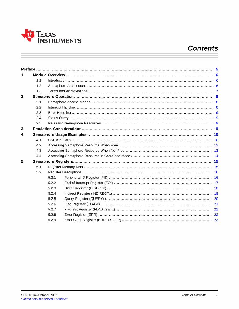
Preface ........................................................................................................................................ 51 Module Overview ................................................................................................................. 6
1.1 Introduction ................................................................................................................ 61.2 Semaphore Architecture ................................................................................................. 61.3 Terms and Abbreviations ................................................................................................ 7
2 Semaphore Operation........................................................................................................... 82.1 Semaphore Access Modes .............................................................................................. 82.2 Interrupt Handling ......................................................................................................... 82.3 Error Handling ............................................................................................................. 92.4 Status Query............................................................................................................... 92.5 Releasing Semaphore Resources ...................................................................................... 9
3 Emulation Considerations ..................................................................................................... 94 Semaphore Usage Examples ............................................................................................... 10
4.1 CSL API Calls ............................................................................................................ 104.2 Accessing Semaphore Resource When Free ....................................................................... 124.3 Accessing Semaphore Resource When Not Free .................................................................. 134.4 Accessing Semaphore Resource in Combined Mode .............................................................. 14
5 Semaphore Registers.......................................................................................................... 155.1 Register Memory Map .................................................................................................. 155.2 Register Descriptions ................................................................................................... 16
5.2.1 Peripheral ID Register (PID)............................................................................... 165.2.2 End-of-Interrupt Register (EOI) ........................................................................... 175.2.3 Direct Register (DIRECTx) ................................................................................ 185.2.4 Indirect Register (INDIRECTx) ............................................................................ 195.2.5 Query Register (QUERYx)................................................................................. 205.2.6 Flag Register (FLAGx) ..................................................................................... 215.2.7 Flag Set Register (FLAG_SETx).......................................................................... 215.2.8 Error Register (ERR) ....................................................................................... 225.2.9 Error Clear Register (ERROR_CLR) ..................................................................... 23
SPRUG14–October 2008 Table of Contents 3Submit Documentation Feedback

www.ti.com
List of Figures1 TMS320C6474 Semaphore Block Diagram .............................................................................. 72 Peripheral ID Register (PID) .............................................................................................. 163 End-of-Interrupt Register (EOI)........................................................................................... 174 Direct Register (DIRECTx) ................................................................................................ 185 Indirect Register (INDIRECTx) ........................................................................................... 196 Query Register (QUERYx) ................................................................................................ 207 Flag Register (FLAGx)..................................................................................................... 218 Flag Set Register (FLAG_SETx) ......................................................................................... 219 Error Register (ERR)....................................................................................................... 2210 Error Clear Register (ERROR_CLR) .................................................................................... 23
List of Tables1 Register Memory Map ..................................................................................................... 152 Peripheral ID Register (PID) Field Descriptions........................................................................ 163 End-of-Interrupt Register (EOI) Field Descriptions .................................................................... 174 Direct Register (DIRECTx) Field Descriptions.......................................................................... 185 Indirect Register (INDIRECTx) Field Descriptions ..................................................................... 196 Query Register (QUERYx) Field Descriptions.......................................................................... 207 Flag Register (FLAGx) Field Descriptions .............................................................................. 218 Flag Set Register (FLAG_SETx) Field Descriptions................................................................... 219 Error Register (ERR) Field Descriptions ................................................................................ 2210 Error Register (ERROR_CLR) Field Descriptions ..................................................................... 23
List of Figures4 SPRUG14–October 2008Submit Documentation Feedback

PrefaceSPRUG14–October 2008
Read This First
About This ManualThe TMS320C6474 semaphore module is used to support atomic arbitration among multiple CPUs forshared resources/peripherals. This document describes the usage of the semaphore and some of the CSLcalls used to configure/use semaphore module.
Notational ConventionsThis document uses the following conventions.• Hexadecimal numbers are shown with the suffix h. For example, the following number is 40
hexadecimal (decimal 64): 40h.• Registers in this document are shown in figures and described in tables.
– Each register figure shows a rectangle divided into fields that represent the fields of the register.Each field is labeled with its bit name, its beginning and ending bit numbers above, and itsread/write properties below. A legend explains the notation used for the properties.
– Reserved bits in a register figure designate a bit that is used for future device expansion.
Related Documentation From Texas InstrumentsThe following documents describe the TMS320C6474 DSP. Copies of these documents are available onthe Internet at www.ti.com. Tip: Enter the literature number in the search box provided at www.ti.com.
SPRU189 — TMS320C6000 DSP CPU and Instruction Set Reference Guide. Describes the CPUarchitecture, pipeline, instruction set, and interrupts for the TMS320C6000 digital signal processors(DSPs).
SPRU198 — TMS320C6000 Programmer's Guide. Describes ways to optimize C and assembly code forthe TMS320C6000™ DSPs and includes application program examples.
SPRU301 — TMS320C6000 Code Composer Studio Tutorial. Introduces the Code Composer Studio™integrated development environment and software tools.
SPRU321 — Code Composer Studio Application Programming Interface Reference Guide.Describes the Code Composer Studio™ application programming interface (API), which allows youto program custom plug-ins for Code Composer.
SPRU871 — TMS320C64x+ Megamodule Reference Guide. Describes the TMS320C64x+ digital signalprocessor (DSP) megamodule. Included is a discussion on the internal direct memory access(IDMA) controller, the interrupt controller, the power-down controller, memory protection, bandwidthmanagement, and the memory and cache.
TrademarksTMS320C6000, Code Composer Studio are trademarks of Texas Instruments.
All other trademarks are the property of their respective owners.
SPRUG14–October 2008 Preface 5Submit Documentation Feedback
1 Module Overview
1.1 Introduction
1.2 Semaphore Architecture
User's GuideSPRUG14–October 2008
TMS320C6474 Semaphore
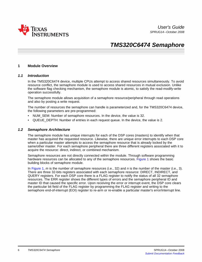
In the TMS320C6474 device, multiple CPUs attempt to access shared resources simultaneously. To avoidresource conflict, the semaphore module is used to access shared resources in mutual exclusion. Unlikethe software flag checking mechanism, the semaphore module is atomic, to satisfy the read-modify-writeoperation successfully.
The semaphore module allows acquisition of a semaphore resource/peripheral through read operationsand also by posting a write request.
The number of resources the semaphore can handle is parameterized and, for the TMS320C6474 device,the following parameters are pre-programmed:• NUM_SEM: Number of semaphore resources. In the device, the value is 32.• QUEUE_DEPTH: Number of entries in each request queue. In the device, the value is 2.
The semaphore module has unique interrupts for each of the DSP cores (masters) to identify when thatmaster has acquired the requested resource. Likewise, there are unique error interrupts to each DSP corewhen a particular master attempts to access the semaphore resource that is already locked by thesame/other master. For each semaphore peripheral there are three different registers associated with it toacquire the resource: direct, indirect, or combined mechanism.
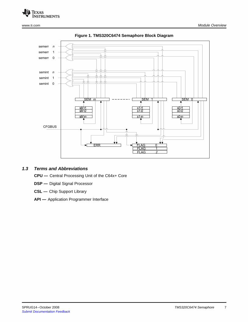
Semaphore resources are not directly connected within the module. Through software programminghardware resources can be allocated to any of the semaphore resources. Figure 1 shows the basicbuilding blocks of semaphore module.
In Figure 1, m is the number of semaphore resources (i.e., 32) and n is the number of the master (i.e., 3).There are three 32-bits registers associated with each semaphore resource: DIRECT, INDIRECT, andQUERY registers. For each DSP core there is a FLAG register to notify the status of all 32 semaphoreresources. The ERR register shows the different types of errors and the semaphore peripheral ID andmaster ID that caused the specific error. Upon receiving the error or interrupt event, the DSP core clearsthe particular bit field of the FLAG register by programming the FLAG register and writing to thesemaphore end-of-interrupt (EOI) register to re-arm or re-enable a particular master's error/interrupt line.
TMS320C6474 Semaphore6 SPRUG14–October 2008Submit Documentation Feedback
sM r1sM r2
sM rn
SEM m
s1r1s1r2
s1rn
s0r1s0r2
s0rn
CFGBUS
semint 0
semint 1
semint n
semerr 0
semerr 1
semerr n
ERR
SEM 1 SEM 0
FLAG 0
FLAG 1
FLAG 2
1.3 Terms and Abbreviations
www.ti.com Module Overview
Figure 1. TMS320C6474 Semaphore Block Diagram
CPU — Central Processing Unit of the C64x+ Core
DSP — Digital Signal Processor
CSL — Chip Support Library
API — Application Programmer Interface
SPRUG14–October 2008 TMS320C6474 Semaphore 7Submit Documentation Feedback

2 Semaphore Operation
2.1 Semaphore Access Modes
2.2 Interrupt Handling
Semaphore Operation www.ti.com
Any of the DSP cores can use the shared semaphore resources.
Any semaphore resource can be accessed by three different modes:• Direct Mode
In direct access mode, a resource is accessed by reading the DIRECTx (x is the semaphore peripheralnumber) register. Since there is no physical connection between the semaphore resources and theregisters, any register can be mapped to any resource by software programming.If the resource is free, access is immediately granted to the requested core. The FREE bit of theDIRECTx register is set to 1 signifying that the resource is free and access is granted to the requestedcore. The OWNER field of the DIRECTx register is set to the requested core ID.If the resource is not available, no further action is taken by the semaphore module. The FREE bit ofthe DIRECTx register is set to 0 signifying that the resource is in use and the requested master shouldstart a fresh request. In any case, there is no interrupt issued and there is no specific bit field set in theFLAGy (y is the granted core ID) register.
• Indirect ModeIn indirect access mode, a resource is accessed by writing to the DIRECTx, INDIRECTx, or QUERYx(x is the semaphore peripheral number) register. Since there is no physical connection between thesemaphore resources and the registers, any register can be mapped to any resource by softwareprogramming.If the resource is free, access is immediately granted to the requested core. The FREE bit of theDIRECTx, INDIRECTx, or QUERYx register is set to 1 signifying that the resource is free and acces isgranted to the requested core. The OWNER field of the DIRECTx, INDIRECTx, or QUERYx register isset to the requested core ID. An interrupt is immediately issued to the requested core.If the resource is not available, the request is added to the request queue assigned to the semaphoreresource. When the resource becomes free, an interrupt is issued and the FREE bit of the DIRECTx,INDIRECTx, or QUERYx register is set to 1 signifying that access is now granted to the requestedcore. An interrupt is issued in this case. The specific bit field for the semaphore resource of the FLAGy(y is the granted core ID) register is set.
• Combined ModeIn combined access mode, a resource is accessed by reading the INDIRECTx (x is the semaphoreperipheral number) register. Since there is no physical connection between the semaphore resourcesand the registers, any register can be mapped to any resource by software programming.If the resource is free, access is immediately granted to the requested core. The FREE bit of theINDIRECTx register is set to 1 signifying that the resource is free and access is granted to therequested core. The OWNER field of the INDIRECTx register is set to the requested core ID. No grantinterrupt or flag register settings happen in this case.If the resource is not available, the request is added to the request queue assigned to the semaphoreresource. When the resource becomes free, an interrupt is issued and the FREE bit of the INDIRECTxregister is set to 1 signifying that access is now granted to the requested core. An interrupt is issued inthis case. The specific bit field for the semaphore resource of the FLAGy (y is the granted core ID)register is set.
The first interrupt occurs when the pending queued request is serviced. To ensure that a re-arm of themaster's interrupt occurs prior to the next access by the same or other resource, the master should:• read the FLAGx (x is the particular master id) register• clear the flag bit by programming the specific bit field for the semaphore resource of the FLAGx
register• write to the EOI register.
TMS320C6474 Semaphore8 SPRUG14–October 2008Submit Documentation Feedback

2.3 Error Handling
2.4 Status Query
2.5 Releasing Semaphore Resources
3 Emulation Considerations
www.ti.com Emulation Considerations
The first error interrupt occurs when there is a semaphore access error. To ensure that a re-arm of themaster's error interrupt occurs prior to the next access violation, the master should:• read the ERR register to determine the error type• clear the error by programming the ERR_CLEAR register• write to the EOI register.
Before acquiring any semaphore resource, the requested core checks the availability of the resource byreading the QUERYx (x is the semaphore peripheral number) register. The FREE bit signifies whether aparticular resource is free or not; when FREE=0 the resource is not free, when FREE=1 the resource isfree. The OWNER field has a master ID that currently holds the resource (when FREE=0) or shows 0x00(when FREE=1). Before taking any action on a resource, check the resource status.
When the master that is granted access is finished with the shared resource, it must free the resource sothat another master can access it. Writing 1 to the FREE bit of the DIRECTx, INDIRECTx, or QUERYxregister releases the specific resource.
During debug, when using the emulator, the CPU(s) may be halted. During emulation halt, the debuggerreads to certain semaphore registers is ignored to avoid changing semaphore state. In other words, thedebugger read of semaphore registers (DIRECTx, INDIRECTx) does not change the state of thesemaphore peripheral. But, during emulation halt, the debugger checks the semaphore peripheral statusvia the QUERYx register.
SPRUG14–October 2008 TMS320C6474 Semaphore 9Submit Documentation Feedback

4 Semaphore Usage Examples
4.1 CSL API Calls
Semaphore Usage Examples www.ti.com
This section provides some of the API call lists and examples to access semaphore resources.
This section provides the basic usage of the semaphore module using different CSL API calls. Threetypical modes of accessing peripherals are illustrated with examples. Example 1 shows some of the APIcall lists.
Example 1. Sample API Call Lists
########CSL_sem_API ###########define HW_SEM_RELEASE 1#define HW_SEM_REQUEST 0/*******************//* ENUMERATIONS *//*******************/typedef enum {
CSL_SEM_ID0 = 0,CSL_SEM_ID1 = 1,CSL_SEM_ID2 = 2,
}CSL_SemOwnerId;
typedef enum {CSL_SEM_ERR0 = 0,CSL_SEM_ERR1 = 1,CSL_SEM_ERR2 = 2,CSL_SEM_ERR3 = 3,CSL_SEM_ERR4 = 4
}CSL_SemError;
typedef enum {CSL_SEM_NOTFREE = 0, /* Semaphore is not available */CSL_SEM_FREE = 1 /* Semaphore is available */
}CSL_SemFlag;
typedef enum {CSL_SEM_REARM_SEMINT0 = 0,CSL_SEM_REARM_SEMINT1 = 1,CSL_SEM_REARM_SEMINT2 = 2,CSL_SEM_REARM_SEMINT_ALL = 0x10
}CSL_SemEOISet
typedef enum {CSL_SEM_QUERY_REVISION,CSL_SEM_QUERY_ERROR,CSL_SEM_QUERY_FLAGS,CSL_SEM_QUERY_STATUS,CSL_SEM_QUERY_DIRECT,CSL_SEM_QUERY_INDIRECT
}CSL_SemHwStatusQuery;
TMS320C6474 Semaphore10 SPRUG14–October 2008Submit Documentation Feedback

www.ti.com Semaphore Usage Examples
Example 1. Sample API Call Lists (continued)typedef enum {
CSL_SEM_CMD_EOI_WRITE,CSL_SEM_CMD_FLAG_SET,CSL_SEM_CMD_FREE_DIRECT,CSL_SEM_CMD_WRITE_POST_DIRECT,CSL_SEM_CMD_FREE_INDIRECT,CSL_SEM_CMD_WRITE_POST_INDIRECT,CSL_SEM_CMD_FREE_QUERY,CSL_SEM_CMD_WRITE_POST_QUERY,CSL_SEM_CMD_CLEAR_ERR,CSL_SEM_CMD_CLEAR_FLAGS
}CSL_SemHwControlCmd;/*******************//* DATA STRUCTURES *//*******************/typedef struct _CSL_SemFlagClear_Arg{
CSL_BitMask32 mask;CSL_SemOwnerId masterId;
}CSL_SemFlagSetClear_Arg;
typedef struct {CSL_SemRegsOvly regs;
} CSL_SemBaseAddress;
typedef struct {CSL_BitMask16 flags;
} CSL_SemParam;
typedef struct {Uint16 contextInfo;
} CSL_SemContext;
typedef struct CSL_SemObj{CSL_InstNum instNum;int semNum;CSL_SemRegsOvly regs;
}CSL_SemObj;
typedef volatile CSL_SemObj *CSL_SemHandle;
typedef struct {int semNum;CSL_SemOwnerId semOwner;CSL_SemFlag semFree;
} CSL_SemVal;
typedef struct CSL_SemFaultStatus {int semNum;CSL_SemError errorMask;Uint16 faultID;
}CSL_SemFaultStatus;
SPRUG14–October 2008 TMS320C6474 Semaphore 11Submit Documentation Feedback

4.2 Accessing Semaphore Resource When FreeSemaphore Usage Examples www.ti.com
A CPU accesses a shared peripheral (semaphore resource) by reading the semaphore direct (DIRECTx)register when the resource is free to use. Checking the semaphore query (QUERYx) register is the way toverify whether a particular resource is free or still in use by other CPU. If the FREE bit of QUERYx (wherex is the semaphore peripheral ID) register is 1, the requested CPU directly locks the peripheral by readingthe DIRECTx register and the requested peripheral is immediately granted access. After finishing theaccess, the CPU must release the resource by writing 1 to the FREE bit of the DIRECTx register so thatanother CPU can access the same resource.
Example 2 shows a semaphore resource (NUM = 4) acquired using the direct-read mode.
Example 2. Sample Code to Access Semaphore in Direct-Read Mode
CSL_SemVal query;CSL_SemHandle mySemHandle;CSL_SemObj mySemObj;CSL_SemContext SemContext;CSL_SemParam mySemParam;
mySemParam.flags = 4;CSL_semInit(&SemContext);
mySemHandle = CSL_semOpen(&mySemObj, 0,&mySemParam, NULL);
if(mySemHandle != NULL) {CSL_semGetHwStatus(mySemHandle,CSL_SEM_QUERY_STATUS,&query);
}
if(query.semFree == CSL_SEM_FREE) {CSL_semGetHwStatus(mySemHandle, CSL_SEM_QUERY_DIRECT,&query);
}CSL_semGetHwStatus(mySemHandle,CSL_SEM_QUERY_STATUS,&query);if (query.semFree != CSL_SEM_FREE) {
// Do peripheral access}else {
// return error.}
CSL_semHwControl(mySemHandle, CSL_SEM_CMD_FREE_DIRECT,NULL);/* END Of Main code */
TMS320C6474 Semaphore12 SPRUG14–October 2008Submit Documentation Feedback
4.3 Accessing Semaphore Resource When Not Freewww.ti.com Semaphore Usage Examples
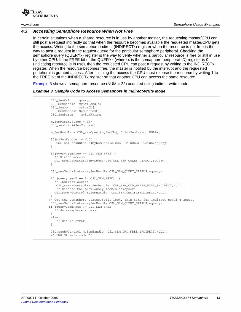
In certain situations when a shared resource is in use by another master, the requesting master/CPU canstill post a request indirectly so that when the resource becomes available the requested master/CPU getsthe access. Writing to the semaphore indirect (INDIRECTx) register when the resource is not free is theway to post a request in the request queue for the particular semaphore peripheral. Checking thesemaphore query (QUERYx) register is the way to verify whether a particular resource is free or still in useby other CPU. If the FREE bit of the QUERYx (where x is the semaphore peripheral ID) register is 0(indicating resource is in use), then the requested CPU can post a request by writing to the INDIRECTxregister. When the resource becomes free, the master is notified by the interrupt and the requestedperipheral is granted access. After finishing the access the CPU must release the resource by writing 1 tothe FREE bit of the INDIRECTx register so that another CPU can access the same resource.
Example 3 shows a semaphore resource (NUM = 22) acquired using indirect-write mode.
Example 3. Sample Code to Access Semaphore in Indirect-Write Mode
CSL_SemVal query;CSL_SemHandle mySemHandle;CSL_SemObj mySemObj;CSL_SemContext SemContext;CSL_SemParam mySemParam;
mySemParam.flags = 22;CSL_semInit(&SemContext);
mySemHandle = CSL_semOpen(&mySemObj, 0,&mySemParam, NULL);
if(mySemHandle != NULL) {CSL_semGetHwStatus(mySemHandle,CSL_SEM_QUERY_STATUS,&query);
}
if(query.semFree == CSL_SEM_FREE) {// Direct accessCSL_semGetHwStatus(mySemHandle,CSL_SEM_QUERY_DIRECT,&query);
}
CSL_semGetHwStatus(mySemHandle,CSL_SEM_QUERY_STATUS,&query);
if (query.semFree != CSL_SEM_FREE) {// Indirect accessCSL_semHwControl(mySemHandle, CSL_SEM_CMD_WRITE_POST_INDIRECT,NULL);// Release the previously locked semaphore
CSL_semHwControl(mySemHandle, CSL_SEM_CMD_FREE_DIRECT,NULL);}// Get the semaphore status.Still lock. This time for indirect pending accessCSL_semGetHwStatus(mySemHandle,CSL_SEM_QUERY_STATUS,&query);if (query.semFree != CSL_SEM_FREE) {
// do semaphore access}else {
// Return error}
CSL_semHwControl(mySemHandle, CSL_SEM_CMD_FREE_INDIRECT,NULL);/* END Of Main code */
SPRUG14–October 2008 TMS320C6474 Semaphore 13Submit Documentation Feedback
4.4 Accessing Semaphore Resource in Combined ModeSemaphore Usage Examples www.ti.com
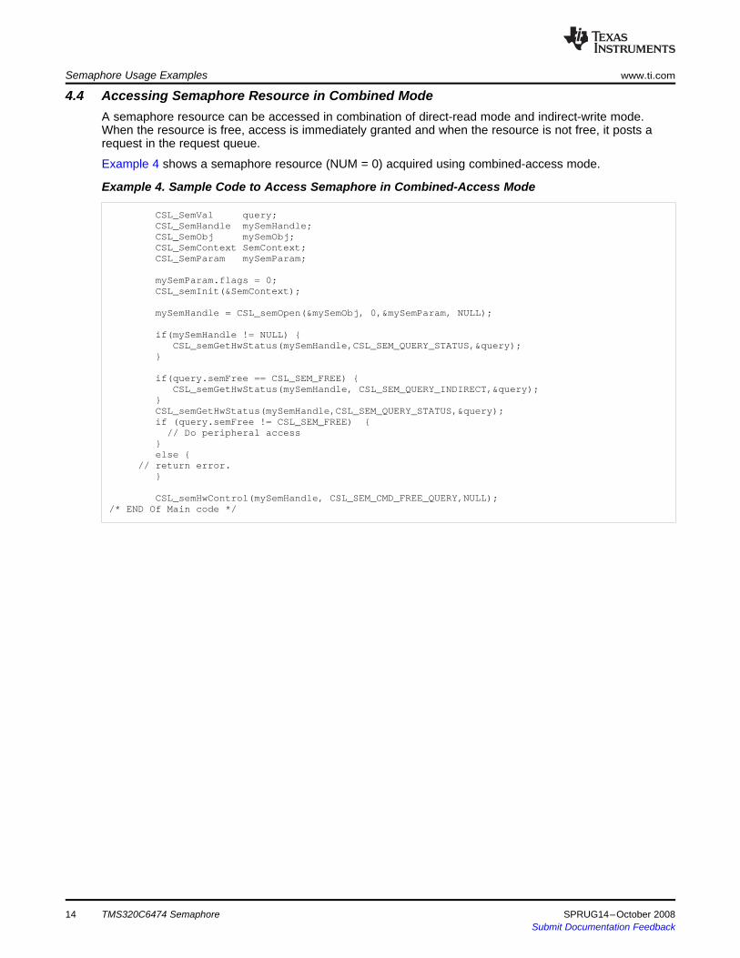
A semaphore resource can be accessed in combination of direct-read mode and indirect-write mode.When the resource is free, access is immediately granted and when the resource is not free, it posts arequest in the request queue.
Example 4 shows a semaphore resource (NUM = 0) acquired using combined-access mode.
Example 4. Sample Code to Access Semaphore in Combined-Access Mode
CSL_SemVal query;CSL_SemHandle mySemHandle;CSL_SemObj mySemObj;CSL_SemContext SemContext;CSL_SemParam mySemParam;
mySemParam.flags = 0;CSL_semInit(&SemContext);
mySemHandle = CSL_semOpen(&mySemObj, 0,&mySemParam, NULL);
if(mySemHandle != NULL) {CSL_semGetHwStatus(mySemHandle,CSL_SEM_QUERY_STATUS,&query);
}
if(query.semFree == CSL_SEM_FREE) {CSL_semGetHwStatus(mySemHandle, CSL_SEM_QUERY_INDIRECT,&query);
}CSL_semGetHwStatus(mySemHandle,CSL_SEM_QUERY_STATUS,&query);if (query.semFree != CSL_SEM_FREE) {
// Do peripheral access}else {
// return error.}
CSL_semHwControl(mySemHandle, CSL_SEM_CMD_FREE_QUERY,NULL);/* END Of Main code */
TMS320C6474 Semaphore14 SPRUG14–October 2008Submit Documentation Feedback

5 Semaphore Registers
5.1 Register Memory Map
www.ti.com Semaphore Registers
This section provides the semaphore memory map and descriptions of the peripheral registers.
Table 1. Register Memory MapOffset Acronym Description See0x000 PID Peripheral Revision ID Register Section 5.2.10x00C EOI EOI Register Section 5.2.2
0x100 - 0x17C DIRECT0-31 Direct Registers 0-31 Section 5.2.30x200 - 0x27C INDIRECT0-31 Indirect Registers 0-31 Section 5.2.40x300 - 0x37C QUERY0-31 Query Registers 0-31 Section 5.2.5
0x400 FLAG0 Flag0 Register (for C64x+ Core0) Section 5.2.60x404 FLAG1 Flag1 Register (for C64x+ Core1) Section 5.2.60x408 FLAG2 Flag2 Register (for C64x+ Core2) Section 5.2.60x480 FLAG_SET0 Flag Set0 Register (for C64x+ Core0) Section 5.2.70x484 FLAG_SET1 Flag Set1 Register (for C64x+ Core1) Section 5.2.70x488 FLAG_SET2 Flag Set2 Register (for C64x+ Core2) Section 5.2.70x500 ERR Error Register Section 5.2.80x504 ERROR_CLR Error Clear Register Section 5.2.9
SPRUG14–October 2008 TMS320C6474 Semaphore 15Submit Documentation Feedback

5.2 Register Descriptions
5.2.1 Peripheral ID Register (PID)
Semaphore Registers www.ti.com
The following are some sample semaphore peripheral registers.
The semaphore peripheral ID (PID) register is shown in Figure 2 and described in Table 2.
Figure 2. Peripheral ID Register (PID)
31 30 29 28 27 16SCHEME Reserved FUNC
R-0x1 R-0x R-0x802
15 11 10 8 7 6 5 0
RTL MAJOR CUSTOM MINORR-0x0 R-0x1 R-0x0 R-0x0
LEGEND: R/W = Read/Write; R = Read only; -n = value after reset
Table 2. Peripheral ID Register (PID) Field DescriptionsBit Field Value Description
31-30 SCHEME 01b Used to distinguish which ID scheme is used.29-28 RSVD 00 Reserved. Read returns 0. Write has no effect.27-16 FUNC 0x802 Specifies module family15-11 RTL 0000b RTL Version10-8 MAJOR 01b Major Revision7-6 CUSTOM 00b Special/Custom Revision5-0 MINOR 000000b Minor Revision
TMS320C6474 Semaphore16 SPRUG14–October 2008Submit Documentation Feedback

5.2.2 End-of-Interrupt Register (EOI)
www.ti.com Semaphore Registers
The semaphore end-of-interrupt (EOI) register is used for re-arming the error/interrupt line after servingthe existing error/interrupt. The EOI register is shown in Figure 3 and described in Table 3.
Figure 3. End-of-Interrupt Register (EOI)
31 16Reserved
W
15 8 7 0
Reserved INTERRUPT/ERROR SELECTW W
LEGEND: W = Write only; -n = value after reset
Table 3. End-of-Interrupt Register (EOI) Field Descriptions (1)
Bit Field Value Description31-8 Reserved Reserved, Write has no effect7-0 INTERRUPT/ERROR Selection of particular Error/Interrupt line to re-arm.
SELECT 0x00 Re-enable semint0 (For C64x+ Core0)0x01 Re-enable semint1 (For C64x+ Core1)0x02 Re-enable semint2 (For C64x+ Core2)0x10 Re-enable All Error interrupt (For all C64x+ Cores)
(1) Reading of the EOI register will result in a memory-read exception being generated.
SPRUG14–October 2008 TMS320C6474 Semaphore 17Submit Documentation Feedback

5.2.3 Direct Register (DIRECTx)
Semaphore Registers www.ti.com
The semaphore direct (DIRECTx) register acquires the semaphore resource in direct-read mode as wellas indirect-write mode. If the resource is free, the FREE field of the DIRECTx (x is the semaphoreperipheral ID being requested) signifies whether the resource is granted or not. The DIRECTx register isshown in Figure 4 and described in Table 4.
Figure 4. Direct Register (DIRECTx)
31 16ReservedR-0x0000
15 8 7 1 0
OWNER Reserved FREER-0x00 R-0x00 R/W-
0x1
LEGEND: R/W = Read/Write; R = Read only; -n = value after reset
Table 4. Direct Register (DIRECTx) Field DescriptionsBit Field Value Description
31-16 Reserved 0x0000 Reserved. Read returns 0. Write has no effect.15-8 OWNER 0x00 When FREE = 0: Semaphore resource owner ID
When FREE = 1: The value returns 0x007-1 Reserved 0x00 Reserved. Read returns 0. Write has no effect.0 FREE Read Operation:
0 Semaphore is not granted.1 Semaphore is granted to the Master. FREE is cleared by the hardware at the end of the access.
Write Operation:0 Request is posted in the queue (indirect mode).1 Semaphore is freed.
TMS320C6474 Semaphore18 SPRUG14–October 2008Submit Documentation Feedback
5.2.4 Indirect Register (INDIRECTx)
www.ti.com Semaphore Registers
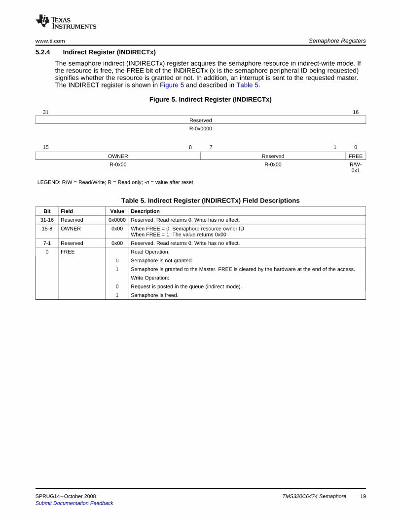
The semaphore indirect (INDIRECTx) register acquires the semaphore resource in indirect-write mode. Ifthe resource is free, the FREE bit of the INDIRECTx (x is the semaphore peripheral ID being requested)signifies whether the resource is granted or not. In addition, an interrupt is sent to the requested master.The INDIRECT register is shown in Figure 5 and described in Table 5.
Figure 5. Indirect Register (INDIRECTx)
31 16ReservedR-0x0000
15 8 7 1 0
OWNER Reserved FREER-0x00 R-0x00 R/W-
0x1
LEGEND: R/W = Read/Write; R = Read only; -n = value after reset
Table 5. Indirect Register (INDIRECTx) Field DescriptionsBit Field Value Description
31-16 Reserved 0x0000 Reserved. Read returns 0. Write has no effect.15-8 OWNER 0x00 When FREE = 0: Semaphore resource owner ID
When FREE = 1: The value returns 0x007-1 Reserved 0x00 Reserved. Read returns 0. Write has no effect.0 FREE Read Operation:
0 Semaphore is not granted.1 Semaphore is granted to the Master. FREE is cleared by the hardware at the end of the access.
Write Operation:0 Request is posted in the queue (indirect mode).1 Semaphore is freed.
SPRUG14–October 2008 TMS320C6474 Semaphore 19Submit Documentation Feedback

5.2.5 Query Register (QUERYx)
Semaphore Registers www.ti.com
Each semaphore query register (QUERYx) checks the current semaphore resource status and also canbe used for indirect-write mode to access the particular resource. Reading the QUERYx (x is thesemaphore peripheral ID being accessed) register does not affect the status of the particular peripheral.The QUERY register is shown in Figure 6 and described in Table 6.
Figure 6. Query Register (QUERYx)
31 16ReservedR-0x0000
15 8 7 1 0
OWNER Reserved FREER-0x00 R-0x00 R/W-
0x1
LEGEND: R/W = Read/Write; R = Read only; -n = value after reset
Table 6. Query Register (QUERYx) Field DescriptionsBit Field Value Description
31-16 Reserved 0x0000 Reserved. Read returns 0. Write has no effect.15-8 OWNER 0x00 When FREE = 0: Semaphore resource owner ID
When FREE = 1: The value returns 0x007-1 Reserved 0x00 Reserved. Read returns 0. Write has no effect.0 FREE Read Operation:
0 Semaphore is not granted1 Semaphore is not granted to the Master
Write Operation:0 Request is posted in the queue (indirect mode)1 Semaphore is freed
TMS320C6474 Semaphore20 SPRUG14–October 2008Submit Documentation Feedback

5.2.6 Flag Register (FLAGx)
5.2.7 Flag Set Register (FLAG_SETx)
www.ti.com Semaphore Registers
Each semaphore flag (FLAGx, where x is the Master ID) register checks whether the particularmaster/core is currently holding the semaphore resource or not. There is one register for each core andthe particular bit field signifies the holding status of the particular semaphore peripheral by the requestedmaster. Once access to the particular semaphore resource is complete, the corresponding flag bit iscleared by writing a 1 to the particular bit of the FLAG register. The FLAGx register is shown in Figure 7and described in Table 7.
Figure 7. Flag Register (FLAGx)
31 30 29 28 27 26 25 24 23 22 21 20 19 18 17 16F31 F30 F29 F28 F27 F26 F25 F24 F23 F22 F21 F20 F19 F18 F17 F16
R-0x0000
15 14 13 12 11 10 9 8 7 6 5 4 3 2 1 0
F15 F14 F13 F12 F11 F10 F9 F8 F7 F6 F5 F4 F3 F2 F1 F0R-0x0000
LEGEND: R/W = Read/Write; R = Read only; -n = value after reset
Table 7. Flag Register (FLAGx) Field DescriptionsBit Field Value Description
31-0 Fy Semaphore Flag Value0x0 Semaphore resource y is not owned by the master x0x1 Semaphore resource y is owned by the master x
Each semaphore flag set (FLAG_SETx, where x is the Master ID) register sets the flag bit of the particularsemaphore peripheral. This register is implemented to check, by software programming, whether anyresource can be accessed by the any of the masters. There is one register for each core and writing to theparticular bit field sets the semaphore flag registers (FLAGx) corresponding bit-field value. TheFLAG_SETx register is shown in Figure 8 and described in Table 8.
Figure 8. Flag Set Register (FLAG_SETx)
31 30 29 28 27 26 25 24 23 22 21 20 19 18 17 16F31 F30 F29 F28 F27 F26 F25 F24 F23 F22 F21 F20 F19 F18 F17 F16
W-0x0000
15 14 13 12 11 10 9 8 7 6 5 4 3 2 1 0
F15 F14 F13 F12 F11 F10 F9 F8 F7 F6 F5 F4 F3 F2 F1 F0W-0x0000
LEGEND: R/W = Read/Write; R = Read only; -n = value after reset
Table 8. Flag Set Register (FLAG_SETx) Field DescriptionsBit Field Value Description
31-0 Fy Semaphore Flag Set0x0 Do nothing0x1 Semaphore flag y is cleared
SPRUG14–October 2008 TMS320C6474 Semaphore 21Submit Documentation Feedback

5.2.8 Error Register (ERR)
Semaphore Registers www.ti.com
The semaphore error (ERR) register updates any kind of error that occurs while acquiring a semaphoreresource by any core. By reading the ERR register the particular master/core should clear the particularerror and program the EOI register so that a re-arm occurs for the next semaphore access by the samemaster. The ERR register is shown in Figure 9 and described in Table 9.
Figure 9. Error Register (ERR)
31 16ReservedR-0x0000
15 8 7 3 2 0
FAULTID SEM_NUM ERRR-0x00 R-0x0 R-0x0
LEGEND: R/W = Read/Write; R = Read only; -n = value after reset
Table 9. Error Register (ERR) Field DescriptionsBit Field Value Description
31-16 Reserved 0x0000 Reserved. Read returns 0. Write has no effect.15-8 FAULTID 0x00 Master ID number that caused the error7-3 SEM_NUM 0x00 Semaphore peripheral ID number (0 to 31)2-0 ERR Semaphore error code.
000 No semaphore access error has occurred.001 Master ID FAULTID attempted to free semaphore NUM when it was already free.010 Master ID FAULTID attempted to free semaphore NUM while not currently owned by FAULTID.011 Master ID FAULTID attempted to acquire semaphore NUM while it was already owned by
FAULTID.100 Master ID FAULTID attempted to acquire semaphore NUM while FAULTID already had a request
pending.
TMS320C6474 Semaphore22 SPRUG14–October 2008Submit Documentation Feedback
5.2.9 Error Clear Register (ERROR_CLR)
www.ti.com Semaphore Registers
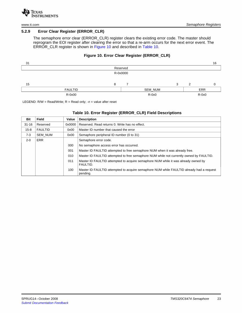
The semaphore error clear (ERROR_CLR) register clears the existing error code. The master shouldreprogram the EOI register after clearing the error so that a re-arm occurs for the next error event. TheERROR_CLR register is shown in Figure 10 and described in Table 10.
Figure 10. Error Clear Register (ERROR_CLR)
31 16ReservedR-0x0000
15 8 7 3 2 0
FAULTID SEM_NUM ERRR-0x00 R-0x0 R-0x0
LEGEND: R/W = Read/Write; R = Read only; -n = value after reset
Table 10. Error Register (ERROR_CLR) Field DescriptionsBit Field Value Description
31-16 Reserved 0x0000 Reserved. Read returns 0. Write has no effect.15-8 FAULTID 0x00 Master ID number that caused the error7-3 SEM_NUM 0x00 Semaphore peripheral ID number (0 to 31)2-0 ERR Semaphore error code.
000 No semaphore access error has occurred.001 Master ID FAULTID attempted to free semaphore NUM when it was already free.010 Master ID FAULTID attempted to free semaphore NUM while not currently owned by FAULTID.011 Master ID FAULTID attempted to acquire semaphore NUM while it was already owned by
FAULTID.100 Master ID FAULTID attempted to acquire semaphore NUM while FAULTID already had a request
pending.
SPRUG14–October 2008 TMS320C6474 Semaphore 23Submit Documentation Feedback
IMPORTANT NOTICETexas Instruments Incorporated and its subsidiaries (TI) reserve the right to make corrections, modifications, enhancements, improvements,and other changes to its products and services at any time and to discontinue any product or service without notice. Customers shouldobtain the latest relevant information before placing orders and should verify that such information is current and complete. All products aresold subject to TI’s terms and conditions of sale supplied at the time of order acknowledgment.TI warrants performance of its hardware products to the specifications applicable at the time of sale in accordance with TI’s standardwarranty. Testing and other quality control techniques are used to the extent TI deems necessary to support this warranty. Except wheremandated by government requirements, testing of all parameters of each product is not necessarily performed.TI assumes no liability for applications assistance or customer product design. Customers are responsible for their products andapplications using TI components. To minimize the risks associated with customer products and applications, customers should provideadequate design and operating safeguards.TI does not warrant or represent that any license, either express or implied, is granted under any TI patent right, copyright, mask work right,or other TI intellectual property right relating to any combination, machine, or process in which TI products or services are used. Informationpublished by TI regarding third-party products or services does not constitute a license from TI to use such products or services or awarranty or endorsement thereof. Use of such information may require a license from a third party under the patents or other intellectualproperty of the third party, or a license from TI under the patents or other intellectual property of TI.Reproduction of TI information in TI data books or data sheets is permissible only if reproduction is without alteration and is accompaniedby all associated warranties, conditions, limitations, and notices. Reproduction of this information with alteration is an unfair and deceptivebusiness practice. TI is not responsible or liable for such altered documentation. Information of third parties may be subject to additionalrestrictions.Resale of TI products or services with statements different from or beyond the parameters stated by TI for that product or service voids allexpress and any implied warranties for the associated TI product or service and is an unfair and deceptive business practice. TI is notresponsible or liable for any such statements.TI products are not authorized for use in safety-critical applications (such as life support) where a failure of the TI product would reasonablybe expected to cause severe personal injury or death, unless officers of the parties have executed an agreement specifically governingsuch use. Buyers represent that they have all necessary expertise in the safety and regulatory ramifications of their applications, andacknowledge and agree that they are solely responsible for all legal, regulatory and safety-related requirements concerning their productsand any use of TI products in such safety-critical applications, notwithstanding any applications-related information or support that may beprovided by TI. Further, Buyers must fully indemnify TI and its representatives against any damages arising out of the use of TI products insuch safety-critical applications.TI products are neither designed nor intended for use in military/aerospace applications or environments unless the TI products arespecifically designated by TI as military-grade or "enhanced plastic." Only products designated by TI as military-grade meet militaryspecifications. Buyers acknowledge and agree that any such use of TI products which TI has not designated as military-grade is solely atthe Buyer's risk, and that they are solely responsible for compliance with all legal and regulatory requirements in connection with such use.TI products are neither designed nor intended for use in automotive applications or environments unless the specific TI products aredesignated by TI as compliant with ISO/TS 16949 requirements. Buyers acknowledge and agree that, if they use any non-designatedproducts in automotive applications, TI will not be responsible for any failure to meet such requirements.Following are URLs where you can obtain information on other Texas Instruments products and application solutions:Products ApplicationsAmplifiers amplifier.ti.com Audio www.ti.com/audioData Converters dataconverter.ti.com Automotive www.ti.com/automotiveDSP dsp.ti.com Broadband www.ti.com/broadbandClocks and Timers www.ti.com/clocks Digital Control www.ti.com/digitalcontrolInterface interface.ti.com Medical www.ti.com/medicalLogic logic.ti.com Military www.ti.com/militaryPower Mgmt power.ti.com Optical Networking www.ti.com/opticalnetworkMicrocontrollers microcontroller.ti.com Security www.ti.com/securityRFID www.ti-rfid.com Telephony www.ti.com/telephonyRF/IF and ZigBee® Solutions www.ti.com/lprf Video & Imaging www.ti.com/video
Wireless www.ti.com/wireless
Mailing Address: Texas Instruments, Post Office Box 655303, Dallas, Texas 75265Copyright © 2008, Texas Instruments Incorporated