Technical Datasheet
10
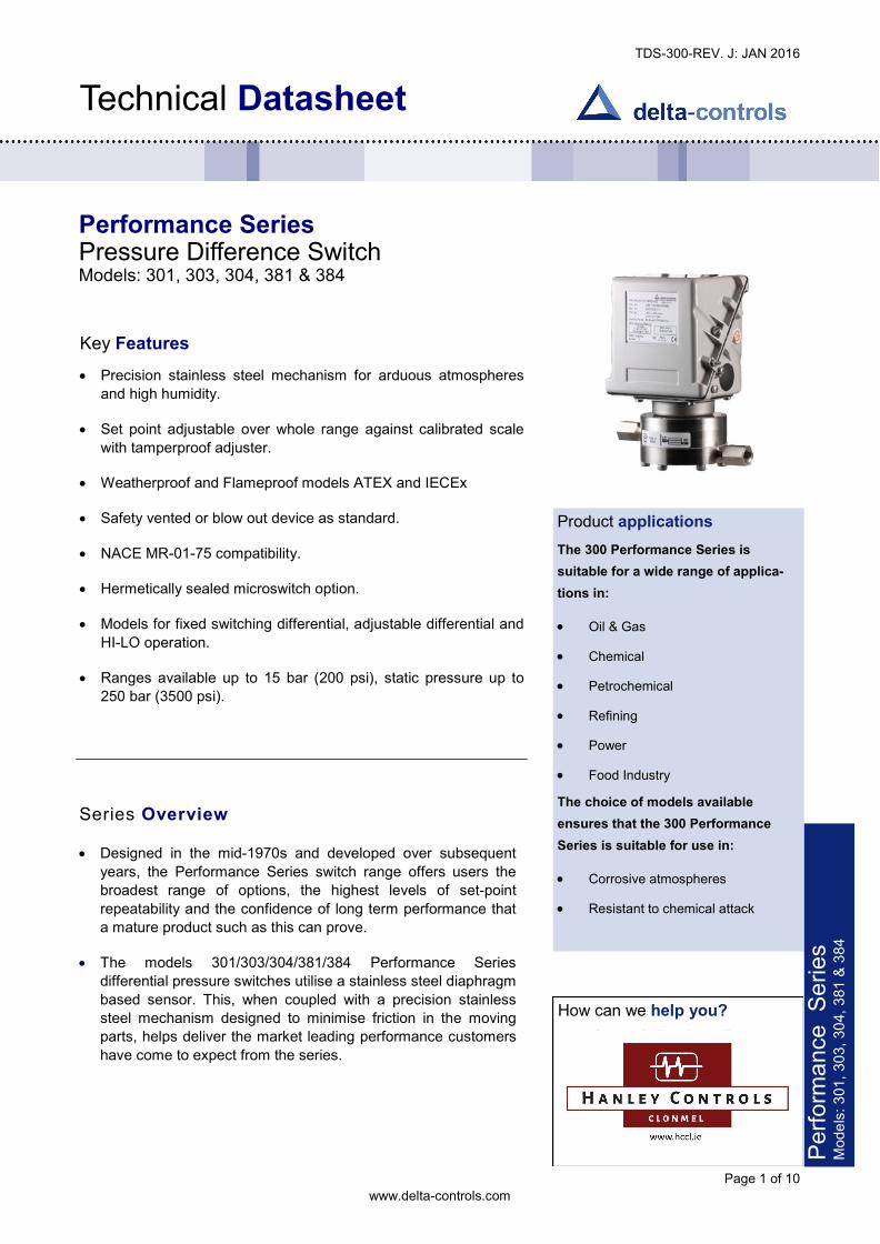
TDS-300-REV. J: JAN 2016 Page 1 of 10 www.delta-controls.com Technical Datasheet Performance Series Pressure Difference Switch Models: 301, 303, 304, 381 & 384 Key Features · Precision stainless steel mechanism for arduous atmospheres and high humidity. · Set point adjustable over whole range against calibrated scale with tamperproof adjuster. · Weatherproof and Flameproof models ATEX and IECEx · Safety vented or blow out device as standard. · NACE MR-01-75 compatibility. · Hermetically sealed microswitch option. · Models for fixed switching differential, adjustable differential and HI-LO operation. · Ranges available up to 15 bar (200 psi), static pressure up to 250 bar (3500 psi). Product applications The 300 Performance Series is suitable for a wide range of applica- tions in: · Oil & Gas · Chemical · Petrochemical · Refining · Power · Food Industry The choice of models available ensures that the 300 Performance Series is suitable for use in: · Corrosive atmospheres · Resistant to chemical attack Series Overview · Designed in the mid-1970s and developed over subsequent years, the Performance Series switch range offers users the broadest range of options, the highest levels of set-point repeatability and the confidence of long term performance that a mature product such as this can prove. · The models 301/303/304/381/384 Performance Series differential pressure switches utilise a stainless steel diaphragm based sensor. This, when coupled with a precision stainless steel mechanism designed to minimise friction in the moving parts, helps deliver the market leading performance customers have come to expect from the series. How can we help you? Delta Controls’ offers fast, efficient and knowledgeable support when and where you need it. Please visit our web site at www.delta-controls.com to find your local support centre or call us on: +44 (0) 1252 729140 Performance Series Models: 301, 303, 304, 381 & 384
-
Upload
khangminh22 -
Category
Documents
-
view
1 -
download
0
Transcript of Technical Datasheet
TDS-300-REV. J: JAN 2016
Page 1 of 10 www.delta-controls.com
Technical Datasheet
Performance Series Pressure Difference SwitchModels: 301, 303, 304, 381 & 384
Key Features · Precision stainless steel mechanism for arduous atmospheres
and high humidity.· Set point adjustable over whole range against calibrated scale
with tamperproof adjuster.· Weatherproof and Flameproof models ATEX and IECEx· Safety vented or blow out device as standard.· NACE MR-01-75 compatibility.· Hermetically sealed microswitch option.· Models for fixed switching differential, adjustable differential and
HI-LO operation.· Ranges available up to 15 bar (200 psi), static pressure up to
250 bar (3500 psi).
Product applications The 300 Performance Series is suitable for a wide range of applica-tions in: · Oil & Gas· Chemical· Petrochemical· Refining· Power· Food IndustryThe choice of models available ensures that the 300 Performance Series is suitable for use in: · Corrosive atmospheres· Resistant to chemical attack
Series Overview · Designed in the mid-1970s and developed over subsequent
years, the Performance Series switch range offers users thebroadest range of options, the highest levels of set-pointrepeatability and the confidence of long term performance thata mature product such as this can prove.
· The models 301/303/304/381/384 Performance Seriesdifferential pressure switches utilise a stainless steel diaphragmbased sensor. This, when coupled with a precision stainlesssteel mechanism designed to minimise friction in the movingparts, helps deliver the market leading performance customershave come to expect from the series.
How can we help you? Delta Controls’ offers fast, efficient and knowledgeable support when and where you need it. Please visit our web site at www.delta-controls.com to find your local support centre or call us on:
+44 (0) 1252 729140 Perfo
rmanc
e Serie
s Mo
dels: 3
01, 30
3, 304,
381 &
384
TDS-300-REV. J: JAN 2016
Page 2 of 10 www.delta-controls.com
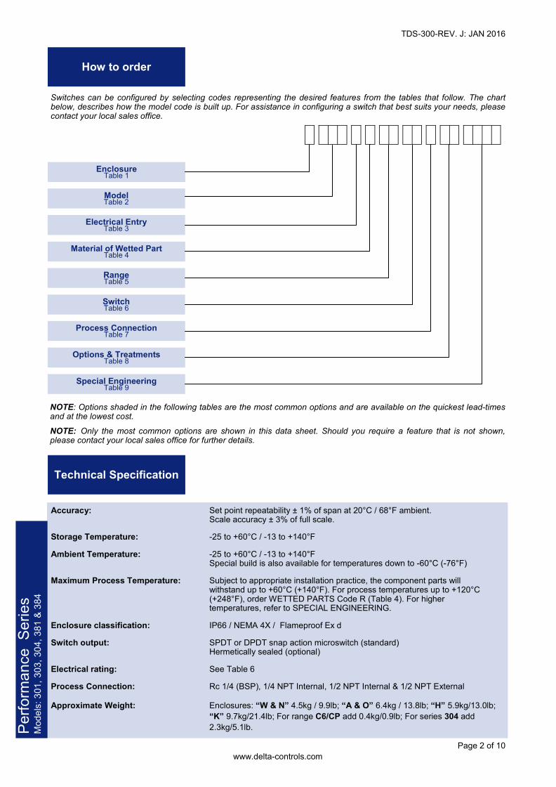
How to order Switches can be configured by selecting codes representing the desired features from the tables that follow. The chart below, describes how the model code is built up. For assistance in configuring a switch that best suits your needs, please contact your local sales office.
Enclosure Table 1 Model Table 2
Electrical Entry Table 3 Material of Wetted Part Table 4
Range Table 5 Switch Table 6
Process Connection Table 7 Options & Treatments Table 8 Special Engineering Table 9
NOTE: Options shaded in the following tables are the most common options and are available on the quickest lead-times and at the lowest cost. NOTE: Only the most common options are shown in this data sheet. Should you require a feature that is not shown, please contact your local sales office for further details.
Technical Specification
Accuracy: Set point repeatability ± 1% of span at 20°C / 68°F ambient. Scale accuracy ± 3% of full scale. Storage Temperature: -25 to +60°C / -13 to +140°F Ambient Temperature: -25 to +60°C / -13 to +140°F Special build is also available for temperatures down to -60°C (-76°F) Maximum Process Temperature: Subject to appropriate installation practice, the component parts will withstand up to +60°C (+140°F). For process temperatures up to +120°C (+248°F), order WETTED PARTS Code R (Table 4). For higher temperatures, refer to SPECIAL ENGINEERING. Enclosure classification: IP66 / NEMA 4X / Flameproof Ex d Switch output: SPDT or DPDT snap action microswitch (standard) Hermetically sealed (optional) Electrical rating: See Table 6 Process Connection: Rc 1/4 (BSP), 1/4 NPT Internal, 1/2 NPT Internal & 1/2 NPT External Approximate Weight: Enclosures: “W & N” 4.5kg / 9.9lb; “A & O” 6.4kg / 13.8lb; “H” 5.9kg/13.0lb; “K” 9.7kg/21.4lb; For range C6/CP add 0.4kg/0.9lb; For series 304 add 2.3kg/5.1lb.
Perfo
rmanc
e Serie
s Mo
dels: 3
01, 30
3, 304,
381 &
384
TDS-300-REV. J: JAN 2016
Page 3 of 10 www.delta-controls.com
Enclosure TABLE 1
Models
TABLE 2
Perfo
rmanc
e Serie
s Mo
dels: 3
01, 30
3, 304,
381 &
384
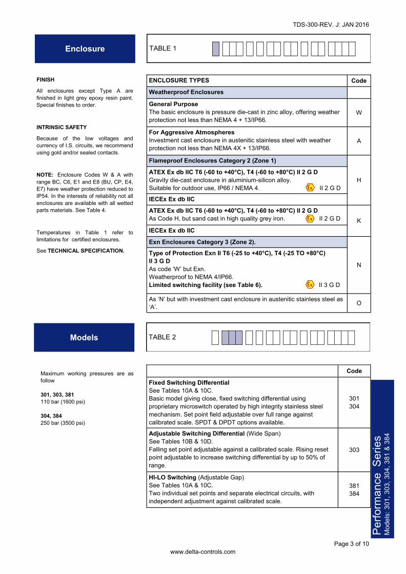
Weatherproof Enclosures General Purpose The basic enclosure is pressure die-cast in zinc alloy, offering weather protection not less than NEMA 4 + 13/IP66.
W
For Aggressive Atmospheres Investment cast enclosure in austenitic stainless steel with weather protection not less than NEMA 4X + 13/IP66.
A
Flameproof Enclosures Category 2 (Zone 1)
H ATEX Ex db IIC T6 (-60 to +40°C), T4 (-60 to +80°C) II 2 G D Gravity die-cast enclosure in aluminium-silicon alloy. Suitable for outdoor use, IP66 / NEMA 4. II 2 G D IECEx Ex db IIC ATEX Ex db IIC T6 (-60 to +40°C), T4 (-60 to +80°C) II 2 G D As Code H, but sand cast in high quality grey iron. II 2 G D K IECEx Ex db IIC Exn Enclosures Category 3 (Zone 2). Type of Protection Exn II T6 (-25 to +40°C), T4 (-25 TO +80°C) II 3 G D As code ‘W’ but Exn. Weatherproof to NEMA 4/IP66. Limited switching facility (see Table 6). II 3 G D As ‘N’ but with investment cast enclosure in austenitic stainless steel as ‘A’. O
N
ENCLOSURE TYPES Code FINISH All enclosures except Type A are finished in light grey epoxy resin paint. Special finishes to order. INTRINSIC SAFETY Because of the low voltages and currency of I.S. circuits, we recommend using gold and/or sealed contacts. NOTE: Enclosure Codes W & A with range BC, C6, E1 and E8 (BU, CP, E4, E7) have weather protection reduced to IP54. In the interests of reliability not all enclosures are available with all wetted parts materials. See Table 4. Temperatures in Table 1 refer to limitations for certified enclosures. See TECHNICAL SPECIFICATION.
Code Fixed Switching Differential See Tables 10A & 10C. Basic model giving close, fixed switching differential using proprietary microswitch operated by high integrity stainless steel mechanism. Set point field adjustable over full range against calibrated scale. SPDT & DPDT options available.
301 304
Adjustable Switching Differential (Wide Span) See Tables 10B & 10D. Falling set point adjustable against a calibrated scale. Rising reset point adjustable to increase switching differential by up to 50% of range.
303
HI-LO Switching (Adjustable Gap) See Tables 10A & 10C. Two individual set points and separate electrical circuits, with independent adjustment against calibrated scale.
381 384
Maximum working pressures are as follow 301, 303, 381 110 bar (1600 psi) 304, 384 250 bar (3500 psi)
TDS-300-REV. J: JAN 2016
Page 4 of 10 www.delta-controls.com
Electrical Entry
Material of Wetted Parts
TABLE 3
TABLE 4
Setting Ranges TABLE 5
Perfo
rmanc
e Serie
s Mo
dels: 3
01, 30
3, 304,
381 &
384
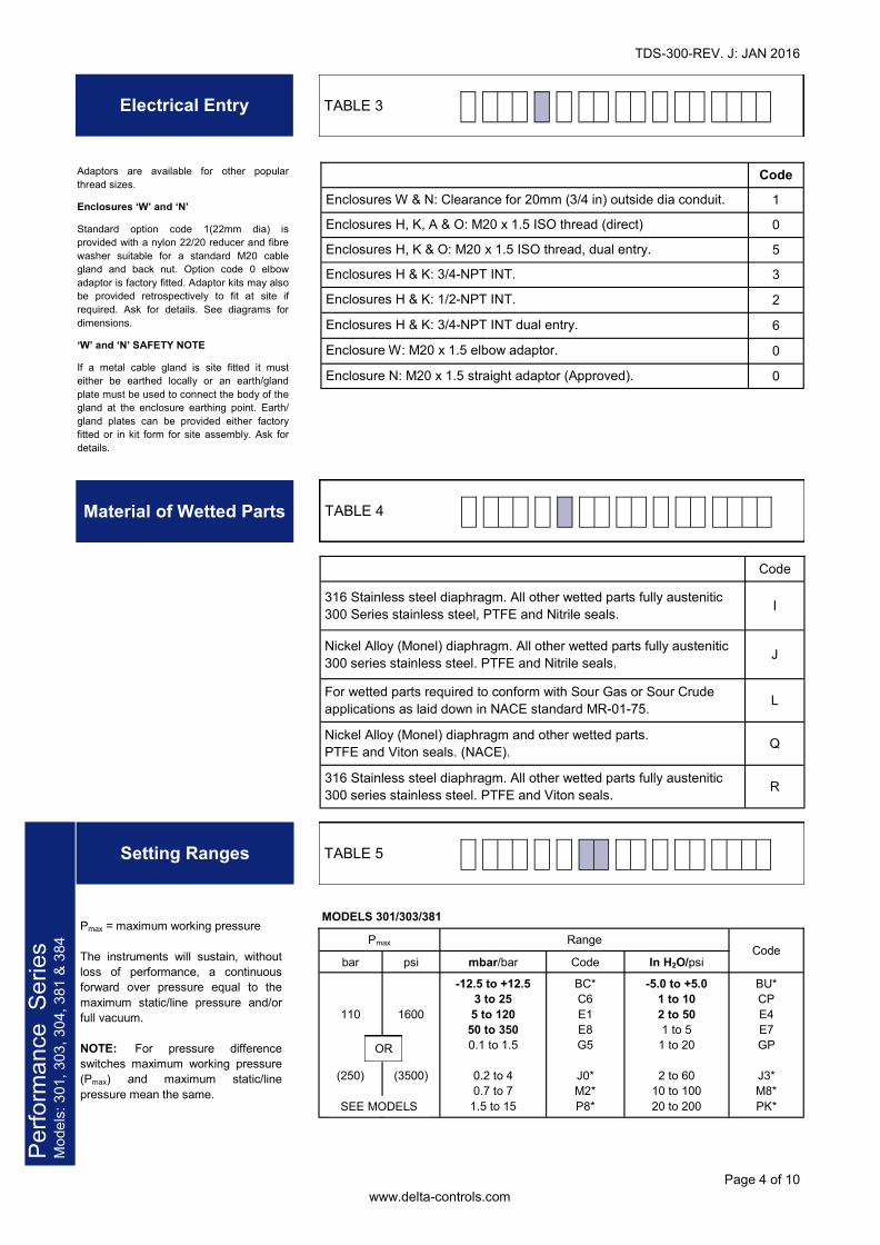
Adaptors are available for other popular thread sizes. Enclosures ‘W’ and ‘N’ Standard option code 1(22mm dia) is provided with a nylon 22/20 reducer and fibre washer suitable for a standard M20 cable gland and back nut. Option code 0 elbow adaptor is factory fitted. Adaptor kits may also be provided retrospectively to fit at site if required. Ask for details. See diagrams for dimensions. ‘W’ and ‘N’ SAFETY NOTE If a metal cable gland is site fitted it must either be earthed locally or an earth/gland plate must be used to connect the body of the gland at the enclosure earthing point. Earth/gland plates can be provided either factory fitted or in kit form for site assembly. Ask for details.
Code Enclosures W & N: Clearance for 20mm (3/4 in) outside dia conduit. 1 Enclosures H, K, A & O: M20 x 1.5 ISO thread (direct) 0 Enclosures H, K & O: M20 x 1.5 ISO thread, dual entry. 5 Enclosures H & K: 3/4-NPT INT. 3
Enclosures H & K: 3/4-NPT INT dual entry. 6 Enclosure W: M20 x 1.5 elbow adaptor. 0 Enclosure N: M20 x 1.5 straight adaptor (Approved). 0
Enclosures H & K: 1/2-NPT INT. 2
Code 316 Stainless steel diaphragm. All other wetted parts fully austenitic 300 Series stainless steel, PTFE and Nitrile seals. I
Nickel Alloy (Monel) diaphragm. All other wetted parts fully austenitic 300 series stainless steel. PTFE and Nitrile seals. J For wetted parts required to conform with Sour Gas or Sour Crude applications as laid down in NACE standard MR-01-75. L Nickel Alloy (Monel) diaphragm and other wetted parts. PTFE and Viton seals. (NACE). Q 316 Stainless steel diaphragm. All other wetted parts fully austenitic 300 series stainless steel. PTFE and Viton seals. R
Range Code bar psi mbar/bar Code In H2O/psi
110
(250)
1600
(3500)
-12.5 to +12.5 3 to 25 5 to 120
50 to 350 0.1 to 1.5
0.2 to 4 0.7 to 7
1.5 to 15
BC* C6 E1 E8 G5
J0* M2* P8*
-5.0 to +5.0 1 to 10 2 to 50 1 to 5
1 to 20
2 to 60 10 to 100 20 to 200
BU* CP E4 E7 GP
J3* M8* PK*
Pmax MODELS 301/303/381 Pmax = maximum working pressure
The instruments will sustain, without loss of performance, a continuous forward over pressure equal to the maximum static/line pressure and/or full vacuum. NOTE: For pressure difference switches maximum working pressure (Pmax) and maximum static/line pressure mean the same.
OR
SEE MODELS
TDS-300-REV. J: JAN 2016
Page 5 of 10 www.delta-controls.com
Switch Options TABLE 6
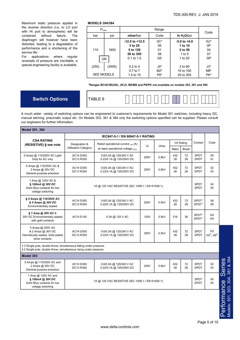
Maximum static pressure applied in the reverse direction (i.e. to LO port with HI port to atmosphere) will be contained without failure. The diaphragm will however have been distorted, leading to a degradation of performance and a shortening of the service life. For applications where regular reversals of pressure are inevitable, a special engineering facility is available.
Range Code bar psi mbar/bar Code In H2O/psi
110
(250)
1600
(3500)
-12.5 to +12.5 3 to 25 5 to 120
50 to 350 0.1 to 1.5
0.2 to 4 0.7 to 7
1.5 to 15
0C* 06 01 08 G5
J0* M2* P8*
-5.0 to +5.0 1 to 10 2 to 50 1 to 5
1 to 20
2 to 60 10 to 100 20 to 200
0U* 0P 04 07 GP
J3* M8* PK*
Pmax MODELS 304/384
*Ranges BC/0C/BU/0U, J0/J3, M2/M8 and P8/PK not available on models 303, 381 and 384
OR
SEE MODELS
Model 301, 304
CSA RATING (RESISTIVE) § see note
IEC947-5-1 / EN 60947-5-1 RATING Contact Code Designation &
Utilisation Category Rated operational current I e (A) at rated operational voltage U e
Ui Uimp VA Rating Make Break
5 Amps @ 110/250V AC Light Duty for AC only
AC14 D300 DC13 R300
0.6/0.3A @ 120/240 V AC 0.22/0.1A @ 125/250V DC 250V 0.8kV 432
28 72 28
SPDT DPDT
00 01
5 Amps @ 110/250V AC & 2 Amps @ 30V DC
General purpose precision AC14 D300 DC13 R300
0.6/0.3A @ 120/240 V AC 0.22/0.1A @ 125/250V DC 250V 0.8kV 432
28 72 28
SPDT DPDT
02 03
1 Amp @ 125V AC & § 100mA @ 30V DC
Gold Alloy contacts for low voltage switching
1A @ 125 VAC RESISTIVE (IEC 1058-1 / EN 61058-1) SPDT DPDT
04 05
§ 5 Amps @ 110/250V AC & 5 Amps @ 30V DC
Environmentally sealed AC14 D300 DC13 R300
0.6/0.3A @ 120/240 V AC 0.22/0.1A @ 125/250V DC 250V 0.5kV 432
28 72 28
SPDT* DPDT*
08 09
§ 1 Amp @ 30V AC & 30V DC Environmentally sealed
with gold contacts AC14 E150 0.3A @ 120 V AC 125V 0.5kV 216 36 SPDT*
DPDT* 0G 0H
5 Amps @ 250V AC & 2 Amps @ 30V DC
Hermetically sealed. Gold plated silver contacts
AC14 D300 DC13 R300
0.6/0.3A @ 120/240 V AC 0.22/0.1A @ 125/250V DC 250V 0.5kV 432
28 72 28
SPDT DPDT
H2 H3†, H6‡
† 2 Single pole, double throw, simultaneous falling under pressure ‡ 2 Single pole, double throw, simultaneous rising under pressure Model 303
5 Amps @ 110/250V AC and 2 Amps @ 30V DC
General purpose precision AC14 D300 DC13 R300
0.6/0.3A @ 120/240 V AC 0.22/0.1A @ 125/250V DC 250V 0.8kV 432
28 72 28
SPDT DPDT
02 03
1 Amp @ 125V AC and § 100mA @ 30V DC
Gold Alloy contacts for low voltage switching
SPDT DPDT
04 05 1A @ 125 VAC RESISTIVE (IEC 1058-1 / EN 61058-1)
A much wider variety of switching options can be engineered to customer’s requirements for Model 301 switches, including heavy DC, manual latching, pneumatic output etc. On Models 303, 381 & 384 only the switching options specified can be supplied. Please consult our engineers for further information.
Perfo
rmanc
e Serie
s Mo
dels: 3
01, 30
3, 304,
381 &
384
TDS-300-REV. J: JAN 2016
Page 6 of 10 www.delta-controls.com
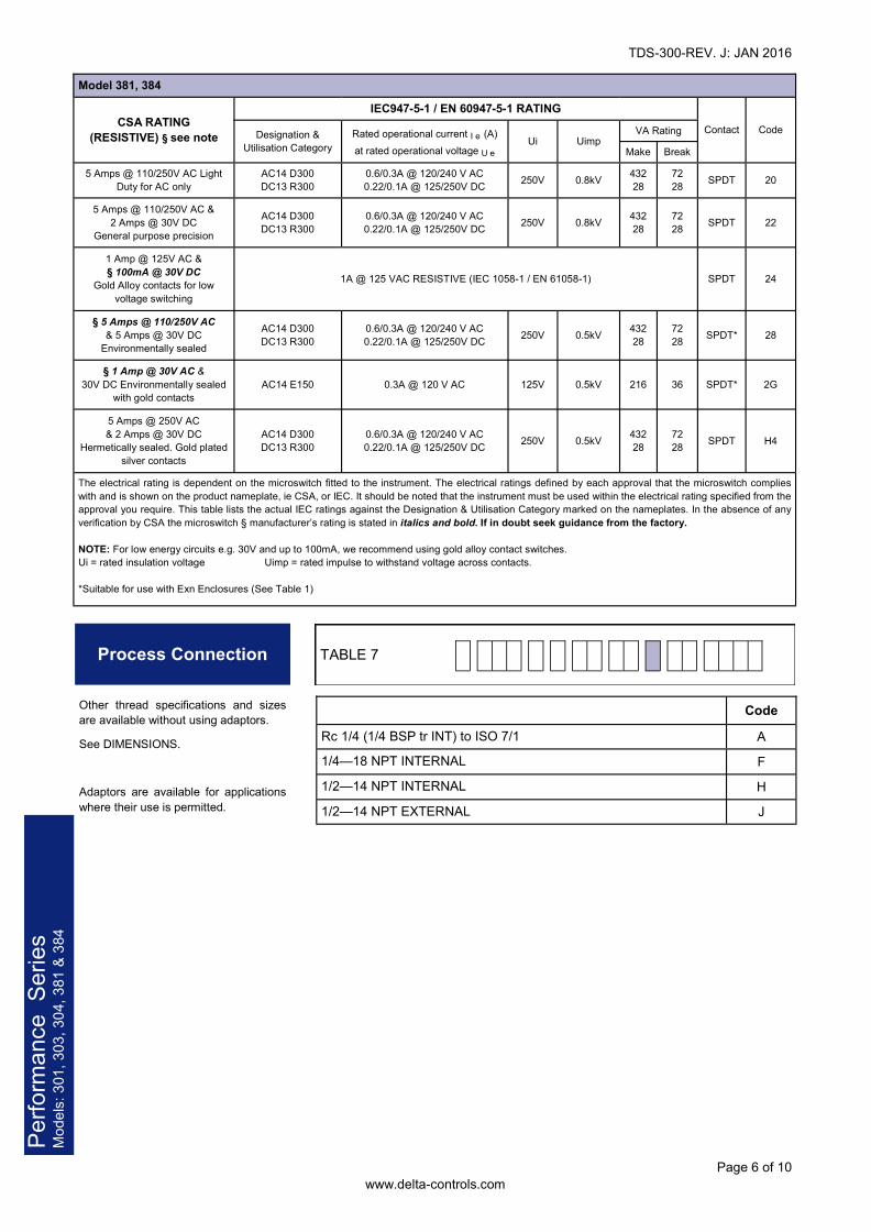
Process Connection TABLE 7
Perfo
rmanc
e Serie
s Mo
dels: 3
01, 30
3, 304,
381 &
384
Model 381, 384
CSA RATING (RESISTIVE) § see note
IEC947-5-1 / EN 60947-5-1 RATING Contact Code Designation &
Utilisation Category Rated operational current I e (A) at rated operational voltage U e
Ui Uimp VA Rating Make Break
5 Amps @ 110/250V AC Light Duty for AC only
AC14 D300 DC13 R300
0.6/0.3A @ 120/240 V AC 0.22/0.1A @ 125/250V DC 250V 0.8kV 432
28 72 28 SPDT 20
5 Amps @ 110/250V AC & 2 Amps @ 30V DC
General purpose precision AC14 D300 DC13 R300
0.6/0.3A @ 120/240 V AC 0.22/0.1A @ 125/250V DC 250V 0.8kV 432
28 72 28 SPDT 22
1 Amp @ 125V AC & § 100mA @ 30V DC
Gold Alloy contacts for low voltage switching
1A @ 125 VAC RESISTIVE (IEC 1058-1 / EN 61058-1) SPDT 24
§ 5 Amps @ 110/250V AC & 5 Amps @ 30V DC
Environmentally sealed AC14 D300 DC13 R300
0.6/0.3A @ 120/240 V AC 0.22/0.1A @ 125/250V DC 250V 0.5kV 432
28 72 28 SPDT* 28
§ 1 Amp @ 30V AC & 30V DC Environmentally sealed
with gold contacts AC14 E150 0.3A @ 120 V AC 125V 0.5kV 216 36 SPDT* 2G
5 Amps @ 250V AC & 2 Amps @ 30V DC
Hermetically sealed. Gold plated silver contacts
AC14 D300 DC13 R300
0.6/0.3A @ 120/240 V AC 0.22/0.1A @ 125/250V DC 250V 0.5kV 432
28 72 28 SPDT H4
The electrical rating is dependent on the microswitch fitted to the instrument. The electrical ratings defined by each approval that the microswitch complies with and is shown on the product nameplate, ie CSA, or IEC. It should be noted that the instrument must be used within the electrical rating specified from the approval you require. This table lists the actual IEC ratings against the Designation & Utilisation Category marked on the nameplates. In the absence of any verification by CSA the microswitch § manufacturer’s rating is stated in italics and bold. If in doubt seek guidance from the factory. NOTE: For low energy circuits e.g. 30V and up to 100mA, we recommend using gold alloy contact switches. Ui = rated insulation voltage Uimp = rated impulse to withstand voltage across contacts. *Suitable for use with Exn Enclosures (See Table 1)
Code Rc 1/4 (1/4 BSP tr INT) to ISO 7/1 A 1/4—18 NPT INTERNAL F 1/2—14 NPT INTERNAL H 1/2—14 NPT EXTERNAL J
Other thread specifications and sizes are available without using adaptors. See DIMENSIONS. Adaptors are available for applications where their use is permitted.
TDS-300-REV. J: JAN 2016
Page 7 of 10 www.delta-controls.com
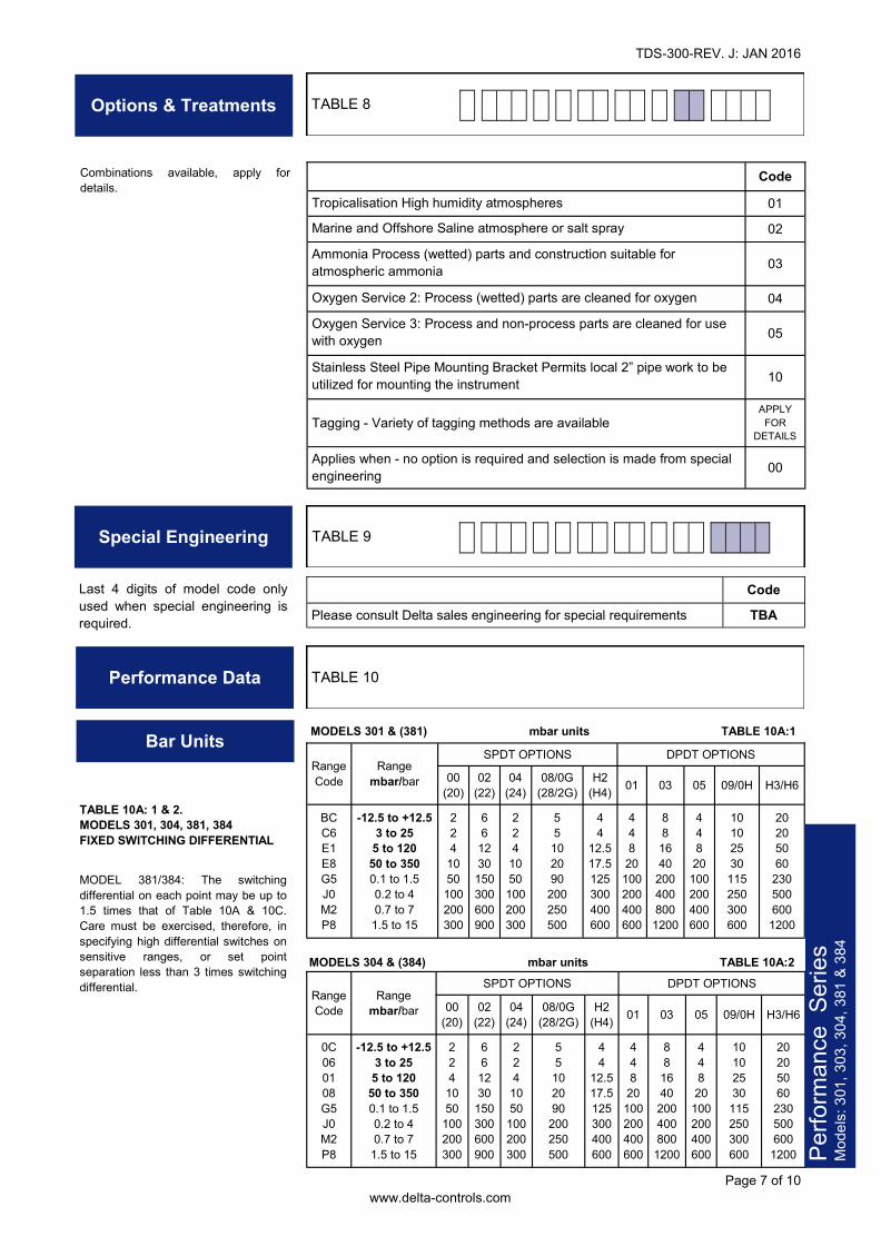
Options & Treatments TABLE 8
Special Engineering
Code Please consult Delta sales engineering for special requirements TBA
Last 4 digits of model code only used when special engineering is required.
TABLE 9
Performance Data TABLE 10
Code Tropicalisation High humidity atmospheres 01 Marine and Offshore Saline atmosphere or salt spray 02 Ammonia Process (wetted) parts and construction suitable for atmospheric ammonia 03 Oxygen Service 2: Process (wetted) parts are cleaned for oxygen 04 Oxygen Service 3: Process and non-process parts are cleaned for use with oxygen 05 Stainless Steel Pipe Mounting Bracket Permits local 2” pipe work to be utilized for mounting the instrument 10
Tagging - Variety of tagging methods are available APPLY FOR
DETAILS Applies when - no option is required and selection is made from special engineering 00
Combinations available, apply for details.
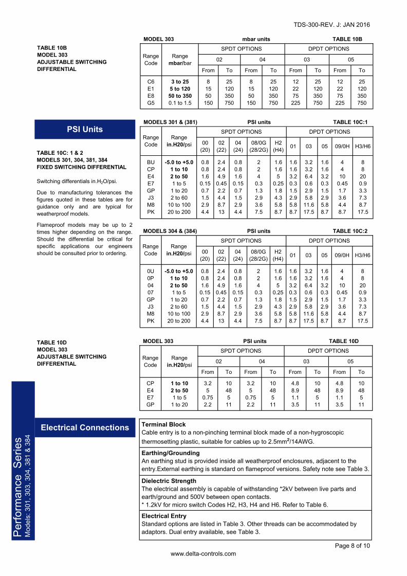
Bar Units
TABLE 10A: 1 & 2. MODELS 301, 304, 381, 384 FIXED SWITCHING DIFFERENTIAL MODEL 381/384: The switching differential on each point may be up to 1.5 times that of Table 10A & 10C. Care must be exercised, therefore, in specifying high differential switches on sensitive ranges, or set point separation less than 3 times switching differential.
Range Code
SPDT OPTIONS DPDT OPTIONS 00
(20) 02
(22) 04
(24) 08/0G
(28/2G) H2
(H4) 01 03 05 09/0H H3/H6 BC C6 E1 E8 G5 J0 M2 P8
-12.5 to +12.5 3 to 25
5 to 120 50 to 350 0.1 to 1.5 0.2 to 4 0.7 to 7 1.5 to 15
2 2 4
10 50 100 200 300
6 6
12 30 150 300 600 900
2 2 4
10 50 100 200 300
5 5 10 20 90
200 250 500
4 4
12.5 17.5 125 300 400 600
4 4 8
20 100 200 400 600
8 8 16 40
200 400 800 1200
4 4 8 20
100 200 400 600
10 10 25 30 115 250 300 600
20 20 50 60
230 500 600 1200
Range mbar/bar
MODELS 301 & (381) mbar units TABLE 10A:1
MODELS 304 & (384) mbar units TABLE 10A:2 Range Code
SPDT OPTIONS DPDT OPTIONS 00
(20) 02
(22) 04
(24) 08/0G
(28/2G) H2
(H4) 01 03 05 09/0H H3/H6 0C 06 01 08 G5 J0 M2 P8
-12.5 to +12.5 3 to 25 5 to 120
50 to 350 0.1 to 1.5 0.2 to 4 0.7 to 7
1.5 to 15
2 2 4 10 50
100 200 300
6 6 12 30
150 300 600 900
2 2 4 10 50
100 200 300
5 5 10 20 90
200 250 500
4 4
12.5 17.5 125 300 400 600
4 4 8
20 100 200 400 600
8 8
16 40 200 400 800
1200
4 4 8 20
100 200 400 600
10 10 25 30
115 250 300 600
20 20 50 60 230 500 600
1200
Range mbar/bar
Perfo
rmanc
e Serie
s Mo
dels: 3
01, 30
3, 304,
381 &
384
TDS-300-REV. J: JAN 2016
Page 8 of 10 www.delta-controls.com
Perfo
rmanc
e Serie
s Mo
dels: 3
01, 30
3, 304,
381 &
384
PSI Units
MODEL 303 mbar units TABLE 10B
Range Code
Range mbar/bar
SPDT OPTIONS DPDT OPTIONS 02 04 03
From To From To From To From To C6 E1 E8 G5
3 to 25 5 to 120 50 to 350 0.1 to 1.5
8 15 50 150
25 120 350 750
8 15 50
150
25 120 350 750
12 22 75 225
25 120 350 750
12 22 75 225
25 120 350 750
05 TABLE 10B MODEL 303 ADJUSTABLE SWITCHING DIFFERENTIAL
MODELS 301 & (381) PSI units TABLE 10C:1 Range Code
SPDT OPTIONS DPDT OPTIONS 00
(20) 02
(22) 04
(24) 08/0G
(28/2G) H2
(H4) 01 03 05 09/0H H3/H6
BU CP E4 E7 GP J3 M8 PK
-5.0 to +5.0 1 to 10 2 to 50 1 to 5 1 to 20 2 to 60
10 to 100 20 to 200
0.8 0.8 1.6 0.15 0.7 1.5 2.9 4.4
2.4 2.4 4.9
0.45 2.2 4.4 8.7 13
0.8 0.8 1.6
0.15 0.7 1.5 2.9 4.4
2 2 4
0.3 1.3 2.9 3.6 7.5
1.6 1.6 5
0.25 1.8 4.3 5.8 8.7
1.6 1.6 3.2 0.3 1.5 2.9 5.8 8.7
3.2 3.2 6.4 0.6 2.9 5.8 11.6 17.5
1.6 1.6 3.2 0.3 1.5 2.9 5.8 8.7
4 4 10
0.45 1.7 3.6 4.4 8.7
8 8 20 0.9 3.3 7.3 8.7 17.5
Range in.H20/psi
TABLE 10C: 1 & 2 MODELS 301, 304, 381, 384 FIXED SWITCHING DIFFERENTIAL Switching differentials in.H2O/psi. Due to manufacturing tolerances the figures quoted in these tables are for guidance only and are typical for weatherproof models. Flameproof models may be up to 2 times higher depending on the range. Should the differential be critical for specific applications our engineers should be consulted prior to ordering.
MODELS 304 & (384) PSI units TABLE 10C:2 Range Code
SPDT OPTIONS DPDT OPTIONS 00
(20) 02
(22) 04
(24) 08/0G
(28/2G) H2
(H4) 01 03 05 09/0H H3/H6
0U 0P 04 07 GP J3 M8 PK
-5.0 to +5.0 1 to 10 2 to 50 1 to 5 1 to 20 2 to 60
10 to 100 20 to 200
0.8 0.8 1.6 0.15 0.7 1.5 2.9 4.4
2.4 2.4 4.9
0.45 2.2 4.4 8.7 13
0.8 0.8 1.6
0.15 0.7 1.5 2.9 4.4
2 2 4
0.3 1.3 2.9 3.6 7.5
1.6 1.6 5
0.25 1.8 4.3 5.8 8.7
1.6 1.6 3.2 0.3 1.5 2.9 5.8 8.7
3.2 3.2 6.4 0.6 2.9 5.8 11.6 17.5
1.6 1.6 3.2 0.3 1.5 2.9 5.8 8.7
4 4 10
0.45 1.7 3.6 4.4 8.7
8 8 20 0.9 3.3 7.3 8.7 17.5
Range in.H20/psi
MODEL 303 PSI units TABLE 10D
Range Code
Range in.H20/psi
SPDT OPTIONS DPDT OPTIONS 02 04 03
From To From To From To From To CP E4 E7 GP
1 to 10 2 to 50 1 to 5
1 to 20
3.2 5
0.75 2.2
10 48 5
11
3.2 5
0.75 2.2
10 48 5 11
4.8 8.9 1.1 3.5
10 48 5 11
4.8 8.9 1.1 3.5
10 48 5
11
05
TABLE 10D MODEL 303 ADJUSTABLE SWITCHING DIFFERENTIAL
Electrical Connections Terminal Block Cable entry is to a non-pinching terminal block made of a non-hygroscopic thermosetting plastic, suitable for cables up to 2.5mm²/14AWG. Earthing/Grounding An earthing stud is provided inside all weatherproof enclosures, adjacent to the entry.External earthing is standard on flameproof versions. Safety note see Table 3. Dielectric Strength The electrical assembly is capable of withstanding *2kV between live parts and earth/ground and 500V between open contacts. * 1.2kV for micro switch Codes H2, H3, H4 and H6. Refer to Table 6. Electrical Entry Standard options are listed in Table 3. Other threads can be accommodated by adaptors. Dual entry available, see Table 3.
TDS-300-REV. J: JAN 2016
Page 9 of 10 www.delta-controls.com
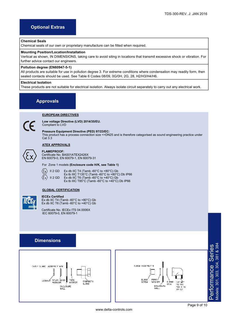
Approvals
EUROPEAN DIRECTIVES Low voltage Directive (LVD) 2014/35/EU. Compliant to LVD Pressure Equipment Directive (PED) 97/23/EC: This product has a process connection size <=DN25 and is therefore categorised as sound engineering practice under Cat 3.3 ATEX APPROVALS FLAMEPROOF: Certificate No. BAS01ATEX2426X EN 60079-0, EN 60079-1, EN 60079-31 For Zone 1 models (Enclosure code H/K, see Table 1) II 2 GD Ex db IIC T4 (Tamb -60°C to +80°C) Gb Ex tb IIIC T135°C (Tamb -60°C to +80°C) Db IP66 II 2 GD Ex db IIC T6 (Tamb -60°C to +40°C) Gb Ex tb IIIC T85°C (Tamb -60°C to +40°C) Db IP66
GLOBAL CERTIFICATION IECEx Certified Ex db IIC T4 (Tamb -60°C to +80°C) Gb Ex db IIC T6 (Tamb -60°C to +40°C) Gb Certificate No. IECEx ITS 04.0006X IEC 60079-0, EN 60079-1
Dimensions
Perfo
rmanc
e Serie
s Mo
dels: 3
01, 30
3, 304,
381 &
384
Chemical Seals Chemical seals of our own or proprietary manufacture can be fitted when required. Mounting Position/Location/Installation Vertical as shown, IN DIMENSIONS, taking care to avoid siting in locations that transmit excessive shock or vibration. For further advice contact our engineers. Pollution degree (EN60947-5-1) All products are suitable for use in pollution degree 3. For extreme conditions where condensation may readily form, then sealed contacts should be used. See Table 6 Codes 08/09, 0G/0H, 2G, 28, H2/H3/H4/H6. Electrical Isolation These products are not suitable for electrical isolation. Always isolate circuit separately to carry out any electrical work.
Optional Extras
TDS-300-REV. J: JAN 2016
Page 10 of 10 www.delta-controls.com
In the interest of development and improvement Delta Controls Ltd, reserves the right to amend, without notice, details contained in this publication. No legal liability will be accepted by Delta Controls Ltd for any errors, omissions or amendments. Delta Controls Limited Riverside Business Park, Dogflud Way, Farnham, Surrey GU9 7SS, UK. T+44 (0)1252 729140 F+44 (0)1252 729168 E [email protected] W www.delta-controls.com
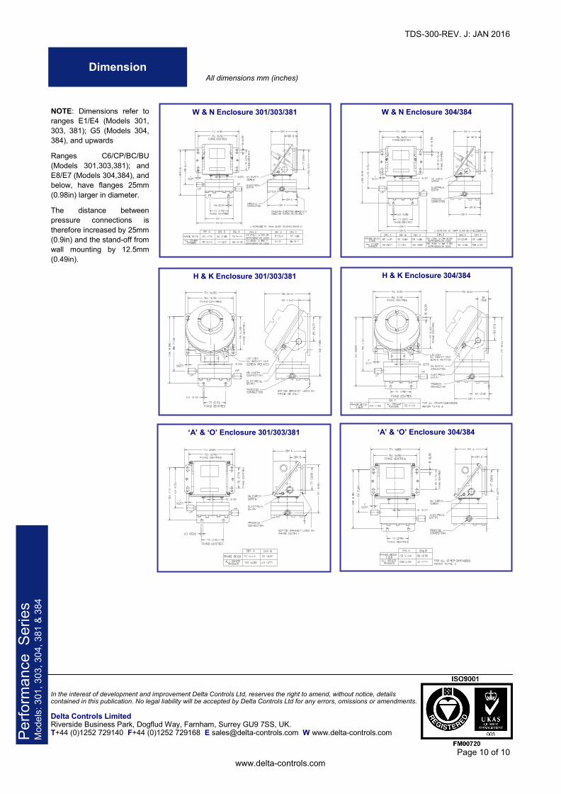
Dimension
W & N Enclosure 304/384 W & N Enclosure 301/303/381
H & K Enclosure 304/384 H & K Enclosure 301/303/381
‘A’ & ‘O’ Enclosure 304/384 ‘A’ & ‘O’ Enclosure 301/303/381
All dimensions mm (inches)
NOTE: Dimensions refer to ranges E1/E4 (Models 301, 303, 381); G5 (Models 304, 384), and upwards Ranges C6/CP/BC/BU (Models 301,303,381); and E8/E7 (Models 304,384), and below, have flanges 25mm (0.98in) larger in diameter. The distance between pressure connections is therefore increased by 25mm (0.9in) and the stand-off from wall mounting by 12.5mm (0.49in).
Perfo
rmanc
e Serie
s Mo
dels: 3
01, 30
3, 304,
381 &
384