
BM26A-1000 Technical Datasheet - Fagerberg
44
BM26A-1000 BM26A-1000 BM26A-1000 BM26A-1000 Technical Datasheet Technical Datasheet Technical Datasheet Technical Datasheet Magnetic Level Indicator for basic liquid applications • Most competitive price • Process conditions up to +200°C (+392°F) / 40 barg (580 psig) • Level indication up to 5.5 m / 18 ft (other dimensions on request) © KROHNE 01/2021 - 4008551501 - TD BM26A-1000 R01 en
-
Upload
khangminh22 -
Category
Documents
-
view
0 -
download
0
Transcript of BM26A-1000 Technical Datasheet - Fagerberg

BM26A-1000BM26A-1000BM26A-1000BM26A-1000 Technical DatasheetTechnical DatasheetTechnical DatasheetTechnical Datasheet
Magnetic Level Indicator for basic liquid applications
• Most competitive price• Process conditions up to +200°C (+392°F) / 40 barg (580 psig)• Level indication up to 5.5 m / 18 ft (other dimensions on request)
© KROHNE 01/2021 - 4008551501 - TD BM26A-1000 R01 en

CONTENTS
2 www.krohne.com 01/2021 - 4008551501 - TD BM26A-1000 R01 en
BM26A-1000
1 Product features 3
1.1 Magnetic level indicator for basic liquid applications ..................................................... 31.2 Measuring principle.......................................................................................................... 5
2 Technical data 6
2.1 Technical data................................................................................................................... 62.1.1 BM26A-1000 magnetic level indicator.................................................................................... 62.1.2 LT40 reed-chain level transmitter ......................................................................................... 92.1.3 MS15-series and MS40-series limit switches...................................................................... 14
2.2 Dimensions ..................................................................................................................... 162.2.1 Magnetic level indicator (measuring chamber) - overall dimensions................................. 162.2.2 Options .................................................................................................................................. 242.2.3 Accessories ........................................................................................................................... 28
2.3 Maximum process pressure: measuring chamber ....................................................... 292.4 Temperature limits: LT40 C/F reed-chain level transmitter ........................................ 30
2.4.1 LT40 without an LCD indicator module ................................................................................ 302.4.2 LT40 with an LCD indicator module ..................................................................................... 31
2.5 Temperature limits: MS15-series limit switch.............................................................. 322.5.1 Aluminium housing ............................................................................................................... 322.5.2 Stainless-steel housing ........................................................................................................ 33
2.6 Temperature limits: MS40-series limit switch.............................................................. 34
3 Installation 35
3.1 Intended use ................................................................................................................... 353.2 Pre-installation requirements ....................................................................................... 35
3.2.1 General notes........................................................................................................................ 353.2.2 Isolation valves...................................................................................................................... 35
3.3 EU Pressure Equipment Directive ................................................................................. 363.4 Reed-chain level transmitter (LT40) .............................................................................. 37
3.4.1 General notes........................................................................................................................ 373.4.2 Thermal insulation................................................................................................................ 37
3.5 Limit switches (MS15 series and MS40 series) ............................................................. 383.5.1 General notes........................................................................................................................ 383.5.2 Thermal insulation................................................................................................................ 39
4 Electrical connections 40
4.1 Reed-chain level transmitter ......................................................................................... 404.1.1 General notes........................................................................................................................ 404.1.2 Electrical schematics and procedure................................................................................... 40
4.2 Limit switches................................................................................................................. 414.2.1 General notes........................................................................................................................ 414.2.2 Electrical schematics and procedure................................................................................... 41
5 Notes 42

PRODUCT FEATURES 1
3
BM26A-1000
www.krohne.com01/2021 - 4008551501 - TD BM26A-1000 R01 en
1.1 Magnetic level indicator for basic liquid applications
The BM26A-1000 is a simple, rugged device designed to indicate or transmit the level of a liquid. The measuring chamber is made of stainless steel.
A magnetic level indicator (MLI) indicates level with a float magnetically coupled to a column of rotating flaps. An optional reed-chain transmitter (LT40) can also transmit level as an analog or digital signal. Optional bistable switches (MS15 series and MS40 series) can be attached to the measuring chamber to detect level.
This device is suitable for measuring liquids that have a density of 700...1200 kg/m³ / 43.70...74.91 lb/ft³, for a temperature range of -70...+200°C / -94...+392°F at a pressure of -1...40 barg / -14.5...580 psig.
Highlights• Proven technology• Easy to install, safe to use and no commissioning required• Rugged design - metal construction• High-visibility level indicator column operates without electrical power• Flaps in the level indicator column are housed in a hermetically sealed, durable glass tube
(IP68)
1 Level indicator - column of rotating flaps in a hermetically sealed tube made of borosilicate glass with options that include a scale, scale units and flap colours
2 Red flaps for float failure indication3 Stainless-steel measuring chamber4 Option: drain5 Side or axial process connections6 Option: vent

1 PRODUCT FEATURES
4
BM26A-1000
www.krohne.com 01/2021 - 4008551501 - TD BM26A-1000 R01 en
• PED / EN 13445• Optional LT40 reed-chain level transmitter
- Outut options: 4…20 mA (HART 7), FOUNDATION™ fieldbus or PROFIBUS PA- Accuracy options: ±10 mm (±0.4¨) or ±5 mm (±0.2¨)
• A wide selection of options and accessories: special materials, isolation valves, high-temperature and low-temperature insulation, approvals for hazardous locations, limit switches, reed-chain transmitter etc.
Industries• Basic applications• Water and wastewater• Pulp and paper
Applications• Water storage and water washtanks• Lubrication oils and hydraulic fluids• Fuel tanks• Condensate receiver tanks• Mill water storage• Turpentine recovery• Surge tanks• Additives• Skid manufacturers• Inks• Condenser hot wells

PRODUCT FEATURES 1
5
BM26A-1000
www.krohne.com01/2021 - 4008551501 - TD BM26A-1000 R01 en
1.2 Measuring principle
The device operates on the principle of communicating tubes. The measuring chamber is connected adjacent to the tank. The process conditions in the measuring chamber are the same as those of the tank.
A float is in the measuring chamber. The float contains magnets that rotate the flaps in the indicator column and operate the optional limit switches and analog transmitter on the side of the measuring chamber. The position of the magnets does not correspond to the level of liquid, so the scale is offset at the factory to take into account this difference. The offset of the magnets depends on the liquid density. Refer to the illustration that follows:
Figure 1-1: Offset between liquid level and the float magnet (liquid level offset)
1 Level of the liquid2 Top of the float magnet. The magnet field around the top of the magnet turns the flaps in the indicator column that
shows the level in the tank.3 Liquid level offset. This offset is the difference between the level of the liquid and the top of the float magnet. The value
is related to the type of float in the measuring chamber and the density of the liquid.4 Indicator column of yellow/black or red/white rotating flaps with the optional scale in m/cm, ft/inch, % (simplified) or
customized volume units

2 TECHNICAL DATA
6
BM26A-1000
www.krohne.com 01/2021 - 4008551501 - TD BM26A-1000 R01 en
2.1 Technical data
2.1.1 BM26A-1000 magnetic level indicator
• The following data is provided for general applications. If you require data that is more relevant to your specific application, please contact us or your local sales office.
• Additional information (certificates, special tools, software,...) and complete product documentation can be downloaded free of charge from the website (Downloadcenter).
Measuring systemMeasuring principle Magnetic level indicator - bypass chamber (principle of
communicating tubes). A float in the measuring chamber (Ø42 mm × 2 mm / NPS 1 1/4 pipe) is magnetically coupled to a mechanical level indicator.
Application range Level indication of liquids in applications from vacuum up to 40 barg / 580 psig
Measured valueMeasured valueMeasured valueMeasured value
Primary measured value Level of the float magnets in the measuring chamber
Secondary measured value Level or volume of the liquid in the tank
DesignMeasuring chamber variants Side / side process connections
Axial / axial process connections
Bottom axial / top side process connections
Bottom side / top axial process connections
Options LT40 reed-chain level transmitter without LCD indicator module with a compact or a remote housing 1
LT40 reed-chain level transmitter with LCD indicator module with a compact or a remote housing 1
Anti-icing cover for glass indicator tube
Bistable limit switches 2
Measuring range (ML) 0.3…5.5 m / 1…18 ft (longer on request)
Display and user interfaceDisplay and user interfaceDisplay and user interfaceDisplay and user interface
Display Indicator column with magnetically coupled rotating flaps that have two colors: yellow/black; red/white
Float failure indication(at the bottom of the indicator column)
Orange flaps
Scale marking options No scale; m + cm; ft + inches; customized volume units; % (simplified) 3
Measuring accuracyAccuracy ±10 mm / 0.4¨
Repeatability ±10 mm / 0.4¨ (when density is constant)
Maximum rate of change 20 mm/s / 0.787¨/s

TECHNICAL DATA 2
7
BM26A-1000
www.krohne.com01/2021 - 4008551501 - TD BM26A-1000 R01 en
Operating conditionsTemperatureTemperatureTemperatureTemperature
Process temperature -70...+200°C / -94…+392°F(Ex: see supplementary instructions or approval certificates)
Ambient temperature -70…+80°C / -94…+176°F(Ex: see supplementary instructions or approval certificates)
Storage temperature -70…+80°C / -94…+176°F
PressurePressurePressurePressure
Process pressure -1...40 barg / -14.5...580 psig 4
Chemical propertiesChemical propertiesChemical propertiesChemical properties
Density 700…1200 kg/m³ / 43.7...74.91 lb/ft³. Higher density on request.
Viscosity ≤ 500 mPa·s / ≤ 500 cP
Other conditionsOther conditionsOther conditionsOther conditions
Ingress protection (IEC 60529) Indicator column: IP66 / IP68 (0.15 barg)
MaterialsMeasuring chamber Stainless steel (1.4404 / 316L)
Float Stainless steel (1.4404 / 316L); titanium
Indicator column rail Stainless steel (1.4401 / 316)
Indicator column tube Borosilicate glass 3.3 (agrees with ISO 3585)- hermetically sealed tube
Scale (option) Stainless steel (1.4401 / 316)
Process connection Stainless steel (1.4404 / 316L)
Gasket options Aramid; graphite; PTFE
Braid insulation Ceramic fibre (thermal insulation between the indicator column and the measuring chamber when the process temperature is +100...+200°C / +210...+392°F)
Anti-icing cover PLEXIGLAS® (option for glass indicator column tube) - when the liquid temperature is -50...+40°C / -58...+104°F
Process connectionsThreaded pipes 1/2...3/4 NPT (male); G 1/2...3/4 (male)
Welded pipes, ASME NPS 1/2...1 in Sch10S 5
Flange optionsFlange optionsFlange optionsFlange options
EN DN15…50 (Type B1) in PN40
ASME NPS 1/2…2 (RF) in Class 150 / 300 5
Drain and vent connectionsDrain optionsDrain optionsDrain optionsDrain options
Thread Without; G 3/8...3/4 (female) with plug; 3/8...3/4 NPT (female) with plug
Flange All process connection options
Vent optionsVent optionsVent optionsVent options
Thread Without; G 3/8...1/2 (female) with plug; 3/8...1/2 NPT (female) with plug
Flange All process connection options

2 TECHNICAL DATA
8
BM26A-1000
www.krohne.com 01/2021 - 4008551501 - TD BM26A-1000 R01 en
Power supplyLimit switches Refer to the technical data for the MS15 series and MS40 series
Reed-chain level transmitter Refer to the technical data for the LT40
Input and outputParameter Level detection or indication
Output signal Refer to the technical data for the LT40 reed-chain level transmitter and the MS15-series and MS40-series limit switches
Approvals and certificationCE The device meets the essential requirements of the EU Directives.
The manufacturer certifies successful testing of the product by applying the CE marking.
For more data about the EU Directives and European Standards related to this device, refer to the EU Declaration of Conformity. You can download this document free of charge from the website (Download Center).
Explosion protectionExplosion protectionExplosion protectionExplosion protection
ATEX II 1/2 G Ex h IIC T6...T3 Ga/Gb or II 2 G Ex h IIC T6...T3 Gb
IECEx Ex h IIC T6...T3 Ga/Gb or Ex h IIC T6...T3 Gb
Other standards and approvalsOther standards and approvalsOther standards and approvalsOther standards and approvals
Pressure Pressure Equipment Directive
Vibration resistance EN 60721-3-4 - vibration class 4M4 (1...200 Hz:1g, 15g shock ½ sinus: 6 ms)
Construction code Standard: EN 13445
Option: NACE MR0175 / MR0103 / ISO 15156
Table 2-1: BM26A-1000: technical data
1 For more data, refer to technical data for the LT40 reed-chain level transmitter in this section2 For more data, refer to technical data for the MS15-series and MS40-series limit switches in this section3 If the scale adjacent to the indicator column has % (simplified) units, then it has a range of 0...100% with an increment
of 10% between each marking4 The maximum pressure is related to the type of process connection, pressure rating and the process temperature. For
more data about 316-316L stainless-steel measuring chambers, refer to the "Maximum process pressure: measuring chamber" section in this chapter.
5 NPS = National Pipe Size. For more data about the dimensions of flanges, refer to the ASME B16.5 standard. For more data about the dimensions of welded pipes, refer to the ASME B36.19M standard.

TECHNICAL DATA 2
9
BM26A-1000
www.krohne.com01/2021 - 4008551501 - TD BM26A-1000 R01 en
2.1.2 LT40 reed-chain level transmitter
4...20 mA and 4...20 mA + HART® communication modules
Measuring systemMeasuring principle A reed resistor chain that is magnetically operated by a magnetic
float in an adjacent measuring chamber
Primary measured value Resistance
Secondary measured value Level or volume of the liquid in the tank
DesignDescription of device Resistance reed chain with 2-wire loop-powered transmitter module
attached adjacent to the measuring chamber of the magnetic level indicator. A transmitter module converts changes in resistance to an output signal. If the LT40 is used in multidrop mode, a maximum of 63 transmitters can be connected to a network that agrees with the HART® communication protocol.
Options Transmitter module position: LT40 C - compact housing at the top of the reed resistor chain
Transmitter module position: LT40 C - compact housing at the bottom of the reed resistor chain
Transmitter module position: LT40 F - remote housing connected to the bottom of the reed resistor chain. Max. cable length: 25 m / 82 ft.
LCD indicator module (non-Ex and Ex d-approved devices only)
Accessories C 95 Basic universal power supply (Panel mount, 2 relays, 4-digit local indicator and non-Ex)
C 95 Basic universal power supply (Panel mount, 2 relays, 4…20 mA output, 4-digit local indicator and non-Ex)
Display and user interfaceDisplay and user interfaceDisplay and user interfaceDisplay and user interface
Display Optional 2-wire loop-powered LCD indicator module (backlit)
4-digit LCD with minus sign, 2-button keypad. Selectable number of decimals, 0 to 3.
Available units mm; inches; %
Range -1999...9999
Measuring accuracyResolution Standard: ±10 mm / 0.4¨ (when density is constant)
Option: ±5 mm / 0.2¨ (when density is constant)
Operating conditionsTemperatureTemperatureTemperatureTemperature
Ambient temperature, transmitter
-40…+80°C / -40…+176°F 1
Ambient temperature, LCD indicator
-20…+70°C / -4…+158°F 1
Process temperature The ambient temperature limit is related to the process temperature. Do not put thermal insulation around the transmitter housing. Refer to the "Temperature limits: LT40 C/F reed-chain level transmitter" section in this chapter.
Storage temperature -40…+80°C / -40…+176°F

2 TECHNICAL DATA
10
BM26A-1000
www.krohne.com 01/2021 - 4008551501 - TD BM26A-1000 R01 en
PressurePressurePressurePressure
Operating pressure Atmospheric pressure
Other conditionsOther conditionsOther conditionsOther conditions
Warm-up time 30 s
Response time 1....60 s 2
Ingress protection (IEC 60529) IP66/IP68 (at a depth of 1.5 m for 2 weeks)
Relative air humidity (RH) 0...99%
Installation conditionsNotes The LT40 is calibrated at the factory and attached to the measuring
chamber before delivery
Dimensions Refer to the "Dimensions" section
MaterialsHousing Polyester-coated aluminium
Reed-chain tube Stainless steel (1.4401 / 316)
Clamp Stainless steel (1.4401 / 316)
Cable gland Plastic (for M20 × 1.5 only), nickel-plated brass or stainless steel
Power supplyVoltage, without LCD indicator
non-Ex or Ex db: 10…35 V DC
Ex ia: 10…30 V DC
Voltage, with LCD indicator
non-Ex or Ex db: 17…35 V DC
EN 60947-1 electrical data Overvoltage category I
Cable entry M20 × 1.5; 1/2 NPT
Cable gland None; M20 × 1.5; 1/2 NPT
Intrinsically safe circuit data for Ex ia-approved devices
Refer to supplementary instructions or approval certificates
Input and outputCurrent outputCurrent outputCurrent outputCurrent output
Output range 4…20 mA
Error signal High: 21 mA; Low: 3.6 mA - agrees with NAMUR NE 43
HARTHARTHARTHART®Description Digital signal transmitted with the current output signal (HART®
protocol)
Version 7
Multidrop operation Yes, current output = 4 mA. Polling address 1...15.
Approvals and certificationsCE The device meets the essential requirements of the EU Directives.
The manufacturer certifies successful testing of the product by applying the CE marking.
For more data about the EU Directives and European Standards related to this device, refer to the EU Declaration of Conformity. You can download this document free of charge from the website (Download Center).

TECHNICAL DATA 2
11
BM26A-1000
www.krohne.com01/2021 - 4008551501 - TD BM26A-1000 R01 en
Fieldbus communication module
Explosion protectionExplosion protectionExplosion protectionExplosion protection
ATEX (EU Type Approval) II 1 G Ex ia IIC T6...T1 Ga or II 2 G Ex ia IIC T6...T1 Gb 3
II 2 G Ex db IIC T6...T1 Gb
IECEx Ex ia IIC T6...T1 Ga or Ex ia IIC T6...T1 Gb 3
Ex db IIC T6...T1 Gb
Other standards and approvalsOther standards and approvalsOther standards and approvalsOther standards and approvals
EMC Electromagnetic Compatibility Directive 4
NAMUR NE 21 (pending) 5
Vibration resistance EN 60721-3-4 - vibration class 4M4 (1...200 Hz:1g, 10g shock ½ sinus: 11 ms)
NAMUR NAMUR NE 43 6
Table 2-2: LT40 (4...20 mA and 4...20 mA + HART® communication modules): technical data
1 The ambient temperature limit is related to the process temperature. Do not put thermal insulation around the trans-mitter housing. Refer to the "Temperature limits: LT40 C/F reed-chain level transmitter" section in this chapter.
2 This value is programmable3 This Ex approval does not include the optional LCD indicator module4 LT40 F: Strong interference from EMC-conducted emissions (EN 61000-4-6) can cause a maximum deviation of 1.8%
along the measurement span5 Electromagnetic Compatibility of Industrial and Laboratory Control Equipment6 Standardization of the Signal Level for the Failure Information of Digital Transmitters
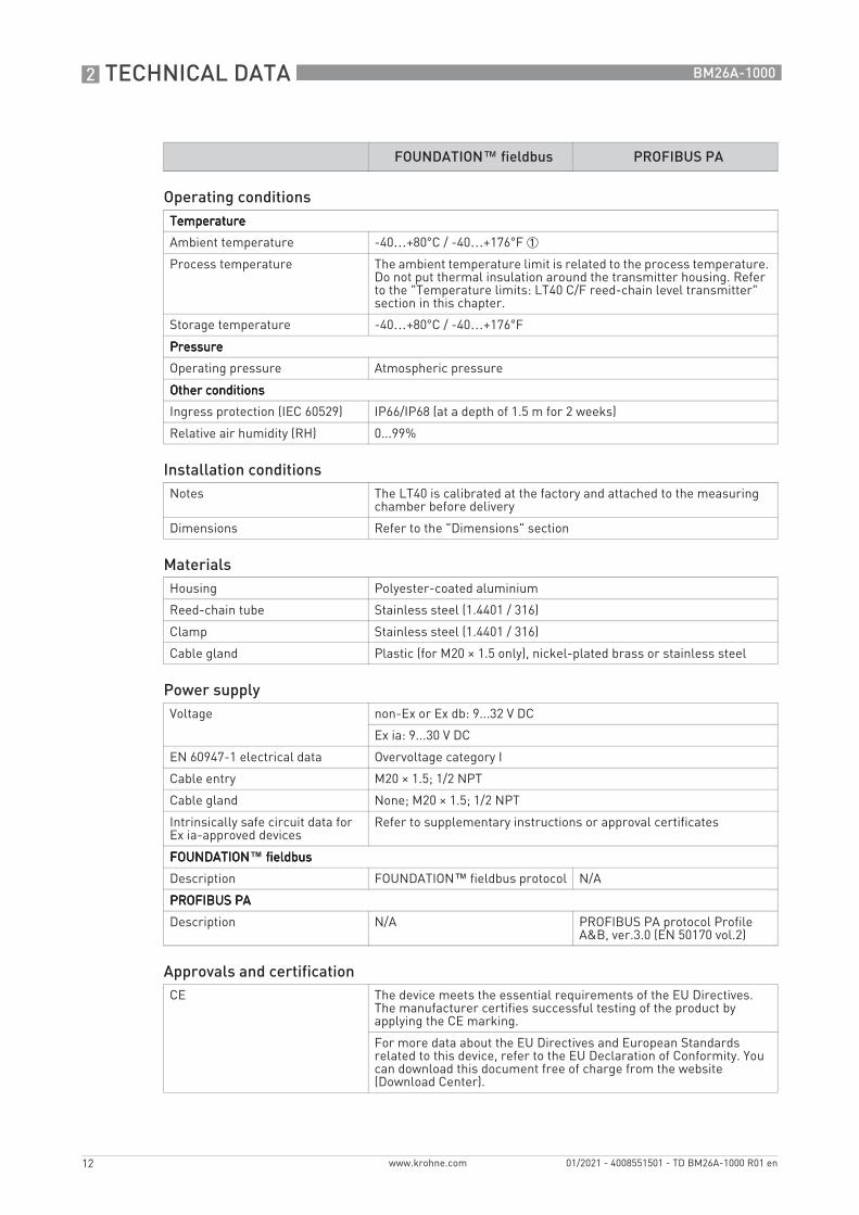
FOUNDATION™ fieldbus PROFIBUS PA
Measuring systemMeasuring principle A reed resistor chain that is magnetically operated by a magnetic
float in an adjacent measuring chamber
Primary measured value Resistance
Secondary measured value Level and volume of the liquid in the measuring chamber
DesignDescription of device Resistance reed chain with 2-wire loop-powered transmitter module
attached adjacent to the measuring chamber of the magnetic level indicator. A transmitter module converts changes in resistance to an output signal.
Description of transmitter module
Changes in resistance are converted to signals that agree with the FOUNDATION™ fieldbus communication protocol.
Changes in resistance are converted to signals that agree with the PROFIBUS PA communication protocol.
Options Transmitter module position: LT40 C - compact housing at the top of the reed resistor chain
Transmitter module position: LT40 C - compact housing at the bottom of the reed resistor chain
Transmitter module position: LT40 F - remote housing connected to the bottom of the reed resistor chain. Max. cable length: 25 m / 82 ft.
Display and user interfaceDisplay and user interfaceDisplay and user interfaceDisplay and user interface
Display None
Measuring accuracyResolution Standard: ±10 mm / 0.4¨ (when density is constant)
Option: ±5 mm / 0.2¨ (when density is constant)
2 TECHNICAL DATA
12
BM26A-1000
www.krohne.com 01/2021 - 4008551501 - TD BM26A-1000 R01 en
Operating conditionsTemperatureTemperatureTemperatureTemperature
Ambient temperature -40…+80°C / -40…+176°F 1
Process temperature The ambient temperature limit is related to the process temperature. Do not put thermal insulation around the transmitter housing. Refer to the "Temperature limits: LT40 C/F reed-chain level transmitter" section in this chapter.
Storage temperature -40…+80°C / -40…+176°F
PressurePressurePressurePressure
Operating pressure Atmospheric pressure
Other conditionsOther conditionsOther conditionsOther conditions
Ingress protection (IEC 60529) IP66/IP68 (at a depth of 1.5 m for 2 weeks)
Relative air humidity (RH) 0...99%
Installation conditionsNotes The LT40 is calibrated at the factory and attached to the measuring
chamber before delivery
Dimensions Refer to the "Dimensions" section
MaterialsHousing Polyester-coated aluminium
Reed-chain tube Stainless steel (1.4401 / 316)
Clamp Stainless steel (1.4401 / 316)
Cable gland Plastic (for M20 × 1.5 only), nickel-plated brass or stainless steel
Power supplyVoltage non-Ex or Ex db: 9...32 V DC
Ex ia: 9...30 V DC
EN 60947-1 electrical data Overvoltage category I
Cable entry M20 × 1.5; 1/2 NPT
Cable gland None; M20 × 1.5; 1/2 NPT
Intrinsically safe circuit data for Ex ia-approved devices
Refer to supplementary instructions or approval certificates
FOUNDATIONFOUNDATIONFOUNDATIONFOUNDATION™ fieldbus fieldbus fieldbus fieldbus
Description FOUNDATION™ fieldbus protocol N/A
PROFIBUS PAPROFIBUS PAPROFIBUS PAPROFIBUS PA
Description N/A PROFIBUS PA protocol Profile A&B, ver.3.0 (EN 50170 vol.2)
Approvals and certificationCE The device meets the essential requirements of the EU Directives.
The manufacturer certifies successful testing of the product by applying the CE marking.
For more data about the EU Directives and European Standards related to this device, refer to the EU Declaration of Conformity. You can download this document free of charge from the website (Download Center).
FOUNDATION™ fieldbus PROFIBUS PA

TECHNICAL DATA 2
13
BM26A-1000
www.krohne.com01/2021 - 4008551501 - TD BM26A-1000 R01 en
Explosion protectionExplosion protectionExplosion protectionExplosion protection
ATEX (EU Type Approval) II 1 G Ex ia IIC T6...T1 Ga or II 2 G Ex ia IIC T6...T1 Gb
II 2 G Ex db IIC T6...T1 Gb
IECEx Ex ia IIC T6...T1 Ga or Ex ia IIC T6...T1 Gb
Ex db IIC T6...T1 Gb
Other standards and approvalsOther standards and approvalsOther standards and approvalsOther standards and approvals
EMC Electromagnetic Compatibility Directive
Vibration resistance EN 60721-3-4 - vibration class 4M4 (1...200 Hz:1g, 10g shock ½ sinus: 11 ms)
Table 2-3: LT40 (fieldbus communication module): technical data
1 The ambient temperature limit is related to the process temperature. Do not put thermal insulation around the trans-mitter housing. Refer to the "Temperature limits: LT40 C/F reed-chain level transmitter" section in this chapter.
FOUNDATION™ fieldbus PROFIBUS PA

2 TECHNICAL DATA
14
BM26A-1000
www.krohne.com 01/2021 - 4008551501 - TD BM26A-1000 R01 en
2.1.3 MS15-series and MS40-series limit switches
MS15 series MS40 series
Measuring systemMeasuring principle Bistable reed switch (SPDT) that is magnetically operated by a
magnetic float in an adjacent measuring chamber
Application range Level detection
DesignDescription of device Limit switch attached adjacent to the measuring chamber of the
magnetic level indicator
Measuring accuracyHysteresis The hysteresis value agrees with the model of the magnetic level
indicator. For more data, refer to the handbook.
Operating conditionsTemperatureTemperatureTemperatureTemperature
Ambient temperature -40...+80°C / -40...+176°F 1
Process temperature The ambient temperature limit is related to the process temperature. Do not put thermal insulation around the transmitter housing. Refer to the "Temperature limits: MS15-series limit switch" and "Temperature limits: MS40-series limit switch" sections in this chapter.
Operating temperature -40…+115°C / -40…+239°F 2 -40…+120°C / -40…+248°F 2
Storage temperature -40…+80°C / -40…+176°F
PressurePressurePressurePressure
Operating pressure Atmospheric pressure Max. height above mean sea level: 2000 m / 6560 ft
Other conditionsOther conditionsOther conditionsOther conditions
Ingress protection (IEC 60529) MS15 series: IP66 / IP68 (at a depth of 1.5 m for 2 weeks)
MS40 series: IP66
Relative air humidity (RH) 0...99%
Installation conditionsNotes Adjust the switch position in relation to the hysteresis data (switching
point offset) and the density of the liquid
Dimensions Refer to the "Dimensions" section
MaterialsHousing Aluminium with epoxy powder paint
Clamp Stainless steel (1.4401 / 316)
Cable gland Plastic (for M20 × 1.5 only), nickel-plated brass or stainless steel
Plastic

TECHNICAL DATA 2
15
BM26A-1000
www.krohne.com01/2021 - 4008551501 - TD BM26A-1000 R01 en
Electrical connectionsSwitching capacity MS15 / MS40:
Absolute ratings: 250 V AC/DC; 1 A; 60 VA/W
MS15 NAMUR / MS40 NAMUR:Agrees with DIN 19234 (NAMUR); Umax = 13 V DC
EN 60947-5-1 electrical data (MS15 and MS40 only)
Overvoltage category II
Rated insulation voltage, Ui: 250 V AC or 250 V DC
Rated impulse withstand voltage, Uimp: 2.5 kV
Rated conventional thermal current, Ith: 1 A
Pollution degree: 4
Utilization category (EN 60947-5-1) with current and voltage ratings
AC13: Ie = 0.5 A; Umax = 60 V AC
AC13: Ie = 0.25 A; Umax = 250 V AC
DC12: Ie = 1 A; Umax = 60 V DC
DC13: Ie = 0.5 A; Umax = 60 V DC
Short-circuit protection device 0.25 A fuse, type 1500 A interrupting rating (IEC 60127-2/1)
1 A fuse, application category gG (IEC 60269) or type 1500 A interrupting rating (IEC 60127-2/1)
Intrinsically safe circuit data Refer to supplementary instructions or approval certificates
Cable entry M20 × 1.5; 1/2 NPT M16 × 1.5
Cable gland None; M20 × 1.5; 1/2 NPT M16 × 1.5
Approvals and certificationCE The device meets the essential requirements of the EU Directives.
The manufacturer certifies successful testing of the product by applying the CE marking.
For more data about the EU Directives and European Standards related to this device, refer to the EU Declaration of Conformity. You can download this document free of charge from the website (Download Center).
Explosion protectionExplosion protectionExplosion protectionExplosion protection
ATEX (EU Type Approval) II 1 G Ex ia IIC T6...T1 or II 2 G Ex ia IIC T6...T1 Gb
II 2 G Ex db IIC T6...T1 Gb N/A
IECEx Ex ia IIC T6...T1 Ga or Ex ia IIC T6...T1 Gb
Ex db IIC T6...T1 Gb N/A
Other standards and approvalsOther standards and approvalsOther standards and approvalsOther standards and approvals
LVD MS15 / MS40: Low-Voltage Directive (LVD)
MS15 NAMUR / MS40 NAMUR: N/A
Vibration resistance EN 60721-3-4 - vibration class 4M4 (1...200 Hz:1g, 10g shock ½ sinus: 11 ms)
Table 2-4: MS15-series and MS40-series limit switches: technical data
1 The ambient temperature limit is related to the process temperature. Do not put thermal insulation around the trans-mitter housing. Refer to the "Temperature limits: MS15-series limit switch" and "Temperature limits: MS40-series limit switch" sections in this chapter.
2 The operating temperature is the temperature of the electronic parts
MS15 series MS40 series

2 TECHNICAL DATA
16
BM26A-1000
www.krohne.com 01/2021 - 4008551501 - TD BM26A-1000 R01 en
2.2 Dimensions
2.2.1 Magnetic level indicator (measuring chamber) - overall dimensions
If the magnetic level indicator has the flanged vent and drain options, these flanges have the same pressure rating as the flanges for the process connections.
Other dimensions are available on request.
Side - side process connections
Figure 2-1: Side - side process connections
1 Optional vent with 3/8...1/2 NPT threaded connection (with plug), G 3/8...1/2 threaded connection on a plate flange (with plug), or DN15...50 / NPS 1/2…2 flange
2 Optional drain with 3/8...3/4 NPT threaded connection (with plug), G 3/8...3/4 threaded connection on a plate flange (with plug), or DN15...50 / NPS 1/2…2 flange
3 Process connection (flange, welded pipe, or pipe with male threaded connection)4 Level indicator column with optional scale (mm, inch, simplified % or volume)
• a = distance from the center axis of the bottom connection to the bottom of the device• b = distance from the center axis of the top connection to the top of the device• C-C = distance between the center axes of the top and bottom process connections• ML = measuring length

TECHNICAL DATA 2
17
BM26A-1000
www.krohne.com01/2021 - 4008551501 - TD BM26A-1000 R01 en
Liquid density [kg/m³]
Dimensions [mm]
a b C-C ML c d k Øt
700…950 1 228 2 300…5500 3 3 4 55.5 5 74 42.4
950…1200 6
Table 2-5: Side - side process connections: general dimensions in mm
1 Drain options are available. NPT connection (female) + plug: 299 mm. G connection (female) + plug: 291 mm. Flange: 399 mm.2 Vent options are available. NPT connection (female) + plug: 228 mm. NPT or G connection (female) + plug: 220 mm. Flange: 328 mm.3 This value agrees with the "C-C" dimension given in the customer order4 NPT or G connection (male): 58 mm. Welded pipe: 130 mm. Flange: 135 mm.5 If the indicator column has the PLEXIGLAS® anti-icing cover option, then d = 85.5 mm6 Drain options are available. NPT connection (female) + plug: 255 mm. G connection (female) + plug: 247 mm. Flange: 355 mm.
Liquid density [lb/ft³]
Dimensions [inches]
a b C-C ML c d k Øt
43.70…59.31 1 8.98 2 11.8...216.5 3 3 4 2.2 5 2.9 1.67
59.31…74.91 6
Table 2-6: Side - side process connections: general dimensions in inches
1 Drain options are available. NPT connection (female) + plug: 11.77¨. G connection (female) + plug: 11.46¨. Flange: 15.71¨.2 Vent options are available. NPT connection (female) + plug: 8.98¨. NPT or G connection (female) + plug: 8.66¨. Flange: 12.91¨.3 This value agrees with the "C-C" dimension given in the customer order4 NPT or G connection (male): 2.28¨. Welded pipe: 5.12¨. Flange: 5.31¨.5 If the indicator column has the PLEXIGLAS® anti-icing cover option, then d = 3.4¨6 Drain options are available. NPT connection (female) + plug: 10.04¨. G connection (female) + plug: 9.72¨. Flange: 13.98¨.

2 TECHNICAL DATA
18
BM26A-1000
www.krohne.com 01/2021 - 4008551501 - TD BM26A-1000 R01 en
Other dimensions are available on request.
Axial - axial process connections
Figure 2-2: Axial - axial process connections
1 Process connection (flange)2 Level indicator column with optional scale (mm, inch, simplified % or volume)
t
• a = bottom dead zone• b = top dead zone• C-C = distance between the flange facings of the top and bottom process connections• ML = measuring length

TECHNICAL DATA 2
19
BM26A-1000
www.krohne.com01/2021 - 4008551501 - TD BM26A-1000 R01 en
Liquid density [kg/m³]
Dimensions [mm]
a b C-C ML d k Øt
700…950 390 250 300...5500 1 C-C - 640 55.5 2 74 42.4
950…1200 340 250 C-C - 590
Table 2-7: Axial - axial process connections: general dimensions in mm
1 This value agrees with the "C-C" dimension given in the customer order2 If the indicator column has the PLEXIGLAS® anti-icing cover option, then d = 85.5 mm
Liquid density [lb/ft³]
Dimensions [inches]
a b C-C ML d k Øt
43.70…59.31 15.35 9.84 11.8…216.5 1 C-C - 25.20 2.2 2 2.9 1.67
59.31…74.91 13.39 C-C - 23.23
Table 2-8: Axial - axial process connections: general dimensions in inches
1 This value agrees with the "C-C" dimension given in the customer order2 If ambient temperature is -76...-4°F: 3.4¨ (level indicator column with a PLEXIGLAS® anti-icing cover)

2 TECHNICAL DATA
20
BM26A-1000
www.krohne.com 01/2021 - 4008551501 - TD BM26A-1000 R01 en
If the magnetic level indicator has the flanged vent option, this flange has the same pressure rating as the flanges for the process connections.
Other dimensions are available on request.
Top side - bottom axial process connections
Figure 2-3: Top side - bottom axial process connections
1 Optional vent with 3/8…1/2 NPT threaded connection (with plug), G 3/8…1/2 threaded connection on a plate flange (with plug), or DN15…50 / NPS 1/2…2 flange
2 Process connection (flange)3 Level indicator column with optional scale (mm, inch, simplified % or volume)
• a = bottom dead zone• b = distance from the center axis of the top process connection to the top of the device• C-C = distance between the center axis of the top process connection and the flange facing of
the bottom process connection• ML = measuring length

TECHNICAL DATA 2
21
BM26A-1000
www.krohne.com01/2021 - 4008551501 - TD BM26A-1000 R01 en
Liquid density [kg/m³]
Dimensions [mm]
a b C-C ML c d k Øt
700…950 400 228 1 300...5500 2 C-C - 400 3 55.5 4 74 42.4
950…1200 360 C-C - 360
Table 2-9: Top side - bottom axial process connections: general dimensions in mm
1 Vent options are available. NPT connection (female) + plug: 228 mm. G connection (female) + plug: 220 mm. Flange: 328 mm.2 This value agrees with the "C-C" dimension given in the customer order3 EN flange, type B: 135.2 mm. EN flange, type C: 134.7 mm. EN flange, type E: 135.2 mm.4 If the indicator column has the PLEXIGLAS® anti-icing cover option, then d = 85.5 mm
Liquid density [lb/ft³]
Dimensions [inches]
a b C-C ML c d k Øt
43.70…59.31 15.75 8.98 1 11.8…216.5 2 C-C - 15.75 3 2.2 4 2.9 1.67
59.31…74.91 14.17 C-C - 14.17
Table 2-10: Top side - bottom axial process connections: general dimensions in inches
1 Vent options are available. NPT connection (female) + plug: 8.98¨. G connection (female) + plug: 8.66¨. Flange: 12.91¨.2 This value agrees with the "C-C" dimension given in the customer order3 EN flange, type B: 5.32¨. EN flange, type C: 5.30¨. EN flange, type E: 5.32¨.4 If the indicator column has the PLEXIGLAS® anti-icing cover option, then d = 3.4¨

2 TECHNICAL DATA
22
BM26A-1000
www.krohne.com 01/2021 - 4008551501 - TD BM26A-1000 R01 en
If the magnetic level indicator has the flanged drain option, this flange has the same pressure rating as the flanges for the process connections.
Other dimensions are available on request.
Top axial - bottom side process connections
Figure 2-4: Top axial - bottom side process connections
1 Process connection (flange)2 Optional drain with 3/8…3/4 NPT threaded connection (with plug), G 3/8…3/4 threaded connection on a plate flange
(with plug), or DN15…50 / NPS 1/2…2 flange3 Level indicator column with optional scale (mm, inch, simplified % or volume)
• a = distance from the center axis of the bottom process connection to the bottom of the device• b = top dead zone• C-C = distance between the flange facing of the top process connection and the center axis of
the bottom process connection• ML = measuring length

TECHNICAL DATA 2
23
BM26A-1000
www.krohne.com01/2021 - 4008551501 - TD BM26A-1000 R01 en
Liquid density [kg/m³]
Dimensions [mm]
a b C-C ML c d k Øt
700…950 1 330 300...5500 2 C-C - 330 135 55.5 3 74 42.4
950…1200 4
Table 2-11: Top axial - bottom side process connections: general dimensions in mm
1 Drain options are available. NPT connection (female) + plug: 299 mm. G connection (female) + plug: 291 mm. Flange: 399 mm.2 This value agrees with the "C-C" dimension given in the customer order3 If the indicator column has the PLEXIGLAS® anti-icing cover option, then d = 85.5 mm4 Drain options are available. NPT connection (female) + plug: 255 mm. G connection (female) + plug: 247 mm. Flange: 355 mm.
Liquid density [lb/ft³]
Dimensions [inches]
a b C-C ML c d k Øt
43.70…59.31 1 12.99 11.8…216.5 2 C-C - 12.99 5.31 2.2 3 2.9 1.67
59.31…74.91 4
Table 2-12: Top axial - bottom side process connections: general dimensions in inches
1 Drain options are available. NPT connection (female) + plug: 11.77¨. G connection (female) + plug: 11.46¨. Flange: 15.71¨.2 This value agrees with the "C-C" dimension given in the customer order3 If the indicator column has the PLEXIGLAS® anti-icing cover option, then d = 3.4¨4 Drain options are available. NPT connection (female) + plug: 10.04¨. G connection (female) + plug: 9.72¨. Flange: 13.98¨.

2 TECHNICAL DATA
24
BM26A-1000
www.krohne.com 01/2021 - 4008551501 - TD BM26A-1000 R01 en
2.2.2 Options
LT40 C reed-chain level transmitter (compact version)
Figure 2-5: LT40 C reed-chain level transmitter (compact version)
Dimensions [mm]
a b c ML d e
66.5 157 153 300...5500 84 50
Table 2-13: LT40 C reed-chain level transmitter: dimensions in mm
Dimensions [inches]
a b c ML d e
2.6 6.2 6.0 11.8…216.5 3.3 2.0
Table 2-14: LT40 C reed-chain level transmitter: dimensions in inches
TECHNICAL DATA 2
25
BM26A-1000
www.krohne.com01/2021 - 4008551501 - TD BM26A-1000 R01 en
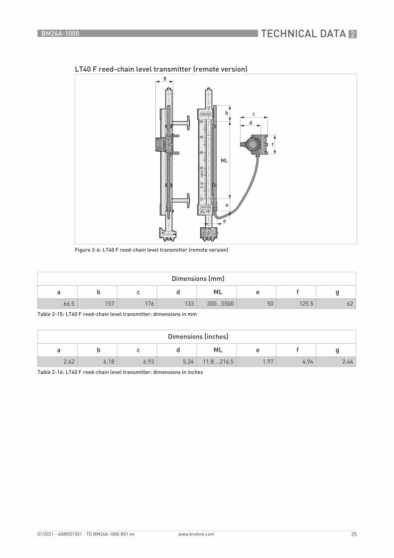
LT40 F reed-chain level transmitter (remote version)
Figure 2-6: LT40 F reed-chain level transmitter (remote version)
Dimensions [mm]
a b c d ML e f g
66.5 157 176 133 300...5500 50 125.5 62
Table 2-15: LT40 F reed-chain level transmitter: dimensions in mm
Dimensions [inches]
a b c d ML e f g
2.62 6.18 6.93 5.24 11.8…216.5 1.97 4.94 2.44
Table 2-16: LT40 F reed-chain level transmitter: dimensions in inches

2 TECHNICAL DATA
26
BM26A-1000
www.krohne.com 01/2021 - 4008551501 - TD BM26A-1000 R01 en
Support for the LT40 F reed-chain level transmitter
Figure 2-7: Support for the LT40 F reed-chain level transmitter
Dimensions [mm]
Øk m n p q
7.5 107.75 3 24.25 31
Table 2-17: Support for the LT40 F reed-chain level transmitter: dimensions in mm
Dimensions [inches]
Øk m n p q
0.30 4.24 0.12 0.95 1.22
Table 2-18: Support for the LT40 F reed-chain level transmitter: dimensions in inches

TECHNICAL DATA 2
27
BM26A-1000
www.krohne.com01/2021 - 4008551501 - TD BM26A-1000 R01 en
MS15 -series and MS40-series limit switches
Figure 2-8: MS15-series and MS40-series limit switches
1 Magnetic level indicator with an MS15-series limit switch2 Magnetic level indicator with an MS40-series limit switch
Limit switch version Dimensions [mm]
p q s
MS15 series 88 122.7 143.5
MS40 series 46 108.7 56
Table 2-19: MS15-series and MS40-series limit switches: dimensions in mm
Limit switch version Dimensions [inches]
p q s
MS15 series 3.46 4.83 5.65
MS40 series 1.81 4.28 2.20
Table 2-20: MS15-series and MS40-series limit switches: dimensions in inches

2 TECHNICAL DATA
28
BM26A-1000
www.krohne.com 01/2021 - 4008551501 - TD BM26A-1000 R01 en
2.2.3 Accessories
The support bracket is an accessory. If necessary, send an order to your supplier.
Support bracket
Figure 2-9: Support bracket
Dimensions [mm]
a b c d e Øf Øg h j k m n p s t u
Support bracket
73 3 52 28.5 4 8.4 15 15 50 80 26 12 16.5 33 4 58
Table 2-21: Support bracket: dimensions in mm
Dimensions [inches]
a b c d e Øf Øg h j k m n p s t u
Support bracket
2.87 0.12 2.05 1.12 0.16 0.33 0.59 0.59 1.97 3.15 1.02 0.47 0.65 1.30 0.16 2.28
Table 2-22: Support bracket: dimensions in inches

TECHNICAL DATA 2
29
BM26A-1000
www.krohne.com01/2021 - 4008551501 - TD BM26A-1000 R01 en
2.3 Maximum process pressure: measuring chamber
Maximum process pressure [bar] for a given maximum process temperature [°C]
Maximum process pressure [psig] for a given maximum process temperature [°F]
Do not use the device at a process pressure more than the maximum limit for a given process temperature.
Standard Pressure rating
Maximum process temperature [°C]
-70 -20 +20 +38 +50 +100 +150 +200
Maximum process pressure [bar]
EN 1092-1 PN40 40 40 40 40 40 40 36.3 33.7
ASME B16.5 Class 150 19 19 19 19 18.4 16 14.8 13.6
Class 300 40 40 40 40 40 40 36.3 33.7
ISO 228-1 G 40 40 40 40 40 40 36.3 33.7
ASME B1.20.1 NPT 40 40 40 40 40 40 36.3 33.7
ASME B36.19M 10S 40 40 40 40 40 40 36.3 33.7
Table 2-23: Maximum process pressure [barg] for a given maximum process temperature [°C]
Standard Pressure rating
Maximum process temperature [°F]
-94 -4 +68 +100.4 +122 +212 +302 +392
Maximum process pressure [psig]
EN 1092-1 PN40 580.2 580.2 580.2 580.2 580.2 580.2 526.5 488.8
ASME B16.5 Class 150 275.6 275.6 275.6 275.6 266.9 232.1 214.7 197.3
Class 300 580.2 580.2 580.2 580.2 580.2 580.2 526.5 488.8
ISO 228-1 G 580.2 580.2 580.2 580.2 580.2 580.2 526.5 488.8
ASME B1.20.1 NPT 580.2 580.2 580.2 580.2 580.2 580.2 526.5 488.8
ASME B36.19M 10S 580.2 580.2 580.2 580.2 580.2 580.2 526.5 488.8
Table 2-24: Maximum process pressure [psig] for a given maximum process temperature [°F]

2 TECHNICAL DATA
30
BM26A-1000
www.krohne.com 01/2021 - 4008551501 - TD BM26A-1000 R01 en
2.4 Temperature limits: LT40 C/F reed-chain level transmitter
2.4.1 LT40 without an LCD indicator module
Do not use the device at an ambient temperature more than the maximum limit for a given process temperature. Do not use the device at an ambient temperature less than the minimum limit for a given process temperature.
The temperature limit calculations for these graphs do not include thermal insulation.
Figure 2-10: Ambient temperature / process temperature - LT40 without an LCD indicator module, in °C
Figure 2-11: Ambient temperature / process temperature - LT40 without an LCD indicator module, in °F
1 Ambient temperature, °C2 Process temperature, °C3 Ambient temperature, °F4 Process temperature, °F5 LT40 F - without thermal insulation6 LT40 C and LT40 F - without thermal insulation

TECHNICAL DATA 2
31
BM26A-1000
www.krohne.com01/2021 - 4008551501 - TD BM26A-1000 R01 en
2.4.2 LT40 with an LCD indicator module
Figure 2-12: Ambient temperature / process temperature - LT40 with an LCD indicator module, in °C
Figure 2-13: Ambient temperature / process temperature - LT40 with an LCD indicator module, in °F
1 Ambient temperature, °C2 Process temperature, °C3 Ambient temperature, °F4 Process temperature, °F5 LT40 F - without thermal insulation6 LT40 C and LT40 F - without thermal insulation

2 TECHNICAL DATA
32
BM26A-1000
www.krohne.com 01/2021 - 4008551501 - TD BM26A-1000 R01 en
2.5 Temperature limits: MS15-series limit switch
2.5.1 Aluminium housing
Do not use the device at an ambient temperature more than the maximum limit for a given process temperature. Do not use the device at an ambient temperature less than the minimum limit for a given process temperature.
The temperature limit calculations for these graphs do not include thermal insulation.
Figure 2-14: MS15 series - aluminium housing: ambient temperature / process temperature, in °C
Figure 2-15: MS15 series - aluminium housing: ambient temperature / process temperature, in °F
1 Ambient temperature, °C2 Process temperature, °C3 Ambient temperature, °F4 Process temperature, °F5 MS15-series limit switch - without thermal insulation

TECHNICAL DATA 2
33
BM26A-1000
www.krohne.com01/2021 - 4008551501 - TD BM26A-1000 R01 en
2.5.2 Stainless-steel housing
Figure 2-16: MS15 series - stainless-steel housing: ambient temperature / process temperature, in °C
Figure 2-17: MS15 series - stainless-steel housing: ambient temperature / process temperature, in °F
1 Ambient temperature, °C2 Process temperature, °C3 Ambient temperature, °F4 Process temperature, °F5 MS15-series limit switch - without thermal insulation

2 TECHNICAL DATA
34
BM26A-1000
www.krohne.com 01/2021 - 4008551501 - TD BM26A-1000 R01 en
2.6 Temperature limits: MS40-series limit switch
Do not use the device at an ambient temperature more than the maximum limit for a given process temperature. Do not use the device at an ambient temperature less than the minimum limit for a given process temperature.
The temperature limit calculations for these graphs do not include thermal insulation.
Figure 2-18: MS40 series: ambient temperature / process temperature, in °C
Figure 2-19: MS40 series: ambient temperature / process temperature, in °F
1 Ambient temperature, °C2 Process temperature, °C3 Ambient temperature, °F4 Process temperature, °F5 MS40-series limit switch - without thermal insulation

INSTALLATION 3
35
BM26A-1000
www.krohne.com01/2021 - 4008551501 - TD BM26A-1000 R01 en
3.1 Intended use
The BM26A-1000 and BM26A- are magnetic level indicators that measure the level or volume of liquids.
The BM26A-1000 is a low-cost solution for basic applications.
These devices are installed next to open or pressurized tanks. With the applicable options, they are resistant to difficult service conditions and liquids that are poisonous or flammable.
3.2 Pre-installation requirements
3.2.1 General notes
Obey the installation conditions that follow. For technical data about the device, refer to Technical data on page 6.
Make sure that the installation conditions obey the design constraints related to PED. For more data, refer to EU Pressure Equipment Directive on page 36.
Other installation conditions• Install the magnetic level indicator vertically on the tank.• Select bolts and gaskets (not supplied) that agree with the pressure rating of the process
connection and the process pressure.• Make sure that mechanical loadings do not cause damage to the process connections. If
necessary, put support brackets on the device.
3.2.2 Isolation valves
We recommend that you install isolation valves between the device and the tank. The device can then be easily removed from the tank for the cleaning procedure. Drain the device only when it is isolated from the tank.
Responsibility for the use of the measuring devices with regard to suitability, intended use and corrosion resistance of the used materials against the measured fluid lies solely with the operator.
The manufacturer is not liable for any damage resulting from improper use or use for other than the intended purpose.
Make sure that the outer surface temperature of the device is less than +60°C / +140°F. If the surface temperature is more than +60°C / +140°F, use the device with precautions that agree with health and safety rules and regulations.
Customer order data is used to adjust the device. If liquid density changes, the device will not measure correctly. For example, if liquid density decreases, then the float does not follow the surface of the liquid and goes down to the bottom of the measuring chamber.

3 INSTALLATION
36
BM26A-1000
www.krohne.com 01/2021 - 4008551501 - TD BM26A-1000 R01 en
3.3 EU Pressure Equipment Directive
These devices are designed, assembled and tested to agree with the EU Pressure Equipment Directive (PED). The PED conformity assessment is approved by a Notified Body.
The manufacturer did a risk analysis on the device that agrees with the Pressure Equipment Directive. All personnel must know the design and operating conditions that follow to prevent the risk of damage and injury:
• This device is designed to function at almost constant pressure and temperature conditions. A maximum of 500 cycles is permitted along the full pressure range. A maximum of 2000 cycles is permitted along the full temperature range.
• This device is not designed for operating conditions where vibration or fatigue stress is present.
• Events that are not taken into account in the calculations include exceptional risks such as: earthquakes, bad weather, fire etc..
• The standard design calculation does not take into account the theoretical coefficient of corrosion. The product circulating in the device must not have properties that cause surface erosion.
• Our conformity declaration is limited to the parts of the device that are pressurized. It does not include parts that can be dismantled (valves etc.).
• The process connections must be attached correctly to prevent mechanical stress. The axis of the process connection must be parallel to and centred with the axis of the tank's process connections. Tighten the process connections in agreement with the design code.
• The user must take necessary steps to protect the installed device from shock waves (water hammer). A pressure-limiting valve must protect the installation.
• The effective pressure of the installation (the maximum pressure permitted by the pressure-limiting valve) must never be more than the maximum permitted pressure, PS. PS is marked on the device nameplate.
• Make sure that the parts in contact with the fluid are compatible with the fluid and conform to the ageing characteristics of the measurement environment and the fluid used. These have either been recommended in the instructions or form the subject of a particular specification in the contract.
• The device is designed to measure a liquid with a gas phase. It is not designed to measure liquids that change to a solid phase because of changes in pressure (solidification) and temperature (freezing), e.g. water and ice.
• Make sure that there are no magnetic particles in the liquid. These particles can have an effect on the performance of the device.
• Make sure that the size of the particles in the liquid are less than 0.05 mm / 0.002¨ in diameter.
• Make sure that the device is correctly sealed. Do a leakage check between the device and the tank.
• The external pressure, Pext, must be equal to atmospheric pressure, Patmos (Pext = Patmos).
If the device has an Ex approval, then you must obey other temperature limits. For more data, refer to the Ex supplementary instructions.

INSTALLATION 3
37
BM26A-1000
www.krohne.com01/2021 - 4008551501 - TD BM26A-1000 R01 en
3.4 Reed-chain level transmitter (LT40)
3.4.1 General notes
LT40 CThe electronics module of the compact version of the LT40 is attached to the reed-chain tube.
LT40 FThe electronics module of the remote version of the LT40 is connected the reed-chain tube by an electrical cable this a maximum of 25 m / 82 ft long. The electronics module of the remote version can be attached to a pipe with two hose clamps or attached to a wall with two bolts. Refer to the illustration that folows:
3.4.2 Thermal insulation
If you put thermal insulation around the magnetic level indicator, do not cover the housing of the reed-chain level transmitter. Make sure that there is approximately 15 mm / 0.6¨ of empty space between the housing and the thermal insulation.
Customer order data is used to adjust the device. If liquid density changes, the device will not measure correctly. For example, if liquid density decreases, then the float does not follow the surface of the liquid and goes down to the bottom of the measuring chamber.
Figure 3-1: LT40 F: Installation of the housing (remote version) for the electronics module: top view
1 The housing is attached to a tube with two hose clamps2 The housing is attached to a wall with two bolts

3 INSTALLATION
38
BM26A-1000
www.krohne.com 01/2021 - 4008551501 - TD BM26A-1000 R01 en
3.5 Limit switches (MS15 series and MS40 series)
3.5.1 General notes
Limit switch condition - LOW limit:Limit switch condition - LOW limit:Limit switch condition - LOW limit:Limit switch condition - LOW limit:The limit switch is open when the float moves belowbelowbelowbelow the switching point.
Limit switch condition - HIGH limit:Limit switch condition - HIGH limit:Limit switch condition - HIGH limit:Limit switch condition - HIGH limit:The limit switch is open when the float moves aboveaboveaboveabove the switching point.
Figure 3-2: Definitions
1 Limit switch in "HIGH limit" position2 Limit switch in "LOW limit" position3 Switching point (the level at which the limit switch changes its condition from "closed" to "open")4 Correct position of the limit switch in relation to the switching point. If it is a "HIGH limit" switch, put it below the switch-
ing point (at a distance equal to the switching point offset value). If it is a "LOW limit" switch, put it above the switching point (at a distance equal to the switching point offset value).

INSTALLATION 3
39
BM26A-1000
www.krohne.com01/2021 - 4008551501 - TD BM26A-1000 R01 en
3.5.2 Thermal insulation
If you put thermal insulation around the magnetic level indicator, do not cover the housing of the limit switch. Make sure that there is approximately 15 mm / 0.6¨ of empty space between the housing and the thermal insulation.
Too much heat can cause damage to the limit switch.
Figure 3-3: Limit switches and thermal insulation for the measuring chamber
1 Limit switch housing2 Thermal insulation around the measuring chamber (cross-section)3 Measuring chamber (cross-section)Empty space between the limit switch and the thermal insulation for the measuring chamber, a ≥15 mm / 0.6¨.

4 ELECTRICAL CONNECTIONS
40
BM26A-1000
www.krohne.com 01/2021 - 4008551501 - TD BM26A-1000 R01 en
4.1 Reed-chain level transmitter
4.1.1 General notes
The reed-chain level transmitter has 4 output options:
• 4…20 mA• 4…20 mA + HART®• PROFIBUS PA• FOUNDATION™ fieldbus
Obey the wiring instructions that follow.
For more data about the reed-chain level transmitter, refer to LT40 reed-chain level transmitter on page 9.
4.1.2 Electrical schematics and procedure
4...20 mA and 4...20 mA + HART output modules
Figure 4-1: Electrical schematic for the 4...20 mA and 4...20 mA + HART output module
1 Internal wiring - brown wire2 Internal wiring - red wire3 Internal wiring - orange wire4 Optional LCD indicator5 Power supply terminals +/-, without LCD indicator (DC voltage range: 10…35 V (non-Ex or Ex db) or 10…30 V (Ex ia))6 LCD indicator power supply terminals +/- (DC voltage range: 17...35 V)
If the reed-chain level transmitter has the LCD indicator option, then there is a red wire between the positive (+) terminals and a black wire between the negative (-) terminals of the output module and the LCD indicator. Use the +/- terminals on the back the LCD indicator to connect the reed-chain level transmitter to the power supply.

ELECTRICAL CONNECTIONS 4
41
BM26A-1000
www.krohne.com01/2021 - 4008551501 - TD BM26A-1000 R01 en
4.2 Limit switches
4.2.1 General notes
There are four limit switch models:
• MS15• MS15 NAMUR• MS40• MS40 NAMUR
Obey the wiring instructions that follow.
For more data, refer to MS15-series and MS40-series limit switches on page 14.
4.2.2 Electrical schematics and procedure
FOUNDATION™ fieldbus / PROFIBUS PA module
Figure 4-2: Electrical schematic for the FOUNDATION™ fieldbus / PROFIBUS PA module
1 Bus connection terminals2 Segment coupler3 Bus termination4 Internal wiring - orange wire5 Internal wiring - red wire6 Internal wiring - brown wire
Figure 4-3: Electrical schematics for the MS15-series and MS40-series limit switches
1 MS15 or MS40 limit switch2 MS15 or MS40 limit switch with a NAMUR output
If the limit switch is set to "LOW limit", make sure that it is open when the float is below the switch position. If the limit switch is set to the "HIGH limit", make sure that it is open when the float is above the switching point.
5 NOTES
42
BM26A-1000
www.krohne.com 01/2021 - 4008551501 - TD BM26A-1000 R01 en

NOTES 5
43
BM26A-1000
www.krohne.com01/2021 - 4008551501 - TD BM26A-1000 R01 en

KROHNE – Products, Solutions and Services
• Process instrumentation for flow, level, temperature, pressure measurementand process analytics
• Flow metering, monitoring, wireless and remote metering solutions
• Engineering, commissioning, calibration, maintenance and training services
Head Office KROHNE Messtechnik GmbHLudwig-Krohne-Str. 547058 Duisburg (Germany)Tel.: +49 203 301 0Fax: +49 203 301 [email protected]
© K
RO
HN
E 01
/202
1 -
4008
5515
01 -
TD
BM
26A
-100
0 R
01 e
n -
Subj
ect t
o ch
ange
with
out n
otic
e.
The current list of all KROHNE contacts and addresses can be found at:www.krohne.com