DATASHEET CATALOG 2018
268
DATASHEET CATALOG 2018 HYDRONIC BALANCING | UNDERFLOOR HEATING TECHNOLOGY | SYSTEM TECHNOLOGY | VALVES AND ACCESSORIES
-
Upload
khangminh22 -
Category
Documents
-
view
1 -
download
0
Transcript of DATASHEET CATALOG 2018

DATASHEET CATALOG 2018 HYDRONIC BALANCING | UNDERFLOOR HEATING TECHNOLOGY | SYSTEM TECHNOLOGY | VALVES AND ACCESSORIES

2 taconova.com
HYDRONIC BALANCINGEnergy in buildings must be distributed in such a way that all building sections, rooms and
consumers are supplied according to their needs. A well-balanced system avoids excess and
deficient supply of consumer circuits and prevents irritating flow noises in the pipes and
valves.
The gain in comfort due to pleasant room temperatures and significantly increased energy
efficiency are the perceptible and measurable results of hydronically balanced flow systems.
Hydronic balancing – the core area of expertise of Taconova – is part of the modern standard
and is indispensable in the building service solutions of today.
UNDERFLOOR HEATING TECHNOLOGYTargeted heating of individual rooms increases the comfort level, reduces energy consumption
and enables economic operation of the heating system. Optimum energy distribution is required
in this regard: for main distribution in basements or pump rooms, the main flows are distributed
to the various parts of the building as part of the hydronic balancing. To achieve the desired
tem peratures in the various rooms and heating circuits, focused distribution using intelligent
and reliable underfloor heating systems is also required on each floor. Taconova’s comprehensive
range of underfloor heating systems is marked by optimally balanced products that can be
combined in many different permu tations.
SYSTEM TECHNOLOGYThe demand for universal solutions in building services is greater than ever. Taconova's connec-
tion-ready heating circuit pump assemblies, solar loading, domestic hot water and storage loading
stations and heat interface units are smart, state of the art systems. Taconova quality products
are assembled from carefully selected, tried-and-tested products to create perfectly functioning
standard units.
The ready-to-use complete solutions simplify and accelerate planning and assembly stages. In
everyday use they guarantee reliable operation, reduce maintenance to a minimum and optimize
energy costs.
VALVES AND ACCESSORIESA smoothly running heating or cooling system requires a large number of compact supporters.
Valves and accessories from Taconova automatically vent heating systems since only continuously
vented heating systems work with the greatest efficiency. Thermal mixer valves reduce the high
domestic hot water temperatures to a constant, non-scalding temperature at the outlet. Multifunc-
tional valves and accessories for monitoring the pressure in heating systems provide additional
safety. Sophisticated sensors and measuring equipment – for example, for individual heat metering –
complete the comprehensive range of Taconova fittings
OVERVIEW OF THE AREAS OF EXPERTISE

3taconova.com
CONTENTS
OVERVIEW OF PRODUCTS AND APPLICATION AREAS 4
HYDRONIC BALANCING 6Balancing valves 8■■ TacoSetter Bypass 100 12■■ TacoSetter Bypass Solar 130 16■■ TacoSetter Bypass Solar 185 20■■ TacoSetter Bypass Flange 24■■ TacoSetter Inline 100 26■■ TacoSetter Inline 130 30■■ TacoSetter Rondo 32■■ TacoSetter Hyline 34■■ TacoSetter Tronic 37
Flow meter 40■■ TacoControl FlowMeter 42■■ Glycol correction curves 44
UNDERFLOOR HEATING TECHNOLOGY 50Underfloor heating systems 52■■ TacoSys Pro 54■■ TacoSys High End | Connect 58■■ Distribution cabinets 62■■ Mixing station 64■■ Mixing station UPM 68■■ Mixing station UPM-T 71■■ TopMeter Plus 74■■ TopMeter Supply 76■■ TopMeter Return 78■■ TacoForm 81
Actuators, room thermostats and wiring modules 84■■ TacoDrive 86■■ NovaDrive NC | NO 90■■ TopDrive NC 93■■ NovaStat EL | NovaMaster EL 96■■ NovaStat RF | NovaMaster RF 100
SYSTEM TECHNOLOGY 104Heat interface units 106■■ TacoTherm Dual Piko 110■■ TacoTherm Fresh/Dual Nano 124
Fresh hot water stations 134■■ TacoTherm Fresh Femto 136■■ TacoTherm Fresh Mega Connect 139■■ TacoTherm Fresh Mega Connect X 144■■ TacoTherm Fresh Mega2 149■■ TacoTherm Fresh Mega2 X 154■■ TacoTherm Fresh Peta 159■■ TacoTherm Fresh Peta X 164■■ Plate heat exchanger requirements 169
Storage loading stations 170■■ TacoSol Load Mega 172■■ TacoSol Load Tera L 175■■ TacoSol Load Exa L 178
Solar stations 182■■ TacoSol Circ ER HE PM2 184■■ TacoSol Circ ER HE UPM3 188■■ TacoSol Circ ZR HE PM2 192■■ TacoSol Circ ZR HE UPM3 196■■ TacoSol Circ ZR PV EU21 200
Heizungspumpengruppe 204■■ TacoHeat Mix 206
VALVES AND ACCESSORIES 210Mixing valves 212■■ NovaMix Value 217■■ NovaMix Standard 220■■ NovaMix High Capacity 223■■ NovaMix Compact 70 226■■ NovaMix Compact 50 228
Zone valves 230■■ NovaZone Ball 232■■ NovaZone Valve 237
Multifunctional valves and accessories 240■■ TriBloc 242
Air, dirt and magnetite separator 244■■ TacoVent Vent 248■■ TacoVent HyVent 250■■ TacoVent AirScoop D 253■■ TacoVent AirScoop R 256■■ TacoVent Pure R 259■■ TacoVent Twin R 262■■ MegaFill 264

4 taconova.com
Heating & cooling generation
Heating & cooling distribution
Sani-tati-on
Other
Geot
herm
al
ener
gy
Sola
r the
rmal
en
ergy
Oil,
gas,
bio
mas
s,
elec
tric
ity
Dist
rict
hea
ting
Radi
ator
s
Unde
rflo
or
heat
ing
Conc
rete
cor
e
Chill
ed a
nd
heat
ed c
eilin
gs
Fan
Coils
, Chi
ll Be
ams
Fres
h w
ater
Wat
erin
g (g
arde
n,
air/
wat
er)
Indu
stri
al
appl
icat
ions
PRODUCT NAME AS OF 2011 PRODUCT NAME UP TO 2010
HYDRONIC BALANCING
TacoSetter Bypass 100 AV23 Setter Bypass SD
TacoSetter Bypass Solar 130 AV23 Setter Bypass SD Solar
TacoSetter Bypass Solar 185 AV23 Setter Bypass HT Solar
TacoSetter Bypass Flange AV23 Setter Bypass Flange
TacoSetter Inline 100 AV23 Setter Inline
TacoSetter Inline 130 AV23 Setter Inline UN
TacoSetter Rondo AV23 Setter Rondo
TacoSetter Hyline Innovation
TacoSetter Tronic AV23 Setter Tronic UN
TacoControl FlowMeter AV23 Flometer
UNDERFLOOR HEATING TECHNOLOGY
TacoSys Pro Innovation
TacoSys HighEnd VH86 Tacosys High End
TacoSys Connect VH86 Tacosys HKA
TopMeter Plus Innovation
TopMeter Supply AO23 Topmeter VL
TopMeter Return AO23 Topmeter RL
TacoDrive Innovation
NovaDrive NC RA57 Novadrive NC
NovaDrive NO RA58 Novadrive NO
TopDrive NC RA57 Topdrive
NovaStat EL Basic RT06 RT-EL
NovaStat EL Quattro RT06 RT-ELQ
NovaStat EL Inwall RT06 RT-UW
NovaStat EL Digital RT06 RT-D
NovaStat EL Week RT06 RT-WP
NovaStat EL Public RT06 RT-P
NovaMaster EL Basic RX58 Master
NovaMaster EL Logic RX58 Master PL
NovaMaster EL SlaveBox RX58 SB
NovaMaster EL Timer RX58 Timer
NovaStat RF Basic RT06 RT-RF
NovaStat RF Digital RT06 RT-RFD
NovaStat RF Week RT06 RT-RFWP
NovaMaster RF Logic RX58 Master/Timer-RF
NovaMaster RF SlaveBox RX58 SB RF
NovaMaster RF Mini RX58 RT-RFK
OVERVIEW OF PRODUCTS AND APPLICATION AREAS
OVERVIEW OF PRODUCTS AND APPLICATION AREAS

5taconova.com
Heating & cooling generation
Heating & cooling distribution
Sani-tati-on
Other
Geot
herm
al
ener
gy
Sola
r the
rmal
en
ergy
Oil,
gas,
bio
mas
s,
elec
tric
ity
Dist
rict
hea
ting
Radi
ator
s
Unde
rflo
or
heat
ing
Conc
rete
cor
e
Chill
ed a
nd
heat
ed c
eilin
gs
Fan
Coils
, Chi
ll Be
ams
Fres
h w
ater
Wat
erin
g (g
arde
n,
air/
wat
er)
Indu
stri
al
appl
icat
ions
PRODUCT NAME AS OF 2011 PRODUCT NAME UP TO 2010
SYSTEM TECHNOLOGY
TacoHeat Mix Innovation
TacoSol Circ ER HE FV70 Tacosol ER
TacoSol Circ ZR HE FV70 Tacosol ZR
TacoSol Circ ZR PV EU21 FV70 Tacosol Edition EU21
TacoSol Load Mega (L) TacoSol Load 25TacoSol Load 25 light
TacoSol Load Tera (L)
TacoSol Load Exa L TacoSol Load 240
TacoTherm Fresh Femto
TacoTherm Fresh Mega Connect X Innovation
TacoTherm Fresh Mega2 X Innovation
TacoTherm Fresh Peta X Innovation
TacoTherm Dual Piko
TacoTherm Dual Nano
VALVES AND ACCESSORIES
NovaMix Value 50 FS Innovation
NovaMix Value 65 FS MT53
NovaMix Value 70 FS MT53
NovaMix Standard 40 MT52
NovaMix Standard 70 MT52
NovaMix Standard 70 FR MT52
NovaMix Standard 70 FS MT52
NovaMix HighCapacity 70 MT52 HC
NovaMix Compact 70 MT52 Compact
NovaZone Ball 2way RK56 Motor-driven ball valve
NovaZone Ball 3way RK57 Motor-driven ball valve
NovaZone Valve 2way RM56 Zone valve
NovaZone Valve 3way RM56 Zone valve
TriBloc 2.5 / 3.0 UK32 Tri-Bloc
TacoVent HyVent ER40 HyVent
TacoVent Vent ER40 Vent
TacoVent AirScoop D horizontal EL43 Airscoop
TacoVent AirScoop D vertical Air separator (vertical)
TacoVent AirScoop R Innovation
TacoVent AirScoop Solar Innovation
TacoVent AirScoop Pure Innovation
TacoVent Twin Innovation

6 taconova.com
Hydr
onic
bal
anci
ng
HYDRONIC BALANCING
In hydraulic heating and cooling systems, the energy carrier is transported over
piping sections of different lengths. On the path from the energy generator to the
consumer, pipe lengths and turns, branches, valves and heat exchangers present
their own resistance that inhibits flow through their cross-sections and surface
roughness.
Energy in buildings must be distributed in such a way that all building sections,
rooms and consumers are optimally supplied according to their needs. A balanced
system avoids excess and wasteful supply of consumer circuits and prevents
irritating flow noises in the pipes and valves. The gain in comfort due to pleasant
room temperatures and significantly increased energy efficiency are the per-
ceptible and measurable results of hydronically balanced flow systems.
HYDRONIC BALANCING

7taconova.com
Hydr
onic
bal
anci
ng
THE ORIGINALThe TacoSetter Bypass, referred to in the branch as just «TacoSetter», is the
classic model of balancing valves. The popular and reliable original for static
hydronic balancing indicates the flow volume by means of a scale directly
in a bypass test object or in the valve/accessories. Along with the standard
version, there are also solar versions with greater temperature resistance (up
to 185 °C).
THE MULTITALENTED MODELTacoSetter Inline is the multitalented model of the balancing valves. It can
be used to directly adjust, indicate and shut off the flow. The valve is used
for underfloor heating, heating circuit distributors, sanitary systems, cooling
circuits, heat pumps and solar systems.
THE COMPACT MODELTacoSetter Rondo saves on space and impresses with its functional design.
It is suitable for direct installation in the flow or return directions of radiators
or manifold bars, and enables uncomplicated adjustment of the volume flow
without valve tables. With a measuring and control range of 0.6 – 8 l/min it has
been designed for systems with small pipe dimensions.
THE PLASTIC SETTERThe new TacoSetter Hyline was developed in Switzerland and consists of
high-quality, glass fiber-reinforced plastic. Thanks to its standard inch
threads, the new plastic setter also enables installation without the need
for additional adapters or tools.
THE HYBRID MODELTacoSetter Tronic is a balancing valve with a shut-off function. The valve
also enables digital volume flow and temperature measurements. It monitors
drinking water, solar and heating systems and supplies accurate data to the
electronic system controller. It is suitable for volume flows of 1 – 40 l/min.
PRECISE MODELThe TacoControl flow meter indicates the volume of water flowing in heating,
ventilation, air-conditioning and sanitary systems easily and comfortably.
The compact design of the TacoControl flow meter makes installation of a
volume flow display, even in tight spaces.
OVERVIEW OF PRODUCT GROUPS
ESSENTIAL FOR MODERN BUILDING SERVICES
Hydronic balancing – the core area of expertise of Taconova – is part of the
modern standard and is indispensable in the building service solutions of
today. Hydronic balancing is promoted in different countries with subsidies.
It is often legally prescribed for new buildings and refurbishment.

8 taconova.com
Hydr
onic
bal
anci
ng
OPTIMUM SUPPLY IS THE TARGET
In order to achieve equally distributed heat appropriate to the surrounding
conditions, the calculated volume flows are limited to the flow values that
correspond to the relevant rated heat requirement. As a result, radiators, surface
heating systems and other consumers in the building can be supplied as required.
NON-BALANCED SYSTEMThe example of a water heating system with radiators
shows that a non-balanced heating system can be directly
felt due to the indoor temperatures: while radiators closer
to the central heating system are overly supplied, the
radiators located further away receive inadequate flow
volumes.
This means that the radiators on higher floor levels are not
supplied enough hot water: they are too cool or respond
only slowly.
This deficiency is often compensated in practise with
greater pump power, but this leads to flow noises in the
system and inefficiently operated energy generators. The
result is increased energy consumption for pumps and
energy generation.
HYDRONICALLY-BALANCED SYSTEMBalanced hydraulics are necessary to optimally use energy
to obtain the specified flow and return temperatures.
As a consequence of the static hydronic balancing, the
required flow volumes are adjusted in such a way that all
consumers in the building are supplied as desired. In this
way, the heat is equally distributed and the lower activity
of the burner saves energy. The interaction between
a hydronically balanced system and the requirement-
based configuration of the consumers enables economic
operation of the heat generator, particularly in regard to
condensing heating technology and heat pumps.
NON-BALANCED SYSTEM HYDRONICALLY BALANCED SYSTEM
2nd upper level: too little supply 2nd upper level: optimum supply
1st upper level: optimum supply 1st upper level: optimum supply
PumpSpeed-controlled pump
Balancing valve (TacoSetter Rondo) in return
Thermostatic valveGround level: excess supply Ground level: optimum supply
Balancing valves

9taconova.com
Hydr
onic
bal
anci
ng
BALANCING OF EXISTING HEATING SYSTEMS
The optimised distribution of heat in existing heating systems can save a large
amount of energy. And that is an ecological and economic demand of our time.
National specifications apply to the hydronic balancing of existing heating
systems. In some cases there are also financial incentives.
STRAND BALANCING OF HEATING SYSTEMS WITH RADIATORS OR UNDERFLOOR HEATING To perform hydronic balancing, the corresponding rated
volume flows of the system and the individual piping
sections must be known. While the calculation results of
pipe dimensioning for new systems provide this data for
adjustment, this information is usually unavailable for
existing systems. For this reason, the rated volume flows
must first be calculated on the basis of the rated heat
requirement or thermal output of the available heating
surfaces and on the temperature difference (between
the flow and return water) of the heating system.
The required rated volume flows can be determined by
means of a heating requirement calculation (DIN EN 12831).
DETERMINING VOLUME FLOWS ON THE BASIS OF THE CALCULATION OF HEATING REQUIREMENTS (DIN EN 12831)The rated heating requirements of the individual rooms is
obtained from the precise calculation of heat requirement.
If this data is not available, the available heating surfaces
(radiators or underfloor heating) can be included with the
formulae from Taconova (download from taconova.com).
The exact thermal output of the heating surfaces included
in this way can be determined using manufacturers’
documentation. The required volume flows are calculated
on the basis of the temperature difference, the calculated
specific heating requirement and the specific heating
capacity of the carrier medium (typically water).
Formulae for radiator and underfloor heating systems are
available, along with empirical values, for the specific
heating requirement at taconova.com

10 taconova.com
Hydr
onic
bal
anci
ng
OPTIMIZING THE ENTIRE SYSTEM THROUGH HYDRONIC BALANCING
A perfectly adjusted heating system ensures an even level of heat at all locations.
This increases comfort, reduces CO2 emissions and cuts energy consumption.
BENEFITS AT THE PLANNING STAGE■■ Simplest system design and installation control■■ Planning certainty and compliance with the relevant
regulations and standards in heating and sanitary
planning■■ Product safety thanks to durable European valves and
accessories
BENEFITS AT THE INSTALLATION STAGE■■ Time-saving regulation of flow rates without any need
for conversion■■ Simple control of flow rates during maintenance and
testing without requiring measurement devices■■ Simple implementation of static hydronic balancing
for existing systems■■ Compact regulation in pipe installations
QUALITY VALVES Taconova offers all the valves that are needed for optimal implementation of a hydraulic balance system. Allowing complete
line balancing of high-pressure circuits which provides quick and easy planning, and thus the economic operation of the
plant.
Balancing Valves
The classic models in the TacoSetter and TopMeter family guarantee the desired flow rates in heating systems, as well as in cooling, solar energy and saline water distribution systems. The flow volume can be directly checked at a glance at any time with these balancing valves – with one exception: the TacoSetter Tronic, which measures the flow rate electronically
■■ TacoSetter Bypass 100■■ TacoSetter Bypass Solar 130/185■■ TacoSetter Bypass Flange■■ TacoSetter Inline 100/130■■ TacoSetter Rondo■■ TacoSetter Tronic■■ TacoSetter Hyline
APPLICATIONS Taconova offers a seamless portfolio of high-quality balancing and measurement valves for a wide range of diverse
app lications.
Heating and cooling energy generation Heating and cooling energy distribution(indoor temperature control)
Sanitary systems
■■ Solar thermal energy■■ Geothermal energy■■ Oil, gas, electricity, biomass■■ District heating
■■ Underfloor heating■■ Radiators■■ Chilled and heated ceilings■■ Fan coils and chill beams■■ Concrete cores
■■ Fresh water

11taconova.com
Hydr
onic
bal
anci
ng
THE RIGHT PRODUCT FOR EVERY VOLUME FLOW Setter Order number 0,3 0,6 1 1,5 2 4 6 8 10 15 20 30 40 50 60 70 80 90 100 200 300 400 500 600 700
TacoSetter Bypass 100
223.22X2.XXX 223.23X1.000 2 – 8 l/min
223.23X0.XXX 4 – 15 l/min
223.23X2.XXX 8 – 30 l/min
223.24X0.XXX 6 – 20 l/min
223.24X1.XXX 10 – 40 l/min
223.25X1.XXX 20 – 70 l/min
223.26X1.XXX 30 – 120 l/min
223.28X1.XXX 50 – 200 l/min
TacoSetter Bypass Solar 130/185
223.238X.XXX 2 – 12 l/min
223.238X.XXX 8 – 20 l/min
223.248X.XXX 10 – 40 l/min
223.2580.000 20 – 70 l/min
TacoSetter Bypass Flange
223.2151.000 60 – 325 l/min
223.2251.000 75 – 450 l/min
223.2351.000 100 – 650 l/min
TacoSetter Inline 100
223.1202.000 0,3 – 1,5 l/min
223.12X3.XXX 0,6 – 2,4 l/min
223.12X4.XXX 1 – 3,5 l/min
223.12X8.XXX 2 – 8 l/min
223.12X9.XXX 3 – 12 l/min
223.1300.000 4 – 15 l/min
223.1302.000 8 – 30 l/min
223.1305.000 10 – 40 l/min
TacoSetter Inline 130
223.7556.334 1,5 – 6 l/min
223.7566.334 4 – 16 l/min
223.7576.334 8 – 28 l/min
223.7586.000 10 – 40 l/min
TacoSetter Rondo
223.3206.XXX 0,6 – 8 l/min
TacoSetter Hyline
223.8410.000 10 – 25 l/min
223.8411.000 15 – 40 l/min
223.8412.000 20 – 60 l/min
223.8523.000 20 – 55 l/min
223.8524.000 30 – 80 l/min
TacoSetter Tronic
223.7702.000 1 – 12 l/min
223.7704.000 2 – 40 l/min

12 taconova.com
Hydr
onic
bal
anci
ng
M
M
MM
ww
w.H
YG.d
e
nach KTW
TACOSETTER BYPASS 100 ADVANTAGES ■ Accurate and fast adjustment with scale and without the aid of diagrams, tables or measure-ment devices
■ Direct reading of the set volume flow in l/min
■ Variable installation position, maintenance-free
■ Flow control with setpoint ad-juster
■ Regulating valve with isolating facility (rest leakage possible)
■ Minimal pressure loss
SYSTEM/BASIC DIAGRAM
BALANCING VALVE
DESCRIPTIONDirect hydraulic balancing and con-trol of flows to consumers or in a subsystem. Balancing valves offer an easy and accurate method of ad-justing the flow rates for heating-, ventilation-, air conditioning- and cooling systems. Correct balancing of hydraulic cir-cuits ensures optimum energy dis-tribution, resulting in more efficient and economical operation in ac-cordance with the energy saving regulations provided for by legisla-tion.
With TacoSetter Bypass balancing valves, any qualified fitter can set the appropriate flow rate using the unique flow measurement device, avoiding investments in training and costly measuring devices.
INSTALLATION POSITIONThe TacoSetter Bypass 100 requires a straight section of pipe of the same length and diameter as the system. The valve can be installed in a horizontal, vertical or inclined position. Care should be taken that the arrow is pointing in the direction of the flow.
Direct regulation, indication and isolation of flows in systems.
OPERATION The flow measurement is based on the principle of a baffle float with return spring. The reading position is the bottom line of the baffle float.The measuring device is placed in a bypass to the main flow, isolated from system flow. By demand the by-pass, with self locking valves, gets opened / closed by pressing / re-leasing the clamp. Reading the flow rate has no influence on the main flow rate.
BUILDING CATEGORIESFor pipe installations in drinking water, heating and cooling area:
■ Apartment blocks, housing estates, multiple dwelling units
■ Residential care facilities, hospitals ■ Administration and service buildings ■ Hotels and restaurants, industrial kitchens
■ School buildings and sports facilities ■ Commercial and industrial buildings ■ Facilities with partial use, such as barracks, camping sites
■■ TacoSetter Bypass 100

13taconova.com
Hydr
onic
bal
anci
ng
8 7 6 5 4
3 2
l/min
DC
BA
B1 Rp
A B2
G C SW
C
D
DIMENSIONAL DRAWING
TYPE OVERVIEW TacoSetter Bypass 100 | Balancing valve with female thread
Order no. DN Rp × Rp Measuring range kVS (m3/h)223.2262.000 15 ½" × ½" 2 – 8 (l/min) 1,95223.2361.000 20 ¾" × ¾" 2 – 8 (l/min) 1,95223.2360.000 20 ¾" × ¾" 4 – 15 (l/min) 3,3223.2362.000 20 ¾" × ¾“ 8 – 30 (l/min) 5,0223.2460.000 25 1" × 1" 6 – 20 (l/min) 5,1223.2461.000 25 1" × 1" 10 – 40 (l/min) 8,1223.2561.000 32 1 ¼" × 1 ¼" 20 – 70 (l/min) 17,0223.2661.000 40 1 ½" × 1 ½" 30 – 120 (l/min) 30,0223.2861.000 50 2" × 2" 50 – 200 (l/min) 54,0
TacoSetter Bypass 100 | Balancing valve with male thread
Order no. DN G × G Measuring range kVS (m3/h)223.2272.000 20 1" × 1" 2 – 8 (l/min) 2,2223.2370.000 20 1" × 1" 4 – 15 (l/min) 3,3223.2372.000 20 1" × 1" 8 – 30 (l/min) 5,0223.2470.000 25 1 ¼" × 1 ¼" 6 – 20 (l/min) 5,1223.2471.000 25 1 ¼" × 1 ¼" 10 – 40 (l/min) 8,1223.2571.000 32 1 ½" × 1 ½" 20 – 70 (l/min) 17,0
MEASUREMENT TABLE TacoSetter Bypass 100 | Balancing valve with female thread
Order no. DN A B1 C D SW Rp223.2262.000 15 142 39 46 79 34 ½"223.2361.000 20 129 39 46 79 34 ¾"223.2360.000 20 129 39 46 79 34 ¾"223.2362.000 20 129 39 46 79 34 ¾"223.2460.000 25 152 47 58 82 41 1"223.2461.000 25 152 47 58 82 41 1"223.2561.000 32 161 56 65 84 49 1 ¼"223.2661.000 40 173 64 79 90 59 1 ½"223.2861.000 50 197 76 91 97 70 2"
TacoSetter Bypass 100 | Balancing valve with male thread
Order no. DN A B2 C D G223.2272.000 20 129 12 46 79 1"223.2370.000 20 129 12 46 79 1"223.2372.000 20 129 12 46 79 1"223.2470.000 25 152 15 58 82 1 ¼"223.2471.000 25 152 15 58 82 1 ¼"223.2571.000 32 161 15 65 84 1 ½"
SPECIFICATION TEXTSee www.taconova.com
TECHNICAL DATAGeneral
■ Operating temperature TO max: 100 ˚C ■ Operating pressure PO max: 10 bar ■ Measuring accuracy:
■ Measurement range 20 – 80%: ±5% of the indicated value
■ Measurement range <20% / >80%: = ±10% of the indicated value
■ kVS value and measurement range see «Type overview»
■ Female thread (cylindrical) to DIN 2999 / ISO 7 or male thread G (cylind-rical) to ISO 228
Material ■ Housing: brass ■ Inside: stainless steel, brass, plastic ■ Sight glass: heat- and impact re-sistant plastic
■ Seals: EPDMFluids
■ Heating water (VDI 2035; SWKI BT 102-01; ÖNORM H 5195–1)
■ Potable water (DIN 1988-200) ■ Water and proprietary additives used against corrosion and freezing up to 50% (see document «Correc-tion curves»)
APPROVALS / CERTIFICATES ■ SVGW, KTW, W270, ACS
ADDITIONAL MODELSSetter for solar applications, see data sheets TacoSetter Bypass Solar 130 and TacoSetter Bypass Solar 185.Complete sets with insulation box are available for the TacoSetter Bypass 100 (see our „Range of Products“ catalog and our „Price List“).
TACOSETTER BYPASS 100 | BALANCING VALVE
GLYCOL CORRECTION CURVESThere is a separate diagram for TacoSetter up to DN25 and its flow ranges with nine correction cur-ves for use of anti-frost and anti-corrosion agents. Corrections are not required for larger dimensions as the devi-ation lies within the measuring tolerance.See www.taconova.com

14 taconova.com
Hydr
onic
bal
anci
ng
1000
100
10
1 1 82 10
1000
100
10
11 1004 10 15
1000
100
10
11 108 30 100
1000
100
10
1 1 10 206 100
1000
100
10
11 4010 100
1000
100
10
110 7020 100
1000
100
10
110 12030 1000
1000
100
10
110 20050 1000
A
B
B
B
A
B
B
B
B C
C
C
B
C
C
C
C D
D
D
C
DD
D
D
DkVS = 1,95
kVS = 5,1
kVS = 30,0
kVS = 3,3
kVS = 8,1
kVS = 54,0
kVS = 5,0
kVS = 17,0
223.2262.000 (DN 15 | ½“ | 2...8 l/min)223.2361.000 (DN 20 | ¾“ | 2...8 l/min)223.2272.000 (DN 20 | 1" | 2...8 l/min)
223.2460.000 (DN 25 | 1" | 6...20 l/min)223.2470.000 (DN 25 | 1¼" | 6...20 l/min)
223.2661.000 (DN 40 | 1½" | 30...120 l/min)
223.2360.000 (DN 20 | ¾" | 4...15 l/min)223.2370.000 (DN 20 | 1" | 4...15 l/min)
223.2461.000 (DN 25 | 1" | 10...40 l/min)223.2471.000 (DN 25 | 1¼" | 10...40 l/min)
223.2861.000 (DN 50 | 2" | 50...200 l/min)
223.2362.000 (DN 20 | ¾" | 8...30 l/min)223.2372.000 (DN 20 | 1" | 8...30 l/min)
223.2561.000 (DN 32 | 1¼" | 20...70 l/min)223.2571.000 (DN 32 | 1½" | 20...70 l/min)
PRESSURE LOSS DIAGRAMSPr
essu
re lo
ss (m
bar)
Pres
sure
loss
(mba
r)Pr
essu
re lo
ss (m
bar)
Pres
sure
loss
(mba
r)Pr
essu
re lo
ss (m
bar)
Pres
sure
loss
(mba
r)
Pres
sure
loss
(mba
r)Pr
essu
re lo
ss (m
bar)
Flow rate (l/min)
Flow rate (l/min)
Flow rate (l/min)
Flow rate (l/min)
Flow rate (l/min)
Flow rate (l/min)
Flow rate (l/min)
Flow rate (l/min)
A – D Valve position
B – D Valve position
B – D Valve position
B – D Valve position
B – D Valve position
B – D Valve position
B – D Valve position
A – D Valve position
TACOSETTER BYPASS 100 | BALANCING VALVE

15taconova.com
Hydr
onic
bal
anci
ng
Subj
ect
to m
odif
icat
ion.
10/
2017
ACCESSORIES
SPARE PARTS
INSULATION BOXEPP, TO -30 – 130 °C, in accordance with EnEV guideline
Order no. Fits to296.2321.004 DN 15 + DN 20296.2322.004 DN 25296.2323.004 DN 32296.2324.004 DN 40296.2325.004 DN 50
SYSTEM SCREW CONNECTION FITS TO TACOSETTER BYPASSScrew connection with male thread R (conical) as per DIN 2999
Order no. G × R Version for Fits to210.6630.000 ¾" × ½" Threaded pipe Rp ¾" DN 15210.6631.000 1" × ½" Threaded pipe Rp ¾" DN 15210.6632.000 1" × ¾" Threaded pipe Rp ¾" DN 20210.6633.000 1¼" × 1" Threaded pipe Rp 1" DN 25
Screw connection with solder connection
Order no. G x mm Version for Fits to 210.5331.019 1 x 18 Copper pipe ø 18 mm DN 15 (Male)210.5332.019 1 x 22 Copper pipe ø 22 mm DN 20 (Male)210.5334.003 1¼ x 28 Copper pipe ø 28 mm DN 25 (Male)
SIGHT GLASS (COMPLETE) AND SEAL
Order no. Range Fits to298.2333.020 2 – 8 (l/min) 223.2262.000 / 223.2272.000298.2334.020 4 – 15 (l/min) 223.2360.000 / 223.2370.000298.2335.020 8 – 30 (l/min) 223.2362.000 / 223.2372.000298.2342.020 6 – 20 (l/min) 223.2460.000 / 223.2470.000298.2343.020 10 – 40 (l/min) 223.2461.000 / 223.2471.000298.2352.020 20 – 70 (l/min) 223.2561.000 / 223.2571.000298.2362.020 30 – 120 (l/min) 223.2661.000298.2382.020 50 – 200 (l/min) 223.2861.000
TACOSETTER BYPASS 100 | BALANCING VALVE
CONTACT AND FURTHER INFORMATION TACONOVA.COM
Taconova Group AG | Neunbrunnenstrasse 40 | CH-8050 Zurich | T +41 44 735 55 55 | F +41 44 735 55 02 | [email protected]

16 taconova.com
Hydr
onic
bal
anci
ng
M
M
MM
TACOSETTER BYPASS SOLAR 130 ADVANTAGES ■ Accurate and fast adjustment with scale and without the aid of diagrams, tables or measure-ment devices
■ Direct reading of the set volume flow in l/min
■ Temperature-resistant up to 130 °C
■ Variable installation position, maintenance-free
■ Flow control with setpoint adjuster
■ Regulating valve with isolating facility (rest leakage possible)
■ Minimal pressure loss
SYSTEM/BASIC DIAGRAM
BALANCING VALVE
DESCRIPTIONDirect hydraulic balancing and con-trol of flows to consumers or in a sub - system. TacoSetter Bypass Solar 130 balancing valves offer an easy and accurate method of adjusting the flow rates for heating-, ventilation-, air conditioning- and cooling sys-tems. Correct balancing of hydraulic cir-cuits ensures optimum energy dis-tribution, resulting in more efficient and economical operation in ac-cordance with the energy saving re-gulations provided for by legislation.
With TacoSetter Bypass Solar 130 balancing valves, any qualified fitter can set the appropriate flow rate using the unique flow measurement device, avoiding investments in trai-ning and costly measuring devices.
INSTALLATION POSITIONThe TacoSetter Bypass Solar 130 requires a straight section of pipe of the same length and diameter as the system. The valve can be installed in a horizontal, vertical or inclined position. Care should be taken that the arrow is pointing in the direction of the flow.
Direct regulation, indication and isolation of flows in solar systems
OPERATION The flow measurement is based on the principle of a baffle float with return spring. The reading position is the bottom line of the baffle float.The measuring device is placed in a bypass to the main flow, isolated from system flow. By demand the by-pass, with self locking valves, gets opened / closed by pressing / re-leasing the clamp. Reading the flow rate has no influence on the main flow rate.
BUILDING CATEGORIESFor pipe installations in drinking water, heating and cooling area:
■ Apartment blocks, housing estates, multiple dwelling units
■ Residential care facilities and hospitals
■ Administration and service buildings
■ Hotels and restaurants, industrial kitchens
■ School buildings and sports facilities
■ Commercial and industrial buildings ■ Facilities with partial use, such as barracks, camping sites
■■ TacoSetter Bypass Solar 130

17taconova.com
Hydr
onic
bal
anci
ng
8 7 6 5 4
3 2
l/min
DC
BA
B1 Rp
A B2
G
C SWC
D
DIMENSIONAL DRAWING
TYPE OVERVIEW TacoSetter Bypass Solar 130 | Balancing valve with female thread
Order no. DN Rp × Rp Measuring range kVS (m3/h)223.2380.000 20 ¾" × ¾" 2 – 12 (l/min) 2,2223.2381.000 20 ¾" × ¾" 8 – 20 (l/min) 5,0223.2482.000 25 1" × 1" 10 – 40 (l/min) 8,1
TacoSetter Bypass Solar 130 | Balancing valve with male thread
Order no. DN G × G Measuring range kVS (m3/h)223.2380.350 20 1" × 1" 2 – 12 (l/min) 2,2223.2381.350 20 1" × 1" 8 – 20 (l/min) 5,0223.2482.350 25 1 ¼" × 1 ¼" 10 – 40 (l/min) 8,1
MEASUREMENT TABLE TacoSetter Bypass Solar 130 | Balancing valve with female thread
Order no. DN A B1 C D SW Rp223.2380.000 20 129 39 46 79 34 ¾"223.2381.000 20 129 39 46 79 34 ¾"223.2482.000 25 152 47 58 82 41 1"
TacoSetter Bypass Solar 130 | Balancing valve with male thread
Order no. DN A B2 C D G223.2380.350 20 129 12 46 79 1"223.2381.350 20 129 12 46 79 1"223.2482.350 25 152 15 58 82 1 ¼"
SPECIFICATION TEXTSee www.taconova.com
TECHNICAL DATAGeneral
■ Max. temperature and pressure range: TO max and PO max: See pressure-temperature curve
■ Measuring accuracy: ■ Measuring range <25%: ±20% of the indicated value
■ Measuring range >25%: ±10% of the indicated value
■ kVS value and measurement range see “Type overview”
■ Female thread to DIN 2999 / ISO 7 or male thread G (cylindrical) to ISO 228
Material ■ Housing: brass ■ Inside: stainless steel, brass, plastic
■ Sight glass: plastic ■ Seals: EPDM
Fluids ■ Heating water (VDI 2035; SWKI BT 102-01; ÖNORM H 5195–1)
■ Potable water (DIN 1988-200) ■ Water and proprietary additives used against corrosion and freezing up to 50% (see document «Correc-tion curves»)
ADDITIONAL MODELSBalancing valves for other applica-tions, see data sheets TacoSetter Bypass 100 and TacoSetter Bypass Solar 185.
TACOSETTER BYPASS SOLAR 130 | BALANCING VALVE
GLYCOL CORRECTION CURVESThere is a separate diagram for TacoSetter up to DN25 and its flow ranges with nine correction cur-ves for use of anti-frost and anti-corrosion agents. Corrections are not required for larger dimensions as the devi-ation lies within the measuring tolerance.See www.taconova.com

18 taconova.com
Hydr
onic
bal
anci
ng
0
2
4
6
8
10
12
20 40 60 80 100 120 130
223.2380.000 (DN 20 | ¾" | 2...12 l/min)223.2380.350 (DN 20 | 1" | 2...12 l/min)
223.2381.000 (DN 20 | ¾" | 8...20 l/min)223.2381.350 (DN 20 | 1" | 8...20 l/min)
223.2482.000 (DN 25 | 1" | 10...40 l/min)223.2482.000 (DN 25 | 1¼" | 10...40 l/min)
1000
100
10
1
1 102 12 100
1000
100
10
1
1 108 20 100
1000
100
10
1
1 10 40 100
A BB
B
C
C
C
D
D
DkVS = 2,2 kVS = 5,0 kVS = 8,1
PRESSURE – TEMPERATURE CURVE
PRESSURE LOSS DIAGRAMS
Oper
atin
g pr
essu
re (b
ar)
Pres
sure
loss
(mba
r)
Druc
kver
lust
(mba
r)
Druc
kver
lust
(mba
r)
Operating temperature (°C)
Flow rate (l/min) Flow rate (l/min) Flow rate (l/min)
A – D Valve position B – D Valve position B – D Valve position
TACOSETTER BYPASS SOLAR 130 | BALANCING VALVE
Permissible operating range
19taconova.com
Hydr
onic
bal
anci
ng
Subj
ect
to m
odif
icat
ion.
08/
2017
ACCESSORIES
SPARE PARTS
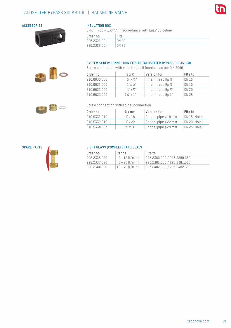
INSULATION BOXEPP, TO -30 – 130 °C, in accordance with EnEV guideline
Order no. Fits296.2321.004 DN 20296.2322.004 DN 25
SYSTEM SCREW CONNECTION FITS TO TACOSETTER BYPASS SOLAR 130Screw connection with male thread R (conical) as per DIN 2999
Order no. G x R Version for Fits to210.6630.000 ¾ x ½" Inner thread Rp ½ DN 15 210.6631.000 1 x ½" Inner thread Rp ½ DN 15 210.6632.000 1 x ¾ Inner thread Rp ¾ DN 20 210.6633.000 1¼ x 1 Inner thread Rp 1 DN 25
Screw connection with solder connection
Order no. G x mm Version for Fits to 210.5331.019 1 x 18 Copper pipe ø 18 mm DN 15 (Male)210.5332.019 1 x 22 Copper pipe ø 22 mm DN 20 (Male)210.5334.003 1¼ x 28 Copper pipe ø 28 mm DN 25 (Male)
SIGHT GLASS (COMPLETE) AND SEALS
Order no. Range Fits to298.2336.020 2 – 12 (l/min) 223.2380.000 / 223.2380.350298.2337.020 8 – 20 (l/min) 223.2381.000 / 223.2381.350298.2344.020 10 – 40 (l/min) 223.2482.000 / 223.2482.350
TACOSETTER BYPASS SOLAR 130 | BALANCING VALVE
CONTACT AND FURTHER INFORMATION TACONOVA.COM
Taconova Group AG | Neunbrunnenstrasse 40 | CH-8050 Zurich | T +41 44 735 55 55 | F +41 44 735 55 02 | [email protected]

20 taconova.com
Hydr
onic
bal
anci
ng
T
T
T
TACOSETTER BYPASS SOLAR 185 ADVANTAGES ■ Accurate and fast adjustment with scale and without the aid of diagrams, tables or measure-ment devices
■ Direct reading of the set volume flow in l/min
■ Temperature-resistant up to 185 °C
■ Variable installation position, maintenance-free
■ Flow control with setpoint adjuster
■ Regulating valve with isolating facility (rest leakage possible)
■ Minimal pressure loss
SYSTEM/BASIC DIAGRAM
BALANCING VALVE
DESCRIPTIONDirect hydraulic balancing and con-trol of flows to consumers or in a subsystem. Balancing valves offer an easy and accurate method of ad-justing the flow rates for heating-, ventilation-, air conditioning - and solar systems. The Version TacoSetter Bypass Solar 185 is designed for higher operating temperatures.Correct balancing of hydraulic cir-cuits ensures optimum energy dis-tribution, resulting in more efficient and economical operation in ac-cordance with the energy saving re-gulations provided for by legislation.
With TacoSetter Bypass Solar 185 balancing valves, any qualified fitter can set the appropriate flow rate using the unique flow measurement device, avoiding investments in trai-ning and costly measuring devices.
INSTALLATION POSITIONThe TacoSetter Bypass Solar 185 requires a straight section of pipe of the same length and diameter as the system. The valve can be installed in a horizontal, vertical or inclined position. Care should be taken that the arrow is pointing in the direction of the flow.
Direct regulation, indication and isolation of flows in solar systems.
In the case of the high-temperature type, the bypass unit is replaced by the sealing cap set after adjustment.
OPERATION The flow measurement is based on the principle of a baffle float with return spring. The reading position is the bottom line of the baffle float.The measuring device is placed in a bypass to the main flow, isolated from system flow. By demand the by-pass, with self locking valves, gets opened / closed by pressing / re-leasing the clamp. Reading the flow rate has no influence on the main flow rate.
BUILDING CATEGORIESFor pipe installations in heating and cooling area:
■ Apartment blocks, housing estates, multiple dwelling units
■ Residential care facilities and hos-pitals
■ Administration and service buildings ■ Hotels and restaurants, industrial kitchens
■ School buildings and sports facilities ■ Commercial and industrial buildings ■ Facilities with partial use, such as barracks, camping sites
■■ TacoSetter Bypass Solar 185

21taconova.com
Hydr
onic
bal
anci
ng
8 7 6 5 4
3 2
l/min
DC
BA
Rp
A
G
C SW
C
D
B1
B2
DIMENSIONAL DRAWING
TYPE OVERVIEW TacoSetter Bypass Solar 185 | Balancing valve with female thread (incl. sealing cap set)
Order no. DN Rp × Rp Measuring range kVS (m3/h)223.2382.000 20 ¾" × ¾" 2 – 12 (l/min) 2,2223.2383.000 20 ¾" × ¾" 8 – 30 (l/min) 5,0223.2480.000 25 1" × 1" 10 – 40 (l/min) 8,1223.2580.000 32 1¼" × 1¼" 20 – 70 (l/min) 17,0
TacoSetter Bypass Solar 185 | Balancing valve with male thread (incl. sealing cap set)
Order no. DN G × G Measuring range kVS (m3/h)223.2382.385 20 1" × 1" 2 – 12 (l/min) 2,2223.2383.385 20 1" × 1" 8 – 30 (l/min) 5,0
MEASUREMENT TABLE TacoSetter Bypass Solar 185 | Balancing valve with female thread
Order no. DN A B1 C D SW Rp223.2382.000 20 129 39 46 79 34 ¾"223.2383.000 20 129 39 46 79 34 ¾"223.2480.000 25 152 47 58 82 41 1"223.2580.000 32 161 56 65 84 49 1"
TacoSetter Bypass Solar 185 | Balancing valve with male thread
Order no. DN A B2 C D G223.2382.385 20 129 12 46 79 1"223.2383.385 20 129 12 46 79 1"
SPECIFICATION TEXTSee www.taconova.com
TECHNICAL DATAGeneral
■ Admissible operating parameters TO max und PO max: see pressure temperature curve
■ Measuring accuracy: ■ Measurement range <25%: ±20% of the indicated value
■ Measurement range >25%: ±10% of the indicated value
■ kVS value and measurement range: see “Type Program”
■ Female thread to DIN 2999 / ISO 7 or male thread G (cylindrical) to ISO 228
Material ■ Housing: brass ■ Inside: stainless steel, brass, plastic ■ Sight glass: heat- and impact-resistant plastic
■ Sealing: EPDM Fluids
■ Heating water (VDI 2035; SWKI BT 102-01; ÖNORM H 5195–1)
■ Potable water (DIN 1988-200) ■ Water and proprietary additives used against corrosion and freezing up to 50% (see document «Correc-tion curves»)
ADDITIONAL MODELSBalancing valves for solar applica-tions, see TacoSetter Bypass 100 and TacoSetter Bypass Solar 130 data sheets.
TACOSETTER BYPASS SOLAR 185 | BALANCING VALVE
GLYCOL CORRECTION CURVESThere is a separate diagram for TacoSetter up to DN25 and its flow ranges with nine correction cur-ves for use of anti-frost and anti-corrosion agents. Corrections are not required for larger dimensions as the devi-ation lies within the measuring tolerance.See www.taconova.com

22 taconova.com
Hydr
onic
bal
anci
ng
0
2
4
6
8
10
12
14
16
18
300 60 90 120100 150 210185130
223.2382.XXX (DN 20 | ¾" | 2...12 l/min)
223.2580.000 (DN 32 | 1¼" | 20...70 l/min)
223.2383.XXX (DN 20 | ¾" | 8...30 l/min) 223.2480.XXX (DN 25 | 1" | 10...40 l/min)
1000
100
10
1
1 102 12 100
1000
100
10
110 7020 100
1000
100
10
11 108 30 100
1000
100
10
11 4010 100
A
A
BB
B
B
C
C
C
C
D
D
D
D
kVS = 2,2
kVS = 17
kVS = 5,0 kVS = 8,1
PRESSURE − TEMPERATURE-CHARACTERISTIC
PRESSURE LOSS DIAGRAMS
Pres
sure
loss
(mba
r)
Pres
sure
loss
(mba
r)
Pres
sure
loss
(mba
r)
Flow rate (l/min)
Flow rate (l/min)
Flow rate (l/min) Flow rate (l/min)
A – D Valve position
A – D Valve position
B – D Valve position B – D Valve position
TACOSETTER BYPASS SOLAR 185 | BALANCING VALVE
Permissible operating range with sealing cap set
Permissible operating range with bypassOp
erat
ing
pres
sure
(bar
)Pr
essu
re lo
ss (m
bar)
Operating temperature (°C) (incl. sealing caps short-term 195 °C)

23taconova.com
Hydr
onic
bal
anci
ng
Subj
ect
to m
odif
icat
ion.
05/
2017
ACCESSORIES
SPARE PARTS
TACOSETTER BYPASS SOLAR 185 | BALANCING VALVE
SYSTEM SCREW CONNECTION FITS TO TACOSETTER BYPASSScrew connection with male thread R (conical) as per DIN 2999
Order no. G x R Version for Fits to 210.6630.000 ¾ x ½" Threaded pipe Rp ½ DN 15 210.6631.000 1 x ½" Threaded pipe Rp ½ DN 15 210.6632.000 1 x ¾ Threaded pipe Rp ¾ DN 20 210.6633.000 1¼ x 1 Threaded pipe Rp 1 DN 25
Screw connection with solder connection
Order no. G x mm Version for Fits to 210.5331.019 1 x 18 Copper pipe ø 18 mm DN 15 AG210.5332.019 1 x 22 Copper pipe ø 22 mm DN 20 AG210.5334.003 1¼ x 28 Copper pipe ø 28 mm DN 25 AG
SIGHT GLASS (COMPLETE) AND SEAL
Order no. Range Fits to298.2336.020 2 – 12 (l/min) 223.2380.000 / 223.2380.350298.2337.020 8 – 20 (l/min) 223.2381.000 / 223.2381.350298.2338.020 8 – 30 (l/min) 223.2383.000 / 223.2383.385298.2344.020 10 – 40 (l/min) 223.2482.000 / 223.2482.350
SEALING CAP SET FOR TACOSETTER BYPASS 130/185
Order no. Fits to 296.2340.003 all versionsIncluded with delivery for Solar 185 model
CONTACT AND FURTHER INFORMATION TACONOVA.COM
Taconova Group AG | Neunbrunnenstrasse 40 | CH-8050 Zurich | T +41 44 735 55 55 | F +41 44 735 55 02 | [email protected]

24 taconova.com
Hydr
onic
bal
anci
ng
M
M
MM
TACOSETTER BYPASS FLANGE ADVANTAGES ■ Accurate and fast adjustment with scale and without the aid of diagrams, tables or measure-ment devices
■ Direct reading of the set volume flow in l/min
■ Variable installation position, maintenance-free
■ Flow control with setpoint ad-juster
■ Regulating valve with isolating facility (rest leakage possible)
■ Minimal pressure loss
SYSTEM / BASIC DIAGRAM
BALANCING VALVE
DESCRIPTIONDirect hydraulic balancing and control of flows to consumers or in a subsystem. TacoSetter Bypass Flange balancing valves offer an easy and accurate method of ad-justing the flow rates for heating-, ventilation-, air conditioning- and cooling systems. Correct balancing of hydraulic circuits ensures optimum energy distribution, resulting in more efficient and eco-nomical operation in accordance with the energy saving regulations provi-ded for by legislation.With TacoSetter Bypass Flange ba-lancing valves, any qualified fitter can set the appropriate flow rate using the unique flow measurement
device, avoiding investments in training and costly measuring devices.
INSTALLATIONTo avoid turbulence and obtain ma-ximum accuracy of the required flow it is necessary to install, on the inlet side of the valve, a section of straight pipe, the same diameter and length as the valve body. The valve may be installed in any po-sition, care should be taken in order to ensure that both the measuring cylinder and adjustment screw are not obstructed and that the arrow is pointing in the direction of the flow.
Direct reading and balancing valve with visual flow indication.
OPERATION Measurement of the flow rate through the valve can be set by turning the adjustment screw until the required flow rate is read on the front edge of the float, which is situated within the measuring cylinder.The two check valves must be in the open position but can be closed af-ter commissioning without affecting the set position.
BUILDING CATEGORIESFor pipe installations in heating water and cooling areas:
■ Apartment blocks, housing estates, multiple dwelling units
■ Residential care facilities and hospitals
■ Administration and service buildings ■ School buildings and sports facilities ■ Commercial and industrial buildings
1
10
100
1000
10 1000650100
2
3
6
4
7
5
81
10
100
1000
10 100045075
2
3
6
4
7
5
81
10
100
1000
10 100032560
2
3
6
4
7
5
8 kVS = 85 kVS = 166 kVS = 208
Subj
ect
to m
odif
icat
ion.
07/
2017
PRESSURE LOSS DIAGRAM
Pres
sure
loss
(mba
r)
Pres
sure
loss
(mba
r)
Pres
sure
loss
(mba
r)
Flow rate (l/min) Flow rate (l/min) Flow rate (l/min)
223.2151.000 (DN 65 | 60...325 l/min) 223.2251.000 (DN 80 | 75...450 l/min) 223.2351.000 (DN 100 | 100...650 l/min)
2 – 8 Valve position 2 – 8 Valve position 2 – 8 Valve position
TACOSETTER BYPASS FLANGE | BALANCING VALVE
CONTACT AND FURTHER INFORMATION TACONOVA.COM
Taconova Group AG | Neunbrunnenstrasse 40 | CH-8050 Zurich | T +41 44 735 55 55 | F +41 44 735 55 02 | [email protected]
■■ TacoSetter Bypass Flange

25taconova.com
Hydr
onic
bal
anci
ng
6
8
4
0
2
Rp ½PN 16 DIN 2501
20
C
240
Ø B
Ø 18
Ø A
DIMENSIONAL DRAWING
TYPE PROGRAM TacoSetter Bypass Flange | Balancing valve
Order no. DN Measuring range Weight kVS (m3/h)223.2151.000 65 60 – 325 (l/min) 13,9 kg 85,0223.2251.000 80 75 – 450 (l/min) 16,5 kg 166,0223.2351.000 100 100 – 650 (l/min) 19,7 kg 208,0
MEASUREMENT TABLE TacoSetter Bypass Flange | Balancing valve
Order no. DN A B C ø 18223.2151.000 65 185 145 110 4 holes223.2251.000 80 200 160 118 8 holes223.2351.000 100 220 180 128 8 holes
SPECIFICATION TEXTSee www.taconova.com
TECHNICAL DATAGenerally
■ Operating temperature TO max: 100 ˚C ■ Operating pressure PO max: 10 bar ■ Measuring accuracy: ±5% of nominal flow
■ kVS-value and measurement range see «Type program»
Material ■ Valve body: grey, cast iron ■ Valve housing materials: brass ■ Sight glass: heat- and impact resistant plastic
■ Seals: EPDMFluids
■ Heating water (VDI 2035; SWKI BT 102-01; ÖNORM H 5195–1)
■ Water and proprietary additives used against corrosion and freezing up to 50%
APPROVALS / CERTIFICATES ■ ACS (drinking water certification France)
TACOSETTER BYPASS FLANGE | BALANCING VALVE
SPARE PARTS SIGHT GLASS (COMPLETE) AND SEAL
Order no. Range Fits to298.2321.000 60 – 325 (l/min) 223.2151.000298.2322.000 75 – 450 (l/min) 223.2251.000298.2323.000 100 – 650 (l/min) 223.2351.000
1
10
100
1000
10 1000650100
2
3
6
4
7
5
81
10
100
1000
10 100045075
2
3
6
4
7
5
81
10
100
1000
10 100032560
2
3
6
4
7
5
8 kVS = 85 kVS = 166 kVS = 208
Subj
ect
to m
odif
icat
ion.
07/
2017
PRESSURE LOSS DIAGRAM
Pres
sure
loss
(mba
r)
Pres
sure
loss
(mba
r)
Pres
sure
loss
(mba
r)
Flow rate (l/min) Flow rate (l/min) Flow rate (l/min)
223.2151.000 (DN 65 | 60...325 l/min) 223.2251.000 (DN 80 | 75...450 l/min) 223.2351.000 (DN 100 | 100...650 l/min)
2 – 8 Valve position 2 – 8 Valve position 2 – 8 Valve position
TACOSETTER BYPASS FLANGE | BALANCING VALVE
CONTACT AND FURTHER INFORMATION TACONOVA.COM
Taconova Group AG | Neunbrunnenstrasse 40 | CH-8050 Zurich | T +41 44 735 55 55 | F +41 44 735 55 02 | [email protected]

26 taconova.com
Hydr
onic
bal
anci
ng
M
M
MM
TACOSETTER INLINE 100
ww
w.H
YG.d
e
nach KTW
ADVANTAGES ■ Accurate and fast adjustment with scale and without the aid of diagrams, tables or measure-ment devices
■ Direct reading of the set volume flow in l/min
■ Variable installation position, maintenance-free
■ Regulating valve with isolating facility (rest leakage possible)
■ Additional types are also available as make resistant to dezincification
SYSTEM/BASIC DIAGRAM
BALANCING VALVE
DESCRIPTIONDirect hydraulic balancing and control of flows to consumers or in a sub-system. Balancing valves offer a quick, easy and accurate method of adjusting the flow rates through heating, ven-tilation, air conditioning and cooling systems.Correct balancing of hydraulic circuits ensures optimum energy distribution, resulting in more efficient and eco-nomical operation in accordance with the energy saving regulations provided for by legislation.With TacoSetter Inline 100 balancing valves, any qualified fitter can set the appropriate flow rate using the unique flow measurement device,
avoiding investments in training and costly measuring devices.
INSTALLATION POSITIONThe valve can be installed in a hori-zontal, vertical or inclined position. Care should be taken that the arrow is pointing in the direction of the flow.
OPERATION The flow measurement is based on the principle of a baffle float with return spring. The flowmeter is built into the housing.The balancing can be carried out with a screwdriver at the adjusting screw. The reading position is the bottom line of the baffle float.
Direct regulation, reading and shut-off of flows in systems
BUILDING CATEGORIESFor pipe installations in drinking water, heating and cooling area:
■ Apartment blocks, housing estates, multiple dwelling units
■ Residential care facilities and hospitals
■ Administration and service buildings ■ Hotels and restaurants, industrial kitchens
■ School buildings and sports facilities ■ Commercial and industrial buildings ■ Facilities with partial use, such as barracks, camping sites
■■ TacoSetter Inline 100
27taconova.com
Hydr
onic
bal
anci
ng
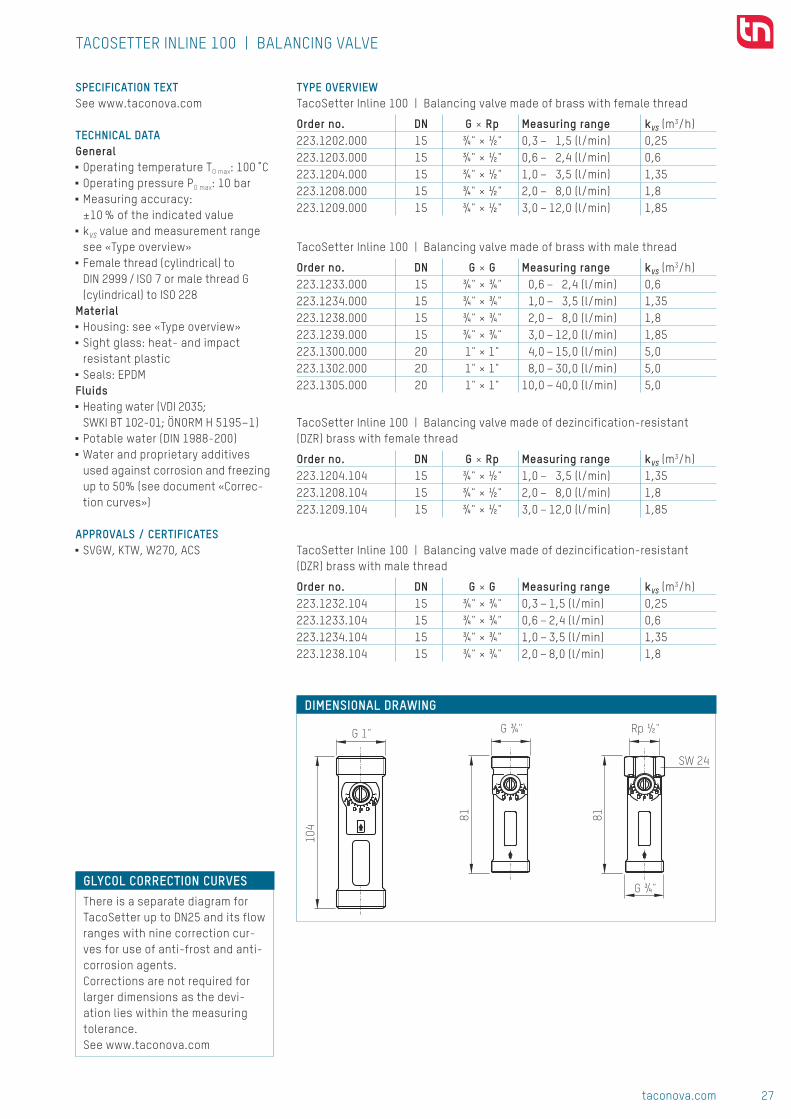
G 1" G ¾" Rp ½"
SW 24
G ¾"
104
81 81
DIMENSIONAL DRAWING
TYPE OVERVIEW TacoSetter Inline 100 | Balancing valve made of brass with female thread
Order no. DN G × Rp Measuring range kVS (m3/h)223.1202.000 15 ¾" × ½" 0,3 – 1,5 (l/min) 0,25223.1203.000 15 ¾" × ½" 0,6 – 2,4 (l/min) 0,6223.1204.000 15 ¾" × ½" 1,0 – 3,5 (l/min) 1,35223.1208.000 15 ¾" × ½" 2,0 – 8,0 (l/min) 1,8223.1209.000 15 ¾" × ½" 3,0 – 12,0 (l/min) 1,85
TacoSetter Inline 100 | Balancing valve made of brass with male thread
Order no. DN G × G Measuring range kVS (m3/h)223.1233.000 15 ¾" × ¾" 0,6 – 2,4 (l/min) 0,6223.1234.000 15 ¾" × ¾" 1,0 – 3,5 (l/min) 1,35223.1238.000 15 ¾" × ¾" 2,0 – 8,0 (l/min) 1,8223.1239.000 15 ¾" × ¾" 3,0 – 12,0 (l/min) 1,85223.1300.000 20 1" × 1" 4,0 – 15,0 (l/min) 5,0223.1302.000 20 1" × 1" 8,0 – 30,0 (l/min) 5,0223.1305.000 20 1" × 1" 10,0 – 40,0 (l/min) 5,0
TacoSetter Inline 100 | Balancing valve made of dezincification-resistant (DZR) brass with female thread
Order no. DN G × Rp Measuring range kVS (m3/h)223.1204.104 15 ¾" × ½" 1,0 – 3,5 (l/min) 1,35223.1208.104 15 ¾" × ½" 2,0 – 8,0 (l/min) 1,8223.1209.104 15 ¾" × ½" 3,0 – 12,0 (l/min) 1,85
TacoSetter Inline 100 | Balancing valve made of dezincification-resistant (DZR) brass with male thread
Order no. DN G × G Measuring range kVS (m3/h)223.1232.104 15 ¾" × ¾" 0,3 – 1,5 (l/min) 0,25223.1233.104 15 ¾" × ¾" 0,6 – 2,4 (l/min) 0,6223.1234.104 15 ¾" × ¾" 1,0 – 3,5 (l/min) 1,35223.1238.104 15 ¾" × ¾" 2,0 – 8,0 (l/min) 1,8
SPECIFICATION TEXTSee www.taconova.com
TECHNICAL DATAGeneral
■ Operating temperature TO max: 100 ̊ C ■ Operating pressure PO max: 10 bar ■ Measuring accuracy: ±10 % of the indicated value
■ kVS value and measurement range see «Type overview»
■ Female thread (cylindrical) to DIN 2999 / ISO 7 or male thread G (cylindrical) to ISO 228
Material ■ Housing: see «Type overview» ■ Sight glass: heat- and impact resistant plastic
■ Seals: EPDMFluids
■ Heating water (VDI 2035; SWKI BT 102-01; ÖNORM H 5195–1)
■ Potable water (DIN 1988-200) ■ Water and proprietary additives used against corrosion and freezing up to 50% (see document «Correc-tion curves»)
APPROVALS / CERTIFICATES ■ SVGW, KTW, W270, ACS
TACOSETTER INLINE 100 | BALANCING VALVE
GLYCOL CORRECTION CURVESThere is a separate diagram for TacoSetter up to DN25 and its flow ranges with nine correction cur-ves for use of anti-frost and anti-corrosion agents. Corrections are not required for larger dimensions as the devi-ation lies within the measuring tolerance.See www.taconova.com

28 taconova.com
Hydr
onic
bal
anci
ng
1
10
100
1000
0 1 101,50,31
10
100
1000
0 1 102,40,6
1
10
100
1000
1 103,5
1
10
100
1000
1 102 8 1
10
100
1000
1 10 100123
1
10
100
1000
1 10 1004 15
1
10
100
1000
1 10 1008 30 40
A
D D
D DD
D
B
B
B B
B
E E
E EE
E
CC
CC
C
C
C
FF
F
F
F
F
E
kVS = 0,25
kVS = 1,8
kVS = 5,0
kVS = 0,6
kVS = 1,85
kVS = 1,35
kVS = 5,0
DF
223.1202.000 (DN 15 | 0,3...1,5 l/min)223.1232.104 (DN 15 | 0,3...1,5 l/min)
223.1208.XXX (DN 15 | 2...8 l/min)223.1238.XXX (DN 15 | 2...8 l/min)
223.1302.000 (DN 20 | 8...30 l/min)223.1305.000 (DN 20 | 10...40 l/min)
223.1203.000 (DN 15 | 0,6...2,4 l/min)223.1233.XXX (DN 15 | 0,6...2,4 l/min)
223.1209.XXX (DN 15 | 3...12 l/min)223.1239.000 (DN 15 | 3...12 l/min)
223.1204.XXX (DN 15 | 1,0...3,5 l/min)223.1234.XXX (DN 15 | 1,0...3,5 l/min)
223.1300.000 (DN 20 | 4...15 l/min)
PRESSURE LOSS DIAGRAMSPr
essu
re lo
ss (m
bar)
Pres
sure
loss
(mba
r)Pr
essu
re lo
ss (m
bar)
Pres
sure
loss
(mba
r)Pr
essu
re lo
ss (m
bar)
Pres
sure
loss
(mba
r)Pr
essu
re lo
ss (m
bar)
Flow rate (l/min)
Flow rate (l/min)
Flow rate (l/min)
Flow rate (l/min)
Flow rate (l/min)
Flow rate (l/min)
Flow rate (l/min)
A – F Valve position
B –F Valve position
C – F Valve position
B – F Valve position
C – F Valve position
B – D Valve position
C – F Valve position
TACOSETTER INLINE 100 | BALANCING VALVE

29taconova.com
Hydr
onic
bal
anci
ng
Subj
ect
to m
odif
icat
ion.
10/
2017
ACCESSORIES SYSTEM SCREW CONNECTION FITS TO TACOSETTER INLINEComprising a cap nut, clamp ring and support sleeve
Order no. G × mm Version for Fits to
210.3325.000 ¾" × 15 Copper pipe 15⁄1 Eurocone
DN 15
Screw connections with cap nut and insert
Order no. G × R Version for Fits to
210.6221.000 ¾" × ½"½" thread, conically sealing, dezincification-resistant
DN 15
210.6632.000 1" × ¾" ¾" thread, flat-sealing DN 20210.6633.000 1¼" × 1" 1" thread, flat-sealing DN 20210.6222.000 ¾" × ½" ½" thread, self-sealing DN 15
TACOSETTER INLINE 100 | BALANCING VALVE
CONTACT AND FURTHER INFORMATION TACONOVA.COM
Taconova Group AG | Neunbrunnenstrasse 40 | CH-8050 Zurich | T +41 44 735 55 55 | F +41 44 735 55 02 | [email protected]

30 taconova.com
Hydr
onic
bal
anci
ng
M
M
MM
TACOSETTER INLINE 130 ADVANTAGES ■ Accurate and fast adjustment with scale and without the aid of diagrams, tables or measure-ment devices
■ Direct reading of the set volume flow in l/min with glycol scale
■ Temperature-resistant up to 130 °C
■ Direct connection to circulating pump, variable installation position
■ Flow control with setpoint adjuster
■ Regulating valve with isolating facility (rest leakage possible)
SYSTEM/BASIC DIAGRAM
BALANCING VALVE
DESCRIPTIONDirect hydraulic balancing and control of flows at the intake manifold of circulating pumps. Balancing valves offer an easy and accurate method of adjusting the flow rates through hea-ting, ventilation, air conditioning and cooling systems.Correct balancing of hydraulic circuits ensures optimum energy distribution, resulting in more efficient and econo-mical operation in accordance with the energy saving regulations provi-ded for by legislation. With TacoSetter Inline 130 balancing valves, any qua-lified fitter can set the appropriate flow rate on the premises in question, thus avoiding investments in training and costly measuring devices.
INSTALLATION POSITIONThe valve can be installed in a hori-zontal, vertical or inclined position.Care should be taken to ensure that the arrow is pointing in the direction of the flow. The TacoSetter Inline 130 can be built into the 1" threaded pump con-nection to the intake manifold of the circulating pump thanks to its spe-cial housing design.
OPERATION The flow measurement is based on the principle of a baffle float with return spring. The flowmeter is built into the housing.
Direct regulation, indication and isolation of flows in systems.
The balancing can be carried out with a screwdriver at the adjusting screw. The reading position is the bottom line of the baffle float.
BUILDING CATEGORIESFor pipe installations in heating area:
■ Apartment blocks, housing estates, multiple dwelling units
■ Residential care facilities and hospitals
■ Administration and service buildings ■ Hotels and restaurants, industrial kitchens
■ School buildings and sports faci-lities
■ Commercial and industrial buildings ■ Facilities with partial use, such as barracks, camping sites
NOTE
Important when using glycol
The system medium must be allo-wed to flow through the measu-ring body for at least 2 hours prior to reading the flow rate when performing the initial start-up or refilling the system
■■ TacoSetter Inline 130
31taconova.com
Hydr
onic
bal
anci
ng
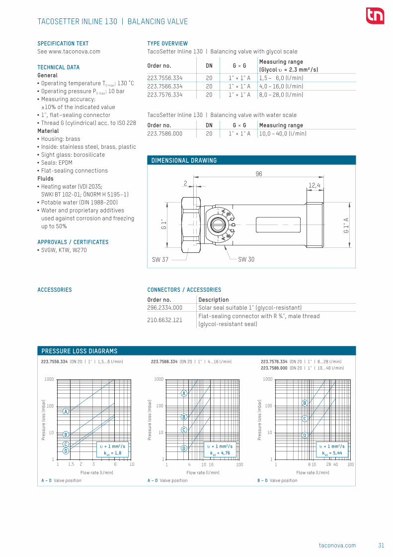
1
10
100
1000
1 101,5 62 31
10
100
1000
1 10 1004 161
10
100
1000
1 10 1008 28 40
A
A
D
D
B
B
B
C
C
CD
223.7556.334 (DN 20 | 1" | 1,5...6 l/min) 223.7566.334 (DN 20 | 1" | 4...16 l/min) 223.7576.334 (DN 20 | 1" | 8...28 l/min)223.7586.000 (DN 20 | 1" | 10...40 l/min)
96
G 1"
A
12,4
G 1"
2
SW 30SW 37
υ = 1 mm2/skVS = 1,8
υ = 1 mm2/skVS = 4,76
υ = 1 mm2/skVS = 5,44
DIMENSIONAL DRAWING
TYPE OVERVIEW TacoSetter Inline 130 | Balancing valve with glycol scale
Order no. DN G × GMeasuring range (Glycol υ = 2.3 mm²/s)
223.7556.334 20 1" × 1" A 1,5 – 6,0 (l/min)223.7566.334 20 1" × 1" A 4,0 – 16,0 (l/min)223.7576.334 20 1" × 1" A 8,0 – 28,0 (l/min)
TacoSetter Inline 130 | Balancing valve with water scale
Order no. DN G × G Measuring range223.7586.000 20 1" × 1" A 10,0 – 40,0 (l/min)
SPECIFICATION TEXTSee www.taconova.com
TECHNICAL DATAGeneral
■ Operating temperature TO max: 130 ˚C ■ Operating pressure PO max: 10 bar ■ Measuring accuracy: ±10% of the indicated value
■ 1", flat–sealing connector ■ Thread G (cylindrical) acc. to ISO 228
Material ■ Housing: brass ■ Inside: stainless steel, brass, plastic ■ Sight glass: borosilicate ■ Seals: EPDM ■ Flat-sealing connections
Fluids ■ Heating water (VDI 2035; SWKI BT 102-01; ÖNORM H 5195–1)
■ Potable water (DIN 1988-200) ■ Water and proprietary additives used against corrosion and freezing up to 50%
APPROVALS / CERTIFICATES ■ SVGW, KTW, W270
TACOSETTER INLINE 130 | BALANCING VALVE
PRESSURE LOSS DIAGRAMS
Pres
sure
loss
(mba
r)
Pres
sure
loss
(mba
r)
Pres
sure
loss
(mba
r)
Flow rate (l/min) Flow rate (l/min) Flow rate (l/min)
A – D Valve position A – D Valve position B – D Valve position
CONNECTORS / ACCESSORIES
Order no. Description296.2334.000 Solar seal suitable 1" (glycol-resistant)
210.6632.121Flat-sealing connector with R ¾", male thread (glycol-resistant seal)
ACCESSORIES
Subj
ect
to m
odif
icat
ion.
12/
2017
CONTACT AND FURTHER INFORMATION TACONOVA.COM
Taconova Group AG | Neunbrunnenstrasse 40 | CH-8050 Zurich | T +41 44 735 55 55 | F +41 44 735 55 02 | [email protected]

32 taconova.com
Hydr
onic
bal
anci
ng
TACOSETTER RONDO ADVANTAGES ■ Accurate and quick balancing without diagrams, tables or measuring devices
■ The flow rate is displayed directly in l/min
■ Variable installation position, maintenance-free, compact
■ Regulating valve with isolating facility (rest leakage possible)
■ Self-sealing screw connector ■ Valve adjustment tool integrated in protective cover
SYSTEM/BASIC DIAGRAM
BALANCING VALVE
DESCRIPTIONDirect hydraulic balancing and con-trol of flows to consumers. Balancing valves offer a quick, easy and accu-rate method of adjusting the flow rates through heating, ventilation, air conditioning and cooling systems.Correct balancing of hydraulic cir-cuits allows for lower flow tempera-tures, resulting in more efficient and economical operation in accordance with the energy saving regulations provided for by legislation.With TacoSetter Rondo balancing valves, any qualified fitter can set the appropriate water distribution, thus avoiding investments in training and costly measuring devices.
INSTALLATION POSITIONThe balancing valve requires a straight section of pipe of the same length and diameter TacoSetter Rondo.The valve can be installed in a hori-zontal, vertical or inclined position. Care should be taken in order to en-sure that the arrow is pointing in the direction of the flow.
OPERATION The flow measurement is based on the displacement principle of a baffle disk, which is inserted in a measuring tube. The movement of the baffle disc is transformed to the sight glass by a mechanical device. The scale printed on the sight glass allows the flow rate to be read with ease.
Direct regulation and indication of flows to consumers.
Turning the sight glass changes the opening profile of the valve and al-lows the desired flow rate to be set.
BUILDING CATEGORIESFor pipe installations in heating and cooling area:
■ Apartment blocks, housing estates, multiple dwelling units
■ Residential care facilities and hospitals
■ Administration and service buildings ■ Hotels and restaurants, industrial kitchens
■ School buildings and sports facilities ■ Commercial and industrial buildings ■ Facilities with partial use, such as barracks, camping sites
■■ TacoSetter Rondo
33taconova.com
Hydr
onic
bal
anci
ng
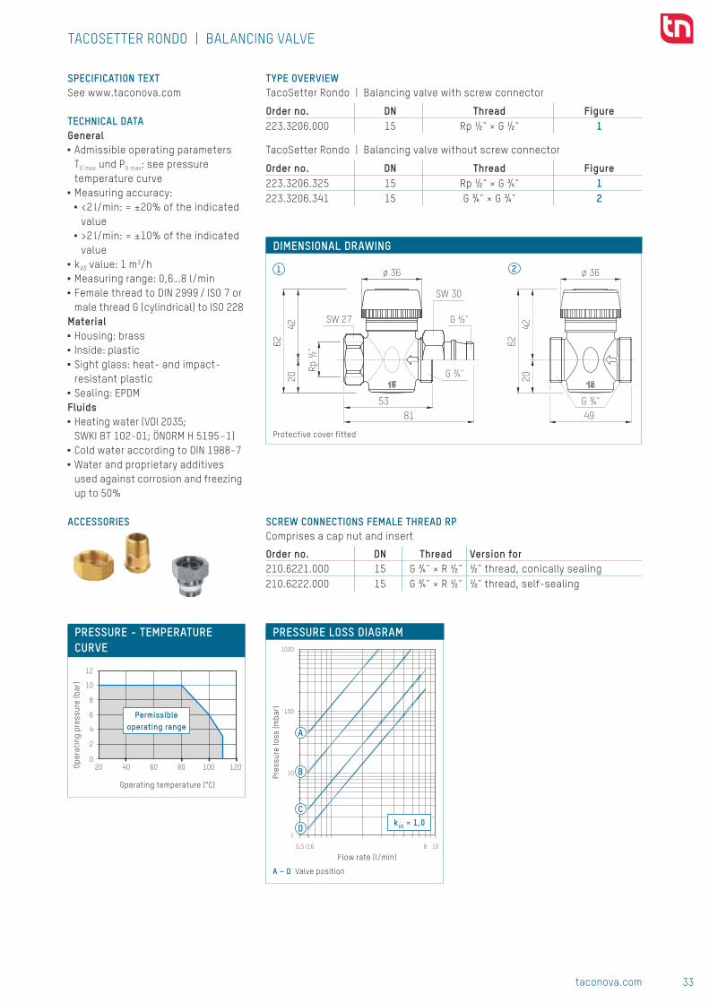
1000
100
10
1
0,5 0,6 10 8
A
B
C
DkVS = 1,0
ø 36
4220
62
49G ¾"
ø 36
Rp ½
"
4220
62
8153
G ¾"
G ½"
SW 30
SW 27
1 2
020 40 60 80 100 120
2
4
6
8
10
12
DIMENSIONAL DRAWING
Protective cover fitted
TYPE OVERVIEW TacoSetter Rondo | Balancing valve with screw connector
Order no. DN Thread Figure223.3206.000 15 Rp ½" × G ½" 1
TacoSetter Rondo | Balancing valve without screw connector
Order no. DN Thread Figure223.3206.325 15 Rp ½" × G ¾" 1223.3206.341 15 G ¾" × G ¾" 2
SPECIFICATION TEXTSee www.taconova.com
TECHNICAL DATAGeneral
■ Admissible operating parameters TO max und PO max: see pressure temperature curve
■ Measuring accuracy: ■ <2 l/min: = ±20% of the indicated value
■ >2 l/min: = ±10% of the indicated value
■ kVS value: 1 m3/h ■ Measuring range: 0,6…8 l/min ■ Female thread to DIN 2999 / ISO 7 or male thread G (cylindrical) to ISO 228
Material ■ Housing: brass ■ Inside: plastic ■ Sight glass: heat- and impact-resistant plastic
■ Sealing: EPDMFluids
■ Heating water (VDI 2035; SWKI BT 102-01; ÖNORM H 5195–1)
■ Cold water according to DIN 1988-7 ■ Water and proprietary additives used against corrosion and freezing up to 50%
TACOSETTER RONDO | BALANCING VALVE
PRESSURE LOSS DIAGRAM
Pres
sure
loss
(mba
r)
Flow rate (l/min)
A – D Valve position
PRESSURE - TEMPERATURE CURVE
Permissibleoperating range
Oper
atin
g pr
essu
re (b
ar)
Operating temperature (°C)
Subj
ect
to m
odif
icat
ion.
08/
2017
SCREW CONNECTIONS FEMALE THREAD RPComprises a cap nut and insert
Order no. DN Thread Version for210.6221.000 15 G ¾" × R ½" ½" thread, conically sealing210.6222.000 15 G ¾" × R ½" ½" thread, self-sealing
ACCESSORIES
CONTACT AND FURTHER INFORMATION TACONOVA.COM
Taconova Group AG | Neunbrunnenstrasse 40 | CH-8050 Zurich | T +41 44 735 55 55 | F +41 44 735 55 02 | [email protected]

34 taconova.com
Hydr
onic
bal
anci
ng
(30°C)
TACOSETTER HYLINE ADVANTAGES ■ Valve made from high-quality, glass fiber-reinforced plastic, ideal for plastic systems
■ Can be used for various media ■ Inch standard thread: can be connected directly to plastic gland, no need for metal conversion adapters
■ Fast, precise adjustment with twist grip
■ High kVS values ■ Fast, simple assembly without tools
SYSTEM/BASIC DIAGRAM
BALANCING VALVE
DESCRIPTIONHydronic balancing and volume flow measurement: manufactured fully from high-quality plastic, TacoSetter Hyline balancing valves allow the required volume of water in geother-mal, drinking water, heating, venti-lating and air conditioning systems to be adjusted precisely and conve-niently.Correct balancing of hydraulic cir-cuits ensures optimum energy dis-tribution, resulting in more efficient and economical operation in ac-cordance with the energy saving re-gulations provided for by legislation.The valves are quick and easy to fit and require no additional tools.
With TacoSetter Hyline balancing valves, specialists on site can adjust the required flow rate in l/min quickly and precisely using a scale, without the aid of diagrams, tables or investments in training and expensive measurement devices.
INSTALLATION POSITIONThe balancing valve requires a straight flow section of the same length and nominal diameter as the valve used. The valve can be installed in a horizontal, tilted or vertical position. Only the arrow in-dicating the direction of flow of the medium needs to be noted. The valve must be installed free of stress.
Direct adjustment, display and shutoff of flow in systems.
OPERATIONThe flow measurement is based on the principle of a baffle float integra-ted in the housing with return spring. The flow is adjusted manually using the twist grip on the angle seat val-ve. The reading position is the lower edge of the float element.
BUILDING CATEGORIESFor pipe installations in geothermal, drinking water and cooling installa-tions:
■ Apartment blocks, housing estates, multiple dwelling units
■ Residential care facilities and hospitals
■ Administration and service buildings
■ Hotels and restaurants, industrial kitchens
■ School buildings and sports halls / sports facilities
■ Commercial and industrial buildings ■ Facilities with partial use, such as barracks, camping sites
■■ TacoSetter Hyline

35taconova.com
Hydr
onic
bal
anci
ng
Volumen: 287253.29 mm3
CH-8902 Urdorf
Techn. Lieferbed.: 1:2Massstab:
cmf
We reserve all rights in connection with this document.
Gez.
Toleranzen ISO 2768
Setter IL Kunststo� kpl
Material:
Gewicht: [SW-Masse] g g
Blatt-Nr.
Anz. Blatt
Datum Name
Gepr.Gen.
Ersatz. für:
Index EM Datum Visum 1
1A3Nous nous reservons tout les droits sur ce document.Für dieses Dokument behalten wir uns alle Rechte vor.
008010
Ober�ächen/SurfacesDIN-ISO 1302
108
G
237
Masszeichnung TacoSetter Hyline.PDF 1 28.08.2015 12:45:58
D 2
D 1
Volumen: 287253.29 mm3
SK
P 1034 - Setter IL Kunststoff
CH-8902 Urdorf
Techn. Lieferbed.: 1:2Massstab:
cmf
We reserve all rights in connection with this document.
02.07.2015####
Gez. 02.07.2015 kalfas
Toleranzen ISO 2768
Setter IL Kunststo� kpl
Material:
Gewicht: [SW-Masse] g g
Blatt-Nr.
Anz. Blatt
Datum Name
Gepr.Gen.
Ersatz. für:
Index EM Datum Visum
1
1A3
Setter IL Kunststoff
Nous nous reservons tout les droits sur ce document.Für dieses Dokument behalten wir uns alle Rechte vor.
x
-008010
Ober�ächen/SurfacesDIN-ISO 1302
0
2
4
6
200-10 40 60 80
DIMENSIONAL DRAWING O-RING
TYPE OVERVIEW TacoSetter Hyline | Balancing valve with external thread
Order no. DN G × G Measuring range kVS (m3/h)223.8410.000 25 1 ½" × 1 ½" 10 – 25 (l/min) 5.9223.8411.000 25 1 ½" × 1 ½" 15 – 40 (l/min) 9.1223.8412.000 25 1 ½" × 1 ½" 20 – 60 (l/min) 11.7223.8523.000 32 2" × 2" 20 – 55 (l/min) 11.7223.8524.000 32 2" × 2" 30 – 80 (l/min) 12.5
MEASUREMENT TABLE TacoSetter Hyline | Balancing valve with external thread
Order no. DN G D1 D2 O-Ring223.8410.000 25 1 ½" 29.7 36.4 29.82 × 2.62223.8411.000 25 1 ½" 29.7 36.4 29.82 × 2.62223.8412.000 25 1 ½" 29.7 36.4 29.82 × 2.62223.8523.000 32 2" 36.0 42.7 36.10 × 3.53223.8524.000 32 2" 36.0 42.7 36.10 × 3.53
SPECIFICATION TEXTSee www.taconova.com
TECHNICAL DATAGeneral
■ Maximum operating parameters TO max and PO max: See pressure- temperature curve
■ Leakage test parameters: max. 12 bar / 20 °C / 1 hr
■ Measuring accuracy: ±8 % of the final value
■ kVS value and measurement range according to „Type overview“ table
■ External thread G (cylindrical) as per ISO 228
Material ■ Housing: plastic, glass fiber- reinforced
■ Spring + clamp: stainless steel ■ Sight glass: borosilicate ■ Seals: EPDM
Fluids ■ Heating water (VDI 2035; SWKI BT 102-01; ÖNORM H 5195–1)
■ Potable water (DIN 1988-200, also treated with chlorine)
■ Water and proprietary additives used against corrosion and freezing up to 50%
■ Rainwater
APPROVALS / CERTIFICATES ■ SVGW / KTW, ACS, WRAS for individual parts
NOTEThe valve must be installed free of stress.
TACOSETTER HYLINE | BALANCING VALVE
PRESSURE-TEMPERATURE CURVE
Oper
atin
g pr
essu
re (b
ar)
Operating temperature (°C)

36 taconova.com
Hydr
onic
bal
anci
ng
M
M
MM
W270
ww
w.H
YG.d
e
nach KTW
TACOSETTER TRONIC ADVANTAGES ■ Precise and fast electronic measurement of flow volume and temperature
■ High measurement precision ■ Measurement range 0...100 °C ■ Temperature measurement directly in the medium
■ Direct connection to circulating pump, variable installation position
■ Glycol resistant ■ Regulating valve with isolating facility (rest leakage possible)
SYSTEM/BASIC DIAGRAM
BALANCING VALVE
DESCRIPTIONFlow volumes and temperatures can be very easily measured and simultaneously evaluated with the TacoSetter Tronic.The features of the TacoSetter Tronic include its different options for use in drinking water, solar and heating systems.The electrical signals for flow and temperature can be used for the control and monitoring of pumps and valves, or for heat quantity metering.A controller, from Sorel for example, can be used to display the measurement data.The control valve can limit or interrupt the flow.
Hydraulically correct balanced systems ensure optimum energy distribution and in this way maintain economic operation as required by the Energy Saving Regulations.
INSTALLATION POSITIONThe valve can be installed in a horizontal, tilted or vertical position. Only the direction of the arrow indicating the flow of the medium needs to be noted.For horizontal installation, it is recommendable to position the sensor on the upper side in order to prevent deposits occurring.
Electronic flow volume and temperature measurement
OPERATION The TacoSetter Tronic was developed for the combined measurement of flow volume and temperature. The flow measurement is based on the vortex principle.The vortex shredding on the body in the flow is proportional to the flow rate.The generated vortices are detected by a piezoelectric sensor and evaluated by the integrated electronics.
BUILDING CATEGORIESFor pipe installations in drinking water, heating and cooling area:
■ Apartment blocks, housing estates, multiple dwelling units
■ Residential care facilities, hospitals ■ Administration and service buildings ■ Hotels and restaurants, industrial kitchens
■ School buildings and sports facilities ■ Commercial and industrial buildings ■ Facilities with partial use, such as barracks, camping sites
Material <nicht festgelegt>
cmf
We reserve all rights in connection with this document.Nous nous reservons tout les droits sur ce document.Für dieses Dokument behalten wir uns alle Rechte vor.
d
e
100
1000
1
10
001011
100
1
10
001011
A
A
B
B
C
DN32
A DN 32, 20 – 55 l/minB DN 32, 30 – 80 l/min
PRESSURE LOSS DIAGRAMSPr
essu
re lo
ss (m
bar)
Pres
sure
loss
(mba
r)
Flow rate (l/min)
A DN 25, 10 – 25 l/minB DN 25, 15 – 40 l/minC DN 25, 20 – 60 l/min
TACOSETTER HYLINE | BALANCING VALVE
DN25
Flow rate (l/min)
Subj
ect
to m
odif
icat
ion.
07/
2017
CONTACT AND FURTHER INFORMATION TACONOVA.COM
Taconova Group AG | Neunbrunnenstrasse 40 | CH-8050 Zurich | T +41 44 735 55 55 | F +41 44 735 55 02 | [email protected]
ACCESSORIES SCREW CONNECTOR FOR TACOSETTER HYLINEPlastic screw connector with washer (PVC) and weld-on socket (PE100)
Order no. G (washer) Fits to210.2025.003 1½" DN 25210.2032.003 2" DN 32
d L eDN25 32 60 2.9DN32 40 63 3.7

37taconova.com
Hydr
onic
bal
anci
ng
M
M
MM
W270
ww
w.H
YG.d
e
nach KTW
TACOSETTER TRONIC ADVANTAGES ■ Precise and fast electronic measurement of flow volume and temperature
■ High measurement precision ■ Measurement range 0...100 °C ■ Temperature measurement directly in the medium
■ Direct connection to circulating pump, variable installation position
■ Glycol resistant ■ Regulating valve with isolating facility (rest leakage possible)
SYSTEM/BASIC DIAGRAM
BALANCING VALVE
DESCRIPTIONFlow volumes and temperatures can be very easily measured and simultaneously evaluated with the TacoSetter Tronic.The features of the TacoSetter Tronic include its different options for use in drinking water, solar and heating systems.The electrical signals for flow and temperature can be used for the control and monitoring of pumps and valves, or for heat quantity metering.A controller, from Sorel for example, can be used to display the measurement data.The control valve can limit or interrupt the flow.
Hydraulically correct balanced systems ensure optimum energy distribution and in this way maintain economic operation as required by the Energy Saving Regulations.
INSTALLATION POSITIONThe valve can be installed in a horizontal, tilted or vertical position. Only the direction of the arrow indicating the flow of the medium needs to be noted.For horizontal installation, it is recommendable to position the sensor on the upper side in order to prevent deposits occurring.
Electronic flow volume and temperature measurement
OPERATION The TacoSetter Tronic was developed for the combined measurement of flow volume and temperature. The flow measurement is based on the vortex principle.The vortex shredding on the body in the flow is proportional to the flow rate.The generated vortices are detected by a piezoelectric sensor and evaluated by the integrated electronics.
BUILDING CATEGORIESFor pipe installations in drinking water, heating and cooling area:
■ Apartment blocks, housing estates, multiple dwelling units
■ Residential care facilities, hospitals ■ Administration and service buildings ■ Hotels and restaurants, industrial kitchens
■ School buildings and sports facilities ■ Commercial and industrial buildings ■ Facilities with partial use, such as barracks, camping sites
■■ TacoSetter Tronic

38 taconova.com
Hydr
onic
bal
anci
ng
1
10
100
1000
1 10 1001
10
100
1000
1 10 100
A
A
B
B
CCD
D
υ = 1 mm2/skVS = 3,03
υ = 1 mm2/skVS = 1,05
3963
2,4
96
12,4
G 1"
G 1"
A
SW37
SW30
223.7702.000 (DN 20 | 1" | 1...12 l/min) 223.7704.000 (DN 20 | 1" | 2...40 l/min)
DIMENSIONAL DRAWING
TYPE OVERVIEW TacoSetter Tronic 100 | Balancing and shutoff valve with electronic measurement function
Order no. DN G × G Measuring range Viscosity223.7702.000 20 1" × 1" A 1 – 12 (l/min) ≤ 4 mm²/s223.7704.000 20 1" × 1" A 2 – 40 (l/min) ≤ 2 mm²/s
SPECIFICATION TEXTSee www.taconova.com
TECHNICAL DATAGeneral
■ Operating temperature TO max: 120 ̊ C ■ Operating pressure PO max: 10 bar ■ Measurement temperature range: 0...100 ̊ C
■ Measurement precision and range: ■ 1–12 l/min: <3 % of final value ■ 2–40 l/min: 1,5 % of final value
■ Viscosity of medium see «Type overview»
■ Thread G (cylindrical) as per ISO 228 ■ 1" flatsealed connections ■ Protective class: IP44a
Material ■ Housing: brass ■ Internal parts: brass, stainless steel, plastic
■ Sensor: PPS, PPA, PA ■ Seals: EPDM
Fluids ■ Heating water (VDI 2035; SWKI BT 10201; ÖNORM H 5195–1)
■ Potable water (DIN 1988200) ■ Water and proprietary additives used against corrosion and freezing up to 50%
Electrical signals for sensors1 Temperature: 0.5 to 3.5 V2 Flow: 0.5 to 3.5 V3 Ground: 0 V (PE)4 Supply voltage (+5VDC), PELV
APPROVALS / CERTIFICATESSensor
■ KTW, W270, ACS, NSF, WRASHousing parts
■ KTW, W270
TACOSETTER TRONIC | BALANCING VALVE
PRESSURE LOSS DIAGRAMS
Pres
sure
loss
(mba
r)
Pres
sure
loss
(mba
r)
Flow (l/min) Flow (l/min)
A – D Valve position A – D Valve position

39taconova.com
Hydr
onic
bal
anci
ng
Subj
ect
to m
odif
icat
ion.
08/
2017
TACOSETTER TRONIC | BALANCING VALVE
ACCESSORIES CONNECTIONS
Order no. Description
210.6632.121flatsealed screw joint with R ¾" Male threads (glycolresistant seal)
296.2334.000 Solar seal 1" (glycolresistant)
SOLAR CONTROLLER SOREL
Order no. Type Use
296.7016.000 TDC4TacoSol solar stations (also with highefficiency pump)
296.7017.000 WMC1 Heat quantity metering
REMOTE SENSOR PT1000 (FOR HEAT QUANTITY METERING)
Order no. Length Version296.7015.000 0.5 m Including pipe clamp
CONTACT AND FURTHER INFORMATION TACONOVA.COM
Taconova Group AG | Neunbrunnenstrasse 40 | CH8050 Zurich | T +41 44 735 55 55 | F +41 44 735 55 02 | [email protected]
1
10
100
1000
1 10 1001
10
100
1000
1 10 100
A
A
B
B
CCD
D
υ = 1 mm2/skVS = 3,03
υ = 1 mm2/skVS = 1,05
3963
2,4
96
12,4
G 1"
G 1"
A
SW37
SW30
223.7702.000 (DN 20 | 1" | 1...12 l/min) 223.7704.000 (DN 20 | 1" | 2...40 l/min)
DIMENSIONAL DRAWING
TYPE OVERVIEW TacoSetter Tronic 100 | Balancing and shutoff valve with electronic measurement function
Order no. DN G × G Measuring range Viscosity223.7702.000 20 1" × 1" A 1 – 12 (l/min) ≤ 4 mm²/s223.7704.000 20 1" × 1" A 2 – 40 (l/min) ≤ 2 mm²/s
SPECIFICATION TEXTSee www.taconova.com
TECHNICAL DATAGeneral
■ Operating temperature TO max: 120 ̊ C ■ Operating pressure PO max: 10 bar ■ Measurement temperature range: 0...100 ̊ C
■ Measurement precision and range: ■ 1–12 l/min: <3 % of final value ■ 2–40 l/min: 1,5 % of final value
■ Viscosity of medium see «Type overview»
■ Thread G (cylindrical) as per ISO 228 ■ 1" flatsealed connections ■ Protective class: IP44a
Material ■ Housing: brass ■ Internal parts: brass, stainless steel, plastic
■ Sensor: PPS, PPA, PA ■ Seals: EPDM
Fluids ■ Heating water (VDI 2035; SWKI BT 10201; ÖNORM H 5195–1)
■ Potable water (DIN 1988200) ■ Water and proprietary additives used against corrosion and freezing up to 50%
Electrical signals for sensors1 Temperature: 0.5 to 3.5 V2 Flow: 0.5 to 3.5 V3 Ground: 0 V (PE)4 Supply voltage (+5VDC), PELV
APPROVALS / CERTIFICATESSensor
■ KTW, W270, ACS, NSF, WRASHousing parts
■ KTW, W270
TACOSETTER TRONIC | BALANCING VALVE
PRESSURE LOSS DIAGRAMS
Pres
sure
loss
(mba
r)
Pres
sure
loss
(mba
r)
Flow (l/min) Flow (l/min)
A – D Valve position A – D Valve position

40 taconova.com
Hydr
onic
bal
anci
ng
FLOW CONTROL IN ANY INSTALLATION POSITION
A display is often required to enable flow values to be checked in hydraulic
systems, without a regulating option also being necessary at the same time.
FLOW CONTROL IN ANY INSTALLATION POSITIONThe TacoControl FlowMeter flow measuring instrument
shows the volume flow of the flowing medium and is used
in heating, cooling and plumbing systems to check the
flow rate.
The meter’s compact design allows it to be installed
in even the most constricted spaces. Any installation
position is possible – all that really matters is the direction
of flow.
DIRECT DISPLAYThe calibrated scale printed on the inspection window
enables the flow rate to be read directly in l/min without
requiring complex meters and counters directly on the
consumer, on distributors or in sections of systems.
FUNCTION IRRESPECTIVE OF THE INSTALLATION POSITIONThe TacoControl FlowMeter flow measuring instrument is
based on the TacoSetter Inline balancing valve. A 1" union
nut is used to connect the valve body, nominal size DN 20,
directly to a flush sealing screw connector, for example to
the intake connectors of a pump housing, in any installa-
tion position.
EXPANDABLE TO FORM A BALANCING VALVEIn combination with the TacoSetter Inline balancing valve,
the function of both flow meters can be extended to
produce a regulating and shutoff valve
Flow meter

41taconova.com
Hydr
onic
bal
anci
ng
FUNCTION MONITORING IN HYDRAULIC SYSTEMS
Flow rates can be recorded in hydraulic systems using measuring valves.
BENEFITS AT THE PLANNING STAGE■■ High measurement precision■■ Short response time
BENEFITS AT THE INSTALLATION STAGE■■ Can be installed in any position■■ Can be combined with TacoSetter Inline balancing valve■■ Can be installed in heating, cooling, solar and drinking
water systems, including heat measurement
Flow meter
Volume flows are measured and indicated purely mechanically. ■■ TacoControl FlowMeter
APPLICATIONS Valves and accessories from Taconova can be used in various ways in heating, air conditioning, ventilation and sanitary
systems:
Heating and cooling energy generation Heating and cooling energy distribution (Indoor temperature control)
Sanitary systems
■■ Solar thermal energy■■ Oil, gas, electricity, biomass■■ District heating
■■ Underfloor heating■■ Radiators■■ Chilled and heated ceilings
■■ Fresh water

42 taconova.com
Hydr
onic
bal
anci
ng
TACOCONTROL FLOWMETER
Direct indications of flows in hydraulic systems.
ADVANTAGES ■ The flow rate is displayed directly in l/min
■ Accurate and quick indication of flow rates without additional measuring devices
■ Low pressure loss ■ Eurocone bore hole ■ Can be installed in any position ■ Compact design
SYSTEM/BASIC DIAGRAM
FLOW INDICATOR
DESCRIPTIONThe FlowMeter offers an accurate and convenient indication of flow rates in heating -, ventilation -, air conditioning- and cooling systems. Due to the compact design of the FlowMeter, the installation of a flow rate indicator is possible, even at most limited space.The particular connection is suitable for a direct and economic fit to com-ponents with eurocone adaptors.Installed on heating manifolds or on a valve, the FlowMeter forms an eco-nomical extension of the function with big benefits. For example, each throttle valve in addition with a FlowMeter turns into a multi function valve for the balan-
cing and the indication of flow rates. With the FlowMeter, any qualified fitter can read the appropriate flow rate easily on site, without any ad-ditional measuring device or special training
INSTALLATION POSITIONThe valve can be installed in a hori-zontal, vertical or inclined position. Care should be taken in order to en-sure that the arrow is pointing in the direction of the flowNoise can be avoided by installing a short calming section in front of the flow meter.
OPERATION The flow measurement is based on the principle of a baffle float with countersprings.The flow rate is displayed on a calibrated scale by an integrated flowmeter.The reading position is the bottom line of the baffle float.
BUILDING CATEGORIESFor pipe installations in heating and cooling area:
■ Apartment blocks, housing estates, multiple dwelling units
■ Residential care facilities and hospitals
■ Administration and service buildings ■ Hotels and restaurants, industrial kitchens
■ School buildings and sports facilities ■ Commercial and industrial buildings
■■ TacoControl FlowMeter

43taconova.com
Hydr
onic
bal
anci
ng
1
10
100
0 0,6 2,4 101
10
100
1 3,5 10
10
1
100
1 10
10
1
100
1 2 8 10
kVS = 0.5 kVS = 1.1
kVS = 1.65kVS = 1.6
223.4213.000 (DN 15 | ¾" | 0,6...2,4 l/min) 223.4214.000 (DN 15 | ¾" | 1,0...3,5 l/min)
223.4219.000 (DN 15 | ¾" | 3,0...12,0 l/min)223.4218.000 (DN 15 | ¾" | 2,0...8,0 l/min)
Subj
ect
to m
odif
icat
ion.
12/
2017
PRESSURE LOSS DIAGRAMS
DIMENSIONAL DRAWING
TYPE OVERVIEW TacoControl FlowMeter | Flow meter with direct indication
Order no. DN G×G Measuring range kVS (m³/h)
223.4213.000 15 ¾"×¾" 0,6 – 2,4 (l/min) 0.5
223.4214.000 15 ¾"×¾" 1,0 – 3,5 (l/min) 1.1223.4218.000 15 ¾"×¾" 2,0 – 8,0 (l/min) 1.6223.4219.000 15 ¾"×¾" 3,0 – 12,0 (l/min) 1.65
TACOCONTROL FLOWMETER | FLOW INDICATOR
Pres
sure
loss
(mba
r)
Pres
sure
loss
(mba
r)Pr
essu
re lo
ss (m
bar)
Pres
sure
loss
(mba
r)
Flow rate (l/min) Flow rate (l/min)
Flow rate (l/min)Flow rate (l/min)
SPECIFICATION TEXTSee www.taconova.com
TECHNICAL DATAGeneral
■ Operating temperature TO max: 100 ˚C ■ Operating pressure PO max: 10 bar ■ Measuring accuracy: ±10 % of the indicated value
■ kVS value and measurement range see «Type overview»
■ Thread G (cylindrical) to ISO 228 ■ With 18 mm hole for Taconova and all Eurokonus screw
Material ■ Housing: brass ■ Inside: stainless steel, brass, plastic ■ Sight glass: heat- and impact re-sistant plastic
■ Seals: EPDMFluids
■ Heating water (VDI 2035; SWKI BT 102-01; ÖNORM H 5195–1)
■ Potable water (DIN 1988-200) ■ Water and proprietary additives used against corrosion and freezing up to 50%
APPROVALS / CERTIFICATES ■ Housing parts: KTW, W270, ACS
CONTACT AND FURTHER INFORMATION TACONOVA.COM
Taconova Group AG | Neunbrunnenstrasse 40 | CH-8050 Zurich | T +41 44 735 55 55 | F +41 44 735 55 02 | [email protected]
G ¾"
56,8
G ¾" ø 2235°

44 taconova.com
Hydr
onic
bal
anci
ng
-40
0
1
10
100
1000
-20 0 20 40 60 80 100
*
**
*
*4
5
6
7
8
3
2
1
GLYCOL CORRECTION CURVES
KINEMATIC VISCOSITY OF ANTIFROGEN LFigure 1 - Water mixtures of different concentrations
For use of anti-frost and anti-corrosion agents with TacoSetter balancing valves
INSTRUCTIONS FOR USE OF THE CORRECTION CURVESAnti-icers and corrosion inhibitors are inhibitors based on propylene glycol which are mixed with water. This prevents undesirable reactions such as corrosion or the freezing of hydraulic systems.These mixtures give rise to other physical material values than those occurring in the case of pure water. These material values depend on the one hand on the mixture ratio in %, and on the other on the temperature of the mixture. The mixture ratio depends on the desired properties, for example frostproofness.
FLOWAs a result of the changed material values, the flow indicated on the TacoSetter varies. The reason for this is the higher viscosity and density of the water mixture compared with pure water.The kinematic viscosity of the water mixture is the critical factor in de-termining the correction value. This value is derived from diagrams and product documentation published by the manufacturers of inhibitors. The diagram set out in Fig. 1, which was provided by Messrs. Clariant, is the basis for the specimen calculation with Antifrogen L.
Fig. 1 Source: Clariant GmbH, Divisions Chemicals, D-65840 Sulzbach
Curve no. Concentration1 100% v/v = Antifrogen L2 80% v/v3 57% v/v4 47% v/v5 38% v/v6 25% v/v7 16% v/v8 Water
* = Frostproofness
Kine
mat
ic v
isco
sity
(mm
²/s)
Temperature (°C)
■■ Glycol correction curves

45taconova.com
Hydr
onic
bal
anci
ng
0
0,2
0,4
0,6
0,8
1
1,2
1,4
1,6
1,8
2
2,2
2,4
0 0,2 0,4 0,6 0,8 1 1,2 1,4 1,6 1,8 2 2,2 2,4
0
1
2
3
4
0 1 2 3 4
4
4
9 9
3
3
7
7
8
8
2
2
6
6
1
1
5
5
223.1202.XXX (0,3...1,5 l/min)223.1203.XXX | 223.1233.XXX (0,6...2,4 l/min)
223.1204.XXX (1,0...3,5 l/min)223.1234.XXX (1,0...3,5 l/min)
DN15 DN15
SPECIMEN CALCULATIONGiven
■ Antifrogen L concentration: 38% -> Figure 1: Curve 5
■ Mix temperature: 10 °C ■ Indicated flow: 3,5 l/min
Sought ■ Effective flow in l/min when using a TacoSetter Inline 100 (Art.: 223.1204.000)
Solution ■ On the basis of the manufacturer’s diagram Fig 1, a kinematic viscosity of 7 mm 2/s is arrived at
■ According to table Fig. 2, 6.7 mm 2/s indicates correction curve No. 4
■ An effective flow of 2.6 l/min can be determined from the indicated 3.5 l/min, using the diagram for this TacoSetter Inline 100 and curve No. 4
Conclusion ■ Given an Antifrogen L concentration of 38% and a mix temperature of 10 °C, the effective flow diverges from the indicated flow by -26%.
CORRECTION CURVESA separate diagram with nine correction curves exists for TacoSetter up to DN25 and its flow ranges.These correction curves cover a kinematic viscosity range from 1 mm ²/s to 53 mm²/s.These curves are assigned to the kinematic viscosity read from Figure 1 in the adjacent table.
GLYCOL CORRECTION CURVES
KINEMATIC VISCOSITY OF THE CORRECTION CURVES
Correction curve no. Kinematic viscosity1 53,0 mm2/s2 30,0 mm2/s3 17,0 mm2/s4 6,7 mm2/s5 4,7 mm2/s6 3,5 mm2/s7 2,2 mm2/s8 1,7 mm2/s9 1,0 mm2/s
CORRECTION CURVES TACOSETTER INLINE 100
Effe
ctiv
e fl
ow (l
/min
)
Effe
ctiv
e fl
ow (l
/min
)
Indicated flow (l/min) Indicated flow (l/min)

46 taconova.com
Hydr
onic
bal
anci
ng
4
4 4
4
9
9 9
9
3
3
3
3
7
77
78
8 8
8
2
2
2
2
6
66
6
1
1
1
1
5
55
5
0
1
2
3
4
5
6
7
8
9
10
11
12
0 1 2 3 4 5 6 7 8 9 10 11 12
0
2
4
6
8
10
12
14
16
18
20
22
24
26
28
30
6 8 10 12 14 16 18 20 22 24 26 28 30
0
2
4
6
8
10
12
14
2 4 6 8 10 12 14 16
2
8
14
20
26
32
38
10 13 16 19 22 25 28 31 34 37 40
223.1238.XXX | 223.1208.XXX (2...8 l/min)223.1239.XXX | 223.1209.XXX (3...12 l/min)
223.1302.XXX (8...30 l/min)
223.1300.XXX (4...15 l/min)
223.1305.XXX (10...40 l/min)
DN15
DN20
DN20
DN20
GLYCOL CORRECTION CURVES
CORRECTION CURVES TACOSETTER INLINE 100Ef
fect
ive
flow
(l/m
in)
Effe
ctiv
e fl
ow (l
/min
)
Effe
ctiv
e fl
ow (l
/min
)Ef
fect
ive
flow
(l/m
in)
Indicated flow (l/min)
Indicated flow (l/min)
Indicated flow (l/min)
Indicated flow (l/min)

47taconova.com
Hydr
onic
bal
anci
ng
223.2262.XXX | 223.2361.XXX | 223.2272.XXX (2...8 l/min)223.2360.XXX | 223.2370.XXX (4...15 l/min)223.2380.XXX | 223.2382.XXX (2...12 l/min)
223.2362.XXX | 223.2372.XXX (8...30 l/min)223.2381.XXX | 223.2383.XXX (8...20 l/min)
223.2460.XXX | 223.2470.XXX (6...20 l/min) 223.2461.XXX | 223.2471.XXX | 223.2480.XXX (10...40 l/min)223.2482.XXX (10...40 l/min)
2
4
6
8
10
12
14
16
2 4 6 8 10 12 14 166
12
18
24
30
6 8 10 12 14 16 18 20 22 24 26 28 30
4
6
8
10
12
14
16
18
20
4 6 8 10 12 14 16 18 205
10
15
20
25
30
35
40
5 10 15 20 25 30 35 40
DN15/DN20 DN20
DN25 DN25
4
9
5
9 1
19
3
82
8
2
2
1
1
5-7
6+7
3+4
5+6
6+7
4+7
5+8
3+8
4+92+3
GLYCOL CORRECTION CURVES
CORRECTION CURVES TACOSETTER BYPASS 100 | TACOSETTER BYPASS SOLAR 130 | TACOSETTER BYPASS SOLAR 185
Effe
ctiv
e fl
ow (l
/min
)
Effe
ctiv
e fl
ow (l
/min
)
Effe
ctiv
e fl
ow (l
/min
)
Effe
ctiv
e fl
ow (l
/min
)
Indicated flow (l/min) Indicated flow (l/min)
Indicated flow (l/min) Indicated flow (l/min)

48 taconova.com
Hydr
onic
bal
anci
ng
20
40
30
70
60
50
80
30 35 40 45 50 55 60 65 70 75 8015
20
35
30
25
55
50
45
40
60
20 25 30 45 50 554035 60
10
25
20
15
40
35
30
15 20 30 35 4025
45
5
10
20
15
25
10 15 20 25
4
4 4
5
5 5
223.8410.000 (10...25 l/min) 223.8411.000 (15...40 l/min)
223.8412.000 (20...60 l/min)223.8523.000 (20...55 l/min)
223.8524.000 (30...80 l/min)
DN25 DN25
DN25/DN32 DN32
6
6 6
6
8
8 8
8
9
9 9
9
3
3 3
3
7
7 7
7
2
2 2
21
1 1
1
Subj
ect
to m
odif
icat
ion.
09/
2016
GLYCOL CORRECTION CURVES
CORRECTION CURVES TACOSETTER HYLINEEf
fect
ive
flow
(l/m
in)
Effe
ctiv
e fl
ow (l
/min
)
Effe
ctiv
e fl
ow (l
/min
)
Effe
ctiv
e fl
ow (l
/min
)
Indicated flow (l/min) Indicated flow (l/min)
Indicated flow (l/min) Indicated flow (l/min)
CONTACT AND FURTHER INFORMATION TACONOVA.COM
Taconova Group AG | Neunbrunnenstrasse 40 | CH-8050 Zurich | T +41 44 735 55 55 | F +41 44 735 55 02 | [email protected]

49taconova.com
Hydr
onic
bal
anci
ng

50 taconova.com
Unde
rflo
or h
eati
ng
tech
nolo
gy
UNDERFLOOR HEATING SYSTEMS
The targeted heating of individual rooms increases the comfort level, reduces
energy consumption and allows economical operation of the heating system.
For this purpose, optimum energy distribution is essential: At the main manifold
in the cellar or service room, the main volume flows are hydraulically balanced
and distributed to the different parts of the building. To achieve the desired room
and heating circuit temperatures, a fine distribution, using intelligent and
reliable underfloor heating systems, is also required on each floor.
This takes place, in part, by further hydraulic balancing directly on the manifold
bar and, in part, through accurate electronic valve control according to the
OPEN/CLOSE principle using room thermostats. The controlled opening and
closing of these valves varies according to the heat requirements.
Taconova’s comprehensive range of underfloor heating systems features
optimally matched products designed for many different combinations.
UNDERFLOOR HEATING TECHNOLOGY

51taconova.com
Unde
rflo
or h
eati
ng
tech
nolo
gy
THE MANIFOLD Robust stainless steel manifold bars fitted with innovative technology ensure
reliable and economical supply of energy where it is needed. In the TacoSys
High End version, the well-known TopMeter ensures perfect hydraulic balan-
cing. The latest TacoDrive actuator is already preinstalled in the TacoSys Pro
version and can be combined with ease with the NovaStat room thermostats.
THE FIRST CHOICEThe TopMeter is the first choice for the regulation of manifold systems.
The flow rate through heating and cooling energy circuits can be regulated,
indicated and shut off directly on the supply or return bar. The last hydraulic
balancing setting can be reproduced with the latest version of the balancing
valve, the TopMeter Plus.
THE GATEKEEPER Actuators are the reliable gatekeepers which open or close the valves of the
individual heating circuits according to the heat requirement. They take care
of the fine adjustment, are silent in operation and require no maintenance.
Together with Nova Stat room thermostats, they create a climate adjusted for
each room. TacoDrive actuators have a drive integrated in the valve, are already
pre-assembled on the manifolds and are thus extremely economical in terms of
time and space when it comes to installation.
NovaDrive and TopDrive fit almost all generally available valves and, thanks to
their bayonet or click connector, are quick and easy to fit.
THE CONTROL CENTREThe NovaStat room thermostats activate actuators on demand. This allows
room temperatures to be adjusted individually and reduces heating costs.
Reduction of the room temperature by only 1 °C means a reduction of heating
costs by about 6 %. The wide product range, designed with price and perfor-
mance in mind, offers a solution for every need. Together with the expandable
NovaMaster connecting modules, the room thermostats can also master
complex requirements. Both NovaStat and NovaMaster are available as cable
and radio versions.
OVERVIEW OF PRODUCT GROUPS
PERFECT INTERACTION
Underfloor heating technology is a core competence of Taconova. Innovative
technology and first class components ensure a reliable, cost-saving energy
supply where it is needed. Matching underfloor heating systems, balance
valves, actuators, room thermo stats and connecting modules work together
to create the optimum room climate for individual requirements.
The selection of high quality products covers all require ments in the field of
heating and cooling distribution.

52 taconova.com
Unde
rflo
or h
eati
ng
tech
nolo
gy
COMFORT AND ENERGY EFFICIENCY WITH PANEL HEATING SYSTEMS
Comfort and energy efficiency are key in any modern heating system and provide
convincing arguments why a panel heating system is the first choice for home
owners and investors alike.
PANEL HEATING SYSTEMS ARE PART OF MODERN ENERGY SYSTEMSWhether they are used in private homes or open-plan
office buildings, low-temperature heating systems offer
cozy comfort as well as excellent conditions for using
renewable energies and the energy-efficient use of
modern heating systems, such as calorific heating
systems or heat pumps.
When combined with low temperature heat generation,
a panel heating system produces a modern, energy-
efficient heating system.
REGULATION OF PANEL HEATING SYSTEMSUnderfloor heating systems require a precise regulation of
the flow rate in the individual heating circuits because low
temperature panel heating and high temperature heating
systems are slow to respond to adjustments.
This response to regulation is largely influenced by the
hydronic characteristics of panel heating systems:■■ The entire floor or wall surface is used to transmit the
heat■■ The heat is distributed by means of numerous heating
circuits, consisting of long lengths of narrow gauge
piping■■ The heat is transmitted at a low temperature and with
low-level spread
LINK FOR HEAT DISTRIBUTIONTogether with the relevant regulators, such as shutoff
values and actuators, the heating circuit distributor
is thus an important link between the heat generator
and the panel heating system and ensures an even
level of heat throughout the property.
BALANCING THE SYSTEM HYDRONICSDuring commissioning it is important to balance the
system hydronics so that all heat consumers are supplied
with hot water in line with their heat requirements.
In the main distribution system the hot water volume
flow is limited by means of hydronic balancing to the
flow rates that correspond to the calculated heat
output in the various sections of the building.
FOCUSED DISTRIBUTION FOR INDIVIDUAL HEATING CIRCUITSIn order to achieve the required room temperatures within
one floor of a building, the flow rates for the relevant
heating circuits in underfloor heating systems are also
regulated.
TopMeter balancing valves make it possible to precisely
adjust and immediately check the flow rate: the rate can
be adjusted and checked on the flow and return bars of
the heating circuit distributor in liters per minute.
This makes it possible to regulate a panel heating system
centrally by means of the heating circuit distributor and to
achieve this on several heating circuits simultaneously,
reducing the expenditure of time. The integrated memory
function in the newly developed TopMeter Plus balancing
valve allows the last flow rate setting to be reproduced
even following shutoff of the flow.
FIRST CHOICEThe simple and efficient operation with the TopMeter
means that installation companies can avoid costly
adjustments. This makes the TopMeter from Taconova the
first choice for regulating distribution systems.
Underfloor heating systems

53taconova.com
Unde
rflo
or h
eati
ng
tech
nolo
gy
Manifolds
The completely pre-assembled TacoSys stainless steel manifolds are designed for two to twelve heating circuits. The equipment also includes, among other things, the TopMeter (TacoSys High End) and the TacoVent Vent.The innovative TacoDrive actuators with first-open function and the TopMeter Plus balancing valves with reproducible balancing function are preinstalled in the latest distribution system, the TacoSys Pro.
■■ TacoSys Pro■■ TacoSys High End■■ TacoSys Value■■ TacoSys Connect
Balancing Valves
With the well-known and proven balance valve Top Meter, the flow in heating circuits can be directly regulated, indicated and turned off.Beim neuen Abgleichventil TopMeter Plus ist die letzte Einstellung des hydraulischen Abgleichs reproduzierbar. Es beinhaltet die Doppelfunktion gemäss DIN EN 1264-4
■■ TopMeter Plus ■■ TopMeter Supply■■ TopMeter Return
Heating and cooling energy generation Heating and cooling energy distribution (room climate)
Sanitary systems
– ■■ Underfloor heating■■ Radiators■■ Chilled and heated ceilings■■ Fan coils and chill beams■■ Concrete cores
–
YOUR TRUMP CARD IN SATISFYING CUSTOMERS
Technical underfloor heating products from Taconova are the perfect solution for a
wide variety of building types. Specialist planners and tradesmen will benefit from the
security of these reliable system solutions and the satisfaction of their customers.
BENEFITS AT THE PLANNING STAGE■■ Reliable compliance with the system layout thanks to
simple regulation■■ Smooth system operation thanks to automatic venting
and lockable flow rate adjustment■■ The regulating functions can be expanded at a later
point by means of retrofittable actuators■■ The comprehensive range, including regulating
components, makes tendering processes easy
BENEFITS AT THE INSTALLATION STAGE■■ Pre-assembled, ready-to-install underfloor heating
systems with a minimum number of screw connections■■ Time-saving, reproducible regulation of the flow rates
in liters per minute without requiring regulation■■ Simple control of flow rates during maintenance and
testing without requiring measurement devices■■ Precise regulation for constant room temperatures

54 taconova.com
Unde
rflo
or h
eati
ng
tech
nolo
gy
TACOSYS PRO ADVANTAGES ■ Balancing with TopMeter Plus in the supply circuit
■ Directly integrated TacoDrive valve drive unit
■ TacoDrive offers high protection class (IP54)
■ Integrated valve position indicator
■ Compliance with DIN-EN 1264-4 standard
■ Light, modern and robust stainless steel manifold bars
■ Ventilation with the fully auto-matic TacoVent Vent air vent
■ Glass-fiber reinforced plastic stay for sound-damping as-sembly
SYSTEM/BASIC DIAGRAM
UNDERFLOOR HEATING CIRCUIT MANIFOLD
DESCRIPTIONThe TacoSys Pro is a next-generation heating circuit manifold, which now comes with two new components. Firstly, the TopMeter Plus balancing valve, which is positioned in the supply and allows reproducible adjustment of the flow control at the stop limit. The last setting can thus be restored any time in compli-ance with DIN-EN 1264-4. Secondly, the TacoDrive valve drive unit, in which case the actuator has been integrated directly in the valve. The actuator is extremely compact and has a reversible first-open function, with the force of the expansion ele-ment acting directly on the valve.
Different valve positions result in different flow volumes. They thus guarantee individual regulation of the room temperature, precisely tailored to the requirements of your customers.The TacoVent Vent air vent ensures fully automatic ventilation of supply and return, thus enhancing operat-ing safety and user convenience.The underfloor heating circuit mani-folds are supplied fully pre-assem-bled and ready-for-connection. The high-quality stainless steel TacoSys Pro manifold can be supplied with between two and twelve heating circuits.
The TacoSys Pro heating circuit manifolds from Taconova ensure the perfect distribution of heat throughout the entire house.
It fulfills all requirements with respect to performance, energy efficiency, reliability, durability and comfort.
INSTALLATION POSITIONFor riser pipe assembly left and right, and overhead.
OPERATIONManifold supply and return bars are connected to the heating system. The heating and cooling circuits can be connected effortlessly to the Eurocone outlets using the likewise optionally available fittings.The designed flow volume is set for each circuit at the TopMeter Plus.The room thermostats together with the actuators ensure comfortable conditions in individual rooms.
BUILDING CATEGORIES ■ Apartment blocks, housing estates, multiple dwelling units
■ Residential care facilities and hospitals
■ Administration and service buildings
■ Hotels and restaurants ■ School buildings and sports halls, sports facilities
■ Commercial and industrial buildings
■■ TacoSys Pro

55taconova.com
Unde
rflo
or h
eati
ng
tech
nolo
gy
0.1
1.0
10.0
100.0
0.010.11.0
Druckverlustdiagramm TacoSys Pro.pdf 1 25.10.2016 10:19:14
TYPE OVERVIEW TacoSys Pro | Heating manifold with TopMeter Plus, TacoDrive and ¾" ball valve
Heating circuits
Flow range 0 – 2,5 l/min
Order No.
Flow range 0 – 5 l/minOrder No.
2 288.5002.000 288.6002.0003 288.5003.000 288.6003.0004 288.5004.000 288.6004.0005 288.5005.000 288.6005.0006 288.5006.000 288.6006.0007 288.5007.000 288.6007.0008 288.5008.000 288.6008.0009 288.5009.000 288.6009.00010 288.5010.000 288.6010.00011 288.5011.000 288.6011.00012 288.5012.000 288.6012.000
Variants with TopMeter Supply and TacoDrive or TopMeter Plus with plastic valve on request.
SPECIFICATION TEXTSee www.taconova.com
TECHNICAL DATAGeneral
■ Medium temperature: -10 °C – + 60 °C ■ Operating pressure PO max: 6 bar ■ Display accuracy: ±10% of final value
■ kVS value and measurement range according to „pressure loss diagram“
■ Heating circuit connections: ¾" eurocone
Material ■ Bars: stainless steel ■ Internal parts: Nickel-plated brass, heat-resistant and impact-proof plastics
■ Seals: EPDM O-rings ■ Securing brackets: Plastic, glass fiber-reinforced
Actuator ■ Type: Normally closed (NC) ■ Ambient temperature: 0 - 50 °C ■ Opening/closing time: approx. 3 minutes
■ Visual inspection of expansion element
■ Reversible first-open ■ Nominal stroke: 4 mm ■ Protection class of actuator: IP54 ■ Protection class II
Electrical connection data ■ Rated voltage: 230 V, 50/60 Hz ■ Permissible voltage deviation: ±10%
■ Operating efficiency: 1.8 W ■ Inrush current: 230 V: 0.6 A for max. 100 ms
■ Recommended fuse: 0.35 A slow-acting, as per DIN 41662
■ Connection cable length: 1 m ■ Connection cable: 2 × 0.75 mm², PVC with connector
Flow media ■ Heating water (VDI 2035; SWKI BT 102-01; ÖNORM H 5195-1)
■ Water free of chemical additives
SYSTEM COMPONENTSRoom thermostats as well as distri-bution cabinets; see separate data sheets
TACOSYS PRO | HEATING CIRCUIT MANIFOLD
NOTEWe recommend that manifolds with 1" ball valves be used if there are eight or more heating circuits and their valves are fully opened (> 2.5 l/min), in order to avoid potential flow noise.
PRESSURE LOSS DIAGRAM
Pres
sure
loss
wit
h va
lves
fully
ope
n (m
bar)
Flow (l/min)
kVS = 0,97

56 taconova.com
Unde
rflo
or h
eati
ng
tech
nolo
gy
364
207
7
7 8
0
50
50 50
35
X
53
37
66
79
Masszeichnung TacoSys Pro.PDF 1 18.11.2016 07:38:30
364
207
7
7 8
0 50
50 50
35
X
53
37
66
79
Masszeichnung TacoSys Pro.PDF 1 18.11.2016 07:38:30
1
23
DIMENSIONAL DRAWING
LENGTH DIMENSIONS
Heating circuits Length X (mm)2 2043 2544 3045 3546 4047 4548 5049 554
10 60411 65412 704
NOTE
Adjusting the TacoSys Pro manifold
The floor heating circuits are re-gulated directly at the manifold using the TopMeter Plus balancing valves. The adjustment process is carried out when the circulating pump is running. All of the valves in the heating circuit must be fully open for adjustment. The first-open function may have to be activated.
1 Start at the TopMeter Plus of the heating circuit with the smallest flow volume
2 Set the calculated volume flow by rotating the red regulation knob
3 Read off the settings from the red indicator collar in the porthole
4 Repeat the adjustment process for all of the heating circuits
5 Next, check the first values and re-adjust if necessary
6 Once adjustment is complete, note the corresponding flow values on the manifold or in the planning documents
TACOSYS PRO | HEATING CIRCUIT MANIFOLD
1 TopMeter Plus2 TacoDrive3 Connector

57taconova.com
Unde
rflo
or h
eati
ng
tech
nolo
gy
ACCESSORIES
SPARE PARTS
SCREW CONNECTIONSTwo nickel-plated compression fittings, complete, for plastic and multilayer pipes, with molded seal, slotted compression ring and barrier seal.
Order No. Dimensions G x mm210.8614.003 Ø 14 x 2 ¾" x 14210.8616.003 Ø 16 x 2 ¾" x 16210.8617.003 Ø 17 x 2 ¾" x 17210.8618.003 Ø 18 x 2 ¾" x 18210.8620.003 Ø 20 x 2 ¾" x 20
BALL VALVE
Order No. Dimensions Length Handle color298.8630.001 ¾" 50 mm red298.8631.001 ¾" 50 mm blue298.8628.001 1" 65 mm red298.8629.001 1" 65 mm blue
BOILER FILLING AND DRAIN VALVEThe boiler filling and drain valve is only available with red handle
Order No. Handle color296.8653.001 red
TOPMETER PLUS BALANCING GROUP
Order No. Range298.8610.001 0 – 2.5 l/min298.8611.001 0 – 5 l/min
VALVE GROUP AND TACODRIVE DRIVE
Order No. Type298.8618.001 Actuator with valve and nipple298.2170.100 Upper part of actuator
AIR VENT GROUP WITHOUT FILLING AND DRAINING VALVE
Order No.298.8604.001
The pipe sections shown are for illustrative purposes only and are not included in the replacement part packs.
TACOSYS PRO | HEATING CIRCUIT MANIFOLD
Subj
ect
to m
odif
icat
ion.
12/
2017
CONTACT AND FURTHER INFORMATION TACONOVA.COM
Taconova Group AG | Neunbrunnenstrasse 40 | CH-8050 Zurich | T +41 44 735 55 55 | F +41 44 735 55 02 | [email protected]

58 taconova.com
Unde
rflo
or h
eati
ng
tech
nolo
gy
TacoSys High End (Supply)
TacoSys High End (Return)
TacoSys Connect
TACOSYS ADVANTAGES ■ Lightweight, modern and robust stainless steel manifold bars
■ Balancing with the proven Top-Meter in supply or return circuit
■ Cone-shaped valve form for fine flow adjustment
■ Handwheel positioning with rat-chet function for reproducible flow control
■ Ventilation with the fully auto-matic TacoVent Vent air vent
■ Glass-fiber reinforced plastic stay for sound-damping assembly
■ 100% leakage test
SYSTEM/BASIC DIAGRAM
UNDERFLOOR HEATING MANIFOLD
DESCRIPTION Thanks to their innovative technology, TacoSys heating circuit manifolds work reliably and according to requi-rements, and are particularly cost-saving.The manifold valves are ready to accept Taconova actuators.The manual control valves enable reproducible, manual flow regulation.Different valve settings result in different flow volumes. They thus guaran-tee individual regulation of the room temperature, precisely tailored to the requirements of your customers.The vent valves TacoVent Vent caters for fully automatic ventilation of sup-
ply and return, thus enhancing opera-ting safety and user convenience.Whether for use with underfloor hea-ting or radiators, TacoSys offers you high-quality manifold systems that satisfy every customer need.The underfloor heating manifolds are supplied fully pre-assembled and ready-for-connection, in a robust, non- slip cardboard packing case.The high-quality stainless steel manifold is available in different versions, making it the ideal solution for hea-ting systems of any type. De-signed for between two and twelve heating circuits, it meets every re-quirement in terms of efficiency and durability.
The TacoSys heating circuit manifolds from Taconova ensure the perfect distribution of heat throughout the entire house.
INSTALLATION POSITIONFor riser pipe assembly left, right and overhead.
OPERATION Manifold supply and return bars are connected to the heating system. The heating/cooling circuits can be connected to the two to twelve Eurocone outlets easily using the optional fittings.The designed flow volume is set for each circuit at the TopMeter.Handwheel or room thermostats with actuators ensure comfortable condi-tions in individual rooms.
BUILDING CATEGORIES ■ Apartment blocks, housing estates, multiple dwelling units
■ Residential care facilities and hospitals
■ Administration and service buildings ■ Hotels and restaurants, industrial kitchens
■ School buildings and sports facilities ■ Commercial and industrial buildings
■■ TacoSys High End | Connect

59taconova.com
Unde
rflo
or h
eati
ng
tech
nolo
gy
0.1
1.0
10.0
100.0
1000.0
0.010.11.0
Druckverlustdiagramm TacoSys_neu.pdf 1 14.10.2017 06:45:45
32
1
TacoSys High End TacoSys ConnectTopMeter Return TopMeter Supply
0.5 – 2.5 l/min 1 – 5 l/min 0 – 2.5 l/min 0 – 5 l/min2 286.2002.000 286.3002.000 286.4002.000 286.1002.000 287.1002.0003 286.2003.000 286.3003.000 286.4003.000 286.1003.000 287.1003.0004 286.2004.000 286.3004.000 286.4004.000 286.1004.000 287.1004.0005 286.2005.000 286.3005.000 286.4005.000 286.1005.000 287.1005.0006 286.2006.000 286.3006.000 286.4006.000 286.1006.000 287.1006.0007 286.2007.000 286.3007.000 286.4007.000 286.1007.000 287.1007.0008 286.2008.000 286.3008.000 286.4008.000 286.1008.000 287.1008.0009 286.2009.000 286.3009.000 286.4009.000 286.1009.000 287.1009.00010 286.2010.000 286.3010.000 286.4010.000 286.1010.000 287.1010.00011 286.2011.000 286.3011.000 286.4011.000 286.1011.000 287.1011.00012 286.2012.000 286.3012.000 286.4012.000 286.1012.000 287.1012.000
TYPE OVERVIEW TacoSys | Heating manifolds, heating circuits with ¾" ball valve
SPECIFICATION TEXTSee www.taconova.com
TECHNICAL DATAGeneral
■ Medium temperature: -10 °C to + 70 °C
■ Operating pressure PO max: ■ TacoSys High End: 6 bar ■ TacoSys Connect: 8 bar
■ Display accuracy: ±10% of final value
■ kVS values and measuring range see „pressure loss diagram“
■ Heating circuit connections: ¾" eurocone
Material ■ Bars: Stainless steel ■ Internal parts: Nickel-plated brass, heat-resistant and impact-proof plastics
■ Seals: EPDM O-rings ■ Securing brackets: Plastic, glass fiber-reinforced
Fluids ■ Heating water (VDI 2035; SWKI BT 102-01; ÖNORM H 5195–1)
■ Water free of chemical additives
SYSTEM COMPONENTSTopDrive and NovaDrive electro-thermal actuators, room thermostats and distribution cabinets: See separate datasheets.
TACOSYS | HEATING CIRCUIT MANIFOLDS
NOTEIn order to avoid potential flow noise, we recommend that manifolds with 1" ball valves be used if there are eight or more heating circuits and their valves are fully opened (≥ 2.5 l/min).
PRESSURE LOSS DIAGRAM
Pres
sure
loss
wit
h va
lves
fully
ope
n (m
bar)
Flow (l/min)
1 TacoSys High End | TopMeter Return 0,5 – 2,5 l/min: kVS = 0,672 TacoSys High End | TopMeter Return 1 – 5 l/min: kVS = 0,833 TacoSys High End | TopMeter Supply 0 – 2. 5 + 0 – 5 l/min: kVS = 0,97
Article numbers for TacoSys High End and TacoSys Connect manifolds with 1" ball valve: 28X.X4XX.000 in each case.
Heating circuits

60 taconova.com
Unde
rflo
or h
eati
ng
tech
nolo
gy
98
207
82
386
X
50
50
35
A
37
67
53
79
X
35
50
50
74
208
8
5
367
A
79
66
53
36
DIMENSIONAL DRAWINGUnderfloor heating manifold with TopMeter Supply (in supply circuit)
LENGTH DIMENSIONS
Heating circuitsLength X with ¾" ball valve
Length X with 1" ball valve
2 213 mm 232 mm3 263 mm 282 mm4 313 mm 332 mm5 363 mm 382 mm6 413 mm 432 mm7 463 mm 482 mm8 513 mm 532 mm9 563 mm 582 mm10 613 mm 632 mm11 663 mm 682 mm12 713 mm 732 mm
NOTE
Adjusting the TacoSys manifold
The floor heating circuits are ad-justed at the TacoSys stainless steel manifold using the advance or return TopMeter.The adjustment process is carried out with the circulating pump running. All of the valves in the heating circuit must be fully open for adjustment. It may be necessary to remove the electro-thermal actuators.
1 Start at the TopMeter of the heating circuit with the smallest flow volume
2 Set the calculated volume flow by rotating the black plastic spindle
3 Read off the settings from the red indicator collar in the porthole
4 Repeat the adjustment pro-cess for all of the heating circuits
5 Next, check the first values and re-adjust if necessary
6 Once adjustment is complete, note the corre-sponding flow values on the manifold or in the planning documents
TACOSYS | HEATING CIRCUIT MANIFOLDS
Underfloor heating manifold with TopMeter Return (in return circuit)

61taconova.com
Unde
rflo
or h
eati
ng
tech
nolo
gy
Subj
ect
to m
odif
icat
ion.
10/
2017
ACCESSORIES
SPARE PARTS
SCREW CONNECTIONSTwo nickel-plated compression fittings, complete, for plastic and multilayer pipes, with molded seal, slotted compression ring and barrier seal.
Order no. Dimension G x mm210.8614.003 Ø 14 x 2 ¾" x 14210.8616.003 Ø 16 x 2 ¾" x 16210.8617.003 Ø 17 x 2 ¾" x 17210.8618.003 Ø 18 x 2 ¾" x 18210.8620.003 Ø 20 x 2 ¾" x 20
MANUAL REGULATORThe ratchet feature on the manual control valves enables a reproducible valve setting. The valves are preinstalled in the TacoSys High End and TacoSys Value as standard.
Order no.296.8651.001
BALL VALVE
Order no. Dimension Length Handle colour298.8630.001 ¾" 50 mm red298.8631.001 ¾" 50 mm blue298.8628.001 1" 65 mm red298.8629.001 1" 65 mm blue
BOILER FILLING AND DRAIN VALVEThe boiler filling and drain valve is only available with red handle
Order no. Handle colour296.8653.001 red
VALVE GROUP WITHOUT MANUAL REGULATOR
Order no. Type Range298.8609.001 TopMeter Supply 0 – 2.5 l/min298.8606.001 TopMeter Supply 0 – 5 l/min298.8601.001 TopMeter Return 0.5 – 2.5 l/min298.8605.001 TopMeter Return 1 – 5 l/min
AIR VENT GROUP WITHOUT MANUAL REGULATOR
Order no. Material298.8613.001 Plastic
AIR VENT GROUP WITHOUT FILLING/DRAINING VALVE
Order no.298.8604.001
TACOSYS | HEATING CIRCUIT MANIFOLDS
The pipe sections shown are for illustrative purposes only and are not included in the replacement part packs.
CONTACT AND FURTHER INFORMATION TACONOVA.COM
Taconova Group AG | Neunbrunnenstrasse 40 | CH-8050 Zurich | T +41 44 735 55 55 | F +41 44 735 55 02 | [email protected]

62 taconova.com
Unde
rflo
or h
eati
ng
tech
nolo
gy
ADVANTAGES ■ High-quality material ■ Flush- and surface-mounted versions available in galvanized and RAL finish
■ Scratch-, shock- and corrosion-proof coating surface
SYSTEM/BASIC DIAGRAM
DESCRIPTIONCabinets made from sturdy, galvanized steel sheet with universal pre-cut pipe openings.Removable and adjustable screed baffle plate. Pipe deflection rail with twist/clip lock.Rounded edges on frame.With height-adjustable cabinet feet.Removable and depth-adjustable front panel.
INSTALLATION POSITIONSurface- or flush-mounted.
OPERATION The choice of correct cabinet size depends on the number of heating circuits and/or the TacoSys manifold used.
Housing of TacoSys heating manifold systems in appropriate distribution cabinets
BUILDING CATEGORIES ■ Apartment blocks, housing estates, multiple dwelling units
■ Residential care facilities and hospitals
■ Administration and service ■ buildings ■ Hotels and restaurants ■ School buildings and sports halls, sports facilities
■ Commercial and industrial buildings
DISTRIBUTION CABINETS
■■ Distribution cabinets

63taconova.com
Unde
rflo
or h
eati
ng
tech
nolo
gy
DISTRIBUTION CABINETS
SPECIFICATION TEXTSee www.taconova.com
TECHNICAL DATAGeneral
■ Dimensions: See overview of types
TYPE OVERVIEW Flush-mounted cabinet, galvanizedFor between two and twelve heating circuits, cabinet sizes 1 to 6
Order no. Color Cabinet sizeWall recess
H × W × D (mm)282.4103.000 galvanized 1 712-802 × 459 × 110-150282.4104.000 galvanized 2 712-802 × 513 × 110-150282.4106.000 galvanized 3 712-802 × 598 × 110-150282.4107.000 galvanized 4 712-802 × 748 × 110-150282.4109.000 galvanized 5 712-802 × 898 × 110-150282.4111.000 galvanized 6 712-802 × 1048 × 110-150
Flush-mounted cabinet RAL 9010For between two and twelve heating circuits, cabinet sizes 1 to 6
Order no. Color Cabinet sizeWall recess
H × W × D (mm)282.4203.000 RAL 9010 1 712-802 × 459 × 110-150282.4204.000 RAL 9010 2 712-802 × 513 × 110-150282.4206.000 RAL 9010 3 712-802 × 598 × 110-150282.4207.000 RAL 9010 4 712-802 × 748 × 110-150282.4209.000 RAL 9010 5 712-802 × 898 × 110-150282.4211.000 RAL 9010 6 712-802 × 1048 × 110-150
Surface-mounted cabinet, galvanizedFor between two and twelve heating circuits, cabinet sizes A to E
Order no. Color Cabinet sizeExternal dimension
H × W × D (mm)282.6104.000 galvanized A 622-712 × 442 × 125282.6106.000 galvanized B 622-712 × 581 × 125282.6107.000 galvanized C 622-712 × 731 × 125282.6109.000 galvanized D 622-712 × 881 × 125282.6112.000 galvanized E 622-712 × 1031 × 125
Surface-mounted cabinet RAL 9010For between two and twelve heating circuits, cabinet sizes A to E
Order no. Color Cabinet sizeExternal dimension
H × W × D (mm)282.6204.000 RAL 9010 A 622-712 × 442 × 125282.6206.000 RAL 9010 B 622-712 × 581 × 125282.6207.000 RAL 9010 C 622-712 × 731 × 125282.6209.000 RAL 9010 D 622-712 × 881 × 125282.6212.000 RAL 9010 E 622-712 × 1031 × 125
Subj
ect
to m
odif
icat
ion.
09/
2016
SELECTING THE RIGHT CABINET SIZE
DISTRIBUTION CABINETS
Flush-mounted cabinets Surface-mounted cabinets
Cabinet size 1 2 3 4 5 6 A B C D E
Internal £dimensions 401 455 540 690 840 990 492 577 727 877 1027
Num
ber o
f hea
ting
cir
cuit
s
2 O ∆ ◊ O ∆ ◊ 3 O ∆ ◊ O ∆ ◊ 4 O ∆ ◊ O ∆ ◊ 5 O ∆ ◊ O ∆ ◊ 6 O ∆ ◊ O ∆ ◊ 7 O ∆ ◊ O ∆ ◊ 8 O ∆ ◊ O ∆ ◊ 9 O ∆ ◊ O ∆ ◊10 O ∆ ◊ O ∆ ◊11 O ∆ ◊ O ∆ ◊12 O ∆ ◊ O ∆ ◊
■ The size of the manifold is determined by the number of heating circuits
■ Decision as to whether a heat counter set needs to be installed
■ Can be derived from table in accordance with the number of heating circuits
LEGENDManifold system with ball valvesin supply and return circuit:O = without heat counter set◊ = with horizontal heat counter set ∆ = with vertical heat counter set
CONTACT AND FURTHER INFORMATION TACONOVA.COM
Taconova Group AG | Neunbrunnenstrasse 40 | CH-8055 Zurich | T +41 44 735 55 55 | F +41 44 735 55 02 | [email protected]

64 taconova.com
Unde
rflo
or h
eati
ng
tech
nolo
gy
T
T
ADVANTAGES Compact
■ Comes equipped with all the ne-cessary valves and components
Secure ■ Intrinsic safety of the station thanks to an integrated safety temperature limiter
Simple ■ Simple adjustment and reading of the required flow temperature
Efficient ■ High-efficiency pump with inte-grated temperature monitoring
Flexible ■ The center distance between the flow and return can be adjusted flexibly through the use of eccentric connectors
SYSTEM/BASIC DIAGRAM
FOR UNDERFLOOR HEATING MANIFOLDS
DESCRIPTIONThe mixing station is a flexible and compact pump assembly for direct installation in heating manifolds. The station is used especially for avoiding installation of a second, costly low-temperature pipework between the boiler and underfloor heating manifold. The boiler manifold and mixing valve for the underfloor heating loop in the central pump room can also be dis-pensed with.When the mixing station is installed directly in the apartment at the heating manifold, adjustments can be performed decentrally for every apartment in accordance with the
individual needs of the user and the type of floor covering.The station therefore guarantees optimal heating comfort for all occu-pants and ensures safe operation of the system thanks to the integrated safety temperature limiter. The mi-xing station can be combined ideally with heating manifolds (TacoSys or others) together with radiator hea-ting systems.
The mixing station supplies heating manifolds with the required flow rate and in the process regulates and monitors the flow temperature.
INSTALLATION POSITIONLeft-, right-, and over-head assem-bly is possible at the hot water inlet in front of the heating manifold.
OPERATION The required flow temperature can be preset at the heating manifold by means of the integrated thermosta-tic mixing valve and then regulated subsequently. The circulating pump switches off the volume flow if the safety temperature of approx. 55 °C is exceeded.
BUILDING CATEGORIESAll building categories with integ-rated panel heating combined with radiator heating.
MIXING STATION
■■ Mixing station

65taconova.com
Unde
rflo
or h
eati
ng
tech
nolo
gy92
194
376
425
123
194105
X m
in.
105
X m
ax.
Minimaler / Maximaler Achsabstand Beimischstation A 1148
� Passend auch zu WATTS Verteiler (210mm, Lochabstand = 211.5)� Nicht Passend zu STRAWA Verteiler (200mm, Lochabstand = 201.0)
Volumen:
Ober�ächen/SurfacesDIN-ISO 1302
-
x
Für dieses Dokument behalten wir uns alle Rechte vor. Nous nous reservons tout les droits sur ce document.
A1 1
1
VisumDatumEMIndex
Ersatz. für:
Gen.Gepr.
NameDatum
Anz. Blatt
Blatt-Nr.
Gewicht: [SW-Masse] g g
Material:
Min. / Max. Achsabstand
Toleranzen ISO 2768
SutterS31.03.2014Gez.
#### 31.03.2014
We reserve all rights in connection with this document.
f m cMassstab:
1:1.4 Techn. Lieferbed.:
CH-8902 Urdorf
SS
4
5
6
7
89
3
2
1
DIMENSIONAL DRAWING
SPECIFICATION TEXTSee www.taconova.com
TECHNICAL DATAGeneral
■ Operating temperature: -10 °C to + 70 °C
■ Max. operating pressure PB max: 6 bar ■ Safety temperature limit 55°C: ±10% of the indicated value
■ Residual pump head in accordance with flow rate and pressure loss diagrams
Materials ■ Pipes: Stainless steel 1.4400 ■ Terminal nuts und eccentric connectors: Brass, nickel-plated
■ Seals: EPDM O-ringsFlow media
■ Heating water (VDI 2035; SWKI BT 102-01; ÖNORM H 5195–1)
■ Water free of chemical additives
SYSTEM COMPONENTSTopDrive and NovaDrive electro-thermal actuators, room thermostats as well as distribution cabinets and heating manifolds: See separate datasheets.
MIXING STATION
NOTE
TYPE OVERVIEW Mixing station with Xylem high-efficiency pump and integrated safety temperature limiter
Order no. Delivery head 296.8662.001 6 m296.8642.001 4 m
1 Panel heating system flow (1" lock nut]2 Panel heating system return (1" lock nut]3 Manifold flow connection (1" outer thread]4 Manifold return connection (1" outer thread]5 Eco Floor T high-efficiency pump (55°C]
15/6
6 NovaMix Value thermostatic mixing valve7 Thermometer flow8 Thermometer return9 Eccentric screw connection
Adjusting the mixing station
The mixing station is regulated by means of the integrated NovaMix Value mixing valve. The adjustment process is carried out when the circulating pump is running. All of the valves in the heating circuit must be fully open for ad-justment. It may be necessary to remove the actuator drives.
1 Check the flow temperature on the thermometer for the hot water flow.
2 The flow temperature can be increased or decreased by rotating the blue plastic handle.
3 The flow temperature at the heating manifold may only be ≤ the boiler flow temperature.
4 The set flow temperature must not exceed 50 °C.
5 A safety temperature limiter is integrated in the circulating pump, which switches the pump off at 55°C.
6 Once adjustment is complete, note the corresponding flow temperature at the manifold or in the planning documents.
Delivery condition dimensions X = 207 mmAdjustable using an eccentric connector to X max: 269 mmReturn flow connecting pipe adjustable between 92 mm and 123 mm

66 taconova.com
Unde
rflo
or h
eati
ng
tech
nolo
gy
321
KVS-Berechnung: Beimischstation mit 2 Exzentern, Mischer und 1-12er-Verteiler KVS-Berechnung 10er Verteiler
Die Messungen wurden an der Wohnungsübergabestation TTD15 gemacht. (P1041) :egnärtS 01 ella:gnartS nie run Durchfluss [l/min] 16.166 Durchfluss [l/min] 161.366Druckdiff [mbar] 1000 Druckdiff [mbar] 1000
Komponente: Exzenter1 Exzenter2 Mischer Verteiler
KVS 6.28 4.14 2.2 9.7
86.9svk79.0svk
1 Heizkreise 2 Heizkreise 3 Heizkreise 4 Heizkreise 5 Heizkreise 6 Heizkreise 7 Heizkreise 8 Heizkreise 9 Heizkreise10
Heizkreise11
Heizkreise12
HeizkreiserelietreV re01 rehcsiM2retnezxE1retnezxE38.138.128.128.118.197.177.137.176.165.143.168.0
l/min mbar Durchfluss [l/min] 104.66 69 36.666 161.3660 0 0.0 0.0 0.0 0.0 0.0 0.0 0.0 0.0 0.0 0.0 0.0 0.0 Druckdiff [mbar] 1000 1000 1000 1000
500 8 338.3 139.0 102.1 89.2 83.2 80.0 78.0 76.7 75.9 75.2 74.8 74.41000 17 1353.1 556.0 408.4 356.7 332.8 319.8 312.0 306.9 303.4 300.9 299.1 297.7 1.482.6svk 4 2.20 9.681500 25 3044.5 1251.0 918.9 802.7 748.9 719.6 702.0 690.6 682.7 677.1 673.0 669.82000 33 5412.5 2224.1 1633.6 1427.0 1331.3 1279.3 1248.0 1227.7 1213.7 1203.8 1196.4 1190.82500 42 8457.0 3475.1 2552.5 2229.6 2080.2 1999.0 1950.0 1918.2 1896.5 1880.9 1869.3 1860.63000 50 12178.1 5004.1 3675.6 3210.6 2995.4 2878.5 2808.0 2762.3 2730.9 2708.5 2691.9 2679.2
Exzenter1 Exzenter2 Mischer 1 Verteiler Total:kvs 6.28 4.14 2.20 0.97 0.86 KVS/ Verteiler: 0.97Durchfluss [l/min] 5 5 5 5 5 Durchfluss/Verteiler 5
Durchfluss TotalDruckdiff. [mbar] 2.3 5.3 18.6 95.7 121.8Druckdiff. [kPa] 0.23 0.53 1.86 9.57
Exzenter1 Exzenter2 Mischer 2 Verteiler Total:kvs 6.28 4.14 2.20 0.97 0.97 1.34Durchfluss [l/min] 10 10 10 5 5 10
Druckdiff. [mbar] 9.1 21.0 74.4 95.7 95.7 200.2Druckdiff. [kPa] 0.91 2.10 7.44 9.57 9.57
Exzenter1 Exzenter2 Mischer 3 Verteiler Total:kvs 6.28 4.14 2.20 0.97 1.56Durchfluss [l/min] 15 15 15 5 5 5 15
Druckdiff. [mbar] 20.5 47.3 167.4 95.7 330.8Druckdiff. [kPa] 2.05 4.73 16.74 9.57
Exzenter1 Exzenter2 Mischer 4 Verteiler Total:kvs 6.28 4.14 2.20 0.97 1.67Durchfluss [l/min] 20 20 20 5 5 5 5 20
Druckdiff. [mbar] 36.5 84.0 297.5 95.7 513.7Druckdiff. [kPa] 3.65 8.40 29.75 9.57
Exzenter1 Exzenter2 Mischer 5 Verteiler Total:kvs 6.28 4.14 2.20 0.97 1.73Durchfluss [l/min] 25 25 25 5 5 5 5 5 25
Druckdiff. [mbar] 57.1 131.3 464.9 95.7 748.9Druckdiff. [kPa] 5.71 13.13 46.49 9.57
Exzenter1 Exzenter2 Mischer 6 Verteiler Total:kvs 6.28 4.14 2.20 0.97 1.77Durchfluss [l/min] 30 30 30 5 5 5 5 5 5 30
Druckdiff. [mbar] 82.2 189.0 669.4 95.7 1036.3Druckdiff. [kPa] 8.22 18.90 66.94 9.57
Exzenter1 Exzenter2 Mischer 7 Verteiler Total:kvs 6.28 4.14 2.20 0.97 1.79Durchfluss [l/min] 35 35 35 5 5 5 5 5 5 5 35
Druckdiff. [mbar] 111.8 257.3 911.2 95.7 1375.9Druckdiff. [kPa] 11.18 25.73 91.12 9.57
Exzenter1 Exzenter2 Mischer 8 Verteilerkvs 6.28 4.14 2.20 0.97 1.81Durchfluss [l/min] 40 40 40 5 5 5 5 5 5 5 5 40
Druckdiff. [mbar] 146.1 336.1 1190.1 95.7 1767.9Druckdiff. [kPa] 14.61 33.61 119.01 9.57
Exzenter1 Exzenter2 Mischer 9 Verteilerkvs 6.28 4.14 2.20 0.97 1.82Durchfluss [l/min] 45 45 45 5 5 5 5 5 5 5 5 5 45
Druckdiff. [mbar] 184.8 425.3 1506.2 95.7 2212.0Druckdiff. [kPa] 18.48 42.53 150.62 9.57
Exzenter1 Exzenter2 Mischer 10 Verteilerkvs 6.28 4.14 2.20 0.97 1.82Durchfluss [l/min] 50 50 50 5 5 5 5 5 5 5 5 5 5 50
Druckdiff. [mbar] 228.2 525.1 1859.5 95.7 2708.5Druckdiff. [kPa] 22.82 52.51 185.95 9.57
Exzenter1 Exzenter2 Mischer 11 Verteiler Total:kvs 6.28 4.14 2.20 0.97 1.83Durchfluss [l/min] 55 55 55 5 5 5 5 5 5 5 5 5 5 5 55
Druckdiff. [mbar] 276.1 635.4 2250.0 95.7 3257.2Druckdiff. [kPa] 27.61 63.54 225.00 9.57
Exzenter1 Exzenter2 Mischer 12 Verteiler Total:kvs 6.28 4.14 2.20 0.97 1.83Durchfluss [l/min] 60 60 60 5 5 5 5 5 5 5 5 5 5 5 5 60
Druckdiff. [mbar] 328.6 756.1 2677.7 95.7 3858.1Druckdiff. [kPa] 32.86 75.61 267.77 9.57
ÜberströmventilUSV16/L
Übe
rströ
mve
ntil
Pos
0
Übe
rströ
mve
ntil
Pos
1
Übe
rströ
mve
ntil
Pos
2
Übe
rströ
mve
ntil
Pos
3
Übe
rströ
mve
ntil
Pos
4
Übe
rströ
mve
ntil
Pos
5
Übe
rströ
mve
ntil
Pos
6
Übe
rströ
mve
ntil
Pos
7
0 90.00 ##### ##### ##### ##### ##### ##### #####500 ##### ##### ##### ##### ##### ##### ##### #####
1000 ##### ##### ##### ##### ##### ##### ##### #####1500 ##### ##### ##### ##### ##### ##### ##### #####
Verteiler
0
50
100
150
200
250
300
350
400
450
0
Druc
kver
lust
mba
r
Durchfluss l/h
-Druckverlust der Beimischstation mit geöffneten Verteilern-Proportionaldruck: Pumpenkennlinie pos.1-7 Laing ecofloor 15-6/130
2 Heizkreise
4 Heizkreise
6 Heizkreise
8 Heizkreise
10 Heizkreise
12 Heizkreise
0
100
200
300
400
500
600
Druc
kver
lust
mba
r
Durchfluss l/h
-Druckverlust der Beimischstation mit geöffneten Verteilern-Konstante Geschwindigkeit: Pumpenkennlinie pos.1-7 Laing ecofloor 15-6/130
2 Heizkreise4 Heizkreise6 Heizkreise8 Heizkreise10 Heizkreise12 Heizkreise
0
0.1
0.2
0.3
0.4
0.5
0.6
0.25 0.5 0.75 1 1.25 1.5ba
rm3/h
Überströmventil USV16/L
01234567
0
100
200
300
400
500
600
Druc
kver
lust
mba
r
Durchfluss l/h
-Druckverlust der Beimischstation mit geöffneten Verteilern-Konstante Geschwindigkeit: Pumpenkennlinie pos.1-7 Laing ecofloor 15-6/13
-Überströmventil USV16L pos. 1-7
2 Heizkreise
4 Heizkreise
6 Heizkreise
8 Heizkreise
10 Heizkreise
12 Heizkreise
Überströmventil Pos 0
Überströmventil Pos 1
Überströmventil Pos 2
Überströmventil Pos 3
Überströmventil Pos 4
Überströmventil Pos 5
Überströmventil Pos 6
Überströmventil Pos 7
x=Druckverlust mit 4-fach Verteiler bei 400l/hY=Restförderhöhe für den Heizstrang z=Druckdifferenz bis zum Öffnungsdruck des Überstromventil Einstellung Pos.1
Einregulierung:1. Erforderlicher maximaler Volumenstrom berechnen.2. Einstellung Pumpenförderhöhe: Anhand der entsprechenden Vereilerkennlinie mit der benötigten Förderhöhe des Heizkreises. (x+y)3. Pumpe einstellen anhand des Pumpendiagrammes. (pos3)4. Überströmventil ca. 20% höher einstellen (x+y+z pos1)
15001000500
0 15001000500
0 15001000500
Z
Y
X
4-6
4
3
5
7
6
2
1
KVS-Berechnung: Beimischstation mit 2 Exzentern, Mischer und 1-12er-Verteiler KVS-Berechnung 10er Verteiler
Die Messungen wurden an der Wohnungsübergabestation TTD15 gemacht. (P1041) :egnärtS 01 ella:gnartS nie run Durchfluss [l/min] 16.166 Durchfluss [l/min] 161.366Druckdiff [mbar] 1000 Druckdiff [mbar] 1000
Komponente: Exzenter1 Exzenter2 Mischer Verteiler
KVS 6.28 4.14 2.2 9.7
86.9svk79.0svk
1 Heizkreise 2 Heizkreise 3 Heizkreise 4 Heizkreise 5 Heizkreise 6 Heizkreise 7 Heizkreise 8 Heizkreise 9 Heizkreise10
Heizkreise11
Heizkreise12
HeizkreiserelietreV re01 rehcsiM2retnezxE1retnezxE38.138.128.128.118.197.177.137.176.165.143.168.0
l/min mbar Durchfluss [l/min] 104.66 69 36.666 161.3660 0 0.0 0.0 0.0 0.0 0.0 0.0 0.0 0.0 0.0 0.0 0.0 0.0 Druckdiff [mbar] 1000 1000 1000 1000
500 8 338.3 139.0 102.1 89.2 83.2 80.0 78.0 76.7 75.9 75.2 74.8 74.41000 17 1353.1 556.0 408.4 356.7 332.8 319.8 312.0 306.9 303.4 300.9 299.1 297.7 1.482.6svk 4 2.20 9.681500 25 3044.5 1251.0 918.9 802.7 748.9 719.6 702.0 690.6 682.7 677.1 673.0 669.82000 33 5412.5 2224.1 1633.6 1427.0 1331.3 1279.3 1248.0 1227.7 1213.7 1203.8 1196.4 1190.82500 42 8457.0 3475.1 2552.5 2229.6 2080.2 1999.0 1950.0 1918.2 1896.5 1880.9 1869.3 1860.63000 50 12178.1 5004.1 3675.6 3210.6 2995.4 2878.5 2808.0 2762.3 2730.9 2708.5 2691.9 2679.2
Exzenter1 Exzenter2 Mischer 1 Verteiler Total:kvs 6.28 4.14 2.20 0.97 0.86 KVS/ Verteiler: 0.97Durchfluss [l/min] 5 5 5 5 5 Durchfluss/Verteiler 5
Durchfluss TotalDruckdiff. [mbar] 2.3 5.3 18.6 95.7 121.8Druckdiff. [kPa] 0.23 0.53 1.86 9.57
Exzenter1 Exzenter2 Mischer 2 Verteiler Total:kvs 6.28 4.14 2.20 0.97 0.97 1.34Durchfluss [l/min] 10 10 10 5 5 10
Druckdiff. [mbar] 9.1 21.0 74.4 95.7 95.7 200.2Druckdiff. [kPa] 0.91 2.10 7.44 9.57 9.57
Exzenter1 Exzenter2 Mischer 3 Verteiler Total:kvs 6.28 4.14 2.20 0.97 1.56Durchfluss [l/min] 15 15 15 5 5 5 15
Druckdiff. [mbar] 20.5 47.3 167.4 95.7 330.8Druckdiff. [kPa] 2.05 4.73 16.74 9.57
Exzenter1 Exzenter2 Mischer 4 Verteiler Total:kvs 6.28 4.14 2.20 0.97 1.67Durchfluss [l/min] 20 20 20 5 5 5 5 20
Druckdiff. [mbar] 36.5 84.0 297.5 95.7 513.7Druckdiff. [kPa] 3.65 8.40 29.75 9.57
Exzenter1 Exzenter2 Mischer 5 Verteiler Total:kvs 6.28 4.14 2.20 0.97 1.73Durchfluss [l/min] 25 25 25 5 5 5 5 5 25
Druckdiff. [mbar] 57.1 131.3 464.9 95.7 748.9Druckdiff. [kPa] 5.71 13.13 46.49 9.57
Exzenter1 Exzenter2 Mischer 6 Verteiler Total:kvs 6.28 4.14 2.20 0.97 1.77Durchfluss [l/min] 30 30 30 5 5 5 5 5 5 30
Druckdiff. [mbar] 82.2 189.0 669.4 95.7 1036.3Druckdiff. [kPa] 8.22 18.90 66.94 9.57
Exzenter1 Exzenter2 Mischer 7 Verteiler Total:kvs 6.28 4.14 2.20 0.97 1.79Durchfluss [l/min] 35 35 35 5 5 5 5 5 5 5 35
Druckdiff. [mbar] 111.8 257.3 911.2 95.7 1375.9Druckdiff. [kPa] 11.18 25.73 91.12 9.57
Exzenter1 Exzenter2 Mischer 8 Verteilerkvs 6.28 4.14 2.20 0.97 1.81Durchfluss [l/min] 40 40 40 5 5 5 5 5 5 5 5 40
Druckdiff. [mbar] 146.1 336.1 1190.1 95.7 1767.9Druckdiff. [kPa] 14.61 33.61 119.01 9.57
Exzenter1 Exzenter2 Mischer 9 Verteilerkvs 6.28 4.14 2.20 0.97 1.82Durchfluss [l/min] 45 45 45 5 5 5 5 5 5 5 5 5 45
Druckdiff. [mbar] 184.8 425.3 1506.2 95.7 2212.0Druckdiff. [kPa] 18.48 42.53 150.62 9.57
Exzenter1 Exzenter2 Mischer 10 Verteilerkvs 6.28 4.14 2.20 0.97 1.82Durchfluss [l/min] 50 50 50 5 5 5 5 5 5 5 5 5 5 50
Druckdiff. [mbar] 228.2 525.1 1859.5 95.7 2708.5Druckdiff. [kPa] 22.82 52.51 185.95 9.57
Exzenter1 Exzenter2 Mischer 11 Verteiler Total:kvs 6.28 4.14 2.20 0.97 1.83Durchfluss [l/min] 55 55 55 5 5 5 5 5 5 5 5 5 5 5 55
Druckdiff. [mbar] 276.1 635.4 2250.0 95.7 3257.2Druckdiff. [kPa] 27.61 63.54 225.00 9.57
Exzenter1 Exzenter2 Mischer 12 Verteiler Total:kvs 6.28 4.14 2.20 0.97 1.83Durchfluss [l/min] 60 60 60 5 5 5 5 5 5 5 5 5 5 5 5 60
Druckdiff. [mbar] 328.6 756.1 2677.7 95.7 3858.1Druckdiff. [kPa] 32.86 75.61 267.77 9.57
ÜberströmventilUSV16/L
Übe
rströ
mve
ntil
Pos
0
Übe
rströ
mve
ntil
Pos
1
Übe
rströ
mve
ntil
Pos
2
Übe
rströ
mve
ntil
Pos
3
Übe
rströ
mve
ntil
Pos
4
Übe
rströ
mve
ntil
Pos
5
Übe
rströ
mve
ntil
Pos
6
Übe
rströ
mve
ntil
Pos
7
0 90.00 ##### ##### ##### ##### ##### ##### #####500 ##### ##### ##### ##### ##### ##### ##### #####
1000 ##### ##### ##### ##### ##### ##### ##### #####1500 ##### ##### ##### ##### ##### ##### ##### #####
Verteiler
0
50
100
150
200
250
300
350
400
450
0
Druc
kver
lust
mba
r
Durchfluss l/h
-Druckverlust der Beimischstation mit geöffneten Verteilern-Proportionaldruck: Pumpenkennlinie pos.1-7 Laing ecofloor 15-6/130
2 Heizkreise
4 Heizkreise
6 Heizkreise
8 Heizkreise
10 Heizkreise
12 Heizkreise
0
100
200
300
400
500
600
Druc
kver
lust
mba
r
Durchfluss l/h
-Druckverlust der Beimischstation mit geöffneten Verteilern-Konstante Geschwindigkeit: Pumpenkennlinie pos.1-7 Laing ecofloor 15-6/130
2 Heizkreise4 Heizkreise6 Heizkreise8 Heizkreise10 Heizkreise12 Heizkreise
0
0.1
0.2
0.3
0.4
0.5
0.6
0.25 0.5 0.75 1 1.25 1.5
bar
m3/h
Überströmventil USV16/L
01234567
0
100
200
300
400
500
600
Druc
kver
lust
mba
r
Durchfluss l/h
-Druckverlust der Beimischstation mit geöffneten Verteilern-Konstante Geschwindigkeit: Pumpenkennlinie pos.1-7 Laing ecofloor 15-6/13
-Überströmventil USV16L pos. 1-7
2 Heizkreise
4 Heizkreise
6 Heizkreise
8 Heizkreise
10 Heizkreise
12 Heizkreise
Überströmventil Pos 0
Überströmventil Pos 1
Überströmventil Pos 2
Überströmventil Pos 3
Überströmventil Pos 4
Überströmventil Pos 5
Überströmventil Pos 6
Überströmventil Pos 7
x=Druckverlust mit 4-fach Verteiler bei 400l/hY=Restförderhöhe für den Heizstrang z=Druckdifferenz bis zum Öffnungsdruck des Überstromventil Einstellung Pos.1
Einregulierung:1. Erforderlicher maximaler Volumenstrom berechnen.2. Einstellung Pumpenförderhöhe: Anhand der entsprechenden Vereilerkennlinie mit der benötigten Förderhöhe des Heizkreises. (x+y)3. Pumpe einstellen anhand des Pumpendiagrammes. (pos3)4. Überströmventil ca. 20% höher einstellen (x+y+z pos1)
15001000500
0 15001000500
0 15001000500
Z
Y
X
4
3
5
7
6
2
1
321 4-6
FLOW AND PRESSURE LOSS DIAGRAMS MIXING STATION WITH OPEN VALVES (DELIVERY HEAD 6 M)
MIXING STATION
Pres
sure
loss
(mba
r)Pr
essu
re lo
ss (m
bar
Hot water flow rate (l/h)
Hot water flow rate (l/h)
Proportional pressure: Pump characteristic pos.1-7 Laing ecofloor 15-6/130
Constant speed: Pump characteristic pos.1-7 Laing ecofloor 15-6/130
Legende
1 2 heating circuits2 4 heating circuits3 6 heating circuits4 8 heating circuits5 10 heating circuits6 12 heating circuits
1 Pump characteristic 1 2 Pump characteristic 23 Pump characteristic 34 Pump characteristic 45 Pump characteristic 56 Pump characteristic 67 Pump characteristic 7
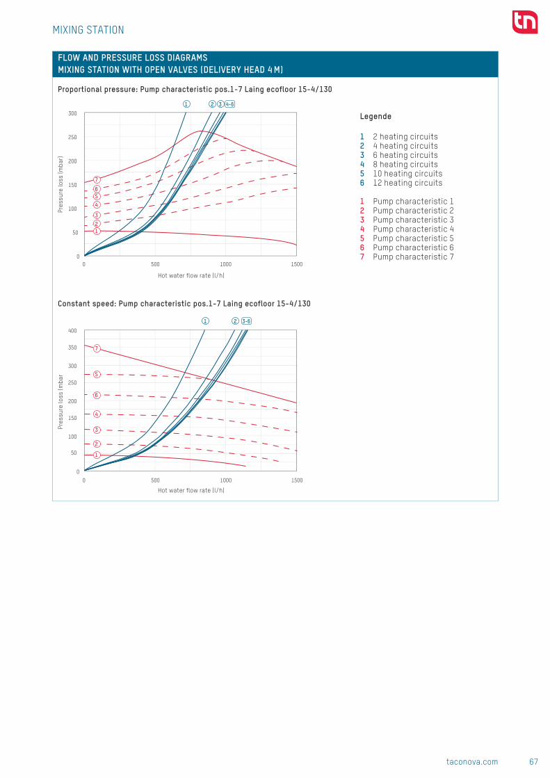
67taconova.com
Unde
rflo
or h
eati
ng
tech
nolo
gy
321
0
100
200
300
400
150
50
250
350
Druc
kver
lust
mba
r
Durchfluss l/h
2 Heizkreise4 Heizkreise6 Heizkreise8 Heizkreise10 Heizkreise12 Heizkreise
0 15001000500
0
50
100
150
200
250
300
0 15001000500
4-6
4
3
5
7
6
21
0
100
200
300
400
150
50
250
350
Druc
kver
lust
mba
r
Durchfluss l/h
2 Heizkreise4 Heizkreise6 Heizkreise8 Heizkreise10 Heizkreise12 Heizkreise
0 15001000500
0
50
100
150
200
250
300
0 15001000500
4
3
5
7
6
2
1
21 3-6
Subj
ect
to m
odif
icat
ion.
07/
2017
FLOW AND PRESSURE LOSS DIAGRAMS MIXING STATION WITH OPEN VALVES (DELIVERY HEAD 4 M)
MIXING STATION
Pres
sure
loss
(mba
r)Pr
essu
re lo
ss (m
bar
Hot water flow rate (l/h)
Hot water flow rate (l/h)
Proportional pressure: Pump characteristic pos.1-7 Laing ecofloor 15-4/130
Constant speed: Pump characteristic pos.1-7 Laing ecofloor 15-4/130
Legende
1 2 heating circuits2 4 heating circuits3 6 heating circuits4 8 heating circuits5 10 heating circuits6 12 heating circuits
1 Pump characteristic 1 2 Pump characteristic 23 Pump characteristic 34 Pump characteristic 45 Pump characteristic 56 Pump characteristic 67 Pump characteristic 7
CONTACT AND FURTHER INFORMATION TACONOVA.COM
Taconova Group AG | Neunbrunnenstrasse 40 | CH-8050 Zurich | T +41 44 735 55 55 | F +41 44 735 55 02 | [email protected]

68 taconova.com
Unde
rflo
or h
eati
ng
tech
nolo
gy
T
T
ADVANTAGES Compact
■ Comes equipped with all the ne-cessary valves and components
Secure ■ Intrinsic safety of station with external safety temperature limiter
Simple ■ Simple adjustment and reading of the required flow temperature
Efficient ■ Energy savings thanks to high-efficiency pump
Flexible ■ The center distance between the flow and return can be adjusted flexibly through the use of eccentric connectors
SYSTEM/BASIC DIAGRAM
FOR UNDERFLOOR HEATING MANIFOLDS
DESCRIPTIONThe mixing station is a flexible and compact pump assembly for direct installation in heating manifolds. The station is used especially for avoiding installation of a second, costly low-temperature pipework between the boiler and underfloor heating manifold. The boiler manifold and mixing valve for the underfloor heating loop in the central pump room can also be dis-pensed with.When the mixing station is installed directly in the apartment at the heating manifold, adjustments can be performed decentrally for every apartment in accordance with the
individual needs of the user and the type of floor covering.The station therefore guarantees optimal heating comfort for all oc-cupants and ensures safe operation of the system thanks to the external safety temperature limiter. The mi-xing station can be combined ideally with heating manifolds (TacoSys or others) together with radiator hea-ting systems.
The mixing station supplies heating manifolds with the required flow rate and in the process regulates and monitors the flow temperature.
INSTALLATION POSITIONLeft-, right-, and over-head assem-bly is possible at the hot water inlet in front of the heating manifold.
OPERATION The required flow temperature can be preset at the heating manifold by means of the integrated thermosta-tic mixing valve and then regulated subsequently. The pump is switched off by an external safety temperature limiter if the flow temperature of ap-prox. 50°C is exceeded.
BUILDING CATEGORIESAll building categories with integ-rated panel heating combined with radiator heating.
MIXING STATION UPM
■■ Mixing station UPM

69taconova.com
Unde
rflo
or h
eati
ng
tech
nolo
gy
105
X m
in.
92
376
194 194
425
X m
ax.
105
123
4
5
6
7
89
3
2
1
DIMENSIONAL DRAWING
SPECIFICATION TEXTSee www.taconova.com
TECHNICAL DATAGeneral
■ Operating temperature: -10 °C to + 70 °C
■ Max. operating pressure PB max: 6 bar ■ Adjustment range mixing valve: 20 – 50 °C
■ Safety temperature limit 50 °C: ±3% ■ Residual pump head in accordance with flow rate and pressure loss diagrams
Materials ■ Pipes: Stainless steel 1.4400 ■ Terminal nuts und eccentric connectors: Brass, nickel-plated
■ Seals: EPDM O-ringsFlow media
■ Heating water (VDI 2035; SWKI BT 102-01; ÖNORM H 5195–1)
■ Water free of chemical additives
SYSTEM COMPONENTSTacoDrive, TopDrive and NovaDrive electro-thermal actuators, room thermostats as well as distribution cabinets and heating manifolds: See separate datasheets.
MIXING STATION UPM
NOTE
TYPE OVERVIEW Mixing station with UPM-3 high-efficiency pump and external safety temperature limiter
Order no. Delivery head 296.8664.001 7 m
1 Panel heating system flow (1" lock nut]2 Panel heating system return (1" lock nut]3 Manifold flow connection (1" outer thread]4 Manifold return connection (1" outer thread]5 High-efficiency pump UPM3 15-70 Hybrid
6 NovaMix Value thermostatic mixing valve7 Thermometer flow8 Thermometer return9 Eccentric screw connection
Adjusting the mixing station
The mixing station is regulated by means of the integrated NovaMix Value mixing valve. The adjustment process is carried out when the circulating pump is running. All of the valves in the heating circuit must be fully open for ad-justment. It may be necessary to remove the actuator drives.
1 Check the flow temperature on the thermometer for the hot water flow.
2 The flow temperature can be increased or decreased by rotating the blue plastic handle.
3 The flow temperature at the heating manifold may only be ≤ the boiler flow temperature.
4 The set flow temperature should not exceed 45 °C.
5 A safety temperature limiter is located upstream from the cir-culating pump, which switches the pump off at approx. 50 °C.
6 Once adjustment is complete, note the corresponding flow temperature at the manifold or in the planning documents.
Delivery condition dimensions X min = 207 mmAdjustable using an eccentric connector to X max: 269 mmReturn flow connecting pipe adjustable between 92 mm and 123 mm

70 taconova.com
Unde
rflo
or h
eati
ng
tech
nolo
gy
KVS-Berechnung: Beimischstation mit 2 Exzentern, Mischer und 1-12er-Verteiler KVS-Berechnung 10er Verteiler
Die Messungen wurden an der Wohnungsübergabestation TTD15 gemacht. (P1041) :egnärtS 01 ella:gnartS nie run Durchfluss [l/min] 16.166 Durchfluss [l/min] 161.366Druckdiff [mbar] 1000 Druckdiff [mbar] 1000
Komponente: Exzenter1 Exzenter2 Mischer Verteiler
KVS 6.28 4.14 2.2 9.7
86.9svk79.0svk
1 Heizkreise 2 Heizkreise 3 Heizkreise 4 Heizkreise 5 Heizkreise 6 Heizkreise 7 Heizkreise 8 Heizkreise 9 Heizkreise10
Heizkreise11
Heizkreise12
HeizkreiserelietreV re01 rehcsiM2retnezxE1retnezxE38.138.128.128.118.197.177.137.176.165.143.168.0
l/min mbar Durchfluss [l/min] 104.66 69 36.666 161.3660 0 0.0 0.0 0.0 0.0 0.0 0.0 0.0 0.0 0.0 0.0 0.0 0.0 Druckdiff [mbar] 1000 1000 1000 1000
500 8 338.3 139.0 102.1 89.2 83.2 80.0 78.0 76.7 75.9 75.2 74.8 74.41000 17 1353.1 556.0 408.4 356.7 332.8 319.8 312.0 306.9 303.4 300.9 299.1 297.7 1.482.6svk 4 2.20 9.681500 25 3044.5 1251.0 918.9 802.7 748.9 719.6 702.0 690.6 682.7 677.1 673.0 669.82000 33 5412.5 2224.1 1633.6 1427.0 1331.3 1279.3 1248.0 1227.7 1213.7 1203.8 1196.4 1190.82500 42 8457.0 3475.1 2552.5 2229.6 2080.2 1999.0 1950.0 1918.2 1896.5 1880.9 1869.3 1860.63000 50 12178.1 5004.1 3675.6 3210.6 2995.4 2878.5 2808.0 2762.3 2730.9 2708.5 2691.9 2679.2
Exzenter1 Exzenter2 Mischer 1 Verteiler Total:kvs 6.28 4.14 2.20 0.97 0.86 KVS/ Verteiler: 0.97Durchfluss [l/min] 5 5 5 5 5 Durchfluss/Verteiler 5
Durchfluss TotalDruckdiff. [mbar] 2.3 5.3 18.6 95.7 121.8Druckdiff. [kPa] 0.23 0.53 1.86 9.57
Exzenter1 Exzenter2 Mischer 2 Verteiler Total:kvs 6.28 4.14 2.20 0.97 0.97 1.34Durchfluss [l/min] 10 10 10 5 5 10
Druckdiff. [mbar] 9.1 21.0 74.4 95.7 95.7 200.2Druckdiff. [kPa] 0.91 2.10 7.44 9.57 9.57
Exzenter1 Exzenter2 Mischer 3 Verteiler Total:kvs 6.28 4.14 2.20 0.97 1.56Durchfluss [l/min] 15 15 15 5 5 5 15
Druckdiff. [mbar] 20.5 47.3 167.4 95.7 330.8Druckdiff. [kPa] 2.05 4.73 16.74 9.57
Exzenter1 Exzenter2 Mischer 4 Verteiler Total:kvs 6.28 4.14 2.20 0.97 1.67Durchfluss [l/min] 20 20 20 5 5 5 5 20
Druckdiff. [mbar] 36.5 84.0 297.5 95.7 513.7Druckdiff. [kPa] 3.65 8.40 29.75 9.57
Exzenter1 Exzenter2 Mischer 5 Verteiler Total:kvs 6.28 4.14 2.20 0.97 1.73Durchfluss [l/min] 25 25 25 5 5 5 5 5 25
Druckdiff. [mbar] 57.1 131.3 464.9 95.7 748.9Druckdiff. [kPa] 5.71 13.13 46.49 9.57
Exzenter1 Exzenter2 Mischer 6 Verteiler Total:kvs 6.28 4.14 2.20 0.97 1.77Durchfluss [l/min] 30 30 30 5 5 5 5 5 5 30
Druckdiff. [mbar] 82.2 189.0 669.4 95.7 1036.3Druckdiff. [kPa] 8.22 18.90 66.94 9.57
Exzenter1 Exzenter2 Mischer 7 Verteiler Total:kvs 6.28 4.14 2.20 0.97 1.79Durchfluss [l/min] 35 35 35 5 5 5 5 5 5 5 35
Druckdiff. [mbar] 111.8 257.3 911.2 95.7 1375.9Druckdiff. [kPa] 11.18 25.73 91.12 9.57
Exzenter1 Exzenter2 Mischer 8 Verteilerkvs 6.28 4.14 2.20 0.97 1.81Durchfluss [l/min] 40 40 40 5 5 5 5 5 5 5 5 40
Druckdiff. [mbar] 146.1 336.1 1190.1 95.7 1767.9Druckdiff. [kPa] 14.61 33.61 119.01 9.57
Exzenter1 Exzenter2 Mischer 9 Verteilerkvs 6.28 4.14 2.20 0.97 1.82Durchfluss [l/min] 45 45 45 5 5 5 5 5 5 5 5 5 45
Druckdiff. [mbar] 184.8 425.3 1506.2 95.7 2212.0Druckdiff. [kPa] 18.48 42.53 150.62 9.57
Exzenter1 Exzenter2 Mischer 10 Verteilerkvs 6.28 4.14 2.20 0.97 1.82Durchfluss [l/min] 50 50 50 5 5 5 5 5 5 5 5 5 5 50
Druckdiff. [mbar] 228.2 525.1 1859.5 95.7 2708.5Druckdiff. [kPa] 22.82 52.51 185.95 9.57
Exzenter1 Exzenter2 Mischer 11 Verteiler Total:kvs 6.28 4.14 2.20 0.97 1.83Durchfluss [l/min] 55 55 55 5 5 5 5 5 5 5 5 5 5 5 55
Druckdiff. [mbar] 276.1 635.4 2250.0 95.7 3257.2Druckdiff. [kPa] 27.61 63.54 225.00 9.57
Exzenter1 Exzenter2 Mischer 12 Verteiler Total:kvs 6.28 4.14 2.20 0.97 1.83Durchfluss [l/min] 60 60 60 5 5 5 5 5 5 5 5 5 5 5 5 60
Druckdiff. [mbar] 328.6 756.1 2677.7 95.7 3858.1Druckdiff. [kPa] 32.86 75.61 267.77 9.57
ÜberströmventilUSV16/L
Übe
rströ
mve
ntil
Pos
0
Übe
rströ
mve
ntil
Pos
1
Übe
rströ
mve
ntil
Pos
2
Übe
rströ
mve
ntil
Pos
3
Übe
rströ
mve
ntil
Pos
4
Übe
rströ
mve
ntil
Pos
5
Übe
rströ
mve
ntil
Pos
6
Übe
rströ
mve
ntil
Pos
7
0 90.00 ##### ##### ##### ##### ##### ##### #####500 ##### ##### ##### ##### ##### ##### ##### #####
1000 ##### ##### ##### ##### ##### ##### ##### #####1500 ##### ##### ##### ##### ##### ##### ##### #####
Verteiler
0
100
200
400
300
500
600
0
Druc
kver
lust
mba
r
Durchfluss l/h
-Druckverlust der Beimischsta�on mit geöffneten Verteilern-Propor�onaldruck: Pumpenkennlinie pos.1-7 Laing ecofloor 15-6/130
2 Heizkreise
4 Heizkreise
6 Heizkreise
8 Heizkreise
10 Heizkreise
12 Heizkreise
0
100
200
300
400
500
600
Druc
kver
lust
mba
r
Durchfluss l/h
-Druckverlust der Beimischsta�on mit geöffneten Verteilern-Konstante Geschwindigkeit: Pumpenkennlinie pos.1-7 Laing ecofloor 15-6/130
2 Heizkreise4 Heizkreise6 Heizkreise8 Heizkreise10 Heizkreise12 Heizkreise
0
0.1
0.2
0.3
0.4
0.5
0.6
0.25 0.5 0.75 1 1.25 1.5
bar
m3/h
Überströmven�l USV16/L
01234567
0
100
200
300
400
500
600
Druc
kver
lust
mba
r
Durchfluss l/h
-Druckverlust der Beimischsta�on mit geöffneten Verteilern-Konstante Geschwindigkeit: Pumpenkennlinie pos.1-7 Laing ecofloor 15-6/13
-Überströmven�l USV16L pos. 1-7
2 Heizkreise
4 Heizkreise
6 Heizkreise
8 Heizkreise
10 Heizkreise
12 Heizkreise
Überströmven�l Pos 0
Überströmven�l Pos 1
Überströmven�l Pos 2
Überströmven�l Pos 3
Überströmven�l Pos 4
Überströmven�l Pos 5
Überströmven�l Pos 6
Überströmven�l Pos 7
x=Druckverlust mit 4-fach Verteiler bei 400l/hY=Res�örderhöhe für den Heizstrang z=Druckdifferenz bis zum Öffnungsdruck des Überstromven�l Einstellung Pos.1
Einregulierung:1. Erforderlicher maximaler Volumenstrom berechnen.2. Einstellung Pumpenförderhöhe: Anhand der entsprechenden Vereilerkennlinie mit der benö�gten Förderhöhe des Heizkreises. (x+y)3. Pumpe einstellen anhand des Pumpendiagrammes. (pos3)4. Überströmven�l ca. 20% höher einstellen (x+y+z pos1)
15001000500
0 15001000500
0 15001000500
Z
Y
X
21 3 - 6
3
4
2
1
5
6
Subj
ect
to m
odif
icat
ion.
10/
2017
FLOW AND PRESSURE LOSS DIAGRAMS MIXING STATION WITH OPEN VALVES (DELIVERY HEAD 7 M)
MIXING STATION UPM
Pres
sure
loss
(mba
r)
Hot water flow rate (l/h)
Constant speed: Pump characteristic UPM3 hybrid 1-70
Legende
1 2 heating circuits2 4 heating circuits3 6 heating circuits4 8 heating circuits5 10 heating circuits6 12 heating circuits
1 Constant pressure 1 2 Proportional pressure 13 Constant pressure 24 Proportional pressure 25 Constant pressure 36 Proportional pressure 3
CONTACT AND FURTHER INFORMATION TACONOVA.COM
Taconova Group AG | Neunbrunnenstrasse 40 | CH-8050 Zurich | T +41 44 735 55 55 | F +41 44 735 55 02 | [email protected]
T
T
ADVANTAGES Compact
■ Comes equipped with all the ne-cessary valves and components
Secure ■ Intrinsic safety of station with external safety temperature limiter
Simple ■ Simple adjustment and reading of the required flow temperature
Efficient ■ Energy savings thanks to high-efficiency pump
Fitting ■ Fits perfectly to TacoSys under-floor heating manifolds
■ Variants for horizontal or vertical installation
SYSTEM/BASIC DIAGRAM
FOR TACOSYS UNDERFLOOR HEATING MANIFOLDS
DESCRIPTIONThe mixing station is a compact pump assembly for direct installation in TacoSys underfloor heating manifolds. The station is used especially for avoiding installation of a second, costly low-temperature pipework between the boiler and underfloor heating manifold. The boiler manifold and mixing valve for the underfloor heating loop in the central pump room can also be dis-pensed with.When the mixing station is installed directly in the apartment at the heating manifold, adjustments can be performed decentrally for every apartment in accordance with the
individual needs of the user and the type of floor covering.The station therefore guarantees optimal heating comfort for all oc-cupants and ensures safe operation of the system thanks to the external safety temperature limiter. The mi-xing station can be combined ideally with TacoSys underfloor heating manifolds together with radiator heating systems.
The mixing station supplies heating manifolds with the required flow rate and in the process regulates and monitors the flow temperature.
INSTALLATION POSITIONLeft-, right-, and over-head assem-bly is possible at the hot water inlet in front of the heating manifold.
OPERATION The required flow temperature can be preset at the heating manifold by means of the integrated thermosta-tic mixing valve and then regulated subsequently. The pump is switched off by an external safety temperature limiter if the flow temperature of ap-prox. 50°C is exceeded.
BUILDING CATEGORIESAll building categories with integ-rated panel heating combined with radiator heating.
MIXING STATION UPM-T

71taconova.com
Unde
rflo
or h
eati
ng
tech
nolo
gy
T
T
ADVANTAGES Compact
■ Comes equipped with all the ne-cessary valves and components
Secure ■ Intrinsic safety of station with external safety temperature limiter
Simple ■ Simple adjustment and reading of the required flow temperature
Efficient ■ Energy savings thanks to high-efficiency pump
Fitting ■ Fits perfectly to TacoSys under-floor heating manifolds
■ Variants for horizontal or vertical installation
SYSTEM/BASIC DIAGRAM
FOR TACOSYS UNDERFLOOR HEATING MANIFOLDS
DESCRIPTIONThe mixing station is a compact pump assembly for direct installation in TacoSys underfloor heating manifolds. The station is used especially for avoiding installation of a second, costly low-temperature pipework between the boiler and underfloor heating manifold. The boiler manifold and mixing valve for the underfloor heating loop in the central pump room can also be dis-pensed with.When the mixing station is installed directly in the apartment at the heating manifold, adjustments can be performed decentrally for every apartment in accordance with the
individual needs of the user and the type of floor covering.The station therefore guarantees optimal heating comfort for all oc-cupants and ensures safe operation of the system thanks to the external safety temperature limiter. The mi-xing station can be combined ideally with TacoSys underfloor heating manifolds together with radiator heating systems.
The mixing station supplies heating manifolds with the required flow rate and in the process regulates and monitors the flow temperature.
INSTALLATION POSITIONLeft-, right-, and over-head assem-bly is possible at the hot water inlet in front of the heating manifold.
OPERATION The required flow temperature can be preset at the heating manifold by means of the integrated thermosta-tic mixing valve and then regulated subsequently. The pump is switched off by an external safety temperature limiter if the flow temperature of ap-prox. 50°C is exceeded.
BUILDING CATEGORIESAll building categories with integ-rated panel heating combined with radiator heating.
MIXING STATION UPM-T
■■ Mixing station UPM-T

72 taconova.com
Unde
rflo
or h
eati
ng
tech
nolo
gy
Volumen: 1645419.27 mm3
PG taconova.com
Techn. Lieferbed.: 1:2Massstab:cmf
We reserve all rights in connection with this document.
17.11.2016####
Verantw.17.11.2016gudeljp
Toleranzen ISO 2768
TNG LC Pumpengruppe
Material: Gewicht: 3.96 g
Blatt-Nr.Anz. Blatt
DatumNameGepr.Gen.
Ersatz. für:
IndexEMDatumVisum
51A2
Nous nous reservons tout les droits sur ce document.Für dieses Dokument behalten wir uns alle Rechte vor.
x
-
DIN-ISO 1302Erstausg.
96.
5
106
172
UM
G 1
" 381
.6
111
(180.7)
15.63
207
9
6.5
100
156
35
(187)
UM G 1"
46.
5
340
111 76
213.6
207
15.63 100
Volumen: 1645419.27 mm3
PG taconova.com
Techn. Lieferbed.: 1:2Massstab:cmf
We reserve all rights in connection with this document.
17.11.2016####
Verantw.17.11.2016gudeljp
Toleranzen ISO 2768
TNG LC Pumpengruppe
Material: Gewicht: 3.96 g
Blatt-Nr.Anz. Blatt
DatumNameGepr.Gen.
Ersatz. für:
IndexEMDatumVisum
52A2
Nous nous reservons tout les droits sur ce document.Für dieses Dokument behalten wir uns alle Rechte vor.
x
-
DIN-ISO 1302Erstausg.
4
5
6
7
89
3
2
1
DIMENSIONAL DRAWING
SPECIFICATION TEXTSee www.taconova.com
TECHNICAL DATAGeneral
■ Operating temperature: -10 °C to + 70 °C
■ Max. operating pressure PB max: 6 bar ■ Adjustment range mixing valve: 20 – 50 °C
■ Safety temperature limit 50 °C: ±3% ■ Residual pump head in accordance with flow rate and pressure loss diagrams
Materials ■ Pipes: Stainless steel 1.4400 ■ Terminal nuts und eccentric connectors: Brass, nickel-plated
■ Seals: EPDM O-ringsFlow media
■ Heating water (VDI 2035; SWKI BT 102-01; ÖNORM H 5195–1)
■ Water free of chemical additives
SYSTEM COMPONENTSTacoDrive, TopDrive and NovaDrive electro-thermal actuators, room thermostats as well as distribution cabinets and heating manifolds: See separate datasheets.
MIXING STATION UPM-T
NOTE
TYPE OVERVIEW Mixing station with UPM-3 high-efficiency pump and external safety temperature limiter
Order no. Delivery head 296.8664.001 7 m
1 Panel heating system flow (1" lock nut]2 Panel heating system return (1" lock nut]3 Manifold flow connection (1" outer thread]4 Manifold return connection (1" outer thread]
5 High-efficiency pump UPM3 15-70 Hybrid6 NovaMix Value thermostatic mixing valve7 Thermometer flow8 Thermometer return
Adjusting the mixing station
The mixing station is regulated by means of the integrated NovaMix Value mixing valve. The adjustment process is carried out when the circulating pump is running. All of the valves in the heating circuit must be fully open for ad-justment. It may be necessary to remove the actuator drives.
1 Check the flow temperature on the thermometer for the hot water flow.
2 The flow temperature can be increased or decreased by rotating the blue plastic handle.
3 The flow temperature at the heating manifold may only be ≤ the boiler flow temperature.
4 The set flow temperature should not exceed 45 °C.
5 A safety temperature limiter is located upstream from the cir-culating pump, which switches the pump off at approx. 50 °C.
6 Once adjustment is complete, note the corresponding flow temperature at the manifold or in the planning documents.

73taconova.com
Unde
rflo
or h
eati
ng
tech
nolo
gy
Volumen: 1645419.27 mm3
PG taconova.com
Techn. Lieferbed.: 1:2Massstab:cmf
We reserve all rights in connection with this document.
17.11.2016####
Verantw.17.11.2016gudeljp
Toleranzen ISO 2768
TNG LC Pumpengruppe
Material: Gewicht: 3.96 g
Blatt-Nr.Anz. Blatt
DatumNameGepr.Gen.
Ersatz. für:
IndexEMDatumVisum
51A2
Nous nous reservons tout les droits sur ce document.Für dieses Dokument behalten wir uns alle Rechte vor.
x
-
DIN-ISO 1302Erstausg.
96.
5
106
172
UM
G 1
" 381
.6
111
(180.7)
15.63
207
9
6.5
100
156
35
(187)
UM G 1"
46.
5
340
111 76
213.6
207
15.63 100
Volumen: 1645419.27 mm3
PG taconova.com
Techn. Lieferbed.: 1:2Massstab:cmf
We reserve all rights in connection with this document.
17.11.2016####
Verantw.17.11.2016gudeljp
Toleranzen ISO 2768
TNG LC Pumpengruppe
Material: Gewicht: 3.96 g
Blatt-Nr.Anz. Blatt
DatumNameGepr.Gen.
Ersatz. für:
IndexEMDatumVisum
52A2
Nous nous reservons tout les droits sur ce document.Für dieses Dokument behalten wir uns alle Rechte vor.
x
-
DIN-ISO 1302Erstausg.
4
5
6
7
89
3
2
1
DIMENSIONAL DRAWING
SPECIFICATION TEXTSee www.taconova.com
TECHNICAL DATAGeneral
■ Operating temperature: -10 °C to + 70 °C
■ Max. operating pressure PB max: 6 bar ■ Adjustment range mixing valve: 20 – 50 °C
■ Safety temperature limit 50 °C: ±3% ■ Residual pump head in accordance with flow rate and pressure loss diagrams
Materials ■ Pipes: Stainless steel 1.4400 ■ Terminal nuts und eccentric connectors: Brass, nickel-plated
■ Seals: EPDM O-ringsFlow media
■ Heating water (VDI 2035; SWKI BT 102-01; ÖNORM H 5195–1)
■ Water free of chemical additives
SYSTEM COMPONENTSTacoDrive, TopDrive and NovaDrive electro-thermal actuators, room thermostats as well as distribution cabinets and heating manifolds: See separate datasheets.
MIXING STATION UPM-T
NOTE
TYPE OVERVIEW Mixing station with UPM-3 high-efficiency pump and external safety temperature limiter
Order no. Delivery head 296.8664.001 7 m
1 Panel heating system flow (1" lock nut]2 Panel heating system return (1" lock nut]3 Manifold flow connection (1" outer thread]4 Manifold return connection (1" outer thread]
5 High-efficiency pump UPM3 15-70 Hybrid6 NovaMix Value thermostatic mixing valve7 Thermometer flow8 Thermometer return
Adjusting the mixing station
The mixing station is regulated by means of the integrated NovaMix Value mixing valve. The adjustment process is carried out when the circulating pump is running. All of the valves in the heating circuit must be fully open for ad-justment. It may be necessary to remove the actuator drives.
1 Check the flow temperature on the thermometer for the hot water flow.
2 The flow temperature can be increased or decreased by rotating the blue plastic handle.
3 The flow temperature at the heating manifold may only be ≤ the boiler flow temperature.
4 The set flow temperature should not exceed 45 °C.
5 A safety temperature limiter is located upstream from the cir-culating pump, which switches the pump off at approx. 50 °C.
6 Once adjustment is complete, note the corresponding flow temperature at the manifold or in the planning documents.
KVS-Berechnung: Beimischstation mit 2 Exzentern, Mischer und 1-12er-Verteiler KVS-Berechnung 10er Verteiler
Die Messungen wurden an der Wohnungsübergabestation TTD15 gemacht. (P1041) :egnärtS 01 ella:gnartS nie run Durchfluss [l/min] 16.166 Durchfluss [l/min] 161.366Druckdiff [mbar] 1000 Druckdiff [mbar] 1000
Komponente: Exzenter1 Exzenter2 Mischer Verteiler
KVS 6.28 4.14 2.2 9.7
86.9svk79.0svk
1 Heizkreise 2 Heizkreise 3 Heizkreise 4 Heizkreise 5 Heizkreise 6 Heizkreise 7 Heizkreise 8 Heizkreise 9 Heizkreise10
Heizkreise11
Heizkreise12
HeizkreiserelietreV re01 rehcsiM2retnezxE1retnezxE38.138.128.128.118.197.177.137.176.165.143.168.0
l/min mbar Durchfluss [l/min] 104.66 69 36.666 161.3660 0 0.0 0.0 0.0 0.0 0.0 0.0 0.0 0.0 0.0 0.0 0.0 0.0 Druckdiff [mbar] 1000 1000 1000 1000
500 8 338.3 139.0 102.1 89.2 83.2 80.0 78.0 76.7 75.9 75.2 74.8 74.41000 17 1353.1 556.0 408.4 356.7 332.8 319.8 312.0 306.9 303.4 300.9 299.1 297.7 1.482.6svk 4 2.20 9.681500 25 3044.5 1251.0 918.9 802.7 748.9 719.6 702.0 690.6 682.7 677.1 673.0 669.82000 33 5412.5 2224.1 1633.6 1427.0 1331.3 1279.3 1248.0 1227.7 1213.7 1203.8 1196.4 1190.82500 42 8457.0 3475.1 2552.5 2229.6 2080.2 1999.0 1950.0 1918.2 1896.5 1880.9 1869.3 1860.63000 50 12178.1 5004.1 3675.6 3210.6 2995.4 2878.5 2808.0 2762.3 2730.9 2708.5 2691.9 2679.2
Exzenter1 Exzenter2 Mischer 1 Verteiler Total:kvs 6.28 4.14 2.20 0.97 0.86 KVS/ Verteiler: 0.97Durchfluss [l/min] 5 5 5 5 5 Durchfluss/Verteiler 5
Durchfluss TotalDruckdiff. [mbar] 2.3 5.3 18.6 95.7 121.8Druckdiff. [kPa] 0.23 0.53 1.86 9.57
Exzenter1 Exzenter2 Mischer 2 Verteiler Total:kvs 6.28 4.14 2.20 0.97 0.97 1.34Durchfluss [l/min] 10 10 10 5 5 10
Druckdiff. [mbar] 9.1 21.0 74.4 95.7 95.7 200.2Druckdiff. [kPa] 0.91 2.10 7.44 9.57 9.57
Exzenter1 Exzenter2 Mischer 3 Verteiler Total:kvs 6.28 4.14 2.20 0.97 1.56Durchfluss [l/min] 15 15 15 5 5 5 15
Druckdiff. [mbar] 20.5 47.3 167.4 95.7 330.8Druckdiff. [kPa] 2.05 4.73 16.74 9.57
Exzenter1 Exzenter2 Mischer 4 Verteiler Total:kvs 6.28 4.14 2.20 0.97 1.67Durchfluss [l/min] 20 20 20 5 5 5 5 20
Druckdiff. [mbar] 36.5 84.0 297.5 95.7 513.7Druckdiff. [kPa] 3.65 8.40 29.75 9.57
Exzenter1 Exzenter2 Mischer 5 Verteiler Total:kvs 6.28 4.14 2.20 0.97 1.73Durchfluss [l/min] 25 25 25 5 5 5 5 5 25
Druckdiff. [mbar] 57.1 131.3 464.9 95.7 748.9Druckdiff. [kPa] 5.71 13.13 46.49 9.57
Exzenter1 Exzenter2 Mischer 6 Verteiler Total:kvs 6.28 4.14 2.20 0.97 1.77Durchfluss [l/min] 30 30 30 5 5 5 5 5 5 30
Druckdiff. [mbar] 82.2 189.0 669.4 95.7 1036.3Druckdiff. [kPa] 8.22 18.90 66.94 9.57
Exzenter1 Exzenter2 Mischer 7 Verteiler Total:kvs 6.28 4.14 2.20 0.97 1.79Durchfluss [l/min] 35 35 35 5 5 5 5 5 5 5 35
Druckdiff. [mbar] 111.8 257.3 911.2 95.7 1375.9Druckdiff. [kPa] 11.18 25.73 91.12 9.57
Exzenter1 Exzenter2 Mischer 8 Verteilerkvs 6.28 4.14 2.20 0.97 1.81Durchfluss [l/min] 40 40 40 5 5 5 5 5 5 5 5 40
Druckdiff. [mbar] 146.1 336.1 1190.1 95.7 1767.9Druckdiff. [kPa] 14.61 33.61 119.01 9.57
Exzenter1 Exzenter2 Mischer 9 Verteilerkvs 6.28 4.14 2.20 0.97 1.82Durchfluss [l/min] 45 45 45 5 5 5 5 5 5 5 5 5 45
Druckdiff. [mbar] 184.8 425.3 1506.2 95.7 2212.0Druckdiff. [kPa] 18.48 42.53 150.62 9.57
Exzenter1 Exzenter2 Mischer 10 Verteilerkvs 6.28 4.14 2.20 0.97 1.82Durchfluss [l/min] 50 50 50 5 5 5 5 5 5 5 5 5 5 50
Druckdiff. [mbar] 228.2 525.1 1859.5 95.7 2708.5Druckdiff. [kPa] 22.82 52.51 185.95 9.57
Exzenter1 Exzenter2 Mischer 11 Verteiler Total:kvs 6.28 4.14 2.20 0.97 1.83Durchfluss [l/min] 55 55 55 5 5 5 5 5 5 5 5 5 5 5 55
Druckdiff. [mbar] 276.1 635.4 2250.0 95.7 3257.2Druckdiff. [kPa] 27.61 63.54 225.00 9.57
Exzenter1 Exzenter2 Mischer 12 Verteiler Total:kvs 6.28 4.14 2.20 0.97 1.83Durchfluss [l/min] 60 60 60 5 5 5 5 5 5 5 5 5 5 5 5 60
Druckdiff. [mbar] 328.6 756.1 2677.7 95.7 3858.1Druckdiff. [kPa] 32.86 75.61 267.77 9.57
ÜberströmventilUSV16/L
Übe
rströ
mve
ntil
Pos
0
Übe
rströ
mve
ntil
Pos
1
Übe
rströ
mve
ntil
Pos
2
Übe
rströ
mve
ntil
Pos
3
Übe
rströ
mve
ntil
Pos
4
Übe
rströ
mve
ntil
Pos
5
Übe
rströ
mve
ntil
Pos
6
Übe
rströ
mve
ntil
Pos
7
0 90.00 ##### ##### ##### ##### ##### ##### #####500 ##### ##### ##### ##### ##### ##### ##### #####
1000 ##### ##### ##### ##### ##### ##### ##### #####1500 ##### ##### ##### ##### ##### ##### ##### #####
Verteiler
0
100
200
400
300
500
600
0
Druc
kver
lust
mba
r
Durchfluss l/h
-Druckverlust der Beimischsta�on mit geöffneten Verteilern-Propor�onaldruck: Pumpenkennlinie pos.1-7 Laing ecofloor 15-6/130
2 Heizkreise
4 Heizkreise
6 Heizkreise
8 Heizkreise
10 Heizkreise
12 Heizkreise
0
100
200
300
400
500
600
Druc
kver
lust
mba
r
Durchfluss l/h
-Druckverlust der Beimischsta�on mit geöffneten Verteilern-Konstante Geschwindigkeit: Pumpenkennlinie pos.1-7 Laing ecofloor 15-6/130
2 Heizkreise4 Heizkreise6 Heizkreise8 Heizkreise10 Heizkreise12 Heizkreise
0
0.1
0.2
0.3
0.4
0.5
0.6
0.25 0.5 0.75 1 1.25 1.5
bar
m3/h
Überströmven�l USV16/L
01234567
0
100
200
300
400
500
600
Druc
kver
lust
mba
r
Durchfluss l/h
-Druckverlust der Beimischsta�on mit geöffneten Verteilern-Konstante Geschwindigkeit: Pumpenkennlinie pos.1-7 Laing ecofloor 15-6/13
-Überströmven�l USV16L pos. 1-7
2 Heizkreise
4 Heizkreise
6 Heizkreise
8 Heizkreise
10 Heizkreise
12 Heizkreise
Überströmven�l Pos 0
Überströmven�l Pos 1
Überströmven�l Pos 2
Überströmven�l Pos 3
Überströmven�l Pos 4
Überströmven�l Pos 5
Überströmven�l Pos 6
Überströmven�l Pos 7
x=Druckverlust mit 4-fach Verteiler bei 400l/hY=Res�örderhöhe für den Heizstrang z=Druckdifferenz bis zum Öffnungsdruck des Überstromven�l Einstellung Pos.1
Einregulierung:1. Erforderlicher maximaler Volumenstrom berechnen.2. Einstellung Pumpenförderhöhe: Anhand der entsprechenden Vereilerkennlinie mit der benö�gten Förderhöhe des Heizkreises. (x+y)3. Pumpe einstellen anhand des Pumpendiagrammes. (pos3)4. Überströmven�l ca. 20% höher einstellen (x+y+z pos1)
15001000500
0 15001000500
0 15001000500
Z
Y
X
21 3 - 6
3
4
2
1
5
6
Subj
ect
to m
odif
icat
ion.
10/
2017
FLOW AND PRESSURE LOSS DIAGRAMS MIXING STATION WITH OPEN VALVES (DELIVERY HEAD 7 M)
MIXING STATION UPM-T
Pres
sure
loss
(mba
r)
Hot water flow rate (l/h)
Constant speed: Pump characteristic UPM3 hybrid 1-70
Legende
1 2 heating circuits2 4 heating circuits3 6 heating circuits4 8 heating circuits5 10 heating circuits6 12 heating circuits
1 Constant pressure 1 2 Proportional pressure 13 Constant pressure 24 Proportional pressure 25 Constant pressure 36 Proportional pressure 3
CONTACT AND FURTHER INFORMATION TACONOVA.COM
Taconova Group AG | Neunbrunnenstrasse 40 | CH-8050 Zurich | T +41 44 735 55 55 | F +41 44 735 55 02 | [email protected]

74 taconova.com
Unde
rflo
or h
eati
ng
tech
nolo
gy
TOPMETER PLUS ADVANTAGES ■ Precise and quick balancing without diagrams, tables or measuring devices
■ Flow rate displayed directly in l/min
■ The last flow rate set can be reproduced using an additional stop ring
■ The regulation knob is sealable ■ Regulating valve with isolating facility
■ Removable sight glass available as a replacement part
■ Can be installed in any position
SYSTEM/BASIC DIAGRAM
BALANCING VALVE (FLOW)
DESCRIPTIONThe TopMeter Plus offers an easy and accurate method of adjusting the flow rates in heating and cooling circuits. Thanks to intensive development work, it is possible to reproduce the last flow rate set using a stop ring. The DIN-EN 1264-4 standard is fulfilled.Correct balancing of hydraulic circuits ensures optimum energy distribution, resulting in more efficient and eco-nomical operation in accor dance with the energy saving regulations provided for by legislation.
With the TopMeter, any qualified fitter can set the appropriate flow rate on the premises in question, thus avoiding investments in training and expensive measuring devices.
INSTALLATION POSITIONThe TopMeter is installed in the flow pipe bar of the manifold in a horizon-tal or vertical position. The adaptation of the manifold must correspond to the manufacturer’s specifications in accordance with the mounting dimension drawings.
Direct regulation, indication and isolation of flows from heating and cooling circuits in manifold flow pipe bars.
OPERATION The flow measurement is based on the displacement principle of a baff-le disc, which is inserted in a measu-ring tube. The position is conveyed to the sight glass on the indicator unit by means of a sliding bar, which fixes the baffle disc to the indicator unit. The scale printed on the sight glass allows the flow rate to be read with ease.The opening cross-section at the valve is changed by rotating the re-gulation knob and consequently the required flow rate set or shut off fully. The stop ring is used in combination with the regulation knob to reproduce the flow rate.
BUILDING CATEGORIESFor installations in the heating and cooling area:
■ Apartment blocks, housing estates, multiple dwelling units
■ Residential care facilities, hospitals ■ Administration and service buildings ■ Hotels and restaurants, industrial kitchens
■ School buildings and sports facilities ■ Commercial and industrial buildings ■ Facilities with partial use, such as barracks, camping sites
■■ TopMeter Plus

75taconova.com
Unde
rflo
or h
eati
ng
tech
nolo
gy
4
5
6
7
9
8
10
11
3
2
1
0.1
1
10
100
1000
1010.1
kVS = 1,1
Subj
ect
to m
odif
icat
ion.
08/
2017
SPARE PARTS
DIMENSIONAL DRAWING
TYPE OVERVIEW TopMeter Plus | Balancing valve - Flow pipe
Order no. DN Measuring range Nipple kVS (m3/h)223.9502.100 15 0 – 2,5 l/min Brass, nickel-plated 1,1*223.9505.100 15 0 – 5,0 l/min Brass, nickel-plated 1,1*223.9506.100 15 0 – 6,0 l/min Brass, nickel-plated 1,1*223.9508.100 15 0 – 8,0 l/min Brass, nickel-plated 1,1*223.9502.116 15 0 – 2,5 l/min Brass 1,1*223.9505.116 15 0 – 5,0 l/min Brass 1,1*223.9506.116 15 0 – 6,0 l/min Brass 1,1*223.9508.116 15 0 – 8,0 l/min Brass 1,1*
* The effective kVS value depends on the counterpart used and the manifold geometry. Available on request with gpm and/or regulation knob in a different color.The definitive order number is assigned on the basis of the particular configuration.
SPECIFICATION TEXTSee www.taconova.com
TECHNICAL DATAGeneral
■ Medium temperature: -10 °C – +70 °C ■ Operating pressure PO max: 6 bar ■ System test pressure: max. 10 bar (20 °C)
■ Measuring accuracy: ±10% of the highest nominal value (the change in viscosity must be taken into account with antifreeze additives)
■ kVS value and measuring range: see type overview
■ External thread G ½" (cylindrical) as per ISO 228
Material ■ Brass, heat-resistant plastics and stainless steel
■ Seals: EPDM Fluids
■ Heating water (VDI 2035; SWKI BT 102-01; ÖNORM H 5195–1)
■ Water and proprietary additives used against corrosion and freezing up to 50%
ADDITIONAL MODELSSee data sheet for TopMeter Supply and TopMeter Return
ASSEMBLYWhen assembling the TopMeter in the manifold, the starting torque must not exceed 20 Nm.
SERVICEThe sight glass can be disassembled and replaced if necessary for ser-vicing. See installation instructions (EA 1075).
TOPMETER PLUS | BALANCING VALVE (FLOW)
PRESSURE LOSS DIAGRAM
Pres
sure
loss
(wit
h m
ax. v
alve
ope
ning
) (m
bar)
Flow rate (l/min)
NOTEDepending on the individual design of your application, the manifold (lower part of valve) has to be adapted to the TopMeter. For this purpose you will receive a drawing from us showing the required mounting dimensions. The sealing as well as the counterpart in the manifold remain in the responsibility of the customer in all cases.
Order no. Sight glass298.2317.000 0 – 2,5 l/min298.2316.000 0 – 5,0 l/min298.2318.000 0 – 6,0 l/min298.2319.000 0 – 8,0 l/min
1 Indicator unit2 Sight glass with scale3 Spindle4 Sliding bar5 Regulation knob6 Stop ring7 Nipple8 Baffle plate9 Measuring cylinder10 Flow manifold *11 Valve bottom section *
* Not included in scope of delivery
½" m
ax. 6
4.2
mm
(Ven
til c
lose
d)
½" m
in. 5
9.8
mm
CONTACT AND FURTHER INFORMATION TACONOVA.COM
Taconova Group AG | Neunbrunnenstrasse 40 | CH-8050 Zurich | T +41 44 735 55 55 | F +41 44 735 55 02 | [email protected]

76 taconova.com
Unde
rflo
or h
eati
ng
tech
nolo
gy
TOPMETER SUPPLY ADVANTAGES ■ Precise and quick balancing without diagrams, tables or measuring devices
■ Flow rate displayed directly in l/min
■ Adjustments can be prevented using a lead seal
■ Regulating valve with isolating facility
■ Removable sight glass available as a replacement part
■ Can be installed in any position
SYSTEM/BASIC DIAGRAM
BALANCING VALVE (FLOW)
DESCRIPTIONThe TopMeter offers an easy and ac-curate method of adjusting the flow rates in heating and cooling circuits. Thanks to intensive development work and new technologies, the TopMeter can be integrated effici-ently in the flow pipe bar to ensure reliable indicator values.Correct balancing of hydraulic circuits ensures optimum energy distribution, resulting in more efficient and eco-nomical operation in accor dance with the energy saving regulations provided for by legislation.
With the TopMeter, any qualified fitter can set the appropriate flow rate on the premises in question, thus avoiding investments in training and expensive measuring devices.
INSTALLATION POSITIONThe TopMeter is installed in the flow pipe bar of the manifold in a horizon-tal or vertical position. The adaptation of the manifold must correspond to the manufacturer’s specifications in accordance with the mounting dimension drawings.
Direct regulation, indication and isolation of flows from heating and cooling circuits in manifold flow pipe bars.
OPERATION The flow measurement is based on the displacement principle of a baff-le disc, which is inserted in a measu-ring tube. The position is conveyed to the sight glass on the indicator unit by means of a sliding bar, which fixes the baffle disc to the indicator unit. The scale printed on the sight glass allows the flow rate to be read with ease.Turning the black spindle changes the opening profile of the valve and allows the desired flow rate to be set. The flow is isolated by turning the spindle fully.
BUILDING CATEGORIESFor installations in the heating and cooling area:
■ Apartment blocks, housing estates, multiple dwelling units
■ Residential care facilities, hospitals ■ Administration and service buildings ■ Hotels and restaurants, industrial kitchens
■ School buildings and sports facilities ■ Commercial and industrial buildings ■ Facilities with partial use, such as barracks, camping sites
■■ TopMeter Supply

77taconova.com
Unde
rflo
or h
eati
ng
tech
nolo
gy
4
5
6
7
8
9
3
2
1
0.1
1
10
100
1000
1010.1
kVS = 1,1
Subj
ect
to m
odif
icat
ion.
08/
2017
SPARE PARTS
DIMENSIONAL DRAWING
TYPE OVERVIEW TopMeter Supply | Balancing valve - Flow pipe
Order no. DN G Measuring range Nipple kVS (m3/h)223.6502.XXX 15 ½" 0 – 2,5 l/min Brass 1,1*223.6505.XXX 15 ½" 0 – 5,0 l/min Brass 1,1*223.6506.XXX 15 ½" 0 – 6,0 l/min Brass 1,1*223.6508.XXX 15 ½" 0 – 8,0 l/min Brass 1,1*223.6605.XXX 10 3⁄8" 0 – 5,0 l/min Brass 1,1*223.6702.XXX 15 ½" 0 – 2,5 l/min Plastic 1,1*223.6705.XXX 15 ½" 0 – 5,0 l/min Plastic 1,1*
* The effective kVS value depends on the counterpart used and the manifold geometry. Available on request with nickel-plated nipple, a different measuring range or with gpm. The definitive order number is assigned on the basis of the particular configuration.
SPECIFICATION TEXTSee www.taconova.com
TECHNICAL DATAGeneral
■ Medium temperature: Brass TopMeter: -10 °C – +70 °C Plastic TopMeter: -5 °C – +60 °C
■ Operating pressure PO max: 6 bar ■ System test pressure: max. 10 bar (20 °C)
■ Measuring accuracy: ±10% of the highest nominal value (the change in viscosity must be taken into account with antifreeze additives)
■ kVS value and measuring range: see type overview
■ External thread G (cylindrical) as per ISO 228
Material ■ Brass, heat-resistant plastics and stainless steel
■ Seals: EPDM Fluids
■ Heating water (VDI 2035; SWKI BT 102-01; ÖNORM H 5195–1)
■ Water and proprietary additives used against corrosion and freezing up to 50%
ADDITIONAL MODELSSee data sheet for TopMeter Return
ASSEMBLYWhen assembling the TopMeter in the manifold, the starting torque must not exceed 20 Nm (½"), 15 Nm (3⁄8") or 12 Nm (plastic TopMeter).
SERVICEThe sight glass can be disassembled and replaced if necessary for ser-vicing. See installation instructions (EA 1075).
TOPMETER SUPPLY | BALANCING VALVE (FLOW)
PRESSURE LOSS DIAGRAM
Pres
sure
loss
(wit
h m
ax. v
alve
ope
ning
) (m
bar)
Flow rate (l/min)
NOTEDepending on the individual design of your application, the manifold (lower part of valve) has to be adapted to the TopMeter. For this purpose you will receive a drawing from us showing the required mounting dimensions. The sealing as well as the counterpart in the manifold remain in the responsibility of the customer in all cases.
Order no. Sight glass298.2317.000 0 – 2,5 l/min298.2316.000 0 – 5,0 l/min298.2318.000 0 – 6,0 l/min298.2319.000 0 – 8,0 l/min
1 Indicator unit2 Sight glass with scale3 Spindle4 Sliding bar5 Nipple6 Flow pipe manifold7 Baffle disc8 Measuring cylinder9 Lower part of valve
Scope of delivery
½" m
ax. 5
7 m
m(V
enti
l ope
n)
3 ⁄8" m
in. 6
3 m
m
CONTACT AND FURTHER INFORMATION TACONOVA.COM
Taconova Group AG | Neunbrunnenstrasse 40 | CH-8050 Zurich | T +41 44 735 55 55 | F +41 44 735 55 02 | [email protected]

78 taconova.com
Unde
rflo
or h
eati
ng
tech
nolo
gy
TOPMETER RETURN ADVANTAGES ■ Precise and quick balancing without diagrams, tables or measuring devices
■ Flow rate displayed directly in l/min
■ Settings can be blocked with the ½" TopMeter and adjustments prevented using a lead seal
■ Regulating valve with isolating facility
■ Removable sight glass available as a replacement part
■ Can be installed in any position
SYSTEM/BASIC DIAGRAM
BALANCING VALVE (RETURN)
DESCRIPTIONThe TopMeter offers an easy and accurate method of adjusting flow rates. The underlying measuring principle requires that the flow has settled in order to ensure reliable indicator values. No complicated flow adjustment is required on the return pipe TopMeter to achieve this. Rather, the medium allows ideal inflow from the upstream inlet pipe.Correct balancing of hydraulic circuits ensures optimum energy distribution, resulting in more efficient and eco-nomical operation in accor dance with the energy saving regulations provi-ded for by legislation.
With TopMeters, any qualified fitter can set the appropriate flow rate on the premises in question, thus avoi-ding investments in training and costly measuring devices.
INSTALLATION POSITIONThe TopMeter is installed in the re-turn pipe bar of the manifold in a horizontal or vertical position. The adaptation of the manifold must cor-respond to the manufacturer’s spe-cifications in accordance with the mounting dimension drawings.
Direct regulation, indication and isolation of flows from heating and cooling circuits in manifold return pipe bars.
OPERATION The flow measurement is based on the displacement principle of a baff-le disc, which is inserted in a measu-ring tube. The position is conveyed to the sight glass on the indicator unit by means of a sliding bar, which fixes the baffle disc to the indicator unit. The scale printed on the sight glass allows the flow rate to be read with ease.Turning the black spindle changes the opening profile of the valve and allows the desired flow rate to be set. The flow is isolated by turning the spindle fully.
BUILDING CATEGORIESFor installations in the heating and cooling area:
■ Apartment blocks, housing estates, multiple dwelling units
■ Residential care facilities, hospitals ■ Administration and service buildings ■ Hotels and restaurants, industrial kitchens
■ School buildings and sports facilities ■ Commercial and industrial buildings ■ Facilities with partial use, such as barracks, camping sites
■■ TopMeter Return

79taconova.com
Unde
rflo
or h
eati
ng
tech
nolo
gy½" m
ax. 4
5 m
m3 ⁄8"
max
. 58
mm
4
5
6
78
9
3
2
1
DIMENSIONAL DRAWING
TYPE OVERVIEW TopMeter Return | Balancing valve - Return pipe
Order no. DN G Measuring range kVS (m3/h)223.5203.XXX 15 ½" 0,6 – 2,4 l/min 1,2*223.5204.XXX 15 ½" 1,0 – 4,0 l/min 1,7*223.5208.XXX 15 ½" 2,0 – 8,0 l/min 2,4*223.5215.XXX 15 ½" 1,0 – 15,0 l/min 2,0*223.5303.XXX 10 3⁄8" 0,5 – 2,5 l/min 0,8*223.5304.XXX 10 3⁄8" 1,0 – 5,0 l/min 1,0*
* The effective kVS value depends on the counterpart used and the manifold geometry.The definitive order number is assigned on the basis of the particular configuration.
SPECIFICATION TEXTSee www.taconova.com
TECHNICAL DATAGeneral
■ Medium temperature: -10 °C – +80 °C ■ Operating pressure PO max: 6 bar ■ Measuring accuracy: ± 10% of the highest nominal value (the change in viscosity must be taken into ac-count with antifreeze additives)
■ kVS value and measuring range: see type overview
■ External thread G (cylindrical) as per ISO 228
Material ■ Brass, heat-resistant plastics and stainless steel
■ Seals: EPDM Fluids
■ Heating water (VDI 2035; SWKI BT 102-01; ÖNORM H 5195–1)
■ Water and proprietary additives used against corrosion and freezing up to 50%
ADDITIONAL MODELSSee data sheet for TopMeter Supply
ASSEMBLYWhen assembling the TopMeter in the manifold, the starting torque must not exceed 30 nM.
SERVICEThe sight glass can be removed if necessary for maintenance purposes and replaced. The relevant under-floor heating circuit must be sepa-rated in this case from the rest of the system. See installation instruc-tions No. EA 1008.
TOPMETER RETURN | BALANCING VALVE (RETURN)
NOTEDepending on the individual design of your application, the manifold (lower part of valve) has to be adapted to the TopMeter. We can provide you with a drawing for this purpose (construction data sheet). Please request our construction data sheet if you need it. The retaining O ring as well as the counterpart in the manifold are the responsibility of the customer in all cases.
1 Indicator unit2 Sight glass with scale3 Spindle4 Sliding bar5 Nipple6 Return pipe manifold7 Baffle disc8 Measuring cylinder9 Lower part of valve
Scope of delivery

80 taconova.com
Unde
rflo
or h
eati
ng
tech
nolo
gy
0,1
1,0
10,0
100,0
0,5 1,0 10,0
Luxor Topmeter 1-15 l/min Ersteller: ADA
Datum: 07.01.2015
O:\DTP\bildarchiv\produkte\VT\TopMeter\technisches\diagramme\To pMeter Return 1_2 zoll - Druckverlustdiagramm.xlsx 04.01.2013 / fh
kvs-Berechnung
Durch�uss [l/min] 27.9Druckdi� [mbar] 700
kvs min maxl/min
Diagramm erstellen
2
21000
100060
kvsQp ��
��
��� �
��
pQkvs
��
��
10001000
60
� �mbarp
lQ
��
���
����min
kvs min maxA 223.5203. x 00.2svk04.206.002.1
p-di� [mbar] 0.90 14.40
kvs min maxB 223.5204. x 1.70 1.00 4.00
p-di� [mbar] 1.25 19.93kvs min max
C 223.5208. x 2.40 2.00 8.00p-di� [mbar] 2.50 40.00kvs min maxkvs min max
D 223.5215. x 1.97 1.00 15.00p-di� [mbar] 0.93 208.71
100.0
A
B
D
C
10.0
Ven
tilö�
nung
[mba
r]
A 223.5203.xxx
1.0
Dru
ckve
rlust
bei
max
imal
er
V
B 223.5204.xxx
C 223.5208.xxx
D 223.5215.xxx15.0
0.1
0.55.0
D
Durch�uss [l/min]1.0
2
21000
100060
kvsQp ��
��
��� �
��
pQkvs
��
��
10001000
60
� �mbarp
lQ
��
���
����min
O:\DTP\bildarchiv\produkte\VT\TopMeter\technisches\diagramme\To pMeter Return 1_2 zoll - Druckverlustdiagramm.xlsx 04.01.2013 / fh
15.0
A
B
BC
D
A
A 223.5303.XXX (3⁄8" | 0,5...2,5 l/min | kVS = 0,8)B 223.5304.XXX (3⁄8" | 1,0...5,0 l/min | kVS = 1,0)
A 223.5203.XXX (½" | 0,6...2,4 l/min | kVS = 1,2)B 223.5204.XXX (½" | 1,0...4,0 l/min | kVS = 1,7)C 223.5215.XXX (½" | 1,0...15,0 l/min | kVS = 2,0)D 223.5208.XXX (½" | 2,0...8,0 l/min | kVS = 2,4)
Subj
ect
to m
odif
icat
ion.
9/2
017
TOPMETER RETURN | BALANCING VALVE (RETURN)
PRESSURE LOSS DIAGRAMSPr
essu
re lo
ss (w
ith
max
. val
ve o
peni
ng) (
mba
r)
Pres
sure
loss
(wit
h m
ax. v
alve
ope
ning
) (m
bar)
Flow rate (l/min) Flow rate (l/min)
Order no. Sight glass ½"298.2303.000 0,6 – 2,4 l/min298.2304.000 1,0 – 4,0 l/min298.2308.000 2,0 – 8,0 l/min
Order no. Sight glass 3⁄8"298.2313.000 0,5 – 2,5 l/min298.2314.000 1,0 – 5,0 l/min
SPARE PARTS
CONTACT AND FURTHER INFORMATION TACONOVA.COM
Taconova Group AG | Neunbrunnenstrasse 40 | CH-8050 Zurich | T +41 44 735 55 55 | F +41 44 735 55 02 | [email protected]
TACOFORM ADVANTAGES ■ Custom-fit ■ Dimensionally stable ■ All bending directions possible ■ Space-saving line routing ■ Protective function ■ Very easy handling without tools ■ Expandable with complementary products
■ 180° installation possible with interlinking (sub-range)
■ Fast and safe
SAMPLE APPLICATION
SCREEN BEND
DESCRIPTIONPlastic pipes and cables are used in many cases where space is very confined and tight bending radii have to be dealt with during installation. This is an everyday challenge, for example, in the area of heating and plumbing.
INSTALLATIONTacoForm pipe guide bends made of plastic are used for deflecting the heating pipe in the area of ceiling break-throughs, distribution feeders, etc. The screen bends are pushed over the pipe or lines in a straight position and fixed in place with a simple hand movement. Various degrees of deflection up to 90° can be selected thanks to multiple locking settings of the screen hooks. Suitable for plastic pipes, multi-layer composite pipes and cables. For dimensionally stable piping in tight radii and mechanical protection at the same time.
Guide bend made of plastic for deflecting the heating pipe
OPERATION Assembly is child‘s play thanks to the simple handling. The TacoForm can be fixed easily in place at 90° with a simple hand movement using the screen hooks, which can then be opened again effortlessly using a screwdriver.
APPLICATIONS ■ Heating ■ Plumbing ■ Electrical ■ Automotive ■ Plastic pipes ■ Alu/plastic composite piping ■ Tubes ■ Cables/cable harnesses

81taconova.com
Unde
rflo
or h
eati
ng
tech
nolo
gy
TACOFORM ADVANTAGES ■ Custom-fit ■ Dimensionally stable ■ All bending directions possible ■ Space-saving line routing ■ Protective function ■ Very easy handling without tools ■ Expandable with complementary products
■ 180° installation possible with interlinking (sub-range)
■ Fast and safe
SAMPLE APPLICATION
SCREEN BEND
DESCRIPTIONPlastic pipes and cables are used in many cases where space is very confined and tight bending radii have to be dealt with during installation. This is an everyday challenge, for example, in the area of heating and plumbing.
INSTALLATIONTacoForm pipe guide bends made of plastic are used for deflecting the heating pipe in the area of ceiling break-throughs, distribution feeders, etc. The screen bends are pushed over the pipe or lines in a straight position and fixed in place with a simple hand movement. Various degrees of deflection up to 90° can be selected thanks to multiple locking settings of the screen hooks. Suitable for plastic pipes, multi-layer composite pipes and cables. For dimensionally stable piping in tight radii and mechanical protection at the same time.
Guide bend made of plastic for deflecting the heating pipe
OPERATION Assembly is child‘s play thanks to the simple handling. The TacoForm can be fixed easily in place at 90° with a simple hand movement using the screen hooks, which can then be opened again effortlessly using a screwdriver.
APPLICATIONS ■ Heating ■ Plumbing ■ Electrical ■ Automotive ■ Plastic pipes ■ Alu/plastic composite piping ■ Tubes ■ Cables/cable harnesses
■■ TacoForm

82 taconova.com
Unde
rflo
or h
eati
ng
tech
nolo
gy
NOTE
USAGE WITH RADIATORS
TYPE OVERVIEW TacoForm | Screen bend
Order no. Diameter (inner) Suitable for pipe Length Radius Other 298.5011.000 16,5 15/16 mm 200 mm Large298.5015.000 16,5 15/16 mm 200 mm Large Fastening clip298.5012.000 17,7 16/17 mm 143 mm Narrow With protective tube mounting
298.5016.000 17,7 16/17 mm 153 mm NarrowWith protective tube mounting, intermatable
298.5013.000 21,2 18/20 mm 175 mm Narrow298.5014.000 20,8 18/20 mm 250 mm Large Long, especially stable
TENDER TEXTSee www.taconova.com
TECHNICAL DATAGeneral
■ Temperature resistance up to 90°CMaterials
■ High break-proven polyamide 6.6
TACOFORM | SCREEN BEND
Calculate the measurement from the lower edge of the radiator valve to the unfinished floor and cut protec-tive tube to length.
Insert the protective tube into the TacoForm screen bend and push in to the required length. Bend the TacoForm including the connecting tube with your hand.
Place the tube fitting on the calibra-ted pipe and tighten at the radiator valve. Fix both TacoForm in place with the mount and secure the opti-onal protective cover.
NOTEOnly available in Germany
USAGEBend the TacoForm screen angle until the screen hooks automatically fix in place at 90°.
The screen hooks can be opened easily using a screwdriver.

83taconova.com
Unde
rflo
or h
eati
ng
tech
nolo
gy
TACOFORM | SCREEN BEND
ACCESSORIES DOUBLE RADIATOR ROSETTEPlastic variant in white or metallic chrome-plating. 19 mm perforation for protective tube, hole spacing 50 mm.
Order no. Version298.5031.000 white298.5032.000 chrome
SINGLE RADIATOR ROSETTEPlastic variant in white or metallic chrome-plating. 19 mm perforation for protective tube.
Order no. Version298.5033.000 white298.5034.000 chrome
PROTECTIVE TUBEVariant in white, can be supplied chrome-plated on request.
Order no.298.5018.000
FIXING BRACKETTo facilitate parallel assembly.
Order no.298.5017.000
WALL RAILSEssential for professional assembly.
Order no.298.5019.000
WALL BOXUnfitted or available as fully preassembled unit.
Order no.298.5022.000
U-PROFILESimple mounting of supply and return distribution pipes. Supplied by running meter.
Order no.298.5021.000
Subj
ect
to m
odif
icat
ion.
11/
2016
CONTACT AND FURTHER INFORMATION TACONOVA.COM
Taconova Group AG | Neunbrunnenstrasse 40 | CH-8055 Zurich | T +41 44 735 55 55 | F +41 44 735 55 02 | [email protected]
NOTE
USAGE WITH RADIATORS
TYPE OVERVIEW TacoForm | Screen bend
Order no. Diameter (inner) Suitable for pipe Length Radius Other 298.5011.000 16,5 15/16 mm 200 mm Large298.5015.000 16,5 15/16 mm 200 mm Large Fastening clip298.5012.000 17,7 16/17 mm 143 mm Narrow With protective tube mounting
298.5016.000 17,7 16/17 mm 153 mm NarrowWith protective tube mounting, intermatable
298.5013.000 21,2 18/20 mm 175 mm Narrow298.5014.000 20,8 18/20 mm 250 mm Large Long, especially stable
TENDER TEXTSee www.taconova.com
TECHNICAL DATAGeneral
■ Temperature resistance up to 90°CMaterials
■ High break-proven polyamide 6.6
TACOFORM | SCREEN BEND
Calculate the measurement from the lower edge of the radiator valve to the unfinished floor and cut protec-tive tube to length.
Insert the protective tube into the TacoForm screen bend and push in to the required length. Bend the TacoForm including the connecting tube with your hand.
Place the tube fitting on the calibra-ted pipe and tighten at the radiator valve. Fix both TacoForm in place with the mount and secure the opti-onal protective cover.
NOTEOnly available in Germany
USAGEBend the TacoForm screen angle until the screen hooks automatically fix in place at 90°.
The screen hooks can be opened easily using a screwdriver.

84 taconova.com
Unde
rflo
or h
eati
ng
tech
nolo
gy
PRECISE, DEMAND-BASED ENERGY DISTRIBUTION
One of the main functions demanded of heating and cooling systems is to ensure
the right room temperature at the right time. Additional regulating components
make it possible to achieve constant heating or cooling performance as and when
needed.
INDIVIDUAL USE OF BUILDINGSDepending on the type of use of the building, room heating
or cooling must be tailored to the individual needs of
users. These are influenced by:■■ Irregular usage or occupancy times■■ Higher heating or cooling requirements at specific times
of the day, for example during the day in residential
buildings or at weekends in commercial premises■■ Loss of heat through opening doors or draughts■■ Room temperature regulation for different zones
AUTOMATION BY MEANS OF ADDITIONAL COMPONENTSIn order to provide individual temperatures as and when
needed, a heating or cooling system can be automated
by adding more components.
This means that the use of the system can be controlled
by means of actuators on the valves in combination with
room thermostats, depending on programmed times and
required temperatures.
In addition, distributors fitted with actuators also allow
the system to be integrated in a building automation
system. The TopMeter Plus with reproducible balancing
function as well as the TacoDrive actuators with first-
open function are already preinstalled in the latest
product, the TacoSys Pro.
PERMANENT CONTROLRoom thermostats constantly monitor the room air tem-
perature and compare it with the set target value. If the
actual temperature drops below the target room tempera-
ture, the room thermostat sends a signal (via a connector
module) to the actuator. This performs a silent lifting
movement which is transmitted directly to the valve in the
distributor bar, opening the heating circuit. This causes
hot or cold liquid to flow into the circuit until the target
temperature is reached and measured by the room thermo-
stat. The latter sends a signal to the actuator, causing it
to close the valve again.
QUICK AND EASY TO INSTALL. PERFECT TEAMWORKThe TacoDrive, TopDrive and NovaDrive actuators use the
room thermostats to open or close the valve settings
in the distributor bar on the basis of the required heat.
The intermediate NovaMaster connector module allows
a fixed line or wireless connection to be established
between the actuators and room thermostats.
THE PERFECT COMPLEMENT FOR SYSTEMS ALREADY AVAILABLE ON THE MARKETNovaDrive actuators are available for both open when off
and closed when off operating modes, while TacoDrive
and TopDrive are available only for closed when off mode.
The actuators will fit almost all commercial valves and
have bayonet or click-in connections for quick and easy
installation.
CAN BE RETROFITTED USING WIRELESS TECHNOLOGYAvailable in both wired and wireless versions: The basic
version for controlling 230 V NC actuators will cover the
most common applications. Other versions allow 230 V
and 24 V NO actuators to be controlled, as well as drives
with auxiliary switches or proportional lifting. In addition,
Taconova also supplies wireless room thermostats. The
use of wireless transmission technology means that there
is no need for time-consuming cable laying – a major
advantage when retrofitting a system and when working
in new buildings.
MAXIMIZING ENERGY SAVINGSA pump logic module can also be added to the controller;
this switches off the pump when heating is no longer
needed. This saves energy and protects the pump.
Actuators, room thermostats and wiring modules

85taconova.com
Unde
rflo
or h
eati
ng
tech
nolo
gy
PERFECT CONTROL FOR SATISFIED CUSTOMERS
The valve actuators and room thermostats from Taconova efficiently automate
the distribution of energy for panel heating and cooling systems as needed.
The broad product range covers every price and performance bracket and offers
the perfect solution for every need.
BENEFITS AT THE PLANNING STAGE■■ Security thanks to customized and proven system solu-
tions ■■ Reliable compliance with design temperatures■■ Flexible installation options even in retrofitting projects
because the actuators match all common valve types■■ Easy retrofitting with wireless room thermostats■■ Combination options and a range of extendable connec-
tor modules mean that complex requirements can be met
BENEFITS AT THE INSTALLATION STAGE■■ Quick and easy installation of actuators by means of
bayonet fittings■■ Easy functional control of the actuators thanks to
tactile and visual valve position guides■■ Comfort thanks to constant room temperatures■■ Long service life means no maintenance required
Actuators
The new TacoDrive actuator can already be found preinstalled in many panel heating manifolds (for example TacoSys Pro). Only the plug for the power supply has to be connected at startup. No complex assembly work is required.The completely pre-assembled TacoSys stainless steel manifolds are designed for two to twelve heating circuits. The equipment also includes, among other things, the TopMeter (TacoSys High End) and the TacoVent Vent.
■■ TacoDrive NC■■ NovaDrive NC/NO■■ TopDrive NC
Room thermostats
Taconova offers a wide range of room thermostats. These work perfectly with the NovaDrive and TopDrive actuators. For new construction and remediation, the cable (EL) and radio (RF) versions are recommended. The radio versions are also particularly suitable for renovation.
■■ NovaStat EL (Electronic)■■ NovaStat RF (Radio Frequency)
Connecting modules
For complex room climate requirements in a building, the room thermostats can be combined with open-ended connecting modules.
■■ NovaMaster EL (Electronic)■■ NovaMaster RF (Radio Frequency)
Heating and cooling energy generation Heating and cooling energy distribution (room climate)
Sanitary systems
– ■■ Underfloor heating■■ Radiators■■ Chilled and heated ceilings■■ Fan coils and chill beams■■ Concrete cores
–

86 taconova.com
Unde
rflo
or h
eati
ng
tech
nolo
gy
TACODRIVE ADVANTAGES ■ Extremely compact ■ Pre-assembled valve drive unit for automatic installation in panel heating manifolds
■ Actuator with connector and maximum protection class (IP54)
■ Integrated valve position indicator ■ Integrated reversible first-open function for manual operation
■ Can be adapted to TopMeter interface
■ Very high valve control force owing to direct-acting expansion element
SYSTEM/BASIC DIAGRAM
THERMAL ACTUATOR WITH MANIFOLD VALVE
DESCRIPTIONTacoDrive is a valve drive unit consisting of an electro-thermal actuator and a heating valve.The valve drive unit is intended for installation in panel heating manifolds.The innovative valve technology is compatible with the standardized Toconova TopMeter interface. This patented technology allows the actuator to be designed in a compact manner.
The valve drive unit has been reduced to the essential functional components and is especially suitable for automatic installation in panel heating manifolds. The integrated and reversible first-open function guarantees the subsequent filling and venting of the system. The system operator can use the integrated valve position indicator to check the actual valve position.
Electro-thermal actuator in normally closed mode for installation in panel heating manifolds.
INSTALLATION POSITIONIn the panel heating manifold return bar. The IP54 protection class allows subsequent installation of the heating manifold in any installed position.
OPERATION The TacoDrive combines valve and actuator for controlling heating circuits at panel heating manifolds. The valve drive unit operates in normally closed (NC) mode.The TacoDrive is activated by a room temperature control unit (e.g. in the NovaStat series) with a two-step output.
BUILDING CATEGORIESFor installation in heating and cooling applications in:
■ Apartment blocks, housing estates, multiple dwelling units
■ Residential care facilities and hospitals
■ Administration and service buildings ■ Hotels and restaurants ■ School buildings and sports halls, sports facilities
■ Commercial and industrial buildings ■ Facilities with partial use – for ex-ample, barracks, camping sites etc.
■■ TacoDrive

87taconova.com
Unde
rflo
or h
eati
ng
tech
nolo
gy
0.1
1
10
100
1010.1
4
5
6
7
8
3
2
1
kVS = 1,55
55 mm
TYPE OVERVIEW TacoDrive | Electro-thermal actuator, NC (Normally Closed) mode, suitable for valves of Taconova
Order no. Fixing Nipple259.2170.000 G ½" Brass259.2170.100 G ½" Brass, nickel-plated
* The required valve bottom section depends on the cross-section of the manifold bar used and has to be agreed with Taconova.
TACODRIVE | ACTUATOR
TECHNICAL DATAActuator
■ Type: Normally closed (NC) ■ Ambient temperature: 0 - 50 °C ■ Opening/closing time: approx. 3 minutes
■ Visual inspection of expansion element
■ Reversible first-open ■ Protection class of actuator: IP54 ■ Protection class II
Electrical connection data ■ Rated voltage. 230 V, 50/60 Hz ■ Permissible voltage deviation: ±10%
■ Operating efficiency: 1.8 W ■ Inrush current: 230 V: 0.6 A for max. 100 ms
■ Recommended fuse: 0.35 A slow-acting, as per DIN 41662
■ Connection cable length: 1 m ■ Connection cable: 2 * 0.75 mm², PVC with plug protected against polarity reversal
Valve ■ Medium temperature: -10 °C - +60 °C ■ Operating pressure PO max: 6 bar ■ System test pressure: max. 10 bar (20 °C)
■ kVS value: 1.55 ■ External thread G ½"(cylindrical) as per ISO 228
■ Double valve stem seal with grease reservoir
■ Visual inspection of valveMaterial
■ Brass, heat-resistant plastics ■ Seals: EPDM, FKM
Fluids ■ Heating water (VDI 2035; SWKI BT 102-01; ÖNORM H 5195-1)
■ Cooling water and water mixtures with typical corrosion and anti-frost additives
APPROVALS / CERTIFICATES ■ VDE
DIMENSIONAL DRAWING
1 Mains connection2 Expansion element with PTC3 Valve spindle with valve position indicator4 Valve spring5 Brass nipple for valve assembly6 Return manifold bar *7 Valve disk8 Valve bottom section *
* Valve bottom section and manifold bars are not included in the scope of delivery
NOTEPTC patent application CH2015/000054
PRESSURE LOSS DIAGRAM
Pres
sure
loss
(mba
r)
Flow (l/min)

88 taconova.com
Unde
rflo
or h
eati
ng
tech
nolo
gy
0
1
2
3
4
4
3
2
1
OPERATING MODES
TACODRIVE | ACTUATOR
Valve open, first open engaged
Valve open, operating function
Valve closed, standby
Splash-proof based on O-rings
CIRCUIT DIAGRAM
Hub
Time
1 Voltage on2 Dwell time on3 Voltage off4 Dwell time off
Subj
ect
to m
odif
icat
ion.
09/
2017
CONTACT AND FURTHER INFORMATION TACONOVA.COM
Taconova Group AG | Neunbrunnenstrasse 40 | CH-8050 Zurich | T +41 44 735 55 55 | F +41 44 735 55 02 | [email protected]

89taconova.com
Syst
em t
echn
olog
y

90 taconova.com
Unde
rflo
or h
eati
ng
tech
nolo
gy
NOVADRIVE NC/NO ADVANTAGES ■ Operating mode NO normally open and NC normally closed
■ Valve position visually indicated and tangible
■ Bayonet connection audibly engaged with click
■ Attractive appearance ■ Low power input ■ Silent operation ■ Available to fit most valve bodies ■ Connection cable, pluggable
SYSTEM/BASIC DIAGRAM
ACTUATOR
DESCRIPTIONNovaDrive NC/NO actuators in the new, attractive appearance used in conjunction with room thermostats, time switches and building auto-mation systems offer an efficient means of controlling temperatures in heating and cooling systems to suit individual requirements.Thanks to the operating mode NO (normally open) and NC (normally closed) as well as the quick-locking, large surface bayonet connection, the actuators can be used in a wide range of applications in all HVAC systems.
These actuators can help eliminate energy wastage in heating as well as in cooling and offer the ideal so-lution for energy control in buildings with irregular occupancy levels. Typical installations include apart-ments, offices, schools, hotels etc. The standard valve position indica-tors integrated into the actuators control the system functions during the assembly, commissioning and monitoring stages.
INSTALLATION POSITIONAny.
Electro-thermal actuators in the operating mode normally open and normally closed for heating circuit manifolds and radiator valves.
OPERATION An electrical resistance heats an ex-pansion element. Any deviation from the nominal room temperature value causes the actuator to transmit an appropriate stroke movement to the valve.The thermostat and actuator operate according to the «ON / OFF» principle. The variable, rhythmic opening and closing, depending on the heat de-mand, also produces an almost con-tinuous control characteristic.In the without current state, the valve is open with the type NO and closed with the type NC.
BUILDING CATEGORIESFor installations in the heating and cooling area:
■ Apartment blocks, housing estates, multiple dwelling units
■ Residential care facilities, hospitals ■ Administration and service buildings ■ Hotels and restaurants, industrial kitchens
■ School buildings and sports facilities ■ Commercial and industrial buildings
■■ NovaDrive NC | NO

91taconova.com
Unde
rflo
or h
eati
ng
tech
nolo
gy
TYPE OVERVIEW NovaDrive NC | Electro-Thermal Actuator, Function NC (Normally Closed)
Order no. 230 V Connection Suitable for valves of make*257.2854.000 M30 × 1,0 Beulco (old type, approx. until march 2005)
257.2855.000 M30 × 1,5
TacoSys/Heimeier/Strawa/Empur Messing/Oventrop/Delphistherm/ Emmeti/Schlösser/Beulco/AC-FIX/ Stramax/Roth/IVR
257.2858.000 M28 × 1,5 Herz (RV 57)
257.2862.000 M30 × 1,5MNG/Cazzaniga/SBK/Empur-Edelstahl/SKV-Ventil frontal
257.2864.000 Adapter Giacomini257.2880.000 M30 × 1,5 Viega
Order no. 24 V Connection Suitable for valves of make*257.1854.000 M30 × 1,0 Beulco (old type, approx. until march 2005)
257.1855.000 M30 × 1,5
TacoSys/Heimeier/Strawa/Empur Messing/Oventrop/Delphistherm/ Emmeti/Schlösser/Beulco/AC-FIX/ Stramax/Roth/IVR
257.1858.000 M28 × 1,5 Herz (RV 57)
257.1862.000 M30 × 1,5MNG/Cazzaniga/SBK/Empur-Edelstahl/SKV-Ventil frontal
257.1864.000 Adapter Giacomini257.1880.000 M30 × 1,5 Viega
NovaDrive NO | Electro-Thermal Actuator, Function NC (Normally Open)
Order no. 230 V Connection Suitable for valves of make*257.2554.000 M30 × 1,0 Beulco (old type, approx. until march 2005)
257.2555.000 M30 × 1,5
TacoSys/Heimeier/Strawa/Empur Messing/Oventrop/Delphistherm/ Emmeti/Schlösser/Beulco/AC-FIX/ Stramax/Roth/IVR
257.2558.000 M28 × 1,5 Herz (RV 57)
257.2562.000 M30 × 1,5MNG/Cazzaniga/SBK/Empur-Edelstahl/SKV-Ventil frontal
257.2564.000 Adapter Giacomini257.2580.000 M30 × 1,5 Viega
Order no. 24 V Connection Suitable for valves of make*257.1554.000 M30 × 1,0 Beulco (old type, approx. until march 2005)
257.1555.000 M30 × 1,5
TacoSys/Heimeier/Strawa/Empur Messing/Oventrop/Delphistherm/ Emmeti/Schlösser/Beulco/AC-FIX/ Stramax/Roth/IVR
257.1558.000 M28 × 1,5 Herz (RV 57)
257.1562.000 M30 × 1,5MNG/Cazzaniga/SBK/Empur-Edelstahl/SKV-Ventil frontal
257.1564.000 Adapter Giacomini257.1580.000 M30 × 1,5 Viega
* Further specific customer designs for all types of valve bodies on request. If you are unsure about valve adjustment, please contact customer service.
SPECIFICATION TEXTSee www.taconova.com
TECHNICAL DATAGeneral
■ Versions: ■ Normally closed NC ■ Normally open NO
■ Ambient temperature: 0 ... 50° C ■ Opening /closing time: approx. 3 min. ■ Nominal stroke: 4 mm ■ Nominal closing force 90 N ■ Protection mode IP 40 ■ Protection class II
Electrical specifications ■ Rated voltage (AC or DC): 24 V or 230 V
■ Permissible voltage deviation: ±10%
■ Operating efficiency: 1.8 W ■ Inrush current:
■ 24V: 0.2 A for max. 1 min; ■ 230V: 0.6 A for max. 100 ms
■ Recommended fuse protection: 0.35 A time delay, according to DIN 41662
■ Connecting cable length 1 m
APPROVALS / CERTIFICATES ■ CE conformity symbol ■ The technical data conforms with the respective EN standards
ACCESSORIESVarious room thermostats and junction modules for wired and wireless applications (see separate data sheets).
NOVADRIVE NC/NO | ACTUATOR

92 taconova.com
Unde
rflo
or h
eati
ng
tech
nolo
gy
TOPDRIVE ADVANTAGES ■ Protection against leaking valves
■ Protection rating actuator IP 44, CE
■ 360° installation ■ Compatible to most valve bodies ■ Valve position visually indicated and tangible
■ Easy installation through bayonet connector
SYSTEM/BASIC DIAGRAM
ACTUATOR
DESCRIPTIONTopDrive actuators in the new, great design used in conjunction with room thermostats, time switches and building automation systems offer an efficient means of controlling temperatures in heating and cooling systems to suit individual requirements.The normally closed (NC) operating mode, the easily and quickly fitted bayonet connection and the possibility of overhead installation (360° in stallation) ensure that the TopDrive actuators can be used for versatile applications in heating, ventilation, air conditioning and sanitary systems.
Homes, offices, schools, hotels, etc. are typical examples of properties with high saving potential, since heating and cooling systems are consistently used only as and when required.Internal visual indication of valve position is standard and serves as a functional control feature during installation, commissioning and monitoring.
INSTALLATION POSITION360° installation
Electrothermal actuators in the operating mode normally closed for heating circuit manifolds and radiator valves.
OPERATION An electric resistance heats an expansion element. Any deviation from the nominal room temperature value triggers the actuator to transmit an appropriate stroke movement to the valve.The thermostat and actuator operate according to the «ON / OFF» principle. The variable, rhythmic opening and closing, depending on the heat demand, also produces an almost continuous control characteristic.The valve is normally closed.
BUILDING CATEGORIESFor installations in the heating and cooling area:
■ Apartment blocks, housing estates, multiple dwelling units
■ Residential care facilities, hospitals ■ Administration and service buildings ■ Hotels and restaurants, industrial kitchens
■ School buildings and sports facilities ■ Commercial and industrial buildings
Max
. 68
58,745,6
Max
. 68
58,745,6
0
1
2
3
4
0
1
2
3
4
4 4
3 3
2 2
1 1
Subj
ect
to m
odif
icat
ion.
12/
2015
DIMENSIONAL DRAWING
OPERATING MODES
ECO-TIP
SAVE ENERGY AND MONEY! To avoid unnecessary hours of operation, the actuator should be switched off via the room thermo-stat out of the heating period.
NOVADRIVE NC/NO | ACTUATOR
Hub
Hub
1 Voltage on2 Dwell time on3 Voltage off4 Dwell time off
Type NC: Valve closed
Assembled state without current: Operated state under current:
Type NO: Valve closedType NO: Valve open Type NC: Valve open
Normally Open (NO)Normally Closed (NC)
TimeTime
CONTACT AND FURTHER INFORMATION TACONOVA.COM
Taconova Group AG | Steinackerstr. 6 | CH-8902 Urdorf | T +41 44 735 55 55 | F +41 44 735 55 02 | [email protected] | taconova.com
CIRCUIT DIAGRAMS

93taconova.com
Unde
rflo
or h
eati
ng
tech
nolo
gy
TOPDRIVE ADVANTAGES ■ Protection against leaking valves
■ Protection rating actuator IP 44, CE
■ 360° installation ■ Compatible to most valve bodies ■ Valve position visually indicated and tangible
■ Easy installation through bayonet connector
SYSTEM/BASIC DIAGRAM
ACTUATOR
DESCRIPTIONTopDrive actuators in the new, great design used in conjunction with room thermostats, time switches and building automation systems offer an efficient means of controlling temperatures in heating and cooling systems to suit individual requirements.The normally closed (NC) operating mode, the easily and quickly fitted bayonet connection and the possibility of overhead installation (360° in stallation) ensure that the TopDrive actuators can be used for versatile applications in heating, ventilation, air conditioning and sanitary systems.
Homes, offices, schools, hotels, etc. are typical examples of properties with high saving potential, since heating and cooling systems are consistently used only as and when required.Internal visual indication of valve position is standard and serves as a functional control feature during installation, commissioning and monitoring.
INSTALLATION POSITION360° installation
Electrothermal actuators in the operating mode normally closed for heating circuit manifolds and radiator valves.
OPERATION An electric resistance heats an expansion element. Any deviation from the nominal room temperature value triggers the actuator to transmit an appropriate stroke movement to the valve.The thermostat and actuator operate according to the «ON / OFF» principle. The variable, rhythmic opening and closing, depending on the heat demand, also produces an almost continuous control characteristic.The valve is normally closed.
BUILDING CATEGORIESFor installations in the heating and cooling area:
■ Apartment blocks, housing estates, multiple dwelling units
■ Residential care facilities, hospitals ■ Administration and service buildings ■ Hotels and restaurants, industrial kitchens
■ School buildings and sports facilities ■ Commercial and industrial buildings
■■ TopDrive NC

94 taconova.com
Unde
rflo
or h
eati
ng
tech
nolo
gy
70
Ø 44
DIMENSIONAL DRAWING
TYPE OVERVIEW TopDrive | ElectroThermal Actuator, Function NC (Normally Closed)
Order no. 230 V Connection Suitable for valves of make*
257.2055.000 M30 × 1,5TacoSys/Heimeier/Strawa/Empur Messing/Oventrop/Delphistherm/Emmeti/Schlösser/Beulco/ACFIX/Stramax/Roth/IVR
257.2058.000 M28 × 1,5 Herz (RV 57)
257.2062.000 M30 × 1,5MNG/Cazzaniga/SBK/EmpurEdelstahl/SKVVentil frontal
257.2064.000 Adapter Giacomini257.2080.000 M30 × 1,5 Viega
Order no. 24 V Connection Suitable for valves of make*
257.1055.000 M30 × 1,5TacoSys/Heimeier/Strawa/Empur Messing/Oventrop/Delphistherm/Emmeti/Schlösser/Beulco/ACFIX/Stramax/Roth/IVR
257.1058.000 M28 × 1,5 Herz (RV 57)
257.1062.000 M30 × 1,5MNG/Cazzaniga/SBK/EmpurEdelstahl/SKVVentil frontal
257.1064.000 Adapter Giacomini257.1080.000 M30 × 1,5 Viega
* Further specific customer designs for all types of valve bodies on request. If you are unsure about valve adjustment, please contact customer service.
SPECIFICATION TEXTSee www.taconova.com
TECHNICAL DATAGeneral
■ Type: Normally closed (NC) ■ Ambient temperature: 0 ... 60°C ■ Opening/closing time: Approx. 3 Min. ■ Hub: 4 mm ■ Nominal closing force: 100 N ± 7% ■ Protection type: IP 44 ■ Electrical protection class II
Electric connection data ■ Operating voltage (AC or DC): 24 V or 230 V
■ Permissible voltage deviation: ±10%
■ Operating efficiency: 1.8 W ■ Inrush current:
■ 24 V: 0.2 A for max. 1 min ■ 230 V: 0.6 A for max. 100 ms
■ Recommended fuse protection: 0,35 A time delay, according to DIN 41662
■ Connecting cable length: 1 m ■ Connection cable: 2 × 0.75 mm2, PVC
APPROVALS / CERTIFICATES ■ CE conformity symbol ■ The technical data conforms with the respective EN standards
ACCESSORIESVarious room thermostats and junction modules for wired and wireless applications (see separate data sheets).
TOPDRIVE | ACTUATOR
ECO-TIP
SAVE ENERGY AND MONEY! To avoid unnecessary hours of operation, the actuator should be switched off via the room thermostat out of the heating period.

95taconova.com
Unde
rflo
or h
eati
ng
tech
nolo
gy
4
32
11
1
0
1
2
3
4
4
3
2
1
Subj
ect
to m
odif
icat
ion.
05/
2015
OPERATING MODES
BAYONET CONNECTION
TOPDRIVE | ACTUATOR
Valve closed (no electric current) Valve open (energised)
Bayonet connection with four large interlocking faces between bayonet sleeve and nut
1 Bayonet sleeve2 Threaded bayonetnut3 Large contact surface 4 Turn until audible click
1 Water protection by means of form seal
CONTACT AND FURTHER INFORMATION TACONOVA.COM
Taconova Group AG | Steinackerstr. 6 | CH8902 Urdorf | T +41 44 735 55 55 | F +41 44 735 55 02 | [email protected] | taconova.com
CIRCUIT DIAGRAMS
Hub
Time
1 Voltage on2 Dwell time on3 Voltage off4 Dwell time off
70
Ø 44
DIMENSIONAL DRAWING
TYPE OVERVIEW TopDrive | ElectroThermal Actuator, Function NC (Normally Closed)
Order no. 230 V Connection Suitable for valves of make*
257.2055.000 M30 × 1,5TacoSys/Heimeier/Strawa/Empur Messing/Oventrop/Delphistherm/Emmeti/Schlösser/Beulco/ACFIX/Stramax/Roth/IVR
257.2058.000 M28 × 1,5 Herz (RV 57)
257.2062.000 M30 × 1,5MNG/Cazzaniga/SBK/EmpurEdelstahl/SKVVentil frontal
257.2064.000 Adapter Giacomini257.2080.000 M30 × 1,5 Viega
Order no. 24 V Connection Suitable for valves of make*
257.1055.000 M30 × 1,5TacoSys/Heimeier/Strawa/Empur Messing/Oventrop/Delphistherm/Emmeti/Schlösser/Beulco/ACFIX/Stramax/Roth/IVR
257.1058.000 M28 × 1,5 Herz (RV 57)
257.1062.000 M30 × 1,5MNG/Cazzaniga/SBK/EmpurEdelstahl/SKVVentil frontal
257.1064.000 Adapter Giacomini257.1080.000 M30 × 1,5 Viega
* Further specific customer designs for all types of valve bodies on request. If you are unsure about valve adjustment, please contact customer service.
SPECIFICATION TEXTSee www.taconova.com
TECHNICAL DATAGeneral
■ Type: Normally closed (NC) ■ Ambient temperature: 0 ... 60°C ■ Opening/closing time: Approx. 3 Min. ■ Hub: 4 mm ■ Nominal closing force: 100 N ± 7% ■ Protection type: IP 44 ■ Electrical protection class II
Electric connection data ■ Operating voltage (AC or DC): 24 V or 230 V
■ Permissible voltage deviation: ±10%
■ Operating efficiency: 1.8 W ■ Inrush current:
■ 24 V: 0.2 A for max. 1 min ■ 230 V: 0.6 A for max. 100 ms
■ Recommended fuse protection: 0,35 A time delay, according to DIN 41662
■ Connecting cable length: 1 m ■ Connection cable: 2 × 0.75 mm2, PVC
APPROVALS / CERTIFICATES ■ CE conformity symbol ■ The technical data conforms with the respective EN standards
ACCESSORIESVarious room thermostats and junction modules for wired and wireless applications (see separate data sheets).
TOPDRIVE | ACTUATOR
ECO-TIP
SAVE ENERGY AND MONEY! To avoid unnecessary hours of operation, the actuator should be switched off via the room thermostat out of the heating period.

96 taconova.com
Unde
rflo
or h
eati
ng
tech
nolo
gy
NOVASTAT / NOVAMASTER EL ADVANTAGES ■ Easy to operate ■ Noiseless Triac circuit ■ Units for 230 V and 24 V power supply
■ Integrated derivative action control or PI control (adjustable)
■ Simple wiring through the NovaMaster EL Basic, Logic and SlaveBox terminal modules
■ Universal NovaStat EL Quattro unit for the 230 V or 24 V voltage range, actuators normally closed (NC) and actuators normally open (NO)
SYSTEM/BASIC DIAGRAM
ELECTRONIC ROOM THERMOSTATS AND CONNECTOR MODULES
DESCRIPTIONRoom thermostats in combination with Taconova NovaDrive or TopDrive actuators provide a constant room temperature in closed and dry rooms. The Taconova room thermostat range, classified according to price/perfor-mance, offers the correct solution for individual needs.The basic version NovaStat EL Basic for the control of 230 V NC actuators covers the most common application range. The NovaStat EL Digital version displays the set and actual values on a digital display. The NovaStat EL Quattro version combines various applications in one unit. For example, 230 V or 24 V NC and NO actuators can be controlled by this room thermostat.
Individual heat regulation as required by the operator is achieved by means of the programmable digital NovaStat EL Week clock thermostat. The time duration of the lowering mode can be set in the week program by means of the integral timer. The connection of the room ther-mostats to the terminal module NovaMaster EL Basic and/or Logic is simple and uncomplicated. Further convenient settings are possible by mean of the optional plug-in Nova-Master EL Timer.
INSTALLATION POSITIONThe thermostats are mounted in the respective room while the connector modules are mounted close to the manifold.
OPERATION By means of an NTC sensor element, the downstream PI or derivative ac-tion controller, the room thermostats pro vide a constant room temperature in combination with actuators. The switching operation is realized by a noiseless Triac element. Con-trol is by means of the actuator acting on the valve according to the OPEN / CLOSED principle. The PI or de-rivative action controller integrated into the room thermostat prevents the room temperature from excee-ding the desired value set on the room thermostat.
BUILDING CATEGORIESFor installations in the heating and cooling area:
■ Apartment blocks, housing estates, multiple dwelling units
■ Residential care facilities, hospitals ■ Administration and service buildings ■ Hotels and restaurants, industrial kitchens
■ School buildings and sports facilities ■ Commercial and industrial buildings
Individual control of room temperature.
■■ NovaStat EL | NovaMaster EL

97taconova.com
Unde
rflo
or h
eati
ng
tech
nolo
gy
4 5321
1 NOVASTAT EL BASICRoom thermostat for normally closed actuators230 V room thermostat for controlling NC actuators for underfloor heating and cooling systems. Noiseless switching output (Triac) with direct or indirect connection of actuators. Dial with integral adjustment facility for correction of actual temperature integrated into the dial.
2 NOVASTAT EL QUATTRORoom thermostat for normally closed and normally open actuators 24 V / 230 V electronic room thermo-stat for controlling NC / NO actuators for underfloor heating and cooling systems. Further functions are similar to NovaStat EL Basic.
3 NOVASTAT EL INWALLRoom thermostat for normally closed actuators Electronic 230 V flush-mounted room thermostat for controlling NC actua-tors for underfloor heating and coo-ling systems. Relay switching output with direct or indirect connection of actuators. An external timer switch or an additional floor sensor can be fitted. Mode can be set by mean of jumpers.
4 NOVASTAT EL DIGITALRoom thermostat for normally closed and normally open actuators Electronic room thermostat with 230 V digital display for controlling NC / NO actuators for underfloor hea-ting and cooling systems. Noiseless switching output (Triac) with direct or indirect connection of actuators. Mode switch for normal and lowering modes or external timer.
TECHNICAL DATA ■ Order no.: 206.1650.000 ■ Operating voltage: 230 VAC 50 Hz ± 10 % ■ Operating temperature: 0–50 °C (32–122 °F) ■ Adjustment range: 5–30 °C (41–86 °F) ■ Switching output: TRIAC 230 VAC, NC max. 75 W ■ Type of protection: Protection class II IP 30 ■ Type of controller: Static derivative action controller ■ Differential gap: ±0,5K ■ Temperature sensor: NTC 100 K ■ Dimensions / color: H80 × W80 × D31 mm / RAL 9010 ■ Version without handwheel (NovaStat EL Public, 230 V + 24 V) on request
TECHNICAL DATA ■ Order no.: 206.1651.000 ■ Operating voltage: 24 VAC / 230 VAC 50 Hz ± 10 % ■ Switching output: TRIAC 24 VAC / 230 VAC, NC, NO max. 75 W ■ Further data similar to NovaStat EL Basic
TECHNICAL DATA ■ Order no.: 206.1654.000 ■ Operating voltage: 230 VAC 50 Hz ± 10 % / 5 VA ■ Operating temperature: 0–50 °C (32–122 °F) ■ Adjustment range: 5–35 °C (41–86 °F) ■ Switching output: Relais 230 VAC / max. 16 A ■ Type of protection: IP 21 ■ Type of controller : Two point control ■ Sensor deviation: ±1 K ■ Hysterese: 0.75 °C ■ Temperature sensor: NTC 10 K ■ Frame dimensions: Standard 65 mm
TECHNICAL DATA ■ Order no.: 206.1652.000 ■ Operating voltage: 230 VAC 50 Hz ± 10 % ■ Operating temperature: 0–50 °C (32–122 °F) ■ Adjustment range: 5–37 °C in 0,5 °C steps (41–99 °F) ■ Switching output: TRIAC 230 VAC, NC / NO max. 75 W ■ Type of protection: Protection class II IP 30 ■ Type of controller : Static differential action or PL controller, adjustable ■ Differential gap: ±0,3 K ■ Temperature sensor: NTC 100 K ■ Dimensions / color: H80 × W80 × D31 mm / RAL 9010
NOVASTAT EL | ELECTRONIC ROOM THERMOSTATS

98 taconova.com
Unde
rflo
or h
eati
ng
tech
nolo
gy
4 5321
5 NOVASTAT EL WEEKRoom thermostat for normally closed and normally open actuatorsElectronic battery operated and programmable room thermostat for controlling NC / NO actuators, for un-derfloor heating and cooling systems with digital display, floating relay out-put for direct or indirect connection of 24 V / 230 V actuators. Mode switch for normal and lowering mode or automatic timed programs. Can be programmed for weekly and daily programs and for vacations, frost protection and key-board lock function. Battery supply to avoid data loss in the event of power failure. Battery charge state shown on the display.
TECHNICAL DATA ■ Order no.: 206.1653.000 ■ Operating voltage: 3 × LR6 AA 1,5 V batteries ■ Operating temperature: 0–50 °C (32–122 °F) ■ Adjustment range: 5–35 °C (41–95 °F) frost protection 0,5–10 °C (33–50 °F) ■ Switching output: Relais floating, NC / NO max. 8 A ■ Type of protection: Protection class II IP 30 ■ Type of controller: PI controller ■ Adjustment bandwidth: 2 °K of proportional band ■ Adjustment speed: 7,5 cycles / hour (8 min cycle) ■ Temperature sensor: NTC 100 K ■ Dimensions / color: H 86 × B 125 × T 32 mm / RAL 9010
NOVASTAT EL | ELECTRONIC ROOM THERMOSTATS
1 NOVAMASTER EL BASICWiring module for connecting elec-trothermal actuators and room ther-mostats with terminals marked by symbols Modular design enables expansion by SlaveBox to provide for further connections. Direct wall mounting or mounting on DIN rail. Control of 24 V actuators by means of optional transformer. Operating status output shown by LEDs
2 NOVAMASTER EL LOGICWiring module for connecting elec-troterminal actuators and room thermostats with terminals marked by symbols. Modular design enables expansion by NovaMaster EL Timer to provide for further control functions. Switching output for time control of room ther-mostat. Two floating switching outputs as a control contact for pump logic. Direct wall mounting or mounting on DIN rail. Operating status indicated by LEDs.
TECHNICAL DATA ■ Order no.: 258.9310.000 ■ Operating voltage: 230 VAC 50 Hz ± 10 % / 24 VAC with transformer ■ Operating temperature: 0–50 °C (32–122 °F) ■ Number of zones: 6 (max. 4 drives / zones) ■ Max. number of drives: 24 × 230 VAC or 18 × 24 VAC ■ Number of drives / zones: Max. 4 drives / zones ■ Time control line: None ■ Type of protection: Protection class II IP 30 ■ Dimensions / color: H88 × B225 × T58 mm / RAL 9010
TECHNICAL DATA ■ Order no.: 258.9311.000 ■ Operating voltage: 230 VAC 50 Hz ± 10 % ■ Operating temperature: 0–50 °C (32–122 °F) ■ Number of zones: 6 (max. 4 drives / zones) ■ Max. number of drives: 24 × 230 VAC ■ Time control line: Zones A and B present ■ Switching output: 2 x relays, floating, max. 8 A ■ Type of protection: Protection class II IP 30 ■ Dimensions / color: H88 × B225 × T58 mm / RAL 9010
NOVAMASTER EL | ELECTRONIC CONNECTOR MODULES

99taconova.com
Unde
rflo
or h
eati
ng
tech
nolo
gy
3 NOVAMASTER EL SLAVEBOXAn expansion module for wiring electro thermal actuators and room thermostats with terminals marked by symbols Plug-in expansion to NovaMaster EL Basic for further connection possibilities. Direct wall mounting or mounting on DIN rail. Control of 24 V actuators by means of optional transformer. Operating status indica-ted by LEDs.
4 NOVAMASTER EL TIMERNovaMaster EL Timer expansion mo-dule for connection to NovaMaster EL Logic Programmable timer function for two time group A and B. Integrated application program of which nine are fixed and two are user program-mable. Intelligent processor. Digital display for program, time and func-tion display. Direct wall mounting or mounting on DIN rail.
5 TRANSFORMATORTransformer for connection to Nova-Master EL Basic or SBEnables 24 V actuators to be con-nected to the respective terminal module.
TECHNICAL DATA ■ Order no.: 258.9313.000 ■ Operating voltage: 24 VAC with transformer / 230 VAC 50 Hz ± 10 % ■ Operating temperature: 0–50 °C (32–122 °F) ■ Number of zones: 4 (max. 4 drives / zones) ■ Max. number of drives: ∑ NovaMaster EL Basic + SlaveBox = 24 × 230 VAC oder 18 × 24 VAC
■ Time control line: None ■ Type of protection: Protection class II IP 30 ■ Dimensions / color: H88 × W160 × D58 mm / RAL 9010
TECHNICAL DATA ■ Order no.: 258.9315.000 ■ Operating voltage: 230 VAC 50 Hz ± 10 % ■ Operating temperature: 0–50 °C (32–122 °F) ■ Number of zones: 12 Zones, controllable ■ Time control line: Zones A and B present ■ Operating modes: Automatic; convenience; lowering ■ Keyboard lock: Present ■ Type of protection: Protection class II IP 30 ■ Dimensions / color: H88 × W160 × D62 mm / RAL 9010
TECHNICAL DATA ■ Order no.: 258.9316.500 ■ Operating voltage: 230 VAC 50 Hz ± 10% ■ Operating temperature: 0–50 °C (32–122 °F) ■ Output voltage: 24 VAC max. 60 W ■ Type of protection: Protection class II IP 30 ■ Dimensions / color: H83 × W110 × D61 mm / RAL 9010
NOVAMASTER EL | ELECTRONIC CONNECTOR MODULES
Subj
ect
to m
odif
icat
ion.
02/
2016
CONTACT AND FURTHER INFORMATION TACONOVA.COM
Taconova Group AG | Steinackerstr. 6 | CH-8902 Urdorf | T +41 44 735 55 55 | F +41 44 735 55 02 | [email protected] | Taconova.com

100 taconova.com
Unde
rflo
or h
eati
ng
tech
nolo
gy
NOVASTAT / NOVAMASTER RF ADVANTAGES ■ No wiring effort required ■ Optimum positioning within the room
■ Own signal encryption for unique assignment of room thermostat
■ Simple connection of the actuators to the wiring module
■ For actuators normally closed (NC) and normally open (NO)
■ Intelligent processor
SYSTEM/BASIC DIAGRAM
WIRELESS ROOM THERMOSTATS AND CONNECTOR MODULES
DESCRIPTIONRoom thermostats in combination with Taconova NovaDrive or TopDrive actuators provide a constant room temperature in enclosed and dry rooms. The room thermostat range, classi-fied according to price/performance, offers the correct solution for indivi-dual needs.The basic version NovaStat RF Basic covers the most common range of applications. The NovaStat RF Digital and NovaStat RF Week versions display the set and actual values on a digital display. Individual regulation of temperature in individual rooms as required by the operator is achieved by means of the
programmable digital NovaStat RF Week clock thermostat or the Nova-Master RF Logic. The time duration of the lowering mode can be set in the week program by means of the integral timer. The individual room thermostats can be assigned to the NovaMaster RF Logic receiver module or the Nova-Master RF Mini single-channel recei-ver simply and without complicated wiring. The connection options for actuators can be expanded with the optional pluggable NovaMaster RF SlaveBox module.
Individual control of room temperature.
INSTALLATION POSITIONThe thermostats are mounted in the respective room while the connector modules are mounted close to the manifold.
OPERATION By mean of an NTC sensor element, the downstream PI or derivative ac-tion controller, the room thermostats pro vide a constant room temperature in combination with actuators. The control signal is transmitted to the central receiver by radio (868 MHz). Control is by means of the actuator acting on the valve according to the OPEN/CLOSED principle. The PI or derivative action controller integrated into the room thermostat prevents the room temperature ex-ceeding the desired value set on the room thermostat.
BUILDING CATEGORIESFor installations in the heating and cooling area:
■ Apartment blocks, housing estates, multiple dwelling units
■ Residential care facilities, hospitals ■ Administration and service buildings ■ Hotels and restaurants, industrial kitchens
■ School buildings and sports facilities ■ Commercial and industrial buildings
■■ NovaStat RF | NovaMaster RF

101taconova.com
Unde
rflo
or h
eati
ng
tech
nolo
gy
321
1 NOVASTAT RF BASICElectronic wireless room thermostat for indirect controlling of NC/NO actuators for underfloor heating and cooling systemsDesired values transmitted by radio signal (868 MHz). Each thermostat has its own signal encryption for unique assignment. Correction of the actual temperature is integrated into the adjustment dial.
2 NOVASTAT RF DIGITALElectronic wireless room thermostat with digital display for indirect cont-rolling of NC/NO actuators for under-floor heating and cooling systems Desired values transmitted by radio signal (868 MHz). Each thermostat has its own signal encryption for unique assignment. Mode switch for normal and lowering modes. Further userdefined settings possible in sys-tem parameter menu.
3 NOVASTAT RF WEEKElectronic wireless room thermostat with digital display for indirect cont-rolling of NC/NO actuators for under-floor heating and cooling systems. Desired values transmitted by radio signal (868 MHz). Each thermostat has its own signal encryption for unique assignment. Mode switch for normal and lowering mode or automatic timed programs. Can be programmed for weekly and daily programs and for vacations, frost protection and keyboard lock func-tion. Further user-defined settings possible in system parameter menu.
TECHNICAL DATA ■ Order no.: 206.1656.000 ■ Operating voltage: 2 batteries 3 V (CR2430) ■ Operating temperature: 0–50 °C (32–122 °F) ■ Adjustment range: 5–30 °C (41–86 °F) ■ Radio frequency: 868 MHz, < 10 mW ■ Certification: CE.EN 300220-1, EN 301489-1 ■ Type of protection: Protection class II IP 30 ■ Control behavior: Proportional band 2 ° K (15 min.) ■ Temperature sensor: NTC 100 K ■ Dimensions: H80 × W80 × D31 mm ■ Color: RAL 9010
TECHNICAL DATA ■ Order no.: 206.1657.000 ■ Operating voltage: 2 batteries 3 V (CR2430) ■ Operating temperature: 0–50 °C (32–122 °F) ■ Adjustment range: 5–30 °C (41–86 °F) ■ Radio frequency: 868 MHz, < 10 mW ■ Certification: CE.EN 300220-1, EN 301489-1 ■ Type of protection: Protection class II IP 30 ■ Control behavior: PI controller or static derivative action controller, adjustable ■ Temperature sensor: NTC 100 K ■ Dimensions: H80 × W80 × D31 mm ■ Color: RAL 9010
TECHNICAL DATA ■ Order no.: 206.1658.000 ■ Operating voltage: 3 batteries LR6 AA 1,5 V ■ Operating temperature: 0–50 °C (32–122 °F) ■ Adjustment range: 5–35 °C (41–95 °F) Frost protection 0,5–10 °C (33–50 °F) ■ Radio frequency: 868 MHz, < 10 mW ■ Certification: CE.EN 300220-1, EN 301489-1 ■ Type of protection: Protection class II IP 30 ■ Type of controller: PI controller, cycle 15 min. ■ Adjustment bandwidth: 2 ° K of proportional band ■ Adjustment speed: 7,5 Cycles / h (8 min cycle) ■ Temperature sensor: NTC 100 K ■ Dimensions: H86 × W125 × D32 mm ■ Color: RAL 9010
NOVASTAT RF | WIRELESS ROOM THERMOSTATS

102 taconova.com
Unde
rflo
or h
eati
ng
tech
nolo
gy
21
NOVAMASTER RF MINISingle-channel radio receiver for controlling NC / NO actuators for under floor heating and cooling systemsDesired values transmitted by radio signal (868 MHz). Combinable with room thermostats NovaStat RF Basic, NovaStat RF Digital and NovaStat RF Week
1 NOVAMASTER RF LOGICWiring module in combination with receiver unit Novamaster RF Logic for the wiring of electrothermal ac-tuators and assignment of the indi-vidual wireless room thermostats Expansion possible with Novamaster RF SlaveBox to provide further con-nection options. Direct wall moun-ting or mounting on DIN rail. Control of 230 V NC/NO actuators. Operating status indicated by LEDs. 2 sepa-rate, floating switching outputs on Novamaster RF Logic wiring module for actuating pumps. Programmable timer function for zone concerned. Integrated user programs, 9 fixed and 12 freely programmable for each individual zone. Digital display for program, time and function.
TECHNICAL DATA ■ Order no.: 206.1659.000 ■ Operating voltages: 230 VAC / NC / NO / 50 Hz ± 10 % ■ Operating temperature: 0–50 °C (32–122 °F) ■ Switching output: Receiver relay 12 A 250 VAC max. ■ Quantity of actuators: Max. 2 actuators (parallel) ■ Radio frequency: 868 MHz, < 10 mW ■ Certification: CE.EN 300220-1, EN 301489-1 ■ Type of protection: Protection class II IP 30 ■ Dimensions: H170 × W28 × D14 mm ■ Color: RAL 9010
TECHNICAL DATA ■ Order no.: 258.9317.000 ■ Operating voltage: 230 VAC 50 Hz ± 10 % ■ Operating temperature: 0–50 °C (32–122 °F) ■ Radio frequency (Timer): 868 MHz, < 10 mW ■ Certification: CE.EN 300220-1, EN 301489-1 ■ Number of zones: 6 (max. 4 drives / zone) ■ Max. quantity of actuators: 24 × 230 VAC ■ Quantity of actuators / Zone: max. 4 drives / zone ■ Type of controller: PI controller proportional bandwidth 2 ° K/1, 2 ° K ■ Type of protection: Protection class II IP 30 ■ Switching outputs: 2 × separate, floating for pump switching max. 8 A ■ Dimensions: H88 × W370 × D58 mm ■ Color: RAL 9010
NOVAMASTER RF | RADIO RECEIVER
NOVAMASTER RF | RADIO RECEIVER WIRING MODULE

103taconova.com
Unde
rflo
or h
eati
ng
tech
nolo
gy
NOVAMASTER RF | RADIO RECEIVER WIRING MODULE
2 NOVAMASTER RF SLAVEBOXExpansion module for the NovaMaster RF Logic module for the extended wiring of electrothermal actuatorsAssignment of the room thermostats takes place via the Novamaster EL Timer. Pluggable expansion and di-rect wall mounting or mounting on DIN rail. Control of 230 V NC/NO ac-tuators. Operating status indicated by LEDs.
TECHNICAL DATA ■ Order no.: 258.9319.000 ■ Operating voltage: 230 VAC 50 Hz ± 10 % ■ Operating temperature: 0–50 °C (32–122 °F) ■ Number of zones: 4 (max. 4 drives / zone) ■ Max. number of actuators: ∑ Novamaster RF Logic + Novamaster RF SlaveBox = 24 × 230 VAC
■ Type of protection: Protection class II IP 30 ■ Dimensions : H88 × W160 × D58 mm ■ Color: RAL 9010
Subj
ect
to m
odif
icat
ion.
12/
2015
CONTACT AND FURTHER INFORMATION TACONOVA.COM
Taconova Group AG | Steinackerstr. 6 | CH-8902 Urdorf | T +41 44 735 55 55 | F +41 44 735 55 02 | [email protected] | Taconova.com

104 taconova.com
Syst
em t
echn
olog
y
SYSTEM TECHNOLOGY
The demand for universal solutions in building services is greater than ever.
Connection-ready heat interface units, fresh hot water, storage loading and
solar energy stations from Taconova are highly evolved systems employing
state-of-the-art technology.
Taconova quality products are assembled from carefully selected, tried-and-
tested products to create perfectly functioning standard units.
The ready-to-use complete solutions simplify and accelerate planning and
assembly stages. In everyday use they guarantee reliable operation, reduce
maintenance to a minimum and optimize energy costs.
Taconova adheres consistently to the system concept: the fresh hot water
solar and storage loading stations can be combined ideally. The energy storage
system for supplying heat and domestic hot water is the centerpiece of the
heating system. The solar energy transmitted via the solar and storage loading
stations is stored here and can be transferred at floor level either by means
of centralized fresh hot water technology or decentralized heat interface units
(domestic hot water and heating energy).
SYSTEM TECHNOLOGY

105taconova.com
Syst
em t
echn
olog
y
INTELLIGENT STATIONS
Taconova's sophisticated stations are equipped with all the necessary valves and
safety features and meet all the requirements of modern machine engineering.
THE ALL-ROUNDER The TacoTherm Dual Piko and Nano heat interface units: fresh hot water and
heating in one station. The modular all-in-one stations supply hot water and
regulate the hot water outlet temperature precisely and without auxiliary
energy if so required. In addition, they regulate and distribute the heating
water to the underfloor heating systems – for radiators and/or panel heating
systems depending on requirements.
THE INSTANT STATION Taconova connection-ready fresh hot water stations dispense with the need
for storing domestic hot water. They therefore avoid hygiene problems and loss
of energy as a result of storage and standby losses. The water is only heated
on demand directly by means of a stainless steel plate heat exchanger and the
hot water temperature is controlled electronically. The Mega2 and Peta series
are also cascadable and are thus ideal for covering wide performance ranges.
The fresh hot water stations can be ideally combined with the TacoSol Load
storage loading stations.
THE POWERFUL STATIONThe ready-to-connect TacoSol Load Mega, Tera and Exa stations are a solar
energy station and loading module in one. They were developed to load central
buffer cylinders via a solar thermal system. Captured solar energy is transferred
to the stratification cylinders via highly efficient stainless steel plate heat
exchangers.
THE INDEPENDENT SOLUTIONAll TacoSol Circ solar loading stations come with integrated hydronic balancing,
flow measurement and flow control. The dual-phase versions increase their
effectiveness through the automatic air separation in the integrated ventila-
ting flask.
COMPACTThe TacoHeat Mix heating circuit pump assembly is delivered connection-ready,
making it quick and easy to install. It features the latest generation of circula-
tion pumps and ensures low power consumption. The integrated 3-way mixer
always provides the correct flow rate and temperature at the consumer.
OVERVIEW OF PRODUCT GROUPS

106 taconova.com
Syst
em t
echn
olog
y
ADVANCED PREPARATION OF DOMESTIC HOT WATER
A fresh hot water station is the ideal link between the storage tank and hygienic
domestic hot water.
With centralized and decentralized preparation of dome-
stic hot water in accordance with the continuous flow
principle, drinking water is only heated as needed and
only in the quantity required at the time. Country-specific
standards, such as DIN or SIA, also allow a reduction in the
domestic hot water temperature in this context to < 60 °C,
especially for decentralized preparation of domestic hot
water. Many European standards furthermore require that
the volume of domestic hot water stored be reduced and
only the required quantity heated. Examples of such
standards include: ÖNORM B 5019:2011 (5.7.3 and 5.8.3),
SIA 385/1 (3.2.6) and DIN 1988-200 (9.7.2.7).
THIS OFFERS SYSTEM PLANNERS AND OPERATORS THE FOLLOWING ADVANTAGES: ■■ Energy savings through reduced volumes of
domestic hot water in case of thermal disinfection■■ Fewer calciferous deposits in the heat exchanger owing
to the low temperature level and turbulent flows■■ Reduced circulation losses owing to the low
temperature level■■ Lower maintenance costs thanks to simple access to
external plate heat exchangers■■ Reduced hygiene risk for domestic hot water as
heated drinking water is not allowed to stagnate
Heated drinking water in multistory residential buildings
or in public buildings is often supplied by means of a
domestic hot water storage tank. This domestic hot
water has to be stored at temperatures of at least 60 °C
in order to ensure drinking water hygiene.
This gives rise to the following disadvantages: ■■ High investment in the choice of materials suitable
for drinking water, for example stainless steel■■ Calciferous deposits as a result of permanent
supply, warming and storage of drinking water■■ High maintenance costs and poor access to
integrated components, such as storage heat
exchangers, spray lances, sacrificial anodes■■ Risk of corrosion with coated storage units owing
to permanent oxygen injection■■ High hygiene risk from germ formation, especially
in the drinking water storage tank in case of non-
compliance with prescribed storage temperatures,
for example failure or malfunction of the heat
source
Storing energy in water as a medium remains the most
efficient solution for handling the costs for space heating
and hot water. It is meanwhile already recommended in
standards such as DIN 1988-200, for example, that this
energy be provided in a storage tank in the form of treated
hot water.
This gives rise to the following advantages:■■ No calciferous deposits in the tank as the process water
is in the closed system■■ No storage fittings and associated maintenance costs■■ Lower investment costs as materials for heating and
storing water do not have to be suitable for drinking
water■■ Simple hydraulic integration of any heat sources, such
as heat pumps for example■■ Low flow temperatures from low-temperature systems
can be realized■■ No hygiene risks even at operating temperatures < 60 °C
in the storage unit
DRINKING WATER STORAGE IS YESTERDAY'S NEWS
Supplying domestic hot water then and now – forward-looking solutions
dispense with hot water storage.
Heat interface units

107taconova.com
Syst
em t
echn
olog
y
CENTRALIZED OR DECENTRALIZED?
When it comes to planning fresh hot water stations,
the choice is yours.
ENERGY TRANSFER AT FLOOR LEVELThe energy storage system for supplying heat and dome-
stic hot water is the centerpiece of the heating system.
The thermal energy stored here can be trans ferred at
floor level either by means of centralized fresh hot water
technology or decentralized heat interface units (domestic
hot water and heating energy).
CENTRALIZED PREPARATION OF DOMESTIC HOT WATER The station is planned to be in the immediate vicinity of the storage tank in the case of centralized prepa ration
of domestic hot water.
T
T
One of these systems can supply heated drinking water for
up to 200 apartments taking account of the simultaneous
dispensing of the domestic hot water. The stations can be
connected individually to the domestic hot water network
in this scenario or also cascaded.
DECENTRALIZED PREPARATION OF DOMESTIC HOT WATERDecentralized fresh hot water stations or heat interface
units operate according to the same technical principle as
centralized systems.
The energy required to prepare domestic hot water is
provided by means of the central storage tank and trans-
ported to the apartment via a riser pipe pump. The fresh hot water stations are installed directly in the apartments
with this type of installation.
T
T
Decentralized heating of drinking water – where only ejec-
tor lines are used – allows the risk level of Legionella to
be reduced to "low". As the volume of domestic hot water
is consequently reduced to <3 l, these heat interface
units are classed as small installations in the sense of
the German Drinking Water Regulations (Trinkwasser-
Verordnung, TrinkwV) from November 2015 and are there-
fore not subject to any special mandatory testing.
In combination with connecting piping for radiators or
underfloor heating, the heat interface unit becomes the
central point of access for supplying energy in an apart-
ment.
This allows energy consumption to be recorded and cal-
culated on an individual apartment basis. The heat meter
takes on the role of an apartment energy meter and there
is no need for domestic hot water meters.

108 taconova.com
T
T
Syst
em t
echn
olog
y
SYSTEM / BASIC DIAGRAM
MODULAR HEAT INTERFACE UNITS
The modular TacoTherm Dual Piko or Nano heat interface units distribute
heat energy and handle decentralized preparation of hot water in apartments
in accordance with the continuous flow principle.
The TacoTherm Dual heat interface units adapt ideally to local conditions.
BENEFITS AT THE PLANNING STAGE■■ The compact design and, if required, small
installation depth make space planning easier■■ Efficient planning thanks to modular basic
concept with large number of variants■■ On-demand, hygienic preparation of domestic
hot water■■ Demand-driven calculation of energy costs ■■ Fixed value-controlled or weather-controlled
versions available
BENEFITS AT THE INSTALLATION STAGE■■ High levels of prefabrication ensure fast and
simple installation and startup and therefore
time savings ■■ Service and warranty from a single source■■ Reliable operation thanks to high-quality
components■■ Easier to provide proof of drinking water quality■■ Simple, retrospective fitting of heat meters
possible

109taconova.com
Syst
em t
echn
olog
y
TacoTherm Dual Piko heat interface unit
The modular design of the TacoTherm Dual Piko offers optimum functionality and gives you free rein when arranging the
modules. The modules impress with their flat construction (110 mm). You can position the station how and where you
wish: vertically, horizontally and even in separate rooms.
Product photo Station / Typ
Dispensing rate / hea-ting circuits
Dimensions in mm (W×H×D) Version
TacoTherm Dual Piko PMCombination Station
22 l/min* up to 12 heating circuits 874 ×
1420–1510 × 110
■■ Compact, combined and connection-ready heat interface unit
■■ Fresh hot water station with heating module, prepa-ration of fresh hot water, underfloor heating manifold and separate radiator connection in one
TacoTherm Dual Piko Connect Combination Station
25 l/min** up to 12 heating circuits
TacoTherm Fresh Piko PM Fresh Hot Water Module
22 l/min*
874 × 772–892 × 110
■■ Compact, connection-ready fresh hot water station■■ Proportional flow-controlled or electronically con-
trolled with options such as standby module and anti-scald protection for increased comfort
TacoTherm Fresh Piko Connect Fresh Hot Water Module
25 l/min**
TacoSys PikoHeating Module
up to 12 heating circuits
874 × 772–892 × 110
■■ Compact, connection-ready heating module ■■ Fixed value or weather-controlled
TacoTherm Dual Nano heat interface unit
The fresh water module and combination station in the Nano series impress with their slender construction (minimum
450 mm). They offer optimum functionality and give you free rein when planning the assembly of the modules.
The fresh water module in this series can be used ideally as a gas boiler replacement unit.
Product photo Station / Typ
Dispensing rate / hea-ting circuits
Dimensions in mm (W×H×D) Version
TacoTherm Dual NanoCombination Station
20 l/min* up to 10 heating circuits
523 × 1233–1323 × 153 (8 circuits) 750 × 1233–1323 × 153 (9–10 circuits)
■■ Compact, combined and connection-ready heat interface unit
■■ Fresh hot water station with heating module, prepa-ration of fresh hot water, underfloor heating manifold and separate radiator connection in one
TacoTherm Fresh NanoFresh Hot Water Module
20 l/min* 450 × 635 × 156
■■ Connection-ready fresh hot water station■■ Suitable for replacement of gas boilers■■ Proportional flow-controlled with options such
as standby module and anti-scald protection for increased comfort
* Performance data for primary = flow 70 °C / secondary = hot water 45 °C; ∆p ≥ 300 mbar** Performance data for primary = flow 60 °C / secondary = hot water 45 °C; ∆p ≥ 300 mbar
HEAT INTERFACE UNIT – PROVEN SYSTEM
High levels of prefabrication and low maintenance systems deliver valuable
savings in terms of assembly time and make servicing almost redundant.
Yet the heat interface units also offer many further advantages.

110 taconova.com
Syst
em t
echn
olog
y
1
TACOTHERM DUAL PIKO
T
T
ADVANTAGES ■ Compact installation depth ■ Large number of variants ■ Preconfigured for simple installation
■ On-demand, hygienic preparation of domestic hot water
■ Demand-driven calculation of energy costs
SYSTEM/BASIC DIAGRAM
HEAT INTERFACE UNIT
DESCRIPTIONThe heat interface unit in the Piko series suits practically any installa-tion situation thanks to its compact installation depth and versatile con-structions. The stations are available as individual fresh hot water modu-les or heating modules as well as combination stations.Various selectable hydraulic com-ponents ensure on-demand pre-paration of domestic hot water, distribution of heat energy as well as calculation of energy costs.
INSTALLATIONThe heat interface units can be in-stalled as a compact station or in a split design. For ease of transport, the compact version can be dis-mantled conveniently into two parts and reassembled using the available plug connection. Ideally the station should be placed next to the outlets for the apartments. The individual modules can be assembled horizon-tally as well as installed at separate locations in the split design.
OPERATIONThe heat interface units in the Piko series are designed for preparation of domestic hot water and distribution of heat energy in multistory residen-tial buildings.The primary energy supply is by means of a centralized storage tank, while the drinking water is heated on demand in the fresh hot water module in accordance with the con-tinuous flow principle. In the case of combination stations, the heating surfaces in living areas are connec-ted with the underfloor heating manifolds of the heating module or the radiator connections. The hea-ting flow temperature in the living area is regulated on a fixed-value or weather-controlled basis. Adjusting pieces are provided in the modules for on-site installation of heat me-ters and cold water meters.
BUILDING CATEGORIES ■ Apartment blocks ■ Hotels and residential homes
Preconfigured heat interface unit with compact installation depth for preparation of domestic hot water and apartment heating.
■■ TacoTherm Dual Piko

111taconova.com
Syst
em t
echn
olog
y
2
TACOTHERM DUAL PIKO | OVERVIEW OF VARIANTS
TacoTherm Dual Piko
Version of fresh hot water module PF control Connect
Pages in datasheet 3 – 6 7 – 11
Variant A B C D A B C D
FRES
H HO
T W
ATER
MOD
ULE
Heat exchanger
Suitable forStandard heat source
Operation with heat pumps
Materials
Copper-soldered
Nickel-soldered
Stainless steel solder
Control type
TypeProportional flow
Electronic regulator
BalancingStatic (TacoSetter Inline)
Dynamic
SecondaryMixer
Circulation
Comfort Keeping warm
ConnectionsHeating / Radiator
Bottom
Top
Left
Right
Sanitary distributor Bottom
Installation options
Installation methods
Base plate
Flush-mounted frame with door
Flush-mounted frame without door
Surface-mounted cabinet with door
Surface-mounted cabinet without door
Door accessories (optional)Spagnolet lock
Locking cylinder
HEAT
ING
MOD
ULE
Regulation
Type Fixed value
Weather-controlled
BalancingDynamic
Static
Underfloor heating circuit manifold Number of heating circuits2 - 10
2 - 12
Distributor accessoriesDistributor valve with
Manual adjustment
TacoDrive actuator
Connector module for Actuators NovaMaster
Primary pipe system See next page for explanation
2-pipe
3-pipe
4-pipe
NOTE
REQUIREMENTS FOR FLOW MEDIA
The stations heat interface units use a copper-soldered stainless steel plate heat exchanger as standard. It must be checked prior to use in the framework of system planning whether the issues of corrosion protection and scale formation have been sufficiently taken into account in accordance with DIN 1988200 and current drinking water analyses according to DIN EN 8065. See datasheet „Plate Heat Exchanger Requirements - Limit Values for Drinking Water Quality“.
KEY
Available for this type
Selectable components (either / or)
Not available for this type

112 taconova.com
Syst
em t
echn
olog
y
3
TACOTHERM DUAL PIKO | PROPORTIONAL FLOW CONTROL
TYPE OVERVIEW TacoTherm Dual Piko | Combination station with 10 heating circuits * 1)
Order no. DN Rp Dispensing range * 2) Heat exchanger276.2111.139 20 1" OT up to 22 l/min copper-soldered
TacoTherm Fresh Piko | Fresh hot water station Order no. DN Rp Dispensing range * 2) Heat exchanger276.2102.000 20 1" OT up to 22 l/min copper-soldered * 1) Any matching accessories required and variants can be individually selected* 2) Performance data for primary = flow 70 °C / secondary = hot water 45 °C; ∆p ≥ 300 mbar
SPECIFICATION TEXTSee www.taconova.com
GENERAL TECHNICAL DATAGeneral
■ Max. operating pressure PO max: ■ Primary: 3 bar ■ Secondary: 6 bar
■ Overall dimensions of combination station: W 874 mm × H 1420 - 1510 mm × D 110 mm
■ Weight of combination station (empty): 70 kg
Materials ■ Galvanized or varnished sheet steel housing according to model
■ Pipes: DN 20 stainless steel 1.4404 ■ Pumps: cast iron ■ Valve housing: brass ■ Seals: AFM34 (flat sealing)
Performance dataSee design diagramElectrical connection data
■ Mains voltage: 230 VAC ± 10 % ■ Mains frequency: 50...60 Hz ■ Power consumption: max. 4 - 60 W ■ Protection type: IP 30 ■ EEI ≤ 0.26
Flow media ■ Heating water (VDI 2035; SWKI BT 102-01; ÖNORM H 5195–1)
■ Cold water as per DIN 1988-200 and DIN EN 806-5
TECHNICAL DATAFRESH HOT WATER MODULEGeneral
■ Max. operating temperature TO max: 95 °C
■ Weight (empty): 35 kg ■ Dimensions: W 874 mm × H 772 - 892 mm × D 110 mm
Material ■ Plate heat exchanger (plates and connector pieces):
■ Stainless steel 1.4401 ■ Copper-soldered / nickel-soldered / stainless steel-soldered
TECHNICAL DATA HEATING MODULEGeneral
■ Max. operating temperature TO max: 70 °C
■ Weight (empty): 30 kg ■ Dimensions: W 874 mm × H 772 - 892 mm × D 110 mm
■ High-efficiency circulating pump: Laing Ecofloor 15-6/130 (230 V) un-derfloor heating circuit
■ 3-way mixing valve (fixed value- controlled) or PICV valve with actuator (weather-controlled)

113taconova.com
Syst
em t
echn
olog
y
4
655 77.5 107.5
840
65
44.5
526 65
74.5
141
9.5
139
9.5
721
65
874
648
.5
790
110
65
44.5
526 65
74.5
77.5 655 107.5 840
65
721 1
419.
5
139
9.5
874
648
.5
790
110
Volumen: 9495529.60 mm3
PG
I-1257 - TTD Piko Überarbeitung
taconova.com
Techn. Lieferbed.: 1:5Massstab:
cmf
We reserve all rights in connection with this document.
26.09.2017####
Verantw. 26.09.2017 gudeljp
Toleranzen ISO 2768
Taco Therm Dual Piko
Material:
Gewicht: 42.18 g
Blatt-Nr.
Anz. Blatt
Datum Name
Gepr.Gen.
Ersatz. für:
Index EM Datum Visum
2
1A1
TTD Piko Überarbeitung
Nous nous reservons tout les droits sur ce document.Für dieses Dokument behalten wir uns alle Rechte vor.
x
-009755
Oberflächen/SurfacesDIN-ISO 1302
Erstausg.
655 77.5 107.5
840
65
44.5
526 65
74.5
141
9.5
139
9.5
721
65
874
648
.5
790
110
65
44.5
526 65
74.5
77.5 655 107.5 840
65
721
141
9.5
139
9.5
874
648
.5
790
110
Volumen: 9495529.60 mm3
PG
I-1257 - TTD Piko Überarbeitung
taconova.com
Techn. Lieferbed.: 1:5Massstab:
cmf
We reserve all rights in connection with this document.
26.09.2017####
Verantw. 26.09.2017 gudeljp
Toleranzen ISO 2768
Taco Therm Dual Piko
Material:
Gewicht: 42.18 g
Blatt-Nr.
Anz. Blatt
Datum Name
Gepr.Gen.
Ersatz. für:
Index EM Datum Visum
2
1A1
TTD Piko Überarbeitung
Nous nous reservons tout les droits sur ce document.Für dieses Dokument behalten wir uns alle Rechte vor.
x
-009755
Oberflächen/SurfacesDIN-ISO 1302
Erstausg.
1 532
6
4
TACOTHERM DUAL PIKO | PROPORTIONAL FLOW CONTROL
DIMENSIONAL DRAWING
1 Primary connection for heat supply on return side
2 Primary connection for heat supply on supply side
3 Connection for hot water distribution
4 Connection for cold water distribution
5 Connection for main supply line for cold water
6 Radiator connection in supply and return circuit

114 taconova.com
Syst
em t
echn
olog
y
5
2015
-05-
08 P
G P
M-T
TD P
IKO
1
16.
10.2
017
15:
23:1
5
2015
-05-
08 P
G P
M-T
TD P
IKO
1
16.
10.2
017
15:
23:1
5
9 9
1 12 2
88
14
7
7
6 6
4 44 4
3 3
15
10 10
11
12
16
12
11
11
13
5 55 55 5
A AB BC C
H H
I I
D DE E
G GF F
TACOTHERM DUAL PIKO | PROPORTIONAL FLOW CONTROL
FLOW DIAGRAM
Key1 Plate heat exchanger2 Proportional flow controller3 Dirt trap with filter4 Shut-off valve for heating5 Shut-off valve with domestic hot water certification6 Heating pump7 Fixed-value three-way mixer (NovaMix Value)8 Thermometer 0 - 60 °C9 Cold water meter adjusting piece10 Heat meter adjusting piece11 Connection of optional temperature storage module12 Automatic air vent valve 13 Weather-controlled regulation14 Dynamic balancing valve with drive motor15 Flow sensor weather-controlled regulation16 Differential pressure controller
ConnectionsA Connection for main supply line for cold waterB Connection for cold water distributionC Connection for hot water distributionD Primary connection for heat supply on supply sideE Primary connection for heat supply on return sideF Radiator connection in supply circuitG Radiator connection in return circuit H Connection for underfloor heating on supply sideI Connection for underfloor heating on return side
Heating control: Fixed valueStatic hydronic balancing
Heating control: Weather-controlledDynamic hydronic balancing
Hea
ting
mod
ule
Hea
ting
mod
ule
Fres
h ho
t w
ater
mod
ule
Fres
h ho
t w
ater
mod
ule

115taconova.com
Syst
em t
echn
olog
y
6
1 1
1
1
1
1
5 5
55
5
3 3
3
3
3
3
2 2
2
2
2
2
6 6
66
6
4 4
44
4
TTD-15 Dual GBS220H-30 TNG PM-Regler
1500
Heizwasserbedarf / Zapfmenge
600
900
12001150
1500
ngsw
asse
r l/h
delta p 400 mbardelta p 300 mbardelta p 200 mbar
Z ft t @ i ä d lt 200 300 400 b / 70°C
0
300
600
2 6 10 14 18 22 26
Heiz
un
Zapfmenge l/min
Zapftemperatur @ primär delta p 200 300 400mbar / 65°C
505560
6570
erat
ur °C
Zapftemperatur @ primär delta p 200, 300, 400mbar / 70°C
delta p 400mbardelta p 300mbar delta p 45
50
55
60
65
erat
ur °C
Zapftemperatur @ primär delta p 200, 300, 400mbar / 65 C
delta p 400mbar
delta p 300mbar
delta p 200mbar
1520252927
3540
4547
Zapf
tem
pe 200mbar Rücklauftemp. 400mbarRücklauftemp. 300mbarRücklauftemp. 200mbar
15
20
25
30
35
40
Zapf
tem
pe
Rücklauftemp. 400mbar
Rücklauftemp. 300mbar
Rücklauftemp. 200mbar
152 6 10 14 18 22 26 Zapfmenge l/min
50
55
Zapftemperatur @ primär delta p 200, 300, 400mbar / 55°C
1353 5 39 955
60
Zapftemperatur @ primär delta p 200, 300, 400mbar / 60°C
1353.5 42.9
152 6 10 14 18 22 26 Zapfmenge l/min
30
35
40
45
50
Zapf
tem
pera
tur °
C
1353.5 39.9
1172.1 37.7 21.6
957.0 34.0
30
35
40
45
50
55
Zapf
tem
pera
tur °C
1172.1 40.6 22.6
957.0 36.6
15
20
25
2 6 10 14 18 22 26 Zapfmenge l/min 15
20
25
2 6 10 14 18 22 26 Zapfmenge l/min
Zapftemperatur @ primär delta p 200 300 400mbar / 50°C
35
40
45
50
pera
tur °C
Zapftemperatur @ primär delta p 200, 300, 400mbar / 50 C 1353.5 39.9
1172.1 37.7 21.6957.0 34.0
15
20
25
30
Zapf
tem
p
Zapfmenge l/min2 6 10 14 18 22 26 Zapfmenge l/min
1000Druckverlust sekundär
400500600700800900
1000
ckve
rlust
mba
r
0100200300400
2 6 10 14 18 22 26
Dru
c
Zapfmenge l/min
TTD-15 Dual GBS220H-30 TNG PM-Regler
1500
Heizwasserbedarf / Zapfmenge
600
900
12001150
1500
ngsw
asse
r l/h
delta p 400 mbardelta p 300 mbardelta p 200 mbar
Z ft t @ i ä d lt 200 300 400 b / 70°C
0
300
600
2 6 10 14 18 22 26
Heiz
un
Zapfmenge l/min
Zapftemperatur @ primär delta p 200 300 400mbar / 65°C
505560
6570
erat
ur °C
Zapftemperatur @ primär delta p 200, 300, 400mbar / 70°C
delta p 400mbardelta p 300mbar delta p 45
50
55
60
65
erat
ur °C
Zapftemperatur @ primär delta p 200, 300, 400mbar / 65 C
delta p 400mbar
delta p 300mbar
delta p 200mbar
1520252927
3540
4547
Zapf
tem
pe 200mbar Rücklauftemp. 400mbarRücklauftemp. 300mbarRücklauftemp. 200mbar
15
20
25
30
35
40
Zapf
tem
peRücklauftemp. 400mbar
Rücklauftemp. 300mbar
Rücklauftemp. 200mbar
152 6 10 14 18 22 26 Zapfmenge l/min
50
55
Zapftemperatur @ primär delta p 200, 300, 400mbar / 55°C
1353 5 39 955
60
Zapftemperatur @ primär delta p 200, 300, 400mbar / 60°C
1353.5 42.9
152 6 10 14 18 22 26 Zapfmenge l/min
30
35
40
45
50
Zapf
tem
pera
tur °
C
1353.5 39.9
1172.1 37.7 21.6
957.0 34.0
30
35
40
45
50
55
Zapf
tem
pera
tur °C
1172.1 40.6 22.6
957.0 36.6
15
20
25
2 6 10 14 18 22 26 Zapfmenge l/min 15
20
25
2 6 10 14 18 22 26 Zapfmenge l/min
Zapftemperatur @ primär delta p 200 300 400mbar / 50°C
35
40
45
50
pera
tur °C
Zapftemperatur @ primär delta p 200, 300, 400mbar / 50 C 1353.5 39.9
1172.1 37.7 21.6957.0 34.0
15
20
25
30
Zapf
tem
p
Zapfmenge l/min2 6 10 14 18 22 26 Zapfmenge l/min
1000Druckverlust sekundär
400500600700800900
1000
ckve
rlust
mba
r
0100200300400
2 6 10 14 18 22 26
Dru
c
Zapfmenge l/min
TACOTHERM DUAL PIKO | PROPORTIONAL FLOW CONTROL
1 Dispensing temperature* for 400 mbar2 Dispensing temperature* for 300 mbar3 Dispensing temperature* for 200 mbar4 Return temperature for ∆p 400 mbar5 Return temperature for ∆p 300 mbar6 Return temperature for ∆p 200 mbar
* Temperature value without additional NovaMix mixing valve
FLOW, TEMPERATURE AND PRESSURE LOSS DIAGRAMSPr
essu
re lo
ss (m
bar)
Hea
ting
wat
er (l
/h)
Dispensing volume (l/min)
Dispensing volume (l/min)
Dispensing volume (l/min)
Dispensing volume (l/min)
Dispensing volume (l/min)
Dispensing volume (l/min)
Dispensing volume (l/min)
A) Secondary pressure loss
B) Hot water temperature = 70°C
C) Hot water temperature = 60°C
D) Hot water temperature = 50°C
E) Hot water demand for 200 / 300 / 400 mbar
F) Hot water temperature = 65°C
G) Hot water temperature = 55°C
Disp
ensi
ng t
empe
ratu
re (°
C)
Disp
ensi
ng t
empe
ratu
re (°
C)
Disp
ensi
ng t
empe
ratu
re (°
C)
Disp
ensi
ng t
empe
ratu
re (°
C)
Disp
ensi
ng t
empe
ratu
re (°
C)
EXAMPLE OF INTERPRETING THE FLOW RATE AND PRESSURE LOSS DIAGRAMS Given
■ Hot water dispensing volume: 22 l/min
■ Primary heating flow temperature: 70°C
■ Available primary differential pressure at the station of 300 mbar
Sought ■ Hot water demand in l/h ■ Pressure loss on secondary side ■ Dispensing temperature
■ Primary heating return temperature in °C
■ Secondary pressure loss in mbarApproach
■ In Diagram B) a hot water dispen-sing temperature of 47 ºC can be read for the given hot water dis-pensing volume of 22 l/min at the intersection point with the diffe-rential pressure of 300 mbar, and the associated return temperature
can be read at the intersection point with the return temperature line at 300 mbar.
■ Diagram A) shows the pressure loss in the system on the secondary side and Diagram E) shows a hot water demand of 1150 l/h at the intersection point between the dispensing volume and the 300 mbar differential pressure.

116 taconova.com
Syst
em t
echn
olog
y
7
TYPE OVERVIEW TacoTherm Dual Piko Connect | Combination station with 10 heating circuits * 1)
Order no. DN Rp Dispensing range * 2) Heat exchanger276.2311.139 20 1" OT up to 25 l/min copper-soldered
TacoTherm Fresh Piko Connect | Fresh hot water stationOrder no. DN Rp Dispensing range * 2) Heat exchanger276.2302.000 20 1" OT up to 25 l/min copper-soldered
* 1) Any matching accessories required and variants can be individually selected * 2) Performance data for primary = flow 60 °C / secondary = hot water 45 °C
SPECIFICATION TEXTSee www.taconova.com
GENERAL TECHNICAL DATAGeneral
■ Max. operating pressure PO max: ■ Primary: 6 bar ■ Secondary: 10 bar
■ Overall dimensions of combination station: W 874 mm × H 1420 - 1510 mm × D 110 mm
■ Weight of combination station (empty): 70 kg
Materials ■ Galvanized or varnished sheet steel housing according to model
■ Pipes: DN 20 stainless steel 1.4404 ■ Primary pump fresh hot water module: PPS
■ Pump heating module: cast iron ■ Valve housing: brass ■ Seals: AFM34 (flat sealing)
Performance data See design diagramElectrical connection data
■ Mains voltage: 230 VAC ± 10 % ■ Mains frequency: 50...60 Hz ■ Power consumption fresh hot water module: max. 50 W
■ Power consumption combination station incl. actuators: 120 – 140 W
■ Protection type: IP 30 ■ EEI ≤ 0.26
Flow media ■ Heating water (VDI 2035; SWKI BT 102-01; ÖNORM H 5195–1)
■ Cold water as per DIN 1988-200 and DIN EN 806-5
TACOTHERM DUAL PIKO | CONNECT
TECHNICAL DATA FRESH HOT WATER MODULEGeneral
■ Max. operating temperature TO max: 90 °C
■ Weight (empty): 35 kg ■ Dimensions: W 874 mm × H 772 - 892 mm × D 110 mm
■ Primary pump: Grundfos Alpha2 FWM incl. Wireless Connect
Materials ■ Plate heat exchanger (plates and connector pieces):
■ Stainless steel 1.4401 ■ Copper-soldered / nickel-soldered / stainless steel-soldered
TECHNICAL DATA HEATING MODULEGeneral
■ Max. operating temperature TO max: 70 °C
■ Weight (empty): 30 kg ■ Dimensions: W 874 mm × H 772 - 892 mm × D 110 mm
■ High-efficiency circulating pump: Grundfos UPM 3 Hybrid (230 V) underfloor heating manifold
■ 3-way mixing valve (fixed value- controlled) or PICV valve with actuator (weather-controlled)

117taconova.com
Syst
em t
echn
olog
y
8
655 77.5 107.5
840
65
44.5
526 65
74.5
141
9.5
139
9.5
721
65
874
648
.5
790
110
65
44.5
526 65
74.5
77.5 655 107.5 840
65
721
141
9.5
139
9.5
874
648
.5
790
110
Volumen: 9495529.60 mm3
PG
I-1257 - TTD Piko Überarbeitung
taconova.com
Techn. Lieferbed.: 1:5Massstab:
cmf
We reserve all rights in connection with this document.
26.09.2017####
Verantw. 26.09.2017 gudeljp
Toleranzen ISO 2768
Taco Therm Dual Piko
Material:
Gewicht: 42.18 g
Blatt-Nr.
Anz. Blatt
Datum Name
Gepr.Gen.
Ersatz. für:
Index EM Datum Visum
2
1A1
TTD Piko Überarbeitung
Nous nous reservons tout les droits sur ce document.Für dieses Dokument behalten wir uns alle Rechte vor.
x
-009755
Oberflächen/SurfacesDIN-ISO 1302
Erstausg.
1 532
6
4
TACOTHERM DUAL PIKO | CONNECT
DIMENSIONAL DRAWING
1 Primary connection for heat supply on return side
2 Primary connection for heat supply on supply side
3 Connection for hot water distribution
4 Connection for cold water distribution
5 Connection for main supply line for cold water
6 Radiator connection in supply and return circuit

118 taconova.com
Syst
em t
echn
olog
y
9
9
9
9
9
13
1 12 2
88
15
1616
18
17
19 1920 20
12 12
6
7 7
6
4 44 4
11 113 310 10
14
5 55 55 5
A AB BC C
H H
I I
D DE E
17
G GF F
FLOW DIAGRAM
TACOTHERM DUAL PIKO | CONNECT
Key1 Plate heat exchanger2 Primary pump for fresh hot water 3 Dirt trap with filter4 Shut-off valve for heating5 Shut-off valve with domestic hot water certification6 Optional temperature maintaining module7 Cold water meter adjusting piece8 Heat meter adjusting piece9 Pressure/temperature sensor 10 Vortex Flow Sensor11 Grundfos controller12 Drive with stepper motor13 Flow sensor weather-controlled regulation 14 Dynamic balancing valve with drive motor15 Weather-controlled regulation16 Optional circulation pump 17 Automatic air vent valve 18 Fixed-value three-way mixer (NovaMix Value)19 High-efficiency pump UPM3 20 Thermometer 0 - 60 °C
ConnectionsA Connection for main supply line for cold waterB Connection for cold water distributionC Connection for hot water distributionD Primary connection for heat supply on supply sideE Primary connection for heat supply on return sideF Radiator connection in supply circuitG Radiator connection in return circuitH Connection for underfloor heating on supply sideI Connection for underfloor heating on return side
Heating control: Fixed valueStatic hydronic balancing
Heating control: Weather-controlledDynamic hydronic balancing
Hea
ting
mod
ule
Hea
ting
mod
ule
Fres
h ho
t w
ater
mod
ule
Fres
h ho
t w
ater
mod
ule

119taconova.com
Syst
em t
echn
olog
y
10
300
350
400
450
500
70
90
110
130
1200
1400
1600
1800
2000
2200
2400
0
50
100
150
200
250
5 10 15 20 25 30
1200
1400
1600
1800
2000
2200
2400
10
30
50
200
400
600
800
1000
5 10 15 20 25 30
23
25
27
29
31
33
35
200
400
600
800
1000
200 300 400 500 600 700 800 900
17
19
21
23
5 10 15 20 25 30
225
31.5
(∆p)
350
50 °C
50 °C
55 °C
55 °C
60 °C
60 °C
65 °C
65 °C
FLOW AND PRESSURE LOSS DIAGRAMS COLD WATER HEATING BY 35K (10 ... 45 °C)
Hot
wat
er d
eman
d (l/
h)
Outp
put
(kW
)
Hot
wat
er d
eman
d (l/
h)
A) Primary flow temperatures B) Primary pressure loss
Pres
sure
loss
(mba
r)
Dispensing volume (l/min)
D) Secondary pressure loss
Dispensing volume (l/min)
Dispensing volume (l/min)
Retu
rn t
empe
ratu
re (°
C)
C) Return temperatures on primary side
Pressure loss (mbar)
TACOTHERM DUAL PIKO | CONNECT
Output
EXAMPLE OF INTERPRETING THE FLOW RATE AND PRESSURE LOSS DIAGRAMS Given
■ Hot water dispensing volume: 20 l/min
■ Primary heating flow temperature: 55°C
Sought ■ Hot water demand in l/h ■ Primary pressure loss in mbar ■ Primary heating return temperature in °C
■ Secondary pressure loss in mbar
Approach ■ In Diagram A) the hot water volume for the given hot water dispensing volume and the available primary flow temperature is 1,800 l/min at the point of intersection; in Diagram B) the primary pressure loss for the station is 600 mbar.
■ The pump delivery head of the FWM pump is 350 mbar for this volume of hot water. The required primary pressure ∆p at
the station is 250 mbar. ■ In Diagram C) the primary return temperature for the given dispen-sing volume and the selected flow temperature of 45 °C is then 31.5 °C.
■ In Diagram D) the secondary pressure loss for the given data is 225 mbar

120 taconova.com
Syst
em t
echn
olog
y
11
450
500
0
50
100
150
200
250
300
350
400
70
90
110
1200
1400
1600
1800
2000
2200
2400
0
5 10 15 20 25 30
1200
1400
1600
1800
2000
2200
2400
10
30
50
200
400
600
800
1000
1200
5 10 15 20 25 30
39
200
400
600
800
1000
200 300 400 500 600 700 800 900
27
29
31
33
35
37
39
25
5 10 15 20 25 30
450
500
0
50
100
150
200
250
300
350
400
70
90
110
1200
1400
1600
1800
2000
2200
2400
0
5 10 15 20 25 30
1200
1400
1600
1800
2000
2200
2400
10
30
50
200
400
600
800
1000
1200
5 10 15 20 25 30
39
200
400
600
800
1000
200 300 400 500 600 700 800 900
27
29
31
33
35
37
39
25
5 10 15 20 25 30
450
500
0
50
100
150
200
250
300
350
400
70
90
110
1200
1400
1600
1800
2000
2200
2400
0
5 10 15 20 25 30
1200
1400
1600
1800
2000
2200
2400
10
30
50
200
400
600
800
1000
1200
5 10 15 20 25 30
39
200
400
600
800
1000
200 300 400 500 600 700 800 900
27
29
31
33
35
37
39
25
5 10 15 20 25 30
450
500
0
50
100
150
200
250
300
350
400
70
90
110
1200
1400
1600
1800
2000
2200
2400
0
5 10 15 20 25 30
1200
1400
1600
1800
2000
2200
2400
10
30
50
200
400
600
800
1000
1200
5 10 15 20 25 30
39
200
400
600
800
1000
200 300 400 500 600 700 800 900
27
29
31
33
35
37
39
25
5 10 15 20 25 30
60 °C
60 °C
65 °C
65 °C
70 °C
70 °C
TACOTHERM DUAL PIKO | CONNECT
Hot
wat
er d
eman
d (l/
h)
Hot
wat
er d
eman
d (l/
h)
A) Primary flow temperatures
B) Primary pressure loss
Pres
sure
loss
(mba
r)
Dispensing volume (l/min)
D) Secondary pressure loss
Dispensing volume (l/min)
Dispensing volume (l/min)
Retu
rn t
empe
ratu
re (°
C)
C) Return temperatures on primary side
Pressure loss (mbar)
FLOW AND PRESSURE LOSS DIAGRAMS COLD WATER HEATING BY 45K (10 ... 55 °C)
Outp
put
(kW
)
Output

121taconova.com
Syst
em t
echn
olog
y
12
KVS-Berechnung: Beimischstation mit 2 Exzentern, Mischer und 1-12er-Verteiler KVS-Berechnung 10er Verteiler
Die Messungen wurden an der Wohnungsübergabestation TTD15 gemacht. (P1041) :egnärtS 01 ella:gnartS nie run Durchfluss [l/min] 16.166 Durchfluss [l/min] 161.366Druckdiff [mbar] 1000 Druckdiff [mbar] 1000
Komponente: Exzenter1 Exzenter2 Mischer Verteiler
KVS 6.28 4.14 2.2 9.7
86.9svk79.0svk
1 Heizkreise 2 Heizkreise 3 Heizkreise 4 Heizkreise 5 Heizkreise 6 Heizkreise 7 Heizkreise 8 Heizkreise 9 Heizkreise10
Heizkreise11
Heizkreise12
HeizkreiserelietreV re01 rehcsiM2retnezxE1retnezxE38.138.128.128.118.197.177.137.176.165.143.168.0
l/min mbar Durchfluss [l/min] 104.66 69 36.666 161.3660 0 0.0 0.0 0.0 0.0 0.0 0.0 0.0 0.0 0.0 0.0 0.0 0.0 Druckdiff [mbar] 1000 1000 1000 1000
500 8 338.3 139.0 102.1 89.2 83.2 80.0 78.0 76.7 75.9 75.2 74.8 74.41000 17 1353.1 556.0 408.4 356.7 332.8 319.8 312.0 306.9 303.4 300.9 299.1 297.7 1.482.6svk 4 2.20 9.681500 25 3044.5 1251.0 918.9 802.7 748.9 719.6 702.0 690.6 682.7 677.1 673.0 669.82000 33 5412.5 2224.1 1633.6 1427.0 1331.3 1279.3 1248.0 1227.7 1213.7 1203.8 1196.4 1190.82500 42 8457.0 3475.1 2552.5 2229.6 2080.2 1999.0 1950.0 1918.2 1896.5 1880.9 1869.3 1860.63000 50 12178.1 5004.1 3675.6 3210.6 2995.4 2878.5 2808.0 2762.3 2730.9 2708.5 2691.9 2679.2
Exzenter1 Exzenter2 Mischer 1 Verteiler Total:kvs 6.28 4.14 2.20 0.97 0.86 KVS/ Verteiler: 0.97Durchfluss [l/min] 5 5 5 5 5 Durchfluss/Verteiler 5
Durchfluss TotalDruckdiff. [mbar] 2.3 5.3 18.6 95.7 121.8Druckdiff. [kPa] 0.23 0.53 1.86 9.57
Exzenter1 Exzenter2 Mischer 2 Verteiler Total:kvs 6.28 4.14 2.20 0.97 0.97 1.34Durchfluss [l/min] 10 10 10 5 5 10
Druckdiff. [mbar] 9.1 21.0 74.4 95.7 95.7 200.2Druckdiff. [kPa] 0.91 2.10 7.44 9.57 9.57
Exzenter1 Exzenter2 Mischer 3 Verteiler Total:kvs 6.28 4.14 2.20 0.97 1.56Durchfluss [l/min] 15 15 15 5 5 5 15
Druckdiff. [mbar] 20.5 47.3 167.4 95.7 330.8Druckdiff. [kPa] 2.05 4.73 16.74 9.57
Exzenter1 Exzenter2 Mischer 4 Verteiler Total:kvs 6.28 4.14 2.20 0.97 1.67Durchfluss [l/min] 20 20 20 5 5 5 5 20
Druckdiff. [mbar] 36.5 84.0 297.5 95.7 513.7Druckdiff. [kPa] 3.65 8.40 29.75 9.57
Exzenter1 Exzenter2 Mischer 5 Verteiler Total:kvs 6.28 4.14 2.20 0.97 1.73Durchfluss [l/min] 25 25 25 5 5 5 5 5 25
Druckdiff. [mbar] 57.1 131.3 464.9 95.7 748.9Druckdiff. [kPa] 5.71 13.13 46.49 9.57
Exzenter1 Exzenter2 Mischer 6 Verteiler Total:kvs 6.28 4.14 2.20 0.97 1.77Durchfluss [l/min] 30 30 30 5 5 5 5 5 5 30
Druckdiff. [mbar] 82.2 189.0 669.4 95.7 1036.3Druckdiff. [kPa] 8.22 18.90 66.94 9.57
Exzenter1 Exzenter2 Mischer 7 Verteiler Total:kvs 6.28 4.14 2.20 0.97 1.79Durchfluss [l/min] 35 35 35 5 5 5 5 5 5 5 35
Druckdiff. [mbar] 111.8 257.3 911.2 95.7 1375.9Druckdiff. [kPa] 11.18 25.73 91.12 9.57
Exzenter1 Exzenter2 Mischer 8 Verteilerkvs 6.28 4.14 2.20 0.97 1.81Durchfluss [l/min] 40 40 40 5 5 5 5 5 5 5 5 40
Druckdiff. [mbar] 146.1 336.1 1190.1 95.7 1767.9Druckdiff. [kPa] 14.61 33.61 119.01 9.57
Exzenter1 Exzenter2 Mischer 9 Verteilerkvs 6.28 4.14 2.20 0.97 1.82Durchfluss [l/min] 45 45 45 5 5 5 5 5 5 5 5 5 45
Druckdiff. [mbar] 184.8 425.3 1506.2 95.7 2212.0Druckdiff. [kPa] 18.48 42.53 150.62 9.57
Exzenter1 Exzenter2 Mischer 10 Verteilerkvs 6.28 4.14 2.20 0.97 1.82Durchfluss [l/min] 50 50 50 5 5 5 5 5 5 5 5 5 5 50
Druckdiff. [mbar] 228.2 525.1 1859.5 95.7 2708.5Druckdiff. [kPa] 22.82 52.51 185.95 9.57
Exzenter1 Exzenter2 Mischer 11 Verteiler Total:kvs 6.28 4.14 2.20 0.97 1.83Durchfluss [l/min] 55 55 55 5 5 5 5 5 5 5 5 5 5 5 55
Druckdiff. [mbar] 276.1 635.4 2250.0 95.7 3257.2Druckdiff. [kPa] 27.61 63.54 225.00 9.57
Exzenter1 Exzenter2 Mischer 12 Verteiler Total:kvs 6.28 4.14 2.20 0.97 1.83Durchfluss [l/min] 60 60 60 5 5 5 5 5 5 5 5 5 5 5 5 60
Druckdiff. [mbar] 328.6 756.1 2677.7 95.7 3858.1Druckdiff. [kPa] 32.86 75.61 267.77 9.57
ÜberströmventilUSV16/L
Übe
rströ
mve
ntil
Pos
0
Übe
rströ
mve
ntil
Pos
1
Übe
rströ
mve
ntil
Pos
2
Übe
rströ
mve
ntil
Pos
3
Übe
rströ
mve
ntil
Pos
4
Übe
rströ
mve
ntil
Pos
5
Übe
rströ
mve
ntil
Pos
6
Übe
rströ
mve
ntil
Pos
7
0 90.00 ##### ##### ##### ##### ##### ##### #####500 ##### ##### ##### ##### ##### ##### ##### #####
1000 ##### ##### ##### ##### ##### ##### ##### #####1500 ##### ##### ##### ##### ##### ##### ##### #####
Verteiler
0
50
100
150
200
250
300
350
400
450
0
Druc
kver
lust
mba
r
Durchfluss l/h
-Druckverlust der Beimischstation mit geöffneten Verteilern-Proportionaldruck: Pumpenkennlinie pos.1-7 Laing ecofloor 15-6/130
2 Heizkreise
4 Heizkreise
6 Heizkreise
8 Heizkreise
10 Heizkreise
12 Heizkreise
0
100
200
300
400
500
600
Druc
kver
lust
mba
r
Durchfluss l/h
-Druckverlust der Beimischstation mit geöffneten Verteilern-Konstante Geschwindigkeit: Pumpenkennlinie pos.1-7 Laing ecofloor 15-6/130
2 Heizkreise4 Heizkreise6 Heizkreise8 Heizkreise10 Heizkreise12 Heizkreise
0
0.1
0.2
0.3
0.4
0.5
0.6
0.25 0.5 0.75 1 1.25 1.5
bar
m3/h
Überströmventil USV16/L
01234567
0
100
200
300
400
500
600
Druc
kver
lust
mba
r
Durchfluss l/h
-Druckverlust der Beimischstation mit geöffneten Verteilern-Konstante Geschwindigkeit: Pumpenkennlinie pos.1-7 Laing ecofloor 15-6/13
-Überströmventil USV16L pos. 1-7
2 Heizkreise
4 Heizkreise
6 Heizkreise
8 Heizkreise
10 Heizkreise
12 Heizkreise
Überströmventil Pos 0
Überströmventil Pos 1
Überströmventil Pos 2
Überströmventil Pos 3
Überströmventil Pos 4
Überströmventil Pos 5
Überströmventil Pos 6
Überströmventil Pos 7
x=Druckverlust mit 4-fach Verteiler bei 400l/hY=Restförderhöhe für den Heizstrang z=Druckdifferenz bis zum Öffnungsdruck des Überstromventil Einstellung Pos.1
Einregulierung:1. Erforderlicher maximaler Volumenstrom berechnen.2. Einstellung Pumpenförderhöhe: Anhand der entsprechenden Vereilerkennlinie mit der benötigten Förderhöhe des Heizkreises. (x+y)3. Pumpe einstellen anhand des Pumpendiagrammes. (pos3)4. Überströmventil ca. 20% höher einstellen (x+y+z pos1)
15001000500
0 15001000500
0 15001000500
21I
II
III
4
3
5
7
6
2
1
3-5
31
206
.8
770
+90
65 44.5 197
840
109
+90
50
260
790
45.
5
23.
5
15
510
10
345
110
90
FLOW AND PRESSURE LOSS DIAGRAMS
Pres
sure
loss
(mba
r)
Hot water flow rate (l/h)
For heating module with mixing station and fixed-value control and with open TopMeters and valves
Pump characteristic: Proportional flow-controlled
TYPE OVERVIEW TacoSys Piko | Heating module with 10 heating circuitsOrder no. DN Rp Heating circuit
connectionsMeasuring rangeSupply TopMeter
276.0012.139 20 1" OT ¾" OT 0 – 5 l/min
SPECIFICATION TEXTSee www.taconova.com
TECHNICAL DATAGeneral
■ Max. operating pressure PO max: 3 bar ■ Max. operating temperature TO max: 70 °C
■ Dimensions: W 874 mm × H 772 - 892 mm × D 110 mm
■ Weight (empty): 30 kgMaterials
■ Galvanized or varnished sheet steel housing according to model
■ Pipes: DN 20 stainless steel 1.4404 ■ Pumps: cast iron ■ Valve housing: brass ■ Seals: AFM34 (flat sealing)
Performance dataSee design diagramElectrical connection data
■ Mains voltage: 230 VAC ± 10 % ■ Mains frequency: 50...60 Hz ■ Power consumption: max. 4 – 60 W ■ Protection type: IP 30 ■ EEI ≤ 0.26
Flow media ■ Heating water (VDI 2035; SWKI BT 102-01; ÖNORM H 5195–1)
■ Cold water as per DIN 1988-200 and DIN EN 806-5
Fittings dependent on model ■ High-efficiency circulating pump: Laing Ecofloor 15-6/130 (230 V) or Grundfos UPM 3 15-70 Hybrid
■ 3-way mixing valve with fixed-value control
■ Underfloor heating circuit manifold TacoSys 2-12 heating circuits
■ Electro-thermal actuators ■ NovaMaster connector module ■ Electronic controller with display ■ PICV valve
TACOSYS PIKO | FIXED VALUE-CONTROLLED HEATING MODULE
DIMENSIONAL DRAWING
1 2 Heating circuits2 4 Heating circuits3 6 Heating circuits4 8 Heating circuits5 10 Heating circuits
Laing Ecofloor1 Pump characteristic 1 2 Pump characteristic 23 Pump characteristic 34 Pump characteristic 45 Pump characteristic 56 Pump characteristic 67 Pump characteristic 7
Grundfos UPMI Pump characteristic 1 II Pump characteristic 2III Pump characteristic 3

122 taconova.com
Syst
em t
echn
olog
y
13
KVS-Berechnung: Beimischstation mit 2 Exzentern, Mischer und 1-12er-Verteiler KVS-Berechnung 10er Verteiler
Die Messungen wurden an der Wohnungsübergabestation TTD15 gemacht. (P1041) :egnärtS 01 ella:gnartS nie run Durchfluss [l/min] 16.166 Durchfluss [l/min] 161.366Druckdiff [mbar] 1000 Druckdiff [mbar] 1000
Komponente: Exzenter1 Exzenter2 Mischer Verteiler
KVS 6.28 4.14 2.2 9.7
86.9svk79.0svk
1 Heizkreise 2 Heizkreise 3 Heizkreise 4 Heizkreise 5 Heizkreise 6 Heizkreise 7 Heizkreise 8 Heizkreise 9 Heizkreise10
Heizkreise11
Heizkreise12
HeizkreiserelietreV re01 rehcsiM2retnezxE1retnezxE38.138.128.128.118.197.177.137.176.165.143.168.0
l/min mbar Durchfluss [l/min] 104.66 69 36.666 161.3660 0 0.0 0.0 0.0 0.0 0.0 0.0 0.0 0.0 0.0 0.0 0.0 0.0 Druckdiff [mbar] 1000 1000 1000 1000
500 8 338.3 139.0 102.1 89.2 83.2 80.0 78.0 76.7 75.9 75.2 74.8 74.41000 17 1353.1 556.0 408.4 356.7 332.8 319.8 312.0 306.9 303.4 300.9 299.1 297.7 1.482.6svk 4 2.20 9.681500 25 3044.5 1251.0 918.9 802.7 748.9 719.6 702.0 690.6 682.7 677.1 673.0 669.82000 33 5412.5 2224.1 1633.6 1427.0 1331.3 1279.3 1248.0 1227.7 1213.7 1203.8 1196.4 1190.82500 42 8457.0 3475.1 2552.5 2229.6 2080.2 1999.0 1950.0 1918.2 1896.5 1880.9 1869.3 1860.63000 50 12178.1 5004.1 3675.6 3210.6 2995.4 2878.5 2808.0 2762.3 2730.9 2708.5 2691.9 2679.2
Exzenter1 Exzenter2 Mischer 1 Verteiler Total:kvs 6.28 4.14 2.20 0.97 0.86 KVS/ Verteiler: 0.97Durchfluss [l/min] 5 5 5 5 5 Durchfluss/Verteiler 5
Durchfluss TotalDruckdiff. [mbar] 2.3 5.3 18.6 95.7 121.8Druckdiff. [kPa] 0.23 0.53 1.86 9.57
Exzenter1 Exzenter2 Mischer 2 Verteiler Total:kvs 6.28 4.14 2.20 0.97 0.97 1.34Durchfluss [l/min] 10 10 10 5 5 10
Druckdiff. [mbar] 9.1 21.0 74.4 95.7 95.7 200.2Druckdiff. [kPa] 0.91 2.10 7.44 9.57 9.57
Exzenter1 Exzenter2 Mischer 3 Verteiler Total:kvs 6.28 4.14 2.20 0.97 1.56Durchfluss [l/min] 15 15 15 5 5 5 15
Druckdiff. [mbar] 20.5 47.3 167.4 95.7 330.8Druckdiff. [kPa] 2.05 4.73 16.74 9.57
Exzenter1 Exzenter2 Mischer 4 Verteiler Total:kvs 6.28 4.14 2.20 0.97 1.67Durchfluss [l/min] 20 20 20 5 5 5 5 20
Druckdiff. [mbar] 36.5 84.0 297.5 95.7 513.7Druckdiff. [kPa] 3.65 8.40 29.75 9.57
Exzenter1 Exzenter2 Mischer 5 Verteiler Total:kvs 6.28 4.14 2.20 0.97 1.73Durchfluss [l/min] 25 25 25 5 5 5 5 5 25
Druckdiff. [mbar] 57.1 131.3 464.9 95.7 748.9Druckdiff. [kPa] 5.71 13.13 46.49 9.57
Exzenter1 Exzenter2 Mischer 6 Verteiler Total:kvs 6.28 4.14 2.20 0.97 1.77Durchfluss [l/min] 30 30 30 5 5 5 5 5 5 30
Druckdiff. [mbar] 82.2 189.0 669.4 95.7 1036.3Druckdiff. [kPa] 8.22 18.90 66.94 9.57
Exzenter1 Exzenter2 Mischer 7 Verteiler Total:kvs 6.28 4.14 2.20 0.97 1.79Durchfluss [l/min] 35 35 35 5 5 5 5 5 5 5 35
Druckdiff. [mbar] 111.8 257.3 911.2 95.7 1375.9Druckdiff. [kPa] 11.18 25.73 91.12 9.57
Exzenter1 Exzenter2 Mischer 8 Verteilerkvs 6.28 4.14 2.20 0.97 1.81Durchfluss [l/min] 40 40 40 5 5 5 5 5 5 5 5 40
Druckdiff. [mbar] 146.1 336.1 1190.1 95.7 1767.9Druckdiff. [kPa] 14.61 33.61 119.01 9.57
Exzenter1 Exzenter2 Mischer 9 Verteilerkvs 6.28 4.14 2.20 0.97 1.82Durchfluss [l/min] 45 45 45 5 5 5 5 5 5 5 5 5 45
Druckdiff. [mbar] 184.8 425.3 1506.2 95.7 2212.0Druckdiff. [kPa] 18.48 42.53 150.62 9.57
Exzenter1 Exzenter2 Mischer 10 Verteilerkvs 6.28 4.14 2.20 0.97 1.82Durchfluss [l/min] 50 50 50 5 5 5 5 5 5 5 5 5 5 50
Druckdiff. [mbar] 228.2 525.1 1859.5 95.7 2708.5Druckdiff. [kPa] 22.82 52.51 185.95 9.57
Exzenter1 Exzenter2 Mischer 11 Verteiler Total:kvs 6.28 4.14 2.20 0.97 1.83Durchfluss [l/min] 55 55 55 5 5 5 5 5 5 5 5 5 5 5 55
Druckdiff. [mbar] 276.1 635.4 2250.0 95.7 3257.2Druckdiff. [kPa] 27.61 63.54 225.00 9.57
Exzenter1 Exzenter2 Mischer 12 Verteiler Total:kvs 6.28 4.14 2.20 0.97 1.83Durchfluss [l/min] 60 60 60 5 5 5 5 5 5 5 5 5 5 5 5 60
Druckdiff. [mbar] 328.6 756.1 2677.7 95.7 3858.1Druckdiff. [kPa] 32.86 75.61 267.77 9.57
ÜberströmventilUSV16/L
Übe
rströ
mve
ntil
Pos
0
Übe
rströ
mve
ntil
Pos
1
Übe
rströ
mve
ntil
Pos
2
Übe
rströ
mve
ntil
Pos
3
Übe
rströ
mve
ntil
Pos
4
Übe
rströ
mve
ntil
Pos
5
Übe
rströ
mve
ntil
Pos
6
Übe
rströ
mve
ntil
Pos
7
0 90.00 ##### ##### ##### ##### ##### ##### #####500 ##### ##### ##### ##### ##### ##### ##### #####
1000 ##### ##### ##### ##### ##### ##### ##### #####1500 ##### ##### ##### ##### ##### ##### ##### #####
Verteiler
0
50
100
150
200
250
300
350
400
450
0
Druc
kver
lust
mba
r
Durchfluss l/h
-Druckverlust der Beimischstation mit geöffneten Verteilern-Proportionaldruck: Pumpenkennlinie pos.1-7 Laing ecofloor 15-6/130
2 Heizkreise
4 Heizkreise
6 Heizkreise
8 Heizkreise
10 Heizkreise
12 Heizkreise
0
100
200
300
400
500
600
Druc
kver
lust
mba
r
Durchfluss l/h
-Druckverlust der Beimischstation mit geöffneten Verteilern-Konstante Geschwindigkeit: Pumpenkennlinie pos.1-7 Laing ecofloor 15-6/130
2 Heizkreise4 Heizkreise6 Heizkreise8 Heizkreise10 Heizkreise12 Heizkreise
0
0.1
0.2
0.3
0.4
0.5
0.6
0.25 0.5 0.75 1 1.25 1.5
bar
m3/h
Überströmventil USV16/L
01234567
0
100
200
300
400
500
600
Druc
kver
lust
mba
r
Durchfluss l/h
-Druckverlust der Beimischstation mit geöffneten Verteilern-Konstante Geschwindigkeit: Pumpenkennlinie pos.1-7 Laing ecofloor 15-6/13
-Überströmventil USV16L pos. 1-7
2 Heizkreise
4 Heizkreise
6 Heizkreise
8 Heizkreise
10 Heizkreise
12 Heizkreise
Überströmventil Pos 0
Überströmventil Pos 1
Überströmventil Pos 2
Überströmventil Pos 3
Überströmventil Pos 4
Überströmventil Pos 5
Überströmventil Pos 6
Überströmventil Pos 7
x=Druckverlust mit 4-fach Verteiler bei 400l/hY=Restförderhöhe für den Heizstrang z=Druckdifferenz bis zum Öffnungsdruck des Überstromventil Einstellung Pos.1
Einregulierung:1. Erforderlicher maximaler Volumenstrom berechnen.2. Einstellung Pumpenförderhöhe: Anhand der entsprechenden Vereilerkennlinie mit der benötigten Förderhöhe des Heizkreises. (x+y)3. Pumpe einstellen anhand des Pumpendiagrammes. (pos3)4. Überströmventil ca. 20% höher einstellen (x+y+z pos1)
15001000500
0 15001000500
0 15001000500
21
4
3
5
7
6
2
1
I
II
III
3-6
770
+90
260
206
.8
109
+90
15 45.
5 5
10
345
9
0
65
840
197 44.5 50
655 67.5
790 110
FLOW AND PRESSURE LOSS DIAGRAMS
Pres
sure
loss
(mba
r)
Hot water flow rate (l/h)
For heating module with mixing station and fixed-value control and with open TopMeters and valves Pump characteristic: Constantly-controlled
TYPE OVERVIEW TacoSys Piko | Heating module with 10 heating circuits Order no. DN Rp Heating circuit
connectionsMeasuring rangeSupply TopMeter
276.0022.139 20 1" OT ¾" OT 0 – 5 l/min
SPECIFICATION TEXTSee www.taconova.com
TECHNICAL DATAGeneral
■ Max. operating pressure PO max: 3 bar ■ Max. operating temperature TO max: 70 °C
■ Dimensions: W 874 mm × H 772 - 892 mm × D 110 mm
■ Weight (empty): 30 kgMaterials
■ Galvanized or varnished sheet steel housing according to model
■ Pipes: DN 20 stainless steel 1.4404 ■ Pumps: cast iron ■ Valve housing: brass ■ Seals: AFM34 (flat sealing)
Performance dataSee design diagramElectrical connection data
■ Mains voltage: 230 VAC ± 10 % ■ Mains frequency: 50...60 Hz ■ Power consumption: max. 4 - 60 W ■ Protection type: IP 30 ■ EEI ≤ 0.26
Flow media ■ Heating water (VDI 2035; SWKI BT 102-01; ÖNORM H 5195–1)
■ Cold water as per DIN 1988-200 and DIN EN 806-5
Fittings dependent on model ■ High-efficiency circulating pump: Laing Ecofloor 15-6/130 (230 V) or Grundfos UPM 3 15-70 Hybrid
■ 3-way mixing valve with fixed-value control
■ Underfloor heating circuit manifold TacoSys 2-12 heating circuits
■ Electro-thermal actuators ■ NovaMaster connector module ■ Electronic controller with display ■ PICV valve
TACOSYS PIKO | WEATHER-CONTROLLED HEATING MODULE
DIMENSIONAL DRAWING
1 2 Heating circuits2 4 Heating circuits3 6 Heating circuits4 8 Heating circuits5 10 Heating circuits6 12 Heating circuits
Laing Ecofloor1 Pump characteristic 1 2 Pump characteristic 23 Pump characteristic 34 Pump characteristic 45 Pump characteristic 56 Pump characteristic 67 Pump characteristic 7
Grundfos UPMI Pump characteristic 1 II Pump characteristic 2III Pump characteristic 3

123taconova.com
Syst
em t
echn
olog
y
14
0.1
1.0
10.0
100.0
1000.0
0.010.11.0
Druckverlustdiagramm TacoSys.pdf 1 26.06.2015 14:03:50
206
.8
510
770
+ 9
0
25.
5
315
+ 9
0
264
+ 9
0 6
3.8
345
9
0
790 840
823.5
128.5 106
Subj
ect
to m
odif
icat
ion.
12/
2017
PRESSURE LOSS-DIAGRAMM
TYPE OVERVIEW TacoSys Piko | Heating module with 10 heating circuits (2-pipe system)Order no. DN Rp Heating circuit
connectionsMeasuring rangeSupply TopMeter
276.0002.139 20 1" OT ¾" OT 0 – 5 l/min
SPECIFICATION TEXTSee www.taconova.com
TECHNICAL DATAGeneral
■ Max. operating pressure PO max: 3 bar ■ Max. operating temperature TO max: 70 °C
■ Dimensions: W 874 mm × H 772 - 892 mm × D 110 mm
■ Weight (empty): approx. 25 kgMaterials
■ Galvanized or varnished sheet steel housing according to model
■ Pipes: DN 20 stainless steel 1.4404 ■ Pumps: cast iron ■ Valve housing: brass seals: AFM34 (flat sealing)
Performance dataSee design diagramElectrical connection dataActuator
■ Protection type: IP 40 ■ Electrical protection class II ■ Rated voltage (AC or DC): 24 V or 230 V ■ Permitted ambient temperature: ±10 %
■ Operating efficiency: 1.8 W ■ Inrush current:
■ 24 V: 0.2 A for max. 1 min ■ 230 V: 0.6 A for max. 100 ms
■ Recommended fuse: 0.35A slow-acting, as per DIN 41662
■ Connecting cable length: 1 mFlow media
■ Heating water (VDI 2035; SWKI BT 102-01; ÖNORM H 5195–1)
■ Cold water as per DIN 1988-200 and DIN EN 806-5
Fittings dependent on model ■ Underfloor heating circuit manifold TacoSys 2-12 heating circuits
■ Electro-thermal actuators ■ NovaMaster connector module ■ Electronic controller with display ■ PICV valve
TACOSYS PIKO | 2-PIPE SYSTEM HEATING MODULE
DIMENSIONAL DRAWING
For TacoSys HighEnd heating circuit manifold with TopMeter Supply (0 – 5 l/min; kVS = 0.97)
Pres
sure
loss
wit
h m
axim
um v
alve
ope
ning
(mba
r)
Flow (l/min)
CONTACT AND FURTHER INFORMATION TACONOVA.COM
Taconova Group AG | Neunbrunnenstrasse 40 | CH-8050 Zurich | T +41 44 735 55 55 | F +41 44 735 55 02 | [email protected]

124 taconova.com
Syst
em t
echn
olog
y
1
TACOTHERM FRESH/DUAL NANO
T
T
ADVANTAGES ■ Slimline design ■ Large number of variants ■ Preconfigured for simple installation
■ On-demand, hygienic preparation of domestic hot water
■ Demand-driven calculation of energy costs
■ Use as a gas boiler replacement unit (TacoTherm Fresh Nano)
SYSTEM/BASIC DIAGRAM
GAS BOILER REPLACEMENT AND HEAT INTERFACE UNIT
DESCRIPTIONThis heat interface unit in the Nano series suits practically any installa-tion situation thanks to its slimline design and versatile constructions. The unit is available as an individual fresh hot water module as well as with integrated panel heating mani-fold.Various selectable hydraulic com-ponents ensure on-demand prepa-ration of domestic hot water, dis-tribution of heat energy as well as de mand-driven calculation of energy costs.
INSTALLATIONThe TacoTherm Dual Nano heat in-terface unit is installed as the base station on a base plate. Models are available for flush or surface moun-ting.The TacoTherm Fresh Nano fresh hot water station is available in the surface-mounted model with a high-quality device enclosure. This station is designed for re-placement of gas boilers in addition to other applications.
OPERATIONThe heat interface unit in the Nano series is designed for preparation of domestic hot water and distribution of heat energy in multistory residen-tial buildings. The primary energy supply is by means of a centralized storage tank, while the drinking wa-ter is heated on demand in the fresh hot water module in accordance with the continuous flow principle. In the case of the combination station, radiators or underfloor heating sys-tems in the apartments are connected to the integrated connections. The combination station meets the heat requirement for the apartment in this way.The heating flow temperature is re-gulated on a fixed-value or weather-controlled basis. Adjusting pieces are provided in the modules for on-site installation of heat meters and cold water meters.
BUILDING CATEGORIES ■ Apartment blocks ■ Hotels and residential homes
Preconfigured heat interface unit in slimline design for preparation of domestic hot water and apartment heating.
■■ TacoTherm Fresh/Dual Nano

125taconova.com
Syst
em t
echn
olog
y
2
TACOTHERM DUAL NANO | OVERVIEW OF VARIANTS
TacoTherm Fresh Nano
TacoTherm Dual Nano
450 mm 490 mm 650 mm 750 mm
UseGas boiler replacement unit
Heat interface unit
Installation method
Base plate
Surface-mounted with varnished unit cover
Flush in cabinet
Heat exchanger
Copper solder
Nickel solder
24 plates
40 plates (other sizes available on request) *
Fresh hot water station regulation
Proportional flow controller
NovaMix Value mixing valve (secondary anti-scalding protection recommended)
Standby module
Circulating pump External External External
Connections for primary, hot and cold water supply
Top
Bottom with connection rail
Bottom
Connection for apartmentheat distribution (bottom)
Pipe connections 1" AG (outer thread)
Panel heating manifold
Heating control
Fixed-value controlled
Weather-controlled
Without mixing station
Manifold options
Without actuator (manual adjustment)
TacoDrive actuator
Connector module for actuator
Up to 8 heating circuits
9 – 10 heating circuits
Hydronic balancing, primary sideDifferential pressure controller
TacoSetter Inline
Hydronic balancing, heatingDyn. volume flow controller (PICV)
TacoSetter Inline
KEY
Available for this type
Selectable components (either / or)
Not available for this type
* Available on request
NOTE
REQUIREMENTS FOR FLOW MEDIA
The stations heat interface units use a copper-soldered stainless steel plate heat exchanger as standard. It must be checked prior to use in the framework of system planning whether the issues of corrosion protection and scale formation have been sufficiently taken into account in accordance with DIN 1988200 and current drinking water analyses according to DIN EN 8065. See datasheet „Plate Heat Exchanger Requirements - Limit Values for Drinking Water Quality“.

126 taconova.com
Syst
em t
echn
olog
y
3
435
450
635
51 306 105 39
139
.5
156
50
Volumen:
008500 -
x
Für dieses Dokument behalten wir uns alle Rechte vor. Nous nous reservons tout les droits sur ce document.
TTD Version BA 1149 - TTD Version B
Enstand aus: FEHLER!:EntstAus
A2 1
1
VisumDatumEMIndex
Ersatz. für:
Gen.Gepr.
NameDatum
Anz. Blatt
Blatt-Nr.
Gewicht: [SW-Masse] g g
Material: FEHLER!:Material
Wohnungsübergabestation TTD VBPM-6U
Toleranzen ISO 2768
gudeljp04.09.2015Gez.
#### 04.09.2015 PG
We reserve all rights in connection with this document.
f m cMassstab:
1:5 Techn. Lieferbed.:
51
306 98
435
620
410
515
14
25
12.5
31
132
50
150
435
450
635
51 306 105 39
139
.5
156
50
Volumen:
008500 -
x
Für dieses Dokument behalten wir uns alle Rechte vor. Nous nous reservons tout les droits sur ce document.
TTD Version BA 1149 - TTD Version B
Enstand aus: FEHLER!:EntstAus
A2 1
1
VisumDatumEMIndex
Ersatz. für:
Gen.Gepr.
NameDatum
Anz. Blatt
Blatt-Nr.
Gewicht: [SW-Masse] g g
Material: FEHLER!:Material
Wohnungsübergabestation TTD VBPM-6U
Toleranzen ISO 2768
gudeljp04.09.2015Gez.
#### 04.09.2015 PG
We reserve all rights in connection with this document.
f m cMassstab:
1:5 Techn. Lieferbed.:
51
306 98
435
620
410
515
14
25
12.5
31
132
50
150
1 5
9
3 72 6
10
11
15
15
12
16
13
13
14
17
4
8
TACOTHERM FRESH NANO | FRESH HOT WATER STATION
TYPE OVERVIEW TacoTherm Fresh Nano | Fresh Hot Water Station * 1)
Order no. DN Rp Dispensing range * 2) Heat exchanger276.1179.000 20 1" OT up to 20 l/min Copper-soldered * 1) Any matching accessories required can be individually selected* 2) Performance data for primary = flow 55 °C / Secondary = hot water 45 °C; ∆p ≥ 300 mbar
SPECIFICATION TEXTSee www.taconova.com
TECHNICAL DATA FOR FRESH HOT WATER MODULEGeneral
■ Max. operating temperature TO max: 95 °C
■ Max. operating pressure PO max: ■ Primary: 3 bar ■ Secondary: 6 bar
■ Dimensions on base plate: ■ Variant 1: W 435 mm × H 634 mm × D 132 mm * D 150 mm with differential pressure controller
■ Variant 2: W 490 mm × H 634 mm × D 132 mm * D 150 mm with differential pressure controller
■ Variant for gas boiler replacement and device enclosure: B 450 mm × H 635 mm × D 156 mm
■ Weight (empty): 35 kgMaterials
■ Plate heat exchanger (plates and connector pieces):
■ Stainless steel 1.4401 ■ Copper soldered / nickel soldered
■ Galvanized or varnished sheet steel housing according to model
■ Pipes: DN 20 Stainless steel 1.4404 ■ Valve housing: Brass ■ Seals: AFM34 (flat sealing)
Performance dataSee design diagram Flow media
■ Heating water (VDI 2035; SWKI BT 102-01; ÖNORM H 5195–1)
■ Cold water according to DIN 1988-200 and DIN EN 806-5
DIMENSIONAL DRAWING
1 Connection for heat distribution on supply side
2 Connection for drinking water distribution (hot)
3 Primary connection for heat supply on supply side*
4 Connection for main supply line for drinking water*
5 Connection for drinking water distribution (cold)
6 Primary connection for heat supply on return side*
7 Connection for heat distribution on return side
8 Heat exchanger9 Proportional flow controller10 Venting11 Standby module (optional)12 NovaMix Value thermal mixing
valve as anti-scald protection (optional, recommended)
13 Sensor seats14 Dirt filter15 Meter adjusting pieces16 Dynamic differential pressure
controller (optional)17 Dynamic mass flow controller
or TacoSetter Inline (optional)
* top connection available optionally, see hydraulic diagram

127taconova.com
Syst
em t
echn
olog
y
4
PI
PODI
DO
T
T
QC
PI
PODI
DO
T
QC
T
1
1
2
2
7
7
9
9
8
8
3
3
6
6
4
4
5
5
11
11
10
1012
12
13
13
14
14
15 15
16
16
15
15
17
17
TACOTHERM FRESH NANO | FRESH HOT WATER STATION
FLOW DIAGRAM
Key1 Connection for heat distribution on supply side2 Connection for drinking water distribution (hot)3 Primary connection for heat supply on supply side4 Connection for main supply line for drinking water5 Connection for drinking water distribution (cold)6 Primary connection for heat supply on return side7 Connection for heat distribution on return side8 Heat exchanger9 Proportional flow controller10 Venting11 Standby module (optional)12 Thermal mixing valve NovaMix Value as anti-scald
protection (optional, recommended)13 Sensor seats14 Dirt filter15 Meter adjusting pieces16 Dynamic differential pressure controller (optional)17 Dynamic mass flow controller (optional)
Fres
h w
ater
mod
ule
(con
nect
ions
at
bott
om)
Fres
h w
ater
mod
ule
(sup
ply
conn
ecti
ons
at t
op)

128 taconova.com
Syst
em t
echn
olog
y
5
TTD-Nano GBS240H-24 TNG PM-Regler
KVS primärKVS
sekundär KVS
sekundä52.189.0 89.1
l/h l/min mbar l/h l/min mbar mbar0 0 0.0 120 2 15.0 9.2
300 5 23.0 360 6 134.9 82.9600 10 91.8 600 10 374.8 230.4900 15 206.6 840 14 734.7 451.6
1200 20 367.3 1080 18 1214.5 746.51500 25 573.9 1320 22 1814.2 1115.1
1560.0 26 2533.9 1557.5
Blende Rot delta p 400 delta p 300 m bdelta p 200 mba rzapf KVS primär 400 300 200
2 0.22 139.1 120.5 98.46 0.78 493.3 427.2 348.8
10 1.6 1011.9 876.4 715.5
14 1.9 1201.7 1040.7 849.718 1.98 1252.3 1084.5 885.522 1.98 1252.3 1084.5 885.526 1.98 1252.3 1084.5 885.5
Q sek. l/min Q prim Zapftemp. Rücklauftemp. Q prim Zapftemp. Rücklauftemp. Q prim Z apftemp. Rücklauftemp. 200mbar021230.0 139.1 64.4 23 120.5 61.2 18.8 98.4 55.5 14.4063601.0 493.3 64.2 30.4 427.2 63.0 28.0 348.8 57.6 210060171.0 1011.9 65.3 37.2 876.4 63.5 33.3 715.5 60.3 27.70484132.0 1201.7 62.1 33.5 1040.7 59.8 29.7 849.7 55.8 24.608018103.0 1252.3 57.6 28.8 1084.5 54.8 25.4 885.5 50.2 20.802312273.0 1252.3 52.8 24.7 1084.5 49.6 21.7 885.5 44.8 17.906516234.0 1252.3 48.5 21.88 1084.5 45.3 19.15 885.5 40.5 16
Q sek. l/min Q prim Zapftemp. Rücklauftemp. Q prim Zapftemp. Rücklauftemp. Q prim Z apftemp. Rücklauftemp. 200mbar021230.0 139.1 59.8 22 120.5 57.0 18.0 98.4 51.6 14063601.0 493.3 59.5 29 427.2 57.4 25.0 348.8 53.5 20.20060171.0 1011.9 60.5 35 876.4 59.0 31.5 715.5 56.0 26.40484132.0 1201.7 57.6 31.7 1040.7 55.5 29.0 849.7 52.0 23.508018103.0 1252.3 53.5 27.4 1084.5 50.8 24.2 885.5 46.7 2002312273.0 1252.3 49 23.7 1084.5 46.2 20.8 885.5 42.0 17.4
delta p 400mbar
VL 65°C rabm002 p atled rabm003 p atledrabm004 p atled
delta p 200mbar delta p 300mbar
Q primär @ dp:
VL 70°C
5055606570
0
300
600
900
1200
1500
2 6 10 14 18 22 26
0
500
1000
1500
2000
2 6 10 14 18 22 26
50
55
60
65
0.37 22 1320 1252 .3 49 23.7 1084 .5 46.2 20.8 885 .5 42.0 17.406516234.0 1252.3 45 21 1084.5 42.2 18.6 885.5 38.0 15.7
.pmetfpaZmirp Qnim/l .kes Q klauftemp. 400 m Q prim Zapftemp. klauftemp. 300 m Q prim Zapftemp. Rücklauftemp. 200mbar021230.0 139.1 55.1 21 120.5 52.5 17.4 98.4 47.7 13.7063601.0 493.3 55 27.2 427.2 52.9 23.7 348.8 49.4 19.60060171.0 1011.9 55.7 32.8 876.4 54.3 29.6 715.5 51.6 250484132.0 1201.7 53 29.8 1040.7 51.7 27.0 849.7 47.9 22.508018103.0 1252.3 49.3 26 1084.5 47.0 23.1 885.5 43.2 19.302312273.0 1252.3 45.3 22.6 1084.5 42.8 20.0 885.5 38.8 16.806516234.0 1252.3 41.8 20.2 1084.5 39.2 18.0 885.5 35.3 15.3
delta p 400mbar
delta p 300mbar
delta p 200mbar
4 rutarepmetfu.pmetfpaZmirp Qnim/l .kes Q 0 Q prim Zapftemp. uftemperatur 3 0 Q prim Zapftemp. Rücklauftemperatur 200mbar021230.0 139.1 50.5 20 120.5 48.2 16.8 98.4 43.8 13.5063601.0 493.3 50.2 25.6 427.2 48.4 22.6 348.8 45.4 18.5 0060171.0 1011.9 51 30.6 876.4 49.7 27.7 715.5 47.3 23.60484132.0 1201.7 48.5 28 1040.7 46.9 25.1 849.7 44.0 21.308018103.0 1252.3 45.2 24.5 1084.5 43.0 21.8 885.5 39.7 18.6
02312273.0 1252.3 41.6 21.5 1084.5 39.3 19 885.5 35.8 16.406516234.0 1252.3 38.5 19.3 1084.5 36.1 17.3 885.5 32.2 14.9
delta p 400mbar
delta p 300mbar
delta p 200mbar
4 rutarepmetfu.pmetfpaZmirp Qnim/l .kes Q 0 Q prim Zapftemp. uftemperatur 3 0 Q prim Zapftemp. Rücklauftemperatur 200mbar021230.0 139.1 45.9 18.9 120.5 43.8 16.2 98.4 40.0 13063601.0 493.3 45.6 24 427.2 44.0 21.3 348.8 41.2 17.80060171.0 1011.9 46.4 28.4 876.4 45.2 25.9 715.5 43.0 22.30484132.0 1201.7 44.1 26 1040.7 42.6 23.6 849.7 40.0 20.308018103.0 1252.3 41.2 23 1084.5 39.2 20.8 885.5 36.4 17.202312273.0 1252.3 38 20.3 1084.5 36.0 18.3 885.5 32.8 15.806516234.0 1252.3 35.2 18.5 1084.5 33.0 16.6 885.5 30.0 14.5
VL 55°C
VL 50°C
VL 60°C rabm002 p atled rabm003 p atledrabm004 p atled
1520253035404550
2 6 10 14 18 22 26
15
20
25
30
35
40
45
50
55
2 6 10 14 18 22 2615
20
25
30
35
40
45
50
55
60
2 6 10 14 18 22 26
30
35
40
45
50
15
20
25
30
35
40
45
2 6 10 14 18 22 26
15
20
25
2 6 10 14 18 22 26
16 16
16
1150
1
A
1
1
1
1
1
5 5
55
5
3 3
3
3
3
3
2
B
2
2
2
2
2
6 6
66
6
4 4
44
4
TACOTHERM FRESH NANO | FRESH HOT WATER STATION
FLOW AND PRESSURE LOSS DIAGRAMS PLATE HEAT EXCHANGER WITH 24 PLATES
A kvs Secondary with mixing valveB kvs Secondary without mixing valve
1 Dispensing temperature (°C) for ∆ p 400 mbar2 Dispensing temperature (°C) for ∆ p 300 mbar3 Dispensing temperature (°C) for ∆ p 200 mbar4 Return temperature (°C) for ∆p 400 mbar5 Return temperature (°C) for ∆p 300 mbar6 Return temperature (°C) for ∆p 200 mbar
Pres
sure
loss
(mba
r)
Hei
zwas
serb
edar
f / h
Dispensing volume (l/min)
Dispensing volume (l/min)
Dispensing volume (l/min)
Dispensing volume (l/min)
Dispensing volume (l/min)
Dispensing volume (l/min)
Dispensing volume (l/min)
Pressure loss on secondary side
B) Hot water temperature = 70 °C
C) Hot water temperature = 60 °C
D) Hot water temperature = 50 °C
E) Hot water demand / Dispensing volume
F) Hot water temperature = 65 °C
G) Hot water temperature = 55 °C
Tem
pera
ture
(°C)
Te
mpe
ratu
re (°
C)
Tem
pera
ture
(°C)
Tem
pera
ture
(°C)
Te
mpe
ratu
re (°
C)
EXAMPLE OF INTERPRETING THE FLOW RATE AND PRESSURE LOSS DIAGRAMS Given
■ Hot water dispensing volume: 16 l/min
■ Primary heating flow temperature: 55 °C
■ Available differential pressure: 300 mbar
Sought ■ Hot water demand in l/h
■ Pressure loss on secondary side ■ Dispensing temperature Primary heating return temperature in °C
■ Secondary pressure loss in mbarApproach
■ In Diagram G) the hot water dispen-sing temperature of 45°C and the associated return temperature can be read for the given hot water dis-pensing volume of 16 l/min at the
intersection point with the diffe-rential pressure of 300 mbar.
■ Diagram A) shows the pressure loss in the system on the secondary side and Diagram E) shows a hot water demand of 1150 l/h at the intersection point between the dispensing temperature and the 300 mbar differential pressure.

129taconova.com
Syst
em t
echn
olog
y
6
TTF Nano GBS240H-40 KVS primär
KVS sekundär mit
Mischer
KVS sekundä
r ohne Mischer
53.10100.1 22.2 l/h l/min mbar l/h l/min mbar mbar
0 0 0.0 120 2 14.4 7.9300 5 18.3 360 6 129.3 71.1600 10 73.0 600 10 359.3 197.5900 15 164.4 840 14 704.2 387.2
1200 20 292.2 1080 18 1164.1 640.01500 25 456.5 1320 22 1738.9 956.0
1560 26 2428.7 1335.3
Blende Rot delta p 400 delta p 300 m bdelta p 200 mba rzapf KVS primär 400 300 200
2 0.25 158.1 136.9 111.86 0.9 569.2 493.0 402.5
10 1.7 1075.2 931.1 760.3
14 2.1 1328.2 1150.2 939.118 2.22 1404.1 1215.9 992.822 2.22 1404.1 1215.9 992.826 2.22 1404.1 1215.9 992.8
l/s Q sek. l/min sek. l/h Q prim Zapftemp. Rücklauftemp. 400mbar Q prim Zapftemp. Rück lauftemp. 300mbar Q prim Zapftemp. Rücklauftemp. 200mbar021230.0 158.1 67.7 26.1 136.9 65.7 21.2 111.8 60.7 15.2063601.0 569.2 67.4 33.7 493.0 65.8 29.2 402.5 62.5 230060171.0 1075.2 67.4 38 931.1 66.0 33.8 760.3 63.4 27.80484132.0 1328.2 65.4 35 1150.2 63.6 31.0 939.1 60.0 25.2508018103.0 1404.1 62 30 1215.9 59.3 26.1 992.8 54.8 2102312273.0 1404.1 57.5 25.3 1215.9 54.3 21.8 992.8 49.0 17.706516234.0 1404.1 53 22 1215.9 49.17 19 992.8 44.5 15.6
Q sek. l/min Q prim Zapftemp. Rücklauftemp. 400mbar Q prim Zapftemp. Rücklauftemp . 300mbar Q prim Zapftemp. Rücklauftemp. 200mbar021230.0 158.1 62.8 24.8 136.9 60.8 20.1 111.8 56.6 15.03063601.0 569.2 62.5 31.8 493.0 61.0 27.7 402.5 58.0 220060171.0 1075.2 62.5 35.7 931.1 61.3 32.0 760.3 58.7 26.50484132.0 1328.2 60.6 33 1150.2 58.9 29.3 939.1 55.7 2408018103.0 1404.1 57.5 28.5 1215.9 55.0 25.0 992.8 51.0 20.302312273.0 1404.1 53.4 24.2 1215.9 50.5 21.0 992.8 45.8 17.25
0 43 26 1560 1404 1 49 5 21 11 1215 9 46 3 18 3 992 8 41 5 15 3
VL 65°C rabm002 p atled rabm003 p atledrabm004 p atled
Q primär @ dp:
VL 70°C rabm002 p atled rabm003 p atledrabm004 p atled
5055606570
0
300
600
900
1200
1500
2 6 10 14 18 22 26
0
250
500
750
1000
1250
1500
1750
2 6 10 14 18 22 26
45
50
55
60
65
0.43 26 1560 1404 .1 49.5 21.11 1215 .9 46.3 18.3 992 .8 41.5 15.3
.pmetfpaZmirp Qrabm004 .pmetfualkcüR.pmetfpaZmirp Qnim/l .kes Q Rücklauftemp. 300mbar Q prim Zapftemp. Rücklauftemp. 200mbar021230.0 158.1 58 23.5 136.9 56.3 19.5 111.8 52.3 14.6063601.0 569.2 57.6 30 493.0 56.3 26.2 402.5 53.5 210060171.0 1075.2 57.5 33 931.1 56.5 30.0 760.3 54.2 25.20484132.0 1328.2 56 31 1150.2 54.3 27.6 939.1 51.4 2308018103.0 1404.1 53 27 1215.9 50.8 23.7 992.8 47.0 19.502312273.0 1404.1 49 23 1215.9 46.6 20.2 992.8 42.4 16.706516234.0 1404.1 45.7 20.2 1215.9 42.8 17.8 992.8 38.5 14.9
delta p 400mbar
delta p 300mbar
delta p 200mbar
fpaZmirp Qrabm004 rutarepmetfualkcüR.pmetfpaZmirp Qnim/l .kes Q temp. Rücklauftemperatur 300mbar Q prim Zapftemp. Rücklauftemperatu r 200mbar021230.0 158.1 53 22.2 136.9 51.5 18.5 111.8 47.8 14063601.0 569.2 52.7 28 493.0 51.5 24.6 402.5 49.0 20 0060171.0 1075.2 52.7 31 931.1 51.7 28.11 760.3 49.6 23.70484132.0 1328.2 51 29 1150.2 49.7 26 939.1 47.0 2208018103.0 1404.1 48.5 25.3 1215.9 46.5 22.5 992.8 43.3 18.6
02312273.0 1404.1 45.2 21.9 1215.9 43.0 19.3 992.8 39 1606516234.0 1404.1 42 19.3 1215.9 39.4 17 992.8 35.6 14.6
delta p 400mbar
delta p 300mbar
delta p 200mbar
fpaZmirp Qrabm004 rutarepmetfualkcüR.pmetfpaZmirp Qnim/l .kes Q temp. Rücklauftemperatur 300mbar Q prim Zapftemp. Rücklauftemperatu r 200mbar021230.0 158.1 48.2 21 136.9 46.8 17.7 111.8 43.5 13.2063601.0 569.2 48 26 493.0 46.8 23.0 402.5 44.5 190060171.0 1075.2 47.8 28.8 931.1 46.9 26.15 760.3 45.0 22.30484132.0 1328.2 46.4 27 1150.2 45.0 24.3 939.1 42.8 20.608018103.0 1404.1 44 23.8 1215.9 42.3 21.2 992.8 38.5 1702312273.0 1404.1 41 20.7 1215.9 39.0 18.4 992.8 34.8 1506516234.0 1404.1 38.3 18.5 1215.9 36.0 16.5 992.8 31.8 13
VL 55°C
VL 50°C
VL 60°C rabm002 p atled rabm003 p atledrabm004 p atled
15202530354045
2 6 10 14 18 22 26
15
20
25
30
35
40
45
50
55
2 6 10 14 18 22 2615
20
25
30
35
40
45
50
55
60
2 6 10 14 18 22 26
25
30
35
40
45
50
15
20
25
30
35
40
45
2 6 10 14 18 22 26
10
15
20
25
2 6 10 14 18 22 26
20
20
17.52017.5
17.5
600
1
A
1
1
1
1
1
5 5
55
5
3 3
3
3
3
3
2
B
2
2
2
2
2
6 6
66
6
4 4
44
4
TACOTHERM FRESH NANO | FRESH HOT WATER STATION
FLOW AND PRESSURE LOSS DIAGRAMS PLATE HEAT EXCHANGER WITH 40 PLATES
A kvs Secondary with mixing valveB kvs Secondary without mixing valve
1 Dispensing temperature (°C) for ∆ p 400 mbar2 Dispensing temperature (°C) for ∆ p 300 mbar3 Dispensing temperature (°C) for ∆ p 200 mbar4 Return temperature (°C) for ∆p 400 mbar5 Return temperature (°C) for ∆p 300 mbar6 Return temperature (°C) for ∆p 200 mbar
Pres
sure
loss
(mba
r)
Hot
wat
er d
eman
d l/
h
Dispensing volume (l/min)
Dispensing volume (l/min)
Dispensing volume (l/min)
Dispensing volume (l/min)
Dispensing volume (l/min)
Dispensing volume (l/min)
Dispensing volume (l/min)
A) Pressure loss on secondary side
B) Hot water temperature = 70 °C
C) Hot water temperature = 60 °C
D) Hot water temperature = 50 °C
E) Hot water demand / Dispensing volume
F) Hot water temperature = 65 °C
G) Hot water temperature = 55 °C
Tem
pera
ture
(°C)
Tem
pera
ture
(°C)
Tem
pera
ture
(°C)
Tem
pera
ture
(°C)
Tem
pera
ture
(°C)

130 taconova.com
Syst
em t
echn
olog
y
7
410 100
716
749
515
5
5
127
3 +
90
20
136
+ 9
0
306 185
50
224
51 155
.4 +
90
17 153
90
Volumen: 13874862.23 mm3
PG
taconova.com
Techn. Lieferbed.: 1:5Massstab:
cmf
We reserve all rights in connection with this document.
27.09.2017####
Verantw. 27.09.2017 gudeljp
Toleranzen ISO 2768 Material:
Gewicht: [SW-Masse] g g
Blatt-Nr.
Anz. Blatt
Datum Name
Gepr.Gen.
Ersatz. für:
Index EM Datum Visum
1
1A2
Nous nous reservons tout les droits sur ce document.Für dieses Dokument behalten wir uns alle Rechte vor.
x
-008776
Oberflächen/SurfacesDIN-ISO 1302
Erstausg.
Masszeichungen TTD NANO.pdf 1 17.10.2017 11:40:00
1 532 4
9
7
6
10
15
21
15 15
22
23
12
11
16
13
14
17
18
19
20
8
TACOTHERM DUAL NANO | HEAT INTERFACE UNIT
DIMENSIONAL DRAWING
TYPE OVERVIEW TacoTherm Dual Nano | Heat Interface Unit Basic Module * 1)
Order no. DN Rp Dispensing range * 2) Heat exchanger276.xxxx.xxx 20 ¾" IT up to 20 l/min Copper-soldered* 1) Any matching accessories required can be individually selected* 2) Performance data for primary = flow 55 °C / Secondary = hot water 45 °C; ∆p ≥ 300 mbar
SPECIFICATION TEXTSee www.taconova.com
TECHNICAL DATA FOR COMBINATION STATIONGeneral
■ Max. operating temperature TO max: ■ Fresh water module: 95 °C ■ Heating manifold: 70 °C
■ Max. operating pressure PO max: ■ Primary: 3 bar ■ Secondary: 6 bar
■ Weight (empty): 65 kg ■ Dimensions in mounting frame
■ Variant with up to 8 heating circuits: W 523 mm × H 1233 (+ 90) mm × D 132 mm
■ Variant with up to 10 heating circuits: W 716 mm × H 1233 (+ 90) mm × D 153 mm
Materials ■ Plate heat exchanger (plates and connector pieces):
■ Stainless steel 1.4401 ■ Copper soldered / nickel soldered
■ Galvanized or varnished sheet steel housing according to model
■ Valve housing: Brass ■ Pipes: DN 20 Stainless steel 1.4404 ■ Seals: AFM34 (flat sealing)
Features of heating module ■ Circulating pump: Grundfos UPM 3 15-70 Hybrid
■ Heating manifold 2 – 8 heating circuits (9 - 10 on request)
■ Supply TopMeter ■ Thermal actuators (optional) ■ Fixed-value or weather-controlled heating module regulation
Performance dataSee design diagram Electrical connection data
■ Mains voltage: 230 VAC ± 10 % ■ Mains frequency: 50...60 Hz ■ Power consumption: max. 4 – 60 W ■ Protection type: IP 30
Flow media ■ Heating water (VDI 2035; SWKI BT 102-01; ÖNORM H 5195–1)
■ Cold water as per DIN 1988-200 and DIN EN 806-5
1 Connection for heat distribution on supply side
2 Connection for drinking water distribution (hot)
3 Primary connection for heat supply on supply side
4 Connection for main supply line for drinking water
5 Connection for drinking water distribution (cold)
6 Primary connection for heat supply on return side
7 Connection for heat distribution on return side
8 Heat exchanger9 Proportional flow controller10 Venting11 Standby module (optional)
12 Thermostatic mixing valve NovaMix Value thermal as anti-scald protection (optional, recommended)
13 Sensor seats14 Dirt filter15 Meter adjusting pieces16 Dynamic differential pressure
controller (optional)17 Dynamic mass flow controller
(optional)18 Circulating pump19 Supply manifold bar with TopMeter20 Return manifold bar with heating
valves and actuators (optional)21 Weather-controlled actuator
(optionally fixed-value controlled)22 Controller23 Circulating pump

131taconova.com
Syst
em t
echn
olog
y
8
PI
PODI
DO
T
QC
T
M
Hyd
raul
iksc
hem
a TT
D N
ano.
1
08.1
2.20
15
18:2
7:41
1 2 7
98
16
15 151514
1313
12
17
18
19
20
21
24
22
23
3 64 5
11
10
FLOW DIAGRAM
TACOTHERM DUAL NANO | HEAT INTERFACE UNIT
Heating control:Fixed-value or weather-controlledConnection for 2-pipe system
Hea
ting
mod
ule
Fres
h w
ater
mod
ule
Key1 Connection for heat distribution on supply side2 Connection for drinking water distribution (hot)3 Primary connection for heat supply on supply side4 Connection for main supply line for drinking water5 Connection for drinking water distribution (cold)6 Primary connection for heat supply on return side7 Connection for heat distribution on return side8 Heat exchanger9 Proportional flow controller10 Venting11 Standby module (optional)12 NovaMix Value thermal mixing valve as anti-scald protection (optional, recommended)13 Sensor seats
14 Dirt filter15 Meter adjusting pieces16 Dynamic differential pressure controller (optional)17 Dynamic mass flow controller (optional)18 Circulating pump19 Supply manifold bar with TopMeter20 Return manifold bar with heating valves and actuators
(optional)21 Weather-controlled actuator22 (optionally fixed-value controlled)23 Controller24 Circulating pump25 Connection for circulating pump
FLOW, TEMPERATURE AND PRESSURE LOSS DIAGRAMS See diagrams for TacoTherm Fresh Nano on Page 5 + 6

132 taconova.com
Syst
em t
echn
olog
y
9
KVS-Berechnung: Beimischstation mit 2 Exzentern, Mischer und 1-12er-Verteiler KVS-Berechnung 10er Verteiler
Die Messungen wurden an der Wohnungsübergabestation TTD15 gemacht. (P1041) :egnärtS 01 ella:gnartS nie run Durchfluss [l/min] 16.166 Durchfluss [l/min] 161.366Druckdiff [mbar] 1000 Druckdiff [mbar] 1000
Komponente: Exzenter1 Exzenter2 Mischer Verteiler
KVS 6.28 4.14 2.2 9.7
86.9svk79.0svk
1 Heizkreise 2 Heizkreise 3 Heizkreise 4 Heizkreise 5 Heizkreise 6 Heizkreise 7 Heizkreise 8 Heizkreise 9 Heizkreise10
Heizkreise11
Heizkreise12
HeizkreiserelietreV re01 rehcsiM2retnezxE1retnezxE38.138.128.128.118.197.177.137.176.165.143.168.0
l/min mbar Durchfluss [l/min] 104.66 69 36.666 161.3660 0 0.0 0.0 0.0 0.0 0.0 0.0 0.0 0.0 0.0 0.0 0.0 0.0 Druckdiff [mbar] 1000 1000 1000 1000
500 8 338.3 139.0 102.1 89.2 83.2 80.0 78.0 76.7 75.9 75.2 74.8 74.41000 17 1353.1 556.0 408.4 356.7 332.8 319.8 312.0 306.9 303.4 300.9 299.1 297.7 1.482.6svk 4 2.20 9.681500 25 3044.5 1251.0 918.9 802.7 748.9 719.6 702.0 690.6 682.7 677.1 673.0 669.82000 33 5412.5 2224.1 1633.6 1427.0 1331.3 1279.3 1248.0 1227.7 1213.7 1203.8 1196.4 1190.82500 42 8457.0 3475.1 2552.5 2229.6 2080.2 1999.0 1950.0 1918.2 1896.5 1880.9 1869.3 1860.63000 50 12178.1 5004.1 3675.6 3210.6 2995.4 2878.5 2808.0 2762.3 2730.9 2708.5 2691.9 2679.2
Exzenter1 Exzenter2 Mischer 1 Verteiler Total:kvs 6.28 4.14 2.20 0.97 0.86 KVS/ Verteiler: 0.97Durchfluss [l/min] 5 5 5 5 5 Durchfluss/Verteiler 5
Durchfluss TotalDruckdiff. [mbar] 2.3 5.3 18.6 95.7 121.8Druckdiff. [kPa] 0.23 0.53 1.86 9.57
Exzenter1 Exzenter2 Mischer 2 Verteiler Total:kvs 6.28 4.14 2.20 0.97 0.97 1.34Durchfluss [l/min] 10 10 10 5 5 10
Druckdiff. [mbar] 9.1 21.0 74.4 95.7 95.7 200.2Druckdiff. [kPa] 0.91 2.10 7.44 9.57 9.57
Exzenter1 Exzenter2 Mischer 3 Verteiler Total:kvs 6.28 4.14 2.20 0.97 1.56Durchfluss [l/min] 15 15 15 5 5 5 15
Druckdiff. [mbar] 20.5 47.3 167.4 95.7 330.8Druckdiff. [kPa] 2.05 4.73 16.74 9.57
Exzenter1 Exzenter2 Mischer 4 Verteiler Total:kvs 6.28 4.14 2.20 0.97 1.67Durchfluss [l/min] 20 20 20 5 5 5 5 20
Druckdiff. [mbar] 36.5 84.0 297.5 95.7 513.7Druckdiff. [kPa] 3.65 8.40 29.75 9.57
Exzenter1 Exzenter2 Mischer 5 Verteiler Total:kvs 6.28 4.14 2.20 0.97 1.73Durchfluss [l/min] 25 25 25 5 5 5 5 5 25
Druckdiff. [mbar] 57.1 131.3 464.9 95.7 748.9Druckdiff. [kPa] 5.71 13.13 46.49 9.57
Exzenter1 Exzenter2 Mischer 6 Verteiler Total:kvs 6.28 4.14 2.20 0.97 1.77Durchfluss [l/min] 30 30 30 5 5 5 5 5 5 30
Druckdiff. [mbar] 82.2 189.0 669.4 95.7 1036.3Druckdiff. [kPa] 8.22 18.90 66.94 9.57
Exzenter1 Exzenter2 Mischer 7 Verteiler Total:kvs 6.28 4.14 2.20 0.97 1.79Durchfluss [l/min] 35 35 35 5 5 5 5 5 5 5 35
Druckdiff. [mbar] 111.8 257.3 911.2 95.7 1375.9Druckdiff. [kPa] 11.18 25.73 91.12 9.57
Exzenter1 Exzenter2 Mischer 8 Verteilerkvs 6.28 4.14 2.20 0.97 1.81Durchfluss [l/min] 40 40 40 5 5 5 5 5 5 5 5 40
Druckdiff. [mbar] 146.1 336.1 1190.1 95.7 1767.9Druckdiff. [kPa] 14.61 33.61 119.01 9.57
Exzenter1 Exzenter2 Mischer 9 Verteilerkvs 6.28 4.14 2.20 0.97 1.82Durchfluss [l/min] 45 45 45 5 5 5 5 5 5 5 5 5 45
Druckdiff. [mbar] 184.8 425.3 1506.2 95.7 2212.0Druckdiff. [kPa] 18.48 42.53 150.62 9.57
Exzenter1 Exzenter2 Mischer 10 Verteilerkvs 6.28 4.14 2.20 0.97 1.82Durchfluss [l/min] 50 50 50 5 5 5 5 5 5 5 5 5 5 50
Druckdiff. [mbar] 228.2 525.1 1859.5 95.7 2708.5Druckdiff. [kPa] 22.82 52.51 185.95 9.57
Exzenter1 Exzenter2 Mischer 11 Verteiler Total:kvs 6.28 4.14 2.20 0.97 1.83Durchfluss [l/min] 55 55 55 5 5 5 5 5 5 5 5 5 5 5 55
Druckdiff. [mbar] 276.1 635.4 2250.0 95.7 3257.2Druckdiff. [kPa] 27.61 63.54 225.00 9.57
Exzenter1 Exzenter2 Mischer 12 Verteiler Total:kvs 6.28 4.14 2.20 0.97 1.83Durchfluss [l/min] 60 60 60 5 5 5 5 5 5 5 5 5 5 5 5 60
Druckdiff. [mbar] 328.6 756.1 2677.7 95.7 3858.1Druckdiff. [kPa] 32.86 75.61 267.77 9.57
ÜberströmventilUSV16/L
Übe
rströ
mve
ntil
Pos
0
Übe
rströ
mve
ntil
Pos
1
Übe
rströ
mve
ntil
Pos
2
Übe
rströ
mve
ntil
Pos
3
Übe
rströ
mve
ntil
Pos
4
Übe
rströ
mve
ntil
Pos
5
Übe
rströ
mve
ntil
Pos
6
Übe
rströ
mve
ntil
Pos
7
0 90.00 ##### ##### ##### ##### ##### ##### #####500 ##### ##### ##### ##### ##### ##### ##### #####
1000 ##### ##### ##### ##### ##### ##### ##### #####1500 ##### ##### ##### ##### ##### ##### ##### #####
Verteiler
0
50
100
150
200
250
300
350
400
450
0
Druc
kver
lust
mba
r
Durchfluss l/h
-Druckverlust der Beimischstation mit geöffneten Verteilern-Proportionaldruck: Pumpenkennlinie pos.1-7 Laing ecofloor 15-6/130
2 Heizkreise
4 Heizkreise
6 Heizkreise
8 Heizkreise
10 Heizkreise
12 Heizkreise
0
100
200
300
400
500
600
Druc
kver
lust
mba
r
Durchfluss l/h
-Druckverlust der Beimischstation mit geöffneten Verteilern-Konstante Geschwindigkeit: Pumpenkennlinie pos.1-7 Laing ecofloor 15-6/130
2 Heizkreise4 Heizkreise6 Heizkreise8 Heizkreise10 Heizkreise12 Heizkreise
0
0.1
0.2
0.3
0.4
0.5
0.6
0.25 0.5 0.75 1 1.25 1.5
bar
m3/h
Überströmventil USV16/L
01234567
0
100
200
300
400
500
600
Druc
kver
lust
mba
r
Durchfluss l/h
-Druckverlust der Beimischstation mit geöffneten Verteilern-Konstante Geschwindigkeit: Pumpenkennlinie pos.1-7 Laing ecofloor 15-6/13
-Überströmventil USV16L pos. 1-7
2 Heizkreise
4 Heizkreise
6 Heizkreise
8 Heizkreise
10 Heizkreise
12 Heizkreise
Überströmventil Pos 0
Überströmventil Pos 1
Überströmventil Pos 2
Überströmventil Pos 3
Überströmventil Pos 4
Überströmventil Pos 5
Überströmventil Pos 6
Überströmventil Pos 7
x=Druckverlust mit 4-fach Verteiler bei 400l/hY=Restförderhöhe für den Heizstrang z=Druckdifferenz bis zum Öffnungsdruck des Überstromventil Einstellung Pos.1
Einregulierung:1. Erforderlicher maximaler Volumenstrom berechnen.2. Einstellung Pumpenförderhöhe: Anhand der entsprechenden Vereilerkennlinie mit der benötigten Förderhöhe des Heizkreises. (x+y)3. Pumpe einstellen anhand des Pumpendiagrammes. (pos3)4. Überströmventil ca. 20% höher einstellen (x+y+z pos1)
15001000500
0 15001000500
0 15001000500
21I
II
III
3-5
KVS-Berechnung: Beimischstation mit 2 Exzentern, Mischer und 1-12er-Verteiler KVS-Berechnung 10er Verteiler
Die Messungen wurden an der Wohnungsübergabestation TTD15 gemacht. (P1041) :egnärtS 01 ella:gnartS nie run Durchfluss [l/min] 16.166 Durchfluss [l/min] 161.366Druckdiff [mbar] 1000 Druckdiff [mbar] 1000
Komponente: Exzenter1 Exzenter2 Mischer Verteiler
KVS 6.28 4.14 2.2 9.7
86.9svk79.0svk
1 Heizkreise 2 Heizkreise 3 Heizkreise 4 Heizkreise 5 Heizkreise 6 Heizkreise 7 Heizkreise 8 Heizkreise 9 Heizkreise10
Heizkreise11
Heizkreise12
HeizkreiserelietreV re01 rehcsiM2retnezxE1retnezxE38.138.128.128.118.197.177.137.176.165.143.168.0
l/min mbar Durchfluss [l/min] 104.66 69 36.666 161.3660 0 0.0 0.0 0.0 0.0 0.0 0.0 0.0 0.0 0.0 0.0 0.0 0.0 Druckdiff [mbar] 1000 1000 1000 1000
500 8 338.3 139.0 102.1 89.2 83.2 80.0 78.0 76.7 75.9 75.2 74.8 74.41000 17 1353.1 556.0 408.4 356.7 332.8 319.8 312.0 306.9 303.4 300.9 299.1 297.7 1.482.6svk 4 2.20 9.681500 25 3044.5 1251.0 918.9 802.7 748.9 719.6 702.0 690.6 682.7 677.1 673.0 669.82000 33 5412.5 2224.1 1633.6 1427.0 1331.3 1279.3 1248.0 1227.7 1213.7 1203.8 1196.4 1190.82500 42 8457.0 3475.1 2552.5 2229.6 2080.2 1999.0 1950.0 1918.2 1896.5 1880.9 1869.3 1860.63000 50 12178.1 5004.1 3675.6 3210.6 2995.4 2878.5 2808.0 2762.3 2730.9 2708.5 2691.9 2679.2
Exzenter1 Exzenter2 Mischer 1 Verteiler Total:kvs 6.28 4.14 2.20 0.97 0.86 KVS/ Verteiler: 0.97Durchfluss [l/min] 5 5 5 5 5 Durchfluss/Verteiler 5
Durchfluss TotalDruckdiff. [mbar] 2.3 5.3 18.6 95.7 121.8Druckdiff. [kPa] 0.23 0.53 1.86 9.57
Exzenter1 Exzenter2 Mischer 2 Verteiler Total:kvs 6.28 4.14 2.20 0.97 0.97 1.34Durchfluss [l/min] 10 10 10 5 5 10
Druckdiff. [mbar] 9.1 21.0 74.4 95.7 95.7 200.2Druckdiff. [kPa] 0.91 2.10 7.44 9.57 9.57
Exzenter1 Exzenter2 Mischer 3 Verteiler Total:kvs 6.28 4.14 2.20 0.97 1.56Durchfluss [l/min] 15 15 15 5 5 5 15
Druckdiff. [mbar] 20.5 47.3 167.4 95.7 330.8Druckdiff. [kPa] 2.05 4.73 16.74 9.57
Exzenter1 Exzenter2 Mischer 4 Verteiler Total:kvs 6.28 4.14 2.20 0.97 1.67Durchfluss [l/min] 20 20 20 5 5 5 5 20
Druckdiff. [mbar] 36.5 84.0 297.5 95.7 513.7Druckdiff. [kPa] 3.65 8.40 29.75 9.57
Exzenter1 Exzenter2 Mischer 5 Verteiler Total:kvs 6.28 4.14 2.20 0.97 1.73Durchfluss [l/min] 25 25 25 5 5 5 5 5 25
Druckdiff. [mbar] 57.1 131.3 464.9 95.7 748.9Druckdiff. [kPa] 5.71 13.13 46.49 9.57
Exzenter1 Exzenter2 Mischer 6 Verteiler Total:kvs 6.28 4.14 2.20 0.97 1.77Durchfluss [l/min] 30 30 30 5 5 5 5 5 5 30
Druckdiff. [mbar] 82.2 189.0 669.4 95.7 1036.3Druckdiff. [kPa] 8.22 18.90 66.94 9.57
Exzenter1 Exzenter2 Mischer 7 Verteiler Total:kvs 6.28 4.14 2.20 0.97 1.79Durchfluss [l/min] 35 35 35 5 5 5 5 5 5 5 35
Druckdiff. [mbar] 111.8 257.3 911.2 95.7 1375.9Druckdiff. [kPa] 11.18 25.73 91.12 9.57
Exzenter1 Exzenter2 Mischer 8 Verteilerkvs 6.28 4.14 2.20 0.97 1.81Durchfluss [l/min] 40 40 40 5 5 5 5 5 5 5 5 40
Druckdiff. [mbar] 146.1 336.1 1190.1 95.7 1767.9Druckdiff. [kPa] 14.61 33.61 119.01 9.57
Exzenter1 Exzenter2 Mischer 9 Verteilerkvs 6.28 4.14 2.20 0.97 1.82Durchfluss [l/min] 45 45 45 5 5 5 5 5 5 5 5 5 45
Druckdiff. [mbar] 184.8 425.3 1506.2 95.7 2212.0Druckdiff. [kPa] 18.48 42.53 150.62 9.57
Exzenter1 Exzenter2 Mischer 10 Verteilerkvs 6.28 4.14 2.20 0.97 1.82Durchfluss [l/min] 50 50 50 5 5 5 5 5 5 5 5 5 5 50
Druckdiff. [mbar] 228.2 525.1 1859.5 95.7 2708.5Druckdiff. [kPa] 22.82 52.51 185.95 9.57
Exzenter1 Exzenter2 Mischer 11 Verteiler Total:kvs 6.28 4.14 2.20 0.97 1.83Durchfluss [l/min] 55 55 55 5 5 5 5 5 5 5 5 5 5 5 55
Druckdiff. [mbar] 276.1 635.4 2250.0 95.7 3257.2Druckdiff. [kPa] 27.61 63.54 225.00 9.57
Exzenter1 Exzenter2 Mischer 12 Verteiler Total:kvs 6.28 4.14 2.20 0.97 1.83Durchfluss [l/min] 60 60 60 5 5 5 5 5 5 5 5 5 5 5 5 60
Druckdiff. [mbar] 328.6 756.1 2677.7 95.7 3858.1Druckdiff. [kPa] 32.86 75.61 267.77 9.57
ÜberströmventilUSV16/L
Übe
rströ
mve
ntil
Pos
0
Übe
rströ
mve
ntil
Pos
1
Übe
rströ
mve
ntil
Pos
2
Übe
rströ
mve
ntil
Pos
3
Übe
rströ
mve
ntil
Pos
4
Übe
rströ
mve
ntil
Pos
5
Übe
rströ
mve
ntil
Pos
6
Übe
rströ
mve
ntil
Pos
7
0 90.00 ##### ##### ##### ##### ##### ##### #####500 ##### ##### ##### ##### ##### ##### ##### #####
1000 ##### ##### ##### ##### ##### ##### ##### #####1500 ##### ##### ##### ##### ##### ##### ##### #####
Verteiler
0
50
100
150
200
250
300
350
400
450
0
Druc
kver
lust
mba
r
Durchfluss l/h
-Druckverlust der Beimischstation mit geöffneten Verteilern-Proportionaldruck: Pumpenkennlinie pos.1-7 Laing ecofloor 15-6/130
2 Heizkreise
4 Heizkreise
6 Heizkreise
8 Heizkreise
10 Heizkreise
12 Heizkreise
0
100
200
300
400
500
600
Druc
kver
lust
mba
r
Durchfluss l/h
-Druckverlust der Beimischstation mit geöffneten Verteilern-Konstante Geschwindigkeit: Pumpenkennlinie pos.1-7 Laing ecofloor 15-6/130
2 Heizkreise4 Heizkreise6 Heizkreise8 Heizkreise10 Heizkreise12 Heizkreise
0
0.1
0.2
0.3
0.4
0.5
0.6
0.25 0.5 0.75 1 1.25 1.5
bar
m3/h
Überströmventil USV16/L
01234567
0
100
200
300
400
500
600
Druc
kver
lust
mba
r
Durchfluss l/h
-Druckverlust der Beimischstation mit geöffneten Verteilern-Konstante Geschwindigkeit: Pumpenkennlinie pos.1-7 Laing ecofloor 15-6/13
-Überströmventil USV16L pos. 1-7
2 Heizkreise
4 Heizkreise
6 Heizkreise
8 Heizkreise
10 Heizkreise
12 Heizkreise
Überströmventil Pos 0
Überströmventil Pos 1
Überströmventil Pos 2
Überströmventil Pos 3
Überströmventil Pos 4
Überströmventil Pos 5
Überströmventil Pos 6
Überströmventil Pos 7
x=Druckverlust mit 4-fach Verteiler bei 400l/hY=Restförderhöhe für den Heizstrang z=Druckdifferenz bis zum Öffnungsdruck des Überstromventil Einstellung Pos.1
Einregulierung:1. Erforderlicher maximaler Volumenstrom berechnen.2. Einstellung Pumpenförderhöhe: Anhand der entsprechenden Vereilerkennlinie mit der benötigten Förderhöhe des Heizkreises. (x+y)3. Pumpe einstellen anhand des Pumpendiagrammes. (pos3)4. Überströmventil ca. 20% höher einstellen (x+y+z pos1)
15001000500
0 15001000500
0 15001000500
21
I
II
III
3-6
Subj
ect
to m
odif
icat
ion.
10/
2017
FLOW AND PRESSURE LOSS DIAGRAMS Pr
essu
re lo
ss (m
bar)
Hot water flow rate (l/h)
Proportional pressure controlled pump
Constant pressure controlled pump
Number of heating circuits1 22 43 64 85 106 12
Pump characteristic Grundfos UPMI 1 II 2III 3
TACOTHERM DUAL NANO | HEATING MODULE
EXAMPLE OF CALCULATING THE AVAILABLE PUMP HEAD FOR DESIGNING THE CONNECTED HEATING SURFACES Given
■ Required hot water flow rate: 1000 l/h
■ Panel heating manifold: 6 heating circuits
Sought ■ Available pump head (a) of pump for heating surfaces to be connected
■ Secondary pressure loss in mbar
Approach ■ Characteristic 3 and a hot water flow rate of 1000 l/h gives rise to a manifold pressure loss of 150 mbar.
■ Pump Position 7 and proportional pressure control gives rise to a max. pump pressure of 425 mbar
Result ■ The available pump head (a) of 275 mbar is derived from the dif-ference between the max. pump pressure (425 mbar) and the mani-fold pressure loss (150 mbar)
Pres
sure
loss
(mba
r)
Hot water flow rate (l/h)
CONTACT AND FURTHER INFORMATION TACONOVA.COM
Taconova Group AG | Neunbrunnenstrasse 40 | CH-8050 Zurich | T +41 44 735 55 55 | F +41 44 735 55 02 | [email protected]
Number of heating circuits1 22 43 64 85 10
Pump characteristic Grundfos UPMI 1 II 2III 3

133taconova.com
Syst
em t
echn
olog
y

134 taconova.com
Syst
em t
echn
olog
y
HOT WATER AS AND WHEN YOU NEED IT
Centralized and decentralized preparation of domestic hot water in accordance
with the continuous flow principle offers the advantage of on-demand supply
without prior storage of domestic hot water, thus providing effective protection
against Legionella bacteria.
HYGIENIC HOT DRINKING WATER Good quality drinking water is fundamental to our
nutritional needs. Legislators have set down principles
in this regard in a variety of ordinances and directives.
Replacing drinking water storage units with fresh water
stations ensures the needs-based heating of drinking
water and the associated hygienic requirements. In
addition, such systems provide reliable protection against
scalding and ensure the best possible use of the available
energy source.
HEATING DRINKING WATER WITH FRESH WATER STATIONSA larger quantity of heated drinking water is stored for
supply in domestic hot water storage tanks. Such
volumes must be stored at a constant temperature of
>60°C to avoid the risk of germ formation. Should technical
problems arise in the system, however, this leads to an
increased hygiene risk owing to the large volume.
Fresh hot water stations only heat the drinking water
immediately on demand and thus avoid the hygiene
problems that come with storage. The thermal energy
required is drawn directly from a storage tank or stratified
storage unit and the process water contained within. The
user is protected against scalding at the same time thanks
to the electronic regulation of the outlet temperature.
CAN BE COMBINED WITH ANY ENERGY SYSTEMThe use of thermal energy from a storage tank means
that the decentralized heating of drinking water does
not depend on the way in which heat is generated: The
storage tank can be loaded by means of solar energy,
gas or oil-fueled burners, pellet or wood-burning boilers
or heat pumps.
DECENTRALIZED HEATING OF DRINKING WATER FOR RESIDENTIAL CONSTRUCTIONUsing the fresh hot water and home station means that
there is no need for large central drinking water storage
systems and thus minimizes the technical measures
needed to protect against Legionella.
In order to cater for the hot water requirements of
individual residential units, Taconova has added the
TacoTherm Fresh Femto and TacoTherm Dual Piko
transfer stations to its range, enabling the decentralized
supply of hot water in residential buildings.
HIGH HOT WATER OUTPUT IN COMMERCIAL PROPERTIESIn commercial buildings, such as sports halls, high simul-
taneous drawing of domestic hot water is to be expected.
For these applications, the TacoTherm Fresh Mega2 and
Peta product versions can be installed in a cascade.
The number of units in this case also ensures excellent
fail-safe reliability for heating drinking water.
The solar heat stored in the storage tank is thus also
available to support the heating process, enhancing
efficiency.
ELECTRONIC OR MECHANICAL CONTROLWhile the larger fresh water stations use electronic regu-
lation, the supply of heat in the TacoTherm Fresh Femto
is controlled by a proportional controller by means of the
pressure differential on the primary side. This smaller
station is suitable both for centralized and decentralized
preparation of domestic hot water. The TacoTherm Fresh
Mega2 and Peta station variants also offer the option of
integrating the station with the building control system via
an interface.
OPTIMUM USE OF SPACEThe compact design of the fresh water station outside
the solar storage unit and storage tank means that there
is no need for a hot drinking water storage tank and the
additional space available can be use to add more or
bigger storage tanks.
Fresh hot water stations

135taconova.com
Syst
em t
echn
olog
y
BENEFITS AT THE PLANNING STAGE■■ Simplified planning of low-temperature heating
systems while at the same time ensuring the quality
of the domestic hot water ■■ Modules and materials approved for drinking water■■ Efficient planning thanks to hydraulic design and
station configuration by the manufacturer
BENEFITS AT THE INSTALLATION STAGE■■ Less time required to install, commission and maintain
the system■■ Service and guarantee from a single source■■ Reliable operation thanks to high-quality components■■ Easier to provide proof of hot water quality
THE LINK BETWEEN THE STORAGE TANK AND THE DISPENSING POINT
Fresh water stations heat up drinking water as and when needed using any
storage tank.
TacoTherm Fresh fresh hot water stations
Connection-ready fresh hot water stations for on-demand preparation of hot water in accordance with the continuous flow principle■■ The required primary energy is obtained directly from the heating system storage tank■■ No pre-storage of domestic hot water, which means water is not allowed to stagnate and effective protection is
provided against Legionella
Product photo Station / Type Dispensing rate Version
TacoTherm Fresh Femto
16 l/min 1)■■ With proportional flow controller■■ For decentralized preparation of domestic hot water
TacoTherm Fresh Mega Connect
21.5 l/min 2)
■■ With and without drinking water circulating pump■■ Optional dual-zone stratification with thermal
mixing valveTacoTherm Fresh Mega Connect X
25.5 l/min 2)
TacoTherm Fresh Mega2
25.5 l/min 2)■■ With and without drinking water circulating pump■■ With and without dual-zone stratification■■ With ModBus RTU interface■■ CascadableTacoTherm Fresh
Mega2 X43 l/min 2)
TacoTherm Fresh Peta
63 l/min 2)■■ With and without drinking water circulating pump■■ With and without dual-zone stratification■■ With ModBus RTU interface■■ CascadableTacoTherm Fresh
Peta X77 l/min 2)
1) Specified for primary flow temperature 55 °C | dispensing temperature 45 °C | DHW heating 35 K.2) Output levels at 70 °C primary temperature, domestic hot water heating from 10 °C to 60 °C and 100 mbar residual head.
You will find information on the previous TacoTherm Fresh Mega, Tera and Exa stations on taconova.com and in the price list.

136 taconova.com
Syst
em t
echn
olog
y
TACOTHERM FRESH FEMTO
Connection-ready transfer station for heating drinking water
ADVANTAGESCompact
■ Comes equipped with all the ne-cessary valves and components
■ Space-saving because a drinking water storage tank is not required
Secure ■ Protection against Legionella by avoiding water stagnation
Simple ■ System is easy to install in refurbishments
■ Station is completely pre- assembled and connection-ready
Efficient ■ Reduced energy costs through regulation of the hot water temperature without auxiliary electric energy
SYSTEM/BASIC DIAGRAM
FRESH HOT WATER STATION
DESCRIPTIONThe TacoTherm Fresh Femto is a highly efficient, thermally insulated and sound-proofed transfer station for supplying hot drinking water in a domestic setting.The station has an integrated proportional flow controller with connecting piping and a plate heat exchanger.
INSTALLATION POSITIONThe station is intended for surface mounting in a domestic setting or in installation shafts or built-in cabinets.
OPERATIONDrinking water is heated to the re-quired dispensing temperature in the TacoTherm Fresh Femto via the plate heat exchanger in accordance with the cyclical flow principle. The ener-gy required to prepare the hot water is taken from the heating distribution network. The integrated pressure-controlled proportional flow control-ler regulates heating of the drinking water up to a maximum dispensing rate of 18 l/min.A constant hot water temperature can be ensured by means of down-stream NovaMix Value or Standard (optional) thermal mixing valves.
BUILDING CATEGORIES ■ Apartment blocks ■ Single family dwellings ■ Multiple dwelling units ■ Office and commercial buildings
■■ TacoTherm Fresh Femto

137taconova.com
Syst
em t
echn
olog
y
540
5541
075
340
2063
80 180 80
215
4
4
3
3
2
2
1
1
QC
DIMENSIONAL DRAWING
TYPE OVERVIEW TacoTherm Fresh Femto | Fresh hot water station
Order no. Rp Dispensing range 272.0013.000 ¾" internal thread 2,5 – 18 l/min
SPECIFICATION TEXTSee www.taconova.com
TECHNICAL DATAGeneral
■ Weight: 11 kg ■ Overall dimensions: W 340 mm × H 540 mm × D 215 mm
■ Dispensing range: 2.5 – 18 l/min A pressure differential of 330 mbar must be available via the proporti-onal flow controller on the primary side.
■ Inner thread Rp (cylindrical) in accordance with ISO 7-1
Primary side ■ Operating temperature TO max: 95 °C ■ Operating pressure PO max: 3 bar ■ Ball valves: DN 20, inner thread ¾" ■ DN18 pipes ■ KVS primary: 2,22
Secondary side ■ Operating temperature TO max: 95 °C ■ Operating pressure PO max: 10 bar ■ DN20 ball valves, inner thread ¾" ■ DN18 pipes ■ Opening flow: 2,3 l/min ■ KVS secondary: 1,56
Material ■ Valve housing for controller: Brass ■ Pipes : 1.4404 ■ Heat exchanger: 1.4401 approved for drinking water
■ Heat exchanger solder: Copper 99.9 % ■ Valves and screw connectors: Brass or plastic approved for drinking water
■ Seals: AFM 34, flat sealing ■ Carrier/hood: EPP ■ Mounting material: Steel or plastic
Fluids ■ Heating water (VDI 2035; SWKI BT 102-01; ÖNORM H 5195–1)
■ Cold water according to DIN 1988200:2012-05
TACOTHERM FRESH FEMTO | FRESH HOT WATER STATION
1 Secondary hot water outlet2 Secondary cold water inlet
3 Primary heating system return 4 Primary heating system flow
HYDRAULIC DIAGRAM
NOTE
REQUIREMENTS FOR FLOW MEDIA
The stations heat interface units use a copper-soldered stainless steel plate heat exchanger as standard. It must be checked prior to use in the framework of system planning whether the issues of corrosion protection and scale formation have been sufficiently taken into account in accordance with DIN 1988200 and current drinking water analyses according to DIN EN 8065. See datasheet „Plate Heat Exchanger Requirements - Limit Values for Drinking Water Quality“.

138 taconova.com
Syst
em t
echn
olog
y
TTF FeF e
otmeFotm TNG PM-Re glerrot grün blau
KVS 2.37 2 1.3
Wärmetauscher SWEP IC8x24Blende rot
Druckverlust primär-sekundär
KVS Sek.2.41 1.6 1.31 1.55Q primär
KVS Prim.
400
450
500
3782.41 1.6
är Blen
dens
tellu
ng g
rün
Blen
dens
tellu
ng b
lau
ndär
Q primär
300
350
400
mba
r
Druckverlust primär
Blen
de R
ot
delta
p 4
00
Hei
zwas
serb
edar
f
delta
p 2
50
Dur
ch�u
ss
Dru
ckve
rlust
prim
är
Dru
ckve
rlust
prim
. B
Dru
ckve
rlust
prim
. B
Dru
ckve
rlust
sek
un
zapf KVS primär 400 300 200 mbar
200
250
Dru
ckve
rlust
Druckverlust sekundär
0.64.86.55.226.19.12.212.020.426.335.229.947.50.71.877.049.593.4310.097.9385.111.412.6145.188.5121.2035.2023.98219.413.811.122216.3830.7350.0637.851611.710.122.423.2614.9951.9385.2659.742027.716.120.5273.2021.3683.80210.0180.753427.716.120.5273.24250
100
150D
300mbardelta p 250mbar / 80°C
Q prim. l/min T sek. Rücklauft e kes Q0.07 4 49.0 22.5 0.050.13 8 51.3 29.50 20 12 52 0 33 0 116
primär 60°C delta p 400mbar / 70°C0
4 8 12 16 20
Q l/min 0.20 12 52.0 33 0.1160.27 16 50.5 32.50.33 20 45.5 30.50.40 24 0.266
delta p 250mbar / 70°CQ prim. l/min T sek. Rücklauft e Q sek
0.07 4 54 23 0.05 35650 13 8 57 5 30 59 57
delta p 400mbar / 70°Cprimär 70°C
Q l/min
40
Heizwasserbedarf und Rücklauftemperatur bei dp 300mbar
0.13 8 57.5 30 59 570.20 12 59 36 0.116 85160.27 16 56 36 5.455.750.33 20 52 34 15450.40 24 0.266
delta p 250mbar / 55°CQ prim. l/min T sek. Rücklauft e Q sek
0 07 4 44 22 0 05 46 43
delta p 400mbar / 55°Cprimär 55°C
351440
1680
n 0.07 4 44 22 0.05 46 430.13 8 47 29 64940.20 12 47 32 0.116 64940.27 16 45 31 44740.33 20 41 29 04440.40 24 0.266
25
3031
12001260
empe
ratu
r °C
erbe
darf
l/m
in
Heizwasserbedarf
Rücklauftemperatur bei primär 70°C
20720 Rück
lauf
te
Hei
zwas
s Rücklauftemperatur bei primär 60°C
Rücklauftemperatur bei primär 55°C
10
15
240
480
Z ft t °C b i d 300 b
4 8 12 16 20Zapfmenge l/min
65
Zap ftempera tur °C bei dp 300 mbar
55
atur
°C primär 70°C 300mbar
45
Zapf
tem
per
a primär 60°C
primär 55°C
354 8 12 16 20
Zapfmenge l/min
300mbar
960
55 °C
55 °C
60 °C
60 °C
70 °C
70 °C
1
Subj
ect
to m
odif
icat
ion.
09/
2016
FLOW AND PRESSURE LOSS DIAGRAMS
TACOTHERM FRESH FEMTO | FRESH HOT WATER STATION
Disp
ensi
ng t
empe
ratu
re (°
C)
A) Dispensing temperature °C for dp 300 mbar and flow temperatures of 55 °C / 60 °C / 70°C
Pres
sure
loss
(mba
r)
Dispensing volume (l/min
C) Secondary pressure loss
Dispensing volume (l/min)
Dispensing volume (l/min)
Hot
wat
er d
eman
d (l/
h)
Retu
rn t
empe
ratu
re (°
C)
B) Hot water demand and return flow temperatures for dp 300 mbar and flow temperatures of 55°C / 60°C / 70°C
EXAMPLE OF INTERPRETING THE FLOW RATE AND PRESSURE LOSS DIAGRAMS Given
■ Hot water dispensing volume 16 l/min
■ Primary heating flow temperature: 55 °C
■ Differential pressure 300 mbarSought
■ Hot water demand ■ Primary heating return temperature
in °C ■ Secondary pressure loss in mbar
Approach ■ In Diagram A) a dispensing tempe-rature of 45 °C can be read at the intersection point between the given hot water dispensing volume (16 l/min), the flow temperature (55 °C) and a differential pressure
(flow/return) of 300 mbar. ■ In Diagram B) consequently, a hot water demand of 1260 l/min as well as return temperature of 31 °C can be read. Diagram C) shows the system pressure loss on the secon-dary side.
1 Hot water demand
CONTACT AND FURTHER INFORMATION TACONOVA.COM
Taconova Group AG | Neunbrunnenstrasse 40 | CH-8050 Zurich | T +41 44 735 55 55 | F +41 44 735 55 02 | [email protected]

139taconova.com
Syst
em t
echn
olog
y
TACOTHERM FRESH MEGA CONNECT
T
T
+-
ADVANTAGES
Efficient ■ Simple and fast commissioning thanks to innovative pump and regulation technology
Safe ■ Integrated safety subassembly, cold water connection with soft-close valve, components and materials suitable for use with drinking water
Variable ■ Choice of models with and without circulating pump
Simple ■ Use of cutting-edge pump technology as well as high transmission performance and low pressure loss thanks to optimized piping
SYSTEM/BASIC DIAGRAM
FRESH HOT WATER STATION WITH HIGH-EFFICIENCY PUMPS
DESCRIPTIONThe TacoTherm Fresh Mega Connect fresh hot water station is used for heating drinking water on demand in accordance with the cyclical principle in conjunction with a storage tank for existing and new heating systems, wood-burning boilers, heat pumps and solar systems. The station replaces the storage of hot drinking water in an additional storage unit and thus provides a high degree of protection against Legionella by avoiding water stagnation.
INSTALLATION POSITIONVertical wall-mounting in the vicinity of the hot water storage tank or on the tank itself.
OPERATION Drinking water is heated to the defined dispensing temperature in the TacoTherm Fresh Mega Connect in accordance with the continuous flow principle. The integrated heat exchanger is supplied with as little hot water from the storage tank as is required to maintain a constant dispensing temperature.
Cutting-edge pump technology is used with wireless connection to the regulating components.Setpoints can be adjusted for domestic hot water and circulation directly at the pumps using simple menu guidance. The station comes in a choice of models with and without circulating pump.
BUILDING CATEGORIES ■ Apartment blocks ■ Housing estates ■ Multiple dwelling units ■ Smaller public buildings ■ Facilities with partial use – for example barracks, camping sites, etc.
Fresh hot water station for hygienically heating drinking water in accordance with the continuous flow principle with innovative pump and regulation technology
■■ TacoTherm Fresh Mega Connect

140 taconova.com
Syst
em t
echn
olog
y
TN Colour Code:
B
E
D
A
C
Kaltwasser
Warmwasser
Speicher Vorlauf
Speicher Rcklauf
Zirkulation
PW
T
DN 20
DN 20
DN 20
DN 20
T
C
IG 1"
D
IG 1"
T
B
IG 1"
E
IG 1" IG 1"
A
T PW
T
DN 20
DN 20
DN 20
DN 20
T
C
IG 1"
D
IG 1"
T
B
IG 1" IG 1"
A
TacoTherm Fresh Mega Connect C TacoTherm Fresh Mega Connect
Blatt-Nr.
Fr dieses Dokument behalten wir uns alle Rechte vor. Nous nous reservons tout les droits sur ce document. We reserve all rights in connection with this document.
EM Datum VisumIndex
Material:
Datum
Gez.
Visum
Gen.
Gepr.
Entstand aus: Ersatz fr:
Toleranzen ISO 2768
Anz. Blatt
Massstab:
Volumen / Gewicht: Techn. Lieferbed.:f cm
Oberflchen / Surfaces
DIN-ISO 1302
CH-8902 Urdorf
C:\Users\gudeljp\Documents\AutoCAD-Vorlagen\Logo\Taconova-Logo.jpg
S-xxxxxx -
Schema
I-1216
23.06.2015 SAS
- -
1
1
- -
-
-
- -
TTF Mega Connect
685
670
470
647070266
196 100 175
191
54
1
1
6
6
2
2
7
7
3
3
8
8
9
9
10
11
11
4
4
5
5
10
DIMENSIONAL DRAWING
PRODUCT DIAGRAM
TACOTHERM FRESH MEGA CONNECT / C | FRESH HOT WATER STATION
1 Primary hot water flow2 Primary hot water return3 Circulation (C version)4 Cold water connection5 Hot water connection6 Primary pump with integrated regulation
7 Circulation pump (C version)8 Flow rate sensor9 Safety valve10 Heat exchanger11 Sensor box
SPECIFICATION TEXTSee www.taconova.com
TECHNICAL DATA General
■ TacoTherm Fresh Mega Connect controller with Wireless Connect
■ Weight (empty): 16.5 – 19 kg ■ Overall dimensions (incl. hood): W 470 mm × H 685 mm × D 191 mm
Material ■ Base plate: Galvanized sheet steel ■ Rear panel and hood: EPP design insulation
■ Pumps: ■ Primary: PPS ■ Secondary: PPS (plastic, approved for drinking water)
■ Valve housing: Brass ■ Pipes: DN 20 stainless steel 1.4404 ■ Plate heat exchanger:
■ Plates and connector pieces: Stainless steel 1.4401
■ Heat exchanger solder: 99.99 % copper (stainless steel solder model available on request)
■ Seals: AFM flush sealPrimary side
■ Operating temperature TO max: 95 °C ■ Operating pressure PO max: 10 bar ■ Primary pump: Grundfos ALPHA2 FWM
Secondary sideModules on secondary side with drinking water certifications
■ Operating temperature TO max: 85 °C ■ Operating pressure PO max: 9 bar ■ Safety valve (intrinsic safety): 10 bar discharge pressure and 9 bar closing pressure
■ Circulation pump: Grundfos ALPHA2 DHW
Performance data ■ See design diagram
Electrical connection data ■ Mains voltage: 230 VAC ± 10 % ■ Mains frequency: 50...60 Hz ■ Power consumption: max. 80 W ■ Protection type: IP 40
Flow media ■ Heating water (VDI 2035; SWKI BT 102-01; ÖNORM H 5195–1)
■ Cold water
TYPE OVERVIEW TacoTherm Fresh Mega Connect and Mega Connect C | Fresh hot water station Order no. Rp Version Version272.6024.000 1" IG Without circulating pump273.6624.000 1" IG C With circulating pump ** Thermostatic mixing valve for dual-zone stratification: see accessories
400
600
800
1000
1200
1400
1600
1800
2000
20
40
60
80
100
120
140
160
100 200 300 400400
600
800
1000
1200
1400
1600
1800
2000
4 8 12 16 20 24 28 32
4 8 12 16 20 24 28 3218
20
22
24
26
28
30
32
34
0
100
200
300
400
500
600
4 8 12 16 20 24 28 32
(∆p)
21.5
280
33
1680 1680
21.5
21.5 210 310400
600
800
1000
1200
1400
1600
1800
2000
20
40
60
80
100
120
140
160
100 200 300 400400
600
800
1000
1200
1400
1600
1800
2000
4 8 12 16 20 24 28 32
4 8 12 16 20 24 28 3218
20
22
24
26
28
30
32
34
0
100
200
300
400
500
600
4 8 12 16 20 24 28 32
(∆p)
21.5
280
33
1680 1680
21.5
21.5 210 310400
600
800
1000
1200
1400
1600
1800
2000
20
40
60
80
100
120
140
160
100 200 300 400400
600
800
1000
1200
1400
1600
1800
2000
4 8 12 16 20 24 28 32
4 8 12 16 20 24 28 3218
20
22
24
26
28
30
32
34
0
100
200
300
400
500
600
4 8 12 16 20 24 28 32
(∆p)
21.5
280
33
1680 1680
21.5
21.5 210 310400
600
800
1000
1200
1400
1600
1800
2000
20
40
60
80
100
120
140
160
100 200 300 400400
600
800
1000
1200
1400
1600
1800
2000
4 8 12 16 20 24 28 32
4 8 12 16 20 24 28 3218
20
22
24
26
28
30
32
34
0
100
200
300
400
500
600
4 8 12 16 20 24 28 32
(∆p)
21.5
280
33
1680 1680
21.5
21.5 210 310
65 °C70 °C
75 °C
2
3
4
5
6
7
1
65 °C 70 °C 75 °C
FLOW AND PRESSURE LOSS DIAGRAMS COLD WATER HEATING AT 50K (10 ... 60 °C)
TACOTHERM FRESH MEGA CONNECT / C | FRESH HOT WATER STATION
Hot
wat
er d
eman
d (l/
h)
A) Cold water heating at 50K B) Residual head
Pres
sure
loss
(mba
r)
Dispensing volume (l/min)
D) Secondary pressure loss
Dispensing volume (l/min)
Dispensing volume (l/min)
Retu
rn t
empe
ratu
re (°
C)
C) Return temperatures
Pressure loss (mbar)
Hot
wat
er d
eman
d (l/
h)
Outp
ut k
W
EXAMPLE FOR INTERPRETING THE FLOW RATE AND PRESSURE LOSS DIAGRAMS Given
■ Hot water dispensing volume: 21.5 l/min
■ Primary heating flow temperature: 70 °C
Sought ■ Hot water demand (l/h) ■ Primary heating return temperature in °C
■ Secondary pressure loss in mbar ■ Primary pressure loss in mbar
Approach ■ In Diagram A) the hot water demand at the intersection point of the dispensing volume of 21.5 l/min and primary flow temperature of 70 °C is 1680 l/h.
■ In Diagram B) the primary pressure loss for a hot water demand of 1680 l/h is 210 mbar. The pump delivery head is 310 mbar, discounting the pressure loss this gives rise to a residual pump head of 100 mbar (Δp).
■ In Diagram C) the primary return temperature for a given dispensing volume of 21.5 l/min and the selec-ted flow temperature of 70 °C is 33 °C.
■ In Diagram D) the secondary pres-sure loss for the given data is 280 mbar
1 Pressure loss for cold water and circulation (secondary)2 Pump characteristic in circulation - Speed stage 63 Pump characteristic in circulation - Speed stage 54 Pump characteristic in circulation - Speed stage 45 Pump characteristic in circulation - Speed stage 36 Pump characteristic in circulation - Speed stage 27 Pump characteristic in circulation - Speed stage 1

141taconova.com
Syst
em t
echn
olog
y
400
600
800
1000
1200
1400
1600
1800
2000
20
40
60
80
100
120
140
160
100 200 300 400400
600
800
1000
1200
1400
1600
1800
2000
4 8 12 16 20 24 28 32
4 8 12 16 20 24 28 3218
20
22
24
26
28
30
32
34
0
100
200
300
400
500
600
4 8 12 16 20 24 28 32
(∆p)
21.5
280
33
1680 1680
21.5
21.5 210 310400
600
800
1000
1200
1400
1600
1800
2000
20
40
60
80
100
120
140
160
100 200 300 400400
600
800
1000
1200
1400
1600
1800
2000
4 8 12 16 20 24 28 32
4 8 12 16 20 24 28 3218
20
22
24
26
28
30
32
34
0
100
200
300
400
500
600
4 8 12 16 20 24 28 32
(∆p)
21.5
280
33
1680 1680
21.5
21.5 210 310400
600
800
1000
1200
1400
1600
1800
2000
20
40
60
80
100
120
140
160
100 200 300 400400
600
800
1000
1200
1400
1600
1800
2000
4 8 12 16 20 24 28 32
4 8 12 16 20 24 28 3218
20
22
24
26
28
30
32
34
0
100
200
300
400
500
600
4 8 12 16 20 24 28 32
(∆p)
21.5
280
33
1680 1680
21.5
21.5 210 310400
600
800
1000
1200
1400
1600
1800
2000
20
40
60
80
100
120
140
160
100 200 300 400400
600
800
1000
1200
1400
1600
1800
2000
4 8 12 16 20 24 28 32
4 8 12 16 20 24 28 3218
20
22
24
26
28
30
32
34
0
100
200
300
400
500
600
4 8 12 16 20 24 28 32
(∆p)
21.5
280
33
1680 1680
21.5
21.5 210 310
65 °C70 °C
75 °C
2
3
4
5
6
7
1
65 °C 70 °C 75 °C
FLOW AND PRESSURE LOSS DIAGRAMS COLD WATER HEATING AT 50K (10 ... 60 °C)
TACOTHERM FRESH MEGA CONNECT / C | FRESH HOT WATER STATION
Hot
wat
er d
eman
d (l/
h)
A) Cold water heating at 50K B) Residual head
Pres
sure
loss
(mba
r)
Dispensing volume (l/min)
D) Secondary pressure loss
Dispensing volume (l/min)
Dispensing volume (l/min)
Retu
rn t
empe
ratu
re (°
C)
C) Return temperatures
Pressure loss (mbar)
Hot
wat
er d
eman
d (l/
h)
Outp
ut k
W
EXAMPLE FOR INTERPRETING THE FLOW RATE AND PRESSURE LOSS DIAGRAMS Given
■ Hot water dispensing volume: 21.5 l/min
■ Primary heating flow temperature: 70 °C
Sought ■ Hot water demand (l/h) ■ Primary heating return temperature in °C
■ Secondary pressure loss in mbar ■ Primary pressure loss in mbar
Approach ■ In Diagram A) the hot water demand at the intersection point of the dispensing volume of 21.5 l/min and primary flow temperature of 70 °C is 1680 l/h.
■ In Diagram B) the primary pressure loss for a hot water demand of 1680 l/h is 210 mbar. The pump delivery head is 310 mbar, discounting the pressure loss this gives rise to a residual pump head of 100 mbar (Δp).
■ In Diagram C) the primary return temperature for a given dispensing volume of 21.5 l/min and the selec-ted flow temperature of 70 °C is 33 °C.
■ In Diagram D) the secondary pres-sure loss for the given data is 280 mbar
1 Pressure loss for cold water and circulation (secondary)2 Pump characteristic in circulation - Speed stage 63 Pump characteristic in circulation - Speed stage 54 Pump characteristic in circulation - Speed stage 45 Pump characteristic in circulation - Speed stage 36 Pump characteristic in circulation - Speed stage 27 Pump characteristic in circulation - Speed stage 1

142 taconova.com
Syst
em t
echn
olog
y
400
600
800
1000
1200
1400
1600
1800
2000
20
40
60
80
100
120
140
160
180
200
400
600
800
1000
1200
1400
1600
1800
2000
11
13
15
17
19
21
23
25
27
29
0
100
200
300
400
500
600
700
800
900
8 12 16 20 24 28 32 36 404
8 12 16 20 24 28 32 36 404
8 12 16 20 24 28 32 36 404 200 300 400100400
600
800
1000
1200
1400
1600
1800
2000
20
40
60
80
100
120
140
160
180
200
400
600
800
1000
1200
1400
1600
1800
2000
11
13
15
17
19
21
23
25
27
29
0
100
200
300
400
500
600
700
800
900
8 12 16 20 24 28 32 36 404
8 12 16 20 24 28 32 36 404
8 12 16 20 24 28 32 36 404 200 300 400100
400
600
800
1000
1200
1400
1600
1800
2000
20
40
60
80
100
120
140
160
180
200
400
600
800
1000
1200
1400
1600
1800
2000
11
13
15
17
19
21
23
25
27
29
0
100
200
300
400
500
600
700
800
900
8 12 16 20 24 28 32 36 404
8 12 16 20 24 28 32 36 404
8 12 16 20 24 28 32 36 404 200 300 400100400
600
800
1000
1200
1400
1600
1800
2000
20
40
60
80
100
120
140
160
180
200
400
600
800
1000
1200
1400
1600
1800
2000
11
13
15
17
19
21
23
25
27
29
0
100
200
300
400
500
600
700
800
900
8 12 16 20 24 28 32 36 404
8 12 16 20 24 28 32 36 404
8 12 16 20 24 28 32 36 404 200 300 400100
50 °C
50 °C
55 °C
55 °C
60 °C
60 °C 65 °C
65 °C
70 °C
70 °C
75 °C
75 °C
2
34
5
67
1
FLOW AND PRESSURE LOSS DIAGRAMS COLD WATER HEATING AT 35K (10 ... 45 °C)
TACOTHERM FRESH MEGA CONNECT / C | FRESH HOT WATER STATION
Hot
wat
er d
eman
d (l/
h)
A) Cold water heating at 35K B) Residual head | Primary pressure loss
Pres
sure
loss
(mba
r)
Dispensing volume (l/min)
D) Secondary pressure loss
Dispensing volume (l/min)
Dispensing volume (l/min)
Retu
rn t
empe
ratu
re (°
C)
C) Return temperatures
Pressure loss (l/min)
Hot
wat
er d
eman
d (l/
h)
1 Pressure loss for cold water and circulation (secondary)2 Pump characteristic in circulation - Speed stage 63 Pump characteristic in circulation - Speed stage 54 Pump characteristic in circulation - Speed stage 45 Pump characteristic in circulation - Speed stage 36 Pump characteristic in circulation - Speed stage 27 Pump characteristic in circulation - Speed stage 1
NOTE
REQUIREMENTS FOR FLOW MEDIA
The stations heat interface units use a copper-soldered stainless steel plate heat exchanger as standard. It must be checked prior to use in the framework of system planning whether the issues of corrosion protection and scale formation have been sufficiently taken into account in accordance with DIN 1988200 and current drinking water analyses according to DIN EN 8065. See datasheet „Plate Heat Exchanger Requirements - Limit Values for Drinking Water Quality“.
Outp
ut k
W
Subj
ect
to m
odif
icat
ion.
07/
2017
TACOTHERM FRESH MEGA CONNECT / C | FRESH HOT WATER STATION
CONTACT AND FURTHER INFORMATION TACONOVA.COM
Taconova Group AG | Neunbrunnenstrasse 40 | CH-8050 Zurich | T +41 44 735 55 55 | F +41 44 735 55 02 | [email protected]
THERMOSTATIC MIXING VALVE FOR DUAL-ZONE STRATIFICATION NovaMix High Capacity for storage water heating, temperature range 20 – 70 °C
Order no. DN G E (l/min) kVS 1 kVS 2252.6034.107 25 1 ¼" 102 6,1 5,9
E = Extracted (outlet) quantity at Δp = 1,0 bar kVS 1 = without check valvekVS 2 = with check valve
ACCESSORIES

143taconova.com
Syst
em t
echn
olog
y
400
600
800
1000
1200
1400
1600
1800
2000
20
40
60
80
100
120
140
160
180
200
400
600
800
1000
1200
1400
1600
1800
2000
11
13
15
17
19
21
23
25
27
29
0
100
200
300
400
500
600
700
800
900
8 12 16 20 24 28 32 36 404
8 12 16 20 24 28 32 36 404
8 12 16 20 24 28 32 36 404 200 300 400100400
600
800
1000
1200
1400
1600
1800
2000
20
40
60
80
100
120
140
160
180
200
400
600
800
1000
1200
1400
1600
1800
2000
11
13
15
17
19
21
23
25
27
29
0
100
200
300
400
500
600
700
800
900
8 12 16 20 24 28 32 36 404
8 12 16 20 24 28 32 36 404
8 12 16 20 24 28 32 36 404 200 300 400100
400
600
800
1000
1200
1400
1600
1800
2000
20
40
60
80
100
120
140
160
180
200
400
600
800
1000
1200
1400
1600
1800
2000
11
13
15
17
19
21
23
25
27
29
0
100
200
300
400
500
600
700
800
900
8 12 16 20 24 28 32 36 404
8 12 16 20 24 28 32 36 404
8 12 16 20 24 28 32 36 404 200 300 400100400
600
800
1000
1200
1400
1600
1800
2000
20
40
60
80
100
120
140
160
180
200
400
600
800
1000
1200
1400
1600
1800
2000
11
13
15
17
19
21
23
25
27
29
0
100
200
300
400
500
600
700
800
900
8 12 16 20 24 28 32 36 404
8 12 16 20 24 28 32 36 404
8 12 16 20 24 28 32 36 404 200 300 400100
50 °C
50 °C
55 °C
55 °C
60 °C
60 °C 65 °C
65 °C
70 °C
70 °C
75 °C
75 °C
2
34
5
67
1
FLOW AND PRESSURE LOSS DIAGRAMS COLD WATER HEATING AT 35K (10 ... 45 °C)
TACOTHERM FRESH MEGA CONNECT / C | FRESH HOT WATER STATION
Hot
wat
er d
eman
d (l/
h)
A) Cold water heating at 35K B) Residual head | Primary pressure loss
Pres
sure
loss
(mba
r)
Dispensing volume (l/min)
D) Secondary pressure loss
Dispensing volume (l/min)
Dispensing volume (l/min)
Retu
rn t
empe
ratu
re (°
C)
C) Return temperatures
Pressure loss (l/min)
Hot
wat
er d
eman
d (l/
h)
1 Pressure loss for cold water and circulation (secondary)2 Pump characteristic in circulation - Speed stage 63 Pump characteristic in circulation - Speed stage 54 Pump characteristic in circulation - Speed stage 45 Pump characteristic in circulation - Speed stage 36 Pump characteristic in circulation - Speed stage 27 Pump characteristic in circulation - Speed stage 1
NOTE
REQUIREMENTS FOR FLOW MEDIA
The stations heat interface units use a copper-soldered stainless steel plate heat exchanger as standard. It must be checked prior to use in the framework of system planning whether the issues of corrosion protection and scale formation have been sufficiently taken into account in accordance with DIN 1988200 and current drinking water analyses according to DIN EN 8065. See datasheet „Plate Heat Exchanger Requirements - Limit Values for Drinking Water Quality“.
Outp
ut k
W
Subj
ect
to m
odif
icat
ion.
07/
2017
TACOTHERM FRESH MEGA CONNECT / C | FRESH HOT WATER STATION
CONTACT AND FURTHER INFORMATION TACONOVA.COM
Taconova Group AG | Neunbrunnenstrasse 40 | CH-8050 Zurich | T +41 44 735 55 55 | F +41 44 735 55 02 | [email protected]
THERMOSTATIC MIXING VALVE FOR DUAL-ZONE STRATIFICATION NovaMix High Capacity for storage water heating, temperature range 20 – 70 °C
Order no. DN G E (l/min) kVS 1 kVS 2252.6034.107 25 1 ¼" 102 6,1 5,9
E = Extracted (outlet) quantity at Δp = 1,0 bar kVS 1 = without check valvekVS 2 = with check valve
ACCESSORIES

144 taconova.com
Syst
em t
echn
olog
y
TACOTHERM FRESH MEGA CONNECT X (C)
T
T
+-
ADVANTAGES
Efficient ■ Simple and fast commissioning thanks to innovative pump and regulation technology
Safe ■ Integrated safety subassembly, cold water connection with soft-close valve, components and materials suitable for use with drinking water
Variable ■ Choice of models with and without circulating pump
Simple ■ Use of cutting-edge pump technology as well as high transmission performance and low pressure loss thanks to optimized piping
SYSTEM/BASIC DIAGRAM
FRESH HOT WATER STATION WITH HIGH-EFFICIENCY PUMPS
DESCRIPTIONThe TacoTherm Fresh Mega Connect X (C) fresh hot water station is used for heating drinking water on demand in accordance with the cyclical principle in conjunction with a storage tank for existing and new heating systems, wood-burning boilers, heat pumps and solar systems. The station replaces the storage of hot drinking water in an additional storage unit and thus provides a high degree of protection against Legionella by avoiding water stagnation.
INSTALLATION POSITIONVertical wall-mounting in the vicinity of the hot water storage tank or on the tank itself.
OPERATION Drinking water is heated to the de-fined dispensing temperature in the TacoTherm Fresh Mega Connect X (C) in accordance with the continuous flow principle. The integrated heat exchanger is supplied with as little hot water from the storage tank as is required to maintain a constant dispensing temperature.
Cutting-edge pump technology is used with wireless connection to the regulating components.Setpoints can be adjusted for domestic hot water and circulation directly at the pumps using simple menu guidance. The station comes in a choice of models with and without circulating pump.
BUILDING CATEGORIES ■ Apartment blocks ■ Housing estates ■ Multiple dwelling units ■ Smaller public buildings ■ Facilities with partial use – for example barracks, camping sites, etc.
Fresh hot water station for hygienically heating drinking water in accordance with the continuous flow principle with innovative pump and regulation technology
■■ TacoTherm Fresh Mega Connect X

145taconova.com
Syst
em t
echn
olog
y
TN Colour Code:
B
E
D
A
C
Kaltwasser
Warmwasser
Speicher Vorlauf
Speicher Rcklauf
Zirkulation
PW
T
DN 20
DN 20
DN 20
DN 20
T
C
IG 1"
D
IG 1"
T
B
IG 1"
E
IG 1" IG 1"
A
T PW
T
DN 20
DN 20
DN 20
DN 20
T
C
IG 1"
D
IG 1"
T
B
IG 1" IG 1"
A
TacoTherm Fresh Mega Connect C TacoTherm Fresh Mega Connect
Blatt-Nr.
Fr dieses Dokument behalten wir uns alle Rechte vor. Nous nous reservons tout les droits sur ce document. We reserve all rights in connection with this document.
EM Datum VisumIndex
Material:
Datum
Gez.
Visum
Gen.
Gepr.
Entstand aus: Ersatz fr:
Toleranzen ISO 2768
Anz. Blatt
Massstab:
Volumen / Gewicht: Techn. Lieferbed.:f cm
Oberflchen / Surfaces
DIN-ISO 1302
CH-8902 Urdorf
C:\Users\gudeljp\Documents\AutoCAD-Vorlagen\Logo\Taconova-Logo.jpg
S-xxxxxx -
Schema
I-1216
23.06.2015 SAS
- -
1
1
- -
-
-
- -
TTF Mega Connect
685
670
470
647070266
196 100 175
191
54
1
1
6
6
2
2
7
7
3
3
8
8
9
9
10
11
11
4
4
5
5
10
DIMENSIONAL DRAWING
PRODUCT DIAGRAM
TACOTHERM FRESH MEGA CONNECT X | FRESH HOT WATER STATION
1 Primary hot water flow2 Primary hot water return3 Circulation (C version)4 Cold water connection5 Hot water connection6 Primary pump with integrated regulation
7 Circulation pump (C version)8 Flow rate sensor9 Safety valve10 Heat exchanger11 Sensor box
SPECIFICATION TEXTSee www.taconova.com
TECHNICAL DATA General
■ TacoTherm Fresh Mega Connect X controller with Wireless Connect
■ Weight (empty): 18.1 – 20.6 kg ■ Overall dimensions (incl. hood): W 470 mm × H 685 mm × D 191 mm
Material ■ Base plate: Galvanized sheet steel ■ Rear panel and hood: EPP design insulation
■ Pumps: ■ Primary: PPS ■ Secondary: PPS (plastic, approved for drinking water)
■ Valve housing: Brass ■ Pipes: DN 20 stainless steel 1.4404 ■ Plate heat exchanger:
■ Plates and connector pieces: Stainless steel 1.4401
■ Heat exchanger solder: 99.99 % copper (stainless steel solder model available on request)
■ Seals: AFM flush sealPrimary side
■ Operating temperature TO max: 95 °C ■ Operating pressure PO max: 10 bar ■ Primary pump: Grundfos ALPHA2 FWM
Secondary sideModules on secondary side with drinking water certifications
■ Operating temperature TO max: 85 °C ■ Operating pressure PO max: 9 bar ■ Safety valve (intrinsic safety): 10 bar discharge pressure and 9 bar closing pressure
■ Circulation pump: Grundfos ALPHA2 DHW
Performance data ■ See design diagram
Electrical connection data ■ Mains voltage: 230 VAC ± 10 % ■ Mains frequency: 50...60 Hz ■ Power consumption: max. 80 W ■ Protection type: IP 40
Flow media ■ Heating water (VDI 2035; SWKI BT 102-01; ÖNORM H 5195–1)
■ Cold water
TYPE OVERVIEW TacoTherm Fresh Mega Connect X and Mega Connect X C | Fresh hot water station Order no. Rp Version Version272.6026.000 1" IG X Without circulating pump273.6626.000 1" IG X C With circulating pump ** Thermostatic mixing valve for dual-zone stratification: see accessories

146 taconova.com
Syst
em t
echn
olog
y
300
400
500
600
34
38
0
100
200
300
8 12 16 20 24 28 32
22001602200
18
22
26
30
34
8 12 16 20 24 28 32
200
400
600
800
1000
1200
1400
1600
1800
2000
2200
100 200 300 40020
40
60
80
100
120
140
160
200
400
600
800
1000
1200
1400
1600
1800
2000
2200
8 12 16 20 24 28 32 100 200 300 4008 12 16 20 24 28 32
(∆p)
25.5
25.5
130
1900
25.5
1900
290190
300
400
500
600
34
38
0
100
200
300
8 12 16 20 24 28 32
22001602200
18
22
26
30
34
8 12 16 20 24 28 32
200
400
600
800
1000
1200
1400
1600
1800
2000
2200
100 200 300 40020
40
60
80
100
120
140
160
200
400
600
800
1000
1200
1400
1600
1800
2000
2200
8 12 16 20 24 28 32 100 200 300 4008 12 16 20 24 28 32
(∆p)
25.5
25.5
130
1900
25.5
1900
290190
65 °C
70 °C
75 °C
2
3
4
5
6
7
1
65 °C 70 °C
75 °C
FLOW AND PRESSURE LOSS DIAGRAMS COLD WATER HEATING AT 50K (10 ... 60 °C)
TACOTHERM FRESH MEGA CONNECT X | FRESH HOT WATER STATION
Hot
wat
er d
eman
d (l/
h)
A) Cold water heating at 50K B) Residual head
Pres
sure
loss
(mba
r)
Dispensing volume (l/min)
D) Secondary pressure loss
Dispensing volume (l/min)
Dispensing volume (l/min)
Retu
rn t
empe
ratu
re (°
C)
C) Return temperatures
Pressure loss (mbar)
Hot
wat
er d
eman
d (l/
h)
Outp
ut k
W
EXAMPLE FOR INTERPRETING THE FLOW RATE AND PRESSURE LOSS DIAGRAMS Given
■ Hot water dispensing volume: 25.5 l/min
■ Primary heating flow temperature: 70 °C
Sought ■ Hot water demand (l/h) ■ Primary heating return temperature in °C
■ Secondary pressure loss in mbar ■ Primary pressure loss in mbar
Approach ■ In Diagram A) the hot water demand at the intersection point of the dispensing volume of 25.5 l/min and primary flow temperature of 70 °C is 1900 l/h.
■ In Diagram B) the primary pressure loss for a hot water demand of 1900 l/h is 190 mbar. The pump delivery head is 290 mbar, discounting the pressure loss this gives rise to a residual pump head of 100 mbar (Δp).
■ In Diagram C) the primary return temperature for a given dispensing volume of 25.5 l/min and the selec-ted flow temperature of 70 °C is 30 °C.
■ In Diagram D) the secondary pres-sure loss for the given data is 130 mbar
1 Pressure loss for cold water and circulation (secondary)2 Pump characteristic in circulation - Speed stage 63 Pump characteristic in circulation - Speed stage 54 Pump characteristic in circulation - Speed stage 45 Pump characteristic in circulation - Speed stage 36 Pump characteristic in circulation - Speed stage 27 Pump characteristic in circulation - Speed stage 1

147taconova.com
Syst
em t
echn
olog
y
200
300
400
500
600
20
22
24
26
28
0
100
200
8 12 16 20 24 28 32 36 40
1200
1400
1600
1800
2000
2200
100
120
140
160
1200
1400
1600
1800
2000
2200
14
16
18
20
8 12 16 20 24 28 32 36 40
200
400
600
800
1000
1200
100 200 300 40020
40
60
80
100
200
400
600
800
1000
1200
8 12 16 20 24 28 32 36 40
200
300
400
500
600
20
22
24
26
28
0
100
200
8 12 16 20 24 28 32 36 40
1200
1400
1600
1800
2000
2200
100
120
140
160
1200
1400
1600
1800
2000
2200
14
16
18
20
8 12 16 20 24 28 32 36 40
200
400
600
800
1000
1200
100 200 300 40020
40
60
80
100
200
400
600
800
1000
1200
8 12 16 20 24 28 32 36 40
200
300
400
500
600
20
22
24
26
28
0
100
200
8 12 16 20 24 28 32 36 40
1200
1400
1600
1800
2000
2200
100
120
140
160
1200
1400
1600
1800
2000
2200
14
16
18
20
8 12 16 20 24 28 32 36 40
200
400
600
800
1000
1200
100 200 300 40020
40
60
80
100
200
400
600
800
1000
1200
8 12 16 20 24 28 32 36 40
200
300
400
500
600
20
22
24
26
28
0
100
200
8 12 16 20 24 28 32 36 40
1200
1400
1600
1800
2000
2200
100
120
140
160
1200
1400
1600
1800
2000
2200
14
16
18
20
8 12 16 20 24 28 32 36 40
200
400
600
800
1000
1200
100 200 300 40020
40
60
80
100
200
400
600
800
1000
1200
8 12 16 20 24 28 32 36 40
50 °C
50 °C
55 °C
55 °C
60 °C
60 °C
65 °C
65 °C
70 °C
70 °C
75 °C
75 °C
2
3
4
5
67
1
FLOW AND PRESSURE LOSS DIAGRAMS COLD WATER HEATING AT 35K (10 ... 45 °C)
TACOTHERM FRESH MEGA CONNECT X | FRESH HOT WATER STATION
Hot
wat
er d
eman
d (l/
h)
A) Cold water heating at 35K B) Residual head | Primary pressure loss
Pres
sure
loss
(mba
r)
Dispensing volume (l/min)
D) Secondary pressure loss
Dispensing volume (l/min)
Dispensing volume (l/min)
Retu
rn t
empe
ratu
re (°
C)
C) Return temperatures
Pressure loss (l/min)
Hot
wat
er d
eman
d (l/
h)
1 Pressure loss for cold water and circulation (secondary)2 Pump characteristic in circulation - Speed stage 63 Pump characteristic in circulation - Speed stage 54 Pump characteristic in circulation - Speed stage 45 Pump characteristic in circulation - Speed stage 36 Pump characteristic in circulation - Speed stage 27 Pump characteristic in circulation - Speed stage 1
NOTE
REQUIREMENTS FOR FLOW MEDIA
The stations heat interface units use a copper-soldered stainless steel plate heat exchanger as standard. It must be checked prior to use in the framework of system planning whether the issues of corrosion protection and scale formation have been sufficiently taken into account in accordance with DIN 1988200 and current drinking water analyses according to DIN EN 8065. See datasheet „Plate Heat Exchanger Requirements - Limit Values for Drinking Water Quality“.
Outp
ut k
W

148 taconova.com
Syst
em t
echn
olog
y
TACOTHERM FRESH MEGA2 (C/CL)
T
T
ADVANTAGES Compact and versatile
■ Models: with and without circulation pump, dual-zone return stratification
■ Cascading possibleSecure
■ Integration in building control system via optionally available ModBus RTU interface
■ Integrated safety subassembly and soft-close valves
Simple ■ Valves and components are fully preassembled as well as fully wired ready for connection
Efficient ■ Simple and fast commissioning
SYSTEM/BASIC DIAGRAM
FRESH HOT WATER STATION WITH HIGH-EFFICIENCY PUMPS
DESCRIPTIONThe TacoTherm Fresh Mega2 (C/CL) fresh water station is used for on-demand preparation of domestic hot water in accordance with the continuous flow principle. It retrieves the heat from the storage tank of an existing or new heating system, which uses solid-fuel boilers, heat pumps, solar systems, etc. as a heat source. The station replaces the storage of hot drinking water and thus provides a high degree of protection against Legionella by avoiding water stagnation.
INSTALLATION POSITIONVertical wall-mounting in the vicinity of the hot water storage tank or on the tank itself.
OPERATION Drinking water is heated to the defined dispensing temperature in the TacoTherm Fresh Mega2 (C/CL) in accordance with the continuous flow principle. The integrated heat exchanger is supplied with as little hot water from the storage tank as is required to maintain a constant dispensing temperature.
The latest pump and regulation technology is used. In recording the temperature difference and flow rate data, the electronic regulator simultaneously records and stores the quantity of heat consumed. In addition to an additional circula-tion pump that can be installed, the TacoTherm Fresh Mega2 (C/CL) can also be supplied with a switching valve for dual-zone return stratifi-cation. The primary pump, circulation pump as well as load valve are controlled by the integrated regulator in ac-cordance with specifications.
BUILDING CATEGORIES ■ Apartment blocks ■ Housing estates ■ Multiple dwelling units ■ Smaller public buildings ■ Facilities with partial use – for example barracks, camping sites, etc.
Fresh hot water station for hygienically heating drinking water in accordance with the continuous flow principle with innovative regulation technology
Subj
ect
to m
odif
icat
ion.
12/
2017
TACOTHERM FRESH MEGA CONNECT X | FRESH HOT WATER STATION
CONTACT AND FURTHER INFORMATION TACONOVA.COM
Taconova Group AG | Neunbrunnenstrasse 40 | CH-8050 Zurich | T +41 44 735 55 55 | F +41 44 735 55 02 | [email protected]
THERMOSTATIC MIXING VALVE FOR DUAL-ZONE STRATIFICATION NovaMix High Capacity for storage water heating, temperature range 20 – 70 °C
Order no. DN G E (l/min) kVS 1 kVS 2252.6034.107 25 1 ¼" 102 6,1 5,9
E = Extracted (outlet) quantity at Δp = 1,0 bar kVS 1 = without check valvekVS 2 = with check valve
ACCESSORIES

149taconova.com
Syst
em t
echn
olog
y
TACOTHERM FRESH MEGA2 (C/CL)
T
T
ADVANTAGES Compact and versatile
■ Models: with and without circulation pump, dual-zone return stratification
■ Cascading possibleSecure
■ Integration in building control system via optionally available ModBus RTU interface
■ Integrated safety subassembly and soft-close valves
Simple ■ Valves and components are fully preassembled as well as fully wired ready for connection
Efficient ■ Simple and fast commissioning
SYSTEM/BASIC DIAGRAM
FRESH HOT WATER STATION WITH HIGH-EFFICIENCY PUMPS
DESCRIPTIONThe TacoTherm Fresh Mega2 (C/CL) fresh water station is used for on-demand preparation of domestic hot water in accordance with the continuous flow principle. It retrieves the heat from the storage tank of an existing or new heating system, which uses solid-fuel boilers, heat pumps, solar systems, etc. as a heat source. The station replaces the storage of hot drinking water and thus provides a high degree of protection against Legionella by avoiding water stagnation.
INSTALLATION POSITIONVertical wall-mounting in the vicinity of the hot water storage tank or on the tank itself.
OPERATION Drinking water is heated to the defined dispensing temperature in the TacoTherm Fresh Mega2 (C/CL) in accordance with the continuous flow principle. The integrated heat exchanger is supplied with as little hot water from the storage tank as is required to maintain a constant dispensing temperature.
The latest pump and regulation technology is used. In recording the temperature difference and flow rate data, the electronic regulator simultaneously records and stores the quantity of heat consumed. In addition to an additional circula-tion pump that can be installed, the TacoTherm Fresh Mega2 (C/CL) can also be supplied with a switching valve for dual-zone return stratifi-cation. The primary pump, circulation pump as well as load valve are controlled by the integrated regulator in ac-cordance with specifications.
BUILDING CATEGORIES ■ Apartment blocks ■ Housing estates ■ Multiple dwelling units ■ Smaller public buildings ■ Facilities with partial use – for example barracks, camping sites, etc.
Fresh hot water station for hygienically heating drinking water in accordance with the continuous flow principle with innovative regulation technology
■■ TacoTherm Fresh Mega2

150 taconova.com
Syst
em t
echn
olog
y
TT
T
T
Volumen: 23602866245766422000000000000000.00 mm3
SS
CH-8902 Urdorf
Techn. Lieferbed.: 1:1.7Massstab:
cmf
We reserve all rights in connection with this document.
16.03.2016####
Gez. 16.03.2016 SutterS
Toleranzen ISO 2768
TacoTherm Fresh Mega (New) CL
Material:
Gewicht: [SW-Masse] g g
Blatt-Nr.
Anz. Blatt
Datum Name
Gepr.Gen.
Ersatz. für:
Index EM Datum Visum
3
1A1
Montagezeichnung
Nous nous reservons tout les droits sur ce document.Für dieses Dokument behalten wir uns alle Rechte vor.
x
-009133
Ober�ächen/SurfacesDIN-ISO 1302
265.5 70 70.8 470
63.7 6
85
195.5 70 70 134.5 53.5
193.2
670
6
80
1
1
7
7
2 3
2 3
8
8
4
4
9
9
10
10
11
12
12
13
5
5
6
6
11
13
DIMENSIONAL DRAWING
PRODUCT DIAGRAM
TACOTHERM FRESH MEGA2 | FRESH HOT WATER STATION
SPECIFICATION TEXTSee www.taconova.com
TECHNICAL DATA General
■ TacoTherm Fresh Mega2 controller
■ Weight (empty): 17.5 – 20 kg ■ Overall dimensions (incl. hood): W 470 mm × H 685 mm × D 193 mm
Material ■ Base plate: Galvanized sheet steel ■ Rear panel and hood: EPP design insulation
■ Pumps: ■ Primary: Cast steel ■ Secondary: PPS (plastic, approved for drinking water)
■ Valve housing: Brass ■ Pipes: DN 20 stainless steel 1.4404 ■ Plate heat exchanger:
■ Plates and connector pieces: Stainless steel 1.4401
■ Heat exchanger solder: 99.99 % copper (stainless steel solder model available on request)
■ Seals: AFM flush sealPrimary side
■ Operating temperature TO max: 95 °C ■ Operating pressure PO max: 10 bar ■ Primary pump: Grundfos UPM3 Hybrid 15-70
Secondary sideModules on secondary side with drinking water certifications
■ Operating temperature TO max: 85 °C ■ Operating pressure PO max: 9 bar ■ Safety valve (intrinsic safety): 10 bar discharge pressure and 9 bar closing pressure
■ Circulation pump: Grundfos UPM3 Auto L 15-70
Performance data ■ See design diagram
Electrical connection data ■ Mains voltage: 230 VAC ± 10 % ■ Mains frequency: 50...60 Hz ■ Power consumption: max. 250 W ■ Protection type: IP 40
Flow media ■ Heating water (VDI 2035; SWKI BT 102-01; ÖNORM H 5195–1)
■ Cold water
TYPE OVERVIEW TacoTherm Fresh Mega2 | Fresh hot water station Order no. Rp Version Version
272.6025.0001" IT / ¾" IT
Without circulating pump, without dual-zone return stratification
273.6625.0001" IT / ¾" IT
CWith circulating pump, without dual-zone return stratification
273.6620.0001" IT / ¾" IT
CLWith circulating pump and dual-zone return stratification
1 Primary hot water flow2 Primary hot water return 1 (integration of storage tank in center in CL models)3 Primary hot water return 2 (integration of storage tank below)4 Circulation (C/CL version)5 Cold water connection (¾") 6 Hot water connection
7 Primary pump8 Circulation pump (C/CL version)9 Flow rate sensor10 Safety valve11 Heat exchanger12 Regulator13 Switching valve (CL version)
400
600
700
800
0
100
200
300
500
4 8 12 16 20 24 28 3225.5
25.5
25.5
32
343536
38
18
20
22
24
26
28
30
4 8 12 16 20 24 28 32
0
20
40
60
80
100
120
140
160
600
800
1000
1200
1400
1600
1800
20002130 21302200
2400
4 8 12 16 20 24 28 32600
800
1000
1200
1400
1600
1800
2000
2200
2400
300310 410200 400 500
(∆p)
65 °C
65 °C 70 °C
70 °C
75 °C
75 °C
2
3
5
1
400
600
700
800
0
100
200
300
500
4 8 12 16 20 24 28 3225.5
25.5
25.5
32
343536
38
18
20
22
24
26
28
30
4 8 12 16 20 24 28 32
0
20
40
60
80
100
120
140
160
600
800
1000
1200
1400
1600
1800
20002130 21302200
2400
4 8 12 16 20 24 28 32600
800
1000
1200
1400
1600
1800
2000
2200
2400
300310 410200 400 500
(∆p)
kW
46
7
8
FLOW AND PRESSURE LOSS DIAGRAMS COLD WATER HEATING AT 50K (10 ... 60 °C)
TACOTHERM FRESH MEGA2 | FRESH HOT WATER STATION
D) Secondary pressure loss
Hot
wat
er d
eman
d (l/
h)
A) Cold water heating at 50K B) Residual head | Primary pressure loss
Pres
sure
loss
(mba
r)
Dispensing volume (l/min)
Dispensing volume (l/min)
Dispensing volume (l/min)
Retu
rn t
empe
ratu
re (°
C)
C) Return temperatures
Pressure loss (l/min)
Hot
wat
er d
eman
d (l/
h)
1 Pressure loss for cold water and circulation (secondary)2 Circulation pump, constant pressure 13 Circulation pump, constant pressure 24 Circulation pump, constant pressure 35 Circulation pump, constant curve 1 6 Circulation pump, constant curve 27 Circulation pump, constant curve 38 Circulation pump, constant curve 4
EXAMPLE FOR INTERPRETING THE FLOW RATE AND PRESSURE LOSS DIAGRAMS Given
■ Hot water dispensing volume: 25.5 l/min
■ Primary heating flow temperature: 70 °C
Sought ■ Hot water demand (l/h) ■ Primary heating return temperature in °C
■ Secondary pressure loss in mbar ■ Primary pressure loss in mbar
Approach ■ In Diagram A) the hot water demand at the intersection point of the dispensing volume of 25.5 l/min and primary flow temperature of 70 °C is 2130 l/h.
■ In Diagram B) the primary pressure loss for a hot water demand of 2130 l/h is 310 mbar. The pump delivery head is 410 mbar, discounting the pressure loss this gives rise to a residual pump head of 100 mbar (Δp).
■ In Diagram C) the primary return temperature for a given dispensing volume of 25.5 l/min and the selec-ted flow temperature of 70 °C is 35 °C.
■ In Diagram D) the secondary pressure loss for the given data is 200 mbar
Output kW

151taconova.com
Syst
em t
echn
olog
y
TT
T
T
Volumen: 23602866245766422000000000000000.00 mm3
SS
CH-8902 Urdorf
Techn. Lieferbed.: 1:1.7Massstab:
cmf
We reserve all rights in connection with this document.
16.03.2016####
Gez. 16.03.2016 SutterS
Toleranzen ISO 2768
TacoTherm Fresh Mega (New) CL
Material:
Gewicht: [SW-Masse] g g
Blatt-Nr.
Anz. Blatt
Datum Name
Gepr.Gen.
Ersatz. für:
Index EM Datum Visum
3
1A1
Montagezeichnung
Nous nous reservons tout les droits sur ce document.Für dieses Dokument behalten wir uns alle Rechte vor.
x
-009133
Ober�ächen/SurfacesDIN-ISO 1302
265.5 70 70.8 470
63.7
685
195.5 70 70 134.5 53.5
193.2
670
6
80
1
1
7
7
2 3
2 3
8
8
4
4
9
9
10
10
11
12
12
13
5
5
6
6
11
13
DIMENSIONAL DRAWING
PRODUCT DIAGRAM
TACOTHERM FRESH MEGA2 | FRESH HOT WATER STATION
SPECIFICATION TEXTSee www.taconova.com
TECHNICAL DATA General
■ TacoTherm Fresh Mega2 controller
■ Weight (empty): 17.5 – 20 kg ■ Overall dimensions (incl. hood): W 470 mm × H 685 mm × D 193 mm
Material ■ Base plate: Galvanized sheet steel ■ Rear panel and hood: EPP design insulation
■ Pumps: ■ Primary: Cast steel ■ Secondary: PPS (plastic, approved for drinking water)
■ Valve housing: Brass ■ Pipes: DN 20 stainless steel 1.4404 ■ Plate heat exchanger:
■ Plates and connector pieces: Stainless steel 1.4401
■ Heat exchanger solder: 99.99 % copper (stainless steel solder model available on request)
■ Seals: AFM flush sealPrimary side
■ Operating temperature TO max: 95 °C ■ Operating pressure PO max: 10 bar ■ Primary pump: Grundfos UPM3 Hybrid 15-70
Secondary sideModules on secondary side with drinking water certifications
■ Operating temperature TO max: 85 °C ■ Operating pressure PO max: 9 bar ■ Safety valve (intrinsic safety): 10 bar discharge pressure and 9 bar closing pressure
■ Circulation pump: Grundfos UPM3 Auto L 15-70
Performance data ■ See design diagram
Electrical connection data ■ Mains voltage: 230 VAC ± 10 % ■ Mains frequency: 50...60 Hz ■ Power consumption: max. 250 W ■ Protection type: IP 40
Flow media ■ Heating water (VDI 2035; SWKI BT 102-01; ÖNORM H 5195–1)
■ Cold water
TYPE OVERVIEW TacoTherm Fresh Mega2 | Fresh hot water station Order no. Rp Version Version
272.6025.0001" IT / ¾" IT
Without circulating pump, without dual-zone return stratification
273.6625.0001" IT / ¾" IT
CWith circulating pump, without dual-zone return stratification
273.6620.0001" IT / ¾" IT
CLWith circulating pump and dual-zone return stratification
1 Primary hot water flow2 Primary hot water return 1 (integration of storage tank in center in CL models)3 Primary hot water return 2 (integration of storage tank below)4 Circulation (C/CL version)5 Cold water connection (¾") 6 Hot water connection
7 Primary pump8 Circulation pump (C/CL version)9 Flow rate sensor10 Safety valve11 Heat exchanger12 Regulator13 Switching valve (CL version)
400
600
700
800
0
100
200
300
500
4 8 12 16 20 24 28 3225.5
25.5
25.5
32
343536
38
18
20
22
24
26
28
30
4 8 12 16 20 24 28 32
0
20
40
60
80
100
120
140
160
600
800
1000
1200
1400
1600
1800
20002130 21302200
2400
4 8 12 16 20 24 28 32600
800
1000
1200
1400
1600
1800
2000
2200
2400
300310 410200 400 500
(∆p)
400
600
700
800
0
100
200
300
500
4 8 12 16 20 24 28 3225.5
25.5
25.5
32
343536
38
18
20
22
24
26
28
30
4 8 12 16 20 24 28 32
0
20
40
60
80
100
120
140
160
600
800
1000
1200
1400
1600
1800
20002130 21302200
2400
4 8 12 16 20 24 28 32600
800
1000
1200
1400
1600
1800
2000
2200
2400
300310 410200 400 500
(∆p)
400
600
700
800
0
100
200
300
500
4 8 12 16 20 24 28 3225.5
25.5
25.5
32
343536
38
18
20
22
24
26
28
30
4 8 12 16 20 24 28 32
0
20
40
60
80
100
120
140
160
600
800
1000
1200
1400
1600
1800
20002130 21302200
2400
4 8 12 16 20 24 28 32600
800
1000
1200
1400
1600
1800
2000
2200
2400
300310 410200 400 500
(∆p)
65 °C
65 °C 70 °C
70 °C
75 °C
75 °C
2
3
5
1
400
600
700
800
0
100
200
300
500
4 8 12 16 20 24 28 3225.5
25.5
25.5
32
343536
38
18
20
22
24
26
28
30
4 8 12 16 20 24 28 32
0
20
40
60
80
100
120
140
160
600
800
1000
1200
1400
1600
1800
20002130 21302200
2400
4 8 12 16 20 24 28 32600
800
1000
1200
1400
1600
1800
2000
2200
2400
300310 410200 400 500
(∆p)
kW
46
7
8
FLOW AND PRESSURE LOSS DIAGRAMS COLD WATER HEATING AT 50K (10 ... 60 °C)
TACOTHERM FRESH MEGA2 | FRESH HOT WATER STATION
D) Secondary pressure loss
Hot
wat
er d
eman
d (l/
h)
A) Cold water heating at 50K B) Residual head | Primary pressure loss
Pres
sure
loss
(mba
r)
Dispensing volume (l/min)
Dispensing volume (l/min)
Dispensing volume (l/min)
Retu
rn t
empe
ratu
re (°
C)
C) Return temperatures
Pressure loss (l/min)
Hot
wat
er d
eman
d (l/
h)
1 Pressure loss for cold water and circulation (secondary)2 Circulation pump, constant pressure 13 Circulation pump, constant pressure 24 Circulation pump, constant pressure 35 Circulation pump, constant curve 1 6 Circulation pump, constant curve 27 Circulation pump, constant curve 38 Circulation pump, constant curve 4
EXAMPLE FOR INTERPRETING THE FLOW RATE AND PRESSURE LOSS DIAGRAMS Given
■ Hot water dispensing volume: 25.5 l/min
■ Primary heating flow temperature: 70 °C
Sought ■ Hot water demand (l/h) ■ Primary heating return temperature in °C
■ Secondary pressure loss in mbar ■ Primary pressure loss in mbar
Approach ■ In Diagram A) the hot water demand at the intersection point of the dispensing volume of 25.5 l/min and primary flow temperature of 70 °C is 2130 l/h.
■ In Diagram B) the primary pressure loss for a hot water demand of 2130 l/h is 310 mbar. The pump delivery head is 410 mbar, discounting the pressure loss this gives rise to a residual pump head of 100 mbar (Δp).
■ In Diagram C) the primary return temperature for a given dispensing volume of 25.5 l/min and the selec-ted flow temperature of 70 °C is 35 °C.
■ In Diagram D) the secondary pressure loss for the given data is 200 mbar
Output kW

152 taconova.com
Syst
em t
echn
olog
y
400
500
600
700
800
25
27
29
0
100
200
300
400
4 8 16 24 32 40 48
4 8 16 24 32 40 48
4 200 300 400 5008 16 24 32 40 48
2002400
11
13
15
17
19
21
23
0
20
40
60
80
100
120
140
160
180
400
600
800
1000
1200
1400
1600
1800
2000
2200
2400
400
600
800
1000
1200
1400
1600
1800
2000
2200
400
500
600
700
800
25
27
29
0
100
200
300
400
4 8 16 24 32 40 48
4 8 16 24 32 40 48
4 200 300 400 5008 16 24 32 40 48
2002400
11
13
15
17
19
21
23
0
20
40
60
80
100
120
140
160
180
400
600
800
1000
1200
1400
1600
1800
2000
2200
2400
400
600
800
1000
1200
1400
1600
1800
2000
2200
400
500
600
700
800
25
27
29
0
100
200
300
400
4 8 16 24 32 40 48
4 8 16 24 32 40 48
4 200 300 400 5008 16 24 32 40 48
2002400
11
13
15
17
19
21
23
0
20
40
60
80
100
120
140
160
180
400
600
800
1000
1200
1400
1600
1800
2000
2200
2400
400
600
800
1000
1200
1400
1600
1800
2000
2200
400
500
600
700
800
25
27
29
0
100
200
300
400
4 8 16 24 32 40 48
4 8 16 24 32 40 48
4 200 300 400 5008 16 24 32 40 48
2002400
11
13
15
17
19
21
23
0
20
40
60
80
100
120
140
160
180
400
600
800
1000
1200
1400
1600
1800
2000
2200
2400
400
600
800
1000
1200
1400
1600
1800
2000
2200
50 °C
50 °C
65 °C
65 °C
55 °C
55 °C
70 °C
70 °C
60 °C
60 °C
75 °C
75 °C
2
3
546
7
8
1
Hot
wat
er d
eman
d (l/
h)
A) Cold water heating at 35K B) Residual head
Pres
sure
loss
(mba
r)
Dispensing volume (l/min)
Dispensing volume (l/min)
Dispensing volume (l/min)
Retu
rn t
empe
ratu
re (°
C)
C) Return temperatures
Pressure loss (mbar)
Hot
wat
er d
eman
d (l/
h)
1 Pressure loss for cold water and circulation (secondary)2 Circulation pump, constant pressure 13 Circulation pump, constant pressure 24 Circulation pump, constant pressure 35 Circulation pump, constant curve 1 6 Circulation pump, constant curve 27 Circulation pump, constant curve 38 Circulation pump, constant curve 4
FLOW AND PRESSURE LOSS DIAGRAMS COLD WATER HEATING AT 35K (10 ... 45 °C)
TACOTHERM FRESH MEGA2 | FRESH HOT WATER STATION
D) Secondary pressure loss
Output kW
NOTE
REQUIREMENTS FOR FLOW MEDIA
The stations heat interface units use a copper-soldered stainless steel plate heat exchanger as standard. It must be checked prior to use in the framework of system planning whether the issues of corrosion protection and scale formation have been sufficiently taken into account in accordance with DIN 1988200 and current drinking water analyses according to DIN EN 8065. See datasheet „Plate Heat Exchanger Requirements - Limit Values for Drinking Water Quality“.
Subj
ect
to m
odif
icat
ion.
12/
2017
TACOTHERM FRESH MEGA2 | FRESH HOT WATER STATION
CONTACT AND FURTHER INFORMATION TACONOVA.COM
Taconova Group AG | Neunbrunnenstrasse 40 | CH-8050 Zurich | T +41 44 735 55 55 | F +41 44 735 55 02 | [email protected]
ACCESSORIES FOR CASCADE CIRCUITRY
Order no. Rp Description295.0200.000 Basic construction kit 295.0201.000 Extension kit
296.7036.000Second zone valve for basic construction kit (sequence switching operation)
296.7024.000 1 ¼" External storage restratification 296.7025.000 2" External storage restratification 272.6030.391 External circulation
MODBUS RTU INTERFACE
Order no. Description296.7027.000 For integration with the building control system
ACCESSORIES
SAMPLE ORDER FOR CASCADE MODULE CASCADE CIRCUIT WITH INTEGRATED CIRCULATION AND STORAGE STRATIFICATION, WITHOUT SEQUENCE SWITCHING
Order no. 2-way cascade 3-way cascade 4-way cascade 5-way cascade272.6025.000 1 2 3 4273.6620.000 1 1 1 1295.0200.000 1 1 1* 1*295.0201.000 0 1 2* 3*
CASCADE CIRCUIT WITH EXTERNAL CIRCULATION, WITH EXTERNAL STORAGE STRATIFICATION FOR SEQUENCE SWITCHING
Order no. 2-way cascade 3-way cascade 4-way cascade 5-way cascade272.6025.000 2 3 4 5295.0200.000 1 1 1* 1*295.0201.000 0 1 2* 3*296.7036.000 1 1 1 1296.7024.000 1* 0 0 0296.7025.000 0 1 1 1272.6030.391 1 1 1 1
* Attention: Note pressure losses in the cascade pipe sets and diverting valves.

153taconova.com
Syst
em t
echn
olog
y
Subj
ect
to m
odif
icat
ion.
12/
2017
TACOTHERM FRESH MEGA2 | FRESH HOT WATER STATION
CONTACT AND FURTHER INFORMATION TACONOVA.COM
Taconova Group AG | Neunbrunnenstrasse 40 | CH-8050 Zurich | T +41 44 735 55 55 | F +41 44 735 55 02 | [email protected]
ACCESSORIES FOR CASCADE CIRCUITRY
Order no. Rp Description295.0200.000 Basic construction kit 295.0201.000 Extension kit
296.7036.000Second zone valve for basic construction kit (sequence switching operation)
296.7024.000 1 ¼" External storage restratification 296.7025.000 2" External storage restratification 272.6030.391 External circulation
MODBUS RTU INTERFACE
Order no. Description296.7027.000 For integration with the building control system
ACCESSORIES
SAMPLE ORDER FOR CASCADE MODULE CASCADE CIRCUIT WITH INTEGRATED CIRCULATION AND STORAGE STRATIFICATION, WITHOUT SEQUENCE SWITCHING
Order no. 2-way cascade 3-way cascade 4-way cascade 5-way cascade272.6025.000 1 2 3 4273.6620.000 1 1 1 1295.0200.000 1 1 1* 1*295.0201.000 0 1 2* 3*
CASCADE CIRCUIT WITH EXTERNAL CIRCULATION, WITH EXTERNAL STORAGE STRATIFICATION FOR SEQUENCE SWITCHING
Order no. 2-way cascade 3-way cascade 4-way cascade 5-way cascade272.6025.000 2 3 4 5295.0200.000 1 1 1* 1*295.0201.000 0 1 2* 3*296.7036.000 1 1 1 1296.7024.000 1* 0 0 0296.7025.000 0 1 1 1272.6030.391 1 1 1 1
* Attention: Note pressure losses in the cascade pipe sets and diverting valves.

154 taconova.com
Syst
em t
echn
olog
y
TACOTHERM FRESH MEGA2 X (C/CL)
T
T
ADVANTAGES Compact and versatile
■ Models: with and without circulation pump, dual-zone return stratification
■ Cascading possibleSecure
■ Integration in building control system via optionally available ModBus RTU interface
■ Integrated safety subassembly and soft-close valves
Simple ■ Valves and components are fully preassembled as well as fully wired ready for connection
Efficient ■ Simple and fast commissioning
SYSTEM/BASIC DIAGRAM
FRESH HOT WATER STATION WITH HIGH-EFFICIENCY PUMPS
DESCRIPTIONThe TacoTherm Fresh Mega2 X (C/CL) fresh water station is used for on-demand preparation of domestic hot water in accordance with the continuous flow principle. It retrieves the heat from the storage tank of an existing or new heating system, which uses solid-fuel boilers, heat pumps, solar systems, etc. as a heat source. The station replaces the storage of hot drinking water and thus provides a high degree of protection against Legionella by avoiding water stagnation.
INSTALLATION POSITIONVertical wall-mounting in the vicinity of the hot water storage tank or on the tank itself.
OPERATION Drinking water is heated to the defined dispensing temperature in the TacoTherm Fresh Mega2 X (C/CL) in accordance with the continuous flow principle. The integrated heat exchanger is supplied with as little hot water from the storage tank as is required to maintain a constant dispensing temperature.
The latest pump and regulation technology is used. In recording the temperature difference and flow rate data, the electronic regulator simultaneously records and stores the quantity of heat consumed. In addition to an additional circula-tion pump that can be installed, the TacoTherm Fresh Mega2 X (C/CL) can also be supplied with a switching valve for dual-zone return stratifi-cation. The primary pump, circulation pump as well as load valve are controlled by the integrated regulator in ac-cordance with specifications.
BUILDING CATEGORIES ■ Apartment blocks ■ Housing estates ■ Multiple dwelling units ■ Smaller public buildings ■ Facilities with partial use – for example barracks, camping sites, etc.
Fresh hot water station for hygienically heating drinking water in accordance with the continuous flow principle with innovative regulation technology
■■ TacoTherm Fresh Mega2 X

155taconova.com
Syst
em t
echn
olog
y
TT
T
T
265.5 70 70.8 63.8 470
193.2 6
85
195.5 70 70 134.5 53.5
680
6
70
265.5 70 70.8 63.8 470
193.2
685
195.5 70 70 134.5 53.5
680
6
70
1
1
7
7
2 3
2 3
8
8
4
4
9
9
10
10
11
1213
12
5
5
6
6
11 13
DIMENSIONAL DRAWING
TACOTHERM FRESH MEGA2 X | FRESH HOT WATER STATION
SPECIFICATION TEXTSee www.taconova.com
TECHNICAL DATA General
■ TacoTherm Fresh Mega2 X controller
■ Weight (empty): 19.5 – 22 kg ■ Overall dimensions (incl. hood): W 470 mm × H 685 mm × D 193 mm
Material ■ Base plate: Galvanized sheet steel ■ Rear panel and hood: EPP design insulation
■ Pumps: ■ Primary: Cast steel ■ Secondary: PPS (plastic, approved for drinking water)
■ Valve housing: Brass ■ Pipes: DN 20 stainless steel 1.4404 ■ Plate heat exchanger:
■ Plates and connector pieces: Stainless steel 1.4401
■ Heat exchanger solder: 99.99 % copper (stainless steel solder model available on request)
■ Seals: AFM flush sealPrimary side
■ Operating temperature TO max: 95 °C ■ Operating pressure PO max: 10 bar ■ Primary pump: Grundfos UPML 25-105 130 PWM
Secondary sideModules on secondary side with drinking water certifications
■ Operating temperature TO max: 85 °C ■ Operating pressure PO max: 9 bar ■ Safety valve (intrinsic safety): 10 bar discharge pressure and 9 bar closing pressure
■ Circulation pump: Grundfos UPM3 Auto L 15-70
Performance data ■ See design diagram
Electrical connection data ■ Mains voltage: 230 VAC ± 10 % ■ Mains frequency: 50...60 Hz ■ Power consumption: max. 250 W ■ Protection type: IP 40
Flow media ■ Heating water (VDI 2035; SWKI BT 102-01; ÖNORM H 5195–1)
■ Cold water
TYPE OVERVIEW TacoTherm Fresh Mega2 X | Fresh hot water station Order no. Rp Version Version
272.6065.0001" IT / ¾" IT
XWithout circulating pump, without dual-zone return stratification
273.6665.0001" IT / ¾" IT
XCWith circulating pump, without dual-zone return stratification
273.6660.0001" IT / ¾" IT
XCLWith circulating pump and dual-zone return stratification
PRODUCT DIAGRAM
1 Primary hot water flow2 Primary hot water return 1 (integration of storage tank in center in CL models)3 Primary hot water return 2 (integration of storage tank below)4 Circulation (C/CL version)5 Cold water connection (¾") 6 Hot water connection
7 Primary pump8 Circulation pump (C/CL version)9 Flow rate sensor10 Safety valve11 Heat exchanger12 Regulator13 Switching valve (CL version)

156 taconova.com
Syst
em t
echn
olog
y
600
700
800
200
300
400
500
0
100
8 16 24 32 40 48
32
24
26
28
30
32
18
20
22
24
8 16 24 32 40 48
2500
3000
3500
2500
3000
1000
1500
2000
1000
1500
2000
500
500 600 700 800 900500
8 16 24 32 40 48
140
160
180
200
220
80
100
120
60
(∆p)
43
43
43 740640
34
370
3500 3500
600
700
800
200
300
400
500
0
100
8 16 24 32 40 48
32
24
26
28
30
32
18
20
22
24
8 16 24 32 40 48
2500
3000
3500
2500
3000
1000
1500
2000
1000
1500
2000
500
500 600 700 800 900500
8 16 24 32 40 48
140
160
180
200
220
80
100
120
60
(∆p)
43
43
43 740640
34
370
3500 3500
600
700
800
200
300
400
500
0
100
8 16 24 32 40 48
32
24
26
28
30
32
18
20
22
24
8 16 24 32 40 48
2500
3000
3500
2500
3000
1000
1500
2000
1000
1500
2000
500
500 600 700 800 900500
8 16 24 32 40 48
140
160
180
200
220
80
100
120
60
(∆p)
43
43
43 740640
34
370
3500 3500
65 °C 70 °C
75 °C
2
3
546
7
8
1
65 °C 70 °C
75 °C
600
700
800
200
300
400
500
0
100
8 16 24 32 40 48
32
24
26
28
30
32
18
20
22
24
8 16 24 32 40 48
2500
3000
3500
2500
3000
1000
1500
2000
1000
1500
2000
500
500 600 700 800 900500
8 16 24 32 40 48
140
160
180
200
220
80
100
120
60
(∆p)
43
43
43 740640
34
370
3500 3500
kW
FLOW AND PRESSURE LOSS DIAGRAMS COLD WATER HEATING AT 50K (10 ... 60 °C)
TACOTHERM FRESH MEGA2 X | FRESH HOT WATER STATION
D) Secondary pressure loss
EXAMPLE FOR INTERPRETING THE FLOW RATE AND PRESSURE LOSS DIAGRAMS Given
■ Hot water dispensing volume: 43 l/min
■ Primary heating flow temperature: 70 °C
Sought ■ Hot water demand (l/h) ■ Primary heating return temperature in °C
■ Secondary pressure loss in mbar ■ Primary pressure loss in mbar
Approach ■ In Diagram A) the hot water demand at the intersection point of the dispensing volume of 43 l/min and primary flow temperature of 70 °C is 3500 l/h.
■ In Diagram B) the primary pressure loss for a hot water demand of 3500 l/h is 640 mbar. The pump delivery head is 740 mbar, discounting the pressure loss this gives rise to a residual pump head of 100 mbar (Δp).
■ In Diagram C) the primary return temperature for a given dispensing volume of 43 l/min and the selec-ted flow temperature of 70 °C is 34 °C.
■ In Diagram D) the secondary pressure loss for the given data is 370 mbar.
Hot
wat
er d
eman
d (l/
h)
A) Cold water heating at 50K B) Residual head
Pres
sure
loss
(mba
r)
Dispensing volume (l/min)
Dispensing volume (l/min)
Dispensing volume (l/min)
Retu
rn t
empe
ratu
re (°
C)
C) Return temperatures
Pressure loss (mbar)
Hot
wat
er d
eman
d (l/
h)
1 Pressure loss for cold water and circulation (secondary)2 Circulation pump, constant pressure 13 Circulation pump, constant pressure 24 Circulation pump, constant pressure 35 Circulation pump, constant curve 1 6 Circulation pump, constant curve 27 Circulation pump, constant curve 38 Circulation pump, constant curve 4
Output kW

157taconova.com
Syst
em t
echn
olog
y
600
700
800
200
300
400
500
0
100
8 16 24 32 40 48 56
24
26
28
18
20
22
14
16
8 16 24 32 40 48 56
3000
3500
3000
3500
1500
2000
2500
1500
2000
2500
500
1000
500 600 700 800 900
500
1000
8 16 24 32 40 48 56
20
0
40
60
80
100
120
140
160
180
600
700
800
200
300
400
500
0
100
8 16 24 32 40 48 56
24
26
28
18
20
22
14
16
8 16 24 32 40 48 56
3000
3500
3000
3500
1500
2000
2500
1500
2000
2500
500
1000
500 600 700 800 900
500
1000
8 16 24 32 40 48 56
20
0
40
60
80
100
120
140
160
180
600
700
800
200
300
400
500
0
100
8 16 24 32 40 48 56
24
26
28
18
20
22
14
16
8 16 24 32 40 48 56
3000
3500
3000
3500
1500
2000
2500
1500
2000
2500
500
1000
500 600 700 800 900
500
1000
8 16 24 32 40 48 56
20
0
40
60
80
100
120
140
160
180
50 °C
50 °C
55 °C
55 °C
60 °C
60 °C
65 °C
65 °C
70 °C
70 °C
75 °C
75 °C
2
3
546
7
8
1
600
700
800
200
300
400
500
0
100
8 16 24 32 40 48 56
24
26
28
18
20
22
14
16
8 16 24 32 40 48 56
3000
3500
3000
3500
1500
2000
2500
1500
2000
2500
500
1000
500 600 700 800 900
500
1000
8 16 24 32 40 48 56
20
0
40
60
80
100
120
140
160
180
kW
FLOW AND PRESSURE LOSS DIAGRAMS COLD WATER HEATING AT 35K (10 ... 45 °C)
TACOTHERM FRESH MEGA2 X | FRESH HOT WATER STATION
D) Secondary pressure loss
NOTE
REQUIREMENTS FOR FLOW MEDIA
The stations heat interface units use a copper-soldered stainless steel plate heat exchanger as standard. It must be checked prior to use in the framework of system planning whether the issues of corrosion protection and scale formation have been sufficiently taken into account in accordance with DIN 1988200 and current drinking water analyses according to DIN EN 8065. See datasheet „Plate Heat Exchanger Requirements - Limit Values for Drinking Water Quality“.
Hot
wat
er d
eman
d (l/
h)
A) Cold water heating at 35K B) Residual head | Primary pressure loss
Pres
sure
loss
(mba
r)
Dispensing volume (l/min)
Dispensing volume (l/min)
Dispensing volume (l/min)
Retu
rn t
empe
ratu
re (°
C)
C) Return temperatures
Pressure loss (l/min)
Hot
wat
er d
eman
d (l/
h)
1 Pressure loss for cold water and circulation (secondary)2 Circulation pump, constant pressure 13 Circulation pump, constant pressure 24 Circulation pump, constant pressure 35 Circulation pump, constant curve 1 6 Circulation pump, constant curve 27 Circulation pump, constant curve 38 Circulation pump, constant curve 4
Output kW

158 taconova.com
Syst
em t
echn
olog
y
Subj
ect
to m
odif
icat
ion.
12/
2017
TACOTHERM FRESH MEGA2 X | FRESH HOT WATER STATION
CONTACT AND FURTHER INFORMATION TACONOVA.COM
Taconova Group AG | Neunbrunnenstrasse 40 | CH-8050 Zurich | T +41 44 735 55 55 | F +41 44 735 55 02 | [email protected]
ACCESSORIES FOR CASCADE CIRCUITRY
Order no. Rp Description295.0200.000 Basic construction kit 295.0201.000 Extension kit
296.7036.000Second zone valve for basic construction kit (sequence switching operation)
296.7024.000 1 ¼" External storage restratification 296.7025.000 2" External storage restratification 272.6030.391 External circulation
ACCESSORIES
SAMPLE ORDER FOR CASCADE MODULE CASCADE CIRCUIT WITH INTEGRATED CIRCULATION AND STORAGE STRATIFICATION, WITHOUT SEQUENCE SWITCHING
Order no. 2-way cascade 3-way cascade 4-way cascade 5-way cascade272.6065.000 1 2 3 4273.6660.000 1 1 1 1295.0200.000 1 1 1* 1*295.0201.000 0 1 2* 3*
CASCADE CIRCUIT WITH EXTERNAL CIRCULATION, WITH EXTERNAL STORAGE STRATIFICATION FOR SEQUENCE SWITCHING
Order no. 2-way cascade 3-way cascade 4-way cascade 5-way cascade272.6065.000 2 3 4 5295.0200.000 1 1 1* 1*295.0201.000 0 1 2* 3*296.7036.000 1 1 1 1296.7024.000 1* 0 0 0296.7025.000 0 1 1 1272.6030.391 1 1 1 1
* Attention: Note pressure losses in the cascade pipe sets and diverting valves.
MODBUS RTU INTERFACE
Order no. Description296.7027.000 For integration with the building control system

159taconova.com
Syst
em t
echn
olog
y
TACOTHERM FRESH PETA (C/CL)
T
T
ADVANTAGES
Compact and versatile ■ Models: with and without circulation pump, dual-zone return stratification
■ Cascading possible
Secure ■ Integration in building control system via optionally available ModBus RTU interface
■ Integrated safety subassembly and soft-close valves
Simple ■ Valves and components are fully preassembled as well as fully wired ready for connection
Efficient ■ High transmission performance and low pressure loss thanks to microplate plate heat exchanger
SYSTEM/BASIC DIAGRAM
FRESH HOT WATER STATION WITH HIGH-EFFICIENCY PUMPS
DESCRIPTIONThe TacoTherm Fresh Peta (C/CL) fresh water station is used for on-demand preparation of domestic hot water in accordance with the continuous flow principle. It retrieves the heat from the storage tank of an existing or new heating system, which uses solid-fuel boilers, heat pumps, solar systems, etc. as a heat source. The station replaces the storage of hot drinking water and thus provides a high degree of protection against Legionella by avoiding water stagnation.
INSTALLATION POSITIONVertical wall-mounting in the vicinity of the hot water storage tank or on the tank itself.
OPERATION Drinking water is heated to the defined dispensing temperature in the TacoTherm Fresh Peta (C/CL) in accordance with the continuous flow principle. The integrated heat exchanger is supplied with as little hot water from the storage tank as is required to maintain a constant dispensing temperature.
A low return temperature of the hea-ting water to the storage tank can be expected owing to the special design of the heat exchanger. In recording the temperature difference and flow rate data, the electronic regulator simultaneously records and stores the quantity of heat consumed. In addition to an additional circula-tion pump that can be installed, the TacoTherm Fresh Peta (C/CL) can also be supplied with a switching valve for dual-zone return stratifi-cation. The primary pump, circulation pump as well as load valve are controlled by the integrated regulator in ac-cordance with specifications.
BUILDING CATEGORIES ■ Apartment blocks ■ Housing estates ■ Multiple dwelling units ■ Residential care facilities and hospitals
■ Administration and service buil-dings
■ Hotels and restaurants, industrial kitchens
■ School buildings and sports faci-lities
■ Commercial and industrial buil-dings, industrial facilities
■ Facilities with partial use – for ex-ample barracks, camping sites, etc.
Fresh hot water station for hygienically heating drinking water in accordance with the continuous flow principle with and without dual-zone return stratification of the storage tank.
■■ TacoTherm Fresh Peta

160 taconova.com
Syst
em t
echn
olog
yPW
T
B C
DA
T
TN Colour Code:
B
E
D
A
C
KaltwasserWarmwasserSpeicher VorlaufSpeicher RücklaufZirkulation
IG 1-1/4" IG 1-1/4"
IG 1-1/4" IG 1-1/4"
DN
32
DN
32
DN
32
DN 3
2
TTF Peta
T
PWT
B C
DA
E
T
IG 1" IG 1-1/4" IG 1-1/4"
IG 1-1/4" IG 1-1/4"
DN
25
DN
32
DN
32
DN
32
DN 3
2
TTF Peta C■ mit Zirkulation
T
PWT
B C
DDA
E
T
IG 1" IG 1-1/4" IG 1-1/4"
IG 1-1/4" IG 1-1/4" IG 1-1/4"
DN
25
DN
32
DN
32
DN
32
DN 3
2
TTF Peta CL■ mit Zirkulation■ mit Umschaltventil
T
A3 Blatt-Nr.
Für dieses Dokument behalten wir uns alle Rechte vor. Nous nous reservons tout les droits sur ce document. We reserve all rights in connection with this document.EM Datum VisumIndex
Material:
DatumGez.
Visum
Gen.Gepr.
Entstand aus: Ersatz für:
Toleranzen ISO 2768
Anz. Blatt
Massstab:Volumen / Gewicht: Techn. Lieferbed.:f cm
Oberflächen / SurfacesDIN-ISO 1302
abcde
ghikl
f
CH-8902 Urdorf
C:\Users\gudeljp\Documents\AutoCAD-Vorlagen\Logo\Taconova-Logo.jpg
S-008599 dSchema
I-1204
28.08.2014 SAS
- -
1
1
- -
-
-
- -
TacoTherm Fresh 60/80
194175
35
1168542 257
470
6
854
648
515
322500
4442
530
92
12
61
1
7
7
2
2
3
3
8
8
4
4
9
9
10
10
11
11
12
13
13
5
5
6
6
DIMENSIONAL DRAWING
PRODUCT DIAGRAM
TACOTHERM FRESH PETA (C/CL) | FRESH HOT WATER STATION
1 Primary hot water flow2 Primary hot water return 1 (integration of storage tank below)3 Primary hot water return 2 (integration of storage tank in center in CL models)4 Circulation (C/CL version)5 Cold water connection6 Hot water connection
7 Primary pump8 Circulation pump (C/CL version)9 Flow rate sensor10 Safety valve11 Heat exchanger12 Regulator13 Switching valve (CL version)
SPECIFICATION TEXTSee www.taconova.com
TECHNICAL DATA General
■ TacoTherm Fresh Peta controller with display
■ Weight (empty): 39.5 – 43 kg ■ Overall dimensions (incl. hood): W 530 mm × H 854 mm × D 194 mm
Material ■ Base plate: Galvanized sheet steel ■ Hood: Varnished sheet steel ■ Pumps:
■ Primary: Cast iron ■ Secondary: PPS (plastic, approved for drinking water)
■ Valve housing: Brass ■ Pipes:
■ Primary/secondary DN 32, stainless steel 1.4404
■ Circulation DN 25, stainless steel 1.4404
■ Microplate plate heat exchanger: ■ Plates and connector pieces: Stainless steel 1.4401
■ Heat exchanger solder: 99.99 % copper (stainless steel solder model available on request)
■ Seals: AFM flush sealPrimary side
■ Operating temperature TO max: 95 °C ■ Operating pressure PO max: 10 bar ■ Primary pump: Grundfos UPML 25-105
Secondary sideModules on secondary side with drinking water certifications
■ Operating temperature TO max: 85 °C ■ Operating pressure PO max: 9 bar ■ Safety valve (intrinsic safety): 10 bar discharge pressure and 9 bar closing pressure
■ Circulation pump: UPM3 Auto L 15-70 CIL
Performance data ■ See design diagram
Electrical connection data ■ Mains voltage: 230 VAC ± 10 % ■ Mains frequency: 50...60 Hz ■ Power consumption: max. 250 W, 3.5 AT fuse
■ eBus interface for cascade function and connection of an optionally available ModBus RTU interface
■ Protection type: IP 40 Flow media
■ Heating water (VDI 2035; SWKI BT 102-01; ÖNORM H 5195–1)
■ Cold water
TYPE OVERVIEW TacoTherm Fresh Peta, Peta C and Peta CL | Fresh hot water station Order no. Rp Version Version
272.6030.000 1 ¼" ITWithout circulating pump, without dual-zone return stratification
273.6632.000 1 ¼" IT CWith circulating pump, without dual-zone return stratification
273.6630.000 1 ¼" IT CL With circulating pump and dual-zone return stratification
TacoTherm Fresh Peta CL Grundfos UPML 25-105
Wilo Stratos Para 30/1 -12
Frischwasser- station Prim
Zusatzventil prim total prim
Druckverlust sek
max. Zapfmenge bei 65/60 -10 Zap�eistung65/60 -10 Zapfmenge bei 50/45 -10 Leistung KW
max. Zapfmenge bei 55/45 -10 Zap�eistung55/45 -10105 Para 30/1-12 station Prim . prim. total prim. sek .
°57C°57tenhcerebC°07tenhcerebC°56C°56tenhcereb7.509.409.4ramirp C/l rämirp nim/l .kes V rabmrabmrabmrabmnim/lh/lnim/lh/l rabmh/l h R.temp prim. primär l/h R .temp pri m primär l/h R.temp prim. primär l/mi n kW primär l/h R .temp prim primär l/h R.temp prim.
00.0!0/VID#!0/VID#0.0008.520551001112745398.2132584.51406011.11!0/VID#!0/VID#0.51010065.631912002 .7 8
2178523.51863112918261523.96!0/VID#!0/VID#7.395200517.444862003 16 13.5 21718622635.125572043.771!0/VID#!0/VID#9.9320400427.1599030040055 .2 39 139 1995 15 36
0323053.322593552.533!0/VID#!0/VID#6.3545500337.7556430050.0574 19 55 191 2814 16.5 50020124465.520135079.245!0/VID#!0/VID#7.4370700243.3669730060034 .2 70 244 3644 17.5 64
5769257586.008!0/VID#!0/VID#3.38015800153.86001400705733200 800 4383 73.0 02750 900 4649 77 5
65/60 -10 Zap�eistung65/60 -10 Zapfmenge bei 50/45 -10 Leistung KW 55/45 -10 Zap�eistung55/45 -10
500
600
700
800
lust
mba
r
Druckverlust Sekundär
Druckverlust sek.
2750 900 4649 77.52250 1000 4900 81.7
Druckverlust ZirkulationKVS Zirkulation Zirkulationpumpe UPM3
1000 3l/min mbar mbar mbar mbar
0
100
200
300
400
10 25 40 55 70
Dru
ckve
rDruckverlust Zirkula�on
Zirkula�onpumpe UPM3
0170.0!0/VID#!0/VID#0.000750.04!0/VID#!0/VID#0.51015730.052!0/VID#!0/VID#7.3952
40 239.9 #DIV/0! #DIV/0! 640.055 453.6 #DIV/0! #DIV/0! 1210.070 734.7 #DIV/0! #DIV/0! 1960.0
20
22
24
ur °C
Rücklau�emperaturen
65°C
70°C
Zapfmenge l/min
14
16
18
Rück
lau�
empe
rat u
75°C
3500
4000
r/h
Res�örderhöhe
350
400
3500
4000
Lite
r/h
Kaltwassererwärmung um 50K (10-60°C)
65°C
12
10 25 40 55 70Zapfmenge l/min
1000
1500
2000
2500
3000
Hei
zwas
serb
edar
f Lite
r
50
100
150
200
250
300
1000
1500
2000
2500
3000
W
Hei
zwas
serb
edar
f L
70°C
75°C
Leistung KW
500
100 300 500 700 900
H
mbar0
50
50010 25 40 55 70
kW
Zapfmenge l/min600
63
63
63
19.7
450
3800 3800(∆p)
TacoTherm Fresh Peta CL Grundfos UPML 25-105
Wilo Stratos Para 30/1 -12
Frischwasser- station Prim
Zusatzventil prim total prim
Druckverlust sek
max. Zapfmenge bei 65/60 -10 Zap�eistung65/60 -10 Zapfmenge bei 50/45 -10 Leistung KW
max. Zapfmenge bei 55/45 -10 Zap�eistung55/45 -10105 Para 30/1-12 station Prim . prim. total prim. sek .
°57C°57tenhcerebC°07tenhcerebC°56C°56tenhcereb7.509.409.4ramirp C/l rämirp nim/l .kes V rabmrabmrabmrabmnim/lh/lnim/lh/l rabmh/l h R.temp prim. primär l/h R .temp pri m primär l/h R.temp prim. primär l/mi n kW primär l/h R .temp prim primär l/h R.temp prim.
00.0!0/VID#!0/VID#0.0008.520551001112745398.2132584.51406011.11!0/VID#!0/VID#0.51010065.631912002 .7 8
2178523.51863112918261523.96!0/VID#!0/VID#7.395200517.444862003 16 13.5 21718622635.125572043.771!0/VID#!0/VID#9.9320400427.1599030040055 .2 39 139 1995 15 36
0323053.322593552.533!0/VID#!0/VID#6.3545500337.7556430050.0574 19 55 191 2814 16.5 50020124465.520135079.245!0/VID#!0/VID#7.4370700243.3669730060034 .2 70 244 3644 17.5 64
5769257586.008!0/VID#!0/VID#3.38015800153.86001400705733200 800 4383 73.0 02750 900 4649 77 5
65/60 -10 Zap�eistung65/60 -10 Zapfmenge bei 50/45 -10 Leistung KW 55/45 -10 Zap�eistung55/45 -10
500
600
700
800
lust
mba
r
Druckverlust Sekundär
Druckverlust sek.
2750 900 4649 77.52250 1000 4900 81.7
Druckverlust ZirkulationKVS Zirkulation Zirkulationpumpe UPM3
1000 3l/min mbar mbar mbar mbar
0
100
200
300
400
10 25 40 55 70
Druc
kverDruckverlust
Zirkula�on
Zirkula�onpumpe UPM3
0170.0!0/VID#!0/VID#0.000750.04!0/VID#!0/VID#0.51015730.052!0/VID#!0/VID#7.3952
40 239.9 #DIV/0! #DIV/0! 640.055 453.6 #DIV/0! #DIV/0! 1210.070 734.7 #DIV/0! #DIV/0! 1960.0
20
22
24
ur °C
Rücklau�emperaturen
65°C
70°C
Zapfmenge l/min
14
16
18
Rück
lau�
empe
rat u
75°C
3500
4000
r/h
Res�örderhöhe
350
400
3500
4000
Lite
r/h
Kaltwassererwärmung um 50K (10-60°C)
65°C
12
10 25 40 55 70Zapfmenge l/min
1000
1500
2000
2500
3000
Heizw
asse
rbed
arf L
iter
50
100
150
200
250
300
1000
1500
2000
2500
3000
W
Heizw
asse
rbed
arf
L
70°C
75°C
Leistung KW
500
100 300 500 700 900
H
mbar0
50
50010 25 40 55 70
kW
Zapfmenge l/min600
63
63
63
19.7
450
3800 3800(∆p)
34
5
6
8
7
9
65 °C
70 °C
75 °C
2
1
65 °C 70 °C
75 °C
kW
FLOW AND PRESSURE LOSS DIAGRAMS COLD WATER HEATING AT 50K (10 ... 60 °C)
TACOTHERM FRESH PETA (C/CL) | FRESH HOT WATER STATION
Hot
wat
er d
eman
d (l/
h)
A) Cold water heating at 50K B) Residual head | Primary pressure loss
Pres
sure
loss
(mba
r)
Dispensing volume (l/min)
D) Secondary pressure loss
Dispensing volume (l/min)
Dispensing volume (l/min)
Retu
rn t
empe
ratu
re (°
C)
C) Return temperatures
Pressure loss (mbar)
Hot
wat
er d
eman
d (l/
h)
EXAMPLE FOR INTERPRETING THE FLOW RATE AND PRESSURE LOSS DIAGRAMS Given
■ Hot water dispensing volume: 63 l/min
■ Primary heating flow temperature: 70 °C
Sought ■ Hot water demand (l/h) ■ Primary heating return temperature in °C
■ Secondary pressure loss in mbar ■ Primary pressure loss in mbar
Approach ■ In Diagram A) the hot water demand at the intersection point of the dispensing volume of 63 l/min and primary flow temperature of 70 °C is 3800 l/h.
■ In Diagram B) the primary pressure loss for a hot water demand of 3800 l/h is 600 mbar. The pump delivery head is 700 mbar, discounting the pressure loss this gives rise to a residual pump head of 100 mbar (Δp).
■ In Diagram C) the primary return temperature for a given dispensing volume of 63 l/min and the selec-ted flow temperature of 70 °C is 19.7 °C.
■ In Diagram D) the secondary pres-sure loss for the given data is 450 mbar
1 Secondary pressure loss2 Secondary pressure loss in circulation3 Pump curve, DHW circulation stage 14 Pump curve, DHW circulation stage 25 Pump curve, DHW circulation stage 36 Pump curve, DHW circulation stage 47 Pump curve, DHW circulation stage 58 Pump curve, DHW circulation stage 69 Pump curve, DHW circulation stage 7
Output kW

161taconova.com
Syst
em t
echn
olog
y
PWT
B C
DA
T
TN Colour Code:
B
E
D
A
C
KaltwasserWarmwasserSpeicher VorlaufSpeicher RücklaufZirkulation
IG 1-1/4" IG 1-1/4"
IG 1-1/4" IG 1-1/4"
DN
32
DN
32
DN
32
DN 3
2
TTF Peta
T
PWT
B C
DA
E
T
IG 1" IG 1-1/4" IG 1-1/4"
IG 1-1/4" IG 1-1/4"
DN
25
DN
32
DN
32
DN
32
DN 3
2
TTF Peta C■ mit Zirkulation
T
PWT
B C
DDA
E
T
IG 1" IG 1-1/4" IG 1-1/4"
IG 1-1/4" IG 1-1/4" IG 1-1/4"
DN
25
DN
32
DN
32
DN
32
DN 3
2
TTF Peta CL■ mit Zirkulation■ mit Umschaltventil
T
A3 Blatt-Nr.
Für dieses Dokument behalten wir uns alle Rechte vor. Nous nous reservons tout les droits sur ce document. We reserve all rights in connection with this document.EM Datum VisumIndex
Material:
DatumGez.
Visum
Gen.Gepr.
Entstand aus: Ersatz für:
Toleranzen ISO 2768
Anz. Blatt
Massstab:Volumen / Gewicht: Techn. Lieferbed.:f cm
Oberflächen / SurfacesDIN-ISO 1302
abcde
ghikl
f
CH-8902 Urdorf
C:\Users\gudeljp\Documents\AutoCAD-Vorlagen\Logo\Taconova-Logo.jpg
S-008599 dSchema
I-1204
28.08.2014 SAS
- -
1
1
- -
-
-
- -
TacoTherm Fresh 60/80
194175
35
1168542 257
470
6
854
648
515
322500
4442
530
92
12
61
1
7
7
2
2
3
3
8
8
4
4
9
9
10
10
11
11
12
13
13
5
5
6
6
DIMENSIONAL DRAWING
PRODUCT DIAGRAM
TACOTHERM FRESH PETA (C/CL) | FRESH HOT WATER STATION
1 Primary hot water flow2 Primary hot water return 1 (integration of storage tank below)3 Primary hot water return 2 (integration of storage tank in center in CL models)4 Circulation (C/CL version)5 Cold water connection6 Hot water connection
7 Primary pump8 Circulation pump (C/CL version)9 Flow rate sensor10 Safety valve11 Heat exchanger12 Regulator13 Switching valve (CL version)
SPECIFICATION TEXTSee www.taconova.com
TECHNICAL DATA General
■ TacoTherm Fresh Peta controller with display
■ Weight (empty): 39.5 – 43 kg ■ Overall dimensions (incl. hood): W 530 mm × H 854 mm × D 194 mm
Material ■ Base plate: Galvanized sheet steel ■ Hood: Varnished sheet steel ■ Pumps:
■ Primary: Cast iron ■ Secondary: PPS (plastic, approved for drinking water)
■ Valve housing: Brass ■ Pipes:
■ Primary/secondary DN 32, stainless steel 1.4404
■ Circulation DN 25, stainless steel 1.4404
■ Microplate plate heat exchanger: ■ Plates and connector pieces: Stainless steel 1.4401
■ Heat exchanger solder: 99.99 % copper (stainless steel solder model available on request)
■ Seals: AFM flush sealPrimary side
■ Operating temperature TO max: 95 °C ■ Operating pressure PO max: 10 bar ■ Primary pump: Grundfos UPML 25-105
Secondary sideModules on secondary side with drinking water certifications
■ Operating temperature TO max: 85 °C ■ Operating pressure PO max: 9 bar ■ Safety valve (intrinsic safety): 10 bar discharge pressure and 9 bar closing pressure
■ Circulation pump: UPM3 Auto L 15-70 CIL
Performance data ■ See design diagram
Electrical connection data ■ Mains voltage: 230 VAC ± 10 % ■ Mains frequency: 50...60 Hz ■ Power consumption: max. 250 W, 3.5 AT fuse
■ eBus interface for cascade function and connection of an optionally available ModBus RTU interface
■ Protection type: IP 40 Flow media
■ Heating water (VDI 2035; SWKI BT 102-01; ÖNORM H 5195–1)
■ Cold water
TYPE OVERVIEW TacoTherm Fresh Peta, Peta C and Peta CL | Fresh hot water station Order no. Rp Version Version
272.6030.000 1 ¼" ITWithout circulating pump, without dual-zone return stratification
273.6632.000 1 ¼" IT CWith circulating pump, without dual-zone return stratification
273.6630.000 1 ¼" IT CL With circulating pump and dual-zone return stratification
TacoTherm Fresh Peta CL Grundfos UPML 25-105
Wilo Stratos Para 30/1 -12
Frischwasser- station Prim
Zusatzventil prim total prim
Druckverlust sek
max. Zapfmenge bei 65/60 -10 Zap�eistung65/60 -10 Zapfmenge bei 50/45 -10 Leistung KW
max. Zapfmenge bei 55/45 -10 Zap�eistung55/45 -10105 Para 30/1-12 station Prim . prim. total prim. sek .
°57C°57tenhcerebC°07tenhcerebC°56C°56tenhcereb7.509.409.4ramirp C/l rämirp nim/l .kes V rabmrabmrabmrabmnim/lh/lnim/lh/l rabmh/l h R.temp prim. primär l/h R .temp pri m primär l/h R.temp prim. primär l/mi n kW primär l/h R .temp prim primär l/h R.temp prim.
00.0!0/VID#!0/VID#0.0008.520551001112745398.2132584.51406011.11!0/VID#!0/VID#0.51010065.631912002 .7 8
2178523.51863112918261523.96!0/VID#!0/VID#7.395200517.444862003 16 13.5 21718622635.125572043.771!0/VID#!0/VID#9.9320400427.1599030040055 .2 39 139 1995 15 36
0323053.322593552.533!0/VID#!0/VID#6.3545500337.7556430050.0574 19 55 191 2814 16.5 50020124465.520135079.245!0/VID#!0/VID#7.4370700243.3669730060034 .2 70 244 3644 17.5 64
5769257586.008!0/VID#!0/VID#3.38015800153.86001400705733200 800 4383 73.0 02750 900 4649 77 5
65/60 -10 Zap�eistung65/60 -10 Zapfmenge bei 50/45 -10 Leistung KW 55/45 -10 Zap�eistung55/45 -10
500
600
700
800
lust
mba
r
Druckverlust Sekundär
Druckverlust sek.
2750 900 4649 77.52250 1000 4900 81.7
Druckverlust ZirkulationKVS Zirkulation Zirkulationpumpe UPM3
1000 3l/min mbar mbar mbar mbar
0
100
200
300
400
10 25 40 55 70
Dru
ckve
rDruckverlust Zirkula�on
Zirkula�onpumpe UPM3
0170.0!0/VID#!0/VID#0.000750.04!0/VID#!0/VID#0.51015730.052!0/VID#!0/VID#7.3952
40 239.9 #DIV/0! #DIV/0! 640.055 453.6 #DIV/0! #DIV/0! 1210.070 734.7 #DIV/0! #DIV/0! 1960.0
20
22
24
ur °C
Rücklau�emperaturen
65°C
70°C
Zapfmenge l/min
14
16
18
Rück
lau�
empe
rat u
75°C
3500
4000
r/h
Res�örderhöhe
350
400
3500
4000
Lite
r/h
Kaltwassererwärmung um 50K (10-60°C)
65°C
12
10 25 40 55 70Zapfmenge l/min
1000
1500
2000
2500
3000
Hei
zwas
serb
edar
f Lite
r
50
100
150
200
250
300
1000
1500
2000
2500
3000
W
Hei
zwas
serb
edar
f L
70°C
75°C
Leistung KW
500
100 300 500 700 900
H
mbar0
50
50010 25 40 55 70
kW
Zapfmenge l/min600
63
63
63
19.7
450
3800 3800(∆p)
TacoTherm Fresh Peta CL Grundfos UPML 25-105
Wilo Stratos Para 30/1 -12
Frischwasser- station Prim
Zusatzventil prim total prim
Druckverlust sek
max. Zapfmenge bei 65/60 -10 Zap�eistung65/60 -10 Zapfmenge bei 50/45 -10 Leistung KW
max. Zapfmenge bei 55/45 -10 Zap�eistung55/45 -10105 Para 30/1-12 station Prim . prim. total prim. sek .
°57C°57tenhcerebC°07tenhcerebC°56C°56tenhcereb7.509.409.4ramirp C/l rämirp nim/l .kes V rabmrabmrabmrabmnim/lh/lnim/lh/l rabmh/l h R.temp prim. primär l/h R .temp pri m primär l/h R.temp prim. primär l/mi n kW primär l/h R .temp prim primär l/h R.temp prim.
00.0!0/VID#!0/VID#0.0008.520551001112745398.2132584.51406011.11!0/VID#!0/VID#0.51010065.631912002 .7 8
2178523.51863112918261523.96!0/VID#!0/VID#7.395200517.444862003 16 13.5 21718622635.125572043.771!0/VID#!0/VID#9.9320400427.1599030040055 .2 39 139 1995 15 36
0323053.322593552.533!0/VID#!0/VID#6.3545500337.7556430050.0574 19 55 191 2814 16.5 50020124465.520135079.245!0/VID#!0/VID#7.4370700243.3669730060034 .2 70 244 3644 17.5 64
5769257586.008!0/VID#!0/VID#3.38015800153.86001400705733200 800 4383 73.0 02750 900 4649 77 5
65/60 -10 Zap�eistung65/60 -10 Zapfmenge bei 50/45 -10 Leistung KW 55/45 -10 Zap�eistung55/45 -10
500
600
700
800
lust
mba
r
Druckverlust Sekundär
Druckverlust sek.
2750 900 4649 77.52250 1000 4900 81.7
Druckverlust ZirkulationKVS Zirkulation Zirkulationpumpe UPM3
1000 3l/min mbar mbar mbar mbar
0
100
200
300
400
10 25 40 55 70
Druc
kverDruckverlust
Zirkula�on
Zirkula�onpumpe UPM3
0170.0!0/VID#!0/VID#0.000750.04!0/VID#!0/VID#0.51015730.052!0/VID#!0/VID#7.3952
40 239.9 #DIV/0! #DIV/0! 640.055 453.6 #DIV/0! #DIV/0! 1210.070 734.7 #DIV/0! #DIV/0! 1960.0
20
22
24
ur °C
Rücklau�emperaturen
65°C
70°C
Zapfmenge l/min
14
16
18Rü
ckla
u�em
pera
t u75°C
3500
4000
r/h
Res�örderhöhe
350
400
3500
4000
Lite
r/h
Kaltwassererwärmung um 50K (10-60°C)
65°C
12
10 25 40 55 70Zapfmenge l/min
1000
1500
2000
2500
3000
Heizw
asse
rbed
arf L
iter
50
100
150
200
250
300
1000
1500
2000
2500
3000
W
Heizw
asse
rbed
arf
L
70°C
75°C
Leistung KW
500
100 300 500 700 900
H
mbar0
50
50010 25 40 55 70
kW
Zapfmenge l/min600
63
63
63
19.7
450
3800 3800(∆p)
TacoTherm Fresh Peta CL Grundfos UPML 25-105
Wilo Stratos Para 30/1 -12
Frischwasser- station Prim
Zusatzventil prim total prim
Druckverlust sek
max. Zapfmenge bei 65/60 -10 Zap�eistung65/60 -10 Zapfmenge bei 50/45 -10 Leistung KW
max. Zapfmenge bei 55/45 -10 Zap�eistung55/45 -10105 Para 30/1-12 station Prim . prim. total prim. sek .
°57C°57tenhcerebC°07tenhcerebC°56C°56tenhcereb7.509.409.4ramirp C/l rämirp nim/l .kes V rabmrabmrabmrabmnim/lh/lnim/lh/l rabmh/l h R.temp prim. primär l/h R .temp pri m primär l/h R.temp prim. primär l/mi n kW primär l/h R .temp prim primär l/h R.temp prim.
00.0!0/VID#!0/VID#0.0008.520551001112745398.2132584.51406011.11!0/VID#!0/VID#0.51010065.631912002 .7 8
2178523.51863112918261523.96!0/VID#!0/VID#7.395200517.444862003 16 13.5 21718622635.125572043.771!0/VID#!0/VID#9.9320400427.1599030040055 .2 39 139 1995 15 36
0323053.322593552.533!0/VID#!0/VID#6.3545500337.7556430050.0574 19 55 191 2814 16.5 50020124465.520135079.245!0/VID#!0/VID#7.4370700243.3669730060034 .2 70 244 3644 17.5 64
5769257586.008!0/VID#!0/VID#3.38015800153.86001400705733200 800 4383 73.0 02750 900 4649 77 5
65/60 -10 Zap�eistung65/60 -10 Zapfmenge bei 50/45 -10 Leistung KW 55/45 -10 Zap�eistung55/45 -10
500
600
700
800
lust
mba
r
Druckverlust Sekundär
Druckverlust sek.
2750 900 4649 77.52250 1000 4900 81.7
Druckverlust ZirkulationKVS Zirkulation Zirkulationpumpe UPM3
1000 3l/min mbar mbar mbar mbar
0
100
200
300
400
10 25 40 55 70
Druc
kverDruckverlust
Zirkula�on
Zirkula�onpumpe UPM3
0170.0!0/VID#!0/VID#0.000750.04!0/VID#!0/VID#0.51015730.052!0/VID#!0/VID#7.3952
40 239.9 #DIV/0! #DIV/0! 640.055 453.6 #DIV/0! #DIV/0! 1210.070 734.7 #DIV/0! #DIV/0! 1960.0
20
22
24
ur °C
Rücklau�emperaturen
65°C
70°C
Zapfmenge l/min
14
16
18
Rück
lau�
empe
rat u
75°C
3500
4000
r/h
Res�örderhöhe
350
400
3500
4000
Lite
r/h
Kaltwassererwärmung um 50K (10-60°C)
65°C
12
10 25 40 55 70Zapfmenge l/min
1000
1500
2000
2500
3000
Heizw
asse
rbed
arf L
iter
50
100
150
200
250
300
1000
1500
2000
2500
3000
W
Heizw
asse
rbed
arf
L
70°C
75°C
Leistung KW
500
100 300 500 700 900
H
mbar0
50
50010 25 40 55 70
kW
Zapfmenge l/min600
63
63
63
19.7
450
3800 3800(∆p)
34
5
6
8
7
9
65 °C
70 °C
75 °C
2
1
65 °C 70 °C
75 °C
kW
FLOW AND PRESSURE LOSS DIAGRAMS COLD WATER HEATING AT 50K (10 ... 60 °C)
TACOTHERM FRESH PETA (C/CL) | FRESH HOT WATER STATION
Hot
wat
er d
eman
d (l/
h)
A) Cold water heating at 50K B) Residual head | Primary pressure loss
Pres
sure
loss
(mba
r)
Dispensing volume (l/min)
D) Secondary pressure loss
Dispensing volume (l/min)
Dispensing volume (l/min)
Retu
rn t
empe
ratu
re (°
C)
C) Return temperatures
Pressure loss (mbar)
Hot
wat
er d
eman
d (l/
h)
EXAMPLE FOR INTERPRETING THE FLOW RATE AND PRESSURE LOSS DIAGRAMS Given
■ Hot water dispensing volume: 63 l/min
■ Primary heating flow temperature: 70 °C
Sought ■ Hot water demand (l/h) ■ Primary heating return temperature in °C
■ Secondary pressure loss in mbar ■ Primary pressure loss in mbar
Approach ■ In Diagram A) the hot water demand at the intersection point of the dispensing volume of 63 l/min and primary flow temperature of 70 °C is 3800 l/h.
■ In Diagram B) the primary pressure loss for a hot water demand of 3800 l/h is 600 mbar. The pump delivery head is 700 mbar, discounting the pressure loss this gives rise to a residual pump head of 100 mbar (Δp).
■ In Diagram C) the primary return temperature for a given dispensing volume of 63 l/min and the selec-ted flow temperature of 70 °C is 19.7 °C.
■ In Diagram D) the secondary pres-sure loss for the given data is 450 mbar
1 Secondary pressure loss2 Secondary pressure loss in circulation3 Pump curve, DHW circulation stage 14 Pump curve, DHW circulation stage 25 Pump curve, DHW circulation stage 36 Pump curve, DHW circulation stage 47 Pump curve, DHW circulation stage 58 Pump curve, DHW circulation stage 69 Pump curve, DHW circulation stage 7
Output kW

162 taconova.com
Syst
em t
echn
olog
y
TacoTherm Fresh Peta CL Grundfos UPML 25-105
Wilo Stratos Para 30/1-12
Frischwasser- station Prim.
Zusatzventil prim. total prim.
Druckverlust sek.
max. Zapfmenge bei 48/45 -10
Zap�eistung48/45-10
max. Zapfmenge bei 65/45-10 Zap�eistung65/45-10
max. Zapfmenge bei 70/45-10 Zap�eistung 70/45-10
max. Zapfmenge bei 75/45-10 Zap�eistung 75/45-10
Zapfmenge bei 50/45-10 Leistung KW
max. Zapfmenge bei 55/45-10 Zap�eistung55/45-10
max. Zapfmenge bei 60/45-10 Zap�eistung 60/45-10p total prim.
enhcereb7.509.409.4ramirp t 48°C 48°C berechne t 50°C 50°C berechne t 55°C 55°C 60°C 60°C 65°C getestet 65°C 70°C 70°C berechne t 75°C 75°C/l rämirp nim/l .kes V rabmrabmrabmrabmnim/lh/lnim/lh/l rabmh/l h R.temp prim. primär l/ hR .temp pri m primär l/h R .temp pri m primär l/min kW primär l/h R .temp prim primär l/h R .temp prim primär l/h R .temp prim primär l/h R .temp prim primär l/h R .temp prim primär l/h R .temp prim primär l/h R .temp prim primär l/h R .temp prim primär l/h R .temp prim primär l/h R .temp prim V sek. l/min
00.0!0/VID#!0/VID#0.0008.520551001 03.110844293176585.41626011.11!0/VID#!0/VID#0.51010065.631912002 8 408 10.7 6.8 390 10.35 6.5 360 10.2 6 330 10.1 5.5 10
211652510051125.710271523.96!0/VID#!0/VID#7.395200517.444862003 60 13 21 1140 11.5 19 990 11 16.5 900 10.7 15 840 10.5 14 25710432635.917492043.771!0/VID#!0/VID#9.9320400427.1599030040055 39 97 2130 14 36 1800 12.5 30 1602 11.7 26.7 1458 11.2 24.3 1338 10.8 22.3 40
0033058.025424552.533!0/VID#!0/VID#6.3545500337.7556430050.0574 18.5 55 134 3000 15 50 2520 13.5 42 2238 12.5 37.3 2022 11.8 33.7 1848 11.2 30.8 55910024465.220675079.245!0/VID#!0/VID#7.4370700243.3669730060034 .8 70 171 3816 16 64 3240 14.2 54 2880 13 48 2592 12.2 43.2 2370 11.6 39.5 70
577100547021257586.008!0/VID#!0/VID#3.38015800153.8600140070573 4020 15 67 3450 13.5 57.5 3180 12.6 53 2880 12 48 853200 800 4383 73.0 02750 900 4649 77.52250 1000 4900 81 7
10 10 65/45 10 Zap�eistung65/45 10 70/45 10 Zap�eistung 70/45 10 75/45 10 Zap�eistung 75/45 1010 Leistung KW 55/45 10 Zap�eistung55/45 10 60/45 10 Zap�eistung 60/45 10
500
600
700
800
erlu
st m
bar
Druckverlust Sekundär
Druckverlust sek.
Druckverlus2250 1000 4900 81.7
Druckverlust ZirkulationKVS Zirkulation Zirkulationpumpe UPM3
1000 3l/min mbar mbar mbar mbar
0170.0!0/VID#!0/VID#0.0010 15 0 #DIV/0! #DIV/0! 40 0 570
0
100
200
300
400
10 25 40 55 70 85
Dru
ckv e
Druckverlust Zirkula�on
Zirkula�onpumpe UPM3
10 15.0 #DIV/0! #DIV/0! 40.0 5705730.052!0/VID#!0/VID#7.3952
40 239.9 #DIV/0! #DIV/0! 640.055 453.6 #DIV/0! #DIV/0! 1210.070 734.7 #DIV/0! #DIV/0! 1960.0
17
18
19
20
pera
tur °
C
Rücklau�emperaturen
48°C
50°C
55°C
Zapfmenge l/min
11
12
13
14
15
16
Rück
lau�
emp55 C
60°C
65°C
70°C
75°C
3000
3500
4000
Res�örderhöhe
300
350
400
3000
3500
4000
ter/
h
Kaltwassererwärmung um 35K (10-45°C)
48°C
50°C
55°C
10
10 25 40 55 70 85Zapfmenge l/min
1000
1500
2000
2500
3000
Heizw
asse
rbed
arf L
iter/
h
50
100
150
200
250
1000
1500
2000
2500
3000
kWHe
izwas
serb
edar
f Li60°C
65°C
70°C
75°C
Leistung KW
500
100 300 500 700 900mbar
050010 25 40 55 70 85
k
l/min
TacoTherm Fresh Peta CL Grundfos UPML 25-105
Wilo Stratos Para 30/1-12
Frischwasser- station Prim.
Zusatzventil prim. total prim.
Druckverlust sek.
max. Zapfmenge bei 48/45 -10
Zap�eistung48/45-10
max. Zapfmenge bei 65/45-10 Zap�eistung65/45-10
max. Zapfmenge bei 70/45-10 Zap�eistung 70/45-10
max. Zapfmenge bei 75/45-10 Zap�eistung 75/45-10
Zapfmenge bei 50/45-10 Leistung KW
max. Zapfmenge bei 55/45-10 Zap�eistung55/45-10
max. Zapfmenge bei 60/45-10 Zap�eistung 60/45-10p total prim.
enhcereb7.509.409.4ramirp t 48°C 48°C berechne t 50°C 50°C berechne t 55°C 55°C 60°C 60°C 65°C getestet 65°C 70°C 70°C berechne t 75°C 75°C/l rämirp nim/l .kes V rabmrabmrabmrabmnim/lh/lnim/lh/l rabmh/l h R.temp prim. primär l/ hR .temp pri m primär l/h R .temp pri m primär l/min kW primär l/h R .temp prim primär l/h R .temp prim primär l/h R .temp prim primär l/h R .temp prim primär l/h R .temp prim primär l/h R .temp prim primär l/h R .temp prim primär l/h R .temp prim primär l/h R .temp prim primär l/h R .temp prim V sek. l/min
00.0!0/VID#!0/VID#0.0008.520551001 03.110844293176585.41626011.11!0/VID#!0/VID#0.51010065.631912002 8 408 10.7 6.8 390 10.35 6.5 360 10.2 6 330 10.1 5.5 10
211652510051125.710271523.96!0/VID#!0/VID#7.395200517.444862003 60 13 21 1140 11.5 19 990 11 16.5 900 10.7 15 840 10.5 14 25710432635.917492043.771!0/VID#!0/VID#9.9320400427.1599030040055 39 97 2130 14 36 1800 12.5 30 1602 11.7 26.7 1458 11.2 24.3 1338 10.8 22.3 40
0033058.025424552.533!0/VID#!0/VID#6.3545500337.7556430050.0574 18.5 55 134 3000 15 50 2520 13.5 42 2238 12.5 37.3 2022 11.8 33.7 1848 11.2 30.8 55910024465.220675079.245!0/VID#!0/VID#7.4370700243.3669730060034 .8 70 171 3816 16 64 3240 14.2 54 2880 13 48 2592 12.2 43.2 2370 11.6 39.5 70
577100547021257586.008!0/VID#!0/VID#3.38015800153.8600140070573 4020 15 67 3450 13.5 57.5 3180 12.6 53 2880 12 48 853200 800 4383 73.0 02750 900 4649 77.52250 1000 4900 81 7
10 10 65/45 10 Zap�eistung65/45 10 70/45 10 Zap�eistung 70/45 10 75/45 10 Zap�eistung 75/45 1010 Leistung KW 55/45 10 Zap�eistung55/45 10 60/45 10 Zap�eistung 60/45 10
500
600
700
800
erlu
st m
bar
Druckverlust Sekundär
Druckverlust sek.
Druckverlus2250 1000 4900 81.7
Druckverlust ZirkulationKVS Zirkulation Zirkulationpumpe UPM3
1000 3l/min mbar mbar mbar mbar
0170.0!0/VID#!0/VID#0.0010 15 0 #DIV/0! #DIV/0! 40 0 570
0
100
200
300
400
10 25 40 55 70 85
Dru
ckv e
Druckverlust Zirkula�on
Zirkula�onpumpe UPM3
10 15.0 #DIV/0! #DIV/0! 40.0 5705730.052!0/VID#!0/VID#7.3952
40 239.9 #DIV/0! #DIV/0! 640.055 453.6 #DIV/0! #DIV/0! 1210.070 734.7 #DIV/0! #DIV/0! 1960.0
17
18
19
20
pera
tur °
C
Rücklau�emperaturen
48°C
50°C
55°C
Zapfmenge l/min
11
12
13
14
15
16
Rück
lau�
emp55 C
60°C
65°C
70°C
75°C
3000
3500
4000
Res�örderhöhe
300
350
400
3000
3500
4000
ter/
h
Kaltwassererwärmung um 35K (10-45°C)
48°C
50°C
55°C
10
10 25 40 55 70 85Zapfmenge l/min
1000
1500
2000
2500
3000
Hei
zwas
serb
edar
f Lite
r/h
50
100
150
200
250
1000
1500
2000
2500
3000
kWH
eizw
asse
rbed
arf
Li60°C
65°C
70°C
75°C
Leistung KW
500
100 300 500 700 900mbar
050010 25 40 55 70 85
k
l/min
kW
TacoTherm Fresh Peta CL Grundfos UPML 25-105
Wilo Stratos Para 30/1-12
Frischwasser- station Prim.
Zusatzventil prim. total prim.
Druckverlust sek.
max. Zapfmenge bei 48/45 -10
Zap�eistung48/45-10
max. Zapfmenge bei 65/45-10 Zap�eistung65/45-10
max. Zapfmenge bei 70/45-10 Zap�eistung 70/45-10
max. Zapfmenge bei 75/45-10 Zap�eistung 75/45-10
Zapfmenge bei 50/45-10 Leistung KW
max. Zapfmenge bei 55/45-10 Zap�eistung55/45-10
max. Zapfmenge bei 60/45-10 Zap�eistung 60/45-10p total prim.
enhcereb7.509.409.4ramirp t 48°C 48°C berechne t 50°C 50°C berechne t 55°C 55°C 60°C 60°C 65°C getestet 65°C 70°C 70°C berechne t 75°C 75°C/l rämirp nim/l .kes V rabmrabmrabmrabmnim/lh/lnim/lh/l rabmh/l h R.temp prim. primär l/ hR .temp pri m primär l/h R .temp pri m primär l/min kW primär l/h R .temp prim primär l/h R .temp prim primär l/h R .temp prim primär l/h R .temp prim primär l/h R .temp prim primär l/h R .temp prim primär l/h R .temp prim primär l/h R .temp prim primär l/h R .temp prim primär l/h R .temp prim V sek. l/min
00.0!0/VID#!0/VID#0.0008.520551001 03.110844293176585.41626011.11!0/VID#!0/VID#0.51010065.631912002 8 408 10.7 6.8 390 10.35 6.5 360 10.2 6 330 10.1 5.5 10
211652510051125.710271523.96!0/VID#!0/VID#7.395200517.444862003 60 13 21 1140 11.5 19 990 11 16.5 900 10.7 15 840 10.5 14 25710432635.917492043.771!0/VID#!0/VID#9.9320400427.1599030040055 39 97 2130 14 36 1800 12.5 30 1602 11.7 26.7 1458 11.2 24.3 1338 10.8 22.3 40
0033058.025424552.533!0/VID#!0/VID#6.3545500337.7556430050.0574 18.5 55 134 3000 15 50 2520 13.5 42 2238 12.5 37.3 2022 11.8 33.7 1848 11.2 30.8 55910024465.220675079.245!0/VID#!0/VID#7.4370700243.3669730060034 .8 70 171 3816 16 64 3240 14.2 54 2880 13 48 2592 12.2 43.2 2370 11.6 39.5 70
577100547021257586.008!0/VID#!0/VID#3.38015800153.8600140070573 4020 15 67 3450 13.5 57.5 3180 12.6 53 2880 12 48 853200 800 4383 73.0 02750 900 4649 77.52250 1000 4900 81 7
10 10 65/45 10 Zap�eistung65/45 10 70/45 10 Zap�eistung 70/45 10 75/45 10 Zap�eistung 75/45 1010 Leistung KW 55/45 10 Zap�eistung55/45 10 60/45 10 Zap�eistung 60/45 10
500
600
700
800
erlu
st m
bar
Druckverlust Sekundär
Druckverlust sek.
Druckverlus2250 1000 4900 81.7
Druckverlust ZirkulationKVS Zirkulation Zirkulationpumpe UPM3
1000 3l/min mbar mbar mbar mbar
0170.0!0/VID#!0/VID#0.0010 15 0 #DIV/0! #DIV/0! 40 0 570
0
100
200
300
400
10 25 40 55 70 85
Dru
ckv e
Druckverlust Zirkula�on
Zirkula�onpumpe UPM3
10 15.0 #DIV/0! #DIV/0! 40.0 5705730.052!0/VID#!0/VID#7.3952
40 239.9 #DIV/0! #DIV/0! 640.055 453.6 #DIV/0! #DIV/0! 1210.070 734.7 #DIV/0! #DIV/0! 1960.0
17
18
19
20
pera
tur °
C
Rücklau�emperaturen
48°C
50°C
55°C
Zapfmenge l/min
11
12
13
14
15
16
Rück
lau�
emp55 C
60°C
65°C
70°C
75°C
3000
3500
4000
Res�örderhöhe
300
350
400
3000
3500
4000
ter/
h
Kaltwassererwärmung um 35K (10-45°C)
48°C
50°C
55°C
10
10 25 40 55 70 85Zapfmenge l/min
1000
1500
2000
2500
3000
Heizw
asse
rbed
arf L
iter/
h
50
100
150
200
250
1000
1500
2000
2500
3000
kWHe
izwas
serb
edar
f Li60°C
65°C
70°C
75°C
Leistung KW
500
100 300 500 700 900mbar
050010 25 40 55 70 85
k
l/min
48 °C
48 °C
50 °C
50 °C
55 °C
55 °C
60 °C
60 °C
65 °C
65 °C
70 °C
70 °C75 °C
75 °C
34
5
6
7
8
9
2
1
FLOW AND PRESSURE LOSS DIAGRAMS COLD WATER HEATING AT 35K (10 ... 45 °C)
TACOTHERM FRESH PETA (C/CL) | FRESH HOT WATER STATION
Hot
wat
er d
eman
d (l/
h)
A) Cold water heating at 35K B) Residual head | Primary pressure loss
Pres
sure
loss
(mba
r)
Dispensing volume (l/min)
D) Secondary pressure loss
Dispensing volume (l/min)
Dispensing volume (l/min)
Retu
rn t
empe
ratu
re (°
C)
C) Return temperatures
Pressure loss (l/min)
Hot
wat
er d
eman
d (l/
h)
1 Secondary pressure loss2 Secondary pressure loss in circulation3 Pump curve, DHW circulation stage 14 Pump curve, DHW circulation stage 25 Pump curve, DHW circulation stage 36 Pump curve, DHW circulation stage 47 Pump curve, DHW circulation stage 58 Pump curve, DHW circulation stage 69 Pump curve, DHW circulation stage 7
NOTE
REQUIREMENTS FOR FLOW MEDIA
The stations heat interface units use a copper-soldered stainless steel plate heat exchanger as standard. It must be checked prior to use in the framework of system planning whether the issues of corrosion protection and scale formation have been sufficiently taken into account in accordance with DIN 1988200 and current drinking water analyses according to DIN EN 8065. See datasheet „Plate Heat Exchanger Requirements - Limit Values for Drinking Water Quality“.
Subj
ect
to m
odif
icat
ion.
12/
2017
TACOTHERM FRESH PETA (C/CL) | FRESH HOT WATER STATION
CONTACT AND FURTHER INFORMATION TACONOVA.COM
Taconova Group AG | Neunbrunnenstrasse 40 | CH-8050 Zurich | T +41 44 735 55 55 | F +41 44 735 55 02 | [email protected]
ACCESSORIES FOR CASCADE CIRCUITRY
Order no. Rp Description295.0100.000 Basic construction kit 295.0101.000 Extension kit
296.7026.000Second zone valve for basic construction kit (sequence switching operation)
296.7024.000 1 ¼" External storage restratification 296.7025.000 2" External storage restratification 272.6030.391 External circulation
MODBUS RTU INTERFACE
Order no. Description296.7027.000 For integration with the building control system
ACCESSORIES
SAMPLE ORDER FOR CASCADE MODULE CASCADE CIRCUIT WITH INTEGRATED CIRCULATION AND STORAGE STRATIFICATION, WITHOUT SEQUENCE SWITCHING
Order no. 2-way cascade 3-way cascade 4-way cascade 5-way cascade272.6030.000 1 2 3 4273.6630.000 1 1 1 1295.0100.000 1 1 1* 1*295.0101.000 0 1 2* 3*
CASCADE CIRCUIT WITH EXTERNAL CIRCULATION, WITH EXTERNAL STORAGE STRATIFICATION FOR SEQUENCE SWITCHING
Order no. 2-way cascade 3-way cascade 4-way cascade 5-way cascade272.6030.000 2 3 4 5295.0100.000 1 1 1* 1*295.0101.000 0 1 2* 3*296.7026.000 1 1 1 1296.7024.000 1* 0 0 0296.7025.000 0 1 1 1272.6030.391 1 1 1 1
* Attention: Note pressure losses in the cascade pipe sets and diverting valves.

163taconova.com
Syst
em t
echn
olog
y
Subj
ect
to m
odif
icat
ion.
12/
2017
TACOTHERM FRESH PETA (C/CL) | FRESH HOT WATER STATION
CONTACT AND FURTHER INFORMATION TACONOVA.COM
Taconova Group AG | Neunbrunnenstrasse 40 | CH-8050 Zurich | T +41 44 735 55 55 | F +41 44 735 55 02 | [email protected]
ACCESSORIES FOR CASCADE CIRCUITRY
Order no. Rp Description295.0100.000 Basic construction kit 295.0101.000 Extension kit
296.7026.000Second zone valve for basic construction kit (sequence switching operation)
296.7024.000 1 ¼" External storage restratification 296.7025.000 2" External storage restratification 272.6030.391 External circulation
MODBUS RTU INTERFACE
Order no. Description296.7027.000 For integration with the building control system
ACCESSORIES
SAMPLE ORDER FOR CASCADE MODULE CASCADE CIRCUIT WITH INTEGRATED CIRCULATION AND STORAGE STRATIFICATION, WITHOUT SEQUENCE SWITCHING
Order no. 2-way cascade 3-way cascade 4-way cascade 5-way cascade272.6030.000 1 2 3 4273.6630.000 1 1 1 1295.0100.000 1 1 1* 1*295.0101.000 0 1 2* 3*
CASCADE CIRCUIT WITH EXTERNAL CIRCULATION, WITH EXTERNAL STORAGE STRATIFICATION FOR SEQUENCE SWITCHING
Order no. 2-way cascade 3-way cascade 4-way cascade 5-way cascade272.6030.000 2 3 4 5295.0100.000 1 1 1* 1*295.0101.000 0 1 2* 3*296.7026.000 1 1 1 1296.7024.000 1* 0 0 0296.7025.000 0 1 1 1272.6030.391 1 1 1 1
* Attention: Note pressure losses in the cascade pipe sets and diverting valves.
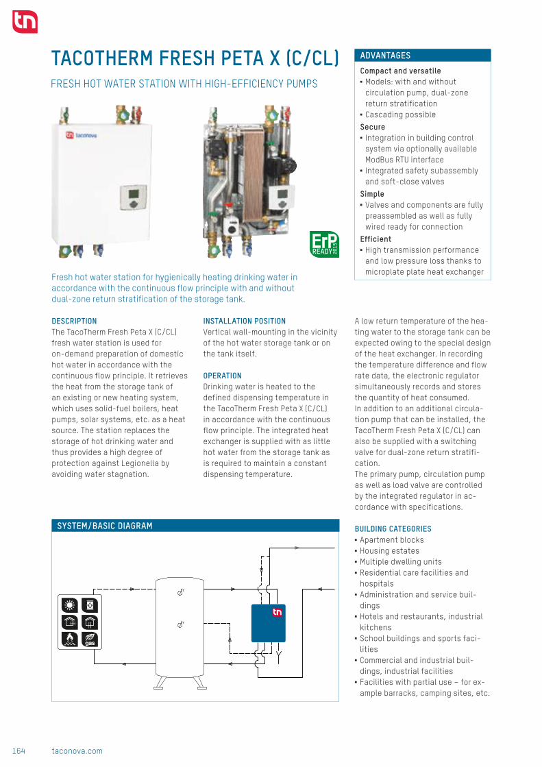
164 taconova.com
Syst
em t
echn
olog
y
TACOTHERM FRESH PETA X (C/CL)
T
T
ADVANTAGES
Compact and versatile ■ Models: with and without circulation pump, dual-zone return stratification
■ Cascading possible
Secure ■ Integration in building control system via optionally available ModBus RTU interface
■ Integrated safety subassembly and soft-close valves
Simple ■ Valves and components are fully preassembled as well as fully wired ready for connection
Efficient ■ High transmission performance and low pressure loss thanks to microplate plate heat exchanger
SYSTEM/BASIC DIAGRAM
FRESH HOT WATER STATION WITH HIGH-EFFICIENCY PUMPS
DESCRIPTIONThe TacoTherm Fresh Peta X (C/CL) fresh water station is used for on-demand preparation of domestic hot water in accordance with the continuous flow principle. It retrieves the heat from the storage tank of an existing or new heating system, which uses solid-fuel boilers, heat pumps, solar systems, etc. as a heat source. The station replaces the storage of hot drinking water and thus provides a high degree of protection against Legionella by avoiding water stagnation.
INSTALLATION POSITIONVertical wall-mounting in the vicinity of the hot water storage tank or on the tank itself.
OPERATION Drinking water is heated to the defined dispensing temperature in the TacoTherm Fresh Peta X (C/CL) in accordance with the continuous flow principle. The integrated heat exchanger is supplied with as little hot water from the storage tank as is required to maintain a constant dispensing temperature.
A low return temperature of the hea-ting water to the storage tank can be expected owing to the special design of the heat exchanger. In recording the temperature difference and flow rate data, the electronic regulator simultaneously records and stores the quantity of heat consumed. In addition to an additional circula-tion pump that can be installed, the TacoTherm Fresh Peta X (C/CL) can also be supplied with a switching valve for dual-zone return stratifi-cation. The primary pump, circulation pump as well as load valve are controlled by the integrated regulator in ac-cordance with specifications. BUILDING CATEGORIES
■ Apartment blocks ■ Housing estates ■ Multiple dwelling units ■ Residential care facilities and hospitals
■ Administration and service buil-dings
■ Hotels and restaurants, industrial kitchens
■ School buildings and sports faci-lities
■ Commercial and industrial buil-dings, industrial facilities
■ Facilities with partial use – for ex-ample barracks, camping sites, etc.
Fresh hot water station for hygienically heating drinking water in accordance with the continuous flow principle with and without dual-zone return stratification of the storage tank.
■■ TacoTherm Fresh Peta X

165taconova.com
Syst
em t
echn
olog
y
194175
35
1168542 257
470
6
854
648
515
322500
4442
530
92
12
61
7
2 3
8
4
9
10
11
12
13
5
6
PWT
B C
DA
T
TN Colour Code:
B
E
D
A
C
KaltwasserWarmwasserSpeicher VorlaufSpeicher RücklaufZirkulation
IG 1-1/4" IG 1-1/4"
IG 1-1/4" IG 1-1/4"
DN
32
DN
32
DN
32
DN 3
2
TTF Peta
T
PWT
B C
DA
E
T
IG 1" IG 1-1/4" IG 1-1/4"
IG 1-1/4" IG 1-1/4"
DN
25
DN
32
DN
32
DN
32
DN 3
2
TTF Peta C■ mit Zirkulation
T
PWT
B C
DDA
E
T
IG 1" IG 1-1/4" IG 1-1/4"
IG 1-1/4" IG 1-1/4" IG 1-1/4"
DN
25
DN
32
DN
32
DN
32
DN 3
2
TTF Peta CL■ mit Zirkulation■ mit Umschaltventil
T
A3 Blatt-Nr.
Für dieses Dokument behalten wir uns alle Rechte vor. Nous nous reservons tout les droits sur ce document. We reserve all rights in connection with this document.EM Datum VisumIndex
Material:
DatumGez.
Visum
Gen.Gepr.
Entstand aus: Ersatz für:
Toleranzen ISO 2768
Anz. Blatt
Massstab:Volumen / Gewicht: Techn. Lieferbed.:f cm
Oberflächen / SurfacesDIN-ISO 1302
abcde
ghikl
f
CH-8902 Urdorf
C:\Users\gudeljp\Documents\AutoCAD-Vorlagen\Logo\Taconova-Logo.jpg
S-008599 dSchema
I-1204
28.08.2014 SAS
- -
1
1
- -
-
-
- -
TacoTherm Fresh 60/80
1
7
2 3
8
4
9
10
11
13
5
6
DIMENSIONAL DRAWING
PRODUCT DIAGRAM
TACOTHERM FRESH PETA X (C/CL) | FRESH HOT WATER STATION
SPECIFICATION TEXTSee www.taconova.com
TECHNICAL DATA General
■ TacoTherm Fresh Peta controller with display
■ Weight (empty): 42 – 46 kg ■ Overall dimensions (incl. hood): W 530 mm × H 854 mm × D 194 mm
Material ■ Base plate: Galvanized sheet steel ■ Hood: Varnished sheet steel ■ Pumps:
■ Primary: Cast iron ■ Secondary: PPS (plastic, approved for drinking water)
■ Valve housing: Brass ■ Pipes:
■ Primary/secondary DN 32, stainless steel 1.4404
■ Circulation DN 25, stainless steel 1.4404
■ Microplate plate heat exchanger: ■ Plates and connector pieces: Stainless steel 1.4401
■ Heat exchanger solder: 99.99 % copper (stainless steel solder model available on request)
■ Seals: AFM flush sealPrimary side
■ Operating temperature TO max: 95 °C ■ Operating pressure PO max: 10 bar ■ Primary pump: Grundfos UPMXL GEO 25-125
Secondary sideModules on secondary side with drinking water certifications
■ Operating temperature TO max: 85 °C ■ Operating pressure PO max: 9 bar ■ Safety valve (intrinsic safety): 10 bar discharge pressure and 9 bar closing pressure
■ Circulation pump: UPM3 Auto L 15-70 CIL
Performance data ■ See design diagram
Electrical connection data ■ Mains voltage: 230 VAC ± 10 % ■ Mains frequency: 50...60 Hz ■ Power consumption: max. 250 W, 3.5 AT fuse
■ Optional interface for ModBus RTU ■ Protection type: IP 40
Flow media ■ Heating water (VDI 2035; SWKI BT 102-01; ÖNORM H 5195–1)
■ Cold water
TYPE OVERVIEW TacoTherm Fresh Peta X / Peta X C / Peta X CL | Fresh hot water station Order no. Rp Version Version
272.6650.000 1 ¼" IT XWithout circulating pump, without dual-zone return stratification
273.6652.000 1 ¼" IT X CWith circulating pump, without dual-zone return stratification
273.6650.000 1 ¼" IT X CL With circulating pump and dual-zone return stratification
1 Primary hot water flow2 Primary hot water return 1 (integration of storage tank below)3 Primary hot water return 2 (integration of storage tank in center in CL models)4 Circulation (C/CL version)5 Cold water connection6 Hot water connection
7 Primary pump8 Circulation pump (C/CL version)9 Flow rate sensor10 Safety valve11 Heat exchanger12 Regulator13 Switching valve (CL version)

166 taconova.com
Syst
em t
echn
olog
y
700
800
900
1000
18
20
22
0
100
200
300
400
500
600
10 25 40 55 70 85 100
10 25 40 55 70 85 100
10 25 40 55 70 85 100
4000
4500
5000
300
350
400
3500
4000
4500
5000
10
12
14
16
500
1000
1500
2000
2500
3000
3500
100 300 500 700 9000
50
100
150
200
250
500
1000
1500
2000
2500
3000
3500
750650
77
77
77
19
(∆p)
345
6
7
8
9
65 °C
70 °C
75 °C
2
1
65 °C 70 °C 75 °C
kW
FLOW AND PRESSURE LOSS DIAGRAMS COLD WATER HEATING AT 50K (10 ... 60 °C)
TACOTHERM FRESH PETA X (C/CL) | FRESH HOT WATER STATION
Hot
wat
er d
eman
d (l/
h)
A) Cold water heating at 50K B) Residual head | Primary pressure loss
Pres
sure
loss
(mba
r)
Dispensing volume (l/min)
D) Secondary pressure loss
Dispensing volume (l/min)
Dispensing volume (l/min)
Retu
rn t
empe
ratu
re (°
C)
C) Return temperatures
Pressure loss (mbar)
Hot
wat
er d
eman
d (l/
h)
EXAMPLE FOR INTERPRETING THE FLOW RATE AND PRESSURE LOSS DIAGRAMS Given
■ Hot water dispensing volume: 77 l/min
■ Primary heating flow temperature: 70 °C
Sought ■ Hot water demand (l/h) ■ Primary heating return temperature in °C
■ Secondary pressure loss in mbar ■ Primary pressure loss in mbar
Approach ■ In Diagram A) the hot water demand at the intersection point of the dispensing volume of 77.5 l/min and primary flow temperature of 70 °C is 4500 l/h.
■ In Diagram B) the primary pressure loss for a hot water demand of 4500 l/h is 650 mbar. The pump delivery head is 750 mbar, discounting the pressure loss this gives rise to a residual pump head of 100 mbar (Δp).
■ In Diagram C) the primary return temperature for a given dispensing volume of 77.5 l/min and the selec-ted flow temperature of 70 °C is 19 °C.
■ In Diagram D) the secondary pressure loss for the given data is 500 mbar
1 Secondary pressure loss2 Secondary pressure loss in circulation3 Pump curve, DHW circulation stage 14 Pump curve, DHW circulation stage 25 Pump curve, DHW circulation stage 36 Pump curve, DHW circulation stage 47 Pump curve, DHW circulation stage 58 Pump curve, DHW circulation stage 69 Pump curve, DHW circulation stage 7
Output kW

167taconova.com
Syst
em t
echn
olog
y
16
17
18
19
20
4500
5000
10
11
12
13
14
15
16
500
1000
1500
2000
2500
3000
3500
4000
4500
5000
10 35 60 85 110
10 35 60 85 110
10 35 60 85 110 100 300 500 700 900
300
400
500
600
700
800
900
1000
0
100
200
300
400
5000
500
1000
1500
2000
2500
3000
3500
4000
4500
5000370
20
70
120
170
220
270
320
370
16
17
18
19
20
4500
5000
10
11
12
13
14
15
16
500
1000
1500
2000
2500
3000
3500
4000
4500
5000
10 35 60 85 110
10 35 60 85 110
10 35 60 85 110 100 300 500 700 900
300
400
500
600
700
800
900
1000
0
100
200
300
400
5000
500
1000
1500
2000
2500
3000
3500
4000
4500
5000370
20
70
120
170
220
270
320
370
kW
16
17
18
19
20
4500
5000
10
11
12
13
14
15
16
500
1000
1500
2000
2500
3000
3500
4000
4500
5000
10 35 60 85 110
10 35 60 85 110
10 35 60 85 110 100 300 500 700 900
300
400
500
600
700
800
900
1000
0
100
200
300
400
5000
500
1000
1500
2000
2500
3000
3500
4000
4500
5000370
20
70
120
170
220
270
320
370
48 °C
48 °C
50 °C
50 °C
55 °C
55 °C
60 °C
60 °C
65 °C
65 °C
70 °C
70 °C75 °C
75 °C
345
6
7
8
9
2
1
FLOW AND PRESSURE LOSS DIAGRAMS COLD WATER HEATING AT 35K (10 ... 45 °C)
TACOTHERM FRESH PETA X (C/CL) | FRESH HOT WATER STATION
Hot
wat
er d
eman
d (l/
h)
A) Cold water heating at 35K B) Residual head | Primary pressure loss
Pres
sure
loss
(mba
r)
Dispensing volume (l/min)
D) Secondary pressure loss
Dispensing volume (l/min)
Dispensing volume (l/min)
Retu
rn t
empe
ratu
re (°
C)
C) Return temperatures
Pressure loss (l/min)
Hot
wat
er d
eman
d (l/
h)
1 Secondary pressure loss2 Secondary pressure loss in circulation3 Pump curve, DHW circulation stage 14 Pump curve, DHW circulation stage 25 Pump curve, DHW circulation stage 36 Pump curve, DHW circulation stage 47 Pump curve, DHW circulation stage 58 Pump curve, DHW circulation stage 69 Pump curve, DHW circulation stage 7
NOTE
REQUIREMENTS FOR FLOW MEDIA
The stations heat interface units use a copper-soldered stainless steel plate heat exchanger as standard. It must be checked prior to use in the framework of system planning whether the issues of corrosion protection and scale formation have been sufficiently taken into account in accordance with DIN 1988200 and current drinking water analyses according to DIN EN 8065. See datasheet „Plate Heat Exchanger Requirements - Limit Values for Drinking Water Quality“.

168 taconova.com
Syst
em t
echn
olog
y
Subj
ect
to m
odif
icat
ion.
12/
2017
TACOTHERM FRESH PETA X (C/CL) | FRESH HOT WATER STATION
CONTACT AND FURTHER INFORMATION TACONOVA.COM
Taconova Group AG | Neunbrunnenstrasse 40 | CH-8050 Zurich | T +41 44 735 55 55 | F +41 44 735 55 02 | [email protected]
ACCESSORIES FOR CASCADE CIRCUITRY
Order no. Rp Description295.0100.000 Basic construction kit 295.0101.000 Extension kit
296.7026.000Second zone valve for basic construction kit (sequence switching operation)
296.7025.000 2" External storage restratification 272.6030.391 External circulation
MODBUS RTU INTERFACE
Order no. Description296.7027.000 For integration with the building control system
ACCESSORIES
SAMPLE ORDER FOR CASCADE MODULE CASCADE CIRCUIT WITH INTEGRATED CIRCULATION AND STORAGE STRATIFICATION, WITHOUT SEQUENCE SWITCHING
Order no. 2-way cascade 3-way cascade 4-way cascade 5-way cascade272.6650.000 1 2 3 4273.6650.000 1 1 1 1295.0100.000 1 1 1* 1*295.0101.000 0 1 2* 3*
CASCADE CIRCUIT WITH EXTERNAL CIRCULATION, WITH EXTERNAL STORAGE STRATIFICATION FOR SEQUENCE SWITCHING
Order no. 2-way cascade 3-way cascade 4-way cascade 5-way cascade272.6650.000 2 3 4 5295.0100.000 1 1 1* 1*295.0101.000 0 1 2* 3*296.7026.000 1 1 1 1296.7025.000 1 1 1 1272.6030.391 1 1 1 1
* Attention: Note pressure losses in the cascade pipe sets and diverting valves.

169taconova.com
Syst
em t
echn
olog
y
The plate heat exchangers in Taco-nova fresh hot water stations are produced as standard as copper soldered stainless steel plate heat exchangers. Before these heat exchangers can be used, building services engineers and installation companies have to check in the framework of system planning whether the issues of corrosion protection and scale formation have been sufficiently taken into account in accordance with DIN 1988-200
and DIN EN 806-5 as well as current drinking water analyses.This includes the following points:
■ Selection of materials ■ Consideration of corrosion-related changes to the drinking water quality
■ Performance of installation ■ Consideration of anticipated operating conditions
Signs of corrosion may occur in copper materials with high electrical conductivity of the drinking water of
more than 500 yS/cm, which could cause damage to the copper solder in the heat exchanger. For electrical conductivities of > 500 yS / cm, we therefore recommend the use of our nickel- or stainless-steel-soldered plate heat exchangers. The following values for water-borne substances and characteristic values should be observed (1.4401/1.4404 / SA240 316/SA240 316L):
Corrosion resistance of soldered plate heat exchangers to water- borne substances – the soldered plate heat exchanger consists of stamped stainless steel plates 1.4401/1.4404 or SA240 316/SA240 316L
PLATE HEAT EXCHANGER – LIMIT VALUES FOR DRINKING WATER QUALITY
Subj
ect
to m
odif
icat
ion.
04/
2017
CONTACT AND FURTHER INFORMATION TACONOVA.COM
Taconova Group AG | Neunbrunnenstrasse 40 | CH-8050 Zurich | T +41 44 735 55 55 | F +41 44 735 55 02 | [email protected]
Water-borne substances and characteristic values
UnitPlate heat exchanger
Copper-soldered Nickel-solderedStainless-steel-
soldered
pH value 7 – 9(considering the SI index)
6 – 10 6 – 10
Saturation index SI (delta pH value) -0,2 < 0 < +0,2 Not specified
Total hardness °dH 6 – 15 6 – 15 6 – 15
Conductivity μS/cm 10 ... 500 10-1000 Not specified
Substances that can be filtered out mg/l < 30 <30 <30
Chloride* mg/l No chloride permitted above 100° C
Free chlorine free mg/l < 0,5 < 0,5 < 0,5
Hydrogen sulfide (H2S) mg/l < 0,05 Not specified
Ammonia (NH3/NH4+) mg/l < 2 < 2 Not specified
Sulfate mg/l < 100 < 300 < 400
Hydrogen carbonate mg/l < 300 Not specified
Hydrogen carbonate / sulfate mg/l > 1,0 Not specified
Sulfide mg/l < 1 < 5 < 7
Nitrate mg/l < 100 Not specified
Nitrite mg/l < 0,1 Not specified
Iron (dissolved) mg/l < 0,2 Not specified
Manganese mg/l < 0,1 Not specified
Free (aggressive) carbonic acid mg/l < 20 Not specified
* At 20 °C max. 600 mg/l | At 25 °C max. 500 mg/l | At 50 °C max. 200 mg/l | At 75 °C max. 75 mg/l | ≥ 100 °C max. 0 mg/l The specified values are guide values, which may deviate under certain operating conditions
■■ Plate heat exchanger requirements

170 taconova.com
Syst
em t
echn
olog
y
MAXIMUM ENERGY USE BY THE COLLECTOR
Storage loading stations transfer the solar heat from the collector to the right
storage tank zone.
OPTIMAL USE OF THE SOLAR COLLECTORThe TacoSol Load storage loading stations increase the
usage heat from solar systems by loading different zones
of the storage tank depending on the available tempe-
rature from the solar circuit. In order to achieve optimum
discharge of the solar collector, the temperature diffe-
rence of the flow and return of the solar thermal energy
system is significant.
Low return temperatures ensure a high level of thermal
transfer in the storage tank and the optimum discharge
of the collector.
SECURE AND EFFICIENT USE OF SOLAR ENERGY AND REGENERATIVE ENERGIESWhen using heat generators that are powered by renew-
able energies or that operated according to the principle
of power-heat coupling, the heat produced is stored in a
storage tank. Examples of this are solar heating systems,
heat pumps, block heating stations or wood pellet and
wood burning boilers. The storage tank means that long
burner/aggregate running times can be achieved and
free solar energy can be used efficiently.
STRATIFIED STORAGE UNIT LOADING WITH EXTERNAL LOADING STATIONSThe loading of storage tanks has a major influence over
how efficiently the thermal energy generated by a solar
energy or heating system can be used. It is important to
avoid disrupting currents in the storage tank in order to
support stratification. Eddies that impact on stratification
mainly occur due to the difference in temperature between
the contents of the storage tank and the heated water
that flows in. The storage is generally loaded with the
same temperature level as in the solar circuit. This means
that although solar heat is pumped into the storage unit,
mixing necessarily occurs if there is a difference in tempe-
rature. Stratified storage unit loading stations increase the
amount of thermal energy that can be used when different
storage tank zones are loaded, depending on the available
temperature level.
STRATIFIED LOADING WITH TEMPERATURE BALANCINGStorage tank loading stations bring together the func-
tions of the solar station and module in a pre-assembled
module.
Loading stations are used to load storage tanks with
solar heat by means of powerful plate heat exchangers.
A temperature-based storage tank loading means that
the relevant storage tank zones are loaded in accordance
with the temperature level available in the solar thermal
energy system.
CONTROLLER COMPARES THE COLLECTOR AND STORAGE UNIT TEMPERATUREThe electronic controller ensures that the solar-heated
hot water is delivered to the storage tank at precisely the
temperature available at one of two storage unit inputs.
The controller evaluates the temperature differences of
the primary and secondary side for this purpose.
The temperature values at the flow connections of the
storage tank and in the collector determine which of the
two buffer inputs is controlled.
The temperature data influences the pump speed in such
a way that the hot water in the plate heat exchanger is
heated to the temperature of the storage tank zone nearer
to the collector temperature.
STABLE LOADING IN THE STORAGE TANKThe storage unit loading stations were developed for
high energy yield in the collector and to establish stable
stratification in the storage tanks without an internal heat
exchanger. The electronically regulated loading station
considers both the solar heat available from the collector
circuit and the temperature in the storage tank.
Depending on their configuration, some storage unit
loading stations for large solar energy systems allow large
solar collector areas to be connected, achieving a high
energy yield.
Storage loading stations

171taconova.com
Syst
em t
echn
olog
y
STRATIFIED STORAGE UNIT LOADING FOR TWO STORAGE TANK ZONES
The storage unit loading stations achieve a high energy yield from the collector
and stable stratification in the storage unit.
BENEFITS AT THE PLANNING STAGE■■ Certainty during planning and dimensioning thanks to
the compact installation-ready design■■ Efficient planning thanks to hydraulic design and station
configuration by the manufacturer■■ Can be combined with a wide variety of heat generator
and storage systems■■ The compact design makes planning easier■■ Costs can be kept under control during planning thanks
to a clear, pre-configured component specification■■ Enables the planner to position himself as an innovator
BENEFITS AT THE INSTALLATION STAGE■■ Less time required to install, commission and maintain
the system■■ Increased sales■■ Service and guarantee from a single source■■ Reliable operation thanks to high quality components■■ Compact design means that less space is required for
installation■■ Easy to provide evidence of energy yield■■ Satisfied customers■■ Enables the fitter to position himself as an innovator
TacoSol Load storage loading station
Solar station and loading module (system separation) in one: ■■ Connection-ready storage loading stations with integrated system separation for loading one or two storage tank
or domestic water storage heating units by means of a solar thermal energy system■■ Maximum solar yield and efficient operation thanks to sensor technology■■ Ideally complements the TacoTherm Fresh fresh hot water stations
Product photo SeriesHeat output *1)
Collector surface *2) Comments
Mega 12.5 kW Approx. 25 m²
■■ Solar station with permanent automatic venting■■ External heat exchanger for loading a storage tank at
one or two levels
Tera 25 kW Approx. 50 m²
■■ Optional temperature-dependent return stratification of the primary circuit in the storage tank
■■ Permanent automatic venting■■ ErP-ready
Exa 120 kWApprox. 240 m²
■■ Wall mounted■■ High-efficiency pump technology■■ Permanent automatic venting
*1) according to VDI 6002 *2) depends on overall pressure loss of solar circuit including collector

172 taconova.com
Syst
em t
echn
olog
y
TACOSOL LOAD MEGA
T
T
ADVANTAGES ■ Maximum solar yield from the roof to the storage tanks owing to high-quality stainless steel plate heat exchanger
■ Zone-based loading of one storage tank or loading of two storage tanks
■ Speed control of the primary and also secondary pump for optimal temperature differentiation
■ Stable stratified loading in the storage tank
■ TacoControl Tronic for recording the primary return temperature and the primary flow rate
■ Maximum energy efficiency, for example for generating fresh hot water with the TacoTherm Fresh fresh water stations
SYSTEM/BASIC DIAGRAM
STORAGE LOADING STATION
DESCRIPTIONThe TacoSol Load Mega storage loading station performs the zone-based loading of one storage tank or loading of two storage tanks via a thermal solar installation according to the available flow temperature.
INSTALLATIONThe station is fully preassembled, connection-ready and can be fitted directly to the storage tank or to the wall. Only the storage and collector sensors as well as the ventilating safety unit have to be assembled.
OPERATION The TacoSol Load Mega is a compact loading station equipped with EPP design insulation for loading one or two storage tanks by means of a solar system.The solar energy recovered is trans-ferred via a high-efficiency stainless steel plate heat exchanger to the storage tank(s). By controlling the speed of the primary and also the secondary pump, the integrated controller ensures the optimal conditions are in place for achieving the best possible solar yield.
The parameters required for this purpose for the TacoSol Load Mega L with switching valve are determined, for example, by means of TacoControl Tronic. The controller regulates the three-way switching valve to operate either storage inflow 1 or 2. This ensure optimal loading of one or more storage tanks.
BUILDING CATEGORIES ■ Single family homes, multiple dwelling units
■ Hotels and restaurants ■ School buildings and sports facilities
■ Industrial buildings and systems
EXPANSION OPTIONThe TacoTherm Fresh Mega and TacoTherm Fresh Tera fresh water stations ideally complement the innovative TacoSol Load Mega zone-based storage loading system. They are used for hygienic fresh water preparation.
Connection-ready storage loading station with high-efficiency pumps for efficient thermal transfer of solar energy to one or two storage tanks
■■ TacoSol Load Mega

173taconova.com
Syst
em t
echn
olog
y
490
331
698
545
170 320
635
477860607716876
90
50
5949
680
181
M
TT
V•
P
1
6
6
2
7
7
3
8
8
9
9
10
10
11
11
13
12
13
4 5
5
1
23 4
DIMENSIONAL DRAWING
TYPE OVERVIEW TacoSol Load Mega | Storage loading station Order no. Rp Version Version271.5512.000 ¾" IG L with switching valve271.5511.000 ¾" IG without switching valve
SPECIFICATION TEXTSee www.taconova.com
TECHNICAL DATAGeneral
■ Controller with display ■ Weight (empty): approx. 12 kg ■ Overall dimensions (incl. hood): W 698.5 mm × H 636 mm × D 181 mm
Material ■ Designer hood made from EPP ■ Pumps: Cast iron ■ Valve housing: Brass ■ Pipes: Stainless steel 1.4404 ■ Plate heat exchanger: Stainless steel
■ Plates and connector pieces: Stainless steel 1.4401
■ Solder: 99.99 % copper ■ Seals: AFM34 (flat sealing)
Primary side ■ Operating temperature TO max:
■ Flow: 110 °C, briefly (2h): 140 °C ■ Return: 95 °C
■ Max. operating pressure PO max: 8 bar ■ Primary pump: WILO Yonos Para ST 15/7.5
■ Ventilator group with integrated shutoff, filling, purging and drainage facility
■ Safety valve 6 bar ■ TacoControl Tronic measurement range: 2 – 40 l/min
Secondary side ■ Operating temperature TO max: 110 °C ■ Max. operating pressure PO max: 3 bar ■ Secondary pump: WILO Yonos Para ST 15/7.5
■ Zone switching valvePerformance data
■ See design diagramElectrical connection data
■ Mains voltage: 230 VAC ± 10 % ■ Mains frequency: 50...60 Hz ■ Power consumption of station: max. 130 W
■ Power consumption of pump: solpump: 4-75 W
■ Power consumption of pump in standby mode: 0.8 W
■ Fuse 2 AT ■ Protection type: IP 40
Flow media ■ Heating water (VDI 2035; SWKI BT 102-01; ÖNORM H 5195–1)
■ Typical glycol mixtures up to 40%
1 Primary – solar flow2 Primary – solar return3 Secondary – storage return4 Secondary – storage flow 15 Secondary – storage flow 2
(optional zu Umschaltventil)6 Primary solar pump
7 Secondary storage loading pump8 Flow rate sensor9 Solar safety valve10 Heat exchanger11 Connection of expansion vessel12 Regulator13 Switching valve (TacoSol Load Mega L)
TACOSOL LOAD MEGA | STORAGE LOADING STATION
HYDRAULIC DIAGRAM

174 taconova.com
Syst
em t
echn
olog
y
Projekt-Nr. I-1211 Ersteller TS Charakteristik Plattenwärmetauscher TSL Mega HE
TNG Auslegematrix Speicherladestation Version 09/13 1 / 2
Produktname TSL Mega HE Datum: 20.04.2015 ]T atled gol[ znereffidrutarepmeT gol erelttiMnegaldnurG
Berechnungswerte 500 [W/m2]
Auslegungsmatrix - Speicherladestation 10 20 30 40
tuälrE / ednegeL:epmuprädnukeS:epmuprämirP:netnenopmoklessülhcS erung: 6.4 9.1 11.0 12.010
Spez. Volumenstrom
[l/(h*m2)]
Kollektor�äche [m 2]
Wärmetauscher:Förderhöhe UWP
Druckverlust Station
Förderhöhe UWP
Druckverlust Station ΔT <5K E�zienter Berieb 4.1 4.8 5.4 5.6
]rabm[]rabm[]nim/l[]h/l[]rabm[]rabm[]nim/l[]h/l[:epmuprämirP ΔT <7K Verminder Ertrag 3.9 3.6 4.3 4.9
0.00570.000.00570.00:epmuprädnukeS ΔT >7K Deutlich verminderter Ertrag 2.9 3.0 3.4 -
Durch�usskoe�zient: 500 8.3 750 51.7 500 8.3 750 47.3
Pumpenkennlinie Yonos Para RS 15/7.5
Pumpenkennlinie Yonos Para RS 15/7.5
Fabrikat SWEP: Plattenwärmetauscher IC 15/30
mortsnemuloVmortsnemuloV 25
35
50
0.9810577.6100016.6020577.6100012.2sierkrämirP SVK
3.5240570.5200519.4640570.5200513.2sierkrädnukeS SVK
Fluideigenschaften: 2000 33.3 625 826.4 2000 33.3 625 756.1
0357.1400523.19210357.140052]%[04
1 000 [k / 3] 3000 50 0 430 3000 50 0 430Dichte
Glykolgehalt
Angaben aus Katalog
Diagramm: Pumpenkennlinie - A nlagekennlinie der Station
700
800
Sta
tion
Primärseite
1.000 [kg/m3] 3000 50.0 430 3000 50.0 430
Spez. Wärmekapazität
3.8500533.850053])K*gk(/Jk[007.3
Spez. Wärmekapazität
4.187 [kJ/(kg*K)]
Ethylenglykol
Daten Primärkreislauf 200
300
400
500
600
inie
-A
nlag
eken
nlin
ie d
er
S
]rabm[ rämirp tsulrevkcurD]nim/l[ ni dlefrotkelloK ssulfhcruD
0403020104030201
1.7 3.3 5.0 6.7 2 8 19 3310
Kollektor�äche [m 2]Spez. Volumenstrom
[l/(h*m2)]Spez. Volumenstrom
[l/(h*m2)]
10
Daten Primärkreislauf
Kollektor�äche [m 2] 0
100
200
0 200 400 600 800 1000 1200 1400 1600 1800
Pum
penk
ennl
Volumenstrom Wasser-Glykol Gemisch [l/h]Förderhöhe UWP Druckverlust Station
4.2 8.3 12.5 16.7 13 52 116 207
5.8 11.7 17.5 23.3 25 101 228 405
8.3 16.7 25.0 33.3 52 207 465 82650 50
25 25
35 35
500
600
700
800
nie
der S
tatio
n
Sekundärseite
]rabm[ rädnukes tsulrevkcurD]nim/l[ ni dlefrotkelloK ssulfhcruD
0403020104030201
Kollektor�äche [m 2]Kollektor�äche [m 2]
Daten Sekundärkreislauf
Spez. Volumenstrom[l/(h*m2)]
Spez. Volumenstrom[l/(h*m2)]
200
300
400
500
enke
nnlin
ie -
Anl
agek
ennl
i
1.5 2.9 4.4 5.9 1 6 13 24
3.7 7.4 11.0 14.7 9 37 83 148
5.2 10.3 15.5 20.6 9823612781
7.4 14.7 22.1 29.5 37 148 332 590
10 10
50 50
25 25
35 350
100
0 200 400 600 800 1000 1200 1400 1600
Pum
p
Volumenstrom Heizungswasser [l/h]Förderhöhe UWP Druckverlust Station
TNG Auslegematrix Speicherladestation Version 09/13 1 / 2
(∆p)
(∆p)
750
100
700
620
750
75
A
A
B
B
Subj
ect
to m
odif
icat
ion.
05/
2017
TACOSOL LOAD MEGA | STORAGE LOADING STATION
CHARACTERISTIC OF PLATE HEAT EXCHANGERBASICSCalculation values 500 [W/m²]
LEGEND / EXPLANATIONΔT <5K Efficient operation ΔT 5-7K Reduced yieldΔT >7K Considerably reduced yield
AVERAGE LOG TEMP DIFFERENCE [LOG DELTA T] Spec. flow rate [l/(h*m²)]
Collector surface (m²)5 10 15 20
10 7.6 8.4 8.5 9.525 3.6 4.3 5.5 6.035 2.8 4.2 4.5 5.050 2.2 3.4 3.7 4.0
FLOW AND PRESSURE LOSS DIAGRAMS
Pres
sure
loss
(mba
r)Pr
essu
re lo
ss (m
bar)
Flow rate of water-glycol mixture [l/h]
Flow rate of heating water [l/h]
A) Pump characteristic System characteristic primary side
B) Pump characteristic System characteristic secondary side
A Pump characteristic | B System characteristic
EXAMPLE OF INTERPRETING THE DIAGRAMS
Given ■ Collector surface: 20 m² ■ Output: 12.5 kW ■ Average log temp difference: 5.0 ■ Spec. flow rate 35 l/h × m²
Sought ■ Residual pump head primary circuit ■ Residual pump head secondary circuit
Approach ■ The primary flow rate of 700 l/h is calculated based on: Collector surface × Specific flow rate
■ In Diagram A) the primary pressu-re loss at the intersection point of the system characteristic is 100 mbar.
■ The residual pump head is 750 mbar. Discounting the pressure loss this gives rise to a residual pump head of 650 mbar (Δp).
■ In Diagram B) the primary flow rate is 620 l/h. The difference between the flow rates is based on the different thermal capaci-ties of the heating water on the secondary side and the ethylene-glycol mixture on the primary side.
■ The secondary pressure loss at the intersection of the system characteristic is 75 mbar.
■ The residual pump head is 750 mbar. Discounting the pressure loss this gives rise to a residual pump head of 670 mbar (Δp).
CONTACT AND FURTHER INFORMATION TACONOVA.COM
Taconova Group AG | Neunbrunnenstrasse 40 | CH-8050 Zurich | T +41 44 735 55 55 | F +41 44 735 55 02 | [email protected]
TACOSOL LOAD TERA L
T
T
ADVANTAGES CompactEquipped with all the necessary valves and components, ideally complements the TacoTherm Fresh Tera C fresh hot water station SecureIntrinsic safety of the system thanks to an integrated safety subassembly SimpleStation is fully preassembled and supplied with ready-to-connect wiring EfficientHighly efficient system operation due to permanent air separation, use of high-efficiency pumps as well as maximum solar yield from the roof owing to the possible dual-zone loading of the storage tank.
SYSTEM/BASIC DIAGRAM
STORAGE TANK LOADING STATION WITH HIGH-EFFICIENCY PUMPS
DESCRIPTIONThe TacoSol Load Tera L storage loading station performs the zone-based loading of one or two storage tanks via a thermal solar installation according to the available flow temperature.
INSTALLATION POSITIONThe station is fully preassembled, connection-ready and can be fitted directly to the storage tank or to the wall. Only the storage and collector sensors still need to be fitted.
OPERATION The TacoSol Load Tera L is a com-pact, zone-based loading station equipped with EPP design insulation for loading one or two storage tanks by means of a solar system.The solar energy recovered is trans-ferred via a high-efficiency stainless steel plate heat exchanger to the storage tank(s). The innovative preset controller undertakes the task of ensuring optimal return supply to the storage tank(s) by regulating the speed of the primary pump.
The controller actuates the three-way switching valve, serving either storage return I or II. This ensures optimal zone loading within the storage tank.
BUILDING CATEGORIES ■ Single family homes, multiple dwelling units
■ Hotels and restaurants ■ School buildings and sports facilities
■ Commercial and industrial buildings, industrial facilities
EXPANSION OPTION The TacoTherm Fresh Tera C fresh hot water station ideally complements the innovative TacoSol Load Tera L stratified storage tank loading system.It is used for hygienic fresh water production and boasts the same compact dimensions, the same design and the same innovative components as the TacoSol Load Tera L.
Connection-ready storage loading station for efficient thermal transfer of solar energy with and without dual-zone loading of the storage tank

175taconova.com
Syst
em t
echn
olog
y
TACOSOL LOAD TERA L
T
T
ADVANTAGES CompactEquipped with all the necessary valves and components, ideally complements the TacoTherm Fresh Tera C fresh hot water station SecureIntrinsic safety of the system thanks to an integrated safety subassembly SimpleStation is fully preassembled and supplied with ready-to-connect wiring EfficientHighly efficient system operation due to permanent air separation, use of high-efficiency pumps as well as maximum solar yield from the roof owing to the possible dual-zone loading of the storage tank.
SYSTEM/BASIC DIAGRAM
STORAGE TANK LOADING STATION WITH HIGH-EFFICIENCY PUMPS
DESCRIPTIONThe TacoSol Load Tera L storage loading station performs the zone-based loading of one or two storage tanks via a thermal solar installation according to the available flow temperature.
INSTALLATION POSITIONThe station is fully preassembled, connection-ready and can be fitted directly to the storage tank or to the wall. Only the storage and collector sensors still need to be fitted.
OPERATION The TacoSol Load Tera L is a com-pact, zone-based loading station equipped with EPP design insulation for loading one or two storage tanks by means of a solar system.The solar energy recovered is trans-ferred via a high-efficiency stainless steel plate heat exchanger to the storage tank(s). The innovative preset controller undertakes the task of ensuring optimal return supply to the storage tank(s) by regulating the speed of the primary pump.
The controller actuates the three-way switching valve, serving either storage return I or II. This ensures optimal zone loading within the storage tank.
BUILDING CATEGORIES ■ Single family homes, multiple dwelling units
■ Hotels and restaurants ■ School buildings and sports facilities
■ Commercial and industrial buildings, industrial facilities
EXPANSION OPTION The TacoTherm Fresh Tera C fresh hot water station ideally complements the innovative TacoSol Load Tera L stratified storage tank loading system.It is used for hygienic fresh water production and boasts the same compact dimensions, the same design and the same innovative components as the TacoSol Load Tera L.
Connection-ready storage loading station for efficient thermal transfer of solar energy with and without dual-zone loading of the storage tank
■■ TacoSol Load Tera L

176 taconova.com
Syst
em t
echn
olog
y
658
70.5127376.5
574
115.5 261 197.5
116
70 33
119
72 95 24295 70
471
197
53.5
2162
0.5
17
893
53.5
T T
M
T
V•
P
1
6
2
7
3
89
10
11
13
13
12
12
4 5
1
6
2
7
3
8
910
4 5
HYDRAULIC DIAGRAM
DIMENSIONAL DRAWING
CHARACTERISTIC OF PLATE HEAT EXCHANGER BASICSCalculation values 500 [W/m²]
LEGEND / EXPLANATIONΔT <5K Efficient operation ΔT <7K Reduced yield ΔT >7K Considerably reduced yield
TACOSOL LOAD TERA L | STORAGE TANK LOADING STATION
1 Primary solar flow2 Primary solar return3 Secondary storage return4 Secondary storage flow 15 Secondary storage flow 26 Primary solar pump7 Secondary storage tank loading pump8 Flow rate sensor9 Solar safety valve10 Heat exchanger11 Controller 12 Zone switching valve13 Expansion vessel connection
SPECIFICATION TEXTSee www.taconova.com
TECHNICAL DATAGeneral
■ Controller with display ■ Weight (empty): approx. 25 kg ■ Overall dimensions (incl. hood): W 656 mm × H 930 mm × D 197 mm
Material ■ Designer hood made from EPP with plastic surround
■ Pumps: Cast iron ■ Valve housing: Brass ■ Pipes: DN 20, stainless steel 1.4404 ■ Plate heat exchanger: Stainless steel ■ Plates and connector pieces: Stainless steel 1.4401
■ Solder: 99.99 % copper ■ Seals: AFM 34, flat sealing
Primary side ■ Max. operating temperature TO max
■ flow: 110 °C ■ return: 95 °C
■ Max. operating pressure PO max: 6 bar ■ Primary pump: WILO Stratos Para 15/1-7 ■ Ventilator group with integrated shutoff, filling, flushing and drainage facility
■ Safety valve 6 barSecondary side
■ Max. operating temp. TO max: 110 °C ■ Max. operating pressure PO max: 3 bar ■ Measuring range of temperature gauge and flow meter: 2 – 40 l/min
■ WILO Yonos Para 15/7.5 PWM ■ Zone switching valve DN 25
Performance data ■ See design diagram
Electrical connection data ■ Mains voltage: 230 VAC ± 10 % ■ Mains frequency: 50...60 Hz ■ Power consumption: max. 180 W ■ Fuse 2 AT ■ Protection type: IP 40
Flow media ■ Heating water (VDI 2035; SWKI BT 102-01; ÖNORM H 5195–1)
■ Typical glycol mixtures up to 40%
TYPE OVERVIEW TacoSol Load Tera L | Storage tank loading Station Order no. Rp Version Equipment271.5522.000 1" IT L With dual-zone loading
AVERAGE LOG TEMP DIFFERENCE [LOG DELTA T] Spec. flow rate[l/(h*m²)]
Collector surface (m²)20 30 40 50 60
10 8.5 9.8 10.8 11.4 –25 4.9 5.9 6.3 6.5 6.835 4.0 4.8 5.0 5.3 –50 3.3 3.8 – – –

177taconova.com
Syst
em t
echn
olog
y
658
70.5127376.5
574
115.5 261 197.5
116
70 33
119
72 95 24295 70
471
197
53.5
2162
0.5
17
893
53.5
T T
M
T
V•
P
1
6
2
7
3
89
10
11
13
13
12
12
4 5
1
6
2
7
3
8
910
4 5
HYDRAULIC DIAGRAM
DIMENSIONAL DRAWING
CHARACTERISTIC OF PLATE HEAT EXCHANGER BASICSCalculation values 500 [W/m²]
LEGEND / EXPLANATIONΔT <5K Efficient operation ΔT <7K Reduced yield ΔT >7K Considerably reduced yield
TACOSOL LOAD TERA L | STORAGE TANK LOADING STATION
1 Primary solar flow2 Primary solar return3 Secondary storage return4 Secondary storage flow 15 Secondary storage flow 26 Primary solar pump7 Secondary storage tank loading pump8 Flow rate sensor9 Solar safety valve10 Heat exchanger11 Controller 12 Zone switching valve13 Expansion vessel connection
SPECIFICATION TEXTSee www.taconova.com
TECHNICAL DATAGeneral
■ Controller with display ■ Weight (empty): approx. 25 kg ■ Overall dimensions (incl. hood): W 656 mm × H 930 mm × D 197 mm
Material ■ Designer hood made from EPP with plastic surround
■ Pumps: Cast iron ■ Valve housing: Brass ■ Pipes: DN 20, stainless steel 1.4404 ■ Plate heat exchanger: Stainless steel ■ Plates and connector pieces: Stainless steel 1.4401
■ Solder: 99.99 % copper ■ Seals: AFM 34, flat sealing
Primary side ■ Max. operating temperature TO max
■ flow: 110 °C ■ return: 95 °C
■ Max. operating pressure PO max: 6 bar ■ Primary pump: WILO Stratos Para 15/1-7 ■ Ventilator group with integrated shutoff, filling, flushing and drainage facility
■ Safety valve 6 barSecondary side
■ Max. operating temp. TO max: 110 °C ■ Max. operating pressure PO max: 3 bar ■ Measuring range of temperature gauge and flow meter: 2 – 40 l/min
■ WILO Yonos Para 15/7.5 PWM ■ Zone switching valve DN 25
Performance data ■ See design diagram
Electrical connection data ■ Mains voltage: 230 VAC ± 10 % ■ Mains frequency: 50...60 Hz ■ Power consumption: max. 180 W ■ Fuse 2 AT ■ Protection type: IP 40
Flow media ■ Heating water (VDI 2035; SWKI BT 102-01; ÖNORM H 5195–1)
■ Typical glycol mixtures up to 40%
TYPE OVERVIEW TacoSol Load Tera L | Storage tank loading Station Order no. Rp Version Equipment271.5522.000 1" IT L With dual-zone loading
AVERAGE LOG TEMP DIFFERENCE [LOG DELTA T] Spec. flow rate[l/(h*m²)]
Collector surface (m²)20 30 40 50 60
10 8.5 9.8 10.8 11.4 –25 4.9 5.9 6.3 6.5 6.835 4.0 4.8 5.0 5.3 –50 3.3 3.8 – – –
Charakteristik PlattenwärmetauscherGrundlagen Mittlere log Tempdifferenz [log delta T]
Berechnungswerte 500 [W/m2]
20 30 40 50 60
Legende / Erläuterung: 8.5 9.8 10.8 11.4 --
∆T <5K Effizienter Berieb 4.9 5.9 6.3 6.5 6.8
∆T <7K Verminder Ertrag 4.0 4.8 5.0 5.3 --
∆T >7K Deutlich verminderter Ertrag 3.3 3.8 -- -- --
Diagramm: Pumpenkennlinie - Anlagekennlinie der Station
Spez. Volumenstrom[l/(h*m2)]
Kollektorfläche [m2]
10
50
25
35
0
100
200
300
400
500
600
700
800
000200010
Pum
penk
ennl
inie
-An
lage
kenn
linie
der
Sta
tion
Volumenstrom Wasser-Glykol Gemisch [l/h]
Primärseite
Pumpenkennlinie Wilo Stratos Para 15/1-7 Anlagekennlinie (Station)
0
100
200
300
125
750
675
75
875
15001050
400
500
600
700
800
0 1000 2000
Pum
penk
ennl
inie
-An
lage
kenn
linie
der
Sta
tion
Sekundärseite
Pumpenkennlinie Wilo Yonos Para 7.5 Anlagekennlinie (Station)
TNG Auslegematrix Speicherladestation Version 09/13 2 / 2
(∆p)
(∆p)
A
A
B
B
Subj
ect
to m
odif
icat
ion.
09/
2016
FLOW AND PRESSURE LOSS DIAGRAMS
TACOSOL LOAD TERA L | STORAGE TANK LOADING STATION
Pres
sure
loss
(mba
r)Pr
essu
re lo
ss (m
bar)
Flow rate of water-glycol mixture [l/h]
Flow rate of heating water [l/h]
A) Pump characteristic - System characteristic primary side
B) Pump characteristic - System characteristic secondary side
A Pump characteristic | B System characteristic
EXAMPLE OF INTERPRETING THE FLOW RATE AND PRESSURE LOSS DIAGRAMS
Given ■ Collector surface: 30 m² ■ Average log temp difference: ≤ 4.8 K ■ Spec. flow rate 35 l/h × m²
Sought ■ Residual pump head primary circuit ■ Residual pump head secondary circuit
Approach
■ The primary flow rate of 1,050 l/h
is calculated based on: Collector surface × Specific flow rate
■ In Diagram A) the primary pressure loss at the intersection point of the system characteristic is 75 mbar.
■ The residual pump head is 675 mbar. Discounting the pressure loss this gives rise to a residual pump head of 600 mbar (Δp).
■ In Diagram B) the primary flow rate is 875 l/h. The difference between the flow rates is based on the
different thermal capacities of the heating water on the secondary side and the ethylene-glycol mixture on the primary side.
■ The secondary pressure loss at the intersection of the system charac-teristic is 125 mbar.
■ The residual pump head is 750 mbar. Discounting the pressure loss this gives rise to a residual pump head of 625 mbar (Δp).
CONTACT AND FURTHER INFORMATION TACONOVA.COM
Taconova Group AG | Neunbrunnenstrasse 40 | CH-8050 Zurich | T +41 44 735 55 55 | F +41 44 735 55 02 | [email protected]

178 taconova.com
Syst
em t
echn
olog
y
T
T
TACOSOL LOAD EXA L
SYSTEM/BASIC DIAGRAM
ADVANTAGESCompact
■ Equipped with all the necessary valves and components, ideally complements the TacoTherm Fresh Exa C fresh water station
Secure ■ Intrinsic safety of the system thanks to an integrated safety subassembly
Simple ■ Station is fully preassembled and supplied with ready-to-connect wiring
Efficient ■ Highly efficient system operation due to permanent air separation, use of high-efficiency pumps as well as maximum solar yield from the roof owing to the possible dual-zone loading of the storage tank
STORAGE LOADING STATION FOR LARGE SOLAR INSTALLATIONS
DESCRIPTIONThe ready-to-connect TacoSol Load Exa L is both a solar energy station and a loading module combined in a single unit. It has been designed to load one or two storage tanks via a solar heating energy system accor-ding to the flow temperature on a zone-specific basis. The solar ener-gy gained is transferred via a high-efficiency stainless steel plate heat exchanger to the storage tank(s).The storage loading station is sui-table for collector surfaces of up to 240 m² (see design diagrams).
INSTALLATION POSITION Fully preassembled, connection-ready and designed for direct moun-ting on the wall. Only the storage and collector sensors still need to be fitted.
OPERATION ■ The solar energy is transferred to the storage tank(s) by means of a highly efficient stainless steel pla-te heat exchanger
■ The pre-set, user-friendly control-ler uses rotational speed regulation to adjust the primary and seconda-ry pump for ensuring optimum tem-perature differentials for loading the storage tank(s)
■ The controller regulates the three-way switching valve to operate either storage inflow 1 or 2, thereby enabling optimal dual-zone supply in the storage unit
BUILDING CATEGORIES ■ Apartment blocks, multiple dwelling units
■ Residential care facilities and hospitals
■ Administration and service buildings ■ Hotels and restaurants, industrial kitchens
■ School buildings and sports facilities
■ Industrial buildings and systems
Connection-ready storage loading station for efficiently transferring heat from solar energy to large installations
■■ TacoSol Load Exa L

179taconova.com
Syst
em t
echn
olog
y
1176
444 180 180 295 77
48 1080 48
952 224
316
97
97
746
14217
142 30
690
28
1030
T
T
M
TV•
P
1 32
4
5
67
89
10
1 32
4
5
67
8
910
11
DIMENSIONAL DRAWING
SPECIFICATION TEXTSee www.taconova.com
TECHNICAL DATAGeneral
■ TSL EXA L Controller ■ Weight (empty): 135 kg ■ Overall dimensions (overall dimensions of hood): W 1176 mm × H 746 mm × D 316 mm
Material ■ Design hood made from galvanized sheet metal, powder-coated
■ Pumps: Cast iron ■ Valve housing: Brass ■ Pipes: Stainless steel 1.4404 ■ Plate heat exchanger: Stainless steel
■ Plates and connector pieces: Stainless steel 1.4401
■ Solder: 99.99 % copper ■ Seals: AFM 34
Primary side ■ Operating temperature TO max: 110 °C ■ Operating pressure PO max: 8 bar ■ DN25 safety valve (intrinsic safety) with 8 bar discharge pressure
■ Primary pump: Wilo Stratos Para 30/1-12 (0-10 V)
■ Ventilator group with integrated shutoff, filling, purging and drainage facility
Secondary side ■ Operating temperature TO max: 110 °C ■ Operating pressure PO max: 3 bar ■ Temperature and flow rate sensor integrated in the return line, measu-rement range: 10 to 200 l/min
■ DN25 safety valve (intrinsic safety) with 3 bar discharge pressure
■ Wilo Stratos Para 30/1-12 (0-10 V) ■ Switching valve DN 32 (optional) ■ TacoSetter Bypass (optional)
Power consumption ■ Circulating pump (primary): 16 - 310 W
Electrical connection data ■ Mains voltage: 230 VAC ± 10 % ■ Mains frequency: 50...60 Hz ■ Protection type: IP 40
Fluids ■ Heating water (VDI 2035; SWKI BT 102-01; ÖNORM H 5195–1)
■ Cold water (DIN 1988-200:2012-05) ■ Water mixtures with typical corrosion and anti-frost additives
TACOSOL LOAD EXA L | STORAGE LOADING STATION FOR LARGE SOLAR INSTALLATIONS
TYPE OVERVIEW Tacosol Load Exa L | Connection-ready storage loading station, basic versionOrder no. Rp Collector surface Thermal insulation275.5561.000 2" up to 240 m2 no275.5561.382 2" up to 240 m2 yes
PRODUCT DIAGRAM
1 Secondary storage flow 1 2 Secondary storage flow 23 Primary solar return4 Secondary storage return5 Primary solar flow6 Primary safety valve 8 bar
7 Secondary safety valve 3 bar8 MAG9 Primary pump10 Secondary pump11 Controller

180 taconova.com
Syst
em t
echn
olog
y
1200
1400
600
800
1000
0
200
400
0 1000 2000 3000 4000 5000 6000 7000 8000
800
1000
1200
1400
0
200
400
600
0 1000 2000 3000 4000 5000 6000 7000
(∆p)
1120
(∆p)
1180
160
175
4500
1200
1400
600
800
1000
0
200
400
0 1000 2000 3000 4000 5000 6000 7000 8000
800
1000
1200
1400
0
200
400
600
0 1000 2000 3000 4000 5000 6000 7000
(∆p)
1120
(∆p)
1180
160
175
4500
A
A
B
B
Subj
ect
to m
odif
icat
ion.
09/
2016
TACOSOL LOAD EXA L | STORAGE LOADING STATION FOR LARGE SOLAR INSTALLATIONS
FLOW AND PRESSURE LOSS DIAGRAMS
CHARACTERISTIC OF PLATE HEAT EXCHANGERBASICSCalculation values 600 [W/m²]
LEGEND / EXPLANATIONΔT <5K Efficient operation ΔT 5-7K Reduced yieldΔT >7K Considerably reduced yield
Pres
sure
loss
(mba
r)Pr
essu
re lo
ss (m
bar)
Flow rate of water-glycol mixture [l/h]
Flow rate of heating water [l/h]
A) Pump characteristic - System characteristic primary side
B) Pump characteristic - System characteristic secondary side
AVERAGE LOG TEMP DIFFERENCE [LOG DELTA T] Spec. flow rate [l/(h*m²)]
Collector surface (m²)80 120 160 200 240
10 6,5 7,0 7,6 8,5 9,025 3,0 3,4 3,7 4,2 4,535 2,3 2,8 3,1 3,5 3,550 1,7 2,2 2,5 2,8 3,0
A Pump characteristic | B System characteristic
EXAMPLE OF INTERPRETING THE DIAGRAMS Given
■ Collector surface: 200 m² ■ Average log temp difference: 4.2 ■ Spec. flow rate 25 l/h × m²
Sought
■ Residual pump head primary circuit ■ Residual pump head secondary circuit
Approach
■ The primary flow rate of 5,000 l/h is calculated based on:
■ Collector surface x Specific flow rate
■ In Diagram A) the primary pressu-re loss at the intersection point of the system characteristic is 175 mbar.
■ The residual pump head is 1120 mbar. Discounting the pressure loss this gives rise to a residual pump head of 945 mbar (Δp).
■ Diagram B): There is a secondary flow rate of 4,500 l/min on the vertical line to the calculated primary flow rate of 5,000 l/min. This correction arises from the different thermal capacities of the heating water on the secon-dary side and the ethylene-glycol mixture on the primary side and was taken into account in the diagram illustration.
■ The secondary pressure loss at the intersection of the system characteristic is 160 mbar.
■ The pump delivery head at the intersection of the pump charac-teristic is 1180 mbar. Discounting the system pressure loss this gives rise to a residual pump head of 1020 mbar (Δp).
CONTACT AND FURTHER INFORMATION TACONOVA.COM
Taconova Group AG | Neunbrunnenstrasse 40 | CH-8050 Zurich | T +41 44 735 55 55 | F +41 44 735 55 02 | [email protected]

181taconova.com
Syst
em t
echn
olog
y

182 taconova.com
Syst
em t
echn
olog
y
EFFICIENT AND SAFE USE OF REGENERATIVE ENERGIES
Safety and efficiency are the key criteria when installing and operating solar
thermal energy systems.
EFFICIENT OPERATION OF THE SOLAR THERMAL SYSTEM When used in conjunction with conventional heating
systems, regenerative energy systems secure the thermal
energy requirements of buildings. Special requirements
apply when integrating solar thermal systems. In addition
to intrinsically safe operation, the efficient transfer of
solar heat from the collector to the thermal storage station
is an important criterion.
The efficient operation of the solar thermal system largely
depends on the system being correctly ventilated and the
performance-specific adjustment of volume flow.
INTRINSIC SAFETY OF SOLAR THERMAL SYSTEMSSolar stations link the collector circuit to the solar storage
tank. The most important functions are pumping, regula-
ting and ventilating in order to ensure safe and efficient
operation of the system under all operating conditions.
Thus, the function of a solar station is not just to circulate
the solar fluid, but also:
Demand-driven volume flow regulation■■ to protect against circulatory malfunctions■■ to protect the components from overpressure■■ to monitor the temperature■■ to separate the air
In addition, the solar station makes it easier to perform
maintenance tasks when filling and emptying the various
circuits by means of the integral multifunctional valves.
PROTECTION AGAINST STEAM AND CAVITATIONOne of the design features of the TacoSol Circ solar station
is the connection for the solar expansion vessel on the
intake side in front of the pump. This prevents a negative
operating pressure (underpressure) from building up in
front of the pump, thus ensuring that the expansion vessel
and circulating pump are protected from cavitation.
AUTOMATIC AIR SEPARATIONIt is necessary to ventilate the solar circuit after it is first
filled and during ongoing operation. Air pockets impair the
operation of the system, reduce solar yield and also cause
the solar fluid to age prematurely.
The TacoSol Circ solar station has an integrated ventilating
flask with built-in manometer, the innovative design of
which ensures automatic air separation both when filling
the system and during ongoing operation. This makes it
possible to ventilate and check the pressure of the solar
circuit directly at the station. This saves time when com-
missioning and maintaining the solar station.
VALVE AND PUMP GROUP FOR THE INTRINSICALLY SAFE OPERATION OF SOLAR STATIONSAs a compact, preassembled valve group, the TacoSol Circ
solar station brings together the most important regula-
ting and safety components, such as circulating pump,
safety valve, non-return valve, flow rate control, ventila-
ting flask, manometer and thermometer.
THE SUN EVEN POWERS THE PUMPWhen connected to a photovoltaic panel, the TacoSol Circ
PV EU21 also uses the solar energy to power the circulating
pump. The intensity of the incident sunlight regulates the
rotational speed directly by means of the solar-generated
pump current, thereby also controlling the performance
of the pump. This makes it possible to operate the solar
thermal energy system completely independently, so that
there is no need for a mains power connection.
In addition, the optional DC-Control pump controller can
be used to increase the efficiency of the system.
Solar stations

183taconova.com
Syst
em t
echn
olog
y
BENEFITS AT THE PLANNING STAGE■■ Certainty during planning and dimensioning thanks to
pre-assembled main components■■ Efficient planning thanks to hydraulic pre-dimensioning
and station configuration■■ Costs can be kept under control during planning thanks
to preconfigured stations and clear component
specification■■ The compact design makes planning easier■■ Enables the planner to position himself as an innovator
BENEFITS AT THE INSTALLATION STAGE■■ Less time required to install, commission and maintain
the system■■ Increased sales■■ Service and guarantee from a single source■■ Reliable operation thanks to high quality components■■ Compact design means that less space is required
for installation■■ Easy to provide evidence of energy yield■■ Satisfied customers■■ Enables the fitter to position himself as an innovator
SAFE USE OF SOLAR ENERGY
The pre-assembled, pre-configured components in the solar stations make it
easier to plan, install and efficiently operate the solar thermal energy system.
TacoSol Circ Solar stations
Connection-ready, fully assembled pump groups for direct installation in the solar circuit of solar power systems. ■■ Der Hydraulic balancing and flow measurement and control can be carried out directly on the solar station in all
versions■■ Permanent, automatic air separation in the integrated ventilating flask (mounted on intake side upstream of the
pump on the expansion vessel connection)
Product photo Station / Type Version Circulating pump type CommentsTacoSol Circ ER Single-line High-efficiency pump ■■ Available with and without
safety subassembly■■ Available with PM2 or UPM3
pumpTacoSol Circ ZR Two-line High-efficiency pump ■■ Available with cover plate
or support for controller■■ Available with PM2 or UPM3
pumpTacoSol Circ ZR PV EU21
Two-line 24 V high-efficiency pump
■■ Solar station can be operated and controlled with an auto-nomous power supply thanks to a PV panel

184 taconova.com
Syst
em t
echn
olog
y
T
T
A6
TACOSOL CIRC ER HE
SYSTEM/BASIC DIAGRAM
SINGLE LINE SOLAR STATION
DESCRIPTION Hydraulic balancing and flow measu-rement can be carried out directly on the station in the case of the TacoSol Circ ER HE solar station. The integra-ted TacoSetter Inline 130 allows the volume flow in the primary circuit to be precisely and conveniently adjus-ted and checked. Systems that are correctly balanced hydraulically en-sure optimal energy transfer from the collector panel to the heat storage unit and therefore allow economical operation of the solar system.
Using scales that are pre-calibrated for inhibitors, specialists locally can adjust and check the flow values. Training and costly measuring de-vices are no longer needed.
INSTALLATION POSITIONThe solar station must be installed vertically. The installation can be carried out by a single installer.
OPERATION In combination with a solar control-ler, the solar station transports the solar liquid heated in the collector to the hot water/drinking water storage tank via a heat exchanger.The integrated TacoSetter Inline 130 balancing valve enables the volume flow to be adjusted to the perfor-mance of the collector or heat ex-changer and checked.The flow measurement of this balan-cing valve is based on the principle of a float. The regulating screw on the flow meter is used to adjust the flow. The reading position is the lo-wer edge of the float element.
BUILDING CATEGORIES ■ Apartments, apartment blocks ■ Single family homes, housing estates
■ Multiple dwelling units
Pump assembly with high-efficiency pumps, balancing valve and optional safety subassembly for solar heating energy systems.
ADVANTAGESCompact
■ Equipped with all the necessary valves and components
Simple ■ Hydraulic balancing and functio-nal checking of the system with TacoSetter Inline 130
■ Pump can be changed with ease as it is lockable on the intake and output sides
■ Simple filling, draining and servicing of the system owing to multifunctional ball valve
Efficient ■ Highly efficient system operati-on owing to permanent air sepa-ration with use of HE pumps
Flexible ■ Flexibility thanks to the option of integrating control systems
■■ TacoSol Circ ER HE PM2

185taconova.com
Syst
em t
echn
olog
y
1 4
2
3
DIMENSIONAL DRAWING
TYPE OVERVIEW TacoSol Circ ER HE | Single line design with safety subassembly with high-efficiency circulating pumpOrder no. kVS
1) Measuring range 2) High-efficiency circulating pump270.8006.345 1.5 1,5 – 6,0 l/min Grundfos PM2 15-105/130270.8016.345 3.3 4,0 – 16,0 l/min Grundfos PM2 15-105/130270.8028.345 3.5 8,0 – 28,0 l/min Grundfos PM2 15-105/130¹) kVS [m³/h] at υ = 1 mm²/s²) Reading scale for water-glycol mix with υ = 2,3 mm²/s
SPECIFICATION TEXTSee www.taconova.com
TECHNICAL DATAGeneral
■ Max. operating temp. TO max: 110 °C ■ Max. operating pressure PO max: 8 bar ■ Actuating pressure of the integrated safety valve: 6 bar
■ kVS value and measurement range according to „Type overview“ table
■ Thread according to DIN 2999/ISO 7 and ISO 228
■ Measuring accuracy ± 10 % of the final value
■ For pump performance, see data sheet Grundfos PM2 15-105/130
Material ■ Valve housing: Brass ■ Internal parts: Stainless steel, brass, plastic, borosilicate (sight glass)
■ O-ring seals: EPDM ■ Flat seals: AFM34 ■ Insulation: EPP
Electric connection data ■ Grundfos PM2 15-105/130:
■ Mains voltage: 230 VAC ± 10 % ■ Mains frequency: 50...60 Hz ■ Power consumption: ■ Speed P1 [W] min. 3.8 // max. 70 ■ I1/1 [A] min 0.05 max. 70 0.58 ■ Protection class: IPX4D ■ EEI ≤ 0.23
Fluids ■ Water mixtures with typical addi-tives used against corrosion and freezing (display scale for medium viscosity υ = 2,3 mm²/s)
■ Heating water (VDI 2035; SWKI BT 102-01; ÖNORM H 5195–1)
■ Cold water
1 Connection of collector return (AG ISO 228, G 1" flat sealing and cutting ring]2 Connection of storage return (AG ISO 228, G 1" flat sealing and cutting ring)3 Connection of expansion vessel (AG ISO 228, G ¾" flat sealing and cutting ring)4 Connection of safety valve drainage line (IG DIN 2999 / ISO 7, Rp ¾")
TACOSOL CIRC ER HE | SINGLE LINE DESIGN WITH SAFETY SUBASSEMBLY
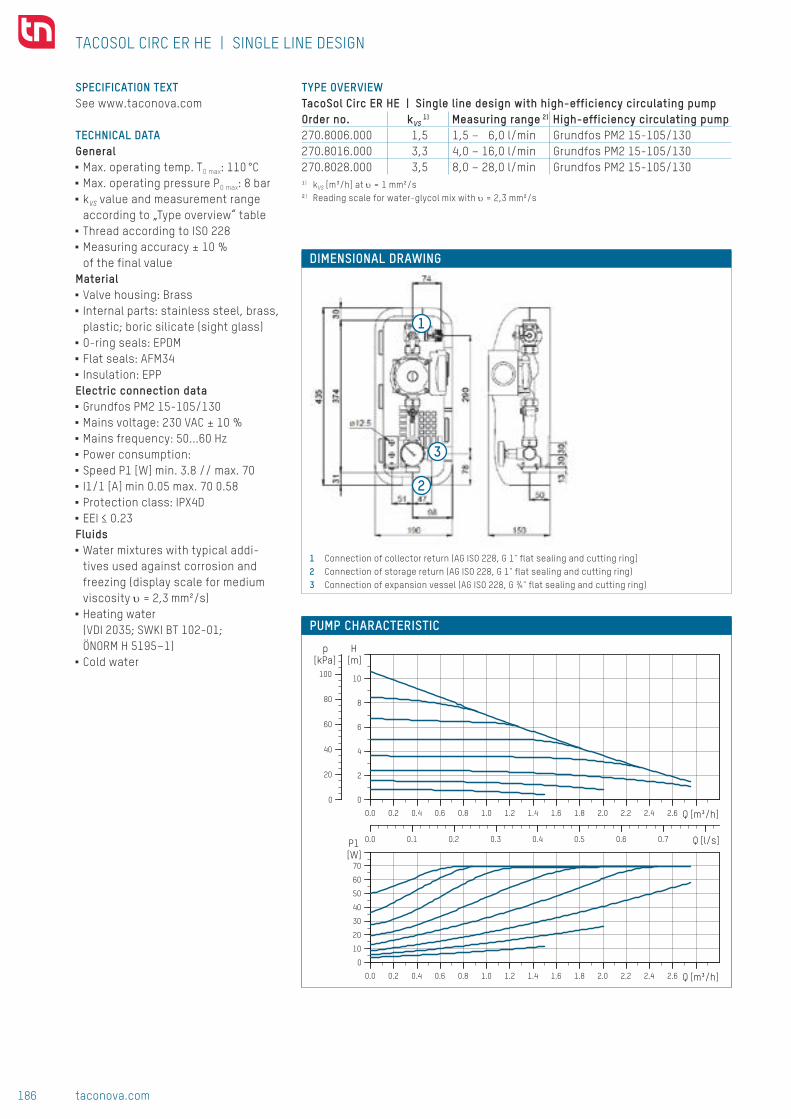
186 taconova.com
Syst
em t
echn
olog
y
1
2
3
0.0 0.2 0.4 0.6 0.8 1.0 1.2 1.4 1.6 1.8 2.0 2.2 2.4 2.6 Q [m³/h]
0
2
4
6
8
10
[m]H
0
20
40
60
80
100
[kPa]p
0.0 0.1 0.2 0.3 0.4 0.5 0.6 0.7 Q [l/s]
0.0 0.2 0.4 0.6 0.8 1.0 1.2 1.4 1.6 1.8 2.0 2.2 2.4 2.6 Q [m³/h]
0
10
20
30
40
50
60
70[W]P1
1 Connection of collector return (AG ISO 228, G 1" flat sealing and cutting ring]2 Connection of storage return (AG ISO 228, G 1" flat sealing and cutting ring)3 Connection of expansion vessel (AG ISO 228, G ¾" flat sealing and cutting ring)
DIMENSIONAL DRAWING
SPECIFICATION TEXTSee www.taconova.com
TECHNICAL DATAGeneral
■ Max. operating temp. TO max: 110 °C ■ Max. operating pressure PO max: 8 bar ■ kVS value and measurement range according to „Type overview“ table
■ Thread according to ISO 228 ■ Measuring accuracy ± 10 % of the final value
Material ■ Valve housing: Brass ■ Internal parts: stainless steel, brass, plastic; boric silicate (sight glass)
■ O-ring seals: EPDM ■ Flat seals: AFM34 ■ Insulation: EPP
Electric connection data ■ Grundfos PM2 15-105/130 ■ Mains voltage: 230 VAC ± 10 % ■ Mains frequency: 50...60 Hz ■ Power consumption: ■ Speed P1 [W] min. 3.8 // max. 70 ■ I1/1 [A] min 0.05 max. 70 0.58 ■ Protection class: IPX4D ■ EEI ≤ 0.23
Fluids ■ Water mixtures with typical addi-tives used against corrosion and freezing (display scale for medium viscosity υ = 2,3 mm²/s)
■ Heating water (VDI 2035; SWKI BT 102-01; ÖNORM H 5195–1)
■ Cold water
TACOSOL CIRC ER HE | SINGLE LINE DESIGN
TYPE OVERVIEW TacoSol Circ ER HE | Single line design with high-efficiency circulating pumpOrder no. kVS
1) Measuring range 2) High-efficiency circulating pump270.8006.000 1,5 1,5 – 6,0 l/min Grundfos PM2 15-105/130270.8016.000 3,3 4,0 – 16,0 l/min Grundfos PM2 15-105/130270.8028.000 3,5 8,0 – 28,0 l/min Grundfos PM2 15-105/130¹) kVS [m³/h] at υ = 1 mm²/s²) Reading scale for water-glycol mix with υ = 2,3 mm²/s
PUMPENKENNLINIEPUMP CHARACTERISTIC

187taconova.com
Syst
em t
echn
olog
y
1000
100
10
1
0,11 1,5 6 10
1000
100
10
11 4 16 10010
1000
100
10
11 8 28 10010
A
AA
BB B
CC
C
DD
kVS = 1,5 kVS = 3,3 kVS = 3,5
270.X016.XXX (DN 20 | 1" | 4...16 l/min)270.X006.XXX (DN 20 | 1" | 1,5...6 l/min) 270.X028.XXX (DN 20 | 1" | 8...28 l/min)
Subj
ect
to m
odif
icat
ion.
08/
2017
PRESSURE LOSS DIAGRAMS
ACCESSORIES SOLDER JOINT PRESSURE FITTINGFlat sealing connector joint, consisting of a soldered connecting nipple, lock nut and flat seal suitable for solar technologyOrder no. G x mm Version for210.5331.019 1" x 18 mm Copper pipe 18 mm210.5332.019 1" x 22 mm Copper pipe 22 mm
EXPANSION VESSEL MOUNTING BRACKET WITH QUICK ACTION COUPLINGFor mounting the expansion vessel on the wall with quick-action shut-off coupling 1 x internal thread, 1 x external thread G ¾".Order no. DN G296.7002.000 20 ¾"
FILL AND DRAIN COCK 3WAY CONNECTORFor connection to the expansion vessel connector piece, consisting of a T- jointwith fill and drain cock, lock nut with G ¾" internal thread with flat seal suitable forsolar technology, G ¾" outer thread connector.Order no. DN G296.7001.354 20 ¾"
STAINLESS STEEL TUBEFor connecting the expansion vessel, incl. ¾" lock nut and flat seals suitable forsolar technology.Order no. DN G Length296.7003.000 20 ¾" 0,5 m
SOLAR CONTROLLER SORELOrder no. Type Info296.7016.000 TDC 4 Complex solar systems and
high efficiency pumps
Pres
sure
loss
(mba
r)
Pres
sure
loss
(mba
r)
Pres
sure
loss
(mba
r)
TACOSOL CIRC ER HE | SINGLE-LINE SOLAR STATION
Flow (l/min) Flow (l/min) Flow (l/min)
A – D Return characteristics of valve position for TacoSetter Inline 130
CONTACT AND FURTHER INFORMATION TACONOVA.COM
Taconova Group AG | Neunbrunnenstrasse 40 | CH-8050 Zurich | T +41 44 735 55 55 | F +41 44 735 55 02 | [email protected]

188 taconova.com
Syst
em t
echn
olog
y
T
T
A6
TACOSOL CIRC ER HE
SYSTEM/BASIC DIAGRAM
SINGLE LINE SOLAR STATION
DESCRIPTION Hydraulic balancing and flow measu-rement can be carried out directly on the station in the case of the TacoSol Circ ER HE solar station. The integra-ted TacoSetter Inline 130 allows the volume flow in the primary circuit to be precisely and conveniently adjus-ted and checked. Systems that are correctly balanced hydraulically en-sure optimal energy transfer from the collector panel to the heat storage unit and therefore allow economical operation of the solar system.
Using scales that are pre-calibrated for inhibitors, specialists locally can adjust and check the flow values. Training and costly measuring de-vices are no longer needed.
INSTALLATION POSITIONThe solar station must be installed vertically. The installation can be carried out by a single installer.
OPERATION In combination with a solar control-ler, the solar station transports the solar liquid heated in the collector to the hot water/drinking water storage tank via a heat exchanger.The integrated TacoSetter Inline 130 balancing valve enables the volume flow to be adjusted to the perfor-mance of the collector or heat ex-changer and checked.The flow measurement of this balan-cing valve is based on the principle of a float. The regulating screw on the flow meter is used to adjust the flow. The reading position is the lo-wer edge of the float element.
BUILDING CATEGORIES ■ Apartments, apartment blocks ■ Single family homes, housing estates
■ Multiple dwelling units
Pump assembly with high-efficiency pumps, balancing valve and optional safety subassembly for solar heating energy systems.
ADVANTAGESCompact
■ Equipped with all the necessary valves and components
Simple ■ Hydraulic balancing and functio-nal checking of the system with TacoSetter Inline 130
■ Pump can be changed with ease as it is lockable on the intake and output sides
■ Simple filling, draining and servicing of the system owing to multifunctional ball valve
Efficient ■ Highly efficient system operati-on owing to permanent air sepa-ration with use of HE pumps
Flexible ■ Flexibility thanks to the option of integrating control systems
■■ TacoSol Circ ER HE UPM3

189taconova.com
Syst
em t
echn
olog
y
30
374
3
1 4
35
139.5
290
7
7 30
30
51 49 98
190
13
12.5
50 148
290
7
7
49 51 98
190
30
30
31
374
3
0 4
35
74
12.5
50 148
Volumen: 5991445.56 mm3
JAN
-
taconova.com
T. Schlatter
Techn. Lieferbed.: 1:2Massstab:cmf
We reserve all rights in connection with this document.
17.01.20173852
Verantw.17.01.2017J. Anaya
Toleranzen ISO 2768
Montagezeichnung: TacoSol Circ ER UPM3 15-105
Material: Gewicht: [SW-Masse] g g
Blatt-Nr.Anz. Blatt
DatumNameGepr.Gen.
Ersatz. für:
IndexEM DatumVisum
17.01.2017
22A017.01.2017T. Schlatter
Art. - Nr.: 213112
Nous nous reservons tout les droits sur ce document.Für dieses Dokument behalten wir uns alle Rechte vor.
x
-009467
Oberflächen/SurfacesDIN-ISO 1302Erstausg.
30
374
3
1 4
35
139.5
290
7
7 30
30
51 49 98
190
13
12.5
50 148
290
7
7
49 51 98
190
30
30
31
374
3
0 4
35
74
12.5
50 148
Volumen: 5991445.56 mm3
JAN
-
taconova.com
T. Schlatter
Techn. Lieferbed.: 1:2Massstab:cmf
We reserve all rights in connection with this document.
17.01.20173852
Verantw.17.01.2017J. Anaya
Toleranzen ISO 2768
Montagezeichnung: TacoSol Circ ER UPM3 15-105
Material: Gewicht: [SW-Masse] g g
Blatt-Nr.Anz. Blatt
DatumNameGepr.Gen.
Ersatz. für:
IndexEM DatumVisum
17.01.2017
22A017.01.2017T. Schlatter
Art. - Nr.: 213112
Nous nous reservons tout les droits sur ce document.Für dieses Dokument behalten wir uns alle Rechte vor.
x
-009467
Oberflächen/SurfacesDIN-ISO 1302Erstausg.
1 4
2
3
DIMENSIONAL DRAWING
TYPE OVERVIEW TacoSol Circ ER HE | Single line design with safety subassembly with high-efficiency circulating pumpOrder no. kVS
1) Measuring range 2)
270.9006.345 1.5 1,5 – 6,0 l/min270.9016.345 3.3 4,0 – 16,0 l/min270.9028.345 3.5 8,0 – 28,0 l/min¹) kVS [m³/h] at υ = 1 mm²/s²) Reading scale for water-glycol mix with υ = 2,3 mm²/s
SPECIFICATION TEXTSee www.taconova.com
TECHNICAL DATAGeneral
■ Max. operating temp. TO max: 110 °C ■ Max. operating pressure PO max: 8 bar ■ Actuating pressure of the integrated safety valve: 6 bar
■ kVS value and measurement range according to „Type overview“ table
■ Thread according to DIN 2999/ISO 7 and ISO 228
■ Measuring accuracy ± 10 % of the final value
■ For pump performance, see data sheet Grundfos UPM3 15-105/130
Material ■ Valve housing: Brass ■ Internal parts: Stainless steel, brass, plastic; borosilicate (sight glass)
■ O-ring seals: EPDM ■ Flat seals: AFM34 ■ Insulation: EPP
Electric connection data ■ Grundfos UPM3 15-105/130
■Mains voltage: 230 VAC ± 10 % ■Mains frequency: 50 Hz ■Power consumption: Speed P1 [W] min. 2 // max. 45 I1/1 [A] min 0.04 max. 0.48
■Protection class: IPX4D ■EEI ≤ 0.20
Fluids ■ Water mixtures with typical addi-tives used against corrosion and freezing (display scale for medium viscosity υ = 2,3 mm²/s)
■ Heating water (VDI 2035; SWKI BT 102-01; ÖNORM H 5195–1)
■ Cold water
1 Connection of collector return (AG ISO 228, G 1" flat sealing and cutting ring]2 Connection of storage return (AG ISO 228, G 1" flat sealing and cutting ring)3 Connection of expansion vessel (AG ISO 228, G ¾" flat sealing and cutting ring)4 Connection of safety valve drainage line (IG DIN 2999 / ISO 7, Rp ¾")
TACOSOL CIRC ER HE | SINGLE LINE DESIGN WITH SAFETY SUBASSEMBLY

190 taconova.com
Syst
em t
echn
olog
y
30
374
3
1 4
35
139.5
290
7
7 30
30
51 49 98
190
13
12.5
50 148
290
7
7
49 51 98
190
30
30
31
374
3
0 4
35
74
12.5
50 148
Volumen: 5991445.56 mm3
JAN
-
taconova.com
T. Schlatter
Techn. Lieferbed.: 1:2Massstab:cmf
We reserve all rights in connection with this document.
17.01.20173852
Verantw.17.01.2017J. Anaya
Toleranzen ISO 2768
Montagezeichnung: TacoSol Circ ER UPM3 15-105
Material: Gewicht: [SW-Masse] g g
Blatt-Nr.Anz. Blatt
DatumNameGepr.Gen.
Ersatz. für:
IndexEM DatumVisum
17.01.2017
22A017.01.2017T. Schlatter
Art. - Nr.: 213112
Nous nous reservons tout les droits sur ce document.Für dieses Dokument behalten wir uns alle Rechte vor.
x
-009467
Oberflächen/SurfacesDIN-ISO 1302Erstausg.
30
374
3
1 4
35
139.5
290
7
7 30
30
51 49 98
190
13
12.5
50 148
290
7
7
49 51 98
190
30
30
31
374
3
0 4
35
74
12.5
50 148
Volumen: 5991445.56 mm3
JAN
-
taconova.com
T. Schlatter
Techn. Lieferbed.: 1:2Massstab:cmf
We reserve all rights in connection with this document.
17.01.20173852
Verantw.17.01.2017J. Anaya
Toleranzen ISO 2768
Montagezeichnung: TacoSol Circ ER UPM3 15-105
Material: Gewicht: [SW-Masse] g g
Blatt-Nr.Anz. Blatt
DatumNameGepr.Gen.
Ersatz. für:
IndexEM DatumVisum
17.01.2017
22A017.01.2017T. Schlatter
Art. - Nr.: 213112
Nous nous reservons tout les droits sur ce document.Für dieses Dokument behalten wir uns alle Rechte vor.
x
-009467
Oberflächen/SurfacesDIN-ISO 1302Erstausg.
1
2
3
0 0.25 0.5 0.75 1.00 1.25 1.5
10
20
30
40
50
60
0 0.25 0.5 0.75 1.00 1.25 1.5
10
20
30
40
50
60
P1 (W
)
Q (m3/h)
Q (m3/h)
CC 4,5m
CC 6,5m
CC 8,5m
CC 10,5m
- - - MIN
H (m
)
CC 10,5mCC 8,5m
CC 6,5m
CC 4,5m
- - - MIN
1 Connection of collector return (AG ISO 228, G 1" flat sealing and cutting ring]2 Connection of storage return (AG ISO 228, G 1" flat sealing and cutting ring)3 Connection of expansion vessel (AG ISO 228, G ¾" flat sealing and cutting ring)
DIMENSIONAL DRAWING
SPECIFICATION TEXTSee www.taconova.com
TECHNICAL DATAGeneral
■ Max. operating temp. TO max: 110 °C ■ Max. operating pressure PO max: 8 bar ■ kVS value and measurement range according to „Type overview“ table
■ Thread according to ISO 228 ■ Measuring accuracy ± 10 % of the final value
Material ■ Valve housing: Brass ■ Internal parts: stainless steel, brass, plastic; boric silicate (sight glass)
■ O-ring seals: EPDM ■ Flat seals: AFM34 ■ Insulation: EPP
Electric connection data ■ Grundfos UPM3 15-105/130
■Mains voltage: 230 VAC ± 10 % ■Mains frequency: 50 Hz ■Power consumption: Speed P1 [W] min. 2 // max. 45 I1/1 [A] min 0.04 max. 0.48
■Protection class: IPX4D ■EEI ≤ 0.20
Fluids ■ Water mixtures with typical addi-tives used against corrosion and freezing (display scale for medium viscosity υ = 2,3 mm²/s)
■ Heating water (VDI 2035; SWKI BT 102-01; ÖNORM H 5195–1)
■ Cold water
TACOSOL CIRC ER HE | SINGLE LINE DESIGN
TYPE OVERVIEW TacoSol Circ ER HE | Single line design with high-efficiency circulating pumpOrder no. kVS
1) Measuring range 2)
270.9006.000 1,5 1,5 – 6,0 l/min270.9016.000 3,3 4,0 – 16,0 l/min270.9028.000 3,5 8,0 – 28,0 l/min¹) kVS [m³/h] at υ = 1 mm²/s²) Reading scale for water-glycol mix with υ = 2,3 mm²/s
PUMPENKENNLINIEPUMP CHARACTERISTIC

191taconova.com
Syst
em t
echn
olog
y
1000
100
10
1
0,11 1,5 6 10
1000
100
10
11 4 16 10010
1000
100
10
11 8 28 10010
A
AA
BB B
CC
C
DD
kVS = 1,5 kVS = 3,3 kVS = 3,5
270.X016.XXX (DN 20 | 1" | 4...16 l/min)270.X006.XXX (DN 20 | 1" | 1,5...6 l/min) 270.X028.XXX (DN 20 | 1" | 8...28 l/min)
Subj
ect
to m
odif
icat
ion.
08/
2017
PRESSURE LOSS DIAGRAMS
ACCESSORIES SOLDER JOINT PRESSURE FITTINGFlat sealing connector joint, consisting of a soldered connecting nipple, lock nut and flat seal suitable for solar technologyOrder no. G x mm Version for210.5331.019 1" x 18 mm Copper pipe 18 mm210.5332.019 1" x 22 mm Copper pipe 22 mm
EXPANSION VESSEL MOUNTING BRACKET WITH QUICK ACTION COUPLINGFor mounting the expansion vessel on the wall with quick-action shut-off coupling 1 x internal thread, 1 x external thread G ¾".Order no. DN G296.7002.000 20 ¾"
FILL AND DRAIN COCK 3WAY CONNECTORFor connection to the expansion vessel connector piece, consisting of a T- jointwith fill and drain cock, lock nut with G ¾" internal thread with flat seal suitable forsolar technology, G ¾" outer thread connector.Order no. DN G296.7001.354 20 ¾"
STAINLESS STEEL TUBEFor connecting the expansion vessel, incl. ¾" lock nut and flat seals suitable forsolar technology.Order no. DN G Length296.7003.000 20 ¾" 0,5 m
SOLAR CONTROLLER SORELOrder no. Type Info296.7016.000 TDC 4 Complex solar systems and
high efficiency pumps
Pres
sure
loss
(mba
r)
Pres
sure
loss
(mba
r)
Pres
sure
loss
(mba
r)
TACOSOL CIRC ER HE | SINGLE-LINE SOLAR STATION
Flow (l/min) Flow (l/min) Flow (l/min)
A – D Return characteristics of valve position for TacoSetter Inline 130
CONTACT AND FURTHER INFORMATION TACONOVA.COM
Taconova Group AG | Neunbrunnenstrasse 40 | CH-8050 Zurich | T +41 44 735 55 55 | F +41 44 735 55 02 | [email protected]

192 taconova.com
Syst
em t
echn
olog
y
T
T
TACOSOL CIRC ZR HE
Two-line pump assembly with high-efficiency pumps, balancing valve, ventilation unit and safety subassembly for solar heating energy systems
ADVANTAGES ■ Compact: Equipped with all the necessary valves and compo-nents
■ Secure: Intrinsic safety of the system thanks to an integrated safety subassembly
■ Simple: Hydraulic balancing and functional checking of the sys-tem with Tacosetter Inline 130. Pump can be changed with ease as it lockable on the intake and output sides
■ Efficient: Highly efficient system operation owing to permanent air separation and use of high-efficiency pumps
■ Flexible: Flexibility thanks to the option of integrating control systems
SYSTEM/BASIC DIAGRAM
TWO-LINE SOLAR STATION
DESCRIPTIONHydraulic balancing, flow measure-ment and ventilation can be carried out directly on the station in the case of the TacoSol Circ ZR HE solar station.The integrated TacoSetter Inline 130 allows the volume flow in the primary circuit to be precisely and conveni-ently adjusted and checked.Permanent air separation in the integrated ventilating flask allows energy-efficient operation of the system. Systems that are correctly balanced hydraulically and air-free guarantee optimal energy extraction and are thus more cost-effective in the sense of the energy-saving directives laid down by law.
Using scales that are pre-calibrated for inhibitors, specialists locally can adjust and check the flow values. Training and costly measuring de-vices are no longer needed.
INSTALLATION POSITION The solar station must be installed vertically to ensure that the ven-tilation unit functions correctly. Installation and ventilation can be performed by a single installer.
OPERATION In combination with a solar cont-roller, the solar liquid heated in the collector is transported to the hot water/drinking water storage tank via a heat exchanger with the help of the solar station.The integrated TacoSetter Inline 130 balancing valve enables the volume flow to be adjusted to the performance of the collector or heat exchanger and checked. The flow measurement of this balancing valve is based on the principle of a float. The regulating screw on the flow meter is used to adjust the flow. The reading position is the lower edge of the float element.The integrated ventilating flask with innovative flow technology design ensures permanent air separation and thereby increases the efficiency of the system.
BUILDING CATEGORIES ■ Apartments, apartment blocks ■ Single family homes, housing estates
■ Multiple dwelling units
■■ TacoSol Circ ZR HE PM2

193taconova.com
Syst
em t
echn
olog
y
1 2
3 4
5
6
0.0 0.2 0.4 0.6 0.8 1.0 1.2 1.4 1.6 1.8 2.0 2.2 2.4 2.6 Q [m³/h]
0
2
4
6
8
10
[m]H
0
20
40
60
80
100
[kPa]p
0.0 0.1 0.2 0.3 0.4 0.5 0.6 0.7 Q [l/s]
0.0 0.2 0.4 0.6 0.8 1.0 1.2 1.4 1.6 1.8 2.0 2.2 2.4 2.6 Q [m³/h]
0
10
20
30
40
50
60
70[W]P1
TYPE OVERVIEW TacoSol Circ ZR HE | Two-line design with high-efficiency pumpVersion with carrier for controllerOrder no. kVS
1) kVS2) Measuring range 3) High-efficiency pump
270.8506.356 1,5 6,0 1,5 – 6,0 l/min Grundfos PM2 15-105/130270.8516.356 3,3 6,0 4,0 – 16,0 l/min Grundfos PM2 15-105/130270.8528.356 3,5 6,0 8,0 – 28,0 l/min Grundfos PM2 15-105/130
TacoSol Circ ZR HE | Two-line design with high-efficiency pumpVersion with cover plateOrder no. kVS
1) kVS2) Measuring range 3) High-efficiency pump
270.8506.000 1,5 6,0 1,5 – 6,0 l/min Grundfos PM2 15-105/130270.8516.000 3,3 6,0 4,0 – 16,0 l/min Grundfos PM2 15-105/130270.8528.000 3,5 6,0 8,0 – 28,0 l/min Grundfos PM2 15-105/1301) kVS [m³/h] at υ = 1 mm²/s in the return line (pump side)2) kVS [m³/h] at υ = 1 mm²/s in the flow line (ventilator side)3) Reading scale for water-glycol mix with υ = 2,3 mm²/s
SPECIFICATION TEXTSee www.taconova.com
TECHNICAL DATAGeneral
■ Maximal operating temperatures: ■ Flow line (ventilator side) TO max: 160 °C
■ Return line (pump side) TO max: 110 °C ■ Max. operating pressure PO max: 8 bar ■ Actuating pressure of the integrated safety valve: 6 bar
■ kVS value and measurement range according to „Type overview“ table
■ Thread according to DIN 2999/ISO 7 and ISO 228
■ Measuring accuracy ± 10 % of the final value
Material ■ Vent pipe: Painted steel ■ Valve housing parts: Brass ■ Internal parts: Stainless steel, brass and plastic, borosilicate (sight glass)
■ O-ring seals: EPDM ■ Flat seals: AFM34 ■ Insulation: EPP
Electric connection data ■ Grundfos PM2 15-105/130
■ Mains voltage: 230 VAC ± 10 % ■ Mains frequency: 50...60 Hz ■ Power consumption: ■ Speed P1 [W] min. 3.8 // max. 70 ■ I1/1 [A] min 0.05 max. 70 0.58 ■ Protection class: IPX4D ■ EEI ≤ 0.23
Fluids ■ Water mixtures with typical addi-tives used against corrosion and freezing (display scale for medium viscosity υ = 2,3 mm²/s)
■ Heating water (VDI 2035; SWKI BT 102-01; ÖNORM H 5195–1)
■ Cold water
TACOSOL CIRC ZR HE | TWO-LINE SOLAR STATION
DIMENSIONAL DRAWING
1 Connection of collector flow (AG ISO 228, G 1" flat sealing and cutting ring)2 Connection of collector return (AG ISO 228, G 1" flat sealing and cutting ring)3 Connection of storage flow (AG ISO 228, G 1" flat sealing and cutting ring)4 Connection of storage return (AG ISO 228, G 1" flat sealing and cutting ring)5 Connection of expansion vessel (AG ISO 228, G ¾" flat sealing and cutting ring)6 Connection of safety valve drainage line (IG DIN 2999 / ISO 7, Rp ¾")
PUMPENDIAGRAMM

194 taconova.com
Syst
em t
echn
olog
y
1
2
3
4 9 10
8
7
6
5
1000
100
10
1
0,11 1,5 6 10
1000
100
10
11 4 16 10010
1000
100
10
11 8 28 10010
270.X516.XXX (DN 20 | 1" | 4...16 l/min)270.X506.XXX (DN 20 | 1" | 1,5...6 l/min) 270.X528.XXX (DN 20 | 1" | 8...28 l/min)
kVS = 6,0
kVS = 6,0
kVS = 6,0
kVS = 1,5
kVS = 3,3
kVS = 3,5
A
A
BB
B
CC
C
D
D
D
V V
V
PRESSURE LOSS DIAGRAMS
COMPONENTS
1 Shutoff ball valve with safety valve and integrated backflow preventer
■ Integrated backflow preventer and check valve
■ Option of lead sealing to protect against incorrect operation by the handle
■ Safety valve function in each ball valve position guaranteed in ac-cordance with safety standards
2 Ventilating flask with ventilating valve
■ Permanent air separation ■ Air collection volume 2.5 dl ■ Integrated manual air vent for ventilating and checking the leak tightness
3 Manometer ■ Display range 0-10 bar
4 Thermometer ■ Display range 0-160 °C ■ Dipping sensors installed in the safety pipe
5 Wall mounting
6 Shutoff ball valve with integrated backflow preventer as well as filling and draining valve
■ Multifunctional valve for filling, draining and shutting off the collector circuit
■ Hose connection outer thread G ¾" ■ Option of lead sealing to protect against incorrect operation by the handle
7 Circulation pump solar version ■ Grundfos PM 2 15-105/130
8 TacoSetter Inline 130 balancing valve
■ Sight glass with scale for medium viscosity of = 2.3 mm2/s
■ Setting ranges in accordance with design
■ 1.5-6 l/min | 4-16 l/min | 8-28 l/min ■ Integrated shut-off function ■ Hydraulic balancing of pump group without correction curves and measuring devices
■ Functional checking of system at sight glass
TACOSOL CIRC ZR HE | TWO-LINE SOLAR STATION
Flow (l/min) Flow (l/min) Flow (l/min)
Pres
sure
loss
(mba
r)
Pres
sure
loss
(mba
r)
Pres
sure
loss
(mba
r)
9 Thermometer ■ Display range 0-160 °C ■ Dipping sensors installed in the safety pipe
10 Expansion vessel connection ■ G ¾"
Insulation and mounting accessories ■ 2 hexagon wood screws 8 x 50 mm ■ 2 washers ■ 2 mounting pins 10 x 50 mm ■ Installation instructions ■ Operating and safety instructions
A – D Return characteristics of valve position for TacoSetter Inline 130V Flow characteristic (vent line]

195taconova.com
Syst
em t
echn
olog
y
Subj
ect
to m
odif
icat
ion.
09/
2017
ACCESSORIES SOLDER JOINT PRESSURE FITTINGFlat sealing connector joint, consisting of a soldered connecting nipple, lock nut and flat seal suitable for solar technology.Order no. G x mm Version for210.5331.019 1" x 18 mm Copper pipe 18 mm210.5332.019 1" x 22 mm Copper pipe 22 mm
EXPANSION VESSEL MOUNTING BRACKET WITH QUICK ACTION COUPLINGFor mounting the expansion vessel on the wall with quick-action shut-off coupling. 1 x inner thread, 1 x outer thread G ¾".Order no. DN G296.7002.000 20 ¾"
FILL AND DRAIN COCK 3 WAY CONNECTORFor connection to the expansion vessel connector piece, consisting of a T-joint with fill and drain cock, lock nut with G ¾" inner thread with flat seal suitable for solar technology and G ¾" outer thread connector.Order no. DN G296.7001.354 20 ¾"
STAINLESS STEEL TUBEFor connecting the expansion vessel, incl. ¾" lock nut and flat seals suitable for solar technology.Order no. DN G Length296.7003.000 20 ¾" 0,5 m
SOLAR CONTROLLER SORELOrder no. Type Application296.7016.000 TDC 4 Version with high-efficiency pumps
CARRIER FOR CONTROLLEROrder no. Application296.7020.000 TacoSol Circ ZR HE
COVER PLATEOrder no. Application296.7021.000 TacoSol Circ ZR HE
TACOSOL CIRC ZR HE | TWO-LINE SOLAR STATION
CONTACT AND FURTHER INFORMATION TACONOVA.COM
Taconova Group AG | Neunbrunnenstrasse 40 | CH-8050 Zurich | T +41 44 735 55 55 | F +41 44 735 55 02 | [email protected]

196 taconova.com
Syst
em t
echn
olog
y
T
T
TACOSOL CIRC ZR HE
Two-line pump assembly with high-efficiency pumps, balancing valve, ventilation unit and safety subassembly for solar heating energy systems
ADVANTAGES ■ Compact: Equipped with all the necessary valves and compo-nents
■ Secure: Intrinsic safety of the system thanks to an integrated safety subassembly
■ Simple: Hydraulic balancing and functional checking of the sys-tem with Tacosetter Inline 130. Pump can be changed with ease as it lockable on the intake and output sides
■ Efficient: Highly efficient system operation owing to permanent air separation and use of high-efficiency pumps
■ Flexible: Flexibility thanks to the option of integrating control systems
SYSTEM/BASIC DIAGRAM
TWO-LINE SOLAR STATION
DESCRIPTIONHydraulic balancing, flow measure-ment and ventilation can be carried out directly on the station in the case of the TacoSol Circ ZR HE solar station.The integrated TacoSetter Inline 130 allows the volume flow in the primary circuit to be precisely and conveni-ently adjusted and checked.Permanent air separation in the integrated ventilating flask allows energy-efficient operation of the system. Systems that are correctly balanced hydraulically and air-free guarantee optimal energy extraction and are thus more cost-effective in the sense of the energy-saving directives laid down by law.
Using scales that are pre-calibrated for inhibitors, specialists locally can adjust and check the flow values. Training and costly measuring de-vices are no longer needed.
INSTALLATION POSITION The solar station must be installed vertically to ensure that the ven-tilation unit functions correctly. Installation and ventilation can be performed by a single installer.
OPERATION In combination with a solar cont-roller, the solar liquid heated in the collector is transported to the hot water/drinking water storage tank via a heat exchanger with the help of the solar station.The integrated TacoSetter Inline 130 balancing valve enables the volume flow to be adjusted to the performance of the collector or heat exchanger and checked. The flow measurement of this balancing valve is based on the principle of a float. The regulating screw on the flow meter is used to adjust the flow. The reading position is the lower edge of the float element.The integrated ventilating flask with innovative flow technology design ensures permanent air separation and thereby increases the efficiency of the system.
BUILDING CATEGORIES ■ Apartments, apartment blocks ■ Single family homes, housing estates
■ Multiple dwelling units
■■ TacoSol Circ ZR HE UPM3

197taconova.com
Syst
em t
echn
olog
y
P1 (W
)
Q (m3/h)
Q (m3/h)
12
10
8
6
4
2
0 0.25 0.50 0.75 1.00 1.25 1.50
CC 4,5m
CC 6,5m
CC 8,5m
CC 10,5m
- - - MIN
H (m
)
12
10
8
6
4
2
0 0.25 0.50
CC 10,5mCC 8,5m
CC 6,5m
CC 4,5m
- - - MIN0.75 1.00 1.25 1.50
83
28
74
= = 125
40 98 87
310
77
290
4
35
30
30
15
12.5
374
50
31
153
83
28
74
= = 125
40 98 87
310
77
290
4
35
30
30
15
12.5
374
50
31
153
1 2
3 4
5
6
TYPE OVERVIEW TacoSol Circ ZR HE | Two-line design with high-efficiency pumpVersion with carrier for controllerOrder no. kVS
1) kVS2) Measuring range 3)
270.9506.356 1,5 6,0 1,5 – 6,0 l/min270.9516.356 3,3 6,0 4,0 – 16,0 l/min270.9528.356 3,5 6,0 8,0 – 28,0 l/min
TacoSol Circ ZR HE | Two-line design with high-efficiency pumpVersion with cover plateOrder no. kVS
1) kVS2) Measuring range 3)
270.9506.000 1,5 6,0 1,5 – 6,0 l/min270.9516.000 3,3 6,0 4,0 – 16,0 l/min270.9528.000 3,5 6,0 8,0 – 28,0 l/min1) kVS [m³/h] at υ = 1 mm²/s in the return line (pump side)2) kVS [m³/h] at υ = 1 mm²/s in the flow line (ventilator side)3) Reading scale for water-glycol mix with υ = 2,3 mm²/s
SPECIFICATION TEXTSee www.taconova.com
TECHNICAL DATAGeneral
■ Maximal operating temperatures: ■ Flow line (ventilator side) TO max: 160 °C
■ Return line (pump side) TO max: 110 °C ■ Max. operating pressure PO max: 8 bar ■ Actuating pressure of the integrated safety valve: 6 bar
■ kVS value and measurement range according to „Type overview“ table
■ Thread according to DIN 2999/ISO 7 and ISO 228
■ Measuring accuracy ± 10 % of the final value
Material ■ Vent pipe: Painted steel ■ Valve housing parts: Brass ■ Internal parts: Stainless steel, brass and plastic, borosilicate (sight glass)
■ O-ring seals: EPDM ■ Flat seals: AFM34 ■ Insulation: EPP
Electric connection data ■ Grundfos UPM3 Solar 15-105/130:
■ Mains voltage: 230 VAC ± 10 % ■ Mains frequency: 50 Hz ■ Power consumption: Speed P1 [W] min. 2 // max. 52 I1/1 [A] min 0.04 max. 70 0.56
■ Protection class: IPX4D ■ EEI ≤ 0.20
Fluids ■ Water mixtures with typical addi-tives used against corrosion and freezing (display scale for medium viscosity υ = 2,3 mm²/s)
■ Heating water (VDI 2035; SWKI BT 102-01; ÖNORM H 5195–1)
■ Cold water
TACOSOL CIRC ZR HE | TWO-LINE SOLAR STATION
DIMENSIONAL DRAWING
1 Connection of collector flow (AG ISO 228, G 1" flat sealing and cutting ring)2 Connection of collector return (AG ISO 228, G 1" flat sealing and cutting ring)3 Connection of storage flow (AG ISO 228, G 1" flat sealing and cutting ring)4 Connection of storage return (AG ISO 228, G 1" flat sealing and cutting ring)5 Connection of expansion vessel (AG ISO 228, G ¾" flat sealing and cutting ring)6 Connection of safety valve drainage line (IG DIN 2999 / ISO 7, Rp ¾")
PUMPENDIAGRAMM

198 taconova.com
Syst
em t
echn
olog
y
1
2
3
4 9
10
8
7
6
5
1000
100
10
1
0,11 1,5 6 10
1000
100
10
11 4 16 10010
1000
100
10
11 8 28 10010
270.X516.XXX (DN 20 | 1" | 4...16 l/min)270.X506.XXX (DN 20 | 1" | 1,5...6 l/min) 270.X528.XXX (DN 20 | 1" | 8...28 l/min)
kVS = 6,0
kVS = 6,0
kVS = 6,0
kVS = 1,5
kVS = 3,3
kVS = 3,5
A
A
BB
B
CC
C
D
D
D
V V
V
PRESSURE LOSS DIAGRAMS
COMPONENTS
1 Shutoff ball valve with safety valve and integrated backflow preventer
■ Integrated backflow preventer and check valve
■ Option of lead sealing to protect against incorrect operation by the handle
■ Safety valve function in each ball valve position guaranteed in ac-cordance with safety standards
2 Ventilating flask with ventilating valve
■ Permanent air separation ■ Air collection volume 2.5 dl ■ Integrated manual air vent for ventilating and checking the leak tightness
3 Manometer ■ Display range 0-10 bar
4 Thermometer ■ Display range 0-160 °C ■ Dipping sensors installed in the safety pipe
5 Wall mounting
6 Shutoff ball valve with integrated backflow preventer as well as filling and draining valve
■ Multifunctional valve for filling, draining and shutting off the collector circuit
■ Hose connection outer thread G ¾" ■ Option of lead sealing to protect against incorrect operation by the handle
7 Circulation pump solar version ■ Grundfos UPM3 Solar 15-105/130
8 TacoSetter Inline 130 balancing valve
■ Sight glass with scale for medium viscosity of = 2.3 mm2/s
■ Setting ranges in accordance with design
■ 1.5-6 l/min | 4-16 l/min | 8-28 l/min ■ Integrated shut-off function ■ Hydraulic balancing of pump group without correction curves and measuring devices
■ Functional checking of system at sight glass
TACOSOL CIRC ZR HE | TWO-LINE SOLAR STATION
Flow (l/min) Flow (l/min) Flow (l/min)
Pres
sure
loss
(mba
r)
Pres
sure
loss
(mba
r)
Pres
sure
loss
(mba
r)
9 Thermometer ■ Display range 0-160 °C ■ Dipping sensors installed in the safety pipe
10 Expansion vessel connection ■ G ¾"
Insulation and mounting accessories ■ 2 hexagon wood screws 8 x 50 mm ■ 2 washers ■ 2 mounting pins 10 x 50 mm ■ Installation instructions ■ Operating and safety instructions
A – D Return characteristics of valve position for TacoSetter Inline 130V Flow characteristic (vent line]

199taconova.com
Syst
em t
echn
olog
y
Subj
ect
to m
odif
icat
ion.
09/
2017
ACCESSORIES SOLDER JOINT PRESSURE FITTINGFlat sealing connector joint, consisting of a soldered connecting nipple, lock nut and flat seal suitable for solar technology.Order no. G x mm Version for210.5331.019 1" x 18 mm Copper pipe 18 mm210.5332.019 1" x 22 mm Copper pipe 22 mm
EXPANSION VESSEL MOUNTING BRACKET WITH QUICK ACTION COUPLINGFor mounting the expansion vessel on the wall with quick-action shut-off coupling. 1 x inner thread, 1 x outer thread G ¾".Order no. DN G296.7002.000 20 ¾"
FILL AND DRAIN COCK 3 WAY CONNECTORFor connection to the expansion vessel connector piece, consisting of a T-joint with fill and drain cock, lock nut with G ¾" inner thread with flat seal suitable for solar technology and G ¾" outer thread connector.Order no. DN G296.7001.354 20 ¾"
STAINLESS STEEL TUBEFor connecting the expansion vessel, incl. ¾" lock nut and flat seals suitable for solar technology.Order no. DN G Length296.7003.000 20 ¾" 0,5 m
SOLAR CONTROLLER SORELOrder no. Type Application296.7016.000 TDC 4 Version with high-efficiency pumps
CARRIER FOR CONTROLLEROrder no. Application296.7020.000 TacoSol Circ ZR HE
COVER PLATEOrder no. Application296.7021.000 TacoSol Circ ZR HE
TACOSOL CIRC ZR HE | TWO-LINE SOLAR STATION
CONTACT AND FURTHER INFORMATION TACONOVA.COM
Taconova Group AG | Neunbrunnenstrasse 40 | CH-8050 Zurich | T +41 44 735 55 55 | F +41 44 735 55 02 | [email protected]

200 taconova.com
Syst
em t
echn
olog
y
T
T
A6
TACOSOL CIRC ZR PV EU21 ADVANTAGESCompact: Equipped with all the necessary valves and components Secure: Intrinsic safety of the system thanks to an integrated safety sub-assembly Simple: Hydraulic balancing and functional checking of the system with Tacosetter Inline 130 Pump can be changed with ease as it lockable on the intake and output sides Efficient: Highly efficient system operation owing to permanent air separation and use of HE pumps Flexible: Flexibility thanks to the option of integrating control sys-tems
SYSTEM/BASIC DIAGRAM
TWO-LINE SOLAR STATION WITH HIGH-EFFICIENCY DC PUMP
DESCRIPTIONThe TacoSol Circ ZR PV EU21 is a solar station with a high-efficiency DC pump, which can be powered and controlled directly by the current of a photovoltaic panel. This eliminates the otherwise customary mains con-nection and enables independent operation of the solar system. Hyd-raulic balancing, flow measurement and ventilation can be carried out directly on the station. The integra-ted TacoSetter Inline 130 allows the volume flow in the primary circuit to be precisely and conveniently ad-justed and checked. Permanent air separation in the ventilating flask
allows energy-efficient operation of the system.Systems that are correctly balanced hydraulically and air-free guarantee optimal energy extraction and are thus more cost-effective in the sen-se of the energy-saving directives laid down by law.Using scales that are pre-calibrated for inhibitors, specialists locally can adjust and check the flow values. Training and costly measuring de-vices are no longer needed.
INSTALLATION POSITION The solar station must be installed vertically to ensure that the ventila-tion unit functions correctly. Instal-lation and ventilation can be perfor-med by a single installer.
OPERATION The solar liquid heated in the collec-tor is transported to the hot water/drinking water storage tank via a heat exchanger in the two-line TacoSol Circ ZR PV EU21 solar station. The output of the integrated high-efficiency DC pump is regulated independently in combination with a photovoltaic panel based on the intensity of the global radiation and the voltage generated in the photo-voltaic module. A DC controller can be installed between the photovol-taic module and the pump to monitor the temperature differential.The integrated TacoSetter Inline 130 balancing valve enables the volume flow to be adjusted to the perfor-mance of the collector or heat ex-changer and checked. The integrated ventilating flask with innovative flow technology design ensures perma-nent air separation and thereby in-creases the efficiency of the system.
Two-line solar station with 24V HE DC pump, balancing valve, ventila-tion unit and safety subassembly for independent operation in solar heating energy systems
■■ TacoSol Circ ZR PV EU21

201taconova.com
Syst
em t
echn
olog
y
7485
7830
0
44538
4
30
ø12,5= =
1330
3015
32
50
135
290
30
= = 40
12587 78
7485
7830
0
44538
4
30
ø12,5= =
1330
3015
32
50
135
290
30
= = 40
12587 78
1 2
3 4
5
6
TYPE OVERVIEW TacoSol Circ ZR PV EU21 | Two-line solar stationOrder no. kVS
1) kVS2) Measuring range 3) Circulating pump
270.7506.000 1,5 6,1 1,5 – 6,0 l/min Laing D5 Solar270.7516.000 3,3 6,0 4,0 – 16,0 l/min Laing D5 Solar1) kVS [m³/h] at υ = 1 mm²/s in the return line (pump side)2) kVS [m³/h] at υ = 1 mm²/s in the flow line (ventilator side)3) Reading scale for water-glycol mix with υ = 2,3 mm²/s
SPECIFICATION TEXTSee www.taconova.com
TECHNICAL DATAGeneral
■ Max. operating temperatures: ■ Flow line (ventilator side): TO max: 160 °C
■ Return line (pump side): TO max: 95 °C
■ Max. operating pressure: PO max: 8 bar
■ Actuating pressure of the integrated safety valve: 6 bar
■ kVS value and measurement range according to „Type overview“ table
■ Thread according to DIN 2999/ISO 7 and ISO 228
■ Measuring accuracy ± 10 % of the final value
Material ■ Vent pipe: Painted steel ■ Valve housing: Brass ■ Internal parts: Stainless steel, brass, plastic; borosilicate (sight glass)
■ O-ring seals: EPDM ■ Flat seals: AFM34 ■ Insulation: EPP
Electric connection data ■ Rated voltage 8 - 24 Volt (operation via a 12 V panel; with a 24 V panel only with maximum voltage limit of 24 V)
■ Power consumption*: ■ Minimal start-up power less than 1 Watt (at 12 Volt)
■ Maximum power input approx. 22 W; current consumption 0.25 - 1.46 A (* power input and start-up may vary from system to system)
■ Insulation class IP 42 / Class FFluids
■ Water mixtures with typical addi-tives used against corrosion and freezing (display scale for medium viscosity υ = 2,3 mm²/s)
■ Heating water (VDI 2035; SWKI BT 102-01; ÖNORM H 5195–1)
■ Cold waterNoteSafe power-off of the pump at approx. 95 °C
TACOSOL CIRC ZR PV EU21 | TWO-LINE SOLAR STATION WITH HIGH-EFFICIENCY DC PUMP
DIMENSIONAL DRAWING
1 Connection of collector flow (AG ISO 228, G 1" flat sealing and cutting ring)2 Connection of collector return (AG ISO 228, G 1" flat sealing and cutting ring)3 Connection of storage flow (AG ISO 228, G 1" flat sealing and cutting ring)4 Connection of storage return (AG ISO 228, G 1" flat sealing and cutting ring)5 Connection of expansion vessel (AG ISO 228, G ¾" flat sealing and cutting ring)6 Connection of safety valve drainage line (IG DIN 2999 / ISO 7, Rp ¾")

202 taconova.com
Syst
em t
echn
olog
y
1000
100
10
11 4 16 10010
1
2
3
411
10
9
8
7
6
5
1000
100
10
1
0,11 1,5 6 10
kVS = 6,1
kVS = 3,3
kVS = 1,5
270.7506.000 (DN 20 | 1" | 1,5...6 l/min) 270.7516.000 (DN 20 | 1" | 4...16 l/min)
AA
BB
CCD
D
F
PRESSURE LOSS DIAGRAMS
COMPONENTS
1 Shutoff ball valve with safety valve and integrated backflow preventer
■ Integrated backflow preventer and check valve
■ Option of lead sealing to protect against incorrect operation by the handle
■ Safety valve function in each ball valve position guaranteed in ac-cordance with safety standards.
2 Ventilating flask with ventilating valve
■ Permanent air separation ■ Air collection volume 2.5 dl ■ Integrated manual air vent for ventilating and checking the leak tightness
3 Manometer ■ Display range 0 - 10 bar
4 Thermometer ■ Display range 0 - 160 °C ■ Dipping sensors installed in the safety pipe
5 Wall mounting
6 Shutoff ball valve with integrated backflow preventer as well as filling and draining valve (KFE)
■ Multifunctional valve for filling, drai-ning and shutting off the collector circuit
■ Hose connection outer thread G ¾" ■ Option of lead sealing to protect against incorrect operation by the handle
7 Circulation pump Laing D5 ■ DC 8 - 24 V ■ Impeller mounted on ultra-hard ceramic ball
■ Delivery pressure 2.8 m
8 TacoSetter Inline 130 balancing valve ■ Sight glass with scale for medium viscosity of = 2,3 mm²/s
■ Setting ranges in accordance with design 1.5 - 6 l/min I 4 - 16l/min I 8 - 28 l/min
■ Integrated shut-off function ■ Hydraulic balancing of pump group without correction curves and measuring devices
■ Functional checking of system at sight glass
TACOSOL CIRC ZR PV EU21 | TWO-LINE SOLAR STATION WITH HIGH-EFFICIENCY DC PUMP
Flow (l/min)
Pres
sure
loss
(mba
r)
Pres
sure
loss
(mba
r)
9 Connection terminals Wago ■ Electrical connection to the photo-voltaic panel
10 Thermometer ■ Display range 0 - 160 °C ■ Dipping sensors installed in the safety pipe
11 Expansion vessel connection ■ G ¾"
Insulation and mounting accessories ■ 2 hexagon wood screws 8 x 50 mm ■ 2 washers ■ 2 mounting pins 10 x 50 mm ■ Installation instructions ■ Operating and safety instructions
Flow (l/min)
A – D Return characteristics of valve position for TacoSetter Inline 130 V Flow characteristic (vent line]

203taconova.com
Syst
em t
echn
olog
y
ACCESSORIES SOLDER JOINT PRESSURE FITTINGFlat sealing connector joint, consisting of a soldered connecting nipple, lock nut and flat seal suitable for solar technologyOrder no. G x mm Version for210.5331.019 1" x 18 mm Copper pipe 18 mm210.5332.019 1" x 22 mm Copper pipe 22 mm
EXPANSION VESSEL MOUNTING BRACKET WITH QUICK ACTION COUPLINGFor mounting the expansion vessel on the wall with quick-action shut-off coupling. 1 x inner thread, 1 x outer thread G ¾".Order no. DN G296.7002.000 20 ¾"
FILL AND DRAIN COCK 3 WAY CONNECTORFor connection to the expansion vessel connector piece, consisting of a T-joint with fill and drain cock, lock nut with G ¾" inner thread with flat seal suitable for solar technology and G ¾" outer thread connector. Order no. DN G296.7001.354 20 ¾"
STAINLESS STEEL TUBEFor connecting the expansion vessel, incl. ¾" lock nut and flat seals suitable for solar technology. Order no. DN G Length296.7003.000 20 ¾" 0,5 m
PV PANELIncluding mounting materialOrder no. Output voltage Size298.5030.000 16 W (peak) 1210 x 155 mm
DC CONTROLIncluding two temperature sensors (PT1000) and a potential equalization cableOrder no. Operating power Size296.7014.362 5-24 V DC 56 x 33 mm
TACOSOL CIRC ZR PV EU21 | TWO-LINE SOLAR STATION WITH HIGH-EFFICIENCY DC PUMP
Deve
lope
d in
coo
pera
tion
wit
h EU
21 E
nerg
y &
Env
iron
men
tal S
ervi
ces
Agen
cy w
ww
.EU2
1.or
g. S
ubje
ct t
o m
odif
icat
ion.
09/
2016
CONTACT AND FURTHER INFORMATION TACONOVA.COM
Taconova Group AG | Neunbrunnenstrasse 40 | CH-8050 Zurich | T +41 44 735 55 55 | F +41 44 735 55 02 | [email protected]

204 taconova.com
Syst
em t
echn
olog
y
IDEAL INTERACTION BETWEEN HEAT GENERATOR AND HEAT CONSUMER
Heating circuit pump assemblies form a unit consisting of several
components, making them quick and easy to install in the heating circuit.
SPACE SAVING SUPPLY THAT ALWAYS PROVIDES THE RIGHT TEMPERATUREThe TacoHeat Mix heating circuit pump assembly can be
installed on a buffer cylinder, for example, without taking
up much space. In combination with a TacoSol Circ solar
loading station and a TacoTherm Fresh domestic hot water
station, it supplies the underfloor heating circuit manifold
or radiators with the right temperature.
Products developed by Taconova are ideally matched and
therefore operate perfectly with each other.
The TacoHeat Mix is also suitable for use as a link between
heat generator and heat consumer, and ensures trouble-
free interaction between these units.
Heizungspumpengruppe

205taconova.com
Syst
em t
echn
olog
y
BENEFITS AT THE PLANNING STAGE■■ Peace of mind at the design and sizing stage
due to pre-assembly of the main components ■■ Efficient design thanks to compact build ■■ Simplified room design due to compact build ■■ Positioning as an innovative designer
BENEFITS AT THE INSTALLATION STAGE■■ Save time when installing, commissioning and
servicing the system ■■ Service and warranty from a single provider ■■ Reliable operation due to high quality components ■■ Compact build requires little space for installation
HEATING CIRCUIT PUMP ASSEMBLIES FOR ALL HEAT GENERATOR TYPES
Pre-assembled and pre-configured components in the heating circuit pump
assembly simplify the design, installation and energy efficient operation of the
heating system.
TacoHeat heating circuit pump assemblies
Connection-ready pump assemblies for direct installation in the heating circuit of heating systems. ■■ Shutting off the suction and pressure sides allows easy pump replacement■■ Use of a high efficiency pump
Product photoHeating circuit pump assembly Circulating pump type CommentsTacoHeat Mix High-efficiency pump ■■ Fully assembled with mixer motor and circulation
pump

206 taconova.com
Syst
em t
echn
olog
y
TACOHEAT MIX
M
M
M M
SYSTEM/SCHEMATIC DIAGRAM
HEATING CIRCUIT PUMP ASSEMBLY
DESCRIPTIONThe TacoHeat Mix pre-assembled pump assembly is suitable for heating circuits. It consists of a three-way mixer with actuator, high efficiency pump, two shut-off ball valves with integral thermometers and a non-return valve integrated into the return.
INSTALLATION POSITIONThe heating circuit pump assembly must be installed vertically so that correct ventilation can be ensured. It can be installed by one person.
OPERATING PRINCIPLE The integral three-way mixer with actuator regulates the required flow temperature to the selected set value in conjunction with the flow sensor and the consumer heating controller. The mixer has an internal bypass which ensures circulation of the return.
Pump assembly with mixer, actuator, high efficiency pump and shut-off ball valves with thermometer for heating circuits
It reduces the high flow temperature from the heat generator down to the required level, which also results in an increase in the flow rate, as required for underfloor heating cir-cuits. This allows the actuator to operate across the entire setting range. The high efficiency circulation pump has various operating modes which can be adjusted to suit the relevant heating circuit. The non-return valve integrated into the return prevents incorrect circu-lation or heat backflow.
BUILDING CATEGORIES ■ Apartments, apartment buildings ■ Detached houses, estates of de-tached houses
■ Multi family homes
BENEFITS ■ Compact: All necessary valves, accessories and components are fitted
■ Simple: Suction and pressure sides can be shut off for simple pump replacement
■ Efficient: High efficiency pump used with EEI ≤ 0.20
■ Flexible: Can be used with any heat generator
■■ TacoHeat Mix

207taconova.com
Syst
em t
echn
olog
y
220
331
90 65
144
293
.6
52 183.5
DIMENSIONAL DRAWING
TENDER DOCUMENTATIONSee www.taconova.com
SPECIFICATIONGeneral
■ Operating temperature TB max: 110 °C ■ Operating pressure PB max: 10 bar ■ kVS value of mixing valve: 4 m³/h ■ Flow rate: max. 1200 l/h ■ Thread to DIN 2999/ISO 7 and ISO 228
■ Recommended application area: ■ Radiator heating system: 2000 l/h x 15 K = 35 kW
■ Underfloor heating system: 2000 l/h x 7 K = 16 kW (11.6 kW at 5 K)
Material ■ Base plate: zinc-plated sheet steel ■ Back panel and cover: stylish EPP insulation
■ Flow: ■ Ball valve: hot-pressed brass nickel-plated
■ Circulation pump: cast iron ■ Three-way mixer: brass ■ Servomotor housing: plastic
■ Return: ■ Ball valve: hot-pressed brass nickel-plated
■ Connection pipe: plastic ■ Tee for three-way mixer: brass
■ Non-return valve: plastic ■ Gaskets/seals: EPDM, PTFE
Electrical connection information ■ Grundfos UPM3 HYBRID 15-70 130
■ Rated voltage: AC 230 V ■ Permissible voltage deviation: +10 % – 15 %
■ Rated frequency: 50/60 Hz ■ Power consumption: Speed P1 [W] min. 2, max. 52 I1/1 [A] min. 0.04, max. 0.52
■ Protection rating: IP 44 ■ EEI ≤ 0.20
■ UNI 3P rotary drive ■ Rated voltage: AC 230 V ■ Permissible voltage deviation: ± 10 %
■ Rated voltage: AC 230 V ± 10 % ■ Rated frequency: 50 Hz ■ Actuating signal: 3-point floating SPDT
■ Power consumption: 6 VA ■ Runtime: 147 s/90° ■ Torque: 15 Nm ■ Protection rating: IP 44
TACOHEAT MIX | HEATING CIRCUIT PUMP ASSEMBLY
TYPE OVERVIEW TacoHeat Mix | Heating circuit pump assembly
Part no. Connection Equipment level
277.1200.000 G 1" / Rp ¾"Mixing valve, actuator and high efficiency pump
SPECIFICATION (CONTINUED)Flow media
■ Water mixtures with standard corrosion and antifreeze additives (indicator scale for viscosity of medium υ = 2.3 mm²/s)
■ Heating water (VDI 2035; SWKI BT 102-01; ÖNORM H 5195–1)
■ Cold water

208 taconova.com
Syst
em t
echn
olog
y
100
200
400
300
500
600
700
1.5 2 2.5 310.50
1
2 2
3 3
4
8
7
6
5
Subj
ect
to m
odif
icat
ion.
10/
2017
CONTACT AND FURTHER INFORMATION TACONOVA.COM
Taconova Group AG | Neunbrunnenstrasse 40 | CH-8050 Zurich | T +41 44 735 55 55 | F +41 44 735 55 02 | [email protected]
PRESSURE DROP CHART
TACOHEAT MIX | HEATING CIRCUIT PUMP ASSEMBLY
Pres
sure
dro
p (m
bar)
Flow rate m³/h
COMPONENTS
1 Wall mounting
2 Ball valve with fem. connection ■ ¾" (fem. thread), DN 20 with round thermometer bezel (red for flow; blue for return)
■ Thermometer Ø: 63 mm ■ Indicator range: 0 – 120 °C
3 Adaptor fittings ■ ¾" (male thread) – union nut G 1"
4 Connection pipe ■ 1" (male thr. - male thr.), L = 130 mm
5 Three-way mixer ■ DN 20 with integral tee
6 Non-return valve ■ DN 20 Neoperl
7 Rotary drive ■ FIRST UNI 3P 230 V
8 High efficiency circulation pump ■ Grundfos UPM3 15-70 Hybrid, L = 130 mm
Insulation and installation accessories
■ EPDM rubber seal ■ Flat gasket ■ 2x M12 insulating sleeves ■ Washers ■ 2x M8x40 hexagon bolts ■ Installation instructions ■ EPP insulation for pump assembly
1
1
2
3
3
2
1
Key
1 Constant pressure CP12 Constant pressure CP23 Constant pressure CP3
1 Proportional pressure pp12 Proportional pressure pp23 Proportional pressure pp3
1 Pressure drop with non-return valve

209taconova.com
Syst
em t
echn
olog
y

210 taconova.com
Valv
es &
acc
esso
ries
VALVES AND ACCESSORIES
A smoothly running heating or cooling system requires a large number of compact
supporters. Thermal mixing valves from Taconova reduce the high domestic hot
water temperatures to a constant, non-scalding temperature at the outlet.
The Taconova valves and accessories vent and remove dirt from heating systems
automatically since only continuously vented and cleaned heating systems
work with the greatest efficiency. Multifunctional valves and accessories for
monitoring the pressure in heating systems provide additional safety.
Sophisticated sensors and measuring equipment – for example for individual
heat metering – complete the comprehensive range of Taconova fittings.
VALVES AND ACCESSORIES

211taconova.com
Valv
es &
acc
esso
ries
FOR THE GREATEST SAFETY IN BUILDING SERVICES
Professionally installed measuring and control valves and accessories are
essential elements in the protection of people and equipment against damage.
Taconova offers a wide range of top-quality products.
THE INDEPENDENT UNIT The thermal mixing valves from Taconova work independently and completely
without auxiliary energy. The high-quality NovaMix valves are used in the solar,
sanitary and heating areas – i.e., everywhere where reliably constant mixing
temperatures are needed.
MEASURED FLOW Volume flows in hydraulic heating, solar energy, sanitary and cooling systems
must be controlled and regulated. The easiest way to do this is to use the
electric zone valves NovaZone Ball (motor-driven ball valve) and NovaZone Valve
(motor-driven valve) from Taconova. Whether the valve has a 2-way or 3-way
design, Taconova has the right valve for your application.
MULTIFUNCTIONAL The TriBloc is a compact safety group for heating systems. It combines
different functions in a single valve: bleeding, ventilation, pressure indication
and pressure reduction by blowing. Expansion vessels or fill/drain valves
can be directly connected to the TriBloc.
THE AIR VENT AND DIRT SEPARATOR The proven automatic TacoVent air vent and dirt separators reliably remove
unwanted air and dirt particles from heating systems. They increase efficiency
and therefore reduce energy consumption and operating costs. Regardless of
whether radiators or system venting and/or dirt removal, whether horizontally
or vertically installed, Taconova provides the ideal solution.
OVERVIEW OF PRODUCT GROUPS

212 taconova.com
Valv
es &
acc
esso
ries
RELIABLE LIMITATION OF HOT WATER OUTLET TEMPERATURE
A convenient supply of hot water is closely linked with the need to have hygienic
drinking water and to save energy. Measures to prevent scalding are essential in
both private sanitary systems and in private homes.
PROTECTION AGAINST SCALDING IN ALL SITUATIONSMixing valves from Taconova cover a wide range of
application areas, from single wash hand basin to central
temperature limiting for large throughput volumes:
At the wash stand connection:The NovaMix Compact mixing valve limits the hot water
temperature directly at the wash hand basin connection,
thereby providing effective protection against scalding
in both public and private sanitary systems. This means
that the hot water temperature can have high temperatures
applied until directly before the dispensing point.
At the outlet of the hot water storage unit or continuous water heaters:This type of installation offers the necessary protection
against scalding in small hot water supply systems, such
as detached, single family homes. The mixing valve ensu-
res a constant and precise mixing temperature.
In large hot water supply systems:With large throughput volumes of up to 100 l/min, the
NovaMix High Capacity regulates the set temperature.
In panel heating systems:For mixing the required flow temperature.
In renewable energy systems:For ensuring correct loading of the storage tank when
using solid fuels.
SAFE TEMPERATURE CONTROLA fast-response thermal element in the NovaMix mixing
valve ensures effective protection against scalding,
precise temperature regulation and constant hot water
temperatures at the dispensing point. Should the cold
water feed fail, the regulating unit automatically stops the
hot water feed.
Those parts of the NovaMix mixing valves that come in
contact with the medium are approved for use in drinking
water installations.
The internal parts have a protective layer to prevent
calcification.
THERMAL DISINFECTIONFor manual thermal disinfection the setting can simply be
changed to maximum temperature and then back again.
MAINTAINING A CONSTANT TEMPERATURE IN HOT WATER CIRCULATION SYSTEMSIn addition to the main function for limiting the tempera-
ture, the NovaMix mixing valves can also be used to reduce
energy consumption in circulation systems. For this the
thermostatic mixing valve is used as a bypass between the
circulation and hot water line before the water re-enters
the hot water storage station. If no hot water is dispensed,
the set temperature is maintained in the circulating circuit
without unnecessarily pumping the water through the
storage unit.
MIXING VALVE FOR TEMPERATURE ISOLATIONOne possible application for cooling systems and air-
conditioning systems is to use the NovaMix as a diverting
valve. The valve is supplied with water from the mixing
water connection and separates the medium into two
temperature zones.
Mixing valves

213taconova.com
Valv
es &
acc
esso
ries
SAFE USE OF THE HOT WATER AT A CONSTANT TEMPERATURE
The thermostatic mixing valves from Taconova provide reliable temperature
controls, meeting the requirements to prevent scalding. The automatic function
of the mixing valves requires no auxiliary energy and therefore removes the
need for additional regulatory components.
BENEFITS AT THE PLANNING STAGE■■ Compliance with drinking water regulations ■■ Compliance with the Energy Conservation Act (EnEV) as
no auxiliary energy is required for regulating the mixer ■■ Can be used for maintaining the temperature in hot
drinking water systems; surface heating systems; load
valves for wood-burning boilers■■ Can be used as a diverting valve when water needs to be
separated into two temperature zones■■ Compliance with applicable design regulations for:
■■ Constant hot water temperatures■■ Cold water feed failure■■ Protection against scalding
BENEFITS AT THE INSTALLATION STAGE■■ Variable installation position■■ Possibility to lock the set point adjustment
(tamper proofing)■■ Low-maintenance thanks to internal parts with
non-stick coating to prevent calcification■■ Backflow preventer can be integrated as an accessory■■ Replaceable thermostat element■■ High temperature regulation range for thermal
disinfection■■ Constant hot water temperatures without additional
installation of sensors and regulators
Mixing valves
The reliable NovaMix mixing valves ensure constant mixing temperatures at the outlet and prevent scalding. Used in the sanitation, heating and solar thermal areas where quality and safety are required.
■■ NovaMix Value■■ NovaMix Standard■■ NovaMix High Capacity■■ NovaMix Compact
APPLICATIONS Valves and accessories from Taconova can be used in various ways in heating, air conditioning, ventilation and sanitary
systems:
Heating and cooling energy generation Heating and cooling energy distribution (Indoor temperature control)
Sanitary systems
■■ Solar thermal energy■■ Oil, gas, electricity, biomass■■ District heating
■■ Underfloor heating■■ Radiators■■ Chilled and heated ceilings
■■ Fresh water

214 taconova.com
3
76
8
1
2
1
2
3
4
5
6
7
8
1
2
3
10
6
7
8
9
Valv
es &
acc
esso
ries
DRINKING WATER AT A CENTRAL LOCATION
1 > Wash basin2 > Mixing valve (Standard, Value, Compact)3 > Fresh hot water output4 > Heating flow5 > Heating return6 > Heat exchanger primary circuit7 > Storage 8 > Cold water inlet
9 > Alternative heat source10 > TacoSol Circ solar station
SCHEMATIC OVERVIEW OF VARIOUS APPLICATIONS
1 > Heating flow2 > Pump3 > Distributor4 > Panel heating system5 > Heating return
DRINKING WATER AT A CENTRAL LOCATION WITH SOLAR ASSISTANCE
DRINKING WATER AT THE OUTLET
PANEL HEATING SYSTEM
A safety temperature limiter (STB) must be installed.
RL
VL+
- STB7
1
3 42
5
DRINKING WATER AND PANEL HEATING

215taconova.com
B
A
AB
12
3
4
6
6
B
AAB
1
2
3
4
5
6
B
AB A
1
2
3
4
5
6
B
A
AB
12
3
4
6
6
Valv
es &
acc
esso
ries
FUNCTION: MIXING
FUNCTION: MIXING, STORAGE LOADING CIRCUIT
FUNCTION: DISTRIBUTING, BOILER CIRCUIT
FUNCTION: DISTRIBUTING, STORAGE LOADING CIRCUIT
STORAGE TANK LOADING WITH SOLID FUELS
1 > Solid-fuel boiler2 > Mixing valve3 > Pump4 > Storage 5 > Check valve6 > Thermometer

216 taconova.com
Valv
es &
acc
esso
ries
NOVAMIX RANGE OF MIXING VALVES
T
T
NOVAMIX VALUE
ww
w.H
YG.d
e
nach KTW
W270
Maintaining constant mix temperatures and limiting temperatures in hot water systems
ADVANTAGES ■ Constant temperature of the water at the outlet
■ Automatic mixing function without the need for auxiliary power and infinite regulation of the mixed water temperature
■ High regulation precision ■ Protection against scalding ■ High kVS values ■ Valve housing with non-stick coating to protect against lime scale deposits
■ Mechanism to prevent adjustment of the nominal value
■ No additional seals required when using the check valves (CV)
■ Can be used in panel heating systems and for loading storage tanks by means of solid-fuel boilers
SYSTEM/BASIC DIAGRAM
THERMOSTATIC MIXING VALVE
DESCRIPTIONThe automatic thermostatic mixing valve NovaMix Value ensures a constant temperature of the mixed water at the outlet when used as the central mixing device. This prevents scalding at the outlet, even with high storage tank tempe-ratures.Wide area of possible application thanks to three different valve dimensions. Available with ¾" (DN15), 1" (DN20) and 1 ¼" (DN25) connection.Special valve seals at the regulator piston keep undesired admixtures to a minimum*, resulting in maxi-mum utilisation of the storage tank temperature.
The NovaMix Value is mainly used in sanitary applications as a regulating device for reducing the temperature of the water coming out of hot water storage tanks. For example as a mixing unit for constant water mixing temperatures in panel heating sys-tems and for loading storage tanks by means of solid-fuel boilers.* If the hot water lies 3K below the set mixing temperature, the cold water leak rate = 0. Otherwise, the maximum value for admixtures is 3K.
INSTALLATION POSITIONAny.
OPERATION The mixing valve is supplied with hot water from the storage tank and cold water from the mains network.The temperature of the mixed water is detected by the thermostatic ex-pansion element. If the mixed water temperature diverges from the target value, the thermostatic expansion element moves the regulator piston, thus regulating the hot and cold water intake quantity accordingly, until the mixed water temperature corresponds to the target value.
BUILDING CATEGORIESFor pipe installations in drinking water and heating area:
■ Apartment blocks, housing estates, multiple dwelling units
■ Residential care facilities, hospitals ■ Administration and service buildings ■ Hotels and restaurants, industrial kitchens
■ School buildings and sports facilities ■ Commercial and industrial buildings
DRINKING
WATER AT CENTRAL
LOCATION
DRINKING WATER AT CENTRAL LOCATION
WITH SOLAR ASSISTANCE
DRINKING WATER AT THE OUTLET
PANEL HEATING SYSTEM (FLOOR,
CEILING, WALL, THERMAL
ACTIVATION OF BUILDING STRUCTURE)
STORAGE LOADING
(SOLID FUELS)
INFLOW TEMPERATURE RANGE & PRODUCT
ARTICLE- NUMBER
kVS < 2 kVS > 2 kVS < 2 kVS > 2 kVS < 2 kVS > 2 kVS < 2 kVS > 2 kVS < 2 kVS > 2
20 – 40 °C
Standard (MT52)
252.6023.104
252.6024.104
252.6023.107
252.6024.107
20 – 70 °C
High Capacity (MT52)252.6034.107
20 – 70 °C
Value
253.3002.000
253.3003.000
253.3004.000
253.3102.000
253.3103.000
253.3104.000
45 – 65 °C
Value (MT53)
253.1002.000
253.1102.000*
253.1003.000
253.1004.000
253.1103.000*
253.1104.000*
30 – 70 °CValue (MT53)
253.2002.000
253.2102.000*
253.2003.000
253.2004.000
253.2103.000*
253.2104.000*
30 – 70 °C
Standard (MT52)
252.6003.104
252.6003.107
252.6003.330*
252.6043.104
252.6004.104
252.6004.107
30 – 50 °C
Compact 50 TMV-2252.6073.107*
30 – 70 °C
Compact 70252.6072.104*
* Integrated backflow preventer (backflow preventers are not required for panel heating and check valves).

217taconova.com
Valv
es &
acc
esso
ries
T
T
NOVAMIX VALUE
ww
w.H
YG.d
e
nach KTW
W270
Maintaining constant mix temperatures and limiting temperatures in hot water systems
ADVANTAGES ■ Constant temperature of the water at the outlet
■ Automatic mixing function without the need for auxiliary power and infinite regulation of the mixed water temperature
■ High regulation precision ■ Protection against scalding ■ High kVS values ■ Valve housing with non-stick coating to protect against lime scale deposits
■ Mechanism to prevent adjustment of the nominal value
■ No additional seals required when using the check valves (CV)
■ Can be used in panel heating systems and for loading storage tanks by means of solid-fuel boilers
SYSTEM/BASIC DIAGRAM
THERMOSTATIC MIXING VALVE
DESCRIPTIONThe automatic thermostatic mixing valve NovaMix Value ensures a constant temperature of the mixed water at the outlet when used as the central mixing device. This prevents scalding at the outlet, even with high storage tank tempe-ratures.Wide area of possible application thanks to three different valve dimensions. Available with ¾" (DN15), 1" (DN20) and 1 ¼" (DN25) connection.Special valve seals at the regulator piston keep undesired admixtures to a minimum*, resulting in maxi-mum utilisation of the storage tank temperature.
The NovaMix Value is mainly used in sanitary applications as a regulating device for reducing the temperature of the water coming out of hot water storage tanks. For example as a mixing unit for constant water mixing temperatures in panel heating sys-tems and for loading storage tanks by means of solid-fuel boilers.* If the hot water lies 3K below the set mixing temperature, the cold water leak rate = 0. Otherwise, the maximum value for admixtures is 3K.
INSTALLATION POSITIONAny.
OPERATION The mixing valve is supplied with hot water from the storage tank and cold water from the mains network.The temperature of the mixed water is detected by the thermostatic ex-pansion element. If the mixed water temperature diverges from the target value, the thermostatic expansion element moves the regulator piston, thus regulating the hot and cold water intake quantity accordingly, until the mixed water temperature corresponds to the target value.
BUILDING CATEGORIESFor pipe installations in drinking water and heating area:
■ Apartment blocks, housing estates, multiple dwelling units
■ Residential care facilities, hospitals ■ Administration and service buildings ■ Hotels and restaurants, industrial kitchens
■ School buildings and sports facilities ■ Commercial and industrial buildings
■■ NovaMix Value

218 taconova.com
Valv
es &
acc
esso
ries
max
. 122
A
G
46
GG
2,5
TYPE OVERVIEW NovaMix Value 50 FS (Fail Safe) | Thermostatic mixing valve Temperature range 20 – 50 °C Order no. DN G Built-in check valve A E (l/min) kVS
253.3002.000 15 ¾" no 76 26 1.6253.3003.000 20 1" no 77 36 2.2253.3004.000 25 1 ¼" no 77 56 3.4253.3102.000 15 ¾" yes 76 25 1.5253.3103.000 20 1" yes 77 35 2.1253.3104.000 25 1 ¼“ yes 77 55 3.3
NovaMix Value 65 FS (Fail Safe) | Thermostatic mixing valve Temperature range 45 – 65 °C (compliant with EN15092) Order no. DN G Built-in check valve A E (l/min) kVS
253.1002.000 15 ¾" no 76 26 1.6253.1003.000 20 1" no 77 36 2.2253.1004.000 25 1 ¼" no 77 56 3.4253.1102.000 15 ¾" yes 76 25 1.5253.1103.000 20 1" yes 77 35 2.1253.1104.000 25 1 ¼“ yes 77 55 3.3
NovaMix Value 70 FS (Fail Safe) | Thermostatic mixing valve Temperature range 35 – 70 °C (75 ˚C for Legionella flushing)Order no. DN G Built-in check valve A E (l/min) kVS
253.2002.000 15 ¾" no 76 26 1.6253.2003.000 20 1" no 77 36 2.2253.2004.000 25 1 ¼" no 77 56 3.4253.2102.000 15 ¾" yes 76 25 1.5253.2103.000 20 1" yes 77 35 2.1253.2104.000 25 1 ¼“ yes 77 55 3.3
A = Housing without check valves E = Extracted (outlet) quantity at Δp = 1,0 barNo additional seals required when using the check valves
NOVAMIX VALUE | THERMOSTATIC MIXING VALVE
DIMENSIONAL DRAWING
SPECIFICATION TEXTSee www.taconova.com
TECHNICAL DATAGeneral
■ Adjustable temperature ranges: ■ 20 – 50 °C ■ 45 – 65 °C ■ 35 – 70 °C
■ kVS values and dimensions as per the relevant tables
■ Operating temperature TO max: 100 °C ■ Operating temperature TO max with check-valve (CV): 90 °C
■ Max. operating pressure PO max: 10 bar ■ Min. operating pressure PO min: 0,5 bar ■ Working pressure (dynamic): max. 5 bar
■ Constant inlet pressure differential: max. 2 bar
■ Temperature stability for mixing: max. 3 K (for change in hot water temperature: 15 K)
■ Locking function in the event of failure of the cold water supply
■ Noise class 2 ■ Installation position: can be installed in any position
Material ■ Housing: brass (resistant to dezincification)
■ Internal parts: High-quality plastic ■ Seals: EPDM ■ Housing with lime resistant-coating
Fluids ■ Heating water (VDI 2035; SWKI BT 102-01; ÖNORM H 5195–1)
■ Potable water (DIN 1988-200)Special application
■ Diverting function possible (inflow via a mixing gate)
■ DN 15 and DN 20 are also suitable for flow water heating units
APPROVALS / CERTIFICATES ■ SVGW, ACS, KTW, W270, TÜV

219taconova.com
Valv
es &
acc
esso
ries
max
. 122
A
G
46
GG
2,5
TYPE OVERVIEW NovaMix Value 50 FS (Fail Safe) | Thermostatic mixing valve Temperature range 20 – 50 °C Order no. DN G Built-in check valve A E (l/min) kVS
253.3002.000 15 ¾" no 76 26 1.6253.3003.000 20 1" no 77 36 2.2253.3004.000 25 1 ¼" no 77 56 3.4253.3102.000 15 ¾" yes 76 25 1.5253.3103.000 20 1" yes 77 35 2.1253.3104.000 25 1 ¼“ yes 77 55 3.3
NovaMix Value 65 FS (Fail Safe) | Thermostatic mixing valve Temperature range 45 – 65 °C (compliant with EN15092) Order no. DN G Built-in check valve A E (l/min) kVS
253.1002.000 15 ¾" no 76 26 1.6253.1003.000 20 1" no 77 36 2.2253.1004.000 25 1 ¼" no 77 56 3.4253.1102.000 15 ¾" yes 76 25 1.5253.1103.000 20 1" yes 77 35 2.1253.1104.000 25 1 ¼“ yes 77 55 3.3
NovaMix Value 70 FS (Fail Safe) | Thermostatic mixing valve Temperature range 35 – 70 °C (75 ˚C for Legionella flushing)Order no. DN G Built-in check valve A E (l/min) kVS
253.2002.000 15 ¾" no 76 26 1.6253.2003.000 20 1" no 77 36 2.2253.2004.000 25 1 ¼" no 77 56 3.4253.2102.000 15 ¾" yes 76 25 1.5253.2103.000 20 1" yes 77 35 2.1253.2104.000 25 1 ¼“ yes 77 55 3.3
A = Housing without check valves E = Extracted (outlet) quantity at Δp = 1,0 barNo additional seals required when using the check valves
NOVAMIX VALUE | THERMOSTATIC MIXING VALVE
DIMENSIONAL DRAWING
SPECIFICATION TEXTSee www.taconova.com
TECHNICAL DATAGeneral
■ Adjustable temperature ranges: ■ 20 – 50 °C ■ 45 – 65 °C ■ 35 – 70 °C
■ kVS values and dimensions as per the relevant tables
■ Operating temperature TO max: 100 °C ■ Operating temperature TO max with check-valve (CV): 90 °C
■ Max. operating pressure PO max: 10 bar ■ Min. operating pressure PO min: 0,5 bar ■ Working pressure (dynamic): max. 5 bar
■ Constant inlet pressure differential: max. 2 bar
■ Temperature stability for mixing: max. 3 K (for change in hot water temperature: 15 K)
■ Locking function in the event of failure of the cold water supply
■ Noise class 2 ■ Installation position: can be installed in any position
Material ■ Housing: brass (resistant to dezincification)
■ Internal parts: High-quality plastic ■ Seals: EPDM ■ Housing with lime resistant-coating
Fluids ■ Heating water (VDI 2035; SWKI BT 102-01; ÖNORM H 5195–1)
■ Potable water (DIN 1988-200)Special application
■ Diverting function possible (inflow via a mixing gate)
■ DN 15 and DN 20 are also suitable for flow water heating units
APPROVALS / CERTIFICATES ■ SVGW, ACS, KTW, W270, TÜV
1
10
100
1000
1 10010
DN kVS RV1 15 1,6 –2 20 2,2 –3 25 3,4 –4 15 1,5 ✓
5 20 2,1 ✓
6 25 3,3 ✓
4
3
6
2
5
1
Subj
ect
to m
odif
icat
ion.
10/
2017
PRESSURE LOSS DIAGRAM
Pres
sure
loss
(mba
r)
Flow rate (l/min)
NOTEThe brochure „NOVAMIX ONE RANGE - NEW APPLICATIONS“ contains addi-tional information on the various applications of Taconova mixing valves.
ACCESSORIES
SPARE PARTS REGULATING PISTON WITH THERMOSTATIC ELEMENTOrder no. Control range298.5280.000 for all versions
CAP AND SPINDELOrder no. Control range G298.5281.000 45 – 65 °C ¾"298.5282.000 45 – 65 °C 1"298.5283.000 45 – 65 °C 1¼"298.5284.000 35 – 70 °C ¾" + 1"298.5285.000 35 – 70 °C 1¼"
INSULATION BOXOrder no. DN296.2329.000 15296.2330.000 20296.2331.000 25
CONNECTION SET FOR THREADED PIPEOrder no. DN G x R210.6630.004 15 ¾" x ½"210.6631.004 20 1" x ½"210.6632.004 20 1" x ¾"210.6633.004 25 1¼" x 1"
CHECK VALVEOrder no. DN G296.5210.003 15 ¾"296.5211.003 20 1"296.5212.003 25 1¼"
NOVAMIX VALUE | THERMOSTATIC MIXING VALVE
CONTACT AND FURTHER INFORMATION TACONOVA.COM
Taconova Group AG | Neunbrunnenstrasse 40 | CH-8050 Zurich | T +41 44 735 55 55 | F +41 44 735 55 02 | [email protected]

220 taconova.com
Valv
es &
acc
esso
ries
T
T
NOVAMIX STANDARD
ww
w.H
YG.d
e
nach KTW
W270
Maintaining constant mixing temperatures and limiting temperatures in hot water systems
ADVANTAGES ■ Constant temperature of the water at the outlet
■ Automatic mixing function wit-hout the need for auxiliary power
■ Infinite regulation of the nominal temperature in 2 ranges: 20 – 40 °C / 30 – 70 °C
■ Protection against scalding; the NovaMix Standard 70 FS model closes tightly
■ Special design with anti-scal-ding device
■ Can be used in panel heating systems and for loading storage tanks by means of solid-fuel boilers
SYSTEM/BASIC DIAGRAM
THERMOSTATIC MIXING VALVE
DESCRIPTIONThe automatic thermostatic mixing valve NovaMix Standard ensures a constant temperature of the mixed water at the outlet when used as the central mixing device. The NovaMix Standard is mainly used in sanitary applications as a regula-ting device for reducing the tempe-rature of the water coming out of hot water storage tanks. It can also be used in numerous other applications requiring a constant mixing tempera-ture, For example as a mixing unit for constant water mixing temperatures in panel heating systems and for loading storage tanks by means of solid-fuel boilers.
INSTALLATION POSITIONAny.
OPERATIONStandard design:A thermostatic cartridge and a return spring ensure the constant blend temperature at the outlet. Thanks to the design of the mixing valve, the thermostatic cartridge can be easily replaced in the installed valve if the performance decreases, which occurs due to normal wear and tear.
Special design NovaMix Standard 70 / 40 FS (Fail Safe):In the case of cold water failure, the hot water supply shuts off automatically and hermetically.
BUILDING CATEGORIESFor pipe installations in drinking water and heating area:
■ Apartment blocks, housing estates, multiple dwelling units
■ Residential care facilities, hospitals ■ Administration and service buildings ■ Hotels and restaurants, industrial kitchens
■ School buildings and sports facilities ■ Commercial and industrial buildings
■■ NovaMix Standard

221taconova.com
Valv
es &
acc
esso
ries
G G
115
45
75
G
DIMENSIONAL DRAWING
TYPE OVERVIEW NovaMix Standard 70 / 40 | Thermostatic mixing valve for storage water heating unit
Order no. DN G Control range TO max V (l/min) kVS1 kVS
2
252.6003.104 20 1" 30 – 70 °C 100 °C 39 1,9 1,65252.6003.330* 20 1" 30 – 70 °C 100 °C 39 1,9 1,65252.6004.104 25 1 ¼" 30 – 70 °C 100 °C 53 2,6 2,25252.6023.104 20 1" 20 – 40 °C 80 °C 39 1,9 1,65252.6024.104 25 1 ¼" 20 – 40 °C 80 °C 53 2,6 2,25* With integrated check valve
NovaMix Standard 70 FR (Fast Response) | Thermostatic mixing valve for continuous flow water heating
Order no. DN G Control range TO max V (l/min) kVS1 kVS
2
252.6043.104 20 1" 30 – 70 °C 100 °C 22 1,1 0,7
NovaMix Standard 70 FS (Fail Safe) | Thermostatic mixing valve | Special design with anti-scalding protection in the event of failure of the cold water supply for storage water heating units
Order no. DN G Control range TO max V (l/min) kVS1 kVS
2
252.6003.107 20 1" 30 – 70 °C 100 °C 39 1,9 1,65252.6004.107 25 1 ¼" 30 – 70 °C 100 °C 53 2,6 2,25
V = Volume obtained at ∆p = 1,5 bar kVS1 = without check-valve kVS
2 = with check-valve
SPECIFICATION TEXTSee www.taconova.com
TECHNICAL DATAGeneral
■ Operating temperature TO max, adjustable temperature ranges, kVS values and dimensions as per the relevant tables
■ Operating temperature TO max with check-valve (CV): 90 °C
■ Max. operating pressure PO max: 10 bar ■ Min. operating pressure PO min: 0,5 bar ■ Working pressure (dynamic): max. 5 bar
■ Constant inlet pressure differential: max. 2 bar
■ Temperature stability for mixing: max. 3 K (for change in hot water temperature: 15 K)
■ Locking function in the event of failure of the cold water supply
■ Noise class 2 ■ Installation position: can be installed in any position
NOVAMIX STANDARD | THERMOSTATIC MIXING VALVE
Material ■ Housing and inner parts: brass (resistant to dezincification)
■ Seals: EPDM ■ Housing with lime resistant-coating
Fluids ■ Heating water (VDI 2035; SWKI BT 102-01; ÖNORM H 5195–1)
■ Potable water (DIN 1988-200)Special application
■ Diverting function possible (inflow via a mixing gate)
APPROVALS / CERTIFICATES ■ SVGW, ACS, KTW, W270

222 taconova.com
Valv
es &
acc
esso
ries
1 10 1001
10
100
1000321
1 252.6043.1042 252.6003.104 | 252.6023.104 | 252.6003.1073 252.6004.104 | 252.6024.104 | 252.6004.107
Subj
ect
to m
odif
icat
ion.
08/
2017
PRESSURE LOSS DIAGRAM
NOVAMIX STANDARD | THERMOSTATIC MIXING VALVE
ACCESSORIES
NOTEThe brochure „NOVAMIX ONE RANGE - NEW APPLICATIONS“ contains addi-tional information on the various applications of Taconova mixing valves.
INSULATION BOX
Order no. DN296.2326.000 20296.2327.000 25
CHECK-VALVEOperating temperature TO max: 95 °C, operating pressure PO max: 10 bar For insertion in the screw connection at the cold and hot water inlets.
Order no. Fits to order no.296.5203.003 252.6003.XXX | 252.6023.104 | 252.6043.104296.5204.003 252.6004.XXX | 252.6024.104
SCREW CONNECTIONSYou will find various suitable screw connections in our „Range of Products“ catalog and our „Price List“.
SPARE PARTS THERMAL ELEMENT WITH REGULATING PISTON
Order no. Description298.5263.000 20 – 40 ̊ C for NovaMix Standard 40298.5262.000 30 – 70 ̊ C for NovaMix Standard 70/70 FR298.5264.109 30 – 70 ̊ C for NovaMix Standard 70 FS
Pres
sure
loss
(mba
r)
Flow rate (l/min)
CONTACT AND FURTHER INFORMATION TACONOVA.COM
Taconova Group AG | Neunbrunnenstrasse 40 | CH-8050 Zurich | T +41 44 735 55 55 | F +41 44 735 55 02 | [email protected]
T
T
NOVAMIX HIGH CAPACITY
ww
w.H
YG.d
e
nach KTW
W270
DESCRIPTIONThe automatic thermostatic mixing valve NovaMix High Capacity ensures a constant temperature of the mixed water at the outlet when used as the central mixing device. This prevents scalding at the outlet, even with high storage tank temperatures.The large valve cross sections in the NovaMix High Capacity reduce the valve’s intrinsic pressure loss (high kVS), permitting high flow rates even at peak times. Special valve seals on the controller piston reduce un-wanted mixtures to a minimum (very low internal cold water leakage rate), which provides maximum utilization of the storage temperature.
The NovaMix High Capacity is mainly used in sanitary applications (SVGW approval) as a regulating device for reducing the temperature of the wa-ter coming out of hot water tanks.It can also be used in numerous other applications requiring a cons-tant mixing temperature. For example as a mixing unit for constant water mixing temperatures in panel hea-ting systems and for loading storage tanks by means of solid-fuel boilers.
INSTALLATION POSITIONAny.
OPERATION The mixing valve is supplied with hot water from the storage tank and cold water from the mains network.The temperature of the mixed water is detected by the thermostatic ex-pansion element. If the mixed water temperature diverges from the target value, the thermostatic expansion element moves the regulator piston, thus regulating the hot and cold wa-ter intake quantity accordingly, until the mixed water temperature corres-ponds to the target value.
BUILDING CATEGORIESFor pipe installations in drinking water and heating area:
■ Apartment blocks, housing estates, multiple dwelling units
■ Residential care facilities, hospitals ■ Administration and service buildings ■ Hotels and restaurants, industrial kitchens
■ School buildings and sports facilities ■ Commercial and industrial buildings
ADVANTAGES ■ Constant temperature of the water at the outlet
■ Automatic mixing function with-out the need for auxiliary power
■ Infinite regulation of the mixed water temperature in the range from 20 – 70 °C
■ Protection against scalding; the NovaMix High Capacity model closes tightly
■ Special design with anti-scalding device
■ Can be used in panel heating systems and for loading storage tanks by means of solid-fuel boilers
THERMOSTATIC MIXING VALVE
Maintaining constant mix temperatures and limiting temperatures in hot water systems
SYSTEM/BASIC DIAGRAM

223taconova.com
Valv
es &
acc
esso
ries
T
T
NOVAMIX HIGH CAPACITY
ww
w.H
YG.d
e
nach KTW
W270
DESCRIPTIONThe automatic thermostatic mixing valve NovaMix High Capacity ensures a constant temperature of the mixed water at the outlet when used as the central mixing device. This prevents scalding at the outlet, even with high storage tank temperatures.The large valve cross sections in the NovaMix High Capacity reduce the valve’s intrinsic pressure loss (high kVS), permitting high flow rates even at peak times. Special valve seals on the controller piston reduce un-wanted mixtures to a minimum (very low internal cold water leakage rate), which provides maximum utilization of the storage temperature.
The NovaMix High Capacity is mainly used in sanitary applications (SVGW approval) as a regulating device for reducing the temperature of the wa-ter coming out of hot water tanks.It can also be used in numerous other applications requiring a cons-tant mixing temperature. For example as a mixing unit for constant water mixing temperatures in panel hea-ting systems and for loading storage tanks by means of solid-fuel boilers.
INSTALLATION POSITIONAny.
OPERATION The mixing valve is supplied with hot water from the storage tank and cold water from the mains network.The temperature of the mixed water is detected by the thermostatic ex-pansion element. If the mixed water temperature diverges from the target value, the thermostatic expansion element moves the regulator piston, thus regulating the hot and cold wa-ter intake quantity accordingly, until the mixed water temperature corres-ponds to the target value.
BUILDING CATEGORIESFor pipe installations in drinking water and heating area:
■ Apartment blocks, housing estates, multiple dwelling units
■ Residential care facilities, hospitals ■ Administration and service buildings ■ Hotels and restaurants, industrial kitchens
■ School buildings and sports facilities ■ Commercial and industrial buildings
ADVANTAGES ■ Constant temperature of the water at the outlet
■ Automatic mixing function with-out the need for auxiliary power
■ Infinite regulation of the mixed water temperature in the range from 20 – 70 °C
■ Protection against scalding; the NovaMix High Capacity model closes tightly
■ Special design with anti-scalding device
■ Can be used in panel heating systems and for loading storage tanks by means of solid-fuel boilers
THERMOSTATIC MIXING VALVE
Maintaining constant mix temperatures and limiting temperatures in hot water systems
SYSTEM/BASIC DIAGRAM
■■ NovaMix High Capacity

224 taconova.com
Valv
es &
acc
esso
ries
85
G G
51,4
max
. 134
G
1 10 100
1
0,1
10
100
1000
1 10 5*5* 100
1
0,1
10
100
1000
1 10 100
1
0,1
10
100
1000
1 10 5*5* 100
1
0,1
10
100
1000
1 2
DIMENSIONAL DRAWING
TYPE OVERVIEW NovaMix High Capacity | Thermostatic mixing valve for storage water heating unit, temperature range 20 – 70 °C
Order no. DN G E (l/min) kVS 1 kVS 2252.6034.107 25 1 ¼" 102 6,1 5,9
E = Extracted (outlet) quantity at Δp = 1,0 bar kVS 1 = without check valvekVS 2 = with check valve
SPECIFICATION TEXTSee www.taconova.com
TECHNICAL DATAGeneral
■ Adjustable temperature range: 20 – 70 °C
■ kVS values and dimensions as per the relevant tables
■ Operating temperature TO max: 90 °C ■ Max. operating pressure PO max: 10 bar ■ Temperature stability for mixing: max. 4 K (for change in hot water temperature: 20 K)
■ Locking function in the event of failure of the cold water supply
■ Weight: 0.9 kg ■ Recommended minimum tap flow rate: 5 l/min
■ Male thread G (cylindrical) to ISO 228 ■ Noise class 2 ■ Installation position: can be installed in any position
Material ■ Housing and inner parts: brass (resistant to dezincification)
■ Seals: EPDM, NBR ■ Housing with lime resistant-coating
Fluids ■ Heating water (VDI 2035; SWKI BT 102-01; ÖNORM H 5195–1)
■ Potable water (DIN 1988-200)Special application
■ Diverting function possible (inflow via a mixing gate)
APPROVALS / CERTIFICATES ■ SVGW, ACS, KTW, W270
NOVAMIX HIGH CAPACITY | THERMOSTATIC MIXING VALVE
PRESSURE LOSS DIAGRAMS
1 252.6034.107 without check valve: kVS = 6,12 252.6034.107 with check valve: kVS = 5,9* Recommended minimum tap flow rate
NOTEThe brochure „NOVAMIX ONE RANGE - NEW APPLICATIONS“ contains addi-tional information on the various applications of Taconova mixing valves.
Pres
sure
loss
(mba
r)
Pres
sure
loss
(mba
r)
Flow rate (l/min) Flow rate (l/min)

225taconova.com
Valv
es &
acc
esso
ries
85
G G
51,4
max
. 134
G
1 10 100
1
0,1
10
100
1000
1 10 5*5* 100
1
0,1
10
100
1000
1 10 100
1
0,1
10
100
1000
1 10 5*5* 100
1
0,1
10
100
1000
1 2
DIMENSIONAL DRAWING
TYPE OVERVIEW NovaMix High Capacity | Thermostatic mixing valve for storage water heating unit, temperature range 20 – 70 °C
Order no. DN G E (l/min) kVS 1 kVS 2252.6034.107 25 1 ¼" 102 6,1 5,9
E = Extracted (outlet) quantity at Δp = 1,0 bar kVS 1 = without check valvekVS 2 = with check valve
SPECIFICATION TEXTSee www.taconova.com
TECHNICAL DATAGeneral
■ Adjustable temperature range: 20 – 70 °C
■ kVS values and dimensions as per the relevant tables
■ Operating temperature TO max: 90 °C ■ Max. operating pressure PO max: 10 bar ■ Temperature stability for mixing: max. 4 K (for change in hot water temperature: 20 K)
■ Locking function in the event of failure of the cold water supply
■ Weight: 0.9 kg ■ Recommended minimum tap flow rate: 5 l/min
■ Male thread G (cylindrical) to ISO 228 ■ Noise class 2 ■ Installation position: can be installed in any position
Material ■ Housing and inner parts: brass (resistant to dezincification)
■ Seals: EPDM, NBR ■ Housing with lime resistant-coating
Fluids ■ Heating water (VDI 2035; SWKI BT 102-01; ÖNORM H 5195–1)
■ Potable water (DIN 1988-200)Special application
■ Diverting function possible (inflow via a mixing gate)
APPROVALS / CERTIFICATES ■ SVGW, ACS, KTW, W270
NOVAMIX HIGH CAPACITY | THERMOSTATIC MIXING VALVE
PRESSURE LOSS DIAGRAMS
1 252.6034.107 without check valve: kVS = 6,12 252.6034.107 with check valve: kVS = 5,9* Recommended minimum tap flow rate
NOTEThe brochure „NOVAMIX ONE RANGE - NEW APPLICATIONS“ contains addi-tional information on the various applications of Taconova mixing valves.
Pres
sure
loss
(mba
r)
Pres
sure
loss
(mba
r)
Flow rate (l/min) Flow rate (l/min)
Subj
ect
to m
odif
icat
ion.
08/
2017
ACCESSORIES
CONNECTION SET FOR THREADED PIPE
Order no. DN G x R210.6633.000 25 1¼" x 1"
CONNECTION SET FOR THREADED PIPE WITH CHECK VALVE
Order no. DN G x R296.5205.003 25 1¼" × 1"
NOVAMIX HIGH CAPACITY | THERMOSTATIC MIXING VALVE
SPARE PARTS
INSULATION BOX
Order no. DN296.2328.000 25
REGULATING PISTON WITH THERMOSTATIC ELEMENT
Order no. 298.5268.000
CONTACT AND FURTHER INFORMATION TACONOVA.COM
Taconova Group AG | Neunbrunnenstrasse 40 | CH-8050 Zurich | T +41 44 735 55 55 | F +41 44 735 55 02 | [email protected]

226 taconova.com
Valv
es &
acc
esso
ries
T
T
T
A11
NOVAMIX COMPACT 70
ww
w.H
YG.d
e
nach KTW
W270
ADVANTAGES ■ Constant temperature of the water at the outlet
■ Automatic mixing function without the need for auxiliary power and infinite regulation of the mixed water temperature
■ Protection against scalding ■ Valve housing with non-stick coa-ting to protect against lime scale deposits
■ Check-valves built into cold and hot water connections
■ SVGW approval for potable water
ANLAGE- / PRINZIPSCHEMA
DESCRIPTIONThe automatic thermostatic mixing valve NovaMix Compact 70 ensures a constant temperature of the mixed water at the outlet when used as the central mixing device. This prevents scalding at the outlet, even with high storage tank temperatures.The mixing valve can be used in sani-tary applications in both public and private areas. Due to its attractive design, it is also suitable for visible installation directly beneath the wash-basin.Temperature can be regulated up to 70°C, thermal disinfection can be carried out.
Backflow preventers are already installed ensuring optimum hydraulic functionality.
INSTALLATION POSITIONAny.
OPERATIONA thermostatic cartridge and a return spring ensure the constant blend temperature at the outlet. Thanks to the design of the mixing valve, the thermostatic cartridge can be easily replaced in the installed valve if the performance decreases, which occurs due to normal wear and tear.
In case of cold water failure, the hot water supply shuts off automatically and hermetically. This ensures full protection against scalding.
BUILDING CATEGORIESFor pipe installations in drinking water and heating area:
■ Apartment blocks, housing estates, multiple dwelling units
■ Residential care facilities, hospitals ■ Administration and service buildings ■ Hotels and restaurants, industrial kitchens
■ School buildings and sports facilities ■ Commercial and industrial buildings
Maintaining constant mix temperatures and limiting temperatures in hot water systems
THERMOSTATIC MIXING VALVE
SYSTEM/BASIC DIAGRAM
■■ NovaMix Compact 70

227taconova.com
Valv
es &
acc
esso
ries
1
10
100
1000
10000
100101
kVS = 1,2
52.5
116
30 43.5
G ½"G ½"
G ½
"
ø 34
Subj
ect
to m
odif
icat
ion.
08/
2017
TYPE OVERVIEW NovaMix Compact 70 | Thermostatic mixing valve Temperature range 30 – 70 °C
Order no. DN G E (l/min) kVS
252.6072.104 15 ½" 25 1,2E = Extracted (outlet) quantity at Δp = 1,5 bar
NOVAMIX COMPACT 70 | THERMOSTATIC MIXING VALVE
PRESSURE LOSS DIAGRAM
Pres
sure
loss
(mba
r)
Flow rate (l/min)
ACCESSORIES ADAPTER FOR FLAT SEALING FITTINGS
Order no.296.5223.004
CONNECTIONSCompression fitting joint with nut, clamping ring and supporting sleeve
Order no. G × mm Version for210.3222.000 ½" × 10 Copper pipe 10/1210.3223.000 ½" × 12 Copper pipe 12/1210.3225.000 ½" × 15 Copper pipe 15/1
NOTEThe brochure „NOVAMIX ONE RANGE - NEW APPLICATIONS“ contains addi-tional information on the various applications of Taconova mixing valves.
DIMENSIONAL DRAWING
SPECIFICATION TEXTSee www.taconova.com
TECHNICAL DATAGeneral
■ Adjustable temperature range: 30 – 70 °C
■ kVS values and dimensions as per the relevant tables
■ Operating temperature TO max: 90 °C ■ Max. operating pressure PO max: 10 bar ■ Min. operating pressure PO min: 0,5 bar ■ Temperature stability for mixing: max. 3 K (for change in hot water temperature: 15 K)
■ Locking function in the event of failure of the cold water supply
■ Noise class 2 ■ Installation position: can be installed in any position
Material ■ Housing: brass (DZR), nickel-plated ■ Internal parts: Stainless steel, brass, high-quality plastic
■ Seals: EPDM ■ Housing with lime resistant-coating
Fluids ■ Heating water (VDI 2035; SWKI BT 102-01; ÖNORM H 5195–1)
■ Potable water (DIN 1988-200)
APPROVALS / CERTIFICATES ■ SVGW, ACS, KTW, W270
CONTACT AND FURTHER INFORMATION TACONOVA.COM
Taconova Group AG | Neunbrunnenstrasse 40 | CH-8050 Zurich | T +41 44 735 55 55 | F +41 44 735 55 02 | [email protected]

228 taconova.com
Valv
es &
acc
esso
ries
T
T
T
A11
NOVAMIX COMPACT 50 TMV2 ADVANTAGES ■ Constant temperature of the water at the outlet
■ Automatic mixing function without auxiliary power
■ Infinite regulation of the mixed water temperature in the range from 30 – 70 °C
■ Anti-scalding device ■ Pipes and draw-off fittings are protected against calcification and corrosion
■ Non-stick coating on valve housing to prevent scale build-up
■ No maintenance ■ Back-flow preventers (check-valves) built into cold and hot water connections
■ Build-Cert, TMV-2, SVGW approval for potable water
SYSTEM/BASIC DIAGRAM
THERMOSTATIC MIXING VALVE
DESCRIPTIONThe autonomous thermostatic mixingvalve NovaMix Compact 50 ensures a constant mixed water temperature at the outlet. This gives permanent pro-tection against scalding, even withhigh storage tank temperatures.The mixing valve can be used in sani-tary applications in both public andprivate areas. Due to its attractive design, it is also suitable for visible installation directly beneath the wash-basin.Temperature can be regulated up to 50 °C, thermal disinfection can be carried out.
Backflow preventers are already in-stalled ensuring optimum hydraulic functionality.
INSTALLATION POSITIONAny.
OPERATION A thermostatic cartridge and a return spring ensure the constant blend temperature at the outlet.Thanks to the design of the mixing valve, the thermostatic cartridge can be easily replaced in the installed valve if the performance decreases,which occurs due to normal wear and tear.
In case of cold water failure, the hot water supply shuts off automatically and hermetically. This ensures full protection against scalding.
BUILDING CATEGORIESFor pipe installations in drinking water and heating area:
■ Apartment blocks, housing estates, multiple dwelling units
■ Residential care facilities, hospitals ■ Administration and service buildings ■ Hotels and restaurants, industrial kitchens
■ School buildings and sports facilities ■ Commercial and industrial buildings
Limits and maintains constant levels of mixing temperatures in systems.
■■ NovaMix Compact 50

229taconova.com
Valv
es &
acc
esso
ries
52.5
116
30 43.5
G ½"G ½"
G ½
"
ø 34
kVS = 1,2
1
10
100
1000
10000
100101
Subj
ect
to m
odif
icat
ion.
08/
2017
TYPE PROGRAM NovaMix Compact 50 TMV2 | Thermostatic mixing valve Temperature range 30 – 70 °C
Item no. DN G E (l/min) kVS
252.6073.107 15 ½" 23,7 1,42E = Extracted outlet quantity at Δp = 1 bar
NOVAMIX COMPACT 50 TMV2 | THERMOSTATIC MIXING VALVE
DIMENSIONAL DRAWING
SPECIFICATION TEXTSee www.taconova.com
TECHNICAL DATAGeneral
■ kVS values and dimensions as per the relevant tables
■ Max. operating temperature TO max: 90 °C
■ Max. operating pressure PO max: 10 bar ■ Min. operating pressure PB min: 0,5 bar ■ Adjustable temp. range: 30 – 50 °C ■ Mix temperature stability: max. 3 K (for hot water temp. change 15 K)
■ Shut-off function in event of cold water failure
■ Noise class 2 ■ Installation position: any
Material ■ Housing: brass (DZR), nickel-plated ■ Internal parts: Stainless steel, brass, high-quality plastic
■ Seals: EPDM ■ Housing with anti-lime scale coating
Flow media ■ Heating water (VDI 2035; SWKI BT 102-01; ÖNORM H 5195–1)
■ Potable water (DIN 1988-200)
APPROVALS ■ Build-Cert, TMV-2, SVGW
PRESSURE LOSS DIAGRAM
Pres
sure
loss
(mba
r)
Flow rate (l/min)
ACCESSORIES ADAPTER FOR FLAT SEALING FITTINGS
Item no.296.5223.004
CONNECTIONSCompression fitting joint with nut, clamping ring and supporting sleeve
Item no. G × mm Version for210.3222.000 ½" × 10 Copper pipe 10/1210.3223.000 ½" × 12 Copper pipe 12/1210.3225.000 ½" × 15 Copper pipe 15/1
NOTEThe brochure „NOVAMIX ONE RANGE - NEW APPLICATIONS“ contains addi-tional information on the various applications of Taconova mixing valves.
CONTACT AND FURTHER INFORMATION TACONOVA.COM
Taconova Group AG | Neunbrunnenstrasse 40 | CH-8050 Zurich | T +41 44 735 55 55 | F +41 44 735 55 02 | [email protected]

230 taconova.com
Valv
es &
acc
esso
ries
SWITCHING WITH AN AUTOMATIC DRIVE
Motorized valves control the direction of flow of the medium by opening
or closing the valve.
VERSATILE APPLICATIONS FOR RENEWABLE ENERGIESThe integration of renewable energies in the heating
systems and the energy-efficient operation of heat
generators, heat distributors, air conditioning and drinking
water heaters pose major challenges to installation tech-
nology. Heating systems with multiple heat generators or
that integrate renewable energies are becoming increasin-
gly the norm, but require corresponding hydraulic circuits.
The areas of application of two and three-way motorized
valves include, for example: switching the loading of solar
storage units■■ Storage tank loading in various temperature levels ■■ Increasing the return for biomass heating boilers ■■ Switching between storage tanks and heat generators■■ Controlling different heat exchangers ■■ Switching between different storage systems
RAPID SWITCHINGThe NovaZone Ball motorized ball valves and NovaZone
Valve motorized valves feature short regulating times
and a broad area of applications for automatic switching,
opening and closing of hydraulic systems.
SWITCHING AND CONTROLLING SYSTEM HYDRAULICSThe opening, closing and switching processes are
triggered by the NovaZone Ball motorized ball valves and
NovaZone Valve motorized valves by means of a control
contact (e.g. a thermostat or switch). The drives of the
motorized ball valves are controlled by means of relays and
only consume power for the opening and closing proces-
ses. On the motorized valve, the return to home position
is achieved by means of a return spring (closed when off
operating mode). The motorized ball valves in dimensions
up to DN 100 offer a broad range of applications and are
also approved for drinking
water installations. These have an additional benefit for
system automation thanks to potential-free auxiliary
switches that can be used to output signal messages or
control pumps, for example. The motorized ball valves and
motorized valves can also be activated manually with a
lever, which
is supplied as part of the deliverables.
Zone valves

231taconova.com
Valv
es &
acc
esso
ries
AUTOMATIC CONTROL AND SAFETY WHEN OPERATING THE SYSTEM
NovaZone Ball motorized ball valves and NovaZone Valve motorized valves enable
automatic two-way or three-way control in heating, solar energy and cooling
systems, as well as drinking water systems.
BENEFITS AT THE PLANNING STAGE■■ Automatically operated two-way and three-way valves
for switching the direction of flow in hydraulic systems■■ System automation by means of potential-free auxiliary
switches■■ Short regulating times■■ Power is only consumed for the opening and closing
process■■ Potential-free auxiliary switches for outputting signals
and controlling pumps■■ Drinking water quality approval for use in drinking water
heating and hot water solar energy systems or for clo-
sing drinking water lines by remote control
BENEFITS AT THE INSTALLATION STAGE■■ Automatically operated two-way and three-way valves
for switching the direction of flow in hydraulic systems■■ System automation by means of potential-free auxiliary
switches■■ Short regulating times■■ Power is only consumed for the opening and closing
process■■ Potential-free auxiliary switches for outputting signals
and controlling pumps■■ Drinking water quality approval for use in drinking
water heating and hot water solar energy systems or
for closing drinking water lines by remote control
Zone valves
The NovaZone Ball and NovaZone Valve zone valves supply system components or individual units with the appropriate volume flow or switch them off.
■■ NovaZone Ball■■ NovaZone Valve
APPLICATIONS Valves and accessories from Taconova can be used in various ways in heating, air conditioning, ventilation and sanitary
systems
Heating and cooling energy generation Heating and cooling energy distribution (Indoor temperature control)
Sanitary systems
■■ Solar thermal energy■■ Oil, gas, electricity, biomass■■ District heating
■■ Underfloor heating■■ Radiators■■ Chilled and heated ceilings
■■ Fresh water

232 taconova.com
Valv
es &
acc
esso
ries
NOVAZONE BALL ADVANTAGESNovaZone Ball up to 2"
■ One potential-free auxiliary switch ■ Short actuating times ■ Lever for manual operation ■ Low maintenance ■ 3-way with inversion of direction of operation
■ Valve setting is evident from the motor
NovaZone Ball up to 2 ½" ■ Available in sizes up to DN 100 (2-way)
■ Two potential-free auxiliary switches
■ Two limit switches acting as toggles
■ Protection type IP 65 ■ Low maintenance
SYSTEM/BASIC DIAGRAM
MOTOR-DRIVEN BALL VALVE
DESCRIPTIONDrive with relay for controlling volume flows in HVAC systems. System parts or individual units are supplied with fluid or switched off depending on the switching criterion (open/closed for 2-way valves and switching for 3-way valves). Range of applications for different fluids (water, glycol mixtures).
INSTALLATION POSITIONThe motor-driven ball valve can be installed horizontally or vertically (180°).
OPERATION System parts or individual units are supplied with fluid or switched off depending on the switching criterion. The ball valve is moved from its initial to its final position by means of a 1-pin control contact (thermostat, switch, etc.).Depending on the control contact, the valve rotates forwards or back-wards until it reaches its final posi-tion. In the case of an open control contact, the relay falls away and causes the direction to be reversed. The ball valve cannot be held in an intermediate position. The motor-driven ball valve can allow flows in both directions.
Control of volume flows for different fluids in HVAC systems
BUILDING CATEGORIESFor pipe installations in heating and cooling area:
■ Apartment blocks, housing estates, multiple dwelling units
■ Residential care facilities and hospitals
■ Administration and service buildings ■ Hotels and restaurants, industrial kitchens
■ School buildings and sports halls / sports facilities
■ Commercial and industrial buildings ■ Facilities with partial use – for ex-ample, barracks, camping sites etc.
■■ NovaZone Ball

233taconova.com
Valv
es &
acc
esso
ries
NOTETaconova Group AG maintains these articles under the name XXX.XXXX.999T.
TYPE OVERVIEWNovaZone Ball 2way | 2-way motor-driven valve with relay, open/closed function
Order no. 230 V DN Rp KVS Weight (kg)Protection standard
Duration Auxiliary switch
256.2172.999 15 ½" 30.0 1,330 IP 42 45 Sec 1 potential-free256.2173.999 20 ¾" 55.6 1,450 IP 42 45 Sec 1 potential-free256.2174.999 25 1" 85.0 1,630 IP 42 45 Sec 1 potential-free256.2175.999 32 1¼" 120.5 1,875 IP 42 45 Sec 1 potential-free256.2176.999 40 1½" 240.0 2,230 IP 42 45 Sec 1 potential-free256.2177.999 50 2" 360.0 2,845 IP 42 45 Sec 1 potential-free256.2178.999 65 2½" 410.0 6,480 IP 65 60 Sec 2 potential-free256.2179.999 * 80 3" 470.0 8,070 IP 65 60 Sec 2 potential-free256.2180.999 * 100 4" 866.0 10,500 IP 65 60 Sec 2 potential-free
Order no. 24 V DN Rp KVS Weight (kg)Protection standard
Duration Auxiliary switch
256.2072.999 15 ½" 30.0 1,330 IP 42 45 Sec 1 potential-free256.2073.999 20 ¾" 55.6 1,450 IP 42 45 Sec 1 potential-free256.2074.999 25 1" 85.0 1,630 IP 42 45 Sec 1 potential-free256.2075.999 32 1¼" 120.5 1,875 IP 42 45 Sec 1 potential-free256.2076.999 40 1½" 240.0 2,230 IP 42 45 Sec 1 potential-free256.2077.999 50 2" 360.0 2,845 IP 42 45 Sec 1 potential-free
NovaZone Ball 3way | 3-way motor-driven valve with relay, switching function
Order no. 230 V DN Rp KVS Weight (kg)Protection standard
Duration Auxiliary switch
256.3172.999 15 ½" 6.5 1,400 IP 42 90 Sec 1 potential-free256.3173.999 20 ¾" 10.5 1,510 IP 42 90 Sec 1 potential-free256.3174.999 25 1" 16.5 1,680 IP 42 90 Sec 1 potential-free256.3175.999 32 1¼" 27.2 2,300 IP 42 90 Sec 1 potential-free256.3176.999 40 1½" 47.3 2,800 IP 42 90 Sec 1 potential-free256.3177.999 50 2" 73.0 4,000 IP 42 90 Sec 1 potential-free256.3178.999 * 80 3" 177.5 10,400 IP 65 120 Sec 2 potential-free
Order no. 24 V DN Rp KVS Weight (kg)Protection standard
Duration Auxiliary switch
256.3072.999 15 ½" 6.5 1,400 IP 42 90 Sec 1 potential-free256.3073.999 * 20 ¾" 10.5 1,510 IP 42 90 Sec 1 potential-free256.3074.999 25 1" 16.5 1,680 IP 42 90 Sec 1 potential-free256.3075.999 32 1¼" 27.2 2,300 IP 42 90 Sec 1 potential-free256.3076.999 * 40 1½" 47.3 2,800 IP 42 90 Sec 1 potential-free256.3077.999 50 2" 73.0 4,000 IP 42 90 Sec 1 potential-free
Silicone-free model available on request * 8-week delivery time
NOVAZONE BALL | MOTOR-DRIVEN BALL VALVE

234 taconova.com
Valv
es &
acc
esso
ries
NovaZone Ball 2way NovaZone Ball 3way
DIMENSIONAL DRAWING
NOVAZONE BALL | MOTOR-DRIVEN BALL VALVE
SPECIFICATION TEXTSee www.taconova.com
TECHNICAL DATAGeneralDrive
■ Operating voltage ■ 230 V (± 10 %) 50 Hz ■ ≤ 2": 24 V (on request)
■ Power consumption ■ Motor ≤ 2": 4,4 VA ■ Motor > 2½": 10,3 VA ■ Relays: 1,75 VA
■ Relay controlled ■ Protection class I (earthed) ■ NovaZone Ball 2-way limit switch
■ > 2½": Limit switches acting as toggles, not potential-free
■ NovaZone Ball 3way limit switch ■ > 2½": Limit switches acting as toggles, not potential-free
■ Switching current: 5 (2) A ■ Angle of rotation limited by limit switches NovaZone Ball 3-way: both limit switches acting as toggles, with terminal output
■ Ambient temperature: - 10 – 55 °CValve bodies
■ Operating temperature TO max: 110 °C ■ Operating pressure PO max: 10 bar ■ Differential pressure: max. 10 bar ■ Temperature of medium: - 15 – 110 °C (NovaZone Ball 3way DN 80 to 95 °C)
■ Inner thread Rp (cylindrical) under DIN 2999 / ISO 7
Material ■ Housing: Brass, nickel-plated ■ Ball: Brass, hard-chrome plated ■ Seal seat: PTFE ■ Seals: EPDM
Fluids ■ Heating water (VDI 2035; SWKI BT 102-01; ÖNORM H 5195–1)
■ Water and proprietary additives used against corrosion and freezing up to 45%
MEASUREMENT TABLE NovaZone Ball 2way
Order no. DN Rp × P A ×B C D E F G H I L256.2172.999 15 ½" × 14 130 × 73 84 55 90 110 100 129 41 56256.2173.999 20 ¾" × 16 130 × 73 84 55 90 110 100 129 45 66256.2174.999 25 1" × 16 130 × 73 84 55 90 110 100 129 49 76256.2175.999 32 1¼" × 18 130 × 73 84 55 90 110 100 129 61 86256.2176.999 40 1½" × 19 130 × 73 84 55 90 110 100 129 66 97256.2177.999 50 2" × 20 130 × 73 84 55 90 110 100 129 72 112256.2178.999 65 2½" × 22 168 × 95 107 – 76 102 145 – 103 141256.2179.999 80 3" × 25 168 × 95 107 – 76 102 145 – 114.5 159256.2180.999 100 4" × 28 168 × 95 107 – 76 102 145 – 145 190
NovaZone Ball 3way
Order no. DN Rp × P A ×B C D E F G H I L K256.3172.999 15 ½" × 14 130 × 73 84 55 90 110 100 129 41 56 30256.3173.999 20 ¾" × 16 130 × 73 84 55 90 110 100 129 45 66 35256.3174.999 25 1" × 17 130 × 73 84 55 90 110 100 129 49 76 40256.3175.999 32 1¼" × 23 130 × 73 84 55 90 110 100 129 61 86 54256.3176.999 40 1½" × 24 130 × 73 84 55 90 110 100 129 66 97 61256.3177.999 50 2" × 28 130 × 73 84 55 90 110 100 129 72 112 73256.3178.999 80 3" × 33 168 × 95 107 – 76 102 145 – 145 190 108
NOTEAvoid formation of condensation in drive

235taconova.com
Valv
es &
acc
esso
ries
1
10
100
1000
0.1
1.0
10.0
100.0
1 10 100 1000
16.6 100 1000 10000
1
10
100
1000
0.1
1.0
10.0
100.0
1 10 100 1000
16.6 100 1000 10000
1
10
100
1000
0.1
1.0
10.0
100.0
1 10 100 1000
16.6 100 1000 10000
1
10
100
1000
0.1
1.0
10.0
100.0
1 10 100 1000
16.6 100 1000 10000
M
KLNPE
LNPE
K
MM
KLNPE
6 6 7 8 9 10 115 65 5
44 431 1
12 213 3
2
NOVAZONE BALL | MOTOR-DRIVEN BALL VALVE
PRESSURE LOSS AND FLOW DIAGRAMSNovaZone Ball 2way NovaZone Ball 3way
kPa
kPa
Flow (l/min) Flow (l/min)
9 765 54 41 12 23 36-8
1 256.2172.9992 256.2173.9993 256.2174.9994 256.2175.9995 256.2176.999
6 256.2177.9997 256.2178.9998 256.2179.9999 256.2180.999
1 256.3172.9992 256.3173.9993 256.3174.9994 256.3175.999
5 256.3176.9996 256.3177.9997 256.3178.999
ANGLE OF ROTATION
NovaZone Ball 2way – Angle of rotation 90 °
Position 0 °
M
Position 90 °
M
NovaZone Ball 3way – Angle of rotation 180 °
Position 0 °
BM
AB
AB
Position 180 °
AM
AB
AB
CIRCUIT DIAGRAMNovaZone Ball 2way NovaZone Ball 3way
Auxiliary switchmax. 5 (2) Afor 230 VAC
Auxiliary switchmax. 5 (2) Afor 230 VAC
Aux. switchmax. 5 (2) Afor 230 VAC
Aux. switchmax. 5 (2) Afor 230 VAC
Pres
sure
loss
(mba
r)
Pres
sure
loss
(mba
r)Flow (m³/h) Flow (m³/h)
Key Key

236 taconova.com
Valv
es &
acc
esso
ries
Subj
ect
to m
odif
icat
ion.
08/
2017
SPARE PARTS DRIVE FOR BALL VALVE FROM ½" – 2"
Order no. Fits298.5625.999 NovaZone Ball 2way298.5635.999 NovaZone Ball 3way
DRIVE FOR BALL VALVE FROM 2½" – 4"
Order no. Fits298.5626.999 NovaZone Ball 2way298.5636.999 NovaZone Ball 3way
Ball valves on request
NOVAZONE BALL | MOTOR-DRIVEN BALL VALVE
CONTACT AND FURTHER INFORMATION TACONOVA.COM
Taconova Group AG | Neunbrunnenstrasse 40 | CH-8055 Zurich | T +41 44 735 55 55 | F +41 44 735 55 02 | [email protected]
NOVAZONE VALVE ADVANTAGES ■ Short actuating times (max. 20 seconds)
■ Robust design ■ With lever for manual operation ■ Low maintenance ■ Visible valve setting ■ For water, heating water and glycol/water mixtures
SYSTEM/BASIC DIAGRAM
ZONE VALVE
DESCRIPTIONZone valve with electromotive drive and spring return for control in HVAC systems. System parts or individual units are supplied with fluid or switched off depending on the switching criterion (open/closed for 2-way valves and switching for 3-way valves). With lever for manual operation. The valve setting is visible. Stuffing box seal provided by two successive O-ring seals. Range of applications for different fluids (water, glycol mixtures).
INSTALLATION POSITIONThe installation position is variable. Only the arrow indicating the direc-tion of flow of the medium needs to be noted.
OPERATION The valve body is moved from its initial to its final position by means of a 1-pin control contact (e.g. thermostat, switch, etc.). The valve is returned to its initial position in a currentless state by means of a return spring.
Control of volume flows for different fluids in HVAC systems
BUILDING CATEGORIESFor pipe installations in heating and cooling area:
■ Apartment blocks, housing estates, multiple dwelling units
■ Residential care facilities and hospitals
■ Administration and service buildings
■ Hotels and restaurants, industrial kitchens
■ School buildings and sports halls / sports facilities
■ Commercial and industrial buildings ■ Facilities with partial use, such as barracks, camping sites
2-Way
Current A B
Currentless A B
Manual A B
3-Way
Current B
AB
A
Currentless B
AB
A
Manual B
AB
A
Diagram partially similar

237taconova.com
Valv
es &
acc
esso
ries
NOVAZONE VALVE ADVANTAGES ■ Short actuating times (max. 20 seconds)
■ Robust design ■ With lever for manual operation ■ Low maintenance ■ Visible valve setting ■ For water, heating water and glycol/water mixtures
SYSTEM/BASIC DIAGRAM
ZONE VALVE
DESCRIPTIONZone valve with electromotive drive and spring return for control in HVAC systems. System parts or individual units are supplied with fluid or switched off depending on the switching criterion (open/closed for 2-way valves and switching for 3-way valves). With lever for manual operation. The valve setting is visible. Stuffing box seal provided by two successive O-ring seals. Range of applications for different fluids (water, glycol mixtures).
INSTALLATION POSITIONThe installation position is variable. Only the arrow indicating the direc-tion of flow of the medium needs to be noted.
OPERATION The valve body is moved from its initial to its final position by means of a 1-pin control contact (e.g. thermostat, switch, etc.). The valve is returned to its initial position in a currentless state by means of a return spring.
Control of volume flows for different fluids in HVAC systems
BUILDING CATEGORIESFor pipe installations in heating and cooling area:
■ Apartment blocks, housing estates, multiple dwelling units
■ Residential care facilities and hospitals
■ Administration and service buildings
■ Hotels and restaurants, industrial kitchens
■ School buildings and sports halls / sports facilities
■ Commercial and industrial buildings ■ Facilities with partial use, such as barracks, camping sites
2-Way
Current A B
Currentless A B
Manual A B
3-Way
Current B
AB
A
Currentless B
AB
A
Manual B
AB
A
Diagram partially similar
■■ NovaZone Valve

238 taconova.com
Valv
es &
acc
esso
ries
107
120
Rp Rp
6464
94.5
92.5
94.5
92.5
107
120
Rp Rp
6464
94.5
92.5
94.5
92.5
NOVAZONE VALVE | ZONE VALVE
SPECIFICATION TEXTSee www.taconova.com
TECHNICAL DATAGeneral
■ Operating mode: normally closed ■ Ambient temperature: up to 60 ̊ C
Drive ■ Ambient temperature: up to 60 ̊ C ■ Operating voltage: 230 V (± 10 %) 50 Hz
■ Power consumption: 6 W ■ Protection type IP 20 ■ CE conformance ■ Cable length 0.6 m ■ Opening times: 12 sec. ■ Closing times: 5 sec.
Valve bodies ■ Operating temperature TO max: 120 °C ■ Operating pressure PO max: 10 bar ■ Temperature of medium: 5 - 120 ̊ C ■ Shaft seal: stuffing box seal provided by two successive O-ring seals
Material ■ Housing: brass ■ Paddle: EPDM
Fluids ■ Heating water (VDI 2035; SWKI BT 102-01; ÖNORM H 5195–1)
■ Water and proprietary additives used against corrosion and freezing up to 50%
DIMENSIONAL DRAWING
TYPE OVERVIEW NovaZone Valve 2way | 2-way zone valve with electromotive drive and spring return, standard version for medium temperatures of 5 - 120 ̊ CFunction: Open / Closed
Order no. Voltage DN Rp KVS m³/h Δ p max (bar) 256.5242.999S 230 V 15 ½" 3300 l/h 1,4256.5243.999S 230 V 20 ¾" 4800 l/h 1,0256.5244.999S 230 V 25 1" 4600 l/h 1,0
NovaZone Valve 3way | 3-way zone valve with electromotive drive and spring return, standard version for medium temperatures of 5 - 120 ̊ CFunction: Switching
Order no. Voltage DN Rp KVS m³/h Δ p max (bar) 256.5342.999S 230 V 15 ½" 3500 l/h 1,4256.5343.999S 230 V 20 ¾" 4400 l/h 1,0256.5344.999S* 230 V 25 1" 8800 l/h 0,5
* high kVS value
SIZE MEASUREMENT
Fits H H1 H2All DN 15 2-way through valves 107 93 14All DN 20 2-way through valves 107 93 14All DN 25 2-way through valves 107 93 14All DN 15 3-way switching valves 120 86 34All DN 20 3-way switching valves 120 86 34All DN 25 3-way switching valves 120 86 34
NOTETaconova Group AG maintains these articles under the name XXX.XXXX.999N.
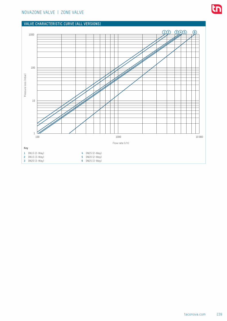
239taconova.com
Valv
es &
acc
esso
ries
107
120
Rp Rp
6464
94.5
92.5
94.5
92.5
107
120
Rp Rp
6464
94.5
92.5
94.5
92.5
NOVAZONE VALVE | ZONE VALVE
SPECIFICATION TEXTSee www.taconova.com
TECHNICAL DATAGeneral
■ Operating mode: normally closed ■ Ambient temperature: up to 60 ̊ C
Drive ■ Ambient temperature: up to 60 ̊ C ■ Operating voltage: 230 V (± 10 %) 50 Hz
■ Power consumption: 6 W ■ Protection type IP 20 ■ CE conformance ■ Cable length 0.6 m ■ Opening times: 12 sec. ■ Closing times: 5 sec.
Valve bodies ■ Operating temperature TO max: 120 °C ■ Operating pressure PO max: 10 bar ■ Temperature of medium: 5 - 120 ̊ C ■ Shaft seal: stuffing box seal provided by two successive O-ring seals
Material ■ Housing: brass ■ Paddle: EPDM
Fluids ■ Heating water (VDI 2035; SWKI BT 102-01; ÖNORM H 5195–1)
■ Water and proprietary additives used against corrosion and freezing up to 50%
DIMENSIONAL DRAWING
TYPE OVERVIEW NovaZone Valve 2way | 2-way zone valve with electromotive drive and spring return, standard version for medium temperatures of 5 - 120 ̊ CFunction: Open / Closed
Order no. Voltage DN Rp KVS m³/h Δ p max (bar) 256.5242.999S 230 V 15 ½" 3300 l/h 1,4256.5243.999S 230 V 20 ¾" 4800 l/h 1,0256.5244.999S 230 V 25 1" 4600 l/h 1,0
NovaZone Valve 3way | 3-way zone valve with electromotive drive and spring return, standard version for medium temperatures of 5 - 120 ̊ CFunction: Switching
Order no. Voltage DN Rp KVS m³/h Δ p max (bar) 256.5342.999S 230 V 15 ½" 3500 l/h 1,4256.5343.999S 230 V 20 ¾" 4400 l/h 1,0256.5344.999S* 230 V 25 1" 8800 l/h 0,5
* high kVS value
SIZE MEASUREMENT
Fits H H1 H2All DN 15 2-way through valves 107 93 14All DN 20 2-way through valves 107 93 14All DN 25 2-way through valves 107 93 14All DN 15 3-way switching valves 120 86 34All DN 20 3-way switching valves 120 86 34All DN 25 3-way switching valves 120 86 34
NOTETaconova Group AG maintains these articles under the name XXX.XXXX.999N.
5 641 2 3
10
1
100
1000
100 1000 10 000
Subj
ect
to m
odif
icat
ion.
05/
2017
NOVAZONE VALVE | ZONE VALVE
VALVE CHARACTERISTIC CURVE (ALL VERSIONS)
Key
1 DN15 (2-Way)2 DN15 (3-Way)3 DN20 (3-Way)
4 DN25 (2-Way)5 DN20 (2-Way)6 DN25 (3-Way)
Pres
sure
loss
(mba
r)
Flow rate (l/h)
CONTACT AND FURTHER INFORMATION TACONOVA.COM
Taconova Group AG | Neunbrunnenstrasse 40 | CH-8055 Zurich | T +41 44 735 55 55 | F +41 44 735 55 02 | [email protected]

240 taconova.com
Valv
es &
acc
esso
ries
COMBINED VALVE FOR THE BOILER PROVIDES VENTILATION AND PROTECTS AGAINST OVERPRESSURE
Boiler valve groups take over the functions of technical safety equipment on
boilers.
SAFETY STANDARDThe safety equipment on boilers includes a safety group
for the ventilation, pressure monitoring and pressure
display functions. The Tri-Bloc safety group unites four
functions in a single valve:■■ Continuous and automatic ventilation■■ Blowing off overpressure■■ Displaying the pressure■■ Providing a connection for an expansion vessel or KFE
spigot
CONNECTION-READY SAFETY GROUPThe Tri-Block combination valve consists of a brass valve
carrier with safety valve (blow-off pressure 2.5 or 3 bar) a
TacoVent HyVent rapid ventilator and a manometer with
self-sealing screw connector. The Tri-Bloc also has two
additional screw connectors for an expansion vessel (R ¾")
and a filling spigot (Rp ½").
FLOAT-CONTROLLED VENTILATING VALVEThe TacoVent HyVent ventilating valve has a float on the
surface of the water that holds the ventilating bore tightly
closed by means of a valve needle. When air collects in
the boiler, the float is lowered as the water level drops,
opening the air outlet. An integrated automatic closure
enables the float-based ventilating valve to be replaced
under system pressure.
COMBINATION VALVE FOR EVERY INSTALLATION POSITIONThe highlight of the Tri-Bloc safety valve group is the
multi-connection system, which permits several different
installation positions and therefore helps avoid time-
consuming installation work with additional fittings:
Thanks to the rotating screw connector, the safety valve
can be turned in the required direction.
The ventilating valve can be connected to the valve body
in several different variants, so that this can be installed
vertically in any installation position without requiring
additional angled components.
The manometer with self-sealing thread can either be
fitted on the side or on the front.
Multifunctional valves and accessories

241taconova.com
Valv
es &
acc
esso
ries
COMPACT SAFETY VALVE
The Tri-Bloc boiler safety group unites the required safety valves in a single valve
body, saving time during installation.
BENEFITS AT THE PLANNING STAGE■■ Combination valve as technical safety equipment for
boilers■■ Ready-assembled and tested safety fitting for
ventilation, pressure monitoring and pressure display
with safety valve approved by the TÜV Technical Control
Association■■ Additional screw connection for expansion vessel and
KFE Spigot■■ Automatic and permanent ventilation
BENEFITS AT THE INSTALLATION STAGE■■ Time-saving installation without additional fittings
thanks to multiple connection system■■ Flexibility for different installation situations thanks
to variable connection options■■ Rapid ventilation when filling the system■■ Easy control of the system filling pressure■■ Float-based ventilating valve can be replaced under
system pressure■■ Rotating safety valve■■ Self-sealing connections
Multi purpose unit
The extremely compact TriBloc valve is a safety group for heating systems to ventilate, to aerate, and to indicate and relieve pressure.
■■ TriBloc
APPLICATIONS Valves and accessories from Taconova can be used in various ways in heating, air conditioning, ventilation and sanitary
systems:
Heating and cooling energy generation Heating and cooling energy distribution (Indoor temperature control)
Sanitary systems
■■ Solar thermal energy■■ Oil, gas, electricity, biomass■■ District heating
■■ Underfloor heating■■ Radiators■■ Chilled and heated ceilings
■■ Fresh water

242 taconova.com
Valv
es &
acc
esso
ries
TRIBLOC ADVANTAGES ■ Four operations (venting, pressure relief, displaying, connecting) in a space-saving combination
■ Self-sealing component connections
■ Use of proven components (float air vent, safety valve, manometer)
■ Versatile positioning of the manometer (frontal, lateral)
■ Manometer with check valve ■ Float air vent with automatic check valve
SYSTEM/BASIC DIAGRAM
SAFETY GROUP
DESCRIPTIONThe safety group is a multiple fitting for heating equipment in the perfor-mance range up to 50 kW (DIN 4751).The individual components are as-sembled into one unit and tested.A self-sealing manometer is included (not assembled). The unit also has a connection for an expansion vessel (R ¾") or, if required, a filling valve (Rp ½").
INSTALLATION POSITIONVertically upwards.
OPERATION Venting and aeratingA float-controlled valve opens as the volume of air increases and continu-ally releases the air collected in the cap. The junction canal transports the water and air straight to the air cap.
Pressure reliefThe safety valve prevents the pres-sure from rising above the normal operating level by releasing heating water via a membrane.
Permanent and automatic venting, aerating as well as pressure relief.
BUILDING CATEGORIESFor pipe installations in heating area:
■ Apartment blocks, housing estates, multiple dwelling units
■ Residential care facilities, hospitals ■ Administration and service buildings ■ Hotels and restaurants, industrial kitchens
■ School buildings and sports facilities ■ Commercial and industrial buildings
■■ TriBloc
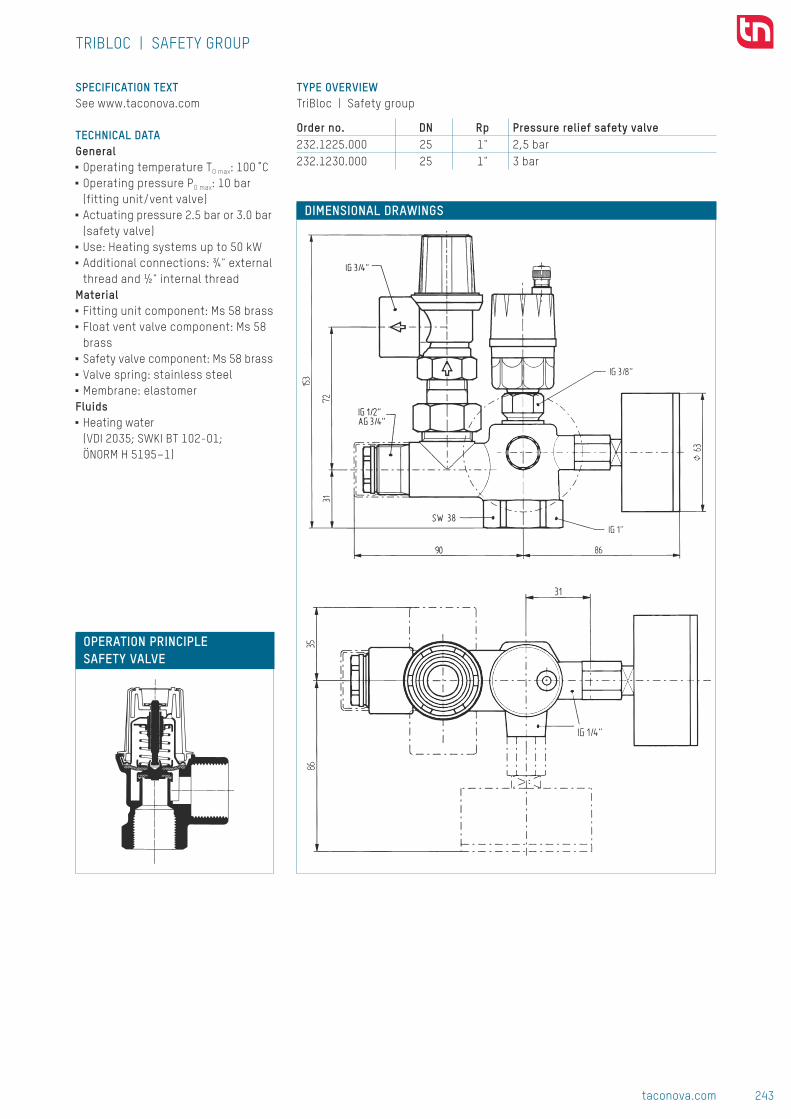
243taconova.com
Valv
es &
acc
esso
ries
Subj
ect
to m
odif
icat
ion.
08/
2017
DIMENSIONAL DRAWINGS
TYPE OVERVIEW TriBloc | Safety group
Order no. DN Rp Pressure relief safety valve 232.1225.000 25 1" 2,5 bar232.1230.000 25 1" 3 bar
SPECIFICATION TEXTSee www.taconova.com
TECHNICAL DATAGeneral
■ Operating temperature TO max: 100 ̊ C ■ Operating pressure PO max: 10 bar (fitting unit/vent valve)
■ Actuating pressure 2.5 bar or 3.0 bar (safety valve)
■ Use: Heating systems up to 50 kW ■ Additional connections: ¾" external thread and ½" internal thread
Material ■ Fitting unit component: Ms 58 brass ■ Float vent valve component: Ms 58 brass
■ Safety valve component: Ms 58 brass ■ Valve spring: stainless steel ■ Membrane: elastomer
Fluids ■ Heating water (VDI 2035; SWKI BT 102-01; ÖNORM H 5195–1)
TRIBLOC | SAFETY GROUP
OPERATION PRINCIPLE SAFETY VALVE
CONTACT AND FURTHER INFORMATION TACONOVA.COM
Taconova Group AG | Neunbrunnenstrasse 40 | CH-8050 Zurich | T +41 44 735 55 55 | F +41 44 735 55 02 | [email protected]
244 taconova.com
Valv
es &
acc
esso
ries
AIR, GASES AND CONTAMINANTS IN HYDRONIC PLANT SYSTEMS
The energy wasted as a result of trapped particles in flow systems should not be
underestimated. Operating safety and comfort mean that air and dirt pockets
should be drained in all closed-cycle systems.
THERMAL CONDUCTIVITY OF CARRIER MEDIUM IMPAIREDAir and gases trapped in the heating system reduce
heating comfort, impede circulation and reduce energy
efficiency. They also diminish the performance and lifetime
of the heating system through the formation of erosion
and incrustations.
IT IS ALMOST IMPOSSIBLE TO PREVENT THE ENTRY OF AIRThere are different reasons why air enters heating and
plumbing systems and why gases are released. This can
result from underpressure on the intake side of the
circulating pump, for example, or can happen if the system
filling pressure is too low, when air is drawn into the pipe
system because connections (such as screw connections)
are not absolutely air-tight.
Another cause is the change in temperature when the
heating water heats up and radiates heat, casing soluble
gases in the water to be released. This means that there
is a high concentration of air and gas freshly driven from
the water at the outlet of the heat flow in the boiler circuit
after water has been heated.
VENTILATOR HOUSING FOR HORIZONTAL AND VERTICAL PIPELINESIn order effectively to remove air and released gases
from long pipe networks with a large capacity, special air
separator housings aid the air and water separation pro-
cess. The design of the TacoVent Airscoop Horizontal and
Airscoop Vertical housing means that the flow is guided in
such a way that the air bubbles rise and the accumulated
air can be released via the integrated ventilation valves.
REMOVING ACCUMULATED AIR FROM BOILERS, TANKS AND DISTRIBUTORSFloat ventilating valves are used to remove the air from
parts of systems such as boilers, storage tanks and the
highest points of distribution and connecting lines. The
ventilating valve has a float on the surface of the water
that holds the ventilating bore tightly closed. When air
collects, the float is lowered as the water level drops,
opening the air outlet.
AUTOMATIC VENTILATION FUNCTIONThere is an expandable membrane in the valve insert of the
TacoVent Vent automatic ventilating valve that dries when
it comes in contact with air, thus becoming air-permeable.
As soon as the air has escaped from the radiator and the
membrane is once again comes in contact with hot water,
the membrane immediately expands again, preventing
water from escaping.
AIR IN THE SOLAR ENERGY CIRCUIT PREVENTS UNIMPEDED CIRCULATIONWhen a solar thermal system is commissioned and filled
for the first time, the trapped air needs to be removed:
eddying as the solar liquid flows in can cause air to be
absorbed which is only gradually released again during
operation. Air and gases are also released during opera-
tion due to the occasional evaporation of the anti-freeze
mixture. Air in the solar energy system impedes circulation
or even blocks it entirely, reducing the solar yield and thus
also causing the anti-freeze mixture to age prematurely.
Air, dirt and magnetite separator

245taconova.com
Valv
es &
acc
esso
ries
AUTOMATIC VENTILATION FOR SMOOTH SYSTEM OPERATION
In heating, plumbing and solar energy systems, vent valves and dirt separators
from Taconova can be used to automatically vent trapped air from the system
components and pipes even in inaccessible areas.
BENEFITS AT THE PLANNING STAGE■■ The range covers all areas where venting and dirt
separation are required in heating, plumbing and
solar energy systems.■■ Broad range of nominal widths and connection types ■■ Optimized operating costs thanks to energy savings■■ Safe ventilation in all installation situations
BENEFITS AT THE INSTALLATION STAGE■■ The magnetite dirt separators protect HE pumps from
damage caused by magnetic particles, ensuring fewer
malfunctions and repairs.■■ Fast installation and simple replacement of valves■■ Simple ventilation and dirt removal during commissio-
ning and maintenance of heating, plumbing and solar
systems■■ Simple and safe operation■■ The separated magnetic particles can be discharged by
means of the available filling and draining valve simply
and at any time and also when the system is operating.
Vent valves
The reliable TacoVent vent valves remove unwanted air from heating systems. This increases the efficiency and reduces costs.
■■ TacoVent HyVent■■ TacoVent Vent■■ TacoVent AirScoop■■ TacoVent Twin
Dirt separator
Taconova valves remove dirt from heating systems automatically and therefore increase their effectiveness. Moreover, the heating components are protected against damage from dirt deposits.
■■ TacoVent Pure■■ TacoVent Twin
APPLICATIONS Valves and accessories from Taconova can be used in various ways in heating, air conditioning, ventilation and sanitary
systems:
Heating and cooling energy generation Heating and cooling energy distribution (Indoor temperature control)
Sanitary systems
■■ Solar thermal energy■■ Oil, gas, electricity, biomass■■ District heating
■■ Underfloor heating■■ Radiators■■ Chilled and heated ceilings
■■ Fresh water

246 taconova.com
Valv
es &
acc
esso
ries
SOLUTIONS FOR EVERY SITUATION
AIR SEPARATOR - CONTINUOUS AIR SEPARATION FOR AUTOMATIC VENTILATION
Operating principle Description Advantages Product variants
I-Rings This technology is based on enlargement of the surface through the installed I-Rings. The special surface structure leads to the accumulation of small gas bubbles from the heating water. These merge to form larger gas bubbles, rise in the reservoir and can then escape automatically here from the heating system.
■■ Continuous air separation using I-Rings
■■ Large surfaces for high separation performance
■■ Lower pressure drop in the system
■■ Reduced consumption of primary energy lowers operating costs
■■ Robust, nonsensitive design■■ Fault and maintenance-free
design■■ Automatic ventilation of
systems during filling and in operation
TacoVent AirScoop RH Air Separator (Horizontal) - Standard Version (120 °C)TacoVent AirScoop Solar RH Air Separator (Horizontal) - Solar Version (200 °C)TacoVent AirScoop RV Air Separator (Vertical) - Standard Version (120 °C)TacoVent AirScoop Solar RVAir Separator (Vertical) - Solar Version (200 °C)
Baffle plate This technology is based on the breakdown of the water flow into laminar and turbulent flows through integrated flow ele-ments. The special size and positioning of the flow bodies causes a laminar flow in the upper area of the valve. Loosened gas bubbles can rise in the reservoir from this laminar flow area and escape automa-tically here from the heating system.
■■ High separation performance■■ Robust, nonsensitive design■■ Fault and maintenance-free
design■■ Additional connections
available from 3" for safety valve or thermometer
TacoVent AirScoop DH Air Separator (Horizontal)TacoVent AirScoop DH Air Separator (Horizontal)TacoVent AirScoop DV Ventilating Flask (Vertical) (principle: cylindrical calming section)
AUTOMATIC VENT VALVE - CONTINUOUS AND AUTOMATIC VENTILATION AND AERATION
Operating principle Description Advantages Product variants
Float When air collects in the vent, the float is lowered as the water level drops, opening the vent valve. As the water level rises, the float closes the air outlet again
■■ Automatic ventilation of systems during filling and in operation
■■ Automatic aeration of systems when emptying
■■ Design allows dirt-sensitive operation
■■ Trouble-free replacement thanks to a check valve
■■ Time-saving assembly■■ DN10 with drinking water
certification (SVGW)
TacoVent HyVent Float Vent Valve

247taconova.com
Valv
es &
acc
esso
ries
Operating principle Description Advantages Product variants
Swelling discs An expandable membrane in the valve insert dries when it comes in contact with air, thus beco-ming air-permeable. As soon as the air has escaped from the radiator, the membrane immedi-ately expands again, preventing water from escaping.
■■ Reliable and long-lasting operation
■■ Versatile use■■ Additional fast manual
ventilation■■ Integrated check valve■■ Small and compact design■■ Self-sealing (DN15)
TacoVent VentHeating Radiator Vent Valves
DIRT AND MAGNETITE SEPARATOR - CONTINUOUS SEPARATION VIA I-RINGS AND MAGNETIC RING
Operating principle Description Advantages Product variants
I-Rings Contaminants are separated from the water as with the air separa-tor with I-Rings, sink downwards, are collected in the housing and can then be removed from the system in a controlled manner. The version with magnetic ring additionally removes magnetite.
■■ Large surfaces for high sepa-
ration performance even of
the smallest particles■■ Separation of magnetite thanks
to strong magnetic ring ■■ Low pressure loss■■ Reduced consumption of
primary energy lowers
operating costs ■■ Rapid maintenance during
system operation also,
therefore no unnecessary
downtimes
TacoVent Pure Mag RH Dirt and Magnetite Separator (Horizontal) Versions without magnetite separation are also availableTacoVent Pure Mag RVDirt and Magnetite Separator
(Vertical) Versions without magnetite separation are also available
AIR, DIRT AND MAGNETITE SEPARATOR - CONTINUOUS AIR AND DIRT SEPARATION WITH I-RINGS IN A SINGLE VALVE
Operating principle Description Advantages Product variants
I-Rings The combination product unites the advantages of air, dirt and magnetite separation with I-Rings in a single valve – saving space and installation time.
■■ Large surfaces for high air and dirt separation performance
■■ Separation of magnetite thanks to strong magnetic ring
■■ Low pressure loss■■ Reduced consumption of
primary energy lowers operating costs
■■ Robust, nonsensitive design■■ Fault and maintenance-free
design
TacoVent Twin RHAir, Dirt and Magnetite Separator (Horizontal)Versions without magnetite separation are also available
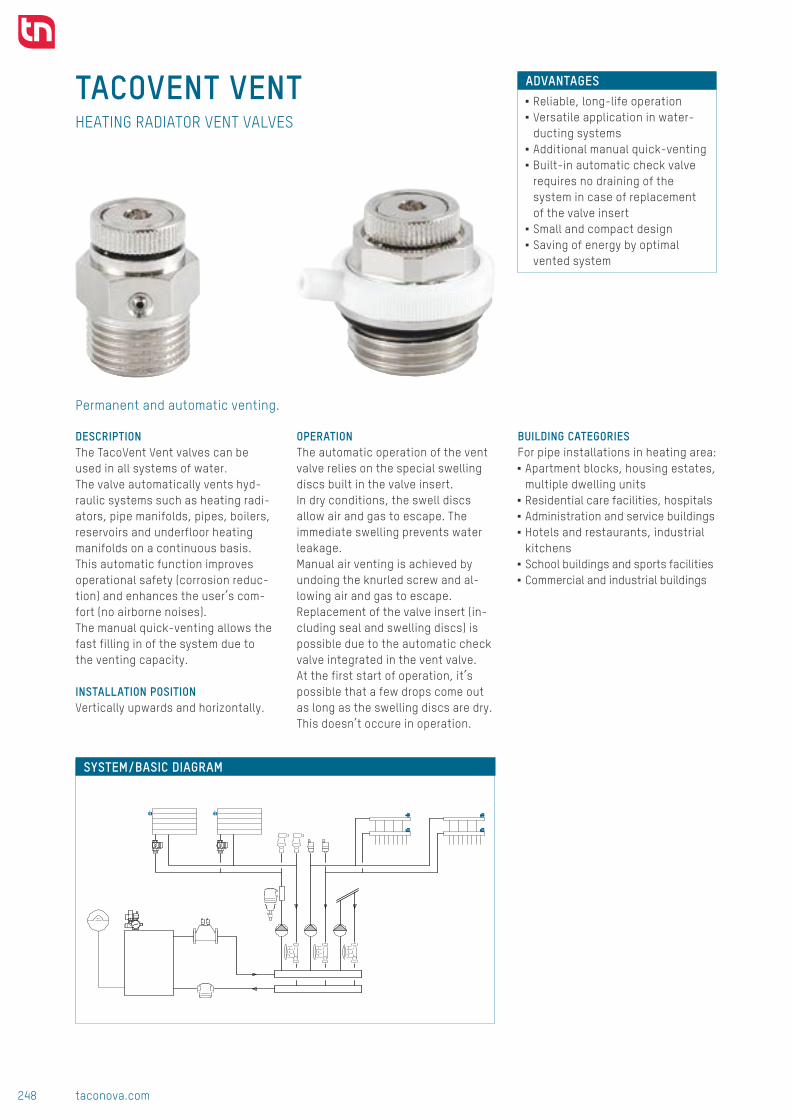
248 taconova.com
Valv
es &
acc
esso
ries
TACOVENT VENT
Permanent and automatic venting.
ADVANTAGES ■ Reliable, long-life operation ■ Versatile application in water- ducting systems
■ Additional manual quick-venting ■ Built-in automatic check valve requires no draining of the system in case of replacement of the valve insert
■ Small and compact design ■ Saving of energy by optimal vented system
SYSTEM/BASIC DIAGRAM
HEATING RADIATOR VENT VALVES
DESCRIPTIONThe TacoVent Vent valves can be used in all systems of water. The valve automatically vents hyd-raulic systems such as heating radi-ators, pipe manifolds, pipes, boilers, reservoirs and underfloor heating manifolds on a continuous basis. This automatic function improves operational safety (corrosion reduc-tion) and enhances the user’s com-fort (no airborne noises).The manual quick-venting allows the fast filling in of the system due to the venting capacity.
INSTALLATION POSITIONVertically upwards and horizontally.
OPERATION The automatic operation of the vent valve relies on the special swelling discs built in the valve insert. In dry conditions, the swell discs allow air and gas to escape. The immediate swelling prevents water leakage. Manual air venting is achieved by undoing the knurled screw and al-lowing air and gas to escape. Replacement of the valve insert (in-cluding seal and swelling discs) is pos sible due to the automatic check valve integrated in the vent valve. At the first start of operation, it’s possible that a few drops come out as long as the swelling discs are dry.This doesn’t occure in operation.
BUILDING CATEGORIESFor pipe installations in heating area:
■ Apartment blocks, housing estates, multiple dwelling units
■ Residential care facilities, hospitals ■ Administration and service buildings ■ Hotels and restaurants, industrial kitchens
■ School buildings and sports facilities ■ Commercial and industrial buildings
■■ TacoVent Vent

249taconova.com
Valv
es &
acc
esso
ries
1
2
3
4
5
6
7
8
A
G
BC
AB
C
25DN 15 ½"
A
G
BC
AB
C
25DN 15 ½"
SW
Subj
ect
to m
odif
icat
ion.
10/
2016
DIMENSIONAL DRAWING
TYPE OVERVIEW TacoVent Vent | Heating Radiator Vent Valves
Order no. DN G Self-sealing240.5417.000 6 1⁄8" -240.5418.000 8 ¼" -240.5419.000 10 3⁄8" -240.5420.000 15 ½" P
MEASUREMENT TABLE TacoVent Vent | Heating Radiator Vent Valves
Order no. G A B C SW240.5417.000 1⁄8" 26 16 10 14240.5418.000 ¼" 26 16 10 14240.5419.000 3⁄8" 26 16 10 17240.5420.000 ½" 26 17 9 19
SPECIFICATION TEXTSee www.taconova.com
TECHNICAL DATAGeneral
■ Operating temperature TO max: 115 ̊ C ■ Operating pressure PO max: 8.5 bar ■ Nominal width:
■
1⁄8" - 3⁄8" ■
½" self-sealing (O-ring)Material
■ Valve body: brass nickel-plated ■ Valve insert: brass nickel-plated ■ Automatic check valve: stainless steel
■ Seals: silicone, EPDMFluids
■ Heating water (VDI 2035; SWKI BT 102-01; ÖNORM H 5195–1)
■ Water free of chemical additives
TACOVENT VENT | HEATING RADIATOR VENT VALVES
SECTIONAL DRAWING
SPARE PART COMPLETE VALVE INSERT
Order no. Version298.4001.000 Including seal and swelling discs
1 Air outlet of automatic venting2 Seal3 Air outlet of manual venting4 Automatic check valve5 Head of valve insert for manual venting6 Swelling discs7 Valve insert8 Valve body
OPERATION PRINCIPLE
CONTACT AND FURTHER INFORMATION TACONOVA.COM
Taconova Group AG | Neunbrunnenstrasse 40 | CH-8050 Zurich | T +41 44 735 55 55 | F +41 44 735 55 02 | [email protected]

250 taconova.com
Valv
es &
acc
esso
ries
TACOVENT HYVENT ADVANTAGES ■ Automatic air venting of systems during filling or normal operation
■ Automatic aerating at draining ■ Design allows dirt-sensitive operation
■ Trouble-free replacement of the float vent valve under full system pressure thanks to a check valve
■ Time saving installation of the float vent valve with the auto-matic check valve
SYSTEM/BASIC DIAGRAM
FLOAT AIR VENTILATOR
DESCRIPTIONThe valve automatically vents and provides air from and to hydraulic systems such as heating, cooling, air conditioning and sanitary equipment on a continual basis.The combination of an air separator with the aerating and venting greatly increases the efficiency of the ven-ting operation. The automatic self-sealing check valve prevents water from escaping from the mains should the vent valve need to be replaced.
INSTALLATION POSITIONVertically upwards.
OPERATION The ventilation valve is closed by means of a float. If air collects in the cup, the float sinks and releases the ventilation valve. The accumulated air escapes until the (inflowing) water pushes the floater down again and the valve closes. The water once more presses the float against the ventilation valve, and closes the latter. In combination with an upstream TacoVent AirScoop, this guarantees efficient separation of the air-water mixture, and the system is rapidly and automatically vented.
Permanent and automatic venting and aerating.
BUILDING CATEGORIESFor pipe installations in drinking water and heating area:
■ Apartment blocks, housing estates, multiple dwelling units
■ Residential care facilities, hospitals ■ Administration and service buildings ■ Hotels and restaurants, industrial kitchens
■ School buildings and sports facilities ■ Commercial and industrial buildings
■■ TacoVent HyVent

251taconova.com
Valv
es &
acc
esso
ries
SW 30
SW80
12
Ø 35
3/8"21
14
8
G 3/8"
G
SW 30
SW80
12
Ø 35
3/8"
21
14
8
G 3/8"
G
l/m
in
bar
HyVent 3/8" HyVent 1/2"bar
0 0 00.5 7.7 10
l/min
50
60
0.5 7.7 101 12.1 20
1.5 15 272 17.4 33
2.5 18.8 383 20.2 42
3.5 21.3 46
30
40
Datenreihen1
Datenreihen23.5 21.3 464 22 50
4.5 22.4 535 21.8 56
5.5 21 586 20 60
0
10
20Datenreihen2
00 0.5 1 1.5 2 2.5 3 3.5 4 4.5 5 5.5 6
TACOVENT HYVENT DN10
DIMENSIONAL DRAWINGFloat air ventilator DN10 Automatic check valve DN10
TYPE OVERVIEW TacoVent HyVent | Float air ventilator DN10
Order no. G1 Automatic check valve 242.5072.001 3⁄8" -242.5072.002 3⁄8" 3⁄8" 242.5072.021 3⁄8" ½"
Automatic check valve DN10
Order no. G1 × G2 To be used with 220.5235.000 3⁄8" × 3⁄8" 242.5072.001, 242.5072.002220.5236.000 3⁄8" × ½" 242.5072.001, 242.5072.021
MEASUREMENT TABLE Check valve DN10
Order no. G SW220.5235.000 3⁄8" 19220.5236.000 ½" 21
SPECIFICATION TEXTSee www.taconova.com
TECHNICAL DATAGeneral
■ Operating temperature TO max: 115 ˚C ■ Operating pressure PO max: 10 bar ■ Exterior threads: G 3⁄8" and G ½" as per ISO 228
Material ■ Internal parts: Plastic, stainless steel
■ Housing: Brass ■ Seals: EPDM, NBR, silicone
Fluids ■ Heating water (VDI 2035; SWKI BT 102-01; ÖNORM H 5195–1)
TACOVENT HYVENT | FLOAT AIR VENTILATOR
VENTING CAPACITY (DRY VENTING)OPERATION PRINCIPLE

252 taconova.com
Valv
es &
acc
esso
ries
l/m
in
bar
HyVent 3/8" HyVent 1/2"bar
0 0 00.5 7.7 10
l/min
50
60
0.5 7.7 101 12.1 20
1.5 15 272 17.4 33
2.5 18.8 383 20.2 42
3.5 21.3 46
30
40
Datenreihen1
Datenreihen23.5 21.3 464 22 50
4.5 22.4 535 21.8 56
5.5 21 586 20 60
0
10
20Datenreihen2
00 0.5 1 1.5 2 2.5 3 3.5 4 4.5 5 5.5 6
TACOVENT HYVENT DN15
120
35
ø 71
G ½"
35
G ½"
120
35
ø 71
G ½"
35
G ½"
Subj
ect
to m
odif
icat
ion.
05/
2017
DIMENSIONAL DRAWINGFloat air ventilator DN15 Automatic check valve DN15
TYPE OVERVIEW TacoVent HyVent | Float air ventilator DN15
Order no. G Automatic check valve 242.5074.000 ½" -
Automatic check valve DN15
Order no. G × G To be used with 242.5073.000 ½" 242.5074.000
SPECIFICATION TEXTSee www.taconova.com
TECHNICAL DATAGeneral
■ Operating temperature TO max: 120 ˚C ■ Operating pressure PO max: 10 bar ■ Threads: G ½" as per ISO 228
Material ■ Internal parts: Plastic, stainless steel
■ Housing: Brass ■ Seals: EPDM, NBR, silicone
Fluids ■ Heating water (VDI 2035; SWKI BT 102-01; ÖNORM H 5195–1)
TACOVENT HYVENT | FLOAT AIR VENTILATOR
VENTING CAPACITY (DRY VENTING)
CONTACT AND FURTHER INFORMATION TACONOVA.COM
Taconova Group AG | Neunbrunnenstrasse 40 | CH-8050 Zurich | T +41 44 735 55 55 | F +41 44 735 55 02 | [email protected]
TACOVENT AIRSCOOP D
Permanent air separation.
ADVANTAGES ■ High air separation capacity ■ Strong robust design ■ Service and maintenance-free structure
■ Two models for horizontal or vertical installation
■ Additional connection for safety valve available from dimension 3"
SYSTEM/BASIC DIAGRAM
AIR SEPARATOR
DESCRIPTIONThe air separator is fitted in the inlet pipe imme di ately behind the heating source. This is the point with the highest concentration of air and gas driven out of the water.The expansion occurring inside the AirScoop and the built-in deflectors speed up the process of separating air and water.When combined with the float air vent TacoVent HyVent, this system ensures air separation as well as elimination.
TacoVent AirScoop DV is recommen-ded for venting in vertical pipes. The air separated from the medium and collected in the bottle can be vented sporadically via the vent valve.
INSTALLATION POSITIONThe horizontal variant may only be installed horizontally and the vertical variant may only be installed verti-cally. The direction of flow must be kept in mind.
OPERATION The air expelled from the water into the heating circuit enters the air separator device as air bubbles. The flow-deflector in the housing drives the air bubbles to the top. The collected air is either automati - cally vented via the TacoVent HyVent (AirScoop horizontal) or manually via the vent valve (AirScoop vertical).The air-separation capac ity can be increased by install ing a straight piece of piping of approx. 0.5 m in length upstream the separator.
BUILDING CATEGORIESFor pipe installations in heating area:
■ Apartment blocks, housing estates, multiple dwelling units
■ Residential care facilities, hospitals ■ Administration and service buildings ■ Hotels and restaurants ■ School buildings and sports facilities ■ Commercial and industrial buildings

253taconova.com
Valv
es &
acc
esso
ries
TACOVENT AIRSCOOP D
Permanent air separation.
ADVANTAGES ■ High air separation capacity ■ Strong robust design ■ Service and maintenance-free structure
■ Two models for horizontal or vertical installation
■ Additional connection for safety valve available from dimension 3"
SYSTEM/BASIC DIAGRAM
AIR SEPARATOR
DESCRIPTIONThe air separator is fitted in the inlet pipe imme di ately behind the heating source. This is the point with the highest concentration of air and gas driven out of the water.The expansion occurring inside the AirScoop and the built-in deflectors speed up the process of separating air and water.When combined with the float air vent TacoVent HyVent, this system ensures air separation as well as elimination.
TacoVent AirScoop DV is recommen-ded for venting in vertical pipes. The air separated from the medium and collected in the bottle can be vented sporadically via the vent valve.
INSTALLATION POSITIONThe horizontal variant may only be installed horizontally and the vertical variant may only be installed verti-cally. The direction of flow must be kept in mind.
OPERATION The air expelled from the water into the heating circuit enters the air separator device as air bubbles. The flow-deflector in the housing drives the air bubbles to the top. The collected air is either automati - cally vented via the TacoVent HyVent (AirScoop horizontal) or manually via the vent valve (AirScoop vertical).The air-separation capac ity can be increased by install ing a straight piece of piping of approx. 0.5 m in length upstream the separator.
BUILDING CATEGORIESFor pipe installations in heating area:
■ Apartment blocks, housing estates, multiple dwelling units
■ Residential care facilities, hospitals ■ Administration and service buildings ■ Hotels and restaurants ■ School buildings and sports facilities ■ Commercial and industrial buildings
■■ TacoVent AirScoop D

254 taconova.com
Valv
es &
acc
esso
ries
R R
E D
C B
A
RR
F
O 18
0 22
0O
A
C B
D D
DIMENSIONAL DRAWINGOPERATION PRINCIPLE
TYPE OVERVIEW TacoVent AirScoop DH | Air separator (horizontal), thread connection
Order no. DN Rp Zeta ζ kV (m3/h) Weight
243.5001.000 20 ¾" 1,1 17,1 0,6 kg243.5002.000 25 1" 1,0 28,8 0,8 kg243.5003.000 32 1¼" 1,0 50,4 1,6 kg243.5004.000 40 1½" 1,1 64,4 3,2 kg243.5005.000 50 2" 0,84 114,0 3,2 kg243.5006.000 65 2½" 0,67 237,0 6,8 kg243.5007.000 80 3" 0,88 287,0 8,3 kg
TacoVent AirScoop DH | Air separator (horizontal), flanged connection
Order no. DN Flange Zeta ζ kV (m3/h) Weight
243.5008.000 100 PN 16 0,83 439,0 21,0 kg
MEASUREMENT TABLE TacoVent AirScoop DH | Air separator (horizontal)
Order no. R A B C D E F 243.5001.000 Rp ¾" 110 69 48 Rp 3⁄8" – –243.5002.000 Rp 1" 120 79 55 Rp 3⁄8" – –243.5003.000 Rp 1¼" 140 93 64 Rp 3⁄8" – –243.5004.000 Rp 1½" 160 96 64 Rp 3⁄8" – –243.5005.000 Rp 2" 228 120 80 Rp 3⁄8" – –243.5006.000 Rp 2½" 235 144 95 Rp 3⁄8" – –243.5007.000 Rp 3" 267 184 127 Rp 3⁄8" Rp 3⁄8" –243.5008.000 DN 100 350 274 164 Rp 3⁄8" – Rp ½"
SPECIFICATION TEXTSee www.taconova.com
TECHNICAL DATAGeneral
■ Operating temperature TO max: 135 ˚C with float vent valve TO max: 115 ˚C
■ Operating pressure PO max: 10 barMaterial
■ Housing in cast iron GG 25, lacqueredFluids
■ Heating water (VDI 2035; SWKI BT 102-01; ÖNORM H 5195–1)
TACOVENT AIRSCOOP | AIR SEPARATOR
AIRSCOOP HORIZONTAL
ACCESSORIES TACOVENT HYVENTSee separate data sheet
Order no. DN G Version242.5072.001 10 3⁄8" without automatic check valve242.5072.002 10 3⁄8" with automatic check valve

255taconova.com
Valv
es &
acc
esso
ries
R R
E D
C B
A
RR
F
O 18
0 22
0O
A
C B
D D
DIMENSIONAL DRAWINGOPERATION PRINCIPLE
TYPE OVERVIEW TacoVent AirScoop DH | Air separator (horizontal), thread connection
Order no. DN Rp Zeta ζ kV (m3/h) Weight
243.5001.000 20 ¾" 1,1 17,1 0,6 kg243.5002.000 25 1" 1,0 28,8 0,8 kg243.5003.000 32 1¼" 1,0 50,4 1,6 kg243.5004.000 40 1½" 1,1 64,4 3,2 kg243.5005.000 50 2" 0,84 114,0 3,2 kg243.5006.000 65 2½" 0,67 237,0 6,8 kg243.5007.000 80 3" 0,88 287,0 8,3 kg
TacoVent AirScoop DH | Air separator (horizontal), flanged connection
Order no. DN Flange Zeta ζ kV (m3/h) Weight
243.5008.000 100 PN 16 0,83 439,0 21,0 kg
MEASUREMENT TABLE TacoVent AirScoop DH | Air separator (horizontal)
Order no. R A B C D E F 243.5001.000 Rp ¾" 110 69 48 Rp 3⁄8" – –243.5002.000 Rp 1" 120 79 55 Rp 3⁄8" – –243.5003.000 Rp 1¼" 140 93 64 Rp 3⁄8" – –243.5004.000 Rp 1½" 160 96 64 Rp 3⁄8" – –243.5005.000 Rp 2" 228 120 80 Rp 3⁄8" – –243.5006.000 Rp 2½" 235 144 95 Rp 3⁄8" – –243.5007.000 Rp 3" 267 184 127 Rp 3⁄8" Rp 3⁄8" –243.5008.000 DN 100 350 274 164 Rp 3⁄8" – Rp ½"
SPECIFICATION TEXTSee www.taconova.com
TECHNICAL DATAGeneral
■ Operating temperature TO max: 135 ˚C with float vent valve TO max: 115 ˚C
■ Operating pressure PO max: 10 barMaterial
■ Housing in cast iron GG 25, lacqueredFluids
■ Heating water (VDI 2035; SWKI BT 102-01; ÖNORM H 5195–1)
TACOVENT AIRSCOOP | AIR SEPARATOR
AIRSCOOP HORIZONTAL
ACCESSORIES TACOVENT HYVENTSee separate data sheet
Order no. DN G Version242.5072.001 10 3⁄8" without automatic check valve242.5072.002 10 3⁄8" with automatic check valve
ø
G
G
L
Subj
ect
to m
odif
icat
ion.
08/
2017
DIMENSIONAL DRAWING
OPERATION PRINCIPLE
TYPE OVERVIEW TacoVent AirScoop DV | Ventilating flask (vertical)
Order no. DN G kV (m3/h)
296.7043.000 25 1" 11,1
MEASUREMENT TABLE TacoVent AirScoop DV | Ventilating flask, vertical
Order no. G × G ø L296.7043.000 1"×1" 60,3 mm 301
SPECIFICATION TEXTSee www.taconova.com
TECHNICAL DATAGeneral
■ Operating temperature TO max: 160 ˚C ■ Operating pressure PO max: 8 bar
Material ■ Black steel, stove enamelled
Fluids ■ Heating water (VDI 2035; SWKI BT 102-01; ÖNORM H 5195–1)
■ Water and proprietary additives used against corrosion and free-zing up to 50%
TACOVENT AIRSCOOP D | AIR SEPARATOR
AIRSCOOP VERTICAL
CONTACT AND FURTHER INFORMATION TACONOVA.COM
Taconova Group AG | Neunbrunnenstrasse 40 | CH-8050 Zurich | T +41 44 735 55 55 | F +41 44 735 55 02 | [email protected]

256 taconova.com
Valv
es &
acc
esso
ries
TACOVENT AIRSCOOP R
Continuous air separation using I-Rings and automatic ventilation and aeration
ADVANTAGES ■ High separation performance ■ Robust, nonsensitive design ■ Fault and maintenance-free design
■ Variants for horizontal or vertical installation
SYSTEM/BASIC DIAGRAM
AIR SEPARATOR WITH I-RINGS
DESCRIPTIONThe TacoVent AirScoop R is installed in heating and solar systems and provides for permanent air separation and ventilation in these systems.The installation of air separators prevents disruptive system noises, reduced heat dissipation to the heating surfaces and damage to the installed circulating pumps caused by running dry. Properly ventilated heating and solar systems are moreover exposed to less corrosion owing to the low oxygen content in the water, which increases the operating life of the system.
INSTALLATION POSITIONThe TacoVent AirScoop R is adapted to the installation position. The RV variant is designed for vertical installation and the RH variant for horizontal installation. The indicated direction of flow must be ensured with both variants.
OPERATION The micro-bubbles loosened in the water adhere to the contact sur-faces of the integrated I-Rings and merge to form larger bubbles. The larger bubbles separate and are then eliminated via the installed float ventilator. The I-Rings are integrated in the TacoVent AirScoop R such that the entire flow comes in contact with the adhesion surface of the I-Rings. This principle results in sustained and permanent ventilation of water-based systems and therefore more economical and more reliable operation.
BUILDING CATEGORIESFor pipe installations in heating and solar systems:
■ Apartment blocks, housing estates, multiple dwelling units
■ Residential care facilities and hospitals
■ Administration and service buildings ■ Hotels and restaurants ■ School buildings and sports halls / sports facilities
■ Commercial and industrial buildings
■■ TacoVent AirScoop R

257taconova.com
Valv
es &
acc
esso
ries
H h
bt
L
Rp
H h
bt
L
Rp
DIMENSIONAL DRAWING (PRODUCT / INSULATION)
OPERATING PRINCIPLE
TYPE OVERVIEW TacoVent AirScoop RH | Air Separator (Horizontal), Thread Connection
Order no. Article description TO max DN Connections kV (m3/h) Weight ** Water content
243.6001.000 TacoVent AirScoop RH 22 120 °C 20 ø 22 mm 11.2 1.4 kg 0.22 l243.6002.000 TacoVent AirScoop RH ¾" 120 °C 20 Rp ¾" 11.2 1.4 kg 0.22 l243.6003.000 TacoVent AirScoop RH 1" 120 °C 25 Rp 1" 20.0 1.8 kg 0.35 l243.6004.000 TacoVent AirScoop RH 1 ¼" 120 °C 32 Rp 1 ¼" 31.4 2.4 kg 0.48 l243.6005.000 TacoVent AirScoop RH 1 ½" 120 °C 40 Rp 1 ½" 40.9 2.5 kg 0.48 l243.6003.380* TacoVent AirScoop RH Plus 1" 120 °C 25 Rp 1" 20.0 1.8 kg 0.35 l243.6004.380* TacoVent AirScoop RH Plus 1 ¼" 120 °C 32 Rp 1 ¼" 31.4 2.4 kg 0.48 l243.6005.380* TacoVent AirScoop RH Plus 1 ½" 120 °C 40 Rp 1 ½" 40.9 2.5 kg 0.48 l243.7001.380* TacoVent AirScoop Solar RH Plus 22 200 °C 20 ø 22 mm 11.2 1.4 kg 0.22 l243.7002.380* TacoVent AirScoop Solar RH Plus ¾" 200 °C 20 Rp ¾" 11.2 1.4 kg 0.22 l243.7003.380* TacoVent AirScoop Solar RH Plus 1" 200 °C 25 Rp 1" 20.0 1.8 kg 0.35 l
* Including insulation box** Weight without insulation box
MEASUREMENT TABLE TacoVent AirScoop RH | Air Separator (Horizontal)
Order no. H (mm) L (mm) h (mm) b (mm) t (mm) ø max.243.6001.000 151 118 * 71243.6002.000 151 88 71243.6003.000 171.5 100 80243.6004.000 192 114 87243.6005.000 192 114 87243.6003.380 171.5 100 206.5 117 110 80243.6004.380 192 114 226.5 121 116 87243.6005.380 192 114 226.5 121 116 87243.7001.380 151 118 * 188 113 102 71243.7002.380 151 88 188 113 102 71243.7003.380 171.5 100 206.5 117 110 80
* including screw connection
SPECIFICATION TEXTSee www.taconova.com
TECHNICAL DATAGeneral
■ Operating temperature ■ Standard version: TO max: 120 ˚C ■ Solar version: TO max: 200 ˚C
■ Operating pressure PO max: 10 barMaterial
■ Brass and plasticFluids
■ Heating water (VDI 2035; SWKI BT 102-01; ÖNORM H 5195–1)
■ Solar version suitable for water mixtures with commonly used anti-corrosion and anti-freeze additives up to 50%
TACOVENT AIRSCOOP R | AIR SEPARATOR
TACOVENT AIRSCOOP RH

258 taconova.com
Valv
es &
acc
esso
ries
Hh
bt
L
A
Rp
RpH
h
bt
L
A
Rp
Rp
Subj
ect
to m
odif
icat
ion.
05/
2017
DIMENSIONAL DRAWING (PRODUCT / INSULATION)
OPERATING PRINCIPLE
TYPE OVERVIEW TacoVent AirScoop RV | Air Separator (Vertical), Thread Connection
Order no. Article description TO max DN Connections Weight ** Water content243.6101.000 TacoVent AirScoop RV 22 120 °C 20 ø 22 mm 1.9 kg 0.4 l243.6102.000 TacoVent AirScoop RV ¾" 120 °C 20 Rp ¾" 1.9 kg 0.4 l243.6101.380* TacoVent AirScoop RV Plus 22 120 °C 20 ø 22 mm 1.9 kg 0.4 l243.6102.380* TacoVent AirScoop RV Plus ¾" 120 °C 20 Rp ¾" 1.9 kg 0.4 l243.6103.380* TacoVent AirScoop RV Plus 1" 120 °C 25 Rp 1" 2.95 kg 0.5 l243.7101.380* TacoVent AirScoop Solar RV Plus 22 200 °C 20 ø 22 mm 1.9 kg 0.4 l243.7102.380* TacoVent AirScoop Solar RV Plus ¾" 200 °C 20 Rp ¾" 2 kg 0.4 l
* Including insulation box** Weight without insulation box
MEASUREMENT TABLE TacoVent AirScoop RV | Air Separator (Vertical)
Order no. H (mm) L (mm) A (mm) h (mm) b (mm) t (mm) ø max243.6101.000 191 * 158 80 71243.6102.000 182 158 80 71243.6101.380 191 * 158 80 215 189 100 71243.6102.380 182 158 80 215 189 100 71243.6103.380 204 184 88 227 215 115 85243.7101.380 191 * 158 80 215 189 100 71243.7102.380 182 158 80 215 189 100 71
* including screw connection
SPECIFICATION TEXTSee www.taconova.com
TECHNICAL DATAGeneral
■ Operating temperature ■ Standard version: TO max: 120 ˚C ■ Solar version: TO max: 200 ˚C
■ Operating pressure PO max: 10 barMaterial
■ Brass and plasticFluids
■ Heating water (VDI 2035; SWKI BT 102-01; ÖNORM H 5195–1)
■ Solar version suitable for water mixtures with commonly used anti-corrosion and anti-freeze additives up to 50%
TACOVENT AIRSCOOP RV
TACOVENT AIRSCOOP R | AIR SEPARATOR
CONTACT AND FURTHER INFORMATION TACONOVA.COM
Taconova Group AG | Neunbrunnenstrasse 40 | CH-8050 Zurich | T +41 44 735 55 55 | F +41 44 735 55 02 | [email protected]
TACOVENT PURE MAG R
Continuous dirt and magnetite separation
ADVANTAGESIncreases the service life of HE pumps and valves by:
■ Separating out magnetite ■ Separating out even the most minute dirt particles
■ Low pressure loss ■ Rapid maintenance during system operation also
■ Optimum operational reliability ■ Numerous product variants available for horizontal and vertical installation
SYSTEM/BASIC DIAGRAM
DIRT SEPARATOR WITH I-RINGS
DESCRIPTIONDirtied system water often leads to premature wear or operational defects of system components in heating systems. These contaminants are largely composed of corrosion particles, magnetite or assembly residues. These residues can be drawn in by the electromagnetic fields of the pumps and control valves and there-fore cause operational defects. The TacoVent Pure Mag R is used to separate out these particles from the system water and remove them in a controlled manner from the system.
INSTALLATION POSITIONThe TacoVent Pure Mag R is designed for different installation positions. The V variant is designed for vertical installation and the H variant for horizontal installation. The indicated direction of flow must be observed with both variants.
OPERATION The direct-flow I-Rings integrated in the TacoVent Pure Mag R ensure that the particles automatically fall into the reservoir. These particles can be flushed out here in a controlled manner when the system is opera-ting.The flushing process only takes a few seconds with the contaminants being quickly forced outwards by the system pressure applied. The versions with magnetite additio-nally separate out magnetite.
NOTE Both advantages of the integrated I-Rings can be drawn on when using a TacoVent Twin Mag R. Air and dirt separation are performed in one valve, thereby ensuring ongoing system operation with low pressure loss.
BUILDING CATEGORIESFor pipe installations in heating and solar systems:
■ Apartment blocks, housing estates, multiple dwelling units
■ Residential care facilities and hospitals
■ Administration and service buildings ■ Hotels and restaurants ■ School buildings and sports halls / sports facilities
■ Commercial and industrial buildings

259taconova.com
Valv
es &
acc
esso
ries
TACOVENT PURE MAG R
Continuous dirt and magnetite separation
ADVANTAGESIncreases the service life of HE pumps and valves by:
■ Separating out magnetite ■ Separating out even the most minute dirt particles
■ Low pressure loss ■ Rapid maintenance during system operation also
■ Optimum operational reliability ■ Numerous product variants available for horizontal and vertical installation
SYSTEM/BASIC DIAGRAM
DIRT SEPARATOR WITH I-RINGS
DESCRIPTIONDirtied system water often leads to premature wear or operational defects of system components in heating systems. These contaminants are largely composed of corrosion particles, magnetite or assembly residues. These residues can be drawn in by the electromagnetic fields of the pumps and control valves and there-fore cause operational defects. The TacoVent Pure Mag R is used to separate out these particles from the system water and remove them in a controlled manner from the system.
INSTALLATION POSITIONThe TacoVent Pure Mag R is designed for different installation positions. The V variant is designed for vertical installation and the H variant for horizontal installation. The indicated direction of flow must be observed with both variants.
OPERATION The direct-flow I-Rings integrated in the TacoVent Pure Mag R ensure that the particles automatically fall into the reservoir. These particles can be flushed out here in a controlled manner when the system is opera-ting.The flushing process only takes a few seconds with the contaminants being quickly forced outwards by the system pressure applied. The versions with magnetite additio-nally separate out magnetite.
NOTE Both advantages of the integrated I-Rings can be drawn on when using a TacoVent Twin Mag R. Air and dirt separation are performed in one valve, thereby ensuring ongoing system operation with low pressure loss.
BUILDING CATEGORIESFor pipe installations in heating and solar systems:
■ Apartment blocks, housing estates, multiple dwelling units
■ Residential care facilities and hospitals
■ Administration and service buildings ■ Hotels and restaurants ■ School buildings and sports halls / sports facilities
■ Commercial and industrial buildings
■■ TacoVent Pure R

260 taconova.com
Valv
es &
acc
esso
ries
h
l
Rp
H
L
b
h
l
Rp
H
L
b
1
DIMENSIONAL DRAWING (PRODUCT / INSULATION)
OPERATING PRINCIPLE
TYPE OVERVIEW TacoVent Pure Mag RH | Dirt and magnetite separator (horizontal), thread connection
Order no. Article description DN Rp kV (m3/h) Weight ** Water content
244.4002.000 TacoVent Pure Mag RH ¾" 20 ¾" 11.2 1.4 kg 0.22 l244.4003.000 TacoVent Pure Mag RH 1" 25 1" 20.0 1.8 kg 0.35 l244.4004.000 TacoVent Pure Mag RH 1 ¼" 32 1 ¼" 31.4 2.4 kg 0.48 l244.4002.380* TacoVent Pure Mag RH Plus ¾" 20 ¾" 11.2 1.4 kg 0.22 l244.4003.380* TacoVent Pure Mag RH Plus 1" 25 1" 20.0 1.8 kg 0.35 l244.4004.380* TacoVent Pure Mag RH Plus 1 ¼" 32 1 ¼" 31.4 2.4 kg 0.48 l
TacoVent Pure RH | Dirt Separator (Horizontal), thread connection
Order no. Article description DN Rp kV (m3/h) Weight ** Water content
244.6002.000 TacoVent Pure RH ¾" 20 ¾" 11.2 1.4 kg 0.22 l244.6003.000 TacoVent Pure RH 1" 25 1" 20.0 1.8 kg 0.35 l244.6004.000 TacoVent Pure RH 1 ¼" 32 1 ¼" 31.4 2.4 kg 0.48 l244.6002.380* TacoVent Pure RH Plus ¾" 20 ¾" 11.2 1.4 kg 0.22 l244.6003.380* TacoVent Pure RH Plus 1" 25 1" 20.0 1.8 kg 0.35 l244.6004.380* TacoVent Pure RH Plus 1 ¼" 32 1 ¼" 31.4 2.4 kg 0.48 l
* Including insulation box | ** Weight without insulation box
MEASUREMENT TABLE TacoVent Pure Mag RH | Dirt Separator (Horizontal), Thread Connection
Order no. H (mm) L (mm) h (mm) b (mm) t (mm) ø max.244.X002.000 192 88 71244.X003.000 212.5 100 80244.X004.000 233 114 87244.X002.380 192 88 157 113 102 71244.X003.380 212.5 100 175.5 117 110 80244.X004.380 233 114 196 121 116 87
SPECIFICATION TEXTSee www.taconova.com
TECHNICAL DATAGeneral
■ Operating temperature TO max: 120 ˚C ■ Operating pressure PB max: 10 bar ■ Available with or without magnetic ring
Material ■ Brass and plastic
Flow media ■ Heating water (VDI 2035; SWKI BT 102-01; ÖNORM H 5195–1)
TACOVENT PURE MAG R | DIRT SEPARATOR
TACOVENT PURE MAG RH
1 Available optionally with or without magnetic ring

261taconova.com
Valv
es &
acc
esso
ries
h
l
Rp
H
L
b
h
l
Rp
H
L
b
1
DIMENSIONAL DRAWING (PRODUCT / INSULATION)
OPERATING PRINCIPLE
TYPE OVERVIEW TacoVent Pure Mag RH | Dirt and magnetite separator (horizontal), thread connection
Order no. Article description DN Rp kV (m3/h) Weight ** Water content
244.4002.000 TacoVent Pure Mag RH ¾" 20 ¾" 11.2 1.4 kg 0.22 l244.4003.000 TacoVent Pure Mag RH 1" 25 1" 20.0 1.8 kg 0.35 l244.4004.000 TacoVent Pure Mag RH 1 ¼" 32 1 ¼" 31.4 2.4 kg 0.48 l244.4002.380* TacoVent Pure Mag RH Plus ¾" 20 ¾" 11.2 1.4 kg 0.22 l244.4003.380* TacoVent Pure Mag RH Plus 1" 25 1" 20.0 1.8 kg 0.35 l244.4004.380* TacoVent Pure Mag RH Plus 1 ¼" 32 1 ¼" 31.4 2.4 kg 0.48 l
TacoVent Pure RH | Dirt Separator (Horizontal), thread connection
Order no. Article description DN Rp kV (m3/h) Weight ** Water content
244.6002.000 TacoVent Pure RH ¾" 20 ¾" 11.2 1.4 kg 0.22 l244.6003.000 TacoVent Pure RH 1" 25 1" 20.0 1.8 kg 0.35 l244.6004.000 TacoVent Pure RH 1 ¼" 32 1 ¼" 31.4 2.4 kg 0.48 l244.6002.380* TacoVent Pure RH Plus ¾" 20 ¾" 11.2 1.4 kg 0.22 l244.6003.380* TacoVent Pure RH Plus 1" 25 1" 20.0 1.8 kg 0.35 l244.6004.380* TacoVent Pure RH Plus 1 ¼" 32 1 ¼" 31.4 2.4 kg 0.48 l
* Including insulation box | ** Weight without insulation box
MEASUREMENT TABLE TacoVent Pure Mag RH | Dirt Separator (Horizontal), Thread Connection
Order no. H (mm) L (mm) h (mm) b (mm) t (mm) ø max.244.X002.000 192 88 71244.X003.000 212.5 100 80244.X004.000 233 114 87244.X002.380 192 88 157 113 102 71244.X003.380 212.5 100 175.5 117 110 80244.X004.380 233 114 196 121 116 87
SPECIFICATION TEXTSee www.taconova.com
TECHNICAL DATAGeneral
■ Operating temperature TO max: 120 ˚C ■ Operating pressure PB max: 10 bar ■ Available with or without magnetic ring
Material ■ Brass and plastic
Flow media ■ Heating water (VDI 2035; SWKI BT 102-01; ÖNORM H 5195–1)
TACOVENT PURE MAG R | DIRT SEPARATOR
TACOVENT PURE MAG RH
1 Available optionally with or without magnetic ring
80
ø 71 158
223
80
Rp ¾"
80
ø 71 158
223
80
Rp ¾"
1
1 čerpadel
Subj
ect
to m
odif
icat
ion.
05/
2017
DIMENSIONAL DRAWING
TYPE OVERVIEW TacoVent Pure Mag RV | Dirt and magnetite separator (vertical), thread connection
Order no. Article description DN Rp Weight ** Water content244.4102.000 TacoVent Pure Mag RV ¾" 20 ¾" 2.15 kg 0.4 l244.4102.380* TacoVent Pure Mag RV Plus ¾" 20 ¾" 2.15 kg 0.4 l
TacoVent Pure RV | Dirt Separator (Vertical), thread connection
Order no. Article description DN Rp Weight ** Water content244.6102.000 TacoVent Pure RV ¾" 20 ¾" 2.15 kg 0.4 l244.6102.380* TacoVent Pure RV Plus ¾" 20 ¾" 2.15 kg 0.4 l
* Including insulation box** Weight without insulation box
SPECIFICATION TEXTSee www.taconova.com
TECHNICAL DATAGeneral
■ Operating temperature TO max: 120 ˚C ■ Operating pressure PB max: 10 bar ■ Available with or without magnetic ring
Material ■ Brass and plastic
Flow media ■ Heating water (VDI 2035; SWKI BT 102-01; ÖNORM H 5195–1)
TACOVENT PURE MAG R | DIRT SEPARATOR
TACOVENT PURE MAG RV
1 Available optionally with or without magnetic ring
SPARE PART MAGNETIC RING
Order no. Fits to298.4004.000 TacoVent Pure and TacoVent Twin
CONTACT AND FURTHER INFORMATION TACONOVA.COM
Taconova Group AG | Neunbrunnenstrasse 40 | CH-8050 Zurich | T +41 44 735 55 55 | F +41 44 735 55 02 | [email protected]

262 taconova.com
Valv
es &
acc
esso
ries
TACOVENT TWIN MAG R
Continuous air, dirt and magnetite separation
ADVANTAGES ■ Two functions combined in one valve
■ High air, dirt and magnetite separation
■ Increases the service life of HE pumps and valves by:
■ Separating out magnetite ■ Separating out even the most minute dirt particles
■ Robust, nonsensitive design ■ Fault and maintenance-free construction
SYSTEM/BASIC DIAGRAM
AIR AND DIRT SEPARATOR WITH I-RINGS
DESCRIPTIONThe TacoVent Twin Mag R is installed in heating and solar systems and provides for permanent air, dirt and magnetite separation as well as auto-matic venting. Disruptive system noi-ses, reduced heat dissipation to the heating surfaces and damage to the installed circulating pumps caused by running dry are prevented. The dirt clearance part of the Taco-Vent Twin is used to separate out the loosened particles from the system water and remove them in a cont-rolled manner from the system. These contaminants are otherwise drawn in by control valves and pumps and can cause operational defects in these system components.
INSTALLATION POSITIONThe TacoVent Twin Mag RH is desig-ned for horizontal installation. It is assembled in the return of the pipe network. The indicated direction of flow must be observed in this regard.
OPERATION The micro-bubbles loosened in the water adhere to the contact sur-faces of the integrated I-Rings and merge to form larger bubbles. The larger bubbles separate out and are then removed via the installed float ventilator. The I-Rings are integrated in the TacoVent Twin Mag R such that the entire flow comes in contact with the adhesion surface of the I-Rings.
The direct flow through the I-Rings ensures at the same time that loosened particles automatically fall into the reservoir. These particles can be flushed out when the system is operating. The flushing process only takes a few seconds. The version with magnetic ring additionally removes damaging magnetite. Both valve functions result in susta-ined and permanent venting as well as removal of dirt from water-based systems.
BUILDING CATEGORIESFor pipe installations in heating and solar installations:
■ Apartment blocks, housing estates, multiple dwelling units
■ Residential care facilities and hospitals
■ Administration and service buildings
■ Hotels and restaurants ■ School buildings and sports halls / sports facilities
■ Commercial and industrial buildings
■■ TacoVent Twin R

263taconova.com
Valv
es &
acc
esso
ries
121
283
115ø 71
Ø121
283
115ø 71
Ø
1
Subj
ect
to m
odif
icat
ion.
05/
2017
DIMENSIONAL DRAWINGOPERATING PRINCIPLE
TYPE OVERVIEW TacoVent Twin Mag RH | Air, Dirt and Magnetite Separator (horizontal), clam-ping ring connection
Order no. DN Ø D kV (m3/h) Weight Water content
244.4111.000 20 22 mm 11.2 2.5 kg 0.44 l
TacoVent Twin RH | Air and Dirt Separator (horizontal), clamping ring connec-tion
Order no. DN Ø D kV (m3/h) Weight Water content
244.6111.000 20 22 mm 11.2 2.5 kg 0.44 l
SPECIFICATION TEXTSee www.taconova.com
TECHNICAL DATAGeneral
■ Operating temperature TO max: 120 ˚C ■ Operating pressure PO max: 10 bar ■ Available with or without magnetic ring
Material ■ Brass and plastic
Fluids ■ Heating water (VDI 2035; SWKI BT 102-01; ÖNORM H 5195–1)
TACOVENT TWIN MAG R | AIR AND DIRT SEPARATOR
1 Optional: Magnet
SPARE PART MAGNET
Order no. Fits to298.4004.000 TacoVent Pure and TacoVent Twin
CONTACT AND FURTHER INFORMATION TACONOVA.COM
Taconova Group AG | Neunbrunnenstrasse 40 | CH-8050 Zurich | T +41 44 735 55 55 | F +41 44 735 55 02 | [email protected]

264 taconova.com
Valv
es &
acc
esso
ries
MEGAFILL
1
2 3
ADVANTAGES ■ Prevention of damage in hot water heating systems
■ Filling in accordance with VDI 2035 Part 1 and 2
■ Preservation of warranty in case of damage
■ Three functions combined in one: decalcification, desalination, ph stabilization
■ No corrosion, no scale formation ■ Improved energy utilization since no lime precipitates
■ Low costs ■ Also suitable for retrofitting, thereby extending the lifetime of the heating system
■ Simple installation and handling
SYSTEM/BASIC DIAGRAM
FILLING UNIT
DESCRIPTIONDemineralization unit for filling water in heating systems in accordance with VDI Directive 2035 for non-refillable use. By mixing selected ion exchange resins and a pH stabilizer, the water is largely demineralized and at the same time alkalized at pH values of between 8.2 and 9.5 (ALU version max. 8.5). Since corrosive ions, such as chloride and sulfate, can also be removed, sustainable corrosion protection can be achieved.
1 Heating system2 Safety valve according to DIN 1988-43 Connection to the drinking water supply according to DIN 1988-2
INSTALLATIONAccording to DIN standards, a system separator must be connected to the fresh water supply prior to filling. A water meter should then be con-nected to measure the filling volume. For best results, the flow rate should not exceed 10 l/min during filling with the MegaFill 5000. This can likewise be checked using the water meter or an optional TacoSetter.You can use two simple pieces of tubing with ¾“ connection to then connect MegaFill to the heating system in the direction of flow (arrow) and now fill the system. Make sure to take note of the previ-ously calculated maximum capacity.
Filling unit for heating and solar systems in accordance with VDI 2035 Part 1 and 2
MegaFill can be removed after filling and the heating system vented as usual. Used MegaFill 5000 filling units can be disposed of with residual waste.
OPERATION The cartridge contains a mixed bed resin with anion and cation ex-changers and a pH stabilizer that neutralize salts and carbonates in the drinking water.
BUILDING CATEGORIESFor pipe installations in drinking water, heating and cooling areas:
■ Apartment blocks, housing estates ■ Multiple dwelling units ■ Residential care facilities and hospitals
■ Administration and service buil-dings
■ Hotels and restaurants, industrial kitchens
■ School buildings and sports halls / sports facilities
■ Commercial and industrial buildings ■ Facilities with partial use, such as barracks, camping sites
■■ MegaFill

265taconova.com
Valv
es &
acc
esso
ries
MAXIMUM HARDNESS FOR FILLING WATER IN HEATING SYSTEMS
DIMENSIONAL DRAWING
TYPE OVERVIEW MegaFill 5000 | Filling Unit Weight: 5.5 kg; width (D): 125 mm; length (b1): 577 mm, for systems with/ without aluminum components
Order no. DN G (d1) pH range298.5041.000 20 ¾" max. 8,5
TENDER TEXTSee www.taconova.com
TECHNICAL DATAGeneral
■ Max. filling temperature TF max 50 °C ■ Max. operating pressure PO max 6 bar ■ Capacity approx. 5000 d/l ■ Dimensions and weight: see type overview
Flow media ■ Heating water (VDI 2035; SWKI BT 102-01; ÖNORM H 5195–1)
■ Cold water according to DIN 1988-7
MEGAFILL | FILLING UNIT
You need the boiler output and the specific system volume (S AV) to establish the required target hardness. The boiler output P is stated in kW, the specific system volume is derived from the system volume in l divided by the boiler output in kW and is stated in l/kW.You can calculate the maximum permitted hardness for the filling water in the heating system for the respective application on the basis of the next diagram.
SAV Boiler output P in kW
SAV < 20 l/kW 20 l/kW < SAV
< 50 l/kW
SAV > 50 l/kW
P ≤ 50≤ 16,8
(with circulation heating)≤ 11,2 < 0,1
50 < P ≤ 200 ≤ 11,2 ≤ 8,4 < 0,1
200 < P ≤ 600 ≤ 8,4 < 0,1 < 0,1
P > 600 < 0,1 < 0,1 < 0,1
NOTEPer i clienti di Taconova Group AGsu richiesta.

266 taconova.com
Valv
es &
acc
esso
ries
0 200 400 600 800 1000
5
10
15
20
25
30
0 800 1000 2000 4000
5
10
20
25
TABLE FOR CALCULATING THE REQUIRED NUMBER OF MEGAFILL FILLING UNITS
CAPACITY OF WATER WITH LOW SALT CONTENTTarget hardness: 0,1 ° d
MEGAFILL | FILLING UNIT
In accordance with VDI 2035, all hardeners only have to be removed with a heat output of P > 600 kW or a SAV > 5 l/kW.Softening to 8.4 ° d or 11.2 ° d only is requi-red in other cases.A raw water blend therefore makes sense.
In order to measure the relevant parame-ters, such as conductivity, pH value and hardness, we recommend inclusion of an analysis kit in the tenders. The filling criteria according to E 1717 are moreover fulfilled with the system separator.
Key5 Number of MegaFill Demineralization units (5 × 140 l) Capacity in liters per MegaFill NFW 1300 l Raw water content in liters
TARGET HARDNESS 8,4 ° DGH
Vol.5 °d 10 °d 15 °d 20 °d 25 °d
200 l 1 1 1 1 1
500 l 1 11
(1 × 240 l) NFW 260 l
2(2 × 175 l) NFW 150 l
3(3 × 140 l) NFW 80 l
1000 l1
(1 × 500 l) NFW 500 l
1(1 × 350 l) NFW 650 l
2(2 × 240 l) NFW 520 l
4(4 × 175 l) NFW 300 l
5(5 × 140 l) NFW 300 l
1500 l1
(1 × 500 l) NFW 1000 l
1(1 × 350 l) NFW 1150 l
3(3 × 240 l) NFW 780 l
5(5 × 175 l) NFW 625 l
7(7 × 140 l) NFW 520 l
2000 l2
(2 × 500 l) NFW 1000 l
2(2 × 350 l)
NFW 1300 l
4(4 × 240 l)
NFW 1040 l
7(7 × 175 l) NFW 775 l
10(10 × 140 l) NFW 600 l
TARGET HARDNESS 11,2 ° DGH
Vol.5 °d 10 °d 15 °d 20 °d 25 °d
200 l 1 1 1 1 1
500 l 1 11
(1 × 240 l) NFW 260 l
2(2 × 175 l) NFW 150 l
2(2 × 140 l) NFW 220 l
1000 l1
(1 × 500 l) NFW 500 l
1(1 × 350 l) NFW 650 l
2(2 × 240 l) NFW 520 l
3(3 × 175 l) NFW 475 l
4(4 × 140 l) NFW 440 l
1500 l1
(1 × 500 l) NFW 1000 l
1(1 × 350 l) NFW 1150 l
3(3 × 240 l) NFW 780 l
4(4 × 175 l) NFW 800 l
6(6× 140 l) NFW 660 l
2000 l2
(2 × 500 l) NFW 1000 l
2(2 × 350 l)
NFW 1300 l
4(4 × 240 l)
NFW 1040 l
5(5 × 175 l) NFW 1125 l
8(8 × 140 l) NFW 880 l
TARGET HARDNESS 16,8 ° DGH
Vol.5 °d 10 °d 15 °d 20 °d 25 °d
200 l 1 1 1 1 1
500 l 1 11
(1 × 240 l) NFW 260 l
1(1 × 175 l) NFW 325 l
2(2 × 140 l) NFW 220 l
1000 l1
(1 × 500 l) NFW 500 l
1(1 × 350 l) NFW 650 l
1(1 × 240 l) NFW 780 l
2(2 × 175 l) NFW 650 l
3(3 × 140 l) NFW 580 l
1500 l1
(1 × 500 l) NFW 1000 l
1(1 × 350 l) NFW 1150 l
2(2 × 240 l)
NFW 1020 l
3(3 × 175 l) NFW 975 l
4(4× 140 l) NFW 940 l
2000 l2
(2 × 500 l) NFW 1000 l
2(2 × 350 l)
NFW 1300 l
3(3 × 240 l)
NFW 1280 l
4(4 × 175 l) NFW 1300 l
5(5 × 140 l)
NFW 1300 l
Har
dnes
s ° d
Har
dnes
s ° d
Liters Liters
Subj
ect
to m
odif
icat
ion.
10/
2016
CONTACT AND FURTHER INFORMATION TACONOVA.COM
Taconova Group AG | Neunbrunnenstrasse 40 | CH-8055 Zurich | T +41 44 735 55 55 | F +41 44 735 55 02 | [email protected]


Taconova Group AG
Neunbrunnenstrasse 40
CH-8050 Zurich
T +41 44 735 55 55
F +41 44 735 55 02
taconova.com
SYSTEM TECHNOLOGY – INTELLIGENT STATIONS
Well thought-out, connection-ready
fresh hot water stations, heat inter-
face units, storage loading and solar
stations boasting the latest techno-
logy.
For reliable operation, reduced main-
tenance and optimized energy costs.
VALVES AND ACCESSORIES – FOR OPTIMUM SAFETY
Comprehensive range of modern valves
and accessories consisting of thermal
mixing valves, venting valves, dirt
separators and multifunctional valves
and accessories as well as sensors
and measuring equipment.
For comfort, exemplary safety and
energy efficiency.
HYDRONIC BALANCING – A MUST FOR MODERN BUILDING SERVICES.
Taconova TacoSetter units are
characterized by a sight glass with
scale and allow fast, precise and
variable regulation of the volume flow.
For uniform heat distribution and
improved energy efficiency.
DISTRIBUTION TECHNOLOGY – FOR PERFECT INTERACTION
Comprehensive range of coordinated
balancing valves, actuators, room
thermostats and connector modules
that can be combined in a variety of
ways as well as complete manifolds for
underfloor heating.
For optimum energy distribution and
high levels of comfort.
YOU WILL FIND THE LATEST NEWS, PRODUCT INFORMATION, ANIMATIONS, DATA SHEETS AND MUCH MORE ON TACONOVA.COM
01/2
018
- 1